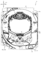
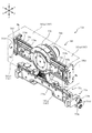
以下、本発明の実施形態について、添付図面を参照して説明する。まず、図1から図71を参照し、第1実施形態として、本発明をパチンコ遊技機(以下、単に「パチンコ機」という)10に適用した場合の一実施形態について説明する。図1は、第1実施形態におけるパチンコ機10の正面図であり、図2はパチンコ機10の遊技盤13の正面図であり、図3はパチンコ機10の背面図である。
Hereinafter, embodiments of the present invention will be described with reference to the accompanying drawings. First, an embodiment in which the present invention is applied to a pachinko gaming machine (hereinafter, simply referred to as “pachinko machine”) 10 will be described as a first embodiment with reference to FIGS. FIG. 1 is a front view of the pachinko machine 10 in the first embodiment, FIG. 2 is a front view of the game board 13 of the pachinko machine 10, and FIG. 3 is a rear view of the pachinko machine 10.
なお、以下の説明では、図1に示す状態のパチンコ機10に対して、紙面手前側を前方(正面)側として、紙面奥側を後方(背面)側として説明する。また、図1に示す状態のパチンコ機10に対して、上側を上方(上)側として、下側を下方(下)側として、右側を右方(右)側として、左側を左方(左)側としてそれぞれ説明する。さらに、図中(例えば、図2参照)の矢印U−D,L−R,F−Bは、パチンコ機10の上下方向,左右方向,前後方向をそれぞれ示している。
In the following description, with respect to the pachinko machine 10 in the state shown in FIG. 1, the near side of the drawing is referred to as a front (front) side, and the far side of the drawing is referred to as a rear (back) side. Also, with respect to the pachinko machine 10 in the state shown in FIG. 1, the upper side is the upper (upper) side, the lower side is the lower (lower) side, the right side is the right (right) side, and the left side is the left (left). ) Side. Further, arrows UD, LR, and FB in the figure (see, for example, FIG. 2) indicate the up-down direction, the left-right direction, and the front-back direction of the pachinko machine 10, respectively.
図1に示すように、パチンコ機10は、略矩形状に組み合わせた木枠により外殻が形成される外枠11と、その外枠11と略同一の外形形状に形成され外枠11に対して開閉可能に支持された内枠12とを備えている。外枠11には、内枠12を支持するために正面視(図1参照)左側の上下2カ所に金属製のヒンジ18が取り付けられ、そのヒンジ18が設けられた側を開閉の軸として内枠12が正面手前側へ開閉可能に支持されている。
As shown in FIG. 1, the pachinko machine 10 has an outer frame 11 having an outer shell formed by a wooden frame combined in a substantially rectangular shape, and an outer frame 11 formed to have substantially the same outer shape as the outer frame 11. And an inner frame 12 supported so as to be openable and closable. Metal hinges 18 are attached to the outer frame 11 at two upper and lower positions on the left side in front view (see FIG. 1) to support the inner frame 12, and the side on which the hinges 18 are provided is used as an opening / closing axis. The frame 12 is supported to be openable and closable toward the front side.
内枠12には、多数の釘や入賞口63,64等を有する遊技盤13(図2参照)が裏面側から着脱可能に装着される。この遊技盤13の正面を球(遊技球)が流下することにより弾球遊技が行われる。なお、内枠12には、球を遊技盤13の正面領域に発射する球発射ユニット112a(図4参照)やその球発射ユニット112aから発射された球を遊技盤13の正面領域まで誘導する発射レール(図示せず)等が取り付けられている。
A game board 13 (see FIG. 2) having a large number of nails, winning holes 63, 64 and the like is detachably mounted on the inner frame 12 from the back side. When a ball (game ball) flows down in front of the game board 13, a ball game is performed. The inner frame 12 has a ball launching unit 112a (see FIG. 4) that launches a ball into the front area of the game board 13 and a launch that guides the ball fired from the ball launch unit 112a to the front area of the game board 13. A rail (not shown) and the like are attached.
内枠12の正面側には、その正面上側を覆う正面枠14と、その下側を覆う下皿ユニット15とが設けられている。正面枠14及び下皿ユニット15を支持するために正面視(図1参照)左側の上下2カ所に金属製のヒンジ19が取り付けられ、そのヒンジ19が設けられた側を開閉の軸として正面枠14及び下皿ユニット15が正面手前側へ開閉可能に支持されている。なお、内枠12の施錠と正面枠14の施錠とは、シリンダ錠20の鍵穴21に専用の鍵を差し込んで所定の操作を行うことでそれぞれ解除される。
On the front side of the inner frame 12, a front frame 14 covering the front upper side and a lower plate unit 15 covering the lower side are provided. In order to support the front frame 14 and the lower plate unit 15, metal hinges 19 are attached to two upper and lower positions on the left side when viewed from the front (see FIG. 1), and the side on which the hinge 19 is provided is used as an opening / closing axis. The lower plate unit 14 and the lower plate unit 15 are supported to be openable and closable toward the front side. The locking of the inner frame 12 and the locking of the front frame 14 are respectively released by inserting a dedicated key into the keyhole 21 of the cylinder lock 20 and performing a predetermined operation.
正面枠14は、装飾用の樹脂部品や電気部品等を組み付けたものであり、その略中央部には略楕円形状に開口形成された窓部14cが設けられている。正面枠14の裏面側には2枚の板ガラスを有するガラスユニット16が配設され、そのガラスユニット16を介して遊技盤13の正面がパチンコ機10の正面側に視認可能となっている。
The front frame 14 is provided with a decorative resin component, an electric component, and the like, and is provided with a window 14c having a substantially elliptical opening at a substantially central portion thereof. A glass unit 16 having two glass sheets is disposed on the back side of the front frame 14, and the front of the game board 13 is visible on the front side of the pachinko machine 10 via the glass unit 16.
正面枠14には、球を貯留する上皿17が正面側へ張り出して上面を開放した略箱状に形成されており、この上皿17に賞球や貸出球などが排出される。上皿17の底面は正面視(図1参照)右側に下降傾斜して形成され、その傾斜により上皿17に投入された球が球発射ユニット112a(図4参照)へと案内される。また、上皿17の上面には、枠ボタン22が設けられている。この枠ボタン22は、例えば、第3図柄表示装置81(図2参照)で表示される演出のステージを変更したり、スーパーリーチの演出内容を変更したりする場合などに、遊技者により操作される。
On the front frame 14, an upper plate 17 for storing a ball is formed in a substantially box shape that protrudes toward the front side and has an open upper surface, and prize balls, loaned balls, and the like are discharged to the upper plate 17. The bottom surface of the upper plate 17 is formed to be inclined downward to the right as viewed from the front (see FIG. 1), and the ball introduced into the upper plate 17 is guided to the ball launching unit 112a (see FIG. 4) by the inclination. A frame button 22 is provided on the upper surface of the upper plate 17. The frame button 22 is operated by the player when, for example, changing the stage of the effect displayed on the third symbol display device 81 (see FIG. 2) or changing the effect of the super reach. You.
正面枠14には、その周囲(例えばコーナー部分)に各種ランプ等の発光手段が設けられている。これら発光手段は、大当たり時や所定のリーチ時等における遊技状態の変化に応じて、点灯又は点滅することにより発光態様が変更制御され、遊技中の演出効果を高める役割を果たす。窓部14cの周縁には、LED等の発光手段を内蔵した電飾部29〜33が設けられている。パチンコ機10においては、これら電飾部29〜33が大当たりランプ等の演出ランプとして機能し、大当たり時やリーチ演出時等には内蔵するLEDの点灯や点滅によって各電飾部29〜33が点灯または点滅して、大当たり中である旨、或いは大当たり一歩手前のリーチ中である旨が報知される。また、正面枠14の正面視(図1参照)左上部には、LED等の発光手段が内蔵され賞球の払い出し中とエラー発生時とを表示可能な表示ランプ34が設けられている。
Light emitting means such as various lamps is provided around the front frame 14 (for example, at a corner). These light-emitting means are controlled to change the light-emitting mode by lighting or blinking according to a change in the game state at the time of a big hit or at a predetermined reach, and play a role of enhancing the effect of the effect during the game. On the periphery of the window 14c, there are provided illuminations 29 to 33 in which light-emitting means such as LEDs are incorporated. In the pachinko machine 10, these illumination parts 29 to 33 function as effect lamps such as a jackpot lamp, and at the time of a big hit or a reach effect, etc., each of the illumination parts 29 to 33 is lit by turning on or blinking a built-in LED. Or, it flashes to notify that a jackpot is in progress or that the player is reaching one step before the jackpot. In addition, at the upper left portion of the front frame 14 when viewed from the front (see FIG. 1), there is provided a display lamp 34 which has a built-in light emitting means such as an LED and which can display when a prize ball is being paid out and when an error has occurred.
また、右側の電飾部32下側には、正面枠14の裏面側を視認できるように裏面側より透明樹脂を取り付けて小窓35が形成され、遊技盤13正面の貼着スペースK1(図2参照)に貼付される証紙等がパチンコ機10の正面から視認可能とされている。また、パチンコ機10においては、より煌びやかさを醸し出すために、電飾部29〜33の周りの領域にクロムメッキを施したABS樹脂製のメッキ部材36が取り付けられている。
Further, a small window 35 is formed by attaching a transparent resin from the back side so that the back side of the front frame 14 can be visually recognized below the right illumination part 32, and a sticking space K1 on the front of the game board 13 (FIG. 2) can be viewed from the front of the pachinko machine 10. Further, in the pachinko machine 10, a plating member 36 made of chrome-plated ABS resin is attached to a region around the electric decorations 29 to 33 in order to bring out more gorgeousness.
窓部14cの下方には、貸球操作部40が配設されている。貸球操作部40には、度数表示部41と、球貸しボタン42と、返却ボタン43とが設けられている。パチンコ機10の側方に配置されるカードユニット(球貸しユニット)(図示せず)に紙幣やカード等を投入した状態で貸球操作部40が操作されると、その操作に応じて球の貸出が行われる。具体的には、度数表示部41はカード等の残額情報が表示される領域であり、内蔵されたLEDが点灯して残額情報として残額が数字で表示される。球貸しボタン42は、カード等(記録媒体)に記録された情報に基づいて貸出球を得るために操作されるものであり、カード等に残額が存在する限りにおいて貸出球が上皿17に供給される。返却ボタン43は、カードユニットに挿入されたカード等の返却を求める際に操作される。なお、カードユニットを介さずに球貸し装置等から上皿17に球が直接貸し出されるパチンコ機、いわゆる現金機では貸球操作部40が不要となるが、この場合には、貸球操作部40の設置部分に飾りシール等を付加して部品構成は共通のものとしても良い。カードユニットを用いたパチンコ機と現金機との共通化を図ることができる。
A ball lending operation unit 40 is provided below the window 14c. The ball lending operation unit 40 is provided with a frequency display unit 41, a ball lending button 42, and a return button 43. When the ball lending operation unit 40 is operated in a state in which bills, cards, and the like are inserted into a card unit (ball lending unit) (not shown) arranged on the side of the pachinko machine 10, the ball is slid according to the operation. Lending is done. More specifically, the frequency display section 41 is an area in which balance information of a card or the like is displayed, and a built-in LED is turned on, and the balance is displayed as a number as balance information. The ball lending button 42 is operated to obtain a lending ball based on information recorded on a card or the like (recording medium), and the lending ball is supplied to the upper plate 17 as long as the card or the like has a remaining amount. Is done. The return button 43 is operated when requesting the return of a card or the like inserted in the card unit. In a pachinko machine in which balls are lent directly to the upper plate 17 from a ball lending device or the like without a card unit, a so-called cash machine, the ball-lending operation unit 40 becomes unnecessary. A decorative seal or the like may be added to the installation part to make the parts configuration common. The pachinko machine using the card unit and the cash machine can be shared.
上皿17の下側に位置する下皿ユニット15には、その左側部に上皿17に貯留しきれなかった球を貯留するための下皿50が上面を開放した略箱状に形成されている。下皿50の右側には、球を遊技盤13の正面へ打ち込むために遊技者によって操作される操作ハンドル51が配設される。
In the lower plate unit 15 located below the upper plate 17, a lower plate 50 for storing balls that could not be stored in the upper plate 17 is formed in a substantially box shape with an open upper surface on the left side thereof. I have. On the right side of the lower plate 50, an operation handle 51 operated by a player to drive a ball into the front of the game board 13 is provided.
操作ハンドル51の内部には、球発射ユニット112aの駆動を許可するためのタッチセンサ51aと、押下操作している期間中には球の発射を停止する発射停止スイッチ51bと、操作ハンドル51の回動操作量(回動位置)を電気抵抗の変化により検出する可変抵抗器(図示せず)などが内蔵されている。操作ハンドル51が遊技者によって右回りに回動操作されると、タッチセンサ51aがオンされると共に可変抵抗器の抵抗値が回動操作量に対応して変化し、その可変抵抗器の抵抗値に対応した強さ(発射強度)で球が発射され、これにより遊技者の操作に対応した飛び量で遊技盤13の正面へ球が打ち込まれる。また、操作ハンドル51が遊技者により操作されていない状態においては、タッチセンサ51aおよび発射停止スイッチ51bがオフとなっている。
Inside the operating handle 51, a touch sensor 51a for permitting driving of the ball firing unit 112a, a firing stop switch 51b for stopping firing of the ball during a pressing operation, and a rotation of the operating handle 51 A variable resistor (not shown) for detecting a dynamic operation amount (rotational position) based on a change in electric resistance is incorporated. When the operation handle 51 is rotated clockwise by the player, the touch sensor 51a is turned on and the resistance value of the variable resistor changes in accordance with the amount of rotation operation, and the resistance value of the variable resistor is changed. The ball is fired at an intensity (firing intensity) corresponding to, and the ball is hit into the front of the game board 13 with a flying amount corresponding to the operation of the player. When the operation handle 51 is not operated by the player, the touch sensor 51a and the firing stop switch 51b are off.
下皿50の正面下方部には、下皿50に貯留された球を下方へ排出する際に操作するための球抜きレバー52が設けられている。この球抜きレバー52は、常時、右方向に付勢されており、その付勢に抗して左方向へスライドさせることにより、下皿50の底面に形成された底面口が開口して、その底面口から球が自然落下して排出される。この球抜きレバー52の操作は、通常、下皿50の下方に下皿50から排出された球を受け取る箱(一般に「千両箱」と称される)を置いた状態で行われる。下皿50の右方には、上述したように操作ハンドル51が配設され、下皿50の左方には灰皿(図示せず)が取り付けられている。
At the lower front part of the lower plate 50, a ball release lever 52 for operating when discharging the balls stored in the lower plate 50 downward is provided. The ball pulling lever 52 is constantly urged rightward, and is slid leftward against the urging, so that a bottom opening formed on the bottom surface of the lower plate 50 is opened. The ball falls naturally from the bottom opening and is discharged. The operation of the ball removing lever 52 is usually performed in a state where a box (generally referred to as a “thousand boxes”) for receiving the balls discharged from the lower plate 50 is placed below the lower plate 50. As described above, the operation handle 51 is disposed on the right side of the lower plate 50, and an ashtray (not shown) is mounted on the left side of the lower plate 50.
図2に示すように、遊技盤13は、正面視略正方形状に切削加工したベース板60に、球案内用の多数の釘(センターフレーム86の下方において図示し、遊技領域の上半部においては図示せず)や風車(図示せず)の他、レール61,62、一般入賞口63、第1入賞口64、第2入賞口140、可変入賞装置65、スルーゲート67、可変表示装置ユニット80等を組み付けて構成され、その周縁部が内枠12(図1参照)の裏面側に取り付けられる。
As shown in FIG. 2, the game board 13 has a base plate 60 cut into a substantially square shape in a front view, and a number of ball guiding nails (shown below the center frame 86. In the upper half of the game area, Are not shown), a windmill (not shown), rails 61 and 62, a general winning opening 63, a first winning opening 64, a second winning opening 140, a variable winning device 65, a through gate 67, a variable display device unit. 80 and the like, and its peripheral edge is attached to the back surface side of the inner frame 12 (see FIG. 1).
ベース板60は、光透過性の樹脂材料から形成されるており、その正面側からベース板60の背面側に配設された各種構造体を遊技者に視認させることが可能となっている。一般入賞口63、第1入賞口64、第2入賞口140及び可変入賞装置65は、ルータ加工によってベース板60に形成された貫通穴に配設され、遊技盤13の正面側からタッピングネジ等により固定されている。
The base plate 60 is formed of a light-transmitting resin material, and allows a player to visually recognize various structures disposed on the back side of the base plate 60 from the front side. The general winning opening 63, the first winning opening 64, the second winning opening 140, and the variable winning device 65 are provided in through holes formed in the base plate 60 by router processing, and tapping screws and the like are provided from the front side of the game board 13. It is fixed by.
なお、ベース板60を木製の板部材から形成しても良い。この場合、センターフレーム86の外側において、その正面側からベース板60の背面側に配設された各種構造体を遊技者に視認不能に遮蔽することが可能となる。
The base plate 60 may be formed from a wooden plate member. In this case, on the outside of the center frame 86, various structures disposed on the back side of the base plate 60 from the front side thereof can be shielded so as to be invisible to the player.
遊技盤13の正面中央部分は、正面枠14の窓部14c(図1参照)を通じて内枠12の正面側から視認することができる。以下に、主に図2を参照して、遊技盤13の構成について説明する。
The front central portion of the game board 13 can be visually recognized from the front side of the inner frame 12 through the window 14c of the front frame 14 (see FIG. 1). Hereinafter, the configuration of the game board 13 will be described mainly with reference to FIG.
遊技盤13の正面には、帯状の金属板を略円弧状に屈曲加工して形成した外レール62が植立され、その外レール62の内側位置には外レール62と同様に帯状の金属板で形成した円弧状の内レール61が植立される。この内レール61と外レール62とにより遊技盤13の正面外周が囲まれ、遊技盤13とガラスユニット16(図1参照)とにより前後が囲まれることにより、遊技盤13の正面には、球の挙動により遊技が行われる遊技領域が形成される。遊技領域は、遊技盤13の正面であって2本のレール61,62とレール間を繋ぐ樹脂製の外縁部材73とにより区画して形成される領域(入賞口等が配設され、発射された球が流下する領域)である。
An outer rail 62 formed by bending a band-shaped metal plate into a substantially arc shape is erected on the front of the game board 13, and a band-shaped metal plate similar to the outer rail 62 is provided inside the outer rail 62. The arc-shaped inner rail 61 formed by the above is planted. The inner rail 61 and the outer rail 62 surround the outer periphery of the front of the game board 13, and the front and rear of the game board 13 and the glass unit 16 (see FIG. 1) surround the front and back of the game board 13. A game area in which a game is played is formed by the behavior of. The game area is an area defined by two rails 61 and 62 and a resin outer edge member 73 connecting the rails, which is the front of the game board 13 (a winning opening or the like is provided and fired). The area where the falling ball flows down).
2本のレール61,62は、球発射ユニット112a(図4参照)から発射された球を遊技盤13上部へ案内するために設けられたものである。内レール61の先端部分(図2の左上部)には戻り球防止部材68が取り付けられ、一旦、遊技盤13の上部へ案内された球が再度球案内通路内に戻ってしまうといった事態が防止される。外レール62の先端部(図2の右上部)には、球の最大飛翔部分に対応する位置に返しゴム69が取り付けられ、所定以上の勢いで発射された球は、返しゴム69に当たって、勢いが減衰されつつ中央部側へ跳ね返される。
The two rails 61 and 62 are provided to guide the ball fired from the ball firing unit 112a (see FIG. 4) to the upper part of the game board 13. A return ball preventing member 68 is attached to a tip portion (upper left portion of FIG. 2) of the inner rail 61 to prevent a situation in which a ball once guided to the upper portion of the game board 13 returns to the ball guide passage again. Is done. A return rubber 69 is attached to the tip of the outer rail 62 (upper right portion in FIG. 2) at a position corresponding to the maximum flight portion of the ball, and the ball fired at a predetermined momentum strikes the return rubber 69 and momentum. Is rebounded toward the center while being attenuated.
遊技領域の正面視左側下部(図2の左側下部)には、発光手段である複数のLED及び7セグメント表示器を備える第1図柄表示装置37A,37Bが配設されている。第1図柄表示装置37A,37Bは、主制御装置110(図4参照)で行われる各制御に応じた表示がなされるものであり、主にパチンコ機10の遊技状態の表示が行われる。本実施形態では、第1図柄表示装置37A,37Bは、球が、第1入賞口64へ入賞したか、第2入賞口140へ入賞したかに応じて使い分けられるように構成されている。具体的には、球が、第1入賞口64へ入賞した場合には、第1図柄表示装置37Aが作動し、一方で、球が、第2入賞口140へ入賞した場合には、第1図柄表示装置37Bが作動するように構成されている。
First symbol display devices 37A and 37B each including a plurality of LEDs as light-emitting means and a 7-segment display are provided at a lower left portion of the game area as viewed from the front (a lower left portion in FIG. 2). The first symbol display devices 37A and 37B are for performing display according to each control performed by the main control device 110 (see FIG. 4), and mainly display the game state of the pachinko machine 10. In the present embodiment, the first symbol display devices 37A and 37B are configured to be properly used depending on whether the ball has won the first winning opening 64 or the second winning opening 140. Specifically, when the ball wins the first winning opening 64, the first symbol display device 37A operates, while when the ball wins the second winning opening 140, the first symbol display device 37A operates. The symbol display device 37B is configured to operate.
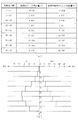
また、第1図柄表示装置37A,37Bは、LEDにより、パチンコ機10が確変中か時短中か通常中であるかを点灯状態により示したり、変動中であるか否かを点灯状態により示したり、停止図柄が確変大当たりに対応した図柄か普通大当たりに対応した図柄か外れ図柄であるかを点灯状態により示したり、保留球数を点灯状態により示すと共に、7セグメント表示装置により、大当たり中のラウンド数やエラー表示を行う。なお、複数のLEDは、それぞれのLEDの発光色(例えば、赤、緑、青)が異なるよう構成され、その発光色の組み合わせにより、少ないLEDでパチンコ機10の各種遊技状態を示唆することができる。
In addition, the first symbol display devices 37A and 37B use LEDs to indicate whether the pachinko machine 10 is in the process of probable change, during working hours, or during normal operation, or to indicate whether or not the pachinko machine 10 is fluctuating. Whether the stop symbol is a symbol corresponding to a probable jackpot or a symbol corresponding to an ordinary jackpot is indicated by an illuminated state, the number of retained balls is indicated by an illuminated state, and a round during a jackpot is displayed by a 7-segment display device. Display number and error. In addition, the plurality of LEDs are configured so that the emission colors (for example, red, green, and blue) of each LED are different, and a combination of the emission colors may indicate various game states of the pachinko machine 10 with a small number of LEDs. it can.
尚、本パチンコ機10では、第1入賞口64及び第2入賞口140へ入賞があったことを契機として抽選が行われる。パチンコ機10は、その抽選において、大当たりか否かの当否判定(大当たり抽選)を行うと共に、大当たりと判定した場合はその大当たり種別の判定も行う。ここで判定される大当たり種別としては、15R確変大当たり、4R確変大当たり、4R通常大当たりが用意されている。第1図柄表示装置37A,37Bには、変動終了後の停止図柄として抽選の結果が大当たりであるか否かが示されるだけでなく、大当たりである場合はその大当たり種別に応じた図柄が示される。
In the pachinko machine 10, a lottery is performed when the first winning port 64 and the second winning port 140 have a winning. In the lottery, the pachinko machine 10 determines whether or not it is a big hit (big hit lottery), and when it is determined to be a big hit, also determines the big hit type. As the jackpot type determined here, a 15R probability-change jackpot, a 4R probability-change jackpot, and a 4R normal jackpot are prepared. The first symbol display devices 37A and 37B not only indicate whether or not the result of the lottery is a jackpot as a stop symbol after the end of the change, but if the jackpot is a jackpot, a symbol corresponding to the jackpot type is displayed. .
ここで、「15R確変大当たり」とは、最大ラウンド数が15ラウンドの大当たりの後に高確率状態へ移行する確変大当たりのことであり、「4R確変大当たり」とは、最大ラウンド数が4ラウンドの大当たりの後に高確率状態へ移行する確変大当たりのことである。また、「4R通常大当たり」は、最大ラウンド数が4ラウンドの大当たりの後に、低確率状態へ移行すると共に、所定の変動回数の間(例えば、100変動回数)は時短状態となる大当たりのことである。
Here, “15R probability variable jackpot” means a probability variable jackpot in which the maximum number of rounds shifts to the high probability state after 15 rounds of jackpot, and “4R probability variable jackpot” means a maximum round number of four rounds. Is a probable jackpot that transitions to a high probability state after. The “4R normal jackpot” is a jackpot in which the maximum number of rounds shifts to the low probability state after four rounds of jackpots, and the time saving state is reached during a predetermined number of changes (for example, 100 changes). is there.
また、「高確率状態」とは、大当たり終了後に付加価値としてその後の大当たり確率がアップした状態、いわゆる確率変動中(確変中)の時をいい、換言すれば、特別遊技状態へ移行し易い遊技の状態のことである。本実施形態における高確率状態(確変中)は、所定の変動回数の間(本実施形態では、100変動回数)、大当たり確率がアップし、後述する第2図柄の当たり確率がアップして第2入賞口140へ球が入賞し易い遊技の状態を含む。「低確率状態」とは、確変中でない時をいい、大当たり確率が通常の状態、即ち、確変の時より大当たり確率が低い状態をいう。また、「低確率状態」のうちの時短状態(時短中)とは、大当たり確率が通常の状態であると共に、大当たり確率がそのままで第2図柄の当たり確率のみがアップして第2入賞口140へ球が入賞し易い遊技の状態のことをいう。一方、パチンコ機10が通常中とは、確変中でも時短中でもない遊技の状態(大当たり確率も第2図柄の当たり確率もアップしていない状態)である。
The “high-probability state” refers to a state in which the subsequent jackpot probability increases as an added value after the end of the jackpot, that is, a state in which the probability is changing (probable change), in other words, a game that is easily shifted to the special game state. State. In the high-probability state (probable change) in the present embodiment, the jackpot probability increases during a predetermined number of changes (100 changes in the present embodiment), and the second symbol hit probability described later increases. This includes a game state in which a ball can easily enter the winning opening 140. The “low-probability state” refers to a state in which the probability of a jackpot is normal, that is, a state in which the jackpot probability is lower than that in the case of a probability change. The time saving state (medium time saving) in the “low probability state” is a state in which the jackpot probability is a normal state, and the jackpot probability of the second symbol is increased while the jackpot probability remains unchanged. This refers to a game state in which the ball is easy to win. On the other hand, the state where the pachinko machine 10 is in the normal state is a state of the game in which the probability is not changed or the time is not reduced (a state in which neither the big hit probability nor the second symbol hit probability is increased).
本実施形態では、後述する振分装置300の確変検出センサSE11の貫通孔を、大当たり遊技の1ラウンド目に遊技球が通過したと判定された時に、その大当たり遊技終了後の遊技状態が100変動回数の間、高確率状態となる。なお、確変検出センサSE11の貫通孔に遊技球が通過したと判定されなかったら大当たり遊技終了後の遊技状態が100変動回数の間、時短状態となる。
In the present embodiment, when it is determined that the game ball has passed through the through hole of the probability change detection sensor SE11 of the distribution device 300 described later in the first round of the jackpot game, the gaming state after the end of the jackpot game changes by 100 times. During the number of times, it is in a high probability state. If it is not determined that the game ball has passed through the through hole of the probability change detection sensor SE11, the game state after the end of the jackpot game is reduced to the time-saving state for 100 times of change.
確変中や時短中は、第2図柄の当たり確率がアップするだけではなく、第2入賞口140に付随する電動役物140a(電動役物)が開放される時間も変更され、通常中と比して長い時間が設定される。電動役物140aが開放された状態(開放状態)にある場合は、その電動役物140aが閉鎖された状態(閉鎖状態)にある場合と比して、第2入賞口140へ球が入賞しやすい状態となる。よって、確変中や時短中は、第2入賞口140へ球が入賞し易い状態となり、大当たり抽選が行われる回数を増やすことができる。
During probable change or during working hours, not only the probability of hitting the second symbol increases, but also the time during which the electric accessory 140a (electric accessory) attached to the second winning opening 140 is opened is changed. Then a long time is set. When the electric accessory 140a is in the open state (open state), the ball wins in the second winning opening 140 as compared to when the electric accessory 140a is in the closed state (closed state). It will be in an easy state. Therefore, during probable change or during working hours, the ball is more likely to win the second winning opening 140, and the number of jackpot lotteries can be increased.
なお、確変中や時短中において、第2入賞口140に付随する電動役物140aの開放時間を変更するのではなく、または、その開放時間を変更することに加えて、1回の当たりで電動役物140aが開放する回数を通常中よりも増やす変更を行うものとしてもよい。また、確変中や時短中において、第2図柄の当たり確率は変更せず、第2入賞口140に付随する電動役物140aが開放される時間および1回の当たりで電動役物140aが開放する回数の少なくとも一方を変更するものとしてもよい。また、確変中や時短中において、第2入賞口140に付随する電動役物140aが開放される時間や、1回の当たりで電動役物140aを開放する回数はせず、第2図柄の当たり確率だけを、通常中と比してアップするよう変更するものであってもよい。
In addition, during the probable change or during working hours, instead of changing the opening time of the motorized accessory 140a attached to the second winning opening 140, or in addition to changing the opening time, the power A change may be made to increase the number of times that the accessory 140a is released from the normal number. In addition, during the probability change or during working hours, the winning probability of the second symbol is not changed, and the electric accessory 140a is opened during the time when the electric accessory 140a attached to the second winning opening 140 is opened and once. At least one of the number of times may be changed. In addition, during probable change or during working hours, the time during which the electric accessory 140a associated with the second winning opening 140 is opened, and the number of times the electric accessory 140a is opened per hit, are not determined. Only the probability may be changed so as to increase as compared with the normal state.
遊技領域には、球が入賞することにより5個から15個の球が賞球として払い出される複数の一般入賞口63が配設されている。また、遊技領域の中央部分には、可変表示装置ユニット80が配設されている。可変表示装置ユニット80には、第1入賞口64及び第2入賞口140への入賞(始動入賞)をトリガとして、第1図柄表示装置37A,37Bにおける変動表示と同期させながら、第3図柄の変動表示を行う液晶ディスプレイ(以下単に「表示装置」と略す)で構成された第3図柄表示装置81と、スルーゲート67の球の通過をトリガとして第2図柄を変動表示するLEDで構成される第2図柄表示装置(図示せず)とが設けられている。また、可変表示装置ユニット80には、第3図柄表示装置81の外周を囲むようにして、センターフレーム86が配設されている。
In the game area, a plurality of general winning openings 63 are provided in which 5 to 15 balls are paid out as winning balls when the balls win. Further, a variable display device unit 80 is provided in a central portion of the game area. The variable display device unit 80 uses the winning of the first winning opening 64 and the second winning opening 140 (start winning) as a trigger, and synchronizes with the variable display on the first symbol display devices 37A and 37B, and outputs the third symbol. A third symbol display device 81 composed of a liquid crystal display (hereinafter simply abbreviated as “display device”) that performs variable display, and an LED that varies and displays the second symbol when the ball of the through gate 67 passes through as a trigger. A second symbol display device (not shown) is provided. Further, a center frame 86 is provided in the variable display device unit 80 so as to surround the outer periphery of the third symbol display device 81.
なお、本実施形態では、第3図柄表示装置81は後述する背面ケース510の開口511aを埋めるように背面ケース510に締結固定され、センターフレーム86はベース板60の窓部を縁取るように配設されている。即ち、正面視では第3図柄表示装置81の外周を囲むようにセンターフレーム86が配設されているように見えるが、実際は、第3図柄表示装置81とセンターフレーム86とは前後に離れて配置されている。
In the present embodiment, the third symbol display device 81 is fastened and fixed to the rear case 510 so as to fill an opening 511a of the rear case 510 described later, and the center frame 86 is arranged to border the window of the base plate 60. It is established. That is, when viewed from the front, the center frame 86 appears to be disposed so as to surround the outer periphery of the third symbol display device 81, but in reality, the third symbol display device 81 and the center frame 86 are spaced apart from each other in the front-back direction. Have been.
第3図柄表示装置81は、例えば9インチサイズの大型の液晶ディスプレイで構成されるものであり、表示制御装置114(図4参照)によって表示内容が制御されることにより、例えば上、中及び下の3つの図柄列が表示される。各図柄列は複数の図柄(第3図柄)によって構成され、これらの第3図柄が図柄列毎に横スクロールして第3図柄表示装置81の表示画面上にて第3図柄が可変表示されるようになっている。本実施形態の第3図柄表示装置81は、主制御装置110(図4参照)の制御に伴った遊技状態の表示が第1図柄表示装置37A,37Bで行われるのに対して、その第1図柄表示装置37A,37Bの表示に応じた装飾的な表示を行うものである。なお、表示装置に代えて、例えばリール等を用いて第3図柄表示装置81を構成するようにしても良い。
The third symbol display device 81 is composed of, for example, a large 9-inch liquid crystal display. The display content is controlled by the display control device 114 (see FIG. 4), so that, for example, the upper, middle, and lower portions are displayed. Are displayed. Each symbol row is composed of a plurality of symbols (third symbols), and these third symbols are horizontally scrolled for each symbol row, and the third symbol is variably displayed on the display screen of the third symbol display device 81. It has become. In the third symbol display device 81 of the present embodiment, the display of the game state accompanying the control of the main control device 110 (see FIG. 4) is performed by the first symbol display devices 37A and 37B. The decorative display corresponding to the display of the symbol display devices 37A and 37B is performed. Note that the third symbol display device 81 may be configured using, for example, a reel or the like instead of the display device.
第2図柄表示装置は、球がスルーゲート67を通過する毎に表示図柄(第2図柄(図示せず))としての「○」の図柄と「×」の図柄とを所定時間交互に点灯させる変動表示を行うものである。パチンコ機10では、球がスルーゲート67を通過したことが検出されると、当たり抽選が行われる。その当たり抽選の結果、当たりであれば、第2図柄表示装置において、第2図柄の変動表示後に「○」の図柄が停止表示される。また、当たり抽選の結果、外れであれば、第2図柄表示装置において、第3図柄の変動表示後に「×」の図柄が停止表示される。
The second symbol display device alternately lights a symbol “O” and a symbol “X” as a display symbol (second symbol (not shown)) for a predetermined time each time the ball passes through the through gate 67. The variable display is performed. In the pachinko machine 10, when it is detected that the ball has passed through the through gate 67, a winning lottery is performed. If the result of the winning lottery is a winning, the symbol "O" is stopped and displayed on the second symbol display device after the variation display of the second symbol. If the result of the winning lottery is off, the symbol "x" is stopped and displayed on the second symbol display device after the variation display of the third symbol.
パチンコ機10は、第2図柄表示装置における変動表示が所定図柄(本実施形態においては「○」の図柄)で停止した場合に、第2入賞口140に付随された電動役物140aが所定時間だけ作動状態となる(開放される)よう構成されている。
In the case of the pachinko machine 10, when the variable display on the second symbol display device is stopped at a predetermined symbol (in the present embodiment, a symbol of “」 ”), the electric accessory 140a attached to the second winning opening 140 is held for a predetermined time. Only the operating state (opened).
第2図柄の変動表示にかかる時間は、遊技状態が通常中の場合よりも、確変中または時短中の方が短くなるように設定される。これにより、確変中および時短中は、第2図柄の変動表示が短い時間で行われるので、当たり抽選を通常中よりも多く行うことができる。よって、当たり抽選において当たりとなる機会が増えるので、第2入賞口140の電動役物140aが開放状態となる機会を遊技者に多く与えることができる。よって、確変中および時短中は、第2入賞口140へ球が入賞しやすい状態とすることができる。
The time required for the fluctuation display of the second symbol is set to be shorter during the probable change or during the time reduction than during the normal game state. Thus, during the probable change and during the time reduction, the fluctuation display of the second symbol is performed in a short time, so that the winning lottery can be performed more than during the normal time. Therefore, the chance of winning in the winning lottery increases, so that the player can be given many opportunities to open the electric accessory 140a of the second winning opening 140. Therefore, during the probability change and during the working hours, the ball can easily enter the second winning opening 140.
なお、確変中または時短中において、当たり確率を高める、1回に当たりに対する電動役物140aの開放時間や開放回数を増やすなど、その他の方法によっても、確変中または時短中に第2入賞口140へ球が入賞しやすい状態としている場合は、第2図柄の変動表示にかかる時間を遊技状態にかかわらず一定としてもよい。一方、第2図柄の変動表示にかかる時間を、確変中または時短中において通常中よりも短く設定する場合は、当たり確率を遊技状態にかかわらず一定にしてもよいし、また、1回の当たりに対する電動役物140aの開放時間や開放回数を遊技状態にかかわらず一定にしてもよい。
In addition, during the probability change or during the working hours, the probability of hitting is increased, and the opening time and the number of times of opening of the electric accessory 140a per hit are increased. When the ball is in a state where it is easy to win, the time required for the variable display of the second symbol may be constant regardless of the game state. On the other hand, in the case where the time required for the fluctuation display of the second symbol is set shorter during the probability change or during the time reduction, the hit probability may be constant irrespective of the game state, or one hit may be performed. May be constant regardless of the gaming state.
スルーゲート67は、可変表示装置ユニット80の左右の領域において遊技盤13に組み付けられ、遊技盤13に発射された球の一部が通過可能に構成されている。スルーゲート67を球が通過すると、第2図柄の当たり抽選が行われる。当たり抽選の後、第2図柄表示装置にて変動表示を行い、当たり抽選の結果が当たりであれば、変動表示の停止図柄として「○」の図柄を表示し、当たり抽選の結果が外れであれば、変動表示の停止図柄として「×」の図柄を表示する。
The through gate 67 is assembled to the game board 13 in the left and right regions of the variable display device unit 80, and is configured to allow a part of the ball fired on the game board 13 to pass through. When the ball passes through the through gate 67, a winning lottery of the second symbol is performed. After the winning lottery, the variable display is performed on the second symbol display device, and if the result of the winning lottery is a hit, a symbol of “○” is displayed as a stop symbol of the variable display, and if the result of the winning lottery is out. For example, a symbol "x" is displayed as a stop symbol of the variable display.
球のスルーゲート67の通過回数は、合計で最大4回まで保留され、その保留球数が上述した第1図柄表示装置37A,37Bにより表示されると共に第2図柄保留ランプ(図示せず)においても点灯表示される。第2図柄保留ランプは、最大保留数分の4つ設けられ、第3図柄表示装置81の下方に左右対称に配設されている。
The number of times the ball has passed through the through gate 67 is retained up to a total of four times, and the number of retained balls is displayed by the above-mentioned first symbol display devices 37A and 37B and at the second symbol retaining lamp (not shown). Is also lit. Four second symbol holding lamps are provided for the maximum number of holdings, and are arranged symmetrically below the third symbol display device 81.
なお、第2図柄の変動表示は、本実施形態のように、第2図柄表示装置において複数のランプの点灯と非点灯を切り換えることにより行うものの他、第1図柄表示装置37A,37B及び第3図柄表示装置81の一部を使用して行うようにしても良い。同様に、第2図柄保留ランプの点灯を第3図柄表示装置81の一部で行うようにしても良い。また、スルーゲート67の球の通過に対する最大保留球数は4回に限定されるものでなく、3回以下、又は、5回以上の回数(例えば、8回)に設定しても良い。また、スルーゲート67の組み付け数は2つに限定されるものではなく、例えば1つであっても良い。また、スルーゲート67の組み付け位置は可変表示装置ユニット80の左右に限定されるものではなく、例えば、可変表示装置ユニット80の下方でも良い。また、第1図柄表示装置37A,37Bにより保留球数が示されるので、第2図柄保留ランプにより点灯表示を行わないものとしてもよい。
The variable display of the second symbol is performed by switching on and off of a plurality of lamps in the second symbol display device as in the present embodiment, and is also performed by the first symbol display devices 37A and 37B and the third symbol display device. This may be performed using a part of the symbol display device 81. Similarly, the lighting of the second symbol holding lamp may be performed by a part of the third symbol display device 81. Further, the maximum number of reserved balls for passing the ball through the through gate 67 is not limited to four, but may be set to three or less, or five or more (for example, eight). The number of through gates 67 is not limited to two, but may be one, for example. Further, the mounting position of the through gate 67 is not limited to the left and right of the variable display device unit 80, and may be, for example, below the variable display device unit 80. Further, since the number of reserved balls is indicated by the first symbol display devices 37A and 37B, the second symbol retaining lamp may not be lit.
可変表示装置ユニット80の下方には、球が入賞し得る第1入賞口64が配設されている。この第1入賞口64へ球が入賞すると遊技盤13の裏面側に設けられる第1入賞口スイッチ(図示せず)がオンとなり、その第1入賞口スイッチのオンに起因して主制御装置110(図4参照)で大当たりの抽選がなされ、その抽選結果に応じた表示が第1図柄表示装置37Aで示される。
Below the variable display unit 80, a first winning port 64 in which a ball can win is provided. When a ball wins in the first winning opening 64, a first winning opening switch (not shown) provided on the back side of the game board 13 is turned on, and the main control device 110 is turned on by turning on the first winning opening switch. A jackpot lottery is performed in (see FIG. 4), and a display corresponding to the lottery result is shown on the first symbol display device 37A.
一方、第1入賞口64の正面視下方には、球が入賞し得る第2入賞口140が配設されている。この第2入賞口140へ球が入賞すると遊技盤13の裏面側に設けられる第2入賞口スイッチ(図示せず)がオンとなり、その第2入賞口スイッチのオンに起因して主制御装置110(図4参照)で大当たりの抽選がなされ、その抽選結果に応じた表示が第1図柄表示装置37Bで示される。
On the other hand, below the first winning opening 64 in front view, a second winning opening 140 from which a ball can win is provided. When a ball wins in the second winning opening 140, a second winning opening switch (not shown) provided on the back side of the game board 13 is turned on, and the main control device 110 is turned on by turning on the second winning opening switch. A jackpot lottery is performed in (see FIG. 4), and a display corresponding to the lottery result is shown on the first symbol display device 37B.
また、第1入賞口64および第2入賞口140は、それぞれ、球が入賞すると5個の球が賞球として払い出される入賞口の1つにもなっている。なお、本実施形態においては、第1入賞口64へ球が入賞した場合に払い出される賞球数と第2入賞口140へ球が入賞した場合に払い出される賞球数とを同じに構成したが、第1入賞口64へ球が入賞した場合に払い出される賞球数と第2入賞口140へ球が入賞した場合に払い出される賞球数とを異なる数、例えば、第1入賞口64へ球が入賞した場合に払い出される賞球数を3個とし、第2入賞口140へ球が入賞した場合に払い出される賞球数を5個として構成してもよい。
Each of the first winning port 64 and the second winning port 140 is also one of winning ports in which five balls are paid out as prize balls when the ball wins. In the present embodiment, the number of award balls to be paid out when a ball wins in the first winning opening 64 and the number of award balls to be paid out when a ball wins to the second winning opening 140 are the same. The number of award balls to be paid out when a ball wins in the first winning opening 64 is different from the number of award balls to be paid out when a ball wins to the second winning opening 140, for example, the number of balls to the first winning opening 64. May be configured to have three prize balls to be paid out when a prize is awarded, and to have five prize balls to be paid out when a ball is awarded to the second winning opening 140.
第2入賞口140には電動役物140aが付随されている。この電動役物140aは開閉可能に構成されており、通常は電動役物140aが閉鎖状態(縮小状態)となって、球が第2入賞口140へ入賞しにくい状態となっている。一方、スルーゲート67への球の通過を契機として行われる第2図柄の変動表示の結果、「○」の図柄が第2図柄表示装置に表示された場合、電動役物140aが開放状態(拡大状態)となり、球が第2入賞口140へ入賞しやすい状態となる。
The second winning port 140 is provided with an electric accessory 140a. The electric accessory 140a is configured to be openable and closable. Normally, the electric accessory 140a is in a closed state (reduced state), so that the ball does not easily enter the second winning opening 140. On the other hand, when the symbol “O” is displayed on the second symbol display device as a result of the variation display of the second symbol performed when the ball passes through the through gate 67, the electric accessory 140a is in the open state (enlarged). State), so that the ball can easily enter the second winning opening 140.
上述した通り、確変中および時短中は、通常中と比して第2図柄の当たり確率が高く、また、第2図柄の変動表示にかかる時間も短いので、第2図柄の変動表示において「○」の図柄が表示され易くなって、電動役物140aが開放状態(拡大状態)となる回数が増える。更に、確変中および時短中は、電動役物140aが開放される時間も、通常中より長くなる。よって、確変中および時短中は、通常時と比して、第2入賞口140へ球が入賞しやすい状態を作ることができる。
As described above, the probability of hitting the second symbol is higher during the probable change and during the working hours, and the time required to display the variation of the second symbol is shorter than that during the normal period. Are easily displayed, and the number of times the electric accessory 140a is opened (increased) is increased. Further, during the probable change and during the working hours, the time during which the electric accessory 140a is opened is also longer than during the normal working hours. Therefore, during probable change and during working hours, it is possible to create a state in which a ball can easily win the second winning opening 140 as compared with the normal time.
ここで、第1入賞口64に球が入賞した場合と第2入賞口140へ球が入賞した場合とで、大当たりとなる確率は、低確率状態であっても高確率状態でも同一である。しかしながら、大当たりとなった場合に選定される大当たりの種別として15R確変大当たりとなる確率は、第2入賞口140へ球が入賞した場合のほうが第1入賞口64へ球が入賞した場合よりも高く設定されている。一方、第1入賞口64は、第2入賞口140にあるような電動役物は有しておらず、球が常時入賞可能な状態となっている。
Here, the probability of the big hit in the case where the ball has won in the first winning opening 64 and the case where the ball has won in the second winning opening 140 is the same in the low probability state and the high probability state. However, the probability of a 15R probability variable jackpot being selected as a jackpot type selected in the event of a jackpot is higher when a ball wins the second winning opening 140 than when a ball wins the first winning opening 64. Is set. On the other hand, the first winning opening 64 does not have the motorized accessory as in the second winning opening 140, and the ball is always in a state capable of winning.
よって、通常中においては、第2入賞口140に付随する電動役物が閉鎖状態にある場合が多く、第2入賞口140に入賞しづらいので、電動役物のない第1入賞口64へ向けて、可変表示装置ユニット80の左方を球が通過するように球を発射し(所謂「左打ち」)、第1入賞口64への入賞によって大当たり抽選の機会を多く得て、大当たりとなることを狙った方が、遊技者にとって有利となる。
Therefore, during normal times, the electric winning accessory attached to the second winning opening 140 is often in the closed state, and it is difficult to win the second winning opening 140. Then, the ball is fired so that the ball passes to the left of the variable display device unit 80 (so-called “left-handed”), and by winning the first winning opening 64, a lot of chances of a jackpot lottery are obtained, and the jackpot is won. It is more advantageous for the player to aim for that.
一方、確変中や時短中は、スルーゲート67に球を通過させることで、第2入賞口140に付随する電動役物140aが開放状態となりやすく、第2入賞口140に入賞しやすい状態であるので、第2入賞口140へ向けて、可変表示装置80の右方を球が通過するように球を発射し(所謂「右打ち」)、スルーゲート67を通過させて電動役物を開放状態にすると共に、第2入賞口140への入賞によって15R確変大当たりとなることを狙った方が、遊技者にとって有利となる。
On the other hand, when the ball is passed through the through gate 67 during the probable change or during working hours, the electric accessory 140a attached to the second winning opening 140 tends to be opened, and the second winning opening 140 is easily won. Therefore, the ball is fired toward the second winning opening 140 so that the ball passes rightward of the variable display device 80 (so-called “right-handed”), and passes through the through gate 67 to open the electric accessory. At the same time, it is more advantageous for the player to aim for a 15R probability change jackpot by winning the second winning opening 140.
なお、本実施形態におけるパチンコ機10は、遊技盤13の構成が左右対称とされるため、「右打ち」で第1入賞口64を狙うことも、「左打ち」で第2入賞口140を狙うこともできる。そのため、本実施形態のパチンコ機10は、パチンコ機10の遊技状態(確変中であるか、時短中であるか、通常中であるか)に応じて、遊技者に対し、球の発射の仕方を「左打ち」と「右打ち」とに変えさせることを不要にできる。よって、球の打ち方を変化させる煩わしさを解消することができる。
In the pachinko machine 10 according to the present embodiment, since the configuration of the game board 13 is symmetrical, the pachinko machine 10 can aim at the first winning opening 64 by “right-handing” or the second winning opening 140 by “left-handing”. You can also aim. For this reason, the pachinko machine 10 of the present embodiment provides the player with a method of shooting a ball in accordance with the playing state of the pachinko machine 10 (whether the game is being changed, is being reduced in time, or is usually being played). Need to be changed to “left-handed” and “right-handed”. Therefore, the trouble of changing the way of hitting the ball can be eliminated.
第1入賞口64の下方には可変入賞装置65(図2参照)が配設されており、その略中央部分に特定入賞口65aが設けられている。パチンコ機10においては、第1入賞口64又は第2入賞口140への入賞に起因して行われた大当たり抽選が大当たりとなると、所定時間(変動時間)が経過した後に、大当たりの停止図柄となるよう第1図柄表示装置37A又は第1図柄表示装置37Bを点灯させると共に、その大当たりに対応した停止図柄を第3図柄表示装置81に表示させて、大当たりの発生が示される。その後、球が入賞し易い特別遊技状態(大当たり)に遊技状態が遷移する。この特別遊技状態として、通常時には閉鎖されている特定入賞口65aが、所定時間(例えば、30秒経過するまで、或いは、球が10個入賞するまで)開放される。
A variable winning device 65 (see FIG. 2) is provided below the first winning opening 64, and a specific winning opening 65a is provided substantially at the center thereof. In the pachinko machine 10, when the jackpot lottery performed due to the winning in the first winning port 64 or the second winning port 140 becomes a jackpot, after a predetermined time (variable time) elapses, the jackpot stop symbol is displayed. Thus, the first symbol display device 37A or the first symbol display device 37B is turned on, and a stop symbol corresponding to the jackpot is displayed on the third symbol display device 81 to indicate the occurrence of the jackpot. After that, the game state transitions to a special game state (big hit) where the ball is easy to win. In this special game state, the specific winning port 65a which is normally closed is opened for a predetermined time (for example, until 30 seconds elapse or 10 balls are won).
この特定入賞口65aは、所定時間が経過すると閉鎖され、その閉鎖後、再度、その特定入賞口65aが所定時間開放される。この特定入賞口65aの開閉動作は、最高で例えば15回(15ラウンド)繰り返し可能にされている。この開閉動作が行われている状態が、遊技者にとって有利な特別遊技状態の一形態であり、遊技者には、遊技上の価値(遊技価値)の付与として通常時より多量の賞球の払い出しが行われる。
The specific winning opening 65a is closed after a predetermined time has elapsed, and after the closing, the specific winning opening 65a is opened again for a predetermined time. The opening / closing operation of the specific winning opening 65a can be repeated up to, for example, 15 times (15 rounds). The state in which the opening and closing operation is performed is one form of a special game state that is advantageous to the player, and the player is paid out a larger amount of prize balls than usual in order to give a game value (game value). Is performed.
なお、上記した形態に特別遊技状態は限定されるものではない。特定入賞口65aとは別に開閉される大開放口を遊技領域に設け、第1図柄表示装置37A,37Bにおいて大当たりに対応したLEDが点灯した場合に、特定入賞口65aが所定時間開放され、その特定入賞口65aの開放中に、球が特定入賞口65a内へ入賞することを契機として特定入賞口65aとは別に設けられた大開放口が所定時間、所定回数開放される遊技状態を特別遊技状態として形成するようにしても良い。また、特定入賞口65aは1つに限るものではなく、1つ若しくは2以上の複数(例えば3つ)を配置しても良く、また配置位置も第1入賞口64の下方右側や、第1入賞口64の下方左側に限らず、例えば、可変表示装置ユニット80の左方でも良い。
Note that the special game state is not limited to the above-described embodiment. A large opening that is opened and closed separately from the specific winning opening 65a is provided in the game area, and when the LED corresponding to the big hit is turned on in the first symbol display devices 37A and 37B, the specific winning opening 65a is opened for a predetermined time. During the opening of the special winning opening 65a, the game state in which the large opening provided separately from the specific winning opening 65a is opened for a predetermined time and a predetermined number of times when the ball wins inside the specific winning opening 65a is a special game. It may be formed as a state. Further, the number of the specific winning opening 65a is not limited to one, and one or two or more (for example, three) may be arranged, and the arrangement position may be the lower right side of the first winning opening 64 or the first winning opening 64a. The present invention is not limited to the lower left side of the winning opening 64, but may be, for example, the left side of the variable display unit 80.
遊技盤13の下側における右隅部には、証紙や識別ラベル等を貼着するための貼着スペースK1が設けられ、貼着スペースK1に貼られた証紙等は、正面枠14の小窓35(図1参照)を通じて視認することができる。
At the lower right corner of the game board 13 is provided a sticking space K1 for sticking a stamp, an identification label and the like, and the stamp attached to the sticking space K1 is a small window of the front frame 14. 35 (see FIG. 1).
遊技盤13には、アウト口71が設けられている。遊技領域を流下する球であって、いずれの入賞口63,64,65a,140にも入賞しなかった球は、アウト口71を通って図示しない球排出路へと案内される。アウト口71は、特定入賞口65aの左右に一対で配設される。
The game board 13 is provided with an out port 71. A ball that flows down the game area and does not win any of the winning ports 63, 64, 65a, and 140 is guided to a ball discharging path (not shown) through the out port 71. The out-opening 71 is provided as a pair on the left and right of the specific winning opening 65a.
遊技盤13には、球の落下方向を適宜分散、調整等するために多数の釘が植設されているとともに、風車等の各種部材(役物)とが配設されている(図示せず)。
In the game board 13, a large number of nails are planted for appropriately dispersing and adjusting the falling direction of the ball, and various members (accessories) such as a windmill are arranged (not shown). ).
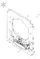
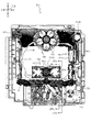
図3に示すように、パチンコ機10の背面側には、制御基板ユニット90,91と、裏パックユニット94とが主に備えられている。制御基板ユニット90は、主基板(主制御装置110)と音声ランプ制御基板(音声ランプ制御装置113)と表示制御基板(表示制御装置114)とが搭載されてユニット化されている。制御基板ユニット91は、払出制御基板(払出制御装置111)と発射制御基板(発射制御装置112)と電源基板(電源装置115)とカードユニット接続基板116とが搭載されてユニット化されている。
As shown in FIG. 3, on the back side of the pachinko machine 10, control board units 90 and 91 and a back pack unit 94 are mainly provided. The control board unit 90 includes a main board (main control device 110), a sound lamp control board (sound lamp control device 113), and a display control board (display control device 114). The control board unit 91 is mounted as a unit on which a payout control board (payout control device 111), a firing control board (firing control device 112), a power supply board (power supply device 115), and a card unit connection board 116 are mounted.
裏パックユニット94は、保護カバー部を形成する裏パック92と払出ユニット93とがユニット化されている。また、各制御基板には、各制御を司る1チップマイコンとしてのMPU、各種機器との連絡をとるポート、各種抽選の際に用いられる乱数発生器、時間計数や同期を図る場合などに使用されるクロックパルス発生回路等が、必要に応じて搭載されている。
In the back pack unit 94, a back pack 92 and a payout unit 93 forming a protective cover unit are unitized. In addition, each control board includes an MPU as a one-chip microcomputer for controlling each control, a port for communicating with various devices, a random number generator used for various lotteries, and a time counting and synchronization. A clock pulse generating circuit and the like are mounted as needed.
なお、主制御装置110、音声ランプ制御装置113及び表示制御装置114、払出制御装置111及び発射制御装置112、電源装置115、カードユニット接続基板116は、それぞれ基板ボックス100〜104に収納されている。基板ボックス100〜104は、ボックスベースと該ボックスベースの開口部を覆うボックスカバーとを備えており、そのボックスベースとボックスカバーとが互いに連結されて、各制御装置や各基板が収納される。
The main control device 110, the sound lamp control device 113 and the display control device 114, the payout control device 111 and the firing control device 112, the power supply device 115, and the card unit connection board 116 are housed in the board boxes 100 to 104, respectively. . Each of the board boxes 100 to 104 includes a box base and a box cover that covers an opening of the box base. The box base and the box cover are connected to each other, and each control device and each board are stored.
また、基板ボックス100(主制御装置110)及び基板ボックス102(払出制御装置111及び発射制御装置112)は、ボックスベースとボックスカバーとを封印ユニット(図示せず)によって開封不能に連結(かしめ構造による連結)している。また、ボックスベースとボックスカバーとの連結部には、ボックスベースとボックスカバーとに亘って封印シール(図示せず)が貼着されている。この封印シールは、脆性な素材で構成されており、基板ボックス100,102を開封するために封印シールを剥がそうとしたり、基板ボックス100,102を無理に開封しようとすると、ボックスベース側とボックスカバー側とに切断される。よって、封印ユニット又は封印シールを確認することで、基板ボックス100,102が開封されたかどうかを知ることができる。
Further, the substrate box 100 (main control device 110) and the substrate box 102 (dispensing control device 111 and firing control device 112) are connected to the box base and the box cover by a sealing unit (not shown) so as not to be opened (the caulking structure). Consolidation). In addition, a seal (not shown) is attached to a connection portion between the box base and the box cover over the box base and the box cover. This sealing seal is made of a brittle material. If the sealing seal is peeled to open the substrate boxes 100 and 102 or if the substrate boxes 100 and 102 are forcibly opened, the box base side and the box cover are closed. Cut to the side and. Therefore, by checking the sealing unit or the sealing seal, it is possible to know whether or not the substrate boxes 100 and 102 have been opened.
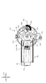
払出ユニット93は、裏パックユニット94の最上部に位置して上方に開口したタンク130と、タンク130の下方に連結され下流側に向けて緩やかに傾斜するタンクレール131と、タンクレール131の下流側に縦向きに連結されるケースレール132と、ケースレール132の最下流部に設けられ、払出モータ216(図4参照)の所定の電気的構成により球の払出を行う払出装置133とを備えている。タンク130には、遊技ホールの島設備から供給される球が逐次補給され、払出装置133により必要個数の球の払い出しが適宜行われる。タンクレール131には、当該タンクレール131に振動を付加するためのバイブレータ134が取り付けられている。
The dispensing unit 93 includes a tank 130 located at the top of the back pack unit 94 and opening upward, a tank rail 131 connected below the tank 130 and gently inclined toward the downstream side, and a downstream side of the tank rail 131. A case rail 132 vertically connected to the side, and a payout device 133 provided at the most downstream portion of the case rail 132 and paying out balls by a predetermined electric configuration of a payout motor 216 (see FIG. 4). ing. The balls supplied from the island facilities of the game hall are sequentially replenished to the tank 130, and the payout device 133 pays out a required number of balls as needed. A vibrator 134 for applying vibration to the tank rail 131 is attached to the tank rail 131.
また、払出制御装置111には状態復帰スイッチ120が設けられ、発射制御装置112には可変抵抗器の操作つまみ121が設けられ、電源装置115にはRAM消去スイッチ122が設けられている。状態復帰スイッチ120は、例えば、払出モータ216(図4参照)部の球詰まり等、払出エラーの発生時に球詰まりを解消(正常状態への復帰)するために操作される。操作つまみ121は、発射ソレノイドの発射力を調整するために操作される。RAM消去スイッチ122は、パチンコ機10を初期状態に戻したい場合に電源投入時に操作される。
Further, the payout control device 111 is provided with a state return switch 120, the firing control device 112 is provided with a variable resistor operation knob 121, and the power supply device 115 is provided with a RAM erase switch 122. The state return switch 120 is operated to clear the clogged ball (return to a normal state) when a payout error occurs, such as a clogged ball in the payout motor 216 (see FIG. 4). The operation knob 121 is operated to adjust the firing force of the firing solenoid. The RAM erase switch 122 is operated when the power is turned on to return the pachinko machine 10 to the initial state.
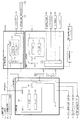
次に、図4を参照して、本パチンコ機10の電気的構成について説明する。図4は、パチンコ機10の電気的構成を示すブロック図である。
Next, an electrical configuration of the pachinko machine 10 will be described with reference to FIG. FIG. 4 is a block diagram showing an electrical configuration of the pachinko machine 10. As shown in FIG.
主制御装置110には、演算装置である1チップマイコンとしてのMPU201が搭載されている。MPU201には、該MPU201により実行される各種の制御プログラムや固定値データを記憶したROM202と、そのROM202内に記憶される制御プログラムの実行に際して各種のデータ等を一時的に記憶するためのメモリであるRAM203と、そのほか、割込回路やタイマ回路、データ送受信回路などの各種回路が内蔵されている。主制御装置110では、MPU201によって、大当たり抽選や第1図柄表示装置37A,37B及び第3図柄表示装置81における表示の設定、第2図柄表示装置における表示結果の抽選といったパチンコ機10の主要な処理を実行する。
The main control device 110 has an MPU 201 as a one-chip microcomputer, which is an arithmetic device. The MPU 201 includes a ROM 202 storing various control programs and fixed value data executed by the MPU 201, and a memory for temporarily storing various data and the like when executing the control programs stored in the ROM 202. A certain RAM 203 and other various circuits such as an interrupt circuit, a timer circuit, and a data transmission / reception circuit are built therein. In the main control device 110, the main processing of the pachinko machine 10 such as the jackpot lottery, the setting of the display on the first symbol display devices 37A and 37B and the third symbol display device 81, and the lottery of the display result on the second symbol display device are performed by the MPU 201. Execute
なお、払出制御装置111や音声ランプ制御装置113などのサブ制御装置に対して動作を指示するために、主制御装置110から該サブ制御装置へ各種のコマンドがデータ送受信回路によって送信されるが、かかるコマンドは、主制御装置110からサブ制御装置へ一方向にのみ送信される。
Various commands are transmitted from the main control device 110 to the sub-control device by the data transmission / reception circuit to instruct the sub-control device such as the payout control device 111 and the sound lamp control device 113 to operate. Such a command is transmitted from the main control device 110 to the sub control device only in one direction.
RAM203は、各種エリア、カウンタ、フラグのほか、MPU201の内部レジスタの内容やMPU201により実行される制御プログラムの戻り先番地などが記憶されるスタックエリアと、各種のフラグおよびカウンタ、I/O等の値が記憶される作業エリア(作業領域)とを有している。なお、RAM203は、パチンコ機10の電源の遮断後においても電源装置115からバックアップ電圧が供給されてデータを保持(バックアップ)できる構成となっており、RAM203に記憶されるデータは、すべてバックアップされる。
The RAM 203 includes, in addition to various areas, counters, and flags, a stack area in which the contents of internal registers of the MPU 201 and a return address of a control program executed by the MPU 201 are stored, and various flags, counters, and I / Os. A work area (work area) in which values are stored. The RAM 203 has a configuration in which a backup voltage is supplied from the power supply 115 to retain data (backup) even after the power of the pachinko machine 10 is cut off, and all data stored in the RAM 203 is backed up. .
停電などの発生により電源が遮断されると、その電源遮断時(停電発生時を含む。以下同様)のスタックポインタや、各レジスタの値がRAM203に記憶される。一方、電源投入時(停電解消による電源投入を含む。以下同様)には、RAM203に記憶される情報に基づいて、パチンコ機10の状態が電源遮断前の状態に復帰される。RAM203への書き込みはメイン処理(図示せず)によって電源遮断時に実行され、RAM203に書き込まれた各値の復帰は電源投入時の立ち上げ処理(図示せず)において実行される。なお、MPU201のNMI端子(ノンマスカブル割込端子)には、停電等の発生による電源遮断時に、停電監視回路252からの停電信号SG1が入力されるように構成されており、その停電信号SG1がMPU201へ入力されると、停電時処理としてのNMI割込処理(図示せず)が即座に実行される。
When the power is cut off due to the occurrence of a power failure or the like, the stack pointer and the value of each register when the power is cut off (including when a power failure occurs; the same applies hereinafter) are stored in the RAM 203. On the other hand, when the power is turned on (including turning on the power by turning off the power supply, the same applies hereinafter), the state of the pachinko machine 10 is returned to the state before the power was turned off based on the information stored in the RAM 203. Writing to the RAM 203 is executed when the power is turned off by a main process (not shown), and restoration of each value written to the RAM 203 is executed in a startup process (not shown) when the power is turned on. It should be noted that the power failure signal SG1 from the power failure monitoring circuit 252 is input to the NMI terminal (non-maskable interrupt terminal) of the MPU 201 when the power is cut off due to the occurrence of a power failure or the like. When an input is made, the NMI interrupt process (not shown) as a process at the time of a power failure is immediately executed.
主制御装置110のMPU201には、アドレスバス及びデータバスで構成されるバスライン204を介して入出力ポート205が接続されている。入出力ポート205には、払出制御装置111、音声ランプ制御装置113、第1図柄表示装置37A,37B、第2図柄表示装置、第2図柄保留ランプ、特定入賞口65aの開閉板65b(図11参照)の下辺を軸として正面側に開閉駆動するための大開放口ソレノイドや電動役物を駆動するためのソレノイドなどからなるソレノイド209が接続され、MPU201は、入出力ポート205を介してこれらに対し各種コマンドや制御信号を送信する。
An input / output port 205 is connected to the MPU 201 of the main controller 110 via a bus line 204 composed of an address bus and a data bus. The input / output port 205 includes a payout control device 111, a sound lamp control device 113, first symbol display devices 37A and 37B, a second symbol display device, a second symbol holding lamp, and an opening / closing plate 65b of a specific winning opening 65a (FIG. 11). Solenoid 209 composed of a solenoid with a large open port for opening and closing the front side with the lower side as an axis and a solenoid for driving an electric accessory is connected thereto, and the MPU 201 is connected to these via an input / output port 205. It transmits various commands and control signals.
また、入出力ポート205には、図示しないスイッチ群およびスライド位置検出センサSや回転位置検出センサRを含むセンサ群などからなる各種スイッチ208、電源装置115に設けられた後述のRAM消去スイッチ回路253が接続され、MPU201は各種スイッチ208から出力される信号や、RAM消去スイッチ回路253より出力されるRAM消去信号SG2に基づいて各種処理を実行する。
The input / output port 205 includes various switches 208 including a switch group (not shown) and a sensor group including a slide position detection sensor S and a rotation position detection sensor R, and a RAM erasure switch circuit 253 described later provided in the power supply device 115. Is connected, and the MPU 201 executes various processes based on signals output from the various switches 208 and the RAM erasure signal SG2 output from the RAM erasure switch circuit 253.
払出制御装置111は、払出モータ216を駆動させて賞球や貸出球の払出制御を行うものである。演算装置であるMPU211は、そのMPU211により実行される制御プログラムや固定値データ等を記憶したROM212と、ワークメモリ等として使用されるRAM213とを有している。
The payout control device 111 drives the payout motor 216 to control the payout of prize balls and loaned balls. The MPU 211 as an arithmetic unit has a ROM 212 storing a control program executed by the MPU 211, fixed value data, and the like, and a RAM 213 used as a work memory or the like.
払出制御装置111のRAM213は、主制御装置110のRAM203と同様に、MPU211の内部レジスタの内容やMPU211により実行される制御プログラムの戻り先番地などが記憶されるスタックエリアと、各種のフラグおよびカウンタ、I/O等の値が記憶される作業エリア(作業領域)とを有している。RAM213は、パチンコ機10の電源の遮断後においても電源装置115からバックアップ電圧が供給されてデータを保持(バックアップ)できる構成となっており、RAM213に記憶されるデータは、すべてバックアップされる。なお、主制御装置110のMPU201と同様、MPU211のNMI端子にも、停電等の発生による電源遮断時に停電監視回路252から停電信号SG1が入力されるように構成されており、その停電信号SG1がMPU211へ入力されると、停電時処理としてのNMI割込処理(図示せず)が即座に実行される。
Like the RAM 203 of the main control device 110, the RAM 213 of the payout control device 111 includes a stack area in which the contents of the internal registers of the MPU 211 and the return address of the control program executed by the MPU 211 are stored, and various flags and counters. , I / O and the like are stored. The RAM 213 has a configuration in which a backup voltage is supplied from the power supply unit 115 to retain data (backup) even after the power of the pachinko machine 10 is cut off, and all data stored in the RAM 213 is backed up. Note that, similarly to the MPU 201 of the main control device 110, the NMI terminal of the MPU 211 is configured to receive the power failure signal SG1 from the power failure monitoring circuit 252 when the power is cut off due to the occurrence of a power failure or the like. When input to the MPU 211, an NMI interrupt process (not shown) as a process at the time of a power failure is immediately executed.
払出制御装置111のMPU211には、アドレスバス及びデータバスで構成されるバスライン214を介して入出力ポート215が接続されている。入出力ポート215には、主制御装置110や払出モータ216、発射制御装置112などがそれぞれ接続されている。また、図示はしないが、払出制御装置111には、払い出された賞球を検出するための賞球検出スイッチが接続されている。なお、該賞球検出スイッチは、払出制御装置111に接続されるが、主制御装置110には接続されていない。
An input / output port 215 is connected to the MPU 211 of the payout control device 111 via a bus line 214 composed of an address bus and a data bus. The main controller 110, the payout motor 216, the firing controller 112, and the like are connected to the input / output port 215. Although not shown, the payout control device 111 is connected to a prize ball detection switch for detecting the paid prize ball. The prize ball detection switch is connected to the payout control device 111, but is not connected to the main control device 110.
発射制御装置112は、主制御装置110により球の発射の指示がなされた場合に、操作ハンドル51の回動操作量に応じた球の打ち出し強さとなるよう球発射ユニット112aを制御するものである。球発射ユニット112aは、図示しない発射ソレノイドおよび電磁石を備えており、その発射ソレノイドおよび電磁石は、所定条件が整っている場合に駆動が許可される。具体的には、遊技者が操作ハンドル51に触れていることをタッチセンサ51aにより検出し、球の発射を停止させるための発射停止スイッチ51bがオフ(操作されていないこと)を条件に、操作ハンドル51の回動操作量(回動位置)に対応して発射ソレノイドが励磁され、操作ハンドル51の操作量に応じた強さで球が発射される。
The launch control device 112 controls the ball launch unit 112a so that the launching strength of the ball according to the amount of turning operation of the operation handle 51 when the main control device 110 gives an instruction to launch a ball. . The ball firing unit 112a includes a firing solenoid and an electromagnet (not shown), and the firing solenoid and the electromagnet are permitted to be driven when predetermined conditions are satisfied. Specifically, the touch sensor 51a detects that the player is touching the operation handle 51, and the operation is performed on condition that the firing stop switch 51b for stopping the firing of the ball is turned off (not operated). The firing solenoid is excited in accordance with the amount of rotation (rotational position) of the handle 51, and the ball is fired with a strength corresponding to the amount of operation of the operation handle 51.
音声ランプ制御装置113は、音声出力装置(図示しないスピーカなど)226における音声の出力、ランプ表示装置(電飾部29〜33、表示ランプ34など)227における点灯および消灯の出力、変動演出(変動表示)や予告演出といった表示制御装置114で行われる第3図柄表示装置81の表示態様の設定などを制御するものである。演算装置であるMPU221は、そのMPU221により実行される制御プログラムや固定値データ等を記憶したROM222と、ワークメモリ等として使用されるRAM223とを有している。
The sound lamp control device 113 outputs sound in a sound output device (such as a speaker (not shown)) 226, turns on and off lights in a lamp display device (such as the illuminated units 29 to 33, and the display lamp 34) 227, and produces a fluctuation effect (fluctuation). It controls the setting of the display mode of the third symbol display device 81, which is performed by the display control device 114, such as the display) and the announcement effect. The MPU 221 as an arithmetic unit has a ROM 222 storing a control program executed by the MPU 221 and fixed value data and the like, and a RAM 223 used as a work memory or the like.
音声ランプ制御装置113のMPU221には、アドレスバス及びデータバスで構成されるバスライン224を介して入出力ポート225が接続されている。入出力ポート225には、主制御装置110、表示制御装置114、音声出力装置226、ランプ表示装置227、その他装置228、枠ボタン22などがそれぞれ接続されている。その他装置228には駆動モータ631,731,782,861が含まれる。
The input / output port 225 is connected to the MPU 221 of the audio ramp control device 113 via a bus line 224 composed of an address bus and a data bus. The main control device 110, the display control device 114, the audio output device 226, the lamp display device 227, other devices 228, the frame button 22, and the like are connected to the input / output port 225, respectively. Other devices 228 include drive motors 631, 731, 782, 861.
音声ランプ制御装置113は、主制御装置110から受信した各種のコマンド(変動パターンコマンド、停止種別コマンド等)に基づいて、第3図柄表示装置81の表示態様を決定し、決定した表示態様をコマンド(表示用変動パターンコマンド、表示用停止種別コマンド等)によって表示制御装置114へ通知する。また、音声ランプ制御装置113は、枠ボタン22からの入力を監視し、遊技者によって枠ボタン22が操作された場合は、第3図柄表示装置81で表示されるステージを変更したり、スーパーリーチ時の演出内容を変更したりするように、表示制御装置114へ指示する。ステージが変更される場合は、変更後のステージに応じた背面画像を第3図柄表示装置81に表示させるべく、変更後のステージに関する情報を含めた背面画像変更コマンドを表示制御装置114へ送信する。ここで、背面画像とは、第3図柄表示装置81に表示させる主要な画像である第3図柄の背面側に表示される画像のことである。表示制御装置114は、この音声ランプ制御装置113から送信されるコマンドに従って、第3図柄表示装置81に各種の画像を表示する。
The voice lamp control device 113 determines the display mode of the third symbol display device 81 based on various commands (variation pattern command, stop type command, etc.) received from the main control device 110, and outputs the determined display mode as a command. (Display variation pattern command, display stop type command, etc.). Further, the sound lamp control device 113 monitors an input from the frame button 22 and, when the player operates the frame button 22, changes the stage displayed on the third symbol display device 81 or performs super reach. The display control device 114 is instructed to change the effect content at the time. When the stage is changed, a back image change command including information on the changed stage is transmitted to the display control device 114 so that the third image display device 81 displays a rear image corresponding to the changed stage. . Here, the back image is an image displayed on the back side of the third symbol, which is a main image displayed on the third symbol display device 81. The display control device 114 displays various images on the third symbol display device 81 according to the command transmitted from the audio lamp control device 113.
また、音声ランプ制御装置113は、表示制御装置114から第3図柄表示装置81の表示内容を表すコマンド(表示コマンド)を受信する。音声ランプ制御装置113では、表示制御装置114から受信した表示コマンドに基づき、第3図柄表示装置81の表示内容に合わせて、その表示内容に対応する音声を音声出力装置226から出力し、また、その表示内容に対応させてランプ表示装置227の点灯および消灯を制御する。
Further, the sound lamp control device 113 receives a command (display command) representing the display content of the third symbol display device 81 from the display control device 114. Based on the display command received from the display control device 114, the sound lamp control device 113 outputs a sound corresponding to the display content from the sound output device 226 in accordance with the display content of the third symbol display device 81. Lighting and extinguishing of the lamp display device 227 are controlled in accordance with the display contents.
表示制御装置114は、音声ランプ制御装置113及び第3図柄表示装置81が接続され、音声ランプ制御装置113より受信したコマンドに基づいて、第3図柄表示装置81における第3図柄の変動演出などの表示を制御するものである。また、表示制御装置114は、第3図柄表示装置81の表示内容を通知する表示コマンドを適宜音声ランプ制御装置113へ送信する。音声ランプ制御装置113は、この表示コマンドによって示される表示内容にあわせて音声出力装置226から音声を出力することで、第3図柄表示装置81の表示と音声出力装置226からの音声出力とをあわせることができる。
The display control device 114 is connected to the audio lamp control device 113 and the third symbol display device 81 and, based on a command received from the audio lamp control device 113, performs a variation effect of the third symbol in the third symbol display device 81. It controls the display. In addition, the display control device 114 appropriately transmits a display command for notifying the display content of the third symbol display device 81 to the sound lamp control device 113. The sound lamp control device 113 outputs the sound from the sound output device 226 in accordance with the display content indicated by the display command, so that the display of the third symbol display device 81 and the sound output from the sound output device 226 are matched. be able to.
電源装置115は、パチンコ機10の各部に電源を供給するための電源部251と、停電等による電源遮断を監視する停電監視回路252と、RAM消去スイッチ122(図3参照)が設けられたRAM消去スイッチ回路253とを有している。電源部251は、図示しない電源経路を通じて、各制御装置110〜114等に対して各々に必要な動作電圧を供給する装置である。その概要としては、電源部251は、外部より供給される交流24ボルトの電圧を取り込み、各種スイッチ208などの各種スイッチや、ソレノイド209などのソレノイド、モータ等を駆動するための12ボルトの電圧、ロジック用の5ボルトの電圧、RAMバックアップ用のバックアップ電圧などを生成し、これら12ボルトの電圧、5ボルトの電圧及びバックアップ電圧を各制御装置110〜114等に対して必要な電圧を供給する。
The power supply device 115 includes a power supply unit 251 for supplying power to each unit of the pachinko machine 10, a power failure monitoring circuit 252 for monitoring power interruption due to a power failure or the like, and a RAM provided with a RAM erase switch 122 (see FIG. 3). And an erase switch circuit 253. The power supply unit 251 is a device that supplies a necessary operating voltage to each of the control devices 110 to 114 and the like via a power supply path (not shown). As an outline, the power supply unit 251 takes in a voltage of 24 volts AC supplied from the outside and outputs a voltage of 12 volts for driving various switches such as various switches 208, a solenoid such as the solenoid 209, a motor, and the like. A voltage of 5 volts for logic, a backup voltage for RAM backup, and the like are generated, and these 12 volts, 5 volts, and backup voltage are supplied to the respective control devices 110 to 114 and the like.
停電監視回路252は、停電等の発生による電源遮断時に、主制御装置110のMPU201及び払出制御装置111のMPU211の各NMI端子へ停電信号SG1を出力するための回路である。停電監視回路252は、電源部251から出力される最大電圧である直流安定24ボルトの電圧を監視し、この電圧が22ボルト未満になった場合に停電(電源断、電源遮断)の発生と判断して、停電信号SG1を主制御装置110及び払出制御装置111へ出力する。停電信号SG1の出力によって、主制御装置110及び払出制御装置111は、停電の発生を認識し、NMI割込処理を実行する。なお、電源部251は、直流安定24ボルトの電圧が22ボルト未満になった後においても、NMI割込処理の実行に充分な時間の間、制御系の駆動電圧である5ボルトの電圧の出力を正常値に維持するように構成されている。よって、主制御装置110及び払出制御装置111は、NMI割込処理(図示せず)を正常に実行し完了することができる。
The power failure monitoring circuit 252 is a circuit for outputting a power failure signal SG1 to each NMI terminal of the MPU 201 of the main control device 110 and the MPU 211 of the payout control device 111 when the power is cut off due to the occurrence of a power failure or the like. The power failure monitoring circuit 252 monitors the voltage of DC stable 24 volts, which is the maximum voltage output from the power supply unit 251, and determines that a power failure (power interruption, power interruption) has occurred if this voltage falls below 22 volts. Then, the power outage signal SG1 is output to the main control device 110 and the payout control device 111. Based on the output of the power failure signal SG1, the main control device 110 and the payout control device 111 recognize the occurrence of the power failure, and execute the NMI interrupt processing. Note that, even after the DC stable voltage of 24 volts becomes less than 22 volts, the power supply unit 251 outputs the voltage of 5 volts, which is the drive voltage of the control system, for a time sufficient for executing the NMI interrupt processing. Is maintained at a normal value. Therefore, main controller 110 and payout controller 111 can normally execute and complete the NMI interrupt process (not shown).
RAM消去スイッチ回路253は、RAM消去スイッチ122(図3参照)が押下された場合に、主制御装置110へ、バックアップデータをクリアさせるためのRAM消去信号SG2を出力するための回路である。主制御装置110は、パチンコ機10の電源投入時に、RAM消去信号SG2を入力した場合に、バックアップデータをクリアすると共に、払出制御装置111においてバックアップデータをクリアさせるための払出初期化コマンドを払出制御装置111に対して送信する。
The RAM erasure switch circuit 253 is a circuit for outputting a RAM erasure signal SG2 for clearing the backup data to the main controller 110 when the RAM erasure switch 122 (see FIG. 3) is pressed. When the pachinko machine 10 is powered on and the RAM erasing signal SG2 is input when the pachinko machine 10 is powered on, the main controller 110 clears the backup data and also controls the payout control device 111 to execute a payout initialization command for clearing the backup data. Transmit to the device 111.
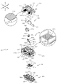
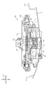
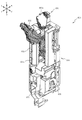
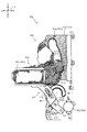
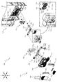
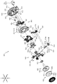
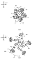
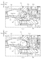
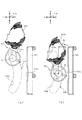
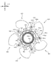
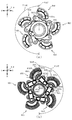
次いで、可変入賞装置65周辺の構造について説明する。図5は、可変入賞装置65及び振分装置300の正面斜視図であり、図6(a)及び図6(b)は、可変入賞装置65の正面斜視図である。図6(a)では、特定入賞口65aへの球の流下を規制するように開閉板65bが閉鎖される開閉板65bの閉鎖状態が図示され、図6(b)では、特定入賞口65aへの球の流下を許容するように開閉板65bが開放される開閉板65bの開放状態が図示される。なお、図5及び図6の説明においては、図2を適宜参照する。
Next, the structure around the variable winning device 65 will be described. FIG. 5 is a front perspective view of the variable winning device 65 and the sorting device 300. FIGS. 6A and 6B are front perspective views of the variable winning device 65. FIG. 6A illustrates a closed state of the opening / closing plate 65b in which the opening / closing plate 65b is closed so as to regulate the flow of the ball to the specific winning opening 65a. In FIG. An open state of the opening / closing plate 65b in which the opening / closing plate 65b is opened so as to allow the ball to flow down is illustrated. Note that FIG. 2 is appropriately referred to in the description of FIG. 5 and FIG.
可変入賞装置65は、開閉板65bの開放状態(図6(b)参照)において、開閉板65bに着地する球を受け入れ、特定入賞口65aへ案内可能となるように、開閉板65bの開放状態において開閉板65bの板上面が背面側へ向けて下降傾斜するように形成される。
In the open state of the opening and closing plate 65b (see FIG. 6B), the variable winning device 65 receives the ball that lands on the opening and closing plate 65b, and opens the opening and closing plate 65b so that it can be guided to the specific winning opening 65a. The upper surface of the opening / closing plate 65b is formed so as to be inclined downward toward the rear side.
開閉板65bの左右中央部の上方には電動役物140aが配置されているので(図2参照)、開閉板65bに着地する球は、電動役物140aから逸れて流下する球に限定される。即ち、開閉板65bへの球の着地は、左右中央部では生じず、主に、電動役物140aよりも左右外側の部分において生じる。換言すれば、開閉板65bに着地する球の配置は、開閉板65bの左右外側寄りの位置に限定される。
Since the electric accessory 140a is disposed above the left and right central portions of the opening / closing plate 65b (see FIG. 2), the ball that lands on the opening / closing plate 65b is limited to a ball that deviates from the electric accessory 140a and flows down. . That is, the landing of the ball on the opening / closing plate 65b does not occur at the left and right central portions, but mainly at the left and right outer portions of the electric accessory 140a. In other words, the arrangement of the ball that lands on the opening / closing plate 65b is limited to a position closer to the left and right outer sides of the opening / closing plate 65b.
なお、開閉板65bに着地した後の球の配置についてはこの限りではない。即ち、開閉板65bに着地した後の球の流れ方によっては、開閉板65bの左右中央位置寄りに球が配置されることは生じ得る。
Note that the arrangement of the ball after landing on the opening / closing plate 65b is not limited to this. That is, depending on how the ball flows after landing on the opening / closing plate 65b, the ball may be arranged near the left and right center positions of the opening / closing plate 65b.
特に、本実施形態では、電動役物140aを前側から覆う前意匠部材141(図2参照)が、開閉板65b側の空間を確保するように湾曲形成されている(ガラスユニット16(図1参照)と対向配置される前端部下端から背面側へ向かうにつれて下側に張り出す態様の湾曲面として形成されている)ので、開閉板65bの左右中央位置寄りにおいて跳ねた球が前意匠部材141と衝突して勢いを落とされる程度を低くすることができる。これにより、開閉板65bの左右中央位置寄りに球が配置される可能性を高めることができる。
In particular, in the present embodiment, the front design member 141 (see FIG. 2) that covers the electric accessory 140a from the front side is curved so as to secure a space on the side of the opening / closing plate 65b (see the glass unit 16 (see FIG. 1). ) Is formed as a curved surface that projects downward from the lower end of the front end portion facing the rear surface side), so that the ball that bounces near the left and right center positions of the opening / closing plate 65b and the front design member 141. It is possible to reduce the degree of losing momentum due to collision. Thereby, the possibility that the ball is arranged near the left and right center position of the opening / closing plate 65b can be increased.
なお、前意匠部材141の下部の湾曲形状の曲率半径の中心は、前後どちらに配置されるものでも良い。本実施形態では、横面視における曲率半径が前側下方に配置されるよう形成することで、開閉板65b側の空間をより大きく確保できるようにしている。また、前意匠部材141が左右端部において下側へ向かう程に左右幅が小さくなる形状とされることで、左右側において開閉板65bとの間に空間を確保し易くすることができる。
The center of the radius of curvature of the lower curved portion of the front design member 141 may be located at the front or the rear. In the present embodiment, by forming the radius of curvature in the lateral view below the front side, a larger space on the side of the opening / closing plate 65b can be secured. In addition, since the left and right widths of the front design member 141 are reduced toward the lower side at the left and right end portions, a space between the front design member 141 and the open / close plate 65b can be easily secured on the left and right sides.
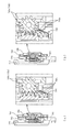
開閉板65bの開放状態においては、開閉板65bに着地した球はほぼ漏れなく特定入賞口65aに案内される。検出センサSE1の球通過孔163bの手前側には、後方へ向けて下降傾斜する傾斜流下面163a1が球を球通過孔163bに案内可能な上下位置で配設されている。
In the open state of the opening / closing plate 65b, the ball that has landed on the opening / closing plate 65b is guided to the specific winning opening 65a almost without omission. On the front side of the ball passage hole 163b of the detection sensor SE1, an inclined flow lower surface 163a1 that is inclined downward and rearward is disposed at an upper and lower position where the ball can be guided to the ball passage hole 163b.
傾斜流下面163a1は、下面部163aにより左右外側に転動された球が抵抗少なく乗り移れるように下面部163aの左右端部よりも一段下がって形成されている。この傾斜流下面163a1よりも左右外側において開閉板65bに着地した球の流下抵抗を低減するため、傾斜流下面163a1の左右外側において案内板部163a2が形成されている。
The inclined flow lower surface 163a1 is formed one step lower than the left and right end portions of the lower surface portion 163a so that the ball rolled to the left and right outer sides by the lower surface portion 163a can move over with less resistance. A guide plate portion 163a2 is formed on the left and right sides of the inclined flow lower surface 163a1 in order to reduce the flow resistance of a ball that has landed on the opening / closing plate 65b on the left and right sides of the inclined flow lower surface 163a1.
案内板部163a2は、受入部材163の後壁部と左右内壁部とから、前側かつ左右内側へ延設される板状部であって、前端面が左右内側ほど後方へ配置がずれる傾斜面として形成される。
The guide plate portion 163a2 is a plate-like portion extending frontward and leftward and rightward inward from the rear wall portion and the left and right inner wall portions of the receiving member 163, and has a front end surface that is displaced rearward toward the left and right inward. It is formed.
これにより、開閉板65bに乗り転動する球が案内板部163a2の前端面に当接した場合に、傾斜面の傾斜に沿って球の流下を案内することができるので、球を傾斜流下面163a1に抵抗少なく案内することができる。そのため、開閉板65bに球が乗った状態で開閉板65bが閉鎖動作を開始した場合において、その球が傾斜流下面163a1よりも左右外側に配置されていたとしても、開閉板65bの閉鎖動作が阻害される程度を低減することができる。
Accordingly, when the ball rolling on the opening / closing plate 65b comes into contact with the front end surface of the guide plate portion 163a2, the ball can be guided to flow down along the slope of the inclined surface. 163a1 can be guided with little resistance. Therefore, when the opening / closing plate 65b starts the closing operation in a state where the ball rides on the opening / closing plate 65b, the closing operation of the opening / closing plate 65b is performed even if the ball is disposed on the left and right sides of the inclined flow lower surface 163a1. The degree of inhibition can be reduced.
即ち、例えば、球の流れが悪くなり開閉板65bの閉鎖が滞ったり、開閉板65bの閉鎖動作により後方に流された球が受入部材163の後壁部で跳ね返って開閉板65bに再び当たり、開閉板65bを開放させる方向(前側)の負荷を与えることで開閉板65bが意図せず開いたり、等という動作不良が生じる可能性を低減することができる。
That is, for example, the flow of the sphere is deteriorated, and the closing of the opening / closing plate 65b is delayed, or the ball that has flowed backward due to the closing operation of the opening / closing plate 65b rebounds on the rear wall of the receiving member 163 and hits the opening / closing plate 65b again, By applying a load in the direction (front side) to open the opening / closing plate 65b, it is possible to reduce the possibility that the opening / closing plate 65b is unintentionally opened or malfunctions occur.
開閉板65bが開放状態から閉鎖状態へ動作する場合、開閉板65bは起き上がり動作で閉じる。即ち、開閉板65bに着地した球は、開閉板65bの動作により特定入賞口65aに案内される(飲み込まれる)ので、開閉板65bに乗っている球の左右位置に寄らず、開閉板65bに乗っている球はほぼ漏れなく特定入賞口65aに案内される。
When the opening / closing plate 65b operates from the open state to the closed state, the opening / closing plate 65b is closed by a rising operation. That is, the ball that has landed on the opening / closing plate 65b is guided (swallowed) to the specific winning opening 65a by the operation of the opening / closing plate 65b. The riding ball is guided to the specific winning opening 65a almost without omission.
この際、開閉板65bにおける球の配置が左右外側に寄っていたり、球の個数が多かったりすると、開閉板65bの閉鎖動作が遅れる可能性がある。これに対し、本実施形態では、受入部材163の下面部163a、傾斜流下面163a1及び案内板部163a2の形状を工夫しているので、特定入賞口65aに案内された球の流れを滞留させることなく、開閉板65bの閉鎖動作の迅速性を保つことができる。
At this time, if the arrangement of the balls on the opening / closing plate 65b is shifted left and right or the number of balls is large, the closing operation of the opening / closing plate 65b may be delayed. On the other hand, in the present embodiment, since the shapes of the lower surface portion 163a, the inclined flow lower surface 163a1, and the guide plate portion 163a2 of the receiving member 163 are devised, the flow of the ball guided to the specific winning opening 65a is retained. Therefore, the quickness of the closing operation of the opening / closing plate 65b can be maintained.
また、受入部材163の形状を工夫する代わりに、開放状態において球が乗る開閉板65bの転動面は、平面状に形成される(図6(b)参照)。そのため、開閉板65bの開放状態において開閉板65bに着地した球は、一旦後方に流れてから、受入部材163の形状の作用により左右方向へ流され検出センサSE1の球通過孔163bに案内されることになるので、開閉板65b上で球の衝突が生じることを回避し易くすることができる。
Instead of devising the shape of the receiving member 163, the rolling surface of the opening / closing plate 65b on which the ball rides in the open state is formed in a planar shape (see FIG. 6B). Therefore, the ball that has landed on the opening / closing plate 65b in the open state of the opening / closing plate 65b once flows backward, and then flows in the left / right direction by the action of the shape of the receiving member 163, and is guided to the ball passage hole 163b of the detection sensor SE1. Therefore, it is possible to easily avoid the collision of the ball on the opening / closing plate 65b.
即ち、開閉板65bに複数の球が同時に着地しても、その球が一旦後方に平行移動することになるので、開閉板65b上で球が互いに衝突することを回避することができる。従って、開閉板65bの転動面が下面部163aのように左右方向の傾斜面を有する形状とされ転動球に左右方向の流れが形成される場合に比較して、開閉板65b上での球の動きが不規則になる可能性を低くすることができるので、意図せぬ動作不良を未然に防ぐことができる。
That is, even if a plurality of balls land on the opening / closing plate 65b at the same time, the balls temporarily move rearward in parallel, so that collision of the balls on the opening / closing plate 65b can be avoided. Therefore, the rolling surface of the opening / closing plate 65b has a shape having a left-right inclined surface like the lower surface portion 163a, and the rolling surface on the opening / closing plate 65b is compared with the case where the left and right flows are formed on the rolling balls. Since the possibility of irregular movement of the ball can be reduced, unintended operation failure can be prevented.
受入部材163には、開閉板65bの閉鎖状態において、開閉板65bの左右両端部における回動先端部と当接し、開閉板65bの配置の再現性を高めるための当接面部163a3が形成されている。当接面部163a3は左右一対で形成されており、且つ、開閉板65bの形状に合わせた形状設計により点接触ではなく面接触可能に形成されているので、開閉板65bの配置を安定させ易く、且つ、当接時の負荷を面で受けることにより応力集中を避けることができるので耐久性を向上させることができる。
The receiving member 163 is provided with a contact surface portion 163a3 that comes into contact with the rotating front end portions at the left and right ends of the opening / closing plate 65b when the opening / closing plate 65b is in a closed state, and that enhances the reproducibility of the arrangement of the opening / closing plate 65b. I have. The contact surface portion 163a3 is formed as a pair of left and right, and is formed so as to be capable of surface contact instead of point contact by a shape design according to the shape of the opening / closing plate 65b. Therefore, it is easy to stabilize the arrangement of the opening / closing plate 65b, In addition, since the load at the time of contact is received on the surface, stress concentration can be avoided, so that durability can be improved.
また、当接面部163a3の下側には、対向配置される開閉板65bと若干の隙間を空け略平行となる面形状で形成される補助当接面163a4が形成されている。補助当接面163a4は、何らかの理由で当接面部163a3と開閉板65bとの当接が不良となった場合のフェールセーフとして設けられている。
In addition, an auxiliary contact surface 163a4 is formed below the contact surface portion 163a3 and has a surface shape that is substantially parallel to the opening / closing plate 65b that is disposed to face with a slight gap. The auxiliary contact surface 163a4 is provided as a fail safe when contact between the contact surface portion 163a3 and the opening / closing plate 65b becomes defective for some reason.
本実施形態では、当接面部163a3の手前側において球の流下を制限する被固定部材161が配置されており、基本的には球は当接面部163a3と衝突しないように構成されている。しかし、例えば、当接面部163a3と当接する開閉板65bの回動先端部が欠けた場合、閉鎖状態における開閉板65bの配置の再現性を保てなくなる可能性がある。
In the present embodiment, the fixed member 161 that restricts the flow of the ball is disposed on the front side of the contact surface portion 163a3, and the ball is basically configured not to collide with the contact surface portion 163a3. However, for example, if the pivotal tip of the opening / closing plate 65b that comes into contact with the contact surface portion 163a3 is missing, there is a possibility that the repeatability of the arrangement of the opening / closing plate 65b in the closed state may not be maintained.
これに対し、本実施形態では、開閉板65bと当接面部163a3との正常な当接が保てなくなった場合には、開閉板65bの左右端部における前後幅間部と補助当接面163a4との面当接を生じさせ、開閉板65bの配置の安定性を保てるように図っている。これにより、閉鎖状態における開閉板65bの配置の再現性を向上することができる。
On the other hand, in the present embodiment, when the normal contact between the opening / closing plate 65b and the contact surface portion 163a3 cannot be maintained, the front / rear width portions at the left and right ends of the opening / closing plate 65b and the auxiliary contact surface 163a4. This makes it possible to maintain the stability of the arrangement of the opening / closing plate 65b. Thereby, the reproducibility of the arrangement of the open / close plate 65b in the closed state can be improved.
なお、補助当接面163a4を、当接面部163a3の形状が正常な状況から開閉板65bと当接するように構成しても良い。この場合、当接面部163a3の形状が正常な状況から開閉板65bとの当接が生じるので負荷が蓄積され易いという不利益が生じ得るものの、負荷を分散させる面積を拡大できるので、開閉板65bとの当接により当接面部163a3が受ける局所的な負荷の大きさを低減することができる。
Note that the auxiliary contact surface 163a4 may be configured to contact the opening / closing plate 65b when the shape of the contact surface portion 163a3 is normal. In this case, since the contact surface portion 163a3 comes into contact with the opening / closing plate 65b when the shape is normal, there is a disadvantage that the load is easily accumulated, but the area for dispersing the load can be enlarged, and the opening / closing plate 65b can be enlarged. , The magnitude of the local load applied to the contact surface portion 163a3 can be reduced.
開閉板65bが開放状態から閉鎖状態へ動作する場合、開閉板65bへ受け入れられる途中の遊技球を、上述した前意匠部材141の形状によって開閉板65bへ押し込む態様で受け入れさせるよう構成することができる。
When the opening / closing plate 65b operates from the open state to the closed state, the game ball being received by the opening / closing plate 65b can be received in a manner of being pushed into the opening / closing plate 65b by the shape of the front design member 141 described above. .
即ち、受け入れられる途中の状態(例えば、開閉板65bの回動先端と特定入賞口65aの開口枠部とに挟まれて横滑りしている状態)で、球が前意匠部材141の下部形状と当接した場合に、その湾曲形状に案内させることで特定入賞口65aの内側へ流下させることができる。これにより、開閉板65bから逸れた球が第3流路構成部336の正面側を落下する事態の発生を避け易くすることができるので、第3流路構成部336への視界を確保し易くすることができる。
That is, in a state in which the ball is received (for example, a state in which the ball slides sideways between the pivotal tip of the opening / closing plate 65b and the opening frame portion of the specific winning opening 65a), the ball contacts the lower shape of the front design member 141. In the case of contact, it can be made to flow down to the inside of the specific winning opening 65a by being guided to the curved shape. This makes it easier to avoid a situation in which a ball that has deviated from the opening / closing plate 65b falls on the front side of the third flow path component 336, so that it is easy to secure a view to the third flow path component 336. can do.
開閉板65bの閉鎖状態においては、開閉板65bへの球の着地が生じないので、開閉板65bの閉鎖状態において開閉板65bの正面側を流下する球の配置は電動役物140aよりも左右外側に限定される。
In the closed state of the opening / closing plate 65b, the ball does not land on the opening / closing plate 65b. Therefore, in the closed state of the opening / closing plate 65b, the ball flowing down the front side of the opening / closing plate 65b is located on the left and right sides of the electric accessory 140a. Is limited to
従って、本実施形態の構成によれば、開閉板65bの閉鎖状態において特定入賞口65aに案内されずに流下する球の配置を、電動役物140aよりも左右外側位置に限定することができる。これにより、電動役物140aの下側において、電動役物140aの左右端部よりも左右内側位置における視界を確保することができる。
Therefore, according to the configuration of the present embodiment, the arrangement of the balls flowing down without being guided to the specific winning opening 65a in the closed state of the opening / closing plate 65b can be limited to the left and right outer positions with respect to the electric accessory 140a. Accordingly, a field of view can be ensured below the left and right end portions of the electrically driven accessory 140a at the left and right inner positions below the electrically driven accessory 140a.
次いで、特定入賞口65aの下流側(特定入賞口65aを通過した球が流れる側)の構成について説明する。図7は、遊技盤13の正面斜視図であり、図8は、遊技盤13の背面斜視図である。なお、図7及び図8では、ベース板60に配設される構成の内、第1入賞口64、第2入賞口140及び可変入賞装置65以外の構成が取り外された状態が図示される。
Next, the configuration of the downstream side of the specific winning opening 65a (the side on which the ball passing through the specific winning opening 65a flows) will be described. FIG. 7 is a front perspective view of the game board 13, and FIG. 8 is a rear perspective view of the game board 13. FIGS. 7 and 8 show a state in which the components other than the first winning port 64, the second winning port 140, and the variable winning device 65 are removed from the components provided on the base plate 60.
図8に示すように、ベース板60の背面側における可変入賞装置65の後方位置には、第1入賞口64、第2入賞口140及び一般入賞口63(図2参照)に入球した球を球排出路(図示せず)へ流すための経路が形成される集合樋150が配設される。
As shown in FIG. 8, at the rear position of the variable winning device 65 on the back side of the base plate 60, the balls having entered the first winning opening 64, the second winning opening 140, and the general winning opening 63 (see FIG. 2). Collecting trough 150 in which a path for flowing the gas to a ball discharge path (not shown) is formed.
集合樋150は、流路を形成する溝状部分を備え、溝状部分においてベース板60と対面する前側部が開放される。この開放部分がベース板60に閉じられることで、球排出路へ球を流すための経路が完成する。
The collecting gutter 150 includes a groove-shaped portion forming a flow path, and a front side portion facing the base plate 60 in the groove-shaped portion is opened. When this open portion is closed by the base plate 60, a path for flowing the sphere to the sphere discharge path is completed.
集合樋150は、第1入賞口64に入球した球の流路を形成する第1流路部151と、第2入賞口140に入球した球の経路を形成する第2流路部152と、左右両側に配置される一般入賞口63に入球した球の流路を左右それぞれに形成する複数の第3流路部153と、を備える。
The collecting gutter 150 includes a first flow path portion 151 that forms a flow path of a ball that has entered the first winning opening 64, and a second flow path portion 152 that forms a path of a ball that has entered the second winning opening 140. And a plurality of third flow path portions 153 that respectively form left and right flow paths of a ball that has entered the general winning opening 63 disposed on both the left and right sides.
第1流路部151は、第1入賞口64の後方位置から左下方向へ傾斜する流路として構成され、第2流路部152は、第2入賞口140の後方位置から右下方向へ傾斜する流路として構成される。第3流路部153は、一般入賞口63の下方へ延びる流路として構成される。
The first channel portion 151 is configured as a channel inclined downward and leftward from the position behind the first winning opening 64, and the second channel portion 152 is inclined downward and rightward from the position behind the second winning hole 140. It is configured as a flow path. The third channel portion 153 is configured as a channel extending below the general winning opening 63.
従って、正面視では、第1入賞口64及び第2入賞口140が遊技領域の左右中央位置に配置される構成ながら、第1入賞口64及び第2入賞口140に入球した球の流れは、集合樋150によって左右中央位置から左右外側に寄せられる。これにより、第1入賞口64及び第2入賞口140の下方に空間を設けることができ、この空間を利用して可変入賞装置65及び後述する振分装置300を配設することができる。
Therefore, in a front view, while the first winning opening 64 and the second winning opening 140 are arranged at the left and right central positions of the game area, the flow of the ball entering the first winning opening 64 and the second winning opening 140 is as follows. , From the center in the left and right direction to the left and right sides. Accordingly, a space can be provided below the first winning opening 64 and the second winning opening 140, and the variable winning device 65 and the distribution device 300 described later can be arranged using this space.
図9は、ベース板60、可変入賞装置65、集合樋150及び振分装置300の分解正面斜視図であり、図10は、ベース板60、可変入賞装置65、集合樋150及び振分装置300の分解背面斜視図である。なお、図9及び図10では、ベース板60の下半部のみが図示され、その他の部分の図示が省略されており、且つ、ベース板60に組み付けられる他の構成についての図示が省略され、ベース板60の地が視認可能となっている。また、図9では、説明の便宜上、センターフレーム86がベース板60に組み付けられた状態で図示される。
FIG. 9 is an exploded front perspective view of the base plate 60, the variable winning device 65, the collecting gutter 150 and the sorting device 300, and FIG. 10 is a base plate 60, the variable winning device 65, the collecting gutter 150 and the sorting device 300. FIG. 4 is an exploded rear perspective view of FIG. 9 and FIG. 10, only the lower half of the base plate 60 is shown, other parts are not shown, and other configurations to be assembled to the base plate 60 are omitted. The ground of the base plate 60 is visible. In FIG. 9, for convenience of description, the center frame 86 is illustrated in a state where the center frame 86 is assembled to the base plate 60.
可変入賞装置65、集合樋150及び振分装置300の固定について説明する。可変入賞装置65は、ルータ加工によってベース板60に形成された貫通穴に配設され、遊技盤13の正面側からタッピングネジ等により固定されている。集合樋150は、ルータ加工によってベース板60に形成された貫通穴に配設され、遊技盤13の背面側からタッピングネジ等により固定されている。
The fixing of the variable winning device 65, the collecting gutter 150, and the distribution device 300 will be described. The variable winning device 65 is provided in a through hole formed in the base plate 60 by router processing, and is fixed from the front side of the game board 13 with a tapping screw or the like. The collecting gutter 150 is provided in a through hole formed in the base plate 60 by router processing, and is fixed from the back side of the game board 13 with a tapping screw or the like.
そして、振分装置300は、上部において挿通孔311が可変入賞装置65に締結固定され、左右部において挿通孔331が集合樋150に締結固定される。即ち、ベース板60に直接的に固定される可変入賞装置65や、集合樋150とは異なり、振分装置300の有無は、遊技盤13の完成に影響するものではない。
In the sorting device 300, the insertion hole 311 is fastened and fixed to the variable winning device 65 at the upper part, and the insertion hole 331 is fastened and fixed to the collecting gutter 150 at the left and right parts. That is, unlike the variable winning device 65 and the collecting gutter 150 that are directly fixed to the base plate 60, the presence or absence of the distribution device 300 does not affect the completion of the game board 13.
換言すれば、本実施形態における可変入賞装置65及び集合樋150は、振分装置300を配設する場合と、振分装置300を配設しない場合とで、そのまま流用することができる。これにより、振分装置300の有無に関わらず、可変入賞装置65と集合樋150との共通化を図ることができる。
In other words, the variable winning device 65 and the collecting gutter 150 in the present embodiment can be used as they are depending on whether the distributing device 300 is provided or not. Thereby, regardless of the presence or absence of the distribution device 300, the variable winning device 65 and the common gutter 150 can be shared.
次いで、可変入賞装置65及び振分装置300の詳細について説明する。可変入賞装置65は、特定入賞口65aを通して遊技領域から球を受け入れ可能に構成されており、振分装置300は、可変入賞装置65に受け入れられた球の流れる流下経路を構成している。本実施形態では、振分装置300の流下経路を流れる球の検出結果に基づいて遊技者が得られる利益が変化するように制御されるが、詳細は後述する。
Next, details of the variable winning device 65 and the sorting device 300 will be described. The variable prize device 65 is configured to be able to receive a ball from the game area through the specific prize port 65a, and the distribution device 300 configures a flowing path of the ball received by the variable prize device 65. In the present embodiment, control is performed so that the profit obtained by the player is changed based on the detection result of the ball flowing down the flow path of the distribution device 300, which will be described in detail later.
図11は、可変入賞装置65の分解正面斜視図であり、図12は、可変入賞装置65の分解背面斜視図である。図11及び図12に示すように、可変入賞装置65は、遊技盤13の正面側からタッピングネジ等により固定される被固定部材161と、その被固定部材161の正面側に配置され被固定部材161に締結固定される前意匠部材162と、被固定部材161の背面側に配置され、被固定部材161に締結固定され、特定入賞口65aを通った球を受け入れ可能に構成される受入部材163と、その受入部材163の背面側に配置され、受入部材163に締結固定され、振分装置300との連結部分として介在する介在部材164と、受入部材163の背面側に配置され、受入部材163に締結固定され、開閉板65bの開閉状態を通電の有無によって切り替え可能に構成される状態切替装置165と、を備える。
FIG. 11 is an exploded front perspective view of the variable winning device 65, and FIG. 12 is an exploded rear perspective view of the variable winning device 65. As shown in FIGS. 11 and 12, the variable winning device 65 includes a fixed member 161 fixed from the front side of the game board 13 by a tapping screw or the like, and a fixed member arranged on the front side of the fixed member 161. A front design member 162 fastened and fixed to the fixed member 161 and a receiving member 163 arranged on the back side of the fixed member 161 and fastened and fixed to the fixed member 161 so as to be able to receive a ball passing through the specific winning opening 65a. And an intervening member 164 that is disposed on the back side of the receiving member 163 and is fastened and fixed to the receiving member 163 and intervenes as a connecting portion with the sorting device 300; and is disposed on the back side of the receiving member 163. And a state switching device 165 configured to be capable of switching the open / close state of the opening / closing plate 65b depending on the presence or absence of energization.
被固定部材161は光透過性の樹脂材料から形成され、その正面側の形状は、ネジ挿通用の貫通孔、前意匠部材162との締結位置および特定入賞口65aを除き平坦面で形成される。一方、被固定部材161の背面側の形状は、外周部においてベース板60に面で当接される薄肉部の内側において背面側に張り出す立体的な形状となっている。
The fixed member 161 is formed of a light-transmitting resin material, and has a front surface formed of a flat surface except for a through hole for screw insertion, a fastening position with the front design member 162, and a specific winning opening 65a. . On the other hand, the shape of the fixed member 161 on the back side has a three-dimensional shape that extends to the back side inside the thin portion that is in contact with the base plate 60 at the outer peripheral portion.
特に、薄肉部との境界部161aは横長略楕円の枠状に形成されており、この境界部161aを配設可能な大きさの貫通孔がベース板60に貫通形成される。即ち、境界部161aは、ベース板60の貫通孔に挿通される部分である。
In particular, the boundary 161a with the thin portion is formed in a horizontally long substantially elliptical frame shape, and a through hole large enough to dispose the boundary 161a is formed through the base plate 60. That is, the boundary portion 161a is a portion that is inserted into the through hole of the base plate 60.
境界部161aの内側では、特定入賞口65aと、その特定入賞口65aの下縁よりも若干下側において特定入賞口65aの下縁と平行な横長板状で後方へ延設される横長板状部およびその横長板状部の途中位置において下方に延設される縦長板状部を備えて左右一対の略T字形状で構成される延設支持板161bと、が形成される。
Inside the boundary portion 161a, a specific winning opening 65a, and a horizontally long plate extending slightly rearward from the lower edge of the specific winning opening 65a in a horizontally elongated plate shape parallel to the lower edge of the specific winning opening 65a. And a pair of left and right substantially T-shaped extended support plates 161b including a vertically long plate-like portion extending downward at an intermediate position of the horizontally long plate-like portion.
延設支持板161bは、特定入賞口65aの後方の範囲と、後述する振分装置300の流下経路と、の双方を支持するよう機能する。延設支持板161bの横長板状部から突設される突設支持部161cと、延設支持板161bの縦長板状部から突設される突設支持部161dと、境界部161aの下縁部上面から突設される突設支持部161eと、は振分装置300を支持する部分としての機能を有するが、詳細は後述する。
The extension support plate 161b functions to support both a range behind the specific winning opening 65a and a flow path of the distribution device 300 described later. A projecting support portion 161c projecting from the horizontally long plate-like portion of the extension support plate 161b, a projecting support portion 161d projecting from the vertically long plate-like portion of the extension support plate 161b, and a lower edge of the boundary portion 161a The projecting support portion 161e projecting from the upper surface has a function as a portion for supporting the distribution device 300, and will be described later in detail.
境界部161aの内側において、特定入賞口65aの左右中央位置下方において左右対称形状で突設される対称突設部161fは、振分装置300を流下する球と当接して球の流下を案内する機能を有する。
Inside the boundary portion 161a, the symmetrically projecting portion 161f projecting in a symmetrical shape below the right and left center position of the specific winning opening 65a comes into contact with the ball flowing down the distribution device 300 and guides the ball flowing down. Has functions.
前意匠部材162に螺入する締結ネジを挿通するための複数の貫通孔161gは、境界部161aの内側および外側に配置される。受入部材163に挿通される締結ネジを螺入するため雌ネジ部を有する複数の被締結部161hは、境界部161aの内側に配置される。
A plurality of through holes 161g for inserting a fastening screw screwed into the front design member 162 are arranged inside and outside the boundary 161a. A plurality of fastened portions 161h each having a female screw portion for screwing a fastening screw inserted into the receiving member 163 are arranged inside the boundary portion 161a.
介在部材164に挿通される締結ネジを螺入するため雌ネジ部を有する被締結部161iは、境界部161aの切れ目(左右中央位置)において境界部161aの外側に配置される。即ち、ベース板60に形成される貫通孔の内、境界部161aを挿通するための貫通孔と第2入賞口140及び電動役物140aを挿通するための貫通孔との連結部分(図9参照)に、被締結部161iは配設される。
The to-be-fastened portion 161i having a female screw portion for screwing the fastening screw inserted into the interposition member 164 is disposed outside the boundary portion 161a at a cut (left and right center position) of the boundary portion 161a. That is, of the through holes formed in the base plate 60, a connecting portion between the through hole for inserting the boundary portion 161a and the through hole for inserting the second winning opening 140 and the electric accessory 140a (see FIG. 9). ), The fastened portion 161i is provided.
前意匠部材162は、光透過性の樹脂材料から形成され、正面側は、ガラスユニット16(図1参照)との距離を均一とするべく平坦形状で形成される。前意匠部材162の背面側かつ被固定部材161の正面側の範囲において、球は流下可能とされる。
The front design member 162 is formed of a light transmissive resin material, and the front side is formed in a flat shape so as to make the distance to the glass unit 16 (see FIG. 1) uniform. The ball is allowed to flow down in a range on the back side of the front design member 162 and on the front side of the fixed member 161.
前意匠部材162の背面側には、被固定部材161の貫通孔161gと合う位置に配設され、貫通孔161gに挿通された締結ネジを螺入可能に形成される雌ネジ部を有する複数の被締結部162aと、その被締結部162aを上側から覆うような形状で背面側に延設される複数の延設部162b,162cと、を備える。
On the back side of the front design member 162, there are provided a plurality of female screw portions which are provided at positions matching the through holes 161g of the fixed member 161 and which are formed so that the fastening screws inserted into the through holes 161g can be screwed therein. It includes a fastened portion 162a, and a plurality of extending portions 162b and 162c extending rearward in a shape that covers the fastened portion 162a from above.
延設部162b,162cにより、被固定部材161と前意匠部材162との間を流下する球が被締結部162aに直接衝突することを回避することができるので、被締結部162aの耐久性を向上することができる。
The extended portions 162b and 162c can prevent a ball flowing down between the fixed member 161 and the front design member 162 from directly colliding with the fastened portion 162a, so that the durability of the fastened portion 162a is reduced. Can be improved.
更に、延設部162b,162cの上面が傾斜面として形成されることにより、球の流下経路を制限することができる。即ち、特定入賞口65aの左右縁部付近で延設される延設部162b(左右中央側の2箇所)の上面が左右外側へ向けて下降傾斜する傾斜面として形成されることで、延設部162bに乗った球が特定入賞口65a側に流れることを抑制することができる。即ち、延設部162bに乗った球は、延設部162bの左右外側を下方へ落下した後、内レール61(図2参照)に沿ってアウト口71へ向けて流下することになる。
Further, since the upper surfaces of the extending portions 162b and 162c are formed as inclined surfaces, the flow path of the ball can be restricted. That is, the upper surface of the extending portion 162b (two locations on the left and right sides) extending near the left and right edges of the specific winning opening 65a is formed as an inclined surface which is inclined downward and leftward and outward. The ball riding on the portion 162b can be suppressed from flowing toward the specific winning opening 65a. That is, the ball riding on the extending portion 162b falls downward on the left and right outer sides of the extending portion 162b, and then flows down toward the out port 71 along the inner rail 61 (see FIG. 2).
また、左右両端に延設される延設部162c(左右両端の2箇所)の上面が左右内側へ向けて下降傾斜する傾斜面として形成されることで、延設部162cに乗って流れる球の流下経路を延設部162bに乗った球の流下経路とまとめることができる。これにより、流下する球の個数に比較して、流下する球が配置される範囲を狭めることができ(球の配置密度を高めることができ)、球に視認性を阻害されない部分(流下経路が構成されない空間)を確保することができる。
In addition, since the upper surfaces of the extending portions 162c (two locations at the left and right ends) extending at the left and right ends are formed as inclined surfaces that incline down toward the left and right inner sides, a ball flowing on the extending portion 162c is formed. The downflow path can be combined with the downflow path of the sphere riding on the extension 162b. Thereby, compared with the number of flowing balls, the range in which the flowing balls are arranged can be narrowed (the arrangement density of the balls can be increased). (A space that is not configured).
なお、図11に図示される前意匠部材162は無地で記載され、背面側の視認性が良好とされているが、前意匠部材162を無地で構成する必要はない。例えば、前意匠部材162の正面側に模様やキャラクターが図示されたシールを貼り付けて装飾するようにしても良いし、前意匠部材162に幾何学模様で溝を掘り、その溝に光が照射されることで幾何学模様が浮かび上がって視認されるようにしても良い。また、無地や、上述のような装飾が加えられた上で、前意匠部材162が非透過性となるように構成しても良い。
Although the front design member 162 shown in FIG. 11 is described in a plain color and has good visibility on the back side, the front design member 162 does not need to be formed in a plain color. For example, a sticker with a pattern or character may be attached to the front side of the front design member 162 to decorate it, or a groove may be formed in the front design member 162 with a geometric pattern, and light may be applied to the groove. By doing so, the geometric pattern may emerge and be visually recognized. Further, the front design member 162 may be configured to be non-transparent after being plain or having the above-described decoration added thereto.
受入部材163は、光透過性の樹脂材料から正面側が開放された横長の枠状(または箱状)に形成され、上述した案内板部163a2と、当接面部163a3と、補助当接面163a4と、枠内側において流下面を形成する下面部163aと、下面部163aを流下した球が通過可能な貫通孔として配設される球通過孔163bと、被固定部材161の被締結部161hに合う位置に配置され被締結部161hに締結固定される締結ネジが背面側から挿通される複数の挿通孔163cと、介在部材164に挿通される締結ネジが螺入される雌ネジ部であって左右中央側に配設される一対の被締結部163dと、状態切替装置165に挿通される締結ネジが螺入される雌ネジ部を有する複数の被締結部163eと、を備える。
The receiving member 163 is formed in a horizontally long frame shape (or box shape) whose front side is opened from a light-transmitting resin material, and includes the above-described guide plate portion 163a2, contact surface portion 163a3, and auxiliary contact surface 163a4. A lower surface portion 163a that forms a flow lower surface inside the frame, a ball passage hole 163b that is provided as a through hole through which a ball flowing down the lower surface portion 163a can pass, and a position that matches the fastened portion 161h of the fixed member 161. A plurality of insertion holes 163c through which a fastening screw to be fastened and fixed to the to-be-fastened portion 161h is inserted from the rear side, and a female screw portion into which a fastening screw inserted through the interposition member 164 is screwed. And a plurality of fastened portions 163e having female screw portions into which fastening screws inserted into the state switching device 165 are screwed.
下面部163aは、左右中央部を頂点として左右外側へ向けて下降傾斜する左右傾斜面として形成され、その左右傾斜面の左右外端部から一段下がった位置において後方へ向けて下降傾斜する傾斜流下面163a1を備えていることで、傾斜流下面163a1の後端部を流下する球が球通過孔163bを抵抗小さく通過できるように配設される。
The lower surface portion 163a is formed as a left and right inclined surface which descends toward the left and right outer sides with the left and right center portions as vertices. Since the lower surface 163a1 is provided, the sphere flowing down the rear end of the inclined flow lower surface 163a1 is disposed so as to pass through the ball passage hole 163b with low resistance.
球通過孔163bは、受入部材163の背面側に係合される検出センサSE1に形成される検出用孔である。即ち、球通過孔163bを球が通過したことは検出センサSE1により検出される。
The ball passage hole 163b is a detection hole formed in the detection sensor SE1 engaged with the back side of the receiving member 163. That is, the detection sensor SE1 detects that the ball has passed through the ball passage hole 163b.
介在部材164は、光透過性の樹脂材料から形成され、後方へ向けて下降傾斜する光屈折面を有する本体部164aと、その本体部164aの上側部において貫通形成され受入部材163の被締結部163dに螺入される締結ネジを挿通可能な一対の挿通孔164bと、その挿通孔164bよりも上側に配置されLEDが配設される発光基板164cと、本体部164aの下端側左右両端部において振分装置300に挿通される締結ネジを螺入可能な雌ネジ部を有して形成される一対の被締結部164dと、本体部164aの上側部において貫通形成され被固定部材161の被締結部161iに螺入される締結ネジを挿通可能な挿通孔164eと、を備える。
The intervening member 164 is formed of a light transmissive resin material, has a main body 164a having a light refracting surface that is inclined downward toward the rear, and a through-hole formed at an upper portion of the main body 164a to be fastened to the receiving member 163. A pair of insertion holes 164b through which fastening screws to be screwed into 163d can be inserted, a light emitting board 164c in which LEDs are arranged above the insertion holes 164b, and left and right ends on the lower end side of the main body 164a. A pair of fastened portions 164d formed with a female screw portion into which a fastening screw inserted into the distribution device 300 can be screwed, and a fastened portion of the fixed member 161 formed through the upper portion of the main body portion 164a. And an insertion hole 164e through which a fastening screw screwed into the portion 161i can be inserted.
発光基板164cは、LEDが配置される面が斜め前上方向を向く姿勢で配設され、組立状態において、正面視で特定入賞口65aの真上位置(図6参照)、且つ、第2入賞口140の真下位置に配置される。このような配置から、発光基板164cからの光は、第2入賞口140や特定入賞口65aへの入球を望みその箇所を斜め後下方向の視線で見つめる遊技者の視界に容易に入る。
The light emitting board 164c is disposed in such a manner that the surface on which the LEDs are arranged is directed obliquely forward and upward. In an assembled state, the position directly above the specific winning opening 65a in front view (see FIG. 6), and the second winning It is located just below the mouth 140. From such an arrangement, the light from the light emitting substrate 164c easily enters the field of view of the player who desires to enter the second winning opening 140 or the specific winning opening 65a and looks at the location obliquely downward and downward.
従って、第2入賞口140や特定入賞口65aへの入球が検出された際に発光基板164cのLEDを点灯させるよう制御することで、第2入賞口140や特定入賞口65aへの入球が生じたか否かを遊技者に容易に把握させることができる。
Therefore, by controlling to turn on the LED of the light emitting substrate 164c when a ball entering the second winning port 140 or the specific winning port 65a is detected, the ball entering the second winning port 140 or the specific winning port 65a is controlled. Can be easily grasped by the player as to whether or not the game has occurred.
上述の構成から、介在部材164は、被固定部材161及び受入部材163の双方に締結固定される。これにより、被固定部材161と受入部材163との締結固定のみで構成する場合に比較して、被固定部材161と受入部材163とを強固に固定することができる。また、介在部材164を介して被固定部材161及び受入部材163と連結固定される振分装置300の配置を安定させることができるので、被固定部材161及び受入部材163と振分装置300との相対的な位置ずれを抑制することができる。
From the above configuration, the intervening member 164 is fastened and fixed to both the fixed member 161 and the receiving member 163. Thereby, the fixed member 161 and the receiving member 163 can be firmly fixed as compared with a case where only the fastening and fixing of the fixed member 161 and the receiving member 163 are performed. In addition, since the arrangement of the distribution device 300 connected and fixed to the fixed member 161 and the receiving member 163 via the intervening member 164 can be stabilized, the distribution of the fixed member 161 and the receiving member 163 to the distribution device 300 can be stabilized. Relative displacement can be suppressed.
状態切替装置165は、受入部材163の被締結部163eに螺入される締結ネジが挿通される複数の挿通部165aを有し、配線通し用、兼、放熱用の複数の開口を有して上側が開放される深底の箱状に形成される下ケース部165bと、その下ケース部165bに収容される電磁ソレノイド165cと、その電磁ソレノイド165cのプランジャーの先端に係合されプランジャーと共にスライド変位するスライド部165dと、下ケース部165bの前端部から回動先端部がはみ出すような配置で下ケース部165bに回動可能に支持され、スライド部165dのスライド変位に伴い回動する回動部165eと、複数の挿通孔165fに挿通される締結ネジにより下ケース部165bに締結固定される上蓋部165gと、を備える。
The state switching device 165 has a plurality of insertion portions 165a into which fastening screws to be screwed into the to-be-fastened portions 163e of the receiving member 163 are inserted, and has a plurality of openings for wiring passage and heat dissipation. A lower case portion 165b formed in a deep bottom box shape whose upper side is opened, an electromagnetic solenoid 165c housed in the lower case portion 165b, and a plunger engaged with the tip of the plunger of the electromagnetic solenoid 165c. A sliding portion 165d that slides and is rotatably supported by the lower case portion 165b in such an arrangement that the tip of the rotation protrudes from the front end of the lower case portion 165b, and is rotated by the sliding displacement of the sliding portion 165d. It has a moving part 165e and an upper lid part 165g that is fastened and fixed to the lower case part 165b by fastening screws inserted into the plurality of insertion holes 165f.
回動部165eの回動先端は、棒状部が係合可能に凹設されており、この凹設部に開閉板65bの右側端部から右方に突設される伝達突部65cが入り込み、係合される。伝達突部65cは、開閉板65bの開閉動作の回転軸を形成する金属製の軸棒部65dから偏心した位置に配置されている。このように構成することで、回動部165eの回動に伴って、開閉板65bの開閉動作を生じさせることができる。
The rotating tip of the rotating portion 165e is recessed so that the rod-shaped portion can be engaged, and a transmission projection 65c projecting rightward from the right end of the opening / closing plate 65b enters the recessed portion. Engaged. The transmission protrusion 65c is disposed at a position eccentric from a metal shaft rod 65d that forms a rotation axis of the opening and closing operation of the opening and closing plate 65b. With this configuration, the opening / closing operation of the opening / closing plate 65b can be caused with the rotation of the rotating portion 165e.
図13及び図14は、振分装置300の分解正面斜視図である。図13では、振分装置300を上方から見た斜視図が図示され、図14では、振分装置300を下方から見た斜視図が図示される。
13 and 14 are exploded front perspective views of the distribution device 300. 13 illustrates a perspective view of the distribution device 300 as viewed from above, and FIG. 14 illustrates a perspective view of the distribution device 300 as viewed from below.
図13及び図14に示すように、振分装置300は、介在部材164の被締結部164dに螺入される締結ネジが挿通可能に貫通形成される一対の挿通孔311を有する上部材310と、その上部材310に上下方向で締結固定されると共に集合樋150の雌ネジ部に螺入される締結ネジを挿通可能に貫通形成される一対の挿通孔331を有する中部材330と、その中部材330と上部材310との間に収容され正面側にLED等の発光手段351が配設される基板350と、中部材330と上部材310との間の位置に収容され通電の有無によって状態を切り替え可能に構成される状態切替装置360と、中部材330の下方に配置され状態切替装置360の状態の切り替えに伴い前側位置と後側位置とで前後にスライド変位するスライド変位部材370と、中部材330との間にスライド変位部材370を挟むように中部材330の下方に配設されると共に集合樋150の雌ネジ部に螺入される締結ネジを挿通可能に貫通形成される挿通孔381を有する下部材380と、を備える。
As shown in FIGS. 13 and 14, the distribution device 300 includes an upper member 310 having a pair of insertion holes 311 through which a fastening screw screwed into the fastened portion 164 d of the interposition member 164 is formed so as to be inserted therethrough. A middle member 330 having a pair of insertion holes 331 that are fastened and fixed to the upper member 310 in the up-down direction and formed to penetrate a fastening screw screwed into the female screw portion of the collecting gutter 150; A substrate 350 housed between the member 330 and the upper member 310 and provided with a light emitting means 351 such as an LED on the front side is housed at a position between the middle member 330 and the upper member 310, and the state is determined depending on whether or not electricity is supplied. Switching device 360 configured to be switchable, and a slidable sliding device that is disposed below the middle member 330 and that slides back and forth between a front position and a rear position as the state of the state switching device 360 is switched. The displacement member 370 is disposed below the middle member 330 so as to sandwich the slide displacement member 370 between the displacement member 370 and the middle member 330. And a lower member 380 having an insertion hole 381 to be formed.
各部の構成の詳細を説明する前に、振分装置300の機能の概要について説明する。振分装置300は、検出センサSE1の球通過孔163b(図12参照)を通過した球が流下する流下経路を構成する装置である。
Before describing the details of the configuration of each unit, an overview of the functions of the distribution device 300 will be described. The distribution device 300 is a device that forms a flow-down path in which the ball that has passed through the ball passage hole 163b (see FIG. 12) of the detection sensor SE1 flows down.
球通過孔163bを通過した球は、上部材310の内部、上部材310と中部材330との間に形成される流路構成部334,335,336、下部材380の内部、という順で流下し、下部材380から流下した球は球排出路(図示せず)へ排出される。
The sphere that has passed through the sphere passage hole 163b flows down in the order of the inside of the upper member 310, the flow path components 334, 335, 336 formed between the upper member 310 and the middle member 330, and the inside of the lower member 380. The ball that has flowed down from the lower member 380 is discharged to a ball discharge path (not shown).
振分装置300の内部を流下する球は遊技者が視認可能となるように構成されており、その流下態様により、遊技者の目を楽しませる単なる演出的効果のみでは無く、遊技者が得られる利益に変化を生じさせるといった遊技利益に関わる効果を奏する。
The ball flowing down inside the distribution device 300 is configured so that the player can visually recognize the ball, and the flow-down mode allows the player to obtain not only a mere staging effect to entertain the eyes of the player, but also a player. An effect related to game profit, such as causing a change in profit.
振分装置300の内部を流下する球の流下態様の違いは、主に、スライド変位部材370の配置により生じる。即ち、球が中部材330から下部材380へ向けて流下する時におけるスライド変位部材370の配置により、球が下部材380のどの箇所を通過するかに違いが生じる。
The difference in the manner in which the spheres flowing down inside the distribution device 300 flow down is mainly caused by the arrangement of the slide displacement member 370. In other words, the location of the slide displacement member 370 when the ball flows down from the middle member 330 to the lower member 380 causes a difference in which part of the lower member 380 the ball passes.
従って、遊技者の視線は、自ずと中部材330から下部材380へ向けて球が流下する箇所(後述するように、スライド変位部材370の配置箇所)に集まり易くなるので、本実施形態では、視線の集中を前提とした工夫が施されている。
Therefore, the line of sight of the player is easily gathered at a place where the ball naturally flows down from the middle member 330 to the lower member 380 (a place where the slide displacement member 370 is arranged as described later). The device is designed on the premise of concentration.
次いで、振分装置300の各部の構成の詳細について説明する。上部材310は、光透過性の樹脂材料から形成される上面視コ字状の薄肉部材であり、上述の挿通孔311と、球を受け入れ可能に貫通形成される一対の開口部312と、目印として貼り付けられる有色(本実施形態では、赤色)透明の一対のシール部材313と、開口部312の下縁から外周部に沿って正面側に延設される一対の上面部314と、中部材330に螺入される締結ネジが挿通可能な貫通孔が形成される複数の挿通筒部315と、中部材330に挿通された締結ネジが螺入可能な雌ネジを有する被締結部316と、上部材310の下面から下方へ向けて突設される前後方向に長尺の部分であって左右に並べて配設される一対の前後長突設部317と、上部材310の下面から下方へ向けて突設される左右方向に長尺の部分であって一対の前後長突設部317の間に配設される一対の左右内突設部318と、上部材310の下面から下方へ向けて突設される左右方向に長尺の部分であって一対の前後長突設部317の左右外側に配設される一対の左右外突設部319と、基板350の上部を配置可能な大きさの凹部として形成される収容凹部320と、を備える。
Next, the configuration of each part of the distribution device 300 will be described in detail. The upper member 310 is a U-shaped thin member formed of a light-transmitting resin material and has a U-shape in a top view, and includes the above-described insertion hole 311, a pair of openings 312 penetratingly formed to receive a ball, and a mark. A pair of colored (in this embodiment, red) transparent seal members 313, a pair of upper surface portions 314 extending from the lower edge of the opening 312 to the front side along the outer peripheral portion, and a middle member A plurality of insertion cylinder portions 315 having through holes through which fastening screws to be screwed into 330 can be inserted; a fastened portion 316 having a female screw into which the fastening screw inserted into the middle member 330 can be screwed; A pair of front and rear long projecting portions 317 that are elongated in the front-rear direction and protrude downward from the lower surface of the upper member 310 and are arranged side by side, and downward from the lower surface of the upper member 310. Is a long part in the left and right direction A pair of left and right inner protruding portions 318 disposed between the pair of front and rear long protruding portions 317, and a horizontally long portion protruding downward from the lower surface of the upper member 310. It includes a pair of left and right outer protrusions 319 disposed on the left and right outer sides of the pair of front and rear long protrusions 317, and a housing recess 320 formed as a recess having a size capable of disposing the upper portion of the substrate 350.
開口部312は、可変入賞装置65の球通過孔163bを通過した球を受け入れ、下方へ流す役割を果たす通路状部(トンネル状部)であり、上前縁部は傾斜姿勢の検出センサSE1(図12参照)の板背面と面一となるように傾斜面で切断したような形状とされる。これにより、開口部312の上前縁部を検出センサSE1の板背面に接触させることができる。
The opening 312 is a passage-like portion (tunnel-like portion) that plays a role of receiving a ball that has passed through the ball passage hole 163b of the variable winning device 65 and flowing the ball downward, and an upper front edge portion of the sensor SE1 ( The shape is such that it is cut along an inclined surface so as to be flush with the rear surface of the plate (see FIG. 12). Thus, the upper front edge of the opening 312 can be brought into contact with the back surface of the detection sensor SE1.
また、開口部312は、球通過孔163bの開口方向視で球通過孔163bの開口内側に侵入しない程度の開口度合いで形成される。これにより、球通過孔163bを通過した球を開口部312に案内する際の流下抵抗を低減することができる。
Further, the opening 312 is formed with such an opening degree that does not enter the inside of the ball passage hole 163b when viewed in the opening direction of the ball passage hole 163b. Thereby, the flow resistance at the time of guiding the ball passing through the ball passage hole 163b to the opening 312 can be reduced.
シール部材313は、基板350の発光手段351から照射される光を受けて煌びやかに視認されることで、遊技者の注目を集める部材として機能するが、詳細は後述する。
The seal member 313 functions as a member that attracts the player's attention by being brilliantly visually recognized by receiving light emitted from the light emitting unit 351 of the substrate 350, and will be described in detail later.
上面部314は、上部材310の下方における球の流下経路に合わせて傾斜が形成される薄板部である。開口部312の正面側に配置される第1上面部314aは正面側へ向かうほど下降傾斜するように形成され、第1上面部314aの前端部と連結され左右内側に配置される第2上面部314bは左右内側へ向かうほど下降傾斜するように形成される。そして、左右の第2上面部314bの左右間隔が手前側ほど長くなるように構成されることで、第2上面部314bの間を通して球を視認する遊技者の視界の確保を図ることができる。
The upper surface portion 314 is a thin plate portion that is inclined in accordance with the flow path of the sphere below the upper member 310. The first upper surface portion 314a disposed on the front side of the opening 312 is formed to be inclined downward toward the front side, and is connected to the front end of the first upper surface portion 314a and disposed on the left and right inner side. 314b is formed so as to be inclined downward toward the left and right inner sides. The left and right intervals between the left and right second upper surface portions 314b are configured to be longer toward the near side, so that the visibility of the player who visually recognizes the ball between the second upper surface portions 314b can be secured.
挿通筒部315は、締結ネジのネジ頭を受ける座グリが上面側に形成される。そのため、締結ネジを上側から挿通するという構成ながら、遊技者に締結ネジのネジ頭が視認されることを回避し易くすることができる。
A counterbore for receiving the screw head of the fastening screw is formed on the upper surface side of the insertion cylindrical portion 315. Therefore, it is possible to easily prevent the player from visually recognizing the screw head of the fastening screw while inserting the fastening screw from above.
挿通筒部315は、中部材330に形成される雌ネジ部を有する被締結部332dに合う位置に配置される。特に、左側の挿通筒部315に対応する被締結部332dは、回動部363を支持する支持部を兼ねるが、詳細は後述する。
The insertion tube portion 315 is arranged at a position that matches the fastened portion 332d having a female screw portion formed on the middle member 330. In particular, the to-be-fastened portion 332d corresponding to the left insertion cylinder portion 315 also serves as a support portion for supporting the rotating portion 363, which will be described in detail later.
被締結部316に螺入される締結ネジは、ネジ部が上向き、ネジ頭が下向きの姿勢で配置される。そのため、被締結部316を手前側に配置する構成ながら、斜め上から視認する遊技者に対してネジ頭が目立ちにくいようにされている。これにより、上部材310と中部材330とを強度に固定しながらも、締結ネジにより振分装置300の見映えが悪くなることを回避することができる。
The fastening screw screwed into the fastened portion 316 is arranged such that the screw portion is upward and the screw head is downward. For this reason, the screw head is configured to be less noticeable to a player who is obliquely viewed from above, while the fastened portion 316 is arranged on the near side. Thus, it is possible to prevent the appearance of the distribution device 300 from being deteriorated due to the fastening screw, while the upper member 310 and the middle member 330 are fixed with strength.
被締結部316が右側にしか形成されていないのは、既に後側において挿通筒部315が2箇所に配設されているので前側における締結位置は1箇所で十分な点や、ネジ頭が下向きにされ目立ちにくいとはいえ不要であれば配設を省略した方が振分装置300の見栄えが良くなる点等が、理由である。なお、被締結部316の配置はこれに限定されるものではない。例えば、左側に配設されても良いし、左右一対で配設されても良い。
The fastening portion 316 is formed only on the right side because the insertion tube portion 315 is already disposed at two locations on the rear side, so that the fastening position on the front side is sufficient at one location, and the screw head faces downward. The reason for this is that the distributing device 300 can be improved in appearance by omitting the disposing device if it is unnecessary even if it is not noticeable and unnecessary. Note that the arrangement of the fastened portions 316 is not limited to this. For example, they may be provided on the left side, or may be provided on a left and right pair.
被締結部316の配置は、球の流下経路を避け、且つ、振分装置300の見映えの低下を最低限に抑えられる位置として設定されているが、詳細は後述する。
The arrangement of the fastened portion 316 is set as a position that avoids the flow path of the ball and minimizes the deterioration of the appearance of the distribution device 300, which will be described in detail later.
各一対で形成される前後長突設部317、左右内突設部318及び左右外突設部319の下面部は、それぞれ同一の箇所を基準として、その箇所から遠ざかるほど配置が下がるような湾曲面として形成される。この湾曲面は、前後長突設部317、左右内突設部318及び左右外突設部319で異なる形状とされており、この形状の違いにより球の流下態様を制御する意図がある。
The lower surface portions of the front and rear long projecting portions 317, the left and right inner projecting portions 318, and the left and right outer projecting portions 319 formed in a pair each have the same location as a reference, and the lower the location, the farther the location is from the location. Formed as a surface. The curved surface has different shapes at the front and rear long projecting portions 317, the left and right inner projecting portions 318, and the left and right outer projecting portions 319, and there is an intention to control the flow-down state of the sphere based on the difference in the shapes.
中部材330は、上述の一対の挿通孔331と、後側において下底部を有する枠状(略箱状)に形成される後側枠状部332と、前側において下底部を有する枠状(略箱状)に形成される一対の前側枠状部333と、その前側枠状部333の左右外側において凹設され球の流下経路を構成する一対の第1流路構成部334と、その第1流路構成部334の前端部に連結されて球の流下経路を構成すると共に前側枠状部333の前側において凹設される一対の第2流路構成部335と、その第2流路構成部335の左右内側端部に連結されて球の流下経路を構成すると共に前側枠状部333の左右内側において凹設される一対の第3流路構成部336と、を備える。
The middle member 330 includes a pair of the above-described insertion holes 331, a rear frame portion 332 formed in a frame shape (substantially box shape) having a lower bottom portion on the rear side, and a frame shape (substantially having a lower bottom portion on the front side). A pair of front frame-shaped portions 333 formed in a box shape), a pair of first flow path forming portions 334 that are recessed on the left and right outer sides of the front frame-shaped portions 333 and constitute a flow path of a ball, A pair of second flow path forming parts 335 connected to the front end of the flow path forming part 334 to form a flow path of a sphere and recessed on the front side of the front frame-shaped part 333; A pair of third flow path components 336 which are connected to left and right inner ends of the front frame 335 to form a flow path of the sphere, and are recessed on the left and right inner sides of the front frame 333.
また、中部材330は、第3流路構成部336の後端部の後ろ側において左右長尺形状で下底に貫通形成され球の排出路として機能する排出孔337と、その排出孔337及び第3流路構成部336を左右に仕切るよう前後方向に長尺の板状に形成される仕切り板部338と、第3流路構成部336の後方端部における下側面から左右長尺の矩形状凸部として突設される一対の位置合わせ突設部339と、を備える。
Further, the middle member 330 has a left and right elongated shape behind the rear end of the third flow path component 336 and is formed to penetrate the lower bottom and functions as a discharge path for a ball. A partition plate portion 338 formed in a long plate shape in the front-rear direction so as to partition the third flow path component portion 336 left and right, and a left and right long rectangular shape from a lower side surface at a rear end portion of the third flow channel component portion 336. A pair of positioning projections 339 projecting as shape projections.
後側枠状部332は、球の流下経路を構成する前側部とは異なり球の流下経路を構成せず、主に基板350や状態切替装置360を支持する部分として構成される。後側枠状部332は、左右中央部の正面側端部において上下方向に貫通形成されスライド変位部材370を配置可能に構成される配置用貫通孔332aと、左右方向に長尺の貫通孔として下底部に貫通形成され状態切替装置360の被案内部362cのスライド変位を案内する案内孔332bと、下部材380に挿通される締結ネジが螺入可能に形成される雌ネジ部を有する複数の被締結部332cと、上部材310の挿通筒部315に挿通された締結ネジが螺入可能な雌ネジ部を上先端に有する円柱形状の被締結部332dと、を備える。
The rear frame-shaped portion 332 does not form a ball flow path unlike the front side portion that forms a ball flow path, and is mainly configured as a portion that supports the substrate 350 and the state switching device 360. The rear frame-shaped portion 332 is formed as a through-hole 332a formed vertically at the front end at the center in the left-right direction and configured to allow the slide displacement member 370 to be arranged, and a through-hole elongated in the left-right direction. A plurality of guide holes 332b formed through the lower bottom portion to guide the slide displacement of the guided portion 362c of the state switching device 360, and a plurality of female screw portions formed with a fastening screw inserted into the lower member 380 so as to be screwable therein. It includes a fastened portion 332c and a cylindrical fastened portion 332d having at its upper end a female screw portion into which a fastening screw inserted into the insertion cylindrical portion 315 of the upper member 310 can be screwed.
前側枠状部333は、枠内側および下底部表裏面に光拡散加工が施されていることで、前側枠状部333の奥側の視認性が低下することになる。前側枠状部333は、上面視略正方形状の枠状に形成されており、上部材310の被締結部316に螺入される締結ネジを挿通可能な座グリ孔として形成される挿通孔333aを備える。
Since the front frame-shaped portion 333 is subjected to light diffusion processing on the inside of the frame and on the front and back surfaces of the lower bottom portion, the visibility of the rear side of the front frame-shaped portion 333 is reduced. The front frame-shaped portion 333 is formed in a substantially square frame shape in a top view, and an insertion hole 333a formed as a counterbore hole through which a fastening screw screwed into the fastened portion 316 of the upper member 310 can be inserted. Is provided.
第1流路構成部334、第2流路構成部335及び第3流路構成部336は、それぞれ球の流下経路を構成する部分であり、球の流下方向や、傾斜角度等が異なるように設計されているが、詳細は後述する。
The first flow path forming section 334, the second flow path forming section 335, and the third flow path forming section 336 are parts forming flow paths of the spheres, respectively, so that the flow direction of the spheres, the inclination angle, and the like are different. It is designed, but details will be described later.
なお、第2流路構成部335と第3流路構成部336との連結位置において正面側が開放される開放部335aは、可変入賞装置65の対称突設部161f(図12参照)が進入可能とするための空隙である。即ち、対称突設部161fは、振分装置300を流下する球に当接可能となるように、開放部335aを通して流路内側に進入するように配置される。
The opening 335a whose front side is opened at the connection position between the second flow path forming section 335 and the third flow path forming section 336 can enter the symmetrically protruding section 161f (see FIG. 12) of the variable winning device 65. It is a gap for That is, the symmetrically protruding portion 161f is arranged so as to enter the inside of the flow path through the opening 335a so as to be able to contact the ball flowing down the distribution device 300.
排出孔337は、仕切り板部338に仕切られる形で、左右一対で構成され、球が少なくとも2経路で排出可能な大きさで形成される。即ち、少なくとも、球の直径の2倍以上の左右長さで構成される。なお、本実施形態では、排出孔337の下側に配置される下部材380に複数の検出センサSE1が横並びにされているので、その検出センサSE1の球貫通孔の配置に合わせて排出孔337の形状を設計するようにすれば良い。
The discharge holes 337 are partitioned by a partition plate portion 338, and are configured as a pair of left and right sides, and are formed in a size that allows a ball to be discharged through at least two paths. That is, it has a left and right length at least twice the diameter of the sphere. In the present embodiment, since the plurality of detection sensors SE1 are arranged side by side on the lower member 380 disposed below the discharge holes 337, the discharge holes 337 are arranged in accordance with the arrangement of the spherical through holes of the detection sensors SE1. May be designed.
仕切り板部338は、上述のように第3流路構成部336を仕切る機能に加え、スライド変位部材370の変位を案内する案内部としての機能を奏するが、詳細は後述する。位置合わせ突設部339は、下部材380の突設部383aと嵌め合わされ、中部材330と下部材380との位置ずれを回避するための部分であるが、詳細は後述する。
The partition plate portion 338 has a function as a guide portion for guiding the displacement of the slide displacement member 370 in addition to the function of partitioning the third flow path forming portion 336 as described above, and the details will be described later. The positioning projection 339 is fitted to the projection 383a of the lower member 380, and is a portion for avoiding a positional shift between the middle member 330 and the lower member 380, which will be described in detail later.
基板350は、下側部353の方が上側部352に比較して左右長尺となる逆T字形状で形成されており、下側部353の左端側における下端部に位置合わせ用の凹設部354を備える。
The substrate 350 is formed in an inverted T-shape in which the lower portion 353 is longer in the left and right direction than the upper portion 352, and the lower portion 353 has a concave portion for positioning at the lower end on the left end side. A section 354 is provided.
凹設部354が、中部材330の内部形状として対応する部分と係合することで左右方向の位置決めがされ、左右長尺の下側部353が中部材330の後側枠状部332に前後から挟まれるように支持されることで前後方向の位置決めがされ、上部材310の収容凹部320に上側部352が収容されることで上方への脱落が防止されることで配置が固定されるよう構成されるが、発光手段351の配置の意図と共に詳細は後述する。
The recessed portion 354 is positioned in the left-right direction by engaging with the corresponding portion as the internal shape of the middle member 330, and the left and right long lower portion 353 is moved back and forth to the rear frame portion 332 of the middle member 330. The upper portion 352 is accommodated in the accommodating concave portion 320 of the upper member 310 so that the upper portion 352 is prevented from dropping upward, so that the arrangement is fixed. The details will be described later together with the intention of disposing the light emitting means 351.
状態切替装置360は、中部材330の後側枠状部332に収容される装置であって、電磁ソレノイド361と、その電磁ソレノイド361に左右方向に直動変位するよう支持されるプランジャーの先端に係合されプランジャーと共にスライド変位するスライド部362と、左側の被締結部332dに挿通されることで回動可能に支持され、スライド部362のスライド変位に伴い回動する回動部363と、を備える。
The state switching device 360 is a device housed in the rear frame portion 332 of the middle member 330, and includes an electromagnetic solenoid 361 and a tip of a plunger supported by the electromagnetic solenoid 361 so as to be linearly displaced in the left-right direction. A sliding portion 362 engaged with the plunger and slidingly displaced together with the plunger; and a rotating portion 363 which is rotatably supported by being inserted into the left-side fastened portion 332d, and which rotates with the sliding displacement of the sliding portion 362. , Is provided.
スライド部362は、電磁ソレノイド361のプランジャーの先端の円板部361aを上側から受け入れ可能に凹設される凹設部362aと、右側面から右方に張り出す張出部362bと、下側面の前後中央部から下方に突設され左右方向に長尺の長円形状の断面で形成される被案内部362cと、を備える。
The slide portion 362 includes a recessed portion 362a recessed to receive the disk portion 361a at the tip of the plunger of the electromagnetic solenoid 361 from above, an overhang portion 362b projecting rightward from the right side, and a lower surface. And a guided portion 362c projecting downward from the front-rear central portion and having an elongated oval cross section in the left-right direction.
凹設部362aの形成方向から、円板部361aがスライド部362を上側から支える構成となるので、スライド部362が上方へ脱落することを防止することができる。そのため、円板部361aにスライド部362を接着剤等で固着せずとも、スライド部362の配置を円板部361aと中部材330の下底部との間で維持することができる。
Since the disk portion 361a supports the slide portion 362 from above from the direction in which the concave portion 362a is formed, the slide portion 362 can be prevented from dropping upward. Therefore, the arrangement of the slide portion 362 can be maintained between the disk portion 361a and the lower bottom portion of the middle member 330 without fixing the slide portion 362 to the disk portion 361a with an adhesive or the like.
被案内部362cは、中部材330の案内孔332bに挿通されることで、スライド部362の変位方向が左右方向からずれることを回避するための部分である。特に、本実施形態では左右方向に長尺に形成されるので、被案内部362cと案内孔332bとの係合により、スライド部362の姿勢維持を図ることができる。なお、被案内部362cの断面形状は必ずしもこれに限られるものではなく、例えば、円形でも良いし、矩形でも良い。
The guided portion 362c is a portion for preventing the displacement direction of the slide portion 362 from being shifted from the left-right direction by being inserted into the guide hole 332b of the middle member 330. In particular, in the present embodiment, the slide portion 362 can be maintained long by engaging the guided portion 362c and the guide hole 332b because it is formed to be long in the left-right direction. The cross-sectional shape of the guided portion 362c is not necessarily limited to this, and may be, for example, a circle or a rectangle.
回動部363は、上面視で略L字状に形成され、L字の接続部において上下方向に長尺の筒状に形成され中部材330の被締結部332dを挿通可能な大きさの貫通孔を有する支持筒部363aと、L字の短手側先端部から上方へ向けて円柱状に突設され張出部362bが有する貫通孔に挿通される上円柱部363bと、L字の長手側先端部から下方へ向けて円柱状に突設されスライド変位部材370の凹設部378に挿通される下円柱部363cと、を備える。
The rotating portion 363 is formed in a substantially L-shape when viewed from above, and is formed in a vertically long tubular shape at the L-shaped connecting portion and has a size large enough to allow the fastened portion 332d of the middle member 330 to be inserted. A supporting cylindrical portion 363a having a hole, an upper cylindrical portion 363b projecting upward from a short-side end portion of the L-shape and being inserted into a through hole of the overhang portion 362b; A lower cylindrical portion 363c protruding downward from the side distal end portion in a cylindrical shape and inserted through the concave portion 378 of the slide displacement member 370.
上述の構成により、回動部363は、支持筒部363aを中心軸として回動可能に構成される。この回動部363の変位は電磁ソレノイド361の状態の変化によって生じる。即ち、電磁ソレノイド361に通電されることでプランジャーがスライド変位しスライド部362が左右方向に変位すると、張出部362bの貫通孔に挿通されている上円柱部363bが変位し、これに伴い下円柱部363cが変位し、結果としてスライド変位部材370を変位させる。
With the above-described configuration, the rotating portion 363 is configured to be rotatable around the support cylinder 363a as a central axis. The displacement of the rotating portion 363 is caused by a change in the state of the electromagnetic solenoid 361. That is, when the electromagnetic solenoid 361 is energized, the plunger slides and the slide portion 362 is displaced in the left-right direction, and the upper cylindrical portion 363b inserted through the through hole of the overhang portion 362b is displaced. The lower cylindrical portion 363c is displaced, and as a result, the slide displacement member 370 is displaced.
スライド変位部材370は、中部材330と下部材380との上下間位置において前後方向にスライド変位するよう支持される部材であって、中部材330の後側枠状部332の下底部と下部材380とに上下から挟み込まれて支持される薄板部371と、その薄板部371から左右一対で上方に突設される上突設部376と、その上突設部376よりも後側において左右中央部で上方に突設される突設部の突設端部で凹設され回動部363の下円柱部363cを受け入れ可能に形成される凹設部378と、を備える。
The slide displacement member 370 is a member that is supported so as to be slid in the front-rear direction at a position between the middle member 330 and the lower member 380 in the vertical direction, and includes a lower bottom portion and a lower member of the rear frame portion 332 of the middle member 330. 380, a thin plate portion 371 sandwiched and supported from above and below, an upper projecting portion 376 projecting upward from the thin plate portion 371 in a pair of right and left, and a left and right center behind the upper projecting portion 376. And a recess 378 formed at the projecting end of the projecting portion projecting upward at the portion and formed so as to be able to receive the lower cylindrical portion 363c of the rotating portion 363.
薄板部371は、後側半部において左右一対で貫通形成される被支持孔371aと、左右中央部における正面側端部から上突設部376の配置間隔よりも短い左右幅で前後長尺に凹設される凹設部372と、その凹設部372の縁部に沿う突条形状で下方に突設される一対の下突条部373と、後側半部における左右縁部に沿う突条形状で上下両方向に突設される複数の上下突条部374と、後端部から下方に円柱状で突設され下部材380の案内長孔386に挿通される円柱突部375と、を備える。
The thin plate portion 371 has a pair of left and right supported holes 371a formed in the rear half and a front-rear end portion at the left and right center portions, and a left-right width shorter than an arrangement interval of the upper protruding portions 376. A recess 372 to be recessed, a pair of lower protrusions 373 projecting downward in a ridge shape along the edge of the recess 372, and a protrusion along left and right edges in the rear half. A plurality of upper and lower protruding ridges 374 protruding in both vertical directions in a strip shape, and a cylindrical protruding portion 375 protruding downward in a columnar shape from the rear end and inserted into the guide elongated hole 386 of the lower member 380. Prepare.
下突条部373及び上下突条部374は、上下側に配置される中部材330又は下部材380と対面し摺動することを想定した部分であり、平面での接触に比較して、中部材330及び下部材380との接触面積を低減するための突条である。接触面積を低減することで、スライド変位部材370の変位抵抗を低減することができるので、スライド変位部材370の変位速度が遅くなることを防止することができる。
The lower protruding ridge 373 and the upper and lower protruding ridges 374 are portions supposed to face and slide with the middle member 330 or the lower member 380 arranged on the upper and lower sides. This is a ridge for reducing the contact area between the member 330 and the lower member 380. Since the displacement resistance of the slide displacement member 370 can be reduced by reducing the contact area, it is possible to prevent the displacement speed of the slide displacement member 370 from becoming slow.
上突設部376は、正面視略台形状の柱状部であり、配置用貫通孔332aを通り後側枠状部332の下底部よりも上方に進入するように配置される。上突設部376の左右内側の隙間の幅長さは、中部材330の仕切り板部338の左右厚みよりも若干長く設計される。この構成により、仕切り板部338により、上突設部376の変位を案内することができる。
The upper projecting portion 376 is a columnar portion having a substantially trapezoidal shape when viewed from the front, and is disposed so as to pass through the placement through-hole 332a and to enter above the lower bottom portion of the rear frame-shaped portion 332. The width of the gap between the left and right inner sides of the upper projecting portion 376 is designed to be slightly longer than the left and right thickness of the partition plate portion 338 of the middle member 330. With this configuration, the displacement of the upper projecting portion 376 can be guided by the partition plate portion 338.
換言すれば、上突設部376は、左右内側の隙間に仕切り板部338を挟むように配置され、仕切り板部338との当接により左右方向の位置ずれが抑制されるよう構成される。これにより、スライド変位部材370の変位を良好に案内することができ、スライド変位部材370の変位方向を前後方向に維持することができる。
In other words, the upper protruding portion 376 is arranged so as to sandwich the partition plate portion 338 in the gap between the left and right inner sides, and is configured such that displacement in the left and right direction is suppressed by contact with the partition plate portion 338. Thereby, the displacement of the slide displacement member 370 can be guided well, and the displacement direction of the slide displacement member 370 can be maintained in the front-back direction.
凹設部378は、スライド変位部材370の前後方向変位を生じさせるのに必要となる回動部363の下円柱部363cの変位に対応できるように、左右方向に長尺の長孔として形成される。
The recessed portion 378 is formed as a long hole in the left-right direction so as to correspond to the displacement of the lower cylindrical portion 363c of the rotating portion 363 necessary for causing the slide displacement member 370 to be displaced in the front-rear direction. You.
凹設部378が形成される突設部は、配置用貫通孔332aを通り後側枠状部332の下底部よりも上方に進入するように構成されることで、回動部363の下円柱部363cを容易に凹設部378に挿通することができる。
The projecting portion in which the recessed portion 378 is formed is configured to enter above the lower bottom portion of the rear frame-shaped portion 332 through the placement through hole 332a, so that the lower column of the rotating portion 363 is formed. The portion 363c can be easily inserted into the concave portion 378.
このように、配置用貫通孔332aの形状は、挿通を予定される上突設部376と、凹設部378が形成される突設部と、が配置される全範囲を内側に含む形状の貫通孔として設計される。
As described above, the shape of the placement through-hole 332a has a shape including the entire range in which the upper projecting portion 376 to be inserted and the projecting portion in which the recessed portion 378 is formed are arranged inside. Designed as a through hole.
下部材380は、上述の挿通孔381と、左右に長尺の薄板状に形成される板状部382と、その板状部382の下側において複数(本実施形態では4個)の検出センサSE1を左右に並べて配置可能とする枠状に形成されるセンサ保持枠部389と、を備える。
The lower member 380 includes the above-described insertion hole 381, a plate-like portion 382 formed in a long thin plate shape on the left and right, and a plurality of (four in the present embodiment) detection sensors below the plate-like portion 382. A sensor holding frame portion 389 formed in a frame shape that enables the SE1 to be arranged side by side.
センサ保持枠部389は、検出センサSE1を挿入する背面側面と、検出センサSE1の貫通孔を通る球が通過する上下側面と、が開口形成されており、その他の部分が閉鎖されてなる枠状に形成される。
The sensor holding frame portion 389 has an opening formed on the rear side surface into which the detection sensor SE1 is inserted, and the upper and lower side surfaces through which a ball passing through the through hole of the detection sensor SE1 is opened, and other portions are closed. Formed.
板状部382は、センサ保持枠部389に上下方向の貫通孔が形成されたことと同様に、検出センサSE1の貫通孔と合う位置に貫通孔が形成され、左右内側の2個の検出センサSE1の中間位置において前後方向に長尺の突条形状で上方へ突設される突条部383と、その突条部383の前側端部から左右に離れた位置で突設される一対の突設部383aと、突条部383よりも後側の位置においてスライド変位部材370の被支持孔371aに挿通可能な位置で突設される一対の案内突設部384と、その案内突設部384よりも左右外側の両位置において前後方向に長尺の突条として形成される一対の案内突条385と、上面視において突条部383と同一直線上に延びる長孔状の案内長孔386と、前側面において後方に突の湾曲面形状で形成される湾曲面部387と、中部材330の被締結部332cに螺入される締結ネジを挿通可能に貫通形成される挿通孔388と、を備える。
The plate-like portion 382 has through holes formed at positions matching the through holes of the detection sensor SE1 in the same manner as the through holes formed in the sensor holding frame portion 389 in the up-down direction. A projecting portion 383 projecting upward in a longitudinally elongated projecting shape at an intermediate position of the SE1 and a pair of projecting portions projecting left and right away from the front end of the projecting portion 383. And a pair of guide projections 384 projecting at a position rearward of the projection 383 at a position that can be inserted into the supported hole 371a of the slide displacement member 370, and the guide projections 384. A pair of guide protrusions 385 formed as long protrusions in the front-rear direction at both left and right outer sides, and a long guide-like hole 386 extending colinearly with the protrusion 383 in a top view. , Curved surface protruding rearward on the front side Includes a curved surface portion 387 which is formed by Jo, an insertion hole 388 formed through the fastening screw is threaded insertable to the fastened portion 332c of the middle member 330, a.
突条部383は、スライド変位部材370の凹設部372の左右隙間幅よりも若干短い左右厚みの突条として形成され、スライド変位部材370は凹設部372で突条部383を挟むように配置される。即ち、突条部383は、スライド変位部材370の前後方向変位を案内する案内部として機能する。
The ridge 383 is formed as a ridge having a slightly smaller left and right thickness than the width of the left and right gaps of the recess 372 of the slide displacement member 370. The slide displacement member 370 sandwiches the protrusion 383 between the recesses 372. Be placed. That is, the ridge 383 functions as a guide that guides the longitudinal displacement of the slide displacement member 370.
突設部383aは、左右内側端部が、中部材330の位置合わせ突設部339の左右外側端部と同等の位置となるように設計される。即ち、一対の突設部383aの左右内側端部に、位置合わせ突設部339の左右外側端部が当接する形で、嵌め合わされることにより、下部材380を基準とした中部材330の左右方向の位置を適切に定めることができる。それと共に、下部材380の枠前部(突条部383を突設部383aとを前端側でつなぐ部分)の背側面と位置合わせ突設部339の前側面とを当接させることで、下部材380を基準とした中部材330の前後方向の位置を適切に定めることができる。
The projecting portion 383a is designed such that the left and right inner ends are located at positions equivalent to the left and right outer ends of the positioning projecting portion 339 of the middle member 330. That is, the right and left outer ends of the positioning protrusion 339 are abutted against the left and right inner ends of the pair of protrusions 383a, so that the left and right of the middle member 330 with the lower member 380 as a reference. The position in the direction can be appropriately determined. At the same time, the rear side surface of the front portion of the frame of the lower member 380 (the portion connecting the protruding portion 383 and the protruding portion 383a on the front end side) and the front side surface of the positioning protruding portion 339 are brought into contact with each other, thereby lowering the lower portion. The position of the middle member 330 in the front-rear direction with respect to the member 380 can be appropriately determined.
これにより、中部材330の構成としての第3流路構成部336と、下部材380の構成としての検出センサSE1と、の間に位置ずれが生じることを回避し易くすることができる。
Accordingly, it is possible to easily avoid the occurrence of a displacement between the third flow path component 336 as the configuration of the middle member 330 and the detection sensor SE1 as the configuration of the lower member 380.
案内突設部384は、左右長尺の長円形状に形成されており、スライド変位部材370の被支持孔371aに挿通され、スライド変位部材370の変位を制限する。即ち、スライド変位部材370の変位は、被支持孔371aの内部に案内突設部384が配置される範囲での変位に制限される。
The guide projecting portion 384 is formed in a left-right elongated oval shape, is inserted into the supported hole 371a of the slide displacement member 370, and limits the displacement of the slide displacement member 370. That is, the displacement of the slide displacement member 370 is limited to a displacement in a range where the guide protrusion 384 is arranged inside the supported hole 371a.
これにより、スライド変位部材370と突条部383との衝突を生じさせないようにすることができるので、例えば、前方向の変位終端がスライド変位部材370と突条部383との衝突した位置で定まる構成に比較して、突条部383の耐久性を向上することができる。そのため、突条部383による案内効果を長く奏し続けることができる。
Accordingly, it is possible to prevent the collision between the slide displacement member 370 and the ridge 383, so that, for example, the forward end of the displacement is determined by the position where the slide displacement member 370 collides with the ridge 383. The durability of the ridge portion 383 can be improved as compared with the configuration. Therefore, the guide effect by the ridge portion 383 can be continued for a long time.
なお、案内突設部384は、破損したとしてもスライド変位部材370の動作に即座に影響が生じる部分では無く、突条部383への衝突を防止するための部分として機能する。そのため、通常は案内突設部384の破損が生じない状態で設定期間(例えば、3年)において使用を維持できる強度で設計するところ、案内突設部384が破損した後は突条部383とスライド変位部材370とが衝突する状態で使用をすることを見込んで、案内突設部384及び突条部383の強度を設計するようにしても良い。即ち、案内突設部384の寿命を設定期間未満として(例えば、2年)として、残りの期間を突条部383の強度で耐えるように設計しても良い。この場合、下部材380に使用する樹脂材料の設定自由度や、形状の自由度を向上することができる。
The guide projecting portion 384 does not immediately affect the operation of the slide displacement member 370 even if it is broken, but functions as a portion for preventing collision with the projecting ridge 383. For this reason, the guide projection 384 is usually designed with sufficient strength so that it can be used for a set period of time (for example, three years) in a state where the guide projection 384 is not damaged. The strength of the guide projection 384 and the projection 383 may be designed in consideration of use in a state where the slide displacement member 370 collides. That is, the life of the guide projecting portion 384 may be set to be shorter than the set period (for example, two years), and the remaining period may be designed to withstand the strength of the projecting portion 383. In this case, the degree of freedom in setting the resin material used for the lower member 380 and the degree of freedom in shape can be improved.
案内突条385は、スライド変位部材370の薄板部371の左右幅よりも若干長い隙間幅で配置され、薄板部371を隙間に配置可能に形成される。スライド変位部材370の変位は、案内突条385の左右内側における変位に制限される。これにより、スライド変位部材370の前後方向変位を、左右方向の位置ずれ小さく生じさせることができる。
The guide protrusion 385 is arranged with a gap width slightly longer than the left and right width of the thin plate portion 371 of the slide displacement member 370, and is formed so that the thin plate portion 371 can be arranged in the gap. The displacement of the slide displacement member 370 is limited to the displacement on the left and right inner sides of the guide ridge 385. Thereby, the displacement in the front-rear direction of the slide displacement member 370 can be made small in the lateral displacement.
案内長孔386は、スライド変位部材370の円柱突部375を挿通可能な左右幅で形成される長孔である。スライド変位部材370の変位の方向は、円柱突部375が案内長孔386に案内されることで前後方向に制限される。
The guide slot 386 is a slot formed with a left and right width that allows the cylindrical projection 375 of the slide displacement member 370 to be inserted. The direction of displacement of the slide displacement member 370 is restricted in the front-rear direction by the cylindrical projection 375 being guided by the guide elongated hole 386.
湾曲面部387は、中部材330よりも下側を流下する球の流下を案内するための当接面である。本実施形態では、アウト口71に入球した球の流下を案内することになるが、詳細は後述する。
The curved surface portion 387 is a contact surface for guiding the flow of a sphere flowing down below the middle member 330. In the present embodiment, the flow of the ball that has entered the out port 71 is guided, but the details will be described later.
挿通孔388には、締結ネジがネジ頭を下側に向けた姿勢で挿通される。これにより、締結ネジが目立って視認されることを回避することができる。また、挿通孔388の配置は、複数の検出センサSE1が配置される範囲よりも左右外側かつ背面側とされる。これにより、挿通孔388に挿通される締結ネジが、検出センサSE1付近または検出センサSE1の貫通孔を通過する球を見る視界を遮る可能性を低くすることができる。
A fastening screw is inserted into the insertion hole 388 with the screw head facing downward. Thereby, it is possible to prevent the fastening screw from being noticeably visually recognized. Further, the insertion holes 388 are arranged on the left and right sides and on the back side of the range where the plurality of detection sensors SE1 are arranged. This can reduce the possibility that the fastening screw inserted into the insertion hole 388 obstructs the field of view of the sphere passing near the detection sensor SE1 or passing through the through hole of the detection sensor SE1.
上述のように、スライド変位部材370は、複数の部分、即ち、薄板部371に対する案内突条385や、被支持孔371aに対する案内突設部384や、凹設部372及び下突条部373に対する突条部383や、円柱突部375に対する案内長孔386や、上突設部376に対する仕切り板部338等、に案内されて前後方向へ変位する。これにより、案内時の負荷を複数位置に分担させることができるので、負荷が局所的にかかることを回避でき、スライド変位部材370及びスライド変位部材370を案内する案内用部分の破損を回避することができる。
As described above, the slide displacement member 370 has a plurality of portions, namely, the guide protrusion 385 for the thin plate portion 371, the guide protrusion 384 for the supported hole 371 a, the recess 372, and the lower protrusion 373. It is displaced in the front-rear direction by being guided by the ridge portion 383, the guide long hole 386 for the cylindrical protrusion 375, the partition plate 338 for the upper protrusion 376, and the like. Thus, the load at the time of guidance can be shared among a plurality of positions, so that the load can be locally prevented, and the slide displacement member 370 and the guide portion for guiding the slide displacement member 370 can be prevented from being damaged. Can be.
ここからも分かるように、スライド変位部材370は、単一の部材に案内されるものではなく、少なくとも、中部材330と、下部材380と、の複数部材に案内される。即ち、スライド変位部材370は、少なくとも、中部材330の仕切り板部338に一対の上突設部376が案内され、且つ、下部材380の突条部383に凹設部372が案内される。
As can be seen from this, the slide displacement member 370 is not guided by a single member, but is guided by at least a plurality of members of the middle member 330 and the lower member 380. That is, in the slide displacement member 370, at least the pair of upper projecting portions 376 are guided by the partition plate portion 338 of the middle member 330, and the recessed portion 372 is guided by the projecting ridge portion 383 of the lower member 380.
そのため、中部材330と、下部材380との組み付けが不良で、配置ずれが大きいと、スライド変位部材370の動きが阻害される。ここで、中部材330と下部材380とは、球の流下経路を連続的に構成する部分として配置ずれを小さく抑えることが好ましい所、スライド変位部材370の変位が良好とされていることにより、配置ずれが小さいことを保証することができる。
Therefore, if the assembly between the middle member 330 and the lower member 380 is poor and the dislocation is large, the movement of the slide displacement member 370 is hindered. Here, it is preferable that the middle member 330 and the lower member 380 have a small displacement as a part that continuously configures the flow path of the sphere, and the displacement of the slide displacement member 370 is good, A small displacement can be guaranteed.
換言すれば、中部材330に対する下部材380の配置ずれが過度に大きくなると、スライド変位部材370の変位が良好に行われないので、スライド変位部材370の変位が不良であることを検出することにより、中部材330及び下部材380の相対的な配置が不良となっている可能性があるとしてエラー報知を実行するよう制御することができる。
In other words, when the displacement of the lower member 380 with respect to the middle member 330 becomes excessively large, the displacement of the slide displacement member 370 is not performed favorably. Therefore, by detecting that the displacement of the slide displacement member 370 is defective, In addition, it is possible to control to execute the error notification on the assumption that the relative arrangement of the middle member 330 and the lower member 380 may be defective.
従って、中部材330及び下部材380の相対的な配置が不良な状態のままの遊技が継続されることを防止できるので、遊技者が不測の不利益を被る可能性を低くすることができる。
Therefore, it is possible to prevent the game from being continued in a state where the relative positions of the middle member 330 and the lower member 380 are in a poor state, and it is possible to reduce the possibility that the player suffers an unexpected disadvantage.
次いで、振分装置300の内部構造の詳細について説明する。なお、ここでは、振分装置300の内部における球の流下に関わる構成と、球の流下経路側に進入する構成と、について主に説明する。
Next, details of the internal structure of the distribution device 300 will be described. Here, a configuration related to the flow of the sphere inside the distribution device 300 and a configuration that enters the flow path of the sphere will be mainly described.
図15は、受入部材163及び振分装置300の正面図であり、図16は、図15のXVI−XVI線における可変入賞装置65及び振分装置300の断面図であり、図17は、図15のXVII−XVII線における可変入賞装置65及び振分装置300の断面図であり、図18は、図15のXVIII−XVIII線における可変入賞装置65及び振分装置300の断面図である。
15 is a front view of the receiving member 163 and the sorting device 300. FIG. 16 is a cross-sectional view of the variable winning device 65 and the sorting device 300 along the line XVI-XVI in FIG. 15, and FIG. FIG. 18 is a cross-sectional view of the variable prize device 65 and the distribution device 300 along the line XVII-XVII of FIG. 15, and FIG. 18 is a cross-sectional view of the variable prize device 65 and the distribution device 300 along the line XVIII-XVIII of FIG.
なお、図15から図18では、図示されている場合には、開閉板65bは閉鎖状態で図示され、スライド変位部材370は前側位置に配置された状態で図示される。まず、振分装置300の内部を流下する球の流下経路の詳細について説明する。
In FIGS. 15 to 18, when shown, the opening / closing plate 65b is shown in a closed state, and the slide displacement member 370 is shown in a state arranged at a front position. First, the details of the flow path of the sphere flowing down inside the distribution device 300 will be described.
開閉板65bが開放状態(図6(b)参照)の時に開閉板65bに着地した球は、受入部材163の下面部163aを転動し球通過孔163bに案内される。球通過孔163bを通過した球は上部材310の開口部312を通過し、中部材330の第1流路構成部334に案内される。第1流路構成部334と、続く第2流路構成部335と、その先に続く第3流路構成部336とは、全て下降傾斜する傾斜流路として構成され、接続される流路同士が上面視で90度の角度を成す渦巻き状に形成される。
When the open / close plate 65b is in the open state (see FIG. 6B), the ball that has landed on the open / close plate 65b rolls on the lower surface portion 163a of the receiving member 163 and is guided to the ball passage hole 163b. The sphere that has passed through the sphere passage hole 163 b passes through the opening 312 of the upper member 310, and is guided to the first flow path component 334 of the middle member 330. The first flow path forming section 334, the subsequent second flow path forming section 335, and the succeeding third flow path forming section 336 are all configured as inclined flow paths that are inclined downward, and the connected flow paths are connected to each other. Are formed in a spiral shape forming an angle of 90 degrees in a top view.
即ち、第1流路構成部334は前後方向正面側に球を流下させる傾斜流路として形成され、第2流路構成部335は第1流路構成部334を流下する球の流下方向を基準として90度回転した左右方向に球を流下させる傾斜流路として形成され、第3流路構成部336は第2流路構成部335を流下する球の流下方向を基準として先の回転方向と同方向に90度回転した前後方向背面側に球を流下させる傾斜流路として形成される。
That is, the first flow path forming part 334 is formed as an inclined flow path for causing the sphere to flow toward the front side in the front-rear direction, and the second flow path forming part 335 is based on the flowing direction of the sphere flowing down the first flow path forming part 334. The third flow path component 336 is formed as an inclined flow path that allows the sphere to flow down in the left-right direction rotated by 90 degrees, and the third flow path configuration part 336 is the same as the previous rotation direction based on the flow direction of the sphere that flows down the second flow path configuration part 335. It is formed as an inclined flow path that allows the sphere to flow down the back side in the front-rear direction rotated by 90 degrees in the direction.
このように、流下経路を屈曲角度が直角の渦巻き状に形成することで、球の流下速度が下流側に向かうにつれて増加する程度を低減することができる。詳述すると、第1流路構成部334を流下する球は正面側へ向けて加速するところ、続く第2流路構成部335での流下方向は前後方向成分を持たないので、第1流路構成部334での加速分から受ける影響を抑えた流下態様を実現することができる。更に、第2流路構成部335に続く第3流路構成部336では、第1流路構成部334での加速方向とは逆の後方へ向けた流下となるので、前後方向の加速分から受ける影響を抑えた流下態様を実現することができる。
In this manner, by forming the flow-down path in a spiral shape having a bending angle of a right angle, it is possible to reduce the degree to which the flow velocity of the sphere increases as it goes downstream. More specifically, when the sphere flowing down the first flow path component 334 accelerates toward the front side, the downward flow in the subsequent second flow path component 335 has no longitudinal component. It is possible to realize a flow-down mode in which the influence of the acceleration in the configuration section 334 is suppressed. Further, in the third flow path forming section 336 following the second flow path forming section 335, the flow is directed backward in the backward direction opposite to the acceleration direction in the first flow path forming section 334. It is possible to realize a flow-down mode in which the influence is suppressed.
従って、例えば、終始一貫して同方向(例えば、左方向)へ向けて流下する流下態様と異なり、下流側において球の流下速度が過大となることを回避し易くすることができる。換言すれば、流路全体において球の流下速度を均一にしやすくすることができ、球に対する遊技者の注目力を高く維持することができ、球を遊技者が見失う事態の発生を回避し易くすることができるという効果を奏する。
Therefore, for example, unlike the flow-down mode in which the ball constantly flows down in the same direction (for example, the left direction) from the beginning, it is possible to easily avoid an excessive increase in the ball's flow-down speed on the downstream side. In other words, it is possible to make the flow velocity of the ball uniform over the entire flow path, to keep the player's attention to the ball high, and to easily avoid the situation where the player loses sight of the ball. It has the effect of being able to do so.
また、例えば、第2流路構成部335を形成しないことも可能だが、第2流路構成部335を形成した方が、球の詰まりや、逆流を防止し易くすることができる。第2流路構成部335が形成されない場合(第2流路構成部335の左右方向長さが0である場合)、即ち、第1流路構成部334と第3流路構成部336とが連結される場合、その連結箇所において、球の流下方向を手前側の流れから後方への流れに180度反転する必要が生じる。この場合、球の流下方向の切り替え角度が大きく、特に速度方向を前後に反転させる必要があるので、球を滑らかに流下させることが困難であり、球の滞留や詰まり、逆流が生じ易く、不具合が生じる可能性がある。
Further, for example, it is possible not to form the second flow path component 335, but it is easier to prevent clogging of the ball and backflow by forming the second flow path component 335. When the second flow path component 335 is not formed (when the length of the second flow path component 335 in the left-right direction is 0), that is, the first flow path component 334 and the third flow path component 336 are In the case of connection, it is necessary to reverse the flowing direction of the sphere at the connection point by 180 degrees from the flow on the near side to the flow on the rear side. In this case, the switching angle of the ball flowing direction is large, and in particular, it is necessary to reverse the velocity direction back and forth, so it is difficult to smoothly flow the ball down, and the ball tends to stay, clog, and backflow, May occur.
これに対し、本実施形態のように、流下方向の切り替え角度が90度以下であれば(本実施形態では、90度)、球の速度方向の反転が生じないので、球を滑らかに流下させることができ、球の滞留や詰まり、逆流を回避し易くすることができる。
On the other hand, if the switching angle in the downflow direction is 90 degrees or less as in the present embodiment (90 degrees in the present embodiment), the reversal of the velocity direction of the ball does not occur, so that the ball flows down smoothly. Stagnation, clogging, and backflow of the ball can be easily avoided.
各流路構成部334〜336の接続端部における流路形状について説明する。第2流路構成部335と第3流路構成部336との接続端部においては、上述の対称突設部161fが球の流下方向を屈曲させる態様で球の流下を案内する部分として配設される。
The flow path shape at the connection end of each of the flow path components 334 to 336 will be described. At the connection end between the second flow path forming part 335 and the third flow path forming part 336, the above-mentioned symmetrically projecting part 161f is provided as a part for guiding the flow of the sphere in a manner to bend the flow direction of the sphere. Is done.
対称突設部161fは、球の上流側に配置される部分よりも下流側に配置される部分の方が球の経路から退くよう形成される。例えば、隣り合って配置される仕切り板部338の左右幅よりも、対向配置される対称突設部161fの左右幅の方が長く形成される。また、開放部335a付近の第2流路構成部335の流路側面よりも、対向配置される対称突設部161fの左右端側の後端部の方が正面側に配置される(図17参照)。
The symmetric protruding portion 161f is formed such that a portion arranged on the downstream side of the sphere retreats from the path of the sphere than a portion arranged on the upstream side of the sphere. For example, the left and right widths of the symmetrically protruding portions 161f disposed to face each other are formed to be longer than the left and right widths of the partition plate portions 338 disposed adjacent to each other. In addition, the rear end portions on the left and right ends of the symmetrically protruding portion 161f that are arranged to face each other are disposed on the front side of the flow path side surface of the second flow path configuration portion 335 near the opening 335a (FIG. 17). reference).
これにより、球が対称突設部161fに衝突した場合に、球が過度に減速されたり、球の逆流が生じたり、することを防止することができる。
Thereby, when the ball collides with the symmetrically protruding portion 161f, it is possible to prevent the ball from being excessively decelerated or the ball from flowing backward.
また、第2流路構成部335と第1流路構成部334との接続端部においては、中部材330の前側左右端部において湾曲形成される側壁部334aが、球の流下方向を屈曲させる態様で球の流下を案内する部分として形成される。
Further, at the connection end between the second flow path forming part 335 and the first flow path forming part 334, the side wall part 334a formed at the front left and right ends of the middle member 330 bends the flowing direction of the sphere. It is formed as a part that guides the flow of the sphere in an embodiment.
また、第1流路構成部334の上流側端部においては、正面側へ向かうほど配置が下がる湾曲面形状(図16参照)で第1流路構成部334の流下面部から上方へ突設される湾曲突部334bが、球の流下方向を屈曲させる態様で球の流下を案内する部分として形成される。
At the upstream end of the first flow path component 334, the first flow path component 334 projects upward from the flow lower surface of the first flow path component 334 in a curved surface shape (see FIG. 16) whose arrangement decreases toward the front side. Curved protrusion 334b is formed as a portion for guiding the flow of the ball in a manner to bend the flow direction of the ball.
即ち、開口部312を通過した球は、湾曲突部334bを転動し、第1流路構成部334を流下し、流下中に側壁部334aに当接することで流下方向を切り替えられ、第2流路構成部335を流下し、流下中に対称突設部161fに当接することで流下方向を切り替えられ、第3流路構成部336を流下し、排出孔337に到達する。
In other words, the ball that has passed through the opening 312 rolls on the curved protrusion 334b, flows down the first flow path component 334, and contacts the side wall 334a during the flow, so that the flow direction can be switched. The flowing direction is switched by flowing down the flow path forming section 335 and abutting on the symmetrically protruding section 161 f during the flowing down, and flows down the third flow path forming section 336 to reach the discharge hole 337.
側壁部334aは、被固定部材161の突設支持部161dと係合し、位置合わせ可能な形状から形成される。即ち、側壁部334aが左右の突設支持部161dに挟み込まれるように支持され、左右方向への位置ずれが規制されることで、可変入賞装置65と振分装置300との左右方向の位置合わせを行うことができる。
The side wall portion 334a is formed in a shape capable of engaging with the projecting support portion 161d of the fixed member 161 and aligning the same. That is, the side wall portion 334a is supported so as to be sandwiched between the left and right protruding support portions 161d, and the displacement in the left and right direction is regulated, so that the variable winning device 65 and the sorting device 300 are aligned in the left and right direction. It can be performed.
各流路構成部334〜336の長手方向の傾斜角度および長さの比について説明する。長手方向の傾斜角度については、第1流路構成部334は、水平に対する傾斜角度が約7度とされ、第2流路構成部335は、水平に対する傾斜角度が約5度とされ、第3流路構成部336は、水平に対する傾斜角度が約5度とされる。即ち、第1流路構成部334において傾斜角度が最大に設定され、第2流路構成部335及び第3流路構成部336では若干緩い共通の傾斜角度に設定される。
A description will be given of the inclination angle and the length ratio of each of the flow path components 334 to 336 in the longitudinal direction. Regarding the inclination angle in the longitudinal direction, the first flow path component 334 has an inclination angle to the horizontal of about 7 degrees, the second flow path component 335 has the inclination angle to the horizontal of about 5 degrees, The flow path forming part 336 has an inclination angle of about 5 degrees with respect to the horizontal. That is, the inclination angle is set to the maximum in the first flow path configuration section 334, and set to a slightly gentle common inclination angle in the second flow path configuration section 335 and the third flow path configuration section 336.
長さについては、各流路構成部334〜336は、上面視において外形正方形状に形成される前側枠状部333を内側側面とし、その前側枠状部333のなす正方形の中心と同じ中心を有する大きな正方形を外側側面とするように形成される。ここで、本実施形態では、前側枠状部333の一辺の長さが21mmとされており、上述の大きな正方形の一辺の長さが45mmとされることにより、周囲に幅12mmの流路が形成される。
Regarding the length, each of the flow path components 334 to 336 has a front frame-shaped portion 333 formed in an outer square shape as an inner side surface in a top view, and the same center as the center of the square formed by the front frame-shaped portion 333. It is formed so that a large square having the outer side surface. Here, in the present embodiment, the length of one side of the front frame-shaped portion 333 is set to 21 mm, and the length of one side of the above-described large square is set to 45 mm. It is formed.
そのため、通常使用される直径11mmの球に対して、流路とのクリアランスが球の両側の合計で1mmとされているので、球は幅方向の位置ずれがほとんどない状態で流下することになる。これは、ベース板60(図2参照)とガラスユニット16(図1参照)との間隔が19mm程度で規定されることから考えても、小さなクリアランスであるといえ、流下する球の位置ずれを抑制することができる。
Therefore, since the clearance with the flow path is 1 mm in total on both sides of the sphere, the sphere flows down in a state where there is almost no displacement in the width direction with respect to the generally used sphere having a diameter of 11 mm. . This is a small clearance, considering that the distance between the base plate 60 (see FIG. 2) and the glass unit 16 (see FIG. 1) is about 19 mm. Can be suppressed.
正方形状の前側枠状部333の周囲を取り巻く正方形上に配置される各流路構成部334〜336の端部を構成する部分の内、第1流路構成部334の上流側の端部を構成する湾曲突部334bのみが正方形の頂点よりも内側(正面側)に配置されているので、第1流路構成部334は、第2流路構成部335及び第3流路構成部336に比べて短い。
Among the parts constituting the ends of the flow path components 334 to 336 arranged on a square surrounding the periphery of the square front frame part 333, the upstream end of the first flow path component 334 is Since only the curved protrusion 334b to be configured is arranged inside (front side) of the apex of the square, the first flow path configuration section 334 is connected to the second flow path configuration section 335 and the third flow path configuration section 336. Shorter than that.
上面視における実測値から言えば、第2流路構成部335及び第3流路構成部336により形成される流路は略同等の長さとされ(球中心間隔で33mm)、その長さは、第1流路構成部材334により形成される流路の長さ(球中心間隔で22mm)の約1.5倍とされる。
Speaking from the actually measured values in a top view, the flow path formed by the second flow path configuration part 335 and the third flow path configuration part 336 has substantially the same length (33 mm at the center of the sphere), and the length is The length is about 1.5 times the length of the flow path formed by the first flow path component member 334 (22 mm between sphere centers).
上述した各流路構成部334〜336の長手方向の傾斜角度および長さの比から、各流路構成部334〜336を球が通過するのに要する時間は一定では無いことが説明できる。即ち、傾斜角度が最大で且つ流路長さが最短の第1流路構成部334を通過する時間は、傾斜角度が緩められ且つ経路長さが1.5倍の第2流路構成部335及び第3流路構成部336を通過する時間よりも短い。
From the above-described ratios of the inclination angle and the length in the longitudinal direction of each of the flow path components 334 to 336, it can be explained that the time required for a sphere to pass through each of the flow path components 334 to 336 is not constant. That is, the passage time through the first flow path forming part 334 having the maximum inclination angle and the shortest flow path length is equal to the second flow path forming part 335 having the slanted angle and 1.5 times the path length. And the time required to pass through the third flow path component 336.
本実施形態では、このように構成することで、検出センサSE1の球通過孔163bを通過する際に配置が背面側へ移り、且つ検出センサSE1の非透過の樹脂部分に一部が隠されることで球の視認性が悪くなる状態から、球を早期に正面側に変位させることができ、遊技者に近く、球の視認性が高い状態へと状態を切り替えることができる。これにより、球通過孔163bを通過した球を遊技者が見失う事態が生じることを回避し易くすることができる。
In the present embodiment, with such a configuration, the arrangement shifts to the rear side when passing through the ball passage hole 163b of the detection sensor SE1, and a part is hidden by the non-transparent resin portion of the detection sensor SE1. From the state in which the visibility of the ball is deteriorated, the ball can be displaced to the front side at an early stage, and the state can be switched to a state close to the player and in which the visibility of the ball is high. This makes it easier to avoid a situation where the player loses sight of the ball that has passed through the ball passage hole 163b.
更に、球の視認性が高い状態においては、球の流下速度を緩めることにより、球へ向けた視線を遊技者が素早く動かすことを不要とし、球に注目する遊技者の遊技負担(眼球の移動による目の疲れ)を低減することができる。
Further, when the visibility of the ball is high, slowing down the flow speed of the ball eliminates the need for the player to quickly move his or her line of sight toward the ball. Eye fatigue) can be reduced.
このように視認性が高くなる第2流路構成部335及び第3流路構成部336を流下する球に注目する際に、第2流路構成部335に沿って左右方向に球が流下する場合に比較して、第3流路構成部336に沿って前後方向に球が流下する場合の方が、正面視における球の変位量が小さくなるので、球に注目する遊技者の遊技負担を、第3流路構成部336を流下する球に注目する際に最小とすることができる。
When attention is paid to the sphere flowing down the second flow path component 335 and the third flow path component 336 having high visibility, the sphere flows down in the left-right direction along the second flow path component 335. In comparison with the case, when the ball flows down in the front-rear direction along the third flow path component 336, the displacement amount of the ball in front view becomes smaller, so that the game burden of the player who pays attention to the ball is reduced. , Can be minimized when focusing on a sphere flowing down the third flow path component 336.
換言すれば、長さ及び傾斜角度が同等であることから、第2流路構成部335を球が通過するのに要する時間と、第3流路構成部336を球が通過するのに要する時間と、は同等とされるところ、正面視における球の変位量が異なるので、結果として見かけ上の球の流下速度(正面視での球の変位速度)は、第3流路構成部336を流下する球の方が第2流路構成部335を流下する球よりも遅くなる。
In other words, since the length and the inclination angle are equal, the time required for the sphere to pass through the second flow path component 335 and the time required for the sphere to pass through the third flow path component 336 Are equivalent, but the amount of displacement of the sphere in front view is different, and as a result, the apparent velocity of the sphere flowing down (the displacement velocity of the sphere in front view) flows down the third flow path component 336. The sphere that flows is slower than the sphere that flows down the second flow path component 335.
遊技負担が最小とされ球に注目させ易い第3流路構成部336の後端部において球の流下経路は唯一変化し、それ以外の部分では球の流下経路は各流路構成部334〜336において共通とされる。従って、遊技者の視線は第3流路構成部336の後端部に自ずと集中し易いところ、このように視線を集中させる遊技者の遊技負担を有効に低減することができる。
The flow path of the ball changes only at the rear end of the third flow path component 336 where the game load is minimized and the ball is easily noticed, and the flow path of the ball in other portions is the flow path component 334 to 336. It is common in. Accordingly, the line of sight of the player tends to be naturally concentrated on the rear end of the third flow path component 336, and the game burden on the player who concentrates the line of sight can be effectively reduced.
また、第3流路構成部336の後端部に注目する遊技者の視界を確保するために、本実施形態では、第2流路構成部335の前側面に開放部335aが形成されるので(図17参照)、第3流路構成部336へ向かう視線を第2流路構成部335の肉部が妨げることを回避することができる。
Further, in the present embodiment, the opening 335a is formed on the front side surface of the second flow path component 335 in order to ensure the visibility of the player who pays attention to the rear end of the third flow path component 336. (See FIG. 17), it is possible to prevent the line of sight toward the third flow path component 336 from being obstructed by the meat of the second flow path component 335.
更に、開放部335aの内側に配設される対称突設部161fは、流下する球との当接、案内のために必要な部分のみが形成され、その上下側においては形状部の形成が省略される。換言すれば、対称突設部161fは上下に薄肉の板状部として形成され、その上下側には空間が確保される(図18参照)。そのため、対称突設部161fが上下に厚みを持って形成される場合に比較して、第3流路構成部336の後端部へ向けた視線が対称突設部161fに妨げられる可能性を低くすることができ、視認性を向上することができる。
Further, in the symmetrically protruding portion 161f disposed inside the open portion 335a, only a portion necessary for contacting and guiding the flowing ball is formed, and the formation of a shape portion on the upper and lower sides is omitted. Is done. In other words, the symmetric protruding portion 161f is formed as a thin plate-like portion vertically, and a space is secured on the upper and lower sides (see FIG. 18). Therefore, the possibility that the line of sight toward the rear end of the third flow path component 336 is obstructed by the symmetrically protruding portion 161f, as compared with the case where the symmetrically protruding portion 161f is formed with a vertical thickness. It can be lowered, and visibility can be improved.
また、第3流路構成部336の後端部を中心とする視界側へ、開閉板65bから逸れてアウト口71へ向かう球が集まってくるように構成される(図5参照)。特に、本実施形態では、アウト口71に入球する球は、第3流路構成部336の下方を流下し、下部材380の湾曲面部387に当接し下方へ排出される。
Further, it is configured such that spheres deviating from the opening / closing plate 65b and heading toward the out port 71 are gathered toward the field of view centered on the rear end of the third flow path component 336 (see FIG. 5). In particular, in the present embodiment, the ball that enters the out port 71 flows down below the third flow path component 336, contacts the curved surface portion 387 of the lower member 380, and is discharged downward.
従って、第3流路構成部336を流下する球を斜め上前側から視認する視線を前提とすると、アウト口71に入球する球は、第3流路構成部336の奥側を流下する。そのため、第3流路構成部336を流下する球と、アウト口71に入球する球とが前後で被って視認されることになるので、第3流路構成部336の後端部に注目する視界に入り込む球の総数が多くなる。
Therefore, assuming a line of sight for observing the ball flowing down the third flow path component 336 from the obliquely upper front side, the ball entering the out port 71 flows down the back side of the third flow path configuration part 336. Therefore, the sphere flowing down the third flow path component 336 and the sphere entering the out port 71 are visible before and after the ball, so that the rear end of the third flow path component 336 is noticed. The total number of spheres that enter the field of view increases.
換言すれば、特定入賞口65aに入球して第3流路構成部336を流下する球か、特定入賞口65aには入球せずアウト口71に入球する球かに寄らず、球が第3流路構成部336の後端部に注目する視界に入り込む。
In other words, whether the ball enters the specific winning opening 65a and flows down the third flow path forming portion 336 or the ball that does not enter the specific winning opening 65a but enters the out opening 71, Enters the field of view focusing on the rear end of the third flow path component 336.
従って、特定入賞口65aへの球の向かい易さ、即ち、ベース板60に植設される釘構成(所謂ゲージの良し悪し)に関わりなく、発射された球の多く(他の入賞口63,64,140に入球した球を除く球)が集まる位置と前後方向で被る位置に、第3流路構成部336の後端部(遊技者の注目が集まる部分)が配置される。これにより、流下する球により、視線を効率的に第3流路構成部336の後端部に誘導することができる。
Therefore, irrespective of the ease with which the ball is directed to the specific winning opening 65a, that is, regardless of the nail configuration (the so-called good or bad gauge) implanted in the base plate 60, many of the shot balls (other winning openings 63, The rear end of the third flow path component 336 (the part that attracts the player's attention) is located at the position where the balls (excluding the balls that have entered the balls 64 and 140) and the position where the third flow path constituent part 336 overlaps. Thereby, the line of sight can be efficiently guided to the rear end of the third flow path component 336 by the flowing sphere.
上述のように、正面側寄りの位置における視認性を向上したが、その上で、本実施形態では、背面側寄りの位置における視認性を、第3流路構成部336の後端部を除いて低下させるよう構成している。
As described above, the visibility at the position closer to the front side is improved, but in this embodiment, the visibility at the position closer to the back side is reduced except for the rear end of the third flow path component 336. It is configured to lower.
例えば、中部材330の前側枠状部333の内側面には、プリズムに倣った形状で光拡散の作用を生じさせるための光拡散加工面333bが形成される。図17において、鋸歯状に視認される箇所が光拡散加工面333bであり、内側面のほぼ全内周、且つ、上下に亘って形成される。
For example, a light diffusion processing surface 333b for generating a light diffusion effect in a shape following the prism is formed on the inner surface of the front frame portion 333 of the middle member 330. In FIG. 17, a portion visually recognized in a saw-tooth shape is the light diffusion processing surface 333 b, which is formed over substantially the entire inner periphery of the inner surface and vertically.
光拡散の作用が生じると、光が複数方向に拡散されることで、面全体が光っているように視認されるので、表面を煌びやかに光らせ演出することができる一方で、光に視線が遮られ、その奥側の視認性が悪くなる。本実施形態によれば、基板350の発光手段351から光が照射される状態では視認性が悪くなり、逆に、光が照射されていない場合には、少なくとも光が照射される状態に比較して視認性を良くすることができる。
When the effect of light diffusion occurs, light is diffused in multiple directions, so that the entire surface is visually recognized as shining. And the visibility on the back side deteriorates. According to the present embodiment, visibility is deteriorated in a state where light is emitted from the light emitting unit 351 of the substrate 350. Conversely, when light is not irradiated, at least as compared with a state where light is irradiated. Visibility can be improved.
一方、光との間に遮蔽物があると、その遮蔽物の影が黒点として視認されることになり、その位置を判別し易くなる。
On the other hand, if there is a shielding object between the light and the light, the shadow of the shielding object is visually recognized as a black point, and the position of the shielding object can be easily determined.
光拡散加工面333bと同様の加工面が他の部分にも形成されている。例えば、左右外突設部319の背側面に形成される光拡散加工面319aや、後側枠状部332の枠前部の背側面に形成される光拡散加工面332e等である(図17参照)。
A processing surface similar to the light diffusion processing surface 333b is also formed in other portions. For example, there are a light diffusion processing surface 319a formed on the rear side surface of the left and right outer projecting portion 319, a light diffusion processing surface 332e formed on the rear side surface of the front portion of the rear frame portion 332 (FIG. 17). reference).
また、同様の形状で形成される加工面としては、上部材310の第2上面部314bの背面側に延設される板状部であって組立状態において中部材330の前側枠状部333に蓋をする部分の上面側において形成される光拡散加工面314cや、中部材330の後側枠状部332よりも前側の部分の下側面全体に亘り形成される光拡散加工面340等が例示される。
The processing surface formed in the same shape is a plate-like portion extending on the back side of the second upper surface portion 314b of the upper member 310, and is formed on the front frame-like portion 333 of the middle member 330 in the assembled state. The light diffusion processing surface 314c formed on the upper surface side of the portion to be covered and the light diffusion processing surface 340 formed over the entire lower surface of the front part of the middle member 330 before the rear frame portion 332 are exemplified. Is done.
これらの構成により、本実施形態では、各流路構成部334〜336から渦状に形成される流路の、背面側、下面側、渦の内側面および、その渦の上側面に、それぞれ光拡散加工面が形成されており、光照射による視認性の変化の効果を図っている。
With these configurations, in the present embodiment, light diffusion is performed on the back surface, the lower surface, the inner surface of the vortex, and the upper surface of the vortex of the flow channel formed in a spiral shape from each of the flow channel components 334 to 336. The processed surface is formed, and the effect of changing the visibility by light irradiation is achieved.
光拡散加工面に光が照射されていない状態において、正面側から第3流路構成部336の後端部に注目する遊技者目線で、第3流路構成部336から左右方向に方向転換した球を前側枠状部333で隠して、即座に見え難くすることができる。
In a state where the light diffusion processing surface is not irradiated with light, the direction is changed in the left-right direction from the third flow path component 336 with the player's eyes paying attention to the rear end of the third flow path component 336 from the front side. The sphere can be hidden by the front frame 333 to make it harder to see immediately.
更に、斜め上からの方向視で第3流路構成部336を流下する球を視認する遊技者目線で、センサ保持枠部389に保持される検出センサSE1を通過し落下した後の球を見ようとしても、その視線は光拡散加工面340を通過することになるので、光拡散加工面340に光が照射されることにより、検出センサSE1を通過し落下した後の球の識別は困難となる。
Further, with a player's line of sight observing a ball flowing down the third flow path component 336 as viewed obliquely from above, let's see the ball that has passed through the detection sensor SE1 held by the sensor holding frame 389 and has dropped. However, since the line of sight passes through the light diffusion processing surface 340, the light is irradiated on the light diffusion processing surface 340, so that it is difficult to identify the sphere after passing through the detection sensor SE1 and falling. .
本実施形態では、後述するように、第3流路構成部336の後端部を球がどのように流下するかによって、遊技者が得られる利益が変化するよう制御される。
In the present embodiment, as will be described later, the profit obtained for the player is controlled to be changed depending on how the ball flows down the rear end of the third flow path component 336.
従って、第3流路構成部336の後端部から球がどのように流下したのかを把握するために、第3流路構成部336の後端部における球の挙動を確認する必要が生じるので、第3流路構成部336の後端部への注目力をより一層向上することができる。
Therefore, it is necessary to confirm the behavior of the sphere at the rear end of the third flow path component 336 in order to grasp how the ball has flowed from the rear end of the third flow path component 336. In addition, the power to pay attention to the rear end of the third flow path component 336 can be further improved.
一方、発光手段351から光が照射されれば、球の影を黒点として視認し易い状態を構成することができる。このように、光の照射の有無を状況に応じて切り替えることで、球の視認性の良し悪しを切り替えることができる。また、黒点よりも正面側における球の配置の有無により、その黒点が球で隠される状況と、黒点が球に隠されずに見える状況を構成することもできる。
On the other hand, when the light is emitted from the light emitting unit 351, it is possible to configure a state where the shadow of the sphere is easily recognized as a black point. As described above, by switching between the light irradiation and the non-light irradiation depending on the situation, it is possible to switch between good and bad visibility of the ball. Further, depending on the presence or absence of the sphere on the front side of the black point, a situation where the black point is hidden by the sphere and a situation where the black point can be seen without being hidden by the sphere can be configured.
上述のように、各流路構成部334〜336の付近において光拡散加工面319a,332e,333b,340が形成されるが、一貫して、各流路構成部334〜336により形成される流路を流下する球と当接しない側の側面に形成される。
As described above, the light diffusion processing surfaces 319a, 332e, 333b, and 340 are formed in the vicinity of the flow path components 334 to 336, but the flow formed by the flow path components 334 to 336 is consistent. It is formed on the side that does not come into contact with the ball that flows down the road.
これにより、光拡散加工面319a,332e,333b,340が球との当接により削られることを避けることができるので、光拡散加工面319a,332e,333b,340の形状を長期間に亘り維持することができ、光拡散の作用を維持することができる。
This can prevent the light diffusion processing surfaces 319a, 332e, 333b, and 340 from being scraped due to contact with the sphere, and maintain the shapes of the light diffusion processing surfaces 319a, 332e, 333b, and 340 for a long period of time. And the effect of light diffusion can be maintained.
更に、光拡散加工面319a,332e,333b,340に球が当接することで、球の流下が阻害されたり、球が減速の作用を受けたりすることを回避することができる。加えて、流路内部の視認性は確保できるようにすることで、球が各流路構成部334〜336により形成される流路を流下している最中にまで球の視認性が低下することを回避することができる。
Furthermore, by contacting the sphere with the light diffusion processing surfaces 319a, 332e, 333b, and 340, it is possible to prevent the sphere from flowing down and prevent the sphere from being decelerated. In addition, by ensuring the visibility inside the flow path, the visibility of the sphere is reduced while the sphere is flowing down the flow path formed by the flow path components 334 to 336. That can be avoided.
なお、敢えて光拡散加工面319a,332e,333b,340を流路側に形成するようにしても良い。この場合、プリズムの大きさの設定次第では、光拡散の作用を生じさせる効果と、球との衝突により球を減速させる効果と、を生じさせるように図ることができる。
The light diffusion processing surfaces 319a, 332e, 333b, and 340 may be formed on the flow path side. In this case, depending on the setting of the size of the prism, it is possible to achieve the effect of causing the effect of light diffusion and the effect of decelerating the ball by collision with the ball.
中部材330の前側枠状部333では、被締結部316との締結位置においては加工の難易度から光拡散加工面333bの形成が省略されており、対策なしでは視認性が高いまま維持される可能性がある。そこで、本実施形態では、締結ネジによる視認性の低下を図っている。
In the front frame-shaped part 333 of the middle member 330, the formation of the light diffusion processing surface 333b is omitted at the fastening position with the part to be fastened 316 due to the difficulty of processing, and the visibility is maintained high without any countermeasure. there is a possibility. Therefore, in the present embodiment, the visibility is reduced by the fastening screw.
即ち、被締結部316に螺入される締結ネジが金属製であり、非透過性であることを利用して、光拡散加工面333bの形成が困難となる箇所における目隠しとすることができる。前側枠状部333に光が照射されると、光拡散加工面333bは煌びやかに光り、光拡散加工面333bの形成が省略されている部分では締結ネジが光を反射して光るので、光拡散加工面333bの形成が省略されている箇所も含めて、正面側からの視線における前側枠状部333の奥側の視認性を低下させることができる。
That is, by utilizing the fact that the fastening screw screwed into the fastened portion 316 is made of metal and is non-transmissive, it can be used as a blindfold at a place where it is difficult to form the light diffusion processing surface 333b. When the front frame-shaped portion 333 is irradiated with light, the light diffusion processing surface 333b shines brightly, and the fastening screw reflects and shines light where the light diffusion processing surface 333b is not formed. The visibility of the back side of the front frame portion 333 in the line of sight from the front side can be reduced, including the portion where the formation of the processing surface 333b is omitted.
中部材330の光拡散加工面332eは、各流路構成部334〜336の背面側に形成されているが、この目的として、煌びやかに光らせることの他に、背面側に配設される基板350及び状態切替装置360の目隠しとしての機能を生じさせることが挙げられる。特に、状態切替装置360は基板350の背面側に配置されるので(図17参照)、基板350が目隠しとなり、状態切替装置360が遊技者に視認されることを防止し易くすることができる。
The light diffusion processing surface 332e of the middle member 330 is formed on the back side of each of the flow path components 334 to 336. For this purpose, besides making the surface brilliantly shine, a substrate 350 disposed on the back side is provided. And causing the state switching device 360 to function as a blindfold. In particular, since the state switching device 360 is arranged on the back side of the substrate 350 (see FIG. 17), the substrate 350 is blindfolded, and it is easy to prevent the state switching device 360 from being visually recognized by a player.
基板350は、中部材330の後側枠状部332に下支えされる形で収容されるが、左右中央部において後側枠状部332の下底部と隙間を空けて配置され、その隙間にスライド変位部材370が配置される(図18参照)。即ち、基板350は、スライド変位部材370を後側枠状部332の下底部との間で挟む位置に配置される。
The substrate 350 is accommodated in a form supported by the rear frame-shaped portion 332 of the middle member 330. The substrate 350 is disposed with a gap between the lower bottom portion of the rear frame-shaped portion 332 at the left and right central portions, and slides into the gap. The displacement member 370 is disposed (see FIG. 18). That is, the substrate 350 is arranged at a position where the slide displacement member 370 is sandwiched between the slide displacement member 370 and the lower bottom portion of the rear frame portion 332.
詳述すると、基板350は、下側部353が左右端部において後側枠状部332に前後から挟まれるように支持される(図17参照)。この支持箇所において、後側枠状部332の下底部は肉厚とされる肉厚部332fを備えており(図16参照)、左右中央位置付近では、この肉厚分が無いことで隙間が生まれ、その隙間にスライド変位部材370を配置することができる(図18参照)。
More specifically, the substrate 350 is supported such that the lower portion 353 is sandwiched between the rear frame portions 332 at the left and right ends from the front and rear (see FIG. 17). In this supporting portion, the lower bottom portion of the rear frame-shaped portion 332 is provided with a thick portion 332f having a large thickness (see FIG. 16). Then, the slide displacement member 370 can be arranged in the gap (see FIG. 18).
図18に示すように、基板350の上側部352は、上部材310の収容凹部320の内側に進入し、介在部材164に形成される光拡散加工面164fと前後に対向配置される。
As shown in FIG. 18, the upper portion 352 of the substrate 350 enters the inside of the accommodation recess 320 of the upper member 310, and is disposed to face the light diffusion processing surface 164 f formed on the interposition member 164 in front and rear.
そのため、上側部352に配置される発光手段351から光が照射されることにより、介在部材164の光拡散加工面164fが煌びやかに光る演出効果を奏することができ、更に、介在部材164の背面側の範囲の視認性を低下させることができる。
Therefore, when the light is emitted from the light emitting means 351 disposed on the upper portion 352, the light diffusion processing surface 164 f of the interposed member 164 can produce an effect of glittering brilliantly. Can be reduced in the visibility of the range.
ここで、上側部352に配置される発光手段351は光拡散加工面164fの下端部付近に光を照射するところ、光拡散加工面164fは、プリズムに倣った断面形状部が、表面に沿って上下方向全体に形成されるので、発光手段351から照射された光は上下幅の広い光として視認される。そのため、遊技者目線で、特定入賞口65aの上下に亘って発光しているように見せることができる。
Here, when the light emitting means 351 arranged on the upper part 352 irradiates light near the lower end of the light diffusion processing surface 164f, the light diffusion processing surface 164f has a cross-sectional shape following the prism along the surface. Since the light is formed in the entire vertical direction, the light emitted from the light emitting means 351 is visually recognized as light having a wide vertical width. Therefore, it can be seen from the player's point of view that the light is emitted above and below the specific winning opening 65a.
なお、正面側からの視界において、光拡散加工面164fは、受入部材163の左右中央側位置に配置されるが、検出センサSE1の背面側に配置したとしても検出センサSE1が視界の妨げとなり良好に視認できないので、少なくとも一対の検出センサSE1の配置隙間内において形成されていれば、十分な効果を奏することができる。
In addition, in the field of view from the front side, the light diffusion processing surface 164f is disposed at the center on the left and right sides of the receiving member 163. Therefore, if it is formed at least in the arrangement gap of the pair of detection sensors SE1, a sufficient effect can be obtained.
なお、基板350の下側部353は、シール部材313や、その下側に配設され球が流下する部分へ向けて光を照射するよう配置されるが、詳細は後述する。
The lower portion 353 of the substrate 350 is disposed so as to irradiate light toward the seal member 313 and a portion disposed below the seal member 313 and in which a ball flows down, which will be described in detail later.
次いで、図19及び図20を参照して、第3流路構成部336の後端部を通過した球の流下経路の切り替えと、その意義について説明する。なお、図19及び図20の説明においては、図15から図18を適宜参照する。
Next, with reference to FIG. 19 and FIG. 20, switching of the flow path of the ball passing through the rear end of the third flow path component 336 and its significance will be described. In the description of FIGS. 19 and 20, FIGS. 15 to 18 will be referred to as appropriate.
図19は、図15のXVII−XVII線における可変入賞装置65及び振分装置300の断面図であり、図20は、図15のXVIII−XVIII線における可変入賞装置65及び振分装置300の断面図である。図19及び図20では、図示されている場合には、開閉板65bは閉鎖状態で図示され、スライド変位部材370は後側位置に配置された状態で図示される。
FIG. 19 is a cross-sectional view of the variable prize device 65 and the sorting device 300 along the line XVII-XVII in FIG. 15, and FIG. 20 is a cross-section of the variable prize device 65 and the sorting device 300 along the line XVIII-XVIII in FIG. FIG. 19 and 20, in the case shown, the opening / closing plate 65b is illustrated in a closed state, and the slide displacement member 370 is illustrated in a state disposed at a rear position.
ここで、センサ保持枠部389に支持される左右4個の検出センサSE1と、各検出センサSE1への球の流下と、各検出センサSE1の機能について説明する。
Here, the four left and right detection sensors SE1 supported by the sensor holding frame portion 389, the flow of the sphere to each detection sensor SE1, and the function of each detection sensor SE1 will be described.
4個の検出センサSE1は、2組が左右対称に配設されるものであり、機能を共通とする確変検出センサSE11と、通常検出センサSE12と、を備える。確変検出センサSE11は、左右方向内側に配設され、通常検出センサSE12は、左右方向外側に配設される。
The four detection sensors SE1 are two sets arranged symmetrically, and include a positive detection sensor SE11 having a common function and a normal detection sensor SE12. The probable change detection sensor SE11 is provided on the inside in the left-right direction, and the normal detection sensor SE12 is provided on the outside in the left-right direction.
この4個の検出センサSE1の機能は、開閉板65bの背後に配置される検出センサSE1とは異なる。開閉板65bの背後に配置される検出センサSE1は、賞球の払い出しを生じる入球センサである。即ち、特定入賞口65aに入球した球が背後の検出センサSE1に入球したと検出されると、所定個数(本実施形態では、1個の検出に対して10個)の賞球が払出制御装置111(図4参照)により遊技者側に払い出される。
The functions of the four detection sensors SE1 are different from those of the detection sensors SE1 arranged behind the opening / closing plate 65b. The detection sensor SE1 disposed behind the opening / closing plate 65b is a ball entry sensor for paying out a prize ball. That is, when it is detected that the ball that has entered the specific winning opening 65a has entered the detection sensor SE1 behind it, a predetermined number (in this embodiment, ten for one detection) of the winning ball is paid out. It is paid out to the player side by the control device 111 (see FIG. 4).
一方、センサ保持枠部389に支持される検出センサSE1は、賞球の払い出しを生じる検出センサではなく、入球を検出することで、大当たり遊技終了後の遊技状態を変化させるための検出センサとして機能する。
On the other hand, the detection sensor SE1 supported by the sensor holding frame portion 389 is not a detection sensor for paying out prize balls, but as a detection sensor for changing the game state after the end of the big hit game by detecting the incoming ball. Function.
なお、後述するように、本実施形態では、センサ保持枠部389に配設される検出センサSE1を確変状態への移行の有無の切替のために利用したが、必ずしもこれに限られるものではない。例えば、検出センサSE1を次回大当たり獲得の有無の切替のための入球センサとして機能させても良い。
In addition, as described later, in the present embodiment, the detection sensor SE1 disposed on the sensor holding frame portion 389 is used for switching whether or not to shift to the positive change state. However, the present invention is not limited to this. . For example, the detection sensor SE1 may function as a ball entry sensor for switching the presence or absence of the next jackpot acquisition.
スライド変位部材370が前側位置に配置される場合(図17及び図18参照)、確変検出センサSE11の上側に薄板部371が被さるようにスライド変位部材370が配置され、確変検出センサSE11の貫通孔への球の通過が防止される。そのため、第3流路構成部336の後端部を通過する球は、スライド変位部材の上突設部376に案内されるようにして、通常検出センサSE12の貫通孔へ案内される。
When the slide displacement member 370 is arranged at the front side position (see FIGS. 17 and 18), the slide displacement member 370 is arranged so that the thin plate portion 371 covers the upper part of the certainty detection sensor SE11, and the through hole of the certainty detection sensor SE11. The passage of the sphere to is prevented. Therefore, the ball that passes through the rear end of the third flow path component 336 is guided to the through hole of the normal detection sensor SE12 as guided by the upper projection 376 of the slide displacement member.
上突設部376は、球と対向する前側面376aが、流路側を凹とした円弧形状で形成されているので、流れてきた球を滑らかに通常検出センサSE12の貫通孔へ向けて流すことができる。
Since the upper side 376a of the upper protruding portion 376 has a front side surface 376a facing the sphere formed in an arc shape with a concave channel side, the flowing sphere smoothly flows toward the through hole of the normal detection sensor SE12. Can be.
一方、スライド変位部材370が後側位置に配置される場合(図19及び図20参照)、確変検出センサSE11の上方からスライド変位部材370が後方に退避し、確変検出センサSE11の貫通孔への球の通過が許容される。
On the other hand, when the slide displacement member 370 is disposed at the rear position (see FIGS. 19 and 20), the slide displacement member 370 retreats backward from above the probability change detection sensor SE11, and the slide displacement member 370 moves to the through hole. A ball is allowed to pass.
即ち、球がいずれの検出センサSE1を通過するかは、スライド変位部材370の配置(前側位置または後側位置)と対応する。そして、大当たり遊技中に球が確変検出センサSE11の貫通孔を通過したことが検出された場合に、その大当たり遊技後の遊技状態を確変状態とするように制御される。換言すれば、球が確変検出センサSE11の貫通孔を通過したと検出されず、通常検出センサSE12の貫通孔のみを通過した場合には、その大当たり遊技後の遊技状態を通常状態(又は時短状態)とするように制御される。
That is, which detection sensor SE1 the ball passes through corresponds to the arrangement (front position or rear position) of the slide displacement member 370. Then, when it is detected that the ball has passed through the through-hole of the probability change detection sensor SE11 during the jackpot game, the game state after the jackpot game is controlled to be the probability change state. In other words, when the ball is not detected as passing through the through hole of the probability change detection sensor SE11 and passes only through the through hole of the normal detection sensor SE12, the game state after the jackpot game is changed to the normal state (or the time reduction state). ).
ここで、本実施形態において、大当たり種別として、確変大当たりと、通常大当たりとが用意されていることについて上述した。これを実現するために、本実施形態では、大当たり種別ごとにスライド変位部材370の動作パターンとして異なる動作パターンが用意されている。
Here, in the present embodiment, as described above, the jackpot type includes the probability variable jackpot and the normal jackpot. In order to realize this, in the present embodiment, different operation patterns are prepared as operation patterns of the slide displacement member 370 for each big hit type.
換言すれば、スライド変位部材370は、確変大当たりの場合には、球が確変検出センサSE11の貫通孔を通過し易いような動作パターンで動作するよう制御され、通常大当たりの場合には、球が確変検出センサSE11の貫通孔を通過し難く、通常検出センサSE12の貫通孔を通過し易いような動作パターンで動作するよう制御されるが、制御の詳細については後述する。
In other words, the slide displacement member 370 is controlled to operate in an operation pattern such that the ball easily passes through the through-hole of the probability change detection sensor SE11 in the case of the probability change jackpot. It is controlled to operate in an operation pattern that makes it difficult to pass through the through-hole of the positive change detection sensor SE11 and to easily pass through the through-hole of the normal detection sensor SE12. The details of the control will be described later.
このように、スライド変位部材370の配置は、遊技者が得られる利益に直結するものであり、その配置に自ずと遊技者の注目が集まることになる。一方、スライド変位部材370の配置を不正に切り替えようとする不正行為は少なからず発見されており、それに対する対策が重要視される。
As described above, the arrangement of the slide displacement member 370 is directly connected to the profit obtained by the player, and the arrangement naturally draws the attention of the player. On the other hand, an illegal act of illegally switching the arrangement of the slide displacement member 370 has been found not a little, and a measure against it has been emphasized.
前提として、スライド変位部材370の配置は、状態切替装置360の電磁ソレノイド361への通電の有無によって切り替えられる。即ち、電磁ソレノイド361に通電がされていない時は、電磁ソレノイド361のプランジャー及びスライド部362が付勢バネ(図示せず)によって右側に配置され、回動部363の下円柱部363cが正面側に配置されることで、スライド変位部材370は前側位置に維持される。
As a premise, the arrangement of the slide displacement member 370 is switched depending on whether or not the electromagnetic solenoid 361 of the state switching device 360 is energized. That is, when power is not supplied to the electromagnetic solenoid 361, the plunger and the slide portion 362 of the electromagnetic solenoid 361 are disposed on the right side by an urging spring (not shown), and the lower column portion 363c of the rotating portion 363 faces the front. By being disposed on the side, the slide displacement member 370 is maintained at the front position.
一方、電磁ソレノイド361が通電されると、電磁ソレノイド361のプランジャー及びスライド部362が電磁力によって左側に移動され、回動部363の下円柱部363c(図13参照、スライド変位部材370の凹設部378に挿入される部分)が背面側に変位することで、スライド変位部材370は後側位置に維持される。これが通常の動作態様であり、電磁ソレノイド361への通電と、スライド変位部材370の配置とが一対一で対応する。
On the other hand, when the electromagnetic solenoid 361 is energized, the plunger and the slide portion 362 of the electromagnetic solenoid 361 are moved to the left by the electromagnetic force, and the lower cylindrical portion 363c of the rotating portion 363 (see FIG. 13, the concave portion of the slide displacement member 370). The slide displacement member 370 is maintained at the rear side position by the rearward displacement of the portion inserted into the setting portion 378). This is a normal operation mode, and the energization of the electromagnetic solenoid 361 and the arrangement of the slide displacement member 370 correspond one-to-one.
上述した不正行為を行う者は、例えば、球払い出し開口や、外枠11と正面枠14(図1参照)との隙間等からピアノ線などの金属細線を振分装置300の内部に差し入れて、その金属細線をスライド変位部材370に押し当てて、スライド変位部材370を奥側へ押し込むようにして、確変検出センサSE11への球の入球が可能となる状態を不正に作り出そうとする可能性がある。
The person who performs the above-mentioned misconduct inserts a thin metal wire such as a piano wire into the sorting device 300 from the ball payout opening or a gap between the outer frame 11 and the front frame 14 (see FIG. 1), for example. By pressing the thin metal wire against the slide displacement member 370 and pushing the slide displacement member 370 to the back side, there is a possibility that the state in which the ball can enter the positive change detection sensor SE11 may be illegally created. is there.
これに対し、本実施形態では、スライド変位部材370の配置として、薄板部371が第3流路構成部336の下底部よりも下側に配置されているので(図18参照)、第3流路構成部336に金属細線を通してスライド変位部材370に押し当てる場合に、薄板部371の前端部に押し当てるのは困難であり、上突設部376に押し当てることになる。上突設部376の前側面376aは、上述のように負荷を左右外側へ逃がすような湾曲面形状とされるので、金属細線を押し当てられたとしても、その負荷を左右外側に逃がすことができ、スライド変位部材370が不正に後側位置に変位させられる事態を回避し易くすることができる。
On the other hand, in the present embodiment, since the thin plate portion 371 is disposed below the lower bottom portion of the third flow path forming section 336 as the arrangement of the slide displacement member 370 (see FIG. 18), It is difficult to press against the front end of the thin plate portion 371 when pressing the slide forming member 370 through the thin metal wire through the road forming portion 336, and press against the upper projecting portion 376. The front side surface 376a of the upper protruding portion 376 has a curved surface shape that allows the load to escape to the left and right sides as described above, so that even if a thin metal wire is pressed, the load can escape to the left and right sides. Thus, it is possible to easily avoid a situation in which the slide displacement member 370 is illegally displaced to the rear side position.
また、スライド変位部材370に到達するまでの経路が、一直線では無く渦状に巻いていることに加え、スライド変位部材370自体の配置もガラスユニット16(図1参照)の前側面から背面側に遠く(約10cm程度)離れているので、そもそも、金属細線をスライド変位部材370に到達させることを困難とすることができる。
Further, in addition to the path leading to the slide displacement member 370 being wound not in a straight line but in a spiral shape, the arrangement of the slide displacement member 370 itself is far from the front side surface of the glass unit 16 (see FIG. 1) to the rear side. Since they are separated (about 10 cm), it is difficult to make the thin metal wires reach the slide displacement member 370 in the first place.
これらの構成から、状態切替装置360の構成の設計自由度を向上することができるという効果も奏する。即ち、従来では、上述のような不正行為に対して、駆動力を伝達する機構の機械的な工夫(変位規制)によりスライド変位部材370の配置を維持するよう構成する場合が多く、その場合には、状態切替装置360の構成が制限されていた。これに対し、本実施形態では、そもそもスライド変位部材370に負荷がかけられ難く構成することにより、状態切替装置360に要求される条件を部分的に省くことができ、状態切替装置360の設計自由度を高めることができる。
From these configurations, there is an effect that the degree of freedom in designing the configuration of the state switching device 360 can be improved. That is, in the related art, in many cases, the arrangement of the slide displacement member 370 is maintained by mechanically devising the mechanism for transmitting the driving force (displacement regulation) in response to the above-described misconduct. Is limited in the configuration of the state switching device 360. On the other hand, in the present embodiment, the condition required for the state switching device 360 can be partially omitted by configuring the slide displacement member 370 such that a load is hardly applied in the first place, and the state switching device 360 can be freely designed. The degree can be increased.
また、第3流路構成部336を通して這わせた金属細線でスライド変位部材370に押し付け負荷を加える場合には、この金属細線自体が、第3流路構成部336を流下しようとする球の流下を阻害することになるので、球を確変検出センサSE11に到達させることを困難とすることができる。
When a pressing load is applied to the slide displacement member 370 with a thin metal wire creeping through the third flow path component 336, the thin metal wire itself flows down the sphere trying to flow down the third flow path component 336. Therefore, it is difficult to make the sphere reach the positive change detection sensor SE11.
上述のように、球が確変検出センサSE11の貫通孔を通過するか、通常検出センサSE12の貫通孔を通過するかにより、遊技者が得られる利益が大きく変化することから、誤入球は極力避けることが望ましい。
As described above, depending on whether the ball passes through the through hole of the positive change detection sensor SE11 or the normal detection sensor SE12, the profit obtained by the player greatly changes. It is desirable to avoid.
従来の機種では、確変検出センサSE11への入球が許容される状態においては通常検出センサSE12への入球を規制するように構成することが通常であったが、本実施形態では、確変検出センサSE11への入球が許容される状態(図19及び図20参照)において通常検出センサSE12への入球を規制するような可動部材は用意されておらず、通常検出センサSE12へも入球させることが可能な構成である。
In the conventional model, it is usual to configure the normal detection sensor SE12 to restrict the ball in the state where the ball is allowed to enter the positive change detection sensor SE11. However, in the present embodiment, the positive change detection is performed. In the state where the ball is allowed to enter the sensor SE11 (see FIGS. 19 and 20), no movable member is provided to restrict the ball from entering the normal detection sensor SE12, and the ball is also entered into the normal detection sensor SE12. This is a configuration that can be performed.
このように構成しても、10個の球が流下した場合に少なくとも1個が確変検出センサSE11の貫通孔を通過すれば、大当たり遊技後の確変状態は確保されることになる。本実施形態では、このような考え方から、通常検出センサSE12の開閉を行う可動部材の配置を省略することにより、材料コストの低減を図ることができ、製品コストを低減することができる。また、可動部材を配置しない結果、その可動部材の故障や動作不良に伴うメンテナンスが不要になったり、可動部材の寿命以上にパチンコ機の使用年数を延ばすことができたりという良い効果を奏する。
Even with such a configuration, if at least one ball passes through the through hole of the probability change detection sensor SE11 when ten balls flow down, the probability change state after the jackpot game is secured. In the present embodiment, from such a concept, by omitting the disposition of the movable member that opens and closes the normal detection sensor SE12, the material cost can be reduced, and the product cost can be reduced. In addition, as a result of not disposing the movable member, there is a good effect that maintenance due to failure or malfunction of the movable member is not required, and the service life of the pachinko machine can be extended beyond the life of the movable member.
一方で、可動部材とは別の工夫として、適切な側の検出センサSE1に球が案内されるようにするための工夫として、流路形状と、固定の突設部317,318,319の配置や形状とが工夫されている。即ち、スライド変位部材370が後側位置に配置されている状態で想定以上の球が通常検出センサSE12へ流れることを防止するような仕組みを、流路内部に固定配置される部分(即ち、突設部317,318,319)の形状により実現するように図っている。このことについて、以下で説明する。
On the other hand, as a device for guiding the ball to the detection sensor SE1 on the appropriate side as a device different from the movable member, the flow channel shape and the arrangement of the fixed protruding portions 317, 318, and 319 are used. And shape are devised. That is, a mechanism that prevents a ball larger than expected from flowing to the normal detection sensor SE12 in a state where the slide displacement member 370 is located at the rear side position is fixedly arranged inside the flow path (that is, the protrusion). It is intended to be realized by the shape of the set portions 317, 318, 319). This will be described below.
まず、流路形状の工夫について説明する。第3流路構成部336の下底面336aは、短手方向において、左右方向中央側(仕切り板部338側)に向かうにつれて水平に対して5度の角度で下降傾斜する傾斜面として形成される(図15参照)。
First, a device of the flow path shape will be described. The lower bottom surface 336a of the third flow path component 336 is formed as an inclined surface that is inclined downward at an angle of 5 degrees with respect to the horizontal in the lateral direction toward the center in the left-right direction (toward the partition plate 338). (See FIG. 15).
この傾斜角度は、第2流路構成部335の長手方向の傾斜と、角度および方向が同様となるように設定されているので、第2流路構成部335から第3流路構成部336に球が流入する際の球の跳ね(仕切り板部338から離れる方向の跳ね)を低減することができる。
The inclination angle is set so that the angle and the direction are the same as the inclination of the second flow path component 335 in the longitudinal direction. It is possible to reduce bouncing of the ball when the ball flows in (bouncing away from the partition plate portion 338).
この短手方向の傾斜によって、第3流路構成部336を流下する球の配置を仕切り板部338側に寄せることができる。そのため、第3流路構成部336の後端部から検出センサSE1側へ流下する際の球を仕切り板部338に近接する側に配置することができるので、スライド変位部材370が後側位置に配置されている状態で、球が誤って通常検出センサSE12(仕切り板部338から離れて配置される検出センサSE1)の貫通孔を通過する事態が生じる可能性を低くすることができる。
Due to the inclination in the short direction, the arrangement of the spheres flowing down the third flow path forming part 336 can be brought closer to the partition plate part 338 side. Therefore, the ball when flowing down from the rear end of the third flow path component 336 toward the detection sensor SE1 can be disposed on the side close to the partition plate 338, and the slide displacement member 370 is located at the rear position. In the arrangement state, it is possible to reduce the possibility that a situation in which the ball erroneously passes through the through hole of the normal detection sensor SE12 (the detection sensor SE1 disposed apart from the partition plate portion 338) may occur.
また、下底面336aの短手方向の傾斜に関わらず、各流路構成部334〜336により構成される流路は、左右方向経路が第2流路構成部335によってのみ形成されており、その傾斜方向は左右中心側(仕切り板部338側)なので、左右方向の速度は左右内向きに生じることになる。これによっても、球が誤って通常検出センサSE12(仕切り板部338から離れて配置される検出センサSE1)の貫通孔を通過する事態が生じる可能性を低くすることができる。
Also, regardless of the inclination of the lower bottom surface 336a in the lateral direction, the flow path formed by the flow path components 334 to 336 has a left-right direction path formed only by the second flow path component 335. Since the inclination direction is the left / right center side (partition plate part 338 side), the speed in the left / right direction is generated in the left / right inward direction. This also makes it possible to reduce the possibility that a ball may accidentally pass through the through-hole of the normal detection sensor SE12 (the detection sensor SE1 disposed apart from the partition plate 338).
次に、固定の突設部317,318,319の配置や形状の工夫について、説明する。第3流路構成部336を流下した球が最初に近接配置されるのは、左右内突設部318である。左右内突設部318は、突設部317,318,319の内で最も小さな突設部でありながら、検出センサSE1の中心よりも正面側、且つ、スライド変位部材370の上突設部376よりも正面側に配置されているので、仕切り板部338に摺動しながら第3流路構成部336の後端部を通過する球と漏れなく当接する。
Next, the arrangement and shape of the fixed projections 317, 318, and 319 will be described. It is the left and right inner protruding portions 318 that the spheres that have flowed down the third flow path forming portion 336 are first arranged close to each other. The left and right inner protruding portions 318 are the smallest protruding portions among the protruding portions 317, 318, and 319, but are located on the front side of the center of the detection sensor SE1 and on the upper protruding portion 376 of the slide displacement member 370. Since it is located on the front side more, it comes into contact with the ball passing through the rear end of the third flow path component 336 without sliding while sliding on the partition plate 338.
左右内突設部318の突設先端面は、正面視では下に凹の湾曲面として構成され(図15参照)、且つ、突設部後端側の方が突設部前端側よりも左右外側および下側に拡がって形成され前後端部が凹形の湾曲面でつながるように形成される(図17参照)。従って、第3流路構成部336の後端部を通過し左右内突設部318に当接した球は、左右外向き成分と、下向き成分とが混合された方向の負荷を受け、流下する。
The protruding distal end surfaces of the left and right inner protruding portions 318 are configured as curved surfaces that are concave downward when viewed from the front (see FIG. 15), and the rear end side of the protruding portion is more left and right than the front end side of the protruding portion. It is formed so as to extend outward and downward, and its front and rear ends are connected to form a concave curved surface (see FIG. 17). Therefore, the sphere that has passed through the rear end of the third flow path component 336 and abutted on the left and right inwardly protruding portions 318 receives a load in a direction in which the left and right outward components and the downward component are mixed, and flows down. .
一方で、左右内突設部318は小型に形成されていることから、左右内突設部318から受けた負荷のみで球の流下方向が下方か左右外方向かに定まるものでは無く、あくまで勢い付けとして機能する。そして、左右内突設部318がスライド変位部材370よりも上流側に配置されることから、上述の勢い付けは、スライド変位部材370の配置に関わらず生じる。
On the other hand, since the left and right inner protruding portions 318 are formed in a small size, the flowing direction of the ball is not determined by the load received from the left and right inner protruding portions 318 as being downward or left and right outward, but is merely a momentum. It functions as an attachment. Since the left and right inner protruding portions 318 are arranged on the upstream side of the slide displacement member 370, the above-described force is generated regardless of the arrangement of the slide displacement member 370.
左右内突設部318に当接した後の球の流下について場合を分けて説明する。スライド変位部材370が前側位置に配置された状態では、球は、上突設部376や、前後長突設部317(図18参照)に当接しながら、スライド変位部材370の薄板部371を転動し、通常検出センサSE12側へ流れる。
The flow of the ball after coming into contact with the left and right inner protrusions 318 will be described separately. In a state where the slide displacement member 370 is disposed at the front side position, the ball rolls on the thin plate portion 371 of the slide displacement member 370 while abutting on the upper projecting portion 376 and the front and rear long projecting portion 317 (see FIG. 18). And flows to the normal detection sensor SE12 side.
前後長突設部317の突設端部は、上突設部376と同様の用途を有する。即ち、球の流下方向を切り替えるための湾曲面として形成されるので、その湾曲面の曲率半径は、上突設部376の前側面376aの曲率半径とほぼ同じとされる。目安として、上突設部376は左右内側を始点とし、上面視で確変検出センサSE11の貫通孔の中心位置の後方位置を終点とする湾曲面を構成し(図17参照)、一方で、前後長突設部317は流路の天井面を始点とし、左右方向視で、スライド変位部材370の前側位置における前側面376aの終点位置(後端位置)と近接する位置を終点とする湾曲面を構成している(図18参照)。
The projecting end of the front and rear long projecting portion 317 has the same use as the upper projecting portion 376. That is, since the curved surface is formed as a curved surface for switching the flowing direction of the ball, the radius of curvature of the curved surface is substantially the same as the radius of curvature of the front side surface 376 a of the upper projecting portion 376. As a guide, the upper protruding portion 376 forms a curved surface starting from the left and right inner sides and ending at a position rearward of the center position of the through hole of the probability change detection sensor SE11 when viewed from above (see FIG. 17). The long protruding portion 317 has a curved surface whose start point is the ceiling surface of the flow path and whose end point is a position close to the end point position (rear end position) of the front side surface 376a at the front side position of the slide displacement member 370 when viewed in the left-right direction. (See FIG. 18).
ここで、薄板部371の上側面が左右外側へ下降傾斜する傾斜面として形成されており、左右内突設部318との当接により左右外側へ勢い付けされた球は、その勢いを活かして左右外方向へ流下することになるので、球の流下を滑らかに形成することができる。
Here, the upper side surface of the thin plate portion 371 is formed as an inclined surface that is inclined downward and leftward and outward, and the ball that is urged right and left outward by contact with the left and right inwardly protruding portion 318 takes advantage of the momentum. Since the ball flows down in the left and right outward directions, the ball can smoothly flow down.
更に、左右外方向へ流下する球の上方において左右外突設部319が形成されており、球跳ねが抑制されることによっても、球の流下を滑らかに形成することができる。左右外突設部319の目的が球の流下方向の切り替えでは無く球跳ねの抑制であることから、その形状は前後長突設部317とは大きく異なり、その突設端部は、確変検出センサSE11の上方から通常検出センサSE12の上方に亘って形成される大きな曲率半径の湾曲面として形成される。
Further, the left and right outer protrusions 319 are formed above the sphere flowing down in the left and right directions, so that the sphere can be smoothly formed by suppressing the ball from jumping. Since the purpose of the left and right outer projections 319 is not switching of the ball flowing direction but suppression of ball bouncing, the shape of the left and right outer projections 319 is significantly different from that of the front and rear long projections 317. It is formed as a curved surface having a large radius of curvature formed from above SE11 to above the normal detection sensor SE12.
特に、本実施形態では、左右外突設部319が検出センサSE1の開口の中心(即ち、流路の中心)よりも正面側に配設されていることから(図19参照)、左右外突設部319と球とが上下方向で当接する場合に、球の中心が左右外突設部319の厚み中心よりも後方側に配置され易い。そのため、左右外突設部319と球とが上下方向で当接した際に、球に対して後方向成分を有する負荷がかかり易いようにすることができるので、球が正面側に逆流することを防止することができる。
In particular, in the present embodiment, since the left and right outer protrusions 319 are disposed on the front side of the center of the opening of the detection sensor SE1 (that is, the center of the flow path) (see FIG. 19), the left and right outer protrusions 319 are provided. When the setting portion 319 and the ball are in contact with each other in the vertical direction, the center of the ball is more likely to be located on the rear side than the thickness center of the left and right outer protrusion portions 319. Therefore, when the left and right outer protrusions 319 and the ball abut in the vertical direction, a load having a backward component can be easily applied to the ball, so that the ball flows backward to the front side. Can be prevented.
これらの構成から、複数の球が流下する場合に球詰まりが生じたり、球の逆流が生じたりすることを防止し易くすることができる。
With these configurations, it is possible to easily prevent clogging of a ball or backflow of a ball when a plurality of balls flow down.
スライド変位部材370が後側位置に配置された状態では、薄板部371や上突設部376が前後長突設部317よりも後方に退避しているので、球は、前後長突設部317に当接して流れる。
When the slide displacement member 370 is disposed at the rear position, the thin plate portion 371 and the upper protruding portion 376 are retracted behind the front and rear long protruding portion 317. Flows in contact with
前後長突設部317は、突設端部(湾曲面)の面形状が、法線が第3流路構成部336の中心を通る形状とされており、確変検出センサSE11の貫通孔の中心位置の真後ろに厚み中心が配置されるので、当接した球に対して左右方向の成分が抑制された負荷を与えやすい。この負荷は、前後長突設部317の突設先端が凹状の湾曲面形状とされることから(図20参照)、球を前斜め下方に流す負荷として機能する。
The front-rear long protruding portion 317 has a protruding end portion (curved surface) whose normal shape passes through the center of the third flow path forming portion 336, and the center of the through hole of the positive change detection sensor SE11. Since the center of thickness is arranged immediately behind the position, it is easy to apply a load in which the component in the left-right direction is suppressed to the ball in contact. This load functions as a load for causing the ball to flow obliquely downward and forward because the protruding tip of the front and rear long protruding portion 317 has a concave curved surface shape (see FIG. 20).
そのため、左右内突設部318からの勢い付けでは右方に行き切らなかった球は、前後長突設部317からの負荷により前斜め下方への負荷を受け確変検出センサSE11側へ流れる。
Therefore, the sphere that has not gone to the right due to the momentum from the left and right inner protruding portions 318 receives the load from the front and rear long protruding portions 317 obliquely downward and forward, and flows toward the positive change detection sensor SE11.
ここで、前後長突設部317との衝突時の当たり所によっては、球が正面側に跳ね返る(逆流が生じる)可能性が危惧されるが、本実施形態では、上述のように、左右内突設部318との当接により左右外斜め下方に勢い付けされているので、球が正面側に跳ね返ったとしても、球は第3流路構成部336の下底部後端(図20参照)や、前側枠状部333の後側面(図19参照)に衝突するに留まり、第3流路構成部336を逆流する事態が生じることを回避し易くすることができる。
Here, depending on the contact point at the time of collision with the front and rear long protruding portion 317, there is a concern that the ball may rebound to the front side (backflow may occur), but in the present embodiment, as described above, the left and right inward collision occurs. Since the ball is urged obliquely downward and to the right and left outside by contact with the setting portion 318, even if the ball rebounds to the front side, the ball does not move toward the lower bottom rear end of the third flow path component portion 336 (see FIG. 20) or However, it is possible to easily avoid a situation in which the collision only occurs with the rear side surface (see FIG. 19) of the front frame-shaped portion 333 and the backflow of the third flow path component 336 occurs.
本実施形態で独特なのは、スライド変位部材370が後側位置に配置され球が確変検出センサSE11側へ流れる際にも、スライド変位部材370が前側位置に配置され球が通常検出センサSE12側へ流れる場合と同様に、左右内突設部318から負荷による左右外側へ向けた変位が球に生じることである。この用途については、後述する。
What is unique in this embodiment is that, even when the slide displacement member 370 is disposed at the rear position and the ball flows to the positive detection sensor SE11, the slide displacement member 370 is disposed at the front position and the ball flows to the normal detection sensor SE12. As in the case, the ball is displaced leftward and rightward by the load from the left and right inner protrusions 318. This use will be described later.
スライド変位部材370は、前側位置と後側位置とでスライド変位可能に構成されるところ、球がスライド変位部材370に向かって第3流路構成部336を流下している最中にスライド変位部材370が閉鎖動作(後側位置から前側位置へ向けた動作)をすると、球に前向きの負荷を与える可能性があり、球に第3流路構成部336を逆流させる方向(前向き)の負荷が与えられる可能性がある。
The slide displacement member 370 is configured to be slidable at a front position and a rear position. When the ball is flowing down the third flow path forming portion 336 toward the slide displacement member 370, the slide displacement member 370 is moved. When the 370 performs the closing operation (the operation from the rear position to the front position), there is a possibility that a forward load is applied to the sphere, and the load in the direction in which the third flow path component 336 flows backward (forward) is applied to the sphere. May be given.
これを防ぐために、スライド変位部材370の変位動作を制御することが好ましい。例えば、球がスライド変位部材370に到達する前に閉鎖動作を完了させておくように制御すれば、動作中のスライド変位部材370に球が衝突する可能性を排除できるので、球が逆流する可能性を低くすることができる。
In order to prevent this, it is preferable to control the displacement operation of the slide displacement member 370. For example, if control is performed so that the closing operation is completed before the ball reaches the slide displacement member 370, the possibility of the ball colliding with the sliding displacement member 370 in operation can be eliminated, so that the ball can flow backward. Can be reduced.
また、スライド変位部材370の上突設部376の前面が左右外側を向く湾曲面として形成されていたり、左右内突設部318が球にもれなく衝突するように配置されたりすることにより、第3流路構成部336の後端部に到達した球を左右外側に案内する作用を生じさせることができる。これにより、球の逆流が生じにくくすることができる。
In addition, the front surface of the upper protruding portion 376 of the slide displacement member 370 is formed as a curved surface facing left and right outer sides, or the left and right inner protruding portions 318 are arranged so as to collide with the ball without causing a third problem. The action of guiding the sphere that has reached the rear end of the flow path component 336 to the left and right sides can be produced. Thereby, the backflow of the sphere can be made hard to occur.
また、スライド変位部材370の開放動作(前側位置から後側位置へ向けた動作)は球と対抗する方向の動作ではなく、球から離れる側への動作なので、例えば、球がスライド変位部材370の薄板部371に乗っている時に動作が実行されても、その球を正面側に押し返す負荷は生じにくい。従って、開放動作については、球の配置を考慮せず任意のタイミングで実行する制御としても、球の逆流が生じ易くすることは無いと考えられる。
In addition, since the opening operation of the slide displacement member 370 (the operation from the front position to the rear position) is not the operation in the direction opposing the ball but the operation away from the ball, for example, the ball is Even if the operation is performed while riding on the thin plate portion 371, a load that pushes the ball back to the front side is less likely to occur. Therefore, in the opening operation, even if the control is executed at an arbitrary timing without considering the arrangement of the sphere, it is considered that the backflow of the sphere does not easily occur.
球がスライド変位部材370の上面で前転回転しながら薄板部371を転動する(まだ左右外側に流れる前段階の)場合、スライド変位部材370の開放動作は、球に対して、回転を抑える方向(後転させる方向)の負荷を与えるので、球の回転を留めることができ、球の流れを停止させ自由落下に移し易い。
When the sphere rolls on the thin plate portion 371 while rotating forward on the upper surface of the slide displacement member 370 (before flowing to the left and right outer sides), the opening operation of the slide displacement member 370 suppresses the rotation with respect to the sphere. Since a load is applied in the direction (the direction in which the ball is rolled backward), the rotation of the ball can be stopped, and the flow of the ball can be stopped and the ball can be easily dropped.
そのため、球が薄板部371を転動中にスライド変位部材370が開放動作した場合に、球がそれまでの転動の勢いで通常検出センサSE12に案内されることを回避し易くすることができ、球を確変検出センサSE11に案内し易くすることができる。
Therefore, when the ball is rolling on the thin plate portion 371 and the slide displacement member 370 is opened, it is possible to easily prevent the ball from being guided to the normal detection sensor SE12 with the current rolling force. And the ball can be easily guided to the positive change detection sensor SE11.
上述した振分装置300を備える本実施形態におけるパチンコ機10における、振分装置300の遊技者目線での見え方について説明する。以下では、一例として、水平方向に対する視線の角度が異なる状態で場合を分けて説明する。
The appearance of the distribution device 300 from the player's perspective in the pachinko machine 10 according to the present embodiment including the above-described distribution device 300 will be described. Hereinafter, as an example, the case where the angle of the line of sight with respect to the horizontal direction is different will be described separately.
図21は、可変入賞装置65及び振分装置300の正面図であり、図22は、図16の矢印XXII方向視における可変入賞装置65及び振分装置300の斜視図であり、図23は、図16の矢印XXIII方向視における可変入賞装置65及び振分装置300の斜視図である。
FIG. 21 is a front view of the variable winning device 65 and the sorting device 300, FIG. 22 is a perspective view of the variable winning device 65 and the sorting device 300 in the direction of the arrow XXII in FIG. 16, and FIG. FIG. 17 is a perspective view of the variable winning device 65 and the distribution device 300 when viewed in the direction of the arrow XXIII in FIG. 16.
前提として、パチンコ機10を操作する遊技者は、操作ハンドル51(図1参照)を握り回転させることを除き、好みの姿勢で遊技を行うことができる。例えば、パチンコ機10から頭を十分に離して、水平または水平から5度程度下降傾斜する方向の視線(図22参照)でガラスユニット16(図1参照)の内側を見るようにして遊技を行っても良いし、パチンコ機10に頭を近づけて、水平から30度程度下降傾斜する方向の視線(図23参照)でガラスユニット16の内側を見るようにして遊技を行っても良い。一般的には、前者の方が広い視界を確保できるが、細かな部分には気付きにくい一方で、後者は視界が狭くなるが、その視界における細かな部分には気付き易い。
As a premise, a player operating the pachinko machine 10 can play a game in a desired posture except for gripping and rotating the operation handle 51 (see FIG. 1). For example, the player plays the game with the head sufficiently separated from the pachinko machine 10 and looking at the inside of the glass unit 16 (see FIG. 1) with a line of sight (see FIG. 22) in a horizontal direction or a direction inclined downward by about 5 degrees from the horizontal. Alternatively, the game may be played by bringing the head closer to the pachinko machine 10 and viewing the inside of the glass unit 16 with a line of sight (see FIG. 23) in a direction inclined downward by about 30 degrees from horizontal. In general, the former can secure a wider field of view, but it is difficult to notice small parts, while the latter has a narrower field of view, but small parts in the field of vision are more noticeable.
図21は、基準として図示するものであり、以下では主に、図22及び図23を対比しながら説明を行う。なお、図21から図23では、便宜上、開閉板65bの開放状態が図示される。
FIG. 21 is shown as a reference, and hereinafter, description will be mainly given by comparing FIG. 22 and FIG. 21 to 23 show the open state of the opening / closing plate 65b for convenience.
図21には、発光手段351が想像線で図示される。なお、発光手段351は左右対称に配設されているが(図13参照)、理解を容易とするために左半部のみが図示される。最上部に配置される発光手段351の機能については上述した通りであるので、ここでは下側部353に配置される左半部における3個の発光手段351について説明する。
In FIG. 21, the light emitting means 351 is illustrated by imaginary lines. Although the light emitting means 351 is arranged symmetrically (see FIG. 13), only the left half is shown for easy understanding. Since the functions of the light emitting means 351 arranged at the top are as described above, the three light emitting means 351 in the left half part arranged in the lower part 353 will be described here.
まず、上側の発光手段351は、シール部材313に向けて光を照射する。シール部材313は上述のように、赤色透明に形成されているので、発光手段351から光が照射された場合、シール部材313の周辺が赤く照らされる。これにより、シール部材313及びその周辺に対する遊技者の注目力を向上することができる。シール部材313は第3流路構成部336の真上に配設されているので(図18参照)、第3流路構成部336に注目させることができる。
First, the upper light emitting unit 351 emits light toward the seal member 313. As described above, since the seal member 313 is formed to be red and transparent, when light is emitted from the light emitting unit 351, the periphery of the seal member 313 is illuminated in red. Thereby, the player's attention to the seal member 313 and its surroundings can be improved. Since the seal member 313 is disposed right above the third flow path component 336 (see FIG. 18), the third flow path component 336 can be noticed.
なお、上側の発光手段351の正面側においては、光拡散加工面332eの形成が省略されている(図18参照)。これにより、発光手段351からの光が光拡散加工面332eにより上下方向に引き延ばされるように視認されることを回避し、シール部材313周辺を集中的に光らせることができる。
Note that the formation of the light diffusion processing surface 332e is omitted on the front side of the upper light emitting unit 351 (see FIG. 18). Accordingly, it is possible to avoid that the light from the light emitting unit 351 is visually recognized as being extended in the vertical direction by the light diffusion processing surface 332e, and the periphery of the seal member 313 can be illuminated intensively.
なお、発光制御については何ら限定されるものではないが、例えば、大当たり遊技中に、第3流路構成部336を流下する球に注目させたい状況においてシール部材313に光を照射するように制御することで、シール部材313に注目させ、その下側に配置される第3流路構成部336の後端部に自然と視線を誘導することができる。
Note that the light emission control is not limited at all. For example, during the big hit game, control is performed so that the seal member 313 is irradiated with light in a situation where it is desired to pay attention to a ball flowing down the third flow path component 336. By doing so, the attention can be paid to the seal member 313, and the line of sight can be naturally guided to the rear end of the third flow path component 336 disposed below the seal member 313.
次に、下側において左右に並んで配置される発光手段351は、それぞれ、確変検出センサSE11と、通常検出センサSE12の真上位置に対応する。即ち、この発光手段351の制御を、球が確変検出センサSE11に入球した場合には確変検出センサSE11の真上位置に配置される発光手段351を発光させる一方、球が通常検出センサSE12に入球した場合には通常検出センサSE12の真上位置に配置される発光手段351を発光させるように制御することで、遊技者に対して、球の通過箇所を報知することができる。
Next, the light emitting means 351 arranged side by side on the lower side respectively correspond to the positions directly above the probability change detection sensor SE11 and the normal detection sensor SE12. That is, the control of the light emitting means 351 is performed such that when the ball enters the certainty detection sensor SE11, the light emitting means 351 disposed directly above the certainty detection sensor SE11 emits light, while the ball is transmitted to the normal detection sensor SE12. By controlling the light-emitting means 351 disposed directly above the detection sensor SE12 to emit light when the ball has entered, it is possible to notify the player of the ball passage location.
これらの、下側において左右に並んで配置される発光手段351から照射される光は、光拡散加工面に向けられる。即ち、左右中央側の発光手段351は、光拡散加工面332eと対向配置されており(図18参照)、左右外側の発光手段351は、光拡散加工面319a(図17参照)と対向配置されている。光拡散加工面319a,332eは、各部の上下に亘って形成される。
The light emitted from the light emitting means 351 arranged side by side on the lower side is directed to the light diffusion processing surface. That is, the light-emitting means 351 on the left and right center sides are disposed to face the light diffusion processing surface 332e (see FIG. 18), and the light-emitting means 351 on the left and right outer sides are disposed to face the light diffusion processing surface 319a (see FIG. 17). ing. The light diffusion processing surfaces 319a and 332e are formed above and below each part.
従って、発光手段351からの光が視認される位置は、発光手段351のLEDの高さ位置に限定されるものではなく、上下に広がりがある範囲として形成される(上下に延びる帯状の光として視認される)。そのため、図21から図23に示すように、遊技者の視線の角度が変わったとしても、発光手段351からの光の視認性を向上することができる。
Therefore, the position where the light from the light emitting unit 351 is visually recognized is not limited to the height position of the LED of the light emitting unit 351, and is formed as a range extending vertically (as a band-like light extending vertically). Visible). Therefore, as shown in FIGS. 21 to 23, even if the angle of the player's line of sight changes, the visibility of light from the light emitting unit 351 can be improved.
図22における水平からの下降傾斜の角度(5度)は、第3流路構成部336の傾斜角度と同じである。そのため、図22では、第3流路構成部336の後端部に配置されるスライド変位部材370の外形を視認することができる。但し、スライド変位部材370は前後方向に変位するため、この視界では、スライド変位部材370の変位による変化を把握し難い。
The angle (5 degrees) of the downward inclination from the horizontal in FIG. 22 is the same as the inclination angle of the third flow path component 336. Therefore, in FIG. 22, the outer shape of the slide displacement member 370 arranged at the rear end of the third flow path component 336 can be visually recognized. However, since the slide displacement member 370 is displaced in the front-back direction, it is difficult to grasp a change due to the displacement of the slide displacement member 370 in this view.
一方、図23に示すように、水平から30度の角度の方向視では、第3流路構成部336の後端部における視界の上下幅が狭まっているので、図22の方向視に比較して、第3流路構成部336の後端部における球の流下態様の切り替わりの確認の難易度が高くなる。但し、この視界では、スライド変位部材370が前後方向に変位する際の上突設部376の変位を把握し易い。
On the other hand, as shown in FIG. 23, when viewed in the direction at an angle of 30 degrees from horizontal, the vertical width of the field of view at the rear end of the third flow path component 336 is narrower, so that it is compared to the direction viewed in FIG. Thus, the difficulty of confirming the switching of the flow-down mode of the sphere at the rear end of the third flow path component 336 increases. However, in this view, it is easy to grasp the displacement of the upper protruding portion 376 when the slide displacement member 370 is displaced in the front-rear direction.
なお、中部材330の配置用貫通孔332aがスライド変位部材370の上突設部376を通すのに十分な最低限の大きさの開口として形成されているので、後側枠状部332の内部に配置される状態切替装置360(図17参照)を視認し難いように隠すことができている。
Since the arrangement through-hole 332a of the middle member 330 is formed as an opening having a minimum size enough to allow the upper projecting portion 376 of the slide displacement member 370 to pass through, the inside of the rear frame-shaped portion 332 is formed. Can be hidden such that the state switching device 360 (see FIG. 17) disposed at the position is difficult to visually recognize.
実際の大当たり遊技中には、ラウンド遊技中に特定入賞口65aに複数個の球が案内され、各流路構成部334〜336を順に流下する。各流路構成部334〜336に複数個の球が同時に配置される場合、奥側の球へ向けた視線が、手前側の球により妨げられる可能性がある。
During the actual jackpot game, a plurality of balls are guided to the specific winning opening 65a during the round game, and flow down the flow path components 334 to 336 in order. When a plurality of spheres are arranged in each of the flow path components 334 to 336 at the same time, the line of sight toward the back sphere may be obstructed by the front sphere.
例えば、第3流路構成部336に複数の球が配置される場合、それらの球は、図22では、同位置に配置される。従って、手前側の球によって、奥側の球が隠される。
For example, when a plurality of spheres are arranged in the third flow path component 336, those spheres are arranged at the same position in FIG. Therefore, the ball on the back side is hidden by the ball on the near side.
また、球が通常検出センサSE12側へ流れる場合、第3流路構成部336の後端部から左右外方向へ流れることになる。第3流路構成部336から左右方向へ外れた後は前側枠状部333の光拡散加工面333bにより視認性が落ちるので、第3流路構成部336から左右方向へ外れる過程の球の動きを把握することが好ましいところ、第2流路構成部335の下流側端部位置(球P1の位置)から第3流路構成部336の上流側端部位置(球P2の位置)へ流入する球(第3流路構成部336から左右方向に若干ずれる球)があると、その球により、第3流路構成部336の後端部から左右方向へ外れる過程の球が隠される。
When the ball flows toward the normal detection sensor SE12, the ball flows from the rear end of the third flow path component 336 to the left and right directions. After deviating in the left-right direction from the third flow path component 336, the visibility is reduced by the light diffusion processing surface 333b of the front frame-shaped part 333. It is preferable to grasp the flow path from the downstream end position (the position of the ball P1) of the second flow path component 335 to the upstream end position (the position of the ball P2) of the third flow path component 336. If there is a sphere (a sphere that is slightly shifted in the left-right direction from the third flow path component 336), the sphere hides a sphere that is coming off the rear end of the third flow path component 336 in the left-right direction.
換言すれば、球が確変検出センサSE11へ流れたか、通常検出センサSE12へ流れたかの把握は、第3流路構成部336の後端部で球の流下方向が左右外側へ切り替わったか、否かを視認すれば可能であり、第3流路構成部336の内側および右縁部周辺に注目していれば良い。これに対し、本実施形態では、その視線の方向上の上流側における第3流路構成部336と第2流路構成部335との連結位置において、第3流路構成部336の内側および右縁部周辺を含む経路で球が流下し得るように構成される(球P1の位置から球P2の位置への移動)。そのため、上流側を流下する球の配置によっては、球が確変検出センサSE11へ流れたか、通常検出センサSE12へ流れたかを把握し損なう事態が生じ得る。
In other words, whether the ball has flowed to the positive change detection sensor SE11 or to the normal detection sensor SE12 can be determined by determining whether the flow direction of the ball has switched to the left or right outside at the rear end of the third flow path component 336. It is possible by visually recognizing it, and it is only necessary to pay attention to the inside of the third flow path component 336 and the vicinity of the right edge. In contrast, in the present embodiment, at the connection position between the third flow path component 336 and the second flow path component 335 on the upstream side in the direction of the line of sight, the inside of the third flow path component 336 and the right The sphere is configured to be able to flow down along a path including the periphery (movement from the position of the sphere P1 to the position of the sphere P2). Therefore, depending on the arrangement of the sphere flowing down the upstream side, a situation may occur in which it is difficult to grasp whether the sphere has flowed to the positive change detection sensor SE11 or the normal detection sensor SE12.
また、図23の視線では、第3流路構成部336の後端部を流れる球と、第2流路構成部335を流れる球とが、上下方向の配置で明確に分けられるので、上流側の球が目隠しとなる事態を回避し易い。一方で、第3流路構成部336の後端部において視認される流路の上下幅が狭い分、方向視で視認できる球の面積が小さくなる。
Also, in the line of sight of FIG. 23, the sphere flowing through the rear end of the third flow path component 336 and the sphere flowing through the second flow path component 335 are clearly separated in the vertical direction, so that the upstream side It is easy to avoid the situation where the ball is blindfolded. On the other hand, as the vertical width of the flow path visually recognized at the rear end of the third flow path component 336 is smaller, the area of the sphere that can be visually recognized in the direction is reduced.
特に、第3流路構成部336の後端部を通過した球は、上述したように、スライド変位部材370の配置によらず、一旦右斜め下方へ流下した後において、確変検出センサSE11へ向かう流下経路か、通常検出センサSE12へ向かう流下経路か、が切り替わる。そのため、球の流下経路として、球が真下に流下するか、球の流下方向が右方へ切り替わるかで切り替えられる場合に比較して、切替位置において視認される球の面積が小さくなる。
In particular, the sphere that has passed through the rear end of the third flow path component 336, once flowing down diagonally to the right, goes to the positive change detection sensor SE11 regardless of the arrangement of the slide displacement member 370, as described above. The flow path is switched between the flow path and the flow path toward the normal detection sensor SE12. For this reason, the area of the sphere visually recognized at the switching position becomes smaller as compared with the case where the sphere flows downward just as the sphere flows downward or the direction in which the sphere flows downward is switched to the right.
切り替わりの態様としては、他に、球の流下経路が真下に流下するか、右方へ切り替わるかで切り替わるかという場合のように、切替位置がより上流側に配置される場合が想定される。例えば、左右内突設部318が形成されず、確変検出センサSE11へ向かう球は第3流路構成部336の後端部から真下へ流下する場合には、切替位置は、少なくとも第3流路構成部336の中心線後方の位置となる。
As another mode of switching, it is assumed that the switching position is located on the more upstream side, such as in the case where the flow path of the sphere flows down just below or when the ball switches to the right. For example, in a case where the left and right inner protruding portions 318 are not formed and the sphere heading toward the probability change detection sensor SE11 flows down from the rear end of the third flow path component 336, the switching position is at least the third flow path. The position is behind the center line of the component 336.
これに対し、本実施形態のように切替位置が第3流路構成部336の中心線後方よりも右側に変位している場合、球が第3流路構成部336の下底部よりも下方に落ちる(第3流路構成部336の下底部上面とスライド変位部材370の薄板部371の上側面との上下差分だけ落ちる、図18参照)ことで、第3流路構成部336自体に球の一部が隠される作用に加え、球が第3流路構成部336を通して視認される範囲よりも左右外側に変位することで、前側枠状部333に球の一部が隠される。
On the other hand, when the switching position is displaced to the right from the rear of the center line of the third flow path component 336 as in the present embodiment, the sphere moves below the lower bottom of the third flow path component 336. By dropping (falling by the vertical difference between the upper surface of the lower bottom portion of the third flow path component 336 and the upper surface of the thin plate portion 371 of the slide displacement member 370, see FIG. 18), the sphere is added to the third flow path component 336 itself. In addition to the action of partially concealing the ball, the sphere is displaced to the left and right outside the range visually recognized through the third flow path component 336, so that the sphere is partially hidden by the front frame portion 333.
従って、第3流路構成部336の後端部を通過した球の、遊技者目線で視認可能な面積が小さくなるので、球がいずれの流下経路で流下したかの把握を行うことが困難となる。これにより、第3流路構成部336の後端部付近を流下する球に対する注目力を更に向上することができる。
Therefore, since the area of the ball that has passed through the rear end of the third flow path component 336 becomes visible from the viewpoint of the player, it becomes difficult to grasp which flow path the ball has flowed down. Become. Thereby, the attention power for the ball flowing down near the rear end of the third flow path component 336 can be further improved.
このように、本実施形態によれば、第3流路構成部336の後端部を流下する球の流下方向を識別する方向視として説明した複数の方向視(図22及び図23参照)において、いずれにも長所および短所が設定される。これにより、振分装置300の視認の仕方をとっても、遊技者に一辺倒の遊技を要求するのではなく、遊技者に好みの視認方法を調整および選択させることができ、遊技態様に幅を持たせることができるので、遊技者が遊技に飽きる事態が生じることを回避することができる。
As described above, according to the present embodiment, in a plurality of directional views (see FIGS. 22 and 23) described as directional views for identifying the flowing direction of the sphere flowing down the rear end of the third flow path component 336. Each has its strengths and weaknesses. Thereby, even if the method of visually recognizing the distribution device 300 is used, it is possible to allow the player to adjust and select a favorite visual recognition method, instead of requiring the player to perform a one-sided game, and to provide a wide variety of game modes. Therefore, it is possible to prevent the player from getting tired of playing the game.
遊技者の視界の確保は種々の方法で実現することができるが、本実施形態では、特に、上部材310の第2上面部314b間に空隙が形成されることで、第3流路構成部336の屋根部が取り外されたような状態とすることができるので、第3流路構成部336を視認し易くすることができる。
Although securing the player's view can be achieved by various methods, in the present embodiment, in particular, a gap is formed between the second upper surface portions 314b of the upper member 310, so that the third flow path component portion is formed. Since the roof 336 can be in a state where it has been removed, the third flow path component 336 can be easily viewed.
図22及び図23の方向視について、振分装置300よりも正面側における視認性について説明する。図22及び図23では図示を省略しているが、振分装置300よりも正面側には、被固定部材161及び前意匠部材162(図5参照)が配置されるので、部材の厚みにより透過する光が少なくなることから、視界が遮られることになる。
22 and 23, the visibility on the front side of the distribution device 300 will be described. Although not shown in FIGS. 22 and 23, the fixed member 161 and the front design member 162 (see FIG. 5) are arranged on the front side of the distribution device 300, so that the light is transmitted depending on the thickness of the member. Since less light is emitted, the field of view is obstructed.
前意匠部材162により視界が遮られる範囲が狭くなる分、図23の方向視の方が、図22の方向視に比較して、振分装置300の内部を流下する球を視認し易くなる可能性がある。
23 can be more easily recognized in the direction view of FIG. 23 than in the direction view of FIG. 22 because the range in which the field of view is blocked by the front design member 162 is smaller than in the direction view of FIG. There is.
被固定部材161及び前意匠部材162は、基本的には、上述のように平坦形状とされおり、光の屈折が生じ難いように構成されている(図12参照)。これにより、振分装置300の視認性が悪くなることを回避することができる。
The fixed member 161 and the front design member 162 are basically formed in a flat shape as described above, and are configured so that refraction of light hardly occurs (see FIG. 12). This can prevent the visibility of the distribution device 300 from being deteriorated.
機能上、平坦形状とできない部分についても、視認性に与える影響が小さくなるように形成している。例えば、振分装置300を位置決め、係合するための突設支持部161c〜161eは、斜め下方向へ向く遊技者の視線を遮ることが無いよう、流路構成部334〜336を見る遊技者の視線の外方(上側後方、左右外側、左右側下方、)に配設されている。
The portion which cannot be formed into a flat shape in function is formed so as to have a small influence on visibility. For example, the protruding support portions 161c to 161e for positioning and engaging the distribution device 300 do not obstruct the player's line of sight facing obliquely downward, so that the player sees the flow path components 334 to 336. (Upper rear, left and right outer, left and right lower, etc.).
また、例えば、対称突設部161fは、球の中心高さに形成され、強度上必要最低限の厚さで肉薄に形成されている(図18参照)。これにより、対称突設部161fが球と遊技者の目との間に配置されたとしても、球全体が隠されることを防止することができるので、流路構成部334〜336を流下する球の視認性を確保することができる。
Further, for example, the symmetrically protruding portion 161f is formed at the center height of the sphere, and is formed to be thin with a minimum thickness in terms of strength (see FIG. 18). Thereby, even if the symmetrically protruding portion 161f is disposed between the ball and the eyes of the player, it is possible to prevent the entire ball from being hidden, so that the ball flowing down the flow path forming portions 334 to 336. Visibility can be ensured.
被固定部材161と前意匠部材162との間には、特定入賞口65aから逸れた球が流下し、アウト口71へ向けて流下する。アウト口71へ向けて流下する球による視界への影響について説明する。
The sphere that has deviated from the specific winning opening 65 a flows down between the fixed member 161 and the front design member 162, and flows down toward the out opening 71. The effect of the ball flowing down to the out port 71 on the field of view will be described.
図22及び図23では、開閉板65bの開放状態でアウト口71へ向けて流下する球の配置の一例が図示される。開閉板65bの開放中は、開閉板65bの上方から流下した球は開閉板65bに乗り特定入賞口65a側へ案内されることになるので、アウト口71へ向けて流下する球は、開閉板65bの左右に逸れた球となる。これらの球は、延設部162bと延設部162cとの間を流下し、内レール61に案内されてアウト口71へ向けて流下する。
FIGS. 22 and 23 illustrate an example of the arrangement of the spheres flowing down to the out port 71 with the opening / closing plate 65b in the open state. While the opening / closing plate 65b is open, the ball flowing down from above the opening / closing plate 65b rides on the opening / closing plate 65b and is guided to the specific winning opening 65a side. The ball is deviated to the left and right of 65b. These balls flow down between the extending portion 162b and the extending portion 162c, and are guided by the inner rail 61 and flow down to the out port 71.
図22及び図23に示すように、遊技者目線では、内レール61を流れる球の配置は、各流路構成部334〜336よりも下方となるので、内レール61を流れる球により各流路構成部334〜336を流下する球の視認性が低下することを回避し易くすることができる。
As shown in FIG. 22 and FIG. 23, in the player's eyes, the arrangement of the spheres flowing through the inner rail 61 is below the respective flow path components 334 to 336, so that the spheres flowing through the inner rail 61 cause the respective spheres to flow. The visibility of the ball flowing down the components 334 to 336 can be prevented from being reduced.
一方で、内レール61を流下する球の流下は、第2流路構成部335を流下する球の流下と同様に、緩やかな角度で遊技領域の左右方向中央側へ向けて流れる態様であるので、第2流路構成部335を流下する球と同様に、遊技者の視線を遊技領域の左右中央位置に誘導する効果を奏する。この効果は、遊技者の視線をアウト口71に誘導すると共に、第3流路構成部336に誘導する。即ち、アウト口71及び第3流路構成部336の左右方向位置が同様の位置(左右中央位置)とされるので、遊技者が上下に視線を動かすことで、アウト口71及び第3流路構成部336の両方を視認可能となるような状態に視線を誘導する。
On the other hand, the flow of the ball flowing down the inner rail 61 is, like the flow of the ball flowing down the second flow path component 335, a mode in which the ball flows at a gentle angle toward the center in the left-right direction of the game area. In the same manner as a ball flowing down the second flow path forming portion 335, an effect of guiding the line of sight of the player to the left and right center positions of the game area is exerted. This effect guides the player's line of sight to the out port 71 and also to the third flow path component 336. That is, since the left and right positions of the out port 71 and the third flow path forming portion 336 are set to the same position (left and right center position), the player moves his or her line of sight up and down, and the out port 71 and the third flow path. The gaze is guided to a state where both of the components 336 can be visually recognized.
従って、遊技領域へ向けて打ち出した球が、効率的に特定入賞口65aに入球し易いか(大当たり遊技中の無駄球が少なくて済む状態か)、逸れて延設部162bと延設部162cとの間を流下する球が頻発するか(大当たり遊技中の無駄球が頻発する状態か)に関わらず、流下する球により遊技者の視線を第3流路構成部336に誘導するという効果を奏することができる。
Therefore, the ball hitting toward the game area is likely to efficiently enter the specific winning opening 65a (whether there is little wasted ball during the jackpot game) or deviates from the extended portion 162b and the extended portion. The effect of guiding the player's line of sight to the third flow path component 336 by the flowing ball irrespective of whether the flowing ball between the ball and the ball 162c frequently occurs (whether the wasteful ball during the jackpot game frequently occurs). Can be played.
即ち、球が特定入賞口65aに入球した場合には、第2流路構成部335を流下する状態において遊技者の視線を第3流路構成部336へ誘導でき、球が特定入賞口65aを逸れる場合には、内レール61を流下する状態において遊技者の視線を第3流路構成部336へ誘導することができる。
That is, when the ball enters the specific winning opening 65a, the line of sight of the player can be guided to the third flow forming unit 336 in a state where the ball flows down the second flow forming unit 335, and the ball is moved to the specific winning opening 65a. In the case where the player deviates, the line of sight of the player can be guided to the third flow path component 336 while flowing down the inner rail 61.
アウト口71へ向かう球は、無駄球として遊技において何ら作用を生じないことが通常であるが、本実施形態では上述のように構成することで、アウト口71へ向かう球に、遊技者の視線を第3流路構成部336へ誘導させる役割を持たせることができる。
The ball heading to the out port 71 usually has no effect in the game as a useless ball, but in the present embodiment, by configuring as described above, the ball heading out port 71 To the third flow path component 336.
なお、開閉板65bの閉鎖状態においては、球が開閉板65bの正面側を流れ第2流路構成部335の正面側を通過することで、第2流路構成部335の視界を低下させる可能性がある。
In the closed state of the opening / closing plate 65b, the ball flows on the front side of the opening / closing plate 65b and passes through the front side of the second flow path forming section 335, so that the visibility of the second flow path forming section 335 can be reduced. There is.
一方で、特定入賞口65aの左右中央位置上方に第2入賞口140及び電動役物140aが配設され、特定入賞口65aの左右中央位置下方に第3流路構成部336が配設されるという本実施形態の構成によれば、第2入賞口140及び電動役物140aにより球の流下を防止することができるので、球が第3流路構成部336の正面側を流下することを防止することができる。従って、開閉板65bの正面側を流下する球により第3流路構成部336及びその後端部周辺の視認性が低下する事態の発生を回避することができる。
On the other hand, the second winning opening 140 and the electric accessory 140a are arranged above the left and right center position of the specific winning opening 65a, and the third flow path forming portion 336 is arranged below the left and right center position of the specific winning opening 65a. According to the configuration of the present embodiment, it is possible to prevent the ball from flowing down by the second winning port 140 and the electric accessory 140a, so that the ball is prevented from flowing down on the front side of the third flow path forming portion 336. can do. Therefore, it is possible to avoid a situation in which the visibility of the vicinity of the third flow path component 336 and its rear end portion is reduced by a ball flowing down the front side of the opening / closing plate 65b.
本実施形態では、特定入賞口65aに入球した球がスライド変位部材370に到達するまでの時間を流路構成部334〜336の形成長さにより確保できているが、この弊害として生じやすい配置スペースの増大の回避を図っている。即ち、図22及び図23に示すように、遊技者目線において、可変入賞装置65の特定入賞口65aと、第3流路構成部336の配置の目安としてのスライド変位部材370と、の配置間隔を短く形成している。
In the present embodiment, the time required for the ball entering the specific winning opening 65a to reach the slide displacement member 370 can be secured by the formation length of the flow path components 334 to 336. An attempt is made to avoid an increase in space. That is, as shown in FIGS. 22 and 23, in the player's eyes, the arrangement interval between the specific winning opening 65a of the variable winning device 65 and the slide displacement member 370 as a guide of the arrangement of the third flow path component 336. Are formed short.
そればかりか、スライド変位部材370が特定入賞口65aの下側後方に配置されているので(図18参照)、図23に示すように遊技者目線として高頻度で生じる後側斜め下方へ向く視線において、特定入賞口65aの外形にスライド変位部材370の外形が食い込むほどに近接配置しているように視認される。
In addition, since the slide displacement member 370 is disposed below and behind the specific winning opening 65a (see FIG. 18), as shown in FIG. In this case, it is visually recognized that the slide displacement member 370 is disposed so close to the outer shape of the specific winning opening 65a as to bite.
加えて、左右長尺に構成した特定入賞口65aに入球し、その左右両端部に配置される検出センサSE1の球通過孔163bを通過した球の流下経路は、左右対称の各流路構成部334〜336を経由して特定入賞口65aの左右中央側下方に集められる。これにより、特定入賞口65aの左右幅を球が左右方向に流下する場合に比較して、スライド変位部材370に球が到達するまでの時間を短くすることができる。加えて、球の流下経路として必要とされる構造を、下側ほど左右長さが短くなる構造とすることができるので、湾曲形状の内レール61の下縁部付近に配置し易くすることができる。
In addition, the flow path of the ball that has entered the specific winning opening 65a formed in the left and right elongated shape and has passed through the ball passage hole 163b of the detection sensor SE1 disposed at the left and right ends thereof has a symmetrical flow path configuration. Through the parts 334 to 336, it is collected below the left and right central sides of the specific winning opening 65a. This makes it possible to shorten the time required for the ball to reach the slide displacement member 370, as compared to the case where the ball flows down the left and right width of the specific winning opening 65a. In addition, since the structure required as the flow path of the sphere can be a structure in which the left and right lengths become shorter toward the lower side, it can be easily arranged near the lower edge of the curved inner rail 61. it can.
特に、本実施形態では、特定入賞口65aがアウト口71に近接配置させる設計思想であるところ、第2流路構成部335の左右内側端部から真下に球を流下させる構造では無く、第2流路構成部335の左右内側端部から第3流路構成部336により球を後方へ流下させる構造を採用することで、アウト口71(湾曲面部387の正面側(上流側)に配設される開口)を第2流路構成部335の真下位置に形成することができる。これにより、特定入賞口65aとアウト口71との上下間隔の短縮化を図っている。
In particular, in the present embodiment, although the design concept is such that the specific winning opening 65a is disposed close to the out opening 71, the specific winning opening 65a does not have a structure in which a ball flows down directly from the left and right inner ends of the second flow path forming portion 335, but has a second flow path. By adopting a structure in which the ball flows down backward from the left and right inner ends of the flow path forming section 335 by the third flow path forming section 336, the out port 71 (disposed on the front side (upstream side) of the curved surface section 387). Opening) can be formed directly below the second flow path component 335. Thus, the vertical interval between the specific winning opening 65a and the out opening 71 is reduced.
このように、遊技者目線における特定入賞口65a及びスライド変位部材370の上下配置幅および左右幅を短くできることで、一定の規格に正面視での大きさが制限される遊技領域の設計において、特定入賞口65a及びスライド変位部材370が占める範囲の上下幅を短縮化できるので、遊技領域の設計自由度を向上することができる。
In this manner, the vertical winning width 65a and the slide displacing member 370 in the player's eyes can be reduced in the vertical arrangement width and the left and right width, so that in the design of the game area where the size in front view is limited to a certain standard, Since the vertical width of the area occupied by the winning opening 65a and the slide displacement member 370 can be reduced, the degree of freedom in designing the game area can be improved.
例えば、本実施形態のように、特定入賞口65aの配置を遊技領域の下端付近に配置することができるので、可変入賞装置65を左右対称の遊技領域に有効に利用することができる。
For example, as in the present embodiment, the arrangement of the specific winning opening 65a can be arranged near the lower end of the gaming area, so that the variable winning device 65 can be effectively used in a symmetrical gaming area.
次いで、振分装置300に入球後の球の流下と、その流下を考慮した可動役物(可変入賞装置65、スライド変位部材370)の作動パターンの一例について説明する。
Next, an example of the flow of the ball after entering the distribution device 300 and the operation pattern of the movable role (variable winning device 65, slide displacement member 370) in consideration of the flow will be described.
まず、前提として、開口部312を通った球は、第1流路構成部334、第2流路構成部335、第3流路構成部336を順に流下する(図16及び図17参照)。各流路構成部334〜336を球が通過するのに要する時間は任意に設定可能であるが、本実施形態では、各流路構成部334〜336を約0.3秒で通過するように設計されている。
First, as a premise, the sphere that has passed through the opening 312 flows down the first flow path forming section 334, the second flow path forming section 335, and the third flow path forming section 336 in order (see FIGS. 16 and 17). The time required for a sphere to pass through each of the flow path components 334 to 336 can be set arbitrarily. In the present embodiment, the time required for the ball to pass through each of the flow path components 334 to 336 in about 0.3 seconds. Designed.
即ち、特定入賞口65aに入球してから第1流路構成部334を通過するのに0.3秒、第2流路構成部335を通過するのに0.3秒、第3流路構成部336を通過するのに0.3秒を要するように構成される。
That is, after entering the specific winning opening 65a, it takes 0.3 seconds to pass through the first flow path component 334, 0.3 second to pass through the second flow path component 335, and the third flow path. It is configured so that it takes 0.3 seconds to pass through the configuration unit 336.
従って、可変入賞装置65の開閉板65bが開放状態となった直後に球が特定入賞口65aに入球したとしても、0.9秒間は、第3流路構成部336の後方端部に配置される検出センサSE1に球が到達することは無いように構成される。これにより、開閉板65bが開放状態となった後の0.9秒間は、スライド変位部材370の位置に寄らず、球が確変検出センサSE11にも、通常検出センサSE12にも通過し得ないので、球の誤入賞を危惧せずにスライド変位部材370の作動パターンを設計することができる。
Therefore, even if the ball enters the specific winning opening 65a immediately after the opening and closing plate 65b of the variable winning device 65 is opened, the ball is disposed at the rear end of the third flow path forming unit 336 for 0.9 seconds. The configuration is such that the sphere does not reach the detected sensor SE1. As a result, for 0.9 seconds after the opening / closing plate 65b is opened, the ball cannot pass through the position of the slide displacement member 370 and cannot pass through the positive change detection sensor SE11 or the normal detection sensor SE12. The operation pattern of the slide displacement member 370 can be designed without fear of erroneous winning of the ball.
そのため、例えば、V確変アタッカーを備えるパチンコ機に一般的に見られるような、V入賞センサへの誤入賞を防ぐためにラウンド遊技R開始時に開閉板を短時間解放させる制御(開閉板の動作に不自然さを伴う制御)を不要とすることができる。これにより、特定入賞口を開閉する開閉板の動作態様が自然な動作となり、安心して遊技を楽しむ環境を遊技者に提供することができる。
Therefore, for example, in order to prevent erroneous winning in the V winning sensor as generally seen in a pachinko machine equipped with a V-variable attacker, a control for releasing the opening / closing plate for a short time at the start of the round game R (the operation of the opening / closing plate is not possible). Control with naturalness) can be made unnecessary. Thereby, the operation mode of the opening and closing plate for opening and closing the specific winning opening becomes a natural operation, and it is possible to provide the player with an environment in which the player can enjoy the game with peace of mind.
また、上記例におけるV確変アタッカーを備えるパチンコ機では、V確変アタッカーの開放直後に入球する球が誤入賞を生じやすかったが、本件の可変入賞装置65では、後述するように、開放直後に入球する球によって、逆に好ましい効果(例えば、スライド変位部材370の動作を球で隠す効果)が生じるので、開放直後の球の入球を生じさせないようにする工夫を不要とすることができる。
Further, in the pachinko machine provided with the V-variable attacker in the above example, a ball entering immediately after the V-variable attacker is opened tends to cause an erroneous prize, but in the variable prize device 65 of the present case, as will be described later, immediately after opening. On the contrary, since a favorable effect (for example, an effect of hiding the operation of the slide displacement member 370 with the ball) is generated by the entering ball, it is possible to eliminate the necessity for preventing the ball from entering immediately after opening. .
なお、球の通過に要する時間は、各流路構成部334〜336の長さや傾斜、流路内壁部の形状など(平滑か、凹凸形状かなど)により任意に設定可能である。
The time required for the passage of the sphere can be arbitrarily set depending on the length and inclination of each of the flow path components 334 to 336, the shape of the inner wall of the flow path (smooth or irregular shape, etc.).
図24を参照して、第1実施形態の第1制御例におけるROM202(図4参照)の内容について説明する。図24(a)は、主制御装置110内のROM202の電気的構成を示すブロック図であり、図24(b)は、第1当たり種別カウンタC2と特別図柄における大当たり種別との対応関係を模式的に示した模式図であり、図24(c)は、第2当たり乱数カウンタC4と普通図柄における当たりとの対応関係を模式的に示した模式図である。
The contents of the ROM 202 (see FIG. 4) in the first control example of the first embodiment will be described with reference to FIG. FIG. 24A is a block diagram showing an electrical configuration of the ROM 202 in the main control device 110, and FIG. 24B schematically shows a correspondence relationship between the first hit type counter C2 and the big hit type in the special symbol. FIG. 24C is a schematic diagram schematically showing the correspondence between the second random number counter C4 and the hit in the ordinary symbol.
図24(a)に示すように、主制御装置110のROM202には、上記した固定値データの一部として、第1当たり乱数テーブル202a、第1当たり種別選択テーブル202b、第2当たり乱数テーブル202c、および変動パターン選択テーブル202dが少なくとも記憶されている。
As shown in FIG. 24A, in the ROM 202 of the main controller 110, as a part of the fixed value data, a first random number table 202a, a first random type selection table 202b, and a second random number table 202c are stored. , And a variation pattern selection table 202d are stored at least.
第1当たり乱数テーブル202aは、定期的(例えば、2msecごと)に更新される第1当たり乱数カウンタの大当たり判定値が記憶されているデータテーブルである。始動入賞に基づいて取得した第1当たり乱数カウンタの値が、第1当たり乱数テーブル202aに規定されているいずれかの判定値と一致した場合に、特別図柄の大当たりであると判別される。
The first hit random number table 202a is a data table in which a big hit determination value of a first hit random number counter that is updated periodically (for example, every 2 msec) is stored. When the value of the first random number counter acquired based on the winning start matches one of the determination values defined in the first random number table 202a, it is determined that the special symbol is a big hit.
第1当たり種別選択テーブル202b(図24(b)参照)は、大当たり種別を決定するための判定値が記憶されているデータテーブルであり、第1当たり種別カウンタC2の判定値が、各大当たり種別、および特別図柄の抽選契機となった入賞口の種別に対応付けて規定されている。本実施形態のパチンコ機10では特別図柄の大当たりと判定された場合に、始動入賞に基づいて取得した第1当たり種別カウンタC2の値と、第1当たり種別選択テーブル202bとが比較され、第1当たり種別カウンタC2の値に対応する大当たり種別が選択される。
The first hit type selection table 202b (see FIG. 24 (b)) is a data table in which the judgment value for determining the big hit type is stored, and the judgment value of the first hit type counter C2 is the big hit type. , And the type of the winning opening that triggered the special symbol lottery. In the pachinko machine 10 of the present embodiment, when it is determined that the special symbol is a big hit, the value of the first hit type counter C2 acquired based on the winning start is compared with the first hit type selection table 202b, and the first hit type selection table 202b is compared. The big hit type corresponding to the value of the hit type counter C2 is selected.
具体的には、特別図柄1の抽選(第1入賞口64への入球に基づく抽選)で大当たりとなった場合には、第1当たり種別カウンタC2の値が「0〜9」の範囲には、大当たりA1が対応付けられて規定されている(図24(b)の202b1参照)。
Specifically, when a special symbol 1 is drawn by lottery (a lottery based on a ball entering the first winning opening 64), the value of the first hit type counter C2 falls within the range of “0 to 9”. Is defined in association with the jackpot A1 (see 202b1 in FIG. 24B).
大当たりA1となった場合は、4ラウンドの大当たり遊技が、可変入賞装置65の第1の作動パターン(詳細は後述する)で実行され、スライド変位部材370は作動パターンX(詳細は後述する)で変位するように制御される。
In the case of the jackpot A1, the jackpot game of four rounds is executed in the first operation pattern (details will be described later) of the variable winning device 65, and the slide displacement member 370 operates in the operation pattern X (details will be described later). It is controlled to be displaced.
第1当たり種別カウンタC2の値が「10〜19」の範囲には、大当たりA2が対応付けられて規定されている(図24(b)の202b2参照)。
The jackpot A2 is defined in association with the value of the first hit type counter C2 in the range of “10 to 19” (see 202b2 in FIG. 24B).
大当たりA2となった場合は、4ラウンドの大当たり遊技が、可変入賞装置65の第1の作動パターン(詳細は後述する)で実行され、スライド変位部材370は作動パターンY(詳細は後述する)で変位するように制御される。
In the case of the jackpot A2, the jackpot game of four rounds is executed in the first operation pattern (details will be described later) of the variable winning device 65, and the slide displacement member 370 operates in the operation pattern Y (details will be described later). It is controlled to be displaced.
第1当たり種別カウンタC2の値が「20〜39」の範囲には、大当たりB1が対応付けられて規定されている(図24(b)の202b3参照)。
The jackpot B1 is defined in association with the value of the first hit type counter C2 in the range of “20 to 39” (see 202b3 in FIG. 24B).
大当たりB1となった場合は、4ラウンドの大当たり遊技が、可変入賞装置65の第2の作動パターン(詳細は後述する)で実行され、スライド変位部材370は作動パターンX(詳細は後述する)で変位するように制御される。
In the case of the jackpot B1, the jackpot game of four rounds is executed in the second operation pattern (details will be described later) of the variable winning device 65, and the slide displacement member 370 operates in the operation pattern X (details will be described later). It is controlled to be displaced.
第1当たり種別カウンタC2の値が「40〜49」の範囲には、大当たりB2が対応付けられて規定されている(図24(b)の202b4参照)。
The jackpot B2 is defined in association with the value of the first hit type counter C2 in the range of “40 to 49” (see 202b4 in FIG. 24B).
大当たりB2となった場合は、4ラウンドの大当たり遊技が、可変入賞装置65の第2の作動パターン(詳細は後述する)で実行され、スライド変位部材370は作動パターンY(詳細は後述する)で変位するように制御される。
In the case of the jackpot B2, the jackpot game of four rounds is executed in the second operation pattern (details will be described later) of the variable winning device 65, and the slide displacement member 370 operates in the operation pattern Y (details will be described later). It is controlled to be displaced.
第1当たり種別カウンタC2の値が「50〜79」の範囲には、大当たりC1が対応付けられて規定されている(図24(b)の202b5参照)。
The jackpot C1 is defined in association with the value of the first hit type counter C2 in the range of “50 to 79” (see 202b5 in FIG. 24B).
大当たりC1となった場合は、4ラウンドの大当たり遊技が、可変入賞装置65の第3の作動パターン(詳細は後述する)で実行され、スライド変位部材370は作動パターンX(詳細は後述する)で変位するように制御される。
In the case of the jackpot C1, the jackpot game of four rounds is executed in the third operation pattern (details will be described later) of the variable winning device 65, and the slide displacement member 370 operates in the operation pattern X (details will be described later). It is controlled to be displaced.
第1当たり種別カウンタC2の値が「80〜99」の範囲には、大当たりC2が対応付けられて規定されている(図24(b)の202b6参照)。
The jackpot C2 is defined in association with the value of the first hit type counter C2 in the range of “80 to 99” (see 202b6 in FIG. 24B).
大当たりC2となった場合は、4ラウンドの大当たり遊技が、可変入賞装置65の第3の作動パターン(詳細は後述する)で実行され、スライド変位部材370は作動パターンY(詳細は後述する)で変位するように制御される。
When the jackpot C2 is reached, the jackpot game of four rounds is executed in the third operation pattern (details will be described later) of the variable winning device 65, and the slide displacement member 370 operates in the operation pattern Y (details will be described later). It is controlled to be displaced.
上述したように、特別図柄1の抽選(第1入賞口64への入球に基づく抽選)で大当たりとなると、いずれの場合であっても、4ラウンドの大当たり遊技が選択される。そのため、後述する特別図柄2の抽選で大当たりとなる場合に比較して大量の賞球を期待することはできない。一方で、4ラウンドの大当たり遊技は、15ラウンドの大当たり遊技に比較して短時間で終了するので、その後の大当たりの獲得を狙うための球の打ち出しを、早期に開始することができる。
As described above, in the case of a jackpot in a lottery of the special symbol 1 (a lottery based on a ball entering the first winning opening 64), in any case, a four-round jackpot game is selected. For this reason, it is not possible to expect a large amount of prize balls as compared with a case where a lottery is won in a lottery of a special symbol 2 described later. On the other hand, the four-round jackpot game is completed in a shorter time than the fifteen-round jackpot game, so that the launch of a ball aiming at the subsequent jackpot acquisition can be started earlier.
一方、特別図柄2の抽選(第2入賞口140への入球に基づく抽選)で大当たりとなった場合には、第1当たり種別カウンタC2の値が「0〜99」の範囲には、大当たりaが対応付けられて規定されている(図24(b)の202b7参照)。
On the other hand, when the special symbol 2 is a lottery (a lottery based on the ball entering the second winning opening 140), the value of the first hit type counter C2 is in the range of “0 to 99”, and the big hit is obtained. a is defined in association with each other (see 202b7 in FIG. 24B).
大当たりaとなった場合は、15ラウンドの大当たり遊技が、可変入賞装置65の第3の作動パターン(詳細は後述する)で実行され、スライド変位部材370は作動パターンX(詳細は後述する)で変位するように制御される。
When the jackpot a is reached, the jackpot game of 15 rounds is executed in the third operation pattern (details will be described later) of the variable winning device 65, and the slide displacement member 370 operates in the operation pattern X (details will be described later). It is controlled to be displaced.
上述したように、特別図柄2の抽選(第2入賞口140への入球に基づく抽選)で大当たりとなると、いずれの場合であっても、15ラウンドの大当たり遊技が選択される。そのため、特別図柄2の抽選での大当たりを獲得した方が、特別図柄1の抽選での大当たりを獲得する場合に比較して大量の払い出し賞球を得ることができるので、遊技者が、特別図柄2の抽選を行うための遊技(第2入賞口140へ入球させるように球を発射するような遊技)を行うことのモチベーションを高めることができる。
As described above, in the case of a jackpot in the lottery of the special symbol 2 (the lottery based on the ball entering the second winning opening 140), in any case, the jackpot game of 15 rounds is selected. Therefore, the player who wins the special symbol 2 lottery can obtain a larger amount of payout prize balls compared to the case where the special symbol 1 lottery is won. Motivation for performing a game for performing the second lottery (a game in which a ball is fired so as to enter the second winning port 140) can be increased.
また、スライド変位部材370の作動パターンが作動パターンXで固定となるので、スライド変位部材370の視認性を確保しないでも、遊技者に生じる不利益が大きくなる可能性が少ない。そのため、スライド変位部材370への視認性が若干悪くなるという短所があるが特定入賞口65aへの入球が生じ易い長所がある作動パターンとして第3の作動パターンがある時に、特別図柄2の抽選での大当たりの可変入賞装置65の作動パターンを第3の作動パターンで設定することで、短所の影響を低下させ、大当たり遊技に要する時間を短くすることができるという長所のみを際立たせることができる。
In addition, since the operation pattern of the slide displacement member 370 is fixed at the operation pattern X, there is little possibility that the disadvantage to the player will increase even if the visibility of the slide displacement member 370 is not secured. Therefore, when there is a third operation pattern as an operation pattern which has a disadvantage that the visibility to the slide displacement member 370 is slightly deteriorated, but has an advantage that a ball can easily enter the specific winning opening 65a, the lottery of the special symbol 2 is performed. By setting the operation pattern of the jackpot variable prize device 65 in the third operation pattern, it is possible to reduce the influence of disadvantages and highlight only the advantage that the time required for the jackpot game can be shortened. .
即ち、特別図柄2の抽選での大当たり遊技が間延びする可能性を低くすることができるので、遊技者にとって気持ちの良い(賞球の払い出しの時間効率が良い)大当たり遊技を実現することができる。
That is, the possibility that the jackpot game in the lottery of the special symbol 2 is prolonged can be reduced, so that a jackpot game that is comfortable for the player (the time efficiency of payout of prize balls is good) can be realized.
なお、特別図柄2の大当たり種別の設定は、これに限定されるものではない。例えば、特別図柄2の大当たり種別として、スライド変位部材370が作動パターンYで変位制御される大当たり種別を設けても良い。また、この大当たり種別は、少ない割合(例えば、20%程度)で設けるようにしても良い。
In addition, the setting of the jackpot type of the special symbol 2 is not limited to this. For example, as the jackpot type of the special symbol 2, a jackpot type in which the slide displacement member 370 is displacement-controlled by the operation pattern Y may be provided. The jackpot type may be provided in a small ratio (for example, about 20%).
これにより、スライド変位部材370に対する遊技者の注目力を向上させることができるので、遊技者が大当たり遊技を漫然と遊技することを防止することができる。即ち、スライド変位部材370の変位動作を遊技者に視認させ、変位動作のタイミングで遊技者を一喜一憂させ、遊技者の興趣を高めることができる。
Accordingly, the player's attention to the slide displacement member 370 can be improved, so that it is possible to prevent the player from playing the jackpot game casually. That is, the player can visually recognize the displacement operation of the slide displacement member 370, disappoint the player at the timing of the displacement operation, and enhance the interest of the player.
上述した通り、特別図柄の確変中は、普通図柄の当たり確率がアップし、普通図柄の変動時間が短くなり(3秒)、普通図柄の当たりとなった場合における電動役物140aの開放時間が長くなる(1秒×2回)ように設定される。よって、第2入賞口140へと球を入球させやすくなるので、特別図柄2の抽選が行われやすくなる。従って、一旦特別図柄の確変状態へと移行させることができれば、特別図柄の大当たりとなりやすく、且つ、大当たりとなった場合に大当たりa(利益バランスの良い大当たり)となりやすい特別図柄の確変状態が繰り返されやすくなるので、遊技者が多量の賞球を獲得し易くなる。これにより、遊技者に対して特別図柄の確変状態へと移行させることを強く期待させながら遊技を行わせることができるので、遊技者の遊技に対する興趣を向上させることができる。
As described above, during the probable change of the special symbol, the hit probability of the normal symbol is increased, the fluctuation time of the normal symbol is shortened (3 seconds), and the opening time of the electric accessory 140a in the case of the hit of the normal symbol is increased. It is set to be longer (1 second × 2 times). Therefore, the ball can easily enter the second winning opening 140, so that the lottery of the special symbol 2 is easily performed. Therefore, once the special symbol can be shifted to the certainty change state, the special symbol is likely to be a jackpot, and when the jackpot is obtained, the special symbol is easily changed to the jackpot a (a jackpot with a good profit balance). This makes it easier for the player to obtain a large amount of prize balls. This allows the player to play the game while strongly expecting the player to make a transition to the certain symbol change state, thereby improving the interest of the player in the game.
第2当たり乱数テーブル202c(図24(c)参照)は、普通図柄の当たり判定値が記憶されているデータテーブルである。具体的には、普通図柄の通常状態において、普通図柄の当たりとなる判定値として、「5〜28」が規定されている(図24(c)の202c1参照)。また、普通図柄の高確率状態において、普通図柄の当たりとなる判定値として、「5〜204」が規定されている(図24(c)の202c2参照)。本実施形態のパチンコ機10では、普通入賞口67を球が通過することに基づいて取得される第2当たり乱数カウンタC4の値と、第2当たり乱数テーブル202cとを参照し、普通図柄の当たりであるか否かを判定している。変動パターン選択テーブル202dは、変動パターンの表示態様を決定するための変動種別カウンタの判定値が表示態様毎にそれぞれ規定されているデータテーブルである。
The second hit random number table 202c (see FIG. 24 (c)) is a data table in which hit determination values of ordinary symbols are stored. Specifically, in the normal state of the ordinary symbol, “5 to 28” is defined as a determination value that is a hit of the ordinary symbol (see 202c1 in FIG. 24C). In addition, in the high probability state of the ordinary symbol, “5 to 204” is defined as the determination value to be the hit of the ordinary symbol (see 202c2 in FIG. 24C). In the pachinko machine 10 of the present embodiment, referring to the value of the second random number counter C4 obtained based on the ball passing through the normal winning opening 67 and the second random number table 202c, and win the normal symbol hit. Is determined. The variation pattern selection table 202d is a data table in which the determination value of the variation type counter for determining the display mode of the variation pattern is specified for each display mode.
図25は、各大当たり種別における1ラウンド目の可変入賞装置65の開閉板65bの作動パターンと、振分装置300のスライド変位部材370の作動パターンと、の計時変化を示した図である。
FIG. 25 is a diagram showing the time change of the operation pattern of the opening / closing plate 65b of the variable winning device 65 in the first round and the operation pattern of the slide displacement member 370 of the distribution device 300 in each jackpot type.
MPU201(図4参照)は、前記特図当り決定において大当りを決定した場合には、特図変動表示(図柄変動演出)の終了後に、(決定した種類の)大当り遊技の制御を開始する。以下、大当り遊技が付与される場合に行われる可変入賞装置65の開閉板65bと、振分装置300のスライド変位部材370と、の作動制御について説明する。なお、図25の説明では、図24を適宜参照する。
When the big hit is determined in the special figure hit determination, the MPU 201 (see FIG. 4) starts controlling the big hit game (of the determined type) after the end of the special figure change display (symbol change effect). Hereinafter, the operation control of the opening / closing plate 65b of the variable winning device 65 and the slide displacement member 370 of the distribution device 300 performed when the big hit game is provided will be described. In the description of FIG. 25, FIG. 24 is appropriately referred to.
なお、本制御例では、大当たり種別の違いで駆動態様が異なるのは1ラウンド目のみであり、2ラウンド目以降は共通の駆動態様とされる。そのため、大当たり種別ごとの1ラウンド目の駆動態様についてそれぞれ説明する。
In this control example, the driving mode differs only in the first round due to the difference in the jackpot type, and the driving mode is the same in the second and subsequent rounds. Therefore, the driving mode of the first round for each jackpot type will be described.
大当たりA1又は大当たりA2の場合には、第1の作動パターンに基づいて開閉板65bが動作するようMPU201が電磁ソレノイド165c(図11参照)を駆動制御する。MPU201は、特図変動表示(図柄変動演出)が終了すると、タイマ手段(図示せず)が所定のオープニング時間OP(10秒)が経過するまで開閉板65bを閉鎖状態に保持するよう電磁ソレノイド165cを駆動制御し、オープニング時間OPの経過後に、1ラウンド目のラウンド遊技Rを開始する。
In the case of the jackpot A1 or the jackpot A2, the MPU 201 controls the drive of the electromagnetic solenoid 165c (see FIG. 11) so that the opening / closing plate 65b operates based on the first operation pattern. When the special figure change display (symbol change effect) ends, the MPU 201 causes the timer means (not shown) to hold the open / close plate 65b in a closed state until a predetermined opening time OP (10 seconds) elapses. , And after the elapse of the opening time OP, the first round game R is started.
すなわち、第1の作動時間T1(最大30秒)をタイマ手段で計測を開始すると共に開閉板65bを閉鎖状態から変位させて特定入賞口65aへの入球が可能な開放状態とする。初回の開放状態は0.2秒間維持される。第1の作動パターンでは、この0.2秒間の開放動作を、1.0秒間隔で実行するよう電磁ソレノイド165cを駆動制御して、開閉板65bに長時間動作を行わせる。
That is, measurement of the first operation time T1 (maximum 30 seconds) is started by the timer means, and the opening / closing plate 65b is displaced from the closed state to an open state where a ball can enter the specific winning opening 65a. The initial open state is maintained for 0.2 seconds. In the first operation pattern, the electromagnetic solenoid 165c is drive-controlled so that the opening operation for 0.2 seconds is performed at 1.0 second intervals, and the opening / closing plate 65b operates for a long time.
なお、初回の開放時間は、遊技球を発射し続ける場合に、少なくとも1個の遊技球が特定入賞口65aに入り得る期間よりも長く、規定個数(本実施形態では10個)の遊技球が特定入賞口65aに入るのに要する期間よりも短い期間として設定される。
In addition, the initial opening time is longer than a period in which at least one game ball can enter the specific winning opening 65a when the game balls are continuously fired, and a specified number (10 in this embodiment) of game balls is used. The period is set as a period shorter than the period required to enter the specific winning opening 65a.
そして、1ラウンド目のラウンド遊技Rにおいてラウンド終了条件(ラウンド遊技時間(第1の作動時間T1の最大値である30秒間)の経過または規定個数(本実施形態では10個)のパチンコ球の入賞)が満たされた場合に、開閉板65bを閉鎖状態へ変位させて特定入賞口65aを閉鎖するよう電磁ソレノイド165cを駆動制御して、1ラウンド目のラウンド遊技Rが終了する。
Then, in the first round of the round game R, a round end condition (elapse of the round game time (30 seconds which is the maximum value of the first operation time T1) or a predetermined number (10 in the present embodiment) of winning a pachinko ball) ) Is satisfied, the open / close plate 65b is displaced to the closed state to drive and control the electromagnetic solenoid 165c so as to close the specific winning opening 65a, and the first round game R is completed.
第1の作動パターンにおける0.2秒の開放時間は、開閉板65bの開放中に特定入賞口65aの左右片側に入球する球の個数を1個に制限するために設定される。特定入賞口65aの左右片側に複数の球が連なって入球する(以下、「連球で入球」とも称する)ことを防止するための開放時間の設定であり、特定入賞口65aへの入球個数を1個に限定する意図では無い。即ち、0.2秒の開放時間であっても、特定入賞口65aの左右両側に各1球ずつ球が到達し、一度に特定入賞口65aに入球することは生じ得ることである。
The opening time of 0.2 seconds in the first operation pattern is set in order to limit the number of balls entering one side of the specific winning opening 65a to one while the opening / closing plate 65b is opened. This is a setting of an opening time for preventing a plurality of balls from continuously entering the left and right sides of the specific winning opening 65a (hereinafter, also referred to as “balls with open balls”). It is not intended to limit the number of balls to one. That is, even if the opening time is 0.2 seconds, the ball reaches one ball at each of the left and right sides of the specific winning opening 65a, and the ball may enter the specific winning opening 65a at once.
大当たりA1の場合には、作動パターンXに基づいてスライド変位部材370が動作するようMPU201が電磁ソレノイド361(図17参照)を駆動制御する。電磁ソレノイド361の駆動制御は、開閉板65bの駆動制御を基準として設定されるものであり、本実施形態では、開閉板65bが開放状態へ変位するのと同時に、スライド変位部材370が前側位置から後側位置へ変位するよう駆動制御される。
In the case of the jackpot A1, the MPU 201 controls the drive of the electromagnetic solenoid 361 (see FIG. 17) so that the slide displacement member 370 operates based on the operation pattern X. The drive control of the electromagnetic solenoid 361 is set based on the drive control of the open / close plate 65b. In the present embodiment, at the same time as the open / close plate 65b is displaced to the open state, the slide displacement member 370 is moved from the front position. Drive control is performed so as to be displaced to the rear side position.
そのため、特定入賞口65aに入球した球は、各流路構成部334〜336(図19参照)を通過し、スライド変位部材370の前側を通り確変検出センサSE11(図20参照)を通過する。
Therefore, the ball that has entered the specific winning opening 65a passes through each of the flow path components 334 to 336 (see FIG. 19), passes through the front side of the slide displacement member 370, and passes through the certainty detection sensor SE11 (see FIG. 20). .
この時、左右片側の各流路構成部334〜336に配置される球が1個に限定されるので、他の球に視認性が低下させられることが無い。そのため、遊技者は、球が確変検出センサSE11を通過する状況を容易に視認することができる。
At this time, since the number of balls arranged in each of the flow path components 334 to 336 on one side is limited to one, the visibility of other balls is not reduced. Therefore, the player can easily visually recognize the situation where the ball passes through the probability change detection sensor SE11.
大当たりA2の場合には、作動パターンYに基づいてスライド変位部材370が動作するようMPU201が電磁ソレノイド361(図17参照)を駆動制御する。電磁ソレノイド361の駆動制御は、開閉板65bの駆動制御を基準として設定されるものであり、本実施形態では、開閉板65bが開放状態へ変位するのと同時に、スライド変位部材370が前側位置から後側位置へ変位するよう駆動制御され、0.8秒経過後にスライド変位部材370が後側位置から前側位置へ変位するよう駆動制御される。
In the case of the jackpot A2, the MPU 201 drives and controls the electromagnetic solenoid 361 (see FIG. 17) so that the slide displacement member 370 operates based on the operation pattern Y. The drive control of the electromagnetic solenoid 361 is set based on the drive control of the open / close plate 65b. In the present embodiment, at the same time as the open / close plate 65b is displaced to the open state, the slide displacement member 370 is moved from the front position. The drive control is performed so that the slide displacement member 370 is displaced from the rear position to the front position after 0.8 seconds have elapsed.
上述の通り、各流路構成部334〜336(図17参照)を球が通過するのに要する時間は約0.9秒で設定されているので、球がスライド変位部材370に到達する前にスライド変位部材370は前側位置に変位される。
As described above, the time required for the sphere to pass through each of the flow path components 334 to 336 (see FIG. 17) is set to about 0.9 seconds. The slide displacement member 370 is displaced to the front position.
そのため、特定入賞口65aに入球した球は、各流路構成部334〜336(図17参照)を通過し、スライド変位部材370の上側を通り通常検出センサSE12(図17参照)を通過する。
Therefore, the ball that has entered the specific winning opening 65a passes through each of the flow path components 334 to 336 (see FIG. 17), passes over the slide displacement member 370, and passes through the normal detection sensor SE12 (see FIG. 17). .
この時、左右片側の各流路構成部334〜336に配置される球が1個に限定されるので、他の球に視認性が低下させられることが無い。そのため、遊技者は、球が通常検出センサSE12を通過する状況を容易に視認することができる。
At this time, since the number of balls arranged in each of the flow path components 334 to 336 on one side is limited to one, the visibility of other balls is not reduced. Therefore, the player can easily visually recognize the situation where the ball passes the normal detection sensor SE12.
スライド変位部材370の変位開始時間としての0.8秒は、球が各流路構成部334〜336を通過するのに要する時間よりも短い時間としての思想と、球が第3流路構成部336に到達するのに要する時間よりも長い時間としての思想から、設定される。
The concept that 0.8 seconds as the displacement start time of the slide displacement member 370 is shorter than the time required for the sphere to pass through each of the flow path components 334 to 336, It is set from the idea of a time longer than the time required to reach 336.
即ち、本実施形態によれば、球が特定入賞口65aに入球してから約0.6秒で第2流路構成部335を通過し、第3流路構成部336に到達するので、開閉板65bの開放時間としての0.2秒の終了間際に球が特定入賞口65aに入球した場合であっても、その球が第3流路構成部336に到達してからスライド変位部材370を変位動作させることができる。
That is, according to the present embodiment, the ball passes through the second flow path component 335 and reaches the third flow path component 336 approximately 0.6 seconds after the ball enters the specific winning opening 65a. Even if the ball enters the specific winning opening 65a just before the end of 0.2 seconds as the opening time of the opening / closing plate 65b, the sliding displacement member is not moved until the ball reaches the third flow path forming portion 336. 370 can be displaced.
従って、特定入賞口65aへの入球が生じさえすれば、球の入球タイミングに寄らず、第3流路構成部336に配置される球によりスライド変位部材370の動作を隠すことができる(図22参照)。これにより、スライド変位部材370の変位動作が目立つことを回避することができ、確変検出センサSE11又は通常検出センサSE12へ入球する球として各流路構成部334〜336を流下する球に対する注目力を向上させることができる。
Therefore, as long as the ball enters the specific winning opening 65a, the operation of the slide displacement member 370 can be hidden by the ball arranged in the third flow path forming portion 336 regardless of the ball entry timing ( See FIG. 22). Thereby, the displacement operation of the slide displacement member 370 can be prevented from being conspicuous, and the attention force on the ball flowing down each of the flow path components 334 to 336 as the ball entering the positive change detection sensor SE11 or the normal detection sensor SE12. Can be improved.
なお、スライド変位部材370の変位開始時間は、0.8秒に限定されるものではない。例えば、0.4秒に設定しても良い。この場合、球が第3流路構成部336に到達するよりも前にスライド変位部材370の変位を生じさせることができるので、球に視線が遮られる可能性は低く、スライド変位部材370の変位を遊技者に視認させることができる。
The displacement start time of the slide displacement member 370 is not limited to 0.8 seconds. For example, it may be set to 0.4 seconds. In this case, since the displacement of the slide displacement member 370 can be generated before the ball reaches the third flow path forming portion 336, the possibility of the line of sight being blocked by the ball is low, and the displacement of the slide displacement member 370 is reduced. Can be visually recognized by the player.
但し、この場合であっても、第2流路構成部335が被固定部材161の前板部に近接配置され、スライド変位部材370よりも手前側に配置されていることから、遊技者の目線は第2流路構成部335を流下する球に集まり易い。即ち、第2流路構成部335を流下する球に注目させることで(例えば、第3図柄表示装置81で「流れる球に注目!」等の表示をすることで)、スライド変位部材370の変位が遊技者に視認されることを回避し易くすることができる。
However, even in this case, since the second flow path forming portion 335 is arranged close to the front plate portion of the fixed member 161 and is arranged on the front side of the slide displacement member 370, the player's eyes Are easily collected on the sphere flowing down the second flow path forming part 335. That is, by displacing the sphere flowing down the second flow path forming part 335 (for example, by displaying “attention to the flowing sphere!” On the third symbol display device 81), the displacement of the slide displacement member 370 is changed. Can be easily prevented from being visually recognized by the player.
なお、一方で、本実施形態では各流路構成部334〜336が左右中央で区切られるように構成されているので、特定入賞口65aへの入球が左右片側であれば、入球が生じていない側の第3流路構成部336の後方に注目することで、流下する球に遮られることなくスライド変位部材370の変位を視認することができる(図22参照)。
On the other hand, in the present embodiment, since each of the flow path components 334 to 336 is configured to be divided at the center on the left and right, if the ball entering the specific winning opening 65a is on one side of the left or right, the ball is generated. The displacement of the slide displacement member 370 can be visually recognized by observing the rear side of the third flow path component 336 on the other side (see FIG. 22) without being blocked by the flowing ball.
このように、大当たりA1,A2の場合は、左右片側の各流路構成部334〜336に配置される球の個数が1個に限定されることにより、その球への注目力の向上を図ることができると共に、球が確変検出センサSE11を通過するか、通常検出センサSE12を通過するか、を容易に遊技者に視認させることができる。
As described above, in the case of the jackpots A1 and A2, the number of spheres arranged in each of the flow path components 334 to 336 on the left and right sides is limited to one, so that attention to the spheres is improved. In addition to the above, it is possible for the player to easily recognize whether the ball passes through the probability change detection sensor SE11 or the normal detection sensor SE12.
大当たりB1又は大当たりB2の場合には、第2の作動パターンに基づいて開閉板65bが動作するようMPU201が電磁ソレノイド165c(図11参照)を駆動制御する。MPU201は、特図変動表示(図柄変動演出)が終了すると、タイマ手段(図示せず)が所定のオープニング時間OP(10秒)が経過するまで開閉板65bを閉鎖状態に保持するよう電磁ソレノイド165cを駆動制御し、オープニング時間OPの経過後に、1ラウンド目のラウンド遊技Rを開始する。
In the case of the jackpot B1 or the jackpot B2, the MPU 201 controls the drive of the electromagnetic solenoid 165c (see FIG. 11) so that the opening / closing plate 65b operates based on the second operation pattern. When the special figure change display (symbol change effect) ends, the MPU 201 causes the timer means (not shown) to hold the open / close plate 65b in a closed state until a predetermined opening time OP (10 seconds) elapses. , And after the elapse of the opening time OP, the first round game R is started.
すなわち、第1の作動時間T1(最大30秒)をタイマ手段で計測を開始すると共に開閉板65bを閉鎖状態から変位させて特定入賞口65aへの入球が可能な開放状態とする。初回の開放状態は1.0秒間維持される。第2の作動パターンでは、この1.0秒間の開放動作を、1.0秒間隔で実行するよう電磁ソレノイド165cを駆動制御して、開閉板65bに長時間動作を行わせる。
That is, measurement of the first operation time T1 (maximum 30 seconds) is started by the timer means, and the opening / closing plate 65b is displaced from the closed state to an open state where a ball can enter the specific winning opening 65a. The initial open state is maintained for 1.0 second. In the second operation pattern, the electromagnetic solenoid 165c is drive-controlled so that the opening operation for 1.0 second is performed at 1.0 second intervals, and the opening / closing plate 65b is operated for a long time.
なお、初回の開放時間は、遊技球を発射し続ける場合に、少なくとも1個の遊技球が特定入賞口65aに入り得る期間よりも長く、規定個数(本実施形態では10個)の遊技球が特定入賞口65aに入るのに要する期間よりも短い期間として設定される。
In addition, the initial opening time is longer than a period in which at least one game ball can enter the specific winning opening 65a when the game balls are continuously fired, and a specified number (10 in this embodiment) of game balls is used. The period is set as a period shorter than the period required to enter the specific winning opening 65a.
そして、1ラウンド目のラウンド遊技Rにおいてラウンド終了条件(ラウンド遊技時間(第1の作動時間T1の最大値である30秒間)の経過または規定個数(本実施形態では10個)のパチンコ球の入賞)が満たされた場合に、開閉板65bを閉鎖状態へ変位させて特定入賞口65aを閉鎖するよう電磁ソレノイド165cを駆動制御して、1ラウンド目のラウンド遊技Rが終了する。
Then, in the first round of the round game R, a round end condition (elapse of the round game time (30 seconds which is the maximum value of the first operation time T1) or a predetermined number (10 in the present embodiment) of winning a pachinko ball) ) Is satisfied, the open / close plate 65b is displaced to the closed state to drive and control the electromagnetic solenoid 165c so as to close the specific winning opening 65a, and the first round game R is completed.
第2の作動パターンにおける1.0秒の開放時間は、開閉板65bの開放中に特定入賞口65aの左右片側に複数の球が入球可能となる時間として設定される。特定入賞口65aの左右片側に複数の球が連なって入球する(以下、「連球で入球」とも称する)ことを許容するための開放時間の設定である。
The opening time of 1.0 second in the second operation pattern is set as a time during which a plurality of balls can enter the left and right sides of the specific winning opening 65a while the opening and closing plate 65b is open. This is a setting of an open time for allowing a plurality of balls to enter the ball continuously on one side of the left and right sides of the specific winning opening 65a (hereinafter, also referred to as “ball entry with a ball”).
本制御例では、球の発射間隔は0.6秒間隔とされるので、球の流下間隔が発射時と変化していない場合であっても、開閉板65bが1.0秒間で1回開放する間に、2個の球が特定入賞口65aに入球し得る。一方で、開閉板65bの開放間隔は1.0秒おきに制限されているので、2個の球が各流路構成部334〜336を通過する前に次の球が各流路構成部334〜336に入球することは規制することができる。
In the present control example, the interval between the launches of the spheres is set to 0.6 seconds. Therefore, even if the interval between the spheres of the sphere does not change from that at the time of launch, the opening / closing plate 65b is opened once in 1.0 second. In the meantime, two balls can enter the specific winning opening 65a. On the other hand, since the opening interval of the opening / closing plate 65b is limited to every 1.0 second, the next ball is connected to each of the flow path components 334 before two balls pass through each of the flow path components 334 to 336. Entering 球 336 can be regulated.
大当たりB1の場合には、上述した作動パターンXに基づいてスライド変位部材370が動作するようMPU201が電磁ソレノイド361(図17参照)を駆動制御する。また、大当たりB2の場合には、作動パターンYに基づいてスライド変位部材370が動作するようMPU201が電磁ソレノイド361を駆動制御する。そのため、大当たりB1の場合に各流路構成部334〜336を通過した球は確変検出センサSE11を通過し、大当たりB2の場合に各流路構成部334〜336を通過した球は通常検出センサSE12を通過する。
In the case of the jackpot B1, the MPU 201 controls the drive of the electromagnetic solenoid 361 (see FIG. 17) so that the slide displacement member 370 operates based on the operation pattern X described above. In the case of the big hit B2, the MPU 201 controls the drive of the electromagnetic solenoid 361 so that the slide displacement member 370 operates based on the operation pattern Y. Therefore, in the case of the big hit B1, the sphere that has passed through each of the flow path components 334 to 336 passes through the positive change detection sensor SE11, and in the case of the big hit B2, the sphere that has passed through each of the flow path components 334 to 336 is the normal detection sensor SE12. Pass through.
この時、左右片側の各流路構成部334〜336に配置される球が1個の場合と、2個(以上)の場合とで各流路構成部334〜336の見え方が異なる。左右片側の各流路構成部334〜336に配置される球が1個の場合には、大当たりA1,A2の場合と同様に、他の球に視認性が低下させられることが無いので、遊技者は、球が確変検出センサSE11を通過する状況を容易に視認することができる。
At this time, the appearance of each of the flow path components 334 to 336 is different between the case where one sphere is disposed in each of the flow path components 334 to 336 on the left and right sides and the case where there are two (or more) spheres. When one ball is arranged in each of the flow path components 334 to 336 on the left and right sides, similarly to the case of the big hits A1 and A2, the visibility of the other balls is not reduced. The person can easily visually recognize the situation where the ball passes through the probability change detection sensor SE11.
一方、左右片側の各流路構成部334〜336に配置される球が2個(以上)の場合には、上流側の球が下流側の球を見る遊技者の視線上に配置されることで、下流側の球の視認性が低下する可能性がある。そのため、球が確変検出センサSE11を通過するか、通常検出センサSE12を通過するかを知ろうと望む遊技者の、各流路構成部334〜336を流下する球に対する注目力を向上することができる。
On the other hand, when two (or more) balls are arranged in each of the flow path components 334 to 336 on the left and right sides, the upstream ball is arranged on the line of sight of the player who views the downstream ball. Thus, the visibility of the ball on the downstream side may be reduced. Therefore, the player who wants to know whether the ball passes through the probability change detection sensor SE11 or the normal detection sensor SE12 can improve the attention power of the ball flowing down each of the flow path components 334 to 336. .
大当たりC1、大当たりC2又は大当たりaの場合には、第3の作動パターンに基づいて開閉板65bが動作するようMPU201が電磁ソレノイド165c(図11参照)を駆動制御する。MPU201は、特図変動表示(図柄変動演出)が終了すると、タイマ手段(図示せず)が所定のオープニング時間OP(10秒)が経過するまで開閉板65bを閉鎖状態に保持するよう電磁ソレノイド165cを駆動制御し、オープニング時間OPの経過後に、1ラウンド目のラウンド遊技Rを開始する。
In the case of the jackpot C1, the jackpot C2, or the jackpot a, the MPU 201 controls the drive of the electromagnetic solenoid 165c (see FIG. 11) so that the opening / closing plate 65b operates based on the third operation pattern. When the special figure change display (symbol change effect) ends, the MPU 201 causes the timer means (not shown) to hold the open / close plate 65b in a closed state until a predetermined opening time OP (10 seconds) elapses. , And after the elapse of the opening time OP, the first round game R is started.
すなわち、第1の作動時間T1(最大30秒)をタイマ手段で計測を開始すると共に開閉板65bを閉鎖状態から変位させて特定入賞口65aへの入球が可能な開放状態とし、第1の作動時間T1を限度に開閉板65bに長時間動作を行わせる。
That is, measurement of the first operation time T1 (maximum 30 seconds) is started by the timer means, and the opening / closing plate 65b is displaced from the closed state to an open state where a ball can enter the specific winning opening 65a. The open / close plate 65b is operated for a long period of time up to the operation time T1.
そして、1ラウンド目のラウンド遊技Rにおいてラウンド終了条件(ラウンド遊技時間(第1の作動時間T1の最大値である30秒間)の経過または規定個数(本実施形態では10個)のパチンコ球の入賞)が満たされた場合に、開閉板65bを閉鎖状態へ変位させて特定入賞口65aを閉鎖するよう電磁ソレノイド165cを駆動制御して、1ラウンド目のラウンド遊技Rが終了する。
Then, in the first round of the round game R, a round end condition (elapse of the round game time (30 seconds which is the maximum value of the first operation time T1) or a predetermined number (10 in the present embodiment) of winning a pachinko ball) ) Is satisfied, the open / close plate 65b is displaced to the closed state to drive and control the electromagnetic solenoid 165c so as to close the specific winning opening 65a, and the first round game R is completed.
本制御例では、1ラウンド目のラウンド遊技R中において開閉板65bが開放状態を維持するので、特定入賞口65aの左右片側に複数の球が連球で入球する状況が生じ得る。一方で、開閉板65bの開放間隔が制限されているわけでは無いので、第2の作動パターンと異なり、2個の球が各流路構成部334〜336を通過する前に次の球が各流路構成部334〜336に入球することも生じ得る。従って、第2の作動パターンに比較して、第3の作動パターンの方が、各流路構成部334〜336の下流側に配置された球の視認性が、上流側に配置される球により低下する状況が生じ易い。
In the present control example, the open / close plate 65b maintains the open state during the first round of the round game R, so that a situation may occur in which a plurality of balls enter the left and right sides of the specific winning opening 65a with a ball. On the other hand, since the opening interval of the opening / closing plate 65b is not limited, unlike the second operation pattern, before the two spheres pass through the respective flow path components 334 to 336, the next spheres The ball may enter the flow path components 334 to 336. Therefore, compared to the second operation pattern, the visibility of the sphere arranged on the downstream side of each of the flow path components 334 to 336 is higher in the third operation pattern than in the sphere arranged on the upstream side. It is easy for the situation to drop.
大当たりC1又は大当たりaの場合には、上述した作動パターンXに基づいてスライド変位部材370が動作するようMPU201が電磁ソレノイド361(図17参照)を駆動制御する。また、大当たりC2の場合には、作動パターンYに基づいてスライド変位部材370が動作するようMPU201が電磁ソレノイド361を駆動制御する。そのため、大当たりC1又は大当たりaの場合に各流路構成部334〜336を通過した球は確変検出センサSE11を通過し、大当たりC2の場合に各流路構成部334〜336を通過した球は通常検出センサSE12を通過する。
In the case of the jackpot C1 or the jackpot a, the MPU 201 controls the drive of the electromagnetic solenoid 361 (see FIG. 17) so that the slide displacement member 370 operates based on the operation pattern X described above. In the case of the big hit C2, the MPU 201 controls the driving of the electromagnetic solenoid 361 so that the slide displacement member 370 operates based on the operation pattern Y. Therefore, in the case of the jackpot C1 or the jackpot a, the sphere that has passed through each of the flow path components 334 to 336 passes through the positive change detection sensor SE11, and in the case of the jackpot C2, the sphere that has passed through each of the flow path components 334 to 336 It passes through the detection sensor SE12.
このように、確変検出センサSE11に球を通すか、通常検出センサSE12に球を通すかに関わらず、開閉板65bを開放状態のまま維持する制御態様としているが、スライド変位部材370に球が到達するのに要する時間を構造から管理しているので、球噛みによるスライド変位部材370の誤動作の可能性は排除することができる。
As described above, the control mode is such that the open / close plate 65b is maintained in the open state regardless of whether the ball is passed through the positive change detection sensor SE11 or the normal detection sensor SE12. Since the time required for the arrival is controlled from the structure, the possibility of the malfunction of the slide displacement member 370 due to the biting of the ball can be eliminated.
この時、左右片側の各流路構成部334〜336に配置される球が1個の場合と、2個の場合とで各流路構成部334〜336の見え方が異なる。左右片側の各流路構成部334〜336に配置される球が1個の場合には、大当たりA1,A2の場合と同様に、他の球に視認性が低下させられることが無いので、遊技者は、球が確変検出センサSE11を通過する状況を容易に視認することができる。
At this time, the appearance of each of the flow path components 334 to 336 is different depending on whether one sphere is disposed in each of the flow path components 334 to 336 on one side of the left and right sides. When one ball is arranged in each of the flow path components 334 to 336 on the left and right sides, similarly to the case of the big hits A1 and A2, the visibility of the other balls is not reduced. The person can easily visually recognize the situation where the ball passes through the probability change detection sensor SE11.
一方、左右片側の各流路構成部334〜336に配置される球が2個の場合には、上流側の球が下流側の球を見る遊技者の視線上に配置されることで、下流側の球の視認性が低下する可能性がある。そのため、球が確変検出センサSE11を通過するか、通常検出センサSE12を通過するかを知ろうと望む遊技者の、各流路構成部334〜336を流下する球に対する注目力を向上することができる。
On the other hand, when two balls are arranged in each of the flow path components 334 to 336 on the left and right sides, the upstream ball is arranged on the line of sight of the player watching the downstream ball, so that the downstream ball is arranged. The visibility of the ball on the side may decrease. Therefore, the player who wants to know whether the ball passes through the probability change detection sensor SE11 or the normal detection sensor SE12 can improve the attention power of the ball flowing down each of the flow path components 334 to 336. .
第3の作動パターンでは、1ラウンド目のラウンド遊技Rにおいて特定入賞口65aに入球可能なタイミングに制限が無いので、第2の作動パターンに比較して、各流路構成部334〜336の球の配置が無秩序になり易い。そのため、検出センサSE1の視認性は低下し易い。
In the third operation pattern, there is no restriction on the timing at which the specific winning port 65a can be pitched in the first round of the round game R. Therefore, compared to the second operation pattern, each of the flow path components 334 to 336 The arrangement of the spheres tends to be disorderly. Therefore, the visibility of the detection sensor SE1 is likely to decrease.
一方で、特定入賞口65aに入球可能なタイミングに制限が無いことは、ラウンド遊技Rの進行を早期に行わせることができる効果がある。即ち、ラウンド終了条件(ラウンド遊技時間(第1の作動時間T1の最大値である30秒間)の経過または規定個数(本実施形態では10個)のパチンコ球の入賞)としての規定個数の球の入賞を早期に満たしやすく、大当たり遊技が間延びすることを回避することができる。
On the other hand, the fact that there is no restriction on the timing at which a ball can enter the specific winning opening 65a has an effect that the progress of the round game R can be performed early. That is, the specified number of balls as the round end condition (elapse of the round game time (30 seconds which is the maximum value of the first operation time T1) or winning of the specified number (10 in the present embodiment) of pachinko balls). It is easy to satisfy the winning at an early stage, and it is possible to prevent the jackpot game from being delayed.
特に、特別図柄2の大当たりは、100%の確率でスライド変位部材370が作動パターンXで駆動制御されるため、特定入賞口65aに入球させれば、確変検出センサSE11を球が通過することが約束されている。この場合、検出センサSE及びスライド変位部材370への遊技者の注目力はそもそも低い。
In particular, since the slide displacement member 370 is driven and controlled in the operating pattern X with a probability of 100% at the special symbol 2 jackpot, if the ball is inserted into the specific winning opening 65a, the ball will pass through the positive change detection sensor SE11. Has been promised. In this case, the player's attention to the detection sensor SE and the slide displacement member 370 is initially low.
従って、検出センサSE1の視認性が悪くなることを許容しても遊技者が感じる不利益は小さい。第3の作動パターンでは、検出センサSE1の視認性が悪くなることは敢えて許容しながら、大当たり遊技が間延びすることを回避することを優先することで、大当たり遊技の短時間での進行の実現を図り、大当たり遊技に対する遊技者の興趣の向上を図ることができるようにしている。
Therefore, even if the visibility of the detection sensor SE1 is allowed to deteriorate, the disadvantage felt by the player is small. In the third operation pattern, while the visibility of the detection sensor SE1 is allowed to deteriorate, priority is given to avoiding the prolongation of the jackpot game, thereby realizing the progress of the jackpot game in a short time. It is possible to improve the player's interest in the jackpot game.
大当たり種別に関わらず、1ラウンド目のラウンド遊技Rが終了すると、タイマ手段は、ラウンド間第1インターバル時間Int1(2.0秒)が経過するまで開閉板65bを閉鎖状態に保持するよう電磁ソレノイド165cを駆動制御し、ラウンド間第1インターバル時間Int1の経過後に、2ラウンド目のラウンド遊技Rを開始する。
Regardless of the jackpot type, when the first round of the round game R is completed, the timer means controls the electromagnetic solenoid to hold the opening / closing plate 65b in the closed state until the first interval time Int1 (2.0 seconds) between rounds elapses. 165c is driven and controlled, and after a lapse of the first interval time Int1 between rounds, a round game R of the second round is started.
2ラウンド目では、1ラウンド目の開始と同様に、第1の作動時間T1(最大30秒)をタイマ手段で計測を開始すると共に開閉板65bを閉鎖状態から開放状態へ変位させて特定入賞口65aを開放するよう電磁ソレノイド165cを駆動制御して、開閉板65bに長時間動作を行わせる。2ラウンド目以降は、スライド変位部材370は前側位置で常時維持されるので、特定入賞口65aに入球した球は通常検出センサSE12を通過して排出される(図17参照)。
In the second round, similarly to the start of the first round, measurement of the first operation time T1 (maximum 30 seconds) is started by the timer means, and the opening / closing plate 65b is displaced from the closed state to the open state to thereby specify the special winning opening. The electromagnetic solenoid 165c is driven and controlled so as to open the opening 65a, and the opening / closing plate 65b operates for a long time. After the second round, since the slide displacement member 370 is always maintained at the front position, the ball that has entered the specific winning opening 65a is discharged through the normal detection sensor SE12 (see FIG. 17).
そして、2ラウンド目のラウンド遊技Rにおいてラウンド終了条件(ラウンド遊技時間(第1の作動時間T1の最大値である30秒間)の経過または規定個数のパチンコ球の入賞)が満たされた場合に、開閉板65bを閉鎖状態へ変位させて特定入賞口65aを閉鎖するよう電磁ソレノイド165cを駆動制御して、2ラウンド目のラウンド遊技Rが終了する。
Then, when the round end condition (elapse of the round game time (the maximum value of the first operation time T1 of 30 seconds) or winning of the specified number of pachinko balls) is satisfied in the second round of the round game R, The electromagnetic solenoid 165c is driven and controlled so as to close the specific winning opening 65a by displacing the opening / closing plate 65b to the closed state, and the second round game R is completed.
以降は、2ラウンド目と同様に、各ラウンド遊技Rの間にラウンド間第1インターバル時間Int1を挟んで3ラウンド目〜最終ラウンド(4ラウンド目)のラウンド遊技Rが繰り返されて、開閉板65bが閉鎖状態および開放状態の間で変位し、特定入賞口65aを開閉するよう電磁ソレノイド165cが駆動制御される。
Thereafter, as in the second round, the round game R of the third round to the final round (the fourth round) is repeated with the first inter-round interval Int1 interposed between the round game Rs, and the open / close plate 65b Is displaced between the closed state and the open state, and the electromagnetic solenoid 165c is driven and controlled to open and close the specific winning opening 65a.
そして、最終ラウンド目のラウンド遊技Rが終了すると、タイマ手段がラウンド間第1インターバル時間Int1およびエンディング時間ED(11秒)が経過するまで開閉板65bを閉鎖状態に保持するよう電磁ソレノイド165cが駆動制御され、当該時間の経過に伴って大当り遊技が終了する。
When the round game R of the last round is completed, the timer means drives the electromagnetic solenoid 165c so as to hold the open / close plate 65b in the closed state until the first interval time Int1 between rounds and the ending time ED (11 seconds) elapse. The big hit game ends with the elapse of the time.
なお、本制御例では、開閉板65bの短開放の変位動作や、スライド変位部材370の駆動制御を、1ラウンド目のみで実行する場合を説明したが、必ずしもこれに限られるものではない。例えば、全ラウンドで実行するようにしても良いし、1ラウンド目以外のラウンド(例えば、3ラウンド目や、8ラウンド目や、12ラウンド目等)で実行するようにしても良い。
In the present control example, the case where the short opening movement of the opening / closing plate 65b and the drive control of the slide displacement member 370 are executed only in the first round is not limited to this. For example, it may be executed in all rounds, or may be executed in rounds other than the first round (for example, the third round, the eighth round, the twelfth round, etc.).
このように、本制御例によれば、開閉板65bの開放パターン(第1の作動パターン〜第3の作動パターン)の違いによって、開閉板65bへの球の入球態様を変化させ、各流路構成部334〜336及び第3流路構成部336の下流側に配置される検出センサSE1の視認性を異ならせることができる。これにより、第3流路構成部336の下流側に配置される検出センサSE1の球の通過に注目する遊技者に球の発射態様を工夫する意欲を生じさせることができる。
As described above, according to this control example, the manner in which the ball enters the opening / closing plate 65b is changed by the difference in the opening pattern (first operation pattern to third operation pattern) of the opening / closing plate 65b, and each flow is changed. The visibility of the detection sensors SE1 disposed downstream of the road components 334 to 336 and the third flow channel components 336 can be made different. Thereby, the player who pays attention to the passage of the ball of the detection sensor SE1 arranged downstream of the third flow path component 336 can be motivated to devise the manner of firing the ball.
例えば、検出センサSE1の視認性の低下は、複数の球が各流路構成部334〜336に同時に配置されることにより生じる場合があるので、必要に応じて(例えば、第2の作動パターン又は第3の作動パターンの大当たり種別において)意図的に球の発射間隔を広げることで、検出センサSE1の視認性の低下を抑制することができる。なお、第1の作動パターンでは、特定入賞口65aへの入球が制限されることから、発射態様によらず、検出センサSE1の視認性の低下を回避することができる。
For example, since the visibility of the detection sensor SE1 may be reduced when a plurality of spheres are simultaneously arranged in each of the flow path components 334 to 336, if necessary (for example, the second operation pattern or By intentionally increasing the firing interval of the sphere (in the jackpot type of the third operation pattern), it is possible to suppress a decrease in the visibility of the detection sensor SE1. In the first operation pattern, since the ball entering the specific winning opening 65a is restricted, a decrease in the visibility of the detection sensor SE1 can be avoided regardless of the firing mode.
一方で、球の発射間隔を広げると特定入賞口65aに規定個数の球が入球するまでの期間が延びるので、ラウンド遊技Rが間延びする可能性がある。即ち、検出センサSE1の視認性を優先する遊技態様と、ラウンド遊技Rの間延びを回避することを優先する遊技態様とで、ラウンド遊技Rの遊技の仕方を遊技者に選択させることができる。
On the other hand, if the firing interval of the balls is increased, the period until the specified number of balls enter the specific winning opening 65a is extended, so that the round game R may be extended. That is, the player can select a game mode of the round game R in a game mode in which the visibility of the detection sensor SE1 is prioritized and in a game mode in which avoidance of the round game R is avoided.
例えば、スライド変位部材370の変位を視認するために、ラウンド遊技Rの開始後、若干の期間(例えば、1.0秒間)を空けて、特定入賞口65aへの入球を生じさせるようにしても良い。この場合、スライド変位部材370の変位が生じるタイミング(作動パターンYの場合においてラウンド遊技R開始から0.8秒経過したタイミング)で第3流路構成部336に球が配置される状況を回避することができるので、スライド変位部材370の変位動作が球で遮られることを回避することができる。
For example, in order to visually recognize the displacement of the slide displacement member 370, a certain period of time (for example, 1.0 second) is left after the start of the round game R so that a ball enters the specific winning opening 65a. Is also good. In this case, a situation in which a ball is arranged in the third flow path forming unit 336 at the timing when the displacement of the slide displacement member 370 occurs (in the case of the operation pattern Y, 0.8 seconds after the start of the round game R) is avoided. Therefore, it is possible to prevent the displacement operation of the slide displacement member 370 from being interrupted by the ball.
一方で、球発射までの期間を空けるようにすると特定入賞口65aに規定個数の球が入球するまでの期間が延びるので、ラウンド遊技Rが間延びする可能性がある。即ち、検出センサSE1の視認性を優先する遊技態様と、ラウンド遊技Rの間延びを回避することを優先する遊技態様とで、ラウンド遊技Rの遊技の仕方を遊技者に選択させることができる。
On the other hand, if a period until the launch of the ball is provided, the period until the specified number of balls enter the specific winning opening 65a is extended, so that the round game R may be extended. That is, the player can select a game mode of the round game R in a game mode in which the visibility of the detection sensor SE1 is prioritized and in a game mode in which avoidance of the round game R is avoided.
例えば、本実施形態によれば、各流路構成部334〜336及びスライド変位部材370が左右対称に構成され、左右のどちら側からも、特定入賞口65aを通して球を入球させることができる。
For example, according to the present embodiment, each of the flow path components 334 to 336 and the slide displacement member 370 are configured to be symmetrical left and right, and a ball can be made to enter from the right or left side through the specific winning opening 65a.
即ち、例えば、上述した球の発射間隔を広げる発射態様や、球発射までの期間を空ける発射態様については左側での入球において維持し、右側での入球については任意の発射態様で球を発射するように遊技しても、上述と同様の効果を図ることができる。
That is, for example, the above-described launch mode for extending the launch interval of the ball and the launch mode for leaving a period until the launch of the ball are maintained in the left-side ball entry, and the ball on the right side in the arbitrary launch mode is maintained. Even if the game is fired, the same effects as described above can be achieved.
具体的には、特定入賞口65aへ向けた球の発射を左右に打ち分けるような発射態様として、少なくとも1発目の球を右側へ発射し、何発目か(例えば2発目)の球を左側へ発射し、残りの球を右側へ発射するように打ち分ければ良い。
Specifically, as a launch mode in which the launch of the ball toward the specific winning opening 65a is divided into right and left, at least the first ball is fired to the right, and the number of balls (for example, the second) To the left and the remaining balls to the right.
この場合、各流路構成部334〜336としての右側流路を流下する球には注目せず、左側流路を流下する球に注目することで、他の球に視線が遮られることを回避しながら、左側流路を流下する球が確変検出センサSE11を通過するか否かを視認することができる。加えて、この場合は、特定入賞口65aの右側部分へ向けて絶えず球を発射し続けているので、特定入賞口65aに規定個数の球が入球するまでの期間が延びることを回避でき、ラウンド遊技Rが間延びすることを回避することができる。
In this case, by not paying attention to the sphere flowing down the right flow path as each of the flow path components 334 to 336, paying attention to the sphere flowing down the left flow path, it is possible to prevent the line of sight from being blocked by other spheres. Meanwhile, it can be visually recognized whether or not the sphere flowing down the left flow path passes through the probability change detection sensor SE11. In addition, in this case, since the ball is continuously fired toward the right portion of the specific winning opening 65a, it is possible to avoid extending the period until the specified number of balls enter the specific winning opening 65a. It is possible to prevent the round game R from being delayed.
なお、この左右への球の発射の打ち分けは、左側流路への入球を1個にすることが目的ではない。特に、左側流路を何発目の球が通過しきるまでの約0.9秒間において左側の各流路構成部334〜336に配置される球の個数を1個に制限できれば良く、その他の期間においては左右流路に任意に球を入球させるように打ち分ければ良い。
It should be noted that the distinction of the launching of the ball to the left and right is not intended to make one ball entering the left channel. In particular, it is sufficient that the number of spheres arranged in each of the left flow path components 334 to 336 can be limited to one in about 0.9 seconds until the number of spheres passes through the left flow path. In the above, it is only necessary to hit the ball so as to arbitrarily enter the left and right flow paths.
これにより、本実施形態のように特定入賞口65aの上方の開放幅が長くは無い場合(例えば、電動役物140aの配置や釘配置(図2参照)から球の入球経路が少数の経路に限定される場合)においても、特定入賞口65aへ向かう球同士が衝突して一方が特定入賞口65aの左右外側に零れる事態の発生を抑制することができる。なお、図2では釘配置を左右非対称としたが、左右対称の釘配置としても良い。
Accordingly, when the opening width above the specific winning opening 65a is not long as in the present embodiment (for example, the arrangement of the electric accessory 140a or the arrangement of the nails (see FIG. 2), the entry path of the ball is a small number of paths. ), It is possible to suppress the occurrence of a situation in which the balls heading toward the specific winning opening 65a collide with each other and one of the balls falls to the left and right outside of the specific winning opening 65a. In FIG. 2, the nail arrangement is asymmetrical in the left and right directions, but may be a symmetrical nail arrangement.
次いで、遊技盤13の背面側に締結固定される動作ユニット500の構造について説明する。動作ユニット500は、遊技盤13のベース板60(図2参照)に背面側から締結固定されるユニットである。
Next, the structure of the operation unit 500 fastened and fixed to the back side of the game board 13 will be described. The operation unit 500 is a unit fastened and fixed to the base plate 60 (see FIG. 2) of the game board 13 from the rear side.
図26は、動作ユニット500の正面斜視図であり、図27は、動作ユニット500の背面斜視図である。なお、図27では、背面ケース510の開口511aに配設される液晶表示装置(可変表示装置ユニット80)の図示が省略され、開口511aを通して奥側を視認可能に図示される。また、図26及び図27の説明においては、図2を適宜参照する。
FIG. 26 is a front perspective view of the operation unit 500, and FIG. 27 is a rear perspective view of the operation unit 500. In FIG. 27, the liquid crystal display device (variable display device unit 80) provided in the opening 511a of the rear case 510 is not shown, and the rear side is visible through the opening 511a. In the description of FIGS. 26 and 27, FIG. 2 is appropriately referred to.
動作ユニット500は、底壁部511と、その底壁部511の外縁から立設される外壁部512とから正面側が開放された箱状に形成される背面ケース510を備える。背面ケース510は、底壁部511の中央に矩形状の開口511aが開口形成されることで、正面視矩形の枠状に形成される。開口511aは、第3図柄表示装置81の表示領域の外形(外縁)に対応した(即ち、第3図柄表示装置81の表示領域を正面視で区切ることが可能な)大きさに形成される。
The operation unit 500 includes a back case 510 formed in a box shape having a front side opened from a bottom wall 511 and an outer wall 512 erected from an outer edge of the bottom wall 511. The rear case 510 is formed in a rectangular frame shape in a front view by forming a rectangular opening 511a in the center of the bottom wall portion 511. The opening 511a is formed in a size corresponding to the outer shape (outer edge) of the display area of the third symbol display device 81 (that is, the display area of the third symbol display device 81 can be divided in a front view).
背面ケース510は、外壁部512の正面側端部に遊技盤13の背面に沿う(例えば、平行に配置される)平面板として延設され、組立状態(図2参照)において遊技盤13を面支持する支持板部513を備える。
The rear case 510 extends as a flat plate along the back surface of the game board 13 (for example, arranged in parallel) at the front end of the outer wall portion 512, and faces the game board 13 in an assembled state (see FIG. 2). A supporting plate portion 513 for supporting is provided.
支持板部513は、遊技盤13のベース板60に形成される嵌合凹部(図示せず)と嵌合可能な形状で正面側へ向けて突設される位置決め凸部513aと、ベース板60に締結される締結ネジを挿通可能に穿設される複数の挿通孔513bとを備える。
The support plate portion 513 has a positioning protrusion 513a projecting toward the front side in a shape fittable with a fitting concave portion (not shown) formed in the base plate 60 of the game board 13, and a base plate 60. And a plurality of insertion holes 513b formed so as to be able to insert a fastening screw to be fastened.
ベース板60の嵌合凹部に位置決め凸部513aを嵌合させることによりベース板60に対して背面ケース510を位置決めし、締結ネジを挿通孔513bに挿通し、ベース板60に螺入することにより、遊技盤13と動作ユニット500とを一体的に固定することができるので、遊技盤13及び動作ユニット500の全体としての剛性の向上を図ることができる。
The rear case 510 is positioned with respect to the base plate 60 by fitting the positioning projections 513a into the fitting recesses of the base plate 60, and fastening screws are inserted into the insertion holes 513b and screwed into the base plate 60. Since the game board 13 and the operation unit 500 can be integrally fixed, the rigidity of the game board 13 and the operation unit 500 as a whole can be improved.
なお、位置決め凸部513aの形状は何ら限定されるものではなく、種々の態様が例示される。例えば、ベース板60の嵌合凹部の内形(本実施形態では、円形または長円形)よりも若干小さな外形の凸部でも良いし、組み付け時の作業性を考慮して、嵌合隙間が大きくなるような形状(更に小さな外形)の突部でも良い。また、嵌合凹部の内形が矩形状に形成される場合には、それに対応して位置決め凸部513aの形状も矩形状とされることは当然想定される。
The shape of the positioning projection 513a is not limited at all, and various modes are exemplified. For example, a convex portion having an outer shape slightly smaller than the inner shape (circular or oval in the present embodiment) of the fitting concave portion of the base plate 60 may be used, or the fitting gap may be large in consideration of workability during assembly. A protrusion having a smaller shape (smaller outer shape) may be used. When the inner shape of the fitting concave portion is formed in a rectangular shape, it is naturally assumed that the shape of the positioning convex portion 513a is correspondingly formed in a rectangular shape.
動作ユニット500は、遊技盤13の背面側に配置され、各種発光手段や、各種動作ユニットが内部に配設されている。即ち、動作ユニット500は、背面ケース510と、その背面ケース510の内側右部に配設される第1動作ユニット600と、背面ケース510の内側下部に配設される第2動作ユニット700と、背面ケース510の内側上部に配設される第3動作ユニット800と、を備える。なお、背面ケース510の内側左部には、LED等の発光手段を有する基板と、その基板を前側から覆うように配設され光透過性材料から形成されると共に全体に亘って光拡散加工が形成される拡散装飾板LB1とが配設される。
The operation unit 500 is disposed on the back side of the game board 13, and various light emitting means and various operation units are disposed inside. That is, the operation unit 500 includes a rear case 510, a first operation unit 600 disposed on the right inside of the rear case 510, a second operation unit 700 disposed on the lower inside of the rear case 510, And a third operation unit 800 disposed on the upper inside of the rear case 510. In addition, a substrate having a light emitting means such as an LED and a substrate having a light emitting means, such as an LED, are disposed on the inner left side of the rear case 510 so as to cover the substrate from the front side, and are formed of a light transmissive material, and light diffusion processing is performed entirely. The diffusion decoration plate LB1 to be formed is provided.
具体的には、第1動作ユニット600は、開口511aの右方位置において、第2動作ユニット700は、開口511aの下方位置において、第3動作ユニット800は、開口511aの上方位置において、それぞれ背面ケース510の底壁部511に配設される。まず、この動作ユニット500の動作制御の概要について説明する。
Specifically, the first operation unit 600 is located at a position to the right of the opening 511a, the second operation unit 700 is located at a position below the opening 511a, and the third operation unit 800 is located at a position above the opening 511a. It is arranged on the bottom wall 511 of the case 510. First, an outline of operation control of the operation unit 500 will be described.
図28から図35は、動作ユニット500の動作の一例を示す動作ユニット500の正面図である。図28では、演出待機状態の各動作ユニット600〜800が図示され、図29では、各動作ユニット600〜800の演出待機状態から第1動作ユニット600が張出状態に変化した状態が図示され、図30では、各動作ユニット600〜800の演出待機状態から第2動作ユニット700が張出状態に変化した状態が図示される。
28 to 35 are front views of the operation unit 500 showing an example of the operation of the operation unit 500. FIG. 28 illustrates the operation units 600 to 800 in the effect standby state, and FIG. 29 illustrates a state in which the first operation unit 600 changes from the effect standby state of each of the operation units 600 to 800 to the extended state. FIG. 30 illustrates a state in which the second operation unit 700 has changed from the effect standby state of each of the operation units 600 to 800 to the extended state.
なお、図30では、第2動作ユニット700が、図29に図示される第2動作ユニット700とは覆設部材787の前側を向く面が異なる状態で図示される。
In FIG. 30, the second operation unit 700 is illustrated in a state where the surface facing the front side of the covering member 787 is different from the second operation unit 700 illustrated in FIG.
図28から図35では、センターフレーム86の内側形状が想像線で図示される。この内側においては背面側に配置される第3図柄表示装置81が良好に視認可能となるが、センターフレーム86の外方においては、ベース板60が透明な樹脂部材から構成されているとはいえ、ベース板60に配設される釘や各種入賞口63,64,65a,140等やスルーゲート67等(図2参照)に視界が遮られ易い。そのため、例えば、図28に示すようにセンターフレーム86の外方に配置されている状態において、各動作ユニット600〜800の正面視における視認性が下がり易い。
28 to 35, the inner shape of the center frame 86 is illustrated by imaginary lines. On the inside, the third symbol display device 81 disposed on the back side can be viewed well, but outside the center frame 86, it can be said that the base plate 60 is made of a transparent resin member. In addition, the field of view is easily blocked by nails provided on the base plate 60, various winning ports 63, 64, 65a, 140, etc., through gates 67, etc. (see FIG. 2). Thus, for example, in a state where the operation units 600 to 800 are arranged outside the center frame 86 as shown in FIG.
なお、動作ユニット500の構成に合わせる関係上、センターフレーム86の枠形状が図2に示すセンターフレーム86とは異なるが、その役割は同様である。また、第3動作ユニット800の手前側においてセンターフレーム86の内枠形状が下に張り出す湾曲形状となっているが、センターフレーム86の外枠まで下方に湾曲しているものではなく、センターフレーム86の内枠側において、第3動作ユニット800を前側から覆うように円形の透明な装飾薄板が張出形成されるものである。従って、センターフレーム86の上側に乗った球を左右両側へ転動させるという役割も、図2で示すものと同様であり、実際のセンターフレーム86の枠上部(外枠上部)は、第3動作ユニット800の上側を左右に跨ぐように配設される。
In addition, although the frame shape of the center frame 86 is different from that of the center frame 86 shown in FIG. 2 in relation to the configuration of the operation unit 500, its role is the same. In addition, although the inner frame shape of the center frame 86 has a curved shape that protrudes downward on the front side of the third operation unit 800, the center frame 86 does not curve downward to the outer frame of the center frame 86, On the inner frame side of 86, a circular transparent decorative thin plate is formed so as to protrude so as to cover the third operation unit 800 from the front side. Therefore, the role of rolling the ball on the upper side of the center frame 86 to the left and right sides is also the same as that shown in FIG. 2, and the upper part of the center frame 86 (the upper part of the outer frame) is the third operation. The unit 800 is disposed so as to straddle the upper side of the unit 800 from side to side.
図31及び図32では、各動作ユニット600〜800の演出待機状態から第3動作ユニット800が張出状態に変化した状態が図示される。図31では、第1装飾部材870が前側を向いており第3動作ユニット800の個別合体状態が図示され、図32では、第2装飾部材880が前側を向いており第3動作ユニット800の一連合体状態が図示される。
FIGS. 31 and 32 illustrate a state in which the third operation unit 800 has changed from the effect standby state of each of the operation units 600 to 800 to the overhang state. In FIG. 31, the first decoration member 870 faces the front side, and the individual operation state of the third operation unit 800 is illustrated. In FIG. 32, the second decoration member 880 faces the front side, and a series of the third operation unit 800 is arranged. The united state is illustrated.
図31の状態と図32の状態とが切り替えられる変位は、直動変位と回転変位とを組み合わせた変位態様で生じるので、第3動作ユニット800の演出待機状態において実行すると、周囲の装飾部材と装飾部材870,880とが衝突して不具合が生じることから、第3動作ユニット800の張出状態において実行される。
Since the displacement in which the state of FIG. 31 and the state of FIG. 32 are switched occurs in a displacement mode in which the linear motion displacement and the rotational displacement are combined, when executed in the effect standby state of the third operation unit 800, the surrounding decoration members and Since the decorative members 870 and 880 collide with each other and cause a problem, the third operation unit 800 is executed in the extended state.
換言すれば、本実施形態では、第3動作ユニット800が張出状態(又は、演出待機状態から装飾部材870,880の衝突を回避するのに十分な程度で下降変位した状態)となり、装飾部材870,880の変位を仮想円800F(図32参照)において許容する状態となっていることを前提に、反転変位(切替回転動作)を実行するように音声ランプ制御装置113(図4参照)で制御されるが、詳細は後述する。
In other words, in the present embodiment, the third operation unit 800 is in the extended state (or in a state in which the third operation unit 800 is displaced downward from the effect standby state by a degree sufficient to avoid collision of the decorative members 870 and 880), and the decorative member Assuming that the displacement of 870 and 880 is allowed in the virtual circle 800F (see FIG. 32), the sound ramp control device 113 (see FIG. 4) performs the reverse displacement (switching rotation operation). It is controlled, but details will be described later.
図33では、張出状態の第3動作ユニット800と、張出状態よりも若干下降変位した中間演出状態における第2動作ユニット700が図示され、図34では、図33の状態から第1動作ユニット600が中間演出状態に変位した状態が図示され、図35では、図33の状態から、第3動作ユニット800が演出待機状態へ変位し、第1動作ユニット600が張出状態に変位した状態が図示される。
FIG. 33 shows the third operation unit 800 in the overhang state and the second operation unit 700 in the intermediate effect state slightly displaced from the overhang state, and FIG. 34 shows the first operation unit from the state of FIG. FIG. 35 illustrates a state in which the third operating unit 800 is displaced from the state of FIG. 33 to the effect standby state, and a state in which the first operating unit 600 is displaced to the extended state. Illustrated.
図28から図35に図示されるように、第3動作ユニット800の変位軌跡と、第1動作ユニット600の変位軌跡または第2動作ユニット700の変位軌跡と、は正面視で部分的に重なる。そのため、例えば、第3動作ユニット800が張出状態(図31参照)の時に、第1動作ユニット600又は第2動作ユニット700が演出待機状態から状態変化すると、衝突する可能性がある。
As illustrated in FIGS. 28 to 35, the displacement trajectory of the third operation unit 800 partially overlaps the displacement trajectory of the first operation unit 600 or the displacement trajectory of the second operation unit 700 in a front view. Therefore, for example, if the first operation unit 600 or the second operation unit 700 changes state from the effect standby state while the third operation unit 800 is in the extended state (see FIG. 31), a collision may occur.
これに対して、本実施形態では、第1動作ユニット600の演出待機状態からの状態変化を、第3動作ユニット800が演出待機状態であることを条件として実行可能に制御したり、第3動作ユニット800の演出待機状態からの状態変化を、第1動作ユニット600が演出待機状態であることを条件として実行可能に制御したりすることで、第1動作ユニット600と第3動作ユニット800とが正面視で重なることを避けることができる。従って、第1動作ユニット600及び第3動作ユニット800の配置自由度を向上することができる(前後位置が重なることを許容できる)。
On the other hand, in the present embodiment, the state change of the first operation unit 600 from the effect standby state is controlled to be executable on condition that the third operation unit 800 is in the effect standby state, or the third operation By controlling the state change of the unit 800 from the effect standby state to be executable on condition that the first operation unit 600 is in the effect standby state, the first operation unit 600 and the third operation unit 800 It is possible to avoid overlapping in a front view. Therefore, the degree of freedom of arrangement of the first operation unit 600 and the third operation unit 800 can be improved (overlapping front and rear positions can be allowed).
更に、本実施形態では、第2動作ユニット700の張出状態への状態変化を、第1動作ユニット600及び第3動作ユニット800が演出待機状態であることを条件として実行可能に制御したり、第3動作ユニット800が張出状態である場合の第2動作ユニット700の配置を中間演出状態(図33参照)にしたりすることで、第2動作ユニット700が他の動作ユニット600,800と正面視で重なることを避けることができる。従って、各動作ユニット600〜800の配置自由度を向上することができる(前後位置が重なることを許容できる)。
Further, in the present embodiment, the state change of the second operation unit 700 to the overhang state is controlled to be executable on condition that the first operation unit 600 and the third operation unit 800 are in the effect standby state, By changing the arrangement of the second operation unit 700 when the third operation unit 800 is in the extended state to the intermediate effect state (see FIG. 33), the second operation unit 700 is in front of the other operation units 600 and 800. It is possible to avoid overlapping visually. Therefore, the degree of freedom of arrangement of the operation units 600 to 800 can be improved (overlapping front and rear positions can be allowed).
特に、第2動作ユニット700の視認状態として、開口511aにより近い張出状態で視認させる場合と、開口511aから若干退くものの第3動作ユニット800と近接配置した状態で視認させる場合と、の複数の状態を構成することで、第2動作ユニット700の演出装置としての機能の向上を図っている。
In particular, as the visual recognition state of the second operation unit 700, there are a plurality of cases in which the second operation unit 700 is visually recognized in a protruding state closer to the opening 511a, and a case in which the second operation unit 700 is slightly retreated from the opening 511a but is closely disposed to the third operation unit 800. By configuring the state, the function of the second operation unit 700 as an effect device is improved.
図28から図35に示すように、第1動作ユニット600は、第3図柄表示装置81の右側において変位動作する。第1動作ユニット600の第2装飾回転部材660は略直方体形状の箱状部材661を備え、箱状部材661は、演出待機状態において斜め左方向へ向く第1演出面661aと、その第1演出面661aの裏面側に形成される第2演出面661bと、第1演出面661a及び第2演出面661bに隣設する面としての第3演出面661cと、を備えている。各演出面661a〜661cには、任意で図形、模様、文字等による装飾が施されている。
As shown in FIGS. 28 to 35, the first operation unit 600 is displaced on the right side of the third symbol display device 81. The second decorative rotation member 660 of the first operation unit 600 includes a box-shaped member 661 having a substantially rectangular parallelepiped shape. The box-shaped member 661 has a first effect surface 661a facing obliquely leftward in the effect standby state, and a first effect thereof. A second effect surface 661b formed on the back side of the surface 661a, and a third effect surface 661c as a surface adjacent to the first effect surface 661a and the second effect surface 661b are provided. Each of the effect surfaces 661a to 661c is arbitrarily decorated with figures, patterns, characters, and the like.
第1動作ユニット600の演出待機状態においては、第2装飾回転部材660は、第3図柄表示装置81の右側という、センターフレーム86の配置によって正面側からの視認性が低下し易い箇所に配置されているものの、第1演出面661aを遊技者側に斜めに向けた姿勢(矢印F−Bを基準として手前側の面が矢印L側に45度傾いた姿勢)とされているので、第3図柄表示装置81とセンターフレーム86の開口の枠内側から、そのセンターフレーム86と第3図柄表示装置81との隙間を通る斜め方向視で第2装飾回転部材660を視認する遊技者目線における第1演出面661aの視認性を向上することができる。
In the effect standby state of the first operation unit 600, the second decorative rotating member 660 is disposed on the right side of the third symbol display device 81, where visibility from the front side is likely to decrease due to the arrangement of the center frame 86. However, since the first presentation surface 661a is inclined obliquely toward the player (the front surface is inclined 45 degrees toward the arrow L with respect to the arrow FB), the third effect surface 661a is oriented in the third direction. From the inside of the frame of the opening of the symbol display device 81 and the center frame 86, the first decorative rotation member 660 is visually recognized in a diagonal direction passing through the gap between the center frame 86 and the third symbol display device 81 in the player's eyes. The visibility of the presentation surface 661a can be improved.
一方、第1動作ユニット600の張出状態においては、第2装飾回転部材660は、第3図柄表示装置81の正面に張り出すことで、センターフレーム86の枠内側を視認する遊技者に対して正対する。この場合には、第2装飾回転部材660は第2演出面661bを真正面に向けた姿勢とされているので、第2装飾回転部材660を視認する遊技者目線における第2演出面661bの視認性を向上することができる。
On the other hand, in the extended state of the first operation unit 600, the second decorative rotating member 660 extends to the front of the third symbol display device 81, so that the player who visually recognizes the inside of the frame of the center frame 86 can be displayed. Face to face. In this case, since the second decorative rotation member 660 is in a posture in which the second production rotation surface 661b faces directly in front, the visibility of the second production surface 661b in the eyes of the player who visually recognizes the second decoration rotation member 660. Can be improved.
このように、第2装飾回転部材660は、配置に応じて遊技者に視認させる演出面661a〜661cを切り替え可能に構成され、且つ、遊技者に視認させる各演出面661a〜661cの視認性を向上する目的で、配置に応じて姿勢を切り替え可能に構成される。
As described above, the second decoration rotating member 660 is configured to be able to switch the effect surfaces 661a to 661c to be visually recognized by the player according to the arrangement, and to increase the visibility of each effect surface 661a to 661c to be visually recognized by the player. For the purpose of improvement, the posture can be switched according to the arrangement.
換言すれば、ガラスユニット16(図1参照)と平行な平面的な姿勢変化に限らず、遊技者の視線との関係を意図した角度変化を付けるよう設計されている。即ち、センターフレーム86の枠中央側の配置となるほど遊技者の視線が前後方向となり正対し易いので、演出面が前方向(矢印F方向)を向く方が視認性を良くすることができ、一方でセンターフレーム86の枠付近の配置となるほど遊技者の視線が斜めになり易いので、演出面をその視線と正対させるために斜めにした方が視認性を良くすることができる。
In other words, it is designed not only to change the attitude in a plane parallel to the glass unit 16 (see FIG. 1), but also to change the angle intended to be related to the player's line of sight. That is, since the player's line of sight is more frontward and rearward as the arrangement is closer to the center of the frame of the center frame 86, it is possible to improve the visibility by directing the production surface in the forward direction (the direction of arrow F). Therefore, the player's line of sight tends to be inclined as the arrangement becomes closer to the frame of the center frame 86, so that the visibility can be improved by making the presentation surface inclined to face the line of sight.
第2装飾回転部材660の変位に伴い、張出装飾部652bが連動して変位する。張出装飾部652bは、板正面に図形や絵柄等の装飾がされており、第1動作ユニット600の演出待機状態(図28参照)及び中間演出状態(図34参照)では、背面ケース510の右上隅に配置されることで遊技者から視認されないように隠される。
With the displacement of the second decorative rotating member 660, the overhang decorative portion 652b is displaced in conjunction with it. The overhanging decorative portion 652b has a decoration such as a figure or a pattern on the front of the board, and in the effect standby state (see FIG. 28) and the intermediate effect state (see FIG. 34) of the first operation unit 600, the rear case 510 is not provided. By being arranged in the upper right corner, it is hidden so as not to be visually recognized by the player.
一方、張出装飾部652bは、第1動作ユニット600の張出状態(図28参照)では、正面視で第3図柄表示装置81の表示領域の右縁と前後で重なるようにセンターフレーム86の枠内側に配置されることで遊技者が視認可能となるよう構成されている。
On the other hand, when the first operation unit 600 is in the overhang state (see FIG. 28), the overhang decorative portion 652 b of the center frame 86 is overlapped with the right edge of the display area of the third symbol display device 81 in front and back. It is configured such that a player can visually recognize it by being arranged inside the frame.
この状態において、張出装飾部652bの外形右端部は、第3図柄表示装置81の右縁よりも右側に位置する。そのため、張出装飾部652bの板正面の装飾を利用して、あたかも第3図柄表示装置81の表示領域が拡大しているように遊技者に錯覚させる表示演出を行うことができる。
In this state, the outer right end of the overhanging decorative portion 652b is located on the right side of the right edge of the third symbol display device 81. Therefore, using the decoration on the front of the board of the overhanging decorative portion 652b, it is possible to perform a display effect that gives an illusion to the player as if the display area of the third symbol display device 81 is enlarged.
詳述すれば、第3図柄表示装置81の表示を視認可能な領域の右縁は第1動作ユニット600に規定されており、第1動作ユニット600の演出待機状態においては、第2装飾回転部材660の第1演出面661aの左縁と、第3図柄表示装置81の表示を視認可能な領域の領域右端RE1とが概ね一致する。
More specifically, the right edge of the area where the display of the third symbol display device 81 can be visually recognized is defined by the first operation unit 600, and the second decorative rotating member is in the effect standby state of the first operation unit 600. The left edge of the first presentation surface 661a at 660 substantially coincides with the region right end RE1 of the region where the display of the third symbol display device 81 can be visually recognized.
これに対し、第1動作ユニット600の張出状態においては、領域右端RE1を右側に超えるようにして張出装飾部652bが配置される。そのため、第3図柄表示装置81の表示と、張出装飾部652bの板正面の装飾とを関連させたり、一致させたりすることで、あたかも、第3図柄表示装置81の表示領域が領域右端RE1を超えて拡大しているかのように、遊技者に視認させることができる。これにより、意外性のある演出を実現することができる。
On the other hand, in the overhang state of the first operation unit 600, the overhang decorative portion 652b is arranged so as to extend beyond the region right end RE1 to the right. Therefore, by associating or matching the display of the third symbol display device 81 with the decoration of the front of the board of the overhanging decorative portion 652b, the display area of the third symbol display device 81 becomes the right end RE1 of the region. Can be visually recognized as if the player is expanding beyond. Thereby, a surprising effect can be realized.
上述の表示と装飾とを一致させる例としては、例えば、第3図柄表示装置81に水玉模様を表示し、且つ、張出装飾部652bの板正面の装飾を同様の水玉模様にする例や、第3図柄表示装置81に変動表示される数字(例えば、抽選の当否を報知するための数字)の書体と同様の書体で、張出装飾部652bの板正面に、とある数字が記載されるようにする例が例示される。
As an example of matching the above display and decoration, for example, a polka dot pattern is displayed on the third symbol display device 81, and a decoration on the plate front of the overhanging decorative portion 652b is set to the same polka dot pattern, A typeface similar to the typeface of a number (for example, a number for notifying the success or failure of a lottery) variably displayed on the third symbol display device 81, and a certain number is written on the front side of the board of the overhang decorative portion 652b. An example in which this is done is illustrated.
上述の表示と装飾とを関連させる例としては、例えば、第3図柄表示装置81に虹色を構成する7色の内の6色が表示され、且つ、張出装飾部652bの板正面が残りの一色で着色される例や、第3図柄表示装置81に領域右端RE1に右端を合わせるようにして配置される木の棒が表示され、且つ、張出装飾部652bの板正面に炎を模した装飾がされることで、第1動作ユニット600の張出状態において着火を連想させる例が例示される。
As an example of associating the above-described display with the decoration, for example, six of the seven colors forming the rainbow are displayed on the third symbol display device 81, and the front of the overhanging decorative portion 652b remains. Or a wooden stick arranged so that the right end is aligned with the right end RE1 of the region on the third symbol display device 81, and a flame is imitated on the plate front of the overhanging decorative portion 652b. An example in which the decoration is performed and the ignition is associated with the extended state of the first operation unit 600 is illustrated.
なお、張出装飾部652bの演出態様は一種類に限定されるものでは無く、張出装飾部652bの明るさを制御することで複数種類の演出態様を構成することができるが、張出装飾部652bの明るさを変える発光手段については後述する。
The effect of the overhanging decorative portion 652b is not limited to one type. By controlling the brightness of the overhanging decorative portion 652b, a plurality of types of effecting modes can be configured. The light emitting means for changing the brightness of the portion 652b will be described later.
また、張出装飾部652bの代わりに正面側に表示面を有する小型の液晶装置を配設することで、その液晶装置の表示を複数種類で変化させることができるので、領域右端RE1を超えて表示領域を拡大する際の第3図柄表示装置81の表示態様が制限されることを回避することができる。
Further, by disposing a small liquid crystal device having a display surface on the front side instead of the overhanging decorative portion 652b, the display of the liquid crystal device can be changed in a plurality of types. It is possible to prevent the display mode of the third symbol display device 81 from being restricted when the display area is enlarged.
また、張出装飾部652bの装飾と関連させる対象は、表示に限定されるものではなく、種々の態様が例示される。例えば、張出装飾部652bの装飾と、第2動作ユニット700の部材(例えば、覆設部材787)に形成される装飾(第1装飾、第2装飾)とを関連させるようにしても良いし、張出装飾部652bの装飾と、第3動作ユニット800の部材(例えば、第1装飾部材870、第2装飾部材880)に形成される装飾(第1覆設部875の装飾、第2覆設部885の装飾)とを関連させるようにしても良い。
In addition, the target associated with the decoration of the overhanging decorative portion 652b is not limited to the display, and various modes are exemplified. For example, the decoration of the overhanging decorative portion 652b may be associated with the decoration (first decoration, second decoration) formed on the member (for example, the covering member 787) of the second operation unit 700. The decoration of the overhanging decorative portion 652b and the decoration (the decoration of the first covering portion 875 and the second covering) formed on the members (for example, the first decorative member 870 and the second decorative member 880) of the third operation unit 800. (Decoration of the setting part 885).
図36は、第1動作ユニット600の正面斜視図であり、図37は、第1動作ユニット600の背面斜視図である。第1動作ユニット600は、第2装飾回転部材660が姿勢変化しながら回転するという複雑な変位態様で構成され、併せて第1装飾回転部材650の張出装飾部652bが第2装飾回転部材660を基準に相対変位することで、変位の前後で異なった外観を遊技者に視認させることができるよう構成される。
FIG. 36 is a front perspective view of the first operation unit 600, and FIG. 37 is a rear perspective view of the first operation unit 600. The first operation unit 600 is configured in a complicated displacement mode in which the second decorative rotating member 660 rotates while changing its posture, and the overhanging decorative portion 652b of the first decorative rotating member 650 is changed to the second decorative rotating member 660. , The player can visually recognize different appearances before and after the displacement.
図38は、第1動作ユニット600の分解正面斜視図であり、図39は、第1動作ユニット600の分解背面斜視図である。
FIG. 38 is an exploded front perspective view of the first operation unit 600, and FIG. 39 is an exploded rear perspective view of the first operation unit 600.
図38及び図39に示すように、第1動作ユニット600は、背面ケース510に締結固定される被固定手段610と、その被固定手段610に回動可能に支持される回動部材620と、その回動部材620を回動させるための駆動力を伝達する駆動伝達装置630と、回動部材620の回動先端部に一側の端部が回動可能に支持される被支持部材640と、その被支持部材640の他側の端部に回転可能に配設される第1装飾回転部材650と、その第1装飾回転部材650に回転可能に支持される第2装飾回転部材660と、被固定手段610の下半部の正面側に固定される装飾固定部材670と、を備える。
As shown in FIGS. 38 and 39, the first operation unit 600 includes a fixed unit 610 fastened and fixed to the rear case 510, a rotating member 620 rotatably supported by the fixed unit 610, A drive transmitting device 630 for transmitting a driving force for rotating the rotating member 620, a supported member 640 having one end rotatably supported at a rotating distal end of the rotating member 620; A first decorative rotating member 650 rotatably disposed at the other end of the supported member 640, a second decorative rotating member 660 rotatably supported by the first decorative rotating member 650, A decorative fixing member 670 fixed to the front side of the lower half of the fixed means 610.
被固定手段610は、背面ケース510の底壁部511に前後に対向配置されるベース部材611と、そのベース部材611の正面側に配置されベース部材611との間に空間を作りながらベース部材611に締結固定される前蓋部材612と、を備える。
The fixed means 610 includes a base member 611 which is disposed facing the bottom wall 511 of the back case 510 in a front-rear direction, and a base member 611 which is disposed on the front side of the base member 611 and forms a space between the base member 611 and the base member 611. And a front lid member 612 fastened and fixed to the front cover member.
前蓋部材612は、駆動伝達装置630を配置するための伝達用配置部613と、その伝達用配置部613の正面側において装飾固定部材670を固定するための固定用部614と、その固定用部614よりも内側において回動部材620を回転可能に支持するための支持締結部615と、被支持部材640の他側の端部を案内する長孔として形成される案内長孔616と、を備える。
The front lid member 612 includes a transmission arrangement portion 613 for disposing the drive transmission device 630, a fixing portion 614 for fixing the decorative fixing member 670 on the front side of the transmission arrangement portion 613, and a fixing portion 614. A support fastening portion 615 for rotatably supporting the rotating member 620 inside the portion 614 and a guide elongated hole 616 formed as an elongated hole for guiding the other end of the supported member 640. Prepare.
案内長孔616は、直線部と曲線部とが混在する独自の形状から形成されるが、その詳細および作用については後述する。
The guide slot 616 is formed from a unique shape in which a straight portion and a curved portion are mixed, and details and operation thereof will be described later.
回動部材620は、長尺板状に形成される本体部621と、その本体部621の一端部(下側端部)に配設され被固定手段610の支持締結部615に外嵌支持される筒状部622と、直線方向に延びる長孔として本体部621の中間部に形成される伝達長孔623と、本体部621の他端部(上側端部)に筒状部622の軸方向と平行な穿設方向で円形孔として穿設される円形貫通孔624と、その円形貫通孔624を中心とした円の一部に沿ってギア歯状に形成されるギア歯部625と、を備える。
The rotating member 620 is disposed at one end (lower end) of the main body 621 formed in a long plate shape, and is externally supported by the support fastening portion 615 of the fixed means 610. A cylindrical portion 622, a transmission elongated hole 623 formed in a middle portion of the main body 621 as an elongated hole extending in a linear direction, and an axial direction of the cylindrical portion 622 at the other end (upper end) of the main body 621. A circular through hole 624 formed as a circular hole in a drilling direction parallel to the above, and a gear tooth portion 625 formed in a gear tooth shape along a part of a circle centered on the circular through hole 624. Prepare.
筒状部622の周りにはトーションばねSP1が巻き付けられている。トーションばねSP1は、一方の腕部が本体部621の側壁に当接され、他方の腕部が前蓋部材612の突片に当接されるよう構成され、回動部材620を起こす方向(正面視時計回り方向)に付勢力が生じるよう構成されている。
A torsion spring SP1 is wound around the cylindrical portion 622. The torsion spring SP1 is configured such that one arm portion is in contact with the side wall of the main body portion 621 and the other arm portion is in contact with the projection of the front lid member 612, and the direction in which the rotating member 620 is raised (front side). A biasing force is generated in the clockwise direction).
なお、筒状部622の軸支においては、支持締結部615が筒状部622に挿通された状態で、支持締結部615の先端部に形成されている雌ネジ部に締結ネジが螺入される。これにより、回動部材620は支持締結部615に脱落不能に軸支される。
In the shaft support of the cylindrical portion 622, a fastening screw is screwed into a female screw portion formed at the distal end of the support fastening portion 615 in a state where the support fastening portion 615 is inserted through the cylindrical portion 622. You. Thus, the rotating member 620 is supported by the support fastening portion 615 so as not to fall off.
伝達長孔623は、駆動伝達装置630の円筒部634aが挿通される案内孔として機能し、円形貫通孔624は被支持部材640の筒状部642が回転可能に挿通固定される挿通孔として機能するが、詳細は後述する。
The transmission long hole 623 functions as a guide hole through which the cylindrical portion 634a of the drive transmission device 630 is inserted, and the circular through hole 624 functions as an insertion hole through which the cylindrical portion 642 of the supported member 640 is rotatably inserted and fixed. However, details will be described later.
駆動伝達装置630は、前蓋部材612の正面側に締結固定される駆動モータ631と、前蓋部材612の貫通孔613aを通して背面側へ突き出される駆動軸に固着される駆動ギア632と、その駆動ギア632に噛み合う状態で前蓋部材612の筒状部613bに軸支される伝達ギア633と、その伝達ギア633に噛み合う状態で前蓋部材612の筒状部613cに軸支される伝達ギアカム634と、を備える。
The drive transmission device 630 includes a drive motor 631 fastened and fixed to the front side of the front cover member 612, a drive gear 632 fixed to a drive shaft protruding to the rear side through the through hole 613a of the front cover member 612, A transmission gear 633 pivotally supported by the cylindrical portion 613b of the front cover member 612 in a state meshing with the drive gear 632, and a transmission gear cam pivotally supported by the cylindrical portion 613c of the front cover member 612 while meshing with the transmission gear 633. 634.
なお、伝達ギア633及び伝達ギアカム634に筒状部613b,613cが挿通された状態で、筒状部613b,613cの先端部に形成されている雌ネジ部に締結ネジが螺入される。これにより、伝達ギア633及び伝達ギアカム634は前蓋部材612に脱落不能に軸支される。
In a state where the cylindrical portions 613b and 613c are inserted through the transmission gear 633 and the transmission gear cam 634, a fastening screw is screwed into a female screw portion formed at a distal end portion of the cylindrical portions 613b and 613c. As a result, the transmission gear 633 and the transmission gear cam 634 are pivotally supported by the front lid member 612 so as not to fall off.
前蓋部材612には、筒状部613cを中心とした円弧に沿って貫通形成される円弧状孔613dが形成されており、その円弧状孔613dには、伝達ギアカム634の偏心位置において正面側に円筒状に突設される円筒部634aが挿通される。
The front lid member 612 is formed with an arc-shaped hole 613d penetratingly formed along an arc centered on the cylindrical portion 613c, and the arc-shaped hole 613d is located on the front side at the eccentric position of the transmission gear cam 634. A cylindrical portion 634a protruding in a cylindrical shape is inserted through.
伝達ギアカム634は、伝達ギア633と歯合するギア部を備える回転部材であって、上述の円筒部634aと、その円筒部634aを含む角度位置から外径方向へ板状に延設される延設部634bと、を備える。
The transmission gear cam 634 is a rotating member including a gear portion that meshes with the transmission gear 633. The transmission gear cam 634 extends from the angular position including the cylindrical portion 634a in a plate shape in an outer radial direction from an angular position including the cylindrical portion 634a. Setting part 634b.
円筒部634aは、円弧状孔613dに挿通され、その正面側において回動部材620の伝達長孔623に挿通される。ここで、円弧状孔613d及び伝達長孔623の幅長さは、円筒部634aの外径よりも、若干長くなるように設計される。これにより、円筒部634aが円弧状孔613d及び伝達長孔623を摺動する際の摺動抵抗を低減することができる。
The cylindrical portion 634a is inserted into the arc-shaped hole 613d, and is inserted into the transmission elongated hole 623 of the rotating member 620 on the front side. Here, the widths of the arc-shaped hole 613d and the transmission elongated hole 623 are designed to be slightly longer than the outer diameter of the cylindrical portion 634a. Thereby, the sliding resistance when the cylindrical portion 634a slides in the arc-shaped hole 613d and the transmission elongated hole 623 can be reduced.
延設部634bは、前蓋部材612に締結固定されるフォトカプラ式の検出センサKS1の検出溝に進入可能に構成されている。これにより、検出センサKS1の出力の変化を読み取ることで、音声ランプ制御装置113(図4参照)が伝達ギアカム634の姿勢を把握可能に構成される。
The extension 634b is configured to be able to enter a detection groove of a photocoupler type detection sensor KS1 fastened and fixed to the front lid member 612. Thus, by reading a change in the output of the detection sensor KS1, the audio lamp control device 113 (see FIG. 4) can comprehend the attitude of the transmission gear cam 634.
被支持部材640は、長尺の本体部641と、その本体部641の背面側から回動部材620の円形貫通孔624に挿通可能な円筒形断面で突設される筒状部642と、その筒状部642と平行に突設される筒状部643と、その筒状部643に軸支された状態で回動部材620のギア歯部625と歯合可能に形成される中間ギア644と、その中間ギア644よりも背面側に穴あきの底部を有する大径の筒状に形成される有底筒状部645と、その有底筒状部645が配置される端部の反対側の端部において正面側に延設される延設支持部646と、を備える。
The supported member 640 includes a long main body 641, a cylindrical portion 642 protruding from the rear side of the main body 641 and having a cylindrical cross-section that can be inserted into the circular through hole 624 of the rotating member 620. A tubular portion 643 protruding in parallel with the tubular portion 642, and an intermediate gear 644 formed to be meshable with the gear teeth 625 of the rotating member 620 while being supported by the tubular portion 643. A bottomed tubular portion 645 formed in a large-diameter tubular shape having a perforated bottom portion behind the intermediate gear 644, and an end opposite to the end where the bottomed tubular portion 645 is disposed. And an extension support portion 646 extending to the front side in the portion.
上述の構成により、回動部材620の回動変位に伴い、ギア歯部625と、中間ギア644との間で歯合による駆動力伝達を生じさせることができる。
With the above-described configuration, a driving force can be transmitted between the gear teeth 625 and the intermediate gear 644 by meshing with the rotation displacement of the rotation member 620.
なお、回動部材620及び中間ギア644に筒状部642,643が挿通された状態で、筒状部642,643の先端部に形成されている雌ネジ部に締結ネジが螺入される。これにより、回動部材620及び中間ギア644は被支持部材640の本体部641に脱落不能に軸支される。
In a state where the tubular portions 642 and 643 are inserted through the rotating member 620 and the intermediate gear 644, a fastening screw is screwed into a female screw portion formed at a distal end portion of the tubular portions 642 and 643. Thus, the rotating member 620 and the intermediate gear 644 are supported by the main body 641 of the supported member 640 so as not to fall off.
有底筒状部645は、底部の背面側が前蓋部材612の正面側縁部に近接配置され、底部の正面側において中間ギア644と第1装飾回転部材650のギア歯654aとが歯合可能となるように周面部に形成される開口645aと、筒状中心を中心とした円形で貫通形成され円筒支持部651aを挿通可能とされる挿通孔645bと、を備える。なお、形状の詳細については後述する。
The bottomed cylindrical portion 645 has a bottom rear surface located close to the front edge of the front lid member 612, and the intermediate gear 644 and the gear teeth 654 a of the first decorative rotating member 650 can mesh with each other on the front front surface of the bottom portion. And an insertion hole 645b that is formed in a circular shape centered on the center of the cylinder and that can be inserted through the cylindrical support portion 651a. The details of the shape will be described later.
延設支持部646は、第2装飾回転部材660を回転可能に軸支するための支持部として機能するが、詳細は後述する。
The extended support portion 646 functions as a support portion for rotatably supporting the second decorative rotation member 660, and details thereof will be described later.
第1装飾回転部材650は、直交する回転軸を形成する本体部材651と、その本体部材651と有底筒状部645との間に軸支される前側回転部材652と、その前側回転部材652の装飾部652bの背面側に固定され正面側にLED等の発光手段が配設される電飾基板653と、前側回転部材652と同軸で後側に締結固定される後側回転部材654と、本体部材651に正面側から締結固定され配線通しとしての円筒状空間を形成する配線受部材655と、その配線受部材655の正面側に配置され本体部材651に背面側から挿通される締結ネジが螺入されることで締結固定される前側装飾部656と、配線受部材655と本体部材651とにより形成される円筒状部に外嵌軸支される軸直角回転部材657と、を備える。
The first decorative rotation member 650 includes a main body member 651 forming a rotation axis orthogonal to the first rotation member 650, a front rotation member 652 supported between the main body member 651 and the bottomed cylindrical portion 645, and a front rotation member 652. An illumination board 653 fixed to the back side of the decorative portion 652b and provided with light emitting means such as an LED on the front side; a rear rotation member 654 coaxially fixed to the front rotation member 652 and fixed to the rear side; A wiring receiving member 655 that is fastened and fixed to the main body member 651 from the front side to form a cylindrical space as a wiring passage, and a fastening screw that is disposed on the front side of the wiring receiving member 655 and inserted through the main body member 651 from the rear side. It includes a front decorative portion 656 that is fastened and fixed by being screwed in, and a shaft right-angle rotating member 657 that is externally fitted to and supported by a cylindrical portion formed by the wiring receiving member 655 and the main body member 651.
本体部材651は、背面側に筒状に延設される円筒支持部651aを備えており、その円筒支持部651aは、先端部の直径位置に一対の雌ネジ部651bが形成され、その雌ネジ部651bを通る平面の片側において壁部を削減するように切りかかれる切り欠き部651cを備える。
The main body member 651 is provided with a cylindrical support portion 651a extending in a tubular shape on the back side. The cylindrical support portion 651a has a pair of female screw portions 651b formed at a position of the diameter of the distal end portion. On one side of a plane passing through the portion 651b, there is provided a cutout portion 651c cut out so as to reduce the wall portion.
円筒支持部651aは、内部に電気配線を挿通可能な太さで形成されており、切り欠き部651cは、電気配線の入口を確保するための開口部としての機能を有する。
The cylindrical support portion 651a is formed to have a thickness through which electric wiring can be inserted, and the cutout portion 651c has a function as an opening for securing an entrance of the electric wiring.
円筒支持部651aは、基端側から順に、前側回転部材652の中心孔、後側回転部材654の中心孔、有底筒状部645の挿通孔645b、段付きリング状のカラーC1及び前蓋部材612の案内長孔616に挿通され、その先端部の雌ネジ部651bに皿状蓋部C2に挿通された締結ネジが螺入されることで締結固定される。
The cylindrical support portion 651a includes a center hole of the front rotation member 652, a center hole of the rear rotation member 654, an insertion hole 645b of the bottomed cylindrical portion 645, a stepped ring-shaped collar C1, and a front lid in this order from the base end side. The fastening screw inserted through the long guide hole 616 of the member 612 and the female screw portion 651b at the distal end thereof is screwed into the female screw portion C2 to be fastened and fixed.
即ち、上述した円筒支持部651a、前側回転部材652、後側回転部材654、有底筒状部645、カラーC1及び皿状蓋部C2は、前後方向に延びる軸線O1に同軸で支持され、案内長孔616に沿って変位可能に構成される。
That is, the above-described cylindrical support portion 651a, the front rotation member 652, the rear rotation member 654, the bottomed cylindrical portion 645, the collar C1, and the dish-shaped lid portion C2 are coaxially supported by the axis O1 extending in the front-rear direction, and are guided. It is configured to be displaceable along the long hole 616.
皿状蓋部C2は、円周部の一部に開口C2aが形成されており、この開口C2aは組立状態において、本体部材651の切欠き部651cと対向配置されることで、電気配線の通り道を形成する。
The dish-shaped lid portion C2 has an opening C2a formed in a part of a circumferential portion thereof. In the assembled state, the opening C2a is arranged to face the notch portion 651c of the main body member 651, thereby providing a path for electric wiring. To form
この電気配線は、一部の配線は軸直角回転部材657の内部を通り、第2装飾回転部材660の内部に案内され、電飾基板662に配設されるコネクタに端子が接続される。また、その他の配線は、本体部材651と配線受部材655との間に形成される隙間(上側、即ち半筒形状部655aの上下反対側において本体部材651と対向配置される側に形成される隙間)を通り、張出装飾部652bの背後に案内され、電飾基板653のコネクタに端子が接続される。
A part of the electric wiring passes through the inside of the rotation member 657 at right angles to the shaft and is guided into the inside of the second decoration rotation member 660, and the terminal is connected to a connector provided on the electric decoration board 662. Further, other wiring is formed on a gap formed between the main body member 651 and the wiring receiving member 655 (on the upper side, that is, on the side opposite to the main body member 651 on the upper and lower sides of the semi-cylindrical portion 655a). The terminal passes through the gap) and is guided behind the overhanging decorative portion 652b, and the terminal is connected to the connector of the illuminated board 653.
後側回転部材654は、背面側端部の円周部に沿ってギア歯654aが形成されており、このギア歯654aと中間ギア644とが歯合可能に形成される。なお、ギア歯654aは、後述する動作に十分な配置として、全円周に亘ってでは無く、円周の一部に沿って形成される。
The rear rotating member 654 has gear teeth 654a formed along the circumference at the rear side end, and the gear teeth 654a and the intermediate gear 644 are formed so as to mesh with each other. The gear teeth 654a are formed along a part of the circumference, not the entire circumference, as an arrangement sufficient for the operation described later.
前側回転部材652は、傘歯車として形成されるギア歯652aと、径外方に張り出す張出装飾部652bと、を備える。張出装飾部652bの背面側には電飾基板653が締結固定され、電飾基板653に配置される発光手段からの光により張出装飾部652bを点灯させたり、点滅させたりする演出を実行可能とされる。
The front rotating member 652 includes gear teeth 652a formed as bevel gears, and a projecting decorative portion 652b that protrudes radially outward. An illuminated board 653 is fastened and fixed to the back side of the overhanging decorative section 652b, and an effect of lighting or blinking the overhanging decorative section 652b with light from a light emitting unit arranged on the illuminated board 653 is executed. It is possible.
前側回転部材652は、後側回転部材654に締結固定されているので、後側回転部材654と前側回転部材652とは一体的に回転動作する。
Since the front rotation member 652 is fastened and fixed to the rear rotation member 654, the rear rotation member 654 and the front rotation member 652 rotate integrally.
軸直角回転部材657は、本体部材651の半筒形状部651dと、配線受部材655の半筒形状部655aとにより形成される円形筒状部に回転可能に支持され、前側回転部材652のギア歯652aと歯合可能な傘歯車として形成されるギア歯657aを備える。
The shaft perpendicular rotation member 657 is rotatably supported by a circular cylindrical portion formed by the half cylindrical shape portion 651d of the main body member 651 and the half cylindrical shape portion 655a of the wiring receiving member 655, and the gear of the front rotary member 652. It has gear teeth 657a formed as bevel gears that can mesh with the teeth 652a.
このように構成することで、前側回転部材652の回転と連動して軸直角回転部材657が回転する。即ち、前側回転部材652、後側回転部材654及び軸直角回転部材657は、連動するが、動作の詳細については後述する。なお、ギア歯652a,657aは、後述する動作に十分な配置として、全円周に亘ってでは無く、円周の一部に沿って形成される。
With such a configuration, the shaft perpendicular rotation member 657 rotates in conjunction with the rotation of the front rotation member 652. That is, the front rotation member 652, the rear rotation member 654, and the shaft right-angle rotation member 657 are linked, but the operation will be described later in detail. The gear teeth 652a and 657a are formed along a part of the circumference, not the entire circumference, as an arrangement sufficient for the operation described later.
第2装飾回転部材660は、軸直角回転部材657に締結固定される箱状部材661と、その箱状部材661の内部において箱状部材661に固定される電飾基板662と、箱状部材661と軸直角回転部材657との間に配設され半筒形状部651d,655aの先端部に締結固定される配線留め板663と、を備える。
The second decorative rotation member 660 includes a box-shaped member 661 fastened and fixed to the axis perpendicular rotation member 657, an electric decoration board 662 fixed to the box-shaped member 661 inside the box-shaped member 661, and a box-shaped member 661. And a wiring fastening plate 663 which is disposed between the rotating member 657 and the right-angle rotation member 657 and is fastened and fixed to the distal ends of the semi-cylindrical portions 651d and 655a.
本実施形態では、後述する箱状部材661の回転に伴って、電飾基板662も回転変位することになるので、電飾基板662のコネクタに案内される際に半筒形状部651d,655aの間を通過している電気配線が捻じれたり、配置が無秩序になったりする可能性があるところ、配線を仮留めする貫通孔を有する配線留め板663の機能により、配線の捻じれや、無秩序に配置されることからの回避を図っている。
In the present embodiment, the decoration board 662 is also rotationally displaced with the rotation of the box-shaped member 661 described later. Therefore, when being guided by the connector of the decoration board 662, the semi-cylindrical portions 651d and 655a are Where there is a possibility that the electric wiring passing between them may be twisted or the arrangement may be disordered, the function of the wiring retaining plate 663 having a through hole for temporarily retaining the wiring may cause twisting or disorder of the wiring. To avoid being placed in
なお、本実施形態では、電気配線が電飾基板662に固定されていることから、電気配線に捻じれが生じることは避けられない。一方で、第2装飾回転部材660の回転変位は、1回転以上の回転で生じるものでは無く、135度の回転角度で反転する回転変位であるので、電気配線に過度な負担がかかったり、電気配線がねじ切れたりする事態を回避することができる。
In the present embodiment, since the electric wiring is fixed to the electric decoration board 662, it is inevitable that the electric wiring is twisted. On the other hand, since the rotational displacement of the second decorative rotating member 660 is not caused by one or more rotations, but is a rotational displacement that is reversed at a rotation angle of 135 degrees, an excessive load is imposed on the electric wiring, The situation in which the wiring is cut off can be avoided.
第2装飾回転部材660は、略直方体形状から形成され、最長辺を有する長方形側面の最長辺と平行な回転軸(半筒形状部651d,655aにより形成される回転軸)で回転可能に構成される。
The second decorative rotation member 660 is formed in a substantially rectangular parallelepiped shape, and is configured to be rotatable around a rotation axis (a rotation axis formed by the half-cylindrical portions 651d and 655a) parallel to the longest side of the rectangular side surface having the longest side. You.
軸直角回転部材657は、配線留め板663が抜け止めとして機能し、半筒形状部651d,655aに脱落不能に支持される。第2装飾回転部材660は軸直角回転部材657に締結固定されるので、第2装飾回転部材660が半筒形状部651d,655aから抜ける事態が発生することを回避することができる。
The shaft perpendicular rotation member 657 is supported by the semi-cylindrical portions 651d and 655a so that the wiring retaining plate 663 functions as a stopper and does not fall off. Since the second decorative rotating member 660 is fastened and fixed to the shaft right-angle rotating member 657, it is possible to avoid a situation in which the second decorative rotating member 660 comes off the semi-cylindrical portions 651d and 655a.
電飾基板662は、板の厚み方向と箱状部材661の厚み方向とが一致するよう配設されている。電飾基板662の厚み方向の側面において、表側に配設され厚み方向に光軸が向くLED等の発光手段により第1演出面661aが照らされ、裏側に配設され厚み方向に光軸が向くLED等の発光手段により第2演出面661bが照らされ、裏側(第2演出面661bを照らす側)に配設され幅方向に光軸が向くLED等の発光手段により第3演出面661cが照らされる。
The illuminated substrate 662 is disposed so that the thickness direction of the plate and the thickness direction of the box-shaped member 661 match. On the side surface in the thickness direction of the illuminated substrate 662, the first effect surface 661a is illuminated by a light emitting unit such as an LED arranged on the front side and having an optical axis oriented in the thickness direction, and arranged on the back side and oriented in the thickness direction. The second effect surface 661b is illuminated by light emitting means such as an LED, and the third effect surface 661c is illuminated by light emitting means such as an LED arranged on the back side (the side illuminating the second effect surface 661b) and having an optical axis directed in the width direction. It is.
このように、電飾基板662に配設される発光手段は、各演出面661a〜661cを個別に照らすように機能するが、第3演出面661cを照らすLEDが裏側(第2演出面661bを照らす側)に配設されていることで、第2演出面661bが正面側に配置される状態(第1動作ユニット600の張出状態)において第3演出面661c(上側を向く面)を照らすLEDを発光させた場合に、そのLEDの光軸から角度をつけて進行する光により第2演出面661bを照らすことができる。
As described above, the light emitting means arranged on the illumination board 662 functions to individually illuminate each of the effect surfaces 661a to 661c, but the LED illuminating the third effect surface 661c is on the back side (the second effect surface 661b is not illuminated). By arranging the second production surface 661b on the front side (extending state of the first operation unit 600), the third production surface 661c (surface facing upward) is illuminated by being disposed on the front side. When the LED emits light, the second effect surface 661b can be illuminated by light traveling at an angle from the optical axis of the LED.
即ち、電飾基板662の背後にLEDが配置される場合と異なり、光が電飾基板662に隠されることを回避することができるので、第3演出面661cを照らす光により第2演出面661bも照らすことができる。これにより、第2演出面661bを照らす演出態様の種類を増加させることができたり、発光演出時の第2演出面661bの明るさを向上させたりすることができる。
That is, unlike the case where the LEDs are arranged behind the illuminated substrate 662, it is possible to prevent the light from being hidden by the illuminated substrate 662, so that the second illuminating surface 661b is illuminated by the light illuminating the third illuminating surface 661c. Can also be illuminated. This makes it possible to increase the number of types of presentation modes that illuminate the second presentation surface 661b, and to improve the brightness of the second presentation surface 661b during a light emission presentation.
装飾固定部材670は、光透過性の樹脂材料から、装飾用の文字や図形が遊技者に視認可能に形成され、その背面側から斜め左前方に光を照射する電飾基板671を備えている。装飾固定部材670の配置は第3図柄表示装置81の右側で固定であり、装飾固定部材670に対する遊技者の視線は、常に斜め右側に傾斜した視線となる。即ち、電飾基板671から照射される光の方向を左側に傾斜させることで、遊技者の目が配置され易い側に光を照射することができる。
The decoration fixing member 670 is formed from a light-transmitting resin material so that characters and figures for decoration can be visually recognized by a player, and includes an illumination substrate 671 that irradiates light diagonally left forward from the back side. . The arrangement of the decoration fixing member 670 is fixed on the right side of the third symbol display device 81, and the line of sight of the player with respect to the decoration fixing member 670 is always a line of sight inclined obliquely to the right. That is, by inclining the direction of the light emitted from the electric decoration board 671 to the left, it is possible to irradiate the light on the side where the eyes of the player are easily arranged.
装飾固定部材670は、下縁部および右縁部が背面側に嵩上げ形成されており、上縁部および左縁部と前蓋部材612との間に前後隙間が形成される。この前後隙間は、回動部材620が傾倒変位する際に通る隙間として機能する。
The decoration fixing member 670 has a lower edge portion and a right edge portion which are raised on the rear side, and a front-rear gap is formed between the upper edge portion and the left edge portion and the front lid member 612. The front and rear gap functions as a gap that passes when the rotating member 620 is tilted and displaced.
図40は、演出待機状態における第1動作ユニット600の正面図であり、図41は、演出待機状態における第1動作ユニット600の背面図であり、図42は、図40の矢印XLII方向視における第1動作ユニット600の側面図である。なお、形状の理解を容易とするために、ベース部材611(図38参照)及び締結ネジの図示は省略している。
40 is a front view of the first operation unit 600 in the effect standby state, FIG. 41 is a rear view of the first operation unit 600 in the effect standby state, and FIG. 42 is a view in the direction of the arrow XLII in FIG. FIG. 10 is a side view of the first operation unit 600. Note that, for easy understanding of the shape, illustration of the base member 611 (see FIG. 38) and the fastening screws is omitted.
演出待機状態において、駆動伝達装置630の円筒部634aの変位開始方向SD1は、伝達長孔623の長手方向に沿う(例えば、平行となる)ように構成される。これにより、円筒部634aが伝達長孔623に摺動しながら変位開始する際の変位抵抗を低減することができる。即ち、変位開始時は、変位途中に比較して慣性の補助を得られず、駆動モータ631で発生させる必要のある駆動力が大きくなり易いところ、本実施形態のように変位抵抗を低減するように構成することで、変位開始時に駆動モータ631にかかる負担の低減を図ることができる。
In the effect standby state, the displacement start direction SD1 of the cylindrical portion 634a of the drive transmission device 630 is configured to be along (for example, parallel to) the longitudinal direction of the transmission elongated hole 623. Thereby, the displacement resistance at the time of starting displacement while the cylindrical portion 634a slides on the transmission slot 623 can be reduced. That is, at the start of the displacement, the assistance of the inertia cannot be obtained as compared with the middle of the displacement, and the driving force required to be generated by the driving motor 631 tends to increase. Therefore, the displacement resistance is reduced as in the present embodiment. With this configuration, it is possible to reduce the load on the drive motor 631 at the start of displacement.
また、同様のことが、張出状態(図45参照)における円筒部634aの変位開始方向SD2についても成立するように構成される。即ち、本実施形態では、回動部材620の両終端位置(演出待機状態の位置、張出状態の位置)における伝達長孔623に配置される円筒部634aの変位方向が、伝達長孔623の長手方向に沿う(例えば、平行となる)ように円筒部634aの変位(即ち、伝達ギアカム634の形状)が設計される。これにより、回動部材620の両終端位置からの変位開始時に駆動モータ631にかかる負担の低減を図ることができる。
The same applies to the displacement start direction SD2 of the cylindrical portion 634a in the extended state (see FIG. 45). That is, in the present embodiment, the displacement direction of the cylindrical portion 634a disposed in the transmission slot 623 at both end positions of the rotating member 620 (the position in the effect standby state and the position in the extended state) is the same as that of the transmission slot 623. The displacement of the cylindrical portion 634a (that is, the shape of the transmission gear cam 634) is designed to be along the longitudinal direction (for example, parallel). Thus, the load on the drive motor 631 at the time of starting the displacement of the rotating member 620 from both end positions can be reduced.
図41に示すように、中間ギア644に両側から、回動部材620のギア歯部625と、第1装飾回転部材650のギア歯654aと、が噛み合う。本実施形態では、ギア歯部625の半径R1と、ギア歯654aの半径R2とが同じ長さで設計されているので、中間ギア644に対するギア歯部625の回転角度と、中間ギア644に対する後側回転部材654の回転角度と、は同角度とされる。
As shown in FIG. 41, the gear teeth 625 of the rotating member 620 and the gear teeth 654a of the first decorative rotating member 650 mesh with the intermediate gear 644 from both sides. In the present embodiment, since the radius R1 of the gear teeth 625 and the radius R2 of the gear teeth 654a are designed to have the same length, the rotation angle of the gear teeth 625 with respect to the intermediate gear 644 and the rear angle with respect to the intermediate gear 644 are determined. The rotation angle of the side rotation member 654 is the same angle.
従って、後側回転部材654の回転角度を、中間ギア644とギア歯部625との間で生じる回転角度(角度θ)の設計次第で、変化可能に構成することができる。
Therefore, the rotation angle of the rear rotation member 654 can be configured to be variable depending on the design of the rotation angle (angle θ) generated between the intermediate gear 644 and the gear teeth 625.
図42に示すように、前側回転部材652のギア歯652aと、軸直角回転部材657のギア歯657aとが噛み合っており、前側回転部材652に伝達された回転駆動力が、回転軸の直交する第2装飾回転部材660に伝達される。
As shown in FIG. 42, the gear teeth 652a of the front rotating member 652 and the gear teeth 657a of the shaft right angle rotating member 657 mesh with each other, and the rotational driving force transmitted to the front rotating member 652 is orthogonal to the rotation axis. The power is transmitted to the second decoration rotating member 660.
第2装飾回転部材660の回転角度はギア歯657aの回転角度と同様であり、ギア歯657aの回転角度は前側回転部材652のギア歯652aの回転角度に比例する。即ち、第2装飾回転部材660の回転角度は、中間ギア644とギア歯部625(図41参照)との間で生じる回転角度に比例する。
The rotation angle of the second decorative rotation member 660 is the same as the rotation angle of the gear tooth 657a, and the rotation angle of the gear tooth 657a is proportional to the rotation angle of the gear tooth 652a of the front rotation member 652. That is, the rotation angle of the second decorative rotation member 660 is proportional to the rotation angle generated between the intermediate gear 644 and the gear teeth 625 (see FIG. 41).
なお、本実施形態では、ギア歯657aの回転角度と、ギア歯652aの回転角度とが同じ(ギア比が1)となるように構成されるので、第2装飾回転部材660の回転角度は、中間ギア644とギア歯部625との間で生じる回転角度と同じとなる。
In this embodiment, since the rotation angle of the gear teeth 657a and the rotation angle of the gear teeth 652a are the same (the gear ratio is 1), the rotation angle of the second decorative rotation member 660 is The rotation angle between the intermediate gear 644 and the gear teeth 625 is the same.
次いで、第1動作ユニット600の演出待機状態からの変位について、時系列で説明する。図43は、中間演出状態における第1動作ユニット600の正面図であり、図44は、中間演出状態における第1動作ユニット600の背面図である。また、図45は、張出状態における第1動作ユニット600の正面図であり、図46は、張出状態における第1動作ユニット600の背面図である。なお、形状の理解を容易とするために、ベース部材611及び締結ネジの図示は省略している。
Next, the displacement of the first operation unit 600 from the effect standby state will be described in chronological order. FIG. 43 is a front view of the first operation unit 600 in the intermediate effect state, and FIG. 44 is a rear view of the first operation unit 600 in the intermediate effect state. FIG. 45 is a front view of the first operation unit 600 in the extended state, and FIG. 46 is a rear view of the first operation unit 600 in the extended state. In addition, illustration of the base member 611 and the fastening screw is omitted for easy understanding of the shape.
演出待機状態と中間演出状態との間で、回動部材620の回動角度は19度に設定され、中間演出状態と張出状態との間で、回動部材620の回動角度は26度に設定されている。
The rotation angle of the rotation member 620 is set to 19 degrees between the effect standby state and the intermediate effect state, and the rotation angle of the rotation member 620 is 26 degrees between the intermediate effect state and the overhang state. Is set to
第1動作ユニット600の中間演出状態では、第2装飾回転部材660の箱状部材661が、幅の狭い第3演出面661cを正面側に向けた姿勢とされる。第1動作ユニット600の張出状態では、第2演出面661bが正面側を向くように構成される(図45参照)。
In the intermediate effect state of the first operation unit 600, the box-shaped member 661 of the second decorative rotating member 660 is in a posture in which the narrow third effect surface 661c faces the front side. In the extended state of the first operation unit 600, the second effect surface 661b is configured to face the front side (see FIG. 45).
図44に示すように、案内長孔616は、上端部から上下方向に延びる直線上に形成される直線状部616aと、その直線状部616aの下端部と連結され曲線上(略円弧形状)に形成される曲線状部616bと、を備える。
As shown in FIG. 44, the guide elongated hole 616 is formed with a linear portion 616a formed on a straight line extending in the vertical direction from the upper end portion, and connected to the lower end portion of the linear portion 616a to form a curved line (substantially arc shape). And a curved portion 616b formed at the bottom.
第1動作ユニット600の中間演出状態では、軸線O1が直線状部616aの下端位置、即ち、直線状部616aと曲線状部616bとの連結部分に配置されている。一方で、図46に示すように、第1動作ユニット600の張出状態では、軸線O1が曲線状部616bの下端位置に配置されている。
In the intermediate effect state of the first operation unit 600, the axis O1 is disposed at the lower end position of the linear portion 616a, that is, at the connection portion between the linear portion 616a and the curved portion 616b. On the other hand, as shown in FIG. 46, in the extended state of the first operation unit 600, the axis O1 is disposed at the lower end position of the curved portion 616b.
従って、演出待機状態と中間演出状態との間における軸線O1の変位は、直線状部616aに沿う直線状変位となり、中間演出状態と張出状態との間における軸線O1の変位は、曲線状部616bに沿う曲線状変位となるように構成される。
Accordingly, the displacement of the axis O1 between the effect standby state and the intermediate effect state is a linear displacement along the linear portion 616a, and the displacement of the axis O1 between the intermediate effect state and the overhanging condition is a curved portion. It is configured to have a curved displacement along 616b.
第1動作ユニット600は、上述のように状態変化可能に構成されており、その状態変化の基端側に配置されるのは回動部材620である。即ち、回動部材620が駆動伝達装置630からの駆動力を受けて変位し、その回動部材620の変位に被支持部材640、第1装飾回転部材650及び第2装飾回転部材660が従動する。
The first operation unit 600 is configured to be capable of changing the state as described above, and the rotation member 620 is disposed on the base end side of the state change. That is, the rotating member 620 is displaced by receiving the driving force from the drive transmission device 630, and the supported member 640, the first decorative rotating member 650, and the second decorative rotating member 660 follow the displacement of the rotating member 620. .
そのため、対策なしでは、案内長孔616に案内される部分の摺動変位によって案内長孔616との間で生じる変位抵抗が大きくなる可能性があるが、本実施形態では、回動部材620の変位方向に案内長孔616の長手方向が沿うように構成されることで、その抑制を図っている。
Therefore, without measures, there is a possibility that the displacement resistance generated between the guide slot 616 and the guide slot 616 due to the sliding displacement of the portion guided by the guide slot 616 becomes large. The configuration is made so that the longitudinal direction of the guide elongated hole 616 is along the displacement direction, so that the suppression is achieved.
例えば、演出待機状態(図41)からの回動部材620のギア歯部625の変位は、下方へ傾動する変位であるところ、案内長孔616も下方に延びるように形成されている。また、例えば、張出状態(図46参照)からの回動部材620のギア歯部625の変位は右斜め上方向に起き上がる変位であるところ、案内長孔616も右斜め上に延びるように形成されている。
For example, the displacement of the gear teeth 625 of the rotating member 620 from the effect standby state (FIG. 41) is a displacement that tilts downward, and the guide slot 616 is also formed to extend downward. In addition, for example, the displacement of the gear tooth portion 625 of the rotating member 620 from the extended state (see FIG. 46) is a displacement that rises obliquely upward to the right, and the guide slot 616 is also formed to extend obliquely upward to the right. Have been.
このように、回動部材620の変位方向と、案内長孔616の長手方向と、を沿わせるようにすることで、案内長孔616の内部を変位する部分(及び軸線O1)の変位抵抗を抑制することができる。
In this way, by making the displacement direction of the rotating member 620 and the longitudinal direction of the guide slot 616 follow, the displacement resistance of the portion displacing the inside of the guide slot 616 (and the axis O1) is reduced. Can be suppressed.
次いで、図47を参照して、案内長孔616の形状が及ぼす効果について他の効果も含めて説明する。図47は、回動部材620の回動変位に伴う被支持部材640の変位量および変位角度を模式的に示す模式図であり、図48(a)及び図48(b)は、回動部材620が角速度一定の態様で傾倒方向に回動した場合における被支持部材640の従動側の変位量の大小関係を示す模式図である。なお、数値の正負は、正が下方への変位量、負が上方への変位量として図示され、図48(b)では、図48(a)の数値が棒グラフとして図示される。
Next, with reference to FIG. 47, the effect of the shape of the guide slot 616 will be described, including other effects. FIGS. 47A and 47B are schematic diagrams schematically showing the displacement amount and the displacement angle of the supported member 640 due to the rotational displacement of the rotating member 620. FIGS. It is a schematic diagram which shows the magnitude relationship of the displacement amount of the driven side of the supported member 640 when 620 rotates in the inclination direction in the aspect with a constant angular velocity. In addition, the positive and negative values of the numerical value are shown as a positive displacement amount and a negative value as an upward displacement amount. In FIG. 48B, the numerical value of FIG. 48A is shown as a bar graph.
図47では、回動部材620の回動に伴う被支持部材640の支持位置の配置が、回動部材620の回動角度として10度間隔で図示されるており、第1動作ユニット600の張出状態における姿勢の回動部材620が実線で図示される。
In FIG. 47, the arrangement of the support position of the supported member 640 accompanying the rotation of the rotation member 620 is illustrated at intervals of 10 degrees as the rotation angle of the rotation member 620, and the tension of the first operation unit 600 is shown. The rotating member 620 in the posture in the extended state is illustrated by a solid line.
図47において、角度θは、軸線O1及び円形貫通孔624の中心を結ぶ線分と、円形貫通孔624の中心および筒状部622の中心を結ぶ線分と、の間の角度として図示されている。
In FIG. 47, the angle θ is illustrated as an angle between a line segment connecting the axis O1 and the center of the circular through hole 624, and a line segment connecting the center of the circular through hole 624 and the center of the cylindrical portion 622. I have.
案内長孔616は、軸線O1が配設される被支持部材640の端部を案内する長孔として機能する。案内長孔616における変位は、回動部材620の円形貫通孔624に連結される被支持部材640の筒状部642が回動部材620の回動に伴って変位することにより生じる変位であるので、以下において、被支持部材640の筒状部642を被支持部材640の主動側とも称し、軸線O1が配設される被支持部材640の端部を被支持部材640の従動側とも称する。
The guide slot 616 functions as a slot for guiding the end of the supported member 640 where the axis O1 is disposed. The displacement in the guide elongated hole 616 is a displacement caused by the displacement of the cylindrical portion 642 of the supported member 640 connected to the circular through hole 624 of the rotating member 620 with the rotation of the rotating member 620. In the following, the cylindrical portion 642 of the supported member 640 is also referred to as the driven side of the supported member 640, and the end of the supported member 640 where the axis O1 is provided is also referred to as the driven side of the supported member 640.
回動部材620を中心とする動作の概要について説明する。回動部材620に支持される被支持部材640の上下変位は、回動部材620の回動による回動先端(被支持部材640の主動側)の上下変位と、被支持部材640の姿勢変位に伴う被支持部材640の従動側の上下変位とが合算された結果として生じる。
An outline of the operation centering on the rotating member 620 will be described. The vertical displacement of the supported member 640 supported by the rotating member 620 includes the vertical displacement of the tip of rotation (the main driving side of the supported member 640) due to the rotation of the rotating member 620 and the posture displacement of the supported member 640. The resulting vertical displacement on the driven side of the supported member 640 is a result of the addition.
演出待機状態においては、被支持部材640が縦姿勢であることに加え、回動部材620の変位の速度成分が上下に比較して左右方向が大きい(回動腕の配置が鉛直から左右45度の範囲)。即ち、上下方向の変位としては、小さくなる条件が2重に揃っている。
In the effect standby state, in addition to the supported member 640 being in the vertical position, the velocity component of the displacement of the rotating member 620 is larger in the left-right direction than in the up-down direction (the arrangement of the rotating arm is 45 degrees left and right from the vertical). Range). In other words, the conditions for the displacement in the up-down direction are doubled.
これらは共に、張出状態においては逆になり、上下方向の変位が大きくなる条件が2重に揃うことになる。従って、下降変位開始時は速度が小であり、下降変位終端において速度が大という状況が生じ易い構成となっている。
Both of these conditions are reversed in the extended state, and the conditions for increasing the displacement in the vertical direction are doubled. Therefore, the speed is low at the start of the downward displacement, and the speed is high at the end of the downward displacement.
次いで、回動部材620を中心とする動作の詳細について説明する。演出待機状態から張出状態へ向けた回動部材620の変位(傾倒変位)について説明する。回動部材620が傾倒変位する場合、被支持部材640の従動側は主に自重により変位する。
Next, details of the operation centering on the rotating member 620 will be described. The displacement (tilt displacement) of the rotating member 620 from the effect standby state to the extended state will be described. When the rotating member 620 is tilted and displaced, the driven side of the supported member 640 is displaced mainly by its own weight.
そのため、案内長孔616が鉛直方向に形成される場合、被支持部材640の従動側は勢いよく落下する可能性がある。一方で、本実施形態では、第1動作ユニット600を中間演出状態(傾倒変位の途中位置、図44参照)で停止させられる方が好ましい。
Therefore, when the guide elongated hole 616 is formed in the vertical direction, the driven side of the supported member 640 may drop vigorously. On the other hand, in the present embodiment, it is preferable that the first operation unit 600 be stopped in the intermediate effect state (the middle position of the tilting displacement, see FIG. 44).
そこで、本実施形態では、案内長孔616の形状として、直線状部616aの下方に曲線状部616bを組み合わせる態様を採用している。これにより、直線状部616aを自重により被支持部材640の従動側が変位し曲線状部616bに進入する際に、被支持部材640の従動側にかかる変位抵抗の増加を図ることができる。これにより、被支持部材640の従動側が中間演出状態における配置を超えて勢いよく落下することを防止し易くすることができる。
Therefore, in the present embodiment, as the shape of the guide elongated hole 616, a mode in which a curved portion 616b is combined below the linear portion 616a is adopted. Accordingly, when the driven side of the supported member 640 is displaced by its own weight and enters the curved portion 616b due to its own weight, the displacement resistance applied to the driven side of the supported member 640 can be increased. Thereby, it is possible to easily prevent the driven side of the supported member 640 from dropping vigorously beyond the arrangement in the intermediate effect state.
直線状部616aにおける被支持部材640の従動側の変位について説明する。被支持部材640の従動側が直線状部616aを変位する際、被支持部材640の主動側が直線状部616aの延長線を跨ぐ。即ち、演出待機状態では被支持部材640の主動側は直線状部616aよりも右側に配置され(図41参照)、中間演出状態では被支持部材640の主動側は直線状部616aよりも左側に配置される(図44参照)。そのため、回動部材620が方向転換せずに傾倒変位する間に、被支持部材640の従動側は上下方向に往復変位する。
The displacement of the supported member 640 on the driven side in the linear portion 616a will be described. When the driven side of the supported member 640 displaces the linear portion 616a, the driven side of the supported member 640 straddles the extension of the linear portion 616a. That is, in the production standby state, the driven side of the supported member 640 is disposed on the right side of the linear portion 616a (see FIG. 41), and in the intermediate production state, the driven side of the supported member 640 is on the left side of the linear portion 616a. (See FIG. 44). Therefore, while the rotating member 620 is tilted and displaced without changing its direction, the driven side of the supported member 640 is vertically reciprocated.
これにより、回動部材620の回動角度の大きさに比較して、被支持部材640の従動側の上下方向の変位を小さく維持することができるので、被支持部材640の従動側が直線状部616aに配置されている間において、被支持部材640が、あたかも被支持部材640の従動側を中心として回動変位しているような変位態様で遊技者に見せることができる。
Accordingly, the displacement of the supported member 640 in the vertical direction on the driven side can be kept small as compared with the magnitude of the rotation angle of the rotating member 620, so that the driven side of the supported member 640 has a linear portion. While being placed at 616a, the supported member 640 can be seen by the player in a displaced manner as if it were rotationally displaced about the driven side of the supported member 640.
この変位態様によれば、被支持部材640の従動側を中心とした回動変位による助走を利用して左右方向のスライド変位を生じさせることができるので、変位開始時から被支持部材640全体を左右方向にスライド変位させる場合に比較して、変位に要する負荷を低く抑えることができる。そのため、被支持部材640の動作開始時に要する負荷を低減することができ、駆動モータ631に要求される性能の程度を低くすることができる。これにより、駆動モータ631の低コスト化を図ることができる。
According to this displacement mode, since the sliding displacement in the left and right direction can be generated by using the advance by the rotational displacement of the supported member 640 around the driven side, the entire supported member 640 is moved from the start of the displacement. The load required for the displacement can be suppressed low as compared with the case where the slide displacement is performed in the left-right direction. Therefore, the load required at the start of the operation of the supported member 640 can be reduced, and the degree of performance required for the drive motor 631 can be reduced. Thus, the cost of the drive motor 631 can be reduced.
一方で、被支持部材640の従動側の変位が小さく抑えられていながら、回動部材620の回動変位に伴い被支持部材640の主動部の変位は十分に確保されており、被支持部材640の主動部を基準とした被支持部材640の従動側の回転方向は背面視反時計回り方向に維持される(方向が切り替えられることが無い)。これにより、上述のように、被支持部材640の姿勢変化の方向および第2装飾回転部材660の回転方向は切り替えられることなく(反転することなく)維持される。
On the other hand, while the displacement of the supported member 640 on the driven side is suppressed to a small value, the displacement of the main driving portion of the supported member 640 is sufficiently ensured with the rotational displacement of the rotating member 620, and the supported member 640 is maintained. The rotation direction on the driven side of the supported member 640 with respect to the main driving portion is maintained in the counterclockwise direction in rear view (the direction is not switched). Accordingly, as described above, the direction of the change in the posture of the supported member 640 and the rotation direction of the second decorative rotation member 660 are maintained without being switched (without being inverted).
これにより、遊技者に対して、被支持部材640及び第2装飾回転部材660が往復動作(戻り動作)しているような印象を与えることを回避することができ、第2装飾回転部材660の変位態様を勢いのある変位態様とすることができる。
Thereby, it is possible to avoid giving the player the impression that the supported member 640 and the second decorative rotating member 660 are performing a reciprocating operation (return operation). The displacement mode can be a vigorous displacement mode.
また、回動部材620の回動変位に伴う被支持部材640の主動部の変位が十分に確保されている状況下においても、被支持部材640の主動部の変位方向は水平方向成分が大きく、且つ、重力方向に沿う方向(下方)向きの変位であるので、回動部材620を変位開始させるために要求される負荷を低減することができ、駆動モータ631に要求される性能の程度を低くすることができる。これにより、駆動モータ631の低コスト化を図ることができる。
Further, even in a situation where the displacement of the driven portion of the supported member 640 accompanying the rotation displacement of the rotating member 620 is sufficiently ensured, the displacement direction of the driven portion of the supported member 640 has a large horizontal component, In addition, since the displacement is in the direction (downward) along the direction of gravity, the load required to start the displacement of the rotating member 620 can be reduced, and the degree of performance required for the drive motor 631 is reduced. can do. Thus, the cost of the drive motor 631 can be reduced.
曲線状部616bにより生じる作用について説明する。直線状部616aと曲線状部616bとの連結部に被支持部材640の従動側が配置される状態が第1動作ユニット600の中間演出状態として規定されている。上述のように、演出待機状態から中間演出状態までの回動部材620の回動角度は19度である。そのため、被支持部材640の従動側が曲線状部616bに配置される状態は、おおよそ、図48の角度幅20度〜45度の範囲に対応する。
The operation caused by the curved portion 616b will be described. The state in which the driven side of the supported member 640 is disposed at the connection between the linear part 616a and the curved part 616b is defined as the intermediate effect state of the first operation unit 600. As described above, the turning angle of the turning member 620 from the effect standby state to the intermediate effect state is 19 degrees. Therefore, the state in which the driven side of the supported member 640 is arranged on the curved portion 616b roughly corresponds to the range of the angle width of 20 to 45 degrees in FIG.
まず、前提として、案内長孔616に曲線状部を採用する必然性は無い。即ち、上述のように中間演出状態において変位抵抗を増加させるために屈曲するような箇所の採用の有無に関わらず、案内長孔616を直線状の部分のみで構成しても良い。
First, as a premise, it is not necessary to adopt a curved portion for the guide slot 616. That is, the guide slot 616 may be composed of only a linear portion regardless of whether or not a bent portion is used to increase the displacement resistance in the intermediate effect state as described above.
一方、本実施形態では、敢えて曲線状部616bを採用することにより、変位終端において被支持部材640の従動側の速度が過大となることの防止を図っている。これについて、以下で説明する。
On the other hand, in the present embodiment, by adopting the curved portion 616b, the speed of the driven member 640 at the end of displacement is prevented from being excessively high. This will be described below.
直線状部616aに案内される場合も、曲線状部616bに案内される場合も、回動部材620に連結される被支持部材640の主動側が下方変位する際に、被支持部材640の従動側が下方変位することは同じである。
In both cases of being guided by the linear portion 616a and the curved portion 616b, when the driven side of the supported member 640 connected to the rotating member 620 is displaced downward, the driven side of the supported member 640 is moved downward. Displacing downward is the same.
違いとして、曲線状部616bに案内される場合において、曲線状部616bの上半部では、被支持部材640の従動側が被支持部材640の主動側の変位向き(左向き)と相反する向き(右向き)に変位案内されるように曲線状部616bが形成され、曲線状部616bの下半部では、被支持部材640の従動側が被支持部材640の主動側の変位向き(左向き)に沿う向き(左向き)に変位案内されるように曲線状部616bが形成される。
The difference is that, when guided by the curved portion 616b, in the upper half portion of the curved portion 616b, the driven side of the supported member 640 is opposite to the displacement direction (leftward) of the driven side of the supported member 640 (rightward). A curved portion 616b is formed so as to be displaced and guided in the lower half of the curved portion 616b. In the lower half of the curved portion 616b, the driven side of the supported member 640 follows the displacement direction (leftward) of the driven side of the supported member 640 (leftward). The curved portion 616b is formed so as to be guided to be displaced leftward.
これにより、被支持部材640の主動側の下方への変位量が大きくなる前(傾倒開始側)においても、被支持部材640の従動側の変位が左右に振られていることで、被支持部材640の従動側の変位速度を大きく確保することができる。
Thus, even before the amount of downward displacement of the supported member 640 on the driving side becomes large (tilting start side), the displacement of the driven member 640 on the driven side is swung right and left, so that the supported member 640 is swung left and right. It is possible to secure a large displacement speed of the driven side 640.
これにより、回動部材620の傾倒変位の変位終端において被支持部材640の従動側の変位速度が過大となることを防止することができる。即ち、被支持部材640の従動側を特定の初期位置から終端位置まで任意の経路で上下変位させる場合、変位に要する時間が同じであれば、上下方向の速度を積分した結果は等しくなるので、変位開始時にゆっくりと変位する場合には、終盤に変位速度が大きくなる。
Accordingly, it is possible to prevent the displacement speed of the supported member 640 on the driven side from becoming excessive at the displacement end of the tilting displacement of the rotating member 620. That is, when the driven side of the supported member 640 is vertically displaced along an arbitrary path from a specific initial position to an end position, if the time required for the displacement is the same, the result of integrating the speed in the vertical direction becomes equal. If the displacement is slow at the start of the displacement, the displacement speed increases at the end.
図47に比較として図示する上下方向に延びる直線上に案内される仮想軸線OE1に被支持部材640の従動側が配置される場合、回動部材620の傾倒変位開始側から、変位速度が漸増することになり、被支持部材640の変位終端(変位下端)において最大となる。換言すれば、回動部材620が10度回転して変位下端に到達する間の案内長孔616に案内される軸線O1の上下変位量UX1に比較して、同じ間の仮想軸線OE1の上下変位量UE1は大きくなる。
When the driven side of the supported member 640 is disposed on the virtual axis OE1 guided on a straight line extending in the vertical direction shown in FIG. 47 for comparison, the displacement speed gradually increases from the tilt displacement start side of the rotating member 620. And becomes the maximum at the displacement end (displacement lower end) of the supported member 640. In other words, the vertical displacement of the virtual axis OE1 during the same period as compared with the vertical displacement UX1 of the axis O1 guided by the guide slot 616 while the rotating member 620 rotates 10 degrees to reach the displacement lower end. The quantity UE1 increases.
そのため、仮想軸線OE1の変位態様では、被支持部材640の従動側が跳ね戻る動作をする可能性があり、被支持部材640を変位下端で停止させる演出を行う場合には、第1動作ユニット600の演出に悪影響を与える。
Therefore, in the displacement mode of the virtual axis OE1, there is a possibility that the driven side of the supported member 640 may perform an operation of bouncing back, and when performing an effect of stopping the supported member 640 at the lower end of the displacement, the first operation unit 600 It adversely affects the performance.
これに対し、本実施形態では、案内長孔616に曲線状部616bを採用することで、被支持部材640の従動側の変位速度が大きくなる範囲を回動部材620の傾倒変位の変位開始側にも割り振るよう図っており、被支持部材640の従動側の変位速度の均一化を図っている。
On the other hand, in the present embodiment, by adopting the curved portion 616 b in the guide slot 616, the range in which the displacement speed of the driven member 640 on the driven side increases becomes the displacement start side of the tilting displacement of the rotating member 620. The displacement speed on the driven side of the supported member 640 is made uniform.
この場合の均一化とは、変位の全範囲に亘って速度を同一となるように寄せることを意味するものばかりでは無く、速度の大小幅を抑制することを含む意味で用いられる。特に、本実施形態では、回動部材620の傾倒変位において、曲線状部616bへの進入開始側において被支持部材640の従動側の変位速度が漸増し、曲線状部616bの下半部に進入開始してから被支持部材640の従動側の変位速度が漸減するよう構成されている。
In this case, the term “uniform” is used not only to mean that the speed is brought to be the same over the entire range of the displacement, but also to mean that the magnitude of the speed is suppressed. In particular, in the present embodiment, in the tilting displacement of the rotating member 620, the displacement speed on the driven side of the supported member 640 gradually increases on the side where the approach to the curved portion 616b starts, and enters the lower half of the curved portion 616b. After the start, the displacement speed of the supported member 640 on the driven side gradually decreases.
即ち、曲線状部616bに被支持部材640の従動側が案内されている場合において、被支持部材640の従動側の変位速度に速度差を設けることで、被支持部材640の変位が単調となることを回避することができる。
That is, when the driven side of the supported member 640 is guided by the curved portion 616b, the displacement of the supported member 640 becomes monotonous by providing a speed difference in the displacement speed of the driven side of the supported member 640. Can be avoided.
更に、曲線状部616bの下端側部において被支持部材640の従動側に要求される速度、即ち、単位時間に要求される変位量を小さくすることにより、回動部材620を上方へ動作(起き上がり動作)させる場合の駆動開始時に、単位時間に被支持部材640の従動側を持ち上げる変位量を小さくすることができるので、駆動モータ631にかかる負担を軽減させることができる。
Further, by lowering the speed required on the driven side of the supported member 640, that is, the displacement required per unit time at the lower end side of the curved portion 616b, the rotating member 620 is moved upward (lifted). When the operation is started, the amount of displacement for lifting the driven side of the supported member 640 per unit time can be reduced in a unit time, so that the load on the drive motor 631 can be reduced.
次いで、図49を参照して、回動部材620の回動変位に伴う第2装飾回転部材660の回転について説明する。図49は、回動部材620の回転に伴う角度θ[度]の変化を示す模式図である。
Next, with reference to FIG. 49, the rotation of the second decorative rotation member 660 associated with the rotation displacement of the rotation member 620 will be described. FIG. 49 is a schematic diagram illustrating a change in the angle θ [degree] with the rotation of the rotating member 620.
角度θは、円形貫通孔624を中心とする回動部材620と被支持部材640との相対回転角度と同一視でき、第2装飾回転部材660の回転に直結する。即ち、角度θの大小に対応して、第2装飾回転部材660の回転角度の大小が規定される。
The angle θ can be regarded as the relative rotation angle between the rotating member 620 and the supported member 640 about the circular through hole 624, and is directly connected to the rotation of the second decorative rotating member 660. That is, the magnitude of the rotation angle of the second decorative rotation member 660 is defined according to the magnitude of the angle θ.
なお、本実施形態では、回動部材620のギア歯部625と第1装飾回転部材650のギア歯654a(図39参照)との回転伝達比、及びギア歯652aと軸直角回転部材657のギア歯657a(図38参照)との回転伝達比、が共に1に設定されている。そのため、角度θと、軸直角回転部材657との回転角度とは同一となることから、角度θの変化を、第2装飾回転部材660の姿勢の変化として把握することができる。
In this embodiment, the rotation transmission ratio between the gear teeth 625 of the rotating member 620 and the gear teeth 654a (see FIG. 39) of the first decorative rotating member 650, and the gear of the gear tooth 652a and the shaft right-angle rotating member 657. The rotation transmission ratio with the tooth 657a (see FIG. 38) is set to 1. Therefore, since the angle θ is the same as the rotation angle of the axis perpendicular rotation member 657, the change in the angle θ can be grasped as the change in the posture of the second decorative rotation member 660.
角度θの変化は、第1動作ユニット600の演出待機状態(図41参照)から第1動作ユニット600の中間演出状態(図44参照)までが45度であり、第1動作ユニット600の中間演出状態から第1動作ユニット600の張出状態(図46参照)までが90度である。
The change of the angle θ is 45 degrees from the effect standby state of the first operation unit 600 (see FIG. 41) to the intermediate effect state of the first operation unit 600 (see FIG. 44), and the intermediate effect of the first operation unit 600 is 45 degrees. The angle from the state to the extended state of the first operation unit 600 (see FIG. 46) is 90 degrees.
演出待機状態では、第2装飾回転部材660は第1演出面661aを45度だけ左方(第3演出面661cを45度だけ右方)に傾けた姿勢とされているので、角度θの変化に従って、状態が中間演出状態、張出状態と順に切り替えられるごとに、第2装飾回転部材660が45度回転することで第3演出面661cが正面側に向き(図43参照)、次いで第2演出面661bが正面側を向く(図45参照)。
In the effect standby state, the second decorative rotating member 660 is in a posture in which the first effect surface 661a is inclined leftward by 45 degrees (the third effect surface 661c is rightward by 45 degrees). Each time the state is switched in the order of the intermediate production state and the overhang state, the second decoration rotating member 660 rotates 45 degrees so that the third production surface 661c faces the front side (see FIG. 43), and then the second The production surface 661b faces the front side (see FIG. 45).
角度θの設定は、被支持部材640の姿勢を規定するための案内長孔616の設計により実現されている。即ち、本実施形態では、第2装飾回転部材660の配置および角度θに応じた第2装飾回転部材660の姿勢の両方を満たすように案内長孔616が設計されている。
The setting of the angle θ is realized by designing the guide slot 616 for defining the attitude of the supported member 640. That is, in the present embodiment, the guide elongated hole 616 is designed to satisfy both the arrangement of the second decorative rotation member 660 and the attitude of the second decorative rotation member 660 according to the angle θ.
これにより、本実施形態のように、検出センサKS1として回動部材620の配置を検出するセンサしか配設しない場合であっても、検出センサKS1の出力を基にして第2装飾回転部材660の配置および姿勢を音声ランプ制御装置113(図4参照)が判定することができる。
Thus, even when only the sensor for detecting the arrangement of the rotation member 620 is provided as the detection sensor KS1 as in the present embodiment, the second decorative rotation member 660 is controlled based on the output of the detection sensor KS1. The arrangement and posture can be determined by the sound lamp control device 113 (see FIG. 4).
即ち、検出センサKS1の検出溝に伝達ギアカム634の延設部634bが配置されていれば第1動作ユニット600の演出待機状態(図41参照)であると判定でき、その状態からの駆動モータ631の回転角度から回動部材620の回動角度、第2装飾回転部材660の配置および姿勢を判定することができる。
That is, if the extension 634b of the transmission gear cam 634 is arranged in the detection groove of the detection sensor KS1, it can be determined that the first operation unit 600 is in the effect standby state (see FIG. 41), and the drive motor 631 from that state is determined. The rotation angle of the rotation member 620 and the arrangement and posture of the second decoration rotation member 660 can be determined from the rotation angle of the second rotation member 620.
ここで、角度θの変化量は、回動部材620の回動角度量に比例するものではない。そのため、駆動モータ631の回転角度から第2装飾回転部材660の配置および姿勢を判定する際には、駆動モータ631の回転角度から比例計算で数値を求めれば良いわけではない。また、これにより、回動部材620を一定速度で回動する場合にあっても、第2装飾回転部材660の回転速度が一定となることを避けることができる。以下、このことについて説明する。
Here, the change amount of the angle θ is not proportional to the rotation angle amount of the rotation member 620. Therefore, when determining the arrangement and posture of the second decorative rotation member 660 from the rotation angle of the drive motor 631, it is not always necessary to obtain a numerical value by proportional calculation from the rotation angle of the drive motor 631. Further, even when the rotating member 620 is rotated at a constant speed, the rotation speed of the second decorative rotating member 660 can be prevented from being constant. Hereinafter, this will be described.
角度θの変化は、被支持部材640の従動側の変位速度の変化量の大小変化と概ね同様である。即ち、演出待機状態から中間演出状態までの角度変化(回動部材620が5度回動する間に約13度)に比較して、中間演出状態から張出状態までの角度変化の方が概ね大きい(被支持部材640の従動側が曲線状部616bの上半部に配置される間において、回動部材620が5度回動する間に約20度)。
The change in the angle θ is substantially the same as the change in the amount of change in the displacement speed of the supported member 640 on the driven side. That is, the angle change from the intermediate effect state to the overhang state is generally larger than the angle change from the effect standby state to the intermediate effect state (about 13 degrees while the rotating member 620 rotates 5 degrees). Large (about 20 degrees while the rotation member 620 rotates 5 degrees while the driven side of the supported member 640 is arranged in the upper half of the curved portion 616b).
一方で、中間演出状態から張出状態までの角度変化は、被支持部材640の従動側が曲線状部616bの下半部への進入位置程度から漸減し、最終的には演出待機状態から中間演出状態までの角度変化の水準以下になる(約7度まで低下する)。
On the other hand, the change in the angle from the intermediate effect state to the overhang state is such that the driven side of the supported member 640 gradually decreases from the approach position to the lower half of the curved portion 616b, and finally from the effect standby state to the intermediate effect. It is below the level of the angle change up to the state (down to about 7 degrees).
このように、回動部材620の単位角度あたりの回動に対する角度θの数値が大小で変化するように構成されることで、同様に第2装飾回転部材660の回転角度の大小が変化するように構成することができる。即ち、角度θの数値が小さい範囲では、第2装飾回転部材660の回転角度が小さくなり易く、その姿勢を維持し易い状態とできる一方で、角度θの数値が大きい範囲では、第2装飾回転部材660の回転角度が大きくなり易く、遊技者側に向ける面(演出面661a〜661c)を迅速に変化させ易い状態とすることができる。
As described above, the numerical value of the angle θ with respect to the rotation per unit angle of the rotation member 620 is configured to change in magnitude, so that the magnitude of the rotation angle of the second decorative rotation member 660 similarly changes. Can be configured. That is, in the range where the numerical value of the angle θ is small, the rotation angle of the second decorative rotation member 660 is likely to be small and the posture can be easily maintained, while in the range where the numerical value of the angle θ is large, the second decorative rotation member 660 can be set. The rotation angle of the member 660 is likely to be large, and the surfaces facing the player (directing surfaces 661a to 661c) can be easily changed quickly.
上述の構成から、第2装飾回転部材660の変位動作に緩急を形成することができる。第2装飾回転部材660の変位動作では、上述の通り、被支持部材640の変位に伴う配置変更および姿勢変更と、半筒形状部651d,655aにより形成される筒状部の中心に形成される回転軸を中心とした回転変位と、が同時に実行される。
From the configuration described above, it is possible to form a gradual change in the displacement operation of the second decorative rotation member 660. In the displacement operation of the second decorative rotation member 660, as described above, the arrangement change and the posture change due to the displacement of the supported member 640 and the center of the cylindrical portion formed by the semi-cylindrical portions 651d and 655a. And rotation displacement about the rotation axis are simultaneously executed.
半筒形状部651d,655aにより形成される筒状部を中心とした回転変位の回転角度(角速度)は、被支持部材640の従動側が案内長孔616の直線状部616aから曲線状部616bに進入するタイミングで目立って大きくなる。
The rotation angle (angular velocity) of the rotational displacement centered on the cylindrical portion formed by the semi-cylindrical portions 651d and 655a is such that the driven side of the supported member 640 changes from the linear portion 616a of the guide slot 616 to the curved portion 616b. It grows noticeably at the timing of entry.
即ち、傾倒変位において、中間演出状態に到達するまでは第2装飾回転部材660の回転角度は抑えられており、中間演出状態における被支持部材640の従動側の配置から多少上下(跳ね戻り)したとしても、第2装飾回転部材660が第3演出面661cを正面側に向ける状態(図43参照)での維持を図ることができる。
That is, in the tilting displacement, the rotation angle of the second decorative rotating member 660 is suppressed until the intermediate effect state is reached, and the upper and lower sides of the supported member 640 in the intermediate effect state slightly move up and down (bounce back). Even in this case, it is possible to maintain the state in which the second decorative rotating member 660 faces the third effect surface 661c toward the front side (see FIG. 43).
一方、中間演出状態から被支持部材640の従動側が下方へ変位すると、回動部材620が一定速度で回動する場合の第2装飾回転部材660の回転速度は増大し、回転方向の姿勢変化が目立って視認される。即ち、遊技者に対して、第2装飾回転部材660が瞬時に回転変位しているように視認させることができる。
On the other hand, when the driven side of the supported member 640 is displaced downward from the intermediate effect state, the rotation speed of the second decorative rotation member 660 when the rotation member 620 rotates at a constant speed increases, and the posture change in the rotation direction is changed. It is visually noticeable. That is, the player can visually recognize that the second decoration rotating member 660 is instantaneously rotationally displaced.
なお、本実施形態では、回動部材620の回動終端(変位下端)において第2装飾回転部材660の第2演出面661bが正面側に向けられ、装飾固定部材670と近接配置された状態で一体的に視認される関係上(図28参照)、回動部材620が変位下端に配置された状態から被支持部材640の従動側が上方へ跳ね戻ることを防止できることが望ましい。
In the present embodiment, at the rotation end (displacement lower end) of the rotation member 620, the second effect surface 661b of the second decoration rotation member 660 is directed to the front side, and is arranged in the vicinity of the decoration fixing member 670. It is desirable that the driven side of the supported member 640 can be prevented from jumping upward from the state in which the rotating member 620 is disposed at the lower end of the displacement, in view of being integrally viewed (see FIG. 28).
これに対し、本実施形態では、上述のように案内長孔616の曲線状部616bbを構成することで、被支持部材640の従動側の変位速度を均一化しているので、回動部材620が変位下端に配置された状態における被支持部材640の従動側の変位速度が過大となることを予め防止することができ、被支持部材640の跳ね戻りを防止することができる。
On the other hand, in the present embodiment, since the curved portion 616bb of the guide slot 616 is configured as described above to make the displacement speed of the supported member 640 on the driven side uniform, the rotating member 620 is Excessive displacement speed of the supported member 640 on the driven side in a state where the supported member 640 is arranged at the displacement lower end can be prevented in advance, and the supported member 640 can be prevented from jumping back.
このように変位速度が均一化されていることに加え、回動部材620の下降変位終端における被支持部材640及び第2装飾回転部材660の中心部の配置(例えば、筒状部643の配置)が、回動部材620の回転軸としての支持締結部615に最接近するよう構成されている。これにより、回動部材620の回動先端側に支持される被支持部材640や第2装飾回転部材660の重量により回動部材620の回動先端が暴れることを回避でき、回動部材620の回動変位を安定させることができる。
In addition to the uniform displacement speed, the center positions of the supported member 640 and the second decorative rotating member 660 at the end of the downward displacement of the rotating member 620 (for example, the cylindrical portion 643). Are configured to be closest to a support fastening portion 615 as a rotation axis of the rotating member 620. Accordingly, it is possible to avoid that the rotating distal end of the rotating member 620 becomes unsteady due to the weight of the supported member 640 and the second decorative rotating member 660 supported on the rotating distal side of the rotating member 620. The rotational displacement can be stabilized.
加えて、曲線状部616bの下半部は、回動部材620の変位下端において被支持部材640の従動側の、回動部材620の円形貫通孔624を中心として跳ね戻る方向(左上方向)への変位を好適に妨害するように構成される。即ち、曲線状部616bの下半部は、左上方向に傾斜する方向が短手方向となっており、この方向への被支持部材640の従動側の変位を抑制することができるので、被支持部材640の跳ね戻りを防止することができる。
In addition, the lower half of the curved portion 616b moves in a direction (upper left direction) that rebounds around the circular through hole 624 of the rotating member 620 on the driven side of the supported member 640 at the lower end of displacement of the rotating member 620. Is preferably configured to hinder the displacement of In other words, the lower half of the curved portion 616b is inclined in the upper left direction in the short direction, and the displacement of the supported member 640 on the driven side in this direction can be suppressed. The rebound of the member 640 can be prevented.
換言すれば、本実施形態では、被支持部材640の主動側の変位に追従して被支持部材640の従動側が変位する際の変位方向と、被支持部材640の主動側が変位終端で停止した場合における被支持部材640の従動側の変位方向と、が異なる。
In other words, in the present embodiment, the displacement direction when the driven side of the supported member 640 is displaced following the displacement of the supported member 640 on the driven side, and when the driven side of the supported member 640 stops at the displacement end. Is different from the displacement direction of the supported member 640 on the driven side.
前者は、案内が無ければ被支持部材640の主動側の変位方向(回動部材620の回動方向)に沿って左下方への変位となると想定されるが、本実施形態では、案内長孔616に案内されることで、案内長孔616に沿う方向として左右方向に若干振られ、下方へ変位する。
The former is supposed to be displaced downward and left along the displacement direction of the supported member 640 on the driving side (the rotational direction of the rotating member 620) if there is no guidance, but in the present embodiment, the guide elongated hole By being guided by the guide 616, it is slightly swung in the left-right direction as a direction along the guide slot 616, and is displaced downward.
一方、後者は、被支持部材640の主動側を中心とした円上の軌道となるので、案内長孔616を沿う方向ではなく、案内長孔616の短手方向に沿う変位方向となる。これにより、被支持部材640の従動側の変位を抑制することができ、被支持部材640の跳ね戻りを防止することができる。
On the other hand, the latter is a circular trajectory centered on the driven side of the supported member 640, and thus has a displacement direction not along the guide long hole 616 but along the short direction of the guide long hole 616. Thus, displacement of the supported member 640 on the driven side can be suppressed, and the supported member 640 can be prevented from jumping back.
回動部材620の起き上がり方向変位の特徴について説明する。第1動作ユニット600の張出状態から演出待機状態への状態変化において、回動部材620は起き上がり方向に変位する。
The feature of the rising direction displacement of the rotating member 620 will be described. In the state change of the first operation unit 600 from the extended state to the effect standby state, the rotating member 620 is displaced in the rising direction.
回動部材620を起き上がり変位させる際に要する負荷(即ち、駆動モータ631で生じる駆動力)は、主に、回動部材620、被支持部材640及び被支持部材640に配設される第1装飾回転部材650及び第2装飾回転部材660を上昇変位させることと、第2装飾回転部材660を回転させることとに利用される。
The load required for raising and displacing the rotating member 620 (that is, the driving force generated by the drive motor 631) mainly depends on the rotating member 620, the supported member 640, and the first decoration provided on the supported member 640. It is used for raising and displacing the rotation member 650 and the second decoration rotation member 660, and for rotating the second decoration rotation member 660.
即ち、第2装飾回転部材660の回転角度が小さいほど、回動部材620を起き上がり変位させる際に要する負荷を低減することができる。
That is, as the rotation angle of the second decorative rotation member 660 is smaller, the load required for raising and displacing the rotation member 620 can be reduced.
ここで、図49に示すように、本実施形態では、第1動作ユニット600の張出状態から回動部材620が回動変位を開始する時点において、第2装飾回転部材660の回転角度に比例する角度θの値が最低となるように設計されている。そのため、回動部材620を起き上がり変位させる際に要する負荷の低減を図ることができる。
Here, as shown in FIG. 49, in the present embodiment, at the time when the rotating member 620 starts rotating and displacing from the extended state of the first operation unit 600, it is proportional to the rotation angle of the second decorative rotating member 660. The angle θ is designed to be the lowest. For this reason, it is possible to reduce the load required when raising and displacing the rotating member 620.
回動部材620の起き上がり方向変位の上昇変位終端において、被支持部材640の延設支持部646を中心とした第2装飾回転部材660の回転軸が、回動部材620の長手方向と沿う姿勢(上下方向を向く姿勢)で配置される。
At the end of the rising displacement of the rising direction displacement of the rotating member 620, the rotation axis of the second decorative rotating member 660 about the extended support portion 646 of the supported member 640 is positioned along the longitudinal direction of the rotating member 620 ( (Vertical orientation).
そのため、回動部材620の上昇変位終端において第2装飾回転部材660の回転変位が停止される際に第2装飾回転部材660の回転方向の慣性力として回動部材620に与えられる負荷を、回動部材620が長手方向を軸としてねじられる態様の負荷として生じさせることができ、回動部材620はその負荷を長手方向に分散させることで局所的には僅かな弾性変位で耐えることができる。
Therefore, when the rotational displacement of the second decorative rotating member 660 is stopped at the end of the upward displacement of the rotating member 620, the load applied to the rotating member 620 as the inertial force in the rotational direction of the second decorative rotating member 660 is reduced. The moving member 620 can be generated as a load that is twisted about the longitudinal direction, and the rotating member 620 can endure the load with a slight elastic displacement locally by dispersing the load in the longitudinal direction.
そのため、第2装飾回転部材660の回転軸が回動部材620の長手方向と正面視で直交する場合に比較して、回動部材620が折れるように破損する事態を回避し易くすることができる。加えて、回動部材620の過度な弾性変位は、前蓋部材612との当接により抑制され、回動部材620で受けきれない負荷に関しては前蓋部材612が弾性変形することにより耐えるよう構成できるので、回動部材620の破損を防止することができる。
Therefore, as compared with the case where the rotation axis of the second decorative rotation member 660 is orthogonal to the longitudinal direction of the rotation member 620 in a front view, it is easier to avoid a situation in which the rotation member 620 is broken and broken. . In addition, an excessive elastic displacement of the rotating member 620 is suppressed by contact with the front cover member 612, and the load that cannot be received by the rotating member 620 is endured by elastic deformation of the front cover member 612. Therefore, the rotation member 620 can be prevented from being damaged.
張出装飾部652bの変位について説明する。張出装飾部652bは軸線O1を中心に回転変位する部材であって、その回転角度は上述の角度θに対応する。従って、演出待機状態から張出状態への変化のように、被支持部材640の従動側の配置変化が小さい場合であっても、角度θが変化していれば張出装飾部652bは回転する。
The displacement of the overhanging decorative portion 652b will be described. The overhanging decorative portion 652b is a member that is rotationally displaced about the axis O1, and the rotation angle thereof corresponds to the angle θ described above. Therefore, even when the change in the arrangement of the supported member 640 on the driven side is small, such as a change from the effect standby state to the overhang state, if the angle θ changes, the overhang decorative portion 652b rotates. .
演出待機状態から張出状態までの角度θの変化は約135度であり、張出装飾部652bは約45度で回転している。ここで、演出待機状態から張出装飾部652bが45度も反時計回りに回転すると、組立状態(図28参照)において他の動作ユニット800(左右の固定装飾部材)と衝突するように感じるが、本実施形態では、張出装飾部652bの回転の基準となる被支持部材640自体が時計回りに回転する態様で姿勢変化しているので、他の動作ユニット800(左右の固定装飾部材)に衝突することを回避することができる。
The change of the angle θ from the effect standby state to the overhang state is about 135 degrees, and the overhang decorative portion 652b rotates at about 45 degrees. Here, when the overhanging decorative portion 652b rotates 45 degrees counterclockwise from the effect standby state, it feels as if it collides with another operation unit 800 (the left and right fixed decorative members) in the assembled state (see FIG. 28). In the present embodiment, since the supported member 640 itself, which is a reference for the rotation of the overhanging decorative portion 652b, changes its posture in a clockwise rotation manner, the other operating unit 800 (the left and right fixed decorative members) changes its posture. Collisions can be avoided.
換言すれば、張出装飾部652bが被支持部材640を基準として変位可能に構成されることで、張出装飾部652bの変位に要するスペースを削減することができる。
In other words, since the overhanging decorative portion 652b is configured to be displaceable with respect to the supported member 640, the space required for displacement of the overhanging decorative portion 652b can be reduced.
例えば、張出装飾部652bが第1動作ユニット600の張出状態において被支持部材640を基準として固定配置される部分である場合、被支持部材640が張出状態の配置から演出待機状態の配置に変化すると、張出装飾部652bは被支持部材640の左上側に張り出し、他の動作ユニット800に衝突したり、第3図柄表示装置81の表示領域の正面側に張り出し表示を部分的に隠したり、という演出に対する悪影響を及ぼす可能性がある。
For example, in the case where the overhanging decorative portion 652b is a portion that is fixedly arranged with respect to the supported member 640 in the overhanging state of the first operation unit 600, the supported member 640 is changed from the overhanging state arrangement to the effect standby state. , The overhanging decorative portion 652b extends to the upper left side of the supported member 640 and collides with another operation unit 800 or partially hides the overhanging display on the front side of the display area of the third symbol display device 81. May have an adverse effect on the production.
これに対し、本実施形態では、被支持部材640の従動側を基準として、被支持部材640の主動側の回転方向とは逆方向に、張出装飾部652bが回転変位するので、被支持部材640が第3図柄表示装置81側に張り出す際には連動して張り出し、被支持部材640が第3図柄表示装置81から退避する側に変位する際には連動して退避する。そのため、退避した状態における張出装飾部652bの配置を、第3図柄表示装置81から離れる側に形成することができる。
On the other hand, in the present embodiment, the projecting decorative portion 652b is rotationally displaced in a direction opposite to the rotation direction of the driven member 640 on the driven side of the supported member 640 as a reference. When 640 projects to the third symbol display device 81 side, it extends in conjunction with it, and when the supported member 640 is displaced away from the third symbol display device 81, it retreats in conjunction with it. Therefore, the arrangement of the overhanging decorative portion 652b in the retracted state can be formed on the side away from the third symbol display device 81.
遊技者目線における、被支持部材640を基準とした張出装飾部652bの回転角度は、角度θの変化と、被支持部材640の姿勢変化と、の差によって求めることができる。即ち、角度θの変化幅である約135度と、被支持部材640の姿勢変化角度である約90度の差としての45度となる。
The rotation angle of the overhanging decorative portion 652b with respect to the supported member 640 in the player's eyes can be obtained from the difference between the change in the angle θ and the change in the posture of the supported member 640. That is, the difference is about 135 degrees, which is the change width of the angle θ, and about 90 degrees, which is the posture change angle of the supported member 640, which is 45 degrees.
ここで、本実施形態では、角度θの変化と、被支持部材640の姿勢変化と、の差が、回動部材620の配置に関わらず等しいよう構成される。即ち、図47に示すように、角度θを、水平線の下側の角度a1,a2と、水平線の上側の角度b1,b2と、で分けた場合に、角度θと、被支持部材640の姿勢変化と、の差は、((a1+b1)−(a2+b2))−(b1−b2)=(a1−a2)と求められ、これは回動部材620の回動角度に等しい。
Here, in the present embodiment, the difference between the change in the angle θ and the change in the posture of the supported member 640 is configured to be equal regardless of the arrangement of the rotating member 620. That is, as shown in FIG. 47, when the angle θ is divided into angles a1 and a2 below the horizontal line and angles b1 and b2 above the horizontal line, the angle θ and the posture of the supported member 640 are obtained. The difference between the change and ((a1 + b1)-(a2 + b2))-(b1-b2) = (a1-a2) is equal to the rotation angle of the rotation member 620.
従って、被支持部材640の姿勢を基準とした張出装飾部652bの回転角度が、回動部材620の回動角度と等しくなるので、回動部材620を角速度一定で回動変位させると、被支持部材640の変位速度は一定ではないにも関わらず、被支持部材640の姿勢を基準とした張出装飾部652bの回転の角速度が一定となる。
Accordingly, the rotation angle of the overhanging decorative portion 652b based on the posture of the supported member 640 becomes equal to the rotation angle of the rotation member 620. Although the displacement speed of the support member 640 is not constant, the angular velocity of rotation of the overhanging decorative portion 652b based on the attitude of the supported member 640 is constant.
そのため、遊技者に対して、被支持部材640に配設される張出装飾部652bが回動部材620を駆動させる駆動モータ631とは別の駆動手段で、一定角速度で駆動されているかのように視認させることができる。
Therefore, it is as if the overhanging decorative portion 652b provided on the supported member 640 is being driven at a constant angular velocity by the driving means different from the driving motor 631 for driving the rotating member 620 to the player. Can be visually recognized.
このように構成することで、張出装飾部652bの被支持部材640を基準とした変位が、遊技者目線で、スライド移動である区間があったり、回転移動がある区間があったりするように見せることができ、張出装飾部652bの変位態様を、あたかも機械では無いような柔らかい変位態様として視認させることができる。
With such a configuration, the displacement of the overhanging decorative portion 652b with respect to the supported member 640 is such that, in the player's eyes, there is a section where the movement is slid or a section where the rotation is performed. It can be shown, and the displacement mode of the overhanging decorative portion 652b can be visually recognized as a soft displacement mode as if it were not a machine.
この作用は、被支持部材640の変位として、スライド方向の変位量に対して姿勢変化が大きい区間と、スライド方向の変位量に対して姿勢変化が小さい区間とを切り分けて設計することで実現することができる。即ち、張出装飾部652bは、回動部材620の回動角度に応じて被支持部材640に対して回転するところ、遊技者目線では、張出装飾部652bの変位が被支持部材640の変位として支配的となる側に影響される。
This operation is realized by designing the displacement of the supported member 640 into a section in which the posture change is large with respect to the displacement amount in the sliding direction and a section in which the posture change is small with respect to the displacement amount in the sliding direction. be able to. That is, when the overhanging decorative portion 652b rotates with respect to the supported member 640 according to the rotation angle of the rotating member 620, the displacement of the overhanging decorative portion 652b is the displacement of the supported member 640 from the player's point of view. Affected by the dominant side.
従って、スライド方向の変位量に対して姿勢変化が大きい区間では張出装飾部652bが回転変位しているように視認させることができ、スライド方向の変位量に対して姿勢変化が小さい区間では張出装飾部652bがスライド変位しているように視認させることができる。
Therefore, in the section where the posture change is large with respect to the displacement amount in the sliding direction, the overhanging decorative portion 652b can be visually recognized as being rotationally displaced. The appearance decoration portion 652b can be visually recognized as being slid.
上述したように、回動部材620は、演出待機状態、中間演出状態および張出状態を構成するように回動変位可能とされ、一方の変位終端から他方の変位終端へ変位する場合について説明したが、変位範囲の途中位置で逆方向へ変位するように駆動方向を切り替えても良い。
As described above, the description has been given of the case where the rotating member 620 is rotatable and displaceable so as to constitute the effect standby state, the intermediate effect state, and the extended state, and is displaced from one displacement end to the other displacement end. However, the driving direction may be switched so as to be displaced in the opposite direction at a position halfway in the displacement range.
例えば、演出待機状態から中間演出状態まで回動部材620を回動変位させた後で、駆動モータ631の駆動方向を反転させることで、演出待機状態に戻すように制御しても良い。この場合、回動部材620を下降途中で停止させる必要があるので、停止位置を正確にするためには、回動部材620の回動速度を低めに設定させる必要が生じる可能性がある。
For example, after rotating the rotating member 620 from the effect standby state to the intermediate effect state, the driving direction of the drive motor 631 may be reversed to control to return to the effect standby state. In this case, since it is necessary to stop the rotating member 620 in the middle of descending, it may be necessary to set the rotating speed of the rotating member 620 to a lower speed in order to make the stop position accurate.
一方で、本実施形態では、演出待機状態に比較して、中間演出状態付近において角度θ(図49参照)の数値が増大傾向に変化する。角度θの大小は、上述のように、第2装飾回転部材660の回転の大小に対応する。
On the other hand, in the present embodiment, the numerical value of the angle θ (see FIG. 49) changes in an increasing tendency near the intermediate effect state as compared to the effect standby state. The magnitude of the angle θ corresponds to the magnitude of the rotation of the second decorative rotating member 660, as described above.
従って、第2装飾回転部材660の回転量が増大する中間演出状態付近において、駆動力の内で第2装飾回転部材660に振り分けられる分が多くなることから、相対的に、回動部材620の回動変位に振り分けられる分を少なくすることができ、自動的に回動部材620の回動変位を抑制することができる。
Therefore, in the vicinity of the intermediate effect state in which the rotation amount of the second decoration rotation member 660 increases, the portion of the driving force that is distributed to the second decoration rotation member 660 increases, so that the rotation member 620 relatively moves. The amount of the rotation displacement can be reduced, and the rotation displacement of the rotation member 620 can be automatically suppressed.
換言すれば、第2装飾回転部材660の回転量が増大することに伴って、回動部材620の回動速度を低下させることができるので、予め回動部材620の回動速度を低めに設定しておかなくとも、中間演出状態付近において回動部材620を停止させ易くすることができる。
In other words, as the rotation amount of the second decorative rotation member 660 increases, the rotation speed of the rotation member 620 can be reduced, so that the rotation speed of the rotation member 620 is set to a low value in advance. Even if it is not performed, the rotation member 620 can be easily stopped near the intermediate effect state.
次いで、第2動作ユニット700について説明する。第2動作ユニット700は、背面ケース510の開口511aよりも下側において底壁部511に締結固定される動作ユニットであって、第3図柄表示装置81(図28参照)を見る遊技者の視界を確保するために開口511aよりも下側に退避する演出待機状態(図28参照)と、第3図柄表示装置81の正面側に配置され注目を集める張出状態(図30参照)と、その間の状態としての中間演出状態(図35参照)とで、主に状態が切り替えられる。
Next, the second operation unit 700 will be described. The second operation unit 700 is an operation unit fastened and fixed to the bottom wall portion 511 below the opening 511a of the rear case 510, and is a field of view of a player who looks at the third symbol display device 81 (see FIG. 28). An effect standby state (see FIG. 28) retracting below the opening 511a in order to secure the position, and an overhanging state (see FIG. 30) arranged on the front side of the third symbol display device 81 to attract attention. The state is mainly switched between the intermediate effect state (see FIG. 35) as the state (1).
図50は、背面ケース510及び第2動作ユニット700の分解正面斜視図であり、図51は、背面ケース510及び第2動作ユニット700の分解背面斜視図である。図50及び図51では、主に昇降反転演出装置770の周辺の部材が分解された状態で図示され、昇降反転演出装置770については非分解の状態で図示される。
FIG. 50 is an exploded front perspective view of the rear case 510 and the second operation unit 700, and FIG. 51 is an exploded rear perspective view of the rear case 510 and the second operation unit 700. In FIGS. 50 and 51, mainly the members around the elevating / reversing effect device 770 are shown in an exploded state, and the elevating / reversing effect device 770 is shown in a non-exploded state.
図50及び図51に示すように、第2動作ユニット700は、背面ケース510の右下隅部に締結固定される右側前板部材710と、その右側前板部材710と背面ケース510との間に配置され背面ケース510の円筒状突設部511bを中心に回動可能とされる回動アーム部材720と、その回動アーム部材720に駆動力を伝達可能に構成される駆動伝達装置730と、回動アーム部材720の先端部が案内可能に連結され昇降変位可能に構成される昇降板部材740と、その昇降板部材740の背面側において背面ケース510の左下隅部に締結固定される左側後板部材750と、左右一組で構成され右側前板部材710及び左側後板部材750の前側に締結固定される一組の前側支持部材760と、金属棒702の前側において背面ケース510に締結固定される目隠し装飾部材768と、昇降板部材740及び前側支持部材760に昇降変位と前後方向変位とを組み合わせた態様で変位可能に構成される昇降反転演出装置770と、を備える。
As shown in FIGS. 50 and 51, the second operation unit 700 includes a right front plate member 710 fastened and fixed to a lower right corner of the rear case 510, and a right front plate member 710 and the rear case 510. A rotating arm member 720 arranged and rotatable around the cylindrical projecting portion 511b of the rear case 510, a drive transmitting device 730 configured to transmit a driving force to the rotating arm member 720, An elevating plate member 740 in which a distal end portion of the rotating arm member 720 is connected so as to be able to be guided and is capable of elevating and lowering, and a rear left side fastened and fixed to the lower left corner of the rear case 510 on the back side of the elevating plate member 740 A plate member 750, a set of left and right front plate members 710 and a pair of front support members 760 fastened and fixed to the front sides of the right front plate member 710 and the left rear plate member 750, and a back on the front side of the metal bar 702. A blind decoration member 768 fastened and fixed to the case 510, and a lifting / reversing effect device 770 configured to be capable of being displaced by the lifting / lowering plate member 740 and the front support member 760 in a mode that combines vertical movement and vertical displacement. .
右側前板部材710は、駆動伝達装置730の各構成を支持する伝達支持部711と、左縁部において背面側から凹設され背面ケース510との間に隙間を形成する隙間形成部712と、駆動伝達装置730の被検出部735の配置を検出するために配設される複数(本実施形態では3個)の検出センサ713と、左側部前側において上側へ向かう程に正面側に向かう態様で傾斜形成され昇降反転演出装置770の回転筒部774eを案内可能に形成される前上傾斜部714と、背面ケース510の背面側から挿通される締結ネジが螺入される雌ネジ部が形成される複数の被締結部718と、を備える。
The right front plate member 710 includes a transmission support portion 711 that supports each component of the drive transmission device 730, a gap formation portion 712 that is recessed from the rear side at the left edge and forms a gap between the rear case 510, A plurality (three in this embodiment) of detection sensors 713 provided to detect the arrangement of the detected portion 735 of the drive transmission device 730, and the front side of the left side of the drive transmission device 730 is directed to the front side toward the upper side. A front upper inclined portion 714 which is formed to be able to guide the rotary cylinder portion 774 e of the vertically inverted reversing effect device 770 and a female screw portion into which a fastening screw inserted from the rear side of the rear case 510 is screwed are formed. And a plurality of fastened portions 718.
検出センサ713は、フォトカプラ式の複数のセンサが、被検出部735が進入可能となる位置に検出溝を配置するようにして、間隔を空けて配設されている。各検出センサ713は、それぞれ、第2動作ユニット700の演出待機状態における被検出部735の位置、第2動作ユニット700の中間演出状態における被検出部735の位置、第2動作ユニット700の張出状態における被検出部735の位置、に合致するように配設される。
The detection sensor 713 is provided with a plurality of photocoupler sensors at intervals so that the detection groove is disposed at a position where the detected portion 735 can enter. Each of the detection sensors 713 includes a position of the detected portion 735 in the effect standby state of the second operation unit 700, a position of the detected portion 735 in the intermediate effect state of the second operation unit 700, and an overhang of the second operation unit 700, respectively. It is arranged so as to match the position of the detected part 735 in the state.
即ち、検出センサ713は、第2動作ユニット700が演出待機状態か、中間演出状態か、張出状態か、により出力を切替可能に構成されており、その出力結果から音声ランプ制御装置113(図4参照)が第2動作ユニット700の状態を把握可能に構成される。
That is, the detection sensor 713 is configured to be able to switch the output depending on whether the second operation unit 700 is in the effect standby state, the intermediate effect state, or the extended state, and the sound lamp control device 113 (FIG. 4) can be grasped the state of the second operation unit 700.
回動アーム部材720は、背面ケース510の底壁部511から正面側に円筒形状に突設される円筒状突設部511bに軸支され、正面視くの字形状の長尺板状に形成される本体部721と、その本体部721の屈曲部において後方へ向けて円筒状に突設され内周側形状が円筒状突設部511bを挿通可能な大きさで形成される支持筒部722と、本体部721の右側端部において長尺方向に沿って長孔状に穿設される長孔部723と、本体部721の左側端部において前方(円筒状突設部711aの突設方向と平行な方向)へ向けて円筒状に突設され内周側に雌ネジが形成される円筒状被締結部724と、その円筒状被締結部724と支持筒部722との中間位置において後方へ円筒状に突設され内周側に雌ネジが形成される円筒状被締結部725と、支持筒部722の周囲に巻き付けられ背面ケース510との間で本体部721に上昇方向(左側部を持ち上げる方向)の付勢力を与えるトーションばねSP2と、を備える。
The rotating arm member 720 is pivotally supported by a cylindrical projection 511b projecting from the bottom wall 511 of the rear case 510 to the front side in a cylindrical shape, and is formed in a long plate shape in a U-shape as viewed from the front. A main body 721 to be formed, and a support cylinder 722 having a cylindrical shape projecting rearward at a bent portion of the main body 721 and having an inner peripheral side formed to have a size capable of being inserted into the cylindrical protrusion 511b. A long hole 723 formed in the right end of the main body 721 in a long hole shape along the long direction, and a front end (the projecting direction of the cylindrical protrusion 711a) at the left end of the main body 721. (In a direction parallel to) and a cylindrically fastened portion 724 in which a female screw is formed on the inner peripheral side in a cylindrical shape, and rearward at an intermediate position between the cylindrically fastened portion 724 and the support tubular portion 722. Cylindrical fastening with a protruding cylindrical shape and a female screw formed on the inner peripheral side It includes a 725, and a torsion spring SP2 to provide a biasing force of the rise in the main body 721 (direction of lifting the left side) with the rear case 510 is wrapped around the supporting tube portion 722.
本体部721の左側部は、支持筒部722の基端側部に比較して正面側に配置がずれるように段が形成されており、その段により背面側に形成される隙間部に支持板701が配設される。
The left side of the main body 721 is formed with a step so as to be displaced on the front side as compared with the base end side of the support cylinder 722, and a support plate is formed in a gap formed on the back side by the step. 701 is provided.
支持板701は、背面ケース510の底壁部511に締結固定される板状部であり、円筒状被締結部725を案内可能に穿設される円弧状の長孔部701aを備える。長孔部701aにリング状のカラーC3を挟んで挿通される締結ネジが円筒状被締結部725に螺入されることで、円筒状被締結部725を介して回動アーム部材720は支持板701に脱落不能に支持される。
The support plate 701 is a plate-shaped portion that is fastened and fixed to the bottom wall portion 511 of the rear case 510, and includes an arc-shaped long hole portion 701a that is bored so as to be able to guide the cylindrical fastened portion 725. When the fastening screw inserted into the long hole portion 701a with the ring-shaped collar C3 interposed therebetween is screwed into the cylindrical fastened portion 725, the rotating arm member 720 is supported by the support plate via the cylindrical fastened portion 725. 701 is supported undetachably.
支持板701は背面ケース510の底壁部511に締結固定されるので、回動アーム部材720の左側部は背面ケース510から正面側へ離間変位することが制限される。これにより、回動アーム部材720の左側にかけられる荷重により回動アーム部材720が正面側に傾倒する変位が生じることを防止することができるので、回動アーム部材720の変位を安定的に支持することができる。
Since the support plate 701 is fastened and fixed to the bottom wall 511 of the rear case 510, the left side of the rotating arm member 720 is restricted from being displaced away from the rear case 510 toward the front. Accordingly, it is possible to prevent the load applied to the left side of the rotating arm member 720 from causing a displacement in which the rotating arm member 720 is tilted to the front side, so that the displacement of the rotating arm member 720 is stably supported. be able to.
本体部721の右側部は、背面ケース510と隙間形成部712との間の隙間に配置される。即ち、本体部721の右側部の前後方向の変位は、背面ケース510と隙間形成部712とにより制限される。
The right side portion of the main body 721 is disposed in a gap between the rear case 510 and the gap forming portion 712. That is, the displacement of the right side of the main body 721 in the front-rear direction is limited by the rear case 510 and the gap forming portion 712.
長孔部723は、幅中心を通り長尺方向に延びる直線が支持筒部722の中心を通る形状で形成される。従って、長孔部723に与えられる負荷が長孔部723の長尺方向を向く場合には、その負荷の回動アーム部材720の回動方向成分は0となる。
The long hole portion 723 is formed in a shape in which a straight line extending in the longitudinal direction passing through the center of the width passes through the center of the support cylindrical portion 722. Therefore, when the load applied to the long hole 723 is directed in the longitudinal direction of the long hole 723, the rotation direction component of the rotation arm member 720 of the load becomes zero.
駆動伝達装置730は、回動アーム部材720の長孔部723を介して駆動力を伝達する装置であって、右側前板部材710に前側から締結固定される駆動モータ731と、その駆動モータ731の駆動軸に固定される駆動ギア732と、その駆動ギア732に歯合される伝達ギア733と、その伝達ギア733に歯合されるギアカム部材734と、を備える。
The drive transmission device 730 is a device that transmits a driving force through the elongated hole portion 723 of the rotating arm member 720, and includes a drive motor 731 fastened and fixed to the right front plate member 710 from the front side, and the drive motor 731 , A transmission gear 733 meshed with the drive gear 732, and a gear cam member 734 meshed with the transmission gear 733.
伝達ギア733及びギアカム部材734は、対応する位置において右側前板部材710の背面側に円筒状に突設される複数の円筒状突設部711aにそれぞれ軸支される。円筒状突設部711aの内周側には雌ネジが形成されており、伝達ギア733やギアカム部材734の軸孔に挿通される締結ネジが螺入可能となっている。これらの締結ネジが螺入固定されることで、伝達ギア733やギアカム部材734が円筒状突設部711aに脱落不能に軸支される。
The transmission gear 733 and the gear cam member 734 are pivotally supported by a plurality of cylindrical projections 711a that project in a cylindrical shape on the rear side of the right front plate member 710 at corresponding positions. A female screw is formed on the inner peripheral side of the cylindrical projecting portion 711a, and a fastening screw inserted into a shaft hole of the transmission gear 733 or the gear cam member 734 can be screwed therein. When these fastening screws are screwed and fixed, the transmission gear 733 and the gear cam member 734 are supported by the cylindrical projecting portion 711a so as not to fall off.
伝達支持部711は、上述の円筒状突設部711aと、ギアカム部材734を軸支する円筒状突設部711aを中心とした円弧状に穿設される円弧状孔711bと、を備える。
The transmission support portion 711 includes the above-described cylindrical projecting portion 711a and an arc-shaped hole 711b formed in an arc around the cylindrical projecting portion 711a that supports the gear cam member 734.
ギアカム部材734は、回転軸部を中心とした円弧形状で正面側へ突設され円弧状孔711bに挿通可能に形成される被検出部735と、ギア部よりも長径となるように延設される延設部736と、その延設部736の先端部から背面側へ円筒状に突設される円筒状突設部736aと、を備える。
The gear cam member 734 is extended in such a manner as to have a longer diameter than the gear portion, and a detected portion 735 which is formed in an arc shape centering on the rotation shaft portion toward the front side and is formed so as to be inserted into the arc-shaped hole 711b. And a cylindrical protruding portion 736a that protrudes cylindrically from the distal end of the extending portion 736 to the rear side.
被検出部735は、右側前板部材710の検出センサ713の検出溝に配置可能に形成されており、検出センサ713からの出力によってギアカム部材734の姿勢を音声ランプ制御装置113(図4参照)が検出可能にするための部分として構成される。
The detected part 735 is formed so as to be able to be disposed in the detection groove of the detection sensor 713 of the right front plate member 710, and changes the attitude of the gear cam member 734 by the output from the detection sensor 713 (see FIG. 4). Is configured as a part for enabling detection.
円筒状突設部736aは、回動アーム部材720の長孔部723に挿通可能に形成されており、円筒状突設部736aの変位が長孔部723を介して回動アーム部材720に伝達される。
The cylindrical projecting portion 736a is formed so as to be inserted into the long hole portion 723 of the rotating arm member 720, and the displacement of the cylindrical projecting portion 736a is transmitted to the rotating arm member 720 via the long hole portion 723. Is done.
円筒状突設部736aの内周側には雌ネジが形成されており、リング状のカラーC3の中心孔に挿通される締結ネジが螺入可能となっている。この締結ネジが螺入固定されることで、回動アーム部材720が円筒状突設部736aに脱落不能に連結される。
A female screw is formed on the inner peripheral side of the cylindrical projecting portion 736a, and a fastening screw inserted into the center hole of the ring-shaped collar C3 can be screwed therein. When the fastening screw is screwed and fixed, the rotating arm member 720 is irremovably connected to the cylindrical projection 736a.
昇降板部材740は、回動アーム部材720の回動に伴い昇降変位する部材であって、左端側に配置され上下方向に案内される被案内部材741と、その被案内部材741の下端側に締結固定される左右に長尺の横長部材742と、を備える。
The elevating plate member 740 is a member that moves up and down with the rotation of the rotating arm member 720, and is disposed at the left end side and guided by the up and down direction, and is provided at the lower end side of the guided member 741. A left and right long horizontally long member 742 to be fastened and fixed.
被案内部材741は、背面ケース510に長尺方向を上下方向に揃えた姿勢で固定される金属棒702が挿通可能に形成され、金属棒702に沿った上下方向変位が可能とされる。被案内部材741の左右両側から背面側へ突設される突条部の先端が背面ケース510の底壁部511と当接することで、被案内部材741の軸回転が規制されることになり、被案内部材741の姿勢の安定化が図られている。
The guided member 741 is formed so that a metal bar 702 fixed to the rear case 510 in a posture in which the longitudinal direction is aligned in the vertical direction can be inserted, and the vertical direction displacement along the metal bar 702 is possible. Since the tips of the ridges projecting from both left and right sides of the guided member 741 to the rear side abut on the bottom wall 511 of the rear case 510, the rotation of the guided member 741 is restricted. The posture of the guided member 741 is stabilized.
被案内部材741の姿勢が安定化されることに伴い、その被案内部材741に締結固定されている横長部材742の姿勢の安定化が図られている。
As the posture of the guided member 741 is stabilized, the posture of the horizontally long member 742 fastened and fixed to the guided member 741 is stabilized.
横長部材742は、回動アーム部材720の円筒状被締結部724が挿通可能な上下幅で左右に長尺の長円形状で穿設される長孔部743と、その長孔部743の上側において正面側に円筒状に突設される円筒状部744と、その円筒状部744を基準として左右に等距離だけ離れた位置における底部の下方に配設される一対の案内部745と、を備える。
The horizontally long member 742 has an elongated hole 743 formed in an elongated oval shape on the left and right with a vertical width in which the cylindrical fastening portion 724 of the rotating arm member 720 can be inserted, and an upper side of the elongated hole 743. And a pair of guide portions 745 disposed below the bottom at positions equidistant left and right with respect to the cylindrical portion 744 as a reference. Prepare.
長孔部743にリング状のカラーC3を挟んで挿通される締結ネジが円筒状被締結部724に螺入されることで、円筒状被締結部724を介して昇降板部材740は回動アーム部材720に脱落不能に支持される。
When the fastening screw inserted into the long hole portion 743 with the ring-shaped collar C3 interposed therebetween is screwed into the cylindrical fastened portion 724, the elevating plate member 740 is rotated through the cylindrical fastened portion 724. It is supported by the member 720 so as not to fall off.
円筒状部744は、昇降反転演出装置770の挿通筒状部773が挿通され、昇降反転演出装置770を前後変位可能な状態で支持する部分である。即ち、昇降反転演出装置770は、昇降板部材740に固定されるのではなく、昇降板部材740を基準とした前後変位が可能な態様で昇降板部材740の正面側に配設される。
The cylindrical portion 744 is a portion through which the insertion cylindrical portion 773 of the elevating / reversing effect device 770 is inserted, and which supports the elevating / reversing effect device 770 in a state where it can be displaced back and forth. In other words, the elevation reversal effect device 770 is not fixed to the elevating plate member 740, but is disposed on the front side of the elevating plate member 740 in such a manner that it can be displaced back and forth with respect to the elevating plate member 740.
円筒状部744及び挿通筒状部773の周囲を巻くようにコイルスプリングCS2が配設される。コイルスプリングCS2の付勢力は、昇降板部材740と昇降反転演出装置770とを引き離す方向に作用する。
A coil spring CS2 is provided so as to wind around the cylindrical portion 744 and the insertion cylindrical portion 773. The biasing force of the coil spring CS2 acts in a direction in which the lifting plate member 740 and the lifting reversal effect device 770 are separated from each other.
案内部745は、左右一対で構成されており、前後に長尺の板部745aと、その板部745aから左右外側へ突設される前後一対の軸部に回転可能に軸支される回転筒部745bと、を備える。
The guide part 745 is constituted by a pair of left and right parts, and a rotating cylinder rotatably supported by a pair of front and rear shaft parts protruding from the plate part 745a to the left and right outside from a long plate part 745a forward and backward. 745b.
回転筒部745bは、上述した昇降反転演出装置770が前後変位する際に回転し、前後方向変位を案内する部分として機能するが、詳細は後述する。
The rotating cylinder portion 745b rotates when the above-described up-down reversal effect device 770 is displaced in the front-rear direction, and functions as a portion for guiding the displacement in the front-rear direction. The details will be described later.
左側後板部材750は、右側前板部材710の前上傾斜部714と同様に、右側部前側において上側へ向かう程に正面側に向かう態様で傾斜形成され昇降反転演出装置770の回転筒部774eを案内可能に形成される前上傾斜部751と、背面ケース510の背面側から挿通される締結ネジが螺入される雌ネジ部が形成される複数の被締結部752と、を備える。
The left rear plate member 750, like the front upper inclined portion 714 of the right front plate member 710, is formed so as to be inclined toward the front side toward the upper side on the right front side, and is a rotating cylindrical portion 774e of the elevation reversal effect device 770. And a plurality of fastened portions 752 in which female screw portions into which fastening screws inserted from the rear side of the rear case 510 are screwed are formed.
目隠し装飾部材768は、光透過性の樹脂材料から立体形状に形成される立体装飾部768aを備え、その立体装飾部768aの背面側にはLEDが正面側に固定される基板が配置されており、LEDから照射される光で立体装飾部768aを光らせることができるよう構成される。
The blind decoration member 768 includes a three-dimensional decoration part 768a formed in a three-dimensional shape from a light-transmitting resin material, and a substrate on which LEDs are fixed to the front side is disposed on the back side of the three-dimensional decoration part 768a. The three-dimensional decorative portion 768a can be illuminated by light emitted from the LED.
前側支持部材760は、それぞれ、締結ネジが挿通される挿通孔を有して構成される固定用板部761と、その固定用板部761の左右内側に隣設配置され板背面が上側へ向かう程に正面側に向かう態様で傾斜形成される受傾斜部762と、を備える。
Each of the front support members 760 has a fixing plate portion 761 configured to have an insertion hole through which a fastening screw is inserted, and the right and left inner sides of the fixing plate portion 761 are disposed adjacent to each other, and the plate back faces upward. And a receiving inclined portion 762 which is formed to be inclined toward the front side.
固定用板部761は、挿通孔に正面側から挿通される締結ネジが、対応する雌ネジ部に螺入されることで右側前板部材710又は左側後板部材750の正面側に締結固定される板部である。
The fixing plate portion 761 is fastened and fixed to the front side of the right front plate member 710 or the left rear plate member 750 by screwing a fastening screw inserted into the insertion hole from the front side into a corresponding female screw portion. Plate.
この固定位置において、受傾斜部762は、前上傾斜部714,751の前方に配置される。即ち、受傾斜部762及び前上傾斜部714,751により案内経路が形成され、この案内経路に昇降反転演出装置770の回転筒部774eが案内されることで、昇降反転演出装置770は前後方向に変位しながら昇降変位するよう構成されている。以下、この昇降変位について説明する。
In this fixed position, the receiving inclined portion 762 is disposed in front of the front upper inclined portions 714 and 751. That is, a guide route is formed by the receiving inclined portion 762 and the front upper inclined portions 714 and 751, and the rotating cylinder portion 774e of the elevating / reversing effect device 770 is guided on the guide route, whereby the elevating / reversing effect device 770 is moved in the front-rear direction. It is configured to be displaced vertically while being displaced. Hereinafter, this vertical displacement will be described.
図52(a)は、図28のLIIa−LIIa線における第2動作ユニット700及びセンターフレーム86の断面図であり、図52(b)は、図28のLIIb−LIIb線における第2動作ユニット700及びセンターフレーム86の断面図である。図52(a)及び図52(b)では、第2動作ユニット700の演出待機状態が図示される。
FIG. 52A is a cross-sectional view of the second operation unit 700 and the center frame 86 taken along line LIIa-LIIa in FIG. 28, and FIG. 52B is a second operation unit 700 taken along line LIIb-LIIb in FIG. FIG. 7 is a cross-sectional view of the center frame 86. FIGS. 52A and 52B show the effect standby state of the second operation unit 700. FIG.
図53(a)は、図33のLIIIa−LIIIa線における第2動作ユニット700及びセンターフレーム86の断面図であり、図53(b)は、図33のLIIIb−LIIIb線における第2動作ユニット700及びセンターフレーム86の断面図である。図53(a)及び図53(b)では、第2動作ユニット700の中間演出状態が図示される。
FIG. 53A is a cross-sectional view of the second operation unit 700 and the center frame 86 taken along line LIIIa-LIIIa in FIG. 33, and FIG. 53B is a second operation unit 700 taken along line LIIIb-LIIIb in FIG. FIG. 7 is a cross-sectional view of the center frame 86. 53 (a) and 53 (b) show an intermediate effect state of the second operation unit 700.
図54(a)は、図30のLIVa−LIVa線における第2動作ユニット700及びセンターフレーム86の断面図であり、図54(b)は、図30のLIVb−LIVb線における第2動作ユニット700及びセンターフレーム86の断面図である。図54(a)及び図54(b)では、第2動作ユニット700の張出状態が図示される。
FIG. 54A is a cross-sectional view of the second operation unit 700 and the center frame 86 taken along line LIVa-LIVA in FIG. 30. FIG. 54B is a second operation unit 700 taken along line LIVb-LIVb in FIG. FIG. 7 is a cross-sectional view of the center frame 86. FIGS. 54A and 54B show the extended state of the second operation unit 700.
図52から図54に示す第2動作ユニット700の昇降反転演出装置770の昇降変位は、駆動伝達装置730の駆動力が回動アーム部材720に伝達されることで生じる。昇降反転演出装置770の昇降変位の際の駆動力伝達について説明する。なお、この説明では、図28、図30及び図33を適宜参照する。
The vertical displacement of the vertical reversing effect device 770 of the second operation unit 700 shown in FIGS. 52 to 54 is caused by the driving force of the drive transmission device 730 being transmitted to the rotating arm member 720. The transmission of the driving force at the time of vertical displacement of the vertical reversing effect device 770 will be described. In this description, FIG. 28, FIG. 30, and FIG.
演出待機状態(図28参照)からの駆動力伝達開始時において、ギアカム部材734の円筒状突設部736a(図51参照)の変位方向は、回動アーム部材720の長孔部723の長尺方向と平行になるように設計されているので、ギアカム部材734の回転開始時に生じる変位抵抗を抑制することができる。また、同様のことが、張出状態においても成立する。
At the time of starting the transmission of the driving force from the effect standby state (see FIG. 28), the displacement direction of the cylindrical projection 736a (see FIG. 51) of the gear cam member 734 is determined by the long hole 723 of the rotary arm member 720. Since the gear cam member 734 is designed to be parallel to the direction, the displacement resistance generated when the gear cam member 734 starts rotating can be suppressed. The same is true in the overhang state.
一方、中間演出状態(図30参照)では、円筒状突設部736aの変位方向が長孔部723の長尺方向と直交することから、ギアカム部材734が回動アーム部材720から回転方向に受ける変位抵抗が極大化することで、ギアカム部材734の回転変位を停止させ易くすることができる。
On the other hand, in the intermediate effect state (see FIG. 30), since the direction of displacement of the cylindrical projection 736a is orthogonal to the length of the elongated hole 723, the gear cam member 734 receives the rotation from the rotating arm member 720 in the rotational direction. By maximizing the displacement resistance, the rotational displacement of the gear cam member 734 can be easily stopped.
図52から図54に示すように、第2動作ユニット700の昇降反転演出装置770は、センターフレーム86の下側においては背面側に配置され、センターフレーム86の内側へ向けて上昇変位することに伴って、前後方向においては正面側に変位するよう構成される。
As shown in FIGS. 52 to 54, the vertical reversing effect device 770 of the second operation unit 700 is disposed on the rear side below the center frame 86, and is displaced upward toward the inside of the center frame 86. Accordingly, it is configured to be displaced to the front side in the front-rear direction.
この変位の変位抵抗は、昇降反転演出装置770の回転筒部774eが受傾斜部762及び前上傾斜部714,751に案内される構成と、昇降反転演出装置770の第1横板774b及び第2横板774cが昇降板部材740の回転筒部745bに案内される構成と、により、低減される。
The displacement resistance of this displacement is based on the configuration in which the rotating cylinder portion 774e of the elevation reversing effect device 770 is guided by the receiving inclined portion 762 and the front upper inclined portions 714, 751, the first horizontal plate 774b and the first horizontal plate 774b of the elevation reversing effect device 770. The configuration in which the two horizontal plates 774c are guided by the rotating cylinder portion 745b of the elevating plate member 740 reduces the number.
即ち、一対の回転筒部774eは、左右対称な位置に配置される受傾斜部762及び前上傾斜部714,751(前上傾斜部751は、図52には図示されない左側に配置、図56参照)の傾斜角度と平行に並ぶよう設計されており、回転筒部774eが筒状部774d中心に転動することで、受傾斜部762及び前上傾斜部714,751に沿った変位を行う本体部材771の変位抵抗を低減することができる。
56. That is, the pair of rotary cylinder portions 774e are provided with the receiving inclined portion 762 and the front upper inclined portion 714, 751 (the front upper inclined portion 751 is disposed on the left side not shown in FIG. 52, FIG. 56). ), And the rotary cylinder 774e rolls around the cylindrical portion 774d, thereby displacing along the receiving inclined portion 762 and the front upper inclined portion 714, 751. The displacement resistance of the main body member 771 can be reduced.
更に、前後に整列される回転筒部745bの配置として、前側の回転筒部745bを若干上側に配置する設計とすることで、本体部材771の傾倒変位の抑制を図ることができ、これにより回転筒部774eが受傾斜部762及び前上傾斜部714,751に過大な負荷を与えることを回避している。
Further, as the arrangement of the rotary cylinder portions 745b aligned in front and rear, the front rotary cylinder portion 745b is designed to be arranged slightly above, so that the tilting displacement of the main body member 771 can be suppressed, thereby enabling the rotation. This prevents the cylindrical portion 774e from applying an excessive load to the receiving inclined portion 762 and the front upper inclined portions 714, 751.
即ち、本実施形態では、演出装置780の重心位置(回転軸位置)が本体部材771の前後中心よりも若干前側に位置するような設計とされており、本体部材771は常時、重力により前傾方向に付勢されている。この付勢力の影響から、第1横板774b及び第2横板774cには、前側が下がり、後側が上がるような変位が生じやすい。
That is, in the present embodiment, the design is such that the position of the center of gravity (position of the rotation axis) of the effect device 780 is located slightly forward of the front-rear center of the main body member 771, and the main body member 771 is always inclined forward by gravity. Biased in the direction. Due to the influence of the biasing force, the first horizontal plate 774b and the second horizontal plate 774c are likely to be displaced such that the front side is lowered and the rear side is raised.
これに対し、本実施形態では、第1横板774bの前側が下がる時に近接配置される前側の回転筒部745bが若干上方に配置されており、第2横板774cの後側が上がる時に近接配置される後側の回転筒部745bが若干下方に配置されている。従って、本体部材771の前傾変位を効果的に抑制することができる。
On the other hand, in the present embodiment, the front rotary cylinder portion 745b, which is disposed close when the front side of the first horizontal plate 774b is lowered, is disposed slightly above, and is positioned close when the rear side of the second horizontal plate 774c is raised. The rear rotating cylinder portion 745b to be formed is disposed slightly below. Therefore, the forward tilt displacement of the main body member 771 can be effectively suppressed.
更に、この構成によれば、前側の回転筒部745bは、第2横板774cとの間に隙間が生じていることから第1横板774bとの間での転動を安定的に生じさせ、後側の回転筒部745bは、第1横板774bとの間に隙間が生じていることから第2横板774cとの間での転動を安定的に生じさせることができる。これにより、回転筒部745bの転動を正常に生じさせることができ、本体部材771が前後方向に変位する際の変位抵抗を低減することができる。
Further, according to this configuration, since the front rotating cylinder portion 745b has a gap with the second horizontal plate 774c, the rolling can be stably generated with the first horizontal plate 774b. Since the rear rotating cylinder portion 745b has a gap with the first horizontal plate 774b, the rolling can be stably generated with the second horizontal plate 774c. Thus, the rotation of the rotary cylinder portion 745b can be normally caused, and the displacement resistance when the main body member 771 is displaced in the front-rear direction can be reduced.
昇降反転演出装置770の正面側への変位は、上述の形状的な案内のほかに、コイルスプリングCS2の付勢力により生じる。そのため、昇降反転演出装置770が正面側へ変位する上昇変位時の方が、下降変位時に比較して、前後方向変位の変位抵抗を低減することができる。
The displacement of the elevation reversing effect device 770 to the front side is caused by the urging force of the coil spring CS2 in addition to the above-described shape guide. For this reason, the displacement resistance of the longitudinal displacement can be reduced at the time of the upward displacement in which the elevation reversal effect device 770 is displaced to the front side, as compared with the downward displacement.
昇降反転演出装置770の上下変位は、駆動モータ731の駆動力により行われるところ、その駆動力は、鉛直方向の変位と、前後方向の変位とに振り分けられる。鉛直方向の変位において、重力に対抗する必要性から、上昇方向の変位の負担が比較的大きくなるが、この場合における前後方向の変位をコイルスプリングCS2の付勢力により補助することができる。従って、昇降反転演出装置770を上昇変位させる際に要する駆動力が過大なることを回避することができる。
The vertical displacement of the elevation reversal effect device 770 is performed by the driving force of the driving motor 731. The driving force is divided into vertical displacement and longitudinal displacement. In the vertical displacement, the burden of the displacement in the ascending direction becomes relatively large due to the necessity of opposing gravity, but the displacement in the front-rear direction in this case can be assisted by the urging force of the coil spring CS2. Therefore, it is possible to prevent the driving force required for raising and lowering the elevation reversal effect device 770 from becoming excessive.
コイルスプリングCS2は、第2動作ユニット700の中間演出状態(図53参照)において自然長となるように長さが設定される。即ち、昇降反転演出装置770が中間演出状態の配置よりも下側に配置されている場合にはコイルスプリングCS2の付勢力が駆動モータ731の駆動力による昇降反転演出装置770の前後方向の変位を補助する方向に作用する一方、昇降反転演出装置770が中間演出状態の配置よりも上側に配置されている場合には、コイルスプリングCS2の付勢力は昇降反転演出装置770の前後変位に作用しない。
The length of the coil spring CS2 is set to be a natural length in the intermediate effect state of the second operation unit 700 (see FIG. 53). That is, when the up-down reversal effect device 770 is disposed below the arrangement in the intermediate effect state, the urging force of the coil spring CS2 causes the longitudinal displacement of the up-down reversal effect device 770 due to the driving force of the drive motor 731. While acting in the assisting direction, when the up-down reversal effect device 770 is disposed above the arrangement in the intermediate effect state, the urging force of the coil spring CS2 does not act on the longitudinal displacement of the up-down reversal effect device 770.
これにより、昇降反転演出装置770の配置を中間演出状態で維持し易くすることができる。例えば、第2動作ユニット700の演出待機状態から駆動モータ731を駆動制御し、第2動作ユニット700を中間演出状態で停止させるよう駆動モータ731を停止制御した場合に、停止タイミングが理想よりも若干早くなったとしても、コイルスプリングCS2の付勢力で第2動作ユニット700を中間演出状態側へ寄せるように変位させることができる。
Thereby, it is possible to easily maintain the arrangement of the elevation reversal effect device 770 in the intermediate effect state. For example, when the drive of the drive motor 731 is controlled from the effect standby state of the second operation unit 700 and the drive motor 731 is controlled to stop to stop the second operation unit 700 in the intermediate effect state, the stop timing is slightly less than ideal. Even if it is earlier, the second operating unit 700 can be displaced toward the intermediate effect state by the urging force of the coil spring CS2.
また、例えば、同様に停止制御した場合に、停止タイミングが理想よりも若干遅くなったとしても、第2動作ユニット700が自重で下降し、且つ、その自重による下降がコイルスプリングCS2の付勢力で抑制されることにより、第2動作ユニット700を中間演出状態側へ寄せて配置を維持することができる。
Further, for example, in the case where the stop control is performed in the same manner, even if the stop timing is slightly later than the ideal, the second operation unit 700 descends by its own weight, and the descending by its own weight is caused by the urging force of the coil spring CS2. By being suppressed, the arrangement can be maintained by moving the second operation unit 700 to the intermediate effect state side.
また、例えば、第2動作ユニット700の張出状態から駆動モータ731を駆動制御し、第2動作ユニット700を中間演出状態で停止させるよう駆動モータ731を停止制御する場合に、昇降反転演出装置770が中間演出状態を下方へ過ぎるとコイルスプリングCS2の付勢力が変位抵抗として作用することから、中間演出状態よりも大きく下方変位することを防止し易くすることができる。そして、駆動モータ731を停止制御した後も、コイルスプリングCS2の付勢力が負荷されることで第2動作ユニット700を中間演出状態側へ寄せることができる。
In addition, for example, when the drive of the drive motor 731 is controlled from the overhung state of the second operation unit 700 and the stop of the drive motor 731 is stopped to stop the second operation unit 700 in the intermediate effect state, the elevation reversal effect device 770 is used. Because the urging force of the coil spring CS2 acts as a displacement resistance when the intermediate production state moves downward, it is possible to easily prevent a downward displacement larger than that in the intermediate production state. Then, even after the stop control of the drive motor 731, the second operating unit 700 can be moved to the intermediate effect state side by applying the urging force of the coil spring CS <b> 2.
ここで、昇降反転演出装置770について、昇降変位に伴い前後方向に変位させることによる作用について説明する。前提として、センターフレーム86により縁取られる枠の内外に変位して遊技者の注目を集める状態と遊技者の視界から退避する状態とで切り替えられる可動役物が知られている。
Here, the action of the vertical reversal effect device 770 displaced in the front-rear direction with the vertical displacement will be described. As a premise, there is known a movable role that can be switched between a state in which the center frame 86 is displaced in and out of the frame framed by the center frame 86 to attract the player's attention and a state in which the player escapes from the player's field of view.
このような可動役物では、センターフレーム86の内側に配置されている時の見映えについて重視した設計のものがほとんどであり、センターフレーム86の外側に退避する状態においては、遊技者から注目はされないという仮定のもとで、見映えについて考慮しないことが多かった。
Most of such movable auditoriums are designed with an emphasis on appearance when they are arranged inside the center frame 86. In the state of retreating outside the center frame 86, attention is paid to the player. Often, they don't consider appearance, assuming they won't.
しかし、最近では、第3図柄表示装置81からセンターフレーム86までの前後距離が長く構成されており、センターフレーム86の内側を通り第3図柄表示装置81の表示領域を見るような視界の端において、センターフレーム86の後側外方位置(遊技領域の背後位置)にまで視線が届くので、センターフレーム86の後側外方位置に退避した状態の可動役物の見栄えが悪いと、遊技者の興趣を低下させる可能性がある。
However, recently, the front-rear distance from the third symbol display device 81 to the center frame 86 is configured to be long, and at the end of the field of view such that the display area of the third symbol display device 81 passes through the inside of the center frame 86 and is viewed. Since the line of sight reaches the rear outside position of the center frame 86 (the position behind the game area), the appearance of the movable role retracted to the rear outside position of the center frame 86 is poor, There is a possibility that the interest will be reduced.
これに対し、本実施形態では、覆設部材787の正面側(図52における第1主装飾面787a1)だけでは無く、背面側(図52における第2主装飾面787b1)および上下面(図52における第1副装飾面787a2及び第2副装飾面787b2)に装飾面を形成した上で、昇降反転演出装置770の変位方向を、遊技者側(正面側)を基端として背面側へ向かう程に広がる(後方へ向かう程に下降傾斜する)線、即ち、遊技者の視界の端における視線の方向に沿った変位方向とすることで、各装飾面が遊技者の視界に容易に収まるように構成している。
On the other hand, in the present embodiment, not only the front side (the first main decorative surface 787a1 in FIG. 52) of the covering member 787, but also the back side (the second main decorative surface 787b1 in FIG. 52) and the upper and lower surfaces (FIG. 52). After the decorative surfaces are formed on the first sub-decorative surface 787a2 and the second sub-decorative surface 787b2), the displacement direction of the elevation reversal effect device 770 is set such that the displacement direction of the device 770 becomes closer to the rear side with the player side (front side) as the base end. (Declining toward the rear), that is, a displacement direction along the direction of the line of sight at the edge of the player's field of view so that each decorative surface can easily fit in the player's field of view. Make up.
これにより、覆設部材787の各装飾面を遊技者の視界に無理なく入れることができる。覆設部材787の各装飾面の詳細については後述するが、張出状態(図54参照)において遊技者が視認可能となる前側面(第1主装飾面787a1又は第2主装飾面787b1、図54では第1主装飾面787a1)と、演出待機状態(図52参照)において遊技者が視認可能となる上側面(第1副装飾面787a2又は第2副装飾面787b2、図52では第1副装飾面787a2)と、に形成される装飾(図形、模様、文字または絵柄など)が、互いに関連する装飾として形成される。
Thus, each decorative surface of the covering member 787 can be easily put in the field of view of the player. The details of each decorative surface of the covering member 787 will be described later, but the front side surface (the first main decorative surface 787a1 or the second main decorative surface 787b1, which is visible to the player in the extended state (see FIG. 54), FIG. 54, a first main decorative surface 787a1) and an upper side surface (first sub-decorative surface 787a2 or second sub-decorative surface 787b2, which can be visually recognized by the player in the effect standby state (see FIG. 52); The decoration (a figure, a pattern, a character, a picture, or the like) formed on the decoration surface 787a2) is formed as a decoration related to each other.
換言すれば、第1主装飾面787a1と第1副装飾面787a2とが互いに関連する第1装飾として形成され、第2主装飾面787b1と第2副装飾面787b2とが互いに関連する第2装飾として形成され、且つ、第1装飾と第2装飾とは互いに異なる装飾として形成される。
In other words, the first main decoration surface 787a1 and the first sub-decoration surface 787a2 are formed as first decorations related to each other, and the second main decoration surface 787b1 and the second decoration surface 787b2 are related to each other. , And the first decoration and the second decoration are formed as different decorations from each other.
上側面に形成される装飾は、第2動作ユニット700の演出待機状態においてセンターフレーム86と、その奥側に配置される第3図柄表示装置81(図26参照)との前後隙間に配置されているので、センターフレーム86(図2参照)の外側に形成される遊技領域を流下する球に注目する状態と、第3図柄表示装置81で展開される表示演出に注目する状態と、を切り替えるように遊技者が目線を動かす際に視界に入り易い。
The decoration formed on the upper side surface is arranged in the front-rear gap between the center frame 86 and the third symbol display device 81 (see FIG. 26) arranged on the back side in the effect standby state of the second operation unit 700. Therefore, a state where attention is paid to a ball flowing down the game area formed outside the center frame 86 (see FIG. 2) and a state where attention is paid to a display effect developed by the third symbol display device 81 are switched. It is easy for the player to enter the field of view when moving his / her eyes.
そのため、張出状態において覆設部材787を通して遊技者が視認可能となった装飾の内容(報知内容、例えば、「チャンス」や「大当たり」等)を、演出待機状態においても覆設部材787の上側面を通して遊技者が視認可能とすることができる。
Therefore, the contents of the decoration (notification contents, for example, “chance” and “big hit”) that can be visually recognized by the player through the covering member 787 in the overhang state are displayed on the covering member 787 even in the production standby state. The player can be made visible through the side surface.
これにより、第3図柄表示装置81を視認し易いように演出待機状態の配置に変位し、目立たないよう配置された覆設部材787に、遊技者の注目を継続して集めさせることができる。
Accordingly, the third symbol display device 81 is displaced to the effect standby state so that the third symbol display device 81 can be easily visually recognized, and the cover member 787 arranged inconspicuously can continuously attract the player's attention.
また、後述するように、覆設部材787は遊技者側に向ける装飾面を切り替えるように回転変位可能に構成されているので、張出状態において遊技者が視認可能となる装飾面の内容が異なる場合を生じさせることができる。
In addition, as described later, since the covering member 787 is configured to be rotatable and displaceable so as to switch the decorative surface facing the player, the contents of the decorative surface that the player can visually recognize in the extended state are different. A case can arise.
例えば、張出状態における覆設部材787の外観を遊技者が確認する前に昇降反転演出装置770が演出待機状態に配置された場合(見逃した場合や、動作速度が過度に速い場合)、前側面からしか装飾面の内容を把握できない構成だと、演出待機状態ではその前側面の大部分が遊技盤13に隠されてしまうので、遊技者は第3図柄表示装置81の表示面で展開される液晶演出に注目せざるを得ず、覆設部材787に対する注目力は低下する。
For example, if the vertical reversing effect device 770 is placed in the effect standby state before the player confirms the appearance of the covering member 787 in the extended state (when overlooked or when the operation speed is excessively fast), In the configuration in which the contents of the decorative surface can be grasped only from the side surface, most of the front side surface is hidden by the game board 13 in the effect standby state, so that the player is unfolded on the display surface of the third symbol display device 81. The attention must be paid to the effect of the liquid crystal, and the attention to the covering member 787 is reduced.
一方、本実施形態のように、上側面からも装飾面の内容を把握できる構成を採用する場合、遊技者は、演出待機状態における昇降反転演出装置770を視認することで、張出状態において覆設部材787を通して遊技者が視認可能であった装飾の内容(報知内容、例えば、「チャンス」や「大当たり」等)について把握することができる。
On the other hand, in the case of adopting a configuration in which the contents of the decorative surface can be grasped also from the upper side surface as in the present embodiment, the player visually recognizes the up-down reversal effect device 770 in the effect standby state, so that the player can cover in the overhang state. Through the setting member 787, it is possible to grasp the contents of the decoration (notification contents, for example, "chance", "big hit", etc.) which were visually recognizable by the player.
これにより、張出状態における覆設部材787の外観を見逃した遊技者に対して、覆設部材787の状態により報知される内容を、演出待機状態でも覆設部材787の視認可能な装飾面で継続して報知することができる。これにより、演出待機状態か、張出状態か、等の各状態に関わらず、覆設部材787の注目力を高く維持することができる。
This allows the player who has overlooked the appearance of the covering member 787 in the extended state to be notified of the content notified by the state of the covering member 787 on the decorative surface that is visible on the covering member 787 even in the effect standby state. It can be reported continuously. Accordingly, the attention power of the covering member 787 can be kept high regardless of each state such as the effect standby state or the extended state.
本実施形態では、第2動作ユニット700の昇降反転演出装置770の前後方向の変位は、遊技領域の後端面の背面側に配置されている状態から、遊技領域の後端面よりも前方に進入するような変位として構成されることについて説明する。
In the present embodiment, the displacement in the front-rear direction of the up-down reversal effect device 770 of the second operation unit 700 enters forward from the rear end face of the game area from the rear side of the rear end face of the game area. A description will be given of such a displacement.
図52に示すように、第2動作ユニット700の演出待機状態において、覆設部材787の正面と、センターフレーム86の板背面とは対向配置されており、センターフレーム86は、覆設部材787側に突設形成される流路形成部86aを備える。
As shown in FIG. 52, in the effect standby state of the second operation unit 700, the front surface of the covering member 787 and the plate rear surface of the center frame 86 are disposed to face each other, and the center frame 86 is located on the covering member 787 side. And a flow path forming portion 86a protrudingly formed at the bottom.
流路形成部86aは、センターフレーム86の左右入口からセンターフレーム86の内側に形成されるワープ流路(転動経路)に飛び込んだ球がセンターフレーム86の下縁部に到達した後、そのセンターフレーム86の下側転動面を流下した球を一旦後方に振り、再び前方に流して、遊技領域に配設される第1入賞口64へ向けて案内するための案内流路の後側部を形成する部分である(図9参照)。即ち、流路形成部86aにより、遊技領域の後端面BE1が、ベース板60(図2参照)の板前面よりも後方側に配置される。
The flow path forming portion 86a is configured such that the sphere jumping from the left and right entrances of the center frame 86 into the warp flow path (rolling path) formed inside the center frame 86 reaches the lower edge of the center frame 86, and then moves to the center thereof The rear side of the guide flow path for once swinging the ball flowing down the lower rolling surface of the frame 86 backward, flowing forward again, and guiding toward the first winning opening 64 arranged in the game area. (See FIG. 9). That is, the rear end surface BE1 of the game area is arranged behind the front surface of the base plate 60 (see FIG. 2) by the flow path forming portion 86a.
流路形成部86aを流下した球は高確率で第1入賞口64に入球することから、流路形成部86aに対する注目力は高く、特に球がセンターフレーム86の内側に飛び込んだ際には、流路形成部86aに遊技者の視線が集まり易い。演出待機状態において(図52参照)、流路形成部86aの真後ろに演出装置780が配設されることから、演出待機状態における演出装置780が遊技者の視界に入り込む状態を構成し易くすることができる。
Since the ball that has flowed down the flow path forming portion 86a enters the first winning opening 64 with a high probability, the attention to the flow path forming portion 86a is high, especially when the ball jumps inside the center frame 86. Therefore, the line of sight of the player is easily gathered in the flow path forming portion 86a. In the effect standby state (see FIG. 52), since the effect device 780 is disposed immediately behind the flow path forming portion 86a, it is easy to configure a state in which the effect device 780 in the effect standby state enters the field of view of the player. Can be.
第2動作ユニット700の演出待機状態では、覆設部材787は後端面BE1の背面側に配置され(図52(a)参照)、第2動作ユニット700の中間演出状態では、覆設部材787の前面部が後端面BE1上に配置され(図53(a)参照)、第2動作ユニット700の張出状態では、覆設部材787の前面部が後端面BE1の正面側に配置される。
In the effect standby state of the second operation unit 700, the covering member 787 is disposed on the back side of the rear end surface BE1 (see FIG. 52A). The front surface portion is disposed on the rear end surface BE1 (see FIG. 53A), and when the second operation unit 700 is in the extended state, the front surface portion of the covering member 787 is disposed on the front side of the rear end surface BE1.
即ち、覆設部材787は、センターフレーム86の内側に向けて上昇変位すると同時に、遊技領域の前後位置と同じ前後位置に進入するように、正面側へ向けて変位する。従って、遊技者に対して、覆設部材787がセンターフレーム86に乗り上げて正面側へ移動してきている(遊技者側に迫ってきている)ように見せることができる。
That is, the covering member 787 is displaced toward the front side so as to enter the front-rear position same as the front-rear position of the game area at the same time as being displaced upward toward the inside of the center frame 86. Therefore, it can be seen to the player that the covering member 787 is riding on the center frame 86 and moving to the front side (approaching the player side).
なお、第2動作ユニット700は昇降変位に伴って演出装置780が前後方向の変位するところ、その前端面の前後位置は、張出状態において、第1動作ユニット600の張出状態における第2装飾回転部材660の第2演出面661bの前後位置と合う(一致する)ように構成される。
In the second operation unit 700, where the effect device 780 is displaced in the front-back direction with the vertical displacement, the front-rear position of the front end face is the second decoration in the extended state of the first operation unit 600 in the extended state. It is configured to match (coincide with) the front-back position of the second presentation surface 661b of the rotating member 660.
これにより、張出状態において正面視で近接配置される第1動作ユニット600の第2演出面661b(図29参照)と、第2動作ユニット700の演出装置780(図30)と、の前後位置が合うことになり、これらを一体的に視認させ易くすることができる。
Thus, the front and rear positions of the second effect surface 661b (see FIG. 29) of the first operation unit 600 and the effect device 780 (FIG. 30) of the second operation unit 700, which are arranged close to each other in front view in the extended state. Are matched, and these can be easily made to be visually recognized integrally.
一方で、演出装置780の前後方向の配置は、中間演出状態や演出待機状態では張出状態における配置よりも後方に下がるので、張出状態に比較して、第1動作ユニット600の箱状部材661と演出装置780とを分けて(独立で)視認させ易くすることができる。
On the other hand, the arrangement of the rendering device 780 in the front-rear direction is lower in the intermediate rendering state and the rendering standby state than in the extended state, so that the box-shaped member of the first operation unit 600 is compared with the extended state. 661 and the rendering device 780 can be separated (independently) to facilitate visual recognition.
昇降反転演出装置770は、昇降板部材740に連結支持される本体部材771と、その本体部材771を基準として変位可能に構成される演出装置780と、を備える。次いで、図55及び図56を参照して昇降反転演出装置770の詳細について説明する。
The elevation reversal effect device 770 includes a main body member 771 connected and supported by the elevating plate member 740, and an effect device 780 configured to be displaceable with respect to the main body member 771. Next, the details of the elevation reversal effect device 770 will be described with reference to FIGS.
図55は、昇降反転演出装置770の分解正面斜視図であり、図56は、昇降反転演出装置770の分解背面斜視図である。なお、図55及び図56の説明では、図50及び図51を適宜参照する。
FIG. 55 is an exploded front perspective view of the elevation reversal effect device 770, and FIG. 56 is an exploded rear perspective view of the elevation reversal effect device 770. In the description of FIGS. 55 and 56, FIGS. 50 and 51 are appropriately referred to.
本体部材771は、左右方向に長尺に形成される下側長尺部772と、その下側長尺部772の左右中央位置から背面側へ円筒状で突設される挿通筒状部773と、下側長尺部772の左右両端部から背面側に延設される一対の案内延設部774と、上下に延びる連結部により下側長尺部772の左右中央位置と一体的に形成され左右方向に長尺に形成される上側長尺部775と、その上側長尺部775の左右両側部から背面側に配設され演出装置780の直動板部材784を左右方向に案内可能に構成される複数の案内部776と、上側長尺部775の左右中央に背面側から締結固定され駆動伝達装置を支持可能とされる伝達装置保持板777と、下側長尺部772及び上側長尺部775の正面側に締結固定される発光演出手段778と、を備える。
The main body member 771 includes a lower elongated portion 772 formed to be elongated in the left-right direction, and an insertion cylindrical portion 773 projecting in a cylindrical shape from the left-right central position of the lower elongated portion 772 to the back side. A pair of guide extending portions 774 extending rearward from both left and right ends of the lower elongated portion 772 and a vertically extending connecting portion are formed integrally with the left and right central positions of the lower elongated portion 772. An upper elongate portion 775 formed to be elongated in the left-right direction, and a linear motion plate member 784 of the rendering device 780 disposed on the back side from both left and right sides of the upper elongate portion 775 so as to be able to be guided in the left-right direction. A plurality of guide portions 776, a transmission device holding plate 777 which is fixed to the left and right centers of the upper elongated portion 775 from the rear side and is capable of supporting the drive transmission device, a lower elongated portion 772, and an upper elongated portion. A light emitting effect means 778 fastened and fixed to the front side of the portion 775, Provided.
挿通筒状部773は、昇降板部材740の円筒状部744の内周側に挿通される部分であり、円筒状部744の内周に摺動可能な寸法関係で形成され、摺動により本体部材771は前後方向に変位する。即ち、挿通筒状部773が円筒状部744に挿通されることで、昇降板部材740を基準とする本体部材771の前後方向の傾倒変位を抑制することができる。
The insertion cylindrical portion 773 is a portion that is inserted into the inner peripheral side of the cylindrical portion 744 of the elevating plate member 740, and is formed in a dimensional relationship slidable on the inner periphery of the cylindrical portion 744. The member 771 is displaced in the front-rear direction. That is, since the insertion cylindrical portion 773 is inserted into the cylindrical portion 744, the tilting displacement of the main body member 771 in the front-rear direction with respect to the elevating plate member 740 can be suppressed.
案内延設部774は、幅が上下方向を向く縦板774aと、その縦板774aの上端部に連結され幅方向が左右方向を向く第1横板774bと、その第1横板774bよりも下側において縦板774aに連結され幅方向が左右方向を向く(第1横板774bの幅と平行となる)第2横板774cと、縦板774aの左右外側面から左右外側へ向けて突設される上下一対の筒状部774dと、その筒状部774dに回転可能に軸支される回転筒部774eと、を備える。
The guide extension 774 includes a vertical plate 774a having a width in the vertical direction, a first horizontal plate 774b connected to the upper end of the vertical plate 774a, and having a horizontal direction in the width direction, and a first horizontal plate 774b. A second horizontal plate 774c, which is connected to the vertical plate 774a on the lower side and whose width direction is in the horizontal direction (parallel to the width of the first horizontal plate 774b), and protrudes from the left and right outer surfaces of the vertical plate 774a to the left and right sides. It comprises a pair of upper and lower tubular portions 774d provided, and a rotating tubular portion 774e rotatably supported by the tubular portion 774d.
第2横板774cは、第1横板774bの幅方向端部よりも左右内側に延びる態様で幅長さが長くされている。この幅方向の拡張部は、組立状態において昇降板部材740の下底部と上下方向に対向配置され、互いに当接することで、案内延設部774が前倒れする傾倒変位が抑制される。即ち、第2横板774cを昇降板部材740の下底部と上下方向に対向配置される程度に幅長さを確保することにより、昇降板部材740を基準として本体部材771が前倒れする傾倒変位を抑制することができる。
The width of the second horizontal plate 774c is longer than the width of the first horizontal plate 774b. The expanded portion in the width direction is vertically opposed to the lower bottom portion of the elevating plate member 740 in the assembled state, and abuts each other to suppress the tilting displacement in which the guide extending portion 774 falls forward. That is, the second horizontal plate 774c has a width enough to be vertically opposed to the lower bottom of the elevating plate member 740, so that the main body member 771 is tilted forward with respect to the elevating plate member 740. Can be suppressed.
筒状部774dは、一対が鉛直方向に並ぶのではなく、上側の筒状部774dの方が、下側の筒状部774dに比較して前側にずれて配置される。このずれは、前上傾斜部714,751の傾斜と、一対の筒状部774dの中心を結ぶ直線の方向と、が平行になるように設定される(図52(a)参照)。即ち、前上傾斜部714,751の傾斜と平行に一対の筒状部774dが配置されることにより、上下一対の回転筒部774eを前上傾斜部714,751又は受傾斜部762に同時に当接させることができる。これにより、上下一対の回転筒部774eを安定して転動させることができ、局所的な負荷が生じることを回避し易くすることができる。
The tubular portions 774d are not arranged in a pair in the vertical direction, but the upper tubular portion 774d is arranged to be shifted to the front side compared to the lower tubular portion 774d. This displacement is set so that the inclination of the front upper inclined portions 714 and 751 and the direction of a straight line connecting the centers of the pair of cylindrical portions 774d are parallel (see FIG. 52A). That is, by disposing a pair of cylindrical portions 774d in parallel with the inclination of the front upper inclined portions 714 and 751, the pair of upper and lower rotary cylinder portions 774e can be simultaneously applied to the front upper inclined portions 714 and 751 or the receiving inclined portion 762. Can be in contact. Thus, the pair of upper and lower rotating cylinder portions 774e can be stably rolled, and it is easy to avoid occurrence of a local load.
案内部776は、左右一対が上下に並ぶ態様で左右両側に配設され内周側に雌ネジが形成される複数の筒状部776aと、左右一対の筒状部776aを繋ぐように締結固定される複数の脱落防止板部776bと、を備える。
The guide portion 776 is fastened and fixed so as to connect a pair of left and right tubular portions 776a with a plurality of tubular portions 776a which are disposed on both left and right sides in such a manner that a pair of left and right sides are vertically arranged and a female screw is formed on the inner peripheral side. A plurality of falling-off prevention plate portions 776b to be formed.
脱落防止板部776bは、複数の筒状部776aに対応する位置に穿設される挿通孔を備え、その挿通孔に背面側から挿通される締結ネジが筒状部776aに螺入されることで筒状部776aに締結固定される部分であり、直動板部材784の脱落を防止するための部分として機能するが、詳細は後述する。
The falling-off prevention plate portion 776b includes an insertion hole formed at a position corresponding to the plurality of cylindrical portions 776a, and a fastening screw inserted from the back side into the insertion hole is screwed into the cylindrical portion 776a. And functions as a portion for preventing the linear motion plate member 784 from falling off, which will be described later in detail.
伝達装置保持板777は、駆動モータ782を支持するためのモータ支持板部777aと、駆動モータ782の駆動軸を挿通可能な位置においてモータ支持板部777aに穿設される挿通孔777bと、その挿通孔777bの下側において正面側に円筒状に突設される円筒状突設部777cと、上下両端位置において締結ネジを挿通可能に穿設される一対の挿通孔777dと、背面側に締結固定される配線留め部材777eと、を備える。
The transmission device holding plate 777 has a motor support plate 777a for supporting the drive motor 782, an insertion hole 777b formed in the motor support plate 777a at a position where the drive shaft of the drive motor 782 can be inserted, and A cylindrical projecting portion 777c is provided on the lower side of the insertion hole 777b to protrude in a cylindrical shape on the front side, a pair of insertion holes 777d formed at upper and lower ends so as to allow fastening screws to be inserted, and a fastening on the rear side. And a fixed wiring fastening member 777e.
円筒状突設部777cは、内周側に雌ネジが形成されており、伝達ギア781bに挿通された状態で締結ネジが螺入されることで、上下反転部材781を脱落不能に軸支する部分である。
The cylindrical projecting portion 777c has a female screw formed on the inner peripheral side, and the fastening screw is screwed in a state of being inserted into the transmission gear 781b, thereby pivotally supporting the vertically reversing member 781 so as not to fall off. Part.
挿通孔777dは、上側長尺部775の対応する部分に形成される雌ネジ部775aに螺入される締結ネジが挿通可能とされ、その締結ネジにより伝達装置保持板777が上側長尺部775に締結固定される。
The insertion hole 777d is configured such that a fastening screw screwed into a female screw portion 775a formed in a corresponding portion of the upper elongated portion 775 can be inserted, and the transmission device holding plate 777 causes the upper elongated portion 775 to be inserted by the fastening screw. Is fixed.
配線留め部材777eは、駆動モータ782に接続される電気配線を伝達装置保持板777との間の隙間に保持し、留めるための部分であるが、伝達装置保持板777の外枠に沿った形状に形成することで、伝達装置保持板777の全体的な剛性の向上をも図ることができる。
The wiring retaining member 777e is a portion for retaining and retaining the electric wiring connected to the drive motor 782 in a gap between the transmission device holding plate 777 and a shape along the outer frame of the transmission device holding plate 777. In this case, the overall rigidity of the transmission device holding plate 777 can be improved.
発光演出手段778は、LED等の発光部材が正面側に配設される左右長尺板状の上下2枚の電飾基板778aと、その電飾基板778aの正面側に配設される光透過性の樹脂材料から形成される板部材であって光拡散加工が形成される光拡散部材778bと、を備える。
The light-emitting effecting means 778 includes a left and right long plate-shaped two upper and lower electric decoration substrates 778a on which light-emitting members such as LEDs are disposed on the front side, and light transmission disposed on the front side of the electric decoration substrates 778a. A light diffusion member 778b, which is a plate member formed of a conductive resin material and formed by light diffusion processing.
上側の電飾基板778aは、背面側に上下一対で配設される検出センサ778dを備える。検出センサ778dは、フォトカプラ形式の検出装置であって、検出溝に円弧状突設部781dが配置されることで演出装置780の上下反転部材781の姿勢を検出可能に構成されるが、詳細は後述する。
The upper illumination board 778a includes a pair of upper and lower detection sensors 778d on the back side. The detection sensor 778d is a photo-coupler type detection device, and is configured to be able to detect the orientation of the upside down member 781 of the rendering device 780 by disposing an arc-shaped protruding portion 781d in the detection groove. Will be described later.
下側の光拡散部材778bは、背面側に複数の被締結部が形成され、その被締結部に、対応する位置において下側長尺部772に穿設される挿通孔に背面側から挿通される締結ネジが螺入されることで締結固定されることで、締結ネジが目立たないようにしている。
The lower light diffusing member 778b has a plurality of fastened portions formed on the back side, and is inserted from the back side into the through-holes formed in the lower elongated portion 772 at corresponding positions in the fastened portions. The fastening screw is screwed into and fastened and fixed, so that the fastening screw is inconspicuous.
一方、上側の光拡散部材778bには、左右両側に締結ネジを挿通するための挿通孔778cが形成され、その挿通孔778cに正面側から挿通された締結ネジが上側長尺部775の雌ネジ部775bに螺入されることで、上側の光拡散部材778bが締結固定される。
On the other hand, the upper light diffusing member 778b is formed with insertion holes 778c for inserting fastening screws on both the left and right sides, and the fastening screws inserted from the front side into the insertion holes 778c are female screws of the upper elongated portion 775. By being screwed into the portion 775b, the upper light diffusion member 778b is fastened and fixed.
この場合、締結ネジの頭部が正面側を向いており、対策なしでは目立ってしまう可能性があるが、本実施形態では、後述するように、常に覆設部材787が挿通孔778cの正面側を覆うような配置とされるので、挿通孔778cに固定される締結ネジの頭部を覆設部材787により隠すことができる。
In this case, the head of the fastening screw faces the front side and may be conspicuous without any countermeasure. However, in this embodiment, as will be described later, the covering member 787 is always connected to the front side of the insertion hole 778c. , The head of the fastening screw fixed to the insertion hole 778c can be hidden by the covering member 787.
そのため、締結ネジの頭部が正面側に向くような設計であっても、その締結ネジの頭部が目立つことで演出に悪影響を与える事態が生じることを回避することができる。換言すれば、覆設部材787が締結ネジを隠すように配置する設計とすることで、締結ネジの挿通方向の設計自由度を高めることができる。
Therefore, even when the head of the fastening screw is designed to face the front side, it is possible to avoid a situation in which the head of the fastening screw stands out and adversely affects the performance. In other words, by designing the covering member 787 to be arranged so as to hide the fastening screw, the degree of freedom in designing the fastening screw in the insertion direction can be increased.
演出装置780は、上側長尺部775の周囲に外形部が配置され変位可能に構成される装置であって、伝達装置保持板777の円筒状突設部777cに軸支される上下反転部材781と、その上下反転部材781の伝達ギア781bに駆動力を伝達する駆動ギア782aが駆動軸に固着される駆動モータ782と、上下反転部材781の長尺方向両端部のそれぞれに一側の端部が軸支される一対の中間腕部材783と、その中間腕部材783の他側の端部が軸支され案内部776に左右方向に変位を案内される一対の直動板部材784と、その直動板部材784と中間腕部材783との間に配設され左右方向に延びる回転軸で回転(反転)可能に構成される一対の軸回転部材785と、その軸回転部材785を直動板部材784と共同で軸支する一対の軸支部材786と、軸回転部材785の左右外側先端部に位相が固定された状態で脱落不能に嵌合固定される一対の端板部材785dと、その端板部材785dの前後に配置され、上側長尺部775の左右側部を覆う左右長さで形成される覆設部材787と、を備える。
The rendering device 780 is a device in which an outer portion is arranged around the upper long portion 775 and is configured to be displaceable, and the upside-down reversing member 781 supported by the cylindrical projecting portion 777 c of the transmission device holding plate 777. A drive motor 782 in which a drive gear 782a for transmitting a driving force to a transmission gear 781b of the upside down member 781 is fixed to a drive shaft; and one end of each of both longitudinal ends of the upside down member 781 And a pair of linear motion plate members 784, the other ends of which are pivotally supported, and the guide portions 776 guide the displacement in the left-right direction. A pair of shaft rotating members 785 disposed between the linear motion plate member 784 and the intermediate arm member 783 and rotatable (reversed) with a rotation shaft extending in the left-right direction; Joint support with member 784 A pair of shaft support members 786, a pair of end plate members 785 d which are fixed to the left and right outer end portions of the shaft rotation member 785 in a state where the phases are fixed so as not to fall off, and before and after the end plate members 785 d And a covering member 787 formed to have a left and right length covering the left and right sides of the upper elongated portion 775.
上下反転部材781は、長尺板状に形成される本体板部781aと、その本体板部781aの中心部の背面側にギア状で突設される伝達ギア781bと、本体板部781aの長尺方向両端部から背面側へ円筒状に突設される一対の円筒状突設部781cと、伝達ギア781bの中心軸を中心とする円弧状に本体板部781aの正面側に突設される円弧状突設部781dと、を備える。
The upside down member 781 includes a main body plate portion 781a formed in a long plate shape, a transmission gear 781b protruding in a gear shape on the back side of the center of the main body plate portion 781a, and a main body plate portion 781a. A pair of cylindrical protruding portions 781c that protrude cylindrically from both ends in the length direction to the rear side, and protrude from the front side of the main body plate portion 781a in an arc shape centered on the central axis of the transmission gear 781b. And an arc-shaped projecting portion 781d.
伝達ギア781bは、中心に前後方向に延びる円形孔を有し、この円形孔に伝達装置保持板777の円筒状突設部777cが挿通され、先端側から締結ネジが螺入されることで、伝達ギア781bを介して上下反転部材781が伝達装置保持板777に脱落不能に軸支される。
The transmission gear 781b has a circular hole extending in the front-rear direction at the center. The cylindrical protrusion 777c of the transmission device holding plate 777 is inserted into the circular hole, and a fastening screw is screwed in from the distal end side. The vertically reversing member 781 is pivotally supported by the transmission device holding plate 777 so as not to fall off via the transmission gear 781b.
伝達ギア781bは、駆動ギア782aと歯合しており、駆動モータ782に通電され駆動ギア782aが回転すると、伝達ギア781bも連動して回転することで、上下反転部材781が回転する。即ち、上下反転部材781は駆動モータ782を通電することで回転駆動可能とされる。
The transmission gear 781b meshes with the drive gear 782a, and when the drive motor 782 is energized and the drive gear 782a rotates, the transmission gear 781b also rotates in conjunction with the rotation, so that the upside down member 781 rotates. That is, the upside down member 781 can be driven to rotate by energizing the drive motor 782.
円筒状突設部781cは、中間腕部材783を軸支する。即ち、中間腕部材783の一側支持孔783aが形成される端部は、上下反転部材781が回転変位することに伴い変位する円筒状突設部781cに追従して変位する。
The cylindrical projecting portion 781c pivotally supports the intermediate arm member 783. That is, the end where the one-side support hole 783a of the intermediate arm member 783 is formed is displaced following the cylindrical projecting portion 781c which is displaced as the vertically reversing member 781 is rotationally displaced.
円弧状突設部781dは、発光演出手段778の検出センサ778dの検出溝に配置可能に形成される。即ち、上下一対の検出センサ778dのどちらかに円弧状突設部781dが配置可能とされている。
The arc-shaped projecting portion 781d is formed so as to be able to be arranged in the detection groove of the detection sensor 778d of the light emission effecting means 778. That is, the arc-shaped projecting portion 781d can be arranged on one of the pair of upper and lower detection sensors 778d.
そのため、検出センサ778dの出力を読み取ることで、上下反転部材781の姿勢を、円弧状突設部781dが検出センサ778dの検出溝に配置される2姿勢と、その間の姿勢(一対の検出センサ778dの検出溝の双方に円弧状突設部781dが配置されていない姿勢)と、で判定可能となっている。
Therefore, by reading the output of the detection sensor 778d, the posture of the vertically reversing member 781 can be changed to two postures in which the arc-shaped projecting portion 781d is arranged in the detection groove of the detection sensor 778d, and a posture (a pair of detection sensors 778d (The posture in which the arc-shaped protruding portions 781d are not arranged in both of the detection grooves (1) and (2)).
中間腕部材783は、長尺棒状(幅狭板状)に形成されており、一側の端部で穿設され円筒状突設部781cに軸支される一側支持孔783aと、一側支持孔783aの反対側である他側の端部で内周側が貫通形成される円筒状の他側円筒状部783bと、その他側円筒状部783bを中心とする傘状のギア歯(傘歯車)として形成される傘歯部783cと、を備える。
The intermediate arm member 783 is formed in a long rod shape (narrow plate shape), and has a one-side support hole 783a that is bored at one end and is pivotally supported by a cylindrical protrusion 781c. A cylindrical other cylindrical portion 783b having an inner peripheral side formed at the other end opposite to the support hole 783a, and an umbrella-shaped gear tooth (bevel gear) centered on the other cylindrical portion 783b. ) Formed as bevel teeth 783c.
円筒状突設部781cの内周側には雌ネジが形成されており、その雌ネジに一側支持孔783aに背面側から挿通される締結ネジが螺入される。これにより、中間腕部材783は、上下反転部材781に脱落不能に軸支される。
A female screw is formed on the inner peripheral side of the cylindrical projecting portion 781c, and a fastening screw inserted into the one-side support hole 783a from the rear side is screwed into the female screw. As a result, the intermediate arm member 783 is pivotally supported by the vertically reversing member 781 so as not to fall off.
直動板部材784は、左右方向に長尺な方形板状に形成され、中間腕部材783の他側円筒状部783bに挿通される円筒状に突設される円筒状突設部784aと、その円筒状突設部784aの中心軸を中心とした円弧状で突設される円弧状板部784bと、円筒状突設部784aの上下両側において左右方向に平行に延びる長円状に穿設される一対の長孔部784cと、その長孔部784cの間の位置において上下一対で平行配置され背面側に突設される一対の支持板部784dと、その支持板部784dの中間部において互いに対向される側に突設され前後方向に延びる突条として形成される一対の突条部784eと、支持板部784dの端部に背面側に開口される筒状に配設され内周側に雌ネジが形成される一対の被締結部784fと、円筒状突設部784aと支持板部784dとの間で貫通形成される配置用孔784gと、軸支部材786との間でリング状金属部材785eを保持可能な半円形状面を有するリング保持半部784hと、軸支部材786との間で磁石Mgを保持可能となるように方形箱状に形成される磁石保持半部784iと、を備える。
The linear motion plate member 784 is formed in a rectangular plate shape that is long in the left-right direction, and has a cylindrical projecting portion 784a that projects in a cylindrical shape that is inserted into the other cylindrical portion 783b of the intermediate arm member 783; An arc-shaped plate portion 784b protruding in an arc shape about the central axis of the cylindrical protruding portion 784a, and an oblong shape extending in the left-right direction on both upper and lower sides of the cylindrical protruding portion 784a. A pair of long hole portions 784c, a pair of upper and lower support plate portions 784d arranged in parallel at a position between the long hole portions 784c, and a pair of support plate portions 784d projecting rearward, and an intermediate portion between the support plate portions 784d. A pair of ridges 784e, which are formed on the sides facing each other and are formed as ridges extending in the front-rear direction, and a cylindrical shape which is disposed at an end of the support plate 784d and is opened on the back side and has an inner peripheral side And a pair of fastened portions 784f in which female threads are formed A ring holding member having a semicircular surface capable of holding a ring-shaped metal member 785e between an arrangement hole 784g formed between the cylindrical projecting portion 784a and the support plate portion 784d and a shaft support member 786. A half 784h and a magnet holding half 784i formed in a rectangular box shape so as to be able to hold the magnet Mg between the shaft support member 786 are provided.
円筒状突設部784aは、中間腕部材783の他側円筒状部783bの内周径よりも若干短い外周径で形成され、他側円筒状部783bの軸方向長さよりも若干長い突設長さとされ、内周側に雌ネジが形成されている。即ち、他側円筒状部783bに背面側から挿通される締結ネジが円筒状突設部784aの雌ネジに螺入されることで、中間腕部材783は、円筒状突設部784aに脱落不能に軸支される。
The cylindrical projecting portion 784a is formed with an outer diameter slightly shorter than the inner diameter of the other cylindrical portion 783b of the intermediate arm member 783, and is slightly longer than the axial length of the other cylindrical portion 783b. A female screw is formed on the inner peripheral side. That is, the fastening screw inserted from the back side into the other cylindrical portion 783b is screwed into the female screw of the cylindrical projecting portion 784a, so that the intermediate arm member 783 cannot fall into the cylindrical projecting portion 784a. It is supported by.
円弧状板部784bは、他側円筒状部783bの外周径よりも若干長い内周径の円弧形状で形成される。これにより、円弧状板部784bが組立状態で他側円筒状部783bと径方向で対向するように近接配置され、他側円筒状部783bの回転軸に対する傾斜変位を制限している。これにより、他側円筒状部783bを中心とした中間腕部材783の回動変位を安定させることができる。
The arc-shaped plate portion 784b is formed in an arc shape having an inner diameter slightly longer than the outer diameter of the other cylindrical portion 783b. Accordingly, the arcuate plate portion 784b is disposed close to the other cylindrical portion 783b in the assembled state so as to radially oppose the other cylindrical portion 783b, thereby limiting the tilt displacement of the other cylindrical portion 783b with respect to the rotation axis. Thus, the rotational displacement of the intermediate arm member 783 around the other cylindrical portion 783b can be stabilized.
長孔部784cは、本体部材771の筒状部776aが挿通される開口であり、筒状部776aに形成される雌ネジに、脱落防止板部776bの挿通孔に背面側から挿通される締結ネジが螺入されることで、直動板部材784が本体部材771に脱落不能に支持される。
The long hole portion 784c is an opening through which the cylindrical portion 776a of the main body member 771 is inserted, and is fastened through a female screw formed in the cylindrical portion 776a from the rear side through the insertion hole of the drop-prevention plate portion 776b. When the screw is screwed in, the linear motion plate member 784 is supported by the main body member 771 so as not to fall off.
その支持状態(組立状態)において、直動板部材784は長孔部784cの形成方向に沿ってスライド変位可能とされる。即ち、直動板部材784は左右方向にスライド変位可能に構成される。
In the supporting state (assembled state), the linear motion plate member 784 is slidable along the direction in which the long hole portion 784c is formed. That is, the linear motion plate member 784 is configured to be slidable in the left-right direction.
支持板部784dは、軸回転部材785の金属棒785aの上下変位を抑制するように保持するための板状部であり、突条部784eは、金属棒785aの左右方向の配置を規定するための突条として機能するが、詳細は後述する。
The support plate portion 784d is a plate-like portion for holding the metal rod 785a of the shaft rotating member 785 so as to suppress the vertical displacement, and the protruding ridge portion 784e defines the horizontal arrangement of the metal rod 785a. , But will be described later in detail.
配置用孔784gは、軸回転部材785の傘歯部材785cとの干渉を避けるための開口であるが詳細は後述する。
The arrangement hole 784g is an opening for avoiding interference of the shaft rotation member 785 with the beveled tooth member 785c, but details thereof will be described later.
軸回転部材785は、左右一組で配設され直動板部材784に軸支される部材であって、金属材料から略円柱状に形成される金属棒785aと、その金属棒785aの長さ方向の中央位置において周方向に形成される凹設溝部785bと、金属棒785aの左右内側端部に配設され金属棒785aに固定される部材であって中間腕部材783の傘歯部783cと歯合する傘歯(傘歯車)が形成される傘歯部材785cと、金属棒785aの左右外側端部に配設され金属棒785aに固定される端板部材785dと、その端板部材785dの金属棒785aの周りに端板部材785dから嵩上げされる態様で配置されるリング状金属部材785eと、端板部材785dの左右内側部に突設される部分であって内部に形成される雌ネジ部に金属製ネジが螺入固定される回転位置安定用部785fと、を備える。
The shaft rotation member 785 is a member disposed in a pair on the left and right sides and supported by the linear motion plate member 784. The shaft rotation member 785 includes a metal rod 785 a formed in a substantially cylindrical shape from a metal material, and a length of the metal rod 785 a. A concave groove portion 785b formed in the circumferential direction at the center position in the direction, a member provided at the left and right inner ends of the metal bar 785a and fixed to the metal bar 785a, and a bevel tooth portion 783c of the intermediate arm member 783; A bevel tooth member 785c having a bevel gear (bevel gear) meshing therewith; an end plate member 785d disposed at the left and right outer ends of the metal bar 785a and fixed to the metal bar 785a; and an end plate member 785d. A ring-shaped metal member 785e arranged around the metal bar 785a in a manner to be raised from the end plate member 785d, and a female screw formed inside the left and right inner portions of the end plate member 785d. Metal part Di is and a rotational position stabilizing portion 785f that is screwed into the fixed.
金属棒785aは、直動板部材784の一対の支持板部784dの間に配置され、凹設溝部785bに突条部784eが進入配置される。ここで、凹設溝部785bは、突条部784eと摺動可能となる寸法関係で構成されると共に、突条部784eに対して左右方向の変位が規制される寸法関係で構成される。
The metal bar 785a is arranged between the pair of support plate portions 784d of the linear motion plate member 784, and the protruding ridge portion 784e is arranged in the concave groove portion 785b. Here, the concave groove portion 785b has a dimensional relationship with the ridge portion 784e so as to be slidable, and has a dimensional relationship with which the lateral displacement with respect to the ridge portion 784e is regulated.
即ち、凹設溝部785bの溝幅は突条部784eの左右幅よりも若干長く設定され、凹設溝部785bの溝深部の直径は突条部784e間の隙間長さよりも短く設定され、凹設溝部785bが形成されていない部分の直径は突条部784e間の隙間長さよりも長く設定される。
That is, the groove width of the concave groove portion 785b is set slightly longer than the left and right width of the ridge portion 784e, the diameter of the groove deep portion of the concave groove portion 785b is set shorter than the gap length between the ridge portions 784e. The diameter of the portion where the groove 785b is not formed is set to be longer than the length of the gap between the ridges 784e.
これにより、金属棒785aを、直動板部材784の背面側において、軸回転可能かつ左右方向への変位が抑制される態様で支持することができる。
Thus, the metal rod 785a can be supported on the back side of the linear motion plate member 784 in a manner that the shaft can rotate and the displacement in the left and right direction is suppressed.
傘歯部材785cは、直動板部材784の配置用孔784gに進入するように配置される。傘歯部材785cが配置用孔784gに部分的に進入した状態において、直動板部材784の反対側(背面側)から中間腕部材783が傘歯部783cを傘歯部材785cと歯合させるように組み付けられる。
The bevel tooth member 785c is arranged so as to enter the arrangement hole 784g of the linear motion plate member 784. In a state where the umbrella member 785c partially enters the placement hole 784g, the intermediate arm member 783 engages the umbrella portion 785c with the umbrella member 785c from the opposite side (rear side) of the linear motion plate member 784. Assembled in
このように組み付けられた状態において、傘歯部材785cは、配置用孔784gに進入配置されているものの、金属棒785aが直動板部材784に支持されていることから正面側へは脱落不能とされ、背面側への変位は中間腕部材783により規制される。従って、傘歯部材785cは、直動板部材784及び中間腕部材783に脱落不能に支持される。
In this assembled state, although the bevel tooth member 785c is inserted into the arrangement hole 784g, it cannot be dropped to the front side because the metal rod 785a is supported by the linear motion plate member 784. The displacement to the rear side is regulated by the intermediate arm member 783. Therefore, the beveled tooth member 785c is undetachably supported by the linear motion plate member 784 and the intermediate arm member 783.
端板部材785dの筒状部785d1は、金属棒785aの先端部としての非円形状(例えば、D字断面形状)に対応する内周側形状で形成され、その内周側形状と金属棒785aの先端部とが締りばめの寸法関係で形成されることで、嵌合固定されている。
The cylindrical portion 785d1 of the end plate member 785d is formed in an inner peripheral shape corresponding to a non-circular shape (for example, a D-shaped cross section) as a tip of the metal rod 785a, and the inner peripheral shape and the metal rod 785a are formed. Are formed and fixed in a dimensional relationship of interference fit.
なお、端板部材785dを金属棒785aに固定する方法は、これに限られるものではない。例えば、接着剤などを利用して固着させる方法でも良いし、金属棒785aの先端部に雌ネジを形成し、その雌ネジに端板部材785dに挿通される締結ネジを螺入することで、金属棒785aに端板部材785dを締結固定する方法でも良いし、その他の方法でも良い。
The method of fixing the end plate member 785d to the metal rod 785a is not limited to this. For example, a method of fixing using an adhesive or the like may be used, or a female screw may be formed at the tip of the metal rod 785a and a fastening screw inserted into the end plate member 785d may be screwed into the female screw. A method of fastening and fixing the end plate member 785d to the metal rod 785a may be used, or another method may be used.
リング状金属部材785eは、直動板部材784のリング保持半部784hに内嵌されるように保持される。リング状金属部材785eが保持され、リング状金属部材785eの内周側に金属棒785aを支持する端板部材785dの筒状部785d1が摺接するよう構成することで、端板部材785dの回転中心を傘歯部材785cの回転中心を通る軸線と一致し易くすることができ、金属棒785aの軸径方向に生じる負荷を低減することができる。
The ring-shaped metal member 785e is held so as to be fitted inside the ring holding half 784h of the linear motion plate member 784. The ring-shaped metal member 785e is held, and the cylindrical portion 785d1 of the end plate member 785d supporting the metal rod 785a is slidably contacted on the inner peripheral side of the ring-shaped metal member 785e, so that the rotation center of the end plate member 785d Can easily match the axis passing through the center of rotation of the bevel tooth member 785c, and the load generated in the axial direction of the metal rod 785a can be reduced.
回転位置安定用部785fは、配設される金属ネジが、磁石Mgに吸着する部分としての機能を奏する。
The rotation position stabilizing portion 785f functions as a portion where the metal screw provided is attracted to the magnet Mg.
軸支部材786は、方形板状に形成される部材であって、被締結部784fに螺入される締結ネジを挿通可能に穿設される挿通孔786aと、直動板部材784のリング保持半部784hとの間でリング状金属部材785eを保持可能な半円形状面を有するリング保持半部786bと、直動板部材784の磁石保持半部784iとの間で磁石Mgを保持可能な方形箱状に形成される磁石保持半部786cと、を備える。
The shaft support member 786 is a member formed in a rectangular plate shape, and has an insertion hole 786a formed so as to be able to insert a fastening screw screwed into the fastened portion 784f, and a ring holding member for the linear motion plate member 784. The magnet Mg can be held between the ring holding half 786b having a semicircular surface capable of holding the ring-shaped metal member 785e with the half 784h and the magnet holding half 784i of the linear motion plate member 784. And a magnet holding half 786c formed in a rectangular box shape.
挿通孔786aに背面側から挿通される締結ネジが被締結部784fに螺入され直動板部材784及び軸支部材786が組み立てられると、軸支部材786の板部に金属棒785aの背面側への脱落が規制され、リング状金属部材785eはリング保持半部784h,786bに保持され、磁石Mgは磁石保持半部784i,786cに保持される。
When the fastening screw inserted into the insertion hole 786a from the back side is screwed into the fastened portion 784f to assemble the linear motion plate member 784 and the shaft support member 786, the plate portion of the shaft support member 786 has the back side of the metal rod 785a. The ring-shaped metal member 785e is held by the ring holding half portions 784h and 786b, and the magnet Mg is held by the magnet holding half portions 784i and 786c.
覆設部材787は、前後一組で左右内側が開口される箱状に形成される左右一対の部材であって、軸回転部材785の端板部材785dに締結固定され、逆側の面に異なる意味で読み取れる図形、模様、文字または絵柄などからなる装飾が形成される。
The covering member 787 is a pair of left and right members formed in a box shape with left and right inner sides opened in a pair in the front and rear directions, and is fastened and fixed to the end plate member 785d of the shaft rotating member 785, and different on the opposite surface. A decoration consisting of a figure, pattern, character, picture, etc. that can be read in a meaning is formed.
即ち、覆設部材787は、張出状態(図54参照)において遊技者に視認させる装飾面として形成される第1主装飾面787a1と、その裏面に形成される第2主装飾面787b1と、第1主装飾面787a1が正面側に配置された状態で演出待機状態(図52参照)となった場合に遊技者が視認可能な側に形成される第1副装飾面787a2と、その裏面に形成される第2副装飾面787b2と、を備える。なお、第2副装飾面787b2は、第2主装飾面787b1が正面側に配置された状態で演出待機状態(図52参照)となった場合に遊技者が視認可能な側に形成される。
That is, the covering member 787 includes a first main decorative surface 787a1 formed as a decorative surface that is visually recognized by a player in the extended state (see FIG. 54), a second main decorative surface 787b1 formed on the back surface thereof, When the first main decoration surface 787a1 is arranged on the front side and enters the effect standby state (see FIG. 52), the first sub decoration surface 787a2 formed on the side visible to the player and the back surface thereof And a second sub-decoration surface 787b2 to be formed. The second sub-decoration surface 787b2 is formed on a side where the player can visually recognize the second sub-decoration surface 787b1 in a state where the second main decoration surface 787b1 is arranged on the front side and enters an effect standby state (see FIG. 52).
覆設部材787は、端板部材785dに締結固定される前後2枚の部材から形成され組立状態(図26参照)において左右内側が開放された略箱状に形成される左右一対の部材であって、左右の各部材に向けて延設される複数の延設部787cと、その延設部787cの間の部分において左右外側へ退避するように凹設される凹設部787dと、を備える。
The covering member 787 is a pair of left and right members formed of two front and rear members fastened and fixed to the end plate member 785d and formed in a substantially box shape with left and right inner sides opened in an assembled state (see FIG. 26). A plurality of extending portions 787c extending toward the left and right members, and a recessed portion 787d recessed so as to retract to the left and right outside at a portion between the extending portions 787c. .
延設部787cは、覆設部材787の近接配置状態(図26参照)において、端部が互いに当接または近接配置されるよう形成される。これにより、左右一対の覆設部材787を一体的に視認させることができる。
The extending portion 787c is formed such that its ends are in contact with or close to each other when the covering member 787 is in the close arrangement state (see FIG. 26). Thereby, the pair of left and right covering members 787 can be visually recognized integrally.
凹設部787dは、覆設部材787の近接配置状態(図26参照)において、発光演出手段778の光拡散部材778bの中央に配置される円形状部や、上側長尺部775の左右中央上側の円弧板部等を視認可能に開放するための部分であり、これらの部分との干渉を少なくとも避ける形状で凹設形成される。
The recessed portion 787d is a circular portion arranged at the center of the light diffusing member 778b of the light emitting effecting means 778 or a left and right center upper portion of the upper elongate portion 775 when the covering member 787 is in the close arrangement state (see FIG. 26). This is a portion for opening the arc plate portion or the like so as to be visible, and is formed in a concave shape so as to at least avoid interference with these portions.
覆設部材787は、演出装置780の動作に伴い、第1主装飾面787a1を正面側に向けると共に第1副装飾面787a2を上側に向ける状態(図29、図52参照)と、第2主装飾面787b1を正面側に向けると共に第2副装飾面787b2を上側に向ける状態(図30参照)と、で状態を切り替え可能に形成される。まず、覆設部材787の状態を切り替える変位を構成する機構について説明する。
The covering member 787 has a state in which the first main decorative surface 787a1 is directed to the front side and the first sub-decorated surface 787a2 is directed to the upper side in accordance with the operation of the rendering device 780 (see FIGS. 29 and 52). The state in which the decorative surface 787b1 faces the front and the second sub-decorative surface 787b2 faces upward (see FIG. 30) can be switched. First, a mechanism that constitutes a displacement for switching the state of the covering member 787 will be described.
図57(a)及び図57(b)は、伝達装置保持板777、上下反転部材781、中間腕部材783、直動板部材784及び軸回転部材785の正面図である。図57(a)では、一対の円筒状突設部781cが同一の鉛直線上に配置される上下反転部材781の縦配置状態(正立の縦配置状態とも称す)が図示され、図57(b)では、図57(a)に示す状態から上下反転部材781が円筒状突設部777cを中心に正面視反時計回りに約24度回転した状態が図示される。なお、図57(a)及び図57(b)では、理解を容易とするために、左側の軸回転部材785の端板部材785d及び右側の軸回転部材785の図示が省略される。
FIGS. 57 (a) and 57 (b) are front views of the transmission device holding plate 777, the upside down member 781, the intermediate arm member 783, the direct acting plate member 784, and the shaft rotating member 785. FIG. 57 (a) shows a vertical arrangement state (also referred to as an upright vertical arrangement state) of an upside-down reversing member 781 in which a pair of cylindrical projecting portions 781c are arranged on the same vertical line, and FIG. ) Shows a state in which the upside-down reversing member 781 has been rotated approximately 24 degrees counterclockwise from the state shown in FIG. 57A around the cylindrical projection 777c in a front view. 57 (a) and 57 (b), the illustration of the end plate member 785d of the left shaft rotating member 785 and the right shaft rotating member 785 is omitted for easy understanding.
正立の縦配置状態では、円弧状突設部781dは、上側の検出センサ778d(図56参照)の検出溝に進入した状態で配置される。また、正立の縦配置状態から上下反転部材781を180度回転させた倒立の縦配置状態では、円弧状突設部781dは、下側の検出センサ778dの検出溝に進入した状態で配置される。
In the upright vertical arrangement state, the arc-shaped projecting portion 781d is arranged so as to enter the detection groove of the upper detection sensor 778d (see FIG. 56). Further, in the inverted vertical arrangement state in which the upside-down reversing member 781 is rotated by 180 degrees from the upright vertical arrangement state, the arc-shaped projecting portion 781d is arranged so as to enter the detection groove of the lower detection sensor 778d. You.
即ち、検出センサ778d(図56参照)の出力は、上下反転部材781が正立の縦配置状態か倒立の縦配置状態かで切り替わるように構成されており、検出センサ778dの出力から音声ランプ制御装置113(図4参照)は演出装置780の状態を判定することができる。
That is, the output of the detection sensor 778d (see FIG. 56) is configured to switch between the upright and downside orientation members 781 and the upside-down vertically arranged state. The device 113 (see FIG. 4) can determine the state of the rendering device 780.
図57(a)及び図57(b)に示すように、上下反転部材781が回転変位されると、中間腕部材783が姿勢変化しながら左右方向に変位する。この姿勢変化の角度が、軸回転部材785の回転角度に対応し(比例し)、他側円筒状部783bの左右方向変位量が、直動板部材784及び軸回転部材785の左右方向変位量に対応する。
As shown in FIGS. 57A and 57B, when the vertically reversing member 781 is rotationally displaced, the intermediate arm member 783 is displaced in the left-right direction while changing its posture. The angle of this posture change corresponds (proportionally) to the rotation angle of the shaft rotating member 785, and the lateral displacement of the other cylindrical portion 785b is the lateral displacement of the linear motion plate member 784 and the shaft rotating member 785. Corresponding to
ここで、回転変位と左右方向変位(直動変位)とが生じる順序について説明する。これらの変位は、同時に同程度で生じるものではなく、回転変位の程度の方が大きくなる配置や、直動変位の程度の方が大きくなる配置等がある。
Here, the order in which the rotational displacement and the lateral displacement (linear motion displacement) occur will be described. These displacements do not occur at the same time at the same time, and there are arrangements in which the degree of rotational displacement is larger and arrangements in which the degree of linear displacement is larger.
まず、概要の説明をすると、上下反転部材781、中間腕部材783及び直動板部材784の構成は、周知のスライダクランク機構となっている。即ち、円筒状突設部777cを中心に上下反転部材781が回転すると、上下反転部材781の円筒状突設部781cに軸支されている中間腕部材783の他側円筒状部783bが、正面視で円筒状突設部777cの中心部を通る移動軸HL1に沿って平行移動するように、他側円筒状部783bに連結される直動板部材784の変位方向が規制されている。左右の一対の直動板部材784は、移動軸HL1に沿って左右逆方向に同時に変位する。
First, a brief description will be given. The configurations of the upside down member 781, the intermediate arm member 783, and the linear motion plate member 784 are a well-known slider crank mechanism. That is, when the upside down reversing member 781 rotates about the cylindrical projecting portion 777c, the other side cylindrical portion 783b of the intermediate arm member 783 supported by the cylindrical projecting portion 781c of the upside down reversing member 781 moves forward. The displacement direction of the linear motion plate member 784 connected to the other-side cylindrical portion 783b is regulated so as to move in parallel along the movement axis HL1 passing through the center of the cylindrical projecting portion 777c when viewed. The pair of right and left linear motion plate members 784 are simultaneously displaced in the left and right opposite directions along the movement axis HL1.
図57(b)に示すように、図57(a)に示す縦配置状態から約24度回転するまでに、他側円筒状部783bは左右方向に長さL1変位している。長さL1は、下側長尺部772と上側長尺部775との連結部分(図55参照)の幅長さの半分の長さ(左右中心と左右幅端部との間の長さ)として図示される。
As shown in FIG. 57B, the other cylindrical portion 783b is displaced by the length L1 in the left-right direction by about 24 degrees from the vertical arrangement state shown in FIG. 57A. The length L1 is half the width of the connecting portion (see FIG. 55) between the lower elongated portion 772 and the upper elongated portion 775 (the length between the left-right center and the left-right width end). It is illustrated as
また、図57(a)から図57(b)への状態変化により、中間腕部材783の他側円筒状部783bを中心とした姿勢変化は、正面視時計回りに5度となっており、傘歯部783cの隣り合う歯の配置間隔としての角度である15度の半分以下の角度に抑えられている。
Also, due to the state change from FIG. 57 (a) to FIG. 57 (b), the posture change centered on the other cylindrical portion 783b of the intermediate arm member 783 is 5 degrees clockwise in front view, The angle is set to be equal to or less than half of 15 degrees, which is the angle between the adjacent teeth of the beveled tooth portion 783c.
傘歯部材785cが中間腕部材783の手前側に配置されていることから、傘歯部783cと傘歯部材785cとの負荷の伝達(歯合伝達)は、互いの前後方向の対向位置、即ち、正面視における移動軸HL1上で生じる。
Since the umbrella tooth member 785c is arranged on the near side of the intermediate arm member 783, the transmission of the load (engaging transmission) between the umbrella tooth portion 783c and the umbrella tooth member 785c is opposed to each other in the front-rear direction, that is, Occurs on the movement axis HL1 in front view.
図58(a)は、図57(a)のLVIIIa−LVIIIa線における伝達装置保持板777、上下反転部材781、中間腕部材783、直動板部材784及び軸回転部材785の断面図であり、図58(b)は、図57(b)のLVIIIb−LVIIIb線における伝達装置保持板777、上下反転部材781、中間腕部材783、直動板部材784及び軸回転部材785の断面図である。
FIG. 58A is a cross-sectional view of the transmission device holding plate 777, the upside-down reversing member 781, the intermediate arm member 783, the direct acting plate member 784, and the shaft rotating member 785 taken along the line LVIIIa-LVIIIa in FIG. FIG. 58B is a cross-sectional view of the transmission device holding plate 777, the upside-down reversing member 781, the intermediate arm member 783, the direct acting plate member 784, and the shaft rotating member 785 taken along the line LVIIIb-LVIIIb in FIG.
図58(b)に示すように、中間腕部材783の傘歯部783cは、軸回転部材785の傘歯部材785cのギア歯を押圧するように変位する(図58(b)においては、上方へ変位する)。なお、図58(b)では、理解を容易とするために、傘歯部783cと傘歯部材785cのギア歯とが重なって配置されるよう図示されており、この重なり幅が傘歯部783cと傘歯部材785cのギア歯との弾性変形により吸収される。
As shown in FIG. 58B, the beveled tooth portion 783c of the intermediate arm member 783 is displaced so as to press the gear teeth of the beveled tooth member 785c of the shaft rotating member 785 (in FIG. To be displaced). In FIG. 58B, in order to facilitate understanding, the beveled tooth portion 783c and the gear teeth of the beveled tooth member 785c are illustrated as being overlapped, and the overlapping width is set to beveled tooth portion 783c. It is absorbed by the elastic deformation of the gear teeth of the bevel tooth member 785c.
傘歯部783cが傘歯部材785cと歯合し、駆動力が伝達されることにより、軸回転部材785が回転変位する。図57(a)に示す状態から上下反転部材781が正面視反時計回りに180度回転変位する間に、右側の軸回転部材785は後転方向に回転し、左側の軸回転部材785は前転方向に回転する。
The bevel tooth portion 783c meshes with the bevel tooth member 785c, and the driving force is transmitted, whereby the shaft rotating member 785 is rotationally displaced. While the upside-down reversing member 781 is rotationally displaced 180 degrees counterclockwise from the front view from the state shown in FIG. 57A, the right shaft rotating member 785 rotates backward and the left shaft rotating member 785 moves forward. Rotate in the turning direction.
なお、上下反転部材781が180度回転する間に、中間腕部材783の傘歯部783cは他側円筒状部783bを中心に90度回転し、それに伴い軸回転部材785の傘歯部材785cは180度回転する。即ち、傘歯部材785cが金属棒785aを中心として回転する角度は、傘歯部783cの他側円筒状部783bを中心とした回転角度の2倍となるように構成される。
In addition, while the upside down member 781 rotates 180 degrees, the bevel tooth portion 783c of the intermediate arm member 783 rotates 90 degrees about the other cylindrical portion 783b, and accordingly, the bevel tooth member 785c of the shaft rotating member 785 becomes Rotate 180 degrees. That is, the angle at which the beveled tooth member 785c rotates about the metal bar 785a is twice as large as the angle of rotation about the other cylindrical portion 783b of the beveled tooth portion 783c.
ここで、図58(a)の状態から図58(b)の状態までの変位による押圧に伴い生じ得る傘歯部材785cの変位量は、ギア歯の周方向の厚みに満たず、傘歯部材785cのギア歯を確実に回転させる量には満たない。即ち、当接する代表歯が隣設する歯の配置まで回転するまでの変位量(傘歯部材785cのギア歯が12等分で配置されていることによれば、角度30度の回転に要する変位量)よりは小さい。
Here, the amount of displacement of the bevel tooth member 785c that can be caused by the pressing due to the displacement from the state of FIG. 58 (a) to the state of FIG. 58 (b) is less than the circumferential thickness of the gear teeth, and This is less than the amount that can reliably rotate the 785c gear teeth. That is, the displacement amount until the contacting representative tooth rotates to the position of the adjacent tooth (the displacement required for the rotation of an angle of 30 degrees according to the fact that the gear teeth of the bevel tooth member 785c are arranged at equal intervals of 12) Volume).
傘歯部783cのギア歯は傘歯部材785cのギア歯を押圧するように変位するが、本実施形態では中間腕部材783及び傘歯部材785cが樹脂材料から形成されていることから、押圧を伴う変位が中間腕部材783及び傘歯部材785cの弾性変形により吸収されることにより、軸回転部材785の傘歯部材785cの回転方向の姿勢は、図57(a)の状態から図57(b)の状態まで維持される。
The gear teeth of the beveled tooth portion 783c are displaced so as to press the gear teeth of the beveled tooth member 785c. However, in this embodiment, since the intermediate arm member 783 and the beveled tooth member 785c are formed from a resin material, the pressing is not performed. Since the accompanying displacement is absorbed by the elastic deformation of the intermediate arm member 783 and the beveled tooth member 785c, the attitude of the shaft rotating member 785 in the rotational direction of the beveled tooth member 785c is changed from the state of FIG. ) Is maintained.
中間腕部材783及び傘歯部材785cの弾性変形は、上下反転部材781を介して中間腕部材783に伝達される駆動力に対して、磁石Mgから軸回転部材785の回転位置安定用部785f(図54参照)に生じる吸着力が対抗することにより生じる。
The elastic deformation of the intermediate arm member 783 and the beveled tooth member 785c is based on the driving force transmitted to the intermediate arm member 783 via the upside-down reversing member 781 from the magnet Mg to the rotational position stabilizing portion 785f of the shaft rotating member 785 ( 54 (see FIG. 54).
即ち、右側の軸回転部材785が後転方向に回転変位するのを制限するように、磁石Mgの磁力が下側の回転位置安定用部785fの金属ネジを吸着するように作用することで、右側の軸回転部材785は磁石Mgから前転方向の付勢力を受ける。従って、磁石Mgの吸着力は、右側の軸回転部材785の回転変位の変位抵抗を上昇させる方向に作用する。
That is, the magnetic force of the magnet Mg acts so as to attract the metal screw of the lower rotational position stabilizing portion 785f so as to limit the right shaft rotating member 785 from rotating and displacing in the backward direction. The shaft rotating member 785 on the right side receives the urging force in the forward rotation direction from the magnet Mg. Therefore, the attraction force of the magnet Mg acts in a direction to increase the displacement resistance of the rotational displacement of the right shaft rotating member 785.
また、左側の軸回転部材785に対しては、回転位置安定用部785fの配置が右側と同様に端板部材785dの前側とされている一方で、磁石Mgの配置が右側と逆の上側とされている(図55参照)。そのため、磁石Mgの磁力が上側の回転位置安定用部785fの金属ネジを吸着するように作用することで、左側の軸回転部材785は磁石Mgから後転方向の付勢力を受ける。従って、磁石Mgの吸着力は、左側の軸回転部材785の回転変位の変位抵抗を上昇させる方向に作用する。
Also, with respect to the shaft rotating member 785 on the left side, the arrangement of the rotation position stabilizing portion 785f is on the front side of the end plate member 785d as in the right side, while the arrangement of the magnet Mg is on the upper side opposite to the right side. (See FIG. 55). Therefore, the magnetic force of the magnet Mg acts so as to attract the metal screw of the upper rotational position stabilizing portion 785f, so that the left shaft rotating member 785 receives the urging force in the backward direction from the magnet Mg. Therefore, the attraction force of the magnet Mg acts in a direction to increase the displacement resistance of the rotational displacement of the left shaft rotating member 785.
本実施形態では、磁石Mgの吸着力は、図57(a)に示す状態から他側円筒状部783bが左右方向に長さL1変位するまでの間に傘歯部材785cに負荷される駆動力を超える負荷を発生可能となるように設計される。
In the present embodiment, the driving force applied to the bevel tooth member 785c from the state shown in FIG. 57A until the other cylindrical portion 783b is displaced by the length L1 in the left-right direction from the state shown in FIG. It is designed to be able to generate a load exceeding.
これにより、図58(b)に示す傘歯部783cの変位量を吸収するように、中間腕部材783及び傘歯部材785cの弾性変形が生じることになる。そして、図57(b)に示す状態を超えて変位が継続されると、磁石Mgの吸着力を超えて傘歯部材785cが回転し、磁石Mgと回転位置安定用部785fの金属ネジとの配置が離れることで磁力が極端に低下することになり、磁石Mgの吸着力から開放された中間腕部材783及び傘歯部材785cが弾性回復しつつ回転変位する。
As a result, the intermediate arm member 783 and the beveled tooth member 785c undergo elastic deformation so as to absorb the displacement of the beveled tooth portion 783c shown in FIG. 58B. When the displacement continues beyond the state shown in FIG. 57 (b), the beveled tooth member 785c rotates beyond the attractive force of the magnet Mg, and the magnet Mg and the metal screw of the rotation position stabilizing portion 785f are rotated. When the arrangement is separated, the magnetic force is extremely reduced, and the intermediate arm member 783 and the beveled tooth member 785c released from the attraction force of the magnet Mg are rotationally displaced while elastically recovering.
そのため、回転開始時においては、弾性回復分が軸回転部材785の回転方向の勢いを増すことになるので、回転開始時における回転速度を瞬間的に向上させることができる。この回転速度の向上は、軸回転部材785だけでなく、軸回転部材785に締結固定される覆設部材787(図55参照)でも同様に生じる。
Therefore, at the start of rotation, the amount of elastic recovery increases the momentum in the rotation direction of the shaft rotation member 785, so that the rotation speed at the start of rotation can be instantaneously increased. This improvement in rotational speed occurs not only in the shaft rotating member 785 but also in the covering member 787 (see FIG. 55) fastened and fixed to the shaft rotating member 785.
これにより、駆動モータ782の駆動速度の変更を行うことなく、覆設部材787の動作の緩急をつけることができるので、駆動モータ782の制御設計の負担を低減しながら、覆設部材787の演出効果を向上することができる。
Thereby, the operation of the covering member 787 can be adjusted without changing the driving speed of the driving motor 782, and the effect of the covering member 787 can be reduced while reducing the load of the control design of the driving motor 782. The effect can be improved.
このように、本実施形態によれば、磁石Mgの吸着力により、軸回転部材785の回転変位が生じるタイミングを、中間腕部材783の傘歯部783cが回転開始するタイミングよりも遅らせることができる。
As described above, according to the present embodiment, the timing at which the rotational rotation of the shaft rotation member 785 occurs due to the attraction force of the magnet Mg can be delayed from the timing at which the beveled tooth portion 783c of the intermediate arm member 783 starts rotating. .
磁石Mgの吸着力を受ける回転位置安定用部785fは、上下一対で構成されており、覆設部材787の第1主装飾面787a1が正面側を向いている時には一方の回転位置安定用部785fが磁石Mgに近接配置され吸着力を受け(図52(b)参照)、向きが反転し覆設部材787の第2主装飾面787b1が正面側を向いている時には他方の(図52(b)参照、上側の)回転位置安定用部785fが磁石Mgに近接配置され吸着力を受ける。
The rotational position stabilizing portion 785f that receives the attracting force of the magnet Mg is configured as a pair of upper and lower parts, and when the first main decorative surface 787a1 of the covering member 787 faces the front side, one of the rotational position stabilizing portions 785f. 52 (b) is placed close to the magnet Mg and receives the attracting force (see FIG. 52 (b)). When the direction is reversed and the second main decorative surface 787b1 of the covering member 787 faces the front side, the other (FIG. 52 (b)). ), The rotational position stabilizing portion 785f on the upper side) is arranged close to the magnet Mg and receives the attracting force.
即ち、正面側を向いている面が第1主装飾面787a1か第2主装飾面787b1かに関わらず、少なくとも近接配置状態(図29及び図30参照)において、磁石Mgの磁力は軸回転部材785の回転変位を制限する目的で有効に作用する。従って、近接配置状態からの変位において、軸回転部材785の回転変位が磁力により遅れる作用を回転変位の方向によらず(両方向で)生じさせることができる。
That is, regardless of whether the surface facing the front side is the first main decorative surface 787a1 or the second main decorative surface 787b1, at least in the close arrangement state (see FIGS. 29 and 30), the magnetic force of the magnet Mg causes the rotation of the shaft rotating member. It works effectively for the purpose of limiting the rotational displacement of the 785. Therefore, in the displacement from the close arrangement state, an effect that the rotational displacement of the shaft rotating member 785 is delayed by the magnetic force can be generated regardless of the direction of the rotational displacement (in both directions).
即ち、図58(a)に示す状態から図58(b)に示す状態までの間は、左右方向の直動変位の程度の方が、回転変位の程度に比較して大きい。そして、上下反転部材781が図57(b)を超えて正面視反時計回りに回転が継続されると、左右方向の直動変位の程度が落ち着き、回転変位が生じる。
That is, from the state shown in FIG. 58 (a) to the state shown in FIG. 58 (b), the degree of the linear motion displacement in the left-right direction is larger than the degree of the rotational displacement. When the vertically reversing member 781 continues to rotate counterclockwise in front view beyond FIG. 57B, the degree of the linear motion displacement in the left-right direction is settled, and a rotational displacement occurs.
本実施形態によれば、上述のようにスライダクランク機構を採用していることから、同様の作用が生じる。即ち、縦配置状態付近においては、円筒状突設部781cの変位は、左右方向に大きく上下方向に小さいので、中間腕部材783の左右方向変位は大きく回転量は小さい。そのため、直動板部材784の左右方向変位は大きく、軸回転部材785の回転変位は小さくなる。
According to the present embodiment, a similar effect occurs because the slider crank mechanism is employed as described above. That is, in the vicinity of the vertical arrangement state, the displacement of the cylindrical projecting portion 781c is large in the left-right direction and small in the up-down direction. Therefore, the displacement in the left-right direction of the translation plate member 784 is large, and the rotation displacement of the shaft rotation member 785 is small.
一方、上下反転部材781の長尺方向が左右方向に近づくように倒れるほど、円筒状突設部781cの変位は、左右方向に小さく上下方向に大きくなるので、中間腕部材783の左右方向変位は小さく回転量は大きくなる。そのため、直動板部材784の左右方向変位は小さく、軸回転部材785の回転変位は大きくなる。
On the other hand, since the displacement of the cylindrical projection 781c becomes smaller in the left-right direction and increases in the up-down direction as the longitudinal direction of the upside-down reversing member 781 falls closer to the left-right direction, the left-right displacement of the intermediate arm member 783 becomes smaller. The rotation amount is small and the rotation amount is large. Therefore, the horizontal displacement of the linear motion plate member 784 is small, and the rotational displacement of the shaft rotation member 785 is large.
従って、縦配置状態から開始され縦配置状態で終了する上下反転部材781の回転動作において、まず直動板部材784の左右方向変位の程度が大きくなり、次いで軸回転部材785の回転変位の程度が大きくなり、再び直動板部材784の左右方向変位の程度が大きくなる。
Therefore, in the rotation operation of the upside-down reversing member 781 starting from the vertical arrangement state and ending in the vertical arrangement state, first, the degree of the lateral displacement of the linear motion plate member 784 increases, and then the degree of the rotational displacement of the shaft rotating member 785 decreases. The degree of displacement of the linear motion plate member 784 in the left-right direction increases again.
このような順序で直動変位と、回転変位とが生じることで、上側長尺部775と下側長尺部772との連結部分(図55参照)に覆設部材787の延設部787cが衝突することを回避することができる。次いで、覆設部材787の外観の変化について説明する。
When the linear displacement and the rotational displacement are generated in such an order, the extending portion 787c of the covering member 787 is provided at the connecting portion (see FIG. 55) between the upper elongated portion 775 and the lower elongated portion 772. Collisions can be avoided. Next, a change in the appearance of the covering member 787 will be described.
図59(a)から図59(c)は、演出装置780の正面図である。図59(a)から図59(c)では、昇降反転演出装置770の反転動作が時系列で図示される。図59(a)では、上下反転部材781の正立の縦配置状態における演出装置780が図示され、図59(b)では、上下反転部材781が縦配置状態から90度回転した時における演出装置780が図示され、図59(c)では、上下反転部材781の倒立の縦配置状態における演出装置780が図示される。
59 (a) to 59 (c) are front views of the rendering device 780. FIG. 59 (a) to 59 (c), the reversing operation of the elevating reversal effect device 770 is illustrated in chronological order. FIG. 59 (a) shows the rendering device 780 with the upside down member 781 in the upright vertical arrangement state, and FIG. 59 (b) shows the rendering device when the upside down member 781 is rotated 90 degrees from the vertical arrangement state. 780 is illustrated, and in FIG. 59 (c), the rendering device 780 in an upside-down vertical arrangement state of the upside down member 781 is illustrated.
上下反転部材781は、正立の縦配置状態(図57(a)参照)から正面視反時計回りに180度回転することで、倒立の縦配置状態に状態が変化する。倒立の縦配置状態では、正立の縦配置状態(図59(a)参照)を基準として、覆設部材787の姿勢が180度反転する。これにより、遊技者が視認可能な装飾面が切り替えられることになる(図59(c)参照)。
The upside down member 781 is turned 180 degrees counterclockwise in front view from the upright vertical arrangement state (see FIG. 57A), thereby changing the state to the inverted vertical arrangement state. In the inverted vertical arrangement state, the posture of the covering member 787 is inverted by 180 degrees with respect to the upright vertical arrangement state (see FIG. 59A). Thus, the decorative surface that can be visually recognized by the player is switched (see FIG. 59 (c)).
倒立の縦配置状態から上下反転部材781が正面視時計回り(反対回り)に180度回転変位することで、正立の縦配置状態(図57(a)参照)に戻る。従って、反転動作は、上下反転部材781を180度回転変位させるように方向を反転させて駆動モータ782(図56参照)を駆動する度に、図59(a)に示す状態と図59(c)に示す状態とで、状態を繰り返し切り替えることができる。
When the vertically reversing member 781 is displaced 180 degrees clockwise (counterclockwise) as viewed from the front in the inverted vertical arrangement state, it returns to the upright vertical arrangement state (see FIG. 57A). Therefore, every time when the driving motor 782 (see FIG. 56) is driven by reversing the direction so that the upside down reversing member 781 is rotated and displaced by 180 degrees, the state shown in FIG. ) Can be repeatedly switched between the states.
上述したように、図57(a)に示す状態から上下反転部材781が正面視反時計回りに180度回転変位する間に、傘歯部783cと噛み合うことで軸回転部材785が180度回転変位する。ここで、傘歯部783cの回転方向から、右側の軸回転部材785は後転方向に回転し、左側の軸回転部材785は前転方向に回転する。即ち、左右に配置される一対の軸回転部材785及び端板部材785dに締結固定される覆設部材787は、逆方向に回転する。
As described above, while the upside-down inversion member 781 rotates 180 degrees counterclockwise from the state shown in FIG. 57 (a), the shaft rotation member 785 engages with the beveled tooth portion 783c to rotate the shaft rotation member 785 by 180 degrees. I do. Here, from the rotation direction of the beveled tooth portion 783c, the right shaft rotating member 785 rotates backward, and the left shaft rotating member 785 rotates forward. That is, the pair of shaft rotation members 785 and the cover member 787 fastened and fixed to the end plate member 785d arranged in the left and right directions rotate in opposite directions.
そのため、途中位置では、右側の覆設部材787は第2副装飾面787b2を正面側に向け、左側の覆設部材787は第1副装飾面787a2を正面側に向ける(図59(b)参照)。
Therefore, at an intermediate position, the right covering member 787 faces the second sub-decoration surface 787b2 toward the front side, and the left covering member 787 faces the first sub-decoration surface 787a2 toward the front side (see FIG. 59B). ).
これにより、覆設部材787の回転変位中に、左側の覆設部材787の第1副装飾面787a2(又は第2副装飾面787b2)と右側の覆設部材787の第1副装飾面787a2(又は第2副装飾面787b2)とが揃って視認されることを回避することができる。
Accordingly, during the rotational displacement of the covering member 787, the first sub-decorating surface 787a2 (or the second sub-decorating surface 787b2) of the left covering member 787 and the first sub-decorating surface 787a2 ( Or, it can be avoided that the second sub-decoration surface 787b2) is visually recognized together.
従って、回転変位中の覆設部材787の装飾面を、敢えて左右で内容のずれたものとすることができ、装飾面の内容を遊技者に認識し難いように構成できるので、回転変位中の覆設部材787が遊技者に与える情報量を低くすることができる。
Therefore, the decoration surface of the covering member 787 during the rotational displacement can be intentionally left and right shifted in content, and the content of the decorative surface can be configured to be difficult for the player to recognize. The amount of information provided by the covering member 787 to the player can be reduced.
これにより、回転変位中の覆設部材787に対する遊技者の注目力を低減させることができる。また、回転変位が停止した時に左右一対の覆設部材787の装飾面が第1主装飾面787a1(又は第2主装飾面787b1)で揃うことから、覆設部材787の回転が停止するまで遊技者の視線を覆設部材787に維持し易いという効果も奏し得る。
Thereby, the player's attention to the covering member 787 during the rotational displacement can be reduced. Further, since the decorative surfaces of the pair of left and right covering members 787 are aligned with the first main decorative surface 787a1 (or the second main decorative surface 787b1) when the rotation displacement is stopped, the game is performed until the rotation of the covering member 787 stops. The effect that the line of sight of the user is easily maintained by the covering member 787 can also be achieved.
回転変位は第2動作ユニット700の張出状態(図54参照)で実行されるが、この回転変位が停止し、左右一対の覆設部材787の装飾面が第1主装飾面787a1(又は第2主装飾面787b1)で揃った状態では、演出装置780が第3図柄表示装置81の表示領域の上下中央付近にまで上昇してきており(図30参照)、この状態で第1副装飾面787a2(又は第2副装飾面787b2)に注目力が集まる可能性は低い。
The rotational displacement is performed in the extended state of the second operation unit 700 (see FIG. 54), but this rotational displacement stops, and the decorative surfaces of the pair of left and right covering members 787 are changed to the first main decorative surface 787a1 (or the second main decorative surface 787a1). In the state where the two main decoration surfaces 787b1) are aligned, the effect device 780 has been raised to near the upper and lower center of the display area of the third symbol display device 81 (see FIG. 30), and in this state, the first sub decoration surface 787a2. (Or the second sub-decoration surface 787b2) is unlikely to attract attention.
特に、第3動作ユニット800が第2動作ユニット700と近接変位されるよう制御される場合などには特に、第1副装飾面787a2(又は第2副装飾面787b2)への視界が第3動作ユニット800に遮られることになる。
In particular, especially when the third operation unit 800 is controlled to be displaced close to the second operation unit 700, the field of view on the first sub-decoration surface 787a2 (or the second sub-decoration surface 787b2) is changed to the third operation. It will be blocked by the unit 800.
一方で、第2動作ユニット700が演出待機状態となり(図52参照)、演出装置780が第3図柄表示装置81の表示領域よりも下側に配置されると、第1副装飾面787a2(又は第2副装飾面787b2)が遊技者の視界に入り易くなる。
On the other hand, when the second operation unit 700 is in the effect standby state (see FIG. 52) and the effect device 780 is disposed below the display area of the third symbol display device 81, the first sub decorative surface 787a2 (or). The second sub-decoration surface 787b2) can easily enter the player's field of view.
このように、第2動作ユニット700では、第1副装飾面787a2(又は第2副装飾面787b2)を、張出状態においては回転変位中に揃って視認されることを防止したり遊技者側に面が向くことを防止したりすることで注目させず、演出待機状態においては遊技者に注目され得る側面として形成している。
As described above, in the second operation unit 700, the first sub-decorative surface 787a2 (or the second sub-decorative surface 787b2) is prevented from being visually recognized during the rotational displacement in the extended state, or the player side. For example, in the effect standby state, it is formed as a side surface that can be noticed by the player.
これにより、第2動作ユニット700の見え方を配置に応じて変化させることができるので、第2動作ユニット700を配置するコスト(場所の占有、上手に隠す負担)に対する演出性能が過度に低くなる状態が生じることを回避し易くすることができる。
Thus, the appearance of the second operation unit 700 can be changed according to the arrangement, so that the production performance with respect to the cost of arranging the second operation unit 700 (occupation of a place, burden of concealing it well) becomes excessively low. The occurrence of a state can be easily avoided.
軸回転部材785及び覆設部材787の回転変位後において、回転位置安定用部785fが磁石Mg(図54(b)参照)に吸着することで軸回転部材785及び覆設部材787の姿勢の安定化を図ることができる。
After the rotation of the shaft rotating member 785 and the covering member 787, the rotation position stabilizing portion 785f is attracted to the magnet Mg (see FIG. 54B), thereby stabilizing the posture of the shaft rotating member 785 and the covering member 787. Can be achieved.
本実施形態では、磁石Mgに吸着する金属部材が金属製ネジで構成されるので、専用の金属部材を設計する場合に比較して、部材コストの削減や、メンテナンス性の向上を図ることができる。
In the present embodiment, since the metal member that is attracted to the magnet Mg is formed of a metal screw, the cost of the member can be reduced and the maintainability can be improved as compared with a case where a dedicated metal member is designed. .
上述したように、軸回転部材785及び覆設部材787の回転変位には左右方向の直動変位が伴うので、回転変位を実行可能な演出装置780の配置は制限されることになる。即ち、第2動作ユニット700の演出待機状態(図28参照)や中間演出状態(図33参照)では、回転変位を実行することで、左右に配置される右側前板部材710、左側後板部材750及び前側支持部材760や、その正面側に固定配置される立体装飾部768a等の装飾部材が覆設部材787に衝突することになる。
As described above, since the rotational displacement of the shaft rotation member 785 and the covering member 787 is accompanied by a linear motion displacement in the left-right direction, the arrangement of the rendering device 780 capable of performing the rotational displacement is limited. That is, in the effect standby state (see FIG. 28) and the intermediate effect state (see FIG. 33) of the second operation unit 700, the right front plate member 710 and the left rear plate member arranged on the left and right are performed by performing rotational displacement. 750 and the front support member 760, and decorative members such as the three-dimensional decorative portion 768 a fixedly arranged on the front side thereof will collide with the covering member 787.
一方、第2動作ユニット700の張出状態(図30参照)では、左右方向に空間が確保されることで、軸回転部材785及び覆設部材787の回転変位を実行可能となる。
On the other hand, in the extended state of the second operation unit 700 (see FIG. 30), the space is secured in the left-right direction, so that the rotation of the shaft rotation member 785 and the covering member 787 can be performed.
従って、軸回転部材785及び覆設部材787の回転変位を生じさせる駆動モータ731の駆動制御は、検出センサ713の出力から第2動作ユニット700が張出状態になっていると判定されていることを前提に実行可能に制御される。これにより、軸回転部材785及び覆設部材787の回転変位を正常に生じさせることができる。
Therefore, the drive control of the drive motor 731 that causes the rotational displacement of the shaft rotation member 785 and the covering member 787 is determined from the output of the detection sensor 713 that the second operation unit 700 is in the extended state. It is controlled to be executable on the assumption of. Thus, the rotational displacement of the shaft rotating member 785 and the covering member 787 can be normally caused.
延設部787cは、上下反転部材781の縦配置状態において互いに近接配置され、この状態において上側長尺部775と下側長尺部772との連結部分と前後で対向配置される。そのため、この配置から覆設部材787を左右方向に延びる回転軸で回転変位させると、延設部787cが上側長尺部775と下側長尺部772との連結部分に衝突することになり、不具合が生じる。
The extending portions 787c are arranged close to each other in the vertically arranged state of the upside-down reversing member 781, and in this state, they are opposed to the connecting portion between the upper elongated portion 775 and the lower elongated portion 772 at the front and rear. Therefore, when the cover member 787 is rotationally displaced from this arrangement by the rotation shaft extending in the left-right direction, the extension portion 787c collides with the connecting portion between the upper long portion 775 and the lower long portion 772, Failure occurs.
一方で、延設部787cが近接配置される構成は、左右一対の覆設部材787を一体的に視認させることができるという効果を生じさせるものであり、演出上必要となる構成であるので、維持できることが好ましい。
On the other hand, the configuration in which the extending portion 787c is arranged close to the other is to produce an effect that the pair of left and right covering members 787 can be visually recognized integrally, and is a configuration necessary for production, Preferably, it can be maintained.
これに対し、本実施形態では、覆設部材787が、回転変位の前に、予め左右方向に長さL1だけ直動変位するよう構成される(図57参照)。長さL1の直動変位により、延設部787cを上側長尺部775と下側長尺部772との連結部分の前後位置から退避させることができ、延設部787cと上側長尺部775と下側長尺部772との連結部分とが衝突する不具合を回避することができる。
On the other hand, in the present embodiment, the covering member 787 is configured to be linearly displaced by the length L1 in the left-right direction before the rotational displacement (see FIG. 57). By the linear motion displacement of the length L1, the extending portion 787c can be retracted from a position before and after the connecting portion between the upper elongated portion 775 and the lower elongated portion 772, and the extending portion 787c and the upper elongated portion 775 can be retracted. It is possible to avoid a problem in which the connecting portion of the lower elongate portion 772 collides with the connecting portion.
また、このように回転変位を構成することで、覆設部材787が左右方向に変位する間において長さL1では回転変位が生じず(又は制限され)、残りの長さL2において回転変位を生じさせることになるので、覆設部材787の回転中における左右方向の変位量を小さく抑えることができる。
Further, by configuring the rotational displacement in this manner, the rotational displacement does not occur (or is limited) at the length L1 while the covering member 787 is displaced in the left-right direction, and the rotational displacement occurs at the remaining length L2. Therefore, the amount of displacement in the left-right direction during rotation of the covering member 787 can be reduced.
これにより、回転中に覆設部材787の配置が大きく変化する場合に比較して、覆設部材787の注目力を低く抑えることができ、回転変位を目立たせなくすることができるので、各装飾面787a1〜787b2の設計として、回転変位中の見映えを無視した設計を行うことができるので、設計自由度を向上することができる。
Thereby, compared with the case where the arrangement of the covering member 787 changes greatly during rotation, the attention force of the covering member 787 can be suppressed low, and the rotational displacement can be made inconspicuous. As the design of the surfaces 787a1 to 787b2, it is possible to perform the design while ignoring the appearance during the rotational displacement, so that the degree of design freedom can be improved.
なお、覆設部材787が回転開始するタイミングは、磁石Mgの吸着力の設計により任意に設定可能である。そのため、例えば、本体部材771の下側長尺部772と上側長尺部775との連結部の左右幅を長くする設計変更が生じたとしても、演出装置780の構成は同じとしながら、磁石Mgを吸着力の大きな磁石に変更することで、本実施形態と同様に、上述の連結部と延設部787cとの衝突を回避することができる。
The timing at which the covering member 787 starts rotating can be arbitrarily set by designing the attraction force of the magnet Mg. Therefore, for example, even if a design change is made to increase the left and right width of the connecting portion between the lower elongated portion 772 and the upper elongated portion 775 of the main body member 771, the magnet Mg Is changed to a magnet having a large attraction force, as in the present embodiment, it is possible to avoid the collision between the connecting portion and the extending portion 787c.
図59において想像線で図示するように、挿通孔778cは、常に覆設部材787に隠されるよう配置される。これにより、挿通孔778cに挿通される締結ネジが遊技者に視認されることを防止することができ、締結ネジにより演出効果が低くなることを回避することができる。
As shown by imaginary lines in FIG. 59, the insertion hole 778c is arranged so as to be always hidden by the covering member 787. This can prevent the player from visually recognizing the fastening screw inserted into the insertion hole 778c, and can prevent the effect from being reduced by the fastening screw.
本実施形態では、左右一対の覆設部材787に形成される各装飾面787a1,787a2,787b1,787b2の装飾(図形、模様または絵柄など)が、左右の覆設部材787で同一では無いことから、左右の装飾に合わせて挿通孔778cの配置が左右非対称とされている。
In this embodiment, the decorations (graphics, patterns, patterns, etc.) of the decorative surfaces 787a1, 787a2, 787b1, 787b2 formed on the pair of left and right covering members 787 are not the same for the left and right covering members 787. The arrangement of the insertion holes 778c is left-right asymmetric in accordance with the right and left decorations.
即ち、挿通孔778cは締結ネジが挿通される部分であるので、その位置で電飾基板787aにLEDを配置することができなくなる(図55参照)。また、締結ネジは金属製であり光を透過しないので、発光演出時に暗く視認され易い。
That is, since the insertion hole 778c is a portion into which the fastening screw is inserted, it becomes impossible to arrange the LED on the electric decoration board 787a at that position (see FIG. 55). Further, since the fastening screw is made of metal and does not transmit light, the fastening screw is likely to be dark and visible at the time of emitting light.
従って、左右の装飾において、明るく光らせて目立たせる箇所を避けて挿通孔778cを配置することが望ましく、そのようにした結果、挿通孔778cの配置が左右非対称とされている。
Therefore, in the left and right decorations, it is desirable to dispose the insertion holes 778c so as to avoid a brightly lit and conspicuous portion. As a result, the arrangement of the insertion holes 778c is left-right asymmetric.
なお、挿通孔778cの配置を左右対称にすることは当然に許容される。特に、左右の覆設部材787で各装飾面787a1,787a2,787b1,787b2の装飾が同一の場合には、挿通孔778cを左右対称に配置することによる不利益は生じず、且つ、電飾基板778aの設計を容易とすることができる。
Note that the arrangement of the insertion holes 778c is left-right symmetric. In particular, when the decoration of the decorative surfaces 787a1, 787a2, 787b1, and 787b2 is the same on the left and right covering members 787, there is no disadvantage caused by arranging the insertion holes 778c symmetrically, and the illuminated substrate 778a can be easily designed.
図59(b)に示すように、本実施形態では、昇降反転演出装置770の反転動作中に覆設部材787が左右に直動変位し、光拡散部材778bの中央部付近が延設部787cに囲まれていない状態においても、上下反転部材781、中間腕部材783及び直動板部材784等の機構部が視認されないように隠される。
As shown in FIG. 59 (b), in the present embodiment, the covering member 787 is linearly displaced left and right during the reversing operation of the elevating / reversing effect device 770, and the vicinity of the central portion of the light diffusing member 778b is the extended portion 787c. Even when not surrounded by, the mechanical parts such as the upside-down reversing member 781, the intermediate arm member 783, and the linear motion plate member 784 are hidden so as not to be visually recognized.
即ち、正面視において、本体部材771の上側長尺部775の外形が、前側に配置される光拡散部材778bの外形に収まる形状に設計されており、直動板部材784の上下幅が、前側に配置される上側長尺部775の左右長尺部の上下幅に収まる形状に設計されている。また、上下反転部材781は前側に配置される上側長尺部775の円板部の外形に収まる形状に設計されており、中間腕部材783は変位軌跡が光拡散部材778bの外形に収まるように設計される。
That is, when viewed from the front, the outer shape of the upper elongated portion 775 of the main body member 771 is designed to fit into the outer shape of the light diffusion member 778b disposed on the front side, and the vertical width of the linear motion plate member 784 is Are designed to fit in the upper and lower widths of the left and right long portions of the upper long portion 775. The upside down member 781 is designed to have a shape that fits in the outer shape of the disk portion of the upper long portion 775 disposed on the front side, and the intermediate arm member 783 is designed so that the displacement trajectory fits in the outer shape of the light diffusing member 778b. Designed.
これにより、演出装置780の変位を実現するための機構部を光拡散部材778bの背後に隠し、視認不能とすることができるので、反転動作中における演出装置780の外観による演出効果が低下することを回避することができる。
As a result, the mechanism for realizing the displacement of the rendering device 780 can be hidden behind the light diffusion member 778b and can be made invisible, so that the rendering effect due to the appearance of the rendering device 780 during the reversing operation is reduced. Can be avoided.
図26に戻って説明する。第3動作ユニット800は、演出待機状態において第3図柄表示装置81の表示領域の上側に配置され、背面ケース510に支持される左右一対の昇降アーム部材801(図31参照)の先端部に支持され、昇降アーム部材801が上下方向に駆動されることに伴って昇降変位可能に構成されるユニットである。
Returning to FIG. The third operation unit 800 is arranged above the display area of the third symbol display device 81 in the effect standby state, and is supported by the distal ends of a pair of left and right lifting arm members 801 (see FIG. 31) supported by the rear case 510. The unit is configured to be able to be displaced up and down as the elevating arm member 801 is driven in the vertical direction.
図60は、第3動作ユニット800の構成の一部の分解正面斜視図であり、図61は、第3動作ユニット800の構成の一部の分解背面斜視図である。なお、図60及び図61では、第3動作ユニット800の変位を構成する部分が図示されており、外側に配設される装飾部分としての装飾部材870,880の図示が省略されている。
FIG. 60 is an exploded front perspective view of a part of the configuration of the third operation unit 800, and FIG. 61 is an exploded rear perspective view of a part of the configuration of the third operation unit 800. In FIGS. 60 and 61, a portion constituting the displacement of the third operation unit 800 is illustrated, and the illustration of the decorative members 870 and 880 as decorative portions disposed outside is omitted.
図60及び図61に示すように、第3動作ユニット800は、昇降アーム部材801に保持される被保持部材810と、その被保持部材810の中心部に円筒部821が締結固定される固定円筒部材820と、円筒部821が内周側に挿通された状態で円筒部821に軸支される内側回転部材830と、その内側回転部材830が内周側に挿通された状態で本体部831に軸支される外側回転部材840と、その外側回転部材840の円筒状部842aに回動可能に連結される複数(本実施形態では5本)の中間腕部材850と、被保持部材810に収容される複数のギア部材を有し内側回転部材830、外側回転部材840及び中間腕部材850を変位させる駆動力を伝達するための駆動伝達装置860と、を備える。
As shown in FIGS. 60 and 61, the third operation unit 800 includes a held member 810 held by the elevating arm member 801 and a fixed cylinder to which the cylindrical portion 821 is fastened and fixed to the center of the held member 810. The member 820, an inner rotating member 830 supported by the cylindrical portion 821 with the cylindrical portion 821 inserted through the inner peripheral side, and a main body portion 831 with the inner rotating member 830 inserted through the inner peripheral side. The rotatable outer rotating member 840, a plurality (five in this embodiment) of intermediate arm members 850 rotatably connected to the cylindrical portion 842a of the outer rotating member 840, and the held member 810 And a drive transmitting device 860 for transmitting a driving force for displacing the inner rotating member 830, the outer rotating member 840, and the intermediate arm member 850.
被保持部材810は、円板形状の本体部材811と、その本体部材811に正面側から蓋をする孔空き蓋部材817と、を備える。
The held member 810 includes a disk-shaped main body member 811 and a perforated lid member 817 that covers the main body member 811 from the front side.
本体部材811は、中心部において固定円筒部材820の円筒部821を保持するために凹設され固定用の締結ネジを挿通する挿通孔や電気配線を挿通する貫通孔が形成される筒固定部812と、フォトカプラ式のセンサであって外側回転部材840の被検出部844を受け入れ可能な側に検出溝を向けて固定される検出センサ813と、駆動モータ861を保持するモータ保持部814と、伝達ギア863を脱落不能に軸支する円筒部として正面側に突設される複数の円筒状突設部815と、負荷応答ギア865を脱落不能に軸支する二重の円筒部として正面側に突設される複数の二重円筒突設部816と、を備える。
The main body member 811 has a cylindrical fixing portion 812 which is concavely formed at a center portion to hold the cylindrical portion 821 of the fixed cylindrical member 820 and has an insertion hole for inserting a fastening screw for fixing and a through hole for inserting electric wiring. A detection sensor 813 which is a photocoupler-type sensor and is fixed with its detection groove facing the side capable of receiving the detected portion 844 of the outer rotating member 840, a motor holding portion 814 holding the drive motor 861, A plurality of cylindrical protrusions 815 projecting forward from the front as cylindrical portions that support the transmission gear 863 so that they cannot fall off, and a double cylindrical portion that supports the load response gear 865 so that they can not fall off. And a plurality of double cylindrical protrusions 816 that are protruded.
孔空き蓋部材817は、中央部に前後方向に穿設される円形孔818を備える。円形孔818は、開口方向視において、その内周縁部から、伝達ギア863及び負荷応答ギア865が内側に張り出すような寸法で設計される。
The perforated lid member 817 has a circular hole 818 formed in the center in the front-rear direction. The circular hole 818 is designed to have such a size that the transmission gear 863 and the load response gear 865 project inward from the inner peripheral edge thereof when viewed in the opening direction.
固定円筒部材820は、上述の円筒部821と、その円筒部821の正面側端部に形成される円形板部822と、その円形板部822に締結固定され正面側にLED等の発光手段が配設される円板状の電飾基板823と、その電飾基板823を正面側から覆うことができるような傘状(又は、お椀状)で光透過性の樹脂材料から形成される透光装飾部材824と、円筒部821の円形板部822側の外径よりも若干長い内径の円環状に形成され円筒部821と摺動可能に構成される摺動部材825と、を備える。
The fixed cylindrical member 820 includes the above-described cylindrical portion 821, a circular plate portion 822 formed at the front end of the cylindrical portion 821, and a light emitting unit such as an LED on the front side which is fastened and fixed to the circular plate portion 822. A disc-shaped illuminated substrate 823 to be provided, and a light-transmitting resin material formed of an umbrella-shaped (or bowl-shaped) light-transmitting resin material capable of covering the illuminated substrate 823 from the front side A decorative member 824 and a sliding member 825 formed in an annular shape having an inner diameter slightly longer than the outer diameter of the cylindrical portion 821 on the circular plate portion 822 side and configured to be slidable with the cylindrical portion 821.
円筒部821は、背面側先端部に雌ネジが形成されており、その雌ネジに被保持部材810の筒固定部812の挿通孔に挿通された締結ネジが螺入されることで、固定円筒部材820が被保持部材810に回転不能に締結固定される。
The cylindrical portion 821 has a female screw formed at the front end portion on the back side, and a fastening screw inserted into the insertion hole of the cylindrical fixing portion 812 of the held member 810 is screwed into the female screw, thereby fixing the cylindrical member. The member 820 is non-rotatably fastened and fixed to the held member 810.
円筒部821は内周側において軸方向に貫通形成されており、この貫通部分を通して筒固定部812の貫通孔に挿通された電気配線が正面側へ這わされ、電飾基板823の背後に配設されるコネクタに接続される。
The cylindrical portion 821 is formed so as to penetrate in the axial direction on the inner peripheral side, and the electric wiring inserted through the through hole of the cylindrical fixing portion 812 is creeped to the front side through this penetrating portion, and is disposed behind the electric decoration board 823. Connected to the connector.
電飾基板823は、LEDとして、五角形の頂点およびそれらの頂点から等距離離れた中心位置に配置される内側発光部823aと、円周上に等間隔で15箇所に配置される外側発光部823bと、を備える。内側発光部823aは、光軸が正面側(前方)を向くLEDから構成され、外側発光部823bは、光軸が径方向外側(直径方向)を向くLEDから構成される。
The illuminated substrate 823 includes, as LEDs, pentagonal vertices and an inner light emitting portion 823a arranged at a center position equidistant from the vertices, and an outer light emitting portion 823b arranged at 15 locations on the circumference at equal intervals. And. The inner light emitting unit 823a is configured by an LED whose optical axis faces the front side (front), and the outer light emitting unit 823b is configured by an LED whose optical axis is directed radially outward (diametrically).
外側発光部823bは、円周上に等間隔に配置される15個のLEDから構成される。後述するように、外側発光部823bから照射される光は、円周上に等間隔で互いに密接して配置される第1装飾部材870の鍍金部871aに照射されることから、各第1装飾部材870に、3個のLEDからの光が照射されることになる。
The outer light emitting portion 823b is composed of 15 LEDs arranged at equal intervals on the circumference. As will be described later, the light emitted from the outer light emitting portion 823b is applied to the plating portion 871a of the first decorative member 870 arranged closely and at equal intervals on the circumference. The member 870 is irradiated with light from the three LEDs.
外側発光部823bは電飾基板823に固定配置されており、第1装飾部材870は円の中心を軸として回転変位するように構成されるが、外側発光部823b及び第1装飾部材870は同軸の円上にそれぞれ等間隔で配置されるので、第1装飾部材870の回転方向の姿勢に関わらず、常に同数(本実施形態では、3個)のLEDからの光を各第1装飾部材870に照射することができる。
The outer light emitting portion 823b is fixedly arranged on the electric decoration board 823, and the first decoration member 870 is configured to be rotationally displaced around the center of the circle, but the outer light emitting portion 823b and the first decoration member 870 are coaxial. Are arranged at regular intervals on the circle of the first decorative member 870, regardless of the rotation direction of the first decorative member 870, the light from the same number (three in this embodiment) of LEDs is always applied to each first decorative member 870. Can be irradiated.
これにより、回転動作中に第1装飾部材870に照射される光LD1の光量の変化を抑制することができる。
Thus, it is possible to suppress a change in the light amount of the light LD1 applied to the first decoration member 870 during the rotation operation.
摺動部材825は、内径側部が固定円筒部材820の円筒部821に摺動可能に構成される一方、外径側部が内側回転部材830の円形フランジ状部831aに摺動可能となるように形成される。
The sliding member 825 is configured such that the inner diameter side portion is slidable on the cylindrical portion 821 of the fixed cylindrical member 820, while the outer diameter side portion is slidable on the circular flange portion 831a of the inner rotating member 830. Formed.
摺動部材825は、正面側にフランジ状部が形成されており、そのフランジ状部の内径側端部から後方に筒状で突設される筒状部を有するが、この筒状部の外径が、円形フランジ状部831aの内径よりも若干短く形成されることで、内側回転部材830に摺動可能に内嵌される。
The sliding member 825 has a flange-shaped portion formed on the front side, and has a cylindrical portion projecting rearward from the inner diameter side end of the flange-shaped portion. The diameter is formed to be slightly shorter than the inner diameter of the circular flange portion 831a, so that the inner portion is slidably fitted to the inner rotating member 830.
摺動部材825を間に介在させることにより、固定円筒部材820と、その周りを回転可能に構成される内側回転部材830とが直接接触することを防止するようにしている。また、円筒部821の円形板部822側であり、同様に本体部831の円形フランジ状部831a側という強度的に有利な側に摺動部材825が配設されることで、摺動時や摺動不良時(意図せず変位抵抗が過大となった時)に生じる負荷によって固定円筒部材820や内側回転部材830が損傷したり変形したりする可能性を低減することができる。
The interposition of the sliding member 825 prevents direct contact between the fixed cylindrical member 820 and the inner rotating member 830 rotatable therearound. Further, the sliding member 825 is disposed on the side of the circular plate portion 822 of the cylindrical portion 821 and also on the side of the main body portion 831 on the side of the circular flange-like portion 831a which is advantageous in terms of strength. The possibility that the fixed cylindrical member 820 or the inner rotating member 830 is damaged or deformed by a load generated at the time of poor sliding (when the displacement resistance becomes unintentionally excessive) can be reduced.
内側回転部材830は、正面側端部に円形フランジ状部831aを有する円筒状の本体部831と、その本体部831の周囲を円周方向に5等分した位置において径方向に長尺方向を沿わせた姿勢で円形フランジ状部831aに締結固定される複数の金属棒832と、その金属棒832が挿通可能に形成され金属棒832に案内される形で直動変位可能に構成される複数の直動部材833と、その直動部材833の径方向外側部において回転可能に軸支される複数の回転部材834と、を備える。
The inner rotating member 830 has a cylindrical main body 831 having a circular flange-shaped portion 831a at the front end and a radially elongated direction at a position obtained by dividing the periphery of the main body 831 into five equal parts in the circumferential direction. A plurality of metal rods 832 fastened and fixed to the circular flange-shaped portion 831 a in a posture along the plurality of metal rods 832, and a plurality of metal rods 832 formed so as to be inserted therethrough and configured to be linearly displaceable by being guided by the metal rods 832. And a plurality of rotating members 834 rotatably supported at a radially outer portion of the linear moving member 833.
本体部831は、上述の円形フランジ状部831aと、隣り合う金属棒832の中間の角度位置(5箇所)において円形フランジ状部831aを基端として突条状に後方に延びる複数の摺動突条部831bと、円形フランジ状部831aの反対側の端部において円周方向に間隔を空けて凹設形成される複数の凹設部831cと、を備える。
The main body portion 831 includes a plurality of sliding protrusions extending rearward in a ridge shape with the circular flange-shaped portion 831a as a base end at an intermediate angular position (five places) between the above-described circular flange-shaped portion 831a and the adjacent metal bar 832. It has a ridge portion 831b and a plurality of recessed portions 831c which are recessed and formed at circumferentially spaced intervals at the end opposite to the circular flange portion 831a.
摺動突条部831bは、外側回転部材840の本体部841の内周側曲面と摺動可能に構成される部分であって、外側回転部材840との接触面積を減らし接触摩擦を低減するために突設先端が断面半円状に形成される。
The sliding ridge 831b is a portion configured to be slidable on the inner peripheral side curved surface of the main body portion 841 of the outer rotating member 840, and to reduce a contact area with the outer rotating member 840 and reduce contact friction. The protruding tip is formed in a semicircular cross section.
摺動突条部831bの配置は、上述のように隣り合う金属棒832の中間の角度位置とされるが、換言すれば、外側回転部材840の中心軸を基準として金属棒832の反対側の位置(180度ずれた位置)とされる。
The arrangement of the sliding ridges 831b is set at an intermediate angular position between the adjacent metal rods 832 as described above. In other words, the sliding ridges 831b are located on the opposite side of the metal rod 832 with respect to the center axis of the outer rotating member 840. Position (a position shifted by 180 degrees).
これにより、後述する切替回転動作において中間腕部材850が金属棒832に沿って径外方向に変位され、その中間腕部材850が軸支される外側回転部材840が径外方向に変位するよう負荷を受けたとしても、その外側回転部材840の変位を摺動突条部831bで受けることができるので、外側回転部材840の内側円周面と内側回転部材830の外側円周面との接触面積を低い状態で維持することができる。
Thus, in the switching rotation operation described later, the intermediate arm member 850 is displaced radially outward along the metal rod 832, and the load is applied so that the outer rotary member 840 on which the intermediate arm member 850 is pivotally displaced radially. Even if the outer rotating member 840 is displaced, the displacement of the outer rotating member 840 can be received by the sliding ridge 831b. Can be kept low.
凹設部831cは、中央円環ギア864の伝達突部864aが進入配置される部分であって、凹設部831cに伝達突部864aが配置されることで、互いの相対回転を不能として、中央円環ギア864の回転角度と内側回転部材830の回転角度とを一致させることができる。
The recessed portion 831c is a portion where the transmission protrusion 864a of the central annular gear 864 enters and is disposed. By disposing the transmission protrusion 864a in the recessed portion 831c, relative rotation of each other is disabled. The rotation angle of the central ring gear 864 and the rotation angle of the inner rotation member 830 can be matched.
直動部材833は、直動変位方向に並ぶように間隔を空けて配置され後方へ向けて円筒状に突設される一対の円筒状突設部833a,833bと、その円筒状突設部833a,833bを基準として本体部831の中心軸から離れた側に形成され回転部材834に挿通される円筒状の円筒状軸部833cと、その円筒状軸部833cの先端部において周方向に沿って凹設される凹設溝833dと、を備える。
The linear motion member 833 includes a pair of cylindrical protruding portions 833a and 833b that are arranged at intervals so as to be arranged in the linear motion displacement direction and protrude rearward in a cylindrical shape, and the cylindrical protruding portions 833a. , 833b as a reference, a cylindrical shaft portion 833c formed on a side away from the central axis of the main body portion 831 and inserted through the rotating member 834, and a distal end portion of the cylindrical shaft portion 833c along the circumferential direction. And a recessed groove 833d to be recessed.
凹設溝833dは、組立状態(図28参照)において回転部材834から突き出た側に配置されており、回転部材834に締結固定される装飾部材870,880の張出部873,883が摺動可能に外嵌されることで、回転部材834の径外方向への脱落を防止する変位規制用の溝として機能するが、詳細は後述する。
The recessed groove 833d is arranged on the side protruding from the rotating member 834 in the assembled state (see FIG. 28), and the overhanging portions 873, 883 of the decorative members 870, 880 fastened and fixed to the rotating member 834 slide. By being fitted to the outside as much as possible, it functions as a displacement regulating groove for preventing the rotating member 834 from dropping in a radially outward direction, which will be described later in detail.
回転部材834は、傘歯車状に形成される傘歯部834aと、直動方向と平行に円筒状に突設される複数の円筒状突設部834bと、を備える。傘歯部834aは、全周に亘って形成されるものではなく、動作に必要となる3/4周(約270度)に亘って形成されている。
The rotating member 834 includes a bevel gear 834a formed in a bevel gear shape, and a plurality of cylindrical protrusions 834b protruding in a cylindrical shape in parallel with the linear motion direction. The beveled tooth portion 834a is not formed over the entire circumference, but is formed over 3/4 circumference (about 270 degrees) necessary for operation.
円筒状突設部834bは、内周側に雌ネジが形成されており、装飾部材870,880の挿通孔874,884に挿通された締結ネジを螺入することで、装飾部材870,880を回転部材834に締結固定するように機能するが、詳細は後述する。
A female screw is formed on the inner peripheral side of the cylindrical projecting portion 834b, and the decorative members 870, 880 are formed by screwing fastening screws inserted into the insertion holes 874, 884 of the decorative members 870, 880. It functions so as to be fastened and fixed to the rotating member 834, but details will be described later.
外側回転部材840は、円筒状の本体部841と、その本体部841の周囲を円周方向に5等分した位置において径方向外方へ延設される複数(本実施形態では、5本)の延設腕部842と、本体部841の後側端部の円周に沿って外周側に形成されるギア歯843と、検出センサ813の検出溝に進入可能な配置で本体部841の径外方向に延設される被検出部844と、を備える。
The outer rotating member 840 has a cylindrical body 841 and a plurality (five in this embodiment) extending radially outward at a position obtained by dividing the circumference of the body 841 into five equal parts in the circumferential direction. Of the main body 841, a gear tooth 843 formed on the outer peripheral side along the circumference of the rear end of the main body 841, and a diameter of the main body 841 which can enter the detection groove of the detection sensor 813. And a detected portion 844 extending outward.
延設腕部842は、本体部841の中心軸と平行に延びる円筒状部842aを備え、その円筒状部842aの内周側には雌ネジが形成されており、中間腕部材850の基端側棒部851に円筒状部842aを挿通した状態で雌ネジに締結ネジを螺入することで、中間腕部材850が延設腕部842に脱落不能に軸支される。
The extension arm portion 842 includes a cylindrical portion 842 a extending parallel to the central axis of the main body portion 841, a female screw is formed on the inner peripheral side of the cylindrical portion 842 a, and the base end of the intermediate arm member 850. By screwing a fastening screw into the female screw in a state where the cylindrical portion 842a is inserted into the side bar portion 851, the intermediate arm member 850 is supported by the extended arm portion 842 so as not to fall off.
ギア歯843は、駆動伝達装置860の負荷応答ギア865と歯合可能に配設されることで、外側回転部材840の回転変位の有無を切り替える部分として機能するが、詳細は後述する。
The gear teeth 843 are provided so as to mesh with the load response gear 865 of the drive transmission device 860, thereby functioning as a portion that switches the presence or absence of rotational displacement of the outer rotating member 840, which will be described later in detail.
中間腕部材850は、長尺に形成される部材であって、一端側が外側回転部材840の円筒状部842aに軸支される基端側棒部851と、その基端側棒部851の他端側において正面側に増厚される増厚部852と、その増厚部852の正面側端部から基端側棒部851の長尺方向と平行に延設される先端側棒部853と、その先端側棒部853の端部にギア歯を有して形成される回転伝達部854と、を備える。
The intermediate arm member 850 is a member that is formed in a long shape, and includes a base rod 851 whose one end is pivotally supported by the cylindrical portion 842 a of the outer rotation member 840, and another part of the base rod 851. A thickened portion 852 which is thickened toward the front side at the end side, and a distal end side rod portion 853 which extends from the front end portion of the thickened portion 852 in parallel to the longitudinal direction of the base side rod portion 851. And a rotation transmitting portion 854 formed with gear teeth at the end of the tip side rod portion 853.
回転伝達部854は、直動部材833及び回転部材834と連動する部分であって、円筒状突設部833aを挿通した状態で互いに回動可能な寸法関係で形成される被支持孔854aと、その被支持孔854aを中心とした円弧状に穿設される長孔であって円筒状突設部833bを挿通した状態で案内する案内孔854bと、被支持孔854aを中心軸とする傘歯車状に形成され回転部材834の傘歯部834aと歯合することで傘歯車を形成する傘歯部854cと、を備える。
The rotation transmitting portion 854 is a portion that interlocks with the linear motion member 833 and the rotating member 834, and has a supported hole 854a that is formed in a dimensional relationship that can rotate relative to each other with the cylindrical projecting portion 833a inserted. A guide hole 854b, which is a long hole formed in an arc centered on the supported hole 854a and guides the cylindrical projected portion 833b while being inserted therethrough, and a bevel gear having the supported hole 854a as a central axis. And a bevel gear 854c that meshes with the bevel gear 834a of the rotating member 834 to form a bevel gear.
駆動伝達装置860は、モータ保持部814に締結固定される駆動モータ861と、その駆動モータ861の駆動軸に固着される駆動ギア862と、円筒状突設部815に脱落不能に軸支され駆動ギア862を介して駆動力を伝達可能に歯合される複数の伝達ギア863と、その伝達ギア863に歯合される中央円環ギア864と、その中央円環ギア864の配置よりも前側にずれて配置され二重円筒突設部816に脱落不能に軸支される一対の負荷応答ギア865と、その負荷応答ギア865の背面側において二重円筒突設部816の二重筒に支持され負荷応答ギア865にかけられる回転方向の負荷に応じた抵抗が可変とされるトルクリミッタ866と、を備える。
The drive transmission device 860 includes a drive motor 861 fastened and fixed to the motor holding portion 814, a drive gear 862 fixed to a drive shaft of the drive motor 861, and a drive supported by the cylindrical projecting portion 815 so as not to fall off. A plurality of transmission gears 863 meshed so as to be able to transmit the driving force via the gear 862, a central annular gear 864 meshed with the transmission gear 863, and a front side of the arrangement of the central annular gear 864. A pair of load response gears 865 which are displaced and are pivotally supported by the double cylindrical protrusion 816 so as not to fall off, and are supported by the double cylinder of the double cylindrical protrusion 816 on the back side of the load response gear 865. A torque limiter 866 whose resistance according to the load in the rotation direction applied to the load response gear 865 is variable.
中央円環ギア864は、環状に形成され、その内周側に固定円筒部材820の円筒部821を挿通可能に設計され、内側回転部材830の凹設部831cに進入配置可能となるように凹設部831cに対応する配置および形状で底板部から正面側に突設される伝達突部864aと、その伝達突部864aの内径側および外径側に配置される同軸二重円環形状で底板部から正面側に突設される支持円環状部864bと、を備える。
The central annular gear 864 is formed in an annular shape, and is designed so that the cylindrical portion 821 of the fixed cylindrical member 820 can be inserted into the inner peripheral side thereof, and is recessed so as to be able to enter the concave portion 831 c of the inner rotating member 830. A transmission projection 864a projecting from the bottom plate portion to the front side in an arrangement and a shape corresponding to the setting portion 831c, and a coaxial double annular bottom plate disposed on the inner and outer diameter sides of the transmission projection 864a. And a support annular portion 864b protruding from the portion to the front side.
組立状態では、伝達突部864aが凹設部831cに進入配置された状態において、支持円環状部864bの間の隙間に内側回転部材830の本体部831の後方端部が中間ばめの寸法関係または締りばめの寸法関係で嵌合される。これにより、中央円環ギア864と内側回転部材830とを一体的に回転させることができる。
In the assembled state, the rear end of the main body portion 831 of the inner rotating member 830 has an intermediate fit in the gap between the support annular portions 864b in a state where the transmission protrusion 864a enters the recessed portion 831c. Alternatively, they are fitted in a dimensional relationship of interference fit. Thereby, the central annular gear 864 and the inner rotating member 830 can be integrally rotated.
なお、凹設部831c及び伝達突部864aの配置については何ら限定されるものではない。例えば、円周方向に等間隔で配置されるようにしても良いし、円周方向に不等間隔で配置されるようにしても良い。
The arrangement of the recess 831c and the transmission protrusion 864a is not limited at all. For example, they may be arranged at regular intervals in the circumferential direction, or may be arranged at irregular intervals in the circumferential direction.
等間隔であれば、内側回転部材830と中央円環ギア864との姿勢を考慮せずとも、伝達突部864aと凹設部831cとの配置を合わせれば組み付けることができるので、組み付けを迅速に行うことが可能となる。本実施形態にように、内側回転部材830及び中央円環ギア864の形状が回転方向で対称(72度間隔で同じ)とされる場合には、内側回転部材830及び中央円環ギア864の姿勢が組み付け時にずれることによる影響は少ないと考えられるので、等間隔とすることは有効である。
If the intervals are equal, it is possible to assemble the transmission projection 864a and the recessed portion 831c by adjusting the arrangement of the transmission projection 864a and the recessed portion 831c without considering the attitude of the inner rotating member 830 and the central annular gear 864. It is possible to do. As in the present embodiment, when the shapes of the inner rotating member 830 and the central annular gear 864 are symmetrical in the rotational direction (the same at 72-degree intervals), the postures of the inner rotating member 830 and the central annular gear 864 are set. It is considered that there is little influence due to misalignment at the time of assembling, so that equal intervals are effective.
不等間隔であれば、組み付け作業時において、内側回転部材830に対して中央円環ギア864の姿勢を合わせてから組み付けるという工数が1個増えるが、凹設部831cへの伝達突部864aの配置を利用して、内側回転部材830と中央円環ギア864との姿勢合わせを行うことができる。
If the intervals are unequal, during the assembling operation, the number of steps for assembling the center annular gear 864 with respect to the inner rotating member 830 and then assembling is increased by one, but the transmission protrusion 864a to the recessed portion 831c is increased. By utilizing the arrangement, the posture of the inner rotating member 830 and the central annular gear 864 can be adjusted.
負荷応答ギア865は、外側回転部材840のギア歯843と歯合可能に配設される。負荷応答ギア865にトルクリミッタ866が係合していることにより、内側回転部材830及び中央円環ギア864と、外側回転部材840と、の間の回転抵抗の大小に起因して、負荷応答ギア865の回転が許容される状態と、規制(制限)される状態と、が切り替えられるよう構成されている。
The load response gear 865 is provided so as to mesh with the gear teeth 843 of the outer rotating member 840. Since the torque limiter 866 is engaged with the load response gear 865, the load response gear 865 is caused by the magnitude of the rotational resistance between the inner rotating member 830 and the central annular gear 864 and the outer rotating member 840. The state in which the rotation of the 865 is permitted and the state in which the rotation is restricted (restricted) are switched.
即ち、トルクリミッタ866は、所謂安全クラッチとして機能するものであり、所定の許容値を超える負荷がかかると接続を切り、駆動力の伝達を解除するよう構成される。本実施形態では、一方向の駆動力を伝達する装置(ワンウェイのトルクリミッタ)が、伝達方向を逆とする一組で構成され、トルクリミッタ866による駆動伝達の切り替えを双方向で応答性良く行えるように構成している。
That is, the torque limiter 866 functions as a so-called safety clutch, and is configured to disconnect when a load exceeding a predetermined allowable value is applied, and release transmission of the driving force. In the present embodiment, a device (one-way torque limiter) for transmitting a driving force in one direction is constituted by a set in which the transmission direction is reversed, and switching of drive transmission by the torque limiter 866 can be performed in two directions with good responsiveness. It is configured as follows.
図62は、第3動作ユニット800の構成の一部の分解正面斜視図であり、図63は、第3動作ユニット800の構成の一部の分解背面斜視図である。なお、図62及び図63では、第3動作ユニット800の装飾部分が図示されており、変位を構成するための部分の図示が省略されている。
FIG. 62 is an exploded front perspective view of a part of the configuration of the third operation unit 800, and FIG. 63 is an exploded rear perspective view of a part of the configuration of the third operation unit 800. 62 and 63, the decorative portion of the third operation unit 800 is illustrated, and a portion for configuring the displacement is not illustrated.
図62及び図63に示すように、第3動作ユニット800は、上述した内側回転部材830と、その内側回転部材830の円筒状突設部834bに締結固定され円筒状突設部834bの一方の側面を覆う第1装飾部材870と、円筒状突設部834bに締結固定されると共に第1装飾部材870の反対側の側面から円筒状突設部834bを覆う第2装飾部材880と、を備える。
As shown in FIGS. 62 and 63, the third operation unit 800 is configured such that one of the inner rotating member 830 and one of the cylindrical projecting portions 834 b fastened and fixed to the cylindrical projecting portion 834 b of the inner rotating member 830. A first decorative member 870 that covers the side surface, and a second decorative member 880 that is fastened and fixed to the cylindrical projecting portion 834b and covers the cylindrical projecting portion 834b from the side opposite to the first decorative member 870. .
第1装飾部材870は、円筒状突設部834bに締結固定可能に形成される第1骨格部871と、その第1骨格部871の一側を覆うよう形成される第1覆設部875と、を備える。
The first decorative member 870 includes a first skeleton portion 871 formed so as to be fastened and fixed to the cylindrical projecting portion 834b, and a first covering portion 875 formed to cover one side of the first skeleton portion 871. , Is provided.
第1骨格部871には、全体に鍍金処理がされており、光を反射し易いよう構成されている。
The first skeleton portion 871 is entirely plated so as to easily reflect light.
第1覆設部875は、枠の内側が無色で光透過性の樹脂材料で形成されており、その表面に図形や模様や、キャラクターの絵柄(以下、「絵柄等」とも称す)が描かれており、表面が正面側に向いた際には、その絵柄等を遊技者に視認させる。
The first covering portion 875 has a frame formed of a colorless and light-transmitting resin material on the inside of the frame, and has a figure, a pattern, and a picture of a character (hereinafter, also referred to as “picture etc.”) drawn on its surface. When the front surface faces the front side, the pattern or the like is visually recognized by the player.
本実施形態では、複数(5個)の第1覆設部875に、それぞれ独立した絵柄等が描かれている。そのため、電飾基板823による発光制御で強発光させる第1覆設部875を変更したり、第1覆設部875の配置を変更したりすることで、遊技者の注目を集める絵柄等を異ならせることができる。
In the present embodiment, a plurality of (five) first covering portions 875 each have an independent pattern or the like. Therefore, by changing the first covering portion 875 that emits light intensely by the light emission control by the electric decoration board 823 or changing the arrangement of the first covering portion 875, the pattern or the like that attracts the player's attention is different. Can be made.
例えば、遊技者目線で、第3図柄表示装置81側にいずれの第1覆設部875が停止するかに注目させるような表示演出を第3図柄表示装置81で実行すると同時に、内側回転部材830を回転させるように制御すれば、その回転に伴い第3図柄表示装置81側の第1覆設部875を継続的に変更することができるので、回転が停止するまでの期間に亘り、遊技者の視線を第1覆設部875に集めることができる。
For example, at the player's point of view, the third symbol display device 81 executes a display effect that causes the third symbol display device 81 to pay attention to which of the first covering portions 875 is stopped, and at the same time, the inner rotating member 830. Is controlled so as to rotate, the first covering portion 875 on the third symbol display device 81 side can be continuously changed with the rotation, so that the player can be changed over until the rotation stops. Can be gathered in the first covering portion 875.
第2装飾部材880は、円筒状突設部834bに締結固定可能に形成される第2骨格部881と、その第2骨格部881の他側を覆うよう形成される第2覆設部885と、を備える。
The second decorative member 880 includes a second skeleton 881 formed to be fastened and fixed to the cylindrical projecting portion 834b, and a second covering portion 885 formed to cover the other side of the second skeleton 881. , Is provided.
第2骨格部881は、第2覆設部885に収容される磁石Mg2を脱落不能に保持するための保持片881aを備える。
The second skeleton portion 881 includes a holding piece 881a for holding the magnet Mg2 accommodated in the second covering portion 885 so as not to fall off.
第2覆設部885は、隣設される第2覆設部885に収容される磁石Mg2の吸着力が作用する位置(近接位置)に金属製ネジが螺入固定されており、この金属製ネジに磁石Mg2が吸着することで、合体状態(特に、一連合体状態、図32参照)における第2覆設部885の一体性が確保できるように図っている。
A metal screw is screwed into and fixed to the second covering portion 885 at a position (adjacent position) where the attraction force of the magnet Mg2 housed in the adjacent second covering portion 885 acts. The magnet Mg2 is attracted to the screw to ensure the integrity of the second covering portion 885 in the united state (particularly, one united state, see FIG. 32).
第2覆設部885は、表面に図形や模様や、キャラクターの絵柄(以下、「絵柄等」とも称す)が描かれており、表面が正面側に向いた際には、その絵柄等を遊技者に視認させる。
The second covering portion 885 has a figure, a pattern, and a pattern of a character (hereinafter, also referred to as a "pattern") drawn on the surface, and when the surface faces the front side, the pattern or the like is played. Is visually recognized.
本実施形態では、複数(本実施形態では、5個)の第2覆設部885に描かれる絵柄等は、複数(少なくとも2個、最大で5個)の第2覆設部885が組となるよう絵柄等が構成されており、5個の第2覆設部885が合体状態を構成した時に正面視で「円状体」として視認されるように各第2覆設部885をその円状体の一部を構成するように装飾している。
In the present embodiment, a plurality of (at least two, at most five) second covering portions 885 form a pattern drawn on a plurality (five in the present embodiment) of second covering portions 885. Each of the second covering portions 885 is formed in a circle so that the five second covering portions 885 are visually recognized as a “circular body” when viewed from the front when the five second covering portions 885 are combined. Decorated to form part of the body.
第2覆設部885に描かれる絵柄等は特に限定されるものではないが、本実施形態では、一連合体状態において第2覆設部885から把握される内容が第2装飾部材880の回転方向の配置が異なっても大きな違いが生じない絵柄として設計している。即ち、絵柄として明確な上下左右があるものではなく、回転させても外形の変化が目立たない(本実施形態では、円形状)を構成する設計としている。
The pattern or the like drawn on the second covering portion 885 is not particularly limited, but in the present embodiment, the content grasped from the second covering portion 885 in the union state is the rotation direction of the second decorative member 880. It is designed as a picture that does not make a big difference even if the arrangement of is different. That is, the design does not have a clear upper, lower, left and right pattern, and the design is such that a change in the outer shape is not conspicuous even when rotated (in the present embodiment, a circular shape).
そのため、複数の第2覆設部885同士を強固に一体化できる方が、第2覆設部885を遊技者に視認させる時の演出性能を向上させることができる。この点で、本実施形態では、合体状態において磁石Mg2の吸着力により第2覆設部885側が強固に一体化されるので、第2覆設部885が正面側に配置されている場合の合体状態における演出性能を向上させることができる。
Therefore, the direction in which the plurality of second covering portions 885 can be firmly integrated with each other can improve the performance when the second covering portion 885 is visually recognized by a player. In this regard, in the present embodiment, in the united state, the second covering unit 885 side is firmly integrated by the attraction force of the magnet Mg2, so that the uniting when the second covering unit 885 is disposed on the front side. The effect performance in the state can be improved.
なお、各第2覆設部885において、幅方向の片側に磁石Mg2が配設され、逆側に金属製ネジが螺入固定されている。後述する切替回転動作により第2覆設部885の向きが前後で反転した場合には、それに伴い正面視での磁石Mg2と金属製ネジとの配置も反転することになる。
In each of the second covering portions 885, a magnet Mg2 is provided on one side in the width direction, and a metal screw is screwed and fixed on the other side. When the direction of the second covering portion 885 is reversed by the switching rotation operation described later, the arrangement of the magnet Mg2 and the metal screw in a front view is also reversed.
この場合でも、各磁石Mg2が吸着する金属製ネジが、逆側に隣設される第2覆設部885に螺入固定される金属製ネジに入れ替わるだけであり、5個の第2覆設部885が円環状に配設されていることから一体化した際の吸着度合いに変化はない。
Also in this case, the metal screws that each magnet Mg2 attracts are replaced only by the metal screws that are screwed into and fixed to the second covering portion 885 adjacent on the opposite side. Since the portions 885 are arranged in an annular shape, there is no change in the degree of adsorption when they are integrated.
一方、本実施形態では、第1覆設部875には、磁石を収容していない。これにより、第1覆設部875側における一体化の強度は、若干弱くなっているが、これにより演出性能が低下することを回避するようにしている。
On the other hand, in the present embodiment, the first covering portion 875 does not contain a magnet. As a result, the strength of integration on the side of the first covering portion 875 is slightly weakened, but this prevents the performance performance from being reduced.
即ち、第1覆設部875には、それぞれ独立した絵柄等が描かれているので、合体状態における一体化の程度が弱く、第1装飾部材870の配置が多少ずれることがあっても、遊技者に視認させる絵柄等を認識できなくなる可能性は無い。従って、第1覆設部875に描かれる絵柄等を利用した演出の演出性能が低下することを回避することができる。
In other words, since the first covering portion 875 has an independent pattern or the like, the degree of integration in the united state is weak, and even if the arrangement of the first decorative member 870 is slightly shifted, There is no possibility that a pattern or the like to be visually recognized by a person cannot be recognized. Therefore, it is possible to prevent the performance performance of the performance using the pattern drawn on the first covering portion 875 from being reduced.
更に、第1覆設部875側の一体化の強度が弱くなっていることにより、昇降変位(からの停止)に伴い生じる振動や、一体回転動作や切替回転動作としての回転変位(からの停止)に伴い生じる振動により、合体している第1覆設部875同士の配置をずらすことができる。これにより、第1覆設部875が分割体ではなく、単一の円形部材から構成される従来機では実現不可能な変位態様で第1覆設部875を変位させることができるので、第1覆設部875による演出の演出効果を向上させることができる。
Further, since the strength of the integration on the first covering portion 875 side is weakened, the vibration caused by the vertical displacement (stop from) and the rotational displacement as integral rotation operation or switching rotation operation (stop from). ), The arrangement of the combined first covering portions 875 can be shifted. Thus, the first covering portion 875 can be displaced in a displacing mode that cannot be realized by a conventional machine in which the first covering portion 875 is not a divided body but is constituted by a single circular member. The production effect of the production by the covering portion 875 can be improved.
上述の事情から、複数の装飾部材870,880が近接配置される合体状態において、第1装飾部材870が前側を向く状態を個別合体状態とも称し(図31参照)、第2装飾部材880が前側を向く状態を一連合体状態とも称す(図32参照)。次いで、個別合体状態と一連合体状態とを切り替えるための動作について説明する。
From the above situation, in the united state in which the plurality of decorative members 870 and 880 are arranged close to each other, a state in which the first decorative member 870 faces the front side is also referred to as an individual united state (see FIG. 31), and the second decorative member 880 is the front side. Is also referred to as one union state (see FIG. 32). Next, an operation for switching between the individual united state and the united state will be described.
図64(a)、図64(b)、図65(a)及び図65(b)は、外側回転部材840及び中間腕部材850の背面図であり、図66(a)、図66(b)、図67(a)及び図67(b)は、外側回転部材840及び中間腕部材850の正面図である。
FIGS. 64 (a), 64 (b), 65 (a) and 65 (b) are rear views of the outer rotating member 840 and the intermediate arm member 850, and FIGS. 66 (a) and 66 (b) ), FIG. 67 (a) and FIG. 67 (b) are front views of the outer rotating member 840 and the intermediate arm member 850.
図64から図67では、駆動モータ861(図60参照)の駆動力が伝達され、内側回転部材830が外側回転部材840に対して相対的に回転動作することにより変位する中間腕部材850の変位が時系列で図示される。
64 to 67, the driving force of the driving motor 861 (see FIG. 60) is transmitted, and the displacement of the intermediate arm member 850, which is displaced by the relative rotation of the inner rotating member 830 and the outer rotating member 840, is performed. Are illustrated in chronological order.
即ち、背面視および正面視において時系列で図示されており、個別合体状態(図64(a)、図66(a))から、内側回転部材830が45度ずつ回転する様子が図示されている。
That is, it is illustrated in chronological order in the rear view and the front view, and illustrates a state in which the inner rotating member 830 rotates by 45 degrees from the individual united state (FIGS. 64A and 66A). .
なお、図64から図67では、金属棒832の軸線が仮想位置線832Fとして記載されており、この仮想位置線832Fの配置の角度変化が、内側回転部材830の回転角度に対応する。なお、個別合体状態(図64(a)、図66(a))からの内側回転部材830の回転角度が角度θ31で図示される。
64 to 67, the axis of the metal rod 832 is described as a virtual position line 832F, and the change in the angle of the arrangement of the virtual position line 832F corresponds to the rotation angle of the inner rotating member 830. The rotation angle of the inner rotation member 830 from the individual united state (FIGS. 64A and 66A) is illustrated by an angle θ31.
図64から図67に示すように、個別合体状態から内側回転部材830が正面視(図66参照)反時計回りに回転すると(この回転動作を、以下において「切替回転動作」とも称する)、中間腕部材850の回動が許容されることから、内側回転部材830の外側回転部材840に対する相対的な回転が許容される。本実施形態では、外側回転部材840はトルクリミッタ866(図60参照)の抵抗により配置が維持され、内側回転部材830のみが回転動作する。
As shown in FIGS. 64 to 67, when the inner rotating member 830 rotates counterclockwise from the individual united state in a front view (see FIG. 66) (this rotating operation is hereinafter also referred to as “switching rotating operation”). Since the rotation of the arm member 850 is allowed, the relative rotation of the inner rotating member 830 with respect to the outer rotating member 840 is allowed. In the present embodiment, the arrangement of the outer rotating member 840 is maintained by the resistance of the torque limiter 866 (see FIG. 60), and only the inner rotating member 830 rotates.
従って、図64から図67において、円筒状部842aの配置は維持されており、中間腕部材850は、外側回転部材840の円筒状部842aを中心に回動変位する。
Therefore, in FIGS. 64 to 67, the arrangement of the cylindrical portion 842a is maintained, and the intermediate arm member 850 is rotationally displaced about the cylindrical portion 842a of the outer rotating member 840.
上述の部材間の構成から、仮想位置線832Fは、被支持孔854aの中心を通る直線であり、被支持孔854aに直動部材833の円筒状突設部833aが締結固定されることから、被支持孔854aの配置変化は、直動部材833の配置変化に対応する。
From the configuration between the above-described members, the virtual position line 832F is a straight line passing through the center of the supported hole 854a, and the cylindrical projection 833a of the linear motion member 833 is fastened and fixed to the supported hole 854a. The change in the arrangement of the supported hole 854a corresponds to the change in the arrangement of the linear member 833.
図64及び図65に示すように、回転伝達部854が内側回転部材830の回転軸を中心とした径方向に変位し、同時に、周方向に変位するので、回転伝達部854に支持される回転部材834も同様に、内側回転部材830の回転軸を中心とした径方向に変位し、同時に、周方向に変位する。即ち、切替回転動作において、直動部材833は、径方向の変位を伴いながら、周方向に180度変位する。
As shown in FIGS. 64 and 65, the rotation transmitting unit 854 is displaced in the radial direction about the rotation axis of the inner rotation member 830 and simultaneously displaced in the circumferential direction. Similarly, the member 834 is displaced in the radial direction about the rotation axis of the inner rotating member 830, and is simultaneously displaced in the circumferential direction. That is, in the switching rotation operation, the linear motion member 833 is displaced by 180 degrees in the circumferential direction with displacement in the radial direction.
切替回転動作に周方向の変位が含まれることから、径方向終端位置においても直動部材833、回転部材834及びそれに締結固定される装飾部材870,880の配置が固定されることなく、周方向への変位を保つことができるので、径方向の直動変位のみで変位が完結する場合(例えば、第2動作ユニット700で上述した反転動作)に比較して、切替回転動作中における演出効果を高く維持することができる。
Since the switching rotation operation includes the circumferential displacement, even in the radial end position, the arrangement of the linear motion member 833, the rotating member 834, and the decorative members 870 and 880 fastened and fixed thereto is not fixed, Since the displacement can be maintained, the effect of the effect during the switching rotation operation can be reduced as compared with the case where the displacement is completed only by the direct translational displacement in the radial direction (for example, the reversing operation described above in the second operation unit 700). Can be kept high.
なお、これに対し、第2動作ユニット700で上述した反転動作においては、傘歯部783c及び傘歯部材785c(図58参照)の弾性回復力を利用した加速度の高い回転動作を生じさせることで、直動方向外側変位終端(図59(b)参照)における覆設部材787の配置が固定されている印象を弱めるよう図っている。
On the other hand, in the reversing operation described above in the second operation unit 700, a high-acceleration rotation operation using the elastic recovery force of the bevel tooth portion 783c and the bevel tooth member 785c (see FIG. 58) is caused. This is intended to weaken the impression that the arrangement of the covering member 787 at the end of the displacement in the linear motion direction outer side (see FIG. 59B) is fixed.
即ち、覆設部材787の回転始期を遅らせ、且つ回転終期を遅らせないことにより、覆設部材787の回転速度の向上を図っており、左右方向外側変位終端において左右位置の変化幅が小さい期間(スライダクランクの死点付近の期間)が継続する状況にあっても、覆設部材787の回転速度を上昇させることで覆設部材787の動作による演出効果を高く維持するよう図っている。
That is, by delaying the start of rotation of the covering member 787 and not delaying the end of rotation, the rotation speed of the covering member 787 is improved, and the change width of the left and right positions is small at the end of the laterally outward displacement ( Even in a situation where the period near the dead center of the slider crank continues, the effect of the operation of the covering member 787 is maintained at a high level by increasing the rotation speed of the covering member 787.
切替回転動作に径方向の変位が含まれることから、中間腕部材850から外側回転部材840に径方向の負荷が生じ易く外側回転部材840の回転軸のずれが生じる可能性が考えられるが、本実施形態では、中間腕部材850の径方向の負荷が回転軸を中心として等間隔(72度間隔)で同様に生じるので、各負荷が互いに相殺し合うことになる。これにより、外側回転部材840の回転軸のずれを抑えることができるので、切替回転動作を正常に実行させ易くすることができる。
Since the switching rotation operation includes a radial displacement, a radial load is likely to be generated from the intermediate arm member 850 to the outer rotating member 840, and there is a possibility that the rotation axis of the outer rotating member 840 is shifted. In the embodiment, since the loads in the radial direction of the intermediate arm member 850 are similarly generated at equal intervals (72-degree intervals) about the rotation axis, the loads cancel each other. Accordingly, the displacement of the rotation axis of the outer rotation member 840 can be suppressed, and the switching rotation operation can be easily performed normally.
このように、第3動作ユニット800の回転動作における径方向変位(拡大縮小変位)は、円周方向の回転を伴いながら生じる。そのため、周囲の装飾部材との衝突を避けるために、第3動作ユニット800の切替回転動作は、第3動作ユニット800が張出状態となっていることが昇降アーム部材801の姿勢を判定する検出センサの出力により判定されている状態において実行可能となるように制御される。
As described above, the radial displacement (enlargement / reduction displacement) in the rotation operation of the third operation unit 800 occurs while rotating in the circumferential direction. Therefore, in order to avoid a collision with the surrounding decoration member, the switching rotation operation of the third operation unit 800 is performed by detecting that the posture of the elevating arm member 801 is determined when the third operation unit 800 is in the extended state. It is controlled to be executable in the state determined by the output of the sensor.
また、回転伝達部854の上述の変位に伴い、回転部材834に締結固定される第1装飾部材870及び第2装飾部材880も同様に、内側回転部材830の回転軸を中心とした径方向に変位し、同時に、周方向に変位する。
In addition, with the above-described displacement of the rotation transmitting unit 854, the first decoration member 870 and the second decoration member 880 fastened and fixed to the rotation member 834 also similarly have a radial direction around the rotation axis of the inner rotation member 830. Displaced and, at the same time, displaced circumferentially.
中間腕部材850が回動変位することにより、傘歯部854c(図66及び図67参照)と、回転部材834の傘歯部834a(図60参照)とが歯合し、回転部材834及び回転部材834に締結固定される装飾部材870,880が金属棒832を軸として回転変位する。
When the intermediate arm member 850 is rotationally displaced, the beveled tooth portion 854c (see FIGS. 66 and 67) meshes with the beveled tooth portion 834a (see FIG. 60) of the rotating member 834, and the rotating member 834 and the rotating member are rotated. The decorative members 870 and 880 fastened and fixed to the member 834 are rotationally displaced around the metal rod 832.
この回転変位の角度は、仮想位置線832Fを基準とした中間腕部材850の回転角度としての角度θ32に比例する。また、その回転方向は、角度θ32が仮想位置線832Fから正面視反時計回り方向に離れるよう増大しており、回転部材834が中間腕部材850の正面側に配置されることから(図60参照)、仮想位置線832Fの径外方向側から見て反時計回り方向に設定される。
The angle of this rotational displacement is proportional to the angle θ32 as the rotational angle of the intermediate arm member 850 with reference to the virtual position line 832F. In addition, the rotation direction is increased so that the angle θ32 is separated from the virtual position line 832F in the counterclockwise direction when viewed from the front, and the rotation member 834 is disposed on the front side of the intermediate arm member 850 (see FIG. 60). ), Are set in a counterclockwise direction as viewed from the radially outer side of the virtual position line 832F.
回転部材834は、一体回転状態において第1装飾部材870又は第2装飾部材880のいずれかが正面側を向く姿勢となるので、角度θ31の最大値としての最大角度θ31E(本実施形態では、180度)の回転によって、中間腕部材850の回転角度が最大値としての最大角度θ32E(本実施形態では、90度)となる場合に、回転部材834の傘歯部834aが半周回転(180度回転)するよう構成される。
Since the rotating member 834 is in a posture in which either the first decorative member 870 or the second decorative member 880 faces the front side in the integrally rotating state, the maximum angle θ31E as the maximum value of the angle θ31 (in the present embodiment, 180 ° When the rotation angle of the intermediate arm member 850 becomes the maximum angle θ32E (90 degrees in the present embodiment) as a result of the rotation of the intermediate arm member 850, the beveled tooth portion 834a of the rotation member 834 rotates half a turn (180 degrees rotation). ).
即ち、回転部材834が金属棒832を中心として回転する角度は、傘歯部854cの被支持孔854aを中心とした回転角度の2倍となるように構成される。
That is, the angle at which the rotation member 834 rotates about the metal rod 832 is configured to be twice the rotation angle about the supported hole 854a of the beveled tooth portion 854c.
ここで、上述の第2動作ユニット700の磁石Mgの作用として説明したものとは異なり、磁石Mg2(図62参照)の吸着力は、金属棒832を中心とする装飾部材870,880の回転変位に対して回転を遅らせるような作用を生じさせるものではない。
Here, unlike what was described as the action of the magnet Mg of the second operation unit 700 described above, the attraction force of the magnet Mg2 (see FIG. 62) indicates the rotational displacement of the decorative members 870 and 880 about the metal rod 832. It does not cause an effect of delaying rotation.
即ち、磁石Mg2は、隣設する第2装飾部材880との間で吸着力を生じるものであり、中間腕部材850の回動に伴い装飾部材880が金属棒832に沿って径外方向に変位することに伴い、隣設される第2装飾部材880の間に隙間が生じることで吸着力は失われ得る。
That is, the magnet Mg2 generates an attractive force between the adjacent second decoration member 880 and the decoration member 880 is displaced radially outward along the metal rod 832 with the rotation of the intermediate arm member 850. Accordingly, a gap is generated between the adjacent second decorative members 880, so that the attraction force may be lost.
従って、金属棒832を中心とする回転変位が開始される前において、磁石Mg2の吸着力は失われることになり、金属棒832を中心とする装飾部材870,880の回転変位に対して回転を遅らせるような作用は生じない。
Therefore, before the rotational displacement about the metal rod 832 is started, the attractive force of the magnet Mg2 is lost, and the rotation is performed with respect to the rotational displacement of the decorative members 870 and 880 about the metal rod 832. There is no delay effect.
そのため、装飾部材870,880を回転変位させるために必要となる駆動力を低減することができる。即ち、駆動モータ861に要求される駆動力を低減することができるので、駆動モータ861の小形化を図ることができる。
Therefore, the driving force required to rotationally displace the decoration members 870 and 880 can be reduced. That is, since the driving force required for the drive motor 861 can be reduced, the size of the drive motor 861 can be reduced.
更に、装飾部材870,880の回転変位を迅速に開始し、早期に終了させることができるので、金属棒832を中心とする回転変位に対する遊技者の注目度合いを低くすることができる。
Furthermore, since the rotational displacement of the decorative members 870 and 880 can be started quickly and terminated early, the player's attention to the rotational displacement centered on the metal bar 832 can be reduced.
装飾部材870,880の回転変位の開始時の迅速性は、内側回転部材830の回転角度に対する装飾部材870,880の回転角度を一定ではないように構成することでも保たれている。
The quickness at the start of the rotational displacement of the decorative members 870, 880 is also maintained by configuring the rotational angle of the decorative members 870, 880 with respect to the rotational angle of the inner rotational member 830 to be not constant.
例えば、中間腕部材850の回動の過程において、中間腕部材850が縮径配置され一体回転動作が可能な状態からの仮想位置線832Fの回転角度(内側回転部材830の回転角度)が45度である場合には角度θ32が18度であり(図66(b)参照)、更に45度の角度で仮想位置線832Fが回転した場合における角度θ32が27度とされる(図67(a)参照)。
For example, in the process of rotating the intermediate arm member 850, the rotation angle of the virtual position line 832F (the rotation angle of the inner rotation member 830) from the state where the diameter of the intermediate arm member 850 is reduced and the integrated rotation operation is possible is 45 degrees. , The angle θ32 is 18 degrees (see FIG. 66 (b)), and the angle θ32 when the virtual position line 832F is rotated at an angle of 45 degrees is 27 degrees (FIG. 67 (a)). reference).
即ち、角度θ32は、一体回転動作が可能な状態からの内側回転部材830の回転開始側の方が、回転途中に比較して小さくなるように設計されている。これにより、内側回転部材830の回転開始時において装飾部材870,880の回転変位の程度を抑制することができる。
That is, the angle θ32 is designed to be smaller on the rotation start side of the inner rotation member 830 from the state where the integral rotation operation is possible, as compared with the rotation in the middle. Thus, the degree of rotational displacement of the decorative members 870 and 880 at the time of starting rotation of the inner rotating member 830 can be suppressed.
駆動モータ861の駆動力は、内側回転部材830の回転、中間腕部材850の回動および装飾部材870,880の回転に利用されることになるが、上述のような構成から、一体回転動作が可能な状態からの内側回転部材830の回転開始時において装飾部材870,880の回転に要する駆動力を低減することができるので、内側回転部材830の回転開始時に駆動モータ861にかけられる負担が過度に大きくなることを回避することができる。
The driving force of the drive motor 861 is used for the rotation of the inner rotation member 830, the rotation of the intermediate arm member 850, and the rotation of the decoration members 870 and 880. Since the driving force required to rotate the decoration members 870 and 880 when the rotation of the inner rotation member 830 starts from a possible state can be reduced, the load applied to the drive motor 861 when the rotation of the inner rotation member 830 starts is excessively increased. It can be prevented from becoming large.
また、金属棒832を中心とする装飾部材870,880の回転変位は、正面視で円周方向に位置ずれしながら生じるので、回転変位中の装飾部材870,880の視認性を低く抑えることができる。これにより、装飾部材870,880の側面部(例えば、第1覆設部875と第2覆設部885との連結面)が視認される可能性を低くすることができ、装飾部材870,880の側面部の設計自由度を向上することができる。
In addition, since the rotational displacement of the decorative members 870 and 880 about the metal rod 832 occurs while being displaced in the circumferential direction when viewed from the front, the visibility of the decorative members 870 and 880 during the rotational displacement can be suppressed low. it can. Thereby, the possibility that the side surfaces of the decorative members 870 and 880 (for example, the connecting surface between the first covering portion 875 and the second covering portion 885) can be reduced, and the decorative members 870 and 880 can be reduced. The degree of freedom in the design of the side surface portion can be improved.
切替回転動作の際、正面視において、中間腕部材850は、隣設される中間腕部材850と配置が重なる。また、自らが軸支される円筒状部842aが配設される延設腕部842に隣設される延設腕部842とも配置が重なる。そのため、対策なしでは、中間腕部材850が周辺の部分と衝突する可能性がある。
At the time of the switching rotation operation, the arrangement of the intermediate arm member 850 overlaps with the adjacent intermediate arm member 850 in a front view. In addition, the arrangement also overlaps with the extension arm 842 provided adjacent to the extension arm 842 on which the cylindrical portion 842a on which the cylinder is supported is disposed. Therefore, there is a possibility that the intermediate arm member 850 collides with a peripheral part without taking measures.
これに対し、本実施形態では、中間腕部材850の構成を部位ごとに前後にずらすことで衝突の回避を図っている。即ち、中間腕部材850の基端側棒部851よりも、先端側棒部853及び回転伝達部854の方が後側に配置されるようにすることで、基端側棒部851と先端側棒部853及び回転伝達部854とが前後で重なるようにでき、切替回転動作の際に衝突することを回避することができる。
On the other hand, in the present embodiment, a collision is avoided by shifting the configuration of the intermediate arm member 850 back and forth for each part. In other words, the distal rod 853 and the rotation transmitting portion 854 are disposed rearward of the proximal rod 851 of the intermediate arm member 850, so that the proximal rod 851 and the distal rod 851 are disposed on the rear side. The rod portion 853 and the rotation transmission portion 854 can be made to overlap in front and back, and it is possible to avoid collision during the switching rotation operation.
また、基端側棒部851は延設腕部842の前側に、先端側棒部853及び回転伝達部854は延設腕部842の後側に配置するようにすることで、切替回転動作の際に中間腕部材850が延設腕部842の前後に配置されるようにすることができ、中間腕部材850と延設腕部842との衝突を回避することができる。
In addition, the base rod 851 is disposed on the front side of the extending arm 842, and the distal rod 853 and the rotation transmitting section 854 are disposed on the rear of the extending arm 842, so that the switching rotation operation is performed. In this case, the intermediate arm member 850 can be arranged before and after the extended arm portion 842, and collision between the intermediate arm member 850 and the extended arm portion 842 can be avoided.
図64から図67では、外側回転部材840を基準とした内側回転部材830の回転方向が、中間腕部材850の回動を許容する方向(個別合体状態における正面視反時計回り方向、図66参照)である場合を説明した。この場合、トルクリミッタ866を介して抵抗を生じる負荷応答ギア865にギア歯843が歯合されることで抵抗を受け、外側回転部材840の回転変位は制限される。
In FIGS. 64 to 67, the rotation direction of the inner rotation member 830 with respect to the outer rotation member 840 is the direction in which the rotation of the intermediate arm member 850 is allowed (counterclockwise direction in front view in the individual united state; see FIG. 66). ). In this case, the gear teeth 843 are meshed with the load response gear 865 that generates the resistance via the torque limiter 866, so that the resistance is received, and the rotational displacement of the outer rotation member 840 is limited.
一方、内側回転部材830の回転方向が上述の逆方向(個別合体状態における正面視時計回り方向)である場合や、中間腕部材850の回動を許容する方向(個別合体状態における正面視反時計回り方向)での回転により中間腕部材850が回動を規制される状態に到達(例えば、個別合体状態から一連合体状態に到達)してからも同方向で回転を継続した場合には、外側回転部材840の回転を規制するトルクリミッタ866の許容値を超える負荷が負荷応答ギア865に負荷され、トルクリミッタ866による負荷応答ギア865の姿勢維持が解除され、内側回転部材830と外側回転部材840とが同期回転する。
On the other hand, when the rotation direction of the inner rotation member 830 is the above-described reverse direction (clockwise direction in front view in the individual united state), or in a direction that allows the rotation of the intermediate arm member 850 (counterclockwise in front view in the individual united state). If rotation in the same direction is continued after rotation of the intermediate arm member 850 reaches a state where rotation is restricted by the rotation in the (circumferential direction) (for example, from the individual union state to the union state), the outer side A load exceeding the allowable value of the torque limiter 866 for restricting the rotation of the rotating member 840 is applied to the load response gear 865, and the maintenance of the attitude of the load response gear 865 by the torque limiter 866 is released, and the inner rotating member 830 and the outer rotating member 840 are released. And rotate synchronously.
換言すれば、回転方向に関わらず、中間腕部材850の回動が規制される状態において、中間腕部材850の回動の規制を継続する方向に内側回転部材830を回転させるように駆動した場合、内側回転部材830及び外側回転部材840が同期回転し、中間腕部材850、第1装飾部材870及び第2装飾部材880が合体状態を維持したまま一体回転する(この回転動作を、以下において「一体回転動作」とも称する)。
In other words, regardless of the rotation direction, in a state where the rotation of the intermediate arm member 850 is regulated, when the inner rotation member 830 is driven to rotate in the direction in which the regulation of the rotation of the intermediate arm member 850 is continued. The inner rotation member 830 and the outer rotation member 840 rotate synchronously, and the intermediate arm member 850, the first decoration member 870, and the second decoration member 880 rotate integrally while maintaining the united state (this rotation operation is hereinafter referred to as " Integrated rotation operation ").
一体回転動作は、中間腕部材850の回動が規制される状態で生じるものであり、本実施形態では、第1装飾部材870及び第2装飾部材880が互いに近接配置された合体状態で生じる。
The integral rotation operation occurs in a state in which the rotation of the intermediate arm member 850 is restricted. In the present embodiment, the integral rotation operation occurs in a united state in which the first decoration member 870 and the second decoration member 880 are arranged close to each other.
そのため、第1装飾部材870及び第2装飾部材880の拡径方向の変位が生じる切替回転動作と異なり、周囲の装飾部材との衝突を考慮する必要が無いので、第3動作ユニット800の演出待機状態において一体回転動作を実行することができる。従って、本実施形態では、一体回転動作は、第3動作ユニット800の配置に関わらず、実行可能に制御される。
Therefore, unlike the switching rotation operation in which the first decoration member 870 and the second decoration member 880 are displaced in the radial direction, it is not necessary to consider the collision with the surrounding decoration members. In the state, the integral rotation operation can be performed. Therefore, in the present embodiment, the integral rotation operation is controlled to be executable regardless of the arrangement of the third operation unit 800.
本実施形態では、上述のように、単一の駆動モータ861(図60参照)の駆動力により、第1装飾部材870及び第2装飾部材880の拡径方向変位を伴う切替回転動作と、拡径方向変位を伴わない第1装飾部材870及び第2装飾部材880の一体回転動作と、を実行可能とされており、両駆動方向でいずれの動作も実行可能であるが、動作に優先順位があり、任意の回転方向で即座に任意の動作を実行可能なわけではない。
In the present embodiment, as described above, by the driving force of the single drive motor 861 (see FIG. 60), the switching rotation operation involving the radial displacement of the first decorative member 870 and the second decorative member 880, The first decorative member 870 and the second decorative member 880 can be integrally rotated without any radial displacement, and any of the operations can be performed in both driving directions. Therefore, it is not always possible to execute an arbitrary operation in an arbitrary rotation direction.
例えば、図64(a)及び図66(a)に示す状態からは、内側回転部材830を正面視反時計回りに回転させることで切替回転動作を実行可能であり、そのまま回転を継続すれば一体回転動作を実行可能であり、また、内側回転部材830を正面視時計回りに回転させることで一体回転動作を実行可能とされるが、即座には、正面視反時計回りの回転で一体回転動作を実行することはできない。
For example, from the state shown in FIG. 64A and FIG. 66A, the switching rotation operation can be executed by rotating the inner rotation member 830 counterclockwise in front view, and if the rotation is continued as it is, the switching rotation operation can be performed. The rotation operation can be performed, and the integral rotation operation can be performed by rotating the inner rotation member 830 clockwise in front view. However, the integral rotation operation is immediately performed by counterclockwise rotation in front view. Can not be performed.
また、例えば、図64(a)及び図66(a)に示す状態から、内側回転部材830を正面視反時計回りに回転させ、中間腕部材850が回動を規制される状態に到達した後で、内側回転部材830を正面視時計回り(逆回り)に回転させた場合には、再び切替回転動作が実行されてしまい、即座には、正面視時計回りに一体回転動作を実行することはできない。
Also, for example, from the state shown in FIGS. 64 (a) and 66 (a), the inner rotating member 830 is rotated counterclockwise in front view, and after the intermediate arm member 850 reaches a state where the rotation is regulated. When the inner rotating member 830 is rotated clockwise (counterclockwise) when viewed from the front, the switching rotation operation is performed again, and immediately, the integrated rotation operation is performed clockwise when viewed from the front. Can not.
このように、本実施形態の第3動作ユニット800の動作態様は、駆動モータ861の回転方向に対して、中間腕部材850の変位が規制される状態か、又は許容される状態か、によって、内側回転部材830及び外側回転部材840の相対的変位が変化する。
As described above, the operation mode of the third operation unit 800 according to the present embodiment depends on whether the displacement of the intermediate arm member 850 is restricted or allowed with respect to the rotation direction of the drive motor 861. The relative displacement between the inner rotating member 830 and the outer rotating member 840 changes.
そのため、本実施形態において、音声ランプ制御装置113(図4参照)は、駆動モータ861の回転方向毎に、中間腕部材850の変位が規制される状態か、又は許容される状態か、を判定可能に制御され、その判定結果から、適切な駆動方向で駆動モータ861を駆動制御可能とされる。以下において、駆動モータ861の駆動制御の一例について説明する。
Therefore, in the present embodiment, the sound lamp control device 113 (see FIG. 4) determines, for each rotation direction of the drive motor 861, whether the displacement of the intermediate arm member 850 is restricted or permitted. It is possible to control the drive motor 861 in an appropriate drive direction based on the determination result. Hereinafter, an example of drive control of the drive motor 861 will be described.
図68は、昇降アーム部材801の配置、駆動モータ861の駆動態様および検出センサ813の出力の一例を時系列で示すタイミングチャートである。図68に示すように、音声ランプ制御装置113(図4参照)は、第3動作ユニット800の演出制御として通常演出と反転演出とを交互に繰り返すよう制御される。
FIG. 68 is a timing chart illustrating an example of the arrangement of the lifting arm member 801, the driving mode of the drive motor 861, and the output of the detection sensor 813 in chronological order. As shown in FIG. 68, the sound lamp control device 113 (see FIG. 4) is controlled so as to alternately repeat the normal effect and the reverse effect as the effect control of the third operation unit 800.
反転演出時には、切替回転動作を含む動作を実行し、通常演出時には、切替回転動作を含まない動作を実行する。これは、切替回転動作において装飾部材870,880と周囲の装飾部材とが衝突することを避けるためである。
At the time of the reversal effect, an operation including the switching rotation operation is executed, and at the time of the normal effect, an operation not including the switching rotation operation is executed. This is to prevent the decorative members 870 and 880 from colliding with surrounding decorative members in the switching rotation operation.
同様の目的から、突然停電が生じた場合等から再度電源を投入した場合や、朝一に電源投入した場合には、第3動作ユニット800を張出状態としてから駆動モータ861の回転制御を実行し、検出センサ813の出力から可動部分の状態を把握した後において、通常演出時の制御を実行するように制御される。これにより、電源投入時において検出センサ813の出力結果から可動部分の状態が把握できない場合であっても、誤って装飾部材870,880と周囲の装飾部材とが衝突する事態を回避することができる。
For the same purpose, when the power is turned on again after a sudden power failure, or when the power is turned on in the morning, the third operation unit 800 is set in the extended state, and then the rotation control of the drive motor 861 is executed. After the state of the movable part is grasped from the output of the detection sensor 813, the control is performed so as to execute the control in the normal effect. Accordingly, even when the state of the movable part cannot be grasped from the output result of the detection sensor 813 when the power is turned on, it is possible to avoid a situation in which the decorative members 870 and 880 and the surrounding decorative members accidentally collide. .
駆動モータ861の駆動方向として、正回転と、逆回転とを記載している。図68における正回転は、内側回転部材830を正面視時計回りに回転させる駆動態様(個別合体状態(図66(a)参照)において一体回転動作を即座に実行する駆動態様)に対応し、図68における逆回転は、内側回転部材830を正面視反時計回りに回転させる駆動態様(個別合体状態において、切替回転動作を即座に実行する駆動態様)に対応する。
The driving direction of the driving motor 861 is described as a forward rotation and a reverse rotation. The forward rotation in FIG. 68 corresponds to a driving mode in which the inner rotation member 830 is rotated clockwise in front view (a driving mode in which the integral rotation operation is immediately performed in the individual united state (see FIG. 66A)). The reverse rotation at 68 corresponds to a driving mode in which the inner rotating member 830 is rotated counterclockwise in front view (a driving mode in which the switching rotation operation is immediately executed in the individual united state).
まず、反転演出時に至る前における、通常演出時の駆動制御について説明する。この通常演出時には、第3動作ユニット800は個別合体状態とされており、駆動モータ861は停止するか、又は正回転の駆動制御のみが実行される。そのため、第1装飾部材870及び第2装飾部材880の回転動作は、常に一体回転動作とされる。
First, a description will be given of drive control during a normal effect before the time of the reverse effect. At the time of this normal effect, the third operation unit 800 is in the individual united state, and the drive motor 861 is stopped or only the forward rotation drive control is executed. Therefore, the rotation operation of the first decoration member 870 and the second decoration member 880 is always an integral rotation operation.
切替回転動作は生じないので、周囲の装飾部材との衝突は生じ得ず、第3動作ユニット800の配置は演出待機状態または張出状態に任意のタイミングで切替可能である。例えば、昇降アーム部材801の上下動作により被保持部材810を昇降変位させている最中に駆動モータ861を駆動することで、昇降変位と同時に第1装飾部材870及び第2装飾部材880の一体回転動作を生じさせることもできるよう、制御される。
Since the switching rotation operation does not occur, the collision with the surrounding decoration member cannot occur, and the arrangement of the third operation unit 800 can be switched to the effect standby state or the extended state at any timing. For example, by driving the drive motor 861 while the held member 810 is displaced up and down by the up and down movement of the up and down arm member 801, the first decoration member 870 and the second decoration member 880 are simultaneously rotated together with the up and down displacement. It is controlled so that an action can be caused.
当然、昇降アーム部材801の配置が固定している状態において第1装飾部材870及び第2装飾部材880の一体回転動作を生じさせても良いし、第1装飾部材870及び第2装飾部材880の一体回転動作を停止した状態で昇降アーム部材801の昇降動作を行うようにしても良い。
Of course, the first decoration member 870 and the second decoration member 880 may be caused to rotate integrally with each other while the arrangement of the lifting arm member 801 is fixed, or the first decoration member 870 and the second decoration member 880 may be integrally rotated. The raising / lowering operation of the raising / lowering arm member 801 may be performed in a state where the integral rotation operation is stopped.
駆動モータ861の駆動の方向が正回転のみなので、外側回転部材840の被検出部844が検出センサ813の検出溝に進入する度に検出センサ813の出力が切り替わり、この出力の切り替わりを判定することで音声ランプ制御装置113(図4参照)は外側回転部材840の姿勢を初期位置として判定することができ、この初期位置からの駆動時間を複数種類で設定することで、外側回転部材840を任意の姿勢で停止するよう制御することができる。
Since the driving direction of the drive motor 861 is only forward rotation, the output of the detection sensor 813 is switched every time the detected portion 844 of the outer rotating member 840 enters the detection groove of the detection sensor 813, and it is determined that this output is switched. The voice lamp control device 113 (see FIG. 4) can determine the attitude of the outer rotating member 840 as an initial position, and by setting a plurality of types of driving times from this initial position, the outer rotating member 840 can be arbitrarily set. It can be controlled to stop at the posture of.
次いで、反転演出時における駆動制御について説明する。まず、反転演出時には、昇降アーム部材801が下降変位し、第3動作ユニット800が張出状態とされる。この状態で駆動モータ861は、検出センサ813の検出溝に被検出部844が進入している状態となるまで正回転を継続するよう制御される。
Next, the drive control during the reversal effect will be described. First, at the time of the reversal effect, the lifting arm member 801 is displaced downward, and the third operation unit 800 is set in the extended state. In this state, the drive motor 861 is controlled so as to continue to rotate forward until the detected portion 844 enters the detection groove of the detection sensor 813.
検出センサ813の出力の切り替わりにより、検出センサ813の検出溝に被検出部844が進入している状態が判定されたら、駆動モータ861を逆回転で駆動する。逆回転の駆動により、第3動作ユニット800では、切替回転動作が実行されるが、この間は外側回転部材840の回転はトルクリミッタ866の抵抗により規制されるので、検出センサ813の出力は維持される。
When it is determined that the detected portion 844 has entered the detection groove of the detection sensor 813 by switching of the output of the detection sensor 813, the drive motor 861 is driven in reverse rotation. In the third operation unit 800, the switching rotation operation is performed by the reverse rotation drive. During this time, the rotation of the outer rotation member 840 is regulated by the resistance of the torque limiter 866, so that the output of the detection sensor 813 is maintained. You.
そのままの回転方向で駆動モータ861の駆動を継続すると、一連合体状態に到達し、第1装飾部材870及び第2装飾部材880の一体回転動作が実行される。一体回転動作開始後は、外側回転部材840も内側回転部材830と連動して回転開始するので、被検出部844が検出センサ813の検出溝から退避し、検出センサ813の出力が切り替えられる。即ち、音声ランプ制御装置113(図4参照)は、検出センサ813の出力の切り替わりにより、第1装飾部材870及び第2装飾部材880の一体回転動作が開始されたと判定することができる。
When the drive of the drive motor 861 is continued in the same rotation direction, the united state is reached, and the first decorative member 870 and the second decorative member 880 are integrally rotated. After the start of the integral rotation operation, the outer rotation member 840 also starts rotating in conjunction with the inner rotation member 830, so that the detected portion 844 is retracted from the detection groove of the detection sensor 813, and the output of the detection sensor 813 is switched. That is, the sound lamp control device 113 (see FIG. 4) can determine that the integrated rotation operation of the first decoration member 870 and the second decoration member 880 has been started by switching the output of the detection sensor 813.
一体回転動作が開始された後は、駆動モータ861は停止するか、又は逆回転の駆動制御のみが実行される。そのため、第1装飾部材870及び第2装飾部材880の回転動作は、常に一体回転動作とされる。切替回転動作は生じないので、周囲の装飾部材との衝突は生じ得ず、第3動作ユニット800の配置は演出待機状態または張出状態に任意のタイミングで切替可能である。
After the start of the integral rotation operation, the drive motor 861 is stopped, or only the reverse rotation drive control is executed. Therefore, the rotation operation of the first decoration member 870 and the second decoration member 880 is always an integral rotation operation. Since the switching rotation operation does not occur, the collision with the surrounding decoration member cannot occur, and the arrangement of the third operation unit 800 can be switched to the effect standby state or the extended state at any timing.
駆動モータ861の駆動の方向が逆回転のみなので、外側回転部材840の被検出部844が検出センサ813の検出溝に進入する度に、検出センサ813の出力が切り替わり、音声ランプ制御装置113(図4参照)は外側回転部材840の姿勢を判定することができる。
Since the driving direction of the drive motor 861 is only reverse rotation, the output of the detection sensor 813 switches every time the detected portion 844 of the outer rotating member 840 enters the detection groove of the detection sensor 813, and the sound lamp control device 113 (FIG. 4) can determine the attitude of the outer rotating member 840.
反転演出時から通常演出時に切り替わる際には、事前に、昇降アーム部材801が下降変位し、第3動作ユニット800が張出状態とされる。この状態で駆動モータ861は、検出センサ813の検出溝に被検出部844が進入している状態となるまで逆回転を継続するよう制御される。
When switching from the reverse effect to the normal effect, the elevating arm member 801 is displaced in advance, and the third operation unit 800 is set in the extended state. In this state, the drive motor 861 is controlled to continue reverse rotation until the detection target 844 enters the detection groove of the detection sensor 813.
検出センサ813の出力の切り替わりにより、検出センサ813の検出溝に被検出部844が進入している状態が判定されたら、駆動モータ861を正回転で駆動する。正回転の駆動により、第3動作ユニット800では、切替回転動作が実行されるが、この間は外側回転部材840の回転はトルクリミッタ866の抵抗により規制されるので、検出センサ813の出力は維持される。
When it is determined that the detected portion 844 has entered the detection groove of the detection sensor 813 by the switching of the output of the detection sensor 813, the drive motor 861 is driven to rotate forward. In the third operation unit 800, the switching rotation operation is performed by the forward rotation drive. During this time, the rotation of the outer rotation member 840 is regulated by the resistance of the torque limiter 866, so that the output of the detection sensor 813 is maintained. You.
次いで、第1装飾部材870及び第2装飾部材880の一体回転動作が実行される。一体回転動作開始後は、外側回転部材840が回転を開始することで、被検出部844が検出センサ813の検出溝から退避し、検出センサ813の出力が切り替えられる。即ち、音声ランプ制御装置113(図4参照)は、検出センサ813の出力の切り替わりにより、第1装飾部材870及び第2装飾部材880の一体回転動作が開始されたと判定することができる。
Next, the integrally rotating operation of the first decorative member 870 and the second decorative member 880 is performed. After the start of the integral rotation operation, when the outer rotation member 840 starts rotating, the detected portion 844 is retracted from the detection groove of the detection sensor 813, and the output of the detection sensor 813 is switched. That is, the sound lamp control device 113 (see FIG. 4) can determine that the integrated rotation operation of the first decoration member 870 and the second decoration member 880 has been started by switching the output of the detection sensor 813.
一体回転動作が開始された後で、再び通常演出時に移行する。この通常演出時の駆動制御についての制限は、上述の反転演出時の前に配置されていた通常演出時において説明した駆動制御についての制限と同様である。
After the unitary rotation operation is started, the process returns to the normal performance again. The restrictions on the drive control during the normal effect are the same as the restrictions on the drive control described during the normal effect, which are arranged before the reverse effect.
このように、本実施形態によれば、単一の検出センサ813を、第3動作ユニット800の回転態様の切り替えの判定(一体回転動作または切替回転動作)と、外側回転部材840の回転角度の基準の判定と、に兼用することができる。従って、各判定に個別の検出センサを利用する場合に比較して、検出センサ813の必要個数を削減することができる。
As described above, according to the present embodiment, the single detection sensor 813 determines whether to switch the rotation mode of the third operation unit 800 (integral rotation operation or switching rotation operation) and determines the rotation angle of the outer rotation member 840. It can be shared with the determination of the reference. Therefore, the required number of detection sensors 813 can be reduced as compared with the case where individual detection sensors are used for each determination.
上述のように、一体回転動作を継続する状態または回転を停止している状態から、駆動モータ861の駆動方向を逆方向に切り替えることにより、切替回転動作を実行することができる。即ち、個別合体状態における第1装飾部材870の姿勢に関わらず、切替回転動作を実行し一連合体状態に切り替えることができる。
As described above, the switching rotation operation can be performed by switching the driving direction of the driving motor 861 from the state where the integral rotation operation is continued or the state where the rotation is stopped to the opposite direction. That is, regardless of the attitude of the first decoration member 870 in the individual united state, the switching rotation operation can be performed to switch to the one united state.
そのため、動作演出において、大当たり告知のタイミングで一連合体状態に切り替えるように制御する場合において、第1装飾部材870の姿勢から大当たり告知の有無を遊技者に予想されることを回避することができる。
Therefore, in the motion effect, when controlling to switch to the union state at the timing of the jackpot notification, it is possible to prevent the player from expecting the presence or absence of the jackpot notification from the attitude of the first decorative member 870.
更に、一連合体状態における装飾は、上述のように、遊技者に把握される内容が、第2装飾部材880の回転方向の配置によって大きく違わないように設計されている。即ち、切替回転動作の開始時における装飾部材870,880の回転方向の配置が異なる場合であっても、切替回転動作の終了時において一連合体状態として遊技者に把握される内容を同様のものとすることができる。
Further, as described above, the decoration in the union state is designed so that the content recognized by the player does not largely differ depending on the arrangement of the second decoration member 880 in the rotation direction. That is, even when the arrangement of the decoration members 870 and 880 in the rotation direction at the start of the switching rotation operation is different, the contents recognized by the player as one union state at the end of the switching rotation operation are the same. can do.
そのため、一連合体状態における絵柄が回転方向の配置で異なる場合と異なり、一連合体状態に到達した後において姿勢を合わせるための一体回転動作を省略することができるので、個別合体状態における第1装飾部材870の姿勢に関わらず、大当たり告知までの駆動制御を同一とすることができる。
Therefore, unlike the case where the patterns in the one united state differ in the arrangement in the rotation direction, the integral rotation operation for adjusting the posture after reaching the one united state can be omitted, and thus the first decorative member in the individual united state Regardless of the position of 870, the drive control up to the jackpot notification can be the same.
このように、本実施形態では、駆動モータ861の駆動方向としての正回転と逆回転との双方で、切替回転動作および一体回転動作の双方の動作態様を実現することができる。従って、正回転と逆回転とで動作態様が固定されている場合に比較して、単一の駆動モータ861で多種多様な演出態様を実現することができる。
As described above, in the present embodiment, both the switching rotation operation and the integral rotation operation can be realized by both the forward rotation and the reverse rotation as the driving direction of the drive motor 861. Therefore, as compared with the case where the operation mode is fixed between the forward rotation and the reverse rotation, it is possible to realize various effect modes with the single drive motor 861.
図69は、図28のLXIX−LXIX線における第3動作ユニット800の断面図である。図69に示すように、固定円筒部材820の円筒部821の開口は、被保持部材810の筒固定部812が配置される後端部から、電飾基板823が配置される前端部まで貫通しており、この開口を後端部から前端部まで電気配線が案内され、電飾基板823に配設されるコネクタに端子が接続される。この電気配線を通して電気が導通され、電飾基板823に配置されるLEDを発光制御可能に構成している。
FIG. 69 is a cross-sectional view of the third operation unit 800 taken along line LXIX-LXIX in FIG. 28. As shown in FIG. 69, the opening of the cylindrical portion 821 of the fixed cylindrical member 820 penetrates from the rear end of the held member 810 where the cylindrical fixing portion 812 is arranged to the front end where the electric decoration substrate 823 is arranged. The electric wiring is guided from the rear end to the front end through this opening, and the terminal is connected to a connector provided on the electric decoration board 823. Electricity is conducted through the electric wiring, and the LEDs arranged on the electric decoration board 823 can be controlled to emit light.
電飾基板823の内側発光部823aから照射される光LH1は、透光装飾部材824の中央部側において正面側に膨出する膨出部824aを照らすように作用する。膨出部824aは、装飾部材870,880の合体状態において第1装飾部材870又は第2装飾部材880が円周上に配置される円の中央部において遊技者に視認可能とされる部分として機能する。
The light LH <b> 1 emitted from the inner light emitting portion 823 a of the electric decoration substrate 823 acts to illuminate the bulging portion 824 a bulging to the front side at the center of the translucent decorative member 824. The bulging portion 824a functions as a portion that can be visually recognized by a player at the center of a circle where the first decoration member 870 or the second decoration member 880 is arranged on the circumference when the decoration members 870 and 880 are united. I do.
電飾基板823の外側発光部823bから照射される光LD1は、前側に配置される装飾部材870,880(図69においては第1装飾部材870)の内部に照射され、装飾部材870,880を内部から照らすように作用する。
The light LD1 emitted from the outer light emitting portion 823b of the electric decoration substrate 823 is irradiated inside decoration members 870, 880 (first decoration member 870 in FIG. 69) arranged on the front side, and the decoration members 870, 880 Works to illuminate from inside.
本実施形態では、装飾部材870が前側に配置される個別合体状態(図69参照)と、装飾部材880が前側に配置される一連合体状態(図32参照)と、を切り替え可能とされているので、光LD1により、装飾部材870を照らす場合と、装飾部材880を照らす場合とを切り替えることができる。
In the present embodiment, it is possible to switch between an individual united state in which the decorative member 870 is arranged on the front side (see FIG. 69) and a single united state in which the decorative member 880 is arranged on the front side (see FIG. 32). Therefore, the case where the decoration member 870 is illuminated by the light LD1 and the case where the decoration member 880 is illuminated can be switched.
個別合体状態(図69参照)では、第1骨格部871の鍍金処理されている鍍金部871aで正面側に反射することで、光LD1の向きを正面側に切り替えるよう構成している。これにより、光LD1の大部分が第1覆設部875に向かうように照射することができ、光LD1の照射時における第1覆設部875の明るさを良好に高めることができる。
In the individual united state (see FIG. 69), the direction of the light LD1 is switched to the front side by being reflected to the front side by the plated portion 871a of the first skeleton portion 871 which has been plated. Thereby, most of the light LD1 can be irradiated so as to be directed to the first covering portion 875, and the brightness of the first covering portion 875 at the time of irradiation with the light LD1 can be favorably increased.
ここで、本実施形態では、電飾基板823は固定配置されており、その周囲を装飾部材870,880が回転するように構成されているので、光LD1の照射方向と装飾部材870,880の配置との関係は装飾部材870,880の回転により変化し得る。例えば、回転中において、鍍金部871aの中心部に光LD1が照射される場合があれば、同じLEDから照射される光LD1が鍍金部871aの中心部からずれた位置に照射される場合も生じ得る。そのため、対策なしでは、光LD1による第1覆設部875の明るさの程度が装飾部材870,880の回転により変化し易くなり、一定明るさで発光させながら装飾部材870,880を一体回転動作させる演出を実行することが困難となる可能性がある。
Here, in the present embodiment, the illumination substrate 823 is fixedly disposed, and the decoration members 870 and 880 are configured to rotate around the illumination substrate 823. Therefore, the irradiation direction of the light LD1 and the decoration members 870 and 880 are controlled. The relationship with the arrangement can be changed by the rotation of the decorative members 870, 880. For example, if the light LD1 is irradiated to the center of the plating unit 871a during rotation, the light LD1 irradiated from the same LED may be irradiated to a position shifted from the center of the plating unit 871a. obtain. Therefore, without measures, the degree of the brightness of the first covering portion 875 by the light LD1 is easily changed by the rotation of the decorative members 870, 880, and the decorative members 870, 880 are integrally rotated while emitting light at a constant brightness. There is a possibility that it will be difficult to perform the effect of causing.
これに対し、本実施形態では、光LD1を反射可能に構成される鍍金部871aの形状が凹面形状とされ、この凹面形状の曲率半径は、電飾基板823の半径よりも小さくなるように形成され、且つ、その中心が正面視で第1覆設部875の中心部付近に配置されるよう設計される。
On the other hand, in the present embodiment, the plating portion 871a configured to reflect the light LD1 has a concave shape, and the radius of curvature of the concave shape is formed to be smaller than the radius of the illuminated substrate 823. It is designed such that its center is located near the center of the first covering portion 875 in a front view.
光LD1は外側発光部823bが配置される円の外径方向に光軸を向けるように配置されるので、光LD1は、鍍金部871aの凹面形状に反射されることで、その曲率半径の中心側へ向けて進行することになり、第1装飾部材870の各第1覆設部875の中央付近を照らす。
Since the light LD1 is arranged so as to direct the optical axis in the outer diameter direction of the circle on which the outer light-emitting portion 823b is arranged, the light LD1 is reflected by the concave shape of the plating portion 871a, so that the center of the radius of curvature is obtained. The first decorative member 870 illuminates the vicinity of the center of each first covering portion 875 of the first decorative member 870.
従って、外側発光部823bを基準とした鍍金部871aの配置によらず、複数の光LD1を、第1覆設部875の中央付近を照らすように反射することができる。これにより、第1覆設部875の前板部の中央付近に光を安定的に照射することができるので、一体回転動作中においても、第1覆設部875を均一な明るさで視認させることができる。
Therefore, the plurality of light LDs 1 can be reflected so as to illuminate the vicinity of the center of the first covering portion 875 regardless of the arrangement of the plating portion 871a with reference to the outer light emitting portion 823b. Accordingly, light can be stably radiated to the vicinity of the center of the front plate portion of the first covering portion 875, so that the first covering portion 875 is visually recognized with uniform brightness even during the integral rotation operation. be able to.
更に、第1骨格部871は、鍍金部871aへの鍍金処理と同様に鍍金処理が行われる部分であって、正面視で第1覆設部875の外方に配置される外鍍金部871bを備える。光LD1は、鍍金部871aと同様に外鍍金部871bでも反射されることになるが、鍍金部871aの配置に比較して外鍍金部871bが後方に配置されていることから、外鍍金部871bの光方の程度を弱めることができる。
Further, the first skeleton portion 871 is a portion where the plating process is performed in the same manner as the plating process on the plating portion 871a, and includes an outer plating portion 871b arranged outside the first covering portion 875 in a front view. Prepare. The light LD1 is also reflected by the outer plating portion 871b in the same manner as the plating portion 871a. However, since the outer plating portion 871b is disposed rearward as compared with the arrangement of the plating portion 871a, the outer plating portion 871b Light intensity can be reduced.
これにより、第1覆設部875の外方において視認される光の強度が強すぎて、遊技者が眩しく感じ、第1覆設部875の枠の内側の視認性を低下させる事態を回避することができる。
This avoids a situation in which the intensity of light visually recognized outside the first covering portion 875 is too strong, and the player feels dazzling, and the visibility inside the frame of the first covering portion 875 is reduced. be able to.
電飾基板823は第1装飾部材870及び第2装飾部材880に前後から挟まれているが、つなぎ目において完全に閉塞されているものではないので、外側発光部823bからの光の全てがその内側に照射されるものではない。
Although the electric decoration board 823 is sandwiched between the first decoration member 870 and the second decoration member 880 from the front and rear, it is not completely closed at the joint, so that all of the light from the outer light emitting unit 823b is inside. It is not what is irradiated.
まず、第1覆設部875の部材縁部875aと、その部材縁部875aに対向配置される第2覆設部885の部材縁部885aとの間には、図69において内部構造が視認可能な程度の隙間VA1が形成されている。この隙間VA1を通って外鍍金部871bが第1覆設部875の枠外方へ張り出しているので、隙間VA1を通った光LD1を外鍍金部871bで反射させることができる。
First, between the member edge portion 875a of the first covering portion 875 and the member edge portion 885a of the second covering portion 885 disposed to face the member edge portion 875a, the internal structure is visible in FIG. The gap VA1 of a certain degree is formed. Since the outer plating portion 871b projects outside the frame of the first covering portion 875 through the gap VA1, the light LD1 passing through the gap VA1 can be reflected by the outer plating portion 871b.
その上、金属棒832と対向配置される第1覆設部875の部材外端部875bと、第2覆設部885の部材外端部885bとの間には、金属棒832との部材干渉を避けるために要する領域を超える大きな隙間VA2が形成される。
In addition, between the member outer end 875b of the first covering portion 875 facing the metal bar 832 and the member outer end 885b of the second covering portion 885, member interference with the metal bar 832 occurs. A large gap VA2 exceeding a region required to avoid the above is formed.
隙間VA2は、第1に、金属棒832と装飾部材870,880との衝突を回避することで、金属棒832の長さを十分に確保できるようにし、金属棒832により直動部材833及び回転部材834の直動変位を案内する機能を確保できるようにする目的で形成される。
First, the gap VA2 avoids collision between the metal bar 832 and the decorative members 870 and 880, so that the length of the metal bar 832 can be sufficiently secured. It is formed for the purpose of ensuring the function of guiding the linear displacement of the member 834.
隙間VA2は、第2に、骨格部871,881に挿通される締結ネジであって、回転部材834の円筒状突設部834bに螺入されることにより装飾部材870,880を回転部材834に締結固定するための締結ネジの組み付け経路を確保できるようにする目的で形成される。
The gap VA2 is, secondly, a fastening screw inserted into the skeleton portions 871 and 881, and the decorative members 870 and 880 are screwed into the cylindrical protruding portion 834b of the rotating member 834 so that the decorative members 870 and 880 are connected to the rotating member 834. It is formed for the purpose of securing an assembling path of a fastening screw for fastening and fixing.
更に、隙間VA2は、第3に、骨格部871,881の透明部分を通過した光を進行させるための、光の通り道を確保できるようにする目的で形成される。装飾部材870,880は円周上に等間隔で配置されていることから、隙間VAを通り外方へ進行する光は、円周上の等間隔位置を通り、その円の中心から放射状に進行する光として視認される。
Thirdly, the gap VA2 is formed for the purpose of securing a light passage for allowing light that has passed through the transparent portions of the skeleton portions 871 and 881 to travel. Since the decorative members 870 and 880 are arranged at equal intervals on the circumference, light traveling outward through the gap VA passes at equal intervals on the circumference and travels radially from the center of the circle. It is visually perceived as a light that is
そのため、装飾部材870,880の一体回転動作を実行することで、隙間VA2を通過する光も同じように回転させることができる。これにより、外側発光部823bからの光の点灯態様を制御することを不要としながら(例えば、全点灯を継続したままで)、第3動作ユニット800の回転中心から径方向に放射状に出る光が回転する発光態様で視認される発光演出を実行することができる。
Therefore, by executing the integrally rotating operation of the decorative members 870 and 880, the light passing through the gap VA2 can be similarly rotated. Accordingly, it is unnecessary to control the lighting mode of the light from the outer light emitting unit 823b (for example, while the entire lighting is continued), and the light radially emitted from the rotation center of the third operation unit 800 in the radial direction. A light emission effect visually recognized in the rotating light emission mode can be executed.
一連合体状態(図32参照)では、第2骨格部881の全体が透光性の樹脂材料から形成されていることにより、第2骨格部881による光LD1の反射作用を抑えている。
In the united state (see FIG. 32), since the entire second skeleton 881 is formed of a translucent resin material, the reflection of the light LD1 by the second skeleton 881 is suppressed.
これにより、第2覆設部885の枠内に照射されるのは、光LD1の内、光軸から離れた光(弱い光)とすることができるので、第2覆設部885の光らせ方の度合いを弱くすることができる。一方で、光LD1の光軸方向の光は、隙間VA2を抜けるので、第3動作ユニット800の回転中心から径方向に放射状に出る光の強度を向上させることができる。
Accordingly, the light (weak light) away from the optical axis of the light LD1 can be irradiated into the frame of the second covering portion 885. Can be reduced. On the other hand, since the light in the optical axis direction of the light LD1 passes through the gap VA2, the intensity of the light radially emitted from the rotation center of the third operation unit 800 in the radial direction can be improved.
第2覆設部885の枠内には、有色(本実施形態では、円状体の色味として任意の色で設定)で光透過性の樹脂材料から形成され、内側に光拡散加工が形成される光拡散装飾部885cが円周方向に亘って配設される。そのため、光LD1の内、光拡散装飾部885cに入射した光は屈折され、光拡散装飾部885cの全体を面発光させるように作用する。
In the frame of the second covering portion 885, a color (in this embodiment, set as an arbitrary color as the color of the circular body) is formed of a light-transmissive resin material, and light diffusion processing is formed inside. The light diffusion decorative portion 885c to be provided is disposed in the circumferential direction. Therefore, of the light LD1, the light incident on the light diffusion decoration part 885c is refracted and acts so that the entire light diffusion decoration part 885c emits surface light.
この面発光により、円周方向に亘って配設される光拡散装飾部885cを介して視認される光の均一化を図ることができ、5個の第2装飾部材880の各光拡散装飾部885cが遊技者に一体的に視認される効果を生じさせることができる。
By this surface light emission, it is possible to equalize the light visually recognized through the light diffusion decoration portion 885c arranged in the circumferential direction, and each light diffusion decoration portion of the five second decoration members 880 can be achieved. 885c can be made to be visually recognized by the player as one.
ここで、複数の第2覆設部885同士を強固に一体化できる方が、第2覆設部885を遊技者に視認させる時の演出性能を向上させることができることは上述した通りであり、この一体化を、光拡散装飾部885cが円周方向に亘って連続的に繋がっているように視認させることで行うことができる。従って、第2覆設部885が正面側に配置されている場合の合体状態における演出性能を向上させることができる。
Here, it is as described above that the direction in which the plurality of second covering portions 885 can be firmly integrated can improve the performance when the second covering portion 885 is visually recognized by the player. This integration can be performed by visually recognizing that the light diffusion decorative portion 885c is continuously connected in the circumferential direction. Therefore, it is possible to improve the performance in the united state when the second covering portion 885 is arranged on the front side.
第2覆設部885の部材外端部885bは、金属棒832と対向する凹形状に形成されており、第1覆設部875の部材外端部875bと近接(当接)する端面885b1は、金属棒832が配設される平面を基準として第1装飾部材870側に張り出している。
The member outer end 885b of the second covering portion 885 is formed in a concave shape facing the metal rod 832, and the end surface 885b1 of the first covering portion 875 that comes close to (contacts) the member outer end 875b is , Protrudes toward the first decorative member 870 with reference to the plane on which the metal bar 832 is provided.
これにより、一連合体状態(図32参照)において第3動作ユニット800を斜め方向から視た際に、背面側に配置される第1装飾部材870の第1覆設部875が遊技者の視界に入る程度を下げることができ、演出に与える影響を低減することができる。
Thereby, when the third operation unit 800 is viewed from an oblique direction in the union state (see FIG. 32), the first covering portion 875 of the first decorative member 870 arranged on the back side is in the player's view. The degree of entry can be reduced, and the effect on the performance can be reduced.
これにより、第1覆設部875の枠部と、第2覆設部885の枠部とが、異なる色味で着色されている場合に、第2覆設部885が前側に配置されている時に、第1覆設部875の色味が視界に入ることを防止し易くすることができる。
Thus, when the frame portion of the first covering portion 875 and the frame portion of the second covering portion 885 are colored with different colors, the second covering portion 885 is disposed on the front side. At times, it is possible to easily prevent the color of the first covering portion 875 from entering the field of view.
特に、一連合体状態で、第3動作ユニット800を単独で張出状態とする場合には(図32参照)、他の動作ユニット600,700を共に張出状態とする場合に比較して(図33,F9参照)、第3動作ユニット800の周りに隙間が多く、第3動作ユニット800を斜め方向から視る視線が通り易い。そのため、対策なしでは、第3動作ユニット800の側面が視認されることで、演出効果を低下させ易い。
In particular, when the third operation unit 800 is in the extended state by itself in one union state (see FIG. 32), it is compared with the case where the other operation units 600 and 700 are both in the extended state (FIG. 32). 33, F9), there are many gaps around the third operation unit 800, and the line of sight when observing the third operation unit 800 from an oblique direction is easy to pass. Therefore, without any countermeasures, the side effect of the third operation unit 800 is visually recognized, and the effect of the effect is easily reduced.
これに対し、本実施形態によれば、一連合体状態において、第2覆設部885の端面885b1を側面の前後幅の中央よりも後方寄りに配置しているので、斜め方向視で第3動作ユニット800の側面が視認されたとしても、側面の大部分を第2覆設部885の部分として視認させることができ、第1覆設部875が視認される程度を低くすることができる。これにより、一連合体状態において、第1覆設部875よりも、第2覆設部885を見せ易くすることができ、演出効果を向上することができる。
On the other hand, according to the present embodiment, in one union state, the end face 885b1 of the second covering portion 885 is disposed closer to the rear than the center of the front-rear width of the side surface, so that the third operation in the oblique direction is performed. Even if the side surface of the unit 800 is visually recognized, most of the side surface can be visually recognized as the second covering portion 885, and the degree of visibility of the first covering portion 875 can be reduced. Thereby, in the one union state, the second covering portion 885 can be more easily seen than the first covering portion 875, and the effect can be improved.
個別合体状態と一連合体状態とを切り替える切替回転動作では、駆動モータ861の駆動力が内側回転部材830に伝達されることで内側回転部材830は回転動作する一方で、外側回転部材840はトルクリミッタ866からの負荷により回転が止められる。
In the switching rotation operation for switching between the individual united state and the united state, the driving force of the drive motor 861 is transmitted to the inner rotating member 830 to rotate the inner rotating member 830, while the outer rotating member 840 operates as a torque limiter. Rotation is stopped by the load from 866.
摺動突条部831bで接触面積の低減を図ってはいるが、内側回転部材830自体の回転抵抗が大きい場合には、外側回転部材840へ伝達される負荷は大きくなってしまい、トルクリミッタ866の負荷伝達の許容値を大きくせざるを得ず、トルクリミッタ866の小形化を阻害し易い。
Although the contact area is reduced by the sliding ridge 831b, when the rotation resistance of the inner rotating member 830 itself is large, the load transmitted to the outer rotating member 840 increases, and the torque limiter 866 is increased. Therefore, it is necessary to increase the allowable value of the load transmission, and it is easy to hinder downsizing of the torque limiter 866.
そのため、内側回転部材830の回転抵抗を抑制できることが好ましい。そのために、本実施形態では、以下のような特徴を備えている。例えば、内側回転部材830の回転に係る固定円筒部材820との間の支持箇所は、摺動部材825と接触する前側端部と、中央円環ギア864に支持される後側端部のみであり、その他の部分では隙間を空けるように構成している。これにより、固定円筒部材820と内側回転部材830との間の接触面積を低減することができ、変位抵抗を低減し易く構成できる。
Therefore, it is preferable that the rotation resistance of the inner rotation member 830 can be suppressed. For this purpose, the present embodiment has the following features. For example, the support points between the fixed cylindrical member 820 related to the rotation of the inner rotation member 830 are only the front end that comes into contact with the sliding member 825 and the rear end that is supported by the central annular gear 864. In other parts, a gap is provided. Thus, the contact area between the fixed cylindrical member 820 and the inner rotating member 830 can be reduced, so that the displacement resistance can be easily reduced.
例えば、内側回転部材830は、中央円環ギア864に締結固定されているわけでは無いので、中央円環ギア864を基準とした前側への変位を抑制するためのストッパが必要と考えられるところ、摺動部材825がこのストッパの機能を果たしている。即ち、摺動部材825には内側回転部材830から前側へ押進する方向の負荷を受け得るが、摺動部材825は、その板前面が円形板部822の短径環状部822aと前後で当接する。
For example, since the inner rotating member 830 is not fastened and fixed to the central annular gear 864, a stopper for suppressing displacement to the front side with respect to the central annular gear 864 is considered necessary. The sliding member 825 performs the function of this stopper. That is, the sliding member 825 can receive a load in the direction of pushing forward from the inner rotating member 830, but the sliding member 825 has a front surface thereof contacting the front and rear with the short-diameter annular portion 822 a of the circular plate portion 822. Touch
短径環状部822aは、外径が摺動部材825の外径と同程度の円環状突部として円形板部822の背面側に配設され、その最外径部において断面半円形状で背面側に突設される突条部822bが円環状に形成される。
The short-diameter annular portion 822a is disposed on the back side of the circular plate portion 822 as an annular protrusion having an outer diameter substantially equal to the outer diameter of the sliding member 825, and has a semicircular cross section at its outermost diameter portion. A ridge 822b protruding from the side is formed in an annular shape.
この突条部822bが、摺動部材825の前面と前後方向で当接するので、短径環状部822aの背面全体と摺動部材825とが接触する場合に比較して、接触面積を低減することができる。これにより、内側回転部材830の回転方向の変位抵抗を低減することができる。
Since the protrusion 822b abuts on the front surface of the sliding member 825 in the front-rear direction, the contact area can be reduced as compared with the case where the entire back surface of the short-diameter annular portion 822a contacts the sliding member 825. Can be. Thereby, the displacement resistance in the rotation direction of the inner rotation member 830 can be reduced.
なお、内側回転部材830及び中央円環ギア864の間で締結ネジを用いていないので、その分、締結ネジの重量増加があった場合に想定される内側回転部材830の変位抵抗を削減することができる。
In addition, since the fastening screw is not used between the inner rotating member 830 and the central annular gear 864, the displacement resistance of the inner rotating member 830 that is assumed when the weight of the fastening screw increases is reduced accordingly. Can be.
回転部材834に対する第1装飾部材870及び第2装飾部材880の固定について説明する。この固定の説明に当たっては、図62及び図63を適宜参照する。
The fixing of the first decorative member 870 and the second decorative member 880 to the rotating member 834 will be described. In the description of the fixing, FIGS. 62 and 63 are appropriately referred to.
第1装飾部材870の回転部材834への固定は、第1骨格部871の挿通孔872に挿通される締結ネジを第1覆設部875の枠後部に形成される被締結部876の雌ネジに螺入することで第1覆設部875を第1骨格部871に締結固定した状態とした後、第1骨格部871の半円状凹設部の端部から張り出す張出部873を凹設溝833dに進入させ(摺動可能に外嵌させ)、挿通孔874に挿通させた締結ネジを円筒状突設部834bに螺入させることで行うことができる。
The fixing of the first decorative member 870 to the rotating member 834 is performed by connecting a fastening screw inserted through the insertion hole 872 of the first skeleton portion 871 to a female screw of the fastened portion 876 formed at the rear of the frame of the first covering portion 875. After the first cover portion 875 is fastened and fixed to the first skeleton portion 871 by being screwed into the first skeleton portion 871, the overhang portion 873 projecting from the end of the semicircular concave portion of the first skeleton portion 871 is formed. This can be performed by entering the recessed groove 833d (slidably fitted to the outside), and screwing the fastening screw inserted through the insertion hole 874 into the cylindrical projection 834b.
第2装飾部材880の回転部材834への固定は、第2骨格部881の挿通孔882に挿通される締結ネジを第2覆設部885の枠後部に形成される被締結部886の雌ネジに螺入することで第2覆設部885を第2骨格部881に締結固定した状態とした後、第2骨格部881の半円状凹設部の端部から張り出す張出部883を凹設溝833dに進入させ(摺動可能に外嵌させ)、挿通孔884に挿通させた締結ネジを円筒状突設部834bに螺入させることで行うことができる。
The fixing of the second decorative member 880 to the rotating member 834 is performed by connecting a fastening screw inserted into the insertion hole 882 of the second skeleton portion 881 to a female screw of the fastened portion 886 formed at the frame rear portion of the second covering portion 885. After the second covering portion 885 is fastened and fixed to the second skeleton portion 881 by being screwed into the second skeleton portion 881, the overhang portion 883 projecting from the end of the semicircular concave portion of the second skeleton portion 881 is formed. This can be performed by allowing the screw to enter the recessed groove 833d (to be slidably fitted to the outside) and screw the fastening screw inserted through the insertion hole 884 into the cylindrical projection 834b.
このようにして、第1装飾部材870及び第2装飾部材880を回転部材834に締結固定することができ、回転部材834の直動変位または回転変位に伴い、第1装飾部材870及び第2装飾部材880が直動変位または回転変位するように構成することができる。
In this way, the first decorative member 870 and the second decorative member 880 can be fastened and fixed to the rotating member 834, and the first decorative member 870 and the second decorative member 870 are associated with the linear or rotational displacement of the rotating member 834. The member 880 can be configured to perform a linear displacement or a rotational displacement.
固定の過程において、張出部873,883が直動部材833の凹設溝833dに進入することで、骨格部871,881の直動部材833上の配置(金属棒832の長尺方向の配置)が規定され、骨格部871,881が直動部材833から脱落することを防止することができる。
In the fixing process, the overhanging portions 873 and 883 enter the recessed grooves 833d of the linear motion member 833, thereby disposing the skeleton portions 871 and 881 on the linear motion member 833 (the metal rod 832 in the longitudinal direction). ) Is defined, and it is possible to prevent the skeleton portions 871 and 881 from falling off the linear motion member 833.
そして、骨格部871,881は回転部材834に締結固定されているので、回転部材834についても同様に、直動部材833上の配置(金属棒832の長尺方向の配置)が規定され、回転部材834が直動部材833から脱落することを防止することができる。
Since the skeleton portions 871 and 881 are fastened and fixed to the rotating member 834, the arrangement of the rotating member 834 on the translation member 833 (the arrangement in the longitudinal direction of the metal rod 832) is similarly defined, and The member 834 can be prevented from dropping from the linear member 833.
このように、本実施形態では、回転部材834の直動部材833への組み付けにおいて、直動部材833上の回転部材834の配置を規定する部分が回転部材834に固定される骨格部871,881に形成されるので、直動部材833上の配置を規定する部分が回転部材834自体に形成される場合と異なり、組み付けや分解の工数を減らすことができる。
As described above, in the present embodiment, in assembling the rotating member 834 to the linear member 833, the skeletal portions 871 and 881 in which the portions defining the arrangement of the rotating member 834 on the linear member 833 are fixed to the rotating member 834. Therefore, unlike the case where the portion defining the arrangement on the linear motion member 833 is formed on the rotating member 834 itself, the number of assembling and disassembling steps can be reduced.
即ち、例えば分解時においては、骨格部871,881を回転部材834に締結固定している締結ネジを取り外せば、骨格部871,881の直動部材833上の配置の規定を解除することができるだけでなく、回転部材834についても直動部材833上の配置の規定を解除することができる。これにより、作業効率を向上することができる。
That is, for example, at the time of disassembly, by removing the fastening screw that fastens and fixes the skeleton portions 871 and 881 to the rotating member 834, the regulation of the arrangement of the skeleton portions 871 and 881 on the linear motion member 833 can be released only. In addition, the arrangement of the rotating member 834 on the translation member 833 can be released. Thereby, work efficiency can be improved.
図70及び図71を参照して、各動作ユニット600〜800の組み合わせ動作について説明する。図70(a)から図70(d)、図71(a)から図71(d)は、各動作ユニット600〜800の組み合わせ動作の例を時系列に沿って模式的に説明する動作ユニット500の正面模式図である。なお、図70及び図71の説明では、図33から図35を適宜参照する。
With reference to FIG. 70 and FIG. 71, a description will be given of the combination operation of the operation units 600 to 800. FIGS. 70 (a) to 70 (d) and FIGS. 71 (a) to 71 (d) schematically show an example of a combination operation of the operation units 600 to 800 in a time series. FIG. In the description of FIGS. 70 and 71, FIGS. 33 to 35 will be referred to as appropriate.
図70及び図71では、第1動作ユニット600の各演出面661a〜661c、第2動作ユニット700の各装飾面787a1,787a2,787b1,787b2及び第3動作ユニット800の各覆設部875,885における装飾が、文字などで識別可能に模式的に図示される。
70 and 71, each of the effect surfaces 661a to 661c of the first operation unit 600, the decorative surfaces 787a1, 787a2, 787b1, 787b2 of the second operation unit 700, and the covering portions 875, 885 of the third operation unit 800. Are schematically illustrated so that they can be identified by characters or the like.
即ち、第1演出面661aには、縦書きで「ノーマル」との文字が、第2演出面661bには、横書きで「発動」との文字が、第3演出面661cには、長手方向に沿って「!」の記号が、それぞれ図示されている。
That is, the characters “normal” are written vertically on the first production surface 661a, the characters “execute” are written horizontally on the second production surface 661b, and the characters “triggered” are written on the third production surface 661c in the longitudinal direction. The symbols “!” Are shown along the respective lines.
また、第1主装飾面787a1には、「開戦」との文字が、第1副装飾面787a2には、「ピンチはチャンス」との文字が、第2主装飾面787b1には、「攻撃」との文字が、第2副装飾面787b2には、「忍耐!?」との文字が、それぞれ図示されている。
In addition, the first main decorative surface 787a1 has a character of "start of war", the first sub decorative surface 787a2 has a character of "pinch is a chance", and the second main decorative surface 787b1 has an "attack". And the character "Patience !?" is shown on the second sub-decoration surface 787b2.
また、第1覆設部875の枠の内側には異なるキャラクターに対応する異なる英数字(「I」〜「V」)が図示され、第2覆設部885には5個で一体の「○」記号が図示されている。
Also, different alphanumeric characters (“I” to “V”) corresponding to different characters are illustrated inside the frame of the first covering portion 875, and five integral “○” are provided in the second covering portion 885. Symbol is shown.
図70(a)では、各動作ユニット600〜800が、それぞれ演出待機状態に配置されている(図28参照)。なお、第2動作ユニット700の上方には、正面視では見えないものの遊技者目線で視認可能な面としての第1副装飾面787a2が想像線で図示される。
In FIG. 70 (a), each of the operation units 600 to 800 is arranged in an effect standby state (see FIG. 28). Above the second operation unit 700, a first sub-decoration surface 787a2 as a surface that cannot be seen in front view but is visible from the player's eyes is illustrated by imaginary lines.
また、図70(b)では、第1動作ユニット600が中間演出状態とされ、第2動作ユニット700が中間演出状態とされ、第3動作ユニット800が張出状態とされている。
In FIG. 70B, the first operation unit 600 is in the intermediate effect state, the second operation unit 700 is in the intermediate effect state, and the third operation unit 800 is in the extended state.
第3動作ユニット800の一体回転動作を実行することで、第2動作ユニット700に近接配置される第1装飾部材870の第1覆設部875を次々に入れ替えることができる。また、一体回転動作の継続中や、停止後に、第1動作ユニット600を中間演出状態とすることで、センターフレーム86の枠内部に第3演出面661cを張り出させ、動作ユニット600〜800の動きを賑やかにすることができる。
By executing the integral rotation operation of the third operation unit 800, the first covering portions 875 of the first decorative member 870 disposed close to the second operation unit 700 can be sequentially replaced. Also, during the continuation of the integral rotation operation or after the stop, the first operation unit 600 is set to the intermediate effect state, so that the third effect surface 661c protrudes inside the frame of the center frame 86, and the operation units 600 to 800 Movement can be lively.
例えば、第3演出面661cが視認可能な場合に、抽選の大当たり期待度が上昇するよう演出を制御することにより、第1動作ユニット600の動作を視認した遊技者の興趣の向上を図ることができる。
For example, when the third effect surface 661c is visible, by controlling the effect so that the jackpot expectation of the lottery is increased, it is possible to improve the interest of the player who has visually recognized the operation of the first operation unit 600. it can.
一体回転動作が停止された際には、第2動作ユニット700の第1主装飾面787a1に形成される装飾と、第2動作ユニット700に近接配置される第1装飾部材870に形成される装飾とを、一体的に視認させることができる。
When the one-piece rotating operation is stopped, the decoration formed on the first main decoration surface 787a1 of the second operation unit 700 and the decoration formed on the first decoration member 870 arranged close to the second operation unit 700. Can be visually recognized integrally.
これにより、第2動作ユニット700に近接配置される第1装飾部材870に対する注目力を向上させることができ、その第1装飾部材870に形成される装飾に関連する表示演出を第3図柄表示装置81で開始しながら第3動作ユニット800を演出待機状態に戻すことにより、遊技者の視線を第3図柄表示装置81へスムーズに誘導することができる。
Thereby, the attention to the first decoration member 870 arranged close to the second operation unit 700 can be improved, and the display effect related to the decoration formed on the first decoration member 870 can be displayed on the third symbol display device. By returning the third operation unit 800 to the effect standby state while starting at 81, it is possible to smoothly guide the player's line of sight to the third symbol display device 81.
注目させる第1装飾部材870としては、第2動作ユニット700に近接配置される第1装飾部材870に限定されるものではない。例えば、第1装飾部材870に光を照射可能に配設される外側発光部823b(図60参照)の点灯パターンを制御することにより、注目させる第1装飾部材870側へ光LD1を照射するLEDを点灯させ、その他のLEDを消灯させることで、任意の第1装飾部材870に注目させることが可能である。
The first decorative member 870 to be noticed is not limited to the first decorative member 870 arranged close to the second operation unit 700. For example, by controlling the lighting pattern of the outer light emitting portion 823b (see FIG. 60) disposed so as to be able to irradiate the first decorative member 870, an LED for irradiating the light LD1 to the first decorative member 870 to be noticed. By turning on the LED and turning off the other LEDs, it is possible to pay attention to an arbitrary first decorative member 870.
この時、第1装飾部材870の一体回転動作を停止させた状態でLEDの点灯パターンを切り替えても良いし、第1装飾部材870の一体回転動作に合わせてLEDの点灯パターンを切り替えても良い。
At this time, the lighting pattern of the LED may be switched in a state where the integral rotation operation of the first decoration member 870 is stopped, or the lighting pattern of the LED may be switched according to the integral rotation operation of the first decoration member 870. .
第1装飾部材870の一体回転動作に合わせてLEDの点灯パターンを切り替える場合には、点灯させるLEDを回転方向で順次切り替えるようにして、光および第1装飾部材870が同軸円に沿って回転変位しているように遊技者に視認させても良い。また、点灯させるLEDは固定しておき、そのLEDから光を照射される位置に各第1装飾部材870が一体回転動作により順番に到達することを利用して、光が照射される第1装飾部材870を切り替えるようにしても良い。
When the lighting pattern of the LED is switched in accordance with the integral rotation operation of the first decoration member 870, the LEDs to be turned on are sequentially switched in the rotation direction, so that the light and the first decoration member 870 are rotationally displaced along the coaxial circle. You may make a player visually recognize it as it is. In addition, the LED to be lit is fixed, and the first decoration member 870 that is illuminated with light utilizes the fact that the first decoration members 870 sequentially reach the position where the light is illuminated from the LED by the integrally rotating operation. The member 870 may be switched.
図70(a)に示す状態では、第1動作ユニット600の第2装飾回転部材660及び装飾固定部材670が、共に縦長に形成される装飾を備えており一体的に視認させることができる。特に、装飾固定部材670の前側面が、演出待機状態における第1演出面661aと同様に、斜め方向を向く面として形成されていることにより、一体的に視認される作用が高められている。
In the state shown in FIG. 70A, the second decorative rotation member 660 and the decorative fixing member 670 of the first operation unit 600 both have decorations that are formed in a vertically long shape, and can be visually recognized integrally. In particular, since the front side surface of the decoration fixing member 670 is formed as a surface facing in an oblique direction, similarly to the first effect surface 661a in the effect standby state, the effect of being integrally viewed is enhanced.
一方、図71(a)に示す状態になると、図70(b)に示す途中経過で第2装飾回転部材660の下端部が装飾固定部材670と離れるように変位することに加え、第1動作ユニット600の第2装飾回転部材660は横長に形成される装飾となることから装飾固定部材670との一体感が低下し、今度は、同様に横長に形成される装飾を備える第2動作ユニット700の覆設部材787と一体的に視認させることができる。
On the other hand, when the state shown in FIG. 71A is reached, the lower end of the second decorative rotating member 660 is displaced away from the decorative fixing member 670 during the course shown in FIG. Since the second decoration rotating member 660 of the unit 600 is a decoration formed in a horizontally long shape, the sense of unity with the decoration fixing member 670 is reduced. Can be visually recognized integrally with the covering member 787.
図35では第2動作ユニット700の中間演出状態が図示されているが、図71(a)に図示されるように、第2動作ユニット700を張出状態とすれば、覆設部材787と第2装飾回転部材660との上下間隔が更に縮まり、一体的に視認される作用を高めることができる。
In FIG. 35, the intermediate effect state of the second operation unit 700 is shown. However, as shown in FIG. 71 (a), if the second operation unit 700 is in the extended state, the covering member 787 and the second The vertical spacing between the second decorative rotating member 660 and the second decorative rotating member 660 is further reduced, and the effect of being visually recognized integrally can be enhanced.
この時、張出装飾部652bが視認可能な位置に張り出しており、第3図柄表示装置81の右縁が領域右端RE1よりも右方に拡大しているように視認させる上述の作用により、第2演出面661bの配置が右縁寄りであっても窮屈な印象を遊技者に与えることを防止できる。
At this time, the overhanging decorative portion 652b is overhanging at a visible position and the right edge of the third symbol display device 81 is visually recognized as expanding to the right from the region right end RE1. Even if the arrangement of the two production surfaces 661b is close to the right edge, it is possible to prevent a cramped impression from being given to the player.
また、これにより、第2主装飾面787b1と同様に、第2演出面661bも第3図柄表示装置81の中央側に配置されているように遊技者に視認させることができ、第2主装飾面787b1と第2演出面661bとが一体的に視認される作用を高めることができる。
In addition, as a result, similarly to the second main decoration surface 787b1, the second effect surface 661b can be visually recognized by the player as if it is arranged on the center side of the third symbol display device 81, and the second main decoration surface The effect that the surface 787b1 and the second effect surface 661b are visually recognized integrally can be enhanced.
この場合において、張出装飾部652bの装飾を、第2演出面661bの装飾や、第2主装飾面787b1(第1主装飾面787a1)の装飾と関連する内容で形成することで、第2主装飾面787b1(第1主装飾面787a1)、第2演出面661b及び張出装飾部652bが一体的に視認される作用を高めることができる。
In this case, the decoration of the overhang decoration portion 652b is formed with the contents related to the decoration of the second effect surface 661b and the decoration of the second main decoration surface 787b1 (first main decoration surface 787a1). The effect that the main decorative surface 787b1 (first main decorative surface 787a1), the second effect surface 661b, and the overhang decorative portion 652b can be integrally viewed can be enhanced.
図70(c)及び図70(d)では、第1動作ユニット600及び第3動作ユニット800が演出待機状態とされ、第2動作ユニット700が張出状態とされている。第2動作ユニット700の反転動作について図70(d)に図示するが、第1動作ユニット600の張出状態において第2装飾回転部材660は、第2動作ユニット700の覆設部材787の左右外側に配置されるものでは無いので、第1動作ユニット600を張出状態としたままでも、覆設部材787の反転動作(図59参照)を実行することができる。
In FIG. 70 (c) and FIG. 70 (d), the first operation unit 600 and the third operation unit 800 are in the effect standby state, and the second operation unit 700 is in the extended state. FIG. 70D illustrates the reversing operation of the second operation unit 700. When the first operation unit 600 is in the extended state, the second decorative rotating member 660 is positioned on the left and right sides of the covering member 787 of the second operation unit 700. , The reversing operation of the covering member 787 (see FIG. 59) can be performed even when the first operation unit 600 is in the extended state.
覆設部材787の反転動作においては、左右が異なる副装飾面787a2,787b2を正面側に向けることになるので、識別力を有しない状態とできることについて上述したが、図70(d)に示すように、異なる副装飾面787a2,787b2が組み合わさることで遊技者が内容を識別可能に構成しても良い。
In the reversing operation of the covering member 787, since the sub-decoration surfaces 787a2 and 787b2 whose right and left sides are different are directed to the front side, it has been described above that a state having no discriminating power can be achieved, as shown in FIG. 70 (d). Alternatively, different sub-decoration surfaces 787a2 and 787b2 may be combined so that the player can identify the contents.
図70(d)によれば、「ピンチ!?」との内容を遊技者が識別でき、この状態で第2動作ユニット700の駆動を停止させることで第2動作ユニット700のその後の動きに注目させることができるので、遊技者の視線を第2動作ユニット700に集めることができる。
According to FIG. 70 (d), the player can identify the content “Pinch !?”, and in this state, stop driving the second operation unit 700 to pay attention to the subsequent movement of the second operation unit 700. Therefore, the line of sight of the player can be collected in the second operation unit 700.
例えば、抽選がはずれであることを報知する場合に、図70(d)の状態から図70(c)に戻すように制御し、抽選結果について未だ報知しない場合や抽選が大当たりであることを報知する場合に、図70(d)の状態から反転を継続し図71(a)に示す状態とするような制御を行うことで、遊技者の視線を第2動作ユニット700に集めることができる。
For example, when notifying that the lottery has been missed, control is performed so that the state of FIG. 70 (d) is returned to FIG. 70 (c). In such a case, by performing control such that the inversion is continued from the state of FIG. 70 (d) and the state shown in FIG.
図71(a)では、第1動作ユニット600及び第2動作ユニット700が張出状態とされ、第3動作ユニット800が演出待機状態とされる。なお、第2動作ユニット700の上方には、正面視では見えないものの遊技者目線で視認可能な面としての第2副装飾面787b2が想像線で図示される。
In FIG. 71A, the first operation unit 600 and the second operation unit 700 are in the extended state, and the third operation unit 800 is in the effect standby state. Above the second operation unit 700, a second sub-decoration surface 787b2 as a surface which is not visible in a front view but can be visually recognized by a player's eyes is illustrated by an imaginary line.
図71(a)に示す状態では、第2演出面661bと、第2主装飾面787b1とが、近接配置され、それぞれに記載される文字が共に横書きであるので、遊技者に一体的に視認させ易い。また、その内容は、「攻撃発動」との一連の意味を成す内容となるので、尚更、一体的に視認させ易い。
In the state shown in FIG. 71 (a), the second presentation surface 661b and the second main decoration surface 787b1 are arranged close to each other, and the characters described in each of them are horizontally written, so that they can be visually recognized integrally by the player. Easy to do. In addition, since the contents have a series of meanings of “attack activation”, it is even easier to visually recognize the contents.
第1動作ユニット600は、演出待機状態(図70(a)参照)においては、第1演出面661aと、装飾固定部材670とが、近接配置され、それぞれに記載される文字が共に縦書きであるので、遊技者に一体的に視認させ易い。また、その内容は、「ノーマルタイム」との一連の意味を成す内容となるので、尚更、一体的に視認させ易い。
In the effect standby state (see FIG. 70A), the first operation unit 600 has the first effect surface 661a and the decorative fixing member 670 arranged close to each other, and the characters described in each of them are written vertically. Because of this, it is easy for the player to visually recognize the whole. In addition, since the contents have a series of meanings of "normal time", it is even easier to visually recognize them.
このように、本実施形態では、第1動作ユニット600の各演出面661a,661bを、異なる部材の側面(例えば、第2主装飾面787b1又は装飾固定部材670の前面)と一体視させるように構成している。これにより、演出効果を向上することができる。
As described above, in the present embodiment, each of the effect surfaces 661a and 661b of the first operation unit 600 is viewed integrally with the side surface of a different member (for example, the front surface of the second main decorative surface 787b1 or the decorative fixing member 670). Make up. Thereby, the production effect can be improved.
図71(b)から図71(d)では、第1動作ユニット600及び第2動作ユニット700が演出待機状態とされ、第3動作ユニット800が張出状態とされる。図71(b)に示す状態と、図71(c)に示す状態とは、第3動作ユニット800が一体回転動作を実行されることにより、第1装飾部材870の配置が異なる。一方で、いずれの状態から切替回転動作が実行されたとしても、遊技者に対して同一の一連合体状態として視認させることができる(図71(d)参照)。
In FIG. 71 (b) to FIG. 71 (d), the first operation unit 600 and the second operation unit 700 are in the effect standby state, and the third operation unit 800 is in the extended state. The arrangement of the first decorative member 870 is different between the state illustrated in FIG. 71B and the state illustrated in FIG. 71C because the third operation unit 800 performs the integral rotation operation. On the other hand, regardless of the state in which the switching rotation operation is performed, the player can be visually recognized as the same union state (see FIG. 71 (d)).
即ち、第2装飾部材880が正面側を向く状態では、第1装飾部材870の配置の違いを遊技者が認識することはできないように構成されている。これにより、第3動作ユニット800の動作制御として、図柄変動中に第3図柄表示装置81で表示される表示演出の終盤に切替回転動作が実行されることで大当たりの当否を報知するよう設定される場合において、第1装飾部材870の配置から大当たりの当否の報知の有無を遊技者に予想されることを回避することができる。
That is, in a state where the second decoration member 880 faces the front side, the configuration is such that the player cannot recognize the difference in the arrangement of the first decoration member 870. Thereby, as the operation control of the third operation unit 800, it is set to notify the success or failure of the jackpot by executing the switching rotation operation at the end of the display effect displayed on the third symbol display device 81 during the symbol change. In such a case, it is possible to prevent the player from expecting the presence or absence of the notification of the jackpot from the arrangement of the first decorative member 870.
換言すれば、表示演出の終盤における第1装飾部材870の配置に寄らず(図71(b)に示す状態であっても図71(c)に示す状態であっても)、大当たり当否の遊技者の期待感を、同様に保つことができる。従って、第3動作ユニット800に対する遊技者の注目力を高い状態で維持し続けることができる。
In other words, regardless of the arrangement of the first decorative member 870 at the end of the display effect (whether in the state shown in FIG. 71 (b) or the state shown in FIG. 71 (c)), the game of winning or not winning a jackpot Person's expectation can be similarly maintained. Therefore, the player's attention to the third operation unit 800 can be kept high.
上述のように、各動作ユニット600〜800は、装飾を単独で視認される場合と、組み合わせで一体的に視認される場合とを形成可能とされる。そのため、各動作ユニット600〜800に形成される装飾は、各動作ユニット600〜800のみで完結するのではなく、各動作ユニット600〜800同士で互いに関連する装飾として設計される。
As described above, each of the operation units 600 to 800 can form a case where the decoration is visually recognized independently and a case where the decoration is integrally viewed in combination. Therefore, the decoration formed in each of the operation units 600 to 800 is not completed only by each of the operation units 600 to 800, but is designed as a decoration related to each other in each of the operation units 600 to 800.
各動作ユニット600〜800の駆動制御は、その実行の可否が互いの配置に影響される。即ち、不適切なタイミングで各動作ユニット600〜800の駆動を実行すると、部材動作が衝突し故障する可能性があるので、駆動制御に当たっては、他のユニットの部材の配置を判定した上で行うように制御される。
The drive control of each of the operation units 600 to 800 is affected by the arrangement of the drive units. That is, if the driving of each of the operation units 600 to 800 is performed at an inappropriate timing, there is a possibility that the member operations will collide and cause a failure. Therefore, the drive control is performed after determining the arrangement of the members of the other units. Is controlled as follows.
例えば、第1動作ユニット600の張出状態への変化は、第2動作ユニット700の状態は任意で良く、第3動作ユニット800は演出待機状態と判定されている場合に実行されるよう制御される。
For example, the change of the first operation unit 600 to the overhang state may be arbitrary in the state of the second operation unit 700, and the third operation unit 800 is controlled to be executed when it is determined to be in the effect standby state. You.
第1動作ユニット600の中間演出状態への変化は、第2動作ユニット700の状態は任意で良く、第3動作ユニット800の上下配置は任意で良く、回転動作は切替回転動作が生じていないと判定されている場合に実行されるよう制御される。
The change of the first operation unit 600 to the intermediate effect state may be arbitrary in the state of the second operation unit 700, the vertical arrangement of the third operation unit 800 may be arbitrary, and the rotation operation is performed when the switching rotation operation does not occur. It is controlled to be executed when it is determined.
第2動作ユニット700の張出状態への変化は、第1動作ユニット600の状態は任意で良く、第3動作ユニット800は演出待機状態と判定されている場合に実行されるよう制御される。
The state of the first operation unit 600 may be arbitrarily changed to the overhang state of the second operation unit 700, and the third operation unit 800 is controlled to be executed when it is determined to be in the effect standby state.
第2動作ユニット700の中間演出状態への変化は、第1動作ユニット600の状態は任意で良く、第3動作ユニット800の上下配置は任意で良く、回転動作は切替回転動作が生じていないと判定されている場合に実行されるよう制御される。
The state of the first operation unit 600 may be arbitrarily changed, the vertical arrangement of the third operation unit 800 may be arbitrarily changed, and the rotation operation is performed when the switching rotation operation does not occur. It is controlled to be executed when it is determined.
第3動作ユニット800が張出状態へ変化し、回転は実行されないか一体回転動作のみが生じる制御は、第1動作ユニット600が中間演出状態または演出待機状態と判定され、第2動作ユニット700が中間演出状態または演出待機状態と判定される場合に実行される。
In the control in which the third operation unit 800 changes to the extended state and the rotation is not executed or only the integral rotation operation is performed, the first operation unit 600 is determined to be in the intermediate effect state or the effect standby state, and the second operation unit 700 This is executed when it is determined that the state is an intermediate effect state or an effect standby state.
第3動作ユニット800が張出状態へ変化し、切替回転動作が生じる制御は、第1動作ユニット600が演出待機状態と判定され、第2動作ユニット700が演出待機状態と判定される場合に実行される。
The control in which the third operation unit 800 changes to the extended state and the switching rotation operation occurs is executed when the first operation unit 600 is determined to be in the effect standby state and the second operation unit 700 is determined to be in the effect standby state. Is done.
上述のように、各動作ユニット600〜800の駆動制御は、任意のタイミングで可能とされるものではなく、他のユニットの部材の配置を判定した上で実行されるよう制御される。
As described above, the drive control of each of the operation units 600 to 800 is not enabled at an arbitrary timing, but is controlled to be executed after determining the arrangement of the members of the other units.
次いで、第1実施形態における振分装置300の細部について、説明する。なお、振分装置300の細部の説明では、図1から図25を適宜参照する。まず、前意匠部材162に施される装飾の一例について説明する。
Next, details of the distribution device 300 in the first embodiment will be described. In the description of the details of the distribution device 300, FIGS. 1 to 25 are appropriately referred to. First, an example of the decoration applied to the front design member 162 will be described.
図72は、振分装置300の正面斜視図である。図72では、上記の図5で示した内容との差異として、前意匠部材162に光透過性の窓部162dが形成されている。
FIG. 72 is a front perspective view of the distribution device 300. In FIG. 72, a light-transmissive window 162d is formed in the front design member 162 as a difference from the contents shown in FIG.
図72に示すように、振分装置300の正面側に配設される前意匠部材162は、前板が光透過性の樹脂材料で形成され、その前板の中央側範囲において周辺範囲よりも光透過性の高い範囲としての窓部162dが形成される。
As shown in FIG. 72, the front design member 162 disposed on the front side of the distribution device 300 has a front plate made of a light-transmitting resin material, and has a central region of the front plate that is larger than a peripheral region. The window 162d is formed as a region having high light transmittance.
本実施形態では、窓部162dの形状に合わせて中央側範囲が切り抜かれた光透過性のシール部材SL1が前意匠部材162の前板に貼り付けられている。この構成により、窓部162dの前後厚みが、その周囲においてシール部材SL1が貼り付けられている範囲の前後厚みに比較して薄くなり、前意匠部材162を光が透過する度合いに差を持たせることができるので、窓部162dの光透過性を高くすることができる。
In the present embodiment, a light-transmissive seal member SL1 having a central area cut out in accordance with the shape of the window 162d is attached to the front plate of the front design member 162. With this configuration, the front and rear thickness of the window portion 162d is smaller than the front and rear thickness of the area around which the sealing member SL1 is adhered, thereby giving a difference in the degree of light transmission through the front design member 162. Therefore, the light transmittance of the window 162d can be increased.
窓部162dは、遊技者が振分装置300を見る際、視線が前意匠部材162の板部を通ることを考慮して、振分装置300の視認性を向上することを第1の目的として形成され、特に、振分装置300の内部を流下する球の流下態様が把握できないという遊技者からの不満を解消することを第2の目的として形成される。即ち、窓部162dは、振分装置300の形状を考慮した形状および大きさで形成される。
The first purpose of the window portion 162d is to improve the visibility of the distribution device 300 in consideration of the line of sight passing through the plate portion of the front design member 162 when the player looks at the distribution device 300. In particular, it is formed for the second purpose to eliminate the complaint from the player that he cannot grasp the flow state of the ball flowing down inside the distribution device 300. That is, the window 162d is formed in a shape and a size in consideration of the shape of the distribution device 300.
なお、周辺範囲よりも光透過性の高い部分としての窓部162dの形成手段は何ら限定されるものではなく、種々の態様が例示される。例えば、前意匠部材162の板部に導光板を配置したり、導光板と同様の機能を奏するよう複数の溝パターンを形成したりして、LED等の発光手段の発光のパターンごとに前意匠部材162の見え方を変化させるようにしても良いし、前意匠部材162に模様や絵柄を直接描いても良いし、前意匠部材162の窓部162dに相当する範囲を開口として形成しても良い。
The means for forming the window portion 162d as a portion having higher light transmittance than the peripheral range is not limited at all, and various modes are exemplified. For example, a light guide plate is disposed on the plate portion of the front design member 162, or a plurality of groove patterns are formed so as to perform the same function as the light guide plate, and the front design is provided for each light emission pattern of the light emitting means such as an LED. The appearance of the member 162 may be changed, a pattern or a pattern may be directly drawn on the front design member 162, or a range corresponding to the window 162d of the front design member 162 may be formed as an opening. good.
また、窓部162dの形状は、図72に示す形状に限定されるものではなく、種々の態様が例示される。例えば、同一の上下幅で左右に延びる帯形状としても良いし、左右幅が上方に張り出す範囲の左右幅と同等となるように、左右外方に延設されている部分を省略した形状(ホームベースのような5角形形状)としても良いし、前意匠部材162の前板縁部の形状に沿った形状としても良い。
The shape of the window 162d is not limited to the shape shown in FIG. 72, and various modes are exemplified. For example, a band shape extending left and right with the same vertical width may be used, or a shape in which a portion extending right and left outward is omitted so that the left and right width is equivalent to the left and right width of a range extending upward ( (A pentagonal shape like a home base) or a shape along the edge of the front plate of the front design member 162.
また、窓部162dは単一の範囲として形成されているが、これに限定されるものではなく、種々の態様が例示される。例えば、光透過性の高い範囲が、格子状部や梯子状部で仕切られる複数箇所の組み合わせで形成されても良いし、小窓が複数個整列する態様で範囲が区画されても良いし、窓部が無秩序に配列される態様で範囲が区画されても良い。また、窓部の形状が可変に構成されても良い。
Further, the window 162d is formed as a single range, but is not limited to this, and various modes are exemplified. For example, a range having a high light transmittance may be formed by a combination of a plurality of portions partitioned by a lattice portion or a ladder-like portion, or the range may be partitioned in a mode in which a plurality of small windows are aligned, The range may be partitioned in such a manner that the windows are arranged randomly. Further, the shape of the window may be variably configured.
また、シール部材SL1の表面形状は何ら限定されるものではない。例えば、シボ加工による表面形状のように多数の凹凸が形成させる表面形状でも良いし、表面に多数の溝形状や突条が形成されても良いし、平滑表面として形成されても良い。
Further, the surface shape of the seal member SL1 is not limited at all. For example, a surface shape in which a large number of irregularities are formed, such as a surface shape by graining, may be formed in the surface, a large number of grooves and protrusions may be formed, or a smooth surface may be formed.
なお、窓部162dの表面形状は、平滑面として形成されることが好ましいが、周囲(シール部材SL1の形成範囲に相当)よりも高い光透過性が確保できる態様であれば良く、上述のシール部材SL1の表面形状と同様の形状の他、種々の態様を採用することができる。
The surface shape of the window portion 162d is preferably formed as a smooth surface, but may be any mode that can ensure a higher light transmittance than the surroundings (corresponding to the formation range of the seal member SL1). Various aspects other than the same shape as the surface shape of the member SL1 can be adopted.
図73は、可変入賞装置65及び振分装置300の正面図である。図73では、上記の図21で示した内容との差異として、前意匠部材162に光透過性の窓部162dが形成されている。
FIG. 73 is a front view of the variable winning device 65 and the sorting device 300. In FIG. 73, as a difference from the contents shown in FIG. 21, a light-transmissive window 162 d is formed in the front design member 162.
図73に示すように、窓部162dは、左右対称形状で形成され、上下に短く左右に長い主窓部162d1と、その主窓部162d1の左右中央部の上方に連なって形成される副窓部162d2と、を備える。
As shown in FIG. 73, the window portion 162d is formed in a symmetrical shape, and has a vertically short and long left and right long main window portion 162d1 and a sub-window formed above the left and right central portion of the main window portion 162d1. 162d2.
本実施形態では、主窓部162d1及び副窓部162d2は、無色透明の樹脂材料から形成され、光透過性が高い状態で維持される。各部の形状について、以下で詳述する。
In the present embodiment, the main window portion 162d1 and the sub window portion 162d2 are formed of a colorless and transparent resin material, and are maintained in a state of high light transmittance. The shape of each part will be described in detail below.
主窓部162d1は、正面視における外縁形状が、第2流路構成部335及び第3流路構成部336の視認性を確保するために十分な形状で設計される。即ち、図73に示すように、第2流路構成部335及び第3流路構成部336の球通路の上下幅と同等の上下幅で形成されると共に、第2流路構成部335の傾斜に合わせて左右外側へ向かう程上昇傾斜するV字形状とされる。
The main window portion 162d1 is designed such that the outer edge shape in a front view is a shape sufficient to ensure the visibility of the second flow path component 335 and the third flow path component 336. That is, as shown in FIG. 73, the second flow path forming part 335 and the third flow path forming part 336 are formed to have the same vertical width as the vertical width of the spherical passage, and the second flow path forming part 335 is inclined. The V-shape is inclined upward toward the left and right sides.
これにより、第2流路構成部335及び第3流路構成部336を流下する球を、正面視で主窓部162d1の内側に収めることができることから、第2流路構成部335及び第3流路構成部336を流下する球の視認性を向上することができる。
Thereby, the sphere flowing down the second flow path component 335 and the third flow path component 336 can be accommodated inside the main window 162d1 in a front view, so that the second flow path component 335 and the third The visibility of the sphere flowing down the flow path forming section 336 can be improved.
主窓部162d1の左右端は、球通過孔163bと同様の左右位置で形成される第1流路構成部334(図17参照)の左右幅の中央付近に設定される。即ち、主窓部162d1を通して第1流路構成部334の外壁の全体が見えるわけではなく、特に、側壁部334aの視認性は低くされる。
The left and right ends of the main window 162d1 are set near the center of the left and right width of the first flow path component 334 (see FIG. 17) formed at the same left and right position as the ball passage hole 163b. That is, the entire outer wall of the first flow path component 334 is not visible through the main window 162d1, and the visibility of the side wall 334a is particularly reduced.
これにより、見栄えの良い形状とすることが要求される場合のように遊技者に視認されることを前提として設計する場合に比較して、側壁部334aの形状設計において、設計の自由度を向上することができる。
This improves the degree of freedom in designing the shape of the side wall portion 334a, as compared to a case in which the shape is required to be visually recognized by a player, such as a case in which a good-looking shape is required. can do.
副窓部162d2は、正面視における外縁形状が、発光手段351からの光で照らされるシール部材313の視認性を確保するために十分な形状で設計される。即ち、図73に示すように、シール部材313を覆う矩形状に形成される。
The sub-window portion 162d2 is designed such that the outer edge shape in a front view is sufficient to ensure the visibility of the seal member 313 illuminated with light from the light emitting unit 351. That is, as shown in FIG. 73, it is formed in a rectangular shape covering the seal member 313.
これにより、第3流路構成部336を流下する球の視認性に加え、球の流下態様に基づいて点灯タイミングが制御される発光手段351により照らされるシール部材313の状態を遊技者が把握し易いように構成できるので、遊技者に快適な遊技を提供することができる。
Thereby, in addition to the visibility of the ball flowing down the third flow path component 336, the player can grasp the state of the seal member 313 illuminated by the light emitting means 351 whose lighting timing is controlled based on the flow down state of the ball. Since it can be configured to be easy, a comfortable game can be provided to the player.
図74は、図16の矢印XXIII方向視における可変入賞装置65及び振分装置300の斜視図であり、図75は、図73のLXXV−LXXV線における可変入賞装置65及び振分装置300の断面図である。図74及び図75では、上記の図23及び図18で示した内容との差異として、前意匠部材162に光透過性の窓部162dが形成されている。
FIG. 74 is a perspective view of the variable winning device 65 and the sorting device 300 when viewed in the direction of the arrow XXIII of FIG. 16. FIG. 75 is a cross-section of the variable winning device 65 and the sorting device 300 along the line LXXV-LXXV of FIG. FIG. In FIGS. 74 and 75, as a difference from the contents shown in FIGS. 23 and 18, a light transmitting window 162 d is formed in the front design member 162.
図74に示すように、振分装置300を見下げる方向視(角度付きの方向視)で視認する場合、前側位置に配置されるスライド変位部材370の上突設部376の一部が開閉板65bの下側で視認される。
As shown in FIG. 74, when the distribution device 300 is viewed in a direction looking down (viewing with an angle), a part of the upper protruding portion 376 of the slide displacement member 370 disposed at the front position is opened and closed. It is visible below 65b.
これに対し、スライド変位部材370が後側位置に移動すると、図74の方向視において上突設部376は開閉板65bの奥側に隠されることになる。従って、遊技者は、上突設部376が見えてさえいれば、第3流路構成部336を流下した球が確変検出センサSE11を通るのか、通常検出センサSE12を通るのかについて、容易に予想することができる。
On the other hand, when the slide displacement member 370 moves to the rear position, the upper projecting portion 376 is hidden behind the opening / closing plate 65b when viewed in the direction of FIG. Therefore, the player can easily predict whether the ball flowing down the third flow path component 336 will pass through the positive change detection sensor SE11 or the normal detection sensor SE12 as long as the upper projecting portion 376 is visible. can do.
上突設部376へ向けた視界は、上部材310の第2上面部314bの内側面314b1が正面側へ向かう程に左右外側へ向かって傾斜する傾斜面として形成されていることによっても、良好に確保されている。
The view toward the upper protruding portion 376 is also good because the inner side surface 314b1 of the second upper surface portion 314b of the upper member 310 is formed as an inclined surface that inclines outward toward the left and right as it approaches the front side. Is secured.
即ち、第2上面部314bは、第2流路構成部335を流下する球の跳ね上がりを防止する天井面としての機能を果たしながら、内側面314b1を傾斜面として構成することで上突設部376への視界が不要に遮られることを回避している。
That is, the second upper surface portion 314b functions as a ceiling surface for preventing a ball flowing down the second flow path forming portion 335 from jumping up, while the inner side surface 314b1 is configured as an inclined surface to form the upper projecting portion 376. To avoid unnecessarily obstructing the field of view.
また、内側面314b1が傾斜面として構成されていることは、上面部314が前方へ向かう程に下降傾斜する傾斜面として構成されていることの短所を補っている。上面部314を上述のような傾斜面として構成する場合、図74に示すような見下げる方向視(角度付きの方向視)における上面部314の投影面積を大きくすることができることから、上面部314の光拡散加工面314cを介して光を視認させる演出の演出効果を向上し易いという長所がある一方で、上面部314の投影面積が大きくなることから、その下を流下する球を遊技者の視界から隠す範囲が広がる場合があるという短所がある。
In addition, the fact that the inner side surface 314b1 is configured as an inclined surface makes up for the disadvantage that the upper surface portion 314 is configured as an inclined surface that is inclined downward toward the front. When the upper surface portion 314 is configured as the above-described inclined surface, the projection area of the upper surface portion 314 can be increased when viewed downward (as viewed from an angle) as shown in FIG. Has the advantage that it is easy to improve the effect of the effect of visually recognizing light through the light diffusion processing surface 314c, but since the projected area of the upper surface portion 314 is large, the ball flowing under the upper surface 314 can be moved by the player. There is a disadvantage that the range to be hidden from view may be widened.
換言すれば、上面部314が前方に向かう程に下降傾斜する傾斜面として構成されることは、光演出には有利に働く一方で、流下する球の視認性には不利に働く可能性がある。
In other words, when the upper surface portion 314 is configured as an inclined surface that is inclined downward as it goes forward, it works advantageously for the light effect, but may work disadvantageously for the visibility of the flowing ball. .
これに対し、本実施形態では、内側面314b1が左右外側へ向かって傾斜する傾斜面として形成されていることにより、第2流路構成部335から第3流路構成部336へ球が進入する箇所において上面部314の投影面積を減らすことができ、上面部314の下を流下する球の視認性を向上することができる。
On the other hand, in the present embodiment, since the inner side surface 314b1 is formed as an inclined surface that is inclined toward the left and right sides, the sphere enters the third flow path component 336 from the second flow path component 335. The projected area of the upper surface portion 314 can be reduced at the location, and the visibility of a ball flowing below the upper surface portion 314 can be improved.
図74に示すように、振分装置300を見下げる方向視(角度付きの方向視)で視認する場合、シール部材313が副窓部162d2の内側には視認されないことから、対策なしでは、シール部材313の状態を視認するためにシール部材313が見えるように目の位置や視線角度を調整することを遊技者に強いることになり、快適な遊技を阻害する可能性がある。
As shown in FIG. 74, when the distribution device 300 is viewed in a direction looking down (viewing with an angle), the seal member 313 is not visible inside the sub window portion 162d2. This forces the player to adjust the position of the eyes and the line-of-sight angle so that the seal member 313 can be seen in order to visually check the state of the member 313, which may hinder a comfortable game.
これに対し、本実施形態では、シール部材313に光を向ける発光手段351の光軸としての直線LL1は、シール部材313を通り、副窓部162d2を通ることから、発光手段351から照射された光の一部はシール部材313を通った後で副窓部162d2に到達する。そのため、直線LL1上の発光手段351が点灯しているか否かを、副窓部162d2を見ることで把握することが可能である。
On the other hand, in the present embodiment, since the straight line LL1 as the optical axis of the light emitting unit 351 for directing light to the seal member 313 passes through the seal member 313 and passes through the sub-window 162d2, the light is emitted from the light emitting unit 351. Part of the light reaches the sub window 162d2 after passing through the seal member 313. Therefore, whether or not the light emitting unit 351 on the straight line LL1 is turned on can be grasped by looking at the sub-window 162d2.
シール部材313には光拡散加工がされていないので、発光手段351からの光の進行を留める作用は弱く、光を十分に副窓部162d2まで到達させることができる。これにより、発光手段351の点灯時には、シール部材313の色である赤色の光が副窓部162d2に到達することで、副窓部162d2を赤色に光らせることができる。
Since the light diffusion processing is not performed on the seal member 313, the action of stopping the light from the light emitting means 351 is weak, and the light can sufficiently reach the sub-window 162d2. Thus, when the light emitting unit 351 is turned on, the red light, which is the color of the seal member 313, reaches the sub-window 162d2, so that the sub-window 162d2 can be illuminated in red.
これにより、光が到達する前における副窓部162d2の無色透明の状態との違いが分かり易くされるので、遊技者は、発光手段351の点灯の有無を把握し易くなる。なお、シール部材313(又はシール部材313が配設される壁部)に光拡散加工を設けるようにしても良い。この場合、シール部材313を均一に発光させ易くすることができる。
Thereby, the difference from the colorless and transparent state of the sub window portion 162d2 before the light reaches can be easily understood, so that the player can easily grasp whether or not the light emitting means 351 is turned on. Note that light diffusion processing may be provided on the seal member 313 (or a wall portion where the seal member 313 is provided). In this case, it is possible to easily make the seal member 313 emit light uniformly.
図75に示すように、直線LL1は、第3流路構成部336を流下する球と重ならない位置(高さ位置)に配置される。即ち、第3流路構成部336を流下する球が配置され得る範囲よりも上側において直線LL1が配置される。
As shown in FIG. 75, the straight line LL1 is arranged at a position (height position) that does not overlap with a sphere flowing down the third flow path component 336. That is, the straight line LL1 is arranged above the range where the sphere flowing down the third flow path component 336 can be arranged.
加えて、直線LL1は、特定入賞口65aに入球する球と重ならない位置に配置される。即ち、特定入賞口65aに入球した球が乗る下面部163aよりも下側において直線LL1が配置される。
In addition, the straight line LL1 is arranged at a position that does not overlap with a ball entering the specific winning opening 65a. That is, the straight line LL1 is arranged below the lower surface portion 163a on which the ball entering the specific winning opening 65a rides.
更に、被固定部材161と前意匠部材162との間においては、上述のように、前意匠部材141(図7参照)により球の流下が阻害されることにより、球の流下範囲は前意匠部材141の左右幅よりも左右外側に寄せられる。そのため、被固定部材161と前意匠部材162との間を流下する球についても、直線LL1と重なることは避けられる。
Further, between the fixed member 161 and the front design member 162, as described above, the flow of the sphere is inhibited by the front design member 141 (see FIG. 7), so that the flow-down range of the sphere is limited to the front design member. It is shifted to the left and right outside of the left and right width of 141. Therefore, the ball flowing between the fixed member 161 and the front design member 162 is also prevented from overlapping the straight line LL1.
従って、直線LL1上に、ベース板60の正面側(例えば、遊技領域)を流下する球や、特定入賞口65aに入球した球や、振分装置300(例えば、第3流路構成部336)を流下する球が配置されることで、光が球で反射して屈折する事態を回避することができる。これにより、球の流下態様に寄らず、発光手段351から照射された光を副窓部162d2に安定的に到達させることができる。
Therefore, on the straight line LL1, a ball flowing on the front side (for example, the game area) of the base plate 60, a ball that has entered the specific winning opening 65a, or the distribution device 300 (for example, the third flow path component 336) The arrangement of the sphere flowing down) can prevent light from being reflected and refracted by the sphere. Accordingly, the light emitted from the light emitting means 351 can stably reach the sub-window 162d2 regardless of the manner in which the ball flows down.
なお、本実施形態におけるシール部材313の配置は、遊技者が目線を変えなければシール部材313を視認し難い状態を継続できることが遊技者にとっての利益につながる場合がある。
In addition, the arrangement of the seal member 313 in the present embodiment may be beneficial to the player because it is possible to continue the state in which the seal member 313 is difficult to visually recognize unless the player changes his / her eyes.
例えば、常時シール部材313が視界に入る構成では、発光手段351が発光する度に光が遊技者の目に入るので、遊技者によっては眩しく感じるところ、本実施形態のように発光手段351を見え難く配置することで、遊技者の感じる眩しさを弱めることができる。
For example, in a configuration in which the sealing member 313 is always in the field of view, the light enters the eyes of the player every time the light emitting means 351 emits light, so that some players feel dazzling. By arranging it difficult, the glare felt by the player can be reduced.
なお、本実施形態では発光手段351からの光が副窓部162d2に到達する場合について説明したが、必ずしもこれに限られるものではない。例えば、直線LL1と交差する範囲において、被固定部材161に光拡散加工を形成することで、光が副窓部162d2まで到達し難いように構成しても良い。
In the present embodiment, the case where the light from the light emitting unit 351 reaches the sub window 162d2 has been described, but the invention is not necessarily limited to this. For example, a light diffusion process may be formed on the fixed member 161 in a range intersecting with the straight line LL1, so that light may hardly reach the sub-window 162d2.
この場合、図74に示す状態から視線を変えてシール部材313を直接見られるようにしなければ、シール部材313に向けて発光手段351が点灯しているか否かを把握し難いように構成することができる。そのため、遊技者が、遊技の好みとして、球が確変検出センサSE11に入球したか否かを知りたくない場合であっても、図74に示す視線を維持していれば目的を達成することができるので、このような遊技者の遊技負担を低減することができる。
In this case, unless the line of sight is changed from the state shown in FIG. 74 so that the seal member 313 can be directly seen, it is difficult to determine whether the light emitting unit 351 is turned on toward the seal member 313. Can be. Therefore, even if the player does not want to know whether or not the ball has entered the probability change detection sensor SE11 as a game preference, the goal can be achieved if the line of sight shown in FIG. 74 is maintained. Therefore, the game burden on such a player can be reduced.
なお、本実施形態では副窓部162d2が平滑な面形状から形成される場合を説明したが、必ずしもこれに限られるものではない。例えば、副窓部162d2の表裏面の少なくとも一方に光拡散加工を施したり、光が拡散し易いように内部に気泡部を設けたりするように形成しても良い。
In the present embodiment, the case where the sub window 162d2 is formed with a smooth surface shape has been described, but the present invention is not necessarily limited to this. For example, at least one of the front and back surfaces of the sub window portion 162d2 may be subjected to light diffusion processing, or a bubble portion may be provided inside so that light can be easily diffused.
この場合、副窓部162d2に到達した光が拡散することで、副窓部162d2を通して視認される光の面積を大きくすることができる。これにより、副窓部162d2が照らされていることを遊技者が気付き易くすることができる。
In this case, the light reaching the sub-window 162d2 is diffused, so that the area of the light visually recognized through the sub-window 162d2 can be increased. This makes it easier for the player to notice that the sub window 162d2 is illuminated.
ここまでは、発光手段351を構成するLEDの内、シール部材313に光を向ける発光手段351、即ち、直線LL1上に配置されるLEDから照射される光について説明した。次いで、発光手段351を構成するLEDの内、最下段で左右4箇所に配置される複数のLEDから照射される光について説明する。
The light emitted from the light emitting unit 351 that directs light to the seal member 313, that is, the light emitted from the LED arranged on the straight line LL1, among the LEDs constituting the light emitting unit 351 has been described. Next, among the LEDs constituting the light emitting means 351, light emitted from a plurality of LEDs arranged at four places on the left and right at the lowest stage will be described.
図76は、図75のLXXVI−LXXVI線における振分装置300の中部材330、スライド変位部材370、下部材380及び検出センサSE1の断面図である。図76では、発光手段351の配置が、想像線で図示される。
FIG. 76 is a cross-sectional view of the middle member 330, the slide displacement member 370, the lower member 380, and the detection sensor SE1 along the line LXXVI-LXXVI in FIG. 75. In FIG. 76, the arrangement of the light emitting means 351 is illustrated by imaginary lines.
以下の説明では、発光手段351の内、最下段で左右内側に配置されるLEDを内側発光手段351cとし、最下段で左右外側に配置されるLEDを外側発光手段351dとして、改めて称して説明する。
In the following description, among the light emitting means 351, the LEDs arranged on the left and right inside at the lowest level are referred to as inside light emitting means 351 c, and the LEDs arranged on the left and right outside at the lowest level are referred to as outside light emitting means 351 d. .
まず、図76に示すように、内側発光手段351cの光軸(前後方向に延びる直線)は、光拡散加工面332eの内側に配置される。そのため、内側発光手段351cから光が照射される場合、左右に亘る範囲で形成される光拡散加工面332eが照らされる発光演出が実行される。
First, as shown in FIG. 76, the optical axis (a straight line extending in the front-rear direction) of the inner light emitting means 351c is arranged inside the light diffusion processing surface 332e. Therefore, when light is emitted from the inner light emitting means 351c, a light emitting effect is performed in which the light diffusion processing surface 332e formed in the left and right range is illuminated.
この発光演出は、確変検出センサSE11と通常検出センサSE12とで球の流れが分岐する分岐箇所BP1(図75参照、第3流路構成部336の後端部から連続的に繋がる左右に長い空間)の背面側で実行される。
This light emission production is performed at a branching point BP1 where the flow of the sphere is branched by the probability change detection sensor SE11 and the normal detection sensor SE12 (see FIG. 75, a long left and right space continuously connected from the rear end of the third flow path component 336). Run on the back side).
そのため、内側発光手段351cが点灯している状況において、分岐箇所BP1を球が流れる場合、左右に亘る範囲で発光する光拡散加工面332eの手前側を流れる球が配置される箇所が影として視認されるので、遊技者は、影の変位を視認することで球がどのように流れたかを容易に把握することができる。
Therefore, when the sphere flows through the branch point BP1 in a state where the inner light-emitting means 351c is turned on, the place where the sphere flowing on the front side of the light diffusion processing surface 332e that emits light in a range extending right and left is visually recognized as a shadow. Therefore, the player can easily understand how the ball has flowed by visually checking the displacement of the shadow.
内側発光手段351cの光軸は、前後長突設部317を通る(図75参照)。また、左右内突設部318には光軸は通らないものの、光軸付近の光が通り得る配置とされており、左右内突設部318の突設端部は前後方向視および上下方向視で湾曲形成されている。
The optical axis of the inner light emitting means 351c passes through the front and rear long projecting portion 317 (see FIG. 75). Although the optical axis does not pass through the left and right inner protrusions 318, light near the optical axis can pass therethrough. The protruding ends of the left and right inner protrusions 318 are viewed in the front-rear direction and the vertical direction. It is curved.
そのため、内側発光手段351から照射された光の一部は、前後長突設部317及び左右内突設部318の湾曲形状によって屈折することで、前斜め下方へ向けて進むようになり、この光は光拡散加工面340(図75参照)に到達し得る。
Therefore, a part of the light emitted from the inner light emitting means 351 is refracted by the curved shapes of the front and rear long projecting portions 317 and the left and right inner projecting portions 318, so that the light travels obliquely downward and forward. Light can reach the light diffusion processing surface 340 (see FIG. 75).
光拡散加工面340は、第3流路構成部336の下側面の全範囲に形成されているので(図14参照)、光拡散加工面340に光を到達させることで、第3流路構成部336の下底面の下側の空間の視認性を低下させることができる。従って、第3流路構成部336の内側を流下する球と、アウト口71(図75参照)を通過して第3流路構成部336の下側を流下するアウト球との区別をし易くすることができる。
Since the light diffusion processing surface 340 is formed in the entire lower surface of the third flow path forming portion 336 (see FIG. 14), the light is made to reach the light diffusion processing surface 340, so that the third flow path configuration 336 is formed. The visibility of the space below the lower bottom surface of the portion 336 can be reduced. Therefore, it is easy to distinguish between a sphere flowing down inside the third flow path component 336 and an out sphere flowing down the lower side of the third flow path configuration part 336 through the outlet 71 (see FIG. 75). can do.
一方、図76に示すように、外側発光手段351dの光軸(前後方向に延びる直線)は、光拡散加工面332eの外側(上側)であり、且つ、光拡散加工面319a,333bの内側に配置される。そのため、外側発光手段351dから光が照射される場合、光拡散加工面319a,333bが照らされる発光演出が実行される。
On the other hand, as shown in FIG. 76, the optical axis (straight line extending in the front-rear direction) of the outer light emitting means 351d is outside (upper side) of the light diffusion processing surface 332e and inside of the light diffusion processing surfaces 319a and 333b. Be placed. Therefore, when light is emitted from the outer light emitting unit 351d, a light emission effect in which the light diffusion processing surfaces 319a and 333b are illuminated is executed.
この発光演出は、確変検出センサSE11と通常検出センサSE12とで球の流れが分岐する分岐箇所BP1(図75参照、第3流路構成部336の後端部から連続的に繋がる左右に長い空間)の上側および正面側で実行される。
This light emission production is performed at a branching point BP1 where the flow of the sphere is branched by the probability change detection sensor SE11 and the normal detection sensor SE12 (see FIG. 75, a long left and right space continuously connected from the rear end of the third flow path component 336). ) Is performed on the upper side and the front side.
そのため、外側発光手段351dが点灯している状況において、分岐箇所BP1を球が流れる場合、その球の上側や手前側において光拡散加工面319a,333bが発光することになり、分岐箇所BP1を流れる球が光拡散加工面333bに隠されることになるので(図17参照)、遊技者は、分岐箇所BP1を球がどのように流れたかの把握がし難くなる。
Therefore, when a sphere flows through the branch point BP1 in a state where the outer light emitting means 351d is turned on, the light diffusion processing surfaces 319a and 333b emit light on the upper side and the near side of the sphere, and flow through the branch point BP1. Since the ball is hidden by the light diffusion processing surface 333b (see FIG. 17), it is difficult for the player to grasp how the ball has flowed through the branch point BP1.
加えて、光拡散加工面333bは上下に亘って形成されており、その上側には上面部314の光拡散加工面314cが配設される(図73参照)。そのため、分岐箇所BP1を前後方向視で視認し難くする作用に加えて、光拡散加工面333bを上側から覗き込むような角度の視線(図74参照)に対しても、光拡散加工面314cの発光により分岐箇所BP1を視認し難くすることができる。
In addition, the light diffusion processing surface 333b is formed vertically, and the light diffusion processing surface 314c of the upper surface portion 314 is disposed above the light diffusion processing surface 333b (see FIG. 73). Therefore, in addition to the effect of making it difficult to visually recognize the branch point BP1 in the front-rear direction, the light diffusion processing surface 314c also has an angle of view (see FIG. 74) that looks into the light diffusion processing surface 333b from above. The light emission makes it difficult to visually recognize the branch point BP1.
また、光拡散加工面333bは上下に亘って形成されており、その下側には光拡散加工面340が配設されており、この光拡散加工面340は第2流路構成部335の下側裏面にまで形成される(図14参照)。そのため、分岐箇所BP1を前後方向視で視認し難くする作用とは別に、第2流路構成部335の下側面を発光させ、第2流路構成部335を球が流下する際に、その球が光(光拡散加工面340で拡散された光)を遮ることによる影を生じさせることで、球が流下していることを遊技者が把握し易くすることができる。
Further, the light diffusion processing surface 333b is formed vertically, and a light diffusion processing surface 340 is provided below the light diffusion processing surface 333b. It is formed up to the side back surface (see FIG. 14). Therefore, separately from the function of making the branch point BP1 difficult to visually recognize in the front-rear direction, the lower surface of the second flow path component 335 emits light, and when the ball flows down the second flow path component 335, Generates a shadow by blocking light (light diffused by the light diffusion processing surface 340), so that the player can easily recognize that the ball is flowing down.
ここで、光拡散加工面333bは、分岐箇所BP1の前側に配設される(図17及び図75参照)。そのため、外側発光手段351dと光拡散加工面333bとの位置関係によっては、球で光が隠される事態が発生し得るところ、本実施形態では、外側発光手段351dの光軸(前後方向に延びる直線)が、分岐箇所BP1を球が流下する範囲の外側(上側)に配置されるので(図76参照)、分岐箇所BP1に配置される球により光が遮られる事態を回避することができる。
Here, the light diffusion processing surface 333b is provided in front of the branch point BP1 (see FIGS. 17 and 75). Therefore, depending on the positional relationship between the outer light emitting means 351d and the light diffusion processing surface 333b, a situation in which light may be hidden by a sphere may occur. In the present embodiment, however, the optical axis of the outer light emitting means 351d (a straight line extending in the front-rear direction) ) Are arranged outside (upper side) of the range in which the ball flows down the branch point BP1 (see FIG. 76), so that the situation where light is blocked by the ball disposed at the branch point BP1 can be avoided.
そのため、振分装置300内の球の流下態様によらず、外側発光手段351dを発光させることで、光拡散加工面333bを明るく照らすことができる。光拡散加工面333bが照らされた場合、その前側に配置される第2流路構成部335(図17参照)を流下する球が光を遮ることで影が生じるので、遊技者は、第2流路構成部335を流下する球の流下態様を把握し易くなる。
Therefore, regardless of the manner in which the spheres flow in the distribution device 300, the light emitting surface 333b can be brightly illuminated by causing the outer light emitting means 351d to emit light. When the light diffusion processing surface 333b is illuminated, the sphere flowing down the second flow path forming part 335 (see FIG. 17) disposed in front of the light diffusion processing surface 333 blocks the light, so that a shadow is generated. It becomes easy to grasp the flow-down state of the sphere flowing down the flow path forming section 335.
本実施形態では、分岐箇所BP1に配置される球により光が遮られる事態を回避するための工夫として、球の流下を滑らかにするための構成が採用されている。その構成について説明する。
In the present embodiment, as a device for avoiding a situation in which light is blocked by a sphere disposed at the branch point BP1, a configuration for smoothing the flow of the sphere is employed. The configuration will be described.
分岐箇所BP1に到達し流下する球は、スライド変位部材370が後側位置に配置されている状態では(図20参照)、真下に流下して確変検出センサSE11を通過し、スライド変位部材370が前側位置に配置されている状態では(図18参照)、球案内部371bの傾斜に沿って左右外側へ流下して通常検出センサSE12を通過する。
The sphere that reaches the branch point BP1 and flows down when the slide displacement member 370 is disposed at the rear side position (see FIG. 20), flows directly below and passes through the certainty detection sensor SE11, and the slide displacement member 370 is moved downward. In the state where it is arranged at the front side position (see FIG. 18), it flows down right and left outward along the inclination of the ball guide 371b and passes through the normal detection sensor SE12.
スライド変位部材370が前側位置に配置されている状態における球の流下において、スライド変位部材370の左右外側端部を支持する板状部382の貫通孔縁部382aは、確変検出センサSE11の左右外側縁部と通常検出センサSE12の左右内側縁部とをつなぐように配設され、上面が左右外側へ向けて下降傾斜する傾斜面として形成される。そのため、貫通孔縁部382aの上面に到達した球は、左右方向外側へ流下し易い構成とされる。
In the downward flow of the ball in a state where the slide displacement member 370 is disposed at the front side position, the through-hole edges 382a of the plate-like portion 382 supporting the left and right outer ends of the slide displacement member 370 are located on the left and right outer sides of the positive change detection sensor SE11. It is arranged so as to connect the edge portion and the left and right inner edge portions of the normal detection sensor SE12, and the upper surface is formed as an inclined surface inclined downward and outward toward the left and right sides. Therefore, the sphere that has reached the upper surface of the through-hole edge 382a is configured to easily flow outward in the left-right direction.
これにより、球案内部371bの傾斜に沿って左右外側へ流下開始した球が、貫通孔縁部382aに橋渡しされた後において左右方向内側に逆流したり、跳ねたりする事態を回避し易くすることができ、球の流下を滑らかにすることができる。
Thereby, it is easy to avoid a situation in which the sphere that has started flowing down to the left and right sides along the inclination of the ball guide 371b flows back and inwards in the left and right direction after being bridged by the through-hole edge 382a. And the flow of the sphere can be smoothed.
なお、光拡散加工面319aは、分岐箇所BP1の前後幅の内側に配設される。そのため、光拡散加工面319aの背面側に球が配置される状況が生じ得ないので、外側発光手段351dと光拡散加工面319aとの位置関係に寄らず、球で光が隠されるという事態は発生し難い。
The light diffusion processing surface 319a is provided inside the front-rear width of the branch point BP1. Therefore, a situation in which a sphere is arranged on the back side of the light diffusion processing surface 319a cannot occur, so that light is hidden by the sphere regardless of the positional relationship between the outer light emitting means 351d and the light diffusion processing surface 319a. It is hard to occur.
このように、内側発光手段351cと外側発光手段351dとは、単純に左右にずれて配置されているだけではなく、その前側において異なる前後位置で配置される光拡散加工面332e,319a,333bと各発光手段351c,351dの光軸との配置関係に意図的に差を設けて設計し、発光手段351c,351dからの光が到達する光拡散加工面332e,319a,333bを異ならせることで、光が到達し拡散され視認される前後位置を異ならせることができる。
In this way, the inner light emitting means 351c and the outer light emitting means 351d are not only arranged simply shifted left and right, but also light diffusion processing surfaces 332e, 319a, 333b arranged at different front and rear positions on the front side. The light emitting units 351c and 351d are designed by intentionally providing a difference in arrangement with the optical axis, and the light diffusion processing surfaces 332e, 319a, and 333b to which the light from the light emitting units 351c and 351d reach are made different. The position before and after the light reaches, diffuses, and is visually recognized can be different.
上述の説明では、内側発光手段351cを発光させる場合と、外側発光手段351dを発光させる場合と、を別々に説明し、逆側の発光手段351c,351dは消灯している前提で説明したが、実際の各発光手段351c,351dの発光制御は片側ずつではなく、両点灯や、両消灯などの制御態様も生じ得る。以下、発光制御のパターンと、その際の振分装置300の内部流路の見え方について説明する。
In the above description, the case where the inner light-emitting unit 351c emits light and the case where the outer light-emitting unit 351d emits light are described separately, and it is described that the opposite light-emitting units 351c and 351d are turned off. The actual light emission control of each of the light emitting means 351c and 351d is not limited to one side, but may be a control mode such as both lighting and both extinguishing. Hereinafter, the light emission control pattern and the appearance of the internal flow path of the distribution device 300 at that time will be described.
図77(a)から図77(d)は、振分装置300の中部材330の正面斜視図である。図77(a)から図77(d)では、理解を容易とするために光拡散加工面の形状線としての筋の図示が省略されており、それぞれ、発光手段351c,351dの点灯および消灯の組み合わせが異なる場合について図示されており、発光手段351c,351dからの光により明るく光る範囲が網掛け模様で図示される。
77 (a) to 77 (d) are front perspective views of the middle member 330 of the distribution device 300. In FIGS. 77 (a) to 77 (d), streaks as shape lines of the light diffusion processing surface are omitted for easy understanding, and light emitting units 351c and 351d are turned on and off, respectively. The case where the combination is different is illustrated, and the range where the light from the light emitting units 351c and 351d shines brightly is illustrated in a hatched pattern.
即ち、図77(a)では、発光手段351c,351dが共に消灯されている両消灯状態が図示され、図77(b)では、内側発光手段351cが点灯し外側発光手段351dが消灯されている内点灯状態が図示され、図77(c)では、内側発光手段351cが消灯し外側発光手段351dが点灯されている外点灯状態が図示され、図77(d)では、発光手段351c,351dが共に点灯されている両点灯状態が図示される。
That is, FIG. 77 (a) illustrates a state where both the light emitting units 351c and 351d are turned off, and FIG. 77 (b) illustrates that the inner light emitting unit 351c is turned on and the outer light emitting unit 351d is turned off. An inner lighting state is illustrated, and in FIG. 77 (c), an outer lighting state in which the inner light emitting unit 351c is turned off and the outer light emitting unit 351d is turned on is illustrated. In FIG. 77 (d), the light emitting units 351c and 351d are turned off. The both lighting states in which both are lit are illustrated.
両消灯状態では、図77(a)に示すように、各光拡散加工面332e,319a,333bが照らされておらず、その奥側の視認性が確保されるものの、メリハリのない印象を遊技者に与える。特に、第3流路構成部336の上側を流れる球と、第3流路構成部336の奥側(下側)を流下するアウト球との区別がつき難い状態となる。
In the both-lights-off state, as shown in FIG. 77 (a), each of the light diffusion processing surfaces 332e, 319a, and 333b is not illuminated, and the visibility on the back side is secured, but the impression without sharpness is played. Give to the person. In particular, it is difficult to distinguish between a sphere flowing on the upper side of the third flow path component 336 and an out sphere flowing on the far side (lower side) of the third flow path component 336.
内点灯状態では、図77(b)に示すように、第3流路構成部336の下側の光拡散加工面340が照らされることで、第3流路構成部336の上側を流れる球の視認性を高く維持し、且つ、第3流路構成部336の奥側(下側)を流下するアウト球の視認性が低くなる。
In the inner lighting state, as shown in FIG. 77 (b), the light diffusion processing surface 340 below the third flow path component 336 is illuminated, so that the sphere flowing above the third flow path component 336 is illuminated. The visibility is maintained high, and the visibility of the out sphere flowing down on the inner side (lower side) of the third flow path component 336 is reduced.
更に、分岐箇所BP1の背面側において光拡散加工面332eが照らされることから、分岐箇所BP1における球の流れの視認性を向上することができる。その上、光拡散加工面332eの手前側に配置される光拡散加工面319a,333bは照らされない状態で維持されるので、分岐箇所BP1が光で目隠しされる事態を回避することができる。
Further, since the light diffusion processing surface 332e is illuminated on the back side of the branch point BP1, the visibility of the flow of the sphere at the branch point BP1 can be improved. In addition, since the light diffusion processing surfaces 319a and 333b arranged on the front side of the light diffusion processing surface 332e are maintained in a state where they are not illuminated, the situation where the branch point BP1 is blinded by light can be avoided.
即ち、内点灯状態では、第3流路構成部336から分岐箇所BP1へ至る範囲が光で照らされ、前側枠状部333を介して分岐箇所BP1を見ようとする視線も通ることから、分岐箇所BP1における球の流下態様を遊技者が把握し易くすることができる。また、球の流下態様を把握する上で注目すべき箇所に光が照らされているので、注目箇所を遊技者が見逃す可能性を低くすることができ、遊技者の遊技ストレスを低減することができる。
That is, in the inner lighting state, the range from the third flow path forming part 336 to the branch point BP1 is illuminated with light, and the line of sight to see the branch point BP1 through the front frame-shaped part 333 passes. This makes it easier for the player to grasp the manner in which the ball flows in the BP1. In addition, since a light is illuminated at a place to be noticed in grasping the flow-down state of the ball, it is possible to reduce a possibility that the player misses the noticed point, and to reduce a game stress of the player. it can.
前側枠状部333の内側面には、全範囲に亘り光拡散加工面333bが形成されており(図13参照)、遊技者目線で前側枠状部333を透かして背後を視認することが困難となるように構成される。
The light diffusion processing surface 333b is formed on the entire inner surface of the front frame portion 333 (see FIG. 13), and it is difficult to see behind the front frame portion 333 from the player's point of view. It is configured to be.
前側枠状部333を透かして背後を視認する場合、前後方向視では、前側枠状部333の内側面の内、前後で対向配置される2側面を透かして背後を視認することになるので、透かして見る必要がある板が多い分、尚更、背面側を視認することが困難である。
In the case of viewing the back through the front frame-shaped portion 333, when viewed in the front-rear direction, the user can see the back through the two inner surfaces of the front frame-shaped portion 333 that are opposed to each other. Since there are many boards that need to be seen through, it is more difficult to see the back side.
同様のことが、前側枠状部333を、左右内側から斜め左右外側方向に傾斜する視線(正面側左右中央位置から、通常検出センサSE12へ向かう傾斜した視線)で奥側を透かして視ようとする遊技者にとっても言える。
The same applies to the case where the front frame-shaped portion 333 is seen through the back side with a line of sight inclined from the left and right inside to the diagonally left and right outside direction (a line of sight inclined toward the normal detection sensor SE12 from the front left and right center position). The same goes for players who do.
即ち、本実施形態では、光拡散加工面333bが矩形筒形状の内側に亘って形成されるところ、この傾斜する視線上には、前側枠状部333の後側面と、左右内側面(仕切り板部338と対向配置される側面)とが配置される。そのため、透かして見る必要がある板が多い分、尚更、背面側を視認することが困難である。
That is, in the present embodiment, where the light diffusion processing surface 333b is formed over the inside of the rectangular cylindrical shape, the rear side surface of the front frame portion 333 and the left and right inner surfaces (partition plate) The part 338 and the side surface opposed to the part 338 are disposed. For this reason, it is more difficult to visually check the back side because there are many boards that need to be seen through.
このように、前側枠状部333によれば、前後方向視だけでなく、斜め方向視であっても、前側枠状部333の後側を透かして見ることを困難にすることができる。
As described above, according to the front frame portion 333, it is possible to make it difficult to see through the rear side of the front frame portion 333 not only in the front-back direction but also in the oblique direction.
外点灯状態では、図77(c)に示すように、光拡散加工面319a,333bが照らされることから、分岐箇所BP1において左右外側に流れた球が光で隠されることになるので、流下球の視認性が低くなる。
In the outside lighting state, as shown in FIG. 77 (c), since the light diffusion processing surfaces 319a and 333b are illuminated, the sphere flowing to the left and right outside at the branch point BP1 is hidden by the light, so that the falling ball Visibility becomes low.
一方で、第2流路構成部335の奥側(下側)に形成される光拡散加工面340が照らされることから、第2流路構成部335を流下する球の視認性を向上することができる。即ち、外点灯状態では、手前側を流れる球の視認性を向上することで遊技者の注目力を向上する効果はあるが、分岐箇所BP1自体の視認性が低くなる。
On the other hand, since the light diffusion processing surface 340 formed on the inner side (lower side) of the second flow path component 335 is illuminated, the visibility of the sphere flowing down the second flow path component 335 is improved. Can be. In other words, in the outside lighting state, the visibility of the ball flowing on the near side is improved to improve the player's attention, but the visibility of the branch point BP1 itself is reduced.
両点灯状態では、図77(d)に示すように、光拡散加工面332e,319a,333bが広範囲で照らされる。光で照らされる状況としては、内点灯状態および外点灯状態の組み合わせであり、双方の効果を生じ得るが、有利な効果で補助し合うばかりではない。
In both lighting states, as shown in FIG. 77 (d), the light diffusion processing surfaces 332e, 319a, 333b are illuminated in a wide range. The situation illuminated by light is a combination of the inside lighting state and the outside lighting state, which can produce both effects, but not only complement each other with advantageous effects.
例えば、光拡散加工面333bが照らされていることから、分岐箇所BP1を左右外側に流れる球が光に隠されるという特徴は、外点灯状態から引き継がれることになる。そのため、分岐箇所BP1の視認性を高める目的からすれば、内点灯状態で維持することが最適である。
For example, since the light diffusion processing surface 333b is illuminated, the feature that the sphere flowing to the left and right outside at the branch point BP1 is hidden by light is inherited from the outside lighting state. Therefore, for the purpose of improving the visibility of the branch point BP1, it is optimal to maintain the inside lighting state.
発光手段351c,351dの点灯消灯に係る制御態様は、種々の態様が例示される。例えば、大当たり遊技において、確変検出センサSE11(図76参照)に球が入球する可能性があるラウンド遊技においては、分岐箇所BP1に遊技者が注目し易いように内点灯状態を構成するよう制御し、それ以外のラウンド遊技では、外点灯状態や両点灯状態を構成することで全体的に明るくするように制御しても良い。
Various modes are exemplified as the control mode for turning on and off the light emitting units 351c and 351d. For example, in a jackpot game, in a round game in which a ball may enter the probability change detection sensor SE11 (see FIG. 76), the inside lighting state is configured so that the player can easily pay attention to the branch point BP1. However, in other round games, control may be performed so as to make the entire area brighter by configuring the outside lighting state or both lighting states.
また、例えば、ラウンド遊技の種類によらず両点灯状態と両消灯状態とを交互に切り替える態様で制御するようにしても良い。
Further, for example, the control may be performed in such a manner as to alternately switch between the both-lit state and the both-lit state regardless of the type of the round game.
また、発光手段351c,351dを点灯させるタイミングはラウンド遊技に限るものではなく、種々の態様が例示される。例えば、図柄変動中のリーチ正立後に発光手段351c,351dを点灯させるように制御しても良いし、入賞口63,64,140,65aやスルーゲート67に球が入球したことが検出されたら、発光手段を351c,351dを点灯させるように制御しても良い。
The timing at which the light-emitting units 351c and 351d are turned on is not limited to the round game, and various modes are exemplified. For example, the light emitting means 351c, 351d may be controlled to be turned on after the reach erecting during the symbol change, or it is detected that a ball has entered the winning opening 63, 64, 140, 65a or the through gate 67. Then, the light emitting means may be controlled so that 351c and 351d are turned on.
図73から図75に戻って、特定入賞口65a付近において球の流下を適正化するための構成について、改めて詳述する。図73に示すように、開閉板65bの左右外側に配置される延設部162bの上側面は左右外側へ向けて下降傾斜する傾斜面として形成されている。
Returning from FIG. 73 to FIG. 75, the configuration for optimizing the flow of the ball in the vicinity of the specific winning opening 65a will be described in detail again. As shown in FIG. 73, the upper surface of the extending portion 162b disposed on the left and right outer sides of the opening and closing plate 65b is formed as an inclined surface that is inclined downward toward the left and right outer sides.
そのため、開閉板65bが開放状態であるか閉鎖状態であるかに関わらず、開閉板65bの左右外側へ逸れた球であって延設部162bの上側面に乗った球を左右外側(開閉板65bが配置される側の反対側)へ流すことができるので、延設部162bに乗った球が特定入賞口65aの手前側を通り流下することを避けることができる。
Therefore, regardless of whether the opening / closing plate 65b is in the open state or the closed state, the sphere that has deviated to the left and right outside of the opening / closing plate 65b and rides on the upper side surface of the extending portion 162b is moved to the left / right outside (opening / closing plate). 65b), it is possible to prevent the ball riding on the extending portion 162b from flowing down the front side of the specific winning opening 65a.
従って、アウト口71へ流下する大部分の球の流下態様を、内レール61を転動する流下態様とすることができるので、アウト口71付近において球が跳ね上がる(高くバウンドする)事態の発生を回避することができる。これにより、跳ね上がった球により、主窓部162d1や、その奥側に配置される第3流路構成部336が隠され、視認性が低下することを回避することができる。
Therefore, the flow-down state of most of the balls flowing down to the out port 71 can be set to the flow-down mode in which the inner rail 61 is rolled, so that a situation in which the ball jumps up (bounces high) near the out port 71 can occur. Can be avoided. Thereby, the main window part 162d1 and the third flow path component part 336 arranged behind the main window part 162d1 are hidden by the jumped sphere, and the visibility can be prevented from being reduced.
図74に示すように、開閉状態における開閉板65bの上側面は左右方向に延びる平面状に形成されている。一方で、第2流路構成部335は、左右中央側(仕切り板部338側)へ向かう程に下降傾斜している。
As shown in FIG. 74, the upper side surface of the open / close plate 65b in the open / closed state is formed in a flat shape extending in the left-right direction. On the other hand, the second flow path forming part 335 is inclined downward toward the left / right center (partition plate part 338 side).
そのため、左右中央側に近づく程、開閉板65bと第2流路構成部335との上下間隔が長くなるので、開閉板65bの上側面を転動する球と、第2流路構成部335から第3流路構成部336へ向かって流れる球と、を区別し易くすることができる。
Therefore, the vertical distance between the opening / closing plate 65b and the second flow path forming portion 335 increases as the position approaches the left and right center side, so that the ball rolling on the upper surface of the opening / closing plate 65b and the second flow path forming portion 335 The sphere flowing toward the third flow path component 336 can be easily distinguished.
図74に示すように、開閉板65bは、上側面に乗った球を漏れなく特定入賞口65aへ流し込むような形状とされるが、球の流れが遅滞しないように種々の形状的な工夫がされている。
As shown in FIG. 74, the opening / closing plate 65b is shaped so that the ball riding on the upper surface flows into the specific winning opening 65a without leaking. However, various shape measures are taken so that the flow of the ball is not delayed. Have been.
例えば、第1に、受入部材163の案内板部163a2は、開閉板65bの左右端部の上側面から後方に流れる球と当接し、その球を左右内側に案内するための板状部である。案内板部163a2は水平方向に延びる板状ではなく、開閉板65bから受入部材163へ向けて流れる球の上下位置変位に合わせて、左右内側に下降傾斜する方向に延びる板状に形成される。
For example, first, the guide plate portion 163a2 of the receiving member 163 is a plate-shaped portion that comes into contact with a ball flowing backward from the upper side surfaces of the left and right ends of the opening / closing plate 65b and guides the ball to the left and right inside. . The guide plate portion 163a2 is not formed in a plate shape extending in the horizontal direction, but is formed in a plate shape extending downward and inward in the right and left direction in accordance with the vertical position displacement of the ball flowing from the opening / closing plate 65b toward the receiving member 163.
即ち、案内板部163a2の前側端部は左右内側ほど後方に配置されるような傾斜面として形成されているところ、開閉板65bに乗る球が当接する左右外側端部付近よりも、開閉板65bよりも床面が低い受入部材163に受け渡される球が当接する左右内側部の方が、位置が下側になるように傾斜する方向に延びる。
That is, the front end portion of the guide plate portion 163a2 is formed as an inclined surface that is disposed rearward toward the left and right inner sides, and is closer to the opening / closing plate 65b than near the left and right outer end portions where the ball riding on the opening / closing plate 65b abuts. The left and right inner portions where the ball delivered to the receiving member 163 having a lower floor surface abuts extend in the direction inclining so that the position is on the lower side.
これにより、案内板部163a2に当接する球の当接位置(球の全長における当接高さ)を安定させることができ、球をスムーズに案内することができる。なお、本実施形態では、球の全長における中心高さ位置で球と当接可能となるように、開閉板65bや受入部材163の床面との相対関係から案内板部163a2の配置が設計される。
This makes it possible to stabilize the contact position (the contact height in the entire length of the ball) of the ball contacting the guide plate portion 163a2, and to smoothly guide the ball. In this embodiment, the arrangement of the guide plate portion 163a2 is designed based on the relative relationship with the opening / closing plate 65b and the floor surface of the receiving member 163 so that the ball can be brought into contact with the ball at the center height position in the entire length of the ball. You.
例えば、第2に、開閉板65bの上側面後端部(回動基端側部)と、受入部材163の下面部163aとの高さ関係は、途中で逆転するように構成されている。即ち、下面部163aの高さ位置が最も高い左右中央位置においては開閉板65bの高さ位置の方が下であるが、下面部163aが左右側へ向かう程に下降傾斜しており、左右幅方向外側における一対の切替位置EP1でその上下が反転するよう構成されている。
For example, secondly, the height relationship between the rear end portion of the upper surface of the opening / closing plate 65b (the rotation base end side portion) and the lower surface portion 163a of the receiving member 163 is configured to be reversed halfway. That is, at the left and right center positions where the height position of the lower surface portion 163a is the highest, the height position of the opening / closing plate 65b is lower, but the lower surface portion 163a is inclined downward toward the left and right sides, and It is configured such that it is turned upside down at a pair of switching positions EP1 on the outside in the direction.
本実施形態では、切替位置EP1は、開閉板65bと受入部材163との間における球の流下態様を切り替える位置としての性質を持っており、前側枠状部333の左右内側面(仕切り板部338と対向配置する側面)と同一平面上の位置(図74で前側枠状部333の真上位置)として設計される。
In the present embodiment, the switching position EP1 has the property of switching the flow-down state of the sphere between the opening / closing plate 65b and the receiving member 163, and includes the left and right inner side surfaces of the front frame portion 333 (partition plate portion 338). 74 is designed as a position on the same plane as that of the side surface opposed to (the position directly above the front frame-shaped portion 333 in FIG. 74).
切替位置EP1の左右内側範囲(左右一対の切替位置EP1の間の範囲)では、球の転動面の上下位置の関係から、開閉板65bから受入部材163への球の転動が抑制される一方、受入部材163から開閉板65bへの球の転動は抵抗少なく生じ得る。
In the left and right inner range of the switching position EP1 (range between the pair of left and right switching positions EP1), the rolling of the ball from the opening / closing plate 65b to the receiving member 163 is suppressed due to the vertical position of the rolling surface of the ball. On the other hand, rolling of the ball from the receiving member 163 to the opening / closing plate 65b may occur with low resistance.
例えば、開閉板65bの左右中央位置付近で後方に跳ねた球が受入部材163(の内側後面)に衝突して再度前方に跳ねたとしても、球跳ねが収まって転動し始めた後では、球が開閉板65bから受入部材163に乗り上げることを抑制することができる。
For example, even if a ball that bounces backward near the left and right center position of the opening / closing plate 65b collides with the receiving member 163 (the inner rear surface) and bounces forward again, after the ball bounce has settled and started rolling, It is possible to suppress the ball from riding on the receiving member 163 from the opening / closing plate 65b.
なお、開閉板65bから受入部材163側に転動する球は、受入部材163に乗り上げるのではなく、球が下面部163aと当接し始めると、下面部163aの左右傾斜に沿って球が左右外側に流されることになる。
Note that the ball rolling from the opening / closing plate 65b to the receiving member 163 does not ride on the receiving member 163, but when the ball starts to contact the lower surface portion 163a, the ball moves left and right along the left and right inclination of the lower surface portion 163a. Will be washed away.
なお、開閉板65bの左右中央位置付近への球の落下は、前意匠部材141(図7参照)が球の落下を規制していることから生じにくいため、球跳ねも生じにくい構成であるといえる。但し、球同士の衝突などにより球跳ねは生じ得る。
Note that the ball is not likely to fall to the vicinity of the central position of the opening / closing plate 65b in the left and right direction because the front design member 141 (see FIG. 7) restricts the ball from falling. I can say. However, ball bouncing may occur due to collision between balls.
切替位置EP1の左右外側範囲(左右一対の切替位置EP1よりも左右外側(球通過孔163bが配置される側)の範囲)では、球の転動面の上下位置の関係から、受入部材163から開閉板65bへの球の転動が抑制される一方、開閉板65bから受入部材163への球の転動は抵抗少なく生じ得る。例えば、他の球との衝突や遊技機の振動等により、下面部163aを転動している球に前側への速度が生じたとしても、球が開閉板65b側に逆流することを回避することができる。
In the left and right outer range of the switching position EP1 (the left and right outer side (the side where the ball passage hole 163b is arranged) than the pair of left and right switching positions EP1), the receiving member 163 is moved from the vertical position of the ball rolling surface. While rolling of the ball to the opening / closing plate 65b is suppressed, rolling of the ball from the opening / closing plate 65b to the receiving member 163 can occur with low resistance. For example, even if a ball rolling on the lower surface portion 163a has a forward speed due to a collision with another ball, vibration of a game machine, or the like, the ball is prevented from flowing back to the opening / closing plate 65b. be able to.
切替位置EP1についての記載をまとめると、受入部材163側から球が前側に転動できる範囲を、一対の切替位置EP1の間の範囲に限定することで、球通過孔163b付近での球の逆流を回避して球の流下をスムーズにすることで、球が滞留する事態の回避を図っている。
To summarize the description of the switching position EP1, the range in which the ball can roll forward from the receiving member 163 side is limited to the range between the pair of switching positions EP1, so that the ball flows backward near the ball passage hole 163b. By avoiding the sphere, the flow of the sphere is made smooth to avoid the situation where the sphere stays.
加えて、一対の切替位置EP1の間の範囲からの球の後方への転動は、後方への流れが済んでから、左右方向の流れに切り替わるという転動態様ではなく、一対の切替位置EP1の間の範囲と球通過孔163bとを結ぶ斜めの直線方向に沿う転動態様となる。
In addition, the rearward rolling of the sphere from the range between the pair of switching positions EP1 is not a rolling mode in which the ball is switched to the left-right flow after the rearward flow is completed, but the pair of switching positions EP1. And a rolling mode along an oblique linear direction connecting the range between the circle and the ball passage hole 163b.
換言すれば、前後方向および左右方向のように直角に交差する経路での流れではなく、一端が同位置に配置される前後方向直線と左右方向直線の他端同士を結ぶ斜辺に沿う流れとすることができるので、球の転動経路を短縮することができる(直角三角形において、斜辺の長さが、他の2辺の長さの合計よりも短いことに相当)。
In other words, the flow is not a flow that intersects at right angles as in the front-rear direction and the left-right direction, but is a flow along the hypotenuse connecting the other ends of the front-rear straight line and the left-right straight line, one end of which is located at the same position. Therefore, the rolling path of the sphere can be shortened (in a right-angled triangle, the length of the hypotenuse is equivalent to being shorter than the sum of the lengths of the other two sides).
更に、開閉板65bの左右位置に亘って球が後方に流れ易い場合に比較して、本実施形態のように、一対の切替位置EP1の間の範囲では球が前方に流れ易いよう構成することで、受入部材163に多数の球が同時に入球した場合でも、球の流れが停滞する事態を回避し易くすることができる。
Furthermore, compared to the case where the ball easily flows backward across the left and right positions of the opening / closing plate 65b, as in the present embodiment, it is configured such that the ball easily flows forward in the range between the pair of switching positions EP1. Thus, even when a large number of balls enter the receiving member 163 at the same time, a situation in which the flow of the balls stagnates can be easily avoided.
図75に示すように、受入部材163は、一対の切替位置EP1の左右外側の範囲には形成されておらず(図16参照)、一対の切替位置EP1の左右中央側の範囲において前側に空間を空けるよう上昇傾斜する板状に形成される上面部163fを備えている。
As shown in FIG. 75, the receiving member 163 is not formed in a range on the left and right outer sides of the pair of switching positions EP1 (see FIG. 16). And an upper surface portion 163f formed in a plate-like shape that is inclined upward so as to leave a space.
上面部163fは、下面部163aの位置が高くなることで一対の切替位置EP1の間の範囲において球が詰まる可能性を低くするための工夫であり、上面部163fにより、球を配置する空間の上下幅を確保することができる。
The upper surface portion 163f is a device for lowering the possibility of the ball clogging in the range between the pair of switching positions EP1 by increasing the position of the lower surface portion 163a. The vertical width can be secured.
これにより、一対の切替位置EP1の間の範囲における球詰まりを防いだり、球が乗った状態で開閉板65bが閉鎖変位する場合に開閉板65bと受入部材163との間で球が噛み込むことを回避したりすることができる。
This prevents the ball from being clogged in the range between the pair of switching positions EP1 and prevents the ball from being caught between the opening / closing plate 65b and the receiving member 163 when the opening / closing plate 65b is closed and displaced while the ball is riding. Can be avoided.
対称突設部161fは、左右に延びる方向が、第2流路構成部335の傾斜角度に沿う方向(水平を基準として5度傾斜する方向)とされ、第2流路構成部335を転動する球の全長における中心高さ位置で球と当接する位置(第2流路構成部335の床底から5.5mm高い位置)に配設される。
The direction in which the symmetric protruding portion 161f extends left and right is a direction along the inclination angle of the second flow path forming section 335 (a direction inclined at 5 degrees with respect to the horizontal), and the second flow path forming section 335 is rolled. The ball is disposed at a position (5.5 mm higher than the floor bottom of the second flow path forming part 335) in contact with the ball at the center height position in the entire length of the ball.
これにより、分岐箇所BP1の視認性を確保する目的から対称突設部161fの形成厚みを最小限とする場合において、球の中心高さから外れた位置で球が対称突設部161fに当接することで、球を持ち上げる方向の負荷や球を床に押し付ける方向の負荷が対称突設部161fから球に生じる場合に比較して、球の転動をスムーズにすることができる。
Thus, when the thickness of the symmetrically protruding portion 161f is minimized for the purpose of ensuring the visibility of the branch point BP1, the sphere contacts the symmetrically protruding portion 161f at a position deviated from the center height of the sphere. Thus, the rolling of the ball can be performed more smoothly than when the load in the direction of lifting the ball or the direction of pressing the ball against the floor is generated on the ball from the symmetrically projecting portion 161f.
なお、分岐箇所BP1の視認性が低下することを許容するのであれば、対称突設部161fの厚みを球の全長程度の厚みで形成することで、球の中心高さから外れた位置で対称突設部161fが球に当接する事態を回避することができる。
If the visibility of the branch point BP1 is allowed to decrease, the thickness of the symmetrically projecting portion 161f is formed to be approximately the entire length of the sphere, so that the symmetrical protrusion 161f is symmetrical at a position deviated from the center height of the sphere. The situation where the protruding portion 161f contacts the ball can be avoided.
次いで、スライド変位部材370及びその周辺構造について、改めて詳述する。図78は、中部材330、状態切替装置360、スライド変位部材370及び下部材380の上面図である。図78では、理解を容易とするために、中部材330が想像線で透明視され、中部材330の下側に配設されるスライド変位部材370が透けて見えている。
Next, the slide displacement member 370 and its peripheral structure will be described in detail again. FIG. 78 is a top view of the middle member 330, the state switching device 360, the slide displacement member 370, and the lower member 380. In FIG. 78, for easy understanding, the middle member 330 is transparently viewed with imaginary lines, and the slide displacement member 370 provided below the middle member 330 is seen through.
スライド変位部材370は、分岐箇所BP1において前後方向にスライド変位する部材であるが、その前端部は、前側位置(図78参照)においても対向配置される排出孔337の側面と当接せず、隙間が維持される。隙間は、球が確変検出センサSE11に入球することを阻害するのに十分に短い寸法の隙間として形成される。
The slide displacement member 370 is a member that is slid in the front-rear direction at the branch point BP1, but its front end does not come into contact with the side surface of the discharge hole 337 that is also opposed to the front position (see FIG. 78). Gaps are maintained. The gap is formed as a gap having a dimension short enough to prevent the ball from entering the probability change detection sensor SE11.
これにより、球の確変検出センサSE11への入球を防止する目的を達成しながら、スライド変位部材370の前端部が排出孔337の側面との当接により削れたり、変形したりする事態を回避することができる。
This avoids the situation where the front end of the slide displacement member 370 is scraped or deformed due to contact with the side surface of the discharge hole 337, while achieving the purpose of preventing the ball from entering the positive change detection sensor SE11. can do.
また、スライド変位部材370の前端部、即ち、薄板部371の前端部は、左右外側へ向かう程に配置が後方にずれる態様で傾斜形成される。これにより、薄板部371の前端部と排出孔337の側面との間に球が挟まれて滞留することを回避し易くすることができる。
Further, the front end of the slide displacement member 370, that is, the front end of the thin plate portion 371 is formed so as to be inclined such that the arrangement is shifted rearward toward the left and right outer sides. Accordingly, it is possible to easily prevent the ball from being trapped and staying between the front end of the thin plate portion 371 and the side surface of the discharge hole 337.
即ち、薄板部371の前端部と排出孔337の側面との間に球が挟まれた場合であっても、薄板部371の前端部が傾斜面として形成されていることから、球に対して生じる負荷は左右外側へ向けた方向成分を有するので、球を左右外側に押し出すことができる。これにより、球詰まりを抑制することができる。
That is, even when a sphere is sandwiched between the front end of the thin plate portion 371 and the side surface of the discharge hole 337, the front end of the thin plate portion 371 is formed as an inclined surface, so Since the generated load has a directional component directed to the left and right sides, the ball can be pushed to the left and right sides. Thereby, ball clogging can be suppressed.
次いで、図79を参照して、スライド変位部材370の変位の案内についての工夫を説明する。スライド変位部材370の配置によって遊技者の利益が変わり得るので、スライド変位部材370の変位には、再現性(安定性)と、スムーズさと、が要求される。
Next, with reference to FIG. 79, a device for guiding the displacement of the slide displacement member 370 will be described. Since the benefit of the player can be changed depending on the arrangement of the slide displacement member 370, the displacement of the slide displacement member 370 requires reproducibility (stability) and smoothness.
図79(a)は、図78のLXXIXa−LXXIXa線における中部材330、スライド変位部材370及び下部材380の断面図であり、図79(b)は、図78のLXXIXb−LXXIXb線における中部材330、スライド変位部材370及び下部材380の断面図であり、図79(c)は、図78のLXXIXc−LXXIXc線における中部材330、スライド変位部材370及び下部材380の断面図である。なお、図79の説明においては、図13及び図14を適宜参照する。
FIG. 79A is a cross-sectional view of the middle member 330, the slide displacement member 370, and the lower member 380 taken along line LXXIXa-LXXIXa in FIG. 78. FIG. 79B is a sectional view taken along line LXXIXb-LXXIXb in FIG. FIG. 79C is a cross-sectional view of the middle member 330, the slide displacement member 370, and the lower member 380 taken along line LXXIXc-LXXIXc in FIG. 78. In the description of FIG. 79, FIG. 13 and FIG. 14 are appropriately referred to.
図79(a)に示すように、上突設部376の正面側における薄板部371の上側面は左右外側ほど下側に位置する傾斜面として形成されており、この傾斜に沿って球が流れ得る。本実施形態では、この傾斜面を転動する球の流れを安定させるために、傾斜面の傾斜が変化するようなスライド変位部材370の姿勢変化を抑制するよう構成されている。
As shown in FIG. 79 (a), the upper surface of the thin plate portion 371 on the front side of the upper protruding portion 376 is formed as an inclined surface which is located on the lower side toward the left and right sides, and the sphere flows along this inclination. obtain. In the present embodiment, in order to stabilize the flow of the ball rolling on the inclined surface, the posture of the slide displacement member 370 that changes the inclination of the inclined surface is suppressed.
即ち、図79(a)に示すように、スライド変位部材370の薄板部371は、左右両端部だけでなく、下突条部373が下部材380の板状部382に当接支持される。これにより、凹設部372で左右に分けられる一対の球案内部371bのそれぞれを左右両側で下支えする(両持ちで支持する)ことができるので、スライド変位部材370の姿勢変化を抑制することができる。
That is, as shown in FIG. 79 (a), the thin plate portion 371 of the slide displacement member 370 is supported not only on both left and right end portions but also on the lower protrusion 373 by the plate-shaped portion 382 of the lower member 380. Thereby, each of the pair of ball guide portions 371b divided into left and right by the recessed portion 372 can be supported under both sides (supported by both ends), so that a change in the posture of the slide displacement member 370 can be suppressed. it can.
換言すれば、左右一対の球案内部371bに球から与えられる負荷が異なる場合であっても(球がバランス悪い個数で乗ったとしても)、各球案内部371bについて左右両端部で下支えされていることから、球案内部371b及びスライド変位部材370の左右への傾き(前後方向に延びる軸を中心とした回動方向の変位)を抑制することができる。
In other words, even if the load applied from the ball to the pair of left and right ball guides 371b is different (even if the balls ride with an unbalanced number), each ball guide 371b is supported by the left and right ends. Therefore, the inclination of the ball guide 371b and the slide displacement member 370 to the left and right (displacement in the rotation direction about an axis extending in the front-rear direction) can be suppressed.
また、凹設部372の縁部は、上側に仕切り板部338が配設されていることにより、上方への変位が規制される。即ち、スライド変位部材370の浮き上がり動作や、後傾方向の傾斜変位を抑制することができる。
In addition, since the partition 338 is disposed on the upper side of the edge of the recess 372, upward displacement is restricted. That is, the lifting operation of the slide displacement member 370 and the tilt displacement in the backward tilt direction can be suppressed.
これにより、スライド変位部材370の姿勢を適正な状態に維持し易くなり、前後方向変位の変位抵抗を抑制することができ、スライド変位部材370の動作不良を防止することができる。
Accordingly, the posture of the slide displacement member 370 can be easily maintained in an appropriate state, the displacement resistance of the longitudinal displacement can be suppressed, and malfunction of the slide displacement member 370 can be prevented.
球案内部371bは、上突設部376の突設基端側において前側に張り出し形成される板状部であって、球が転動可能とされる上側面が左右外側へ向かう程に下がる傾斜面として形成される。
The ball guide portion 371b is a plate-like portion that is formed so as to protrude forward on the protruding base end side of the upper protruding portion 376, and is inclined so that the upper surface on which the ball can roll is lowered toward the left and right sides. Formed as a surface.
球案内部371bと突条部383との接触は、点接触となるように構成されている。即ち、本実施形態では、凹設部372から突条部383側へ一対の半球状突設部372aが突設されており、間隔が埋まる際には、半球状突設部372aと突条部383とが点接触するよう構成される。
The contact between the ball guide 371b and the ridge 383 is configured to be a point contact. That is, in the present embodiment, a pair of hemispherical protruding portions 372a is protruded from the recessed portion 372 to the protruding portion 383 side, and when the space is filled, the hemispherical protruding portion 372a and the protruding portion are formed. 383 is configured to make point contact.
ここで、上述したように、球案内部371bは球が転動し得る上側面が左右方向に傾斜する傾斜面として形成されているので、球の自重により球案内部371bにかけられる負荷は、上下方向成分と左右方向成分とに分解されることになり、左右方向成分によりスライド変位部材370は左右方向(スライド変位部材370の変位方向である前後方向と交差する方向)に変位し得る。
Here, as described above, since the upper surface on which the ball can roll is formed as an inclined surface that is inclined in the left-right direction, the load applied to the ball guide 371b by the weight of the ball is vertical. The slide displacement member 370 can be displaced in the left-right direction (the direction intersecting the front-rear direction which is the displacement direction of the slide displacement member 370) due to the left-right component.
この時、スライド変位部材370の凹設部372と突条部383との左右方向隙間を小さくした方が球案内部371bの左右位置が安定し易く好ましい一方で、接触摩擦が生じ易くなることから、機能上の問題が生じる可能性がある。
At this time, it is preferable to reduce the left-right gap between the recessed portion 372 of the slide displacement member 370 and the ridge 383 because the left-right position of the ball guide portion 371b is easily stabilized, while contact friction is easily generated. , May cause functional problems.
例えば、球が球案内部371bに乗った状態でスライド変位部材370を前後方向変位させる場合に、接触摩擦が過度に大きくなると前後方向変位が不良となる(例えば、変位が生じない)事態が発生する可能性がある。
For example, when the slide displacement member 370 is displaced in the front-rear direction while the ball rides on the ball guide 371b, a situation occurs in which the displacement in the front-rear direction becomes poor (for example, no displacement occurs) if the contact friction becomes excessively large. there's a possibility that.
これに対し、本実施形態では、半球状突設部372aと突条部383との接触が点接触となるように構成されているので、摩擦力が生じる面積を低減することができ、接触摩擦を小さく抑えることができる。これにより、球が球案内部371bに乗った状態であっても、スライド変位部材370の前後方向変位を良好に実行することができる。
On the other hand, in the present embodiment, since the contact between the hemispherical protrusion 372a and the ridge 383 is a point contact, the area where the frictional force is generated can be reduced, and the contact friction can be reduced. Can be kept small. Accordingly, even when the ball is on the ball guide 371b, the slide displacement member 370 can be favorably displaced in the front-rear direction.
特に、球案内部371bに球が乗っている状態でのスライド変位部材370の前後方向変位は、確変検出センサSE11に球が入球し得ない状態から、確変検出センサSE11に球が入球可能な状態へ状態を切り替える変位動作であるので、この変位動作を良好に実行することで、遊技者が不利益を被ることを回避することができる。
In particular, the longitudinal displacement of the slide displacement member 370 when the ball is on the ball guide portion 371b is such that the ball can enter the certainty detection sensor SE11 from the state where the ball cannot enter the certainty detection sensor SE11. Since this is a displacement operation for switching the state to a proper state, by performing this displacement operation satisfactorily, it is possible to prevent the player from being disadvantaged.
尚且つ、この変位動作の変位速度を高速とすることで、スライド変位部材370の前後方向変位の時に球案内部371bに乗っている球の回転を変化させる作用を生じさせることができる。
In addition, by setting the displacement speed of the displacement operation to be high, an action of changing the rotation of the ball on the ball guide portion 371b when the slide displacement member 370 is displaced in the front-rear direction can be generated.
図80(a)及び図80(b)は、スライド変位部材370と球案内部371bの上側面に乗る球との側面図である。図80(a)では、前側位置のスライド変位部材370に球が乗っている状態が図示され、図80(b)では、スライド変位部材370が後側位置に変位した状態が図示される。図80(a)及び図80(b)では、球の回転方向の例が矢印で図示される。
FIGS. 80A and 80B are side views of the slide displacement member 370 and a ball riding on the upper surface of the ball guide 371b. FIG. 80 (a) illustrates a state where a ball is riding on the slide displacement member 370 at the front position, and FIG. 80 (b) illustrates a state where the slide displacement member 370 is displaced to the rear position. In FIGS. 80 (a) and 80 (b), an example of the rotation direction of the sphere is shown by an arrow.
図80(a)に示すように、後方へ向けて転動しスライド変位部材370に到達した球の回転方向は前転方向である。その球がスライド変位部材370に乗っている状態でスライド変位部材370が後側位置へ前後変位するよう電磁ソレノイド361(図13参照)が駆動されると、スライド変位部材370から球に与えられる負荷は、球の回転方向(案内方向)を逆方向(後転方向)とするように作用する。
As shown in FIG. 80 (a), the rotation direction of the ball that has rolled rearward and reached the slide displacement member 370 is the forward rotation direction. When the electromagnetic solenoid 361 (see FIG. 13) is driven so that the slide displacement member 370 is displaced back and forth to the rear position while the ball is on the slide displacement member 370, the load applied to the ball from the slide displacement member 370 Acts so that the rotation direction (guiding direction) of the ball is reversed (backward rotation direction).
これにより、球の回転を抑制することができるので、重力の作用を球が受けやすい状態とすることができ、球を真下に落下させ易くなる。従って、スライド変位部材370に球が乗っている状態でスライド変位部材370が駆動された場合に、球が確変検出センサSE11に流下し易い構成とすることができる。
Accordingly, the rotation of the ball can be suppressed, so that the ball can be easily subjected to the action of gravity, and the ball can be easily dropped directly below. Therefore, when the slide displacement member 370 is driven while the ball is on the slide displacement member 370, the ball can easily flow down to the positive change detection sensor SE11.
前後長突設部317は、分岐箇所BP1へ到達した球をスライド変位部材370側へ案内する機能を有する。換言すれば、前後長突設部317は、確変検出センサSE11へ球を案内する機能に留まるものではなく、確変検出センサSE11の上流側に配置されるスライド変位部材370の配置によらず球を適切に案内可能な形状部として構成される。
The front-rear long projecting portion 317 has a function of guiding the ball reaching the branch point BP1 to the slide displacement member 370 side. In other words, the front and rear long projecting portions 317 are not limited to the function of guiding the ball to the probability change detection sensor SE11, and the ball can be moved regardless of the arrangement of the slide displacement member 370 disposed on the upstream side of the probability change detection sensor SE11. It is configured as an appropriately guided shape.
スライド変位部材370が後側位置に配置されている場合には、経路構成上、前後長突設部317に当接した球は確変検出センサSE11を通過する。このとき、前後長突設部317の端部の曲線が、上下方向幅に比較して前後方向幅が長い略円弧形状とされるので(図18参照)、当接した球に対して、前方向成分よりも下方向成分の方が大となる負荷を与えることになる。これにより、前後長突設部317に当接した球が前後方向に跳ね返り、第3流路構成部336を逆流する事態が生じることを回避することができる。
When the slide displacement member 370 is disposed at the rear side position, the ball that has contacted the front and rear long projecting portion 317 passes through the positive change detection sensor SE11 due to the path configuration. At this time, since the curve of the end of the long front and rear protruding portion 317 has a substantially circular arc shape whose front and rear width is longer than the vertical width (see FIG. 18), The downward component gives a larger load than the directional component. Accordingly, it is possible to avoid a situation where the ball abutting on the front-rear long projecting portion 317 rebounds in the front-rear direction and flows backward through the third flow path forming portion 336.
一方、スライド変位部材370が前側位置に配置されている場合には、球の流下方向はスライド変位部材370の形状に委ねられる。本実施形態では、スライド変位部材370の上突設部376の前側面376aが左右外側へ向かって湾曲する湾曲面を形成しているので、球はこの湾曲に沿って左右外側へ案内される。
On the other hand, when the slide displacement member 370 is arranged at the front side position, the flowing direction of the ball is left to the shape of the slide displacement member 370. In the present embodiment, since the front side surface 376a of the upper protruding portion 376 of the slide displacement member 370 forms a curved surface that curves to the left and right outside, the ball is guided to the left and right outside along this curve.
ここで、スライド変位部材370が前側位置に配置されている状態において、前後方向に流れる球が勢いのままにスライド変位部材370に衝突すると、その衝突時の負荷によりスライド変位部材370が後方に押しのけられ、確変検出センサSE11への球の通過が可能な状態に切り替わる可能性が考えられる。
Here, in a state where the slide displacement member 370 is located at the front side position, when a ball flowing in the front-rear direction collides with the slide displacement member 370 with a momentum, the load at the time of the collision pushes the slide displacement member 370 backward. It is possible that the state may be switched to a state where the ball can pass through the probability change detection sensor SE11.
これに対し、本実施形態では、球がスライド変位部材370の上突設部376に衝突する前に前後長突設部317に当接することで、球の速度方向が下方寄りに修正される。そのため、球からの負荷によるスライド変位部材370の変位方向は主に下方向となるので、スライド変位部材370が後方に押しのけられる事態の発生を回避し易くすることができる。
On the other hand, in the present embodiment, the velocity direction of the ball is corrected to be lower by contacting the front and rear long protrusion 317 before the ball collides with the upper protrusion 376 of the slide displacement member 370. Therefore, since the displacement direction of the slide displacement member 370 due to the load from the ball is mainly downward, it is possible to easily avoid the situation where the slide displacement member 370 is pushed backward.
また、球から与えられる、スライド変位部材370を後方に変位させる方向の負荷が小さくなることから、スライド変位部材370を前側位置に維持するための付勢力(電磁ソレノイド361(図13参照)が有する戻りバネの付勢力)を小さくできると共に、その付勢力に抗してプランジャーを駆動する電磁力を小さくすることができるので、結果として、電磁ソレノイド361の設計自由度を向上することができる。
In addition, since the load applied from the ball in the direction of displacing the slide displacement member 370 backward is reduced, the urging force (the electromagnetic solenoid 361 (see FIG. 13) for maintaining the slide displacement member 370 at the front position is provided. The urging force of the return spring) can be reduced, and the electromagnetic force for driving the plunger against the urging force can be reduced. As a result, the degree of freedom in designing the electromagnetic solenoid 361 can be improved.
分岐箇所BP1に球が配置されている状態でスライド変位部材370が後側位置から前側位置に変位した場合にも、球の逆流が生じることを回避し易くすることができる。
Even when the slide displacement member 370 is displaced from the rear position to the front position in a state where the ball is arranged at the branch point BP1, it is possible to easily avoid the backflow of the ball.
左右内突設部318は上突設部376の前側変位終端位置よりも前側において球と当接し、球の勢いが左右外側下方向へ向けられる。尚且つ、前後長突設部317により球の勢いが下方向へ向けられる。これにより、球の前後方向の速度が収まるので、自重による慣性で配置が安定し、スライド変位部材370から与えられる負荷程度では球の逆流が生じ難い状態とすることができる。
The left and right inner protruding portions 318 abut against the ball at a position forward of the front side displacement end position of the upper protruding portion 376, and the momentum of the ball is directed right and left outward and downward. In addition, the momentum of the ball is directed downward by the front and rear long projecting portions 317. Thereby, the velocity of the ball in the front-rear direction can be reduced, so that the arrangement is stabilized by the inertia due to its own weight, and it is possible to make the ball less likely to flow backward under the load applied from the slide displacement member 370.
更に、球と上突設部376との当接は前後長突設部317と当接する高さ位置よりも球が下がった状態で生じるが、球が上突設部376と当接可能な程度に下がった状態では(図80(a)参照)、球と当接する箇所は球案内部371bであり、第3流路構成部336の下底面336aのよりも低い位置に配置される。これにより、上突設部376から前後方向の負荷を受けて球が手前側に変位したとしても、球案内部371bの上側面から下底面336aに乗り上がるために相当のエネルギーを必要とするので、球の逆流の程度を低くすることができる。
Further, the contact between the ball and the upper protruding portion 376 occurs when the ball is lower than the height position at which the ball contacts the front-rear long protruding portion 317. (See FIG. 80 (a)), the portion in contact with the ball is the ball guide portion 371b, which is disposed at a position lower than the lower bottom surface 336a of the third flow path component 336. Accordingly, even if the ball is displaced to the near side by receiving a load in the front-rear direction from the upper protruding portion 376, considerable energy is required to ride on the lower bottom surface 336a from the upper surface of the ball guide portion 371b. , The degree of backflow of the sphere can be reduced.
また、上突設部376は仕切り板部338側の前側端部が鋭角形状に形成されており、平面が球と前後方向で正面衝突する衝突態様ではない(図78参照)。即ち、上突設部376から球に対して与えられる負荷は、左右方向の負荷が大きく、前後方向の負荷は小さい。
Further, the upper protruding portion 376 has a front end portion on the partition plate portion 338 side formed in an acute angle shape, and does not have a collision mode in which the plane collides with the ball in the front-rear direction (see FIG. 78). That is, the load applied to the ball from the upper protruding portion 376 is large in the left-right direction and small in the front-rear direction.
これにより、上突設部376に当接した球を左右外側方向にスムーズに流すことができるので、分岐箇所BP1に球が配置された状態でスライド変位部材370が後側位置から前側位置に変位する制御態様とした場合に、上突設部376と排出孔337の前側面との間に球が噛み込んでしまい動作不良を生じる事態を回避し易くすることができる。
As a result, the ball abutting on the upper projecting portion 376 can flow smoothly in the left and right outer directions, so that the slide displacement member 370 is displaced from the rear position to the front position in a state where the ball is disposed at the branch point BP1. When the control mode is such that the ball is caught between the upper protruding portion 376 and the front side surface of the discharge hole 337, it is possible to easily avoid a situation in which a malfunction occurs.
図78、図79(b)及び図79(c)に戻って説明する。スライド変位部材370を分岐箇所BP1側(前側)に張り出すよう構成している関係上、球案内部371bに乗った球の自重によりスライド変位部材370が前倒れ方向に変位する可能性がある。
Returning to FIG. 78, FIG. 79 (b) and FIG. 79 (c), the description will be continued. Because the slide displacement member 370 is configured to project toward the branch point BP1 (front side), there is a possibility that the slide displacement member 370 is displaced in the forward falling direction by the weight of the ball riding on the ball guide 371b.
これに対し、本実施形態では、上突設部376よりも後側に形成される部分、即ち、上下突条部374が左右両側において前後に亘って形成される部分の、前後幅長さを十分に確保し、その前後幅に亘って後側枠状部332の下底部と当接可能に構成されている。これにより、スライド変位部材370の前傾方向に傾倒変位を防止することができる。
On the other hand, in the present embodiment, the front-rear width of the portion formed on the rear side of the upper protruding portion 376, that is, the portion where the upper and lower protruding ridges 374 are formed on the left and right sides of the front and rear sides, is reduced. The lower frame portion 332 is configured to be sufficiently secured and to be able to contact the lower bottom portion of the rear frame portion 332 over the front and rear width. Accordingly, the tilt displacement of the slide displacement member 370 in the forward tilt direction can be prevented.
加えて、上下突条部374が前後に長く形成されていることから、スライド変位部材370を前傾方向に傾倒変位させる負荷がかけられた場合に後側枠状部332に与えられる負荷が一点に集中することを避けることができる。これにより、スライド変位部材370の変形を抑制(剛性を高める)することができる。
In addition, since the upper and lower ridges 374 are formed long in the front and rear direction, when a load for tilting and displacing the slide displacement member 370 in the forward tilt direction is applied, a load applied to the rear frame-shaped portion 332 is one point. You can avoid concentrating on Thereby, the deformation of the slide displacement member 370 can be suppressed (the rigidity can be increased).
また、球案内部371bに球が乗り得る前側位置にスライド変位部材370が配置された状態では、凹設部378が形成される突設部(以下、突設部378aとも称する)の前側面が仕切り板部338の後側面と当接する。
In a state where the slide displacement member 370 is arranged at a front position where the ball can ride on the ball guide portion 371b, the front side surface of the projecting portion (hereinafter, also referred to as projecting portion 378a) on which the recessed portion 378 is formed. It comes into contact with the rear side surface of the partition plate portion 338.
換言すれば、スライド変位部材370は、突設部378aの前側面が仕切り板部338の後側面に当接する位置として前側位置が設定されている。この目的から、仕切り板部338の後側面には光拡散加工面が形成されず、突設部378aと前後で対向配置され互いに当接可能とされる面が平坦面で形成される。これにより、前側位置におけるスライド変位部材370の配置を安定させることができる。
In other words, the front position of the slide displacement member 370 is set as a position at which the front side surface of the projecting portion 378a contacts the rear side surface of the partition plate portion 338. For this purpose, a light diffusion processing surface is not formed on the rear side surface of the partition plate portion 338, and a surface that is disposed opposite to the protruding portion 378a so as to be in contact with each other is formed as a flat surface. Thereby, the arrangement of the slide displacement member 370 at the front position can be stabilized.
回動部363の下円柱部363cは凹設部378の内側に配置されているので、下円柱部363cを介して伝達される電磁ソレノイド361の駆動力は、突設部378aの前側肉部を介して仕切り板部338の後側面にかけられる。
Since the lower cylindrical portion 363c of the rotating portion 363 is disposed inside the recessed portion 378, the driving force of the electromagnetic solenoid 361 transmitted through the lower cylindrical portion 363c is applied to the front side flesh of the protruding portion 378a. It is hung on the rear side surface of the partition plate part 338 through.
このように、駆動力が伝達される位置がスライド変位部材370の左右中央部であることから、スライド変位部材370にバランスよく駆動力を伝達することができる。即ち、前後方向変位時に、スライド変位部材370に上下方向軸を中心とする回転方向の姿勢ずれが生じることを回避し易くすることができる。
As described above, since the position where the driving force is transmitted is the left and right central portion of the slide displacement member 370, the drive force can be transmitted to the slide displacement member 370 in a well-balanced manner. That is, it is possible to easily avoid the occurrence of a posture shift in the rotation direction about the vertical axis in the slide displacement member 370 at the time of longitudinal displacement.
更に、突設部378aの前側面が仕切り板部338の後側面に面で押し付けられることにより、スライド変位部材370の姿勢を、上下方向軸を中心とする回転方向で修正し易くすることができる。
Further, since the front side surface of the protruding portion 378a is pressed against the rear side surface of the partition plate portion 338, the posture of the slide displacement member 370 can be easily corrected in the rotation direction about the vertical axis. .
ここで、スライド変位部材370の姿勢維持や姿勢復帰を仕切り板部338と半球状突設部372aとの当接により実行する場合、仕切り板部338と半球状突設部372aとの当接面積が小さいことから、負荷が局所的にかかってしまい、半球状突設部372aの耐久性が劣化する可能性がある。
Here, when maintaining the posture and returning the posture of the slide displacement member 370 by abutting the partition plate portion 338 and the hemispherical protruding portion 372a, the contact area between the partition plate portion 338 and the hemispherical protruding portion 372a. Is small, the load is locally applied, and the durability of the hemispherical protrusion 372a may be deteriorated.
これに対し、本実施形態では、突設部378aの前側面が仕切り板部338の後側面に面で押し付けられる前段階において、スライド変位部材370に上下方向軸を中心とする回転方向の姿勢ずれが生じていたとしても、駆動力の伝達により、突設部378aの前側面が仕切り板部338の後側面に面接触する過程でスライド変位部材370の姿勢ずれを解消することができ、適正な姿勢に修正することができる。
On the other hand, in the present embodiment, before the front side surface of the protruding portion 378a is pressed against the rear side surface of the partition plate portion 338, the slide displacement member 370 is displaced in the rotational direction about the vertical axis. Even when the sliding force occurs, the displacement of the slide displacement member 370 can be eliminated in the process of transmitting the driving force while the front surface of the protruding portion 378a is in surface contact with the rear surface of the partition plate 338. Can be corrected to posture.
突設部378aに対する仕切り板部338は、前後方向変位時に当接することでスライド変位部材370の位置合わせをする目的の他、スライド変位部材370に与えられる前傾方向の負荷を受ける部分としての機能を有する。
The partition plate portion 338 against the protruding portion 378a functions not only for the purpose of positioning the slide displacement member 370 by abutting at the time of longitudinal displacement, but also for receiving a load in the forward tilt direction applied to the slide displacement member 370. Having.
即ち、スライド変位部材370が前側位置に配置される状態において、球案内部371bに乗った球の自重により、スライド変位部材370を前傾方向に姿勢変化させる方向の負荷が生じた場合において、スライド変位部材370に許容される隙間内で突設部378aが変位(前傾方向に変位)しかけると、突設部378aは仕切り板部338の後側面に押し付けられる。
That is, in the state where the slide displacement member 370 is arranged at the front side position, when the load on the slide displacement member 370 changes its posture in the forward tilt direction due to its own weight of the ball riding on the ball guide portion 371b, the slide is performed. When the protruding portion 378a is displaced (displaced in the forward tilting direction) within the gap allowed by the displacement member 370, the protruding portion 378a is pressed against the rear side surface of the partition plate portion 338.
この場合、仕切り板部338の後側面から突設部378aに対して反対方向の抵抗がかけられることで、突設部378aの変位が抑制されることから、スライド変位部材370の姿勢変化を抑制することができる。
In this case, resistance in the opposite direction is applied to the protruding portion 378a from the rear side surface of the partition plate portion 338, so that the displacement of the protruding portion 378a is suppressed. can do.
次いで、各動作ユニット600,700,800の詳細について説明が不足していた部分について、改めて説明する。まず、第1動作ユニット600の詳細の説明として、回動部材620について説明する。
Next, portions of the operation units 600, 700, and 800 that have not been described in detail will be described again. First, as a detailed description of the first operation unit 600, the rotating member 620 will be described.
図81(a)は、回動部材620の正面図であり、図81(b)は、回動部材620の背面図であり、図81(c)は、図81(a)の矢印LXXXIc方向視における回動部材620の側面図である。
FIG. 81 (a) is a front view of the rotating member 620, FIG. 81 (b) is a rear view of the rotating member 620, and FIG. 81 (c) is the direction of the arrow LXXXIc in FIG. 81 (a). It is a side view of the rotation member 620 in a visual view.
また、図82は、第1動作ユニット600の正面図であり、図83は、第1動作ユニット600の背面図である。図82及び図83では、案内長孔616に沿って変位する皿状蓋部C2が変位範囲の右端に配置された状態が図示される。
FIG. 82 is a front view of the first operation unit 600, and FIG. 83 is a rear view of the first operation unit 600. FIGS. 82 and 83 show a state in which the dish-shaped lid C2 displaced along the guide elongated hole 616 is arranged at the right end of the displacement range.
図81(a)から図81(c)に示すように、動作の実行の際に回動部材620に与えられる負荷との関係から、回動部材620は非対称形状で設計されている。以下、回動部材620の詳細と、回動部材620への作用とについて説明する。
As shown in FIG. 81 (a) to FIG. 81 (c), the rotating member 620 is designed to be asymmetrical in relation to the load applied to the rotating member 620 when performing the operation. Hereinafter, the details of the rotating member 620 and the action on the rotating member 620 will be described.
回動部材620の本体部621は、停止時に負荷を受ける平らな側面として、第1側面621aと、第2側面621bと、第3側面621cと、を備える。筒状部622から近い順に、第1側面621a、第2側面621b、第3側面621cが形成されている。
The main body 621 of the rotating member 620 includes a first side surface 621a, a second side surface 621b, and a third side surface 621c as flat side surfaces that receive a load when stopped. A first side surface 621a, a second side surface 621b, and a third side surface 621c are formed in order from the cylindrical portion 622.
第1側面621aは、回動部材620の傾倒変位側に形成される側面であって、前蓋部材612から正面側に断面コ字状で突設される基端側突設部617aに面で当接可能となる形状で形成される(基端側突設部617aとの関係で形状が設計される)。第1側面621aが基端側突設部617aに変位を規制されることにより、回動部材620の変位可能範囲が規定される(変位可能範囲の終端位置における回動部材620について、図45参照)。
The first side surface 621a is a side surface formed on the tilting displacement side of the rotating member 620, and has a surface formed on a base-side projecting portion 617a projecting from the front lid member 612 to the front side in a U-shaped cross section. It is formed in a shape that can be abutted (the shape is designed in relation to the base-side protruding portion 617a). The displacement of the first side surface 621a is restricted by the base-side protruding portion 617a, thereby defining the range in which the rotating member 620 can be displaced (see FIG. 45 for the rotating member 620 at the end position of the displaceable range). ).
第2側面621bは、回動部材620の起き上がり変位側に形成される側面であって、前蓋部材612から正面側に断面コ字状で突設される先端側突設部617bに面で当接可能となる形状で形成される(先端側突設部617bとの関係で形状が設計される)。第2側面621bが先端側突設部617bに変位を規制されることにより、回動部材620の変位可能範囲が規定される(変位可能範囲の終端位置における回動部材620について、図40参照)。
The second side surface 621b is a side surface formed on the rising displacement side of the rotating member 620, and comes into contact with a front-side projecting portion 617b projecting from the front lid member 612 to the front side in a U-shaped cross section. It is formed in a shape that allows contact (the shape is designed in relation to the tip-side protruding portion 617b). The displacement of the second side surface 621b is restricted by the distal-side protruding portion 617b, so that the range in which the rotating member 620 can be displaced is defined (for the rotating member 620 at the end position of the displaceable range, see FIG. 40). .
第3側面621cは、回動部材620の起き上がり変位側に形成される側面であって、前蓋部材612の正面側に外形略矩形の箱状に形成される矩形状箱部618に面で当接可能となる形状で形成される(矩形状箱部618との関係で形状が設計される)。第3側面621cが矩形状箱部618に変位を規制されることにより、回動部材620の変位可能範囲が規定される(変位可能範囲の終端位置における回動部材620について、図40参照)。
The third side surface 621 c is a side surface formed on the rising displacement side of the rotating member 620, and is in contact with a rectangular box portion 618 formed in a substantially rectangular box shape on the front side of the front lid member 612. It is formed in a shape that allows contact (the shape is designed in relation to the rectangular box portion 618). The displacement of the third side surface 621c is restricted by the rectangular box portion 618, so that the range in which the rotating member 620 can be displaced is defined (for the rotating member 620 at the end position of the displaceable range, see FIG. 40).
このように、回動部材620の変位終端では、回動部材620の各側面621a〜621cが、対応した前蓋部材612の部分に当接し、変位を規制される。特に、回動部材620の起き上がり側の変位終端において当接箇所が複数形成されている。
As described above, at the displacement end of the rotating member 620, the side surfaces 621a to 621c of the rotating member 620 abut on the corresponding front lid member 612, and the displacement is regulated. In particular, a plurality of contact locations are formed at the end of the displacement on the rising side of the rotating member 620.
このように当接箇所を複数形成させることの目的として、当接時に受ける回動方向の負荷を複数箇所で分散させる目的と、回動部材620に生じ得る前後方向の負荷を複数箇所で分散させることで回動部材620の前後方向の変形を抑える目的と、がある。
The purpose of forming a plurality of contact portions in this way is to distribute the load in the turning direction received at the time of contact at the plurality of positions, and to disperse the load in the front-rear direction that may occur on the rotating member 620 at the plurality of positions. This has the purpose of suppressing deformation of the rotating member 620 in the front-rear direction.
回動部材620に生じ得る前後方向の負荷としては、例えば、第2装飾回転部材660の重みを受けることによる前倒れ方向の負荷や、第2装飾回転部材660の回転停止時の慣性による捻じれ方向の負荷(回動部材620の長手方向を軸とする回転方向の負荷)等が例示される。
The load in the front-rear direction that can be generated on the rotating member 620 includes, for example, a load in the forward falling direction due to receiving the weight of the second decorative rotating member 660 and a twist due to inertia when the rotation of the second decorative rotating member 660 is stopped. Load in the direction of rotation (load in the direction of rotation about the longitudinal direction of the rotating member 620).
特に、前倒れ方向の負荷は、筒状部622を支点とする前傾方向の負荷であるので、力のモーメントを考慮することにより、負荷を受ける当接位置が筒状部622から離れるほど、当接位置に生じる負荷は小さくなる。当接位置に生じる負荷を小さくすることを一つの目的として、第2側面621b及び第3側面621cが筒状部622から離れた位置に形成されている。
In particular, since the load in the forward falling direction is a load in the forward tilting direction with the cylindrical portion 622 as a fulcrum, by considering the moment of force, the farther the contact position receiving the load is from the cylindrical portion 622, the more the load becomes. The load generated at the contact position is reduced. The second side surface 621b and the third side surface 621c are formed at positions away from the cylindrical portion 622 for one purpose of reducing the load generated at the contact position.
回動部材620の本体部621は、駆動モータ631との干渉を避けるために駆動モータ631から退避する方向に凹設形成される凹設部621dと、その凹設部621dを含む範囲であって、筒状部622を中心とする回動部分として基端側突設部617aと当接する範囲を含んで増厚形成される増厚部621eと、を備える。
The main body portion 621 of the rotating member 620 is a range including the concave portion 621d formed in a direction to be retracted from the drive motor 631 in order to avoid interference with the drive motor 631, and the concave portion 621d. And a thickened portion 621e formed as a rotating portion centered on the cylindrical portion 622 so as to include a region in contact with the base-side protruding portion 617a.
回動部材620の回動基端側は、凹設部621dが形成されることで細幅となっているので、対策なしでは衝撃負荷による折損が生じる可能性が考えられるが、増厚部621eが形成されていることで、強度面での凹設部621dの影響を相殺することができる。これにより、回動部材620の折損を回避し易くすることができる。
Since the rotation base end side of the rotation member 620 has a narrow width due to the formation of the concave portion 621d, it is possible that breakage due to an impact load may occur without any countermeasure. Is formed, the influence of the concave portion 621d on the strength surface can be offset. Accordingly, it is possible to easily avoid the breakage of the rotating member 620.
更に、増厚部621eが基端側突設部617aと当接し得る箇所を含む範囲に形成されていることで、回動部材620と基端側突設部617aとの間で生じ得る衝撃負荷に対する回動部材620の耐久性を向上することができる。
Further, since the thickened portion 621e is formed in a range including a portion that can come into contact with the base-side protruding portion 617a, an impact load that can be generated between the rotating member 620 and the base-side protruding portion 617a. , The durability of the rotating member 620 can be improved.
図84は、第1動作ユニット600の正面図であり、図85は、第1動作ユニット600の背面図である。図84及び図85では、伝達ギアカム634の延設部634bの幅方向端部が検出センサKS1の検出溝に配置された状態が図示される。
FIG. 84 is a front view of the first operation unit 600, and FIG. 85 is a rear view of the first operation unit 600. FIGS. 84 and 85 show a state in which the width direction end of the extension 634b of the transmission gear cam 634 is arranged in the detection groove of the detection sensor KS1.
延設部634bは、検出センサKS1の背面視での幅長さに比較して、3倍以上に長い幅長さ(周方向長さ)で形成される。ここで、延設部634bの幅長さを十分長く形成することは、検出に利用する目的の他に、構造的な目的がある。
The extension 634b is formed to have a width (circumferential length) that is at least three times as long as the width of the detection sensor KS1 in rear view. Here, forming the extension 634b to have a sufficiently large width has a structural purpose in addition to the purpose of detection.
即ち、本実施形態では、回動部材620の回動先端部の前側に被支持部材640が連結されており、その被支持部材640の前側に第2装飾回転部材660が配設されているので、回動部材620に前倒れ方向の負荷が与えられ得るところ、対策なしでは、回動部材620が前後方向に撓み変形し、動作不良を生じる可能性がある。
That is, in the present embodiment, the supported member 640 is connected to the front side of the rotating tip of the rotating member 620, and the second decorative rotating member 660 is disposed in front of the supported member 640. However, where a load in the forward falling direction can be applied to the rotating member 620, without any countermeasure, the rotating member 620 may be bent and deformed in the front-rear direction, resulting in malfunction.
これに対し、本実施形態のように、回動部材620に連結される円筒部634aの背後において、被固定手段610の背面と対向配置する延設部634bを幅広形状で形成することで、円筒部634aを介して延設部634bから被固定手段610に、回動部材620の前倒れ方向で与えられる負荷を、円弧状孔613dの広い角度範囲で受けることができる(負荷が生じる面積を大きく確保することができる)。これにより、単位面積当たりで受ける負荷を低減することができるので、延設部634bが破損することを回避しつつ、回動部材620の前傾変位を抑制することができる。
On the other hand, by forming the extended portion 634b facing the back surface of the fixed member 610 in a wide shape behind the cylindrical portion 634a connected to the rotating member 620 as in the present embodiment, The load applied from the extending portion 634b to the fixed means 610 via the portion 634a in the forward falling direction of the rotating member 620 can be received in a wide angle range of the arc-shaped hole 613d. Can be secured). Thus, the load received per unit area can be reduced, so that the forwardly displaced displacement of the rotating member 620 can be suppressed while preventing the extension portion 634b from being damaged.
本実施形態では、延設部634bの幅長さを長く確保することで構造的に有利な効果を奏することができる一方で、延設部634bの端部が検出センサKS1の検出溝に配置された状態(図84参照)で回動部材620の起き上がり方向の駆動を停止させる制御態様であっても、慣性等の負荷により、回動部材620が初期位置側の終端位置(図40参照)まで到達するように構造が工夫されている。
In the present embodiment, a structurally advantageous effect can be obtained by securing a long width of the extension 634b, while the end of the extension 634b is arranged in the detection groove of the detection sensor KS1. Even if the control mode is such that the driving of the rotating member 620 in the rising direction is stopped in the state (see FIG. 84), the rotating member 620 is moved to the end position on the initial position side (see FIG. 40) due to a load such as inertia. The structure is devised to reach.
例えば、第1に、各部材の慣性力が、回動部材620を初期位置側の終端位置へ変位させる方向で生じる。回動部材620自体の回動変位に伴う慣性力だけでなく、被支持部材640及び第2装飾回転部材660が軸線O1を中心として背面視時計回りに回動される回動変位に伴う慣性力も、回動部材620を初期位置側の終端位置へ変位させる方向(回動部材620を背面視反時計回りに回動させる方向)で生じる。
For example, first, the inertial force of each member is generated in a direction that displaces the rotating member 620 to the end position on the initial position side. Not only the inertial force due to the rotational displacement of the rotating member 620 itself, but also the inertial force due to the rotational displacement in which the supported member 640 and the second decorative rotating member 660 are rotated clockwise around the axis O1 in rear view. This occurs in a direction in which the rotating member 620 is displaced to the end position on the initial position side (a direction in which the rotating member 620 is rotated counterclockwise in rear view).
例えば、第2に、中間ギア644を介して回動部材620のギア歯部625と歯車機構を構成するギア歯654aと一体動作するように配設される前側回転部材652の重心(本実施形態では、張出装飾部652bの中心と同じ)は、ギア歯654aの回転軸としての軸線O1の上下位置から左右に離れた位置に配置される。
For example, secondly, the center of gravity of the front rotating member 652 (this embodiment) which is arranged to operate integrally with the gear teeth 625 of the rotating member 620 and the gear teeth 654a constituting the gear mechanism via the intermediate gear 644. Here, the same as the center of the overhanging decorative portion 652b) is disposed at a position left and right away from the vertical position of the axis O1 as the rotation axis of the gear teeth 654a.
そのため、前側回転部材652に生じる自重は、ギア歯654aを回転させる方向で生じる。本実施形態では、ギア歯654aが、前側回転部材652の自重により、背面視反時計回りに回転する方向に負荷を受ける。
Therefore, the weight of the front rotating member 652 occurs in the direction in which the gear teeth 654a rotate. In the present embodiment, the gear teeth 654a receive a load in a direction in which the gear teeth 654a rotate counterclockwise in rear view due to the weight of the front rotation member 652.
この負荷が中間ギア644、ギア歯部625と順に伝達されることにより、ギア歯部625を介して、回動部材620に背面視反時計回りに回転する方向の負荷が与えられる。即ち、回動部材620の回動変位の慣性とは異なる負荷として、前側回転部材652の自重による回転方向の負荷が、回動部材620を初期位置側の終端位置へ変位させる方向で生じる。
The load is transmitted to the intermediate gear 644 and the gear teeth 625 in this order, so that a load is applied to the rotating member 620 via the gear teeth 625 in the direction of rotating counterclockwise in rear view. That is, as a load different from the inertia of the rotational displacement of the rotating member 620, a load in the rotating direction due to the weight of the front rotating member 652 is generated in a direction for displacing the rotating member 620 to the end position on the initial position side.
このように、回動部材620に対して生じる慣性負荷や、前側回転部材652の自重による回転方向の負荷により、駆動モータ631の通電を切断した後においても回動部材620を回動させる負荷が生じるよう構成される。
As described above, due to the inertial load generated on the rotating member 620 and the load in the rotating direction due to the weight of the front rotating member 652, the load for rotating the rotating member 620 even after the energization of the drive motor 631 is cut off. Configured to occur.
そのため、図85に示すような、延設部634bが検出センサKS1の検出溝に配置されており、且つ、回動部材620が変位終端位置に到達していない状態で、駆動モータ631の通電を切断するように制御したとしても、上述の負荷により回動部材620の回動変位が継続され、回動部材620を初期位置側の変位終端位置(図40参照)に到達させることができる。
Therefore, as shown in FIG. 85, when the extending portion 634b is disposed in the detection groove of the detection sensor KS1, and the turning member 620 has not reached the displacement end position, the drive motor 631 is energized. Even when the cutting is controlled, the turning displacement of the turning member 620 is continued by the above-mentioned load, and the turning member 620 can reach the displacement end position on the initial position side (see FIG. 40).
図86(a)、図86(b)、図87(a)、図87(b)及び図88は、案内長孔616、皿状蓋部C2、検出センサKS1及び伝達ギアカム634の延設部634bの背面図である。
FIGS. 86 (a), 86 (b), 87 (a), 87 (b) and 88 show the extended portion of the guide slot 616, the dish-shaped lid C2, the detection sensor KS1 and the transmission gear cam 634. It is a rear view of 634b.
図86(a)、図86(b)、図87(a)、図87(b)及び図88では、第1動作ユニット600の演出待機状態から開始される伝達ギアカム634の回転動作が時系列で図示される。
In FIGS. 86 (a), 86 (b), 87 (a), 87 (b) and 88, the rotation operation of the transmission gear cam 634 started from the effect standby state of the first operation unit 600 is time-series. Is illustrated in FIG.
なお、図86(a)は、第1動作ユニット600の演出待機状態に対応し、図86(b)は、図85に図示される状態に対応し、図87(a)は、第1動作ユニット600の中間演出状態に対応し、図87(b)は、図83に図示される状態に対応し、図88は、第1動作ユニット600の張出状態に対応する。
86A corresponds to the effect standby state of the first operation unit 600, FIG. 86B corresponds to the state illustrated in FIG. 85, and FIG. 87A corresponds to the first operation unit. FIG. 87 (b) corresponds to the state illustrated in FIG. 83, and FIG. 88 corresponds to the extended state of the first operation unit 600.
皿状蓋部C2の開口C2aを通る電気配線の配置について説明する。矩形状箱部618に収容される基板に配設されているコネクタ618cに端部が固定される電気配線618dが開口C2aを通り第2装飾回転部材660に進入するように配設される。
The arrangement of the electric wiring passing through the opening C2a of the dish-shaped lid C2 will be described. An electric wiring 618d whose end is fixed to a connector 618c provided on a substrate accommodated in the rectangular box portion 618 is provided so as to enter the second decorative rotating member 660 through the opening C2a.
電気配線618dは、ベース部材611(図39参照)へ向けて前蓋部材612から突設形成される仕切り部619の下側を迂回し、開口C2aに進入するように配設される。電気配線618bは、開口C2aを備える皿状蓋部C2の移動軌跡を考慮した長さで構成され、コネクタ618cと開口C2aとの間で、自重で撓むようにして配置される。
The electric wiring 618d is disposed so as to bypass the lower side of the partition 619 formed protruding from the front lid member 612 toward the base member 611 (see FIG. 39) and to enter the opening C2a. The electric wiring 618b has a length in consideration of the movement trajectory of the dish-shaped lid C2 having the opening C2a, and is arranged between the connector 618c and the opening C2a so as to be bent by its own weight.
仕切り部619は、上下両端部に形成される柱状部619aと、その柱状部619aの間を連結するように長尺板状に突設される板状部619bと、を備える。柱状部619a及び板上部619bは、ベース部材611の前側面に当接する。
The partitioning portion 619 includes a columnar portion 619a formed at both upper and lower ends, and a plate-like portion 619b protruding in a long plate shape so as to connect between the columnar portions 619a. The columnar portion 619a and the plate upper portion 619b abut on the front side surface of the base member 611.
柱状部619aの内側には雌ネジが形成されており、柱状部619aと対応する配置でベース部材611に穿設される開口を通る締結ネジが螺入されることで、ベース部材611及び前蓋部材612が締結固定される。即ち、仕切り部619により、電気配線618dの配設位置を制限する作用だけでなく、ベース部材611及び前蓋部材612の剛性を確保する作用も生じさせることができる。
A female screw is formed inside the columnar portion 619a, and a fastening screw passing through an opening formed in the base member 611 in a position corresponding to the columnar portion 619a is screwed into the base member 611 and the front lid. The member 612 is fastened and fixed. That is, the partition portion 619 can not only function to limit the arrangement position of the electric wiring 618d but also function to secure the rigidity of the base member 611 and the front lid member 612.
次いで、特に開口C2aの動きに注目して、電気配線618dの配置に対する工夫について説明する。まず、図86(a)から開始される皿状蓋部C2の下降変位に着目して説明する。皿状蓋部C2は、図86(a)、図86(b)、図87(a)、図87(b)、図88の時系列で下降変位する。
Next, focusing on the movement of the opening C2a, a device for the arrangement of the electric wiring 618d will be described. First, description will be given focusing on the downward displacement of the dish-shaped lid portion C2 started from FIG. 86 (a). The dish-shaped lid C2 is displaced downward in the time series of FIGS. 86 (a), 86 (b), 87 (a), 87 (b), and 88.
演出待機状態(図86(a)参照)から、延設部634bの幅方向端部が検出センサKS1の検出溝に配置された状態(図86(b)参照)までの動作では、皿状蓋部C2の上下配置は大きくは変わらない一方で、開口C2aの配置が背面視反時計回りに回転変位する。
In the operation from the effect standby state (see FIG. 86 (a)) to the state where the width direction end of the extension 634b is arranged in the detection groove of the detection sensor KS1 (see FIG. 86 (b)), the dish-shaped lid is used. While the vertical arrangement of the portion C2 does not change much, the arrangement of the opening C2a is rotationally displaced counterclockwise in rear view.
これにより、皿状蓋部C2が本格的な下降変位を開始する前に、開口C2a付近の電気配線618dの配置を仕切り部619から離れる方向に寄せることができ、皿状蓋部C2が下降変位する過程で電気配線618dが皿状蓋部C2と仕切り部619との間に挟まることを防止することができる。
Thereby, before the dish-shaped lid part C2 starts full-scale downward displacement, the arrangement of the electric wiring 618d near the opening C2a can be moved in a direction away from the partition part 619, and the dish-shaped lid part C2 can be displaced downward. In this process, the electric wiring 618d can be prevented from being caught between the dish-shaped lid C2 and the partition 619.
特に、皿状蓋部C2と仕切り部619とが最接近するタイミング(図87(b)参照)では、開口C2aは仕切り部619から電気配線618dを退避させる側(下側)を向く姿勢となっている。
In particular, at the timing when the dish-shaped lid portion C2 and the partitioning portion 619 come closest to each other (see FIG. 87B), the opening C2a faces the side (downward) where the electric wiring 618d is retracted from the partitioning portion 619. ing.
これにより、電気配線618dを仕切り部619との間で挟む事態を回避することができるので、皿状蓋部C2を、仕切り部619に近接配置させるよう設計しても、電気配線618dが断線する等の不具合が生じることを回避することができる。
This can avoid a situation where the electric wiring 618d is sandwiched between the partition 619 and the electric wiring 618d is disconnected even if the dish-shaped lid C2 is designed to be disposed close to the partition 619. And the like can be avoided.
図86(a)から図88に示すように、皿状蓋部C2の下降変位中に、開口C2aの姿勢は、背面視反時計回りに継続的に回転変位している。皿状蓋部C2の下側変位終端では、開口C2aがコネクタ618cの反対側(下側)を向いており、敢えて電気配線618dに下向きの弛みが生じるように構成している。これにより、電気配線618d自体の長さを確保しながら、変位終端位置における電気配線の不要な弛み(例えば、前後方向へ弛むことによるばたつき)を回避することができる。
As shown in FIGS. 86 (a) to 88, during the downward displacement of the dish-shaped lid C2, the posture of the opening C2a is continuously rotationally displaced counterclockwise in rear view. At the lower displacement end of the dish-shaped lid C2, the opening C2a faces the opposite side (lower side) of the connector 618c, so that the electric wiring 618d is intentionally loosened downward. Thereby, while the length of the electric wiring 618d itself is secured, unnecessary loosening of the electric wiring at the displacement end position (for example, fluttering due to loosening in the front-back direction) can be avoided.
更に、電気配線618dの長さは、第1動作ユニット600の動作中において延設部634bと当接しない程度の長さで設計される。これにより、延設部634bと電気配線618dとの間に仕切りを設けなくとも、電気配線618dが延設部634bに接触し負荷を受ける事態の発生を回避することができる。
Further, the length of the electric wiring 618d is designed to be a length that does not abut on the extension 634b during the operation of the first operation unit 600. Thus, even if a partition is not provided between the extending portion 634b and the electric wiring 618d, it is possible to avoid a situation in which the electric wiring 618d contacts the extending portion 634b and receives a load.
本実施形態では、皿状蓋部C2が伝達ギアカム634に最接近する状態(図88参照)において、延設部634bは、コネクタ618cから離れて配置(伝達ギアカム634の回転軸を基準としてコネクタ618cの反対側に配置)されることから、延設部634bとの接触を避けながら電気配線618dを配置する範囲を大きく確保することができるので、電気配線618dの長さの設計自由度を向上することができる。
In the present embodiment, in a state where the dish-shaped lid portion C2 is closest to the transmission gear cam 634 (see FIG. 88), the extension portion 634b is disposed away from the connector 618c (the connector 618c is based on the rotation axis of the transmission gear cam 634). Is arranged on the opposite side), it is possible to secure a large range in which the electric wiring 618d is arranged while avoiding contact with the extending portion 634b, thereby improving the degree of freedom in designing the length of the electric wiring 618d. be able to.
次いで、図88から開始される皿状蓋部C2の上昇変位に着目して説明する。皿状蓋部C2は、図88、図87(b)、図87(a)、図86(b)、図86(a)の時系列で上昇変位する。
Next, description will be made focusing on the upward displacement of the dish-shaped lid portion C2 started from FIG. The dish-shaped lid portion C2 is displaced upward in the time series of FIGS. 88, 87 (b), 87 (a), 86 (b), and 86 (a).
皿状蓋部C2の上昇変位では、変位下端位置(図88参照)から、皿状蓋部C2が仕切り部619に最接近するまで、開口C2aは仕切り部619側を向くことは無く、下側を向いている。これにより、電気配線618dの下方への弛みを確保しつつ皿状蓋部C2を上昇変位させることができる。
In the upward displacement of the dish-shaped lid part C2, the opening C2a does not face the partition part 619 side from the displacement lower end position (see FIG. 88) until the dish-shaped lid part C2 comes closest to the partition part 619, and the lower side. Is facing. Thereby, the dish-shaped lid portion C2 can be displaced upward while ensuring that the electric wiring 618d is loosened downward.
開口C2aの向きは、皿状蓋部C2が仕切り部619の下端を通過した後においても、徐々に回転しながらも、下側を向いた状態(開口C2a付近の電気配線618dを仕切り部619の長手方向に沿って配置させる状態)が維持される(図87(a)参照)。
The direction of the opening C2a is such that even after the dish-shaped lid C2 has passed through the lower end of the partition 619, the opening C2a faces downward while rotating gradually (the electric wiring 618d in the vicinity of the opening C2a is closed by the partition 619). The state of being arranged along the longitudinal direction is maintained (see FIG. 87 (a)).
そして、皿状蓋部C2が仕切り部619から十分離れた状態において、開口C2aが仕切り部619側を向く姿勢まで回転され(図86(a)及び図86(b)参照)、電気配線618dが仕切り部619と皿状蓋部C2との間に進入する(収容される)ように配置される。
Then, in a state where the dish-shaped lid portion C2 is sufficiently separated from the partition portion 619, the opening C2a is rotated to a posture facing the partition portion 619 side (see FIGS. 86 (a) and 86 (b)), and the electric wiring 618d is formed. It is arranged so as to enter (accommodate) between the partition part 619 and the dish-shaped lid part C2.
これにより、電気配線618dを皿状蓋部C2と仕切り部619との間に挟むことにより断線を生じさせる事態の発生を回避することができ、皿状蓋部C2の上下変位に伴い電気配線618dに与えられる負荷の抑制を図ることができる。
Thus, it is possible to avoid a situation in which the electric wiring 618d is sandwiched between the dish-shaped lid part C2 and the partition part 619 to cause a disconnection, and the electric wiring 618d is caused by the vertical displacement of the dish-shaped lid part C2. Can be suppressed.
換言すれば、仕切り部619と皿状蓋部C2との配置関係に対応して、開口C2aの配置を変化させることで電気配線618dの配置を制限し、皿状蓋部C2と仕切り部619との間隔が狭くなる時に電気配線618dが皿状蓋部C2と仕切り部619との間に配置されることを回避していることから、電気配線618dに与えられる負荷の抑制を図ることができる。
In other words, the arrangement of the openings C2a is changed in accordance with the arrangement relationship between the partition 619 and the dish-shaped lid C2 to limit the arrangement of the electric wiring 618d, and the dish-shaped lid C2 and the dish 619 Since the electric wiring 618d is prevented from being disposed between the dish-shaped lid portion C2 and the partitioning part 619 when the distance between them becomes narrow, the load applied to the electric wiring 618d can be suppressed.
従って、電気配線618dが任意位置で配置される場合に比較して、電気配線618d及び皿状蓋部C2を近接配置するよう設計することができるので、電気配線618d及び皿状蓋部C2の配置の自由度を向上することができる。
Therefore, compared to the case where the electric wiring 618d is arranged at an arbitrary position, the electric wiring 618d and the dish-shaped lid C2 can be designed to be arranged closer to each other, so that the arrangement of the electric wiring 618d and the dish-shaped lid C2 can be designed. Degree of freedom can be improved.
また、電気配線618dの配置の制限を結束バンド等の別部材を利用してではなく、皿状蓋部C2の開口C2aにより実現している。皿状蓋部C2は、上述したように、第1装飾回転部材650の本体部材651との締結固定に利用される部材であるが、これを電気配線618dの配置制限に兼用している。
Further, the restriction on the arrangement of the electric wiring 618d is realized not by using a separate member such as a binding band but by the opening C2a of the dish-shaped lid C2. As described above, the dish-shaped lid portion C2 is a member used for fastening and fixing the first decorative rotating member 650 to the main body member 651, and is also used to restrict the arrangement of the electric wiring 618d.
これにより、結束バンド等の電気配線618dを束ねるのに専用の部材を不要とすることができる。更に、結束バンドと異なり、皿状蓋部C2の配置に対応した適切な側に電気配線618dを配置できるように開口C2aの向きを変えることができるので、電気配線618dが突っ張ったり、屈曲したりする事態を回避し易くすることができる。
This eliminates the need for a dedicated member for bundling the electric wiring 618d such as a binding band. Further, unlike the binding band, the direction of the opening C2a can be changed so that the electric wiring 618d can be arranged on an appropriate side corresponding to the arrangement of the dish-shaped lid portion C2, so that the electric wiring 618d is stretched or bent. Can be easily avoided.
本実施形態では、開口C2aは、中心角度が約110の扇形状の開口として形成される。開口C2aが幅広の開口として形成されているので、開口C2aを通過させる電気配線618dの部分(接続端子等)として採用される形状の自由度を向上することができる。
In the present embodiment, the opening C2a is formed as a fan-shaped opening having a center angle of about 110. Since the opening C2a is formed as a wide opening, it is possible to improve the degree of freedom of a shape adopted as a portion (connection terminal or the like) of the electric wiring 618d passing through the opening C2a.
次いで、開口C2aよりも正面側に配置される電気配線618dの配設構造について説明する。図89は、第1装飾回転部材650及び第2装飾回転部材660の正面斜視図である。
Next, an arrangement structure of the electric wiring 618d arranged on the front side with respect to the opening C2a will be described. FIG. 89 is a front perspective view of the first decorative rotating member 650 and the second decorative rotating member 660.
図89では、説明に必要な部分のみが図示され、その他の部分の図示が省略されている。即ち、第1装飾回転部材650の本体部材651及び配線受部材655、第2装飾回転部材660の電飾基板662及び配線留め板663が実線で図示されており、理解を容易とするために箱状部材661を想像線で図示し内部を視認可能としている。
In FIG. 89, only parts necessary for explanation are shown, and illustration of other parts is omitted. That is, the main body member 651 and the wiring receiving member 655 of the first decorative rotating member 650 and the electric decoration board 662 and the wiring retaining plate 663 of the second decorative rotating member 660 are illustrated by solid lines, and the box is provided for easy understanding. The shape member 661 is shown by an imaginary line so that the inside can be visually recognized.
また、図89では、電気配線618dの配設例が図示され、その電気配線618dが挿通される開口C2aを備える皿状蓋部C2が図示される。電気配線618dは、電飾基板653(図41参照)の端子に接続される配線と、電飾基板662の端子に接続される配線と、が本体部材651と配線受部材655との間で分岐する様子が図示される。
FIG. 89 illustrates an example of the arrangement of the electric wiring 618d, and illustrates a dish-shaped lid C2 having an opening C2a through which the electric wiring 618d is inserted. The electric wiring 618d is configured such that the wiring connected to the terminal of the electric decoration board 653 (see FIG. 41) and the wiring connected to the terminal of the electric decoration board 662 branch between the main body member 651 and the wiring receiving member 655. Is illustrated.
図89に示すように、配線留め板663は、半筒形状部651d,655aの外径よりも大きな直径の円板状部材であって、電気配線618dを挿通可能な長孔形状で穿設される配線挿通長孔663aと、その挿通長孔663aの両側に締結ネジを挿通可能な貫通孔として穿設される一対の挿通孔663bと、を備える。
As shown in FIG. 89, the wiring retaining plate 663 is a disk-shaped member having a diameter larger than the outer diameter of the semi-cylindrical portions 651d and 655a, and is formed in a long hole shape through which the electric wiring 618d can be inserted. And a pair of insertion holes 663b formed as through holes through which fastening screws can be inserted on both sides of the insertion hole 663a.
配線留め板663の直径が半筒形状部651d,655aの外径よりも大きく形成されていることから、軸直角回転部材657(図39参照)が半筒形状部651d,655aから脱落することを配線留め板663により防止することができる。
Since the diameter of the wiring retaining plate 663 is formed to be larger than the outer diameter of the semi-cylindrical portions 651d and 655a, the rotation member 657 (see FIG. 39) perpendicular to the shaft is prevented from falling off from the semi-cylindrical portions 651d and 655a. This can be prevented by the wiring retaining plate 663.
配線留め板663の挿通孔663bを通る締結ネジは、半筒形状部651d,655aにそれぞれ形成される雌ネジに螺入される。これにより、配線留め板663及び半筒形状部651d,655aが一体的に固定される。
Fastening screws passing through the insertion holes 663b of the wiring retaining plate 663 are screwed into female screws formed on the half-cylindrical portions 651d and 655a, respectively. As a result, the wiring retaining plate 663 and the semi-cylindrical portions 651d and 655a are integrally fixed.
このように、配線留め板663は、軸直角回転部材657の脱落を防止する機能と、半筒形状部651d,655aを一体的に固定する機能と、を兼ね備えている。これに加えて、配線留め板663は、電気配線618dを仮留めする機能を備えている。
As described above, the wiring retaining plate 663 has both a function of preventing the rotation member 657 from falling off and a function of integrally fixing the half-cylindrical portions 651d and 655a. In addition, the wiring retaining plate 663 has a function of temporarily retaining the electric wiring 618d.
図89に示すように、電気配線618dは、配線留め板663の配線挿通長孔663aの内側を通り、挟まれることで変位が抑制される態様で仮保持されている。本実施形態では、第2装飾回転部材660の回転動作が、1回転以上の動作では無く、半回転未満の回転動作(約135度の回転動作)が往復方向に実行される回転動作とされるので、第2装飾回転部材660が複数回回転して電気配線618dが捻じ切られるという事態が生じることは無いように構成される。
As shown in FIG. 89, the electric wiring 618d passes through the inside of the wiring insertion long hole 663a of the wiring retaining plate 663, and is temporarily held in such a manner that displacement is suppressed by being sandwiched. In the present embodiment, the rotation operation of the second decorative rotation member 660 is a rotation operation in which a rotation operation of less than half a rotation (a rotation operation of about 135 degrees) is performed in a reciprocating direction instead of an operation of one or more rotations. Therefore, it is configured such that the second decorative rotating member 660 does not rotate a plurality of times and the electric wiring 618d is not twisted.
第2装飾回転部材660が回転動作する際に電気配線618dに与えられる負荷(捻じれ方向の負荷)は、捻じれが生じ易い配線挿通長孔663a付近において大きくなると考えられるが、本実施形態では、配線挿通長孔663aが長孔状に形成され、電気配線618dは配線挿通長孔663aに挟まれて仮保持される態様とされるので、長孔形状内における電気配線618dの変位は許容されている。
The load (the load in the twisting direction) applied to the electric wiring 618d when the second decorative rotating member 660 rotates is considered to be large in the vicinity of the wiring insertion long hole 663a where twisting is likely to occur, but in this embodiment, Since the wire insertion long hole 663a is formed in a long hole shape and the electric wiring 618d is temporarily held between the wire insertion long holes 663a, the displacement of the electric wiring 618d within the long hole shape is allowed. ing.
そのため、電気配線618dに捻じれ方向の過負荷が生じたとしても、電気配線618dを配線挿通長孔663a内で変位させることで、負荷を逃がすことができる。これにより、電気配線618dの耐久性を向上することができる。
Therefore, even if an overload in the twisting direction occurs in the electric wiring 618d, the load can be released by displacing the electric wiring 618d in the wiring insertion long hole 663a. Thereby, the durability of the electric wiring 618d can be improved.
本体部材651の内部に配置される電気配線618dの捻じれ方向と、皿状蓋部C2の開口C2aの方向との関係について説明する。図86(a)から図88に示す皿状蓋部C2の回転動作と一体的に本体部材651は回転動作するので、本体部材651の内部に配置される電気配線618dには、本体部材651の回転方向の捻じれが生じる。即ち、回動部材620の傾倒方向の回動変位に伴って、背面視反時計回り方向の捻じれが生じる。
The relationship between the twist direction of the electric wiring 618d disposed inside the main body member 651 and the direction of the opening C2a of the dish-shaped lid C2 will be described. Since the main body member 651 rotates integrally with the rotation of the dish-shaped lid portion C2 shown in FIGS. 86A to 88, the electric wiring 618d disposed inside the main body member 651 includes Rotational twisting occurs. That is, with the rotational displacement of the rotating member 620 in the tilting direction, a twist in the counterclockwise direction in rear view occurs.
回動部材620の傾倒方向の回動変位に伴い、皿状蓋部C2の開口C2aも背面視反時計回りに変位するので、捻じれによって電気配線618dに与えられる負荷を低減することができる(電気配線618dの耐久性を向上させることができる)。
The opening C2a of the dish-shaped lid C2 is also displaced in the counterclockwise direction in rear view with the rotational displacement of the pivoting member 620 in the tilting direction, so that the load applied to the electric wiring 618d by the twist can be reduced. The durability of the electric wiring 618d can be improved).
皿状蓋部C2は、案内長孔616に沿って上下方向に変位しながら回転動作している。ここで、図86(a)から図88までの時系列で、電気配線618dは、コネクタ618cと皿状蓋部C2との間における弛みが大きな状態から弛みが小さな状態へ変化する。
The dish-shaped lid C2 rotates while being displaced vertically along the guide slot 616. Here, in the time series from FIG. 86 (a) to FIG. 88, the electrical wiring 618d changes from a state where the slack between the connector 618c and the dish-shaped lid C2 is large to a state where the slack is small.
これに対応して、電飾基板662の回転動作は、電気配線618dの電飾基板662側の端子が背面側(本体部材651側)に配置される状態(図89参照)から、同端子が正面側(配線受部材655側)に配置される状態へ状態変化する動作として構成される。従って、電気配線618dを正面側に引っ張る態様の状態変化とすることができる。
Correspondingly, the rotation operation of the illuminated board 662 starts from a state in which the terminal of the electric wiring 618d on the illuminated board 662 side is disposed on the back side (the main body member 651 side) (see FIG. 89). It is configured as an operation of changing the state to a state of being arranged on the front side (the wiring receiving member 655 side). Accordingly, the state can be changed such that the electric wiring 618d is pulled to the front side.
即ち、図86(a)から図88までの時系列で、電気配線618dは、本体部材651内部における電気配線618dの弛みが大きな状態(電飾基板662側の端子が背面側に配置される状態)から弛みが小さな状態(電飾基板662側の端子が正面側に配置される状態)に状態が変化する。
That is, in the time series from FIG. 86 (a) to FIG. 88, the electric wiring 618d is in a state where the electric wiring 618d inside the main body member 651 has a large slack (the state where the terminal on the electric decoration board 662 side is arranged on the back side). ) Changes to a state in which the slack is small (a state in which the terminal on the illumination board 662 side is arranged on the front side).
従って、本実施形態では、弛みの大小関係が、コネクタ618cと皿状蓋部C2との間における関係と、本体部材651内部における関係とで、反転している(バランスしている)。これにより、第1動作ユニット600の動作に伴って電気配線618dに加えられる負荷を低減することができる。
Therefore, in the present embodiment, the magnitude relationship of the slack is reversed (balanced) between the relationship between the connector 618c and the dish-shaped lid portion C2 and the relationship inside the main body member 651. Thus, the load applied to the electric wiring 618d due to the operation of the first operation unit 600 can be reduced.
本体部材651の内部に配置される部分の電気配線618dの捻じれ方向と、本体部材651と配線受部材655との間に配置される部分の電気配線618dの捻じれ方向と、の関係について説明する。
The relationship between the twisting direction of the electric wiring 618d in the portion arranged inside the main body member 651 and the twisting direction of the electric wiring 618d in the portion arranged between the main body member 651 and the wiring receiving member 655 will be described. I do.
図86(a)から図88に示す時系列の動作において、本体部材651の内部に配置される電気配線618dは背面視反時計回りに捻じれる一方で、本体部材651と配線受部材655との間に配置される部分の電気配線618dは電飾基板662の回転方向(図89における下面視(電飾基板662側から挿通孔663bを見る方向視)で反時計回り)で捻じれる。即ち、互いに反対方向に捻じれる。
In the time series operation shown in FIGS. 86 (a) to 88, the electric wiring 618d disposed inside the main body member 651 is twisted counterclockwise as viewed from the rear, while the electric wiring 618d is not connected to the main body member 651 and the wiring receiving member 655. The electric wiring 618d of the portion disposed therebetween is twisted in the rotational direction of the electric decoration board 662 (counterclockwise when viewed from below in FIG. 89 (viewing the insertion hole 663b from the electric decoration board 662 side)). That is, they are twisted in opposite directions.
本実施形態では、第1動作ユニット600の演出待機状態における電気配線618dの捻じれを最小化するように設計しており、張出状態において、電気配線618dの捻じれが最大となるようにしている。
In the present embodiment, the first operation unit 600 is designed to minimize the torsion of the electric wiring 618d in the effect standby state, and to maximize the torsion of the electric wiring 618d in the extended state. I have.
これにより、コネクタ618cと開口C2aとの間における電気配線618dの弛みが大きくても問題が生じ難い状態(演出待機状態、図86(a)を参照)においては敢えて弛ませて、電気配線618dに生じる負荷を低減する一方、コネクタ618cと開口C2aとの間における電気配線618dの弛みを小さくすることが好ましい状態(張出状態、図88参照)においては、本体部材651、配線受部材655及び電飾基板662の回転動作による捻じれを最大に生じさせ電気配線618dの弛みを抑制する(電気配線618dの変位を抑制する)ことができる。
Thus, even if the electric wiring 618d between the connector 618c and the opening C2a has a large slack, the electric wiring 618d is loosened in a state where a problem hardly occurs (effect standby state, see FIG. 86A). In a state in which it is preferable to reduce the slack of the electric wiring 618d between the connector 618c and the opening C2a (extended state, see FIG. 88) while reducing the generated load, the main body member 651, the wiring receiving member 655, and the power The twisting of the decorative board 662 due to the rotation operation can be maximized, and the slack of the electric wiring 618d can be suppressed (the displacement of the electric wiring 618d can be suppressed).
このように、電気配線618dの耐久性向上の手段として、捻じれを最小とし、十分な弛みを生じさせる状態と、捻じれにより弛みを低減して周囲部材(例えば、延設部634b)と電気配線618dとの接触を回避する状態と、を切り替えるように構成される。
As described above, as a means for improving the durability of the electric wiring 618d, a state in which the twist is minimized and sufficient slack is generated, and the slack is reduced by the twist and the surrounding member (for example, the extension portion 634b) is electrically connected to the electric wiring 618d. It is configured to switch between a state of avoiding contact with the wiring 618d.
なお、別の実施形態として、図86(a)から図88に示す時系列の動作において、電飾基板662の回転方向を逆方向(図89における下面視(電飾基板662側から挿通孔663bを見る方向視)で時計回り)で構成しても良い。この場合、本体部材651の内部に配置される電気配線618dの捻じれ方向と、電飾基板662の回転動作による電気配線618dの捻じれ方向とが、同方向になるので、電気配線618dの捻じれ変形を相殺することができる。
As another embodiment, in the time series operation shown in FIGS. 86 (a) to 88, the direction of rotation of the illuminated substrate 662 is reversed (when viewed from the bottom in FIG. 89 (from the side of the illuminated substrate 662 to the insertion hole 663b). In the clockwise direction). In this case, the torsion direction of the electric wiring 618d disposed inside the main body member 651 and the torsion direction of the electric wiring 618d due to the rotation of the illuminated board 662 are in the same direction. Deformation can be offset.
次いで、第1動作ユニット600の動作における、張出装飾部652bの特徴について説明する。図90(a)、図90(b)、図91(a)、図91(b)及び図92は、案内長孔616、矩形状箱部618及び張出装飾部652bを模式的に示す正面模式図である。
Next, features of the overhanging decorative portion 652b in the operation of the first operation unit 600 will be described. FIGS. 90 (a), 90 (b), 91 (a), 91 (b), and 92 show front views schematically showing the guide slot 616, the rectangular box portion 618, and the overhanging decorative portion 652b. It is a schematic diagram.
図90(a)、図90(b)、図91(a)、図91(b)及び図92では、案内長孔616及び矩形状箱部618の外形が模式的に図示され、理解を容易とするために前側回転部材652のギア歯652aの図示が省略された状態で、第1動作ユニット600の演出待機状態からの張出装飾部652bの変位が時系列で図示される。
In FIGS. 90 (a), 90 (b), 91 (a), 91 (b) and 92, the outlines of the guide slot 616 and the rectangular box 618 are schematically shown, so that it is easy to understand. In this state, in a state where the gear teeth 652a of the front rotation member 652 are omitted, the displacement of the overhanging decorative portion 652b from the effect standby state of the first operation unit 600 is illustrated in a time series.
図90(a)では、第1動作ユニット600の演出待機状態(図40参照)に相当する配置が図示され、図90(b)では、伝達ギアカム634の延設部634bの幅方向端部が検出センサKS1の検出溝に配置された状態(図84参照)に相当する配置が図示され、図91(a)では、第1動作ユニット600の中間演出状態(図43参照)に相当する配置が図示され、図91(b)では、案内長孔616に沿って変位する皿状蓋部C2が変位範囲の右端に配置された状態(図82参照)に相当する配置が図示され、図92では、第1動作ユニット600の張出状態(図45参照)に相当する配置が図示される。
In FIG. 90 (a), an arrangement corresponding to the effect standby state of the first operation unit 600 (see FIG. 40) is shown, and in FIG. 90 (b), the width direction end of the extending portion 634b of the transmission gear cam 634 is formed. An arrangement corresponding to a state (see FIG. 84) arranged in the detection groove of the detection sensor KS1 is shown. In FIG. 91 (a), an arrangement corresponding to the intermediate effect state of the first operation unit 600 (see FIG. 43) is shown. FIG. 91 (b) shows an arrangement corresponding to a state in which the dish-shaped lid portion C2 displaced along the guide slot 616 is arranged at the right end of the displacement range (see FIG. 82). An arrangement corresponding to the extended state of the first operation unit 600 (see FIG. 45) is shown.
演出待機状態(図90(a)参照)では、張出装飾部652bが上面視で矩形状箱部618と重なる程度に右に寄せて配置されている。これにより、張出装飾部652bを遊技者の視界の外側に配置することができる(図28参照)。更に、本実施形態では、演出待機状態において張出装飾部652bは外縁部材73(図2参照)の後方に配置されることで、外縁部材73により視線が遮られ易いので、張出装飾部652bの視認性を下げることができる。
In the effect standby state (see FIG. 90 (a)), the overhanging decorative portion 652b is arranged to the right so as to overlap the rectangular box portion 618 in a top view. Thus, the overhanging decorative portion 652b can be arranged outside the player's field of view (see FIG. 28). Further, in the present embodiment, in the effect standby state, the overhanging decorative portion 652b is arranged behind the outer edge member 73 (see FIG. 2), so that the line of sight is easily blocked by the outer edge member 73. Visibility can be reduced.
一方で、張出装飾部652bが上面視で矩形状箱部618と重なる程度に右に寄せて配置されている状態のまま張出装飾部652bが下降変位する場合、張出装飾部652bと矩形状箱部618とは衝突してしまい不具合を生じることになる。
On the other hand, in a case where the overhanging decorative portion 652b is displaced downward while the overhanging decorative portion 652b is arranged rightward enough to overlap the rectangular box portion 618 in a top view, the overhanging decorative portion 652b and the rectangular It will collide with the shape box part 618 and cause a problem.
これに対し、本実施形態では、張出装飾部652bの下降変位に先立ち、又は、張出装飾部652bの下降変位に伴って、張出装飾部652bの姿勢が変化するように構成される(図90(b)及び図91(a)参照)。この姿勢変化は、矩形状箱部618から退避する方向(正面視斜め左上方向、軸線O1を中心とした回転方向)への回転動作として生じるので、張出装飾部652bと矩形状箱部618との衝突を避け易くすることができる。
On the other hand, in the present embodiment, the posture of the overhanging decorative portion 652b is changed prior to the downward displacement of the overhanging decorative portion 652b or with the downward displacement of the overhanging decorative portion 652b ( FIG. 90 (b) and FIG. 91 (a)). This change in posture occurs as a rotation operation in a direction to retreat from the rectangular box portion 618 (obliquely upper left direction when viewed from the front, a rotation direction around the axis O1), so that the overhanging decorative portion 652b and the rectangular box portion 618 Collision can be easily avoided.
本実施形態では、この姿勢変化により、張出装飾部652bが矩形状箱部618の上方位置から退避した後で(図91(a)参照)、本格的な皿状蓋部C2及び張出装飾部652bの下降変位が開始される。
In the present embodiment, after the overhang decorative portion 652b is retracted from the position above the rectangular box portion 618 (see FIG. 91 (a)) due to this posture change, the full-fledged dish-shaped lid portion C2 and the overhang decorative portion are provided. The downward displacement of the portion 652b is started.
張出装飾部652bの下降変位は、軸線O1の下降変位に伴って生じるところ、下降変位においては、案内長孔616の形状に沿って軸線O1が矩形状箱部618に接近する方向(右方)に変位するため(図91(b)参照)、張出装飾部652bが矩形状箱部618に衝突する可能性がある。
The downward displacement of the overhanging decorative portion 652b is caused by the downward displacement of the axis O1. In the downward displacement, the direction in which the axis O1 approaches the rectangular box portion 618 along the shape of the guide slot 616 (rightward direction). ) (See FIG. 91 (b)), the overhanging decorative portion 652b may collide with the rectangular box portion 618.
これに対し、本実施形態では、矩形状箱部618が、左側面に、案内長孔616の形状に沿って凹設形成される凹設部618aを備えている。特に、凹設部618aは、案内長孔616と矩形状箱部618が最も接近する箇所、即ち、案内長孔616の右端部の右方位置に凹設形成されている。このように、矩形状箱部618の形状の設計は、前側回転部材652と矩形状箱部618との衝突を避けることを一つの目的として検討される。
On the other hand, in the present embodiment, the rectangular box portion 618 is provided with a recessed portion 618 a formed on the left side surface along the shape of the guide elongated hole 616. In particular, the recessed portion 618a is formed as a recess at a position where the guide elongated hole 616 and the rectangular box portion 618 are closest to each other, that is, at a position to the right of the right end of the guide elongated hole 616. As described above, the design of the shape of the rectangular box portion 618 is examined with one object of avoiding collision between the front rotating member 652 and the rectangular box portion 618.
更に、軸線O1の下降変位に伴って、張出装飾部652bの姿勢変化が継続されるので、張出装飾部652bを矩形状箱部618から退避する方向に変位させることができる。本実施形態では、図91(a)から図91(b)への変位において、張出装飾部652bの左方向への変位寸法XL1(退避距離)が、軸線O1の右方向への変位寸法XR1以上(同等または超過)となるように、設計されている。これにより、張出装飾部652bと矩形状箱部618との衝突を避けることができる。
Further, the posture change of the overhanging decorative portion 652b is continued with the downward displacement of the axis O1, so that the overhanging decorative portion 652b can be displaced in a direction to retreat from the rectangular box portion 618. In the present embodiment, in the displacement from FIG. 91 (a) to FIG. 91 (b), the displacement dimension XL1 (retreat distance) of the overhanging decorative portion 652b to the left is the displacement dimension XR1 of the axis O1 to the right. Designed to be above (equal or exceed). Thereby, collision between the overhanging decorative portion 652b and the rectangular box portion 618 can be avoided.
図91(a)から図91(b)までに示す状態では、軸線O1の左右方向変位と、張出装飾部652bの姿勢変化に伴う左右方向変位とが左右反対方向とされ、相殺するので、張出装飾部652bの左右方向変位が小さく抑えられていた。
In the state shown in FIGS. 91 (a) to 91 (b), the left-right displacement of the axis O1 and the left-right displacement caused by the change in the posture of the overhanging decorative portion 652b are in opposite directions, and cancel each other. The displacement in the left-right direction of the overhanging decorative portion 652b was suppressed to be small.
これに対し、図91(b)から図92までに示す状態では、軸線O1の左右方向変位と、張出装飾部652bの姿勢変化に伴う左右方向変位とが左右同方向とされるので、変位が重ね合わされることにより、張出装飾部652bの左右方向変位量が大きくなる。
On the other hand, in the state shown in FIGS. 91 (b) to 92, the left-right displacement of the axis O1 and the left-right displacement caused by the change in the posture of the overhanging decorative portion 652b are in the same direction. Are superimposed, the displacement amount of the overhanging decorative portion 652b in the left-right direction increases.
これにより、張出装飾部652bの姿勢変化としては常に軸線O1を中心とする回転動作が行われているにも関わらず、遊技者には、張出装飾部652bが、図90(a)から図91(b)までは小さな左右方向変位(細幅の変位軌跡)で上下方向に変位し、図91(b)から図92までは、左右方向に大きく変位するように案内されているように見せることができる。
Thereby, despite the fact that the rotation of the overhanging decorative portion 652b is constantly changed about the axis O1, the overhanging decorative portion 652b is displayed to the player from FIG. 90 (a). As shown in FIG. 91 (b), it is displaced in the vertical direction with a small lateral displacement (narrow width displacement trajectory), and from FIG. 91 (b) to FIG. I can show you.
従って、張出装飾部652bの変位を案内する構造(部材形状)と、遊技者が見る張出装飾部652bの変位により想定される構造と、の間に差を設けることができる。これにより、意外性のある演出を実行することができる。
Therefore, a difference can be provided between the structure (member shape) for guiding the displacement of the overhanging decorative portion 652b and the structure assumed by the displacement of the overhanging decorative portion 652b seen by the player. Thereby, a surprising effect can be executed.
即ち、張出装飾部652bの変位は、あたかも張出装飾部652bが矩形状箱部618の右側から左方へ飛び出すような変位として、遊技者に見せることができる。そのため、センターフレーム86(図30参照)の左右という、幅が狭く左右方向の変位が十分に確保できないであろう範囲において、左右方向に飛び出すという意外性のある変位を遊技者に見せることができることから、張出装飾部652bへの注目力を向上させることができる。
That is, the displacement of the overhanging decorative portion 652b can be shown to the player as if the overhanging decorative portion 652b protruded from the right side of the rectangular box portion 618 to the left. Therefore, in the range of the left and right of the center frame 86 (see FIG. 30), where the width is small and the lateral displacement cannot be sufficiently secured, the unexpected displacement of jumping in the lateral direction can be shown to the player. Therefore, attention to the overhanging decorative portion 652b can be improved.
なお、便宜上、軸線O1の左右変位と張出装飾部652bの左右変位とを比較したが、必ずしもこれに限られるものではない。例えば、軸線O1は第1動作ユニット600の構成の一部の回転軸なので、この回転軸を中心として回転動作可能に構成される皿状蓋部C2の左右変位と、軸線O1の左右変位との意味は同じである。そのため、上述の説明を、皿状蓋部C2の左右変位と張出装飾部652bの左右変位との比較として理解しても良い。
Although the lateral displacement of the axis O1 and the lateral displacement of the overhanging decorative portion 652b are compared for convenience, the present invention is not limited to this. For example, since the axis O1 is a part of the rotation axis of the configuration of the first operation unit 600, the left-right displacement of the dish-shaped lid portion C2 and the left-right displacement of the axis O1 configured to be rotatable about this rotation axis are described. The meaning is the same. Therefore, the above description may be understood as a comparison between the lateral displacement of the dish-shaped lid C2 and the lateral displacement of the overhanging decorative portion 652b.
図93は、図85のXCIII−XCIII線における第1動作ユニット600の断面図である。図93では、軸線O1と中間ギア644の回転軸とが通る平面における断面図が図示される。図93に示すように、後側回転部材654は有底筒状部645に正面側から配置される一方、中間ギア644は本体部641に背面側から配置され、開口645aが形成され連通される箇所でギア歯654aと中間ギア644とが歯合している。
FIG. 93 is a cross-sectional view of the first operation unit 600 along the line XCIII-XCIII in FIG. 85. FIG. 93 illustrates a cross-sectional view in a plane where the axis O <b> 1 and the rotation axis of the intermediate gear 644 pass. As shown in FIG. 93, the rear rotating member 654 is disposed on the bottomed cylindrical portion 645 from the front side, while the intermediate gear 644 is disposed on the main body portion 641 from the rear side, and an opening 645a is formed and communicated therewith. The gear teeth 654a and the intermediate gear 644 mesh with each other.
図93に示すように、配線留め板663の直径が、半筒形状部651d,655aの外径よりも大きく形成されており、軸直角回転部材657の内径が配線留め板663の直径よりも小さくされていることから、配線留め板663により軸直角回転部材657の軸方向の変位を規制することができる。
As shown in FIG. 93, the diameter of the wiring retaining plate 663 is formed larger than the outer diameters of the semi-cylindrical portions 651d and 655a, and the inner diameter of the rotation member 657 is smaller than the diameter of the wiring retaining plate 663. Therefore, the displacement of the rotation member 657 in the axial direction can be restricted by the wiring retaining plate 663.
本実施形態では、軸方向基端側(図93上側)において半筒形状部651d,655aに形成される段部と、配線留め板663と、の間に軸直角回転部材657が若干の隙間を空けて配置されている。これにより、軸直角回転部材657の脱落防止と、半筒形状部651d,655aにより形成される筒状部の中心軸方向における軸直角回転部材657の配置の安定化を図ることができる。
In the present embodiment, the vertical rotation member 657 has a small gap between the step formed on the semi-cylindrical portions 651d and 655a on the base end side in the axial direction (the upper side in FIG. 93) and the wiring retaining plate 663. It is arranged in a space. This can prevent the shaft perpendicular rotation member 657 from falling off and stabilize the arrangement of the shaft perpendicular rotation member 657 in the direction of the central axis of the cylindrical portion formed by the semi-cylindrical portions 651d and 655a.
配線留め板663の挿通孔663bを通る締結ネジは、半筒形状部651d,655aにそれぞれ形成される雌ネジに螺入される。これにより、配線留め板663及び半筒形状部651d,655aが一体的に固定される。
Fastening screws passing through the insertion holes 663b of the wiring retaining plate 663 are screwed into female screws formed on the half-cylindrical portions 651d and 655a, respectively. As a result, the wiring retaining plate 663 and the semi-cylindrical portions 651d and 655a are integrally fixed.
図93に示すように、張出装飾部652bの配置は、第2装飾回転部材660に比較して後側とされることから、第2装飾回転部材660に比較して第3図柄表示装置81(図2参照)と前後方向で近接配置される。換言すれば、第3図柄表示装置81が配置される開口511a(図26参照)に前後方向で近接配置される。
As shown in FIG. 93, the overhanging decorative portion 652 b is disposed on the rear side as compared with the second decorative rotating member 660, and thus the third symbol display device 81 is compared with the second decorative rotating member 660. (See FIG. 2). In other words, the third symbol display device 81 is arranged close to the opening 511a (see FIG. 26) in the front-rear direction.
これにより、第3図柄表示装置81と張出装飾部652bとが離れて配置される場合に比較して、第3図柄表示装置81の表示領域の領域右端RE1に重なるように張出装飾部652bが配置され(図29参照)、表示領域が右側に拡大されているように遊技者に見せる(錯覚させる)作用を生じさせ易くすることができる。
Thereby, compared with the case where the third symbol display device 81 and the overhang decoration portion 652b are arranged apart from each other, the overhang decoration portion 652b is overlapped with the region right end RE1 of the display area of the third symbol display device 81. Are arranged (see FIG. 29), and it is possible to easily cause an effect of making the player see (illusion) as if the display area is enlarged to the right.
特に、張出装飾部652bと第2装飾回転部材660とを同時に視認する場合(例えば、図29参照)には、第2装飾回転部材660が第3図柄表示装置81から手前側に離れて配置され、第3図柄表示装置の表示とは独立して視認し易いことから、逆に、第3図柄表示装置81に正面側から近接配置される張出装飾部652bを表示の一部として遊技者に見せる(錯覚させる)作用を際立たせることができる。
In particular, when the overhanging decorative portion 652b and the second decorative rotating member 660 are visually recognized at the same time (for example, see FIG. 29), the second decorative rotating member 660 is arranged away from the third symbol display device 81 on the near side. On the other hand, the overhanging decorative portion 652b disposed close to the third symbol display device 81 from the front side is part of the display because it is easy to visually recognize independently of the display of the third symbol display device. The effect shown (illusion) can be emphasized.
換言すれば、特に目立つ対象(第2装飾回転部材660に相当)を一つ用意することによって、それ以外の構成(第3図柄表示装置81の表示や、張出装飾部652bに相当)の判別度合いが低くなるように図っている。これにより、第3図柄表示装置81の表示と張出装飾部652bとを区別し難くすることができる。
In other words, by preparing one object that is particularly conspicuous (corresponding to the second decorative rotating member 660), the other configuration (corresponding to the display of the third symbol display device 81 and the overhang decorative portion 652b) is determined. We try to reduce the degree. This makes it difficult to distinguish the display of the third symbol display device 81 from the overhanging decorative portion 652b.
張出装飾部652bは、硬質樹脂から形成される部分であって、途中で形状を変化させることはできないが、電飾基板653に配設されるLED等の発光手段の発光態様(色や明るさ等)を変化させるように制御することで、張出装飾部652bの見え方(色や明るさ等)を変化させることはできる。
The overhanging decorative portion 652b is a portion formed of a hard resin and cannot change its shape on the way. However, the overhanging decorative portion 652b has a light emitting mode (color or brightness) of a light emitting unit such as an LED provided on the electric decoration board 653. By controlling so as to change the appearance (color, brightness, etc.) of the overhanging decorative portion 652b.
そのため、第3図柄表示装置81の表示領域で表示される動画に合うように、電飾基板653に配設されるLED等の発光手段の発光態様を変化させることで、第3図柄表示装置81の表示領域の領域右端RE1に重なるように張出装飾部652bが配置され(図29参照)、表示領域が右側に拡大されているように遊技者に見せる(錯覚させる)作用を生じさせ易くすることができる。
Therefore, by changing the light emission mode of the light emitting means such as the LED provided on the electric decoration board 653 so as to match the moving image displayed in the display area of the third symbol display device 81, the third symbol display device 81 is changed. The overhanging decorative portion 652b is arranged so as to overlap the region right end RE1 of the display region (see FIG. 29), and it is easy to cause an effect of making the player see (illusion) that the display region is enlarged to the right. be able to.
次いで、第2動作ユニット700の詳細の説明を改めて行う。図94は、張出状態における第2動作ユニット700の正面図であり、図95は、図94のXCV−XCV線における第2動作ユニット700の断面図である。
Next, the details of the second operation unit 700 will be described again. FIG. 94 is a front view of the second operation unit 700 in the extended state, and FIG. 95 is a cross-sectional view of the second operation unit 700 along the line XCV-XCV in FIG.
第2動作ユニット700では、上述のように、スライド変位において、昇降変位と前後方向変位とが同期して生じる(斜めに傾倒した前後方向にスライド変位する)ように構成されているところ、前後方向変位が過度に目立たないように、変位が滑らかに生じるように工夫されている。
As described above, the second operation unit 700 is configured so that the vertical displacement and the longitudinal displacement are generated synchronously (sliding in the longitudinally inclined direction) in the sliding displacement. It is devised that the displacement occurs smoothly so that the displacement is not excessively conspicuous.
例えば、第2動作ユニット700のスライド変位において、斜めに傾倒した前後方向への変位は単一の変位から構成されているのではなく、上下方向の変位と、前後方向の変位と、の組み合わせで構成されている。
For example, in the sliding displacement of the second operation unit 700, the displacement in the front-back direction inclined obliquely does not consist of a single displacement, but is a combination of the displacement in the up-down direction and the displacement in the front-back direction. It is configured.
即ち、まず、回動アーム部材720に連結される昇降板部材740は、金属棒702の長尺方向(上下方向)に昇降変位するように左端部において金属棒702に案内されている。左端部では、その他に、左側後板部材750や目隠し装飾部材768が昇降板部材740の前後に配置されており、昇降板部材740が前後方向に自由に変位することを防止している。これにより、昇降板部材740の変位方向を、上下方向に制限することができる。
That is, first, the elevating plate member 740 connected to the rotating arm member 720 is guided by the metal bar 702 at the left end so as to be vertically displaced in the longitudinal direction (vertical direction) of the metal bar 702. At the left end, in addition, a left rear plate member 750 and a blind decoration member 768 are disposed before and after the elevating plate member 740 to prevent the elevating plate member 740 from being freely displaced in the front-rear direction. Thereby, the displacement direction of the lifting plate member 740 can be restricted in the up-down direction.
昇降板部材740の右側部は、回動アーム部材720に支持されている。昇降板部材740の右端部は、固定の部材(背面ケース510に固定される部材)に支持されてはいないが、演出装置780を介して間接的に固定の部材(前上傾斜部714,751及び受傾斜部762)に支持される(図54参照)。これにより、昇降板部材740の右端部が前後方向に自由に変位することを防止しており、昇降板部材740の変位方向を上下方向に制限することができる。
The right side of the elevating plate member 740 is supported by the rotating arm member 720. The right end of the lifting plate member 740 is not supported by a fixed member (a member fixed to the rear case 510), but is indirectly fixed via the rendering device 780 (a front upper inclined portion 714, 751). And the receiving inclined portion 762) (see FIG. 54). This prevents the right end of the elevating plate member 740 from being freely displaced in the front-rear direction, so that the displacement direction of the elevating plate member 740 can be restricted in the up-down direction.
そして、昇降板部材740に支持される演出装置780は、前後方向に変位するように円筒状部744(図50参照)に案内される。このように、斜めに傾倒した前後方向へのスライド変位を実現するにあたって、構成部材としての昇降板部材740や演出装置780の変位の案内が、重力方向と、水平方向と、でそれぞれ分けて構成されている。
The effect device 780 supported by the elevating plate member 740 is guided by the cylindrical portion 744 (see FIG. 50) so as to be displaced in the front-rear direction. As described above, in realizing the sliding displacement in the front-back direction that is inclined obliquely, the guide of the displacement of the elevating plate member 740 or the rendering device 780 as a component is configured separately in the gravity direction and the horizontal direction. Have been.
これにより、斜めに傾倒した前後方向に案内する構成に比較して、変位抵抗を低く維持するように構成することを容易とすることができる。
This makes it easier to maintain the displacement resistance low as compared to a configuration in which the guide is guided in the front-back direction that is inclined obliquely.
図94及び図95で図示される第2動作ユニット700の張出状態は、覆設部材787の状態を切り替える変位(図57参照)を実行するよう制御可能な状態である。即ち、本実施形態では、張出状態の他の状態(例えば、第2動作ユニット700の演出待機状態(図28参照)や第2動作ユニット700の中間演出状態(図33参照))では、覆設部材787の状態を切り替える変位を生じないように第2動作ユニット700が制御される。
The extended state of the second operation unit 700 illustrated in FIGS. 94 and 95 is a state that can be controlled to execute a displacement (see FIG. 57) for switching the state of the covering member 787. That is, in this embodiment, in other states of the overhang state (for example, the effect standby state of the second operation unit 700 (see FIG. 28) and the intermediate effect state of the second operation unit 700 (see FIG. 33)), The second operation unit 700 is controlled so as not to generate a displacement for switching the state of the installation member 787.
このように制御することで、覆設部材787の状態を切り替える変位の実行時に覆設部材787の左右端部が到達する左右位置と重なる位置に、右側前板部材710や左側後板部材750を配設するように構成しても、覆設部材787が右側前板部材710や左側後板部材750と衝突する事態が生じることを回避することができる。従って、右側前板部材710や左側後板部材750の配置自由度を向上することができる。
By controlling in this manner, the right front plate member 710 and the left rear plate member 750 are placed at positions overlapping the left and right positions reached by the left and right end portions of the covering member 787 when the displacement for switching the state of the covering member 787 is executed. Even if it arrange | positions so that it may arrange | position, it can avoid that the cover member 787 collides with the right front plate member 710 or the left rear plate member 750. Therefore, the degree of freedom in arranging the right front plate member 710 and the left rear plate member 750 can be improved.
覆設部材787の状態を切り替える変位に対する、演出装置780の構成の工夫について説明する。まず、覆設部材787の状態を切り替える変位の駆動力を生じる駆動モータ782(図56参照)は、演出装置780の左右中心位置(円筒状部744に挿通される挿通筒状部773の中心の真上に中心が配置される位置)に配置される。
A description will be given of a configuration of the effect device 780 with respect to a displacement for switching the state of the covering member 787. First, a drive motor 782 (see FIG. 56) that generates a driving force of displacement for switching the state of the covering member 787 is located at the left and right center positions of the rendering device 780 (the center of the insertion cylindrical portion 773 inserted into the cylindrical portion 744). (Where the center is located directly above).
これにより、駆動モータ782の自重により演出装置780の姿勢が左右に傾くことを回避するだけでなく、駆動モータ782から生じる駆動力の左右バランスを安定させることができる。
Thus, not only can the posture of the effect device 780 be tilted left and right due to the weight of the drive motor 782, but also the left and right balance of the driving force generated by the drive motor 782 can be stabilized.
更に、覆設部材787の状態を切り替える変位を実行可能な第2動作ユニット700の張出状態(図95参照)において、昇降板部材740を支持する回動アーム部材720の円筒状被締結部724の左右位置は、演出装置780の左右中心位置と同等か、右側位置とされる。
Further, in the extended state (see FIG. 95) of the second operation unit 700 capable of executing the displacement for switching the state of the covering member 787, the cylindrical fastened portion 724 of the rotating arm member 720 supporting the elevating plate member 740. The left and right positions are equal to the right and left center positions of the rendering device 780 or the right positions.
このように、昇降板部材740の右側部分の支持を、支持位置としての円筒状被締結部724が左右方向に変位し得る回動アーム部材720のみで構成しつつも、特に演出装置780の配置や姿勢の変動が生じ易いと想定される時、即ち覆設部材787の状態を切り替える変位の実行時における円筒状被締結部724の配置を演出装置780の左右中心位置と同等か、右側位置に設定することにより、演出装置780の配置や姿勢の安定化を図ることができる。
As described above, the right side portion of the elevating plate member 740 is supported only by the rotating arm member 720 that can be displaced in the left-right direction with the cylindrical portion to be fastened 724 serving as the supporting position, but in particular, the arrangement of the staging device 780. When the position of the cylindrical fastening part 724 at the time of execution of the displacement for switching the state of the covering member 787 is assumed to be likely to occur or the posture of the posture is likely to fluctuate, By setting, it is possible to stabilize the arrangement and posture of the effect device 780.
なお、覆設部材787の状態を切り替える変位を実行する制御は、第2動作ユニット700が張出状態の時に限定して行われるが、覆設部材787の状態が切り替えられた後においては、第2動作ユニット700の状態を演出待機状態や、中間演出状態に変化させるよう制御することは可能である。
Note that the control for executing the displacement for switching the state of the covering member 787 is performed only when the second operation unit 700 is in the extended state, but after the state of the covering member 787 is switched, It is possible to control to change the state of the two operation unit 700 to the effect standby state or the intermediate effect state.
即ち、例えば、第2動作ユニット700の演出待機状態から、覆設部材787の状態を切り替え、且つ、第2動作ユニット700を中間演出状態とするためには、第2動作ユニット700を一旦、張出状態として、覆設部材787の状態を切り替える変位を実行してから、第2動作ユニット700を中間演出状態に変化させるよう下降変位させるよう制御される。
That is, for example, in order to switch the state of the covering member 787 from the effect standby state of the second operation unit 700 and to set the second operation unit 700 to the intermediate effect state, the second operation unit 700 is temporarily set. As the projecting state, after performing the displacement for switching the state of the covering member 787, the second operating unit 700 is controlled to be displaced downward so as to change to the intermediate effect state.
図95に図示されるように、光拡散部材778bは、一組の前側支持部材760の内側端部と前後方向視で重なる程度に左右方向に長く形成されている。これにより、前側支持部材760に支持される回転筒部774e(図54参照)が遊技者に見られないように隠すことができるので、回転筒部774eの配置や形状が遊技者に把握されることで演出装置780が前後方向に変位していることを遊技者に把握される事態を回避することができる。
As shown in FIG. 95, the light diffusing member 778b is formed to be long in the left-right direction so as to overlap the inner end of the pair of front support members 760 when viewed in the front-back direction. Thereby, the rotating cylinder portion 774e (see FIG. 54) supported by the front support member 760 can be hidden so as not to be seen by the player, so that the player can grasp the arrangement and the shape of the rotating cylinder portion 774e. This makes it possible to avoid a situation in which the player knows that the effect device 780 is displaced in the front-back direction.
更に、光拡散部材778bは、第2動作ユニット700の張出状態において、固定配置の立体装飾部768aと、正面視で左右一列に重なって視認される(図94参照)。この状態における光拡散部材778b及び立体装飾部768aの配置は、正面視における第3図柄表示装置81の下縁部に沿い、下縁部の左右長さに亘って配置される。
Further, when the second operation unit 700 is in the extended state, the light diffusing member 778b is visually recognized so as to overlap the fixedly arranged three-dimensional decoration portion 768a in a right and left line in a front view (see FIG. 94). The arrangement of the light diffusing member 778b and the three-dimensional decorative portion 768a in this state is arranged along the lower edge of the third symbol display device 81 in front view and over the left and right lengths of the lower edge.
光拡散部材778b及び立体装飾部768aの背面側には、それぞれ正面側にLEDが固定される基板が配設されており、対応するLEDから照射される光により光拡散部材778b及び立体装飾部768aの発光演出を実行することができる。この発光演出により、第3図柄表示装置81の表示領域の下縁が光で区切られているように見せる演出をしたり、第3図柄表示装置81の表示領域の下縁を光で明るくするように演出したりすることができる。
On the back side of the light diffusion member 778b and the three-dimensional decoration part 768a, substrates to which LEDs are fixed are provided on the front side, respectively, and the light diffusion member 778b and the three-dimensional decoration part 768a are irradiated with light emitted from the corresponding LED. Can be performed. With this light-emitting effect, an effect is provided in which the lower edge of the display area of the third symbol display device 81 appears to be separated by light, or the lower edge of the display area of the third symbol display device 81 is brightened with light. And can be directed.
従って、本実施形態によれば、光拡散部材778bを、回転筒部774e(図54参照)を隠す部材としての機能と、立体装飾部768aと合同で発光演出を行う部材としての機能と、を兼ね備えるように構成することができる。
Therefore, according to the present embodiment, the light diffusing member 778b has a function as a member for hiding the rotating cylindrical portion 774e (see FIG. 54) and a function as a member for performing a light emission effect jointly with the three-dimensional decoration portion 768a. It can be configured to have both.
図95に示すように、横長部材742は、立体装飾部768aの後方であって、光拡散部材778bの後方から外れている範囲(左側の範囲)において正面側間隔を空けて覆設される覆設カバー742aを備える。
As shown in FIG. 95, the horizontally long member 742 is a cover that is provided behind the three-dimensional decoration portion 768a and separated from the back of the light diffusing member 778b (left side range) with a front-side interval therebetween. The cover 742a is provided.
覆設カバー742aは、横長部材742の上下幅に亘って形成される目隠し用の部材であって、横長部材742との間の隙間で電気配線を通すことができるように配設される。即ち、演出装置780に通電するための電気配線は、目隠し装飾部材768の後方から、覆設カバー742aと横長部材742との間の隙間を通って、演出装置780側に案内され、駆動モータ782や、電飾基板778aや、検出センサ778d(図56参照)等に接続される。
The covering cover 742 a is a blindfold member formed over the vertical width of the horizontally long member 742, and is disposed so that electric wiring can be passed through a gap between the horizontally long member 742 and the horizontally long member 742. That is, the electric wiring for supplying electricity to the rendering device 780 is guided to the rendering device 780 side from behind the blindfolding decorative member 768 through the gap between the covering cover 742 a and the horizontally long member 742, and the drive motor 782. , An electric decoration board 778a, a detection sensor 778d (see FIG. 56), and the like.
この時、電気配線の前方には、覆設カバー742aだけではなく、光拡散部材778bや立体装飾部768aが折り重なって配置されているので、遊技者の視線を遮り易い構成であり、電気配線が遊技者に視認されることを防止し易くすることができる。
At this time, not only the covering cover 742a but also the light diffusing member 778b and the three-dimensional decoration portion 768a are arranged in a folded state in front of the electric wiring, so that the configuration is such that the line of sight of the player is easily blocked. This makes it easier to prevent the player from being visually recognized.
換言すれば、本来は光演出のために配設される光拡散部材778bや立体装飾部768aを、電気配線の目隠しとして機能させるために電気配線の通り道の前方に配置することで、電気配線の目隠しのために必要となる覆設カバー742aの大きさを、最低限の大きさに抑えることができる。
In other words, by arranging the light diffusion member 778b and the three-dimensional decoration portion 768a, which are originally provided for producing light, in front of the path of the electric wiring in order to function as a blindfold of the electric wiring, The size of the cover 742a required for blindfolding can be reduced to the minimum size.
なお、立体装飾部768aは、配置が固定されているので、演出待機状態(図31参照)や中間演出状態(図33参照)では横長部材742と前後に重ならず、電気配線の目隠しには使えない。
Since the arrangement of the three-dimensional decorative portion 768a is fixed, the three-dimensional decorative portion 768a does not overlap with the horizontally long member 742 in the effect standby state (see FIG. 31) or the intermediate effect state (see FIG. 33). Not available.
これを考慮して、本実施形態では、横長部材742の形成範囲を、正面視における光拡散部材778bの外方の範囲にしている。これにより、横長部材742及び光拡散部材778によって電気配線の目隠しを達成することができるので、第2動作ユニット700の状態(演出待機状態、中間演出状態、張出状態)に関わらず、電気配線が遊技者に視認されることを防止することができる。
In consideration of this, in the present embodiment, the formation range of the horizontally long member 742 is set to the outside of the light diffusion member 778b when viewed from the front. Thus, the electric wiring can be hidden by the horizontally long member 742 and the light diffusing member 778, and therefore, regardless of the state of the second operation unit 700 (the effect standby state, the intermediate effect state, and the extended state), the electric wiring can be hidden. Can be prevented from being visually recognized by the player.
図96及び図97は、伝達装置保持板777、上下反転部材781、中間腕部材783、直動板部材784及び軸回転部材785の正面図である。図96では、一対の円筒状突設部781cが左右方向に延びる同一直線上に配置される上下反転部材781の横配置状態が図示され、図97では、上下反転部材781の倒立の縦配置状態(図59(c)参照)が図示される。
FIG. 96 and FIG. 97 are front views of the transmission device holding plate 777, the upside down member 781, the intermediate arm member 783, the direct acting plate member 784, and the shaft rotating member 785. FIG. 96 shows a horizontal arrangement state of the upside-down reversing member 781 in which a pair of cylindrical projecting portions 781c are arranged on the same straight line extending in the left-right direction. FIG. 97 shows an upside-down vertical arrangement state of the upside-down inversion member 781. (See FIG. 59 (c)).
一対の中間腕部材783は、同一形状で形成されるものではなく、上下反転部材781の横配置状態における下側面から上方へ向けて湾曲形成される湾曲形成部783dを備える。湾曲形成部783dは、上下反転部材781の縦配置状態において中間腕部材783と駆動ギア782aとの衝突を避けるため、駆動ギア782aから退避する方向に張り出すように湾曲形成される。
The pair of intermediate arm members 783 are not formed in the same shape, but include a curved forming portion 783d that is formed to be curved upward from the lower side surface in the state where the vertically reversing member 781 is horizontally arranged. The curve forming portion 783d is formed so as to protrude in a direction to withdraw from the drive gear 782a in order to avoid a collision between the intermediate arm member 783 and the drive gear 782a when the vertically reversing member 781 is vertically arranged.
図98は、昇降反転演出装置770の正面斜視図である。図98では、覆設部材787を透過して内側を視認可能とするために、覆設部材の外形が模式的に想像線で図示される。
FIG. 98 is a front perspective view of the elevation reversal effect device 770. In FIG. 98, the outer shape of the covering member is schematically illustrated by imaginary lines so that the inside can be seen through the covering member 787.
図98に図示されるように、磁石Mgは一対の覆設部材787が互いに近接配置される側ではなく、左右両端部付近に配置されている。従って、磁石Mgの磁力は、覆設部材787同士を直接的に合体させるように作用するのではなく、一対の覆設部材787にそれぞれ独立して作用する。
As shown in FIG. 98, the magnet Mg is not disposed on the side where the pair of covering members 787 are disposed close to each other but near the left and right ends. Therefore, the magnetic force of the magnet Mg does not act so as to unite the covering members 787 directly, but acts independently on the pair of covering members 787.
これにより、例えば、一方の覆設部材787の動作が不良となった場合に、それにつられて他方の覆設部材787の動作も不良となることを避けることができる。
Thus, for example, when the operation of one of the covering members 787 becomes defective, it is possible to prevent the operation of the other covering member 787 from becoming defective.
また、例えば、一対の覆設部材787が互いに左右方向に離れ始める変位開始時において、左右方向変位の逆方向に磁力が作用することを回避することができる。即ち、上下反転部材781が正立の縦配置状態から回転動作を開始する場合に、磁力が作用するタイミングを遅らせることができる。
Further, for example, at the start of the displacement in which the pair of covering members 787 start to separate from each other in the left-right direction, it is possible to prevent the magnetic force from acting in the direction opposite to the left-right displacement. That is, when the rotation operation is started from the upright vertical arrangement state of the upside down member 781, the timing at which the magnetic force acts can be delayed.
これにより、一対の覆設部材787が互いに左右方向に離れ始める変位開始時において、磁石Mgにより覆設部材787に与えられる負荷の変化を抑制することができるので、左右方向に離れ始める変位開始時に磁石の吸着を剥す必要がある場合に比較して、一対の覆設部材787が互いに左右方向に離れ始める変位開始時に、急激な磁力の変化に伴い覆設部材787が振動したり、変位が不安定となり動作不良を起こしたりする事態を回避し易くすることができる。
Accordingly, at the time of starting displacement when the pair of covering members 787 start moving away from each other in the left-right direction, a change in load applied to the covering member 787 by the magnet Mg can be suppressed. Compared to the case where it is necessary to remove the magnet, when the pair of covering members 787 starts to be displaced from each other in the left and right direction, the covering member 787 vibrates due to a sudden change in magnetic force, and the displacement is not good. It becomes stable, and it is easy to avoid a situation in which an operation failure occurs.
図98に示すように、磁石Mgは、左右で上下反対側に配置されているが、この効果について説明する。磁石Mgと当接して磁力が負荷される金属ネジが固定される回転位置安定用部785fは、前後方向同じ側に配置される(上下反転部材781が正立の縦配置状態において正面側、図55参照)。そのため、磁石Mgに金属ネジとの関係で生じる負荷の方向は、左右両側において前後同方向となる。
As shown in FIG. 98, the magnets Mg are arranged on the left and right sides on opposite sides, and this effect will be described. The rotational position stabilizing portion 785f to which the metal screw that is in contact with the magnet Mg and to which a magnetic force is applied is fixed is disposed on the same side in the front-rear direction (the front side when the upside-down reversing member 781 is in the upright vertical position, FIG. 55). Therefore, the direction of the load generated in relation to the metal screw on the magnet Mg is the same in the front and rear directions on both the left and right sides.
詳述すると、例えば、上下反転部材781が正立の縦配置状態(図59(a)参照)から倒立の縦配置状態(図59(c)参照)に変化する場合、正面視左側の覆設部材787は前転方向に回転動作するので、磁石Mgと近接配置されている(上側に配置されている)金属ネジの前方への変位に伴い磁石Mgには吸着力の反作用としての前方向の負荷が生じる一方、正面視右側の覆設部材787は後転方向に回転動作するので、磁石Mgと近接配置されている(下側に配置されている)金属ネジの前方への変位に伴い磁石Mgには吸着力の反作用としての前方向の負荷が生じる。
More specifically, for example, when the upside down member 781 changes from an upright vertical arrangement state (see FIG. 59 (a)) to an inverted vertical arrangement state (see FIG. 59 (c)), the left side of the front view is covered. Since the member 787 rotates in the forward rotation direction, the forward movement of the attracting force is applied to the magnet Mg by the forward displacement of the metal screw disposed close to the magnet Mg (disposed on the upper side). While a load is generated, the cover member 787 on the right side in the front view rotates in the backward direction, so that the metal screw disposed close to the magnet Mg (disposed on the lower side) is displaced forward with the magnet. A forward load is generated on Mg as a reaction of the attraction force.
また、例えば、上下反転部材781が倒立の縦配置状態(図59(c)参照)から正立の縦配置状態(図59(a)参照)に変化する場合、正面視左側の覆設部材787は後転方向に回転動作するので、磁石Mgと近接配置されている(上側に配置されている)金属ネジの後方への変位に伴い磁石Mgには吸着力の反作用としての後方向の負荷が生じる一方、正面視右側の覆設部材787は前転方向に回転動作するので、磁石Mgと近接配置されている(下側に配置されている)金属ネジの後方への変位に伴い磁石Mgには吸着力の反作用としての後方向の負荷が生じる。
Also, for example, when the upside down member 781 changes from an inverted vertical arrangement state (see FIG. 59 (c)) to an erect vertical arrangement state (see FIG. 59 (a)), the left side cover member 787 in a front view is shown. Rotates backward, so that a rearward load is applied to the magnet Mg as a reaction to the attraction force due to the rearward displacement of the metal screw disposed close to the magnet Mg (located on the upper side). On the other hand, since the cover member 787 on the right side in the front view rotates in the forward rotation direction, the cover member 787 is moved closer to the magnet Mg (disposed on the lower side) by the rearward displacement of the metal screw. Generates a backward load as a reaction of the attraction force.
このように、回転動作する覆設部材787と、姿勢を維持して覆設部材787を支持する本体部材771や直動板部材784と、の間で磁石Mgによって生じる負荷の方向が、左右両側において前後同方向となるように構成される。
As described above, the direction of the load generated by the magnet Mg between the rotating covering member 787 and the main body member 771 or the linear motion plate member 784 that supports the covering member 787 while maintaining the posture is determined on both the left and right sides. In the same direction.
ここで、左右両側において前後逆方向の負荷が生じる場合(例えば、左側の磁石Mgが下位置に配置されることで左右両側の磁石Mgの配置が下位置とされ、左側の軸回転部材785の回転位置安定用部785fの配置が正立の縦配置状態において磁石Mgの背面側に配置されるよう設計変更する場合)、磁石Mgと金属ネジとが吸着状態から剥がされる際に生じる負荷により昇降反転演出装置770に与えられる変位のモードが、昇降反転演出装置770を上下方向に延びる回転軸で回転させる態様となる。
Here, in the case where a load in the front-rear direction is generated on both the left and right sides (for example, by disposing the left magnet Mg in the lower position, the arrangement of the left and right magnets Mg is set to the lower position, and the left shaft rotating member 785 is In the case where the design is changed so that the rotation position stabilizing portion 785f is arranged on the back side of the magnet Mg in the upright vertical arrangement state), the magnet Mg and the metal screw are raised and lowered by a load generated when the metal screw is peeled from the attracted state. The mode of the displacement applied to the reversal effect device 770 is such that the up-down reversal effect device 770 is rotated about a rotation axis extending in the vertical direction.
この場合、昇降反転演出装置770に上下方向に延びる回転軸での回転方向の振動が生じ易くなる。特に、本実施形態のように、磁石Mgの吸着を剥す過程で傘歯部材785c(図96参照)が弾性変形し、磁石Mgの吸着が剥がれた後で傘歯部材785cの弾性回復を利用して覆設部材787を勢いよく回転動作させる構成では、昇降反転演出装置770に、上下方向に延びる回転軸での回転方向の振動が生じ易くなることが想定される。
In this case, it is easy for the vertical reversal effect device 770 to generate vibration in the rotation direction on the rotation shaft extending in the vertical direction. In particular, as in the present embodiment, the beveled tooth member 785c (see FIG. 96) is elastically deformed in the process of removing the attraction of the magnet Mg, and the elastic recovery of the beveled tooth member 785c is used after the attraction of the magnet Mg is removed. In the configuration in which the cover member 787 is rotated vigorously, it is assumed that the vertical reversal effect device 770 is likely to generate vibration in the rotation direction on the rotation shaft extending in the vertical direction.
更に、昇降反転演出装置770から負荷を逃がすことが困難となり、昇降反転演出装置770が破損したり、昇降反転演出装置770の耐久性が低下したりする可能性がある。そのため、長期で、昇降反転演出装置770の変位を安定させるという目的からすると、対策が必要となると考えられる。
Furthermore, it is difficult to release the load from the lifting / reversing effect device 770, and the lifting / reversing effect device 770 may be damaged, or the durability of the lifting / reversing effect device 770 may be reduced. Therefore, from the viewpoint of stabilizing the displacement of the elevation reversal effect device 770 for a long time, it is considered that a countermeasure is required.
これに対し、本実施形態では、磁石Mgと金属ネジとが吸着状態から剥がされる際に、回転動作する覆設部材787と、姿勢を維持して覆設部材787を支持する本体部材771や直動板部材784と、の間で生じる負荷の方向が、左右両側において前後同方向となるように構成されるので、磁石Mgと金属ネジとが吸着状態から剥がされる際に生じる負荷により昇降反転演出装置770に与えられる変位のモードを、昇降反転演出装置770を前後方向に変位させる態様とすることができる。
On the other hand, in the present embodiment, when the magnet Mg and the metal screw are peeled from the attracted state, the cover member 787 that rotates and the main body member 771 that supports the cover member 787 while maintaining the posture and the straight member 771 Since the direction of the load generated between the moving plate member 784 and the left and right sides is the same in the front-rear direction, the up-down reversal effect is produced by the load generated when the magnet Mg and the metal screw are peeled from the attracted state. The mode of the displacement applied to the device 770 may be a mode in which the up-down reversal effect device 770 is displaced in the front-rear direction.
そのため、昇降反転演出装置770の変位(前後方向成分を有する変位)により容易に相殺することができ、磁石Mgと金属ネジとが吸着状態から剥がされる際に生じる負荷により昇降反転演出装置770に破損が生じることを回避することができる。
Therefore, it can be easily offset by the displacement (displacement having a component in the front-rear direction) of the elevating / reversing effect device 770, and the load generated when the magnet Mg and the metal screw are peeled from the attracted state is damaged by the elevating / reversal effect device 770. Can be avoided.
第2動作ユニット700では、演出装置780のスライド変位の方向(上下方向成分と前後方向成分を有する方向、即ち、左右方向と直交する平面内での方向)と、覆設部材787が互いに近接配置される状態(上下反転部材781の縦配置状態)からの変位開始方向(左右方向)と、が直交する。
In the second operation unit 700, the direction of the slide displacement of the rendering device 780 (the direction having the vertical component and the front-rear component, that is, the direction in a plane orthogonal to the horizontal direction) and the covering member 787 are arranged close to each other. The displacement start direction (left-right direction) from the state (vertical arrangement state of the upside-down reversing member 781) is orthogonal.
そのため、一方の変位が、他方の変位の慣性により生じることを回避し易くすることができる。例えば、演出装置780のスライド変位が実行される場合に、意図せず、覆設部材787が互いに近接配置される状態からの変位(互いに離れる方向の変位)が開始される事態を回避し易くすることができる。
Therefore, it is easy to avoid that one displacement is caused by the inertia of the other displacement. For example, when the slide displacement of the effect device 780 is performed, it is easy to avoid a situation in which a displacement (displacement in a direction away from each other) from a state in which the covering members 787 are arranged close to each other is unintentionally started. be able to.
次いで、第3動作ユニット800の詳細の説明を改めて行う。まず、中間腕部材850の詳細について説明する。図99(a)は、中間腕部材850の正面斜視図であり、図99(b)は、中間腕部材850の背面斜視図である。
Next, the details of the third operation unit 800 will be described again. First, details of the intermediate arm member 850 will be described. FIG. 99 (a) is a front perspective view of the intermediate arm member 850, and FIG. 99 (b) is a rear perspective view of the intermediate arm member 850.
図99(a)及び図99(b)に示すように、中間腕部材850は、長尺の棒部の軸方向位置が、増厚部852において切り替わるという特徴的な形状をしている。
As shown in FIGS. 99 (a) and 99 (b), the intermediate arm member 850 has a characteristic shape in which the axial position of the long rod is switched at the thickened portion 852.
図99(a)に示すように、増厚部852は、隣合う回動部材850の先端側棒部853と対向配置され、先端側棒部853と対向配置される基端側補強部852aと、軸方向に沿って正面側から肉抜き形成される凹設部852bと、を備えている。
As shown in FIG. 99 (a), the thickened portion 852 is disposed to face the distal rod 853 of the adjacent rotating member 850, and the base reinforcing portion 852 a disposed to be opposed to the distal rod 853. And a recessed portion 852b formed by cutting out light from the front side along the axial direction.
基端側補強部852aは、凹設部852bと同様に肉抜きされているが、相対的な肉抜き量が小さくされ、変形抵抗が大きくなるように設計している。これにより、回動腕部材850の回転先端側という、回転における慣性力が大きくなり易い側に形成される先端側棒部853と当接することになっても、変形量が過大となることを回避することができる。
The base-side reinforcing portion 852a is lightened like the recessed portion 852b, but is designed so that the relative lightening amount is reduced and the deformation resistance is increased. Accordingly, even when the rotating arm member 850 comes into contact with the distal end side rod portion 853 formed on the side where the inertial force in rotation tends to increase, it is possible to avoid an excessive amount of deformation. can do.
凹設部852bは、増厚部852の弾性変形の変形抵抗を弱めるよう作用する。これにより、増厚部852の可撓性を確保することができ、中間腕部材850の耐久性を向上することができる。
The concave portion 852b acts to reduce the deformation resistance of the thickened portion 852 due to elastic deformation. Thereby, the flexibility of the thickened portion 852 can be ensured, and the durability of the intermediate arm member 850 can be improved.
増厚部852の短手方向の両側面には、湾曲形状で凹設形成される湾曲形状部852cが形成される。湾曲形状部852cは、合体状態において隣合う中間腕部材850の先端側棒部853の端部に形成される回転伝達部854の回転基端側に形成される湾曲形状部854dを滑らかに受け入れ可能な形状から形成される。
Curved portions 852c that are concavely formed in a curved shape are formed on both side surfaces in the short direction of the thickened portion 852. The curved shape portion 852c can smoothly receive the curved shape portion 854d formed on the rotation base end side of the rotation transmitting portion 854 formed on the end of the distal end rod portion 853 of the adjacent intermediate arm member 850 in the united state. Formed from various shapes.
本実施形態では、個別合体状態(図66(a)参照)と一連合体状態とで、隣合う中間腕部材850同士が回動して近接配置される際の中間腕部材850の回動方向が逆転することになるので、中間腕部材850の短手方向側面のどちらの側面が湾曲形状部854dと近接配置されるかは、どちらの合体状態を構成するかで異なる。
In the present embodiment, in the individual united state (see FIG. 66 (a)) and the unified state, the rotation direction of the intermediate arm members 850 when the adjacent intermediate arm members 850 are rotated and arranged close to each other is changed. Since this is reversed, which side of the short side surface of the intermediate arm member 850 is disposed closer to the curved portion 854d depends on which united state is configured.
この前提において、湾曲形状部852cが両側面に形成されていることから、いずれの合体状態においても湾曲形状部854dを滑らかに受け入れることができる。これにより、合体状態への状態変化をスムーズに実行することができる。
On this premise, since the curved portion 852c is formed on both side surfaces, the curved portion 854d can be smoothly received in any of the united states. Thereby, the state change to the united state can be smoothly performed.
また、湾曲形状部852cと湾曲形状部854dとが面で当接可能となるように設計されることで、合体状態において湾曲形状部852cと湾曲形状部854dとの間で局所的に過大な負荷が生じることを抑制することができ、中間腕部材850の耐久性を向上することができる。
In addition, since the curved shape portion 852c and the curved shape portion 854d are designed to be able to abut against each other in a plane, an excessively large load is locally applied between the curved shape portion 852c and the curved shape portion 854d in the united state. Can be suppressed, and the durability of the intermediate arm member 850 can be improved.
第3動作ユニット800は、昇降アーム部材801により昇降変位可能に構成されているが、その昇降変位の方向と、装飾部材870,880の合体状態からの直動部材833や回転部材834の変位開始方向と、が必ずしも直交する関係にはない。
The third operation unit 800 is configured to be able to move up and down by the elevating arm member 801. The direction of the up and down displacement and the start of the displacement of the linear motion member 833 and the rotating member 834 from the combined state of the decorative members 870 and 880. The directions are not necessarily orthogonal to each other.
例えば、図66(a)に示すように、回転部材834の変位開始方向として認められる仮想位置線832Fが72度間隔で異なる方向として設定されているので、全ての回転部材834の変位開始方向と、昇降変位の方向と、が直交することは生じ得ない。
For example, as shown in FIG. 66A, since the virtual position line 832F recognized as the displacement start direction of the rotating member 834 is set as a direction different at intervals of 72 degrees, the displacement starting direction of all the rotating members 834 is , And the direction of the vertical displacement cannot be orthogonal.
そのため、第3動作ユニット800の昇降変位時に生じる負荷や慣性によって、意図せず、回転動作(一体回転動作や切替回転動作)が生じる可能性がある。この誤動作への対策についての工夫を説明する。
Therefore, there is a possibility that a rotation operation (integral rotation operation or switching rotation operation) may occur unintentionally due to a load or inertia generated when the third operation unit 800 is displaced vertically. Means for taking measures against this malfunction will be described.
図100は、金属棒832と中間腕部材850との変位を模式的に示す第3動作ユニット800の模式図である。
FIG. 100 is a schematic diagram of the third operation unit 800 schematically illustrating the displacement between the metal bar 832 and the intermediate arm member 850.
図100では、金属棒832の仮想位置線832Fの内、個別合体状態において下方に延びる仮想位置線832Fと、仮想位置線832Fと中間腕部材850の長尺方向との角度とが0.5度変化するまで正面視反時計回りに回転した仮想位置線832Fと、が図示される。
In FIG. 100, among the virtual position lines 832F of the metal bar 832, the virtual position line 832F extending downward in the individual united state, and the angle between the virtual position line 832F and the longitudinal direction of the intermediate arm member 850 is 0.5 degrees. A virtual position line 832F rotated counterclockwise in front view until it changes is illustrated.
即ち、図100において、角度θ51は45度であり、角度θ52は44.5度である状態が図示されている。
That is, FIG. 100 illustrates a state in which the angle θ51 is 45 degrees and the angle θ52 is 44.5 degrees.
図100に示すように、中間腕部材850は、切替回転動作の開始時において、回転部材834の回転動作を抑制した状態で、金属棒832の長手方向に沿って回転部材834をスライド移動させることができるよう構成される。
As shown in FIG. 100, at the start of the switching rotation operation, the intermediate arm member 850 slides the rotation member 834 along the longitudinal direction of the metal rod 832 in a state where the rotation operation of the rotation member 834 is suppressed. It is configured to be able to.
図100における角度θ51,θ52の変化量は、金属棒832に対する中間腕部材850の回転角度を意味しており、傘歯部834a,854c(図61参照)の歯合回転が生じる角度に対応する。
The amount of change in the angles θ51 and θ52 in FIG. 100 means the rotation angle of the intermediate arm member 850 with respect to the metal rod 832, and corresponds to the angle at which the bevel teeth 834a and 854c (see FIG. 61) cause the meshing rotation. .
ここで、ギア歯の噛み合いを正立させるためにはバックラッシュ(隙間)が不可欠であり、この隙間の大小の設定で回転の応答性の良し悪しが変わる。バックラッシュの設定には種々の態様を選択可能であるが、本実施形態では、バックラッシュを0.5度で設定している。
Here, a backlash (gap) is indispensable for erecting the meshing of the gear teeth, and the setting of the size of this gap changes the quality of rotation response. Various modes can be selected for setting the backlash, but in the present embodiment, the backlash is set at 0.5 degrees.
即ち、合体状態における角度θ51が、角度θ52に変化するまでの間には、バックラッシュ(隙間)が埋まるに留まり、歯合回転は開始されない。一方で、中間腕部材850の回動先端側部は仮想位置線832Fに沿って第3動作ユニット800の径方向外側にスライド移動している。
That is, until the angle θ51 in the united state changes to the angle θ52, the backlash (gap) is only filled, and the meshing rotation is not started. On the other hand, the pivotal tip side of the intermediate arm member 850 slides radially outward of the third operation unit 800 along the virtual position line 832F.
即ち、合体状態(個別合体状態)からの切替回転動作の開始時には、回動部材834の回転動作が抑制され、主に、金属棒832に沿ったスライド移動が生じるように構成される。
That is, at the time of starting the switching rotation operation from the united state (individual united state), the rotation operation of the rotating member 834 is suppressed, and the slide movement mainly along the metal rod 832 occurs.
図101は、第3動作ユニット800の正面模式図である。図101の説明では、図100を適宜参照する。図101では、一連合体状態における第3動作ユニット800が図示され、第3動作ユニット800の変位に対する抵抗力を生じるトルクリミッタ866及び磁石Mg2が図示される。
FIG. 101 is a schematic front view of the third operation unit 800. In the description of FIG. 101, FIG. 100 is appropriately referred to. In FIG. 101, the third operating unit 800 in the union state is illustrated, and the torque limiter 866 and the magnet Mg2 that generate a resistance to the displacement of the third operating unit 800 are illustrated.
ここで、内側回転部材830が外側回転部材840に対して僅かに回転動作(例えば、約5度(図100参照)の回転動作)する程度では、回転部材834に回転が生じないように構成されている。
Here, the rotation member 834 is configured not to rotate when the inner rotation member 830 slightly rotates (eg, rotates about 5 degrees (see FIG. 100)) with respect to the outer rotation member 840. ing.
これにより、本実施形態のように、複数の第1装飾部材870及び第2装飾部材880の合体状態を維持するために磁石Mg2を採用し、周方向で吸着力を発生さえる構成であっても、合体状態からの第1装飾部材870及び第2装飾部材880の変位を直動変位に限定できることから、磁石Mg2の磁力による合体を維持し易くすることができる。
Thus, as in the present embodiment, even in a configuration in which the magnet Mg2 is employed to maintain the united state of the plurality of first decorative members 870 and the second decorative members 880, an attractive force is generated in the circumferential direction. In addition, since the displacement of the first decorative member 870 and the second decorative member 880 from the united state can be limited to the linear displacement, the united state by the magnetic force of the magnet Mg2 can be easily maintained.
換言すれば、合体状態からの変位開始時において、第1装飾部材870及び第2装飾部材880が金属棒832を中心として回転動作する場合には、磁力の方向に直交する方向で第1装飾部材870及び第2装飾部材880が変位することから、磁力が消失し易いと考えられる。これに対し、本実施形態における、第1装飾部材870及び第2装飾部材880の合体状態からの変位開始時の変位は、あくまで5個の磁石Mg2が配置される平面に沿う変位(金属棒832に沿うスライド方向の変位)であることから、磁力による合体状態を維持し易い。
In other words, when the first decoration member 870 and the second decoration member 880 rotate around the metal rod 832 at the time of starting displacement from the united state, the first decoration member 870 and the second decoration member 880 rotate in the direction orthogonal to the direction of the magnetic force. Since the 870 and the second decorative member 880 are displaced, it is considered that the magnetic force is easily lost. On the other hand, in the present embodiment, the displacement at the time of starting the displacement from the combined state of the first decoration member 870 and the second decoration member 880 is only the displacement (the metal rod 832) along the plane on which the five magnets Mg2 are arranged. (Displacement in the sliding direction along the axis), it is easy to maintain the united state by the magnetic force.
これにより、意図しない負荷の影響などにより、内側回転部材830が意図せず僅かに回転動作(例えば、約5度回転動作)した場合であっても、複数の第1装飾部材870及び第2装飾部材880の合体状態を維持し易くすることができる。
Accordingly, even when the inner rotating member 830 is slightly rotated unintentionally (for example, rotated about 5 degrees) due to an unintended load or the like, the plurality of first decorative members 870 and the second decorative members 870 are formed. The united state of the member 880 can be easily maintained.
図101に示すように、トルクリミッタ866は、正方向への回転では、所定の許容値を超える負荷がかかると接続を切り、抵抗を低減する(空転する)ように切替回転DR1が生じるように構成され、逆方向への回転では、抵抗が低減される(空転する)ように空転回転AR1が生じるように構成される。この正逆の回転が反対で構成される一組で、トルクリミッタ866は構成されている。
As shown in FIG. 101, in the forward rotation, the torque limiter 866 disconnects when a load exceeding a predetermined allowable value is applied, so that the switching rotation DR1 is generated so as to reduce the resistance (slip). In the rotation in the opposite direction, the idle rotation AR1 is generated so that the resistance is reduced (idle). The torque limiter 866 is configured as a set in which the forward and reverse rotations are reversed.
詳述すると、本実施形態では、左側のトルクリミッタ866は、正面視時計回りの回転では、かけられる負荷が許容値に達するまでは抵抗を生じ、許容値を超えると空転するという切替回転DR1が生じるように構成される一方、正面視反時計回りの回転方向では、空転するという空転回転AR1が生じるように構成される。
More specifically, in the present embodiment, the left rotation of the torque limiter 866 generates a resistance until the applied load reaches an allowable value in a clockwise rotation when viewed from the front, and causes the switching rotation DR1 to idle when the applied load exceeds the allowable value. On the other hand, in the counterclockwise rotation direction as viewed from the front, the motor is configured to generate an idling rotation AR1 of idling.
また、右側のトルクリミッタ866は、正面視時計回りの回転方向では、空転するという空転回転AR1が生じるように構成される一方、正面視反時計回りの回転方向では、かけられる負荷が許容値に達するまでは抵抗を生じ、許容値を超えると空転するという切替回転DR1が生じるように構成される。
In addition, the right torque limiter 866 is configured to generate an idling rotation AR1 of idling in a clockwise rotation direction in a front view, while the applied load is an allowable value in a counterclockwise rotation direction in a front view. The switching rotation DR1 is generated until the resistance is reached, and the idle rotation occurs when the rotation exceeds the allowable value.
このように、一組のトルクリミッタ866が、それぞれ異なる回転方向で安全クラッチとして機能することで、上述のように、両方向で切替回転動作を実行することが可能に構成されている。
As described above, the pair of torque limiters 866 function as safety clutches in different rotation directions, so that the switching rotation operation can be performed in both directions as described above.
更に、回転方向での許容値を超える負荷が生じない状態においては、トルクリミッタ866に組み付けられる負荷応答ギア865(図61参照)を介して外側回転部材840に正逆両方向の抵抗がかけられるので、意図しない負荷(昇降変位の慣性力や、扉開閉時の衝撃力)に起因して生じ得る外側回転部材840の回転動作を抑制することができる。従って、一組のトルクリミッタ866によって、外側回転部材840の姿勢維持を図ることができる。
Further, in a state where no load exceeding the allowable value in the rotational direction is generated, resistance in both the forward and reverse directions is applied to the outer rotating member 840 via the load response gear 865 (see FIG. 61) mounted on the torque limiter 866. In addition, it is possible to suppress a rotating operation of the outer rotating member 840 that may be caused by an unintended load (an inertial force of vertical displacement or an impact force when the door is opened and closed). Therefore, the posture of the outer rotating member 840 can be maintained by the set of torque limiters 866.
図101に示すように、磁石Mg2は、第2覆設部885の幅方向片側に固定され、5個の第2覆設部885が円環状に合体した状態において、同心円状に配置される。磁石Mg2は、隣合って近接配置される第2覆設部885に固定される金属ネジNj2との間で吸着力を生じる。
As shown in FIG. 101, the magnet Mg2 is fixed to one side in the width direction of the second covering portion 885, and is arranged concentrically in a state where the five second covering portions 885 are united in an annular shape. The magnet Mg2 generates an attraction force between the magnet Mg2 and the metal screw Nj2 fixed to the second covering portion 885 which is arranged adjacent to and adjacent to the magnet Mg2.
このように構成することで、特定の第2覆設部885の幅方向両側に磁石Mg2が配設される場合(即ち、特定の第2覆設部885に両隣りで近接配置される第2覆設部885の双方が、その特定の第2覆設部885に接近する方向の付勢力を磁石Mg2から受ける場合)に比較して、合体状態において特定の第2覆設部885から離れた位置で第2覆設部885間に生じる隙間が大きくなることを回避し、全ての隣合う第2覆設部885間の隙間を均一化することができる。
With such a configuration, when the magnet Mg2 is disposed on both sides in the width direction of the specific second covering portion 885 (that is, the second second covering portion 885 is disposed adjacent to and adjacent to the specific second covering portion 885 on both sides). Both of the covering portions 885 are separated from the specific second covering portion 885 in the combined state as compared with the case where both of the covering portions 885 receive the urging force in the direction approaching the specific second covering portion 885 from the magnet Mg2). It is possible to prevent the gap generated between the second covering portions 885 from increasing at the position, and to make the gaps between all adjacent second covering portions 885 uniform.
また、上述のように、第2装飾部材880の合体状態からの変位は径方向外側へのスライド移動として構成され、金属棒832を中心とする回転動作が開始されるまでには磁力による合体が解除される程度にまで離れるところ(図100参照)、磁石Mg2の磁力が、第2装飾部材880が整列される同心円の円周を短縮する方向(同心円の中心を向く方向)に作用するので、第2装飾部材880の径方向外側へのスライド移動の抵抗力となる。
In addition, as described above, the displacement of the second decorative member 880 from the united state is configured as a slide movement in the radially outward direction, and the uniting by the magnetic force is started before the rotation around the metal rod 832 is started. At a position where the magnets Mg2 are separated to such an extent that they are released (see FIG. 100), the magnetic force of the magnet Mg2 acts in the direction of shortening the circumference of the concentric circle in which the second decorative member 880 is aligned (the direction toward the center of the concentric circle). The second decorative member 880 serves as a resisting force for the radially outward sliding movement of the second decorative member 880.
また、この抵抗力が、360度を5等分した各方向から同等の大きさで生じるので、第3動作ユニット800が磁石Mg2から受ける負荷のバランスをとることができる。即ち、磁力Mg2が不均一に作用する場合に比較して、第3動作ユニット800の配置を安定させ易くすることができる。
In addition, since this resistance force is generated with the same magnitude from each direction obtained by dividing 360 degrees into five equal parts, the load received by the third operation unit 800 from the magnet Mg2 can be balanced. That is, the arrangement of the third operation unit 800 can be more easily stabilized than when the magnetic force Mg2 acts non-uniformly.
第2装飾部材880の形状は5個とも共通とされ、磁石Mg2の配置も共通なので、各磁石Mg2の前後位置は同等とされる。これにより、磁石Mg2の磁力により、第2装飾部材880に前後方向成分を有する負荷が与えられることを回避することができるので、合体状態からの変位開始時または合体状態への到達直前時において磁力が前後方向に生じ、第2装飾部材880が前後方向に振動する事態を回避し易くすることができる。
Since the shape of the second decorative member 880 is common to all five and the arrangement of the magnets Mg2 is also common, the front and rear positions of each magnet Mg2 are equal. Accordingly, it is possible to avoid applying a load having a component in the front-rear direction to the second decorative member 880 due to the magnetic force of the magnet Mg2, so that the magnetic force is generated at the time of starting displacement from the combined state or immediately before reaching the combined state. Occur in the front-rear direction, and the second decorative member 880 can be easily prevented from vibrating in the front-rear direction.
図102は、外側回転部材840及び中間腕部材850の正面図である。図102では、装飾部材870,880の個別合体状態に対応する配置状態が図示され、理解を容易とするために、中間腕部材850を想像線で図示し、後側に配置される外側回転部材840を視認可能としている。
FIG. 102 is a front view of the outer rotating member 840 and the intermediate arm member 850. In FIG. 102, an arrangement state corresponding to the individual united state of the decorative members 870 and 880 is illustrated, and for easy understanding, the intermediate arm member 850 is illustrated by imaginary lines, and the outer rotating member arranged on the rear side is illustrated. 840 is made visible.
図102に示すように、本実施形態では、中間腕部材850の一方向(図102では、正面視時計回り方向)への回転を規制する部分が少なくとも一箇所確保可能となるように構成され、多くは二箇所で中間腕部材850の回転を規制している。この中間腕部材850の回転を規制する構成について説明する。
As shown in FIG. 102, in the present embodiment, at least one portion that restricts rotation of the intermediate arm member 850 in one direction (clockwise direction in front view in FIG. 102) can be secured, In many cases, the rotation of the intermediate arm member 850 is restricted at two places. A configuration for restricting the rotation of the intermediate arm member 850 will be described.
まず、第1に、外側回転部材840の本体部841の外周面から径方向外側に突設される当接突設部845が挙げられる。当接突設部845は、隣合う延設腕部842の中間角度位置において、径方向外側へ向けて先細りする形状から形成され、内部が本体部841の軸方向と平行な方向に肉抜きされている。
First, there is a contact protruding portion 845 protruding radially outward from the outer peripheral surface of the main body portion 841 of the outer rotating member 840. The contact protruding portion 845 is formed to have a shape tapering outward in the radial direction at an intermediate angle position between the adjacent extending arm portions 842, and the inside thereof is hollowed out in a direction parallel to the axial direction of the main body portion 841. ing.
この当接突設部845が、中間腕部材850の回転方向で中間腕部材850と対向配置され、中間腕部材850の増厚部852の湾曲形状部852cと当接可能に配置されることで、中間腕部材850の過回転を防止するよう構成している。
The contact protruding portion 845 is disposed so as to face the intermediate arm member 850 in the rotation direction of the intermediate arm member 850, and is disposed so as to be able to contact the curved portion 852c of the thickened portion 852 of the intermediate arm member 850. , The intermediate arm member 850 is prevented from rotating excessively.
増厚部852は、凹設部852bにより弾性変形の変形抵抗が弱められている(図99(a)参照)。同様に、当接突設部845は肉抜きされている。これにより、中間腕部材850が高速で変位し、増厚部852の湾曲形状部852cと当接突設部845とが衝突した場合であっても、その際に生じる負荷を当接突設部845や増厚部852の弾性変形により吸収することができるので、当接突設部845や増厚部852の破損を回避することができる。
In the thickened portion 852, the deformation resistance of the elastic deformation is reduced by the concave portion 852b (see FIG. 99 (a)). Similarly, the contact protruding portion 845 is lightened. Accordingly, even when the intermediate arm member 850 is displaced at a high speed and the curved shape portion 852c of the thickened portion 852 collides with the contact protruding portion 845, the load generated at that time is reduced by the contact protruding portion. Since it can be absorbed by the elastic deformation of the thickening portion 845 and the thickened portion 852, the damage of the contact protruding portion 845 and the thickened portion 852 can be avoided.
当接突設部845は、延設腕部842の中間角度位置としての全位置に配設されるのではなく、被検出部844が形成される角度位置においては形成が省略される。これにより、軸方向視における当接突設部845と被検出部844との配置をずらしており、外側回転部材840の成形金型の抜き方向を本体部841の軸方向に設定することができる。よって、成形金型の設計の容易化を図ることができる。
The contact protruding portion 845 is not provided at all positions as the intermediate angular position of the extending arm portion 842, but is omitted at the angular position where the detected portion 844 is formed. Thus, the arrangement of the contact protruding portion 845 and the detected portion 844 in the axial direction is shifted, and the direction in which the outer rotating member 840 is pulled out of the molding die can be set in the axial direction of the main body portion 841. . Therefore, the design of the molding die can be facilitated.
このように、本実施形態では、成形金型の設計の容易化の代償として当接突設部845の形成が省略されているが、本実施形態では、回動腕部材850の回転を規制する第2の構成として、増厚部852に基端側補強部852aが形成される。
As described above, in the present embodiment, the formation of the contact protruding portion 845 is omitted as a price for facilitating the design of the molding die, but in the present embodiment, the rotation of the rotating arm member 850 is restricted. As a second configuration, a base-side reinforcing portion 852a is formed in the thickened portion 852.
基端側補強部852aは、隣合う回動部材850の回転方向で先端側棒部853(図99(a)参照)と対向配置され、先端側棒部853が過回転する際に当接可能に配置されることで、中間腕部材850の過回転を防止するよう構成している。
The proximal reinforcing portion 852a is disposed to face the distal rod portion 853 (see FIG. 99 (a)) in the rotation direction of the adjacent rotating member 850, and can be contacted when the distal rod portion 853 rotates excessively. Is arranged to prevent the intermediate arm member 850 from over-rotating.
基端側補強部852aは、凹設部852bと同様に肉抜きされているが、相対的な肉抜き量が小さくされ、変形抵抗が大きくなるように設計している。これにより、回動腕部材850の回転先端側という回転における慣性力が大きくなり易い側と当接することになっても、変形量が過大となることを回避することができる。
The base-side reinforcing portion 852a is lightened like the recessed portion 852b, but is designed so that the relative lightening amount is reduced and the deformation resistance is increased. Accordingly, even if the rotation arm member 850 comes into contact with the rotation tip side, which is the side where the inertia force in rotation tends to be large, it is possible to prevent the deformation amount from becoming excessive.
湾曲形状部852cは、湾曲形状部854dと面で当接可能となるように設計されており、合体状態において湾曲形状部852cと湾曲形状部854dとの間で局所的に過大な負荷が生じることを抑制することができ、中間腕部材850の耐久性を向上することができる。
The curved portion 852c is designed to be able to abut on the curved portion 854d in a plane, so that an excessive load is locally generated between the curved portion 852c and the curved portion 854d in a united state. Can be suppressed, and the durability of the intermediate arm member 850 can be improved.
このように、回動腕部材850の変位は、当接突設部845が対向配置される場合には、当接突設部845との当接に加えて、隣合う回動腕部材850の湾曲形状部852cと湾曲形状部854dとを当接させたり、隣合う回動腕部材850の基端側補強部852aと先端側棒部853とを当接させたりすることができるような構成により、回動腕部材850の過回転が規制される。
As described above, when the contact protruding portion 845 is disposed to face the contact portion 845, the displacement of the rotating arm member 850 is caused by not only the contact with the contact protruding portion 845 but also the adjacent turning arm member 850. The curved shape portion 852c and the curved shape portion 854d can be brought into contact with each other, or the proximal reinforcing portion 852a of the adjacent rotating arm member 850 and the distal end rod portion 853 can be brought into contact with each other. Thus, excessive rotation of the rotating arm member 850 is restricted.
一方、当接突設部845の配置が省略される場合であっても、隣合う回動腕部材850の湾曲形状部852cと湾曲形状部854dとを当接させたり、隣合う回動腕部材850の基端側補強部852aと先端側棒部853とを当接させたりすることができるような構成により、回動腕部材850の過回転を規制することができる。
On the other hand, even when the arrangement of the contact protruding portion 845 is omitted, the curved portion 852c and the curved portion 854d of the adjacent rotating arm member 850 are brought into contact with each other, or the adjacent rotating arm member 850 is contacted. With such a configuration that the base end side reinforcing portion 852a and the front end side rod portion 853 of the base 850 can be brought into contact with each other, excessive rotation of the rotating arm member 850 can be restricted.
これらの当接の構成は、5個の回動腕部材850で互いに関連するように構成している(循環配置されている)。そのため、一見、一箇所の当接突設部845の形成が省略され、その省略箇所に対応する回動腕部材850についてのみ回転を規制する構成が少ないので、当接時の負荷が集中するかのように思えるが、実際は、5個の回動腕部材850の相互作用により、当接時の負荷の分散を図ることができる。
The configuration of these abutments is such that the five rotating arm members 850 are related to each other (circulated). Therefore, at first glance, the formation of one contact protruding portion 845 is omitted, and there is little configuration that restricts the rotation only of the rotating arm member 850 corresponding to the omitted portion. However, in reality, the load at the time of contact can be dispersed by the interaction of the five rotating arm members 850.
これにより、単一の回動腕部材850(当接突設部845の形成が省略された箇所に対応する回動腕部材850)の耐久性が極端に低下することを防止することができる。
Accordingly, it is possible to prevent the durability of the single rotating arm member 850 (the rotating arm member 850 corresponding to the portion where the formation of the contact protruding portion 845 is omitted) from being extremely reduced.
また、本体部841の外周面から、当接突設部845の背面側端部に沿う一平面上に円環板状に延設される円環板状部846の形成も、当接突設部845と同様に、軸方向視で被検出部844と重なる箇所において省略されている。
Also, the formation of the annular plate-shaped portion 846 extending in an annular shape from the outer peripheral surface of the main body portion 841 on one plane along the rear side end of the abutting projecting portion 845 is performed by the abutting and projecting. Similarly to the portion 845, it is omitted in a portion overlapping the detected portion 844 in the axial direction.
円環板状部846の形成の省略は、上述の当接突設部845の形成の省略と同様に、成形金型の設計の容易化の代償として説明することができるが、円環板状部846の奏する効果は、円環板状部846の形成が省略されている箇所においても、隣合う回動腕部材850(を支持する構成)により実現される。
The omission of the formation of the annular plate-shaped portion 846 can be described as a cost of facilitating the design of the molding die, similarly to the omission of the formation of the contact protruding portion 845 described above. The effect of the portion 846 is realized by (the configuration for supporting) the rotating arm members 850 adjacent to each other even in a place where the formation of the annular plate-shaped portion 846 is omitted.
即ち、円環板状部846の効果は、回動腕部材850の前後位置のずれの修正として説明することができる。即ち、合体状態(図64(a)参照)から、回動腕部材850が径方向外側へ変位し(図65(a)参照)、再び合体状態へ向かう際に、回動腕部材850の先端の配置が意図せず前後に位置ずれした場合であっても、基端側棒部851(図99(b)参照)の背面側側面が円環板状部846と対向配置され当接可能とされていることで、その当接により回動腕部材850の前後位置を修正することができる。
That is, the effect of the annular plate-shaped portion 846 can be described as a correction of the displacement of the front and rear positions of the rotating arm member 850. That is, when the rotating arm member 850 is displaced radially outward from the united state (see FIG. 64A) (see FIG. 65A), and returns to the united state, the leading end of the rotating arm member 850 is moved. Even if the disposition is unintentionally shifted back and forth, the rear side surface of the proximal end rod portion 851 (see FIG. 99 (b)) is arranged to face the annular plate-shaped portion 846 so that it can be contacted. By doing so, the front and rear positions of the rotating arm member 850 can be corrected by the contact.
この作用は、円環板状部846が省略されている場合には、円環板状部846との当接が生じないことから奏することができない。一方で、本実施形成では、回動腕部材850の先端側棒部853の背面側側面が延設腕部842の正面側側面と対向配置されるので、回動腕部材850の先端の配置が前後に位置ずれした場合であっても、先端側棒部853の背面側側面が延設腕部842の正面側側面と対向配置され当接可能とされていることで、その当接により回動腕部材850の前後位置を修正することができる。
This operation cannot be achieved when the annular plate-shaped portion 846 is omitted, because the contact with the annular plate-shaped portion 846 does not occur. On the other hand, in the present embodiment, since the rear side surface of the distal end rod portion 853 of the rotating arm member 850 is arranged to face the front side surface of the extending arm portion 842, the distal end of the rotating arm member 850 is disposed at a lower position. Even if it is displaced back and forth, the rear side surface of the distal end rod portion 853 is disposed to be in contact with the front side surface of the extension arm portion 842 so that it can be brought into contact therewith. The front-back position of the arm member 850 can be corrected.
このように、本実施形態では、円環板状部846と同様の作用を、延設腕部842によって生じさせるように構成している。これにより、円環板状部846の形成を一部省略しながらも、回動腕部材850の前後配置を修正する効果を、全回動腕部材850に生じさせることができる。
As described above, in the present embodiment, the same operation as that of the annular plate-shaped portion 846 is generated by the extended arm portion 842. Thus, the effect of correcting the front-rear arrangement of the rotating arm member 850 can be exerted on all the rotating arm members 850 while partially forming the annular plate-shaped portion 846.
図103(a)は、外側回転部材840及び中間腕部材850の背面図であり、図103(b)は、外側回転部材840及び中間腕部材850の正面図である。図103(a)及び図103(b)では、一連合体状態における外側回転部材840及び中間腕部材850の相対配置で図示される。
FIG. 103 (a) is a rear view of the outer rotating member 840 and the intermediate arm member 850, and FIG. 103 (b) is a front view of the outer rotating member 840 and the intermediate arm member 850. FIGS. 103 (a) and 103 (b) show the relative arrangement of the outer rotating member 840 and the intermediate arm member 850 in the united state.
図103(a)で図示される状態は、図65(b)の状態から仮想位置線832Fが最大角度θ31E(本実施形態では、180度)まで回転した状態(切替回転動作が完了した状態)に対応し、図103(b)で図示される状態は、図67(b)の状態から仮想位置線832Fが最大角度θ31E(本実施形態では、180度)まで回転した状態(切替回転動作が完了した状態)に対応する。
The state illustrated in FIG. 103A is a state in which the virtual position line 832F has been rotated from the state in FIG. 65B to the maximum angle θ31E (180 degrees in the present embodiment) (a state in which the switching rotation operation has been completed). The state illustrated in FIG. 103B corresponds to the state in which the virtual position line 832F has been rotated from the state in FIG. 67B to the maximum angle θ31E (180 degrees in the present embodiment) (the switching rotation operation is performed). (Completed state).
一連合体状態と、個別合体状態(図64(a)、図66(a)参照)とを比較すると、中間腕部材850の外側回転部材840に近接する短手方向の側が逆転するため、当接突設部845に当接する湾曲形状部852cが反対側になったり、湾曲形状部854dに当接する湾曲形状部852cが逆になったりという違いがある。
Comparing the union state and the individual union state (see FIGS. 64A and 66A), the short side of the intermediate arm member 850 near the outer rotating member 840 is reversed, so There is a difference that the curved portion 852c abutting on the projecting portion 845 is on the opposite side, and the curved portion 852c abutting on the curved portion 854d is reversed.
この違いに対応することを目的として、当接突設部845は、本体部841の径方向を基準として正面視で線対称形状とされており、一対の湾曲形状部852c及び湾曲形状部854dは、中間腕部材850の長手方向線(回動基端と被支持孔854aとを結ぶ直線)を基準として正面視で線対称形状とされている。
For the purpose of coping with this difference, the contact protruding portion 845 has a line-symmetric shape in a front view with respect to the radial direction of the main body portion 841, and the pair of curved portions 852c and 854d , A line symmetrical shape in a front view with respect to a longitudinal direction line (a straight line connecting the rotation base end and the supported hole 854a) of the intermediate arm member 850.
更に、湾曲形状部852cの形状に合わせて、当接突設部845の湾曲形状と、湾曲形状部854dの湾曲形状とを、同様の湾曲形状として設計している。これにより、個別合体状態においても、一連合体状態においても、同様の係合関係で合体状態を構成することができる。
Further, the curved shape of the contact protruding portion 845 and the curved shape of the curved portion 854d are designed to have the same curved shape in accordance with the shape of the curved portion 852c. Thus, in the individual united state and the one united state, the united state can be configured in a similar engagement relationship.
また、合体状態では、中間腕部材850の増厚部852が当接突設部845と湾曲形状部854dとに両側から挟まれる位置関係で構成される。これにより、中間腕部材850の増厚部852が、いずれの回動方向に変位することも抑制することができるので、中間腕部材850の状態を維持し易くすることができ、合体状態を保持し易くすることができる。
In the combined state, the thickened portion 852 of the intermediate arm member 850 is configured to be sandwiched between the contact protruding portion 845 and the curved portion 854d from both sides. This can suppress the displacement of the thickened portion 852 of the intermediate arm member 850 in any of the rotation directions, so that the state of the intermediate arm member 850 can be easily maintained, and the united state is maintained. Can be made easier.
図104及び図105は、第3動作ユニット800の正面図である。図104では、装飾部材870,880が最外径位置に配置された状態(個別合体状態と一連合体状態との中間の状態)が図示され、図105では、一連合体状態が図示される。
104 and 105 are front views of the third operation unit 800. FIG. FIG. 104 illustrates a state in which the decorative members 870 and 880 are arranged at the outermost diameter positions (a state intermediate between the individual united state and the united state), and FIG. 105 illustrates the united state.
図106は、図105のCVI−CVI線における第3動作ユニット800の断面図であり、図107は、図104のCVII−CVII線における第3動作ユニット800の断面図である。第3動作ユニット800の構成として、金属棒832と中間腕部材850との前後配置は任意に設定可能である。
FIG. 106 is a cross-sectional view of the third operation unit 800 along the line CVI-CVI in FIG. 105, and FIG. 107 is a cross-sectional view of the third operation unit 800 along the line CVII-CVII in FIG. As the configuration of the third operation unit 800, the front and rear arrangement of the metal bar 832 and the intermediate arm member 850 can be arbitrarily set.
中間腕部材850を金属棒832の正面側に配置すれば、遊技者は中間腕部材850越しに金属棒832を視認することになるので、金属棒832の視認性を下げることができる。これに対して、本実施形態では、図106及び図107に示すように、金属棒832が中間腕部材850の正面側に配置されている。
If the intermediate arm member 850 is arranged on the front side of the metal bar 832, the player can visually recognize the metal bar 832 through the intermediate arm member 850, so that the visibility of the metal bar 832 can be reduced. On the other hand, in the present embodiment, as shown in FIGS. 106 and 107, the metal bar 832 is arranged on the front side of the intermediate arm member 850.
この配置により、支持部材としての金属棒832が中間腕部材850を部分的に隠す遮蔽部材として機能する。これにより、装飾部材ではなく機能部材としての中間腕部材850が目立つことを避けることができ、第3動作ユニット800の見栄えをよくすることができる。
With this arrangement, the metal bar 832 as a support member functions as a shielding member that partially hides the intermediate arm member 850. Thereby, the middle arm member 850 as a functional member, not a decorative member, can be prevented from being conspicuous, and the appearance of the third operation unit 800 can be improved.
金属棒832は、露出した状態(図104参照)においては、表面の光沢により光を反射する演出部材としても機能するので、外側発光部823b(図107参照)から照射される光による光演出の演出効果を向上することができる。即ち、金属棒832を光演出用の反射部材として利用することができる。
In the exposed state (see FIG. 104), the metal bar 832 also functions as an effect member that reflects light due to the gloss of the surface, so that the light effect by the light emitted from the outer light emitting portion 823b (see FIG. 107) is obtained. The production effect can be improved. That is, the metal bar 832 can be used as a reflection member for producing light.
中間腕部材850が金属棒832の正面側に配置される場合には遊技者の目に入る光が中間腕部材850により遮られる可能性があるが、本実施形態では中間腕部材850が金属棒832の背面側に配置されるので、中間腕部材850により光が遮られ、見栄えが悪くなることを回避することができる。
When the intermediate arm member 850 is disposed on the front side of the metal bar 832, light that enters the player's eyes may be blocked by the intermediate arm member 850, but in the present embodiment, the intermediate arm member 850 is connected to the metal bar 832. Since it is arranged on the back side of 832, it is possible to avoid that light is blocked by the intermediate arm member 850 and the appearance is deteriorated.
このように、本実施形態では、金属棒832が露出する状態としての切替回転動作の途中の状態(図104及び図107参照)において、金属棒832を介して光を反射可能に構成することで、光演出を実行する範囲を拡張することができる。即ち、電飾基板823(図60参照)が配設される透光装飾部材824の後方の範囲のみならず、正面視で透光装飾部材824の径方向外側に張り出すように配設される金属棒832が露出して視認される範囲ER1(図104参照)においても、反射光を遊技者に視認させることができる。
As described above, in the present embodiment, the light is reflected via the metal rod 832 in a state where the metal rod 832 is exposed (see FIGS. 104 and 107) during the switching rotation operation. The range in which the light effect is performed can be extended. That is, it is arranged not only in a range behind the translucent decorative member 824 on which the electric decoration board 823 (see FIG. 60) is disposed, but also so as to protrude radially outward of the translucent decorative member 824 in front view. Also in the range ER1 (see FIG. 104) where the metal bar 832 is exposed and visible, the reflected light can be visually recognized by the player.
なお、光を受ける部分として、膨出部824aは、内周面に、光拡散形状が円環状に形成される光拡散形状部824b(図106及び図107参照)を備える。内側発光部823aから照射された光は光拡散形状部824bに照射可能とされ、その光を受けた光拡散形状部824bは円環状に明るく光る。
The bulging portion 824a has a light diffusion shape portion 824b (see FIGS. 106 and 107) having a light diffusion shape formed in an annular shape on the inner peripheral surface as a portion for receiving light. The light emitted from the inner light emitting portion 823a can be applied to the light diffusion shape portion 824b, and the light diffusion shape portion 824b that receives the light shines brightly in an annular shape.
これにより、装飾部材870,880の合体状態のみならず、装飾部材870,880の円環配置が解除される切替回転動作の最中においても、光拡散形状部824bが円環状に明るく視認されることにより、第3動作ユニット800の円環形状を利用した演出効果を維持し易くすることができる。
Accordingly, the light diffusion shape portion 824b is visually recognized as being annularly bright not only during the combined state of the decorative members 870 and 880, but also during the switching rotation operation in which the annular arrangement of the decorative members 870 and 880 is released. Thereby, it is possible to easily maintain the effect of utilizing the annular shape of the third operation unit 800.
図104及び図105に示すように、透光装飾部材824は、合体状態において視認される膨出部824aだけでなく、その膨出部824aよりも正面視で径方向外方に延びる延設部824cを備えている。
As shown in FIG. 104 and FIG. 105, the translucent decorative member 824 is not only a bulged portion 824 a visually recognized in the united state, but also an extended portion that extends radially outward from the bulged portion 824 a in front view. 824c.
延設部824cは、合体状態においては装飾部材870,880に隠されることになり装飾部としての機能が低いが、図104に示す切替回転動作の途中において、機構部分の目隠しをする効果を奏する。
The extended portion 824c is hidden by the decorative members 870 and 880 in the united state, and has a low function as a decorative portion. However, the extension portion 824c has an effect of blindfolding the mechanism during the switching rotation operation shown in FIG. .
即ち、図104及び図107に示すように、延設部824cは、内側回転部材830の本体部831や、外側回転部材840の延設腕部842等(図61参照)、演出に利用し難い機構部分を遮蔽して目隠しできる程度の大きさで形成される。
That is, as shown in FIGS. 104 and 107, the extending portion 824c is difficult to use for production, such as the main body portion 831 of the inner rotating member 830 and the extending arm portion 842 of the outer rotating member 840 (see FIG. 61). It is formed in such a size as to be able to cover and block the mechanism.
そして、膨出部824aだけでなく、延設部824cの正面側にも装飾模様が施されているので、機構部分を遮蔽して目隠ししている範囲について装飾模様を視認させることができ、演出効果を向上することができる。
Since the decorative pattern is provided not only on the bulging portion 824a but also on the front side of the extending portion 824c, the decorative pattern can be visually recognized in a range where the mechanical portion is shielded and blindfolded. The effect can be improved.
第3動作ユニット800の駆動制御の一例について説明する。まず、昇降アーム部材801が駆動制御されることによる第3動作ユニット800の昇降変位と、駆動モータ861が駆動制御されることによる第3動作ユニット800の回転変位との関係について説明する。
An example of drive control of the third operation unit 800 will be described. First, the relationship between the vertical displacement of the third operation unit 800 due to the drive control of the vertical arm member 801 and the rotational displacement of the third operation unit 800 due to the drive control of the drive motor 861 will be described.
本実施形態によれば、第3動作ユニット800の昇降変位と、回転変位とは、独立して実行可能に構成されているが、例えば、第3動作ユニット800の昇降変位時の慣性負荷により、連動して第3動作ユニット800に回転変位が生じる可能性がある。この場合、第3動作ユニット800が姿勢変化したり、第3動作ユニット800の合体状態が解除されたりする(磁石Mg2の吸着力に対抗して装飾部材870,880が径方向外側へ変位する)ことにより、演出効果が低下する可能性がある。
According to the present embodiment, the up / down displacement and the rotational displacement of the third operation unit 800 are configured to be executable independently. For example, due to the inertial load at the time of the up / down displacement of the third operation unit 800, There is a possibility that a rotational displacement occurs in the third operation unit 800 in conjunction therewith. In this case, the posture of the third operation unit 800 changes, or the combined state of the third operation unit 800 is released (the decorative members 870 and 880 are displaced radially outward against the attraction force of the magnet Mg2). As a result, there is a possibility that the production effect is reduced.
これを回避するために、例えば、第3動作ユニット800の昇降変位と、第3動作ユニット800の回転変位(特に、一体回転動作)と、を同時に実行するように制御しても良い。
In order to avoid this, for example, the vertical movement of the third operation unit 800 and the rotational displacement (particularly, the integral rotation operation) of the third operation unit 800 may be controlled to be executed simultaneously.
これにより、第3動作ユニット800の昇降変位時の回転変位を演出動作として遊技者に見せることができるので、演出効果の低下を防ぐことができる。更に、一体回転動作の継続中には、装飾部材870,880を径方向内側へ変位させる方向に負荷がかかり続けるので(図101参照)、第3動作ユニット800の合体状態が解除されることを回避することができる。
Thereby, the rotational displacement at the time of the vertical movement of the third operation unit 800 can be shown to the player as a rendering operation, so that a reduction in the rendering effect can be prevented. Further, while the integral rotation operation is continued, a load is continuously applied in the direction of displacing the decoration members 870 and 880 inward in the radial direction (see FIG. 101), so that the union state of the third operation unit 800 is released. Can be avoided.
また、昇降変位と回転変位とを同時に実行する制御を行わないまでも、第3動作ユニット800の姿勢を、昇降変位により回動腕部材850が変位し難い姿勢となるように、予め第3動作ユニット800の回転方向の姿勢を調整するように制御しても良い。
In addition, even if control for simultaneously executing the vertical displacement and the rotational displacement is not performed, the posture of the third operation unit 800 is set in advance so that the rotating arm member 850 is not easily displaced by the vertical displacement. Control may be performed to adjust the attitude of the unit 800 in the rotation direction.
検出センサ813による外側回転部材840の被検出部844の検出態様が変化することは(図68参照)、本実施形態では、内側回転部材830の回転態様が一体回転動作で実行されていることを意味する。そのため、これを前提に検出センサ813の検出態様と、第3動作ユニット800の制御とを関連付けて設計することが想定される。
The fact that the detection mode of the detected portion 844 of the outer rotation member 840 by the detection sensor 813 changes (see FIG. 68) indicates that in the present embodiment, the rotation mode of the inner rotation member 830 is executed by an integral rotation operation. means. Therefore, based on this, it is assumed that the detection mode of the detection sensor 813 and the control of the third operation unit 800 are associated with each other and designed.
この前提は、切替回転動作が、外側回転部材840の姿勢を維持した状態(内側回転部材830と外側回転部材840とが連動しない状態)で行われることに基づくものである。そのため、この前提が崩れる可能性がある状態は回避することが好ましい。
This premise is based on the fact that the switching rotation operation is performed in a state where the posture of the outer rotating member 840 is maintained (a state in which the inner rotating member 830 and the outer rotating member 840 are not linked). Therefore, it is preferable to avoid a state in which this assumption may be broken.
本実施形態では、内側回転部材830が駆動モータ861の駆動力で回転制御される際に、トルクリミッタ866によりかけられる抵抗が外側回転部材840の回転を抑制するように作用することで外側回転部材840の姿勢が維持される。
In the present embodiment, when the rotation of the inner rotating member 830 is controlled by the driving force of the drive motor 861, the resistance applied by the torque limiter 866 acts to suppress the rotation of the outer rotating member 840. The position of 840 is maintained.
そのため、例えば、切替回転動作の実行中に金属棒832、直動部材833、回転部材834及び中間腕部材850間の抵抗が大きくなり、内側回転部材830と外側回転部材840との間の動作抵抗が大きくなり、トルクリミッタによりかけられる抵抗を超える場合には、外側回転部材840と内側回転部材830とが連動して、切替回転動作が適切に実行できなくなる可能性がある。
Therefore, for example, during the execution of the switching rotation operation, the resistance between the metal rod 832, the linear motion member 833, the rotation member 834, and the intermediate arm member 850 increases, and the operation resistance between the inner rotation member 830 and the outer rotation member 840 increases. Becomes larger and exceeds the resistance applied by the torque limiter, the outer rotating member 840 and the inner rotating member 830 may be interlocked and the switching rotation operation may not be properly performed.
これに対し、本実施形態では、金属棒832、直動部材833、回転部材834及び中間腕部材850間の抵抗を低減するように構成している。
On the other hand, in the present embodiment, the resistance between the metal rod 832, the linear member 833, the rotating member 834, and the intermediate arm member 850 is reduced.
例えば、合体状態からの直動部材833及び回転部材834を変位させる中間腕部材850の回動先端の変位方向は、金属棒832の長手方向に沿う方向となる。即ち、金属棒832の回転方向と直交する方向に中間腕部材850が変位するので、金属棒832の回転の抵抗を生じ難くすることができ、金属棒832と、直動部材833、回転部材834及び中間腕部材850との間で生じる抵抗を小さく抑えることができる。
For example, the direction of displacement of the rotation tip of the intermediate arm member 850 for displacing the translation member 833 and the rotation member 834 from the combined state is a direction along the longitudinal direction of the metal rod 832. That is, since the intermediate arm member 850 is displaced in a direction orthogonal to the rotation direction of the metal rod 832, it is possible to make the resistance of the rotation of the metal rod 832 unlikely to occur, and the metal rod 832, the linear motion member 833, and the rotation member 834. And the resistance generated between the arm member 850 and the intermediate arm member 850 can be reduced.
直動部材833及び回転部材834が径方向外方終端位置に配置される状態(図104参照)では、中間腕部材850の回動先端側(例えば、被支持孔854a)の変位方向が金属棒832の回転方向と沿うので、速度が不十分な場合等には特に、金属棒832と中間腕部材850とが平行移動する状態を構成し易い。この場合、切替回転動作が不良となる。
In a state where the translation member 833 and the rotation member 834 are arranged at the radially outer end positions (see FIG. 104), the displacement direction of the rotation tip side (for example, the supported hole 854a) of the intermediate arm member 850 is determined by the metal rod. Since it is along the rotation direction of 832, especially when the speed is insufficient, it is easy to configure a state in which the metal rod 832 and the intermediate arm member 850 move in parallel. In this case, the switching rotation operation becomes defective.
これに対し、本実施形態では、切替回転動作を開始したら合体状態に至るまで十分な速度で駆動を継続するという制御態様を採用しており、直動部材833及び回転部材834が径方向外終端位置に配置される状態(図104参照)では、装飾部材870,880が金属棒832を中心として回転動作するように慣性を受ける。
On the other hand, in the present embodiment, a control mode is adopted in which the drive is continued at a sufficient speed until the united state is reached after the start of the switching rotation operation, and the linear motion member 833 and the rotation member 834 have the radial outer end. In the state of being placed at the position (see FIG. 104), the decorative members 870 and 880 receive inertia so as to rotate around the metal rod 832.
この慣性の影響で、装飾部材870,880に締結固定されている回転部材834が回転し、傘歯部834aと傘歯部854cとが歯合回転するので、中間腕部材850の回動先端側が径方向外方終端位置を通過して径方向内側へ回動する(図65(b)及び図67(b)参照)。
Under the influence of this inertia, the rotating member 834 fastened and fixed to the decorative members 870 and 880 rotates, and the beveled tooth portion 834a and the beveled tooth portion 854c mesh with each other. It passes through the radially outer end position and pivots radially inward (see FIGS. 65 (b) and 67 (b)).
径方向外方終端位置を外れた状態では、中間腕部材850の回動先端側が金属棒832に沿う方向で変位し易くなり、金属棒832の回転動作に対する抵抗を小さく抑えやすくすることができる。
In a state where the outer end of the intermediate arm member 850 is out of the radially outer end position, the rotation tip side of the intermediate arm member 850 is easily displaced in the direction along the metal bar 832, so that resistance to the rotating operation of the metal bar 832 can be easily suppressed.
このように、本実施形態では、金属棒832、直動部材833、回転部材834及び中間腕部材850間の抵抗の低減を、部材間の関係や、駆動制御の設計によって実現するように図っている。
As described above, in the present embodiment, reduction of the resistance between the metal rod 832, the linear motion member 833, the rotation member 834, and the intermediate arm member 850 is realized by the relationship between the members and the design of the drive control. I have.
切替回転動作中においては外側回転部材840の姿勢が維持され、被検出部844の配置が変化しないことから、切替回転動作の終了タイミングを、検出センサ813による被検出部844の検出態様の変化で判定することはできない。
During the switching rotation operation, the posture of the outer rotation member 840 is maintained, and the arrangement of the detected portion 844 does not change. Therefore, the end timing of the switching rotation operation is determined by the change in the detection mode of the detection portion 844 by the detection sensor 813. It cannot be determined.
例えば、合体状態に到達したタイミングで駆動モータ861を停止させる制御は、切替回転動作に必要十分な駆動時間を予め設定しておき、その駆動時間で駆動を停止するよう制御することで実現可能となるが、金属棒832、直動部材833、回転部材834及び中間腕部材850間の抵抗の程度によっては、駆動時間が同じであっても変位量が異なる場合があり、合体状態となる前に駆動停止する可能性がある。この場合、演出効果が低くなる可能性がある。
For example, the control for stopping the drive motor 861 at the timing when the united state is reached can be realized by setting a sufficient drive time necessary for the switching rotation operation in advance, and controlling to stop the drive at the drive time. However, depending on the degree of resistance between the metal rod 832, the linear member 833, the rotating member 834, and the intermediate arm member 850, the displacement amount may be different even if the driving time is the same, and before the united state is reached. Driving may be stopped. In this case, the effect may be reduced.
これに対し、合体状態に到達したタイミングで駆動モータ861を停止させる制御態様ではなく、検出センサ813による被検出部844の検出態様が変化したことで、切替回転動作が終了して一体回転動作が始まったことを判定し(図68参照)、この判定後に駆動モータ861を停止させるよう制御しても良い。この制御により、切替回転動作の実行後に、装飾部材870,880が合体状態に到達していない状態で駆動モータ861の駆動が停止される事態を回避することができる。
On the other hand, instead of the control mode in which the drive motor 861 is stopped at the timing when the united state is reached, the change in the detection mode of the detection target 844 by the detection sensor 813 causes the switching rotation operation to end and the integrated rotation operation to be completed. It may be determined that it has started (see FIG. 68), and after this determination, control may be performed to stop the drive motor 861. With this control, it is possible to avoid a situation in which the drive of the drive motor 861 is stopped in a state where the decorative members 870 and 880 have not reached the united state after the execution of the switching rotation operation.
駆動制御として、切替回転動作は第3動作ユニット800の張出状態において実行されることは上述の通りであるが、一体回転動作については、第3動作ユニット800の状態に左右されずに実行可能である。
As described above, the switching rotation operation is performed in the extended state of the third operation unit 800 as the drive control. However, the integral rotation operation can be performed without being affected by the state of the third operation unit 800. It is.
駆動制御として、第3動作ユニット800の回転方向の配置に左右されず、切替回転動作を実行可能であるので、図68で上述したように、大当たり告知の有無を遊技者に予想されることを回避することができる。即ち、検出センサ813の検出溝に被検出部844が配置されている状態(図66(a)参照)からに限定されず、検出センサ813の検出溝に被検出部844が配置されていない状態からでも切替回転動作を実行することができる。
As the drive control, the switching rotation operation can be performed without being affected by the arrangement of the third operation unit 800 in the rotation direction. Therefore, as described above with reference to FIG. Can be avoided. That is, the state is not limited to the state in which the detected portion 844 is arranged in the detection groove of the detection sensor 813 (see FIG. 66A), and the state in which the detected portion 844 is not arranged in the detection groove of the detection sensor 813. The switching rotation operation can be performed even from.
一方で、検出センサ813の検出溝に被検出部844が配置されている状態で切替回転動作を実行する場合と異なり、切替回転動作の終了後から被検出部844が検出センサ813の検出溝に進入するまでは、検出センサ813の出力が変化しないので、制御態様を工夫する必要がある。
On the other hand, unlike the case where the switching rotation operation is performed in a state where the detection target portion 844 is arranged in the detection groove of the detection sensor 813, the detection target portion 844 moves to the detection groove of the detection sensor 813 after the switching rotation operation ends. Until the vehicle enters, the output of the detection sensor 813 does not change, so it is necessary to devise a control mode.
例えば、検出センサ813の出力によらず、切替回転動作に必要十分な駆動期間として予め設定される駆動期間で切替回転動作を実行するようにしても良いし、被検出部844が検出センサ813の検出溝に進入するまで駆動モータ861の駆動を継続するよう制御するようにしても良い。
For example, regardless of the output of the detection sensor 813, the switching rotation operation may be performed in a driving period that is set in advance as a driving period necessary and sufficient for the switching rotation operation. Control may be performed such that driving of the drive motor 861 is continued until the drive motor 861 enters the detection groove.
後者の場合、切替回転動作の終了後は一体回転動作に動作態様が移行して、検出センサ813の検出溝に被検出部844が進入することにより、既に切替回転動作が終了し装飾部材870,880が合体状態となっていることを判定することができる。
In the latter case, the operation mode shifts to an integral rotation operation after the end of the switching rotation operation, and the detected portion 844 enters the detection groove of the detection sensor 813, so that the switching rotation operation has already ended and the decorative member 870, 880 can be determined to be in the united state.
一方で、駆動モータ861の駆動を、切替回転動作から一体回転動作に移行して被検出部844が検出センサ813の検出溝に進入するのに十分な時間長さで実行しているにも関わらず、検出センサ813の出力が変化しない場合には、その検出センサ813の出力に基づいて、第3動作ユニット800に動作不良が生じていると判定することができる。
On the other hand, although the drive of the drive motor 861 is executed for a time period sufficient for the detected portion 844 to enter the detection groove of the detection sensor 813 by shifting from the switching rotation operation to the integral rotation operation. If the output of the detection sensor 813 does not change, it can be determined that the third operation unit 800 has an operation failure based on the output of the detection sensor 813.
また、後者の場合、第3動作ユニット800の任意の回転配置から、切替回転動作が実行され、一連合体状態(図32参照)が維持されている状態において、検出センサ813の検出溝に被検出部844が進入するまで駆動が継続される。
In the latter case, the switching rotation operation is performed from an arbitrary rotation arrangement of the third operation unit 800, and the detection groove is detected in the detection groove of the detection sensor 813 in a state where the union state (see FIG. 32) is maintained. The driving is continued until the section 844 enters.
第3動作ユニット800の一連合体状態では、上述のように、回転配置が異なっても見映えが異なりにくい。そのため、一連合体状態で検出センサ813の検出溝に被検出部844が進入するまで第3動作ユニット800の回転変位を継続しても、演出効果が低下することを回避し易くすることができる。
In the united state of the third operation unit 800, as described above, the appearance is unlikely to differ even if the rotational arrangement is different. Therefore, even if the rotational displacement of the third operation unit 800 is continued until the detected portion 844 enters the detection groove of the detection sensor 813 in the union state, it is easy to avoid a reduction in the effect.
更に、図68に示す反転演出時から通常演出時に復帰させる制御をする場合には、被検出部844が検出センサ813の検出溝に既に配置されていることから、切替回転動作の終了後に検出センサ813の出力が変化するまでの期間を最短化することができる。換言すれば、検出センサ813の検出溝に配置されている被検出部844が検出溝から退避する程度の短い駆動期間で十分であるので、反転演出時から通常演出時に復帰させる制御に要する長さを最短化することができる。
Further, in the case of performing the control for returning from the reversal effect to the normal effect shown in FIG. 68, since the detected portion 844 is already arranged in the detection groove of the detection sensor 813, the detection sensor The period until the output of the signal 813 changes can be minimized. In other words, a short drive period in which the detected portion 844 disposed in the detection groove of the detection sensor 813 is retracted from the detection groove is sufficient, and thus the length required for the control for returning from the reverse effect to the normal effect. Can be minimized.
このように、本実施形態によれば、通常演出時から反転演出時に切り替える切替回転動作を開始する第3動作ユニット800の回転配置の自由度の向上を図っており、通常は復帰動作が長期化する場合があるところ、復帰動作としての反転演出時から通常演出時への切替回転動作の短縮化を図っている。
As described above, according to the present embodiment, the degree of freedom of the rotational arrangement of the third operation unit 800 for starting the switching rotation operation for switching from the normal effect to the reverse effect is improved, and the return operation is usually prolonged. However, there is a case where the switching rotation operation from the reversal effect as the return operation to the normal effect is shortened.
即ち、第3動作ユニット800の回転配置の違いを戻すための復帰動作の一部(被検出部844を検出センサ813の検出溝に配置するまでの回転変位)を、回転配置が異なっても見映えが変わり難い一連合体状態において行うことで、復帰動作中の第3動作ユニット800の演出効果の低下を回避することができる。
That is, a part of the return operation for returning the difference in the rotational arrangement of the third operation unit 800 (the rotational displacement until the detected portion 844 is arranged in the detection groove of the detection sensor 813) is viewed even if the rotational arrangement is different. By performing in the one union state in which the appearance is unlikely to change, it is possible to avoid a decrease in the effect of the third operation unit 800 during the return operation.
更に、予め復帰動作の一部を行っておくことで、残りの復帰動作としての切替回転動作に要する期間の短縮化を図ることができる。
Further, by performing a part of the return operation in advance, the period required for the switching rotation operation as the remaining return operation can be shortened.
各動作ユニット600,700,800の内、複数の動作ユニット600,700,800で共通して採用されている構成について、その採用態様の違いの理由も含めて横断的な説明を行う。
Among the operation units 600, 700, and 800, the structure commonly used by the plurality of operation units 600, 700, and 800 will be described in cross-section, including the reason for the difference in the adoption mode.
まず、第1の横断的な説明として、各動作ユニット600,700,800で共通して採用されている検出センサKS1,713,778d,813について構成を確認し、その採用態様(センサの個数、被検出片の形状等)の違いの理由について説明する。
First, as a first cross-sectional description, the configuration of the detection sensors KS1, 713, 778d, and 813 commonly used in each of the operation units 600, 700, and 800 is confirmed, and the mode of adoption (the number of sensors, The reason for the difference in the shape of the detection piece will be described.
第1動作ユニット600の検出センサKS1は、第1動作ユニット600の配置を検出するための検出装置であって、検出溝に延設部634bが進入可能とされる。第1動作ユニット600が備える検出装置は1個の検出センサKS1のみである(図41参照)。回動部材620、被支持部材640、張出装飾部652b及び第2装飾回転部材660という複数の変位部材について、回動部材620の姿勢が定まれば他の変位部材の配置や姿勢が定まるように構成していることから、1個の検出センサKS1での検出結果により、複数の変位部材の配置や姿勢を判定することができる。これにより、検出装置の配設個数を低減することができる。
The detection sensor KS1 of the first operation unit 600 is a detection device for detecting the arrangement of the first operation unit 600, and the extension 634b can enter the detection groove. The detection device included in the first operation unit 600 is only one detection sensor KS1 (see FIG. 41). With respect to a plurality of displacement members such as the rotation member 620, the supported member 640, the overhanging decoration part 652b, and the second decoration rotation member 660, if the posture of the rotation member 620 is determined, the arrangement and posture of the other displacement members are determined. , The arrangement and posture of the plurality of displacement members can be determined based on the detection result of one detection sensor KS1. This makes it possible to reduce the number of detection devices provided.
第2動作ユニット700の検出センサ713は、第2動作ユニット700のギアカム部材734の姿勢を検出するための検出装置であって、検出溝に被検出部735が進入可能とされる。第2動作ユニット700がギアカム部材734の姿勢を検出するための検出装置は3個であり(図50参照)、それぞれ、第2動作ユニット700の演出待機状態、中間演出状態、張出状態に対応する。
The detection sensor 713 of the second operation unit 700 is a detection device for detecting the attitude of the gear cam member 734 of the second operation unit 700, and the detection target 735 can enter the detection groove. There are three detection devices for the second operation unit 700 to detect the attitude of the gear cam member 734 (see FIG. 50), corresponding to the effect standby state, the intermediate effect state, and the overhang state of the second operation unit 700, respectively. I do.
演出待機状態を判定する検出センサ713は、初期位置への復帰を判定するために必要となる。張出状態を判定する検出センサ713は、上昇変位終端位置への到達を判定するために必要となる他、昇降反転演出装置770の反転動作や、意図しない負荷の影響による位置ずれの判定のために必要となる。中間演出状態を判定する検出センサ713は、中間演出状態での上下位置への到達を判定するために必要となる他、意図しない負荷の影響による位置ずれの判定のために必要となる。以下、反転動作と、意図しない負荷の影響とについて、順に説明する。
The detection sensor 713 that determines the effect standby state is necessary to determine the return to the initial position. The detection sensor 713 for judging the overhang state is necessary for judging the arrival at the end position of the ascending displacement, in addition to the reversing operation of the elevating and reversing effect device 770 and the judging of the displacement due to the unintended load. Is required. The detection sensor 713 that determines the intermediate effect state is necessary for determining whether the vehicle has reached the vertical position in the intermediate effect state, and is also necessary for determining a position shift due to an unintended load. Hereinafter, the inversion operation and the effect of an unintended load will be described in order.
まず、反転動作について説明する。第2動作ユニット700では、ギアカム部材734の回転動作に連動して生じる昇降反転演出装置770の上下変位の他、昇降反転演出装置770の反転動作(図59参照)が可能に構成される。
First, the inversion operation will be described. In the second operation unit 700, in addition to the vertical displacement of the elevating / reversing effect device 770 generated in conjunction with the rotation operation of the gear cam member 734, the inverting operation of the elevating / reversing effect device 770 (see FIG. 59) is possible.
反転動作により昇降反転演出装置770が上下方向に変位する可能性があるので、例えば、単一の検出センサ713(演出待機状態を判定する検出装置)のみを採用する場合には、張出状態や中間演出状態における上下方向の位置ずれを判定することができず、適正な演出動作が実行できない可能性がある。
The reversing operation may cause the up-down reversal effect device 770 to be displaced in the up-down direction. For example, when only a single detection sensor 713 (a detection device that determines an effect standby state) is employed, the overhang state It is not possible to determine the vertical position shift in the intermediate effect state, and there is a possibility that an appropriate effect operation cannot be performed.
これに対し、本実施形態によれば、第2動作ユニット700の演出待機状態、中間演出状態、張出状態に対応した検出センサ713を備えている。そのため、例えば、張出状態で昇降反転演出装置770を反転動作させたことで昇降反転演出装置770が上下方向に変位したことを判定でき、この判定結果を基にギアカム部材734の姿勢を適正に(張出状態となるように)修正する方向に駆動モータ731を回転させることで、昇降反転演出装置770の配置を適正に保つことができる。
On the other hand, according to the present embodiment, the detection sensor 713 corresponding to the effect standby state, the intermediate effect state, and the overhang state of the second operation unit 700 is provided. Therefore, for example, it is possible to determine that the elevating / reversing effect device 770 has been displaced in the up-down direction by performing the inverting operation of the elevating / reversing effect device 770 in the extended state, and appropriately adjust the attitude of the gear cam member 734 based on the determination result. By rotating the drive motor 731 in the direction to be corrected (to be in the overhang state), it is possible to keep the arrangement of the vertical inversion effect device 770 properly.
なお、本実施形態では、反転動作は第2動作ユニット700が張出状態の時(ギアカム部材734が動作終端側の時)にのみ許容されるので、反転動作時の位置ずれの修正は、ギアカム部材734を動作終端側に回転させれば良く、容易である。
In the present embodiment, since the reversing operation is allowed only when the second operation unit 700 is in the extended state (when the gear cam member 734 is at the end of operation), the correction of the displacement during the reversing operation is performed by the gear cam. It is easy to rotate the member 734 to the operation end side, which is easy.
次に、意図しない負荷の影響について説明する。第2動作ユニット700では、ギアカム部材734の回転動作により回動する回動アーム部材720に連動して生じる昇降板部材740の上下変位の他、その昇降板部材740の上下位置に対応した前後位置に変位するための昇降板部材740を基準とした昇降反転演出装置770の前後変位が生じる(図52から図54参照)。
Next, the effect of an unintended load will be described. In the second operation unit 700, in addition to the vertical displacement of the lifting / lowering plate member 740 generated in conjunction with the rotating arm member 720 that rotates by the rotation operation of the gear cam member 734, the front / rear position corresponding to the vertical position of the lifting / lowering plate member 740 The longitudinal reversal effect device 770 is displaced back and forth with reference to the lift plate member 740 for displacement (see FIGS. 52 to 54).
そのため、遊技機の前後幅方向にかけられる負荷で昇降反転演出装置770が前後方向に変位することに伴って、昇降反転演出装置770及び昇降板部材740の上下位置が変動し、これに伴ってギアカム部材734の姿勢が変化する可能性がある。遊技機の前後幅方向にかけられる負荷としては、遊技者が遊技機を叩くなどする場合の衝撃負荷や、正面枠14を開閉する際の負荷等が例示される。
Therefore, with the vertical reversing effect device 770 being displaced in the front-rear direction by the load applied in the front-rear width direction of the gaming machine, the vertical position of the reversing effect device 770 and the elevating plate member 740 fluctuate. The posture of the member 734 may change. Examples of the load applied in the front-rear width direction of the gaming machine include an impact load when a player hits the gaming machine, a load when opening and closing the front frame 14, and the like.
前後幅方向の負荷により昇降反転演出装置770が上下方向に変位する可能性があるので、例えば、単一の検出センサ713(演出待機状態を判定する検出装置)のみを採用する場合には、張出状態や中間演出状態における上下方向の位置ずれを判定することができず、昇降反転演出装置770が適正な配置に維持できない可能性がある。
Since there is a possibility that the up-down reversal effect device 770 is displaced in the vertical direction due to the load in the front-rear width direction, for example, when only a single detection sensor 713 (detection device for judging the effect standby state) is used, It is not possible to determine the vertical position shift in the appearing state or the intermediate effect state, and there is a possibility that the vertical reversing effect device 770 cannot be maintained in an appropriate arrangement.
これに対し、本実施形態によれば、第2動作ユニット700の演出待機状態、中間演出状態、張出状態に対応した検出センサ713を備えている。そのため、例えば、中間演出状態で前後幅方向の負荷が遊技機にかけられ、昇降反転演出装置770及び昇降板部材740の上下位置が変動した場合に、連動してギアカム部材734の姿勢が変化するので、昇降反転演出装置770が上下方向に変位したことを判定でき、この判定結果を基にギアカム部材734の姿勢を適正に(中間演出状態となるように)修正する方向に駆動モータ731を回転させることで、昇降反転演出装置770の配置を適正に保つことができる。
On the other hand, according to the present embodiment, the detection sensor 713 corresponding to the effect standby state, the intermediate effect state, and the overhang state of the second operation unit 700 is provided. Therefore, for example, when a load in the front-rear width direction is applied to the gaming machine in the intermediate effect state and the vertical position of the elevating / reversing effect device 770 and the elevating plate member 740 fluctuates, the posture of the gear cam member 734 changes in conjunction with the change. The drive motor 731 can be rotated in a direction in which the attitude of the gear cam member 734 is appropriately corrected (to be in an intermediate effect state) based on the determination result. Thus, the arrangement of the elevation reversal effect device 770 can be appropriately maintained.
なお、中間演出状態に対応した検出センサ713にギアカム部材734の被検出部735が配置されている状態から、意図しない負荷により被検出部735が検出センサ713から外れたと判定された場合、本実施形態では、被検出部735がいずれの方向に外れたのかの判定まではできないが、先に演出装置780を下降変位させる方向に駆動モータ731を駆動するように制御している。これにより、第2動作ユニット700と第3動作ユニット800とが衝突する事態を未然に回避することができる。
Note that, when it is determined that the detected portion 735 has deviated from the detection sensor 713 due to an unintended load from the state in which the detected portion 735 of the gear cam member 734 is disposed on the detection sensor 713 corresponding to the intermediate effect state, In the embodiment, although it is not possible to determine in which direction the detected portion 735 has deviated, control is performed such that the drive motor 731 is driven in a direction in which the effect device 780 is displaced downward. This can prevent a situation in which the second operation unit 700 and the third operation unit 800 collide with each other.
本実施形態では、この駆動により、被検出部735が再度、中間演出状態に対応した検出センサ713に進入した場合には、意図しない負荷による被検出部735の変位は、演出装置780を上昇変位させる側に生じていたことが分かり、その時点で駆動を停止するようにすれば、意図しない負荷によって生じた影響を相殺することができる。
In the present embodiment, when the detected portion 735 enters the detection sensor 713 corresponding to the intermediate effect state again by this driving, the displacement of the detected portion 735 due to an unintended load causes the effect device 780 to be displaced upward. It can be seen that this has occurred on the side to be driven, and if the drive is stopped at that point, the effect caused by the unintended load can be offset.
また、この駆動により、被検出部735が中間演出状態に対応した検出センサ713に進入することなく、演出待機状態に対応した検出センサ713に進入した場合には、意図しない負荷による被検出部735の変位は、演出装置780を下降変位させる側に生じていたことが分かり、再度上昇変位させるように駆動を継続して中間演出状態に対応した検出センサ713に被検出部735が進入した時点で駆動を停止するようにすれば、意図しない負荷によって生じた影響を相殺することができる。
In addition, if the detected portion 735 enters the detection sensor 713 corresponding to the effect standby state without entering the detection sensor 713 corresponding to the intermediate effect state by this driving, the detected portion 735 due to an unintended load is generated. Is found to have occurred on the side that lowers the effect device 780, and when the detected part 735 enters the detection sensor 713 corresponding to the intermediate effect state by continuing to drive to effect the upward displacement again. By stopping the driving, it is possible to offset the influence caused by the unintended load.
なお、検出センサ713の検出溝に進入する被検出部735については、延設部634bで説明したような構造上の目的は生じないので、検出センサ713の検出幅に適切な幅長さの板状部として形成される。これにより、ギアカム部材734の姿勢を検出する分解能を高めることができる。
Note that the detected portion 735 that enters the detection groove of the detection sensor 713 does not have a structural purpose as described in the extended portion 634b, and therefore a plate having a width appropriate for the detection width of the detection sensor 713 is used. It is formed as a shape. Thereby, the resolution for detecting the attitude of the gear cam member 734 can be increased.
検出センサ778dは、第2動作ユニット700の上下反転部材781の姿勢を検出するための検出装置であって、検出溝に円弧状突設部781dが進入可能とされる。第2動作ユニット700が上下反転部材781の姿勢を検出するための検出装置は2個であり(図56参照)、それぞれ、上下反転部材781の正立の縦配置状態と、倒立の縦配置状態と、に対応する。
The detection sensor 778d is a detection device for detecting the posture of the upside down member 781 of the second operation unit 700, and the arc-shaped projecting portion 781d can enter the detection groove. There are two detection devices for the second operation unit 700 to detect the posture of the vertically inverted member 781 (see FIG. 56), and the vertically inverted member 781 is in an upright vertical state and an inverted vertically arranged state, respectively. And corresponding to.
第2動作ユニット700は、上下反転部材781の正立の縦配置状態(図59(a)参照)と、倒立の縦配置状態(図59(c)参照)とにおいて、左右一対で配設される覆設部材787が近接する合体状態とされる。
The second operation unit 700 is disposed as a pair of left and right in an upright vertical arrangement state (see FIG. 59A) and an inverted vertical arrangement state (see FIG. 59C) of the upside down member 781. Are placed in a united state in which the covering members 787 close to each other.
例えば、単一の検出センサ778d(上下反転部材781の正立の縦配置状態を反転する検出装置)のみを採用する場合には、正立の縦配置状態からの上下反転部材781の姿勢ずれは判定できるので、判定結果に基づいて覆設部材787の合体状態を維持するように駆動モータ782を駆動制御することは可能である。一方で、倒立の縦配置状態からの上下反転部材781の姿勢ずれを判定することはできないので、倒立の縦配置状態における覆設部材787の合体状態が、意図しない負荷や、制御不良等により状態変化した場合であっても、その状態変化を検出センサ778dで判定することはできず、合体状態が解除された状態が継続することになり、演出上好ましくない。
For example, when only a single detection sensor 778d (a detection device that reverses the upright vertical arrangement state of the upside down member 781) is used, the posture shift of the upside down rotation member 781 from the upright vertical arrangement state is reduced. Since the determination can be made, it is possible to control the driving of the drive motor 782 so as to maintain the united state of the covering member 787 based on the determination result. On the other hand, since it is not possible to determine the posture shift of the upside down member 781 from the inverted vertical arrangement state, the union state of the covering member 787 in the inverted vertical arrangement state may be changed due to unintended load or poor control. Even in the case of a change, the change in the state cannot be determined by the detection sensor 778d, and the state in which the united state has been released is continued, which is not preferable in production.
これに対し、本実施形態によれば、上下反転部材781の正立の縦配置状態と、上下反転部材781の倒立の縦配置状態と、に対応した検出センサ778dを備えている。そのため、正立の縦配置状態か、倒立の縦配置状態かに関わらず、合体状態からの状態変化が生じたことを検出センサ778dにより判定することができ、その判定結果を基に合体状態に戻す側に駆動モータ782を駆動制御することで、覆設部材787を合体状態に戻すことができる。これにより、第2動作ユニット700の演出効果を向上することができる。
On the other hand, according to the present embodiment, the detection sensor 778d corresponding to the upright vertical arrangement state of the upside down member 781 and the upright vertical arrangement state of the upside down member 781 is provided. Therefore, regardless of the upright or inverted vertical arrangement state, the detection sensor 778d can determine that a state change from the union state has occurred, and based on the determination result, the union state can be determined. By controlling the drive of the drive motor 782 to the return side, the covering member 787 can be returned to the combined state. Thereby, the effect of the second operation unit 700 can be improved.
なお、検出センサ778dの検出溝に進入する円弧状突設部781dについては、延設部634bで説明したような構造上の目的は生じないので、検出センサ778dの検出幅に適切な幅長さの板状部として形成される。これにより、上下反転部材781の姿勢を検出する分解能を高めることができる。
Note that the arc-shaped protruding portion 781d that enters the detection groove of the detection sensor 778d does not have a structural purpose as described in the extended portion 634b, and therefore has an appropriate width for the detection width of the detection sensor 778d. Is formed as a plate-shaped portion. Thereby, the resolution for detecting the attitude of the upside down member 781 can be increased.
第3動作ユニット800の検出センサ813は、第3動作ユニット800の外側回転部材840の姿勢を検出するための検出装置であって、検出溝に被検出部844が進入可能とされる(図60参照)。第3動作ユニット800が外側回転部材840の姿勢を検出するための検出装置は1個であり、この単一の検出装置が、外側回転部材840自体の回転と、外側回転部材840の回転が停止した状態における内側回転部材830の回転(切替回転動作)と、の判定に利用(兼用)される。
The detection sensor 813 of the third operation unit 800 is a detection device for detecting the attitude of the outer rotation member 840 of the third operation unit 800, and the detection target 844 can enter the detection groove (FIG. 60). reference). The third operation unit 800 has one detecting device for detecting the posture of the outer rotating member 840, and this single detecting device stops the rotation of the outer rotating member 840 itself and the rotation of the outer rotating member 840. The rotation (switching rotation operation) of the inner rotating member 830 in the state of being performed is used (also used).
なお、検出センサ813の検出溝に進入する被検出部844については、延設部634bで説明したような構造上の目的は生じないので、検出センサ813の検出幅に適切な幅長さの板状部として形成される。これにより、外側回転部材840の姿勢を検出する分解能を高めることができる。
Note that the detected portion 844 that enters the detection groove of the detection sensor 813 does not have a structural purpose as described in the extended portion 634b, and therefore a plate having a width appropriate for the detection width of the detection sensor 813 is used. It is formed as a shape. Thus, the resolution for detecting the attitude of the outer rotating member 840 can be increased.
検出センサ813は、外側回転部材840の姿勢を検出する目的から配設され、個数も1個と少ないので、装飾部材870,880の合体状態からのずれを判定するには不十分である。例えば、検出センサ813に被検出部844が配置されていない姿勢で外側回転部材840が維持されている時に合体状態が解除されるような変位が生じても、それを検出センサ813で判定することはできない。
The detection sensor 813 is provided for the purpose of detecting the attitude of the outer rotating member 840, and has a small number of one. Therefore, the detection sensor 813 is insufficient to determine the deviation of the decorative members 870 and 880 from the combined state. For example, even if a displacement occurs such that the united state is released when the outer rotation member 840 is maintained in a posture in which the detection target portion 844 is not disposed on the detection sensor 813, the detection sensor 813 determines the displacement. Can not.
そのため、合体状態からのずれを判定してから、合体状態に復帰させるという制御よりは、一定の時間間隔で、装飾部材870,880を合体状態へ復帰させる方向(個別合体状態(図66(a)参照)では正面視で内側回転部材830を時計回りに回転させる方向、一連合体状態(図103(b)参照)では正面視で内側回転部材830を反時計回りに回転させる方向)に駆動モータ861を一定時間(例えば、短時間)回転させるよう駆動する制御が好ましいと考えられる。
Therefore, rather than performing control to determine the deviation from the united state and then return to the united state, the direction in which the decorative members 870 and 880 are returned to the united state at fixed time intervals (individual united state (FIG. 66 (a) )), The drive motor rotates in the direction of rotating the inner rotating member 830 clockwise in a front view, and in the union state (see FIG. 103 (b)) in the direction of rotating the inner rotating member 830 counterclockwise in a front view). It is considered that control for driving the 861 to rotate for a predetermined time (for example, a short time) is preferable.
この制御により、装飾部材870,880の合体状態が予期せず解除された場合であっても、一定の時間間隔での駆動モータ861の駆動により装飾部材870,880を合体状態に復帰させることができるので、装飾部材870,880の合体状態が解除されたまま長期に亘り維持されることを回避することができる。
With this control, even when the union state of the decorative members 870 and 880 is unexpectedly released, the decorative members 870 and 880 can be returned to the union state by driving the drive motor 861 at a fixed time interval. Since it is possible, it is possible to prevent the combined state of the decorative members 870 and 880 from being maintained for a long time while being released.
第2の横断的説明として、磁石Mg,Mg2の作用について説明する。上述のように、第2動作ユニット700では磁石Mgが覆設部材787の姿勢維持に機能しており、第3動作ユニット800では磁石Mg2が装飾部材870,880の合体状態の維持に機能しているように、類似の技術を採用しているが、それぞれ、磁石Mg,Mg2が生じる負荷の方向の設計思想が異なるので、ここで説明する。
As a second transverse explanation, the operation of the magnets Mg and Mg2 will be described. As described above, in the second operation unit 700, the magnet Mg functions to maintain the posture of the covering member 787, and in the third operation unit 800, the magnet Mg2 functions to maintain the united state of the decorative members 870, 880. As described above, similar techniques are employed, but the design philosophy of the directions of the loads generated by the magnets Mg and Mg2 is different from each other.
第2動作ユニット700では、左右にそれぞれ配設される磁石Mgと金属ネジとの間で生じる磁力の方向が、左右両位置において、前後方向で揃うよう設計されている。換言すれば、磁力の作用線が、覆設部材787の回転動作の回転軸としての金属棒785aと直交する平面に平行となるように設計されている。
The second operation unit 700 is designed such that the directions of the magnetic forces generated between the magnets Mg and the metal screws disposed on the left and right sides are aligned in the front-rear direction at both left and right positions. In other words, it is designed such that the line of action of the magnetic force is parallel to a plane orthogonal to the metal rod 785a as the rotation axis of the rotation operation of the covering member 787.
この場合、磁石Mgの磁力が金属棒785aの軸方向に生じる場合と比較して、覆設部材787が互いに近接離反するスライド変位の抵抗として生じる磁力の程度(大きさ)を下げることができる。これにより、覆設部材787の動作開始時の動作抵抗を下げることができる。
In this case, the degree (magnitude) of the magnetic force generated as the resistance of the slide displacement in which the covering member 787 approaches and separates from each other can be reduced as compared with the case where the magnetic force of the magnet Mg is generated in the axial direction of the metal bar 785a. Thus, the operating resistance of the covering member 787 at the start of the operation can be reduced.
一方、第3動作ユニット800では、装飾部材880に配設される磁石Mg2と金属ネジNj2との間で生じる磁力の作用線の方向が、装飾部材880の回転動作の回転軸としての5本の金属棒832が配置される平面(内側回転部材830の回転軸に直交する平面)と、平行な一平面上に配置されるよう設計されている。
On the other hand, in the third operation unit 800, the direction of the line of action of the magnetic force generated between the magnet Mg2 disposed on the decoration member 880 and the metal screw Nj2 is the five rotation axes of the rotation operation of the decoration member 880. It is designed to be arranged on a plane parallel to a plane on which the metal rod 832 is arranged (a plane orthogonal to the rotation axis of the inner rotation member 830).
この場合、磁石Mg2の磁力により装飾部材870,880に回転動作方向の負荷がかけられる程度を下げることができるので、磁力により、装飾部材870,880が回転動作方向にぐらつく誤動作を回避し易くすることができる。
In this case, the degree to which the decoration members 870 and 880 are loaded in the rotational operation direction by the magnetic force of the magnet Mg2 can be reduced, so that it is easy to avoid a malfunction in which the decorative members 870 and 880 wobble in the rotational operation direction due to the magnetic force. be able to.
第3の横断的説明として、第3図柄表示装置81等の表示装置における表示と、動作ユニット600,700,800とを一体的に視認させる演出について説明する。
As a third cross-sectional description, a description will be given of a display on a display device such as the third symbol display device 81 and an effect of visually recognizing the operation units 600, 700, and 800 integrally.
第1動作ユニット600では、張出装飾部652bが第3図柄表示装置81の表示領域の領域右端RE1と重なって見えるよう配置される(図29参照)。そのため、例えば、第3図柄表示装置81の表示領域の領域右端RE1付近に、張出装飾部652bを配置させる位置に対応する表示をすることで、表示領域と張出装飾部652bとをひとまとまりの表示演出として視認させ易くすることができる。
In the first operation unit 600, the overhanging decorative portion 652b is disposed so as to overlap with the right end RE1 of the display area of the third symbol display device 81 (see FIG. 29). Therefore, for example, by displaying a display corresponding to the position where the overhang decorative portion 652b is arranged near the region right end RE1 of the display region of the third symbol display device 81, the display region and the overhang decorative portion 652b are united. Can be easily recognized as a display effect.
第2動作ユニット700では、第1副装飾面787a2が、センターフレーム86の内側下縁部と、開口511aの下縁部と、の間において高さを合わせて配置される(図26及び図52参照)。そのため、例えば、第3図柄表示装置81の表示領域の下縁付近に、第1副装飾面787a2を配置させる位置に対応する表示をすることで、表示領域と第1副装飾面787a2とをひとまとまりの表示演出として視認させ易くすることができる。
In the second operation unit 700, the first sub-decorative surface 787a2 is disposed so as to have the same height between the inner lower edge of the center frame 86 and the lower edge of the opening 511a (FIGS. 26 and 52). reference). Therefore, for example, by displaying a display corresponding to the position where the first sub-decoration surface 787a2 is arranged near the lower edge of the display region of the third symbol display device 81, the display region and the first sub-decoration surface 787a2 are combined. It is possible to make it easy to visually recognize as a united display effect.
第3動作ユニット800では、個別合体状態で遊技者が視認可能となる各第1覆設部875には異なる装飾がされており、張出状態では、その周囲を正面視で囲むように第3図柄表示装置81の表示領域が配置される。そのため、例えば、第3図柄表示装置81の表示領域における第1覆設部875と近接した範囲において、第1覆設部875を配置させる位置に対応する表示をすることで、表示領域と第1覆設部875とをひとまとまりの表示演出として視認させ易くすることができる。
In the third operation unit 800, each of the first covering portions 875 that can be visually recognized by the player in the individual united state has a different decoration, and in the extended state, the third covering unit 875 surrounds the perimeter in a front view. The display area of the symbol display device 81 is arranged. Therefore, for example, in the display area of the third symbol display device 81 in a range close to the first covering section 875, a display corresponding to the position where the first covering section 875 is arranged is performed, so that the display area and the first The covering portion 875 can be easily recognized as a group of display effects.
また、第3動作ユニット800が一体回転動作するように駆動制御すれば、各第1覆設部875が回転するルーレット状の動作演出を実行可能となるが、その際にも、例えば、第3図柄表示装置81の表示領域における第1覆設部875と近接した範囲において、第1覆設部875と並走するように表示を動かすことで、表示領域と第1覆設部875とをひとまとまりの表示演出として視認させ易くすることができる。
Further, if the third operation unit 800 is driven and controlled to rotate integrally, a roulette-like operation effect in which each first covering portion 875 rotates can be executed. By moving the display so as to run in parallel with the first covering portion 875 in the range close to the first covering portion 875 in the display region of the symbol display device 81, the display region and the first covering portion 875 are moved together. It is possible to make it easy to visually recognize as a united display effect.
次いで、図108を参照して、第2実施形態について説明する。第1実施形態では、流路構成部334〜336の内部形状が固定である場合を説明したが、第2実施形態の振分装置2300では、内部形状を可変とする第1流路構成部2334を備える。なお、上述した各実施形態と同一の部分には同一の符号を付して、その説明は省略する。
Next, a second embodiment will be described with reference to FIG. In the first embodiment, the case where the internal shapes of the flow path components 334 to 336 are fixed has been described. However, in the distribution device 2300 of the second embodiment, the first flow path components 2334 having a variable internal shape. Is provided. The same parts as those in the above-described embodiments are denoted by the same reference numerals, and description thereof will be omitted.
第1実施形態での第1流路構成部334の代替部として第1流路構成部2334を説明する際、右側に配設される構成について図示して説明するが、左側に配設される構成についても第1流路構成部2334とすることはできる。また、左右一方だけ第1流路構成部2334とし、他方は第1流路構成部334とするように、左右で構成を異なるようにしても良い。
When describing the first flow path component 2334 as an alternative to the first flow path component 334 in the first embodiment, the configuration disposed on the right side is illustrated and described, but is disposed on the left side. The configuration can also be the first flow path configuration section 2334. Further, the left and right sides may be configured differently so that only one of the left and right sides is the first flow path forming section 2334 and the other is the first flow path forming section 334.
図108は、図15のXVI−XVI線に対応する線における第2実施形態における振分装置2300の断面図である。図108に示すように、振分装置2300の第1流路構成部2334は、湾曲突部334bの下部において前後方向に穿設される貫通孔2410と、その貫通孔2410に沿って前後にスライド変位可能に案内されるスライド部材2420と、そのスライド部材2420をスライド変位させる駆動力を発生可能となるように後側枠状部332内部に配設されるソレノイド2430と、を備える。
FIG. 108 is a cross-sectional view of the distribution device 2300 in the second embodiment along a line corresponding to the XVI-XVI line in FIG. As shown in FIG. 108, the first flow path component 2334 of the distribution device 2300 includes a through hole 2410 formed in the front-rear direction below the curved protrusion 334 b, and slides back and forth along the through hole 2410. It includes a slide member 2420 guided to be displaceable, and a solenoid 2430 disposed inside the rear frame-shaped portion 332 so as to generate a driving force for slidingly displacing the slide member 2420.
図108では、ソレノイド2430の非励磁状態におけるスライド部材2420の前側配置FPが実線で図示されている。ソレノイド2430に通電されると、ソレノイド2430の駆動力によりスライド部材2420が後側配置RPまでスライド変位する。
In FIG. 108, the front side arrangement FP of the slide member 2420 in a state where the solenoid 2430 is not excited is illustrated by a solid line. When the solenoid 2430 is energized, the slide member 2420 is slid to the rear position RP by the driving force of the solenoid 2430.
本実施形態では、スライド部材2420の前側配置FPでは、スライド部材2420の上側面が、固定の流路の底面であって球が転動可能な底面2334cよりも内側(上側)に張り出し、後側配置RPでは、スライド部材2420の上側面が底面2334cよりも内側(上側)には張り出さない(没入する)ように構成される。
In the present embodiment, in the front arrangement FP of the slide member 2420, the upper side surface of the slide member 2420 is the bottom surface of the fixed flow path and projects inward (upper side) from the bottom surface 2334c where the ball can roll, and the rear side In the arrangement RP, the upper side surface of the slide member 2420 is configured not to protrude (submerge) inside (upper side) of the bottom surface 2334c.
即ち、スライド部材2420の前側配置FPでは、スライド部材2420の上側面に球が当接し、スライド部材2420の後側配置RPでは、スライド部材2420と球とは当接しない。
That is, in the front arrangement FP of the slide member 2420, the ball contacts the upper surface of the slide member 2420, and in the rear arrangement RP of the slide member 2420, the slide member 2420 does not contact the ball.
スライド部材2420の上側面は、底面2334cと平行な平面として形成される。そのため、球が底面2334cを転動している際にスライド部材2420のスライド変位が生じても、球の流下態様に対する影響を小さく抑えることができる。
The upper side surface of the slide member 2420 is formed as a plane parallel to the bottom surface 2334c. Therefore, even if the slide displacement of the slide member 2420 occurs while the ball is rolling on the bottom surface 2334c, the influence on the flow-down state of the ball can be suppressed.
底面2334cを転動する球の流下方向は斜め前下方向であり、スライド部材2420のスライド変位の方向は前後方向であるので、スライド部材2420のスライド変位の方向が球の流下方向に沿う。そのため、スライド部材2420のスライド変位が、球の回転の強弱に影響する。
The falling direction of the sphere rolling on the bottom surface 2334c is a diagonally forward and downward direction, and the sliding displacement direction of the sliding member 2420 is the front-back direction. Therefore, the sliding displacement direction of the sliding member 2420 follows the flowing direction of the sphere. Therefore, the sliding displacement of the sliding member 2420 affects the strength of the rotation of the ball.
球は、底面2334cを前方へ向けて転動するので、進行方向(前方)へ向けて前転する方向の回転が生じることになる。ソレノイド2430が非励磁の状態(図108参照)から、ソレノイド2430に通電されることにより、スライド部材2420が前側配置FPから後側配置RPにスライド変位される場合、スライド部材2420の上側面を転動している球の下端に対して後方向への負荷(摩擦力)が生じる。そのため、球の前転方向の回転が加速され、球の回転の程度を大きくでき、球の転動速度を増速させることができる。
Since the sphere rolls forward with the bottom surface 2334c, rotation in a direction in which the sphere rolls forward in the traveling direction (forward) occurs. When the solenoid 2430 is energized from the non-excited state (see FIG. 108) to slide the slide member 2420 from the front arrangement FP to the rear arrangement RP, the upper surface of the slide member 2420 is rolled. A rearward load (frictional force) is generated on the lower end of the moving ball. Therefore, the rotation of the ball in the forward rolling direction is accelerated, the degree of rotation of the ball can be increased, and the rolling speed of the ball can be increased.
一方、ソレノイド2430が通電されている状態から、非励磁の状態(図108参照)へと変化されることで、スライド部材2420が後側配置RPから前側配置FPにスライド変位される場合、底面2334bを転動している球の下端に対してスライド部材2420の上側面を介して前方向への負荷(摩擦力)が生じる。そのため、球の前転方向の回転が減速され、球の回転の程度を小さくでき、球の転動速度を減速させることができる。
On the other hand, when the solenoid 2430 is changed from the energized state to the non-excited state (see FIG. 108), and the slide member 2420 is slid from the rear arrangement RP to the front arrangement FP, the bottom surface 2334b A load (frictional force) is generated in the forward direction via the upper surface of the slide member 2420 with respect to the lower end of the ball rolling. Therefore, the rotation of the ball in the forward rotation direction is reduced, the degree of rotation of the ball can be reduced, and the rolling speed of the ball can be reduced.
更に、底面2334bの上下位置よりも、前側配置FPにおけるスライド部材2420の上側面の上下位置の方が上側にあるので、スライド部材2420からの摩擦力に加えて、球を上側に押し上げる方向の負荷が生じる。そのため、下方へ向けて転動する球の上下方向の速度を低減させることができるので、球の流下速度を減速させることができる。
Further, since the upper and lower positions of the upper side surface of the slide member 2420 in the front side arrangement FP are higher than the upper and lower positions of the bottom surface 2334b, in addition to the frictional force from the slide member 2420, the load in the direction of pushing the ball upward. Occurs. Therefore, the vertical speed of the ball rolling downward can be reduced, and the falling speed of the ball can be reduced.
このように、本実施形態によれば、球が底面2334bを転動している時にスライド部材2420のスライド変位を生じさせる制御を実行することで、振分装置2300の内部を流下する球の流下速度を変化可能とすることができる。これにより、球が、球通過孔163bを通過してから分岐箇所BP1(図74参照)に到達するまでの時間を変化可能に制御することができる。
As described above, according to the present embodiment, by performing the control of causing the slide displacement of the slide member 2420 when the ball is rolling on the bottom surface 2334b, the flow of the ball flowing down the inside of the distribution device 2300 is performed. The speed can be variable. Thus, the time from when the ball passes through the ball passage hole 163b to when it reaches the branch point BP1 (see FIG. 74) can be controlled to be variable.
本実施形態では、スライド部材2420が第2流路構成部335よりも後方に配置されているので、スライド部材2420により球が影響を受けている最中の様子を、遊技者に把握され難くすることができる。
In the present embodiment, since the slide member 2420 is disposed behind the second flow path component 335, it is difficult for the player to grasp the state where the ball is being affected by the slide member 2420. be able to.
即ち、遊技者が視認し易く注目が集まり易い第2流路構成部335に球が導入される前段階でスライド部材2420と球との当接を生じさせることになるので、球に回転を付加したり、上下方向に変位させたりする様子を遊技者に把握され難くすることができる。これにより、第2流路構成部335を流下する球を視認する遊技者に与える違和感を小さくすることができる。
In other words, the ball is brought into contact with the slide member 2420 at a stage before the ball is introduced into the second flow path forming portion 335, which is easy for the player to visually recognize and attract attention, so that rotation is added to the ball. It is possible to make it difficult for the player to grasp the state of being displaced or displaced in the vertical direction. Thereby, a sense of incongruity given to the player who visually recognizes the ball flowing down the second flow path forming portion 335 can be reduced.
本実施形態では、球が底面2334cの上側に配置されている時にスライド部材2420が変位する場合には当接負荷が与えられる一方で、スライド部材2420の変位前後(停止時)に底面2334cの上側を通過する球にはスライド部材2420との当接負荷が与えられない。
In this embodiment, when the slide member 2420 is displaced when the sphere is disposed above the bottom surface 2334c, a contact load is applied, while before and after the slide member 2420 is displaced (at the time of stop), the contact load is applied. No contact load is applied to the ball passing through the slide member 2420.
従って、スライド部材2420の動作中に底面2334cの上側に配置される球と、スライド部材2420の停止中に底面2334cの上側に配置される球とで、流下態様(回転、回転の変化、流下速度、流下速度変化、等)を異ならせることができる。
Therefore, the ball arranged above the bottom surface 2334c during the operation of the slide member 2420 and the ball arranged above the bottom surface 2334c during the stop of the slide member 2420 flow down (rotation, change in rotation, flow down speed). , Flow velocity change, etc.).
次いで、図109を参照して、第3実施形態について説明する。第1実施形態では、確変検出センサSE11及び通常検出センサSE12が左右に並んで配置される場合を説明したが、第3実施形態の振分装置3300では、確変検出センサSE11の配置が通常検出センサSE12の後側に移動されることで、確変検出センサSE11及び通常検出センサSE12が前後に並んで配置される。なお、上述した各実施形態と同一の部分には同一の符号を付して、その説明は省略する。
Next, a third embodiment will be described with reference to FIG. In the first embodiment, the case where the probability change detection sensor SE11 and the normal detection sensor SE12 are arranged side by side has been described. However, in the distribution device 3300 of the third embodiment, the position of the probability change detection sensor SE11 is the normal detection sensor. By being moved to the rear side of SE12, the probability change detection sensor SE11 and the normal detection sensor SE12 are arranged side by side. The same parts as those in the above-described embodiments are denoted by the same reference numerals, and description thereof will be omitted.
確変検出センサSE11及び通常検出センサSE12の配置の変更例として左右中央よりも右側において説明を行うが、左右よりも左側における構成は任意に設計可能である。例えば、左側においては、第1実施形態と同様に確変検出センサSE11及び通常検出センサSE12を左右に並べて配置するようにして、振分装置3300の左右で確変検出センサSE11及び通常検出センサSE12の配置が異なるように構成しても良いし、左側においても、以下で詳述するように前後に並べて配置されるようにして、振分装置3300の左右で確変検出センサSE11及び通常検出センサSE12の配置が対称となるように構成しても良い。
As a modification example of the arrangement of the positive change detection sensor SE11 and the normal detection sensor SE12, a description will be given on the right side of the left and right center, but the configuration on the left side of the left and right can be arbitrarily designed. For example, on the left side, the probability change detection sensor SE11 and the normal detection sensor SE12 are arranged side by side similarly to the first embodiment, and the probability change detection sensor SE11 and the normal detection sensor SE12 are arranged on the left and right sides of the distribution device 3300. May be configured to be different from each other, and also on the left side, as will be described in detail below, may be arranged side by side so that the positive detection sensor SE11 and the normal detection sensor SE12 are arranged on the left and right of the distribution device 3300. May be configured to be symmetric.
図109(a)及び図109(b)は、図15のXVII−XVII線に対応する線における第3実施形態における振分装置3300の断面図である。図109(a)では、電磁ソレノイド361(図17参照)が非励磁とされ、スライド変位部材3370が前側位置に配置された状態が図示され、図109(b)では、電磁ソレノイド361に通電されスライド変位部材3370が後側位置に配置された状態が図示される。
FIGS. 109 (a) and 109 (b) are cross-sectional views of the distribution device 3300 according to the third embodiment along a line corresponding to the line XVII-XVII in FIG. FIG. 109 (a) shows a state in which the electromagnetic solenoid 361 (see FIG. 17) is de-energized and the slide displacement member 3370 is arranged at the front position. In FIG. 109 (b), the electromagnetic solenoid 361 is energized. The state where the slide displacement member 3370 is arranged at the rear side position is illustrated.
また、図109(a)及び図109(b)では、第3流路構成部336を流れた後の球の案内経路が想像線で図示される。このように、スライド変位部材3370の配置によって、球の案内経路が変化される。
Further, in FIGS. 109 (a) and 109 (b), the guide route of the sphere after flowing through the third flow path component 336 is illustrated by imaginary lines. Thus, the guide path of the ball is changed by the arrangement of the slide displacement member 3370.
図109(a)及び図109(b)に示すように、振分装置3300の中部材3330には、確変検出センサSE11及び通常検出センサSE12への球案内経路を区画する後側枠状部3332が、左側から球を受入可能に開放される形状で構成されている。
As shown in FIG. 109 (a) and FIG. 109 (b), the rear frame 3332 which partitions the ball guide path to the positive change detection sensor SE11 and the normal detection sensor SE12 is provided in the middle member 3330 of the distribution device 3300. Is configured to be open from the left side so as to receive a ball.
スライド変位部材3370は、前側位置と後側位置とでスライド変位可能に構成されている。スライド変位部材3370の後側位置(図109(b)参照)は、上突設部376の前側面376aの右端部と、確変検出センサSE11へ球を案内する経路入口として後側枠状部3332に形成される開放部3332gの後側内面と、が左右で揃う(又は、前側面376aの右端部の方が若干前側に配置される)位置として設定される。
The slide displacement member 3370 is configured to be slidable between a front position and a rear position. The rear position of the slide displacement member 3370 (see FIG. 109 (b)) is at the right end of the front side surface 376a of the upper protruding portion 376 and the rear frame portion 3332 as a path entrance for guiding the ball to the positive change detection sensor SE11. Is set as a position where the rear side inner surface of the open portion 3332g formed on the left and right is aligned on the left and right (or the right end of the front side surface 376a is disposed slightly forward).
このようにスライド変位部材3370の位置を設定することで、スライド変位部材3370が前側位置に配置されていれば、第3流路構成部336を通過した球がスライド変位部材3370の前側面376aに当接しながら右側へ流され、通常検出センサSE12を通過する一方で、スライド変位部材3370が後側位置に配置されていれば、第3流路構成部336を通過した球がスライド変位部材3370の前側面376aに当接しながら右側へ流され、確変検出センサSE11を通過するように構成することができる。
By setting the position of the slide displacement member 3370 in this manner, if the slide displacement member 3370 is disposed at the front position, the sphere that has passed through the third flow path component 336 is placed on the front side surface 376a of the slide displacement member 3370. If the slide displacement member 3370 is arranged at the rear side position while the slide displacement member 3370 is disposed at the rear side position while flowing to the right while abutting, the ball that has passed through the third flow path component 336 is It can be configured to flow to the right while abutting on the front side surface 376a and pass through the probability change detection sensor SE11.
即ち、通常検出センサSE12を通過する球の流下経路と、確変検出センサSE11を通過する球の流下経路とが、双方共に、第3流路構成部336を通過した後で右方に流れる流下経路で構成される。違いは、右方に流れる前後位置のみである。
That is, both the downflow path of the sphere passing through the normal detection sensor SE12 and the downflow path of the sphere passing through the positive change detection sensor SE11 flow to the right after passing through the third flow path component 336. It consists of. The only difference is the front and rear position flowing to the right.
そのため、正面側から第3流路構成部336を視認する遊技者目線で、球が確変検出センサSE11へ流れたか、通常検出センサSE12へ流れたかの判別を困難とすることができる。
Therefore, it is possible to make it difficult to determine whether the ball has flowed to the positive change detection sensor SE11 or the normal detection sensor SE12 from the viewpoint of the player who views the third flow path component 336 from the front side.
スライド変位部材3370は、薄板部371の前端部から正面側に棒状に延設される一対の棒状案内部3371cと、上突設部376に一体的に形成される上前突設部3376bと、上突設部376に一体的に形成される上横突設部3376cと、を備える。
The slide displacement member 3370 includes a pair of rod-shaped guide portions 3371c extending in a rod shape from the front end of the thin plate portion 371 to the front side, an upper front projecting portion 3376b formed integrally with the upper projecting portion 376, And an upper horizontal projecting portion 3376c formed integrally with the upper projecting portion 376.
棒状案内部3371cは、上側面が球案内部371bの上面と面一とされ、第3流路構成部336を流下する球の球中心の左右両側に左右一対で形成されており、排出孔337の前側面を貫通して、第3流路構成部336の下面裏側に収容可能に構成される。
The rod-shaped guide portion 3371c has an upper surface flush with the upper surface of the ball guide portion 371b, and is formed as a pair of left and right holes on the left and right sides of the center of the ball flowing down the third flow path component 336. And is configured to be able to be housed on the back side of the lower surface of the third flow path component 336.
即ち、スライド変位部材3370が前側位置に配置される場合には、棒状案内部3371cは第3流路構成部336の下面裏側に配置されることで球とは当接せず、スライド変位部材3370が後側位置に配置される場合には、棒状案内部3371cは排出孔337の前側面と球案内部371bとの前後方向隙間に亘って配設される。
That is, when the slide displacement member 3370 is disposed at the front position, the rod-shaped guide portion 3371c is disposed behind the lower surface of the third flow path forming portion 336, so that the rod-shaped guide portion 3371c does not contact the ball, and the slide displacement member 3370 Is disposed at the rear side position, the rod-shaped guide portion 3371c is disposed over the front-rear gap between the front side surface of the discharge hole 337 and the ball guide portion 371b.
このように棒状案内部3371cを構成することで、スライド変位部材3370が後側位置に配置されている時に、球の下側左右部を棒状案内部3371cで支持することができ、球をスライド変位部材3370まで橋渡しすることができる。
By configuring the rod-shaped guide portion 3371c in this way, the lower left and right portions of the ball can be supported by the rod-shaped guide portion 3371c when the slide displacement member 3370 is disposed at the rear position, and the ball can be displaced by sliding. Bridges can be made to member 3370.
これにより、スライド変位部材3370が後側位置に配置されている時に、球が通常検出センサSE12へ向けて流下する事態を回避し易くすることができる。即ち、棒状案内部3371cにより、流下球の誤案内を回避し易くすることができる。
Accordingly, when the slide displacement member 3370 is disposed at the rear position, it is possible to easily avoid a situation where the ball flows down toward the normal detection sensor SE12. That is, erroneous guidance of the falling ball can be easily avoided by the rod-shaped guide portion 3371c.
また、第3流路構成部336を通過した球の配置が、球案内部371bの上面と面一で形成される棒状案内部3371cの上面に乗る配置とされることで、球と球案内部371bとが前後方向で正面衝突する事態を回避することができる。即ち、棒状案内部3371cにより、球と球案内部371bとが正面衝突して球が前方に逆流する事態や、球案内部371bの前側面と排出孔337の前側面との間に球が挟まって動作が不良となる事態を、回避し易くすることができる。
In addition, the arrangement of the sphere passing through the third flow path component 336 is such that the sphere is placed on the upper surface of the rod-shaped guide 3371c formed flush with the upper surface of the sphere guide 371b. 371b can be prevented from colliding head-on in the front-rear direction. That is, the ball-shaped guide portion 3371c causes the ball to collide with the ball guide portion 371b head-on, causing the ball to flow backward, or the ball being pinched between the front side surface of the ball guide portion 371b and the front side surface of the discharge hole 337. This can make it easier to avoid a situation in which the operation becomes defective.
上前突設部3376bは、第1実施形態で上述した前後長突設部317(図18参照)と同様の形状部が、第1実施形態のスライド変位部材370の前側位置における相対位置と同様の位置関係で上突設部376と一体形成される形状部である。
The upper front protruding portion 3376b has the same shape as the front-rear long protruding portion 317 (see FIG. 18) described in the first embodiment, and is the same as the relative position at the front position of the slide displacement member 370 of the first embodiment. Are formed integrally with the upper protruding portion 376 in the positional relationship described above.
上横突設部3376cは、第1実施形態で上述した左右内突設部318(図18参照)と同様の形状部が、第1実施形態のスライド変位部材370の前側位置における相対位置と同様の位置関係で上前突設部3376bと一体形成される形状部である。
The upper horizontal protruding portion 3376c has the same shape as the left and right inner protruding portions 318 (see FIG. 18) described in the first embodiment, and is the same as the relative position at the front side position of the slide displacement member 370 of the first embodiment. Are formed integrally with the upper front protruding portion 3376b.
これにより、上前突設部3376b及び上横突設部3376cが、当接した球に与える作用は、スライド変位部材3370の配置に関わらず、上突設部376付近を流下する球に対する作用として生じる。
Accordingly, the action of the upper front protruding portion 3376b and the upper horizontal protruding portion 3376c on the abutted ball is an action on the ball flowing down near the upper protruding portion 376 regardless of the arrangement of the slide displacement member 3370. Occurs.
換言すれば、前後長突設部317や左右内突設部318(図18参照)のように固定配置される場合と異なり、スライド変位部材3370が後側位置に配置される状態において、突設部3376b,3376cが、上突設部376の前方位置に到達した球を通常検出センサSE12側へ勢い付けする作用を排除することができる。
In other words, unlike the case where the slide displacement member 3370 is arranged at the rear side position, unlike the case where the slide displacement member 3370 is arranged at the rear position, unlike the case where the slide displacement member 3370 is arranged fixedly like the front and rear long projecting portion 317 or the left and right inner projecting portion 318 (see FIG. 18). The action of the portions 3376b and 3376c for urging the ball reaching the front position of the upper protruding portion 376 toward the normal detection sensor SE12 can be eliminated.
次いで、図110及び図111を参照して、第4実施形態について説明する。第1実施形態では、確変検出センサSE11及び通常検出センサSE12が左右に並んで配置される場合を説明したが、第4実施形態の振分装置4300では、通常検出センサSE12の配置が確変検出センサSE11の後側に移動されることで、確変検出センサSE11及び通常検出センサSE12が前後に並んで配置される。なお、上述した各実施形態と同一の部分には同一の符号を付して、その説明は省略する。
Next, a fourth embodiment will be described with reference to FIGS. In the first embodiment, the case where the probability change detection sensor SE11 and the normal detection sensor SE12 are arranged side by side has been described, but in the distribution device 4300 of the fourth embodiment, the position of the normal detection sensor SE12 is By being moved to the rear side of SE11, the positive detection sensor SE11 and the normal detection sensor SE12 are arranged side by side. The same parts as those in the above-described embodiments are denoted by the same reference numerals, and description thereof will be omitted.
図110(a)及び図110(b)は、第4実施形態における第3流路構成部336の下流側の構成を模式的に示す第3流路構成部336、確変検出センサSE11、通常検出センサSE12及びスライド変位部材4370の模式上面図である。
FIGS. 110 (a) and 110 (b) schematically show a configuration on the downstream side of the third channel configuration unit 336 in the fourth embodiment, a third variation detection sensor SE11, and normal detection. It is a schematic top view of sensor SE12 and slide displacement member 4370.
図111(a)は、図110(a)のCXIa−CXIa線における第3流路構成部336、確変検出センサSE11、通常検出センサSE12及びスライド変位部材4370の模式断面図であり、図111(b)は、図110(b)のCXIb−CXIb線における第3流路構成部336、確変検出センサSE11、通常検出センサSE12及びスライド変位部材4370の模式断面図である。図111(b)では、分かり易さのために、上当接部4373の図示を省略している。
FIG. 111A is a schematic cross-sectional view of the third flow path component 336, the positive change detection sensor SE11, the normal detection sensor SE12, and the slide displacement member 4370 along the line CXIa-CXIa in FIG. 110B is a schematic cross-sectional view of the third flow path component 336, the positive change detection sensor SE11, the normal detection sensor SE12, and the slide displacement member 4370 along line CXIb-CXIb in FIG. In FIG. 111B, the illustration of the upper contact portion 4373 is omitted for easy understanding.
スライド変位部材4370は、確変検出センサSE11又は通常検出センサSE12の一方を球が通過不能に塞ぎ、他方を開放して球の通過を可能とするよう構成されており、確変検出センサSE11の上方で左右にスライド移動する前側スライド部材4371と、通常検出センサSE12の上方で左右にスライド移動する後側スライド部材4375と、を備える。
The slide displacement member 4370 is configured to block one of the probability change detection sensor SE11 or the normal detection sensor SE12 so that the ball cannot pass, and open the other to allow the ball to pass. The front slide member 4371 that slides left and right and the rear slide member 4375 that slides right and left above the normal detection sensor SE12 are provided.
前側スライド部材4371と後側スライド部材4375とは、ソレノイドの駆動力により、互いに左右反対方向にスライド変位する。即ち、図110(a)及び図111(a)に示す前開放状態から、図110(b)及び図111(b)に示す後開放状態に状態変化する際に、前側スライド部材4371は左方にスライド移動し、後側スライド部材4375は右方にスライド移動するよう構成される。
The front slide member 4371 and the rear slide member 4375 slide and displace in opposite directions to each other by the driving force of the solenoid. That is, when the state changes from the front open state shown in FIGS. 110 (a) and 111 (a) to the rear open state shown in FIGS. 110 (b) and 111 (b), the front slide member 4371 moves leftward. , And the rear slide member 4375 is configured to slide to the right.
前側スライド部材4371は、確変検出センサSE11の上方に被さるように配置されるスライド板4372と、左右内突設部318(図17参照)の形状と同様の形状で形成される上当接部4373と、を備え、不図示の連結部により一体的に形成される。即ち、図110において、スライド板4372及び上当接部4373は一体的にスライド変位する。
The front slide member 4371 includes a slide plate 4372 disposed so as to cover over the probability change detection sensor SE11, and an upper contact portion 4373 formed in a shape similar to the shape of the left and right inner protrusions 318 (see FIG. 17). , And are integrally formed by a connecting portion (not shown). That is, in FIG. 110, the slide plate 4372 and the upper contact portion 4373 are integrally slid and displaced.
スライド板4372の上側面4372aは、第3流路構成部336の下底面336aと面一とされ、前後方向の傾斜が同一傾斜の傾斜平面として形成される(図111(b)参照)。そのため、後開放状態(図111(b)参照)において、上側面4372aの傾斜によって、上側面4372aを転動する球を通常検出センサSE12側へ流すことができる。一方で、前開放状態(図111(a)参照)では、下底面336aを通過した球は上当接部4373と当接し負荷を受けることで、下方(右下方)に流される。
The upper side surface 4372a of the slide plate 4372 is flush with the lower bottom surface 336a of the third flow path component 336, and is formed as an inclined plane having the same inclination in the front-rear direction (see FIG. 111 (b)). Therefore, in the rear open state (see FIG. 111B), a ball rolling on the upper side surface 4372a can flow toward the normal detection sensor SE12 due to the inclination of the upper side surface 4372a. On the other hand, in the front open state (see FIG. 111A), the sphere that has passed through the lower bottom surface 336a contacts the upper contact portion 4373, receives a load, and flows downward (to the lower right).
従って、前側スライド部材4371は、前開放状態と、後開放状態とが変化すると、異なる箇所で球と当接するようになり、異なる方向に球を案内する(流す)ように状態が変化するよう構成される。
Therefore, when the front slide member 4371 changes between the front open state and the rear open state, the front slide member 4371 comes into contact with the ball at a different location, and the state changes so as to guide (flow) the ball in different directions. Is done.
後側スライド部材4375は、通常検出センサSE12の上方に被さるように配置されるスライド板4376と、前後長突設部317(図17参照)の形状と同様の形状で形成される上当接部4377と、を備え、不図示の連結部により一体的に形成される。即ち、図110において、スライド板4376及び上当接部4377は一体的にスライド変位する。
The rear slide member 4375 has a slide plate 4376 arranged so as to cover the normal detection sensor SE12 and an upper contact portion 4377 formed in a shape similar to the shape of the front and rear long projecting portion 317 (see FIG. 17). And are integrally formed by a connecting portion (not shown). That is, in FIG. 110, the slide plate 4376 and the upper contact portion 4377 slide and displace integrally.
スライド板4376の上側面4376aは、上側面4372aと前後逆の形状から形成される傾斜平面とされる(図111(a)参照)。そのため、前開放状態(図111(a)参照)において、上側面4376aの傾斜によって、上側面4376aに配置されている球を確変検出センサSE11側へ流すことができる。一方で、後開放状態(図111(b)参照)では、下底面336a及び上側面6372aを通過した球は上当接部4377と当接し負荷を受けることで、下方に流される。
The upper side surface 4376a of the slide plate 4376 is an inclined plane formed in a shape opposite to the upper side surface 4372a in the front-rear direction (see FIG. 111A). Therefore, in the front open state (see FIG. 111A), the ball disposed on the upper side surface 4376a can flow toward the positive change detection sensor SE11 due to the inclination of the upper side surface 4376a. On the other hand, in the rear open state (see FIG. 111 (b)), the sphere that has passed through the lower bottom surface 336a and the upper side surface 6372a comes into contact with the upper contact portion 4377 and receives a load, thereby flowing downward.
従って、後側スライド部材4375は、前開放状態と、後開放状態とが変化すると、異なる箇所で球と当接するようになり、異なる方向に球を案内する(流す)ように状態が変化するよう構成される。
Therefore, when the rear side slide member 4375 changes between the front open state and the rear open state, the rear side slide member 4375 comes into contact with the ball at a different location, and the state changes so as to guide (flow) the ball in different directions. Be composed.
このように構成することにより、確変検出センサSE11の上方を後方に通過した後の球が、再び確変検出センサSE11の上方に戻り確変検出センサSE11を通過するという事態が生じ得ることから、第3流路構成部336を通過した球に対する注目力を向上することができる。
With this configuration, the ball that has passed rearward above the probability change detection sensor SE11 may return to above the probability change detection sensor SE11 and pass through the probability change detection sensor SE11. The attention power to the sphere that has passed through the flow path configuration portion 336 can be improved.
再び確変検出センサSE11の上方に戻る態様としては、例えば、上側面4372aを後方に球が通過するタイミングで、後開放状態から前開放状態に状態変化するようにソレノイドが駆動される場合が想定される。この場合、球は通常検出センサSE12を通過する前に上側面4376aに乗り上げることになり、上側面4376aの傾斜に沿って手前側に逆流し、確変検出センサSE11側に戻る。
As a mode of returning to above the probability change detection sensor SE11 again, for example, it is assumed that the solenoid is driven so that the state changes from the rear open state to the front open state at the timing when the ball passes backward on the upper side surface 4372a. You. In this case, the ball normally rides on the upper side surface 4376a before passing through the detection sensor SE12, flows backward along the inclination of the upper side surface 4376a, and returns to the positive change detection sensor SE11 side.
このように、球が第3流路構成部336を通過するタイミングと、スライド変位部材4370の駆動タイミングとが合うと、球は確変検出センサSE11側に戻り得るように構成される。従って、確変検出センサSE11の上方を下流側に通過した球が確変検出センサSE11を通過することは無いように構成される遊技機に比較して、第3流路構成部336を通過した後の球や、スライド変位部材4370の駆動タイミングに対する注目力を向上することができる。
As described above, when the timing at which the ball passes through the third flow path forming portion 336 matches the drive timing of the slide displacement member 4370, the ball can return to the positive change detection sensor SE11. Therefore, as compared with a gaming machine configured so that a ball that has passed over the certainty detection sensor SE11 on the downstream side does not pass through the certainty detection sensor SE11, the ball after passing through the third flow path forming part 336 is compared with a gaming machine configured so as not to pass through the certainty detection sensor SE11. The attention to the driving timing of the ball and the slide displacement member 4370 can be improved.
次いで、図112を参照して、第5実施形態について説明する。第1実施形態では、第3流路構成部336までは球の流路が共通であり、第3流路構成部336の後方に分岐箇所BP1が配置される場合を説明したが、第5実施形態の振分装置5300では、第3流路構成部336の上流側にスライド変位部材5370が配設され、第3流路構成部336の上流側で球の流路が変化する。なお、上述した各実施形態と同一の部分には同一の符号を付して、その説明は省略する。
Next, a fifth embodiment will be described with reference to FIG. In the first embodiment, the case where the spherical flow path is common up to the third flow path component 336 and the branch point BP1 is arranged behind the third flow path component 336 has been described. In the sorting device 5300 in the form, the slide displacement member 5370 is disposed on the upstream side of the third flow path component 336, and the flow path of the sphere changes on the upstream side of the third flow path component 336. The same parts as those in the above-described embodiments are denoted by the same reference numerals, and description thereof will be omitted.
図112(a)及び図112(b)は、図15のXVII−XVII線に対応する線における第5実施形態における振分装置5300の部分断面図である。図112(a)では、スライド変位部材5370が右側位置に配置され、スライド変位部材5370によって球が確変検出センサSE11へ案内される状態が図示され、図112(b)では、スライド変位部材5370が左側位置に配置され、スライド変位部材5370によって球が通常検出センサSE12へ案内される状態が図示される。
FIGS. 112 (a) and 112 (b) are partial cross-sectional views of the distribution device 5300 according to the fifth embodiment along a line corresponding to the line XVII-XVII in FIG. FIG. 112 (a) shows a state in which the slide displacement member 5370 is disposed at the right position and the ball is guided to the positive change detection sensor SE11 by the slide displacement member 5370. In FIG. 112 (b), the slide displacement member 5370 is The state in which the ball is guided to the normal detection sensor SE12 by the slide displacement member 5370 is shown in the left side position.
また、図112(a)及び図112(b)では、第1流路構成部334を流れた後の球の案内経路が想像線で図示される。このように、スライド変位部材5370の配置によって、球の案内経路が変化される。
Also, in FIGS. 112 (a) and 112 (b), the guide route of the sphere after flowing through the first flow path forming part 334 is illustrated by imaginary lines. Thus, the guide path of the ball is changed by the arrangement of the slide displacement member 5370.
スライド変位部材5370は、不図示の電磁ソレノイドにより左右方向にスライド変位可能に構成されており、球の転動面を構成する薄板部5371と、その薄板部5371の上面から上方に突設される上突設部5376と、を備える。
The slide displacement member 5370 is configured to be slidable in the left-right direction by an electromagnetic solenoid (not shown), and is provided so as to protrude upward from an upper surface of the thin plate portion 5371 which forms a rolling surface of the ball. And an upper protruding portion 5376.
薄板部5371は、第1流路構成部334を通過した球が乗り上げ可能な程度に薄肉で形成される。上突設部5376は、球と対向する左側面5376aが、流路側を凹とした円弧形状で形成されているので、流れてきた球を滑らかに後方へ向けて流すことができる。
The thin plate portion 5371 is formed so thin that a ball that has passed through the first flow path forming portion 334 can ride on. Since the left side surface 5376a facing the sphere of the upper protruding portion 5376 is formed in an arc shape having a concave channel side, the flowing sphere can flow smoothly backward.
本実施形態によれば、振分装置5300のように、球の流下経路の前後幅が長く形成され、後側を流下する球に比較して、手前側を流下する球の視認性が高くなる構成を採用しながら、スライド変位部材5370の配置を、球の視認性が高くなる手前側としていることから、球の流下態様(流下経路)を遊技者に判別させ易くすることができる。
According to the present embodiment, as in the distribution device 5300, the front and rear width of the flow path of the ball is formed longer, and the visibility of the ball flowing on the near side is higher than that of the ball flowing on the rear side. While adopting the configuration, the arrangement of the slide displacement member 5370 is on the near side where the visibility of the ball is high, so that it is possible to make it easier for the player to determine the flow-down state (flow-down path) of the ball.
本実施形態では、スライド変位部材5370が右側位置に配置される場合、通常検出センサSE11への経路入口は特に塞がれておらず、球の入球が生じ得る構造とされる。一方で、通常検出センサSE11への経路入口の上流側を流下する球は、第1流路構成部334を流下する間に正面側に向けて流れている。
In the present embodiment, when the slide displacement member 5370 is disposed at the right position, the path entrance to the normal detection sensor SE11 is not particularly closed, and has a structure in which a ball can enter. On the other hand, the sphere flowing down the upstream side of the path entrance to the normal detection sensor SE11 flows toward the front side while flowing down the first flow path component 334.
そのため、第1流路構成部334を通過した直後において、真逆の後方側への速度が生じ難いため、通常検出センサSE11への経路入口への球の進入が生じ難い構成となっている。そこで、本実施形態では、敢えて通常検出センサSE11への経路入口を塞ぐための部材を設けることを省略し、部材コストの削減を図っている。
Therefore, immediately after passing through the first flow path forming portion 334, a velocity in the reverse direction hardly occurs, so that a ball does not easily enter the path entrance to the normal detection sensor SE11. Therefore, in the present embodiment, provision of a member for closing the path entrance to the normal detection sensor SE11 is omitted, and the member cost is reduced.
次いで、図113を参照して、第6実施形態について説明する。第1実施形態では、左右の流路が仕切り板部338により分断され、流路同士が合流しない場合を説明したが、第6実施形態の振分装置6300では、右側の第3流路構成部336に、左側の湾曲突部334bの下流側から右方に延びる合流流路6341が連結される。なお、上述した各実施形態と同一の部分には同一の符号を付して、その説明は省略する。
Next, a sixth embodiment will be described with reference to FIG. In the first embodiment, the case where the left and right flow paths are separated by the partition plate portion 338 and the flow paths do not merge has been described. However, in the distribution device 6300 of the sixth embodiment, the right third flow path configuration section A junction channel 6341 extending to the right from the downstream side of the left curved projection 334b is connected to 336. The same parts as those in the above-described embodiments are denoted by the same reference numerals, and description thereof will be omitted.
図113は、図15のXVII−XVII線に対応する線における第6実施形態における振分装置6300の断面図である。図113に示すように、振分装置6300の右側の流路は、第1実施形態と同様に流路構成部334〜336から形成されている。
FIG. 113 is a cross-sectional view of the distribution device 6300 in the sixth embodiment along a line corresponding to the line XVII-XVII in FIG. 15. As shown in FIG. 113, the flow path on the right side of the distribution device 6300 is formed from flow path components 334 to 336 as in the first embodiment.
一方、振分装置6300の左側の流路は、湾曲突部334bの正面側に球1個分のスペースを空けた箇所から右方に直線的に延びる合流流路6341から形成され、この合流流路6341は、右側の流路としての第3流路構成部336に接続される。従って、本実施形態では、右側流路を流下する球と、左側流路を流下する球とが、流路が接続される接続箇所JP1で合流するので、球同士が衝突し得る。
On the other hand, the flow path on the left side of the distribution device 6300 is formed by a merged flow path 6341 that extends linearly to the right from a space with a space for one ball on the front side of the curved projection 334b. The passage 6341 is connected to the third passage component 336 as the right passage. Therefore, in the present embodiment, the spheres flowing down the right flow path and the spheres flowing down the left flow path merge at the connection point JP1 where the flow paths are connected, so that the spheres may collide with each other.
合流流路6341は、流路下端に上げ床部6342を備える。上げ床部6342は、第3流路構成部336の下底面336aよりも高い位置の床面として形成される。これにより、合流流路6341から接続箇所JP1に流入する球と、右側流路を流下し第3流路構成部336を流下する球のとの高さ位置に差をつけることができるので、球同士の衝突時に生じる逆流の度合いを低減することができる。
The junction channel 6341 includes a raised floor 6342 at the lower end of the channel. The raised floor portion 6342 is formed as a floor surface at a position higher than the lower bottom surface 336a of the third flow path component 336. This makes it possible to make a difference in the height position between the sphere flowing into the connection point JP1 from the merging flow path 6341 and the sphere flowing down the right flow path and flowing down the third flow path component 336. It is possible to reduce the degree of backflow generated at the time of collision between them.
接続箇所JP1における球同士の接触により、球同士の接触が生じない場合と比較して、球の流下を遅延させることができる。これにより、球同士の接触が生じる場合と、接触が生じない場合とで、球通過孔163b(図16参照)を通過した球が分岐箇所BP1に到達するまでの時間を変化させることができる。
The flow of the sphere can be delayed by the contact between the spheres at the connection point JP1 as compared with the case where the sphere does not contact with each other. This makes it possible to change the time required for the ball passing through the ball passage hole 163b (see FIG. 16) to reach the branch point BP1, depending on whether the balls contact each other or not.
スライド変位部材370の動作タイミングは球の入球態様によらず、開閉板65bの開放タイミングから一定動作で設定されるので、球が分岐箇所BP1に到達するタイミングを変化させることにより、スライド変位部材370が異なる配置の時に球を分岐箇所BP1に到達させることができる可能性がある。
Since the operation timing of the slide displacement member 370 is set by a constant operation from the opening timing of the opening / closing plate 65b regardless of the ball entering mode, the slide displacement member is changed by changing the timing at which the ball reaches the branch point BP1. There is a possibility that the ball can reach the branch point BP1 when the positions 370 are different.
球同士の接触の前提は、球の合流が発生することであり、合流流路6341を流下する球が存在することである。遊技者は、球同士の接触を生じさせたい場合には、左右一対の球通過孔163b(図74参照)にそれぞれ球を入球させるように発射強度を調節して遊技すればよく、球同士の接触を避けたい場合には、片側(右側)の球通過孔163bにのみ球を入球させるように発射強度を調節して遊技すればいい。
The premise of the contact between the spheres is that the spheres merge, and that there are spheres flowing down the merge channel 6341. When the player wants to make contact between the balls, the player only has to adjust the firing intensity so that the balls enter the pair of left and right ball passage holes 163b (see FIG. 74) and play the balls. If it is desired to avoid the contact, the game may be adjusted by adjusting the firing intensity so that the ball enters only the ball passing hole 163b on one side (right side).
本実施形態によれば、球の発射強度の調節が、接続箇所JP1における球の接触の有無に関与し、球が分岐箇所BP1に到達するタイミングでのスライド変位部材370の状態と関与することから、遊技者の利益に直接的に影響する。従って、遊技者の、球の発射強度を調節する意欲を向上することができる。
According to the present embodiment, the adjustment of the launching strength of the sphere is related to the presence or absence of contact of the sphere at the connection point JP1, and is related to the state of the slide displacement member 370 at the timing when the sphere reaches the branch point BP1. , Which directly affects the interests of the player. Therefore, the player's willingness to adjust the firing strength of the ball can be improved.
また、本実施形態によれば、接続箇所JP1での接触は、球の連球の形成と密接に関連する。即ち、接続箇所JP1で接触した2球を、近接配置した状態で分岐箇所BP1へ流下させることができる。
Further, according to the present embodiment, the contact at the connection point JP1 is closely related to the formation of the open ball. That is, the two balls contacting at the connection point JP1 can be caused to flow down to the branch point BP1 in a state of being arranged close to each other.
次いで、図114及び図115を参照して、第7実施形態について説明する。第1実施形態では、分岐箇所BP1への流下経路が、流路構成部334〜336により構成される流路のみである場合を説明したが、第7実施形態の振分装置7300では、第1流路構成部334及び第2流路構成部335を経由せずに球が分岐箇所BP1へ流下可能に構成される。なお、上述した各実施形態と同一の部分には同一の符号を付して、その説明は省略する。
Next, a seventh embodiment will be described with reference to FIGS. 114 and 115. In the first embodiment, the case where the flow-down path to the branch point BP1 is only the flow path constituted by the flow path configuration parts 334 to 336 has been described. However, in the distribution device 7300 of the seventh embodiment, the flow path is the first flow path. The sphere is configured to be able to flow down to the branch point BP1 without passing through the flow path forming section 334 and the second flow path forming section 335. The same parts as those in the above-described embodiments are denoted by the same reference numerals, and description thereof will be omitted.
図114は、第7実施形態における振分装置7300の正面斜視図であり、図115は、図114のCXV−CXV線における振分装置7300の断面図である。図114及び図115に示すように、振分装置7300は、特定入賞口65aに入球した球が通過可能な経路として、球通過孔163bの他に、左右略中央位置において開口形成される球通過孔7163bを備える。
FIG. 114 is a front perspective view of the distribution device 7300 in the seventh embodiment, and FIG. 115 is a cross-sectional view of the distribution device 7300 along the line CXV-CXV in FIG. As shown in FIGS. 114 and 115, the sorting device 7300 has a ball formed at a substantially central position on the left and right as well as the ball passing hole 163b as a path through which the ball entering the specific winning opening 65a can pass. A passage hole 7163b is provided.
球通過孔7163bは、可変入賞装置65への入球を検出し、規定個数の入球の判定により開閉板65bを閉鎖状態に状態変化させるタイミングを検出するために利用される検出センサSE1と同様の機能を有する検出センサSE71の球通過開口として形成される。
The ball passing hole 7163b is the same as the detection sensor SE1 that is used to detect a ball entering the variable winning device 65 and to detect the timing of changing the state of the opening / closing plate 65b to the closed state based on the determination of the specified number of balls. Is formed as a sphere passage opening of the detection sensor SE71 having the function of.
球通過孔7163bの下流側には、後方に向けて下降傾斜する方向に矩形筒状断面で延設される筒状流路7164が配設される。筒状流路7164は、内部を球が流下可能となるように十分に大きく形成されており、その端部は、分岐箇所BP1の正面側上方まで延びている。即ち、球通過孔7163bを通過した球は、筒状流路7164の内部を流下して、分岐箇所BP1まで到達可能に構成される。
On the downstream side of the ball passage hole 7163b, a tubular channel 7164 extending in a rectangular tubular cross section in a direction inclined downward toward the rear is provided. The cylindrical flow path 7164 is formed large enough to allow a sphere to flow down inside, and its end portion extends to the upper front side of the branch point BP1. That is, the sphere that has passed through the sphere passage hole 7163b flows down the inside of the cylindrical flow path 7164, and is configured to be able to reach the branch point BP1.
筒状流路7164を球が通過するのに要する時間長さは、流路構成部334〜336を球が通過するのに要する時間長さよりも短くなるように設定され、第1流路構成部334を球が通過するのに要する時間長さと同等となるように設定される。
The length of time required for the sphere to pass through the cylindrical flow path 7164 is set to be shorter than the length of time required for the sphere to pass through the flow path constituent parts 334 to 336, and the first flow path constituent part It is set to be equal to the length of time required for the ball to pass through 334.
そのため、例えば、振分装置7300が、上述した作動パターンY(図25参照)で駆動制御される場合において、上述のように、球通過孔163bを通過して流路構成部334〜336を通過する球はスライド変位部材370が前側位置に復帰した後の状態でしか分岐箇所BP1に到達できないのに対し、球通過孔7163bを通過して筒状流路7164を流下した球はスライド変位部材370が後側位置に配置されている間に分岐箇所BP1に到達する可能性がある。
Therefore, for example, when the distribution device 7300 is drive-controlled in the above-described operation pattern Y (see FIG. 25), as described above, the distribution device 7300 passes through the ball passage hole 163b and passes through the flow path components 334 to 336. The ball that moves can reach the branch point BP1 only after the slide displacement member 370 has returned to the front position, whereas the ball that has passed through the ball passage hole 7163b and has flowed down the cylindrical flow path 7164 is the slide displacement member 370. May reach the branch point BP1 while the is located at the rear position.
特に、開閉板65bが開放状態に状態変化した直後に球通過孔7163bを通過した球は、スライド変位部材370が後側位置に配置されている間に分岐箇所BP1に到達し易い。
In particular, the ball that has passed through the ball passage hole 7163b immediately after the opening / closing plate 65b has changed to the open state easily reaches the branch point BP1 while the slide displacement member 370 is disposed at the rear position.
即ち、スライド変位部材370の駆動制御のパターンが同じであっても、特定入賞口65aに入球した球が、球通過孔163bを通過するか、球通過孔7163bを通過するかで、確変検出センサSE11を球が通過するか否かが変化するように構成することができる。これにより、特定入賞口65aの内側における球の流下態様に対する遊技者の注目力を向上することができる。
That is, even if the drive control pattern of the slide displacement member 370 is the same, whether the ball having entered the specific winning opening 65a passes through the ball passage hole 163b or the ball passage hole 7163b, the probability change detection is performed. It can be configured such that whether or not a sphere passes through the sensor SE11 changes. This makes it possible to improve the player's attention to the downward flow of the ball inside the specific winning opening 65a.
図114に示すように、遊技中における一般的な方向視で見る場合に、筒状流路7164によって分岐箇所BP1やスライド変位部材370や流路構成部334〜336の視認性が低下することを回避できるように筒状流路7164の配置を工夫している。
As shown in FIG. 114, when viewed in a general direction during a game, the tubular channel 7164 reduces the visibility of the branch point BP1, the slide displacement member 370, and the channel components 334 to 336. The arrangement of the cylindrical flow path 7164 is devised so as to avoid it.
このように、本実施形態によれば、分岐箇所BP1の視認性は高く維持しながら、分岐箇所BP1へ球が案内される流路を増やしたことで、球が分岐箇所BP1へ到達するまでに要する時間長さの種類を増やすことができ、特定入賞口65aに対する遊技者の注目力を向上することができる。
As described above, according to the present embodiment, while maintaining the visibility of the branch point BP1 high, the number of flow paths through which the ball is guided to the branch point BP1 is increased, so that the ball reaches the branch point BP1. The type of time required can be increased, and the player's attention to the specific winning opening 65a can be improved.
次いで、図116を参照して、第8実施形態について説明する。第1実施形態では、第1動作ユニット600の案内長孔616が直線状部616aと曲線状部616bとが一箇所で連結され、その連結位置において軸線O1の経路が屈曲し軸線O1の変位方向が切り替えられる場合を説明したが、第8実施形態の第1動作ユニット8600では、案内長孔8616が、複数箇所(二箇所)で連結され、その連結位置において軸線O1の経路が屈曲し変位方向O1の変位方向が切り替えられる。なお、上述した各実施形態と同一の部分には同一の符号を付して、その説明は省略する。
Next, an eighth embodiment will be described with reference to FIG. In the first embodiment, the guide elongated hole 616 of the first operation unit 600 connects the linear portion 616a and the curved portion 616b at one place, and the path of the axis O1 is bent at the connection position to displace the axis O1. Has been described, but in the first operation unit 8600 of the eighth embodiment, the guide long holes 8616 are connected at a plurality of places (two places), and the path of the axis O1 is bent at the connection position and the displacement direction is changed. The displacement direction of O1 is switched. The same parts as those in the above-described embodiments are denoted by the same reference numerals, and description thereof will be omitted.
図116は、第8実施形態における案内長孔8616と回動部材620との関係を模式的に示す正面模式図である。図116に示すように、案内長孔8616は、直線状部616aの下側において、左右に2度屈曲する。
FIG. 116 is a schematic front view schematically showing the relationship between the guide elongated hole 8616 and the rotating member 620 in the eighth embodiment. As shown in FIG. 116, the guide slot 8616 is bent right and left twice below the linear portion 616a.
即ち、案内長孔8616は、直線状部616aと、その直線状部616aの下端部と連結され曲線上(略円弧形状)に形成される第1曲線状部8616bと、その第1曲線状部8616bの下端部と連結され、第1曲線状部8616bとは曲率半径の中心が左右逆となる曲線上(略円弧形状)に形成される第2曲線状部8616cと、を備える。
That is, the guide slot 8616 includes a linear portion 616a, a first curved portion 8616b connected to the lower end of the linear portion 616a and formed on a curve (substantially arc shape), and a first curved portion thereof. The first curved portion 8616b is connected to a lower end portion of the second curved portion 8616b, and includes a second curved portion 8616c formed on a curved line (substantially circular arc shape) in which the center of the radius of curvature is reversed left and right.
本実施形態では、第1実施形態と同様に、軸線O1が直線状部616aの下端位置、即ち、直線状部616aと第1曲線状部8616bとの連結部分に配置される場合、軸線O1の変位方向が切り替えられることから軸線O1の変位速度を低減する(落とす)ことができる。
In the present embodiment, similarly to the first embodiment, when the axis O1 is disposed at the lower end position of the linear portion 616a, that is, at the connecting portion between the linear portion 616a and the first curved portion 8616b, the axis O1 Since the displacement direction is switched, the displacement speed of the axis O1 can be reduced (dropped).
加えて、軸線O1が第1曲線状部8616bの下端位置、即ち、第1曲線状部8616bと第2曲線状部8616cとの連結部分に配置される場合、軸線O1の変位方向が切り替えられることから軸線O1の変位速度を低減する(落とす)ことができる。
In addition, when the axis O1 is disposed at the lower end position of the first curved portion 8616b, that is, at the connecting portion between the first curved portion 8616b and the second curved portion 8616c, the displacement direction of the axis O1 is switched. Therefore, the displacement speed of the axis O1 can be reduced (dropped).
このように、軸線O1を停止させ易い途中位置を複数位置で構成することができるので、軸線O1を途中で止めて、途中で停止している第2装飾回転部材660(図43参照)の停止姿勢の種類(バリエーション)を増やすことができる。
As described above, the intermediate position at which the axis O1 can be easily stopped can be configured at a plurality of positions. Therefore, the axis O1 is stopped halfway, and the second decorative rotating member 660 (see FIG. 43) stopped halfway is stopped. The types (variations) of postures can be increased.
次いで、図117を参照して、第9実施形態について説明する。第1実施形態では、第1動作ユニット600の案内長孔616が単一の経路で構成される場合を説明したが、第9実施形態の第1動作ユニット9600では、案内長孔9616が、直線状部616a及び曲線状部616bで構成される第1の経路と、その第1の経路の右側に連結される第2の経路と、を備える。なお、上述した各実施形態と同一の部分には同一の符号を付して、その説明は省略する。
Next, a ninth embodiment will be described with reference to FIG. In the first embodiment, the case where the guide slot 616 of the first operation unit 600 is constituted by a single path has been described. However, in the first operation unit 9600 of the ninth embodiment, the guide slot 9616 is formed by a straight line. It has a first path composed of the shape part 616a and the curved part 616b, and a second path connected to the right side of the first path. The same parts as those in the above-described embodiments are denoted by the same reference numerals, and description thereof will be omitted.
図117は、第9実施形態における案内長孔9616と回動部材620との関係を模式的に示す正面模式図である。図117に示すように、案内長孔9616は、第1実施形態の案内長孔616と同様に直線状部616a及び曲線状部616bを備えることに加え、直線状部616a及び曲線状部616bの連結箇所から右方に傾斜して延びる角度維持部9616cと、その角度維持部9616cの右端から曲線状部616b側へ延びて曲線状部616bの途中位置と連結される連結部9616dと、を備える。
FIG. 117 is a schematic front view schematically showing the relationship between the guide elongated hole 9616 and the rotating member 620 in the ninth embodiment. As shown in FIG. 117, the guide long hole 9616 has a straight portion 616a and a curved portion 616b similarly to the guide long hole 616 of the first embodiment, and also includes a straight portion 616a and a curved portion 616b. An angle maintaining portion 9616c that extends inclining rightward from the connection portion, and a connecting portion 9616d that extends from the right end of the angle maintaining portion 9616c toward the curved portion 616b and is connected to a middle position of the curved portion 616b. .
角度維持部9616cは、軸線O1が直線状部616aと曲線状部616bとの連結箇所に配置された状態(図43及び図44参照)から、回動部材620を傾倒側に回動させる場合に角度θが維持された状態で軸線O1が変位すると仮定した場合の、軸線O1の変位軌跡と同方向に形成される。
The angle maintaining portion 9616c is used when the rotation member 620 is turned to the tilting side from the state where the axis O1 is arranged at the connecting portion between the straight portion 616a and the curved portion 616b (see FIGS. 43 and 44). When it is assumed that the axis O1 is displaced while the angle θ is maintained, it is formed in the same direction as the displacement trajectory of the axis O1.
このように、軸線O1が角度維持部9616cを変位する間は角度θが維持されるので、第2装飾回転部材660の箱状部材661の回転方向の姿勢は、第3演出面661cが正面を向く姿勢(図43参照)が維持される。
As described above, the angle θ is maintained while the axis O1 displaces the angle maintaining unit 9616c, so that the posture of the box-shaped member 661 of the second decorative rotating member 660 in the rotation direction is such that the third production surface 661c faces the front. The facing posture (see FIG. 43) is maintained.
換言すれば、回動部材620が回動変位する際に軸線O1が角度維持部9616cを変位する場合、回動部材620が傾倒方向に回動することに連動して回転する箱状部材661の回転態様として、角度維持部9616cの形成長さ(形成角度幅)に亘り、第3演出面661cが正面を向いた姿勢を維持することができる。
In other words, when the axis O1 displaces the angle maintaining portion 9616c when the rotating member 620 is rotationally displaced, the box-shaped member 661 that rotates in conjunction with the rotation of the rotating member 620 in the tilting direction. As a rotation mode, the posture in which the third production surface 661c faces the front can be maintained over the formation length (formation angle width) of the angle maintaining portion 9616c.
連結部9616dを軸線O1が変位する場合は、回動部材620の回動に伴う角度θの変化は許容されるので、回動部材620の回動に連動して、箱状部材661は回転する。
When the axis O1 of the connecting portion 9616d is displaced, a change in the angle θ due to the rotation of the rotating member 620 is allowed, so that the box-shaped member 661 rotates in conjunction with the rotation of the rotating member 620. .
一方で、回動部材620の傾倒角度が同じ場合であっても、軸線O1が曲線状部616bに配置される場合の角度θの大きさと、軸線O1が連結部9616dに配置される場合の角度θの大きさと、は異なるので、軸線O1が変位する経路を左右で異ならせることで、回動部材620の回動に連動する箱状部材661の途中姿勢を異ならせることができる。
On the other hand, even when the tilt angle of the rotating member 620 is the same, the magnitude of the angle θ when the axis O1 is disposed on the curved portion 616b and the angle when the axis O1 is disposed on the connecting portion 9616d is different from the magnitude of θ, so that the path along which the axis O <b> 1 is displaced differs between the left and right, so that the middle position of the box-shaped member 661 interlocked with the rotation of the rotation member 620 can be changed.
また、軸線O1が変位する経路が左右いずれであろうと、軸線O1が変位可能範囲の上端に配置される場合の角度θや、下端に配置される場合の角度θは、それぞれ一種類なので、軸線O1が変位可能範囲の上端または下端に配置されている場合における箱状部材661の姿勢は維持することができる(図40及び図45参照)。
Also, regardless of whether the axis O1 is displaced on the left or right, the angle θ when the axis O1 is disposed at the upper end of the displaceable range and the angle θ when the axis O1 is disposed at the lower end are of one type. The posture of the box-shaped member 661 when O1 is arranged at the upper end or the lower end of the displaceable range can be maintained (see FIGS. 40 and 45).
換言すれば、本実施形態では、軸線O1が変位可能範囲の端部間(途中位置)に配置された状態における、軸線O1の配置に関連する被支持部材640及び第2装飾回転部材660(図43及び図44参照)の配置と、軸線O1の変位速度に関連する被支持部材640の変位速度および第2装飾回転部材660の箱状部材661の回転速度と、を複数種類で生じさせることができる。
In other words, in the present embodiment, the supported member 640 and the second decorative rotating member 660 related to the arrangement of the axis O1 in a state where the axis O1 is arranged between the ends of the displaceable range (middle position) (see FIG. 43 and FIG. 44), the displacement speed of the supported member 640 related to the displacement speed of the axis O1, and the rotation speed of the box-shaped member 661 of the second decorative rotating member 660 can be generated in a plurality of types. it can.
案内長孔9616は、複数の経路で構成されているに留まり、軸線O1が変位可能な経路を制限する機構は備えていない。これにより、経路を制限する機構の不良による動作不良の発生を回避したり、構成を簡素化することによる製品コストの低減を図ったりすることができる。
The guide slot 9616 is formed of only a plurality of paths, and does not include a mechanism for limiting a path along which the axis O1 can be displaced. As a result, it is possible to avoid the occurrence of operation failure due to the failure of the mechanism that restricts the path, and to reduce the product cost by simplifying the configuration.
一方で、軸線O1の変位経路の分岐は、回動部材620を介して軸線O1にかけられる負荷の方向で制御することができる。以下、これについて説明する。まず、回動部材620が傾倒方向に回動変位する場合を説明する。
On the other hand, the branch of the displacement path of the axis O1 can be controlled in the direction of the load applied to the axis O1 via the rotating member 620. Hereinafter, this will be described. First, a case where the rotating member 620 is rotationally displaced in the tilting direction will be described.
第1に、軸線O1を左側の経路(直線状部616a及び曲線状部616b)で変位させる場合、回動部材620の回動変位が途中で停止しないように駆動モータ631(図40参照)を駆動制御する。
First, when the axis O1 is displaced along the left path (the straight portion 616a and the curved portion 616b), the drive motor 631 (see FIG. 40) is used so that the turning displacement of the turning member 620 does not stop halfway. Drive control.
この場合、軸線O1は、直線状部616aの延びる方向(上下方向)に沿う変位の慣性で曲線状部616bに進入し、そのまま案内長孔9616の下端位置まで変位する。
In this case, the axis O1 enters the curved portion 616b by the inertia of displacement along the direction (vertical direction) in which the linear portion 616a extends, and is displaced as it is to the lower end position of the guide slot 9616.
第2に、軸線O1を右側の経路(角度維持部9616c及び連結部9616d)で変位させる場合、直線状部616a及び曲線状部616bの連結箇所に軸線O1が配置された段階で回動部材620を途中停止または減速させるよう駆動モータ631(図40参照)を駆動制御し、その後で再度、駆動モータ631を同方向に駆動制御する。
Second, when the axis O1 is displaced along the right path (the angle maintaining portion 9616c and the connecting portion 9616d), the rotating member 620 is provided at the stage where the axis O1 is disposed at the connecting portion between the linear portion 616a and the curved portion 616b. The drive motor 631 (see FIG. 40) is drive-controlled so as to stop or decelerate halfway, and then the drive motor 631 is drive-controlled again in the same direction.
この場合、直線状部616aの延びる方向(上下方向)に沿う変位の慣性が減少するので、軸線O1が左側の経路を変位するか、右側の経路を変位するかの選択は、変位抵抗が少ない側が選ばれる。
In this case, the inertia of the displacement along the direction in which the linear portion 616a extends (vertical direction) is reduced. Therefore, whether the axis O1 displaces the path on the left side or the path on the right side has little displacement resistance. The side is chosen.
ここで、角度維持部9616cへ軸線O1が進入する場合、角度θの大きさが維持されることから、回動部材620と歯合回転する中間ギア644(図44参照)や、中間ギア644よりも駆動力の伝達下流側の部材に駆動力を伝達する必要がない。即ち、その分だけ変位抵抗が少ないので、軸線O1を角度維持部9616b側に進入させることができる。
Here, when the axis O1 enters the angle maintaining portion 9616c, since the magnitude of the angle θ is maintained, the intermediate gear 644 (see FIG. 44) that meshes with the rotating member 620 and the intermediate gear 644 is used. Also, there is no need to transmit the driving force to the members downstream of the transmission of the driving force. That is, since the displacement resistance is smaller by that amount, the axis O1 can enter the angle maintaining portion 9616b side.
このように、本実施形態では、回動部材620の傾倒方向の駆動制御において、駆動モータ631を途中で停止制御させるか、停止させないかにより、軸線O1が変位する経路を選択するように制御することができる。
As described above, in the present embodiment, in the drive control of the rotating member 620 in the tilting direction, control is performed such that the path along which the axis O1 is displaced is selected depending on whether the drive motor 631 is stopped or not stopped in the middle. be able to.
なお、回動部材620の起き上がり方向の変位では、軸線O1が回動部材620から斜め右上方向へ向けた負荷を受けるので、軸線O1が連結部9616dに進入するように変位する事態は生じ難くされ、曲線状部616bに沿って軸線O1を上昇変位させることができる。
In the displacement of the rotating member 620 in the rising direction, the axis O1 receives a load directed obliquely to the upper right from the rotating member 620. The axis O1 can be displaced upward along the curved portion 616b.
本実施形態では、連結部9616dと曲線状部616bとの連結箇所は、曲線状部616bの途中位置に設定されているので、曲線状部616bの右側面が、曲線状部616bの下端位置に配置された軸線O1の右上側に配置される左上傾斜の面として形成される。
In the present embodiment, the connecting portion between the connecting portion 9616d and the curved portion 616b is set at an intermediate position of the curved portion 616b, so that the right side surface of the curved portion 616b is located at the lower end position of the curved portion 616b. It is formed as an upper left inclined surface arranged on the upper right side of the arranged axis O1.
そのため、軸線O1が曲線状部616bの下端位置に配置された状態で、円形貫通孔624を中心とする円に沿って軸線O1が上方変位(跳ね戻り)することを防止することができる。
Therefore, it is possible to prevent the axis O1 from being upwardly displaced (bounced back) along a circle centered on the circular through hole 624 in a state where the axis O1 is arranged at the lower end position of the curved portion 616b.
以上、上記実施形態に基づき本発明を説明したが、本発明は上記形態に何ら限定されるものではなく、本発明の趣旨を逸脱しない範囲内で種々の変形改良が可能であることは容易に推察できるものである。
As described above, the present invention has been described based on the above embodiments. However, the present invention is not limited to the above embodiments, and it is easily understood that various modifications and improvements can be made without departing from the spirit of the present invention. It can be inferred.
上記各実施形態において、一の実施形態における構成の一部または全部を、他の実施形態における構成の一部または全部の構成と組み合わせて或いは置き換えて、別の実施形態としても良い。
In each of the above embodiments, some or all of the configuration in one embodiment may be combined with or replaced by part or all of the configuration in another embodiment to form another embodiment.
上記第1実施形態では、振分装置300により球が一旦手前側に流下した後で、後方に流下する場合を説明したが、必ずしもこれに限られるものではない。例えば、手前側に流下する部分を構成することなく、複数回の経路屈曲や、球を減速させる減速凸部を形成することにより、球の流下に要する時間の確保を図っても良い。
In the above-described first embodiment, the case where the ball once flows down to the near side by the distribution device 300 and then flows down backward has been described. However, the present invention is not limited to this. For example, the time required for the ball to flow down may be secured by forming a plurality of path bends or forming a deceleration convex portion for decelerating the ball without forming a part that flows down to the near side.
上記第1実施形態では、第2入賞口140の前意匠部材141の下底面が湾曲面形状とされる場合を説明したが、必ずしもこれに限られるものではなく、当接により球の流下を遮ることができる形状であれば良い。例えば、傾斜平面形状で構成しても良いし、平面から細かな凸部が多数突設されるよう形成され、衝突した球に不規則な負荷を与えられるようにしても良い。
In the first embodiment described above, the case where the lower bottom surface of the front design member 141 of the second winning opening 140 has a curved surface shape is described. However, the present invention is not necessarily limited to this. Any shape can be used as long as the shape can be used. For example, it may be configured in an inclined plane shape, or may be formed so as to protrude a large number of fine projections from the plane, so that an irregular load can be applied to the colliding sphere.
上記第1実施形態では、特定入賞口65aに入球した球が振分装置300を流下する際、専ら流路構成部334〜336を順に流下する場合を説明したが、必ずしもこれに限定されるものではない。例えば、特定入賞口65aの左右中央部に下方へ貫通する開口が形成され、この開口を通り第3流路構成部336に球が直接流入可能に形成しても良い。
In the above-described first embodiment, the case where the ball that has entered the specific winning opening 65a flows down the distribution device 300 and flows down the flow path components 334 to 336 in sequence has been described, but is not necessarily limited to this. Not something. For example, an opening penetrating downward may be formed at the left and right central portions of the specific winning opening 65a, and a ball may be formed so as to be able to flow directly into the third flow path component 336 through this opening.
例えば、球が1球ずつ入球する場合には開口を球が通過することは無いが、複数球がまとまって特定入賞口65aに入球した場合に球が開口を通過し得るよう構成しても良い。この場合、特定入賞口65aに入球した球が開口を通過する場合と、開口を通過しない場合とで、球がスライド変位部材370に到達するまでに要する時間を変化させることができる。
For example, when the balls enter the ball one by one, the ball does not pass through the opening, but when a plurality of balls collectively enter the specific winning opening 65a, the ball can pass through the opening. Is also good. In this case, the time required for the ball to reach the slide displacement member 370 can be changed depending on whether the ball that has entered the specific winning opening 65a passes through the opening or not.
上記第1実施形態では、検出センサSE11,SE12が特定入賞口65aよりも後方に配置される場合を説明したが、必ずしもこれに限られるものではない。例えば、第2流路構成部335の下流側端部の真下に検出センサSE11,SE12が配設されるようにしても良い。また、この場合において、第1流路構成部334と第2流路構成部335との順番を逆転させても良い。即ち、検出センサSE11,SE12への入球において、左右方向への流下の直後に各検出センサSE11,SE12への分岐が生じても良いし、前後方向流下(手前側へ向けた流下)の直後に各検出センサSE11,SE12への分岐が生じても良い。
In the first embodiment, the case where the detection sensors SE11 and SE12 are arranged behind the specific winning opening 65a has been described, but the present invention is not limited to this. For example, the detection sensors SE11 and SE12 may be arranged immediately below the downstream end of the second flow path forming part 335. Further, in this case, the order of the first flow path component 334 and the second flow path component 335 may be reversed. That is, when entering the detection sensors SE11 and SE12, a branch to each of the detection sensors SE11 and SE12 may occur immediately after the flow in the left-right direction, or immediately after the flow in the front-rear direction (flow toward the front side). May branch to each of the detection sensors SE11 and SE12.
上記第1実施形態では、振分装置300単体での特徴として、各流路構成部334〜336の流路方向や傾斜について説明したが、必ずしもこれに限られるものではない。例えば、パチンコ機10の島への設置の際に、日常的に行われる「ねかせ」を考慮して、この流路方向や傾斜について設計するようにしても良い。
In the first embodiment, the flow direction and the inclination of each of the flow path components 334 to 336 have been described as features of the distribution device 300 alone, but the present invention is not necessarily limited to this. For example, when the pachinko machine 10 is installed on an island, the direction of the flow path and the inclination may be designed in consideration of the daily “kick”.
ねかせとは、パチンコ機10を垂直な姿勢で設置するのではなく、前後方向に傾斜させた状態で設置することを言う。通常、パチンコ機は、約1度(四分五厘)後方に倒れた姿勢(ねかせ)で設置される。上述の振分装置300単体(ねかせが無い状態状態)での説明に比較して、約1度という設置角度を考慮すると、前後方向の傾斜を有する第1流路構成部334及び第2流路構成部336の傾斜の意味が変わってくる。
The term “lay” means that the pachinko machine 10 is not installed in a vertical posture, but installed in a state of being inclined in the front-rear direction. Normally, the pachinko machine is installed in a posture (nekase) that has fallen backward by about one degree (fifty-fourths). In consideration of the installation angle of about 1 degree in comparison with the above description of the distributing device 300 alone (in a state where there is no skein), the first flow path forming portion 334 and the second flow path having the front-back inclination are considered. The meaning of the inclination of the component 336 changes.
即ち、振分装置300単体では、上述のように、第1流路構成部334が前側へ水平から7度だけ下降傾斜し、第3流路構成部336が後側へ水平から5度だけ下降傾斜するように設計されているが、設置角度を合わせて検討すると、第1流路構成部334も第3流路構成部336も同様に6度だけ下降傾斜する流路を構成することになる。一方で、第2流路構成部335は、左右方向の傾斜であるので設置角度の影響を受けにくく、上述と同様に約5度の傾斜とみなすことができる。
That is, in the distributing apparatus 300 alone, as described above, the first flow path forming part 334 is inclined downward by 7 degrees from the horizontal to the front side, and the third flow path forming part 336 is lowered by 5 degrees from the horizontal to the rear side. Although it is designed to be inclined, when the installation angle is also examined, both the first flow path forming part 334 and the third flow path forming part 336 similarly form a flow path which is lowered and tilted by 6 degrees. . On the other hand, since the second flow path component 335 is inclined in the left-right direction, it is hardly affected by the installation angle, and can be regarded as having an inclination of about 5 degrees as described above.
この場合、振分装置300内の球の流下について、第1流路構成部334及び第3流路構成部336での球の加速度は同様とされ、第2流路構成部335において若干加速度が小さくなる。そのため、左右方向の球の流下速度を落とすことができるので、第2流路構成部335を流下する球を遊技者に視認させ易くすることができる。また、第1流路構成部334の方が第3流路構成部336よりも短いことは変わらないので、第1流路構成部334を、第3流路構成部336を通過するよりも短期間で通過させることができる。
In this case, regarding the flow of the sphere in the distribution device 300, the acceleration of the sphere in the first flow path component 334 and the sphere in the third flow path component 336 is the same, and the acceleration is slightly increased in the second flow path component 335. Become smaller. Therefore, the falling speed of the ball in the left-right direction can be reduced, and the ball flowing down the second flow path forming portion 335 can be easily recognized by the player. In addition, since the first flow path component 334 is shorter than the third flow path component 336, the first flow path component 334 is shorter than the third flow path component 336. Can be passed between.
このように、振分装置300の内部での球の流下は、前後方向の流路を有していることからパチンコ機10のねかせの影響を受ける。そのため、各流路構成部334,336の傾斜角度をねかせの角度(約1度)よりも小さくすると、ねかせの良し悪し(角度設定)により流路構成部334,336における球の流下方向が変わって(反転して)しまうので、傾斜角度はねかせの角度よりも大きな角度として設定する必要がある。
As described above, the flow of the ball inside the distribution device 300 is affected by the slapping of the pachinko machine 10 due to the presence of the flow path in the front-rear direction. Therefore, when the inclination angle of each of the flow path components 334 and 336 is smaller than the angle of the skewing (about 1 degree), the flow direction of the sphere in the flow path components 334 and 336 changes depending on the quality of the skewing (angle setting). Therefore, it is necessary to set the inclination angle to be larger than the angle of the skewing.
また、振分装置300の内部での球の流下が前後方向の流路を有しており、その流路が視認可能な構成では、その流路を流下する球の流速の僅かな違いから、パチンコ機10のねかせの程度を把握される可能性がある。敢えて、ねかせの程度を把握させたいなら、振分装置300の流路を視認し易い構成とすればいい。
Further, the flow of the sphere inside the distribution device 300 has a flow path in the front-rear direction, and in a configuration in which the flow path is visible, a slight difference in the flow velocity of the sphere flowing down the flow path causes There is a possibility that the degree of slack of the pachinko machine 10 may be grasped. If one wishes to grasp the degree of skein, a configuration may be adopted in which the flow path of the distribution device 300 is easily visible.
一方、上記第1実施形態では、球の流下速度の僅かな違いから「ねかせ」の程度を把握されないように、各流路構成部334〜336の、前側周囲において被固定部材161や前意匠部材162が囲むように配置され、上側において可変入賞装置65が覆うように配設され、下側において光拡散加工面340で視認性を悪くするように構成されるようにしている。
On the other hand, in the first embodiment, the fixed member 161 and the front design member around the front side of each of the flow path components 334 to 336 so as not to grasp the degree of “skew” from a slight difference in the flow speed of the ball. 162 is arranged so as to surround it, the variable winning device 65 is arranged so as to cover it on the upper side, and the light diffusion processing surface 340 is configured to lower visibility on the lower side.
このように、各流路構成部334〜336を流下する球の視認性を、通常の遊技者目線(正面視0度〜約30度程度の範囲)を除き、悪くするようにしている。これにより、各流路構成部334〜336を流下する球の流速を比較してパチンコ機10の「ねかせ」の程度を把握されることを回避することができる。
In this way, the visibility of the ball flowing down each of the flow path components 334 to 336 is made worse, except for the normal player's eyes (a range of 0 ° to about 30 ° in front view). Thereby, it is possible to avoid comprehending the degree of the “pause” of the pachinko machine 10 by comparing the flow speeds of the balls flowing down the respective flow path components 334 to 336.
上記第1実施形態では、第1流路構成部334の傾斜の方が、第3流路構成部336の傾斜よりも大きい場合について説明したが、必ずしもこれに限られるものではない。例えば、この傾斜の関係を逆転させても良いし、同様の傾斜で構成しても良い。
In the first embodiment, the case where the inclination of the first flow path component 334 is greater than the inclination of the third flow path component 336 is described, but the present invention is not necessarily limited to this. For example, the relationship of the inclination may be reversed, or the inclination may be similar.
また、各流路構成部334〜336は、それぞれ直線状の流路が屈曲して渦状の流路を構成するものとして説明したが、必ずしもこれに限られるものではない。例えば、蛇行する流路形状でも良いし、階段状に屈曲する流路形状でも良い。
In addition, each of the flow path components 334 to 336 has been described as forming a spiral flow path by bending a straight flow path, but is not necessarily limited to this. For example, a meandering channel shape or a channel shape bent stepwise may be used.
また、各流路構成部334〜336の接続箇所で流路が直角に曲げられるように構成されているが、必ずしもこれに限られるものではない。例えば、接続箇所で流路が鋭角で曲げられても良いし、鈍角で曲げられても良い。また、各流路構成部334〜336としてクルーンを採用しても良い。
In addition, the flow path is configured so that the flow path is bent at a right angle at the connection point of the flow path forming parts 334 to 336, but is not necessarily limited to this. For example, the flow path may be bent at an acute angle or an obtuse angle at the connection point. Further, a clune may be used as each of the flow path components 334 to 336.
上記第1実施形態では、第3流路構成部336を球が通過するのに要する時間が0.3秒となるように設計される場合を説明したが、必ずしもこれに限られるものではない。例えば、第3流路構成部336を通過するのに要する時間が1秒(0.6秒以上)となるように設計しても良い。これにより、球が発射間隔(0.6秒)を維持したまま振分装置300に入球した場合であっても、第3流路構成部336を流下する上流側の球を、その下流側において第3流路構成部336を流下する球の目隠しとして機能させることができる。
In the first embodiment, the case where the time required for the ball to pass through the third flow path component 336 is designed to be 0.3 seconds is described, but the present invention is not necessarily limited to this. For example, it may be designed so that the time required to pass through the third flow path component 336 is 1 second (0.6 seconds or more). Thereby, even if the ball enters the distribution device 300 while maintaining the firing interval (0.6 seconds), the upstream ball flowing down the third flow path component 336 is moved downstream of the ball. In this case, the third flow path component 336 can function as a blind for a ball flowing down.
上記第1実施形態では、流路構成部334〜336の経路長さを確保することで、球の流下時間を確保する場合を説明したが、必ずしもこれに限られるものではない。例えば、スライド変位部材370までの経路の内側両壁から遊技球の流下方向と交差する方向に長尺で形成され、互い違いに突設される突条を設け、この突条を遊技球に衝突させることで球を減速させるように構成しても良い。これにより、経路長さを長くせずとも、球の流下時間の確保を図ることができる。
In the first embodiment, the case where the flow time of the sphere is secured by securing the path length of the flow path components 334 to 336 has been described. However, the present invention is not necessarily limited to this. For example, protruding ridges are formed from both inner walls of the path to the slide displacement member 370 in a direction intersecting with the flow-down direction of the game ball, and are provided alternately so as to collide with the game ball. Thus, the ball may be decelerated. As a result, it is possible to secure the time required for the ball to flow down without increasing the length of the path.
なお、減速用の突条は、スライド変位部材370までの経路の全範囲に均等に配置するようにしても良いし、配置を不均等にしても良い。例えば、第1流路構成部334及び第2流路構成部335については突条を形成せず、第3流路構成部336においてのみ突条を構成することで、第3流路構成部336までは迅速に球を到達させる一方、球が第3流路構成部336を緩やかに流下するように構成することができる。
The deceleration ridges may be arranged uniformly over the entire range of the path to the slide displacement member 370, or may be unevenly arranged. For example, the first flow path forming section 334 and the second flow path forming section 335 are not formed with a ridge, and the ridge is formed only in the third flow path forming section 336, so that the third flow path forming section 336 is formed. Up to this point, the sphere can be made to arrive quickly, while the sphere flows down the third flow path component 336 slowly.
また、突条の突設方向は、左右方向から球の流下経路に沿って経路内側へ互い違いに突設されるような方向でも良いし、所定間隔を空けて下側から上方へ突設されるような方向でも良い。
Also, the projecting direction of the ridge may be a direction in which the ridges are alternately projected from the left and right along the flow path of the ball toward the inside of the path, or may be projected upward from the lower side at a predetermined interval. It may be in such a direction.
左右方向からの突設の場合、突条から球に与えられる負荷が左右方向の成分を有するので、この負荷により球が通常検出センサSE12に誤って案内されないように配置を考慮することが好ましい。例えば、スライド変位部材370に最も近接する位置においては、左右外側の壁部から左右内側に突設させることで、突条からの負荷が通常検出センサSE12側へ向かわず仕切り板部338側へ向かうようにすることで、球が誤って通常検出センサSE12に案内されることを回避し易くすることができる。
In the case of projecting from the left and right, the load applied to the ball from the ridge has a component in the left and right direction. Therefore, it is preferable to consider the arrangement so that the ball is not erroneously guided to the normal detection sensor SE12 by this load. For example, at the position closest to the slide displacement member 370, by projecting inward from the left and right outer wall portions to the left and right inner sides, the load from the ridge goes to the partition plate portion 338 side without going to the normal detection sensor SE12 side. By doing so, it is possible to easily prevent the ball from being erroneously guided to the normal detection sensor SE12.
下側から上方への突設の場合、突条自体がスライド変位部材370の目隠しとして機能する可能性があるので、遊技者の視線を考慮して、形成高さや形成位置を設計することが好ましい。
In the case of projecting from the lower side to the upper side, since the ridge itself may function as a blind of the slide displacement member 370, it is preferable to design the formation height and the formation position in consideration of the line of sight of the player. .
なお、突条は、出没可動に形成しても良い。この場合、出状態では球の流下をせき止めて、没状態となった場合に球の流下を再開可能としても良い。
In addition, the protrusion may be formed to be movable. In this case, the falling of the ball may be dammed in the outgoing state, and the falling of the ball may be restarted in the case of the sunken state.
上記第1実施形態では、スライド変位部材370の手前側を流下する球により目隠しがされる場合を説明したが、必ずしもこれに限られるものではない。例えば、振分装置300の前に、可動の化粧部材が配置され、その化粧部材によって流路構成部334〜336の目隠しがされるようにしても良い。この化粧部材は、駆動されても良いし、球の重みで動作するものでも良い。
In the above-described first embodiment, the case where the ball is blinded by the ball flowing down on the front side of the slide displacement member 370 has been described, but the present invention is not necessarily limited to this. For example, a movable makeup member may be arranged in front of the distribution device 300, and the makeup member may blind the flow path components 334 to 336. This decorative member may be driven or may operate with the weight of a sphere.
また、球により目隠しがされる場合において、球が手前側に配置される場合に限られるものではない。例えば、スライド変位部材370の背面側に鏡が配設され、その鏡の反射を利用してスライド変位部材370の状態を視認させる場合には、球がスライド変位部材370と鏡との間に配置されれば、目隠し機能を生じさせることができる。
Further, when the ball is blindfolded, it is not limited to the case where the ball is arranged on the near side. For example, when a mirror is provided on the back side of the slide displacement member 370 and the state of the slide displacement member 370 is visually recognized using the reflection of the mirror, a ball is placed between the slide displacement member 370 and the mirror. Then, a blindfold function can be generated.
上記第1実施形態では、スライド変位部材370に到達する球が目隠しされる場合を説明したが、必ずしもこれに限られるものではない。例えば、第1入賞口64が、検出センサSE11,SE12のように遊技領域よりも後方に配置され、第1入賞口64が目隠しされるものでも良いし、他の一般入賞口63が目隠しされるものでも良い。
In the first embodiment, the case where the ball reaching the slide displacement member 370 is blindfolded has been described, but the present invention is not necessarily limited to this. For example, the first winning opening 64 may be disposed behind the game area like the detection sensors SE11 and SE12, and the first winning opening 64 may be blindfolded, or the other general winning openings 63 may be blindfolded. It may be something.
上記第1実施形態では、流路構成部334〜336が直線的で球を1個ずつ案内可能な流路から形成される場合を説明したが、必ずしもこれに限られるものではない。例えば、蛇行する流路として形成されても良いし、複数に枝分かれが生じる流路として形成されても良いし、流路幅の大小があり流路幅が大の箇所では球が滞留し易いよう構成されても良い。
In the above-described first embodiment, the case has been described where the flow path components 334 to 336 are formed of linear flow paths that can guide balls one by one. However, the present invention is not necessarily limited to this. For example, it may be formed as a meandering flow path, may be formed as a flow path in which a plurality of branches occur, or may have a large or small flow path width so that spheres can easily stay there. It may be configured.
上記第1実施形態では、スライド変位部材370へ向かう球により目隠しの効果が生じる場合について説明したが、必ずしもこれに限られるものではない。例えば、他の入賞口63,64,65,140に入球した球を排出するための排出経路がスライド変位部材370の前側に配置され(例えば、手前側において交差するように配置され)、その排出経路および排出経路に配置される球によりスライド変位部材370が目隠しされるようにしても良い。
In the above-described first embodiment, the case where the effect of the blindfold is produced by the ball heading to the slide displacement member 370 has been described, but the present invention is not necessarily limited to this. For example, a discharge path for discharging the balls that have entered the other winning ports 63, 64, 65, and 140 is disposed on the front side of the slide displacement member 370 (for example, disposed so as to intersect on the near side), and The slide displacement member 370 may be blindfolded by a discharge path and a ball arranged in the discharge path.
上記第1実施形態では、特定入賞口65aに入球した球は、専ら第1流路構成部334を通り第2流路構成部335側(手前側)に流れてくる場合を説明したが、必ずしもこれに限られるものではない。例えば、特定入賞口65aの下流側に球を振り分けるシーソー状の振分機構が配設され、その振分機構により第2流路構成部335側に流れる球が選別されることで、一部の球が第2流路構成部335側に流れるようにしても良い。
In the first embodiment described above, a case has been described where the ball that has entered the specific winning opening 65a flows exclusively through the first flow path component 334 to the second flow path component 335 side (front side). It is not necessarily limited to this. For example, a seesaw-shaped distribution mechanism for distributing the balls is disposed downstream of the specific winning opening 65a, and the distribution mechanism sorts the balls flowing to the second flow path component 335 side, so that some of the balls are sorted out. The sphere may be made to flow to the second flow path component 335 side.
振分機構は、球の自重で変位動作するものでも良いし、駆動装置で開閉板65bの開閉から一定動作するよう駆動されても良いし、パチンコ機の電源オンから一定のパターンで駆動されるように制御しても良い。
The distributing mechanism may be one that is displaced by its own weight of the ball, may be driven by a driving device so as to perform a constant operation from opening and closing of the opening and closing plate 65b, or may be driven in a fixed pattern when the power of the pachinko machine is turned on. Control may be performed as follows.
駆動制御する場合は、例えば、入球の種類が変化する場合において第2流路構成部335側に球が流れるように制御しても良い。例えば、特定入賞口65aへの入球において、カウント数(10個/ラウンド)を超える入球(超過入賞)があった場合に、第2流路構成部335側に球が流れるように構成しても良い。この場合、第2流路構成部335側を流下する球の個数と、超過賞球の払い出し個数とを照合でき、得られる追加利益を遊技者が早期に把握することができる。この場合において、スライド変位部材370及びその下流の構成は維持しても良いし、省略しても良い。
In the case of drive control, for example, when the type of entering ball changes, control may be performed so that the ball flows to the second flow path forming portion 335 side. For example, in a case where a ball (excessive winning) exceeding the counted number (10 / round) is found in a ball entering the specific winning opening 65a, the ball is configured to flow to the second flow path forming unit 335 side. May be. In this case, the number of balls flowing down the second flow path forming part 335 side can be compared with the number of payouts of the extra prize balls, so that the player can grasp the additional profit obtained at an early stage. In this case, the configuration of the slide displacement member 370 and its downstream may be maintained or may be omitted.
また、例えば、第1入賞口64に入球した球が振分装置300を流下するような構成においては、特別図柄1の保留個数が4個(満タン)の場合に入球があったら、その球は第2流路構成部335側に流すように構成しても良い。この場合、第2流路構成部335側を流れる球を視認することで、特別図柄1の保留個数が満タンであることを遊技者に気付かせることができる。この場合において、スライド変位部材370及びその下流の構成は維持しても良いし、省略しても良い。
Also, for example, in a configuration in which a ball that has entered the first winning opening 64 flows down the distribution device 300, if the number of special symbols 1 to be held is four (full), then if there is an incoming ball, The sphere may be configured to flow to the second flow path forming section 335 side. In this case, by visually recognizing the ball flowing on the side of the second flow path forming portion 335, the player can be made aware that the reserved number of the special symbol 1 is full. In this case, the configuration of the slide displacement member 370 and its downstream may be maintained or may be omitted.
球の自重で変位動作する場合は、球が到達する度に所定動作を繰り返すようにしても良いし、到達する球の個数によって異なる動作をするように構成しても良い。例えば、1個の球が特定入賞口65aに入球した場合には第2流路構成部335側へは流れず、2個以上の球がまとまって特定入賞口65aに入球した場合には第2流路構成部335側へ球が流れるようにしても良い。また、逆でも良い。
When the ball is displaced by its own weight, the predetermined operation may be repeated each time the ball arrives, or a different operation may be performed depending on the number of balls that arrive. For example, when one ball enters the specific winning opening 65a, it does not flow to the second flow path forming portion 335 side, and when two or more balls collectively enter the specific winning opening 65a. The sphere may flow to the second flow path component 335 side. Alternatively, the reverse may be used.
また、これらの動作態様は、特定入賞口65aの左右に一対で配設される検出センサSE1の下流でいずれも同じでも良いし、左右で異なるように構成しても良い。
In addition, these operation modes may be the same downstream of the pair of detection sensors SE1 disposed on the left and right of the specific winning opening 65a, or may be different from each other.
ここで、特定入賞口65aからスライド変位部材370までの球の流下時間が長い場合、球排出時間が長いことにより遊技が間延びする可能性がある。そのため、例えば、上述の振分機構を利用して、特定入賞口65aに入球した何球目までかの球を第2流路構成部335側へ流下させ、それ以降の球については第2流路構成部335を経ずに排出するように構成しても良い。これにより、カウント数目の球が流路構成部334〜336を流下しきるのを待つ必要が無くなるので、ラウンド間長さを短く設定することができる。
Here, if the ball flows from the specific winning opening 65a to the slide displacement member 370 for a long time, there is a possibility that the game is prolonged due to the long ball discharging time. Therefore, for example, by using the above-described distribution mechanism, up to the number of balls that have entered the specific winning opening 65a are caused to flow down to the second flow path forming unit 335 side, and the subsequent balls are set to the second You may comprise so that it may discharge | emit without passing through the flow-path formation part 335. This eliminates the need to wait for the ball of the counted number to flow down the flow path components 334 to 336, so that the length between rounds can be set short.
上記第1実施形態では、第3図柄表示装置81の下側において振分装置300が配置され、遊技領域の下端部付近で球を手前側に流す場合を説明したが、必ずしもこれに限られるものではない。例えば、特定入賞口65aが第3図柄表示装置81の下縁よりも上側に配置され、振分装置300の流路構成部334〜336が、第3図柄表示装置81に近接配置または正面視で表示領域の手前側に配置されるよう構成しても良い。
In the first embodiment described above, the case where the sorting device 300 is arranged below the third symbol display device 81 and the ball is caused to flow toward the near side near the lower end of the game area, but is not necessarily limited to this. is not. For example, the specific winning opening 65a is disposed above the lower edge of the third symbol display device 81, and the flow path components 334 to 336 of the distribution device 300 are arranged close to the third symbol display device 81 or in front view. You may comprise so that it may be arrange | positioned at the near side of a display area.
この場合、振分装置300を流下する球を視認する視線を第3図柄表示装置81の表示領域側を向く視線にすることができる。この場合、振分装置300での球の流下により遊技者が得られる利益の大小と、液晶表示での報知の内容とを対応付けることで、遊技者は表示を確認することで大小いずれの利益を獲得できたのかを容易に把握することができる。
In this case, the line of sight for viewing the sphere flowing down the distribution device 300 can be the line of sight facing the display area side of the third symbol display device 81. In this case, by associating the magnitude of the profit obtained by the player by the flow of the ball with the distribution device 300 with the content of the notification on the liquid crystal display, the player can confirm the display to determine whether the profit is large or small. It can be easily grasped whether or not it has been acquired.
また、内レール61を転動する球が、第3流路構成部336を転動する球を基準として、正面視で下側にずれた位置で視認される場合を説明したが、必ずしもこれに限られるものではない。例えば、内レール61を転動する球が第3流路構成部336を転動する球を基準として、正面視で上下に位置ずれせず、重なって視認され得るような配置関係で構成しても良い。この場合、振分装置300に入球した球のみでなく、内レール61を転動する球を第3流路構成部336を流下する球の目隠しとして機能させることができる。
Further, the case where the ball rolling on the inner rail 61 is visually recognized at a position shifted downward in front view with reference to the ball rolling on the third flow path forming portion 336 has been described, but this is not necessarily required. It is not limited. For example, the ball that rolls on the inner rail 61 is configured so that the ball that rolls on the third flow path forming part 336 does not displace vertically in front view and can be visually recognized in an overlapping manner. Is also good. In this case, not only the ball that has entered the distribution device 300 but also the ball that rolls on the inner rail 61 can function as a blindfold for the ball that flows down the third flow path component 336.
上記第1実施形態では、スライド変位部材370の作動パターンYとして、特定入賞口65aに入球した球が到達し得ない時間にスライド変位部材370を前側位置に切り替える場合を説明したが、必ずしもこれに限られるものではない。例えば、開閉板65bの開放タイミングから、1.2秒経過後にスライド変位部材370が前側位置に切り替えられるように制御しても良い。
In the first embodiment, as the operation pattern Y of the slide displacement member 370, the case where the slide displacement member 370 is switched to the front position at a time when the ball entering the specific winning opening 65a cannot reach has been described. It is not limited to. For example, control may be performed such that the slide displacement member 370 is switched to the front position after 1.2 seconds have elapsed from the opening timing of the opening / closing plate 65b.
この場合、1.2秒が経過する前にスライド変位部材370に到達していた前流れ球については、確変検出センサSE11の貫通孔に入球させることができる。一方、その前流れ球を追うように流れ、1.2秒の経過後にスライド変位部材370に到達した後追い球は、通常検出センサSE12の貫通孔に入球することになる。
In this case, the forward flow ball that has reached the slide displacement member 370 before 1.2 seconds has elapsed can be made to enter the through hole of the positive change detection sensor SE11. On the other hand, the trailing ball that flows following the preceding ball and reaches the slide displacement member 370 after 1.2 seconds elapses enters the through hole of the normal detection sensor SE12.
ここで、後追い球が、前流れ球の目隠しとして機能する位置関係であった場合、遊技者は、前流れ球の流れが確変検出センサSE11へ向けて(下方へ)切り替わるタイミングを、後追い球に隠されることで、視認することができない。その上、後追い球は通常検出センサSE12に入球するので、遊技者は、球が確変検出センサSE11に入球していないと思い込むと考えられる。
Here, when the trailing ball has a positional relationship functioning as a blindfold for the leading ball, the player sets the timing at which the flow of the leading ball switches (downward) to the probability change detection sensor SE11 to the trailing ball. Being hidden makes it invisible. In addition, since the trailing ball normally enters the detection sensor SE12, the player may assume that the ball has not entered the probability change detection sensor SE11.
このように、あたかも確変検出センサSE11の貫通孔に球が入球していないように見せることができるので、時短状態と確変状態との表示演出を同様にして遊技者の期待感を維持させるような遊技機において、その表示演出の演出効果を向上することができる。
In this way, it is possible to make it appear as if the ball has not entered the through hole of the probability change detection sensor SE11, so that the display effects of the time saving state and the probability change state are made similar to maintain the player's expectation. In a simple gaming machine, the effect of the display effect can be improved.
上記第1実施形態では、左右内突設部318に衝突した球は、その衝突による負荷だけでは通常検出センサSE12側には流れない場合を説明したが、必ずしもこれに限られるものではない。例えば、左右内突設部318に案内されるまでの球の速度や、回転が、複数種類で構成可能となるように左右内突設部318の上流側における流路を構成し(例えば、クルーンを配設したり、経路幅を広くしたりすることで球の流下方向の自由度を増加させ)、球の速度や、回転の違いによって、左右内突設部318との衝突による負荷だけで通常検出センサSE12に案内され得るように構成しても良い。
In the above-described first embodiment, the case where the ball that has collided with the left and right inner protruding portions 318 does not flow toward the normal detection sensor SE12 only with the load due to the collision has been described. However, the present invention is not necessarily limited to this. For example, the flow path on the upstream side of the left and right inner protruding portions 318 is configured so that the velocity and rotation of the ball until being guided by the left and right inner protruding portions 318 can be configured in a plurality of types (for example, a crow And increasing the width of the path to increase the degree of freedom of the ball in the downflow direction). Depending on the speed and rotation of the ball, only the load caused by the collision with the left and right inner protruding portions 318 can be used. It may be configured to be guided by the normal detection sensor SE12.
上記第1実施形態では、スライド変位部材370と、各突設部317〜319とが別体として形成される場合を説明したが、必ずしもこれに限られるものではない。例えば、各突設部317〜319の少なくとも一つが、スライド変位部材370に一体的に形成されても良い。即ち、スライド変位部材370の上突設部376から各突設部317〜319の少なくとも一つが突設されるようにしても良い。
In the first embodiment, the case where the slide displacement member 370 and each of the projecting portions 317 to 319 are formed as a separate body has been described, but the present invention is not necessarily limited to this. For example, at least one of the projecting portions 317 to 319 may be formed integrally with the slide displacement member 370. That is, at least one of the projecting portions 317 to 319 may project from the upper projecting portion 376 of the slide displacement member 370.
上記第1実施形態では、スライド変位部材370の動作タイミングとして、球で隠される可能性を考慮した作動パターンYについて説明したが、必ずしもこれに限られるものではない。例えば、球で隠されるタイミングで発光手段351のLEDを発光させる制御を織り交ぜても良い。
In the first embodiment described above, the operation pattern Y considering the possibility of being hidden by a sphere was described as the operation timing of the slide displacement member 370, but is not necessarily limited to this. For example, control for causing the LED of the light emitting means 351 to emit light at a timing hidden by a sphere may be interwoven.
上記第1実施形態では、案内長孔616の形状により軸線O1の変位抵抗を変化させる場合を説明したが、必ずしもこれに限られるものではない。例えば、案内長孔616の幅長さを変えて隙間の外相を形成することで変位抵抗を変えても良いし、磁力やコイルスプリングの付勢力を利用して変位抵抗を変化させても良い。
In the first embodiment, the case where the displacement resistance of the axis O1 is changed by the shape of the guide slot 616 has been described, but the present invention is not necessarily limited to this. For example, the displacement resistance may be changed by forming the outer phase of the gap by changing the width of the guide slot 616, or the displacement resistance may be changed by utilizing the magnetic force or the urging force of the coil spring.
上記第1実施形態では、案内長孔616の形状を途中位置で屈曲する形状で構成したが、必ずしもこれに限られるものではない。例えば、複数回屈曲する形状としても良い。この場合、軸線O1の上下方向変位の抵抗が増大する位置を複数位置で形成することができる。
In the above-described first embodiment, the shape of the guide elongated hole 616 is configured to be bent at an intermediate position, but is not necessarily limited to this. For example, the shape may be bent a plurality of times. In this case, a plurality of positions where the resistance of the vertical displacement of the axis O1 in the vertical direction increases can be formed.
また、案内長孔616の形状を、回動部材620の回動中における角度θの変化量の大小を変化させる目的から設計しても良い。例えば、回動部材620の回動中における角度θの大きさが維持できる範囲を部分的に形成できるように被支持部材640を案内可能な形状で案内長孔616を形成しても良い。
Further, the shape of the guide slot 616 may be designed for the purpose of changing the magnitude of the change amount of the angle θ during the rotation of the rotating member 620. For example, the guide slot 616 may be formed in a shape that can guide the supported member 640 so that a range in which the magnitude of the angle θ can be maintained during the rotation of the rotating member 620 can be partially formed.
上記第1実施形態では、案内長孔616が固定される場合を説明したが、必ずしもこれに限られるものではない。例えば、軸線O1が移動可能な案内長孔616が複数形成され、所定の切替手段(例えば、他の駆動装置や、回動部材620に当接して切り替えられるボタン式の切替装置)によって軸線O1が案内される案内長孔616を切り替えられるように構成しても良いし、案内長孔616を形状変化可能に構成しても良い。
In the first embodiment, the case where the guide slot 616 is fixed has been described, but the present invention is not necessarily limited to this. For example, a plurality of guide slots 616 in which the axis O1 can move are formed, and the axis O1 is moved by a predetermined switching unit (for example, another driving device or a button-type switching device that switches by contacting the rotating member 620). The guide slot 616 to be guided may be configured to be switchable, or the guide slot 616 may be configured to be changeable in shape.
上記第1実施形態では、第2装飾回転部材660が第3図柄表示装置81の右側に配置された状態で第1演出面661aを前斜め左側へ向ける構成について説明したが、必ずしもこれに限られるものではない。例えば、第3図柄表示装置81の左側に配置された状態で演出面を前斜め右側へ向けるように構成しても良いし、第3図柄表示装置81の下側(上側)に配置される場合に演出面を前斜め上側(下側)へ向けるように構成しても良い。
In the first embodiment, the configuration in which the first effect surface 661a is directed obliquely to the front left in a state where the second decorative rotating member 660 is disposed on the right side of the third symbol display device 81 has been described, but is not limited thereto. Not something. For example, the rendering surface may be directed obliquely forward and rightward in a state where it is arranged on the left side of the third symbol display device 81, or may be arranged below (upper side) the third symbol display device 81. The effect surface may be configured to face obliquely upward (downward) to the front.
上記第1実施形態では、回動部材620を変位の基端側に配置するよう構成したが、必ずしもこれに限られるものではなく、直動変位する部材を変位の基端側に配置しても良い。一方で、直動の部材ではなく回動部材620を利用していることは、第2装飾回転部材660及び張出装飾部652bの回転角度を確保することに好適に機能する。
In the first embodiment, the rotating member 620 is configured to be arranged on the base end side of the displacement. However, the present invention is not limited to this. good. On the other hand, the use of the rotating member 620 instead of the direct-moving member suitably functions to ensure the rotation angles of the second decorative rotating member 660 and the overhanging decorative portion 652b.
例えば、横スライドする部材を被支持部材640の主動側に固定する場合、第2装飾回転部材660及び張出装飾部652bの回転角度に影響する角度は、水平より上側の角度(角度a1等)に限定される。これに対し、回動部材620を利用する場合であれば、水平より上側の角度だけでなく、下側の角度(角度b1等)をも利用することができる。なお、この好適な効果に関わらず、被支持部材640の主動側に直動スライドする部材を連結するようにしても良い。
For example, when the member that slides horizontally is fixed to the driven side of the supported member 640, the angle that affects the rotation angle of the second decorative rotation member 660 and the overhanging decorative portion 652b is an angle above horizontal (such as the angle a1). Is limited to On the other hand, if the rotating member 620 is used, not only the angle above the horizontal but also the angle below (such as the angle b1) can be used. Regardless of this preferred effect, a member that slides linearly may be connected to the driven side of the supported member 640.
上記第1実施形態では、第2装飾回転部材660が直方体で形成され、直角に交差する3側面に装飾が施される場合を説明したが、必ずしもこれに限られるものではない。例えば、第2装飾回転部材660が断面五角形で形成され、各側面が前側を向く姿勢で停止制御可能に構成されても良い。
In the above-described first embodiment, the case where the second decoration rotating member 660 is formed of a rectangular parallelepiped and the decoration is applied to three side surfaces that intersect at right angles has been described, but the present invention is not necessarily limited to this. For example, the second decorative rotating member 660 may be formed in a pentagonal cross section, and may be configured to be stop-controllable in a posture in which each side faces the front side.
上記第1実施形態では、装飾固定部材670は固定の装飾部材としたが、必ずしもこれに限られるものではない。例えば、液晶表示装置が配設されても良い。この場合、第1動作ユニット600や第2動作ユニット700と一体視させ易い表示を容易に切り替えることができる。
In the first embodiment, the decorative fixing member 670 is a fixed decorative member. However, the present invention is not limited to this. For example, a liquid crystal display device may be provided. In this case, it is possible to easily switch the display easily integrated with the first operation unit 600 and the second operation unit 700.
上記第1実施形態では、回動部材620の回転軸と、第2装飾回転部材660とが直角に交差し得る場合を説明したが、必ずしもこれに限られるものではない。例えば、第2装飾回転部材660の回転軸が前後方向の成分を軸として(斜めな回転軸として)構成されても良い。
In the first embodiment, the case where the rotation axis of the rotation member 620 and the second decoration rotation member 660 can intersect at a right angle has been described, but the present invention is not necessarily limited to this. For example, the rotation axis of the second decorative rotation member 660 may be configured with a component in the front-back direction as an axis (as an oblique rotation axis).
上記第1実施形態では、コイルスプリングCS2の付勢力の設定から、第2動作ユニット700を中間演出状態で維持し易くなるように構成する場合を説明したが、必ずしもこれに限られるものではない。例えば、回動アーム部材720の長孔部723付近に磁石を配設し、この磁石が右側前板部材710に配設される磁石との間で吸着力を生じさせるよう構成し、この吸着力が第2動作ユニット700の中間演出状態において生じ易くなるようにしても良い。
In the first embodiment described above, the case where the second operation unit 700 is configured to be easily maintained in the intermediate effect state from the setting of the urging force of the coil spring CS2 has been described. However, the present invention is not necessarily limited to this. For example, a magnet is provided in the vicinity of the long hole portion 723 of the rotating arm member 720, and this magnet generates an attraction force between the magnet and the magnet provided at the right front plate member 710. May easily occur in the intermediate effect state of the second operation unit 700.
また、例えば、傾斜部751,762を直線的に形成するのではなく、波形状や鋸歯形状など屈曲した形状から形成しても良い。また、コイルスプリングCS2を利用する場合についても、コイルスプリングCS2が圧縮される場合にのみ付勢力が生じるものに限らず、コイルスプリングCS2の伸長変位に対する付勢力が生じるよう構成しても良い。
Further, for example, the inclined portions 751 and 762 may be formed not in a straight line but in a bent shape such as a wave shape or a sawtooth shape. Also, when the coil spring CS2 is used, the biasing force is not limited to being generated only when the coil spring CS2 is compressed, but may be configured to generate the biasing force against the extension displacement of the coil spring CS2.
上記第1実施形態では、磁石Mgの吸着力を超えるまでは傘歯部783cと傘歯部材785cとが弾性変形することで軸回転部材785の姿勢が維持される場合を説明したが、必ずしもこれに限られるものではない。例えば、ギアの弾性変形ではなく、回転する軸棒と、その軸棒を支持する支持筒との間の摺動摩擦に許容値を設けることで構成しても良い。
In the first embodiment, the case where the attitude of the shaft rotating member 785 is maintained by elastically deforming the beveled tooth portion 783c and the beveled tooth member 785c until the attraction force of the magnet Mg is exceeded has been described. It is not limited to. For example, instead of the elastic deformation of the gear, an allowable value may be provided for sliding friction between a rotating shaft and a support cylinder supporting the shaft.
上記第1実施形態では、覆設部材787が下からせり上がり、遊技領域の後端部から前側に入り込む場合を説明したが、必ずしもこれに限られるものではない。例えば、下降変位によって前側に張り出す態様でも良い。この場合において、センターフレーム86の上縁を下から前方へ越える態様でも良いし、遊技領域の上方(例えば、正面枠14の上方)から前側に張り出す態様でも良い。
In the first embodiment, the case where the covering member 787 rises from below and enters the front side from the rear end of the game area, but is not necessarily limited to this. For example, a mode in which it projects to the front side by a downward displacement may be used. In this case, a mode in which the upper edge of the center frame 86 is extended from below to the front, or a mode in which the center frame 86 projects forward from above the game area (for example, above the front frame 14) may be used.
上記第1実施形態では、覆設部材787の回転が逆方向となることで副装飾面787a2,787b2が揃って視認されないことで識別力を低下させる場合を説明したが、必ずしもこれに限られるものではない。例えば、副装飾面787a2,787b2を正面側に向けながら回転する態様ではなく、左右外側に向けながら回転する態様としても良い。また、同方向の回転であっても、回転角度をずらして回転させるように構成しても良い。
In the above-described first embodiment, the case where the rotation of the covering member 787 is in the opposite direction and the sub-decorative surfaces 787a2 and 787b2 are not visually recognized in a uniform manner to reduce the discriminating power has been described. is not. For example, instead of rotating the sub-decoration surfaces 787a2 and 787b2 toward the front side, the embodiment may be configured to rotate while facing the left and right outer sides. In addition, even in the case of rotation in the same direction, the rotation angle may be shifted to rotate.
上記第1実施形態では、第2動作ユニット700及び第3動作ユニット800で共通して、リンク機構(中間腕部材783、中間腕部材850)の回転角度を利用して軸回転部材785や回転部材834を回転(反転)させるように構成されるが、必ずしもこれに限られるものではない。例えば、回転部材834を案内する金属棒832に一筆書き状に溝が掘られ、その溝に回転部材834から突設される突片が差し込まれるような構成では、溝の設計次第で、回転部材834の回転タイミングを規定することができる。
In the above-described first embodiment, the shaft rotation member 785 and the rotation member are commonly used in the second operation unit 700 and the third operation unit 800 by using the rotation angle of the link mechanism (the intermediate arm member 783 and the intermediate arm member 850). The 834 is configured to be rotated (reversed), but is not necessarily limited to this. For example, in a configuration in which a groove is dug in a single stroke in a metal rod 832 that guides the rotating member 834, and a protrusion protruding from the rotating member 834 is inserted into the groove, the rotating member depends on the design of the groove. 834 rotation timing can be defined.
上記第1実施形態では、検出センサ813に被検出部844が配置された状態から、検出センサ813の出力が切り替わることで切替回転動作から一体回転動作に切り替わったと判定するように制御する場合を説明したが、必ずしもこれに限られるものではない。例えば、検出センサ813に被検出部844が配置されていない状態で駆動モータ861の駆動方向を反転した後、被検出部844が検出センサ813に進入したことを検出することで、切替回転動作から一体回転動作に切り替わったと判定しても良い。
In the above-described first embodiment, a case will be described in which the detection sensor 813 is controlled to determine that the switching from the switching rotation operation to the integral rotation operation has been performed by switching the output of the detection sensor 813 from the state where the detection target portion 844 is disposed. However, the present invention is not necessarily limited to this. For example, after reversing the drive direction of the drive motor 861 in a state where the detection unit 844 is not disposed on the detection sensor 813, it is detected that the detection unit 844 has entered the detection sensor 813. It may be determined that the operation has been switched to the integral rotation operation.
上記第1実施形態では、第1装飾部材870の構成と、第2装飾部材880の構成とが所々で異なるように構成する場合を説明したが、必ずしもこれに限られるものではない。例えば、磁石Mg2が両装飾部材870,880に配設されるようにしても良いし、両装飾部材870,880に鍍金処理がされるようにしても良い。
In the first embodiment, the case where the configuration of the first decoration member 870 and the configuration of the second decoration member 880 are different from each other has been described. However, the configuration is not necessarily limited to this. For example, the magnet Mg2 may be provided on both the decorative members 870 and 880, or the decorative members 870 and 880 may be plated.
上記第1実施形態では、トルクリミッタ866を配設することで切替回転動作と一体回転動作とを明確に分ける場合を説明したが、必ずしもこれに限られるものではない。例えば、粘性抵抗を生じるオイルダンパを設けるようにしても良い。なお、オイルダンパの場合、動作態様の切り替えによらず、常時抵抗が生じ続けるので、トルクリミッタの方が、一体回転動作に動作態様が切り替えられた後の回転方向の変位抵抗を低減することができ、一体回転動作に切り替えられた後の高速回転を実現し易い。
In the first embodiment, the case where the switching rotation operation and the integral rotation operation are clearly separated by disposing the torque limiter 866 has been described. However, the present invention is not necessarily limited to this. For example, an oil damper that generates viscous resistance may be provided. In addition, in the case of the oil damper, since the resistance is always generated regardless of the switching of the operation mode, the torque limiter can reduce the displacement resistance in the rotation direction after the operation mode is switched to the integral rotation operation. It is easy to realize high-speed rotation after switching to integral rotation operation.
上記第1実施形態では、光LD1が鍍金部871aで正面側に反射される場合を説明したが、必ずしもこれに限られるものではない。例えば、金属棒832で光を反射させても良い。一体回転動作中は、直動部材833が金属棒832の基端側(円の内径側)に配置されることで金属棒832が直動部材833に隠されるが、切替回転動作において直動部材833が金属棒832の先端側(円の外径側)に配置される場合には、金属棒832の基端側(円の内径側)が露出することで、光LD1を反射させることが可能である。
In the first embodiment, the case where the light LD1 is reflected to the front side by the plating unit 871a has been described, but the present invention is not necessarily limited to this. For example, light may be reflected by the metal rod 832. During the integral rotation operation, the linear member 833 is disposed on the proximal end side (the inner diameter side of the circle) of the metal rod 832, so that the metal rod 832 is hidden by the linear member 833. When the metal rod 833 is disposed on the distal end side (the outer diameter side of the circle) of the metal rod 832, the light LD1 can be reflected by exposing the base end side (the inner diameter side of the circle) of the metal rod 832. It is.
上記第1実施形態では、第3流路構成部336の下底面が左右内側に下降傾斜する場合を説明したが、必ずしもこれに限られるものではない。例えば、第1流路構成部334の転動面(底面)が左右方向に沿って非傾斜(水平面と平行)となるように構成しても良いし、左右内側に下降傾斜するように構成しても良い。前者の方が、後者に比較して、第2流路構成部335への球の勢いを低減することができる。
In the above-described first embodiment, the case where the lower bottom surface of the third flow path component 336 is inclined downward and left inward has been described, but the present invention is not necessarily limited to this. For example, the rolling surface (bottom surface) of the first flow path forming portion 334 may be configured so as to be non-slant (parallel to the horizontal plane) along the left-right direction, or to be slanted down left and right. May be. The former can reduce the momentum of the ball to the second flow path component 335 as compared to the latter.
また、例えば、第2流路構成部335の転動面(底面)が前後方向に沿って非傾斜(水平面と平行)となるように構成しても良いし、後方へ向かうにつれて下降傾斜するように構成しても良い。前者の方が、後者に比較して、第3流路構成部336への球の勢いを低減することができる。
In addition, for example, the rolling surface (bottom surface) of the second flow path forming portion 335 may be configured not to be inclined (parallel to the horizontal plane) along the front-rear direction, or may be inclined downward toward the rear. May be configured. The former can reduce the momentum of the ball to the third flow path component 336 as compared with the latter.
また、第3流路構成部336について、転動面(底面)が左右方向内側に下降傾斜する場合を説明したが、必ずしもこれに限られるものではない。例えば、第3流路構成部336の転動面(底面)が左右方向に沿って非傾斜(水平面と平行)となるように構成しても良い。この場合、球が仕切り板部338側に付勢される度合いが下がるので、球との衝突や擦れによる仕切り板部338の損傷の度合いを低く維持することができる。
Further, the case where the rolling surface (bottom surface) of the third flow path component 336 is inclined downward in the left-right direction is described, but the present invention is not limited to this. For example, the rolling surface (bottom surface) of the third flow path forming portion 336 may be configured to be non-slant (parallel to the horizontal plane) along the left-right direction. In this case, the degree to which the ball is urged toward the partition plate portion 338 decreases, so that the degree of damage to the partition plate portion 338 due to collision or friction with the ball can be kept low.
上記第1実施形態では、外側発光手段351dの光軸が、分岐箇所を通る球の軌跡の外側に配置される場合を説明したが、必ずしもこれに限られるものではない。例えば、外側発光手段351dの光軸が分岐箇所を通る球の軌跡の内側を通るように構成(配置位置を下げて構成)しても良い。この場合、外側発光手段351dを点灯している時に、分岐箇所を通る球が外側発光手段351dの光軸と重なることで、光を背面側に反射するように構成することができるので、光が光拡散加工面333bに到達しない状態(暗い状態)とすることができる。
In the first embodiment, the case where the optical axis of the outer light emitting unit 351d is arranged outside the trajectory of the sphere passing through the branch point has been described. However, the present invention is not necessarily limited to this. For example, the outer light emitting unit 351d may be configured so that the optical axis passes through the inside of the trajectory of the sphere passing through the branch point (the arrangement position is lowered). In this case, when the outer light emitting unit 351d is turned on, the sphere passing through the branch point overlaps with the optical axis of the outer light emitting unit 351d, so that the light can be reflected to the back side. The state (dark state) that does not reach the light diffusion processing surface 333b can be obtained.
即ち、外側発光手段351dの点灯は継続したままで、分岐箇所での球の流下態様と、光拡散加工面333b(及び光拡散加工面333bから拡散される光を受けて照らされる光拡散加工面314c,340)の明暗とを関連付けることができる。各光拡散加工面314c,333b,340は、球よりも遊技者目線での面積(投影される面積)が大きいので、分岐箇所での球の流下態様について遊技者に容易に把握させることができる。
In other words, while the lighting of the outer light emitting means 351d is continued, the flow-down state of the sphere at the branch point and the light diffusion processing surface 333b (and the light diffusion processing surface illuminated by receiving the light diffused from the light diffusion processing surface 333b) 314c, 340). Since each of the light diffusion processing surfaces 314c, 333b, and 340 has a larger area (projected area) in the player's eyes than the sphere, the player can easily understand the flow-down state of the sphere at the branch point. .
上記第1実施形態では、発光手段351を点灯制御するタイミングとして、大当たり遊技中の説明をしたが、必ずしもこれに限られるものではない。例えば、入賞口63,64,140等への入賞が検出されたことに起因して発光制御するようにしても良いし、枠ボタン22の入力操作があったことに起因して発光制御するようにしても良いし、規定個数(大当たり遊技のラウンド遊技の終了を規定する入賞個数、入賞口64,140の入球に基づく変動の最大保留回数)を超える入賞が生じたことに起因して発光制御するようにしても良い。
In the first embodiment, the timing of controlling the lighting of the light emitting unit 351 has been described during the big hit game, but the timing is not necessarily limited to this. For example, light emission control may be performed based on detection of winning in the winning openings 63, 64, 140, or the like, or light emission control may be performed based on an input operation of the frame button 22. Alternatively, the light emission may be performed due to occurrence of a prize exceeding a predetermined number (a number of prizes defining the end of the round game of the jackpot game, the maximum number of times of change based on the entry of the prize holes 64 and 140). You may make it control.
上記第1実施形態では、スライド変位部材370の動作が不良である場合には、中部材330と下部材380との組み付け位置が不良となっていることから、スライド変位部材370の動作を確認することで、中部材330と下部材380との組み付けの良し悪しを製造段階で判定することができる場合について説明したが、必ずしもこれに限られるものではない。
In the first embodiment, when the operation of the slide displacement member 370 is defective, the operation of the slide displacement member 370 is confirmed because the assembly position of the middle member 330 and the lower member 380 is defective. Thus, a case has been described where the quality of the assembly of the middle member 330 and the lower member 380 can be determined at the manufacturing stage. However, the present invention is not necessarily limited to this.
例えば、スライド変位部材370の位置を検出する検出センサを備えるようにして、稼働時におけるスライド変位部材370の動作を検出するようにしても良い。この場合、製造段階では現れなかったものの、繰り返しの稼働や、何らかの外力の影響により、中部材330と下部材380との位置関係がずれた場合に、そのずれの発生をスライド変位部材370の動作不良により判定することができる。
For example, a detection sensor for detecting the position of the slide displacement member 370 may be provided to detect the operation of the slide displacement member 370 during operation. In this case, although not appearing in the manufacturing stage, when the positional relationship between the middle member 330 and the lower member 380 is shifted due to repeated operation or some external force, the occurrence of the shift is determined by the operation of the slide displacement member 370. It can be determined based on the defect.
上記第1実施形態では、分岐箇所BP1において球の流下方向を切り替えるスライド変位部材370の変位方向を前後方向の直動変位としたが、必ずしもこれに限られるものではない。例えば、回転動作(例えば、ルーレット形式)としても良いし、球の流下を不規則にする形状部(例えば、漏斗状のクルーン)を配設し球が複数の方向に流下し得るようにしても良い。
In the first embodiment, the displacement direction of the slide displacement member 370 that switches the flow direction of the ball at the branch point BP1 is the linear motion displacement in the front-rear direction, but is not necessarily limited to this. For example, a rotation operation (for example, a roulette type) may be performed, or a shape portion (for example, a funnel-shaped crune) that makes the flow of the ball irregular may be provided so that the ball can flow in a plurality of directions. good.
上記第1実施形態では、振分装置300を、球が、確変検出センサSE11と通常検出センサSE12とのいずれかを通過するかを切り替えるための装置として採用したが、必ずしもこれに限られるものではない。例えば、始動入賞口(入賞口64,140)へ球を案内するための装置として採用しても良いし、特定入賞口65aへ球を案内する装置として採用しても良いし、その他の入賞口または入賞領域へ球を案内する装置として採用しても良い。
In the first embodiment, the distribution device 300 is employed as a device for switching whether the ball passes through one of the positive change detection sensor SE11 and the normal detection sensor SE12, but is not necessarily limited to this. Absent. For example, it may be employed as a device for guiding a ball to a starting winning opening (winning holes 64 and 140), a device for guiding a ball to a specific winning opening 65a, or other winning openings. Alternatively, it may be adopted as a device for guiding a ball to a winning area.
上記第1実施形態では、振分装置300が遊技領域の下隅部に配置される場合を説明したが、必ずしもこれに限られるものではない。例えば、振分装置300は、遊技領域の上隅部(例えば、センターフレーム86の上方)に配置されても良いし、左右隅部(センターフレーム86の左右縁部よりも左右外側)に配置されても良いし、遊技領域の中央側部に配置されても良い。例えば、遊技領域の上隅部に配置される場合、振分装置300を見る遊技者の目線は水平面に対して斜め上方向に傾斜するので、正面側へ向けて下降傾斜する流路部分において、下流側の球が上流側の球を隠すよう構成することができる。
In the first embodiment, the case where the distribution device 300 is disposed at the lower corner of the game area has been described, but the present invention is not necessarily limited to this. For example, the distribution device 300 may be arranged at the upper corner (for example, above the center frame 86) of the game area, or at the left and right corners (outer left and right than the left and right edges of the center frame 86). It may be arranged on the center side of the game area. For example, in the case of being arranged at the upper corner of the game area, the line of sight of the player who looks at the distribution device 300 is inclined obliquely upward with respect to the horizontal plane. The downstream sphere may be configured to hide the upstream sphere.
また、流路構成部334〜336の構造が前後逆の傾斜となるように構成し、確変検出センサSE11,通常検出センサSE12を被固定部材161付近に配設するように構成しても良い。
Further, the structure of the flow path components 334 to 336 may be configured to be inclined in the front-rear direction, and the certainty detection sensor SE11 and the normal detection sensor SE12 may be provided near the fixed member 161.
上記第1実施形態では、窓部162dの形状を、正面視における流路構成部335,336の形状と、シール部材313の配置と、から設計する場合を説明したが、必ずしもこれに限られるものではない。例えば、遊技者目線(斜め下方向視)でスライド変位部材370(だけ)を視認可能となる形状でも良いし、スライド変位部材370の視認性が低下するような形状でも良い。また、スライド変位部材370の前側位置または後側位置の一方では視認可能とされ、他方では視認不能となる形状でも良い。
In the first embodiment, the case where the shape of the window 162d is designed based on the shapes of the flow path components 335 and 336 and the arrangement of the seal member 313 when viewed from the front is described, but is not necessarily limited to this. is not. For example, a shape that allows the slide displacement member 370 (only) to be visually recognized from the player's eyes (obliquely viewed downward) may be used, or a shape that reduces the visibility of the slide displacement member 370 may be used. Further, the shape may be such that one of the front side position and the rear side position of the slide displacement member 370 is visible and the other side is invisible.
また、第1実施形態では、流路構成部334〜336を左右一対で構成し、合流しないようにすることで、一つの流路に入球する球の個数を少なくでき(入球を分散させることができ)、球詰まりを回避し易くすることができる作用を生じさせながら、それぞれの流路を通過した球のいずれの経路もスライド変位部材370で切り替えられるようにしている。
Further, in the first embodiment, the number of spheres entering one flow path can be reduced by disposing the flow path constituent parts 334 to 336 in a pair of right and left so as not to join (dispersing the entering spheres). This allows the slide displacement member 370 to switch any of the paths of the spheres that have passed through the respective flow paths, while producing an action that can easily avoid clogging of the spheres.
この点、窓部162dの形状を、スライド変位部材370の左右一対の構成(例えば、球案内部371b、上突設部376)の内、片方のみが視認できてもう片方は視認できなくなるような形状でも良い。この場合、視認できなくなっている側での球の流下経路を遊技者に予想させることができるので、遊技者の興趣の向上を図ることができる。
In this regard, the shape of the window 162d is such that only one of the pair of left and right configurations (for example, the ball guide 371b and the upper protruding portion 376) of the slide displacement member 370 can be visually recognized and the other cannot be visually recognized. Shape may be sufficient. In this case, it is possible to make the player predict the flow path of the ball on the side where the player cannot visually recognize the ball, so that the interest of the player can be improved.
上記第1実施形態では、球案内部371bに球が乗り得る状態からのスライド変位部材370の変位方向を後ろ方向(第3流路構成部336を流下する球の進行方向の順方向)として、摺動により球の前転方向の回転を抑制し、球の落下直前の状態における回転量を抑えて、球が一時停止しているように遊技者に見せることができる場合について説明したが、必ずしもこれに限られるものではない。
In the first embodiment, the displacement direction of the slide displacement member 370 from the state where the ball can ride on the ball guide portion 371b is defined as the backward direction (the forward direction of the traveling direction of the ball flowing down the third flow path forming portion 336). Although the description has been given of the case where the rotation of the ball in the forward rotation direction is suppressed by sliding, the amount of rotation in the state immediately before the ball falls is suppressed, and the player can be seen as if the ball is temporarily stopped, but it is not necessarily described. However, it is not limited to this.
例えば、球案内部371bに球が乗り得る状態からのスライド変位部材370の変位方向を前方向(第3流路構成部336を流下する球の進行方向の逆方向)として構成しても良い。
For example, the direction in which the slide displacement member 370 is displaced from the state in which the ball can ride on the ball guide 371b may be the forward direction (the direction opposite to the traveling direction of the ball flowing down the third flow path forming portion 336).
即ち、球案内部371bを前方向に変位させて、球案内部371bが第3流路構成部336の下側に進入させることで、確変検出センサSE11を開放可能に構成する。上突設部376については、球案内部371bと別体で構成し、球案内部371bに球が乗り得る状態では分岐箇所BP1側に張り出すように配置する。球案内部371bに球が乗らない状態へ球案内部371bが変位する場合には、上突設部376が球案内部371bの変位と同じタイミングで前後逆方向に変位して、確変検出センサSE11への球の通路を確保するようにすれば良い。
In other words, the ball guide 371b is displaced in the forward direction so that the ball guide 371b enters the lower side of the third flow path component 336, so that the positive change detection sensor SE11 can be opened. The upper projecting portion 376 is formed separately from the ball guide portion 371b, and is arranged so as to project toward the branch point BP1 when the ball can ride on the ball guide portion 371b. When the ball guide 371b is displaced so that the ball does not ride on the ball guide 371b, the upper protruding portion 376 is displaced in the front-rear direction at the same timing as the displacement of the ball guide 371b, and the certainty detection sensor SE11 What is necessary is just to secure the passage of the ball to.
この場合、球案内部371bのスライド変位時の球との摺動により、球の前転方向の回転を増速することができるので、球の落下直前の状態における回転量を増大させて、球が即座に落下(スムーズに落下)したように遊技者に見せることができる。
In this case, the rotation of the ball in the forward rotation direction can be accelerated by sliding the ball at the time of sliding displacement of the ball guide portion 371b. Can be shown to the player as if it had immediately dropped (falled smoothly).
上記第1実施形態では、回動部材620の制御は、駆動モータ631の通電切断後に回動部材620に与えられる慣性負荷を考慮して、検出センサKS1の検出溝に延設部634bが配置されたことをもって駆動モータ631の通電を切断する制御態様としていたが、必ずしもこれに限られるものではない。例えば、検出センサKS1の検出溝に延設部634bが配置されたことを検出センサKS1により検出したら、駆動モータ631の駆動電力を落として、短時間だけ弱めに回転させてから停止させるようにしても良い。これにより、回動部材620を変位終端位置(演出待機状態の位置)まで確実に到達させることができる。
In the first embodiment, in the control of the rotating member 620, the extension 634b is arranged in the detection groove of the detection sensor KS1 in consideration of the inertial load applied to the rotating member 620 after the drive motor 631 is turned off. Although the control mode in which the energization of the drive motor 631 is cut off in response to this, the present invention is not necessarily limited to this. For example, when the detection sensor KS1 detects that the extension 634b is disposed in the detection groove of the detection sensor KS1, the drive power of the drive motor 631 is reduced, and the drive motor 631 is rotated slightly weaker and then stopped. Is also good. Thereby, the rotating member 620 can reliably reach the displacement end position (the position in the effect standby state).
上記第1実施形態では、第2動作ユニット700について、前上傾斜部714,751や受傾斜部762の溝を、真っすぐな傾斜溝から構成する場合を説明したが、必ずしもこれに限られるものではない。例えば、下端側で前側に湾曲するような、部分的なカーブを有する溝とすることで、演出装置780の変位を、上下スライド変位と、前後スライド変位と、前後方向の姿勢変位とを合わせた変位態様とすることができる。
In the first embodiment, the case where the grooves of the front upper inclined portions 714 and 751 and the receiving inclined portion 762 are constituted by straight inclined grooves in the second operation unit 700 has been described. However, the present invention is not necessarily limited to this. Absent. For example, by forming a groove having a partial curve so as to be curved forward at the lower end side, the displacement of the rendering device 780 is adjusted by vertical slide displacement, longitudinal slide displacement, and longitudinal posture displacement. It can be a displacement mode.
なお、前上傾斜部714,751や受傾斜部762の溝の形状としては、種々の態様が例示される。例えば、左右方向視でくの字形状(又は逆くの字形状)としても良いし、S字に湾曲する形状としても良い。
Various shapes are exemplified as the shapes of the grooves of the front upper inclined portions 714 and 751 and the receiving inclined portion 762. For example, the shape may be a U-shape (or an inverted U-shape) as viewed in the left-right direction, or may be a shape curved into an S-shape.
上記第1実施形態では、第2動作ユニット700の反転動作について、磁力により反転動作の開始タイミングを遅らせることで、部材同士(例えば、本体部材771と覆設部材787、駆動モータ782と覆設部材787)の衝突を避けるように変位させる場合について説明したが、必ずしもこれに限られるものではない。
In the first embodiment, in the reversing operation of the second operation unit 700, the members (for example, the main body member 771 and the covering member 787, and the driving motor 782 and the covering member 787), the case of displacing so as to avoid the collision has been described, but the present invention is not necessarily limited to this.
例えば、中間腕部材783の傘歯部783cと軸回転部材785の傘歯部材785cとのギア数の設定により、部材同士の衝突を避ける設計手法でも良い。
For example, a design method for avoiding collision between members by setting the number of gears between the bevel tooth portion 783c of the intermediate arm member 783 and the bevel tooth member 785c of the shaft rotating member 785 may be used.
上記第1実施形態では、第2動作ユニット700では、上端位置としての張出状態で回動アーム部材720の回動先端が演出装置780の左右中央と一致する左右位置に配置される場合を説明したが、必ずしもこれに限られるものではない。例えば、回動アーム部材720の回動先端が演出装置780の左右中央よりも右寄りに配置されることで、昇降板部材740の左側を支持する金属棒702と、昇降板部材740の右側を支持する回動アーム部材720との支持位置間隔を長く確保することができる。これにより、昇降板部材740を安定して支持することができる。
In the first embodiment described above, in the second operation unit 700, a case is described in which the rotation tip of the rotation arm member 720 is disposed at the left and right positions that match the left and right centers of the rendering device 780 in the extended state as the upper end position. However, the present invention is not necessarily limited to this. For example, the rotating tip of the rotating arm member 720 is disposed closer to the right than the left and right center of the rendering device 780, so that the metal bar 702 supporting the left side of the lifting plate member 740 and the right side of the lifting plate member 740 are supported. It is possible to secure a long support position interval with the rotating arm member 720. Thereby, the lifting plate member 740 can be stably supported.
上記第3動作ユニット800では、膨出部824aは、装飾部材870,880が個別合体状態か、一連合体状態かに関わらず、形状不変で遊技者に視認される部分として構成し、個別合体状態も、一連合体状態も、膨出部824aを一部(中央部)として遊技者に視認させる状態としたことで、膨出部824a、第1覆設部875及び第2覆設部885を互いに違和感の抑えた形状となるように設計する場合を説明したが、必ずしもこれに限られるものではない。
In the third operation unit 800, the bulging portion 824a is configured as a portion that is invariant in shape and visually recognized by a player regardless of whether the decorative members 870 and 880 are in the individual united state or the union united state. In the union state, the bulging portion 824a, the first covering portion 875, and the second covering portion 885 are connected to each other by making the bulging portion 824a partly (central portion) visible to the player. Although the case where the design is made so as to suppress the discomfort has been described, the present invention is not necessarily limited to this.
例えば、膨出部824aの正面に表示部が配設される位置関係で表示装置(セグ表示装置や、液晶表示装置)を配設しても良い。この場合、内側発光部823aからの光の照射態様(明暗や色)の変化で膨出部824aの視認性を変化させる場合と異なり、膨出部824aで視認される対象を表示部の表示態様を切り替えることで変化させることができるので、演出自由度を向上することができる。
For example, a display device (segment display device or liquid crystal display device) may be provided in a positional relationship where the display portion is provided in front of the bulging portion 824a. In this case, unlike the case where the visibility of the bulging portion 824a is changed by a change in the irradiation mode (brightness or darkness or color) of the light from the inner light emitting portion 823a, the target visually recognized by the bulging portion 824a is displayed on the display unit. Can be changed by switching, so that the degree of freedom of production can be improved.
また、例えば、第1装飾部材870又は第2装飾部材880のいずれか一方について、覆設部875,885の形状を、合体状態における円形状の中心側に延設するように設計変更し、その延設した部分によって膨出部824aを覆うように構成しても良い。この場合、個別合体状態または一連合体状態のいずれか一方において、膨出部824aが遊技者に視認されないように隠すことができるので、膨出部824a、第1覆設部875及び第2覆設部885の設計自由度の制限の程度を下げることができる。
Also, for example, the design of one of the first decorative member 870 and the second decorative member 880 is changed so that the shape of the covering portions 875 and 885 is extended toward the center of the circular shape in the united state. The extended portion may be configured to cover the bulging portion 824a. In this case, in any one of the individual united state or the union state, the bulging portion 824a can be hidden so that the player does not visually recognize the bulging portion 824a, the bulging portion 824a, the first covering portion 875, and the second covering portion. The degree of restriction on the degree of freedom of design of the portion 885 can be reduced.
上記第1実施形態では、第3動作ユニット800について複数の装飾部材870,880が磁力で吸着する場合を説明したが、必ずしもこれに限られるものではない。例えば、凹凸係合による負荷により合体状態を維持するものでも良いし、バネ部材による付勢力で合体状態を維持するように構成しても良い。
In the first embodiment, the case where the plurality of decorative members 870 and 880 are attracted by the magnetic force in the third operation unit 800 has been described, but the present invention is not necessarily limited to this. For example, the united state may be maintained by the load due to the uneven engagement, or the united state may be maintained by the urging force of the spring member.
上記第1実施形態では、第3動作ユニット800の磁石Mg2の吸着力がトルクリミッタ866の抵抗力よりも小さくなるように設定することにより切替回転動作を実現しているが、必ずしもこれに限られるものではない。例えば、勢いをつけるような動作態様を採用することで、磁石Mg2の吸着力がトルクリミッタ866の抵抗力以上または同等である場合にも、切替回転動作を実現することができる。
In the first embodiment, the switching rotation operation is realized by setting the attraction force of the magnet Mg2 of the third operation unit 800 to be smaller than the resistance force of the torque limiter 866, but is not necessarily limited to this. Not something. For example, by adopting an operation mode that gives momentum, the switching rotation operation can be realized even when the attraction force of the magnet Mg2 is equal to or more than the resistance force of the torque limiter 866.
勢いをつけるような動作態様としては、例えば、準備動作(予備動作)として、逆方向へ回転制御するようにしても良い。この場合、装飾部材870,880の回転変位に反動をつけることができると共に、中間腕部材850を合体状態における配置から径方向外方へ放る方向の負荷を生じさせることができる。これにより、磁力による吸着を解除し易くすることができる。
As an operation mode that gives momentum, for example, the rotation may be controlled in the reverse direction as a preparatory operation (preliminary operation). In this case, a reaction can be applied to the rotational displacement of the decorative members 870 and 880, and a load can be generated in a direction in which the intermediate arm member 850 is released radially outward from the combined state. Thereby, it is possible to easily release the suction by the magnetic force.
上記第1実施形態では、第3動作ユニット800の切替回転動作時のぐらつき抑制のための工夫として、装飾部材870,880が反転動作の前に径方向変位が生じるよう構成される場合を説明したが、必ずしもこれに限られるものではない。例えば、反転動作の回転軸としての金属棒832が配置される平面上に磁力の作用線が書けるように磁石Mg2を配設するように構成する場合、合体状態からの装飾部材870,880の径方向変位の前に反転動作が生じたとしても、複数(5個)の装飾部材870,880間で生じる磁力は同一平面上で生じるので、切替回転動作時に第3動作ユニット800に生じるぐらつきを抑制することができる。
In the first embodiment, the case where the decoration members 870 and 880 are configured so that radial displacement occurs before the reversing operation has been described as a device for suppressing the wobble at the time of the switching rotation operation of the third operation unit 800. However, it is not necessarily limited to this. For example, when the magnet Mg2 is arranged so that the line of action of the magnetic force can be drawn on the plane on which the metal rod 832 as the rotation axis of the reversing operation is arranged, the diameter of the decorative members 870, 880 from the combined state is set. Even if the reversing operation occurs before the directional displacement, the magnetic force generated between the plurality of (five) decorative members 870 and 880 is generated on the same plane, so that the wobble generated in the third operation unit 800 during the switching rotation operation is suppressed. can do.
上記第1実施形態では、切替回転動作は、装飾部材870,880が180度反転動作する態様で構成したが、必ずしもこれに限られるものではない。例えば、120度の反転動作で再び合体するように構成しても良い。この場合、切替回転動作の前後において、装飾部材870,880の正面視で視認される側を同じとしながら、覆設部875,885の視認される角度を異ならせる(例えば、動作前は右向き60度、動作後は左向き60度)とする動作演出を実行することができる。
In the first embodiment, the switching rotation operation is configured such that the decorative members 870 and 880 perform the 180-degree inversion operation, but are not necessarily limited to this. For example, it may be configured to unite again by a 120-degree inversion operation. In this case, before and after the switching operation, the decorative members 870 and 880 have the same visible side in front view, and the viewing angles of the covering portions 875 and 885 are different (for example, before the operation, the rightward direction is 60 degrees). (After the operation, leftward 60 degrees).
また、複数の中間腕部材850の構造について、例えば、長さを非共通に構成したり、傘歯部854cの形成範囲や形状を非共通に構成したりすることで、切替回転動作において、180度の反転動作で合体状態を再構成する装飾部材870,880と、120度の反転動作で合体状態を再構成する装飾部材870,880とを、共存させるように構成しても良い。例えば、5個の装飾部材870,880の内、一個の装飾部材870,880は切替回転動作で120度反転するように構成し、その他(四個)の装飾部材870,880は切替回転動作で180度反転するように構成しても良い。
Further, regarding the structure of the plurality of intermediate arm members 850, for example, by configuring the length to be non-common, or by forming the formation range and the shape of the beveled tooth portion 854 c to be non-common, 180 degrees in the switching rotation operation. The decorative members 870 and 880 that reconfigure the united state by the reversal operation of degrees and the decorative members 870 and 880 that reconfigure the united state by the reversal operation of 120 degrees may coexist. For example, of the five decorative members 870, 880, one decorative member 870, 880 is configured to be inverted by 120 degrees in the switching rotation operation, and the other (four) decoration members 870, 880 are switched in the switching rotation operation. It may be configured to be inverted by 180 degrees.
なお、切替回転動作における反転動作の角度は任意に設定可能である。上述した180度や120度でも良いし、0度でも、360でも、0度から360度の任意の角度でも設定可能である。
Note that the angle of the inversion operation in the switching rotation operation can be arbitrarily set. The angle may be set to 180 degrees or 120 degrees as described above, 0 degrees, 360 degrees, or any angle from 0 degrees to 360 degrees.
上記第1実施形態では、トルクリミッタ866が、左右一対で、外側回転部材840の回転軸よりも上側で、左右非対称位置に配置される場合を説明したが、必ずしもこれに限られるものではない。例えば、左右対称位置に配置するようにしても良しい、外側回転部材840の左側、右側または下側に一対のトルクリミッタ866の双方を配置するようにしても良いし、外側回転部材840の回転軸を挟んで対向する側(正反対の側)に配置されるようにしても良い。
In the first embodiment described above, the case where the torque limiters 866 are arranged in a pair of right and left asymmetrical positions above the rotation axis of the outer rotation member 840 has been described, but the invention is not necessarily limited to this. For example, both of the pair of torque limiters 866 may be disposed on the left side, right side, or lower side of the outer rotating member 840, or may be arranged at symmetrical positions. You may make it arrange | position on the opposite side (directly opposite side) across the axis | shaft.
上記第1実施形態では、複数(第1実施形態では、5個)の中間腕部材850が共通の形状で構成される場合を説明したが、必ずしもこれに限られるものではない。例えば、金属棒832に沿ってスライド変位する直動部材833が配設される被支持孔854aや案内孔854bの形状を異ならせて、金属棒832に沿ったスライド変位の開始タイミングを直動部材833同士で差を生じさせるようにしても良い。
In the above-described first embodiment, the case where a plurality of (five in the first embodiment) intermediate arm members 850 are configured in a common shape has been described, but the present invention is not necessarily limited to this. For example, by changing the shapes of the supported holes 854a and the guide holes 854b in which the linear motion members 833 that slide and displace along the metal rods 832 are arranged, the start timing of the slide displacement along the metal rods 832 can be adjusted. 833 may be different from each other.
例えば、被支持孔854aを長孔または径の大きな孔として形成するよう設計変更し、対応して案内孔854bの形状を設計変更した中間腕部材850を混在させることで、切替回転動作における直動部材833の変位開始タイミングに差を設けることができる。
For example, by changing the design so that the supported hole 854a is formed as a long hole or a hole having a large diameter and mixing the intermediate arm member 850 whose design of the shape of the guide hole 854b is correspondingly changed, the linear movement in the switching rotation operation is performed. A difference can be provided in the displacement start timing of the member 833.
これにより、直動部材833に連結される回転部材834に締結固定される装飾部材870,880の合体状態からの径方向外側への変位タイミングに、装飾部材870,880同士で差を持たせることができるので、磁石Mg2と金属ネジNj2との吸着部分をせん断方向(径方向)で離すことができる。
Thus, the decoration members 870 and 880 have a difference in the displacement timing from the united state of the decoration members 870 and 880 fastened and fixed to the rotating member 834 connected to the linear motion member 833 to the radially outward position. Therefore, the attracted portion between the magnet Mg2 and the metal screw Nj2 can be separated in the shear direction (radial direction).
この場合、吸着を剥すための負荷を低減することができるので、駆動モータ862に要求される駆動力を低減することができると共に、第3動作ユニット800の配置の安定を図ることができる。
In this case, the load for removing the suction can be reduced, so that the driving force required for the drive motor 862 can be reduced and the arrangement of the third operation unit 800 can be stabilized.
なお、磁石Mg2と金属ネジNj2との吸着部分にせん断方向(径方向)の変位を生じさせる変位態様は、毎回生じるようにする必要は無い。例えば、せん断方向の変位を生じさせる変位態様が、合体状態から切替回転動作を実行する場合(往路)に生じる一方で、切替回転動作により合体状態に至る場合(復路)では生じないように構成しても良い。
In addition, it is not necessary to cause the displacement mode in which the displacement in the shear direction (radial direction) occurs in the attracted portion between the magnet Mg2 and the metal screw Nj2 every time. For example, it is configured such that the displacement mode that causes the displacement in the shear direction occurs when the switching rotation operation is performed from the united state (outbound path), but does not occur when the switching rotation operation reaches the united state (return path). May be.
例えば、中間腕部材850の設計を、合体状態(回動先端が内側回転部材830の回転軸側に配置されている状態)から、装飾部材870,880が最外径位置に配置される状態へ中間腕部材850が回動する変位態様と、装飾部材870,880が最外径位置に配置される状態から、合体状態へ中間腕部i850が回動する変位態様と、で態様を異ならせるように構成することで、磁石Mg2と金属ネジNj2との吸着部分にせん断方向(径方向)の変位を生じさせる変位態様を選択的に生じさせることができる。
For example, the design of the intermediate arm member 850 is changed from a united state (a state where the rotating tip is disposed on the rotation shaft side of the inner rotating member 830) to a state where the decorative members 870 and 880 are disposed at the outermost diameter position. The manner in which the intermediate arm member 850 is rotated is different from the manner in which the decorative members 870 and 880 are arranged at the outermost diameter positions, and the intermediate arm portion i850 is rotated into a united state. With this configuration, it is possible to selectively generate a displacement mode in which a displacement in the shear direction (radial direction) is caused in the attracted portion between the magnet Mg2 and the metal screw Nj2.
上記第1実施形態では、各動作ユニット600,700,800ごとに、検出センサKS1,713,778d,813の個数を説明したが、必ずしもこれに限られるものではない。例えば、1個の検出センサKS1ではなく、複数の検出センサKS1が延設部634bを検出可能な位置に配置されるように構成しても良いし、3個の検出センサ713ではなく、2個以下または4個以上の検出センサ713を採用しても良い。なお、検出センサKS1の配置としては、第1動作ユニット600の中間演出状態または張出状態における延設部634bを検出可能な位置が例示される。
In the first embodiment, the number of the detection sensors KS1, 713, 778d, and 813 has been described for each of the operation units 600, 700, and 800. However, the present invention is not limited to this. For example, instead of one detection sensor KS1, a plurality of detection sensors KS1 may be arranged at positions where the extension 634b can be detected, and instead of three detection sensors 713, two detection sensors KS1 may be used. The following or four or more detection sensors 713 may be employed. In addition, as an arrangement of the detection sensor KS1, a position where the extension portion 634b of the first operation unit 600 in the intermediate effect state or the overhang state can be detected is exemplified.
また、例えば、2個の検出センサ778dの内の片方のみを採用しても良いし、1個の検出センサ813ではなく、複数の検出センサ813が被検出部844を検出可能な位置に配置されるように構成しても良い。検出センサ813の配置としては、例えば、5個の検出センサ813を円周上等間隔で配置することにより、第3動作ユニット800の個別合体状態における第1装飾部材870の配置を5種類(回転方向で異なる5態様)で判定することができる。
Further, for example, only one of the two detection sensors 778d may be employed, and a plurality of detection sensors 813 instead of one detection sensor 813 are arranged at positions where the detection target 844 can be detected. You may comprise so that it may be. As the arrangement of the detection sensors 813, for example, by arranging five detection sensors 813 at equal intervals on the circumference, five arrangements (rotational) of the first decoration member 870 in the individual united state of the third operation unit 800 are provided. (5 modes differing in direction).
上記第2実施形態では、スライド部材2420の配置によらず球の転動が継続される場合を説明したが、必ずしもこれに限定されるものではない。例えば、前側配置FPにおけるスライド部材2420の上側面と、上部材310の上面部314の下側面との間隔が、球の直径と同等の長さとなるように構成しても良い。この場合、スライド部材2420が前側配置FPとなった場合には、球が、スライド部材2420の上側面と上面部314の下側面とに挟まれる状態を構成できるので、球の減速作用を強化し、球の滞留が生じ易くすることができる。
In the second embodiment described above, the case where the rolling of the ball is continued irrespective of the arrangement of the slide member 2420 is described, but the present invention is not necessarily limited to this. For example, the distance between the upper surface of the slide member 2420 in the front side arrangement FP and the lower surface of the upper surface portion 314 of the upper member 310 may be configured to be equal to the diameter of the sphere. In this case, when the slide member 2420 is in the front-side arrangement FP, the ball can be sandwiched between the upper surface of the slide member 2420 and the lower surface of the upper surface portion 314, so that the deceleration action of the ball is enhanced. In addition, stagnation of the ball can be easily caused.
上記第2実施形態では、第1流路構成部2334の内側に突条を形成するという記載はしなかったが、第1流路構成部2334に球を減速させるための突条を突設するように構成しても良い。この場合において、突条の配設高さを、前側位置FPにおけるスライド部材2420に乗る球か、又は、スライド部材2420が後側配置BPの際に底面2334cに乗る球か、の一方と当接し、他方とは当接しない高さとして設定しても良い。この場合、突条による減速作用を、スライド部材2420が前側配置FPの状態か、後側配置BPの状態か、の何れかで生じさせることができる。
In the above-described second embodiment, the description that the protrusion is formed inside the first flow path component 2334 is not described, but the protrusion that decelerates the ball is provided in the first flow path component 2334. It may be configured as follows. In this case, the arranging height of the ridge is brought into contact with one of a ball that rides on the slide member 2420 at the front position FP and a ball that the slide member 2420 rides on the bottom surface 2334c at the time of the rear arrangement BP. Alternatively, the height may be set so as not to contact the other. In this case, the deceleration action by the ridge can be generated when the slide member 2420 is in the front arrangement FP or the rear arrangement BP.
上記第3実施形態では、スライド変位部材3370は、薄板部371と上前突設部3376b及び上横突設部3376cとが一体形成される場合を説明したが、必ずしもこれに限られるものではない。例えば、薄板部371が前側位置、後側位置に配置されるタイミングに合わせて、別部材としての上前突設部3376b及び上横突設部3376cが上下方向に出没し、球を当接する状態と、当接しない状態とを構成するようにしても良い。
In the third embodiment, the slide displacement member 3370 has been described in the case where the thin plate portion 371 and the upper front protruding portion 3376b and the upper horizontal protruding portion 3376c are integrally formed. However, the present invention is not necessarily limited to this. . For example, a state in which the upper front protruding portion 3376b and the upper horizontal protruding portion 3376c as separate members protrude and retract in the vertical direction in accordance with the timing at which the thin plate portion 371 is disposed at the front side position and the rear side position, and contact the ball. And a non-contact state.
なお、確変検出センサSE11及び通常検出センサSE12の前後配置は何ら限定されるものではないが、本実施形態のように、後側を確変検出センサSE11とする方が、確変検出センサSE11への誤入賞を回避し易くすることができる。
Note that the front and rear arrangement of the probability change detection sensor SE11 and the normal detection sensor SE12 is not limited at all. However, as in the present embodiment, when the probability change detection sensor SE11 is provided on the rear side, an error Winning can be easily avoided.
上記第4実施形態では、スライド板4372及び上当接部4373や、スライド板4376及び上当接部4377が一体形成されている場合を説明したが、必ずしもこれに限られるものではない。例えば、これらが別部材として構成されると共に、タイミングを合わせて同期動作(連動)するように構成しても良い。なお、前後方向にスライド変位するよう構成しても良い。
In the fourth embodiment, the case where the slide plate 4372 and the upper contact portion 4373 and the slide plate 4376 and the upper contact portion 4377 are integrally formed has been described. However, the present invention is not necessarily limited to this. For example, they may be configured as separate members, and may be configured to perform a synchronous operation (interlock) at the same time. In addition, you may comprise so that it may slide in the front-back direction.
上記第4実施形態では、スライド板4372の上側面4372aを球が後方に通過したタイミングでスライド部材4371,4375がスライド変位すると、上側面4376aの傾斜によって球が前側に戻される場合を説明したが、必ずしもこれに限られるものではない。例えば、前開放状態におけるスライド板4372の後方に、追加の入球検出センサが配設されるように構成しても良い。
In the fourth embodiment, the case has been described in which when the slide members 4371 and 4375 slide and displace at the timing when the ball has passed rearward on the upper side surface 4372a of the slide plate 4372, the ball is returned to the front side due to the inclination of the upper side surface 4376a. However, the present invention is not necessarily limited to this. For example, an additional ball detection sensor may be provided behind the slide plate 4372 in the front open state.
この場合、後開放状態から前開放状態に状態変化する際にスライド板4372に乗っていた球だけが追加の入球検出センサに案内されるよう構成することができる。追加の入球検出センサに球が入球することにより遊技者が得られる利益(例えば、確変検出センサSE11への入球により得られる権利よりも大きいものとして、複数回の大当たりの獲得や、上位の確変状態への移行の権利の獲得等)が大きいほど、第3流路構成部336を通過した球への注目力を向上することができる。
In this case, when the state is changed from the rear open state to the front open state, only the ball on the slide plate 4372 can be guided to the additional incoming ball detection sensor. The profit obtained by the player when the ball enters the additional ball detection sensor (for example, a plurality of jackpots may be acquired or ranked higher than the right obtained by entering the probability change detection sensor SE11). Of the ball that has passed through the third flow path component 336 can be improved as the right of the transition to the probable change state is obtained.
上記第6実施形態では、合流流路6341の下流側端部の上げ床部6342からの流路が左右方向に沿う流路として構成される場合を説明したが、必ずしもこれに限られるものではない。例えば、上げ床部6342付近で、接続箇所JP1側が後方に向く湾曲流路として構成しても良い。これにより、上げ床部6342から接続箇所JP1に進入する球と、第2流路構成部335から接続箇所JP1に進入する球と、の双方共に後方への速度成分を有するようにでき、これらが衝突することによって、逆流が生じることを防止することができる。
In the above-described sixth embodiment, the case has been described where the flow path from the raised floor portion 6342 at the downstream end of the merged flow path 6341 is configured as a flow path extending in the left-right direction. However, the present invention is not necessarily limited to this. . For example, it may be configured as a curved flow path in which the connection point JP1 side is directed rearward near the raised floor portion 6342. Thereby, both the ball that enters the connection point JP1 from the raised floor portion 6342 and the ball that enters the connection point JP1 from the second flow path component 335 can have a backward velocity component. The collision can prevent the backflow from occurring.
なお、接続箇所JP1は、振分装置6300の左右中心位置に配置されるように構成しても良い。また、流路構成部334〜336の構造が前後逆の傾斜となるように構成し、確変検出センサSE11,通常検出センサSE12を被固定部材161付近に配設するように構成しても良い。この場合、球が接続箇所JP1で集まってから手前側に流下する状況を生じ易くすることができ、振分装置6300の内部を流下する球に対する注目力を向上することができる。
Note that the connection point JP1 may be configured to be arranged at the left and right center positions of the distribution device 6300. Further, the structure of the flow path components 334 to 336 may be configured to be inclined in the front-rear direction, and the certainty detection sensor SE11 and the normal detection sensor SE12 may be provided near the fixed member 161. In this case, it is possible to easily cause a situation where the spheres flow toward the front side after gathering at the connection point JP1, and it is possible to improve the attention to the spheres flowing inside the distribution device 6300.
上記第9実施形態では、案内長孔9616が分岐を有する長孔として構成され、軸線O1への負荷の与え方によって、軸線O1が案内長孔9616のどこを通るかを切り替えるように構成する場合を説明したが、必ずしもこれに限られるものではない。
In the ninth embodiment, the guide slot 9616 is configured as a slot having a branch, and where the axis O1 passes through the guide slot 9616 is switched depending on how the load is applied to the axis O1. However, the present invention is not limited to this.
例えば、案内長孔9616の形状を切り替えるよう構成しても良い。即ち、案内長孔9616において、常に長孔として構成されるのは直線状部616aのみとされ、曲線状部616bと、角度維持部9616c及び連結部9616dと、は、長孔として構成される場合と、その長孔が塞がれる場合とが、交互に切り替わるように構成しても良い。この場合、軸線O1が誤った経路で変位することを防止することができるので、被支持部材640及び第2装飾回転部材660が意図しない態様で変位することを防止することができる。
For example, the shape of the guide slot 9616 may be switched. That is, in the guide long hole 9616, only the linear portion 616a is always configured as a long hole, and the curved portion 616b, the angle maintaining portion 9616c, and the connecting portion 9616d are configured as a long hole. And the case where the slot is closed may be alternately switched. In this case, since the axis O1 can be prevented from being displaced along an incorrect path, the supported member 640 and the second decorative rotating member 660 can be prevented from being displaced in an unintended manner.
例えば、分岐を有する案内長孔9616において、いずれかの経路を塞ぐことで軸線O1の変位経路を制限する切替弁を備えるように構成しても良い。この場合、案内長孔9616の形状は固定としながら、切替弁により軸線O1の変位経路を制限することができるので、軸線O1が誤った経路で変位することを防止することができるので、被支持部材640及び第2装飾回転部材660が意図しない態様で変位することを防止することができる。
For example, a configuration may be adopted in which a guide valve 9616 having a branch is provided with a switching valve that restricts the displacement path of the axis O1 by closing any path. In this case, since the displacement path of the axis O1 can be limited by the switching valve while the shape of the guide slot 9616 is fixed, it is possible to prevent the axis O1 from being displaced along an erroneous path. It is possible to prevent the member 640 and the second decorative rotating member 660 from being displaced in an unintended manner.
本発明を上記各実施形態とは異なるタイプのパチンコ機等に実施してもよい。例えば、一度大当たりすると、それを含めて複数回(例えば2回、3回)大当たり状態が発生するまで、大当たり期待値が高められるようなパチンコ機(通称、2回権利物、3回権利物と称される)として実施してもよい。また、大当たり図柄が表示された後に、所定の領域に球を入賞させることを必要条件として遊技者に所定の遊技価値を付与する特別遊技を発生させるパチンコ機として実施してもよい。また、Vゾーン等の特別領域を有する入賞装置を有し、その特別領域に球を入賞させることを必要条件として特別遊技状態となるパチンコ機に実施してもよい。更に、パチンコ機以外にも、アレパチ、雀球、スロットマシン、いわゆるパチンコ機とスロットマシンとが融合した遊技機などの各種遊技機として実施するようにしても良い。
The present invention may be implemented in a pachinko machine or the like of a type different from the above embodiments. For example, once a jackpot is hit, a pachinko machine (commonly known as a twice-rights item or a three-times rights item) that increases the jackpot expectation value until a jackpot condition occurs a plurality of times (for example, two or three times) including that. ). Further, after the big hit symbol is displayed, the game may be implemented as a pachinko machine that generates a special game for giving a predetermined game value to a player on condition that a ball is won in a predetermined area. Further, a prize winning device having a special area such as a V zone may be provided, and the pachinko machine may be put into a special game state on condition that a ball is won in the special area. Furthermore, in addition to the pachinko machine, the present invention may be implemented as various game machines such as areaches, sparrow balls, slot machines, so-called game machines in which a so-called pachinko machine and a slot machine are combined.
なお、スロットマシンは、例えばコインを投入して図柄有効ラインを決定させた状態で操作レバーを操作することにより図柄が変動され、ストップボタンを操作することにより図柄が停止されて確定される周知のものである。従って、スロットマシンの基本概念としては、「複数の識別情報からなる識別情報列を変動表示した後に識別情報を確定表示する表示装置を備え、始動用操作手段(例えば操作レバー)の操作に起因して識別情報の変動表示が開始され、停止用操作手段(例えばストップボタン)の操作に起因して、或いは、所定時間経過することにより、識別情報の変動表示が停止して確定表示され、その停止時の識別情報の組合せが特定のものであることを必要条件として、遊技者に所定の遊技価値を付与する特別遊技を発生させるスロットマシン」となり、この場合、遊技媒体はコイン、メダル等が代表例として挙げられる。
In the slot machine, for example, a symbol is changed by operating an operation lever in a state where a symbol is inserted and a symbol valid line is determined, and the symbol is stopped and determined by operating a stop button. Things. Therefore, the basic concept of the slot machine is as follows: "a display device for variably displaying an identification information string composed of a plurality of identification information and then confirming and displaying the identification information is provided by operating a starting operation means (for example, an operation lever). The variable display of the identification information is started, and the variable display of the identification information is stopped and fixedly displayed due to the operation of the stop operation means (for example, a stop button) or after a predetermined time has elapsed. A slot machine that generates a special game that gives a predetermined game value to a player on the condition that the combination of the identification information at the time is a specific one ". In this case, coins, medals, etc. are representative game media. As an example.
また、パチンコ機とスロットマシンとが融合した遊技機の具体例としては、複数の図柄からなる図柄列を変動表示した後に図柄を確定表示する表示装置を備えており、球打出用のハンドルを備えていないものが挙げられる。この場合、所定の操作(ボタン操作)に基づく所定量の球の投入の後、例えば操作レバーの操作に起因して図柄の変動が開始され、例えばストップボタンの操作に起因して、或いは、所定時間経過することにより、図柄の変動が停止され、その停止時の確定図柄がいわゆる大当たり図柄であることを必要条件として遊技者に所定の遊技価値を付与する特別遊技が発生させられ、遊技者には、下部の受皿に多量の球が払い出されるものである。かかる遊技機をスロットマシンに代えて使用すれば、遊技ホールでは球のみを遊技価値として取り扱うことができるため、パチンコ機とスロットマシンとが混在している現在の遊技ホールにおいてみられる、遊技価値たるメダルと球との別個の取扱による設備上の負担や遊技機設置個所の制約といった問題を解消し得る。
In addition, as a specific example of a gaming machine in which a pachinko machine and a slot machine are integrated, a display device for variably displaying a symbol row including a plurality of symbols and then displaying the symbols in a fixed manner is provided, and a handle for hitting a ball is provided. Not included. In this case, after throwing in a predetermined amount of balls based on a predetermined operation (button operation), the fluctuation of the symbol is started, for example, due to the operation of the operation lever, and, for example, due to the operation of the stop button, or By the passage of time, the fluctuation of the symbol is stopped, and a special game for giving a predetermined game value to the player is generated on the condition that the confirmed symbol at the time of the stop is a so-called big hit symbol is generated. Is a method in which a large amount of balls are paid out to a lower saucer. If such a gaming machine is used in place of a slot machine, only balls can be treated as a game value in a game hall, so it is a game value seen in a current game hall where pachinko machines and slot machines are mixed. Problems such as the burden on equipment due to the separate handling of medals and balls and restrictions on the location of gaming machines can be solved.
以下に、本発明の遊技機に加えて上述した実施形態に含まれる各種発明の概念を示す。
Hereinafter, the concept of various inventions included in the above-described embodiment in addition to the gaming machine of the present invention will be described.
<経路構成手段を通る球が被通過手段の目隠しになるポイント>
遊技球が流下可能に構成される経路構成手段と、その経路構成手段を流下した遊技球が通過可能に構成される被通過手段と、を備え、前記経路構成手段は、所定方向視における、前記被通過手段の上流側で前記経路構成手段を流下する第1の遊技球の手前側で、その第1の遊技球の少なくとも一部と重なる位置に配置可能な変位可能手段を備えることを特徴とする遊技機A1。
<Points where a sphere passing through the route construction means becomes a blindfold for the passed means>
A path configuration means configured to allow a game ball to flow down, and a passed means configured to allow a game ball flowing down the path configuration means to pass therethrough, wherein the path configuration means, when viewed in a predetermined direction, Displaceable means that can be arranged at a position on the upstream side of the passed means and in front of the first game ball flowing down the route forming means and at least partially overlapping the first game ball. Gaming machine A1.
パチンコ機等の遊技機において、球検出孔431へ向けた遊技球の流下経路を複数種類構成可能な大入賞部品300を備え、球検出孔431付近が化粧板302によって認識し難く構成される遊技機がある(例えば、特開2017−185021号公報を参照)。しかし、上述した従来の遊技機では、化粧板302により常に球検出孔431を認識し難く構成されているので、球検出孔431への入球を確認して遊技球の発射の継続または停止を行うという遊技態様に対応できず、遊技者が不満に感じる可能性があった。即ち、遊技球の発射操作と関連する部分において改善の余地があるという問題点があった。
A gaming machine such as a pachinko machine includes a large winning part 300 that can configure a plurality of types of flow paths of a game ball toward the ball detection hole 431, and the vicinity of the ball detection hole 431 is hardly recognized by the decorative plate 302. (For example, see Japanese Patent Application Laid-Open No. 2017-185021). However, in the above-described conventional gaming machine, since the ball detecting hole 431 is not always easily recognized by the decorative plate 302, it is confirmed that the ball has entered the ball detecting hole 431 to continue or stop the launch of the game ball. It was not possible to cope with the game mode of performing, and the player might feel dissatisfied. That is, there is a problem that there is room for improvement in a portion related to the launch operation of the game ball.
これに対し、遊技機A1によれば、経路構成手段において第1の遊技球の視認性を低下させる手段が所定の変位可能手段であるので、第1の遊技球が見え易い状態を構成可能とされる。従って、第1の遊技球が見え易い状態においては、第1の遊技球の流下を確認して、遊技球の発射操作の継続または停止の判断を行い易くなることから、遊技球の発射操作と関連する部分において改善することができる。
On the other hand, according to the gaming machine A1, since the means for lowering the visibility of the first gaming ball in the route forming means is the predetermined displaceable means, it is possible to configure a state in which the first gaming ball is easily visible. Is done. Therefore, in a state in which the first game ball is easily visible, it is easy to determine whether to continue or stop the operation of launching the game ball by confirming the downward flow of the first game ball. Improvements can be made in relevant areas.
なお、所定の変位可能手段の態様は何ら限定されるものではない。例えば、別の遊技球でも良いし、遊技球の流下経路とガラスユニットとの間で変位可能に構成される装飾用部材でも良い。
It should be noted that the mode of the predetermined displaceable means is not limited at all. For example, another game ball may be used, or a decoration member configured to be displaceable between a flow path of the game ball and the glass unit may be used.
なお、被通過手段の態様は何ら限定されるものではない。例えば、特定領域を構成する開口でも良いし、図柄の抽選に関わる入球口(例えば、始動口)でも良いし、賞球の払い出しに関わる賞球口でも良いし、遊技球が通過可能なその他の手段でも良い。
It should be noted that the mode of the passed means is not limited at all. For example, it may be an opening that constitutes a specific area, an entrance (for example, a starting port) related to a lottery of a symbol, a prize ball that is related to a payout of a prize ball, or a game ball that can pass through. Means may be used.
遊技機A1において、前記変位可能手段は、前記第1遊技球の上流側を流下する第2の遊技球であることを特徴とする遊技機A2。
The gaming machine A2, wherein the displaceable means is a second gaming ball flowing down the upstream side of the first gaming ball.
遊技機A2によれば、遊技機A1の奏する効果に加え、被通過手段へ向けて案内される遊技球を利用して第1の遊技球の視認性を変化させることができるので、変位可能手段として他の装飾部材を用意する場合に比較して、材料コストや設計コストを低減することができる。
According to the gaming machine A2, in addition to the effect of the gaming machine A1, the visibility of the first gaming ball can be changed by using the gaming ball guided toward the passed-through means, so that the displaceable means is provided. As compared with the case where other decorative members are prepared, material costs and design costs can be reduced.
遊技機A2において、前記経路構成手段は、第1の遊技球の正面側に第2の遊技球を配置可能な前後幅長さで形成される前後方向経路を備えることを特徴とする遊技機A3。
In the gaming machine A2, the path forming means includes a front-rear path formed with a front-rear width in which a second gaming ball can be arranged in front of the first gaming ball. .
遊技機A3によれば、遊技機A2の奏する効果に加え、第1の遊技球の正面側に、第2の遊技球を配置可能に前後方向経路が構成されるので、正面視において、第2の遊技球で第1の遊技球の少なくとも一部を隠すことができる。
According to the gaming machine A3, in addition to the effect played by the gaming machine A2, the front-rear path is configured so that the second gaming ball can be arranged on the front side of the first gaming ball. Can cover at least a part of the first game ball.
遊技機A3において、前記前後方向経路は、前記第1の遊技球と前記第2の遊技球とが、発射装置に設定された発射間隔で前記経路構成手段を流下した場合に、前記第2の遊技球が前記第1の遊技球の少なくとも一部を隠すよう構成されることを特徴とする遊技機A4。
In the gaming machine A3, when the first game ball and the second game ball flow down the route forming means at a firing interval set in a firing device, the front-rear direction route is the second game ball. A gaming machine A4, wherein a gaming ball is configured to hide at least a portion of the first gaming ball.
遊技機A4によれば、遊技機A3の奏する効果に加え、発射間隔のままで経路構成手段を複数の遊技球が流下した場合に、第1の遊技球を第2の遊技球で認識し難くする効果を奏することができる。これにより、認識し難い状況を平常時から生じさせることができる。
According to the gaming machine A4, in addition to the effect of the gaming machine A3, when a plurality of gaming balls flow down the route forming means with the firing interval kept, it is difficult to recognize the first gaming ball by the second gaming ball. Can be achieved. As a result, a situation that is difficult to recognize can be generated from normal times.
遊技機A3又はA4において、前記前後方向経路は、正面側構成部が、背面側構成部よりも遊技領域の中央側に配置されることを特徴とする遊技機A5。
In the gaming machine A3 or A4, the front-rear path is such that the front-side component is located closer to the center of the game area than the rear-side component.
遊技機A5によれば、遊技機A3又はA4の奏する効果に加え、被通過手段を見る遊技者の視線に沿う傾きを有する経路として前後方向経路を構成することができるので、第1の遊技球が第2の遊技球に隠される状態を生じ易くすることができる。即ち、目隠しの効果を向上させることができる。
According to the gaming machine A5, in addition to the effect played by the gaming machine A3 or A4, the front-rear direction path can be configured as a path having an inclination along the line of sight of the player looking at the passed-through means. Is easily hidden by the second game ball. That is, the effect of blindfold can be improved.
遊技機A5において、前記正面側構成部は、被通過手段を見る遊技者の視線上に配置されることを特徴とする遊技機A6。
In the gaming machine A5, the front-side component is disposed on a line of sight of a player who looks at the passed-through means.
遊技機A6によれば、遊技機A5の奏する効果に加え、前後方向経路に配置される第1の遊技球と第2の遊技球との間隔の長短に関わらず、同様の目隠し効果を生じさせることができる。
According to the gaming machine A6, in addition to the effect played by the gaming machine A5, a similar blindfold effect is produced irrespective of the length of the interval between the first gaming ball and the second gaming ball arranged in the front-rear direction path. be able to.
即ち、通常であれば、第1の遊技球と第2の遊技球とが近接しているほど、目隠し効果を向上させることができると考えられるが、視線上に第1の遊技球および第2の遊技球が配置されている場合には、間隔の長短が及ぼす影響を無くすことができる。
That is, normally, it is considered that the closer the first game ball and the second game ball are, the more the blindfold effect can be improved. However, the first game ball and the second game ball appear on the line of sight. When the game balls are arranged, the effect of the length of the interval can be eliminated.
遊技機A2からA6のいずれかにおいて、前記経路構成手段は、第1の遊技球の正面側に第2の遊技球を配置可能な前後幅長さで形成される前後方向経路と、その前後方向経路の上流側で遊技球が左右方向に流下可能な左右幅で形成される左右方向経路と、を備えることを特徴とする遊技機A7。
In any one of the gaming machines A2 to A6, the path forming unit includes a front-rear path formed with a front-rear width that allows a second game ball to be disposed in front of the first game ball, and a front-rear direction thereof. A gaming machine A7 comprising: a left-right path formed with a left-right width that allows a game ball to flow in a left-right direction on an upstream side of the path.
遊技機A7によれば、遊技機A2からA6のいずれかの奏する効果に加え、左右方向経路を流下する遊技球によっても遊技者の視線を遮ることができるので、遊技者が、被通過手段に対して左右に位置ずれしない視線で被通過手段を視認する場合に限らず、左右に位置ずれして、覗き見るような視線に対しても、目隠し効果を生じさせることができる。即ち、遊技者の視線の方向に寄らず、被通過手段への入球態様を認識し難くすることができる(全方位で目隠し効果を生じさせることができる)。
According to the gaming machine A7, in addition to the effect of any one of the gaming machines A2 to A6, the line of sight of the player can be blocked by the game ball flowing down the left-right direction path. On the other hand, the blinding effect can be produced not only in the case where the passing-through means is visually recognized with a line of sight that does not shift left and right, but also in the case of a line of sight with a horizontal shift. In other words, it is possible to make it difficult to recognize the manner of entering the passed-through means regardless of the direction of the player's line of sight (it is possible to produce a blindfold effect in all directions).
この作用は、前後方向に延びる流路の左右片側を壁部で封じることにより顕著に生じる。即ち、左右片側が壁部で封じられている構成では、左右片側においては壁部が目隠しとなるので、被通過手段への視界が通らない状態を構成し易くできる。
This effect is remarkably produced by sealing the left and right sides of the flow path extending in the front-rear direction with the walls. In other words, in a configuration in which the left and right sides are sealed by the wall, the wall is blindfolded on the left and right sides, so that it is easy to configure a state in which the field of view to the passing-through means cannot pass.
遊技機A1からA7のいずれかにおいて、前記経路構成手段は、遊技球が前記被通過手段を第1の態様で通過する第1の流下経路と、遊技球が第2の態様で通過する第2の流下経路と、を備え、前記第1の遊技球が、前記経路構成手段のいずれの流下経路を流下するかに関わらず、前記所定の変位可能手段に少なくとも一部を覆われて視認され得るよう構成されることを特徴とする遊技機A8。
In any one of the gaming machines A1 to A7, the path forming means includes a first flow path in which a game ball passes through the passed means in a first mode, and a second flow path in which a game ball passes in a second mode. And the first game ball can be visually recognized by being covered at least in part by the predetermined displaceable means, regardless of which of the flow paths of the path constituting means flows down. A gaming machine A8 characterized by being configured as described above.
遊技機A8によれば、遊技機A1からA7のいずれかの奏する効果に加え、被通過手段の通過の有無に関わらず、経路構成手段を流下する遊技球の流下態様を認識し難くし得るので、経路構成手段を流下する遊技球に対する注目力を向上させることができる。
According to the gaming machine A8, in addition to the effect of any one of the gaming machines A1 to A7, it is possible to make it difficult to recognize the flow-down state of the game ball flowing down the route forming means regardless of the presence or absence of the passed means. In addition, it is possible to improve the attention of the game ball flowing down the route forming means.
なお、第1の態様や、第2の態様としては、何ら限定されるものではない。例えば、球の流下方向が違う態様でも良いし、球が通過する検出センサが異なる態様でも良い。
Note that the first mode and the second mode are not limited at all. For example, the flow direction of the ball may be different, or the detection sensor through which the ball passes may be different.
遊技機A1からA8のいずれかにおいて、前記被通過手段の上流側において遊技球の流下方向を分ける分岐手段を備え、前記分岐手段は、受け入れた遊技球の流下方向を切り替える切替手段を備え、前記経路構成手段は、分岐手段で流下経路が分けられる遊技球であって前記切替手段に到達した遊技球が、所定区間は同じ経路を流下するよう構成されることを特徴とする遊技機A9。
In any of the gaming machines A1 to A8, a branching means for dividing a flowing direction of a game ball on an upstream side of the passed means is provided, and the branching means is provided with a switching means for switching a flowing direction of the received game ball, The game machine A9, wherein the path forming means is a game ball whose flow-down path is divided by the branching means, and wherein the game ball reaching the switching means flows down the same path in a predetermined section.
遊技機A9によれば、遊技機A1からA8のいずれかの奏する効果に加え、切替手段に到達した遊技球が所定区間は同じ経路を流下するので、切替手段に到達した遊技球が即座にその後の流下経路に対応した流下態様となる場合に比較して、遊技球の流下の把握を困難とすることができる。これにより、遊技球に対する遊技者の注目力を向上することができる。
According to the gaming machine A9, in addition to the effect of any one of the gaming machines A1 to A8, since the gaming ball that has reached the switching means flows down the same path in the predetermined section, the gaming ball that has reached the switching means immediately It is possible to make it more difficult to grasp the downflow of the game ball as compared with the case where the downflow mode corresponds to the downflow path. Thereby, the player's attention to the game ball can be improved.
遊技機A9において、前記経路構成手段は、流下する遊技球側に突設される突設部を備え、その突設部は、前記分岐手段における遊技球の分岐に作用することを特徴とする遊技機A10。
In the gaming machine A9, the route forming means includes a projecting portion projecting from a flowing game ball, and the projecting portion acts on a branch of the game ball in the branching means. Machine A10.
遊技機A10によれば、遊技機A9の奏する効果に加え、突設部で遊技球の分岐に作用することができるので、例えば、弁体の移動により分岐を生じさせる場合に比較して、構造の耐久性を向上させることができる。
According to the gaming machine A10, in addition to the effect of the gaming machine A9, the projecting portion can act on the branch of the game ball. Can be improved in durability.
遊技機A10において、前記突設部は、所定方向に延びる第1突設部と、その第1突設部とは異なる方向に延びる第2突設部と、を備え、前記第1突設部の突設量と前記第2突設部の突設量とが異なるように構成されることを特徴とする遊技機A11。
In the gaming machine A10, the projecting portion includes a first projecting portion extending in a predetermined direction, and a second projecting portion extending in a direction different from the first projecting portion. A gaming machine A11 characterized in that the projecting amount of the second projecting portion is different from the projecting amount of the second projecting portion.
遊技機A11によれば、遊技機A10の奏する効果に加え、遊技球の流下態様に応じて、第1突設部が遊技球に与える影響と、第2突設部が遊技球に与える影響とを異ならせることができる。これにより、固定の第1突設部および第2突設部を利用しながら、遊技球の流下態様に応じた所定のルールで遊技球を分岐させる作用を生じさせることができる。
According to the gaming machine A11, in addition to the effect played by the gaming machine A10, the effect of the first projecting portion on the game ball and the effect of the second projecting portion on the game ball in accordance with the flow-down mode of the game ball. Can be different. Thereby, while utilizing the fixed first projecting portion and the second projecting portion, an action of branching the game ball according to a predetermined rule according to the flow-down mode of the game ball can be generated.
<経路構成手段を通る球が被通過手段への導入をアピールするポイント>
遊技球が流下可能に構成される経路構成手段と、その経路構成手段を流下した遊技球が通過可能に構成される被通過手段と、を備え、前記経路構成手段は、前記被通過手段よりも上流側を構成する所定部を備え、その所定部は、前記被通過手段よりも目立つ側に配置され、前記被通過手段へ遊技球を案内可能に構成されることを特徴とする遊技機B1。
<Points where the sphere passing through the route construction means appeals to the passing means>
A route configuration unit configured to allow a game ball to flow down, and a passed unit configured to allow a game ball flowing down the route configuration unit to pass therethrough, wherein the route configuration unit is more than the passed unit. A gaming machine B1 comprising a predetermined portion constituting an upstream side, wherein the predetermined portion is arranged on a side more conspicuous than the passed means, and is configured to be able to guide a game ball to the passed means.
パチンコ機等の遊技機において、球検出孔431へ向けた遊技球の流下経路を複数種類構成可能な大入賞部品300を備え、球検出孔431付近が化粧板302によって認識し難く構成され、大入賞部品300の状態の違いによって、化粧板302から外れた位置を遊技球が流下したり、化粧板302の後方に隠されるようにして遊技球が流下したりする遊技機がある(例えば、特開2017−185021号公報を参照)。しかし、上述した従来の遊技機では、化粧板302から外れて流下する視認性の良い遊技球は、むしろ球検出孔431を逸れて流下するよう構成され、化粧板302の後方に隠されるように流下する遊技球の一部が球検出孔431に案内されるので、遊技球の見え易さの良し悪しと、遊技者が得られる利益の多少とが対応しておらず、遊技球に注目したことが無駄になり易いので遊技者が不満に感じる可能性があった。即ち、注目を集めた後の遊技球の流下態様を、注目する意義があるものにするという点で改善の余地があるという問題点があった。
In a gaming machine such as a pachinko machine, a large winning prize part 300 capable of configuring a plurality of types of flow paths of a game ball toward the ball detection hole 431 is provided, and the vicinity of the ball detection hole 431 is hardly recognized by the decorative plate 302. Depending on the difference in the state of the winning parts 300, there are gaming machines in which a game ball flows down from a position deviating from the decorative plate 302 or a game ball flows down as it is hidden behind the decorative plate 302 (for example, See Japanese Unexamined Patent Publication No. 2017-185021). However, in the above-described conventional gaming machine, the game balls with good visibility that fall off the decorative board 302 are rather configured to flow off the ball detection holes 431 and are hidden behind the decorative board 302. Since a part of the flowing game ball is guided to the ball detection hole 431, the visibility of the game ball does not correspond to the profit obtained by the player, and the player pays attention to the game ball. The player was likely to be dissatisfied because things were easily wasted. In other words, there is a problem that there is room for improvement in that the manner in which the game balls flow down after the attention has been made is significant.
これに対し、遊技機B1によれば、目立つ側に配置される所定部を流下した遊技球が、被通過手段へ案内可能に構成されていることから、遊技球に対する注目力の向上度合いと、遊技球が被通過手段を通過することとを対応づけることができる。従って、所定部を流下した遊技球が被通過手段を通過する可能性を向上させることができるので、注目を集めた後の遊技球に注目する意義があるという点で改善することができる。
On the other hand, according to the gaming machine B1, since the game balls flowing down the predetermined portion arranged on the conspicuous side are configured to be able to be guided to the passed means, the degree of improvement in the attention to the game balls, It can be associated with a game ball passing through the passed means. Therefore, it is possible to improve the possibility that the game ball that has flowed down the predetermined portion passes through the passed-through means, and thus it is possible to improve the game ball after the attention has been paid.
また、このように構成することで、所定部を流下する遊技球で遊技者の視線を誘導し易くすることができ、被通過手段に遊技球が向かうことを遊技者が見逃す可能性を低くすることができる。
In addition, with this configuration, it is possible to easily guide the player's line of sight with the game ball flowing down the predetermined portion, and to reduce the possibility that the player misses that the game ball is going to the passed means. be able to.
なお、被通過手段の態様は何ら限定されるものではない。例えば、特定領域を構成する開口でも良いし、図柄の抽選に関わる入球口(例えば、始動口)でも良いし、賞球の払い出しに関わる賞球口でも良いし、遊技球が通過可能なその他の手段でも良い。
It should be noted that the mode of the passed means is not limited at all. For example, it may be an opening that constitutes a specific area, an entrance (for example, a starting port) related to a lottery of a symbol, a prize ball that is related to a payout of a prize ball, or a game ball that can pass through. Means may be used.
なお、目立つ側の態様は何ら限定されるものではない。例えば、遊技者の目を引き易い表示装置側でも良いし、入賞口側や始動口側でも良いし、遊技者にとって視認し易い前方側(手前側)でも良いし、特定の入球口への入球確率が際立って高くなる箇所として視線が集まり易い部分としてのステージ(主に、センターフレームにより形成される枠の下縁部において遊技球を一時滞留させる箇所)側や、大当たり獲得に直結するV入賞口側や、操作対象としての球貸し装置側や、演出操作ボタン側や、入球口から逸れた遊技球が流下する範囲(遊技者が、悔しくてついつい目で追ってしまう範囲)側や、発光手段での明暗での切替として明るい側や、その他の側でも良い。また、目立ちがたい側を敢えて形成し、相対的に目立たせるようにしても良い。
In addition, the aspect on the conspicuous side is not limited at all. For example, it may be a display device side that is easy to catch the eyes of the player, a winning port side or a starting port side, a front side (front side) that is easy for the player to see, or a specific entrance port. The stage where the line-of-sight is likely to converge as a place where the probability of entering the ball becomes remarkably high (mainly at the lower edge of the frame formed by the center frame where the game ball temporarily stays) or directly connected to the jackpot acquisition The V winning opening side, the ball lending device side as an operation target, the staging operation button side, the range where the game ball escaping from the entrance port flows down (the range where the player frustratedly follows the ball with eyes) and Alternatively, the light side may be switched between light and dark on the bright side or on the other side. Alternatively, the inconspicuous side may be intentionally formed so as to be relatively conspicuous.
遊技機B1において、前記経路構成手段は、その経路構成手段へ入球した遊技球を、入球時よりも目立たなくする第2所定部を備え、前記所定部は、前記第2所定部よりも目立つ側に配置されることを特徴とする遊技機B2。
In the gaming machine B1, the route configuration unit includes a second predetermined unit that makes the game ball entering the route configuration unit less noticeable than when the ball is entered, and the predetermined unit is more than the second predetermined unit. A gaming machine B2 which is arranged on a prominent side.
遊技機B2によれば、遊技機B1の奏する効果に加え、経路構成手段に入球した遊技球が所定部を流下する前に、第2所定部において注目力を下げることで、所定部を流下する際の遊技球の注目力を際立たせることができる。
According to the gaming machine B2, in addition to the effect played by the gaming machine B1, before the game ball entering the route forming means flows down the predetermined portion, the attention power is reduced in the second predetermined portion, so that the predetermined portion flows down. The attention power of the game ball at the time of playing can be emphasized.
遊技機B1又はB2において、前記所定部は、遊技球の流下速度が異なる区間を備えることを特徴とする遊技機B3。
The gaming machine B3, wherein in the gaming machine B1 or B2, the predetermined portion includes a section in which a flowing speed of a game ball is different.
遊技機B3によれば、遊技機B1又はB2の奏する効果に加え、遊技球の流下速度に差が無い場合に比較して、遊技者の視線を集める効果を向上することができる。
According to the gaming machine B3, in addition to the effect played by the gaming machine B1 or B2, the effect of collecting the player's line of sight can be improved as compared with the case where there is no difference in the flowing speed of the gaming ball.
遊技機B3において、前記所定部を流下する遊技球の第1流下速度よりも、前記第2所定部を流下する遊技球の第2流下速度の方が高速となるよう構成されることを特徴とする遊技機B4。
In the gaming machine B3, the second falling speed of the game ball flowing down the second predetermined portion is configured to be higher than the first flowing speed of the game ball flowing down the predetermined portion. Gaming machine B4.
遊技機B4によれば、遊技機B3の奏する効果に加え、経路構成手段に入球した遊技球が所定部に到達するまでの期間を短縮することができる。
According to the gaming machine B4, in addition to the effect played by the gaming machine B3, it is possible to shorten the period until the gaming ball that has entered the route forming means reaches the predetermined portion.
遊技機B1からB4のいずれかにおいて、前記所定部は、所定方向視における遊技球の変位速度が異なる区間を備えることを特徴とする遊技機B5。
The gaming machine B5 according to any one of the gaming machines B1 to B4, wherein the predetermined portion includes a section in which the displacement speed of the gaming ball when viewed in a predetermined direction is different.
遊技機B5によれば、遊技機B1からB4のいずれかの奏する効果に加え、実際の遊技球の流下速度の大小に関わらず、所定方向視における見かけ上の遊技球の変位速度が異なる区間を構成することができるので、任意の所定箇所において所定方向視における遊技球の変位速度を小さくすることにより、遊技者の視線を所定箇所に容易に集め、その他の部分から目を逸らさせることができる。
According to the gaming machine B5, in addition to the effect of any one of the gaming machines B1 to B4, the section in which the apparent displacement speed of the gaming ball in the predetermined direction is different regardless of the actual flowing speed of the gaming ball is different. Since it can be configured, by reducing the displacement speed of the game ball in a predetermined direction at any predetermined position, the player's line of sight can be easily collected at a predetermined position, and the eyes can be turned away from other parts .
なお、見かけ上の遊技球の変位速度を異ならせる態様は何ら限定されるものではない。例えば、正面視において前後方向と直交する平面に配置される直線上を変位する場合と、前後方向成分を有する直線上を変位する場合とでの異なりでも良いし、直線上を変位する場合と、曲線状または蛇行状に変位する場合とでの異なりでも良いし、その他の異なりでも良い。
The manner in which the apparent displacement speed of the game ball is made different is not limited at all. For example, when displacing on a straight line arranged on a plane orthogonal to the front-rear direction in front view, and when displacing on a straight line having a front-rear component, or when displacing on a straight line, It may be different from the case of displacing in a curved or meandering manner, or may be other differences.
遊技機B1からB5のいずれかにおいて、前記経路構成手段へ遊技球を導入可能に構成される導入手段を備え、前記所定部は、所定方向視において前記導入手段の外方に配置されることを特徴とする遊技機B6。
In any one of the gaming machines B1 to B5, the game machine may further include an introduction unit configured to be capable of introducing a game ball into the path configuration unit, and the predetermined unit may be disposed outside the introduction unit in a predetermined direction. A gaming machine B6 characterized by the following.
遊技機B6によれば、遊技機B1からB5のいずれかの奏する効果に加え、導入手段の視認性を確保することができる。従って、導入手段の視認性の確保と、被通過手段を通過する可能性の高い遊技球の注目力の向上とを両立させることができる。
According to the gaming machine B6, in addition to the effect of any one of the gaming machines B1 to B5, visibility of the introduction means can be secured. Therefore, it is possible to achieve both the securing of the visibility of the introduction unit and the improvement of the attention of the game ball that is likely to pass through the passed unit.
遊技機B1からB6のいずれかにおいて、前記経路構成手段の正面側における遊技球が、前記被通過手段へ向けた視線または前記所定部を避けるよう流下するように構成する回避手段を備えることを特徴とする遊技機B7。
In any one of the gaming machines B1 to B6, an avoiding means is provided which is configured so that a game ball on the front side of the route forming means flows down to avoid the line of sight toward the passed means or the predetermined portion. Gaming machine B7.
遊技機B7によれば、遊技機B1からB6のいずれかの奏する効果に加え、経路構成手段の正面側において遊技球が流下可能に構成され、遊技球の流下経路が被通過手段へ向けた視線を避けるようにするための回避手段を備えているので、遊技領域の大きさの確保と、被通過手段へ向けた遊技球の視認性の確保と、を両立させることができる。
According to the gaming machine B7, in addition to the effect of any one of the gaming machines B1 to B6, the game sphere is configured to be able to flow on the front side of the path forming means, and the flowing path of the game sphere is directed toward the passed means. Since avoidance means is provided for avoiding the problem, it is possible to ensure both the securing of the size of the game area and the visibility of the game ball toward the passed means.
なお、回避手段の影響を受けた遊技球の流下態様は、何ら限定されるものではない。例えば、被通過手段の正面位置を避けて流下するものでも良いし、被通過手段と遊技者の目の位置とを結ぶ直線を避けて流下するものでも良いし、被通過手段へ向かう遊技球を遊技者が確認できる最後の位置を基準として、その位置の正面位置を避けて流下するものでも良いし、上述の最後の位置と遊技者の目の位置とを結ぶ直線を避けて流下するものでも良いし、その他でも良い。
In addition, the flow-down mode of the game ball affected by the avoiding means is not limited at all. For example, it may flow down avoiding the front position of the passed-through means, may flow down a straight line connecting the passed-through means and the position of the eyes of the player, or may play a game ball heading to the passed-through means. With reference to the last position that can be confirmed by the player, it may flow down avoiding the front position of that position, or may flow down the straight line connecting the last position and the eye position of the player. Good and others.
遊技機B7において、前記経路構成手段は、流下する遊技球を受け入れ可能な受入状態と受入不能な非受入状態とで状態変化可能に構成される受入状態変化手段を備え、その受入状態変化手段は、前記受入状態から前記非受入状態への状態変化において、前記受入状態において受入状態変化手段に到達していた遊技球を経路構成手段側へ案内可能に構成されることを特徴とする遊技機B8。
In the gaming machine B7, the route forming unit includes an accepting state changing unit configured to be capable of changing a state between an accepting state capable of accepting a flowing game ball and an unacceptable non-accepting state, and the accepting state changing unit includes: A game machine B8 configured to be able to guide a game ball, which has reached the receiving state changing means in the receiving state, to the route forming means side in the state change from the receiving state to the non-receiving state. .
遊技機B8によれば、遊技機B7の奏する効果に加え、受入状態変化手段に到達してから橋渡しされるように流下した遊技球が、被通過手段へ向けた視線を遮ることを防止することができる。
According to the gaming machine B8, in addition to the effect played by the gaming machine B7, it is also possible to prevent a gaming ball flowing down so as to be bridged after arriving at the receiving state changing means to block the line of sight toward the passed means. Can be.
遊技機B7又はB8において、正面視で前記被通過手段の上方に配設され、遊技領域を区画する区画手段を備え、その区画手段は、遊技球が左右外側を流下可能に構成されることを特徴とする遊技機B9。
In the gaming machine B7 or B8, the game machine B7 or B8 is provided above the passed means in a front view, and includes a partitioning means for partitioning a game area, and the partitioning means is configured so that a game ball can flow down the left and right outer sides. A gaming machine B9 characterized by the following.
遊技機B9によれば、遊技機B7又はB8の奏する効果に加え、区画手段によって、被通過手段の正面位置を遊技球が流下する事態を避けることができるので、被通過手段へ向けた視界を確保し易くすることができる。
According to the gaming machine B9, in addition to the effect of the gaming machine B7 or B8, the situation in which the game ball flows down the front position of the passed-through means can be avoided by the partitioning means. It can be easily secured.
なお、区画手段の態様としては、何ら限定されるものではない。例えば、遊技球の流下面を構成する板状部でも良いし、遊技球が入球可能な入球口構成手段でも良い。また、区画手段は、形状(外観)固定の手段でも良いし、形状(外観)可変の手段でも良い。
It should be noted that the mode of the partition means is not limited at all. For example, it may be a plate-like portion that forms the lower surface of a game ball, or a ball-opening-portion-forming unit that allows a game ball to enter. The partitioning means may be a means for fixing the shape (appearance) or a means for changing the shape (appearance).
遊技機B9において、前記経路構成手段は、流下する遊技球を受け入れ可能な受入状態と受入不能な非受入状態とで状態変化可能に構成される受入状態変化手段を備え、前記区画手段の前記受入状態変化手段側の部分が、遊技球を前記受入状態変化手段側へ案内し易く構成されることを特徴とする遊技機B10。
In the gaming machine B9, the route forming means includes receiving state changing means configured to be capable of changing a state between a receiving state in which a game ball flowing down can be received and a non-receiving state in which the ball cannot be received. A gaming machine B10 characterized in that a portion on the state changing means side is configured to easily guide a game ball to the receiving state changing means side.
遊技機B10によれば、遊技機B9の奏する効果に加え、受入状態変化手段へ受け入れられる途中の遊技球を、区画手段によって受入状態変化手段へ押し込む態様で受け入れさせるよう構成することができる。これにより、受け入れられる途中の状態で横滑りした遊技球が、受入状態変化手段から逸れて被通過手段の正面側を落下する事態の発生を避け易くすることができる。
According to the gaming machine B10, in addition to the effect of the gaming machine B9, it is possible to adopt a configuration in which a game ball being received by the receiving state changing means is received by the partitioning means by being pushed into the receiving state changing means. This makes it easier to avoid a situation in which the game ball that has slid in the middle of being accepted is deviated from the acceptance state changing means and falls on the front side of the passed means.
例えば、受入状態変化手段として、左右方向軸で傾倒変位する開閉板を備える特別入賞装置が想定され、区画手段として特別入賞装置の特別入賞口の上方に配置される第1入賞口が想定される。開閉板の閉鎖間際に特別入賞口に到達した遊技球は、しばしば、開閉板の回動先端と、開閉板に蓋をされる開口の縁部との間に挟まれ、縁部の形成方向(開閉板の回動軸方向)に横滑りする。
For example, a special winning device having an opening / closing plate that tilts and displaces in the horizontal direction is assumed as the receiving state changing means, and a first winning opening arranged above the special winning opening of the special winning device is assumed as the dividing means. . A game ball that has reached the special winning opening just before the closing of the opening / closing plate is often sandwiched between the rotating tip of the opening / closing plate and the edge of the opening covered with the opening / closing plate, and the direction of forming the edge ( (Slides in the direction of the rotation axis of the open / close plate).
横滑りした後の遊技球は、開閉板の回動先端の形成範囲のいずれの位置にも到達し得るので、開閉板の少なくとも一部が被通過手段の上方に配置される場合には、横滑りした後の遊技球が正面側に落下した後で被通過手段の正面位置を通過する可能性があり、横滑りした後の遊技球を正面側に落下させるべきでは無い。
Since the game ball after skidding can reach any position in the range of formation of the pivotal tip of the opening and closing plate, if at least a part of the opening and closing plate is arranged above the passed means, it slides. There is a possibility that the subsequent game ball may pass through the front position of the passed means after dropping to the front side, and the game ball after skidding should not be dropped to the front side.
横滑りした後の遊技球の正面側への落下を回避できない場合には、被通過手段の正面視上位置を避けて開閉板を配置する必要が生じるので、開閉板の設計自由度が低下することになる。
If it is not possible to avoid the falling of the game ball to the front side after skidding, it will be necessary to dispose the open / close plate so as to avoid the position of the passed means in front view, which reduces the design freedom of the open / close plate become.
これに対し、遊技機B10によれば、横滑りした後の遊技球が開閉板の正面側へ落下することを回避し易くすることができ、開閉板の設計自由度を向上することができる。
On the other hand, according to the gaming machine B10, it is possible to easily prevent the gaming ball after the skidding from falling to the front side of the opening and closing plate, and it is possible to improve the degree of freedom in designing the opening and closing plate.
遊技機B7からB10のいずれかにおいて、前記経路構成手段を流下する遊技球と、前記経路構成手段の正面側を流下する遊技球とが、類似の流下態様で流下するよう構成されることを特徴とする遊技機B11。
In any one of the gaming machines B7 to B10, a game ball flowing down the route forming means and a game ball flowing down the front side of the route forming means flow down in a similar manner. Gaming machine B11.
遊技機B11によれば、遊技機B7からB10のいずれかの奏する効果に加え、経路構成手段を流下し被通過手段を通過する可能性のある遊技球と、経路構成手段の正面側を流下し被通過手段を通過しない遊技球と、を区別し難くすることで、経路構成手段を流下する遊技球の個数を判別し難くすることができる。
According to the gaming machine B11, in addition to the effect of any one of the gaming machines B7 to B10, a game ball which may flow down the route forming means and pass through the passed means, and flows down the front side of the route forming means. By making it difficult to distinguish game balls that do not pass through the passed means, it is possible to make it difficult to determine the number of game balls flowing down the route forming means.
換言すれば、経路構成手段に遊技球が入り易い場合と、入りにくい場合とを、経路構成手段付近を流下する遊技球から判別することを困難とすることができる。
In other words, it is possible to make it difficult to distinguish between a case where the game ball easily enters the route forming unit and a case where the game ball does not easily enter from the game ball flowing down near the route forming unit.
遊技機B1からB11のいずれかにおいて、前記所定部を流下する球の後側から光を照射する発光手段を備えることを特徴とする遊技機B12。
A gaming machine B12, comprising: any one of the gaming machines B1 to B11, provided with a light emitting means for emitting light from the rear side of the ball flowing down the predetermined portion.
遊技機B12によれば、遊技機B1からB11のいずれかの奏する効果に加え、所定部を流下する球の前側が光で反射し、球が見え難くなることを回避し易くすることができる。
According to the gaming machine B12, in addition to the effect of any one of the gaming machines B1 to B11, it is possible to easily avoid that the front side of the ball flowing down the predetermined portion is reflected by light and the ball becomes difficult to see.
<V通口への経路長さを省スペースで確保するポイント>
遊技球が流下可能に構成される経路構成手段と、その経路構成手段を流下した遊技球が通過可能に構成される被通過手段と、遊技球が前記被通過手段に流下可能な第1状態とその第1状態とは異なる第2状態とで切り替え可能に構成される状態切替手段と、を備え、前記経路構成手段は、遊技球の上下方向の変位を遅らせる遅延手段を備え、その遅延手段により遊技球を前記被通過手段へ向けて流下可能に構成されることを特徴とする遊技機C1。
<Points to save the route length to the V entrance with space saving>
A path forming means configured to allow a game ball to flow down, a passed-through means configured to allow a game ball flowing down the path forming means to pass therethrough, and a first state in which the game ball can flow down to the passed-through means. State switching means configured to be switchable between a first state and a second state different from the first state, wherein the path forming means includes a delay means for delaying the vertical displacement of the game ball, and the delay means A gaming machine C1 configured to allow a game ball to flow down to the passed means.
パチンコ機等の遊技機において、第2大入賞口12に入球した遊技球の流下経路に左右に移動可能に構成される振分部75が配設され、振分部75の配置によって遊技球の流下方向を変化可能に構成される遊技機がある(例えば、特開2014−155538号公報を参照)。しかし、上述した従来の遊技機では、特定領域73への誤入賞や振分部75による球かみを防止するための振分部75の短期間動作が不可欠とされており、遊技者によっては振分部75の挙動を不信と感じ、安心して遊技を継続できない場合があった。
In a gaming machine such as a pachinko machine or the like, an allocating unit 75 configured to be movable left and right in a flow path of the gaming ball entering the second big winning opening 12 is provided. There is a gaming machine configured to be able to change the flowing direction of the game machine (for example, see Japanese Patent Application Laid-Open No. 2014-155538). However, in the above-described conventional gaming machine, it is essential to operate the distribution unit 75 for a short period of time to prevent erroneous winning in the specific area 73 and biting of the ball by the distribution unit 75. In some cases, the player felt that the behavior of the division 75 was distrustful and could not continue the game with peace of mind.
この解決のための手段の一例として、第2大入賞口12から振分部75までの流路長さを長くすることが想定される。例えば、振分部75の配置を、第2大入賞口12の真下から、遊技領域の左右中央部付近(第1大入賞口10付近)の位置に変えることで、第2大入賞口12から振分部75までの流路長さを長く確保することができる。これにより、特定領域73への誤入賞の可能性を低くすることができると考えられる。
As an example of a means for solving this problem, it is assumed that the length of the flow path from the second big winning opening 12 to the distribution unit 75 is increased. For example, by changing the arrangement of the distribution unit 75 from a position directly below the second special winning opening 12 to a position near the center of the left and right of the game area (near the first special winning opening 10), the position from the second special winning opening 12 is changed. A long flow path length to the distribution unit 75 can be ensured. Thus, it is considered that the possibility of erroneous winning in the specific area 73 can be reduced.
一方、この手段を実行すると、第2大入賞口12から第1大入賞口10までの広範囲に亘って遊技球の流下経路の視認性を確保する必要が生じ、この範囲において遊技領域の設計自由度が制限される。即ち、特定領域73への誤入賞を回避するために、遊技領域の設計自由度が広範囲で制限されるという問題点があった。
On the other hand, when this means is executed, it is necessary to ensure the visibility of the flow path of the game ball over a wide range from the second special winning opening 12 to the first special winning opening 10, and in this range, the design of the game area can be freely performed. The degree is limited. That is, there is a problem that the degree of freedom in designing the game area is restricted in a wide range in order to avoid erroneous winning in the specific area 73.
換言すれば、遊技領域の設計自由度を高く維持しつつ、遊技球の誤入球を回避するという観点から改善の余地があるという問題点があった。
In other words, there is a problem that there is room for improvement from the viewpoint of avoiding erroneous entry of game balls while maintaining a high degree of freedom in designing the game area.
これに対し、遊技機C1によれば、経路構成手段が所定の遅延手段を備えることから、正面視における経路構成手段の上下長さを短くし省スペースに抑えた場合でも、経路構成手段に入球した遊技球が被通過手段を通過するまでに経過する時間を長く確保することができる。
On the other hand, according to the gaming machine C1, since the route forming unit includes the predetermined delay unit, even if the vertical length of the route forming unit in a front view is reduced to save space, the route forming unit enters the route forming unit. It is possible to secure a long time that elapses until the ball that has been hit passes through the passed means.
そのため、被通過手段への遊技球の入球の可否を切り替えるために状態切替手段を作動させる必要が生じるタイミングを経路構成手段への遊技球の入球から所定時間後にすることができるので、経路構成手段への入球の可否を切り替える開閉装置を短期間動作させることなく、誤入賞を回避することができる。そのため、開閉手段が慌ただしく動作しているという印象を遊技者に与えることを回避することができる。これにより、遊技領域の設計自由度を高く維持しつつ、遊技球の誤入球を回避することができる。
Therefore, the timing at which it is necessary to operate the state switching means in order to switch whether or not a game ball can enter the passed-through means can be made a predetermined time after the game ball enters the route forming means, so that the route An erroneous winning can be avoided without operating the opening / closing device for switching whether or not to enter the constituent means for a short period of time. Therefore, it is possible to avoid giving the player the impression that the opening / closing means is operating in a hurry. This makes it possible to avoid erroneous entry of game balls while maintaining a high degree of freedom in designing the game area.
なお、遅延手段の態様は何ら限定されるものではない。例えば、流下経路に減速用の凸部を構成する態様でも良いし、前後方向成分を有する流下経路で遊技球を流下させる所定の流下経路を備える態様でも良い。
The mode of the delay unit is not limited at all. For example, a mode in which a convex portion for deceleration is formed in the flow-down path, or a mode in which a predetermined flow-down path through which a game ball flows down in a flow-down path having a longitudinal component, may be used.
遊技機C1において、前記遅延手段は複数の所定の流下経路を備え、その所定の流下経路は、正面側へ向かう流下経路の方が、背面側へ向かう流下経路に比較して、流下する遊技球の加速度が大きくなるよう構成されることを特徴とする遊技機C2。
In the gaming machine C1, the delay means includes a plurality of predetermined flow paths, and the predetermined flow paths are such that the flow path toward the front side is lower than the flow path toward the rear side, and the game balls flow down. A gaming machine C2 characterized in that the acceleration of the game machine is increased.
遊技機C2によれば、遊技機C1の奏する効果に加え、所定の流下経路を流下する遊技球を遊技者に視認させる期間を長く確保することができる。
According to the gaming machine C2, in addition to the effect played by the gaming machine C1, it is possible to secure a long period of time in which a player can visually recognize a game ball flowing down a predetermined flow path.
なお、遊技球の加速度の違いを生じる原因については、何ら限定されるものではない。例えば、所定の流下経路の水平面に対する傾斜の大小でも良いし、所定の流下経路の遊技球側の面形状の設計でも良い。
The cause of the difference in the acceleration of the game ball is not limited at all. For example, the inclination of the predetermined flow path with respect to the horizontal plane may be large or small, or the surface shape of the predetermined flow path on the game ball side may be designed.
遊技機C1又はC2において、前記遅延手段は複数の所定の流下経路を備え、その所定の流下経路は、正面側へ向かう流下経路の方が、前後位置を維持して流下する流下経路に比較して、流下する遊技球の加速度が大きくなるよう構成されることを特徴とする遊技機C3。
In the gaming machine C1 or C2, the delay means includes a plurality of predetermined flow paths, and the predetermined flow path is such that the flow path toward the front side is lower than the flow path that flows while maintaining the front-rear position. The gaming machine C3, wherein the acceleration of the flowing game balls is increased.
遊技機C3によれば、遊技機C1又はC2の奏する効果に加え、手前側を流れる遊技球を遊技者に視認させる期間を長く確保することができる。これにより、所定の流下経路を流下する遊技球に対する遊技者の注目力を向上させ易くすることができる。
According to the gaming machine C3, in addition to the effect played by the gaming machine C1 or C2, it is possible to secure a long period for the player to visually recognize the game ball flowing on the near side. Thereby, it is possible to easily improve the player's attention to the game ball flowing down the predetermined flow path.
なお、遊技球の加速度の違いを生じる原因については、何ら限定されるものではない。例えば、所定の流下経路の水平面に対する傾斜の大小でも良いし、所定の流下経路の遊技球側の面形状の設計でも良い。
The cause of the difference in the acceleration of the game ball is not limited at all. For example, the inclination of the predetermined flow path with respect to the horizontal plane may be large or small, or the surface shape of the predetermined flow path on the game ball side may be designed.
遊技機C1からC3のいずれかにおいて、前記遅延手段は複数の所定の流下経路を備え、その所定の流下経路は、所定方向視で前記被通過手段の手前に配置される手前位置を遊技球が通るように構成されることを特徴とする遊技機C4。
In any of the gaming machines C1 to C3, the delay means includes a plurality of predetermined flow-down paths, and the predetermined flow-down path is such that a game ball is positioned in front of the passed means in a predetermined direction. A gaming machine C4 configured to pass through.
遊技機C4によれば、遊技機C1からC3のいずれかの奏する効果に加え、手前位置に遊技球が配置された場合に、被通過手段付近の視認性を低下させることができる。これにより、被通過手段付近の範囲に対する注目力を向上させることができる。
According to the gaming machine C4, in addition to the effect of any one of the gaming machines C1 to C3, when the gaming ball is arranged at the near position, the visibility near the passed means can be reduced. As a result, it is possible to improve the attention to the range near the passed means.
遊技機C4において、前記手前位置を複数個構成可能とされることを特徴とする遊技機C5。
A gaming machine C5, wherein a plurality of the near positions can be configured in the gaming machine C4.
遊技機C5によれば、複数の手前位置に遊技球が配置されることにより、手前側の遊技球によって奥側の遊技球の少なくとも一部を隠すことができる。被通過手段は奥側の遊技球よりも背面側に配置されているので、被通過手段へ向けた視界を複数の遊技球で遮ることができ、被通過手段の視認性を低下させることができる。
According to the gaming machine C5, at least a part of the game balls on the back side can be hidden by the game balls on the near side by arranging the game balls at a plurality of front positions. Since the passed-through means is disposed on the back side of the game balls on the back side, the field of view toward the passed-through means can be blocked by a plurality of game balls, and the visibility of the passed-through means can be reduced. .
この場合、所定の流下経路への遊技球の入球間隔が短い場合、手前位置のいずれかに常に遊技球が配置される状態を構成可能となるので、被通過手段を視認不能な状態を構成可能となる。
In this case, when the pitch of the game balls entering the predetermined flow path is short, it is possible to configure a state in which the game balls are always arranged at any of the near positions, so that the passed means cannot be visually recognized. It becomes possible.
遊技機C1からC5のいずれかにおいて、前記経路構成手段は、上面視で渦を巻く態様で視認されるように形成されることを特徴とする遊技機C6。
The gaming machine C6, wherein in any of the gaming machines C1 to C5, the path forming means is formed so as to be visually recognized in a spiral manner in a top view.
遊技機C6によれば、遊技機C1からC5のいずれかの奏する効果に加え、同じ長さの経路構成手段を配設するために要する上下幅を短くすることができる。
According to the gaming machine C6, in addition to the effect of any one of the gaming machines C1 to C5, the vertical width required for disposing the route forming means having the same length can be shortened.
また、折り返し経路が形成される場合に比較して、経路壁の厚みを薄くする必要が無いので、流路の強度を向上することができるし、180度で折り返される折り返し経路に比較して、球の詰まり等が生じる可能性を低くできる。
Further, compared with the case where the folded path is formed, it is not necessary to reduce the thickness of the path wall, so that the strength of the flow path can be improved, and compared with the folded path that is folded at 180 degrees, The possibility of clogging of the ball or the like can be reduced.
遊技機C1からC6のいずれかにおいて、前記経路構成手段は、前後方向に延びる前後流路部を備えることを特徴とする遊技機C7。
The gaming machine C7 according to any one of the gaming machines C1 to C6, wherein the path forming unit includes a front-rear flow path portion extending in the front-rear direction.
遊技機C7によれば、遊技機C1からC6のいずれかの奏する効果に加え、経路構成手段の左右幅を抑えられるので、左右対称で一対の経路構成手段を抑えられた左右幅で構成することができる。
According to the gaming machine C7, in addition to the effect of any one of the gaming machines C1 to C6, since the left and right widths of the route forming means can be suppressed, the pair of route forming means can be symmetrically configured with the suppressed left and right widths. Can be.
遊技機C1からC7のいずれかにおいて、前記被通過手段は、前記経路構成手段の球受入部を基準として、斜め下後方に配置されることを特徴とする遊技機C8。
The gaming machine C8 according to any one of the gaming machines C1 to C7, wherein the passed means is disposed obliquely downward and rearward with respect to a ball receiving portion of the route forming means.
遊技機C8によれば、遊技機C1からC7のいずれかの奏する効果に加え、正面側から視認する遊技者の視界に被通過手段と経路構成手段の球受入部とを収め易くすることができる。
According to the gaming machine C8, in addition to the effect of any one of the gaming machines C1 to C7, it is possible to make it easier to fit the passed-through means and the ball receiving portion of the route forming means in the field of view of the player visually recognized from the front side. .
遊技機C1からC8のいずれかにおいて、前記経路構成手段は、遊技球を受け入れ可能に構成される第1受入手段と、その第1受入手段とは異なる手段であって遊技球を受け入れ可能に構成される第2受入手段と、を備え、前記第1受入手段および前記第2受入手段の遊技球の受入態様により、遊技者が得られる利益が変化するように構成されることを特徴とする遊技機C9。
In any one of the gaming machines C1 to C8, the route forming unit is configured to be a first receiving unit configured to receive a game ball, and to be a unit different from the first receiving unit and configured to receive a game ball. And a second receiving means to be performed, wherein a profit obtained by the player is changed depending on a mode of receiving the game ball by the first receiving means and the second receiving means. Machine C9.
遊技機C9によれば、遊技機C1からC8のいずれかの奏する効果に加え、第1受入手段および第2受入手段が遊技球を常時受入可能に構成されており、更に、第1受入手段および第2受入手段の遊技球の受入態様により遊技者が得られる利益が変化するので、遊技球に対する注目力を向上させることができる。
According to the gaming machine C9, in addition to the effect of any of the gaming machines C1 to C8, the first receiving means and the second receiving means are configured to be able to always receive game balls, and further, the first receiving means and Since the profit obtained by the player changes depending on the mode of receiving the game ball by the second receiving means, the attention to the game ball can be improved.
なお、遊技球の受入態様としては、何ら限定されるものではない。例えば、第1受入手段に限定して遊技球が受け入れられる態様でも良いし、第2受入手段に限定して遊技球が受け入れられる態様でも良いし、第1受入手段に所定個数受け入れられ第2受入手段に所定個数受け入れられる態様でも良い。また、各受入手段に対する入球の頻度が異なる態様でも良いし、入球位置が異なる態様でも良い。
It should be noted that the mode of receiving game balls is not limited at all. For example, a mode in which game balls are received only by the first receiving means, a mode in which game balls are received only by the second receiving means, or a mode in which a predetermined number of game balls are received by the first receiving means. A mode in which a predetermined number is accepted by the means may be adopted. Further, the mode of entering the ball with respect to each receiving means may be different, or the mode of entering the ball may be different.
遊技機C9において、遊技者が得られる利益の変化は、前記第1受入手段または前記第2受入手段の片方に限定して遊技球が受け入れられるか、前記第1受入手段および前記第2受入手段の両方に遊技球が受け入れられるかにより生じることを特徴とする遊技機C10。
In the gaming machine C9, the change in the profit obtained by the player is limited to one of the first receiving means or the second receiving means and the game ball is received, or the first receiving means and the second receiving means are changed. A game machine C10, which is generated depending on whether or not a game ball is accepted by both.
遊技機C10によれば、遊技機C9の奏する効果に加え、遊技者が得られる利益の大小の設定の仕方により、遊技者が、遊技球を所定の発射態様で打ち出し易いようにすることができる。
According to the gaming machine C10, in addition to the effect of the gaming machine C9, the player can easily launch the gaming ball in a predetermined firing mode by setting the magnitude of the profit obtained by the player. .
なお、遊技者が得られる利益としては、何ら限定されるものではない。例えば、流下する遊技球の認識し易さでも良いし、流下する遊技球により得られる遊技に関連する利益(賞球の払い出し、大当たりの獲得、大当たり終了後の遊技状態が確変状態となること、遊技状態が通常状態になること(転落すること)等)でも良い。
It should be noted that the profit obtained by the player is not limited at all. For example, it may be easy to recognize the flowing game balls, or profits related to the game obtained by the flowing game balls (payout of prize balls, acquisition of jackpots, that the game state after the end of the jackpot becomes a stable state, The game state may be a normal state (falling down).
遊技機C9又はC10において、前記経路構成手段は、第1受入手段および第2受入手段から前記被通過手段までが左右対称で構成されることを特徴とする遊技機C11。
In the gaming machine C9 or C10, the route forming unit is configured such that the portion from the first receiving unit and the second receiving unit to the passed unit is symmetrical.
遊技機C11によれば、遊技機C9又はC10の奏する効果に加え、左右どちらを主にして遊技球を発射しても、遊技者が不利益を被る可能性を低くすることができる。
According to the gaming machine C11, in addition to the effect of the gaming machine C9 or C10, the possibility that the player suffers a disadvantage can be reduced even if the game ball is fired mainly on the left or right.
遊技機C9からC11のいずれかにおいて、前記経路構成手段は、流下する遊技球を受け入れ可能な受入状態と受入不能な非受入状態とで状態変化可能に構成される受入状態変化手段を備え、前記受入態様は、前記受入状態変化手段の形状または状態変化の態様により変化することを特徴とする遊技機C12。
In any one of the gaming machines C9 to C11, the route forming unit includes an accepting state changing unit configured to be capable of changing a state between an accepting state capable of accepting a flowing game ball and an unacceptable non-accepting state, The gaming machine C12, wherein the receiving mode changes according to the shape of the receiving state changing means or the mode of the status change.
遊技機C12によれば、遊技機C9からC11のいずれかの奏する効果に加え、受入状態変化手段の形状または状態変化の態様により受入態様が変化するので、遊技球の発射に関する遊技者の技術の熟練度が遊技者の得られる利益に与える影響を低くすることができる。
According to the gaming machine C12, in addition to the effect of any one of the gaming machines C9 to C11, the receiving state changes according to the shape of the receiving state changing means or the state of the state change. The effect of the skill level on the profits obtained for the player can be reduced.
遊技機C12において、前記受入状態変化手段の状態変化の態様が、複数種類で構成されることを特徴とする遊技機C13。
In the gaming machine C12, the mode of the state change of the receiving state changing means is constituted by a plurality of types.
遊技機C13によれば、遊技機C12の奏する効果に加え、一定の発射態様で遊技球が発射されている場合であっても、第1受入手段および第2受入手段への遊技球の受入態様を変化させることができる。これにより、受入状態変化手段の状態変化の態様から、遊技者が得られる利益を調整することができる。
According to the gaming machine C13, in addition to the effect played by the gaming machine C12, even when the game ball is fired in a fixed firing mode, the mode of receiving the game ball to the first receiving means and the second receiving means. Can be changed. Thereby, the profit obtained by the player can be adjusted from the state of the state change of the receiving state changing means.
<球の流下方向と平行に移動する開閉部材についてのポイント>
遊技球が流下可能に構成される経路構成手段と、その経路構成手段を流下した遊技球が通過可能に構成される被通過手段と、前記経路構成手段へ遊技球を導入可能な導入状態と前記経路構成手段へ遊技球を導入不能な非導入状態とで状態変化可能に構成される状態切替手段と、を備え、前記状態切替手段は、前記状態変化において生じる変位の方向が、遊技球の流下方向に沿うように構成されることを特徴とする遊技機XA1。
<Points regarding the opening / closing member that moves parallel to the downward flow of the ball>
A path forming means configured to allow a game ball to flow down, a passed-through means configured to allow a game ball flowing down the path forming means to pass therethrough, an introduction state capable of introducing a game ball to the path forming means, State switching means configured to be able to change state between a non-introduced state in which a game ball cannot be introduced into the path forming means, and the direction of the displacement generated in the state change is caused by the downflow of the game ball. A gaming machine XA1 characterized by being arranged along a direction.
パチンコ機等の遊技機において、球検出孔431へ向けた遊技球の流下経路を複数種類構成可能な大入賞部品300を備える遊技機がある(例えば、特開2017−185021号公報を参照)。しかし、上述した従来の遊技機では、遊技球の流下方向と大入賞部品300の開閉板の開閉方向とが略直角方向であり、開閉が遊技球の転動に関与することなく開閉動作が完了することから、開閉板(状態切替手段)の役割について改善の余地があるという問題点があった。
In a gaming machine such as a pachinko machine, there is a gaming machine provided with a large winning part 300 capable of configuring a plurality of types of flow paths of a gaming ball toward a ball detection hole 431 (for example, see Japanese Patent Application Laid-Open No. 2017-185021). However, in the above-described conventional gaming machine, the flowing direction of the gaming ball and the opening / closing direction of the opening / closing plate of the special winning part 300 are substantially perpendicular to each other, and the opening / closing operation is completed without involving the opening / closing of the rolling of the gaming ball. Therefore, there is a problem that there is room for improvement in the role of the opening / closing plate (state switching means).
これに対し、遊技機XA1によれば、状態切替手段の変位の方向が、遊技球の流下方向に沿うように構成されるので、遊技球が状態切替手段に近接または当接している状態で状態切替手段の変位を生じさせることで、遊技球の転動態様を変化させるように影響させることができる。これにより、状態切替手段の役割を改善することができる。
On the other hand, according to the gaming machine XA1, the direction of displacement of the state switching means is configured to be along the downflow direction of the game ball, so that the state in which the game ball is close to or in contact with the state switching means. By generating the displacement of the switching means, it is possible to change the rolling mode of the game ball. Thereby, the role of the state switching means can be improved.
例えば、遊技球が左方へ流下している際に、その遊技球が上に乗った状態で状態切替手段を右方にスライド移動させることで、遊技球に対して転動回転の順方向に回転させる負荷を与えることになるので、遊技球を加速させることができる。
For example, when the game ball is flowing down to the left, the state switching means is slid to the right while the game ball is on the top, so that the game ball moves in the forward direction of rolling rotation with respect to the game ball. Since a rotating load is applied, the game ball can be accelerated.
また、逆に、遊技球が左方へ流下している際に、その遊技球が上に乗った状態で状態切替手段を左方にスライド移動させることで、遊技球に対して転動回転の逆方向に回転させる負荷を与えることになるので、遊技球の回転を遅らせることができる。
Conversely, when the game ball is flowing down to the left, the state switching means is slid to the left while the game ball is on the top, so that the rolling rotation of the game ball is performed. Since a load for rotating in the opposite direction is applied, the rotation of the game ball can be delayed.
また、転動する遊技球の下端部をかすめるように状態切替手段がスライド移動すると、遊技球の転動方向のみではなく、転動方向に直交する方向の成分も有する負荷を遊技球に与えることができるので、遊技球の流下態様の変化を複雑かつ不規則に生じさせることができる。
Further, when the state switching means slides so as to graze the lower end of the rolling game ball, a load having not only the rolling direction of the game ball but also a component in a direction orthogonal to the rolling direction is applied to the game ball. Because of this, it is possible to cause a complicated and irregular change in the manner in which the game balls flow down.
これらの遊技球の流下態様に与える影響により、状態切替手段の開閉動作時に状態切替手段に乗っていた球の流下態様を様々に変化させることができるので、遊技球を視認する遊技者を飽きさせることなく、遊技に集中させることができる。
Due to these effects on the flow-down state of the game ball, the flow-down state of the ball riding on the state switching means at the time of the opening / closing operation of the state switching means can be changed in various ways, so that the player visually recognizing the game ball gets bored. Without having to concentrate on the game.
また、状態切替手段の開閉動作と遊技球との配置関係は、何ら限定されるものではない。例えば、遊技球の側面と擦れる配置関係でも良いし、遊技球に流下方向で対抗して遊技球と衝突するような配置関係でも良い。
Further, the positional relationship between the opening / closing operation of the state switching means and the game balls is not limited at all. For example, the positional relationship may be such that the ball rubs against the side surface of the game ball, or the ball may collide against the game ball in the downflow direction.
遊技球と衝突する態様で変位する状態切替手段において、閉鎖動作の方向は何ら限定されるものではない。例えば、遊技球の流下方向と対抗する方向で閉鎖動作し、遊技球を跳ね返せるように構成しても良いし、遊技球の流下方向の順方向で閉鎖動作し、それ以降の遊技球の導入を抵抗少なく規制可能に構成しても良い。
In the state switching means that is displaced in a manner of colliding with the game ball, the direction of the closing operation is not limited at all. For example, the closing operation may be performed in the direction opposite to the flowing direction of the game ball, and the game ball may be configured to be able to bounce off, or the closing operation may be performed in the forward direction of the flowing direction of the game ball, and the subsequent introduction of the game ball. May be configured to be regulated with low resistance.
遊技機XA1において、前記状態切替手段の状態変化は、前記状態切替手段と遊技球とが当接しながら実行可能に構成されることを特徴とする遊技機XA2。
In the gaming machine XA1, the state change of the state switching means is configured to be executable while the state switching means and a game ball are in contact with each other.
遊技機XA2によれば、遊技機XA1の奏する効果に加え、状態切替手段の状態変化によって、遊技球に回転を生じさせることができる。
According to the gaming machine XA2, in addition to the effects of the gaming machine XA1, the rotation of the gaming ball can be caused by the state change of the state switching means.
遊技機XA1又はXA2において、前記状態切替手段は、前記変位の方向と交差する方向に負荷の方向を変化させる変化手段を備えることを特徴とする遊技機XA3。
The gaming machine XA3 of the gaming machine XA1 or XA2, wherein the state switching means includes a changing means for changing a direction of a load in a direction intersecting with the direction of the displacement.
遊技機XA3によれば、遊技機XA1又はXA2の奏する効果に加え、状態切替手段の変位中に遊技球から与えられる負荷を逃がすことができ、状態切替手段に与えられる負荷を低減することができる。
According to the gaming machine XA3, in addition to the effect provided by the gaming machine XA1 or XA2, the load given to the game ball during the displacement of the state switching means can be released, and the load given to the state switching means can be reduced. .
<開放時は第1方向へ、閉鎖時は第2方向へ球を流す開閉部材についてのポイント>
遊技球が流下可能に構成される経路構成手段と、その経路構成手段を流下した遊技球が通過可能に構成される被通過手段と、前記被通過手段へ遊技球を導入可能な導入状態と前記被通過手段へ遊技球を導入不能な非導入状態とで状態変化可能に構成される状態切替手段と、を備え、前記状態切替手段は、前記導入状態で遊技球を第1方向に案内可能とされ、前記非導入状態で遊技球を第2方向に案内可能に構成されることを特徴とする遊技機XB1。
<Points for the opening / closing member that allows the ball to flow in the first direction when opened and in the second direction when closed>
A path forming means configured to allow a game ball to flow down, a passed means configured to allow a game ball flowing down the path forming means to pass therethrough, an introduction state capable of introducing a game ball to the passed means, State switching means configured to be changeable between a non-introduced state in which a game ball cannot be introduced into the passed means, and the state switching means can guide the game ball in the first direction in the introduced state. The gaming machine XB1 is configured to be able to guide the gaming ball in the second direction in the non-introduced state.
パチンコ機等の遊技機において、球検出孔431へ向けた遊技球の流下経路を複数種類構成可能な大入賞部品300を備える遊技機がある(例えば、特開2017−185021号公報を参照)。しかし、上述した従来の遊技機では、下側可動体371は前側に張り出す状態では遊技球を右方に案内するものの、後側に退避する状態では、遊技球とは当接せず自由落下となり、案内はしない。換言すれば、遊技球の流下に下側可動体371が影響しない。そのため、後側に退避している状態では、下側可動体371以外で遊技球の流下を案内する部分(枠部等)を用意することが必要であり、遊技球の流下を案内するための構成(部材)の個数を削減するという観点で改善の余地があるという問題点があった。
In a gaming machine such as a pachinko machine, there is a gaming machine provided with a large winning part 300 capable of configuring a plurality of types of flow paths of a gaming ball toward a ball detection hole 431 (for example, see Japanese Patent Application Laid-Open No. 2017-185021). However, in the above-described conventional gaming machine, the lower movable body 371 guides the game ball to the right when protruding forward, but does not contact the game ball when retracted to the rear side and freely falls without contacting the game ball. No guidance is given. In other words, the lower movable body 371 does not affect the flow of the game ball. Therefore, in the state of being retracted to the rear side, it is necessary to prepare a portion (a frame portion or the like) for guiding the flow of the game ball other than the lower movable body 371, and for guiding the flow of the game ball. There is a problem that there is room for improvement from the viewpoint of reducing the number of components (members).
これに対し、遊技機XB1によれば、状態切替手段が導入状態と、非導入状態とで、遊技球を異なる方向に案内するよう構成されるので、遊技球の流下経路を案内するための専用部材を不要とできるので、必要な構成(部材)の個数を削減することができる。これにより、限られたスペースで遊技球の流下方向の多様化を図ることができる。
On the other hand, according to the gaming machine XB1, since the state switching means is configured to guide the game ball in different directions between the introduced state and the non-introduced state, a special purpose for guiding the flow path of the game ball is provided. Since members can be eliminated, the number of necessary components (members) can be reduced. Thereby, it is possible to diversify the flowing direction of the game ball in a limited space.
なお、第1方向と第2方向との関係は何ら限定されるものではない。例えば、方向間の角度が鋭角でも良いし、直角でも良いし、鈍角でも良い。例えば、直角の場合において、前後方向に沿って流下する遊技球に対し、第1方向が下方、第2方向が左右方向に設定するようにしても良い。この場合、正面視において、状態切替手段に案内される前は遊技球の変位が僅かしか認められないようにしながら、状態切替手段による案内が開始された後の方向の差(違い)の最大化を図ることができる。
Note that the relationship between the first direction and the second direction is not limited at all. For example, the angle between the directions may be an acute angle, a right angle, or an obtuse angle. For example, in the case of a right angle, the first direction may be set downward and the second direction may be set left and right with respect to a game ball flowing down in the front-back direction. In this case, in front view, while the game ball is slightly displaced before being guided by the state switching unit, the difference (difference) in the direction after the guidance by the state switching unit is started is maximized. Can be achieved.
状態切替手段による案内の作用を生じさせる案内部の配置は何ら限定されるものではない。例えば、状態切替手段が備える可動部材に案内部が配設されても良いし、案内部は状態切替手段の周辺の非可動部に配設されており可動部材の動作によって遊技球が案内部に近接または当接し易い状態に切り替えられるように構成しても良い。
The arrangement of the guide section that causes the operation of the state switching means to be guided is not limited at all. For example, a guide portion may be provided on a movable member provided in the state switching means, or the guide portion may be provided on a non-movable portion around the state switching means, and the game ball may be provided on the guide portion by the operation of the movable member. You may comprise so that it can be switched to the state which is close or easy to contact.
案内部が可動部材に配設される場合には、導入状態と非導入状態との状態切替が完了した後における案内に留まらず、状態を切り替える動作中において遊技球に与える影響も考慮した設計とすることが好ましい。
When the guide portion is provided on the movable member, the design is not limited to the guide after the completion of the state switching between the introductory state and the non-introduced state, but also takes into account the effect on the game ball during the operation of switching the state. Is preferred.
例えば、遊技球の流下方向に対抗する方向で変位する可動部材を状態切替手段が備える場合、流下方向と直交する平面形状の壁部を設けるよりは、流下方向と傾斜する面(平面、曲面等)形状の壁部を設ける方が、可動部材が遊技球に衝突した際に生じる負荷が、遊技球を逆流させる方向に大きくなる事態を回避し易くすることができる。これにより、遊技球の逆流を回避し易くすることができる。
For example, when the state switching unit includes a movable member that is displaced in a direction opposing the flowing direction of the game ball, a surface (plane, curved surface, or the like) inclined with respect to the flowing direction is provided, rather than providing a planar wall perpendicular to the flowing direction. Providing a wall having a shape can make it easier to avoid a situation in which the load generated when the movable member collides with the game ball increases in the direction in which the game ball flows backward. Thereby, it is possible to easily avoid the backflow of the game ball.
遊技機XB1において、前記状態切替手段の状態変化は第3方向への変位により生じるものであり、前記第3方向は、前記第1方向および第2方向と直交することを特徴とする遊技機XB2。
In the gaming machine XB1, the state change of the state switching means is caused by displacement in a third direction, and the third direction is orthogonal to the first direction and the second direction. .
遊技機XB2によれば、遊技機XB1の奏する効果に加え、案内されている遊技球から与えられる負荷により状態切替手段の動作不良が生じる可能性を低くすることができる。
According to the gaming machine XB2, in addition to the effect of the gaming machine XB1, it is possible to reduce the possibility that the state switching unit malfunctions due to the load applied from the guided gaming ball.
遊技機XB1又はXB2において、前記経路構成手段は、左右一対の経路を備え、前記状態切替手段は、前記左右一対の経路からそれぞれ遊技球を受け入れ可能な一対の案内部を備え、それら一対の案内部において、前記第1方向および第2方向が、それぞれ左右対称に構成されることを特徴とする遊技機XB3。
In the gaming machine XB1 or XB2, the route configuration unit includes a pair of left and right routes, and the state switching unit includes a pair of guide units that can receive game balls from the pair of left and right routes, respectively. The gaming machine XB3, wherein the first direction and the second direction are symmetrical with each other.
遊技機XB3によれば、遊技機XB1又はXB2の奏する効果に加え、遊技球の流下する経路を複雑化することができる。また、一対の案内部において、第1方向および第2方向が、それぞれ左右対称に構成されるので、一対の案内部が遊技球から受ける負荷により状態切替手段が受ける変位を、左右で対称とすることができる。
According to the gaming machine XB3, in addition to the effect of the gaming machine XB1 or XB2, the path along which the gaming ball flows can be complicated. In the pair of guides, the first direction and the second direction are configured symmetrically to each other, so that the displacement received by the state switching means due to the load applied to the pair of guides from the game ball is symmetrical in the left and right. be able to.
これにより、例えば、左右一対の経路に遊技球を略同等の個数で入球させる場合等、遊技球から案内部が受ける負荷によって、状態切替手段の配置を均一化し易くすることができる。
Accordingly, for example, when a game ball is entered into a pair of left and right paths by a substantially equal number, the arrangement of the state switching means can be easily made uniform by the load received by the guide unit from the game ball.
遊技機XB3において、前記状態切替手段は、前記第3方向と交差する方向で張り出すように形成される張出部を備えることを特徴とする遊技機XB4。
In the gaming machine XB3, the gaming machine XB4 is characterized in that the state switching means includes an overhang formed so as to overhang in a direction intersecting the third direction.
遊技機XB4によれば、遊技機XB3の奏する効果に加え、張出部により他の部材との接触面積を低減することができ、状態切替手段の変位抵抗を低減することができる。
According to the gaming machine XB4, in addition to the effect of the gaming machine XB3, the contact area with another member can be reduced by the overhang, and the displacement resistance of the state switching means can be reduced.
遊技機XB3又はXB4において、前記状態切替手段の導入状態または非導入状態において当接可能に構成される当接手段を備え、その当接手段との当接により、前記状態切替手段の左右方向の変位を修正可能に構成されることを特徴とする遊技機XB5。
In the gaming machine XB3 or XB4, a contact means configured to be able to contact in the introduced state or the non-introduced state of the state switching means is provided. A gaming machine XB5 characterized in that the displacement can be corrected.
遊技機XB5によれば、遊技機XB3又はXB4の奏する効果に加え、遊技球からの負荷を左右いずれの方向からも受け得るので、変位態様が無秩序になり易い状態切替手段の変位を、当接手段の作用により秩序的に戻すことができる。
According to the gaming machine XB5, in addition to the effect of the gaming machine XB3 or XB4, the load from the gaming ball can be received from either the left or right direction. It can be returned orderly by the action of the means.
<分離、反転、合体、回転が一連動作>
視認される面が変化するように変位可能に構成される変位手段を備え、前記変位手段は、第1変位部材と、第2変位部材と、を備え、所定態様の変位において、前記第1変位部材と前記第2変位部材とが相対変位するように構成されることを特徴とする遊技機D1。
<Separation, inversion, union, and rotation are a series of operations>
Displacement means configured to be displaceable so that a surface to be viewed is changed, the displacement means includes a first displacement member and a second displacement member, and in a displacement in a predetermined mode, the first displacement member is provided. A gaming machine D1 wherein a member and the second displacement member are configured to be relatively displaced.
パチンコ機等の遊技機において、ベースアーム220の先端部に配設される回動ベース214が複数回回転可能に構成される遊技機がある(例えば、特開2016−116782号公報を参照)。しかし、上述した従来の遊技機では、回動ベース214が回転変位するものの、遊技者側に見えている面は同一なので、変位手段への注目力を維持し難いという問題点があった。
In a gaming machine such as a pachinko machine, there is a gaming machine in which a rotation base 214 provided at a distal end portion of a base arm 220 is configured to be rotatable a plurality of times (for example, see JP-A-2006-116782). However, in the conventional gaming machine described above, although the rotation base 214 is rotationally displaced, there is a problem that it is difficult to maintain the attention to the displacement means because the surface seen by the player is the same.
これに対し、遊技機D1によれば、変位手段の視認される面を、変位に伴い変化可能に構成されるので、変位手段への注目力を維持することができる。
On the other hand, according to the gaming machine D1, the surface on which the displacement means is visually perceived can be changed in accordance with the displacement, so that attention to the displacement means can be maintained.
また、第1変位部材と第2変位部材とが相対変位することで、変位手段の外観を変化させることができるので、変位手段に対する注目力を向上させることができる。
In addition, since the first displacement member and the second displacement member are relatively displaced, the appearance of the displacement means can be changed, so that attention to the displacement means can be improved.
遊技機D1において、前記所定態様の変位は、前記第1変位部材と前記第2変位部材とが集合配置される集合部を基準として近接離反する第1の変位と、前記第1変位部材と前記第2変位部材とが前記集合部を基準として回転動作する第2の変位と、を少なくとも含むことを特徴とする遊技機D2。
In the gaming machine D1, the displacement in the predetermined mode includes a first displacement that approaches and separates from a gathering portion where the first displacement member and the second displacement member are gathered and arranged, and the first displacement member and the first displacement member. A gaming machine D2 comprising: at least a second displacement member and a second displacement that rotates with respect to the gathering portion.
遊技機D2によれば、遊技機D1の奏する効果に加え、第1変位部材と第2変位部材との相対動作を動的に生じさせ易くすることができる。即ち、集合部を基準とした変位として、第1の変位だけでは、集合部からの距離が最短または最長となる終端部において第1変位部材と第2変位部材との変位が低減され易く、第1変位部材と第2変位部材とが止まって見えてしまい、演出効果が低くなる可能性があるところ、第2の変位を混ぜることで、終端部においても回転方向の変位を生じさせることができるので、演出効果を向上させることができる。
According to the gaming machine D2, in addition to the effect of the gaming machine D1, the relative movement between the first displacement member and the second displacement member can be easily generated dynamically. That is, as the displacement based on the gathering portion, only the first displacement can easily reduce the displacement between the first displacement member and the second displacement member at the terminal end where the distance from the gathering portion is the shortest or the longest. Although the 1st displacement member and the 2nd displacement member seem to be stopped and there is a possibility that the production effect may be reduced, by mixing the second displacement, it is possible to generate a displacement in the rotation direction even at the end portion. Therefore, it is possible to improve the production effect.
遊技機D1又はD2において、前記所定態様の変位は、前記変位手段の視認される面が反転する第3の変位を少なくとも含むことを特徴とする遊技機D3。
The gaming machine D3, wherein in the gaming machine D1 or D2, the displacement in the predetermined mode includes at least a third displacement in which a visible surface of the displacement means is reversed.
遊技機D3によれば、遊技機D1又はD2の奏する効果に加え、第3の変位により視認される面を反転させることで、第3の変位の前後で遊技者に視認させる装飾を顕著に異ならせることができる。
According to the gaming machine D3, in addition to the effect of the gaming machine D1 or D2, by inverting the surface visually recognized by the third displacement, the decoration visually recognized by the player before and after the third displacement is significantly different. Can be made.
遊技機D1からD3のいずれかにおいて、前記第1変位部材および前記第2変位部材は、吸着または接着により固定可能に構成され、その固定に係る負荷は、前記第1変位部材および前記第2変位部材の変位を制限する向きで作用することを特徴とする遊技機D4。
In any of the gaming machines D1 to D3, the first displacement member and the second displacement member are configured to be fixable by suction or adhesion, and a load related to the fixation is the first displacement member and the second displacement member. A gaming machine D4 that operates in a direction that limits the displacement of a member.
遊技機D4によれば、遊技機D1からD3のいずれかの奏する効果に加え、固定に係る負荷が第1変位部材および第2変位部材の変位を制限する向きで作用するので、固定に係る負荷を加味して、第1変位部材および第2変位部材の変位を設計することができる。
According to the gaming machine D4, in addition to the effect of any one of the gaming machines D1 to D3, the load related to the fixation acts in the direction that limits the displacement of the first displacement member and the second displacement member, so the load related to the fixation. In consideration of the above, the displacement of the first displacement member and the second displacement member can be designed.
例えば、ギアに寄る駆動力伝達の場合に、形状の変形を加味しない場合には機械的に変位が生じる場合に、固定に係る負荷を加味すれば、その負荷による部材の弾性変化が顕在化することで、部材の変位タイミングの遅れを生じさせることができる。
For example, in the case of transmitting a driving force to a gear, when a deformation is caused mechanically without considering deformation of a shape, when a load related to fixing is added, a change in elasticity of a member due to the load becomes apparent. This can cause a delay in the displacement timing of the member.
また、固定の程度が第1変位部材および第2変位部材の視認される面に対応して異なるよう構成しても良い。
Further, the degree of fixation may be configured to be different depending on the visible surfaces of the first displacement member and the second displacement member.
この場合、固定による作用が視認される面に対応して異なるので、遊技者が視認される側面における固定の程度に強弱を設けることができる。
In this case, the effect of the fixation differs according to the surface to be visually recognized, so that the degree of fixation on the side to be visually recognized by the player can be increased or decreased.
これにより、例えば、同じ変位手段の、反転された面について、一方の面は固く合体して一体的に視認させ易く、他方の面は緩く合体して相対変位し易い状態で視認させ易くすることができる。
Thus, for example, with respect to the inverted surface of the same displacement means, one surface is firmly united and easily visible together, and the other surface is loosely united and easily visible in a state where relative displacement is easy. Can be.
また、例えば、第1変位部材および第2変位部材の吸着の程度が固定位置ごとに異なるよう構成することで、第1変位部材および第2変位部材の固定の程度が異なる状態を構成することができる。
Also, for example, by configuring the degree of suction of the first displacement member and the second displacement member to be different for each fixing position, it is possible to configure a state in which the degree of fixation of the first displacement member and the second displacement member is different. it can.
なお、吸着可能にする態様は何ら限定されるものではない。例えば、粘着テープで接着する態様でも良いし、磁石と金属部との吸着力を利用するものでも良い。また、磁石に吸着する金属部として、例えば、固定用のビス、ネジ等を利用するように第1反転部材や第2反転部材を設計しても良い。
It should be noted that the mode in which adsorption is enabled is not limited at all. For example, an adhesive tape may be used, or an attractive force between a magnet and a metal part may be used. Further, the first reversing member or the second reversing member may be designed so that, for example, a fixing screw, a screw, or the like is used as the metal part to be attracted to the magnet.
遊技機D1からD4のいずれかにおいて、前記変位手段は、正逆方向に変位可能に構成され、所定状態において、正方向へは、第1変位態様で変位し、逆方向へは、前記第1変位態様とは異なる第2変位態様で変位し、前記第2変位態様は、所定態様での変位後、前記第1変位態様で変位するよう構成されることを特徴とする遊技機D5。
In any of the gaming machines D1 to D4, the displacing means is configured to be displaceable in forward and reverse directions, and in a predetermined state, is displaced in the forward direction in the first displacement mode, and in the reverse direction, the first displacement is performed. The gaming machine D5 is configured to be displaced in a second displacement mode different from the displacement mode, and to be displaced in the first displacement mode after being displaced in a predetermined mode.
遊技機D5によれば、遊技機D1からD4のいずれかの奏する効果に加え、変位手段の変位態様が、正逆方向で異なるように構成され、第2変位態様は第1変位態様の前に所定態様が追加された変位態様として構成されるので、変位手段を退避させる際に変位手段に必要とされる変位量を低減することができる。これにより、退避時における変位手段への注目力を低減することができるので、相対的に、演出位置で変位する変位手段の注目力を向上させることができる。
According to the gaming machine D5, in addition to the effect of any one of the gaming machines D1 to D4, the displacement mode of the displacement means is configured to be different in the forward and reverse directions, and the second displacement mode is provided before the first displacement mode. Since the predetermined mode is configured as a displacement mode, the amount of displacement required for the displacement unit when the displacement unit is retracted can be reduced. Thereby, the attention power to the displacement means at the time of evacuation can be reduced, so that the attention power of the displacement means displaced at the production position can be relatively improved.
従来機では、回転の態様が正逆方向で同様なので、演出位置(液晶表示領域の正面側位置)へ張り出して演出した後で、退避位置(液晶表示領域の外方位置)へ退避するまでに逆方向に再び複数回回転する必要があった。この場合、演出位置から退避する部材に視線が集まり易くなることが問題視される可能性があった。
In the conventional machine, since the rotation mode is the same in the forward and reverse directions, after extending to the effecting position (the position on the front side of the liquid crystal display area) and effecting, before retreating to the retreat position (the position outside the liquid crystal display area). It was necessary to rotate again several times in the opposite direction. In this case, there is a possibility that the problem that the line of sight easily gathers on the member retracted from the effect position.
なお、変位態様としては、何ら限定されるものではない。例えば、回転変位でも良いし、直動変位でも良い。また、変位は平面上におけるものでも良いし、複数平面にまたがるものでも良いし、3次元的なものでも良い。
Note that the displacement mode is not limited at all. For example, the displacement may be a rotational displacement or a linear displacement. The displacement may be on a plane, may be over a plurality of planes, or may be three-dimensional.
遊技機D5において、前記変位手段は、動作抵抗が所定量よりも大きくなると負荷伝達を解除するように構成される解除手段を備えることを特徴とする遊技機D6。
The gaming machine D6, wherein the displacing means includes releasing means configured to release the load transmission when the operation resistance becomes larger than a predetermined amount.
遊技機D6によれば、遊技機D5の奏する効果に加え、変位手段の変位態様の変化を、変位手段の内部の構成の動作抵抗の大小により生じさせることができる。
According to the gaming machine D6, in addition to the effect provided by the gaming machine D5, a change in the displacement mode of the displacement means can be caused by the magnitude of the operating resistance of the internal configuration of the displacement means.
遊技機D1からD6のいずれかにおいて、前記変位手段へ向けて光を照射する発光手段を備え、前記変位手段は前記第1変位部材および前記第2変位部材を備え、前記第1変位部材および前記第2変位部材は、視認される面が一側か、他側かで、発光手段からの光の視認態様を変化可能に構成されることを特徴とする遊技機D7。
In any one of the gaming machines D1 to D6, a light emitting unit that irradiates light to the displacement unit is provided, the displacement unit includes the first displacement member and the second displacement member, and the first displacement member and the The gaming machine D7, wherein the second displacement member is configured to be able to change the visual recognition mode of the light from the light emitting unit depending on whether the surface to be visually recognized is on one side or the other side.
遊技機D7によれば、遊技機D1からD6のいずれかの奏する効果に加え、発光手段からの光に関して変位手段の見え方を、第1変位部材および第2変位部材の視認される面に対応して変化させることができる。
According to the gaming machine D7, in addition to the effect of any one of the gaming machines D1 to D6, the appearance of the displacement means with respect to the light from the light emitting means corresponds to the visible surfaces of the first displacement member and the second displacement member. Can be changed.
例えば、第1変位部材および第2変位部材が個別に発光しているように視認される場合と、第1変位部材および第2変位部材が一体的に発光しているように視認される場合とで変化させることができる。
For example, a case where the first displacement member and the second displacement member are visually recognized as emitting light individually, and a case where the first displacement member and the second displacement member are visually recognized as emitting light integrally. Can be changed.
遊技機D1からD7のいずれかにおいて、前記変位手段の配置を検出する検出手段を備え、前記検出手段は、前記変位手段の変位が許容可能な状態か否かを検出可能に構成されることを特徴とする遊技機D8。
In any one of the gaming machines D1 to D7, the game machine further includes a detection unit that detects an arrangement of the displacement unit, and the detection unit is configured to be capable of detecting whether or not the displacement of the displacement unit is in an allowable state. A gaming machine D8 characterized by the following.
遊技機D8によれば、遊技機D1からD7のいずれかにおいて、前記変位手段の変位を許容可能な状態を検出手段により検出可能なので、変位手段が変位中に周囲の構造部と衝突することを回避することができる。
According to the gaming machine D8, in any of the gaming machines D1 to D7, the state in which the displacement of the displacement means can be allowed can be detected by the detection means, so that the displacement means collides with the surrounding structure during the displacement. Can be avoided.
また、検出手段により変位手段の変位可能な区間を検出しつつ、変位手段の変位を実行することができるので、ある程度、演出位置から退避位置へ向けて変位した後で拡大縮小を含む変位態様で変位するように制御することで、演出位置から退避位置に変位する際に変位開始時から拡大縮小を含む変位態様で変位する場合に比較して、変位手段に対する注目力の上昇を押さえることができる。
In addition, since the displacement of the displacement means can be executed while detecting the section in which the displacement means can be displaced by the detection means, to a certain extent, the displacement mode including the enlargement / reduction after being displaced from the production position to the retreat position. By controlling so as to be displaced, it is possible to suppress an increase in attentional power to the displacement means when displacing from the production position to the retreat position in comparison with a case where displacement is performed in a displacement mode including enlargement / reduction from the start of displacement. .
遊技機D1からD7のいずれかにおいて、前記変位手段の状態を検出する検出手段を備え、その検出手段は、前記変位手段の変位について2種類以上の数値を検出可能に構成されることを特徴とする遊技機D9。
In any one of the gaming machines D1 to D7, a detection unit for detecting a state of the displacement unit is provided, and the detection unit is configured to be able to detect two or more types of numerical values for the displacement of the displacement unit. Gaming machine D9.
遊技機D9によれば、遊技機D1からD7の奏する効果に加え、検出手段の配設個数を削減することができる。なお、変位手段の変位についての数値の種類としては、種々の態様が例示される。例えば、異なる可動部材のそれぞれの配置や姿勢についての数値でも良いし、所定タイミングで動作態様が変化する場合にその動作態様の変化に関与する数値でも良い。
According to the gaming machine D9, in addition to the effects achieved by the gaming machines D1 to D7, the number of detectors provided can be reduced. In addition, various modes are illustrated as the kind of numerical value about the displacement of the displacement means. For example, it may be a numerical value for the arrangement and posture of each of the different movable members, or a numerical value related to a change in the operation mode when the operation mode changes at a predetermined timing.
また、検出手段の配置は何ら限定されるものではない。例えば、変位手段の変位基端側に検出手段を配置することで、その変位手段の変位先端側に連結される第2変位手段の配置や姿勢を検出する構造を構成し易い。
Further, the arrangement of the detecting means is not limited at all. For example, by arranging the detection means on the displacement base end side of the displacement means, it is easy to configure a structure for detecting the arrangement and posture of the second displacement means connected to the displacement tip side of the displacement means.
遊技機D1からD9のいずれかにおいて、前記変位手段は前記第1変位部材および前記第2変位部材を備え、その第1変位部材および前記第2変位部材は遊技者側に向ける面が一側の面となる姿勢と、他側の面となる姿勢とで反転動作可能に構成され、前記第1変位部材および前記第2変位部材が一側の面を遊技者側に向ける場合には、第1変位部材および第2変位部材を区別可能とされる一方、前記第1変位部材および前記第2変位部材が他側の面を遊技者側に向ける場合には、第1変位部材および第2変位部材を区別不能に構成されることを特徴とする遊技機D10。
In any of the gaming machines D1 to D9, the displacement means includes the first displacement member and the second displacement member, and the first displacement member and the second displacement member have one surface facing the player side. When the first displacement member and the second displacement member face one side toward the player, the first and second displacement members are configured so as to be able to perform a reversing operation. While the displacement member and the second displacement member can be distinguished from each other, when the first displacement member and the second displacement member face the other side toward the player, the first displacement member and the second displacement member Is a game machine D10.
遊技機D10によれば、遊技機D1からD9のいずれかの奏する効果に加え、一側が遊技者側に向けられている場合の第1変位部材および第2変位部材の状態に関わらず、反転動作が生じることに対する遊技者の期待感を高く維持することができる。
According to the gaming machine D10, in addition to the effect of any one of the gaming machines D1 to D9, the reversing operation is performed regardless of the state of the first displacement member and the second displacement member when one side is directed to the player side. The player's expectation that the game will occur can be kept high.
<複数の被視認面を備える変位手段の配置により視認容易面を変えるポイント>
視認可能に構成される第1視認可能面および第2視認可能面を備える変位手段を備え、その変位手段は、配置に応じて、前記第1視認可能面が視認し易い第1状態と、前記第2視認可能面が視認し易い第2状態と、を切り替え可能に構成されることを特徴とする遊技機E1。
<Points that change the easy-to-view surface by arranging the displacement means having a plurality of surfaces to be viewed>
Displacement means comprising a first viewable surface and a second viewable surface configured to be viewable, the displacement means depending on the arrangement, a first state in which the first viewable surface is easily viewable, A gaming machine E1 configured to be switchable between a second state in which the second viewable surface is easily visible.
パチンコ機等の遊技機において、反転可能に構成される反転動作部71を備え、視認される面を変化させることで遊技者に視認される外観を変化可能に構成される遊技機がある(例えば、特開2016−153095号公報を参照)。しかし、上述した従来の遊技機では、反転動作部71の反転は、位置が固定された状態で行われるので、視認される面の変化により遊技者の視線を変化させることはできない。即ち、遊技者の視線を効率よく変化させるという観点で改善の余地があるという問題点があった。
In a gaming machine such as a pachinko machine, there is a gaming machine including a reversing operation unit 71 configured to be reversible and configured to be able to change the appearance visually recognized by a player by changing a surface to be viewed (for example, And JP-A-2006-153095). However, in the conventional gaming machine described above, the reversal of the reversing operation section 71 is performed in a state where the position is fixed, so that the line of sight of the player cannot be changed due to a change in the surface to be viewed. That is, there is a problem that there is room for improvement in terms of efficiently changing the player's line of sight.
これに対し、遊技機E1によれば、変位手段が、配置に応じて、第1視認可能面が視認し易い状態と、第2視認可能面が視認し易い状態とが切り替えられるので、第1視認可能面または第2視認可能面を見たいと考える遊技者の視線を、変位手段の配置変化の経路に沿う態様で変化させることができる。
On the other hand, according to the gaming machine E1, the displacing means switches between a state in which the first visually recognizable surface is easily visible and a state in which the second visually recognizable surface is easily visible according to the arrangement. The line of sight of the player who wants to see the visible surface or the second visible surface can be changed in a manner along the path of the change in the arrangement of the displacement means.
遊技機E1において、前記変位手段を視認可能に開放される開放部を備え、前記変位手段は、前記開放部側が視認され易いように構成されることを特徴とする遊技機E2。
The gaming machine E2, wherein the gaming machine E1 is provided with an opening for opening the displacing means so as to be visible, and the displacing means is configured such that the opening side is easily visible.
遊技機E2によれば、遊技機E1の奏する効果に加え、開放部を通して奥側を視認する遊技者が、変位手段の第1視認可能面または第2視認可能面を容易に視認できる。
According to the gaming machine E2, in addition to the effect of the gaming machine E1, the player who visually recognizes the back side through the opening can easily visually recognize the first visible surface or the second visible surface of the displacement unit.
遊技機E2において、前記変位手段は、開放部の中央側に配置される場合よりも、開放部の縁側に配置される場合の方が、配置が背面側に寄ることを特徴とする遊技機E3。
In the gaming machine E2, the displacing means is disposed closer to the back side when the displacing means is disposed on the edge side of the opening than when it is disposed on the center side of the opening. .
遊技機E3によれば、遊技機E2の奏する効果に加え、変位手段が開放部の中央側に配置される場合に変位手段を手前側で大きく視認可能としながら、変位手段が開放部の縁側に配置される場合に変位手段を見る際の視線の動きを少なくすることができる。これにより、変位手段の視認性と、変位手段を目で追う遊技者の疲労抑制と、の両立を図ることができる。
According to the gaming machine E3, in addition to the effect of the gaming machine E2, when the displacing means is disposed at the center side of the opening, the displacing means can be largely visually recognized on the near side, while the displacing means is located on the edge of the opening. When placed, the movement of the line of sight when viewing the displacement means can be reduced. This makes it possible to achieve both the visibility of the displacement means and the suppression of fatigue of the player who follows the displacement means with his or her eyes.
遊技機E1からE3のいずれかにおいて、前記変位手段は、複数組の前記第1視認可能面および前記第2視認可能面を備え、一の組の前記第1視認可能面および前記第2視認可能面が視認可能な状態において、他の組の前記第1視認可能面および前記第2視認可能面を視認し難く構成することを特徴とする遊技機E4。
In any one of the gaming machines E1 to E3, the displacement unit includes a plurality of sets of the first viewable surface and the second viewable surface, and one set of the first viewable surface and the second viewable surface. A gaming machine E4 characterized in that it is difficult to visually recognize another set of the first visible surface and the second visible surface when the surface is visible.
遊技機E4によれば、遊技機E1からE3のいずれかの奏する効果に加え、第1視認可能面および第2視認可能面に、組ごとに異なる文字や図形を施しておくことで、変位手段を視認する遊技者に対して、異なる文字や図形を視認させることができ、且つ、視認させることを目的としない組の第1視認可能面および第2視認可能面に関しては視認し難く構成することで、変位手段の外観がみっともなくなることを回避することができる。
According to the gaming machine E4, in addition to the effect of any one of the gaming machines E1 to E3, different characters and figures are applied to the first viewable surface and the second viewable surface for each set, so that the displacement means is provided. To allow a player who visually recognizes a different character or figure to be visually recognized, and that it is difficult to visually recognize a first visible surface and a second visible surface of a set not intended to be visually recognized. Thus, it is possible to prevent the appearance of the displacement means from being completely lost.
例えば、第1の組には、抽選結果が大当たりである期待感が低いことを示す文字や図形が第1視認可能面および第2視認可能面に表示され、第2の組には、抽選結果が大当たりである期待感が高いことを示す文字や図形が第1視認可能面および第2視認可能面に表示される場合に、変位手段の配置に関わらず、変位手段を通して、大当たりの期待感の高低を確認することができる。この場合において、変位手段が表示装置の表示領域の正面側から退避した後においても、変位手段による大当たりの期待感についての表示を維持できるので、液晶表示装置から目線を外した遊技者に対しても、大当たりの期待感についての表示を視認させることを継続することができる。
For example, in the first set, a character or a graphic indicating that the lottery result is a big hit and a low expectation is displayed on the first viewable surface and the second viewable surface, and the second set includes the lottery result. Is displayed on the first viewable surface and the second viewable surface when a character or a graphic indicating that the expectation of the jackpot is high is displayed through the displacement means regardless of the arrangement of the displacement means. You can check the height. In this case, even after the displacement means has retreated from the front side of the display area of the display device, the display of the expectation of the jackpot by the displacement means can be maintained, so that the player who has taken his eyes off the liquid crystal display device can Also, it is possible to continue to display the display of the jackpot expectation.
なお、視認し難く構成する態様は何ら限定されるものではない。例えば、遊技者側とは異なる側の面(後側面、左右外側面、等)に配置するようにしても良いし、遮蔽手段で遮蔽することで視認性を落とすように構成しても良い。
In addition, the aspect which is hard to visually recognize is not limited at all. For example, it may be arranged on a surface (rear side surface, left and right outer surface, etc.) on the side different from the player side, or may be configured so as to reduce visibility by shielding with shielding means.
遊技機E4において、視認される前記第1視認可能面および前記第2視認可能面の組を切り替える動作は、動作中において、前記第1視認可能面および前記第2視認可能面を認識され難いよう構成されることを特徴とする遊技機E5。
In the gaming machine E4, the operation of switching the set of the first visible surface and the second visible surface to be visually recognized is such that the first visible surface and the second visible surface are hardly recognized during the operation. A gaming machine E5 characterized by being constituted.
遊技機E5によれば、遊技機E4において、視認される第1視認可能面および第2視認可能面の組を切り替える動作中(確定前)に、遊技者側に表示される第1視認可能面および第2視認可能面の組を予測されることを回避し易くすることができる。これにより、変位手段に対する注目力を向上させることができる。
According to the gaming machine E5, in the gaming machine E4, the first viewable surface displayed on the player side during the operation of switching the set of the first viewable surface and the second viewable surface to be viewed (before confirmation). In addition, it is possible to easily prevent the prediction of the set of the second visually recognizable surfaces. As a result, it is possible to improve the attention of the displacement means.
なお、上述の切り替える動作中において第1視認可能面および第2視認可能面を認識され難いよう構成される態様については、何ら限定されるものではない。例えば、変位手段を高速で回転動作させ認識され難くしても良いし、第1視認可能面(第2視認可能面)の一部と、その他の部分とを結合分離可能に構成し、それら一部とその他の部分とを分離した状態で動作させることで認識され難くしても良いし、発光手段による明暗の設定により相対的に暗くする部分を作り認識され難くしても良い。
Note that there is no limitation on the mode in which the first viewable surface and the second viewable surface are hardly recognized during the switching operation described above. For example, the displacement means may be rotated at a high speed to make it difficult to be recognized, or a part of the first viewable surface (the second viewable surface) and another part may be configured to be connectable and separable. The recognition may be made difficult by operating the part and the other parts in a separated state, or a part that is made relatively dark by setting the brightness of the light emitting means may be made difficult to be recognized.
なお、この場合において、分離した状態の態様としては、何ら限定されるものではない。例えば、上述の切り替える動作中において、第1視認可能面(第2視認可能面)の一部と、その他の部分との一方のみが視認され、他方は視認されないように背面側を向いて動作するよう構成しても良いし、それら一部とその他の部分とが同時に視認可能であるが配置がずれて視認される状態で動作するよう構成しても良い。
In this case, the state of the separated state is not limited at all. For example, during the above-described switching operation, only one of the first viewable surface (the second viewable surface) and the other portion is viewed, and the other side faces the rear side so as not to be viewed. Such a configuration may be employed, or a configuration may be employed in which a part thereof and the other part can be visually recognized at the same time, but the arrangement is shifted and visually recognized.
遊技機E5において、前記変位手段を視認可能に開放される開放部を備え、前記切り替える動作は、前記変位手段が前記開放部の中央側に配置されている状態で実行されることを特徴とする遊技機E6。
In the gaming machine E5, an opening is provided to open the displacement means so that the displacement means can be visually recognized, and the switching operation is performed in a state where the displacement means is arranged at the center side of the opening. Gaming machine E6.
遊技機E6によれば、遊技機E5の奏する効果に加え、切り替える動作を遊技者に視認させ易くすることができ、切り替える動作に対する注目力を向上させることができる。
According to the gaming machine E6, in addition to the effect played by the gaming machine E5, the switching operation can be easily made visible to the player, and the attention to the switching operation can be improved.
遊技機E5又はE6において、前記切り替える動作中において、前記第1視認可能面の一部とその他の部分との、一方は正面側を向き、他方は正面側とは異なる側を向くことを特徴とする遊技機E7。
In the gaming machine E5 or E6, during the switching operation, one of the part of the first viewable surface and the other part faces a front side, and the other faces a side different from the front side. Gaming machine E7.
遊技機E7によれば、遊技機E5又はE6の奏する効果に加え、動作中において第1視認可能面の一部を視認可能とし、全体は視認不可能とすることで、動作中において第1視認可能面を認識され難くすることができる。
According to the gaming machine E7, in addition to the effect of the gaming machine E5 or E6, a part of the first visually recognizable surface can be visually recognized during the operation, and the entire surface cannot be visually recognized. Possible surfaces can be made harder to recognize.
遊技機E1からE7のいずれかにおいて、前記第2視認可能面への視線の少なくとも一部を遮蔽可能に構成される第2変位手段を備え、前記変位手段は、前記第2変位手段と共に前記第1視認可能面を視認させるための第3状態に切替可能に構成されることを特徴とする遊技機E8。
In any of the gaming machines E1 to E7, the game machine further includes a second displacement unit configured to shield at least a part of a line of sight to the second viewable surface, and the displacement unit together with the second displacement unit includes the second displacement unit. (1) A gaming machine E8 configured to be switchable to a third state for visually recognizing a viewable surface.
遊技機E8によれば、遊技機E1からE7のいずれかの奏する効果に加え、第2変位手段により第2視認可能面の少なくとも一部を視認し難く構成することにより、変位手段の演出位置の設計自由度を向上させることができる。
According to the gaming machine E8, in addition to the effect of any one of the gaming machines E1 to E7, at least a part of the second viewable surface is hardly visually recognized by the second displacement means, so that the effect position of the displacement means can be determined. The degree of freedom in design can be improved.
遊技機E1からE8のいずれかにおいて、前記変位手段は、変位に伴って、所定方向視で視認される面を第1視認可能面と第2視認可能面との間で変化させるように構成されることを特徴とする遊技機E9。
In any of the gaming machines E1 to E8, the displacement unit is configured to change a surface visually recognized in a predetermined direction between a first visible surface and a second visible surface according to the displacement. A gaming machine E9.
遊技機E9によれば、遊技機E1からE8のいずれかの奏する効果に加え、所定方向視で視認される面が第1視認可能面と第2視認可能面との間で変化するので、遊技者の視線の変化量に依存せずに、視認し易い面を任意に変更することができる。
According to the gaming machine E9, in addition to the effect of any one of the gaming machines E1 to E8, the surface viewed in the predetermined direction changes between the first viewable surface and the second viewable surface. It is possible to arbitrarily change a surface that is easily visible without depending on the amount of change in the line of sight of the user.
遊技機E9において、前記第1状態と前記第2状態とで前記変位手段の姿勢が変化することを特徴とする遊技機E10。
The gaming machine E10, wherein the attitude of the displacement means changes between the first state and the second state.
遊技機E10によれば、遊技機E9の奏する効果に加え、第1状態における変位手段の外観と第2状態における変位手段の外観との違いを、変位手段の姿勢を違えることにより大きくすることができる。
According to the gaming machine E10, in addition to the effect of the gaming machine E9, the difference between the appearance of the displacement means in the first state and the appearance of the displacement means in the second state can be increased by changing the posture of the displacement means. it can.
遊技機E9又はE10において、前記変位手段に近接配置可能に構成される補助手段を備え、前記第1状態では、前記変位手段は前記補助手段に近接配置され、前記第2状態では、前記変位手段は前記補助手段から離れて配置されることを特徴とする遊技機E11。
In the gaming machine E9 or E10, an auxiliary means is provided so as to be able to be disposed close to the displacement means. In the first state, the displacement means is disposed close to the auxiliary means, and in the second state, the displacement means is disposed. Is a gaming machine E11 characterized by being located away from said auxiliary means.
遊技機E11によれば、遊技機E9又はE10の奏する効果に加え、補助手段を変位手段に近接配置させ、一体的に視認させる状態と、補助手段と変位手段とを分けて視認させる状態とを構成することができ、変位手段が遊技者に与える印象を複数構成することができる。
According to the gaming machine E11, in addition to the effect of the gaming machine E9 or E10, the auxiliary means is disposed in the vicinity of the displacement means, and the state in which the auxiliary means and the displacement means are visually recognized separately and the state in which the auxiliary means and the displacement means are visually recognized separately. It is possible to configure a plurality of impressions given to the player by the displacement means.
なお、補助手段の態様は何ら限定されるものではない。例えば、配置が固定された手段でも良いし、可動の手段でも良い。
The mode of the auxiliary means is not limited at all. For example, the arrangement may be fixed or movable.
遊技機E11において、前記補助手段は、前記変位手段と一体的に視認させる状態と、前記変位手段とは分離して視認させる状態と、を切替可能に構成されることを特徴とする遊技機E12。
In the gaming machine E11, the auxiliary means is configured to be switchable between a state in which the auxiliary means is visually recognized integrally with the displacement means and a state in which the auxiliary means is visually recognized separately from the displacement means. .
遊技機E12によれば、遊技機E11の奏する効果に加え、変位手段と補助手段とを一体的に視認させるか分離して視認させるかを切り替えることができるので、部材個数に対する視認可能態様のバリエーションを増やすことができる。
According to the gaming machine E12, in addition to the effect of the gaming machine E11, it is possible to switch whether the displacement means and the auxiliary means are visually recognized integrally or separately and visually recognized. Can be increased.
<変位手段の変位量と配設手段の変位量との同時点での比が区間で異なるポイント>
変位可能に構成される変位手段と、その変位手段に第1の部分が配設される配設手段と、前記配設手段の第2の部分を支持する支持手段と、を備え、その支持手段は、前記変位手段の変位中における前記第1の部分を基準とした前記第2の部分の配置を制御可能に構成されることを特徴とする遊技機F1。
<Point where the ratio of the displacement amount of the displacement means and the displacement amount of the disposition means at the same point differs in the section>
Displacement means configured to be displaceable, disposition means having a first portion disposed on the displacement means, and support means for supporting a second portion of the disposition means, the support means being provided. Is a game machine F1 characterized in that the arrangement of the second part with respect to the first part during the displacement of the displacement means can be controlled.
パチンコ機等の遊技機において、傾倒変位可能なベースアーム220と、そのベースアーム220の傾倒先端側に回動可能に取り付けられた回動役物211と、その回動役物211を回動させるための駆動力を発生させる駆動モータ222と、を備え、ベースアーム220の変位と独立して回動役物211を回動可能に構成される遊技機がある(例えば、特開2016−116782号公報を参照)。しかし、上述した従来の遊技機では、回動役物211がベースアーム220の先端においてぐらつき易く、ベースアーム220の傾倒変位中に回動役物211を回動させると機構に不具合が生じる可能性がある結果、回動役物211の回動変位はベースアーム220の停止中に行うと想定されることから、変位の自由度が低くなっていた。
In a gaming machine such as a pachinko machine, a tiltable and displaceable base arm 220, a pivoting member 211 rotatably attached to a tip end side of the base arm 220, and the pivoting member 211 are rotated. And a driving motor 222 that generates a driving force for the rotation of the base arm 220, and is configured to be able to rotate the rotating role 211 independently of the displacement of the base arm 220 (for example, JP-A-2006-116782). Gazette). However, in the above-described conventional gaming machine, the rotating role 211 is likely to wobble at the tip of the base arm 220, and if the rotating role 211 is rotated during the tilting displacement of the base arm 220, a malfunction may occur in the mechanism. As a result, since the rotational displacement of the rotating role 211 is assumed to be performed while the base arm 220 is stopped, the degree of freedom of the displacement is low.
即ち、変位可能な部分の変位の設計自由度を高くするという観点で改善の余地があるという問題点があった。
That is, there is a problem that there is room for improvement from the viewpoint of increasing the degree of freedom in designing the displacement of the displaceable portion.
これに対し、遊技機F1によれば、配設手段が変位手段と支持手段とに少なくとも2点で支持され、その2つの支持点が変位手段の変位中に相対変位するように構成されており、支持手段により、第1の部分を基準とする第2の部分の配置を制御可能としているので、配設手段を安定的に支持しながら、変位手段の変位中に配設手段を変位させることができる。これにより、配設手段(変位可能な部分)の変位の設計自由度を高めることができる。
On the other hand, according to the gaming machine F1, the arranging means is supported by the displacement means and the support means at at least two points, and the two support points are configured to be relatively displaced during the displacement of the displacement means. Since the arrangement of the second portion with respect to the first portion can be controlled by the support means, the disposing means can be displaced during the displacement of the displacing means while the disposing means is stably supported. Can be. Thus, the degree of freedom in designing the displacement of the disposing means (the displaceable portion) can be increased.
なお、支持手段の態様は、何ら限定されるものではない。例えば、固定のベース手段に形成される案内溝に変位を制限される態様で支持されても良いし、変位可能な第2の変位手段に連結されて支持されても良い。また、支持手段による制御は、電子制御に限定されるものではなく、第2の部分の変位を壁部で規制(案内)する等の機械的な制御も含まれる。
In addition, the aspect of the support means is not limited at all. For example, it may be supported by a guide groove formed in the fixed base means in a mode in which the displacement is limited, or may be supported by being connected to a displaceable second displacement means. Further, the control by the support means is not limited to the electronic control, but also includes mechanical control such as regulating (guiding) the displacement of the second portion by the wall.
遊技機F1において、前記変位手段は、第1の区間および第2の区間を、変位可能に構成され、前記支持手段は、前記変位手段が前記第1区間を変位する場合に前記第2の部分を支持する第1範囲と、前記変位手段が前記第2区間を変位する場合に前記第2の部分を支持する第2範囲と、を備え、前記第1範囲において前記第2の部分が変位する方向と、前記第2範囲において前記第2の部分が変位する方向とが異なるよう構成されることを特徴とする遊技機F2。
In the gaming machine F1, the displacement means is configured to be capable of displacing a first section and a second section, and the support means is configured to displace the second section when the displacement means displaces the first section. And a second range for supporting the second portion when the displacement means displaces the second section, wherein the second portion is displaced in the first range. A gaming machine F2, wherein a direction is different from a direction in which the second portion is displaced in the second range.
遊技機F2によれば、遊技機F1の奏する効果に加え、変位手段の変位速度を一定とする場合であっても、配設手段の変位速度を異ならせることができ、支持手段は、第2の部分の変位方向の変化を許容するように構成されるので、第2の部分の変位方向が不規則に変化するとしても配設手段の変位を滑らかにすることができる。
According to the gaming machine F2, in addition to the effect achieved by the gaming machine F1, even when the displacement speed of the displacement means is constant, the displacement speed of the arranging means can be made different. Since it is configured to allow the change in the displacement direction of the portion, even if the displacement direction of the second portion changes irregularly, the displacement of the disposing means can be made smooth.
遊技機F1又はF2において、前記支持手段は、前記第2の部分の変位を制限する制限部を備えることを特徴とする遊技機F3。
The gaming machine F3, wherein in the gaming machine F1 or F2, the support means includes a limiter for limiting displacement of the second portion.
遊技機F3によれば、遊技機F1又はF2の奏する効果に加え、第1範囲と第2範囲との境界位置(制限部)において第2の部分の変位を制限することができるので、第2の部分を変位の大きい側から小さい側へ向けて変位させる場合に、第1範囲と第2範囲との境界位置(制限部)で第2の部分を停止し易くすることができる。
According to the gaming machine F3, in addition to the effect of the gaming machine F1 or F2, the displacement of the second portion can be limited at the boundary position (restriction portion) between the first range and the second range. When the part is displaced from the side where the displacement is large to the side where the displacement is small, the second part can be easily stopped at the boundary position (restriction part) between the first range and the second range.
なお、第2の部分の第1の部分を基準とした変位に要する負荷の態様は何ら限定されるものではない。例えば、第2の部分が引かれる態様でも良いし、第2の部分が押進される態様でも良い。
The form of the load required for the displacement of the second portion with respect to the first portion is not limited at all. For example, the second portion may be pulled, or the second portion may be pushed.
なお、制限部の態様は何ら限定されるものではない。例えば、第2の部分の変位抵抗の増減を設定する態様でも良いし、第2の部分の変位方向を切り替える態様でも良い。
Note that the mode of the restriction unit is not limited at all. For example, a mode may be set in which the displacement resistance of the second portion is increased or decreased, or a mode in which the displacement direction of the second portion is switched.
遊技機F2又はF3において、前記第1の区間は、前記第2の区間よりも前記変位手段の変位範囲の終端側に配置され、前記第2の区間における前記変位手段を基準とした配設手段の相対的な変位量は、前記第1の区間における前記変位手段を基準とした配設手段の相対的な変位量に比較して小さくなるように構成されることを特徴とする遊技機F4。
In the gaming machine F2 or F3, the first section is disposed closer to the end of the displacement range of the displacement means than the second section, and the arrangement means based on the displacement means in the second section. The gaming machine F4 is characterized in that the relative displacement amount is smaller than the relative displacement amount of the arranging means based on the displacement means in the first section.
遊技機F4によれば、遊技機F2又はF3の奏する効果に加え、変位手段の変位途中位置において、変位手段を基準とした配設手段の相対的な変位量が小さくなる区間を構成することができるので、変位手段の変位終端位置の他に、変位手段と配設手段とを一体的に視認し易い位置を設けることができ、結果として、変位手段と配設手段とを一体的に視認し易い位置を増やすことができる。
According to the gaming machine F4, in addition to the effect of the gaming machine F2 or F3, it is possible to configure a section where the relative displacement amount of the arranging means with respect to the displacing means is small at the position of the displacement means. Since it is possible, in addition to the displacement end position of the displacement means, it is possible to provide a position where the displacement means and the disposing means can be easily visually recognized integrally. Easy positions can be increased.
遊技機F1からF4のいずれかにおいて、前記第1の部分の変位速度を基準とした前記第2の部分の変位速度(の比)を変化可能に構成されることを特徴とする遊技機F5。
In any of the gaming machines F1 to F4, the gaming machine F5 is configured to be capable of changing (the ratio of) the displacement speed of the second portion based on the displacement speed of the first portion.
遊技機F5によれば、遊技機F1からF4のいずれかの奏する効果に加え、変位手段の変位速度が一定の場合であっても、支持手段側における配設手段の第2の部分の変位速度を変化させることができるので、駆動手段の簡易な駆動制御(等速駆動)で、配設手段の変位速度を可変とするような動作演出を構成することができる。
According to the gaming machine F5, in addition to the effect of any one of the gaming machines F1 to F4, even when the displacement speed of the displacement means is constant, the displacement speed of the second portion of the arranging means on the support means side Can be changed, so that an operation effect in which the displacement speed of the arranging means is made variable by simple driving control (constant speed driving) of the driving means can be configured.
遊技機F1からF5のいずれかにおいて、前記支持手段は、前記第2の部分の変位終端における変位速度を低減するよう構成されることを特徴とする遊技機F6。
The gaming machine F6 according to any of the gaming machines F1 to F5, wherein the support means is configured to reduce a displacement speed at a displacement end of the second portion.
遊技機F6によれば、遊技機F1からF5の奏する効果に加え、第2の部分の跳ね戻りを防止することができ、変位終端において配設手段を早期に停止させ易くすることができる。
According to the gaming machine F6, in addition to the effects of the gaming machines F1 to F5, it is possible to prevent the second portion from rebounding, and to easily stop the arrangement means at the end of displacement.
なお、第2の部分の跳ね戻りを防止する手法については何ら限定されるものではない。例えば、変位終端における第2の部分の変位速度(例えば、第1の部分が所定の単位長さ変位する場合の第2の部分の変位量)を低減するように構成する手法でも良いし、第1の部分が停止した状態における第2の部分の変位方向に壁を立てる等の形状的工夫により第2の部分の変位を規制するような手法でも良い。
Note that there is no limitation on the technique for preventing the second portion from jumping back. For example, a method of reducing the displacement speed of the second portion at the displacement end (for example, the displacement amount of the second portion when the first portion is displaced by a predetermined unit length) may be used. A method may be used in which the displacement of the second portion is regulated by a geometrical measure such as raising a wall in the direction of displacement of the second portion when the first portion is stopped.
また、第2の部分の変位量を低減する手法に限らず、第2の部分の変位抵抗を増加させるようにしても良い。例えば、第2の部分の変位終端において磁力等により負荷を与え、第2の部分の変位抵抗を向上するようにしても良いし、コイルスプリング等の付勢力で変位抵抗を向上するようにしても良い。
Further, the invention is not limited to the method of reducing the displacement amount of the second portion, and the displacement resistance of the second portion may be increased. For example, a load may be applied by a magnetic force or the like at the end of displacement of the second portion to improve the displacement resistance of the second portion, or the displacement resistance may be improved by the urging force of a coil spring or the like. good.
遊技機F6において、前記支持手段は、前記第1の部分の変位に伴う前記第2の部分の変位の変位軌跡と、前記第1の部分が変位終端で停止した場合の前記第2の部分の変位の変位軌跡とが、交差するよう構成されることを特徴とする遊技機F7。
In the gaming machine F6, the support unit may include a displacement trajectory of a displacement of the second portion accompanying a displacement of the first portion, and a displacement trajectory of the second portion when the first portion stops at a displacement end. A gaming machine F7, wherein the displacement trajectory of the displacement intersects.
遊技機F7によれば、遊技機F6の奏する効果に加え、第1の部分の変位に伴う第2の部分の変位を案内する機能を有する支持手段により、第1の部分が停止した場合における第2の部分の戻り変位(バウンド)を低減することができる。
According to the gaming machine F7, in addition to the effect achieved by the gaming machine F6, the support means having a function of guiding the displacement of the second portion accompanying the displacement of the first portion causes the third portion when the first portion stops. The return displacement (bound) of the portion 2 can be reduced.
遊技機F1からF7のいずれかにおいて、前記配設手段に変位可能に支持される被支持手段を備え、その被支持手段は、前記変位手段を基準とした前記配設手段の相対的変位量に応じた変位量で変位するように構成されることを特徴とする遊技機F8。
In any one of the gaming machines F1 to F7, the game machine further includes a supported unit that is displaceably supported by the arrangement unit, and the supported unit has a relative displacement amount of the arrangement unit with respect to the displacement unit. A gaming machine F8 configured to be displaced by a corresponding displacement amount.
遊技機F8によれば、遊技機F1からF7のいずれかの奏する効果に加え、配設手段と共同で変位する被支持手段により、複雑な演出を実行することができる。
According to the gaming machine F8, in addition to the effect provided by any one of the gaming machines F1 to F7, a complicated effect can be executed by the supported means that is displaced jointly with the arranging means.
なお、被支持手段の変位の態様は、何ら限定されるものではない。例えば、配設手段が変位する所定平面上を配設手段と並走するように変位する態様でも良いし、配設手段が変位する所定平面とは離れた位置において配設手段の変位態様(例えば、所定平面上のスライド変位態様)とは異なる変位態様(例えば、所定の軸を中心とした回転変位態様)でも良い。
The mode of displacement of the supported means is not limited at all. For example, the disposition means may be displaced so as to run in parallel with the disposition means on a predetermined plane on which the disposition means is displaced. , A slide displacement mode (for example, a rotational displacement mode about a predetermined axis) may be used.
なお、配設手段の変位量に係る配設手段の変位の態様については、何ら限定されるものではない。例えば、姿勢変化でも良いし、姿勢を維持したままでの変位でも良い。
It should be noted that the mode of displacement of the arranging means with respect to the amount of displacement of the arranging means is not limited at all. For example, the posture may be changed, or the displacement may be performed while maintaining the posture.
遊技機F8において、前記第1の部分が所定方向に変位する間に、前記第2の部分は、前記第1の部分の変位軌跡と交差する方向に往復変位可能な区間を備えることを特徴とする遊技機F9。
In the gaming machine F8, while the first portion is displaced in a predetermined direction, the second portion is provided with a section capable of reciprocating displacement in a direction intersecting a displacement trajectory of the first portion. Gaming machine F9.
遊技機F9によれば、遊技機F8の奏する効果に加え、第1の部分が変位している間に、第1の部分に対する第2の部分の相対変位量が戻り変化する(例えば、増加後に減少する)態様とすることができるので、第2の部分の配置は維持しながら、被支持手段の変位量は大きくするという変位態様を実現することができる。
According to the gaming machine F9, in addition to the effect of the gaming machine F8, the relative displacement of the second portion with respect to the first portion changes while the first portion is being displaced (for example, after the increase). Since the position of the second portion is maintained, the displacement amount of the supported means can be increased while maintaining the arrangement of the second portion.
遊技機F8又はF9において、前記配設手段を基準とした前記被支持手段の(相対)回転の変位速度は、前記変位手段の変位速度と同等となるよう構成されることを特徴とする遊技機F10。
In the gaming machine F8 or F9, the displacement speed of the (relative) rotation of the supported means with respect to the arrangement means is configured to be equal to the displacement speed of the displacement means. F10.
遊技機F10によれば、遊技機F8又はF9の奏する効果に加え、被支持手段の変位態様を、配設手段を挟んで変位手段と同等することができる。これにより、あたかも、被支持手段が独自の駆動手段で変位しているように遊技者に錯覚させることができる。
According to the gaming machine F10, in addition to the effect of the gaming machine F8 or F9, the displacement mode of the supported device can be made equivalent to the displacement device with the arrangement device interposed therebetween. Thereby, it is possible to give an illusion to the player as if the supported means is being displaced by the unique driving means.
遊技機F1からF10のいずれかにおいて、前記配設手段は、自らの変位に伴い遊技者側に向ける面を第1面と第2面とで切り替えるように姿勢変化する姿勢変化手段を備え、その姿勢変化手段は、前記第2の部分が変位終端に配置された状態において、前記第1面または前記第2面が遊技者側に向けられる姿勢となるように構成されることを特徴とする遊技機F11。
In any one of the gaming machines F1 to F10, the arranging means includes a posture changing means for changing a posture so as to switch a surface facing a player side between a first surface and a second surface according to its own displacement, The attitude changing means is configured such that the first surface or the second surface is oriented toward a player when the second portion is disposed at a displacement end. Machine F11.
遊技機F11によれば、遊技機F1からF10のいずれかの奏する効果に加え、姿勢変化手段の第1面または第2面が遊技者側に向けられることで、第2の部分が変位終端に到達したことを遊技者が把握できるので、変位手段による演出動作の終期を分かり易く構成することができる。
According to the gaming machine F11, in addition to the effect of any one of the gaming machines F1 to F10, the first surface or the second surface of the posture changing means is directed toward the player, so that the second portion is at the displacement end. Since the player can recognize that the player has arrived, the end of the effect operation by the displacement means can be easily understood.
遊技機F1からF11のいずれかにおいて、前記第2の部分を通して前記配設手段に電気配線が挿通されるよう構成され、前記電気配線が内部に配置されると共に前記第2の部分に固定される配置手段を備え、前記配置手段は、前記電気配線を挿通可能な開口部を備え、その開口部は、周囲に形成される周囲部分との前記電気配線の接触を避けるよう変位可能に構成されることを特徴とする遊技機F12。
In any of the gaming machines F1 to F11, the electric wiring is configured to be inserted through the second part to the arranging means, and the electric wiring is arranged inside and fixed to the second part. Arranging means, wherein the arranging means includes an opening through which the electric wiring can be inserted, and the opening is configured to be displaceable so as to avoid contact of the electric wiring with a peripheral portion formed around the electric wiring. A gaming machine F12 characterized by the above-mentioned.
遊技機F12によれば、遊技機F1からF11のいずれかの奏する効果に加え、電気配線が周囲部分と接触することを避けることができる。
According to the gaming machine F12, in addition to the effect of any one of the gaming machines F1 to F11, it is possible to prevent the electric wiring from coming into contact with the surrounding portion.
配置手段は、第2の部分が複数部材で構成される場合にそれら複数部材を合体させるための手段として構成しても良いし、第2の部分に別部材が配設される場合に、その別部材の第2の部分からの脱落を防止するための手段として構成しても良い。
The arranging means may be configured as a means for uniting the plurality of members when the second portion is formed of a plurality of members, or may be configured when a separate member is provided in the second portion. It may be configured as means for preventing the separate member from falling off from the second portion.
遊技機A1からA11、B1からB12、C1からC13、XA1からXA3、XB1からXB5、D1からD10、E1からE12及びF1からF12のいずれかにおいて、前記遊技機はスロットマシンであることを特徴とする遊技機Z1。中でも、スロットマシンの基本構成としては、「複数の識別情報からなる識別情報列を動的表示した後に識別情報を確定表示する可変表示手段を備え、始動用操作手段(例えば操作レバー)の操作に起因して識別情報の動的表示が開始され、停止用操作手段(ストップボタン)の操作に起因して、或いは、所定時間経過することにより、識別情報の動的表示が停止され、その停止時の確定識別情報が特定識別情報であることを必要条件として、遊技者に有利な特別遊技状態を発生させる特別遊技状態発生手段とを備えた遊技機」となる。この場合、遊技媒体はコイン、メダル等が代表例として挙げられる。
In any of the gaming machines A1 to A11, B1 to B12, C1 to C13, XA1 to XA3, XB1 to XB5, D1 to D10, E1 to E12, and F1 to F12, the gaming machine is a slot machine. Gaming machine Z1. Above all, the basic configuration of the slot machine is as follows. The dynamic display of the identification information is started, and the dynamic display of the identification information is stopped due to the operation of the stop operation means (stop button) or after a predetermined time has elapsed. And a special game state generating means for generating a special game state advantageous to the player on condition that the determined identification information is the specific identification information. In this case, coins and medals are typical examples of the game medium.
遊技機A1からA11、B1からB12、C1からC13、XA1からXA3、XB1からXB5、D1からD10、E1からE12及びF1からF12のいずれかにおいて、前記遊技機はパチンコ遊技機であることを特徴とする遊技機Z2。中でも、パチンコ遊技機の基本構成としては操作ハンドルを備え、その操作ハンドルの操作に応じて球を所定の遊技領域へ発射し、球が遊技領域内の所定の位置に配設された作動口に入賞(又は作動口を通過)することを必要条件として、表示手段において動的表示されている識別情報が所定時間後に確定停止されるものが挙げられる。また、特別遊技状態の発生時には、遊技領域内の所定の位置に配設された可変入賞装置(特定入賞口)が所定の態様で開放されて球を入賞可能とし、その入賞個数に応じた有価価値(景品球のみならず、磁気カードへ書き込まれるデータ等も含む)が付与されるものが挙げられる。
In any of the gaming machines A1 to A11, B1 to B12, C1 to C13, XA1 to XA3, XB1 to XB5, D1 to D10, E1 to E12, and F1 to F12, the gaming machine is a pachinko gaming machine. Gaming machine Z2. Above all, as a basic configuration of a pachinko gaming machine, an operation handle is provided, and a ball is fired to a predetermined game area in accordance with the operation of the operation handle, and the ball is provided at an operation port arranged at a predetermined position in the game area. A requirement for winning (or passing through the operating port) is that identification information dynamically displayed on the display means is fixedly stopped after a predetermined time. In addition, when a special game state occurs, a variable winning device (specific winning opening) arranged at a predetermined position in the game area is opened in a predetermined mode to enable the ball to win, and a value corresponding to the winning number is obtained. A value (including not only a prize ball but also data written on a magnetic card) is given.
遊技機A1からA11、B1からB12、C1からC13、XA1からXA3、XB1からXB5、D1からD10、E1からE12及びF1からF12のいずれかにおいて、前記遊技機はパチンコ遊技機とスロットマシンとを融合させたものであることを特徴とする遊技機Z3。中でも、融合させた遊技機の基本構成としては、「複数の識別情報からなる識別情報列を動的表示した後に識別情報を確定表示する可変表示手段を備え、始動用操作手段(例えば操作レバー)の操作に起因して識別情報の変動が開始され、停止用操作手段(例えばストップボタン)の操作に起因して、或いは、所定時間経過することにより、識別情報の動的表示が停止され、その停止時の確定識別情報が特定識別情報であることを必要条件として、遊技者に有利な特別遊技状態を発生させる特別遊技状態発生手段とを備え、遊技媒体として球を使用すると共に、前記識別情報の動的表示の開始に際しては所定数の球を必要とし、特別遊技状態の発生に際しては多くの球が払い出されるように構成されている遊技機」となる。
In any of the gaming machines A1 to A11, B1 to B12, C1 to C13, XA1 to XA3, XB1 to XB5, D1 to D10, E1 to E12, and F1 to F12, the gaming machine is a pachinko gaming machine and a slot machine. A gaming machine Z3 characterized by being fused. Above all, the basic configuration of the integrated gaming machine is as follows: "variable display means for dynamically displaying an identification information string comprising a plurality of identification information and then confirming and displaying the identification information, and starting operation means (for example, an operation lever) The change of the identification information is started due to the operation of, and the dynamic display of the identification information is stopped due to the operation of the stop operation means (for example, the stop button) or after a predetermined time elapses. A special game state generating means for generating a special game state advantageous to the player on condition that the fixed identification information at the time of stop is the specific identification information, and using a ball as a game medium, The game machine is configured so that a predetermined number of balls are required at the start of the dynamic display of the game, and many balls are paid out when the special game state occurs.