JP2020009970A - Solar cell module, wall forming member, and solar cell system - Google Patents
Solar cell module, wall forming member, and solar cell system Download PDFInfo
- Publication number
- JP2020009970A JP2020009970A JP2018131767A JP2018131767A JP2020009970A JP 2020009970 A JP2020009970 A JP 2020009970A JP 2018131767 A JP2018131767 A JP 2018131767A JP 2018131767 A JP2018131767 A JP 2018131767A JP 2020009970 A JP2020009970 A JP 2020009970A
- Authority
- JP
- Japan
- Prior art keywords
- solar cell
- layer
- cell module
- buffer layer
- glare
- Prior art date
- Legal status (The legal status is an assumption and is not a legal conclusion. Google has not performed a legal analysis and makes no representation as to the accuracy of the status listed.)
- Granted
Links
Images


Classifications
-
- Y—GENERAL TAGGING OF NEW TECHNOLOGICAL DEVELOPMENTS; GENERAL TAGGING OF CROSS-SECTIONAL TECHNOLOGIES SPANNING OVER SEVERAL SECTIONS OF THE IPC; TECHNICAL SUBJECTS COVERED BY FORMER USPC CROSS-REFERENCE ART COLLECTIONS [XRACs] AND DIGESTS
- Y02—TECHNOLOGIES OR APPLICATIONS FOR MITIGATION OR ADAPTATION AGAINST CLIMATE CHANGE
- Y02E—REDUCTION OF GREENHOUSE GAS [GHG] EMISSIONS, RELATED TO ENERGY GENERATION, TRANSMISSION OR DISTRIBUTION
- Y02E10/00—Energy generation through renewable energy sources
- Y02E10/50—Photovoltaic [PV] energy
Abstract
Description
本発明は、太陽電池モジュール、壁面形成部材、及び太陽電池システムに関する。 The present invention relates to a solar cell module, a wall forming member, and a solar cell system.
従来から、受光面での反射によるぎらつき等を防止する防眩型の太陽電池モジュールが知られている(例えば、特許文献1)。この防眩型の太陽電池モジュールは、ブラスト加工により、受光面に微細な表面凹凸を形成し、当該表面凹凸により、可視光を散乱させ、表面での反射によるぎらつきを防止している。 BACKGROUND ART Conventionally, an anti-glare solar cell module that prevents glare or the like due to reflection on a light receiving surface has been known (for example, Patent Document 1). In this antiglare solar cell module, fine surface irregularities are formed on the light receiving surface by blasting, and the surface irregularities scatter visible light to prevent glare due to reflection on the surface.
太陽電池モジュールは、屋外の外壁面に設置する場合、投石や風圧等の物理的衝撃を受ける可能性があるので、これらの物理的衝撃に耐える強度が必要となる。そこで、従来から、太陽電池を封止する封止部材として強化ガラスを使用することによって、太陽電池モジュールの強度を強化する試みがなされている(特許文献2)。 When the solar cell module is installed on an outer wall surface outdoors, there is a possibility that the solar cell module will be subjected to physical impacts such as stoning and wind pressure. Therefore, the solar cell module needs to have strength to withstand these physical impacts. Therefore, conventionally, attempts have been made to enhance the strength of the solar cell module by using tempered glass as a sealing member for sealing the solar cell (Patent Document 2).
一般的に、強化ガラスは、圧縮応力層、引張応力層、圧縮応力層の3層構造となっており、引張応力と圧縮応力のつり合いによって、表面の強度が通常の非強化ガラス(フロートガラス)に比べて3倍から5倍程度の強度を持っている。 Generally, tempered glass has a three-layer structure of a compressive stress layer, a tensile stress layer, and a compressive stress layer, and the surface strength is ordinary non-strengthened glass (float glass) by the balance of tensile stress and compressive stress. It has about three to five times the strength as compared to.
しかしながら、強化ガラスは、通常の非強化ガラスに比べて高強度であるものの、外部からの物理的衝撃によって、一度、ガラスの表面や角に亀裂が入り、当該亀裂が圧縮応力層を超えて引張応力層に達すると、圧縮応力と引張応力のバランスが崩れ、一瞬にして強化ガラス全体が細かい粒子状に破損するといういわゆる自然破損の問題がある。
すなわち、特許文献1のように、防眩機能を付加するべく、強化ガラスの表面にブラスト加工によって表面凹凸を形成すると、表面にクラックが生じ、製造時に自然破壊が生じるおそれがある。また、ブラスト加工により圧縮応力層に潜在的な亀裂が形成された場合、外部から物理的衝撃を受けると、当該亀裂が広がり、自然破壊が生じるおそれがある。
However, although tempered glass has higher strength than ordinary non-tempered glass, the surface and corners of the glass are once cracked by a physical impact from the outside, and the crack is pulled beyond the compressive stress layer. When the stress layer is reached, the balance between the compressive stress and the tensile stress is lost, and there is a problem of so-called spontaneous breakage, in which the tempered glass is broken into fine particles instantaneously.
That is, as in
そこで、本発明は、外部からの衝撃による強化ガラスでの自然破損の発生を抑制できる太陽電池モジュール、壁面形成部材、及び太陽電池システムを提供することを目的とする。 Therefore, an object of the present invention is to provide a solar cell module, a wall forming member, and a solar cell system that can suppress occurrence of spontaneous damage in tempered glass due to external impact.
上記した課題を解決するための請求項1に記載の発明は、第1封止部材と、第2封止部材と、太陽電池セルを含み、前記太陽電池セルが前記第1封止部材と前記第2封止部材の間に配された太陽電池モジュールであって、前記第1封止部材は、前記太陽電池モジュールの一方の主面を形成するものであって、前記太陽電池セル側から、第1強化ガラス層と、緩衝層と、防眩層が積層されており、前記第1強化ガラス層は、前記緩衝層側の表面に圧縮応力層を有する強化ガラスで構成されており、前記緩衝層は、平均厚みが0.5mm以上であって、弾性変形可能であり、前記防眩層は、フィルム状又は板状であって、前記緩衝層とは反対側の表面に可視光を散乱させる表面凹凸が形成されている、太陽電池モジュールである。
The invention according to
本発明の構成によれば、第1強化ガラス層を備えているので、通常の非強化ガラスを用いた場合に比べて高い強度を確保できる。
本発明の構成によれば、第1強化ガラス層とは別途防眩層を設けるので、強化ガラスの表面凹凸を形成することによる強化ガラスの製造時の自然破損や潜在的な亀裂の発生を防止できる。
本発明の構成によれば、第1強化ガラス層と防眩層との間に平均厚みが0.5mm以上の緩衝層が介在している。すなわち、通常の接着用途に使用される接着層等に比べて厚い緩衝層が第1強化ガラス層と防眩層との間に介在しているため、防眩層に伝わった外部からの物理的衝撃が緩衝層で緩和され、第1強化ガラス層の圧縮応力層を超えてさらに内側に伝達されることを防止できる。
本発明の構成によれば、可視光を散乱させる防眩層を備えているので、防眩機能を確保でき、ぎらつき等が生じにくい。
According to the configuration of the present invention, since the first tempered glass layer is provided, higher strength can be ensured as compared with the case where ordinary non-tempered glass is used.
According to the structure of the present invention, since the antiglare layer is provided separately from the first tempered glass layer, natural damage and potential cracking during the production of the tempered glass due to the formation of the surface irregularities of the tempered glass are prevented. it can.
According to the configuration of the present invention, the buffer layer having an average thickness of 0.5 mm or more is interposed between the first tempered glass layer and the antiglare layer. That is, since a buffer layer that is thicker than the adhesive layer or the like used for normal adhesive applications is interposed between the first tempered glass layer and the anti-glare layer, physical The shock is alleviated by the buffer layer, and can be prevented from being transmitted further inward beyond the compressive stress layer of the first tempered glass layer.
According to the configuration of the present invention, since the anti-glare layer that scatters visible light is provided, an anti-glare function can be ensured, and glare and the like hardly occur.
請求項2に記載の発明は、前記防眩層は、非強化ガラスで形成されたものであって、平均厚みが0.05mm以上0.7mm以下であり、前記緩衝層の平均厚みは、前記防眩層の平均厚み以上である、請求項1に記載の太陽電池モジュールである。
The invention according to
ここでいう「非強化ガラス」とは、強化ガラス以外のガラスであって圧縮応力層及び引張応力層が形成されていないガラスをいう。 The term “non-tempered glass” as used herein refers to a glass other than tempered glass and having no compression stress layer and no tensile stress layer.
本発明の構成によれば、防眩層が容易に撓む程度に薄い非強化ガラスで形成され、緩衝層の厚みが0.5mm以上であって防眩層の厚み以上であるので、外部から物理的衝撃を受けたときの防眩層の撓みを緩衝層が吸収でき、曲げ破壊が生じにくい。 According to the configuration of the present invention, the antiglare layer is formed of a thin non-tempered glass thin enough to be easily bent, and the thickness of the buffer layer is 0.5 mm or more and the thickness of the antiglare layer is more than The buffer layer can absorb the deflection of the anti-glare layer when subjected to a physical impact, and is less likely to bend and break.
請求項3に記載の発明は、前記防眩層は、前記第1封止部材を正面視したときに、前記表面凹凸が形成されている防眩領域があり、前記防眩領域は、JIS Z 8741:1997に準ずる60度鏡面光沢度が6パーセント以下であって、前記一方の主面の法線に対して60度の角度で光を入射したときの最大反射率が1パーセント以下であり、さらに、前記防眩領域は、JIS B 0601:2013に準ずる算術平均粗さRaが0.2μm以上1μm以下である、請求項1又は2に記載の太陽電池モジュールである。
In the invention according to
本発明の構成によれば、良好な防眩機能を発揮できる。 According to the configuration of the present invention, a good anti-glare function can be exhibited.
請求項4に記載の発明は、前記第1封止部材は、前記防眩層の前記表面凹凸を覆う保護層を有し、前記保護層は、平均厚みが1μm以上10μm以下であって、フッ素系樹脂で形成されている、請求項1乃至3のいずれか一項に記載の太陽電池モジュールである。
The invention according to claim 4, wherein the first sealing member has a protective layer that covers the surface irregularities of the antiglare layer, wherein the protective layer has an average thickness of 1 µm or more and 10 µm or less; The solar cell module according to any one of
ここでいう「フッ素系樹脂」とは、フッ素樹脂だけではなく、フッ素樹脂の骨格構造を維持しつつ、その一部のみが他の置換基と置換されたもの等を含む。 The term "fluororesin" as used herein includes not only fluororesin but also one in which only a part thereof is substituted with another substituent while maintaining the skeleton structure of the fluororesin.
本発明の構成によれば、表面での耐衝撃性をさらに向上できる。 According to the configuration of the present invention, the impact resistance on the surface can be further improved.
ところで、従来から、太陽電池を壁等に設置する場合、同じデザインの太陽電池モジュールを屋根や壁面に敷き詰めて設置されていた。そのため、どの部分の太陽電池モジュールでも一様に同じデザインとなり、単調で面白味にかける外観となっていた。 By the way, conventionally, when a solar cell is installed on a wall or the like, a solar cell module of the same design has been spread over a roof or a wall. For this reason, the solar cell modules in all parts had the same design, and had a monotonous and interesting appearance.
そこで、請求項5に記載の発明は、前記防眩層は、前記第1封止部材を正面視したときに、前記表面凹凸が形成された防眩領域と、前記表面凹凸が形成されていない非防眩領域を有し、前記非防眩領域は、所定の模様を形成している、請求項1乃至4のいずれか一項に記載の太陽電池モジュールである。
Therefore, in the invention according to
ここでいう「模様」には、図形や絵、文字等を含む。 The “pattern” here includes figures, pictures, characters, and the like.
本発明の構成によれば、防眩領域と非防眩領域の間の可視光の光散乱の度合の差によって、太陽光が当たったときに非防眩領域の模様が浮かび上がって見える。そのため、従来にはないデザイン性に優れた太陽電池モジュールとなる。 According to the configuration of the present invention, the pattern of the non-glare area appears to be raised when sunlight is applied due to the difference in the degree of light scattering of visible light between the anti-glare area and the non-glare area. For this reason, a solar cell module having an unprecedented design property is obtained.
請求項6に記載の発明は、前記緩衝層は、以下の(1)又は(2)の構成を満たし、正面視したときに少なくとも前記太陽電池セルと重なる部分が着色されている、請求項1乃至5のいずれか一項に記載の太陽電池モジュールである。
(1)前記緩衝層は、色素層と樹脂層を含む積層構造である。
(2)前記緩衝層は、樹脂中に色素成分を含んだ単層である。
The invention according to
(1) The buffer layer has a laminated structure including a dye layer and a resin layer.
(2) The buffer layer is a single layer containing a dye component in a resin.
本発明の構成によれば、太陽電池セルと重なる部分が着色されているため、太陽電池セルを目立ちにくくでき、外観上、太陽電池セルを内蔵した太陽電池モジュールであると判別しにくくできる。 According to the configuration of the present invention, since the portion overlapping with the solar cell is colored, the solar cell can be made inconspicuous, and it can be difficult to determine that the solar cell module has a built-in solar cell in appearance.
ところで、太陽電池モジュールを建物の壁面を形成する外装用の建材として使用する場合、強度だけではなく、遮音性や防音性等といった発電以外の付加的な機能も求められる。 By the way, when a solar cell module is used as an exterior building material forming a wall surface of a building, not only strength but also additional functions other than power generation, such as sound insulation and sound insulation, are required.
そこで、請求項7に記載の発明は、請求項1乃至6のいずれか一項に記載の太陽電池モジュールを使用する壁面形成部材であって、建物の外壁面を形成する壁面形成部材において、前記第2封止部材は、第2強化ガラス層を有し、前記第2強化ガラス層は、前記太陽電池セルとは反対側の表面に圧縮応力層を有する強化ガラスで構成されている、壁面形成部材である。
Therefore, an invention according to
本発明の構成によれば、2つの強化ガラス層を備えているため、壁面を形成する建材としての強度を確保できる。
また、本発明の構成によれば、二重のガラスとなっているので、バックシート等の封止シートで封止する場合に比べて断熱性能及び防音性能を発揮できる。
According to the configuration of the present invention, since two tempered glass layers are provided, the strength as a building material forming a wall surface can be secured.
Further, according to the configuration of the present invention, since it is made of double glass, heat insulating performance and soundproofing performance can be exhibited as compared with the case of sealing with a sealing sheet such as a back sheet.
ところで、近年、ドローン等の飛行体の発達により、テレビ等の放送で上空から地面が撮影される機会が多くなっている。そこで、遊休地等で太陽電池モジュールによる大規模発電を行っている会社の中には、太陽電池モジュールを一般の視聴者等に自社を知らしめる広告媒体として使用したいという要望がある。 By the way, in recent years, due to the development of flying objects such as drones, the chances of photographing the ground from above by broadcasting on television or the like have increased. Therefore, among companies that perform large-scale power generation using solar cell modules in idle lands and the like, there is a demand that the solar cell modules be used as an advertising medium for informing general viewers of the company.
そこで、請求項8に記載の発明は、請求項1乃至5のいずれか一項に記載の太陽電池モジュールを複数有する太陽電池システムであって、前記複数の太陽電池モジュールには、第1太陽電池モジュールと、前記第1太陽電池モジュールの緩衝層とは異なる色に着色された緩衝層を有する第2太陽電池モジュールがあり、前記第2太陽電池モジュールの緩衝層は、以下の(3)又は(4)の構成を満たし、正面視したときに実質的に全面が着色されており、前記第1太陽電池モジュールと前記第2太陽電池モジュールは、緩衝層の色の違いにより所定の模様になるように並んでいる、太陽電池システムである。
(3)前記緩衝層は、色素層と樹脂層を含む積層構造である。
(4)前記緩衝層は、樹脂中に色素成分を含んだ単層である。
Therefore, an invention according to claim 8 is a solar cell system having a plurality of the solar cell modules according to any one of
(3) The buffer layer has a laminated structure including a dye layer and a resin layer.
(4) The buffer layer is a single layer containing a dye component in a resin.
ここでいう「色」には、有色だけでなく、無色を含む。
ここでいう「異なる色」とは、濃淡も含む。
ここでいう「実質的に全面が着色される」とは、全面の95パーセント以上の領域が着色されていることをいう。
The “color” here includes not only color but also colorless.
The term "different colors" includes shades.
Here, "substantially the entire surface is colored" means that 95% or more of the entire surface is colored.
本発明の構成によれば、緩衝層の色が異なる第1太陽電池モジュールと第2太陽電池モジュールが所定の模様になるように並んでいるので、例えば、会社のロゴタイプやシンボルマーク、ロゴマーク(ロゴタイプとシンボルマークが合わさったもの)等の模様になるように並べることによって、飛行体等により遠くから視たときに、一体感のある模様を浮かび上がらせることができる。 According to the configuration of the present invention, since the first solar cell module and the second solar cell module having different colors of the buffer layer are arranged in a predetermined pattern, for example, a company logotype, a symbol mark, and a logo mark are provided. By arranging them in a pattern such as (a combination of a logotype and a symbol mark), a pattern with a sense of unity can be made to emerge when viewed from a distance from a flying object or the like.
本発明の太陽電池モジュール、壁面形成部材、及び太陽電池システムによれば、圧縮応力層と防眩層の間に緩衝層が設けられているため、外部からの衝撃による第1強化ガラス層での自然破損の発生を抑制できる。 According to the solar cell module, the wall surface forming member, and the solar cell system of the present invention, the buffer layer is provided between the compressive stress layer and the anti-glare layer. The occurrence of natural damage can be suppressed.
以下、本発明の実施形態について詳細に説明する。なお、物性については、摂氏25度、1気圧換算とする。 Hereinafter, embodiments of the present invention will be described in detail. In addition, about physical property, it is 25 degrees Celsius and 1 atmosphere conversion.
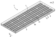
本発明の第1実施形態の太陽電池モジュール1は、図1のように、家やビル等の建物の壁面4に取り付けられ、建物の外壁面を形成する壁面形成部材である。すなわち、太陽電池モジュール1は、水平面に対して実質的に垂直に立ち上がった壁面4に受光面7が鉛直方向に対して直交する方向を向く縦姿勢で設置されるものである。
ここでいう「実質的に垂直」とは、完全な垂直(90度)の状態だけではなく、完全な垂直の状態に対してプラスマイナス3度以下の角度で傾いた状態も含む。すなわち、「実質的に垂直」とは、垂直状態を基準として−3度から3度までの範囲をいう。
As shown in FIG. 1, a
The term “substantially vertical” as used herein includes not only a state of perfect vertical (90 degrees) but also a state inclined at an angle of ± 3 degrees or less with respect to the perfect vertical state. That is, “substantially vertical” refers to a range from −3 degrees to 3 degrees with respect to the vertical state.
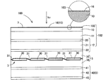
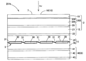
本実施形態での太陽電池モジュール1は、図2,図3のように、一方の主面が受光面7となる片面受光型の太陽電池モジュールであり、主要構成部材として、第1封止部材2と、太陽電池ユニット3と、接着封止層5と、第2封止部材6を備えている。
第1封止部材2は、図3のように、太陽電池モジュール1の一方の主面たる受光面7を構成する部材であり、受光面7側から防眩層10と、緩衝層11と、第1強化ガラス層12が積層されている。
The
As shown in FIG. 3, the
防眩層10は、図3の拡大図のように、受光側の表面に微細な表面凹凸16が形成され、表面凹凸16によって可視光を散乱させるものである。すなわち、防眩層10は、緩衝層11とは反対側の表面に表面凹凸16が形成されており、受光面7を構成している。
防眩層10は、フィルム状又は板状の部材であり、本実施形態では、板状の非強化ガラスの表面にブラスト加工によって表面凹凸16が形成されたものである。
防眩層10の平均厚みは、0.05mm以上0.7mm以下であることが好ましい。
この範囲であれば、撓む程度の薄さであって弾性変形しやすく、外部からの衝撃を受けたときに割れずに弾性変形して緩衝層11側に逃がすことができる。
防眩層10は、正面視したときに、表面凹凸16が形成され、防眩機能を発揮する防眩領域15を備えている。
本実施形態では、防眩領域15は、防眩層10の全面に形成されている。
防眩層10は、JIS K 7171:2016(ISO 178:2010)に準ずる曲げ弾性率が2GPa以上であることが好ましく、60GPa以上であることがより好ましい。
防眩層10は、当該曲げ弾性率が120GPa以下であることが好ましい。
これらの範囲であれば、防眩層10での曲げ破壊が生じにくい。
As shown in the enlarged view of FIG. 3, the
The
The average thickness of the
Within this range, it is thin enough to be bent and easily elastically deformed, and can be elastically deformed and released to the
The
In the present embodiment, the
The
The
Within these ranges, bending failure in the
防眩領域15は、JIS Z 8741:1997(ISO 2813:1994及びISO 7668:1986に対応)に準ずる60度鏡面光沢度が6パーセント以下であることが好ましい。
防眩領域15は、受光面7の法線に対して60度の角度で光を入射したときの最大反射率が1パーセント以下であることが好ましい。
防眩領域15は、JIS B 0601:2013(ISO 4287:1997に対応)に準ずる算術平均粗さRaが0.2μm以上1μm以下であり、最大高さ粗さRzが5μm以上50μm以下であることが好ましい。
これらの範囲であれば、ぎらつきが生じにくく、眩しくない太陽電池モジュールとなる。
防眩領域15は、単位面積当たりのクラックの面積(表面クラック面積)が1パーセント未満であることが好ましい。
ここでいう「クラック」とは、防眩層10の表面から概ね5μm以上の深さを有するひび割れや破折をいう。
この範囲であれば、自然破壊の発生を抑制できる。
The
The
The
Within these ranges, the solar cell module hardly causes glare and does not dazzle.
The
The term “crack” as used herein refers to a crack or a fracture having a depth of about 5 μm or more from the surface of the
Within this range, occurrence of spontaneous destruction can be suppressed.
緩衝層11は、防眩層10で受けた物理的衝撃を緩和させる層であり、図3のように、防眩層10と第1強化ガラス層12を接着する接着層である。
緩衝層11は、弾性変形可能なシート状又は板状の部材である。
緩衝層11は、透明性と接着性を有していれば、特に限定されない。例えば、ポリビニルブチラール樹脂(PVB樹脂)やエチレン・酢酸ビニル共重合樹脂(EVA樹脂)、アイオノマー樹脂などの熱可塑性樹脂が採用できる。
本実施形態の緩衝層11は、着色しておらず、無色透明である。
The
The
The
The
緩衝層11の平均厚みは、0.5mm以上であり、0.8mm以下であることが好ましい。この範囲であれば、防眩層10で受けた衝撃を十分に緩和でき、厚みも大きくなりすぎない。
緩衝層11の平均厚みは、防眩層10の平均厚み以上であることが好ましい。
緩衝層11は、JIS K 7171:2016(ISO 178:2010)に準ずる曲げ弾性率が防眩層10の曲げ弾性率以下であり、防眩層10の曲げ弾性率未満であることが好ましい。
緩衝層11は、当該曲げ弾性率が1GPa以上10GPa以下であることがより好ましい。
この範囲であれば、形状を維持しつつ、防眩層10で受けた衝撃を十分に緩和できる。
The average thickness of the
The average thickness of the
The
The
Within this range, the impact received by the
第1強化ガラス層12は、板状の熱強化ガラスで構成されており、図3のように、第1圧縮応力層20と、第1引張応力層21と、第2圧縮応力層22を備えている。
第1強化ガラス層12の平均厚みは、2.5mm以上4mm以下であることが好ましい。この範囲であれば、十分な強度を確保でき、厚みも厚くなりすぎない。
本実施形態の第1圧縮応力層20及び第2圧縮応力層22は、それぞれ平均厚みが第1強化ガラス層12の平均厚みの1/6の厚みとなっており、通常の化学強化ガラスの圧縮応力層よりも厚い。
The first tempered
The average thickness of the first tempered
Each of the first
太陽電池ユニット3は、図3のように、主要構成部材として、複数の太陽電池セル30と、配線部材31を備え、太陽電池セル30が配線部材31を介して直列又は並列接続されている。
太陽電池セル30は、結晶型の太陽電池セルであり、本実施形態では結晶シリコン太陽電池である。すなわち、本実施形態の太陽電池セル30は、支持基板として半導体基板を使用し、半導体基板上に半導体層が積層されたものである。
配線部材31は、隣接する太陽電池セル30間を接続する金属配線である。
As shown in FIG. 3, the
The
The
接着封止層5は、図3のように、第1封止部材2と第2封止部材6を接着する接着層であり、太陽電池セル30を埋没させて封止する封止層である。
接着封止層5は、2つの透明封止材で太陽電池ユニット3を挟み、2つの透明封止材が熱融着されて形成されるものである。すなわち、接着封止層5は、第1透明樹脂層35と、第2透明樹脂層36の二層構造となっている。
本実施形態の接着封止層5は、上記の機能に加えて断熱性を有した断熱層でもある。
接着封止層5を構成する透明樹脂層35,36は、透明性と接着性と封止性を有していれば、特に限定されない。透明樹脂層35,36は、例えば、エチレン・酢酸ビニル共重合樹脂(EVA)などの熱可塑性樹脂が採用できる。
なお、透明樹脂層35,36は、同じ材料で構成されていてもよいし、異なる材料で構成されていてもよい。
As shown in FIG. 3, the
The
The
The transparent resin layers 35 and 36 constituting the
The transparent resin layers 35 and 36 may be made of the same material or different materials.
第2封止部材6は、第1封止部材2とともに太陽電池ユニット3を封止する部材であり、図3のように、第2強化ガラス層40を備えている。
第2強化ガラス層40は、板状の熱強化ガラスで構成されており、第3圧縮応力層41と、第2引張応力層42と、第4圧縮応力層43を備えている。
第2強化ガラス層40の平均厚みは、2.5mm以上4mm以下であることが好ましい。この範囲であれば、十分な強度を確保でき、厚みも厚くなりすぎない。
第3圧縮応力層41及び第4圧縮応力層43は、それぞれ平均厚みが第1強化ガラス層12の平均厚みの1/6の厚みとなっており、通常の化学強化ガラスの圧縮応力層よりも厚い。
The
The second tempered
The average thickness of the second tempered
Each of the third
続いて、本発明の第1実施形態の太陽電池モジュール1の各部位の位置関係について説明する。
Subsequently, the positional relationship of each part of the
太陽電池モジュール1は、図3のように、第1封止部材2と第2封止部材6の間が接着封止層5で充填されており、太陽電池ユニット3が接着封止層5内に埋没している。すなわち、第1封止部材2と第2封止部材6は、接着封止層5によって接着されており、太陽電池ユニット3は、接着封止層5によって封止されている。
緩衝層11は、第1強化ガラス層12の第1圧縮応力層20と直接接しており、太陽電池ユニット3を基準として、第1強化ガラス層12の外側に位置している。
防眩層10は、緩衝層11と直接接しており、太陽電池ユニット3を基準として、緩衝層11の外側に位置している。
このように、太陽電池モジュール1は、受光面7側から順に、防眩層10、緩衝層11、第1強化ガラス層12、第1透明樹脂層35、太陽電池セル30、第2透明樹脂層36、第2強化ガラス層40が積層された断面構造を備えている。
In the
The
The
As described above, the
続いて、本発明の第1実施形態の太陽電池モジュール1を建物の壁面4に取り付けられ、外壁を形成したときの各部位の位置関係について説明する。
Subsequently, a description will be given of a positional relationship of each part when the
太陽電池モジュール1は、図1のように、他の太陽電池モジュール1とともに、建物の壁面4の外面に取り付けられており、第2封止部材6は、第1封止部材2に対して建物の壁面4側に位置している。すなわち、各太陽電池モジュール1の防眩層10で構成される受光面7は、建物の外壁面を構成している。
建物の壁面4には、複数の太陽電池モジュール1が縦方向及び横方向に隙間なく並設されており、壁面構造が形成されている。
As shown in FIG. 1, the
A plurality of
本実施形態の太陽電池モジュール1によれば、第1強化ガラス層12とは別途防眩層10を設けるので、強化ガラスに表面凹凸を形成することによる第1強化ガラス層12の製造時の自然破損や潜在的な亀裂の発生を防止できる。
According to the
本実施形態の太陽電池モジュール1によれば、第1強化ガラス層12と防眩層10との間に平均厚みが0.5mm以上の緩衝層11が介在している。そのため、外部からの物理的衝撃が防眩層10に伝わっても、緩衝層11で緩和され、第1強化ガラス層12の第1圧縮応力層20を超えて第1引張応力層21に伝達されることを防止できる。その結果、外部からの物理的衝撃による自然破壊の発生を抑制できる。
According to the
本実施形態の太陽電池モジュール1によれば、可視光を散乱させる防眩層10を備えているため、防眩機能を確保できる。
According to the
本実施形態の太陽電池モジュール1によれば、厚み方向に間隔を空けて第1強化ガラス層12と第2強化ガラス層40を備えているため、二重ガラスとなり、断熱性能及び防音性能を発揮できる。
According to the
続いて、本発明の第2実施形態の太陽電池モジュール100について説明する。なお、第1実施形態の太陽電池モジュール1と同様の構成は、同様の付番をして説明を省略する。以下、同様とする。
Subsequently, a
本発明の第2実施形態の太陽電池モジュール100は、第1封止部材102の構造が第1実施形態と異なる。
第2本実施形態の第1封止部材102は、図4のように、受光側から保護層103と、防眩層10と、緩衝層11と、第1強化ガラス層12を備えている。すなわち、第1封止部材102は、防眩層10の表面に保護層103を備えている。
保護層103は、防眩層10の表面凹凸16を覆う保護膜であって、太陽電池モジュール100の最表面に位置し、受光面7を構成するものである。
保護層103は、防眩層10の表面凹凸16に比べて表面が平滑となっている。
保護層103の平均厚みは、1μm以上10μm以下であることが好ましい。
この範囲であれば、高い耐衝撃性を維持しつつ、防眩層10の表面凹凸16での防眩機能の低下を抑制できる。
保護層103は、フッ素系樹脂で形成されていることが好ましく、ポリテトラフルオロエチレン(PTFE)などが好適に採用できる。
The
As shown in FIG. 4, the
The
The surface of the
The average thickness of the
Within this range, a decrease in the antiglare function at the
The
本実施形態の太陽電池モジュール100によれば、防眩層10の表面が保護層103でコーティングされているため、表面の耐衝撃性をさらに向上できる。また、ブラスト加工時に防眩層10にクラックが形成されていても、保護層103でクラックを埋めることができ、クラックの拡大を防止できる。
According to the
続いて、本発明の第3実施形態の太陽電池モジュール150について説明する。
Subsequently, a
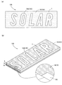
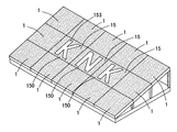
本発明の第3実施形態の太陽電池モジュール150は、防眩層151の構造が第1実施形態の太陽電池モジュール1と異なる。
第3実施形態の防眩層151は、図5のように、部分的にブラスト加工が施されており、部分的に表面凹凸16が形成されている。すなわち、防眩層151は、正面視したときに、表面凹凸16が形成された防眩領域15と、表面凹凸16が形成されていない非防眩領域153が形成されている。
The
As shown in FIG. 5, the
非防眩領域153は、防眩領域15よりも平滑な領域であり、防眩機能がない領域である。
非防眩領域153は、算術平均粗さRaが5nm以下であり、最大高さ粗さRzが50nm以下であることが好ましい。すなわち、非防眩領域153は、算術平均粗さRa及び最大高さ粗さRzのいずれも防眩領域15よりも小さい。
非防眩領域153は、防眩領域15よりも60度鏡面光沢度が高く、受光面7の法線に対して60度の角度で光を入射したときの最大反射率も高い。
The
The
The
非防眩領域153は、所定の模様を形成しており、当該所定の模様の輪郭を防眩領域15が形成している。
非防眩領域153が形成する模様は、特に限定されるものではない。当該模様としては、例えば、文字や絵、図形等が挙げられる。さらに詳細な具体例を挙げると、当該模様としては、会社のロゴタイプやシンボルマーク、ロゴマーク(ロゴタイプとシンボルマークが合わさったもの)、自己の太陽電池モジュール150に関する情報(製造番号、製造年月日等)、幾何学模様などがある。
The
The pattern formed by the
第3実施形態の太陽電池モジュール150によれば、防眩加工がされている防眩領域15と防眩加工がされていない非防眩領域153があり、非防眩領域153が所定の模様を形成している。そのため、光が受光面7に当たったときに非防眩領域153だけが輝き、所定の模様が浮き上がって見える。その結果、今までにない意匠性に優れた外観を呈する太陽電池モジュールとなる。
According to the
続いて、本発明の第4実施形態の太陽電池システム200について説明する。
Subsequently, a
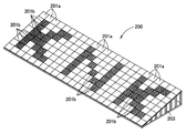
本発明の第4実施形態の太陽電池システム200は、いわゆるメガソーラーと呼ばれる大規模発電システムであり、遊休地等に複数の太陽電池モジュール201が並設されたものである。すなわち、太陽電池システム200は、図6のように、複数の太陽電池モジュール201を備えており、複数の太陽電池モジュール201が架台等の固定部材203によって水平面に対して所定の角度で傾斜する姿勢で並設されるものである。
太陽電池システム200を構成する太陽電池モジュール201の中には、緩衝層の構造が異なる少なくとも2種類の太陽電池モジュール201a,201bがある。
第1太陽電池モジュール201aは、第1実施形態の太陽電池モジュール1と同様のものであり、緩衝層11が無色透明となっている。
The
Among the solar cell modules 201 constituting the
The first
第2太陽電池モジュール201bは、図7のように、緩衝層202の構造が第1太陽電池モジュール201aと異なっており、樹脂層205と、色素層206を含む積層構造となっている。
樹脂層205は、弾性変形可能な透明樹脂層である。
樹脂層205には、緩衝層11と同様のものが使用でき、例えば、ポリビニルブチラール樹脂(PVB)やエチレン・酢酸ビニル共重合樹脂(EVA)、アイオノマー樹脂などの熱可塑性樹脂が採用できる。
なお、樹脂層205は、透明樹脂中に色素成分を含んだ有色透明の層であってもよい。
7, the structure of the
The
As the
Note that the
色素層206は、有色透明に着色されたシート又はフィルムである。
色素層206は、第1太陽電池モジュール201aの緩衝層11の色と異なる色であれば、特に限定されない。色素層206としては、例えば、カラーフィルムや金属光沢をもつ金属薄膜等が採用できる。
The
The
第2太陽電池モジュール201bは、正面視したときに緩衝層202によって実質的に受光面7の全面が着色されている。すなわち、第2太陽電池モジュール201bは、正面視したときに有色の緩衝層202が少なくとも太陽電池セル30と重なっており、太陽電池セル30が見えにくくなっている。
In the second
続いて、第4実施形態の太陽電池システム200の各部材の位置関係について説明する。
Subsequently, the positional relationship of each member of the
第1太陽電池モジュール201aと第2太陽電池モジュール201bは、正面視したときに、いずれも緩衝層11,202の色が外観に反映されている。
第1太陽電池モジュール201aと第2太陽電池モジュール201bは、図6のように、緩衝層11,202の色の違いによって所定の模様になるように並んでいる。
本実施形態の太陽電池システム200では、着色された第2太陽電池モジュール201bが集まって所定の模様を形成し、第1太陽電池モジュール201aは、その模様の周囲に配されて模様の輪郭を形成している。すなわち、第2太陽電池モジュール201bは、隣接する他の第2太陽電池モジュール201bとともに模様を構成している。
第1太陽電池モジュール201aと第2太陽電池モジュール201bの色の違いで形成される模様は、特に限定されるものではない。当該模様としては、例えば、文字や絵、図形等が挙げられる。さらに詳細な具体例を挙げると、当該模様としては、会社のロゴタイプやシンボルマーク、ロゴマーク(ロゴタイプとシンボルマークが合わさったもの)、自己の太陽電池システム200に関する情報、幾何学模様などがある。
When the first
As shown in FIG. 6, the first
In the
The pattern formed by the color difference between the first
第4実施形態の太陽電池システム200によれば、緩衝層11,202の色が異なる第1太陽電池モジュール201aと第2太陽電池モジュール201bで所定の模様を形成する。そのため、飛行体等で上空からみたときや、建物の屋上からみたときに、所定の模様が強調され、今までにない意匠性に優れた外観を呈する太陽電池システムとなる。
According to the
第4実施形態の第2太陽電池モジュール201bによれば、正面視したときに、着色された緩衝層202が少なくとも太陽電池セル30と重なる部分を着色されているので、太陽電池セル30が緩衝層202の色で見えにくくできる。そのため、例えば、第2太陽電池モジュール201bを第1実施形態のように外壁面を構成する壁面形成部材とし、適宜色を設定する。こうすることで、化粧パネル等の他の壁面形成部材と同様の外観を呈することが可能であり、外観上、太陽電池モジュールと判別しにくくできる。
According to the second
上記した第4実施形態では、緩衝層202は、樹脂層205と色素層206の積層構造であり、色素層206の色が反映されて着色されていたが、本発明はこれに限定されるものではない。緩衝層202は、透明樹脂中に色素成分を含んだ単層であってもよい。
In the above-described fourth embodiment, the
上記した第4実施形態では、第1太陽電池モジュール201aは、無色透明であったが、本発明はこれに限定されるものではない。第1太陽電池モジュール201aは、緩衝層11の色が第2太陽電池モジュール201bの緩衝層202の色と異なっていれば、有色透明であってもよい。
In the above-described fourth embodiment, the first
上記した第3実施形態では、一枚の太陽電池モジュール150において非防眩領域153で所定の模様を形成していたが、本発明はこれに限定されるものではない。非防眩領域153をもつ複数の太陽電池モジュール150を組み合わせて一つの模様を形成してもよい。例えば、隣接する他の太陽電池モジュールとともに一つの模様を形成してもよい。
In the third embodiment described above, the predetermined pattern is formed in the
上記した第1〜3実施形態では、太陽電池モジュール1,100,150は、水平面に対して実質的に垂直な壁面4に取り付けられていたが、本発明はこれに限定されるものではない。太陽電池モジュール1,100,150は、実質的に水平となる建物の床面や天面、屋根に取り付けられていてもよいし、図8のように、水平面に対して傾斜した架台等の固定部材に取り付けられていてもよい。
ここでいう「実質的に水平」とは、完全な水平(0度)の状態だけではなく、完全な水平の状態に対してプラスマイナス3度以下の角度で傾いた状態も含む。すなわち、「実質的に水平」とは、水平状態を基準として−3度から3度までの範囲をいう。
In the above-described first to third embodiments, the
The term "substantially horizontal" as used herein includes not only a state of perfect horizontal (0 degree) but also a state inclined at an angle of plus or minus 3 degrees or less with respect to the perfect horizontal state. That is, “substantially horizontal” refers to a range from −3 degrees to 3 degrees with respect to the horizontal state.
上記した実施形態では、片面が受光面7となる片面受光型の太陽電池モジュール1,100,150,201について説明したが、本発明はこれに限定されるものではない。両面が受光面となる両面受光型の太陽電池モジュールであってもよい。この場合、窓やベランダの手すり等に好適に使用できる。
In the above-described embodiment, the single-sided light receiving type
上記した実施形態では、太陽電池セル30は、結晶型の太陽電池セルであったが、本発明はこれに限定されるものではない。太陽電池セル30は、薄膜型の太陽電池セル等の他の種類の太陽電池セルであってもよい。例えば、太陽電池セルとして薄膜シリコン太陽電池を使用する場合、第1強化ガラス層12を支持基板とすることが好ましい。この場合、受光面7側から順に、防眩層10、緩衝層11、第1強化ガラス層12、太陽電池セル、第2透明樹脂層36、第2強化ガラス層40が積層された断面構造を備えることが好ましい。
In the above-described embodiment, the
上記した実施形態の太陽電池モジュール1,100,150,201は、厚み方向に光が透過するシースルー型の太陽電池モジュールであってもよい。この場合、窓等に好適に使用できる。
The
上記した実施形態では、強化ガラス層12,40は、物理強化ガラスで構成されていたが、本発明はこれに限定されるものではない。強化ガラス層12,40は、化学強化ガラスで構成されていてもよい。 In the embodiment described above, the tempered glass layers 12 and 40 are made of physically tempered glass, but the present invention is not limited to this. The tempered glass layers 12, 40 may be made of chemically tempered glass.
上記した実施形態では、第2封止部材6として強化ガラスで構成された第2強化ガラス層40を使用していたが、本発明はこれに限定されるものではない。第2封止部材6として樹脂製の封止シートを使用してもよい。
In the embodiment described above, the second tempered
上記した実施形態では、片面にのみ防眩加工を施していたが、本発明はこれに限定されるものではない。両面に防眩加工を施してもよい。例えば、太陽電池セル30を基準として第2強化ガラス層40の外側にも緩衝層11及び防眩層10を設けてもよい。
In the embodiment described above, the anti-glare processing is performed only on one side, but the present invention is not limited to this. Anti-glare processing may be performed on both sides. For example, the
上記した実施形態は、本発明の技術的範囲に含まれる限り、各実施形態間で各構成部材を自由に置換や付加できる。 In the above-described embodiments, each constituent member can be freely replaced or added between the embodiments as long as it is included in the technical scope of the present invention.
1,100,150 太陽電池モジュール
2,102 第1封止部材
3 太陽電池ユニット
4 建物の壁面
5 接着封止層
6 第2封止部材
7 受光面
10,151 防眩層
11,202 緩衝層
12 第1強化ガラス層
15 防眩領域
16 表面凹凸
20 第1圧縮応力層
30 太陽電池セル
31 配線部材
40 第2強化ガラス層
43 第4圧縮応力層
103 保護層
153 非防眩領域
200 太陽電池システム
201a 第1太陽電池モジュール
201b 第2太陽電池モジュール
205 弾性層
206 色素層
DESCRIPTION OF
Claims (8)
前記第1封止部材は、前記太陽電池モジュールの一方の主面を形成するものであって、前記太陽電池セル側から、第1強化ガラス層と、緩衝層と、防眩層が積層されており、
前記第1強化ガラス層は、前記緩衝層側の表面に圧縮応力層を有する強化ガラスで構成されており、
前記緩衝層は、平均厚みが0.5mm以上であって、弾性変形可能であり、
前記防眩層は、フィルム状又は板状であって、前記緩衝層とは反対側の表面に可視光を散乱させる表面凹凸が形成されている、太陽電池モジュール。 A solar cell module including a first sealing member, a second sealing member, and a solar cell, wherein the solar cell is disposed between the first sealing member and the second sealing member. ,
The first sealing member forms one main surface of the solar cell module, and a first tempered glass layer, a buffer layer, and an antiglare layer are laminated from the solar cell side. Yes,
The first tempered glass layer is made of tempered glass having a compressive stress layer on the surface on the buffer layer side,
The buffer layer has an average thickness of 0.5 mm or more and is elastically deformable,
The solar cell module, wherein the anti-glare layer has a film shape or a plate shape, and has a surface unevenness for scattering visible light formed on a surface opposite to the buffer layer.
前記緩衝層の平均厚みは、前記防眩層の平均厚み以上である、請求項1に記載の太陽電池モジュール。 The anti-glare layer is formed of non-tempered glass, has an average thickness of 0.05 mm or more and 0.7 mm or less,
The solar cell module according to claim 1, wherein the average thickness of the buffer layer is equal to or greater than the average thickness of the antiglare layer.
前記防眩領域は、JIS Z 8741:1997に準ずる60度鏡面光沢度が6パーセント以下であって、前記一方の主面の法線に対して60度の角度で光を入射したときの最大反射率が1パーセント以下であり、
さらに、前記防眩領域は、JIS B 0601:2013に準ずる算術平均粗さRaが0.2μm以上1μm以下である、請求項1又は2に記載の太陽電池モジュール。 The anti-glare layer has an anti-glare region where the surface irregularities are formed when the first sealing member is viewed from the front,
The anti-glare area has a 60-degree specular gloss according to JIS Z8741: 1997 of 6% or less, and has a maximum reflection when light is incident at an angle of 60 degrees with respect to a normal line of the one main surface. The rate is less than 1%,
3. The solar cell module according to claim 1, wherein the anti-glare region has an arithmetic average roughness Ra according to JIS B 0601: 2013 of 0.2 μm or more and 1 μm or less. 4.
前記保護層は、平均厚みが1μm以上10μm以下であって、フッ素系樹脂で形成されている、請求項1乃至3のいずれか一項に記載の太陽電池モジュール。 The first sealing member has a protective layer that covers the surface irregularities of the antiglare layer,
4. The solar cell module according to claim 1, wherein the protective layer has an average thickness of 1 μm or more and 10 μm or less, and is formed of a fluororesin. 5.
前記非防眩領域は、所定の模様を形成している、請求項1乃至4のいずれか一項に記載の太陽電池モジュール。 The anti-glare layer has an anti-glare region where the surface irregularities are formed and a non-glare region where the surface irregularities are not formed when the first sealing member is viewed from the front,
The solar cell module according to claim 1, wherein the non-glare area forms a predetermined pattern.
(1)前記緩衝層は、色素層と樹脂層を含む積層構造である。
(2)前記緩衝層は、樹脂中に色素成分を含んだ単層である。 6. The buffer layer according to claim 1, wherein the buffer layer satisfies the following configuration (1) or (2), and at least a portion overlapping the solar cell when viewed from the front is colored. 7. Solar module.
(1) The buffer layer has a laminated structure including a dye layer and a resin layer.
(2) The buffer layer is a single layer containing a dye component in a resin.
前記第2封止部材は、第2強化ガラス層を有し、
前記第2強化ガラス層は、前記太陽電池セルとは反対側の表面に圧縮応力層を有する強化ガラスで構成されている、壁面形成部材。 A wall forming member using the solar cell module according to any one of claims 1 to 6, wherein the wall forming member forms an outer wall surface of a building.
The second sealing member has a second tempered glass layer,
The wall forming member, wherein the second tempered glass layer is made of tempered glass having a compressive stress layer on a surface on a side opposite to the solar cell.
前記複数の太陽電池モジュールには、第1太陽電池モジュールと、前記第1太陽電池モジュールの緩衝層とは異なる色に着色された緩衝層を有する第2太陽電池モジュールがあり、
前記第2太陽電池モジュールの緩衝層は、以下の(3)又は(4)の構成を満たし、正面視したときに実質的に全面が着色されており、
前記第1太陽電池モジュールと前記第2太陽電池モジュールは、緩衝層の色の違いにより所定の模様になるように並んでいる、太陽電池システム。
(3)前記緩衝層は、色素層と樹脂層を含む積層構造である。
(4)前記緩衝層は、樹脂中に色素成分を含んだ単層である。 A solar cell system having a plurality of solar cell modules according to any one of claims 1 to 5,
The plurality of solar cell modules include a first solar cell module and a second solar cell module having a buffer layer colored in a different color from the buffer layer of the first solar cell module,
The buffer layer of the second solar cell module satisfies the following configuration (3) or (4), and is substantially entirely colored when viewed from the front,
The solar cell system, wherein the first solar cell module and the second solar cell module are arranged in a predetermined pattern depending on a color of a buffer layer.
(3) The buffer layer has a laminated structure including a dye layer and a resin layer.
(4) The buffer layer is a single layer containing a dye component in a resin.
Priority Applications (1)
| Application Number | Priority Date | Filing Date | Title |
|---|---|---|---|
| JP2018131767A JP7079684B2 (en) | 2018-07-11 | 2018-07-11 | Solar cell modules, wall forming members, and solar cell systems |
Applications Claiming Priority (1)
| Application Number | Priority Date | Filing Date | Title |
|---|---|---|---|
| JP2018131767A JP7079684B2 (en) | 2018-07-11 | 2018-07-11 | Solar cell modules, wall forming members, and solar cell systems |
Publications (2)
| Publication Number | Publication Date |
|---|---|
| JP2020009970A true JP2020009970A (en) | 2020-01-16 |
| JP7079684B2 JP7079684B2 (en) | 2022-06-02 |
Family
ID=69152260
Family Applications (1)
| Application Number | Title | Priority Date | Filing Date |
|---|---|---|---|
| JP2018131767A Active JP7079684B2 (en) | 2018-07-11 | 2018-07-11 | Solar cell modules, wall forming members, and solar cell systems |
Country Status (1)
| Country | Link |
|---|---|
| JP (1) | JP7079684B2 (en) |
Citations (6)
| Publication number | Priority date | Publication date | Assignee | Title |
|---|---|---|---|---|
| JP2003110128A (en) * | 2001-09-28 | 2003-04-11 | Sharp Corp | Thin film solar cell module and its manufacturing method |
| JP2003124491A (en) * | 2001-10-15 | 2003-04-25 | Sharp Corp | Thin film solar cell module |
| JP2010087351A (en) * | 2008-10-01 | 2010-04-15 | Toppan Printing Co Ltd | Optical sheet for solar cell |
| CN202503006U (en) * | 2012-02-07 | 2012-10-24 | 泰通(泰州)工业有限公司 | Anti-glare crystalline silica photovoltaic assembly |
| JP3188125U (en) * | 2013-10-02 | 2014-01-09 | 株式会社不二製作所 | Solar cell module, solar cell array |
| KR20140120436A (en) * | 2013-04-02 | 2014-10-14 | 엘지전자 주식회사 | Solar cell module |
-
2018
- 2018-07-11 JP JP2018131767A patent/JP7079684B2/en active Active
Patent Citations (6)
| Publication number | Priority date | Publication date | Assignee | Title |
|---|---|---|---|---|
| JP2003110128A (en) * | 2001-09-28 | 2003-04-11 | Sharp Corp | Thin film solar cell module and its manufacturing method |
| JP2003124491A (en) * | 2001-10-15 | 2003-04-25 | Sharp Corp | Thin film solar cell module |
| JP2010087351A (en) * | 2008-10-01 | 2010-04-15 | Toppan Printing Co Ltd | Optical sheet for solar cell |
| CN202503006U (en) * | 2012-02-07 | 2012-10-24 | 泰通(泰州)工业有限公司 | Anti-glare crystalline silica photovoltaic assembly |
| KR20140120436A (en) * | 2013-04-02 | 2014-10-14 | 엘지전자 주식회사 | Solar cell module |
| JP3188125U (en) * | 2013-10-02 | 2014-01-09 | 株式会社不二製作所 | Solar cell module, solar cell array |
Also Published As
| Publication number | Publication date |
|---|---|
| JP7079684B2 (en) | 2022-06-02 |
Similar Documents
| Publication | Publication Date | Title |
|---|---|---|
| KR102373662B1 (en) | Glass resin laminate | |
| RU2009128180A (en) | GLAZING HEATING ELEMENT, ITS MANUFACTURE AND APPLICATION | |
| CN213876082U (en) | Optical adhesive film layer, adhesive film layer and display screen | |
| JP5972049B2 (en) | Solar cell module | |
| JP2011165874A (en) | Solar cell panel | |
| TWI698842B (en) | Building material glass plate with display device and building material glass structure | |
| JP7079684B2 (en) | Solar cell modules, wall forming members, and solar cell systems | |
| JP2020032545A (en) | Protective sheet for solar cell module | |
| WO2019214061A1 (en) | Solar cell module and solar photoelectric curtain wall | |
| CN102664201B (en) | Glass filled hollow solar cell film assembly | |
| JP6887618B2 (en) | Laminated body with dimming function | |
| CN211917940U (en) | Transparent glass and observation window | |
| CN214774499U (en) | Low-radiation low-e coated glass structure | |
| CN210082576U (en) | Hot-cast mosaic glass | |
| CN216915074U (en) | Antistatic low-e glass structure | |
| US20220006420A1 (en) | Building-integrated photovoltaic system | |
| JP7161900B2 (en) | Method for manufacturing solar cell module | |
| CN210343116U (en) | A glass luffer board structure for building window | |
| US20220388280A1 (en) | Laminated glazing with improved resistance to relatively discrete impact types | |
| WO2020045360A1 (en) | Lighting device | |
| CN110700451A (en) | Printing opacity type solar module and solar energy curtain | |
| JP2017068108A (en) | Lighting sheet, lighting glass and building | |
| JP5968393B2 (en) | Integration of optical elements in an insulating glass unit | |
| CA3085698A1 (en) | Building-integrated photovoltaic system | |
| CN115302889A (en) | Explosion-proof glass |
Legal Events
| Date | Code | Title | Description |
|---|---|---|---|
| A621 | Written request for application examination |
Free format text: JAPANESE INTERMEDIATE CODE: A621 Effective date: 20210519 |
|
| A977 | Report on retrieval |
Free format text: JAPANESE INTERMEDIATE CODE: A971007 Effective date: 20220420 |
|
| TRDD | Decision of grant or rejection written | ||
| A01 | Written decision to grant a patent or to grant a registration (utility model) |
Free format text: JAPANESE INTERMEDIATE CODE: A01 Effective date: 20220512 |
|
| A61 | First payment of annual fees (during grant procedure) |
Free format text: JAPANESE INTERMEDIATE CODE: A61 Effective date: 20220523 |
|
| R150 | Certificate of patent or registration of utility model |
Ref document number: 7079684 Country of ref document: JP Free format text: JAPANESE INTERMEDIATE CODE: R150 |