JP2020008736A - Image formation apparatus - Google Patents
Image formation apparatus Download PDFInfo
- Publication number
- JP2020008736A JP2020008736A JP2018130024A JP2018130024A JP2020008736A JP 2020008736 A JP2020008736 A JP 2020008736A JP 2018130024 A JP2018130024 A JP 2018130024A JP 2018130024 A JP2018130024 A JP 2018130024A JP 2020008736 A JP2020008736 A JP 2020008736A
- Authority
- JP
- Japan
- Prior art keywords
- image
- image forming
- forming apparatus
- control unit
- line
- Prior art date
- Legal status (The legal status is an assumption and is not a legal conclusion. Google has not performed a legal analysis and makes no representation as to the accuracy of the status listed.)
- Pending
Links
Images


Abstract
Description
本発明は、画像形成装置に関し、特に、電子写真プロセス等を利用したカラー画像形成装置に関する。 The present invention relates to an image forming apparatus, and more particularly, to a color image forming apparatus using an electrophotographic process or the like.
従来から、電子写真方式の画像形成装置として、中間転写体を有する画像形成装置が知られている。中間転写体を有する画像形成装置は、像担持体である感光ドラム上に形成されたトナー画像を中間転写体(以下、中間転写ベルトという)に転写する1次転写工程を、並置されたイエロー、マゼンタ、シアン、ブラックの各画像形成ステーションで実行する。画像形成装置は、1次転写工程において中間転写ベルト表面に複数色のトナー画像を重畳して形成する。中間転写ベルト表面に形成された複数色からなるトナー画像は、給紙口から給紙された記録材の表面に一括して転写され(以下、2次転写という)、熱及び圧力が加えられてトナー像を定着することによりカラー画像となる。 Conventionally, an image forming apparatus having an intermediate transfer member has been known as an electrophotographic image forming apparatus. An image forming apparatus having an intermediate transfer member performs a primary transfer step of transferring a toner image formed on a photosensitive drum serving as an image carrier to an intermediate transfer member (hereinafter, referred to as an intermediate transfer belt) by using yellow, This is executed at each of the magenta, cyan, and black image forming stations. The image forming apparatus forms a plurality of color toner images on the surface of the intermediate transfer belt in a superimposed manner in the primary transfer step. The toner images of a plurality of colors formed on the surface of the intermediate transfer belt are collectively transferred onto a surface of a recording material fed from a paper feed port (hereinafter, referred to as secondary transfer), and heat and pressure are applied thereto. A color image is obtained by fixing the toner image.
例えば特許文献1には、感光ドラム上に残留したトナー(転写残トナー)を回収するクリーニング手段を感光ドラムに設けない方式(ドラムクリーナレス方式)の画像形成装置が提案されている。この画像形成装置は、画像形成時においては転写残トナーを帯電ローラへ蓄積し、非画像形成時に転写残トナーを帯電ローラから吐き出している(以下、「帯電ローラクリーニング」と呼ぶ)。これにより、転写残トナーによって帯電性能が低下し、画像不良が発生することを防いでいる。連続プリントが続く場合は、例えば、ジョブ内のページカウントを記憶し、ページカウントが所定の閾値を超えた場合に、プリントを一時中断して、帯電ローラクリーニングを行っている。
For example,
上述した画像形成装置において、縦線(副走査方向に連なる線)画像を連続してプリントするようなケースでは、転写残トナーによる画像不良が顕著になる。この理由は、帯電ローラの特定の箇所に転写残トナーが蓄積することで、主走査方向における画像の境界で濃度むらが発生しやすくなるためである。このようなケースでも良好な画像を保つためには、帯電ローラクリーニングを高頻度で行う必要があり、結果として、生産性が低下してしまうおそれがある。 In the above-described image forming apparatus, in a case where a vertical line (line continuing in the sub-scanning direction) image is continuously printed, an image defect due to untransferred toner becomes conspicuous. The reason for this is that since the untransferred toner accumulates at a specific portion of the charging roller, density unevenness tends to occur at the boundary of the image in the main scanning direction. Even in such a case, in order to maintain a good image, it is necessary to frequently perform the charging roller cleaning, and as a result, the productivity may be reduced.
本発明は、このような状況のもとでなされたもので、ドラムクリーナレス方式の画像形成装置において副走査方向に連なる画像を連続してプリントする場合でも、良好な画像を保ちつつ、帯電ローラクリーニングの実行頻度を下げることを目的とする。 The present invention has been made under such a circumstance, and even when continuously printing images connected in the sub-scanning direction in a drum cleaner-less image forming apparatus, the charging roller is maintained while maintaining a good image. It is intended to reduce the frequency of execution of cleaning.
上述した課題を解決するために、本発明は、以下の構成を備える。 In order to solve the above-described problem, the present invention has the following configuration.
(1)所定の回転方向に回転する感光体と、前記感光体を所定の電位に帯電する帯電手段と、画像データに応じた光ビームを出射する光源を有し、画像データに応じた光ビームを前記回転方向に略直交する走査方向に走査することにより前記感光体上に潜像を形成する露光手段と、前記露光手段によって形成された潜像をトナーにより現像しトナー像を形成する現像手段と、前記現像手段により形成されたトナー像を像担持体に転写する転写手段と、を備え、前記感光体上のトナー像を前記転写手段により前記像担持体に転写した後に前記感光体上に残ったトナーを前記帯電手段に一時的に蓄積させ、蓄積したトナーを前記帯電手段から除去するクリーニング制御を行う画像形成装置であって、前記画像データに基づいて前記走査方向における前記感光体の所定の位置に前記回転方向に連続する連続画像が形成されることを判断する判断手段と、複数のページに画像形成を行う場合に、前記判断手段の判断結果に基づいて前記走査方向における前記光ビームの走査を開始する開始位置をページ毎に決定する決定手段と、を備えることを特徴とする画像形成装置。 (1) A photoreceptor that rotates in a predetermined rotation direction, a charging unit that charges the photoreceptor to a predetermined potential, and a light source that emits a light beam corresponding to image data, the light beam corresponding to image data Exposing means for forming a latent image on the photoreceptor by scanning the image in a scanning direction substantially orthogonal to the rotational direction, and developing means for developing the latent image formed by the exposing means with toner to form a toner image And a transfer unit for transferring the toner image formed by the developing unit to an image carrier. The transfer unit transfers the toner image on the photoconductor to the image carrier by the transfer unit, and then transfers the toner image onto the image carrier. An image forming apparatus for performing a cleaning control for temporarily accumulating remaining toner in the charging unit and removing the accumulated toner from the charging unit, wherein the image forming apparatus performs a cleaning control in the scanning direction based on the image data. Determining means for determining that a continuous image continuous in the rotation direction is formed at a predetermined position of the photoconductor; and performing image scanning on the basis of the determination result of the determining means when forming images on a plurality of pages. Determining means for determining a start position at which scanning of the light beam in a direction is started for each page.
本発明によれば、ドラムクリーナレス方式の画像形成装置において副走査方向に連なる画像を連続してプリントする場合でも、良好な画像を保ちつつ、帯電ローラクリーニングの実行頻度を下げることができる。 According to the present invention, it is possible to reduce the frequency of executing the charging roller cleaning while maintaining a good image even when continuously printing images connected in the sub-scanning direction in an image forming apparatus of a drum cleanerless type.
以下、本発明を実施するための形態を、実施例により図面を参照しながら詳しく説明する。 Hereinafter, embodiments for carrying out the present invention will be described in detail with reference to the drawings by way of examples.
[全体構成]
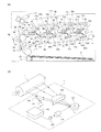
図1(a)では、画像形成装置としてのレーザープリンタの全体構成について説明する。なお、以下の説明では、第1ステーションをイエロー(Y)色のトナー画像形成用のステーション、第2ステーションをマゼンタ(M)色のトナー画像形成用のステーションとしている。また、第3ステーションをシアン(C)色のトナー画像形成用のステーション、第4ステーションをブラック(K)色のトナー画像形成用のステーションとしている。
[overall structure]
FIG. 1A illustrates an overall configuration of a laser printer as an image forming apparatus. In the following description, the first station is a station for forming a yellow (Y) toner image, and the second station is a station for forming a magenta (M) toner image. The third station is a station for forming a cyan (C) toner image, and the fourth station is a station for forming a black (K) toner image.
(画像形成部)
第1ステーションでは、感光体である感光ドラム1aは有機感光体(OPC)のドラムである。感光ドラム1aは、金属円筒上に感光して電荷を生成するキャリア生成層、発生した電荷を輸送する電荷輸送層等からなる機能性有機材料が複数層積層されたものであり、最外層は電気的導電性が低く略絶縁である。帯電手段である帯電ローラ2aは、感光ドラム1に当接され、感光ドラム1aの回転にともなって従動回転しながら感光ドラム1aの表面を均一に帯電する。ここで、感光ドラム1aの回転方向を副走査方向、回転方向に略直交する方向を主走査方向(走査方向)とする。感光ドラム1aの回転軸方向は主走査方向でもあり長手方向でもある。
(Image forming unit)
In the first station, the
帯電ローラ2aには直流電圧又は交流電圧を重畳した電圧が印加され、帯電ローラ2aと感光ドラム1a表面とが当接するニップ部から上流側、下流側の微小な空気ギャップで放電が発生することにより感光ドラム1aは帯電される。現像手段である現像ユニット8aは、感光ドラム1aに当接された現像ローラ4a、非磁性一成分現像剤(以下、現像剤という)5a、現像剤塗布ブレード7aからなる。上述した感光ドラム1a、帯電ローラ2a、現像ユニット8aは、画像形成装置から着脱自在な一体型のプロセスカートリッジ9aとなっている。露光手段であるスキャナユニット11aは、光ビームであるレーザー光を多面鏡によって走査させるスキャナユニット又はLEDアレイから構成され、画像信号に基づいて変調された走査ビーム12aを感光ドラム1a上に照射する。
A voltage in which a DC voltage or an AC voltage is superimposed is applied to the
また、帯電ローラ2aは、帯電ローラ2aへの電圧供給手段である帯電電圧電源20aに接続されている。現像ローラ4aは、現像ローラ4aへの電圧供給手段である現像電圧電源21aに接続されている。転写手段である1次転写ローラ81aは、1次転写ローラ81aへの電圧供給手段である1次転写電圧電源84aに接続されている。以上が第1ステーションの構成である。第2、第3、第4ステーションも同様の構成をしており、同一の符号に添え字b、c、dを付している。以降の説明で、特定の画像形成用のステーションを説明する場合を除き、添え字a、b、c、dを省略する。
Further, the
像担持体である中間転写ベルト80は、その張架部材として2次転写対向ローラ86、駆動ローラ14、テンションローラ15の3本のローラにより支持されており、適切なテンションが維持されるようになっている。駆動ローラ14を駆動させることにより中間転写ベルト80は感光ドラム1に対して順方向に略同速度で移動する。また、中間転写ベルト80は、矢印方向(時計回り方向)に回転し、1次転写ローラ81は中間転写ベルト80を挟んで感光ドラム1と反対側に配置されている。また、1次転写ローラ81の中間転写ベルト80の回転方向における下流側には、除電部材23が配置されている。駆動ローラ14、テンションローラ15及び除電部材23、2次転写対向ローラ86は電気的に接地されている。
The
感光ドラム1は、アルミニウム製シリンダの外周面に有機光導電体層(OPC)を塗布して構成したものである。感光ドラム1はその両端部をフランジによって回転自在に支持されており、一方の端部に駆動モータ(不図示)から駆動力を伝達することにより、図に対して反時計回り方向に回転駆動される。帯電ローラ2は、ローラ状に形成された導電性のローラで、これを感光ドラム1表面に当接させると共に、帯電電圧電源20aによって帯電電圧を印加することにより、感光ドラム1表面を一様に帯電させる。スキャナユニット11は回転多面鏡を有し、この回転多面鏡にはレーザーダイオード(不図示)から画像信号に対応する画像光が照射される。スキャナユニット11に関しては、図1(b)を用いて詳しく説明する。
The
現像ローラ4は、それぞれイエロー、マゼンタ、シアン、ブラックの各色のトナーを収納したトナー収納部、感光ドラム1表面に隣接し、駆動部(不図示)により回転駆動される。現像ローラ4は、現像電圧電源21により現像電圧を印加されることにより現像を行う。
The developing
また、中間転写ベルト80の内側には、4個の感光ドラム1a〜1dに対向して、中間転写ベルト80に当接する1次転写ローラ81a〜81dがそれぞれ併設されている。これら1次転写ローラ81a〜81dは1次転写電圧電源84a〜84dに接続されている。1次転写ローラ81a〜81dから正極性の電圧が作用し、中間転写ベルト80を介して感光ドラム1に接触中の中間転写ベルト80に、感光ドラム1上(感光体上)の負極性の各色トナー画像が順次転写され、多色画像が形成される。感光ドラム1から中間転写ベルト80へのトナー像の転写を、以下、1次転写という。なお、画像形成装置の構成は上述した構成に限定されない。例えば、2次転写部を有さず、中間転写ベルト80のかわりに、記録媒体であるシートPを搬送する搬送ベルトを有する画像形成装置であってもよく、この場合、シートPが像担持体となる。更に、モノクロの画像形成装置であってもよい。
Further, inside the
(給送部)
本体カセット16から給紙する際には、ピックアップローラ17を駆動させることによって、本体カセット16の底板29が上昇し、本体カセット16内に設置されたシートPを押し上げる。押し上げられたシートPの最上の1枚が、ピックアップローラ17と当接し、ピックアップローラ17の回転により、1枚ずつシートPが分離給送され、レジストレーションセンサ(以下レジセンサという)35でシートPの先端が検知される。レジセンサ35に到達したシートPは、その時点からレジストローラ18によって所定時間搬送され、一時停止位置36で用紙搬送が中断される。
(Feeding section)
When feeding paper from the
(シート搬送詳細)
その後、一時停止位置36に停止していたシートPは、レジストローラ18によって搬送が再開され、画像先端とシート先端とが位置37で合うように、2次転写部に搬送される。以下、位置37をマージポイント37という。2次転写部を構成する中間転写ベルト80は、2次転写対向ローラ86、駆動ローラ14、テンションローラ15の3本のローラで張架支持され、すべての感光ドラム1a〜1dに対向して配設されている。中間転写ベルト80は、駆動ローラ14によって循環移動し、感光ドラム1に対向する外周面にトナーを静電吸着させる。これにより中間転写ベルト80の外周に多色のトナー画像が形成され、中間転写ベルト80上に形成された画像は、2次転写位置である2次転写ローラ82と中間転写ベルト80との当接部まで搬送される。2次転写ローラ82は、2次転写ローラ82への電圧供給手段である2次転写電圧電源85に接続されている。
(Details of sheet conveyance)
Thereafter, the sheet P stopped at the
シートPの搬送に際しては、2次転写ローラ82に電圧を印加することで、対向に設置された2次転写対向ローラ86に電界を形成し、中間転写ベルト80及びシートPの間に誘電分極を発生させて両者に静電吸着力を生じさせるようになっている。2次転写工程後に、中間転写ベルト80上に残ったトナーはベルトクリーナー88によって除去される。ベルトクリーナー88は、ベルトクリーナー88への電圧供給手段であるベルトクリーナー電圧電源89に接続されている。中間転写ベルト80からシートPへのトナー像の転写を、以下、2次転写という。
When the sheet P is conveyed, a voltage is applied to the
(定着部)
定着手段である定着器19は、シートP上に形成された未定着のトナー画像に熱及び圧力を加えてトナー画像を定着させるものであり、定着ベルト(不図示)と弾性加圧ローラ(不図示)とを有している。弾性加圧ローラは定着ベルトを挟み、ベルトガイド部材と所定の圧接力をもって所定幅の定着ニップ部を形成している。定着ニップ部が所定の温度に立ち上がって温度が制御された状態において、画像形成部から搬送された未定着のトナー画像が形成されたシートPが定着ニップ部の定着ベルトと弾性加圧ローラとの間に画像面が上向き、即ち定着ベルト面に対向して導入される。定着ニップ部において画像面が定着ベルトの外面に密着して定着ベルトと一緒に定着ニップ部を挟持搬送されていく。この定着ニップ部を定着ベルトと一緒にシートPが挟持搬送されていく過程において、定着ベルトで加熱され、シートP上の未定着のトナー画像が加熱定着される。定着処理が終了したシートPは、トレイ38に排出される。
(Fusing unit)
The fixing
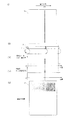
[スキャナ構成]
図1(b)はスキャナユニット11の外観を示す図である。駆動回路130は、コントローラ201(図2参照)から設定された発光レベルに応じて作動する。これにより、発光素子(光源)であるレーザーダイオード107に駆動電流が流れる。レーザーダイオード107は、駆動電流に応じた強度レベルでレーザー光を出射する。レーザーダイオード107から出射されたレーザー光は、コリメータレンズ134によりビーム形状が整形され、かつ平行ビームとされたうえで回転多面鏡133により感光ドラム1の走査方向に走査される。そして走査されたレーザー光は、fθレンズ132により、回転軸を中心に矢印方向に回転する感光ドラム1表面上に結像されてドット状に露光される。以下、ドット状に露光された部分を、所定の解像度における潜像の単位として1ドットと表現する。一方、感光ドラム1の一端側の走査位置に対応して反射ミラー131が設けられる。反射ミラー131は、レーザー光の走査を開始する開始位置に投射されるレーザー光を、出力手段である同期センサ121に向けて反射させる。同期センサ121は、レーザー光が入射されたことに応じて信号を出力する。駆動回路130は、同期センサ121から出力された信号に基づいて、レーザー光の走査開始タイミングを決定する。同期センサ121から出力された信号を、以下、BD(Beam Detect)信号とする。
[Scanner configuration]
FIG. 1B is a diagram illustrating an appearance of the
[実施例1の画像形成装置の制御ブロック図]
図2は、実施例1の画像形成装置100のシステム構成全体を説明するためのブロック図である。コントローラ201は、ホストコンピュータ200、エンジン制御部202と相互に通信が可能となっている。コントローラ201は、ホストコンピュータ200から画像情報及びプリント命令を受信し、受信した画像情報を解析してビットデータに変換する。そして、シリアル通信線を介してプリントコマンドを、画像信号線を介してビットデータ(以下、画像データともいう)を、それぞれエンジン制御部202に出力する。また、コントローラ201は、判断手段である縦線検知部210を有する。縦線検知部210に関しては、図5を用いて詳しく説明する。
[Control Block Diagram of Image Forming Apparatus of First Embodiment]
FIG. 2 is a block diagram illustrating the entire system configuration of the
エンジン制御部202は、コントローラ201からシリアル通信線を介してプリントコマンドを受信すると、高電圧制御部203、光学系制御部204、定着器制御部205、シート搬送制御部207を制御し、画像形成を行う。また、エンジン制御部202は、内部にRAM212を有し、制御に使用するデータをRAM212に書き込んだり、RAM212から読み出したりすることができる。
Upon receiving a print command from the
高電圧制御部203は、帯電、現像、転写の高電圧出力の制御をエンジン制御部202の指示に従って実行する。光学系制御部204は、回転多面鏡133を駆動するスキャナモータ104の駆動/停止、レーザーダイオード107の点灯と消灯をエンジン制御部202の指示に従って制御する。定着器制御部205は、定着器19が有する定着ヒータ(不図示)への電力供給のオン(供給)/オフ(供給停止)をエンジン制御部202の指示に従って行う。センサ入力部206は、シートPを搬送するための各センサの検知結果、同期センサ121の検知結果をエンジン制御部202へ報知する。シート搬送制御部207は、シートPの搬送のための各ローラの駆動源となるモータ(不図示)の駆動/停止を、エンジン制御部202の指示に従って行う。
The high
(主走査方向における画像書き出し位置)
センサ入力部206は同期センサ121からBD信号が出力されると、エンジン制御部202は、同期センサ121からBD信号が出力されたことをセンサ入力部206から報知される。エンジン制御部202がセンサ入力部206を介して同期センサ121のBD信号を入力される(検知する)ことを、同期センサ121からのBD信号を受信したと表現する。エンジン制御部202は、センサ入力部206から報知された結果(BD信号の出力)を、所定のタイミングで画像出力指示信号線を介してコントローラ201に出力する。コントローラ201は、エンジン制御部202から入力された同期センサ121の出力結果に基づいて、主走査方向の一走査における画像データに対応する画像信号の送信タイミングを決定する。エンジン制御部202は同期センサ121からのBD信号を受信した後、コントローラ201へBD信号を受信したことを伝えるタイミングを操作することが可能である。すなわち、エンジン制御部202は、BD信号を受信したことを所定のタイミングで報知するだけでなく、所定のタイミングよりも早く報知したり遅く報知したりすることができる。このため、エンジン制御部202がBD信号を受信した所定のタイミングを操作することを、以下単に、BD信号の出力タイミングの操作ともいう。
(Image writing position in main scanning direction)
When the
エンジン制御部202は、このように報知のタイミングを操作することで、主走査方向における画像書き出し位置を操作することができる。画像書き出し位置とは、感光ドラム1上に画像データに応じて発光するレーザー光の照射を開始する位置のことである。エンジン制御部202からコントローラ201への報知を所定のタイミングよりも早くすると、画像書き出し位置が主走査方向における書き出し側にずれる。エンジン制御部202からコントローラ201への報知を所定のタイミングよりも遅くすると、画像書き出し位置が主走査方向におけるレーザー光の照射を終了する位置、すなわち書き終わり側にずれる。
By operating the notification timing in this way, the
(帯電ローラクリーニング)
実施例1の画像形成装置は、感光ドラム1上に残留したトナー(以下、残トナーという)を回収するクリーニング手段を設けない方式(ドラムクリーナレス方式)である。画像形成装置は、画像形成時においては1次転写後に感光ドラム1上の残トナーを帯電ローラ2へ蓄積し、非画像形成時に残トナーを帯電ローラ2から感光ドラム1上に吐き出す。以下、このような残トナーの除去方法を、帯電ローラクリーニングという。これにより、残トナーによって帯電性能が低下し、画像不良が発生することを防いでいる。連続プリントが続く場合は、例えば、ジョブ内のページカウントを記憶し、ページカウントが所定の閾値を超えた場合に、プリントを一時中断して、上述の帯電ローラクリーニングを行う。
(Charging roller cleaning)
The image forming apparatus according to the first exemplary embodiment is a system (drum cleanerless system) that does not include a cleaning unit that collects toner remaining on the photosensitive drum 1 (hereinafter, referred to as residual toner). The image forming apparatus accumulates the residual toner on the
クリーニング制御である帯電ローラクリーニングは、エンジン制御部202が高電圧制御部203を操作し、帯電ローラ2に画像形成シーケンス時とは異なる電圧を印加することで行われる。帯電ローラ2に電圧を供給する帯電電圧電源20は、帯電ローラ2にトナーを蓄積する際にはトナーを帯電ローラ2に引き付けるような所定の極性の電圧を出力する。帯電電圧電源20は、帯電ローラ2からトナーを除去する際には所定の極性とは反対の極性の電圧を出力する。これにより、エンジン制御部202は、帯電ローラ2から感光ドラム1へのトナーの積極的な吐き出しを行う。なお、感光ドラム1上に吐き出されたトナーは、例えば公知技術のように、現像ユニット8に回収される。
The charging roller cleaning, which is a cleaning control, is performed by the
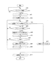
[従来の帯電ローラクリーニングの実施タイミング判断のフローチャート]
実施例1の制御と比較するために、従来の制御について説明する。図3は従来の帯電ローラクリーニングの実施タイミング判断のフローチャートである。ステップ(以下、sとする)400でエンジン制御部202は、シリアル通信線を介してコントローラ201からプリントコマンドを受信したか否かを判断する。s400でエンジン制御部202は、プリントコマンドを受信していないと判断した場合、処理をs400に戻し、プリントコマンドを受信したと判断した場合、処理をs401に進める。s401でエンジン制御部202は、帯電ローラクリーニングを実施するか否かを判断するためのカウンタpを0で初期化する。s402でエンジン制御部202は、画像形成動作を実行するために必要な準備動作(以下、前回転シーケンスという)を実施する。s403でエンジン制御部202は、画像形成動作が終了した後に実行される必要な動作(以下、後回転シーケンスという)の開始タイミングか否かを判断する。s403でエンジン制御部202は、後回転シーケンスを実行するタイミングではないと判断した場合、処理をs404に進め、後回転シーケンスを実行するタイミングであると判断した場合、処理をs410に進める。s410でエンジン制御部202は、非画像形成時であるため帯電ローラクリーニングを実施する。s411でエンジン制御部202は、後回転シーケンスを実行し、処理を終了する。
[Flowchart of conventional charging roller cleaning execution timing determination]
Conventional control will be described for comparison with the control of the first embodiment. FIG. 3 is a flowchart of a conventional timing determination of charging roller cleaning. In step (hereinafter referred to as s) 400,
s404でエンジン制御部202は、プリントコマンドを受信したか否かを判断する。s404でエンジン制御部202は、プリントコマンドを受信したと判断した場合、処理をs405に進め、プリントコマンドを受信していないと判断した場合、処理をs403に戻す。s405でエンジン制御部202は、画像形成シーケンスを実施する。画像形成シーケンス中は、同期センサ121から出力されたBD信号に基づいてエンジン制御部202からコントローラ201へ画像データの出力を指示する信号が出力される。s406でエンジン制御部202は、カウンタpを1インクリメントする(p=p+1)。これにより、s405で実行された画像形成シーケンスに対して帯電ローラクリーニングが実行されなかったことがカウンタpに反映される。s407でエンジン制御部202は、カウンタpの値が所定の閾値(例えば、50)を超えたか否かを判断する。s407でエンジン制御部202は、カウンタpの値が閾値以下であると判断した場合、処理をs403に戻し、画像形成を継続する。s407でエンジン制御部202は、カウンタpの値が閾値を超えたと判断した場合、処理をs408に進める。s408でエンジン制御部202は、帯電ローラクリーニングを実施する。s409でエンジン制御部202は、カウンタpを0で初期化し、処理をS403に戻して画像形成を再開する。
In S404, the
[帯電ローラへのトナー蓄積による影響]
図4は、帯電ローラ2に一時的に蓄積されているトナーの蓄積量(以下、トナー蓄積量という)と、帯電ローラ2による帯電処理後の感光ドラム1表面の電位(以下、帯電後ドラム電位という)との関係を示した図である。図4(i)は、縦線画像(感光ドラム1の回転方向(又は副走査方向)に伸びる画像)の印刷等で感光ドラム1の長手方向(主走査方向)の特定の位置P1(所定の位置)に画像を形成した場合のシートPに形成される画像の例を示す。図4(ii)は感光ドラム1と帯電ローラ2を示す要部模式図である。シートPの位置P1に対応する箇所で、感光ドラム1上の残トナー(グレー部分)は帯電ローラ2に蓄積される(黒部分)。図4(iii)は、縦軸に帯電ローラ2のトナー蓄積量を示し、横軸に長手方向の位置を示すグラフである。位置P1に縦線画像を形成し続けたため、帯電ローラ2の位置P1に対応する箇所でトナー蓄積量が多くなっている。図4(iv)は、縦軸に帯電後ドラム電位[−V]を示し、横軸に長手方向の位置を示すグラフである。帯電ローラ2に残トナーが蓄積されたことに起因して、感光ドラム1上の位置P1に対応する箇所における帯電後ドラム電位が必要な値を満たしておらず、一様ではないことがわかる。図4(v)は図4(i)に示す画像を形成し続けた場合に生じる画像不良の例を示す。その結果、シートPの位置P1において図示のような画像不良が発生するおそれがある。
[Effect of toner accumulation on charging roller]
FIG. 4 shows the amount of toner temporarily accumulated in the charging roller 2 (hereinafter, referred to as toner accumulation amount) and the potential on the surface of the
図4についてより詳細に説明する。図4(i)に示すようなシートP上の特定の位置P1に縦線画像を連続して形成する。そうすると、その画像を形成したプロセスカートリッジ9及びそのプロセスカートリッジ9よりも画像形成の工程において後続するプロセスカートリッジ9において、帯電ローラ2の長手方向でトナー蓄積量に差が生じる。帯電後ドラム電位は、帯電ローラ2のトナー蓄積量が大きいほど大きくなる傾向にある。このことから、帯電ローラ2の長手方向で蓄積量に差があった場合に、帯電後ドラム電位においても長手方向で電位差が生じる。そして、電位差が生じた感光ドラム1で長手方向に均一なパターンの画像を形成すると、強く帯電している箇所(位置P1に対応する箇所)で、画像が薄くなる画像不良が発生する。
FIG. 4 will be described in more detail. A vertical line image is continuously formed at a specific position P1 on the sheet P as shown in FIG. Then, in the
[縦線検知部]
実施例1のコントローラ201が有する縦線検知部210に関して、図5を用いて説明する。コントローラ201は、ホストコンピュータ200から図5(a)のような1ページ分の画像情報を受信すると、画像情報を解析してビットデータに変換する。コントローラ201は、変換したビットデータについて感光ドラム1の長手方向における画像形成可能領域Pgを、所定のドット幅、例えば5ドット幅の領域に分割する。以下、所定のドット幅に分割した分割領域をラインという。コントローラ201は、各ラインにおけるドット数をカウントする。図5(b)は、長手方向における画像形成可能領域Pgを、5ドット幅のラインに分割した様子を示す図である。ラインは、例えば、解像度600dpiの画像形成を行う画像形成装置において、レターサイズの幅(感光ドラム1の長手方向における幅)で1024ライン(0〜1023)存在する。1ページの画像データについて、分割後のラインの数は、解像度とシートPのサイズとに依存する。そして、コントローラ201は、1つのライン内のドットが副走査方向に連続する連続画像、すなわち縦線となるような画像である場合、次のような判断を行う。コントローラ201は、感光ドラム1の回転方向におけるドット数が例えば10000ドット以上(所定のドット数以上)連続している画像である場合は、縦線ありと判断する。
[Vertical line detector]
The vertical
コントローラ201は、回転方向におけるドット数が10000ドット未満(所定のドット数未満)の画像である場合は、縦線なしと判断する。コントローラ201は、このような判断を、各ラインについて行う。表1は、図5(b)に示す各ライン(0〜1023)に対して縦線あり(TRUE)か、縦線なし(FALSE)か、の判断を行った結果を示す表である。表1は、1列目にラインの番号、2列目に縦線有無の判断結果を示す。例えば、図5(b)で2ライン目に回転方向に略直交する方向にドット数が10000ドット以上連続する画像があるため、コントローラ201は「TRUE(縦線あり)」と判断している。

コントローラ201は、シリアル通信線を介して、全てのラインの判断結果(以下、縦線検知結果という)(表1)を、エンジン制御部202へのビットデータの送信を行うよりも前に、エンジン制御部202へ送信する。これにより、エンジン制御部202は、感光ドラム1上に画像を形成するよりも前に、形成する画像の縦線の有無に関する情報を把握することができる。以上、縦線検知部210は、レーザー光の走査を開始する開始位置からレーザー光の走査を終了する終了位置までの走査方向における領域を所定のドット幅を有する分割領域に分割する。縦線検知部210は、複数の分割領域のそれぞれについて連続画像が形成されるか否かを判断する。
The
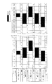
[BD信号の出力タイミングの操作]
実施例1の画像形成装置の特徴的な制御であるBD信号の出力タイミングの操作に関して、図6を用いて説明する。BD信号の出力タイミングの操作とは、上述した主走査方向における画像書き出し位置を主走査方向にずらす制御をいう。図6は、プリントジョブ中の各ラインの様子を示した図であり、横方向にライン(0〜1023)、縦方向にシートPの枚数(N−1枚目、N枚目、N+1枚目等)を示す。エンジン制御部202は、縦線を形成したラインをRAM212に記憶している。エンジン制御部202は、各ラインについて、複数ページにわたって連続して縦線を形成した数(以下、縦線形成数という)をカウントしているものとする。各セルは各ラインの縦線検知結果又は実際に縦線が形成されたか否かを示し、黒いセルがTRUE(縦線ありとなった、又は縦線が実際に形成された)、白いセルがFALSE(縦線なしとなった、又は縦線が形成されなかった)を示す。図6は、上から順番に次のようなことを意味している。「N−1(実施パターン)」は、前回N−1枚目のシートPに対して実施された印刷結果を示す。「N−1(実施)」は、前回N−1枚目のシートPに対して実施された印刷における、各ラインの縦線検知結果の積算のカウント値(以下、縦線形成数という)を示し、0以上の値となる。例えば、ライン4では、TRUE(縦線が実際に形成された)であっため、縦線形成数が「1」となっている。「N(コントローラ通知パターン)」は、今回N枚目に印刷するためのビットデータの送信が行われる前に、コントローラ201から通知された縦線検知結果を示す。「N(コントローラ通知)」は、今回N枚目の各ラインの縦線検知結果の積算の縦線形成数を示す。例えば、ライン4では、N−1枚目で縦線形成数が「1」であったため、今回の1が加算されて縦線形成数が「2」となっている。ライン3、5に関しては今回TRUEと判断されたため、「1」となっている。「N(実施パターン)」は、今回N枚目のシートPに対して実施された印刷結果を示す。ここで、N枚目のシートPに対して実施された印刷では、後述するBD信号の出力タイミングが操作されている。「N(実施)」は、BD信号の出力タイミングが操作された後の各ラインの縦線検知結果の積算の縦線形成数を示す。以降についてはNがN+1となる他は同様であるため、説明を省略する。
[Operation of output timing of BD signal]
The operation of the output timing of the BD signal, which is a characteristic control of the image forming apparatus according to the first embodiment, will be described with reference to FIG. The operation of the output timing of the BD signal refers to the control of shifting the image writing position in the main scanning direction in the main scanning direction described above. FIG. 6 is a diagram illustrating a state of each line in the print job, in which lines (0 to 1023) are arranged in the horizontal direction, and the number of sheets P (N−1, N, N + 1) in the vertical direction. Etc.). The
今回(N枚目)のプリントジョブにおいては、N−1枚目の印刷を終えた時点で、コントローラ201は、ライン4とライン1020で、上述した縦線検知部210による縦線検知によって縦線を検知している。そして、エンジン制御部202は、コントローラ201から、N枚目の印刷ではライン3、4、5、1018、1019、1020で縦線を形成するという判断結果を通知されている。そのため、ライン4とライン1020で再び縦線を形成することになる。エンジン制御部202は、カウントしている各ラインでの縦線形成数が所定数以上になると、前述したように、帯電ローラクリーニングを実施する必要があると判断する。帯電ローラクリーニングを頻繁に実施することは生産性を低下させることになるため、特定のラインでの縦線形成数が大きくなることは好ましくない。
In the print job of this time (N-th sheet), at the time when the printing of the (N-1) -th sheet is completed, the
そこで、エンジン制御部202は、ライン4の縦線形成数が増加しないように、BD信号の出力タイミングを操作し、感光ドラム1上の画像形成位置を操作する。なお、実施例1の画像形成装置おいては、BD信号の出力タイミングを操作することで感光ドラム1上の画像形成位置を操作する。しかし、BD信号の出力タイミングを操作しないで、コントローラ201が画像形成タイミングを操作することで画像形成位置を操作してもかまわない。この際、ライン4とライン1020の両方の縦線形成数が増加しないことが望ましいが、両方を増加させないよう操作できない場合もあるので、1つのラインを対象として、操作を行う。実施例1のエンジン制御部202は、主走査方向における上流側、すなわちシートPの左端に近いラインを対象とするようになっており、図6の場合にはライン4が対象となる。なお、主走査方向における下流側、すなわちシートPの右端に近いラインを対象としてもよい。以下、複数のライン(分割領域)の中で、縦線ありとなった回数が最も多くなった分割領域(例えば、ライン4やライン1020)を対象領域ともいう。
Therefore, the
ライン4で縦線を形成しないようにするために、エンジン制御部202は、コントローラ201によるライン3、5で縦線を形成するか否かの判断をする。図6の例では、ライン3、5共に縦線を形成する。このため、BD信号の出力タイミングを1ライン分遅く又は1ライン分早くしても、ライン4に縦線を形成することに変わりはなく、BD信号の出力タイミングの操作としては不十分と言える。そこで、エンジン制御部202は、コントローラ201によってライン2、6で縦線形成予定か否かを判断する。図6の例では、ライン2、6共に縦線を形成しないことから、BD信号の出力タイミングを、2ライン分遅くする。すなわち、もともと縦線を形成しないライン2を2ライン分遅らせて、ライン4を縦線を形成しない領域とする。なお、ライン6にも縦線が形成されないため、BD信号の出力タイミングを2ライン分早くしてもよい。すなわち、もともと縦線を形成しないライン6を2ライン分早くして、ライン4を縦線を形成しない領域としてもよい。これにより、ライン4の縦線形成数の増加を抑制することができる。「N(実施)」に示すように、BD信号の出力タイミングを操作したことにより、ライン4の縦線検知結果の縦線形成数は、コントローラ201から通知された時点では「2」であったものが「1」となっている。
In order not to form a vertical line on the
しかし、ライン1020に関しては、BD信号の出力タイミングを2ライン分遅くしてもライン1020に縦線を形成することに変わりはなく、ライン1020では縦線形成数が増加する(「2」のまま)。そのため、N枚目のプリントを終えた時点の縦線形成数が最大のラインはライン1020となり、エンジン制御部202は、N+1枚目においては、ライン1020を対象として、BD信号の出力タイミングを操作する。図6の例では、N+1枚目についてはBD信号の出力タイミングを1ライン分早くする。「N+1(実施)」に示すように、BD信号の出力タイミングを操作したことにより、ライン1020の縦線検知結果の縦線形成数は、コントローラ201から通知された時点では「3」であったものが「2」となっている。更に、N+2枚目(不図示)のプリントでは、縦線形成数の最大値は2でライン4とライン1020が該当するが、例えばライン4で縦線形成数が増えないようにBD信号の出力タイミングが操作される。
However, with respect to the
このように、エンジン制御部202は、各ページで縦線形成数が最大のラインで縦線を形成しないように、画像情報に応じて主走査方向の画像書き出し位置をずらすBD信号の出力タイミングの制御を行う。すなわち、エンジン制御部202は、縦線検知部210の縦線判断結果に基づいて走査方向におけるレーザー光の走査を開始する開始位置を決定する決定手段として機能する。これにより、全ラインの縦線形成数の最大数を小さくすることができる。結果として、帯電ローラ2のトナー蓄積量が多くなる箇所を分散し、帯電ローラクリーニングの頻度を抑制することができる。
As described above, the
[BD信号の出力タイミング判断のフローチャート]
上述したBD信号の出力タイミング判断の制御フローチャートを、図7を用いて説明する。なお、本判断は、エンジン制御部202がコントローラ201から各ラインの縦線形成の予定(縦線検知結果)を取得した後に実施される制御である。ここで、各ラインの縦線形成の予定(以下、縦線形成予定という)は、図6のN(コントローラ通知パターン)に相当する。s800でエンジン制御部202は、RAM212に記憶している各ラインの縦線形成数の情報に基づき、縦線形成数が最大となるラインを、今回の画像形成において縦線形成しないラインLとして決定する。例えば、図6のN枚目のシートPに印刷する場合、縦線形成数が最大のラインは、ライン4とライン1020であり、例えば走査方向における上流側のラインを選択するとすれば、L=4となる。s801でエンジン制御部202は、コントローラ201から取得した各ラインの縦線形成予定に基づいて、ラインLで縦線形成予定か否かを判断する。s801でエンジン制御部202は、縦線形成予定ではないと判断した場合、処理をs810に進める。s810でエンジン制御部202は、BD信号の出力タイミングを操作することなく(通常のタイミングで)BD信号を出力することを決定する。このようにエンジン制御部202は、対象領域に画像形成が行われない場合には、レーザー光の走査の開始位置をずらすことなく画像形成を行う。s811でエンジン制御部202は、コントローラ201からの各ラインの縦線形成予定に従って、RAM212に記憶している各ラインの縦線形成数に1を加算し、処理を終了する。すなわち、エンジン制御部202は、図6のN枚目やN+1枚目で説明したようなBD信号の出力タイミングを遅くしたり早くしたりして、形成する縦線を主走査方向にシフトさせる処理(以下、ラインシフトという)を行わない(ラインシフトなし)。
[Flowchart for judging output timing of BD signal]
A control flowchart for determining the output timing of the BD signal described above will be described with reference to FIG. Note that this determination is control performed after the
s801でエンジン制御部202は、ラインLで縦線形成予定であると判断した場合、処理をs802に進める。この場合、エンジン制御部202は、図6で説明したように、ラインLで縦線形成を行わないよう、主走査方向の画像書き出し位置を何ラインずらすかを判断していく。そこで、エンジン制御部202は、まずラインLの前後のラインL−1、L+1から縦線形成予定か否かを確認していく。
If the
s802でエンジン制御部202は、ラインLの前後のラインを示すiを1とする(i=1)。s803でエンジン制御部202は、ラインL−iで縦線形成予定か否かを判断する。s803でエンジン制御部202は、ラインL−iで縦線形成予定でないと判断した場合、処理をs808に進める。s808でエンジン制御部202は、BD信号の出力タイミングをiライン分遅らせてBD信号を出力することを決定する。すなわち、エンジン制御部202は、縦線を形成しないラインL−iをiライン分遅らせることで、ラインLを縦線を形成しない領域とする。s809でエンジン制御部202は、コントローラ201からの各ラインの縦線形成予定をiライン分遅らせて、RAM212に記憶している各ラインの縦線形成数に1を加算し、処理を終了する。以下、主走査方向における画像書き出し位置をiライン分遅らせる、すなわち、主走査方向の下流側に移動させることを、iラインプラスシフトともいう。
In s802, the
s803でエンジン制御部202は、ラインL−iで縦線形成予定であると判断した場合、処理をs804に進める。s804でエンジン制御部202は、ラインL+iで縦線形成予定か否かを判断する。s804でエンジン制御部202は、ラインL+iで縦線形成予定ではないと判断した場合、処理をs806に進める。s806でエンジン制御部202は、BD信号の出力タイミングをiライン分早めてBD信号を出力することを決定する。すなわち、エンジン制御部202は、縦線を形成しないラインL+iをiライン分早くして、ラインLを縦線を形成しない領域とする。s807でエンジン制御部202は、コントローラ201からの各ラインの縦線形成予定をiライン分早くして、RAM212に記憶している各ラインの縦線形成数に1を加算し、処理を終了する。以下、主走査方向における画像書き出し位置をiライン分早くする、すなわち、主走査方向の上流側に移動させることを、iラインマイナスシフトともいう。
If the
s804でエンジン制御部202は、ラインL+iで縦線形成予定であると判断した場合、処理をs805に進める。s805でエンジン制御部202は、現在のiではL−iでもL+iでも縦線形成予定であるため、iを1インクリメントする(i=i+1)。s812でエンジン制御部202は、iがシフト量S(例えば、S=10)未満であるか否かを判断する。s812の判断は、ラインシフトを行う量(以下、ラインシフト量という)が一定以上となる場合に、画像欠損が発生してしまうことを回避するためであり、エンジン制御部202は画像欠損が発生しない範囲でラインシフトを行う。実施例1の画像形成装置では、例えばシフト量Sが10以上になると画像欠損が発生するものとする。s812でエンジン制御部202は、iがシフト量S以上であると判断した場合、処理をs810に進める。この場合、更なるラインシフトを行うと画像欠損が発生してしまうため、s810、s811の処理を行い、ラインシフトを行うことなく処理を終了する。s803、s804の判断は、縦線画像があるラインLに隣接又は所定の範囲内で近接するラインL±iの中から縦線が形成されないライン(以下、非連続画像形成領域ともいう)を抽出する処理ともいえる。
If the
s812でエンジン制御部202は、iがシフト量S未満であると判断した場合、処理をs803に戻す。例えば、ライン4では、ラインL−i(ライン3)でもラインL+i(ライン5)でも縦線形成予定であるため、次のライン(ライン2、ライン6)への判断に進む。この場合、s803でエンジン制御部は、ラインL−i(ライン2)が縦線形成予定ではないため、s808でBD信号の出力タイミングを2ライン分遅くする。なお、エンジン制御部202は、ラインL−iがライン0よりも小さいラインを示す場合及びラインL+iがライン1023よりも大きいラインを示す場合、画像領域外となり縦線は形成されないので、縦線を形成しないラインとして扱う。
If the
以上の処理で、これから画像形成を行うシートPに対して、BD信号の出力タイミングが決定される。エンジン制御部202は、非連続画像形成領域が対象領域よりもレーザー光の走査の開始位置側の領域である場合は、レーザー光の走査の開始位置を終了位置の方向にずらす。エンジン制御部202は、非連続画像形成領域が対象領域よりもレーザー光の走査の終了位置側の領域である場合はレーザー光の走査の開始位置をその開始位置の方向にずらす。
Through the above processing, the output timing of the BD signal is determined for the sheet P on which image formation is to be performed. If the non-continuous image forming area is an area closer to the laser light scanning start position than the target area, the
[実施例1の帯電ローラクリーニングの実施タイミング判断のフローチャート]
図8は実施例1の帯電ローラクリーニングの実施タイミング判断のフローチャートである。なお、s900、s903、s904、s908、s912、s915、s916の処理は、図3のs400、s402、s403、s404、s408、s410、s411の処理と同様であり、説明を省略する。
[Flowchart for Judgment of Execution Timing of Charging Roller Cleaning of First Embodiment]
FIG. 8 is a flowchart for determining the execution timing of the charging roller cleaning of the first embodiment. The processing of s900, s903, s904, s908, s912, s915, and s916 is the same as the processing of s400, s402, s403, s404, s408, s410, and s411 in FIG.
s902でエンジン制御部202は、全ラインの縦線形成数をカウントするカウンタ(不図示)を0で初期化する。s904でエンジン制御部202は、後回転シーケンスの開始タイミングではないと判断した場合、処理をs905に進める。s905でエンジン制御部202は、コントローラ201から縦線形成予定に関する情報を取得済みか否かを判断する。s905でエンジン制御部202は、縦線形成予定に関する情報を取得済みではないと判断した場合、処理をs904に戻す。s905でエンジン制御部202は、縦線形成予定に関する情報を取得済みであると判断した場合、処理をs906に進める。s906でエンジン制御部202は、取得したタイミングでBD信号の出力タイミングの決定処理を実施する。s906で実施される制御は、図7を用いて前述したとおりであり、説明を省略する。
In s902, the
s907でエンジン制御部202は、後回転シーケンスの開始タイミングであるか否かを判断する。s907でエンジン制御部202は、後回転シーケンスの開始タイミングであると判断した場合、処理をs915に進める。s907でエンジン制御部202は、後回転シーケンスの開始タイミングではないと判断した場合、処理をs908に進める。なお、s908でエンジン制御部202は、プリントコマンドを受信していないと判断した場合、処理をs907に戻す。s909でエンジン制御部は、プリントコマンドを受信したタイミングで画像形成シーケンスを実施する。ここで、エンジン制御部202は、s906(図7)でのBD信号の出力タイミングの決定処理で決定したタイミング(通常か、遅らせるか、早めるか)に従って、BD信号の出力を行う。
In s907, the
s911でエンジン制御部202は、全ラインの縦線形成数のうちいずれかが閾値(所定の回数)(例えば、50)を超えているか否かを判断する。s911でエンジン制御部202は、少なくとも1つのラインについて縦線形成数が閾値を超えていると判断した場合、処理をs912に進める。s911でエンジン制御部202は、全てのラインで縦線形成数が閾値以下であると判断した場合、処理をs904に戻し、画像形成を継続する。s914でエンジン制御部202は、s912で帯電ローラクリーニングを実施したため、全ラインの縦線形成数をカウントするカウンタを0で初期化し、処理をs904に戻す。
In s911, the
以上のように、ページ毎に副走査方向に連なる画像の度合いを判断し、残トナーによる画像不良が発生しやすい画像パターン(例えば、縦線)であると判断した際には、画像書き出し位置を主走査方向にずらす。実施例1の画像形成装置は、感光ドラム1の長手方向における画像形成量の多い箇所で、副走査方向に連なる画像の形成を行わないように、画像情報に応じて主走査方向の画像書き出し位置をずらす制御を行う。これにより、帯電ローラにおけるトナー蓄積箇所を分散させて特定の箇所にトナーの蓄積が集中することを緩和し、帯電後ドラム電位の差が大きくなるまでの時間を遅らせる。これにより、従来の画像形成装置と比べて、帯電ローラクリーニングが実行される頻度を抑制することができる。その結果、良好な画像を保ちつつ、生産性の低下を抑制することができる。
As described above, the degree of an image connected in the sub-scanning direction is determined for each page, and when it is determined that the image pattern (for example, a vertical line) is likely to cause an image defect due to residual toner, the image writing position is determined. Shift in the main scanning direction. In the image forming apparatus of the first embodiment, the image writing position in the main scanning direction according to the image information is set so that an image continuous in the sub-scanning direction is not formed at a position where the amount of image formation in the longitudinal direction of the
以上、実施例1によれば、ドラムクリーナレス方式の画像形成装置において副走査方向に連なる画像を連続してプリントする場合でも、良好な画像を保ちつつ、帯電ローラクリーニングの実行頻度を下げることができる。 As described above, according to the first embodiment, it is possible to reduce the execution frequency of the charging roller cleaning while maintaining a good image even when continuously printing images connected in the sub-scanning direction in the drum cleanerless image forming apparatus. it can.
実施例1の画像形成装置は、シリアル信号線を介してコントローラ201から得られる、形成する画像の縦線の有無に関する情報に応じて、BD信号を操作して主走査方向における画像書き出し位置をずらした。これにより、実施例1では、帯電ローラクリーニングの実行頻度の抑制を可能にした。実施例2では、画像の縦線の有無をエンジン制御部202が検知する形態について説明する。エンジン制御部202が画像の縦線の有無を検知する場合、実施例1と異なり、縦線有無検知は当該ページの画像形成後になる。そこで、実施例2では、同じ画像を連続してプリントするケース(コピー、複数部印刷等)において、主走査方向における書き出し位置をずらす手法について説明する。実施例2の画像形成装置は、実施例1の図1と同じ構成の画像形成装置である。このため、実施例1の画像形成装置と異なる部分のみを説明し、同じ部分に関しては説明を省略する。
The image forming apparatus according to the first embodiment shifts the image writing position in the main scanning direction by operating the BD signal in accordance with information on the presence or absence of a vertical line of an image to be formed, which is obtained from the
[実施例2の画像形成装置のブロック図]
図9は、実施例2の画像形成装置のシステム構成全体を説明するためのブロック図である。図2で説明した構成と同じ構成には同じ符号を付し、説明を省略する。実施例2の画像形成装置は、コントローラ201がこれから形成する画像が1つ前に形成した画像と同じ画像か否かを判断する同一画像判断部211を有する。コントローラ201は、シリアル通信線を介して、同一画像判断部211による判断結果を、エンジン制御部202へのビットデータの送信を行うよりも前に、エンジン制御部202へ送信する。これにより、エンジン制御部202は、感光ドラム1上に画像を形成するよりも前に、これから感光ドラム1上に形成する画像とその1つ前に形成された画像とが同一か否かの情報を把握することができる。
[Block Diagram of Image Forming Apparatus of Second Embodiment]
FIG. 9 is a block diagram for explaining the entire system configuration of the image forming apparatus according to the second embodiment. The same components as those described with reference to FIG. 2 are denoted by the same reference numerals, and description thereof will be omitted. The image forming apparatus according to the second embodiment includes the same
また、実施例2の画像形成装置は、エンジン制御部202が縦線検知部210を有する。エンジン制御部202は、コントローラ201から画像信号線を介して送信されたビットデータに基づいて、実施例1の画像形成装置でコントローラ201が実行した処理と同様の方法で、縦線の有無を判断する。エンジン制御部202は、コントローラ201からビットデータを受信すると、感光ドラム1の長手方向の画像形成可能領域Pgを例えば5ドット幅の領域に分割し、各ラインにおけるドット数をカウントする。すなわち、実施例2では、図5で説明した処理をエンジン制御部202が実行する。縦線有無の判断は、図5を用いて説明した処理と同様であり、説明を省略する。エンジン制御部202は、実施例1と同様に、形成した画像の縦線の有無に関する情報を把握することができる。しかし、実施例1と異なり、エンジン制御部202は、感光ドラム1上に画像を形成するよりも前に、画像の縦線の有無に関する情報を把握することはできない。
In the image forming apparatus according to the second embodiment, the
[実施例1の帯電ローラクリーニングの実施タイミング判断のフローチャート]
図10は実施例2の帯電ローラクリーニングの実施タイミング判断のフローチャートである。図10では、実施例1の図8のフローチャートで説明した処理と同じ処理には同じステップ番号を付し、説明を省略する。s904でエンジン制御部202は、後回転シーケンスを開始するタイミングではないと判断した場合、処理をs925に進める。s925でエンジン制御部202は、コントローラ201の同一画像判断部211による同一画像の判断結果を取得済みか否かを判断する。s925でエンジン制御部202は、同一画像判断部211による判断結果を取得していないと判断した場合、処理をs904に戻し、取得したと判断した場合、処理をs917に進める。s917でエンジン制御部202は、取得した同一画像判断部211による判断結果に基づき、これからプリントする画像が1つ前に形成した画像と同じか否かを判断する。s917でエンジン制御部202は、これからプリントする画像と1つ前の画像とが同じであると判断した場合、処理をs906に進め、同じではないと判断した場合、処理をs918に進める。s918でエンジン制御部202は、これからプリントする画像が1つ前の画像と同じでないため、BD信号の出力タイミングをずらすことなく、通常のタイミングで出力することを決定し、処理をs907に進める。
[Flowchart for Judgment of Execution Timing of Charging Roller Cleaning of First Embodiment]
FIG. 10 is a flowchart for determining the execution timing of the charging roller cleaning according to the second embodiment. In FIG. 10, the same processes as those described in the flowchart of FIG. 8 of the first embodiment are denoted by the same step numbers, and description thereof will be omitted. If the
エンジン制御部202は、s909の画像形成シーケンス後、s919で、s925で取得した同一画像判断部211による判断結果が、これからプリントする画像が前の画像と同じか否かを判断する。なお、s919の時点では、s909で画像形成シーケンスが終了しているため、ここでいう「これからプリントする画像」とはs909で既にプリントが終了した画像を指す。s919でエンジン制御部202は、これからプリントする画像が前の画像と同じであると判断した場合、処理をs911に進め、同じではないと判断した場合、処理をs920に進める。s920でエンジン制御部202は、RAM212に記憶している各ラインの縦線形成数を、縦線検知部210によって検知した縦線形成数の情報によって更新し、処理をs911に進める。このように、コントローラ201の同一画像判断部211は、所定のページに形成される画像と所定のページの前のページに形成された画像とが一致するか否かを判断する。
After the image forming sequence in s909, the
以上のように、実施例2の画像形成装置は、感光ドラム1の長手方向の画像形成量の多い箇所で、搬送方向に連なる画像の形成を行わないように、画像情報に応じて主走査方向の画像書き出し位置をずらす制御を行う。これにより、帯電ローラ2のトナー蓄積箇所を分散し、帯電後ドラム電位の差が大きくなるまでの時間を遅らせることで、従来の画像形成装置と比べて、帯電ローラクリーニングの実行頻度を抑制することができる。
As described above, in the image forming apparatus according to the second embodiment, the main scanning direction is determined in accordance with the image information so as not to form an image continuous in the transport direction at a location where the image forming amount in the longitudinal direction of the
以上、実施例2によれば、ドラムクリーナレス方式の画像形成装置において副走査方向に連なる画像を連続してプリントする場合でも、良好な画像を保ちつつ、帯電ローラクリーニングの実行頻度を下げることができる。 As described above, according to the second embodiment, it is possible to reduce the execution frequency of the charging roller cleaning while maintaining a good image even when continuously printing images connected in the sub-scanning direction in the drum cleanerless type image forming apparatus. it can.
2 帯電ローラ
121 同期センサ
201 コントローラ
202 エンジン制御部
210 縦線検知部
2 Charging
Claims (13)
前記感光体を所定の電位に帯電する帯電手段と、
画像データに応じた光ビームを出射する光源を有し、画像データに応じた光ビームを前記回転方向に略直交する走査方向に走査することにより前記感光体上に潜像を形成する露光手段と、
前記露光手段によって形成された潜像をトナーにより現像しトナー像を形成する現像手段と、
前記現像手段により形成されたトナー像を像担持体に転写する転写手段と、
を備え、前記感光体上のトナー像を前記転写手段により前記像担持体に転写した後に前記感光体上に残ったトナーを前記帯電手段に一時的に蓄積させ、蓄積したトナーを前記帯電手段から除去するクリーニング制御を行う画像形成装置であって、
前記画像データに基づいて前記走査方向における前記感光体の所定の位置に前記回転方向に連続する連続画像が形成されることを判断する判断手段と、
複数のページに画像形成を行う場合に、前記判断手段の判断結果に基づいて前記走査方向における前記光ビームの走査を開始する開始位置をページ毎に決定する決定手段と、
を備えることを特徴とする画像形成装置。 A photoreceptor that rotates in a predetermined rotation direction,
Charging means for charging the photoconductor to a predetermined potential,
An exposure unit having a light source that emits a light beam corresponding to the image data, and forming a latent image on the photoconductor by scanning the light beam corresponding to the image data in a scanning direction substantially orthogonal to the rotation direction; ,
Developing means for developing the latent image formed by the exposure means with toner to form a toner image,
Transfer means for transferring the toner image formed by the developing means to an image carrier,
The toner remaining on the photoconductor after the toner image on the photoconductor is transferred to the image carrier by the transfer unit is temporarily accumulated in the charging unit, and the accumulated toner is transferred from the charging unit to the charging unit. An image forming apparatus that performs cleaning control for removing,
Determining means for determining that a continuous image continuous in the rotation direction is formed at a predetermined position of the photoconductor in the scanning direction based on the image data;
When performing image formation on a plurality of pages, a determination unit that determines a start position at which scanning of the light beam in the scanning direction is started for each page based on a determination result of the determination unit,
An image forming apparatus comprising:
前記決定手段は、前記複数のページにわたって前記連続画像が形成されると判断された回数を積算し、前記複数の分割領域の中で積算された前記回数が最も多くなった分割領域である対象領域に対して隣接又は所定の範囲内で近接する領域の中から前記連続画像が形成されない領域を抽出し、抽出された前記連続画像が形成されない領域が前記対象領域に移動するように前記開始位置をずらすことを特徴とする請求項2に記載の画像形成装置。 The determining means divides an area in the scanning direction from the start position to an end position at which scanning of the light beam ends, into divided areas having a predetermined dot width, and for each of the plurality of divided areas, To determine whether or not
The determining means accumulates the number of times that it is determined that the continuous image is formed over the plurality of pages, and is a target area that is a divided area having the largest number of times accumulated among the plurality of divided areas. An area where the continuous image is not formed is extracted from an area adjacent to or within a predetermined range, and the start position is set so that the area where the extracted continuous image is not formed moves to the target area. The image forming apparatus according to claim 2, wherein the image forming apparatus is shifted.
前記画像データを出力するコントローラと、
前記出力手段から前記信号が入力されたことに応じて前記画像データを出力するよう前記コントローラに指示する制御手段と、
を備えることを特徴とする請求項1から請求項6のいずれか1項に記載の画像形成装置。 Output means for outputting a signal in response to detecting a light beam emitted from the light source,
A controller that outputs the image data,
Control means for instructing the controller to output the image data in response to the signal being input from the output means,
The image forming apparatus according to any one of claims 1 to 6, further comprising:
前記決定手段は、所定のページの画像形成を行う前に、前記所定のページに形成される画像に対応する画像データに基づいて前記開始位置を決定することを特徴とする請求項7に記載の画像形成装置。 The controller has the determination unit,
The image forming apparatus according to claim 7, wherein the determining unit determines the start position based on image data corresponding to an image formed on the predetermined page before forming an image on the predetermined page. Image forming device.
前記決定手段は、所定のページの画像形成を行った後に、前記所定のページに形成された画像に対応する画像データに基づいて前記開始位置を決定することを特徴とする請求項7に記載の画像形成装置。 The control means has the determination means,
The image processing apparatus according to claim 7, wherein the determining unit determines the start position based on image data corresponding to an image formed on the predetermined page after forming an image on the predetermined page. Image forming device.
前記判断手段は、前記情報に基づいて前記開始位置を決定することを特徴とする請求項9に記載の画像形成装置。 The controller transmits information on whether or not an image formed on the predetermined page matches an image formed on a page before the predetermined page to the determination unit,
The image forming apparatus according to claim 9, wherein the determination unit determines the start position based on the information.
前記制御手段は、前記電圧供給手段を制御することにより前記クリーニング制御を行うことを特徴とする請求項7から請求項12のいずれか1項に記載の画像形成装置。 When accumulating toner in the charging unit, a voltage having a predetermined polarity is output so as to attract the toner to the charging unit, and when removing the toner from the charging unit, a voltage opposite to the predetermined polarity is output. A voltage supply means for outputting a voltage having a polarity,
13. The image forming apparatus according to claim 7, wherein the control unit performs the cleaning control by controlling the voltage supply unit.
Priority Applications (1)
| Application Number | Priority Date | Filing Date | Title |
|---|---|---|---|
| JP2018130024A JP2020008736A (en) | 2018-07-09 | 2018-07-09 | Image formation apparatus |
Applications Claiming Priority (1)
| Application Number | Priority Date | Filing Date | Title |
|---|---|---|---|
| JP2018130024A JP2020008736A (en) | 2018-07-09 | 2018-07-09 | Image formation apparatus |
Publications (1)
| Publication Number | Publication Date |
|---|---|
| JP2020008736A true JP2020008736A (en) | 2020-01-16 |
Family
ID=69151520
Family Applications (1)
| Application Number | Title | Priority Date | Filing Date |
|---|---|---|---|
| JP2018130024A Pending JP2020008736A (en) | 2018-07-09 | 2018-07-09 | Image formation apparatus |
Country Status (1)
| Country | Link |
|---|---|
| JP (1) | JP2020008736A (en) |
-
2018
- 2018-07-09 JP JP2018130024A patent/JP2020008736A/en active Pending
Similar Documents
| Publication | Publication Date | Title |
|---|---|---|
| US8068752B2 (en) | Image forming apparatus and method for controlling image forming apparatus | |
| US9856101B2 (en) | Sheet conveying device and image forming apparatus | |
| US20060127139A1 (en) | Image forming apparatus | |
| EP2775353B1 (en) | Electrophotographic image forming apparatus | |
| EP2019341B1 (en) | Image forming apparatus | |
| JP2013214047A (en) | Image forming apparatus | |
| US7747188B2 (en) | Image forming apparatus and secondary transfer roller cleaning method of the image forming apparatus | |
| US9939757B2 (en) | Image forming apparatus including a contact-separation mechanism | |
| JP2006235103A (en) | Image forming apparatus and its control program | |
| CN111722495B (en) | Print job switching method, image forming apparatus, and readable storage medium | |
| US8351826B2 (en) | Image forming method, image forming device, and image forming program | |
| JP6228109B2 (en) | Image forming apparatus | |
| JP2020008736A (en) | Image formation apparatus | |
| JP2001092202A (en) | Image-forming device | |
| US20110317190A1 (en) | Image forming apparatus | |
| JP5241651B2 (en) | Image forming apparatus | |
| JP2014077881A (en) | Image forming apparatus | |
| JP2008049694A (en) | Imaging device/method | |
| JP2013044790A (en) | Image forming apparatus | |
| JP7472456B2 (en) | Image forming device | |
| JP7215279B2 (en) | image forming device | |
| JP2005055624A (en) | Image forming apparatus | |
| JP2006293161A (en) | Image forming apparatus and its control program | |
| JP2007108587A (en) | Image forming apparatus | |
| JP2015090422A (en) | Cleaning device, process cartridge, image forming apparatus, and cleaning blade |