JP2020008561A - Device and method for presenting information and program - Google Patents
Device and method for presenting information and program Download PDFInfo
- Publication number
- JP2020008561A JP2020008561A JP2019071580A JP2019071580A JP2020008561A JP 2020008561 A JP2020008561 A JP 2020008561A JP 2019071580 A JP2019071580 A JP 2019071580A JP 2019071580 A JP2019071580 A JP 2019071580A JP 2020008561 A JP2020008561 A JP 2020008561A
- Authority
- JP
- Japan
- Prior art keywords
- image
- unit
- destination
- output control
- target
- Prior art date
- Legal status (The legal status is an assumption and is not a legal conclusion. Google has not performed a legal analysis and makes no representation as to the accuracy of the status listed.)
- Granted
Links
- 238000000034 method Methods 0.000 title claims abstract description 26
- 238000004891 communication Methods 0.000 claims description 29
- 238000009795 derivation Methods 0.000 claims description 15
- 230000033001 locomotion Effects 0.000 claims description 9
- 238000001514 detection method Methods 0.000 claims description 8
- 230000007423 decrease Effects 0.000 claims description 3
- 238000010586 diagram Methods 0.000 description 26
- 238000012545 processing Methods 0.000 description 17
- 238000003860 storage Methods 0.000 description 16
- 230000006870 function Effects 0.000 description 6
- 239000004973 liquid crystal related substance Substances 0.000 description 6
- 238000004519 manufacturing process Methods 0.000 description 5
- 238000003384 imaging method Methods 0.000 description 4
- 230000005484 gravity Effects 0.000 description 3
- 230000001133 acceleration Effects 0.000 description 2
- 230000000694 effects Effects 0.000 description 2
- 230000005389 magnetism Effects 0.000 description 2
- 238000010295 mobile communication Methods 0.000 description 2
- 230000001413 cellular effect Effects 0.000 description 1
- 239000003086 colorant Substances 0.000 description 1
- 230000000295 complement effect Effects 0.000 description 1
- 238000005401 electroluminescence Methods 0.000 description 1
- 230000008451 emotion Effects 0.000 description 1
- 238000005516 engineering process Methods 0.000 description 1
- 238000011156 evaluation Methods 0.000 description 1
- 230000010354 integration Effects 0.000 description 1
- 238000004900 laundering Methods 0.000 description 1
- 229910044991 metal oxide Inorganic materials 0.000 description 1
- 150000004706 metal oxides Chemical class 0.000 description 1
- 238000012986 modification Methods 0.000 description 1
- 230000004048 modification Effects 0.000 description 1
- 238000009877 rendering Methods 0.000 description 1
- 239000004065 semiconductor Substances 0.000 description 1
- 238000006467 substitution reaction Methods 0.000 description 1
- 230000029305 taxis Effects 0.000 description 1
Images


Classifications
-
- G—PHYSICS
- G01—MEASURING; TESTING
- G01C—MEASURING DISTANCES, LEVELS OR BEARINGS; SURVEYING; NAVIGATION; GYROSCOPIC INSTRUMENTS; PHOTOGRAMMETRY OR VIDEOGRAMMETRY
- G01C21/00—Navigation; Navigational instruments not provided for in groups G01C1/00 - G01C19/00
- G01C21/26—Navigation; Navigational instruments not provided for in groups G01C1/00 - G01C19/00 specially adapted for navigation in a road network
- G01C21/34—Route searching; Route guidance
- G01C21/36—Input/output arrangements for on-board computers
- G01C21/3626—Details of the output of route guidance instructions
- G01C21/3635—Guidance using 3D or perspective road maps
- G01C21/3638—Guidance using 3D or perspective road maps including 3D objects and buildings
-
- G—PHYSICS
- G01—MEASURING; TESTING
- G01C—MEASURING DISTANCES, LEVELS OR BEARINGS; SURVEYING; NAVIGATION; GYROSCOPIC INSTRUMENTS; PHOTOGRAMMETRY OR VIDEOGRAMMETRY
- G01C21/00—Navigation; Navigational instruments not provided for in groups G01C1/00 - G01C19/00
- G01C21/26—Navigation; Navigational instruments not provided for in groups G01C1/00 - G01C19/00 specially adapted for navigation in a road network
- G01C21/34—Route searching; Route guidance
- G01C21/36—Input/output arrangements for on-board computers
- G01C21/3626—Details of the output of route guidance instructions
- G01C21/365—Guidance using head up displays or projectors, e.g. virtual vehicles or arrows projected on the windscreen or on the road itself
-
- G—PHYSICS
- G01—MEASURING; TESTING
- G01C—MEASURING DISTANCES, LEVELS OR BEARINGS; SURVEYING; NAVIGATION; GYROSCOPIC INSTRUMENTS; PHOTOGRAMMETRY OR VIDEOGRAMMETRY
- G01C21/00—Navigation; Navigational instruments not provided for in groups G01C1/00 - G01C19/00
- G01C21/26—Navigation; Navigational instruments not provided for in groups G01C1/00 - G01C19/00 specially adapted for navigation in a road network
- G01C21/265—Navigation; Navigational instruments not provided for in groups G01C1/00 - G01C19/00 specially adapted for navigation in a road network constructional aspects of navigation devices, e.g. housings, mountings, displays
-
- G—PHYSICS
- G01—MEASURING; TESTING
- G01C—MEASURING DISTANCES, LEVELS OR BEARINGS; SURVEYING; NAVIGATION; GYROSCOPIC INSTRUMENTS; PHOTOGRAMMETRY OR VIDEOGRAMMETRY
- G01C21/00—Navigation; Navigational instruments not provided for in groups G01C1/00 - G01C19/00
- G01C21/26—Navigation; Navigational instruments not provided for in groups G01C1/00 - G01C19/00 specially adapted for navigation in a road network
- G01C21/28—Navigation; Navigational instruments not provided for in groups G01C1/00 - G01C19/00 specially adapted for navigation in a road network with correlation of data from several navigational instruments
-
- G—PHYSICS
- G01—MEASURING; TESTING
- G01C—MEASURING DISTANCES, LEVELS OR BEARINGS; SURVEYING; NAVIGATION; GYROSCOPIC INSTRUMENTS; PHOTOGRAMMETRY OR VIDEOGRAMMETRY
- G01C21/00—Navigation; Navigational instruments not provided for in groups G01C1/00 - G01C19/00
- G01C21/26—Navigation; Navigational instruments not provided for in groups G01C1/00 - G01C19/00 specially adapted for navigation in a road network
- G01C21/34—Route searching; Route guidance
- G01C21/36—Input/output arrangements for on-board computers
- G01C21/3605—Destination input or retrieval
-
- G—PHYSICS
- G01—MEASURING; TESTING
- G01C—MEASURING DISTANCES, LEVELS OR BEARINGS; SURVEYING; NAVIGATION; GYROSCOPIC INSTRUMENTS; PHOTOGRAMMETRY OR VIDEOGRAMMETRY
- G01C21/00—Navigation; Navigational instruments not provided for in groups G01C1/00 - G01C19/00
- G01C21/26—Navigation; Navigational instruments not provided for in groups G01C1/00 - G01C19/00 specially adapted for navigation in a road network
- G01C21/34—Route searching; Route guidance
- G01C21/36—Input/output arrangements for on-board computers
- G01C21/3626—Details of the output of route guidance instructions
- G01C21/3644—Landmark guidance, e.g. using POIs or conspicuous other objects
-
- G—PHYSICS
- G06—COMPUTING; CALCULATING OR COUNTING
- G06T—IMAGE DATA PROCESSING OR GENERATION, IN GENERAL
- G06T19/00—Manipulating 3D models or images for computer graphics
- G06T19/20—Editing of 3D images, e.g. changing shapes or colours, aligning objects or positioning parts
Abstract
Description
本発明は、情報提示装置、情報提示方法、及びプログラムに関する。 The present invention relates to an information presentation device, an information presentation method, and a program.
従来、地図上に走行経路を表示する技術が開示されている(例えば、特許文献1参照)。また、従来、走行経路を示す仮想的な線を実空間に重畳して表示する技術が開示されている(例えば、特許文献2参照)。 2. Description of the Related Art Conventionally, a technique for displaying a travel route on a map has been disclosed (for example, see Patent Document 1). Further, conventionally, a technology has been disclosed in which a virtual line indicating a traveling route is displayed so as to be superimposed on a real space (for example, see Patent Document 2).
従来の技術による地図上の走行経路の表示や、走行経路を示す仮想的な線の表示では、目標位置の方向を直感的に把握することが困難であった。 It is difficult to intuitively grasp the direction of the target position by displaying the traveling route on the map or displaying the virtual line indicating the traveling route according to the related art.
本発明は、このような事情を考慮してなされたものであり、目標位置までの方向を直感的に把握することを支援する情報提示装置、情報提示方法、及びプログラムを提供することを目的の一つとする。 The present invention has been made in view of such circumstances, and has as its object to provide an information presenting apparatus, an information presenting method, and a program that support intuitively grasping a direction to a target position. One.
この発明に係る情報提示装置、情報提示方法、及びプログラムは、以下の構成を採用した。
(1):この発明の一態様に係る情報提示装置は、現在位置取得部の現在位置を取得する現在位置取得部と、実空間の風景に重畳して見える像を出現させる像生成部と、前記像を出現させる前記実空間上の目標位置を取得する目標位置取得部と、前記現在位置と前記目標位置とに基づいて、前記現在位置から前記目標位置の方向を導出する方向導出部と、前記像生成部を制御し、前記方向導出により取得された方向に基づき前記像を出現させる出力制御部と、を備える情報提示装置。
An information presentation device, an information presentation method, and a program according to the present invention employ the following configurations.
(1): An information presentation device according to an aspect of the present invention includes a current position acquisition unit that acquires a current position of a current position acquisition unit, an image generation unit that causes an image to appear to be superimposed on a scene in a real space, and A target position acquisition unit that acquires a target position in the real space where the image appears, a direction deriving unit that derives a direction of the target position from the current position based on the current position and the target position, An information presentation device, comprising: an output control unit that controls the image generation unit and causes the image to appear based on a direction acquired by the direction derivation.
(2):(1)の態様において、前記目標位置と前記現在位置との距離を導出する距離導出部を更に備え、前記出力制御部は、前記距離が小さくなるほど、前記像を大きくするもの。 (2): In the aspect of (1), further comprising a distance deriving unit for deriving a distance between the target position and the current position, wherein the output control unit enlarges the image as the distance decreases.
(3):(2)の態様において、前記出力制御部は、前記距離が所定距離以上である場合、前記像のサイズを所定のサイズに固定するもの。 (3): In the aspect of (2), the output control section fixes the size of the image to a predetermined size when the distance is equal to or longer than a predetermined distance.
(4):(1)〜(3)の態様において、前記像生成部は、地面から鉛直方向に延びる像を出現させることを含む。 (4): In the aspect of (1) to (3), the image generation unit includes causing an image extending vertically from the ground to appear.
(5):(1)〜(4)の態様において、前記出力制御部は、前記現在位置から前記目標位置より奥の風景を遮蔽し、且つ前記現在位置から前記目標位置より手前の風景を遮蔽しない前記像を出現させるもの。 (5): In the aspect of (1) to (4), the output control unit shields a scenery behind the target position from the current position and shields a scenery before the target position from the current position. Not to make the image appear.
(6):(1)〜(5)の態様において、実空間の状況を認識する実空間認識部を更に備え、前記出力制御部は、前記実空間認識部によって認識された前記実空間の状況に応じて、前記像の態様を決定するもの。 (6): In the aspect of (1) to (5), the apparatus further includes a real space recognizing unit that recognizes a real space situation, and the output control unit is configured to recognize the real space situation recognized by the real space recognizing unit. Determining the aspect of the image in accordance with
(7):(6)の態様において、前記実空間認識部は、実空間における風の動きを認識し、前記出力制御部は、前記風の動きに応じて前記像を動かすもの。 (7): In the aspect of (6), the real space recognition section recognizes a wind movement in a real space, and the output control section moves the image according to the wind movement.
(8):(1)〜(7)の態様において、情報提示装置は、ユーザの操作の内容を認識する操作認識部を更に備え、前記出力制御部は、前記操作の内容に基づいて、前記像を移動させ、または消去するもの。 (8): In the aspect of (1) to (7), the information presentation device further includes an operation recognizing unit that recognizes a content of a user's operation, and the output control unit performs the operation based on the content of the operation. What moves or erases an image.
(9):(1)〜(8)の態様において、情報提示装置は、ユーザの視線を検出する視線検出部と、前記視線検出部の検出結果が、前記ユーザが前記像を視認していないことを示す場合、前記ユーザに前記目標位置の方向を示す情報を出力する報知部と、を更に備える。 (9): In the aspect of (1) to (8), in the information presentation device, the gaze detection unit that detects the gaze of the user, and the detection result of the gaze detection unit does not visually recognize the image of the user. A notification unit that outputs information indicating the direction of the target position to the user.
(10):(1)〜(9)の態様において、前記目標位置は、ユーザの目的地を含む。 (10): In the aspect of (1) to (9), the target position includes a destination of the user.
(11):(1)〜(10)の態様において、前記目標位置は、ユーザによって指定された対象人物の位置を含む。 (11): In the aspect of (1) to (10), the target position includes a position of the target person specified by the user.
(12):(11)の態様において、前記出力制御部は、前記対象人物の状態に応じて、前記像の態様を決定するもの。 (12): In the aspect of (11), the output control section determines an aspect of the image according to a state of the target person.
(13):(1)〜(12)の態様において、前記目標位置は、ユーザによって指定された対象車両の位置を含む。 (13): In the aspect of (1) to (12), the target position includes a position of the target vehicle specified by the user.
(14):(13)の態様において、前記ユーザによる前記対象車両に対する操作の内容を認識する操作認識部と、他の装置と通信する通信部とを備え、前記通信部は、前記操作の内容を示す情報を前記他の装置に送信するもの。 (14): In the mode of (13), further comprising: an operation recognizing unit for recognizing the content of the operation on the target vehicle by the user, and a communication unit for communicating with another device, wherein the communication unit is configured to perform the operation. Transmitting information indicating the above to the other device.
(15):(14)の態様において、前記出力制御部は、前記操作認識部の認識結果に基づいて、前記像の態様を決定するもの。 (15): In the aspect of (14), the output control section determines the mode of the image based on a recognition result of the operation recognition section.
(16):この発明の一態様に係る情報提示方法は、表示部と、所定のユーザが実空間の風景に重畳して見える像を出現させる像生成部とを備える出力制御システムのコンピュータが、前記表示部の現在位置を取得し、前記像を出現させる前記実空間上の目標位置を取得し、前記現在位置と前記目標位置とに基づいて、前記現在位置から前記目標位置の方向を導出し、前記像生成部を制御し、前記方向に前記像を出現させる。 (16): In an information presentation method according to an aspect of the present invention, a computer of an output control system that includes a display unit and an image generation unit that causes a predetermined user to appear as an image superimposed on a scene in real space includes: Obtain the current position of the display unit, obtain a target position in the real space where the image appears, and derive the direction of the target position from the current position based on the current position and the target position. , Controlling the image generation unit to cause the image to appear in the direction.
(17):この発明の一態様に係るプログラムは、表示部と、所定のユーザが実空間の風景に重畳して見える像を出現させる像生成部とを備える出力制御システムのコンピュータに、前記表示部の現在位置を取得させ、前記像を出現させる前記実空間上の目標位置を取得させ、前記現在位置と前記目標位置とに基づいて、前記現在位置から前記目標位置の方向を導出させ、前記像生成部を制御させ、前記方向に前記像を出現させる。 (17): The program according to an aspect of the present invention provides a computer for an output control system including: a display unit; and an image generation unit that causes a predetermined user to generate an image that appears to be superimposed on a scene in real space. The current position of the unit is obtained, the target position in the real space where the image appears is obtained, and based on the current position and the target position, the direction of the target position is derived from the current position, The image generator is controlled to cause the image to appear in the direction.
(1)〜(17)によれば、目標位置の方向を直感的に把握することができる。 According to (1) to (17), the direction of the target position can be intuitively grasped.
(2)によれば、目標位置の距離を直感的に把握することができる。 According to (2), the distance to the target position can be grasped intuitively.
(3)によれば、目標位置を把握しづらくなることを抑制することができる。 According to (3), it is possible to suppress the difficulty in grasping the target position.
(5)によれば、目標位置の遠近感を演出することができる。 According to (5), a sense of perspective at the target position can be produced.
(6)によれば、より現実感のある目標位置の案内を行うことができる。 According to (6), more realistic guidance of the target position can be performed.
(8)によれば、目標位置の変更を容易に行うことができる。 According to (8), the target position can be easily changed.
(9)によれば、目標位置を視認する以外の方法によって把握することができる。 According to (9), the target position can be grasped by a method other than visually recognizing the target position.
以下、図面を参照し、本発明の情報提示装置、情報提示方法、及びプログラムの実施形態について説明する。 Hereinafter, embodiments of an information presentation device, an information presentation method, and a program of the present invention will be described with reference to the drawings.
<第1実施形態>
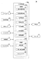
図1は、第1実施形態の出力制御システム1の構成の一例を示す図である。出力制御システム1は、カメラ10と、ナビゲーション装置20と、車両センサ30と、像生成部40と、情報提示装置100とを備える。以下、出力制御システム1が、車両(以下、自車両M)に搭載される場合について説明する。自車両Mは、例えば、二輪や三輪、四輪等の車両である。
<First embodiment>
FIG. 1 is a diagram illustrating an example of a configuration of an
カメラ10は、例えば、CCD(Charge Coupled Device)やCMOS(Complementary Metal Oxide Semiconductor)等の固体撮像素子を利用したデジタルカメラである。カメラ10は、自車両Mの任意の箇所に取り付けられる。カメラ10は、例えば、前方を撮像する場合、フロントウインドシールド上部やルームミラー裏面等に取り付けられる。カメラ10は、例えば、周期的に繰り返し自車両Mの周辺を撮像する。カメラ10は、ステレオカメラであってもよい。
The
ナビゲーション装置20は、例えば、GNSS(Global Navigation Satellite System)受信機21と、ナビHMI(Human Machine Interface)22と、経路決定部23とを備える。ナビゲーション装置20は、HDD(Hard Disk Drive)やフラッシュメモリなどの記憶装置に第1地図情報24を保持している。
The
GNSS受信機21は、GNSS衛星から受信した信号に基づいて、自車両Mの現在位置を特定する。自車両Mの現在位置は、車両センサ30の出力を利用したINS(Inertial Navigation System)によって特定または補完されてもよい。また、GNSS受信機21は、GNSS衛星から受信した信号に基づいて、自車両Mの現在位置を特定する構成に代えて(又は、加えて)自車両Mの乗員の現在位置を特定する構成であってもよい。例えば、GNSS受信機21は、GNSS衛星から受信した信号に基づいて特定された位置を、乗員の位置として取得する。なお、GNSS受信機21は、GNSS衛星から受信した信号によって特定された位置を、シートの着座センサや車内カメラによって検出された乗員の位置によって補正することにより乗員の現在位置を特定してもよい。
The
ナビHMI22は、表示装置、スピーカ、タッチパネル、キーなどを含む。ナビHMI22には、自車両Mの乗員によって目的地(以下、目的地DP)が入力される。自車両Mが他のHMIを備えている場合、ナビHMI22は、他のHMI装置と機能の一部又は全部が共通化されてもよい。目的地DPは、「目標位置」の第1例である。目的地DPを示す情報は、情報提示装置100に出力される。以降の説明において、自車両Mの乗員を単に乗員と記載する。
The
経路決定部23は、例えば、GNSS受信機21により特定された自車両Mの位置(或いは入力された任意の位置)から、ナビHMI22に入力された目的地DPまでの経路を、第1地図情報24を参照して決定する。第1地図情報24は、例えば、道路を示すリンクと、リンクによって接続されたノードとによって道路形状が表現された情報である。第1地図情報24は、道路の曲率やPOI(Point Of Interest)情報などを含んでもよい。
For example, the
ナビゲーション装置20は、地図上経路に基づいて、ナビHMI22を用いた経路案内を行ってもよい。ナビゲーション装置20は、例えば、乗員の保有するスマートフォンやタブレット端末等の端末装置の機能によって実現されてもよい。ナビゲーション装置20は、通信装置(不図示)を介してナビゲーションサーバに現在位置と目的地を送信し、ナビゲーションサーバから地図上経路と同等の経路を取得してもよい。
The
車両センサ30は、自車両Mの速度を検出する車速センサ、加速度を検出する加速度センサ、鉛直軸回りの角速度を検出するヨーレートセンサ、自車両Mの向きを検出する方位センサ等を含む。また、車両センサ30は、例えば、地磁気を検出し、自車両Mの進行方向の方位を検出する。具体的には、車両センサ30は、自車両Mの基準点(例えば、重心)を通る基準線であり、基準点と自車両Mの前方とを結ぶ基準線の方位を検出する。方位を示す情報は、情報提示装置100に出力される。
The
像生成部40は、実空間の風景に重畳して見える像(以下、像VI)を出現させる。像生成部40は、例えば、フロントウィンドウ、又はフロンウィンドウ付近に表示されるヘッドアップディスプレイ(HUD:Head-Up Display)や、フロントウィンドウ、又はフロントウィンドウ付近に設けられる透明液晶ディスプレイによって実現される。像生成部40は、情報提示装置100の制御に基づいて像VIを出現させる。なお、像生成部40は、フロントウィンドウに限らず、サイドウインドウやリアウィンドウ(及びその付近)に設けられているヘッドアップディスプレイや透明液晶ディスプレイによって実現されてもよく、ナビやメーター等として用いられるヘッドアップディスプレイや透明液晶ディスプレイによって実現されてもよい。また、自車両Mが二輪、或いは三輪の場合には、HUDや透明液晶ディスプレイがフロントウィンドウに代えてカウルに設けられていてもよく、透明液晶ディスプレイがヘルメットのシールドに設けられる構成であってもよい。なお、像生成部40によって出現される像が表示される出現対象(フロントウィンドウやパネル等)は、「表示部」の一例である。
The
情報提示装置100は、例えば、制御部120と、記憶部200とを備える。制御部120は、例えば、現在位置取得部121と、目標位置取得部122と、方向導出部124と、距離導出部126と、出力制御部128とを備える。これらの制御部120の各部は、例えば、CPU(Central Processing Unit)などのハードウェアプロセッサが記憶部200に格納されたプログラム(ソフトウェア)を実行することにより実現される。また、これらの構成要素のうち一部または全部は、LSI(Large Scale Integration)やASIC(Application Specific Integrated Circuit)、FPGA(Field-Programmable Gate Array)、GPU(Graphics Processing Unit)などのハードウェア(回路部;circuitryを含む)によって実現されてもよいし、ソフトウェアとハードウェアの協働によって実現されてもよい。
The
記憶部200は、例えば、HDD、フラッシュメモリ、EEPROM(Electrically Erasable Programmable Read Only Memory)、ROM(Read Only Memory)又はRAM(Random Access Memory)などの非一過性記憶媒体により実現される。記憶部200は、例えば、ハードウェアプロセッサによって読み出されて実行されるプログラムを格納する。また、記憶部200には、例えば、像生成部40によって像VIとして出現される画像である重畳画像202が記憶される。重畳画像202は、例えば、鉛直方向に物体が延びているように乗員に視認させる画像の画像データ、或いは画像を生成するための要素データである。以降の説明では、重畳画像202がのろしの画像に関するデータであり、像生成部40によって出現される像VIが、のろしの像である場合について説明する。
The
現在位置取得部121は、GNSS受信機21から自車両Mの現在位置を示す情報を取得する。目標位置取得部122は、ナビゲーション装置20から目的地DPを取得する。
The current
方向導出部124は、現在位置取得部121によって取得された自車両Mの現在位置と、目標位置取得部122によって取得された目的地DPと、車両センサ30によって検出された自車両Mの基準線の方位とに基づいて、自車両Mに対する目的地DPの方向を導出する。
The
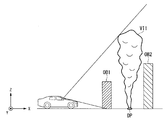
図2は、第1実施形態の方向導出部124の処理の一例を模式的に示す図である。方向導出部124は、自車両Mの現在位置と、目的地DPと、自車両Mの基準線の方位とに基づいて、自車両Mの現在位置と目的地DPとを結ぶ線分と、自車両Mの基準線とのなす角度を、自車両Mに対する目的地DPの方位角(以下、目的地方位角ψ1)として導出する。方位角は、例えば、自車両Mの基準点(例えば、重心)を鉛直方向に通る軸周りの角度であり、自車両Mの基準線(例えば車両中心軸)に沿う方向を0度として時計回りに正の値をとる角度である。
FIG. 2 is a diagram schematically illustrating an example of a process of the
図1に戻り、距離導出部126は、現在位置取得部121によって取得された自車両Mの現在位置と、目標位置取得部122によって取得された目的地DPとに基づいて、現在位置から目的地DPまでの距離(以下、目的地距離L1)を導出する。
Returning to FIG. 1, the
出力制御部128は、方向導出部124によって導出された目的地方位角ψ1と、距離導出部126によって導出された目的地距離L1とに基づいて、実空間に重畳して目的地像VI1を出現させるように、像生成部40を制御する。目的地像VI1は、例えば、目的地DPの方向と目的地DPの距離とを示す像VIであり、目的地DPの地面から鉛直方向にのろしが延びているように乗員に視認させる像VIである。また、以降の説明では、出力制御部128が像生成部40を制御し、像VIを出現させることを、出力制御部128が像VIを出現させるとも記載する。
The
[目的地DPを示す目的地像VI1について]
図3は、像生成部40によって出現される目的地像VI1aの一例を示す図である。図3に示される目的地方位角ψ1aは、目的地方位角ψ1に対応し、目的地距離L1aは、目的地距離L1に対応する。
[About destination image VI1 indicating destination DP]
FIG. 3 is a diagram illustrating an example of the destination image VI1a appearing by the
出力制御部128は、例えば、目的地方位角ψ1aの方向であり、かつ現在位置から目的地距離L1a離れた目的地DPに存在すると見えるように目的地像VI1aを出現させる。これにより、乗員は、目的地DPまでの距離と、目的地DPの方向を直感的に把握することができる。
The
[目的地DPを示す目的地像VI1について:目的地距離L1が短い場合]
図4は、図3よりも目的地距離L1が近い場合に像生成部40によって出現させる目的地像VI1の一例を示す。図4に示される目的地方位角ψ1bは、目的地方位角ψ1に対応し、目的地距離L1bは、目的地距離L1に対応する。目的地像VI1bは、自車両Mの現在位置において出現される目的地像VI1である。図3に示される一例の自車両Mの現在位置と、図4に示される一例の自車両Mの現在位置とは、互いに異なり、目的地距離L1aと、目的地距離L1bとでは、目的地距離L1bの方が短い距離である。
[Destination image VI1 indicating destination DP: destination distance L1 is short]
FIG. 4 shows an example of a destination image VI1 that is made to appear by the
出力制御部128は、像生成部40を制御し、目的地像VI1のサイズを目的地距離L1に応じて決定して出現させ、乗員による目的地像VI1の視認のされ方を演出する。出力制御部128は、例えば、目的地距離L1が遠い場合、目的地像VI1を小さく出現させ、目的地距離L1が近い場合、目的地像VI1を大きく出現させる。したがって、目的地像VI1bは、目的地像VI1aよりも大きいサイズによって示される。具体的には、出力制御部128は、重畳画像202を拡大して示した目的地像VI1bを出現させる。これにより、乗員は、目的地DPまでの目的地距離L1を直感的に把握することができる。
The
[目的地DPを示す目的地像VI1について:目的地距離L1が長い場合]
図5は、図3よりも目的地距離L1が遠い場合に像生成部40によって出現させる目的地像VI1の一例を示す。図5に示される目的地方位角ψ1cは、目的地方位角ψ1に対応し、目的地距離L1cは、目的地距離L1に対応する。図3に示される一例の自車両Mの現在位置と、図5に示される一例の自車両Mの現在位置とは、互いに異なり、目的地距離L1aと、目的地距離L1cとでは、目的地距離L1cの方が長い距離である。
[Destination image VI1 indicating destination DP: destination distance L1 is long]
FIG. 5 shows an example of a destination image VI1 that is made to appear by the
上述したように、出力制御部128は、例えば、目的地距離L1が大きい場合、目的地像VI1を小さく出現させ、乗員による目的地像VI1の視認のされ方を演出するが、目的地距離L1の値が大きい場合には、目的地像VI1が小さく出現され過ぎて、乗員が視認できなくなってしまう場合がある。これに伴い、出力制御部128は、目的地距離L1が所定距離以上である場合、目的地像VI1のサイズを所定のサイズ(例えば、目的地像VI1aのサイズ)に固定する。換言すると、出力制御部128は、目的地距離L1a以上の位置(例えば、目的地距離L1cの位置)から、目的地距離L1a未満となる位置に移動するまでの間、目的地像VI1aを出現させ、目的地距離L1a未満の位置では、目的地距離L1に応じた大きさの目的地像VI1を出現させる。これにより、乗員が目的地DPまでの目的地距離L1を把握しづらくなることを抑制しつつ、乗員が目的地像VI1を遠くからも直感的に把握することができる。
As described above, for example, when the destination distance L1 is large, the
[実空間の状況に応じた目的地像VI1の演出について:天候等の外部状況]
図6は、自車両Mの外部状況に応じた目的地像VI1の一例を示す図である。出力制御部128は、例えば、自車両Mの外部状況に応じて、乗員による目的地像VI1の視認のされ方を演出する。外部状況とは、例えば、自車両Mの周囲環境の天候等である。車両センサ30は、例えば、自車両Mの周囲環境における風向きを検出し、出力制御部128は、車両センサ30によって検出された風向きに応じて、風向きの方向にのろしが流れているように視認されるような目的地像VI1(図示する目的地像VI1c)を出現させる。これにより、出力制御システム1は、乗員に、より現実感のある像を提供しつつ目的地DPの案内を行うことができる。
[About production of destination image VI1 according to the situation of real space: external situation such as weather]
FIG. 6 is a diagram illustrating an example of the destination image VI1 according to the external situation of the host vehicle M. The
なお、自車両Mの周囲環境の天候は、風向きに限られず、出力制御部128は、他の天候に応じた目的地像VI1を像生成部40に出現させてもよい。出力制御部128は、例えば、霧が発生している場合や雨が降っている場合、乗員に視認されにくいような目的地像VI1を像生成部40に出現させてもよい。
In addition, the weather of the surrounding environment of the own vehicle M is not limited to the wind direction, and the
[実空間の状況に応じた目的地像VI1の演出について:建物等の物体]
図7は、自車両Mの周囲の建物と、目的地像VI1との関係の一例を側面から示す図である。図8は、自車両Mの周囲の建物と、目的地像VI1との関係の一例を正面から示す図である。図7及び図8に示されるX方向は、自車両Mの前方であり、Y方向は、自車両Mの幅方向であり、Z方向は、自車両Mの上下方向である。
[About the production of the destination image VI1 according to the situation of the real space: an object such as a building]
FIG. 7 is a diagram illustrating an example of a relationship between buildings around the vehicle M and the destination image VI1 from a side. FIG. 8 is a front view illustrating an example of a relationship between buildings around the host vehicle M and the destination image VI1. The X direction shown in FIGS. 7 and 8 is ahead of the host vehicle M, the Y direction is the width direction of the host vehicle M, and the Z direction is the vertical direction of the host vehicle M.
上述した図3〜図6では、カメラ10によって撮像された画像に目的地DPが示されている場合について説明した。ここで、自車両Mと目的地DPとの間に建物等の物体(図示する物体OB1)が存在する場合、画像には、目的地DPが示されない場合がある。この場合に、出力制御部128が上述したような処理によって目的地像VI1を出現させると、目的地像VI1が物体OB1に重畳して出現され、物体OB1よりも手前に目的地DPがあるように乗員が誤認する場合がある。
In FIGS. 3 to 6 described above, the case where the destination DP is indicated in the image captured by the
これに伴い、出力制御部128は、乗員から見て目的地DPより奥の風景を遮蔽し、且つ乗員から見て目的地DPより手前の風景を遮蔽しないように、目的地像VI1を出現させる。この場合、カメラ10は、例えば、ステレオカメラであり、出力制御部128は、カメラ10によって撮像される画像に基づいて、自車両Mの周囲の物体OB(図示する物体OB1〜OB2)の外形、高さ、及び奥行きを取得する。出力制御部128は、画像に撮像される物体OB1が、自車両Mから見て目的地DPよりも手前であるか奥であるかを判定する。図示する一例において、出力制御部128は、物体OB1が目的地DPよりも手前にあると判定し、物体OB2が目的地DPよりも奥にあると判定する。
Accordingly, the
出力制御部128は、物体OB1を遮蔽しないように、取得した物体OB1の高さよりも上の位置から目的地像VI1を出現させる。また、出力制御部128は、物体OB2を遮蔽するように、目的地像VI1を出現させる。これにより、乗員は、目的地DPまでの目的地距離L1を目的地像VI1によってより直感的に把握することができる。
The
[目的地像VI1の演出の他の例について]
なお、上述では、出力制御部128が、乗員によって入力された目的地DPを示す目的地像VI1を出現させる場合について説明したが、これに限られない。図9は、目的地像VI1の演出の他の例を示す図である。出力制御部128は、例えば、車車間通信によって、自車両Mの近傍に存在する他車両(例えば、他車両m2〜m3)と通信し、他車両が目的地として指定している位置を示す目的地像VI1(図示する目的地像VI1−2〜VI1−3)を出現させてもよい。これにより、乗員が目的地DPを指定しない場合であっても、他車両の乗員が指定している目的地DPを乗員に通知し、ドライブの娯楽性を高めることができる。この場合、他車両の目的地DPに応じた目的地像VI1−2〜VI1−3は、自車両Mの目的地DPに応じた目的地像VI1−1とは、異なる態様(例えば、異なる色)によって出現されてもよい。
[Other Examples of the Production of the Destination Image VI1]
In the above description, a case has been described where the
また、目的地像VI1は、到達のしやすさに応じて形態(例えば、色)が決定されてもよい。例えば、目的地DPまでの道のりが渋滞している場合、目的地像VI1は、暖色系の色ののろしとして出現されてもよい。また、ナビゲーション装置20によって目的地DPまでの移動経路が空いている経路に変更された場合、目的地像VI1は、寒色系の色ののろしとして出現されてもよい。また、目的地像VI1は、渋滞の程度に応じてのろしの色が変更される構成であってもよい。
Further, the form (for example, color) of the destination image VI1 may be determined according to the accessibility. For example, when the road to the destination DP is congested, the destination image VI1 may appear as a slow color of a warm color. Further, when the
また、目的地像VI1は、新たな情報(例えば、新たな目的地DP)を取得したタイミングにおいて出現(更新)されてもよい。自車両Mや他車両が複数集合する位置は、人気のスポットである可能性がある。出力制御部128は、出力制御システム1を搭載した他車両が、ある位置に複数集合した場合、人気のスポットの可能性があるその位置を車車間通信によって取得し、取得した位置を目的地DPとする目的地像VI1を出現させ、乗員に通知してもよい。また、自車両Mと他車両とが、ある位置に複数集合した場合、情報提示装置100は、出力制御システム1を搭載する他車両に、その位置を示す情報を送信し、目的地像VI1の出現を促してもよい。
Further, the destination image VI1 may appear (update) at the timing when new information (for example, a new destination DP) is acquired. The position where the own vehicle M and a plurality of other vehicles gather may be a popular spot. When a plurality of other vehicles equipped with the
[像VIの停止について]
出力制御部128は、自車両Mが目的地DPに到着した場合、像生成部40を制御し、目的地像VI1の出現を停止させる。ここで、自車両Mが目的地DPに到着してすぐに目的地像VI1の出現が停止されると、乗員が目的地DPを把握できず、目的地DPを通過してしまう場合がある。したがって、出力制御部128は、自車両Mが目的地DPに到着してから所定時間が経過した後、像生成部40を制御し、目的地像VI1の出現を停止させる。
[About stopping image VI]
When the vehicle M arrives at the destination DP, the
なお、上述では、目的地像VI1が、例えば、目的地DPの方向と目的地DPの距離とを示す像VIである場合について説明したが、これに限られない。目的地像VI1は、例えば、目的地DPの方向を少なくとも示す像VIであってもよい。この場合、出力制御部128は、距離導出部126に基づいて、目的地像VI1の態様(例えば、サイズ)を決定せず、常時所定の大きさによって目的地像VI1を出現させる。
In the above description, the case where the destination image VI1 is, for example, the image VI indicating the direction of the destination DP and the distance to the destination DP has been described, but the present invention is not limited to this. The destination image VI1 may be, for example, an image VI indicating at least the direction of the destination DP. In this case, the
[処理フロー]
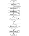
図10は、第1実施形態の情報提示装置100の処理の一例を示すフローチャートである。図10に示されるフローチャートは、所定の時間間隔で繰り返し実行される。現在位置取得部121は、ナビゲーション装置20から自車両Mの現在位置を示す情報を取得し、目標位置取得部122は、ナビゲーション装置20から目的地DPを示す情報を取得する(ステップS102)。次に、方向導出部124は、現在位置取得部121によって取得された自車両Mの現在位置と、目標位置取得部122によって取得された目的地DPと、車両センサ30によって検出された自車両Mの基準線の方位とに基づいて、自車両Mに対する目的地DPの目的地方位角ψ1を導出する(ステップS104)。次に、距離導出部126は、自車両Mの現在位置と、目的地DPとに基づいて、現在位置から目的地DPまでの目的地距離L1を導出する(ステップS106)。次に、出力制御部128は、導出された目的地方位角ψ1と、目的地距離L1とに基づいて、目的地像VI1を出現させる(ステップS108)。
[Processing flow]
FIG. 10 is a flowchart illustrating an example of processing of the
次に、出力制御部128は、自車両Mが目的地DPに到着するまでの間、ステップS104〜ステップS108の処理を繰り返す(ステップS110)。次に、出力制御部128は、自車両Mが目的地DPに到着した場合、目的地DPに到着してから所定時間が経過するまでの間(ステップS112;NO)、目的地像VI1を出現させる。次に、出力制御部128は、自車両Mが目的地DPに到着してから所定時間が経過した後、像生成部40に目的地像VI1の出現を停止させる(ステップS114)。
Next, the
[第1実施形態のまとめ]
以上説明した第1実施形態の情報提示装置100によれば、所定のユーザ(この一例では、乗員)が実空間の風景に重畳して見える像(この一例では、目的地像VI1)を出現させる像生成部40と、目的地像VI1を出現させる実空間上の目標位置(この一例では、目的地DP)を取得する目標位置取得部122と、目的地DPに基づいて、乗員に対して目的地像VI1を視認させる方向(この一例では、目的地方位角ψ1)を導出する方向導出部124と、乗員から見て目的地方位角ψ1に目的地像VI1が見えるように、像生成部40を制御する出力制御部128と、を備え、乗員は、目的地DPの方向を直感的に把握することができる。
[Summary of First Embodiment]
According to the
また、第1実施形態の情報提示装置100によれば、目的地DPと乗員(自車両M)との距離(この一例では、目的地距離L1)を導出する距離導出部126を更に備え、出力制御部128は、目的地距離L1が小さくなるほど、乗員の目に映る目的地像VI1を大きくし、乗員に、目的地DPの遠近感を演出することができる。
According to the
また、第1実施形態の情報提示装置100によれば、出力制御部128は、目的地距離L1が所定距離以上である場合、目的地像VI1のサイズを所定のサイズに固定することにより、乗員が、目的地DPを把握しづらくなることを抑制することができる。
Further, according to the
また、第1実施形態の情報提示装置100によれば、目的地像VI1(像VI)は、地面から鉛直方向に延びる像(この一例では、のろしの像)であり、出力制御部128は、乗員から見て目的地DPより奥の風景を遮蔽し、且つ乗員から見て目的地DPより手前の風景を遮蔽しないように目的地像VI1を出現させることにより、乗員に、より現実感のある像を提供しつつ目的地DPの案内を行うことができる。
Further, according to the
また、第1実施形態の情報提示装置100によれば、実空間の状況を認識する実空間認識部(この一例では、車両センサ30)を更に備え、出力制御部128は、車両センサ30によって認識された実空間の状況に応じて、目的地像VI1の態様を決定し、車両センサ30は、例えば、実空間における風の動きを認識し、出力制御部128は、風の動きに応じて目的地像VI1の態様を決定する。これにより、第1実施形態の情報提示装置100は、乗員により現実感のある像を提供しつつ目的地DPの案内を行うことができる。
Further, according to the
<第2実施形態>
以下、本発明の第2実施形態について説明する。第2実施形態では、乗員が、出現された像VIに対して各種操作を行う場合について説明する。なお、上述した実施形態と同様の構成については、同一の符号を付して説明を省略する。
<Second embodiment>
Hereinafter, a second embodiment of the present invention will be described. In the second embodiment, a case will be described in which the occupant performs various operations on the appearing image VI. In addition, about the structure similar to embodiment mentioned above, the same code | symbol is attached | subjected and description is abbreviate | omitted.
図11は、第2実施形態の出力制御システム2の構成の一例を示す図である。出力制御システム2は、出力制御システム1が備える構成に加えて、車内カメラ50と、スピーカ60とを備える。また、出力制御システム2は、情報提示装置100に代えて(、或いは加えて)、情報提示装置100aを備える。
FIG. 11 is a diagram illustrating an example of a configuration of the
車内カメラ50は、例えば、自車両Mの車室内に設置されたシートに着座する乗員を撮像する。乗員とは、例えば、運転席に着座する乗員(以下、運転者)であるが、これに加えて助手席や後部座席に着座する乗員(同乗者)でもよい。車内カメラ50は、例えば、CCDやCMOS等の固体撮像素子を利用したデジタルカメラである。車内カメラ50は、例えば、所定のタイミングで乗員を撮像する。車内カメラ50の撮像画像は、情報提示装置100aに出力される。
The in-
スピーカ60は、情報提示装置100aの制御によって動作し、音を出力する。なお、出力制御システム2は、乗員に音によって情報を報知できれば、スピーカ60に代えて、ブザーを備えていてもよい。
The
情報提示装置100aは、制御部120に代えて(、或いは加えて)、制御部120aを備える。制御部120aは、現在位置取得部121と、目標位置取得部122と、方向導出部124と、距離導出部126と、出力制御部128と、操作認識部130と、視線認識部132とを備える。
The information presentation device 100a includes a
操作認識部130は、車内カメラ50によって撮像された画像に基づいて、乗員の操作を認識する。ここで、乗員の操作とは、例えば、ジェスチャー等の動作によって示される操作である。出力制御部128は、操作認識部130の認識結果に基づいて、像VIの態様を決定する。
The
図11に戻り、視線認識部132は、車内カメラ50によって撮像された画像に基づいて、乗員の視線を認識する。出力制御部128は、視線認識部132の認識結果が、乗員が像VIを視認していないことを示す場合、目的地DPの方向を示す音をスピーカ60に出力させる。
Returning to FIG. 11, the line-of-
[操作認識部130による認識結果について]
図12は、操作認識部130によって認識される操作の一例を示す図である。図12に示される一例において、操作認識部130は、車内カメラ50によって撮像された画像に基づいて、乗員が目的地像VI1ののろしを払うジェスチャーを認識する。このジェスチャーには、目的地DPをキャンセル(消去)する操作が予め対応付けられる。出力制御部128は、操作認識部130の認識結果が「目的地像VI1ののろしを払うジェスチャー」を示すため、像生成部40に目的地像VI1の出現を停止させ、ナビゲーション装置20に目的地DPの消去を示す情報を供給する。これにより、乗員は、目的地DPの消去を容易に行うことができる。
[Recognition Result by Operation Recognition Unit 130]
FIG. 12 is a diagram illustrating an example of an operation recognized by the
図13は、操作認識部130によって認識される操作の他の例を示す図である。図13に示される一例において、操作認識部130は、車内カメラ50によって撮像された画像に基づいて、乗員が目的地像VI1ののろしを掴んで別の位置で離すジェスチャーを認識する。このジェスチャーには、目的地DPを変更する操作が予め対応付けられる。出力制御部128は、操作認識部130の認識結果が、「目的地像VI1ののろしを掴んで別の位置で離すジェスチャー」を示すため、目的地像VI1を離した別の位置(図示する新たな目的地DP*)を新たな目的地とする情報をナビゲーション装置20に供給する。これにより、乗員は、目的地DPの変更を容易に行うことができる。
FIG. 13 is a diagram illustrating another example of the operation recognized by the
なお、出力制御部128は、乗員が目的地像VI1を掴んで別の位置に移動させている間、移動の軌跡を示す目的地像VI1を出現させてもよい。
Note that the
図14は、目的地DPを変更する際のナビHMI22の表示画面の一例を示す図である。乗員は、目的地像VI1を掴んで目的地DPを変更する場合、自車両Mから見える位置(つまり、カメラ10によって撮像された画像に示される位置)以外の位置に新たな目的地DP*を変更したい場合がある。この場合、上述したように目的地像VI1ののろしを掴んでも、新たな目的地DP*の位置においてのろしを離すジェスチャーを行うことができない。このため、図14に示される通り、出力制御部128は、ナビゲーション装置20のナビHMI22に、新たな目的地DP*を示す目的地画像DPDを表示する。
FIG. 14 is a diagram illustrating an example of a display screen of the
具体的には、出力制御部128は、操作認識部130の認識結果が、目的地像VI1ののろしを掴んだジェスチャーをしたままの状態が所定の時間が経過したことを示す場合、ナビHMI22に表示される地図上に、新たな目的地DP*を示す目的地画像DPDを表示する。目的地像VI1ののろしを掴んだジェスチャーをしたままの状態が所定の時間が経過した場合は、例えば、新たな目的地DP*にのろしを離すジェスチャーを行うことができないため、つかんだままの状態が継続している状態である。
Specifically, when the recognition result of the
出力制御部128は、操作認識部130の認識結果が、乗員が目的地像VI1を掴んで新たな目的地DP*に移動させていることを示す間、ナビHMI22に表示される地図上に、新たな目的地DP*の移動軌跡を示す目的地画像DPDを重畳して表示させてもよい。方向導出部124、及び距離導出部126は、操作認識部130の認識結果がのろしを離すジェスチャーが認識されたことを示す場合、ジェスチャーが認識されたタイミングにおいて、ナビHMI22に表示される地図上の目的地画像DPDの位置を、新たな目的地DP*としてナビゲーション装置20から取得する。方向導出部124、及び距離導出部126は、新たな目的地DP*に基づいて、目的地距離L1や目的地方位角ψ1を導出し、出力制御部128は、新たな目的地DP*に目的地像VI1を出現させる。
The
[視線認識部132による認識結果について]
図15は、視線認識部132の認識結果に応じた乗員に対する報知の一例を示す図である。ここで、自車両Mの進行方向と、目的地DPとの位置関係によっては、目的地像VI1が自車両Mの前方に出現されず、乗員が目的地像VI1を視認することができない、或いは目的地像VI1を視認することによって前方不注意となる場合がある。出力制御部128は、視線認識部132の認識結果が、乗員が目的地像VI1を視認していないことを示す場合、自車両Mに設置される複数のスピーカ60のうち、方向導出部124によって導出された目的地方位角ψ1の方向に設置されるスピーカ60に、目的地DPを示す情報(例えば報知音)を出力させる。これにより、乗員は、目的地像VI1を視認できなくても目的地DPの方向を直感的に把握することができる。
[Recognition result by gaze recognition unit 132]
FIG. 15 is a diagram illustrating an example of notification to the occupant according to the recognition result of the
なお、出力制御部128は、報知音に代えて、「目的地は、右方向です」等のメッセージの音声をスピーカ60に出力させてもよい。また、出力制御部128は、スピーカ60に代えて、自車両Mの車内に設置される複数のLED(Light Emitting Diode)ライトのうち、目的地方位角ψ1の方向に設置されるLEDライトを明滅させ、目的地DPを報知してもよく、自車両Mのステアリングの円外側周上に設けられるバイブレータのうち、目的地方位角ψ1の方向に応じた位置のバイブレータによって振動を生じさせ、目的地DPを報知(通知)してもよい。
Note that the
図16は、視線認識部132の認識結果に応じた乗員に対する報知の他の例を示す図である。例えば、出力制御部128は、視線認識部132の認識結果が、乗員が目的地像VI1を視認していないことを示す場合、目的地像VI1以外の像VIを像生成部40に出現させてもよい。この像VIは、例えば、目的地方位角ψ1を示す矢印等の指示像VIdである。これにより、乗員は、目的地像VI1を視認できなくても指示像VIdによって目的地DPの方向を直感的に把握することができる。
FIG. 16 is a diagram illustrating another example of notification to the occupant according to the recognition result of the
[処理フロー]
図17は、第2実施形態の情報提示装置100aの操作認識部130に係る処理の一例を示すフローチャートである。図17に示されるフローチャートは、所定の時間間隔で繰り返し実行される。まず、出力制御部128は、操作認識部130の認識結果が目的地DPをキャンセルするジェスチャー(例えば、のろしを手で払うジェスチャー)であることを示すか否かを判定する(ステップS202)。出力制御部128は、操作認識部130の認識結果が目的地DPをキャンセルするジェスチャーであることを示す場合、像生成部40に目的地像VI1の出現を停止させる(ステップS204)。次に、出力制御部128は、ナビゲーション装置20に目的地DPを消去することを示す情報を出力し、目的地DPを消去させ(ステップS206)、処理を終了する。
[Processing flow]
FIG. 17 is a flowchart illustrating an example of a process related to the
出力制御部128は、操作認識部130の認識結果が目的地DPをキャンセルするジェスチャーではないことを示す場合、操作認識部130の認識結果が目的地DPを変更するジェスチャー(例えば、のろしを掴むジェスチャー)であることを示すか否かを判定する(ステップS208)。出力制御部128は、操作認識部130の認識結果が目的地DPを変更するジェスチャーではないことを示す場合、処理をステップS202に進める。次に、出力制御部128は、操作認識部130の認識結果が目的地DPを変更するジェスチャーであることを示す場合、ジェスチャーによって示される新たな目的地DP*が自車両Mの現在地の近傍であるか否かを判定する(ステップS210)。次に、出力制御部128は、ジェスチャーによって示される新たな目的地DP*が自車両Mの現在地の近傍である場合、ジェスチャーによって示される新たな目的地DP*に目的地像VI1を出現させる(ステップS212)。
If the recognition result of the
次に、出力制御部128は、操作認識部130の認識結果が新たな目的地DP*が現在位置の近傍ではない場合(例えば、のろしを掴むジェスチャーをしたままの状態が所定の時間が経過した場合)、ナビHMI22に表示される地図上に目的地画像DPDを表示させる(ステップS214)。次に、方向導出部124、及び距離導出部126は、のろしを離すジェスチャーが認識されたタイミングにおいて、ナビHMI22に表示される地図上の目的地画像DPDの位置を、新たな目的地DP*として取得する(ステップS216)。次に、方向導出部124、及び距離導出部126は、新たな目的地DP*に基づいて、目的地距離L1や目的地方位角ψ1を導出し、出力制御部128は、導出された目的地距離L1や目的地方位角ψ1に基づいて、新たな目的地DP*に目的地像VI1を出現させる(ステップS218)。
Next, the
図18は、第2実施形態の情報提示装置100aの視線認識部132に係る処理の一例を示すフローチャートである。図18に示されるフローチャートは、所定の時間間隔で繰り返し実行される。まず、出力制御部128は、視線認識部132の認識結果が目的地像VI1を乗員が視認していることを示すか否かを判定する(ステップS302)。出力制御部128は、視線認識部132の認識結果が目的地像VI1を乗員が認識していないことを示すまでの間、処理を進めず待機する。次に、出力制御部128は、視線認識部132の認識結果が目的地像VI1を乗員が視認していないことを示す場合、スピーカ60、LEDライト、バイブレータ、或いは指示像VIdを出現させることにより、目的地DPの方向を報知する(ステップS304)。
FIG. 18 is a flowchart illustrating an example of a process related to the
[第2実施家形態のまとめ]
以上説明した第2実施形態の情報提示装置100aにおいて、乗員の操作の内容を認識する操作認識部(この一例では、車内カメラ50)を更に備え、出力制御部128は、操作の内容に基づいて、目的地像VI1を移動させ、または消去する。これにより、第2実施形態の情報提示装置100aは、乗員に目的地DPの変更を容易に行わせることができる。
[Summary of Second Embodiment]
The information presentation device 100a according to the second embodiment described above further includes an operation recognizing unit (in this example, the in-vehicle camera 50) for recognizing the content of the operation of the occupant, and the
また、第2実施形態の情報提示装置100aにおいて、乗員の視線を検出する視線検出部(この一例では、車内カメラ50)と、車内カメラ50の検出結果が乗員が像(この一例では、目的地像VI1)を視認していないことを示す場合、乗員に目的地DPの方向を示す情報(この一例では、報知音、又は指示像VId)を出力する報知部(この一例では、スピーカ60、又は像生成部40)とを備え、乗員が目的地像VI1を視認していない場合であっても、目的地DPの方向を報知することができる。
In the information presentation device 100a according to the second embodiment, the line-of-sight detection unit (in this example, the in-vehicle camera 50) that detects the line of sight of the occupant, and the detection result of the in-
<第3実施形態>
以下、本発明の第3実施形態について説明する。上述した実施形態では、乗員の目的地DPに目的地像VI1を出現させる場合について説明した。第3実施形態では、予め定められた所定の位置に像VIを出現させる場合について説明する。なお、上述した実施形態と同様の構成については、同一の符号を付して説明を省略する。
<Third embodiment>
Hereinafter, a third embodiment of the present invention will be described. In the embodiment described above, the case where the destination image VI1 appears at the destination DP of the occupant has been described. In the third embodiment, a case will be described in which the image VI appears at a predetermined position. In addition, about the structure similar to embodiment mentioned above, the same code | symbol is attached | subjected and description is abbreviate | omitted.
図19は、第3実施形態の出力制御システム3の構成の一例を示す図である。出力制御システム3は、出力制御システム1、又は出力制御システム2が備える構成に加えて、通信装置70を備える。また、出力制御システム3は、情報提示装置100aと、記憶部200bとを備える。
FIG. 19 is a diagram illustrating an example of a configuration of the
通信装置70は、例えば、セルラー網やWi−Fi網、Bluetooth(登録商標)、DSRC(Dedicated Short Range Communication)などを利用して、自車両Mの周辺に存在する他車両と通信し、或いは無線基地局を介して各種サーバ装置と通信する。
The
記憶部200bには、重畳画像202を示す情報と、対象人物位置情報204とが記憶される。対象人物位置情報204は、例えば、自車両Mの乗員によって予め設定された対象人物と、対象人物の位置(以下、対象人物位置RP)を示す情報とが互いに対応付けられた情報である。対象人物は、例えば、乗員が状況を把握したい人物であり、乗員の親族(例えば、祖父母)や、友人等である。対象人物位置RPは、例えば、対象人物の住所等である。対象人物位置RPは、「目標位置」の第2例である。
The
なお、対象人物位置情報204に含まれる対象人物が、情報の送受信が可能な機器であり、現在位置を取得可能な機器(例えば、携帯電話)を有している場合、通信装置70に対して(対象人物の)現在地を示す情報を送信し、対象人物位置情報204の対象人物位置RPが逐次更新される構成であってもよい。以降の説明では、対象人物位置情報204についてこのような更新が行われず、対象人物位置RPが、対象人物の住所である場合について説明する。
Note that if the target person included in the target person position
図20は、第3実施形態の方向導出部124、及び距離導出部126の処理の一例を模式的に示す図である。本実施形態の方向導出部124は、自車両Mの現在位置と、対象人物位置RPと、自車両Mの基準線の方位とに基づいて、自車両Mの現在位置と対象人物位置RPとを結ぶ線分と、自車両Mの基準線とのなす角度を、自車両Mに対する対象人物位置RPの方位角(以下、対象人物方位角ψ2)として導出する。また、本実施形態の距離導出部126は、自車両Mの現在位置と、対象人物位置情報204に示される対象人物位置RPとに基づいて、現在位置から対象人物位置RPまでの距離(以下、対象人物距離L2)を導出する。
FIG. 20 is a diagram schematically illustrating an example of processing of the
出力制御部128は、方向導出部124によって導出された対象人物方位角ψ2と、距離導出部126によって導出された対象人物距離L2とに基づいて、実空間に重畳して対象人物位置像VI2を出現させるように、像生成部40を制御する。対象人物位置像VI2は、対象人物位置RPの方向と、対象人物位置RPの位置とのうち、少なくとも一方を示す像VIである。以降の説明において、対象人物位置像VI2が、対象人物位置RPの位置の地面から鉛直方向にのろしが伸びているように乗員に視認させる像VIである場合について説明する。
The
[対象人物位置RPを示す対象人物位置像VI2について]
図21は、像生成部40によって出現される対象人物位置像VI2の一例を示す図である。図21に示される一例において、対象人物位置像VI2aは、対象人物位置RPの位置を示す像VIであり、自車両Mの現在位置において出現される対象人物位置像VI2である。これにより、乗員は、対象人物の方向を直感的に把握することができる。
[About the target person position image VI2 indicating the target person position RP]
FIG. 21 is a diagram illustrating an example of the target person position image VI2 appearing by the
出力制御部128は、上述した目的地距離L1に応じて目的地像VI1に施されるようなサイズの変更、実空間の状況に応じた目的地像VI1の演出、或いは目的地像VI1の方向の報知等を、対象人物位置像VI2に対して行ってもよい。
The
[対象人物の状態に応じた対象人物位置像VI2の演出について]
また、出力制御部128は、対象人物位置RPによって位置が示される対象人物の状態に応じて、対象人物位置像VI2の演出を行ってもよい。この場合、通信装置70は、ネットワークを介して対象人物の状態を示す情報を受信する。対象人物の状態には、例えば、対象人物の体調、就寝、起床、感情、及び在宅又は不在かのうち、少なくともいずれか1つの状態が含まれる。対象人物は、例えば、通信装置70と通信可能な機器であって、スマートフォンやタブレット型のコンピューター(タブレットPC)等の携帯通信端末装置、又は据置き型の端末装置(例えば、据置き型のパーソナルコンピュータ等)を有する。これらの機器は、対象人物による対象人物の状態を送信する操作が行われた基づくタイミングにおいて、対象人物の状態を示す情報を通信装置70に送信する。
[About production of target person position image VI2 according to state of target person]
In addition, the
なお、対象人物は、携帯通信端末装置、又は据置き型の端末装置等の他、対象人物のバイタルサインを検出可能なウェアラブル機器を有していてもよい。ウェアラブル機器は、対象人物の状態(例えば、バイタルサイン)を示す情報を常時、又は所定の時間間隔で繰り返し通信装置70に送信してもよい。
Note that the target person may have a wearable device that can detect a vital sign of the target person, in addition to a portable communication terminal device, a stationary terminal device, or the like. The wearable device may transmit the information indicating the state of the target person (for example, vital signs) to the
図22は、像生成部40によって出現される対象人物位置像VI2の他の例を示す図である。例えば、出力制御部128は、通信装置70によって受信された対象人物の体調が正常である場合、図21に示される対象人物位置像VI2aを出現させ、対象人物の体調が正常ではない場合、図22に示される対象人物位置像VI2bを出現させる。対象人物位置像VI2aは、例えば、寒色系の色ののろしであり、対象人物位置像VI2bは、例えば、暖色系の色ののろしである。これにより、乗員は、対象人物の状態を容易に直感的に把握することができる。
FIG. 22 is a diagram illustrating another example of the target person position image VI2 appearing by the
なお、出力制御部128は、対象人物の体調の他、対象人物の就寝、起床、感情、在宅、又は不在等に基づいて、対象人物位置像VI2の態様を決定してもよい。
Note that the
[操作認識部130による認識結果について]
また、本実施形態の操作認識部130は、車内カメラ50によって撮像された画像に基づいて、乗員が対象人物位置像VI2ののろしを掴むジェスチャーを認識する。このジェスチャーには、対象人物位置RPの位置の対象人物に連絡する(例えば、発呼や、定型メールの送信)操作が予め対応付けられる。出力制御部128は、操作認識部130の認識結果が「対象人物位置像VI2ののろしを掴むジェスチャー」を示す場合、対象人物に連絡する。これにより、乗員は、対象人物と容易に連絡を取ることができる。
[Recognition Result by Operation Recognition Unit 130]
In addition, the
また、出力制御部128は、視線認識部132の認識結果に基づいて、乗員が対象人物位置像VI2を確認した回数をログとして他の機器(例えば、乗員の端末装置)に出力してもよい。
Further, the
[処理フロー]
図23は、第3実施形態の情報提示装置100aの処理の一例を示すフローチャートである。図23に示されるフローチャートは、所定の時間間隔で繰り返し実行される。まず、通信装置70は、対象人物の状態を示す情報を受信する(ステップS402)。次に、出力制御部128は、受信した対象人物の状態に応じた対象人物位置像VI2を出現させる(ステップS404)。次に、出力制御部128は、操作認識部130の認識結果が対象人物に連絡するジェスチャー(例えば、のろしを掴むジェスチャー)であることを示すか否かを判定する(ステップS406)。出力制御部128は、対象人物に連絡するジェスチャーが認識されなかった場合、処理を終了する。次に、出力制御部128は、操作認識部130の認識結果が、対象人物に連絡するジェスチャーであることを示す場合、対象人物に連絡する処理(例えば、発呼や、定型メールの送信)を実行する(ステップS408)。
[Processing flow]
FIG. 23 is a flowchart illustrating an example of processing of the information presentation device 100a according to the third embodiment. The flowchart shown in FIG. 23 is repeatedly executed at predetermined time intervals. First, the
[第3実施形態のまとめ]
以上説明した第3実施形態の情報提示装置100cにおいて、目標位置は、乗員によって指定された対象人物の対象人物位置RPであり、乗員は、対象人物の方向や位置を直感的に把握することができる。
[Summary of Third Embodiment]
In the
また、第3実施形態の情報提示装置100cにおいて、出力制御部128は、対象人物の状態に応じて、対象人物位置像VI2の態様を決定し、乗員に、対象人物の状態を容易に直感的に把握させることができる。
Further, in the
<第4実施形態>
以下、本発明の第4実施形態について説明する。上述した実施形態では、情報提示装置100a〜100bが自車両Mに搭載されている場合について説明した。第4実施形態では、情報提示装置100aがユーザの端末装置TMに搭載されている場合について説明する。なお、上述した実施形態と同様の構成については、同一の符号を付して説明を省略する。
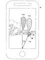
<Fourth embodiment>
Hereinafter, a fourth embodiment of the present invention will be described. In the above-described embodiment, the case where the information presenting devices 100a to 100b are mounted on the host vehicle M has been described. In the fourth embodiment, a case will be described in which the information presentation device 100a is mounted on a user terminal device TM. In addition, about the structure similar to embodiment mentioned above, the same code | symbol is attached | subjected and description is abbreviate | omitted.
図24は、第4実施形態の端末装置TMの構成の一例を示す図である。端末装置TMは、アウトカメラ11と、GNSS受信機21cと、方位センサ31と、表示部41と、インカメラ51と、スピーカ61と、通信装置71と、タッチパネル81と、情報提示装置100cとを備える。端末装置TMは、例えば、スマートフォンやタブレット型のコンピューター(タブレットPC)等の携帯通信端末装置である。以降の説明において、端末装置TMが前面と背面とを有するタブレット型の携帯端末である場合について説明する。
FIG. 24 is a diagram illustrating an example of the configuration of the terminal device TM according to the fourth embodiment. The terminal device TM includes the out-
アウトカメラ11は、例えば、CCDやCMOS等の固体撮像素子を利用したデジタルカメラである。アウトカメラ11は、端末装置TMの背面の任意の箇所に取り付けられ、端末装置TMの背面の方向(例えば、ユーザの進行方向の風景)を撮像する。アウトカメラ11は、ステレオカメラであってもよい。
The out
GNSS受信機21cは、上述したGNSS受信機21と同様の構成を有し、GNSS衛星から受信した信号に基づいて、端末装置TMの現在位置を特定する。
The
方位センサ31は、地磁気を検出し、端末装置TMの前方の方位を検出する。具体的には、端末装置TMは、端末装置TMの基準点(例えば、重心)を通る基準線であり、基準点と端末装置TMの上部とを結ぶ基準線の方位を検出する。方位を示す情報は、情報提示装置100cに出力される。
The
表示部41は、例えば、液晶ディスプレイパネル、あるいは、有機EL(ElectroLuminescence)ディスプレイパネルであり、情報提示装置100cの制御に基づいて各種画像を表示する。表示部41は、端末装置TMの前面に設けられる。
The
インカメラ51は、アウトカメラ11と同様の機能をする。インカメラ51は、端末装置TMの前面の任意の箇所に取り付けられ、端末装置TMの前面の方向(例えば、ユーザの顔面)を撮像する。
The in-
スピーカ61は、上述したスピーカ60と同様の機能を有し、情報提示装置100cの制御によって動作し、音を出力する。
The
通信装置71は、上述した通信装置70と同様の機能を有し、出力制御システム1〜3を搭載する車両や他の装置と通信する。
The
タッチパネル81は、端末装置TMの前面に設けられ、ユーザの操作を受け付ける。以降の説明において、表示部41と、タッチパネル81とが、端末装置TMの前面に一体に構成される場合について説明する。
The
情報提示装置100cは、制御部120aと、記憶部200cとを備える。記憶部200cには、重畳画像202と、対象人物位置情報204と、タクシーアプリ206とが記憶される。制御部120aは、記憶部200cに記憶されるタクシーアプリ206を実行することにより、タクシーの配車、タクシー乗車後の料金支払い、端末装置TMの近傍に存在するタクシーの確認等の機能を有するアプリケーションを実現する。
The
端末装置TMにおいてタクシーアプリ206が実行されることに伴い、アウトカメラ11は、ユーザ(端末装置TM)の背面が向いている方向の風景を撮像する。
With the execution of the
本実施形態の現在位置取得部121は、端末装置TMの現在位置を示す情報を取得する。また、目標位置取得部122は、端末装置TMの周辺に存在するタクシーの位置(以下、対象車両位置MP)を取得する。対象車両位置MPは、「目標位置」の第3例である。
The current
また、方向導出部124は、現在位置取得部121によって取得された端末装置TMの現在位置と、対象車両位置MPと、方位センサ31によって検出された端末装置TMの方位とに基づいて、端末装置TMの現在位置と対象車両位置MPとを結ぶ線分と、端末装置TMの基準線とのなす角度を、端末装置TMに対する対象車両位置MPの方位角(以下、対象車両方位角ψ3)として導出する。距離導出部126は、現在位置取得部121によって取得された自車両Mの現在位置と、目標位置取得部122によって取得された対象車両位置MPとに基づいて、現在位置から対象車両位置MPまでの距離(以下、対象車両距離L3)を導出する。
In addition, the
出力制御部128は、方向導出部124によって導出された対象車両方位角ψ3と、距離導出部126によって導出された対象車両距離L3と、アウトカメラ11によって撮像された実空間の画像とに基づいて、実空間の画像に重畳して対象車両像VI3を出現(表示)させるように、表示部41を制御する。対象車両像VI3は、対象車両位置MPの方向と、タクシーの位置とのうち、少なくとも一方を示す像VIである。以降の説明において、対象車両像VI3が、対象車両位置MPの地面から鉛直方向にのろしが延びているように乗員に視認させる像VIである場合について説明する。タクシーは、「対象車両」の一例である。
The
[タクシーアプリの実行画面]
図25は、タクシーアプリの実行画面の一例を示す図である。タクシーアプリの実行画面では、アウトカメラ11によって撮像された実空間の画像に、対象車両像VI3(図示する対象車両像VI3a〜VI3b)が重畳して出現(表示)される。具体的には、図25に示される一例において、タクシーmtについての対象車両方位角ψ3aは、対象車両方位角ψ3にお対応し、対象車両距離L3aは、対象車両距離L3に対応する。対象車両像VI3aは、ユーザの周辺に存在するタクシーmtの対象車両位置MPを示す像VIであり、端末装置TMの現在位置において出現される対象車両像VI3である。これにより、ユーザは、タクシーの位置や方向を直感的に把握することができる。
[Execution screen of taxi application]
FIG. 25 is a diagram illustrating an example of the execution screen of the taxi application. On the execution screen of the taxi application, a target vehicle image VI3 (illustrated target vehicle images VI3a to VI3b) is superimposed (appears) on the image of the real space captured by the
出力制御部128は、上述した目的地距離L1に応じて目的地像VI1に施されるようなサイズの変更、実空間の状況に応じた目的地像VI1の演出、或いは目的地像VI1の方向の報知等を、対象車両像VI3に対して行ってもよい。
The
[対象車両像VI3の演出について]
また、出力制御部128は、対象車両位置MPによって位置が示されるタクシーの評価に応じて、対象車両像VI3の演出を行ってもよい。ここで、タクシーアプリによって配車を依頼可能なタクシーには、ランクが付される場合がある。このランクは、例えば、そのタクシーを運転する運転手の評判や、そのタクシーが所属するタクシー会社の評判等に基づくランクであり、ランクが高い程、そのタクシーの評判が良く、ランクが低い程、そのタクシーの評判が悪い。
[About production of target vehicle image VI3]
Further, the
通信装置70は、例えば、端末装置TMにおいてタクシーアプリ206が実行されることに伴い、端末装置TMの周辺に存在するタクシーのランクを示す情報を各タクシーから受信する。出力制御部128は、例えば、通信装置70によって受信されたタクシーのランクが高い場合、図25に示される対象車両像VI3aを出現させ、タクシーのランクが低い場合、図26に示される対象車両像VI3bを出現させる。対象車両像VI3aは、例えば、寒色系の色ののろしであり、対象車両像VI3bは、例えば、暖色系の色ののろしである。これにより、ユーザは、タクシーの評判を容易に把握し、評判の良いタクシーを選択することができる。
The
[操作認識部130による認識結果について]
また、本実施形態の操作認識部130は、インカメラ51によって撮像された画像に基づいて、ユーザが対象車両像VI3ののろしを掴むジェスチャーを認識する。このジェスチャーには、対象車両位置MPの位置のタクシーに配車を依頼する操作が予め対応付けられる。出力制御部128は、操作認識部130の認識結果が「対象車両像VI3ののろしを掴むジェスチャー」を示す場合、当該タクシーに対して配車を要求する。これにより、ユーザは、容易に配車を依頼することができる。なお、通信装置70によって配車要求が承認されたことを示す情報を受信した場合、出力制御部128は、対象車両像VI3の態様を変更してもよい。具体的には、出力制御部128は、配車を要求していないタクシーについては寒色系ののろしの色の対象車両像VI3aを出現させ、配車を要求したタクシーについては暖色系ののろしの色の対象車両像VI3bに変更し、出現させる。
[Recognition Result by Operation Recognition Unit 130]
In addition, the
また、本実施形態の操作認識部130は、インカメラ51によって撮像された画像に基づいて、ユーザが対象車両像VI3ののろしを払うジェスチャーを認識する。このジェスチャーには、対象車両位置MPの位置のタクシーの配車をキャンセルする操作が予め対応付けられる。出力制御部128は、操作認識部130の認識結果が「対象車両像VI3ののろしを払うジェスチャー」を示す場合、当該タクシーに対して配車のキャンセルを行う。これにより、ユーザは、容易に配車をキャンセルすることができる。
In addition, the
[視線認識部132による認識結果について]
ここで、ユーザは、上述したジェスチャーによってタクシーに配車を要求した後、タクシーアプリの実行画面を視認し続けていない場合がある。この場合、ユーザは、配車を要求したタクシーの到着に気がつくことが困難である。出力制御部128は、タクシーに配車を要求した後に、タクシーアプリが起動されていない場合、又は視線認識部132の認識結果がタクシーアプリの実行画面をユーザが視認していないことを示す場合に、スピーカ61に、タクシーの到着を示す情報(例えば報知音)を出力させる。これにより、乗員は、タクシーアプリを視認し続けていなくてもタクシーの到着を直感的に把握することができる。
[Recognition result by gaze recognition unit 132]
Here, there is a case where the user does not continue to visually recognize the execution screen of the taxi application after requesting the taxi to dispatch by the gesture described above. In this case, it is difficult for the user to notice the arrival of the taxi requesting the dispatch. The
なお、出力制御部128は、報知音に代えて、「タクシーが到着しました」等のメッセージの音声をスピーカ61に出力させてもよい。また、出力制御部128は、スピーカ61に代えて、端末装置TMが備えるLEDライトを明滅させ、タクシーの到着を報知してもよく、端末装置TMが備えるバイブレータによって振動を生じさせ、タクシーの到着を報知(通知)してもよい。
Note that the
[像VIの停止について]
出力制御部128は、タクシーがユーザの近傍に到着した場合、表示部41を制御し、対象車両像VI3の出現(表示)を停止させる。ここで、タクシーが到着してすぐに対象車両像VI3の出現が停止されると、ユーザが配車を要求したタクシーを見つけることが困難である場合がある。したがって、出力制御部128は、タクシーが到着してから所定時間が経過した後、或いはユーザが当該タクシーに乗車した後、表示部41を制御し、対象車両像VI3の出現を停止させる。
[About stopping image VI]
When the taxi arrives near the user, the
なお、上述では、出力制御部128が操作認識部130によって認識されたユーザの操作(ジェスチャー)に基づいて、対象車両像VI3の態様を変更する場合について説明したが、これに限られない。出力制御部128は、タッチパネル81によって認識されたユーザの操作(例えば、タップ、フリック、スワイプ等)に基づいて、対象車両像VI3の態様を変更してもよい。
In the above description, the case where the
また、上述では、「対象車両」の一例としてタクシーについて説明したが、これに限られない。「対象車両」は、例えば、カーシェアリングやライドシェアに用いられる車両であってもよい。 In the above description, a taxi has been described as an example of the “target vehicle”, but the present invention is not limited to this. The “target vehicle” may be, for example, a vehicle used for car sharing or ride sharing.
[処理フロー]
図26は、第4実施形態の情報提示装置100cの処理の一例を示すフローチャートである。図26に示されるフローチャートは、所定の時間間隔で繰り返し実行される。まず、目標位置取得部122は、端末装置TMの周辺に存在するタクシーの対象車両位置MPを取得する(ステップS502)。方向導出部124は、現在位置取得部121によって取得された端末装置TMの現在位置と、目標位置取得部122によって取得された対象車両位置MPとに基づいて、対象車両方位角ψ3を導出する(ステップS504)。距離導出部126は、端末装置TMの現在位置と、対象車両位置MPとに基づいて、対象車両距離L3を導出する(ステップS506)。出力制御部128は、導出した対象車両方位角ψ3と、対象車両距離L3とに基づいて、表示部41に対象車両像VI3を出現(表示)させる(ステップS508)。
[Processing flow]
FIG. 26 is a flowchart illustrating an example of a process of the
次に、出力制御部128は、操作認識部130の認識結果が対象車両像VI3に対する操作を認識したか否かを判定する(ステップS510)。次に、出力制御部128は、操作認識部130の認識結果が対象車両像VI3に対する操作を認識していないことを示す場合、処理を終了する。次に、出力制御部128は、対象車両像VI3に対する操作が、タクシーの配車を要求するジェスチャー(例えば、のろしを手で掴むジェスチャー)であることを示すか否かを判定する(ステップS510)。次に、出力制御部128は、操作認識部130の認識結果がタクシーの配車を要求するジェスチャーである場合、タクシーに配車を要求する処理を実行し(ステップS514)、処理を終了する。
Next, the
次に、出力制御部128は、操作認識部130の認識結果がタクシーの配車を要求するジェスチャーではない場合、タクシーの配車をキャンセルするジェスチャー(例えば、のろしを手で払うジェスチャー)であることを示すか否かを判定する(ステップS516)。次に、出力制御部128は、操作認識部130の認識結果がタクシーの配車をキャンセルするジェスチャーではない場合、処理を終了する。次に、出力制御部128は、操作認識部130の認識結果がタクシーの配車をキャンセルするジェスチャーである場合、タクシーの配車をキャンセルする処理を実行し(ステップS518)、処理を終了する。
Next, when the recognition result of the
[第4実施形態のまとめ]
以上説明した第4実施形態の情報提示装置100cにおいて、目標位置は、乗員によって指定された対象車両(この一例では、タクシー)の位置であり、乗員によるタクシーに対する操作の内容を認識する操作認識部(この一例では、車内カメラ50)と、他の装置と通信する通信部(この一例では、通信装置70)とを備え、通信装置70は、操作の内容を示す情報を他の装置(例えば、タクシー)に送信する。これにより、第4実施形態の情報提示装置100cは、乗員にタクシーに配車要求、或いは配車キャンセルを容易に行わせことができる。
[Summary of Fourth Embodiment]
In the
また、第4実施形態の情報提示装置100cにおいて、出力制御部128は、車内カメラ50の認識結果(この一例では、配車の要求の有無)に基づいて、対象車両像VI3の態様を決定し、乗員にタクシーを識別し易い対象車両像VI3を提供することができる。
In the
[像VIの他の例]
なお、像VIがのろしである場合について説明したが、これに限られない。像VIは、目的地DP、対象人物位置RP、或いは対象車両位置MPの地面から、鉛直方向に延びる物体であれば、のろし以外であってもよい。例えば、重畳画像202は、例えば、光の柱を示す画像であってもよく、塔を示す画像であってもよい。この場合、像VIは、光の柱の像であり、塔の像である。また、上述において例示したのろしの色は一例であって、これに限られない。
[Another Example of Image VI]
Although the case where the image VI is slow is described, the invention is not limited to this. The image VI may be anything other than slowing down as long as it extends vertically from the ground at the destination DP, the target person position RP, or the target vehicle position MP. For example, the
上記説明した実施形態は、以下のように表現することができる。
プログラムを記憶するストレージと、
情報を記憶する記憶装置と、
前記記憶装置に格納されたプログラムを実行するハードウェアプロセッサと、を備え、
前記ハードウェアプロセッサは、前記プログラムを実行することにより、
前記像を出現させる前記実空間上の目標位置を取得させ、
前記目標位置に基づいて、前記所定のユーザに対して前記像を視認させる方向を導出させ、
前記所定のユーザから見て前記方向に前記像が見えるように前記像生成部を制御させる、
ように構成されている、車両制御装置。
The embodiment described above can be expressed as follows.
Storage for storing programs,
A storage device for storing information;
A hardware processor that executes a program stored in the storage device,
The hardware processor executes the program,
Acquiring a target position in the real space where the image appears,
Based on the target position, derive a direction in which the predetermined user visually recognizes the image,
Controlling the image generation unit so that the image can be seen in the direction viewed from the predetermined user,
The vehicle control device is configured as follows.
以上、本発明を実施するための形態について実施形態を用いて説明したが、本発明はこうした実施形態に何等限定されるものではなく、本発明の要旨を逸脱しない範囲内において種々の変形及び置換を加えることができる。 As described above, the embodiments for carrying out the present invention have been described using the embodiments. However, the present invention is not limited to such embodiments at all, and various modifications and substitutions may be made without departing from the gist of the present invention. Can be added.
1、2、3…出力制御システム、10…カメラ、11…アウトカメラ、20…ナビゲーション装置、21…GNSS受信機、21c…GNSS受信機、22…ナビHMI、23…経路決定部、24…第1地図情報、30…車両センサ、31…方位センサ、40…像生成部、41…表示部、50…車内カメラ、51…インカメラ、60、61…スピーカ、70、71…通信装置、81…タッチパネル、100、100a、100b、100c…情報提示装置、120、120a…制御部、121…現在位置取得部、122…目標位置取得部、124…方向導出部、126…距離導出部、128…出力制御部、130…操作認識部、132…視線認識部、200、200b、200c…記憶部、202…重畳画像、204…対象人物位置情報、206…タクシーアプリ、L1、L1a、L1b、L1c…目的地距離、L2…対象人物距離、L3、L3a…対象車両距離、M…自車両、m2、m3…他車両、mt…タクシー、DP…目的地、MP…対象車両位置、RP…対象人物位置、TM…端末装置、VI…像、VI1、VI1−1、VI1−2、VI1−3、VI1a、VI1b、VI1c…目的地像、VI2、VI2a、VI2b…対象人物位置像、VI3、VI3a、VI3b…対象車両像、VId…指示像、ψ1、ψ1a、ψ1b、ψ1c…目的地方位角、ψ2…対象人物方位角、ψ3、ψ3a…対象車両方位角 1, 2, 3 ... output control system, 10 ... camera, 11 ... out camera, 20 ... navigation device, 21 ... GNSS receiver, 21 c ... GNSS receiver, 22 ... navigation HMI, 23 ... route determination unit, 24 ... 1 map information, 30 ... vehicle sensor, 31 ... direction sensor, 40 ... image generation unit, 41 ... display unit, 50 ... in-vehicle camera, 51 ... in camera, 60, 61 ... speaker, 70, 71 ... communication device, 81 ... Touch panel, 100, 100a, 100b, 100c Information presenting device, 120, 120a Control unit, 121 Current position acquisition unit, 122 Target position acquisition unit, 124 Direction derivation unit, 126 Distance derivation unit, 128 Output Control unit, 130: operation recognition unit, 132: gaze recognition unit, 200, 200b, 200c: storage unit, 202: superimposed image, 204: target person position information, 2 6: Taxi application, L1, L1a, L1b, L1c: Destination distance, L2: Target person distance, L3, L3a: Target vehicle distance, M: Own vehicle, m2, m3: Other vehicles, mt: Taxi, DP: Purpose Ground, MP: Target vehicle position, RP: Target person position, TM: Terminal device, VI: Image, VI1, VI1-1, VI1-2, VI1-3, VI1a, VI1b, VI1c: Destination image, VI2, VI2a , VI2b: Target person position image, VI3, VI3a, VI3b: Target vehicle image, VId: Instruction image, # 1, # 1a, # 1b, # 1c: Target local position angle, # 2: Target person azimuth angle, # 3, # 3a: Target vehicle direction Corner
Claims (17)
実空間の風景に重畳して見える像を出現させる像生成部と、
前記像を出現させる前記実空間上の目標位置を取得する目標位置取得部と、
前記現在位置と前記目標位置とに基づいて、前記現在位置から前記目標位置への方向を導出する方向導出部と、
前記像生成部を制御し、前記方向導出により取得された方向に基づき前記像を出現させる出力制御部と、
を備える情報提示装置。 A current position acquisition unit for acquiring the current position of the current position acquisition unit;
An image generation unit that makes an image appearing to be superimposed on a real space landscape;
A target position acquisition unit that acquires a target position in the real space where the image appears,
A direction deriving unit that derives a direction from the current position to the target position based on the current position and the target position;
An output control unit that controls the image generation unit and causes the image to appear based on the direction acquired by the direction derivation,
An information presentation device comprising:
前記出力制御部は、前記距離が小さくなるほど、前記像を大きくする、
請求項1に記載の情報提示装置。 Further comprising a distance deriving unit for deriving a distance between the target position and the current position,
The output control unit increases the image as the distance decreases.
The information presentation device according to claim 1.
請求項2に記載の情報提示装置。 The output control unit, when the distance is equal to or longer than a predetermined distance, fixes the size of the image to a predetermined size,
The information presentation device according to claim 2.
請求項1から請求項3のいずれか一項に記載の情報提示装置。 The image generating unit causes an image extending vertically from the ground to appear,
The information presentation device according to any one of claims 1 to 3.
前記現在位置から前記目標位置より奥の風景を遮蔽し、且つ前記現在位置から前記目標位置より手前の風景を遮蔽しない前記像を出現させる、
請求項1から請求項4のいずれか一項に記載の情報提示装置。 The output control unit includes:
Appearing the image that does not occlude the scenery behind the target position from the current position and shields the scenery before the target position from the current position,
The information presentation device according to any one of claims 1 to 4.
前記出力制御部は、
前記実空間認識部によって認識された前記実空間の状況に応じて、前記像の態様を決定する、
請求項1から請求項5のいずれか一項に記載の情報提示装置。 It further includes a real space recognition unit that recognizes the situation of the real space,
The output control unit includes:
According to the situation of the real space recognized by the real space recognition unit, determine the aspect of the image,
The information presentation device according to any one of claims 1 to 5.
前記出力制御部は、前記風の動きに応じて前記像を動かす、
請求項6に記載の情報提示装置。 The real space recognition unit recognizes the movement of the wind in the real space,
The output control unit moves the image according to the movement of the wind,
The information presentation device according to claim 6.
前記出力制御部は、
前記操作の内容に基づいて、前記像を移動させ、または消去する、
請求項1から請求項7のいずれか一項に記載の情報提示装置。 An operation recognition unit that recognizes the content of the user operation;
The output control unit includes:
Move or delete the image based on the content of the operation,
The information presentation device according to any one of claims 1 to 7.
前記視線検出部の検出結果が、前記ユーザが前記像を視認していないことを示す場合、前記ユーザに前記目標位置の方向を示す情報を出力する報知部と、
を更に備える請求項1から請求項8のいずれか一項に記載の情報提示装置。 A line-of-sight detection unit that detects the line of sight of the user,
When the detection result of the line-of-sight detection unit indicates that the user is not visually recognizing the image, a notification unit that outputs information indicating the direction of the target position to the user,
The information presentation device according to any one of claims 1 to 8, further comprising:
請求項1から請求項9のいずれか一項に記載の情報提示装置。 The target position is a destination of the user,
The information presentation device according to any one of claims 1 to 9.
請求項1から請求項10のいずれか一項に記載の情報提示装置。 The target position is a position of the target person specified by the user,
The information presentation device according to any one of claims 1 to 10.
請求項11に記載の情報提示装置。 The output control unit determines a mode of the image according to a state of the target person,
The information presentation device according to claim 11.
請求項1から請求項12のいずれか一項に記載の情報提示装置。 The target position is a position of the target vehicle specified by the user,
The information presentation device according to any one of claims 1 to 12.
他の装置と通信する通信部とを備え、
前記通信部は、前記操作の内容を示す情報を前記他の装置に送信する、
請求項13に記載の情報提示装置。 An operation recognition unit that recognizes the content of an operation on the target vehicle by the user,
A communication unit that communicates with another device,
The communication unit transmits information indicating the content of the operation to the other device,
The information presentation device according to claim 13.
請求項14に記載の情報提示装置。 The output control unit determines an aspect of the image based on a recognition result of the operation recognition unit.
The information presentation device according to claim 14.
前記表示部の現在位置を取得し、
前記像を出現させる前記実空間上の目標位置を取得し、
前記現在位置と前記目標位置とに基づいて、前記現在位置から前記目標位置の方向を導出し、
前記像生成部を制御し、前記方向に前記像を出現させる、
情報提示方法。 A computer of an output control system including a display unit and an image generation unit that causes a predetermined user to generate an image that appears to be superimposed on a scene in real space,
Obtain the current position of the display unit,
Obtaining a target position in the real space where the image appears,
Based on the current position and the target position, derive a direction of the target position from the current position,
Controlling the image generating unit to cause the image to appear in the direction;
Information presentation method.
前記表示部の現在位置を取得させ、
前記像を出現させる前記実空間上の目標位置を取得させ、
前記現在位置と前記目標位置とに基づいて、前記現在位置から前記目標位置の方向を導出させ、
前記像生成部を制御させ、前記方向に前記像を出現させる、
プログラム。 A display unit, and a computer of an output control system including an image generation unit that causes an image that a predetermined user appears to be superimposed on a scene in real space to appear,
The current position of the display unit is obtained,
Acquiring a target position in the real space where the image appears,
Based on the current position and the target position, the direction of the target position is derived from the current position,
Controlling the image generation unit to cause the image to appear in the direction,
program.
Applications Claiming Priority (2)
| Application Number | Priority Date | Filing Date | Title |
|---|---|---|---|
| US16/028,725 | 2018-07-06 | ||
| US16/028,725 US10876853B2 (en) | 2018-07-06 | 2018-07-06 | Information presentation device, information presentation method, and storage medium |
Publications (2)
| Publication Number | Publication Date |
|---|---|
| JP2020008561A true JP2020008561A (en) | 2020-01-16 |
| JP7361486B2 JP7361486B2 (en) | 2023-10-16 |
Family
ID=69101381
Family Applications (1)
| Application Number | Title | Priority Date | Filing Date |
|---|---|---|---|
| JP2019071580A Active JP7361486B2 (en) | 2018-07-06 | 2019-04-03 | Information presentation device, information presentation method, and program |
Country Status (3)
| Country | Link |
|---|---|
| US (1) | US10876853B2 (en) |
| JP (1) | JP7361486B2 (en) |
| CN (1) | CN110686696A (en) |
Families Citing this family (1)
| Publication number | Priority date | Publication date | Assignee | Title |
|---|---|---|---|---|
| WO2021171475A1 (en) * | 2020-02-27 | 2021-09-02 | 三菱電機株式会社 | Joining assistance device, joining assistance system, and joining assistance method |
Citations (20)
| Publication number | Priority date | Publication date | Assignee | Title |
|---|---|---|---|---|
| JP2001296134A (en) * | 2000-04-14 | 2001-10-26 | Mitsubishi Electric Corp | Map information display device |
| JP2003291688A (en) * | 2002-04-03 | 2003-10-15 | Denso Corp | Display method, driving support device and program |
| JP2005069776A (en) * | 2003-08-21 | 2005-03-17 | Denso Corp | Display method for vehicle, and display device for vehicle |
| JP2005106650A (en) * | 2003-09-30 | 2005-04-21 | Mazda Motor Corp | Device for providing information for vehicle |
| JP2005241385A (en) * | 2004-02-25 | 2005-09-08 | Sony Ericsson Mobilecommunications Japan Inc | Destination guiding system and portable terminal system |
| JP2007003328A (en) * | 2005-06-23 | 2007-01-11 | Denso Corp | Car navigation system |
| WO2008117712A1 (en) * | 2007-03-26 | 2008-10-02 | Toyota Jidosha Kabushiki Kaisha | Navigation device |
| JP2009092520A (en) * | 2007-10-09 | 2009-04-30 | Denso Corp | Navigation apparatus and program for navigation apparatus |
| WO2009072366A1 (en) * | 2007-12-05 | 2009-06-11 | Bosch Corporation | Vehicle information display device |
| JP2009226978A (en) * | 2008-03-19 | 2009-10-08 | Mazda Motor Corp | Vehicular circumference monitoring device |
| US20100063655A1 (en) * | 2008-09-05 | 2010-03-11 | Thales | Viewing device for aircraft comprising means of displaying the final destination and associated display method |
| JP2011095238A (en) * | 2009-09-30 | 2011-05-12 | Aisin Aw Co Ltd | Navigation device and program |
| WO2013136447A1 (en) * | 2012-03-13 | 2013-09-19 | パイオニア株式会社 | Display information generation device, display information generation method, display information generation program, and information recording medium |
| JP2013231655A (en) * | 2012-04-27 | 2013-11-14 | Fujitsu Ten Ltd | Display system, portable device, on-vehicle unit, and program |
| JP2017111649A (en) * | 2015-12-17 | 2017-06-22 | 大学共同利用機関法人自然科学研究機構 | Visual perception recognition assist system and visual recognition object detection system |
| WO2018037954A1 (en) * | 2016-08-26 | 2018-03-01 | ソニー株式会社 | Moving object control device, moving object control method, and moving object |
| US20180075287A1 (en) * | 2016-09-14 | 2018-03-15 | General Motors Llc | Identifying a vehicle using a mobile device |
| JP2018078655A (en) * | 2013-11-21 | 2018-05-17 | パナソニック インテレクチュアル プロパティ コーポレーション オブ アメリカPanasonic Intellectual Property Corporation of America | Information communication method, information communication device, and program |
| US20180357824A1 (en) * | 2017-06-08 | 2018-12-13 | Baidu Online Network Technology (Beijing) Co., Ltd | Augmented Reality Positioning Method and Apparatus for Location-Based Service LBS |
| JP2019095213A (en) * | 2017-11-17 | 2019-06-20 | アイシン・エィ・ダブリュ株式会社 | Superimposed image display device and computer program |
Family Cites Families (14)
| Publication number | Priority date | Publication date | Assignee | Title |
|---|---|---|---|---|
| US8521411B2 (en) | 2004-06-03 | 2013-08-27 | Making Virtual Solid, L.L.C. | En-route navigation display method and apparatus using head-up display |
| JP5231595B2 (en) * | 2006-03-30 | 2013-07-10 | 株式会社デンソー | Navigation device |
| JP2007292713A (en) * | 2006-03-30 | 2007-11-08 | Denso Corp | Navigation device |
| JP2008151754A (en) | 2006-12-20 | 2008-07-03 | Pioneer Electronic Corp | Route guidance device, route guidance technique, route guidance program, and recording medium |
| US8629903B2 (en) * | 2009-04-02 | 2014-01-14 | GM Global Technology Operations LLC | Enhanced vision system full-windshield HUD |
| US9292093B2 (en) * | 2010-11-18 | 2016-03-22 | Alpine Electronics, Inc. | Interface method and apparatus for inputting information with air finger gesture |
| US9057874B2 (en) * | 2010-12-30 | 2015-06-16 | GM Global Technology Operations LLC | Virtual cursor for road scene object selection on full windshield head-up display |
| US20120224060A1 (en) * | 2011-02-10 | 2012-09-06 | Integrated Night Vision Systems Inc. | Reducing Driver Distraction Using a Heads-Up Display |
| JP2012208705A (en) * | 2011-03-29 | 2012-10-25 | Nec Casio Mobile Communications Ltd | Image operation apparatus, image operation method and program |
| US9533772B2 (en) * | 2014-07-09 | 2017-01-03 | Honeywell International Inc. | Visual search assistance for an occupant of a vehicle |
| JP2016091192A (en) | 2014-10-31 | 2016-05-23 | パイオニア株式会社 | Virtual image display apparatus, control method, program, and storage medium |
| KR101750876B1 (en) * | 2015-05-28 | 2017-06-26 | 엘지전자 주식회사 | Display apparatus for vehicle and Vehicle |
| JP6516241B2 (en) * | 2015-10-28 | 2019-05-22 | アルパイン株式会社 | Gesture input device |
| US20180096668A1 (en) * | 2016-09-30 | 2018-04-05 | Ford Global Technologies, Llc | Hue adjustment of a vehicle display based on ambient light |
-
2018
- 2018-07-06 US US16/028,725 patent/US10876853B2/en active Active
-
2019
- 2019-04-03 JP JP2019071580A patent/JP7361486B2/en active Active
- 2019-05-27 CN CN201910448426.6A patent/CN110686696A/en active Pending
Patent Citations (20)
| Publication number | Priority date | Publication date | Assignee | Title |
|---|---|---|---|---|
| JP2001296134A (en) * | 2000-04-14 | 2001-10-26 | Mitsubishi Electric Corp | Map information display device |
| JP2003291688A (en) * | 2002-04-03 | 2003-10-15 | Denso Corp | Display method, driving support device and program |
| JP2005069776A (en) * | 2003-08-21 | 2005-03-17 | Denso Corp | Display method for vehicle, and display device for vehicle |
| JP2005106650A (en) * | 2003-09-30 | 2005-04-21 | Mazda Motor Corp | Device for providing information for vehicle |
| JP2005241385A (en) * | 2004-02-25 | 2005-09-08 | Sony Ericsson Mobilecommunications Japan Inc | Destination guiding system and portable terminal system |
| JP2007003328A (en) * | 2005-06-23 | 2007-01-11 | Denso Corp | Car navigation system |
| WO2008117712A1 (en) * | 2007-03-26 | 2008-10-02 | Toyota Jidosha Kabushiki Kaisha | Navigation device |
| JP2009092520A (en) * | 2007-10-09 | 2009-04-30 | Denso Corp | Navigation apparatus and program for navigation apparatus |
| WO2009072366A1 (en) * | 2007-12-05 | 2009-06-11 | Bosch Corporation | Vehicle information display device |
| JP2009226978A (en) * | 2008-03-19 | 2009-10-08 | Mazda Motor Corp | Vehicular circumference monitoring device |
| US20100063655A1 (en) * | 2008-09-05 | 2010-03-11 | Thales | Viewing device for aircraft comprising means of displaying the final destination and associated display method |
| JP2011095238A (en) * | 2009-09-30 | 2011-05-12 | Aisin Aw Co Ltd | Navigation device and program |
| WO2013136447A1 (en) * | 2012-03-13 | 2013-09-19 | パイオニア株式会社 | Display information generation device, display information generation method, display information generation program, and information recording medium |
| JP2013231655A (en) * | 2012-04-27 | 2013-11-14 | Fujitsu Ten Ltd | Display system, portable device, on-vehicle unit, and program |
| JP2018078655A (en) * | 2013-11-21 | 2018-05-17 | パナソニック インテレクチュアル プロパティ コーポレーション オブ アメリカPanasonic Intellectual Property Corporation of America | Information communication method, information communication device, and program |
| JP2017111649A (en) * | 2015-12-17 | 2017-06-22 | 大学共同利用機関法人自然科学研究機構 | Visual perception recognition assist system and visual recognition object detection system |
| WO2018037954A1 (en) * | 2016-08-26 | 2018-03-01 | ソニー株式会社 | Moving object control device, moving object control method, and moving object |
| US20180075287A1 (en) * | 2016-09-14 | 2018-03-15 | General Motors Llc | Identifying a vehicle using a mobile device |
| US20180357824A1 (en) * | 2017-06-08 | 2018-12-13 | Baidu Online Network Technology (Beijing) Co., Ltd | Augmented Reality Positioning Method and Apparatus for Location-Based Service LBS |
| JP2019095213A (en) * | 2017-11-17 | 2019-06-20 | アイシン・エィ・ダブリュ株式会社 | Superimposed image display device and computer program |
Also Published As
| Publication number | Publication date |
|---|---|
| JP7361486B2 (en) | 2023-10-16 |
| US10876853B2 (en) | 2020-12-29 |
| CN110686696A (en) | 2020-01-14 |
| US20200011695A1 (en) | 2020-01-09 |
Similar Documents
| Publication | Publication Date | Title |
|---|---|---|
| US11676346B2 (en) | Augmented reality vehicle interfacing | |
| US11155268B2 (en) | Utilizing passenger attention data captured in vehicles for localization and location-based services | |
| US11900815B2 (en) | Augmented reality wayfinding in rideshare applications | |
| JP6524422B2 (en) | Display control device, display device, display control program, and display control method | |
| JP5921320B2 (en) | Display system, portable device, in-vehicle device, and program | |
| JP7236442B2 (en) | Control method for display device in automobile | |
| JP2019109707A (en) | Display control device, display control method and vehicle | |
| US10232710B2 (en) | Wireless data sharing between a mobile client device and a three-dimensional heads-up display unit | |
| JP7232604B2 (en) | NAVIGATION SYSTEM, NAVIGATION DISPLAY METHOD AND NAVIGATION DISPLAY PROGRAM | |
| JP6186905B2 (en) | In-vehicle display device and program | |
| JP7361486B2 (en) | Information presentation device, information presentation method, and program | |
| JP2019028542A (en) | Information processing device, management device, portable electronic apparatus, control program, method for operating information processing device, method for operating portable electronic apparatus, and data structure | |
| JP2019028541A (en) | Information processing device, management device, control program, method for operating information processing device, and data structure | |
| JP2019117435A (en) | Image generation device | |
| JP2019117434A (en) | Image generation device | |
| JP7333445B2 (en) | image generator | |
| JP2016082409A (en) | Radio communication device | |
| KR20220046553A (en) | Autonomous Vehicle Interaction System | |
| US20240105052A1 (en) | Information management device, information management method and storage medium | |
| JP2019012152A (en) | Display control system, display system, display control method, program, and mobile body | |
| US20240011788A1 (en) | Animated route preview facilitated by autonomous vehicles | |
| JP2019028533A (en) | Information processing device, management device, portable electronic apparatus, control program, method for operating information processing device, method for operating portable electronic apparatus, and data structure | |
| JP2021136584A (en) | Video information output device | |
| CN116972873A (en) | Navigation information display method, apparatus, device, storage medium and program product | |
| JP2020086882A (en) | Display control device, method and computer program |
Legal Events
| Date | Code | Title | Description |
|---|---|---|---|
| A621 | Written request for application examination |
Free format text: JAPANESE INTERMEDIATE CODE: A621 Effective date: 20210329 |
|
| A131 | Notification of reasons for refusal |
Free format text: JAPANESE INTERMEDIATE CODE: A131 Effective date: 20220524 |
|
| A521 | Request for written amendment filed |
Free format text: JAPANESE INTERMEDIATE CODE: A523 Effective date: 20220720 |
|
| A131 | Notification of reasons for refusal |
Free format text: JAPANESE INTERMEDIATE CODE: A131 Effective date: 20221108 |
|
| A521 | Request for written amendment filed |
Free format text: JAPANESE INTERMEDIATE CODE: A523 Effective date: 20221213 |
|
| A131 | Notification of reasons for refusal |
Free format text: JAPANESE INTERMEDIATE CODE: A131 Effective date: 20230418 |
|
| A521 | Request for written amendment filed |
Free format text: JAPANESE INTERMEDIATE CODE: A523 Effective date: 20230607 |
|
| TRDD | Decision of grant or rejection written | ||
| A01 | Written decision to grant a patent or to grant a registration (utility model) |
Free format text: JAPANESE INTERMEDIATE CODE: A01 Effective date: 20230905 |
|
| A61 | First payment of annual fees (during grant procedure) |
Free format text: JAPANESE INTERMEDIATE CODE: A61 Effective date: 20231003 |
|
| R150 | Certificate of patent or registration of utility model |
Ref document number: 7361486 Country of ref document: JP Free format text: JAPANESE INTERMEDIATE CODE: R150 |