JP2020007795A - Work machine and motor grader - Google Patents
Work machine and motor grader Download PDFInfo
- Publication number
- JP2020007795A JP2020007795A JP2018130129A JP2018130129A JP2020007795A JP 2020007795 A JP2020007795 A JP 2020007795A JP 2018130129 A JP2018130129 A JP 2018130129A JP 2018130129 A JP2018130129 A JP 2018130129A JP 2020007795 A JP2020007795 A JP 2020007795A
- Authority
- JP
- Japan
- Prior art keywords
- lever
- steering
- work implement
- steering operation
- operation lever
- Prior art date
- Legal status (The legal status is an assumption and is not a legal conclusion. Google has not performed a legal analysis and makes no representation as to the accuracy of the status listed.)
- Granted
Links
Images


Classifications
-
- E—FIXED CONSTRUCTIONS
- E02—HYDRAULIC ENGINEERING; FOUNDATIONS; SOIL SHIFTING
- E02F—DREDGING; SOIL-SHIFTING
- E02F9/00—Component parts of dredgers or soil-shifting machines, not restricted to one of the kinds covered by groups E02F3/00 - E02F7/00
- E02F9/20—Drives; Control devices
- E02F9/2004—Control mechanisms, e.g. control levers
-
- E—FIXED CONSTRUCTIONS
- E02—HYDRAULIC ENGINEERING; FOUNDATIONS; SOIL SHIFTING
- E02F—DREDGING; SOIL-SHIFTING
- E02F3/00—Dredgers; Soil-shifting machines
- E02F3/04—Dredgers; Soil-shifting machines mechanically-driven
- E02F3/76—Graders, bulldozers, or the like with scraper plates or ploughshare-like elements; Levelling scarifying devices
- E02F3/7636—Graders with the scraper blade mounted under the tractor chassis
- E02F3/764—Graders with the scraper blade mounted under the tractor chassis with the scraper blade being pivotable about a vertical axis
-
- E—FIXED CONSTRUCTIONS
- E02—HYDRAULIC ENGINEERING; FOUNDATIONS; SOIL SHIFTING
- E02F—DREDGING; SOIL-SHIFTING
- E02F3/00—Dredgers; Soil-shifting machines
- E02F3/04—Dredgers; Soil-shifting machines mechanically-driven
- E02F3/76—Graders, bulldozers, or the like with scraper plates or ploughshare-like elements; Levelling scarifying devices
- E02F3/7636—Graders with the scraper blade mounted under the tractor chassis
- E02F3/7645—Graders with the scraper blade mounted under the tractor chassis with the scraper blade being pivotable about a horizontal axis disposed parallel to the blade
-
- E—FIXED CONSTRUCTIONS
- E02—HYDRAULIC ENGINEERING; FOUNDATIONS; SOIL SHIFTING
- E02F—DREDGING; SOIL-SHIFTING
- E02F3/00—Dredgers; Soil-shifting machines
- E02F3/04—Dredgers; Soil-shifting machines mechanically-driven
- E02F3/76—Graders, bulldozers, or the like with scraper plates or ploughshare-like elements; Levelling scarifying devices
- E02F3/7636—Graders with the scraper blade mounted under the tractor chassis
- E02F3/765—Graders with the scraper blade mounted under the tractor chassis with the scraper blade being pivotable about a horizontal axis disposed perpendicular to the blade
-
- E—FIXED CONSTRUCTIONS
- E02—HYDRAULIC ENGINEERING; FOUNDATIONS; SOIL SHIFTING
- E02F—DREDGING; SOIL-SHIFTING
- E02F3/00—Dredgers; Soil-shifting machines
- E02F3/04—Dredgers; Soil-shifting machines mechanically-driven
- E02F3/76—Graders, bulldozers, or the like with scraper plates or ploughshare-like elements; Levelling scarifying devices
- E02F3/7636—Graders with the scraper blade mounted under the tractor chassis
- E02F3/7654—Graders with the scraper blade mounted under the tractor chassis with the scraper blade being horizontally movable into a position near the chassis
-
- E—FIXED CONSTRUCTIONS
- E02—HYDRAULIC ENGINEERING; FOUNDATIONS; SOIL SHIFTING
- E02F—DREDGING; SOIL-SHIFTING
- E02F9/00—Component parts of dredgers or soil-shifting machines, not restricted to one of the kinds covered by groups E02F3/00 - E02F7/00
- E02F9/20—Drives; Control devices
- E02F9/22—Hydraulic or pneumatic drives
- E02F9/2221—Control of flow rate; Load sensing arrangements
- E02F9/2225—Control of flow rate; Load sensing arrangements using pressure-compensating valves
- E02F9/2228—Control of flow rate; Load sensing arrangements using pressure-compensating valves including an electronic controller
-
- E—FIXED CONSTRUCTIONS
- E02—HYDRAULIC ENGINEERING; FOUNDATIONS; SOIL SHIFTING
- E02F—DREDGING; SOIL-SHIFTING
- E02F9/00—Component parts of dredgers or soil-shifting machines, not restricted to one of the kinds covered by groups E02F3/00 - E02F7/00
- E02F9/20—Drives; Control devices
- E02F9/22—Hydraulic or pneumatic drives
- E02F9/225—Control of steering, e.g. for hydraulic motors driving the vehicle tracks
-
- G—PHYSICS
- G05—CONTROLLING; REGULATING
- G05G—CONTROL DEVICES OR SYSTEMS INSOFAR AS CHARACTERISED BY MECHANICAL FEATURES ONLY
- G05G1/00—Controlling members, e.g. knobs or handles; Assemblies or arrangements thereof; Indicating position of controlling members
- G05G1/04—Controlling members for hand actuation by pivoting movement, e.g. levers
- G05G1/06—Details of their grip parts
-
- E—FIXED CONSTRUCTIONS
- E02—HYDRAULIC ENGINEERING; FOUNDATIONS; SOIL SHIFTING
- E02F—DREDGING; SOIL-SHIFTING
- E02F3/00—Dredgers; Soil-shifting machines
- E02F3/04—Dredgers; Soil-shifting machines mechanically-driven
- E02F3/76—Graders, bulldozers, or the like with scraper plates or ploughshare-like elements; Levelling scarifying devices
- E02F3/80—Component parts
- E02F3/84—Drives or control devices therefor, e.g. hydraulic drive systems
Abstract
Description
本開示は、作業機械およびモータグレーダに関するものである。 The present disclosure relates to a work machine and a motor grader.
モータグレーダにおいて複数のジョイスティックをコンソールボックスに配置した構成が、米国特許第7913798号明細書(特許文献1)に開示されている。この特許文献1では、上記複数のジョイスティックの1つが、前後に動かされることによってブレードのサイドシフト制御に用いられ、かつ左右に動かすことによってモータグレーダのステアリング制御に用いられる。 A configuration in which a plurality of joysticks are arranged in a console box in a motor grader is disclosed in US Pat. No. 7,913,798 (Patent Document 1). In Patent Literature 1, one of the plurality of joysticks is used for side shift control of a blade by being moved back and forth, and is used for steering control of a motor grader by being moved right and left.
特許文献1に記載の複数のジョイスティックでは、ステアリング操作と作業機の操作とを同時に行う場合、ステアリングと作業機との双方を繊細に操作することが難しいという問題がある。 The plurality of joysticks described in Patent Literature 1 have a problem that it is difficult to delicately operate both the steering and the working machine when performing the steering operation and the working machine operation at the same time.
本開示の目的は、ステアリング操作と作業機の操作とを同時に行う場合であってもステアリングと作業機との双方を繊細に操作することが容易な作業機械およびモータグレーダを提供することである。 An object of the present disclosure is to provide a work machine and a motor grader that can easily delicately operate both the steering and the work machine even when the steering operation and the work machine operation are performed simultaneously.
本開示の作業機械は、作業機と、ステアリング機構と、運転席と、コンソールと、少なくとも1つの作業機レバーと、ステアリング操作レバーとを備えている。コンソールは、運転席の側方に配置されている。少なくとも1つの作業機レバーは、コンソールに支持され、かつ作業機を操作する。ステアリング操作レバーは、少なくとも1つの作業機レバーの後方にてコンソールに支持され、かつステアリング機構を操作する。ステアリング操作レバーは、上面と、その上面より下方に位置する下部とを有している。上面は、下部における回動中心を中心として回動可能であり、かつ上面が回動中心の延びる方向から見て円弧形状を有する。 A work machine according to the present disclosure includes a work machine, a steering mechanism, a driver's seat, a console, at least one work machine lever, and a steering operation lever. The console is located beside the driver's seat. At least one work implement lever is supported on the console and operates the work implement. The steering operation lever is supported by the console behind at least one work implement lever, and operates a steering mechanism. The steering operation lever has an upper surface and a lower portion located below the upper surface. The upper surface is rotatable about a rotation center at a lower portion, and has an arc shape when viewed from a direction in which the rotation center extends.
本開示のモータグレーダは、上記作業機械よりなる。 A motor grader according to the present disclosure includes the above working machine.
本開示によれば、ステアリング操作と作業機の操作とを同時に行う場合であってもステアリングと作業機との双方を繊細に操作することが容易な作業機械およびモータグレーダを実現することができる。 According to the present disclosure, it is possible to realize a work machine and a motor grader that can easily delicately operate both the steering and the work machine even when the steering operation and the work machine operation are performed simultaneously.
以下、本開示の実施の形態に係る作業機械について、図に基づいて説明する。以下の説明では、同一部品には、同一の符号を付している。それらの名称および機能も同じである。したがって、それらについての詳細な説明は繰り返さない。 Hereinafter, a working machine according to an embodiment of the present disclosure will be described with reference to the drawings. In the following description, the same components are denoted by the same reference numerals. Their names and functions are the same. Therefore, detailed description thereof will not be repeated.
まず、本開示の思想を適用可能な作業機械の一例であるモータグレーダの構成について説明する。なお本開示はモータグレーダ以外に油圧ショベル、ブルドーザ、ホイールローダなどの他の作業機械にも適用可能である。以下において平面視とは、キャブ3の床30(図3)の上面に対して直交方向から見た視点を意味する。
First, the configuration of a motor grader, which is an example of a working machine to which the concept of the present disclosure can be applied, will be described. The present disclosure can be applied to other working machines such as a hydraulic excavator, a bulldozer, and a wheel loader other than the motor grader. Hereinafter, the term “plan view” means a viewpoint viewed from a direction orthogonal to the upper surface of the floor 30 (FIG. 3) of the
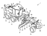
図1および図2は、一実施の形態におけるモータグレーダの構成を概略的に示す斜視図および側面図である。図1および図2に示されるように、本実施の形態におけるモータグレーダ1は、走行輪11、12と、車体フレーム2と、キャブ(運転室)3と、作業機4とを主に有している。また、モータグレーダ1は、エンジン室6に配置されたエンジンなどの構成部品を有している。作業機4は、たとえばブレード42を含んでいる。モータグレーダ1は、ブレード42で整地作業、除雪作業、軽切削、材料混合などの作業を行なうことができる。
1 and 2 are a perspective view and a side view schematically showing a configuration of a motor grader according to one embodiment. As shown in FIGS. 1 and 2, motor grader 1 in the present embodiment mainly includes traveling
走行輪11、12は、前輪11と後輪12とを含んでいる。図1、2においては、片側1輪ずつの2つの前輪11と片側2輪ずつの4つの後輪12とからなる全6輪の走行輪を示しているが、前輪11および後輪12の数および配置は、図1、2に示す例に限られるものではない。
The running
なお以下の図の説明において、モータグレーダ1が直進走行する方向を、モータグレーダ1の前後方向という。モータグレーダ1の前後方向において、作業機4に対して前輪11が配置されている側を、前方向とする。モータグレーダ1の前後方向において、作業機4に対して後輪12が配置されている側を、後方向とする。モータグレーダ1の左右方向とは、平面視において前後方向と直交する方向である。前方向を見て左右方向の右側、左側が、それぞれ右方向、左方向である。モータグレーダ1の上下方向とは、前後方向および左右方向によって定められる平面に直交する方向である。上下方向において地面のある側が下側、空のある側が上側である。
In the following description of the drawings, the direction in which the motor grader 1 travels straight is referred to as the front-back direction of the motor grader 1. In the front-rear direction of the motor grader 1, the side where the
前後方向とは、キャブ3内の運転席に着座したオペレータの前後方向である。左右方向とは、運転席に着座したオペレータの左右方向である。左右方向とは、モータグレーダ1の車幅方向である。上下方向とは、運転席に着座したオペレータの上下方向である。運転席に着座したオペレータに正対する方向が前方向であり、運転席に着座したオペレータの背後方向が後方向である。運転席に着座したオペレータが正面に正対したときの右側、左側がそれぞれ右方向、左方向である。運転席に着座したオペレータの足元側が下側、頭上側が上側である。
The front-back direction is the front-back direction of the operator sitting on the driver's seat in the
車体フレーム2は、前後方向(図2中の左右方向)に延びている。車体フレーム2は、最前部の前端2Fと、最後部の後端2Rとを有している。車体フレーム2は、リアフレーム21と、フロントフレーム22とを含んでいる。
The
リアフレーム21は、外装カバー25と、エンジン室6に配置されたエンジンなどの構成部品とを支持している。外装カバー25はエンジン室6を覆っている。リアフレーム21には、上記のたとえば4つの後輪12の各々が取付けられている。4つの後輪12の各々は、エンジンからの駆動力によって回転駆動可能である。
The
フロントフレーム22は、リアフレーム21の前方に取り付けられている。フロントフレーム22は、リアフレーム21に、回動可能に連結されている。フロントフレーム22は、前後方向に延びている。フロントフレーム22は、リアフレーム21に連結されている基端部と、基端部と反対側の先端部とを有している。フロントフレーム22の基端部は、上下方向に延びるセンタピンにより、リアフレーム21の先端部と連結されている。
The
フロントフレーム22とリアフレーム21との間には、アーティキュレートシリンダ23が取り付けられている。フロントフレーム22は、アーティキュレートシリンダ23の伸縮により、リアフレーム21に対して回動可能に設けられている。アーティキュレートシリンダ23は、キャブ3の内部に設けられる操作レバーの操作により、伸縮可能に設けられている。
An
フロントフレーム22の先端部には、上記のたとえば2つの前輪11が回転可能に取り付けられている。前輪11は、ステアリングシリンダ7の伸縮によって、フロントフレーム22に対して旋回可能に取り付けられている。モータグレーダ1は、ステアリングシリンダ7の伸縮によって、進行方向を変更することが可能である。ステアリングシリンダ7は、キャブ3の内部に設けられるハンドルまたはステアリング操作レバーの操作によって、伸縮可能である。
The
車体フレーム2の前端2Fには、カウンタウェイト55が取り付けられている。カウンタウェイト55は、フロントフレーム22に取り付けられるアタッチメントの一種である。カウンタウェイト55は、前輪11に負荷される下向きの荷重を増加して、操舵を可能にするとともにブレード42の押付荷重を増加するために、フロントフレーム22に装着されている。
A
キャブ3はフロントフレーム22に載置されている。キャブ3の内部には、ハンドル、変速レバー、作業機4の操作レバー、ブレーキ、アクセルペダル、インチングペダルなどの操作部(図示せず)が設けられている。なお、キャブ3は、リアフレーム21に載置されていてもよい。
The
作業機4は、たとえばドローバ40と、旋回サークル41と、ブレード42とを主に有している。ドローバ40は、フロントフレーム22の下方に配置されている。ドローバ40の前端部は、フロントフレーム22の先端部に、玉軸部を用いて連結されている。ドローバ40の前端部は、フロントフレーム22の先端部に揺動可能に取付けられている。
The work machine 4 mainly includes, for example, a
ドローバ40の後端部は、リフトシリンダ44、45によってフロントフレーム22に支持されている。リフトシリンダ44、45の伸縮によって、ドローバ40の後端部がフロントフレーム22に対して上下に昇降可能である。また、ドローバ40は、リフトシリンダ44、45の伸縮によって、車両進行方向に沿った軸を中心に上下に揺動可能である。また、ドローバ40は、ドローバシフトシリンダ46の伸縮によって、フロントフレーム22に対して左右に移動可能である。
The rear end of the
旋回サークル41は、フロントフレーム22の下方に配置されている。旋回サークル41は、ドローバ40の下方に配置されている。旋回サークル41は、ドローバ40の後端部に旋回(回転)可能に取付けられている。旋回サークル41は、油圧モータ49によって、ドローバ40に対し、車両上方から見て時計方向と反時計方向との両方に、旋回駆動可能である。ブレード42は、旋回サークル41に配設されている。旋回サークル41の旋回駆動によって、ブレード42のブレード推進角が調整される。ブレード推進角とは、モータグレーダ1の前後方向に対するブレード42の傾斜角度である。
The turning
ブレード42は、前輪11と後輪12との間に配置されている。前輪11は、ブレード42よりも前方に配置されている。後輪12は、ブレード42よりも後方に配置されている。ブレード42は、車体フレーム2の前端2Fと、車体フレーム2の後端2Rとの間に、配置されている。ブレード42は、旋回サークル41に支持されている。ブレード42は、旋回サークル41を介して、ドローバ40に支持されている。ブレード42は、旋回サークル41およびドローバ40を介して、フロントフレーム22に支持されている。
The
ブレード42は、旋回サークル41に対して左右方向に移動可能に支持されている。具体的には、ブレードシフトシリンダ47が、旋回サークル41およびブレード42に取り付けられており、ブレード42の長手方向に沿って配置されている。このブレードシフトシリンダ47によって、ブレード42は旋回サークル41に対して左右方向に移動可能である。ブレード42は、フロントフレーム22の長手方向に交差する方向に移動可能である。
The
またブレード42は、旋回サークル41に対して、ブレード42の長手方向に延びる軸を中心に揺動可能に支持されている。具体的には、チルトシリンダ(図示せず)が、旋回サークル41およびブレード42に取り付けられている。このチルトシリンダを伸縮させることによって、ブレード42は旋回サークル41に対してブレード42の長手方向に延びる軸を中心に揺動して、ブレード42の進行方向に対する傾斜角度を変更することができる。
The
以上のように、ブレード42は、ドローバ40と旋回サークル41とを介して、車両に対する上下の昇降、車両進行方向に沿った軸を中心とする揺動、前後方向に対する傾斜角度の変更、左右方向の移動、および、ブレード42の長手方向に延びる軸を中心とする揺動を行なうことが可能に構成されている。
As described above, the
次に、本実施の形態におけるキャブ内の構成について図3を用いて説明する。
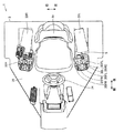
図3は、一実施の形態におけるモータグレーダのキャブ内部の構成を示す平面図である。図3に示されるように、モータグレーダ1は、キャブ3内に、運転席31、右側コンソール32Rと、左側コンソール32Lと、操作レバーと、右側アームレスト33Rと、左側アームレスト33Lと、ステアリングホイール(ハンドル)34とを主に有している。
Next, the configuration inside the cab according to the present embodiment will be described with reference to FIG.
FIG. 3 is a plan view showing a configuration inside the cab of the motor grader according to one embodiment. As shown in FIG. 3, the motor grader 1 includes a
運転席31は、モータグレーダ1を操作するオペレータが着座するためのシートである。運転席31の側方には、右側コンソール32Rおよび左側コンソール32Lの各々が配置されている。具体的には、運転席31の右側には右側コンソール32Rが配置されており、運転席31の左側には左側コンソール32Lが配置されている。
The driver's
右側コンソール32Rおよび左側コンソール32Lの各々の上部には、操作レバーが支持されている。左側コンソール32Lの上部に支持された操作レバーは、少なくとも1つの作業機レバーと、ステアリング操作レバー5とを主に有している。左側コンソール32Lに支持された少なくとも1つの作業機レバーは、作業機レバー35RR、35RC、35RL、35FR、35FLを含んでいる。
An operation lever is supported on the upper part of each of the
運転席31の側方には、右側アームレスト33Rおよび左側アームレスト33Lの各々が配置されている。右側アームレスト33Rおよび左側アームレスト33Lの各々は、運転席31に着座したオペレータが肘を載せるための部分である。右側アームレスト33Rおよび左側アームレスト33Lの各々は、運転席31の座部および背もたれ部の双方の側方に位置している。運転席31の右側に右側アームレスト33Rが配置されており、運転席31の左側に左側アームレスト33Lが配置されている。
A
右側アームレスト33Rは、右側コンソール32R上に配置されており、右側コンソール32Rに支持されている。左側アームレスト33Lは、左側コンソール32L上に配置されており、左側コンソール32Lに支持されている。
The
上記のステアリング操作レバー5と、少なくとも1つの作業機レバー35RR、35RC、35RL、35FR、35FLとは、平面視において左側アームレスト33Lと重畳しないように配置されている。
The
運転席31の前方には、ステアリングホイール34が配置されている。ステアリングホイール34は、後述するステアリング機構90(図11)を操作するものである。ステアリングホイール34を回転操作することにより、図1に示されるステアリングシリンダ7が伸縮し、前輪11がフロントフレーム22に対して旋回可能である。ステアリング操作レバー5は、たとえばステアリングの操作のみに用いられる。
A
次に、作業機レバー35RR、35RC、35RL、35FR、35FLと、ステアリング操作レバー5とについて図4〜図7を用いて説明する。
Next, the working machine levers 35RR, 35RC, 35RL, 35FR, 35FL and the
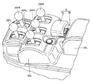
図4および図5は、左側コンソールに配置された操作レバーの構成を示す斜視図および平面図である。図4に示されるように、作業機レバー35RR、35RC、35RL、35FR、35FLの各々は、たとえば前後のみに回動可能で、かつ左右に回動不可能に構成されている。作業機レバー35RR、35RC、35RL、35FR、35FLの各々は、たとえば前後に動かすことによって操作することができる。本実施の形態では、作業機レバー35RR、35RC、35RL、35FR、35FLの各々の操作方向は同じである。作業機レバー35RR、35RC、35RL、35FR、35FLの各々は、操作されない状態では中立位置に位置しており、この中立位置から前方または後方へ移動操作される。 4 and 5 are a perspective view and a plan view showing the configuration of the operation lever arranged on the left console. As shown in FIG. 4, each of the work implement levers 35RR, 35RC, 35RL, 35FR, 35FL is configured to be rotatable only in the front-rear direction, for example, and not to be rotatable left and right. Each of the work implement levers 35RR, 35RC, 35RL, 35FR, 35FL can be operated by, for example, moving back and forth. In the present embodiment, the operation directions of the work implement levers 35RR, 35RC, 35RL, 35FR, 35FL are the same. Each of the work implement levers 35RR, 35RC, 35RL, 35FR, and 35FL is located at a neutral position when not operated, and is operated to move forward or backward from the neutral position.
作業機レバー35RRは、たとえば旋回サークル41の回転を操作するものである。作業機レバー35RRを操作することによって、図1に示される油圧モータ49が駆動し、旋回サークル41がドローバ40に対して車両上方から見て時計方向と反時計方向とのいずれかに旋回駆動可能である。
The work implement lever 35RR operates, for example, the rotation of the turning
作業機レバー35RCは、たとえばブレード42の左右方向へのシフトを操作するものである。作業機レバー35RCを操作することによって、図1に示されるブレードシフトシリンダ47が伸縮し、ブレード42は旋回サークル41に対して左右方向に移動可能である。
The work implement lever 35RC operates, for example, to shift the
作業機レバー35RLは、たとえばブレード42の左端の高さを操作するものである。作業機レバー35RLを操作することによって、図1に示されるリフトシリンダ44が伸縮し、ブレード42の左端が上下方向に移動可能である。
The work implement lever 35RL operates, for example, the height of the left end of the
作業機レバー35FR、35FLの各々は、たとえばブレード42(図1)のチルト操作、リッパの上下操作、モータグレーダ1のアーティキュレート操作などをするものである。 Each of the work implement levers 35FR and 35FL performs, for example, a tilt operation of the blade 42 (FIG. 1), a vertical operation of the ripper, an articulate operation of the motor grader 1, and the like.
上記の作業機レバー35RR、35RC、35RL、35FR、35FLと、ステアリング操作レバー5とが、左側コンソール32Lではなく、右側コンソール32Rに設けられていてもよい。この場合、作業機レバー35RR、35RC、35RL、35FR、35FLと、ステアリング操作レバー5とは、左側コンソール32Lに設けられた場合と左右対称となるように右側コンソール32Rに配置されてもよい。
The work implement levers 35RR, 35RC, 35RL, 35FR, 35FL and the
図3に示されるように、右側コンソール32Rに支持された操作レバーは、少なくとも1つ(たとえば5つ)の作業機レバーを有している。少なくとも1つの作業機レバーは、たとえば前方において左右方向に並んで配置された2つの作業機レバーと、後方において左右方向に並んで配置された3つの作業機レバーとを有している。これらの作業機レバーの各々は、たとえばドローバ40の左右方向へのシフト操作、前輪11の傾き操作(リーニング操作)、ブレード42の右端の高さ操作、アタッチメントの上下操作、モータグレーダ1のアーティキュレート操作などをするものである。
As shown in FIG. 3, the operation lever supported by the
図5に示されるように、作業機レバー35RR(第1作業機レバー)、作業機レバー35RC(第2作業機レバー)および作業機レバー35RL(第3作業機レバー)は、左右方向に1列に配置されている。作業機レバー35RCは、複数(たとえば3つ)の作業機レバーの中央に配置されている。作業機レバー35RRは、複数(たとえば3つ)の作業機レバーのうち最も右側に配置されている。作業機レバー35RLは、複数(たとえば3つ)の作業機レバーのうち最も左側に配置されている。作業機レバー35RLは、作業機レバー35RRとの間で作業機レバー35RCを挟んでいる。 As shown in FIG. 5, the working machine lever 35RR (first working machine lever), the working machine lever 35RC (second working machine lever), and the working machine lever 35RL (third working machine lever) are arranged in one row in the left-right direction. Are located in The work implement lever 35RC is arranged at the center of a plurality (for example, three) of work implement levers. The work implement lever 35RR is arranged on the rightmost side of a plurality (for example, three) of work implement levers. The work implement lever 35RL is arranged on the leftmost side among a plurality (for example, three) of work implement levers. The work implement lever 35RL sandwiches the work implement lever 35RC between the work implement lever 35RR.
作業機レバー35FRおよび作業機レバー35FLの各々は、作業機レバー35RR、35RC、35RLの前方に位置している。作業機レバー35FRおよび作業機レバー35FLは、左右方向に互いに並んで配置されている。作業機レバー35FRは右側に、作業機レバー35FLは左側に配置されている。 Each of work implement lever 35FR and work implement lever 35FL is located in front of work implement levers 35RR, 35RC, 35RL. The work implement lever 35FR and the work implement lever 35FL are arranged side by side in the left-right direction. The work implement lever 35FR is arranged on the right side, and the work implement lever 35FL is arranged on the left side.
作業機レバー35FRは、作業機レバー35RRおよび作業機レバー35RCに挟まれる領域に対して、作業機レバー35RR、35RCの操作方向の前方に位置している。作業機レバー35FLは、作業機レバー35RCおよび作業機レバー35RLに挟まれる領域に対して、作業機レバー35RC、35RLの操作方向の前方に位置している。 The work implement lever 35FR is located forward in the operation direction of the work implement levers 35RR, 35RC with respect to a region sandwiched between the work implement levers 35RR and 35RC. The work implement lever 35FL is located forward in the operation direction of the work implement levers 35RC and 35RL with respect to a region sandwiched between the work implement lever 35RC and the work implement lever 35RL.
図4に示されるように、ステアリング操作レバー5は、後述するステアリング機構90(図11)を操作するものである。具体的には、ステアリング操作レバー5を操作することにより、図1に示されるステアリングシリンダ7が伸縮し、前輪11がフロントフレーム22に対して旋回可能である。
As shown in FIG. 4, the
ステアリング操作レバー5は、たとえばジョイスティックレバーである。ステアリング操作レバー5の操作方向は、作業機レバー35RR、35RC、35RL、35FR、35FLの各々の操作方向と交差する方向(たとえば直交する方向)である。ステアリング操作レバー5は、たとえば左右のみに回動可能で、かつ前後に回動不可能に構成されている。ステアリング操作レバー5は、たとえば左右に動かすことによって操作することができる。
The
図5に示されるように、ステアリング操作レバー5は、左側コンソール32Lに支持された少なくとも1つの作業機レバー(作業機レバー35RR、35RC、35RL、35FR、35FL)の後方に配置されている。
As shown in FIG. 5, the
ステアリング操作レバー5は、平面視において、作業機レバー35RR(第1作業機レバー)と作業機レバー35RC(第2作業機レバー)とに挟まれる領域RAに対して、作業機レバー35RR、35RC、35RLの操作方向の後方側(図中矢印A側)に配置されている。ステアリング操作レバー5のレバー本体5aの下面に接続されたスティック5bも、平面視において、上記領域RAに対して、作業機レバー35RR、35RC、35RLの操作方向の後方側(図中矢印A側)に配置されている。
The
作業機レバー35RR、35RC、35RLが並ぶ方向は、運転席31に着座したオペレータ視点における左右方向に対して平面視において傾斜していてもよい。この場合、運転席31に近い作業機レバー35RRが作業機レバー35RCに対して前方に位置し、かつ運転席31から遠い作業機レバー35RLが作業機レバー35RCに対して後方に位置するように、作業機レバー35RR、35RC、35RLが並ぶ方向がオペレータ視点における左右方向に対して傾斜していてもよい。
The direction in which the work implement levers 35RR, 35RC, and 35RL are arranged may be inclined in plan view with respect to the left and right directions from the viewpoint of the operator sitting on the driver's
また作業機レバー35RR、35RC、35RLの操作方向は、運転席31に着座したオペレータ視点における前後方向に対して平面視において傾斜していてもよい。この場合、各作業機レバーが操作方向の前方に移動するにつれて運転席31から側方側に離れるように、作業機レバー35RR、35RC、35RLの操作方向がオペレータ視点における前後方向に対して傾斜していてもよい。
Further, the operation direction of the work implement levers 35RR, 35RC, 35RL may be inclined in a plan view with respect to the front-back direction at the viewpoint of the operator sitting on the driver's
またステアリング操作レバー5の操作方向は、運転席31に着座したオペレータ視点における左右方向に対して平面視において傾斜していてもよい。この場合、ステアリング操作レバー5の操作方向は、ステアリング操作レバー5が運転席31から側方側に離れるにつれて後方側へ移動するように、オペレータ視点における左右方向に対して傾斜していてもよい。
Further, the operation direction of the
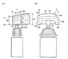
図6は、ステアリング操作レバーの構成を示す側面図(A)および背面図(B)である。図6(A)および図6(B)に示されるように、ステアリング操作レバー5は、上面5a1と、上面5a1より下方に位置する下部(たとえばスティック5bなど)を有している。ステアリング操作レバー5は、レバー本体5aと、スティック5bとを有している。レバー本体5aは、上面5a1と、面取り5a2、5a3と、側面5a4、5a5と、下面5a6とを有している。
FIG. 6 is a side view (A) and a rear view (B) showing the configuration of the steering operation lever. As shown in FIGS. 6A and 6B, the
図6(B)に示されるように、上面5a1は、左右方向に互いに対向する第1端E1と第2端E2とを有している。上面5a1の第1端E1には面取り5a2が接続され、面取り5a2は上面5a1に連なっている。上面5a1との間で面取り5a2を挟むように側面5a4が面取り5a2に接続され、側面5a4は面取り5a2に連なっている。側面5a4は、たとえば上下方向および前後方向に延びている。 As shown in FIG. 6B, the upper surface 5a1 has a first end E1 and a second end E2 facing each other in the left-right direction. A chamfer 5a2 is connected to the first end E1 of the upper surface 5a1, and the chamfer 5a2 is connected to the upper surface 5a1. The side surface 5a4 is connected to the chamfer 5a2 so as to sandwich the chamfer 5a2 between the upper surface 5a1 and the side surface 5a4 is continuous with the chamfer 5a2. The side surface 5a4 extends, for example, in the up-down direction and the front-back direction.
面取り5a2は、上面5a1の第1端E1から第2端E2側とは反対側へ向かうにしたがって下方に位置するように傾斜して側面5a4の上端に達している。面取り5a2は、上面5a1の第1端E1から側面5a4の上端までたとえばラウンドしながら傾斜している。ただし面取り5a2は、上面5a1の第1端E1から側面5a4の上端まで直線状に傾斜していてもよい。 The chamfer 5a2 is inclined so as to be located lower as going from the first end E1 of the upper surface 5a1 to the side opposite to the second end E2, and reaches the upper end of the side surface 5a4. The chamfer 5a2 is inclined, for example, in a round from the first end E1 of the upper surface 5a1 to the upper end of the side surface 5a4. However, the chamfer 5a2 may be linearly inclined from the first end E1 of the upper surface 5a1 to the upper end of the side surface 5a4.
上面5a1の第2端E2には面取り5a3が接続され、面取り5a3は上面5a1に連なっている。上面5a1との間で面取り5a3を挟むように側面5a5が面取り5a3に接続され、側面5a5は面取り5a3に連なっている。側面5a5は、たとえば上下方向および前後方向に延びている。 A chamfer 5a3 is connected to the second end E2 of the upper surface 5a1, and the chamfer 5a3 is connected to the upper surface 5a1. The side surface 5a5 is connected to the chamfer 5a3 so as to sandwich the chamfer 5a3 with the upper surface 5a1, and the side surface 5a5 is continuous with the chamfer 5a3. The side surface 5a5 extends, for example, in the up-down direction and the front-back direction.
面取り5a3は、上面5a1の第2端E2から第1端E1側とは反対側へ向かうにしたがって下方に位置するように傾斜して側面5a5の上端に達している。面取り5a3は、上面5a1の第2端E2から側面5a5の上端までたとえばラウンドしながら傾斜している。ただし面取り5a3は、上面5a1の第2端E2から側面5a5の上端まで直線状に傾斜していてもよい。 The chamfer 5a3 is inclined so as to be located lower as it goes from the second end E2 of the upper surface 5a1 to the side opposite to the first end E1, and reaches the upper end of the side surface 5a5. The chamfer 5a3 is inclined, for example, in a round from the second end E2 of the upper surface 5a1 to the upper end of the side surface 5a5. However, the chamfer 5a3 may be linearly inclined from the second end E2 of the upper surface 5a1 to the upper end of the side surface 5a5.
図6(A)に示されるように、側面視における面取り5a2の高さHcは、後方から前方に向かうに従って大きくなる。面取り5a2の高さHcは、側面視における側面5a4の上端から上面5a1の第1端E1までのスティック5bの延びる方向(またはレバー本体5aの下面5a6に直交する方向)の投影寸法である。
As shown in FIG. 6A, the height Hc of the chamfer 5a2 in a side view increases from the rear to the front. The height Hc of the chamfer 5a2 is a projection dimension in a direction in which the
側面視における側面5a4の高さHsは、後方から前方の途中位置までは一定でありその途中位置からは前方に向かうに従って小さくなる。 The height Hs of the side surface 5a4 in the side view is constant from the rear to the front midpoint, and decreases from the midpoint toward the front.
レバー本体5aの側面視における上端(破線LUに沿う部分)は、レバー本体5aの側面視における下端(破線LBに沿う部分)に対して前方に向かって上がり傾斜となっている。これによりレバー本体5aの前端におけるレバー本体5aの下端から上端までの高さHFは、レバー本体5aの後端におけるレバー本体5aの下端から上端までの高さHBよりも高くなっている。上記高さHF、HBの各々は、側面視におけるスティック5bの延びる方向(またはレバー本体5aの下面5a6に直交する方向)の高さである。
The upper end (the portion along the broken line LU) of the
図7は、ステアリング操作レバーの回動の様子を示す図である。図7に示されるように、ステアリング操作レバー5は、上面5a1と、上面5a1より下方に位置する下部を有している。ステアリング操作レバー5の上面5a1はレバー本体5aの上面であり、ステアリング操作レバー5の下部はスティック5bである。
FIG. 7 is a diagram illustrating a state of rotation of the steering operation lever. As shown in FIG. 7, the
上面5a1は、ステアリング操作レバー5の下部における回動中心CEを中心として回動可能である。具体的にはスティック5bの上端が左右方向に揺動するようにスティック5bが回動軸SHにより回動可能に支持されている。回動軸SHは、スティック5bの下端部付近(根元部付近)においてスティック5bを回動可能に支持している。回動軸SHの回動中心CEはたとえば前後方向に延びている。スティック5bの上端はたとえば左右方向に揺動可能である。なお回動中心CEの延びる方向は、前後方向と左右方向とを含む面内に位置していれば、前後方向からずれていてもよい。
The upper surface 5a1 is rotatable around a rotation center CE at a lower portion of the
ステアリング操作レバー5は、操作されない状態においては中立位置(図7において実線で示された位置)に位置している。ステアリング操作レバー5は、この中立位置から上記の回動により右側または左側へ移動するよう操作される。スティック5bの回動によりステアリング操作レバー5は、操作方向へ移動可能である。
The
レバー本体5aの上面5a1は、回動中心CEの延びる方向から見て円弧形状を有している。上面5a1の円弧形状は、たとえば回動中心CEを中心とした円周(破線CP)に沿う形状である。具体的には上面5a1の円弧形状は、円周方向の全体において回動中心CEから同じ距離rの位置にある。回動中心CEの延びる方向から見た上面5a1の円弧形状の回動中心CEから円弧形状の中央部CPまでの距離rは、回動中心CEから円弧形状の第1端E1までの距離rおよび回動中心CEから円弧形状の第2端E2までの距離rの各々と同じである。
The upper surface 5a1 of the
ただし回動中心CEの延びる方向から見た上面5a1の円弧形状は、上記距離rと異なる曲率半径を有していてもよい。具体的には回動中心CEの延びる方向から見た上面5a1の円弧形状は、回動中心CEから円弧形状の中央部CPまでの距離(半径)rと異なる曲率半径を有していてもよい。たとえば上面5a1の上記円弧形状は、回動中心CEから円弧形状の中央部CPまでの距離(半径)rよりも大きい曲率半径を有していてもよく、また上記距離(半径)rよりも小さい曲率半径を有していてもよい。 However, the arc shape of the upper surface 5a1 viewed from the direction in which the rotation center CE extends may have a radius of curvature different from the distance r. Specifically, the arc shape of the upper surface 5a1 viewed from the direction in which the rotation center CE extends may have a curvature radius different from the distance (radius) r from the rotation center CE to the center portion CP of the arc shape. . For example, the arc shape of the upper surface 5a1 may have a radius of curvature larger than the distance (radius) r from the center of rotation CE to the center portion CP of the arc shape, and may be smaller than the distance (radius) r. It may have a radius of curvature.
この場合、上面5a1の上記円弧形状の回動中心CEから円弧形状の中央部CPまでの距離rは、回動中心CEから円弧形状の第1端E1までの距離および回動中心CEから円弧形状の第2端E2までの距離の各々よりも大きくてもよく、また小さくてもよい。 In this case, the distance r from the arc-shaped rotation center CE of the upper surface 5a1 to the arc-shaped center portion CP is the distance from the rotation center CE to the arc-shaped first end E1 and the arc-shaped from the rotation center CE. May be larger or smaller than each of the distances to the second end E2.
ステアリング操作レバー5の中立位置から左右方向の一方への回動可能角度A1および左右方向の他方への回動可能角度A2の各々はたとえば25±1°である。ステアリング操作レバー5が中立位置から左右方向の一方へ最大限回動した状態(中立位置から25±1°回動した状態)において上面5a1の一部は、中立位置にある上面5a1の一部と領域R1において重畳する。またステアリング操作レバー5が中立位置から左右方向の他方へ最大限回動した状態(中立位置から25±1°回動した状態)において上面5a1の一部は、中立位置にある上面5a1の一部と領域R2において重畳する。
Each of the rotatable angle A1 in the left-right direction from the neutral position of the
図6(A)に示される上面5a1のたとえば前後方向の全体において、上面5a1は図7に示されるように回動中心CEを中心とした円周(破線CP)に沿う形状を有している。 For example, as shown in FIG. 7, the upper surface 5a1 has a shape along the circumference (broken line CP) around the rotation center CE as shown in FIG. .
図8は、キャブ内における運転席と操作レバーとの構成を示す側面図である。図8に示されるように、少なくとも1つの作業機レバー35RR、35RC、35RLの上端の高さ位置H1は、ステアリング操作レバー5の上端の高さ位置H3よりも高い。作業機レバー35RR、35RC、35RLの上端の高さ位置H1は、ステアリング操作レバー5の上端の高さ位置H3よりも高い。
FIG. 8 is a side view showing the configuration of the driver's seat and the operation lever in the cab. As shown in FIG. 8, the height position H1 at the upper end of at least one of the work implement levers 35RR, 35RC, 35RL is higher than the height position H3 at the upper end of the
作業機レバー35RRの上端の高さ位置H1、作業機レバー35RCの上端の高さ位置H1、および作業機レバー35RLの上端の高さ位置H1はほぼ同じである。 The height position H1 of the upper end of the work implement lever 35RR, the height position H1 of the upper end of the work implement lever 35RC, and the height position H1 of the upper end of the work implement lever 35RL are substantially the same.
なお上記の高さ位置H1、H3は、キャブ3の床30の上面(床面)からの高さである。
The above-mentioned height positions H1 and H3 are the heights of the
次に、本実施の形態におけるステアリング操作レバー5および作業機レバーの最大離間距離とについて、図9および図10を用いて説明する。
Next, the maximum separation distance between the steering
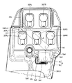
図9は、操作レバーの操作の第1の態様における作業機レバー35RLとステアリング操作レバー5との最大離間距離を説明するための平面図である。図10は、操作レバーの操作の第2の態様における作業機レバー35RRとステアリング操作レバー5との最大離間距離を説明するための平面図である。
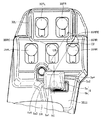
FIG. 9 is a plan view for explaining the maximum separation distance between the work implement lever 35RL and the
図9に示されるように、オペレータは、ステアリング操作をしながら作業機の操作を行う、いわゆる複合操作を行う場合がある。たとえばオペレータがステアリング操作をしながら、ブレード42の左端部の上下操作をする場合、オペレータはステアリング操作レバー5を操作しながら、作業機レバー35RLを操作することになる。
As shown in FIG. 9, the operator sometimes performs a so-called combined operation of operating a work implement while performing a steering operation. For example, when the operator performs the up / down operation of the left end of the
この操作においてステアリング操作レバー5が最大限右へ回動され、かつ作業機レバー35RLが最大限前方に回動された場合、ステアリング操作レバー5と作業機レバー35RLとの距離が最も大きくなる。
In this operation, when the
ここでステアリング操作レバー5と作業機レバー35RLとの距離が最も大きくなる距離(最大離間距離)LAが大きくなりすぎると、オペレータの左手の掌がステアリング操作レバー5に載せられた状態において左手の指が作業機レバー35RLに届かなくなる。このため、ステアリング操作レバー5と作業機レバー35RLとの最大離間距離LAを適切に設定しなければ上記の複合操作ができない状況が生じる。
Here, if the distance LA (the maximum separation distance) at which the distance between the steering
そこで図9に示されるように、ステアリング操作レバー5と作業機レバー35RLとの最大離間距離LAは、たとえば120mm以上160mm以下に設定される。最大離間距離LAが上記のとおり設定されることにより、比較的指の短いオペレータであっても、上記の複合操作を適切に行うことが可能となる。
Therefore, as shown in FIG. 9, the maximum separation distance LA between the steering
なお本開示における最大離間距離LAは、ステアリング操作レバー5が最大限右へ回動され、かつ作業機レバー35RLが最大限前方に回動された状態での、レバー本体5aの前端における左右方向の中心部5Cと作業機レバー35RLの前方部35RLEとの間の距離である。作業機レバー35RLの前方部35RLEは、上記中心部5Cと作業機レバー35RLの中心C1とを通る仮想の直線が作業機レバー35RLと交差する点のうち最も前方の点である。
Note that the maximum separation distance LA in the present disclosure is the left and right direction at the front end of the lever
また図10に示されるように、上記と同様、たとえばオペレータがステアリング操作をしながら、旋回サークル41の回転操作をする場合、オペレータはステアリング操作レバー5を操作しながら、作業機レバー35RRを操作することになる。
Further, as shown in FIG. 10, similarly to the above, for example, when the operator performs the rotation operation of the turning
この操作においてステアリング操作レバー5が最大限左へ回動され、かつ作業機レバー35RRが最大限前方に回動された場合、ステアリング操作レバー5と作業機レバー35RRとの距離が最も大きくなる。
In this operation, when the
ここでステアリング操作レバー5と作業機レバー35RRとの距離が最も大きくなる距離(最大離間距離)LBが大きくなりすぎると、左手の掌がステアリング操作レバー5に載せられた状態において左手の指が作業機レバー35RRに届かなくなる。このため、ステアリング操作レバー5と作業機レバー35RRとの最大離間距離LBを適切に設定しなければ上記の複合操作ができない状況が生じる。
If the distance (maximum separation distance) LB at which the distance between the steering
そこで図10に示されるように、ステアリング操作レバー5と作業機レバー35RRとの最大離間距離LBは、たとえば100mm以上140mm以下に設定される。最大離間距離LBが上記のとおり設定されることにより、比較的指の短いオペレータであっても、上記の複合操作を適切に行うことが可能となる。
Therefore, as shown in FIG. 10, the maximum separation distance LB between the steering
なお本開示における最大離間距離LBは、ステアリング操作レバー5が最大限左へ回動され、かつ作業機レバー35RRが最大限前方に回動された状態での、レバー本体5aの前端における左右方向の中心部5Cと作業機レバー35RRの前方部35RREとの間の距離である。作業機レバー35RRの前方部35RREは、上記中心部5Cと作業機レバー35RRの中心C2とを通る仮想の直線が作業機レバー35RRと交差する点のうち最も前方の点である。上記最大離間距離LAは上記最大離間距離LBよりも大きいことが好ましい。
Note that the maximum separation distance LB in the present disclosure is the left-right direction at the front end of the lever
次に、本実施の形態におけるステアリング機構の構成およびステアリング操作について図11を用いて説明する。 Next, the configuration of the steering mechanism and the steering operation in the present embodiment will be described with reference to FIG.
図11は、ステアリング機構の構成を示す油圧回路図である。図11に示されるように、ステアリング機構90は、レバー用バルブ81と、ステアリングコントロールバルブ82と、ステアリング優先弁83と、ステアリング角センサ84と、ポンプ85と、油タンク86、87とを主に有している。
FIG. 11 is a hydraulic circuit diagram showing the configuration of the steering mechanism. As shown in FIG. 11, the
ステアリングホイール34は、ステアリング角センサ84を介在してステアリングコントロールバルブ82に接続されている。ステアリングコントロールバルブ82のPポートはポンプ85に接続されている。ステアリングコントロールバルブ82のTポートは油タンク86に接続されている。ステアリングコントロールバルブ82のRポートは、油路91を介在してステアリングシリンダ7a、7bに接続されている。ステアリングコントロールバルブ82のLポートは、油路92を介在してステアリングシリンダ7a、7bに接続されている。
The
ステアリング操作レバー5は、レバー用バルブ81に電気的に接続されている。これによりステアリング操作レバー5の制御信号がレバー用バルブ81に入力される。レバー用バルブ81のPポートはポンプ85に接続されている。レバー用バルブ81のTポートは油タンク87に接続されている。レバー用バルブ81のRポートは、ステアリング優先弁83を介在して油路91に接続されており、油路91を介在してステアリングシリンダ7a、7bに接続されている。レバー用バルブ81のLポートは、ステアリング優先弁83を介在して油路92に接続されており、油路92を介在してステアリングシリンダ7a、7bに接続されている。ステアリング優先弁83にはステアリング角センサ84からの出力信号を入力可能である。
The
上記のステアリング機構におけるステアリング操作は以下のように行われる。
ステアリングコントロールバルブ82には、ポンプ85から吐出された油が入る。ステアリングホイール34の右回転時には、ステアリングホイール34の回転量に比例した量の油がステアリングコントロールバルブ82のRポートからステアリングシリンダ7a、7bの各々へ吐出される。これによりステアリングホイール34の右回転時には、車両が右旋回するように車輪の操舵が行われる。
The steering operation in the above steering mechanism is performed as follows.
The oil discharged from the
またステアリングホイール34の左回転時には、ステアリングホイール34の回転量に比例した量の油がステアリングコントロールバルブ82のLポートからステアリングシリンダ7a、7bの各々へ吐出される。これによりステアリングホイール34の左回転時には、車両が左旋回するように車輪の操舵が行われる。
When the
レバー用バルブ81には、ポンプ85から吐出された油が入る。ステアリング操作レバー5を右側へ回動させた時には、ステアリング操作レバー5の回動量に比例した量の油がレバー用バルブ81のRポートからステアリング優先弁83を通じてステアリングシリンダ7a、7bの各々へ吐出される。これによりステアリング操作レバー5の右回動時には、車両が右旋回するように車輪の操舵が行われる。
The oil discharged from the
またステアリング操作レバー5を左側へ回動させた時には、ステアリング操作レバー5の回動量に比例した量の油がレバー用バルブ81のLポートからステアリング優先弁83を通じてステアリングシリンダ7a、7bの各々へ吐出される。これによりステアリング操作レバー5の左回動時には、車両が左旋回するように車輪の操舵が行われる。
When the
またステアリングホイール34が操作されている場合、ステアリング角センサ84からの出力信号がステアリング優先弁83に入力される。ステアリング優先弁83がステアリング角センサ84からの信号を受けると、ステアリング優先弁83は閉じる。これにより、ステアリングホイール34が操作されている状態でステアリング操作レバー5が操作された場合、またはステアリング操作レバー5が操作されている状態でステアリングホイール34が操作された場合のいずれにおいても、ステアリングホイール34による操作が優先される。
When the
次に本実施の形態の作用効果について説明する。
本実施の形態によれば、図7に示されるようにステアリング操作レバー5の上面5a1は、上面5a1が回動中心CEの延びる方向から見て円弧形状を有している。これによりオペレータが掌を上面5a1に載せてステアリング操作レバー5を操作する際に、掌を自然な状態で上面5a1に載せてステアリング操作レバー5を操作できる。このためオペレータはステアリング操作レバー5の操作に気を取られることが少なくなり、その分、作業機レバー35RR、35RC、35RL、35FR、35FLの各々の操作に集中することが可能となる。これによりステアリング操作と作業機操作とを同時に行う場合でも、ステアリングと作業機4との双方を繊細に操作することが容易となる。
Next, the operation and effect of the present embodiment will be described.
According to the present embodiment, as shown in FIG. 7, the upper surface 5a1 of the
また本実施の形態によれば、図7に示されるように、上面5a1の円弧形状は、スティック5bにおける回動中心CEを中心とした円周に沿う形状である。これにより上面5a1が回動しても上面5a1の位置が円周上に位置し続けるため、オペレータはステアリング操作レバー5の操作に気を取られることがさらに少なくなる。このためステアリングと作業機4との双方を繊細に操作することがより容易となる。
According to the present embodiment, as shown in FIG. 7, the arc shape of upper surface 5a1 is a shape along the circumference of
また本実施の形態によれば、図6(A)に示されるように、側面視においてレバー本体5aの上端はレバー本体5aの下端に対して前方に向かって上がり傾斜となっている。これにより上面5a1に掌を載せた状態で指を指の付け根から指先に向かって上がり傾斜にすることが容易となる。このため図8に示すように作業機レバーの上端の高さ位置H1がステアリング操作レバー5の上端の高さ位置H3よりも高い場合でも、指で作業機レバーを操作することが容易となる。
Further, according to the present embodiment, as shown in FIG. 6A, the upper end of the lever
また本実施の形態によれば、図5に示されるように、ステアリング操作レバー5は平面視において矩形形状を有している。これによりレバー本体5aの形状をオペレータの掌の形状に整合させやすくなる。
Further, according to the present embodiment, as shown in FIG. 5, the
また本実施の形態によれば、図6(A)に示されるように、運転席31側に位置する面取り5a2の高さHcは側面視において後方から前方に向かうにしたがって大きくなる。これにより掌を上面5a1に載せた状態で親指の付け根を面取り5a2に沿わせることが容易となり、より自然な状態でオペレータはステアリング操作レバー5を操作することができる。
Further, according to the present embodiment, as shown in FIG. 6A, the height Hc of the chamfer 5a2 located on the driver's
また本実施の形態によれば、図9および図10に示されるように、作業機レバーは前後に回動可能であり、ステアリング操作レバー5は左右に回動可能である。このように回動するレバーの組合せにおいて、上記円弧形状の上面5a1を有するステアリング操作レバー5は特に適している。
Further, according to the present embodiment, as shown in FIGS. 9 and 10, the work implement lever can rotate back and forth, and the
また本実施の形態によれば、図8に示されるように、作業機レバー35RR、35RC、35RLの上端の高さ位置H1は、ステアリング操作レバー5の上端の高さ位置H3よりも高い。これによりオペレータがアームレスト33Lに肘を載せた状態で作業機レバーを操作する際に、誤ってステアリング操作レバー5を操作することが抑制される。
According to the present embodiment, as shown in FIG. 8, the height position H1 at the upper end of the work implement levers 35RR, 35RC, 35RL is higher than the height position H3 at the upper end of the
また本実施の形態によれば、図9に示される作業機レバー35RLとステアリング操作レバー5との最大離間距離LAは、図10に示される作業機レバー35RRとステアリング操作レバー5との最大離間距離LBよりも大きい。これにより、オペレータが片手(たとえば左手)で操作する際に操作が容易となる。
Further, according to the present embodiment, the maximum separation distance LA between work implement lever 35RL and steering
また図9に示される最大離間距離LAは120mm以上160mm以下であり、図10に示される最大離間距離LBは100mm以上140mm以下である。これにより上述のとおり比較的指の短いオペレータでもステアリング操作レバー5を操作しながら作業機レバー35RL、35RRを操作することが容易となる。
The maximum separation distance LA shown in FIG. 9 is 120 mm or more and 160 mm or less, and the maximum separation distance LB shown in FIG. 10 is 100 mm or more and 140 mm or less. As a result, as described above, even an operator having relatively short fingers can easily operate the work implement levers 35RL and 35RR while operating the
今回開示された実施の形態はすべての点で例示であって制限的なものではないと考えられるべきである。本発明の範囲は上記した説明ではなくて請求の範囲によって示され、請求の範囲と均等の意味および範囲内でのすべての変更が含まれることが意図される。 The embodiments disclosed this time are to be considered in all respects as illustrative and not restrictive. The scope of the present invention is defined by the terms of the claims, rather than the description above, and is intended to include any modifications within the scope and meaning equivalent to the terms of the claims.
1 モータグレーダ、2 車体フレーム、2F 前端、2R 後端、3 キャブ、4 作業機、5 ステアリング操作レバー、5C 中心部、5a レバー本体、5a1 上面、5a2,5a3 面取り、5a4,5a5 側面、5a6 下面、5b スティック、6 エンジン室、7,7a,7b ステアリングシリンダ、11 前輪、12 後輪、21 リアフレーム、22 フロントフレーム、23 アーティキュレートシリンダ、25 外装カバー、30 床、31 運転席、32L 左側コンソール、32R 右側コンソール、33L 左側アームレスト、33R 右側アームレスト、34 ステアリングホイール、35FL,35FR,35RC,35RL,35RR 作業機レバー、35RLE,35RRE 前方部、40 ドローバ、41 旋回サークル、42 ブレード、44 リフトシリンダ、46 ドローバシフトシリンダ、47 ブレードシフトシリンダ、49 油圧モータ、55 カウンタウェイト、81 レバー用バルブ、82 ステアリングコントロールバルブ、83 ステアリング優先弁、84 ステアリング角センサ、85 ポンプ、86,87 油タンク、90 ステアリング機構、91,92 油路、A1,A2 回動可能角度、C1,C2 中心、CE 回動中心、CP 中央部、E1 第1端、E2 第2端、LA,LB 最大離間距離、R1,R2,RA 領域、SH 回動軸。 Reference Signs List 1 motor grader, 2 body frame, 2F front end, 2R rear end, 3 cab, 4 work machine, 5 steering operation lever, 5C center, 5a lever body, 5a1 upper surface, 5a2, 5a3 chamfer, 5a4, 5a5 side surface, 5a6 lower surface , 5b stick, 6 engine room, 7, 7a, 7b steering cylinder, 11 front wheels, 12 rear wheels, 21 rear frame, 22 front frame, 23 articulated cylinder, 25 exterior cover, 30 floor, 31 driver seat, 32L left console , 32R right console, 33L left armrest, 33R right armrest, 34 steering wheel, 35FL, 35FR, 35RC, 35RL, 35RR work equipment lever, 35RLE, 35RRE front part, 40 drawbar, 41 turning support Wheels, 42 blades, 44 lift cylinders, 46 drawbar shift cylinders, 47 blade shift cylinders, 49 hydraulic motors, 55 counterweights, 81 lever valves, 82 steering control valves, 83 steering priority valves, 84 steering angle sensors, 85 pumps, 86, 87 oil tank, 90 steering mechanism, 91, 92 oil passage, A1, A2 rotatable angle, C1, C2 center, CE rotation center, CP center, E1 first end, E2 second end, LA, LB Maximum separation distance, R1, R2, RA area, SH rotation axis.
Claims (8)
ステアリング機構と、
運転席と、
前記運転席の側方に配置されたコンソールと、
前記コンソールに支持され、かつ前記作業機を操作する少なくとも1つの作業機レバーと、
前記少なくとも1つの作業機レバーの後方にて前記コンソールに支持され、かつ前記ステアリング機構を操作するステアリング操作レバーとを備え、
前記ステアリング操作レバーは、上面と、前記上面より下方に位置する下部とを有し、
前記上面は、前記下部における回動中心を中心として回動可能であり、かつ前記上面が前記回動中心の延びる方向から見て円弧形状を有する、作業機械。 Work equipment,
A steering mechanism,
Driver's seat,
A console arranged beside the driver's seat,
At least one work implement lever supported by the console and operating the work implement;
A steering operation lever that is supported by the console behind the at least one work implement lever and that operates the steering mechanism;
The steering operation lever has an upper surface and a lower portion located below the upper surface,
The work machine, wherein the upper surface is rotatable about a rotation center in the lower portion, and the upper surface has an arc shape when viewed from a direction in which the rotation center extends.
側面視において、前記レバー本体の上端は前記レバー本体の下端に対して前方に向かって上がり傾斜となっている、請求項1に記載の作業機械。 The steering operation lever has a lever body having the upper surface,
The work machine according to claim 1, wherein an upper end of the lever body is inclined upward and forward with respect to a lower end of the lever body in a side view.
側面視における前記面取りの高さは、後方から前方に向かうにしたがって大きくなる、請求項1に記載の作業機械。 The steering operation lever has a side surface located on the driver's seat side of the upper surface, and a chamfer located between the upper surface and the side surface,
The work machine according to claim 1, wherein a height of the chamfer in a side view increases from a rear side to a front side.
前記第3作業機レバーと前記ステアリング操作レバーとの最大離間距離は、前記第1作業機レバーと前記ステアリング操作レバーとの最大離間距離よりも大きい、請求項1に記載の作業機械。 The at least one work implement lever has a first work implement lever, a second work implement lever, and a third work implement lever that sandwiches the second work implement lever between the first work implement lever. ,
The work machine according to claim 1, wherein a maximum separation distance between the third work equipment lever and the steering operation lever is larger than a maximum separation distance between the first work equipment lever and the steering operation lever.
Priority Applications (4)
| Application Number | Priority Date | Filing Date | Title |
|---|---|---|---|
| JP2018130129A JP7201350B2 (en) | 2018-07-09 | 2018-07-09 | Working machines and motor graders |
| CN201980038662.9A CN112236563B (en) | 2018-07-09 | 2019-02-26 | Working machine and motor grader |
| US17/254,995 US20210270012A1 (en) | 2018-07-09 | 2019-02-26 | Work machine and motor grader |
| PCT/JP2019/007336 WO2020012692A1 (en) | 2018-07-09 | 2019-02-26 | Work machinery and motor grader |
Applications Claiming Priority (1)
| Application Number | Priority Date | Filing Date | Title |
|---|---|---|---|
| JP2018130129A JP7201350B2 (en) | 2018-07-09 | 2018-07-09 | Working machines and motor graders |
Publications (2)
| Publication Number | Publication Date |
|---|---|
| JP2020007795A true JP2020007795A (en) | 2020-01-16 |
| JP7201350B2 JP7201350B2 (en) | 2023-01-10 |
Family
ID=69142310
Family Applications (1)
| Application Number | Title | Priority Date | Filing Date |
|---|---|---|---|
| JP2018130129A Active JP7201350B2 (en) | 2018-07-09 | 2018-07-09 | Working machines and motor graders |
Country Status (4)
| Country | Link |
|---|---|
| US (1) | US20210270012A1 (en) |
| JP (1) | JP7201350B2 (en) |
| CN (1) | CN112236563B (en) |
| WO (1) | WO2020012692A1 (en) |
Cited By (1)
| Publication number | Priority date | Publication date | Assignee | Title |
|---|---|---|---|---|
| WO2023286442A1 (en) * | 2021-07-16 | 2023-01-19 | 株式会社小松製作所 | Work machine and method for controlling work machine |
Citations (3)
| Publication number | Priority date | Publication date | Assignee | Title |
|---|---|---|---|---|
| JP2002323931A (en) * | 2001-04-26 | 2002-11-08 | Komatsu Ltd | Hydraulic shovel |
| JP2008054536A (en) * | 2006-08-30 | 2008-03-13 | Mitsubishi Agricult Mach Co Ltd | Operating lever of combine harvester |
| US20090223092A1 (en) * | 2008-03-07 | 2009-09-10 | Deere And Company | Arrangement of steering wheel and operator seat assembly |
Family Cites Families (14)
| Publication number | Priority date | Publication date | Assignee | Title |
|---|---|---|---|---|
| US354367A (en) * | 1886-12-14 | William h | ||
| DE2747589C2 (en) * | 1977-10-24 | 1982-05-27 | International Harvester Company Mbh, 4040 Neuss | Device for displaying symbols on gear levers |
| US4738417A (en) * | 1987-02-02 | 1988-04-19 | Fmc Corporation | Hand operated control |
| JP2000230506A (en) * | 1999-02-10 | 2000-08-22 | Komatsu Ltd | Actuator drive device by operation lever and operation lever device |
| US6550562B2 (en) * | 2000-12-08 | 2003-04-22 | Clark Equipment Company | Hand grip with microprocessor for controlling a power machine |
| USD556790S1 (en) * | 2006-11-17 | 2007-12-04 | Deere & Company | Electronic grader control unit assembly |
| US8333250B2 (en) * | 2008-03-07 | 2012-12-18 | Deere & Company | Mounting console with visibility improvements |
| GB2460658A (en) * | 2008-06-04 | 2009-12-09 | Valtra Oy Ab | Driver interface for a utility vehicle |
| CN201738367U (en) * | 2009-11-25 | 2011-02-09 | 天津建筑机械厂 | Special left-hand centralized control system for earthmovers |
| WO2011075012A1 (en) * | 2009-12-17 | 2011-06-23 | Volvo Construction Equipment Ab | A control lever for operating a working machine |
| CN102470890B (en) * | 2010-03-31 | 2014-01-29 | 株式会社Kcm | Steering system for industrial machinery and vehicle-refracting angle changing method |
| US8543298B2 (en) * | 2011-06-03 | 2013-09-24 | Caterpillar Inc. | Operator interface with tactile feedback |
| MX2018009507A (en) * | 2016-02-05 | 2018-09-05 | Crown Equip Corp | Control elements for materials handling vehicles. |
| CN107882087A (en) * | 2016-11-30 | 2018-04-06 | 徐州徐工筑路机械有限公司 | A kind of land leveller console system, control method and land leveller |
-
2018
- 2018-07-09 JP JP2018130129A patent/JP7201350B2/en active Active
-
2019
- 2019-02-26 WO PCT/JP2019/007336 patent/WO2020012692A1/en active Application Filing
- 2019-02-26 CN CN201980038662.9A patent/CN112236563B/en active Active
- 2019-02-26 US US17/254,995 patent/US20210270012A1/en active Pending
Patent Citations (3)
| Publication number | Priority date | Publication date | Assignee | Title |
|---|---|---|---|---|
| JP2002323931A (en) * | 2001-04-26 | 2002-11-08 | Komatsu Ltd | Hydraulic shovel |
| JP2008054536A (en) * | 2006-08-30 | 2008-03-13 | Mitsubishi Agricult Mach Co Ltd | Operating lever of combine harvester |
| US20090223092A1 (en) * | 2008-03-07 | 2009-09-10 | Deere And Company | Arrangement of steering wheel and operator seat assembly |
Cited By (1)
| Publication number | Priority date | Publication date | Assignee | Title |
|---|---|---|---|---|
| WO2023286442A1 (en) * | 2021-07-16 | 2023-01-19 | 株式会社小松製作所 | Work machine and method for controlling work machine |
Also Published As
| Publication number | Publication date |
|---|---|
| CN112236563A (en) | 2021-01-15 |
| WO2020012692A1 (en) | 2020-01-16 |
| US20210270012A1 (en) | 2021-09-02 |
| CN112236563B (en) | 2023-04-04 |
| JP7201350B2 (en) | 2023-01-10 |
Similar Documents
| Publication | Publication Date | Title |
|---|---|---|
| US10633022B2 (en) | Track-type machine propulsion system having independent track controls integrated to joysticks | |
| JP6850078B2 (en) | Motor grader | |
| JP2023158184A (en) | Motor grader and display control method | |
| WO2018159210A1 (en) | Construction machine | |
| WO2020012692A1 (en) | Work machinery and motor grader | |
| WO2019146206A1 (en) | Work machine, work machine control method, program, and recording medium for same | |
| JP6689639B2 (en) | Control method in motor grader and motor grader | |
| JP7358164B2 (en) | Control system, work vehicle control method, and work vehicle | |
| JP7358163B2 (en) | Control system, work vehicle control method, and work vehicle | |
| JP2007120222A (en) | Wheel type construction machine | |
| JP7281869B2 (en) | work vehicle | |
| WO2020179566A1 (en) | Operator's cab and work vehicle | |
| JP7406414B2 (en) | Motor grader and motor grader control method | |
| JP6026143B2 (en) | Swivel work machine | |
| JP6896558B2 (en) | Work machine | |
| WO2020179565A1 (en) | Operator cab and work vehicle | |
| WO2023021826A1 (en) | Work machine and method for controlling work machine | |
| WO2023112563A1 (en) | Work machine, method for controlling work machine, and system | |
| WO2023112560A1 (en) | Work machine, and method and system for controlling work machine | |
| US20230117431A1 (en) | Working machine | |
| WO2022123972A1 (en) | Work machine, device for controlling work machine, and method for controlling work machine | |
| WO2023238504A1 (en) | Work machinery, and method and system for controlling work machinery | |
| JP2006298295A (en) | Running vehicle | |
| JP2022068632A (en) | Work vehicle | |
| JP4351978B2 (en) | Wheeled excavator |
Legal Events
| Date | Code | Title | Description |
|---|---|---|---|
| A621 | Written request for application examination |
Free format text: JAPANESE INTERMEDIATE CODE: A621 Effective date: 20210607 |
|
| A131 | Notification of reasons for refusal |
Free format text: JAPANESE INTERMEDIATE CODE: A131 Effective date: 20220712 |
|
| A521 | Request for written amendment filed |
Free format text: JAPANESE INTERMEDIATE CODE: A523 Effective date: 20220823 |
|
| TRDD | Decision of grant or rejection written | ||
| A01 | Written decision to grant a patent or to grant a registration (utility model) |
Free format text: JAPANESE INTERMEDIATE CODE: A01 Effective date: 20221213 |
|
| A61 | First payment of annual fees (during grant procedure) |
Free format text: JAPANESE INTERMEDIATE CODE: A61 Effective date: 20221222 |
|
| R150 | Certificate of patent or registration of utility model |
Ref document number: 7201350 Country of ref document: JP Free format text: JAPANESE INTERMEDIATE CODE: R150 |