JP2020007084A - Sheet transport apparatus and image forming apparatus - Google Patents
Sheet transport apparatus and image forming apparatus Download PDFInfo
- Publication number
- JP2020007084A JP2020007084A JP2018128623A JP2018128623A JP2020007084A JP 2020007084 A JP2020007084 A JP 2020007084A JP 2018128623 A JP2018128623 A JP 2018128623A JP 2018128623 A JP2018128623 A JP 2018128623A JP 2020007084 A JP2020007084 A JP 2020007084A
- Authority
- JP
- Japan
- Prior art keywords
- sheet
- rotating body
- paper dust
- roller
- sponge
- Prior art date
- Legal status (The legal status is an assumption and is not a legal conclusion. Google has not performed a legal analysis and makes no representation as to the accuracy of the status listed.)
- Granted
Links
Images


Classifications
-
- G—PHYSICS
- G03—PHOTOGRAPHY; CINEMATOGRAPHY; ANALOGOUS TECHNIQUES USING WAVES OTHER THAN OPTICAL WAVES; ELECTROGRAPHY; HOLOGRAPHY
- G03G—ELECTROGRAPHY; ELECTROPHOTOGRAPHY; MAGNETOGRAPHY
- G03G15/00—Apparatus for electrographic processes using a charge pattern
- G03G15/65—Apparatus which relate to the handling of copy material
- G03G15/6529—Transporting
-
- B—PERFORMING OPERATIONS; TRANSPORTING
- B65—CONVEYING; PACKING; STORING; HANDLING THIN OR FILAMENTARY MATERIAL
- B65H—HANDLING THIN OR FILAMENTARY MATERIAL, e.g. SHEETS, WEBS, CABLES
- B65H5/00—Feeding articles separated from piles; Feeding articles to machines
- B65H5/06—Feeding articles separated from piles; Feeding articles to machines by rollers or balls, e.g. between rollers
- B65H5/062—Feeding articles separated from piles; Feeding articles to machines by rollers or balls, e.g. between rollers between rollers or balls
-
- G—PHYSICS
- G03—PHOTOGRAPHY; CINEMATOGRAPHY; ANALOGOUS TECHNIQUES USING WAVES OTHER THAN OPTICAL WAVES; ELECTROGRAPHY; HOLOGRAPHY
- G03G—ELECTROGRAPHY; ELECTROPHOTOGRAPHY; MAGNETOGRAPHY
- G03G21/00—Arrangements not provided for by groups G03G13/00 - G03G19/00, e.g. cleaning, elimination of residual charge
-
- B—PERFORMING OPERATIONS; TRANSPORTING
- B65—CONVEYING; PACKING; STORING; HANDLING THIN OR FILAMENTARY MATERIAL
- B65H—HANDLING THIN OR FILAMENTARY MATERIAL, e.g. SHEETS, WEBS, CABLES
- B65H2301/00—Handling processes for sheets or webs
- B65H2301/50—Auxiliary process performed during handling process
- B65H2301/51—Modifying a characteristic of handled material
- B65H2301/511—Processing surface of handled material upon transport or guiding thereof, e.g. cleaning
- B65H2301/5115—Cleaning
-
- B—PERFORMING OPERATIONS; TRANSPORTING
- B65—CONVEYING; PACKING; STORING; HANDLING THIN OR FILAMENTARY MATERIAL
- B65H—HANDLING THIN OR FILAMENTARY MATERIAL, e.g. SHEETS, WEBS, CABLES
- B65H2301/00—Handling processes for sheets or webs
- B65H2301/50—Auxiliary process performed during handling process
- B65H2301/53—Auxiliary process performed during handling process for acting on performance of handling machine
- B65H2301/531—Cleaning parts of handling machine
-
- B—PERFORMING OPERATIONS; TRANSPORTING
- B65—CONVEYING; PACKING; STORING; HANDLING THIN OR FILAMENTARY MATERIAL
- B65H—HANDLING THIN OR FILAMENTARY MATERIAL, e.g. SHEETS, WEBS, CABLES
- B65H2404/00—Parts for transporting or guiding the handled material
- B65H2404/10—Rollers
- B65H2404/14—Roller pairs
- B65H2404/144—Roller pairs with relative movement of the rollers to / from each other
-
- G—PHYSICS
- G03—PHOTOGRAPHY; CINEMATOGRAPHY; ANALOGOUS TECHNIQUES USING WAVES OTHER THAN OPTICAL WAVES; ELECTROGRAPHY; HOLOGRAPHY
- G03G—ELECTROGRAPHY; ELECTROPHOTOGRAPHY; MAGNETOGRAPHY
- G03G2215/00—Apparatus for electrophotographic processes
- G03G2215/00362—Apparatus for electrophotographic processes relating to the copy medium handling
- G03G2215/00535—Stable handling of copy medium
- G03G2215/00679—Conveying means details, e.g. roller
-
- G—PHYSICS
- G03—PHOTOGRAPHY; CINEMATOGRAPHY; ANALOGOUS TECHNIQUES USING WAVES OTHER THAN OPTICAL WAVES; ELECTROGRAPHY; HOLOGRAPHY
- G03G—ELECTROGRAPHY; ELECTROPHOTOGRAPHY; MAGNETOGRAPHY
- G03G2221/00—Processes not provided for by group G03G2215/00, e.g. cleaning or residual charge elimination
- G03G2221/0005—Cleaning of residual toner
Landscapes
- Physics & Mathematics (AREA)
- General Physics & Mathematics (AREA)
- Engineering & Computer Science (AREA)
- Mechanical Engineering (AREA)
- Delivering By Means Of Belts And Rollers (AREA)
- Feeding Of Articles By Means Other Than Belts Or Rollers (AREA)
Abstract
Description
本発明は、シートを搬送するシート搬送装置及びこれを備える画像形成装置に関する。 The present invention relates to a sheet conveying device for conveying a sheet and an image forming apparatus including the same.
一般に、電子写真方式のプリンタは、カセットから給送されたシートに対して、感光ドラムに形成されたトナー像を転写し、トナー像をシートに定着させた後にシートを機外に排出する。搬送ローラや分離パッド等の間での擦れによって、シートには紙粉が発生することがあり、紙粉が感光ドラムやトナーに付着することで画像品質の低下を招いてしまう。 In general, an electrophotographic printer transfers a toner image formed on a photosensitive drum to a sheet fed from a cassette, fixes the toner image on the sheet, and discharges the sheet outside the apparatus. Paper dust may be generated on the sheet due to rubbing between the conveying roller and the separation pad and the like, and the paper dust adheres to the photosensitive drum and the toner, thereby deteriorating the image quality.
従来、レジストローラと、レジストローラと対向して配置される紙粉除去手段と、を備えたプリンタが提案されている(特許文献1参照)。紙粉除去手段は、レジストローラとの間でシートを挟むことでシートから紙粉を回収する紙粉取りローラと、紙粉取りローラに接触して紙粉取りローラに付着した紙粉を掻き落とす押圧部材と、を有している。押圧部材は、バネの付勢力によって紙粉取りローラに圧接している。 2. Description of the Related Art Conventionally, there has been proposed a printer including a registration roller and paper dust removing means arranged to face the registration roller (see Patent Document 1). The paper dust removing means removes the paper dust from the sheet by sandwiching the sheet with the registration roller, and scrapes off the paper dust attached to the paper dust removing roller by contacting the paper dust removing roller. And a pressing member. The pressing member is pressed against the paper dust removing roller by the urging force of the spring.
特許文献1に記載の紙粉除去手段は、レジストローラと紙粉取りローラとの間にシートが進入すると、離間位置に向けて揺動する。このとき、紙粉除去手段の紙粉取りローラ及び押圧部材は、一体に揺動し、これら紙粉取りローラ及び押圧部材の相対位置が変化することはない。このため、スポンジ等から形成される押圧部材は、常に紙粉取りローラに対して同じ位置で圧接しており、例えば長期間保管した場合や長期間使用した場合には、押圧部材に作用する応力によってクリープ変形が生じてしまう。押圧部材が変形すると、押圧部材による紙粉の掻取性能が低下する。そして、十分に紙粉取りローラから除去できなかった紙粉が感光ドラムやトナーに付着し、画像不良が発生する虞があった。 The paper dust removing means described in Patent Literature 1 swings toward the separated position when the sheet enters between the registration roller and the paper dust removing roller. At this time, the paper dust removing roller and the pressing member of the paper dust removing unit swing integrally, and the relative positions of the paper dust removing roller and the pressing member do not change. For this reason, the pressing member formed of a sponge or the like is always in pressure contact with the paper dust removing roller at the same position. For example, when the pressing member is stored for a long time or used for a long time, the stress acting on the pressing member is This causes creep deformation. When the pressing member is deformed, the performance of scraping the paper dust by the pressing member is reduced. Then, the paper dust that could not be sufficiently removed from the paper dust removing roller adheres to the photosensitive drum and the toner, and there is a possibility that an image defect occurs.
そこで、本発明は、シートが搬送ニップを通過する際に回転体と当接部材との相対位置が変化するように構成し、上述した課題を解決したシート搬送装置及び画像形成装置を提供することを目的とする。 Therefore, the present invention provides a sheet conveying apparatus and an image forming apparatus that are configured so that the relative position between the rotating body and the contact member changes when the sheet passes through the conveying nip, and solves the above-described problem. With the goal.
本発明は、シート搬送装置において、回転体と、前記回転体に対向して前記回転体と共に搬送ニップを形成する対向部材と、を有し、前記搬送ニップにおいてシートを搬送する搬送部と、前記回転体の表面に当接して、前記表面に付着した紙粉を掻き取る当接部材と、前記回転体を回転可能かつ前記当接部材に対して相対移動可能に支持する支持部と、を備え、前記回転体は、前記搬送ニップをシートが通過しない際に、前記対向部材に当接する第1位置に位置し、前記搬送ニップをシートが通過する際に、シートの厚みによって前記第1位置よりも前記対向部材に対して離れる第2位置に位置し、前記当接部材は、前記回転体が前記第1位置及び前記第2位置のいずれの位置に位置していても、前記回転体に対して当接している、ことを特徴とする。 The present invention is a sheet conveying device, comprising a rotating body, an opposing member facing the rotating body and forming a conveying nip together with the rotating body, a conveying unit that conveys a sheet in the conveying nip, A contact member that comes into contact with the surface of the rotating body and scrapes paper powder attached to the surface; and a support portion that supports the rotating body so as to be rotatable and relatively movable with respect to the contact member. The rotator is located at a first position where the sheet abuts on the opposing member when the sheet does not pass through the transport nip, and when the sheet passes through the transport nip, the rotator is shifted from the first position by the thickness of the sheet. Is located at a second position away from the opposing member, and the contact member is positioned relative to the rotating body regardless of whether the rotating body is located at the first position or the second position. Is in contact with To.
本発明によると、搬送ニップをシートが通過しない際と通過する際とで、当接部材に対する回転体の相対位置が変化するので、当接部材の性能を維持できる。また、回転体が第1位置及び第2位置のいずれの位置に位置していても当接部材は回転体に対して当接しているので、当接部材によって掻き取られた紙粉が飛散することを低減できる。これにより、画像不良を低減することができる。 According to the present invention, the relative position of the rotating body with respect to the contact member changes between when the sheet does not pass and when the sheet passes through the transport nip, so that the performance of the contact member can be maintained. Further, since the contact member is in contact with the rotating member regardless of the position of the rotating member in the first position or the second position, the paper dust scraped by the contact member is scattered. Can be reduced. As a result, image defects can be reduced.
<第1の実施の形態>
〔全体構成〕
まず、本発明の第1の実施の形態について説明する。画像形成装置としてのプリンタ100は、モノクロのトナー像を形成する電子写真方式のレーザビームプリンタである。なお、以下の説明において、シートPとは、プリンタ100によって画像が形成されるものであって、例えば、紙、OHTシート等が含まれる。
<First embodiment>
〔overall structure〕
First, a first embodiment of the present invention will be described. The
プリンタ100は、図1に示すように、積載されたシートを給送するシート給送装置10と、シート給送装置10によって給送されたシートを搬送するシート搬送装置30と、を有している。また、プリンタ100は、シート搬送装置30によって搬送されたシートに画像を形成する画像形成部11と、シートに転写された画像を定着させる定着装置19と、シートを排出トレイ21に排出可能な排出ローラ対20と、を有している。
As illustrated in FIG. 1, the
プリンタ100に画像形成ジョブが出力されると、プリンタ100に接続された外部のコンピュータ等から入力された画像情報に基づいて、画像形成部11による画像形成プロセスが開始される。画像形成部11は、レーザスキャナ12と、感光ドラム16と、帯電ローラ28と、現像ローラ29と、転写ローラ18と、を有している。感光ドラム16、帯電ローラ28及び現像ローラ29は、一体となって交換できるようにカートリッジ化されている。感光ドラム16及び転写ローラ18は、転写ニップT1を形成している。
When an image forming job is output to the
レーザスキャナ12は、入力された画像情報に基づいて、感光ドラム16に向けてレーザ光を照射する。このとき感光ドラム16は、帯電ローラ28により予め帯電されており、レーザ光が照射されることで感光ドラム16上に静電潜像が形成される。その後、現像ローラ29によりこの静電潜像が現像され、感光ドラム16上にモノクロのトナー像が形成される。
The
上述の画像形成プロセスに並行して、シート給送装置10からシートPが給送される。シート給送装置10は、プリンタ100の装置本体100Aに対して引出し及び装着可能なカセット26と、給送ローラ13と、分離ローラ対14と、を有している。カセット26に収容されたシートPは、給送ローラ13によって給送され、給送ローラ13によって給送されたシートPは、分離ローラ対14によって1枚ずつに分離される。給送ローラ13及び分離ローラ対14がシートに摺動する際に、シートPの表面に紙粉が発生することがある。シートPの表面に発生した紙粉は、後述するシート搬送装置30によって回収される。
The sheet P is fed from the
なお、カセット26には、シートを支持可能かつ昇降可能な中板を設けてもよく、例えば画像形成ジョブが入力されることによって中板を上昇させ、中板に支持されたシートと給送ローラ13とを接触させてもよい。また、分離ローラ対14は、ローラ対の一方がパッド等でもよく、トルクリミッタ方式やリタードローラ方式等を適用できる。
The
シート搬送装置30によって搬送されたシートPには、転写ローラ18に印加された静電的負荷バイアスによって、転写ニップT1において感光ドラム16上のトナー像が転写される。感光ドラム16上に残った残トナーは、不図示のクリーニングブレードによって回収される。トナー像が転写されたシートPは、定着装置19によって所定の熱及び圧力が付与されて、トナーが溶融固着(定着)される。定着装置19を通過したシートPは、排出ローラ対20によって排出トレイ21に排出される。図1の破線で示す搬送経路Aは、シートPの仮想的な搬送経路である。
The toner image on the
なお、シート搬送装置30と転写ニップT1との間には、シートPの斜行を補正可能なレジストレーションローラ対を設けてもよい。シートPは、停止状態のレジストレーションローラ対のニップに突き当たることで斜行が補正される。レジストレーションローラ対は、転写ニップT1におけるトナー像の転写タイミングに合わせて、シートPを搬送する。
A registration roller pair capable of correcting the skew of the sheet P may be provided between the
シートPの両面に画像を形成する場合には、第1面に画像が形成されたシートPは、排出ローラ対20によってスイッチバックされて、両面搬送路CPに搬送される。両面搬送路CPは、シートPを再びシート搬送装置30に案内する。そして、シートPは、転写ニップT1において第2面に画像が形成され、排出トレイ21に排出される。
When forming an image on both sides of the sheet P, the sheet P on which the image is formed on the first side is switched back by the
[シート搬送装置]
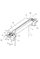
次に、図2乃至図4を参照して、シート搬送装置30について詳述する。シート搬送装置30は、図2及び図3に示すように、装置本体100Aに固定されるフレーム部40と、不図示のモータによって駆動する駆動ローラ15と、駆動ローラ15に当接して従動回転する紙粉吸着ローラ17と、引張りバネ24と、を有している。対向部材としての駆動ローラ15は、回転体としての紙粉吸着ローラ17に対向して紙粉吸着ローラ17と共に搬送ニップN1を形成している。これら駆動ローラ15及び紙粉吸着ローラ17は、搬送ニップN1においてシートを搬送する搬送部200を構成している。
[Sheet conveying device]
Next, the
支持部としてのフレーム部40は、シートの幅方向において並設される左フレーム31L及び右フレーム31Rと、例えば板金等から構成される板部材34と、板部材34に固定される紙粉収納容器25と、を有している。紙粉収納容器25及び板部材34には、図3に示すように、当接部材としてのスポンジ23が固定されており、スポンジ23は、紙粉吸着ローラ17の表面に当接し、表面に付着した紙粉を掻き取る。
The
左フレーム31L及び右フレーム31Rは、同様の構成を有しており、以下では、左フレーム31Lのみを説明し、右フレーム31Rの説明を省略する。左フレーム31Lは、軸受15bを介して駆動ローラ15の回転軸15aを回転可能に支持可能な孔部32と、軸受17bを介して紙粉吸着ローラ17の回転軸17aを回転可能に支持可能な長孔部33と、を有している。軸受15bは、孔部32に嵌合しており、紙粉吸着ローラ17の径方向に移動不能である。すなわち、フレーム部40は、駆動ローラ15及びスポンジ23を紙粉吸着ローラ17の径方向に移動不能に支持すると共に、紙粉吸着ローラ17を回転可能かつスポンジ23に対して相対移動可能に支持している。なお、長孔部33は、紙粉吸着ローラ17が左フレーム31Lから脱落しなければ、一方が開放された切欠きでもよい。
The
駆動ローラ15の回転軸15aと紙粉吸着ローラ17の回転軸17aとの間には、引張りバネ24が張設されており、付勢部材としての引張りバネ24は、紙粉吸着ローラ17を駆動ローラ15に向けて付勢している。長孔部33に支持された紙粉吸着ローラ17は、図3(a)に示すように、駆動ローラ15に当接する第1位置と、駆動ローラ15に対して離れ、第1位置とはスポンジに対する相対位置が異なる第2位置と、の間で移動可能である。このように、紙粉吸着ローラ17は、第1位置と第2位置とで移動方向MDにおいて移動可能に構成されている。長孔部33は、移動方向MDが長手方向となるように形成されている。
A
スポンジ23は、移動方向MDに対して直交する方向に延びて紙粉吸着ローラ17に対向する第1対向面としての対向面23aを有している。そして、スポンジ23は、対向面23aの一部が常に紙粉吸着ローラ17の表面に接触している。例えば、紙粉吸着ローラ17の表面は、フッ素樹脂で被覆されており、スポンジ23は、弾性体であるナイロン製のスポンジ部材から構成されている。なお、対向面23aは、移動方向MDに直交する方向に限らず、移動方向MDに交差する方向に延びていればよい。
The
紙粉吸着ローラ17が駆動ローラ15に対して従動回転すると、紙粉吸着ローラ17の表面は、スポンジ23との摺動によって帯電する。より具体的には、フッ素樹脂で被覆される紙粉吸着ローラ17の表面は、マイナス(−)に帯電しやすく、ナイロン製のスポンジ部材からなるスポンジ23は、プラス(+)に帯電しやすい。
When the paper
このため、給送ローラ13及び分離ローラ対14において発生してシートPの表面に付着し、プラス(+)に帯電した紙粉は、紙粉吸着ローラ17によって静電気的に吸着される。紙粉吸着ローラ17の表面に付着した紙粉は、スポンジ23によって掻き取られ、紙粉収納容器25に貯蔵される。これにより、紙粉が感光ドラム16やトナーに付着して、画像品質が低下することを抑えることができる。また、シートP上の紙粉が掻き取られることで、転写ニップT1においてシートPがスリップしてしまうことを低減し、転写ニップT1における画像ずれ等の画像不良を低減することができる。また、スポンジ23は、紙粉吸着ローラ17に対して常に当接しているので、スポンジ23に堆積している紙粉が搬送路へ飛散することを低減できる。更に、スポンジ23は、シートPに含まれる填料(例えば炭酸カルシウムやタルク)等の粒度の小さい紙粉も掻き取ることができるので、紙粉に起因する画像不良を低減することができる。
For this reason, the paper dust generated at the
ここで、シートPの紙粉除去性能と、紙粉吸着ローラ17での紙粉回収性能に関して、スポンジ23の作用を説明する。シートPからの紙粉除去は、上述したように静電吸着力を利用するため、紙粉除去能力は紙粉吸着ローラ17の帯電量に依存する。紙粉吸着ローラ17とスポンジ23との当接圧が高くなると、これらの接触面積が増加し、紙粉吸着ローラ17の表面の帯電量は増加する。反対に、紙粉吸着ローラ17とスポンジ23との当接圧が小さくなると、紙粉吸着ローラ17の表面の帯電量は減少する。
Here, the operation of the
一方で、スポンジ23は、紙粉吸着ローラ17の表面に対して圧接することで、紙粉吸着ローラ17の表面に付着した紙粉を掻き取っている。このため、紙粉吸着ローラ17とスポンジ23との当接圧が小さくなると、紙粉吸着ローラ17に付着した紙粉がスポンジ23からすり抜けやすくなる。以上のように、紙粉吸着ローラ17に対するスポンジ23の当接圧は、シートPからの紙粉除去性能及び紙粉吸着ローラ17からの紙粉回収性能に影響する。したがって、紙粉吸着ローラ17に対するスポンジ23の相対位置は重要となる。
On the other hand, the
[紙粉吸着ローラとスポンジの相対位置関係]
次に、搬送ニップN1をシートPが通過しない際と、シートPが通過する際の紙粉吸着ローラ17とスポンジ23の相対位置関係について説明する。図3(a)に示すように、搬送ニップN1をシートPが通過していない際には、紙粉吸着ローラ17は第1位置に位置している。このとき、図4(a)に示すように、紙粉吸着ローラ17は、移動方向MDにおいて対向面23aから第1距離Δs1だけスポンジ23に進入しており、スポンジ23は、第1当接圧で紙粉吸着ローラ17に対して当接している。
[Relative positional relationship between paper dust suction roller and sponge]
Next, the relative positional relationship between the paper
また、図3(b)に示すように、搬送ニップN1をシートPが通過している際には、紙粉吸着ローラ17は、シートの厚みによって、引張りバネ24(図2参照)の付勢力に抗して第1位置から第2位置に移動する。このとき、図4(b)に示すように、紙粉吸着ローラ17は、移動方向MDにおいて対向面23aから第1距離Δs1よりも大きい第2距離Δs2だけスポンジ23に進入している。このため、スポンジ23は、第1当接圧よりも大きい第2当接圧で紙粉吸着ローラ17に対して当接している。なお、スポンジ23は、紙粉吸着ローラ17が第1位置及び第2位置のいずれの位置に位置していても、紙粉吸着ローラ17に対して当接している。
Further, as shown in FIG. 3B, when the sheet P is passing through the transport nip N1, the paper
以上のように、本実施の形態では、シートPが搬送ニップN1を通過する際に、紙粉吸着ローラ17が第1位置から第2位置に移動し、紙粉吸着ローラ17の移動によりスポンジ23との当接圧が変化する。すなわち、シートPが搬送ニップN1を通過中は、紙粉吸着ローラ17が第2位置に位置し、スポンジ23に対して比較的大きい第2当接圧で当接する。これにより、紙粉吸着ローラ17の帯電量を増加させて紙粉吸着ローラ17の紙粉除去能力が向上すると共に、スポンジ23によって確実に紙粉吸着ローラ17に付着した紙粉を掻き取ることができる。
As described above, in the present embodiment, when the sheet P passes through the transport nip N1, the paper
また、シートPが搬送ニップN1を通過しない際には、紙粉吸着ローラ17が第1位置に位置し、スポンジ23に対して比較的小さい第1当接圧で当接する。なお、この時、スポンジ23は紙粉吸着ローラ17から離間しないので、スポンジ23に堆積した紙粉が搬送路に逆流することはない。また、スポンジ23に作用する応力が、シートPが搬送ニップN1を通過中よりも小さいため、特に長期保管時や通紙時間よりも非通紙時間が多いユーザ環境において、スポンジ23のクリープ変形を低減し、スポンジ23を長寿命化できる。
When the sheet P does not pass through the transport nip N1, the paper
スポンジ23が変形すると、スポンジ23の変形部に紙粉が入り込んだり、紙粉吸着ローラ17との当接圧が低減したりすることにより、スポンジ23の紙粉除去性能が低下する。しかしながら、本実施の形態では、スポンジ23の変形が抑えられるため、スポンジ23の性能を維持し、画像不良を低減することができる。
When the
また、紙粉吸着ローラ17がスポンジ23に対して相対移動することで、スポンジ23及びスポンジ23に堆積している紙粉に対して外乱が加わり、スポンジ23に堆積していた紙粉が紙粉収納容器25内へ拡散される。これにより、スポンジ23に堆積している紙粉が減少してスポンジ23の紙粉除去能力が回復し、耐久性を向上できる。
Further, since the paper
<第2の実施の形態>
次いで、本発明の第2の実施の形態について説明するが、第2の実施の形態は、第1の実施の形態に対して、スポンジ及びフレーム部の構成を変更したのみである。このため、第1の実施の形態と同様の構成については、図示を省略、又は図に同一符号を付して説明する。
<Second embodiment>
Next, a second embodiment of the present invention will be described. The second embodiment differs from the first embodiment only in the configuration of the sponge and the frame unit. Therefore, configurations similar to those of the first embodiment will be described by omitting illustration or by attaching the same reference numerals to the drawings.
シート搬送装置30Aは、図5に示すように、フレーム部40Aと、駆動ローラ15と、紙粉吸着ローラ17と、引張りバネ24(図2参照)と、当接部材としてのスポンジ51と、を有している。支持部としてのフレーム部40Aは、左フレーム31L及び右フレーム31Rと、例えば板金等から構成される板部材53と、板部材53に固定される紙粉収納容器52と、を有している。
As shown in FIG. 5, the
紙粉収納容器52には、スポンジ51が固定されており、スポンジ51は、移動方向MDに対して平行な方向に延びて紙粉吸着ローラ17に対向する第2対向面としての対向面51aを有している。スポンジ51は、紙粉吸着ローラ17が第1位置及び第2位置に位置する際に、対向面51aの異なる位置で紙粉吸着ローラ17に対して当接する。すなわち、スポンジ51は、紙粉吸着ローラ17が第1位置及び第2位置のいずれの位置に位置していても、紙粉吸着ローラ17に対して当接している。
A
図6(a)は、長期保管前の非通紙時における紙粉吸着ローラ17及びスポンジ51を示す断面図である。図6(b)は、長期保管後の非通紙時における紙粉吸着ローラ17及びスポンジ51を示す断面図である。図6(c)は、長期保管後の通紙時における紙粉吸着ローラ17及びスポンジ51を示す断面図である。図6(a)に示すように、長期保管前の非通紙時においては、紙粉吸着ローラ17は、対向面51aから第3距離Δt0だけスポンジ51に進入している。
FIG. 6A is a cross-sectional view showing the paper
一方、プリンタ100を長期保管していると、図7に示すように、スポンジ51は、紙粉吸着ローラ17に押圧されていた被押圧部分51bが紙粉吸着ローラ17の形状に沿ってクリープ変形してしまう。このとき、図6(b)に示すように、長期保管後の非通紙時において、紙粉吸着ローラ17は、被押圧部分51bから第4距離Δt1だけスポンジ51に進入している。距離Δt1は、スポンジ51がクリープ変形した分だけ、第3距離Δt0よりも小さい(Δt1<Δt0)。
On the other hand, when the
しかし、図6(c)に示すように、搬送ニップN1をシートPが通過すると、シートPの厚みによって、紙粉吸着ローラ17が第1位置から第2位置に移動する。これにより、スポンジ51の紙粉吸着ローラ17に対する当接部分が、被押圧部分51bから移動方向MDにおいて移動する。このため、紙粉吸着ローラ17は、再びスポンジ51のクリープ変形していない箇所で当接し、対向面51aから第5距離Δt2だけスポンジ51に進入する。このとき、第5距離Δt2は、第3距離Δt0と同一であり(Δt2=Δt0)、長期保管前と長期保管後とで、スポンジ51の紙粉吸着ローラ17に対する当接圧を一定に保つことができる。すなわち、紙粉吸着ローラ17は、第1位置及び第2位置に位置する際に、移動方向MDに直交する方向において対向面51aから第3距離Δt0(=Δt2)だけスポンジ51に進入する。このため、長期保管前と長期保管後とで、スポンジ51の紙粉除去性能は変わらず、紙粉を確実に除去して画像不良を低減できる。
However, as shown in FIG. 6C, when the sheet P passes through the transport nip N1, the paper
更に、図8に示すように、シート搬送装置30Aの長期使用により、駆動ローラ15が摩耗すると、紙粉吸着ローラ17が駆動ローラ15に近づいていく方向に移動する。搬送ニップN1を通過するシートPの厚みよりも駆動ローラ15の摩耗量の方が大きくなると、紙粉吸着ローラ17は、被押圧部分51bとは異なる位置でスポンジ51に対して当接する。このため、長期保管後だけでなく、長期使用時に駆動ローラ15が摩耗した場合でも、スポンジ51の紙粉除去性能を維持することができ、画像不良を低減できる。
Further, as shown in FIG. 8, when the driving
また、本実施の形態では、シートPを鉛直上方に搬送し、かつスポンジ51を紙粉吸着ローラ17の搬送ニップN1に対して回転方向上流側、すなわち紙粉吸着ローラ17の下方位置に配置している。これにより、新たな機構を追加することなく、紙粉吸着ローラ17から紙粉を掻き落とし、紙粉収納容器52内に紙粉を貯留することができる。
Further, in the present embodiment, the sheet P is transported vertically upward, and the
以上のように、本実施の形態では、紙粉吸着ローラ17が第1位置及び第2位置のいずれの位置に位置していても、スポンジ51は紙粉吸着ローラ17に対して一定の当接圧で当接する。このため、スポンジ51による紙粉除去の信頼性を向上できる。
As described above, in the present embodiment, the
なお、既述のいずれの形態においても、紙粉吸着ローラ17と共に搬送ニップN1を形成する部材は、駆動ローラ15に限らず、分離パッドのように回転しない部材でもよい。この場合、紙粉吸着ローラ17に不図示の駆動から駆動が入力される。
In any of the above-described embodiments, the member that forms the transport nip N1 together with the paper
また、既述のいずれの形態においても、引張りバネ24を設けずに、スポンジ23,51の弾性力によって紙粉吸着ローラ17を駆動ローラ15に対して押し付けるように構成してもよい。
Further, in any of the above-described embodiments, the paper
また、既述のいずれの形態においても、シートPが搬送ニップN1を通過する際に、紙粉吸着ローラ17が移動方向MDに移動するのであれば、駆動ローラ15も移動方向MDに移動してもよい。
In any of the above-described embodiments, if the paper
また、既述のいずれの形態においても、紙粉吸着ローラ17の帯電方法は、スポンジ23,51との摺動に限らず、例えば帯電器などで紙粉吸着ローラ17の表面の帯電量を任意に制御してもよい。また、スポンジ23,51に代えて、樹脂シート等によって紙粉吸着ローラ17に付着した紙粉を除去してもよい。
In any of the above-described embodiments, the method of charging the paper
また、既述のいずれの形態においても、電子写真方式のプリンタ100を用いて説明したが、本発明はこれに限定されない。例えば、ノズルからインク液を吐出させることでシートに画像を形成するインクジェット方式の画像形成装置にも本発明を適用することが可能である。
In each of the above-described embodiments, the description has been made using the
11:画像形成部/15:対向部材(駆動ローラ)/17:回転体(紙粉吸着ローラ)/23:当接部材(スポンジ)/23a:第1対向面(対向面)/24:付勢部材(引張りバネ)/30,30A:シート搬送装置/40,40A:支持部(フレーム部)/51:当接部材(スポンジ)/51a:第2対向面(対向面)/100:画像形成装置(プリンタ)/200:搬送部/MD:移動方向/N1:搬送ニップ/Δs1:第1距離/Δs2:第2距離 11: Image forming unit / 15: Opposing member (driving roller) / 17: Rotating body (paper dust suction roller) / 23: Contact member (sponge) / 23a: First opposing surface (opposing surface) / 24: urging Member (tensile spring) / 30, 30A: sheet transporting device / 40, 40A: support portion (frame portion) / 51: contact member (sponge) / 51a: second facing surface (facing surface) / 100: image forming device (Printer) / 200: Transport unit / MD: Moving direction / N1: Transport nip / Δs1: First distance / Δs2: Second distance
Claims (10)
前記回転体の表面に当接して、前記表面に付着した紙粉を掻き取る当接部材と、
前記回転体を回転可能かつ前記当接部材に対して相対移動可能に支持する支持部と、を備え、
前記回転体は、前記搬送ニップをシートが通過しない際に、前記対向部材に当接する第1位置に位置し、前記搬送ニップをシートが通過する際に、シートの厚みによって前記第1位置よりも前記対向部材に対して離れる第2位置に位置し、
前記当接部材は、前記回転体が前記第1位置及び前記第2位置のいずれの位置に位置していても、前記回転体に対して当接している、
ことを特徴とするシート搬送装置。 A rotating unit, and an opposing member that forms a conveying nip with the rotating body in opposition to the rotating unit, and a conveying unit that conveys a sheet in the conveying nip;
A contact member that contacts the surface of the rotating body and scrapes the paper powder attached to the surface;
A supporting portion that supports the rotating body so as to be rotatable and relatively movable with respect to the contact member,
When the sheet does not pass through the transport nip, the rotator is located at a first position in contact with the facing member, and when the sheet passes through the transport nip, the rotator is more than the first position due to the thickness of the sheet. Located at a second position away from the opposing member,
The contact member is in contact with the rotating body regardless of whether the rotating body is located at the first position or the second position.
A sheet conveying device, characterized in that:
前記回転体は、前記搬送ニップをシートが通過する際に、前記付勢部材の付勢力に抗して前記第1位置から前記第2位置に移動する、
ことを特徴とする請求項1に記載のシート搬送装置。 Further comprising an urging member for urging the rotating body toward the facing member,
The rotating body moves from the first position to the second position against a biasing force of the biasing member when a sheet passes through the transport nip,
The sheet conveying device according to claim 1, wherein:
ことを特徴とする請求項1又は2に記載のシート搬送装置。 The support portion supports the facing member and the contact member so as to be immovable in a radial direction of the rotating body.
The sheet conveying device according to claim 1, wherein:
ことを特徴とする請求項1乃至3のいずれか1項に記載のシート搬送装置。 The contact member is formed of an elastic body, and extends in a direction intersecting a moving direction in which the rotating body moves between the first position and the second position, and is a first member facing the rotating body. Having opposing surfaces,
The sheet conveying device according to claim 1, wherein:
ことを特徴とする請求項4に記載のシート搬送装置。 The contact member contacts the rotating body with the first contact pressure when the rotating body is located at the first position, and the first contacting member contacts the first rotating body when the rotating body is located at the second position. Abutting against the rotating body at a second abutting pressure greater than the abutting pressure;
The sheet conveying device according to claim 4, wherein:
ことを特徴とする請求項5に記載のシート搬送装置。 When the rotating body is located at the first position, it enters the contact member by a first distance from the first facing surface in the moving direction, and when it is located at the second position, the moving direction is Enters the contact member from the first facing surface by a second distance larger than the first distance,
The sheet conveying device according to claim 5, wherein:
ことを特徴とする請求項1乃至3のいずれか1項に記載のシート搬送装置。 The contact member is formed of an elastic body, and extends in a direction parallel to a moving direction in which the rotating body moves between the first position and the second position, and is a second member facing the rotating body. Having opposing surfaces,
The sheet conveying device according to claim 1, wherein:
ことを特徴とする請求項7に記載のシート搬送装置。 When the rotating body is located at the first position and the second position, the rotating body enters the contact member by a third distance from the second facing surface in a direction orthogonal to the moving direction.
The sheet conveying device according to claim 7, wherein:
前記回転体は、前記駆動ローラに従動回転するローラである、
ことを特徴とする請求項1乃至8のいずれか1項に記載のシート搬送装置。 The opposing member is a drive roller,
The rotating body is a roller driven and rotated by the driving roller,
The sheet conveying device according to claim 1, wherein
シートに画像を形成する画像形成部と、を備える、
ことを特徴とする画像形成装置。 A sheet conveying device according to any one of claims 1 to 9,
An image forming unit that forms an image on a sheet,
An image forming apparatus comprising:
Priority Applications (2)
| Application Number | Priority Date | Filing Date | Title |
|---|---|---|---|
| JP2018128623A JP7158927B2 (en) | 2018-07-05 | 2018-07-05 | Sheet conveying device and image forming device |
| US16/442,957 US11604429B2 (en) | 2018-07-05 | 2019-06-17 | Sheet conveyance apparatus and image forming apparatus |
Applications Claiming Priority (1)
| Application Number | Priority Date | Filing Date | Title |
|---|---|---|---|
| JP2018128623A JP7158927B2 (en) | 2018-07-05 | 2018-07-05 | Sheet conveying device and image forming device |
Publications (2)
| Publication Number | Publication Date |
|---|---|
| JP2020007084A true JP2020007084A (en) | 2020-01-16 |
| JP7158927B2 JP7158927B2 (en) | 2022-10-24 |
Family
ID=69102051
Family Applications (1)
| Application Number | Title | Priority Date | Filing Date |
|---|---|---|---|
| JP2018128623A Active JP7158927B2 (en) | 2018-07-05 | 2018-07-05 | Sheet conveying device and image forming device |
Country Status (2)
| Country | Link |
|---|---|
| US (1) | US11604429B2 (en) |
| JP (1) | JP7158927B2 (en) |
Citations (5)
| Publication number | Priority date | Publication date | Assignee | Title |
|---|---|---|---|---|
| JP2002255398A (en) * | 2001-03-02 | 2002-09-11 | Canon Inc | Printer device |
| JP2008056434A (en) * | 2006-08-31 | 2008-03-13 | Oki Data Corp | Image processing device and image processing unit |
| JP2010037008A (en) * | 2008-07-31 | 2010-02-18 | Sharp Corp | Sheet carrying device and image forming device |
| JP2010241530A (en) * | 2009-04-02 | 2010-10-28 | Canon Inc | Sheet conveyance apparatus and electrophotographic apparatus |
| JP2014046996A (en) * | 2012-08-29 | 2014-03-17 | Brother Ind Ltd | Image forming apparatus |
Family Cites Families (7)
| Publication number | Priority date | Publication date | Assignee | Title |
|---|---|---|---|---|
| JP3251171B2 (en) | 1996-03-12 | 2002-01-28 | 京セラミタ株式会社 | Paper dust removal equipment |
| US6708009B2 (en) * | 1998-09-30 | 2004-03-16 | Brother Kogyo Kabushiki Kaisha | Image forming device having paper dust removing units |
| JP5409325B2 (en) | 2009-12-17 | 2014-02-05 | キヤノン株式会社 | Sheet conveying apparatus, image forming apparatus, and image reading apparatus |
| JP5265509B2 (en) * | 2009-12-23 | 2013-08-14 | ブラザー工業株式会社 | Image forming apparatus and paper feeding apparatus |
| JP6657802B2 (en) * | 2015-11-02 | 2020-03-04 | セイコーエプソン株式会社 | Printing equipment |
| JP2019081630A (en) * | 2017-10-30 | 2019-05-30 | キヤノン株式会社 | Image forming apparatus and conveying apparatus |
| JP7086696B2 (en) * | 2018-04-23 | 2022-06-20 | キヤノン株式会社 | Sheet transfer device and image forming device |
-
2018
- 2018-07-05 JP JP2018128623A patent/JP7158927B2/en active Active
-
2019
- 2019-06-17 US US16/442,957 patent/US11604429B2/en active Active
Patent Citations (5)
| Publication number | Priority date | Publication date | Assignee | Title |
|---|---|---|---|---|
| JP2002255398A (en) * | 2001-03-02 | 2002-09-11 | Canon Inc | Printer device |
| JP2008056434A (en) * | 2006-08-31 | 2008-03-13 | Oki Data Corp | Image processing device and image processing unit |
| JP2010037008A (en) * | 2008-07-31 | 2010-02-18 | Sharp Corp | Sheet carrying device and image forming device |
| JP2010241530A (en) * | 2009-04-02 | 2010-10-28 | Canon Inc | Sheet conveyance apparatus and electrophotographic apparatus |
| JP2014046996A (en) * | 2012-08-29 | 2014-03-17 | Brother Ind Ltd | Image forming apparatus |
Also Published As
| Publication number | Publication date |
|---|---|
| US20200012225A1 (en) | 2020-01-09 |
| JP7158927B2 (en) | 2022-10-24 |
| US11604429B2 (en) | 2023-03-14 |
Similar Documents
| Publication | Publication Date | Title |
|---|---|---|
| JP3515292B2 (en) | Cleaning device and image forming apparatus provided with the cleaning device | |
| US7995960B2 (en) | Image forming apparatus having units for cleaning photosensitive members | |
| JPH09301565A (en) | Belt device | |
| JP5281956B2 (en) | Image forming apparatus | |
| JP5108610B2 (en) | Lubricant imparting agent coating apparatus, cleaning apparatus, process cartridge, and image forming apparatus | |
| JP4336982B2 (en) | Image forming apparatus | |
| JP2012027225A (en) | Cleaning device and image formation apparatus | |
| JP2020007084A (en) | Sheet transport apparatus and image forming apparatus | |
| US11048202B2 (en) | Sheet conveyance apparatus having paper dust removal and image forming apparatus | |
| JPH10203672A (en) | Paper feed device | |
| JP5434225B2 (en) | Developing device and image forming apparatus including the developing device | |
| JP6919284B2 (en) | Image forming device | |
| JP2014134620A (en) | Image forming apparatus | |
| JP2002148965A (en) | Image forming device | |
| JP2023121972A (en) | image forming device | |
| JP5634276B2 (en) | Cleaning device and image forming apparatus equipped with the same | |
| JPH11272135A (en) | Image forming device | |
| JP7163089B2 (en) | Sheet conveying device and image forming device | |
| JP2007304301A (en) | Cleaning device and image forming apparatus | |
| JP2004157176A (en) | Image forming apparatus | |
| JP6490529B2 (en) | Image forming apparatus | |
| JP2022051454A (en) | Cleaning device and image forming apparatus | |
| JP2021020762A (en) | Contact pressure switching device, sheet conveyance device, and image formation apparatus | |
| JPH01167165A (en) | Sheet material carrier | |
| JP2001312148A (en) | Image forming device |
Legal Events
| Date | Code | Title | Description |
|---|---|---|---|
| RD02 | Notification of acceptance of power of attorney |
Free format text: JAPANESE INTERMEDIATE CODE: A7422 Effective date: 20200206 |
|
| RD04 | Notification of resignation of power of attorney |
Free format text: JAPANESE INTERMEDIATE CODE: A7424 Effective date: 20200207 |
|
| A621 | Written request for application examination |
Free format text: JAPANESE INTERMEDIATE CODE: A621 Effective date: 20210701 |
|
| A977 | Report on retrieval |
Free format text: JAPANESE INTERMEDIATE CODE: A971007 Effective date: 20220408 |
|
| A131 | Notification of reasons for refusal |
Free format text: JAPANESE INTERMEDIATE CODE: A131 Effective date: 20220419 |
|
| A521 | Request for written amendment filed |
Free format text: JAPANESE INTERMEDIATE CODE: A523 Effective date: 20220617 |
|
| TRDD | Decision of grant or rejection written | ||
| A01 | Written decision to grant a patent or to grant a registration (utility model) |
Free format text: JAPANESE INTERMEDIATE CODE: A01 Effective date: 20220913 |
|
| A61 | First payment of annual fees (during grant procedure) |
Free format text: JAPANESE INTERMEDIATE CODE: A61 Effective date: 20221012 |
|
| R151 | Written notification of patent or utility model registration |
Ref document number: 7158927 Country of ref document: JP Free format text: JAPANESE INTERMEDIATE CODE: R151 |