JP2020006773A - Electric drive type travel device and electric drive type work vehicle - Google Patents
Electric drive type travel device and electric drive type work vehicle Download PDFInfo
- Publication number
- JP2020006773A JP2020006773A JP2018128482A JP2018128482A JP2020006773A JP 2020006773 A JP2020006773 A JP 2020006773A JP 2018128482 A JP2018128482 A JP 2018128482A JP 2018128482 A JP2018128482 A JP 2018128482A JP 2020006773 A JP2020006773 A JP 2020006773A
- Authority
- JP
- Japan
- Prior art keywords
- electric motor
- duct
- air
- rear axle
- air guide
- Prior art date
- Legal status (The legal status is an assumption and is not a legal conclusion. Google has not performed a legal analysis and makes no representation as to the accuracy of the status listed.)
- Pending
Links
Images


Abstract
Description
本発明は、電気駆動式走行装置および電気駆動式作業車両に関する。 The present invention relates to an electric drive type traveling device and an electric drive type work vehicle.
本技術分野の背景技術として、例えば特許文献1および特許文献2には、エンジンで発電機を駆動し、発電機で発電された電力により左右一対の電動モータを駆動して左右一対の駆動輪(後輪)を回転させるダンプトラックが記載されている。各電動モータは、ダンプトラックの各後輪を駆動させるため、各後輪の内側に減速機を介して取り付けられている。 As background art in the present technical field, for example, Patent Documents 1 and 2 disclose a method in which a generator is driven by an engine, and a pair of left and right electric motors is driven by electric power generated by the generator. It describes a dump truck that rotates the rear wheel). Each electric motor is mounted via a speed reducer inside each rear wheel to drive each rear wheel of the dump truck.
左右一対の電動モータは、左右一対の後輪間に懸架された略円筒形状を有する部材(以下、リアアクスルと称す)の左右内部に、それぞれ収容されている。リアアクスルの略中心位置には電動モータ冷却用のダクトが接続されており、ブロワから供給される空気がダクト内を流れて各電動モータの表面に当たることで、各電動モータが冷却される。 The pair of left and right electric motors are housed in left and right insides of a substantially cylindrical member (hereinafter, referred to as a rear axle) suspended between a pair of left and right rear wheels. A duct for cooling the electric motor is connected to a substantially central position of the rear axle, and the air supplied from the blower flows through the duct and hits the surface of each electric motor, thereby cooling each electric motor.
特許文献1および特許文献2に記載の従来技術では、電動モータ冷却用のダクトを流れてリアアクスル内に流入した空気は左右に分流して各電動モータへと向かうが、その構造上、各電動モータの周囲全体に均一に流れることは難しい。具体的には、特許文献1および特許文献2は、各電動モータの下部には空気が流れやすいが、上部には空気が流れにくい構造である。そのため、特許文献1および特許文献2に記載の従来技術では、電動モータ全体を概ね均一に冷却することは難しく、電動モータの放熱性の向上が求められている。 In the prior arts described in Patent Literatures 1 and 2, air flowing through a duct for cooling an electric motor and flowing into a rear axle is diverted right and left toward each electric motor. It is difficult to flow uniformly around the motor. Specifically, Patent Literature 1 and Patent Literature 2 have a structure in which air easily flows at a lower portion of each electric motor, but hardly flows at an upper portion. For this reason, it is difficult to cool the entire electric motor substantially uniformly with the conventional techniques described in Patent Literature 1 and Patent Literature 2, and there is a demand for improving the heat radiation of the electric motor.
本発明の課題は、電動モータの放熱性を向上させることにある。 An object of the present invention is to improve the heat dissipation of an electric motor.
上記課題を解決するための本発明の特徴は、例えば以下の通りである。 The features of the present invention for solving the above problems are, for example, as follows.
本発明は、左右一対の車輪を駆動するための電気駆動式走行装置であって、前記左右一対の車輪の一方を駆動する第1電動モータと、前記左右一対の車輪の他方を駆動する第2電動モータと、前記左右一対の車輪の間に懸架され、前記第1電動モータを一方の端部に収容すると共に前記第2電動モータを他方の端部に収容するリアアクスルと、前記第1電動モータおよび前記第2電動モータを冷却するモータ冷却装置と、を備えた電気駆動式走行装置において、前記モータ冷却装置は、前記リアアクスルの軸方向の中央部に連通するダクトと、前記ダクトに空気を流すためのブロワと、前記ダクトの出口から前記リアアクスルに流入した空気のうち前記第1電動モータに向かう空気の一部を、流れの向きを変えて前記第1電動モータの第1特定部分に導く第1導風部と、前記ダクトの出口から前記リアアクスルに流入する空気のうち前記第2電動モータに向かう空気の一部を、流れの向きを変えて前記第2電動モータの第2特定部分に導く第2導風部と、を備えたことを特徴とする。 The present invention is an electrically driven traveling device for driving a pair of left and right wheels, a first electric motor driving one of the pair of left and right wheels, and a second electric motor driving the other of the pair of left and right wheels. An electric motor, a rear axle suspended between the pair of left and right wheels, accommodating the first electric motor at one end, and accommodating the second electric motor at the other end; An electric drive traveling device including a motor and a motor cooling device for cooling the second electric motor, wherein the motor cooling device includes a duct communicating with a central portion of the rear axle in an axial direction, and air flowing through the duct. And a part of air flowing from the outlet of the duct to the rear axle toward the first electric motor by changing a flow direction of the first characteristic of the first electric motor. A first air guiding portion that guides a portion of the second electric motor, by changing a flow direction of a part of the air that flows from the outlet of the duct to the rear axle toward the second electric motor. And a second wind guiding portion for leading to the second specific portion.
また、本発明は、車体フレームと、前記車体フレームに起伏可能に設けられ、積載物を積載するためのボディと、前記車体フレームの前後にそれぞれ設けられる左右一対の車輪と、前後の前記左右一対の車輪のうち少なくとも一方を駆動する電気駆動式走行装置と、を備え、前記電気駆動式走行装置は、前記左右一対の車輪の一方を駆動する第1電動モータと、前記左右一対の車輪の他方を駆動する第2電動モータと、前記左右一対の車輪の間に懸架され、前記第1電動モータを一方の端部に収容すると共に前記第2電動モータを他方の端部に収容するリアアクスルと、前記第1電動モータおよび前記第2電動モータを冷却するモータ冷却装置と、を備えた電気駆動式作業車両において、前記モータ冷却装置は、前記リアアクスルの軸方向の中央部に連通するダクトと、前記ダクトに空気を流すためのブロワと、前記ダクトの出口から前記リアアクスルに流入した空気のうち前記第1電動モータに向かう空気の一部を、流れの向きを変えて前記第1電動モータの第1特定部分に導く第1導風部と、前記ダクトの出口から前記リアアクスルに流入する空気のうち前記第2電動モータに向かう空気の一部を、流れの向きを変えて前記第2電動モータの第2特定部分に導く第2導風部と、を備えたことを特徴とする。 Further, the present invention provides a vehicle body frame, a body provided on the vehicle body frame so as to be able to undulate and load a load, a pair of left and right wheels respectively provided before and after the vehicle body frame, and An electrically driven traveling device that drives at least one of the wheels, wherein the electrically driven traveling device includes a first electric motor that drives one of the pair of left and right wheels, and the other of the pair of left and right wheels. And a rear axle suspended between the pair of left and right wheels, accommodating the first electric motor at one end and accommodating the second electric motor at the other end. A motor cooling device for cooling the first electric motor and the second electric motor, wherein the motor cooling device is disposed in an axial direction of the rear axle. A duct communicating with a central portion, a blower for flowing air through the duct, and a part of air flowing from the outlet of the duct to the rear axle toward the first electric motor. A first air guiding portion that guides to a first specific portion of the first electric motor, and a part of the air that flows from the outlet of the duct to the rear axle toward the second electric motor. And a second air guiding portion for changing the direction and leading to a second specific portion of the second electric motor.
本発明によれば、電動モータの放熱性を向上させることができる。なお、上記した以外の課題、構成および効果は、以下の実施形態の説明により明らかにされる。 ADVANTAGE OF THE INVENTION According to this invention, the heat dissipation of an electric motor can be improved. In addition, problems, configurations, and effects other than those described above will be clarified by the following description of the embodiments.
以下、図面等を用いて、本発明の実施形態について説明する。以下の説明は、本発明の内容の具体例を示すものであり、本発明がこれらの説明に限定されるものでは無く、本明細書に開示される技術的思想の範囲内において、当業者による様々な変更および修正が可能である。また、本発明を説明するための全図において、同一の機能を有するものは、同一の符号を付け、その繰り返しの説明は省略する場合がある。 Hereinafter, embodiments of the present invention will be described with reference to the drawings and the like. The following description shows specific examples of the contents of the present invention, and the present invention is not limited to these descriptions, and is within the scope of the technical idea disclosed in this specification. Various changes and modifications are possible. In all the drawings for describing the present invention, components having the same function are denoted by the same reference numerals, and repeated description thereof may be omitted.
本実施形態に係る電気駆動式ダンプトラックは、例えば、露天掘り工法等による鉱山の採掘現場において、大量の鉱石や土砂等を運搬するために使用されるが、本発明は、鉱山用の電気駆動式ダンプトラックに限定されるものではなく、その他の用途に用いられるあらゆる電気駆動式の作業車両が対象となる。 The electrically driven dump truck according to the present embodiment is used to transport a large amount of ore, earth and sand, for example, at a mine mining site by an open pit mining method, etc. The invention is not limited to a dump truck, but may be any electric-driven work vehicle used for other purposes.
なお、各図に示すx軸、y軸、z軸は、それぞれが直交する関係にある。電気駆動式ダンプトラック(以下、ダンプトラックと称す)1000の前進方向をx軸の矢印方向とし、車幅方向であって、前進方向に向かって右側をy軸の矢印方向とし、鉛直方向で上向きをz軸の矢印方向とする。また、以下の説明において、x軸の矢印方向を「前」、その反対方向を「後」、y軸の矢印方向を「右」、その反対方向を「左」、z軸の矢印方向を「上」、その反対方向を「下」と表記する。 Note that the x-axis, y-axis, and z-axis shown in each drawing are in a relationship orthogonal to each other. The forward direction of the electric drive type dump truck (hereinafter referred to as a dump truck) 1000 is defined as an x-axis arrow direction, the vehicle width direction, the right side toward the forward direction is defined as a y-axis arrow direction, and the vertical direction is upward. Is the direction of the arrow on the z-axis. In the following description, the x-axis arrow direction is “front”, the opposite direction is “rear”, the y-axis arrow direction is “right”, the opposite direction is “left”, and the z-axis arrow direction is “ The direction “up” and the opposite direction are described as “down”.
[第1実施形態]
図1は第1実施形態に係る電気駆動式ダンプトラックの概略構成を示す側面図、図2は図1に示す電気駆動式ダンプトラックの斜視図、図3は図1に示す電気駆動式ダンプトラックの背面図、図4は図3に示すリアアクスルの内部構成を示す断面図である。なお、図1では電動モータを冷却するための空気の流れを矢印で表示しており、図2では鉱石や土砂等の運搬物を積載するためのボディ420の図示は省略している。また、図4等において左右の電動モータ110と左右の導風部104は同一の構成であるため、符号の一部の図示を省略し、明細書中の説明において左右の区別は特にしない。
[First Embodiment]
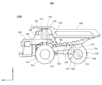
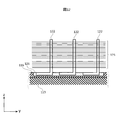
FIG. 1 is a side view showing a schematic configuration of an electrically driven dump truck according to a first embodiment, FIG. 2 is a perspective view of the electrically driven dump truck shown in FIG. 1, and FIG. 3 is an electrically driven dump truck shown in FIG. FIG. 4 is a sectional view showing the internal configuration of the rear axle shown in FIG. In FIG. 1, the flow of air for cooling the electric motor is indicated by arrows, and in FIG. 2, the illustration of a
なお、本発明において「第1・・・」は各図の左側の構成に相当し、「第2・・・」は各図の右側の構成に相当する。例えば、図4において左側の電動モータ110は本発明の第1電動モータ、左側の導風部104は本発明の第1導風部に相当し、右側の電動モータ110は本発明の第2電動モータ、右側の導風部104は本発明の第2導風部に相当する。
In the present invention, “first...” Corresponds to the configuration on the left side of each drawing, and “second...” Corresponds to the configuration on the right side of each drawing. For example, in FIG. 4, the left
図1、図2に示すように、車体フレーム410の前部において、その左右両側には、ダンプトラック1000を左右方向へ操舵することを可能にする、前輪(操舵輪)510がそれぞれ組み付けられている。左右一対の前輪510は、それぞれゴム製のタイヤ511およびタイヤ511の内部に組み付けられるタイヤホイール512で構成され、車体フレーム410の前部を支持している。車体フレーム410の後部においては、その左右両側に、ダンプトラック1000の前進および後進を可能にする、車幅方向に互いに並行に配置された2本の後輪(駆動輪)、すなわち後外輪520および後内輪530がそれぞれ組み付けられている。後外輪520は、ゴム製のタイヤ521およびタイヤ521の内部に組み付けられるタイヤホイール522で構成され、後内輪530は、ゴム製のタイヤ531およびタイヤ531の内部に組み付けられるタイヤホイール532で構成される。左右一対の後外輪520および後内輪530は、車体フレーム410の後部を支持している。
As shown in FIGS. 1 and 2, front wheels (steering wheels) 510 that enable the
車体フレーム410の中央付近から後部において、その上方には、鉱石や土砂等の運搬物を積載するためのボディ420が搭載される。ボディ420の後部は、ヒンジピン(図示せず)を介して車体フレーム410に回転自在に支持されており、左右一対のホイストシリンダ(図示せず)の伸縮動作に伴って、ボディ420はヒンジピンを支点として起伏可能である。
A
ダンプトラック1000の前部には、ダンプトラック1000を走行駆動させるための電気駆動式パワーユニットが搭載される。この電気駆動式パワーユニットを構成する主たる機器は、発電用のエンジン330、エンジン330の出力軸に連結された発電機320、ならびに、インバータ等の制御機器311である。この内、エンジン330および発電機320は、車体フレーム410の前部に組み付けられている。また、車体フレーム410の前部にはフロントデッキ430が設けられており、フロントデッキ430上の左右方向のどちらか片側にキャビネット310が設置されている。制御機器311は、そのキャビネット310の内部に、制御機器311の放熱器(図示せず)と共に設置される。なお、フロントデッキ430の左右方向の片側で、キャビネット310が設置されていない側には、ダンプトラック1000の運転操作に必要な各種機器(ステアリングホイール、アクセルペダル、ブレーキペダル、ボディ操作部、計器盤、オペレータ用シート等)が装備されてなるキャビン440が設けられる。
An electrically driven power unit for driving the
車体フレーム410を支持する左右の後内輪530の内側付近には、図3、図4に示すように、左右一対の電動モータ110が設置される。左右一対の電動モータ110は、それぞれの出力軸111を介して、タイヤホイール522、532の支持部(図示せず)に連結される。そして、左右一対の電動モータ110は、タイヤホイール522、532の内側に設置される左右一対の減速機(図示せず)と共に、電気駆動式走行装置を構成する。
As shown in FIGS. 3 and 4, a pair of left and right
車体フレーム410の後方で左右の後内輪530の間には、略円筒形状のリアアクスル100が車体フレーム410に対して上下動可能に懸架されている。一対の電動モータ110は、このリアアクスル100の内部の左右両側に1つずつ固定支持される。具体的には、図4に示すように、電動モータ110は、リアアクスル100と一体をなす支持部118およびモータフレーム114と一体をなす支持部117を介してリアアクスル100に固定される。こうして、後外輪520および後内輪530は、リアアクスル100の左右外周部に、リアアクスル100に対して回転自在に支持される。
A substantially cylindrical
電動モータ110の主要構成要素は、出力軸111、ロータ112、ステータ113、モータフレーム114であり、ロータ112には、ロータ112の周方向に複数個、それぞれロータ112の軸方向に貫通する通風孔115が設けられる。また、ステータ113は、モータフレーム114の内側で、モータフレーム114の周方向に複数設けられたステータ固定部116を介して、モータフレーム114に固定される。また、出力軸111には、例えば、パーキング用のブレーキディスク119が取り付けられ、モータフレーム114に組み付けられるブレーキパッド(図示せず)と共に、ダンプトラック1000のパーキングブレーキ機構を構成する。
The main components of the
電動モータ110や発電機320は、キャビネット310内に収容されるインバータ等の制御機器311に電気接続されている。例えば、エンジン330により発電機320を駆動させ、発電機320からの電力をインバータ等の制御機器311にて交流に変換することで、電動モータ110を駆動させる。
The
また、図2に示すように、電動モータ110を冷却するため、空気を送風するためのブロワ210が、例えば、車体フレーム410において、リアアクスル100の周辺に位置する穴部415に据え付けられている。ブロワ210の吐き出し部は、ダクト225を介して、リアアクスル100の略中心位置で、且つ、上方側と接続される。このとき、ダクト225とリアアクスル100の接続部226は、空気の流れを円滑にするために曲線状であることが望ましい。また、ブロワ210の吸込み部は、ダクト220を介して、インバータ等の制御機器311を収納するキャビネット310の壁部に接続され、リアアクスル100の内部とキャビネット310の内部は連通されている。なお、リアアクスル100は、前述のように車体フレーム410に対して上下動可能に懸架されるため、ダクト225とブロワ210の吹き出し部は、後外輪520および後内輪530の上下動を吸収可能とする部材で形成された接続部(図示せず)で接続されているものとする。
Further, as shown in FIG. 2, a
また、キャビネット310の壁部、例えば、前面壁の上部には、図1に示すように、外気(A)を取り込むための吸気口312が設けられており、リアアクスル100の左右両側には、図4に示すように、取り込んだ空気を排気するための排気口101が設けられている。
In addition, as shown in FIG. 1, an
ダンプトラック1000の走行中もしくは停止中で、電動モータ110の温度が上昇しているとき、ダクト220およびダクト225を介して、ブロワ210により、外気(A)をキャビネット310の吸気口312から取り込み、リアアクスル100の略中心位置からリアアクスル100の内部へ送風することで、電動モータ110を冷却する(図1)。なお、ここでは、制御機器311を冷却した空気(B)をリアアクスル100の内部へ送風し(送風空気(C))、電動モータ110を冷却する構造としているが、制御機器311の冷却を介さないで、取り込んだ外気を直接、電動モータ110まで送風して冷却する構造であってもよい。
When the temperature of the
また、ブロワ210の据付位置は、キャビネット310の内部、もしくは、キャビネット310の周辺でダクト220の上流側であってもよい。なお、発電機320については、電動モータ110の冷却と同様に、例えば、車体フレーム410に設置したブロワ230(図2参照)により、キャビネット310の内部と連通されたダクト240を介して冷却される。ここでも、ブロワ230の据付位置は、キャビネット310の内部、もしくは、キャビネット310の周辺でダクト240の上流側であってもよい。
The installation position of the
以上の構成において、図4に示すように、リアアクスル100の内部であって、リアアクスル100とダクト225の接続部226に、ダクト225の出口付近から電動モータ110の上方空間(電動モータ110のモータフレーム114において、ダクト225の出口に近接する側の表面、すなわち電動モータ110の上面)へ向けて空気を導入するための導風部104が設けられている。
In the above configuration, as shown in FIG. 4, the space above the electric motor 110 (from the vicinity of the outlet of the duct 225) to the
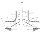
導風部104について図を参照して具体的に説明する。図5は導風部の斜視図、図6はダクトの出口部分の要部断面図である。図5、図6に示すように、導風部104は、矩形平板状の導風板102と、ダクト225とリアアクスル100との接続部226に固定され、導風板102を支持する支持部材103とで構成される。
The
導風板102の取付位置について図6を用いて説明する。図6に示すように、導風板102のダクト225側の端部102aとダクト225の電動モータ110側の内周面225aとの間のダクト225の径方向における距離d1は、ダクト225の内径をd2としたとき、(1)式の関係を満たす。
0<d1<d2 ・・・(1)
The mounting position of the
0 <d1 <d2 (1)
また、導風板102の電動モータ110側の端部102bと電動モータ110の上面との距離d3は、電動モータ110の上方を正値として、(2)式の関係を満たす。
0<d3 ・・・(2)
The distance d3 between the
0 <d3 (2)
さらに、導風板102のダクト225側の端部102aと、電動モータ110側の端部102bとのダクト225の軸方向における距離d4は、ダクト225の上流側(ブロワ210側)を正値として、(3)式の関係を満たす。
0<d4 ・・・(3)
Further, a distance d4 in the axial direction of the
0 <d4 (3)
導風板102が上記式(1)〜(3)の関係を全て満たす位置に取り付けられることで、図4に示すように、リアアクスル100の内部に送風された空気(C)の内、その一部(D)は、電動モータ110の上方空間(E)へ流れ込むことが可能となる。すなわち、電動モータ110の上部(特定部分)に対しても空気が行き渡るようになる。その結果、電動モータ110の周囲の流れが均一化される。よって、電動モータ110の表面が均一に冷却され、電動モータ110の放熱性が向上する。
When the
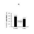
ここで、本発明者らは、導風部104を設けた本実施形態と、導風部104を設けない従来構造とで、同一条件下にて電動モータ110の表面の熱抵抗にどの程度の差があるかを解析した。図7に本発明の第1実施形態による効果を解析した結果を示す。図中の「従来構造」は、導風板102を設けない従来構造であり、「本構造」が本発明の第1実施形態に係る構造である。図7に示すように、従来構造に比べて本構造では、モータフレーム114の表面の熱抵抗が約24%低減し、電動モータ110の放熱性が向上することが分かった。このように、第1実施形態では、導風板102によって空気が電動モータ110の上方空間(E)に導かれ、電動モータ110の周囲が均一に冷却される結果、電動モータ110の放熱性が向上する。
Here, the present inventors, in the present embodiment in which the
[第2実施形態]
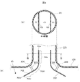
次に、本発明の第2実施形態について説明する。第2実施形態では、導風板602の形状が第1実施形態と相違するため、この相違点を中心に説明する。図8(a)は第2実施形態にかかる導風板の構造を示す縦断面図、図8(b)は同図(a)のA−A断面図である。図8(a)、(b)に示すように、第2実施形態では、導風板602が、ダクト225の内部にまで端部602aが延在する直線部602cと、接続部226のR形状に沿って屈曲した屈曲部602d、屈曲部602dから連続して設けられる直線部602eと、を有している。勿論、導風板602の取付位置は、上記式(1)〜(3)の関係は満たす。このような形状であっても、電動モータ110の上方空間(E)に確実に空気を導入できるため、第1実施形態と同様に電動モータ110の周囲を均一に冷却できる。
[Second embodiment]
Next, a second embodiment of the present invention will be described. In the second embodiment, since the shape of the
[第3実施形態]
次に、本発明の第3実施形態について説明する。第3実施形態では、導風板702の形状が第1および第2実施形態と相違するため、この相違点を中心に説明する。図9(a)は第3実施形態にかかる導風板の構造を示す縦断面図、図9(b)は同図(a)のB−B断面図である。図9(a)、(b)に示すように、第3実施形態では、導風板702が、ダクト225の内部にまで端部702aが延在する直線部702cと、接続部226のR形状に沿って屈曲した屈曲部702d、屈曲部702dから連続して設けられる直線部702eと、を有している。さらに、図9(b)に示すように、導風板702の側部がダクト225の内周壁に固定されており、ダクト225の断面は、2つの導風板702によって仕切られている。なお、ダクト225の断面積C1、C2、C3の関係は、C1:C2:C3=1:2:1である。勿論、導風板702の取付位置は、上記式(1)〜(3)の関係は満たす。このような形状であっても、電動モータ110の上方空間に確実に空気を導入できるため、第1および第2実施形態と同様に、電動モータ110の周囲を均一に冷却できる。
[Third embodiment]
Next, a third embodiment of the present invention will be described. In the third embodiment, since the shape of the
[第4実施形態]
次に、本発明の第4実施形態について説明する。第4実施形態は、第1実施形態と比べて電動モータ110の上面に冷却部120を設けた点が相違するため、この相違点を中心に説明する。図10は本発明の第4実施形態におけるリアアクスル内の構造を示す断面図である。図10に示すように、第4実施形態では、電動モータ110の上面(特定部分)に冷却部120が取り付けられている。
[Fourth embodiment]
Next, a fourth embodiment of the present invention will be described. The fourth embodiment is different from the first embodiment in that a
図11は冷却部の取付構造を示す図であって、電動モータの上部をX−Z平面で切断した図、図12は冷却部の取付構造を示す図であって、電動モータの上部をY−Z平面で切断した図である。図11に示すように、第4実施形態に用いられる冷却部120は、受熱部121、熱輸送部122、放熱部123から成る。電動モータ110には、ステータ113をモータフレーム114の内側に固定するため、モータフレーム114の内周にステータ固定部116が複数設けられており、冷却部120は、このステータ固定部116に固定される。なお、モータフレーム114の内側で、ステータ固定部116が無い箇所は、空隙124となっている。なお、図12に示すように、第4実施形態では、熱輸送部122が電動モータ110の軸方向に複数(3つ)設けられているが、その数は問わない。
FIG. 11 is a diagram showing a mounting structure of the cooling unit, in which an upper part of the electric motor is cut along an XZ plane, and FIG. 12 is a diagram showing a mounting structure of the cooling unit. It is the figure cut | disconnected in the -Z plane. As shown in FIG. 11, the
第4実施形態によれば、電動モータ110の駆動時に、ステータ113およびロータ112の内部に発生する熱を、ステータ固定部116を介して受熱部121に熱伝導により伝え、さらに、受熱部121に伝わった熱を、熱輸送部122を介して放熱部123まで伝えることが可能となる。熱輸送部122は、例えば、ヒートパイプのような冷媒の相変化を利用した熱輸送デバイスとし、ヒートパイプの受熱側での冷媒の沸騰、および、ヒートパイプの放熱側での冷媒の凝縮により、受熱部121の熱を効率的に放熱部123まで伝えることができる。また、放熱部123はフィン形状とし、受熱部121および放熱部123の材質は、望ましくは、アルミ、銅など、熱伝導率が比較的高い材料とする。
According to the fourth embodiment, when the
放熱部123まで伝わった熱は、図10に示すように、導風板102によって、電動モータ110の上部空間(E)に導かれる空気(D)により放熱される。この際、空気が冷却部120に当たることで冷却部120と空気との間で熱交換が行われ、電動モータ110のステータ113およびロータ112の内部に生じる熱が、電動モータ110の外側に効率良く放熱される。よって、第4実施形態は、第1〜第3実施形態と比べて電動モータ110の冷却効率が向上する。
As shown in FIG. 10, the heat transmitted to the
なお、冷却部120は、モータフレーム114上に直接設けられるフィンのみであってもよい。また、導風板102は、前述した図8および図9の形状であってもよい。
The
[第5実施形態]
次に、本発明の第5実施形態について説明する。第5実施形態は、第1実施形態と比べて2本のダクト325a,325bがリアアクスル100に接続されている点が相違するため、この相違点を中心に説明する。図13は第5実施形態においてリアアクスル100の内部構成を示す縦断面図である。図13に示すように、2本のダクト325a,325bがリアアクスル100の幅方向の中央部に接続されている。ダクト325aは主に左側の電動モータ110に空気を供給し、ダクト325bは主に右側の電動モータ110に空気を供給する。このようなダクトの構成を採用した場合であっても、電動モータ110の上方空間にまで空気を導入できるため、電動モータ110の周囲を均一に冷却できる。
[Fifth Embodiment]
Next, a fifth embodiment of the present invention will be described. The fifth embodiment is different from the first embodiment in that two
以上説明したように、各実施形態によれば、電動モータ110の周囲を均一に冷却でき、電動モータ110の放熱性を向上させることができる。なお、上記した各実施形態において、リアアクスル100と接続するダクト225の位置は、リアアクスル100の上方でなくても、例えば、リアアクスル100の下方であってもよい。また、上記した各実施形態では、駆動輪である後輪に本発明に係る電気駆動式走行装置を適用した例を挙げたが、駆動輪が前輪である場合は前輪に本発明に係る電気駆動式走行装置を適用できるし、四輪駆動の場合には前後輪に本発明に係る電気駆動式走行装置を適用できる。また、上記の説明では、本発明に係るモータ冷却装置および電気駆動式走行装置を電気駆動式ダンプトラックに適用した具体例を挙げているが、本発明に係るモータ冷却装置および電気駆動式走行装置の適用対象は電気駆動式ダンプトラックに限らない。例えば、本発明に係るモータ冷却装置は、工場で稼働するモータの冷却装置に適用しても良い。また、本発明に係る電気駆動式走行装置は、乗用自動車や自動二輪車に適用しても良い。
As described above, according to each embodiment, the periphery of the
100 リアアクスル
101 排気口(第1排気口、第2排気口)
102 導風板(第1導風板、第2導風板)
102a、102b 導風板の端部
103 支持部材(第1支持部材、第2支持部材)
104 導風部(第1導風部、第2導風部)
110 電動モータ(第1電動モータ、第2電動モータ)
120 冷却部(第1冷却部、第2冷却部)
210 ブロワ
225 ダクト
225a ダクトの内周面
325a、325b ダクト
410 車体フレーム
420 ボディ
510 前輪(車輪)
520 後外輪(車輪)
530 後内輪(車輪)
602 導風板(第1導風板、第2導風板)
602a、602b 導風板の端部
602c 直線部(第1直線部、第2直線部)
602d 屈曲部(第1屈曲部、第2屈曲部)
602e 直線部
702 導風板(第1導風板、第2導風板)
702a、702b 導風板の端部
702c 直線部(第1直線部、第2直線部)
702d 屈曲部(第1屈曲部、第2屈曲部)
702e 直線部
1000 ダンプトラック(電気駆動式作業車両)
100
102 Wind guide plate (1st wind guide plate, 2nd wind guide plate)
102a, 102b Ends of
104 Wind guide section (first wind guide section, second wind guide section)
110 electric motor (first electric motor, second electric motor)
120 cooling unit (first cooling unit, second cooling unit)
210
520 Rear outer ring (wheel)
530 Rear inner wheel (wheel)
602 air guide plate (first air guide plate, second air guide plate)
602a, 602b Ends of
602d bent part (first bent part, second bent part)
602e
702a, 702b Ends of
702d bent part (first bent part, second bent part)
Claims (9)
前記左右一対の車輪の一方を駆動する第1電動モータと、前記左右一対の車輪の他方を駆動する第2電動モータと、前記左右一対の車輪の間に懸架され、前記第1電動モータを一方の端部に収容すると共に前記第2電動モータを他方の端部に収容するリアアクスルと、前記第1電動モータおよび前記第2電動モータを冷却するモータ冷却装置と、を備えた電気駆動式走行装置において、
前記モータ冷却装置は、
前記リアアクスルの軸方向の中央部に連通するダクトと、前記ダクトに空気を流すためのブロワと、前記ダクトの出口から前記リアアクスルに流入した空気のうち前記第1電動モータに向かう空気の一部を、流れの向きを変えて前記第1電動モータの第1特定部分に導く第1導風部と、前記ダクトの出口から前記リアアクスルに流入する空気のうち前記第2電動モータに向かう空気の一部を、流れの向きを変えて前記第2電動モータの第2特定部分に導く第2導風部と、を備えたことを特徴とする電気駆動式走行装置。 An electrically driven traveling device for driving a pair of left and right wheels,
A first electric motor driving one of the pair of left and right wheels, a second electric motor driving the other of the pair of left and right wheels, and the first electric motor suspended between the pair of left and right wheels; An electric drive type comprising: a rear axle housed at one end and housing the second electric motor at the other end; and a motor cooling device cooling the first electric motor and the second electric motor. In the device,
The motor cooling device,
A duct communicating with the axial central portion of the rear axle, a blower for flowing air through the duct, and one of air flowing toward the first electric motor from the outlet of the duct and flowing into the rear axle. A first baffle that guides a portion to a first specific portion of the first electric motor by changing a flow direction, and an air flowing from the outlet of the duct to the rear axle toward the second electric motor. And a second wind guiding portion for guiding a part of the second electric motor to a second specific portion of the second electric motor by changing a flow direction.
前記ダクトは前記リアアクスルの前記中央部に上方から接続されており、
前記ダクトの出口から前記リアアクスルに流入して前記第1電動モータに向かう空気の一部は前記第1導風部により前記第1電動モータの前記第1特定部分である上部を流れ、残りの空気が前記第1電動モータの下部を流れて、前記リアアクスルの一方の端部に設けられた第1排気口から外気に排出され、
前記ダクトの出口から前記リアアクスルに流入して前記第2電動モータに向かう空気の一部は前記第2導風部により前記第2電動モータの前記第2特定部分である上部を流れ、残りの空気が前記第2電動モータの下部を流れて、前記リアアクスルの他方の端部に設けられた第2排気口から外気に排出されることを特徴とする電気駆動式走行装置。 The electric drive traveling device according to claim 1,
The duct is connected to the central portion of the rear axle from above,
Part of the air flowing into the rear axle from the outlet of the duct and heading toward the first electric motor flows through the upper part, which is the first specific portion of the first electric motor, by the first air guide portion, and Air flows through a lower portion of the first electric motor, and is discharged to outside air from a first exhaust port provided at one end of the rear axle,
Part of the air that flows from the outlet of the duct to the rear axle and travels toward the second electric motor flows through the upper portion, which is the second specific portion of the second electric motor, by the second wind guide portion, and An electrically driven traveling device, wherein air flows through a lower portion of the second electric motor and is discharged to outside air from a second exhaust port provided at the other end of the rear axle.
前記第1導風部は、前記ダクトの出口付近のうち前記第1電動モータ側に配置される第1導風板を有し、
前記第2導風部は、前記ダクトの出口付近のうち前記第2電動モータ側に配置される第2導風板を有することを特徴とする電気駆動式走行装置。 The electric drive traveling device according to claim 1,
The first air guide section has a first air guide plate disposed on the first electric motor side in the vicinity of an outlet of the duct,
The electric drive type traveling device, wherein the second air guide section includes a second air guide plate disposed on the side of the second electric motor near an outlet of the duct.
前記第1導風板の前記ダクト側の端部と前記ダクトの前記第1電動モータ側の内周面との間の前記ダクトの径方向における距離をd1、前記ダクトの内径をd2、前記第1導風板の前記第1電動モータ側の端部と前記第1電動モータの上面との距離をd3、前記第1導風板の前記ダクト側の端部と前記第1電動モータ側の端部との前記ダクトの軸方向における距離をd4としたとき、
前記第1導風板は、0<d1<d2、かつ、0<d3、かつ、0<d4を満たす位置に設けられ、
前記第2導風板の前記ダクト側の端部と前記ダクトの前記第2電動モータ側の内周面との間の前記ダクトの径方向における距離をd5、前記ダクトの内径をd2、前記第2導風板の前記第2電動モータ側の端部と前記第2電動モータの上面との距離をd6、前記第2導風板の前記ダクト側の端部と前記第2電動モータ側の端部との前記ダクトの軸方向における距離をd7としたときに、
前記第2導風板は、0<d5<d2、かつ、0<d6、かつ、0<d7を満たす位置に設けられることを特徴とする電気駆動式走行装置。 The electric drive traveling device according to claim 3,
The distance in the radial direction of the duct between the end of the first air guide plate on the duct side and the inner peripheral surface of the duct on the first electric motor side is d1, the inner diameter of the duct is d2, A distance between an end of the first air guide plate on the first electric motor side and an upper surface of the first electric motor is d3, and an end of the first air guide plate on the duct side and an end of the first air guide plate on the first electric motor side. When the distance in the axial direction of the duct with respect to the portion is d4,
The first air guide plate is provided at a position satisfying 0 <d1 <d2, and 0 <d3, and 0 <d4,
The distance in the radial direction of the duct between the end of the second air guide plate on the duct side and the inner peripheral surface of the duct on the second electric motor side is d5, the inner diameter of the duct is d2, The distance between the end of the second air guide plate on the second electric motor side and the upper surface of the second electric motor is d6, the end of the second air guide plate on the duct side and the end of the second air guide plate on the second electric motor side. When the distance in the axial direction of the duct with respect to the portion is d7,
The electric drive type traveling device, wherein the second air guide plate is provided at a position satisfying 0 <d5 <d2, 0 <d6, and 0 <d7.
前記第1導風部は、前記ダクトと前記リアアクスルとの接続部のうち前記第1電動モータ側に設けられ、前記第1導風板を支持する第1支持部材を有し、
前記第2導風部は、前記ダクトと前記リアアクスルとの接続部のうち前記第2電動モータ側に設けられ、前記第2導風板を支持する第2支持部材を有することを特徴とする電気駆動式走行装置。 The electric drive type traveling device according to claim 4,
The first air guide section is provided on the first electric motor side of the connection section between the duct and the rear axle, and has a first support member that supports the first air guide plate,
The second air guide section is provided on the second electric motor side of a connection section between the duct and the rear axle, and has a second support member that supports the second air guide plate. Electric drive type traveling device.
前記第1導風板は、空気の流れの上流側に形成され、空気の流れに沿う方向に延在する第1直線部と、前記第1直線部から空気の流れの下流側に延在し、前記接続部の形状に沿って屈曲した第1屈曲部とを有し、
前記第2導風板は、空気の流れの上流側に形成され、空気の流れに沿う方向に延在する第2直線部と、前記第2直線部から空気の流れの下流側に延在し、前記接続部の形状に沿って屈曲した第2屈曲部とを有することを特徴とする電気駆動式走行装置。 The electric drive type traveling device according to claim 5,
The first air guide plate is formed on an upstream side of an air flow, and extends in a direction along the air flow, and extends from the first linear portion to a downstream side of the air flow. A first bent portion bent along the shape of the connection portion,
The second baffle plate is formed on the upstream side of the air flow, extends in the direction along the air flow, and extends from the second linear portion to the downstream side of the air flow. And a second bent portion bent along the shape of the connection portion.
前記第1直線部および前記第2直線部は、前記ダクトの出口から空気の流れの上流側に向かって前記ダクトの内部に延在していることを特徴とする電気駆動式走行装置。 The electrically driven traveling device according to claim 6,
The electric drive type traveling device, wherein the first straight portion and the second straight portion extend inside the duct from an outlet of the duct toward an upstream side of an air flow.
前記第1電動モータは、前記第1特定部分に設けられ、外気との間で冷媒を介して熱交換することで前記第1特定部分を冷却する第1冷却部を有し、
前記第2電動モータは、前記第2特定部分に設けられ、外気との間で冷媒を介して熱交換することで前記第2特定部分を冷却する第2冷却部を有することを特徴とする電気駆動式走行装置。 The electric drive traveling device according to claim 1,
The first electric motor is provided in the first specific portion, and has a first cooling unit that cools the first specific portion by exchanging heat between the outside air and a refrigerant.
The second electric motor includes a second cooling unit provided in the second specific portion and exchanging heat with the outside air via a refrigerant to cool the second specific portion. Driven traveling device.
前記電気駆動式走行装置は、前記左右一対の車輪の一方を駆動する第1電動モータと、前記左右一対の車輪の他方を駆動する第2電動モータと、前記左右一対の車輪の間に懸架され、前記第1電動モータを一方の端部に収容すると共に前記第2電動モータを他方の端部に収容するリアアクスルと、前記第1電動モータおよび前記第2電動モータを冷却するモータ冷却装置と、を備えた電気駆動式作業車両において、
前記モータ冷却装置は、
前記リアアクスルの軸方向の中央部に連通するダクトと、前記ダクトに空気を流すためのブロワと、前記ダクトの出口から前記リアアクスルに流入した空気のうち前記第1電動モータに向かう空気の一部を、流れの向きを変えて前記第1電動モータの第1特定部分に導く第1導風部と、前記ダクトの出口から前記リアアクスルに流入する空気のうち前記第2電動モータに向かう空気の一部を、流れの向きを変えて前記第2電動モータの第2特定部分に導く第2導風部と、を備えたことを特徴とする電気駆動式作業車両。
At least one of a body frame, a body provided on the body frame so as to be able to undulate and for loading a load, a pair of left and right wheels respectively provided before and after the body frame, and the pair of left and right wheels before and after And an electrically driven traveling device for driving the
The electric drive traveling device is suspended between a first electric motor that drives one of the pair of left and right wheels, a second electric motor that drives the other of the pair of left and right wheels, and the pair of left and right wheels. A rear axle that houses the first electric motor at one end and houses the second electric motor at the other end, and a motor cooling device that cools the first electric motor and the second electric motor. In the electric drive type work vehicle provided with,
The motor cooling device,
A duct communicating with the axial central portion of the rear axle, a blower for flowing air through the duct, and one of air flowing toward the first electric motor from the outlet of the duct and flowing into the rear axle. A first baffle that guides a portion to a first specific portion of the first electric motor by changing a flow direction, and an air flowing from the outlet of the duct to the rear axle toward the second electric motor. And a second wind guiding portion for guiding a part of the second electric motor to a second specific portion of the second electric motor by changing a flow direction of the electric motor.
Priority Applications (1)
| Application Number | Priority Date | Filing Date | Title |
|---|---|---|---|
| JP2018128482A JP2020006773A (en) | 2018-07-05 | 2018-07-05 | Electric drive type travel device and electric drive type work vehicle |
Applications Claiming Priority (1)
| Application Number | Priority Date | Filing Date | Title |
|---|---|---|---|
| JP2018128482A JP2020006773A (en) | 2018-07-05 | 2018-07-05 | Electric drive type travel device and electric drive type work vehicle |
Publications (1)
| Publication Number | Publication Date |
|---|---|
| JP2020006773A true JP2020006773A (en) | 2020-01-16 |
Family
ID=69150118
Family Applications (1)
| Application Number | Title | Priority Date | Filing Date |
|---|---|---|---|
| JP2018128482A Pending JP2020006773A (en) | 2018-07-05 | 2018-07-05 | Electric drive type travel device and electric drive type work vehicle |
Country Status (1)
| Country | Link |
|---|---|
| JP (1) | JP2020006773A (en) |
-
2018
- 2018-07-05 JP JP2018128482A patent/JP2020006773A/en active Pending
Similar Documents
| Publication | Publication Date | Title |
|---|---|---|
| US9369023B2 (en) | Motor unit having cooling channel | |
| WO2013153997A1 (en) | Cooling structure for inverter device | |
| CN108859731B (en) | Wireless inline electric assembly with integrated in-wheel cooling and vehicle incorporating same | |
| JP5585667B2 (en) | Cooling system | |
| CN111836756B (en) | Saddle-ride type electric vehicle | |
| JP6355927B2 (en) | Drive control device for motor-equipped automobiles | |
| JP5534934B2 (en) | In-wheel motor cooling structure | |
| US20110303395A1 (en) | Vehicle heat exchanger assembly | |
| US20200106344A1 (en) | Motor unit | |
| WO2012032972A1 (en) | In-wheel motor electric vehicle | |
| US20060232146A1 (en) | Electric drive system for floor conveyances | |
| EP3546265B1 (en) | Vehicle | |
| JP2020006773A (en) | Electric drive type travel device and electric drive type work vehicle | |
| JP6995439B2 (en) | Hybrid car cooling system | |
| JP2008213777A (en) | In-wheel motor | |
| JP7162962B2 (en) | electric drive running gear | |
| JP6680237B2 (en) | Fuel cell vehicle | |
| JP2017171252A (en) | Cooling structure of in-wheel motor unit | |
| JP4180974B2 (en) | Fully-closed self-cooling motor for driving a vehicle and method for manufacturing a cooler provided in the motor | |
| US20230032949A1 (en) | Systems and methods for an electrified vehicle | |
| EP4362288A1 (en) | Electric vehicle drive unit cooling system | |
| JP7055553B2 (en) | Hybrid car cooling system | |
| CN117642304A (en) | Vehicle-mounted structure of driving unit | |
| US20240140192A1 (en) | Electric vehicle drive unit cooling system | |
| JP7201317B2 (en) | hybrid car cooling system |