JP2020006232A - Information processing device and information processing method - Google Patents
Information processing device and information processing method Download PDFInfo
- Publication number
- JP2020006232A JP2020006232A JP2019182531A JP2019182531A JP2020006232A JP 2020006232 A JP2020006232 A JP 2020006232A JP 2019182531 A JP2019182531 A JP 2019182531A JP 2019182531 A JP2019182531 A JP 2019182531A JP 2020006232 A JP2020006232 A JP 2020006232A
- Authority
- JP
- Japan
- Prior art keywords
- image
- face image
- display
- information processing
- octa
- Prior art date
- Legal status (The legal status is an assumption and is not a legal conclusion. Google has not performed a legal analysis and makes no representation as to the accuracy of the status listed.)
- Granted
Links
- 230000010365 information processing Effects 0.000 title claims abstract description 41
- 238000003672 processing method Methods 0.000 title claims description 6
- FCKYPQBAHLOOJQ-UHFFFAOYSA-N Cyclohexane-1,2-diaminetetraacetic acid Chemical compound OC(=O)CN(CC(O)=O)C1CCCCC1N(CC(O)=O)CC(O)=O FCKYPQBAHLOOJQ-UHFFFAOYSA-N 0.000 claims description 89
- 230000003287 optical effect Effects 0.000 claims description 39
- 239000000835 fiber Substances 0.000 description 25
- 238000012014 optical coherence tomography Methods 0.000 description 22
- 238000005259 measurement Methods 0.000 description 19
- 230000006870 function Effects 0.000 description 13
- 238000000034 method Methods 0.000 description 13
- 238000003384 imaging method Methods 0.000 description 9
- 238000010586 diagram Methods 0.000 description 5
- 238000005516 engineering process Methods 0.000 description 5
- 230000010287 polarization Effects 0.000 description 5
- 230000000694 effects Effects 0.000 description 3
- 230000015654 memory Effects 0.000 description 3
- 238000012935 Averaging Methods 0.000 description 2
- 230000017531 blood circulation Effects 0.000 description 2
- 239000013307 optical fiber Substances 0.000 description 2
- 208000010412 Glaucoma Diseases 0.000 description 1
- 125000002066 L-histidyl group Chemical group [H]N1C([H])=NC(C([H])([H])[C@](C(=O)[*])([H])N([H])[H])=C1[H] 0.000 description 1
- 206010025421 Macule Diseases 0.000 description 1
- 230000004323 axial length Effects 0.000 description 1
- 210000004204 blood vessel Anatomy 0.000 description 1
- 238000004364 calculation method Methods 0.000 description 1
- 238000004590 computer program Methods 0.000 description 1
- 230000007423 decrease Effects 0.000 description 1
- 238000001514 detection method Methods 0.000 description 1
- 239000000284 extract Substances 0.000 description 1
- 210000004220 fundus oculi Anatomy 0.000 description 1
- 238000005286 illumination Methods 0.000 description 1
- 230000001678 irradiating effect Effects 0.000 description 1
- 239000004973 liquid crystal related substance Substances 0.000 description 1
- 210000002445 nipple Anatomy 0.000 description 1
- 230000004044 response Effects 0.000 description 1
- 210000001525 retina Anatomy 0.000 description 1
- 230000002207 retinal effect Effects 0.000 description 1
- 238000010079 rubber tapping Methods 0.000 description 1
- 230000035945 sensitivity Effects 0.000 description 1
Images


Abstract
Description
開示の技術は被検眼の画像を処理する情報処理装置及び情報処理方法に関する。 The disclosed technology relates to an information processing apparatus and an information processing method for processing an image of an eye to be examined.
OCT(Optical Coherence Tomography)装置は、被検眼の眼底の断層像を取得することに用いられている。 An OCT (Optical Coherence Tomography) apparatus is used for acquiring a tomographic image of a fundus of an eye to be examined.
OCT装置により得られた複数の断層像の所定層の画素を用いて、疑似的に眼底を正面から見た二次元画像であるEn−Face画像を生成することが知られている(特許文献1)。さらに特許文献1ではEn−Face画像とSLO(Scanning Laser Ophthalmoscope)により取得されたSLO画像とを並べて表示することが記載されている。
It is known to generate an En-Face image, which is a two-dimensional image of the fundus viewed from the front, using pixels of a predetermined layer of a plurality of tomographic images obtained by an OCT apparatus (Patent Document 1). ). Further,
しかしながら、特許文献1ではSLO画像とEn−Face画像とが並べて表示されているため、検者はSLO画像とEn−Face画像とを比較するために視線を大きく動かすことが必要となるという課題がある。
However, in
開示の技術は、SLO画像とEn−Face画像とを観察する際の視線の移動量を低減することを目的の1つとする。 It is an object of the disclosed technology to reduce the amount of movement of the line of sight when observing an SLO image and an En-Face image.
なお、前記目的に限らず、後述する発明を実施するための形態に示す各構成により導かれる作用効果であって、従来の技術によっては得られない作用効果を奏することも本件の他の目的の1つとして位置付けることができる。 It is to be noted that the present invention is not limited to the above-described object, and it is an operation effect derived from each configuration shown in an embodiment for carrying out the invention described later, and it is another object of the present invention to provide an operation effect that cannot be obtained by the conventional technology. It can be positioned as one.
開示の情報処理装置の一つは、
被検眼の正面画像を取得する第1取得部と、
OCT光学系を用いて得た前記被検眼の異なる位置の複数の断層像を用いて、前記被検眼のEn−Face画像を取得する第2取得部と、
前記En−Face画像を前記正面画像に重畳して表示部に表示させる表示制御部と、を備え、
前記表示制御部は、前記正面画像に重畳された前記En−Face画像の前記被検眼における深さ範囲を変更可能に構成される。
One of the disclosed information processing devices is:
A first acquisition unit that acquires a front image of the eye to be inspected,
A second acquisition unit configured to acquire an En-Face image of the subject's eye using a plurality of tomographic images at different positions of the subject's eye obtained using an OCT optical system;
A display control unit that superimposes the En-Face image on the front image and displays the display on a display unit,
The display control unit is configured to change a depth range of the En-Face image superimposed on the front image in the subject's eye.
開示の技術によれば、SLO画像とEn−Face画像とを観察する際の視線の移動量を低減することが可能となる。 According to the disclosed technology, it is possible to reduce the amount of movement of the line of sight when observing the SLO image and the En-Face image.
開示の眼科装置および情報処理装置を図1〜図6を参照して説明する。なお、以下の実施例において示す構成は一例に過ぎず、本発明は以下の実施形態に限定されるものではない。 The disclosed ophthalmologic apparatus and information processing apparatus will be described with reference to FIGS. The configuration shown in the following examples is merely an example, and the present invention is not limited to the following embodiments.
[実施例1]
<装置の概略構成>
本実施例における眼底装置の概略構成について図1を用いて説明する。
[Example 1]
<Schematic configuration of device>
A schematic configuration of the fundus oculi device in the present embodiment will be described with reference to FIG.
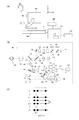
図1(a)は、眼科装置の構成を示す図であり、900は眼底の2次元像(SLO画像)および断層画像を撮像するための測定光学系を含む光学ヘッドである。950は光学ヘッドを図中xyz方向に移動可能なステージ部である。
FIG. 1A is a diagram illustrating a configuration of an ophthalmologic apparatus. An
925はステージ部の制御を行うパソコン(情報処理装置)であり、正面画像、断層画像およびEn−Face画像の生成を行う。また、情報処理装置925は、撮影方法としてOCTAが選択されている場合には、例えば、OCTAのEn−Face画像を生成する。
926は各種の情報を記憶する記憶部である。928は表示部であり、例えば、表示部928は液晶モニタである。929はパソコンへの指示を行う入力部であり、具体的にはキーボードおよびマウスから構成される。なお、入力部929はタッチパネルであってもよい。
A
光学ヘッド900に含まれる光学系を図本実施例の測定光学系、参照系および光源周辺の構成について図1(b)を用いて説明する。
An optical system included in the
まず、測定光学系について説明する。被検眼100に対向して対物レンズ101が設置され、その光軸上で第1ダイクロイックミラー130および第2ダイクロイックミラー131によってOCT光学系の光路201、SLO光学系と固視灯用の光路202および前眼観察用の光路203とに波長帯域ごとに分岐される。
First, the measurement optical system will be described. An
光路202はXYスキャナ135を経由して穴あきミラー139によって眼底からの反射光をアバランシェフォトダイオード(APD)142に受光させる。XYスキャナ135は一枚のミラーとして図示してあるが、X走査スキャナ401、Y走査スキャナ402からなる2軸方向の走査を行うものである。第3ダイクロイックミラー140によって眼底観察用のSLO光源143および固視灯141からの光が光路202に入射する。ここで136、137,138はレンズであり、137は固視灯および眼底観察用の光の焦点合わせのため不図示のモータによって駆動される。SLO光源143からは中心波長780nmの光が出射される。固視灯141は可視光を発生して被検者の固視を促すものである。
In the
光路203において132,133はレンズ、134は前眼観察用の赤外線CCDである。このCCD134は不図示の前眼観察用照明光の波長、具体的には970nm付近に感度を持つものである。
In the
光路201は前述の通りOCT光学系を成しており被検眼100の眼底の断層画像を撮像するためのものである。より具体的には断層画像を形成するための干渉信号を得るものである。102はレンズであり、104は披検眼への光照射を撮像時のみにするためのシャッター、103は光を眼底上で走査するためのXYスキャナである。XYスキャナ103は一枚のミラーとして図示してあるが、XY2軸方向の走査を行うものである。105、106はレンズであり、レンズ105は、ファイバーカプラー110に接続されているファイバー108から出射する光源114からの光を被検眼100の眼底上に焦点合わせするために不図示のモータによって駆動される。この焦点合わせによって被検眼100の眼底からの光は同時にファイバー108先端にスポット状に結像されて入射されることとなる。
The
次に、光源114から被検眼へ向かう光路と参照光学系の構成について説明する。
Next, an optical path from the
光源114は、前記光源は波長を変化させることが可能な波長掃引型光源であり、例えば、中心波長1040nm、バンド幅100nmの光を出射する。なお、上述の中心波長およびバンド幅は例示でありこれらの値に限定されるものではない。光源114から出射された光は、ファイバー113を介して、ファイバーカプラー112に導かれ、光量を測定するためのファイバー115とOCT測定するためのファイバー111に分岐される。光源114から出射された光は、ファイバー115を介して、PM(Power Meter)116にてパワーが測定される。ファイバー111を介した光は、ファイバーカプラー110に導かれる。ファイバーカプラー110は光源114からの光が伝送される光路を参照光路と測定光路とに分割する分割部として機能する、すなわち、ファイバーカプラー110により光源からの光は、測定光(OCT測定光とも言う)と参照光とに分岐される。ファイバーカプラー112の分岐比は、99:1であり、ファイバーカプラー110の分岐比は、90(参照光):10(測定光)である。なお、分岐比は例示であり上記の値に限定されるものではない。
The
ファイバーカプラー110で分岐された測定光は、ファイバー108を介してコリメータ107から平行光として出射される。109は光ファイバー108中に設けられた測定光側の偏光調整部である。偏光調整部は光ファイバーをループ状に引き回した部分を幾つか持ち、このループ状の部分をファイバーの長手方向を中心として回動させることでファイバーに捩じりを加え測定光と参照光との偏光状態を各々調整して合わせることが可能なものである。本装置ではあらかじめ測定光と参照光との偏光状態が調整されて固定されているものとする。
The measurement light split by the fiber coupler 110 is emitted from the
コリメータ107から出射された測定光は測定光学系を通り、被検眼100の眼底で所望の範囲の領域を走査することができる。
The measurement light emitted from the
一方、ファイバーカプラー110で分岐された参照光は、ファイバー117、偏光調整部118を介してコリメータ119から平行光として射出される。射出された参照光はコヒーレンスゲートステージ122上の参照ミラー120、121で反射され、コリメータ123、ファイバー124を介し、ファイバーカプラー126に到達する。
On the other hand, the reference light branched by the fiber coupler 110 is emitted as a parallel light from the collimator 119 via the fiber 117 and the polarization adjusting unit 118. The emitted reference light is reflected by the reference mirrors 120 and 121 on the coherence gate stage 122 and reaches the
コヒーレンスゲートステージ122は、参照ミラー120、121の光軸方向における位置を変更する変更部として機能し、係る機能により参照光の光路長を調整する。ミラー120、121は測定光の光路長と参照光の光路長とが等しくなる位置が撮影対象付近となるように調整される。コヒーレンスゲートステージ122は被検眼の眼軸長の相違等に対応する為、不図示のモータによって駆動される。 The coherence gate stage 122 functions as a change unit that changes the positions of the reference mirrors 120 and 121 in the optical axis direction, and adjusts the optical path length of the reference light by using such a function. The mirrors 120 and 121 are adjusted so that the position where the optical path length of the measurement light and the optical path length of the reference light are equal is near the imaging target. The coherence gate stage 122 is driven by a motor (not shown) to cope with a difference in the axial length of the eye to be examined.
ファイバーカプラー126は参照光路を経由した参照光と測定光路を経由した測定光とを合波する合波部として機能する。これによりファイバーカプラー126に到達した測定光と参照光とは合波されて干渉光となり、ファイバー127、128を経由し、合波された光を検出する光検出器である差動検出器(balanced receiver)129によって干渉信号が電気信号に変換される。情報処理装置925は、差動検出器129から出力を受信する。そして、情報処理装置925は、受信した信号に対して、一般的な再構成処理を行うことで、断層画像を生成する。
The
以上は、被検眼100のある1点における断層に関する情報の取得プロセスであり、眼科装置は、このプロセスをX方向に複数回行うことで2次元の断層像を取得することができる。また、眼科装置は、上記のプロセスをX方向およびY方向にそれぞれ複数回実行することで3次元断層像を取得することができる。2次元または3次元の断層像を取得するための走査は上述したX走査スキャナ401および/またはY走査スキャナ402により行われる。
The above is the process of acquiring information relating to a tomogram at a certain point of the subject's
なお、X走査スキャナ401、Y走査スキャナ402は、それぞれ回転軸が互いに直交するように配置された偏向ミラーで構成されている。X走査スキャナ401は、X軸方向の走査を行い、Y走査スキャナ402は、Y軸方向の走査を行う。X軸方向、Y軸方向の各方向は、被検眼100の眼軸方向に対して垂直な方向で、互いに垂直な方向である。
It should be noted that the X-scanning scanner 401 and the Y-scanning scanner 402 are each constituted by a deflecting mirror arranged so that the rotation axes are orthogonal to each other. The X scanning scanner 401 performs scanning in the X axis direction, and the Y scanning scanner 402 performs scanning in the Y axis direction. Each of the X-axis direction and the Y-axis direction is a direction perpendicular to the eye axis direction of the subject's
なお、上記の例ではSS−OCTの構成を説明したが、SD−OCTであってもよい。 In the above example, the configuration of SS-OCT has been described, but SD-OCT may be used.
<OCTAについての説明>
本実施例におけるOCTAについて図1(c)を用いて説明する。
<Description of OCTA>
OCTA in the present embodiment will be described with reference to FIG.
OCTAでは血流による干渉信号の時間変化を計測するため、眼底の同じ場所で複数の断層像を取得することが望ましい。本実施例ではOCT装置は、n箇所のY位置それぞれにおいて眼底の同じ場所でのBスキャンをm回繰り返すスキャンを行う。 In OCTA, it is desirable to acquire a plurality of tomographic images at the same place on the fundus in order to measure a time change of an interference signal due to a blood flow. In this embodiment, the OCT apparatus performs a scan in which the B scan at the same position on the fundus is repeated m times at each of n Y positions.
具体的なスキャン方法の一例を図1(c)に示す。OCT装置は、眼底平面状でy1〜ynのn箇所のY位置それぞれにおいて、Bスキャンをm回ずつ繰り返し実施する。mが大きいと同じ場所での計測回数が増えるため、血流の検出精度が向上する。その一方でスキャン時間が長くなり、スキャン中の眼の動き(固視微動)により画像にモーションアーチファクトが発生する問題と被検者の負担が増える問題が生じる。本実施例では両者のバランスを考慮してm=3とする。なお、Bスキャンの繰返し回数は3に限定されるものではない。なお、OCT装置のAスキャン速度、被検眼100の動き量に応じて、mを自由に変更してもよい。pは1つのBスキャンにおけるAスキャンのサンプリング数を示している。すなわち、p×nにより平面画像サイズが決定される。p×nが大きいと、同じ計測ピッチであれば広範囲がスキャンできるが、スキャン時間が長くなり、上述のモーションアーチファクト及び患者負担の問題が生じる。図1(c)において、Δxは隣り合うX位置の間隔(xピッチ)であり、Δyは隣り合うY位置の間隔(yピッチ)である。本実施例ではxピッチは眼底における照射光のビームスポット径の1/2として決定し、10μmとする。また、ΔyもΔxと同様に10μmとする。なお、これらの数値は例示であり適宜変更してもよい。スキャン時間短縮のため、Δyを10μmより大きくしてもよいが、ビームスポット径である20μmを超えない範囲にするとよい。xピッチ、yピッチに関しては、眼底ビームスポット径を大きくすると精細度は悪化するが、小さなデータ容量で広い範囲の画像を取得することができる。臨床上の要求に応じてxピッチ、yピッチを自由に変更してもよい。
FIG. 1C shows an example of a specific scanning method. The OCT apparatus repeats B scans m times at each of n Y positions y1 to yn on the fundus plane. If m is large, the number of measurements at the same place increases, so that the accuracy of blood flow detection is improved. On the other hand, the scanning time becomes longer, and there arises a problem that motion artifacts occur in the image due to the movement of the eyes (fine fixation) during scanning and a problem that the burden on the subject increases. In this embodiment, m = 3 in consideration of the balance between the two. The number of repetitions of the B scan is not limited to three. Note that m may be freely changed according to the A-scan speed of the OCT apparatus and the amount of movement of the subject's
情報処理装置925は各Y位置で得られた3枚のBスキャン間の各画素の相関または分散をモーションコントラスト値として取得する。そして、情報処理装置925はモーションコントラスト値に対して輝度値を割り当てることで3次元のOCTA画像を取得することができる。例えば、情報処理装置925は分散が大きいほど高い輝度値を割り当てることとしてもよいし、情報処理装置925は相関値が小さいほど高い輝度値を割り当てることとしてもよい。
The
<画像処理方法の説明>
本実施例における画像処理方法について図2を用いて説明する。
<Description of image processing method>
An image processing method according to the present embodiment will be described with reference to FIG.
図2は情報処理装置925の機能構成を示す図である。情報処理装置925は、不図示のCPUなどのプロセッサが記憶部926に記憶されたプログラムを実行することで第一取得部301、第二取得部302、層認識部303、生成部304および表示制御部305として機能する。
FIG. 2 is a diagram illustrating a functional configuration of the
なお、情報処理装置925が備えるCPUは1つであってもよいし複数であってもよい。また、記憶部926は複数のメモリを含むこととしてもよい。すなわち、少なくとも1以上のプロセッサ(CPUなど)と少なくとも1つのメモリとが接続されており、少なくとも1以上のプロセッサが少なくとも1以上のメモリに記憶されたプログラムを実行した場合に情報処理装置925のプロセッサは上記の各手段として機能する。
Note that the
第一取得部301は、差動検出器129の出力に基づいて断層像を取得する。また、第一取得部301は、さらに、第一取得部301はAPD142の出力に基づいて眼底の正面画像(以下、SLO画像という場合がある)を取得する。また、第一取得部301は、3次元のOCTA画像を取得する。具体的には、第一取得部301は、m回の繰返しBスキャンにより得られた干渉信号に基づいて生成されたm枚の断層像間の相関を計算する。第一取得部301はこの相関の計算を複数のY位置毎に行うことで、断層画像間の相関に基づいて3次元のOCTA画像を取得する。例えば、第一取得部301は、相関が低いほど高い輝度を割り当てることで、血管が強調されたOCTA画像を取得する。なお、OCTA画像は既知の種々の方法により生成可能であるため、詳細な説明は省略する。
The
また、第二取得部302はEn−Face画像を取得する。より具体的には、第二取得部302は、OCTAのEn−Face画像と強度のEn−Face画像とを取得する。ここで、強度のEn−Face画像とは、信号強度を示す通常の断層像複数枚から得られたEn−Face画像であり、3次元のOCTA画像から得れるOCTAのEn−Face画像とは異なる画像である。第二取得部302は、層認識部303と生成部304とを含む。
Further, the
層認識部303は、第一取得部301で得られた断層画像において被測定対象物(網膜)の層構造を抽出し、それぞれの層境界の形状を認識する。なお、層境界の認識は、深さ方向における輝度の変化に基づいて層境界を認識する方法など既知の方法により実現可能である。
The
層認識部303は、RNFL、GCL、INL、ONL+IS、OS、RPE、BM等の層の層境界を認識する。特定された層境界の形状は断層像と共に生成部304へと入力される。
The
生成部304は、層認識部303により認識された層境界に基づいて、断層画像の所定の深さ領域における画素値列の画素をそれぞれの画素列毎(Aスキャン毎)に積算(または加算平均)して強度のEn−Face画像を生成する。なお、生成部304は、断層画像の所定の深さ領域における画素値列から1の画素をそれぞれの画素列毎に選択して強度のEn−Face画像を生成することとしてもよい。また、生成部304は、層認識部303により認識された層境界に基づいて、3次元のOCTA画像から、所定の深さ領域におけるOCT画像の画素値列の画素をそれぞれの画素列毎(Aスキャン毎)に積算(または加算平均)してOCTAのEn−Face画像を生成する。生成部304は、3次元のOCTA画像の所定の深さ領域における画素値列から1の画素をそれぞれの画素列毎に選択してOCTAのEn−Face画像を生成することとしてもよい。なお、3次元のOCTA画像と層境界が得られた断層画像とは共通の断層画像であるため、生成部304は、3次元のOCTA画像において層認識部303により得られた層境界の位置を容易に特定することができる。また、上記の例に限らず、En−Face画像の生成には既知の種々の手法を用いることが可能である。例えば、En−Face画像を生成する断層像における深さ範囲(眼底における深さ範囲)は層境界に基づいて決定することとしたが、深さ方向に直行する水平な複数の直線により決定することとしてもよい。
Based on the layer boundary recognized by the
なお、生成部304は、入力部929からの指示によりEn−Face画像を生成する深さ領域が変更された場合には、逐次En−Face画像を生成し直す。従って、操作者の希望に応じた深さ領域のEn−Face画像が生成部304により適宜生成される。例えば、入力部による深さ範囲の変更は、図3(a)、(b)に示すように断層像に重畳された層境界を例えばドラッグにより移動することで実現できる。なお、生成部304は、層境界をドラッグしてドロップしたことを生成部304が検知した場合に、En−Face画像の生成を行うこととしてもよいし、層境界がドラッグにより移動したことを生成部304が検知した場合にドロップが行われたか否かに関わらずEn−Face画像の生成を行うこととしてもよい。なお、ドラッグのみならず、マウスホイールの回転によって層境界を移動させることとしてもよい。
Note that when the depth region for generating the En-Face image is changed according to an instruction from the
また、生成部304は、不図示の外部記憶装置から取得した層境界の情報及び断層像を用いてEn−Face画像を生成するように構成してもよい。
The
表示制御部305は、第一取得部301により取得された断層像、正面画像および第二取得部302により取得された輝度およびOCTAのEn−Face画像を選択的に表示部928に表示させる。例えば、表示制御部305は、表示部928に輝度またはOCTAのEn−Face画像を正面画像に重畳して表示させる。また、表示制御部305は、入力部929からの指示によりEn−Face画像を生成する深さ領域が変更された場合には、生成部304により逐次生成されるEn−Faceを表示手段に順次表示する。
The
上記のように構成された眼科装置の動作の一例を図4〜図6を用いて説明する。 An example of the operation of the ophthalmologic apparatus configured as described above will be described with reference to FIGS.
図5は撮影手順の一例を示すフローチャートである。なお、前提として、表示制御部305は、表示部928に図4に示す表示画面を表示させている。なお、1001は左右眼の何れかを示す表示である。また、図4において、領域1002には前眼部画像1003が、領域1011には断層像の撮影領域が重畳された眼底像1012が表示される。また、領域1006には断層像が表示される。なお、入力部929により移動可能なマウスカーソル1005も表示される。
FIG. 5 is a flowchart showing an example of the photographing procedure. As a premise, the
ステップS2001では、操作者によりスキャンモードが選択される。言い換えれば、情報処理装置925が備えるプロセッサが操作者により選択されたスキャンモードを認識する。具体的には、操作者は入力部929を介して図4に示す測定画面1000のScan Modeボタン1004から所望のスキャンモードを選択する。Scan Modeボタン1004には、Macula3Dボタン1014、Glaucoma3Dボタン1015、Disc3Dボタン1016、Anterior3Dボタン1017、OCTAボタン1013が含まれている。スキャンモードボタンがクリックされると、情報処理装置925が備えるプロセッサはクリックされたスキャンモードを認識するとともに、それぞれのスキャンモードに最適な走査パターン、固視位置をOCT装置に設定する。走査パターンとしては、例えば、3Dスキャン、ラジアルスキャン、クロススキャン、サークルスキャン、ラスタースキャンが含まれる。
In step S2001, a scan mode is selected by the operator. In other words, the processor included in the
次に、ステップS2002で、情報処理装置925が備えるプロセッサは、Startボタン1008の押し下げを検知すると、OCT装置を制御することでピント調整およびアライメント調整を自動的に行わせる。ピントやアライメントを微調整する際は、操作者はスライダ1018により被検眼に対する光学ヘッドのZ方向の位置を移動させることで調整し、スライダ1010によりフォーカス調整を行い、スライダ1009によりコヒーレンスゲートの位置調整を行う。
Next, in step S2002, when the processor included in the
ステップS2003で、情報処理装置925が備えるプロセッサはCaptureボタン1007の押し下げを検知すると、設定された走査パターンで被検眼を撮影するようOCT装置を制御する。そして、OCT装置により撮影が行われると、第一生成部301および第二生成部302により被検眼の画像(SLO画像、OCT画像、En−Face画像、3次元OCTA画像など)が取得される。
In step S2003, when the processor included in the
そして、ステップS2004で、表示制御手段305は、被検眼の画像を表示部928に表示させる。
Then, in step S2004, the
ステップS2004で、表示制御部305により表示部928に表示される撮影結果画面の例を図6に示す。図6(a)に示す撮影結果画面3100では、第1の表示領域3102には眼底の正面画像(SLO画像)3103に強度のEn−Face画像3104が重畳して表示される。強度のEn−Face画像3104の領域の大きさおよび位置は、入力部929による操作(例えばドラッグアンドドロップ)により変更することも可能である。具体的には、表示制御部305が入力部929からの信号を受け付けて、表示部928に強度のEn−Face画像3104の領域の大きさおよび位置を変更させる。なお、初期状態において、第1の表示領域3102に強度のEn−Face画像ではなく、OCTAのEn−Face画像を表示させることとしてもよい。
FIG. 6 shows an example of a shooting result screen displayed on the display unit 928 by the
なお、プルダウンメニュー3101から強度のEn−Face画像、OCTAのEn−Face画像、SLO画像およびプロジェクション画像のいずれかを選択することで正面画像3103に重ねる画像を選択することが出来る。例えば、表示制御部305は、プルダウンメニュー3101からOCTAのEn−Face画像が選択されたことを検知した場合、強度のEn−Face画像に代えてOCTAのEn−Face画像を表示部928に表示させる。なお、プロジェクション画像が深さ方向全域において加算平均を行うことで生成された画像であり、深さ方向の1部の領域を用いるEn−Face画像とは異なる画像である。
Note that an image to be superimposed on the
第2の表示領域3112には強度のEn−Face画像3104と同じ深さ領域のOCTAのEn−Face画像3113が表示される。プルダウンメニュー3111から強度のEn−Face画像、OCTAのEn−Face画像、SLO画像およびプロジェクション画像のいずれかを選択することが出来る。例えば、表示制御部305は、プルダウンメニュー3111から強度のEn−Face画像が選択されたことを検知した場合、OCTAのEn−Face画像に代えて強度のEn−Face画像を表示部928に表示させる。
In the second display area 3112, an OCTA En-Face image 3113 in the same depth area as the intensity En-Face image 3104 is displayed. From the pull-down menu 3111, any one of the intensity En-Face image, the OCTA En-Face image, the SLO image, and the projection image can be selected. For example, when detecting that the En-Face image of the intensity is selected from the pull-down menu 3111, the
第3の表示領域3121には、SLO画像3103中の断層像の取得位置を示す線3105の位置に対応する断層像3122が表示される。線3105を入力部929を用いてドラッグすることで移動させることができる。表示制御部305は、線3105の位置を検知して、検知した位置に対応する断層像を表示部928に表示させる。OCTAのEn−Face画像3113に重畳表示される線3114は線3105と同様の機能を有するものであるため詳細な説明は省略する。なお、表示制御部305は、線3105および線3114の一方が移動する場合、他方も連動して移動するように表示部928を制御する。
In the third display area 3121, a tomographic image 3122 corresponding to the position of the
また、断層像3122には、層認識部303により認識された層境界が境界線3123として重畳して表示されている。また、境界線3123から深さ方向において所定距離(例えば10μm)離れた位置に境界線3124が断層像3122に重畳して表示されている。なお、2つの境界線の両者ともRPE、ILMなど具体的な層境界を指定することで、深さ領域を規定できるようにしてもよい。境界線3123と境界線3124とで規定される深さ領域は、強度のEn−Face画像3104、OCTAのEn−Face画像3113の深さ領域を示している。
Further, in the tomographic image 3122, the layer boundaries recognized by the
なお、表示制御部305は、プルダウンメニュー3120から所望の網膜層の境界(RNFL、GCL、INL、ONL+IS、OS、RPE、BM)が選択されたことを検知すると、選択された層境界に対応して境界線3123、境界線3124の表示位置を表示部928に変更させる。また、境界線3123、境界線3124は入力部929を用いてドラッグすることでそれぞれ独立に自由に位置を変えることが出来る。また、境界線3123、境界線3124は独立ではなく一定の間隔を保持して動かすことも可能である。
If the
第4の表示領域3107にはEn−Face画像3104とは異なる深さ領域の強度のEn−Face画像3108が表示される。第5の表示領域3116には強度のEn−Face画像3108と同じ深さ領域のOCTAのEn−Face画像3117が表示される。第6の表示領域3126にはSLO画像3103中の断層像の取得位置を示す線3105の位置に対応する断層像3127が表示される。境界線3128、境界線3129の位置は境界線3123、境界線3124とは異なる位置になっており、異なる深さ方向における眼底の状態を個別に確認することが出来る。なお、線3110および線3118の機能は線3105および線3114と同様の機能を有するものであるため、説明を省略する。なお、線3105、3110,3114、3118の全ての位置が眼底の同一位置となるように連動させることとしてもよい。さらに、プルダウンメニュー3106、3115、3125は、プルダウンメニュー3101、3111、3120と同様の機能を有するものであるため、説明を省略する。
In the fourth display area 3107, an En-Face image 3108 having a different depth from the En-Face image 3104 is displayed. A fifth display area 3116 displays an OCTA En-Face image 3117 in the same depth region as the intensity En-Face image 3108. In the sixth display area 3126, a tomographic image 3127 corresponding to the position of the
なお、線3105、3110,3114、3118は、図6(a)の画面が表示された初期状態では、OCTAのEn−Face画像の視認性を高めるために非表示としてもよい。この場合、線3110は表示切替ボタン3119により線3105、3110,3114、3118の表示、非表示の切換えを行うことができる。すなわち、表示制御部305は、表示切替ボタン3119に対する操作を検知して、線3105、3110,3114、3118を表示させるか否かの制御を行う。なお、OCTAモード以外の場合にも、OCTAのEn−Face画像は含まれないが、図6(a)と同様の構成の撮影結果画面が表示される。例えば、図6(a)においてOCTAのEn−Face画像が表示されている部分は強度のEn−Face画像またはプロジェクション画像に置き換えられる。その場合、表示制御部305は、断層像の位置を示す線を撮影結果画面の初期状態において表示部928に表示させることとしてもよい。すなわち、撮影モードに応じて、撮影結果画面の初期状態において断層像の位置を示す線を表示させるか否かを切り替えることとしてもよい。
Note that the
上記実施形態においては表示領域3102にSLO画像を表示したがEn−Face画像やOCTA画像等、他の画像を表示してもよい。また、初期状態において、第1の表示領域には強度のEn−Face画像3104ではなくOCTAのEn−Face画像をSLO画像に重畳して表示させることとしてもよい。 In the above embodiment, the SLO image is displayed in the display area 3102, but another image such as an En-Face image or an OCTA image may be displayed. In the initial state, the OCTA En-Face image may be superimposed on the SLO image instead of the strong En-Face image 3104 in the first display area.
上記の実施例によれば、強度のEn−Face画像またはOCTAのEn−Face画像を正面画像の一例であるSLO画像上に重ねて表示するため、En−Face画像と正面画像との比較する際の視線の移動を軽減することが可能となる。 According to the above embodiment, since the En-Face image of the intensity or the En-Face image of OCTA is displayed on the SLO image which is an example of the front image, the En-Face image is compared with the front image. Movement of the line of sight can be reduced.
また、深さ位置を変更した場合、SLO画像3103に重畳された強度またはOCTAのEn−Face画像とOCTAのEn−Face画像3112が連動して変化するため、操作者は簡単に複数のEn−Face画像を変更することが可能となる。
When the depth position is changed, the intensity superimposed on the
[実施例2]
実施例2について、図6(b)を用いて説明する。なお、眼科装置の構成は実施例1と同様であるため、説明を省略する。実施例2では、撮影結果画面が実施例1とは異なっている。図6(b)は、第2の表示領域から第6の表示領域までは実施例1に係る撮影結果画面である図6(a)と同様であるため、説明を省略する。
[Example 2]
Example 2 will be described with reference to FIG. The configuration of the ophthalmologic apparatus is the same as that of the first embodiment, and a description thereof will not be repeated. In the second embodiment, the photographing result screen is different from the first embodiment. FIG. 6B is the same as FIG. 6A, which is the shooting result screen according to the first embodiment, from the second display area to the sixth display area, and a description thereof will be omitted.
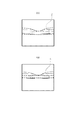
図6(b)における第1の表示領域3203には眼底の正面画像(SLO画像)3204に、OCTAのEn−Face画像3205および強度のEn−Face画像3206が重ねて表示されている。なお、図6(b)においては、左側にOCTAのEn−Face画像3205、右側に強度のEn−Face画像3206が表示されているが、左右は逆であってもよい。 In the first display area 3203 in FIG. 6B, an OCTA En-Face image 3205 and an intensity En-Face image 3206 are displayed superimposed on the front image (SLO image) 3204 of the fundus. In FIG. 6B, the Enta-Face image 3205 of OCTA is displayed on the left and the En-Face image 3206 of intensity is displayed on the right, but the left and right may be reversed.
第1の表示領域3203にはOCTAのEn−Face画像3205が表示されているが、プルダウンメニュー3201から強度のEn−Face画像、SLO画像、プロジェクション画像を選択することで表示する画像を変えることが出来る。同様にEn−Face画像3206が表示されているが、プルダウンメニュー3202からOCTAのEn−Face画像、SLO画像、プロジェクション画像のいずれかを選択することで表示する画像を変えることが出来る。具体的には、表示制御部305は、プルダウンメニュー3201,3202で選択された画像の種別を受け付け、選択された画像をSLO画像3204に重畳して表示部928に表示させる。なお、実施例1と同様に、境界線3123,3124の位置を変更することでEn−Face画像の深さ領域が変更された場合には、表示制御部305によりOCTAのEn−Face画像3205および強度のEn−Face画像3206が更新される。
An OCTA En-Face image 3205 is displayed in the first display area 3203, but the displayed image can be changed by selecting a strong En-Face image, an SLO image, and a projection image from the pull-down menu 3201. I can do it. Similarly, an En-Face image 3206 is displayed. However, an image to be displayed can be changed by selecting any one of an En-Face image, an SLO image, and a projection image of OCTA from the pull-down menu 3202. More specifically, the
上記に説明した実施形態によると強度のEn−Face画像とOCTAのEn−Face画像とがSLO画像上に半分ずつ重ねて表示されているため、実施例1の効果に加えて、異なる種類のEn−Face画像を操作により切換えることなく確認することが可能となる。 According to the above-described embodiment, the En-Face image of the intensity and the En-Face image of the OCTA are displayed on the SLO image by half, so that in addition to the effect of the first embodiment, different types of En-Face images are obtained. -It is possible to confirm the Face image without switching by operation.
なお、強度のEn−Face画像とOCTAのEn−Face画像との領域は等しい大きさとしたが、例えば両En−Face画像の境界をドラッグすることで、それぞれの領域の大きさを変更できるように構成してもよい。すなわち、両En−Face画像の境界の移動を表示制御部305が検知した場合、表示制御部305は、En−Face画像とOCTAのEn−Face画像との領域の大きさを表示部928に変更させる。
Note that the regions of the intensity En-Face image and the OCTA En-Face image have the same size, but the size of each region can be changed by, for example, dragging the boundary between both En-Face images. You may comprise. That is, when the
また、強度のEn−Face画像とOCTAのEn−Face画像との領域は左右ではなく上下で分割することとしてもよい。 Further, the region of the En-Face image of the intensity and the En-Face image of OCTA may be divided not vertically but vertically.
また、境界線3123,3124の位置が変更された場合、第2の表示領域に表示されたEn−Face画像と同じ種類のSLO画像3204上のEn−Face画像のみ更新されることとしてもよい。 When the positions of the boundaries 3123 and 3124 are changed, only the En-Face image on the SLO image 3204 of the same type as the En-Face image displayed in the second display area may be updated.
[実施例3]
実施例3について、図6(c)を用いて説明する。なお、眼科装置の構成は実施例1と同様であるため、説明を省略する。実施例3では、撮影結果画面が実施例1とは異なっている。図6(c)は、第2の表示領域、第4の表示領域から第6の表示領域までは実施例1に係る撮影結果画面である図6(a)と同様であるため、説明を省略する。
[Example 3]
Example 3 will be described with reference to FIG. The configuration of the ophthalmologic apparatus is the same as that of the first embodiment, and a description thereof will not be repeated. In the third embodiment, the photographing result screen is different from the first embodiment. FIG. 6C is the same as FIG. 6A which is the photographing result screen according to the first embodiment from the second display area, the fourth display area to the sixth display area, and the description is omitted. I do.
第1の表示領域3303には、En−Face画像3305が重畳された眼底の正面画像画像(SLO画像)3304が表示されている。更に、En−Face画像3305上にOCTAのEn−Face画像3306が表示されている。表示されている強度のEn−Face画像3305を、プルダウンメニュー3301からOCTAのEn−Face画像、SLO画像、プロジェクション画像のいずれかを選択することで変えることが出来る。 In the first display area 3303, a front image image (SLO image) 3304 of the fundus on which the En-Face image 3305 is superimposed is displayed. Further, an Enta-Face image 3306 of OCTA is displayed on the En-Face image 3305. The displayed En-Face image 3305 of the intensity can be changed by selecting one of the OCTA En-Face image, SLO image, and projection image from the pull-down menu 3301.
同様に表示されたOCTAのEn−Face画像3306もプルダウンメニュー3302から強度のEn−Face画像、SLO画像、プロジェクション画像のいずれかを選択することで変えることが出来る。具体的には、表示制御部305が、プルダウンメニュー3301、3302を用いて選択された画像を、表示部928に表示させる。
Similarly, the displayed OCTA En-Face image 3306 can be changed by selecting any of the strong En-Face image, SLO image, or projection image from the pull-down menu 3302. Specifically, the
第3の表示領域3308にはSLO画像3304中の線3307に対応する断層像3309が表示される。強度のEn−Face画像3305は境界線3310、境界線3311に挟まれた深さ方向の領域のEn−Face画像である。OCTAのEn−Face画像3306は境界線3312、境界線3313に挟まれた深さ方向の領域のEn−Face画像になっている。表示制御部305は、強度のEn−Face画像3305と境界線3310、3311とが対応していること、および、OCTAのEn−Face画像3306が境界線3312、3313とが対応していることを明示するように、各境界線およびEn−Face画像を表示部928に表示させる。例えば、表示制御部305は、En−Face画像の外枠の色を対応する境界線と同様の色で表示部928に表示させる。
In the third display area 3308, a tomographic image 3309 corresponding to the line 3307 in the SLO image 3304 is displayed. The strength En-Face image 3305 is an En-Face image of the region in the depth direction between the boundary lines 3310 and 3311. The OCTA En-Face image 3306 is an En-Face image of the region in the depth direction between the boundary lines 3312 and 3313. The
操作者は境界線3310、3311を境界線3312、3313と独立して操作することが可能である。従って、本実施例では、それぞれのEn−Face画像の深さ範囲を個別に設定することができる。 The operator can operate the boundaries 3310 and 3311 independently of the boundaries 3312 and 3313. Therefore, in this embodiment, the depth range of each En-Face image can be set individually.
なお、第2領域に表示されたOCTAのEn−Face画像は、境界線3312、3313の位置により規定される深さ方向の領域に対応している。OCTAのEn−Face画像の深さ方向の領域を示す境界線3312、3313変更された場合のみ、第2領域に表示されたOCTAのEn−Face画像が更新されることとしてもよい。すなわち、図6(c)において、境界線3310、3311が変更された場合には、強度のEn−Face画像3305のみが表示制御部305により更新されることとしてもよい。
The OCTA En-Face image displayed in the second area corresponds to an area in the depth direction defined by the positions of the boundaries 3312 and 3313. The OCTA En-Face image displayed in the second area may be updated only when the boundaries 3312 and 3313 indicating the area in the depth direction of the OCTA En-Face image are changed. That is, in FIG. 6C, when the boundaries 3310 and 3311 are changed, only the En-Face image 3305 of the intensity may be updated by the
さらに、入力部929からの信号に応じて表示制御部305は、表示部928にOCTAのEn−Face画像3306の大きさおよび位置を変更させることとしてもよい。例えば、OCTAのEn−Face画像3306の位置が変更された場合、表示制御部305は、第3の表示領域における境界線3312,3313の水平方向における表示位置を表示部928に変更させる。
Furthermore, the
また、図6(c)に示した例では、強度のEn−Face画像3305上の一部にOCTAのEn−Face画像3306が表示されているが、OCTAのEn−Face画像上の一部に強度のEn−Face画像が表示されることとしてもよい。 Also, in the example shown in FIG. 6C, the OCTA En-Face image 3306 is displayed on a part of the intensity En-Face image 3305, but the OCTA En-Face image is displayed on a part of the OCTA En-Face image. A strong En-Face image may be displayed.
本実施例によれば、異なる種類のEn−Face画像をそれぞれ個別に深さ方向を設定することが可能となる。 According to the present embodiment, it is possible to individually set the depth direction for different types of En-Face images.
[実施例4]
実施例4について、図6(d)を用いて説明する。なお、眼科装置の構成は実施例1と同様であるため、説明を省略する。実施例4では、撮影結果画面が実施例1とは異なっている。図6(b)は、第2の表示領域、第4の表示領域から第6の表示領域までは実施例1に係る撮影結果画面である図6(a)と同様であるため、説明を省略する。
[Example 4]
Example 4 will be described with reference to FIG. The configuration of the ophthalmologic apparatus is the same as that of the first embodiment, and a description thereof will not be repeated. In the fourth embodiment, the photographing result screen is different from that of the first embodiment. FIG. 6B is the same as FIG. 6A which is the photographing result screen according to the first embodiment from the second display area, the fourth display area to the sixth display area, and the description is omitted. I do.
第1の表示領域3403には、強度のEn−Face画像3406が重畳された眼底の正面画像画像(SLO画像)3404が表示されている。さらに、強度のEn−Face画像3406にはOCTAのEn−Face画像3405、3407が重ねて表示されている。 In the first display area 3403, a front image image (SLO image) 3404 of the fundus on which the En-Face image 3406 of intensity is superimposed is displayed. Further, the En-Face images 3405 and 3407 of OCTA are superimposed on the En-Face image 3406 of the intensity.
表示制御部305によりOCTAのEn−Face画像3405の領域形状を円形にすることで、操作者は乳頭周辺の深さ方向の画像を観察することが出来る。また、領域形状は入力部929からの入力される指示に応じて任意に大きさや形を変えることが出来る。具体的には、表示制御部305は入力部929からの入力に従い、表示部928にEn−Face画像の領域形状を変更させる。
By making the region shape of the OCTA En-Face image 3405 circular by the
表示されたEn−Face画像3406を、プルダウンメニュー3401からOCTAのEn−Face画像やSLO画像、プロジェクション画像のいずれかを選択することで変えることが出来る。同様に表示されたOCTAのEn−Face画像3405、3407を、プルダウンメニュー3402から強度のEn−Face画像、SLO画像、プロジェクション画像のいずれかを選択することで変えることが出来る。 The displayed En-Face image 3406 can be changed by selecting any of the OCTA En-Face image, SLO image, and projection image from the pull-down menu 3401. Similarly, the displayed OCTA En-Face images 3405 and 3407 can be changed by selecting any of the strong En-Face images, SLO images, and projection images from the pull-down menu 3402.
第3の表示領域3409にはSLO画像3404中の線3308に対応する断層像3310が表示される。強度のEn−Face画像3406は境界線3311、境界線3312に挟まれた深さ方向の領域のEn−Face画像である。OCTAのEn−Face画像3405は境界線3415、3416に挟まれた深さ方向の領域のEn−Face画像である。同様にOCTAのEn−Face画像3407は境界線3413、境界線3414に挟まれた深さ方向の領域のEn−Face画像である。 In the third display region 3409, a tomographic image 3310 corresponding to the line 3308 in the SLO image 3404 is displayed. The strength En-Face image 3406 is an En-Face image of a region in the depth direction between the boundary lines 3311 and 3312. An OCTA En-Face image 3405 is an En-Face image of a region in the depth direction between the boundary lines 3415 and 3416. Similarly, an OCTA En-Face image 3407 is an En-Face image of a region in the depth direction between the boundary lines 3413 and 3414.
表示制御部305は、実施例3と同様に、En−Face画像と境界線との対応を明示するように、各境界線およびEn−Face画像を表示部928に表示させる。具体的には、実施例3と同様に色を用いて境界線とEn−Face画像との対応関係を示すこととしてもよい。
The
図6(d)においては、同種のEn−Face画像であっても、OCTAのEn−Face画像3405,3407それぞれの深さ方向の領域を個別に設定することが可能である。具体的には、入力部929を介して、境界線3413、3414が変更された場合でも表示制御部305は、OCTAのEn−Face画像3405は更新せずOCTAのEn−Face画像3407のみを更新するように表示部929を制御する。従って、操作者は、同種のEn−Face画像の異なる深さ範囲の画像を一見して観察することが可能となる。すなわち、表示制御部305は、正面画像の領域毎に眼底における深さ範囲が異なるOCTAのEn−Face画像を表示部928に表示させることが可能となる。
In FIG. 6D, even in the case of the same type of En-Face image, it is possible to individually set the respective regions in the depth direction of the OCTA En-Face images 3405 and 3407. More specifically, even when the boundaries 3413 and 3414 are changed via the
なお、第2の表示領域に表示されたOCTAのEn−Face画像の深さ方向の範囲は、OCTAのEn−Face画像3405,3407のどちらに連動してもよい。また、例えば、第2の表示領域に表示されたOCTAのEn−Face画像をOCTAのEn−Face画像3405,3407のうち領域の大きい画像に連動させることとしてもよいし、領域が小さい画像に連動させることとしてもよい。 Note that the range in the depth direction of the OCTA En-Face image displayed in the second display area may be linked to either of the OCTA En-Face images 3405 and 3407. Further, for example, the OCTA En-Face image displayed in the second display area may be linked to the OCTA En-Face images 3405 and 3407 having a larger area, or may be linked to the OCTA En-Face image having a smaller area. It is good also as making it do.
また、図6(d)に示した例では、強度のEn−Face画像3406上の一部に複数のOCTAのEn−Face画像3405,3407が表示されているが、OCTAのEn−Face画像上の一部に複数の強度のEn−Face画像が表示されることとしてもよい。なお、強度のEn−Face画像3406を表示せず、SLO画像3304に直接OCTAのEn−Face画像3405,3407を直接重畳するようにしてもよい。 In the example shown in FIG. 6D, a plurality of OCTA En-Face images 3405 and 3407 are displayed on a part of the intensity En-Face image 3406. However, on the OCTA En-Face image, May be displayed on a part of the image. Note that the En-Face images 3405 and 3407 of OCTA may be directly superimposed directly on the SLO image 3304 without displaying the En-Face image 3406 of the intensity.
本実施例によれば、同種のEn−Face画像の異なる深さ方向の画像を一見して把握することが可能となる。また、En−Face画像の形状を変更することが可能であるため、目的に適したEn−Face画像を表示することが可能となる。 According to the present embodiment, it is possible to grasp at a glance images of the same type of En-Face images in different depth directions. In addition, since the shape of the En-Face image can be changed, an En-Face image suitable for the purpose can be displayed.
[その他の実施形態]
上記の実施例において、表示される画像の変更はプルダウンメニューを用いることとしたが、表示部929がタッチパネルを備える場合には、画像をタップすることで表示される画像が変更されることとしてもよい。
[Other embodiments]
In the above embodiment, the displayed image is changed using a pull-down menu. However, when the
また、上記の実施例においては、SLO画像にEn−Face画像を重畳することとしたが、En−Face画像にSLO画像を重畳する構成としてもよい。 Further, in the above embodiment, the En-Face image is superimposed on the SLO image, but the SLO image may be superimposed on the En-Face image.
さらに、上記の実施例においては正面画像としてSLO画像を例に上げたが、眼底カメラにより撮影された眼底像を正面画像として取り扱ってもよい。 Further, in the above embodiment, the SLO image is taken as an example of the front image, but the fundus image captured by the fundus camera may be handled as the front image.
以上、実施例を詳述したが、開示の技術は例えば、システム、装置、方法、プログラム若しくは記録媒体(記憶媒体)等としての実施態様をとることが可能である。具体的には、複数の機器(例えば、ホストコンピュータ、インタフェース機器、撮像装置、webアプリケーション等)から構成されるシステムに適用してもよいし、また、一つの機器からなる装置に適用してもよい。 Although the embodiment has been described in detail, the disclosed technology can take an embodiment as, for example, a system, an apparatus, a method, a program, or a recording medium (storage medium). Specifically, the present invention may be applied to a system including a plurality of devices (for example, a host computer, an interface device, an imaging device, a web application, etc.), or may be applied to a device including a single device. Good.
また、本発明の目的は、以下のようにすることによって達成されることはいうまでもない。即ち、前述した実施形態の機能を実現するソフトウェアのプログラムコード(コンピュータプログラム)を記録した記録媒体(または記憶媒体)を、システムあるいは装置に供給する。係る記憶媒体は言うまでもなく、コンピュータ読み取り可能な記憶媒体である。そして、そのシステムあるいは装置のコンピュータ(またはCPUやMPU)が記録媒体に格納されたプログラムコードを読み出し実行する。この場合、記録媒体から読み出されたプログラムコード自体が前述した実施形態の機能を実現することになり、そのプログラムコードを記録した記録媒体は本発明を構成することになる。 Needless to say, the object of the present invention is achieved by the following. That is, a recording medium (or a storage medium) that records a program code (computer program) of software that realizes the functions of the above-described embodiments is supplied to a system or an apparatus. Needless to say, such a storage medium is a computer-readable storage medium. Then, the computer (or CPU or MPU) of the system or apparatus reads out and executes the program code stored in the recording medium. In this case, the program code itself read from the recording medium implements the functions of the above-described embodiment, and the recording medium on which the program code is recorded constitutes the present invention.
開示の情報処理装置の一つは、
被検眼の正面画像を取得する第1取得部と、
OCT光学系を用いて得た前記被検眼の異なる位置の複数の断層像を用いて、前記被検眼のEn−Face画像を取得する第2取得部と、
前記En−Face画像を前記正面画像に重畳して表示部に表示させる表示制御部と、を備え、
前記表示制御部は、前記正面画像に重畳された前記En−Face画像の前記被検眼における深さ範囲を、前記断層像における層境界の情報を用いて設定可能に構成される。
One of the disclosed information processing devices is:
A first acquisition unit that acquires a front image of the eye to be inspected,
A second acquisition unit that acquires an En-Face image of the subject's eye using a plurality of tomographic images at different positions of the subject's eye obtained using an OCT optical system;
A display control unit that superimposes the En-Face image on the front image and displays the display on a display unit,
The display control unit is configured to be able to set a depth range of the En-Face image superimposed on the front image in the subject's eye using information on a layer boundary in the tomographic image .
Claims (16)
OCT光学系を用いて得た前記被検眼の異なる位置の複数の断層像を用いて、前記被検眼のEn−Face画像を取得する第2取得部と、
前記En−Face画像を前記正面画像に重畳して表示部に表示させる表示制御部と、を備え、
前記表示制御部は、前記正面画像に重畳された前記En−Face画像の前記被検眼における深さ範囲を変更可能に構成されることを特徴とする情報処理装置。 A first acquisition unit that acquires a front image of the eye to be inspected,
A second acquisition unit that acquires an En-Face image of the subject's eye using a plurality of tomographic images at different positions of the subject's eye obtained using an OCT optical system;
A display control unit that superimposes the En-Face image on the front image and displays the display on a display unit,
The information processing apparatus according to claim 1, wherein the display control unit is configured to be able to change a depth range of the En-Face image superimposed on the front image in the subject's eye.
前記表示制御部は、前記正面画像に重畳された前記En−Face画像の前記被検眼における深さ範囲と、前記正面画像に重畳された前記En−Face画像とは異なる大きさのEn−Face画像の前記被検眼における深さ範囲とを連動して変更可能に構成されることを特徴とする請求項1乃至4のいずれか1項に記載の情報処理装置。 The display control unit causes the display unit to display the En-Face image at a size different from the En-Face image superimposed on the front image,
The display control unit may include a depth range of the En-Face image superimposed on the front image in the subject's eye, and an En-Face image having a size different from the En-Face image superimposed on the front image. 5. The information processing apparatus according to claim 1, wherein the information processing apparatus is configured to be able to change the depth range of the subject's eye in conjunction therewith.
前記表示制御部は、操作者からの指示に応じて、前記第3の表示領域に表示される断層像上の線を移動することにより、前記深さ範囲を変更することを特徴とする請求項1乃至7のいずれか1項に記載の情報処理装置。 The display control unit displays the front image on which the En-Face image is superimposed on a first display area on a shooting result screen displayed on the display unit, and displays the En-F image superimposed on the front image. The En-Face image having a size larger than the Face image is displayed in a second display area, and a tomographic image of the subject's eye obtained by using the OCT optical system is displayed in a third display area,
The said display control part changes the said depth range by moving the line on the tomographic image displayed on the said 3rd display area according to the instruction | indication from an operator. The information processing apparatus according to any one of claims 1 to 7.
前記表示制御部は、前記正面画像に前記強度のEn−Face画像と前記OCTAのEn−Face画像と同時に重畳して前記表示部に表示させることを特徴とする請求項1乃至9のいずれか1項に記載の情報処理装置。 The second acquisition unit acquires, as the En-Face image, an En-Face image of the intensity of the eye to be inspected and an En-Face image of the OCTA of the eye to be inspected,
10. The display control unit according to claim 1, wherein the display control unit superimposes the En-Face image of the intensity and the En-Face image of the OCTA on the front image at the same time and displays the image on the display unit. The information processing device according to item.
前記正面画像に重畳された前記En−Face画像の前記被検眼における深さ範囲を変更する工程と、
を有することを特徴とする情報処理方法。 A display unit configured to superimpose a plurality of tomographic images at different positions of the eye to be inspected obtained using an OCT optical system, the En-Face images obtained using the plurality of tomographic images being superimposed on a front image of the eye to be inspected; A step of displaying the
Changing a depth range of the En-Face image superimposed on the front image in the subject's eye;
An information processing method comprising:
Priority Applications (1)
| Application Number | Priority Date | Filing Date | Title |
|---|---|---|---|
| JP2019182531A JP6780081B2 (en) | 2019-10-02 | 2019-10-02 | Information processing device and information processing method |
Applications Claiming Priority (1)
| Application Number | Priority Date | Filing Date | Title |
|---|---|---|---|
| JP2019182531A JP6780081B2 (en) | 2019-10-02 | 2019-10-02 | Information processing device and information processing method |
Related Parent Applications (1)
| Application Number | Title | Priority Date | Filing Date |
|---|---|---|---|
| JP2016048703A Division JP6598713B2 (en) | 2016-03-11 | 2016-03-11 | Information processing device |
Related Child Applications (1)
| Application Number | Title | Priority Date | Filing Date |
|---|---|---|---|
| JP2020173411A Division JP7071469B2 (en) | 2020-10-14 | 2020-10-14 | Information processing equipment and information processing method |
Publications (2)
| Publication Number | Publication Date |
|---|---|
| JP2020006232A true JP2020006232A (en) | 2020-01-16 |
| JP6780081B2 JP6780081B2 (en) | 2020-11-04 |
Family
ID=69149666
Family Applications (1)
| Application Number | Title | Priority Date | Filing Date |
|---|---|---|---|
| JP2019182531A Active JP6780081B2 (en) | 2019-10-02 | 2019-10-02 | Information processing device and information processing method |
Country Status (1)
| Country | Link |
|---|---|
| JP (1) | JP6780081B2 (en) |
Citations (5)
| Publication number | Priority date | Publication date | Assignee | Title |
|---|---|---|---|---|
| US20080100612A1 (en) * | 2006-10-27 | 2008-05-01 | Dastmalchi Shahram S | User interface for efficiently displaying relevant oct imaging data |
| JP2012071113A (en) * | 2010-08-31 | 2012-04-12 | Canon Inc | Image processing apparatus, method for controlling the same, and program |
| JP2014128366A (en) * | 2012-12-28 | 2014-07-10 | Canon Inc | Ophthalmology apparatus and positioning method |
| JP2014226514A (en) * | 2013-05-27 | 2014-12-08 | キヤノン株式会社 | Information processing apparatus, information processing method and computer program |
| JP2016010658A (en) * | 2014-06-30 | 2016-01-21 | 株式会社ニデック | Optical coherence tomography device, optical coherence tomography calculation method and optical coherence tomography calculation program |
-
2019
- 2019-10-02 JP JP2019182531A patent/JP6780081B2/en active Active
Patent Citations (5)
| Publication number | Priority date | Publication date | Assignee | Title |
|---|---|---|---|---|
| US20080100612A1 (en) * | 2006-10-27 | 2008-05-01 | Dastmalchi Shahram S | User interface for efficiently displaying relevant oct imaging data |
| JP2012071113A (en) * | 2010-08-31 | 2012-04-12 | Canon Inc | Image processing apparatus, method for controlling the same, and program |
| JP2014128366A (en) * | 2012-12-28 | 2014-07-10 | Canon Inc | Ophthalmology apparatus and positioning method |
| JP2014226514A (en) * | 2013-05-27 | 2014-12-08 | キヤノン株式会社 | Information processing apparatus, information processing method and computer program |
| JP2016010658A (en) * | 2014-06-30 | 2016-01-21 | 株式会社ニデック | Optical coherence tomography device, optical coherence tomography calculation method and optical coherence tomography calculation program |
Also Published As
| Publication number | Publication date |
|---|---|
| JP6780081B2 (en) | 2020-11-04 |
Similar Documents
| Publication | Publication Date | Title |
|---|---|---|
| JP6598713B2 (en) | Information processing device | |
| JP4864515B2 (en) | Fundus observation device | |
| JP5061380B2 (en) | Fundus observation apparatus, ophthalmologic image display apparatus, and program | |
| JP4969925B2 (en) | Fundus observation device | |
| JP4823693B2 (en) | Optical image measuring device | |
| KR20180075458A (en) | Interactive control apparatus | |
| JP2007275375A (en) | Ophthalmologic device | |
| JP2017136215A (en) | Ophthalmologic apparatus and ophthalmologic examination system | |
| JP2014147501A (en) | Optical tomographic imaging device and method for controlling the same | |
| JP6274728B2 (en) | Optical coherence tomography apparatus and control method thereof | |
| JP7394897B2 (en) | Ophthalmological device and method for controlling the ophthalmological device | |
| JP6780081B2 (en) | Information processing device and information processing method | |
| JP7071469B2 (en) | Information processing equipment and information processing method | |
| JP5913519B2 (en) | Fundus observation device | |
| JP7394948B2 (en) | ophthalmology equipment | |
| JP2012176162A (en) | Fundus oculi observing device | |
| JP7030577B2 (en) | Ophthalmic equipment | |
| JP2018064662A (en) | Ophthalmologic imaging device and control method thereof | |
| JP2017070635A (en) | Ophthalmologic apparatus and control method of ophthalmologic apparatus | |
| JP2016123722A (en) | Examination apparatus and control method for examination apparatus | |
| JP2019115762A (en) | Examination apparatus and control method for examination apparatus | |
| JP2019170470A (en) | Ophthalmologic apparatus | |
| JP2019130046A (en) | Ophthalmologic apparatus | |
| JP2019054981A (en) | Inspection device, control method and program of inspection device | |
| JP2019054982A (en) | Examination apparatus, method of controlling examination apparatus, and program |
Legal Events
| Date | Code | Title | Description |
|---|---|---|---|
| A521 | Request for written amendment filed |
Free format text: JAPANESE INTERMEDIATE CODE: A523 Effective date: 20191025 |
|
| A621 | Written request for application examination |
Free format text: JAPANESE INTERMEDIATE CODE: A621 Effective date: 20191025 |
|
| A977 | Report on retrieval |
Free format text: JAPANESE INTERMEDIATE CODE: A971007 Effective date: 20200909 |
|
| TRDD | Decision of grant or rejection written | ||
| A01 | Written decision to grant a patent or to grant a registration (utility model) |
Free format text: JAPANESE INTERMEDIATE CODE: A01 Effective date: 20200915 |
|
| A61 | First payment of annual fees (during grant procedure) |
Free format text: JAPANESE INTERMEDIATE CODE: A61 Effective date: 20201014 |
|
| R151 | Written notification of patent or utility model registration |
Ref document number: 6780081 Country of ref document: JP Free format text: JAPANESE INTERMEDIATE CODE: R151 |