JP2016123722A - Examination apparatus and control method for examination apparatus - Google Patents
Examination apparatus and control method for examination apparatus Download PDFInfo
- Publication number
- JP2016123722A JP2016123722A JP2015000318A JP2015000318A JP2016123722A JP 2016123722 A JP2016123722 A JP 2016123722A JP 2015000318 A JP2015000318 A JP 2015000318A JP 2015000318 A JP2015000318 A JP 2015000318A JP 2016123722 A JP2016123722 A JP 2016123722A
- Authority
- JP
- Japan
- Prior art keywords
- changing
- light
- inspection object
- measurement light
- alignment
- Prior art date
- Legal status (The legal status is an assumption and is not a legal conclusion. Google has not performed a legal analysis and makes no representation as to the accuracy of the status listed.)
- Pending
Links
Images
Landscapes
- Eye Examination Apparatus (AREA)
Abstract
Description
本発明は、眼科診療等に用いられる検査装置および当該検査装置の制御方法に関する。 The present invention relates to an inspection apparatus used for ophthalmic medical care and the like, and a method for controlling the inspection apparatus.
現在、検査装置の一態様である眼科用機器として、光学機器を用いた様々なものが使用されている。例えば、眼を観察する光学機器として、前眼部撮影機、眼底カメラ、共焦点レーザ走査検眼鏡(Scanning Laser Ophthalmoscope: SLO)、等様々な機器が使用されている。 Currently, various devices using an optical device are used as an ophthalmic device which is an aspect of an inspection apparatus. For example, various apparatuses such as an anterior ocular segment photographing machine, a fundus camera, and a confocal laser scanning ophthalmoscope (SLO) are used as optical instruments for observing the eyes.
中でも、光干渉断層撮像装置(Optical Coherence Tomography:OCT、以下OCT装置と記す)は、試料の断層像を高解像度に得る装置であり、眼科用機器として網膜の専門外来では必要不可欠な装置になりつつある。該OCT装置は、低コヒーレント光を被検査物に照射し且つ該被検査物上で走査する。そして、測定光の被検査物からの戻り光を干渉系により処理することで、被検査物の断層に関する輝度情報等を高感度に測定する。また、その輝度情報に基づいて、被検査物の断層像を高解像度に得ることができる。そのため、被検眼の眼底における網膜について高解像度の断層像を得ることが可能であることから、網膜の眼科診断等において広く利用されている。 Among them, the optical coherence tomography (OCT, hereinafter referred to as OCT device) is a device that obtains a tomographic image of a sample with high resolution, and is an indispensable device for retina outpatients as an ophthalmic device. It's getting on. The OCT apparatus irradiates the inspection object with low coherent light and scans the inspection object. Then, the return light of the measurement light from the object to be inspected is processed by the interference system, so that the luminance information and the like relating to the tomography of the object to be inspected is measured with high sensitivity. Further, a tomographic image of the inspection object can be obtained with high resolution based on the luminance information. Therefore, since it is possible to obtain a high-resolution tomographic image of the retina on the fundus of the eye to be examined, it is widely used in ophthalmic diagnosis of the retina.
ここで、OCT断層画像の取得の手順について簡単に述べる。断層像取得時には、被検眼の前眼部観察像を見ながら、ジョイスティック等を用いて被検眼に対する光学系の位置合わせを行う。位置合わせ完了の後、SLO眼底画像を取得し、このSOL眼底画像に基づいてSLO光学系に配置されたフォーカスレンズを移動させて合焦操作を行う。また、その際に、同時にOCT光学系の粗い合焦操作を行う。さらに、この後、OCT断層画像に基づいて、参照ミラーを移動してコヒーレンスゲートを自動調整し且つOCT光学系の精密な自動合焦を行う。これらコヒーレンスゲートの調整及びOCT光学系の自動合焦では、複雑な制御或いは操作が必要になる。 Here, a procedure for acquiring an OCT tomographic image will be briefly described. When acquiring a tomographic image, the optical system is aligned with the eye to be examined using a joystick or the like while observing the anterior ocular segment observation image of the eye to be examined. After the alignment is completed, an SLO fundus image is acquired, and a focus lens arranged in the SLO optical system is moved based on the SOL fundus image to perform a focusing operation. At the same time, a rough focusing operation of the OCT optical system is simultaneously performed. Further, based on the OCT tomographic image, the reference mirror is moved to automatically adjust the coherence gate and perform precise automatic focusing of the OCT optical system. The adjustment of the coherence gate and the automatic focusing of the OCT optical system require complicated control or operation.
このような操作に関して、特許文献1には、被検眼前眼部の画像に基づいて該前眼部の位置合わせをおこない、位置が適正であると判断された場合にはコヒーレンスゲートの位置調整を自動で行う装置が記載されている。 With regard to such an operation, Patent Document 1 discloses that the anterior eye part is aligned based on the image of the anterior eye part to be examined, and the position of the coherence gate is adjusted when it is determined that the position is appropriate. An automatic device is described.
被検査物が眼の時、強度の近視或いは遠視の場合にはその視度の影響によって適切な合焦状態が得られないことがある。これまでの装置では、光路長変更手段の調整範囲内の視度である被検眼に対してはフォーカスレンズの合焦操作を全て自動で行えた。しかし、被検眼の視度が調整範囲から少しでも外れた場合、適切な合焦状態が選らず、コントラストの合ったOCT画像を取得することは困難であった。また、適当なコントラストが容易に得られないことから、検者への負担も大きかった。 When the object to be inspected is an eye, in the case of intense myopia or hyperopia, an appropriate in-focus state may not be obtained due to the effect of the diopter. In the conventional apparatus, the focusing operation of the focus lens can be automatically performed on the subject's eye whose diopter is within the adjustment range of the optical path length changing means. However, when the diopter of the eye to be examined is slightly out of the adjustment range, an appropriate in-focus state is not selected, and it is difficult to obtain an OCT image with a suitable contrast. In addition, since an appropriate contrast cannot be easily obtained, the burden on the examiner was also great.
本発明はこのような状況に鑑みて為されたものであって、被検眼の視度が眼科装置の調整範囲を超えた場合であっても、簡単に被検眼の適正な断層画像を取得可能とする検査装置及び該検査装置の制御方法の提供を目的とする。 The present invention has been made in view of such a situation, and even when the diopter of the eye to be examined exceeds the adjustment range of the ophthalmologic apparatus, an appropriate tomographic image of the eye to be examined can be easily obtained. It is an object of the present invention to provide an inspection apparatus and a control method for the inspection apparatus.
上記課題を解決するために、本発明に係る検査装置は、
測定光を照射した被検査物の画像を取得する画像取得手段と、
前記被検査物に対する前記測定光の合焦状態を得るために合焦部材の位置を変更する合焦位置変更手段と、
前記合焦部材を有する光学ヘッドと前記被検査物との相対位置を変化させて位置合わせを行う位置合わせ手段と、
前記合焦位置変更手段による合焦部材の位置変更範囲の内での位置変更にて前記合焦状態が得られるか否かを判断する判断手段と、
前記判断手段の判断結果に応じて、前記位置合わせ手段を動作させる制御手段と、を有することを特徴とする。
In order to solve the above problems, an inspection apparatus according to the present invention provides:
Image acquisition means for acquiring an image of the inspection object irradiated with the measurement light;
In-focus position changing means for changing the position of the focusing member in order to obtain the in-focus state of the measurement light with respect to the inspection object;
Alignment means for performing alignment by changing a relative position between the optical head having the focusing member and the inspection object;
Determining means for determining whether or not the in-focus state is obtained by position change within a position change range of the focusing member by the focus position changing means;
Control means for operating the positioning means according to the judgment result of the judgment means.
本発明によれば、簡単に適正な断層像を得ることができ、検者の負担を減らすことができる。 According to the present invention, an appropriate tomographic image can be easily obtained, and the burden on the examiner can be reduced.
本発明に係る眼科システム又は装置は、コヒーレンスゲート位置の自動調整或いは変更が終了後の合焦位置の自動調整時に、通常の調整状態にある被検眼と光学系との位置関係ではフォーカスの調整範囲に入らない視度の被検眼の観察の場合対応するものである。本発明では、このような場合に、観察視野を優先するか断層像のコントラストを優先するかを選択できるようにしている。具体的には、断層像解像度を優先した場合には、被検眼と光学系との位置関係を変更し、自動で最適なコントラストが得られる位置へ光学系を移動させる。これにより、検者の操作の負担を減らすことができる。なお、本発明は眼科システム又は装置に限定されるものではなく、人体の皮膚等の被検査物を観察するための内視鏡等の医療システム又は装置に適用可能である。 The ophthalmic system or apparatus according to the present invention provides a focus adjustment range according to the positional relationship between the eye to be examined and the optical system in a normal adjustment state during automatic adjustment of the in-focus position after completion of automatic adjustment or change of the coherence gate position. This corresponds to the case of observing the eye to be examined whose diopter does not fall within the range. In the present invention, in such a case, it is possible to select whether to give priority to the observation visual field or tomogram contrast. Specifically, when priority is given to the tomographic image resolution, the positional relationship between the eye to be examined and the optical system is changed, and the optical system is automatically moved to a position where an optimum contrast is obtained. Thereby, the burden of an examiner's operation can be reduced. The present invention is not limited to an ophthalmic system or apparatus, but can be applied to a medical system or apparatus such as an endoscope for observing an object to be inspected such as the skin of a human body.
なお、コヒーレンスゲートとは、OCTにおいて測定光の光路における参照光の光路長に対応する位置のことである。このため、後述する光路長差変更部により、測定光と参照光との光路長差を変更することにより、コヒーレンスゲートの位置を変更することができる。なお、光路長差変更部としては、参照ミラーの位置を光軸方向に移動する構成や、被検眼に対して装置を光軸方向に移動する構成等が考えられ、例えば、参照ミラーや装置に設けた移動ステージの駆動機構が例示できる。 The coherence gate is a position corresponding to the optical path length of the reference light in the optical path of the measurement light in OCT. For this reason, the position of the coherence gate can be changed by changing the optical path length difference between the measurement light and the reference light by an optical path length difference changing unit described later. As the optical path length difference changing unit, a configuration in which the position of the reference mirror is moved in the optical axis direction, a configuration in which the device is moved in the optical axis direction with respect to the eye to be examined, and the like can be considered. The drive mechanism of the provided moving stage can be illustrated.
(装置の概略構成)
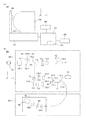
本発明の一実施形態に係る眼科装置の概略構成について、眼科装置の側面図である図2(a)を用いて説明する。該眼科装置は、光学ヘッド900、ステージ部950、ベース部951、パソコン925、表示部928、入力部929、及びあご台323を有する。
(Schematic configuration of the device)
A schematic configuration of an ophthalmologic apparatus according to an embodiment of the present invention will be described with reference to FIG. The ophthalmologic apparatus includes an
光学ヘッド900は、被検眼の前眼部画像及び眼底についての2次元画像或いは断層画像を取得するための測定光学系である。該光学ヘッド900は、図中XYZ方向にモータ等により移動するステージ部950即ち移動部を用いて、後述する分光器を内蔵するベース部951に対して移動することができる。また、ステージ部950の制御部を兼ねるパソコン925は、ステージ部の制御とともに断層画像の構成等を行う。ステージ部950は、これを制御する構成と共に、本実施形態において、後述する合焦レンズ等の合焦部材を有する光学ヘッド900と被検眼107との相対位置を変化させて位置合わせを行う位置合わせ手段を構成する。パソコン925はハードディスク926を有し、該ハードディスク926は被検者情報記憶部を兼ね、断層像撮像用のプログラムなどを記憶する。
The
パソコン925は、モニタ等の表示部928及びキーボード、マウス等からなる入力部929に接続される。入力部929は、不図示の表示制御部への指示等も行う。表示部928は、該表示制御部からの指示に応じて、後述する測定画面等を表示画面上に表示するあご台323は、測定時において被検者がこれに対してあごと額と当接させることによって被検眼を固定する。
The
(測定光学系および分光器の構成)
次に、本実施形態に係る眼科装置の測定光学系および分光器の構成について図2(b)を用いて説明する。
(Configuration of measurement optical system and spectrometer)
Next, the configuration of the measurement optical system and the spectroscope of the ophthalmic apparatus according to the present embodiment will be described with reference to FIG.
まず、光学ヘッド900部の内部について説明する。被検者の被検眼107に対向して対物レンズ135−1が設置され、該対物レンズ135−1の光軸上には第1ダイクロイックミラー132−1及び第2ダイクロイックミラー132−2が配置される。被検眼107からの光路は、第1ダイクロイックミラー132−1によって、波長帯域に応じて前眼部観察用の光路353と、固視灯用の光路352及びOCT光学系の光路351とに分岐される。また、光路353に分岐後の光路は、第2ダイクロイックミラー132−2によって、波長帯域に応じて固視灯用の光路352とOCT光学系の光路351とに分岐される。光路352は、更に第3ダイクロイックミラー132−3によって眼底観察用のCCD172への光路と固視灯191への光路へと上記と同じく波長帯域ごとに分岐される。
First, the inside of the
第2ダイクロイックミラー132−2から第3ダイクロイックミラー132−3に至る光路352上には、合焦レンズ135−3及びレンズ135−4がこの順で配置される。合焦レンズ135−3は、固視灯および眼底観察用の合焦調整のため不図示のモータによって、光路352に沿った光軸方向に駆動される。
A focusing lens 135-3 and a lens 135-4 are arranged in this order on an
CCD172は、不図示の眼底観察用照明光の波長、具体的には780nm付近に感度を持つものである。一方固視灯191は、可視光を発生して被検者の固視を促すものである。なお、眼底観察用の光学系は、走査型レーザ検眼鏡(SLO:Scaning Laser Ophthlmoscope)等の光学系により構成しても良い。
The CCD 172 has sensitivity at the wavelength of illumination light for fundus observation (not shown), specifically around 780 nm. On the other hand, the
第1ダイクロイックミラー132−1による分岐後の光路353上には、レンズ135−2及び前眼観察用の赤外CCD117がこの順で配置される。赤外CCD171は、不図示の前眼観察用照明光の波長、具体的には970nm付近に感度を持つものである。また、光路353上には、不図示のイメージスプリットプリズムが配置されている。このイメージスプリットプリズムより得られる前眼部のスプリット像に基づいて、被検眼107に対する光学ヘッド900部のZ方向の距離を検出することができる。
On the
光路351は前述の通りOCT光学系を成しており、被検眼107の眼底の断層画像を取得するためのものである。より具体的には、断層画像を形成するための干渉信号を得るものである。OCT光学系は、測定光の光路に配置される光学部材、参照光の光路に配置される光学部材、光源101、光カップラー131、及び干渉光から干渉信号を得る分光器180を有する。当該OCT光学系は、本実施形態において、測定光を照射した被検査物からの戻り光と、測定光に対応する参照光と、を合波した合波光に基づいて被検眼107の眼底の断層画像を取得する断層画像取得手段を構成する。
The
光源101から発せられた光は光ファイバー131−1介して光カップラー131に導かれてここで測定光として分離され、光ファイバー131−2を経て測定光の光路に至る。第2ダイクロイックミラー132−2に至る測定光の光路上にはXYスキャナ134、合焦レンズ135−5及びレンズ135−6が配置される。
The light emitted from the
XYスキャナ134は、測定光を被検眼107の眼底上で走査するために用いられる。なお、XYスキャナ134は一枚のミラーとして図示してあるが、XYの2軸方向の走査を行うものであって実際には2枚のミラーが用いられる。合焦レンズ135−5は、ファイバー131−2から射出する光源101からの測定光を眼底上に合焦調整をする。このため、不図示のモータによって測定光の光路に沿ってその光軸上で駆動される。また、この合焦調整によって眼底からの反射或いは散乱光は、同時にファイバー131−2先端にスポット状に結像されて入射されることとなる。
The
次に、光源101からの光路と参照光学系の構成について説明する。光源101から発せられた光は、光カップラー131により参照光に分離され、光ファイバー131−3を経て参照光学系に至る。参照光学系には、該光ファイバー131−3側から、レンズ135−5、分散補償用ガラス115、及びミラー132−4が配置される。前述した光カプラー131には、光カプラーに接続されて一体化しているシングルモードの光ファイバー131−1〜4が接続されている。参照光路を経た135−7は光ファイバー131−4を経て分光器180に至る。これらの構成によってマイケルソン干渉計を構成している。
Next, the configuration of the optical path from the
次に干渉光の生成について述べる。前述したように、光源101から射出された光は光ファイバー131−1を通り、光カプラー131を介して光ファイバー131−2側に導かれる測定光と光ファイバー131−3側に導かれる参照光とに分割される。測定光は前述のOCT光学系の光路351を通じ、観察対象である被検眼107の眼底に照射され、網膜による反射や散乱により同じ光路を通じて再び光カプラー131に到達する。
Next, generation of interference light will be described. As described above, the light emitted from the
一方、参照光は光ファイバー131−3及びレンズ135−7を経て、測定光と参照光の分散を合わせるために挿入された分散補償ガラス115を介してミラー132−4に到達し、反射される。そして同じ光路を戻り、再び光カプラー131に到達する。光カプラー131によって、これら測定光と参照光とは合波されて干渉光(合波光とも呼ぶ)となる。ここで、測定光の光路長と参照光の光路長がほぼ同一となったときに干渉を生じる。
On the other hand, the reference light passes through the optical fiber 131-3 and the lens 135-7, reaches the mirror 132-4 through the dispersion compensation glass 115 inserted in order to match the dispersion of the measurement light and the reference light, and is reflected. Then, it returns on the same optical path and reaches the
ミラー132−4は不図示のモータ及び駆動機構によって参照光の光路に沿った光軸方向に位置調整が可能に保持される。これにより、ミラー132−4の位置を動かして参照光の光路長を変化させ、被検眼107によって変わる測定光の光路長に参照光の光路長を合わせることが可能である。干渉光は光ファイバー131−4を介して分光器180に導かれる。
The mirror 132-4 is held by a motor and a drive mechanism (not shown) so that the position of the mirror 132-4 can be adjusted in the optical axis direction along the optical path of the reference light. As a result, the position of the mirror 132-4 is moved to change the optical path length of the reference light, and the optical path length of the reference light can be adjusted to the optical path length of the measurement light that varies depending on the eye 107 to be examined. The interference light is guided to the
なお、本実施形態では、光ファイバー131−2中には測定光側の偏光調整部139−1が設けられている。また、光ファイバー131−3中には参照光側の偏光調整部139−2が設けられている。これらの偏光調整部は、光ファイバーをループ状に引き回した部分を幾つか持つ。このループ状の部分をファイバーの長手方向を中心として回動させてファイバーにねじりを加えることで、測定光と参照光の偏光状態を各々調整して合わせることが可能となる。本装置では、予め測定光と参照光の偏光状態が調整されて固定されている。 In the present embodiment, the optical fiber 131-2 is provided with a measurement light side polarization adjusting unit 139-1. Further, a polarization adjusting unit 139-2 on the reference light side is provided in the optical fiber 131-3. These polarization adjusting units have several portions in which the optical fiber is routed in a loop. By rotating this loop-shaped portion about the longitudinal direction of the fiber and twisting the fiber, the polarization states of the measurement light and the reference light can be adjusted and matched. In this apparatus, the polarization states of the measurement light and the reference light are adjusted and fixed in advance.
分光器180は、レンズ135−8、135−9、回折格子181、及びラインセンサ182から構成される。光ファイバー131−4から射出された干渉光はレンズ135−8を介して略平行光となった後、回折格子181で分光され、レンズ135−3によってラインセンサ182に結像される。ラインセンサ182により得られた該干渉光に基づく干渉信号はパソコン925に送られ、該パソコン925によりこの干渉信号を用いて断層画像が生成される。
The
次に、光源101の周辺について説明する。光源101は、代表的な低コヒーレント光源であるSLD(Super Luminescent Diode)である。該光源101から得られる光の中心波長は855nm、波長バンド幅は約100nmである。ここで、バンド幅は、得られる断層画像の光軸方向の分解能に影響するため、重要なパラメータである。また、光源の種類は、ここではSLDを選択したが、低コヒーレント光が射出できればよく、ASE(Amplified Spontaneous Emission)等も用いることができる。中心波長は眼を測定することを鑑みると、近赤外光が適する。また、中心波長は得られる断層画像の横方向の分解能に影響するため、なるべく短波長であることが望ましい。双方の理由から、本実施形態では用いる光の中心波長を855nmとした。
Next, the periphery of the
なお、上述したように、本実施形態では干渉計としてマイケルソン干渉計を用いたが、マッハツェンダー干渉計を用いてもよい。測定光と参照光との光量差が比較的小さい場合には、分割部と合成部とが別々に設けられるマッハツェンダー干渉計よりも、分割部と合成部とが共通に設けられるマイケルソン干渉計を用いる方が望ましい。 As described above, in this embodiment, a Michelson interferometer is used as an interferometer, but a Mach-Zehnder interferometer may be used. Michelson interferometer in which the splitting unit and the combining unit are provided in common rather than the Mach-Zehnder interferometer in which the splitting unit and the combining unit are provided separately when the difference in the amount of light between the measurement light and the reference light is relatively small It is preferable to use
(断層画像の取得方法)
続いて、断層画像の取得方法について説明する。不図示の制御部は、パソコン925からの指示に応じてXYスキャナ134を制御する。これにより、被検眼107の眼底における所望部位上で測定光を走査し、該部位の断層画像を取得することができる。具体的には、まず眼底上でX方向に測定光のスキャンを行い、眼底におけるX方向の撮像範囲から得られた所定の撮像本数の干渉光をラインセンサ182で結像させる。X方向のある位置で得られるラインセンサ182上の輝度分布は、FFTにより線状の輝度分布とされる。
(Tomographic image acquisition method)
Next, a method for acquiring a tomographic image will be described. A control unit (not shown) controls the
FFTで得られた線状の輝度分布は、表示部928上に示す画像とするために、濃度あるいはカラー情報に変換される。この変換後に得られる画像を、Aスキャン画像と呼ぶ。この複数のAスキャン画像を並べた2次元の画像をBスキャン画像と呼ぶ。1つのBスキャン画像を構築するための複数のAスキャン画像を撮像し、これを合成する。1つのBスキャン画像を得た後、Y方向のスキャン位置を移動させて再びX方向のスキャンを行うことにより、複数のBスキャン画像が得られる。
The linear luminance distribution obtained by FFT is converted into density or color information in order to obtain an image shown on the
検者は、表示部928に表示されるBスキャン画像あるいは複数のBスキャン画像から構築した3次元断層画像を見ることにより、被検眼を診断することができる。
The examiner can diagnose the eye to be examined by viewing a B-scan image displayed on the
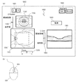
(測定画面)
続いて、表示画面に表示される測定画面1000について、図1を用いて説明する。測定画面1000上には、画像を表示する前眼観察画面1101、眼底2次元像表示画面1201、及び断層画像表示画面1301が配置される。また各々の表示画面にはこれらの画像の所謂ピント、コントラスト等を調整して好適な画像を表示させるためのスライダ1103、1203、1302が配置される。
(Measurement screen)
Next, the
前眼観察画面1101には、前眼観察用CCDによって得られた被検眼107の前眼部の観察像が表示される。ここで、前眼観察画面1101に表示される観察像は、前眼観察系に設けられたイメージスプリットプリズムによって得られる前眼部のスプリット像1102である。該スプリット像1102は、前述したように光学ヘッド900と被検眼107とのアライメントを行う際に利用する。
On the anterior
また、眼底2次元像表示画面1201には、眼底観察用CCDによって得られた被検眼の眼底の2次元像が表示される。この眼底2次元像表示画面1201には、眼底画像における断層画像を撮像する撮像範囲1202も併せて表示される。被検眼の断層画像は、断層画像表示画面1301のコヒーレンスゲート位置に基づく表示位置に表示される。
Further, the fundus two-dimensional
被検眼の左右眼を切り替えるためのボタン1001は検者がLボタンとRボタンとのうちいずれか一方を押すと、該押された左右眼のいずれかに対応する位置に光学ヘッド900が移動される。また、検者が入力手段929である図1(b)に示すマウス930を机上等で移動させた場合、この移動に連動して測定画面1000上に重ねて表示されているカーソル1002の表示位置を移動させることができる。
When the examiner presses either the L button or the R button, the
本実施形態に係る眼科装置においては、不図示の位置検出部により検出されたカーソルの画面上表示位置に応じて、前述したアライメント等を変更することができる。本実施形態では、表示画面上においてボタン等の入力用の表示形態を中心に所定の広さの範囲を設けている。該所定の範囲の画素内にカーソルがある場合には、該カーソルを介して該所定の範囲の中心となる表示形態で定められた調整を行うことができる。即ち、マウス930を操作してマウス930内のホイール931を回転させることにより、カーソル1002が位置している表示領域の画像に対応する調整の指示を行うことができる。例えば、カーソルが前眼部画像の表示領域に位置している場合にアライメント、眼底画像の表示領域に位置している場合には眼底のフォーカス位置、断層画像の表示領域に位置している場合にはコヒーレンスゲート位置をそれぞれ調整することができる。
In the ophthalmologic apparatus according to the present embodiment, the above-described alignment and the like can be changed according to the on-screen display position of the cursor detected by a position detection unit (not shown). In the present embodiment, a range of a predetermined area is provided on the display screen with a display form for input such as buttons as the center. When the cursor is within the pixels in the predetermined range, adjustments determined by the display form that is the center of the predetermined range can be performed via the cursor. That is, by operating the
なお、この場合、測定画面1000のアライメントのモード選択ボタン1004は検者によりマニュアルが選択されている。また、マウス930のドラッグ等の操作により、アライメント等の各調整の指示を行うこともできる。なお、アライメント等の各調整が終了した後に、検者が撮像ボタン1003を押すことで所望の撮像が行われる。
In this case, the manual is selected by the examiner for the alignment
前述したように画像の近傍に配置されている各スライダは、各々対応する表示画面に表示される画像の画質等の調整を行うために用いられる。スライダ1103は被検眼107に対する光学ヘッド900のZ方向の位置を調整するもの、スライダ1203はフォーカス位置を調整するもの、スライダ1302はコヒーレンスゲート位置を調整するものである。
As described above, the sliders arranged in the vicinity of the image are used for adjusting the image quality and the like of the image displayed on the corresponding display screen. The slider 1103 adjusts the position of the
フォーカス位置の調整は、眼底に対する合焦調整を行うために、合焦レンズ135−3及び合焦レンズ135−5を各々光軸に沿った図示の矢印の方向に移動することで行われる。これら合焦レンズは、これらを位置制御する駆動系等の構成を含めて、本実施形態において、被検眼107或いは眼底に対する測定光の合焦状態を得るために合焦部材たる合焦レンズの光軸上の位置を変更する合焦位置変更手段を構成する。コヒーレンスゲート位置の調整は、断層画像が断層画像表示画面1301の所望の位置で観察されるようにするために、反射ミラー132−4を光軸に沿った図示の矢印の方向に移動することで行われる。この反射ミラー132−4とこれを光軸上で駆動する構成は、本実施形態において、測定光と参照光との光路長差を変更する光路長差変更手段を構成する。また、これらのスライダは、それぞれの画像上にカーソル1002を位置させて、マウス930によりホイール931を操作した際にも連動して動くようになっている。
The focus position is adjusted by moving the focusing lens 135-3 and the focusing lens 135-5 in the direction of the arrow shown in the drawing along the optical axis in order to adjust the focus on the fundus. These focusing lenses include the configuration of a drive system that controls the positions of these focusing lenses, and in this embodiment, the light of the focusing lens that is a focusing member in order to obtain the focusing state of the measuring light with respect to the eye 107 or the fundus. In-focus position changing means for changing the position on the axis is configured. The coherence gate position is adjusted by moving the reflection mirror 132-4 in the direction of the arrow along the optical axis so that the tomographic image is observed at a desired position on the tomographic
(オートによる撮影)
《第1の実施形態》
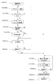
次に、本発明の第1の実施形態に係る眼底の撮影方法について、図3のフローチャートを用いて説明する。なお、ここでは、測定画面1000のアライメントのモード選択ボタン1004でオートを選択した場合について述べる。
(Automatic shooting)
<< First Embodiment >>
Next, a fundus imaging method according to the first embodiment of the present invention will be described with reference to the flowchart of FIG. Here, a case will be described where auto is selected with the alignment
まず、ステップ301において、撮影を開始する。次に、ステップ304において、被検眼107と装置(光学ヘッド900)との位置合わせであるアライメントを開始する。このアライメントの終了は、ステップ305において判断される。ステップ305にて、アライメントが良好になったと判断された場合、アライメントを終了してフローはステップ306に進む。また、アライメントが良好でないと判断された場合には、フローはステップ304に戻り、以降アライメントが良好と判断されるまでこのループは継続する。なお、アライメントを完了せずに、アライメントを継続したまま、アライメントが良好になったときにフローがステップ306に進むこととすることも可能である。 First, in step 301, shooting is started. Next, in step 304, alignment that is alignment between the eye 107 to be examined and the apparatus (optical head 900) is started. The end of the alignment is determined in step 305. If it is determined in step 305 that the alignment is good, the alignment is completed and the flow proceeds to step 306. If it is determined that the alignment is not good, the flow returns to step 304, and the loop continues until it is determined that the alignment is good. It should be noted that the flow may proceed to step 306 when the alignment becomes satisfactory while the alignment is continued without completing the alignment.
ステップ306において、SLOとOCTとの各々の光学系でのフォーカス調整(合焦操作)を行う。ここで述べるフォーカス調整は、前述した合焦レンズ135−3、135−5各々の光軸上の位置を調整する操作に対応する。つぎに、ステップ307において被検眼の視度が合焦調整範囲内或いは光路長変更範囲に収まるか否かを判断する。範囲内であると判断された場合は、フローはステップ308へ進み、測定光と参照光とのうちいずれか一方の偏光の調整を行う。また、ステップ308において参照光の光量調整を行う。次に、ステップ309において、前述したコヒーレンスゲート位置の調整を行う。コヒーレンスゲート位置の調整の終了の判断はステップ310に進み行われる。ステップ310で、調整が終了していないと判断されればフローはステップ308に戻り、このループは調整が終わるまで継続する。調整が終了したと判断されると、続くステップ311で断層画像の取得を開始して、ステップ312で撮影を終了する。 In step 306, focus adjustment (focusing operation) is performed in each of the SLO and OCT optical systems. The focus adjustment described here corresponds to the operation of adjusting the position on the optical axis of each of the focusing lenses 135-3 and 135-5 described above. Next, in step 307, it is determined whether the diopter of the eye to be examined is within the focus adjustment range or the optical path length change range. If it is determined that the value is within the range, the flow proceeds to step 308, and the polarization of one of the measurement light and the reference light is adjusted. In step 308, the amount of reference light is adjusted. Next, in step 309, the above-described coherence gate position is adjusted. The determination of the end of the adjustment of the coherence gate position is performed in step 310. If it is determined in step 310 that the adjustment has not been completed, the flow returns to step 308 and this loop continues until the adjustment is completed. When it is determined that the adjustment has been completed, acquisition of tomographic images is started in subsequent step 311, and imaging is ended in step 312.
また、ステップ307にて被検眼の視度が装置の現状のアライメントにおける測定仕様範囲外であると判断された場合には、フローはステップ313へ進む。ステップ313では、検者へ被検眼107と光学系(光学ヘッド900)との距離(WD)を初期値(ここでは、35mm)から変更するか否かを問う。検者の操作により、ステップ313にてWDを変更しないことを選択した場合は、フローはステップ308へ進み、その後は前述した操作と同様の操作を行う。また、WDを変更することを選択した場合には、フローはステップ314へ進む。本実施形態におけるこのステップ313の操作は、合焦状態が得られないと判断した場合に行われる光学ヘッド900による被検眼107に対する相対位置の変化を行うか否かを確認する操作となる。当該操作は入力部929を介して行われ、パソコン925において確認手段として機能する領域により実行に移される。
If it is determined in step 307 that the diopter of the eye to be examined is outside the measurement specification range in the current alignment of the apparatus, the flow proceeds to step 313. In step 313, the examiner is asked whether or not to change the distance (WD) between the eye 107 to be examined and the optical system (optical head 900) from the initial value (35 mm in this case). If it is selected by the examiner's operation that the WD is not changed in step 313, the flow proceeds to step 308, and thereafter, the same operation as that described above is performed. If it is selected to change the WD, the flow proceeds to step 314. The operation of step 313 in the present embodiment is an operation for confirming whether or not to change the relative position with respect to the eye 107 to be examined by the
ステップ314ではステップ306において得られたSLOフォーカス画像から、WDを初期値からどれだけ変更すればよいかを演算し、その結果をもってWDを変更する。なお、WDの変更は、被検眼の視度がマイナスディオプターの場合には被検眼107と光学系とが近づく方向(30〜35mmの範囲)に光学ヘッド900を移動させる。また、プラスディオプターの場合には遠ざかる方向(35〜40mmの範囲)に光学ヘッド900が移動される。即ち、合焦状態が得られない場合において、ステップ314では、求められる被検眼の視度に応じて相対位置を離間及び接近の何れかを選択してその操作が行われることとなる。
In step 314, how much the WD should be changed from the initial value is calculated from the SLO focus image obtained in step 306, and the WD is changed based on the result. Note that the WD is changed by moving the
光学ヘッド900が移動されて、被検眼視度に応じたWDとなった後、フローはステップ315に進む。ステップ315にて、SLO像についてのフォーカス調整が合っていなければフローはステップ314に戻って、調整が終わるまでこのループを継続する。ステップ314におけるWDの変更の際には、調整完了をSLO画像における輝度のピーク値を探してピントがあったことを判断する。ステップ315にて調整が終わったと判断された後、フローはステップ308へ進み、その後は前述したフローでの操作と同様の操作を行う。
After the
上述したステップ307においては、換言すれば、合焦位置変更手段による合焦レンズの位置変更範囲の内での位置変更にて合焦状態が得られるか否かが判断される。この判断はパソコン925において判断手段として機能する領域により実行される。或いは、当該判断は、光路長差変更手段による光路長差を変更可能な範囲にて所定の断層画像が得られるか否かであってもよい。この場合得られないと判断された場合には、光学ヘッド900による被検眼107との相対位置の変化が行われる。
In other words, in step 307 described above, it is determined whether or not the in-focus state can be obtained by the position change within the position change range of the focus lens by the focus position changing means. This determination is executed by an area functioning as a determination means in the
また、該パソコン925は、この判断手段の判断結果に応じて、ステージ部950等の位置合わせ手段を動作させる制御手段として機能する領域も有する。また、前述した判断手段は、より好適には、本実施形態の如く、位置合わせ手段による位置合わせの終了後に合焦操作を行った場合に、合焦状態が得られるか否かを判断するとよい。また、制御手段は、この合焦状態が得られないと判断された場合に、光学ヘッド900を移動させるとよい。
In addition, the
なお、本実施形態ではステージ部950が移動する例を示しているが、あご台323を介して被検眼107自体の位置を変えてもよい。よって、位置合わせ手段は当該態様も含めて、被検眼107と光学ヘッド900との相対位置を変化させると解釈されることが好ましい。
In the present embodiment, an example in which the
なお、本第1の実施形態では、ステップ313で検者にWDを変更するか否かを問うようにしている。しかし、予め装置の設定によりフローを変更することとし、ステップ313を省いてステップ314へ進むようにすれば、さらに検者の負担を減らすことができる。 In the first embodiment, in step 313, the examiner is asked whether to change the WD. However, the burden on the examiner can be further reduced if the flow is changed in advance according to the setting of the apparatus and step 313 is omitted and the process proceeds to step 314.
また、WDを変更するとその変更量が大きくなるほどSLO画像とOCT画像には、所謂「けられ」が発生してくる。このため、ピントの判定範囲は変更距離に応じて画像の中心部に重み付けするように範囲を変更することが好ましい。これにより、「けられ」の影響を無くすことができる。また、被検眼が小瞳孔径の場合にも「けられ」が発生する。このため、前眼像から被検眼の瞳孔径を演算し、同様にピント調整範囲を中心部に重み付けするようにしておくとなお良い。なお、WDの変更や被検眼が小瞳孔径の場合には前述のように画像に「けられ」が発生するため、予め、それぞれにおいてどのくらいのけられ量になるか演算し、断層像撮影におけるX方向のスキャン範囲(XYスキャナ134の振る角度)を小さくするとなお良い。 Further, when the WD is changed, so-called “skeletal” occurs in the SLO image and the OCT image as the change amount increases. For this reason, it is preferable to change the focus determination range so that the center of the image is weighted according to the change distance. As a result, it is possible to eliminate the influence of “kake”. In addition, when the subject's eye has a small pupil diameter, “skeletal” occurs. For this reason, it is better to calculate the pupil diameter of the eye to be examined from the anterior eye image and similarly weight the focus adjustment range to the center. If the WD is changed or the eye to be examined has a small pupil diameter, the image is “scratched” as described above. It is better to reduce the scan range in the X direction (the swing angle of the XY scanner 134).
このように第1の実施形態では被検眼の視度が光路長変更手段の調整範囲外であった場合に、自動で被検眼と光学系との位置関係を変更することで、コントラストのあった断層画像を得ることができる。 As described above, in the first embodiment, when the diopter of the eye to be examined is out of the adjustment range of the optical path length changing unit, the positional relationship between the eye to be examined and the optical system is automatically changed to provide contrast. A tomographic image can be obtained.
《第2の実施形態》
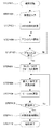
本発明の第2の実施形態に係る眼底の撮影方法について、図4のフローチャートを用いて説明する。
<< Second Embodiment >>
A fundus imaging method according to the second embodiment of the present invention will be described with reference to the flowchart of FIG.
第1の実施形態ではでは被検眼の視度がわからない状態での撮影におけるフローを説明したが、本実施形態では予め視度がわかっている場合について述べる。なお、図4に示すフローチャートにおけるステップ404〜ステップ412の工程は、前述した図3に示すフローチャートにおけるステップ304〜ステップ312の工程と同じであることから、ここでのこれらステップについての説明は省略する。 In the first embodiment, the flow of imaging in a state where the diopter of the eye to be examined is not explained, but in this embodiment, a case where the diopter is known in advance will be described. Note that steps 404 to 412 in the flowchart shown in FIG. 4 are the same as steps 304 to 312 in the flowchart shown in FIG. 3 described above, and thus description of these steps is omitted here. .
このような被検眼の視度が予めわかっている場合は、ステップ402のように測定開始前にその視度情報を入力することで、ステップ403でWD初期値を変更させることとする。このステップを組み込むことで、第1の実施形態であったステップ307、およびステップ313〜315の工程を省略することができ、さらに短時間で撮影を行うことができる。 When the diopter of the eye to be examined is known in advance, the initial WD value is changed in step 403 by inputting the diopter information before starting the measurement as in step 402. By incorporating this step, the steps 307 and 313 to 315 of the first embodiment can be omitted, and photographing can be performed in a shorter time.
なお、この視度値の入力は、入力部929を介して行ってもよく、ハードディスク926から読み出すこととしてもよい。これら構成は、本実施形態において、被検眼107の情報を入力する情報入力手段を構成する。また、パソコン925に配される先の実施形態で述べた判断手段は、本実施形態においてはこの入力された情報に応じて合焦レンズの位置変更範囲の内で合焦状態が得られるか否かを判断することとなる。そして得られないと判断された場合には、光学ヘッド900と被検眼107との相対位置を変化させてアライメントを行う際の初期の位置関係が変更される。
The diopter value may be input via the
以上述べたように、本発明では、光路長変更手段の調整範囲外の視度である被検眼の撮影において、眼底画像の視野角を優先するか断層像のコントラストを優先するかを選択できるようにしている。これにより、視野角を優先した場合にはこれまで通りの撮影を行い、コントラストを優先した場合には自動で被検眼と光学系との相対位置を変更することが可能となる。その結果、被検眼の視度が眼科装置の調整範囲を超えた場合であっても、簡単に被検眼の適正な断層画像を取得可能となる。 As described above, in the present invention, it is possible to select whether to prioritize the viewing angle of the fundus image or the contrast of the tomographic image when photographing the eye to be examined whose diopter is outside the adjustment range of the optical path length changing unit. I have to. As a result, when the viewing angle is prioritized, it is possible to perform the same photographing as before, and when the contrast is prioritized, the relative position between the eye to be examined and the optical system can be automatically changed. As a result, even when the diopter of the eye to be examined exceeds the adjustment range of the ophthalmologic apparatus, an appropriate tomographic image of the eye to be examined can be easily acquired.
(その他の実施形態)
また、本発明は、以下の処理を実行することによっても実現される。即ち、上述した実施形態の機能を実現するソフトウェア(プログラム)を、ネットワーク又は各種記憶媒体を介してシステム或いは装置に供給し、そのシステム或いは装置のコンピュータ(またはCPUやMPU等)がプログラムを読み出して実行する処理である。
(Other embodiments)
The present invention can also be realized by executing the following processing. That is, software (program) that realizes the functions of the above-described embodiments is supplied to a system or apparatus via a network or various storage media, and a computer (or CPU, MPU, or the like) of the system or apparatus reads the program. It is a process to be executed.
また、本発明は上記の実施形態に限定されるものではなく、本発明の趣旨を逸脱しない範囲内において、種々の変形、変更して実施することができる。例えば、上記の実施形態では、被検査物が眼、特に眼底の場合について述べているが、眼以外の皮膚や臓器等の被測定物に本発明を適用することも可能である。この場合、本発明は眼科装置以外の、例えば内視鏡等の医療機器としての態様を有する。従って、本発明は眼科装置に例示される検査装置として把握され、被検眼は被検査物の一態様として把握されることが望ましい。
また、上記実施形態では、本発明の効果が好適に得られる対象としてOCT装置を例として述べたが、本発明の適用対象は当該OCT装置に限定されない。即ち、測定光によって証明された被検査物の画像を得る装置に対しても適用することは可能である。
Further, the present invention is not limited to the above-described embodiment, and various modifications and changes can be made without departing from the spirit of the present invention. For example, in the above embodiment, the case where the object to be inspected is the eye, particularly the fundus is described, but the present invention can also be applied to objects to be measured such as skin and organs other than the eye. In this case, the present invention has an aspect as a medical device such as an endoscope other than the ophthalmologic apparatus. Therefore, it is preferable that the present invention is grasped as an inspection apparatus exemplified by an ophthalmologic apparatus, and the eye to be examined is grasped as one aspect of the object to be inspected.
Moreover, in the said embodiment, although the OCT apparatus was described as an example as a target from which the effect of this invention is acquired suitably, the application object of this invention is not limited to the said OCT apparatus. That is, the present invention can be applied to an apparatus that obtains an image of an inspection object proved by measurement light.
Claims (17)
前記被検査物に対する前記測定光の合焦状態を得るために合焦部材の位置を変更する合焦位置変更手段と、
前記合焦部材を有する光学ヘッドと前記被検査物との相対位置を変化させて位置合わせを行う位置合わせ手段と、
前記合焦位置変更手段による合焦部材の位置変更範囲の内での位置変更にて前記合焦状態が得られるか否かを判断する判断手段と、
前記判断手段の判断結果に応じて、前記位置合わせ手段を動作させる制御手段と、を有することを特徴とする検査装置。 Image acquisition means for acquiring an image of the inspection object irradiated with the measurement light;
In-focus position changing means for changing the position of the focusing member in order to obtain the in-focus state of the measurement light with respect to the inspection object;
Alignment means for performing alignment by changing a relative position between the optical head having the focusing member and the inspection object;
Determining means for determining whether or not the in-focus state is obtained by position change within a position change range of the focusing member by the focus position changing means;
An inspection apparatus comprising: a control unit that operates the alignment unit in accordance with a determination result of the determination unit.
前記合焦状態が得られないと判断された場合に、前記位置合わせ手段により前記相対位置を変化させる制御手段、を有することを特徴とする請求項1に記載の検査装置。 The determining means determines whether the in-focus state is obtained by the in-focus position changing means when the in-focus position changing means is operated after completion of the alignment by the aligning means;
The inspection apparatus according to claim 1, further comprising a control unit that changes the relative position by the positioning unit when it is determined that the in-focus state cannot be obtained.
前記判断手段は前記情報入力手段により入力された情報に応じて前記合焦状態が得られるか否かを判断することを特徴とする請求項1に記載の検査装置。 Having information input means for inputting information of the inspection object;
The inspection apparatus according to claim 1, wherein the determination unit determines whether or not the in-focus state is obtained according to information input by the information input unit.
前記断層画像取得手段は、前記測定光と前記参照光との光路長差を変更する光路長差変更手段を有することを特徴とする請求項1乃至6の何れか一項に記載の検査装置。 The image acquisition means obtains a tomographic image of the inspection object based on the combined light obtained by combining the return light from the inspection object irradiated with the measurement light and the reference light corresponding to the measurement light. A tomographic image acquisition means for acquiring,
The inspection apparatus according to claim 1, wherein the tomographic image acquisition unit includes an optical path length difference changing unit that changes an optical path length difference between the measurement light and the reference light.
前記被検査物に対する前記測定光の合焦状態を得るために合焦部材の位置を変更する合焦位置変更手段と、
前記合焦部材を有する光学ヘッドと前記被検査物との相対位置を変化させて位置合わせを行う位置合わせ手段と、
前記測定光と前記参照光との光路長差を変更する光路長差変更手段と、
前記光路長差変更手段による前記光路長差を変更可能な範囲にて所定の断層画像が得られないと判断された場合には、前記位置合わせ手段により前記相対位置を変化させる制御手段と、を有することを特徴とする検査装置。 A tomographic image acquisition means for acquiring a tomographic image of the inspection object based on the combined light obtained by combining the return light from the inspection object irradiated with the measurement light and the reference light corresponding to the measurement light;
In-focus position changing means for changing the position of the focusing member in order to obtain the in-focus state of the measurement light with respect to the inspection object;
Alignment means for performing alignment by changing a relative position between the optical head having the focusing member and the inspection object;
An optical path length difference changing means for changing an optical path length difference between the measurement light and the reference light;
Control means for changing the relative position by the positioning means when it is determined that a predetermined tomographic image cannot be obtained within a range in which the optical path length difference can be changed by the optical path length difference changing means; An inspection apparatus comprising:
前記被検査物に対する前記測定光の合焦状態を得るために合焦部材の位置を変更する合焦位置変更手段と、
前記合焦部材を有する光学ヘッドと前記被検眼との相対位置を変化させて位置合わせを行う位置合わせ手段と、
前記被検眼の視度値に応じて前記位置合わせ手段により前記相対位置を変化させる際の初期の位置関係を変更する制御手段と、を有することを特徴とする検査装置。 Image acquisition means for acquiring an image of the eye to be examined irradiated with measurement light;
In-focus position changing means for changing the position of the focusing member in order to obtain the in-focus state of the measurement light with respect to the inspection object;
Alignment means for performing alignment by changing a relative position between the optical head having the focusing member and the eye to be examined;
An inspection apparatus comprising: control means for changing an initial positional relationship when the relative position is changed by the alignment means in accordance with a diopter value of the eye to be examined.
前記断層画像取得手段は、前記測定光と前記参照光との光路長差を変更する光路長差変更手段を有することを特徴とする請求項10に記載の検査装置。 The image acquisition means obtains a tomographic image of the inspection object based on the combined light obtained by combining the return light from the inspection object irradiated with the measurement light and the reference light corresponding to the measurement light. A tomographic image acquisition means for acquiring,
The inspection apparatus according to claim 10, wherein the tomographic image acquisition unit includes an optical path length difference changing unit that changes an optical path length difference between the measurement light and the reference light.
前記被検査物に対する前記測定光の合焦状態を得るための合焦部材を有する光学ヘッドと前記被検査物との相対位置を変化させる位置合わせ手段を用いて位置合わせを行う位置合わせ工程と、
前記合焦部材の位置を変更して前記合焦状態を得る合焦位置変更工程と、
前記合焦位置変更工程による合焦部材の位置変更範囲の内での位置変更にて前記合焦状態が得られるか否かを判断する判断工程と、
前記判断工程での判断結果に応じて、前記位置合わせ手段を動作させる工程と、を有することを特徴とする検査装置の制御方法。 A method for controlling an inspection apparatus having an image acquisition means for acquiring an image of an inspection object irradiated with measurement light,
An alignment step of performing alignment using an alignment unit that changes the relative position between the optical head having a focusing member for obtaining a focused state of the measurement light with respect to the inspection object and the inspection object;
A focusing position changing step of changing the position of the focusing member to obtain the focused state;
A determination step of determining whether or not the in-focus state is obtained by a position change within a position change range of the focusing member by the focusing position changing step;
And a step of operating the positioning means in accordance with a determination result in the determination step.
前記被検査物に対する前記測定光の合焦状態を得るための合焦部材を有する光学ヘッドと前記被検査物との相対位置を変化させる位置合わせ手段を用いて位置合わせを行う位置合わせ工程と、
前記合焦部材の位置を変更して前記合焦状態を得る合焦位置変更工程と、
前記測定光と前記参照光との光路長差を変更する光路長差変更工程と、
前記光路長差変更工程における前記光路長差を変更可能な範囲にて所定の断層画像が得られないと判断された場合には、前記位置合わせ手段により前記相対位置を変更する工程を有することを特徴とする検査装置の制御方法。 A tomographic image acquisition unit configured to acquire a tomographic image of the inspection object based on a combined light obtained by combining the return light from the inspection object irradiated with the measurement light and the reference light corresponding to the measurement light; A control method for an inspection apparatus,
An alignment step of performing alignment using an alignment unit that changes the relative position between the optical head having a focusing member for obtaining a focused state of the measurement light with respect to the inspection object and the inspection object;
A focusing position changing step of changing the position of the focusing member to obtain the focused state;
An optical path length difference changing step for changing an optical path length difference between the measurement light and the reference light;
And a step of changing the relative position by the alignment means when it is determined that a predetermined tomographic image cannot be obtained within a range in which the optical path length difference can be changed in the optical path length difference changing step. A method for controlling an inspection apparatus.
前記被検眼の視度値に応じて前記位置合わせ手段により前記相対位置を変化させる際の初期の位置関係を変更する工程と、
前記位置合わせ手段を用いて前記相対位置の位置合わせを行う位置合わせ工程と、
前記合焦部材の位置を変更して前記合焦状態を得る合焦位置変更工程と、を有することを特徴とする検査装置の制御方法。 The image acquisition means for acquiring the image of the eye to be inspected irradiated with the measurement light, the optical head having the focusing member for obtaining the focus state of the measurement light with respect to the inspection object, and the relative position of the inspection object A control method for an inspection apparatus having alignment means for changing,
Changing the initial positional relationship when the relative position is changed by the positioning means according to the diopter value of the eye to be examined;
An alignment step of aligning the relative position using the alignment means;
And a focusing position changing step of changing the position of the focusing member to obtain the focused state.
Priority Applications (1)
| Application Number | Priority Date | Filing Date | Title |
|---|---|---|---|
| JP2015000318A JP2016123722A (en) | 2015-01-05 | 2015-01-05 | Examination apparatus and control method for examination apparatus |
Applications Claiming Priority (1)
| Application Number | Priority Date | Filing Date | Title |
|---|---|---|---|
| JP2015000318A JP2016123722A (en) | 2015-01-05 | 2015-01-05 | Examination apparatus and control method for examination apparatus |
Related Child Applications (1)
| Application Number | Title | Priority Date | Filing Date |
|---|---|---|---|
| JP2019076790A Division JP2019115762A (en) | 2019-04-15 | 2019-04-15 | Examination apparatus and control method for examination apparatus |
Publications (2)
| Publication Number | Publication Date |
|---|---|
| JP2016123722A true JP2016123722A (en) | 2016-07-11 |
| JP2016123722A5 JP2016123722A5 (en) | 2018-02-15 |
Family
ID=56357212
Family Applications (1)
| Application Number | Title | Priority Date | Filing Date |
|---|---|---|---|
| JP2015000318A Pending JP2016123722A (en) | 2015-01-05 | 2015-01-05 | Examination apparatus and control method for examination apparatus |
Country Status (1)
| Country | Link |
|---|---|
| JP (1) | JP2016123722A (en) |
Cited By (1)
| Publication number | Priority date | Publication date | Assignee | Title |
|---|---|---|---|---|
| JP2018201749A (en) * | 2017-06-01 | 2018-12-27 | キヤノン株式会社 | Control device, tomographic imaging system, control method, and program |
Citations (4)
| Publication number | Priority date | Publication date | Assignee | Title |
|---|---|---|---|---|
| JP2007037897A (en) * | 2005-08-05 | 2007-02-15 | Topcon Corp | Fundus camera |
| JP2012050592A (en) * | 2010-08-31 | 2012-03-15 | Canon Inc | Fundus imaging apparatus |
| JP2013153797A (en) * | 2012-01-26 | 2013-08-15 | Canon Inc | Optical tomographic apparatus and control method |
| JP2014094141A (en) * | 2012-11-09 | 2014-05-22 | Canon Inc | Ophthalmologic apparatus, control method and program |
-
2015
- 2015-01-05 JP JP2015000318A patent/JP2016123722A/en active Pending
Patent Citations (4)
| Publication number | Priority date | Publication date | Assignee | Title |
|---|---|---|---|---|
| JP2007037897A (en) * | 2005-08-05 | 2007-02-15 | Topcon Corp | Fundus camera |
| JP2012050592A (en) * | 2010-08-31 | 2012-03-15 | Canon Inc | Fundus imaging apparatus |
| JP2013153797A (en) * | 2012-01-26 | 2013-08-15 | Canon Inc | Optical tomographic apparatus and control method |
| JP2014094141A (en) * | 2012-11-09 | 2014-05-22 | Canon Inc | Ophthalmologic apparatus, control method and program |
Cited By (1)
| Publication number | Priority date | Publication date | Assignee | Title |
|---|---|---|---|---|
| JP2018201749A (en) * | 2017-06-01 | 2018-12-27 | キヤノン株式会社 | Control device, tomographic imaging system, control method, and program |
Similar Documents
| Publication | Publication Date | Title |
|---|---|---|
| JP5936371B2 (en) | Ophthalmic apparatus, method for controlling ophthalmic apparatus, and program | |
| JP5306493B2 (en) | Ophthalmic apparatus, control method for ophthalmic apparatus, and program | |
| JP5210443B1 (en) | Optical tomographic imaging apparatus and control method | |
| JP5210442B1 (en) | Optical tomographic imaging apparatus and control method | |
| JP5220156B2 (en) | Medical devices and systems | |
| JP6184113B2 (en) | Optical tomographic imaging apparatus and control method thereof | |
| JP5792977B2 (en) | Image processing apparatus, image processing method, ophthalmic apparatus, and medical system | |
| JP6188296B2 (en) | Image processing apparatus and image processing method | |
| JP2014217423A (en) | Optical interference tomography apparatus | |
| JP6300443B2 (en) | Optical tomographic imaging apparatus and control method thereof | |
| JP5241878B2 (en) | Ophthalmic system, ophthalmic apparatus, control method, and program | |
| CN103654717B (en) | Ophthalmic device and control method for ophthalmic device | |
| JP6188339B2 (en) | Optical tomographic imaging apparatus and control method thereof | |
| JP2016123480A (en) | Ophthalmologic apparatus and control method of ophthalmologic apparatus | |
| JP2016123722A (en) | Examination apparatus and control method for examination apparatus | |
| JP6308723B2 (en) | CONTROL DEVICE, ITS OPERATION METHOD, AND PROGRAM | |
| JP5766225B2 (en) | Optical tomographic imaging apparatus and control method | |
| JP2019115762A (en) | Examination apparatus and control method for examination apparatus | |
| JP6635716B2 (en) | Display control device, display control method and program | |
| JP6701250B2 (en) | Ophthalmic photographing apparatus, control method thereof, and program | |
| JP2018143695A (en) | Information processing apparatus, information processing method, and program |
Legal Events
| Date | Code | Title | Description |
|---|---|---|---|
| RD05 | Notification of revocation of power of attorney |
Free format text: JAPANESE INTERMEDIATE CODE: A7425 Effective date: 20171214 |
|
| A521 | Request for written amendment filed |
Free format text: JAPANESE INTERMEDIATE CODE: A523 Effective date: 20171228 |
|
| A621 | Written request for application examination |
Free format text: JAPANESE INTERMEDIATE CODE: A621 Effective date: 20171228 |
|
| RD04 | Notification of resignation of power of attorney |
Free format text: JAPANESE INTERMEDIATE CODE: A7424 Effective date: 20180126 |
|
| A131 | Notification of reasons for refusal |
Free format text: JAPANESE INTERMEDIATE CODE: A131 Effective date: 20180925 |
|
| A977 | Report on retrieval |
Free format text: JAPANESE INTERMEDIATE CODE: A971007 Effective date: 20180921 |
|
| A521 | Request for written amendment filed |
Free format text: JAPANESE INTERMEDIATE CODE: A523 Effective date: 20181122 |
|
| A02 | Decision of refusal |
Free format text: JAPANESE INTERMEDIATE CODE: A02 Effective date: 20190117 |