JP2020005434A - Electric motor provided with inner fan - Google Patents
Electric motor provided with inner fan Download PDFInfo
- Publication number
- JP2020005434A JP2020005434A JP2018124054A JP2018124054A JP2020005434A JP 2020005434 A JP2020005434 A JP 2020005434A JP 2018124054 A JP2018124054 A JP 2018124054A JP 2018124054 A JP2018124054 A JP 2018124054A JP 2020005434 A JP2020005434 A JP 2020005434A
- Authority
- JP
- Japan
- Prior art keywords
- fan
- rotor
- stator
- electric motor
- blade
- Prior art date
- Legal status (The legal status is an assumption and is not a legal conclusion. Google has not performed a legal analysis and makes no representation as to the accuracy of the status listed.)
- Granted
Links
Images


Classifications
-
- H—ELECTRICITY
- H02—GENERATION; CONVERSION OR DISTRIBUTION OF ELECTRIC POWER
- H02K—DYNAMO-ELECTRIC MACHINES
- H02K9/00—Arrangements for cooling or ventilating
- H02K9/10—Arrangements for cooling or ventilating by gaseous cooling medium flowing in closed circuit, a part of which is external to the machine casing
-
- H—ELECTRICITY
- H02—GENERATION; CONVERSION OR DISTRIBUTION OF ELECTRIC POWER
- H02K—DYNAMO-ELECTRIC MACHINES
- H02K9/00—Arrangements for cooling or ventilating
- H02K9/02—Arrangements for cooling or ventilating by ambient air flowing through the machine
- H02K9/04—Arrangements for cooling or ventilating by ambient air flowing through the machine having means for generating a flow of cooling medium
- H02K9/06—Arrangements for cooling or ventilating by ambient air flowing through the machine having means for generating a flow of cooling medium with fans or impellers driven by the machine shaft
-
- F—MECHANICAL ENGINEERING; LIGHTING; HEATING; WEAPONS; BLASTING
- F04—POSITIVE - DISPLACEMENT MACHINES FOR LIQUIDS; PUMPS FOR LIQUIDS OR ELASTIC FLUIDS
- F04D—NON-POSITIVE-DISPLACEMENT PUMPS
- F04D17/00—Radial-flow pumps, e.g. centrifugal pumps; Helico-centrifugal pumps
- F04D17/06—Helico-centrifugal pumps
-
- F—MECHANICAL ENGINEERING; LIGHTING; HEATING; WEAPONS; BLASTING
- F04—POSITIVE - DISPLACEMENT MACHINES FOR LIQUIDS; PUMPS FOR LIQUIDS OR ELASTIC FLUIDS
- F04D—NON-POSITIVE-DISPLACEMENT PUMPS
- F04D17/00—Radial-flow pumps, e.g. centrifugal pumps; Helico-centrifugal pumps
- F04D17/08—Centrifugal pumps
- F04D17/16—Centrifugal pumps for displacing without appreciable compression
- F04D17/162—Double suction pumps
-
- F—MECHANICAL ENGINEERING; LIGHTING; HEATING; WEAPONS; BLASTING
- F04—POSITIVE - DISPLACEMENT MACHINES FOR LIQUIDS; PUMPS FOR LIQUIDS OR ELASTIC FLUIDS
- F04D—NON-POSITIVE-DISPLACEMENT PUMPS
- F04D25/00—Pumping installations or systems
- F04D25/02—Units comprising pumps and their driving means
- F04D25/06—Units comprising pumps and their driving means the pump being electrically driven
- F04D25/0606—Units comprising pumps and their driving means the pump being electrically driven the electric motor being specially adapted for integration in the pump
-
- F—MECHANICAL ENGINEERING; LIGHTING; HEATING; WEAPONS; BLASTING
- F04—POSITIVE - DISPLACEMENT MACHINES FOR LIQUIDS; PUMPS FOR LIQUIDS OR ELASTIC FLUIDS
- F04D—NON-POSITIVE-DISPLACEMENT PUMPS
- F04D25/00—Pumping installations or systems
- F04D25/02—Units comprising pumps and their driving means
- F04D25/08—Units comprising pumps and their driving means the working fluid being air, e.g. for ventilation
- F04D25/082—Units comprising pumps and their driving means the working fluid being air, e.g. for ventilation the unit having provision for cooling the motor
-
- F—MECHANICAL ENGINEERING; LIGHTING; HEATING; WEAPONS; BLASTING
- F04—POSITIVE - DISPLACEMENT MACHINES FOR LIQUIDS; PUMPS FOR LIQUIDS OR ELASTIC FLUIDS
- F04D—NON-POSITIVE-DISPLACEMENT PUMPS
- F04D29/00—Details, component parts, or accessories
- F04D29/26—Rotors specially for elastic fluids
- F04D29/28—Rotors specially for elastic fluids for centrifugal or helico-centrifugal pumps for radial-flow or helico-centrifugal pumps
- F04D29/30—Vanes
-
- F—MECHANICAL ENGINEERING; LIGHTING; HEATING; WEAPONS; BLASTING
- F04—POSITIVE - DISPLACEMENT MACHINES FOR LIQUIDS; PUMPS FOR LIQUIDS OR ELASTIC FLUIDS
- F04D—NON-POSITIVE-DISPLACEMENT PUMPS
- F04D29/00—Details, component parts, or accessories
- F04D29/58—Cooling; Heating; Diminishing heat transfer
- F04D29/5806—Cooling the drive system
-
- H—ELECTRICITY
- H02—GENERATION; CONVERSION OR DISTRIBUTION OF ELECTRIC POWER
- H02K—DYNAMO-ELECTRIC MACHINES
- H02K2213/00—Specific aspects, not otherwise provided for and not covered by codes H02K2201/00 - H02K2211/00
- H02K2213/03—Machines characterised by numerical values, ranges, mathematical expressions or similar information
Abstract
Description
本発明は、内扇ファンを備えた電動機に関する。 The present invention relates to an electric motor including an internal fan.
本技術分野の背景技術として、特開2004−236439号公報(特許文献1)がある。この公報には、中空にした回転子鉄心を回転子軸アームにより回転子軸に保持させ、これにより回転子鉄心と回転子軸との間にアキシャルダクトを形成するようにした回転電機が記載されている。 As a background art of this technical field, there is Japanese Patent Application Laid-Open No. 2004-236439 (Patent Document 1). This publication describes a rotating electric machine in which a hollow rotor core is held on a rotor shaft by a rotor shaft arm, thereby forming an axial duct between the rotor core and the rotor shaft. ing.
また、本技術分野の背景技術として、特開平11−4559号公報(特許文献2)がある。この公報には、回転子鉄心に冷却用気体が通る複数の冷却用貫通孔が形成された電動機本体と、電動機本体の出力軸が突出する端部とは反対側の端部側に設けられて複数の冷却用貫通孔を通る冷却用気体に圧力を付与する冷却ファンと、複数の冷却用貫通孔と冷却ファンの通風路とを連結する気体流通路を構成するダクトとを具備している冷却ファン付き電動機が記載されている。 As a background art in the present technical field, there is Japanese Patent Application Laid-Open No. 11-4559 (Patent Document 2). In this publication, a motor body in which a plurality of cooling through holes through which a cooling gas passes is formed in a rotor core, and an end portion opposite to an end portion from which an output shaft of the motor body protrudes is provided. A cooling system comprising: a cooling fan for applying pressure to a cooling gas passing through a plurality of cooling through holes; and a duct forming a gas flow path connecting the plurality of cooling through holes and a ventilation path of the cooling fan. An electric motor with a fan is described.
前記特許文献1には、アキシャルダクトが形成された回転電機が、また、前記特許文献2には、冷却ファン付き電動機が、それぞれ記載されている。しかし、特許文献1及び特許文献2に記載の回転電機もしくは電動機では、電動機(回転電機)が更に高出力化や高密度化された場合、回転子及び固定子で発生する発熱量が電動機の冷却能力を上回ってしまい、回転子及び固定子の温度上昇が定格値を超過してしまう可能性がある。
そこで、本発明は、電動機が高出力化や高密度化される場合であっても、電動機の大型化や騒音増大することなく、回転子及び固定子を効率よく冷却することができる内扇ファンを備えた電動機を提供する。 Therefore, the present invention provides an internal fan that can efficiently cool the rotor and the stator without increasing the size of the motor or increasing the noise even when the motor has a higher output or a higher density. An electric motor provided with:
上記課題を解決するために、本発明の内扇ファンを備えた電動機は、シャフトと共に回転する回転子と、回転子の外周面に対向する固定子と、回転子に接続したエンドリングと、固定子に接続した固定子巻線と、スリーブを介してシャフトとともに回転するファンと、ファンの翼外周先端に対向するファンガイドと、回転子、固定子、ファン、ファンガイド、エンドリング、および固定子巻線を格納するフレームと、を有し、回転子は、回転子の軸方向に貫通するアキシャルダクト、及び、アキシャルダクトに連通し、回転子の内側から外側へ放射状に貫通するラジアルダクトを有し、ファンは、フレームの内部に設置される内扇ファンであり、内扇ファンは斜流型であると共に内扇ファンの吐出方向が内側方向であることを特徴とする。 In order to solve the above problems, an electric motor including an internal fan according to the present invention includes a rotor that rotates with a shaft, a stator facing an outer peripheral surface of the rotor, an end ring connected to the rotor, Stator winding connected to the rotor, a fan that rotates with the shaft via the sleeve, a fan guide facing the tip of the fan outer periphery, a rotor, a stator, a fan, a fan guide, an end ring, and a stator A rotor for storing windings, the rotor having an axial duct penetrating in the axial direction of the rotor, and a radial duct communicating with the axial duct and radially penetrating from the inside to the outside of the rotor. The fan is an internal fan installed inside the frame, and the internal fan is of a diagonal flow type, and the discharge direction of the internal fan is inward.
本発明によれば、電動機が高出力化や高密度化される場合であっても、電動機の大型化や騒音増大することなく、回転子及び固定子を効率よく冷却することができる内扇ファンを備えた電動機を提供することができる。 ADVANTAGE OF THE INVENTION According to this invention, even if it is a case where a motor has a high output and a high density, an internal fan which can cool a rotor and a stator efficiently, without enlarging a motor and increasing noise. Can be provided.
なお、上記した以外の課題、構成及び効果は、以下の実施例の説明により明らかにされる。 The problems, configurations, and effects other than those described above will be clarified by the following description of the embodiments.
以下、実施例を、図面を用いて説明する。 Hereinafter, embodiments will be described with reference to the drawings.
図1は、本実施例に係る内扇ファンを備えた電動機の要部断面を示す模式図である。 FIG. 1 is a schematic diagram illustrating a cross section of a main part of an electric motor including an internal fan according to the present embodiment.
なお、本実施例で記載する電動機100は、比較的容量が大きなMW(メガワット)クラスの産業用誘導電動機(例えば、回転速度60Hz)などの電動機である。
The
電動機100は、シャフト2と、シャフト2によって支持され、シャフト2と共に回転する回転子3と、回転子3の外周面に対向するように位置して回転子3が回転することで磁力が発生する固定子11と、これらを格納するフレーム1と、で構成される。
The
フレーム1には、シャフト2が軸受10を介して回転自在に設置される。二つある軸受10の間の部分に回転子3が固定されており、回転子3はシャフト2の軸線を中心にシャフト2と一体に回転する。
A
そして、回転子3には両端部に2つのエンドリング6が接続され、固定子11には両端部に2つの固定子巻線12が接続される。また、シャフト2には、スリーブ21を介して支持され、シャフト2と共に回転する内扇ファン22が設置される。更に、内扇ファン22の翼外周先端には、内扇ファン22に対向するように、ファンガイド23が設置される。
Two
つまり、シャフト2には、軸受10と回転子3との間の両側の部分にスリーブ21を介して内扇ファン22がそれぞれ固定され、シャフト2と一体に回転される。このとき、内扇ファン22とスリーブ21とは斜流型である。また、内扇ファン22は、2つの軸受10の間、つまり、フレーム1の内部に設置されるファンである。
That is, the
ファンガイド23は、内扇ファン22の翼外周先端と対向するように設置され、内扇ファン22の吸込側と吐出側とを区切るように設置される。
The
このように、内扇ファン22の外周面には、ファンガイド23が隙間を介して対向する。また、ファンガイド23は、フレーム1の中に設置される天板33に固定される。
As described above, the
フレーム1は、回転子3、固定子11、内扇ファン22、ファンガイド23、エンドリング6、固定子巻扇12を格納する。
The
なお、フレーム1の上側には、クーラーボックス14が設置される。クーラーボックス14の中には、図示していないが、水平方向に長い冷却管が多数設置される。
Note that a
回転子3には、回転子3の軸方向に貫通するアキシャルダクト5が設置され、アキシャルダクト5に連通し、回転子3の内側から外側へ放射状に貫通するラジアルダクト4が設置される。
An
このように、回転子3には、回転子3の内径から外径に放射状に延びた複数のラジアルダクト4と、回転子3の内径側の部分に、シャフト2の軸線方向に沿って延び、かつ、周方向に互いに間隔をおいて設けられた複数のアキシャルダクト5と、が設置される。
As described above, the
回転子3の外周面には、円筒状の固定子11の内面が隙間を介して対向する。固定子11にも、固定子11の内径から外径に放射状に延びた複数のラジアルダクト4が設置される。
また、固定子11は、フレーム1の中に設置される天板33に固定される。
The inner surface of the
The
内扇ファン22は、フレーム1の内部に設置されるものである。そして、この内扇ファン22は斜流型である。更に、この内扇ファン22の吐出方向は、内側方向、つまり、回転子3や固定子11が設置されている方向(冷却風の流れ方向31)である。
The
なお、内扇ファン22は、回転子3の近傍の片側もしくは両側に、吐出方向が回転子3側になるように設置される。
The
また、内扇ファン22とシャフト2との間に介在するスリーブ21は、その外周面に、内扇ファン22の後流側の外周面端部が、内径方向に転向するように転向面40が形成される。
The
これにより、内扇ファン22の出口で、斜め外径方向に吐出される冷却風の流れの一部を、内径方向に転向させ、回転子3のアキシャルダクト5やラジアルダクト4への冷却風の流入を促進することができ、回転子3のアキシャルダクト5やラジアルダクト4への冷却風の風量低下を抑制することができ、冷却能力を増大させることができる。
Thereby, at the outlet of the
さらに、内扇ファン22から吐出される冷却風の流れと、冷却風にとっては障害物となるエンドリング6との干渉を効率的に抑制し、冷却能力を増大することができる。
Furthermore, it is possible to efficiently suppress interference between the flow of the cooling air discharged from the
フレーム2の内部は、フレーム2の外部と異なり、回転子3や固定子11が密集して設置され、ファンを設置する空間的余裕が小さい。このため、ファンの体格が過大になると周辺構造物と干渉し、十分な冷却能力を得られないとの課題があった。しかし、本実施例に記載する内扇ファン22やスリーブ21を使用することにより、回転子3や固定子11や固定子巻線12に効率よく冷却風を供給することができるため、冷却能力を増大することができる。
The inside of the
また、内扇ファンを使用する場合、通常、冷却風をファンの内側から外側へ流通させる。回転子3や固定子11を均等に冷却するためである。しかし、本実施例に記載する電動機100では、斜流型の内扇ファン22を使用し、冷却風の流れ方向31を内扇ファン22の外側から内側へとすることにより、回転子3や固定子11や固定子巻線12に直接的に冷却風を供給することができるため、局所的な冷却能力を増大することができる。さらに、冷却風の流れ方向31をアキシャルダクト5の吸込方向と同じにすることで、ラジアルダクト4の昇圧効果を損なくことなく、冷却風を効率的に用いることができる。
When an internal fan is used, cooling air is usually circulated from the inside to the outside of the fan. This is for uniformly cooling the
電動機100は、電力が印加されると、シャフト2に支持された回転子3が固定子11で発生した磁力によって高速で回転することにより駆動する。
When electric power is applied, the
このとき熱損失により、回転子3及び固定子11の温度が上昇する。電動機100は、この熱損失による温度上昇の上限を定格値に保持するため、アキシャルダクト5、ラジアルダクト4、内扇ファン22等の放熱手段を備える。
At this time, the temperature of the
例えば、フレーム1の内部に冷却風(強制対流)を発生させる内扇ファン22を、シャフト2で支持するようにして備え、回転子3と固定子11との間の隙間や、回転子3や固定子11に冷却風を通風させるようにする。
For example, an
冷却能力の向上のため、回転子3と固定子11とにラジアルダクト4を設置し、回転子3の内側から外側へ放射状に冷却風を通風させると共に、固定子11の内側から外側へ放射状に冷却風を通風させ、回転子3及び固定子11とを冷却する。
つまり、本実施例に記載するラジアルダクト4は、回転子3と固定子11とを通って、回転子3の内径側から外径側へ放射状に、そして、固定子11の内径側から外径側へ放射状に、延びている複数の通風路のことである。
That is, the
なお、ファンの形状を大別すると、遠心ファン、軸流ファン、斜流ファンとなる。ファンの形状にはそれぞれに長所と短所がある。一般的に、軸流ファンは大風量・低圧力、遠心ファンは小風量・高圧力であり、斜流ファンは軸流ファンと遠心ファンとの中間の特性を有する。また、遠心ファンよりも軸流ファンの方が、一般的に構造が単純であり、斜流ファンはその中間である。 The fans are roughly classified into a centrifugal fan, an axial fan, and a mixed flow fan. Each fan shape has advantages and disadvantages. Generally, the axial fan has a large air flow and low pressure, the centrifugal fan has a small air flow and high pressure, and the mixed flow fan has an intermediate characteristic between the axial fan and the centrifugal fan. Axial fans are generally simpler in structure than centrifugal fans, and mixed-flow fans are intermediate.
本実施例に記載する電動機100では、斜流ファンを使用し、特に、フレーム1の外部に設置する外扇ファンとして使用するのではなく、この斜流ファンをフレーム1の内部に設置する内扇ファンとして使用している。外扇ファンは、通常、温度が上がった冷却風の温度を下げるための熱交換用に使用され、本実施例においても、図示はしていないが、こうした外扇ファンを設置してもよい。
In the
このように、本実施例に記載する電動機100に使用されるファンは、フレーム1の内部に設置される内扇ファン22であり、内扇ファン22は斜流型であると共に内扇ファン22の吐出方向が内側方向、つまり回転子3側になる。
As described above, the fan used in the
これにより、本実施例に記載する内扇ファン22を備えた電動機は、アキシャルダクト5やラジアルダクト4の昇圧効果と内扇ファン22の昇圧効果とを効率的に使用し、通風抵抗が大きい通風路においても、冷却風の風量を増大させることができ、冷却能力を増大することができる。また、本実施例に記載する内扇ファン22を備えた電動機100は、内扇ファン22を大型化及び騒音増大することなく、冷却能力を向上させることができる。
Thus, the electric motor having the
このように本実施例では、冷却能力の向上のため、適切な形状の冷却用の内扇ファン22やスリーブ21を備えることにより、内扇ファン22と周辺構造物との干渉を抑制することができる。
As described above, in the present embodiment, in order to improve the cooling capacity, by providing the cooling
次に、動作について説明する。 Next, the operation will be described.
本実施例に記載する電動機100は、固定子11と固定子巻線12とへの通電により、回転子3、シャフト2、スリーブ21及び内扇ファン22が回転する。これにより、回転子3及び固定子11に熱が発生する。
In the
一方、内扇ファン22とラジアルダクト4とでは空気が昇圧され、この回転により、冷却風が発生する。
On the other hand, the pressure of the air is increased in the
冷却風の流れ方向31は、内扇ファン22の外側から内側であり、つまり、回転子3や固定子11へ向かう方向である。内扇ファン22の出口から吐出された冷却風は、外径側の主に固定子巻線12の間を通過する方向とアキシャルダクト5を通過する方向に分岐するように流れる。これは、スリーブ21に形成される転向面40が作用するためである。
The
アキシャルダクト5を通過した冷却風は、ラジアルダクト4を通過し、クーラーボックス14に中央部から流入する。固定子巻線12の間を通過した冷却風も、同様にクーラーボックス14に中央部から流入する。内扇ファン22の出口から吐出された冷却風は、クーラーボックス14に流入するまでの間に、回転子3と固定子11とで発生した熱を吸熱し、温度が上昇する。
The cooling air passing through the
このように温度が上昇した冷却風は、クーラーボックス14の中に設置される冷却管を流れる低温空気と熱交換(低温空気に放熱)し、温度が低下する。温度が低下した冷却風は、クーラーボックス14の端部から下方に流れ、再度、内扇ファン22の入口から吸い込まれる。そして、冷却風は、フレーム1の下方とクーラーボックス14との間を循環する。
The cooling air whose temperature has risen in this way exchanges heat with the low-temperature air flowing through the cooling pipe provided in the cooler box 14 (radiates heat to the low-temperature air), and the temperature decreases. The cooling air whose temperature has decreased flows downward from the end of the
本実施例に記載する内扇ファン22を有する電動機100では、内扇ファン22の吐出方向とアキシャルダクト5の吸込方向が同じであるため、両方の昇圧効果を効率的に用いることができる。さらに、内扇ファン22は、斜流型であるため、通風抵抗が比較的大きな通風路であっても、外径を大きくすることなく、大きな風量の冷却風を発生させることができる。
In the
このように、電動機100が高出力化される場合や構成部品が高密度実装(高密度化)される場合のように、通風抵抗が大きくなる場合であっても、電動機100の小型化や低騒音化を実現しつつ、回転子3及び固定子11の温度上昇を抑制することができる。
As described above, even when the ventilation resistance increases, such as when the output of the
また、スリーブ21は、内扇ファン22の後流側の外周面端部が、内径方向に滑らかに転向するように形成される(転向面40が形成される)ため、斜流型の内扇ファン22の出口で、斜め外径方向に吐出される冷却風の流れの一部を内径方向に転向させ、回転子3のアキシャルダクト5への冷却風の流入を促進し、冷却風の風量を増大することができる。従って、回転子3の温度上昇を抑制することができる。
Further, the
なお、本実施例では、スリーブ21の内扇ファン22の後流側の外周面端部に形成される転向面40の形状は、曲面を有するが、平面の組み合わせであってもよい。
In the present embodiment, the turning
本実施例によれば、電動機100の出力を向上させる(高出力化する)場合であっても、ファンを大型化することなく(小型化(同サイズ)のまま)、実現することができる。すなわち、ファンの大型化を図ることなく、冷却効率を高める(効率よく冷却風を使用する)ことができるためである。また、ファンの大型化を図る必要がないため、ファンの大型化による風切り音の増大も抑制することができ、低騒音化も実現することができる。
According to the present embodiment, even when the output of the
このように、内扇ファン22の外径を小さくすることにより、低騒音化が可能となり、冷却風の風量を増大することにより、冷却能力を増大することができる。
As described above, by reducing the outer diameter of the
また、本実施例に記載する電動機100は、内扇ファン22の翼根元側後縁とエンドリング6との軸(回転軸)方向距離32を、内扇ファン22の翼最大外径41の0.17倍以上0.20倍以下に設置することが好ましい。具体的には、本実施例に記載する電動機100は、内扇ファン22の翼根元側後縁とエンドリング6との軸方向距離32が内扇ファン22の翼最大外径41の0.18倍になる位置に設置される。
Further, the
本実施例に記載する電動機100は、内扇ファン22の翼根元側後縁とエンドリング6との軸方向距離32を小さく設定することができ、軸長が短縮され、振動低減が実現できる。また、内扇ファン22と吐出側障害物との距離は、干渉を避けるために、流れ方向に、内扇ファン22の翼最大外径41の0.20倍以上に設定されることが好ましく、内扇ファン22の翼根元側後縁とエンドリング6との軸方向距離32を、内扇ファン22の翼最大外径41の0.20倍と設定すれば、内扇ファン22から吐出される冷却風の風量低下を抑制することができる。更に、内扇ファン22から吐出される冷却風の風量低下を抑制するためには、斜流型である内扇ファン22の傾斜角度は、軸流型との差異を発揮するために、30°以上であることが好ましく、こうした内扇ファン22の傾斜角度を考慮すると、内扇ファン22の翼根元側後縁とエンドリング6との軸方向距離32を、内扇ファン22の翼最大外径41の0.17(0.20×cos30°=0.17)倍以上とすることが好ましい。すなわち、内扇ファン22の翼根元側後縁とエンドリング6との軸方向距離32を、内扇ファン22の翼最大外径41の0.17倍以上0.20倍以下とすることが好ましい。
In the
内扇ファン22とエンドリング6との間の軸方向距離32を、このように設置することにより、内扇ファン22の吐出流れ(冷却風流れ)とエンドリング6との干渉が抑制され、冷却風の風量の低下を回避することができる。結果的に、回転子3と固定子11との温度上昇を抑制することができる。
By setting the
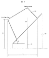
図2は、本実施例に係る内扇ファンの寸法定義を子午面で説明する説明図である。 FIG. 2 is an explanatory diagram illustrating a dimension definition of the internal fan according to the present embodiment in a meridional plane.
本実施例に記載する内扇ファン22は、図2に示すように、翼の子午面形状を、曲線を用いずに、全て直線で形成することが好ましい。このような形状とすることにより、翼の形状が、比較的単純な形状となるため、製造や組立が容易となる。
As shown in FIG. 2, the
また、内扇ファン22とファンガイド23との隙間量を、より小さな値に管理できるようになり、内扇ファン22の性能を向上することができる。これにより、冷却能力を増加することができる。結果的に、回転子3と固定子11との温度上昇を抑制することができる。
Further, the gap amount between the
また、内扇ファン22の翼の軸(回転軸)方向全長(L)を翼最大外径41(出口外径:D2)の0.17倍以下(0.15倍以上)とすることが好ましい。
Further, it is preferable that the total length (L) of the blades of the
本実施例では、図2に示すように、翼の子午面において、内扇ファン22の翼子午面形状は、全て直線で形成される。そして、翼の軸方向全長(L)は、翼最大外径41(出口外径:D2)の0.16倍となっている。
In the present embodiment, as shown in FIG. 2, the meridian plane of the
このような形状とすることにより、内扇ファン22とエンドコイル6との距離を、適切な距離に保ちつつ、2つの軸受間距離を過大にすることなく適切な距離に設定することができるため、軸振動を安定化させることができ、内扇ファン22の吐出流れ(冷却風流れ)とエンドリング6との干渉が抑制され、冷却風の風量の低下を回避することができる。結果的に、回転子3と固定子11との温度上昇を抑制することができる。
By adopting such a shape, the distance between the
さらに、内扇ファン22の翼の前縁外径D1を翼最大外径D2の0.87倍以上(0.89倍以下)と設定し、スリーブ21の外周部とシャフト2の軸線との間の傾斜角度θを、45°以上(50°以下)とすることが好ましい。
Further, the outer diameter D1 of the leading edge of the blade of the
本実施例では、内扇ファン22の翼の前縁外径D1は翼最大外径D2の0.88倍となっている。さらに、スリーブ21の外周部とシャフト2の軸線との間の傾斜角度θは、約45°となっている。
In this embodiment, the outer diameter D1 of the leading edge of the blade of the
このような形状とすることにより、内扇ファン22の翼の前縁外径D1を適切に設定することができ、かつ、スリーブ21の外周部とシャフト2の軸線との間の傾斜角度θも適切に設定することができるため、翼間流れのはく離を抑制しつつ、内扇ファン22の静圧効率を高めることができる。結果的に、回転子3と固定子11との温度上昇を抑制することができる。
With such a shape, the outer diameter D1 of the leading edge of the blade of the
図3は、本実施例に係る内扇ファンの寸法定義を翼型で説明する説明図である。 FIG. 3 is an explanatory diagram illustrating the definition of the dimensions of the internal fan according to the present embodiment in terms of an airfoil.
内扇ファン22の翼根元の出口角度β2は、図3に示すように、約90°と設定されている。なお、内扇ファン22の翼根元の出口角度β2は、85°以上90°以下であることが好ましい。このような形状とすることにより、内扇ファン22の翼先端の出口角度β2(図示なし)を適切な角度とし、翼先端での隙間漏れ流れやはく離流れの悪影響を抑制しつつ、内扇ファン22を高圧化することができる。これにより、冷却能力を増加することができる。
The outlet angle β2 at the blade root of the
このように、内扇ファン22の翼根元の出口角度β2を大きくするにより、内扇ファン22から吐出される冷却風の風量低下を抑制することができる。したがって、回転子3や固定子11の温度上昇を抑制することができる。
As described above, by increasing the exit angle β2 at the blade root of the
このような形状とすることにより、入口での速度を小さくすることで入口損失を小さくし、翼間で増速することができる。そして、翼間の流れのはく離を抑制し、大きな遠心力を圧力に変換することができ、内扇ファン22の静圧効率を高くすることができ、冷却能力を増加することができる。
With such a shape, the speed at the inlet is reduced, thereby reducing the loss at the inlet and increasing the speed between the blades. Then, the separation of the flow between the blades can be suppressed, a large centrifugal force can be converted into pressure, the static pressure efficiency of the
図4は、他の実施例に係る内扇ファンを備えた電動機の要部断面を示す模式図である。 FIG. 4 is a schematic diagram illustrating a cross section of a main part of an electric motor including an internal fan according to another embodiment.
本実施例(図4)に記載する電動機100は、実施例1(図1)に記載した電動機100と概ね同様であり、実施例1に記載した電動機100との相違は、実施例1に記載するファンガイド23が、本実施例では、内径側ファンガイド24と外径側ファンガイド25との2重構造になっている点である。
The
なお、図4に記載する符号は、図1に記載した符号と同様であるため、説明を省略する。 Note that the reference numerals described in FIG. 4 are the same as the reference numerals described in FIG.
内扇ファン22と外径側ファンガイド25との隙間を小さくすることにより、内扇ファン22の翼先端部の(内扇ファン22と外径側ファンガイド25との隙間における)漏れ流れを抑制し、内扇ファン22の性能を向上させることができる。
By reducing the gap between the
同時に、固定子巻線12と内径側ファンガイド24との隙間を小さくすることにより、固定子巻線12と内径側ファンガイド24との隙間における漏れ流れや渦を抑制し、固定子巻線12近傍の通風路における損失を低減することができる。
At the same time, by reducing the gap between the stator winding 12 and the inner diameter
これにより、回転子3や固定子11の温度上昇を抑制することができる。
Thereby, the temperature rise of the
なお、外径側ファンガイド25の材質は鉄材で構成されることが好ましい。また、内径側ファンガイド24の材質は樹脂などの非鉄材で構成されてもよい。
The material of the outer diameter
つまり、本実施例に記載する電動機100は、実施例1に記載するファンガイド23を2重構造とし、外径側(外径側ファンガイド25)は内扇ファン22の翼外周の先端部に沿って設置され、内径側(内径側ファンガイド24)は固定子巻線12の外径側輪郭に沿って設置されることが好ましい。
That is, the
このように構成することにより、内扇ファン22と外径側ファンガイド25との隙間を小さくしつつ、固定子巻線12と内径側ファンガイド24との隙間も小さくすることができ、漏れ流れや渦を抑制し、通風路における損失を低減し、簡易な構成で冷却能力を増加することができる。
With such a configuration, the gap between the stator winding 12 and the inner diameter
なお、本発明は上記した本実施例に限定されるものではなく、様々な変形例が含まれる。例えば、上記した実施例は本発明を分かりやすく説明するために詳細に説明したものであり、必ずしも説明した全ての構成を備えるものに限定されるものではない。 Note that the present invention is not limited to the above-described embodiment, and includes various modifications. For example, the above-described embodiments have been described in detail in order to explain the present invention in an easy-to-understand manner, and are not necessarily limited to those having all the described configurations.
なお、本実施例に記載した電動機は、誘導電動機や永久磁石同期電動機に適用することができる。 The motor described in the present embodiment can be applied to an induction motor or a permanent magnet synchronous motor.
1 フレーム
2 シャフト
3 回転子
4 ラジアルダクト
5 アキシャルダクト
6 エンドリング
10 軸受
11 固定子
12 固定子巻線
14 クーラーボックス
21 スリーブ
22 内扇ファン
23 ファンガイド
31 冷却風の流れ方向
33 天板
Claims (6)
前記回転子は、回転子の軸方向に貫通するアキシャルダクト、及び、前記アキシャルダクトに連通し、回転子の内側から外側へ放射状に貫通するラジアルダクトを有し、
前記ファンは、前記フレームの内部に設置される内扇ファンであり、前記内扇ファンは斜流型であると共に内扇ファンの吐出方向が内側方向であることを特徴とする内扇ファンを備えた電動機。 A rotor that rotates with the shaft, a stator facing the outer peripheral surface of the rotor, an end ring connected to the rotor, a stator winding connected to the stator, and the shaft via a sleeve. A rotating fan, a fan guide facing the tip of the blade outer periphery of the fan, and a frame for storing the rotor, the stator, the fan, the fan guide, the end ring, and the stator winding. Have
The rotor has an axial duct penetrating in the axial direction of the rotor, and a radial duct communicating with the axial duct and radially penetrating from the inside to the outside of the rotor.
The fan is an internal fan installed inside the frame, wherein the internal fan is of a diagonal flow type and the discharge direction of the internal fan is an inward direction. Electric motor.
Priority Applications (2)
| Application Number | Priority Date | Filing Date | Title |
|---|---|---|---|
| JP2018124054A JP7075836B2 (en) | 2018-06-29 | 2018-06-29 | Motor with internal fan fan |
| US16/283,014 US10797565B2 (en) | 2018-06-29 | 2019-02-22 | Motor with inner fan |
Applications Claiming Priority (1)
| Application Number | Priority Date | Filing Date | Title |
|---|---|---|---|
| JP2018124054A JP7075836B2 (en) | 2018-06-29 | 2018-06-29 | Motor with internal fan fan |
Publications (2)
| Publication Number | Publication Date |
|---|---|
| JP2020005434A true JP2020005434A (en) | 2020-01-09 |
| JP7075836B2 JP7075836B2 (en) | 2022-05-26 |
Family
ID=69008419
Family Applications (1)
| Application Number | Title | Priority Date | Filing Date |
|---|---|---|---|
| JP2018124054A Active JP7075836B2 (en) | 2018-06-29 | 2018-06-29 | Motor with internal fan fan |
Country Status (2)
| Country | Link |
|---|---|
| US (1) | US10797565B2 (en) |
| JP (1) | JP7075836B2 (en) |
Citations (7)
| Publication number | Priority date | Publication date | Assignee | Title |
|---|---|---|---|---|
| JPS56154198A (en) * | 1980-04-30 | 1981-11-28 | Mitsubishi Heavy Ind Ltd | Mixed flow fan with intermediate shroud |
| JPH05106592A (en) * | 1991-10-18 | 1993-04-27 | Toshiba Corp | Axial flow fan for air-conditioner |
| JPH07247991A (en) * | 1994-03-04 | 1995-09-26 | Hitachi Ltd | Diagonal flow fan |
| JPH114559A (en) * | 1997-06-12 | 1999-01-06 | Sanyo Denki Co Ltd | Cooling fan and motor therewith |
| JP2000041361A (en) * | 1998-07-22 | 2000-02-08 | Toshiba Corp | Electric rotary machine |
| JP2013119816A (en) * | 2011-12-08 | 2013-06-17 | Samsung Yokohama Research Institute Co Ltd | Propeller fan and outdoor unit of air conditioning apparatus |
| JP2016100953A (en) * | 2014-11-20 | 2016-05-30 | 株式会社明電舎 | Rotary electric machine |
Family Cites Families (4)
| Publication number | Priority date | Publication date | Assignee | Title |
|---|---|---|---|---|
| DE3724186A1 (en) * | 1987-07-17 | 1989-01-26 | Siemens Ag | ELECTRIC MACHINE WITH CLOSED COOLING CIRCUIT |
| JP2004236439A (en) | 2003-01-30 | 2004-08-19 | Hitachi Ltd | Rotating electric machine |
| JP4375075B2 (en) * | 2004-03-24 | 2009-12-02 | ダイキン工業株式会社 | Motor cooling device |
| US7701096B2 (en) * | 2004-10-01 | 2010-04-20 | Kabushiki Kaisha Toshiba | Totally enclosed type main drive motor for vehicle |
-
2018
- 2018-06-29 JP JP2018124054A patent/JP7075836B2/en active Active
-
2019
- 2019-02-22 US US16/283,014 patent/US10797565B2/en active Active
Patent Citations (7)
| Publication number | Priority date | Publication date | Assignee | Title |
|---|---|---|---|---|
| JPS56154198A (en) * | 1980-04-30 | 1981-11-28 | Mitsubishi Heavy Ind Ltd | Mixed flow fan with intermediate shroud |
| JPH05106592A (en) * | 1991-10-18 | 1993-04-27 | Toshiba Corp | Axial flow fan for air-conditioner |
| JPH07247991A (en) * | 1994-03-04 | 1995-09-26 | Hitachi Ltd | Diagonal flow fan |
| JPH114559A (en) * | 1997-06-12 | 1999-01-06 | Sanyo Denki Co Ltd | Cooling fan and motor therewith |
| JP2000041361A (en) * | 1998-07-22 | 2000-02-08 | Toshiba Corp | Electric rotary machine |
| JP2013119816A (en) * | 2011-12-08 | 2013-06-17 | Samsung Yokohama Research Institute Co Ltd | Propeller fan and outdoor unit of air conditioning apparatus |
| JP2016100953A (en) * | 2014-11-20 | 2016-05-30 | 株式会社明電舎 | Rotary electric machine |
Also Published As
| Publication number | Publication date |
|---|---|
| US10797565B2 (en) | 2020-10-06 |
| JP7075836B2 (en) | 2022-05-26 |
| US20200007008A1 (en) | 2020-01-02 |
Similar Documents
| Publication | Publication Date | Title |
|---|---|---|
| JP5358667B2 (en) | Permanent magnet generator | |
| JP4187606B2 (en) | Electric motor | |
| JP6376981B2 (en) | Rotating device | |
| BRPI0716803A2 (en) | ELECTRIC MACHINE WITH AN INTERNALLY COOLED ROTOR | |
| JP2014033584A (en) | Wind cooling structure of rotary electric machine | |
| KR101714477B1 (en) | OUTER ROTOR MOTOR WITH A STREAMLINED Blade for POWER OF of Unmanned Aircraft Robot | |
| JP6638427B2 (en) | Outer rotor type rotary electric machine | |
| KR101372320B1 (en) | Turbo machinary | |
| JP2020156264A (en) | Rotary electric machine and rotor shaft | |
| JP2012107561A (en) | Fan | |
| JP7075836B2 (en) | Motor with internal fan fan | |
| JP3235100U (en) | Motor equipped with speed control function as standard equipment | |
| CN110630536A (en) | Fan and electromechanical assembly and method thereof | |
| JP2015228768A (en) | Rotary machine | |
| KR20220149978A (en) | Axial flux motor with airflow cooling structure | |
| JP2022189307A (en) | Cooling fan and electric motor assembly | |
| JP2021195883A (en) | Electric blower | |
| JPH07245914A (en) | Cooling air ventilator for electric rotating machine | |
| JP7414706B2 (en) | rotating electric machine | |
| JP7416161B2 (en) | Series axial fan | |
| JP2001119896A (en) | Totally enclosed outer rotor electric rotating machine | |
| JP6775715B1 (en) | Rotor and rotary electric machine | |
| KR102482413B1 (en) | Fan Motor | |
| JPH07213018A (en) | Fan apparatus for totally-enclosed fan-cooled rotating machine | |
| JP2001327123A (en) | Outer rotor type dynamoelectric machine |
Legal Events
| Date | Code | Title | Description |
|---|---|---|---|
| A711 | Notification of change in applicant |
Free format text: JAPANESE INTERMEDIATE CODE: A712 Effective date: 20200122 |
|
| A621 | Written request for application examination |
Free format text: JAPANESE INTERMEDIATE CODE: A621 Effective date: 20210112 |
|
| A131 | Notification of reasons for refusal |
Free format text: JAPANESE INTERMEDIATE CODE: A131 Effective date: 20211116 |
|
| A977 | Report on retrieval |
Free format text: JAPANESE INTERMEDIATE CODE: A971007 Effective date: 20211118 |
|
| A521 | Request for written amendment filed |
Free format text: JAPANESE INTERMEDIATE CODE: A523 Effective date: 20211224 |
|
| TRDD | Decision of grant or rejection written | ||
| A01 | Written decision to grant a patent or to grant a registration (utility model) |
Free format text: JAPANESE INTERMEDIATE CODE: A01 Effective date: 20220510 |
|
| A61 | First payment of annual fees (during grant procedure) |
Free format text: JAPANESE INTERMEDIATE CODE: A61 Effective date: 20220516 |
|
| R150 | Certificate of patent or registration of utility model |
Ref document number: 7075836 Country of ref document: JP Free format text: JAPANESE INTERMEDIATE CODE: R150 |