JP2020003463A - Vehicle's self-position estimating device - Google Patents
Vehicle's self-position estimating device Download PDFInfo
- Publication number
- JP2020003463A JP2020003463A JP2018126157A JP2018126157A JP2020003463A JP 2020003463 A JP2020003463 A JP 2020003463A JP 2018126157 A JP2018126157 A JP 2018126157A JP 2018126157 A JP2018126157 A JP 2018126157A JP 2020003463 A JP2020003463 A JP 2020003463A
- Authority
- JP
- Japan
- Prior art keywords
- vehicle
- curve
- map
- position error
- curvature
- Prior art date
- Legal status (The legal status is an assumption and is not a legal conclusion. Google has not performed a legal analysis and makes no representation as to the accuracy of the status listed.)
- Pending
Links
Images


Abstract
Description
本発明は、自車位置推定装置に関する。 The present invention relates to a vehicle position estimation device.
従来、自車位置推定装置に関する技術文献として、特開2015―194397号公報が知られている。この公報には、車両周囲の撮像画像と地図情報とに基づいて現時刻における車両の位置を検出する車両位置検出装置であって、地図情報に含まれる複数の地図線分(区画線等)の位置情報と車両周囲の撮像画像から検出して鳥瞰変換等を行なった複数の線分の位置とに基づいて、地図線分と撮像された線分との対応する組を求め、対応する地図線分及び線分が一致するように車両の位置の推定を行う装置が示されている。 2. Description of the Related Art Conventionally, Japanese Patent Application Laid-Open No. 2015-194397 is known as a technical document related to a vehicle position estimation device. This publication discloses a vehicle position detecting device that detects a position of a vehicle at a current time based on a captured image around a vehicle and map information, and detects a plurality of map line segments (partition lines and the like) included in the map information. Based on the position information and the positions of a plurality of line segments that have been subjected to bird's eye view conversion and the like detected from a captured image around the vehicle, a corresponding set of map line segments and the captured line segments is obtained, and the corresponding map line is determined. A device for estimating the position of the vehicle such that the segments and the line segments match is shown.
上述した従来技術では、画一的に地図に対応する区画線と車両の撮像した区画線とを一致させることで車両の位置を推定している。しかしながら、カーブにおいて無理に区画線の一致を図ろうとすると僅かな横位置誤差の影響で区画線の対応付けを誤り、大きな縦位置誤差が発生する場合がある。このため、縦位置誤差の発生を抑制して自車位置推定の精度を向上させることが求められている。 In the above-described conventional technology, the position of the vehicle is estimated by uniformly matching the lane markings corresponding to the map with the lane markings captured by the vehicle. However, when trying to force the lane markings to coincide with each other on the curve, the lane markings may be incorrectly associated with a slight horizontal position error, and a large vertical position error may occur. Therefore, it is required to suppress the occurrence of the vertical position error and to improve the accuracy of the own vehicle position estimation.
上記課題を解決するため、本発明の一態様は、車線の区画線を用いて車両の自車位置を推定する自車位置推定装置であって、車両の測定部の測定結果に基づいて、車両の地図上の測定位置を認識する測定位置認識部と、カーブ区画線の地図上の位置及びカーブ区画線の地図上の曲率を含む地図情報を有する地図データベースと、車両の車載センサの検出結果に基づいて、車両の走行する走行車線のカーブ区画線を検出したか否かを判定するカーブ区画線判定部と、車両の車載センサの検出結果に基づいて、車両に対するカーブ区画線の相対位置とカーブ区画線の検出曲率とを認識するカーブ区画線認識部と、カーブ判定部によりカーブ区画線を検出したと判定された場合に、カーブ区画線の地図上の位置と測定位置とに基づいて、車両を基準としたカーブ区画線の地図上の位置を演算する地図区画線演算部と、車両を基準としたカーブ区画線の地図上の位置と、車両に対するカーブ区画線の相対位置と、カーブ区画線の地図上の曲率と、カーブ区画線の検出曲率とに基づいて、車両を基準としたカーブ区画線の地図上の位置と車両に対するカーブ区画線の相対位置との横位置誤差を演算する横位置誤差演算部と、カーブ区画線の地図上の曲率又はカーブ区画線の検出曲率と横位置誤差とに基づいて、縦位置誤差を演算する縦位置誤差演算部と、車両の測定位置と横位置誤差と縦位置誤差とに基づいて、車両の自車位置を推定する自車位置推定部と、を備える。 In order to solve the above problems, one embodiment of the present invention is a host vehicle position estimation device that estimates the host vehicle position of a vehicle using lane markings. A measurement position recognition unit for recognizing a measurement position on a map, a map database having map information including a position of the curve demarcation line on the map and a curvature of the curve demarcation line on the map, and a detection result of a vehicle-mounted sensor. A curve lane determining unit that determines whether or not a curve lane marking of a traveling lane in which the vehicle travels is detected, and a relative position of the curve lane marking with respect to the vehicle and a curve based on a detection result of a vehicle-mounted sensor of the vehicle. A curve section line recognition section that recognizes the detected curvature of the section line, and a vehicle based on the position of the curve section line on the map and the measured position when the curve section section determines that the curve section line has been detected. Based on Map lane calculation unit that calculates the position of the curved lane marking on the map, the position of the curve lane marking on the map with respect to the vehicle, the relative position of the curve lane marking with respect to the vehicle, and the curve lane marking on the map Horizontal position error calculating unit that calculates a horizontal position error between the position of the curve lane marking on the map with respect to the vehicle and the relative position of the curve lane marking with respect to the vehicle, based on the curvature of the curve lane and the detected curvature of the curve lane marking. A vertical position error calculation unit that calculates a vertical position error based on the curvature of the curve division line on the map or the detected curvature of the curve division line and the horizontal position error; and a measurement position, the horizontal position error, and the vertical position of the vehicle. A vehicle position estimating unit that estimates a vehicle position of the vehicle based on the error.
本発明の一態様の自車位置推定装置によれば、車両の自車位置の推定精度の向上を図ることができる。 According to the host vehicle position estimation device of one embodiment of the present invention, it is possible to improve the estimation accuracy of the host vehicle position of the vehicle.
以下、本発明の実施形態について図面を参照して説明する。 Hereinafter, embodiments of the present invention will be described with reference to the drawings.
図1に示す自車位置推定装置100は、車線の区画線を用いて乗用車等の車両の地図上の位置である自車位置の推定を行う装置である。車線の区画線には、車道通行帯境界線、車線境界線、中央線等のうち少なくとも一つが含まれる。
The own-vehicle
[自車位置推定装置の構成]
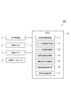
図1に示すように、自車位置推定装置100は、システムを統括的に管理するECU[Electronic Control Unit]10を備えている。ECU10は、CPU[CentralProcessing Unit]、ROM[Read Only Memory]、RAM[Random Access Memory]、CAN[Controller AreaNetwork]通信回路等を有する電子制御ユニットである。ECU10では、例えば、ROMに記憶されているプログラムをRAMにロードし、RAMにロードされたプログラムをCPUで実行することにより各種の機能を実現する。ECU10は、複数の電子ユニットから構成されていてもよい。
[Configuration of the vehicle position estimation device]
As shown in FIG. 1, the vehicle
ECU10は、GPS受信部(測定部)1、外部センサ(車載センサ)2、内部センサ3、及び地図データベース4と接続されている。
The ECU 10 is connected to a GPS receiving unit (measuring unit) 1, an external sensor (vehicle sensor) 2, an
GPS受信部1は、3個以上のGPS衛星から信号を受信することにより、車両の地図上の位置(例えば車両の緯度及び経度)を測定する測定部である。GPS受信部1は、測定した車両の位置情報(測定結果)をECU10へ送信する。
The
外部センサ2は、車両に搭載され、車両の周辺の状況を検出する検出機器(車載センサ)である。外部センサ2は、カメラ及びレーダセンサのうち少なくとも一つを含む。
The
カメラは、車両の外部状況を撮像する撮像機器である。カメラは、車両のフロントガラスの裏側に設けられている。カメラは、車両の外部状況に関する撮像情報をECU10へ送信する。カメラは、単眼カメラであってもよく、ステレオカメラであってもよい。ステレオカメラは、両眼視差を再現するように配置された二つの撮像部を有している。ステレオカメラの撮像情報には、奥行き方向の情報も含まれている。カメラは、車両の側方を撮像するように設けられていてもよい。
The camera is an imaging device that captures an external situation of the vehicle. The camera is provided behind the windshield of the vehicle. The camera transmits imaging information regarding an external situation of the vehicle to the
レーダセンサは、電波(例えばミリ波)又は光を利用して車両の周辺の物体を検出する検出機器である。レーダセンサには、例えば、ミリ波レーダ又はライダー[LIDAR:Light Detection And Ranging]が含まれる。レーダセンサは、電波又は光を車両の周辺に送信し、物体で反射された電波又は光を受信することで物体を検出する。レーダセンサは、検出した物体情報をECU10へ送信する。レーダセンサには、ミリ波レーダ及びライダーの両方を含む複数のセンサから構成されていてもよい。レーダセンサは、車両の側方の物体を検出するように設けられていてもよい。
A radar sensor is a detection device that detects an object around a vehicle using radio waves (for example, millimeter waves) or light. The radar sensor includes, for example, a millimeter wave radar or a lidar [LIDAR: Light Detection And Ranging]. The radar sensor transmits an electric wave or light to the vicinity of the vehicle, and detects the object by receiving the electric wave or light reflected by the object. The radar sensor transmits the detected object information to the
内部センサ3は、車両の走行状態を検出する検出機器である。内部センサ3は、車速センサ、加速度センサ、及びヨーレートセンサを含む。車速センサは、車両の速度を検出する検出器である。車速センサとしては、例えば、車両の車輪又は車輪と一体に回転するドライブシャフト等に対して設けられ、車輪の回転速度を検出する車輪速センサが用いられる。車速センサは、検出した車速情報(車輪速情報)をECU10に送信する。
The
加速度センサは、車両の加速度を検出する検出器である。加速度センサは、例えば、車両の前後方向の加速度を検出する前後加速度センサと、車両の横加速度を検出する横加速度センサとを含んでいる。加速度センサは、例えば、車両の加速度情報をECU10に送信する。ヨーレートセンサは、車両の重心の鉛直軸周りのヨーレート(回転角速度)を検出する検出器である。ヨーレートセンサとしては、例えばジャイロセンサを用いることができる。ヨーレートセンサは、検出した車両のヨーレート情報をECU10へ送信する。
The acceleration sensor is a detector that detects the acceleration of the vehicle. The acceleration sensor includes, for example, a longitudinal acceleration sensor that detects a longitudinal acceleration of the vehicle, and a lateral acceleration sensor that detects a lateral acceleration of the vehicle. The acceleration sensor transmits, for example, vehicle acceleration information to the
内部センサ3の検出結果(車速情報、ヨーレート情報等)は、車両の地図上の位置の測定に利用されてもよい。この場合、内部センサ3は、車両の地図上の位置の測定部として機能する。なお、ECU10は、必ずしも内部センサ3と接続されている必要はない。
The detection results (vehicle speed information, yaw rate information, etc.) of the
地図データベース4は、地図情報を記憶するデータベースである。地図データベース4は、例えば、車両に搭載されたHDD[Hard Disk Drive]内に形成されている。地図情報には、道路の位置情報(車線の位置情報)、交差点及び分岐点の位置情報等が含まれる。また、地図情報には、区画線の地図上の位置及び区画線の地図上の曲率が含まれる。曲率は、例えば右カーブの場合に正の値、左カーブの場合には負の値などカーブの方向が分かる値となっている。或いは、曲率にはカーブの向きの情報が付与されている。なお、地図データベース4は、車両と通信可能なサーバに形成されていてもよい。
The
次に、ECU10の機能的構成について説明する。ECU10は、測定位置認識部11、カーブ区画線判定部12、カーブ区画線認識部13、地図区画線演算部14、横位置誤差演算部15、縦位置誤差演算部16、及び自車位置推定部17を有する。
Next, a functional configuration of the
測定位置認識部11は、GPS受信部1の測定した車両の位置情報に基づいて、車両の地図上の位置である測定位置を取得する。測定位置認識部11は、内部センサ3の検出結果に基づいて、車両の車速の履歴(或いは車輪の回転数の履歴)及び車両のヨーレートの履歴等から車両の測定位置を取得してもよい。言い換えれば、測定位置認識部11は、周知の手法を用いて、いわゆるオドメトリにより車両の測定位置を取得してもよい。この場合、内部センサ3は測定部として機能する。
The measurement
また、測定位置認識部11は、車両の自車位置の推定の実行後である場合、前回の自車位置を基準としてオドメトリにより車両の位置変化を推定することで現在の車両の地図上の位置として測定位置を取得してもよい。
Further, when the estimation of the own vehicle position of the vehicle has been performed, the measured
カーブ区画線判定部12は、外部センサ2の検出結果に基づいて、車両の走行する走行車線のカーブ区画線を検出したか否かを判定する。カーブ区画線とは、予め設定された長さ閾値以上の長さの区画線であって、予め設定されたカーブ閾値以上の曲率を有する区画線である。長さ閾値は、カーブ区画線を検出するために適切に設定された閾値である。なお、カーブ区画線が破線である場合は破線を連続線とみなして長さを認識してもよい。カーブ閾値は、カーブと直線路とを区別するために適切に設定された閾値である。
The curve
カーブ区画線判定部12は、例えばカメラの撮像情報から区画線認識(白線認識)を行うことでカーブ区画線を検出する。カーブ区画線判定部12は、レーダセンサの物体情報からカーブ区画線を検出してもよい。
The curve lane marking determining
なお、カーブ区画線判定部12は、車両の走行する走行車線のカーブ区画線を検出したと判定した場合、カーブ区画線が定常カーブであるかクロソイドカーブであるかを判定してもよい。定常カーブとは曲率が一定のカーブである。クロソイドカーブとは、曲率を一定割合で変化させたカーブ(クロソイド曲線に沿ったカーブ)である。カーブ区画線判定部12は、カーブ区画線の曲率の変化から定常カーブであるかクロソイドカーブであるかを判定することができる。カーブ区画線判定部12は、測定位置などを用いて地図情報を参照することで、定常カーブであるかクロソイドカーブであるかを判定してもよい。
When determining that the curve lane marking of the traveling lane in which the vehicle travels is detected, the curve lane marking
カーブ区画線認識部13は、外部センサ2の検出結果に基づいて、車両に対するカーブ区画線の相対位置とカーブ区画線の検出曲率とを認識する。カーブ区画線認識部13は、例えばカメラの撮像情報から車両に対するカーブ区画線の相対位置を認識する。
The curve section
カーブ区画線認識部13は、車両に対するカーブ区画線の検出曲率を認識する。カーブ区画線認識部13は、レーダセンサの物体情報から車両に対するカーブ区画線の相対位置とカーブ区画線の検出曲率とを認識してもよい。また、カーブ区画線認識部13は、外部センサ2の検出結果に基づいて区画線の曲率がカーブ閾値以上となった位置であるカーブ開始位置を認識している。
The curve section
地図区画線演算部14は、カーブ区画線判定部12によりカーブ区画線を検出したと判定された場合に、地図情報に含まれるカーブ区画線の地図上の位置と測定位置認識部11の取得した測定位置とに基づいて、車両を基準としたカーブ区画線の地図上の位置を演算する。車両を基準としたカーブ区画線の地図上の位置とは、地図上における車両に対するカーブ区画線の相対位置を意味する。
The map lane
横位置誤差演算部15は、車両を基準としたカーブ区画線の地図上の位置と、車両に対するカーブ区画線の相対位置(検出位置)と、カーブ区画線の地図上の曲率と、カーブ区画線の検出曲率とに基づいて、車両を基準としたカーブ区画線の地図上の位置と車両に対するカーブ区画線の相対位置との横位置誤差を演算する。
The lateral position
横位置誤差とは、カーブ開始位置(車線の曲率がカーブ閾値以上となった位置)で車線の幅方向(横方向)における位置誤差である。GPS受信部1などから得た測定位置を基準としたカーブ区画線の地図上の位置と実際に外部センサ2の検出結果から得られた車両に対するカーブ区画線の相対位置とは位置誤差があることが想定される。横位置誤差演算部15は、横方向における位置誤差に着目して、車両を基準としたカーブ区画線の地図上の位置と車両に対するカーブ区画線の相対位置との横位置誤差を演算する。横位置誤差演算部15は、マップマッチング等に利用される周知の技術を用いて横位置誤差を演算してもよい。
The lateral position error is a positional error in the width direction (lateral direction) of the lane at the curve start position (the position at which the curvature of the lane is equal to or greater than the curve threshold). There is a positional error between the position of the curve demarcation line on the map based on the measurement position obtained from the
縦位置誤差演算部16は、横位置誤差演算部15の演算した横位置誤差と、カーブ区画線の地図上の曲率又はカーブ区画線の検出曲率と横位置誤差とに基づいて、車両を基準としたカーブ区画線の地図上の位置と車両に対するカーブ区画線の相対位置との縦位置誤差を演算(推定)する。縦位置誤差とは、カーブ開始位置で車線の延在方向(縦方向)における位置誤差である。
The vertical position
ここで、図2は、縦位置誤差と横位置誤差の両方が生じている場合の例を示す図である。図2に、車両を基準として検出された左カーブ区画線Ld1、車両を基準として検出された右カーブ区画線Ld2、車両を基準とした地図上の左カーブ区画線Lm1、車両を基準とした地図上の右カーブ区画線Lm2を示す。 Here, FIG. 2 is a diagram illustrating an example in which both a vertical position error and a horizontal position error occur. FIG. 2 shows a left curve section line Ld1 detected based on the vehicle, a right curve section line Ld2 detected based on the vehicle, a left curve section line Lm1 on the map based on the vehicle, and a map based on the vehicle. The upper right curve division line Lm2 is shown.
また、図2に、地図上の左カーブ区画線Lm1における点Pm、検出された左カーブ区画線Ld1における点Pd及び点Peを示す。点Pdは、地図上の左カーブ区画線Lm1と検出された左カーブ区画線Ld1とを一致させた場合(正確にマッチングできた場合)に点Pmと一致する点である。点Peは、地図上の左カーブ区画線Lm1と検出された左カーブ区画線Ld1と縦方向で無理に対応付けさせた場合に、点Pmと対応付けられる点である。このとき、点Pmと点Peを結ぶ矢印ΔZ’は、横位置誤差ΔXの影響により実際の縦位置誤差より大きい誤差を示している。 FIG. 2 shows a point Pm on the left curve division line Lm1 on the map, and points Pd and Pe on the detected left curve division line Ld1. The point Pd is a point that coincides with the point Pm when the left curve division line Lm1 on the map is matched with the detected left curve division line Ld1 (when it is accurately matched). The point Pe is a point associated with the point Pm when the left curve division line Lm1 on the map is forcibly associated with the detected left curve division line Ld1 in the vertical direction. At this time, the arrow [Delta] Z 'connecting the point Pm and the point Pe indicates an error larger than the actual vertical position error due to the influence of the horizontal position error [Delta] X.
図2に示す縦位置誤差と横位置誤差の両方が生じている場合において、従来は、最初に縦方向を無理に対応付けしようとしていた。その結果、矢印ΔZ’を誤って縦位置誤差と認識する場合があった。また、縦方向と横方向とを一度に対応付けしようとすると、車両を基準とした対応付けには車両の方位も影響するところ、方位がずれた状態で無理な対応付けがなされることがあった。 Conventionally, in a case where both the vertical position error and the horizontal position error shown in FIG. 2 occur, the vertical direction is first forcibly associated. As a result, the arrow [Delta] Z 'may be erroneously recognized as a vertical position error. Also, when trying to associate the vertical direction and the horizontal direction at once, the association based on the vehicle is affected by the direction of the vehicle. Was.
縦位置誤差演算部16では、地図上のカーブ区画線と検出されたカーブ区画線との縦方向の対応付けを行わず、カーブ区画線の形状の特性を利用して、カーブ区画線の曲率と横位置誤差から縦位置誤差を演算(推定)する。縦位置誤差演算部16は、車両から見た地図上のカーブ区画線と検出されたカーブ区画線との位置誤差において横位置誤差と縦位置誤差に一定の関係性が存在すると考えられることから、横位置誤差とカーブ区画線の曲率とを用いて縦方向誤差を演算する。カーブ区画線の曲率としては、地図上の曲率を用いてもよく、検出曲率を用いてもよい。
The vertical position
縦位置誤差演算部16は、例えば予め決められた演算式により、カーブ区画線の曲率と横位置誤差から縦位置誤差を演算する。演算式は、例えば多数の実験データ及びシュミレーションデータから導き出すことができる。縦位置誤差演算部16は、演算式に代えて、カーブ区画線の曲率及び横位置誤差と縦位置誤差とを予め関連付けたテーブルデータを利用してもよい。縦位置誤差演算部16は、機械学習モデルにより、カーブ区画線の曲率及び横位置誤差を入力として、縦位置誤差を出力させてもよい。機械学習モデルは、例えば、多数のカーブ区画線の曲率及び横位置誤差のデータと、これらのデータに対応する縦位置誤差のデータ(教師データ)を用いて学習させることができる。
The vertical
縦位置誤差演算部16は、カーブ区画線判定部12によりカーブ区画線が定常カーブであるかクロソイドカーブであるかが判定されている場合、定常カーブの場合とクロソイドカーブの場合とで異なる方法で縦位置誤差を演算してもよい。縦位置誤差演算部16は、例えば、定常カーブと判定された場合、定常カーブ用に予め決められた定常カーブ演算式によりカーブ区画線の曲率と横位置誤差から縦位置誤差を演算する。定常カーブ演算式とは、曲率が一定の定常カーブの特性を利用して、カーブ区画線の曲率と横位置誤差から縦位置誤差を演算する式である。
The vertical position
定常カーブ演算式の一例について図3を用いて説明する。図3は、定常カーブにおける横位置誤差と縦位置誤差との関係を示す図である。図3に、地図上のカーブ区画線Lm1におけるカーブ開始位置Gn、検出されたカーブ区画線Ld1におけるカーブ開始位置Gd、任意の位置における横位置誤差ΔX、及びカーブ開始位置Gnとカーブ開始位置Gdの差である縦位置誤差ΔZを示す。また、図3において、定常カーブのカーブ区画線におけるカーブ開始位置を原点としてXZ直交座標系を示す。X軸はカーブ開始位置における車線の幅方向(横方向)、Z軸はカーブ開始位置における車線の延在方向(縦方向)に対応している。 An example of the steady curve calculation formula will be described with reference to FIG. FIG. 3 is a diagram illustrating a relationship between a horizontal position error and a vertical position error in a steady curve. FIG. 3 shows the curve start position Gn at the curve section line Lm1 on the map, the curve start position Gd at the detected curve section line Ld1, the lateral position error ΔX at an arbitrary position, and the curve start position Gn and the curve start position Gd. The vertical position error ΔZ as a difference is shown. In FIG. 3, the XZ orthogonal coordinate system is shown with the origin at the curve start position on the curve section line of the steady curve. The X axis corresponds to the lane width direction (lateral direction) at the curve start position, and the Z axis corresponds to the lane extending direction (vertical direction) at the curve start position.
図3に示す場合において、縦位置誤差ΔZは、下記の式(1)を用いて求めてもよい。
![]()
z(小文字)は、原点から注目点までの距離、Δx(小文字)はzにおける横位置誤差(絶対値)、Rは曲率半径(曲率の逆数)である。注目点は、カーブ開始位置を基準として予め設定された点(例えばカーブ開始位置から一定距離の点)である。
In the case shown in FIG. 3, the vertical position error ΔZ may be obtained using the following equation (1).
![]()
z (small letter) is the distance from the origin to the point of interest, Δx (small letter) is the lateral position error (absolute value) at z, and R is the radius of curvature (reciprocal of curvature). The point of interest is a point set in advance based on the curve start position (for example, a point at a certain distance from the curve start position).
ΔZの符号は、RとΔxの符号の組み合わせで決定する。カーブ入口では、巻き込みの場合、測定位置の車両が後退する方向に縦位置誤差が発生し、膨らみの場合、測定位置の車両が後退する方向に縦位置誤差が発生している。巻き込みの場合とは、横方向において、検出されたカーブ区画線を地図上のカーブ区画線に対してカーブ曲がり方向に移動させることで対応付けされる場合である。膨らみの場合とは、横方向において、検出されたカーブ区画線を地図上のカーブ区画線に対してカーブ曲がり方向と逆方向に移動させることで対応付けされる場合である。 The sign of ΔZ is determined by a combination of the signs of R and Δx. At the entrance to the curve, a vertical position error occurs in the direction in which the vehicle at the measurement position moves backward when the vehicle is involved, and a vertical position error occurs in the direction in which the vehicle at the measurement position moves backward when the vehicle expands. The case of the entanglement is a case where the detected curve section line is moved in the curve bending direction with respect to the curve section line on the map in the horizontal direction to be associated with the curve section line. The case of bulge is a case in which the detected curve section line is moved in the horizontal direction with respect to the curve section line on the map in a direction opposite to the curve bending direction to be associated with the curve section line.
縦位置誤差演算部16は、クロソイドカーブと判定された場合、クロソイドカーブ用に予め決められたクロソイドカーブ演算式によりカーブ区画線の曲率と横位置誤差から縦位置誤差を演算してもよい。クロソイドカーブ演算式とは、曲率変化が一定のクロソイドカーブの特性を利用して、カーブ区画線の曲率と横位置誤差から縦位置誤差を演算する式である。
If it is determined that the clothoid curve is used, the vertical position
クロソイドカーブ演算式の一例について図4を用いて説明する。図4は、クロソイドカーブを示す図である。図4に、横位置の変化dxに対応する縦位置の変化dzを示す。αは接線の傾きである。この場合、曲率変化による横位置の変化dxは下記の式(2)で示すことができる。

式(2)のα(z)は、下記の式(3)のように記載することができる。
cは曲率変化率、C1はzにおける曲率、C2はz=0における接線の傾きである。
Α (z) in equation (2) can be described as in equation (3) below.
c is the curvature change rate, C 1 is the curvature at z, C 2 is the gradient of the tangent at z = 0.
以上の式(2)、(3)とクロソイドカーブの特性から下記の式(4)を導くことができる。
ΔXRは、定常カーブの演算式を用いて演算した場合の横位置誤差である。縦位置誤差演算部16は、上記の式(4)を用いて横位置誤差から縦位置誤差を求めることができる。
The following equation (4) can be derived from the above equations (2) and (3) and the characteristics of the clothoid curve.
ΔX R is the lateral position error when the calculation is performed using the calculation formula of the steady curve. The vertical
自車位置推定部17は、測定位置認識部11の取得した車両の測定位置と横位置誤差演算部15の演算した横位置誤差と縦位置誤差演算部16の演算した縦位置誤差とに基づいて、車両の自車位置を推定する。
The vehicle
自車位置推定部17は、測定位置に対して横位置誤差及び縦位置誤差に応じた位置補正を行うことで、車両の地図上の位置である自車位置を推定する。自車位置推定部17は、横位置誤差を横位置補正量、縦位置誤差を縦位置補正量として用いることで自車位置の推定を行う。なお、自車位置推定部17は、一度でも自車位置を推定した後は、前回の自車位置と横位置誤差及び縦位置誤差と用いて、次の自車位置の推定を行ってもよい。
The own-vehicle
[自車位置推定装置の処理]
次に、本実施形態の自車位置推定装置100による自車位置推定処理及び演算式の切り換え処理について図面を参照して説明する。
[Process of own vehicle position estimation device]
Next, the own vehicle position estimating process and the switching process of the arithmetic expression by the own vehicle
図5は、自車位置推定処理の一例を示すフローチャートである。図5に示すフローチャートの処理は、例えば車両の走行中に実行される。 FIG. 5 is a flowchart illustrating an example of the vehicle position estimation process. The process of the flowchart shown in FIG. 5 is executed, for example, while the vehicle is running.
図5に示すように、自車位置推定装置100のECU10は、S10として、カーブ区画線判定部12により車両の走行する走行車線のカーブ区画線を検出したか否かの判定を行う。カーブ区画線判定部12は、外部センサ2の検出結果に基づいて上記判定を行う。ECU10は、カーブ区画線を検出したと判定されなかった場合(S10:NO)、今回の処理を終了する。その後、ECU10は一定時間の経過後に再びS10から処理を繰り返す。ECU10は、カーブ区画線を検出したと判定された場合(S10:YES)、S12に移行する。
As shown in FIG. 5, the
S12において、ECU10は、カーブ区画線認識部13により車両に対するカーブ区画線の相対位置とカーブ区画線の検出曲率とを認識する。カーブ区画線認識部13は、例えばカメラの撮像情報から車両に対するカーブ区画線の相対位置を認識する。
In S12, the
S14において、ECU10は、地図区画線演算部14により車両を基準としたカーブ区画線の地図上の位置を演算する。地図区画線演算部14は、地図情報に含まれるカーブ区画線の地図上の位置と測定位置認識部11の取得した測定位置とに基づいて、車両を基準としたカーブ区画線の地図上の位置を演算する。
In S14, the
S16において、ECU10は、横位置誤差演算部15により横位置誤差を演算する。横位置誤差演算部15は、車両を基準としたカーブ区画線の地図上の位置と、車両に対するカーブ区画線の相対位置(検出位置)と、カーブ区画線の地図上の曲率と、カーブ区画線の検出曲率とに基づいて、車両を基準としたカーブ区画線の地図上の位置と車両に対するカーブ区画線の相対位置との横位置誤差を演算する。
In S16, the
S18において、ECU10は、縦位置誤差演算部16により縦位置誤差を演算する。縦位置誤差演算部16は、横位置誤差演算部15の演算した横位置誤差と、カーブ区画線の地図上の曲率又はカーブ区画線の検出曲率と横位置誤差とに基づいて、車両を基準としたカーブ区画線の地図上の位置と車両に対するカーブ区画線の相対位置との縦位置誤差を演算(推定)する。
In S18, the
S20において、ECU10は、自車位置推定部17により自車位置の推定を行う。自車位置推定部17は、測定位置認識部11の取得した車両の測定位置と横位置誤差演算部15の演算した横位置誤差と縦位置誤差演算部16の演算した縦位置誤差とに基づいて、車両の自車位置を推定する。
In S20, the
図6は、演算式の切り換え処理を示すフローチャートである。図6に示すフローチャートの処理は、例えば図5のS10においてカーブ区画線が検出された場合に実行される。ここでは、カーブ区画線が定常カーブではない場合にはクロソイドカーブであると仮定している。なお、ECU10は、必ずしも図6に示すフローチャートの処理を行う必要はない。
FIG. 6 is a flowchart showing the switching process of the arithmetic expression. The process of the flowchart shown in FIG. 6 is executed, for example, when a curve division line is detected in S10 of FIG. Here, it is assumed that when the curve division line is not a steady curve, it is a clothoid curve. Note that the
図6に示すように、ECU10は、カーブ区画線判定部12によりカーブ区画線が定常カーブであるか否かを判定する。カーブ区画線判定部12は、例えば外部センサ2の検出結果に基づいて上記判定を行う。ECU10は、カーブ区画線が定常カーブであると判定された場合(S30:YES)、S32に移行する。ECU10は、カーブ区画線が定常カーブではないと判定された場合(S30:NO)、S34に移行する。
As shown in FIG. 6, the
S32において、ECU10は、縦位置誤差演算部16により定常カーブ演算式を用いて縦位置誤差を演算するように設定を行う。この設定により、図5のS18において、縦位置誤差演算部16は、定常カーブ演算式を用いた縦位置誤差の演算を行う。
In S32, the
S34において、ECU10は、縦位置誤差演算部16によりクロソイドカーブ演算式を用いて縦位置誤差を演算するように設定を行う。この設定により、図5のS18において、縦位置誤差演算部16は、クロソイドカーブ演算式を用いた縦位置誤差の演算を行う。
In S34, the
[自車位置推定装置の作用効果]
以上説明した本実施形態の自車位置推定装置100では、走行車線のカーブ区画線を検出した場合に、カーブ区画線の地図上の曲率及びカーブ区画線の検出曲率を用いて、カーブ区画線の地図上の位置とカーブ区画線の相対位置との横位置誤差を演算し、カーブ区画線の曲率と横位置誤差とを用いて縦位置誤差を演算する。これにより、自車位置推定装置100では、カーブ区画線の地図上の位置とカーブ区画線の相対位置とを縦方向で無理に対応付けすることなく、横位置誤差を用いて縦位置誤差を演算することで、対応付けミスの発生を抑制して車両の自車位置の推定精度の向上を図ることができる。また、自車位置推定装置100では、車両の方位による縦位置誤差の誤認識を避けることができるので、車両の自車位置の推定精度の向上に有利である。
[Operation and effect of the vehicle position estimation device]
In the vehicle
以上、本発明の好適な実施形態について説明したが、本発明は上述した実施形態に限定されるものではない。本発明は、上述した実施形態を始めとして、当業者の知識に基づいて種々の変更、改良を施した様々な形態で実施することができる。 The preferred embodiment of the present invention has been described above, but the present invention is not limited to the above-described embodiment. The present invention can be implemented in various forms including various modifications and improvements based on the knowledge of those skilled in the art, including the above-described embodiment.
例えば、横位置誤差における横方向は、カーブ開始位置における車線の幅方向に限らず、カーブ開始位置における車両の車幅方向としてもよい。この場合、縦位置誤差における縦方向は、カーブ開始位置における車線の延在方向ではなく、カーブ開始位置における車両の進行方向とすることができる。また、横位置誤差における横方向は、厳密に区画線の曲率がカーブ閾値未満からカーブ閾値以上になったカーブ開始位置である必要はなく、カーブの手前の直進区間における車線の幅方向を採用してもよい。縦位置誤差の縦方向についても同様である。 For example, the lateral direction in the lateral position error is not limited to the lane width direction at the curve start position, but may be the vehicle width direction at the curve start position. In this case, the vertical direction in the vertical position error may be the traveling direction of the vehicle at the curve start position, not the extending direction of the lane at the curve start position. In addition, the lateral direction in the lateral position error does not need to be the curve start position where the curvature of the lane marking is strictly from the value less than the curve threshold to the value equal to or greater than the curve threshold, and the width direction of the lane in the straight traveling section before the curve is adopted. You may. The same applies to the vertical direction of the vertical position error.
1…GPS受信部、2…外部センサ、3…内部センサ、4…地図データベース、10…ECU、11…測定位置認識部、12…カーブ区画線判定部、13…カーブ区画線認識部、14…地図区画線演算部、15…横位置誤差演算部、16…縦位置誤差演算部、17…自車位置推定部、100…自車位置推定装置。
DESCRIPTION OF
Claims (1)
前記車両の測定部の測定結果に基づいて、前記車両の地図上の測定位置を認識する測定位置認識部と、
カーブ区画線の地図上の位置及びカーブ区画線の地図上の曲率を含む地図情報を有する地図データベースと、
前記車両の車載センサの検出結果に基づいて、前記車両の走行する走行車線のカーブ区画線を検出したか否かを判定するカーブ区画線判定部と、
前記車両の車載センサの検出結果に基づいて、前記車両に対する前記カーブ区画線の相対位置と前記カーブ区画線の検出曲率とを認識するカーブ区画線認識部と、
前記カーブ区画線判定部により前記カーブ区画線を検出したと判定された場合に、前記カーブ区画線の地図上の位置と前記測定位置とに基づいて、前記車両を基準とした前記カーブ区画線の地図上の位置を演算する地図区画線演算部と、
前記車両を基準とした前記カーブ区画線の地図上の位置と、前記車両に対する前記カーブ区画線の相対位置と、前記カーブ区画線の地図上の曲率と、前記カーブ区画線の検出曲率とに基づいて、前記車両を基準とした前記カーブ区画線の地図上の位置と前記車両に対する前記カーブ区画線の相対位置との横位置誤差を演算する横位置誤差演算部と、
前記カーブ区画線の地図上の曲率又は前記カーブ区画線の検出曲率と前記横位置誤差とに基づいて、縦位置誤差を演算する縦位置誤差演算部と、
前記車両の測定位置と前記横位置誤差と前記縦位置誤差とに基づいて、前記車両の自車位置を推定する自車位置推定部と、
を備える、自車位置推定装置。 A vehicle position estimation device that estimates the vehicle position of the vehicle using lane markings,
A measurement position recognition unit that recognizes a measurement position on the map of the vehicle based on a measurement result of the measurement unit of the vehicle,
A map database having map information including the position of the curve plot line on the map and the curvature of the curve plot line on the map,
Based on the detection result of the vehicle-mounted sensor of the vehicle, a curve lane determination unit that determines whether or not a curve lane marking of a traveling lane in which the vehicle travels is detected.
A curve division line recognition unit that recognizes a relative position of the curve division line with respect to the vehicle and a detected curvature of the curve division line based on a detection result of the vehicle-mounted sensor of the vehicle,
When it is determined that the curve lane marking is detected by the curve lane marking, the curve lane marking based on the vehicle is determined based on the position of the curve lane marking on the map and the measurement position. A map division line calculation unit that calculates a position on the map;
Based on the position of the curve lane marking on the map with respect to the vehicle, the relative position of the curve lane marking with respect to the vehicle, the curvature of the curve lane marking on the map, and the detected curvature of the curve lane marking. A lateral position error calculation unit that calculates a lateral position error between a position on the map of the curve lane marking based on the vehicle and a relative position of the curve lane marking relative to the vehicle;
A vertical position error calculation unit that calculates a vertical position error based on the curvature on the map of the curve division line or the detected curvature of the curve division line and the horizontal position error;
A vehicle position estimating unit that estimates a vehicle position of the vehicle based on the measured position of the vehicle, the horizontal position error, and the vertical position error,
A vehicle position estimation device comprising:
Priority Applications (1)
| Application Number | Priority Date | Filing Date | Title |
|---|---|---|---|
| JP2018126157A JP2020003463A (en) | 2018-07-02 | 2018-07-02 | Vehicle's self-position estimating device |
Applications Claiming Priority (1)
| Application Number | Priority Date | Filing Date | Title |
|---|---|---|---|
| JP2018126157A JP2020003463A (en) | 2018-07-02 | 2018-07-02 | Vehicle's self-position estimating device |
Publications (1)
| Publication Number | Publication Date |
|---|---|
| JP2020003463A true JP2020003463A (en) | 2020-01-09 |
Family
ID=69099684
Family Applications (1)
| Application Number | Title | Priority Date | Filing Date |
|---|---|---|---|
| JP2018126157A Pending JP2020003463A (en) | 2018-07-02 | 2018-07-02 | Vehicle's self-position estimating device |
Country Status (1)
| Country | Link |
|---|---|
| JP (1) | JP2020003463A (en) |
Cited By (4)
| Publication number | Priority date | Publication date | Assignee | Title |
|---|---|---|---|---|
| JP2022071741A (en) * | 2020-10-28 | 2022-05-16 | 株式会社豊田中央研究所 | Self position estimation device |
| JP2022084303A (en) * | 2020-11-26 | 2022-06-07 | 本田技研工業株式会社 | Vehicle control device, vehicle control method, and program |
| JP2022150979A (en) * | 2021-03-26 | 2022-10-07 | 本田技研工業株式会社 | Vehicle control device, vehicle control method, and program |
| CN115877429A (en) * | 2023-02-07 | 2023-03-31 | 安徽蔚来智驾科技有限公司 | Positioning method and device for automatic driving vehicle, storage medium and vehicle |
-
2018
- 2018-07-02 JP JP2018126157A patent/JP2020003463A/en active Pending
Cited By (7)
| Publication number | Priority date | Publication date | Assignee | Title |
|---|---|---|---|---|
| JP2022071741A (en) * | 2020-10-28 | 2022-05-16 | 株式会社豊田中央研究所 | Self position estimation device |
| JP2022084303A (en) * | 2020-11-26 | 2022-06-07 | 本田技研工業株式会社 | Vehicle control device, vehicle control method, and program |
| JP7225185B2 (en) | 2020-11-26 | 2023-02-20 | 本田技研工業株式会社 | VEHICLE CONTROL DEVICE, VEHICLE CONTROL METHOD, AND PROGRAM |
| JP2022150979A (en) * | 2021-03-26 | 2022-10-07 | 本田技研工業株式会社 | Vehicle control device, vehicle control method, and program |
| JP7184951B2 (en) | 2021-03-26 | 2022-12-06 | 本田技研工業株式会社 | VEHICLE CONTROL DEVICE, VEHICLE CONTROL METHOD, AND PROGRAM |
| CN115877429A (en) * | 2023-02-07 | 2023-03-31 | 安徽蔚来智驾科技有限公司 | Positioning method and device for automatic driving vehicle, storage medium and vehicle |
| CN115877429B (en) * | 2023-02-07 | 2023-07-07 | 安徽蔚来智驾科技有限公司 | Positioning method and device for automatic driving vehicle, storage medium and vehicle |
Similar Documents
| Publication | Publication Date | Title |
|---|---|---|
| CN110869700B (en) | System and method for determining vehicle position | |
| CN109752741B (en) | Vehicle positioning apparatus | |
| JP5218656B2 (en) | Vehicle travel position determination method and vehicle travel position determination device | |
| US11352090B2 (en) | Information providing device and program for motorcycle | |
| JP5747787B2 (en) | Lane recognition device | |
| KR20200042760A (en) | Vehicle localization method and vehicle localization apparatus | |
| JP2020003463A (en) | Vehicle's self-position estimating device | |
| CN110470309B (en) | Vehicle position estimation device | |
| JP2019045379A (en) | Own vehicle position estimation device | |
| CN110969055B (en) | Method, apparatus, device and computer readable storage medium for vehicle positioning | |
| JP6838285B2 (en) | Lane marker recognition device, own vehicle position estimation device | |
| WO2022147924A1 (en) | Method and apparatus for vehicle positioning, storage medium, and electronic device | |
| JP2018021777A (en) | Own vehicle position estimation device | |
| JP2015021858A (en) | Vehicle position correction apparatus | |
| JPWO2014115319A1 (en) | Road environment recognition system | |
| JP2018048949A (en) | Object recognition device | |
| JP6941178B2 (en) | Automatic operation control device and method | |
| JP2007278813A (en) | Vehicle-position positioning device | |
| US11908206B2 (en) | Compensation for vertical road curvature in road geometry estimation | |
| US10839678B2 (en) | Vehicle identifying device | |
| JP2015069287A (en) | Own vehicle position recognition device | |
| JP6790951B2 (en) | Map information learning method and map information learning device | |
| JP7025293B2 (en) | Vehicle position estimation device | |
| JP2019212154A (en) | Road boundary detection device | |
| KR20190005189A (en) | Inter-vehicle distance estimation method and inter-vehicle distance estimation device |