JP2020003288A - Degradation detection method and degradation detection device - Google Patents
Degradation detection method and degradation detection device Download PDFInfo
- Publication number
- JP2020003288A JP2020003288A JP2018121744A JP2018121744A JP2020003288A JP 2020003288 A JP2020003288 A JP 2020003288A JP 2018121744 A JP2018121744 A JP 2018121744A JP 2018121744 A JP2018121744 A JP 2018121744A JP 2020003288 A JP2020003288 A JP 2020003288A
- Authority
- JP
- Japan
- Prior art keywords
- detection
- coil
- conductor
- excitation
- detection signal
- Prior art date
- Legal status (The legal status is an assumption and is not a legal conclusion. Google has not performed a legal analysis and makes no representation as to the accuracy of the status listed.)
- Granted
Links
Images


Abstract
Description
本発明は、劣化検出方法及び劣化検出装置に関する。 The present invention relates to a deterioration detection method and a deterioration detection device.
従来の劣化検出方法として、例えば、特許文献1に記載された異常検出装置が提案されている。特許文献1の異常検出装置は、変圧器のブッシングに接続している電線の錆(以下、腐食)を診断することを目的としている。励磁コイル、検出コイルを内蔵するクランプヘッドに電線を挟み、励磁コイルに励磁電流を流して電線に渦電流を発生させ、検出コイルから出力される渦電流に応じた検出出力に基づいて腐食を診断している。
As a conventional deterioration detection method, for example, an abnormality detection device described in
しかしながら、従来の異常検出装置では、腐食の有無が検出できる程度の精度しかなく、どの程度の腐食(劣化)が生じているか検出することができない、という問題があった。 However, the conventional abnormality detection device has a problem that the accuracy is only high enough to detect the presence or absence of corrosion, and it is not possible to detect how much corrosion (deterioration) occurs.
本発明は、以上の背景に鑑みてなされたものであり、劣化状態の検出精度向上を図った劣化検出方法及び劣化検出装置を提供することを目的としている。 The present invention has been made in view of the above background, and an object of the present invention is to provide a deterioration detection method and a deterioration detection device that improve detection accuracy of a deterioration state.
本発明の態様である劣化検出方法は、導体の劣化状態を検出するための劣化検出方法であって、励磁コイルに励磁信号を流して前記導体上に渦電流を発生させ、検出コイルを用いて前記渦電流に応じた検出信号を出力させる出力工程と、前記検出信号の大きさと、前記励磁信号及び前記検出信号の位相差と、に基づいて前記導体の劣化状態を検出する検出工程と、を備えたことを特徴とする。 A deterioration detection method according to an aspect of the present invention is a deterioration detection method for detecting a deterioration state of a conductor, in which an excitation signal is supplied to an excitation coil to generate an eddy current on the conductor, and a detection coil is used. An output step of outputting a detection signal corresponding to the eddy current, and a detection step of detecting a deterioration state of the conductor based on a magnitude of the detection signal and a phase difference between the excitation signal and the detection signal. It is characterized by having.
また、前記導体が、電線の導体から構成され、前記出力工程において、前記励磁コイル及び前記検出コイルを前記導体に対して、その長手方向に沿って移動させ、前記検出工程において、前記励磁コイル及び前記検出コイルが移動する毎に得た前記検出信号の大きさと、前記位相差と、に基づいて前記導体の劣化状態を検出してもよい。 Further, the conductor is formed of a conductor of an electric wire, and in the output step, the excitation coil and the detection coil are moved along the longitudinal direction with respect to the conductor, and in the detection step, the excitation coil and the detection coil are moved. The deterioration state of the conductor may be detected based on the magnitude of the detection signal obtained each time the detection coil moves and the phase difference.
また、前記検出工程において、前記励磁コイル及び前記検出コイルが移動する毎に得た前記検出信号の大きさと、前記位相差と、の関係をマッピングしたグラフを作成し、前記グラフに基づいて前記導体の劣化状態を検出してもよい。 In the detecting step, a graph is created by mapping a relationship between the magnitude of the detection signal obtained each time the excitation coil and the detection coil move, and the phase difference, and the conductor is formed based on the graph. May be detected.
また、本発明の態様である劣化検出装置は、導体に渦電流を発生させるための励磁コイルと、前記渦電流に応じた検出信号を出力するための検出コイルと、を備え、前記導体の劣化状態を検出するための劣化検出装置において、前記検出信号の大きさと、前記励磁信号及び前記検出信号の位相差と、を出力する出力部をさらに備えたことを特徴とする。 Further, a deterioration detection device according to an aspect of the present invention includes: an excitation coil for generating an eddy current in a conductor; and a detection coil for outputting a detection signal in accordance with the eddy current. The deterioration detection device for detecting a state further includes an output unit that outputs a magnitude of the detection signal and a phase difference between the excitation signal and the detection signal.
また、本発明の態様である劣化検出装置は、導体に渦電流を発生させるための励磁コイルと、前記渦電流に応じた検出信号を出力するための検出コイルと、を備え、前記導体の劣化状態を検出するための劣化検出装置において、前記検出信号の大きさと、前記励磁信号及び前記検出信号の位相差と、に基づいて前記導体状態を検出する検出部をさらに備えたことを特徴とする。 Further, a deterioration detection device according to an aspect of the present invention includes: an excitation coil for generating an eddy current in a conductor; and a detection coil for outputting a detection signal in accordance with the eddy current. The deterioration detection device for detecting a state further includes a detection unit that detects the conductor state based on a magnitude of the detection signal and a phase difference between the excitation signal and the detection signal. .
上述した態様によれば、検出信号の大きさと、励磁信号及び検出信号の位相差と、の双方に基づいて導体の劣化状態を検出しているので、劣化状態の検出精度向上を図ることができる。 According to the above aspect, since the deterioration state of the conductor is detected based on both the magnitude of the detection signal and the phase difference between the excitation signal and the detection signal, the detection accuracy of the deterioration state can be improved. .
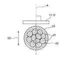
以下、本発明の一実施形態を図1に基づいて説明する。同図に示す劣化検出装置1は、電線2の導体22の劣化状態(=腐食状態)を検出する装置である。電線2は、図2に示すように、複数の素線21を撚り合わせた導体22と、この導体22を覆う被覆部23と、を備えている。
Hereinafter, an embodiment of the present invention will be described with reference to FIG. The
劣化検出装置1は、図1に示すように、励磁コイル11と、検出コイル12と、交流電源13と、検出部14と、コイル移動部15と、表示部16と、制御部17と、を備えている。
As illustrated in FIG. 1, the
励磁コイル11及び検出コイル12は各々、巻線を、例えば、らせん状に巻回して構成されている。励磁コイル11は、励磁信号(交流電流)を流して電線2の表面に渦電流を誘導させるためのコイルである。検出コイル12は、渦電流による磁束変化により誘導電流が流れるコイルである。交流電源13は、励磁コイル11に励磁信号を流す電源である。検出部14は、検出コイル12に流れる誘導電流を検出して、検出信号として出力する。即ち、検出信号は渦電流に応じた信号である。
Each of the
コイル移動部15は、上記励磁コイル11及び検出コイル12を、電線2の長手方向D1に沿って移動させる。コイル移動部15は、励磁コイル11及び検出コイル12が取り付けられ、内部に電線2が通される図示しない本体部と、この本体部を長手方向D1に沿って移動させるための図1に示すモータ151と、を備えている。
The
図示しない本体部には、その内側に例えば走行コロなどの回転体が設けられ、電線2に対して長手方向D1に沿って移動自在になっている。上記励磁コイル11及び検出コイル12は、図2に示すように、その中心軸Aが電線2の径方向D2に沿うように本体部に取り付けられている。また、励磁コイル11及び検出コイル12は、図3に示すように、長手方向D1に沿って並べられ、一部が重なるように配置されている。
The main body (not shown) is provided with a rotating body such as a running roller inside the main body, and is movable along the longitudinal direction D1 with respect to the electric wire 2. As shown in FIG. 2, the
出力部としての表示部16は、検出信号の出力値(振幅の大きさ)と、検出信号及び励磁信号の位相差と、の関係を示すグラフを表示するためのものである。
The
制御部17は、CPU、ROM、RAMなどを内蔵したマイクロコンピュータから構成され、劣化検出装置1全体の制御を司る。制御部17は、交流電源13に接続され、交流電源13のオンオフを制御する。制御部17は、モータ151に接続され、モータ151を駆動することにより、励磁コイル11及び検出コイル12を長手方向D1に沿って移動させる。
The
制御部17は、検出部14に接続され、検出部14から出力された検出信号が入力される。制御部17は、励磁コイル11及び検出コイル12が移動する毎に検出した検出信号の出力値と位相差とを求める。また、制御部17は、求めた検出信号の出力値と位相差とをプロットしたグラフ(図6参照)を作成し、表示部16に表示させる。
The
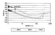
次に、上記劣化検出装置1を用いた劣化検出方法の原理について図4〜図6を参照して説明する。上述した劣化検出装置1を用いて、試料A〜Cの電線2に対して1kHz〜100kHzの励磁信号を励磁コイル11に流して、検出コイル12の検出信号の出力値及び位相差を測定した結果を図4及び図5に示す。なお、励磁コイル11及び検出コイル12としては、内径が30[mm]、ターン数300[T]のものを用いた。
Next, the principle of a deterioration detection method using the
なお、試料Aが、腐食していない試料である。また、試料Bは、各素線21が接点以外が腐食した状態であり、中レベルの腐食が発生している試料である。また、試料Cは、素線21が一様に腐食した状態であり、大レベルの腐食が発生している試料である。
Note that Sample A is a sample that has not corroded. Sample B is a sample in which each
図4及び図5に示すように、腐食が発生している電線2は、腐食が発生していない電線2に比べて検出信号の出力値が低下し、位相が遅れる。検出信号の出力値が低下する理由は以下の通りである。腐食している電線2は、導体22表面の抵抗が腐食していない電線2に比べて大きく、導体22表面に発生する渦電流が抑制され、これに伴い出力値が低下する。位相が遅れる理由は以下の通りである。素線21表面に腐食が発生する場合、各素線21(電極)間の腐食が絶縁体となり、各素線21が疑似的なコンデンサとなる。このコンデンサの容量成分により位相遅れが発生する。
As shown in FIGS. 4 and 5, the output value of the detection signal of the corroded electric wire 2 is lower than that of the corroded electric wire 2, and the phase is delayed. The reason why the output value of the detection signal decreases is as follows. The corroded electric wire 2 has a larger resistance on the surface of the
図4に示すように、約10[kHz]以下では、腐食が発生していない試料Aと、中レベルの腐食が発生している試料Bと、における検出信号の出力値の差は、ある程度大きい。しかしながら、中レベルの腐食が発生している試料Bと、大レベルの腐食が発生している試料Cと、における検出信号の出力値の差は小さい。約10[kHz]以上では、逆に、中レベルの腐食が発生している試料Bと、大レベルの腐食が発生している試料Cと、における検出信号の出力値差は、ある程度大きいが、腐食が発生していない試料Aと、中レベルの腐食が発生している試料Bと、における検出信号の出力値の差は、小さい。このため、検出信号の出力値だけでは、腐食の程度まで精度よく診断するのは難しい。 As shown in FIG. 4, at about 10 kHz or less, the difference between the output values of the detection signals between the sample A where no corrosion has occurred and the sample B where the medium level corrosion has occurred is somewhat large. . However, the difference in the output value of the detection signal between the sample B in which the medium level corrosion has occurred and the sample C in which the large level corrosion has occurred is small. Above about 10 [kHz], on the contrary, the output value difference of the detection signal between the sample B in which the medium level corrosion has occurred and the sample C in which the large level corrosion has occurred is somewhat large, The difference in the output value of the detection signal between the sample A in which corrosion has not occurred and the sample B in which medium-level corrosion has occurred is small. For this reason, it is difficult to diagnose accurately the degree of corrosion using only the output value of the detection signal.
また、図5に示すように、中レベルの腐食が発生している試料Bと、大レベルの腐食が発生している試料Cと、における位相差の差は、ある程度大きい。しかしながら、中レベルの腐食が発生している試料Bと、腐食が発生していない試料Aと、における位相差の差は、ほとんどなく、腐食の程度まで精度よく検出するのは難しい。 Further, as shown in FIG. 5, the difference in phase difference between sample B in which medium-level corrosion has occurred and sample C in which large-level corrosion has occurred is somewhat large. However, there is almost no difference in the phase difference between the sample B in which medium-level corrosion has occurred and the sample A in which no corrosion has occurred, and it is difficult to accurately detect the degree of corrosion.
次に、発明者らは、励磁コイル11及び検出コイル12が移動する毎に求めた複数の検出信号の出力値と、位相差と、の関係をマッピングしたグラフを作成した。結果を図6に示す。なお、周波数は、検出信号の出力値の差及び位相差の差が最も大きくなる3[kHz]の間に設定されている。同図に示すように、腐食が発生していない試料Aと、中レベルの腐食が発生している試料Bと、は、検出信号の出力値の差がある程度大きい。このため、両者を区別して診断することができる。一方、中レベルの腐食が発生している試料Bと、大レベルの腐食が発生している試料Cと、は、位相差の差がある程度あるため、両者を区別して診断することができる。このため、検出信号の出力値及び位相差の双方に基づいて腐食の検出を行うことにより、腐食の程度まで精度よく検出できる。
Next, the inventors have created a graph in which the relationship between the output values of a plurality of detection signals obtained each time the
次に、上記概略で説明した劣化検出装置1の動作について図7を参照して説明する。まず、作業員が、励磁コイル11及び検出コイル12を取り付けた図示しない本体部内に電線2を挿入する。これにより、図2及び図3に示すように、電線2上に励磁コイル11及び検出コイル12を配置することができる。次に、作業員が図示しない操作部を操作すると、制御部17は、図7に示す処理を実行する。
Next, the operation of the
まず、制御部17は、交流電源13をオンする(ステップS1)。これにより、励磁コイル11に励磁信号が流れて、電流2の導体表面に渦電流が誘導される。本実施形態では、励磁信号の周波数は、1〜100kHzに設定されている。図4及び図5に示すように、励磁信号の周波数を1〜100kHzとすることにより、試料Aと試料Bとにおける検出信号の出力差を大きくし、試料Bと試料Cとにおける位相差の差を大きくすることができる。ただし、出力値や位相差の差が大きくなる周波数は、励磁コイル11、検出コイル12の設計に応じて変動するため、この限りではない。
First, the
次に、制御部17は、検出部14から出力される検出信号を取り込む(ステップS2)。次に、制御部17は、取り込んだ検出信号の出力値及び位相差を求めて、RAM等の記憶部に記憶させる(ステップS3)。
Next, the
その後、制御部17は、作業員によって終了操作が行われたか否かを判定する(ステップS4)。終了操作が行われていなければ(ステップS4でN)、制御部17は、モータ151を駆動して励磁コイル11及び検出コイル12を電線2の長手方向D1に沿って所定距離移動させた後(ステップS5)、ステップS2に戻る。これにより、RAMには、励磁コイル11及び検出コイル12が移動する毎に、検出信号の出力値及び位相差が記憶される。
Thereafter, the
一方、終了操作が行われていれば(ステップS4でY)、制御部17は、RAM内に記憶された複数の検出信号の出力値と、位相差と、の関係をマッピングしたグラフを作成し、表示部16に表示して(ステップS5)、処理を終了する。作業員は、表示部16に表示されたグラフから電線2の腐食を診断する。
On the other hand, if the end operation has been performed (Y in step S4), the
制御部17は、図6に示すように、大レベルの腐食を示す領域と、中レベルの腐食を示す領域と、腐食がない領域と、がグラフ上、識別できるように表示されている。詳しくは、大レベルの腐食を示す領域と中レベルの腐食を示す領域との境界に境界ラインL2を表示し、中レベルの腐食を示す領域と腐食がない領域との境界に境界ラインL1を表示している。作業員は、グラフ上にプロットされた点がどの領域に位置するかによって腐食レベルを検出することができる。
As shown in FIG. 6, the
なお、上述した大レベルの腐食を示す領域と、中レベルの腐食を示す領域と、腐食がない領域と、は、事前に腐食が発生していない電線2を励磁コイル11及び検出コイル12により走査し、そのときの検出信号に基づいて定められる。
Note that the above-mentioned region showing a large level of corrosion, the region showing a medium level of corrosion, and the region without corrosion are scanned by the
上述した実施形態によれば、制御部17が、励磁コイル11に励磁信号を流して電線2上に渦電流を発生させ、検出コイル12に渦電流に応じた検出信号を出力させる。そして、作業員が、表示部16に表示されたグラフ上にプロットされている検出信号の出力と、励磁信号及び検出信号の位相差と、に基づいて電線2の腐食レベルを検出している。このように、検出信号の大きさと、励磁信号及び検出信号の位相差と、の双方に基づいて電線2の腐食レベルを検出しているので、腐食レベルの検出精度向上を図ることができる。また、電線2の腐食の度合いがわかるため、電線2の寿命が分かり、電線2の管理がしやすくなる。
According to the above-described embodiment, the
上述した実施形態によれば、制御部17は、励磁コイル11及び検出コイル12を電線2の長手方向D1に沿って移動させ、励磁コイル11及び検出コイル12が移動する毎に得た検出信号の出力値と、励磁信号及び励磁信号の位相差と、をグラフ上にプロットして表示する。このように、励磁コイル11及び検出コイル12を用いて電線2上を走査することにより、電線2全体の腐食検出を行うことができる。
According to the above-described embodiment, the
また、図6に示すように、検出信号の出力値と、励磁信号及び励磁信号の位相差と、の関係をマッピングしたグラフを表示することにより、腐食の度合いが視覚的に分かりやすくなるため、腐食検出しやすい。 In addition, as shown in FIG. 6, by displaying a graph in which the relationship between the output value of the detection signal, the excitation signal, and the phase difference between the excitation signals is mapped, the degree of corrosion can be visually easily understood. Easy to detect corrosion.
なお、上述した実施形態によれば、制御部17は、検出信号の出力値と、励磁信号及び励磁信号の位相差と、の関係を示すグラフを表示させていたが、これに限ったものではない。制御部17は、検出信号の出力値と、励磁信号及び励磁信号の位相差と、を表示するだけでもよい。
In addition, according to the above-described embodiment, the
また、上述した実施形態によれば、作業員が、検出信号の出力値と、励磁信号及び励磁信号の位相差と、の関係を示すグラフを見て腐食レベルを検出していたが、これに限ったものではない。制御部17が、検出部として機能し、検出信号の出力値と、励磁信号及び励磁信号の位相差と、から腐食状態を判断し、その旨を表示部16に表示させるようにしてもよい。
According to the above-described embodiment, the worker detects the corrosion level by looking at the graph showing the relationship between the output value of the detection signal, the excitation signal, and the phase difference between the excitation signals. It is not limited. The
また、上述した実施形態によれば、励磁コイル11、検出コイル12を移動させて、励磁コイル11、検出コイル12を電線2に対して移動させていたが、これに限ったものではない。電線2を長手方向D1に沿って移動させて、励磁コイル11、検出コイル12を電線2に対して移動させるようにしてもよい。
Further, according to the above-described embodiment, the
また、上述した実施形態によれば、電線2の導体の劣化を検出していたが、これに限ったものではない。電線2の導体でなくてもよい。 Further, according to the above-described embodiment, the deterioration of the conductor of the electric wire 2 is detected, but the present invention is not limited to this. The conductor may not be the conductor of the electric wire 2.
なお、本発明は上記実施形態に限定されるものではない。即ち、本発明の骨子を逸脱しない範囲で種々変形して実施することができる。 Note that the present invention is not limited to the above embodiment. That is, various modifications can be made without departing from the gist of the present invention.
2 電線
11 励磁コイル
12 検出コイル
16 表示部(出力部)
17 制御部(検出部)
22 導体
D1 長手方向
2
17 control unit (detection unit)
22 conductor D1 longitudinal direction
Claims (5)
励磁コイルに励磁信号を流して前記導体上に渦電流を発生させ、検出コイルを用いて前記渦電流に応じた検出信号を出力させる出力工程と、
前記検出信号の大きさと、前記励磁信号及び前記検出信号の位相差と、に基づいて前記導体の劣化状態を検出する検出工程と、を備えたことを特徴とする劣化検出方法。 A deterioration detection method for detecting a deterioration state of a conductor,
An output step of causing an excitation signal to flow through an excitation coil to generate an eddy current on the conductor, and using a detection coil to output a detection signal corresponding to the eddy current;
A deterioration detection method for detecting a deterioration state of the conductor based on a magnitude of the detection signal and a phase difference between the excitation signal and the detection signal.
前記出力工程において、前記励磁コイル及び前記検出コイルを前記導体に対して、その長手方向に沿って移動させ、
前記検出工程において、前記励磁コイル及び前記検出コイルが移動する毎に得た前記検出信号の大きさと、前記位相差と、に基づいて前記導体の劣化状態を検出することを特徴とする請求項1に記載の劣化検出方法。 The conductor is composed of a conductor of an electric wire,
In the output step, the exciting coil and the detecting coil are moved along the longitudinal direction with respect to the conductor,
2. The detection step according to claim 1, wherein the deterioration state of the conductor is detected based on the magnitude of the detection signal obtained each time the excitation coil and the detection coil move, and the phase difference. The deterioration detection method described in 1.
前記検出信号の大きさと、前記励磁信号及び前記検出信号の位相差と、を出力する出力部をさらに備えたことを特徴とする劣化検出装置。 An excitation coil for generating an eddy current in the conductor, and a detection coil for outputting a detection signal according to the eddy current, a deterioration detection device for detecting a deterioration state of the conductor,
A deterioration detection device, further comprising an output unit that outputs a magnitude of the detection signal and a phase difference between the excitation signal and the detection signal.
前記検出信号の大きさと、前記励磁信号及び前記検出信号の位相差と、に基づいて前記導体状態を検出する検出部をさらに備えたことを特徴とする劣化検出装置。 An excitation coil for generating an eddy current in the conductor, and a detection coil for outputting a detection signal according to the eddy current, a deterioration detection device for detecting a deterioration state of the conductor,
The degradation detection device further comprising a detection unit that detects the conductor state based on a magnitude of the detection signal and a phase difference between the excitation signal and the detection signal.
Priority Applications (1)
| Application Number | Priority Date | Filing Date | Title |
|---|---|---|---|
| JP2018121744A JP7204291B2 (en) | 2018-06-27 | 2018-06-27 | Deterioration detection method and deterioration detection device |
Applications Claiming Priority (1)
| Application Number | Priority Date | Filing Date | Title |
|---|---|---|---|
| JP2018121744A JP7204291B2 (en) | 2018-06-27 | 2018-06-27 | Deterioration detection method and deterioration detection device |
Publications (2)
| Publication Number | Publication Date |
|---|---|
| JP2020003288A true JP2020003288A (en) | 2020-01-09 |
| JP7204291B2 JP7204291B2 (en) | 2023-01-16 |
Family
ID=69099516
Family Applications (1)
| Application Number | Title | Priority Date | Filing Date |
|---|---|---|---|
| JP2018121744A Active JP7204291B2 (en) | 2018-06-27 | 2018-06-27 | Deterioration detection method and deterioration detection device |
Country Status (1)
| Country | Link |
|---|---|
| JP (1) | JP7204291B2 (en) |
Citations (3)
| Publication number | Priority date | Publication date | Assignee | Title |
|---|---|---|---|---|
| JP2006071350A (en) * | 2004-08-31 | 2006-03-16 | Tohoku Electric Power Co Inc | Method and apparatus for diagnosing deterioration of insulated covered wire |
| JP2007127600A (en) * | 2005-11-07 | 2007-05-24 | Kaisei Engineer Kk | Electromagnetic induction type inspection device and method therefor |
| JP2014102197A (en) * | 2012-11-21 | 2014-06-05 | Meielec:Kk | Magnetic induction rail flow detection method, and magnetic induction rail flow detection device |
-
2018
- 2018-06-27 JP JP2018121744A patent/JP7204291B2/en active Active
Patent Citations (3)
| Publication number | Priority date | Publication date | Assignee | Title |
|---|---|---|---|---|
| JP2006071350A (en) * | 2004-08-31 | 2006-03-16 | Tohoku Electric Power Co Inc | Method and apparatus for diagnosing deterioration of insulated covered wire |
| JP2007127600A (en) * | 2005-11-07 | 2007-05-24 | Kaisei Engineer Kk | Electromagnetic induction type inspection device and method therefor |
| JP2014102197A (en) * | 2012-11-21 | 2014-06-05 | Meielec:Kk | Magnetic induction rail flow detection method, and magnetic induction rail flow detection device |
Also Published As
| Publication number | Publication date |
|---|---|
| JP7204291B2 (en) | 2023-01-16 |
Similar Documents
| Publication | Publication Date | Title |
|---|---|---|
| JP5315814B2 (en) | Insulation coated conductor inspection method and apparatus | |
| JP6180831B2 (en) | Eddy current flaw detector, eddy current flaw detection method, and eddy current flaw detection program | |
| JP2020034432A (en) | Conductor degradation detecting device | |
| JP4988796B2 (en) | Motor status inspection method | |
| JP7112157B2 (en) | Winding test equipment | |
| US10058944B2 (en) | Wire electric discharge machine determining whether or not electrical discharge machining of workpiece can be performed | |
| JP5629971B2 (en) | Stator winding inspection device and inspection method | |
| JP2020003288A (en) | Degradation detection method and degradation detection device | |
| JP6158057B2 (en) | Electrode type liquid level detection device and electrode type liquid level detection method | |
| JP5286127B2 (en) | Shield member abnormality detection method and shield member abnormality detection device | |
| JP6988696B2 (en) | Material tester | |
| JP6984975B2 (en) | Corrosion diagnosis method and corrosion diagnosis device | |
| JP7339881B2 (en) | Partial discharge detection device and partial discharge detection method | |
| JP6007923B2 (en) | Thinning detection device | |
| JP7196297B2 (en) | Winding short-circuit diagnostic device and winding short-circuit diagnostic method | |
| JP2017515120A (en) | Apparatus and method for detecting an inter-turn defect and electric machine | |
| RU67284U1 (en) | DEVICE INDICATOR INDICATOR OF DC COLLECTOR ELECTRIC MACHINES WITH CUTTING BRUSHES | |
| JP2020003289A (en) | Degradation detection device and degradation detection method | |
| JP5903029B2 (en) | Insulation inspection equipment | |
| WO2022145269A1 (en) | Coating defect detection device, coating defect detection method, and method for manufacturing rotating electrical machine | |
| JP6608234B2 (en) | Contact determination device and measurement device | |
| JP6018011B2 (en) | Insulation inspection equipment for rotating electrical machines | |
| JP2020038072A5 (en) | ||
| JP2011112549A (en) | Device and method for detecting abnormality of electric wiring | |
| JP2016133459A (en) | Eddy current flaw detection probe, and eddy current flaw detection device |
Legal Events
| Date | Code | Title | Description |
|---|---|---|---|
| A621 | Written request for application examination |
Free format text: JAPANESE INTERMEDIATE CODE: A621 Effective date: 20210518 |
|
| A977 | Report on retrieval |
Free format text: JAPANESE INTERMEDIATE CODE: A971007 Effective date: 20220316 |
|
| A131 | Notification of reasons for refusal |
Free format text: JAPANESE INTERMEDIATE CODE: A131 Effective date: 20220405 |
|
| A521 | Request for written amendment filed |
Free format text: JAPANESE INTERMEDIATE CODE: A523 Effective date: 20220518 |
|
| A131 | Notification of reasons for refusal |
Free format text: JAPANESE INTERMEDIATE CODE: A131 Effective date: 20220920 |
|
| A521 | Request for written amendment filed |
Free format text: JAPANESE INTERMEDIATE CODE: A523 Effective date: 20221026 |
|
| TRDD | Decision of grant or rejection written | ||
| A01 | Written decision to grant a patent or to grant a registration (utility model) |
Free format text: JAPANESE INTERMEDIATE CODE: A01 Effective date: 20221227 |
|
| A61 | First payment of annual fees (during grant procedure) |
Free format text: JAPANESE INTERMEDIATE CODE: A61 Effective date: 20221227 |
|
| R150 | Certificate of patent or registration of utility model |
Ref document number: 7204291 Country of ref document: JP Free format text: JAPANESE INTERMEDIATE CODE: R150 |
|
| S531 | Written request for registration of change of domicile |
Free format text: JAPANESE INTERMEDIATE CODE: R313531 |
|
| R350 | Written notification of registration of transfer |
Free format text: JAPANESE INTERMEDIATE CODE: R350 |