JP2020003281A - Temperature detection device, temperature detection device issuance device, and method for temperature detection - Google Patents
Temperature detection device, temperature detection device issuance device, and method for temperature detection Download PDFInfo
- Publication number
- JP2020003281A JP2020003281A JP2018121544A JP2018121544A JP2020003281A JP 2020003281 A JP2020003281 A JP 2020003281A JP 2018121544 A JP2018121544 A JP 2018121544A JP 2018121544 A JP2018121544 A JP 2018121544A JP 2020003281 A JP2020003281 A JP 2020003281A
- Authority
- JP
- Japan
- Prior art keywords
- temperature
- indicator
- temperature detection
- low
- detection device
- Prior art date
- Legal status (The legal status is an assumption and is not a legal conclusion. Google has not performed a legal analysis and makes no representation as to the accuracy of the status listed.)
- Granted
Links
Images


Classifications
-
- G—PHYSICS
- G01—MEASURING; TESTING
- G01K—MEASURING TEMPERATURE; MEASURING QUANTITY OF HEAT; THERMALLY-SENSITIVE ELEMENTS NOT OTHERWISE PROVIDED FOR
- G01K11/00—Measuring temperature based upon physical or chemical changes not covered by groups G01K3/00, G01K5/00, G01K7/00 or G01K9/00
- G01K11/12—Measuring temperature based upon physical or chemical changes not covered by groups G01K3/00, G01K5/00, G01K7/00 or G01K9/00 using changes in colour, translucency or reflectance
-
- A—HUMAN NECESSITIES
- A61—MEDICAL OR VETERINARY SCIENCE; HYGIENE
- A61J—CONTAINERS SPECIALLY ADAPTED FOR MEDICAL OR PHARMACEUTICAL PURPOSES; DEVICES OR METHODS SPECIALLY ADAPTED FOR BRINGING PHARMACEUTICAL PRODUCTS INTO PARTICULAR PHYSICAL OR ADMINISTERING FORMS; DEVICES FOR ADMINISTERING FOOD OR MEDICINES ORALLY; BABY COMFORTERS; DEVICES FOR RECEIVING SPITTLE
- A61J1/00—Containers specially adapted for medical or pharmaceutical purposes
-
- B—PERFORMING OPERATIONS; TRANSPORTING
- B41—PRINTING; LINING MACHINES; TYPEWRITERS; STAMPS
- B41J—TYPEWRITERS; SELECTIVE PRINTING MECHANISMS, i.e. MECHANISMS PRINTING OTHERWISE THAN FROM A FORME; CORRECTION OF TYPOGRAPHICAL ERRORS
- B41J2/00—Typewriters or selective printing mechanisms characterised by the printing or marking process for which they are designed
- B41J2/315—Typewriters or selective printing mechanisms characterised by the printing or marking process for which they are designed characterised by selective application of heat to a heat sensitive printing or impression-transfer material
- B41J2/32—Typewriters or selective printing mechanisms characterised by the printing or marking process for which they are designed characterised by selective application of heat to a heat sensitive printing or impression-transfer material using thermal heads
-
- G—PHYSICS
- G01—MEASURING; TESTING
- G01K—MEASURING TEMPERATURE; MEASURING QUANTITY OF HEAT; THERMALLY-SENSITIVE ELEMENTS NOT OTHERWISE PROVIDED FOR
- G01K11/00—Measuring temperature based upon physical or chemical changes not covered by groups G01K3/00, G01K5/00, G01K7/00 or G01K9/00
- G01K11/12—Measuring temperature based upon physical or chemical changes not covered by groups G01K3/00, G01K5/00, G01K7/00 or G01K9/00 using changes in colour, translucency or reflectance
- G01K11/16—Measuring temperature based upon physical or chemical changes not covered by groups G01K3/00, G01K5/00, G01K7/00 or G01K9/00 using changes in colour, translucency or reflectance of organic materials
-
- G—PHYSICS
- G01—MEASURING; TESTING
- G01K—MEASURING TEMPERATURE; MEASURING QUANTITY OF HEAT; THERMALLY-SENSITIVE ELEMENTS NOT OTHERWISE PROVIDED FOR
- G01K3/00—Thermometers giving results other than momentary value of temperature
- G01K3/005—Circuits arrangements for indicating a predetermined temperature
-
- A—HUMAN NECESSITIES
- A61—MEDICAL OR VETERINARY SCIENCE; HYGIENE
- A61J—CONTAINERS SPECIALLY ADAPTED FOR MEDICAL OR PHARMACEUTICAL PURPOSES; DEVICES OR METHODS SPECIALLY ADAPTED FOR BRINGING PHARMACEUTICAL PRODUCTS INTO PARTICULAR PHYSICAL OR ADMINISTERING FORMS; DEVICES FOR ADMINISTERING FOOD OR MEDICINES ORALLY; BABY COMFORTERS; DEVICES FOR RECEIVING SPITTLE
- A61J2200/00—General characteristics or adaptations
- A61J2200/70—Device provided with specific sensor or indicating means
- A61J2200/72—Device provided with specific sensor or indicating means for temperature
-
- A—HUMAN NECESSITIES
- A61—MEDICAL OR VETERINARY SCIENCE; HYGIENE
- A61J—CONTAINERS SPECIALLY ADAPTED FOR MEDICAL OR PHARMACEUTICAL PURPOSES; DEVICES OR METHODS SPECIALLY ADAPTED FOR BRINGING PHARMACEUTICAL PRODUCTS INTO PARTICULAR PHYSICAL OR ADMINISTERING FORMS; DEVICES FOR ADMINISTERING FOOD OR MEDICINES ORALLY; BABY COMFORTERS; DEVICES FOR RECEIVING SPITTLE
- A61J2205/00—General identification or selection means
- A61J2205/30—Printed labels
-
- B—PERFORMING OPERATIONS; TRANSPORTING
- B41—PRINTING; LINING MACHINES; TYPEWRITERS; STAMPS
- B41J—TYPEWRITERS; SELECTIVE PRINTING MECHANISMS, i.e. MECHANISMS PRINTING OTHERWISE THAN FROM A FORME; CORRECTION OF TYPOGRAPHICAL ERRORS
- B41J2202/00—Embodiments of or processes related to ink-jet or thermal heads
- B41J2202/30—Embodiments of or processes related to thermal heads
- B41J2202/37—Writing and erasing thermal head
-
- B—PERFORMING OPERATIONS; TRANSPORTING
- B41—PRINTING; LINING MACHINES; TYPEWRITERS; STAMPS
- B41J—TYPEWRITERS; SELECTIVE PRINTING MECHANISMS, i.e. MECHANISMS PRINTING OTHERWISE THAN FROM A FORME; CORRECTION OF TYPOGRAPHICAL ERRORS
- B41J3/00—Typewriters or selective printing or marking mechanisms characterised by the purpose for which they are constructed
- B41J3/407—Typewriters or selective printing or marking mechanisms characterised by the purpose for which they are constructed for marking on special material
- B41J3/4075—Tape printers; Label printers
Abstract
Description
本発明は、温度検知デバイス、温度検知デバイス発行装置、および温度検知方法に関する。 The present invention relates to a temperature detection device, a temperature detection device issuing device, and a temperature detection method.
一般に、医薬品等は、製造後又は開封後の経過時間や保管温度環境に注意しなければならない。医薬品の利用者は、医薬品を製造した企業により印刷又はプリンタ出力された情報により、医薬品の使用期限情報を認識している。 In general, medicines and the like must be carefully monitored for the elapsed time after production or opening and the storage temperature environment. A user of a medicine recognizes expiration date information of the medicine by information printed or printed by a company that manufactures the medicine.
また、医薬品の多くは、温度環境等の保管状態が適切に管理されなければならない。例えば、医薬品の中でも生物由来製剤は、極めて不安定な製剤であるため、特に温度管理が厳しく、主に2℃以上8℃以下での管理が必要とされている。この温度管理を逸脱すると、タンパク質の立体構造が壊れてしまい、適切な効力を発揮できなくなる可能性が高い。この際、高温側の温度管理が重要であるが、低温側の管理値を逸脱すると凍結してしまうため、低温側の温度管理も重要である。例えば、ワクチン等の液剤は、凍結してしまうと医薬品としての効力が無くなってしまうことがある。医薬品は、その保管状態が適切に管理されることで初めてその医薬品としての効果を発揮する。 In addition, storage conditions such as temperature environment of many pharmaceuticals must be appropriately managed. For example, among pharmaceuticals, biological preparations are extremely unstable preparations, so that temperature control is particularly strict, and control at 2 ° C or higher and 8 ° C or lower is required. If the temperature control is deviated, there is a high possibility that the three-dimensional structure of the protein will be broken, and the protein will not be able to exert appropriate effects. At this time, it is important to control the temperature on the high temperature side, but if the temperature deviates from the control value on the low temperature side, it freezes. Therefore, the temperature control on the low temperature side is also important. For example, liquid medicines such as vaccines may lose their efficacy as pharmaceuticals when frozen. Pharmaceuticals only exert their effects as pharmaceuticals when their storage conditions are properly managed.
生物由来製剤の中でも特に液剤の医薬品等は、今後も増加することが予想されている。よって、これらの製品個々に対する適正な温度管理は、ますます重要である。医薬品が適切な温度下で管理されているかは、その医薬品を使用する個人のみならず、医薬品の製造および販売等を行う企業によってもモニタリングされる必要がある。特に、ワクチン等の液剤が、保管中に低温側の温度逸脱があったか、また凍結があったかどうかを把握することは極めて重要である。 Among biological preparations, especially liquid pharmaceuticals are expected to increase in the future. Therefore, proper temperature control for each of these products is increasingly important. Whether a drug is controlled at an appropriate temperature must be monitored not only by the individual who uses the drug, but also by the companies that manufacture and sell the drug. In particular, it is extremely important to determine whether a liquid preparation such as a vaccine has undergone a temperature deviation on the low-temperature side during storage or has been frozen.
医薬品の製造工程、保管工程、および配送工程等において、現状では、医薬品が管理される設備に設置される電子計測器を用いて温度管理をしている。電子計測器を用いて温度管理をする場合、その温度履歴を記録するには、電子計測器をコンピュータ等に接続し、計測された温度履歴をコンピュータ等に出力する必要がある。
温度管理としての電子計測器の利用は、バッテリー駆動型の動作原理であることから高コストであること、サイズが大きいため、医薬品ごとに個別設置して温度管理できないこと、更に上述のように温度履歴を把握する操作が煩雑であり、取扱い上の簡便性がないことから、本用途に適していない。
At present, in a pharmaceutical manufacturing process, a storage process, a delivery process, and the like, temperature control is performed using an electronic measuring instrument installed in a facility where pharmaceuticals are managed. When temperature management is performed using an electronic measuring instrument, it is necessary to connect the electronic measuring instrument to a computer or the like and record the measured temperature history to a computer or the like in order to record the temperature history.
The use of electronic measuring instruments for temperature management is expensive due to the principle of battery-driven operation, and because of its large size, it is not possible to control the temperature by installing it separately for each drug. Since the operation of grasping the history is complicated and there is no simple handling, it is not suitable for this use.
他の温度管理ツールとしては、示温インク材料を利用したサーモラベルがある。サーモラベルの取扱いは簡便ではあるが、特定の温度以上になると自発的に反応して発色してしまい、温度検知開始機能がなく、使用前は測定温度以下に保管しておかなければならない。示温インク材料は、発色反応が可逆性であるため、温度管理のエビデンス性を確保するには、温度検知の対象や利用状況が限定される。また、サーモラベルは、高精度な温度測定が困難である。
その他、材料の収縮率差を用いた技術やコロイド水溶液の白濁化を利用した技術などがあるが、医薬品の個々管理を行うには、小型、軽量、薄型のタグ、ラベル等が必要とされるため、本用途に適していない。
Another temperature management tool is a thermo label using a temperature indicating ink material. Although the handling of the thermolabel is simple, it will react spontaneously when the temperature exceeds a specific temperature and develop color, there is no temperature detection start function, and it must be kept below the measurement temperature before use. The temperature-indicating ink material has a reversible color-forming reaction. Therefore, in order to secure the evidence of temperature management, the target of temperature detection and the usage status are limited. In addition, it is difficult to measure the temperature of a thermolabel with high accuracy.
In addition, there are technologies that use the difference in the shrinkage of the material and technologies that use clouding of the aqueous colloid solution, but small, lightweight, thin tags, labels, etc. are needed to individually manage pharmaceuticals. Therefore, it is not suitable for this use.
例えば、特許文献1には、フォトクロミック化合物を用いた温度履歴表示材が記載されている。また、特定のフォトクロミック化合物が、紫外線で着色し、着色状態が可視光下で安定であり、なおかつ加熱により不可逆的に消色することが記載されている。特許文献1に記載の温度履歴表示材によれば、紫外線照射による着色、特定温度での加熱による再生不可能な消色という機能により、温度上昇を手軽にエビデンス性を確保して管理することができる。
For example,
ところで、高温側の温度逸脱を管理する技術は色々あるが、低温側の温度逸脱を管理する技術は限られている。そのため、小型、軽量でかつ、低温側の温度逸脱をエビデンス性を確保して管理することができる技術が望まれている。 By the way, there are various technologies for managing the temperature deviation on the high temperature side, but the technology for managing the temperature deviation on the low temperature side is limited. Therefore, there is a demand for a technology that is small and lightweight, and that can manage the temperature deviation on the low-temperature side while ensuring the evidence.
本発明は、上記の課題を解決するためになされたものであって、小型、軽量でかつ、低温側の温度逸脱をエビデンス性を確保して管理することができる温度検知デバイスを提供することを目的とする。また、上記の温度検知デバイスを発行することができる温度検知デバイス発行装置を提供することを目的とする。また、上記の温度検知デバイスを用いた温度検知方法を提供することを目的とする。 The present invention has been made in order to solve the above-described problems, and provides a small-sized, light-weight, and temperature detecting device capable of managing a temperature deviation on a low-temperature side by securing evidence. Aim. It is another object of the present invention to provide a temperature detection device issuing device capable of issuing the above temperature detection device. Another object of the present invention is to provide a temperature detecting method using the above temperature detecting device.
(1)本発明の一態様に係る温度検知デバイスは、基材と、前記基材に設けられ、常温環境において変色温度ヒステリシスを有する可逆熱変色性組成材料を含み、検知温度が閾値以下になると変色する温度インジケータと、を備えることを特徴とする。
この構成によれば、基材と温度インジケータとにより温度検知デバイスが構成されるため、小型化、軽量化を図ることができる。加えて、温度インジケータは、検知温度が閾値以下になると変色するため、温度インジケータが変色したことをもって、低温側の温度逸脱を管理することができる。したがって、小型、軽量でかつ、低温側の温度逸脱をエビデンス性を確保して管理することができる。例えば、目視により温度インジケータを容易に確認することができる。加えて、温度インジケータは、常温環境において変色温度ヒステリシスを有する可逆熱変色性組成材料を含むため、温度インジケータを所定温度以上に加熱して変色させることにより、温度インジケータを初期化(リセット)することができる。
(1) A temperature detection device according to one embodiment of the present invention includes a base material, and a reversible thermochromic composition material provided on the base material and having a color change temperature hysteresis in a normal temperature environment. And a temperature indicator that changes color.
According to this configuration, since the temperature detection device is configured by the base material and the temperature indicator, the size and weight can be reduced. In addition, since the temperature indicator changes color when the detected temperature becomes lower than the threshold value, it is possible to manage the temperature deviation on the low-temperature side based on the color change of the temperature indicator. Therefore, it is possible to manage the small-sized, light-weight, and low-temperature-side temperature deviation while ensuring evidence. For example, the temperature indicator can be easily checked visually. In addition, since the temperature indicator includes a reversible thermochromic composition material having a discoloration temperature hysteresis in a normal temperature environment, the temperature indicator is initialized (reset) by heating the temperature indicator to a predetermined temperature or more to change color. Can be.
(2)上記の温度検知デバイスにおいて、前記基材は、シート状をなしていてもよい。
この構成によれば、温度検知デバイスを、小型、軽量、薄型のタグ、ラベル等に適用しやすい。
(2) In the above-described temperature detection device, the base material may be in a sheet shape.
According to this configuration, the temperature detection device can be easily applied to small, lightweight, thin tags, labels, and the like.
(3)上記の温度検知デバイスにおいて、前記基材に設けられ、温度検知の開始情報が印字される開始情報印字予定部を更に備えていてもよい。
この構成によれば、開始情報印字予定部に温度検知の開始情報が印字されることによって、温度検知の開始時間を把握することができる。
(3) In the above-described temperature detection device, a start information printing scheduled portion provided on the base material and printing temperature detection start information may be further provided.
According to this configuration, the start time of the temperature detection can be grasped by printing the start information of the temperature detection on the scheduled start information printing portion.
(4)上記の温度検知デバイスにおいて、前記開始情報印字予定部は、前記基材における前記温度インジケータの設置面と同一の面に設けられていてもよい。
この構成によれば、開始情報印字予定部が基材における温度インジケータの設置面と反対側の面に設けられた場合と比較して、温度検知の開始情報を温度インジケータの変色と併せて把握しやすい。
(4) In the above-mentioned temperature detection device, the start information printing scheduled portion may be provided on the same surface of the base material as the surface on which the temperature indicator is installed.
According to this configuration, the start information of the temperature detection is grasped together with the discoloration of the temperature indicator, as compared with the case where the start information printing scheduled portion is provided on the surface of the base material opposite to the surface where the temperature indicator is installed. Cheap.
(5)上記の温度検知デバイスにおいて、前記開始情報印字予定部は、感熱記録層を含んでいてもよい。
この構成によれば、加熱部を備えた発行装置(例えば、サーマルプリンタ等)を用いて開始情報を印字することができる。
(5) In the temperature detection device described above, the start information printing scheduled portion may include a thermosensitive recording layer.
According to this configuration, the start information can be printed using an issuing device including a heating unit (for example, a thermal printer or the like).
(6)上記の温度検知デバイスにおいて、前記温度インジケータは、検知温度が前記閾値以下になると発色し、検知温度が前記閾値よりも高い第二閾値以上になると消色してもよい。
この構成によれば、温度インジケータが発色したことをもって、低温側の温度逸脱を管理することができる。加えて、温度インジケータを第二閾値以上に加熱して消色させることにより、温度インジケータを初期化することができる。
(6) In the above temperature detecting device, the temperature indicator may emit color when the detected temperature is equal to or lower than the threshold, and may be decolored when the detected temperature is equal to or higher than a second threshold higher than the threshold.
According to this configuration, it is possible to manage the temperature deviation on the low-temperature side based on the color development of the temperature indicator. In addition, the temperature indicator can be initialized by heating the temperature indicator to the second threshold value or more to erase the color.
(7)上記の温度検知デバイスにおいて、前記温度インジケータは、1つのみ設けられ、1つの前記温度インジケータの発色開始温度は、対象物の凍結温度に設定されていてもよい。
この構成によれば、温度インジケータが発色したことをもって、対象物の凍結温度に達したことを把握することができる。加えて、温度インジケータが複数設けられている場合と比較して、装置構成の簡素化および低コスト化を図ることができる。
(7) In the above temperature detection device, only one temperature indicator may be provided, and the color development start temperature of one temperature indicator may be set to the freezing temperature of the target object.
According to this configuration, the fact that the temperature indicator has reached the freezing temperature of the object can be grasped based on the color development of the temperature indicator. In addition, compared to the case where a plurality of temperature indicators are provided, simplification of the device configuration and cost reduction can be achieved.
(8)上記の温度検知デバイスにおいて、前記温度インジケータは、複数設けられ、複数の前記温度インジケータは、第一インジケータと、前記第一インジケータよりも発色開始温度が高い第二インジケータと、であってもよい。
この構成によれば、低温側の温度逸脱を段階的に管理することができる。
(8) In the above temperature detection device, a plurality of the temperature indicators are provided, and the plurality of the temperature indicators are a first indicator and a second indicator having a higher coloring start temperature than the first indicator. Is also good.
According to this configuration, the temperature deviation on the low temperature side can be managed stepwise.
(9)上記の温度検知デバイスにおいて、前記第一インジケータの発色開始温度は、対象物の凍結温度に設定され、前記第二インジケータの発色開始温度は、前記凍結温度よりも高い、前記対象物の適正保管温度域の下限値に設定されていてもよい。
この構成によれば、第一インジケータが発色したことをもって、対象物の凍結温度に達したことを把握することができる。加えて、第二インジケータが発色したことをもって、対象物の適正保管温度域の下限値に達したことを把握することができる。
(9) In the temperature detection device described above, the coloring start temperature of the first indicator is set to a freezing temperature of the target, and the coloring start temperature of the second indicator is higher than the freezing temperature of the target. The lower limit of the appropriate storage temperature range may be set.
According to this configuration, it is possible to know that the freezing temperature of the target object has been reached based on the fact that the first indicator has developed color. In addition, it can be grasped that the lower limit of the appropriate storage temperature range of the target object has been reached by the color development of the second indicator.
(10)上記の温度検知デバイスにおいて、前記基材に設けられ、不可逆熱変色性組成材料を含み、検知温度が常温環境温度範囲の上限値以下では消色状態を保持し、検知温度が前記常温環境温度範囲の上限値を超えると発色する第二温度インジケータを更に備えていてもよい。
この構成によれば、第二温度インジケータが発色したことをもって、常温環境の上限値を超えたことを把握することができる。第二温度インジケータの発色は不可逆な反応であるため、その後温度が低下しても消色せずに色が残り、履歴が分かる。
(10) In the above temperature detecting device, the device is provided on the base material, contains an irreversible thermochromic composition material, maintains a decolored state when a detected temperature is equal to or lower than an upper limit value of a normal temperature environment temperature range, and has a detection temperature of the normal temperature. A second temperature indicator that emits color when the temperature exceeds the upper limit of the environmental temperature range may be further provided.
According to this configuration, it is possible to know that the upper limit value of the normal temperature environment has been exceeded by the color development of the second temperature indicator. Since the coloring of the second temperature indicator is an irreversible reaction, the color remains without erasing even if the temperature subsequently decreases, and the history can be known.
(11)本発明の一態様に係る温度検知デバイス発行装置は、上記の温度検知デバイスの発行装置であって、前記温度インジケータを加熱可能な加熱部と、前記温度検知デバイスに開始情報を印字可能な印字部と、前記加熱部および前記印字部を制御する制御部と、を備えることを特徴とする。
この構成によれば、上記の温度検知デバイスを発行することができる温度検知デバイス発行装置を提供することができる。
(11) A temperature detection device issuing device according to an aspect of the present invention is the above-described temperature detection device issuing device, and is capable of printing the start information on the heating unit capable of heating the temperature indicator and the temperature detection device. A printing unit, and a control unit that controls the heating unit and the printing unit.
According to this configuration, it is possible to provide a temperature detection device issuing device that can issue the above temperature detection device.
(12)上記の温度検知デバイス発行装置において、前記温度インジケータは、検知温度が前記閾値以下になると発色し、検知温度が前記閾値よりも高い第二閾値以上になると消色し、前記加熱部は、前記温度インジケータを前記第二閾値以上に加熱可能であってもよい。
この構成によれば、温度インジケータが発色したことをもって、低温側の温度逸脱を管理することができる。加えて、温度インジケータを第二閾値以上に加熱して消色させることにより、温度インジケータを初期化することができる。
(12) In the above temperature detection device issuing device, the temperature indicator emits a color when the detected temperature is equal to or lower than the threshold, and is decolored when the detected temperature is equal to or higher than a second threshold higher than the threshold. The temperature indicator may be capable of being heated above the second threshold.
According to this configuration, it is possible to manage the temperature deviation on the low-temperature side based on the color development of the temperature indicator. In addition, the temperature indicator can be initialized by heating the temperature indicator to the second threshold value or more to erase the color.
(13)上記の温度検知デバイス発行装置において、前記加熱部および前記印字部として、サーマルヘッドを備えてもよい。
この構成によれば、サーマルヘッドによって温度インジケータの初期化と開始情報の印字とを併せて行うことができる。
(13) In the temperature detection device issuing device, a thermal head may be provided as the heating unit and the printing unit.
According to this configuration, the initialization of the temperature indicator and the printing of the start information can be performed simultaneously by the thermal head.
(14)上記の温度検知デバイス発行装置において、前記サーマルヘッドは、前記加熱部および前記印字部を兼ねて1つのみ設けられていてもよい。
この構成によれば、サーマルヘッドが加熱部および印字部のそれぞれに別個に複数設けられている場合と比較して、装置構成の簡素化および低コスト化を図ることができる。
(14) In the temperature detection device issuing device, only one thermal head may be provided as the heating unit and the printing unit.
According to this configuration, the device configuration can be simplified and the cost can be reduced as compared with the case where a plurality of thermal heads are separately provided in each of the heating unit and the printing unit.
(15)上記の温度検知デバイス発行装置において、前記開始情報は、前記温度インジケータが消色された時間であってもよい。
この構成によれば、温度インジケータが消色された時間を開始情報として関連付けされるため、温度インジケータが消色されてからの経過時間を把握することができ、信頼性(エビデンス性)が向上する。
(15) In the above-described temperature detection device issuing device, the start information may be a time when the temperature indicator is erased.
According to this configuration, the time at which the temperature indicator has been erased is associated as the start information, so that the elapsed time since the temperature indicator has been erased can be grasped, and the reliability (evidence) is improved. .
(16)上記の温度検知デバイス発行装置において、前記温度インジケータは、複数設けられ、複数の前記温度インジケータは、第一インジケータと、前記第一インジケータよりも発色開始温度が高い第二インジケータと、であり、前記加熱部は、前記第一インジケータおよび前記第二インジケータを同時に完全消色温度以上に加熱可能であってもよい。
この構成によれば、第一インジケータの初期化と第二インジケータの初期化とを一括して行うことができる。
(16) In the above-described temperature detection device issuing device, a plurality of the temperature indicators are provided, and the plurality of the temperature indicators include a first indicator and a second indicator having a higher coloring start temperature than the first indicator. The heating unit may be capable of simultaneously heating the first indicator and the second indicator to a temperature equal to or higher than a complete decoloring temperature.
According to this configuration, the initialization of the first indicator and the initialization of the second indicator can be performed collectively.
(17)上記の温度検知デバイス発行装置において、前記温度検知デバイスは、前記基材に設けられ、不可逆熱変色性組成材料を含み、検知温度が常温環境温度範囲の上限値以下では消色状態を保持し、検知温度が前記常温環境温度範囲の上限値を超えると発色する第二温度インジケータを更に備え、前記加熱部は、前記温度インジケータを前記第二閾値以上に加熱するときに、前記第二温度インジケータの消色状態を保持してもよい。
この構成によれば、温度インジケータの初期化を行うときに、第二温度インジケータが発色することを回避することができる。
(17) In the above temperature detection device issuing device, the temperature detection device is provided on the base material and includes an irreversible thermochromic composition material. Holding, further comprising a second temperature indicator that emits a color when the detected temperature exceeds the upper limit of the normal temperature environment temperature range, wherein the heating unit heats the temperature indicator to the second threshold or more, The decolored state of the temperature indicator may be maintained.
According to this configuration, it is possible to prevent the second temperature indicator from coloring when the temperature indicator is initialized.
(18)本発明の一態様に係る温度検知方法は、上記の温度検知デバイスを用いて、対象物の保管温度の下限域を検知することを特徴とする。
この方法によれば、上記の温度検知デバイスを用いた温度検知方法を提供することができる。
(18) A temperature detection method according to one embodiment of the present invention is characterized in that a lower limit range of a storage temperature of an object is detected using the above-described temperature detection device.
According to this method, a temperature detection method using the above-described temperature detection device can be provided.
(19)上記の温度検知方法において、前記温度インジケータを加熱する加熱工程と、前記温度検知デバイスに開始情報を印字する印字工程と、を含んでいてもよい。
この方法によれば、加熱工程において、温度インジケータを所定温度以上に加熱して変色させることにより、温度インジケータを初期化することができる。印字工程において、温度検知デバイスに開始情報を印字することにより、温度検知の開始時間を把握することができる。
(19) In the temperature detection method described above, a heating step of heating the temperature indicator and a printing step of printing start information on the temperature detection device may be included.
According to this method, in the heating step, the temperature indicator can be initialized by heating the temperature indicator to a predetermined temperature or higher to change its color. In the printing process, the start time of the temperature detection can be grasped by printing the start information on the temperature detection device.
(20)上記の温度検知方法において、前記温度インジケータは、検知温度が前記閾値以下になると発色し、検知温度が前記閾値よりも高い第二閾値以上になると消色し、前記加熱工程では、前記温度インジケータを前記第二閾値以上に加熱してもよい。
この方法によれば、温度インジケータが発色したことをもって、低温側の温度逸脱を管理することができる。加熱工程において、温度インジケータを第二閾値以上に加熱して消色させることにより、温度インジケータを初期化することができる。
(20) In the above-described temperature detection method, the temperature indicator emits color when the detected temperature is equal to or lower than the threshold, and is decolored when the detected temperature is equal to or higher than a second threshold higher than the threshold. The temperature indicator may be heated above the second threshold.
According to this method, the temperature deviation on the low-temperature side can be managed based on the fact that the temperature indicator has developed color. In the heating step, the temperature indicator can be initialized by heating the temperature indicator to a second threshold value or more to erase the color.
(21)上記の温度検知方法において、前記基材は、感熱記録層を含み、前記感熱記録層には、温度検知の開始情報が印字される印字領域が設けられ、前記印字工程では、サーマルヘッドを用いて、前記開始情報を前記印字領域に印字してもよい。
この方法によれば、サーマルヘッドを用いた簡便な方法で、開始情報を印字領域に印字することができる。
(21) In the above-described temperature detection method, the base material includes a thermosensitive recording layer, and the thermosensitive recording layer is provided with a print area where temperature detection start information is printed. The start information may be printed in the print area by using.
According to this method, the start information can be printed on the print area by a simple method using the thermal head.
(22)上記の温度検知方法において、前記加熱工程では、サーマルヘッドを用いて、前記温度インジケータを完全消色温度以上に加熱してもよい。
この方法によれば、サーマルヘッドを用いた簡便な方法で、温度インジケータを完全消色温度以上に加熱することができる。
(22) In the temperature detection method described above, in the heating step, the temperature indicator may be heated to a temperature equal to or higher than a complete decoloring temperature using a thermal head.
According to this method, the temperature indicator can be heated to the complete decoloring temperature or higher by a simple method using a thermal head.
(23)上記の温度検知方法において、前記加熱工程および前記印字工程では、共通のサーマルヘッドを用いてもよい。
この方法によれば、加熱工程および印字工程のそれぞれで異なるサーマルヘッドを用いる場合と比較して、簡便な方法で行うことができる。
(23) In the temperature detection method, a common thermal head may be used in the heating step and the printing step.
According to this method, a simpler method can be used as compared with a case where different thermal heads are used in each of the heating step and the printing step.
(24)上記の温度検知方法において、前記印字工程では、前記開始情報を、前記温度インジケータが消色された時間としてもよい。
この方法によれば、温度インジケータが消色された時間を開始情報として関連付けされるため、温度インジケータが消色されてからの経過時間を把握することができ、信頼性(エビデンス性)が向上する。
(24) In the above-described temperature detection method, in the printing step, the start information may be a time when the temperature indicator is decolored.
According to this method, the time at which the temperature indicator is erased is associated as the start information, so that the elapsed time since the temperature indicator was erased can be grasped, and the reliability (evidence) is improved. .
(25)上記の温度検知方法において、前記温度インジケータは、1つのみ設けられ、1つの前記温度インジケータの発色開始温度を、対象物の凍結温度に設定してもよい。
この方法によれば、温度インジケータが発色したことをもって、対象物の凍結温度に達したことを把握することができる。加えて、温度インジケータが複数設けられている場合と比較して、装置構成の簡素化および低コスト化を図ることができる。
(25) In the above-described temperature detection method, only one temperature indicator may be provided, and the color development start temperature of one temperature indicator may be set to the freezing temperature of the object.
According to this method, the fact that the temperature of the object has reached the freezing temperature can be grasped based on the color development of the temperature indicator. In addition, compared to the case where a plurality of temperature indicators are provided, simplification of the device configuration and cost reduction can be achieved.
(26)上記の温度検知方法において、前記温度インジケータは、複数設けられ、複数の前記温度インジケータは、第一インジケータと、前記第一インジケータよりも発色開始温度が高い第二インジケータと、であり、前記加熱工程では、前記第一インジケータおよび前記第二インジケータを同時に完全消色温度以上に加熱してもよい。
この方法によれば、第一インジケータの初期化と第二インジケータの初期化とを一括して行うことができる。
(26) In the above-described temperature detection method, a plurality of the temperature indicators are provided, and the plurality of the temperature indicators are a first indicator and a second indicator having a higher coloring start temperature than the first indicator. In the heating step, the first indicator and the second indicator may be simultaneously heated to a complete decoloring temperature or higher.
According to this method, the initialization of the first indicator and the initialization of the second indicator can be performed collectively.
(27)上記の温度検知方法において、前記第一インジケータの発色開始温度を、対象物の凍結温度に設定し、前記第二インジケータの発色開始温度を、前記凍結温度よりも高い、前記対象物の適正保管温度域の下限値に設定してもよい。
この方法によれば、第一インジケータが発色したことをもって、対象物の凍結温度に達したことを把握することができる。加えて、第二インジケータが発色したことをもって、対象物の適正保管温度域の下限値に達したことを把握することができる。
(27) In the above-described temperature detection method, the coloring start temperature of the first indicator is set to a freezing temperature of the target, and the coloring start temperature of the second indicator is higher than the freezing temperature. The lower limit of the appropriate storage temperature range may be set.
According to this method, the fact that the freezing temperature of the object has been reached can be grasped by the fact that the first indicator has developed color. In addition, it can be grasped that the lower limit of the appropriate storage temperature range of the target object has been reached by the color development of the second indicator.
(28)上記の温度検知方法において、前記基材に設けられ、不可逆熱変色性組成材料を含み、常温環境温度範囲の上限値を超えると発色する第二温度インジケータを更に備え、前記加熱工程では、前記温度インジケータを前記第二閾値以上に加熱するときに、前記第二温度インジケータの消色状態を保持してもよい。
この方法によれば、温度インジケータの初期化を行うときに、第二温度インジケータが発色することを回避することができる。
(28) In the above temperature detection method, the method further comprises a second temperature indicator provided on the base material, the second temperature indicator including an irreversible thermochromic composition material, and developing a color when the temperature exceeds an upper limit value of a normal temperature environment temperature range. When the temperature indicator is heated to the second threshold value or more, the decolored state of the second temperature indicator may be maintained.
According to this method, it is possible to prevent the second temperature indicator from coloring when the temperature indicator is initialized.
(29)本発明の一態様に係る温度検知デバイスは、基材と、前記基材に設けられ、常温環境において変色温度ヒステリシスを有する可逆熱変色性組成材料を含み、検知温度が閾値以下になると発色する温度インジケータと、前記基材における前記温度インジケータの設置面と同一の面に設けられ、温度検知の開始情報が印字される開始情報印字予定部と、を備えることを特徴とする。
この構成によれば、小型、軽量でかつ、低温側の温度逸脱をエビデンス性を確保して管理することができる。加えて、温度インジケータが発色したことをもって、低温側の温度逸脱を管理することができる。加えて、開始情報印字予定部が基材における温度インジケータの設置面と反対側の面に設けられた場合と比較して、温度検知の開始情報を温度インジケータの発色と併せて把握しやすい。
(29) A temperature detection device according to one embodiment of the present invention includes a base material, a reversible thermochromic composition material provided on the base material, and having a color change temperature hysteresis in a normal temperature environment, and when the detection temperature is equal to or lower than a threshold. It is characterized by comprising a temperature indicator for coloring, and a start information printing scheduled portion provided on the same surface of the base material as the surface on which the temperature indicator is installed and on which start information for temperature detection is printed.
According to this configuration, it is small and lightweight, and it is possible to manage the temperature deviation on the low temperature side while ensuring evidence. In addition, the temperature deviation on the low temperature side can be managed based on the color development of the temperature indicator. In addition, as compared with the case where the scheduled start information printing portion is provided on the surface of the base material opposite to the surface on which the temperature indicator is installed, it is easier to grasp the start information of the temperature detection together with the coloring of the temperature indicator.
(30)本発明の一態様に係る温度検知デバイス発行装置は、常温環境において変色温度ヒステリシスを有する可逆熱変色性組成材料を含み、検知温度が閾値以下になると発色し、検知温度が前記閾値よりも高い第二閾値以上になると消色する温度インジケータを備えた温度検知デバイスの発行装置であって、前記温度インジケータを前記第二閾値以上に加熱可能な加熱部と、前記温度検知デバイスに開始情報を印字可能な印字部と、前記加熱部および前記印字部を制御する制御部と、を備えることを特徴とする。
この構成によれば、小型、軽量でかつ、低温側の温度逸脱をエビデンス性を確保して管理することが可能な温度検知デバイスを発行することができる温度検知デバイス発行装置を提供することができる。加えて、温度インジケータが発色したことをもって、低温側の温度逸脱を管理することができる。加えて、温度インジケータを第二閾値以上に加熱して消色させることにより、温度インジケータを初期化することができる。加えて、温度検知の開始情報が印字されることによって、温度検知の開始時間を把握することができる。
(30) The temperature detection device issuing apparatus according to one embodiment of the present invention includes a reversible thermochromic composition material having a discoloration temperature hysteresis in a normal temperature environment, and develops a color when the detection temperature falls below a threshold, and the detection temperature exceeds the threshold. It is a issuing device of a temperature detection device having a temperature indicator that decolors when it becomes higher than a second threshold value, a heating unit capable of heating the temperature indicator to the second threshold value or more, and start information to the temperature detection device. And a control unit that controls the heating unit and the printing unit.
According to this configuration, it is possible to provide a temperature detection device issuing apparatus that can issue a temperature detection device that is small and lightweight, and that can manage the temperature deviation on the low-temperature side while ensuring evidence. . In addition, the temperature deviation on the low temperature side can be managed based on the color development of the temperature indicator. In addition, the temperature indicator can be initialized by heating the temperature indicator to the second threshold value or more to erase the color. In addition, the start time of the temperature detection can be grasped by printing the start information of the temperature detection.
(31)本発明の一態様に係る温度検知方法は、常温環境において変色温度ヒステリシスを有する可逆熱変色性組成材料を含み、検知温度が閾値以下になると発色し、検知温度が前記閾値よりも高い第二閾値以上になると消色する温度インジケータを備えた温度検知デバイスを用いて、対象物の保管温度の下限域を検知する温度検知方法であって、前記温度インジケータを前記第二閾値以上に加熱する加熱工程と、前記温度検知デバイスに開始情報を印字する印字工程と、を含むことを特徴とする。
この方法によれば、小型、軽量でかつ、低温側の温度逸脱をエビデンス性を確保して管理することが可能な温度検知デバイスを用いた温度検知方法を提供することができる。加えて、温度インジケータが発色したことをもって、低温側の温度逸脱を管理することができる。加熱工程において、温度インジケータを第二閾値以上に加熱して消色させることにより、温度インジケータを初期化することができる。印字工程において、温度検知の開始情報が印字されることによって、温度検知の開始時間を把握することができる。
(31) The temperature detection method according to one embodiment of the present invention includes a reversible thermochromic composition material having a discoloration temperature hysteresis in a normal temperature environment, and develops a color when the detection temperature is lower than or equal to a threshold, and the detection temperature is higher than the threshold. A temperature detection method for detecting a lower limit of a storage temperature of an object by using a temperature detection device having a temperature indicator for decoloring when the temperature is equal to or more than a second threshold, wherein the temperature indicator is heated to the second threshold or more. And a printing step of printing start information on the temperature detection device.
According to this method, it is possible to provide a temperature detection method using a temperature detection device that is small and lightweight, and that can manage the temperature deviation on the low temperature side while ensuring evidence. In addition, the temperature deviation on the low temperature side can be managed based on the color development of the temperature indicator. In the heating step, the temperature indicator can be initialized by heating the temperature indicator to a second threshold value or more to erase the color. In the printing process, the start time of the temperature detection can be grasped by printing the start information of the temperature detection.
本発明によれば、小型、軽量でかつ、低温側の温度逸脱をエビデンス性を確保して管理することができる温度検知デバイスを提供することができる。また、上記の温度検知デバイスを発行することができる温度検知デバイス発行装置を提供することができる。また、上記の温度検知デバイスを用いた温度検知方法を提供することができる。 Advantageous Effects of Invention According to the present invention, it is possible to provide a temperature detection device that is small and lightweight, and that can manage a temperature deviation on a low temperature side while ensuring evidence. Further, it is possible to provide a temperature detection device issuing device capable of issuing the above temperature detection device. Further, a temperature detection method using the above-described temperature detection device can be provided.
以下、本発明に係る実施形態について図面を参照して説明する。以下の実施形態では、温度検知の対象を低温保存が必要な医薬品とし、温度検知デバイスとして医薬品に貼り付け可能なラベルを例に挙げて説明する。例えば、医薬品の適正保管温度域は5℃±3℃(2℃以上8℃以下)、医薬品の凍結温度は−10℃程度とする。なお、以下の説明に用いる図面では、各部材を認識可能な大きさとするため、各部材の縮尺を適宜変更している。 Hereinafter, embodiments of the present invention will be described with reference to the drawings. In the following embodiment, a temperature detection target is a drug that needs to be stored at a low temperature, and a label that can be attached to a drug as a temperature detection device will be described as an example. For example, the appropriate storage temperature range for the drug is 5 ° C. ± 3 ° C. (2 ° C. or more and 8 ° C. or less), and the freezing temperature of the drug is about −10 ° C. In the drawings used in the following description, the scale of each member is appropriately changed in order to make each member a recognizable size.
<温度検知デバイス1>
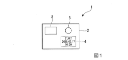
図1は、実施形態の温度検知デバイス1の平面図である。
図1に示すように、温度検知デバイス1は、基材2、低温検知インジケータ3(温度インジケータ)、開始情報印字予定部4および高温検知インジケータ5(第二温度インジケータ)を備える。
<
FIG. 1 is a plan view of the
As shown in FIG. 1, the
<基材2>
基材2は、平面視矩形のシート状をなしている。基材2は、感熱紙ラベルである。基材2の厚さは、低温検知インジケータ3および高温検知インジケータ5等を支持可能な厚さとされている。例えば、印字品質を向上させる観点では、基材2の厚さは、10μm以上100μm以下であることが好ましい。
<
The
基材2の裏面(低温検知インジケータ3の設置面とは反対側の面)には、粘着剤層が設けられていてもよい。これにより、対象物である医薬品に貼付して使用することができる温度検知デバイスが得られる。
An adhesive layer may be provided on the back surface of the substrate 2 (the surface opposite to the surface on which the low-
<低温検知インジケータ3>
低温検知インジケータ3は、基材2の第一面に1つのみ設けられている。低温検知インジケータ3は、常温環境において変色温度ヒステリシスを有する可逆熱変色性組成材料を含む。
低温検知インジケータ3は、検知温度が閾値以下になると発色(変色)する。発色とは、無色から有色になることを意味する。例えば、低温検知インジケータ3の発色開始温度は、対象物である医薬品の凍結温度(例えば−10℃程度)に設定されている。発色開始とは、無色から発色(着色)し始めることを意味する。
低温検知インジケータ3は、検知温度が閾値よりも高い第二閾値以上になると消色する。消色とは、有色から無色になることを意味する。
<Low
Only one low-
The low-
The low-
低温検知インジケータ3は、可逆熱変色性組成材料をマイクロカプセルに内包させた示温材で作製されている。
例えば、可逆熱変色性組成材料には、電子供与性呈色性有機化合物(発色剤)、電子受容性化合物(顕色剤)および変色温度調整剤が含まれている。例えば、可逆熱変色性組成材料には、その他の成分として、紫外線吸収剤、赤外線吸収剤、酸化防止剤、非熱変色性顔料、非変色性染料、蛍光増白剤、界面活性剤、消泡剤、レベリング剤、溶剤、増粘剤等が含まれていてもよい。
例えば、マイクロカプセルの製法としては、公知の界面重合法、in-situ重合法、液中硬化被覆法、水溶液からの相分離法、有機溶媒からの相分離法、融解分散冷却法、気中懸濁被覆法、スプレードライング法等が挙げられる。
The low-
For example, the reversible thermochromic composition material contains an electron-donating color-forming organic compound (color former), an electron-accepting compound (color developer), and a color-change temperature regulator. For example, the reversible thermochromic composition material includes, as other components, an ultraviolet absorber, an infrared absorber, an antioxidant, a non-thermochromic pigment, a non-chromogenic dye, a fluorescent brightener, a surfactant, and a defoamer. Agents, leveling agents, solvents, thickeners and the like.
For example, microcapsules can be produced by known interfacial polymerization methods, in-situ polymerization methods, in-liquid curing coating methods, phase separation methods from aqueous solutions, phase separation methods from organic solvents, melt dispersion cooling methods, air suspension methods. A turbid coating method, a spray drying method and the like can be mentioned.
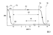
図2は、実施形態の低温検知インジケータ3の温度・色濃度特性を示す図である。図2において、横軸は低温検知インジケータ3の検知温度(温度(℃))、縦軸は色濃度(濃度)を示す。図2中符号C1は低温検知インジケータ3(可逆熱変色性組成材料)の温度・色濃度特性曲線、符号P1〜P4は変色プロセス、符号T1は完全発色温度、符号T2は発色開始温度、符号T3は消色開始温度、符号T4は完全消色温度(リセット温度)、符号H1は常温環境温度範囲(以下単に「常温範囲」ともいう。)、符号H2は発色消色温度差をそれぞれ示す。完全発色とは、色濃度がこれ以上濃くならない飽和色(発色しきった状態の色)を意味する。消色開始とは、有色から脱色し始めることを意味する。完全消色とは、色濃度がこれ以上薄くならない無色(消色しきった状態の色)を意味する。
FIG. 2 is a diagram illustrating temperature / color density characteristics of the low-
低温検知インジケータ3は、可逆の変色プロセスP1〜P4を有する。
低温検知インジケータ3は、温度下降の過程(変色プロセスP1→P2→P3)で、完全消色(無色)、常温範囲無色、発色開始、着色、完全発色(飽和色)の順に変色する。
低温検知インジケータ3は、温度上昇の過程(変色プロセスP3→P4→P1)で、完全発色(飽和色)、常温範囲有色、消色開始、脱色、完全消色(無色)の順に変色する。
低温検知インジケータ3は、常温範囲においては、無色と有色の状態が存在する。
The low-
The low-
The low-
The low-
変色プロセスP1において、低温検知インジケータ3は、検知温度が完全消色温度T4以上であり、完全消色とされている。常温範囲H1において、低温検知インジケータ3は、完全消色を維持している。検知温度が発色開始温度T2以下になると、低温検知インジケータ3は、発色し始める(変色プロセスP2)。その後、低温検知インジケータ3は、検知温度の低下とともに色濃度が濃くなる。検知温度が完全発色温度T1以下になると、低温検知インジケータ3は、完全発色する(変色プロセスP3)。例えば、発色開始温度と凍結温度とが同等な場合、低温検知インジケータ3は、着色した状態により凍結があったことを示す。
In the discoloration process P1, the detected temperature of the low-
変色プロセスP3において、低温検知インジケータ3は、検知温度が完全発色温度T1以下であり、完全発色とされている。常温範囲H1において、低温検知インジケータ3は、完全発色を維持している。検知温度が消色開始温度T3以上になると、低温検知インジケータ3は、消色し始める(変色プロセスP4)。その後、低温検知インジケータ3は、検知温度の上昇とともに色濃度が薄くなる。検知温度が完全消色温度T4以上になると、低温検知インジケータ3は、完全消色する(変色プロセスP1)。よって、低温検知インジケータ3を発行前に完全消色温度T4以上に加熱することにより、低温検知インジケータ3を初期化(リセット)することができる。
In the discoloration process P3, the low-
発色消色温度差H2は、発色開始温度T2と消色開始温度T3との差を意味する。発色消色温度差H2は、常温範囲H1の全部を含んでいる。言い換えると、発色開始温度T2は常温範囲H1の下限値よりも低く、かつ、消色開始温度T3は常温範囲H1の上限値よりも高く設定されている。そのため、通常のラベル保管環境温度(常温範囲H2)では、低温検知インジケータ3は消色状態から発色したり、発色状態から消色したりはしない。
The coloring / decoloring temperature difference H2 means a difference between the coloring start temperature T2 and the decoloring start temperature T3. The coloring / decoloring temperature difference H2 includes the entire normal temperature range H1. In other words, the color development start temperature T2 is set lower than the lower limit of the room temperature range H1, and the color erasure start temperature T3 is set higher than the upper limit of the room temperature range H1. Therefore, at the normal label storage environment temperature (normal temperature range H2), the low-
ただし、発色開始温度T2が例えば2℃の場合、冬季または寒冷地での保管において低温検知インジケータ3が発色してしまうことがある。そのため、低温検知インジケータ3を使用前(発行前)に完全消色温度T4以上に加熱して消色することにより、ラベル(温度検知デバイス)の信頼性を確保することができる。
However, when the coloring start temperature T2 is, for example, 2 ° C., the low-
<開始情報印字予定部4>
開始情報印字予定部4は、温度検知の開始情報が印字される領域である。図1に示すように、開始情報印字予定部4は、基材2の第一面に設けられている。開始情報印字予定部4は、基材2における低温検知インジケータ3の設置面と同一の面に設けられている。開始情報印字予定部4は、感熱記録層を含んでいる。実施形態では、基材2が感熱紙ラベルであるため、開始情報印字予定部4は基材2の一部の領域で構成されている。
<Start information printing scheduled
The start information
開始情報印字予定部4は、サーマルプリンタ等を用いて部分的に加熱されることにより変色し、印字される。図1の例では、開始情報印字予定部4に、温度検知の開始情報(日時など)が印字されている。温度検知の開始情報は、低温検知インジケータ3が消色された時間(初期化された時間)である。
The start
<高温検知インジケータ5>
高温検知インジケータ5は、基材2の第一面に設けられている。高温検知インジケータ5は、基材2における低温検知インジケータ3の設置面と同一の面に設けられている。高温検知インジケータ5は、不可逆熱変色性組成材料を含む。
高温検知インジケータ5は、検知温度が常温環境温度範囲の上限値以下では消色状態を保持している。高温検知インジケータ5は、検知温度が常温環境温度範囲の上限値を超えると発色する。
<High
The high
When the detected temperature is equal to or lower than the upper limit of the normal temperature environment temperature range, the high
高温検知インジケータ5は、不可逆熱変色性組成材料を含む示温材で作製されている。
例えば、不可逆熱変色性組成材料を含む示温材としては、加熱することにより染料(ロイコ染料)と顕色剤とが化学結合して発色するロイコ系感熱発色材料(ロイコ方式)、ワックスの溶融特性を利用することにより発色する溶融方式などが挙げられる。
The high
For example, as a temperature indicator containing an irreversible thermochromic composition material, a leuco-based thermosensitive coloring material (leuco method), in which a dye (leuco dye) and a developer are colored by heating to form a color, a melting property of wax And a melting method in which a color is formed by utilizing the above method.
図3は、実施形態の高温検知インジケータ5の温度・色濃度特性を示す図である。図3において、横軸は高温検知インジケータ5の検知温度(温度(℃))、縦軸は色濃度(濃度)を示す。図3中符号C2は高温検知インジケータ5(不可逆熱変色性組成材料)の温度・色濃度特性曲線、符号Q1〜Q3は変色プロセス、符号S1は発色開始温度、符号S2は完全発色温度をそれぞれ示す。
FIG. 3 is a diagram illustrating temperature / color density characteristics of the high
高温検知インジケータ5は、不可逆の変色プロセスQ1〜Q3を有する。
高温検知インジケータ5は、温度上昇の過程(変色プロセスQ1→Q2→Q3)で、完全消色(無色)、常温範囲無色、発色開始、着色、完全発色(飽和色)の順に変色する。
高温検知インジケータ5は、発色後は温度下降しても消色せず、飽和色を保持する。
The high
The high
After the color is developed, the high
変色プロセスQ1において、高温検知インジケータ5は、検知温度が常温範囲H1の下限値未満であり、完全消色とされている。常温範囲H1において、高温検知インジケータ5は、完全消色を維持している。検知温度が発色開始温度S1を超えると、高温検知インジケータ5は、発色し始める(変色プロセスQ2)。その後、高温検知インジケータ5は、検知温度の上昇とともに色濃度が濃くなる。検知温度が完全発色温度S2以上になると、高温検知インジケータ5は、完全発色する(変色プロセスQ3)。例えば、発色開始温度S1が常温範囲H1の上限値を超える場合、高温検知インジケータ5は、着色した状態により、何らかの意図的な加熱が行われたことを示す。これは、不可逆な反応であるため、その後温度が低下しても、高温検知インジケータ5は消色せずに色が残り、履歴が分かる。すなわち、高温インジケータ5は、意図的な加熱による偽造や改竄の有無を示す機能を有する。これにより、更に信頼性(エビデンス性)の向上を図ることができる。
In the discoloration process Q1, the detected temperature of the high
図4は、実施形態の低温検知インジケータ3の温度・色濃度特性を高温検知インジケータ5の温度・色濃度特性とともに示す図である。図4において、横軸は検知温度(温度(℃))、縦軸は色濃度(濃度)を示す。図4中符号R1は対象物である医薬品の凍結温度、符号R2は常温範囲H1の上限値をそれぞれ示す。
FIG. 4 is a diagram showing the temperature / color density characteristics of the low
図4に示すように、低温検知インジケータ3の発色開始温度T2は、対象物である医薬品の凍結温度R1(例えば−10℃程度)に設定されている(T2≒R1)。
低温検知インジケータ3の発色開始温度T2は、常温範囲H1の下限値よりも低く設定されている。低温検知インジケータ3の消色開始温度T3は、常温範囲H1の上限値R2よりも高く設定されている(T3>R2)。例えば、低温検知インジケータ3の消色開始温度T3は、50℃程度に設定されている。
高温検知インジケータ5の発色開始温度S1は、常温範囲H1の上限値R2よりも高く設定されている(S1>R2)。高温検知インジケータ5の発色開始温度S1は、低温検知インジケータ3の消色開始温度T3よりも低く設定されている(S1<T3)。
As shown in FIG. 4, the coloring start temperature T2 of the low-
The coloring start temperature T2 of the low
The coloring start temperature S1 of the high
<温度検知デバイス発行装置10>
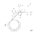
図5は、実施形態の温度検知デバイス発行装置10の側面図である。
図5に示すように、温度検知デバイス発行装置10(以下単に「発行装置10」ともいう。)は、基材供給部11、印字記録部12および制御部13を備える。
<Temperature detection
FIG. 5 is a side view of the temperature detection
As shown in FIG. 5, the temperature detection device issuing device 10 (hereinafter, also simply referred to as “issuing
基材供給部11は、ロール紙14を収容する収容部15を備える。ロール紙14は、台紙(剥離紙)がロール状に巻回されたものである。台紙の一面(表面)には、温度検知デバイス1(ラベル)が剥離可能に貼り付けられている。収容部15は、ロール紙14を軸回りに回転自在に収容している。
The base material supply unit 11 includes a
印字記録部12は、サーマルヘッド16およびプラテンローラ17を備える。
サーマルヘッド16は、低温検知インジケータ3(図6参照)を加熱する加熱部として機能する。サーマルヘッド16は、温度検知デバイス1に開始情報を印字する印字部としても機能する。発行装置10は、加熱部および印字部としてサーマルヘッド16を備える。サーマルヘッド16は、加熱部および印字部を兼ねて1つのみ設けられている。
The
The
サーマルヘッド16は、低温検知インジケータ3を第二閾値以上に加熱可能である。サーマルヘッド16は、低温検知インジケータ3を第二閾値以上(例えば、完全消色温度以上)に加熱するときに、高温検知インジケータ5の消色状態を保持する。サーマルヘッド16は、低温検知インジケータ3を加熱するときに、高温インジケータ5は加熱しない。
サーマルヘッド16は、温度検知デバイス1の感熱紙領域(例えば、開始情報印字予定部4)を加熱して印字する。サーマルヘッド16は、温度検知の開始情報として、低温検知インジケータ3が消色された時間(リセット時間)を印字する。
The
The
プラテンローラ17は、サーマルヘッド16との間でロール紙14とともに温度検知デバイス1を挟持して搬送可能である。ロール紙14の挟持位置で、ロール紙14の表面(温度検知デバイス1が設けられた面)は、サーマルヘッド16に対向している。ロール紙14の挟持位置で、ロール紙14の裏面(温度検知デバイス1が設けられた面とは反対側の面)は、プラテンローラ17に対向している。
The
制御部13は、温度検知デバイスの構成要素を統括制御する。例えば、制御部13は、相互に接続されたCPU(Central Processing Unit)、ROM(Read Only Memory)、およびRAM(Random Access Memory )を備える。例えば、制御部13は、予め記憶されたプログラムをCPUにより実行する。
The
制御部13は、不図示の加熱制御部、印字制御部、情報取得部、計時部および位置制御部を備える。
加熱制御部は、サーマルヘッド16(加熱部)による温度検知デバイスへの加熱を制御する。
印字制御部は、サーマルヘッド16(印字部)による温度検知デバイスへの表示情報の印字を制御する。例えば、表示情報は、温度検知デバイスの温度検知の開始時間になる時間情報、商品情報等である。
情報取得部は、時間情報、商品情報を取得する。
計時部は、サーマルヘッド16(加熱部)において温度検知デバイスを加熱する加熱時刻を計時し、時刻情報(加熱時刻)を出力する。
位置制御部は、基材供給部11から供給される温度検知デバイスの搬送を制御する。例えば、位置制御部は、プラテンローラ17の回転(ロール紙14および温度検知デバイスの搬送)を制御する。位置制御部は、温度検知デバイスの位置に合わせて加熱制御部および印字制御部に制御信号を出力し、印字記録部12(サーマルヘッド16およびプラテンローラ17)を動作させる。
The
The heating control unit controls heating of the temperature detection device by the thermal head 16 (heating unit).
The print control unit controls printing of display information on the temperature detection device by the thermal head 16 (printing unit). For example, the display information is time information at which the temperature detection device starts to detect temperature, product information, and the like.
The information acquisition unit acquires time information and product information.
The timer measures the heating time at which the thermal head 16 (heating unit) heats the temperature detection device, and outputs time information (heating time).
The position control unit controls conveyance of the temperature detection device supplied from the base material supply unit 11. For example, the position control unit controls rotation of the platen roller 17 (transport of the
図6は、実施形態の温度検知デバイス発行装置10の平面図である。図6中矢印V1はロール紙14および温度検知デバイス1の搬送方向、矢印W1は搬送方向V1と直交する幅方向、符号CLは温度検知デバイス1の幅方向中心線をそれぞれ示す。
FIG. 6 is a plan view of the temperature detection
図6に示すように、温度検知デバイス1は、ロール紙14の表面に複数設けられている。複数の温度検知デバイス1は、搬送方向V1に互いに間隔をあけて配置されている。温度検知デバイス1の幅方向中心線CLは、ロール紙14の幅方向中心位置に位置している。温度検知デバイス1の幅方向の長さは、ロール紙14よりも短い。サーマルヘッド16の幅方向の長さは、ロール紙14よりも長い。
As shown in FIG. 6, a plurality of
平面視で、低温検知インジケータ3は、温度検知デバイス1の幅方向中心線CLの左側方に配置されている。平面視で、高温検知インジケータ5は、温度検知デバイス1の幅方向中心線CLの右側方(幅方向中心線CLを挟んで低温検知インジケータ3とは反対側)に配置されている。平面視で、低温検知インジケータ3および高温検知インジケータ5は、温度検知デバイス1の搬送方向下流側の領域に配置されている。
In a plan view, the low
平面視で、開始情報印字予定部4は、温度検知デバイス1の幅方向中心線CLの右側方(幅方向中心線CLを挟んで低温検知インジケータ3とは反対側)に配置されている。平面視で、開始情報印字予定部4は、温度検知デバイス1の搬送方向上流側の領域(高温検知インジケータ5の上流側の領域)に配置されている。
In plan view, the start information printing scheduled
<発行装置10の動作>
以下、実施形態の発行装置10の動作の一例を説明する。図7は、実施形態の温度検知デバイス発行装置10の動作の一例を示す図である。
<Operation of
Hereinafter, an example of the operation of the
まず、発行装置10の発行スタートスイッチを押す(ステップS1、発行開始)。
次に、温度検知デバイス(ラベル)の頭出しを行う。例えば、ラベルの位置出しマークをPI(Photo Interrupter)センサーで認識して、印刷開始位置にラベルの頭出し(位置出し)を行う(ステップS2)。ラベルの頭出しは、前段の発行後に行ってもよい。
First, the issuing start switch of the
Next, the cue of the temperature detection device (label) is performed. For example, the position mark of the label is recognized by a PI (Photo Interrupter) sensor, and the head of the label is located (positioned) at the printing start position (step S2). The cueing of the label may be performed after the previous issue.
次に、センサー部(低温検知インジケータ3)を加熱する(ステップS3)。例えば、事前に位置および形状が決定しているセンサー部に対してラベルを走査させて、所定領域をサーマルヘッド16で完全消色温度以上に加熱する。これにより、センサー部を初期化する(消色リセット)。
Next, the sensor unit (low temperature detection indicator 3) is heated (step S3). For example, the label is scanned with respect to a sensor portion whose position and shape are determined in advance, and a predetermined area is heated by the
センサー部の加熱温度は、プリンタ制御により行う。例えば、サーマルプリンタの特性に応じて、印加電圧および時間(印字スピード)を制御する。ステップS3では、示温材の特性に影響を与えない必要最小限の加熱エネルギーでセンサー部を加熱する。センサー部の加熱パターンは、予め決まっているラベルパターンに合わせて設定しておく。 The heating temperature of the sensor unit is controlled by printer control. For example, the applied voltage and time (print speed) are controlled according to the characteristics of the thermal printer. In step S3, the sensor unit is heated with the minimum necessary heating energy that does not affect the characteristics of the temperature indicating material. The heating pattern of the sensor unit is set in accordance with a predetermined label pattern.
次に、温度検知の開始情報を印字する(ステップS4)。例えば、センサー部以外の感熱領域に対して、開始時間情報などのスタート表示を印字する。
そして、ラベルを発行装置10より排出する(ステップS5、出力終了)。例えば、排出されたラベルは、ロール紙14から剥離され、対象物である医薬品に貼付される。
Next, temperature detection start information is printed (step S4). For example, a start display such as start time information is printed in a heat sensitive area other than the sensor section.
Then, the label is discharged from the issuing device 10 (step S5, output end). For example, the discharged label is peeled off from the
<温度検知方法>
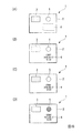
以下、実施形態の温度検知方法の一例を説明する。図8は、実施形態の温度検知方法の一例を示す工程図である。図8(A)は、ラベルの保管状態の図である。図8(B)は、加熱工程および印字工程の説明図である。図8(C)は、低温検知インジケータ3の作用の説明図である。図8(D)は、高温検知インジケータ5の作用の説明図である。
温度検知方法は、温度検知デバイスを用いて、医薬品の保管温度の下限値を検知する方法である。実施形態では、低温検知インジケータ3の発色開始温度を、医薬品の凍結温度に設定する。
<Temperature detection method>
Hereinafter, an example of the temperature detection method of the embodiment will be described. FIG. 8 is a process chart illustrating an example of the temperature detection method according to the embodiment. FIG. 8A is a diagram illustrating a storage state of the label. FIG. 8B is an explanatory diagram of the heating step and the printing step. FIG. 8C is an explanatory diagram of the operation of the low-
The temperature detection method is a method of detecting the lower limit value of the storage temperature of a medicine using a temperature detection device. In the embodiment, the coloring start temperature of the low-
図8(A)に示すように、ラベルの保管状態において、低温検知インジケータ3が発色していることがある。これは、冬季や寒冷地での保管においては、保管温度が低温検知インジケータ3の発色開始温度よりも低くなることがあるためである。
As shown in FIG. 8A, the low-
図8(B)に示すように、低温検知インジケータ3を完全消色温度以上に加熱する(加熱工程)。これにより、低温検知インジケータ3を初期化(リセット)する。
加熱工程では、低温検知インジケータ3を完全消色温度以上に加熱するときに、高温検知インジケータ5の消色状態を保持する。
As shown in FIG. 8B, the low
In the heating step, when the low-
また、開始情報を印字領域に印字する(印字工程)。開始情報は、低温検知インジケータ3が消色された時間とする。
加熱工程および印字工程では、共通のサーマルヘッド16(図6参照)を用いる。
Further, the start information is printed in the print area (printing step). The start information is the time at which the low-
In the heating step and the printing step, a common thermal head 16 (see FIG. 6) is used.
図8(C)に示すように、低温検知インジケータ3は、検知温度が医薬品の凍結温度以下になると、発色する。例えば、低温検知インジケータ3は、黄色に発色する。低温検知インジケータ3が発色したことをもって、医薬品の凍結温度に達したことを把握することができる。
As shown in FIG. 8 (C), the low-
図8(D)に示すように、高温検知インジケータ5は、検知温度が常温範囲の上限値を超えると発色する。例えば、高温検知インジケータ5は、青色に発色する。高温検知インジケータ5が発色したことをもって、常温環境の上限値を超えたことを把握することができる。
As shown in FIG. 8D, the high
以上説明したように、本実施形態に係る温度検知デバイス1は、基材2と、基材2に設けられ、常温環境において変色温度ヒステリシスを有する可逆熱変色性組成材料を含み、検知温度が閾値以下になると変色する低温検知インジケータ3と、を備える。
本実施形態によれば、基材2と低温検知インジケータ3とにより温度検知デバイス1が構成されるため、小型化、軽量化を図ることができる。加えて、低温検知インジケータ3は、検知温度が閾値以下になると変色するため、低温検知インジケータ3が変色したことをもって、低温側の温度逸脱を管理することができる。したがって、小型、軽量でかつ、低温側の温度逸脱をエビデンス性を確保して管理することができる。例えば、目視により低温検知インジケータ3を容易に確認することができる。加えて、低温検知インジケータ3は、常温環境において変色温度ヒステリシスを有する可逆熱変色性組成材料を含むため、低温検知インジケータ3を所定温度以上に加熱して変色させることにより、低温検知インジケータ3を初期化(リセット)することができる。
As described above, the
According to the present embodiment, since the
本実施形態において、基材2は、シート状をなしている。
本実施形態によれば、温度検知デバイス1を、小型、軽量、薄型のタグ、ラベル等に適用しやすい。
In the present embodiment, the
According to the present embodiment, the
本実施形態では、基材2に設けられ、温度検知の開始情報が印字される開始情報印字予定部4を更に備える。
本実施形態によれば、開始情報印字予定部4に温度検知の開始情報が印字されることによって、温度検知の開始時間を把握することができる。
In the present embodiment, the apparatus further includes a start
According to the present embodiment, the start time of the temperature detection can be grasped by printing the start information of the temperature detection on the scheduled start
本実施形態において、開始情報印字予定部4は、基材2における低温検知インジケータ3の設置面と同一の面に設けられている。
本実施形態によれば、開始情報印字予定部4が基材2における低温検知インジケータ3の設置面と反対側の面に設けられた場合と比較して、温度検知の開始情報を低温検知インジケータ3の変色と併せて把握しやすい。
In the present embodiment, the start information printing scheduled
According to the present embodiment, the start information for the temperature detection is compared with the case where the start information printing scheduled
本実施形態において、開始情報印字予定部4は、感熱記録層を含んでいる。
本実施形態によれば、加熱部を備えた発行装置10(例えば、サーマルプリンタ等)を用いて開始情報を印字することができる。サーマルプリンタは、小型、軽量、高印字信頼性、低コストであるため、温度検知デバイス1を用いて対象物の温度検知を開始する際、対象物の保管場所へサーマルプリンタを持ち運ぶことができる。加えて、オンデマンドで印刷すべき情報を修正し、温度検知デバイス1に印字することができる。
In the present embodiment, the start information printing scheduled
According to the present embodiment, the start information can be printed using the issuing device 10 (for example, a thermal printer or the like) including the heating unit. Since the thermal printer is small, lightweight, high printing reliability, and low cost, when the temperature detection of the target is started using the
本実施形態において、低温検知インジケータ3は、検知温度が閾値以下になると発色し、検知温度が前記閾値よりも高い第二閾値以上になると消色する。
本実施形態では、低温検知インジケータ3が発色したことをもって、低温側の温度逸脱を管理することができる。加えて、低温検知インジケータ3を第二閾値以上に加熱して消色させることにより、低温検知インジケータ3を初期化することができる。
In the present embodiment, the low-
In the present embodiment, the temperature deviation on the low-temperature side can be managed based on the fact that the low-
本実施形態において、低温検知インジケータ3は、1つのみ設けられ、1つの低温検知インジケータ3の発色開始温度は、対象物の凍結温度に設定されている。
本実施形態によれば、低温検知インジケータ3が発色したことをもって、対象物の凍結温度に達したことを把握することができる。加えて、低温検知インジケータ3が複数設けられている場合と比較して、装置構成の簡素化および低コスト化を図ることができる。
In the present embodiment, only one low-
According to the present embodiment, it is possible to know that the freezing temperature of the target object has been reached by the low-
本実施形態では、基材2に設けられ、不可逆熱変色性組成材料を含み、検知温度が常温環境温度範囲の上限値以下では消色状態を保持し、検知温度が前記常温環境温度範囲の上限値を超えると発色する高温検知インジケータ5を更に備える。
本実施形態によれば、高温検知インジケータ5が発色したことをもって、常温環境の上限値を超えたことを把握することができる。高温検知インジケータ5の発色は不可逆な反応であるため、その後温度が低下しても消色せずに色が残り、履歴が分かる。
In the present embodiment, the erasable thermochromic composition material is provided on the
According to the present embodiment, it is possible to know that the temperature has exceeded the upper limit value of the normal temperature environment by the high
本実施形態に係る温度検知デバイス発行装置10は、上記の温度検知デバイス1の発行装置10であって、低温検知インジケータ3を加熱可能な加熱部と、温度検知デバイス1に開始情報を印字可能な印字部と、加熱部および印字部を制御する制御部13と、を備える。
本実施形態によれば、上記の温度検知デバイス1を発行することができる温度検知デバイス発行装置10を提供することができる。
The temperature detecting
According to the present embodiment, it is possible to provide a temperature detection
本実施形態において、低温検知インジケータ3は、検知温度が閾値以下になると発色し、検知温度が閾値よりも高い第二閾値以上になると消色し、加熱部は、低温検知インジケータ3を第二閾値以上に加熱可能である。
本実施形態によれば、低温検知インジケータ3が発色したことをもって、低温側の温度逸脱を管理することができる。加えて、低温検知インジケータ3を第二閾値以上に加熱して消色させることにより、低温検知インジケータ3を初期化することができる。
In the present embodiment, the low-
According to the present embodiment, the temperature deviation on the low-temperature side can be managed based on the fact that the low-
本実施形態では、加熱部および印字部として、サーマルヘッド16を備える。
本実施形態によれば、サーマルヘッド16によって低温検知インジケータ3の初期化と開始情報の印字とを併せて行うことができる。
In the present embodiment, a
According to the present embodiment, the initialization of the low-
本実施形態において、サーマルヘッド16は、加熱部および印字部を兼ねて1つのみ設けられている。
本実施形態によれば、サーマルヘッド16が加熱部および印字部のそれぞれに別個に複数設けられている場合と比較して、装置構成の簡素化および低コスト化を図ることができる。
In the present embodiment, only one
According to the present embodiment, the apparatus configuration can be simplified and the cost can be reduced as compared with the case where a plurality of
本実施形態において、開始情報は、低温検知インジケータ3が消色された時間である。
本実施形態によれば、低温検知インジケータ3が消色された時間を開始情報として関連付けされるため、低温検知インジケータ3が消色されてからの経過時間を把握することができ、信頼性(エビデンス性)が向上する。
In the present embodiment, the start information is the time when the low-
According to the present embodiment, since the time at which the low-
本実施形態において、加熱部は、低温検知インジケータ3を前記第二閾値以上に加熱するときに、高温検知インジケータ5の消色状態を保持する。
本実施形態によれば、低温検知インジケータ3の初期化を行うときに、高温検知インジケータ5が発色することを回避することができる。
In this embodiment, when heating the low-
According to the present embodiment, when the low-
本実施形態に係る温度検知方法は、上記の温度検知デバイス1を用いて、対象物の保管温度の下限域を検知する。
本実施形態によれば、上記の温度検知デバイス1を用いた温度検知方法を提供することができる。
The temperature detection method according to the present embodiment uses the above-described
According to the present embodiment, a temperature detection method using the above-described
本実施形態では、低温検知インジケータ3を加熱する加熱工程と、温度検知デバイス1に開始情報を印字する印字工程と、を含む。
本実施形態によれば、加熱工程において、低温検知インジケータ3を所定温度以上に加熱して変色させることにより、低温検知インジケータ3を初期化することができる。印字工程において、温度検知デバイス1に開始情報を印字することにより、温度検知の開始時間を把握することができる。
The present embodiment includes a heating step of heating the low-
According to the present embodiment, in the heating step, the low-
本実施形態において、低温検知インジケータ3は、検知温度が閾値以下になると発色し、検知温度が閾値よりも高い第二閾値以上になると消色し、加熱工程では、低温検知インジケータ3を第二閾値以上に加熱する。
本実施形態によれば、低温検知インジケータ3が発色したことをもって、低温側の温度逸脱を管理することができる。加熱工程において、低温検知インジケータ3を第二閾値以上に加熱して消色させることにより、低温検知インジケータ3を初期化することができる。
In the present embodiment, the low-
According to the present embodiment, the temperature deviation on the low-temperature side can be managed based on the fact that the low-
本実施形態において、基材2は、感熱記録層を含み、感熱記録層には、温度検知の開始情報が印字される印字領域が設けられ、印字工程では、サーマルヘッド16を用いて、開始情報を印字領域に印字する。
本実施形態によれば、サーマルヘッド16を用いた簡便な方法で、開始情報を印字領域に印字することができる。例えば、感熱記録式のサーマルプリンタを採用することができる。サーマルプリンタは、動作音が非常に小さく、小型軽量に適した簡単な構造であり、コストが抑えられるという特徴がある。サーマルプリンタは、インクリボン、インクカートリッジといったインク類を使用しないため、消耗品は感熱紙(感熱記録層)のみである。したがって、簡便な方法でランニングコストを抑えることができる。
In the present embodiment, the
According to the present embodiment, the start information can be printed in the print area by a simple method using the
本実施形態において、加熱工程では、サーマルヘッド16を用いて、低温検知インジケータ3を完全消色温度以上に加熱する。
本実施形態によれば、サーマルヘッド16を用いた簡便な方法で、低温検知インジケータ3を完全消色温度以上に加熱することができる。
In the present embodiment, in the heating step, the low-
According to the present embodiment, the low-
本実施形態において、加熱工程および印字工程では、共通のサーマルヘッド16を用いる。
本実施形態によれば、加熱工程および印字工程のそれぞれで異なるサーマルヘッド16を用いる場合と比較して、簡便な方法で行うことができる。
In the present embodiment, a common
According to the present embodiment, it is possible to perform the heating step and the printing step by a simpler method than in the case where different
本実施形態において、印字工程では、開始情報を、低温検知インジケータ3が消色された時間とする。
本実施形態によれば、低温検知インジケータ3が消色された時間を開始情報として関連付けされるため、低温検知インジケータ3が消色されてからの経過時間を把握することができ、信頼性(エビデンス性)が向上する。
In the present embodiment, in the printing process, the start information is the time when the low-
According to the present embodiment, since the time at which the low-
本実施形態では、低温検知インジケータ3は、1つのみ設けられ、1つの低温検知インジケータ3の発色開始温度を、対象物の凍結温度に設定する。
本実施形態によれば、低温検知インジケータ3が発色したことをもって、対象物の凍結温度に達したことを把握することができる。加えて、低温検知インジケータ3が複数設けられている場合と比較して、装置構成の簡素化および低コスト化を図ることができる。
In the present embodiment, only one low-
According to the present embodiment, it is possible to know that the freezing temperature of the target object has been reached by the low-
本実施形態において、加熱工程では、低温検知インジケータ3を第二閾値以上に加熱するときに、高温検知インジケータ5の消色状態を保持する。
この方法によれば、低温検知インジケータ3の初期化を行うときに、高温検知インジケータ5が発色することを回避することができる。
In the present embodiment, in the heating step, when the low-
According to this method, it is possible to prevent the high-
(変形例)
なお、本発明の技術範囲は上述した実施形態に限定されるものではなく、本発明の趣旨を逸脱しない範囲において種々の変更を加えることが可能である。
(Modification)
Note that the technical scope of the present invention is not limited to the above-described embodiment, and various changes can be made without departing from the spirit of the present invention.
例えば、上述した実施形態では、低温検知インジケータは、1つのみ設けられている例を挙げて説明したが、これに限らない。例えば、低温検知インジケータは、複数設けられていてもよい。 For example, in the above-described embodiment, an example has been described in which only one low-temperature detection indicator is provided, but the present invention is not limited to this. For example, a plurality of low temperature detection indicators may be provided.
図9は、実施形態の第一変形例に係る温度検知デバイス101の平面図である。
図9に示すように、温度検知デバイス101は、複数(本変形例では2つ)の低温検知インジケータ131,132を備える。複数の低温検知インジケータ131,132は、第一低温検知インジケータ131(第一インジケータ)と、第一低温検知インジケータ131よりも発色開始温度が高い第二低温検知インジケータ132(第二インジケータ)と、である。
FIG. 9 is a plan view of a
As shown in FIG. 9, the
図10は、実施形態の第一変形例に係る第一低温検知インジケータ131および第二低温検知インジケータ132の温度・色濃度特性を高温検知インジケータ5の温度・色濃度特性とともに示す図である。図10中符号C11は第一低温検知インジケータ131(第一の可逆熱変色性組成材料)の温度・色濃度特性曲線、符号C12は第二低温検知インジケータ132(第二の可逆熱変色性組成材料)の温度・色濃度特性曲線、符号C2は高温検知インジケータ5(不可逆熱変色性組成材料)の温度・色濃度特性曲線、符号T12は第一低温検知インジケータ131の発色開始温度、符号T22は第二低温検知インジケータ132の発色開始温度、符号T13は第一低温検知インジケータ131の消色開始温度、符号T23は第二低温検知インジケータ132の消色開始温度、符号S1は高温検知インジケータ5の発色開始温度、符号S2は高温検知インジケータ5の完全発色温度、符号R1は対象物である医薬品の凍結温度、符号R2は常温範囲H1の上限値、符号L1は適正保管温度域の下限値をそれぞれ示す。
FIG. 10 is a diagram showing the temperature / color density characteristics of the first low-
図10に示すように、第一低温検知インジケータ131の発色開始温度T12は、医薬品の凍結温度R1(例えば−10℃程度)に設定されている(T12≒R1)。
第二低温検知インジケータ132の発色開始温度T22は、医薬品の凍結温度よりも高い、医薬品の適正保管温度域の下限値L1(例えば2℃程度)に設定されている(T22≒L1)。
第一低温検知インジケータ131の消色開始温度T13は、常温範囲H1の上限値R2よりも高く設定されている(T13>R2)。
第二低温検知インジケータ132の消色開始温度T23は、第一低温検知インジケータ131の消色開始温度T13よりも高く設定されている(T23>T13)。
高温検知インジケータ5の発色開始温度S1は、常温範囲H1の上限値R2よりも高く設定されている(S1>R2)。高温検知インジケータ5の発色開始温度S1は、第一低温検知インジケータ131の消色開始温度T13よりも低く設定されている(S1<T13)。
As shown in FIG. 10, the coloring start temperature T12 of the first low-
The coloring start temperature T22 of the second low-
The decoloring start temperature T13 of the first low
The decoloring start temperature T23 of the second low-
The coloring start temperature S1 of the high
図11は、実施形態の第一変形例に係る温度検知デバイス発行装置の平面図である。図11中矢印V1はロール紙14および温度検知デバイスの搬送方向、矢印W1は搬送方向V1と直交する幅方向、符号CLは温度検知デバイス101の幅方向中心線をそれぞれ示す。
FIG. 11 is a plan view of a temperature detection device issuing device according to a first modification of the embodiment. In FIG. 11, arrow V1 indicates the transport direction of the
図11に示すように、平面視で、第一低温検知インジケータ131および第二低温検知インジケータ132は、温度検知デバイス101の幅方向中心線CLの左側方に配置されている。第一低温検知インジケータ131および第二低温検知インジケータ132は、搬送方向V1に互いに間隔をあけて配置されている。平面視で、第一低温検知インジケータ131は、温度検知デバイス101の搬送方向下流側の領域に配置されている。平面視で、第二低温検知インジケータ132は、温度検知デバイス101の搬送方向上流側の領域(第一低温検知インジケータ131の上流側の領域)に配置されている。
As shown in FIG. 11, the first low-
サーマルヘッド16は、第一低温検知インジケータ131および第二低温検知インジケータ132を同時に完全消色温度以上に加熱可能である。サーマルヘッド16は、第一低温検知インジケータ131および第二低温検知インジケータ132を完全消色温度以上に加熱するときに、高温検知インジケータ5の消色状態を保持する。
The
図12は、実施形態の第一変形例に係る温度検知方法の一例を示す工程図である。図12(A)は、ラベルの保管状態の図である。図12(B)は、加熱工程および印字工程の説明図である。図12(C)は、第二低温検知インジケータ132の作用の説明図である。図12(D)は、第一低温検知インジケータ131の作用の説明図である。図12(E)は、高温検知インジケータ5の作用の説明図である。
FIG. 12 is a process diagram illustrating an example of a temperature detection method according to a first modification of the embodiment. FIG. 12A is a diagram showing a storage state of the label. FIG. 12B is an explanatory diagram of the heating step and the printing step. FIG. 12C is an explanatory diagram of the operation of the second low-
温度検知方法は、第一低温検知インジケータ131および第二低温検知インジケータ132を備えた温度検知デバイス101を用いて、医薬品の保管温度の下限値を検知する方法である。本変形例では、第一低温検知インジケータ131の発色開始温度を、医薬品の凍結温度に設定する。第二低温検知インジケータ132の発色開始温度を、医薬品の凍結温度よりも高い、医薬品の適正保管温度域の下限値に設定する。
The temperature detection method is a method of detecting the lower limit of the storage temperature of a medicine using the
図12(A)に示すように、ラベルの保管状態において、各低温検知インジケータ131,132が発色していることがある。これは、冬季や寒冷地での保管においては、保管温度が各低温検知インジケータ131,132の発色開始温度よりも低くなることがあるためである。
As shown in FIG. 12A, the low-
図12(B)に示すように、各低温検知インジケータ131,132を完全消色温度以上に加熱する(加熱工程)。これにより、各低温検知インジケータ131,132を初期化(リセット)する。
加熱工程では、第一低温検知インジケータ131および第二低温検知インジケータ132を同時に完全消色温度以上に加熱する。
加熱工程では、第一低温検知インジケータ131および第二低温検知インジケータ132を完全消色温度以上に加熱するときに、高温検知インジケータ5の消色状態を保持する。
As shown in FIG. 12B, each of the low-
In the heating step, the first low
In the heating step, when the first low-
また、開始情報を印字領域に印字する(印字工程)。開始情報は、第一低温検知インジケータ131および第二低温検知インジケータ132が消色された時間とする。
加熱工程および印字工程では、共通のサーマルヘッド16(図11参照)を用いる。
Further, the start information is printed in the print area (printing step). The start information is a time at which the first low-
In the heating step and the printing step, a common thermal head 16 (see FIG. 11) is used.
図12(C)に示すように、第二低温検知インジケータ132は、検知温度が医薬品の適正保管温度域の下限値以下になると、発色する。例えば、第二低温検知インジケータ132は、赤色に発色する。第二低温検知インジケータ132が発色したことをもって、医薬品の適正保管温度域の下限値に達したことを把握することができる。
As shown in FIG. 12 (C), the second low-
図12(D)に示すように、第一低温検知インジケータ131は、検知温度が医薬品の凍結温度以下になると、発色する。第一低温検知インジケータ131は、第二低温検知インジケータ132とは異なる色に発色する。例えば、第一低温検知インジケータ131は、黄色に発色する。第一低温検知インジケータ131が発色したことをもって、医薬品の凍結温度に達したことを把握することができる。
As shown in FIG. 12 (D), the first low-
図12(E)に示すように、高温検知インジケータ5は、検知温度が常温範囲の上限値を超えると発色する。例えば、高温検知インジケータ5は、青色に発色する。高温検知インジケータ5が発色したことをもって、常温環境の上限値を超えたことを把握することができる。
As shown in FIG. 12 (E), the high
本変形例において、低温検知インジケータ131,132は、複数設けられ、複数の低温検知インジケータ3は、第一低温検知インジケータ131と、第一低温検知インジケータ131よりも発色開始温度が高い第二低温検知インジケータ132と、である。
本変形例によれば、低温側の温度逸脱を段階的に管理することができる。
In this modification, a plurality of low-
According to this modification, the temperature deviation on the low temperature side can be managed stepwise.
本変形例において、第一低温検知インジケータ131の発色開始温度は、医薬品の凍結温度に設定され、第二低温検知インジケータ132の発色開始温度は、医薬品の凍結温度よりも高い、医薬品の適正保管温度域の下限値に設定されている。
本変形例によれば、第一低温検知インジケータ131が発色したことをもって、医薬品の凍結温度に達したことを把握することができる。加えて、第二低温検知インジケータ132が発色したことをもって、医薬品の適正保管温度域の下限値に達したことを把握することができる。
In this modification, the color-forming start temperature of the first low-
According to the present modification, it is possible to know that the freezing temperature of the medicine has been reached by the first low-
本変形例において、サーマルヘッド16は、第一低温検知インジケータ131および第二低温検知インジケータ132を同時に完全消色温度以上に加熱可能である。
本変形例によれば、第一低温検知インジケータ131の初期化と第二低温検知インジケータ132の初期化とを一括して行うことができる。
In this modification, the
According to this modification, the initialization of the first low-
例えば、上述した実施形態では、平面視で、低温検知インジケータ3は、温度検知デバイス1の幅方向中心線CLの左側方に配置され、開始情報印字予定部4は、温度検知デバイス1の幅方向中心線CLの右側方(幅方向中心線CLを挟んで低温検知インジケータ3とは反対側)に配置されている例を挙げて説明したが、これに限らない。例えば、開始情報印字予定部4は、温度検知デバイス1の幅方向中心線CLの左側方(幅方向中心線CLを挟んで低温検知インジケータ3と同じ側)に配置されていてもよい。
For example, in the above-described embodiment, in a plan view, the low-
図13は、実施形態の第二変形例に係る温度検知デバイス201の平面図である。図13中矢印V1は温度検知デバイス201(ロール紙14)の搬送方向、矢印W1は搬送方向V1と直交する幅方向、符号CLは温度検知デバイス201の幅方向中心線をそれぞれ示す。
FIG. 13 is a plan view of a
図13に示すように、平面視で、第一低温検知インジケータ131、第二低温検知インジケータ132および開始情報印字予定部4は、温度検知デバイス201の幅方向中心線CLの左側方(幅方向中心線CLを挟んで高温検知インジケータ5とは反対側)に配置されている。第一低温検知インジケータ131、第二低温検知インジケータ132および開始情報印字予定部4は、搬送方向V1に互いに間隔をあけて配置されている。平面視で、第一低温検知インジケータ131は、温度検知デバイス201の搬送方向下流側の領域に配置されている。平面視で、第二低温検知インジケータ132は、第一低温検知インジケータ131の上流側の領域に配置されている。平面視で、開始情報印字予定部4は、第二低温検知インジケータ132の上流側の領域に配置されている。
As shown in FIG. 13, in plan view, the first low-
本変形例において、平面視で、第一低温検知インジケータ131、第二低温検知インジケータ132および開始情報印字予定部4は、温度検知デバイス201の幅方向中心線CLを挟んで高温検知インジケータ5とは反対側に配置されている。
本変形例によれば、温度検知デバイス201の幅方向中心線CLを挟んで高温検知インジケータ5とは反対側に、加熱してもよい領域をまとめることができるため、各低温検知インジケータ131,132の初期化や開始情報印字予定部4への印字を行うときに、高温検知インジケータ5が発色することを回避することができる。
In the present modification, the first low-
According to this modification, the regions that may be heated can be grouped on the opposite side of the high-
上述した実施形態では、温度検知デバイス1は、基材2、低温検知インジケータ3、開始情報印字予定部4および高温検知インジケータ5を備える例を挙げて説明したが、これに限らない。例えば、温度検知デバイスは、開始情報印字予定部4および高温検知インジケータ5を備えていなくてもよい。例えば、温度検知デバイスは、基材2および低温検知インジケータ3のみを備えていてもよい。
In the above-described embodiment, an example has been described in which the
上述した実施形態では、基材2は、シート状をなしている例を挙げて説明したが、これに限らない。例えば、基材は、タブレット等のシート状以外の形態をなしていてもよい。
In the above-described embodiment, the example in which the
上述した実施形態では、開始情報印字予定部4は、基材2における低温検知インジケータ3の設置面と同一の面に設けられている例を挙げて説明したが、これに限らない。例えば、開始情報印字予定部4は、基材2における低温検知インジケータ3の設置面と反対側の面(異なる面)に設けられていてもよい。
In the above-described embodiment, the example in which the scheduled start
上述した実施形態では、基材2は感熱紙ラベルであり、開始情報印字予定部4は基材2の一部の領域で構成されている例を挙げて説明したが、これに限らない。例えば、基材2は合成紙または上質紙であり、基材2の一部の領域に開始情報印字予定部4としての感熱記録層が支持されていてもよい。
In the above-described embodiment, the example has been described in which the
上述した実施形態では、低温検知インジケータ3は、検知温度が閾値以下になると発色し、検知温度が前記閾値よりも高い第二閾値以上になると消色する例を挙げて説明したが、これに限らない。例えば、低温検知インジケータは、検知温度が前記閾値以下になると第一の色(例えば黄色)に発色し、検知温度が前記閾値よりも高い第二閾値以上になると第一の色とは異なる第二の色(例えば緑色)に発色してもよい。低温検知インジケータは、検知温度が閾値以下になると第二の色から第一の色に変色し、検知温度が第二閾値以上になると第一の色から第二の色に変色してもよい。
In the above-described embodiment, an example has been described in which the low-
例えば、基材2の表面(低温検知インジケータ3の設置面)には、低温検知インジケータ3の色を特定するための指標となる基準色を呈する参照部が設けられていてもよい。目視により低温検知インジケータ3を参照部と比較することによって、低温検知インジケータ3の色を把握することができる。参照部は、外部環境(温度、光など)の影響で変色することなく所望の色強度を維持でき、耐水性、耐光性に優れた材料(例えば顔料)を含む着色層を有していることが好ましい。
For example, on the surface of the base material 2 (the surface on which the low-
上述した実施形態では、温度検知の対象を低温保存が必要な医薬品とした例を挙げて、説明したが、これに限らない。例えば、温度検知の対象は食品などの医薬品以外の対象物であってもよい。 In the above-described embodiment, an example has been described in which the target of temperature detection is a medicine requiring low-temperature storage, but the present invention is not limited to this. For example, the target of temperature detection may be a non-pharmaceutical target such as food.
その他、本発明の趣旨を逸脱しない範囲で、上記した実施形態における構成要素を周知の構成要素に置き換えることは適宜可能である。 In addition, the components in the above-described embodiments can be appropriately replaced with known components without departing from the spirit of the present invention.
1,101,201…ラベル(温度検知デバイス)
2…基材
3…低温検知インジケータ(温度インジケータ)
4…開始情報印字予定部
5…高温検知インジケータ(第二温度インジケータ)
10…発行装置(温度検知デバイス発行装置)
13…制御装置
16…サーマルヘッド(加熱部、印字部)
131…第一低温検知インジケータ(第一インジケータ)
132…第二低温検知インジケータ(第二インジケータ)
1, 101, 201 ... label (temperature detection device)
2: Base material 3: Low temperature detection indicator (temperature indicator)
4: Start information print scheduled portion 5: High temperature detection indicator (second temperature indicator)
10. Issuing device (Temperature detection device issuing device)
13: control device 16: thermal head (heating unit, printing unit)
131: first low temperature detection indicator (first indicator)
132 ... second low temperature detection indicator (second indicator)
Claims (31)
前記基材に設けられ、常温環境において変色温度ヒステリシスを有する可逆熱変色性組成材料を含み、検知温度が閾値以下になると変色する温度インジケータと、を備えることを特徴とする温度検知デバイス。 A substrate,
A temperature indicator provided on the base material, the reversible thermochromic composition material having a discoloration temperature hysteresis in a normal temperature environment, and a color indicator that discolors when a detection temperature falls below a threshold value.
1つの前記温度インジケータの発色開始温度は、対象物の凍結温度に設定されていることを特徴とする請求項6に記載の温度検知デバイス。 The temperature indicator is provided only one,
The temperature detection device according to claim 6, wherein a coloring start temperature of one of the temperature indicators is set to a freezing temperature of the object.
複数の前記温度インジケータは、
第一インジケータと、
前記第一インジケータよりも発色開始温度が高い第二インジケータと、であることを特徴とする請求項6に記載の温度検知デバイス。 A plurality of the temperature indicators are provided,
The plurality of temperature indicators include:
A first indicator,
The temperature detection device according to claim 6, wherein the second indicator has a higher color development start temperature than the first indicator.
前記第二インジケータの発色開始温度は、前記凍結温度よりも高い、前記対象物の適正保管温度域の下限値に設定されていることを特徴とする請求項8に記載の温度検知デバイス。 The color development start temperature of the first indicator is set to the freezing temperature of the object,
9. The temperature detection device according to claim 8, wherein a color development start temperature of the second indicator is set to a lower limit of a proper storage temperature range of the object, which is higher than the freezing temperature.
前記温度インジケータを加熱可能な加熱部と、
前記温度検知デバイスに開始情報を印字可能な印字部と、
前記加熱部および前記印字部を制御する制御部と、を備えることを特徴とする温度検知デバイス発行装置。 It is an issuing device of the temperature detection device according to any one of claims 1 to 10,
A heating unit capable of heating the temperature indicator,
A printing unit capable of printing start information on the temperature detection device,
A temperature detecting device issuing device, comprising: a control unit that controls the heating unit and the printing unit.
前記加熱部は、前記温度インジケータを前記第二閾値以上に加熱可能であることを特徴とする請求項11に記載の温度検知デバイス発行装置。 The temperature indicator is colored when the detected temperature is equal to or lower than the threshold, and is decolored when the detected temperature is equal to or higher than a second threshold higher than the threshold.
The device according to claim 11, wherein the heating unit is capable of heating the temperature indicator to the second threshold or more.
複数の前記温度インジケータは、
第一インジケータと、
前記第一インジケータよりも発色開始温度が高い第二インジケータと、であり、
前記加熱部は、前記第一インジケータおよび前記第二インジケータを同時に完全消色温度以上に加熱可能であることを特徴とする請求項12から15のいずれか一項に記載の温度検知デバイス発行装置。 A plurality of the temperature indicators are provided,
The plurality of temperature indicators include:
A first indicator,
A second indicator having a higher color development start temperature than the first indicator,
16. The temperature detection device issuing device according to claim 12, wherein the heating unit can simultaneously heat the first indicator and the second indicator to a temperature equal to or higher than a complete decoloring temperature.
前記加熱部は、前記温度インジケータを前記第二閾値以上に加熱するときに、前記第二温度インジケータの消色状態を保持することを特徴とする請求項12から16のいずれか一項に記載の温度検知デバイス発行装置。 The temperature detection device is provided on the base material, includes an irreversible thermochromic composition material, and maintains a decolored state when the detection temperature is equal to or lower than the upper limit of the normal temperature environment temperature range, and the detection temperature is in the normal temperature environment temperature range. It further comprises a second temperature indicator that develops color when it exceeds the upper limit,
The heating unit according to any one of claims 12 to 16, wherein the heating unit maintains the decolored state of the second temperature indicator when heating the temperature indicator to the second threshold value or more. Temperature detection device issuing device.
前記温度検知デバイスに開始情報を印字する印字工程と、を含むことを特徴とする請求項18に記載の温度検知方法。 A heating step of heating the temperature indicator,
The method according to claim 18, further comprising: printing a start information on the temperature detection device.
前記加熱工程では、前記温度インジケータを前記第二閾値以上に加熱することを特徴とする請求項19に記載の温度検知方法。 The temperature indicator is colored when the detected temperature is equal to or lower than the threshold, and is decolored when the detected temperature is equal to or higher than a second threshold higher than the threshold.
20. The temperature detecting method according to claim 19, wherein, in the heating step, the temperature indicator is heated to the second threshold value or more.
前記感熱記録層には、温度検知の開始情報が印字される印字領域が設けられ、
前記印字工程では、サーマルヘッドを用いて、前記開始情報を前記印字領域に印字することを特徴とする請求項19または20に記載の温度検知方法。 The base material includes a heat-sensitive recording layer,
The heat-sensitive recording layer is provided with a print area on which temperature detection start information is printed,
21. The temperature detection method according to claim 19, wherein in the printing step, the start information is printed in the printing area using a thermal head.
1つの前記温度インジケータの発色開始温度を、対象物の凍結温度に設定することを特徴とする請求項19から24のいずれか一項に記載の温度検知方法。 The temperature indicator is provided only one,
The temperature detection method according to any one of claims 19 to 24, wherein a coloring start temperature of one of the temperature indicators is set to a freezing temperature of the object.
複数の前記温度インジケータは、
第一インジケータと、
前記第一インジケータよりも発色開始温度が高い第二インジケータと、であり、
前記加熱工程では、前記第一インジケータおよび前記第二インジケータを同時に完全消色温度以上に加熱することを特徴とする請求項19から24のいずれか一項に記載の温度検知方法。 A plurality of the temperature indicators are provided,
The plurality of temperature indicators include:
A first indicator,
A second indicator having a higher color development start temperature than the first indicator,
25. The temperature detecting method according to claim 19, wherein in the heating step, the first indicator and the second indicator are simultaneously heated to a temperature equal to or higher than a complete decoloring temperature.
前記第二インジケータの発色開始温度を、前記凍結温度よりも高い、前記対象物の適正保管温度域の下限値に設定することを特徴とする請求項26に記載の温度検知方法。 The color development start temperature of the first indicator is set to the freezing temperature of the object,
27. The temperature detection method according to claim 26, wherein a color development start temperature of the second indicator is set to a lower limit of a proper storage temperature range of the object, which is higher than the freezing temperature.
前記加熱工程では、前記温度インジケータを前記第二閾値以上に加熱するときに、前記第二温度インジケータの消色状態を保持することを特徴とする請求項19から27のいずれか一項に記載の温度検知方法。 Provided on the base material, contains an irreversible thermochromic composition material, maintains a decolored state when the detection temperature is equal to or lower than the upper limit of the normal temperature environment temperature range, and develops a color when the detection temperature exceeds the upper limit of the normal temperature environment temperature range. Further comprising a second temperature indicator,
The said heating process WHEREIN: When heating the said temperature indicator more than the said 2nd threshold value, the decolored state of the said 2nd temperature indicator is maintained, The Claims any one of Claims 19-27 characterized by the above-mentioned. Temperature detection method.
前記基材に設けられ、常温環境において変色温度ヒステリシスを有する可逆熱変色性組成材料を含み、検知温度が閾値以下になると発色する温度インジケータと、
前記基材における前記温度インジケータの設置面と同一の面に設けられ、温度検知の開始情報が印字される開始情報印字予定部と、
を備えることを特徴とする温度検知デバイス。 A substrate,
A temperature indicator that is provided on the base material and includes a reversible thermochromic composition material having a discoloration temperature hysteresis in a normal temperature environment, and that develops a color when the detected temperature is equal to or lower than a threshold.
Provided on the same surface as the installation surface of the temperature indicator in the base material, start information printing scheduled portion where the start information of the temperature detection is printed,
A temperature sensing device comprising:
前記温度インジケータを前記第二閾値以上に加熱可能な加熱部と、
前記温度検知デバイスに開始情報を印字可能な印字部と、
前記加熱部および前記印字部を制御する制御部と、
を備えることを特徴とする温度検知デバイス発行装置。 A temperature including a reversible thermochromic composition material having a discoloration temperature hysteresis in a normal temperature environment, a temperature indicator having a temperature indicator that develops a color when the detection temperature is equal to or lower than a threshold and is decolorized when the detection temperature is equal to or higher than a second threshold higher than the threshold. A device for issuing a detection device,
A heating unit capable of heating the temperature indicator to the second threshold or more,
A printing unit capable of printing start information on the temperature detection device,
A control unit that controls the heating unit and the printing unit,
A temperature detection device issuing device, comprising:
前記温度インジケータを前記第二閾値以上に加熱する加熱工程と、
前記温度検知デバイスに開始情報を印字する印字工程と、
を含むことを特徴とする温度検知方法。 A temperature including a reversible thermochromic composition material having a discoloration temperature hysteresis in a normal temperature environment, a temperature indicator having a temperature indicator that develops a color when the detection temperature is equal to or lower than a threshold and is decolorized when the detection temperature is equal to or higher than a second threshold higher than the threshold. A temperature detection method for detecting a lower limit of a storage temperature of an object by using a detection device,
A heating step of heating the temperature indicator to the second threshold or more,
A printing step of printing start information on the temperature detection device,
A temperature detection method comprising:
Priority Applications (4)
| Application Number | Priority Date | Filing Date | Title |
|---|---|---|---|
| JP2018121544A JP7136604B2 (en) | 2018-06-27 | 2018-06-27 | temperature sensing device |
| EP19181955.6A EP3588029A1 (en) | 2018-06-27 | 2019-06-24 | Temperature detection device, temperature detection device issuing apparatus, and temperature detection method |
| CN201910552969.2A CN110646110A (en) | 2018-06-27 | 2019-06-25 | Temperature detection device, temperature detection device distribution device and temperature detection method |
| US16/453,444 US20200003631A1 (en) | 2018-06-27 | 2019-06-26 | Temperature Detection Device, Temperature Detection Device Issuing Apparatus, and Temperature Detection Method |
Applications Claiming Priority (1)
| Application Number | Priority Date | Filing Date | Title |
|---|---|---|---|
| JP2018121544A JP7136604B2 (en) | 2018-06-27 | 2018-06-27 | temperature sensing device |
Publications (2)
| Publication Number | Publication Date |
|---|---|
| JP2020003281A true JP2020003281A (en) | 2020-01-09 |
| JP7136604B2 JP7136604B2 (en) | 2022-09-13 |
Family
ID=67003270
Family Applications (1)
| Application Number | Title | Priority Date | Filing Date |
|---|---|---|---|
| JP2018121544A Active JP7136604B2 (en) | 2018-06-27 | 2018-06-27 | temperature sensing device |
Country Status (4)
| Country | Link |
|---|---|
| US (1) | US20200003631A1 (en) |
| EP (1) | EP3588029A1 (en) |
| JP (1) | JP7136604B2 (en) |
| CN (1) | CN110646110A (en) |
Families Citing this family (1)
| Publication number | Priority date | Publication date | Assignee | Title |
|---|---|---|---|---|
| US20230126486A1 (en) * | 2021-10-22 | 2023-04-27 | Temptime Corporation | Customizable supplies for high temperature exposure monitoring |
Citations (5)
| Publication number | Priority date | Publication date | Assignee | Title |
|---|---|---|---|---|
| JPH11248552A (en) * | 1998-02-26 | 1999-09-17 | Toshiba Tec Corp | Member and method for control of temperature |
| JP2000321148A (en) * | 1999-05-15 | 2000-11-24 | Kamoi Kakoshi Kk | Seal or label for displaying control state of product |
| US20070091981A1 (en) * | 2005-10-21 | 2007-04-26 | Chen Peng | Reversible thermochromic optical disc |
| JP2008238768A (en) * | 2007-03-29 | 2008-10-09 | Sato Corp | Heat-sensitive recording sheet and its usage |
| WO2017203851A1 (en) * | 2016-05-24 | 2017-11-30 | 株式会社日立製作所 | Temperature history indicator and article quality management method using same |
Family Cites Families (4)
| Publication number | Priority date | Publication date | Assignee | Title |
|---|---|---|---|---|
| JPH0646335U (en) * | 1992-11-27 | 1994-06-24 | パイロットインキ株式会社 | Temperature sensitive indicator |
| US8083423B2 (en) * | 2006-03-01 | 2011-12-27 | Ncr Corporation | Thermal indicators |
| FR2919721B1 (en) | 2007-07-30 | 2017-05-19 | Sa Cryolog | CROSSING INDICATOR WITH TEMPERATURE THRESHOLD |
| JP5920780B2 (en) | 2012-07-10 | 2016-05-18 | 公立大学法人大阪市立大学 | Photochromic material and difunctional device containing diarylethene compound |
-
2018
- 2018-06-27 JP JP2018121544A patent/JP7136604B2/en active Active
-
2019
- 2019-06-24 EP EP19181955.6A patent/EP3588029A1/en not_active Withdrawn
- 2019-06-25 CN CN201910552969.2A patent/CN110646110A/en active Pending
- 2019-06-26 US US16/453,444 patent/US20200003631A1/en not_active Abandoned
Patent Citations (5)
| Publication number | Priority date | Publication date | Assignee | Title |
|---|---|---|---|---|
| JPH11248552A (en) * | 1998-02-26 | 1999-09-17 | Toshiba Tec Corp | Member and method for control of temperature |
| JP2000321148A (en) * | 1999-05-15 | 2000-11-24 | Kamoi Kakoshi Kk | Seal or label for displaying control state of product |
| US20070091981A1 (en) * | 2005-10-21 | 2007-04-26 | Chen Peng | Reversible thermochromic optical disc |
| JP2008238768A (en) * | 2007-03-29 | 2008-10-09 | Sato Corp | Heat-sensitive recording sheet and its usage |
| WO2017203851A1 (en) * | 2016-05-24 | 2017-11-30 | 株式会社日立製作所 | Temperature history indicator and article quality management method using same |
Also Published As
| Publication number | Publication date |
|---|---|
| JP7136604B2 (en) | 2022-09-13 |
| EP3588029A1 (en) | 2020-01-01 |
| US20200003631A1 (en) | 2020-01-02 |
| CN110646110A (en) | 2020-01-03 |
Similar Documents
| Publication | Publication Date | Title |
|---|---|---|
| JP6613371B2 (en) | Temperature history display body and article quality control method using the same | |
| JP3578391B2 (en) | Temperature management member and temperature management method using the same | |
| JP6998168B2 (en) | Temperature display device and temperature history management label | |
| US20220402239A1 (en) | Thermal transfer of active ink with dynamic environmental data | |
| US20070268319A1 (en) | Image processing apparatus and image processing method, digital information storage medium, and reversible display recording medium | |
| KR102113112B1 (en) | Variable display apparatus | |
| JP2020003281A (en) | Temperature detection device, temperature detection device issuance device, and method for temperature detection | |
| JPH11248552A (en) | Member and method for control of temperature | |
| US20220112391A1 (en) | Thermal transfer ribbons and direct thermal print media including environmental exposure indicator material | |
| JP2008238768A (en) | Heat-sensitive recording sheet and its usage | |
| JP2019152434A (en) | Environment history display object, data reading processing device, data reading processing method, and article quality control method | |
| WO2018186094A1 (en) | Marking system and marking device | |
| JP3578392B2 (en) | Temperature control member initialization control method and temperature management member | |
| JP6933913B2 (en) | Temperature display device issuing device | |
| JP3604076B2 (en) | Temperature indicating material | |
| JP7174590B2 (en) | Temperature sensing material, temperature sensing ink using the same, temperature indicator, and article management system | |
| ITBO20100047A1 (en) | FLEXIBLE DIGITAL READING DEVICE FOR RECORDING OF TEMPERATURE AND EXPOSURE TIME AT SUCH TEMPERATURE | |
| JP7313949B2 (en) | temperature display device | |
| JPH11248550A (en) | Temperature management member | |
| JPH0218081A (en) | Recording medium | |
| JP2021018189A (en) | Temperature display device | |
| EP3117365B1 (en) | Optical information code reading method | |
| CN114446142A (en) | Thermal exposure temperature sensing timing device | |
| JP2013137213A (en) | Temperature-indicating label | |
| JP2007190903A (en) | Recording/erasure system |
Legal Events
| Date | Code | Title | Description |
|---|---|---|---|
| A621 | Written request for application examination |
Free format text: JAPANESE INTERMEDIATE CODE: A621 Effective date: 20210401 |
|
| A977 | Report on retrieval |
Free format text: JAPANESE INTERMEDIATE CODE: A971007 Effective date: 20220204 |
|
| A131 | Notification of reasons for refusal |
Free format text: JAPANESE INTERMEDIATE CODE: A131 Effective date: 20220215 |
|
| A521 | Request for written amendment filed |
Free format text: JAPANESE INTERMEDIATE CODE: A523 Effective date: 20220414 |
|
| A131 | Notification of reasons for refusal |
Free format text: JAPANESE INTERMEDIATE CODE: A131 Effective date: 20220517 |
|
| A521 | Request for written amendment filed |
Free format text: JAPANESE INTERMEDIATE CODE: A523 Effective date: 20220715 |
|
| TRDD | Decision of grant or rejection written | ||
| A01 | Written decision to grant a patent or to grant a registration (utility model) |
Free format text: JAPANESE INTERMEDIATE CODE: A01 Effective date: 20220818 |
|
| A61 | First payment of annual fees (during grant procedure) |
Free format text: JAPANESE INTERMEDIATE CODE: A61 Effective date: 20220901 |
|
| R150 | Certificate of patent or registration of utility model |
Ref document number: 7136604 Country of ref document: JP Free format text: JAPANESE INTERMEDIATE CODE: R150 |