JP2020003264A - Nitrous oxide concentration detector - Google Patents
Nitrous oxide concentration detector Download PDFInfo
- Publication number
- JP2020003264A JP2020003264A JP2018121025A JP2018121025A JP2020003264A JP 2020003264 A JP2020003264 A JP 2020003264A JP 2018121025 A JP2018121025 A JP 2018121025A JP 2018121025 A JP2018121025 A JP 2018121025A JP 2020003264 A JP2020003264 A JP 2020003264A
- Authority
- JP
- Japan
- Prior art keywords
- electrode
- current
- nitrous oxide
- voltage
- state
- Prior art date
- Legal status (The legal status is an assumption and is not a legal conclusion. Google has not performed a legal analysis and makes no representation as to the accuracy of the status listed.)
- Granted
Links
Images


Classifications
-
- G—PHYSICS
- G01—MEASURING; TESTING
- G01N—INVESTIGATING OR ANALYSING MATERIALS BY DETERMINING THEIR CHEMICAL OR PHYSICAL PROPERTIES
- G01N27/00—Investigating or analysing materials by the use of electric, electrochemical, or magnetic means
- G01N27/26—Investigating or analysing materials by the use of electric, electrochemical, or magnetic means by investigating electrochemical variables; by using electrolysis or electrophoresis
- G01N27/403—Cells and electrode assemblies
- G01N27/406—Cells and probes with solid electrolytes
- G01N27/4067—Means for heating or controlling the temperature of the solid electrolyte
-
- G—PHYSICS
- G01—MEASURING; TESTING
- G01N—INVESTIGATING OR ANALYSING MATERIALS BY DETERMINING THEIR CHEMICAL OR PHYSICAL PROPERTIES
- G01N27/00—Investigating or analysing materials by the use of electric, electrochemical, or magnetic means
- G01N27/26—Investigating or analysing materials by the use of electric, electrochemical, or magnetic means by investigating electrochemical variables; by using electrolysis or electrophoresis
- G01N27/403—Cells and electrode assemblies
- G01N27/406—Cells and probes with solid electrolytes
- G01N27/407—Cells and probes with solid electrolytes for investigating or analysing gases
-
- G—PHYSICS
- G01—MEASURING; TESTING
- G01N—INVESTIGATING OR ANALYSING MATERIALS BY DETERMINING THEIR CHEMICAL OR PHYSICAL PROPERTIES
- G01N27/00—Investigating or analysing materials by the use of electric, electrochemical, or magnetic means
- G01N27/26—Investigating or analysing materials by the use of electric, electrochemical, or magnetic means by investigating electrochemical variables; by using electrolysis or electrophoresis
- G01N27/416—Systems
- G01N27/49—Systems involving the determination of the current at a single specific value, or small range of values, of applied voltage for producing selective measurement of one or more particular ionic species
Landscapes
- Chemical & Material Sciences (AREA)
- Life Sciences & Earth Sciences (AREA)
- Health & Medical Sciences (AREA)
- Physics & Mathematics (AREA)
- Chemical Kinetics & Catalysis (AREA)
- Electrochemistry (AREA)
- Molecular Biology (AREA)
- Analytical Chemistry (AREA)
- Biochemistry (AREA)
- General Health & Medical Sciences (AREA)
- General Physics & Mathematics (AREA)
- Immunology (AREA)
- Pathology (AREA)
- Measuring Oxygen Concentration In Cells (AREA)
- Electrolytic Production Of Non-Metals, Compounds, Apparatuses Therefor (AREA)
Abstract
Description
本発明は、亜酸化窒素(N2O、一酸化二窒素)の濃度を検出する装置に関する。 The present invention relates to an apparatus for detecting the concentration of nitrous oxide (N2O, nitrous oxide).
従来、陽イオン伝導体を電解質とし、電解質の一面に亜酸化窒素分解触媒からなる電極層を形成し、電解質と電極層との間に発生する起電力を測定して、起電力から亜酸化窒素濃度を算出する装置がある(特許文献1参照)。 Conventionally, a cation conductor is used as an electrolyte, an electrode layer composed of a nitrous oxide decomposition catalyst is formed on one side of the electrolyte, and an electromotive force generated between the electrolyte and the electrode layer is measured. There is a device for calculating the density (see Patent Document 1).
ところで、亜酸化窒素と共に一酸化窒素(NO)が存在する場合、一酸化窒素は亜酸化窒素よりも電解分解し易いため、測定される起電力が一酸化窒素により影響を受ける。したがって、特許文献1に記載の装置では、亜酸化窒素濃度を正確に算出することができないおそれがある。
By the way, when nitric oxide (NO) is present together with nitrous oxide, nitric oxide is more easily electrolytically decomposed than nitrous oxide, and thus the measured electromotive force is affected by nitric oxide. Therefore, the apparatus described in
本発明は、上記課題を解決するためになされたものであり、一酸化窒素が存在する場合であっても、亜酸化窒素濃度を正確に検出することのできる亜酸化窒素濃度検出装置を提供することを主たる目的とする。 The present invention has been made to solve the above problems, and provides a nitrous oxide concentration detection device that can accurately detect the nitrous oxide concentration even when nitric oxide is present. It is the main purpose.
上記課題を解決するための第1の手段は、
第1電極(23)と、
酸素イオン導電性を有する電解質(22)と、
前記電解質を介して前記第1電極に接続された第2電極(24)と、
前記第1電極と前記第2電極との間に電圧を印加する電圧印加部(31,32,33)と、
前記電解質を加熱するヒータ(25)と、
前記第1電極と前記第2電極との間に流れる電流を検出する電流検出部(40)と、
前記電圧印加部及び前記ヒータを制御する制御ユニット(50)と、
を備える亜酸化窒素濃度検出装置(10)であって、
前記制御ユニットは、
前記電圧印加部及び前記ヒータを制御して、一酸化窒素が電気分解し亜酸化窒素が電気分解しない第1状態にする第1制御部と、
前記電圧印加部及び前記ヒータを制御して、一酸化窒素及び亜酸化窒素が電気分解する第2状態にする第2制御部と、
前記第1状態において前記電流検出部により検出された第1電流に基づいて、前記第2状態において一酸化窒素の電気分解に起因して前記第1電極と前記第2電極との間に流れる推定電流を推定する推定部と、
前記第2状態において前記電流検出部により検出された第2電流から、前記推定部により推定された前記推定電流を引いた第3電流に基づいて、亜酸化窒素濃度を算出する算出部と、
を備える。
A first means for solving the above-mentioned problem is:
A first electrode (23);
An electrolyte having oxygen ion conductivity (22);
A second electrode (24) connected to the first electrode via the electrolyte;
A voltage application unit (31, 32, 33) for applying a voltage between the first electrode and the second electrode;
A heater (25) for heating the electrolyte;
A current detector (40) for detecting a current flowing between the first electrode and the second electrode;
A control unit (50) for controlling the voltage applying unit and the heater;
A nitrous oxide concentration detection device (10) comprising:
The control unit includes:
A first control unit that controls the voltage application unit and the heater to set a first state in which nitric oxide is electrolyzed and nitrous oxide is not electrolyzed;
A second control unit that controls the voltage application unit and the heater to make a second state in which nitric oxide and nitrous oxide are electrolyzed;
Estimating the flow between the first electrode and the second electrode due to the electrolysis of nitric oxide in the second state based on the first current detected by the current detection unit in the first state An estimator for estimating the current;
A calculating unit configured to calculate a nitrous oxide concentration based on a third current obtained by subtracting the estimated current estimated by the estimating unit from the second current detected by the current detecting unit in the second state;
Is provided.
上記構成によれば、電圧印加部により、第1電極と、電解質を介して第1電極に接続された第2電極との間に電圧が印加される。また、ヒータにより電解質が加熱される。電圧印加部及びヒータは、制御ユニットにより制御される。そして、一酸化窒素及び亜酸化窒素の少なくとも一方が第1電極又は第2電極で電気分解されると、酸素イオン導電性を有する電解質を介して、第1電極と第2電極との間に電流が流れる。第1電極と第2電極との間に流れる電流は、電流検出部により検出される。 According to the above configuration, the voltage application unit applies a voltage between the first electrode and the second electrode connected to the first electrode via the electrolyte. Further, the electrolyte is heated by the heater. The voltage application unit and the heater are controlled by the control unit. When at least one of nitric oxide and nitrous oxide is electrolyzed at the first electrode or the second electrode, a current flows between the first electrode and the second electrode via an electrolyte having oxygen ion conductivity. Flows. The current flowing between the first electrode and the second electrode is detected by a current detection unit.
ここで、第1制御部により、電圧印加部及びヒータが制御され、一酸化窒素が電気分解し亜酸化窒素が電気分解しない第1状態にされる。第1状態では、一酸化窒素の電気分解に起因した電流が第1電極と第2電極との間に流れ、亜酸化窒素の電気分解に起因した電流は第1電極と第2電極との間に流れない。また、第2制御部により、電圧印加部及びヒータが制御され、一酸化窒素及び亜酸化窒素が電気分解する第2状態にされる。第2状態では、一酸化窒素の電気分解に起因した電流、及び亜酸化窒素の電気分解に起因した電流が、第1電極と第2電極との間に流れる。 Here, the voltage application unit and the heater are controlled by the first control unit, so that the first state is set in which nitric oxide is electrolyzed and nitrous oxide is not electrolyzed. In the first state, a current caused by the electrolysis of nitric oxide flows between the first electrode and the second electrode, and a current caused by the electrolysis of nitrous oxide flows between the first and second electrodes. Does not flow to Further, the voltage application unit and the heater are controlled by the second control unit, and the second control unit is set to the second state in which nitric oxide and nitrous oxide are electrolyzed. In the second state, a current caused by the electrolysis of nitric oxide and a current caused by the electrolysis of nitrous oxide flow between the first electrode and the second electrode.
第1状態において一酸化窒素の電気分解に起因して第1電極と第2電極との間に流れる電流と、第2状態において一酸化窒素の電気分解に起因して第1電極と第2電極との間に流れる電流とは、相関している。このため、推定部は、第1状態において電流検出部により検出された第1電流に基づいて、第2状態において一酸化窒素の電気分解に起因して第1電極と第2電極との間に流れる推定電流を推定することができる。 A current flowing between the first electrode and the second electrode due to the electrolysis of nitric oxide in the first state, and a first electrode and a second electrode due to the electrolysis of nitric oxide in the second state Are correlated with the current flowing between them. For this reason, based on the first current detected by the current detection unit in the first state, the estimating unit is configured to interpose the first electrode and the second electrode in the second state due to the electrolysis of nitric oxide. The estimated current flowing can be estimated.
そして、第2状態において電流検出部により検出された第2電流から、推定部により推定された推定電流を引いた第3電流は、第2状態において亜酸化窒素の電気分解に起因して第1電極と第2電極との間に流れる電流に相当する。第3電流は一酸化窒素の電気分解に起因する電流を除いた電流であり、第3電流と亜酸化窒素濃度とは相関している。このため、一酸化窒素が存在する場合であっても、算出部は第3電流に基づいて亜酸化窒素濃度を正確に検出することができる。 The third current obtained by subtracting the estimated current estimated by the estimating unit from the second current detected by the current detecting unit in the second state is the first current due to the electrolysis of nitrous oxide in the second state. It corresponds to the current flowing between the electrode and the second electrode. The third current is a current excluding the current resulting from the electrolysis of nitric oxide, and the third current is correlated with the nitrous oxide concentration. Therefore, even when nitric oxide is present, the calculating unit can accurately detect the nitrous oxide concentration based on the third current.
一酸化窒素及び亜酸化窒素が電気分解されるか否かは、電解質の温度及び第1電極と第2電極との間に印加する電圧(以下、「印加電圧」という)によって変化する。一般に、電解質の温度を変化させて所定温度で安定させるために必要な時間は、印加電圧を変化させて所定電圧で安定させるために必要な時間よりも長い。 Whether or not nitric oxide and nitrous oxide are electrolyzed depends on the temperature of the electrolyte and the voltage applied between the first electrode and the second electrode (hereinafter referred to as “applied voltage”). Generally, the time required to change the temperature of the electrolyte and stabilize it at a predetermined temperature is longer than the time required to change the applied voltage and stabilize it at a predetermined voltage.
この点、第2の手段では、第1制御部は、前記電圧印加部及び前記ヒータを制御して、前記電解質の温度を第1温度にし、前記第1電極と前記第2電極との間に第1電圧を印加させることで前記第1状態にし、前記第2制御部は、前記電圧印加部及び前記ヒータを制御して、前記電解質の温度を前記第1温度にし、前記第1電極と前記第2電極との間に前記第1電圧よりも高い第2電圧を印加させることで前記第2状態にする。このため、第1状態と第2状態とで、電解質の温度を変化させる必要がなく、印加電圧を変化させればよいため、亜酸化窒素濃度の検出を短時間で行うことができる。 In this regard, in the second means, the first control unit controls the voltage applying unit and the heater to set the temperature of the electrolyte to the first temperature, and to set the temperature of the electrolyte between the first electrode and the second electrode. By applying a first voltage to the first state, the second control unit controls the voltage application unit and the heater, the temperature of the electrolyte to the first temperature, the first electrode and the first The second state is established by applying a second voltage higher than the first voltage to the second electrode. Therefore, the temperature of the electrolyte does not need to be changed between the first state and the second state, and the applied voltage may be changed. Therefore, the concentration of nitrous oxide can be detected in a short time.
本願発明者の実験によると、電解質の温度が350℃よりも低くなると、印加電圧にかかわらず、亜酸化窒素はほとんど分解しないことが分かった。また、電解質の温度が450℃よりも高くなると、亜酸化窒素が熱分解し始め、亜酸化窒素の熱分解に起因する電流、すなわち一酸化窒素の電気分解及び亜酸化窒素の電気分解に起因しない電流が、第1電極と第2電極との間に流れるおそれがあることが分かった。 According to experiments performed by the inventors of the present application, it was found that when the temperature of the electrolyte was lower than 350 ° C., nitrous oxide was hardly decomposed regardless of the applied voltage. Further, when the temperature of the electrolyte is higher than 450 ° C., nitrous oxide starts to be thermally decomposed, and current caused by the thermal decomposition of nitrous oxide, that is, not due to the electrolysis of nitric oxide and the electrolysis of nitrous oxide It has been found that current may flow between the first electrode and the second electrode.
この点、第3の手段では、前記第1温度は、350〜450℃の範囲内で設定されている。したがって、一酸化窒素及び亜酸化窒素が電気分解する第2状態を実現することができるとともに、亜酸化窒素濃度の検出精度が低下することを抑制することができる。 In this regard, in the third means, the first temperature is set within a range of 350 to 450 ° C. Therefore, the second state in which nitric oxide and nitrous oxide are electrolyzed can be realized, and a decrease in the detection accuracy of the nitrous oxide concentration can be suppressed.
本願発明者の実験によると、電解質の温度が400℃である場合、印加電圧が0.15Vよりも低いと一酸化窒素が電気分解せず、印加電圧が0.26Vよりも高いと亜酸化窒素が電気分解し始めることが分かった。 According to experiments performed by the present inventor, when the temperature of the electrolyte is 400 ° C., when the applied voltage is lower than 0.15 V, nitric oxide is not electrolyzed, and when the applied voltage is higher than 0.26 V, nitrous oxide is Was found to begin to electrolyze.
この点、第4の手段では、前記第1温度は400℃に設定されており、前記第1電圧は、0.15〜026Vの範囲内で設定されている。したがって、一酸化窒素が電気分解し亜酸化窒素が電気分解しない第1状態を実現することができる。 In this regard, in the fourth means, the first temperature is set to 400 ° C., and the first voltage is set within a range of 0.15 to 026V. Therefore, a first state in which nitric oxide is electrolyzed and nitrous oxide is not electrolyzed can be realized.
本願発明者の実験によると、電解質の温度が400℃である場合、印加電圧が0.80Vよりも高くなると、水(H2O)が電気分解し始め、水の電気分解に起因する電流、すなわち一酸化窒素の電気分解及び亜酸化窒素の電気分解に起因しない電流が、第1電極と第2電極との間に流れるおそれがあることが分かった。 According to an experiment conducted by the inventor of the present invention, when the temperature of the electrolyte is 400 ° C., when the applied voltage is higher than 0.80 V, water (H 2 O) starts to electrolyze, and the current caused by the electrolysis of water, It has been found that a current not caused by the electrolysis of nitric oxide and nitrous oxide may flow between the first electrode and the second electrode.
この点、第5の手段では、前記第1温度は400℃に設定されており、前記第2電圧は、0.26〜0.80Vの範囲内で設定されている。したがって、一酸化窒素及び亜酸化窒素が電気分解する第2状態を実現することができるとともに、亜酸化窒素濃度の検出精度が低下することを抑制することができる。 In this regard, in the fifth means, the first temperature is set to 400 ° C., and the second voltage is set within a range of 0.26 to 0.80 V. Therefore, the second state in which nitric oxide and nitrous oxide are electrolyzed can be realized, and a decrease in the detection accuracy of the nitrous oxide concentration can be suppressed.
第6の手段では、前記推定部は、一酸化窒素の濃度と、前記第1状態において一酸化窒素の電気分解に起因して前記第1電極と前記第2電極との間に流れる電流と、前記第2状態において一酸化窒素の電気分解に起因して前記第1電極と前記第2電極との間に流れる電流と、の予め設定された関係である第1関係と、前記第1状態において前記電流検出部により検出された前記第1電流と、に基づいて、前記推定電流を推定する。 In the sixth means, the estimating unit comprises: a concentration of nitric oxide; a current flowing between the first electrode and the second electrode due to electrolysis of nitric oxide in the first state; A first relationship which is a preset relationship between a current flowing between the first electrode and the second electrode due to electrolysis of nitric oxide in the second state; The estimated current is estimated based on the first current detected by the current detection unit.
上記構成によれば、一酸化窒素の濃度と、第1状態において一酸化窒素の電気分解に起因して第1電極と第2電極との間に流れる電流と、第2状態において一酸化窒素の電気分解に起因して第1電極と第2電極との間に流れる電流と、の関係である第1関係が、予め設定されている。そして、推定部により、第1関係と、第1状態において電流検出部により検出された第1電流とに基づいて、上記推定電流が推定される。すなわち、第1状態において電流検出部により検出された第1電流を第1関係に適用することにより、一酸化窒素の濃度を算出することできる。そして、算出した一酸化窒素の濃度を第1関係に適用することにより、第2状態において一酸化窒素の電気分解に起因して第1電極と第2電極との間に流れる電流、すなわち推定電流を推定することができる。なお、第1関係は、予め実験等に基づいて設定しておくことができる。 According to the above configuration, the concentration of nitric oxide, the current flowing between the first electrode and the second electrode due to the electrolysis of nitric oxide in the first state, and the concentration of nitric oxide in the second state. A first relationship, which is a relationship between a current flowing between the first electrode and the second electrode due to the electrolysis, is set in advance. Then, the estimating unit estimates the estimated current based on the first relationship and the first current detected by the current detecting unit in the first state. That is, the concentration of nitric oxide can be calculated by applying the first current detected by the current detection unit in the first state to the first relation. Then, by applying the calculated concentration of nitric oxide to the first relationship, the current flowing between the first and second electrodes due to the electrolysis of nitric oxide in the second state, that is, the estimated current Can be estimated. The first relationship can be set in advance based on an experiment or the like.
第7の手段では、前記算出部は、亜酸化窒素の濃度と、前記第2状態において亜酸化窒素の電気分解に起因して前記第1電極と前記第2電極との間に流れる電流と、の予め設定された関係である第2関係と、前記第3電流と、に基づいて、亜酸化窒素濃度を算出する。 In a seventh aspect, the calculation unit is configured to determine a concentration of nitrous oxide, a current flowing between the first electrode and the second electrode due to electrolysis of nitrous oxide in the second state, The nitrous oxide concentration is calculated based on the second relationship, which is a preset relationship, and the third current.
上記構成によれば、亜酸化窒素の濃度と、第2状態において亜酸化窒素の電気分解に起因して第1電極と第2電極との間に流れる電流と、の関係である第2関係が、予め設定されている。そして、算出部により、第2関係と上記第3電流とに基づいて、亜酸化窒素濃度が算出される。すなわち、第2状態において亜酸化窒素の電気分解に起因して第1電極と第2電極との間に流れる電流に相当する第3電流を第2関係に適用することにより、亜酸化窒素濃度を算出することできる。なお、第2関係は、予め実験等に基づいて設定しておくことができる。 According to the above configuration, the second relationship, which is the relationship between the concentration of nitrous oxide and the current flowing between the first electrode and the second electrode due to the electrolysis of nitrous oxide in the second state, is satisfied. Are set in advance. Then, the calculation unit calculates the nitrous oxide concentration based on the second relationship and the third current. That is, by applying a third current corresponding to a current flowing between the first electrode and the second electrode due to electrolysis of nitrous oxide in the second state to the second relationship, the nitrous oxide concentration can be reduced. It can be calculated. Note that the second relationship can be set in advance based on an experiment or the like.
具体的には、第8の手段では、前記電解質は安定化ジルコニアで形成されており、前記第1電極は白金で形成されており、前記第2電極は前記安定化ジルコニアを含んでいる。 Specifically, in the eighth means, the electrolyte is made of stabilized zirconia, the first electrode is made of platinum, and the second electrode contains the stabilized zirconia.
以下、大気中あるいは特定の雰囲気下における亜酸化窒素濃度を検出する亜酸化窒素濃度検出装置に具現化した一実施形態について、図面を参照して説明する。 Hereinafter, an embodiment embodied in a nitrous oxide concentration detecting device that detects a nitrous oxide concentration in the air or under a specific atmosphere will be described with reference to the drawings.
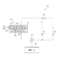
図1に示すように、亜酸化窒素濃度検出装置10は、センサ部20、第1電源31、第2電源32、スイッチ33、電流計40、及び制御ユニット50を備えている。
As shown in FIG. 1, the nitrous oxide
センサ部20は、ハウジング21、固体電解質22、検知電極23、基準電極24、及びヒータ25を備えている。ハウジング21は、直方体状に形成されており、内部に固体電解質22、検知電極23、基準電極24、及びヒータ25を収納している。ハウジング21の内部には、亜酸化窒素濃度の測定を行う測定室27が形成されている。測定室27には、一酸化窒素(NO)や亜酸化窒素(N2O)を含む測定対象ガスが導入される。
The
固体電解質22(電解質)は、酸素イオン導電性を有する酸化イットリア(Y2O3)安定化ジルコニア(YSZ)により、板状に形成されている。固体電解質22の主面(最も面積の大きい面)の一方には、検知電極23が取り付けられており、他方には基準電極24が取り付けられている。検知電極23(第1電極)は、白金(Pt)により板状に形成され、測定室27内に配置されている。基準電極24(第2電極)は、YSZにより板状に形成され、固体電解質22を介して検知電極23に接続されている。
The solid electrolyte 22 (electrolyte) is formed in a plate shape from yttria oxide (Y2O3) stabilized zirconia (YSZ) having oxygen ion conductivity. A
ヒータ25は、固体電解質22、検知電極23、及び基準電極24を加熱し、固体電解質22の温度を調節する。ヒータ25は、固体電解質22の温度が目標温度になるように、制御ユニット50により制御される。
The
固体電解質22、検知電極23、及び基準電極24で構成された素子部には、スイッチ33を介して第1電源31と第2電源32とが並列に接続されている。第1電源31は、検知電極23と基準電極24との間に、例えば0.2V(第1電圧)を印加する電源である。第1電源31の正極がスイッチ33を介して検知電極23に接続されており、第1電源31の負極が電流計40を介して基準電極24に接続されている。第2電源32は、検知電極23と基準電極24との間に、例えば0.5V(第2電圧)を印加する電源である。第2電源32の正極がスイッチ33を介して検知電極23に接続されており、第2電源32の負極が電流計40を介して基準電極24に接続されている。スイッチ33は、制御ユニット50により制御され、素子部に電圧を印加する電源を、第1電源31と第2電源32とで切り替える。なお、第1電源31、第2電源32、及びスイッチ33により、電圧印加部が構成されている。
A
電流計40(電流検出部)は、検知電極23と基準電極24との間に流れる電流(以下、「素子電流」という)を検出する。電流計40により検出された電流は、制御ユニット50に入力される。
The ammeter 40 (current detection unit) detects a current flowing between the
制御ユニット50は、CPU、ROM、RAM、記憶装置、及び入出力インターフェース等を備えるマイクロコンピュータにより構成されている。制御ユニット50は、固体電解質22のインピーダンスと温度との関係に基づいて、固体電解質22のインピーダンスが目標温度に対応するインピーダンスになるようにヒータ25を制御する。これにより、固体電解質22の温度(以下、「素子温度」という)が目標温度に維持される。制御ユニット50は、スイッチ33を切り替えることで、検知電極23と基準電極24との間に印加する電圧(以下、「印加電圧」という)を制御する。
The
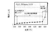
図2は、素子温度と素子電流との関係を示すグラフである。ここでは、亜酸化窒素の濃度が250ppmであり、印加電圧が0.5Vの場合について示している。 FIG. 2 is a graph showing the relationship between element temperature and element current. Here, the case where the concentration of nitrous oxide is 250 ppm and the applied voltage is 0.5 V is shown.
同図に示すように、素子温度が350℃よりも低くなると、亜酸化窒素が電気分解しにくくなり、素子電流が急激に低下している。素子温度が350℃以上になると、以下の反応式により亜酸化窒素が電気分解される。なお、O^2−は、酸素の二価のイオンを表す。 As shown in the figure, when the element temperature is lower than 350 ° C., nitrous oxide becomes difficult to be electrolyzed, and the element current sharply decreases. When the element temperature becomes 350 ° C. or higher, nitrous oxide is electrolyzed by the following reaction formula. O ^ 2- represents a divalent ion of oxygen.
N2O+2e→N2+O^2−
そして、O^2−が固体電解質22中を移動することにより、素子電流が流れる。素子温度が350〜450℃の範囲では、素子温度の上昇に伴って、素子電流が徐々に大きくなっている。素子温度が450℃よりも高くなると、亜酸化窒素が熱分解し始める。このため、素子電流が急激に増加している。素子温度が450℃よりも高い範囲では、亜酸化窒素の熱分解に起因する素子電流、すなわち亜酸化窒素の電気分解に起因しない電流により、素子電流が増加している。
N2O + 2e → N2 + O ^ 2-
Then, the element current flows when O 固体 2- moves in the
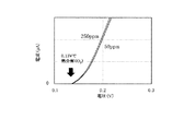
図3は、素子温度と分解電圧との関係を示すグラフである。ここでは、250ppmの亜酸化窒素と250ppmの一酸化窒素とについて示している。 FIG. 3 is a graph showing the relationship between the element temperature and the decomposition voltage. Here, 250 ppm of nitrous oxide and 250 ppm of nitric oxide are shown.
同図に示すように、素子温度が350℃よりも低くなると、亜酸化窒素が電気分解しにくくなり、亜酸化窒素の分解電圧が急激に上昇している。素子温度が350〜450℃の範囲では、素子温度の上昇に伴って、亜酸化窒素の分解電圧が徐々に低くなっている。素子温度が450℃よりも高くなると、亜酸化窒素が熱分解し始める。このため、素子温度が450℃よりも高い範囲では、亜酸化窒素の分解電圧が急激に低下している。一方、素子温度が340〜470℃の範囲において、素子温度の上昇に伴って、一酸化窒素の分解電圧が徐々に低くなっている。すなわち、素子温度が340〜470℃の範囲において、一酸化窒素は電気分解し易い状態になっている。一酸化窒素は、以下の反応式により電気分解される。 As shown in the figure, when the element temperature is lower than 350 ° C., the nitrous oxide is hardly electrolyzed, and the decomposition voltage of the nitrous oxide sharply increases. When the element temperature is in the range of 350 to 450 ° C., the decomposition voltage of nitrous oxide gradually decreases as the element temperature increases. When the element temperature becomes higher than 450 ° C., nitrous oxide starts to thermally decompose. For this reason, in the range where the element temperature is higher than 450 ° C., the decomposition voltage of nitrous oxide sharply decreases. On the other hand, when the element temperature is in the range of 340 to 470 ° C., the decomposition voltage of nitric oxide gradually decreases as the element temperature increases. That is, when the element temperature is in the range of 340 to 470 ° C., nitric oxide is in a state of being easily electrolyzed. Nitric oxide is electrolyzed by the following reaction formula.
2NO+4e→N2+2O^2−
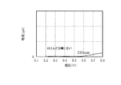
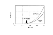
図4は、340℃での亜酸化窒素の印加電圧と素子電流との関係を示すグラフである。図5は、図4のA1部を拡大して示すグラフである。ここでは、亜酸化窒素の濃度が250ppmである場合について示している。
2NO + 4e → N2 + 2O ^ 2-
FIG. 4 is a graph showing the relationship between the applied voltage of nitrous oxide at 340 ° C. and the device current. FIG. 5 is a graph showing the A1 part of FIG. Here, the case where the concentration of nitrous oxide is 250 ppm is shown.
これらの図に示すように、素子温度が340℃の場合は、印加電圧を0.8Vまで高くしても、素子電流はほとんど流れていない。すなわち、素子温度が340℃の場合は、印加電圧を0.8Vまで高くしても、亜酸化窒素はほとんど電気分解していない。 As shown in these figures, when the element temperature is 340 ° C., almost no element current flows even if the applied voltage is increased to 0.8V. That is, when the element temperature is 340 ° C., nitrous oxide is hardly electrolyzed even when the applied voltage is increased to 0.8 V.
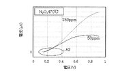
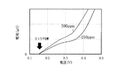
図6は、470℃での亜酸化窒素の印加電圧と素子電流との関係を示すグラフである。図7は、図6のA2部を拡大して示すグラフである。ここでは、亜酸化窒素の濃度が50ppm,250ppmである場合についてそれぞれ示している。 FIG. 6 is a graph showing the relationship between the applied voltage of nitrous oxide at 470 ° C. and the device current. FIG. 7 is a graph showing the A2 part of FIG. 6 in an enlarged manner. Here, the case where the concentration of nitrous oxide is 50 ppm and 250 ppm is shown.
これらの図に示すように、素子温度が470℃の場合は、亜酸化窒素の濃度が50ppm,250ppmのいずれにおいても、印加電圧が0.13Vよりも高くなると、素子電流が急激に増加している。すなわち、素子温度が470℃の場合は、印加電圧が0.13Vよりも高くなると、亜酸化窒素が熱分解している。 As shown in these figures, when the element temperature is 470 ° C., the element current sharply increases when the applied voltage becomes higher than 0.13 V regardless of the concentration of nitrous oxide at 50 ppm or 250 ppm. I have. That is, when the element temperature is 470 ° C., when the applied voltage is higher than 0.13 V, nitrous oxide is thermally decomposed.
以上により、図3に示すように、素子温度が350〜450℃の範囲においては、印加電圧を一酸化窒素の分解温度よりも高く亜酸化窒素の分解電圧よりも低い電圧(第1電圧)にすることで、一酸化窒素が電気分解し亜酸化窒素が電気分解しない第1状態にすることができる。そして、素子温度が350〜450℃の範囲においては、印加電圧を亜酸化窒素の分解電圧よりも高い電圧(第2電圧)にすることで、一酸化窒素及び亜酸化窒素が電気分解する第2状態にすることができる。さらに、素子温度が350〜450℃の範囲では、亜酸化窒素が熱分解しないため、印加電圧を亜酸化窒素の分解電圧よりも高くした場合に、一酸化窒素の電気分解及び亜酸化窒素の電気分解に起因しない素子電流が流れることを抑制することができる。したがって、本実施形態では、素子温度が350〜450℃の範囲を、亜酸化窒素濃度を検出する検出温度範囲(第1温度)とする。詳しくは、制御ユニット50は、素子温度を400℃(第1温度)にした状態で、亜酸化窒素濃度を検出する。
Thus, as shown in FIG. 3, when the element temperature is in the range of 350 to 450 ° C., the applied voltage is set to a voltage (first voltage) higher than the decomposition temperature of nitric oxide and lower than the decomposition voltage of nitrous oxide. By doing so, the first state can be achieved in which nitric oxide is electrolyzed and nitrous oxide is not electrolyzed. Then, when the element temperature is in the range of 350 to 450 ° C., the applied voltage is set to a voltage (second voltage) higher than the decomposition voltage of nitrous oxide, so that the nitric oxide and nitrous oxide are electrolyzed. State. Furthermore, when the element temperature is in the range of 350 to 450 ° C., nitrous oxide does not thermally decompose. Therefore, when the applied voltage is higher than the decomposition voltage of nitrous oxide, the electrolysis of nitric oxide and the It is possible to suppress the flow of the element current not caused by the decomposition. Therefore, in the present embodiment, a range in which the element temperature is 350 to 450 ° C. is set as a detection temperature range (first temperature) for detecting the concentration of nitrous oxide. Specifically, the
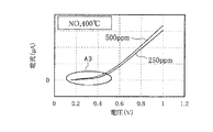
図8は、400℃での一酸化窒素の印加電圧と素子電流との関係を示すグラフである。図9は、図8のA3部を拡大して示すグラフである。ここでは、一酸化窒素の濃度が250ppm,500ppmである場合についてそれぞれ示している。 FIG. 8 is a graph showing the relationship between the applied voltage of nitric oxide at 400 ° C. and the device current. FIG. 9 is a graph showing the A3 part of FIG. 8 in an enlarged manner. Here, the case where the concentration of nitric oxide is 250 ppm and 500 ppm is shown.
これらの図に示すように、素子温度が400℃の場合は、亜酸化窒素の濃度が250ppm,500ppmのいずれにおいても、印加電圧が0.15Vよりも高くなると、素子電流が徐々に増加している。すなわち、素子温度が400℃の場合は、印加電圧が0.15Vよりも高くなると、一酸化窒素が電気分解している。 As shown in these figures, when the element temperature is 400 ° C., the element current gradually increases when the applied voltage becomes higher than 0.15 V regardless of the concentration of nitrous oxide at 250 ppm or 500 ppm. I have. That is, when the element temperature is 400 ° C., when the applied voltage is higher than 0.15 V, nitric oxide is electrolyzed.
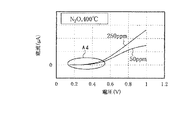
図10は、400℃での亜酸化窒素の印加電圧と素子電流との関係を示すグラフである。図11は、図10のA4部を拡大して示すグラフである。ここでは、亜酸化窒素の濃度が50ppm,250ppmである場合についてそれぞれ示している。 FIG. 10 is a graph showing the relationship between the applied voltage of nitrous oxide at 400 ° C. and the device current. FIG. 11 is a graph showing the A4 part of FIG. 10 in an enlarged manner. Here, the case where the concentration of nitrous oxide is 50 ppm and 250 ppm is shown.
これらの図に示すように、素子温度が400℃の場合は、亜酸化窒素の濃度が50ppm,250ppmのいずれにおいても、印加電圧が0.26Vよりも高くなると、素子電流が徐々に増加している。すなわち、素子温度が400℃の場合は、印加電圧が0.26Vよりも高くなると、亜酸化窒素が電気分解している。 As shown in these figures, when the device temperature is 400 ° C., the device current gradually increases when the applied voltage becomes higher than 0.26 V, regardless of the concentration of nitrous oxide, either 50 ppm or 250 ppm. I have. That is, when the element temperature is 400 ° C., when the applied voltage is higher than 0.26 V, nitrous oxide is electrolyzed.
したがって、素子温度が400℃の場合は、印加電圧を0.15〜0.26V(第1電圧)にすることで、一酸化窒素が電気分解し亜酸化窒素が電気分解しない第1状態にすることができる。また、素子温度が400℃の場合は、印加電圧を0.26よりも高くすることで、一酸化窒素及び亜酸化窒素が電気分解する第2状態にすることができる。 Therefore, when the element temperature is 400 ° C., by setting the applied voltage to 0.15 to 0.26 V (first voltage), a first state is obtained in which nitric oxide is electrolyzed and nitrous oxide is not electrolyzed. be able to. When the element temperature is 400 ° C., by setting the applied voltage higher than 0.26, the second state in which nitric oxide and nitrous oxide are electrolyzed can be achieved.
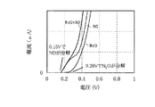
図12は、400℃での印加電圧と素子電流との関係を示すグラフである。図13は、図12のA5部を拡大して示すグラフである。ここでは、一酸化窒素及び亜酸化窒素の濃度がそれぞれ250ppmである場合について示している。図中において、「N2O」は亜酸化窒素の電気分解に起因する素子電流(N2O電流)を示しており、「NO」は一酸化窒素の電気分解に起因する素子電流(NO電流)を示している。図中において、「N2O+NO」はN2O電流とNO電流との合計電流を示している。また、図の上部に、各印加電圧の範囲において分解されるガスの種類を示している。 FIG. 12 is a graph showing the relationship between the applied voltage at 400 ° C. and the device current. FIG. 13 is a graph showing the A5 part of FIG. 12 in an enlarged manner. Here, the case where the concentrations of nitric oxide and nitrous oxide are 250 ppm is shown. In the figure, "N2O" indicates an element current (N2O current) caused by electrolysis of nitrous oxide, and "NO" indicates an element current (NO current) caused by electrolysis of nitric oxide. I have. In the figure, “N2O + NO” indicates the total current of the N2O current and the NO current. The upper part of the figure shows the types of gas decomposed in each applied voltage range.
これらの図に示すように、素子温度が400℃の場合は、印加電圧が0.15〜0.26Vの範囲において、一酸化窒素が電気分解され、亜酸化窒素が電気分解されない。このため、印加電圧が0.15〜0.26Vの範囲において、NO電流と合計電流とが一致している。印加電圧が0.26Vよりも高くなると、N2O電流が増加し始め、合計電流はNO電流とN2O電流との合計になるため、合計電流はNO電流よりも大きくなっている。素子温度が400℃の場合は、印加電圧が0.26Vよりも高い範囲において、一酸化窒素及び亜酸化窒素が電気分解される。 As shown in these figures, when the element temperature is 400 ° C., when the applied voltage is in the range of 0.15 to 0.26 V, nitric oxide is electrolyzed and nitrous oxide is not electrolyzed. Therefore, when the applied voltage is in the range of 0.15 to 0.26 V, the NO current matches the total current. When the applied voltage becomes higher than 0.26 V, the N2O current starts to increase, and the total current is the sum of the NO current and the N2O current, so that the total current is larger than the NO current. When the element temperature is 400 ° C., nitric oxide and nitrous oxide are electrolyzed in a range where the applied voltage is higher than 0.26 V.
ただし、図12に示すように、印加電圧が0.80Vよりも高くなると、水(H2O)が電気分解し始める。このため、印加電圧が0.80Vよりも高い範囲では、水の電気分解に起因する素子電流、すなわち一酸化窒素の電気分解及び亜酸化窒素の電気分解に起因しない素子電流が流れる。そこで、本実施形態では、素子温度を400℃にして、印加電圧を0.26〜0.8V(第2電圧)にすることで、一酸化窒素及び亜酸化窒素が電気分解する第2状態にする。詳しくは、制御ユニット50は、素子温度を400℃にして、印加電圧を0.50V(第2電圧)にすることで第2状態にする。
However, as shown in FIG. 12, when the applied voltage becomes higher than 0.80 V, water (H2O) starts to be electrolyzed. Therefore, when the applied voltage is higher than 0.80 V, an element current caused by the electrolysis of water, that is, an element current not caused by the electrolysis of nitric oxide and nitrous oxide flows. Thus, in the present embodiment, by setting the element temperature to 400 ° C. and setting the applied voltage to 0.26 to 0.8 V (second voltage), the second state in which nitric oxide and nitrous oxide are electrolyzed is set. I do. Specifically, the
一般に、素子温度を変化させて所定温度で安定させるために必要な時間は、印加電圧を変化させて所定電圧で安定させるために必要な時間よりも長い。そこで、本実施形態では、制御ユニット50は、ヒータ25を制御して素子温度を第1温度にし、スイッチ33を制御して印加電圧として第1電圧を印加させることで第1状態にする。そして、制御ユニット50は、ヒータ25を制御して素子温度を上記第1温度に維持し、スイッチ33を制御して印加電圧として第1電圧よりも高い第2電圧を印加させることで第2状態にする。
Generally, the time required to change the element temperature and stabilize at a predetermined temperature is longer than the time required to change the applied voltage and stabilize at a predetermined voltage. Therefore, in the present embodiment, the
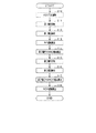
図14は、亜酸化窒素濃度検出の手順を示すフローチャートである。この一連の処理は、制御ユニット50により所定の周期で実行される。
FIG. 14 is a flowchart showing a procedure for detecting nitrous oxide concentration. This series of processing is executed by the
まず、ヒータ25を制御して素子温度を400℃に維持する(S10)。印加電圧として第1電圧を印加させる(S11)。詳しくは、スイッチ33を第1電源31に切り替えて、印加電圧として0.2Vを印加させる。続いて、電流計40により、第1電圧(第1状態)での素子電流として第1電流I1を検出させる(S12)。
First, the
続いて、第1電流I1に基づいて、一酸化窒素濃度D1を算出する(S13)。詳しくは、図15に示すように、一酸化窒素濃度と、第1電圧(0.2V)において一酸化窒素の電気分解に起因して流れる素子電流と、第2電圧(0.5V)において一酸化窒素の電気分解に起因して流れる素子電流と、の関係である第1関係が、予め設定されている。そこで、第1電圧において電流計40により検出された第1電流I1を第1関係に適用することにより、一酸化窒素濃度D1を算出する。なお、第1関係は、予め実験等に基づいて設定しておくことができる。
Subsequently, the concentration D1 of nitric oxide is calculated based on the first current I1 (S13). More specifically, as shown in FIG. 15, the concentration of nitric oxide, the element current flowing due to the electrolysis of nitric oxide at the first voltage (0.2 V), and the element current flowing at the second voltage (0.5 V) A first relation, which is a relation between the element current flowing due to the electrolysis of nitric oxide and the element current, is set in advance. Therefore, the nitrogen monoxide concentration D1 is calculated by applying the first current I1 detected by the
続いて、一酸化窒素濃度D1に基づいて、第2電圧(第2状態)でのNO電流Ie(推定電流)を推定する(S14)。詳しくは、図15に示すように、一酸化窒素濃度D1を第1関係に適用することにより、第2電圧(0.5V)でのNO電流Ieを推定する。 Subsequently, the NO current Ie (estimated current) at the second voltage (second state) is estimated based on the nitric oxide concentration D1 (S14). More specifically, as shown in FIG. 15, the NO current Ie at the second voltage (0.5 V) is estimated by applying the nitrogen monoxide concentration D1 to the first relation.
続いて、印加電圧として第2電圧を印加させる(S15)。詳しくは、スイッチ33を第2電源32に切り替えて、印加電圧として0.5Vを印加させる。続いて、電流計40により、第2電圧(第2状態)での素子電流として第2電流I2を検出させる(S16)。第2電流I2からNO電流Ieを引いて、第2電圧でのN2O電流I3(第3電流)を算出する(S17)。
Subsequently, a second voltage is applied as an applied voltage (S15). Specifically, the
続いて、第2電圧でのN2O電流I3に基づいて、亜酸化窒素濃度D2を算出する(S18)。詳しくは、図16に示すように、亜酸化窒素濃度と、第2電圧(0.5V)において亜酸化窒素の電気分解に起因して流れる素子電流と、の関係である第2関係が、予め設定されている。そこで、第2電圧でのN2O電流I3を第2関係に適用することにより、亜酸化窒素濃度D2を算出する。なお、第2関係は、予め実験等に基づいて設定しておくことができる。その後、この一連の処理を一旦終了する(END)。 Subsequently, the nitrous oxide concentration D2 is calculated based on the N2O current I3 at the second voltage (S18). Specifically, as shown in FIG. 16, the second relationship, which is the relationship between the nitrous oxide concentration and the element current flowing due to the electrolysis of nitrous oxide at the second voltage (0.5 V), is set in advance. Is set. Therefore, the N2O current I3 at the second voltage is applied to the second relation to calculate the nitrous oxide concentration D2. Note that the second relationship can be set in advance based on an experiment or the like. Thereafter, this series of processing is temporarily ended (END).
なお、S10及びS11の処理が第1制御部としての処理に相当し、S10及びS15の処理が第2制御部としての処理に相当し、S12〜S14の処理が推定部としての処理に相当し、S16〜S18の処理が算出部としての処理に相当する。 Note that the processing of S10 and S11 corresponds to processing as a first control unit, the processing of S10 and S15 corresponds to processing as a second control unit, and the processing of S12 to S14 corresponds to processing as an estimation unit. , S16 to S18 correspond to the processing as the calculating unit.
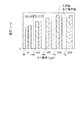
図17は、本実施形態と実測値とにおける各亜酸化窒素濃度に対する第2電圧でのN2O電流を示すグラフである。同図に示すように、各亜酸化窒素濃度において、本実施形態の第2電圧でのN2O電流と実測値の第2電圧でのN2O電流との差は、±8%以内になっている。すなわち、各亜酸化窒素濃度において、本実施形態は±8%以内の誤差で亜酸化窒素濃度を検出することができる。 FIG. 17 is a graph showing the N2O current at the second voltage with respect to each nitrous oxide concentration in the present embodiment and measured values. As shown in the figure, at each concentration of nitrous oxide, the difference between the N2O current at the second voltage of the present embodiment and the N2O current at the actually measured second voltage is within ± 8%. That is, for each nitrous oxide concentration, the present embodiment can detect the nitrous oxide concentration with an error within ± 8%.
以上詳述した本実施形態は、以下の利点を有する。 The present embodiment described above has the following advantages.
・第1状態において一酸化窒素の電気分解に起因して検知電極23と基準電極24との間に流れるNO電流と、第2状態において一酸化窒素の電気分解に起因して検知電極23と基準電極24との間に流れるNO電流とは、相関している。このため、推定部は、第1状態において電流計40により検出された第1電流I1に基づいて、第2状態において一酸化窒素の電気分解に起因して検知電極23と基準電極24との間に流れるNO電流Ieを推定することができる。
A NO current flowing between the
・第2状態において電流計40により検出された第2電流I2から、推定部により推定されたNO電流Ieを引いた第3電流I3は、第2状態において亜酸化窒素の電気分解に起因して検知電極23と基準電極24との間に流れるN2O電流に相当する。第3電流I3は一酸化窒素の電気分解に起因するNO電流を除いた電流であり、第3電流I3と亜酸化窒素濃度とは相関している。このため、一酸化窒素が存在する場合であっても、算出部は第3電流I3に基づいて亜酸化窒素濃度D2を正確に検出することができる。
The third current I3 obtained by subtracting the NO current Ie estimated by the estimator from the second current I2 detected by the
・第1制御部は、スイッチ33及びヒータ25を制御して、固体電解質22の温度を第1温度にし、検知電極23と基準電極24との間に第1電圧を印加させることで第1状態にする。第2制御部は、スイッチ33及びヒータ25を制御して、固体電解質22の温度を第1温度にし、検知電極23と基準電極24との間に第1電圧よりも高い第2電圧を印加させることで第2状態にする。このため、第1状態と第2状態とで、固体電解質22の温度を変化させる必要がなく、印加電圧を変化させればよいため、亜酸化窒素濃度D2の検出を短時間で行うことができる。
The first control unit controls the
・第1温度は、350〜450℃の範囲内で設定されている。したがって、一酸化窒素及び亜酸化窒素が電気分解する第2状態を実現することができるとともに、亜酸化窒素濃度D2の検出精度が低下することを抑制することができる。 -The first temperature is set within a range of 350 to 450 ° C. Therefore, a second state in which nitric oxide and nitrous oxide are electrolyzed can be realized, and a decrease in detection accuracy of the nitrous oxide concentration D2 can be suppressed.
・第1温度は400℃に設定されており、第1電圧は、0.15〜0.26Vの範囲内で設定されている。したがって、一酸化窒素が電気分解し亜酸化窒素が電気分解しない第1状態を実現することができる。 -The first temperature is set to 400 ° C, and the first voltage is set within a range of 0.15 to 0.26V. Therefore, a first state in which nitric oxide is electrolyzed and nitrous oxide is not electrolyzed can be realized.
・第1温度は400℃に設定されており、第2電圧は、0.26〜0.80Vの範囲内で設定されている。したがって、一酸化窒素及び亜酸化窒素が電気分解する第2状態を実現することができるとともに、亜酸化窒素濃度D2の検出精度が低下することを抑制することができる。 -The first temperature is set to 400 ° C, and the second voltage is set in the range of 0.26 to 0.80V. Therefore, a second state in which nitric oxide and nitrous oxide are electrolyzed can be realized, and a decrease in detection accuracy of the nitrous oxide concentration D2 can be suppressed.
・一酸化窒素の濃度と、第1状態において一酸化窒素の電気分解に起因して検知電極23と基準電極24との間に流れるNO電流と、第2状態において一酸化窒素の電気分解に起因して検知電極23と基準電極24との間に流れるNO電流と、の関係である第1関係が、予め設定されている。そして、推定部により、第1関係と、第1状態において電流計40により検出された第1電流I1とに基づいて、上記NO電流Ieが推定される。すなわち、第1状態において電流計40により検出された第1電流I1を第1関係に適用することにより、一酸化窒素濃度D1を算出することできる。そして、算出した一酸化窒素濃度D1を第1関係に適用することにより、第2状態において一酸化窒素の電気分解に起因して検知電極23と基準電極24との間に流れる電流、すなわちNO電流Ieを推定することができる。
The concentration of nitric oxide, the NO current flowing between the sensing
・亜酸化窒素濃度と、第2状態において亜酸化窒素の電気分解に起因して検知電極23と基準電極24との間に流れるN2O電流と、の関係である第2関係が、予め設定されている。そして、算出部により、第2関係と上記第3電流I3とに基づいて、亜酸化窒素濃度D2が算出される。すなわち、第2状態において亜酸化窒素の電気分解に起因して検知電極23と基準電極24との間に流れるN2O電流に相当する第3電流I3を第2関係に適用することにより、亜酸化窒素濃度D2を算出することできる。
A second relationship, which is a relationship between the nitrous oxide concentration and the N2O current flowing between the
なお、上記実施形態を、以下のように変更して実施することもできる。上記実施形態と同一の部分については、同一の符号を付すことにより説明を省略する。 The above embodiment can be modified and implemented as follows. The same parts as those in the above embodiment are denoted by the same reference numerals, and description thereof will be omitted.
・固体電解質22(電解質)を、酸素イオン導電性を有する酸化カルシウム(CaO)安定化ジルコニア(CSZ)により、板状に形成してもよい。この場合、検知電極23(第1電極)を白金(Pt)により板状に形成し、基準電極24(第2電極)をCSZと白金により板状に形成するとよい。 The solid electrolyte 22 (electrolyte) may be formed in a plate shape from calcium oxide (CaO) stabilized zirconia (CSZ) having oxygen ion conductivity. In this case, the detection electrode 23 (first electrode) may be formed in a plate shape using platinum (Pt), and the reference electrode 24 (second electrode) may be formed in a plate shape using CSZ and platinum.
・上記実施形態では、図15に示すように、一酸化窒素濃度と、第1状態(400℃、0.2V)において一酸化窒素の電気分解に起因して流れる素子電流と、第2状態(400℃、0.5V)において一酸化窒素の電気分解に起因して流れる素子電流と、の関係である第1関係を、グラフとして予め設定した。これに対して、第1関係を数式として、予め設定しておいてもよい。 In the above embodiment, as shown in FIG. 15, the concentration of nitric oxide, the element current flowing due to the electrolysis of nitric oxide in the first state (400 ° C., 0.2 V), and the second state ( (400 ° C., 0.5 V) and a device current flowing due to the electrolysis of nitric oxide were set in advance as a graph. On the other hand, the first relationship may be set in advance as a mathematical expression.
・上記実施形態では、図16に示すように、亜酸化窒素濃度と、第2状態(400℃、0.5V)において亜酸化窒素の電気分解に起因して流れる素子電流と、の関係である第2関係を、グラフとして予め設定した。これに対して、第2関係を数式として、予め設定しておいてもよい。 In the above embodiment, as shown in FIG. 16, the relationship between the concentration of nitrous oxide and the element current flowing due to the electrolysis of nitrous oxide in the second state (400 ° C., 0.5 V). The second relationship was set in advance as a graph. On the other hand, the second relationship may be set in advance as a mathematical expression.
・上記実施形態では、第1温度を400℃に設定し、第1電圧を、0.15〜0.26Vの範囲内で設定した。これに対して、350〜450℃の範囲内で第1温度を400℃以外の温度T1に設定し、第1電圧を温度T1に対応した電圧に設定してもよい。すなわち、第1温度を温度T1に設定し、第1電圧を、温度T1において一酸化窒素が電気分解し亜酸化窒素が電気分解しない電圧に設定してもよい。 -In the said embodiment, the 1st temperature was set to 400 degreeC and the 1st voltage was set in the range of 0.15-0.26V. On the other hand, the first temperature may be set to a temperature T1 other than 400 ° C. within the range of 350 to 450 ° C., and the first voltage may be set to a voltage corresponding to the temperature T1. That is, the first temperature may be set to the temperature T1, and the first voltage may be set to a voltage at which the nitric oxide is electrolyzed and the nitrous oxide is not electrolyzed at the temperature T1.
・上記実施形態では、第1温度を400℃に設定し、第2電圧を、0.26〜0.80Vの範囲内で設定した。これに対して、350〜450℃の範囲内で第1温度を400℃以外の温度T1に設定し、第2電圧を温度T1に対応した電圧に設定してもよい。すなわち、第1温度を温度T1に設定し、第2電圧を、温度T1において一酸化窒素及び亜酸化窒素が電気分解する電圧に設定してもよい。 -In the said embodiment, the 1st temperature was set to 400 degreeC and the 2nd voltage was set in the range of 0.26-0.80V. On the other hand, the first temperature may be set to a temperature T1 other than 400 ° C within the range of 350 to 450 ° C, and the second voltage may be set to a voltage corresponding to the temperature T1. That is, the first temperature may be set to the temperature T1, and the second voltage may be set to a voltage at which nitric oxide and nitrous oxide are electrolyzed at the temperature T1.
・上記実施形態では、第1制御部は、スイッチ33及びヒータ25を制御して、固体電解質22の温度を第1温度にし、検知電極23と基準電極24との間に第1電圧を印加させることで第1状態にした。そして、第2制御部は、スイッチ33及びヒータ25を制御して、固体電解質22の温度を第1温度にし、検知電極23と基準電極24との間に第1電圧よりも高い第2電圧を印加させることで第2状態にした。
In the above embodiment, the first control unit controls the
これに対して、第1制御部が上記同様に第1状態にし、第2制御部は、スイッチ33及びヒータ25を制御して、固体電解質22の温度を第1温度よりも高い第2温度にし、検知電極23と基準電極24との間に第1電圧を印加させることで第2状態にすることもできる。この場合、図3に示すように、例えば第1電圧を0.25Vに設定し、第1温度を、一酸化窒素の分解電圧が0.25Vよりも低く、亜酸化窒素の分解電圧が0.25Vよりも高くなる温度の範囲に設定すればよい。そして、第2温度を、亜酸化窒素の分解電圧が0.25Vよりも低くなる温度の範囲に設定すればよい。
On the other hand, the first controller sets the first state in the same manner as described above, and the second controller controls the
・上記実施形態では、第1電源31、第2電源32、及びスイッチ33により、電圧印加部を構成した。これに代えて、印加電圧を可変とする可変電圧電源を、電圧印加部として採用することもできる。そして、第1制御部が上記同様に第1状態にし、第2制御部は、スイッチ33及びヒータ25を制御して、固体電解質22の温度を第2温度にし、検知電極23と基準電極24との間に第2電圧を印加させることで第2状態にすることもできる。要するに、第1制御部は、一酸化窒素の分解電圧が第1電圧よりも低く、亜酸化窒素の分解電圧が第1電圧よりも高くなるように、第1温度及び第1電圧を設定すればよい。また、第2制御部は、一酸化窒素の分解電圧及び亜酸化窒素の分解電圧が第2電圧よりも低くなるように、第2温度及び第2電圧を設定すればよい。
In the above embodiment, the
・検知電極23(第1電極)と、固体電解質22(電解質)と、基準電極24(第2電極)と、電圧印加部と、ヒータ25とからなる組を2つ備え、制御ユニット50は、一方の組を第1状態にし、他方の組を第2状態にし、2つの組の動作結果から亜酸化窒素濃度を検出することもできる。こうした構成によれば、亜酸化窒素濃度検出装置は、第1状態と第2状態とを同時に実現することができ、亜酸化窒素濃度の検出を迅速に行うことができる。
-Two sets each including the detection electrode 23 (first electrode), the solid electrolyte 22 (electrolyte), the reference electrode 24 (second electrode), the voltage applying unit, and the
10…亜酸化窒素濃度検出装置、22…固体電解質、23…検知電極、24…基準電極、25…ヒータ、31…第1電源、32…第2電源、33…スイッチ、40…電流計、50…制御ユニット。
DESCRIPTION OF
Claims (8)
酸素イオン導電性を有する電解質(22)と、
前記電解質を介して前記第1電極に接続された第2電極(24)と、
前記第1電極と前記第2電極との間に電圧を印加する電圧印加部(31,32,33)と、
前記電解質を加熱するヒータ(25)と、
前記第1電極と前記第2電極との間に流れる電流を検出する電流検出部(40)と、
前記電圧印加部及び前記ヒータを制御する制御ユニット(50)と、
を備える亜酸化窒素濃度検出装置(10)であって、
前記制御ユニットは、
前記電圧印加部及び前記ヒータを制御して、一酸化窒素が電気分解し亜酸化窒素が電気分解しない第1状態にする第1制御部と、
前記電圧印加部及び前記ヒータを制御して、一酸化窒素及び亜酸化窒素が電気分解する第2状態にする第2制御部と、
前記第1状態において前記電流検出部により検出された第1電流に基づいて、前記第2状態において一酸化窒素の電気分解に起因して前記第1電極と前記第2電極との間に流れる推定電流を推定する推定部と、
前記第2状態において前記電流検出部により検出された第2電流から、前記推定部により推定された前記推定電流を引いた第3電流に基づいて、亜酸化窒素濃度を算出する算出部と、
を備える、亜酸化窒素濃度検出装置。 A first electrode (23);
An electrolyte having oxygen ion conductivity (22);
A second electrode (24) connected to the first electrode via the electrolyte;
A voltage application unit (31, 32, 33) for applying a voltage between the first electrode and the second electrode;
A heater (25) for heating the electrolyte;
A current detector (40) for detecting a current flowing between the first electrode and the second electrode;
A control unit (50) for controlling the voltage applying unit and the heater;
A nitrous oxide concentration detection device (10) comprising:
The control unit includes:
A first control unit that controls the voltage application unit and the heater to set a first state in which nitric oxide is electrolyzed and nitrous oxide is not electrolyzed;
A second control unit that controls the voltage application unit and the heater to make a second state in which nitric oxide and nitrous oxide are electrolyzed;
Estimating the flow between the first electrode and the second electrode due to the electrolysis of nitric oxide in the second state based on the first current detected by the current detection unit in the first state An estimator for estimating the current;
A calculating unit configured to calculate a nitrous oxide concentration based on a third current obtained by subtracting the estimated current estimated by the estimating unit from the second current detected by the current detecting unit in the second state;
A nitrous oxide concentration detection device comprising:
前記第2制御部は、前記電圧印加部及び前記ヒータを制御して、前記電解質の温度を前記第1温度にし、前記第1電極と前記第2電極との間に前記第1電圧よりも高い第2電圧を印加させることで前記第2状態にする、請求項1に記載の亜酸化窒素濃度検出装置。 The first control unit controls the voltage application unit and the heater to set the temperature of the electrolyte to a first temperature, and to apply a first voltage between the first electrode and the second electrode. Into the first state,
The second control unit controls the voltage application unit and the heater to set the temperature of the electrolyte to the first temperature, and is higher than the first voltage between the first electrode and the second electrode. The nitrous oxide concentration detection device according to claim 1, wherein the second state is established by applying a second voltage.
前記第1電圧は、0.15〜0.26Vの範囲内で設定されている、請求項2又は3に記載の亜酸化窒素濃度検出装置。 The first temperature is set to 400 ° C.,
4. The nitrous oxide concentration detection device according to claim 2, wherein the first voltage is set within a range of 0.15 to 0.26 V. 5.
前記第2電圧は、0.26〜0.80Vの範囲内で設定されている、請求項2〜4のいずれか1項に記載の亜酸化窒素濃度検出装置。 The first temperature is set to 400 ° C.,
5. The nitrous oxide concentration detection device according to claim 2, wherein the second voltage is set within a range of 0.26 to 0.80 V. 6.
Priority Applications (3)
| Application Number | Priority Date | Filing Date | Title |
|---|---|---|---|
| JP2018121025A JP7068943B2 (en) | 2018-06-26 | 2018-06-26 | Nitrous oxide concentration detector |
| US16/448,092 US11193907B2 (en) | 2018-06-26 | 2019-06-21 | Nitrous oxide concentration detector |
| DE102019116887.2A DE102019116887A1 (en) | 2018-06-26 | 2019-06-24 | NITROUS OXIDE CONCENTRATION DETECTOR |
Applications Claiming Priority (1)
| Application Number | Priority Date | Filing Date | Title |
|---|---|---|---|
| JP2018121025A JP7068943B2 (en) | 2018-06-26 | 2018-06-26 | Nitrous oxide concentration detector |
Publications (2)
| Publication Number | Publication Date |
|---|---|
| JP2020003264A true JP2020003264A (en) | 2020-01-09 |
| JP7068943B2 JP7068943B2 (en) | 2022-05-17 |
Family
ID=68886240
Family Applications (1)
| Application Number | Title | Priority Date | Filing Date |
|---|---|---|---|
| JP2018121025A Active JP7068943B2 (en) | 2018-06-26 | 2018-06-26 | Nitrous oxide concentration detector |
Country Status (3)
| Country | Link |
|---|---|
| US (1) | US11193907B2 (en) |
| JP (1) | JP7068943B2 (en) |
| DE (1) | DE102019116887A1 (en) |
Families Citing this family (2)
| Publication number | Priority date | Publication date | Assignee | Title |
|---|---|---|---|---|
| US11306669B1 (en) * | 2020-12-15 | 2022-04-19 | Caterpillar Inc. | System, apparatus, and method for controlling an engine system to account for varying fuel quality |
| US11480119B2 (en) * | 2020-12-15 | 2022-10-25 | Caterpillar Inc. | System, apparatus, and method for controlling an engine system to account for varying fuel quality |
Citations (6)
| Publication number | Priority date | Publication date | Assignee | Title |
|---|---|---|---|---|
| JPS62112050A (en) * | 1985-11-11 | 1987-05-23 | Fujikura Ltd | Method for measuring gas concentration using solid electrolyte oxygen sensor |
| JPH11148916A (en) * | 1997-11-14 | 1999-06-02 | Riken Corp | Gas sensor |
| JP2000121607A (en) * | 1998-10-16 | 2000-04-28 | Varta Geraetebatterie Gmbh | Method and device for measuring o2 and n2o in gas mixture |
| JP2002031619A (en) * | 2000-07-17 | 2002-01-31 | Riken Corp | Nitrous oxide gas sensor |
| JP2014215116A (en) * | 2013-04-24 | 2014-11-17 | トヨタ自動車株式会社 | Exhaust gas component detector |
| JP2016095283A (en) * | 2014-11-17 | 2016-05-26 | 一般財団法人ファインセラミックスセンター | Nitrogen oxide responsive element and method for producing the same |
Family Cites Families (2)
| Publication number | Priority date | Publication date | Assignee | Title |
|---|---|---|---|---|
| JPS5991358A (en) | 1982-11-16 | 1984-05-26 | Fuji Electric Corp Res & Dev Ltd | Nitrous gas sensor |
| JP4475587B2 (en) | 2005-03-31 | 2010-06-09 | 九州電力株式会社 | Nitrous oxide gas sensor |
-
2018
- 2018-06-26 JP JP2018121025A patent/JP7068943B2/en active Active
-
2019
- 2019-06-21 US US16/448,092 patent/US11193907B2/en active Active
- 2019-06-24 DE DE102019116887.2A patent/DE102019116887A1/en not_active Withdrawn
Patent Citations (6)
| Publication number | Priority date | Publication date | Assignee | Title |
|---|---|---|---|---|
| JPS62112050A (en) * | 1985-11-11 | 1987-05-23 | Fujikura Ltd | Method for measuring gas concentration using solid electrolyte oxygen sensor |
| JPH11148916A (en) * | 1997-11-14 | 1999-06-02 | Riken Corp | Gas sensor |
| JP2000121607A (en) * | 1998-10-16 | 2000-04-28 | Varta Geraetebatterie Gmbh | Method and device for measuring o2 and n2o in gas mixture |
| JP2002031619A (en) * | 2000-07-17 | 2002-01-31 | Riken Corp | Nitrous oxide gas sensor |
| JP2014215116A (en) * | 2013-04-24 | 2014-11-17 | トヨタ自動車株式会社 | Exhaust gas component detector |
| JP2016095283A (en) * | 2014-11-17 | 2016-05-26 | 一般財団法人ファインセラミックスセンター | Nitrogen oxide responsive element and method for producing the same |
Non-Patent Citations (1)
| Title |
|---|
| 清水 陽一 外4名: "酸化物電極と固体電解質を用いた全固体型NOxセンサの応答特性", 日本化学会講演予稿集, vol. 85,1, JPN6022012567, 2005, pages 468, ISSN: 0004742039 * |
Also Published As
| Publication number | Publication date |
|---|---|
| JP7068943B2 (en) | 2022-05-17 |
| US20190391108A1 (en) | 2019-12-26 |
| DE102019116887A1 (en) | 2020-01-02 |
| US11193907B2 (en) | 2021-12-07 |
| DE102019116887A9 (en) | 2020-02-27 |
Similar Documents
| Publication | Publication Date | Title |
|---|---|---|
| JP3843881B2 (en) | Gas concentration sensor heater control device | |
| JP5074358B2 (en) | Gas sensor control device and nitrogen oxide concentration detection method | |
| JP4375236B2 (en) | Exhaust gas sensor deterioration detection device | |
| US11035821B2 (en) | Gas concentration detection apparatus | |
| US9297778B2 (en) | Sensor control apparatus, sensor control system, and sensor control method | |
| JP3880507B2 (en) | Gas concentration detector | |
| JP5119304B2 (en) | Gas sensor control device and gas sensor control method | |
| JP5465263B2 (en) | NOx sensor control device | |
| US7872480B2 (en) | Gas sensor control apparatus | |
| CN110609073B (en) | Gas sensor and gas concentration measuring method | |
| JP7043437B2 (en) | Oxygen measuring device and oxygen measuring method | |
| JP6561719B2 (en) | Gas sensor | |
| JP7068943B2 (en) | Nitrous oxide concentration detector | |
| JP2013148358A (en) | Method for setting correction coefficient in gas concentration detector, gas concentration detector, and gas sensor | |
| US20220074884A1 (en) | Gas sensor | |
| JP5189537B2 (en) | Gas sensor and method for controlling electrode potential of gas sensor | |
| US20190107505A1 (en) | Sensor control device and sensor unit | |
| JP5711836B2 (en) | NOx concentration detection device and detection method thereof | |
| JP4715927B2 (en) | Exhaust gas sensor deterioration detection device | |
| JP2010008121A (en) | Sensor output processor and sensor output processing system | |
| JP2004205357A (en) | Detection method of gas concentration | |
| US20200116665A1 (en) | Gas sensor | |
| JP6889079B2 (en) | Sensor control device | |
| JP2010266358A (en) | Nox sensor control device and nox sensor control method | |
| JP5126886B2 (en) | Gas concentration detector |
Legal Events
| Date | Code | Title | Description |
|---|---|---|---|
| A621 | Written request for application examination |
Free format text: JAPANESE INTERMEDIATE CODE: A621 Effective date: 20210317 |
|
| A977 | Report on retrieval |
Free format text: JAPANESE INTERMEDIATE CODE: A971007 Effective date: 20220221 |
|
| TRDD | Decision of grant or rejection written | ||
| A01 | Written decision to grant a patent or to grant a registration (utility model) |
Free format text: JAPANESE INTERMEDIATE CODE: A01 Effective date: 20220405 |
|
| A61 | First payment of annual fees (during grant procedure) |
Free format text: JAPANESE INTERMEDIATE CODE: A61 Effective date: 20220502 |
|
| R150 | Certificate of patent or registration of utility model |
Ref document number: 7068943 Country of ref document: JP Free format text: JAPANESE INTERMEDIATE CODE: R150 |