JP2020003230A - Resolver - Google Patents

Resolver Download PDF

Info

Publication number
JP2020003230A
JP2020003230A JP2018120170A JP2018120170A JP2020003230A JP 2020003230 A JP2020003230 A JP 2020003230A JP 2018120170 A JP2018120170 A JP 2018120170A JP 2018120170 A JP2018120170 A JP 2018120170A JP 2020003230 A JP2020003230 A JP 2020003230A
Authority
JP
Japan
Prior art keywords
resolver
coil
rotor
core
stator core
Prior art date
Legal status (The legal status is an assumption and is not a legal conclusion. Google has not performed a legal analysis and makes no representation as to the accuracy of the status listed.)
Granted
Application number
JP2018120170A
Other languages
Japanese (ja)
Other versions
JP7118766B2 (en
Inventor
山本 繁
Shigeru Yamamoto
繁 山本
康之 ▲高▼森
康之 ▲高▼森
Yasuyuki Takamori
正章 井川
Masaaki Igawa
正章 井川
Current Assignee (The listed assignees may be inaccurate. Google has not performed a legal analysis and makes no representation or warranty as to the accuracy of the list.)
Mabuchi Motor Co Ltd
Original Assignee
Mabuchi Motor Co Ltd
Priority date (The priority date is an assumption and is not a legal conclusion. Google has not performed a legal analysis and makes no representation as to the accuracy of the date listed.)
Filing date
Publication date
Application filed by Mabuchi Motor Co Ltd filed Critical Mabuchi Motor Co Ltd
Priority to JP2018120170A priority Critical patent/JP7118766B2/en
Publication of JP2020003230A publication Critical patent/JP2020003230A/en
Application granted granted Critical
Publication of JP7118766B2 publication Critical patent/JP7118766B2/en
Active legal-status Critical Current
Anticipated expiration legal-status Critical

Links

Images

Abstract

To provide a resolver capable of effectively improving detection accuracy of a rotational position of a rotor and achieving downsizing and lower cost.SOLUTION: A resolver comprises: a resolver stator core 25; a resolver rotor core 42 facing the resolver stator core 25 in a rotational axis direction; a stator transformer coil and an excitation coil provided in the resolver stator core 25; and a rotor transformer coil and a detection coil provided in the resolver rotor core 42. At least a slit 38 or 39 having higher electric resistance than the resolver stator core 25 and the resolver rotor core 42 and blocking a flow of an eddy current is provided in at least the resolver stator core 25 or the resolver rotor core 42 and in a region overlapping a part of the location in which at least the stator transformer coil, the rotor transformer coil, the excitation coil, and the detection coil are arranged.SELECTED DRAWING: Figure 4

Description

本発明は、レゾルバに関するものである。   The present invention relates to a resolver.

例えば、ブラシレスモータは、ロータの回転位置を検出し、この検出結果に基づいてステータに供給する電流の制御を行う。ロータの回転位置を検出する手段として、例えば、レゾルバが用いられる。レゾルバの中でも、いわゆるシートコイル型レゾルバと称されるものがある。このものは、モータケース等に固定される板状のステータコアと、ロータの回転軸に固定され、ステータコアと軸方向で対向する板状のロータコアと、を備えている。   For example, a brushless motor detects the rotational position of a rotor and controls the current supplied to the stator based on the detection result. As a means for detecting the rotational position of the rotor, for example, a resolver is used. Among the resolvers, there is a so-called sheet coil type resolver. This includes a plate-shaped stator core fixed to a motor case or the like, and a plate-shaped rotor core fixed to a rotating shaft of a rotor and facing the stator core in the axial direction.

ステータコアのロータコアとの対向面には、径方向中央に配置されたステータトランスコイルと、ステータトランスコイルの周囲を取り囲むように、このステータトランスコイルと同心円上に配置された励磁コイル(レゾルバステータコイル部)と、が設けられている。ステータトランスコイルと励磁コイルとは、電気的に遮断されている。   On the surface of the stator core facing the rotor core, a stator transformer coil disposed at the center in the radial direction and an exciting coil (resolver stator coil portion) disposed concentrically with the stator transformer coil so as to surround the stator transformer coil. ) And are provided. The stator transformer coil and the excitation coil are electrically disconnected.

一方、ロータコアのステータコアとの対向面には、径方向中央に配置され、ステータトランスコイルと軸方向で対向するロータトランスコイルと、ロータトランスコイルの周囲を取り囲むように、このロータトランスコイルと同心円上に配置された検出コイル(レゾルバロータコイル)と、が設けられている。ロータトランスコイルと検出コイルとは、直列に接続されている。   On the other hand, on the surface of the rotor core facing the stator core, the rotor transformer coil is disposed at the center in the radial direction, and faces the stator transformer coil in the axial direction. And a detection coil (resolver rotor coil) disposed at the same position. The rotor transformer coil and the detection coil are connected in series.

このような構成のもと、外部電力により励磁コイルに高周波の入力信号(電圧)を印可して交番電流を流すとステータに交番磁束が発生する。この交番磁束により、検出コイルに誘起電圧が生じ(電磁誘導が生じ)、交番電流が流れる。この交番電流は、ロータトランスコイルへと供給され、ロータトランスコイルが設けられている箇所に交番磁束が発生する。この交番磁束により、ステータトランスコイルに誘起電圧が生じる。   In such a configuration, when a high-frequency input signal (voltage) is applied to the exciting coil by external power and an alternating current flows, an alternating magnetic flux is generated in the stator. Due to this alternating magnetic flux, an induced voltage is generated in the detection coil (electromagnetic induction is generated), and an alternating current flows. This alternating current is supplied to the rotor transformer coil, and an alternating magnetic flux is generated at a position where the rotor transformer coil is provided. The alternating magnetic flux generates an induced voltage in the stator transformer coil.

ここで、ロータが回転することにより、励磁コイルに印加する入力信号と、ステータトランスコイルの出力信号(電圧)に位相差が生じる。この位相差を検出することにより、ロータの回転位置を検出することができる。   Here, the rotation of the rotor causes a phase difference between the input signal applied to the excitation coil and the output signal (voltage) of the stator transformer coil. By detecting this phase difference, the rotational position of the rotor can be detected.

同一のコア上で励磁コイルとステータトランスコイルを形成すると、励磁コイルで生じた交番磁束がステータトランスコイルに影響する。この影響を抑えるため、励磁コイルとステータトランスコイルの間のコアに、隙間を設ける従来技術が開示されている。   When the exciting coil and the stator transformer coil are formed on the same core, the alternating magnetic flux generated in the exciting coil affects the stator transformer coil. In order to suppress this effect, a conventional technique has been disclosed in which a gap is provided in a core between an excitation coil and a stator transformer coil.

特開2011−17584号公報JP 2011-17584 A

ところで、励磁コイルで交番磁束を生じさせると、その磁束変化に伴って励磁コイル周囲のステータコアに渦電流が生じる。また、励磁コイルの交番磁束は、対向する検出コイルを通るため、ロータコアの検出コイルの周囲のロータコアにも渦電流を生じる。さらに、検出コイルに直列接続されているロータトランスコイルに生じた交番磁束によって、ロータトランスコイルの周囲のロータコア、及びロータトランスコイルと対向するステータトランスコイルの周囲のステータコアにも渦電流が生じる。これらの渦電流は、コイルに生じる電流変化を妨げる向きに磁束が生じる。このため、励磁コイルやロータトランスコイルで発生させたい交番磁束や、検出コイルで生じる電流を低減させてしまう。その結果としてステータトランスコイルから得られる出力信号を減衰させる。   By the way, when an alternating magnetic flux is generated in the exciting coil, an eddy current is generated in the stator core around the exciting coil with the change in the magnetic flux. Further, since the alternating magnetic flux of the excitation coil passes through the opposed detection coil, an eddy current also occurs in the rotor core around the detection coil of the rotor core. Further, an eddy current is generated in the rotor core around the rotor transformer coil and the stator core around the stator transformer coil facing the rotor transformer coil due to the alternating magnetic flux generated in the rotor transformer coil connected in series to the detection coil. These eddy currents generate a magnetic flux in a direction that hinders a current change occurring in the coil. For this reason, the alternating magnetic flux desired to be generated by the excitation coil and the rotor transformer coil and the current generated by the detection coil are reduced. As a result, the output signal obtained from the stator transformer coil is attenuated.

上述の従来技術にあっては、励磁コイルとステータトランスコイルとの間に隙間を設け、両者を磁気的に分離することで、共通コア(ステータコア)を介して磁束が干渉しないという点では優れているが、各コイルの周囲のコアに生じる渦電流の影響を抑制することができない。このため、この渦電流に起因して、励磁コイルやロータトランスコイルで発生させる交番磁束が減少してしまい、信号が弱まることで、ロータの回転位置の検出精度を向上できない可能性があった。   The above-described prior art is excellent in that a gap is provided between the exciting coil and the stator transformer coil and both are magnetically separated, so that magnetic flux does not interfere via a common core (stator core). However, the influence of the eddy current generated in the core around each coil cannot be suppressed. For this reason, due to the eddy current, the alternating magnetic flux generated in the excitation coil and the rotor transformer coil is reduced, and the signal is weakened, so that the detection accuracy of the rotational position of the rotor may not be improved.

また、上述の従来技術において、励磁コイル及び検出コイルが設けられているコアと、各トランスコイルが設けられているコアとを磁気的に分離するために、各コアに設ける溝やスリットの幅の大きさを、十分な大きさに設定する必要がある。この分、レゾルバが大型化してしまったり、製造コストが増大したりする可能性があった。   Further, in the above-described conventional technology, in order to magnetically separate the core provided with the excitation coil and the detection coil from the core provided with each transformer coil, the width of the groove or slit provided in each core is reduced. The size needs to be set to a sufficient size. Accordingly, there is a possibility that the resolver becomes large and the manufacturing cost increases.

そこで、本発明は、ロータの回転位置の検出精度を効果的に向上でき、かつ小型化、低コスト化を図ることができるレゾルバを提供する。   Therefore, the present invention provides a resolver that can effectively improve the accuracy of detecting the rotational position of the rotor, and can reduce the size and cost.

上記の課題を解決するために、本発明に係るレゾルバは、ステータコアと、前記ステータコアに対して回転可能に設けられ、回転軸線方向で前記ステータコアと対向するロータコアと、前記ステータコアに設けられた第1トランスコイルと、前記ロータコアに設けられ、前記第1トランスコイルと対向する第2トランスコイルと、前記ステータコアに設けられ前記第1トランスコイルと同心円上に設けられた励磁コイルと、前記ロータコアに設けられ、かつ前記励磁コイルと対向する検出コイルと、を備え、前記ステータコア、及び前記ロータコアの少なくともいずれか一方で、かつ少なくとも前記第1トランスコイル、前記第2トランスコイル、前記励磁コイル、及び前記検出コイルが配置されている箇所の一部に重なる領域に、前記ステータコア、及び前記ロータコアよりも電気抵抗が高く、渦電流の流れを阻害する抵抗部が少なくとも1つ設けられていることを特徴とする。   In order to solve the above problems, a resolver according to the present invention includes a stator core, a rotor core rotatably provided with respect to the stator core, and a rotor core facing the stator core in a rotation axis direction, and a first core provided on the stator core. A transformer coil, a second transformer coil provided on the rotor core and facing the first transformer coil, an exciting coil provided on the stator core and provided concentrically with the first transformer coil, and a second transformer coil provided on the rotor core. And a detection coil facing the excitation coil, and at least one of the stator core and the rotor core, and at least the first transformer coil, the second transformer coil, the excitation coil, and the detection coil. In the area that partially overlaps the place where Stator core, and the higher electrical resistance than the rotor core, the resistance unit that inhibits the flow of eddy currents, characterized in that it is provided at least one.

このように、ステータコア、及びロータコアの少なくともいずれか一方に前記抵抗部を設けることにより、ステータコア、又はロータコアに生じる渦電流の大きさを小さくすることができる。このため、渦電流に起因して、各トランスコイル、励磁コイル、及び検出コイルの少なくともいずれかのコイルで形成される交番磁束が減少してしまうことを抑制できる。よって、ロータの回転位置の検出精度を効果的に向上できる。   As described above, by providing the resistance portion on at least one of the stator core and the rotor core, the magnitude of the eddy current generated in the stator core or the rotor core can be reduced. For this reason, it is possible to suppress a decrease in the alternating magnetic flux formed by at least one of the transformer coil, the exciting coil, and the detection coil due to the eddy current. Therefore, the detection accuracy of the rotational position of the rotor can be effectively improved.

本発明に係るレゾルバにおいて、前記抵抗部は、前記ロータコアの回転軸線方向に直交する径方向に沿って形成されていることを特徴とする。
また、前記抵抗部は、前記ロータコアの回転方向に沿うように、回転軸線方向からみて湾曲形成されていてもよい。
In the resolver according to the present invention, the resistance portion is formed along a radial direction orthogonal to a rotation axis direction of the rotor core.
Further, the resistance portion may be curved so as to be along a rotation direction of the rotor core when viewed from a rotation axis direction.

このように構成することで、抵抗部によって、各コアのいずれかに生じる渦電流を効果的に減少できる。このため、確実にロータの回転位置の検出精度を向上できる。   With such a configuration, the eddy current generated in any of the cores can be effectively reduced by the resistance portion. For this reason, the detection accuracy of the rotational position of the rotor can be reliably improved.

本発明に係るレゾルバにおいて、前記ステータコア、及び前記ロータコアは、板状に形成されており、前記抵抗部は、前記ステータコア、及び前記ロータコアの少なくともいずれかに形成されたスリットであることを特徴とする。
また、前記抵抗部は、前記ステータコア、及び前記ロータコアの少なくともいずれかに形成された凹部であってもよい。
In the resolver according to the present invention, the stator core and the rotor core are formed in a plate shape, and the resistance portion is a slit formed in at least one of the stator core and the rotor core. .
Further, the resistance portion may be a concave portion formed in at least one of the stator core and the rotor core.

このように、凹部やスリットのような簡素な構造で抵抗部を形成することができる。このため、レゾルバの製造コストをさらに低減できる。   In this manner, the resistance portion can be formed with a simple structure such as a concave portion or a slit. Therefore, the manufacturing cost of the resolver can be further reduced.

本発明によれば、ステータコア、及びロータコアの少なくともいずれか一方に前記抵抗部を設けることにより、ステータコア、又はロータコアに生じる渦電流の大きさを小さくすることができる。このため、渦電流に起因して、各トランスコイル、励磁コイル、及び検出コイルの少なくともいずれかのコイルで形成される交番磁束が減少してしまうことを抑制できる。よって、ロータの回転位置の検出精度を効果的に向上できる。   According to the present invention, the magnitude of the eddy current generated in the stator core or the rotor core can be reduced by providing the resistance portion in at least one of the stator core and the rotor core. For this reason, it is possible to suppress a decrease in the alternating magnetic flux formed by at least one of the transformer coil, the exciting coil, and the detection coil due to the eddy current. Therefore, the detection accuracy of the rotational position of the rotor can be effectively improved.

本発明の第1実施形態におけるブラシレスモータの軸方向に沿う断面図である。FIG. 2 is a cross-sectional view along the axial direction of the brushless motor according to the first embodiment of the present invention. 図1のA部拡大図である。It is the A section enlarged view of FIG. 本発明の第1実施形態における励磁コイルの形成パターンを、図2における矢印Y方向からみた平面図であって、(a)は、第2絶縁シートの表面を示し、(b)は、第2絶縁シートの裏面を示している。FIGS. 3A and 3B are plan views of a formation pattern of an exciting coil according to the first embodiment of the present invention, as viewed in a direction indicated by an arrow Y in FIG. 2, wherein FIG. The back surface of the insulating sheet is shown. 本発明の第1実施形態におけるレゾルバステータコアを軸方向からみた平面図である。It is the top view which looked at the resolver stator core in a 1st embodiment of the present invention from the direction of an axis. 本発明の第1実施形態におけるレゾルバステータコア上に、ステータトランスコイル、及びsin励磁コイルを投影した図である。It is the figure which projected the stator transformer coil and the sine excitation coil on the resolver stator core in 1st Embodiment of this invention. 本発明の第1実施形態における第3絶縁シートの表面側を図2における矢印Y方向からみた平面図である。FIG. 3 is a plan view of a front surface side of a third insulating sheet according to the first embodiment of the present invention when viewed from a direction of an arrow Y in FIG. 2. 本発明の第1実施形態におけるレゾルバステータコア、及びレゾルバロータコアの一部拡大図である。It is a partial enlarged view of a resolver stator core and a resolver rotor core in the first embodiment of the present invention. 本発明の第1実施形態の変形例におけるレゾルバステータコア、及びレゾルバロータコアを軸方向からみた平面図である。It is the top view which looked at the resolver stator core and the resolver rotor core in the modification of a 1st embodiment of the present invention from the direction of an axis. 本発明の第1実施形態の変形例におけるレゾルバステータコア、及びレゾルバロータコアを軸方向からみた平面図である。It is the top view which looked at the resolver stator core and the resolver rotor core in the modification of a 1st embodiment of the present invention from the direction of an axis. 本発明の第1実施形態の変形例におけるレゾルバステータコア、及びレゾルバロータコアを軸方向からみた平面図である。It is the top view which looked at the resolver stator core and the resolver rotor core in the modification of a 1st embodiment of the present invention from the direction of an axis. 本発明の第1実施形態の変形例におけるレゾルバステータコア上に、ステータトランスコイル、及びsin励磁コイルを投影した図である。It is the figure which projected the stator transformer coil and the sine excitation coil on the resolver stator core in the modification of 1st Embodiment of this invention. 本発明の第1実施形態の変形例におけるレゾルバステータコア、及びレゾルバロータコアを軸方向からみた平面図である。It is the top view which looked at the resolver stator core and the resolver rotor core in the modification of a 1st embodiment of the present invention from the direction of an axis. 本発明の第1実施形態の変形例におけるレゾルバステータコア、及びレゾルバロータコアを軸方向からみた平面図である。It is the top view which looked at the resolver stator core and the resolver rotor core in the modification of a 1st embodiment of the present invention from the direction of an axis. 本発明の第2実施形態におけるレゾルバステータコア、及びレゾルバロータコアを軸方向からみた平面図である。It is the top view which looked at the resolver stator core and the resolver rotor core in a 2nd embodiment of the present invention from the direction of an axis. 本発明の第2実施形態の変形例におけるレゾルバステータコア、及びレゾルバロータコアを軸方向からみた平面図である。It is the top view which looked at the resolver stator core and the resolver rotor core in the modification of a 2nd embodiment of the present invention from the direction of an axis. 本発明の第2実施形態の変形例におけるレゾルバステータコア、及びレゾルバロータコアを軸方向からみた平面図である。It is the top view which looked at the resolver stator core and the resolver rotor core in the modification of a 2nd embodiment of the present invention from the direction of an axis. 本発明の第2実施形態の変形例におけるレゾルバステータコア、及びレゾルバロータコアを軸方向からみた平面図である。It is the top view which looked at the resolver stator core and the resolver rotor core in the modification of a 2nd embodiment of the present invention from the direction of an axis. 本発明の実施形態の変形例におけるステータトランスコイルを図2における矢印Y方向からみた平面図である。It is the top view which looked at the stator transformer coil in the modification of the embodiment of the present invention from arrow Y in FIG. 本発明の実施形態の変形例におけるロータトランスコイル、及び検出コイルを図2における矢印Y方向からみた平面図である。It is the top view which looked at the rotor transformer coil and the detection coil in the modification of embodiment of this invention from arrow Y direction in FIG.

次に、本発明の実施形態を図面に基づいて説明する。   Next, an embodiment of the present invention will be described with reference to the drawings.

(第1実施形態)
(ブラシレスモータ)
図1は、本発明に係るレゾルバ6が設けられたブラシレスモータ1の軸方向に沿う断面図である。
図1に示すように、ブラシレスモータ1は、略有底筒状のモータケース2と、モータケース2の開口部2aを閉塞する略円板状のブラケット3と、モータケース2内に収納されているモータステータ4と、モータステータ4に対して回転自在に設けられたモータロータ5と、モータロータ5の回転位置を検出するレゾルバ6と、を備えている。
なお、以下の説明では、モータロータ5の回転軸線方向を単に軸方向、モータロータ5の回転方向を周方向、軸方向及び周方向に直交するモータロータ5の径方向を単に径方向、と称する。
(1st Embodiment)
(Brushless motor)
FIG. 1 is a cross-sectional view along the axial direction of a brushless motor 1 provided with a resolver 6 according to the present invention.
As shown in FIG. 1, the brushless motor 1 includes a substantially bottomed cylindrical motor case 2, a substantially disk-shaped bracket 3 for closing an opening 2 a of the motor case 2, and a brushless motor 1 housed in the motor case 2. A motor stator 4, a motor rotor 5 rotatably provided with respect to the motor stator 4, and a resolver 6 for detecting a rotational position of the motor rotor 5.
In the following description, the rotation axis direction of the motor rotor 5 is simply referred to as an axial direction, the rotation direction of the motor rotor 5 is referred to as a circumferential direction, and the radial direction of the motor rotor 5 orthogonal to the axial direction and the circumferential direction is simply referred to as a radial direction.

モータケース2の周壁2bには、内周面に、モータステータ4の外周面が嵌合固定されている。また、モータケース2の底壁2cには、径方向略中央に、モータステータ4側に向かって突出する軸受ハウジング7が設けられている。この軸受ハウジング7に、モータロータ5の回転軸13の一端13a側(図1における下側)を回転自在に支持するための軸受8が設けられている。   The outer peripheral surface of the motor stator 4 is fitted and fixed to the inner peripheral surface of the peripheral wall 2 b of the motor case 2. A bearing housing 7 projecting toward the motor stator 4 is provided substantially at the center of the bottom wall 2c of the motor case 2 in the radial direction. This bearing housing 7 is provided with a bearing 8 for rotatably supporting the one end 13a side (the lower side in FIG. 1) of the rotating shaft 13 of the motor rotor 5.

モータステータ4は、略円筒状のモータステータコア9を有している。このモータステータコア9の外周面が、モータケース2の周壁2bの内周面に嵌合されている。モータステータコア9は、プレス加工によって略環状に打ち抜いた金属板(電磁鋼板)を軸方向に積層してなる。しかしながら、モータステータコア9を、軟磁性粉を加圧成形して形成することも可能である。   The motor stator 4 has a substantially cylindrical motor stator core 9. The outer peripheral surface of the motor stator core 9 is fitted to the inner peripheral surface of the peripheral wall 2b of the motor case 2. The motor stator core 9 is formed by laminating metal plates (electromagnetic steel plates) punched out in a substantially annular shape by press working in the axial direction. However, it is also possible to form the motor stator core 9 by pressing soft magnetic powder.

モータステータコア9の内周面には、径方向内側に向かって突出する複数のティース10が周方向に並んで形成されている。これらティース10には、コイル10aが巻回されている。各コイル10aの端末部は、制御部を介して外部電源(いずれも不図示)に電気的に接続される。そして、不図示の制御部によって、各コイル10aに選択的に電流が供給される。各コイル10aに電流が供給されると、モータステータ4に所望の磁束が形成される。   A plurality of teeth 10 projecting radially inward are formed on the inner circumferential surface of the motor stator core 9 so as to be arranged in the circumferential direction. These teeth 10 are wound with coils 10a. The terminal of each coil 10a is electrically connected to an external power supply (both not shown) via a control unit. Then, a current is selectively supplied to each coil 10a by a control unit (not shown). When a current is supplied to each coil 10a, a desired magnetic flux is formed in the motor stator 4.

ブラケット3の径方向略中央には、モータステータ4側に向かって突出する軸受ハウジング11が設けられている。軸受ハウジング11には、モータロータ5の回転軸13の他端13b側(図1における上側)を回転自在に支持するための軸受12が設けられている。
また、ブラケット3には、モータステータ4とは反対側の一面3aに、凹部3bが形成されている。この凹部3bに、レゾルバ6の一方を構成するレゾルバステータ21(図2参照)が固定されている。なお、レゾルバ6の詳細構造については、後述する。
At a substantially radial center of the bracket 3, a bearing housing 11 protruding toward the motor stator 4 is provided. The bearing housing 11 is provided with a bearing 12 for rotatably supporting the other end 13 b side (upper side in FIG. 1) of the rotating shaft 13 of the motor rotor 5.
The bracket 3 has a recess 3b on one surface 3a opposite to the motor stator 4. A resolver stator 21 (see FIG. 2) that forms one of the resolvers 6 is fixed to the concave portion 3b. The detailed structure of the resolver 6 will be described later.

モータロータ5は、両端側が各軸受8,12に回転自在に支持されている回転軸13と、回転軸13のモータステータ4に対応する位置に固定されているモータロータコア14と、を備えている。
モータロータコア14は、略円柱状に形成されている。モータロータコア14は、プレス加工によって略環状に打ち抜いた金属板(電磁鋼板)を軸方向に積層してなる。しかしながら、モータロータコア14を、軟磁性粉を加圧成形して形成することも可能である。
The motor rotor 5 includes a rotating shaft 13 whose both ends are rotatably supported by the bearings 8 and 12, and a motor rotor core 14 fixed to a position of the rotating shaft 13 corresponding to the motor stator 4.
The motor rotor core 14 is formed in a substantially columnar shape. The motor rotor core 14 is formed by laminating metal plates (electromagnetic steel plates) punched out in a substantially annular shape by press working in the axial direction. However, it is also possible to form the motor rotor core 14 by press-molding soft magnetic powder.

モータロータ5は、不図示のマグネットを備えている。このマグネットの磁束とモータステータ4に形成される磁束との間で、磁気的な吸引力や反発力が生じ、モータロータ5が回転する。なお、モータロータ5は、マグネットを備えないものであってもよい。その場合、モータステータ4の磁束との間に生じる磁気的な吸引力によってモータロータ5が回転する。
また、モータロータコア14の径方向略中央には、軸方向に貫通する貫通孔14aが形成されている。この貫通孔14aに、回転軸13が、例えば圧入等により固定されている。
The motor rotor 5 has a magnet (not shown). Magnetic attraction or repulsion is generated between the magnetic flux of the magnet and the magnetic flux formed on the motor stator 4, and the motor rotor 5 rotates. Note that the motor rotor 5 may not include a magnet. In this case, the motor rotor 5 is rotated by magnetic attraction generated between the motor rotor 4 and the magnetic flux of the motor stator 4.
Further, a through hole 14a is formed substantially at the center in the radial direction of the motor rotor core 14 so as to penetrate in the axial direction. The rotating shaft 13 is fixed to the through hole 14a by, for example, press fitting.

回転軸13のブラケット3側の他端13bは、軸受12を介して軸方向外側に突出されている。この突出した箇所に、レゾルバ6の他方を構成するレゾルバロータ22(図2参照)が固定されている。   The other end 13 b of the rotating shaft 13 on the bracket 3 side protrudes axially outward via the bearing 12. A resolver rotor 22 (see FIG. 2) that constitutes the other side of the resolver 6 is fixed to the protruding portion.

(レゾルバ)
図2は、図1のA部拡大図である。なお、図2以降では、説明を分かりやすくするために、各部の縮尺を適宜変更して示している。
図2に示すように、レゾルバ6は、いわゆるシートコイル型レゾルバである。レゾルバ6は、ブラケット3に固定されている略円板状のレゾルバステータ21と、レゾルバステータ21のブラケット3とは反対側に所定間隔をあけて配置され、レゾルバステータ21と軸方向で対向する略円板状のレゾルバロータ22と、を備えている。
(Resolver)
FIG. 2 is an enlarged view of a portion A in FIG. In addition, in FIG. 2 and subsequent figures, the scale of each part is appropriately changed and shown for easy understanding.
As shown in FIG. 2, the resolver 6 is a so-called sheet coil type resolver. The resolver 6 has a substantially disk-shaped resolver stator 21 fixed to the bracket 3, and is disposed at a predetermined interval on the opposite side of the resolver stator 21 from the bracket 3, and substantially faces the resolver stator 21 in the axial direction. And a disc-shaped resolver rotor 22.

(レゾルバステータ)
レゾルバステータ21は、略円板状に形成されたレゾルバステータ部23を有している。このレゾルバステータ部23が、ブラケット3の凹部3bに接するように配置される。そして、ブラケット3に、レゾルバステータ21が固定されている。
レゾルバステータ部23の径方向略中央には、ブラケット3とは反対側に向かって円筒部24が突出形成されている。円筒部24の内径は、回転軸13の軸径よりも大きく設定されている。このような円筒部24を介し、レゾルバステータ21からレゾルバロータ22側に回転軸13の他端13bが突出されている。
(Resolver stator)
The resolver stator 21 has a resolver stator portion 23 formed in a substantially disk shape. The resolver stator portion 23 is disposed so as to be in contact with the concave portion 3b of the bracket 3. The resolver stator 21 is fixed to the bracket 3.
At a substantially radial center of the resolver stator portion 23, a cylindrical portion 24 is formed so as to protrude toward a side opposite to the bracket 3. The inner diameter of the cylindrical portion 24 is set to be larger than the shaft diameter of the rotating shaft 13. The other end 13b of the rotating shaft 13 protrudes from the resolver stator 21 toward the resolver rotor 22 via such a cylindrical portion 24.

レゾルバステータ部23のレゾルバロータ22との対向面23aには、円筒部24を避けた大部分に、軸方向からみて略円環状の凹部23bが形成されている。この凹部23bに、レゾルバステータコア25が配置されている。なお、凹部23bは、後述の励磁コイル29等の位置決めを容易にするために設けられており、レゾルバステータ部23は、平板であってもよい。
レゾルバステータコア25は磁性材料から成り、凹部23bの形状に対応するように、軸方向からみて略円環状に形成されている。すなわち、レゾルバステータコア25の径方向略中央には、円筒部24を挿通可能な開口部25aが形成されている。レゾルバステータコア25は、後述の励磁コイル29による交番磁束の形成効率を高めるためのものである。
On the surface 23a of the resolver stator portion 23 facing the resolver rotor 22, a substantially annular concave portion 23b is formed on most of the surface except the cylindrical portion 24 when viewed from the axial direction. The resolver stator core 25 is disposed in the recess 23b. The concave portion 23b is provided for facilitating the positioning of the excitation coil 29 and the like described later, and the resolver stator portion 23 may be a flat plate.
The resolver stator core 25 is made of a magnetic material, and is formed in a substantially annular shape when viewed from the axial direction so as to correspond to the shape of the concave portion 23b. That is, an opening 25 a through which the cylindrical portion 24 can be inserted is formed substantially at the center of the resolver stator core 25 in the radial direction. The resolver stator core 25 is for increasing the efficiency of forming an alternating magnetic flux by the excitation coil 29 described later.

レゾルバステータコア25のレゾルバステータ部23とは反対側で、レゾルバロータ22と対向する一面25bには、第1絶縁シート26、及び第2絶縁シート27が順に積層されている。第1絶縁シート26、及び第2絶縁シート27は、レゾルバステータコア25の形状に対応するように、それぞれ略円環状に形成されている。すなわち、第1絶縁シート26、及び第2絶縁シート27には、各々径方向略中央に、円筒部24を挿通可能な開口部26a,27aが形成されている。また、第1絶縁シート26、及び第2絶縁シート27は、同一形状に形成されており、それぞれレゾルバステータコア25と同心円上に配置されている。   A first insulating sheet 26 and a second insulating sheet 27 are sequentially laminated on one surface 25b of the resolver stator core 25 opposite to the resolver stator portion 23 and facing the resolver rotor 22. The first insulating sheet 26 and the second insulating sheet 27 are each formed in a substantially annular shape so as to correspond to the shape of the resolver stator core 25. That is, the first insulating sheet 26 and the second insulating sheet 27 have openings 26a and 27a at substantially the center in the radial direction, respectively, through which the cylindrical portion 24 can be inserted. Further, the first insulating sheet 26 and the second insulating sheet 27 are formed in the same shape, and are arranged concentrically with the resolver stator core 25, respectively.

第2絶縁シート27には、励磁コイル29、及びステータトランスコイル30が形成されている。第1絶縁シート26は、第2絶縁シート27に形成されている励磁コイル29、及びステータトランスコイル30や図示しないトランスコイル30の渡り線と、レゾルバステータコア25との絶縁を確保するためのものである。   The excitation coil 29 and the stator transformer coil 30 are formed on the second insulating sheet 27. The first insulating sheet 26 is for securing insulation between the exciting coil 29 formed on the second insulating sheet 27, the crossover of the stator transformer coil 30 and the transformer coil 30 (not shown), and the resolver stator core 25. is there.

以下、レゾルバステータコア25、励磁コイル29、及びステータトランスコイル30の構成について詳述する。   Hereinafter, the configurations of the resolver stator core 25, the exciting coil 29, and the stator transformer coil 30 will be described in detail.

まず、図3(a)、図3(b)に基づいて、励磁コイル29、及びステータトランスコイル30の構成について詳述する。
図3は、励磁コイル29の形成パターンを図2における矢印Y方向からみた平面図であって、(a)は、第2絶縁シート27におけるレゾルバロータ22側の表面27bを示し、(b)は、第2絶縁シート27における第1絶縁シート26側の裏面27c示している。なお、図3(b)において、レゾルバロータ22側から第2絶縁シート27をみると、本来裏面27c側は視認できないが、ここでは、第2絶縁シート27を透過してみているものとする。以下の図6で示す第3絶縁シート43、変形例の図16、図17で示す第2絶縁シート27、第3絶縁シート43も同様である。
First, the configurations of the excitation coil 29 and the stator transformer coil 30 will be described in detail based on FIGS. 3A and 3B.
3A and 3B are plan views of the formation pattern of the exciting coil 29 viewed from the direction of the arrow Y in FIG. 2. FIG. 3A illustrates a surface 27 b of the second insulating sheet 27 on the resolver rotor 22 side, and FIG. , The back surface 27c of the second insulating sheet 27 on the first insulating sheet 26 side. In addition, in FIG. 3B, when the second insulating sheet 27 is viewed from the resolver rotor 22 side, the back surface 27 c side is originally not visible, but here, it is assumed that the second insulating sheet 27 is transmitted. The same applies to the third insulating sheet 43 shown in FIG. 6 and the second insulating sheet 27 and the third insulating sheet 43 shown in FIGS.

ここで、励磁コイル29は、互いに位相のずれたsin励磁コイル31と、cos励磁コイル32と、の2つの励磁コイル31,32により構成されている。これら励磁コイル31,32やステータトランスコイル30は、第2絶縁シート27に成膜処理等を施すことにより形成される。   Here, the excitation coil 29 is composed of two excitation coils 31, 32, a sin excitation coil 31 and a cos excitation coil 32, which are out of phase with each other. The exciting coils 31 and 32 and the stator transformer coil 30 are formed by performing a film forming process or the like on the second insulating sheet 27.

図3(a)に示すように、第2絶縁シート27の表面27bには、ステータトランスコイル30、及びsin励磁コイル31が形成されている。
ステータトランスコイル30は、第2絶縁シート27の開口部27aの周囲を取り囲むように、渦巻き状に形成されている。ステータトランスコイル30の両端末部30a,30bは、リード線等を介して制御部(いずれも不図示)に電気的に接続されている。
As shown in FIG. 3A, a stator transformer coil 30 and a sine excitation coil 31 are formed on a front surface 27b of the second insulating sheet 27.
The stator transformer coil 30 is formed in a spiral shape so as to surround the periphery of the opening 27a of the second insulating sheet 27. Both end portions 30a and 30b of the stator transformer coil 30 are electrically connected to a control unit (neither is shown) via a lead wire or the like.

sin励磁コイル31は、ステータトランスコイル30の周囲を取り囲むように形成されている。sin励磁コイル31は、2極で構成されている。すなわち、sin励磁コイル31は、軸方向からみて略半円状の2つの渦巻きコイル33,34からなる。
2つの渦巻きコイル33,34のうちの一方の渦巻きコイル33は、大きい略半円状のループの内側に小さい略半円状のループが形成されるように、かつ内側のループほど円周角が小さくなるように形成されている。2つの渦巻きコイル33,34のうちの他方の渦巻きコイル34は、回転軸13の回転軸線を通る径方向の任意の直線に対し、一方の渦巻きコイル33と線対称や点対称(2回回転対称)に形成されている。なお、レゾルバ6の軸倍角をN(Nは2以上の整数)とすると、2N回転対称に形成するとよい。
The sin excitation coil 31 is formed so as to surround the periphery of the stator transformer coil 30. The sin excitation coil 31 has two poles. That is, the sin excitation coil 31 is composed of two spiral coils 33 and 34 that are substantially semicircular when viewed from the axial direction.
One spiral coil 33 of the two spiral coils 33, 34 is formed such that a small substantially semicircular loop is formed inside a large substantially semicircular loop, and the circumferential angle becomes larger toward the inner loop. It is formed to be small. The other spiral coil 34 of the two spiral coils 33, 34 is line-symmetric or point-symmetric (twice-rotation-symmetric) with one spiral coil 33 with respect to an arbitrary radial line passing through the rotation axis of the rotating shaft 13. ). In addition, if the axial angle of the resolver 6 is N (N is an integer of 2 or more), the resolver 6 may be formed to have 2N rotational symmetry.

また、2つの渦巻きコイル33,34は、直列に接続されている。すなわち、2つの渦巻きコイル33,34の各端末部33a,33b,34a,34bを、それぞれ径方向外側に位置する外側端末部33a,34aと径方向内側に位置する内側端末部33b,34bとしたとき、一方の渦巻きコイル33の内側端末部33bと他方の渦巻きコイル34の外側端末部34aとが接続されている。コイル33とコイル34とは、互いに流れる励磁電流の向きが図2における矢印Y方向から見て逆方向、つまり反対の磁極を生じるように接続される。一方の渦巻きコイル33の外側端末部33a、及び他方の渦巻きコイル34の内側端末部34bは、リード線等を介して制御部(いずれも不図示)に電気的に接続されている。なお、渦巻きコイル33,34同士の接続線は、絶縁シート上の同一面であってコイルの交番磁束に悪影響しない余白部分に通すか、または、スルーホールを用いて裏面や、多層構成されている場合は他面を通すとよい。これについては、以下で説明する渦巻きコイル35,36でも同様である。   Further, the two spiral coils 33 and 34 are connected in series. That is, the end portions 33a, 33b, 34a, 34b of the two spiral coils 33, 34 are respectively defined as outer end portions 33a, 34a located radially outward and inner end portions 33b, 34b located radially inside. At this time, the inner terminal portion 33b of one spiral coil 33 and the outer terminal portion 34a of the other spiral coil 34 are connected. The coils 33 and 34 are connected such that the directions of the exciting currents flowing in each other are opposite to each other when viewed from the direction of arrow Y in FIG. 2, that is, opposite magnetic poles are generated. An outer terminal portion 33a of one spiral coil 33 and an inner terminal portion 34b of the other spiral coil 34 are electrically connected to a control unit (neither is shown) via a lead wire or the like. The connection lines between the spiral coils 33 and 34 are formed on the same surface on the insulating sheet and pass through a blank portion which does not adversely affect the alternating magnetic flux of the coils, or are formed on the back surface using a through hole or in a multilayer structure. In that case, it is better to pass through the other side. The same applies to the spiral coils 35 and 36 described below.

図3(b)に示すように、第2絶縁シート27の表面27bとは反対側の裏面27cには、ステータトランスコイル30が形成されておらず、cos励磁コイル32が形成されている。
cos励磁コイル32は、sin励磁コイル31と基本的構成が同一である。cos励磁コイル31は、軸方向からみてsin励磁コイル31と重なるように配置されている。但し、cos励磁コイル32は、sin励磁コイル31に対し、軸方向からみて機械角で90°ずれて配置されている。なお、本第1実施形態は軸倍角1のレゾルバ6であるが、軸倍角Nのレゾルバの場合、90°/Nずれた位置に配置する。
As shown in FIG. 3B, on the back surface 27c of the second insulating sheet 27 opposite to the front surface 27b, the stator transformer coil 30 is not formed, and the cos exciting coil 32 is formed.
The cos excitation coil 32 has the same basic configuration as the sin excitation coil 31. The cos excitation coil 31 is arranged so as to overlap the sin excitation coil 31 when viewed from the axial direction. However, the cos excitation coil 32 is arranged at a mechanical angle of 90 ° with respect to the sin excitation coil 31 when viewed from the axial direction. In the first embodiment, the resolver 6 has the double shaft angle of 1. However, in the case of the resolver having the double shaft angle N, the resolver 6 is arranged at a position shifted by 90 ° / N.

cos励磁コイル32を構成する2つの渦巻きコイル35,36は、直列に接続されている。すなわち、2つの渦巻きコイル35,36の各端末部35a,35b,36a,36bを、それぞれ径方向外側に位置する外側端末部35a,36aと径方向内側に位置する内側端末部35b,36bとしたとき、一方の渦巻きコイル35の内側端末部35bと他方の渦巻きコイル36の外側端末部36aとが接続されている。一方の渦巻きコイル35と他方の渦巻きコイル36とは、互いに流れる励磁電流の向きが図2における矢印Y方向から見て逆方向、つまり反対の磁極を生じるように接続される。一方の渦巻きコイル35の外側端末部35a、及び他方の渦巻きコイル36の内側端末部36bは、リード線等を介して制御部(いずれも不図示)に電気的に接続されている。   The two spiral coils 35 and 36 constituting the cos exciting coil 32 are connected in series. That is, the end portions 35a, 35b, 36a, 36b of the two spiral coils 35, 36 are respectively defined as outer end portions 35a, 36a located radially outward and inner end portions 35b, 36b located radially inward. At this time, the inner terminal portion 35b of one spiral coil 35 and the outer terminal portion 36a of the other spiral coil 36 are connected. The one spiral coil 35 and the other spiral coil 36 are connected so that the directions of the exciting currents flowing in each other are opposite to each other when viewed from the arrow Y direction in FIG. 2, that is, opposite magnetic poles are generated. An outer terminal portion 35a of one spiral coil 35 and an inner terminal portion 36b of the other spiral coil 36 are electrically connected to a control unit (neither is shown) via a lead wire or the like.

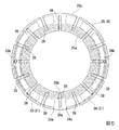
次に、図4に基づいて、レゾルバステータコア25の構成について詳述する。
図4は、レゾルバステータコア25を軸方向からみた平面図である。
図4に示すように、レゾルバステータコア25には、開口部25aの周縁から径方向に沿って、かつ径方向外側に向かって延びる複数(例えば、本第1実施形態では9つ)の内スリット38が形成されている。また、レゾルバステータコア25には、外周縁25cから径方向に沿って、かつ径方向内側に向かって延びる複数(例えば、本第1実施形態では9つ)の外スリット39が形成されている。内スリット38及び外スリット39は、周方向に等間隔で、交互に配置されている。
Next, the configuration of the resolver stator core 25 will be described in detail with reference to FIG.
FIG. 4 is a plan view of the resolver stator core 25 as viewed from the axial direction.
As shown in FIG. 4, the resolver stator core 25 has a plurality of (for example, nine in the first embodiment) inner slits 38 extending radially outward from the periphery of the opening 25a. Is formed. The resolver stator core 25 is formed with a plurality of (for example, nine in the first embodiment) outer slits 39 extending radially inward from the outer peripheral edge 25c and radially inward. The inner slits 38 and the outer slits 39 are alternately arranged at regular intervals in the circumferential direction.

図5は、レゾルバステータコア25上に、図3(a)に示すステータトランスコイル30、及びsin励磁コイル31を投影した図である。なお、図5において、説明を分かりやすくするために、ステータトランスコイル30、及びsin励磁コイル31は、2点鎖線で示している。
図5に示すように、レゾルバステータコア25は、内周部側がステータトランスコイル30の軸方向の投影上となるように、かつ外周部側がsin励磁コイル31(cos励磁コイル32)の軸方向の投影上となるように略円環状に形成されている。ここで、レゾルバステータコア25に形成されている内スリット38及び外スリット39は、ステータトランスコイル30、sin励磁コイル31、及びcos励磁コイル32を径方向に跨るように延在されている。
FIG. 5 is a diagram in which the stator transformer coil 30 and the sin excitation coil 31 shown in FIG. 3A are projected onto the resolver stator core 25. In FIG. 5, the stator transformer coil 30 and the sin excitation coil 31 are indicated by two-dot chain lines for easy understanding.
As shown in FIG. 5, the resolver stator core 25 has an inner peripheral side projected on the axial direction of the stator transformer coil 30 and an outer peripheral side projected on the axial direction of the sin excitation coil 31 (cos excitation coil 32). It is formed in a substantially annular shape so as to face upward. Here, the inner slit 38 and the outer slit 39 formed in the resolver stator core 25 extend so as to straddle the stator transformer coil 30, the sin excitation coil 31, and the cos excitation coil 32 in the radial direction.

(レゾルバロータ)
図2に戻り、レゾルバロータ22は、略円板状に形成されたレゾルバロータ部41を有している。レゾルバロータ部41の径方向略中央には、厚さ方向に貫通する貫通孔41aが形成されている。この貫通孔41aに、回転軸13の他端13b側が圧入等により固定されている。これにより、回転軸13とレゾルバロータ22とが一体となって回転する。
(Resolver rotor)
Returning to FIG. 2, the resolver rotor 22 has a resolver rotor section 41 formed in a substantially disk shape. At a substantially radial center of the resolver rotor section 41, a through hole 41a penetrating in the thickness direction is formed. The other end 13b of the rotating shaft 13 is fixed to the through hole 41a by press fitting or the like. Thereby, the rotating shaft 13 and the resolver rotor 22 rotate integrally.

レゾルバロータ部41のレゾルバステータ21との対向面41bには、径方向中央の大部分に、凹部41cが形成されている。この凹部41cに、レゾルバロータコア42が配置されている。
レゾルバロータコア42は磁性材料により形成されており、基本的構成は前述のレゾルバステータコア25(図4参照)と同一である。このため以下では、レゾルバロータコア42の構成について、レゾルバステータコア25と同一符号で説明し、レゾルバロータコア42の詳細についての説明を省略する。
A concave portion 41c is formed at a large portion at the center in the radial direction on a surface 41b of the resolver rotor portion 41 facing the resolver stator 21. The resolver rotor core 42 is arranged in the concave portion 41c.
The resolver rotor core 42 is formed of a magnetic material, and its basic configuration is the same as that of the resolver stator core 25 (see FIG. 4). Therefore, hereinafter, the configuration of the resolver rotor core 42 will be described with the same reference numerals as those of the resolver stator core 25, and the detailed description of the resolver rotor core 42 will be omitted.

レゾルバロータコア42のレゾルバロータ部41とは反対側の一面42aには、第3絶縁シート43が配置されている。第3絶縁シート43は、レゾルバロータコア42の形状に対応するように、略円板状に形成されている。第3絶縁シート43の径方向中央にも、回転軸13を挿通可能な開口部43aが形成されている。
第3絶縁シート43のレゾルバステータ21側の表面43bには、第3絶縁シート43に成膜処理等を施すことにより、ロータトランスコイル44、及び検出コイル45が形成されている。第3絶縁シート43は、ロータトランスコイル44、及び検出コイル45と、レゾルバロータコア42との絶縁を確保するためのものである。
A third insulating sheet 43 is disposed on one surface 42 a of the resolver rotor core 42 opposite to the resolver rotor section 41. The third insulating sheet 43 is formed in a substantially disk shape so as to correspond to the shape of the resolver rotor core 42. An opening 43 a through which the rotating shaft 13 can be inserted is also formed at the radial center of the third insulating sheet 43.
A rotor transformer coil 44 and a detection coil 45 are formed on the surface 43b of the third insulating sheet 43 on the resolver stator 21 side by subjecting the third insulating sheet 43 to a film forming process or the like. The third insulating sheet 43 is for securing insulation between the rotor transformer coil 44 and the detection coil 45 and the resolver rotor core 42.

以下、図6に基づいて、ロータトランスコイル44、及び検出コイル45の構成について詳述する。   Hereinafter, the configurations of the rotor transformer coil 44 and the detection coil 45 will be described in detail with reference to FIG.

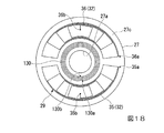
図6は、第3絶縁シート43の表面43b側を図2における矢印Y方向からみた平面図である。
図6に示すように、ロータトランスコイル44は、第3絶縁シート43の開口部43aの周囲を取り囲むように、渦巻き状に形成されている。また、検出コイル45は、ロータトランスコイル44の周囲を取り囲むように形成されている。検出コイル45は、2極で構成されている。すなわち、検出コイル45は、励磁コイル29の形状に対応するように、軸方向からみて略半円状の2つの渦巻きコイル46,47からなる。より具体的には、2つの渦巻きコイル46,47は、各励磁コイル31,32の最外側のループ形状とほぼ同じ大きさの略半円状に形成されている。また、2つの渦巻きコイル46,47は、回転軸13の回転軸線を通る径方向の任意の直線を中心として、線対称に形成されている。
FIG. 6 is a plan view of the front surface 43b side of the third insulating sheet 43 viewed from the direction of the arrow Y in FIG.
As shown in FIG. 6, the rotor transformer coil 44 is formed in a spiral shape so as to surround the periphery of the opening 43a of the third insulating sheet 43. The detection coil 45 is formed so as to surround the periphery of the rotor transformer coil 44. The detection coil 45 has two poles. That is, the detection coil 45 includes two spiral coils 46 and 47 having a substantially semicircular shape as viewed from the axial direction so as to correspond to the shape of the excitation coil 29. More specifically, the two spiral coils 46 and 47 are formed in a substantially semicircular shape having substantially the same size as the outermost loop shape of each of the exciting coils 31 and 32. Further, the two spiral coils 46 and 47 are formed symmetrically with respect to an arbitrary radial straight line passing through the rotation axis of the rotation shaft 13.

このように形成されたロータトランスコイル44、及び検出コイル45(渦巻きコイル46,47)は、直列に接続されている。
すなわち、2つの渦巻きコイル46,47の各端末部46a,46b,47a,47bを、それぞれ径方向外側に位置する外側端末部46a,47aと径方向内側に位置する内側端末部46b,47bとしたとき、一方の渦巻きコイル46の内側端末部46bと他方の渦巻きコイル47の内側端末部47bとが接続されている。
The rotor transformer coil 44 and the detection coil 45 (the spiral coils 46 and 47) formed in this way are connected in series.
That is, the end portions 46a, 46b, 47a, 47b of the two spiral coils 46, 47 are the outer end portions 46a, 47a located radially outward and the inner end portions 46b, 47b located radially inward, respectively. At this time, the inner terminal portion 46b of one spiral coil 46 and the inner terminal portion 47b of the other spiral coil 47 are connected.

また、他方の渦巻きコイル47の外側端末部47aは、ロータトランスコイル44の両端末部44a,44bのうちの径方向外側の端末部44aに接続されている。
また、ロータトランスコイル44の両端末部44a,44bのうちの径方向内側の端末部44bは、一方の渦巻きコイル46の外側端末部46aに接続されている。すなわち、ロータトランスコイル44、及び検出コイル45は、1つの閉回路とされている。
The outer terminal portion 47a of the other spiral coil 47 is connected to the radially outer terminal portion 44a of the two terminal portions 44a and 44b of the rotor transformer coil 44.
Further, a radially inner terminal portion 44b of both terminal portions 44a and 44b of the rotor transformer coil 44 is connected to an outer terminal portion 46a of one spiral coil 46. That is, the rotor transformer coil 44 and the detection coil 45 form one closed circuit.

(レゾルバの作用)
次に、レゾルバ6の作用について説明する。
レゾルバ6の励磁コイル29(sin励磁コイル31、cos励磁コイル32)には、不図示の外部電源、制御部を介して予め励磁信号が入力されている。励磁コイル29に励磁信号を入力することにより、励磁コイル29に電流が生じ、それに伴ってレゾルバステータ21に交番磁束が発生する。具体的には、位相のずれた2つの励磁コイル31,32(sin励磁コイル31、cos励磁コイル32)により、レゾルバステータ21には、位相のずれた2つの交番磁束が発生する。これら交番磁束により、レゾルバロータ22の検出コイル45に誘起電圧が生じ、検出コイル45に交番電流が流れる。この交番電流は、2つの励磁コイル31,32により発生した2つの交番磁束を合成した形で生成される。
(Action of resolver)
Next, the operation of the resolver 6 will be described.
An excitation signal is previously input to the excitation coil 29 (sin excitation coil 31, cos excitation coil 32) of the resolver 6 via an external power supply (not shown) and a control unit. When an excitation signal is input to the excitation coil 29, a current is generated in the excitation coil 29, and an alternating magnetic flux is generated in the resolver stator 21 accordingly. More specifically, two alternating magnetic fluxes out of phase are generated in the resolver stator 21 by the two exciting coils 31, 32 (sin exciting coil 31, cos exciting coil 32) out of phase. Due to these alternating magnetic fluxes, an induced voltage is generated in the detection coil 45 of the resolver rotor 22, and an alternating current flows through the detection coil 45. This alternating current is generated in a form in which two alternating magnetic fluxes generated by the two exciting coils 31 and 32 are combined.

検出コイル45はロータトランスコイル44と直列接続されているので、ロータトランスコイル44にも電流が流れる。すると、レゾルバロータ22に交番磁束が発生する。この交番磁束により(電磁誘導により)、レゾルバステータ21のステータトランスコイル30に誘起電圧が生じる。ステータトランスコイル30は、不図示の制御部に接続されているので、ステータトランスコイル30で発生した誘起電圧は、信号として不図示の制御部に出力される。   Since the detection coil 45 is connected in series with the rotor transformer coil 44, a current also flows through the rotor transformer coil 44. Then, an alternating magnetic flux is generated in the resolver rotor 22. Due to the alternating magnetic flux (by electromagnetic induction), an induced voltage is generated in the stator transformer coil 30 of the resolver stator 21. Since the stator transformer coil 30 is connected to a controller (not shown), the induced voltage generated in the stator transformer coil 30 is output to the controller (not shown) as a signal.

ここで、レゾルバ6によるモータロータ5の回転位置を検出する原理について説明する。
モータロータ5が回転することにより、レゾルバステータ21に対してレゾルバロータ22が回転する。レゾルバロータ22が回転すると、レゾルバステータ21に対するレゾルバロータ22の位置が変化すると、励磁コイル29に入力する高周波の入力信号に対して検出コイル45から各トランスコイル30,44を介して出力される出力信号は回転位置に応じた位相差を持つ。この位相差を不図示の制御部によって検出し、モータロータ5の回転位置が検出される。
Here, the principle of detecting the rotational position of the motor rotor 5 by the resolver 6 will be described.
As the motor rotor 5 rotates, the resolver rotor 22 rotates with respect to the resolver stator 21. When the resolver rotor 22 rotates and the position of the resolver rotor 22 with respect to the resolver stator 21 changes, an output output from the detection coil 45 via the transformer coils 30 and 44 with respect to a high-frequency input signal input to the excitation coil 29. The signal has a phase difference according to the rotational position. This phase difference is detected by a control unit (not shown), and the rotational position of the motor rotor 5 is detected.

図7は、レゾルバステータコア25、及びレゾルバロータコア42の一部拡大図であって、図5のB部に対応している。
ここで、図7に示すように、各コイル31,32,44,45に交番電流が流れると、交番磁束を発生するとともに、レゾルバステータコア25やレゾルバロータコア42に渦電流Uが発生しようとする。渦電流Uは、レゾルバステータコア25やレゾルバロータコア42の各コイル31,32,44,45が配置されている箇所及びその周囲全ての位置に面方向に沿って渦状に発生し、特にコイルの近傍に強く生じる。すなわち、レゾルバステータコア25やレゾルバロータコア42の各コイル31,32,44,45が配置されている箇所及びその周囲全ての箇所、特にコイルの近傍が、渦電流Uの発生領域Rである。換言すれば、発生領域Rは、レゾルバステータコア25やレゾルバロータコア42の各コイル31,32,44,45が配置されている箇所の一部に重なる領域である。渦電流Uは、各コイル31,32,44,45に流れる交番電流を妨げる向きに磁束を生じるため、効率よく交番磁束を形成するのを阻害してしまう。
FIG. 7 is a partially enlarged view of the resolver stator core 25 and the resolver rotor core 42, and corresponds to a portion B in FIG.
Here, as shown in FIG. 7, when an alternating current flows through each of the coils 31, 32, 44, and 45, an alternating magnetic flux is generated, and an eddy current U is generated in the resolver stator core 25 and the resolver rotor core. The eddy current U is generated in a vortex along the surface direction at the places where the coils 31, 32, 44, and 45 of the resolver stator core 25 and the resolver rotor core 42 are arranged, and at all positions around the coils. It occurs strongly. That is, the area where the coils 31, 32, 44, and 45 of the resolver stator core 25 and the resolver rotor core 42 are arranged and all surrounding areas, particularly the vicinity of the coil, are the generation region R of the eddy current U. In other words, the generation region R is a region that partially overlaps the portion where the coils 31, 32, 44, and 45 of the resolver stator core 25 and the resolver rotor core 42 are arranged. The eddy current U generates a magnetic flux in a direction that prevents the alternating current flowing through each of the coils 31, 32, 44, and 45, thereby hindering efficient formation of the alternating magnetic flux.

しかしながら、レゾルバステータコア25、及びレゾルバロータコア42には、渦電流Uの発生領域Rに、内スリット38、及び外スリット39が形成されている。これらスリット38,39は、渦電流Uの流れを妨げる。しかも、内スリット38、及び外スリット39は、渦電流Uの流れを阻害するように、各コイル31,32,44,45を径方向に跨るように形成されている。このため、レゾルバステータコア25、及びレゾルバロータコア42で発生する渦電流Uの大きさを小さくしたりすることができる。この結果、各コイル31,32,44,45によって、効率よく交番磁束を形成することが可能になる。   However, in the resolver stator core 25 and the resolver rotor core 42, the inner slit 38 and the outer slit 39 are formed in the region R where the eddy current U is generated. These slits 38 and 39 obstruct the flow of the eddy current U. Moreover, the inner slit 38 and the outer slit 39 are formed so as to straddle the coils 31, 32, 44, and 45 in the radial direction so as to obstruct the flow of the eddy current U. For this reason, the magnitude of the eddy current U generated in the resolver stator core 25 and the resolver rotor core 42 can be reduced. As a result, the alternating magnetic flux can be efficiently formed by the coils 31, 32, 44, and 45.

このように、上述の第1実施形態において、レゾルバステータコア25、及びレゾルバロータコア42には、渦電流Uの発生領域Rに、この渦電流Uの流れの抵抗となる内スリット38、及び外スリット39が形成されている。このため、レゾルバステータコア25、及びレゾルバロータコア42に発生する渦電流Uの大きさを小さくすることができる。この結果、各コイル31,32,44,45によって、効率よく交番磁束を形成することが可能になる。よって、その結果、外乱ノイズに対して十分な強度の信号が得られレゾルバ6によるモータロータ5の回転位置の検出精度を効果的に向上できる(いわゆる、S/N比が高い状況とすることができる)。   As described above, in the above-described first embodiment, the resolver stator core 25 and the resolver rotor core 42 have the inner slit 38 and the outer slit 39 in the generation region R of the eddy current U, which serve as resistance to the flow of the eddy current U. Is formed. For this reason, the magnitude of the eddy current U generated in the resolver stator core 25 and the resolver rotor core 42 can be reduced. As a result, the alternating magnetic flux can be efficiently formed by the coils 31, 32, 44, and 45. Therefore, as a result, a signal having a sufficient strength against disturbance noise can be obtained, and the detection accuracy of the rotational position of the motor rotor 5 by the resolver 6 can be effectively improved (so-called high S / N ratio can be achieved). ).

また、レゾルバステータコア25、及びレゾルバロータコア42に、径方向に沿って内スリット38、及び外スリット39を形成している。このため、渦電流Uの大きさを小さくすることができ、レゾルバ6によるモータロータ5の回転位置の検出精度を確実に向上できる。
また、内スリット38、及び外スリット39を、レゾルバステータコア25、及びレゾルバロータコア42における渦電流Uの流れの抵抗としている。このように、簡素な構造で渦電流Uの流れを阻害できるので、レゾルバ6の製造コストを低減できる。
Further, an inner slit 38 and an outer slit 39 are formed in the resolver stator core 25 and the resolver rotor core 42 along the radial direction. For this reason, the magnitude of the eddy current U can be reduced, and the detection accuracy of the rotational position of the motor rotor 5 by the resolver 6 can be reliably improved.
Further, the inner slit 38 and the outer slit 39 are resistances of the flow of the eddy current U in the resolver stator core 25 and the resolver rotor core 42. As described above, since the flow of the eddy current U can be inhibited with a simple structure, the manufacturing cost of the resolver 6 can be reduced.

(第1実施形態の変形例)
なお、上述の第1実施形態では、レゾルバステータコア25、及びレゾルバロータコア42に形成された内スリット38及び外スリット39を、周方向に等間隔で配置した場合について説明した。しかしながら、これに限られるものではなく、内スリット38及び外スリット39を等間隔に配置しなくてもよい。
また、上述の第1実施形態では、各スリット38,42の個数がそれぞれ9つである場合について説明した。しかしながら、これに限られるものではなく、各スリット38,42の個数は、任意に設定することが可能である。
(Modification of First Embodiment)
In the first embodiment described above, the case where the inner slit 38 and the outer slit 39 formed in the resolver stator core 25 and the resolver rotor core 42 are arranged at equal intervals in the circumferential direction has been described. However, the present invention is not limited to this, and the inner slit 38 and the outer slit 39 need not be arranged at equal intervals.
In the above-described first embodiment, the case where the number of each of the slits 38 and 42 is nine has been described. However, the present invention is not limited to this, and the number of the slits 38 and 42 can be set arbitrarily.

また、上述の第1実施形態では、レゾルバステータコア25、及びレゾルバロータコア42に、渦電流Uの流れを阻害する手段として、径方向に沿う内スリット38及び外スリット39を形成した場合について説明した。しかしながら、これに限られるものではなく、レゾルバステータコア25、及びレゾルバロータコア42に、渦電流Uの流れを阻害するようにスリットが形成されていればよい。以下、図8〜図11に基づいて、具体的に変形例を挙げて説明する。   Further, in the first embodiment described above, the case where the inner slit 38 and the outer slit 39 along the radial direction are formed in the resolver stator core 25 and the resolver rotor core 42 as means for inhibiting the flow of the eddy current U is described. However, the present invention is not limited to this, and slits may be formed in the resolver stator core 25 and the resolver rotor core 42 so as to obstruct the flow of the eddy current U. Hereinafter, a specific modification will be described with reference to FIGS. 8 to 11.

例えば、図8に示すように、レゾルバステータコア25、及びレゾルバロータコア42に、径方向全体に渡って形成されるスリット51を複数設けてもよい。各スリット51は、周方向に等間隔で形成されている。しかしながら、各スリット51を、周方向に等間隔で形成しなくてもよい。   For example, as shown in FIG. 8, the resolver stator core 25 and the resolver rotor core 42 may be provided with a plurality of slits 51 formed over the entire radial direction. Each slit 51 is formed at equal intervals in the circumferential direction. However, the slits 51 need not be formed at equal intervals in the circumferential direction.

ところで、本変形例のように、レゾルバステータコア25、及びレゾルバロータコア42に、径方向全体に渡ってスリット51を形成すると、レゾルバステータコア25、及びレゾルバロータコア42が周方向に分割される。このような場合、特に図示は省略するが、分割された各レゾルバステータコア25、及びレゾルバロータコア42を連結する箇所を設けることが望ましい(以下の実施形態や変形例についても同様)。このように構成することで、レゾルバステータコア25やレゾルバロータコア42を一体化できるので、これらレゾルバステータコア25やレゾルバロータコア42の生産性を向上できる。   By the way, when the slit 51 is formed in the resolver stator core 25 and the resolver rotor core 42 over the entire radial direction as in the present modification, the resolver stator core 25 and the resolver rotor core 42 are divided in the circumferential direction. In such a case, although not shown, it is desirable to provide a portion for connecting each of the divided resolver stator cores 25 and the resolver rotor core 42 (the same applies to the following embodiments and modified examples). With this configuration, the resolver stator core 25 and the resolver rotor core 42 can be integrated, so that the productivity of the resolver stator core 25 and the resolver rotor core 42 can be improved.

また、図9に示すように、レゾルバステータコア25、及びレゾルバロータコア42に、軸方向からみて複数(例えば、図9では5つ)の略円環状のスリット52を形成し、これらスリット52を同心円上に配置してもよい。   As shown in FIG. 9, a plurality of (for example, five in FIG. 9) substantially annular slits 52 are formed in the resolver stator core 25 and the resolver rotor core 42 when viewed from the axial direction, and these slits 52 are concentric. May be arranged.

また、図10に示すように、レゾルバステータコア25、及びレゾルバロータコア42に、軸方向からみて複数(例えば、図10では2つ)の略円環状のスリット53を形成するとともに、径方向に沿う複数(例えば、図10では4つ)の縦スリット54を形成してもよい。縦スリット54は、回転軸13の回転軸線を通る径方向の任意の直線を中心に形成されている。
このように、スリット53と縦スリット54とを組み合わせることにより、渦電流Uの流れる経路を効果的に寸断することができ、渦電流Uを小さくすることができる。
As shown in FIG. 10, a plurality of (for example, two in FIG. 10) substantially annular slits 53 are formed in the resolver stator core 25 and the resolver rotor core 42 when viewed from the axial direction, and a plurality of slits 53 are formed along the radial direction. (For example, four slits in FIG. 10) may be formed. The vertical slit 54 is formed around an arbitrary straight line in the radial direction passing through the rotation axis of the rotation shaft 13.
In this way, by combining the slit 53 and the vertical slit 54, the path through which the eddy current U flows can be effectively cut off, and the eddy current U can be reduced.

なお、レゾルバステータコア25やレゾルバロータコア42の磁気的な抵抗を増やさないためには、スリットを設けることで減少するコアの面積を最小限にすべきであり、スリットの幅は狭い方が望ましい。例えば、レゾルバステータコア25やレゾルバロータコア42を、薄板鋼板材で制作する場合であれば、板厚の1.5倍以下とすることが望ましい。一方で量産の加工技術を考慮すると、スリット幅を、板厚の半分以上とすべきである。生産方法としては、例えば、レーザ加工やエッチング、プレス加工などがある。   In order to prevent the magnetic resistance of the resolver stator core 25 and the resolver rotor core 42 from increasing, the area of the core, which is reduced by providing the slit, should be minimized, and the slit width is preferably narrow. For example, when the resolver stator core 25 and the resolver rotor core 42 are made of a thin steel plate, the thickness is desirably 1.5 times or less the plate thickness. On the other hand, in consideration of mass-production processing technology, the slit width should be at least half of the plate thickness. Examples of the production method include laser processing, etching, and press processing.

図11は、図10に示すレゾルバステータコア25上に、ステータトランスコイル30、及びsin励磁コイル31を投影した図である。なお、図11において、説明を分かりやすくするために、ステータトランスコイル30、及びsin励磁コイル31を2点鎖線で示している。
図11に示すように、スリット53と縦スリット54とを組み合わせることにより、レゾルバステータコア25上の渦電流U(図7参照)の発生領域Rで渦電流Uの流れを阻害することができる。より効果的に渦電流Uの流れを阻害するために、略円環状のスリット53は、各コイル30,31の一部と重なるように配置されている。レゾルバロータコア42についても、同様の効果を奏する。
FIG. 11 is a diagram in which the stator transformer coil 30 and the sin excitation coil 31 are projected on the resolver stator core 25 shown in FIG. In FIG. 11, the stator transformer coil 30 and the sin excitation coil 31 are shown by two-dot chain lines for easy understanding.
As shown in FIG. 11, by combining the slit 53 and the vertical slit 54, the flow of the eddy current U can be inhibited in the generation region R of the eddy current U (see FIG. 7) on the resolver stator core 25. In order to more effectively inhibit the flow of the eddy current U, the substantially annular slit 53 is arranged so as to overlap a part of each of the coils 30 and 31. The resolver rotor core 42 has the same effect.

また、図12に示すように、レゾルバステータコア25、及びレゾルバロータコア42に形成された複数の内スリット38、及び外スリット39を、磁極中心Cに向かうに従って密になるように配置してもよい。すなわち、内スリット38と外スリット39との間の間隔は、磁極中心Cに向かうに従って狭くなり、磁極中心Cから離間するに従って広くなるようにしてもよい。磁極中心Cは、渦巻きコイル33〜36,46,47の巻回数が多くなるので、渦電流Uの発生が多くなりやすい。このため、磁極中心Cに向かうに従って各スリット38,39を密にすることにより、各コア25,42の機械的強度を十分確保しつつ、渦電流Uの流れる経路を、より効率的に寸断することができる。   As shown in FIG. 12, a plurality of inner slits 38 and outer slits 39 formed in the resolver stator core 25 and the resolver rotor core 42 may be arranged so as to become denser toward the magnetic pole center C. That is, the interval between the inner slit 38 and the outer slit 39 may be narrower toward the magnetic pole center C, and may be wider as the distance from the magnetic pole center C increases. At the magnetic pole center C, the number of turns of the spiral coils 33 to 36, 46, and 47 increases, so that the generation of the eddy current U tends to increase. For this reason, by making the slits 38 and 39 denser toward the magnetic pole center C, the path through which the eddy current U flows can be more efficiently cut while ensuring sufficient mechanical strength of the cores 25 and 42. be able to.

ここで、磁極中心Cについて詳述する。
図6に示すように、検出コイル45は、2極で構成されている。すなわち、検出コイル45は、軸方向からみて略半円状の2つの渦巻きコイル46,47からなる。これら2つの渦巻きコイル46,47の周方向中央が、レゾルバロータコア42(検出コイル45)の磁極中心Cとなる。
Here, the magnetic pole center C will be described in detail.
As shown in FIG. 6, the detection coil 45 has two poles. That is, the detection coil 45 includes two spiral coils 46 and 47 having a substantially semicircular shape when viewed from the axial direction. The circumferential center of these two spiral coils 46 and 47 is the magnetic pole center C of the resolver rotor core 42 (detection coil 45).

これに対し、図3(a)、図3(b)に示すように、励磁コイル29の場合、機械角で90°ずれたsin励磁コイル31と、cos励磁コイル32と、からなる。つまり、sin励磁コイル31の磁極中心Csinと、cos励磁コイル32の磁極中心Ccosと、の2つの磁極中心Csin,Ccosを有し、しかもこれら2つの磁極中心Csin,Ccosが機械角で90°ずれている。このような場合、sin励磁コイル31、及びcos励磁コイル32のそれぞれ磁極中心Csin,Ccosの間に、レゾルバステータコア25(励磁コイル29)の磁極中心Cが生じる。つまり、sin励磁コイル31とcos励磁コイル32とを合算した磁極中心Cを、レゾルバステータコア25(励磁コイル29)の磁極中心Cとなる。本実施形態では、sin励磁コイル31の磁極中心Csin、及びcos励磁コイル32の磁極中心Ccosに対し、機械角で45°ずれた位置が、レゾルバステータコア25(励磁コイル29)の磁極中心Cとなる(図3(a)、図3(b)に各磁極中心を結ぶ磁極中心線を示す)。この磁極中心Cの考え方については、以下の変形例についても同様である。   On the other hand, as shown in FIGS. 3A and 3B, the excitation coil 29 includes a sin excitation coil 31 shifted by 90 ° in mechanical angle and a cos excitation coil 32. That is, there are two magnetic pole centers Csin and Ccos, that is, the magnetic pole center Csin of the sin exciting coil 31 and the magnetic pole center Ccos of the cos exciting coil 32, and the two magnetic pole centers Csin and Ccos are shifted by 90 ° in mechanical angle. ing. In such a case, the magnetic pole center C of the resolver stator core 25 (exciting coil 29) is generated between the magnetic pole centers Csin and Ccos of the sin exciting coil 31 and the cos exciting coil 32, respectively. That is, the magnetic pole center C obtained by adding the sin exciting coil 31 and the cos exciting coil 32 becomes the magnetic pole center C of the resolver stator core 25 (the exciting coil 29). In the present embodiment, a position shifted by 45 ° in mechanical angle from the magnetic pole center Csin of the sin exciting coil 31 and the magnetic pole center Ccos of the cos exciting coil 32 becomes the magnetic pole center C of the resolver stator core 25 (the exciting coil 29). (FIGS. 3A and 3B show magnetic pole center lines connecting the magnetic pole centers). The concept of the magnetic pole center C is the same for the following modified examples.

図13に示すように、レゾルバステータコア25、及びレゾルバロータコア42の径方向全体に渡って形成された複数のスリット51を、磁極中心Cに向かうに従って密になるように配置してもよい。すなわち、スリット51の周方向の間隔は、磁極中心Cに向かうに従って狭くなり、磁極中心Cから離間するに従って広くなるようにしてもよい。このように構成することで、上述の変形例と同様の効果を奏することができる。   As shown in FIG. 13, a plurality of slits 51 formed over the entire radial direction of the resolver stator core 25 and the resolver rotor core 42 may be arranged so as to become denser toward the magnetic pole center C. That is, the circumferential interval of the slits 51 may be narrower toward the magnetic pole center C, and may be wider as the distance from the magnetic pole center C increases. With this configuration, it is possible to obtain the same effects as those of the above-described modification.

(第2実施形態)
次に、図14に基づいて、本発明の第2実施形態について説明する。なお、第1実施形態と同一態様には、同一符号を付して説明を省略する。
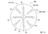
図14は、第2実施形態におけるレゾルバステータコア225、及びレゾルバロータコア242を軸方向からみた平面図である。
第2実施形態において、ブラシレスモータ1の基本的構成は、前述の第1実施形態と同様である。また、レゾルバ206の基本的構成も前述の第1実施形態と同様である。
(2nd Embodiment)
Next, a second embodiment of the present invention will be described with reference to FIG. Note that the same reference numerals are given to the same aspects as the first embodiment, and description thereof will be omitted.
FIG. 14 is a plan view of the resolver stator core 225 and the resolver rotor core 242 in the second embodiment as viewed from the axial direction.
In the second embodiment, the basic configuration of the brushless motor 1 is the same as that of the first embodiment. The basic configuration of the resolver 206 is the same as that of the first embodiment.

ここで、前述の第1実施形態と本第2実施形態との相違点は、前述の第1実施形態におけるレゾルバステータコア25、及びレゾルバロータコア42の形状と、本第2実施形態におけるレゾルバステータコア225、及びレゾルバロータコア242の形状とが異なる点である。これに伴い、レゾルバステータ221、及びレゾルバロータ222の固定方向が、前述の第1実施形態と異なる。以下、詳述する。   Here, the difference between the first embodiment and the second embodiment is that the shapes of the resolver stator core 25 and the resolver rotor core 42 in the first embodiment, the resolver stator core 225 in the second embodiment, And the shape of the resolver rotor core 242 is different. Accordingly, the fixing directions of the resolver stator 221 and the resolver rotor 222 are different from those in the first embodiment. The details will be described below.

図14に示すように、本第2実施形態におけるレゾルバステータコア225、及びレゾルバロータコア242は、略円板状に形成されている。但し、レゾルバステータコア225、及びレゾルバロータコア242の径方向略中央には、回転軸13(例えば、図1参照)を挿通可能な開口部25a(例えば、図2参照)が形成されていない。
このため、特に図示は省略するが、レゾルバロータ222は、回転軸13の他端13bに固定される。また、レゾルバステータ221は、前述の第1実施形態におけるレゾルバステータ21の位置とは反対側に配置される。すなわち、レゾルバステータ221は、レゾルバロータ222のモータステータ4とは反対側に配置される。そして、レゾルバステータ221は、ブラシレスモータ1に別途設けられるカバー等(不図示)に取り付けられる。
As shown in FIG. 14, the resolver stator core 225 and the resolver rotor core 242 in the second embodiment are formed in a substantially disc shape. However, an opening 25a (for example, see FIG. 2) through which the rotating shaft 13 (for example, see FIG. 1) can be inserted is not formed at substantially the center in the radial direction of the resolver stator core 225 and the resolver rotor core 242.
Therefore, although not particularly shown, the resolver rotor 222 is fixed to the other end 13 b of the rotating shaft 13. Further, the resolver stator 221 is arranged on the opposite side to the position of the resolver stator 21 in the above-described first embodiment. That is, the resolver stator 221 is disposed on the resolver rotor 222 on the side opposite to the motor stator 4. The resolver stator 221 is attached to a cover or the like (not shown) separately provided on the brushless motor 1.

レゾルバステータコア225、及びレゾルバロータコア242の径方向略中央には、厚さ方向に貫通する貫通孔61が形成されている。この貫通孔61は、軸方向からみてステータトランスコイル30、及びロータトランスコイル44(図3(a)、図6参照、本第2実施形態では不図示)よりも径方向内側に位置する。   At a substantially radial center of the resolver stator core 225 and the resolver rotor core 242, a through-hole 61 penetrating in the thickness direction is formed. The through hole 61 is located radially inward of the stator transformer coil 30 and the rotor transformer coil 44 (see FIGS. 3A and 6, not shown in the second embodiment) when viewed from the axial direction.

また、レゾルバステータコア225、及びレゾルバロータコア242には、貫通孔61の内周縁から径方向に沿って、かつ径方向外側に向かって延びる複数(例えば、本第2実施形態では4つ)の内スリット62が形成されている。さらに、レゾルバステータコア225、及びレゾルバロータコア242には、外周縁225a,242aから径方向に沿って、かつ径方向内側に向かって延びる複数(例えば、本第2実施形態では4つ)の外スリット63が形成されている。内スリット62及び外スリット63は、周方向に等間隔で、交互に配置されている。   In the resolver stator core 225 and the resolver rotor core 242, a plurality of (for example, four in the second embodiment) inner slits extending radially outward from the inner peripheral edge of the through hole 61 and radially outward. 62 are formed. Further, the resolver stator core 225 and the resolver rotor core 242 have a plurality of (for example, four in the second embodiment) outer slits 63 extending radially inward and radially inward from the outer peripheral edges 225a and 242a. Is formed. The inner slits 62 and the outer slits 63 are alternately arranged at equal intervals in the circumferential direction.

このように構成した場合であっても、前述の第1実施形態と同様の効果を奏する。   Even in the case of such a configuration, the same effects as those of the first embodiment can be obtained.

(第2実施形態の変形例)
なお、上述の第2実施形態では、レゾルバステータコア225、及びレゾルバロータコア242に形成された内スリット62及び外スリット63を、周方向に等間隔で配置した場合について説明した。しかしながら、これに限られるものではなく、内スリット62及び外スリット63を等間隔に配置しなくてもよい。
また、上述の第1実施形態では、各スリット62,63の個数がそれぞれ4つである場合について説明した。しかしながら、これに限られるものではなく、各スリット62,63の個数は、任意に設定することが可能である。
(Modification of the second embodiment)
In the above-described second embodiment, the case where the inner slit 62 and the outer slit 63 formed in the resolver stator core 225 and the resolver rotor core 242 are arranged at equal intervals in the circumferential direction has been described. However, the present invention is not limited to this, and the inner slit 62 and the outer slit 63 do not have to be arranged at equal intervals.
In the above-described first embodiment, the case where the number of each of the slits 62 and 63 is four has been described. However, the present invention is not limited to this, and the number of the slits 62 and 63 can be set arbitrarily.

また、上述の第2実施形態では、レゾルバステータコア225、及びレゾルバロータコア242に、渦電流Uの流れを阻害する手段として、貫通孔61、内スリット62及び外スリット63を形成した場合について説明した。しかしながら、これに限られるものではなく、レゾルバステータコア225、及びレゾルバロータコア242に、渦電流Uの流れを阻害するようにスリットが形成されていればよい。以下、図15〜図17に基づいて、具体的に変形例を挙げて説明する。   In the above-described second embodiment, a case has been described in which the through hole 61, the inner slit 62, and the outer slit 63 are formed in the resolver stator core 225 and the resolver rotor core 242 as means for inhibiting the flow of the eddy current U. However, the present invention is not limited to this, and slits may be formed in the resolver stator core 225 and the resolver rotor core 242 so as to obstruct the flow of the eddy current U. Hereinafter, a specific modification will be described with reference to FIGS. 15 to 17.

例えば、図15に示すように、レゾルバステータコア225、及びレゾルバロータコア242に、貫通孔61と外周縁225a,242aとの間を跨るように、径方向全体に渡って形成されるスリット64を複数設けてもよい。各スリット64は、周方向に等間隔で形成されている。しかしながら、各スリット64を、周方向に等間隔で形成しなくてもよい。   For example, as shown in FIG. 15, a plurality of slits 64 formed over the entire radial direction are provided in the resolver stator core 225 and the resolver rotor core 242 so as to straddle between the through hole 61 and the outer peripheral edges 225a and 242a. You may. Each slit 64 is formed at equal intervals in the circumferential direction. However, the slits 64 need not be formed at equal intervals in the circumferential direction.

また、上述の第2実施形態及び変形例の各スリット62,63,64を、磁極中心Cに向かうに従って密になるように配置してもよい。すなわち、各スリット62,63,64の周方向の間隔は、磁極中心Cに向かうに従って狭くなり、磁極中心Cから離間するに従って広くなるようにしてもよい。   Further, the slits 62, 63, and 64 of the second embodiment and the modified example described above may be arranged so as to be denser toward the magnetic pole center C. That is, the circumferential interval between the slits 62, 63, 64 may be narrower toward the magnetic pole center C, and may be wider as the distance from the magnetic pole center C increases.

また、図16に示すように、レゾルバステータコア225、及びレゾルバロータコア242に、軸方向からみて複数(例えば、図16では6つ)の略円環状のスリット65を形成し、これらスリット65を同心円上に配置してもよい。   As shown in FIG. 16, a plurality of (for example, six in FIG. 16) substantially annular slits 65 are formed in the resolver stator core 225 and the resolver rotor core 242 when viewed from the axial direction, and these slits 65 are concentric. May be arranged.

また、図17に示すように、レゾルバステータコア225、及びレゾルバロータコア242に、軸方向からみて複数(例えば、図17では3つ)の略円環状のスリット66を形成するとともに、径方向に沿う複数(例えば、図17では6つ)の縦スリット67を形成してもよい。縦スリット67は、回転軸13の回転軸線を通る径方向の任意の直線を中心に形成されている。
このように、スリット66と縦スリット67とを組み合わせることにより、渦電流Uの流れる経路を効果的に寸断することができ、渦電流Uを小さくすることができる。この結果、スリット66のスリット幅を大きくすることが可能になる。
なお、各コア225,242の磁気的な抵抗を増やさないためには、各スリット66,67を設けることで減少する各コア225,242の面積を最小限にすべきであり、スリットの幅は狭い方が望ましい。例えば、各コア225,242が薄板鋼板材であれば、板厚の0.5倍からから板厚の1.5倍とするのが望ましい。
As shown in FIG. 17, a plurality of (for example, three in FIG. 17) substantially annular slits 66 are formed in the resolver stator core 225 and the resolver rotor core 242 when viewed from the axial direction, and a plurality of slits 66 are formed along the radial direction. (For example, six slits in FIG. 17) may be formed. The vertical slit 67 is formed around an arbitrary radial line passing through the rotation axis of the rotation shaft 13.
In this way, by combining the slit 66 and the vertical slit 67, the path through which the eddy current U flows can be effectively cut off, and the eddy current U can be reduced. As a result, the slit width of the slit 66 can be increased.
In order to prevent the magnetic resistance of each core 225, 242 from increasing, the area of each core 225, 242, which is reduced by providing each slit 66, 67, should be minimized. A narrow one is desirable. For example, if each of the cores 225 and 242 is a thin steel plate, the thickness is desirably 0.5 to 1.5 times the plate thickness.

なお、本発明は上述の実施形態に限られるものではなく、本発明の趣旨を逸脱しない範囲において、上述の実施形態に種々の変更を加えたものを含む。
例えば、上述の実施形態では、レゾルバ6,206は、ブラシレスモータ1に設けられ、モータロータ5の回転位置を検出するために用いられる場合について説明した。しかしながら、これに限られるものではなく、さまざまな回転電機に、レゾルバ6,206を用いることが可能である。
Note that the present invention is not limited to the above-described embodiment, and includes various modifications of the above-described embodiment without departing from the spirit of the present invention.
For example, in the above-described embodiment, the case has been described where the resolvers 6 and 206 are provided in the brushless motor 1 and are used to detect the rotational position of the motor rotor 5. However, the present invention is not limited to this, and the resolvers 6 and 206 can be used for various rotating electric machines.

また、上述の実施形態では、レゾルバステータコア25,225、及びレゾルバロータコア42,242に、渦電流Uの流れを阻害する手段として、各種スリット38,39,51〜54,62〜67や貫通孔61を形成した場合について説明した。これら各種スリット38,39,51〜54,62〜67や貫通孔61を適宜組み合わせてもよい。また、これら各種スリット38,39,51〜54,62〜67や貫通孔61に限られるものではなく、レゾルバステータコア25,225、及びレゾルバロータコア42,242よりも電気抵抗が高く、渦電流Uの流れを阻害するものが形成されていればよい。各種スリット38,39,51〜54,62〜67や貫通孔61の個数も、上述の実施形態の個数に限られるものではない。   In the above-described embodiment, the slits 38, 39, 51 to 54, 62 to 67, and the through holes 61 are provided in the resolver stator cores 25 and 225 and the resolver rotor cores 42 and 242 as means for inhibiting the flow of the eddy current U. Has been described. These various slits 38, 39, 51 to 54, 62 to 67 and the through holes 61 may be combined as appropriate. The various slits 38, 39, 51 to 54, 62 to 67 and the through holes 61 are not limited to the above, and the electrical resistance is higher than the resolver stator cores 25 and 225 and the resolver rotor cores 42 and 242. It is only necessary that something that inhibits the flow is formed. The number of the various slits 38, 39, 51 to 54, 62 to 67 and the number of the through holes 61 are not limited to the numbers in the above embodiment.

つまり、例えば、各種スリット38,39,51〜54,62〜67や貫通孔61に代わって、凹部(例えば、図4に符号70で示す)としてもよい。凹部70とすることにより、この凹部が形成されている箇所の肉厚が減少するので、凹部70が形成されている箇所と比較して電気抵抗が高くなる。このため、凹部70によって、渦電流Uの流れを阻害できる。(例えば、図4のスリット39が連続した薄肉部となり、周囲に対して凹部となる。)   That is, for example, instead of the various slits 38, 39, 51 to 54, 62 to 67 and the through hole 61, a concave portion (for example, indicated by reference numeral 70 in FIG. 4) may be provided. By forming the concave portion 70, the thickness of the portion where the concave portion is formed is reduced, so that the electric resistance is higher than that of the portion where the concave portion 70 is formed. For this reason, the flow of the eddy current U can be inhibited by the recess 70. (For example, the slit 39 in FIG. 4 becomes a continuous thin portion, and becomes a recess with respect to the periphery.)

また、各種スリット38,39,51〜54,62〜67や貫通孔61に、樹脂等を充填してもよい。樹脂等を充填する分、レゾルバステータコア25,225、及びレゾルバロータコア42,242の機械的強度を高めることができる。
また、レゾルバステータコア25,225、及びレゾルバロータコア42,242の渦電流Uの発生領域Rであれば、抵抗となる形状は、如何なる形状でもよい。軸方向からみてU字状やV字状等、さまざまな形状を採用できる。
Further, the various slits 38, 39, 51 to 54, 62 to 67 and the through holes 61 may be filled with resin or the like. The mechanical strength of the resolver stator cores 25 and 225 and the resolver rotor cores 42 and 242 can be increased by the amount of resin or the like.
In addition, as long as the eddy current U is generated in the region R where the resolver stator cores 25 and 225 and the resolver rotor cores 42 and 242 are generated, any shape may be used as the resistance. Various shapes such as a U-shape and a V-shape can be adopted as viewed from the axial direction.

また、上述の実施形態では、レゾルバステータコア25,225、及びレゾルバロータコア42,242の励磁コイル29、検出コイル45、各トランスコイル30,44が形成されている箇所のそれぞれに、各種スリット38,39,51〜54,62〜67や貫通孔61を形成した場合について説明した。しかしながら、これに限られるものではなく、少なくともレゾルバステータコア25,225の励磁コイル29が形成されている箇所に、渦電流Uの流れを阻害する抵抗(各種スリット38,39,51〜54,62〜67や貫通孔61)があればよい。
少なくともレゾルバステータコア25,225の励磁コイル29が形成されている箇所に、渦電流Uの流れを阻害する抵抗があれば、レゾルバステータコア25,225、及びレゾルバロータコア42,242のいずれかに各種スリット38,39,51〜54,62〜67や貫通孔61が形成されていても、形成されていなくてもよい。
Further, in the above-described embodiment, various slits 38, 39 are provided at the positions where the exciting coil 29, the detecting coil 45, and the transformer coils 30, 44 of the resolver stator cores 25, 225 and the resolver rotor cores 42, 242 are formed. , 51 to 54, 62 to 67 and the case where the through holes 61 are formed have been described. However, the present invention is not limited to this. At least at the location where the exciting coils 29 of the resolver stator cores 25 and 225 are formed, the resistance (various slits 38, 39, 51 to 54, 62 to 62) that inhibits the flow of the eddy current U is provided. 67 and through holes 61).
If there is a resistance that inhibits the flow of the eddy current U at least at a position where the exciting coil 29 of the resolver stator cores 25 and 225 is formed, various slits 38 are provided in any one of the resolver stator cores 25 and 225 and the resolver rotor cores 42 and 242. , 39, 51 to 54, 62 to 67 and the through hole 61 may or may not be formed.

ここで、励磁コイル29への通電により発生する渦電流Uは、その他のコイル30,44,45への通電の場合と比較して大きくなりやすい。このため、励磁コイル29が配置されている箇所に抵抗を設けることにより、渦電流Uによる影響を最も低減しやすい。よって、レゾルバ6,206によるモータロータ5の回転位置の検出精度を、効果的に向上できる。   Here, the eddy current U generated by energizing the exciting coil 29 tends to be larger than when energizing the other coils 30, 44, 45. For this reason, by providing a resistor at the position where the exciting coil 29 is arranged, the influence of the eddy current U is most easily reduced. Therefore, the detection accuracy of the rotational position of the motor rotor 5 by the resolvers 6, 206 can be effectively improved.

また、上述の実施形態では、励磁コイル29、検出コイル45、各トランスコイル30,44を、成膜処理等を施すことにより形成した場合について説明した。しかしながら、これに限られるものではなく、さまざまな方法で励磁コイル29、検出コイル45、各トランスコイル30,44を形成することが可能である。例えば、第2絶縁シート27や第3絶縁シート43に銅線を渦巻き状に敷設し、励磁コイル29、検出コイル45、各トランスコイル30,44を形成してもよい。   In the above-described embodiment, the case has been described in which the excitation coil 29, the detection coil 45, and the transformer coils 30, 44 are formed by performing a film forming process or the like. However, the present invention is not limited to this, and the excitation coil 29, the detection coil 45, and the transformer coils 30, 44 can be formed by various methods. For example, a copper wire may be spirally laid on the second insulating sheet 27 or the third insulating sheet 43 to form the excitation coil 29, the detection coil 45, and the transformer coils 30, 44.

また、上述の実施形態では、第2絶縁シート27の裏面27cには、ステータトランスコイル30が形成されておらず、cos励磁コイル31が形成されている場合について説明した。しかしながら、これに限られるものではなく、図18に示すように、第2絶縁シート27の裏面27cにもステータトランスコイル130を形成してもよい。   In the above-described embodiment, the case where the stator transformer coil 30 is not formed on the back surface 27c of the second insulating sheet 27 and the cos exciting coil 31 is formed has been described. However, the present invention is not limited to this, and the stator transformer coil 130 may be formed on the back surface 27c of the second insulating sheet 27 as shown in FIG.

この場合、第2絶縁シート27の表面27bに形成されたステータトランスコイル30の両端末部30a,30bのうち、径方向内側の端末部30b(図3(a)参照)と、第2絶縁シート27の裏面27cに形成されたステータトランスコイル130の両端末部130a,130bのうち、径方向内側の端末部130bと接続する。そして、ステータトランスコイル30の径方向外側の端末部30a(図3(a)参照)と、ステータトランスコイル130の径方向外側の端末部130aとを、リード線等を介して制御部(いずれも不図示)に電気的に接続する。
このように構成することで、ステータトランスコイル30,130とロータトランスコイル44との間の電磁誘導を、より促進させることができる。この結果、レゾルバ6によるモータロータ5の回転位置の検出精度を、さらに向上できる。
In this case, of the two terminal portions 30a and 30b of the stator transformer coil 30 formed on the surface 27b of the second insulating sheet 27, the radially inner terminal portion 30b (see FIG. 3A) and the second insulating sheet Of the two terminal portions 130a and 130b of the stator transformer coil 130 formed on the back surface 27c of the terminal 27, it is connected to the radially inner terminal portion 130b. Then, the control unit (in each case) connects the radially outer terminal portion 30a of the stator transformer coil 30 (see FIG. 3A) and the radially outer terminal portion 130a of the stator transformer coil 130 via a lead wire or the like. (Not shown).
With this configuration, electromagnetic induction between the stator transformer coils 30, 130 and the rotor transformer coil 44 can be further promoted. As a result, the detection accuracy of the rotational position of the motor rotor 5 by the resolver 6 can be further improved.

また、上述の実施形態では、第3絶縁シート43の表面43bに、ロータトランスコイル44、及び検出コイル45が形成されている場合について説明した。しかしながら、これに限られるものではなく、図19(a)、図19(b)に示すように、第3絶縁シート43の表面43bとは反対側の裏面43cにもロータトランスコイル144、及び検出コイル145を形成してもよい。   In the above-described embodiment, the case where the rotor transformer coil 44 and the detection coil 45 are formed on the surface 43b of the third insulating sheet 43 has been described. However, the present invention is not limited to this. As shown in FIGS. 19 (a) and 19 (b), the rotor transformer coil 144 and the detector 43 are also provided on the back surface 43c opposite to the front surface 43b of the third insulating sheet 43. The coil 145 may be formed.

この場合、第3絶縁シート43の表面43bでは、一方の渦巻きコイル46の内側端末部46bと他方の渦巻きコイル47の内側端末部47bとが接続されている。また、他方の渦巻きコイル47の外側端末部47aは、ロータトランスコイル44の両端末部44a,44bのうちの径方向外側の端末部44aに、渡り線部48を介して接続されている。ロータトランスコイル44の径方向内側の端末部44bは、第3絶縁シート43の裏面43cに形成されたロータトランスコイル144の両端末部144a,144bのうちの径方向外側の端末部144aに接続されている。   In this case, on the front surface 43b of the third insulating sheet 43, the inner terminal portion 46b of one spiral coil 46 and the inner terminal portion 47b of the other spiral coil 47 are connected. The outer end portion 47a of the other spiral coil 47 is connected to the radially outer end portion 44a of the two end portions 44a and 44b of the rotor transformer coil 44 via a crossover portion 48. The radially inner terminal portion 44b of the rotor transformer coil 44 is connected to the radially outer terminal portion 144a of the two terminal portions 144a and 144b of the rotor transformer coil 144 formed on the back surface 43c of the third insulating sheet 43. ing.

また、第3絶縁シート43の裏面43cにおいて、ロータトランスコイル144の両端末部144a,144bのうちの径方向内側の端末部144bは、表面43bのロータトランスコイル44における径方向内側の端末部44bに接続されている。一方の渦巻きコイル146、及び他方の渦巻きコイル147は、一連に形成されている。これら一方の渦巻きコイル146、及び他方の渦巻きコイル147は、対応する表面43bの一方の渦巻きコイル46、及び他方の渦巻きコイル47に接続されている。これにより、ロータトランスコイル44,144、及び検出コイル45,145は、1つの閉回路とされている。   Also, on the back surface 43c of the third insulating sheet 43, the radially inner terminal portion 144b of both the terminal portions 144a and 144b of the rotor transformer coil 144 is the radially inner terminal portion 44b of the rotor transformer coil 44 on the front surface 43b. It is connected to the. One spiral coil 146 and the other spiral coil 147 are formed in a series. The one spiral coil 146 and the other spiral coil 147 are connected to one spiral coil 46 and the other spiral coil 47 of the corresponding surface 43b. Thereby, the rotor transformer coils 44 and 144 and the detection coils 45 and 145 form one closed circuit.

このように構成することで、ステータトランスコイル30,130とロータトランスコイル44,144との間の電磁誘導を、より促進させることができる。この結果、レゾルバ6によるモータロータ5の回転位置の検出精度を、さらに向上できる。   With this configuration, electromagnetic induction between the stator transformer coils 30, 130 and the rotor transformer coils 44, 144 can be further promoted. As a result, the detection accuracy of the rotational position of the motor rotor 5 by the resolver 6 can be further improved.

この他、励磁コイル29、検出コイル45、各トランスコイル30,44の形状は、種々変更可能である。例えば、上述の実施形態では、励磁コイル29、及び検出コイル45は、2極で構成されている場合について説明した。すなわち、励磁コイル29、及び検出コイル45は、軸方向からみて略半円状に形成された渦巻きコイル33〜36,46,47により構成した場合について説明した。また、各渦巻きコイル33〜36,46,47は、回転軸13の回転軸線を通る任意の直線を中心に、線対称に配置されている場合について説明した。しかしながら、これに限られるものではなく、励磁コイル29、及び検出コイル45の極数を任意に設定することが可能である。2つ以上の複数の渦巻きコイルにより、励磁コイル29や検出コイル45を構成してもよい。
また、各コイル29,45の形成方法は、絶縁シート27,43上に形成した銅箔シートからエッチングで形成する他、絶縁シート27,43状に銅や銀を直接印刷してパターン形成する方法や、電線でコイル状に形成する方法であってもよい。
In addition, the shapes of the excitation coil 29, the detection coil 45, and the transformer coils 30, 44 can be variously changed. For example, in the above-described embodiment, a case has been described in which the excitation coil 29 and the detection coil 45 have two poles. That is, the case where the excitation coil 29 and the detection coil 45 are constituted by the spiral coils 33 to 36, 46, and 47 formed in a substantially semicircular shape when viewed from the axial direction has been described. In addition, the case where the spiral coils 33 to 36, 46, and 47 are arranged symmetrically about an arbitrary straight line passing through the rotation axis of the rotation shaft 13 has been described. However, the present invention is not limited to this, and the number of poles of the exciting coil 29 and the detection coil 45 can be arbitrarily set. The excitation coil 29 and the detection coil 45 may be configured by two or more spiral coils.
The coils 29 and 45 are formed by etching a copper foil sheet formed on the insulating sheets 27 and 43, and by directly printing copper or silver on the insulating sheets 27 and 43 to form a pattern. Alternatively, a method of forming a coil with an electric wire may be used.

また、sin励磁コイル31とcos励磁コイル32とは、機械角で90°ずれている場合について説明した。しかしながら、これに限られるものではなく、モータロータ5の磁極数に応じ、sin励磁コイル31とcos励磁コイル32との機械角のずれを適宜変更可能である。つまり、レゾルバ6の軸倍角は1に限られず、2以上についても適用可能である。   In addition, the case where the sin excitation coil 31 and the cos excitation coil 32 are shifted by 90 ° in mechanical angle has been described. However, the present invention is not limited to this, and the deviation of the mechanical angle between the sin excitation coil 31 and the cos excitation coil 32 can be changed as appropriate according to the number of magnetic poles of the motor rotor 5. That is, the axial multiple angle of the resolver 6 is not limited to one, and is applicable to two or more.

また、上述の実施形態では、レゾルバステータ21,221の励磁コイル29を入力に用いた。しかしながら、これに限られるものではなく、ステータトランスコイル30,130を入力に用いてもよい。このとき、入力信号は1相(例えばsin相の電圧信号)となり、出力信号が2相(例えばsin相とcos相の電圧信号)となる。このため、励磁コイルは検出コイルに、検出コイルは励磁コイルになる。そして、出力の2相の信号からレゾルバステータ21,221に対するレゾルバロータ22,222の回転角度を検出することができる。   In the above-described embodiment, the excitation coils 29 of the resolver stators 21 and 221 are used for input. However, the present invention is not limited to this, and the stator transformer coils 30, 130 may be used for input. At this time, the input signal has one phase (for example, a sin-phase voltage signal), and the output signal has two phases (for example, a sin-phase and cos-phase voltage signal). For this reason, the excitation coil becomes a detection coil, and the detection coil becomes an excitation coil. Then, the rotation angles of the resolver rotors 22 and 222 with respect to the resolver stators 21 and 221 can be detected from the output two-phase signals.

6,206…レゾルバ、21,221…レゾルバステータ、22,222…レゾルバロータ、25,225…レゾルバステータコア(ステータコア)、25b…一面(第1面)、27…第2絶縁シート、29…励磁コイル、30,130…ステータトランスコイル(第1トランスコイル)、31…sin励磁コイル(励磁コイル)、32…cos励磁コイル(励磁コイル)、38,62…内スリット(抵抗部)、39,63…外スリット(抵抗部)、42,242…レゾルバロータコア(ロータコア)、42a…一面(第2面)、43…第3絶縁シート、44…ロータトランスコイル(第2トランスコイル)、45…検出コイル、51,52,53,64,65,66…スリット(抵抗部)、54,67…縦スリット(スリット)、61…貫通孔(抵抗部)、70…凹部(抵抗部)、R…発生領域、U…渦電流 6, 206 resolver, 21, 221 resolver stator, 22, 222 resolver rotor, 25, 225 resolver stator core (stator core), 25b one surface (first surface), 27 second insulating sheet, 29 excitation coil , 30, 130 ... stator transformer coil (first transformer coil), 31 ... sin excitation coil (excitation coil), 32 ... cos excitation coil (excitation coil), 38, 62 ... inner slit (resistance part), 39, 63 ... Outer slits (resistance portions), 42, 242: resolver rotor core (rotor core), 42a: one surface (second surface), 43: third insulating sheet, 44: rotor transformer coil (second transformer coil), 45: detection coil, 51, 52, 53, 64, 65, 66... Slit (resistor), 54, 67 .. vertical slit (slit), 61. Hole (resistance portion), 70 ... recess (resistance portion), R ... generation region, U ... eddy current

Claims (5)

ステータコアと、
前記ステータコアに対して回転可能に設けられ、回転軸線方向で前記ステータコアと対向するロータコアと、
前記ステータコアに設けられた第1トランスコイルと、
前記ロータコアに設けられ、前記第1トランスコイルと対向する第2トランスコイルと、
前記ステータコアに設けられ前記第1トランスコイルと同心円上に設けられた励磁コイルと、
前記ロータコアに設けられ、かつ前記励磁コイルと対向する検出コイルと、
を備え、
前記ステータコア、及び前記ロータコアの少なくともいずれか一方で、かつ少なくとも前記第1トランスコイル、前記第2トランスコイル、前記励磁コイル、及び前記検出コイルが配置されている箇所の一部に重なる領域に、前記ステータコア、及び前記ロータコアよりも電気抵抗が高く、渦電流の流れを阻害する抵抗部が少なくとも1つ設けられている
ことを特徴とするレゾルバ。
A stator core,
A rotor core provided rotatably with respect to the stator core, and opposed to the stator core in a rotation axis direction;
A first transformer coil provided on the stator core;
A second transformer coil provided on the rotor core and facing the first transformer coil;
An exciting coil provided on the stator core and provided on a concentric circle with the first transformer coil;
A detection coil provided on the rotor core and facing the excitation coil;
With
At least one of the stator core and the rotor core, and at least a region overlapping a part of a place where the first transformer coil, the second transformer coil, the excitation coil, and the detection coil are arranged, A resolver comprising: a stator core; and at least one resistance portion that has a higher electrical resistance than the rotor core and that inhibits eddy current flow.
前記抵抗部は、前記ロータコアの回転軸線方向に直交する径方向に沿って形成されている
ことを特徴とする請求項1に記載のレゾルバ。
The resolver according to claim 1, wherein the resistance portion is formed along a radial direction orthogonal to a rotation axis direction of the rotor core.
前記抵抗部は、前記ロータコアの回転方向に沿うように、回転軸線方向からみて湾曲形成されている
ことを特徴とする請求項1に記載のレゾルバ。
2. The resolver according to claim 1, wherein the resistance portion is formed so as to be curved along the rotation direction of the rotor core when viewed from a rotation axis direction. 3.
前記ステータコア、及び前記ロータコアは、板状に形成されており、
前記抵抗部は、前記ステータコア、及び前記ロータコアの少なくともいずれかに形成されたスリットである
ことを特徴とする請求項1〜請求項3のいずれか1項に記載のレゾルバ。
The stator core and the rotor core are formed in a plate shape,
4. The resolver according to claim 1, wherein the resistance portion is a slit formed in at least one of the stator core and the rotor core. 5.
前記抵抗部は、前記ステータコア、及び前記ロータコアの少なくともいずれかに形成された凹部である
ことを特徴とする請求項1〜請求項3のいずれか1項に記載のレゾルバ。
4. The resolver according to claim 1, wherein the resistance portion is a concave portion formed in at least one of the stator core and the rotor core. 5.
JP2018120170A 2018-06-25 2018-06-25 Resolver Active JP7118766B2 (en)

Priority Applications (1)

Application Number Priority Date Filing Date Title
JP2018120170A JP7118766B2 (en) 2018-06-25 2018-06-25 Resolver

Applications Claiming Priority (1)

Application Number Priority Date Filing Date Title
JP2018120170A JP7118766B2 (en) 2018-06-25 2018-06-25 Resolver

Publications (2)

Publication Number Publication Date
JP2020003230A true JP2020003230A (en) 2020-01-09
JP7118766B2 JP7118766B2 (en) 2022-08-16

Family

ID=69099567

Family Applications (1)

Application Number Title Priority Date Filing Date
JP2018120170A Active JP7118766B2 (en) 2018-06-25 2018-06-25 Resolver

Country Status (1)

Country Link
JP (1) JP7118766B2 (en)

Cited By (2)

* Cited by examiner, † Cited by third party
Publication number Priority date Publication date Assignee Title
WO2022124416A1 (en) * 2020-12-11 2022-06-16 マブチモーター株式会社 Resolver
JP7411505B2 (en) 2020-06-03 2024-01-11 ホシデン株式会社 Shield members, shield units, and connector modules

Citations (3)

* Cited by examiner, † Cited by third party
Publication number Priority date Publication date Assignee Title
JP2006006081A (en) * 2004-06-21 2006-01-05 Asmo Co Ltd Brushless motor and vehicular blower
JP2006138806A (en) * 2004-11-15 2006-06-01 Tamagawa Seiki Co Ltd Brushless rotation detector
JP2011226907A (en) * 2010-04-20 2011-11-10 Aisan Ind Co Ltd Rotation angle sensor

Patent Citations (3)

* Cited by examiner, † Cited by third party
Publication number Priority date Publication date Assignee Title
JP2006006081A (en) * 2004-06-21 2006-01-05 Asmo Co Ltd Brushless motor and vehicular blower
JP2006138806A (en) * 2004-11-15 2006-06-01 Tamagawa Seiki Co Ltd Brushless rotation detector
JP2011226907A (en) * 2010-04-20 2011-11-10 Aisan Ind Co Ltd Rotation angle sensor

Cited By (5)

* Cited by examiner, † Cited by third party
Publication number Priority date Publication date Assignee Title
JP7411505B2 (en) 2020-06-03 2024-01-11 ホシデン株式会社 Shield members, shield units, and connector modules
WO2022124416A1 (en) * 2020-12-11 2022-06-16 マブチモーター株式会社 Resolver
JP2022092918A (en) * 2020-12-11 2022-06-23 マブチモーター株式会社 Resolver
CN116648599A (en) * 2020-12-11 2023-08-25 马渊马达株式会社 Rotary transformer
CN116648599B (en) * 2020-12-11 2024-04-09 马渊马达株式会社 Rotary transformer

Also Published As

Publication number Publication date
JP7118766B2 (en) 2022-08-16

Similar Documents

Publication Publication Date Title
JP4862118B2 (en) Angle detector
JP2011043378A (en) Sheet coil type resolver
JP5110233B2 (en) Winding method of rotation detector stator, winding structure thereof and electric motor using rotation detector
JP2007267565A (en) Coreless motor
JPWO2011158415A1 (en) Winding method and structure of stator for rotation detector and electric motor having rotation detector
JP2019530400A (en) Rotor position sensing device and motor including the same
JP2016111842A (en) Double-stator rotary electric machine
JP2012186938A (en) Armature
JP5275930B2 (en) Sheet coil type resolver
JP7118766B2 (en) Resolver
JP5182752B2 (en) Angle detection device and manufacturing method thereof
JP2018189485A (en) Angle detector
JP5295023B2 (en) Electric motor
JP7461967B2 (en) Rotating electric machines, rotors and electromagnetic steel sheets
JP2015119523A (en) Resolver
JP2009247112A (en) Magnetic flux interference reducing type redundant resolver structure
JP5698715B2 (en) Axial gap type brushless motor
JP2005237191A (en) Motor
JP2020003232A (en) Resolver
JP5342963B2 (en) Sheet coil type resolver
JP7172979B2 (en) Rotating electric machine
US10686340B2 (en) Interior permanent magnet motor
JP2011202966A (en) Rotation angle sensor
US20240035857A1 (en) Resolver
JP2019140789A (en) Rotary electric machine

Legal Events

Date Code Title Description
A621 Written request for application examination

Free format text: JAPANESE INTERMEDIATE CODE: A621

Effective date: 20210623

A977 Report on retrieval

Free format text: JAPANESE INTERMEDIATE CODE: A971007

Effective date: 20220408

A131 Notification of reasons for refusal

Free format text: JAPANESE INTERMEDIATE CODE: A131

Effective date: 20220419

A521 Request for written amendment filed

Free format text: JAPANESE INTERMEDIATE CODE: A523

Effective date: 20220615

TRDD Decision of grant or rejection written
A01 Written decision to grant a patent or to grant a registration (utility model)

Free format text: JAPANESE INTERMEDIATE CODE: A01

Effective date: 20220705

A61 First payment of annual fees (during grant procedure)

Free format text: JAPANESE INTERMEDIATE CODE: A61

Effective date: 20220803

R150 Certificate of patent or registration of utility model

Ref document number: 7118766

Country of ref document: JP

Free format text: JAPANESE INTERMEDIATE CODE: R150