JP2020003105A - Chimney and lining member of the same - Google Patents
Chimney and lining member of the same Download PDFInfo
- Publication number
- JP2020003105A JP2020003105A JP2018120752A JP2018120752A JP2020003105A JP 2020003105 A JP2020003105 A JP 2020003105A JP 2018120752 A JP2018120752 A JP 2018120752A JP 2018120752 A JP2018120752 A JP 2018120752A JP 2020003105 A JP2020003105 A JP 2020003105A
- Authority
- JP
- Japan
- Prior art keywords
- chimney
- lining
- corner
- angle
- lining member
- Prior art date
- Legal status (The legal status is an assumption and is not a legal conclusion. Google has not performed a legal analysis and makes no representation as to the accuracy of the status listed.)
- Granted
Links
Images


Abstract
Description
本発明は、煙突に関し、特に煙突本体の内周に内張部材が設けられた煙突に関する。 The present invention relates to a chimney, and more particularly to a chimney in which a lining member is provided on an inner periphery of a chimney main body.
例えば特許文献1の煙突は、鋼製の煙突本体の内周に内張部材が設けられている。内張部材の内部が煙道となっている。煙突本体の内周面から錆等の剥離物が遊離したとしても、内張部材で煙突本体の内周を覆っておくことによって、前記剥離物が排ガスと一緒に煙道を通って大気中にまき散らされるのが防止される。 For example, the chimney of Patent Literature 1 has a lining member provided on the inner periphery of a steel chimney main body. The inside of the lining member is a flue. Even if exfoliated substances such as rust are released from the inner peripheral surface of the chimney main body, by covering the inner periphery of the chimney main body with the lining member, the exfoliated substances pass through the flue together with exhaust gas to the atmosphere. Scattering is prevented.
特許文献1における煙突本体は円筒形であり、内張部材も円筒形になっている。円筒形の内張部材は、加熱されると周方向の全周にわたって一様に膨張変形され得る。
四角形などの多角形断面の煙突も知られている。
The chimney body in Patent Document 1 is cylindrical, and the lining member is also cylindrical. When heated, the cylindrical lining member can be uniformly expanded and deformed over the entire circumference in the circumferential direction.
Chimneys with polygonal cross-sections such as quadrilaterals are also known.
円形断面の煙突は、その周りに大きなデッドスペースが出来る。大型になればなるほど、デッドスペースが大きくなってしまう。
これに対し、煙突を例えば四角形断面にすれば、デッドスペースを小さくできる。好ましくは、前記四角形断面の煙突本体の内周には四角形断面の内張部材を設けることで、特許文献1の円筒形煙突と同様に煙突本体の内周面からの剥離物の放散を防止できる。一方、四角形断面の内張部材が加熱されると円形断面の場合よりも不規則的に熱変形される。熱変形の仕方によっては、排ガスが、内張部材の内側を通るだけでなく煙突本体の内周面と内張部材との間をも通ることで、煙突本体の内周面からの剥離物が排ガスと一緒に大気中に放散されるおそれがある。また、排ガスが煙突本体に接触することで、煙突本体の損傷、劣化が進むおそれがある。
本発明は、かかる事情に鑑み、四角形などの多角形の煙突において、内張部材の熱変形態様の不規則性を緩和ないしは解消して、所望の方向に熱変形が起きるようにし、ひいては前記剥離物の放散や煙突本体の損傷、劣化を防止することを目的とする。
A chimney with a circular cross section creates a large dead space around it. The larger the size, the larger the dead space.
On the other hand, if the chimney has a square cross section, for example, the dead space can be reduced. Preferably, a quadrangular section lining member is provided on the inner periphery of the square section chimney main body, so that the exfoliation from the inner peripheral surface of the chimney body can be prevented as in the case of the cylindrical chimney of Patent Document 1. . On the other hand, when the lining member having a square cross section is heated, it is deformed more irregularly than in the case of a circular cross section. Depending on the method of thermal deformation, the exhaust gas not only passes through the inside of the lining member but also passes between the inner peripheral surface of the chimney main body and the lining member, so that exfoliated substances from the inner peripheral surface of the chimney main body are removed. There is a risk of being released into the atmosphere together with the exhaust gas. In addition, the exhaust gas comes into contact with the chimney main body, which may cause damage and deterioration of the chimney main body.
In view of such circumstances, the present invention reduces or eliminates irregularities in the thermal deformation mode of the lining member in a polygonal chimney such as a quadrangle, so that thermal deformation occurs in a desired direction, and thus the peeling. The purpose of the present invention is to prevent emission of objects and damage and deterioration of the chimney main body.
前記課題を解決するため、本発明に係る煙突は、多角形断面の煙突本体と、前記煙突本体の内周に設けられた内張部材とを備え、
前記内張部材が、前記煙突本体より多い角数の多角形の筒形状に形成され、かつ前記煙突本体の1の煙突角部と対峙する前記内張部材の第1内張角部の内角が、前記煙突角部の内角より大きいことを特徴とする。
これによって、内張部材の熱変形態様の不規則性を緩和できる。
「煙突角部の内角<第1内張角部の内角」であることから、第1内張角部は煙突角部から煙突内側へ離れて配置される。
好ましくは、内張部材の角数は、煙突本体の角数の2倍である。例えば、四角形断面の煙突本体においては、内張部材は八角形断面であることが好ましい。
In order to solve the above problems, a chimney according to the present invention includes a chimney main body having a polygonal cross section, and a lining member provided on an inner periphery of the chimney main body,
The inner lining member is formed in a polygonal cylindrical shape having a larger number of angles than the chimney main body, and the inner angle of the first lining angle portion of the lining member facing the chimney angle portion of one of the chimney main bodies is It is characterized by being larger than the inner angle of the chimney corner.
Thereby, the irregularity of the thermal deformation mode of the lining member can be reduced.
Since “the inner angle of the chimney corner <the inner angle of the first lining corner”, the first lining corner is arranged away from the chimney corner to the inside of the chimney.
Preferably, the number of corners of the lining member is twice the number of corners of the chimney body. For example, in a chimney body having a rectangular cross section, the lining member preferably has an octagonal cross section.
前記内張部材における前記第1内張角部と周方向に隣接する第2内張角部が、前記煙突本体の煙突壁板の内壁面の中間部と対峙していることが好ましい。
言い換えると、内張部材における、煙突本体の前記内壁面の中間部と対峙する部分が屈曲されて第2内張角部が形成されていることが好ましい。これによって、例えば、第1内張角部が煙突角部に対して接近離間したり、第2内張角部が煙突壁板に対して接近離間したりするような熱変形態様を起こさせることができる。
煙突本体は、該煙突本体の角数と同じ数の煙突壁板を有し、これら煙突壁板が環状に組まれ、隣接する煙突壁板どうしが交差して煙突角部が形成されることが好ましい。各煙突壁板は、平板状であることが好ましい。
It is preferable that a second lining corner portion of the lining member that is circumferentially adjacent to the first lining corner portion is opposed to an intermediate portion of an inner wall surface of a chimney wall plate of the chimney main body.
In other words, it is preferable that a portion of the lining member facing the intermediate portion of the inner wall surface of the chimney main body is bent to form a second lining corner portion. Thereby, for example, it is possible to cause a thermal deformation mode in which the first lining corner portion approaches and separates from the chimney corner portion, and the second lining corner portion approaches and separates from the chimney wall plate. .
The chimney main body has the same number of chimney wall panels as the number of corners of the chimney main body, and these chimney wall panels are assembled in an annular shape, and adjacent chimney wall panels intersect to form a chimney corner. preferable. Each chimney wall plate is preferably flat.
前記第1内張角部の内角が、前記第2内張角部の内角より小さいことが好ましい。すなわち、前記第2内張角部の内角が、前記第1内張角部の内角よりも180°に近いことが好ましい。これによって、内張部材の熱変形態様の不規則性を確実に緩和できる。 It is preferable that the inner angle of the first lining angle is smaller than the inner angle of the second lining angle. That is, it is preferable that the inner angle of the second inner corner is closer to 180 ° than the inner angle of the first inner corner. Thereby, irregularities in the thermal deformation mode of the lining member can be reliably alleviated.
前記第1内張角部が前記煙突角部から解放され、かつ前記第2内張角部が前記煙突壁板に拘束されていることが好ましい。そうすることによって、内張部材の熱変形時には、第1内張角部が煙突角部に対して接近離間されるとともに、該第1内張角部の角度が拡縮される。 It is preferable that the first lining corner is released from the chimney corner, and the second lining corner is restrained by the chimney wall plate. By doing so, at the time of thermal deformation of the lining member, the first lining corner is moved closer to and away from the chimney corner, and the angle of the first lining corner is expanded or contracted.
前記第1内張角部が前記煙突角部に拘束され、かつ前記第2内張角部が前記煙突壁板から解放されていてもよい。この場合、内張部材の熱変形時には、第2内張角部が煙突壁板に対して接近離間されるとともに、該第2内張角部の角度が拡縮される。 The first lining corner may be restrained by the chimney corner, and the second lining corner may be released from the chimney wall plate. In this case, at the time of thermal deformation of the lining member, the second lining corner is moved toward and away from the chimney wall plate, and the angle of the second lining corner is enlarged or reduced.
前記内張部材が、シームレスの多角形筒形状又はシームレス溶接部を有するセミシームレスの多角形筒形状であることが好ましい。
これによって、排ガスが内張部材の継目(シーム部)を透過して煙突本体と内張部材との間に入り込むのを防止できる。したがって、排ガスとの接触による煙突本体の損傷、劣化を一層確実に防止できる。
It is preferable that the lining member has a seamless polygonal cylinder shape or a semi-seamless polygonal cylinder shape having a seamless weld.
Thus, it is possible to prevent the exhaust gas from passing through the joint (seam portion) of the lining member and entering between the chimney main body and the lining member. Therefore, damage and deterioration of the chimney main body due to contact with the exhaust gas can be more reliably prevented.
前記煙突本体の煙突壁板が、珪酸カルシウムを成分として含むことが好ましい。
当該煙突壁板からは珪酸カルシウムを含む粉状の剥離物が遊離され得る。これに対し、内張部材で煙突本体の内周を覆っておくことによって、前記粉状の剥離物が排ガスと一緒に大気中にまき散らされるのを防止できる。更に内張部材をシームレス構造又はセミシームレス構造とすれば、例えば高温かつ高湿度の排ガスが珪酸カルシウム製煙突壁板に接触するのを確実に防止でき、前記珪酸カルシウム製煙突壁板の損傷を確実に防止することができる。
It is preferable that the chimney wall plate of the chimney main body contains calcium silicate as a component.
A powdery exfoliated substance containing calcium silicate can be released from the chimney wall plate. On the other hand, by covering the inner periphery of the chimney main body with the lining member, it is possible to prevent the powdery exfoliated material from being scattered into the atmosphere together with the exhaust gas. Furthermore, if the lining member has a seamless structure or a semi-seamless structure, for example, high-temperature and high-humidity exhaust gas can be reliably prevented from coming into contact with the calcium silicate chimney wall plate, and the calcium silicate chimney wall plate is surely damaged. Can be prevented.
本発明に係る煙突の内張部材は、多角形断面の煙突本体の内周に設けられる内張部材であって、
前記煙突本体より多い角数の多角形の筒形状に形成され、かつ前記煙突本体の1の煙突角部と対峙する第1内張角部の内角が、前記煙突角部の内角より大きいことを特徴とする。
The chimney lining member according to the present invention is a lining member provided on the inner periphery of the chimney body having a polygonal cross section,
The interior angle of the first lining angle portion, which is formed in a polygonal cylindrical shape having a larger number of corners than the chimney body and faces the one chimney angle portion of the chimney body, is larger than the interior angle of the chimney angle portion. And
本発明によれば、四角形などの多角形の煙突において、内張部材の熱変形の不規則性を緩和ないしは解消でき、所望の方向に熱変形が起きるようにすることができる。したがって、内張部材の不規則変形によって、排ガスが煙突本体と内張部材との間に入り込むのを防止できる。ひいては、煙突本体の内周面からの剥離物が排ガスと一緒に大気中に放散されるのを防止できる。また、排ガスが煙突本体に接触、吸収されるのを防止でき、煙突本体の損傷、劣化を抑制できる。 ADVANTAGE OF THE INVENTION According to this invention, in the chimney of polygons, such as a square, the irregularity of the thermal deformation of a lining member can be eased or eliminated, and a thermal deformation can be caused in a desired direction. Therefore, it is possible to prevent exhaust gas from entering between the chimney main body and the lining member due to irregular deformation of the lining member. Consequently, it is possible to prevent the exfoliated matter from the inner peripheral surface of the chimney main body from being released into the atmosphere together with the exhaust gas. Further, the exhaust gas can be prevented from contacting and being absorbed by the chimney main body, and damage and deterioration of the chimney main body can be suppressed.
以下、本発明の実施形態を図面にしたがって説明する。
<第1実施形態>
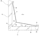
図1〜図4は、本発明の第1実施形態を示したものである。図1に示すように、例えば商業用ビル等の建物(図示省略)の内部又は外部に煙突1が鉛直に立設されている。煙突1は、例えばボイラー、発電機、冷温水発生器などからの排ガスgの放出用であるが、本発明が特にこれに限るものではない。
Hereinafter, embodiments of the present invention will be described with reference to the drawings.
<First embodiment>
1 to 4 show a first embodiment of the present invention. As shown in FIG. 1, a chimney 1 is provided vertically inside or outside a building (not shown) such as a commercial building. The chimney 1 is for discharging exhaust gas g from, for example, a boiler, a generator, a cold / hot water generator, and the like, but the present invention is not particularly limited to this.
煙突1は、煙突本体10と、フレーム20と、内張部材30を備えている。
図2に示すように、煙突本体10の断面形状は四角形(多角形)になっている。詳しくは、煙突本体10は、4つの平板状の煙突壁板11を有している。これら煙突壁板11が互いに四角形の環状に組まれている。隣接する2つの煙突壁板11どうしが直角に交差することによって煙突角部13が形成されている。煙突本体10には4つの煙突角部13が形成されている。各煙突角部13の内角θ13は、θ13=90°である。
図2における煙突本体10の断面は正方形であるが、これに限らず長方形、平行四辺形、台形などであってもよい。
The chimney 1 includes a chimney
As shown in FIG. 2, the sectional shape of the chimney
The cross section of the chimney
煙突壁板11は、珪酸カルシウムを主成分として含む。煙突壁板11は、600℃以上の温度に耐え得る耐熱性を有している。
The
図1に示すように、煙突本体10の外周には、フレーム20が設けられている。フレーム20は、鉛直な縦フレーム部材21と、水平な横フレーム部材22を含む。フレーム部材21,22は、例えばL字アングルなどの鋼材によって構成されている。
As shown in FIG. 1, a
図2に示すように、煙突本体10の内周に内張部材30が設けられている。煙突本体10の各煙突壁板11の内壁面11aが、内張部材30によって覆われている。内張部材30の内部が、排ガスgの通る煙道1aとなっている。
As shown in FIG. 2, an
図3に示すように、内張部材30は、八角形断面の筒形状になっている。要するに、内張部材30は、煙突本体10より多い角数の多角形、好ましくは煙突本体10の角数の2倍の角数の多角形の筒形状に形成されている。
内張部材30の厚さは、1mm程度である。図において内張部材30の厚みは誇張されている。
As shown in FIG. 3, the lining
The thickness of the lining
図2及び図3に示すように、内張部材30は、1枚の金属板39を折り曲げ加工することによって構成されている。金属板39の材質としては、ステンレス、鋼鉄などが挙げられる。該金属板39の折り曲げ加工によって、8つの平板状の内張板部31が形成されている。金属板39の周方向の両端部39e,39eは、互いに突き当てられ、シームレス溶接によって一体化されている。これによって、ビード状のシームレス溶接部32が形成されている。内張部材30は、周方向にセミシームレスの多角形環状となっている。
なお、シームレス溶接部32は、図3においては内張部材30の後記4つの第1内張角部33のうちの1つに配置されているが、これに限らず、後記4つの第2内張角部34のうちの1つに配置されていてもよく、1の内張板部31の中間部に配置されていてもよい。
As shown in FIGS. 2 and 3, the lining
In FIG. 3, the seamless welded
図2に示すように、内張部材30における隣接する2つの内張板部31どうしが交差することによって内張角部33,34が形成されている。内張板部31には8つの内張角部33,34が形成されている。具体的には、内張部材30は、4つの第1内張角部33と、4つの第2内張角部34を有している。内張部材30の周方向に沿って第1内張角部33と第2内張角部34が交互に配置されている。言い換えると、第1内張角部33と第2内張角部34とが周方向に隣接している。
As shown in FIG. 2, two adjacent
各第1内張角部33は、煙突本体10の1の煙突角部13に対して煙突内側に離れて対峙している。第1内張角部33の内角(以下「第1内角θ33」と称す)は、煙突角部13の内角θ13より大きい。好ましくは、第1内角θ33は、θ33=100°〜120°程度である。
第1内張角部33は、煙突角部13から解放されている。したがって、図4に示すように、第1内張角部33は、煙突角部13に対して接近離間するような熱変形及び第1内角θ33が拡縮するような熱変形を許容されている。
Each
The
図2に示すように、第2内張角部34は、煙突本体10の煙突壁板11の内壁面11aの中間部と対峙している。言い換えると、内張部材30における、煙突本体10の内壁面11aの中間部と対峙する部分が屈曲されて第2内張角部34が形成されている。第2内張角部34の内角(以下「第2内角θ34」と称す)は、第1内角θ33より大きい(θ34<θ33)。好ましくは、第2内角θ34は、θ34=120°〜170°程度である。
As shown in FIG. 2, the
第2内張角部34と煙突壁板11との間の距離d2は、第1内張角部33と煙突角部13との間の距離d1より短い(d2<d1)。好ましくは、第2内張角部34は煙突壁板11の内壁面11aにほぼ接しており、d2≒0である。
The distance d 2 between the
第2内張角部34は、拘束部材41によって煙突壁板11に拘束されている。これによって、第2内張角部34が煙突壁板11に対して接近離間するような熱変形を阻止されている。なお、第2内角θ34が拡縮するような第2内張角部34の熱変形は許容されている。
拘束部材41は、例えばアンカーボルトによって構成されている。
The
The restraining
図1に示すように、商業用ビルのボイラや発電機等からの排ガスgは、四角形煙突1の内張部材30の内側の煙道1aを通って大気に放出される。煙突本体10を四角形断面とすることによって円形断面の煙突よりデッドスペースを小さくできる。
煙突壁板11からは珪酸カルシウムを含む粉状の剥離物が遊離され得る。これに対し、内張部材30で煙突本体10の内周を覆っておくことによって、粉状の剥離物が排ガスgと一緒に大気中にまき散らされるのを防止できる。
As shown in FIG. 1, exhaust gas g from a boiler, a generator, and the like in a commercial building is discharged to the atmosphere through a
From the
排ガスgは例えば数百℃〜600℃程度の高温である。かかる高温の排ガスgが内張部材30と接触し、内張部材30が加熱されて熱変形される。詳しくは図4の実線にて示すように、第1内張角部33を挟んで両側の内張板部31が伸び変形し、これに伴って第1内張角部33が煙突角部13へ向かって接近され、第1内角θ33が小さくなる。
なお、図4において二点鎖線は、熱変形していない状態の内張部材30を示す。
換言すると、内張部材30が一定の熱変形を起こすようにでき、熱変形の不規則性を緩和ないしは解消できる。好ましくは、煙道1aが外周側へ広がる方向に熱変形を起こすようにできる。したがって、内張部材30が熱変形を来しても、煙突本体10の内周面と内張部材30の外周面との間の隙間1cに排ガスgが入り込むのを防止できる。この結果、前記粉状剥離物が排ガスgと一緒に大気中に放散されるのを確実に防止できる。更には、高温高湿度の排ガスgが煙突本体10と接触して珪酸カルシウムに吸収されるのを防止でき、煙突本体10が破損するのを防止できる。
加えて、内張部材30はセミシームレス構造であるから、前記高温高湿度の排ガスgが隙間1cに入り込むのを確実に防止できる。したがって、前記粉状剥離物の大気中への放散や煙突本体10の破損を一層確実に防止できる。
The exhaust gas g has a high temperature of, for example, about several hundred degrees C. to 600 degrees C. The high-temperature exhaust gas g comes into contact with the lining
In FIG. 4, a two-dot chain line indicates the lining
In other words, the lining
In addition, since the lining
次に、本発明の他の実施形態を説明する。以下の実施形態において既述の形態と重複する構成に関しては、図面に同一符号を付して説明を省略する。
<第2実施形態>
図5〜図6は、本発明の第2実施形態を示したものである。
図5に示すように、第2実施形態の煙突1Bにおいては、第1内張角部33が、斜めのブラケットからなる拘束部材42によって煙突角部13に拘束されている。第1内張角部33は煙突角部13に対して接近離間するような熱変形を阻止されている。第1内角θ33が拡縮するような第1内張角部33の熱変形は許容されている。
Next, another embodiment of the present invention will be described. In the following embodiments, the same components as those described above are denoted by the same reference numerals in the drawings, and description thereof will be omitted.
<Second embodiment>
5 and 6 show a second embodiment of the present invention.
As shown in FIG. 5, in the
煙突1Bの第2内張角部34は、煙突壁板11から解放されており、かつ煙突壁板11に対して煙突内側に離れている。したがって、第2内張角部34は、煙突壁板11に対して接近離間するような熱変形及び第2内角θ34が拡縮するような熱変形を許容されている。
The
図6の実線に示すように、内張部材30が排ガスgによって加熱されたときは、第2内張角部34を挟んで両側の内張板部31が伸び変形し、これに伴って第2内張角部34が煙突壁板11へ向かって接近され、第2内角θ34が小さくなる。かつ第1内角θ33が大きくなる。このようにして、第2実施形態の煙突1Bにおいても内張部材30が一定の熱変形を起こすようにでき、熱変形の不規則性を緩和ないしは解消できる。
なお、図6において、二点鎖線は、熱変形していない状態の内張部材30を示す。
As shown by the solid line in FIG. 6, when the lining
In FIG. 6, the two-dot chain line indicates the lining
本発明は、前記実施形態に限定されるものではなく、その趣旨を逸脱しない範囲において種々の改変をなすことができる。
例えば、煙突本体の断面形状は、四角形に限られず、三角形や五角形以上の多角形であってもよい。
内張部材の断面形状は、煙突本体の断面形状に合わせた多角形状とする。
内張部材30が、周方向に完全なシームレスの多角形筒形状であってもよい。
The present invention is not limited to the above embodiment, and various modifications can be made without departing from the gist of the present invention.
For example, the cross-sectional shape of the chimney main body is not limited to a quadrangle, but may be a triangle or a polygon such as a pentagon or more.
The cross-sectional shape of the lining member is a polygonal shape that matches the cross-sectional shape of the chimney body.
The lining
本発明は、例えば商業用ビルのボイラや発電機の排ガス用煙突に適用できる。 INDUSTRIAL APPLICABILITY The present invention is applicable to, for example, a boiler of a commercial building and an exhaust gas stack of a generator.
1,1B 煙突
1a 煙道
1c 隙間
10 煙突本体
11 煙突壁板
11a 内壁面
13 煙突角部
30 内張部材
31 内張板部
32 シームレス溶接部
33 第1内張角部
34 第2内張角部
θ13 煙突角部の内角
θ33 第1内角θ33
θ34 第2内角θ34
g 排ガス
1,
θ 34 second internal angle θ 34
g exhaust gas
Claims (8)
前記内張部材が、前記煙突本体より多い角数の多角形の筒形状に形成され、かつ前記煙突本体の1の煙突角部と対峙する前記内張部材の第1内張角部の内角が、前記煙突角部の内角より大きいことを特徴とする煙突。 A chimney body with a polygonal cross section, and a lining member provided on the inner periphery of the chimney body,
The inner lining member is formed in a polygonal cylindrical shape having a larger number of angles than the chimney main body, and the inner angle of the first lining angle portion of the lining member facing the chimney angle portion of one of the chimney main bodies is A chimney characterized by being larger than the inner angle of the chimney corner.
前記煙突本体より多い角数の多角形の筒形状に形成され、かつ前記煙突本体の1の煙突角部と対峙する第1内張角部の内角が、前記煙突角部の内角より大きいことを特徴とする煙突の内張部材。 A lining member provided on the inner periphery of the chimney body having a polygonal cross section,
The interior angle of the first lining angle portion, which is formed in a polygonal cylindrical shape having a larger number of corners than the chimney body and faces the one chimney angle portion of the chimney body, is larger than the interior angle of the chimney angle portion. And chimney lining members.
Priority Applications (1)
| Application Number | Priority Date | Filing Date | Title |
|---|---|---|---|
| JP2018120752A JP7049194B2 (en) | 2018-06-26 | 2018-06-26 | Chimney and its lining member |
Applications Claiming Priority (1)
| Application Number | Priority Date | Filing Date | Title |
|---|---|---|---|
| JP2018120752A JP7049194B2 (en) | 2018-06-26 | 2018-06-26 | Chimney and its lining member |
Publications (2)
| Publication Number | Publication Date |
|---|---|
| JP2020003105A true JP2020003105A (en) | 2020-01-09 |
| JP7049194B2 JP7049194B2 (en) | 2022-04-06 |
Family
ID=69099388
Family Applications (1)
| Application Number | Title | Priority Date | Filing Date |
|---|---|---|---|
| JP2018120752A Active JP7049194B2 (en) | 2018-06-26 | 2018-06-26 | Chimney and its lining member |
Country Status (1)
| Country | Link |
|---|---|
| JP (1) | JP7049194B2 (en) |
Citations (7)
| Publication number | Priority date | Publication date | Assignee | Title |
|---|---|---|---|---|
| US1994809A (en) * | 1932-04-22 | 1935-03-19 | Aloysius J Carr | Combination ventilating system and flue cooling system |
| JPS4877727U (en) * | 1971-12-24 | 1973-09-25 | ||
| JPS5276739A (en) * | 1975-12-22 | 1977-06-28 | Shimizu Construction Co Ltd | Steel inner cylinder for reinforced concrete stack |
| JPS5684384A (en) * | 1979-12-10 | 1981-07-09 | Nippon Asbestos Co Ltd | Manufacture of duct material for combustion gas |
| JPS60165416A (en) * | 1984-12-12 | 1985-08-28 | Hokkaido Nouzai Kogyo Kk | Ceramic pipe |
| CN201209873Y (en) * | 2008-04-17 | 2009-03-18 | 中冶东方工程技术有限公司上海分公司 | Chimney |
| JP2017015277A (en) * | 2015-06-29 | 2017-01-19 | コーキ株式会社 | chimney |
-
2018
- 2018-06-26 JP JP2018120752A patent/JP7049194B2/en active Active
Patent Citations (7)
| Publication number | Priority date | Publication date | Assignee | Title |
|---|---|---|---|---|
| US1994809A (en) * | 1932-04-22 | 1935-03-19 | Aloysius J Carr | Combination ventilating system and flue cooling system |
| JPS4877727U (en) * | 1971-12-24 | 1973-09-25 | ||
| JPS5276739A (en) * | 1975-12-22 | 1977-06-28 | Shimizu Construction Co Ltd | Steel inner cylinder for reinforced concrete stack |
| JPS5684384A (en) * | 1979-12-10 | 1981-07-09 | Nippon Asbestos Co Ltd | Manufacture of duct material for combustion gas |
| JPS60165416A (en) * | 1984-12-12 | 1985-08-28 | Hokkaido Nouzai Kogyo Kk | Ceramic pipe |
| CN201209873Y (en) * | 2008-04-17 | 2009-03-18 | 中冶东方工程技术有限公司上海分公司 | Chimney |
| JP2017015277A (en) * | 2015-06-29 | 2017-01-19 | コーキ株式会社 | chimney |
Also Published As
| Publication number | Publication date |
|---|---|
| JP7049194B2 (en) | 2022-04-06 |
Similar Documents
| Publication | Publication Date | Title |
|---|---|---|
| JP6245202B2 (en) | Brick structure repair method and coke oven flue repair method | |
| US20180328226A1 (en) | Turbine housing | |
| US5787709A (en) | Exhaust manifold | |
| KR20190012261A (en) | Clip with insulating layer | |
| JP2020003105A (en) | Chimney and lining member of the same | |
| JP5798676B1 (en) | Chimney for building | |
| KR101734783B1 (en) | Dual Exhaust Pipe with Air Tight Socket | |
| JP5237064B2 (en) | Exhaust duct | |
| JP6152809B2 (en) | Beam-column joint structure | |
| KR20210099016A (en) | Connections, exhaust gas sensors and sensor systems | |
| KR20100011498U (en) | Inner pipe connecting structure of chimney stack | |
| JP2022057671A (en) | Chimney for building | |
| JP2022057672A (en) | Chimney for building | |
| JP3245067U (en) | chimney | |
| JP2022057670A (en) | Chimney for building | |
| JP2006192445A (en) | Structure for positioning pipe end joint of duplex pipe to be welded to another member | |
| JP2016188747A (en) | Connection structure of chimney | |
| KR101829035B1 (en) | Leakage prevention structure for duct duct assembly | |
| JP5969370B2 (en) | Thermal insulation panels and insulation | |
| WO2023120095A1 (en) | Ring tray for honeycomb substrate firing | |
| JPH11166397A (en) | Covered conduit excellent in corrosion resistance | |
| CN213888902U (en) | Sheet metal part welding device | |
| JP7194062B2 (en) | Brick stack for coke oven and its manufacturing method | |
| JPH11166398A (en) | Repairing method of covered conduit | |
| JP2023148630A (en) | Chimney for building |
Legal Events
| Date | Code | Title | Description |
|---|---|---|---|
| A621 | Written request for application examination |
Free format text: JAPANESE INTERMEDIATE CODE: A621 Effective date: 20210405 |
|
| A977 | Report on retrieval |
Free format text: JAPANESE INTERMEDIATE CODE: A971007 Effective date: 20220222 |
|
| TRDD | Decision of grant or rejection written | ||
| A01 | Written decision to grant a patent or to grant a registration (utility model) |
Free format text: JAPANESE INTERMEDIATE CODE: A01 Effective date: 20220301 |
|
| A61 | First payment of annual fees (during grant procedure) |
Free format text: JAPANESE INTERMEDIATE CODE: A61 Effective date: 20220325 |
|
| R150 | Certificate of patent or registration of utility model |
Ref document number: 7049194 Country of ref document: JP Free format text: JAPANESE INTERMEDIATE CODE: R150 |