JP2020003060A - Modular valve with O-ring valve seat - Google Patents
Modular valve with O-ring valve seat Download PDFInfo
- Publication number
- JP2020003060A JP2020003060A JP2019075236A JP2019075236A JP2020003060A JP 2020003060 A JP2020003060 A JP 2020003060A JP 2019075236 A JP2019075236 A JP 2019075236A JP 2019075236 A JP2019075236 A JP 2019075236A JP 2020003060 A JP2020003060 A JP 2020003060A
- Authority
- JP
- Japan
- Prior art keywords
- valve
- valve member
- bush
- solenoid
- pole piece
- Prior art date
- Legal status (The legal status is an assumption and is not a legal conclusion. Google has not performed a legal analysis and makes no representation as to the accuracy of the status listed.)
- Pending
Links
- 239000012530 fluid Substances 0.000 claims abstract description 35
- 238000004891 communication Methods 0.000 claims abstract description 14
- 239000000696 magnetic material Substances 0.000 claims description 13
- 230000003068 static effect Effects 0.000 claims description 10
- 230000036316 preload Effects 0.000 claims description 7
- 230000004907 flux Effects 0.000 claims description 4
- 239000012141 concentrate Substances 0.000 claims description 3
- 239000000463 material Substances 0.000 abstract description 17
- 239000000853 adhesive Substances 0.000 abstract description 10
- 230000001070 adhesive effect Effects 0.000 abstract description 10
- 229920001971 elastomer Polymers 0.000 abstract description 7
- 239000000806 elastomer Substances 0.000 abstract description 3
- 239000013536 elastomeric material Substances 0.000 description 5
- 238000000034 method Methods 0.000 description 4
- 239000005060 rubber Substances 0.000 description 4
- 230000015556 catabolic process Effects 0.000 description 3
- 238000005260 corrosion Methods 0.000 description 3
- 230000007797 corrosion Effects 0.000 description 3
- 238000006731 degradation reaction Methods 0.000 description 3
- 230000005672 electromagnetic field Effects 0.000 description 3
- 239000002184 metal Substances 0.000 description 3
- 229910052751 metal Inorganic materials 0.000 description 3
- 229920006169 Perfluoroelastomer Polymers 0.000 description 2
- 239000007767 bonding agent Substances 0.000 description 2
- 239000000356 contaminant Substances 0.000 description 2
- 230000035699 permeability Effects 0.000 description 2
- 239000004033 plastic Substances 0.000 description 2
- 239000000126 substance Substances 0.000 description 2
- RYGMFSIKBFXOCR-UHFFFAOYSA-N Copper Chemical compound [Cu] RYGMFSIKBFXOCR-UHFFFAOYSA-N 0.000 description 1
- 229920000459 Nitrile rubber Polymers 0.000 description 1
- 150000001875 compounds Chemical class 0.000 description 1
- 238000005516 engineering process Methods 0.000 description 1
- 239000000976 ink Substances 0.000 description 1
- 238000012986 modification Methods 0.000 description 1
- 230000004048 modification Effects 0.000 description 1
- 238000004806 packaging method and process Methods 0.000 description 1
- 229920000642 polymer Polymers 0.000 description 1
- 239000007787 solid Substances 0.000 description 1
Images


Classifications
-
- F—MECHANICAL ENGINEERING; LIGHTING; HEATING; WEAPONS; BLASTING
- F16—ENGINEERING ELEMENTS AND UNITS; GENERAL MEASURES FOR PRODUCING AND MAINTAINING EFFECTIVE FUNCTIONING OF MACHINES OR INSTALLATIONS; THERMAL INSULATION IN GENERAL
- F16K—VALVES; TAPS; COCKS; ACTUATING-FLOATS; DEVICES FOR VENTING OR AERATING
- F16K31/00—Actuating devices; Operating means; Releasing devices
- F16K31/02—Actuating devices; Operating means; Releasing devices electric; magnetic
- F16K31/06—Actuating devices; Operating means; Releasing devices electric; magnetic using a magnet, e.g. diaphragm valves, cutting off by means of a liquid
- F16K31/0644—One-way valve
- F16K31/0655—Lift valves
- F16K31/0658—Armature and valve member being one single element
-
- F—MECHANICAL ENGINEERING; LIGHTING; HEATING; WEAPONS; BLASTING
- F16—ENGINEERING ELEMENTS AND UNITS; GENERAL MEASURES FOR PRODUCING AND MAINTAINING EFFECTIVE FUNCTIONING OF MACHINES OR INSTALLATIONS; THERMAL INSULATION IN GENERAL
- F16K—VALVES; TAPS; COCKS; ACTUATING-FLOATS; DEVICES FOR VENTING OR AERATING
- F16K31/00—Actuating devices; Operating means; Releasing devices
- F16K31/02—Actuating devices; Operating means; Releasing devices electric; magnetic
- F16K31/06—Actuating devices; Operating means; Releasing devices electric; magnetic using a magnet, e.g. diaphragm valves, cutting off by means of a liquid
-
- F—MECHANICAL ENGINEERING; LIGHTING; HEATING; WEAPONS; BLASTING
- F16—ENGINEERING ELEMENTS AND UNITS; GENERAL MEASURES FOR PRODUCING AND MAINTAINING EFFECTIVE FUNCTIONING OF MACHINES OR INSTALLATIONS; THERMAL INSULATION IN GENERAL
- F16K—VALVES; TAPS; COCKS; ACTUATING-FLOATS; DEVICES FOR VENTING OR AERATING
- F16K1/00—Lift valves or globe valves, i.e. cut-off apparatus with closure members having at least a component of their opening and closing motion perpendicular to the closing faces
- F16K1/32—Details
- F16K1/34—Cutting-off parts, e.g. valve members, seats
- F16K1/36—Valve members
- F16K1/38—Valve members of conical shape
- F16K1/385—Valve members of conical shape contacting in the closed position, over a substantial axial length, a seat surface having the same inclination
-
- F—MECHANICAL ENGINEERING; LIGHTING; HEATING; WEAPONS; BLASTING
- F16—ENGINEERING ELEMENTS AND UNITS; GENERAL MEASURES FOR PRODUCING AND MAINTAINING EFFECTIVE FUNCTIONING OF MACHINES OR INSTALLATIONS; THERMAL INSULATION IN GENERAL
- F16K—VALVES; TAPS; COCKS; ACTUATING-FLOATS; DEVICES FOR VENTING OR AERATING
- F16K1/00—Lift valves or globe valves, i.e. cut-off apparatus with closure members having at least a component of their opening and closing motion perpendicular to the closing faces
- F16K1/32—Details
- F16K1/34—Cutting-off parts, e.g. valve members, seats
- F16K1/42—Valve seats
-
- F—MECHANICAL ENGINEERING; LIGHTING; HEATING; WEAPONS; BLASTING
- F16—ENGINEERING ELEMENTS AND UNITS; GENERAL MEASURES FOR PRODUCING AND MAINTAINING EFFECTIVE FUNCTIONING OF MACHINES OR INSTALLATIONS; THERMAL INSULATION IN GENERAL
- F16K—VALVES; TAPS; COCKS; ACTUATING-FLOATS; DEVICES FOR VENTING OR AERATING
- F16K1/00—Lift valves or globe valves, i.e. cut-off apparatus with closure members having at least a component of their opening and closing motion perpendicular to the closing faces
- F16K1/32—Details
- F16K1/34—Cutting-off parts, e.g. valve members, seats
- F16K1/46—Attachment of sealing rings
- F16K1/465—Attachment of sealing rings to the valve seats
-
- F—MECHANICAL ENGINEERING; LIGHTING; HEATING; WEAPONS; BLASTING
- F16—ENGINEERING ELEMENTS AND UNITS; GENERAL MEASURES FOR PRODUCING AND MAINTAINING EFFECTIVE FUNCTIONING OF MACHINES OR INSTALLATIONS; THERMAL INSULATION IN GENERAL
- F16K—VALVES; TAPS; COCKS; ACTUATING-FLOATS; DEVICES FOR VENTING OR AERATING
- F16K11/00—Multiple-way valves, e.g. mixing valves; Pipe fittings incorporating such valves
- F16K11/02—Multiple-way valves, e.g. mixing valves; Pipe fittings incorporating such valves with all movable sealing faces moving as one unit
- F16K11/04—Multiple-way valves, e.g. mixing valves; Pipe fittings incorporating such valves with all movable sealing faces moving as one unit comprising only lift valves
- F16K11/044—Multiple-way valves, e.g. mixing valves; Pipe fittings incorporating such valves with all movable sealing faces moving as one unit comprising only lift valves with movable valve members positioned between valve seats
-
- F—MECHANICAL ENGINEERING; LIGHTING; HEATING; WEAPONS; BLASTING
- F16—ENGINEERING ELEMENTS AND UNITS; GENERAL MEASURES FOR PRODUCING AND MAINTAINING EFFECTIVE FUNCTIONING OF MACHINES OR INSTALLATIONS; THERMAL INSULATION IN GENERAL
- F16K—VALVES; TAPS; COCKS; ACTUATING-FLOATS; DEVICES FOR VENTING OR AERATING
- F16K25/00—Details relating to contact between valve members and seat
- F16K25/005—Particular materials for seats or closure elements
-
- F—MECHANICAL ENGINEERING; LIGHTING; HEATING; WEAPONS; BLASTING
- F16—ENGINEERING ELEMENTS AND UNITS; GENERAL MEASURES FOR PRODUCING AND MAINTAINING EFFECTIVE FUNCTIONING OF MACHINES OR INSTALLATIONS; THERMAL INSULATION IN GENERAL
- F16K—VALVES; TAPS; COCKS; ACTUATING-FLOATS; DEVICES FOR VENTING OR AERATING
- F16K27/00—Construction of housing; Use of materials therefor
- F16K27/02—Construction of housing; Use of materials therefor of lift valves
- F16K27/0254—Construction of housing; Use of materials therefor of lift valves with conical shaped valve members
-
- F—MECHANICAL ENGINEERING; LIGHTING; HEATING; WEAPONS; BLASTING
- F16—ENGINEERING ELEMENTS AND UNITS; GENERAL MEASURES FOR PRODUCING AND MAINTAINING EFFECTIVE FUNCTIONING OF MACHINES OR INSTALLATIONS; THERMAL INSULATION IN GENERAL
- F16K—VALVES; TAPS; COCKS; ACTUATING-FLOATS; DEVICES FOR VENTING OR AERATING
- F16K27/00—Construction of housing; Use of materials therefor
- F16K27/02—Construction of housing; Use of materials therefor of lift valves
- F16K27/029—Electromagnetically actuated valves
-
- F—MECHANICAL ENGINEERING; LIGHTING; HEATING; WEAPONS; BLASTING
- F16—ENGINEERING ELEMENTS AND UNITS; GENERAL MEASURES FOR PRODUCING AND MAINTAINING EFFECTIVE FUNCTIONING OF MACHINES OR INSTALLATIONS; THERMAL INSULATION IN GENERAL
- F16K—VALVES; TAPS; COCKS; ACTUATING-FLOATS; DEVICES FOR VENTING OR AERATING
- F16K31/00—Actuating devices; Operating means; Releasing devices
- F16K31/02—Actuating devices; Operating means; Releasing devices electric; magnetic
- F16K31/06—Actuating devices; Operating means; Releasing devices electric; magnetic using a magnet, e.g. diaphragm valves, cutting off by means of a liquid
- F16K31/0644—One-way valve
- F16K31/0655—Lift valves
-
- F—MECHANICAL ENGINEERING; LIGHTING; HEATING; WEAPONS; BLASTING
- F16—ENGINEERING ELEMENTS AND UNITS; GENERAL MEASURES FOR PRODUCING AND MAINTAINING EFFECTIVE FUNCTIONING OF MACHINES OR INSTALLATIONS; THERMAL INSULATION IN GENERAL
- F16K—VALVES; TAPS; COCKS; ACTUATING-FLOATS; DEVICES FOR VENTING OR AERATING
- F16K31/00—Actuating devices; Operating means; Releasing devices
- F16K31/02—Actuating devices; Operating means; Releasing devices electric; magnetic
- F16K31/06—Actuating devices; Operating means; Releasing devices electric; magnetic using a magnet, e.g. diaphragm valves, cutting off by means of a liquid
- F16K31/0675—Electromagnet aspects, e.g. electric supply therefor
Abstract
Description
本開示は、電磁モジュラーバルブに関する。 The present disclosure relates to electromagnetic modular valves.
このセクションは、本発明の開示に関連する背景技術情報を提供するが、これは必ずしも先行技術ではない。 This section provides background information related to the present disclosure, but this is not necessarily prior art.
電磁弁は、ソータ、包装機、フードプロセッサ等の様々な異なる用途で頻繁に用いられる。これらのバルブは、流体の流れの制御に用いられ、数百万回にわたり作動する可能性がある。電磁弁は、通常、コイルと電機子を備える。コイルに電力が供給されると(すなわち、ソレノイドに通電すると)、コイルは、電機子に電磁力を印加する。バルブ部材は、電機子の動きに応じて、開位置と閉位置の間を、電磁弁のバルブ本体内で、長手方向に移動する。バルブ本体は弁座を有し、バルブ部材は当接面を有する。バルブ部材の当接面は、バルブ部材が開位置にある時にバルブ本体の弁座から離間し、バルブ部材が閉位置にある時にバルブ本体の弁座と当接する。バネ等の付勢部材は、コイルが電機子に印加する電磁力に抵抗するのに用いられる。
電磁バルブの構成に応じて、付勢部材は、バルブ部材を弁座に押しつける(一般に常時閉バルブと呼ばれるもの)、または、弁座から離間させる(一般に常時開バルブと呼ばれる)。
Solenoid valves are frequently used in a variety of different applications, such as sorters, packaging machines, food processors, and the like. These valves are used to control the flow of fluids and can operate millions of times. The solenoid valve usually includes a coil and an armature. When power is supplied to the coil (ie, when the solenoid is energized), the coil applies an electromagnetic force to the armature. The valve member moves in the longitudinal direction within the valve body of the solenoid valve between the open position and the closed position according to the movement of the armature. The valve body has a valve seat, and the valve member has an abutment surface. The contact surface of the valve member is separated from the valve seat of the valve body when the valve member is in the open position, and contacts the valve seat of the valve body when the valve member is in the closed position. A biasing member such as a spring is used to resist the electromagnetic force applied by the coil to the armature.
Depending on the configuration of the electromagnetic valve, the biasing member presses the valve member against a valve seat (generally referred to as a normally closed valve) or separates from the valve seat (generally referred to as a normally open valve).
漏れ止めシールを提供するために、バルブ部材の当接面は、エラストマー材料で形成されることが多い。従来、バルブ部材は金属またはプラスチックで製造され、エラストマー材料はバルブ部材の金属またはプラスチックに被覆成形されるか接合される。他の構成では、エラストマー材料は、バルブ部材に接着剤で固定される。このようなバルブで使用されるエラストマー材料の種類は、バルブ部材または接着剤に接合されるのに適した材料に限定される。このような材料の欠点の一つは、特定の流体と接触すると、しばしば劣化および/または腐食しやすいことである。その結果、このようなバルブは、電磁弁を流れる流体が、当接面を形成するエラストマー材料に対して腐食性がある場合や、エラストマー材料をバルブ部材に固定する接合剤または接着剤に対して腐食性がある用途にはあまり適していない。 To provide a leak tight seal, the abutment surface of the valve member is often formed of an elastomeric material. Conventionally, the valve member is made of metal or plastic, and the elastomeric material is overmolded or bonded to the metal or plastic of the valve member. In another configuration, the elastomeric material is adhesively secured to the valve member. The type of elastomeric material used in such valves is limited to materials suitable for being joined to the valve member or adhesive. One disadvantage of such materials is that they are often susceptible to degradation and / or corrosion when in contact with certain fluids. As a result, such a valve may be used when the fluid flowing through the solenoid valve is corrosive to the elastomer material forming the abutting surface, or when the adhesive or the adhesive fixing the elastomer material to the valve member is used. Not very suitable for corrosive applications.
このセクションは、本開示の概要を提供するが、全範囲または特徴の全ての包含的開示ではない。 This section provides an overview of the disclosure, but is not an exhaustive disclosure of all its scope or features.
本開示は、バルブ本体と、バルブ本体の内部孔に摺動可能に収容されるバルブ部材と、開位置と閉位置の間を長手軸に沿って、バルブ本体に対してバルブ部材を移動させるソレノイドと、を備える電磁モジュラーバルブを提供する。バルブ本体は端面と側面を有する。端面の流出口も、バルブ本体の内部孔と流体連通して設けられる。側面の流入口も、バルブ本体の内部孔と流体連通して設けられる。バルブ本体は、端面とは反対側に接続端部を備える。ソレノイドは、バルブ本体の接続端部に接続されるソレノイド本体と、ソレノイド本体の内部に配置されるコイルとを備える。ソレノイドのコイルが通電されると、ソレノイドは、開位置および/または閉位置の間で長手軸に沿って、バルブ本体に対してバルブ部材を移動させる。 The present disclosure relates to a valve body, a valve member slidably received in an inner hole of the valve body, and a solenoid for moving the valve member with respect to the valve body along a longitudinal axis between an open position and a closed position. And an electromagnetic modular valve comprising: The valve body has an end face and side faces. An outlet at the end face is also provided in fluid communication with the internal bore of the valve body. A side inlet is also provided in fluid communication with the internal bore of the valve body. The valve body has a connection end on the side opposite to the end face. The solenoid includes a solenoid body connected to a connection end of the valve body, and a coil arranged inside the solenoid body. When the coil of the solenoid is energized, the solenoid moves the valve member relative to the valve body along the longitudinal axis between an open position and / or a closed position.
本開示によれば、バルブ本体は、長手方向において内部孔と流出口の間に配置されるOリング弁座を備える。さらに、バルブ部材は、円錐台形状のテーパー端部、およびバルブ部材当接面を有する。バルブ部材当接面は、バルブ部材が閉位置にある時、Oリング弁座と当接し、バルブ部材が開位置にある時、Oリング弁座から離間する。その結果、バルブ部材は、開位置では、内部孔の内部および流入口と流出口の間を流体が流れるのを可能にし、閉位置ではその流れを遮断する。 According to the present disclosure, the valve body includes an O-ring valve seat disposed between the internal bore and the outlet in the longitudinal direction. Furthermore, the valve member has a frusto-conical tapered end and a valve member contact surface. The valve member abutment surface abuts the O-ring valve seat when the valve member is in the closed position and separates from the O-ring valve seat when the valve member is in the open position. As a result, the valve member allows fluid to flow within the interior bore and between the inlet and outlet in the open position and shuts off the flow in the closed position.
有利なことには、Oリング弁座の材料は、バルブ部材に接合したり、接着剤で固定する必要がない。これは、Oリング弁座の材料が、バルブ部材の材料または接着剤に対する接合性ではなくて、特定の流体による劣化および/または腐食に対する化学的耐性の点で選択可能であることを意味する。したがって、特に、従来のバルブ部材の当接面を形成するのに使用されるエラストマー材料、接合剤および/または接着剤を攻撃する(例えば、腐食させる)流体の流れを制御するために電磁モジュラーバルブが使用される用途において、本発明の電磁モジュラーバルブにより、より十全に密封可能である。 Advantageously, the material of the O-ring valve seat does not need to be bonded to the valve member or secured with an adhesive. This means that the material of the O-ring valve seat is selectable in terms of its chemical resistance to degradation and / or corrosion by a particular fluid, rather than its bondability to the valve member material or adhesive. Thus, in particular, electromagnetic modular valves for controlling the flow of fluids that attack (e.g., corrode) the elastomeric materials, bonding agents and / or adhesives used to form the abutment surfaces of conventional valve members. In applications where is used, the electromagnetic modular valve of the present invention is more fully sealable.
さらなる利用分野は、ここに示される記載から明らかになるであろう。この概要における説明および特定の実施例は、説明のためのみであり、本開示の範囲を限定するものではない。 Further areas of application will become apparent from the description provided herein. The description and specific examples in this summary are illustrative only and do not limit the scope of the present disclosure.
本明細書における図面は、選択された実施形態の図解のためのみであり、全ての可能な実施のためではなく、本開示の範囲を限定するものではない。
添付の図面を参照して、より詳細に実施形態を説明する。 Embodiments will be described in more detail with reference to the accompanying drawings.
この開示が詳細かつ当業者に発明範囲を十分伝えるように、実施形態を示す。特定部品、装置および方法の例として多くの特定の詳細が記載され、本開示の実施形態を完全に理解させる。特定の詳細が用いられる必要はないこと、実施形態は多くの異なる形状で具現化可能なこと、およびどちらも発明の範囲を限定するものと解釈すべきでないことは、当業者にとって自明であろう。いくつかの実施例において、公知のプロセス、公知の装置構造、および公知の技術は詳細には記載されない。 Embodiments are provided so that this disclosure will be thorough and will fully convey the scope of the invention to those skilled in the art. Many specific details are described as examples of specific components, devices, and methods to provide a thorough understanding of embodiments of the present disclosure. It will be obvious to one skilled in the art that specific details need not be used, embodiments may be embodied in many different forms, and neither should be construed as limiting the scope of the invention. . In some embodiments, well-known processes, well-known device structures, and well-known technologies are not described in detail.
本明細書で用いられる用語は、特定の実施例を記載するためのみであり、限定的であることを意図しない。本明細書で使用される際、単数形は、明示されていない限り複数形も含むことを意図する。用語「備える」、「備えて」、「含んで」および「有して」は包括的であり、述べられた特徴、整数、工程、操作、要素、および/または部品の存在を特定する。しかし、1以上の特徴、整数、工程、操作、要素、部品および/または群の存在または追加を排除するものではない。本明細書で記載される方法工程、プロセスおよび操作は、実行順序として詳細に特定されない限り、必ずしも記載または図示された特定の順序で実行を要するものと解釈されるべきではない。追加工程または代替工程が用いられてもよいことも理解される。 The terms used in the description are intended to describe certain embodiments only, and are not intended to be limiting. As used herein, the singular is intended to include the plural unless specifically stated otherwise. The terms "comprising," "including," "including," and "having" are inclusive and identify the presence of the stated feature, integer, step, operation, element, and / or component. However, this does not preclude the presence or addition of one or more features, integers, steps, operations, elements, parts and / or groups. The method steps, processes, and operations described herein should not necessarily be construed as requiring execution in the particular order described or illustrated, unless otherwise specified. It is also understood that additional or alternative steps may be used.
要素または層が、他の要素または層「上に」ある、「に係合」、「に接続」または「に連結」すると記される場合、この要素または層は直接に他の要素または層上にあるか、係合、接続、または連結してもよい。または、介在要素または層があってもよい。一方、要素が、他の要素または層の「直接上に」ある、「に直接係合」、「に直接接続」または「に直接連結」すると記される場合、介在要素または層は存在しなくてよい。要素同士の関係を説明するのに使用される他の文言(例えば、「の間に」と「直接〜の間に」、「隣接して」と「直接隣接して」など)は、同様に解釈されるべきである。本明細書で用いられる際、用語「および/または」は1以上の関連づけられたリスト項目の全ての組み合わせを含む。 When an element or layer is described as "engaged with," "connected to," or "coupled to," it is "on" another element or layer, the element or layer is directly on another element or layer. Or may be engaged, connected, or connected. Alternatively, there may be intervening elements or layers. On the other hand, if an element is described as being "directly on," "directly engaged with," "directly connected to" or "directly connected to" another element or layer, then no intervening element or layer is present. May be. Other terms used to describe the relationship between elements (e.g., "between" and "directly between," "adjacent" and "directly adjacent," etc.) Should be interpreted. As used herein, the term “and / or” includes any and all combinations of one or more associated listings.
第一、第二、第三等の用語が各種要素、部品、領域、層および/または切断面を説明するために本明細書で使用されるが、これらの要素、部品、領域、層および/または切断面はこれらの用語により限定されるものではない。これらの用語は、ある要素、部品、領域、層および/または切断面を他の領域、層または切断面から区別するためにのみ使用されてもよい。本明細書で使用される際の「第一」「第二」のような用語および他の数に関する用語は、文脈で明示されない限り、配列または順序を意味しない。したがって、下記で論じられる第一要素、部品、領域、層および/または切断面は、実施例の教示から逸脱することなく第二要素、部品、領域、層および/または切断面と称されることも可能である。 The terms first, second, third and the like are used herein to describe various elements, components, regions, layers and / or cut surfaces, but these elements, components, regions, layers and / or Alternatively, the cut surface is not limited by these terms. These terms may only be used to distinguish one element, component, region, layer and / or section from another region, layer or section. Terms such as "first," "second," and other numerical terms as used herein do not imply a sequence or order, unless context clearly indicates otherwise. Accordingly, a first element, component, region, layer and / or cut surface discussed below may be referred to as a second element, component, region, layer and / or cut surface without departing from the teachings of the examples. Is also possible.
「インナー」、「アウター」、「真下に」、「下に」、「下側の」「上に」、「上部に」等のような空間的に相対的な用語が、図示する際、ある要素または特徴と他の要素または特徴との関係の記載を容易にするために、本明細書で使われてもよい。空間的に相対的な用語は、図示される向きに加えて、使用時または操作時における装置の異なる向きを包含するとしてもよい。例えば、図の装置がひっくり返ると、他の要素または特徴の「下に」または「真下に」と記載される要素は、他の要素または特徴の「上に」置かれるだろう。このように、例示的な用語「下に」は上と下両方への向きを包含することが可能である。装置は他方向に向かされてもよい(90度回転または他の向きに)。本明細書で使用される空間関連記述子は適宜解釈される。本明細書で使用される用語「磁性材料」は、0.000005ヘンリーパーメーター(H/m)を超える透磁率を有する材料を意味し、用語「非磁性材料」は、0.000005ヘンリーパーメーター(H/m)未満の透磁率を有する材料を意味する。 Spatial relative terms such as “inner”, “outer”, “below”, “below”, “below”, “above”, “above” etc. It may be used herein to facilitate describing the relationship between an element or feature and another element or feature. Spatial relative terms may encompass different orientations of the device in use or operation in addition to the orientation shown. For example, if the depicted apparatus is turned over, an element described as "below" or "directly below" another element or feature will be placed "above" the other element or feature. Thus, the exemplary term “below” can encompass both an upward and downward orientation. The device may be oriented in the other direction (90 degree rotation or other orientation). Space-related descriptors used in this specification are interpreted as appropriate. As used herein, the term "magnetic material" refers to a material having a magnetic permeability greater than 0.000005 Henry per meter (H / m), and the term "non-magnetic material" refers to 0.000005 Henry per meter. A material having a magnetic permeability of less than (H / m).
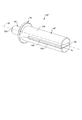
図1〜4を参照し、常時閉電磁モジュラーバルブ20を説明する。常時閉電磁モジュラーバルブ20は、バルブ本体22と、バルブ本体22に摺動可能に収容されるバルブ部材24と、閉位置(図2)と開位置(図3)の間を長手軸28に沿って、バルブ本体22に対してバルブ部材24を移動させるソレノイド26とを備える。バルブ本体22は、端面30、側面32および内部孔34を有する。端面30にある流出口36は、バルブ本体22の内部孔34と流体連通して設けられる。側面32にある流入口38は、バルブ本体22の内部孔34と流体連通して設けられる。バルブ本体22は、端面30とは反対側に接続端部40も備える。バルブ本体22は、多種多様な異なる材料で製造されてもよい。限定的でない例として、バルブ本体22は、金属またはポリマー製であってもよい。バルブ本体22の側面32に沿って、1つ以上のアウターシール42を設けてもよい。限定的でない例として、アウターシール42a、42bは、ゴム製のOリングのようなエラストマー材料で製造されてもよい。
The normally closed electromagnetic
バルブ部材24は、プランジャ部44、ピストン部46および電機子部48を備える。
バルブ部材24のプランジャ部44は、バルブ本体22の内部孔34内に配置され、流出口36に向かって長手軸28に沿って延出する。バルブ部材24の電機子部48は、長手軸28に沿って、バルブ本体22の内部孔34からソレノイド26内部に延出する。バルブ部材24のピストン部46は、長手方向において、プランジャ部44と電機子部48との間で配置される。
バルブ部材24は、バルブ部材直径50を有する。バルブ部材直径50は、プランジャ部44や電機子部48よりも、ピストン部46において大きい。バルブ部材24のピストン部46は、バルブ本体22の内部孔34と滑合して摺動可能に配置される。とは言うものの、ピストン部46は、バルブ本体22の内部孔34を密封してもよいし、しなくてもよい。図示される例のように、ピストン部46がバルブ本体22の内部孔34を封止しない構成において、流入口38を介して内部孔34に流入する流体は、バルブ部材24のピストン部46とバルブ本体22との間を流通可能である。バルブ部材24は、複数の部品を組み立てたものであってもよいが、図示される例では、プランジャ部44、ピストン部46および電機子部48が一体として、バルブ部材24をなす一体型構造である。
The
The
The
ソレノイド26は、第一端部52と第二端部54との間で長手方向に延出する。ソレノイド26は、ソレノイド本体56、コイル58、ボビン60、および磁極片62を備える。ソレノイド本体56は、ソレノイド26の第一端部52で、バルブ本体22の接続端部40に接続される。バルブ本体22の接続端部40は、様々な異なる方法で、ソレノイド本体56に接続されてもよい。図示される例では、バルブ本体22の接続端部40は、ソレノイド26の第一端部52に設けられた螺合部64によってソレノイド本体56に接続される。ソレノイド本体56は、ソレノイド26の第一端部52に設けられるねじ山68を有する外側面66を備えてもよい。コイル58は、ソレノイド本体56内部に配置される。ソレノイド本体56は、ソレノイド26の第二端部54で、コイル58を覆って径方向内側に延出し、エンドキャップ70に装着される。他の構成も可能であるが、図示される例では、コイル58は、ボビン60の回りに環状に巻きつけられる導電性ワイヤである。限定的でない例として、コイル58は、銅線からなってもよい。電気コネクタ72は、コイル58に電気的に接続される。電気コネクタ72は、ソレノイド本体56およびエンドキャップ70を貫通して延出し、図示されない電源と接続するためのインターフェースとなる。
The
コイル58は、コイル58を通して流れる電流に応じて電磁場を発生させる。磁極片62は、ソレノイド26の第二端部54からコイル58内部に延出する。バルブ部材24の電機子部48は、ソレノイド26の第一端部52からコイル58に延出する。閉位置(図2)において、磁極片62とバルブ部材24の電機子部48とは、長手方向に隙間74だけ離間している。磁極片62およびバルブ部材24の電機子部48は、磁性材料で製造されている。コイル58により発生した電磁場により、磁極片62は、バルブ部材24に電磁力76を加え、磁極片62側にバルブ部材24の電機子部48を引っ張る(すなわち、引き寄せる)。ソレノイド26がバルブ部材24に加える電磁力76により、バルブ部材24は、バルブ本体22に対して長手軸28に沿って、開位置側に移動する。その結果、バルブ部材24の電機子部48と磁極片62との間の隙間74は、バルブ部材24が開位置にくると、狭まるか消失する(図3)。
The
磁極片62は、ボビン60内に移動可能に配置され、さらに、ソレノイド本体56と螺合するねじ端部78を備えてもよい。磁極片62のねじ端部78により、ボビン60に対する磁極片62の長手方向位置が調整可能である。ソレノイド本体56に対して磁極片62が回転することで、バルブ部材24のストローク長さ(すなわち、バルブ部材24が開位置と閉位置との間を長手軸28に沿って移動する距離)が変わる。図示される例に示されるように、磁極片62のねじ端部78は、ソレノイド本体56に対する磁極片62の回転調整を容易にするツールインターフェイス80を備えてもよい。
The
常時閉電磁モジュラーバルブ20は、第一ブッシュ82および第二ブッシュ84を備える。第一ブッシュ82は、ブッシュフランジ86および筒状部88を有する。ブッシュフランジ86は、長手方向においてバルブ本体22の接続端部40とコイル58との間に配置される。したがって、ブッシュフランジ86は、コイル58に対して第一ブッシュ82が長手方向に移動するのを防止する。インナーシール90を、バルブ本体22の接続端部40とブッシュフランジ86との間に配置してもよい。他の構成も可能であるが、インナーシール90は、ゴム製Оリングであってもよい。第一ブッシュ82の筒状部88は、ブッシュフランジ86から延出し、ボビン60に収容される。第一ブッシュ82の筒状部88は、磁極片62とバルブ部材24の電機子部48との間の隙間74を越えて延出する長手方向長さ92を有する。その結果、第一ブッシュ82の筒状部88は、バルブ部材24の電機子部48および磁極片62の少なくとも一部の回りを環状に延出する。したがって、第一ブッシュ82の筒状部88は、径方向においてボビン60とバルブ部材24の電機子部48との間に配置され、かつ、径方向においてボビン60と磁極片62との間に配置される。第一ブッシュ82は、複数の部品を組み立てたものであってもよいが、図示される例では、ブッシュフランジ86および筒状部88が一体として、第一ブッシュ82をなす一体型構造である。
The normally closed electromagnetic
第二ブッシュ84は、円盤形状である。第二ブッシュ84は、第一ブッシュ82の筒状部88回りに環状に配置され、長手方向においてコイル58と第一ブッシュ82のブッシュフランジ86との間に配置される。ソレノイド本体56および第二ブッシュ84は共働して、ソレノイド26の断面形状を、コイル58を収容する内向きU字形断面94とする。第一ブッシュ82は、非磁性材料で製造されるが、ソレノイド本体56および第二ブッシュ84は磁性材料で製造される。その結果、ソレノイド本体56および第二ブッシュ84により形成される内向きU字形断面94は、コイル58により発生する磁場(すなわち、磁場の磁束線)を、長手軸28に向かって内側に集める。これにより、ソレノイド26の性能が向上し、その結果、より小さなコイル58が使用可能となり、重量およびコストの節約となる。
The
図示される実施例において、常時閉電磁モジュラーバルブ20は、バルブ部材24に付勢力98を加える付勢部材96を備える。付勢力98は、ソレノイド26により発生する電磁力76とは反対方向に作用し、バルブ部材24を閉位置に向けて付勢する(図2)。その結果、付勢部材96は、コイル58が通電されていない場合は、バルブ部材24を閉位置に戻す。付勢部材96は、バルブ本体22の内部孔34内に配置される。他の構成であってもよいが、図示される実施例では、付勢部材96は、バルブ部材24の電機子部48を中心に螺旋状に延出し、かつ、バルブ部材24のピストン部46から第一ブッシュ82のブッシュフランジ86まで長手方向に延出するコイルばねである。ラッチソレノイド、またはバルブ部材24を押したり引いたりするソレノイドを利用し、付勢部材96を不要とする構成も可能であることが理解される。
In the illustrated embodiment, normally closed electromagnetic
常時閉電磁モジュラーバルブ20のバルブ本体22は、長手方向において内部孔34と流出口36との間に位置する溝100を備える。バルブ本体22の溝100は、Oリング弁座102を収容し支持する。その結果、Oリング弁座102も、長手方向においてバルブ本体22の内部孔34と流出口36との間に位置する。バルブ本体22は、長手方向においてOリング弁座102を保持する溝100とバルブ本体22の内部孔34との間に位置するバルブ本体当接面104をさらに有する。バルブ本体当接面104は、長手軸28に対して斜角106に配置され、それにより、バルブ本体22の内部孔34から流出口36へ長手方向に向かうにしたがい狭くなる漏斗形状を有する。
The
バルブ部材24は、円錐台形状のテーパー端部108、およびバルブ部材当接面110を有する。バルブ部材24が閉位置にある時(図2)、バルブ部材当接面110の少なくとも一部がOリング弁座102に当接する。バルブ部材24が閉位置にある時、バルブ部材当接面110の一部がバルブ本体当接面104にも当接し、バルブ部材24の堅固なストッパとなってもよい。バルブ部材24が開位置にある時(図3)、バルブ部材当接面110はOリング弁座102からバルブクリアランス量112だけ離間する。バルブクリアランス量112は、上述の通り、磁極片62の長手方向位置を調節することにより変更できる。その結果、流体の流路114は、バルブ部材24が開位置にある時、バルブ部材24のバルブ本体当接面104とOリング弁座102との間に形成される。この流路114は、バルブ部材24が閉位置にある時、バルブ部材当接面110により閉鎖される(すなわち、遮断される)。
The
他の構成も可能であるが、図示される実施例では、バルブ本体当接面104の斜角106は、バルブ部材24のテーパー端部108の円錐台形状と一致する。すなわち、バルブ本体当接面104およびバルブ部材当接面110は、長手軸28に対して同一の斜角(すなわち、非垂直)106で配置されてもよい。非限定的な実施例として、斜角106は、40度以上50度以下であってもよい。
Although other configurations are possible, in the illustrated embodiment, the
Oリング弁座102は、種々の異なる材料から製造されてもよい。限定的でない例として、Oリング弁座102は、種々のゴム化合物または他のエラストマー性材料の一つから製造されてもよい。有利なことには、Oリング弁座102の材料は、バルブ部材24に接合したり、接着剤で固定する必要がない。これは、Oリング弁座102の材料が、バルブ部材24の材料または接着剤に対する接合性ではなくて、特定の流体による劣化および/または腐食に対する化学的耐性の点で選択可能であることを意味する。限定的でない例として、Oリング弁座102はパーフルオロエラストマー(FFKM)で製造されてもよい。したがって、特に、従来のバルブ部材の当接面において密封を形成するために使用される通常のゴム(ニトリルゴム等)、接合剤および/または接着剤を攻撃する(例えば、腐食させる)流体(インク等)と一緒に本発明の電磁モジュラーバルブ20が使用される用途において、本発明の電磁モジュラーバルブ20により、より十全に密閉可能である。
O-
図示される実施形態のような、バルブ部材24のピストン部46が、バルブ本体22の内部孔34を封止しない構成において、1つ以上の磁極片シール116が磁極片62に設けられる。磁極片シール116は、磁極片62回りに環状に延出し、径方向において磁極片62と第一ブッシュ82の筒状部88との間で配置される。バルブ部材24の全体が、バルブ本体22の内部孔34と、内部孔34と磁極片62の間の第一ブッシュ82内の空間とで形成される予圧室120内に位置するように、磁極片シール116は、第一ブッシュ82と磁極片62との間に静的シール118を形成する。したがって、磁極片シール116は、予圧室120の流体および汚染物がコイル58に達するのを防ぐ。
In configurations where the
バルブ部材24が開位置と閉位置の間を移動する際、第一ブッシュ82および磁極片62は互いに移動しないので、磁極片シール116により形成されるシール118は静的である。有利なことに、この構成により、例えば、バルブ部材24とバルブ本体22の内部孔34との間、または、バルブ部材24と第一ブッシュ82との間のような摺動シールの構成に比べて、摩擦が減る。本願の設計では、バルブ部材24のプランジャ部44、ピストン部46および電機子部48はシールされないので、摩擦は最小限に留められる。バルブ部材24と当接する唯一のシールは、Oリング弁座102であり、バルブ部材24が閉位置または閉位置付近にある場合にのみ、バルブ部材24はOリング弁座102に当接する。
When the
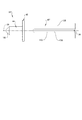
図5−8を参照し、常時開電磁モジュラーバルブ20’を説明する。図5−8に示される常時開電磁モジュラーバルブ20’は、図1−4に示される上記常時閉電磁モジュラーバルブ20と略同一のバルブ本体22、Oリング弁座102、ソレノイド本体56、コイル58、ボビン60、およびエンドキャップ70を有する。さらに、図5−8に示される常時開電磁モジュラーバルブ20’は、バルブ部材24’を有する。バルブ部材24’のテーパー端部108、プランジャ部44およびピストン部46は、図1−4に示される上記常時閉電磁モジュラーバルブ20のバルブ部材24と略同一である。しかし、図5−8に示される常時開電磁モジュラーバルブ20’のバルブ部材24’は、バルブ部材24’のピストン部46から延出するステム部122を有する。図1−4に示される常時閉電磁モジュラーバルブ20と異なり、常時開電磁モジュラーバルブ20’のバルブ部材24’は、非磁性材料で製造されている。その結果、バルブ部材24’のステム部122は、コイル58により発生する磁界に影響されず、ステム部122は電機子として作動しない。
The normally open electromagnetic modular valve 20 'will be described with reference to FIGS. The normally open electromagnetic
常時開電磁モジュラーバルブ20’は、磁極片62’を有するソレノイド26’を備える。磁極片62’は、上述の構成のようにソレノイド26’の第二端部54ではなく、ソレノイド26’の第一端部52に配置される。磁極片62’は、長手方向においてコイル58とバルブ本体22の接続端部40の間に配置される磁極片フランジ124と、磁極片フランジ124からボビン60内部にソレノイド26の第一端部52をから延出するシリンダー部125を有する。磁極片フランジ124は、磁極片62’が、コイル58に対して長手軸28に沿って長手方向に移動するのを防ぐ。本実施形態において、インナーシール90は、長手方向において、バルブ本体22の接続端部40と磁極片フランジ124の間で配置されてもよい。ソレノイド26’は、さらに、ソレノイド26’の第二端部54からボビン60内部に延出するエンドストッパ126と、磁極片62’のシリンダー部125とエンドストッパ126の間でボビン60内に摺動可能に配置される電機子128とを備える。
The normally open electromagnetic modular valve 20 'includes a solenoid 26' having a pole piece 62 '. The pole piece 62 'is located at the
磁極片62’は、長手軸28と整列配置され、磁極片62’を貫通して延出する長手方向孔130を有する。バルブ部材24のステム部122は、磁極片62’の長手方向孔130に摺動可能に収容される。ステム部122は、磁極片62’の長手方向孔130を貫通して延出し、バルブ部材24’が開位置にある時、電機子128と当接する(図6)。磁極片62’および電機子128は、磁性材料で製造されている。コイル58により発生した電磁場により、磁極片62’は、電機子128に電磁力76’を加え、磁極片62’側(ソレノイド26の第一端部52側)に電機子128を引っ張る(すなわち、引き寄せる)。バルブ部材24が、磁極片62’側へ引っ張られると、電機子128は、バルブ部材24のステム部122と当接し、それにより、バルブ部材24’は、バルブ本体22に対して、長手軸28に沿って閉位置側へ移動する(図7)。
The pole piece 62 'has a
常時開電磁モジュラーバルブ20’は、バルブ本体22の内部孔34に配置され、バルブ部材24’を開位置に付勢する付勢部材96’を備える(図6)。開位置において、電機子128は、ソレノイド26’の第二端部54のエンドストッパ126に長手方向に隣接し当接するように配置される。他の構成であってもよいが、図示される実施例では、付勢部材96’は、バルブ部材24’のプランジャ部44を中心に螺旋状に延出し、かつ、バルブ部材24’のピストン部46からバルブ本体22の内部孔34内でバルブ本体当接面104に隣接する支持面132まで長手方向に延出するコイルばねである。したがって、付勢部材96’は、電機子128に印加される電磁力76’とは反対方向に作用する付勢力98’をバルブ部材24に加える。その結果、付勢部材96’は、コイル58が通電されていない場合には、バルブ部材24’を開位置に戻す(図6)。
The normally open electromagnetic modular valve 20 'includes an urging member 96' disposed in the
エンドストッパ126は、ボビン60内に移動可能に配置され、さらに、ソレノイド本体56と螺合するねじ端部78’を備えてもよい。エンドストッパ126のねじ端部78’により、ボビン60に対するエンドストッパ126の長手方向位置を調整することが可能となる。ソレノイド本体56に対してエンドストッパ126が回転することで、電機子128のストローク長さを変え、それにより、バルブ部材24’のストローク長さ(すなわち、バルブ部材24’が開位置と閉位置との間を長手軸28に沿って移動する距離)を変える。図示される例に示されるように、エンドストッパ126のねじ端部78’は、ソレノイド本体56に対するエンドストッパ126の回転調整を容易にするツールインターフェイス80’を備えてもよい。
The
常時開電磁モジュラーバルブ20’は、ブッシュフランジ86’を有するブッシュ82’と、ブッシュフランジ86’から長手方向に延出する筒状部88’とを備える。ブッシュフランジ86は、コイル58に対するブッシュ82’の長手方向の移動を防止するように、長手方向において磁極片フランジ124とコイル58の間に配置される。ブッシュ82’の筒状部88’は、ボビン60内に収容され、磁極片62’のシリンダー部125、電機子128、およびエンドストッパ126の少なくとも一部の回りを環状に延出する。その結果、ブッシュ82’の筒状部88’は、(1)径方向においてボビン60と磁極片62’のシリンダー部125の間に、(2)径方向においてボビン60と電機子128の間に、および(3)径方向においてボビン60とエンドストッパ126の少なくとも一部の間に、配置される。ソレノイド本体56および磁極片62’が共働して長手軸28側である内側へ磁束を集中させるように、ブッシュ82’およびエンドストッパ126は、非磁性材料で製造され、ソレノイド本体56および磁極片62’は、磁性材料で製造される。
The normally open electromagnetic modular valve 20 'includes a bush 82' having a bush flange 86 'and a tubular portion 88' extending in the longitudinal direction from the bush flange 86 '. The
図示される実施形態のような、バルブ部材24’のピストン部46が、バルブ本体22の内部孔34を封止しない構成において、磁極片シール116’が磁極片62’に設けられ、1つ以上のエンドストッパシール134がエンドストッパ126に設けられる。磁極片シール116’は、磁極片62’のシリンダー部125回りに環状に延出し、径方向において磁極片62’のシリンダー部125とブッシュ82’の筒状部88’との間で配置される。エンドストッパシール134は、エンドストッパ126回りに環状に延出し、径方向においてエンドストッパ126とブッシュ82’の筒状部88’との間で配置される。バルブ部材24’の全体が、バルブ本体22の内部孔34と、磁極片62’の長手方向孔130と、磁極片62’とエンドストッパ126の間のブッシュ82’内の空間とで形成される予圧室120’内に配置されるように、磁極片シール116は、ブッシュ82’と磁極片62’との間に第一静的シール118aを形成し、エンドストッパシール134は、ブッシュ82’とエンドストッパ126の間に第二静的シール118bを形成する。したがって、磁極片シール116’およびエンドストッパシール134は、予圧室120’の流体および汚染物がコイル58に達するのを防ぐ。
In configurations where the
磁極片シール116’およびエンドストッパシール134によりなされるシール118aおよび118bは静的とされるのは、バルブ部材24’が開位置と閉位置の間を移動する際、ブッシュ82’は磁極片62’およびエンドストッパ126に対して移動しないからである。有利なことに、これにより、摺動シールの構成に比べて、摩擦が減る。本願の設計では、バルブ部材24’のプランジャ部44、ピストン部46およびステム部122はシールされないので、摩擦は最小限に留められる。バルブ部材24’と当接する唯一のシールは、Oリング弁座102であり、バルブ部材24’が閉位置または閉位置付近にある場合にのみ、バルブ部材24’はOリング弁座102に当接する。
The
図9および図10は、常時閉電磁モジュラーバルブ20に使用される別のバルブ部材24”の実施形態を図示する。図9および図10において、バルブ部材24”のテーパー端部108、プランジャ部44、およびピストン部46は、図1から図4に示される上述のバルブ部材24と略同一である。しかし、図9および図10に示されるバルブ部材24は、1つ以上の長手方向溝136を有する電機子部48”を有する。長手方向溝136は、筒状外面138から径方向に、バルブ部材24”の電機子部48”の内側へ延出する。長手方向溝136は、長手軸28と平行に伸び、バルブ部材24”の電機子部24”に沿って流体流路140を提供することにより、閉位置と閉位置の間をバルブ部材24”が長手方向に移動するのを容易にする。この流体流路140は、バルブ部材24”と、内部孔34および/または第一ブッシュ82との間の流体固着現象を防止するのを助ける。
9 and 10 illustrate another embodiment of a
図11を参照して、図1から図4に示される常時閉電磁モジュラーバルブ20は、マニホールド142に装着される。バルブ本体22は、マニホールド142のメインキャビティ146の孔壁144に収容される。アウターシール42a、42bは、孔壁144に当接し密封する。図示される実施例において、バルブ本体22の端面30は、メインキャビティ146の末端壁148と直に当接する。しかしながら、他の構成であってもよく、バルブ本体22の端面30が、メインキャビティ146の末端壁148から軸方向に離間していてもよい。バルブ本体22の流入口38は、マニホールド142の流入路150と流体連通して配置され、バルブ本体22の流出口36は、マニホールド142の流出路152と流体連通して配置される。バルブ部材24が開位置の場合、流体は流路154に沿って流通可能である。流路154は、マニホールド142の流入路150から、バルブ本体22の流入口38、バルブ本体22の内部孔34、Oリング弁座102とバルブ部材当接面110の間、および、バルブ本体22の流出口36を通って、マニホールド142の流出路152へと延出する。バルブ部材24が閉位置の場合、バルブ部材24は流路154を塞ぐ。他の構成であってもよいが、常時閉電磁モジュラーバルブ20は、ソレノイド本体56の外側面66にあるねじ山68が、ソレノイド26の第一端部52付近の孔壁144と係合することによって、メインキャビティ146内に固定される。図1−4に示される常時閉電磁モジュラーバルブ20が図11に示されるが、図5−8に示される常時開電磁モジュラーバルブ20’を、同様に同一のマニホールド142に装着可能であると理解される。
Referring to FIG. 11, normally closed electromagnetic
実施形態に関する上記記載は、図解および説明の目的で提供される。網羅的または発明を限定することを意図しない。本明細書で記載されるモジュラーバルブ20、20’のサイズおよび流動特性は、本開示の範囲を逸脱することなく変更してもよいことが理解される。さらに、本明細書で記載されるモジュラーバルブ20、20’を通る流れは、逆向きにして、流体が開口部36から流入し、開口部38から流出するようにしてもよいことが理解される。特定の実施形態の個別の要素または特徴は、一般にその特定の実施形態に限定されないが、適用可能な場合には、詳細に図示または説明されないとしても選択された実施形態で交換可能であり、使用可能である。同じものが多くの点で変更されてもよい。そのような変更は本開示からの逸脱とはみなされない。そのような修正は全て本開示の範囲内に含まれることが意図される。
The above description of the embodiments is provided for purposes of illustration and description. It is not intended to be exhaustive or to limit the invention. It is understood that the size and flow characteristics of the
Claims (20)
端面と、側面と、内部孔と、前記端面に設けられ前記内部孔と流体連通して配置される流出口と、前記側面に設けられ前記内部孔と流体連通して配置される流入口と、前記端面とは反対側の接続端部と、を有するバルブ本体と、
前記バルブ本体の前記内部孔に摺動可能に収容され、長手軸に沿って延出するバルブ部材と、
前記バルブ本体の前記接続端部と接続されるソレノイド本体と、前記ソレノイド本体の内部に配置されるコイルとを備え、開位置と閉位置の間を、前記長手軸に沿って、前記バルブ本体に対して前記バルブ部材を移動させるように作動可能なソレノイドと、
を備える電磁モジュラーバルブであって、
前記バルブ本体は、長手方向において前記内部孔と前記流出口の間に配置されるOリング弁座を備え、
前記バルブ部材は、円錐台形状のテーパー端部と、前記バルブ部材が前記閉位置にある時に前記Oリング弁座と当接し、前記バルブ部材が前記開位置にある時に前記Oリング弁座から離間するバルブ部材当接面と、を有することを特徴とする電磁モジュラーバルブ。 An electromagnetic modular valve,
An end face, a side face, an internal hole, an outlet provided on the end face and arranged in fluid communication with the internal hole, and an inlet provided on the side face and arranged in fluid communication with the internal hole, A valve body having a connection end opposite to the end face;
A valve member slidably received in the internal hole of the valve body and extending along a longitudinal axis;
A solenoid body connected to the connection end of the valve body, and a coil arranged inside the solenoid body, between the open position and the closed position, along the longitudinal axis, the valve body, A solenoid operable to move the valve member relative thereto;
An electromagnetic modular valve comprising:
The valve body includes an O-ring valve seat disposed between the internal hole and the outflow port in a longitudinal direction,
The valve member is in contact with the O-ring valve seat when the valve member is in the closed position, and is separated from the O-ring valve seat when the valve member is in the open position. And a valve member contact surface.
前記バルブ本体は、長手方向において前記内部孔と前記流出口の間に配置され、前記Oリング弁座を収容し支持する溝を有することを特徴とする電磁モジュラーバルブ。 The electromagnetic modular valve according to claim 1,
An electromagnetic modular valve, wherein the valve body has a groove that is disposed in the longitudinal direction between the internal hole and the outflow port, and that receives and supports the O-ring valve seat.
前記バルブ本体は、長手方向において前記バルブ本体の前記溝と前記内部孔の間に配置され、前記長手軸に対して斜角に配置されるバルブ本体当接面を有し、前記バルブ部材が前記閉位置にある時、前記バルブ部材当接面は前記バルブ本体当接面と当接し、堅固なストッパとなることを特徴とする電磁モジュラーバルブ。 The electromagnetic modular valve according to claim 2,
The valve body is disposed between the groove and the internal hole of the valve body in a longitudinal direction, and has a valve body contact surface that is disposed at an oblique angle with respect to the longitudinal axis, and the valve member is configured such that When in the closed position, the valve member abutment surface abuts the valve body abutment surface and serves as a rigid stopper.
前記バルブ本体当接面の前記斜角は、前記バルブ部材の前記テーパー端部の円錐台形状と一致し、40度以上50度以下であることを特徴とする電磁モジュラーバルブ。 The electromagnetic modular valve according to claim 3,
The oblique angle of the valve body contact surface coincides with the truncated cone shape of the tapered end of the valve member, and is not less than 40 degrees and not more than 50 degrees.
端面と、側面と、内部孔と、前記端面に設けられ前記内部孔と流体連通して配置される流出口と、前記側面に設けられ前記内部孔と流体連通して配置される流入口と、前記端面と反対側の接続端部と、を有するバルブ本体と、
前記バルブ本体の前記内部孔に摺動可能に収容され、長手軸に沿って延出するバルブ部材と、
前記バルブ本体の前記接続端部と接続されるソレノイド本体と、前記ソレノイド本体の内部に配置され、前記長手軸回りを環状に延出するコイルとを備え、開位置と閉位置の間を、前記長手軸に沿って、前記バルブ本体に対して前記バルブ部材を移動させるように作動可能なソレノイドと、
前記バルブ本体の前記内部孔に配置され、前記バルブ部材を前記閉位置側へ付勢する付勢部材とを備え、
前記バルブ本体は、長手方向において前記内部孔と前記流出口の間に配置されるOリング弁座を備え、
前記バルブ部材は、円錐台形状のテーパー端部と、前記バルブ部材が前記閉位置にある時に前記Oリング弁座と当接し、前記バルブ部材が前記開位置にある時に前記Oリング弁座から離間するバルブ部材当接面と、を有することを特徴とする電磁モジュラーバルブ。 An electromagnetic modular valve,
An end face, a side face, an internal hole, an outlet provided on the end face and arranged in fluid communication with the internal hole, and an inlet provided on the side face and arranged in fluid communication with the internal hole, A valve body having a connection end opposite to the end face;
A valve member slidably received in the internal hole of the valve body and extending along a longitudinal axis;
A solenoid body connected to the connection end of the valve body, and a coil disposed inside the solenoid body and extending annularly around the longitudinal axis, between an open position and a closed position, A solenoid operable to move the valve member relative to the valve body along a longitudinal axis;
A biasing member disposed in the internal hole of the valve body, and biasing the valve member toward the closed position;
The valve body includes an O-ring valve seat disposed between the internal hole and the outflow port in a longitudinal direction,
The valve member is in contact with the O-ring valve seat when the valve member is in the closed position, and is separated from the O-ring valve seat when the valve member is in the open position. And a valve member contact surface.
前記ソレノイドは第一端部と第二端部の間に亘って延出し、前記第一端部には前記バルブ本体が接続され、前記ソレノイドは、前記第二端部から前記コイル内に延出する磁極片を備え、前記バルブ部材は、前記ソレノイドの前記第一端部から前記コイル内に延出する電機子部を備えることを特徴とする電磁モジュラーバルブ。 The electromagnetic modular valve according to claim 5,
The solenoid extends between a first end and a second end, the valve body is connected to the first end, and the solenoid extends into the coil from the second end. An electromagnetic modular valve comprising: a magnetic pole piece; and an armature portion extending into the coil from the first end of the solenoid.
前記ソレノイドは、前記コイルを支持するボビンを備え、前記コイルは前記ボビン回りを環状に延出することを特徴とする電磁モジュラーバルブ。 The electromagnetic modular valve according to claim 6,
An electromagnetic modular valve, wherein the solenoid includes a bobbin that supports the coil, and the coil extends annularly around the bobbin.
前記電磁モジュラーバルブはさらに第一ブッシュを備え、
前記第一ブッシュはブッシュフランジと、前記ブッシュフランジから延出する筒状部とを備え、
前記ブッシュフランジは、前記第一ブッシュの前記コイルに対する長手方向の移動を防止するように、長手方向において前記バルブ本体の前記接続端部と前記コイルの間に配置され、
前記第一ブッシュの前記筒状部は、前記ボビンに収容され、前記バルブ部材の前記電機子部および前記磁極片の少なくとも一部の回りを環状に延出し、
前記電磁モジュラーバルブはさらに、前記磁極片回りに環状に延出し、径方向において前記磁極片と前記第一ブッシュの前記筒状部との間に配置される少なくとも1つの磁極片シールを備え、
前記少なくとも1つの磁極片シールは、前記バルブ部材全体が、前記バルブ本体の前記内部孔により形成される予圧室および前記内部孔と前記磁極片の間の前記第一ブッシュ内の空間の内部に配置されるように、前記第一ブッシュと前記磁極片の間に静的シールを形成する、ことを特徴とする電磁モジュラーバルブ。 The electromagnetic modular valve according to claim 7,
The electromagnetic modular valve further includes a first bush,
The first bush includes a bush flange and a cylindrical portion extending from the bush flange,
The bush flange is disposed between the coil and the connection end of the valve body in the longitudinal direction so as to prevent the first bush from moving in the longitudinal direction with respect to the coil.
The tubular portion of the first bush is housed in the bobbin, and extends annularly around at least a part of the armature portion and the pole piece of the valve member,
The electromagnetic modular valve further comprises at least one pole piece seal extending annularly around the pole piece and radially disposed between the pole piece and the tubular portion of the first bush.
The at least one pole piece seal is disposed such that the entire valve member is disposed within a preload chamber formed by the internal hole of the valve body and a space within the first bush between the internal hole and the pole piece. Forming a static seal between the first bush and the pole piece.
前記第一ブッシュの前記筒状部回りに環状に配置され、長手方向において前記コイルと前記第一ブッシュの前記ブッシュフランジとの間に配置される円盤形状の第二ブッシュをさらに備え、
前記ソレノイド本体および前記第二ブッシュは共働し、前記ソレノイドの断面形状を、前記コイルを収容する内向きU字形断面とし、
前記第一ブッシュは、非磁性材料で製造され、
前記ソレノイド本体および前記第二ブッシュで形成された前記内向きU字形断面が、前記長手軸に向かって内側へ磁束を集中させるように、前記ソレノイド本体および前記第二ブッシュは、磁性材料で製造されることを特徴とする電磁モジュラーバルブ。 The electromagnetic modular valve according to claim 8,
It further comprises a disk-shaped second bush disposed annularly around the cylindrical portion of the first bush and disposed between the coil and the bush flange of the first bush in the longitudinal direction,
The solenoid body and the second bush cooperate with each other, and the sectional shape of the solenoid is an inward U-shaped section that accommodates the coil.
The first bush is made of a non-magnetic material,
The solenoid body and the second bush are made of a magnetic material so that the inward U-shaped section formed by the solenoid body and the second bush concentrates magnetic flux inward toward the longitudinal axis. An electromagnetic modular valve, characterized in that:
前記磁極片は、前記ボビン内に移動可能に配置され、さらに、前記ソレノイド本体と螺合し、前記ソレノイド本体に対して前記磁極片を回転させることによって、前記磁極片の長手方向位置、すなわち、前記バルブ部材のストローク長さを調整可能とするねじ端部を備えることを特徴とする電磁モジュラーバルブ。 The electromagnetic modular valve according to claim 7,
The pole piece is movably disposed in the bobbin, further screwed with the solenoid body, and by rotating the pole piece with respect to the solenoid body, the longitudinal position of the pole piece, that is, An electromagnetic modular valve, comprising: a threaded end for adjusting a stroke length of the valve member.
前記バルブ部材は、さらに、前記テーパー端部に隣接するプランジャ部と、長手方向において前記プランジャ部と前記電機子部の間に配置され、前記バルブ本体の前記内部孔と滑合して摺動可能に配置されるピストン部とを備え、
前記付勢部材は、長手方向において前記バルブ部材の前記ピストン部と前記第一ブッシュの前記ブッシュフランジの間に配置されることを特徴とする電磁モジュラーバルブ。 The electromagnetic modular valve according to claim 6,
The valve member is further disposed between the plunger portion adjacent to the tapered end portion and the plunger portion and the armature portion in a longitudinal direction, and is slidably slidable with the internal hole of the valve body. And a piston portion arranged on the
The electromagnetic modular valve, wherein the biasing member is disposed between the piston portion of the valve member and the bush flange of the first bush in a longitudinal direction.
前記バルブ部材の前記電機子部は、筒状外面と、前記筒状外面に設けられた少なくとも1つの長手方向溝を有し、
前記長手方向溝は、前記長手軸と平行に延出し、前記開位置と前記閉位置の間の前記バルブ部材の長手方向の移動を、前記バルブ部材の前記電機子部に沿って、流体固着現象を防止する流体流路を提供することにより容易にする、ことを特徴とする電磁モジュラーバルブ。 The electromagnetic modular valve according to claim 6,
The armature portion of the valve member has a cylindrical outer surface and at least one longitudinal groove provided on the cylindrical outer surface,
The longitudinal groove extends parallel to the longitudinal axis, and causes longitudinal movement of the valve member between the open position and the closed position to cause a fluid sticking phenomenon along the armature portion of the valve member. An electromagnetic modular valve characterized by providing a fluid flow path that prevents fluid flow.
端面と、側面と、内部孔と、前記端面に設けられ前記内部孔と流体連通して配置される流出口と、前記側面に設けられ前記内部孔と流体連通して配置される流入口と、前記端面と反対側の接続端部と、を有するバルブ本体と、
前記バルブ本体の前記内部孔に摺動可能に収容され、長手軸に沿って延出するバルブ部材と、
前記バルブ本体の前記接続端部と接続されるソレノイド本体と、前記ソレノイド本体の内部に配置され、前記長手軸回りを環状に延出するコイルとを備え、開位置と閉位置の間を、前記長手軸に沿って、前記バルブ本体に対して前記バルブ部材を移動させるように作動可能なソレノイドと、
前記バルブ本体の前記内部孔に配置され、前記バルブ部材を前記開位置側へ付勢する付勢部材とを備え、
前記バルブ本体は、長手方向において前記内部孔と前記流出口の間に配置されるOリング弁座を備え、
前記バルブ部材は、円錐台形状のテーパー端部と、前記バルブ部材が前記閉位置にある時に前記Oリング弁座と当接し、前記バルブ部材が前記開位置にある時に前記Oリング弁座から離間するバルブ部材当接面と、を有することを特徴とする電磁モジュラーバルブ。 An electromagnetic modular valve,
An end face, a side face, an internal hole, an outlet provided on the end face and arranged in fluid communication with the internal hole, and an inlet provided on the side face and arranged in fluid communication with the internal hole, A valve body having a connection end opposite to the end face;
A valve member slidably received in the internal hole of the valve body and extending along a longitudinal axis;
A solenoid body connected to the connection end of the valve body, and a coil disposed inside the solenoid body and extending annularly around the longitudinal axis, between an open position and a closed position, A solenoid operable to move the valve member relative to the valve body along a longitudinal axis;
A biasing member disposed in the internal hole of the valve body, and biasing the valve member toward the open position;
The valve body includes an O-ring valve seat disposed between the internal hole and the outflow port in a longitudinal direction,
The valve member is in contact with the O-ring valve seat when the valve member is in the closed position, and is separated from the O-ring valve seat when the valve member is in the open position. And a valve member contact surface.
前記ソレノイドは、第一端部と第二端部の間に亘って延出し、前記第一端部には前記バルブ本体が接続され、
前記ソレノイドは、長手方向において前記コイルと前記バルブ本体の前記接続端部との間に配置される磁極片フランジを有する磁極片と、前記磁極片フランジから前記コイル内部に前記ソレノイドの前記第一端部を通って延出するシリンダー部と、前記ソレノイドの前記第二端部から前記コイル内部に延出するエンドストッパと、前記磁極片の前記シリンダー部と前記エンドストッパの間で前記コイル内に摺動可能に配置される電機子とを備えることを特徴とする電磁モジュラーバルブ。 The electromagnetic modular valve according to claim 13,
The solenoid extends between a first end and a second end, and the valve body is connected to the first end,
The solenoid includes a pole piece having a pole piece flange disposed between the coil and the connection end of the valve body in a longitudinal direction, and the first end of the solenoid is provided inside the coil from the pole piece flange. A cylinder portion extending through the portion, an end stopper extending into the coil from the second end of the solenoid, and a slide into the coil between the cylinder portion and the end stopper of the pole piece. An electromagnetic modular valve, comprising: an armature movably arranged.
前記ソレノイドは、前記コイルを支持するボビンを備え、前記コイルは前記ボビン回りを環状に延出することを特徴とする電磁モジュラーバルブ。 The electromagnetic modular valve according to claim 14,
An electromagnetic modular valve, wherein the solenoid includes a bobbin that supports the coil, and the coil extends annularly around the bobbin.
前記電磁モジュラーバルブはさらに、ブッシュフランジと、前記ブッシュフランジから延出する筒状部とを備えるブッシュを備え、
前記ブッシュフランジは、前記ブッシュの前記コイルに対する長手方向の移動を防止するように、長手方向において前記磁極片フランジと前記コイルの間に配置され、
前記ブッシュの前記筒状部は、前記ボビンに収容され、前記磁極片の前記シリンダー部、前記電機子、および前記エンドストッパの少なくとも一部の回りを環状に延出し、
前記電磁モジュラーバルブはさらに、
前記磁極片の前記シリンダー部回りに環状に延出し、径方向において前記磁極片の前記シリンダー部と前記ブッシュの前記筒状部との間で配置され、前記ブッシュと前記磁極片の間に第一静的シールを形成する少なくとも1つの磁極片シールと、
前記エンドストッパ回りに環状に延出し、径方向において前記エンドストッパと前記ブッシュの前記筒状部の間に配置され、前記ブッシュと前記エンドストッパの間に第二静的シールを形成する少なくとも1つのエンドストッパシールとを備えることを特徴とする電磁モジュラーバルブ。 The electromagnetic modular valve according to claim 15,
The electromagnetic modular valve further includes a bush including a bush flange and a tubular portion extending from the bush flange,
The bush flange is disposed between the pole piece flange and the coil in the longitudinal direction so as to prevent the bush from moving in the longitudinal direction with respect to the coil,
The tubular portion of the bush is housed in the bobbin, and extends annularly around at least a part of the cylinder portion, the armature, and the end stopper of the pole piece,
The electromagnetic modular valve further comprises:
The pole piece extends annularly around the cylinder portion and is radially disposed between the cylinder portion of the pole piece and the cylindrical portion of the bush, and a first portion is provided between the bush and the pole piece. At least one pole piece seal forming a static seal;
At least one extending radially around the end stopper and radially disposed between the end stopper and the tubular portion of the bush to form a second static seal between the bush and the end stopper; An electromagnetic modular valve comprising an end stopper seal.
前記磁極片は、内部に貫通する長手方向孔を有し、
前記バルブ部材は、前記テーパー端部に隣接するプランジャ部と、前記磁極片の前記長手方向孔を貫通して延出し、前記電機子と当接するステム部と、長手方向において前記プランジャ部と前記ステム部の間で配置され、前記バルブ本体の前記内部孔と滑合して摺動可能に配置されるピストン部とを備え、
前記付勢部材は、長手方向において、前記バルブ部材の前記ピストン部と、前記バルブ本体当接面に隣接する前記バルブ本体の前記内部孔内に設けられる支持面との間に配置されることを特徴とする電磁モジュラーバルブ。 The electromagnetic modular valve according to claim 16,
The pole piece has a longitudinal hole extending therethrough,
The valve member includes a plunger portion adjacent to the tapered end, a stem portion extending through the longitudinal hole of the pole piece and abutting on the armature, and the plunger portion and the stem in the longitudinal direction. And a piston portion slidably disposed to slide between the internal holes of the valve body.
The biasing member may be disposed between the piston portion of the valve member and a support surface provided in the internal hole of the valve body adjacent to the valve body contact surface in the longitudinal direction. Characteristic electromagnetic modular valve.
前記第一静的シールおよび前記第二静的シールは、前記バルブ部材全体および前記電機子全体が内部に配置される予圧室を形成し、
前記予圧室は、前記バルブ本体の前記内部孔と、前記磁極片の前記長手方向孔と、前記磁極片の前記シリンダー部と前記エンドストッパとの間で前記ブッシュの内部の空間とから形成されることを特徴とする電磁モジュラーバルブ。 The electromagnetic modular valve according to claim 17,
The first static seal and the second static seal form a preload chamber in which the entire valve member and the entire armature are disposed,
The preload chamber is formed by the internal hole of the valve body, the longitudinal hole of the pole piece, and a space inside the bush between the cylinder portion of the pole piece and the end stopper. An electromagnetic modular valve, characterized in that:
前記ブッシュおよび前記エンドストッパは、非磁性材料で製造され、
前記ソレノイド本体および前記磁極片が共働して前記長手軸に向かって内側へ磁束を集中させるように、前記ソレノイド本体および前記磁極片は、磁性材料で製造されることを特徴とする電磁モジュラーバルブ。 The electromagnetic modular valve according to claim 16,
The bush and the end stopper are made of a non-magnetic material,
An electromagnetic modular valve, wherein the solenoid body and the pole piece are made of a magnetic material so that the solenoid body and the pole piece cooperate to concentrate magnetic flux inward toward the longitudinal axis. .
前記エンドストッパは前記ボビン内に移動可能に配置され、さらに、前記ソレノイド本体と螺合し、前記ソレノイド本体に対して前記エンドストッパを回転させることによって、前記エンドストッパの長手方向位置、すなわち、前記バルブ部材のストローク長さを調整可能とするねじ端部を備えることを特徴とする電磁モジュラーバルブ。 The electromagnetic modular valve according to claim 14,
The end stopper is movably disposed in the bobbin, and is further screwed with the solenoid main body, and by rotating the end stopper with respect to the solenoid main body, a longitudinal position of the end stopper, that is, An electromagnetic modular valve comprising a threaded end for adjusting a stroke length of a valve member.
Applications Claiming Priority (2)
| Application Number | Priority Date | Filing Date | Title |
|---|---|---|---|
| US15/954,815 US10774943B2 (en) | 2018-04-17 | 2018-04-17 | Modular valve with O-ring valve set |
| US15/954815 | 2018-04-17 |
Publications (2)
| Publication Number | Publication Date |
|---|---|
| JP2020003060A true JP2020003060A (en) | 2020-01-09 |
| JP2020003060A5 JP2020003060A5 (en) | 2022-04-11 |
Family
ID=66182421
Family Applications (1)
| Application Number | Title | Priority Date | Filing Date |
|---|---|---|---|
| JP2019075236A Pending JP2020003060A (en) | 2018-04-17 | 2019-04-11 | Modular valve with O-ring valve seat |
Country Status (11)
| Country | Link |
|---|---|
| US (1) | US10774943B2 (en) |
| EP (1) | EP3557100A1 (en) |
| JP (1) | JP2020003060A (en) |
| KR (1) | KR102418509B1 (en) |
| CN (1) | CN110388469B (en) |
| AU (1) | AU2019202361A1 (en) |
| BR (1) | BR102019007894B1 (en) |
| CA (1) | CA3040072A1 (en) |
| MX (1) | MX2019004516A (en) |
| TW (1) | TWI706098B (en) |
| ZA (1) | ZA201902414B (en) |
Families Citing this family (1)
| Publication number | Priority date | Publication date | Assignee | Title |
|---|---|---|---|---|
| WO2022046636A1 (en) * | 2020-08-24 | 2022-03-03 | Lancer Corporation | Cartridge valve and system |
Citations (12)
| Publication number | Priority date | Publication date | Assignee | Title |
|---|---|---|---|---|
| US3379214A (en) * | 1965-01-15 | 1968-04-23 | Skinner Prec Ind Inc | Permanent magnet valve assembly |
| JPS49122425U (en) * | 1973-02-14 | 1974-10-19 | ||
| JPS50155627U (en) * | 1974-06-12 | 1975-12-23 | ||
| JPS5573670U (en) * | 1978-11-17 | 1980-05-21 | ||
| JPS60137276U (en) * | 1984-02-23 | 1985-09-11 | 万歳工業株式会社 | non-return valve |
| JPS6194663U (en) * | 1984-11-29 | 1986-06-18 | ||
| JPH08219381A (en) * | 1995-02-17 | 1996-08-30 | Orion Mach Co Ltd | Electromagnetic drain trap |
| JP2003240149A (en) * | 2002-02-13 | 2003-08-27 | Aisan Ind Co Ltd | Solenoid valve |
| JP2006207695A (en) * | 2005-01-28 | 2006-08-10 | Zama Japan Co Ltd | Solenoid |
| JP2012532299A (en) * | 2009-07-08 | 2012-12-13 | ローベルト ボツシユ ゲゼルシヤフト ミツト ベシユレンクテル ハフツング | valve |
| JP2015197221A (en) * | 2014-04-02 | 2015-11-09 | バット ホールディング アーゲー | vacuum valve |
| JP2016537576A (en) * | 2013-11-15 | 2016-12-01 | チャージポイント テクノロジー リミテッド | valve seat |
Family Cites Families (26)
| Publication number | Priority date | Publication date | Assignee | Title |
|---|---|---|---|---|
| US2350905A (en) * | 1941-12-11 | 1944-06-06 | Gustave J Koehler | Fluid valve |
| US2853659A (en) * | 1952-03-10 | 1958-09-23 | Herion Erich | Solenoid arrangements |
| US3489170A (en) * | 1966-06-17 | 1970-01-13 | Arthur L Leman | Slush pump valve assembly |
| FR2244948A1 (en) | 1973-09-21 | 1975-04-18 | Guilbert Fils Anciens Ets Leon | Stop cock having special flow path for low rate setting - formed by recess in valve member |
| CA1021225A (en) * | 1974-06-28 | 1977-11-22 | General Signal Corporation | Quick-acting valve assembly |
| DE3173841D1 (en) * | 1980-12-26 | 1986-03-27 | Hitachi Ltd | Solenoid valve |
| JP2607670Y2 (en) * | 1993-10-21 | 2002-03-04 | エスエムシー株式会社 | Self-holding solenoid valve |
| FR2721085B1 (en) * | 1994-06-10 | 1996-07-12 | Commissariat Energie Atomique | Compressed seal system between two non-parallel spans. |
| DE19604315A1 (en) * | 1996-02-07 | 1997-08-14 | Bosch Gmbh Robert | Electromagnetically operated valve, in particular for hydraulic brake systems in motor vehicles |
| US5967487A (en) * | 1997-08-25 | 1999-10-19 | Siemens Canada Ltd. | Automotive emission control valve with a cushion media |
| US6065734A (en) * | 1997-10-03 | 2000-05-23 | Kelsey-Hayes Company | Control valve for a hydraulic control unit of vehicular brake systems |
| US6948697B2 (en) * | 2000-02-29 | 2005-09-27 | Arichell Technologies, Inc. | Apparatus and method for controlling fluid flow |
| US20070241298A1 (en) * | 2000-02-29 | 2007-10-18 | Kay Herbert | Electromagnetic apparatus and method for controlling fluid flow |
| US6845965B2 (en) * | 2002-04-18 | 2005-01-25 | Teleflex Gpi Control Systems L.P. | Pressurized valve seal |
| CN201173329Y (en) * | 2007-12-30 | 2008-12-31 | 瑞立集团有限公司 | Valve core movement continuous adjustable electromagnetic valve |
| CN102741600B (en) * | 2010-02-03 | 2016-03-16 | 凯尔西-海耶斯公司 | Solenoid valve |
| JP5661407B2 (en) | 2010-10-05 | 2015-01-28 | 株式会社ジェイテクト | solenoid valve |
| US8342479B2 (en) * | 2010-12-29 | 2013-01-01 | Shih Shih Technology Co., Ltd. | Solenoid controlled valve for fluid media |
| CN102661396A (en) * | 2012-05-18 | 2012-09-12 | 郑红侠 | Novel valve core connecting sleeve mechanism for stop valve |
| US8684036B1 (en) * | 2013-03-07 | 2014-04-01 | Yozo Satoda | Cryogenic valve |
| US9022069B2 (en) | 2013-03-15 | 2015-05-05 | Mac Valves, Inc. | Solenoid operated valve with constant bleed port |
| NO336259B1 (en) * | 2014-02-03 | 2015-07-06 | Subsea Chokes Internat As | Valve for flow control of a fluid |
| JP6331645B2 (en) | 2014-04-22 | 2018-05-30 | 株式会社ジェイテクト | Valve device |
| CN104565502A (en) * | 2015-01-27 | 2015-04-29 | 重庆融焕电器有限公司 | Valve head of pulsed electromagnetic valve |
| CN105299240B (en) * | 2015-10-26 | 2017-12-29 | 陈妍雨 | A kind of improved stop valve of silica gel pipeline structure |
| US10473229B2 (en) | 2017-09-25 | 2019-11-12 | Mac Valves, Inc. | Diaphragm valve |
-
2018
- 2018-04-17 US US15/954,815 patent/US10774943B2/en active Active
-
2019
- 2019-04-04 AU AU2019202361A patent/AU2019202361A1/en active Pending
- 2019-04-11 CA CA3040072A patent/CA3040072A1/en active Pending
- 2019-04-11 JP JP2019075236A patent/JP2020003060A/en active Pending
- 2019-04-15 EP EP19169248.2A patent/EP3557100A1/en active Pending
- 2019-04-16 ZA ZA2019/02414A patent/ZA201902414B/en unknown
- 2019-04-16 KR KR1020190044453A patent/KR102418509B1/en active IP Right Grant
- 2019-04-16 MX MX2019004516A patent/MX2019004516A/en unknown
- 2019-04-17 TW TW108113309A patent/TWI706098B/en active
- 2019-04-17 CN CN201910310514.XA patent/CN110388469B/en active Active
- 2019-04-17 BR BR102019007894-4A patent/BR102019007894B1/en active IP Right Grant
Patent Citations (12)
| Publication number | Priority date | Publication date | Assignee | Title |
|---|---|---|---|---|
| US3379214A (en) * | 1965-01-15 | 1968-04-23 | Skinner Prec Ind Inc | Permanent magnet valve assembly |
| JPS49122425U (en) * | 1973-02-14 | 1974-10-19 | ||
| JPS50155627U (en) * | 1974-06-12 | 1975-12-23 | ||
| JPS5573670U (en) * | 1978-11-17 | 1980-05-21 | ||
| JPS60137276U (en) * | 1984-02-23 | 1985-09-11 | 万歳工業株式会社 | non-return valve |
| JPS6194663U (en) * | 1984-11-29 | 1986-06-18 | ||
| JPH08219381A (en) * | 1995-02-17 | 1996-08-30 | Orion Mach Co Ltd | Electromagnetic drain trap |
| JP2003240149A (en) * | 2002-02-13 | 2003-08-27 | Aisan Ind Co Ltd | Solenoid valve |
| JP2006207695A (en) * | 2005-01-28 | 2006-08-10 | Zama Japan Co Ltd | Solenoid |
| JP2012532299A (en) * | 2009-07-08 | 2012-12-13 | ローベルト ボツシユ ゲゼルシヤフト ミツト ベシユレンクテル ハフツング | valve |
| JP2016537576A (en) * | 2013-11-15 | 2016-12-01 | チャージポイント テクノロジー リミテッド | valve seat |
| JP2015197221A (en) * | 2014-04-02 | 2015-11-09 | バット ホールディング アーゲー | vacuum valve |
Also Published As
| Publication number | Publication date |
|---|---|
| KR102418509B1 (en) | 2022-07-07 |
| TWI706098B (en) | 2020-10-01 |
| ZA201902414B (en) | 2021-04-28 |
| US10774943B2 (en) | 2020-09-15 |
| CA3040072A1 (en) | 2019-10-17 |
| CN110388469B (en) | 2023-03-10 |
| KR20190121259A (en) | 2019-10-25 |
| MX2019004516A (en) | 2019-10-18 |
| BR102019007894A2 (en) | 2019-10-29 |
| AU2019202361A1 (en) | 2019-10-31 |
| TW201945656A (en) | 2019-12-01 |
| BR102019007894B1 (en) | 2023-01-24 |
| US20190316704A1 (en) | 2019-10-17 |
| CN110388469A (en) | 2019-10-29 |
| EP3557100A1 (en) | 2019-10-23 |
Similar Documents
| Publication | Publication Date | Title |
|---|---|---|
| KR102368773B1 (en) | Diaphragm valve | |
| JP6227998B2 (en) | Multi-port normally open modular valve with screw-in valve seat | |
| US9010373B2 (en) | Pressure balanced valve with diaphragm valve member end seal | |
| JP5225978B2 (en) | Solenoid valve and manufacturing method thereof | |
| JP2014129877A (en) | Multi-port modular valve with snap-in seat | |
| JP7089865B2 (en) | Multi-port valve | |
| JP2020003060A (en) | Modular valve with O-ring valve seat | |
| US7246787B2 (en) | Solenoid valve assembly | |
| EP3690245A1 (en) | Solenoid pump | |
| NZ741227A (en) | Diaphragm Valve | |
| GB2480100A (en) | High pressure solenoid valve |
Legal Events
| Date | Code | Title | Description |
|---|---|---|---|
| A521 | Request for written amendment filed |
Free format text: JAPANESE INTERMEDIATE CODE: A523 Effective date: 20220401 |
|
| A621 | Written request for application examination |
Free format text: JAPANESE INTERMEDIATE CODE: A621 Effective date: 20220401 |
|
| A977 | Report on retrieval |
Free format text: JAPANESE INTERMEDIATE CODE: A971007 Effective date: 20230427 |
|
| A131 | Notification of reasons for refusal |
Free format text: JAPANESE INTERMEDIATE CODE: A131 Effective date: 20230523 |
|
| A521 | Request for written amendment filed |
Free format text: JAPANESE INTERMEDIATE CODE: A523 Effective date: 20230822 |
|
| A02 | Decision of refusal |
Free format text: JAPANESE INTERMEDIATE CODE: A02 Effective date: 20231212 |
|
| A521 | Request for written amendment filed |
Free format text: JAPANESE INTERMEDIATE CODE: A523 Effective date: 20240308 |
|
| A911 | Transfer to examiner for re-examination before appeal (zenchi) |
Free format text: JAPANESE INTERMEDIATE CODE: A911 Effective date: 20240319 |