JP2019536532A - Method and device for piercing tissue - Google Patents
Method and device for piercing tissue Download PDFInfo
- Publication number
- JP2019536532A JP2019536532A JP2019523866A JP2019523866A JP2019536532A JP 2019536532 A JP2019536532 A JP 2019536532A JP 2019523866 A JP2019523866 A JP 2019523866A JP 2019523866 A JP2019523866 A JP 2019523866A JP 2019536532 A JP2019536532 A JP 2019536532A
- Authority
- JP
- Japan
- Prior art keywords
- assembly
- support member
- dilator
- guidewire
- flexible
- Prior art date
- Legal status (The legal status is an assumption and is not a legal conclusion. Google has not performed a legal analysis and makes no representation as to the accuracy of the status listed.)
- Pending
Links
Images


Classifications
-
- A—HUMAN NECESSITIES
- A61—MEDICAL OR VETERINARY SCIENCE; HYGIENE
- A61B—DIAGNOSIS; SURGERY; IDENTIFICATION
- A61B17/00—Surgical instruments, devices or methods
- A61B17/32—Surgical cutting instruments
- A61B17/3205—Excision instruments
-
- A—HUMAN NECESSITIES
- A61—MEDICAL OR VETERINARY SCIENCE; HYGIENE
- A61B—DIAGNOSIS; SURGERY; IDENTIFICATION
- A61B17/00—Surgical instruments, devices or methods
- A61B17/34—Trocars; Puncturing needles
- A61B17/3417—Details of tips or shafts, e.g. grooves, expandable, bendable; Multiple coaxial sliding cannulas, e.g. for dilating
-
- A—HUMAN NECESSITIES
- A61—MEDICAL OR VETERINARY SCIENCE; HYGIENE
- A61B—DIAGNOSIS; SURGERY; IDENTIFICATION
- A61B17/00—Surgical instruments, devices or methods
- A61B17/34—Trocars; Puncturing needles
- A61B17/3478—Endoscopic needles, e.g. for infusion
-
- A—HUMAN NECESSITIES
- A61—MEDICAL OR VETERINARY SCIENCE; HYGIENE
- A61B—DIAGNOSIS; SURGERY; IDENTIFICATION
- A61B18/00—Surgical instruments, devices or methods for transferring non-mechanical forms of energy to or from the body
- A61B18/04—Surgical instruments, devices or methods for transferring non-mechanical forms of energy to or from the body by heating
- A61B18/12—Surgical instruments, devices or methods for transferring non-mechanical forms of energy to or from the body by heating by passing a current through the tissue to be heated, e.g. high-frequency current
- A61B18/14—Probes or electrodes therefor
- A61B18/1492—Probes or electrodes therefor having a flexible, catheter-like structure, e.g. for heart ablation
-
- A—HUMAN NECESSITIES
- A61—MEDICAL OR VETERINARY SCIENCE; HYGIENE
- A61B—DIAGNOSIS; SURGERY; IDENTIFICATION
- A61B90/00—Instruments, implements or accessories specially adapted for surgery or diagnosis and not covered by any of the groups A61B1/00 - A61B50/00, e.g. for luxation treatment or for protecting wound edges
- A61B90/39—Markers, e.g. radio-opaque or breast lesions markers
-
- A—HUMAN NECESSITIES
- A61—MEDICAL OR VETERINARY SCIENCE; HYGIENE
- A61M—DEVICES FOR INTRODUCING MEDIA INTO, OR ONTO, THE BODY; DEVICES FOR TRANSDUCING BODY MEDIA OR FOR TAKING MEDIA FROM THE BODY; DEVICES FOR PRODUCING OR ENDING SLEEP OR STUPOR
- A61M29/00—Dilators with or without means for introducing media, e.g. remedies
-
- A—HUMAN NECESSITIES
- A61—MEDICAL OR VETERINARY SCIENCE; HYGIENE
- A61B—DIAGNOSIS; SURGERY; IDENTIFICATION
- A61B17/00—Surgical instruments, devices or methods
- A61B17/00234—Surgical instruments, devices or methods for minimally invasive surgery
- A61B2017/00238—Type of minimally invasive operation
- A61B2017/00243—Type of minimally invasive operation cardiac
- A61B2017/00247—Making holes in the wall of the heart, e.g. laser Myocardial revascularization
- A61B2017/00252—Making holes in the wall of the heart, e.g. laser Myocardial revascularization for by-pass connections, i.e. connections from heart chamber to blood vessel or from blood vessel to blood vessel
-
- A—HUMAN NECESSITIES
- A61—MEDICAL OR VETERINARY SCIENCE; HYGIENE
- A61B—DIAGNOSIS; SURGERY; IDENTIFICATION
- A61B17/00—Surgical instruments, devices or methods
- A61B17/00234—Surgical instruments, devices or methods for minimally invasive surgery
- A61B2017/00292—Surgical instruments, devices or methods for minimally invasive surgery mounted on or guided by flexible, e.g. catheter-like, means
- A61B2017/003—Steerable
- A61B2017/00318—Steering mechanisms
- A61B2017/00331—Steering mechanisms with preformed bends
-
- A—HUMAN NECESSITIES
- A61—MEDICAL OR VETERINARY SCIENCE; HYGIENE
- A61B—DIAGNOSIS; SURGERY; IDENTIFICATION
- A61B17/00—Surgical instruments, devices or methods
- A61B17/22—Implements for squeezing-off ulcers or the like on inner organs of the body; Implements for scraping-out cavities of body organs, e.g. bones; for invasive removal or destruction of calculus using mechanical vibrations; for removing obstructions in blood vessels, not otherwise provided for
- A61B2017/22038—Implements for squeezing-off ulcers or the like on inner organs of the body; Implements for scraping-out cavities of body organs, e.g. bones; for invasive removal or destruction of calculus using mechanical vibrations; for removing obstructions in blood vessels, not otherwise provided for with a guide wire
- A61B2017/22042—Details of the tip of the guide wire
- A61B2017/22044—Details of the tip of the guide wire with a pointed tip
-
- A—HUMAN NECESSITIES
- A61—MEDICAL OR VETERINARY SCIENCE; HYGIENE
- A61B—DIAGNOSIS; SURGERY; IDENTIFICATION
- A61B18/00—Surgical instruments, devices or methods for transferring non-mechanical forms of energy to or from the body
- A61B2018/00315—Surgical instruments, devices or methods for transferring non-mechanical forms of energy to or from the body for treatment of particular body parts
- A61B2018/00345—Vascular system
- A61B2018/00351—Heart
- A61B2018/00357—Endocardium
-
- A—HUMAN NECESSITIES
- A61—MEDICAL OR VETERINARY SCIENCE; HYGIENE
- A61B—DIAGNOSIS; SURGERY; IDENTIFICATION
- A61B18/00—Surgical instruments, devices or methods for transferring non-mechanical forms of energy to or from the body
- A61B2018/00571—Surgical instruments, devices or methods for transferring non-mechanical forms of energy to or from the body for achieving a particular surgical effect
- A61B2018/00601—Cutting
-
- A—HUMAN NECESSITIES
- A61—MEDICAL OR VETERINARY SCIENCE; HYGIENE
- A61B—DIAGNOSIS; SURGERY; IDENTIFICATION
- A61B18/00—Surgical instruments, devices or methods for transferring non-mechanical forms of energy to or from the body
- A61B2018/00636—Sensing and controlling the application of energy
- A61B2018/00773—Sensed parameters
- A61B2018/00839—Bioelectrical parameters, e.g. ECG, EEG
-
- A—HUMAN NECESSITIES
- A61—MEDICAL OR VETERINARY SCIENCE; HYGIENE
- A61B—DIAGNOSIS; SURGERY; IDENTIFICATION
- A61B18/00—Surgical instruments, devices or methods for transferring non-mechanical forms of energy to or from the body
- A61B18/04—Surgical instruments, devices or methods for transferring non-mechanical forms of energy to or from the body by heating
- A61B18/12—Surgical instruments, devices or methods for transferring non-mechanical forms of energy to or from the body by heating by passing a current through the tissue to be heated, e.g. high-frequency current
- A61B18/14—Probes or electrodes therefor
- A61B2018/1405—Electrodes having a specific shape
- A61B2018/144—Wire
-
- A—HUMAN NECESSITIES
- A61—MEDICAL OR VETERINARY SCIENCE; HYGIENE
- A61B—DIAGNOSIS; SURGERY; IDENTIFICATION
- A61B90/00—Instruments, implements or accessories specially adapted for surgery or diagnosis and not covered by any of the groups A61B1/00 - A61B50/00, e.g. for luxation treatment or for protecting wound edges
- A61B90/08—Accessories or related features not otherwise provided for
- A61B2090/0801—Prevention of accidental cutting or pricking
- A61B2090/08021—Prevention of accidental cutting or pricking of the patient or his organs
-
- A—HUMAN NECESSITIES
- A61—MEDICAL OR VETERINARY SCIENCE; HYGIENE
- A61B—DIAGNOSIS; SURGERY; IDENTIFICATION
- A61B90/00—Instruments, implements or accessories specially adapted for surgery or diagnosis and not covered by any of the groups A61B1/00 - A61B50/00, e.g. for luxation treatment or for protecting wound edges
- A61B90/39—Markers, e.g. radio-opaque or breast lesions markers
- A61B2090/3966—Radiopaque markers visible in an X-ray image
Landscapes
- Health & Medical Sciences (AREA)
- Life Sciences & Earth Sciences (AREA)
- Surgery (AREA)
- Engineering & Computer Science (AREA)
- General Health & Medical Sciences (AREA)
- Veterinary Medicine (AREA)
- Biomedical Technology (AREA)
- Heart & Thoracic Surgery (AREA)
- Animal Behavior & Ethology (AREA)
- Public Health (AREA)
- Medical Informatics (AREA)
- Molecular Biology (AREA)
- Nuclear Medicine, Radiotherapy & Molecular Imaging (AREA)
- Pathology (AREA)
- Anesthesiology (AREA)
- Oral & Maxillofacial Surgery (AREA)
- Hematology (AREA)
- Cardiology (AREA)
- Physics & Mathematics (AREA)
- Plasma & Fusion (AREA)
- Otolaryngology (AREA)
- Surgical Instruments (AREA)
- Materials For Medical Uses (AREA)
- Prostheses (AREA)
- Media Introduction/Drainage Providing Device (AREA)
Abstract
組織を穿刺する方法およびシステムが開示され、組織を穿刺する穿刺デバイスと、穿刺デバイスを支持する支持部材とを備え、穿刺デバイスは、支持部材内に挿入可能であり、組織を穿刺する処置の一部の間、支持部材と協働して選択的に使用可能であり、処置の別の部分の間、支持部材から独立して使用可能である。
【選択図】図1AA method and system for piercing tissue is disclosed, comprising a puncture device for piercing tissue, and a support member for supporting the puncture device, wherein the puncture device is insertable into the support member and provides a method for puncturing tissue. It can be selectively used in cooperation with the support member during the section and independently of the support member during another part of the procedure.
[Selection] Figure 1A
Description
本開示は、組織に穿刺を生成するシステムおよび方法に関する。より具体的には、本開示は、穿刺デバイスおよび支持部材を含むアセンブリを使用して穿刺を生成するシステムおよび方法に関する。 The present disclosure relates to systems and methods for creating a puncture in tissue. More specifically, the present disclosure relates to systems and methods for generating a puncture using an assembly including a puncture device and a support member.
本発明を容易に理解できるように、本発明の実施形態は、添付の図面に例として示されている。 In order that the invention may be readily understood, embodiments of the invention are shown by way of example in the accompanying drawings.
トランスセプタル処置を実施するためには、心臓へのアクセスを得ることが必要である。アクセスは、(特に、心臓の右心房へのアクセスを、心臓の上方のアクセスポイントから、例えば、上位静脈から上位静脈を通って、取得することによって)上位アプローチから取得されてもよく、あるいは、アクセスは、(心臓の下方のアクセスポイントから、例えば、下位静脈から、下位静脈を通って、心臓へのアクセスを取得することによって)大脳または下位アプローチから取得されてもよい。右心房へのアクセスが得られると、例えば心臓の隔壁を横切って組織を穿刺して右心房から心臓の左心房へのアクセスを得るために、穿刺デバイスが利用される。 To perform a transceptal procedure, it is necessary to gain access to the heart. Access may be obtained from a superior approach (particularly by acquiring access to the right atrium of the heart from an access point above the heart, eg, from superior vein to superior vein), or Access may be obtained from the cerebrum or inferior approach (by gaining access to the heart from an access point below the heart, eg, from inferior veins, through inferior veins). Once access to the right atrium is obtained, a lancing device is utilized, for example, to puncture tissue across the septum of the heart to gain access from the right atrium to the left atrium of the heart.
いくつかの従来のトランスセプタル処置、例えば、心臓へのアクセスを得るために下位アプローチを適用するものは、トランスセプタル穿刺を行うために針を適用する。ある制限は、トランスセプタル穿刺処置を実施する針または他の剛性デバイスの使用に関連し得る。 Some conventional transceptal procedures, such as those applying a subordinate approach to gain access to the heart, apply a needle to perform a transceptal puncture. Certain limitations can relate to the use of a needle or other rigid device to perform a transceptal puncture procedure.
これらの制限は、(1)SVCへのアクセスを得るために別個の交換ワイヤが必要であり、その結果、右側に複数のデバイス交換が生じる場合(2)針の使用は、手順を完了するために複数のデバイス交換を必要とする場合(3)窩上の標的位置が見逃された場合に、緊密なアリウム内への挿入後に穿刺デバイスの配置を矯正することが困難である場合(4)穿刺を効果的かつタイムリーに完了する手順の特定の局面について、再現性が欠如している場合(5)穿刺デバイスは、十分な非外傷性を提供せず、組織に損傷をもたらす穿刺組織に過剰な力が適用される場合(6)前進力による穿刺後の左心房内の構造への外傷の可能性のある危険性(7)アクセスを維持するために穿刺後に適切な固定が欠如している場合(8)定着を容易にするために、穿刺デバイスの取り外しおよび別のワイヤ(例えば、ピグテールワイヤ)の前進を必要とする左側の追加の交換の必要性および/または(9)左側のワイヤ上を一度追跡可能にする追跡可能性のうちの1つ以上を含み得る。 These limitations are that (1) the need for a separate replacement wire to gain access to the SVC, resulting in multiple device replacements on the right side, and (2) the use of a needle to complete the procedure. (3) If the target position on the fossa is overlooked, it is difficult to correct the placement of the puncture device after insertion into the tight allium (4) Puncture Lack of reproducibility for certain aspects of the procedure to effectively and timely complete the procedure (5) the lancing device does not provide sufficient atraumaticity and over- (6) possible trauma to structures in the left atrium after puncture by advancing force (7) lack of proper fixation after puncture to maintain access Case (8): facilitate fixing The need for additional replacement on the left side, which requires removal of the lancing device and advancement of another wire (eg, pigtail wire) and / or (9) trackability to allow tracking once on the left side wire One or more of the following.
本発明の発明者は、従来技術のシステムに関連する制限を克服することを試みるシステムおよび方法を発見した。 The inventors of the present invention have discovered systems and methods that attempt to overcome limitations associated with prior art systems.
いくつかのそのような例では、鋭い機械的針が使用される場合、デバイスは、組織への損傷の危険性を最小限に抑えるほど十分に非外傷性ではなく、機械的針は、穿刺後に適切な固定を提供しない。 In some such cases, if a sharp mechanical needle is used, the device is not atraumatic enough to minimize the risk of damage to the tissue, and the mechanical needle is Does not provide proper fixation.
他の例では、RF針などのエネルギーベースの針が使用される場合、RF針は、複数のデバイス交換を必要とすることがあり、手順の1つまたは複数のステップについての再現性が欠如することがあり、処置時間および/または非効率性の増加につながることがある。さらに、RF針は、穿刺後に適切な固定を提供しない可能性がある。 In another example, if an energy-based needle such as an RF needle is used, the RF needle may require multiple device replacements and lack repeatability for one or more steps of the procedure And may lead to increased treatment time and / or inefficiency. Further, RF needles may not provide adequate fixation after puncture.
1つの広範な態様では、本発明者らは、例えば下位アプローチを使用して、トランスセプタル穿刺を容易にするために、RFワイヤおよびそれを支持するデバイスを提供するシステムおよび方法を発見した。本発明のシステムおよび方法は、トランスセプタル穿刺処置を完了するために針を利用する従来のトランスセプタルシステムに関連する制限を克服することを試みる。針の使用を必要とするいくつかのそのような従来のトランスセプタル手順は、トランスセプタル穿刺を実行するために、心臓へのアクセスを得るために下位アプローチを使用する。 In one broad aspect, the present inventors have discovered systems and methods that provide RF wires and devices supporting them to facilitate transceptive puncture, for example, using a low-level approach. The systems and methods of the present invention attempt to overcome the limitations associated with conventional transceptal systems that utilize a needle to complete a transceptive lancing procedure. Some such conventional transceptal procedures that require the use of a needle use a subordinate approach to gain access to the heart to perform a transceptal puncture.
現在の硬質機械針は、組織を穿刺するために鋭い先端を提供する。そのような機械的針は、(1)鋭い機械的針が、十分なアートラマティシティを提供せず、組織に損傷をもたらす穿刺組織に過度の力を加える可能性があること、(2)前進の力による穿刺後の左心房内の構造体への外傷の恐れがあること、(3)固定を容易にするために針の除去および別のワイヤ(ピグテールワイヤなど)の前進を必要とする左側での追加の交換の必要性、および/または左側で一度ワイヤ上で追加のデバイスを追跡することを可能にする追跡可能性、のうちの1つ以上を含み得るいくつかの制限がある。 Current rigid mechanical needles provide a sharp tip for piercing tissue. Such mechanical needles have the following disadvantages: (1) sharp mechanical needles do not provide sufficient artimaticity and can apply excessive force to punctured tissue that causes tissue damage; (2) Risk of trauma to structures in the left atrium after puncture due to advancement forces; (3) requires removal of needle and advancement of another wire (eg, pigtail wire) to facilitate fixation There are some limitations that may include one or more of the need for additional replacement on the left side and / or the ability to track additional devices once on the wire on the left side.
さらに、組織を穿刺するために使用される現在の剛性エネルギーベースのデバイスは、本明細書で上述したいくつかの制限のうちの1つまたは複数を有することもできる。 Further, current rigid energy based devices used to pierce tissue may also have one or more of the several limitations described herein above.
本発明の発明者らは、1つの広い態様において、2つの構成要素、すなわち(1)別個の穿刺構成要素または部材と、(2)穿刺構成要素または部材から取り外し可能であるか、または独立しており、支持部材が穿刺デバイスと共に選択的に使用されることを可能にする実質的に剛性および/または剛性の支持部材とを有する穿刺デバイスを提供することを含む新規なシステムおよび方法の様々な実施形態を開発した。 In one broad aspect, the inventors of the present invention have two components: (1) a separate piercing component or member, and (2) removable or independent of the piercing component or member. And a variety of novel systems and methods that include providing a lancing device having a substantially rigid and / or rigid support member that allows the support member to be selectively used with the lancing device. An embodiment has been developed.
いくつかの例では、(1)別個の穿刺構成要素または部材は、実質的に可撓性の組織穿刺構成要素または部材を備える。いくつかのそのような例では、別個の実質的に可撓性の組織穿刺構成要素または部材は、実質的に非外傷性であり得る。さらに、いくつかの例では、別個の実質的に可撓性の組織穿刺構成要素または部材は、比較的鋭い遠位先端構成要素などの比較的鋭い構成要素を有し得る。 In some examples, (1) the separate piercing component or member comprises a substantially flexible tissue piercing component or member. In some such examples, the separate substantially flexible tissue piercing component or member can be substantially atraumatic. Further, in some examples, the separate substantially flexible tissue piercing component or member can have a relatively sharp component, such as a relatively sharp distal tip component.
いくつかの実施形態では、本発明の発明者は、(1)可撓性[非外傷性]エネルギーベースの穿刺デバイスまたは高周波(RF)ワイヤなどの部材と、(2)可撓性エネルギーベースの穿刺デバイスから取り外し可能または独立した補強部材などの剛性支持部材との2つの構成要素を有する剛性エネルギーベースの穿刺デバイスを提供することを含む新規なシステムを開発した。 In some embodiments, the inventors of the present invention provide (1) a member such as a flexible [atraumatic] energy-based lancing device or radio frequency (RF) wire, and (2) a flexible energy-based puncture device. A novel system has been developed that includes providing a rigid energy-based lancing device having two components, with a rigid support member, such as a stiffening member, removable or independent of the lancing device.
別の広い態様では、(1)組織を穿刺する実質的に可撓性の組織穿刺部材または構成要素(これは、さらに実質的に非外傷性であり得る)と、(2)それとともに選択的に使用可能である穿刺部材を支持する実質的に剛性の針シャフトとを備える、分離された針アセンブリを含む新規なアセンブリが提供される。いくつかのそのような実施形態では、針シャフトは、力伝達能力を提供するために実質的に剛性であるが、組織穿刺能力を欠く(言い換えれば、針シャフトは、組織を穿刺しないように依然として十分に非外傷性である)。 In another broad aspect, (1) a substantially flexible tissue piercing member or component for piercing tissue, which may be further substantially non-traumatic, and (2) selective therewith. And a substantially rigid needle shaft that supports a piercing member that can be used for a new assembly including a separate needle assembly. In some such embodiments, the needle shaft is substantially rigid to provide force transfer capability, but lacks tissue puncture capability (in other words, the needle shaft is still punctured to prevent tissue puncture). Sufficiently atraumatic).
従って、本発明のいくつかの実施形態は、穿刺デバイスの構成要素を、アセンブリを形成し、それによって2つの別個の独立した機能を提供する2つの独立して動作可能な構成要素に分離することを含み、それらの機能は、(i)実質的に可撓性および/または非外傷性の構成要素(可撓性エネルギー送達デバイスなどであるが、これに限定されない)を有する穿刺組織の機能、および(ii)実質的に剛性または剛性の針シャフトを使用して実質的に非外傷性の穿刺構成要素を支持する機能である。そのような実施形態は、既存のシステムを使用して以前に実現されずまたは実現可能ではなかった1つまたは複数の利点を提供する。 Accordingly, some embodiments of the present invention separate the components of the lancing device into two independently operable components that form an assembly, thereby providing two distinct and independent functions. And their functions include (i) the function of a puncture tissue having substantially flexible and / or atraumatic components (such as, but not limited to, a flexible energy delivery device); And (ii) the ability to support a substantially atraumatic puncture component using a substantially rigid or rigid needle shaft. Such embodiments provide one or more advantages not previously realized or feasible using existing systems.
利点は、(i)実質的に可撓性および/または非外傷性の穿刺デバイス(エネルギー送達穿刺デバイスなど)を提供することと、(ii)実質的に非外傷性の穿刺デバイスを支持する剛性の針シャフトなどの実質的に剛性の支持部材を提供することとのうちの1つ以上を含み得る。 The advantages are: (i) providing a substantially flexible and / or non-traumatic puncture device (such as an energy delivery puncture device); and (ii) rigidity supporting the substantially non-traumatic puncture device. And / or providing a substantially rigid support member, such as a needle shaft.
実質的に可撓性の穿刺デバイスが実質的に剛性の支持部材とは別個に使用可能であることを可能にし、実質的に可撓性の穿刺デバイスが交換ワイヤとして機能することを可能にする。 Enables the substantially flexible lancing device to be usable separately from the substantially rigid support member, and allows the substantially flexible lancing device to function as a replacement wire .
実質的に可撓性の穿刺デバイスを実質的に剛性の支持部材と協働して使用することを可能とし、例えば、実質的に剛性の支持部材を実質的に可撓性の穿刺デバイス上で前進させることによって、十分な力の伝達および/またはトルクがアセンブリの遠位先端に伝達されることを可能にし(例えば、以下に記載されるように、ドロップダウン手順を容易にして、窩を位置付ける)、穿刺を容易にする適切な支持を提供する(実質的に可撓性の穿刺デバイスを使用し、実質的に可撓性の穿刺デバイスとの交差を容易にする)。 It allows a substantially flexible lancing device to be used in conjunction with a substantially rigid support member, e.g., a substantially rigid support member on a substantially flexible lancing device. Advancement allows sufficient force transmission and / or torque to be transmitted to the distal tip of the assembly (eg, to facilitate the drop-down procedure and position the fossa as described below) ), To provide adequate support to facilitate puncturing (using a substantially flexible puncture device and facilitating intersection with a substantially flexible puncture device).
実質的に可撓性の穿刺デバイスの使用を実質的に剛性の支持部材とは別個に使用可能にし、実質的に可撓性の穿刺デバイスは、穿刺中の組織(例えば、穿刺されていない組織)への損傷の危険性を最小限に抑えながら組織を穿刺する穿刺デバイスとしてさらに機能することを可能にし、実質的に可撓性の穿刺デバイスを使用して交差することを容易にする。 The use of a substantially flexible lancing device is enabled separately from the substantially rigid support member, and the substantially flexible lancing device can be used to puncture tissue (eg, non-punctured tissue). ) To further function as a piercing device for piercing tissue while minimizing the risk of damage to) and facilitate crossing using a substantially flexible piercing device.
実質的に可撓性の穿刺デバイスを実質的に剛性の支持部材とは別個に使用可能にして、例えば、非外傷性の先端を設け、例えば、エネルギーの送達を使用することによって、組織を穿刺するのに必要な力の量を低減することによって、例えば、心臓の左側において、アクセスが得られた後、組織への損傷の危険性を最小限に抑えることができる。 The substantially flexible lancing device can be used separately from the substantially rigid support member to puncture tissue, for example, by providing an atraumatic tip and using, for example, energy delivery. By reducing the amount of force required to do so, for example, on the left side of the heart, the risk of damage to the tissue after access has been obtained can be minimized.
例えば、実質的に剛性の支持部材が実質的に可撓性のエネルギー送達デバイス上を再前進することを可能にするために、実質的に剛性の支持部材から独立して使用可能である実質的に可撓性の(付加的に非外傷性であってもよい)エネルギー送達穿刺デバイスを所望の血管系内に再追跡することを可能にすることによって、針シャフトなどの実質的に剛性の支持部材は、標的組織部位に対してアセンブリの再配置を可能にするように除去または後退されることを可能にし、窩に対してアセンブリを配置するためのトランスセプタル穿刺のドロップダウン手順を繰り返す。 For example, a substantially rigid support member can be used independently of a substantially rigid support member to enable re-advancement over a substantially flexible energy delivery device. A substantially rigid support, such as a needle shaft, by allowing the flexible (which may additionally be atraumatic) energy delivery puncture device to be re-tracked into the desired vasculature The member can be removed or retracted to allow for repositioning of the assembly relative to the target tissue site, and repeat the transceptive puncture drop-down procedure to position the assembly relative to the fovea.
針シャフトなどの実質的に剛性の支持部材が穿刺後に除去されることを可能にし、実質的に非外傷性のエネルギー送達デバイスが、実質的に剛性の支持部材とは独立して使用可能であることを可能にし、心臓の左側へのアクセスを維持するために心臓の左側に位置決めされたままであることを可能にすることによって、穿刺デバイスを使用して穿刺後に固定を提供し、さらに、心臓の左側への誘導のために穿刺デバイスの上の追加のデバイスの追跡能力を可能にする。 A substantially rigid support member, such as a needle shaft, can be removed after puncture, and a substantially atraumatic energy delivery device can be used independently of the substantially rigid support member To provide fixation after puncture using a puncture device by allowing the puncture device to remain positioned on the left side of the heart to maintain access to the left side of the heart. Allows additional device tracking capability above the lancing device for guidance to the left.
本発明のシステムは、実質的に剛性の針シャフトまたは実質的に剛性の針シャフトを形成する補強部材(例えば、実質的に剛性の針シャフトを形成する)のような別個のまたは独立した支持部材と組み合わせて、RFワイヤのような実質的に可撓性の非外傷性穿刺デバイスを提供する場合に、上述の問題に対応するいくつかの利点を提供し、実質的に可撓性の非外傷性穿刺デバイスとともに選択的に使用可能である。
a)システムは、補強部材がRFワイヤ上を前進することを可能にし、RFワイヤが交換ワイヤとして機能することを可能にし、これは、作業の流れを合理化し、心臓の右側でのデバイス交換の数を減らすのを助け、処置の時間および複雑さを減らすのを助けることができる。
b)システムは、追加の交換を必要とすることなく、SVC内のRFワイヤなどのRF穿刺デバイスの再配置および/または再前進を可能にするために、補強部材の部分的な除去または部分的な後退または引き抜きを可能にすることによって、ドロップダウン手順の再現性を可能にする。
c)システムは、穿刺後の補強部材の除去をさらに可能にし、(i)RFワイヤが左心房内に配置されたままで、外傷の危険を回避するのを助けることを可能にし、および/または(ii)例えば処置上の安全性または効率を高めるために追加の交換を必要とせずに左側内に固定することを可能にし、および/または(iii)RFワイヤが、追跡可能性のために、言い換えれば、適切なデバイスの送達および追跡を助けるために、左心房内に維持されることを可能にする。RFワイヤの交換を最小限に抑えることの利点は、時間/ステップを短縮することに加えて、毒性のリスクを最小限に抑えることである。これは、心臓の左側で特に重要であり、不必要な交換があれば、塞栓およびストロークなどのリスクが増大する可能性がある。
The system of the present invention may include a separate or independent support member, such as a substantially rigid needle shaft or a stiffening member that forms a substantially rigid needle shaft (eg, forming a substantially rigid needle shaft). Providing a substantially flexible, non-traumatic puncture device, such as an RF wire, in combination with It can be selectively used with a sexual puncture device.
a) The system allows the stiffening member to advance over the RF wire, allowing the RF wire to function as a replacement wire, which streamlines the workflow and allows for device replacement on the right side of the heart. It can help reduce numbers and help reduce treatment time and complexity.
b) The system may partially remove or partially reinforce the stiffening member to allow repositioning and / or re-advancement of an RF lancing device, such as an RF wire, in the SVC without requiring additional replacement. By allowing for regression or withdrawal, the drop-down procedure is reproducible.
c) the system further allows for removal of the stiffening member after puncture, (i) allows the RF wire to remain in the left atrium while helping to avoid the risk of trauma, and / or ( ii) allows for fixation in the left side without requiring additional replacement, for example to increase procedural safety or efficiency, and / or (iii) RF wires are paraphrased for traceability For example, it could be maintained in the left atrium to help deliver and track the appropriate device. The advantage of minimizing RF wire replacement is that in addition to reducing time / step, it minimizes the risk of toxicity. This is particularly important on the left side of the heart, and unnecessary replacement may increase risks such as emboli and strokes.
上述のように、いくつかの実施形態では、実質的に可撓性の組織穿刺構成要素または部材は、実質的に剛性の支持部材と共に選択的に使用可能である。いくつかのそのような例では、選択的に使用可能であるとは、実質的に可撓性のエネルギーベースの穿刺デバイスが、処置の一部分の間に支持部材と共に使用されるために、支持部材内に取り外し可能に使用可能であるか、または支持部材内に選択的に挿入可能であるか、または取り外し可能に結合されることが可能であり、かつ処置の別の部分の間に支持部材から取り外し可能であるか、取り外し可能であるかである。 As discussed above, in some embodiments, a substantially flexible tissue piercing component or member can be selectively used with a substantially rigid support member. In some such examples, the selectively usable means that the substantially flexible energy-based lancing device is used with the support member during a portion of the procedure. Can be removably used within, or selectively insertable into, or removably coupled to, the support member, and can be removed from the support member during another portion of the procedure. It is removable or removable.
本発明の1つの広範な態様では、組織を穿刺し、交換および位置決めを容易にすることによって処置効率を高めるための針アセンブリを含み、針アセンブリは、組織を穿刺する穿刺デバイスと、穿刺デバイスを支持する支持部材とを含み、穿刺デバイスは、支持部材内に挿入可能であり、組織を穿刺する処置の一部の間、それと協働して選択的に使用可能であり、穿刺デバイスは、処置の別の部分の間、それとは独立して使用可能である。 In one broad aspect of the invention, a needle assembly for puncturing tissue to enhance treatment efficiency by facilitating replacement and positioning, the needle assembly comprising a piercing device for piercing tissue, and a piercing device A piercing device, the piercing device being insertable into the support member and selectively operable in cooperation therewith during a portion of the procedure for piercing tissue, the piercing device comprising: Can be used independently of it during another part.
本発明の別の広範な態様では、組織を穿刺するアセンブリを含み、アセンブリは、組織を穿刺する実質的に可撓性の穿刺デバイスと、実質的に可撓性の穿刺デバイスを支持する支持部材とを含み、実質的に可撓性の穿刺デバイスは、交換および位置決めを容易にしながら組織を穿刺するために、組織を穿刺する処置の一部分の間、支持部材と協働して選択的に使用可能であるように支持部材内に選択的に挿入可能であり、実質的に可撓性の穿刺デバイスは、処置の別の部分の間、それとは独立して使用可能である。 In accordance with another broad aspect of the invention, there is provided an assembly for piercing tissue, the assembly comprising a substantially flexible piercing device for piercing tissue, and a support member for supporting the substantially flexible piercing device. Wherein the substantially flexible lancing device is selectively used in conjunction with the support member during a portion of the lancing procedure to facilitate lancing and positioning while facilitating replacement and positioning. The piercing device, which is selectively insertable into the support member as possible, can be used independently during another part of the procedure.
別の広い態様では、本発明の実施形態は、組織を穿刺するアセンブリを含み、アセンブリは、エネルギーの送達を介して組織を穿刺する実質的に可撓性のエネルギー送達穿刺デバイスと、実質的に可撓性のエネルギー送達穿刺デバイスを支持する支持部材とを含み、実質的に可撓性のエネルギー送達穿刺デバイスは、組織の実質的に非外傷性の穿刺を提供しながら交換および位置決めを容易にするために、組織を穿刺する処置の一部分の間、支持部材内に選択的に挿入可能であり、実質的に可撓性のエネルギー送達穿刺デバイスは、処置の別の部分の間、それとは独立して使用可能である。 In another broad aspect, embodiments of the present invention include an assembly for piercing tissue, the assembly comprising a substantially flexible energy delivery piercing device for piercing tissue via the delivery of energy; A support member for supporting a flexible energy delivery puncture device, wherein the substantially flexible energy delivery puncture device facilitates replacement and positioning while providing substantially atraumatic puncture of tissue. A substantially flexible energy delivery piercing device that is selectively insertable into the support member during a portion of the procedure to pierce tissue, and is independent of another portion of the procedure during another portion of the procedure. It can be used.
別の広い態様では、本発明の実施形態は、組織を穿刺する針アセンブリを含み、針アセンブリは、組織を穿刺する可撓性穿刺デバイスと、穿刺デバイスを支持する補強部材とを含み、穿刺デバイスは、組織を穿刺し、交換および位置決めを容易にすることによって処置効率を高めるために、処置の一部の間に補強部材と協働して選択的に使用可能であり、穿刺デバイスは、処置の別の部分の間に補強部材から独立して使用可能である。 In another broad aspect, embodiments of the present invention include a needle assembly for piercing tissue, the needle assembly including a flexible piercing device for piercing tissue, and a reinforcing member for supporting the piercing device, wherein the piercing device Can be selectively used in conjunction with a stiffening member during a portion of the procedure to enhance procedural efficiency by piercing tissue and facilitating replacement and positioning, and the puncturing device can be used to Can be used independently of the reinforcement member during another part of the.
別の広い態様では、本発明の実施形態は、組織を穿刺する方法を含み、その方法は、(i)デバイスを組織の領域内に前進させることによって患者の体内の組織の領域にアクセスするステップと、(ii)デバイスを支持するためにデバイスをデバイスの上で追跡することによって、デバイスを標的組織部位に向かって前進させることによって、デバイスを組織の領域内の標的組織部位に位置決めするステップであって、穿刺のためにデバイスを標的組織部位に位置決めするステップと、アクセスするステップおよび位置決めするステップは、同じデバイスを使用して実行され、デバイスは、アクセスするステップ中に支持メンバなしで使用可能であり、位置決めするステップ中にデバイスは、支持メンバとともに使用可能である。 In another broad aspect, embodiments of the present invention include a method of piercing tissue, the method comprising: (i) accessing a region of tissue within a patient's body by advancing a device into the region of tissue. And (ii) positioning the device at a target tissue site within the region of tissue by advancing the device toward the target tissue site by tracking the device over the device to support the device. Wherein the steps of positioning the device at the target tissue site for puncturing, accessing and positioning are performed using the same device, and the device can be used without a support member during the accessing step And during the positioning step, the device is usable with the support member.
さらに別の広範な態様では、本発明の実施形態は、(i)アクセスデバイスを使用して患者の体内の組織の領域にアクセスするステップと、(ii)穿刺のためにデバイスを標的組織部位に位置決めするために、デバイスを標的組織部位に向かって進めるようにデバイスを支持するために、デバイスによって規定される経路に沿ってデバイスにアクセスすることによって、デバイスをデバイスとともに追跡することによって、組織の領域内の標的組織部位にデバイスを位置決めするステップとを備え、アクセスするステップおよび位置決めするステップは、別個のデバイスを使用して実行され、アクセスするステップおよび位置決めするステップは、支持部材なしで実行され、デバイスは、位置決めするステップの間、支持部材とともに使用可能である。 In yet another broad aspect, embodiments of the present invention include (i) accessing an area of tissue within a patient's body using an access device; and (ii) placing the device at a target tissue site for lancing. By tracking the device with the device by accessing the device along a path defined by the device to support the device for advancing the device toward a target tissue site for positioning, tissue Positioning the device at a target tissue site within the region, wherein the accessing and positioning steps are performed using separate devices, and the accessing and positioning steps are performed without a support member. The device is used with a support member during the positioning step It is a function.
1つの広範な態様では、本発明の実施形態は、組織を穿刺する方法を含み、その方法は、可撓性穿刺デバイスを組織の領域内に前進させるステップと、シースと支持部材を可撓性穿刺デバイス上で組織の領域内に前進させるステップと、可撓性穿刺デバイスを支持部材内に引き込むステップと、可撓性穿刺デバイスを組織の領域内の標的組織部位にアセンブリとして位置決めするステップと、支持部材を用いて探索するステップと、可撓性穿刺デバイスを穿刺位置まで前進させるステップと、穿刺および可撓性穿刺デバイスを前進させるステップと、可撓性穿刺デバイス上でシースおよび拡張器を交差させるステップとを含む。 In one broad aspect, embodiments of the present invention include a method for piercing tissue, the method comprising advancing a flexible piercing device into an area of tissue, and providing a flexible sheath and support member. Advancing the puncture device into the region of tissue, retracting the flexible puncture device into the support member, and positioning the flexible puncture device as an assembly at a target tissue site within the region of tissue; Searching with the support member, advancing the flexible lancing device to the lancing position, advancing the lancing and flexible lancing device, crossing the sheath and dilator over the flexible lancing device And causing it to occur.
別の広範な態様では、本発明の実施形態は、トランスセプタル穿刺を実施する方法を含み、RFガイドワイヤを上位大静脈内に前進させるステップと、シースおよび拡張器をRFガイドワイヤ上で上位大静脈内に前進させるステップと、RFガイドワイヤを上位大静脈内に引き込むステップと、上位大静脈から心臓内にドロップダウンさせて窩を見つけるステップと、拡張器で探索するステップと、RFガイドワイヤを穿刺位置まで前進させるステップと、RFガイドワイヤを使用して穿刺し、RFガイドワイヤを前進させるステップと、シースおよび拡張器をRFガイドワイヤ上で交差させるステップとを含む。 In another broad aspect, embodiments of the invention include a method of performing a transceptal puncture, advancing an RF guidewire into a superior vena cava, and positioning a sheath and dilator over the RF guidewire. Advancing into the vena cava, retracting the RF guidewire into the superior vena cava, dropping down from the superior vena cava into the heart to find the fossa, exploring with a dilator; Advancing to the puncturing position, puncturing using an RF guidewire, advancing the RF guidewire, and crossing the sheath and dilator over the RF guidewire.
さらに別の広範な態様では、本発明の実施形態は、トランスセプタル穿刺を実施する方法を含み、その方法は、RFガイドワイヤを上位大静脈内に前進させるステップと、シースおよび拡張器を上位大静脈内に前進させるステップと、拡張器内にスタイレットを挿入して停止部に到達させるステップと、RFガイドワイヤをスタイレット内に引き込むステップと、上位大静脈から心臓内にドロップダウンさせて窩を見つけるステップと、拡張器で探索するステップと、RFワイヤを穿刺位置まで前進させるステップと、穿刺およびRFワイヤを前進させるステップと、シースおよび拡張器をRFワイヤ上で交差させるステップと、スタイレットを除去するステップとを含む。 In yet another broad aspect, embodiments of the present invention include a method of performing a transceptive puncture, the method comprising: advancing an RF guidewire into a superior vena cava; Advancing the stylet into the vena cava, inserting the stylet into the dilator to reach the stop, retracting the RF guidewire into the stylet, and dropping down from the superior vena cava into the heart. Locating the fovea, searching with a dilator, advancing the RF wire to the puncture position, advancing the puncture and RF wire, crossing the sheath and dilator over the RF wire, Removing the let.
さらに別の広範な態様では、本発明の実施形態は、トランスセプタル穿刺を実施する方法を含み、その方法は、Jワイヤを上位大静脈内に前進させるステップと、シースおよび拡張器を上位大静脈内に前進させるステップと、Jワイヤを除去するステップと、2本の指の位置で拡張器内にスタイレットおよびRFガイドワイヤを備える針アセンブリを挿入するステップと、上位大静脈内から心臓内にドロップダウンさせて窩を見つけるステップと、拡張器を用いて探索するステップと、針アセンブリを穿刺位置まで前進させるステップと、拡張器内の停止部まで穿刺および針アセンブリを前進させるステップと、位置を保持してRFガイドワイヤをロック解除するステップと、RFガイドワイヤを前進させて固定するステップとを備える。 In yet another broad aspect, embodiments of the present invention include a method of performing a transceptive puncture, the method comprising: advancing a J-wire into the superior vena cava; Advancing into the vein, removing the J-wire, inserting the needle assembly with the stylet and RF guidewire into the dilator at the location of two fingers, and from the superior vena cava into the heart Dropping down to find the fossa, exploring with a dilator, advancing the needle assembly to a puncture position, advancing the puncture and needle assembly to a stop in the dilator; And unlocking the RF guidewire by holding the RF guidewire, and advancing and fixing the RF guidewire.
組織を穿刺する方法のいくつかの実施形態では、デバイスは、可撓性エネルギーベースの穿刺デバイスを含み、実質的にすべてのステップが、可撓性エネルギーベースの穿刺デバイスを使用して実行される。 In some embodiments of the method for piercing tissue, the device comprises a flexible energy-based puncture device, wherein substantially all steps are performed using the flexible energy-based puncture device. .
組織を穿刺する方法のいくつかの実施形態では、デバイスは、可撓性RFガイドワイヤを含み、実質的にすべてのステップが、可撓性RFガイドワイヤを使用して実行される。 In some embodiments of the method for piercing tissue, the device includes a flexible RF guidewire, and substantially all steps are performed using the flexible RF guidewire.
組織を穿刺する方法のいくつかの実施形態では、デバイスは、比較的鋭い遠位先端を有する可撓性の機械的ガイドワイヤを含み、実質的にすべてのステップが、可撓性の機械的ガイドワイヤを使用して実行される。 In some embodiments of the method for piercing tissue, the device comprises a flexible mechanical guidewire having a relatively sharp distal tip, wherein substantially all steps are performed by the flexible mechanical guide. Performed using wires.
ここで、特に図面を詳細に参照すると、示されている詳細は、例示のためであり、本発明の特定の実施形態の説明のためだけであることが強調される。本発明の少なくとも1つの実施形態を詳細に説明する前に、本発明は、その用途において、以下の説明に記載されるまたは図面に示される構成要素の構造および配置の詳細に限定されない。本発明は、他の実施形態または様々な方法で実行または実施することができる。また、本明細書で使用される用語および語句は、説明の目的のためのものであり、限定とみなされるべきではない。 It is emphasized that the details shown herein, particularly with particular reference to the drawings, are by way of example only and are merely illustrative of particular embodiments of the present invention. Before describing at least one embodiment of the present invention in detail, the present invention is not limited in its application to the details of construction and the arrangement of components set forth in the following description or illustrated in the drawings. The invention can be implemented or implemented in other embodiments or in various ways. Also, the terms and phrases used herein are for the purpose of explanation and should not be considered limiting.
本発明の実施形態の概要として、システムのいくつかの実施形態は、システムの有用性を高めるために、可撓性RF構成要素および剛性支持部材を備える2部品アセンブリを提供する。補強部材などの剛性部材は、RFワイヤなどの可撓性RF構成要素とは別個に、かつそれから取り外し可能に設けられ、従って可撓性RFワイヤとは独立して導入することができる。
これは、2つの構成要素、RFワイヤおよび補強部材の組み合わせが使用されることができる方法における柔軟性を提供する。RFワイヤは、必要に応じて補強部材とは独立して使用することができ、補強部材がない場合の可撓性RFワイヤの初期前進は、(上大静脈)SVCへの初期アクセスのために使用される別個の交換ワイヤの必要性を除去する。
次いで、補強部材を選択的に使用することができ、補強部材をSVC内に前進させて、適切な力の伝達を提供して、窩の位置を突き止めるためのドロップダウン手順を容易にすることができる。
窩の位置決めにおける最初のパスが成功しなかった場合、2部品アセンブリは、剛性支持部材の部分的な除去または引き抜きを可能にし、RFワイヤを再位置決めすることを可能にする。
剛性支持部材は、その後、適切な剛性および力の伝達を提供するために、再度前進または再配置され得、ドロップダウン手順を繰り返し、窩を位置決めし、RFワイヤを使用する穿刺を容易にし、RFワイヤとの交差を容易にする適切な支持を提供する。
このように、剛性支持部材は、RFワイヤを使用してトランスセプタル穿刺を容易にし、穿刺が完了した後に左側への横断をさらに容易にするように機能する。その後、補強部材を除去して、心臓の左側内に可撓性RFを残すことができる。
従って、可撓性RFワイヤは、補強部材とは独立して使用可能であり、固定を容易にし、追跡を容易にし、左側の交換を最小限に抑え、塞栓の危険性を最小限に抑え、外傷の危険性を最小限に抑える。
従って、補強部材は、剛性を必要とする処置の一部のために選択的に導入することができ、その後(部分的にまたは完全に)除去して、処置の残りの部分を容易にすることができる。
さらに、補強構成要素は、可撓性RFワイヤとは別個に設けられるので、補強構成要素は、手順の態様を完成するために、所望に応じて、再度前進または再挿入されてもよい。
As an overview of embodiments of the present invention, some embodiments of the system provide a two-part assembly with a flexible RF component and a rigid support member to enhance the utility of the system. A rigid member, such as a stiffening member, is provided separately and detachably from a flexible RF component, such as an RF wire, and thus can be introduced independently of the flexible RF wire.
This provides flexibility in the way that the combination of the two components, the RF wire and the stiffener, can be used. The RF wire can be used independently of the stiffener if desired, and the initial advancement of the flexible RF wire in the absence of the stiffener will allow for initial access to the (superior vena cava) SVC. Eliminates the need for a separate replacement wire to be used.
The stiffening member can then be selectively used, and the stiffening member can be advanced into the SVC to provide adequate force transmission to facilitate a drop-down procedure for locating the fossa. it can.
If the first pass in the positioning of the fossa was not successful, the two-part assembly allows for partial removal or withdrawal of the rigid support member and allows for repositioning of the RF wire.
The rigid support member can then be advanced or repositioned again to provide adequate stiffness and force transmission, repeat the drop-down procedure, locate the fossa, facilitate puncture using RF wires, Provide adequate support to facilitate crossing with wires.
Thus, the rigid support member functions to facilitate transceptal puncture using RF wires and further facilitate traversal to the left after the puncture is completed. The stiffening member can then be removed, leaving the flexible RF in the left side of the heart.
Thus, the flexible RF wire can be used independently of the stiffener, facilitating fixation, facilitating tracking, minimizing left side replacement, minimizing the risk of emboli, Minimize the risk of trauma.
Thus, the reinforcement member can be selectively introduced for a portion of the procedure that requires stiffness and then removed (partially or completely) to facilitate the rest of the procedure. Can be.
Further, because the stiffening component is provided separately from the flexible RF wire, the stiffening component may be re-advanced or re-inserted as desired to complete the procedural aspect.
本発明のいくつかの実施形態によれば、RFワイヤの詳細は、出願番号PCT/IB2013/060287および公開番号WO2015019132に開示されており、その全体が参照によって本明細書に組み込まれる。以下に提供される詳細は、参照される出願に開示されるRFガイドワイヤのような穿刺デバイスと共に使用可能な支持部材のいくつかの実施形態を含む。 According to some embodiments of the present invention, details of RF wires are disclosed in application number PCT / IB2013 / 060287 and publication number WO2015011322, which is incorporated herein by reference in its entirety. The details provided below include some embodiments of a support member that can be used with a lancing device, such as the RF guidewire disclosed in the referenced application.
本発明のいくつかの実施形態では、組織を穿刺するアセンブリが提供され、アセンブリは、エネルギーの送達を介して組織を穿刺する実質的に可撓性の穿刺デバイス(エネルギーベースの穿刺デバイスなど、実質的に非外傷性である)を備える。
アセンブリは、剛性針シャフトなどの実質的に可撓性の穿刺デバイスを支持する支持部材をさらに備える。いくつかのそのような例では、支持部材は、補強部材(針シャフトを形成することができる)を含む。
支持部材は、実質的に可撓性の穿刺デバイスと共に選択的に使用可能であるように動作可能であり、そこから取り外し可能または取り外し可能である。さらに、実質的に可撓性の穿刺デバイスは、組織を穿刺するために、支持部材とは独立して動作可能である。いくつかのそのような例では、実質的に可撓性の穿刺デバイスは、穿刺組織にエネルギーを送達するエネルギーベースのデバイスである。
In some embodiments of the present invention, there is provided an assembly for piercing tissue, the assembly comprising a substantially flexible piercing device (such as an energy-based piercing device) for piercing tissue via the delivery of energy. Which is essentially non-traumatic).
The assembly further comprises a support member for supporting a substantially flexible lancing device, such as a rigid needle shaft. In some such examples, the support member includes a stiffening member (which may form a needle shaft).
The support member is operable to be selectively usable with a substantially flexible lancing device, and is removable or removable therefrom. Further, the substantially flexible piercing device is operable independently of the support member to pierce tissue. In some such examples, the substantially flexible piercing device is an energy-based device that delivers energy to the piercing tissue.
本発明のいくつかのそのような実施形態では、実質的に可撓性のエネルギーベースの穿刺デバイスは、処置の一部の間、実質的に剛性の支持部材と協働して選択的に使用可能である。さらに、実質的に可撓性のエネルギーベースの穿刺デバイスは、処置の別の部分の間、支持部材とは独立して使用可能である。 In some such embodiments of the present invention, the substantially flexible energy-based lancing device is selectively used in conjunction with a substantially rigid support member during a portion of the procedure. It is possible. Further, the substantially flexible energy-based lancing device can be used independently of the support member during another part of the procedure.
いくつかのそのような例では、支持部材は、処置の一部の間、実質的に可撓性のエネルギーベースの穿刺デバイスから取り外し可能であり、実質的に可撓性のエネルギーベースの穿刺デバイスは、それからから分離して使用されることを可能にする。 In some such examples, the support member is removable from the substantially flexible energy-based lancing device during a portion of the procedure, and the substantially flexible energy-based lancing device is removed. Allows it to be used separately from it.
アセンブリは、実質的に可撓性のエネルギーベースの穿刺デバイスが、処置の一部の間、支持部材から独立して使用可能であり、処置の一部の間、協働して使用可能であることを可能にする。
これは、可撓性エネルギーベースの穿刺デバイスが組織を穿刺するために、および交換ワイヤとして使用されることを可能にすることによって交換を容易にし、さらに、実質的に可撓性エネルギーベースの穿刺が実質的に非外傷性であるので、組織を穿刺する非外傷性先端を提供するという利点を提供する。
アセンブリのエネルギー送達部分を支持部材から切り離すことにより、可撓性エネルギーベース穿刺デバイスが所望の標的位置に配置されていない場合、支持部材をさらに除去することが可能になり、支持部材が、実質的に可撓性エネルギーベース穿刺デバイスの上を再度前進することを可能にするように再配置されることを可能にし、所望の標的組織位置に対する可撓性の穿刺デバイスのエネルギー送達部分の配置を容易にし、さらに、処置の複雑さを低減し、処置の効率を高めることができる。
実施例1
穿刺デバイスおよび支持部材を含むアセンブリ
The assembly allows a substantially flexible energy-based lancing device to be used independently of the support member during a portion of the procedure, and to be used cooperatively during a portion of the procedure. Make it possible.
This facilitates replacement by allowing the flexible energy-based lancing device to be used to puncture tissue and as a replacement wire, and furthermore, substantially flexible energy-based lancing. Is substantially non-traumatic, providing the advantage of providing a non-traumatic tip for piercing tissue.
Separating the energy delivery portion of the assembly from the support member allows the support member to be further removed if the flexible energy-based lancing device is not located at a desired target location, and the support member is substantially Can be repositioned to allow re-advancement over the flexible energy-based lancing device, facilitating placement of the energy delivery portion of the flexible lancing device with respect to a desired target tissue location. And reduce the complexity of the procedure and increase the efficiency of the procedure.
Example 1
Assembly including puncturing device and support member
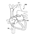
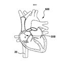
いくつかの実施形態では、図1Aおよび1Bに示すように、本発明は、心臓の隔壁を通るトランスセプタル穿刺を生成するためなどの組織を穿刺するアセンブリ100を提供し、アセンブリは、組織穿刺または穿刺デバイス110と、穿刺デバイス110を支持するために組織穿刺デバイス110とともに選択的に使用可能な別個の支持部材130とを提供する。
穿刺デバイス110は、処置の1つまたは複数の部分またはステップの間に支持部材130と協働して選択的に使用することができ、穿刺デバイス110は、処置の1つまたは複数の部分またはステップの間に、組織を穿刺するために、それから独立して使用することができる。
いくつかのそのような実施形態では、別個の穿刺デバイス110と、それを選択的に備えるための支持部材130とを提供することは、交換および位置決めを容易にすることによって、処置の効率をさらに向上させる。
In some embodiments, as shown in FIGS. 1A and 1B, the present invention provides an
The lancing
In some such embodiments, providing a
再び図1Aおよび図1Bに関して、いくつかの実施形態において、組織を穿刺するアセンブリ100が提供され、アセンブリ100は、実質的に可撓性の穿刺デバイスを支持する支持部材130および組織穿刺するために、本明細書でさらに説明するように、実質的に可撓性の穿刺デバイス112を含む。
実質的に可撓性の穿刺デバイス112は、上述の実施形態と同様に、組織を穿刺し、交換および位置決めを容易にするために、処置の一部の間に支持部材130と協働して選択的に使用可能であるように支持部材130内に選択的に挿入可能であり、実質的に可撓性の穿刺デバイス112は、処置の別の部分の間に支持部材130から独立して使用可能である。
いくつかのそのような例では、実質的に可撓性の穿刺デバイス112は、組織を穿刺するためにエネルギーを送達するように動作可能なエネルギー送達デバイスを備える。いくつかのそのような例では、以下でさらに詳細に説明するように、支持部材130は、補強部材34を備える。
Referring again to FIGS. 1A and 1B, in some embodiments, an
The substantially
In some such examples, the substantially
そのような一例では、アセンブリ100は、組織を穿刺する針アセンブリを備え、針アセンブリは、穿刺デバイス110および支持部材130を備える。針アセンブリのいくつかのそのような実施形態では、穿刺デバイスは、図1Aおよび1Bに示すように、実質的に可撓性の穿刺デバイス112を備える。
In one such example,
針アセンブリの特定の例では、図1Aに示すように、穿刺デバイス110は、実質的に非外傷性の遠位先端112dを備え、穿刺デバイス110は、実質的に非外傷性である。
再び図1Aを参照すると、いくつかの実施形態では、穿刺デバイス110は、組織を穿刺するためにエネルギーを送達するエネルギー送達部分または構成要素114dをその遠位先端に有する実質的に可撓性のエネルギーベースの穿刺デバイス114などのエネルギーベースの穿刺デバイス114を備える。
この特定の例では、穿刺デバイス130は、組織を穿刺するために高周波エネルギーを送達する遠位電極先端10dを有する可撓性(高周波)RFガイドワイヤ10を備える。
In a particular example of a needle assembly, as shown in FIG. 1A, the
Referring again to FIG. 1A, in some embodiments, the piercing
In this particular example, the lancing
場合によっては、RFガイドワイヤ10は、遠位電極先端10dなどの選択された遠位領域を除いて、概して電気的に絶縁された可撓性ワイヤである。
In some cases, RF guidewire 10 is a flexible wire that is generally electrically insulated, except at selected distal regions, such as
針アセンブリの特定の例では、図1Aに示すように、穿刺デバイスは、機械的穿刺デバイス118を備える。いくつかのそのような実施形態では、針アセンブリの機械的穿刺デバイス118は、組織を穿刺する比較的鋭い遠位先端118dを備える。
In a particular example of a needle assembly, the lancing device comprises a
いくつかのそのような実施形態では、図に示すように、針アセンブリなどのアセンブリ100がある。図1Aおよび1Bにおいて、支持部材は、補強部材からなる。
いくつかのそのような実施形態では、図示のように、支持部材130は、穿刺デバイス110を支持する補強部材34を備える針シャフト132を備える。
いくつかのそのような実施形態では、針シャフト132は、機械的針の特性を提供するか、または有することができる。特定の例では、補強部材(例えば、1つ以上のポリマー層を有する金属ハイポチューブ)は、針シャフト132を形成するように構造化される。
In some such embodiments, there is an
In some such embodiments, as shown, the
In some such embodiments, the
本明細書で以下に説明するいくつかの実施形態では、針アセンブリなどのアセンブリ100は、RFワイヤと、別個の補強部材とを備える。従って、本明細書で以下に提供される本発明のいくつかの実施形態は、RFガイドワイヤに関して説明されるが、本明細書で説明されるいくつかのそのような実施形態は、機械的ガイドワイヤなどの機械的穿刺デバイスなどの他の穿刺デバイスを伴ってもよい。しかしながら、RFガイドワイヤは、機械的ガイドワイヤのような他の穿刺デバイスには見られない利点を提供し得る。
デバイス例1
針シャフト/補強拡張器を含む支持部材
In some embodiments described herein below, an
Device example 1
Support member including needle shaft / reinforcement dilator
1つの広範な態様において、本発明の実施形態は、組織を穿刺するアセンブリ100を提供し、アセンブリ100は、エネルギーの送達を介して組織を穿刺する実質的に可撓性のエネルギーベースの(またはエネルギー送達)穿刺デバイス114と、実質的に可撓性のエネルギー送達穿刺デバイス114を支持する支持部材130とを備える。
実質的に可撓性のエネルギー送達穿刺デバイス114は、組織の実質的に無傷の穿刺を提供しながら、交換および位置決めを容易にするために、処置の一部の間、支持部材130内に選択的に挿入可能であり、処置の別の部分の間、それとは独立して使用可能である。一例では、支持部材130は、補強部材34を含む。
In one broad aspect, embodiments of the present invention provide an
The substantially flexible energy
1つのそのような例では、図1Aに示される実施形態を参照すると、アセンブリ100は、支持部材130とは別個に提供され、支持部材130とは独立して動作可能である実質的に可撓性のエネルギー送達穿刺デバイスまたは構成要素114を備える。
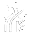
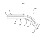
1つのそのような例では、可撓性エネルギー送達穿刺デバイスまたは構成要素114(可撓性エネルギーベース送達デバイスまたは可撓性のエネルギー送達穿刺デバイスとも呼ばれる)は、高周波(RF)ガイドワイヤ10を備え、別個の支持部材130は、補強部材34と、拡張器30Aのポリマーシャフト39を形成する1つ以上のポリマー層38とを備える針シャフト132を備え、補強部材34は、1つ以上のポリマー層によって実質的に囲まれる。
改質電極チップ
In one such example, referring to the embodiment shown in FIG. 1A, the
In one such example, the flexible energy delivery puncture device or component 114 (also referred to as a flexible energy-based delivery device or flexible energy delivery puncture device) comprises a radio frequency (RF) guidewire 10. , A
Modified electrode tip
図示の例では、RFガイドワイヤ10は、高周波エネルギーを送達する電極を備える。1つの特定の例では、図示するように、RFガイドワイヤ10は、組織を穿刺するために高周波エネルギーを送達する遠位電極先端10dを有する。
いくつかのそのような実施形態では、遠位電極先端10dは、組織に及ぼされる圧力を低減するために、実質的に非外傷性である。1つのそのような例では、RFガイドワイヤ10の遠位電極先端は、組織に及ぼされる圧力を低減するために実質的に非外傷性である実質的にドーム形状の電極先端を備える。
In the illustrated example, RF guidewire 10 includes electrodes that deliver high frequency energy. In one particular example, as shown, the RF guidewire 10 has a
In some such embodiments, the
いくつかのそのような例では、図1Aを参照すると、RFガイドワイヤ10は、半球状の電極先端10dを有するシリンダ10cを備えてもよく、いくつかの例では、シリンダ10cの遠位に、かつシリンダ10cに隣接して形成されるキャップを形成してもよい。
言い換えれば、電極先端10dは、実質的に完全に丸いドームのようなシリンダ10cの上部のドームによって画定されてもよい。いくつかのそのような例では、ドームの外径は、シリンダ10cの外径と実質的に一致し得る。
これは、所望の標的組織部位における外傷および/または傷害の危険性を最小限にするために、組織との実質的に非外傷性の遠位インターフェースを提供するのに役立ち得る。いくつかのそのような実施形態では、RFガイドワイヤ10のドーム形状の遠位電極先端10dは、先端によって組織に及ぼされる圧力の量を低減して、先端をより非外傷性にすることができ、従って、遠位先端によって及ぼされる力は、より広い領域にわたって広がる。いくつかのそのような例では、RFガイドワイヤ10は、0.035インチのワイヤとして提供される。
In some such examples, referring to FIG. 1A, the RF guidewire 10 may include a
In other words, the
This may help to provide a substantially non-traumatic distal interface with tissue to minimize the risk of trauma and / or injury at the desired target tissue site. In some such embodiments, the dome-shaped
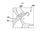
より具体的には、図1Aおよび図1Cを参照すると、アセンブリは、シース10と、可撓性RFワイヤとともに使用可能な拡張器30Aなどの補強拡張器を備える支持部材とをさらに備え、拡張器30Aは、補強部材34と、拡張器30Aのポリマーシャフト39を画定する1つまたは複数のポリマー層38とを備え、補強部材34は、1つまたは複数のポリマー層38によって実質的に囲まれる。
More specifically, referring to FIGS. 1A and 1C, the assembly further comprises a
本発明のいくつかのそのような実施形態では、組織を穿刺するアセンブリ100が提供され、支持部材130は、針シャフト132を備え、針シャフト132は、補強部材34および1つ以上のポリマー層38を備え、補強部材34は、1つ以上のポリマー層38によって実質的に囲まれる。いくつかのそのような実施形態において、針シャフト132は、拡張器30A内に設けられる。
従って、いくつかの実施形態では、支持部材は、拡張器30Aの一部として設けられるか、または拡張器30Aによって画定される針シャフト132を備え、針シャフト132は、拡張器130の1つ以上のポリマー層38に埋め込まれるか、またはそれによって囲まれる。
In some such embodiments of the present invention, an
Thus, in some embodiments, the support member comprises a
補強部材34の詳細を図1Cに示す。より具体的には、図1Cは、針シャフト132を有する補強された拡張器30Aを備える支持部材130を示し、支持部材130は、RFガイドワイヤ10などのエネルギーベースの組織穿刺デバイス114などの実質的に可撓性の組織穿刺デバイスまたは部材112とは別個に提供される。
一例では、針シャフト132は、拡張器30Aの一部として設けられるか、または言い換えれば、拡張器30Aによって画定される。いくつかのそのような例では、針シャフト132(従って、支持部材130を画定する拡張器30A)は、組織穿刺デバイスまたは部材を支持する非穿刺構成要素として提供される。
いくつかのそのような例では、針シャフト132を備える拡張器30Aは、遠位先端41で終端する近位部分31を備える。いくつかのそのような実施形態では、補強部材34は、剛性針の剛性と実質的に同様の十分な剛性を提供する。
Details of the reinforcing
In one example,
In some such examples,
いくつかのそのような例では、拡張器シャフト32は、近位部分31に沿って延在し、補強部材34を備える。図示の特定の例では、補強部材34は、1つ以上のポリマー層38によって実質的に囲まれている。
いくつかのそのような例では、補強部材34は、内側ポリマー層および外側ポリマー層を含む1つまたは複数のポリマー層38内に埋め込まれる。いくつかのそのような例では、内側および外側ポリマー層は、拡張器シャフト32の内側および外側管状部材35、37を含む。
いくつかのそのような例では、実質的に囲まれているとは、補強部材34の周りにポリマーシャフト39(拡張器シャフト32を形成する)を形成する1つまたは複数のポリマー層38によって、補強部材34の外側またはその外部が実質的に囲まれていることを意味すると解釈することができる。
いくつかの実施形態では、拡張器30Aは、遠位先端41に放射線不透過性マーカ42をさらに含んでもよい。一例では、補強部材34は、金属ハイポチューブなどのハイポチューブを含む。1つのそのような例では、補強部材34はステンレス鋼ハイポチューブを含み、内側および外側管状部材35、37はHDPEを含む。
ハイポチューブは、支持部材の内側ルーメンを画定する。
In some such examples,
In some such examples, the
In some such examples, being substantially enclosed is one or more polymer layers 38 that form a polymer shaft 39 (forming dilator shaft 32) around
In some embodiments,
The hypotube defines an inner lumen of the support member.
そのような一例では、ステンレス鋼ハイポチューブなどの補強部材34は、図1Cに示すように、1つまたは複数のポリマー層内、例えば、内側および外側管状部材35、37内で長手方向に延在する。従って、補強部材34(例えばハイポチューブ)は、支持部材130の内側ルーメンを画定する。
1つ以上のポリマー層の間に位置するハイポチューブ
In one such example, a stiffening
Hypotube located between one or more polymer layers
一例では、支持部材130は、再び図1Cを参照すると、1つまたは複数のポリマー層38は、内側ポリマー層および外側ポリマー層を含み、いくつかの例では、内側および外側管状部材35、37を含むことができる。特定の例では、補強部材34は、上述のように、その外側に沿って1つ以上のポリマー層38によって実質的に囲まれる。
他の例では、補強部材34は、例えば、図1Dに示される内側および外側管状部材35、37によって画定されるように、内側ポリマー層と内側ポリマー層との間に位置するように、1つ以上のポリマー層38によって実質的に囲まれる(いくつかの例では、ハイポチューブは、ポリマーの2つの層の間に位置するか、または挟まれる)。言い換えれば、補強部材34は、内側および外側ポリマー層の両方によって実質的に囲まれ、その内部に埋め込まれる。言い換えれば、補強部材34は、内側および外側ポリマー層38と、拡張器シャフト32を形成するポリマーシャフト39との間に挟まれる。そのようないくつかの例では、内側および外側管状部材35、37は、高密度ポリエチレン(HDPE)を備える。
In one example, the
In other examples, the
トランスセプタルアセンブリ100のいくつかの実施形態では、シース10は、標準的なトランスセプタルシースを備え、針シャフト132(拡張器30OAの一部として提供されるか、または拡張器30OAによって規定される)は、本明細書で上述したような補強部材34を備え、RFガイドワイヤまたはRFワイヤは、0.035インチワイヤとして提供される。いくつかのそのような例では、RFワイヤは、Jチップワイヤを含むか、または代替の例では、RFワイヤは、ピグテールワイヤを含む。
拡張器の内部ルーメン内に固定されたハイポチューブ
In some embodiments of the
A hypotube secured within the inner lumen of the dilator
本発明のいくつかのそのような実施形態において、補強部材34は、遠位端34Dおよび近位端34Pを備え、補強部材34は、図1Cに示すように、拡張器30Aの内部ルーメン内に延在する。
いくつかのそのような実施形態では、アセンブリ100は、遠位端および近位端における補強部材と1つまたは複数のポリマー層との間の接合部に、実質的にギャップのない界面を提供する。いくつかのそのような例では、補強部材34は、拡張器30Aのポリマーシャフト39を形成する1つ以上のポリマー層38内に固定される。
ここで、図7A〜7Cを参照すると、1つのそのような例では、補強部材34は、その遠位端および近位端(言い換えれば、補強部材の遠位端および補強部材の近位端)で拡張器30Aの1つ以上のポリマー層38に実質的に固定されて、遠位端および近位端での補強部材34と1つ以上のポリマー層38補強部材との間の接合部に実質的にギャップのない界面を提供する。
図面は、補強部材34の遠位端における界面を示している。補強部材34の基端にも、同様の界面が設けられている。
本発明のいくつかのそのような実施形態では、補強部材34は、その遠位端および近位端(言い換えれば、補強部材の遠位端および補強部材の近位端)で、拡張器30Aの1つまたは複数のポリマー層38に実質的に封止される。いくつかのそのような実施形態では、補強部材34と拡張器30Aのポリマーシャフト39との間の間隙を実質的に排除することによって、血液または他の液体が補強部材34とポリマーシャフト39との間に入ることを防止し得る。
力伝達および/またはトルク伝達
力/トルク伝達を提供する支持部材
In some such embodiments of the present invention, the stiffening
In some such embodiments, the
Referring now to FIGS. 7A-7C, in one such example, the reinforcing
The drawing shows the interface at the distal end of the
In some such embodiments of the invention, the stiffening
Support member for providing force transmission and / or torque transmission force / torque transmission
本発明のいくつかのそのような実施形態では、支持部材130は、RFワイヤなどの穿刺デバイスに十分な剛性を提供し、アセンブリ100の遠位端に力を伝達することを可能にするのに十分な力伝達を可能にする。
In some such embodiments of the present invention,
いくつかのそのような実施形態では、支持部材130は、トルクがアセンブリの遠位端に伝達されることを可能にするために、穿刺デバイスに十分な剛性を提供する。
力伝達/トルクを提供する補強部材
In some such embodiments,
Reinforcement members that provide force transmission / torque
いくつかのそのような例では、補強部材34は、アセンブリ100の遠位端に力が伝達されることを可能にするのに十分な力伝達を可能にするのに十分な剛性を支持部材130に提供する。より具体的には、補強部材34は、実質的に可撓性の穿刺デバイス112(RFワイヤ10などの実質的に可撓性のエネルギーベースの穿刺デバイス114など)が、支持部材130とともに、アセンブリ100の遠位端に力が伝達されることを可能にする(従って、実質的に可撓性の穿刺デバイス112の遠位端に力が伝達されることを可能にする)のに十分な力伝達が可能であるように、アセンブリ100に十分な剛性を提供する。
In some such examples, the stiffening
このように、補強部材34は、実質的に可撓性のRFワイヤ10に力伝達能力を付与することができ、この力伝達能力は、支持部材130と一緒に使用される場合、例えば、標的組織部位の組織と係合するために、アセンブリ100の遠位端に力が伝達されることを可能にし、力伝達可能である。このように、補強部材34は、アセンブリ100の力伝達部分として機能する。
In this manner, the
いくつかのそのような例では、アセンブリ100は、図1Aに示すように、シース20をさらに備え、シース20は、アセンブリ100の遠位端に伝達される力を容易にするために、アセンブリ100に剛性を提供するために、支持部材130とともに使用可能である。
In some such examples, the
本発明のいくつかのそのような実施形態では、補強部材34は、トルクがアセンブリ100の遠位端に伝達されることを可能にするのに十分な剛性を提供する。従って、補強部材34は、アセンブリに十分な剛性を提供し、実質的に可撓性のエネルギーベースの穿刺デバイス114などの実質的に可撓性の穿刺デバイス112は、支持部材130とともに、アセンブリ100に十分な剛性を提供し、トルクがアセンブリ100の遠位端に伝達されることを可能にする(従って、トルクが実質的に可撓性の穿刺デバイス112の遠位端に伝達されることを可能にする)。
In some such embodiments of the present invention, stiffening
本発明のいくつかのそのような実施形態は、横断的な穿刺を容易にし、補強部材34は、所望の組織部位(心臓の隔壁など)に係合する十分な力の伝達を可能にするために、アセンブリ100に十分な剛性を提供する。いくつかのそのような例では、支持部材130は、実質的に可撓性の穿刺デバイス112に力伝達能力を提供し、実質的に可撓性の穿刺デバイス112は、支持部材130と共に使用されるときに力伝達が可能である。
Some such embodiments of the present invention facilitate transversal puncture, and the stiffening
いくつかのそのような実施形態では、アセンブリ100は、図1Aに示すように、シース20をさらに備え、シース20は、アセンブリ100に剛性を提供して、トルクがアセンブリ100の遠位端に伝達されることを可能にするために、支持部材130とともに使用可能である。
In some such embodiments, the
いくつかのそのような例では、シース20は、1つ以上の構成要素(すなわち、シース20または拡張器30A)を使用して、力および/またはトルク伝達を可能にする拡張器30Aに連結され得る。
言い換えれば、使用者は、シース20および拡張器30Aを操作する必要がなく(使用者は、シース20または拡張器30Aを操作するだけでよい)、RFガイドワイヤ10は、シース20および/または拡張器30Aの案内および/または方向に従う。
いくつかのそのような例では、シース20は、全体のトルクにいくらかの寄与を有する。いくつかのそのような実施形態では、シース20および/または拡張器30Aにトルクを加えることによって、補強部材34にトルクを加えることが可能になる。
補強部材の剛性
In some such examples,
In other words, the user does not need to operate the
In some such examples,
Reinforcement member rigidity
本発明のいくつかの実施形態では、アセンブリ100の力伝達部分は、少なくとも約0.0085Nm2、例えば、約0.0115Nm2の力伝達部分曲げ剛性を有する。本発明のいくつかの実施形態では、アセンブリの力伝達部分は、アセンブリ100の遠位端に力が伝達されることを可能にするのに十分な力伝達を可能にするために、少なくとも約0.0115Nm2の曲げ剛性値を有する剛性を持つ支持部材130である。
いくつかのそのような例では、支持部材は、約0.0085Nm2〜約0.0145Nm2の曲げ剛性を有する。そのような一例では、支持部材130は、少なくとも約0.0085Nm2、例えば、約0.0115Nm2の曲げ剛性を有する強化拡張器30Aである。
特定の例では、強化拡張器30Aは、約0.0085Nm2〜約0.0145Nm2の曲げ剛性を有する。そのような一実施例では、強化拡張器30Aは、例えば、図2A〜2Gに関して提供されるような、実施例1に提供されるような強化拡張器30Aである。
In some embodiments of the present invention, the force transmitting portion of the
In some such examples, the support member has a flexural rigidity of about 0.0085Nm 2 ~ about 0.0145Nm 2. In one such example,
In a particular example, the reinforced
いくつかのそのような例では、支持部材130は、実質的に可撓性の穿刺デバイスなどの穿刺デバイスを含むアセンブリ100に剛性を付与し、実質的に可撓性の穿刺デバイスなどの穿刺デバイスを含むアセンブリに力伝達能力を提供するように機能する。
In some such examples, the
いくつかの実施例では、支持部材130に提供される曲げ剛性値は、図4A〜4Gおよび図6A〜6Hに関して、本明細書に提供される実施例2、3にも使用可能である。
実施例2、3
In some embodiments, the flexural stiffness values provided for the
Examples 2 and 3
本発明のいくつかの実施形態では、アセンブリの力伝達部分は、スタイレットを備える補強部材である支持部材130である。スタイレットは、少なくとも約0.008Nm2、例えば、約0.015Nm2の曲げ剛性値を有する剛性を持ち、力がアセンブリ100の遠位端に伝達されることを可能にするのに十分な力伝達を可能にする。いくつかのそのような例では、支持部材は、約0.008Nm2〜約0.024Nm2の曲げ剛性を有する。
穿刺デバイスの剛性
In some embodiments of the present invention, the force transmitting portion of the assembly is a
Puncture device rigidity
本発明のいくつかの実施形態では、実質的に可撓性の穿刺デバイスなどの穿刺デバイスの遠位部分は、遠位部分または遠位領域の曲げ剛性を有する。いくつかのそのような例では、実質的に可撓性のRFガイドワイヤ10が設けられ、実質的に可撓性のRFガイドワイヤ10は、遠位部分(遠位電極先端10dに沿った部分を含む)を有し、RFガイドワイヤ10は、少なくとも約3.57×10⁻⁶Nm2、例えば、約4.76×10⁻⁶Nm2の曲げ剛性によって規定される遠位部分剛性を有する。
本発明のいくつかの実施形態では、RFガイドワイヤ10は、約3.57×10⁻⁶Nm2〜約5.95×10⁻⁶Nm2の曲げ剛性を有する遠位部分剛性を有する。
In some embodiments of the invention, the distal portion of the puncture device, such as a substantially flexible puncture device, has a bending stiffness of the distal portion or region. In some such examples, a substantially
In some embodiments of the present invention, the RF guidewire 10 has a distal portion stiffness having a bending stiffness of about 3.57 × 10 −6 Nm 2 to about 5.95 × 10 −6 Nm 2 .
いくつかのそのような例では、RFガイドワイヤ10の遠位領域は、RFガイドワイヤ10の近位領域から約12cm〜15cmにわたって先細になっている。言い換えれば、RFガイドワイヤ10の遠位部分は、約12cm〜約15cmの長さを有する。いくつかのそのような例では、RFガイドワイヤ10の遠位部分は、RFガイドワイヤ10の最も薄い点である。
In some such examples, the distal region of RF guidewire 10 tapers from approximately 12 cm to 15 cm from the proximal region of
いくつかのそのような実施形態では、実質的に可撓性のRFガイドワイヤ10は、約0.00179Nm2未満、例えば約0.00143Nm2の近位部分曲げ剛性を有する近位部分を有する。本発明のいくつかの実施形態では、RFガイドワイヤ10は、約0.00107Nm2〜約0.00179Nm2の曲げ剛性を有する近位部分剛性を有する。 In some such embodiments, RF guidewire 10 substantially flexible, less than about 0.00179Nm 2, having a proximal portion having a proximal portion flexural rigidity, for example, about 0.00143Nm 2. In some embodiments of the present invention, the RF guidewire 10 has a proximal partial stiffness having a bending stiffness of about 0.00107 Nm 2 to about 0.00179 Nm 2 .
本発明のいくつかの実施形態では、実質的に可撓性の穿刺デバイスは、RFガイドワイヤ10を含み、約2.0×10⁻⁶〜約1.4×10⁻³Nm2の間の曲げ剛性を有する。
いくつかのそのような例では、RFガイドワイヤ10は、約0.127mm〜約0.635mmのワイヤ直径を有する。
支持部材/補強部材の形状能力
In some embodiments of the present invention, a substantially flexible puncture device includes an
In some such examples, RF guidewire 10 has a wire diameter from about 0.127 mm to about 0.635 mm.
Supporting / reinforcing member shape capability
より具体的には、心臓の隔壁などの標的組織部位に対するアセンブリ100の位置を最適化するために、補強部材34は、支持部材130(例えば、補強された拡張器30Aの一部として提供されるか、または補強された拡張器30Aによって画定されるような針シャフト132を備える)が、実質的に可撓性のエネルギー送達穿刺デバイス110(RFワイヤ10など)から除去されて、支持部材130の湾曲が、それとともに再挿入されることを可能にするように成形可能である。
More specifically, to optimize the position of the
本発明のいくつかの実施形態では、支持部材130は、標的組織部位に対するアセンブリ100の位置を最適化するために、支持部材130の湾曲部がそれとともに再挿入されることを可能にするように、穿刺デバイス(RFガイドワイヤ10などの実質的に可撓性の穿刺デバイス114など)から除去されることを可能にするように成形可能である。
いくつかのそのような例では、補強部材34は、成形性をさらに提供し、補強部材34、従って支持部材130を成形可能にすることができる。いくつかのそのような実施形態では、補強部材34が成形可能である場合、心臓の隔壁などの標的組織部位に対するアセンブリ100の位置を最適化するために、支持部材130(補強部材34を含む)を実質的に可撓性の穿刺デバイス(RFガイドワイヤなど)から除去して、支持部材の湾曲をそれとともに再挿入することを可能にする。
In some embodiments of the present invention, the
In some such examples, the stiffening
いくつかのそのような実施形態では、支持部材130は、補強された拡張器30A内(補強された拡張器30Aの針シャフト132内など)に設けられ、従って、拡張器30Aに形状能力を与える補強部材34を備える。
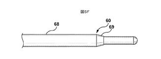
他の例では、支持部材130は、拡張器30Aとは別個に提供されるスタイレット60を備える(本明細書で以下にさらに説明される実施形態で説明されるように、アセンブリ100に形状安定性を与える)。
言い換えれば、スタイレット60は、アセンブリ100と共に使用するときに、アセンブリ100に所望の曲率および剛性を与えるように機能する。スタイレット60は、アセンブリから取り外し可能であり、アセンブリ100に所望の曲率を提供するために、アセンブリ100に対して再成形および再挿入可能である。
拡張器とシースとの間の連結
実施例1のロック機能
In some such embodiments, the
In another example, the
In other words, stylet 60 functions to provide desired curvature and stiffness to
Locking function of connection example 1 between dilator and sheath
本発明のいくつかの実施形態では、図1Cを参照すると、アセンブリ100が提供され、アセンブリ100は、処置の一部の間、補強された拡張器30aとともに使用する図1Aに示されるようなシース20を備える。
このような実施例のいくつかでは、アセンブリ100は、処置の一部のために、拡張器30Aとシース20との軸方向および回転方向の結合を可能にするロック機構を含む。
本発明のいくつかの実施形態では、ロック機構は、シース20と拡張器30Aとの間の協働係合を可能にして、回転および軸方向の結合を提供する。これは、シース20と拡張器30Aとの間の回転ミスアラインメントのリスクを最小化するのに役立ち、従って、ミスアラインメントから生じる混乱のリスクを低減することができる。
In some embodiments of the present invention, referring to FIG. 1C, an
In some such embodiments,
In some embodiments of the present invention, the locking mechanism allows for cooperative engagement between the
ここで、図1Eを参照すると、拡張器30A(の一部として提供されるか、またはそれによって規定される)を備える針シャフト132を備える支持部材130は、処置の一部のためにシースハブ21に連結されるように動作可能である拡張器ハブ51を備える。
一例では、図1Fに示すように、拡張器ハブ51がシース20との軸方向および回転方向のロックを可能にするシースハブ21上の対応する機構(キー受容機構など)と協働的に係合する1つ以上のキー52を備えるロック機構が提供される。
従って、本発明のいくつかの実施形態では、処置の一部のために拡張器とシースとの軸方向および回転方向の結合を可能にするために、ロック機構が提供される。
いくつかの例では、可変シースが提供され、可変シース20は、8Fr可変シースであってもよい。あるいは、8.5Fr可変シース20が提供され得る。いくつかのそのような例では、可変シース20は、異なる曲率を備えることができる。
特定の例では、可変シース20は、異なる曲率で、具体的には、37度、45度、55度、90度または135度の角度で提供されてもよい。この特定の例では、シースチュービングは、内側PTFEライナー、ブレードおよびPebax外側ジャケットを含む。
いくつかのそのような実施形態では、8Frシースに適合する8Fr拡張器30Aの針シャフト132(例えば、その一部として提供されるか、またはそれによって画定される)を備える支持部材130が提供される。あるいは、針シャフト132を含む支持部材130は、8Fr可変シース20の一部として設けられてもよく、または8.5Fr拡張器30Aによって規定されてもよい。
針シャフト132(例えば、拡張器30Aの一部として提供されるか、または拡張器30Aによって画定される)を備える支持部材130は、50度または86度の湾曲を備えることができる。いくつかの例では、材料は、HDPEと、補強部材34を形成する金属ハイポチューブとを含むことができる。
いくつかのそのような例では、RFワイヤは、0.035インチODワイヤを含み、Jチップワイヤまたはピグテールワイヤであってもよい。この特定の例では、ワイヤは、PTFEコーティングを有するステンレス鋼コアを含むことができる。
放射線不透過性マーカ
Referring now to FIG. 1E, a
In one example, as shown in FIG. 1F,
Accordingly, in some embodiments of the present invention, a locking mechanism is provided to allow for axial and rotational coupling of the dilator and sheath for a portion of the procedure.
In some examples, a variable sheath is provided, and the
In certain examples, the
In some such embodiments, a
The
In some such examples, the RF wires include 0.035 inch OD wires and may be J-tip wires or pigtail wires. In this particular example, the wire may include a stainless steel core with a PTFE coating.
Radiopaque marker
いくつかの実施形態では、図1Cおよび1Dに示すように、支持部材130は、支持部材放射線不透過性マーカ42などの1つ以上の放射線不透過性マーカを備える。
上記のようないくつかの例では、アセンブリ100は、支持部材130(例えば、補強された拡張器30Aの一部として提供されるか、または補強された拡張器30Aによって画定されるような針シャフト132を備える)を提供し、支持部材130の遠位先端などに放射線不透過性マーカ42を備える。いくつかのそのような例では、支持部材130は、示したように、その遠位先端のポリマー内に埋め込まれた放射線不透過性マーカ42を備える。
In some embodiments, as shown in FIGS. 1C and 1D,
In some examples, such as described above, the
特定の例では、図7A、7Bおよび7Cに示すように、放射線不透過性マーカ42は、例えば、(支持部材130の)その遠位先端において、(拡張器シャフト32を順に形成するポリマーシャフト39を形成する)1つ以上のポリマー層38内などの、支持部材130のポリマー内に埋め込まれた放射線不透過性コイル142(例えば、強化拡張器30Aの一部として提供されるか、または強化拡張器30Aによって規定される針シャフト132を備える)を備える。
より具体的な例では、放射線不透過性コイル142は、1つ以上のポリマー層が放射線不透過性コイル42を越えて遠位方向に延在するように、1つ以上のポリマー層内に埋め込まれる。
放射線不透過性マーカを用いたアラインメント
In a particular example, as shown in FIGS. 7A, 7B and 7C, the
In a more specific example,
Alignment using radiopaque markers
本発明のいくつかの実施形態では、例えば、図3Bおよび3Cに示すように、その遠位端に1つまたは複数のデバイス側放射線不透過マーカ(または言い換えれば、1つまたは複数のデバイス放射線不透過マーカ)を備える実質的に可撓性のエネルギーベースの穿刺デバイス114(RFガイドワイヤなど)が提供される。
いくつかのそのような実施形態では、上述のように、支持部材130はまた、支持部材130の遠位端に(図1Cおよび1Dに示すように)支持部材放射線不透過性マーカを備える。
いくつかのそのような実施形態では、図3Bおよび3Cに示される実施形態と同様に、1つ以上のデバイス放射線不透過性マーカ12は、支持部材放射線不透過性マーカ42と協働して、実質的に可撓性のエネルギーベースの穿刺デバイス114(RFガイドワイヤ10など)の相対位置を示すように構成される。
図3Bおよび3Cに示す実施形態は、スタイレット64とは別個に設けられた拡張器30Bを示す。しかしながら、現在説明されているような代替実施形態では、スタイレット64は、拡張器30A内に設けられた補強部材34であってもよい。
In some embodiments of the invention, one or more device-side radiopaque markers (or in other words, one or more device radiopaque markers) are provided at the distal end thereof, for example, as shown in FIGS. 3B and 3C. A substantially flexible energy-based lancing device 114 (such as an RF guidewire) with a transmission marker) is provided.
In some such embodiments, as described above,
In some such embodiments, similar to the embodiment shown in FIGS. 3B and 3C, one or more device
The embodiment shown in FIGS. 3B and 3C shows the
いくつかのそのような実施形態では、アセンブリ100は、図3Aに示すように、1つ以上のデバイス放射線不透過性マーカ12が支持部材130の放射線不透過性マーカ42と整列しないように、実質的に可撓性のエネルギーベースの穿刺デバイス114(RFガイドワイヤ10など)が支持部材130内に位置決め可能である初期構成100Aを備える。
いくつかのそのような例では、1つまたは複数のデバイス放射線不透過性マーカ12および支持部材放射線不透過性マーカ42を含む複数の放射線不透過性マーカが、撮像中に見えることがある。
In some such embodiments, the
In some such examples, a plurality of radiopaque markers, including one or more device
いくつかのこのような実施形態では、アセンブリ100は、図3Bに示すように、第1の構成100Bを備え、実質的に可撓性のエネルギーベースの穿刺デバイス114(RFガイドワイヤ10など)は、1つ以上のデバイス放射線不透過性マーカ12が、図3Bに示すように、支持部材130放射線不透過性マーカ42と整列するように、支持部材130内に配置可能である。
いくつかのそのような例では、単一の放射線不透過性マーカは、撮像中に見ることができる(1つまたは複数のデバイス放射線不透過性マーカ12と、互いに近接して配置することができる支持部材放射線不透過性マーカ42とを含む)。
In some such embodiments, the
In some such examples, a single radiopaque marker is visible during imaging (can be placed in close proximity to one or more device radiopaque markers 12) Support member radiopaque marker 42).
アセンブリ100は、さらに第2の構成100Bを有し、実質的に可撓性のエネルギーベースの穿刺デバイス114(RFガイドワイヤ10など)は、1つまたは複数のデバイス放射線不透過性マーカ12の支持部材放射線不透過性マーカ42との位置合わせ不可または位置合わせ不良が実質的にないように、支持部材130内で位置決め可能/前進可能である。その結果、1つまたは複数のデバイス放射線不透過性マーカ12と支持部材放射線不透過性マーカ42との位置合わせ不良は、組織の穿刺のために標的組織部位に対して位置決めするための支持部材を越えた(例えば、支持部材130の遠位先端または末端から遠位に)可撓性のエネルギーベースの穿刺デバイス114のエネルギー送達部分114d(RFガイドワイヤ10の電極端10dような)の位置決めを示す。
いくつかのそのような例では、図3Aと同様に、複数の放射線不透過性マーカは、撮像中に見ることができる[1つ以上のデバイス放射線不透過性マーカ12および支持部材放射線不透過性マーカ42を含む]。ここで、1つ以上のデバイス放射線不透過性マーカ12は、支持部材放射線不透過性マーカ42に対して遠位に配置され、組織を穿刺するために、遠位電極先端10dが標的組織部位(心臓の隔壁など)に対して配置されることを示す。
The
In some such examples, as in FIG. 3A, a plurality of radiopaque markers may be visible during imaging [one or more device
いくつかのそのような例では、シース20、拡張器30Aおよび補強部材34は、すべて放射線不透過性であり、撮像中にそれらを見ることができるように放射線不透過性を有する。
いくつかのそのような例では、シース20、拡張器30Aおよび金属ハイポチューブなどの補強部材34のうちの1つまたは複数は、放射線不透過性マーカ[42]に加えて放射線不透過性材料を備える。金属シャフトまたはハイポチューブのような補強部材34も放射線不透過性である。
いくつかのそのような実施形態では、シース20および/または拡張器30Aを形成するポリマーは、20%硫酸バリウムなどのポリマー放射線不透過性充填剤を含んでもよく、その結果、遠位先端における1つ以上のマーカ[12、42]とのコントラストが存在する。
言い換えれば、これは、撮像下での可視性を提供し、さらに、1つ以上のマーカ[42、12]とのコントラストを提供し得、RFガイドワイヤ10が拡張器30Aの中または外側に配置されているかどうか[すなわち、RFガイドワイヤ10の遠位セグメントが拡張器30Aの遠位にあるかどうか]を見るために、撮像下でRFガイドワイヤ10と比較して拡張器30Aをユーザが観察可能とする。
鈍いダイレータチップ[実施例1]
In some such examples,
In some such examples, one or more of the
In some such embodiments, the
In other words, this may provide visibility under imaging, and may also provide contrast with one or more markers [42, 12], with the RF guidewire 10 positioned inside or outside the
Dull dilator tip [Example 1]
本発明のいくつかの実施形態では、支持部材130は、実質的に非外傷性の遠位先端143を備え、図1Aに示すように、実質的に鈍い遠位先端または縁部143を備える一方で、(補強部材34を提供することなどによって)実質的に剛性の支持部材130の利点を備える。
いくつかのそのような実施形態では、上記のように、図1Aを再び参照すると、補強された拡張器30Aが提供される。いくつかの例では、拡張器30Aは、実質的に非外傷性の遠位先端144を提供するために、実質的に鈍い遠位先端またはエッジ144を備える。いくつかのそのような実施形態では、強化された拡張器30Aは、遠位先端144に沿って実質的に厚い遠位壁を備え、遠位先端144は、実質的に丸みを帯びた遠位先端縁によって画定される。
いくつかのそのような実施形態では、拡張器30Aは、位置決め、追跡デバイス、穿刺および固定のうちの1つまたは複数のためのRFガイドワイヤ10の使用を可能にすることに加えて、実質的に剛性の構成要素(その中に補強部材34など)を提供することによって、実質的に剛性の本体を提供することに関連する利点を提供しながら、追跡可能性および交差の容易性を提供するために、実質的に非外傷性の遠位先端およびさらに遠位先端のテーパ形状を備えることによって拡張器としての利点を備える。
In some embodiments of the present invention, the
In some such embodiments, as described above, referring again to FIG. 1A, a reinforced
In some such embodiments,
1つのそのような実施形態では、全体的な方法/ワークフローが提供され、この方法/ワークフローは、本明細書で上述したように、アセンブリ100を使用してトランスセプタル穿刺手順を実行する方法を示す。
本明細書に開示される方法は、剛性構成要素とは別個に提供されるエネルギー送達構成要素を備えるアセンブリに関連する1つ以上の利点を提供する。この方法の詳細を以下に示す。
方法
方法[実施例1]
初期追跡/アクセスおよび位置決めのために同じデバイスを使用すること
In one such embodiment, an overall method / workflow is provided that includes a method of performing a transceptive lancing procedure using the
The methods disclosed herein provide one or more advantages associated with an assembly that includes an energy delivery component that is provided separately from the rigid component. Details of this method will be described below.
Method Method [Example 1]
Using the same device for initial tracking / access and positioning
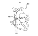
本発明のいくつかの実施形態において、図2A〜2Gを参照すると、組織を穿刺する方法が開示される。この方法は、[1]図2Bに示すように、デバイス(RFガイドワイヤ10などの穿刺デバイス110など)を組織の領域内に前進させることによって、患者の体内の組織の領域にアクセスするステップを含む。
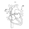
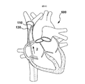
いくつかのそのような例では、組織領域を穿刺する方法は、組織領域にアクセスするステップが、患者の心臓500に隣接する上大静脈(SVC)501内にデバイス(穿刺デバイス110など)を前進させることを含むトランスセプタル穿刺を実行する方法を備える。
In some embodiments of the present invention, referring to FIGS. 2A-2G, a method for piercing tissue is disclosed. The method includes the steps of [1] accessing a region of tissue within a patient's body by advancing a device (such as a lancing
In some such examples, the method of puncturing a tissue area includes the step of accessing the tissue area, wherein the step of advancing a device (such as puncture device 110) into the superior vena cava (SVC) 501 adjacent to the patient's
本発明のいくつかの実施形態では、組織を穿刺する方法は、さらに、[3]例えば、[2]図2Cに示すように、穿刺デバイス110の上で支持部材130(強化拡張器30Aなど)を最初に追跡して、デバイス(穿刺デバイス110など)を支持し、[3]図2Dに示すように、穿刺のためにデバイスを標的組織部位に位置決めするために、デバイス(穿刺デバイス110など)を標的組織部位に向かって前進させることを可能にすることによって、図2Dに示すように、組織の領域内の標的組織部位にデバイスを位置決めする。
In some embodiments of the present invention, the method of piercing tissue further includes [3], for example, [2] a support member 130 (such as a reinforced
いくつかのそのような例では、穿刺デバイス110を標的組織部位に配置するステップは、[3]例えば、最初に(2)支持部材130(拡張器30Aなど)をデバイス(穿刺デバイス110など)上でSVC内に追跡または前進させて、(3)穿刺デバイス110を窩504に配置するようにドロップダウンを容易にすることによって、患者の心臓500内に上大静脈(SVC)からドロップダウンを実行して、卵円窩(または換言すれば窩)504を心臓500の隔壁502に沿って位置付けるステップを含む。
In some such examples, placing the lancing
いくつかのそのような例では、図2B〜2Dに示すように、図2Bに示されるようなアクセスするステップ[1]および図2Dに示されるような位置決めするステップ[3]は、穿刺デバイス110などの同じデバイスを使用して実行され、穿刺デバイス110は、アクセスするステップ[1]の間、支持部材130なしで使用可能であり、デバイスは、位置決めするステップ[3]の間、支持部材130とともに使用可能である。
初期アクセスおよび位置決めのための穿刺デバイスの使用
In some such examples, as shown in FIGS. 2B-2D, the accessing step [1] as shown in FIG. 2B and the positioning step [3] as shown in FIG. Performed using the same device, such as, the
Use of puncture device for initial access and positioning
本発明のいくつかのそのような実施形態では、図2B〜2Dに示すように、アクセスおよび位置決めのステップは、穿刺デバイス110を使用して実行される。
初期アクセス、位置決めおよび穿刺のために同じデバイスを使用すること
In some such embodiments of the present invention, the steps of accessing and positioning are performed using a lancing
Using the same device for initial access, positioning and puncturing
本発明のいくつかのそのような実施形態では、図2Eに示すように、方法は、図2Dに示すように、位置決めするステップ[3]の後に、デバイス(穿刺デバイス110など)を使用して標的組織部位を穿刺するステップ[4]をさらに含む。
支持部材130は、アクセス[1]、位置決め[3]および穿刺[4]のステップが同じデバイスを使用して実行される穿刺[4]中にデバイス(穿刺デバイス110など)を支持する。
In some such embodiments of the invention, as shown in FIG. 2E, the method uses a device (such as lancing device 110) after the positioning step [3], as shown in FIG. 2D. The method further includes the step of puncturing the target tissue site [4].
The
本発明のいくつかの実施形態では、標的組織部位を穿刺するステップ[4]は、心臓500の左側へのアクセスを得るために、窩504を穿刺するステップ[4]を含む。これは、アセンブリ100の支持部材130(拡張器30Aなど)およびシース20などのアセンブリ100の1つ以上のデバイスが、RFガイドワイヤ10上を心臓の左側に追跡されることを可能にする。
初期アクセス、位置決めおよび穿刺のための穿刺デバイスの使用
In some embodiments of the present invention, puncturing the target tissue site [4] includes puncturing the
Use of lancing device for initial access, positioning and lancing
いくつかのそのような例では、図2B〜2Eに示すように、アクセスするステップ、位置決めするステップおよび穿刺するステップは、穿刺デバイス110を使用して実行される。
初期アクセス、位置決め、穿刺および固定のための同じデバイスの使用
In some such examples, the steps of accessing, locating, and puncturing are performed using
Use of the same device for initial access, positioning, puncture and fixation
本発明の一実施形態によれば、方法は、図2Eに示すように、固定するステップをさらに含み、固定するステップは、標的組織部位を通って穿刺するステップ[4]の後に、標的組織部位を通って標的組織部位の他方の側へのアクセスを維持するために、デバイス(穿刺デバイス110など)を使用して実行され、図2Fに示すように、1つまたは複数の追加のデバイス[シース20および拡張器30Aを備える支持部材130など]が、デバイス(穿刺デバイス110など)の上で標的組織部位の他方の側に追跡されることを可能にする。ここで、アクセスするステップ、位置決めするステップ、穿刺するステップおよび固定するステップは、同じデバイスを使用して実行される。
RFガイドワイヤ10のような穿刺デバイス110は、図2Gに示すように、心臓の左側へのアクセスを維持するために残され得る。例えば、拡張器30Aを備える支持部材130は、RFガイドワイヤ10を使用して固定することを可能にするために、取り外され得るか、または引き込まれ得る。
RFガイドワイヤ10は、1つ以上のデバイスを心臓の左側に案内するレールとして機能する。いくつかのそのような例では、RFガイドワイヤ10は、組織への損傷を最小限に抑えるために実質的に非外傷性でありながら、1つまたは複数のデバイスを心臓の左側に案内する実質的に剛性のレールを提供する。
According to one embodiment of the present invention, the method further comprises the step of securing, as shown in FIG. 2E, wherein the securing step is followed by a puncture through the target tissue site [4]. Performed using a device (such as a lancing device 110) to maintain access to the other side of the target tissue site through the device, as shown in FIG. 2F, one or more additional devices [
A lancing
The RF guidewire 10 functions as a rail that guides one or more devices to the left side of the heart. In some such examples, the RF guidewire 10 is substantially non-traumatic to minimize damage to tissue, while guiding the one or more devices to the left side of the heart. Provides a rigid rail in nature.
本発明のいくつかのそのような実施形態では、標的組織部位を通るアクセスを維持するために固定するステップは、心臓の左側へのアクセスを維持するために、(穿刺デバイス110のような)デバイスを心臓の左側に窩を通って前進させることを含む。このステップは、心臓の左側などの組織の領域へのアクセスを維持するために、支持部材130(拡張器30Aなど)を除去し、穿刺デバイス110(RFガイドワイヤ10など)を残すステップをさらに含む。
In some such embodiments of the present invention, the step of securing to maintain access through the target tissue site comprises the step of maintaining a device (such as a puncture device 110) to maintain access to the left side of the heart. Advancing through the fossa to the left side of the heart. This step further includes removing the support member 130 (such as the
従って、いくつかの例では、固定するステップは、拡張器30Aを備える支持部材130を除去して、RFガイドワイヤ10が心臓の左側へのアクセスを維持するように配置されたままであることを可能にすることによって、固定を可能にすることを含む。シース20は、付加的に取り外されてもよい。
初期アクセス、位置決めおよび穿刺のための穿刺デバイスの使用
Thus, in some examples, the securing step removes the
Use of lancing device for initial access, positioning and lancing
本発明のいくつかのそのような実施形態では、アクセスするステップ、位置決めするステップ、穿刺するステップおよび固定するステップは、穿刺デバイスを使用して実行される。
初期アクセス、位置決めおよび/または穿刺に使用されるデバイスの代替案は、これらの依存関係が依存する基本クレームに基づく。
In some such embodiments of the present invention, the steps of accessing, locating, puncturing, and securing are performed using a lancing device.
Alternatives to the device used for initial access, positioning and / or puncturing are based on the basic claims on which these dependencies depend.
本発明のいくつかのそのような実施形態では、デバイスは、アクセスするステップ、位置決めするステップ、穿刺するステップおよび固定するステップのうちの1つまたは複数が可撓性穿刺デバイス112を使用して実行される可撓性穿刺デバイス112を備える。いくつかのそのような例では、アクセスするステップ、位置決めするステップ、穿刺するステップおよび固定するステップのそれぞれは、実質的に可撓性穿刺デバイス112を使用して実施される。
In some such embodiments of the present invention, the device is such that one or more of accessing, locating, puncturing, and securing are performed using the
本発明のいくつかのそのような実施形態では、デバイスは、実質的に可撓性のガイドワイヤ(機械的ガイドワイヤ118またはRFガイドワイヤ10など)を含み、アクセスするステップ、位置決めするステップ、穿刺するステップおよび固定するステップのうちの1つまたは複数は、実質的に可撓性のガイドワイヤ(機械的ガイドワイヤ118またはRFガイドワイヤ10など)を使用して実行される。
いくつかのそのような例では、アクセスするステップ、位置決めするステップ、穿刺するステップおよび固定するステップのそれぞれは、実質的に可撓性のガイドワイヤ(機械的ガイドワイヤ118またはRFガイドワイヤ10など)を使用して実質的に実施される。
In some such embodiments of the present invention, the device includes a substantially flexible guidewire (such as
In some such examples, the accessing, locating, puncturing, and securing steps each comprise a substantially flexible guidewire (such as a
本発明のいくつかのそのような実施形態では、デバイスは、可撓性エネルギーベースの穿刺デバイス114を含み、アクセスするステップ、位置決めするステップ、穿刺するステップおよび固定するステップのうちの1つまたは複数が、可撓性エネルギーベースの穿刺デバイス114を使用して実行される。
いくつかのそのような例では、アクセスするステップ、位置決めするステップ、穿刺するステップおよび固定するステップのそれぞれは、実質的に可撓性エネルギーベースの穿刺デバイス114を使用して実施される。
In some such embodiments of the present invention, the device includes a flexible energy-based
In some such examples, the accessing, positioning, puncturing, and securing steps are each performed using a substantially flexible energy-based
本発明のいくつかのそのような実施形態では、デバイスは、可撓性RFガイドワイヤ10を含み、アクセスするステップ、位置決めするステップ、穿刺するステップおよび固定するステップのうちの1つまたは複数は、可撓性RFガイドワイヤ10を使用して実行される。
いくつかのそのような例では、アクセスするステップ、位置決めするステップ、穿刺するステップおよび固定するステップのそれぞれは、実質的に可撓性RFガイドワイヤ10を使用して実施される。
In some such embodiments of the present invention, the device includes a
In some such examples, the accessing, locating, puncturing, and securing steps are each performed using a substantially
本発明のいくつかのそのような実施形態では、デバイスは、比較的鋭い遠位先端118dを有する可撓性の機械的ガイドワイヤ118を含み、アクセス、位置決め、穿刺および固定のステップのうちの1つまたは複数は、可撓性の機械的ガイドワイヤ118を使用して実施される。
いくつかのそのような例では、アクセスするステップ、位置決めするステップ、穿刺するステップおよび固定するステップのそれぞれは、実質的に可撓性の機械的ガイドワイヤ118を使用して実施される。
アクセスと位置決めのステップの繰り返し
In some such embodiments of the present invention, the device includes a flexible
In some such examples, the accessing, positioning, puncturing and securing steps are each performed using a substantially flexible
Repeat access and positioning steps
本発明のいくつかのそのような実施形態では、方法は、図2Bに示されるアクセスするステップ[1]と、図2Dに示される位置決めするステップ[3]とを、図2Eに示される穿刺するステップ[4]の前に、デバイス(穿刺デバイス110など)が所望の標的組織部位に位置決めされるまで繰り返すステップとをさらに含む。
支持部材の再成形
In some such embodiments of the present invention, the method includes puncturing the accessing step [1] shown in FIG. 2B and the positioning step [3] shown in FIG. 2D. Prior to step [4], repeating until a device (such as lancing device 110) is positioned at the desired target tissue site.
Reshaping of support members
いくつかのそのような例では、図2Dに示すように位置決めするステップ[3]を繰り返すことは、支持部材130を除去した後に支持部材130の湾曲を再成形することと、図2Cに示すように(図2Bに示すようにSVC内で再位置決め[1]された穿刺デバイス110などの)デバイスの上で支持部材130を再追跡することとをさらに含み、その後、図2Dに示すように位置決めするステップを繰り返すことを含み、図2Dに示すように位置決めするステップを繰り返すことは、図示される例では、具体例では、支持部材130は、補強部材34を含み、この補強部材34を用いて位置決め工程が行われる。
In some such examples, repeating the positioning step [3] as shown in FIG. 2D includes reshaping the curvature of the
本発明のいくつかのそのような実施形態では、この方法は、支持部材130(補強された拡張器30Aなど)を再成形することを含む。いくつかのそのような例では、この方法は、拡張器要素または拡張器30Aを引き出し、それを再成形することを含む。他の例では、拡張器要素30Aおよびシース20aの両方を引き出し、それを再成形することを含む。
支持部材は、補強された拡張器を含む。
In some such embodiments of the invention, the method includes reshaping the support member 130 (such as the reinforced
The support member includes a reinforced dilator.
いくつかのそのような例では、再成形は、補強された拡張器30Aを備える支持部材130を使用して実行され、補強された拡張器30Aは、補強部材34を備え、位置決めするステップは、再成形することができる補強された拡張器30Aを使用して実行される。
支持部材は、スタイレットを備える。
In some such examples, the reshaping is performed using a
The support member includes a stylet.
いくつかの実施形態では、代替的に、以下でさらに論じるように、図4A〜4Eに関して、スタイレット60は、補強部材34であるスタイレット60を備える支持部材130を使用して、再成形のステップを実行することができ、位置決めするステップは、スタイレット60を使用して実行される。
In some embodiments, as discussed further below, with respect to FIGS. 4A-4E, the
いくつかのそのような例では、スタイレット要素60を取り出し、再成形することができる。他の例では、スタイレット要素60は、シース20および/または拡張器30Bと共に引き出され、ネット形状が何であるかを見るために再成形されてもよく、その後、その中に再挿入されてもよい。
In some such examples, the
上記で概説した方法は、図4A−4Eおよび図6A−6Hに示すように、取り外し可能なスタイレット60を有する以下でさらに論じる実施形態にも使用することができる。
初期アクセス追跡および位置決めを視覚化するマッピングシステム
The methods outlined above can also be used for the embodiments discussed further below with a
Mapping system to visualize initial access tracking and positioning
図2A〜2Gに関するいくつかのそのような実施形態では、さらに、図4A−4Eおよび図6A〜6Hに示される実施形態を参照する。
位置決めのステップは、可撓性RFガイドワイヤ10を使用して実施される。いくつかのそのような例では、位置決めおよび穿刺するステップは、可撓性RFガイドワイヤ10を使用して実施される。
さらに、いくつかのそのような例では、位置決め、穿刺および固定のステップは、可撓性RFガイドワイヤ10を使用して実施される。いくつかのそのような例では、以下で提供されるようなマッピングシステムを使用して、位置決めおよび固定のステップを視覚化することができる。
いくつかのそのような例では、図2A−2Gおよび図4A〜4Eに示すように、アクセスするステップは、RFガイドワイヤ10を使用してさらに実行されてもよい。
従って、いくつかのそのような例では、以下に提供されるようなマッピングシステムを使用して、アクセス、位置決めおよび固定するステップの間にマッピングシステムを使用して可撓性RFガイドワイヤ10を視覚化することができる。いくつかのそのような例では、方法は、アクセスおよび位置決めのステップ中にマッピングシステムを使用して可撓性RFガイドワイヤ10を視覚化するステップをさらに含む。
Some such embodiments with respect to FIGS. 2A-2G further refer to the embodiments shown in FIGS. 4A-4E and FIGS. 6A-6H.
The positioning step is performed using a
Further, in some such examples, the positioning, puncturing and securing steps are performed using a
In some such examples, the accessing step may be further performed using an
Accordingly, in some such examples, the mapping system as provided below is used to visualize the flexible RF guidewire 10 using the mapping system during the accessing, positioning and securing steps. Can be In some such examples, the method further includes visualizing the flexible RF guidewire 10 using a mapping system during the accessing and positioning steps.
従って、本発明のこのような実施形態は、アクセスするステップ、位置決めするステップおよび固定するステップのうちの1つまたは複数のステップの間に組織を穿刺する方法の間にRFガイドワイヤ10を視覚化するために使用可能なマッピングシステムを提供する。 Accordingly, such embodiments of the present invention visualize the RF guidewire 10 during the method of piercing tissue during one or more of the steps of accessing, locating, and securing. To provide a mapping system that can be used to
いくつかの例では、マッピングデバイスは、エレクトロ−アナトミカルマッピングシステムを含み、エレクトロ−アナトミカルマッピングシステムは、仮想ボリュームを生成するために、磁気またはインピーダンスに基づくことができる。
いくつかの実施例では、エレクトロ−アナトミカルマッピングシステムは、超音波であってもよい他の心エコーイメージングモダリティと共に使用可能である。心エコーイメージングモダリティは、マップ内のオーバーレイとして使用されてもよく、言い換えれば、マッピングシステムに追加情報を提供するために使用されてもよい。心エコーイメージングモダリティは、心内心エコーグラフィまたはTEE心エコーグラフィを含むことができる。
In some examples, the mapping device includes an electro-anatomical mapping system, which can be based on magnetism or impedance to create a virtual volume.
In some embodiments, the electro-anatomical mapping system can be used with other echocardiographic imaging modalities, which may be ultrasound. The echocardiographic imaging modality may be used as an overlay in the map, in other words, to provide additional information to the mapping system. Echocardiographic imaging modalities may include intracardiac or TEE echocardiography.
いくつかの例では、この方法は、アクセスするステップ、位置決めするステップおよび固定するステップのそれぞれのために使用されるマッピングモードと、穿刺するステップのために使用される穿刺モードとの間で切り替えることを伴う。 In some examples, the method switches between a mapping mode used for each of the accessing, positioning and fixing steps and a puncture mode used for the puncturing step. Accompanied by
いくつかのそのような例では、イメージングモダリティを使用して視覚化するようにRFガイドワイヤ10をマッピングする方法は、目的を記録するために使用され得るエネルギーを送達し得るまたは送達し得ない電極を有する可撓性ワイヤとともに使用可能であり得る。場合によっては、それは、記録目的のための受動電極であってもよい。代替的に、上述したように、RFガイドワイヤ10が使用される場合、マッピングシステムは、RFガイドワイヤ10の遠位電極先端部lOdなどの活性電極と共に使用可能である。
このように、マッピングシステムの記録およびマッピング特性は、受動電極または能動電極を有するガイドワイヤと共に使用可能である。ワイヤがマッピングのための受動電極を備える特定の例では、ワイヤは、穿刺手段または組織を穿刺する手段を備えてもよい。一例では、ワイヤは、組織を穿刺する鋭い遠位先端118dを有することができる機械的ガイドワイヤ118を含むことができる。
In some such examples, the method of mapping the RF guidewire 10 for visualization using an imaging modality may include an electrode that may or may not deliver energy that may be used to record the purpose. May be usable with a flexible wire having In some cases, it may be a passive electrode for recording purposes. Alternatively, if an
Thus, the recording and mapping characteristics of the mapping system can be used with guidewires having passive or active electrodes. In certain instances, where the wire comprises a passive electrode for mapping, the wire may comprise a piercing means or a means for piercing tissue. In one example, the wire can include a
いくつかのそのような実施形態では、補強部材は、RFワイヤ10などの実質的に可撓性のエネルギーベースの穿刺デバイス114とは独立して使用可能なスタイレット60である。
In some such embodiments, the stiffening member is a
一般的な概要として、再び図2A〜2Gに関して、1つの広範な実施形態において、トランスセプタル穿刺を実施する方法が提供され、この方法は、(i)図2Bに示すように、上大静脈内にRFワイヤを前進させるステップと、(ii)図2Cに示すように、上大静脈内にワイヤ上でシースおよび拡張器を前進させるステップと、(iii)図2Dに示すように、拡張器内にRFワイヤを引き込むステップと、(iv)追加的に図2Dに示すように、SVCから心窩を見つけるために心臓内にドロップダウンさせるステップと、(v)拡張器を用いて探索するステップと、(vi)図2Dにも示すように、穿刺位置までRFワイヤを前進させるステップと、(vii)図2Eに示すように、穿刺およびRFワイヤを前進させるステップと、(viii)図2Fに示すように、RFワイヤ上でシースおよび拡張器を交差させるステップとを含む。 As a general overview, referring again to FIGS. 2A-2G, in one broad embodiment, there is provided a method of performing a transceptal puncture, which comprises (i) a superior vena cava, as shown in FIG. 2B. A. Advancing the RF wire into the catheter; (ii) advancing the sheath and dilator over the wire into the superior vena cava, as shown in FIG. 2C; and (iii) a dilator as shown in FIG. 2D. (Iv) dropping down into the heart to find the fovea from the SVC, as shown in FIG. 2D, and (v) searching using a dilator. (Vi) advancing the RF wire to the puncture position, as also shown in FIG. 2D, and (vii) advancing the puncture and RF wire, as shown in FIG. 2E; viii) As shown in FIG. 2F, and a step to cross the sheath and dilator over the RF wire.
より具体的には、本発明の方法の特定の実施形態では、再び図2Aを参照すると、可撓性RFワイヤ10、シース20および拡張器30Aを備えるアセンブリ100を使用して、トランスセプタル穿刺処置を実施する方法が提供される。この方法は、図2Bにさらに示すように、アクセスを得るために、ステップ202において、[1]RFワイヤを上大静脈(SVC)内に前進させるステップを含む。
いくつかのそのような実施形態では、補強部材とは別個にエネルギー送達構成要素(可撓性RFワイヤ)を提供することによって、エネルギー送達構成要素をアクセスワイヤとして使用することが可能になる。
より具体的には、拡張器30Aは、後に前進させることができ、可撓性のRFワイヤが、追加のアクセスワイヤを使用することなくSVCにアクセスすることを可能にする。これは、ステップの数を減らし、手順を合理化するのを助けることができ、従って、手順の時間および複雑さを減らすことができる。
More specifically, in certain embodiments of the method of the present invention, referring again to FIG. 2A, a transceptal puncture is performed using an
In some such embodiments, providing the energy delivery component (flexible RF wire) separately from the stiffening member allows the energy delivery component to be used as an access wire.
More specifically,
この方法は、ステップ204において、[2]シース20と拡張器30Aとの組み合わせを可撓性RFワイヤ上でSVC内に前進させるステップをさらに含む。従って、可撓性RFワイヤ10は、アクセスワイヤとして機能し、シース20および拡張器30A(例えば、アセンブリとして)が、図2Cに示すように、可撓性RFワイヤ10上をSVC内に追跡されることを可能にする。
The method further includes, at
この方法は、さらに、ステップ206において、RFワイヤを拡張器30A内に引き込み、ステップ208において、[3]アセンブリ100を位置決めするステップを実行するために、図2Dに示されているように、SVCから心臓内へのドロップダウンを実行して、窩の位置を突き止めることを提供する。
1つのそのような例では、(拡張器30A内の)補強部材34を、可撓性RFワイヤとは別個であり、独立して動作可能であるように有することは、第1のパスで窩が見逃された場合に、ドロップダウンを繰り返すことを可能にするという追加の利点を提供する。
より具体的には、それは、再配線する必要性、言い換えれば、アクセスワイヤを再挿入し、アクセスワイヤを取り外し、次いで、ドロップダウンを繰り返すために、針などの剛性穿刺デバイスをSVC内に再前進させる必要性を排除する。
より具体的には、本出願の一実施形態では、拡張器30A(従って、補強部材34)は、シース20と共に部分的に除去または後退されてもよく、可撓性RFワイヤ10は、SVC内に再前進されてもよい。
次いで、シース20および拡張器30は、図2Cに示すように、可撓性RFワイヤ10の上を再度前進させられ得、そしてドロップダウンは、RFワイヤ10が窩に係合することを可能にするために繰り返され得る。これは、追加の交換が必要とされないので、手順時間を短縮し、安全性を高めるのに役立ち得る。
追加の交換を追加することは、より多くの時間を追加し、不必要なリスクを追加する可能性がある。従って、エネルギー送達構成要素および剛性構成要素が分離される本実施形態では、処置時間およびリスクが低減され得る。
The method further includes pulling the RF wire into the
In one such example, having the stiffening member 34 (within the
More specifically, it is necessary to rewire, in other words, re-insert the access wire, remove the access wire, and then re-advance the rigid puncture device, such as a needle, into the SVC to repeat the drop down Eliminate the need to let
More specifically, in one embodiment of the present application,
The
Adding additional exchanges can add more time and add unnecessary risk. Thus, in this embodiment where the energy delivery component and the rigid component are separated, treatment time and risk may be reduced.
補強部材34(拡張器30A内)は、ステップ208において、ドロップダウンを容易にするのに十分な剛性をアセンブリ100に提供するという付加的な利点を提供する。従って、補強部材34は、図2Dに示すように、アセンブリ100が隔壁と係合することを可能にするのに十分な力およびトルクの伝達を可能にする。
この方法は、ステップ212において、図2Dを参照して、拡張器30Aで探索することをさらに含む。補強部材34は、アセンブリ100に十分な剛性を与えて、アセンブリ100の遠位端に力を加えることを可能にし、従って拡張器30Aでの探索を可能にする。
いくつかの実施例では、拡張器30A内に補強部材34を有することによって、拡張器30Aを取り外し、再成形して、窩に対する位置を最適化することが可能になる。
いくつかのそのような実施形態では、探索のステップの前に、ステップ210において、医師は、拡張器30Aおよび/またはアセンブリ100の角度が十分であるかどうかを評価し得る。角度が十分であるとみなされない場合、ステップ211において、医師は拡張器30Aを引き出し、曲線を再整形することができる。
次に、ステップ213に示すように、拡張器を再挿入することができる。
この手順は、ステップ210から始まって繰り返され、アセンブリ100を使用してドロップダウンが再び実行される。一旦、窩が位置特定されると、医師は、ステップ212において、拡張器で探索するステップに進むことができる。
Reinforcing member 34 (within
The method further includes searching in
In some embodiments, having the
In some such embodiments, prior to the searching step, at
The dilator can then be reinserted, as shown in
This procedure is repeated, starting at
この方法は、図2Eに示すように、ステップ214において、RFワイヤ10を穿刺位置まで前進させるステップと、ステップ216において、[4]RFワイヤ10を穿刺して前進させるステップとをさらに含む。
心臓500の左側へのRFワイヤ10の前進は、心臓の左側へのアクセスを維持するために、心臓の左側へのRFワイヤ10の固定を可能にする。
可撓性RFワイヤ10は、可撓性RFワイヤがより可撓性であるように、オペレータが傷害なしに強く押すことを可能にするという追加の利点を提供することができる。
この方法は、図2Fにさらに示すように、ステップ218において、[5]RFワイヤ10上でシースおよび拡張器を交差させるステップをさらに含む。
可撓性RFワイヤ10は、シース20/拡張器30Aの開放端をさらに保護して、組織内に強く押し込まれないようにすることができる。
次いで、ステップ218において、シース20および拡張器30A(補強構成要素34を含む)は、除去され得る。
As shown in FIG. 2E, the method further includes advancing the
Advancement of the
The method further includes crossing the sheath and dilator over the [5]
The
Then, in
本明細書で概説するように、エネルギー送達構成要素は、補強部材34(拡張器30A内に提供される)などの剛性構成要素から分離される可撓性RFワイヤ10として提供され、補強部材34(拡張器30Aを有する)は、可撓性RFワイヤ10から分離可能であり、かつ取り外し可能である。
これは、補強部材34(拡張器30A内)が、トランスセプタル穿刺およびアクセスの後に取り外し可能であり得、(6)可撓性RFワイヤ10が左心房内に配置されたままであることを可能にするステップを提供し、図2Gに示すように、左心房内での可撓性RFワイヤの即座の固定を可能にするというさらなる利点を提供する。
1つのそのような例では、RFワイヤは、固定のために左上位神経静脈内に配置されてもよい。これは、RFワイヤが左心房へのアクセスを維持することを可能にし、可撓性RFワイヤを使用して左心房へのデバイスの交換を容易にするために、拡張器30Aとともに補強部材34の除去を可能にする。
これは、左側への追加のデバイスを追跡するために左側へのアクセスを維持するために、穿刺後に医師が別のワイヤを前進させる必要性を排除することができ、左側での追加の交換をさらに低減することができる。
左側での交換を最小限に抑えることのさらなる利点は、処置時間および必要とされるステップの数を減らすことに加えて、毒性、塞栓およびストロークのリスクを最小限に抑えることである。
別の例では、RFワイヤ10は、遠位端にピグテール曲線を有することができる。これにより、RFワイヤ10を、呼吸静脈の代わりに左心房に固定することが可能になる。代替的に、RFワイヤ10は、神経静脈内に固定するために使用されてもよい。
いくつかのそのような例では、左心房に固定する前者の方法は、後者の方法には見られない追加の利点を提供することができる。
実施例1[強化拡張器]
As outlined herein, the energy delivery component is provided as a
This allows the stiffening member 34 (within the
In one such example, the RF wire may be placed in the left superior nerve vein for fixation. This allows the RF wire to maintain access to the left atrium and the use of the
This eliminates the need for the physician to advance another wire after a puncture to maintain access to the left side to track additional devices on the left side, and allows for additional replacement on the left side. It can be further reduced.
A further advantage of minimizing left side exchange is that in addition to reducing treatment time and the number of steps required, the risk of toxicity, emboli and stroke is minimized.
In another example, the
In some such examples, the former method of anchoring in the left atrium can provide additional benefits not found in the latter method.
Example 1 [Enhanced dilator]
本発明のいくつかの実施形態では、要約すると、組織を穿刺する方法が開示され、この方法は、可撓性穿刺デバイス112を組織の領域内に前進させるステップと、可撓性穿刺デバイス112を覆って組織の領域内に前進させるステップと、可撓性穿刺デバイス112を支持部材130内に引き込むステップと、アセンブリ100を組織の領域内の標的組織部位に位置決めするステップと、支持部材130で探索するステップと、可撓性穿刺デバイス112を穿刺位置に前進させるステップと、穿刺および可撓性穿刺デバイス112を前進させるステップと、可撓性穿刺デバイス112を覆ってシース20および拡張器30Aを交差させるステップを備える。
In some embodiments of the present invention, in summary, disclosed is a method of piercing tissue, the method comprising: advancing a
いくつかのそのような例では、上記のように、組織を穿刺する方法は、トランスセプタル穿刺を実行する方法を含み、組織の領域は、上大静脈を含む。いくつかの例では、可撓性穿刺デバイスは、RFガイドワイヤ10を備え、支持部材は、補強された拡張器30Aを備える。
In some such examples, as described above, the method of puncturing tissue includes a method of performing a transceptal puncture, and the area of tissue includes the superior vena cava. In some examples, the flexible puncture device comprises an
本発明のいくつかのそのような実施形態は、トランスセプタル穿刺を実施する方法を含み、RFガイドワイヤを上位大静脈内に前進させるステップと、シースおよび拡張器をRFガイドワイヤ上で上位大静脈内に前進させるステップと、RFガイドワイヤを拡張器内に引き込むステップと、上位大静脈から心臓内にドロップダウンさせて窩を見つけるステップと、拡張器で探索するステップと、RFガイドワイヤを穿刺位置まで前進させるステップと、RFガイドワイヤを使用して穿刺し、RFガイドワイヤを前進させるステップと、シースおよび拡張器をRFワイヤ上で交差させるステップとを含む。
実施例2
Some such embodiments of the invention include a method of performing a transceptal puncture, advancing an RF guidewire into the superior vena cava, and placing the sheath and dilator on the RF guidewire. Advancing into the vein, retracting the RF guidewire into the dilator, dropping down from the superior vena cava into the heart to find the fossa, searching with the dilator, puncturing the RF guidewire Advancing to a position, puncturing using an RF guidewire, advancing the RF guidewire, and crossing the sheath and dilator over the RF wire.
Example 2
別の例では、本発明の実施形態は、図3Aに示すように、組織を穿刺する(例えば、心臓の隔壁を貫通するトランスセプタル穿刺を生成する)ためのアセンブリ300を提供する。
上述の実施形態と同様に、アセンブリ300は、エネルギーの送達を介して組織を穿刺する実質的に可撓性のエネルギー送達穿刺デバイス114(可撓性のRFガイドワイヤ10など)と、別個の補強部材34などの実質的に可撓性のエネルギー送達穿刺デバイスを支持する支持部材とを提供する。
いくつかのそのような実施形態では、実質的に可撓性のエネルギー送達穿刺デバイス114(RFガイドワイヤ10など)は、組織の実質的に非外傷性の穿刺を提供しながら交換および位置決めを容易にするために、処置の一部の間にそれと協働して選択的に使用可能であるように、支持部材130内に選択的に挿入可能であり、処置の別の部分の間にそれから独立して使用可能である。
デバイス
In another example, embodiments of the present invention provide an
As with the embodiments described above, the
In some such embodiments, the substantially flexible energy delivery puncture device 114 (such as the RF guidewire 10) facilitates replacement and positioning while providing substantially atraumatic puncture of tissue. To be selectively insertable within the
device
そのような一例では、図3Aに示すように、アセンブリ300は、支持部材とは別個に設けられ、支持部材とは独立して動作可能な可撓性エネルギー送達構成要素114を備える。
そのような一例では、可撓性エネルギー送達構成要素は、RFワイヤ10を備え、別個の支持部材130は、補強部材34を画定するスタイレット60を備える。換言すれば、支持部材130の下には、可撓性穿刺デバイス112のような穿刺デバイス110とは独立して使用可能なスタイレット60として設けられた補強部材34が設けられている。
さらに言い換えれば、支持部材130は、補強部材34によって画定され、一例では、補強部材34は、スタイレット60を備える。アセンブリ300は、さらに、可撓性RFワイヤ10と共に使用可能なシース20および拡張器30Bを備える。図示の特定の例では、補強部材64はまた、本実施形態では可撓性拡張器として設けられている拡張器30Bとは別個に設けられ、それから取り外し可能である。
In one such example, as shown in FIG. 3A, the
In one such example, the flexible energy delivery component comprises the
In other words, the
いくつかのそのような実施形態は、図3Bに示すように、処置の一部の間、そこで選択的に使用する支持部材アセンブリ134を形成するために、支持部材130とともに使用可能である拡張器30Bを備える。
いくつかのそのような実施形態では、上述のように、支持部材130は、補強部材34を画定するスタイレット60を備える。いくつかの例では、図3Cに示すように、スタイレットアセンブリ164を形成するために、そこでの選択的使用のためにスタイレット60と共に使用可能な拡張器30Bが提供される。
Some such embodiments can be used with the
In some such embodiments,
いくつかのそのような実施形態では、穿刺デバイス110は、実質的に可撓性のエネルギーベースの穿刺デバイス114を備える。
この特定の例では、実質的に可撓性のエネルギーベースの穿刺デバイス114は、可撓性のRFガイドワイヤまたはワイヤ10を備える。
いくつかの実施形態では、RFガイドワイヤ10は、処置の一部の間、スタイレット60と協働して選択的に使用可能であり(例えば、それに選択的に結合されることによって)、RFガイドワイヤ10は、処置の別の部分の間、スタイレット60とは独立して使用可能である。
RFガイドワイヤ10をスタイレットと組み合わせて、またスタイレット60なしで選択的に使用する場合、組織の穿刺が容易になる。
支持部材/補強部材の形状能力
In some such embodiments, the lancing
In this particular example, the substantially flexible energy-based
In some embodiments, the RF guidewire 10 is selectively usable (e.g., by being selectively coupled thereto) with the
If the RF guidewire 10 is selectively used in combination with a stylet and without the
Supporting / reinforcing member shape capability
支持部材130が拡張器30Bとは別個に設けられている本発明のいくつかのそのような実施形態では、アセンブリ300は、支持部材130の湾曲部がそれと共に再挿入されることを可能にするために、穿刺デバイス110(例えば、実質的に可撓性のエネルギーベースの組織穿刺デバイス114のための可撓性組織穿刺デバイス112など)から除去されることを可能にするように成形可能な支持部材130を提供する。
例えば、再成形支持部材130は、実質的に可撓性のエネルギーベースの組織穿刺デバイス114および/または拡張器30Bおよび/またはシース20などのアセンブリ300の1つ以上の他の構成要素とともに再挿入可能であり、および/またはそれらとともに使用可能であり、穿刺を容易にするために標的組織部位に対するアセンブリ300の位置を最適化する(心臓の窩など、トランスセプタル穿刺を容易にする)。
In some such embodiments of the invention where the
For example, the reshaped
特定の例では、スタイレット60は、標的組織部位に対するアセンブリの位置を最適化するために、スタイレット60の湾曲部が再挿入されることを可能にするために、スタイレット60が実質的に可撓性の穿刺デバイスから除去されることを可能にするように成形可能である。
いくつかのそのような例では、スタイレット60は、アセンブリ300の1つまたは複数の構成要素または部材から取り外し可能であり、アセンブリ300を標的組織部位に位置決めするために、それとともに再挿入されるように再成形される。
拡張器30Bおよび可撓性RFワイヤ10と共に使用される補強部材34を画定するスタイレット60の詳細が図3Bおよび3Cに示されている。
より具体的には、図3Bおよび3Cは、いくつかの例では、補強部材が埋め込まれていない、または言い換えれば、拡張器30Bとは別個に埋め込まれていない、標準的なトランスセプタル拡張器などの可撓性拡張器30Bを示し、拡張器30Bは、遠位先端41で終端する近位部分31を備える拡張器30Bである。
いくつかの実施形態では、拡張器30Bは、遠位先端41に放射線不透過性マーカ42をさらに含むことができる。上記で開示した実施形態と同様に、拡張器30Bは、近位部分31に沿って延在する拡張器シャフト32を備える。
しかしながら、上述の実施形態とは異なり、アセンブリ300は、拡張器30Bとは別個に設けられ、拡張器30Bから取り外し可能な補強部材として機能するスタイレット60によって画定される補強部材または構成要素34を提供する。このように、補強部材34は、フレキシブルRFワイヤ10および拡張器30Bの両方とは別個に設けられ、それらから取り外し可能である。
図3Bは、ドロップダウンの位置にあるアセンブリ300を示し、一方、図3Cは、トランスセプタル穿刺を可能にするアーク放電の位置にあるアセンブリ300を示す。
非外傷性スタイレット
In certain examples, the
In some such examples,
Details of the
More specifically, FIGS. 3B and 3C illustrate, in some examples, a standard transceptor dilator with no stiffeners embedded, or in other words, embedded separately from dilator 30B. 7 shows a
In some embodiments,
However, unlike the embodiments described above, the
FIG. 3B shows the
Non-traumatic stylet
いくつかの実施形態では、スタイレット60は、挿入される拡張器30Aへの損傷を防ぐために、図5Fに示すように、実質的に非外傷性のスタイレット68として提供される。
いくつかのそのような例では、スタイレット68は、スカイビングを防止し、および/または最小限に抑えるのを助け、かつ使用中に拡張器に挿入したときに使用者により滑らかな感触を提供するために、先細の遠位先端69を備える。
In some embodiments,
In some such examples, the
いくつかの実施形態では、先細の遠位先端69を提供することの代替として、またはそれに加えて、スタイレット60は、スカイビングを防止および/または最小限に抑えるのを助け、使用中に拡張器に挿入されたときに使用者により滑らかな感触を提供するために、スタイレット60上に潤滑性コーティング67を提供することによって実質的に非外傷性にされる。
In some embodiments, as an alternative to or in addition to providing a tapered
いくつかのそのような例では、潤滑性コーティング67は、PTFEコーティングを含む。PTFEコーティングは、スタイレット60上にスプレーコーティングされてもよく、または熱シールドとして提供されてもよい。
放射線不透過性マーカを用いたアラインメント
In some such examples, lubricious coating 67 includes a PTFE coating. The PTFE coating may be spray coated on the
Alignment using radiopaque markers
本発明のいくつかの実施形態では、アセンブリ100に関して先に論じた実施形態と同様に、アセンブリ300は、その遠位端に1つまたは複数のデバイス放射線不透過性マーカ12を備える実質的に可撓性のエネルギーベースの穿刺デバイス114(RFガイドワイヤ10など)を備える。
さらに、支持部材アセンブリは、支持部材アセンブリ134(例えば、スタイレット60などの別個の補強部材34と、実質的に可撓性のエネルギーベースの穿刺デバイス114などの穿刺デバイス110とを備える)の遠位端に、1つ以上の支持アセンブリ放射線不透過性マーカ42を備える。
1つのそのような例では、支持アセンブリ放射線不透過性マーカ42は、支持部材アセンブリ134の拡張器30B上に提供される。
いくつかのそのような例では、1つまたは複数のデバイス放射線不透過性マーカ12は、支持アセンブリ放射線不透過性マーカ42と協働して、実質的に可撓性のエネルギーベースの穿刺デバイス114の相対位置を示すように構成される。
In some embodiments of the invention, similar to the embodiments discussed above with respect to
Further, the support member assembly includes a support member assembly 134 (eg, a
In one such example, support assembly
In some such examples, the one or more device
いくつかのそのような実施形態では、アセンブリ300は、初期構成100Aを含み、実質的に可撓性のエネルギーベースの穿刺デバイス114(RFガイドワイヤ10など)は、1つ以上のデバイス放射線不透過性マーカ12が、図3Aに示すように、支持アセンブリ放射線不透過性マーカ42と整列しないように、支持部材アセンブリ134内に配置可能である。
いくつかのそのような例では、1つまたは複数のデバイス放射線不透過性マーカ12および支持部材放射線不透過性マーカ42を含む複数の放射線不透過性マーカは、撮像中に見えることがある。
In some such embodiments, the
In some such examples, a plurality of radiopaque markers, including one or more device
アセンブリ300は、さらに、第1の構成I00Bを有し、実質的に可撓性のエネルギーベースの穿刺デバイス114は、1つ以上のデバイス放射線不透過性マーカ12が支持アセンブリ放射線不透過性マーカ42と整列するように、支持部材アセンブリ134内に位置決め可能である。いくつかのそのような例では、単一の放射線不透過性マーカは、撮像中に可視であり得る[1つ以上のデバイス放射線不透過性マーカ12および互いに近接して配置され得る支持部材放射線不透過性マーカ42を含む]。
The
アセンブリ300は、第2の構成100Bをさらに有し、実質的に可撓性のエネルギーベースの穿刺デバイス114(RFガイドワイヤ10など)は、1つ以上のデバイス放射線不透過性マーカ12が支持アセンブリ放射線不透過性マーカ42と実質的に不整列/整列不良とならないように、支持部材アセンブリ134内で位置決め可能/前進可能である。
いくつかのそのような例では、1つ以上のデバイス放射線不透過性マーカ12と支持アセンブリ放射線不透過性マーカ42との整列不良は、組織の穿刺のために標的組織部位に対して位置決めするために、支持部材アセンブリ134(例えば、支持部材130の遠位先端または末端に対して遠位)を超えて、可撓性エネルギーベースの穿刺デバイス114(RFガイドワイヤ10など)のエネルギー送達部分114(電極遠位先端10dまたは電極遠位先端10dと呼ばれる)の位置決めを示す。
The
In some such examples, misalignment of the one or more device
ここで、図3Aを参照すると、図3Aに示した実施形態と同様に、複数の放射線不透過性マーカは、1つ以上のデバイス放射線不透過性マーカ12および支持部材放射線不透過性マーカ42を含む撮像下で見ることができ、1つ以上のデバイス放射線不透過性マーカ12は、支持部材放射線不透過性マーカ42に対して遠位に配置され、組織を穿刺するために遠位電極先端10dが標的組織部位(心臓の隔壁など)に対して配置されることを示す。
Referring now to FIG. 3A, similar to the embodiment shown in FIG. 3A, the plurality of radiopaque markers comprises one or more device
本発明のいくつかの実施形態では、アセンブリ300の1つまたは複数の部材または構成要素は、アセンブリ300の視覚化を容易にするために、放射線不透過性であってもよい。
1つのそのような例では、シース20および/または拡張器30Bは、放射線不透過性ポリマーを含み、スタイレット60(例えば、金属シャフトを含む)は、放射線不透過性である。
従って、いくつかの例では、スタイレット60、シース20および/または拡張器30Bは、すべて放射線不透過性であり、従って、放射線不透過性の特性を有する。
特定の例では、シース20および/または拡張器30Bを形成するポリマーは、使用者がRFガイドワイヤ10と比較してシース20および/または拡張器30Bを見ることを可能にするために、遠位先端で1つ以上のマーカ12、42とのコントラストを提供するために、20%硫酸バリウムなどの放射線不透過性充填剤を含む。
従って、本構成は、可視性を高めることができ、RFガイドワイヤ10(より具体的には、RFガイドワイヤ10の電極遠位先端10d)がいつ内部に配置されるか、またはそれが拡張器30Bの遠位先端の外側に延在するか、またはそれを超えて延在するかをユーザが確認することを可能にすることができる。
In some embodiments of the invention, one or more members or components of
In one such example,
Thus, in some examples,
In certain instances, the
Thus, the present arrangement can enhance visibility, and when the RF guidewire 10 (more specifically, the electrode
トランスセプタルアセンブリ300のいくつかの実施形態では、シース20は、基準トランスセプタルシースを含み、拡張器30Bは、基準可撓性拡張器を含み、可撓性RFワイヤ10は、0.035インチワイヤとして提供される。
いくつかのそのような例では、可撓性RFワイヤ10は、Jチップワイヤまたはピグテールワイヤであってもよい。1つの特定の例では、拡張器30はHDPEを含む。拡張器30は、スタイレット60を収容するのに十分な内径を画定する。一例では、補強部材34を画定するスタイレット60は、金属ハイポチューブなどのハイポチューブを含む。特定の例では、スタイレット60は、ステンレス鋼ハイポチューブを含む金属ハイポチューブを含む。1つのそのような例では、ステンレス鋼ハイポチューブは、約0.035インチより大きいIDを有する。
In some embodiments of
In some such examples,
いくつかの例では、可変シース20は、8フレンチ(Fr)可変シースであってもよい。あるいは、8.5Fr可変シース20が提供され得る。いくつかのそのような例では、可変シース20は、異なる曲率を備えることができる。特定の例では、可変シース20は、異なる曲率で、具体的には、37度、45度、55度、90度または135度の角度で提供されてもよい。
この特定の例では、シースチュービングは、内側PTFEライナー、ブレードおよびPebax外側ジャケットを含む。いくつかのそのような実施形態では、8フレンチ(Fr)シースと互換性のある8フレンチ(Fr)拡張器30Bが提供される。あるいは、8フレンチ(Fr)可変シース20に適合する8.5(Fr)拡張器30Bを設けてもよい。いくつかのそのような拡張器は、64度の曲率およびHDPEシャフトを備えることができる。
スタイレット60は、金属ハイポチューブとして提供されてもよい。そのような一例では、スタイレット60は、約0.038インチより大きいIDと、約0.060インチより小さいODとを有することができる。拡張器30Aは、50度または86度の曲率を備えてもよい。いくつかの例では、材料は、HDPEと、補強部材34を形成する金属ハイポチューブとを含むことができる。
いくつかのそのような例では、RFワイヤ10は、0.035インチODワイヤを含み、Jチップワイヤまたはピグテールワイヤであってもよい。この特定の例では、RFワイヤ10は、PTFEコーティングを有するステンレス鋼コアを含むことができる。
方法
方法[実施例2−着脱式スタイレット]
初期追跡/アクセスおよび位置決めのために同じデバイスを使用すること
In some examples, the
In this particular example, the sheath tubing includes an inner PTFE liner, a blade and a Pebax outer jacket. In some such embodiments, an 8 French (Fr)
The
In some such examples,
Method [Example 2-Removable stylet]
Using the same device for initial tracking / access and positioning
本発明のいくつかの実施形態において、図4A〜4Gを参照すると、組織を穿刺する方法が開示される。この方法は、図4Bに示すように、[1]デバイス(RFガイドワイヤ10などの穿刺デバイス110など)を組織の領域内に前進させることによって、患者の体内の組織の領域にアクセスするステップを含む。
いくつかのそのような例では、組織領域を穿刺する方法は、組織領域にアクセスするステップが、図4Bに示すように、患者の心臓500に隣接する上大静脈(SVC)501内にデバイス(穿刺デバイス110など)を前進させることを含むトランスセプタル穿刺を実行する方法を含む。
In some embodiments of the present invention, referring to FIGS. 4A-4G, a method for piercing tissue is disclosed. The method includes, as shown in FIG. 4B, [1] accessing a region of tissue within a patient's body by advancing a device (such as a
In some such examples, the method of puncturing a tissue region includes the step of accessing the tissue region, wherein the step of accessing the tissue region includes a device (SVC) 501 in the superior vena cava (SVC) 501 adjacent to the patient's
本発明のいくつかの実施形態では、組織を穿刺する方法は、さらに、[4]図4Dに示すように、穿刺のためにデバイスを標的組織部位に位置決めするために、例えば、[3]最初に、図4Cに示すように、穿刺デバイス110の上で支持部材130を追跡して、デバイス(穿刺デバイス110など)を支持し、[4]デバイス(穿刺デバイス110など)を標的組織部位に向かって前進させることを可能にすることによって、図4Dに示すように、組織の領域内の標的組織部位にデバイスを位置決めする。
In some embodiments of the present invention, the method of piercing tissue further comprises, as shown in [4] FIG. 4D, positioning of the device at a target tissue site for puncturing, for example, [3] first. 4C, the
いくつかのそのような例では、標的組織部位に穿刺デバイス110を位置決めするステップは、まず、例えば、(3)支持部材130(例えば、スタイレット)をデバイス(例えば、穿刺デバイス110)上でSVC内に追跡または前進させて、(3)図4Dに示すように、ドロップダウン手順を容易にし、[4]穿刺デバイス110を中心に位置決めすることによって、患者の上大静脈(SVC)から心臓500内にドロップダウンを実行して、心臓500の隔壁502に沿って窩(または窩)504を位置決めするステップを含む。例えば、これは、上大静脈から心臓内にアセンブリ300をドロップダウンさせて、窩を見つけることを含む。
In some such examples, positioning the lancing
いくつかの実施例では、位置決めするステップ[4]は、図4Cに示すように、拡張器30Bにスタイレット60を挿入するステップ[例えば、停止部に達するまで]を含み得る支持部材130を追跡および前進させる前に、例えば、最初に、デバイス(RFガイドワイヤ10など)の上のシース20および拡張器30Bを上大静脈内に前進させるステップ[2]をさらに含む。いくつかのそのような例では、位置決めするステップ[4]は、RFガイドワイヤをスタイレット60内に引き込むステップの後に実行される。
In some embodiments, positioning [4] tracks the
いくつかのそのような例では、図4B〜4Dに示すように、図4Bに示すアクセスするステップ[1]と、図4Dに示す位置決めするステップ4]は、穿刺デバイス110などの同じデバイスを使用して実行され、穿刺デバイス110は、アクセスするステップ[1]の間、支持部材130[スタイレット60を備える]なしで使用可能であり、デバイスは、位置決めするステップ[4]の間、支持部材130[スタイレット60を備える]と共に使用可能である。
初期アクセスおよび位置決めのための穿刺デバイスの使用
In some such examples, as shown in FIGS. 4B-4D, the accessing step [1] shown in FIG. 4B and the locating step 4] shown in FIG. The
Use of puncture device for initial access and positioning
本発明のいくつかのそのような実施形態では、図4B〜4Dに示すように、アクセスおよび位置決めのステップは、穿刺デバイス110(RFガイドワイヤ10など)を使用して実施される。
初期アクセス、位置決めおよび穿刺のために同じデバイスを使用すること
In some such embodiments of the present invention, the access and positioning steps are performed using a puncture device 110 (such as the RF guidewire 10), as shown in FIGS. 4B-4D.
Using the same device for initial access, positioning and puncturing
本発明のいくつかのそのような実施形態では、方法は、図4Dに示すように、位置決めするステップ[4]の後に、図4Eに示すように、デバイス(穿刺デバイス110など)を使用して標的組織部位を穿刺するステップ[5]をさらに含む。
支持部材130[スタイレット60を含む]は、穿刺[5]中にデバイス(穿刺デバイス110など)を支持し、アクセスするステップ[1]、位置決めするステップ[4]および穿刺するステップ[5]は、同じデバイスを使用して実行される。
In some such embodiments of the invention, the method uses a device (such as lancing device 110) as shown in FIG. 4E after the positioning step [4], as shown in FIG. 4D. Puncturing the target tissue site [5] is further included.
The support member 130 (including the stylet 60) supports and accesses a device (such as the puncturing device 110) during puncturing [5], positioning [4] and puncturing [5]. , Run using the same device.
本発明のいくつかの実施形態では、標的組織部位を穿刺するステップ[5]は、心臓500の左側へのアクセスを得るために、窩504を穿刺するステップ[5]を含む。これは、アセンブリ100の支持部材130(拡張器30Aなど)およびシース20などのアセンブリ100の1つ以上のデバイスが、RFガイドワイヤ10上を心臓の左側に追跡されることを可能にする。
In some embodiments of the present invention, puncturing the target tissue site [5] includes puncturing the
いくつかのそのような実施形態では、穿刺するステップ[5]は、最初にデバイス(RFガイドワイヤ10など)を前進させ、拡張器30Bで探索して、図4Dに示すように、RFガイドワイヤ10を穿刺位置まで前進させて、窩504のところで隔壁502を穿刺することを可能にすることによって実施される。
初期アクセス、位置決めおよび穿刺のための穿刺デバイスの使用
In some such embodiments, the puncturing step [5] involves first advancing the device (such as the RF guidewire 10) and searching with the
Use of lancing device for initial access, positioning and lancing
いくつかのそのような例では、図2B〜2Eに示すように、アクセスするステップ、位置決めするステップおよび穿刺するステップは、穿刺デバイス110を使用して実行される。
初期アクセス、位置決め、穿刺および固定のための同じデバイスの使用
In some such examples, the steps of accessing, locating, and puncturing are performed using
Use of the same device for initial access, positioning, puncture and fixation
本発明の一実施形態によれば、方法は、図4Eに示すように、固定するステップ[6]をさらに含み、固定するステップは、標的組織部位を通して標的組織部位の他方の側へのアクセスを維持するために、標的組織部位を通して穿刺するステップ[5]の後にデバイス(穿刺デバイス110など)を使用して実行され、1つまたは複数の追加のデバイス[シース20および拡張器30Bなど]をデバイス(穿刺デバイス110、例えば、RFガイドワイヤ10など)上で前進または追跡させて、シース20および拡張器30Bを標的組織部位の他方の側、例えば、図4Fに示すように、心臓の左側に交差させることを可能にし、アクセスするステップ[1]、位置決めするステップ[4]、穿刺するステップ、および固定するステップ[5]は、同じデバイスを使用して実行される。
RFガイドワイヤ10は、図4Gに示すように、心臓の左側へのアクセスを維持するために残され得る。RFガイドワイヤ10は、1つ以上のデバイスを心臓の左側に案内するレールとして機能する。いくつかのそのような例では、RFガイドワイヤ10は、組織への損傷を最小限に抑えるために実質的に非外傷性でありながら、1つまたは複数のデバイスを心臓の左側に案内する実質的に剛性のレールを提供する。
According to one embodiment of the present invention, the method further comprises a fixing step [6], as shown in FIG. 4E, wherein the fixing step provides access to the other side of the target tissue site through the target tissue site. Performing using a device (such as puncturing device 110) after puncturing through the target tissue site [5] to maintain one or more additional devices (such as
An RF guidewire 10 may be left to maintain access to the left side of the heart, as shown in FIG. 4G. The RF guidewire 10 functions as a rail that guides one or more devices to the left side of the heart. In some such examples, the RF guidewire 10 is substantially non-traumatic to minimize damage to tissue, while guiding the one or more devices to the left side of the heart. Provides a rigid rail in nature.
本発明のいくつかのそのような実施形態では、標的組織部位を通るアクセスを維持するために固定するステップは、心臓の左側へのアクセスを維持するために、(穿刺デバイス110のような)デバイスを、心臓の左側に窩を通って前進させることを含む。 In some such embodiments of the present invention, the step of securing to maintain access through the target tissue site comprises the step of maintaining a device (such as a puncture device 110) to maintain access to the left side of the heart. Advancing through the fossa to the left side of the heart.
いくつかのそのような例では、固定するステップは、RFガイドワイヤ10が心臓の左側へのアクセスを維持するように配置されたままであることを可能にすることによって固定を可能にするために、スタイレット60を除去することをさらに含む。シース20および/または拡張器30Bは、さらに取り外されてもよい。
In some such examples, the securing step is to enable the fixation by allowing the RF guidewire 10 to remain positioned to maintain access to the left side of the heart. The method further includes removing the
いくつかのそのような実施形態では、アクセスするステップ、位置決めするステップ、穿刺するステップおよび固定するステップは、実質的にRFガイドワイヤおよび取り外し可能なスタイレット60などのワイヤを使用して実行される。
初期アクセス、位置決めおよび穿刺のための穿刺デバイスの使用
In some such embodiments, the steps of accessing, locating, puncturing, and securing are performed using a wire, such as a substantially RF guidewire and a
Use of lancing device for initial access, positioning and lancing
本発明のいくつかのそのような実施形態では、アクセスするステップ、位置決めするステップ、穿刺するステップおよび固定するステップは、穿刺デバイス(RFガイドワイヤ10を備えるワイヤなど)と、取り外し可能なスタイレット60とを使用して実行される。
初期アクセス、位置決めおよび/または穿刺に使用されるデバイスの代替案は、これらの依存関係が依存する基本クレームに基づく。
In some such embodiments of the present invention, the steps of accessing, positioning, puncturing and securing are performed by a puncturing device (such as a wire with an RF guidewire 10) and a
Alternatives to the device used for initial access, positioning and / or puncturing are based on the basic claims on which these dependencies depend.
本発明のいくつかのそのような実施形態では、デバイスは、アクセスするステップ、位置決めするステップ、穿刺するステップおよび固定するステップのうちの1つまたは複数が可撓性穿刺デバイス112を使用して実行される可撓性穿刺デバイス112を備える。
いくつかのそのような例では、アクセスするステップ、位置決めするステップ、穿刺するステップおよび固定するステップのそれぞれは、実質的に可撓性穿刺デバイス112を使用して実施される。
In some such embodiments of the present invention, the device is such that one or more of accessing, locating, puncturing, and securing are performed using the
In some such examples, each of the steps of accessing, positioning, puncturing, and securing are performed using a substantially
本発明のいくつかのそのような実施形態では、デバイスは、実質的に可撓性のガイドワイヤ(機械的ガイドワイヤ118またはRFガイドワイヤ10など)を含み、アクセスするステップ、位置決めするステップ、穿刺するステップおよび固定するステップのうちの1つまたは複数は、実質的に可撓性のガイドワイヤ(機械的ガイドワイヤ118またはRFガイドワイヤ10など)を使用して実行される。
いくつかのそのような例では、アクセスするステップ、位置決めするステップ、穿刺するステップおよび固定するステップのそれぞれは、実質的に可撓性のガイドワイヤ(機械的ガイドワイヤ118またはRFガイドワイヤ10など)を使用して実施される。
In some such embodiments of the present invention, the device includes a substantially flexible guidewire (such as
In some such examples, the accessing, locating, puncturing, and securing steps each comprise a substantially flexible guidewire (such as a
本発明のいくつかのそのような実施形態では、デバイスは、可撓性エネルギーベースの穿刺デバイス114を含み、ステップにアクセスするステップ、位置決めするステップ、穿刺するステップおよび固定するステップのうちの1つまたは複数は、可撓性エネルギーベースの穿刺デバイス114を使用して実行される。
いくつかのそのような例では、アクセスするステップ、位置決めするステップ、穿刺するステップおよび固定するステップのそれぞれは、実質的に可撓性エネルギーベースの穿刺デバイス114を使用して実施される。
In some such embodiments of the present invention, the device includes a flexible energy-based
In some such examples, the accessing, positioning, puncturing, and securing steps are each performed using a substantially flexible energy-based
本発明のいくつかのそのような実施形態では、デバイスは、可撓性RFガイドワイヤ10を含み、アクセスするステップ、位置決めするステップ、穿刺するステップおよび固定するステップのうちの1つまたは複数は、可撓性RFガイドワイヤ10を使用して実行される。
いくつかのそのような例では、アクセスするステップ、位置決めするステップ、穿刺するステップおよび固定するステップのそれぞれは、実質的に可撓性RFガイドワイヤ10を使用して実施される。
In some such embodiments of the present invention, the device includes a
In some such examples, the accessing, locating, puncturing, and securing steps are each performed using a substantially
本発明のいくつかのそのような実施形態では、デバイスは、比較的鋭い遠位先端118dを有する可撓性の機械的ガイドワイヤ118を含み、アクセス、位置決め、穿刺および固定のステップのうちの1つまたは複数は、可撓性の機械的ガイドワイヤ118を使用して実施される。
いくつかのそのような例では、アクセスするステップ、位置決めするステップ、穿刺するステップおよび固定するステップのそれぞれは、実質的に可撓性の機械的ガイドワイヤ118を使用して実施される。
アクセスと位置決めのステップの繰り返し
In some such embodiments of the present invention, the device includes a flexible
In some such examples, the accessing, positioning, puncturing and securing steps are each performed using a substantially flexible
Repeat access and positioning steps
本発明のいくつかのそのような実施形態では、方法は、図4Bに示されるアクセスするステップ[1]と、図4Dに示される位置決めするステップ[4]とを、図4Eに示すように、穿刺するステップ[5]の前に、デバイス(穿刺デバイス110など)が所望の標的組織部位に位置決めされるまで繰り返すステップとをさらに含む。
支持部材の再成形
In some such embodiments of the present invention, the method includes the step of accessing [1] shown in FIG. 4B and the step of positioning [4] shown in FIG. 4D, as shown in FIG. 4E. Prior to puncturing [5], repeating until a device (such as puncturing device 110) is positioned at the desired target tissue site.
Reshaping of support members
いくつかのそのような例では、図4Dに示すように、位置決めするステップ[4]を繰り返すことは、さらに、図4Dに示すように、窩504を見つけるドロップダウン手順を備える実施例において位置決めするステップを繰り返す前に、支持部材130[スタイレット60]を除去した後に支持部材130の湾曲を再成形することと、図4Cに示すように、支持部材130[スタイレット60]をデバイス上で再トラッキングすること[3](図4Bに示すように、[1]SVC内で再位置決めされた穿刺デバイス110など)とを含む。特定の例では、支持部材130は、スタイレット60を含み、位置決めステップは、スタイレット60を使用して実行される。
In some such examples, repeating positioning step [4], as shown in FIG. 4D, further positions in an embodiment comprising a drop-down procedure for finding
本発明のいくつかのそのような実施形態では、この方法は、(スタイレット60を引き出して再成形することによって)支持部材130を再成形することを含む。
支持部材は、スタイレットを備える。
In some such embodiments of the present invention, the method includes reshaping the support member 130 (by pulling out and reshaping the stylet 60).
The support member includes a stylet.
いくつかの実施形態では、図4A〜4Eに関して論じたように、再成形のステップは、スタイレット60を備える支持部材130を使用して行うことができる。スタイレット60は、補強部材34であり、位置決めのステップは、スタイレット60を使用して行われる。
In some embodiments, the step of reshaping can be performed using a
いくつかのそのような例では、スタイレット要素60を取り出し、再成形することができる。他の例では、スタイレット要素60は、シース20および/または拡張器30Bと共に引き出され、ネット形状が何であるかを見るために再成形されてもよく、その後、その中に再挿入されてもよい。
In some such examples, the
上記で概説した方法は、図6A−6Hに示すように、取り外し可能なスタイレット60を有する以下でさらに論じる実施形態にも使用することができる。
The methods outlined above can also be used for the embodiments discussed further below with a
上述した実施形態と同様に、アセンブリ300を使用してトランスセプタル穿刺手順を実行する方法を示す全体的な方法/ワークフローが提供される。本明細書に開示される方法は、剛性構成要素とは別個に提供されるエネルギー送達構成要素を備えるアセンブリに関連する1つ以上の利点を提供する。
この方法の詳細を以下に示す。
As with the embodiments described above, an overall method / workflow is provided that illustrates how to perform a transceptive lancing procedure using the
Details of this method will be described below.
一般的な概観として、図4A〜4Gに示すように、1つの広範な実施形態において、トランスセプタル穿刺を実行する方法が提供され、この方法は、(i)RFワイヤを上大静脈内に前進させること、(ii)シースおよび拡張器をワイヤ上で上大静脈内に前進させること、(iii)スタイレットを拡張器内に挿入して停止部に到達させること、(iv)RFワイヤをスタイレット内に引き込むこと、(v)SVCから心臓内にドロップダウンさせて窩を見つけること、(vi)拡張器を用いて探索すること、(vii)RFワイヤを穿刺位置に前進させること、(viii)穿刺およびRFワイヤを前進させること、(ix)シースおよび拡張器をRFワイヤ上で交差させることおよび(x)スタイレットを除去することを備える。 As a general overview, and as shown in FIGS. 4A-4G, in one broad embodiment, there is provided a method of performing a transceptive puncture, the method comprising: (i) placing an RF wire in the superior vena cava Advancing the sheath and dilator over the wire into the superior vena cava, (iii) inserting a stylet into the dilator to reach the stop, (iv) applying the RF wire (V) dropping down from the SVC into the heart to find the fossa, (vi) exploring with a dilator, (vii) advancing the RF wire to the puncture position, ( viii) advancing the puncture and RF wire, (ix) crossing the sheath and dilator over the RF wire, and (x) removing the stylet.
より具体的には、再び図4Aを参照すると、可撓性RFワイヤ10またはRFガイドワイヤ10と、シース20と、標準的なトランスセプタル拡張器30Bと、スタイレット60とを備えるアセンブリ100を使用してトランスセプタル穿刺処置を実行する方法が提供され、この方法は、図4Bにさらに示すように、ステップ402において、アクセスを得るためにRFワイヤを上大静脈(SVC)内に前進させるステップを含む。
先に概説したように、いくつかのそのような実施形態では、エネルギー送達構成要素(可撓性RFワイヤ10)を補強部材34とは別個に提供することによって、エネルギー送達構成要素をアクセスワイヤまたはスタータワイヤとして使用することが可能になる。
より具体的には、補強部材34を画定するスタイレット60は、後で前進させることができ、可撓性RFワイヤ10が、追加のアクセスワイヤを使用することなく、SVCへのアクセスを提供することを可能にする。これは、ステップの数を減らし、手順を合理化するのを助けることができ、従って、手順の時間および複雑さを減らすことができる。
More specifically, referring again to FIG. 4A, an
As outlined above, in some such embodiments, the energy delivery component (flexible RF wire 10) is provided separately from the stiffening
More specifically, the
この方法は、[2]ステップ404において、シース20と可撓性拡張器30Bとの組み合わせを可撓性RFワイヤ上でSVC内に前進させるステップをさらに含む。従って、この実施形態においても、可撓性RFワイヤ10は、アクセスワイヤとして機能し、シース20および拡張器30B(例えば、アセンブリとして)が、図4Cに示すように、可撓性RFワイヤ10上をSVC内に追跡されることを可能にする。
さらに、そのような一例では、埋め込まれた補強部材なしで、標準的なトランスセプタル拡張器30Bを設けることができる。これは、シース20および拡張器30Bの最初の追跡を可能にし、標準的なトランスセプタルと同様の感覚を医師に提供するのに役立ち得る。
The method further includes, [2], in
Further, in one such example, a
この方法は、付加的なステップを提供し、ステップ406において、[3]拡張器30B内の停止部に到達するまでスタイレット60を挿入する。
ステップ408では、RFワイヤを拡張器30B内に引き込み、ステップ410では、図4Dに示すように、心臓500の隔壁502に沿って窩504などの標的組織部位にアセンブリ300を位置決めするために、SVCから心臓内へのドロップダウンを実行して窩を位置決めすることによって、アセンブリ300を位置決めするステップを提供する。
補強部材34(スタイレット60によって画定される)は、アセンブリ100に十分な剛性を与え、ドロップダウンを容易にする。従って、補強部材34は、図4Dに示すように、アセンブリ100が隔壁502と係合することを可能にするのに十分な力およびトルクの伝達を可能にする。
The method provides an additional step, in
In
The stiffening member 34 (defined by the stylet 60) provides sufficient stiffness to the
1つのそのような例では、可撓性RFワイヤ10から分離され、独立して動作可能であるように(スタイレット60によって画定されるような)補強部材34を有することは、処置における1つ以上のステップが繰り返される必要がある場合、再現性をさらに支援し得る。
可撓性RFワイヤ10の隔壁502に対する最初の配置が、ドロップダウン後に適切でない場合、シース20および拡張器30Bは、スタイレット60[従って、補強部材34]とともに、部分的に除去され得るか、または部分的に引き抜かれ得、可撓性RFワイヤ10は、上大静脈(SVC)内に再配置され得る。
シース20、拡張器30Bおよびスタイレット60[従って、補強部材34]は、RF送達の前に、例えば、窩504などの標的組織部位にアセンブリ300を配置するステップの間に、RF送達の前に窩504を位置付けるために、図4Dに示すように、RFワイヤ10を隔壁に対してドロップダウンして再配置するために、適切な力およびトルク伝達を提供するように、RFワイヤ10の上を再前進され得る。
従って、補強部材34およびRFワイヤ10は、交換ワイヤを再挿入する必要性を低減することによって、デバイス交換を最小限に抑えるのに役立ち得る。これは、交換を排除することによって、手順時間を短縮し、安全性を高めるのに役立ち得る。従って、エネルギー送達構成要素および剛性構成要素が分離される本実施形態では、処置時間およびリスクが低減され得る。
In one such example, having the stiffening member 34 (as defined by the stylet 60) separate from the
If the initial placement of the
The
Thus, the stiffening
さらに、本明細書に記載の実施形態では、スタイレット60、従って補強部材34は、拡張器30Bから取り外し可能かつ分離可能であるという点で、取り外し可能な補強部材が提供される。
取り外し可能なスタイレット60によって取り外し可能な補強要素を提供することによって、スタイレットは異なる曲率を与えることができる。拡張器30Bを窩504に対して位置決めするための優先的な位置を利用するために、拡張器30B内のスタイレット60の位置を調節する可変システムが提供される。加えて、スタイレット60は、再成形可能であってもよく、引き出されて手動で再成形されてもよい。
いくつかのそのような実施形態では、ステップ410でドロップダウンが実行された後、医師は、探索の前に、ステップ412で、スタイレット60および/またはアセンブリ300の角度が十分であるかどうかを評価することができる。角度が十分であるとみなされない場合、医師は、ステップ422において、スタイレット60を引き出し、曲線を再整形することができる。
次に、手順は、ステップ406からステップ412まで繰り返すことができる。
Further, in the embodiments described herein, a removable stiffener is provided in that the
By providing a removable stiffening element with a
In some such embodiments, after the drop down has been performed at
Next, the procedure can be repeated from
角度が十分であるとみなされる場合、ステップ412において、方法は、図4Dを参照し、ステップ414において、拡張器30Bで探索することをさらに含む。補強部材34は、アセンブリ100に十分な剛性を与えて、アセンブリ100の遠位端に力を加えることを可能にし、従って拡張器30Bでの探索を可能にする。
この方法は、ステップ416において、RFワイヤ10を穿刺位置まで前進させ、ステップ416において、図4Eに示すように、[5]RFワイヤ10を穿刺し、前進させて、RFワイヤ10が、窩504において隔壁502を穿刺して、心臓の左側にアクセスすることを可能にし、それによって、RFワイヤ10を使用して固定するステップを提供するステップをさらに含む。
いくつかのそのような例では、このように配置されたRFワイヤ10は、穿刺後に心臓の左側へのアクセスを維持するアンカーとして機能する。可撓性RFワイヤ10は、可撓性RFワイヤ10がより可撓性であるので、オペレータが傷害なしに強く押すことを可能にするという追加の利点を提供することができる。
この方法は、図4Fにさらに示すように、ステップ420において、RFワイヤ10上でシース10および拡張器30Bをスタイレット60と交差させるステップ[6]をさらに含む。可撓性RFワイヤ10は、シース20/拡張器30Bの開放端部をさらに保護し得、その結果、それは、組織内に硬く押し込まない。
ステップ422では、シース20および拡張器30ならびにスタイレット60(従って、それによって画定される補強部材34)を取り外すことができる。
If the angle is deemed to be sufficient, at
The method includes, in
In some such examples, the
The method further includes, at
At
本明細書で概説するように、エネルギー送達構成要素は、補強部材34(スタイレット60によって提供されるような)などの剛性構成要素から分離された可撓性RFワイヤ10として提供され、スタイレット60は、可撓性RFワイヤ10から分離可能および取り外し可能である。
これは、補強部材34(スタイレット60によって画定される)が、横断的な穿刺およびアクセスの後に取り外し可能であり得、例えば、図4Gに示すように、左心房内に可撓性RFワイヤ10を即座に固定することを可能にし、左心房内に可撓性RFワイヤ10が位置付けられたままであることを可能にするステップ[7]を提供するさらなる利点を提供する。
1つのそのような例では、RFワイヤ10は、固定のために左上位神経静脈内に配置されてもよい。これは、RFワイヤ10が左心房内へのアクセスを維持することを可能にし、可撓性RFワイヤ10を使用して左心房内へのデバイスの交換を容易にするために、スタイレット60[従って補強部材34]の除去を可能にし得る。
これは、左側への追加のデバイスを追跡するために左側へのアクセスを維持するために、穿刺後に医師が別のワイヤを前進させる必要性を排除することができるので、左側への追加の交換をさらに低減することができる。
上記で概説したように、本実施形態はまた、左側での交換を最小限に抑えることによって、処置時間および必要なステップ数を低減することに加えて、汚染、塞栓およびストロークのリスクを最小限に抑えるという追加の利点を提供する。
実施例2一般的な概要
スタイレットと別個のRFワイヤ
As outlined herein, the energy delivery component is provided as a
This means that the stiffening member 34 (defined by the stylet 60) may be removable after transverse puncture and access, for example, as shown in FIG. 4G, the
In one such example, the
This eliminates the need for the physician to advance another wire after a puncture to maintain access to the left side to track the additional device to the left side, so the additional replacement on the left side Can be further reduced.
As outlined above, this embodiment also minimizes the risk of contamination, emboli and stroke, in addition to reducing treatment time and the number of steps required, by minimizing left side replacement. To provide the additional benefit of keeping
Example 2 General Overview Stylet and Separate RF Wire
従って、要約すると、本発明の実施形態では、トランスセプタル穿刺を実行する方法が提供され、この方法は、RFガイドワイヤを上位大静脈内に前進させるステップと、シースおよび拡張器を上位大静脈内に前進させるステップと、拡張器内にスタイレットを挿入し、それが停止に達するまで、RFガイドワイヤをスタイレット内に引き込むステップと、上位大静脈から心臓内にドロップダウンさせて窩を見つけるステップと、拡張器で探索するステップと、RFワイヤを穿刺位置まで前進させるステップと、穿刺およびRFワイヤを前進させるステップと、シースおよび拡張器をRFワイヤ上で横切るステップと、スタイレットを除去するステップとを備える。
実施例3
Thus, in summary, in an embodiment of the present invention, there is provided a method of performing a transceptive puncture, the method comprising advancing an RF guidewire into the superior vena cava and providing a sheath and dilator for the superior vena cava. Advancing into the dilator and retracting the RF guidewire into the stylet until it reaches a stop, and dropping down the superior vena cava into the heart to find the fossa Exploring the dilator, advancing the RF wire to the puncture position, advancing the puncture and RF wire, traversing the sheath and dilator over the RF wire, and removing the stylet. And steps.
Example 3
別の例では、本発明の実施形態は、心臓の隔壁を通るトランスセプタル貫通孔を形成するアセンブリ302を提供する。上述の実施形態と同様に、アセンブリ302は、可撓性RFワイヤおよび別個の補強部材を提供する。
デバイス
In another example, embodiments of the present invention provide an
device
そのような一例では、図5Aに示すように、アセンブリ302は、前述のアセンブリ300と同様であり、支持部材とは別個に設けられ、支持部材とは独立して動作可能な可撓性エネルギー送達構成要素を備える。
いくつかの実施形態では、アセンブリ302は、アセンブリ300の例として提供される。アセンブリ302は、RFワイヤ10と、補強部材34を画定するスタイレット60と、シース10と、標準的なトランスセプタル拡張器30Bとを備え、これらの詳細は、本明細書で上述される。図示の特定の例では、補強部材34はまた、拡張器30Bならびに可撓性RFワイヤ10とは別個に設けられ、それから取り外し可能である。
In one such example, as shown in FIG. 5A,
In some embodiments,
ここで、図5Aおよび5Bを参照すると、本発明のいくつかの実施形態では、アセンブリ302は、RFガイドワイヤの使用を可能にしながら針の感触を提供するために、可撓性エネルギーベース穿刺デバイス114(RFガイドワイヤ10など)が補強部材34と選択的に使用可能であることを可能にする針アセンブリ136を形成するために、可撓性エネルギーベース穿刺デバイス114(RFガイドワイヤ10など)が補強部材34(スタイレット60など)に結合されることを可能にするロック機構75をさらに備える。
Referring now to FIGS. 5A and 5B, in some embodiments of the present invention,
特定の例では、アセンブリ302のロック機構75は、RFガイドワイヤ10がスタイレット60に結合されることを可能にし、RFガイドワイヤ10がスタイレット60と共に選択的に使用可能であることを可能にし、RFガイドワイヤ10の使用を可能にしながら針の感触を提供する。
In certain examples, the
いくつかのそのような例では、ロック機構75は、ワイヤ(RFガイドワイヤ10など)およびスタイレット60が、ワイヤおよびスタイレット60が一緒に前後に動かされ得るように、軸方向にロックされることを可能にし得る。付加的な実施形態では、ロック機構75は、付加的に回転ロックを提供することができる。
In some such examples, the
本明細書に提示される実施形態は、可撓性RFワイヤ10と補強部材34とをロックする手段を提供し、この手段は、RFワイヤ10の使用を可能にしながら、この組み合わせが剛性RF針の感触を提供することを可能にする。この組み合わせは、RFワイヤ10のような可撓性エネルギー送達構成要素が、補強部材34のような支持部材130とは別個に設けられた分離エネルギー送達システムの上記で提供される利点を提供する。
より具体的には、一例では、図5Bに示すように、スタイレット60は、処置の一部のために、その近位部分に沿って可撓性RFワイヤ10に連結されるように動作可能なロックハンドル71を備える。
ロックハンドル71は、ロックアームがRFワイヤ10と係合し、スタイレット60を所定の位置にロックすることを可能にするためにバネ付勢され得るロックアーム73を含み、従って、ロック機構75を規定する。
いくつかの例では、スタイレット60および/またはRFワイヤ10は、ロック前のスタイレット60/RFワイヤ10の相対的な位置決めを容易にするために、マーカバンド62をさらに備える。従って、スタイレットハンドル71は、整列のために可撓性RFワイヤ10上にロックする。
The embodiments presented herein provide a means for locking the
More specifically, in one example, as shown in FIG. 5B,
The lock handle 71 includes a
In some examples,
図5C、5Dおよび5Eは、手順の様々なステップに従って使用されるアセンブリ302の詳細を示す。より具体的には、図5Cは、スタイレット60内に配置された可撓性RFワイヤ10を示し、スタイレット60は、一例では、組み立てられて患者の外側にロックされるように構成される。別の例では、スタイレット60およびRFワイヤ10は、患者の体内に配置されると、ロックされてもよい。
図5Dは、2本の指の位置と呼ばれるドロップダウン位置のために拡張器30B内に配置された結合されたRFワイヤ10およびスタイレット60アセンブリを示す。図5Eは、アーク位置にある拡張器30B内に配置されたスタイレット20、RFワイヤ10アセンブリを示す。
5C, 5D and 5E show details of the
FIG. 5D shows the combined
いくつかの例では、上述のように、可変シース20は、8Fr可変シースであってもよい。あるいは、8.5Fr可変シース20が提供され得る。いくつかのそのような例では、可変シース20は、異なる曲率を備えることができる。
特定の例では、可変シース20は、異なる曲率で、具体的には、37度、45度、55度、90度または135度の角度で提供されてもよい。この特定の例では、シースチュービングは、内側PTFEライナー、ブレードおよびPebax外側ジャケットを含む。いくつかのそのような実施形態では、8Frシースに適合する8Fr拡張器30Bが提供される。
あるいは、8Fr可変シース20と互換性のある8.5Fr拡張器30Bを設けてもよい。いくつかのそのような拡張器は、64度の曲率およびHDPEシャフトを備えることができる。スタイレット60は、金属ハイポチューブとして提供されてもよい。そのような一例では、スタイレット60は、約0.038インチより大きいIDと、約0.060インチより小さいODとを有することができる。
拡張器30Bは、50度または86度の曲率を備えてもよい。いくつかの例では、材料は、HDPEと、補強部材34を形成する金属ハイポチューブとを含むことができる。いくつかのそのような例では、RFワイヤ10は、0.035インチODワイヤを含み、Jチップワイヤまたはピグテールワイヤであってもよい。この特定の例では、RFワイヤ10は、PTFEコーティングを有するステンレス鋼コアを含むことができる。
方法
実施例3[ロック可能なスタイレットおよびRFガイドワイヤ]
初期追跡またはアクセスおよび位置決めのために同じデバイスを使用すること
In some examples, as described above, the
In certain examples, the
Alternatively, an 8.5
The
Method Example 3 [Lockable Stylet and RF Guidewire]
Using the same device for initial tracking or access and positioning
本発明のいくつかの実施形態において、図6A〜6Hを参照すると、組織を穿刺する方法が開示される。この方法は、図6Bに示すように、[1]デバイス(Jワイヤ101など)を組織の領域内に前進させることによって、患者の体内の組織の領域にアクセスするステップを含む。
いくつかのそのような例では、組織領域を穿刺する方法は、組織領域にアクセスするステップが、図6Bに示すように、患者の心臓500に隣接する上大静脈(SVC)501内にデバイス(Jワイヤ101など)を前進させることを含むトランスセプタル穿刺を実行する方法を含む。
In some embodiments of the present invention, referring to FIGS. 6A-6H, a method for piercing tissue is disclosed. The method includes accessing a region of tissue within a patient's body by advancing a device (eg, J-wire 101) into the region of tissue, as shown in FIG. 6B.
In some such examples, the method of piercing a tissue region may include the step of accessing the tissue region, wherein the step of accessing the tissue region includes a device (SVC) 501 in the superior vena cava (SVC) 501 adjacent to the patient's
本発明のいくつかの実施形態では、組織を穿刺する方法は、さらに、例えば、まず、[2]シース20および拡張器30Bをワイヤ(Jワイヤ101など)を越えて上大静脈内に前進させ、[3]Jワイヤを除去し、[4]拡張器内の拡張器30B(例えば、2本の指の位置で)に針アセンブリを挿入するステップを備え、[4]拡張器内の支持部材130[スタイレット60を備える]を前進させるか、または追跡するステップとを含むことにより、図6Dに示すように、[5]組織の領域内の標的組織部位にデバイスを位置決めするステップとを含む。
より具体的には、[4]支持部材を前進または追跡するステップは、[4]針アセンブリを拡張器30B内に(例えば、2本の指の位置で)拡張器内に挿入するステップを含む。針アセンブリは、スタイレット60と、RFガイドワイヤ10のような穿刺デバイス110とを備える。いくつかのそのような例では、針アセンブリは、RFガイドワイヤ10をスタイレット60にロックするロック機構を備える。
In some embodiments of the present invention, the method of piercing tissue further includes, for example, first advancing [2]
More specifically, [4] advancing or tracking the support member includes [4] inserting the needle assembly into the
スタイレット60は、図6Cに示すように、デバイス(穿刺デバイス110など)を支持するように機能し、図6Dに示すように、[5]穿刺のためにデバイスを標的組織部位に位置決めするために、標的組織部位に向かってデバイス(穿刺デバイス110など)の前進を可能にする。
The
いくつかのそのような例では、標的組織部位に穿刺デバイス110を位置決めするステップは、[5]上大静脈(SVC)から患者の心臓500へのドロップダウンを実行して、心臓500の隔壁502に沿って卵形窩(または窩)504を位置特定することを含む。
例えば、これは、上大静脈から心臓内にアセンブリ300をドロップダウンさせて、窩を見つけることを含む。
In some such examples, positioning the
For example, this involves dropping the
いくつかの例では、RFガイドワイヤ10およびスタイレット60が、それらのロック位置で拡張器30B内に挿入され、RFガイドワイヤ10が拡張器30B内に着座するとき、RFガイドワイヤをスタイレット60内に引き込むステップは、必要とされなくてもよい。
アクセスおよび位置決めのために異なるまたは別個のデバイスを使用する[実施例3]。
In some examples, the RF guidewire 10 and
Use different or separate devices for access and positioning [Example 3].
このようないくつかの実施形態では、Jワイヤが提供され、患者の体内の組織の領域にアクセスするステップに使用され、RFワイヤ10が提供され、使用され(例えば、スタイレット60に結合されたRFワイヤ10を有する針アセンブリとして提供される)、デバイス(例えば、RFワイヤ10として提供される)を支持するデバイス(例えば、RFワイヤ10として提供される)と共に支持部材(例えば、スタイレット60として提供される)を追跡することによって、デバイスを組織の領域内の標的組織部位に配置して、穿刺のためにデバイスを標的組織部位に配置するために、デバイス(例えば、RFワイヤ10)を標的組織部位に向かって前進させるステップに使用される。
このように、いくつかの例では、アクセスするステップおよび位置決めするステップは、異なるまたは別個のデバイス(例えば、それぞれJワイヤおよびRFワイヤ10)を使用して実行され、アクセスするステップは、支持部材(スタイレット60など)なしで実行され、デバイス(RFワイヤ10など)は、位置決めするステップの間、支持部材(スタイレット60など)とともに使用可能である。
初期位置決めおよび穿刺のための同じデバイスの使用
In some such embodiments, a J wire is provided and used to access a region of tissue within the patient's body, and an
Thus, in some examples, the accessing and locating steps are performed using different or separate devices (eg, J and
Use of the same device for initial positioning and puncturing
本発明のいくつかのそのような実施形態では、図6Eに示すように、方法は、図6Dに示すように、[5]位置決めするステップの後に、[5]デバイス(穿刺デバイス110など)を使用して標的組織部位を穿刺するステップをさらに含む。 In some such embodiments of the present invention, as shown in FIG. 6E, the method includes, after the [5] positioning step, a [5] device (such as lancing device 110), as shown in FIG. 6D. Further comprising the step of puncturing the target tissue site using.
本発明のいくつかの実施形態では、標的組織部位を穿刺するステップ[5]は、心臓500の左側へのアクセスを得るために、窩504を穿刺するステップ[5]を含む。
いくつかのそのような実施形態では、穿刺するステップ[5]は、まず、拡張器30Bで探索し、針アセンブリを穿刺位置まで前進させ、図6Eに示すように、拡張器30B内の停止部まで穿刺および針アセンブリを前進させて、RFガイドワイヤ10を穿刺位置まで前進させて、窩504に位置で隔壁502を穿刺することによって実施される。
穿刺デバイスの使用、位置決めおよび穿刺
In some embodiments of the invention, puncturing the target tissue site [5] includes puncturing the
In some such embodiments, the puncturing step [5] comprises first searching with
Use, positioning and lancing of lancing devices
いくつかのそのような例では、図6B〜6Hに示すように、位置決めステップおよび穿刺ステップは、穿刺デバイス110を使用して実行される。
位置決め、穿刺および固定のための同じデバイスの使用
In some such examples, the locating and lancing steps are performed using lancing
Use of the same device for positioning, puncturing and fixing
本発明の一実施形態によれば、この方法は、図6Fに示すように、固定するステップ[6]をさらに含み、固定するステップは、標的組織部位を通して標的組織部位の他方の側へのアクセスを維持するために、標的組織部位を通して穿刺するステップ[5]の後にデバイス(穿刺デバイス110など)を使用して実行され、1つまたは複数の追加のデバイス[シース20および拡張器30Bなど]は、図6Gに示すように、標的組織部位の他方の側への、例えば、心臓の左側へのシース20および拡張器30Bの交差を可能にするために、デバイス(穿刺デバイス110など、例えば、RFガイドワイヤ10)上で前進または追跡されることを可能にし、位置決め、穿刺および固定するステップは、同じデバイスを使用して実行される。
According to one embodiment of the invention, the method further comprises the step of fixing [6], as shown in FIG. Is performed using a device (such as a puncture device 110) after the step [5] of puncturing through the target tissue site to maintain the one or more additional devices (such as the
いくつかのそのような例では、図6Fに示すように、固定するステップは、針アセンブリを含むアセンブリの位置を最初に保持し、RFガイドワイヤをスタイレット60からロック解除し、RFガイドワイヤをアンカーまで前進させることによって実行される。この方法は、図6Gに示すように、シース20および拡張器30BをRFガイドワイヤ10上で交差させるステップと、スタイレット60を取り外すステップとをさらに含む。
In some such examples, the securing step initially holds the position of the assembly, including the needle assembly, unlocks the RF guidewire from the
本発明のいくつかのそのような実施形態では、標的組織部位を通るアクセスを維持するために固定するステップは、心臓の左側へのアクセスを維持するために、(穿刺デバイス110のような)デバイスを、心臓の左側に窩を通って前進させることを含む。 In some such embodiments of the present invention, the step of securing to maintain access through the target tissue site comprises the step of maintaining a device (such as a puncture device 110) to maintain access to the left side of the heart. Advancing through the fossa to the left side of the heart.
いくつかのそのような例では、固定するステップは、RFガイドワイヤ10が心臓の左側へのアクセスを維持するように配置されたままであることを可能にすることによって固定を可能にするために、スタイレット60を除去することをさらに含む。シース20および/または拡張器30Bは、さらに取り外されてもよい。
いくつかのそのような実施形態では、アクセスするステップ、位置決めするステップ、穿刺するステップおよび固定するステップは、実質的にRFガイドワイヤおよび取り外し可能なスタイレット60などのワイヤを使用して実行される。穿刺デバイス110は、図6Hに示すように、心臓の左側へのアクセスを維持するために残され得る。
RFガイドワイヤ10は、1つ以上のデバイスを心臓の左側に案内するレールとして機能する。いくつかのそのような例では、RFガイドワイヤ10は、組織への損傷を最小限に抑えるために実質的に非外傷性でありながら、1つまたは複数のデバイスを心臓の左側に案内する実質的に剛性のレールを提供する。
位置決め、穿刺および固定のための穿刺デバイスの使用
In some such examples, the securing step is to enable the fixation by allowing the RF guidewire 10 to remain positioned to maintain access to the left side of the heart, The method further includes removing the
In some such embodiments, the steps of accessing, locating, puncturing, and securing are performed using a wire, such as a substantially RF guidewire and a
The RF guidewire 10 functions as a rail that guides one or more devices to the left side of the heart. In some such examples, the RF guidewire 10 is substantially non-traumatic to minimize damage to tissue, while guiding the one or more devices to the left side of the heart. Provides a rigid rail in nature.
Use of puncture device for positioning, puncturing and fixing
本発明のいくつかのそのような実施形態では、位置決め、穿刺および固定のステップは、針アセンブリの穿刺デバイス(RFガイドワイヤ10を備えるワイヤなど)および取り外し可能なスタイレット60を使用して実施される。
位置決めおよび/または穿刺および固定のために使用されるデバイスの代替物
In some such embodiments of the invention, the positioning, puncturing and securing steps are performed using a piercing device of the needle assembly (such as a wire with RF guidewire 10) and a
Alternatives to devices used for positioning and / or puncturing and securing
本発明のいくつかのそのような実施形態では、デバイスは、可撓性穿刺デバイス112を含み、位置決め、穿刺および固定のステップのうちの1つまたは複数は、可撓性穿刺デバイス112を使用して実行される。いくつかのそのような例では、位置決め、穿刺および固定の各ステップは、実質的に可撓性穿刺デバイス112を使用して実施される。
In some such embodiments of the present invention, the device includes a
本発明のいくつかのそのような実施形態では、デバイスは、実質的に可撓性のガイドワイヤ(機械的ガイドワイヤ118またはRFガイドワイヤ10など)を含み、位置決め、穿刺および固定のステップのうちの1つまたは複数が、実質的に可撓性のガイドワイヤ(機械的ガイドワイヤ118またはRFガイドワイヤ10など)を使用して実施される。いくつかのそのような例では、位置決め、穿刺および固定の各ステップは、実質的に可撓性のガイドワイヤ(機械的ガイドワイヤ118またはRFガイドワイヤ10など)を使用して実施される。
In some such embodiments of the present invention, the device includes a substantially flexible guidewire (such as
本発明のいくつかのそのような実施形態では、デバイスは、可撓性エネルギーベースの穿刺デバイス114を含み、ステップの位置決め、穿刺および固定のステップのうちの1つまたは複数は、可撓性エネルギーベースの穿刺デバイス114を使用して実行される。いくつかのそのような例では、位置決め、穿刺および固定のステップのそれぞれは、実質的に可撓性エネルギーベースの穿刺デバイス114を使用して実施される。
In some such embodiments of the present invention, the device includes a flexible energy-based
本発明のいくつかのそのような実施形態では、デバイスは、可撓性RFガイドワイヤ10を含み、位置決め、穿刺および固定のステップのうちの1つまたは複数は、可撓性RFガイドワイヤ10を使用して実行される。いくつかのそのような例では、位置決め、穿刺および固定の各ステップは、実質的に可撓性RFガイドワイヤ10を使用して実施される。
In some such embodiments of the present invention, the device includes a
本発明のいくつかのそのような実施形態では、デバイスは、比較的鋭い遠位先端118dを有する可撓性の機械的ガイドワイヤ118を含み、位置決め、穿刺および固定のステップのうちの1つまたは複数は、可撓性の機械的ガイドワイヤ118を使用して実施される。いくつかのそのような例では、位置決め、穿刺および固定の各ステップは、実質的に可撓性の機械的ガイドワイヤ118を使用して実施される。
アクセスと位置決めのステップの繰り返し
In some such embodiments of the present invention, the device includes a flexible
Repeat access and positioning steps
本発明のいくつかのそのような実施形態では、方法は、図6Bに示されるアクセスするステップ[1]と、図8Dに示される位置決めするステップ[5]とを、図6Eに示すように、デバイス(穿刺デバイス110など)が穿刺するステップ[5]の前に所望の標的組織部位に位置決めされるまで繰り返すステップをさらに含む。
支持部材の再成形
In some such embodiments of the invention, the method comprises the steps of accessing [1] shown in FIG. 6B and locating [5] shown in FIG. 8D, as shown in FIG. 6E, The method further includes repeating until the device (such as lancing device 110) is positioned at the desired target tissue site prior to lancing (5).
Reshaping of support members
いくつかのそのような例では、図6Dに示すように、位置決めするステップ[4]を繰り返すことは、図4Dに示すように、窩504を見つけるためのドロップダウン手順を含む位置決めステップを繰り返す前に、図6Cに示すように(図6Bに示すように、[1]SVC内で再位置決めされた穿刺デバイス110など)、スタイレット60の湾曲を再形成することと、デバイスの上で針アセンブリ[スタイレット60]の一部としてスタイレット60を再トラッキングすること[4]とをさらに含む。特定の例では、支持部材130は、スタイレット60を含み、位置決めステップは、スタイレット60を使用して実行される。
In some such examples, repeating the locating step [4], as shown in FIG. 6D, is performed before repeating the locating step, which includes a drop-down procedure for finding the
本発明のいくつかのそのような実施形態では、方法は、支持部材130を(スタイレット60を引き出し、それを再成形することによって)再成形すること、および、例えば、針アセンブリからそれをロック解除することによって、再成形することを含む。
支持部材は、スタイレットを備える。
In some such embodiments of the present invention, the method includes reshaping the support member 130 (by pulling out the
The support member includes a stylet.
いくつかの実施形態では、図6A〜6Eに関して論じたように、スタイレット60が補強部材34である場合に再成形するステップを行うことができ、位置決めするステップはスタイレット60を使用して行うことができる。
In some embodiments, the reshaping step can be performed when the
いくつかのそのような例では、スタイレット要素60を取り出し、再成形することができる。他の例では、スタイレット要素60は、シース20および/または拡張器30Bと共に引き出され、ネット形状が何であるかを見るために再成形されてもよく、その後、その中に再挿入されてもよい。
In some such examples, the
上述の実施形態と同様に、図6Aは、アセンブリ302を使用してトランスセプタル穿刺手順を実行する方法の全体的な方法/ワークフローを示す。本明細書に開示される方法は、剛性構成要素とは別個に提供されるエネルギー送達構成要素を備えるアセンブリに関連する1つ以上の利点を提供する。
この方法の詳細を以下に示す。
総括
As with the embodiments described above, FIG. 6A illustrates the overall method / workflow of a method for performing a transceptive lancing procedure using the
Details of this method will be described below.
Summary
一般的な概要として、図6A〜6Hに示すように、1つの広範な実施形態において、トランスセプタル穿刺を実施する方法が提供され、この方法は、(i)上大静脈内にJワイヤを前進させるステップと、(ii)上大静脈内にワイヤを覆ってシースおよび拡張器を前進させるステップと、(iii)Jワイヤを除去するステップと、(iv)2本の指の位置のための拡張器内にスタイレット/ワイヤアセンブリを挿入するステップと、(v)窩を見つけるためにSVCから心臓内にドロップダウンさせるステップと、(vi)拡張器を用いて探索するステップと、(vii)穿刺位置にスタイレット/RFワイヤアセンブリを前進させるステップと、(viii)拡張器内の停止部まで穿刺およびスタイレット/RFワイヤアセンブリを前進させるステップと、(ix)位置を保持してRFワイヤをロック解除するステップと、(x)固定するためにワイヤを前進させるステップと、(xi)RFワイヤを覆ってシースおよび拡張器を交差させるステップと、(xii)スタイレットを除去するステップとを含む。 As a general overview, as shown in FIGS. 6A-6H, in one broad embodiment, there is provided a method of performing a transceptive puncture, the method comprising: (i) placing a J wire in the superior vena cava. Advancing; (ii) advancing the sheath and dilator over the wire into the superior vena cava; (iii) removing the J wire; and (iv) two finger positions. Inserting the stylet / wire assembly into the dilator, (v) dropping down from the SVC into the heart to find the fossa, (vi) searching with the dilator, (vii) Advancing the stylet / RF wire assembly to the puncture position; and (viii) puncturing the stylet / RF wire assembly to a stop in the dilator. (Ix) holding and unlocking the RF wire; (x) advancing the wire to secure; and (xi) crossing the sheath and dilator over the RF wire. And (xii) removing the stylet.
より具体的には、再び図6Aを参照すると、可撓性RFワイヤ10、シース20、標準的なトランスセプタル拡張器30Bおよびスタイレット60を備えるアセンブリ302を使用してトランスセプタル穿刺処置を実施する方法が提供され、この方法は、以下のステップを含む。
ステップ602において、患者の外側にスタイレットおよびRFワイヤ10を組み立て、それらを一緒にロックする。ステップ604において、図6Bにさらに示すように、[1]アクセスを得るためにJワイヤを上大静脈(SVC)に前進させる。この方法は、ステップ606において、図6Cに示すように、[2]シース20と可撓性拡張器30Bとの組み合わせをJワイヤ上でSVC内に前進させるステップと、ステップ607において、[3]Jワイヤを除去するステップをさらに含む。
標準的なトランスセプタル拡張器30Bは、埋め込まれた補強部材なしで提供されるので、シース20および拡張器30Bの最初の追跡は、標準的なトランスセプタル手順と同様の感覚を医師に提供し得る。
この方法は、図6Cにさらに示すように、ステップ608において、[4]スタイレット60/RFワイヤ10アセンブリ302を2本の指の位置に挿入する追加のステップをさらに提供する。
この方法は、図6Dに示すように、ステップ610において、[5]SVCから心臓500へのドロップダウンを実行して、窩の位置を突き止めることをさらに含む。スタイレット60は、補強部材34を画定し、アセンブリ302に十分な剛性を提供して、ドロップダウンを容易にする。
More specifically, referring again to FIG. 6A, a transceptal puncture procedure is performed using an
At
Since the
The method further provides an additional step of inserting the [4]
The method further includes performing a [5] drop down from the SVC to the
本開示のいくつかの実施形態において、拡張器30Bは、標準的なトランスセプタル拡張器30Bとして提供される。
他の実施形態では、拡張器30Bは、標準的なトランスセプタル拡張器30Bよりも柔らかいか、またはより柔軟であり得る(または言い換えれば、より硬くなくなり得る)。
In some embodiments of the present disclosure,
In other embodiments,
より具体的には、補強部材34は、図6Dに示すように、アセンブリ100が隔壁と係合することを可能にするのに十分な力およびトルク伝達を可能にする。
More specifically, the stiffening
1つのそのような例では、先に論じた実施形態と同様に、可撓性RFワイヤ10とは別個であり、それから独立して動作可能であるような(スタイレット60によって画定されるような)補強部材34を有することは、処置の1つまたは複数のステップを繰り返す必要がある場合、処置の態様の再現性をさらに支援することができる。
ドロップダウン後に中隔に対するフレキシブルRFワイヤ10の初期配置が適切でない場合、シース20およびダイレータ30Bは、スタイレット60とともに(RFワイヤからの分離後に)部分的に除去または部分的に後退されてもよく、フレキシブルRFワイヤ10は、上大静脈(SVC)内に再配置されてもよく、ドロップダウン手順は、シース20/ダイレータ30Bの再前進後に繰り返されてもよく、スタイレット60は、上記で概説されたようにRFワイヤ10上を再前進されてもよい。
In one such example, similar to the embodiments discussed above, the
If the initial placement of
さらに、本明細書に記載の実施形態では、スタイレット60、従って、補強部材34は、拡張器30Bから取り外し可能かつ分離可能であるという点で、取り外し可能な補強部材が提供される。取り外し可能なスタイレット60によって取り外し可能な補強要素を提供することによって、スタイレットが異なる曲率を与えることを可能にすることができる。
拡張器30Bを窩に対して位置決めするための優先的な位置を利用するために、拡張器30B内のスタイレット60の位置を調節する可変システムが提供される。前述したように、スタイレット60は、再成形可能であってもよく、引き抜かれて手動で再成形されてもよい。
いくつかのそのような実施形態では、ステップ610でドロップダウンが実行された後、医師は、探索前に、ステップ612で、スタイレット60および/またはアセンブリ300の角度が十分であるかどうかを評価することができる。角度が十分であるとみなされない場合、医師は、ステップ613で、スタイレット60を引き出し、曲線を再整形することができる。
次に、手順は、ステップ608からステップ612まで繰り返すことができる。
Further, in the embodiments described herein, a removable reinforcement member is provided in that the
To take advantage of the preferential position for positioning
In some such embodiments, after the drop down has been performed at
Next, the procedure can be repeated from
ステップ612において、角度が十分であるとみなされる場合、方法は、ステップ614において、拡張器30Bを用いて探索することをさらに含む。
補強部材34は、アセンブリ100に十分な剛性を与えて、アセンブリ100の遠位端に力を加えることを可能にし、従って拡張器30Bによる探索を可能にする。
この方法は、ステップ616において、RFワイヤ10/スタイレット60アセンブリを穿刺位置まで前進させ、ステップ618において、図6Eに示すように、[6]拡張器30B内の停止部までRFワイヤ100/スタイレット60アセンブリを穿刺し、前進させるステップをさらに含む。
可撓性RFワイヤ10は、可撓性RFワイヤ10がより可撓性であるので、オペレータが傷害なしに強く押すことを可能にするという追加の利点を提供することができる。
If, at
The stiffening
The method includes, in
この方法は、さらに、ステップ620において、RFワイヤ10をRFワイヤ10/スタイレット60アセンブリから所定の位置に保持し、ロックを解除するステップと、図6Fに示すように、RFワイヤ10をアンカーに前進させるステップとを含む。
実施例2と同様に、図4A〜4Gに関して上記で概説したように、実施例3では、図6A〜6Hに関して概説したように、取外し可能な補強部材であるスタイレット60が提供され、手順の合理化を容易にし得る。
エネルギー送達構成要素は、可撓性RFワイヤ10として提供され、スタイレット60は、可撓性RFワイヤ10から分離可能であり、可撓性RFワイヤ10から取り外し可能である。これは、RFワイヤ10が補強構成要素から独立して左側に前進され得るという点で、さらなる利点を提供する。
[7]RFワイヤ10の位置決めおよび左側での前進のステップは、固定、安全性の向上、左側での交換の最小化および追加のデバイスの追跡可能性を容易にすることを含む上記で概説した実施例2と同様の利点を提供することができる。
この方法は、さらに、[8]左側624でシース20/拡張器30B[およびスタイレット60]と交差するステップと、ステップ626でスタイレットを除去または後退させるステップとを含む。いくつかの例では、スタイレット60は、シース20および拡張器30Bと一緒に左側に交差してもよい。
あるいは、スタイレット60は、シース20/拡張器30Bが心臓の左側を横切ることを容易にしながら、心臓の右側に留まってもよい。これは、スタイレット60が左側に交差することができる方法では見られない追加の利点(交差中に非外傷性を提供し、左側へのアクセスを維持するなど)を提供することができる。
The method further includes, in
As in Example 2, as outlined above with respect to FIGS. 4A-4G, in Example 3, as outlined with respect to FIGS. It can facilitate rationalization.
The energy delivery component is provided as a
[7] The steps of positioning and advancing the left side of the
The method further includes [8] intersecting the
Alternatively,
従って、いくつかの実施形態では、除去可能な補強材は、RFワイヤ10と併せて使用可能な補強された支持部材を形成するシース20/拡張器30Bアセンブリと併せて、しかしそれとは別個に使用されて、力およびトルクの伝達を容易にし、隔壁との係合を確実にし、ドロップダウン処置中の窩の位置付けを容易にし得る。
取り外し可能な補強材(スタイレット60など)は、シース/拡張器アセンブリから取り外されたRFワイヤ10からロック解除されてもよく、その後、RFワイヤ10を残し、いくつかの例では、シースおよび/または拡張器は、さらなるデバイス交換を容易にするために、左心房内に配置されたままである。
補強部材および可撓性穿刺デバイスを備えた針アセンブリ
補強部材
Thus, in some embodiments, the removable stiffener is used in conjunction with, but separately from, the
The removable stiffener (eg, stylet 60) may be unlocked from the
Needle assembly reinforcement member with reinforcement member and flexible puncture device
上記のように、本発明のいくつかの実施形態は、組織を穿刺する針アセンブリを提供し、針アセンブリは、図1A、1Bおよび3B〜3Cを参照して、組織を穿刺する穿刺デバイス110可撓性穿刺デバイス112(RFガイドワイヤ10または機械的ガイドワイヤ118など)と、穿刺デバイスを支持する補強部材(拡張器30Aなどの支持部材130またはスタイレット60などの補強部材34など)とを備える。
穿刺デバイスは、組織を穿刺し、交換および位置決めを容易にすることによって処置効率を高めるために、処置の一部の間、補強部材と協働して選択的に使用可能であり、処置の別の部分の間、それとは独立して使用可能である。
As mentioned above, some embodiments of the present invention provide a needle assembly for piercing tissue, the needle assembly being capable of piercing
The puncture device can be selectively used in conjunction with a reinforcement member during a portion of the procedure to enhance the efficiency of the procedure by piercing the tissue and facilitating replacement and positioning, allowing for separate procedures. Can be used independently of it.
いくつかのそのような実施形態では、図1Bに示すように、針アセンブリは、機械的穿刺デバイス118を備える可撓性穿刺デバイス112を備える。いくつかのそのような実施形態では、図1Aに示すように、実質的に可撓性の穿刺デバイス112は、エネルギーベースの穿刺デバイス114を備える。
いくつかの実施形態では、図1Aに示すように、針アセンブリは、実質的に非外傷性の先端(RFガイドワイヤ10など)を備える実質的に可撓性の穿刺デバイス112を提供する。いくつかの実施形態では、図1Bに示すように、実質的に可撓性の穿刺デバイスは、比較的鋭い(遠位)先端118dを備える。いくつかの実施形態では、図1A、図1B、および図3A〜図3Bに示すように、補強部材は補強部材34を備える。
In some such embodiments, as shown in FIG. 1B, the needle assembly comprises a
In some embodiments, as shown in FIG. 1A, the needle assembly provides a substantially
1つの広範な態様において、本発明の実施形態は、下位アプローチを利用するトランスセプタル穿刺処置を容易にするトランスセプタルシステムを提供する。
このシステムは、剛性エネルギーベースの穿刺デバイスを、(i)RFを使用して穿刺するためにRFワイヤなどのRFエネルギーを送達する可撓性エネルギー送達構成要素と、(ii)アセンブリに構造的および機械的支持を付与し、RFワイヤが隔壁と係合することを可能にし、穿刺部位を横切る前進を容易にするために十分なトルク伝達を提供する補強部材などの別個の支持部材とに変換することを含む。
従って、いくつかの実施形態では、本発明のシステムは、従来技術の針ベースのシステムに関連する制限を克服するために、互いに分離され、かつ互いに取り外し可能なRFワイヤおよび補強部材を提供する。
いくつかのそのような実施形態では、本発明のシステムは、デバイス交換の数を減らし、再現性を容易にし、適切な固定を提供し、安全性を高めることができる作業フローを提供する。従って、いくつかの実施形態では、本発明のシステムは、別個の補強部材を通して構造的支持を提供しながら、エネルギー送達構成要素を機能的に切り離し、可撓性のエネルギー送達構成要素を提供する切り離されたシステムを提供する。
In one broad aspect, embodiments of the present invention provide a transceptor system that facilitates a transceptive lancing procedure utilizing a subordinate approach.
The system includes a rigid energy-based lancing device, (i) a flexible energy delivery component for delivering RF energy, such as an RF wire, for lancing using RF, and (ii) structural and Converts to a separate support member, such as a stiffener, that provides mechanical support, allows the RF wire to engage the septum, and provides sufficient torque transmission to facilitate advancement across the puncture site Including.
Thus, in some embodiments, the system of the present invention provides RF wires and stiffeners that are separated from each other and detachable from each other to overcome limitations associated with prior art needle-based systems.
In some such embodiments, the system of the present invention provides a workflow that can reduce the number of device replacements, facilitate reproducibility, provide proper fixation, and increase security. Thus, in some embodiments, the system of the present invention provides a functional disconnection of the energy delivery component while providing structural support through a separate stiffening member and a disconnection providing a flexible energy delivery component. To provide an improved system.
利点として、補強部材は、RFワイヤの位置決め後にRFワイヤ上を前進可能であり、RFワイヤが交換ワイヤとして機能することを可能にし、心臓へのアクセスを得るための別個の交換ワイヤの必要性を排除するのを助ける。
このように、本システムは、交換能力を提供するRFワイヤのような可撓性のエネルギー送達構成要素を使用することによって、右側のデバイス交換の数の低減を可能にする。
Advantageously, the stiffening member can be advanced over the RF wire after positioning of the RF wire, allowing the RF wire to function as a replacement wire, reducing the need for a separate replacement wire to gain access to the heart. Help eliminate.
Thus, the system allows for a reduction in the number of right-side device exchanges by using flexible energy delivery components, such as RF wires, that provide exchange capabilities.
さらなる利点として、補強部材は、剛性が、アセンブリに構造的および機械的支持を付与する手順の局面を完成させるために、および、RFワイヤが隔壁と係合して穿刺を生成し、穿刺後に左側への前進/交差を容易にすることを可能にするために、窩を配置する十分なトルク伝達を提供するために、選択的に前進され得る。
補強部材は、RFワイヤから分離され、さらに、必要であれば、繰り返しドロップダウン手順を容易にするために、SVC内でのRFワイヤの再配置を可能にするという利点を提供する。
より具体的には、補強部材は、RFワイヤを心臓の右側内に維持しながら、部分的に除去され得るか、または部分的に引き抜かれ得る。これは、交換ワイヤを再挿入する必要性を排除することによって交換を排除し、手続きの時間および複雑さを低減する。RFワイヤは、SVC内で再配置することができ、補強部材をRFワイヤ上で再前進させて、ドロップダウン手順を繰り返し、穿刺後の交差を容易にすることができる。
As a further advantage, the stiffening member may be rigid enough to complete an aspect of the procedure that provides structural and mechanical support to the assembly, and that the RF wire engages the septum to create a puncture, and the left side after the puncture. It can be selectively advanced to provide sufficient torque transmission to position the fossa to allow for easy advancement / crossing into the fossae.
The stiffening member provides the advantage of being separated from the RF wires and further allowing the repositioning of the RF wires within the SVC, if necessary, to facilitate a repeated drop down procedure.
More specifically, the stiffening member may be partially removed or partially withdrawn while maintaining the RF wire within the right side of the heart. This eliminates the exchange by eliminating the need to reinsert the exchange wire, reducing the time and complexity of the procedure. The RF wire can be repositioned within the SVC and the stiffener can be re-advanced over the RF wire to repeat the drop down procedure and facilitate crossing after puncture.
さらなる利点として、システムは、穿刺後の補強部材の除去を可能にし、エネルギー送達部材、RFワイヤが左心房内に留まることを可能にし、左心房内への固定を容易にし、追跡可能であり、左側に進む間に安全性を提供する。
実施例3[ロック可能なスタイレットおよびRFガイドワイヤ]
As a further advantage, the system allows removal of the stiffening member after puncture, allows the energy delivery member, RF wire to remain in the left atrium, facilitates fixation in the left atrium, and is trackable; Provide safety while traveling to the left.
Example 3 [Lockable stylet and RF guidewire]
このように、本発明のいくつかの実施形態は、トランスセプタル穿刺を実施する方法を提供し、この方法は、Jワイヤを上位大静脈内に前進させるステップと、シースおよび拡張器を上位大静脈内に前進させるステップと、Jワイヤを除去するステップと、2本の指の位置で拡張器内にスタイレットおよびRFガイドワイヤを備える針アセンブリを挿入するステップと、上位大静脈から心臓内にドロップダウンさせて窩を見つけるステップと、拡張器を用いて探索するステップと、針アセンブリを穿刺位置まで前進させるステップと、拡張器内の停止部まで穿刺および針アセンブリを前進させるステップと、位置を保持し、RFガイドワイヤをロック解除するステップと、RFガイドワイヤをアンカーまで前進させるステップと、シースおよび拡張器をRFガイドワイヤ上で交差させるステップと、スタイレットを除去するステップを備える。 Thus, some embodiments of the present invention provide a method of performing a transceptive puncture, which includes advancing a J-wire into the superior vena cava and placing the sheath and dilator in the superior vena cava. Advancing into the vein, removing the J-wire, inserting the needle assembly with the stylet and RF guidewire into the dilator at the position of two fingers, and from the superior vena cava into the heart. Dropping down to find the fossa, searching with a dilator, advancing the needle assembly to a puncture position, advancing the puncture and needle assembly to a stop in the dilator, Holding and unlocking the RF guidewire; advancing the RF guidewire to the anchor; The dilator comprises a step of crossing over the RF guide wire, the step of removing the stylet.
従って、いくつかの実施形態では、本発明のシステムは、デバイス交換の数を減らし、再現性を容易にし、適切な固定を提供し、安全性を高めることができる作業フローを提供する。 Thus, in some embodiments, the system of the present invention provides a workflow that can reduce the number of device replacements, facilitate reproducibility, provide proper fixation, and increase security.
上述した本発明の実施形態は、単に例示的なものであることを意図している。従って、本発明の範囲は、添付の特許請求の範囲によってのみ限定されることが意図される。 The embodiments of the invention described above are intended to be merely exemplary. Accordingly, it is intended that the scope of the invention be limited only by the appended claims.
明確にするために、別々の実施形態の文脈で説明される本発明の特定の特徴は、単一の実施形態において組み合わせて提供されてもよいことが理解される。逆に、簡潔にするために、単一の実施形態の文脈で説明される本発明の様々な特徴は、別個にまたは任意の適切なサブコンビネーションで提供されてもよい。 It is understood that certain features of the invention, which are, for clarity, described in the context of separate embodiments, may be provided in combination in a single embodiment. Conversely, various features of the invention that are, for brevity, described in the context of a single embodiment, may be provided separately or in any suitable sub-combination.
本発明をその特定の実施形態に関連して説明してきたが、多くの代替、修正および変形が当業者には明らかであろうことは明らかである。従って、添付の特許請求の範囲の広い範囲内に入るすべてのそのような代替、修正および変形を包含することが意図される。
この明細書に記載されているすべての出版物、特許および特許出願は、個々の出版物、特許または特許出願の各々が、参照によって本明細書に組み込まれるように具体的かつ個別に示されているかのように、その全体が本明細書に参照によって組み込まれる。さらに、この出願における引用または特定は、そのような引用が本発明の先行技術として利用可能であることを認めるものと解釈してはならない。
Although the present invention has been described in relation to particular embodiments thereof, it is evident that many alternatives, modifications and variations will be apparent to those skilled in the art. Accordingly, it is intended to embrace all such alternatives, modifications and variances that fall within the broad scope of the appended claims.
All publications, patents and patent applications mentioned in this specification are specifically and individually indicated as each individual publication, patent or patent application is incorporated herein by reference. As if fully incorporated herein by reference. Further, citation or identification in this application shall not be construed as an admission that such citation is available as prior art to the present invention.
Claims (132)
組織を穿刺する穿刺デバイスおよび前記穿刺デバイスを支持する支持部材を備え、
前記穿刺デバイスは、組織を穿刺する処置の一部の間、前記支持部材内に挿入可能であり、前記支持部材と協働して選択的に使用可能であり、処置の別の部分の間、前記支持部材から独立して使用可能である針アセンブリ。 A needle assembly for enhancing procedural efficiency by piercing tissue and facilitating replacement and positioning, comprising:
A puncture device for puncturing tissue and a support member for supporting the puncture device,
The piercing device is insertable into the support member during a portion of a procedure for piercing tissue, is selectively usable in cooperation with the support member, and is provided during another portion of the procedure. A needle assembly operable independently of the support member.
組織を穿刺する実質的に可撓性の穿刺デバイスおよび前記実質的に可撓性の穿刺デバイスを支持する支持部材を備え、
前記実質的に可撓性の穿刺デバイスは、交換および位置決めを容易にしながら組織を穿刺するために、組織を穿刺する処置の一部の間、前記支持部材と協働して選択的に使用可能であるように前記支持部材内に選択的に挿入可能であり、処置の別の部分の間、前記支持部材から独立して使用可能であるアセンブリ。 An assembly for piercing tissue,
A substantially flexible lancing device for piercing tissue and a support member for supporting the substantially flexible lancing device,
The substantially flexible lancing device can be selectively used in conjunction with the support member during a portion of the lancing procedure to pierce tissue while facilitating replacement and positioning. An assembly that is selectively insertable into said support member so that it can be used independently of said support member during another portion of a procedure.
エネルギーの送達を介して組織を穿刺する実質的に可撓性のエネルギー送達穿刺デバイスおよび前記実質的に可撓性のエネルギー送達穿刺デバイスを支持する支持部材を備え、
前記実質的に可撓性のエネルギー送達穿刺デバイスは、組織の実質的に非外傷性の穿刺を提供しながら交換および位置決めを容易にするために、組織を穿刺する処置の一部の間に、前記支持部材と協働して選択的に使用可能であるように前記支持部材内に選択的に挿入可能であり、処置の別の部分の間に、前記支持部材から独立して使用可能であるアセンブリ。 An assembly for piercing tissue,
A substantially flexible energy delivery piercing device for piercing tissue via energy delivery and a support member for supporting the substantially flexible energy delivery piercing device;
The substantially flexible energy delivery piercing device may provide a substantially atraumatic puncture of tissue while facilitating replacement and positioning during a portion of the procedure for piercing tissue. Selectively insertable into the support member so as to be selectively usable in cooperation with the support member, and may be used independently of the support member during another portion of a procedure. assembly.
補強部材と、
前記補強部材を実質的に取り囲む1つ以上のポリマー層を含む請求項15に記載のアセンブリ。 The support member includes a reinforced dilator, the dilator comprising:
A reinforcing member,
16. The assembly of claim 15, including one or more polymer layers substantially surrounding the stiffening member.
補強部材と、
前記補強部材を実質的に取り囲む1つ以上のポリマー層を含む請求項15に記載のアセンブリ。 The support member includes a needle shaft, and the needle shaft includes:
A reinforcing member,
16. The assembly of claim 15, including one or more polymer layers substantially surrounding the stiffening member.
前記実質的に可撓性の穿刺デバイスは、前記支持部材とともに、力を前記アセンブリの遠位端に伝達することを可能にする力伝達が可能である請求項10、13および15のいずれか1項に記載のアセンブリ。 The reinforcing member provides sufficient rigidity to the assembly;
16. The force transmitting device according to any of claims 10, 13 and 15, wherein the substantially flexible piercing device is capable of transmitting force with the support member to transmit force to a distal end of the assembly. An assembly according to clause.
前記実質的に可撓性の穿刺デバイスは、前記支持部材とともに、前記アセンブリに十分な剛性を提供し、トルクが前記アセンブリの遠位端に伝達されることを可能にする請求項10、13および15のいずれか1項に記載のアセンブリ。 The reinforcing member provides sufficient rigidity to the assembly;
14. The substantially flexible piercing device, together with the support member, provides sufficient rigidity to the assembly and allows torque to be transmitted to a distal end of the assembly. 16. An assembly according to any one of the preceding claims.
デバイスの遠位端にあるデバイス放射線不透過性マーカを備え、
前記デバイス放射線不透過性マーカは、前記支持部材放射線不透過性マーカと協働して、前記実質的に可撓性のエネルギーベースの穿刺デバイスの相対位置を示すように構成される請求項37に記載のアセンブリ。 The substantially flexible energy-based lancing device comprises:
A device radiopaque marker at a distal end of the device,
38. The device of claim 37, wherein the device radiopaque marker is configured to cooperate with the support member radiopaque marker to indicate a relative position of the substantially flexible energy-based lancing device. The described assembly.
前記シースは、シースハブを含み、
前記ロック機構は、前記シースハブと協働的に係合する前記拡張器ハブ上の1つ以上のキーを含む請求項44に記載のアセンブリ。 The dilator includes a dilator hub;
The sheath includes a sheath hub,
45. The assembly of claim 44, wherein the locking mechanism includes one or more keys on the dilator hub that cooperate with the sheath hub.
前記RFガイドワイヤは、組織の穿刺を容易にするために、処置の一部の間、前記スタイレットと協働して選択的に使用可能であり、処置の別の部分の間、前記スタイレットとは独立して使用可能である請求項47に記載のアセンブリ。 The substantially flexible energy-based lancing device comprises an RF guidewire;
The RF guidewire can be selectively used in conjunction with the stylet during a portion of a procedure to facilitate puncture of tissue, and the stylet can be used during another portion of the procedure. 48. The assembly of claim 47, wherein the assembly can be used independently of.
前記支持部材アセンブリは、支持部材アセンブリの遠位端に支持アセンブリ放射線不透過性マーカを備え、
前記デバイス放射線不透過性マーカは、前記支持アセンブリ放射線不透過性マーカと協働して、前記実質的に可撓性のエネルギーベースの穿刺デバイスの相対位置を示すように構成される請求項57に記載のアセンブリ。 The substantially flexible energy-based lancing device comprises a device radiopaque marker at a distal end thereof;
The support member assembly comprises a support assembly radiopaque marker at a distal end of the support member assembly;
58. The device of claim 57, wherein the device radiopaque marker is configured to cooperate with the support assembly radiopaque marker to indicate a relative position of the substantially flexible energy-based lancing device. The described assembly.
第1の構成では、前記実質的に可撓性のエネルギーベースの穿刺デバイスは、前記デバイス放射線不透過性マーカが前記支持アセンブリ放射線不透過性マーカと整列するように、支持部材アセンブリ内に位置決め可能であり、
第2の構成では、前記実質的に可撓性のエネルギーベースの穿刺デバイスは、前記デバイス放射線不透過性マーカが、前記支持アセンブリ放射線不透過性マーカと実質的に整列しないように、支持部材アセンブリ内で前進可能であり、
前記デバイス放射線不透過性マーカと前記支持アセンブリ放射線不透過性マーカとの不整合は、組織の穿刺のために標的組織部位に対して位置決めするために、前記支持部材アセンブリを越えて可撓性エネルギーベース穿刺デバイスのエネルギー送達部分の位置決めを示す請求項62に記載のアセンブリ。 The assembly is
In a first configuration, the substantially flexible energy-based lancing device is positionable within a support member assembly such that the device radiopaque marker is aligned with the support assembly radiopaque marker. And
In a second configuration, the substantially flexible energy-based lancing device includes a support member assembly such that the device radiopaque marker is not substantially aligned with the support assembly radiopaque marker. Can move forward within
Misalignment between the device radiopaque marker and the support assembly radiopaque marker may cause flexible energy over the support member assembly to position against a target tissue site for tissue puncture. 63. The assembly of claim 62, illustrating positioning of an energy delivery portion of the base lancing device.
前記RFガイドワイヤが前記スタイレットに結合されることを可能にし、前記RFガイドワイヤが前記スタイレットと選択的に使用可能であることを可能にし、RFガイドワイヤの使用を可能にしながら針の感触を提供するロッキング機構をさらに備える請求項47に記載のアセンブリ。 The flexible energy-based lancing device comprises an RF guidewire;
A needle feel while allowing the RF guidewire to be coupled to the stylet, enabling the RF guidewire to be selectively usable with the stylet, and enabling use of the RF guidewire 48. The assembly of claim 47, further comprising a locking mechanism that provides:
組織を穿刺する可撓性の穿刺デバイスおよび穿刺デバイスを支持する補強部材を備え、
前記穿刺デバイスは、組織を穿刺し、交換および位置決めを容易にすることによって処置効率を高めるために、処置の一部の間、前記補強部材と協働して選択的に使用可能であり、処置の別の部分の間、それとは独立して使用可能である針アセンブリ。 A needle assembly for piercing tissue,
A flexible puncturing device for puncturing tissue and a reinforcing member supporting the puncturing device,
The piercing device is selectively usable in cooperation with the reinforcement member during a portion of a procedure to enhance procedural efficiency by piercing tissue and facilitating replacement and positioning; A needle assembly that can be used independently during another portion of the needle assembly.
(ii)前記デバイスを支持するために前記デバイス上の支持部材を追跡し、穿刺のために前記デバイスを標的組織部位に配置するために、前記デバイスを標的組織部位に向かって前進させることによって、前記デバイスを組織領域内の標的組織部位に位置決めするステップを備え、
前記アクセスするステップおよび前記位置決めするステップは、同じデバイスを使用して実行され、前記デバイスは、前記アクセスするステップの間、前記支持部材なしで使用可能であり、前記デバイスは、前記配置するステップの間、前記支持部材とともに使用可能である組織を穿刺する方法。 (I) accessing an area of tissue within a patient's body by advancing the device into the area of tissue;
(Ii) tracking a support member on the device to support the device and advancing the device toward a target tissue site to place the device at the target tissue site for puncturing; Positioning the device at a target tissue site within a tissue region;
The step of accessing and the step of positioning are performed using the same device, wherein the device is usable without the support member during the step of accessing, and the device comprises A method of piercing tissue that can be used with the support member.
(iv)デバイスを穿刺のために標的組織部位に位置決めするために、前記デバイスを標的組織部位に向かって前進させるために、前記デバイスを支持する前記アクセスデバイスによって規定される経路に沿って、前記デバイスとともに支持部材を追跡することによって、前記デバイスを組織の領域内の標的組織部位に位置決めするステップとを備え、
前記アクセスするステップおよび前記位置決めするステップは、別個のデバイスを使用して実行され、前記アクセスするステップは、前記支持部材なしで実行され、前記デバイスは、位置決めするステップの間、前記支持部材とともに使用可能である組織を穿刺する方法。 (Iii) using an access device to access an area of tissue within a patient's body;
(Iv) to position the device at a target tissue site for puncturing, to advance the device toward the target tissue site, along a path defined by the access device supporting the device, Positioning the device at a target tissue site within an area of tissue by tracking a support member with the device;
The step of accessing and the step of positioning are performed using separate devices, the step of accessing is performed without the support member, and the device is used with the support member during the step of positioning. A possible method of puncturing tissue.
前記アクセスするステップ、前記位置決めするステップおよび前記穿刺するステップは、同じデバイスを使用して実行される請求項83に記載の方法。 After the positioning step, the support member supports the device during puncturing, and further comprises puncturing a target tissue site using the device;
84. The method of claim 83, wherein the accessing, locating, and puncturing are performed using the same device.
前記アクセスするステップ、前記位置決めするステップ、前記穿刺するステップおよび前記固定するステップは、同じデバイスを使用して実行される請求項86に記載の方法。 To allow one or more additional devices to be tracked beyond the device to the other side of the target tissue site and to maintain access through the target tissue site to the other side of the target tissue site Further comprising securing the device after penetrating the target tissue site by retracting the support member;
87. The method of claim 86, wherein the accessing, locating, puncturing, and securing are performed using the same device.
前記位置決めするステップ、前記穿刺するステップおよび前記固定するステップは、同じデバイスを使用して実行される請求項88に記載の方法 To allow one or more additional devices to be tracked across the device to the other side of the target tissue site and maintain access through the target tissue site to the other side of the target tissue site Further comprising the step of securing using the puncture device by retracting the support member after the step of puncturing through the target tissue site,
89. The method of claim 88, wherein the positioning, puncturing, and securing are performed using the same device.
前記支持部材は、前記デバイスに結合されたスタイレットを備え、
前記固定するステップは、前記針アセンブリを所定位置に保持するステップと、前記穿刺デバイスをロック解除するステップと、前記穿刺デバイスを前進させて前記スタイレットを固定および後退させるステップとを含む請求項90に記載の方法。 The step of puncturing is performed using a needle assembly comprising a support member coupled to the puncturing device;
The support member comprises a stylet coupled to the device;
90. The securing step includes: holding the needle assembly in place, unlocking the puncture device, and advancing the puncture device to secure and retract the stylet. The method described in.
前記組織領域にアクセスするステップは、前記デバイスを上大静脈内に前進させるステップを備え、
前記標的組織部位に前記デバイスを配置するステップは、前記デバイスを前記上大静脈から患者の心臓内にドロップダウンさせて前記心臓の隔壁に沿って窩を位置決めして前記窩に前記デバイスを位置決めするステップを備え、
前記標的組織部位を穿刺するステップは、前記窩を穿刺して前記心臓の左側へのアクセスするステップを備え、
前記標的組織部位を通るアクセスを維持するために固定するステップは、前記心臓の左側へのアクセスを維持するために前記窩を通って前記デバイスを前進させるステップを備える請求項89に記載の方法。 The method of puncturing tissue includes a method of performing transceptal puncture,
Accessing the tissue region comprises advancing the device into a superior vena cava;
Locating the device at the target tissue site includes dropping the device from the superior vena cava into a patient's heart and positioning a device along the septum of the heart to position the device in the device. With steps,
Puncturing the target tissue site comprises puncturing the fossa to access the left side of the heart;
90. The method of claim 89, wherein securing to maintain access through the target tissue site comprises advancing the device through the fossa to maintain access to the left side of the heart.
デバイスと、それに結合されたスタイレットを備える支持部材とを備える針アセンブリを前記標的組織部位に前進させるステップと、
前記標的組織部位を穿刺するステップと、
拡張器内の停止部まで針アセンブリを前進させて、前記デバイスを穿刺位置に前進させて、窩で隔壁を穿刺することを可能にするステップとを備える請求項90に記載の方法。 Puncturing the target tissue site,
Advancing a needle assembly comprising a device and a support member comprising a stylet coupled thereto to the target tissue site;
Puncturing the target tissue site;
Advancing the needle assembly to a stop in the dilator to advance the device to a puncturing position to allow the septum to be pierced in the fossa.
シースおよび拡張器を前記デバイス上の上位大静脈内に前進させるステップと、
前記デバイスを支持して前記デバイスを標的組織部位として位置決めするために、前記デバイス上にスタイレットを備える支持部材を前進させるステップを備え、
前記支持部材を前進させるステップは、
ロッッキング機構を使用して前記デバイスに結合されたスタイレットを備える針アセンブリを前進させ、前記デバイスを支持して、ドロップダウンを完了させて、前記デバイスを窩に位置決めするステップを備える請求項90に記載の方法。 The step of positioning,
Advancing the sheath and dilator into the superior vena cava on the device;
Advancing a support member comprising a stylet over the device to support the device and position the device as a target tissue site;
Advancing the support member,
90. The method of claim 90, comprising using a locking mechanism to advance a needle assembly comprising a stylet coupled to the device, supporting the device, completing a drop down, and positioning the device in the fossa. The described method.
前記支持部材を除去した後に前記支持部材の曲率を再成形するステップと、
前記支持部材を前記デバイスの上で再追跡するステップとをさらに備える請求項108に記載の方法。 Repeating the positioning step,
Reshaping the curvature of the support member after removing the support member,
Retracking said support member over said device.
前記位置決めするステップは、前記補強部材を使用して実行される請求項109に記載の方法。 The support member includes a reinforcing member,
110. The method of claim 109, wherein said positioning is performed using said stiffening member.
前記位置決めするステップは、前記補強された拡張器を使用して実行される請求項110に記載の方法。 The support member includes a reinforced dilator, the reinforced dilator includes the reinforcement member,
1 12. The method of claim 1 10, wherein the step of positioning is performed using the reinforced dilator.
前記位置決めするステップは、前記スタイレットを使用して実行される請求項110に記載の方法。 The support member includes the stylet, the stylet is the reinforcing member,
1 12. The method of claim 1 10, wherein the step of positioning is performed using the stylet.
前記可撓性の穿刺デバイスの上でシースおよび支持部材を前記組織の領域内に前進させるステップと、
前記可撓性の穿刺デバイスを支持部材内に引き込むステップと、
前記可撓性の穿刺デバイス、前記シースおよび前記支持部材を、前記組織の領域内の標的組織部位にアセンブリとして配置するステップと、
前記支持部材を使用して探索するために標的組織部位に圧力を加えるステップと、
前記可撓性の穿刺デバイスを穿刺位置まで前進させるステップと、
標的組織部位に穿刺を形成し、この穿刺を通して可撓性穿刺デバイスを前進させるステップと、
前記シースおよび前記支持部材を前記可撓性の穿刺デバイスの上に前進させて、前記穿刺を通して横断させるステップとを備える組織を穿刺する方法。 Advancing the flexible lancing device into the area of tissue;
Advancing a sheath and a support member over the flexible piercing device into an area of the tissue;
Retracting the flexible piercing device into a support member;
Disposing the flexible puncture device, the sheath and the support member as an assembly at a target tissue site in the region of the tissue;
Applying pressure to a target tissue site for searching using the support member;
Advancing the flexible lancing device to a lancing position;
Forming a puncture at the target tissue site and advancing the flexible puncture device through the puncture;
Advancing the sheath and the support member over the flexible puncture device and traversing through the puncture.
前記組織の領域が上大静脈を備える請求項122に記載の方法。 The method for puncturing the tissue comprises a method of performing transceptal puncture,
130. The method of claim 122, wherein the area of tissue comprises the superior vena cava.
シースおよび拡張器を前記RFガイドワイヤ上で上大静脈内に前進させてアセンブリを形成するステップと、
前記RFガイドワイヤを前記拡張器内に引き込むステップと、
心臓の隔壁上の窩を探索するために、前記アセンブリを前記上大静脈から前記心臓内にドロップダウンさせるステップと、
前記拡張器を使用して前記窩を探索するステップと、
前記RFガイドワイヤを穿刺位置まで前進させて、前記窩を穿刺するステップと、
前記RFガイドワイヤによって送達されるエネルギーを使用して、前記窩を穿刺するステップと、
前記穿刺を通して前記RFガイドワイヤを前進させるステップと、
前記シースおよび前記拡張器を前記RFガイドワイヤ上で前進させて、前記穿刺を通して前記シースおよび前記拡張器を交差させるステップを備えるトランスセプタル穿刺を実施する方法。 Advancing an RF guidewire into the superior vena cava;
Advancing a sheath and dilator over the RF guidewire into the superior vena cava to form an assembly;
Retracting the RF guidewire into the dilator;
Dropping the assembly from the superior vena cava into the heart to search for fossae on the septum of the heart;
Exploring the fossa using the dilator;
Advancing the RF guidewire to a puncturing position to puncture the fossa;
Piercing the fossa using energy delivered by the RF guidewire;
Advancing the RF guidewire through the puncture;
A method of performing a transceptal puncture comprising advancing the sheath and the dilator over the RF guidewire to cross the sheath and the dilator through the puncture.
シースおよび拡張器を前記RFガイドワイヤ上で上大静脈内に前進させるステップと、
スタイレットが停止するまで前記スタイレットを前記拡張器に挿入するステップと、
前記RFガイドワイヤを前記スタイレット内に引き込むステップと、
心臓の隔壁上の窩を見つけるために、前記上大静脈から心臓内にドロップダウンさせるステップと、
前記拡張器を使用して前記窩を探索するステップと、
前記RFガイドワイヤを前記窩に穿刺する穿刺位置に前進させるステップと、
前記RFガイドワイヤによって送達されるエネルギーを使用して前記窩を穿刺するステップと、
前記穿刺を通して前記RFガイドワイヤを前進させるステップと、
シースおよび拡張器をRFガイドワイヤ上で前進させて、シースおよび拡張器が前記穿刺を通して交差するステップと、
前記スタイレットを引き抜くステップとを備えるトランスセプタル穿刺を実施する方法。 Advancing an RF guidewire into the superior vena cava;
Advancing a sheath and dilator over the RF guidewire into the superior vena cava;
Inserting the stylet into the dilator until the stylet stops;
Retracting the RF guidewire into the stylet;
Dropping down from the superior vena cava into the heart to find fossa on the septum of the heart;
Exploring the fossa using the dilator;
Advancing the RF guidewire to a puncturing position for puncturing the fossa;
Piercing the fossa using energy delivered by the RF guidewire;
Advancing the RF guidewire through the puncture;
Advancing the sheath and dilator over the RF guidewire so that the sheath and dilator intersect through the puncture;
Withdrawing the stylet.
シースおよび拡張器を前記Jワイヤ上で上大静脈内に前進させるステップと、
前記Jワイヤを取り外すステップと、
スタイレットとRFガイドワイヤとを含む針アセンブリを拡張器内で2本の指の位置に挿入してアセンブリを形成するステップと、
心臓の隔壁上の窩を見つけるために、前記アセンブリを上大静脈から心臓内にドロップダウンさせるステップと、
前記拡張器を使用して前記窩を探索するステップと、
前記針アセンブリを穿刺位置まで前進させるステップと、
前記窩を穿刺し、前記アセンブリが前記拡張器内の停止部と接触するまで前記窩を通って前記針アセンブリを前進させるステップと、
前記RFガイドワイヤを前記スタイレットからロック解除しながら、前記針アセンブリの位置を維持するステップと、
前記穿刺を通して前記RFガイドワイヤを前進させ、前記窩の反対側に固定するステップと、
前記シースと前記拡張器を前記RFガイドワイヤ上で前進させ、前記窩の反対側で前記シースと前記拡張器を交差させるステップと、
前記スタイレットを取り外すステップを備えるトランスセプタル穿刺を実施する方法。 Advancing the J wire into the superior vena cava;
Advancing a sheath and dilator over the J-wire into the superior vena cava;
Removing the J wire;
Inserting a needle assembly including a stylet and an RF guidewire at two finger locations within the dilator to form the assembly;
Dropping said assembly from the superior vena cava into the heart to find a fossa on the heart septum;
Exploring the fossa using the dilator;
Advancing the needle assembly to a puncture position;
Piercing the fossa and advancing the needle assembly through the fossa until the assembly contacts a stop in the dilator;
Maintaining the position of the needle assembly while unlocking the RF guidewire from the stylet;
Advancing the RF guidewire through the puncture and securing it opposite the fossa;
Advancing the sheath and the dilator over the RF guidewire and crossing the sheath and the dilator opposite the fossa;
A method of performing transceptal puncture comprising removing the stylet.
Priority Applications (1)
| Application Number | Priority Date | Filing Date | Title |
|---|---|---|---|
| JP2022120173A JP7699087B2 (en) | 2016-11-01 | 2022-07-28 | Method and device for puncturing tissue - Patents.com |
Applications Claiming Priority (3)
| Application Number | Priority Date | Filing Date | Title |
|---|---|---|---|
| US201662415913P | 2016-11-01 | 2016-11-01 | |
| US62/415,913 | 2016-11-01 | ||
| PCT/IB2017/056777 WO2018083599A1 (en) | 2016-11-01 | 2017-10-31 | Methods and devices for puncturing tissue |
Related Child Applications (1)
| Application Number | Title | Priority Date | Filing Date |
|---|---|---|---|
| JP2022120173A Division JP7699087B2 (en) | 2016-11-01 | 2022-07-28 | Method and device for puncturing tissue - Patents.com |
Publications (2)
| Publication Number | Publication Date |
|---|---|
| JP2019536532A true JP2019536532A (en) | 2019-12-19 |
| JP2019536532A5 JP2019536532A5 (en) | 2020-11-19 |
Family
ID=62075903
Family Applications (2)
| Application Number | Title | Priority Date | Filing Date |
|---|---|---|---|
| JP2019523866A Pending JP2019536532A (en) | 2016-11-01 | 2017-10-31 | Method and device for piercing tissue |
| JP2022120173A Active JP7699087B2 (en) | 2016-11-01 | 2022-07-28 | Method and device for puncturing tissue - Patents.com |
Family Applications After (1)
| Application Number | Title | Priority Date | Filing Date |
|---|---|---|---|
| JP2022120173A Active JP7699087B2 (en) | 2016-11-01 | 2022-07-28 | Method and device for puncturing tissue - Patents.com |
Country Status (8)
| Country | Link |
|---|---|
| US (2) | US12207836B2 (en) |
| EP (2) | EP4144316A1 (en) |
| JP (2) | JP2019536532A (en) |
| CN (2) | CN115486948A (en) |
| AU (2) | AU2017354078B2 (en) |
| CA (1) | CA3042354A1 (en) |
| ES (1) | ES2933683T3 (en) |
| WO (1) | WO2018083599A1 (en) |
Cited By (3)
| Publication number | Priority date | Publication date | Assignee | Title |
|---|---|---|---|---|
| JP2022153554A (en) * | 2016-11-01 | 2022-10-12 | ベイリス メディカル カンパニー インコーポレイテッド | Methods and devices for puncturing tissue |
| JP2023530885A (en) * | 2020-06-18 | 2023-07-20 | ボストン サイエンティフィック メディカル デバイス リミテッド | Support assembly for flexible medical assemblies |
| JP2023534536A (en) * | 2020-07-20 | 2023-08-09 | ボストン サイエンティフィック メディカル デバイス リミテッド | Hybrid transseptal dilator and method of use thereof |
Families Citing this family (22)
| Publication number | Priority date | Publication date | Assignee | Title |
|---|---|---|---|---|
| JP7237858B2 (en) | 2017-05-26 | 2023-03-13 | パイパー・アクセス、エルエルシー | Catheter delivery device, system and method |
| JP7337846B2 (en) | 2018-05-08 | 2023-09-04 | ボストン サイエンティフィック メディカル デバイス リミテッド | Apparatus and method for puncturing tissue |
| US11779390B2 (en) | 2018-12-26 | 2023-10-10 | Biosense Webster (Israel) Ltd. | Pericardium catheter including camera for guiding cutting through pericardium |
| US20200353215A1 (en) * | 2019-05-06 | 2020-11-12 | Baylis Medical Company Inc. | System and Methods for Left Atrial Access |
| US20210045773A1 (en) * | 2019-08-14 | 2021-02-18 | Ethicon, Inc. | Transseptal sheath with anchoring coil for controlled left atrial access |
| US12213727B2 (en) | 2020-05-14 | 2025-02-04 | Circa Scientific, Inc. | Method for single pass large bore transseptal crossing |
| WO2021255643A1 (en) * | 2020-06-18 | 2021-12-23 | Baylis Medical Company Inc. | Energy-emitting devices for elongated medical assembly |
| US12343042B2 (en) * | 2020-07-16 | 2025-07-01 | Boston Scientific Medical Device Limited | Pericardial puncture device and method |
| EP4196030A4 (en) * | 2020-08-12 | 2024-09-25 | Boston Scientific Medical Device Limited | System of medical devices and method for pericardial puncture |
| EP4203828A4 (en) | 2020-08-25 | 2024-09-18 | Cross Vascular, Inc. | TRANSSEPTAL CROSSING SYSTEM |
| EP4228538A4 (en) * | 2020-10-15 | 2024-11-06 | Boston Scientific Medical Device Limited | ELECTROSURGICAL DEVICE WITH AUTOMATIC SHUT-OFF |
| JP7612878B2 (en) * | 2021-01-14 | 2025-01-14 | ボストン サイエンティフィック メディカル デバイス リミテッド | Medical dilators and systems, methods, and kits for medical dilation - Patents.com |
| CN114052826B (en) * | 2021-12-03 | 2023-05-26 | 上海玮琅医疗科技有限公司 | Expander assembly |
| US20230380890A1 (en) * | 2022-05-26 | 2023-11-30 | Biosense Webster (Israel) Ltd. | Transseptal tissue puncture apparatuses, systems, and methods |
| US12343074B2 (en) * | 2022-12-28 | 2025-07-01 | Atraverse Medical, Inc. | Methods, systems, and apparatuses for perforating tissue structures |
| US20240252794A1 (en) * | 2023-02-01 | 2024-08-01 | Boston Scientific Scimed, Inc. | Rotational lock for dilator |
| US20240325074A1 (en) * | 2023-03-27 | 2024-10-03 | Boston Scientific Scimed, Inc. | Passive steerable dilator |
| US20240382233A1 (en) * | 2023-05-17 | 2024-11-21 | Merit Medical Systems, Inc. | Pigtail dilator system |
| US20240407835A1 (en) * | 2023-06-09 | 2024-12-12 | Boston Scientific Scimed, Inc. | Layered core insulated guidewire |
| WO2024251731A1 (en) * | 2023-06-09 | 2024-12-12 | Boston Scientific Medical Device Limited | Electroanatomical mapping enabled dilator and sheath with electrical coupling |
| US20250127563A1 (en) * | 2023-10-19 | 2025-04-24 | Boston Scientific Medical Device Limited | Flexible radiopaque catheter tip that can withstand rf energy |
| CN118648974B (en) * | 2024-08-19 | 2025-02-11 | 绍兴梅奥心磁医疗科技有限公司 | Radiofrequency puncture device and system |
Citations (4)
| Publication number | Priority date | Publication date | Assignee | Title |
|---|---|---|---|---|
| JP2002532164A (en) * | 1998-12-16 | 2002-10-02 | クック インコーポレイティド | Guide catheter |
| JP2011206179A (en) * | 2010-03-29 | 2011-10-20 | Fuji Systems Corp | Gastrostomy instrument and gastrostomy method |
| JP2015504328A (en) * | 2011-11-04 | 2015-02-12 | ケイマス メディカル,インク. | System and method for percutaneous endovascular access and guidewire placement |
| JP2016530928A (en) * | 2013-08-07 | 2016-10-06 | ベイリス メディカル カンパニー インコーポレイテッドBaylis Medical Company Inc. | Method and device for puncturing tissue |
Family Cites Families (312)
| Publication number | Priority date | Publication date | Assignee | Title |
|---|---|---|---|---|
| US175254A (en) | 1876-03-28 | Improvement in game apparatus | ||
| US827626A (en) | 1905-02-15 | 1906-07-31 | Alexis F Gillet | Game apparatus. |
| US848711A (en) | 1906-06-28 | 1907-04-02 | Daniel Weaver | Game apparatus. |
| US1072954A (en) | 1913-03-29 | 1913-09-09 | Frank B Junn | Game apparatus. |
| US1279654A (en) | 1916-04-14 | 1918-09-24 | Horace M Charlesworth | Game apparatus. |
| US1918094A (en) | 1931-04-04 | 1933-07-11 | Demetrius G Geekas | Game device |
| US2021989A (en) | 1931-12-08 | 1935-11-26 | Master Matthew J De | Ball tossing game |
| US1996986A (en) | 1932-05-13 | 1935-04-09 | Weinberg Alexander | Game apparatus |
| US2146636A (en) | 1937-01-09 | 1939-02-07 | Walter F Lipchow | Baseball game |
| US3429574A (en) | 1965-08-12 | 1969-02-25 | Charles L Williams | Game with ball-receiving spaced divider members |
| US3448739A (en) | 1966-08-22 | 1969-06-10 | Edwards Lab Inc | Double lumen diagnostic balloon catheter |
| US3575415A (en) | 1968-05-17 | 1971-04-20 | Franklin G Fulp | Pocketed ball-receiving target |
| US3595239A (en) | 1969-04-04 | 1971-07-27 | Roy A Petersen | Catheter with electrical cutting means |
| US4129129A (en) | 1977-03-18 | 1978-12-12 | Sarns, Inc. | Venous return catheter and a method of using the same |
| US4244362A (en) | 1978-11-29 | 1981-01-13 | Anderson Charles C | Endotracheal tube control device |
| US4401124A (en) | 1981-08-13 | 1983-08-30 | Technicare Corporation | Reflection enhancement of a biopsy needle |
| US4682596A (en) | 1984-05-22 | 1987-07-28 | Cordis Corporation | Electrosurgical catheter and method for vascular applications |
| US4669467A (en) | 1985-03-22 | 1987-06-02 | Massachusetts Institute Of Technology | Mode mixer for a laser catheter |
| US4639252A (en) | 1985-04-05 | 1987-01-27 | Research Medical, Inc. | Venous return catheter |
| US4790809A (en) | 1985-08-29 | 1988-12-13 | Medical Engineering Corporation | Ureteral stent |
| US4641649A (en) | 1985-10-30 | 1987-02-10 | Rca Corporation | Method and apparatus for high frequency catheter ablation |
| US4790311A (en) | 1986-06-03 | 1988-12-13 | Ruiz Oscar F | Radio frequency angioplasty catheter system |
| WO1988001851A1 (en) | 1986-09-12 | 1988-03-24 | Oral Roberts University | Radio frequency surgical tool |
| US4793350A (en) | 1987-01-06 | 1988-12-27 | Advanced Cardiovascular Systems, Inc. | Liquid filled low profile dilatation catheter |
| US5211183A (en) | 1987-05-13 | 1993-05-18 | Wilson Bruce C | Steerable memory alloy guide wires |
| US4807620A (en) | 1987-05-22 | 1989-02-28 | Advanced Interventional Systems, Inc. | Apparatus for thermal angioplasty |
| US4863441A (en) | 1987-07-17 | 1989-09-05 | Minnesota Mining And Manufacturing Company | Venous return catheter |
| US4840622A (en) | 1987-10-06 | 1989-06-20 | Menlo Care, Inc. | Kink resistant catheter |
| US4832048A (en) | 1987-10-29 | 1989-05-23 | Cordis Corporation | Suction ablation catheter |
| US4884567A (en) | 1987-12-03 | 1989-12-05 | Dimed Inc. | Method for transvenous implantation of objects into the pericardial space of patients |
| US4998933A (en) | 1988-06-10 | 1991-03-12 | Advanced Angioplasty Products, Inc. | Thermal angioplasty catheter and method |
| US4896671A (en) | 1988-08-01 | 1990-01-30 | C. R. Bard, Inc. | Catheter with contoured ablation electrode |
| US4977897A (en) | 1988-08-17 | 1990-12-18 | Robert Hurwitz | Amniocentesis needle with improved sonographic visibility |
| DE3852393T2 (en) | 1988-09-02 | 1995-07-27 | Nihon Kohden Corp | Stimulus heart exam device. |
| US5507751A (en) | 1988-11-09 | 1996-04-16 | Cook Pacemaker Corporation | Locally flexible dilator sheath |
| US5230349A (en) | 1988-11-25 | 1993-07-27 | Sensor Electronics, Inc. | Electrical heating catheter |
| US5904679A (en) | 1989-01-18 | 1999-05-18 | Applied Medical Resources Corporation | Catheter with electrosurgical cutter |
| US5081997A (en) | 1989-03-09 | 1992-01-21 | Vance Products Incorporated | Echogenic devices, material and method |
| US4928693A (en) | 1989-03-13 | 1990-05-29 | Schneider (Usa), Inc. | Pressure monitor catheter |
| US4960410A (en) | 1989-03-31 | 1990-10-02 | Cordis Corporation | Flexible tubular member for catheter construction |
| US4936281A (en) | 1989-04-13 | 1990-06-26 | Everest Medical Corporation | Ultrasonically enhanced RF ablation catheter |
| US5098431A (en) | 1989-04-13 | 1992-03-24 | Everest Medical Corporation | RF ablation catheter |
| US5006119A (en) | 1989-05-25 | 1991-04-09 | Engineering & Research Associates, Inc. | Hollow core coaxial catheter |
| US5047026A (en) | 1989-09-29 | 1991-09-10 | Everest Medical Corporation | Electrosurgical implement for tunneling through tissue |
| US5916210A (en) | 1990-01-26 | 1999-06-29 | Intraluminal Therapeutics, Inc. | Catheter for laser treatment of atherosclerotic plaque and other tissue abnormalities |
| US5154724A (en) | 1990-05-14 | 1992-10-13 | Andrews Winston A | Atherectomy catheter |
| US5201756A (en) | 1990-06-20 | 1993-04-13 | Danforth Biomedical, Inc. | Radially-expandable tubular elements for use in the construction of medical devices |
| US5364393A (en) | 1990-07-02 | 1994-11-15 | Heart Technology, Inc. | Tissue dissipative recanalization catheter |
| JP2830440B2 (en) | 1990-09-21 | 1998-12-02 | 東洋紡績株式会社 | Cannula |
| US5112048A (en) | 1990-11-05 | 1992-05-12 | Kienle Robert N | Garage roof party game |
| US5599347A (en) | 1991-02-13 | 1997-02-04 | Applied Medical Resources Corporation | Surgical trocar with cutoff circuit |
| US5209741A (en) | 1991-07-08 | 1993-05-11 | Endomedix Corporation | Surgical access device having variable post-insertion cross-sectional geometry |
| US5380304A (en) | 1991-08-07 | 1995-01-10 | Cook Incorporated | Flexible, kink-resistant, introducer sheath and method of manufacture |
| US5605162A (en) | 1991-10-15 | 1997-02-25 | Advanced Cardiovascular Systems, Inc. | Method for using a variable stiffness guidewire |
| US6179824B1 (en) | 1993-05-10 | 2001-01-30 | Arthrocare Corporation | System and methods for electrosurgical restenosis of body lumens |
| US6277112B1 (en) | 1996-07-16 | 2001-08-21 | Arthrocare Corporation | Methods for electrosurgical spine surgery |
| US5683366A (en) | 1992-01-07 | 1997-11-04 | Arthrocare Corporation | System and method for electrosurgical tissue canalization |
| US6142992A (en) | 1993-05-10 | 2000-11-07 | Arthrocare Corporation | Power supply for limiting power in electrosurgery |
| KR0145453B1 (en) | 1992-01-21 | 1998-07-01 | 알렌 제이 | Electrosurgical trocar control device |
| IL100721A (en) | 1992-01-21 | 1996-12-05 | Milo Simcha | Punch for opening passages between two compartments |
| US5699796A (en) | 1993-01-29 | 1997-12-23 | Cardima, Inc. | High resolution intravascular signal detection |
| US5509411A (en) | 1993-01-29 | 1996-04-23 | Cardima, Inc. | Intravascular sensing device |
| US5221256A (en) | 1992-02-10 | 1993-06-22 | Mahurkar Sakharam D | Multiple-lumen catheter |
| US5327905A (en) | 1992-02-14 | 1994-07-12 | Boaz Avitall | Biplanar deflectable catheter for arrhythmogenic tissue ablation |
| US5281216A (en) | 1992-03-31 | 1994-01-25 | Valleylab, Inc. | Electrosurgical bipolar treating apparatus |
| US5318525A (en) | 1992-04-10 | 1994-06-07 | Medtronic Cardiorhythm | Steerable electrode catheter |
| AU4026793A (en) | 1992-04-10 | 1993-11-18 | Cardiorhythm | Shapable handle for steerable electrode catheter |
| US5540681A (en) | 1992-04-10 | 1996-07-30 | Medtronic Cardiorhythm | Method and system for radiofrequency ablation of tissue |
| US5300068A (en) | 1992-04-21 | 1994-04-05 | St. Jude Medical, Inc. | Electrosurgical apparatus |
| US5667488A (en) | 1992-08-12 | 1997-09-16 | Vidamed, Inc. | Transurethral needle ablation device and method for the treatment of the prostate |
| US5300069A (en) | 1992-08-12 | 1994-04-05 | Daniel Hunsberger | Electrosurgical apparatus for laparoscopic procedures and method of use |
| US5490859A (en) | 1992-11-13 | 1996-02-13 | Scimed Life Systems, Inc. | Expandable intravascular occlusion material removal devices and methods of use |
| US6346074B1 (en) | 1993-02-22 | 2002-02-12 | Heartport, Inc. | Devices for less invasive intracardiac interventions |
| US6233491B1 (en) | 1993-03-16 | 2001-05-15 | Ep Technologies, Inc. | Cardiac mapping and ablation systems |
| US5531715A (en) | 1993-05-12 | 1996-07-02 | Target Therapeutics, Inc. | Lubricious catheters |
| US5571088A (en) | 1993-07-01 | 1996-11-05 | Boston Scientific Corporation | Ablation catheters |
| US5545200A (en) | 1993-07-20 | 1996-08-13 | Medtronic Cardiorhythm | Steerable electrophysiology catheter |
| US5372596A (en) | 1993-07-27 | 1994-12-13 | Valleylab Inc. | Apparatus for leakage control and method for its use |
| DE4428914C2 (en) | 1993-08-18 | 2000-09-28 | Scimed Life Systems Inc | Thin-walled multi-layer catheter |
| US5490521A (en) | 1993-08-31 | 1996-02-13 | Medtronic, Inc. | Ultrasound biopsy needle |
| US5425382A (en) | 1993-09-14 | 1995-06-20 | University Of Washington | Apparatus and method for locating a medical tube in the body of a patient |
| US5555618A (en) | 1993-10-12 | 1996-09-17 | Arrow International Investment Corp. | Method of making electrode-carrying catheter |
| US5673695A (en) | 1995-08-02 | 1997-10-07 | Ep Technologies, Inc. | Methods for locating and ablating accessory pathways in the heart |
| US5575766A (en) | 1993-11-03 | 1996-11-19 | Daig Corporation | Process for the nonsurgical mapping and treatment of atrial arrhythmia using catheters guided by shaped guiding introducers |
| US5497774A (en) | 1993-11-03 | 1996-03-12 | Daig Corporation | Guiding introducer for left atrium |
| US5536267A (en) | 1993-11-08 | 1996-07-16 | Zomed International | Multiple electrode ablation apparatus |
| US5658282A (en) | 1994-01-18 | 1997-08-19 | Endovascular, Inc. | Apparatus for in situ saphenous vein bypass and less-invasive varicose vein treatment |
| US6009877A (en) | 1994-06-24 | 2000-01-04 | Edwards; Stuart D. | Method for treating a sphincter |
| US6302898B1 (en) | 1994-06-24 | 2001-10-16 | Advanced Closure Systems, Inc. | Devices for sealing punctures in body vessels |
| US5921957A (en) | 1994-07-12 | 1999-07-13 | Scimed Life Systems, Inc. | Intravascular dilation catheter |
| US5967976A (en) | 1994-08-19 | 1999-10-19 | Novoste Corporation | Apparatus and methods for procedures related to the electrophysiology of the heart |
| US6017340A (en) | 1994-10-03 | 2000-01-25 | Wiltek Medical Inc. | Pre-curved wire guided papillotome having a shape memory tip for controlled bending and orientation |
| US5779688A (en) | 1994-10-28 | 1998-07-14 | Intella Interventional Systems, Inc. | Low profile balloon-on-a-wire catheter with shapeable and/or deflectable tip and method |
| US5830214A (en) | 1994-11-08 | 1998-11-03 | Heartport, Inc. | Fluid-evacuating electrosurgical device |
| US5624430A (en) | 1994-11-28 | 1997-04-29 | Eton; Darwin | Magnetic device to assist transcorporeal guidewire placement |
| US5766135A (en) | 1995-03-08 | 1998-06-16 | Terwilliger; Richard A. | Echogenic needle tip |
| US5720744A (en) | 1995-06-06 | 1998-02-24 | Valleylab Inc | Control system for neurosurgery |
| US6117131A (en) | 1995-06-09 | 2000-09-12 | Engineering & Research Associates, Inc. | Multi-electrode probe for thermal ablation |
| US5849011A (en) | 1995-06-19 | 1998-12-15 | Vidamed, Inc. | Medical device with trigger actuation assembly |
| US6607529B1 (en) | 1995-06-19 | 2003-08-19 | Medtronic Vidamed, Inc. | Electrosurgical device |
| US6293942B1 (en) | 1995-06-23 | 2001-09-25 | Gyrus Medical Limited | Electrosurgical generator method |
| US6156031A (en) | 1995-08-09 | 2000-12-05 | Eclipse Surgical Technologies | Transmyocardial revascularization using radiofrequency energy |
| EP0868146B1 (en) | 1995-10-06 | 2004-02-25 | Cordis Webster, Inc. | Split tip electrode catheter |
| US6283983B1 (en) | 1995-10-13 | 2001-09-04 | Transvascular, Inc. | Percutaneous in-situ coronary bypass method and apparatus |
| US5944023A (en) | 1995-12-07 | 1999-08-31 | Sims Deltec, Inc. | Systems and methods for determining the location of an implanted device including a magnet |
| US6709444B1 (en) | 1996-02-02 | 2004-03-23 | Transvascular, Inc. | Methods for bypassing total or near-total obstructions in arteries or other anatomical conduits |
| JPH09215753A (en) | 1996-02-08 | 1997-08-19 | Schneider Usa Inc | Self-expanding stent made of titanium alloy |
| US6053904A (en) | 1996-04-05 | 2000-04-25 | Robert M. Scribner | Thin wall catheter introducer system |
| US5617878A (en) | 1996-05-31 | 1997-04-08 | Taheri; Syde A. | Stent and method for treatment of aortic occlusive disease |
| US5741249A (en) | 1996-10-16 | 1998-04-21 | Fidus Medical Technology Corporation | Anchoring tip assembly for microwave ablation catheter |
| US5893848A (en) | 1996-10-24 | 1999-04-13 | Plc Medical Systems, Inc. | Gauging system for monitoring channel depth in percutaneous endocardial revascularization |
| US5893885A (en) | 1996-11-01 | 1999-04-13 | Cordis Webster, Inc. | Multi-electrode ablation catheter |
| US7229413B2 (en) | 1996-11-06 | 2007-06-12 | Angiotech Biocoatings Corp. | Echogenic coatings with overcoat |
| WO1998019625A2 (en) | 1996-11-08 | 1998-05-14 | Houser Russell A | Percutaneous bypass graft and securing system |
| US6419674B1 (en) | 1996-11-27 | 2002-07-16 | Cook Vascular Incorporated | Radio frequency dilator sheath |
| US6030380A (en) | 1996-12-09 | 2000-02-29 | Bsc Northwest Technology Center, Inc. | Radio frequency transmyocardial revascularization |
| US6155264A (en) | 1997-03-06 | 2000-12-05 | Scimed Life Systems, Inc. | Percutaneous bypass by tunneling through vessel wall |
| US5851210A (en) | 1997-03-21 | 1998-12-22 | Torossian; Richard | Stent delivery system and method |
| US5885227A (en) | 1997-03-25 | 1999-03-23 | Radius Medical Technologies, Inc. | Flexible guidewire with radiopaque plastic tip |
| US6007555A (en) | 1997-04-25 | 1999-12-28 | Surgical Design Corp | Ultrasonic needle for surgical emulsification |
| US6855143B2 (en) | 1997-06-13 | 2005-02-15 | Arthrocare Corporation | Electrosurgical systems and methods for recanalization of occluded body lumens |
| US6565562B1 (en) | 1997-06-27 | 2003-05-20 | Baylis Medical Company Inc. | Method for the radio frequency perforation and the enlargement of a body tissue |
| US6500174B1 (en) | 1997-07-08 | 2002-12-31 | Atrionix, Inc. | Circumferential ablation device assembly and methods of use and manufacture providing an ablative circumferential band along an expandable member |
| US6869431B2 (en) | 1997-07-08 | 2005-03-22 | Atrionix, Inc. | Medical device with sensor cooperating with expandable member |
| US6048349A (en) | 1997-07-09 | 2000-04-11 | Intraluminal Therapeutics, Inc. | Systems and methods for guiding a medical instrument through a body |
| US6013072A (en) | 1997-07-09 | 2000-01-11 | Intraluminal Therapeutics, Inc. | Systems and methods for steering a catheter through body tissue |
| US6056747A (en) | 1997-08-04 | 2000-05-02 | Gynecare, Inc. | Apparatus and method for treatment of body tissues |
| US6015414A (en) | 1997-08-29 | 2000-01-18 | Stereotaxis, Inc. | Method and apparatus for magnetically controlling motion direction of a mechanically pushed catheter |
| US5964757A (en) | 1997-09-05 | 1999-10-12 | Cordis Webster, Inc. | Steerable direct myocardial revascularization catheter |
| EP1019145A1 (en) | 1997-09-23 | 2000-07-19 | United States Surgical Corporation | Source wire for radiation treatment |
| US6106520A (en) | 1997-09-30 | 2000-08-22 | Hearten Medical, Inc. | Endocardial device for producing reversible damage to heart tissue |
| US6842639B1 (en) | 1997-10-03 | 2005-01-11 | Intraluminal Therapeutics, Inc. | Method and apparatus for determining neovascular flow through tissue in a vessel |
| US6193676B1 (en) | 1997-10-03 | 2001-02-27 | Intraluminal Therapeutics, Inc. | Guide wire assembly |
| US5951482A (en) | 1997-10-03 | 1999-09-14 | Intraluminal Therapeutics, Inc. | Assemblies and methods for advancing a guide wire through body tissue |
| US6296615B1 (en) | 1999-03-05 | 2001-10-02 | Data Sciences International, Inc. | Catheter with physiological sensor |
| US6304769B1 (en) | 1997-10-16 | 2001-10-16 | The Regents Of The University Of California | Magnetically directable remote guidance systems, and methods of use thereof |
| US6053870A (en) | 1997-11-08 | 2000-04-25 | Angiodynamics, Inc. | Ultrasonic visible surgical needle |
| US6530923B1 (en) | 1998-02-10 | 2003-03-11 | Artemis Medical, Inc. | Tissue removal methods and apparatus |
| US6146380A (en) | 1998-01-09 | 2000-11-14 | Radionics, Inc. | Bent tip electrical surgical probe |
| US6295990B1 (en) | 1998-02-03 | 2001-10-02 | Salient Interventional Systems, Inc. | Methods and systems for treating ischemia |
| US6093185A (en) | 1998-03-05 | 2000-07-25 | Scimed Life Systems, Inc. | Expandable PMR device and method |
| US6179827B1 (en) | 1998-03-16 | 2001-01-30 | Chase Medical | Catheter having integral expandable/collapsible lumen |
| US6450989B2 (en) | 1998-04-27 | 2002-09-17 | Artemis Medical, Inc. | Dilating and support apparatus with disease inhibitors and methods for use |
| US6171305B1 (en) | 1998-05-05 | 2001-01-09 | Cardiac Pacemakers, Inc. | RF ablation apparatus and method having high output impedance drivers |
| US6315777B1 (en) | 1998-07-07 | 2001-11-13 | Medtronic, Inc. | Method and apparatus for creating a virtual electrode used for the ablation of tissue |
| US6106515A (en) | 1998-08-13 | 2000-08-22 | Intraluminal Therapeutics, Inc. | Expandable laser catheter |
| US6385472B1 (en) | 1999-09-10 | 2002-05-07 | Stereotaxis, Inc. | Magnetically navigable telescoping catheter and method of navigating telescoping catheter |
| US6428551B1 (en) | 1999-03-30 | 2002-08-06 | Stereotaxis, Inc. | Magnetically navigable and/or controllable device for removing material from body lumens and cavities |
| JP2002526148A (en) | 1998-10-02 | 2002-08-20 | ステリオタクシス インコーポレイテツド | Magnetically navigable and / or controllable device for removing material from body cavities and sinuses |
| US7901400B2 (en) | 1998-10-23 | 2011-03-08 | Covidien Ag | Method and system for controlling output of RF medical generator |
| US6475222B1 (en) | 1998-11-06 | 2002-11-05 | St. Jude Medical Atg, Inc. | Minimally invasive revascularization apparatus and methods |
| NZ510602A (en) | 1998-11-06 | 2003-08-29 | Amersham Plc | Radioactive source sealed in a bicompatible roughened container for use in brachytherapy |
| US6245054B1 (en) | 1998-11-09 | 2001-06-12 | Kristine B. Fuimaono | Guiding sheath exchange system |
| DE69920178T2 (en) | 1998-12-09 | 2005-09-22 | Cook Inc., Bloomington | SUPER-ELASTIC CURVED CAVITY NEEDLE FOR MEDICAL USE |
| US20010051790A1 (en) * | 1998-12-16 | 2001-12-13 | Parker Fred T. | Finishing technique for a guiding catheter |
| US6228076B1 (en) | 1999-01-09 | 2001-05-08 | Intraluminal Therapeutics, Inc. | System and method for controlling tissue ablation |
| US7449019B2 (en) | 1999-01-25 | 2008-11-11 | Smith & Nephew, Inc. | Intervertebral decompression |
| US6217575B1 (en) | 1999-02-24 | 2001-04-17 | Scimed Life Systems, Inc. | PMR catheter |
| US6210408B1 (en) | 1999-02-24 | 2001-04-03 | Scimed Life Systems, Inc. | Guide wire system for RF recanalization of vascular blockages |
| US20020022836A1 (en) | 1999-03-05 | 2002-02-21 | Gyrus Medical Limited | Electrosurgery system |
| US6193715B1 (en) | 1999-03-19 | 2001-02-27 | Medical Scientific, Inc. | Device for converting a mechanical cutting device to an electrosurgical cutting device |
| US6911026B1 (en) | 1999-07-12 | 2005-06-28 | Stereotaxis, Inc. | Magnetically guided atherectomy |
| US6702811B2 (en) | 1999-04-05 | 2004-03-09 | Medtronic, Inc. | Ablation catheter assembly with radially decreasing helix and method of use |
| US20040044350A1 (en) | 1999-04-09 | 2004-03-04 | Evalve, Inc. | Steerable access sheath and methods of use |
| US6270476B1 (en) | 1999-04-23 | 2001-08-07 | Cryocath Technologies, Inc. | Catheter |
| US6758830B1 (en) | 1999-05-11 | 2004-07-06 | Atrionix, Inc. | Catheter positioning system |
| US6292678B1 (en) | 1999-05-13 | 2001-09-18 | Stereotaxis, Inc. | Method of magnetically navigating medical devices with magnetic fields and gradients, and medical devices adapted therefor |
| US6626899B2 (en) | 1999-06-25 | 2003-09-30 | Nidus Medical, Llc | Apparatus and methods for treating tissue |
| US6712812B2 (en) | 1999-08-05 | 2004-03-30 | Broncus Technologies, Inc. | Devices for creating collateral channels |
| US6692494B1 (en) | 1999-08-05 | 2004-02-17 | Broncus Technologies, Inc. | Methods and devices for creating collateral channels in the lungs |
| US6702804B1 (en) | 1999-10-04 | 2004-03-09 | Stereotaxis, Inc. | Method for safely and efficiently navigating magnetic devices in the body |
| US6639999B1 (en) | 1999-11-04 | 2003-10-28 | Eastman Kodak Company | Apparatus for assessing overall quality of hardcopy images |
| US6395002B1 (en) | 2000-01-18 | 2002-05-28 | Alan G. Ellman | Electrosurgical instrument for ear surgery |
| US7041101B2 (en) | 1999-12-27 | 2006-05-09 | Neothermia Corporation | Electrosurgical accessing of tissue with controlled collateral thermal phenomena |
| US6328699B1 (en) | 2000-01-11 | 2001-12-11 | Cedars-Sinai Medical Center | Permanently implantable system and method for detecting, diagnosing and treating congestive heart failure |
| US6394976B1 (en) | 2000-01-31 | 2002-05-28 | Intraluminal Therapeutics, Inc. | Catheter for controlling the advancement of a guide wire |
| US6752800B1 (en) | 2000-02-18 | 2004-06-22 | Intraluminal Therapeutics Inc. | Catheter handle for controlling the advancement of a guide wire |
| US7300436B2 (en) | 2000-02-22 | 2007-11-27 | Rhytec Limited | Tissue resurfacing |
| US6562049B1 (en) | 2000-03-01 | 2003-05-13 | Cook Vascular Incorporated | Medical introducer apparatus |
| US6293945B1 (en) | 2000-03-06 | 2001-09-25 | Everest Medical Corporation | Electrosurgical instrument with suction capability |
| US8048070B2 (en) | 2000-03-06 | 2011-11-01 | Salient Surgical Technologies, Inc. | Fluid-assisted medical devices, systems and methods |
| US7056294B2 (en) | 2000-04-13 | 2006-06-06 | Ev3 Sunnyvale, Inc | Method and apparatus for accessing the left atrial appendage |
| US6650923B1 (en) | 2000-04-13 | 2003-11-18 | Ev3 Sunnyvale, Inc. | Method for accessing the left atrium of the heart by locating the fossa ovalis |
| US6475214B1 (en) | 2000-05-01 | 2002-11-05 | Biosense Webster, Inc. | Catheter with enhanced ablation electrode |
| GB0011581D0 (en) | 2000-05-15 | 2000-07-05 | Nycomed Amersham Plc | Grooved brachytherapy |
| GB0011568D0 (en) | 2000-05-15 | 2000-06-28 | Nycomed Amersham Plc | Grooved medical devices |
| US20040073243A1 (en) | 2000-06-29 | 2004-04-15 | Concentric Medical, Inc., A Delaware Corporation | Systems, methods and devices for removing obstructions from a blood vessel |
| US7771422B2 (en) | 2002-06-06 | 2010-08-10 | Nuortho Surgical, Inc. | Methods and devices for electrosurgery |
| US6524303B1 (en) | 2000-09-08 | 2003-02-25 | Stereotaxis, Inc. | Variable stiffness magnetic catheter |
| US6662034B2 (en) | 2000-11-15 | 2003-12-09 | Stereotaxis, Inc. | Magnetically guidable electrophysiology catheter |
| US6847849B2 (en) | 2000-11-15 | 2005-01-25 | Medtronic, Inc. | Minimally invasive apparatus for implanting a sacral stimulation lead |
| US6820614B2 (en) | 2000-12-02 | 2004-11-23 | The Bonutti 2003 Trust -A | Tracheal intubination |
| US6554827B2 (en) | 2000-12-11 | 2003-04-29 | Scimed Life Systems, Inc. | Radio frequency ablation system |
| US20020103430A1 (en) | 2001-01-29 | 2002-08-01 | Hastings Roger N. | Catheter navigation within an MR imaging device |
| US7766894B2 (en) | 2001-02-15 | 2010-08-03 | Hansen Medical, Inc. | Coaxial catheter system |
| US6666862B2 (en) | 2001-03-01 | 2003-12-23 | Cardiac Pacemakers, Inc. | Radio frequency ablation system and method linking energy delivery with fluid flow |
| US7824401B2 (en) | 2004-10-08 | 2010-11-02 | Intuitive Surgical Operations, Inc. | Robotic tool with wristed monopolar electrosurgical end effectors |
| US6663627B2 (en) | 2001-04-26 | 2003-12-16 | Medtronic, Inc. | Ablation system and method of use |
| US6723052B2 (en) | 2001-06-07 | 2004-04-20 | Stanley L. Mills | Echogenic medical device |
| US6923804B2 (en) | 2001-07-12 | 2005-08-02 | Neothermia Corporation | Electrosurgical generator |
| US6860856B2 (en) | 2002-01-11 | 2005-03-01 | Scimed Life Systems, Inc. | Echogenic surface for enhanced ultasonic visibility |
| US20080275439A1 (en) | 2002-01-25 | 2008-11-06 | David Francischelli | Cardiac ablation and electrical interface system and instrument |
| US6814733B2 (en) | 2002-01-31 | 2004-11-09 | Biosense, Inc. | Radio frequency pulmonary vein isolation |
| US7618430B2 (en) | 2002-02-28 | 2009-11-17 | Biosense Webster, Inc. | Retractable dilator needle |
| US20030171642A1 (en) * | 2002-03-05 | 2003-09-11 | Schock Robert B. | Intra-aortic balloon catheter having a releasable guide wire |
| US20030225392A1 (en) | 2002-05-31 | 2003-12-04 | Kimberly-Clark Worldwide, Inc. | Low profile transpyloric jejunostomy system and method to enable |
| US6852109B2 (en) | 2002-06-11 | 2005-02-08 | Intraluminal Therapeutics, Inc. | Radio frequency guide wire assembly with optical coherence reflectometry guidance |
| US6887237B2 (en) | 2002-07-22 | 2005-05-03 | Medtronic, Inc. | Method for treating tissue with a wet electrode and apparatus for using same |
| DE60336914D1 (en) | 2002-08-24 | 2011-06-09 | Atrial Fibrillation Division Inc | METHOD AND DEVICE FOR LOCATING THE FOSSA OVALIS AND PERFORMING A TRANSSEPTAL PUNCTURE |
| US7422571B2 (en) | 2002-08-29 | 2008-09-09 | Medical Components, Inc. | Releasably locking dilator and sheath assembly |
| US6951554B2 (en) | 2002-12-16 | 2005-10-04 | Intraluminal Therapeutics Inc. | Deflecting catheter |
| US20040133130A1 (en) | 2003-01-06 | 2004-07-08 | Ferry Steven J. | Magnetically navigable medical guidewire |
| US7819866B2 (en) | 2003-01-21 | 2010-10-26 | St. Jude Medical, Atrial Fibrillation Division, Inc. | Ablation catheter and electrode |
| US7947040B2 (en) | 2003-01-21 | 2011-05-24 | Baylis Medical Company Inc | Method of surgical perforation via the delivery of energy |
| US7828796B2 (en) | 2003-01-21 | 2010-11-09 | Baylis Medical Company Inc. | Method for creating a channel through an occlusion and apparatus therefor |
| US10493259B2 (en) | 2003-01-21 | 2019-12-03 | Baylis Medical Company Inc. | Medical apparatus for fluid communication |
| US8192425B2 (en) | 2006-09-29 | 2012-06-05 | Baylis Medical Company Inc. | Radiofrequency perforation apparatus |
| US7112197B2 (en) | 2003-01-21 | 2006-09-26 | Baylis Medical Company Inc. | Surgical device with pressure monitoring ability |
| US8092450B2 (en) | 2003-01-21 | 2012-01-10 | Baylis Medical Company Inc. | Magnetically guidable energy delivery apparatus and method of using same |
| US7048733B2 (en) | 2003-09-19 | 2006-05-23 | Baylis Medical Company Inc. | Surgical perforation device with curve |
| US20040147950A1 (en) | 2003-01-24 | 2004-07-29 | Mueller Richard L. | Atraumatic dilator for human mammary duct |
| JP4076019B2 (en) | 2003-03-11 | 2008-04-16 | 株式会社日本エム・ディ・エム | Biological tissue treatment electrode |
| US7303533B2 (en) | 2003-04-10 | 2007-12-04 | Intraluminal Therapeutics, Inc. | Shapeable intraluminal device and method therefor |
| US20040230188A1 (en) | 2003-05-12 | 2004-11-18 | Iulian Cioanta | Treatment catheters with thermally insulated regions |
| US6980843B2 (en) | 2003-05-21 | 2005-12-27 | Stereotaxis, Inc. | Electrophysiology catheter |
| US7666203B2 (en) | 2003-11-06 | 2010-02-23 | Nmt Medical, Inc. | Transseptal puncture apparatus |
| CA2549586A1 (en) | 2003-12-23 | 2005-07-14 | Medical Components, Inc. | Graduated sheath and dilator assembly |
| US7320695B2 (en) | 2003-12-31 | 2008-01-22 | Biosense Webster, Inc. | Safe septal needle and method for its use |
| US7955331B2 (en) | 2004-03-12 | 2011-06-07 | Ethicon Endo-Surgery, Inc. | Electrosurgical instrument and method of use |
| US7678081B2 (en) | 2004-07-12 | 2010-03-16 | Pacesetter, Inc. | Methods and devices for transseptal access |
| US7422589B2 (en) | 2004-08-17 | 2008-09-09 | Encision, Inc. | System and method for performing an electrosurgical procedure |
| US20060135962A1 (en) | 2004-09-09 | 2006-06-22 | Kick George F | Expandable trans-septal sheath |
| EP1796568A1 (en) | 2004-09-09 | 2007-06-20 | Vnus Medical Technologies, Inc. | Methods and apparatus for treatment of hollow anatomical structures |
| US9713730B2 (en) | 2004-09-10 | 2017-07-25 | Boston Scientific Scimed, Inc. | Apparatus and method for treatment of in-stent restenosis |
| US9326756B2 (en) * | 2006-05-17 | 2016-05-03 | St. Jude Medical, Atrial Fibrillation Division, Inc. | Transseptal catheterization assembly and methods |
| US20060079787A1 (en) | 2004-09-30 | 2006-04-13 | Whiting James S | Transmembrane access systems and methods |
| US8029470B2 (en) | 2004-09-30 | 2011-10-04 | Pacesetter, Inc. | Transmembrane access systems and methods |
| US7335197B2 (en) | 2004-10-13 | 2008-02-26 | Medtronic, Inc. | Transurethral needle ablation system with flexible catheter tip |
| WO2006044374A1 (en) | 2004-10-14 | 2006-04-27 | Cook Incorporated | Echogenic medical device and method of forming echogenic surface |
| US20060089638A1 (en) | 2004-10-27 | 2006-04-27 | Yuval Carmel | Radio-frequency device for passivation of vascular plaque and method of using same |
| US8617152B2 (en) | 2004-11-15 | 2013-12-31 | Medtronic Ablation Frontiers Llc | Ablation system with feedback |
| US7918795B2 (en) | 2005-02-02 | 2011-04-05 | Gynesonics, Inc. | Method and device for uterine fibroid treatment |
| US8007440B2 (en) | 2005-02-08 | 2011-08-30 | Volcano Corporation | Apparatus and methods for low-cost intravascular ultrasound imaging and for crossing severe vascular occlusions |
| CA2601284C (en) | 2005-03-03 | 2011-11-01 | St. Jude Medical, Atrial Fibrillation Division, Inc. | Method and apparatus for locating the fossa ovalis, creating a virtual fossa ovalis and performing transseptal puncture |
| US7699846B2 (en) | 2005-03-04 | 2010-04-20 | Gyrus Ent L.L.C. | Surgical instrument and method |
| US20060241586A1 (en) | 2005-04-22 | 2006-10-26 | Wilk Patent, Llc | Intra-abdominal medical device and associated method |
| US20060247672A1 (en) | 2005-04-27 | 2006-11-02 | Vidlund Robert M | Devices and methods for pericardial access |
| US7857810B2 (en) | 2006-05-16 | 2010-12-28 | St. Jude Medical, Atrial Fibrillation Division, Inc. | Ablation electrode assembly and methods for improved control of temperature and minimization of coagulation and tissue damage |
| US8257323B2 (en) | 2005-08-03 | 2012-09-04 | Medtronic, Inc. | Cannula system and method |
| WO2007022150A2 (en) | 2005-08-15 | 2007-02-22 | Eva Corporation | Method and apparatus for endovascular graft cutting |
| US8142470B2 (en) | 2005-12-01 | 2012-03-27 | Atritech, Inc. | Method for accessing the left atrial appendage with a balloon-tipped transeptal sheath |
| WO2007069258A2 (en) | 2005-12-15 | 2007-06-21 | Galil Medical Ltd. | Apparatus for protecting a cavity wall during ablation of tissue near the cavity |
| US9345509B2 (en) * | 2006-02-22 | 2016-05-24 | Baylis Medical Company Inc. | Guide-wire dilation device for facilitation of lesion crossing |
| EP2322112B1 (en) * | 2006-02-24 | 2014-10-15 | Terumo Kabushiki Kaisha | Patent Foramen Ovale closing device |
| US20070208256A1 (en) | 2006-03-03 | 2007-09-06 | Medtronic Vascular, Inc. | Multiple Branch Tubular Prosthesis and Methods |
| US20070225681A1 (en) | 2006-03-21 | 2007-09-27 | Medtronic Vascular | Catheter Having a Selectively Formable Distal Section |
| US7651492B2 (en) | 2006-04-24 | 2010-01-26 | Covidien Ag | Arc based adaptive control system for an electrosurgical unit |
| CN101442946A (en) * | 2006-05-17 | 2009-05-27 | 圣朱德医疗有限公司房颤分公司 | Transseptal needle assemblies and methods |
| US8103356B2 (en) | 2006-05-23 | 2012-01-24 | Vertech, Inc. | High frequency epidural neuromodulation catheter without needle for effectuating RF treatment |
| US20080039865A1 (en) | 2006-08-08 | 2008-02-14 | Maasal Shaher | Maasal cervical dilator |
| US20080042360A1 (en) | 2006-08-15 | 2008-02-21 | Veikley Aaron M | Hybrid bag toss and card game |
| US8048071B2 (en) | 2006-09-29 | 2011-11-01 | Baylis Medical Company Inc | Method for creating a channel through a foreign material |
| US7963960B2 (en) | 2006-11-07 | 2011-06-21 | Medtronic Vascular, Inc. | Cutting radio frequency catheter for creating fenestrations in graft cloth |
| US7682360B2 (en) | 2006-12-07 | 2010-03-23 | Tyco Healthcare Group Lp | Bipolar tissue debrider and method |
| US8473030B2 (en) | 2007-01-12 | 2013-06-25 | Medtronic Vascular, Inc. | Vessel position and configuration imaging apparatus and methods |
| US7922696B2 (en) * | 2007-01-24 | 2011-04-12 | Access Scientific, Inc. | Access device |
| US7673881B2 (en) | 2007-01-29 | 2010-03-09 | Sapo U.S.A. Corp. | Target game |
| WO2008121888A1 (en) | 2007-03-30 | 2008-10-09 | Onset Medical Corporation | Expandable trans-septal sheath |
| US8500697B2 (en) * | 2007-10-19 | 2013-08-06 | Pressure Products Medical Supplies, Inc. | Transseptal guidewire |
| US20090105742A1 (en) | 2007-10-19 | 2009-04-23 | Pressure Products Medical Supplies Inc. | Transseptal guidewire |
| WO2009061860A1 (en) | 2007-11-05 | 2009-05-14 | Stereotaxis, Inc. | Magnetically guided energy delivery apparatus |
| US20090125097A1 (en) * | 2007-11-13 | 2009-05-14 | Medtronic Vascular, Inc. | Device and Method for Stent Graft Fenestration in Situ |
| US20090177114A1 (en) | 2007-12-13 | 2009-07-09 | Yem Chin | Echogenic needle aspiration device |
| US20110087261A1 (en) | 2008-03-11 | 2011-04-14 | Umc Utrecht Holding B.V. | Device and Method for Transseptal Puncturing |
| US8292885B2 (en) | 2008-04-21 | 2012-10-23 | Medtronic Vascular, Inc. | Family of electrodes for use in performing in situ fenestration using a plasma RF catheter |
| US8454632B2 (en) * | 2008-05-12 | 2013-06-04 | Xlumena, Inc. | Tissue anchor for securing tissue layers |
| PL2310071T3 (en) | 2008-07-29 | 2020-03-31 | Coco Research Pty Ltd | An echogenic medical needle |
| US8403896B2 (en) | 2008-08-29 | 2013-03-26 | AUST Development, LLC | Apparatus and methods for making coated liners and tubular devices including such liners |
| US20100125282A1 (en) | 2008-11-14 | 2010-05-20 | Medtronic Vascular, Inc. | Robotically Steered RF Catheter |
| US8388549B2 (en) | 2008-12-29 | 2013-03-05 | St. Jude Medical, Atrial Fibrillation Division, Inc. | Anatomical thermal sensing device and method |
| US9521993B2 (en) | 2008-12-30 | 2016-12-20 | Boston Scientific Scimed, Inc. | Echogenic enhancement for a needle |
| WO2010078196A1 (en) * | 2008-12-31 | 2010-07-08 | St. Jude Medical, Atrial Fibrillation Division, Inc. | Fast-acting or rotating transseptal needle |
| US20100179632A1 (en) | 2009-01-12 | 2010-07-15 | Medtronic Vascular, Inc. | Robotic Fenestration Device Having Impedance Measurement |
| US20100194047A1 (en) | 2009-02-05 | 2010-08-05 | Sauerwine Dean N | Weighted bag toss game |
| US9980818B2 (en) | 2009-03-31 | 2018-05-29 | Edwards Lifesciences Corporation | Prosthetic heart valve system with positioning markers |
| WO2010115134A1 (en) * | 2009-04-02 | 2010-10-07 | Spine View, Inc. | Minimally invasive discectomy |
| AU2010284405B2 (en) | 2009-08-19 | 2014-07-24 | Cook Medical Technologies Llc | Echogenic electrosurgical device |
| US8308723B2 (en) * | 2009-10-09 | 2012-11-13 | Coaptus Medical Corporation | Tissue-penetrating guidewires with shaped tips, and associated systems and methods |
| US8480592B2 (en) | 2009-12-23 | 2013-07-09 | C. R. Bard, Inc. | Biopsy probe mechanism having multiple echogenic features |
| US20110190763A1 (en) | 2010-01-29 | 2011-08-04 | Medtronic, Inc. | Needle Design for Recording Monophasic Action Potential and Delivery of Therapy |
| US9095684B2 (en) | 2010-02-09 | 2015-08-04 | Joaquin Martinez-Arraras | Bidirectional introducer catheter |
| US20130310804A1 (en) | 2010-03-04 | 2013-11-21 | ProMed, Inc. | Methods, devices and systems for accessing a hollow organ |
| WO2011140535A1 (en) * | 2010-05-07 | 2011-11-10 | Entellus Medical, Inc. | Sinus balloon dilation catheters and sinus surgury tools |
| US9072872B2 (en) | 2010-10-29 | 2015-07-07 | Medtronic, Inc. | Telescoping catheter delivery system for left heart endocardial device placement |
| US8882754B2 (en) | 2010-12-31 | 2014-11-11 | Volcano Corporation | Multiple sclerosis therapeutic methods using therapeutic ablation devices and systems |
| US20120265055A1 (en) | 2011-04-15 | 2012-10-18 | Melsheimer Jeffry S | Tubular feeding device having shapeable distal end |
| CN202300672U (en) | 2011-10-26 | 2012-07-04 | 德尔福(上海)动力推进系统有限公司 | Electric spraying control device integrated with air inlet pressure sensor |
| US8747428B2 (en) | 2012-01-12 | 2014-06-10 | Fischell Innovations, Llc | Carotid sheath with entry and tracking rapid exchange dilators and method of use |
| US20130184551A1 (en) | 2012-01-13 | 2013-07-18 | Jude V. Paganelli | Neuromonitoring dilator |
| US9821145B2 (en) * | 2012-03-23 | 2017-11-21 | Pressure Products Medical Supplies Inc. | Transseptal puncture apparatus and method for using the same |
| US8961550B2 (en) | 2012-04-17 | 2015-02-24 | Indian Wells Medical, Inc. | Steerable endoluminal punch |
| EP2838444A4 (en) * | 2012-04-20 | 2016-02-24 | Inceptus Medical LLC | EXPANDABLE OCCLUSION DEVICES AND METHODS OF USE |
| WO2014160887A2 (en) | 2013-03-28 | 2014-10-02 | Silk Road Medical, Inc. | Methods and systems for establishing retrograde carotid arterial blood flow |
| US9775643B2 (en) * | 2013-05-08 | 2017-10-03 | Clph, Llc | Catheters and dilators for trans-septal procedures and methods for making and using them |
| HK1225660A1 (en) | 2013-09-19 | 2017-09-15 | W. L. Gore & Associates, Inc. | Dilator systems and methods |
| US9820761B2 (en) | 2014-03-21 | 2017-11-21 | Route 92 Medical, Inc. | Rapid aspiration thrombectomy system and method |
| US9919112B2 (en) * | 2014-06-30 | 2018-03-20 | Elwha Llc | Active lubrication of penetrating devices |
| CN106687168A (en) * | 2014-09-12 | 2017-05-17 | X-节奏有限责任公司 | Multi-electrode mapping catheter |
| WO2018081239A1 (en) | 2016-10-25 | 2018-05-03 | Gittard Shaun David | Vascular anchoring introducer sheath |
| CN115486948A (en) * | 2016-11-01 | 2022-12-20 | 贝利斯医疗公司 | a medical dilator |
| US11339579B1 (en) | 2017-05-17 | 2022-05-24 | Kenneth W Stearns | Electrically powered pool vacuum cleaner |
| JP2019017875A (en) | 2017-07-20 | 2019-02-07 | テルモ株式会社 | Introducer sheath and introducer |
-
2017
- 2017-10-31 CN CN202211049009.2A patent/CN115486948A/en active Pending
- 2017-10-31 AU AU2017354078A patent/AU2017354078B2/en active Active
- 2017-10-31 US US16/346,404 patent/US12207836B2/en active Active
- 2017-10-31 CN CN201780081271.6A patent/CN110114027B/en active Active
- 2017-10-31 EP EP22203980.2A patent/EP4144316A1/en active Pending
- 2017-10-31 WO PCT/IB2017/056777 patent/WO2018083599A1/en unknown
- 2017-10-31 EP EP17868016.1A patent/EP3534815B1/en active Active
- 2017-10-31 ES ES17868016T patent/ES2933683T3/en active Active
- 2017-10-31 CA CA3042354A patent/CA3042354A1/en active Pending
- 2017-10-31 JP JP2019523866A patent/JP2019536532A/en active Pending
-
2022
- 2022-07-28 JP JP2022120173A patent/JP7699087B2/en active Active
-
2023
- 2023-08-11 AU AU2023214362A patent/AU2023214362B2/en not_active Expired - Fee Related
-
2024
- 2024-12-31 US US19/007,300 patent/US20250127537A1/en active Pending
Patent Citations (4)
| Publication number | Priority date | Publication date | Assignee | Title |
|---|---|---|---|---|
| JP2002532164A (en) * | 1998-12-16 | 2002-10-02 | クック インコーポレイティド | Guide catheter |
| JP2011206179A (en) * | 2010-03-29 | 2011-10-20 | Fuji Systems Corp | Gastrostomy instrument and gastrostomy method |
| JP2015504328A (en) * | 2011-11-04 | 2015-02-12 | ケイマス メディカル,インク. | System and method for percutaneous endovascular access and guidewire placement |
| JP2016530928A (en) * | 2013-08-07 | 2016-10-06 | ベイリス メディカル カンパニー インコーポレイテッドBaylis Medical Company Inc. | Method and device for puncturing tissue |
Cited By (3)
| Publication number | Priority date | Publication date | Assignee | Title |
|---|---|---|---|---|
| JP2022153554A (en) * | 2016-11-01 | 2022-10-12 | ベイリス メディカル カンパニー インコーポレイテッド | Methods and devices for puncturing tissue |
| JP2023530885A (en) * | 2020-06-18 | 2023-07-20 | ボストン サイエンティフィック メディカル デバイス リミテッド | Support assembly for flexible medical assemblies |
| JP2023534536A (en) * | 2020-07-20 | 2023-08-09 | ボストン サイエンティフィック メディカル デバイス リミテッド | Hybrid transseptal dilator and method of use thereof |
Also Published As
| Publication number | Publication date |
|---|---|
| US20200060710A1 (en) | 2020-02-27 |
| WO2018083599A1 (en) | 2018-05-11 |
| EP3534815B1 (en) | 2022-11-09 |
| EP3534815A1 (en) | 2019-09-11 |
| EP3534815A4 (en) | 2020-07-08 |
| AU2017354078B2 (en) | 2023-05-11 |
| CN110114027B (en) | 2022-09-06 |
| JP2022153554A (en) | 2022-10-12 |
| AU2023214362A1 (en) | 2023-08-31 |
| ES2933683T3 (en) | 2023-02-13 |
| US12207836B2 (en) | 2025-01-28 |
| CA3042354A1 (en) | 2018-05-11 |
| AU2017354078A1 (en) | 2019-05-23 |
| JP7699087B2 (en) | 2025-06-26 |
| CN115486948A (en) | 2022-12-20 |
| CN110114027A (en) | 2019-08-09 |
| EP4144316A1 (en) | 2023-03-08 |
| AU2023214362B2 (en) | 2025-01-30 |
| US20250127537A1 (en) | 2025-04-24 |
Similar Documents
| Publication | Publication Date | Title |
|---|---|---|
| JP7699087B2 (en) | Method and device for puncturing tissue - Patents.com | |
| JP7682842B2 (en) | Method and device for puncturing tissue - Patents.com | |
| KR20160041955A (en) | Methods and devices for puncturing tissue | |
| US20210275246A1 (en) | Methods and Devices for Puncturing Tissue | |
| US10932815B1 (en) | Steerable endoluminal punch | |
| US20230285074A1 (en) | Medical devices and methods for carrying out a medical procedure | |
| JP2025106415A (en) | Method and device for puncturing tissue - Patent application | |
| US20200353215A1 (en) | System and Methods for Left Atrial Access | |
| US20240325074A1 (en) | Passive steerable dilator |
Legal Events
| Date | Code | Title | Description |
|---|---|---|---|
| A521 | Request for written amendment filed |
Free format text: JAPANESE INTERMEDIATE CODE: A523 Effective date: 20201006 |
|
| A621 | Written request for application examination |
Free format text: JAPANESE INTERMEDIATE CODE: A621 Effective date: 20201006 |
|
| A977 | Report on retrieval |
Free format text: JAPANESE INTERMEDIATE CODE: A971007 Effective date: 20210810 |
|
| A131 | Notification of reasons for refusal |
Free format text: JAPANESE INTERMEDIATE CODE: A131 Effective date: 20210817 |
|
| A521 | Request for written amendment filed |
Free format text: JAPANESE INTERMEDIATE CODE: A523 Effective date: 20211110 |
|
| A02 | Decision of refusal |
Free format text: JAPANESE INTERMEDIATE CODE: A02 Effective date: 20220329 |
|
| C60 | Trial request (containing other claim documents, opposition documents) |
Free format text: JAPANESE INTERMEDIATE CODE: C60 Effective date: 20220728 |
|
| A521 | Request for written amendment filed |
Free format text: JAPANESE INTERMEDIATE CODE: A821 Effective date: 20220728 |
|
| C22 | Notice of designation (change) of administrative judge |
Free format text: JAPANESE INTERMEDIATE CODE: C22 Effective date: 20221122 |
|
| A711 | Notification of change in applicant |
Free format text: JAPANESE INTERMEDIATE CODE: A711 Effective date: 20230104 |
|
| C13 | Notice of reasons for refusal |
Free format text: JAPANESE INTERMEDIATE CODE: C13 Effective date: 20230104 |
|
| A601 | Written request for extension of time |
Free format text: JAPANESE INTERMEDIATE CODE: A601 Effective date: 20230404 |
|
| A521 | Request for written amendment filed |
Free format text: JAPANESE INTERMEDIATE CODE: A523 Effective date: 20230627 |
|
| A601 | Written request for extension of time |
Free format text: JAPANESE INTERMEDIATE CODE: A601 Effective date: 20240104 |
|
| A521 | Request for written amendment filed |
Free format text: JAPANESE INTERMEDIATE CODE: A523 Effective date: 20240403 |