JP2019534026A - Aerosol generation system with variable airflow - Google Patents
Aerosol generation system with variable airflow Download PDFInfo
- Publication number
- JP2019534026A JP2019534026A JP2019524453A JP2019524453A JP2019534026A JP 2019534026 A JP2019534026 A JP 2019534026A JP 2019524453 A JP2019524453 A JP 2019524453A JP 2019524453 A JP2019524453 A JP 2019524453A JP 2019534026 A JP2019534026 A JP 2019534026A
- Authority
- JP
- Japan
- Prior art keywords
- cartridge
- vaporizer
- aerosol
- housing
- air inlet
- Prior art date
- Legal status (The legal status is an assumption and is not a legal conclusion. Google has not performed a legal analysis and makes no representation as to the accuracy of the status listed.)
- Granted
Links
Images


Classifications
-
- A—HUMAN NECESSITIES
- A24—TOBACCO; CIGARS; CIGARETTES; SIMULATED SMOKING DEVICES; SMOKERS' REQUISITES
- A24F—SMOKERS' REQUISITES; MATCH BOXES; SIMULATED SMOKING DEVICES
- A24F40/00—Electrically operated smoking devices; Component parts thereof; Manufacture thereof; Maintenance or testing thereof; Charging means specially adapted therefor
- A24F40/40—Constructional details, e.g. connection of cartridges and battery parts
- A24F40/42—Cartridges or containers for inhalable precursors
-
- A—HUMAN NECESSITIES
- A24—TOBACCO; CIGARS; CIGARETTES; SIMULATED SMOKING DEVICES; SMOKERS' REQUISITES
- A24F—SMOKERS' REQUISITES; MATCH BOXES; SIMULATED SMOKING DEVICES
- A24F40/00—Electrically operated smoking devices; Component parts thereof; Manufacture thereof; Maintenance or testing thereof; Charging means specially adapted therefor
- A24F40/20—Devices using solid inhalable precursors
-
- A—HUMAN NECESSITIES
- A24—TOBACCO; CIGARS; CIGARETTES; SIMULATED SMOKING DEVICES; SMOKERS' REQUISITES
- A24F—SMOKERS' REQUISITES; MATCH BOXES; SIMULATED SMOKING DEVICES
- A24F40/00—Electrically operated smoking devices; Component parts thereof; Manufacture thereof; Maintenance or testing thereof; Charging means specially adapted therefor
- A24F40/10—Devices using liquid inhalable precursors
-
- A—HUMAN NECESSITIES
- A24—TOBACCO; CIGARS; CIGARETTES; SIMULATED SMOKING DEVICES; SMOKERS' REQUISITES
- A24F—SMOKERS' REQUISITES; MATCH BOXES; SIMULATED SMOKING DEVICES
- A24F40/00—Electrically operated smoking devices; Component parts thereof; Manufacture thereof; Maintenance or testing thereof; Charging means specially adapted therefor
- A24F40/30—Devices using two or more structurally separated inhalable precursors, e.g. using two liquid precursors in two cartridges
-
- A—HUMAN NECESSITIES
- A24—TOBACCO; CIGARS; CIGARETTES; SIMULATED SMOKING DEVICES; SMOKERS' REQUISITES
- A24F—SMOKERS' REQUISITES; MATCH BOXES; SIMULATED SMOKING DEVICES
- A24F40/00—Electrically operated smoking devices; Component parts thereof; Manufacture thereof; Maintenance or testing thereof; Charging means specially adapted therefor
- A24F40/40—Constructional details, e.g. connection of cartridges and battery parts
- A24F40/48—Fluid transfer means, e.g. pumps
- A24F40/485—Valves; Apertures
-
- A—HUMAN NECESSITIES
- A61—MEDICAL OR VETERINARY SCIENCE; HYGIENE
- A61M—DEVICES FOR INTRODUCING MEDIA INTO, OR ONTO, THE BODY; DEVICES FOR TRANSDUCING BODY MEDIA OR FOR TAKING MEDIA FROM THE BODY; DEVICES FOR PRODUCING OR ENDING SLEEP OR STUPOR
- A61M11/00—Sprayers or atomisers specially adapted for therapeutic purposes
- A61M11/04—Sprayers or atomisers specially adapted for therapeutic purposes operated by the vapour pressure of the liquid to be sprayed or atomised
- A61M11/041—Sprayers or atomisers specially adapted for therapeutic purposes operated by the vapour pressure of the liquid to be sprayed or atomised using heaters
- A61M11/042—Sprayers or atomisers specially adapted for therapeutic purposes operated by the vapour pressure of the liquid to be sprayed or atomised using heaters electrical
-
- A—HUMAN NECESSITIES
- A61—MEDICAL OR VETERINARY SCIENCE; HYGIENE
- A61M—DEVICES FOR INTRODUCING MEDIA INTO, OR ONTO, THE BODY; DEVICES FOR TRANSDUCING BODY MEDIA OR FOR TAKING MEDIA FROM THE BODY; DEVICES FOR PRODUCING OR ENDING SLEEP OR STUPOR
- A61M15/00—Inhalators
- A61M15/06—Inhaling appliances shaped like cigars, cigarettes or pipes
-
- A—HUMAN NECESSITIES
- A61—MEDICAL OR VETERINARY SCIENCE; HYGIENE
- A61M—DEVICES FOR INTRODUCING MEDIA INTO, OR ONTO, THE BODY; DEVICES FOR TRANSDUCING BODY MEDIA OR FOR TAKING MEDIA FROM THE BODY; DEVICES FOR PRODUCING OR ENDING SLEEP OR STUPOR
- A61M11/00—Sprayers or atomisers specially adapted for therapeutic purposes
- A61M11/001—Particle size control
- A61M11/003—Particle size control by passing the aerosol trough sieves or filters
-
- A—HUMAN NECESSITIES
- A61—MEDICAL OR VETERINARY SCIENCE; HYGIENE
- A61M—DEVICES FOR INTRODUCING MEDIA INTO, OR ONTO, THE BODY; DEVICES FOR TRANSDUCING BODY MEDIA OR FOR TAKING MEDIA FROM THE BODY; DEVICES FOR PRODUCING OR ENDING SLEEP OR STUPOR
- A61M2205/00—General characteristics of the apparatus
- A61M2205/36—General characteristics of the apparatus related to heating or cooling
- A61M2205/3653—General characteristics of the apparatus related to heating or cooling by Joule effect, i.e. electric resistance
-
- A—HUMAN NECESSITIES
- A61—MEDICAL OR VETERINARY SCIENCE; HYGIENE
- A61M—DEVICES FOR INTRODUCING MEDIA INTO, OR ONTO, THE BODY; DEVICES FOR TRANSDUCING BODY MEDIA OR FOR TAKING MEDIA FROM THE BODY; DEVICES FOR PRODUCING OR ENDING SLEEP OR STUPOR
- A61M2205/00—General characteristics of the apparatus
- A61M2205/82—Internal energy supply devices
- A61M2205/8206—Internal energy supply devices battery-operated
Landscapes
- Health & Medical Sciences (AREA)
- Engineering & Computer Science (AREA)
- Anesthesiology (AREA)
- Biomedical Technology (AREA)
- Heart & Thoracic Surgery (AREA)
- Hematology (AREA)
- Life Sciences & Earth Sciences (AREA)
- Animal Behavior & Ethology (AREA)
- General Health & Medical Sciences (AREA)
- Public Health (AREA)
- Veterinary Medicine (AREA)
- Bioinformatics & Cheminformatics (AREA)
- Pulmonology (AREA)
- Chemical & Material Sciences (AREA)
- Dispersion Chemistry (AREA)
- Disinfection, Sterilisation Or Deodorisation Of Air (AREA)
- Catching Or Destruction (AREA)
- Cleaning And Drying Hair (AREA)
Abstract
カートリッジ(16)、気化器セクション(14)、および電源セクション(12)を備えるエアロゾル発生システム(10)が提供されている。カートリッジ(16)は、カートリッジ空気吸込み口(42)およびカートリッジ空気出口(44)を画定するカートリッジハウジング(40)を備え、カートリッジ空気吸込み口(42)は、カートリッジハウジング(40)の壁部分(45)を通って延びる。カートリッジ(16)はまた、カートリッジハウジング(40)の中に位置付けられた固体エアロゾル形成基体(46)を備える。気化器セクション(14)は、気化器空気吸込み口(27)および気化器空気出口(30)を画定する気化器ハウジング(18)を備え、気化器空気出口(30)は気化器ハウジング(18)の壁部分(31)を通って延びる。気化器ハウジング(18)は、カートリッジ(16)の少なくとも一部分を受容するように構成されている。気化器セクション(14)はまた、各々が気化器ハウジング(18)の中に位置付けられた電気ヒーター(38)および液体エアロゾル形成基体(32)を備える。カートリッジ(16)および気化器セクション(14)は、気化器セクション(14)がカートリッジ(16)を受容する時にカートリッジハウジング壁部分(45)が気化器ハウジング壁部分(31)に当接するように構成されている。気化器セクション(14)に対するカートリッジ(16)の回転方向は可変であり、カートリッジ空気吸込み口(42)と気化器空気出口(30)との間の重複の量は、異なる回転配向の間で可変である。電源セクション(12)は、電力を電気ヒーター(38)に供給するための電源(26)を備える。【選択図】図3An aerosol generation system (10) is provided that includes a cartridge (16), a vaporizer section (14), and a power supply section (12). The cartridge (16) comprises a cartridge housing (40) defining a cartridge air inlet (42) and a cartridge air outlet (44), the cartridge air inlet (42) being a wall portion (45) of the cartridge housing (40). ) Extends through. The cartridge (16) also includes a solid aerosol forming substrate (46) positioned within the cartridge housing (40). The carburetor section (14) comprises a carburetor housing (18) that defines a carburetor air inlet (27) and a carburetor air outlet (30), the carburetor air outlet (30) being the carburetor housing (18). Extending through the wall portion (31) of the. The vaporizer housing (18) is configured to receive at least a portion of the cartridge (16). The vaporizer section (14) also includes an electric heater (38) and a liquid aerosol forming substrate (32), each positioned within the vaporizer housing (18). The cartridge (16) and the vaporizer section (14) are configured such that the cartridge housing wall portion (45) abuts the vaporizer housing wall portion (31) when the vaporizer section (14) receives the cartridge (16). Has been. The direction of rotation of the cartridge (16) relative to the vaporizer section (14) is variable and the amount of overlap between the cartridge air inlet (42) and the vaporizer air outlet (30) is variable between different rotational orientations. It is. The power section (12) comprises a power source (26) for supplying power to the electric heater (38). [Selection] Figure 3
Description
本発明は、エアロゾル発生システムを通る可変気流を可能にするように構成されたエアロゾル発生システムに関する。本発明は、電気的に作動する喫煙システムとして特定の用途がある。 The present invention relates to an aerosol generation system configured to allow a variable airflow through the aerosol generation system. The present invention has particular application as an electrically operated smoking system.
エアロゾル発生システムの一つのタイプは、電気的に作動する喫煙システムである。周知の手持ち式の電気的に作動する喫煙システムは典型的に、電池と、制御電子回路と、エアロゾル形成基体を加熱するための電気ヒーターとを備えるエアロゾル発生装置を備える。エアロゾル形成基体はエアロゾル発生装置の一部の中に収容されてもよい。例えば、エアロゾル発生装置は、ニコチン溶液などの液体エアロゾル形成基体が貯蔵される液体貯蔵部分を備えてもよい。しばしば「eシガレット」と呼ばれるこうした装置は典型的に、複数の従来の紙巻たばこを消費するのに相当する吸煙回数を提供するために十分な液体エアロゾル形成基体を含有する。 One type of aerosol generation system is an electrically operated smoking system. Known hand-held electrically operated smoking systems typically comprise an aerosol generator comprising a battery, control electronics, and an electrical heater for heating the aerosol-forming substrate. The aerosol-forming substrate may be housed in a part of the aerosol generator. For example, the aerosol generator may include a liquid storage portion in which a liquid aerosol forming substrate such as a nicotine solution is stored. Such devices, often referred to as “e cigarettes”, typically contain sufficient liquid aerosol-forming substrate to provide a number of smoke absorptions equivalent to consuming a plurality of conventional cigarettes.
従来の紙巻たばこを消費する体験をより忠実にシミュレートする体験をeシガレットユーザーに提供する試みにおいて、一部の装置はeシガレット構成をたばこ由来の基体と組み合わせて、ユーザーによって吸入されるエアロゾルにたばこの味覚を付与することを試みている。しかしながら、こうした装置は典型的に、ユーザーが喫煙の体験をカスタマイズするためのいかなる手段も提供しない。 In an attempt to provide e-cigarette users with an experience that more faithfully simulates the traditional cigarette consuming experience, some devices combine e-cigarette configurations with tobacco-derived substrates into aerosols that are inhaled by the user. Attempts to impart the taste of cigarettes. However, such devices typically do not provide any means for the user to customize the smoking experience.
周知の装置でのこれらの問題の少なくとも一部を低減または除去するエアロゾル発生システムを提供することが望ましいことになる。 It would be desirable to provide an aerosol generation system that reduces or eliminates at least some of these problems with known devices.
本発明によると、カートリッジと、気化器セクションと、電源セクションとを備えるエアロゾル発生システムが提供されている。カートリッジは、カートリッジ空気吸込み口およびカートリッジ空気出口を画定するカートリッジハウジングを備え、カートリッジ空気吸込み口はカートリッジハウジングの壁部分を通って延びる。カートリッジはまた、カートリッジハウジングの中に位置付けられた固体エアロゾル形成基体を備える。気化器セクションは、気化器空気吸込み口および気化器空気出口を画定する気化器ハウジングを備え、気化器空気出口は気化器ハウジングの壁部分を通って延びる。気化器ハウジングは、カートリッジの少なくとも一部分を受容するように構成されている。気化器セクションはまた、各々が気化器ハウジングの中に位置付けられた電気ヒーターおよび液体エアロゾル形成基体を備える。カートリッジおよび気化器セクションは、気化器セクションがカートリッジを受容する時に、カートリッジハウジング壁部分が気化器ハウジング壁部分に当接するように構成されている。気化器セクションに対するカートリッジの回転配向は可変であり、カートリッジ空気吸込み口と気化器空気出口との間の重複の量は、異なる回転配向の間で可変である。電源セクションは、電力を電気ヒーターに供給するための電源を備える。 In accordance with the present invention, an aerosol generation system is provided that includes a cartridge, a vaporizer section, and a power supply section. The cartridge includes a cartridge housing defining a cartridge air inlet and a cartridge air outlet, the cartridge air inlet extending through a wall portion of the cartridge housing. The cartridge also includes a solid aerosol forming substrate positioned within the cartridge housing. The carburetor section includes a carburetor housing defining a carburetor air inlet and a carburetor air outlet, the carburetor air outlet extending through a wall portion of the carburetor housing. The vaporizer housing is configured to receive at least a portion of the cartridge. The vaporizer section also includes an electric heater and a liquid aerosol forming substrate, each positioned within the vaporizer housing. The cartridge and vaporizer section are configured such that the cartridge housing wall portion abuts the vaporizer housing wall portion when the vaporizer section receives the cartridge. The rotational orientation of the cartridge relative to the vaporizer section is variable and the amount of overlap between the cartridge air inlet and the vaporizer air outlet is variable between different rotational orientations. The power section includes a power source for supplying power to the electric heater.
本明細書で使用される「エアロゾル形成基体」という用語は、エアロゾルを形成することができる揮発性化合物を放出する能力を有する基体を説明するために使用されている。本発明によるエアロゾル発生システムのエアロゾル形成基体から生成されるエアロゾルは、可視であってもよく、または不可視であってもよく、またベイパー(例えば、室温にて通常、液体または固体である物質の、気体状態の微粒子)、ならびに気体および凝縮されたベイパーの液体の液滴を含んでもよい。 As used herein, the term “aerosol-forming substrate” is used to describe a substrate that has the ability to release volatile compounds capable of forming an aerosol. The aerosol produced from the aerosol-forming substrate of the aerosol generation system according to the present invention may be visible or invisible, and may be a vapor (for example, a substance that is normally liquid or solid at room temperature). Gas particulates), and gas and condensed vapor liquid droplets.
本発明によるエアロゾル発生システムは有利なことに、エアロゾル発生システムを通る気流の変動を容易にする。気流の変動は有利なことに、エアロゾル発生システムの引き出し抵抗を変える場合がある。エアロゾル発生システムを通る気流の変動は、固体エアロゾル形成基体を通る気流と、固体エアロゾル形成基体を迂回する気流との比を有利にも変える場合がある。有利なことに、エアロゾル発生システムを通る気流の変動は、ユーザーがユーザー体験をカスタマイズすることを容易にする。 The aerosol generation system according to the present invention advantageously facilitates fluctuations in the airflow through the aerosol generation system. Airflow fluctuations can advantageously change the draw resistance of the aerosol generation system. Variations in the airflow through the aerosol generation system may advantageously change the ratio of the airflow through the solid aerosol forming substrate to the airflow bypassing the solid aerosol forming substrate. Advantageously, fluctuations in the airflow through the aerosol generation system facilitates the user to customize the user experience.
エアロゾル発生システムは、約60〜約120水柱ミリメートルの間で可変である引き出し抵抗を有してもよい。 The aerosol generation system may have a draw resistance that is variable between about 60 and about 120 millimeters of water.
気化器ハウジングは、カートリッジハウジングの上流端を受容するためのくぼみを画定することが好ましい。有利なことに、カートリッジハウジングの上流端を受容するためのくぼみを提供することは、ユーザーが気化器セクションにカートリッジを係合するのを容易にする場合がある。有利なことに、くぼみは、エアロゾル発生システムの使用中にカートリッジが気化器セクションと係合している状態を保持する場合がある。 The vaporizer housing preferably defines a recess for receiving the upstream end of the cartridge housing. Advantageously, providing a recess for receiving the upstream end of the cartridge housing may facilitate a user engaging the cartridge with the vaporizer section. Advantageously, the indentation may keep the cartridge engaged with the vaporizer section during use of the aerosol generation system.
くぼみとカートリッジハウジングの上流端とは、エアロゾル発生システムの使用中にカートリッジハウジングの上流端がくぼみ内に締まり嵌めによって保持されるように、サイズが決められることが好ましい。 The indentation and the upstream end of the cartridge housing are preferably sized so that the upstream end of the cartridge housing is retained within the indentation by an interference fit during use of the aerosol generation system.
くぼみの断面形状は、カートリッジハウジングの上流端の断面形状と実質的に同一であることが好ましい。 The cross-sectional shape of the recess is preferably substantially the same as the cross-sectional shape of the upstream end of the cartridge housing.
くぼみは、気化器セクションに対するカートリッジの複数の回転配向においてカートリッジハウジングの上流端を受容するように構成されている。カートリッジの各回転配向におけるカートリッジ空気吸込み口と気化器空気出口との間の重複の量は、カートリッジのその他の回転配向のうちの少なくとも一つにおけるカートリッジ空気吸込み口と気化器空気出口との間の重複の量とは異なることが好ましい。カートリッジの各回転配向におけるカートリッジ空気吸込み口と気化器空気出口との間の重複の量は、カートリッジのその他の各々の回転配向におけるカートリッジ空気吸込み口と気化器空気出口との間の重複の量とは異なることがより好ましい。 The indentation is configured to receive the upstream end of the cartridge housing in a plurality of rotational orientations of the cartridge relative to the vaporizer section. The amount of overlap between the cartridge air inlet and the vaporizer air outlet at each rotational orientation of the cartridge is such that the amount of overlap between at least one of the other rotational orientations of the cartridge is between the cartridge air inlet and the vaporizer air outlet. Preferably, the amount of overlap is different. The amount of overlap between the cartridge air inlet and the vaporizer air outlet at each rotational orientation of the cartridge is the amount of overlap between the cartridge air inlet and the vaporizer air outlet at each of the other rotational orientations of the cartridge. Are more preferably different.
カートリッジの回転配向のうちの少なくとも一つにおいて、カートリッジ空気吸込み口と気化器空気出口との間には実質的に重複が無いことが好ましい。カートリッジ空気吸込み口と気化器空気出口との間に実質的に重複が無い回転配向を提供することは有利なことに、エアロゾル発生システムが使用されていない時にエアロゾル発生システムを通る気流を防止できる場合がある。 Preferably, in at least one of the rotational orientations of the cartridge, there is substantially no overlap between the cartridge air inlet and the vaporizer air outlet. Providing a rotational orientation that is substantially non-overlapping between the cartridge air inlet and the vaporizer air outlet is beneficial if it can prevent airflow through the aerosol generation system when it is not in use There is.
カートリッジハウジング壁部分は、カートリッジハウジングの上流端壁を形成し、また気化器ハウジング壁部分はくぼみの上流端壁を形成することが好ましい。カートリッジハウジングの上流端がくぼみの中に受容された時、カートリッジハウジングの上流端壁はくぼみの上流端壁に当接する。有利なことに、二つの上流端壁が当接することは、気化器空気出口からの気流がカートリッジ空気吸込み口の中へのみ直接流れることができることを確実にする。有利なことに、これは、カートリッジ空気吸込み口と気化器空気出口との間の重複の量と、エアロゾル発生システムの引き出し抵抗との間の直接的な相関を確実にする場合がある。気化器セクションに対するカートリッジの少なくとも一つの回転配向においてカートリッジ空気吸込み口と気化器空気出口との間の重複が実質的に無い実施形態において、二つの上流端壁に当接することは有利なことに、エアロゾル発生システムを通る気流の防止を容易にする場合がある。 Preferably, the cartridge housing wall portion forms the upstream end wall of the cartridge housing and the vaporizer housing wall portion forms the upstream end wall of the recess. When the upstream end of the cartridge housing is received in the recess, the upstream end wall of the cartridge housing abuts the upstream end wall of the recess. Advantageously, the abutment of the two upstream end walls ensures that the air flow from the vaporizer air outlet can only flow directly into the cartridge air inlet. Advantageously, this may ensure a direct correlation between the amount of overlap between the cartridge air inlet and the vaporizer air outlet and the withdrawal resistance of the aerosol generation system. In embodiments where there is substantially no overlap between the cartridge air inlet and the vaporizer air outlet in at least one rotational orientation of the cartridge relative to the vaporizer section, it is advantageous to abut the two upstream end walls, It may facilitate prevention of airflow through the aerosol generation system.
カートリッジハウジングの上流端およびくぼみは、気化器セクションに対するカートリッジの回転配向が連続的に可変となるように、各々が円形断面形状を有する場合がある。 The upstream end and indentation of the cartridge housing may each have a circular cross-sectional shape so that the rotational orientation of the cartridge relative to the vaporizer section is continuously variable.
有利なことに、円形断面形状を有するカートリッジハウジングの上流端およびくぼみを提供することは、カートリッジハウジングの上流端をくぼみから取り外すことなく、カートリッジの回転配向を変動できるようにする場合がある。 Advantageously, providing an upstream end and indentation of the cartridge housing having a circular cross-sectional shape may allow the rotational orientation of the cartridge to be varied without removing the upstream end of the cartridge housing from the indentation.
有利なことに、気化器セクションに対するカートリッジの連続的に可変である回転配向を提供することは、最大引き出し抵抗と最小引き出し抵抗との間の引き出し抵抗の連続的な変動をエアロゾル発生システムに提供する場合がある。最大引き出し抵抗は、カートリッジ空気吸込み口と気化器空気出口との間の重複の量が最小である時に生じてもよい。最小引き出し抵抗は、カートリッジ空気吸込み口と気化器空気出口との間の重複の量が最大である時に生じてもよい。 Advantageously, providing a continuously variable rotational orientation of the cartridge relative to the vaporizer section provides the aerosol generation system with a continuous variation of the pullout resistance between the maximum pullout resistance and the minimum pullout resistance. There is a case. Maximum draw resistance may occur when the amount of overlap between the cartridge air inlet and the vaporizer air outlet is minimal. Minimum draw resistance may occur when the amount of overlap between the cartridge air inlet and the vaporizer air outlet is maximum.
カートリッジハウジングの上流端およびくぼみは各々、気化器に対するカートリッジの複数の個別の回転配向を画定する多角形の断面形状を有してもよい。有利なことに、複数の個別の回転配向は、エアロゾル発生システムの複数の個別かつ所定の引き出し抵抗の値に対応してもよい。 The upstream end and indentation of the cartridge housing may each have a polygonal cross-sectional shape that defines a plurality of individual rotational orientations of the cartridge relative to the vaporizer. Advantageously, the plurality of individual rotational orientations may correspond to a plurality of individual and predetermined extraction resistance values of the aerosol generation system.
カートリッジ空気吸込み口および気化器空気出口の各々は、任意の適切なサイズおよび形状を有してもよい。カートリッジ空気吸込み口および気化器空気出口は、実質的に同一のサイズおよび形状を有してもよい。カートリッジ空気吸込み口は、気化器空気出口と比較して、異なるサイズおよび異なる形状のうちの少なくとも一つを有してもよい。 Each of the cartridge air inlet and the vaporizer air outlet may have any suitable size and shape. The cartridge air inlet and the vaporizer air outlet may have substantially the same size and shape. The cartridge air inlet may have at least one of a different size and a different shape compared to the vaporizer air outlet.
気化器空気出口およびカートリッジ空気吸込み口の各々は、半円形形状を有してもよい。半円形気化器空気出口および半円形カートリッジ空気吸込み口は、カートリッジハウジングの上流端およびくぼみが各々、円形断面形状を有する実施形態において特に好ましい場合がある。有利なことに、半円形気化器空気出口と半円形カートリッジ空気吸込み口との組み合わせは、気化器空気吸込み口とカートリッジ空気出口との間に実質的に重複が無い回転配向を保持する一方で、気化器空気出口とカートリッジ空気吸込み口との間の重複の最大量を提供する場合がある。 Each of the vaporizer air outlet and the cartridge air inlet may have a semi-circular shape. A semi-circular vaporizer air outlet and a semi-circular cartridge air inlet may be particularly preferred in embodiments where the upstream end and recess of the cartridge housing each have a circular cross-sectional shape. Advantageously, the combination of the semicircular vaporizer air outlet and the semicircular cartridge air inlet maintains a rotational orientation that is substantially non-overlapping between the vaporizer air inlet and the cartridge air outlet, while May provide a maximum amount of overlap between the vaporizer air outlet and the cartridge air inlet.
カートリッジハウジングは、固体エアロゾル形成基体が中に位置付けられている単一の区画を画定してもよい。 The cartridge housing may define a single compartment in which the solid aerosol forming substrate is positioned.
カートリッジハウジングは第一の区画および第二の区画を画定してもよく、固体エアロゾル形成基体は第一の区画の中に位置付けられ、カートリッジ空気吸込み口は、第一の区画と流体連通する第一のカートリッジ空気吸込み口と、第二の区画と流体連通する第二のカートリッジ空気吸込み口とを備える。有利なことに、第二のカートリッジ空気吸込み口と組み合わせた第二の区画は、第一の区画の中に位置付けられた固体エアロゾル形成基体を迂回するカートリッジを通る第二の気流経路を提供してもよい。 The cartridge housing may define a first compartment and a second compartment, the solid aerosol forming substrate is positioned within the first compartment, and the cartridge air inlet is in first fluid communication with the first compartment. A cartridge air inlet and a second cartridge air inlet in fluid communication with the second compartment. Advantageously, the second compartment in combination with the second cartridge air inlet provides a second air flow path through the cartridge that bypasses the solid aerosol forming substrate positioned within the first compartment. Also good.
カートリッジ空気出口は、第一の区画と流体連通する第一のカートリッジ空気出口と、第二の区画と流体連通する第二のカートリッジ空気出口とを備えることが好ましい。第一のカートリッジ空気吸込み口および第一のカートリッジ空気出口が第一の区画を介して相互に流体連通するように、第一のカートリッジ空気吸込み口はカートリッジハウジングの上流端に位置付けられ、かつ第一のカートリッジ空気出口はカートリッジハウジングの下流端に位置付けられることが好ましい。第二のカートリッジ空気吸込み口および第二のカートリッジ空気出口が第二の区画を介して相互に流体連通するように、第二のカートリッジ空気吸込み口はカートリッジハウジングの上流端に位置付けられ、かつ第二のカートリッジ空気出口はカートリッジハウジングの下流端に位置付けられることが好ましい。 The cartridge air outlet preferably comprises a first cartridge air outlet in fluid communication with the first compartment and a second cartridge air outlet in fluid communication with the second compartment. The first cartridge air inlet is positioned at the upstream end of the cartridge housing and the first cartridge air inlet is in fluid communication with each other through the first compartment. Preferably, the cartridge air outlet is located at the downstream end of the cartridge housing. The second cartridge air inlet is positioned at the upstream end of the cartridge housing and the second cartridge air inlet is in fluid communication with each other through the second compartment. Preferably, the cartridge air outlet is located at the downstream end of the cartridge housing.
エアロゾル発生システムは、気化器空気出口と第一のカートリッジ空気吸込み口および第二のカートリッジ空気吸込み口の各々との間の重複の量が、気化器セクションに対するカートリッジの異なる回転配向の間で可変となるように構成されていることが好ましい。エアロゾル発生システムは、気化器空気出口と第二のカートリッジ空気吸込み口との間の重複の量が減少するにつれて、気化器空気出口と第一のカートリッジ空気吸込み口との間の重複の量が増加するように構成されていることが好ましい。エアロゾル発生システムは、気化器空気出口と第一のカートリッジ空気吸込み口との間の重複の量が減少するにつれて、気化器空気出口と第二のカートリッジ空気吸込み口との間の重複の量が増加するように構成されていることが好ましい。有利なことに、こうした配置は、第一の区画を通る気流の量と、第二の区画を通る気流の量との比をユーザーが変化させることを可能にする。 The aerosol generation system allows the amount of overlap between the vaporizer air outlet and each of the first cartridge air inlet and the second cartridge air inlet to be variable between different rotational orientations of the cartridge relative to the vaporizer section. It is preferable that it is comprised so that it may become. The aerosol generation system increases the amount of overlap between the vaporizer air outlet and the first cartridge air inlet as the amount of overlap between the vaporizer air outlet and the second cartridge air inlet decreases. It is preferable that it is comprised. The aerosol generation system increases the amount of overlap between the vaporizer air outlet and the second cartridge air inlet as the amount of overlap between the vaporizer air outlet and the first cartridge air inlet decreases. It is preferable that it is comprised. Advantageously, such an arrangement allows the user to change the ratio of the amount of airflow through the first compartment and the amount of airflow through the second compartment.
気化器空気出口、第一のカートリッジ空気吸込み口、および第二のカートリッジ空気吸込み口の各々は、半円形形状を有してもよい。これは、カートリッジハウジングの上流端およびくぼみが各々、円形断面形状を有する実施形態において特に好ましい場合がある。こうした配置は、エアロゾル発生システムを通るすべての気流が第一の区画を経由する構成と、エアロゾル発生システムを通るすべての気流が第二の区画を経由する構成との間の、エアロゾル発生システムを通る気流の連続的な変動を容易にする場合がある。これらの構成の各々の間で、エアロゾル発生システムを通る気流は、第一の区画と第二の区画との間で分割されてもよい。カートリッジの回転配向が変わるにつれて、気化器空気出口と第一のカートリッジ空気吸込み口との間の重複の量は、気化器空気出口と第二のカートリッジ空気吸込み口との間の重複の量に反比例することが好ましい。 Each of the vaporizer air outlet, the first cartridge air inlet, and the second cartridge air inlet may have a semicircular shape. This may be particularly preferred in embodiments where the upstream end and recess of the cartridge housing each have a circular cross-sectional shape. Such an arrangement passes through the aerosol generation system between a configuration in which all airflow through the aerosol generation system passes through the first compartment and a configuration in which all airflow through the aerosol generation system passes through the second compartment. May facilitate continuous fluctuations in airflow. Between each of these configurations, the airflow through the aerosol generation system may be divided between the first compartment and the second compartment. As the rotational orientation of the cartridge changes, the amount of overlap between the vaporizer air outlet and the first cartridge air inlet is inversely proportional to the amount of overlap between the vaporizer air outlet and the second cartridge air inlet. It is preferable to do.
気化器空気出口は半円形形状を有してもよく、また第一のカートリッジ空気吸込み口および第二のカートリッジ空気吸込み口の各々は四半円形形状を有してもよい。この構成は、第一および第二のカートリッジ空気吸込み口の各々が半円形である前述の実施形態と同一の利点を提供し、また追加的な利点を提供する。半円形の気化器出口を四半円形の第一および第二のカートリッジ空気吸込み口と組み合わせて提供することは、第一のカートリッジ空気吸込み口の一部またはすべてが気化器空気出口と重複し、かつ第二のカートリッジ空気吸込み口のいかなる部分も気化器空気出口と重複しないカートリッジの回転配向を可能にする。半円形の気化器出口を四半円形の第一および第二のカートリッジ空気吸込み口と組み合わせて提供することは、第二のカートリッジ空気吸込み口の一部またはすべてが気化器空気出口と重複し、かつ第一のカートリッジ空気吸込み口のいかなる部分も気化器空気出口と重複しないカートリッジの回転配向を可能にする。半円形の気化器出口を四半円形の第一および第二のカートリッジ空気吸込み口と組み合わせて提供することは、気化器空気出口が第一のカートリッジ空気吸込み口および第二のカートリッジ空気吸込み口のいずれとも重複しないカートリッジの回転配向を可能にする。 The vaporizer air outlet may have a semi-circular shape, and each of the first cartridge air inlet and the second cartridge air inlet may have a quarter-circular shape. This configuration provides the same advantages as the previous embodiment where each of the first and second cartridge air inlets is semi-circular, and provides additional advantages. Providing the semi-circular vaporizer outlet in combination with the quarter-circular first and second cartridge air inlets means that some or all of the first cartridge air inlets overlap the vaporizer air outlet, and Any portion of the second cartridge air inlet allows for a rotational orientation of the cartridge that does not overlap with the vaporizer air outlet. Providing the semicircular vaporizer outlet in combination with the quarter-circular first and second cartridge air inlets means that part or all of the second cartridge air inlet overlaps the vaporizer air outlet, and Any portion of the first cartridge air inlet allows for a rotational orientation of the cartridge that does not overlap with the vaporizer air outlet. Providing the semicircular vaporizer outlet in combination with the quarter-circular first and second cartridge air inlets means that the vaporizer air outlet is either the first cartridge air inlet or the second cartridge air inlet. Allows rotational orientation of the cartridges that do not overlap.
第二の区画は、固体エアロゾル形成基体を迂回する気流経路を提供するためのバイパス区画であってもよい。有利なことに、これは、液体エアロゾル形成基体からの揮発性化合物と、使用中にエアロゾル発生システムからユーザーに送達される固体エアロゾル形成基体からの揮発性化合物との比をユーザーが変えることを可能できる場合がある。例えば、第一のカートリッジ空気吸込み口と気化器空気出口との間の重複の量を低減すること、および第二のカートリッジ空気吸込み口と気化器空気出口との間の重複の量を増加することは、液体エアロゾル形成基体から送達される揮発性化合物の量と比較して、固体エアロゾル形成基体から送達される揮発性化合物の量を低減させる場合がある。 The second compartment may be a bypass compartment for providing an air flow path that bypasses the solid aerosol forming substrate. Advantageously, this allows the user to change the ratio of volatile compounds from the liquid aerosol-forming substrate to volatile compounds from the solid aerosol-forming substrate delivered to the user from the aerosol generation system during use. There are cases where it is possible. For example, reducing the amount of overlap between the first cartridge air inlet and the vaporizer air outlet, and increasing the amount of overlap between the second cartridge air inlet and the vaporizer air outlet. May reduce the amount of volatile compounds delivered from a solid aerosol forming substrate as compared to the amount of volatile compounds delivered from a liquid aerosol forming substrate.
第二の区画は実質的に空であってもよい。第二の空気吸込み口は、第一の区画と比較して、より低い第二の区画の引き出し抵抗に合わせるために、第一の空気吸込み口よりも小さくてもよい。 The second compartment may be substantially empty. The second air inlet may be smaller than the first air inlet in order to match the lower withdrawal resistance of the second compartment compared to the first compartment.
カートリッジは、第二の区画の中に位置付けられたフィルター材料を含んでもよい。 The cartridge may include a filter material positioned in the second compartment.
カートリッジは、第二の区画の中に位置付けられた第二のエアロゾル形成基体を備えてもよい。有利なことに、これは、固体エアロゾル形成基体からの揮発性化合物と、使用中にエアロゾル発生システムからユーザーに送達される第二のエアロゾル形成基体からの揮発性化合物との比をユーザーが変えることを可能にできる場合がある。有利なことに、この配置は、使用中にエアロゾル発生システムによって送達された風味プロファイルをユーザーが変えることを可能にできる場合がある。すなわち、ユーザーは、第二のエアロゾル形成基体から送達された風味の量と比較して、固体エアロゾル形成基体から送達された風味の量を変化させてもよい。 The cartridge may comprise a second aerosol forming substrate positioned within the second compartment. Advantageously, this allows the user to change the ratio of volatile compounds from the solid aerosol forming substrate to the volatile compounds from the second aerosol forming substrate that are delivered to the user from the aerosol generating system during use. May be possible. Advantageously, this arrangement may allow the user to change the flavor profile delivered by the aerosol generation system during use. That is, the user may vary the amount of flavor delivered from the solid aerosol-forming substrate as compared to the amount of flavor delivered from the second aerosol-forming substrate.
第二のエアロゾル形成基体は第二の液体エアロゾル形成基体を含んでもよい。第二のエアロゾル形成基体は第二の固体エアロゾル形成基体を含んでもよい。 The second aerosol forming substrate may comprise a second liquid aerosol forming substrate. The second aerosol forming substrate may comprise a second solid aerosol forming substrate.
液体エアロゾル形成基体、固体エアロゾル形成基体、および(存在する場合)第二のエアロゾル形成基体の各々は、風味剤を含んでもよい。風味剤はメントールを含んでもよい。 Each of the liquid aerosol-forming substrate, the solid aerosol-forming substrate, and the second aerosol-forming substrate (if present) may comprise a flavoring agent. The flavoring agent may include menthol.
エアロゾル発生システムは、カートリッジハウジングの外表面上に提供された第一のしるしと、気化器ハウジングの外表面上に提供された第二のしるしとをさらに備えてもよく、第一のしるしおよび第二のしるしは協働して、気化器セクションに対するカートリッジの回転配向を示す。有利なことに、これは、気化器セクションに対するカートリッジの所望の回転配向を設定する上でユーザーを支援する場合がある。 The aerosol generation system may further comprise a first indicia provided on the outer surface of the cartridge housing and a second indicia provided on the outer surface of the vaporizer housing. The two indicia cooperate to indicate the rotational orientation of the cartridge relative to the vaporizer section. Advantageously, this may assist the user in setting the desired rotational orientation of the cartridge relative to the vaporizer section.
気化器セクションは多孔性担体材料を含んでもよく、ここで液体エアロゾル形成基体は多孔性担体材料上に提供されている。有利なことに、多孔性担体材料上に液体エアロゾル形成基体を提供することは、液体エアロゾル形成基体が気化器セクションから漏れるリスクを低減できる場合がある。 The vaporizer section may include a porous carrier material, wherein a liquid aerosol forming substrate is provided on the porous carrier material. Advantageously, providing a liquid aerosol-forming substrate on a porous carrier material may reduce the risk of the liquid aerosol-forming substrate leaking from the vaporizer section.
多孔性担体材料は、液体エアロゾル形成基体に対して透過性であり、かつ液体エアロゾル形成基体が多孔性担体材料を通して移動することを可能にする任意の適切な材料または材料の組み合わせを含んでもよい。材料または材料の組み合わせは、液体エアロゾル形成基体に対して不活性であることが好ましい。多孔性担体材料は毛細管材料であってもよく、または毛細管材料でなくてもよい。多孔性担体材料は、液体エアロゾル形成基体の分散および拡散を改善する親水性の材料を含んでもよい。これは、一貫したエアロゾル形成を支援する場合がある。特定の好ましい材料(複数可)は、液体エアロゾル形成基体の物理的特性に依存することになる。適切な材料の例は毛細管材料であり、例えば海綿体または発泡体材料、繊維または焼結粉末の形態のセラミック系またはグラファイト系の材料、発泡性の金属またはプラスチックの材料、例えば紡糸または押出成形された繊維(セルロースアセテート、ポリエステル、または結合されたポリオレフィン、ポリエチレン、テリレンもしくはポリプロピレン繊維、ナイロン繊維またはセラミックなど)で作製された繊維性材料である。多孔性担体材料は、異なる液体物理的特性を有して使用されるように、任意の適切な空隙率を有してもよい。 The porous carrier material may comprise any suitable material or combination of materials that is permeable to the liquid aerosol-forming substrate and that allows the liquid aerosol-forming substrate to move through the porous carrier material. The material or combination of materials is preferably inert to the liquid aerosol-forming substrate. The porous carrier material may be a capillary material or may not be a capillary material. The porous carrier material may comprise a hydrophilic material that improves the dispersion and diffusion of the liquid aerosol-forming substrate. This may support consistent aerosol formation. The particular preferred material (s) will depend on the physical properties of the liquid aerosol forming substrate. Examples of suitable materials are capillary materials, e.g. cavernous or foam materials, ceramic or graphite based materials in the form of fibers or sintered powder, foamable metal or plastic materials, e.g. spun or extruded Fibrous materials made of woven fibers (such as cellulose acetate, polyester, or bonded polyolefin, polyethylene, terylene or polypropylene fibers, nylon fibers or ceramics). The porous carrier material may have any suitable porosity so that it is used with different liquid physical properties.
固体エアロゾル形成基体は、たばこを含んでもよい。固体エアロゾル形成基体は、加熱に伴い基体から放出される揮発性のたばこ風味化合物を含有するたばこ含有材料を含んでもよい。 The solid aerosol forming substrate may include tobacco. The solid aerosol-forming substrate may include a tobacco-containing material containing a volatile tobacco flavor compound that is released from the substrate upon heating.
固体エアロゾル形成基体は、脱プロトン化ニコチンを含有するたばこを含んでもよい。たばこの中のニコチンを脱プロトン化することは有利なことに、ニコチンの揮発性を増大させる場合がある。ニコチンは、たばこをアルカリ化処理に供することによって脱プロトン化されてもよい。 The solid aerosol forming substrate may include tobacco containing deprotonated nicotine. Deprotonating nicotine in tobacco can advantageously increase the volatility of nicotine. Nicotine may be deprotonated by subjecting tobacco to an alkalinization treatment.
固体エアロゾル形成基体は非たばこ材料を含んでもよい。固体エアロゾル形成基体は、たばこ含有材料および非たばこ含有材料を含んでもよい。 The solid aerosol forming substrate may comprise a non-tobacco material. The solid aerosol forming substrate may include tobacco-containing materials and non-tobacco-containing materials.
固体エアロゾル形成基体は少なくとも一つのエアロゾル形成体を含んでもよい。本明細書で使用される「エアロゾル形成体」という用語は、使用時にエアロゾルの形成を容易にする任意の適切な周知の化合物または化合物の混合物を説明するために使用されている。適切なエアロゾル形成体としては、多価アルコール(プロピレングリコール、トリエチレングリコール、1,3−ブタンジオール、およびグリセリンなど)、多価アルコールのエステル(グリセロールモノアセテート、ジアセテート、もしくはトリアセテートなど)、およびモノカルボン酸、ジカルボン酸、またはポリカルボン酸の脂肪族エステル(ドデカン二酸ジメチルおよびテトラデカン二酸ジメチルなど)が挙げられるが、これらに限定されない。 The solid aerosol forming substrate may comprise at least one aerosol forming body. As used herein, the term “aerosol former” is used to describe any suitable well-known compound or mixture of compounds that facilitates the formation of an aerosol in use. Suitable aerosol formers include polyhydric alcohols (such as propylene glycol, triethylene glycol, 1,3-butanediol, and glycerin), esters of polyhydric alcohols (such as glycerol monoacetate, diacetate, or triacetate), and Examples include, but are not limited to, aliphatic esters of monocarboxylic acids, dicarboxylic acids, or polycarboxylic acids (such as dimethyl dodecanedioate and dimethyl tetradecanedioate).
好ましいエアロゾル形成体は、プロピレングリコール、トリエチレングリコール、1,3−ブタンジオールおよび最も好ましくはグリセリンなどの多価アルコールまたはその混合物である。 Preferred aerosol formers are polyhydric alcohols such as propylene glycol, triethylene glycol, 1,3-butanediol and most preferably glycerin or mixtures thereof.
固体エアロゾル形成基体は単一のエアロゾル形成体を含んでもよい。別の方法として、固体エアロゾル形成基体は、二つ以上のエアロゾル形成体の組み合わせを含んでもよい。 The solid aerosol forming substrate may comprise a single aerosol former. Alternatively, the solid aerosol forming substrate may comprise a combination of two or more aerosol formers.
固体エアロゾル形成基体のエアロゾル形成体の含有量は、乾燥重量基準で5パーセントを超えてもよい。 The content of the aerosol forming body of the solid aerosol forming substrate may exceed 5 percent on a dry weight basis.
固体エアロゾル形成基体のエアロゾル形成体の含有量は、乾燥重量基準でおよそ5パーセント〜およそ30パーセントであってもよい。 The aerosol-former content of the solid aerosol-forming substrate may be from about 5 percent to about 30 percent on a dry weight basis.
固体エアロゾル形成基体のエアロゾル形成体の含有量は、乾燥重量基準でおよそ20パーセントであってもよい。 The aerosol-former content of the solid aerosol-forming substrate may be approximately 20 percent on a dry weight basis.
液体エアロゾル形成基体は、加熱に伴い液体から放出される揮発性のたばこ風味化合物を含む、たばこ含有材料を含んでもよい。液体エアロゾル形成基体は非たばこ材料を含んでもよい。液体エアロゾル形成基体は水、溶媒、エタノール、植物エキス、および天然の風味または人工の風味を含んでもよい。液体エアロゾル形成基体はエアロゾル形成体を含むことが好ましい。適切なエアロゾル形成体としては、プロピレングリコール、トリエチレングリコール、1,3−ブタンジオール、およびグリセリンなどの多価アルコールまたはその混合物が挙げられる。 The liquid aerosol-forming substrate may include a tobacco-containing material that includes a volatile tobacco flavor compound that is released from the liquid upon heating. The liquid aerosol forming substrate may comprise a non-tobacco material. Liquid aerosol forming substrates may include water, solvents, ethanol, plant extracts, and natural or artificial flavors. The liquid aerosol-forming substrate preferably contains an aerosol-forming body. Suitable aerosol formers include polyhydric alcohols such as propylene glycol, triethylene glycol, 1,3-butanediol, and glycerin or mixtures thereof.
液体エアロゾル形成基体はニコチンを含んでもよい。 The liquid aerosol forming substrate may comprise nicotine.
液体エアロゾル形成基体はニコチンを含まなくてもよい。こうした実施形態において、気化された液体エアロゾル形成基体は、固体エアロゾル形成基体から一つ以上の揮発性化合物を揮散するために、使用中に固体エアロゾル形成基体を通して引き出されてもよい。気化された液体エアロゾル形成基体は、固体エアロゾル形成基体からニコチンを揮散してもよい。脱プロトン化ニコチンを含有するたばこを含む固体エアロゾル形成基体は、液体エアロゾル形成基体がニコチンを含まない実施形態に特に適切である場合がある。 The liquid aerosol-forming substrate may not contain nicotine. In such embodiments, the vaporized liquid aerosol-forming substrate may be drawn through the solid aerosol-forming substrate during use in order to strip one or more volatile compounds from the solid aerosol-forming substrate. The vaporized liquid aerosol-forming substrate may volatilize nicotine from the solid aerosol-forming substrate. Solid aerosol-forming substrates comprising tobacco containing deprotonated nicotine may be particularly suitable for embodiments in which the liquid aerosol-forming substrate does not contain nicotine.
存在する場合には、第二のエアロゾル形成基体は、本明細書で説明されている固体エアロゾル形成基体および液体エアロゾル形成基体のうちのいずれかを含んでもよい。第二のエアロゾル形成基体の組成は、液体エアロゾル形成基体および固体エアロゾル形成基体の各々の組成とは異なることが好ましい。 If present, the second aerosol-forming substrate may include any of the solid aerosol-forming substrates and liquid aerosol-forming substrates described herein. The composition of the second aerosol-forming substrate is preferably different from the composition of each of the liquid aerosol-forming substrate and the solid aerosol-forming substrate.
電気ヒーターは抵抗加熱コイルを備えてもよい。 The electric heater may comprise a resistance heating coil.
電気ヒーターは抵抗加熱メッシュを備えてもよい。 The electric heater may comprise a resistance heating mesh.
抵抗加熱メッシュは複数の導電性フィラメントを備えてもよい。導電性フィラメントは実質的に平面であってもよい。本明細書で使用される「実質的に平坦」とは、単一の平面内に形成され、かつ湾曲した形状もしくはその他の非平面形状に巻かれない、または湾曲した形状もしくはその他の非平面形状に合うように適合されないことを意味する。平坦な加熱メッシュは、製造中に簡単に取り扱うことができ、かつ頑丈な構造を提供する。 The resistive heating mesh may comprise a plurality of conductive filaments. The conductive filament may be substantially planar. As used herein, “substantially flat” is formed in a single plane and is not wound into a curved shape or other non-planar shape, or is a curved shape or other non-planar shape. Means not adapted to fit. A flat heated mesh can be easily handled during manufacture and provides a sturdy structure.
導電性フィラメントはフィラメントの間に隙間を画定してもよく、また隙間は約10マイクロメートル〜約100マイクロメートルの幅を有してもよい。フィラメントは、使用時に液体エアロゾル形成基体が隙間の中へと引き出されるように隙間内に毛細管作用を生じさせて、ヒーター組立品と液体の間の接触面積が増えることが好ましい。 The conductive filaments may define gaps between the filaments, and the gaps may have a width from about 10 micrometers to about 100 micrometers. The filament preferably produces a capillary action in the gap so that the liquid aerosol-forming substrate is drawn into the gap during use, increasing the contact area between the heater assembly and the liquid.
導電性フィラメントは160〜600メッシュUS(±10%)(すなわち、1インチ当たりのフィラメント数が約160〜約600個(±10%))のサイズのメッシュを形成してもよい。隙間の幅は約75マイクロメートル〜約25マイクロメートルであることが好ましい。メッシュの総面積に対する隙間の面積の比であるメッシュの開口面積の割合は約25パーセント〜約56パーセントであることが好ましい。メッシュは、異なるタイプの織り構造または格子構造を使用して形成されてもよい。導電性フィラメントは、互いに平行に配列されたフィラメントのアレイであってもよい。 The conductive filaments may form a mesh having a size of 160-600 mesh US (± 10%) (ie, about 160 to about 600 filaments per inch (± 10%)). The gap width is preferably between about 75 micrometers and about 25 micrometers. The ratio of the mesh open area, which is the ratio of the gap area to the total mesh area, is preferably from about 25 percent to about 56 percent. The mesh may be formed using different types of woven or lattice structures. The conductive filaments may be an array of filaments arranged parallel to each other.
導電性フィラメントは約8マイクロメートル〜約100マイクロメートルの直径を有してもよく、約8マイクロメートル〜50マイクロメートルの直径を有することが好ましく、約8マイクロメートル〜約39マイクロメートルの直径を有することがより好ましい。 The conductive filament may have a diameter of about 8 micrometers to about 100 micrometers, preferably has a diameter of about 8 micrometers to 50 micrometers, and has a diameter of about 8 micrometers to about 39 micrometers. More preferably.
抵抗加熱メッシュは、約25平方ミリメートル以下の面積を覆ってもよい。抵抗加熱メッシュは長方形であってもよい。抵抗加熱メッシュは正方形であってもよい。抵抗加熱メッシュは、約5ミリメートル×約2ミリメートルの寸法を有してもよい。 The resistive heating mesh may cover an area of about 25 square millimeters or less. The resistance heating mesh may be rectangular. The resistance heating mesh may be square. The resistive heating mesh may have a dimension of about 5 millimeters x about 2 millimeters.
導電性フィラメントは任意の適切な導電性材料を含んでもよい。適切な材料としては、ドープされたセラミックなどの半導体、「導電性」のセラミック(例えば、二ケイ化モリブデンなど)、炭素、黒鉛、金属、合金、およびセラミック材料・金属材料で作製された複合材料が挙げられるが、これらに限定されない。こうした複合材料は、ドープされたセラミックまたはドープされていないセラミックを含んでもよい。適切なドープされたセラミックの例としては、ドープ炭化ケイ素が挙げられる。適切な金属の例としては、チタン、ジルコニウム、タンタル、および白金族の金属が挙げられる。適切な合金の例には、ステンレス鋼、コンスタンタン、ニッケル含有、コバルト含有、クロム含有、アルミニウム含有、チタン含有、ジルコニウム含有、ハフニウム含有、ニオビウム含有、モリブデン含有、タンタル含有、タングステン含有、スズ含有、ガリウム含有、マンガン含有、および鉄含有の合金、およびニッケル、鉄、コバルト、ステンレス鋼系の超合金、Timetal(登録商標)、鉄−アルミニウム系合金および鉄−マンガン−アルミニウム系合金が挙げられる。Timetal(登録商標)は、Titanium Metals Corporationの登録商標である。フィラメントは一つ以上の絶縁体で被覆されていてもよい。導電性フィラメント用の好ましい材料は、304、316、304L、および316Lステンレス鋼、ならびに黒鉛である。 The conductive filament may comprise any suitable conductive material. Suitable materials include semiconductors such as doped ceramics, “conductive” ceramics (eg, molybdenum disilicide), carbon, graphite, metals, alloys, and composite materials made of ceramic / metal materials However, it is not limited to these. Such composite materials may include doped ceramics or undoped ceramics. An example of a suitable doped ceramic is doped silicon carbide. Examples of suitable metals include titanium, zirconium, tantalum, and platinum group metals. Examples of suitable alloys include stainless steel, constantan, nickel containing, cobalt containing, chromium containing, aluminum containing, titanium containing, zirconium containing, hafnium containing, niobium containing, molybdenum containing, tantalum containing, tungsten containing, tin containing, gallium Alloys, manganese-containing, and iron-containing alloys, and nickel, iron, cobalt, stainless steel-based superalloys, Timetal®, iron-aluminum alloys, and iron-manganese-aluminum alloys. Timetal (R) is a registered trademark of Titanium Metals Corporation. The filament may be coated with one or more insulators. Preferred materials for the conductive filament are 304, 316, 304L, and 316L stainless steel, and graphite.
抵抗加熱メッシュの電気抵抗は、約0.3〜約4オームであることが好ましい。メッシュの電気抵抗は約0.5〜約3オームであることがより好ましく、約1オームであることがより好ましい。 The electrical resistance of the resistive heating mesh is preferably about 0.3 to about 4 ohms. More preferably, the electrical resistance of the mesh is about 0.5 to about 3 ohms, more preferably about 1 ohm.
電気ヒーターが抵抗加熱コイルを備える実施形態において、コイルのピッチは約0.5ミリメートル〜約1.5ミリメートルであることが好ましく、約1.5ミリメートルであることが最も好ましい。コイルのピッチは、コイルの隣接した巻きの間隔を意味する。コイルは6回未満の巻き数を備えてもよく、5回未満の巻き数を有することが好ましい。コイルは、約0.10ミリメートル〜約0.15ミリメートル、好ましくは約0.125ミリメートルの直径を有する電気抵抗性のあるワイヤーで形成されてもよい。電気抵抗性のあるワイヤーは、904または301ステンレス鋼で形成されることが好ましい。他の適切な金属の例としては、チタン、ジルコニウム、タンタル、および白金族の金属が挙げられる。他の適切な合金の例には、コンスタンタン、ニッケル含有、コバルト含有、クロム含有、アルミニウム含有、チタン含有、ジルコニウム含有、ハフニウム含有、ニオビウム含有、モリブデン含有、タンタル含有、タングステン含有、スズ含有、ガリウム含有、マンガン含有、および鉄含有合金、ならびにニッケル、鉄、コバルト、ステンレス鋼系の超合金、Timetal(登録商標)、鉄−アルミニウム系合金および鉄−マンガン−アルミニウム系合金が挙げられる。抵抗加熱コイルはまた、リボンの形態で提供される金属箔(アルミ箔など)を含んでもよい。 In embodiments in which the electric heater comprises a resistance heating coil, the coil pitch is preferably between about 0.5 millimeters and about 1.5 millimeters, and most preferably about 1.5 millimeters. The pitch of the coil means the interval between adjacent turns of the coil. The coil may comprise less than 6 turns and preferably has less than 5 turns. The coil may be formed of an electrically resistant wire having a diameter of about 0.10 millimeters to about 0.15 millimeters, preferably about 0.125 millimeters. The electrically resistant wire is preferably formed of 904 or 301 stainless steel. Examples of other suitable metals include titanium, zirconium, tantalum, and platinum group metals. Examples of other suitable alloys are constantan, nickel containing, cobalt containing, chromium containing, aluminum containing, titanium containing, zirconium containing, hafnium containing, niobium containing, molybdenum containing, tantalum containing, tungsten containing, tin containing, gallium containing , Manganese-containing and iron-containing alloys, as well as nickel, iron, cobalt, stainless steel based superalloys, Timetal®, iron-aluminum alloys and iron-manganese-aluminum alloys. The resistance heating coil may also include a metal foil (such as an aluminum foil) provided in the form of a ribbon.
エアロゾル発生システムはマウスピースを備えてもよい。マウスピースは、カートリッジの部分を形成してもよい。マウスピースは、カートリッジとは別個に形成されてもよく、またカートリッジおよび気化器セクションのうちの少なくとも一つへの取り付けのために構成されてもよい。マウスピースは、使用中にカートリッジ空気出口と流体連通するように構成されたマウスピース空気出口を備えることが好ましい。 The aerosol generation system may comprise a mouthpiece. The mouthpiece may form part of the cartridge. The mouthpiece may be formed separately from the cartridge and may be configured for attachment to at least one of the cartridge and vaporizer sections. The mouthpiece preferably comprises a mouthpiece air outlet configured to be in fluid communication with the cartridge air outlet during use.
電源は電池を備えてもよい。例えば、電源はニッケル水素電池、ニッケルカドミウム電池、またはリチウム系電池(例えば、リチウムコバルト電池、リン酸鉄リチウム電池、またはリチウムポリマー電池)であってもよい。別の方法として、電源はコンデンサーなど別の形態の電荷蓄積装置であってもよい。電源は再充電を必要とする場合があり、またエアロゾル発生装置を二つ以上のカートリッジとともに使用するのに十分なエネルギーを蓄積できる容量を有してもよい。 The power source may comprise a battery. For example, the power source may be a nickel metal hydride battery, a nickel cadmium battery, or a lithium-based battery (eg, a lithium cobalt battery, a lithium iron phosphate battery, or a lithium polymer battery). Alternatively, the power source may be another form of charge storage device such as a capacitor. The power source may require recharging and may have a capacity to store sufficient energy to use the aerosol generator with more than one cartridge.
電源セクションは、電源から電気ヒーターへの電力の供給を制御するためのコントローラを備えることが好ましい。 The power supply section preferably comprises a controller for controlling the supply of power from the power supply to the electric heater.
添付図面を参照しながら、例証としてのみ、本発明をさらに説明する。 The invention will be further described, by way of example only, with reference to the accompanying drawings.
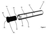
図1〜5は、本発明の第一の実施形態によるエアロゾル発生システム10を示す。エアロゾル発生システムは、気化器セクション14に接続された電源セクション12と、電源および気化器セクション12、14とは別個のカートリッジ16とを備える。気化器セクション14は、カートリッジ16の上流端を受容するためのくぼみ20を画定する気化器ハウジング18を備える。
1 to 5 show an
電源セクション12は、空気を電源セクション12の中へと入れるためのシステム空気吸込み口22、コントローラ24、および電源26を備える。
The
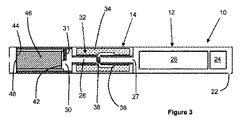
気化器セクション14は、電源セクション12から空気を受容するための気化器空気吸込み口27、気化器空気吸込み口26とその上流端で流体連通する気流通路28、および気流通路28の下流端と流体連通する気化器空気出口30を備える。気化器空気出口30は半円形形状を有し、かつカートリッジ気化器ハウジング18の壁部分31によって形成され、壁部分31はまた、くぼみ20の上流端壁を形成する。
The
気化器セクション14は、気流通路28の外側に位置付けられた環状の多孔性担体材料34の中へと収着された液体エアロゾル形成基体32をさらに備える。毛細管芯36は、多孔性担体材料34と接触して位置付けられた第一の端および第二の端と、気流通路28の中に位置付けられた中央部分とを備える。液体エアロゾル形成基体32は、毛細管芯36に沿った毛細管作用によって、多孔性担体材料34から毛細管芯36の中央部分に吸い出される。
The
気化器セクション14はまた、毛細管芯36の中央部分の周囲に巻かれた抵抗加熱コイルを備える電気ヒーター38を備える。エアロゾル発生システム10の作動中、コントローラ24は、電源26から電気ヒーター38への電気エネルギーの供給を制御して、毛細管芯36の中央部分からの液体エアロゾル形成基体32を加熱および気化する。
The
カートリッジ16は、カートリッジ空気吸込み口42およびカートリッジ空気出口44を画定するカートリッジハウジング40を備える。カートリッジ空気吸込み口42は、半円形形状を有し、カートリッジハウジング40の上流壁部分45によって形成されている。固体エアロゾル形成基体46は、カートリッジ空気吸込み口42とカートリッジ空気出口44との間でカートリッジハウジング40の中に位置付けられている。メッシュフィルター48は、カートリッジ空気吸込み口42およびカートリッジ空気出口44を横切って延び、固体エアロゾル形成基体46をカートリッジハウジング40内に保持してもよい。マウスピース50はカートリッジ16の下流端に形成され、マウスピース50はカートリッジ空気出口44と流体連通するマウスピース空気出口52を有する。
The
エアロゾル発生システム10の使用中、空気はシステム空気吸込み口22を通してシステムの中へと引き出され、気化器空気吸込み口27を通り、かつ気化された液体エアロゾル形成基体32が気流内に同伴される気流通路28の中へと引き出される。その後、気流は気化器空気出口30を通って流れ、カートリッジ空気吸込み口42を経由してカートリッジ16の中へと流れ、かつ固体エアロゾル形成基体46を通って流れ、そこで固体エアロゾル形成基体46からの揮発性化合物は気流内に同伴される。その後、気流は、カートリッジ空気出口44を通って流れ、マウスピース空気出口52を通ってエアロゾル発生システム10の外に流れて、気化された液体エアロゾル形成基体32および固体エアロゾル形成基体46からの揮発性化合物をユーザーに送達する。
During use of the
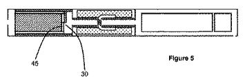
エアロゾル発生システム10を通る気流を変えるために、例えばエアロゾル発生システム10の引き出し抵抗を変えるために、ユーザーは気化器セクション14に対するカートリッジ16の回転配向を変えることができる。図3〜5(各々がカートリッジ16の異なる回転配向を示す)に示す通り、カートリッジ16の回転配向を変えると、半円気化器空気出口30と半円カートリッジ空気吸込み口42との間の重複の量が変わる。図3は、気化器空気出口30とカートリッジ空気吸込み口42との間に完全な重複がある回転配向を図示し、これは最小の引き出し抵抗を提供する。図4は、気化器空気出口30とカートリッジ空気吸込み口42との間に部分的な重複がある回転配向を図示し、これは図3の回転配向と比較した時に引き出し抵抗を増大させる。図5は、カートリッジハウジング40の上流壁部分45が気化器空気出口30を遮るように、気化器空気出口30とカートリッジ空気吸込み口42との間に重複が無い回転配向を図示する。従って、図5に示す回転配向では、エアロゾル発生システム10を通る気流が防止され、これはエアロゾル発生システム10が使用されていない時に望ましい場合がある。
In order to change the airflow through the
気化器セクション14に対するカートリッジ16の相対回転をユーザーに示すために、第一のしるし62がカートリッジハウジング40上に提供されていて、また第二のしるし64が気化器ハウジング18上に提供されている。
A
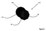
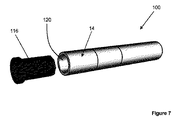
図6は、本発明の第二の実施形態による代替的なカートリッジ116を示す。カートリッジ116は、図1〜5に示すカートリッジ16と類似していて、同様の部分を指定するために同様の参照符号が使用されている。
FIG. 6 shows an
カートリッジ116は、カートリッジハウジング140の形状によって、カートリッジ16とは異なる。図1〜5に示す第一の実施形態において、カートリッジハウジング40は、任意の回転配向でカートリッジ16をくぼみ20の中へと挿入できるように、円形断面形状を有する。図6に示す第二の実施形態において、カートリッジ116は、複数の平面状の面141を画定する多角形の断面形状を有するカートリッジハウジング140を含む。カートリッジハウジング140の多角形形状は、エアロゾル発生システムの気化器セクションに対するカートリッジ116の回転配向を制限する。
The
図7は、カートリッジ116を備えるエアロゾル発生システム100を示す。エアロゾル発生システム100は、図1〜5を示されたエアロゾル発生システム10と類似していて、同様の部分を指定するために同様の参照符号が使用されている。
FIG. 7 shows an
エアロゾル発生システム100は、くぼみ120の形状によって、エアロゾル発生システム10とは異なる。特に、くぼみ120は、カートリッジハウジング140の多角形断面形状と一致する多角形断面形状を有する。くぼみの多角形形状は、気化器セクション14に対するカートリッジ116の回転配向を複数の個別の回転配向に制限する。この配置は、気化器空気出口30とカートリッジ空気吸込み口42との間の所定の量の重複に各々対応する複数の所定の回転配向の中からユーザーが選ぶことを可能にする。
The
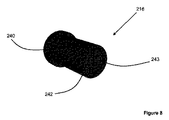
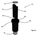
図8および9は、本発明の第三の実施形態によるカートリッジ216を示す。カートリッジ216は、図1〜5に示すカートリッジ16と類似していて、同様の部分を指定するために同様の参照符号が使用されている。カートリッジ216は、図1〜5に示す電源セクション12および気化器セクション14とともに使用されてもよい。
8 and 9 show a
カートリッジ216は、カートリッジハウジング240の形状によって、カートリッジ16とは異なる。図1〜5に示す第一の実施形態において、カートリッジハウジング40は、固体エアロゾル形成基体46が中に位置付けられている単一の区画を画定する。図8および図9に示す第三の実施形態において、カートリッジハウジング240は、固体エアロゾル形成基体46が中に位置付けられている第一の区画260と、第二のエアロゾル形成基体246が中に位置付けられている第二の区画262とを画定する。第二のエアロゾル形成基体246は、固体エアロゾル形成基体46および液体エアロゾル形成基体32とは異なる。
The
カートリッジ216のカートリッジ空気吸込み口は、第一の区画260の上流端と流体連通する第一のカートリッジ空気吸込み口242と、第二の区画262の上流端と流体連通する第二のカートリッジ空気吸込み口243とを備える。カートリッジ216のカートリッジ空気出口は、第一の区画260の下流端と流体連通する第一のカートリッジ空気出口244と、第二の区画262の下流端と流体連通する第二のカートリッジ空気出口245とを備える。使用中に、気化器セクション14に対するカートリッジ216の回転配向を変えて、気化器空気出口30と第一のカートリッジ空気吸込み口242および第二のカートリッジ空気吸込み口243の各々との間の重複の量を変えてもよい。従って、気化器セクション14に対するカートリッジ216の回転配向を変化させることは、第一の区画260および第二の区画262の各々を通る気流の相対量をユーザーが変えることを可能にする。
The cartridge air inlet of the
Claims (15)
カートリッジであって、
カートリッジ空気吸込み口およびカートリッジ空気出口を画定するカートリッジハウジングであって、前記カートリッジ空気吸込み口が前記カートリッジハウジングの壁部分を通って延びる、カートリッジハウジングと、
前記カートリッジハウジング内に位置付けられた固体エアロゾル形成基体と、を備えるカートリッジと、
気化器セクションであって、
気化器空気吸込み口および気化器空気出口を画定する気化器ハウジングであって、前記気化器空気出口が前記気化器ハウジングの壁部分を通って延び、前記気化器ハウジングが前記カートリッジの少なくとも一部分を受容するように構成されている、気化器ハウジングと、
各々が前記気化器ハウジングの中に位置付けられた電気ヒーターおよび液体エアロゾル形成基体と、を備え、
前記カートリッジおよび前記気化器セクションは、前記気化器セクションが前記カートリッジを受容する時に、前記カートリッジハウジング壁部分が前記気化器ハウジング壁部分に当接するように構成されていて、
前記気化器セクションに対する前記カートリッジの回転配向が可変であり、前記カートリッジ空気吸込み口と前記気化器空気出口との間の重複の量が、異なる回転配向の間で変動する、気化器セクションと、
電力を前記電気ヒーターに供給するための電源を備える電源セクションと、を備える、エアロゾル発生システム。 An aerosol generation system,
A cartridge,
A cartridge housing defining a cartridge air inlet and a cartridge air outlet, wherein the cartridge air inlet extends through a wall portion of the cartridge housing;
A solid aerosol forming substrate positioned within the cartridge housing;
A vaporizer section,
A vaporizer housing defining a vaporizer air inlet and a vaporizer air outlet, wherein the vaporizer air outlet extends through a wall portion of the vaporizer housing, the vaporizer housing receiving at least a portion of the cartridge; A vaporizer housing configured to, and
An electric heater and a liquid aerosol-forming substrate, each positioned within the vaporizer housing;
The cartridge and the vaporizer section are configured such that the cartridge housing wall portion abuts the vaporizer housing wall portion when the vaporizer section receives the cartridge;
A vaporizer section, wherein the rotational orientation of the cartridge relative to the vaporizer section is variable, and the amount of overlap between the cartridge air inlet and the vaporizer air outlet varies between different rotational orientations;
An aerosol generation system comprising: a power supply section comprising a power supply for supplying power to the electric heater.
Applications Claiming Priority (3)
| Application Number | Priority Date | Filing Date | Title |
|---|---|---|---|
| EP16198749.0 | 2016-11-14 | ||
| EP16198749 | 2016-11-14 | ||
| PCT/EP2017/078151 WO2018086999A1 (en) | 2016-11-14 | 2017-11-03 | Aerosol-generating system having variable airflow |
Publications (2)
| Publication Number | Publication Date |
|---|---|
| JP2019534026A true JP2019534026A (en) | 2019-11-28 |
| JP7399711B2 JP7399711B2 (en) | 2023-12-18 |
Family
ID=57288315
Family Applications (1)
| Application Number | Title | Priority Date | Filing Date |
|---|---|---|---|
| JP2019524453A Active JP7399711B2 (en) | 2016-11-14 | 2017-11-03 | Aerosol generation system with variable airflow |
Country Status (10)
| Country | Link |
|---|---|
| US (4) | US10765149B2 (en) |
| EP (1) | EP3537903B1 (en) |
| JP (1) | JP7399711B2 (en) |
| KR (1) | KR102578396B1 (en) |
| CN (1) | CN109890232B (en) |
| CA (1) | CA3032485A1 (en) |
| IL (1) | IL266438A (en) |
| MX (1) | MX2019005355A (en) |
| RU (1) | RU2754249C2 (en) |
| WO (1) | WO2018086999A1 (en) |
Cited By (3)
| Publication number | Priority date | Publication date | Assignee | Title |
|---|---|---|---|---|
| JP2022551026A (en) * | 2020-09-02 | 2022-12-07 | ケーティー アンド ジー コーポレイション | AEROSOL SUPPLY DEVICE AND AEROSOL GENERATOR WITH SAME |
| JP2023529327A (en) * | 2021-04-02 | 2023-07-10 | ケーティー アンド ジー コーポレイション | Multi-cartridge and aerosol generator including this |
| JP2025502004A (en) * | 2022-01-05 | 2025-01-24 | ニコベンチャーズ トレーディング リミテッド | Aerosol Delivery System |
Families Citing this family (44)
| Publication number | Priority date | Publication date | Assignee | Title |
|---|---|---|---|---|
| MX2019005355A (en) | 2016-11-14 | 2019-07-01 | Philip Morris Products Sa | Aerosol-generating system having variable airflow. |
| WO2018114313A1 (en) | 2016-12-19 | 2018-06-28 | Philip Morris Products S.A. | Aerosol-generating system comprising a modular assembly |
| JP7080888B2 (en) * | 2016-12-19 | 2022-06-06 | フィリップ・モーリス・プロダクツ・ソシエテ・アノニム | Aerosol generation system with cartridges with side openings |
| US10856579B2 (en) * | 2016-12-19 | 2020-12-08 | Altria Client Services Llc | Aerosol-generating system comprising a modular assembly |
| US10758686B2 (en) * | 2017-01-31 | 2020-09-01 | Altria Client Services Llc | Aerosol-generating device and aerosol-generating system |
| US11273428B2 (en) | 2017-04-10 | 2022-03-15 | Iconic Ventures, Inc. | Vaporizable substance storage device |
| US10413685B2 (en) | 2017-04-10 | 2019-09-17 | Iconic Ventures, Inc. | Vaporizer |
| WO2019030602A1 (en) * | 2017-08-09 | 2019-02-14 | Twenty Sixteen (2016) Pharma Limited | Pulmonary delivery devices |
| AT521172B1 (en) * | 2018-05-23 | 2019-11-15 | Von Erl Gmbh | Evaporator body for an evaporator device of an inhaler |
| EP4427778B1 (en) | 2018-07-31 | 2025-12-24 | Juul Labs, Inc. | Cartridge-based heat not burn vaporizer |
| USD896437S1 (en) | 2019-09-06 | 2020-09-15 | Puff Corporation | Portable cartridge vaporizer |
| WO2020051400A1 (en) * | 2018-09-07 | 2020-03-12 | Puff Corporation | Portable vaporizing device, cartridge and methods |
| US20200077710A1 (en) | 2018-09-07 | 2020-03-12 | Puff Corporation | Portable vaporizing device, cartridge and methods |
| KR102467836B1 (en) | 2018-10-30 | 2022-11-16 | 주식회사 케이티앤지 | Aerosol-generating article and aerosol-generating device comprising theh same |
| EP3908131B8 (en) * | 2019-01-07 | 2024-07-17 | LuxCan Innovation S.A. | Device and method for the extraction and aspiration of active substances, in particular from the cannabis plant |
| WO2020154690A1 (en) | 2019-01-25 | 2020-07-30 | Juul Labs, Inc. | Vaporizer device and cartridge |
| GB201901652D0 (en) | 2019-02-06 | 2019-03-27 | Nicoventures Trading Ltd | Vapour provision systems |
| GB201905425D0 (en) * | 2019-04-17 | 2019-05-29 | Nicoventures Trading Ltd | Electronic aerosol provision device |
| EP4585242A3 (en) | 2019-06-12 | 2025-08-20 | Juul Labs, Inc. | Vaporizable material insert for vaporizer device |
| EP4009823A1 (en) | 2019-08-08 | 2022-06-15 | Juul Labs, Inc. | Vaporizable material insert for vaporizer device |
| US12446619B2 (en) * | 2019-08-14 | 2025-10-21 | Philip Morris Products S.A. | Aerosol-generating device and a method of generating a mixed aerosol |
| EP4025084B1 (en) | 2019-09-06 | 2025-12-03 | Juul Labs, Inc. | Cartridge-based heat not burn vaporizer |
| GB201914691D0 (en) * | 2019-10-10 | 2019-11-27 | Nicoventures Trading Ltd | Aerosol generating article |
| WO2021127227A1 (en) | 2019-12-17 | 2021-06-24 | Juul Labs, Inc. | Heating system for vaporizable material insert |
| CN111759010B (en) * | 2020-01-17 | 2025-07-04 | 浙江迈博高分子材料有限公司 | An aerosol bomb with a gas-liquid channel |
| EP3895555A1 (en) * | 2020-04-17 | 2021-10-20 | Nerudia Limited | Smoking substitute system and apparatus |
| TW202142136A (en) * | 2020-05-12 | 2021-11-16 | 瑞士商傑太日煙國際股份有限公司 | Aerosol generation device with adjustable rtd and rtd-based automatic power control |
| USD997093S1 (en) | 2020-07-16 | 2023-08-29 | Philip Morris Products S.A. | Door for a charging unit for an aerosol generating device |
| US12507730B2 (en) | 2020-08-05 | 2025-12-30 | Philip Morris Products S.A. | Replaceable module for an aerosol and flavor generating device |
| KR102545842B1 (en) * | 2020-11-24 | 2023-06-20 | 주식회사 케이티앤지 | Device for generating aerosol |
| KR102545840B1 (en) | 2020-11-24 | 2023-06-20 | 주식회사 케이티앤지 | Device for generating aerosol |
| WO2022136150A1 (en) * | 2020-12-22 | 2022-06-30 | Philip Morris Products S.A. | Aerosol-generating device with offset airflow path |
| US20240373937A1 (en) * | 2020-12-22 | 2024-11-14 | Philip Morris Products S.A. | Aerosol-generating device with angled vaporizer |
| EP4026435A1 (en) * | 2021-01-12 | 2022-07-13 | JT International SA | Aerosol generation assembly system with modularized elements |
| EP4291053A1 (en) * | 2021-02-09 | 2023-12-20 | JT International SA | Cartridge for aerosol-generating system |
| JP2024540730A (en) * | 2021-11-02 | 2024-11-01 | ジュール・ラブズ・インコーポレイテッド | Non-combustion heating vaporizer device |
| GB202200793D0 (en) * | 2022-01-21 | 2022-03-09 | Nicoventures Trading Ltd | Aerosol provision system |
| WO2023177838A1 (en) | 2022-03-18 | 2023-09-21 | Puff Corporation | System and method for filling of cartridges for portable vaporizing devices |
| CN114532601B (en) * | 2022-03-25 | 2025-07-22 | 云南中烟工业有限责任公司 | Aerosol generating system with aerosol generating product locking function |
| CN114532600B (en) * | 2022-03-25 | 2025-08-01 | 云南中烟工业有限责任公司 | Blanking type particle type aerosol generating product and aerosol generating system |
| CN114847531B (en) * | 2022-03-25 | 2025-07-25 | 云南中烟工业有限责任公司 | Blanking type particle type aerosol generating product with spiral structure and aerosol generating system |
| KR102752201B1 (en) * | 2022-05-30 | 2025-01-13 | 주식회사 케이티앤지 | Aerosol generating module and aerosol generating device |
| GB202219330D0 (en) * | 2022-12-21 | 2023-02-01 | Twenty Sixteen 2016 Pharma Ltd | Pulmonary delivery devices |
| CN221241697U (en) * | 2023-11-20 | 2024-07-02 | 深圳市美园科技有限公司 | A snap-on cigarette cartridge magazine |
Citations (5)
| Publication number | Priority date | Publication date | Assignee | Title |
|---|---|---|---|---|
| US3713452A (en) * | 1969-05-01 | 1973-01-30 | Delcron Prod Inc | Smoking device with controllable air admitting means |
| US4848375A (en) * | 1987-11-10 | 1989-07-18 | Philip Morris Incorporated | Filter cigarette |
| WO2015052192A1 (en) * | 2013-10-08 | 2015-04-16 | Jt International S.A. | Aerosol transferring adapter for an aerosol generating device and method for transferring aerosol within an aerosol generating device |
| EP2989912A1 (en) * | 2014-09-01 | 2016-03-02 | Fontem Holdings 2 B.V. | Electronic smoking device |
| WO2016135342A2 (en) * | 2015-02-27 | 2016-09-01 | British American Tobacco (Investments) Limited | Apparatus for generating an inhalable medium |
Family Cites Families (49)
| Publication number | Priority date | Publication date | Assignee | Title |
|---|---|---|---|---|
| US2124130A (en) * | 1937-04-05 | 1938-07-19 | Albert G Van Deventer | Smoking implement |
| US2967528A (en) * | 1959-03-12 | 1961-01-10 | Falmouth Pharmaceuticals Ltd | Device for ending habit of smoking |
| US3270751A (en) * | 1964-03-16 | 1966-09-06 | Delcron Products Inc | Smoking device |
| US4922901A (en) * | 1988-09-08 | 1990-05-08 | R. J. Reynolds Tobacco Company | Drug delivery articles utilizing electrical energy |
| US4947875A (en) * | 1988-09-08 | 1990-08-14 | R. J. Reynolds Tobacco Company | Flavor delivery articles utilizing electrical energy |
| TW200808202A (en) * | 2006-08-01 | 2008-02-16 | Wan-Kuo Chiang | Cigarette sucker for environmental protection and safety |
| US7726320B2 (en) * | 2006-10-18 | 2010-06-01 | R. J. Reynolds Tobacco Company | Tobacco-containing smoking article |
| EP2460423A1 (en) * | 2010-12-03 | 2012-06-06 | Philip Morris Products S.A. | An electrically heated aerosol generating system having improved heater control |
| JP5681819B2 (en) | 2011-02-11 | 2015-03-11 | バットマーク・リミテッド | Inhaler components |
| WO2013007020A1 (en) | 2011-07-12 | 2013-01-17 | Liu Qiuming | Electronic flue-cured tobacco |
| EP3586653B1 (en) * | 2011-12-08 | 2023-08-23 | Philip Morris Products S.A. | An aerosol generating device with adjustable airflow |
| WO2013091252A1 (en) * | 2011-12-23 | 2013-06-27 | Liu Qiuming | Electronic cigarette suction nozzle |
| EP2797449B1 (en) * | 2011-12-30 | 2019-08-07 | Philip Morris Products S.a.s. | Smoking article with front-plug and aerosol-forming substrate and method |
| RU2602053C2 (en) * | 2012-01-03 | 2016-11-10 | Филип Моррис Продактс С.А. | Aerosol generating device and system with improved air flow |
| US9854839B2 (en) * | 2012-01-31 | 2018-01-02 | Altria Client Services Llc | Electronic vaping device and method |
| GB2511303A (en) * | 2013-02-27 | 2014-09-03 | British American Tobacco Co | Smoking apparatus |
| US20140261486A1 (en) * | 2013-03-12 | 2014-09-18 | R.J. Reynolds Tobacco Company | Electronic smoking article having a vapor-enhancing apparatus and associated method |
| US9814266B2 (en) | 2013-03-26 | 2017-11-14 | Shenzhen Kimsen Technology Co., Ltd. | Electronic cigarette |
| CN204466898U (en) | 2013-03-27 | 2015-07-15 | 吉瑞高新科技股份有限公司 | Electronic cigarette |
| US20150181928A1 (en) | 2013-04-15 | 2015-07-02 | Kimree Hi-Tech Inc. | Electronic cigarette and mouthpiece cover thereof |
| WO2014169467A1 (en) | 2013-04-18 | 2014-10-23 | Liu Qiuming | Electronic cigarette |
| RU2015151690A (en) | 2013-06-03 | 2017-06-06 | ПРИСКО Андреа Витторио | ENHANCED ELECTRONIC CIGARETTE |
| US20160143354A1 (en) * | 2013-06-20 | 2016-05-26 | Kimree Hi-Tech Inc. | Vent hole-adjustable electronic cigarette |
| US9877511B2 (en) * | 2013-07-24 | 2018-01-30 | Altria Client Services Llc | Electronic smoking article |
| EP3068244A4 (en) | 2013-11-15 | 2017-07-05 | VMR Products, LLC | Vaporizer with cover sleeve |
| CN203633506U (en) | 2013-12-13 | 2014-06-11 | 深圳市合元科技有限公司 | Electronic cigarette and atomizer for electronic cigarette |
| US20150173417A1 (en) | 2013-12-19 | 2015-06-25 | L. Perrigo Company | Safety mouthpiece |
| KR102518749B1 (en) * | 2014-02-10 | 2023-04-07 | 필립모리스 프로덕츠 에스.에이. | An aerosol-generating system having a fluid-permeable heater assembly |
| WO2015117705A2 (en) * | 2014-02-10 | 2015-08-13 | Philip Morris Products S.A. | Cartridge for an aerosol-generating system |
| US9833019B2 (en) * | 2014-02-13 | 2017-12-05 | Rai Strategic Holdings, Inc. | Method for assembling a cartridge for a smoking article |
| US20150335070A1 (en) | 2014-05-20 | 2015-11-26 | R.J. Reynolds Tobacco Company | Electrically-powered aerosol delivery system |
| CN103960785A (en) * | 2014-05-22 | 2014-08-06 | 惠州市凯尔文科技有限公司 | Atomizer with multiple tobacco extract bottles |
| WO2015180061A1 (en) | 2014-05-28 | 2015-12-03 | 吉瑞高新科技股份有限公司 | Electronic cigarette and air intake volume regulating method therefor |
| WO2015180058A1 (en) | 2014-05-28 | 2015-12-03 | 吉瑞高新科技股份有限公司 | Electronic cigarette and air intake volume regulating method for electronic cigarette |
| WO2016045058A1 (en) * | 2014-09-25 | 2016-03-31 | 惠州市吉瑞科技有限公司 | Atomization assembly and electronic cigarette |
| AR103016A1 (en) * | 2014-12-15 | 2017-04-12 | Philip Morris Products Sa | AEROSOL GENERATOR SYSTEMS AND METHODS FOR DIRECTING AN AIR FLOW TOWARDS AN ELECTRIC HEATED AEROSOL GENERATOR SYSTEM |
| CN204796749U (en) * | 2015-06-19 | 2015-11-25 | 卓尔悦(常州)电子科技有限公司 | Atomizer and aerosol generating device thereof |
| GB2542376A (en) * | 2015-09-16 | 2017-03-22 | Nicoventures Holdings Ltd | Aerosol provision system with variable airflow |
| CN105249536B (en) * | 2015-10-13 | 2020-02-14 | 卓尔悦欧洲控股有限公司 | Atomizer and its electronic cigarette |
| RU2728103C2 (en) * | 2015-12-21 | 2020-07-28 | Филип Моррис Продактс С.А. | Aerosol-generating system comprising a variable air inlet |
| US10368581B2 (en) * | 2016-03-11 | 2019-08-06 | Altria Client Services Llc | Multiple dispersion generator e-vaping device |
| CA3021541A1 (en) * | 2016-05-31 | 2017-12-07 | Philip Morris Products S.A. | Aerosol generating device with multiple heaters |
| US10952471B2 (en) * | 2016-05-31 | 2021-03-23 | Altria Client Services Llc | Aerosol-generating device with integral heater assembly |
| MX2019005355A (en) * | 2016-11-14 | 2019-07-01 | Philip Morris Products Sa | Aerosol-generating system having variable airflow. |
| US10092039B2 (en) * | 2016-12-14 | 2018-10-09 | Rai Strategic Holdings, Inc. | Smoking article for on-demand delivery of an increased quantity of an aerosol precursor composition, a cartridge, and a related method |
| US10856579B2 (en) * | 2016-12-19 | 2020-12-08 | Altria Client Services Llc | Aerosol-generating system comprising a modular assembly |
| WO2018215142A1 (en) * | 2017-05-23 | 2018-11-29 | Philip Morris Products S.A. | Customizable devices for multiple consumables |
| PL3684203T3 (en) * | 2017-09-18 | 2023-04-17 | Philip Morris Products S.A. | CONTRIBUTION TO THE AEROSOL GENERATION SYSTEM |
| US10798969B2 (en) * | 2018-03-16 | 2020-10-13 | R. J. Reynolds Tobacco Company | Smoking article with heat transfer component |
-
2017
- 2017-11-03 MX MX2019005355A patent/MX2019005355A/en unknown
- 2017-11-03 CN CN201780067237.3A patent/CN109890232B/en active Active
- 2017-11-03 WO PCT/EP2017/078151 patent/WO2018086999A1/en not_active Ceased
- 2017-11-03 EP EP17797298.1A patent/EP3537903B1/en active Active
- 2017-11-03 CA CA3032485A patent/CA3032485A1/en not_active Abandoned
- 2017-11-03 JP JP2019524453A patent/JP7399711B2/en active Active
- 2017-11-03 RU RU2019115678A patent/RU2754249C2/en active
- 2017-11-03 KR KR1020197010101A patent/KR102578396B1/en active Active
- 2017-11-14 US US15/812,057 patent/US10765149B2/en active Active
-
2019
- 2019-05-05 IL IL266438A patent/IL266438A/en unknown
-
2020
- 2020-08-10 US US16/988,977 patent/US11684730B2/en active Active
-
2023
- 2023-05-23 US US18/322,277 patent/US12194233B2/en active Active
-
2024
- 2024-12-09 US US18/973,324 patent/US20250099696A1/en active Pending
Patent Citations (5)
| Publication number | Priority date | Publication date | Assignee | Title |
|---|---|---|---|---|
| US3713452A (en) * | 1969-05-01 | 1973-01-30 | Delcron Prod Inc | Smoking device with controllable air admitting means |
| US4848375A (en) * | 1987-11-10 | 1989-07-18 | Philip Morris Incorporated | Filter cigarette |
| WO2015052192A1 (en) * | 2013-10-08 | 2015-04-16 | Jt International S.A. | Aerosol transferring adapter for an aerosol generating device and method for transferring aerosol within an aerosol generating device |
| EP2989912A1 (en) * | 2014-09-01 | 2016-03-02 | Fontem Holdings 2 B.V. | Electronic smoking device |
| WO2016135342A2 (en) * | 2015-02-27 | 2016-09-01 | British American Tobacco (Investments) Limited | Apparatus for generating an inhalable medium |
Cited By (6)
| Publication number | Priority date | Publication date | Assignee | Title |
|---|---|---|---|---|
| JP2022551026A (en) * | 2020-09-02 | 2022-12-07 | ケーティー アンド ジー コーポレイション | AEROSOL SUPPLY DEVICE AND AEROSOL GENERATOR WITH SAME |
| JP7316435B2 (en) | 2020-09-02 | 2023-07-27 | ケーティー アンド ジー コーポレイション | AEROSOL SUPPLY DEVICE AND AEROSOL GENERATOR WITH SAME |
| US12137735B2 (en) | 2020-09-02 | 2024-11-12 | Kt&G Corporation | Aerosol delivering device and aerosol generating device including the same |
| JP2023529327A (en) * | 2021-04-02 | 2023-07-10 | ケーティー アンド ジー コーポレイション | Multi-cartridge and aerosol generator including this |
| JP7508751B2 (en) | 2021-04-02 | 2024-07-02 | ケーティー アンド ジー コーポレイション | Multi-cartridge and aerosol generating device including the same |
| JP2025502004A (en) * | 2022-01-05 | 2025-01-24 | ニコベンチャーズ トレーディング リミテッド | Aerosol Delivery System |
Also Published As
| Publication number | Publication date |
|---|---|
| CA3032485A1 (en) | 2018-05-17 |
| IL266438A (en) | 2019-06-30 |
| CN109890232B (en) | 2022-04-08 |
| KR102578396B1 (en) | 2023-09-14 |
| US20250099696A1 (en) | 2025-03-27 |
| RU2019115678A (en) | 2020-12-14 |
| KR20190077328A (en) | 2019-07-03 |
| CN109890232A (en) | 2019-06-14 |
| EP3537903A1 (en) | 2019-09-18 |
| MX2019005355A (en) | 2019-07-01 |
| US11684730B2 (en) | 2023-06-27 |
| RU2754249C2 (en) | 2021-08-31 |
| US20180132534A1 (en) | 2018-05-17 |
| US12194233B2 (en) | 2025-01-14 |
| US10765149B2 (en) | 2020-09-08 |
| JP7399711B2 (en) | 2023-12-18 |
| WO2018086999A1 (en) | 2018-05-17 |
| RU2019115678A3 (en) | 2021-02-15 |
| US20230310765A1 (en) | 2023-10-05 |
| EP3537903B1 (en) | 2022-02-09 |
| US20200367554A1 (en) | 2020-11-26 |
Similar Documents
| Publication | Publication Date | Title |
|---|---|---|
| JP7399711B2 (en) | Aerosol generation system with variable airflow | |
| CN110022704B (en) | Aerosol-generating system having a cartridge with a side orifice | |
| JP7118968B2 (en) | Aerosol-generating system comprising multiple aerosol-forming substrates and penetrating elements | |
| JP6995854B2 (en) | Aerosol generation system with cartridge and bypass air inlet | |
| JP7005616B2 (en) | Aerosol generation system with solid aerosol forming substrate and liquid aerosol forming substrate | |
| JP7121746B2 (en) | Aerosol generating system with external cartridge | |
| KR102590701B1 (en) | Aerosol-generating system comprising modular assemblies | |
| JP7066710B2 (en) | Aerosol generation system with multiple aerosol forming substrates and liquid transfer elements | |
| JP2024023409A (en) | Aerosol generation system that provides preferential evaporation of nicotine | |
| JP7332793B2 (en) | Aerosol generator with staggered airflow channels |
Legal Events
| Date | Code | Title | Description |
|---|---|---|---|
| A621 | Written request for application examination |
Free format text: JAPANESE INTERMEDIATE CODE: A621 Effective date: 20201022 |
|
| A977 | Report on retrieval |
Free format text: JAPANESE INTERMEDIATE CODE: A971007 Effective date: 20211012 |
|
| A131 | Notification of reasons for refusal |
Free format text: JAPANESE INTERMEDIATE CODE: A131 Effective date: 20211020 |
|
| A02 | Decision of refusal |
Free format text: JAPANESE INTERMEDIATE CODE: A02 Effective date: 20220413 |
|
| A521 | Request for written amendment filed |
Free format text: JAPANESE INTERMEDIATE CODE: A523 Effective date: 20220812 |
|
| C60 | Trial request (containing other claim documents, opposition documents) |
Free format text: JAPANESE INTERMEDIATE CODE: C60 Effective date: 20220812 |
|
| A911 | Transfer to examiner for re-examination before appeal (zenchi) |
Free format text: JAPANESE INTERMEDIATE CODE: A911 Effective date: 20220822 |
|
| C21 | Notice of transfer of a case for reconsideration by examiners before appeal proceedings |
Free format text: JAPANESE INTERMEDIATE CODE: C21 Effective date: 20220824 |
|
| A912 | Re-examination (zenchi) completed and case transferred to appeal board |
Free format text: JAPANESE INTERMEDIATE CODE: A912 Effective date: 20220909 |
|
| C211 | Notice of termination of reconsideration by examiners before appeal proceedings |
Free format text: JAPANESE INTERMEDIATE CODE: C211 Effective date: 20220914 |
|
| C22 | Notice of designation (change) of administrative judge |
Free format text: JAPANESE INTERMEDIATE CODE: C22 Effective date: 20221114 |
|
| C22 | Notice of designation (change) of administrative judge |
Free format text: JAPANESE INTERMEDIATE CODE: C22 Effective date: 20230406 |
|
| A521 | Request for written amendment filed |
Free format text: JAPANESE INTERMEDIATE CODE: A523 Effective date: 20230816 |
|
| A61 | First payment of annual fees (during grant procedure) |
Free format text: JAPANESE INTERMEDIATE CODE: A61 Effective date: 20231206 |
|
| R150 | Certificate of patent or registration of utility model |
Ref document number: 7399711 Country of ref document: JP Free format text: JAPANESE INTERMEDIATE CODE: R150 |