JP2019529286A - Crane, ship including such a crane, and method for erecting a vertical structure - Google Patents
Crane, ship including such a crane, and method for erecting a vertical structure Download PDFInfo
- Publication number
- JP2019529286A JP2019529286A JP2019515469A JP2019515469A JP2019529286A JP 2019529286 A JP2019529286 A JP 2019529286A JP 2019515469 A JP2019515469 A JP 2019515469A JP 2019515469 A JP2019515469 A JP 2019515469A JP 2019529286 A JP2019529286 A JP 2019529286A
- Authority
- JP
- Japan
- Prior art keywords
- crane
- boom
- hoisting
- block
- pulley
- Prior art date
- Legal status (The legal status is an assumption and is not a legal conclusion. Google has not performed a legal analysis and makes no representation as to the accuracy of the status listed.)
- Granted
Links
Images


Classifications
-
- B—PERFORMING OPERATIONS; TRANSPORTING
- B66—HOISTING; LIFTING; HAULING
- B66C—CRANES; LOAD-ENGAGING ELEMENTS OR DEVICES FOR CRANES, CAPSTANS, WINCHES, OR TACKLES
- B66C23/00—Cranes comprising essentially a beam, boom, or triangular structure acting as a cantilever and mounted for translatory of swinging movements in vertical or horizontal planes or a combination of such movements, e.g. jib-cranes, derricks, tower cranes
- B66C23/62—Constructional features or details
- B66C23/84—Slewing gear
-
- B—PERFORMING OPERATIONS; TRANSPORTING
- B66—HOISTING; LIFTING; HAULING
- B66C—CRANES; LOAD-ENGAGING ELEMENTS OR DEVICES FOR CRANES, CAPSTANS, WINCHES, OR TACKLES
- B66C23/00—Cranes comprising essentially a beam, boom, or triangular structure acting as a cantilever and mounted for translatory of swinging movements in vertical or horizontal planes or a combination of such movements, e.g. jib-cranes, derricks, tower cranes
- B66C23/18—Cranes comprising essentially a beam, boom, or triangular structure acting as a cantilever and mounted for translatory of swinging movements in vertical or horizontal planes or a combination of such movements, e.g. jib-cranes, derricks, tower cranes specially adapted for use in particular purposes
- B66C23/185—Cranes comprising essentially a beam, boom, or triangular structure acting as a cantilever and mounted for translatory of swinging movements in vertical or horizontal planes or a combination of such movements, e.g. jib-cranes, derricks, tower cranes specially adapted for use in particular purposes for use erecting wind turbines
-
- B—PERFORMING OPERATIONS; TRANSPORTING
- B66—HOISTING; LIFTING; HAULING
- B66C—CRANES; LOAD-ENGAGING ELEMENTS OR DEVICES FOR CRANES, CAPSTANS, WINCHES, OR TACKLES
- B66C23/00—Cranes comprising essentially a beam, boom, or triangular structure acting as a cantilever and mounted for translatory of swinging movements in vertical or horizontal planes or a combination of such movements, e.g. jib-cranes, derricks, tower cranes
- B66C23/18—Cranes comprising essentially a beam, boom, or triangular structure acting as a cantilever and mounted for translatory of swinging movements in vertical or horizontal planes or a combination of such movements, e.g. jib-cranes, derricks, tower cranes specially adapted for use in particular purposes
- B66C23/36—Cranes comprising essentially a beam, boom, or triangular structure acting as a cantilever and mounted for translatory of swinging movements in vertical or horizontal planes or a combination of such movements, e.g. jib-cranes, derricks, tower cranes specially adapted for use in particular purposes mounted on road or rail vehicles; Manually-movable jib-cranes for use in workshops; Floating cranes
- B66C23/52—Floating cranes
-
- B—PERFORMING OPERATIONS; TRANSPORTING
- B66—HOISTING; LIFTING; HAULING
- B66C—CRANES; LOAD-ENGAGING ELEMENTS OR DEVICES FOR CRANES, CAPSTANS, WINCHES, OR TACKLES
- B66C23/00—Cranes comprising essentially a beam, boom, or triangular structure acting as a cantilever and mounted for translatory of swinging movements in vertical or horizontal planes or a combination of such movements, e.g. jib-cranes, derricks, tower cranes
- B66C23/62—Constructional features or details
- B66C23/82—Luffing gear
- B66C23/821—Bracing equipment for booms
- B66C23/826—Bracing equipment acting at an inclined angle to vertical and horizontal directions
- B66C23/828—Bracing equipment acting at an inclined angle to vertical and horizontal directions where the angle is adjustable
Abstract
本発明は、ベース構造と、旋回ベアリングと、垂直な旋回軸を中心に回転できるように旋回ベアリングを介してベース構造に移動可能に取り付けられたクレーンハウジングと、水平な第1枢動軸を中心に枢動できるようにクレーンハウジングに移動可能に取り付けられているブームと、3つの主巻上げシステムと、ラフィングシステムとを備えるクレーンに関し、ブームは、一端部がクレーンハウジングに接続され、反対端部がハンマーヘッド構造を介して互いに接続された2つのブーム脚を有するAフレームを含み、各主巻上げシステムは、巻上げケーブルと、滑車回転軸を中心に回転可能な1つ以上の滑車を有する滑車ブロックであって、ブームのハンマーヘッド構造上に配置される滑車ブロックと、巻上げケーブルによって滑車ブロックから吊り下げられた巻上げブロックと、巻上げケーブルを引き込む、または引き出すことによって、巻上げブロックを昇降させるための巻上げウインチとを備え、各主巻上げシステムの滑車ブロックは、滑車回転軸に垂直な水平な第2枢動軸を中心に枢動可能であり、3つの主巻上げシステムの滑車ブロックは並んで配置され、ラフィングシステムは、クレーンハウジングの2つのラフィングウインチと、クレーンハウジングの2つのラフィングウインチそれぞれとブームの間に延在する2つのラフィングケーブルとを備え、ラフィングケーブルは、平面図で見てAフレームのブーム脚を越えて延びるハンマーヘッド構造のそれぞれのアウトリガーに接続されている。The present invention includes a base structure, a slewing bearing, a crane housing movably attached to the base structure via a slewing bearing so as to be rotatable about a vertical slewing axis, and a horizontal first pivot axis. A boom comprising a boom movably attached to a crane housing for pivotal movement, a three main hoisting system, and a luffing system, the boom having one end connected to the crane housing and the opposite end Each main hoisting system is a pulley block having a hoisting cable and one or more pulleys rotatable about a pulley axis of rotation, including an A frame having two boom legs connected to each other via a hammerhead structure. A pulley block arranged on the hammer head structure of the boom and a pulley block by means of a hoisting cable. And a hoisting winch for raising and lowering the hoisting block by pulling in or pulling out the hoisting cable, and the pulley block of each main hoisting system has a horizontal vertical axis perpendicular to the pulley rotation axis. It is pivotable about two pivot axes, the pulley blocks of the three main hoisting systems are arranged side by side, the luffing system consists of two luffing winches of the crane housing, two luffing winches of the crane housing and a boom respectively Two luffing cables extending between the two, and the luffing cables are connected to respective outriggers of the hammerhead structure that extend beyond the boom leg of the A-frame in plan view.
Description
本発明は、クレーン、そのようなクレーンを含む船舶、および縦構造を直立させる方法に関する。 The present invention relates to a crane, a ship including such a crane, and a method for erecting a vertical structure.
本発明は特に、沖合風力タービンの設置および/または保守の分野に関する。現在の沖合風力タービンには、モノパイルの形の基礎を必要としている。風力タービンは、一体的にまたは複数の部品のいずれかでモノパイルに取り付けられる。 The invention particularly relates to the field of offshore wind turbine installation and / or maintenance. Current offshore wind turbines require a foundation in the form of a monopile. The wind turbine is attached to the monopile either integrally or in a plurality of parts.
風力エネルギーを効率的に利用するために、風力タービンのローターの直径を大きくする傾向がある。長さ60〜90m以上の風力タービンブレードは、近い将来ごく一般的になるだろう。しかし、これにより、基礎を含む他のすべての構成要素のサイズと重量も増加する。例えば2000mt以上の重量の長く大径のモノパイルが設置される必要がある。長さ約100メートルの実用的なモノパイルが提案されている。 In order to efficiently use wind energy, there is a tendency to increase the diameter of the rotor of the wind turbine. Wind turbine blades over 60-90 meters in length will become very common in the near future. However, this also increases the size and weight of all other components, including the foundation. For example, it is necessary to install a long and large monopile having a weight of 2000 mt or more. A practical monopile of about 100 meters in length has been proposed.
風力タービンが陸上に設置されるか沖合に設置されるかにかかわらず、モノパイルの設置場所への輸送では、モノパイルを略水平の向きにして行われることが多い。モノパイルを地面に打ち込むためには、モノパイルをクレーンで持ち上げて垂直方向に動かす必要がある。 Regardless of whether the wind turbine is installed on land or offshore, the monopile is often placed in a substantially horizontal orientation when transported to the installation site. In order to drive the monopile into the ground, it is necessary to lift the monopile with a crane and move it vertically.
多くの沖合風力タービン設置船はジャッキアップタイプであり、伸縮脚と風力タービン設置用のクレーンを備えている。既知のデザインでは、クレーンは足回りクレーンである。 Many offshore wind turbine-equipped ships are jack-up types, with telescopic legs and cranes for wind turbine installation. In the known design, the crane is an undercarriage crane.
モノパイルを直立させる方法において知られている先行技術の解決策は、クレーンがモノパイルの上端部のみを持ち上げ、下端部が地面または船の甲板上に傾斜支持フレームによって支持されたままである方法を含む。この方法の欠点は、例えばモノパイルを水中へ落とすために特に下端部が地面や甲板に対して動く必要がある場合、下端の制御が非常に難しいことである。さらに、直立は通常、クレーンでモノパイルを直立させるのに十分なスペースがある限られた数の場所でしか行えない。 Prior art solutions known in upright monopile methods include methods where the crane lifts only the upper end of the monopile and the lower end remains supported on the ground or ship deck by an inclined support frame. The disadvantage of this method is that the lower end is very difficult to control, especially when the lower end needs to move relative to the ground or deck to drop the monopile into the water. Furthermore, uprights are usually only possible in a limited number of places where there is sufficient space for the crane to stand up the monopile.
モノパイルを直立させるための他の従来技術の解決策は、「ランビズ」ボートのような、モノパイルの上端部と下端部用の2つのクレーンを使用することを提案している。しかし、これには2つのクレーンの同期操作が必要であり、時間の経過とともに、上端部を持ち上げるクレーンが下端部を持ち上げるクレーンよりも多くのモノパイルの重量を支える必要がある。ほとんどの風力タービン設置船には、この作業を行うことができる2つのクレーンがなく、この作業のために船上に別のクレーンを取り付けるスペースがない。 Other prior art solutions for upstanding monopiles have suggested using two cranes for the top and bottom of the monopile, such as a "Lanbiz" boat. However, this requires synchronized operation of the two cranes, and over time, the crane that lifts the upper end must support more monopile weight than the crane that lifts the lower end. Most wind turbine-equipped ships do not have two cranes that can perform this task and do not have the space to install another crane on the ship for this task.
本出願人の未公開特許出願PCT/NL2017/050393号では、2つの別々の主巻上げシステムを使用する単一クレーンを使用してモノパイルの上端部および下端部をそれぞれ持ち上げて直立させる解決策が提案されている。 Applicant's unpublished patent application PCT / NL2017 / 050393 proposes a solution in which a single crane using two separate main hoisting systems is used to lift and erect the upper and lower ends of the monopile respectively. Has been.
特許文献1および特許文献2は両方とも、脚部の一方の端部でクレーンハウジングに接続され、反対側の端部が互いに接続されるAフレームブームを備える2つの主巻上げシステムを有するクレーンを開示している。主巻上げシステムの滑車ブロックは、後端部に並べて配置されている。
Both
しかし、これらのシステムの欠点は、直立が進むにつれて、2つの主巻上げシステムによって支持される負荷がますます異なり始め(いわゆるクレーンの非対称負荷)、それがクレーンのブームに望ましくないねじり負荷をもたらす可能性があることである。 However, the disadvantage of these systems is that as the uprights progress, the loads supported by the two main hoisting systems begin to differ increasingly (so-called crane asymmetric loads), which can lead to undesirable torsional loads on the crane boom. It is to have sex.
したがって、本発明の目的は、縦構造を直立させるための改良された方法を提供すること、およびこの改良された方法を実行するのに適したクレーンおよび/または船舶を提供することである。 Accordingly, it is an object of the present invention to provide an improved method for erecting a vertical structure and to provide a crane and / or ship suitable for carrying out this improved method.
特許文献3および特許文献4は、3つ(またはそれ以上)の滑車構成を有するシステムを開示している。特許文献5は、代替の滑車装置を開示している。 Patent Documents 3 and 4 disclose systems having three (or more) pulley configurations. Patent document 5 discloses an alternative pulley apparatus.
本発明の第1の態様によれば、上述の目的は、以下のものを含むクレーンによって達成される。
− ベース構造
− 旋回ベアリング
− クレーンハウジングがベース構造に対して略垂直な旋回軸を中心に回転できるように旋回ベアリングを介してベース構造に移動可能に取り付けられたクレーンハウジング
− ブームがクレーンハウジングに対して略水平な第1枢動軸を中心に枢動できるようにクレーンハウジングに移動可能に取り付けられているブーム
− 3つの主巻上げシステム
− クレーンハウジングに対するブームの角度方向を設定するためのラフィングシステム
ブームは、一端部がクレーンハウジングに接続され、反対端部がハンマーヘッド構造を介して互いに接続された2つのブーム脚を有するAフレームを含み、
各主巻上げシステムは、
・巻上げケーブル
・滑車回転軸を中心に回転可能な1つ以上の滑車を有する滑車ブロックであって、ブームのハンマーヘッド構造上に配置される滑車ブロック
・巻上げケーブルによって滑車ブロックから吊り下げられた巻上げブロック
・巻上げケーブルを引き込む、または引き出すことによって、巻上げブロックを昇降させるための巻上げウインチ
を備え、
各主巻上げシステムの滑車ブロックは、滑車ブロックの1つ以上の滑車の滑車回転軸に垂直な略水平な第2枢動軸を中心に枢動可能であり、
3つの主巻上げシステムの滑車ブロックは並んで配置され、
ラフィングシステムは、
・クレーンハウジングの2つのラフィングウインチ
・クレーンハウジングの2つのラフィングウインチそれぞれとブームの間に延在する2つのラフィングケーブル
を備え、
ラフィングケーブルは、平面図で見てAフレームのブーム脚を越えて延びるハンマーヘッド構造のそれぞれのアウトリガーに接続されている。
According to a first aspect of the present invention, the above object is achieved by a crane comprising:
-Base structure-Slewing bearing-Crane housing movably mounted on the base structure via a slewing bearing so that the crane housing can rotate around a pivot axis that is substantially perpendicular to the base structure-The boom is relative to the crane housing A boom movably attached to the crane housing for pivoting about a first, substantially horizontal first pivot axis; three main hoisting systems; a luffing system for setting the angular orientation of the boom relative to the crane housing Comprises an A-frame having two boom legs, one end connected to the crane housing and the other end connected to each other via a hammerhead structure;
Each main hoisting system
-Pull-up cable-Pulley block having one or more pulleys that can rotate around the pulley rotation axis, the pulley block arranged on the hammer head structure of the boom-Hoisting suspended from the pulley block by the hoisting cable A hoisting winch for raising and lowering the hoisting block by pulling in or pulling out the block hoisting cable,
The pulley block of each main hoisting system is pivotable about a substantially horizontal second pivot axis perpendicular to the pulley rotation axis of one or more pulleys of the pulley block;
The pulley blocks of the three main hoisting systems are arranged side by side,
Roughing system
・ Two roughing winches of the crane housing ・ Two roughing winches of the crane housing and two roughing cables extending between the boom and each boom,
The luffing cable is connected to each outrigger of the hammerhead structure that extends beyond the boom leg of the A frame when viewed in plan view.
本発明によるクレーンの主な利点は、クレーンが、例えば縦構造の直立中に遭遇するような非対称荷重に非常に適していることである。後により詳細に説明するように、3つの主巻上げシステムのうちの2つを組み合わせて、縦構造、例えばモノパイルの上端部に必要な巻上げ能力を高めることができる一方で、残りの巻上げシステムは、下端部を保持して持ち上げるために使用することができる。さらに、滑車ブロックに提供される追加の自由度により、滑車ブロックの1つ以上の滑車をそれぞれの巻上ケーブルと巻上ブロックの1つ以上の滑車と整列させたまま、縦構造のそれぞれの端部に接続するためにそれぞれの巻上げブロックを横に動かすことができる。最後に、ブームのAフレーム構造は、非対称荷重に対してねじり剛性を提供し、同時にラフィングケーブルは、ブームの中心からより離れた距離でブームに接続されているため、ブームにかかる非対称荷重を相殺するのに役立つ。その結果として、クレーンのこの特別な構造により、クレーンは、モノパイルのような重い縦構造を直立させるために非常に適したものとなる。 The main advantage of the crane according to the invention is that the crane is very suitable for asymmetric loads, such as encountered during upright vertical structures, for example. As will be described in more detail later, two of the three main winding systems can be combined to increase the required winding capacity for the vertical structure, eg, the upper end of the monopile, while the remaining winding systems are: Can be used to hold and lift the lower end. In addition, the additional degrees of freedom provided for the pulley block allows one or more pulleys of the pulley block to be aligned with the respective hoisting cable and one or more pulleys of the hoisting block, so that each end of the vertical structure Each winding block can be moved sideways to connect to the part. Finally, the boom A-frame structure provides torsional rigidity against asymmetric loads, while the luffing cable is connected to the boom at a greater distance from the center of the boom, thus offsetting the asymmetric loads on the boom. To help. As a result, this special construction of the crane makes it very suitable for erecting heavy vertical structures such as monopiles.
一実施形態では、第2枢動軸は、第1枢動軸と平行である。 In one embodiment, the second pivot axis is parallel to the first pivot axis.
一実施形態では、ブーム脚は、トラス構造である。好ましくは、ブーム脚は、さらに好ましくはトラス構造を使用して、ブーム脚の2つの端部の間で互いに接続される。 In one embodiment, the boom leg is a truss structure. Preferably, the boom legs are connected to each other between the two ends of the boom legs, more preferably using a truss structure.
一実施形態では、ハンマーヘッド構造は、ボックス構造、例えば、ボックス構造を強化するために可能な内部補強部材を用いてボックスの外側を形成する鋼板で溶接されたボックスを備える。 In one embodiment, the hammerhead structure comprises a box structure, for example a box welded with a steel plate that forms the outside of the box with internal reinforcement members that are possible to strengthen the box structure.
一実施形態では、ブームは、ハンマーヘッド構造体から延びるジブを含む。場合によっては、ジブは、例えばクレーンブームの剛性の延長部としてハンマーヘッド構造に固定されているため移動できない。 In one embodiment, the boom includes a jib extending from the hammerhead structure. In some cases, the jib cannot move because it is secured to the hammerhead structure, for example, as a rigid extension of the crane boom.
好ましくは、クレーンは、主巻上げシステムと同様の巻上げケーブル、滑車ブロック、巻上げブロックおよび巻上げウインチを有する1つ以上の補助巻上げシステムを含み、滑車ブロックは、ジブに取り付けられ、例えば単一のこのような滑車ブロックは、ブームの長手方向軸上のジブに配置されている。 Preferably, the crane includes one or more auxiliary hoisting systems having a hoisting cable, pulley block, hoisting block and hoisting winch similar to the main hoisting system, the pulley block being attached to a jib, for example a single such A simple pulley block is arranged in a jib on the longitudinal axis of the boom.
一実施形態では、ブームのAフレームの中心面は、第1枢動軸とAフレームの長手方向軸とによって広がる平面として定義され、3つの主巻上げシステムの中央滑車ブロックは、3つの主要な巻上げシステムの2つの外側滑車ブロックよりも中心面からの距離が大きい位置で取り付けられている。 In one embodiment, the central plane of the boom A frame is defined as a plane extending by the first pivot axis and the longitudinal axis of the A frame, and the central pulley block of the three main hoisting systems has three main hoisting blocks. It is mounted at a position that is more distant from the center plane than the two outer pulley blocks of the system.
第1の態様による発明はまた、本発明によるクレーンを含む船舶に関する。このような船舶は、現場でモノパイルを直立させるためにクレーンを使用するような、沖合風力タービンの設置および保守に使用することができる。 The invention according to the first aspect also relates to a ship comprising a crane according to the invention. Such a ship can be used for installation and maintenance of offshore wind turbines, such as using cranes to upright monopile on-site.
一実施形態では、船はジャッキアップ船であり、
− 船体に少なくとも3つの開口部を有する船体であって、前記開口部は、それぞれの脚部を受け入れるために船体を通って垂直に延びる、船体
− 船体の開口部ごとの脚
− 船体が水中から持ち上げられることを可能にするために、船体に対して対応する脚を垂直方向に動かすことを可能にする、脚ごとの脚駆動装置
を備える。
In one embodiment, the ship is a jack-up ship,
-A hull having at least three openings in the hull, said openings extending vertically through the hull to receive the respective leg, hull-legs per hull opening-the hull from underwater In order to be able to be lifted, a leg drive for each leg is provided which allows the corresponding leg to be moved vertically relative to the hull.
その結果、クレーン作業中に船舶を海底に対して安定させることができ、船上での重い負荷の取り扱いを可能にする。 As a result, the ship can be stabilized with respect to the seabed during the crane operation, and it is possible to handle heavy loads on the ship.
一実施形態では、クレーンのベース構造およびクレーンハウジングが船体の開口部の周りに配置されることにより、それぞれの脚部がベース構造およびクレーンハウジングを通って延びることができる。このような足回りクレーンは、船舶の利用可能なデッキスペースを効率的に利用することができ、同時に負荷を含むクレーンの重量を船舶の船体を介してそれぞれの脚に効率的に伝達することができる。 In one embodiment, the crane base structure and crane housing are positioned around the hull opening so that the respective legs can extend through the base structure and crane housing. Such an undercarriage crane can efficiently use the available deck space of the ship, and at the same time, can efficiently transmit the weight of the crane including the load to each leg through the hull of the ship. it can.
第1の態様による本発明はさらに、例えば、風力タービン用のモノパイルのような縦構造を直立させるための方法に関し、本発明によるクレーンが使用され、方法は
a)例えばクレーンを装備した船舶のデッキ上に、上端部および下端部を有する縦構造を略水平方向に準備するステップ
b)3つの主巻上げシステムの中央巻上げブロックと3つの主巻上げシステムの1つの外側巻上げブロックとを縦構造の上端部または端部に接続するステップ
c)3つの主巻上げシステムの他方の外側巻上げブロックを縦構造の下端部または端部に接続するステップ
d)縦構造が上端部が下端部より上の状態で略垂直方向になるまで3つの主巻上げシステムのそれぞれのウインチを操作するステップ
を含む。
The invention according to the first aspect further relates to a method for erecting a vertical structure, such as a monopile for a wind turbine, for example, in which a crane according to the invention is used, the method comprising: a) a ship deck equipped with a crane, for example B) preparing a vertical structure having an upper end and a lower end in a substantially horizontal direction; b) a central winding block of three main winding systems and one outer winding block of three main winding systems; Step c) connecting to the end c) Step connecting the other outer hoisting block of the three main hoisting systems to the lower end or end of the vertical structure. Manipulating the winch of each of the three main winding systems until it is in the direction.
一実施形態では、3つの主巻上げシステムの他方の外側巻上げブロックを縦構造の下端部に接続するステップは
c1)把持要素を提供するステップ
c2)縦構造の下端部または端部の周りに把持要素を提供するステップ
c3)3つの主巻上げシステムの他方の外側巻上げブロックを把持要素に接続するステップ
を含む。
In one embodiment, connecting the other outer winding block of the three main winding systems to the lower end of the longitudinal structure is c1) providing a gripping element c2) the gripping element around the lower end or end of the vertical structure C3) connecting the other outer winding block of the three main winding systems to the gripping element.
一実施形態では、3つの主巻上げシステムを接続した後、縦構造体は、最初に略水平の向きを維持しながら持ち上げられ、縦方向の構造を垂直方向に移動する前に、例えばクレーンを回転させるステップを含み、好ましくは設置場所に移動される。例えばモノパイルのような縦構造は、最初に船の船体を越えて、船外に移動され、例えばクレーンを旋回させるステップを含み、それからその垂直方向に移動される。 In one embodiment, after connecting the three main hoisting systems, the vertical structure is first lifted while maintaining a generally horizontal orientation, for example rotating a crane before moving the vertical structure vertically. And is preferably moved to the installation location. A vertical structure, such as a monopile, is first moved out of the ship over the hull of the ship, including for example turning the crane and then moving in its vertical direction.
一実施形態では、縦構造は、平面視で縦構造の重心とクレーンの旋回軸との間の直線が縦構造の長手方向軸に対して垂直となるように設けられる。 In one embodiment, the vertical structure is provided such that a straight line between the center of gravity of the vertical structure and the pivot axis of the crane is perpendicular to the longitudinal axis of the vertical structure in plan view.
本発明の第2の態様によれば、沖合風力タービンの基礎としてのモノパイルのような縦構造を直立させるための方法が提供され、例えば使用されるクレーンは、
− ベース構造
− 旋回ベアリング
− クレーンハウジングがベース構造に対して略垂直な旋回軸を中心に回転できるように旋回ベアリングを介してベース構造に移動可能に取り付けられたクレーンハウジング
− ブームがクレーンハウジングに対して略水平な第1枢動軸を中心に枢動できるようにクレーンハウジングに移動可能に取り付けられているブーム
− 3つの主巻上げシステム
を備え、
ブームは、一端部がクレーンハウジングに接続され、反対端部が接続要素を介して互いに接続された2つのブーム脚を有するAフレームを好ましくは含み、
各主巻上げシステムは、
・巻上げケーブル
・滑車回転軸を中心に回転可能な1つ以上の滑車を有する滑車ブロックであって、ブームの接続要素上に配置される滑車ブロック
・巻上げケーブルによって滑車ブロックから吊り下げられた巻上げブロック
・巻上げケーブルを引き込む、または引き出すことによって、巻上げブロックを昇降させるための巻上げウインチ
を備え、
各主巻上げシステムの滑車ブロックは、滑車ブロックの1つ以上の滑車の滑車回転軸に垂直な略水平な第2枢動軸を中心に枢動可能であり、
3つの主巻上げシステムの滑車ブロックは並んで配置され、
方法は、
a)上端部および下端部を有する縦構造を実質的に水平方向に準備するステップ
b)3つの主巻上げシステムの中央巻上げブロックと3つの主巻上げシステムの1つの外側巻上げブロックとを縦構造の上端部に接続するステップ
c)3つの主巻上げシステムの他方の外側巻上げブロックを縦構造の下端部に接続するステップ
d)縦構造が上端部が下端部より上の状態で略垂直方向になるまで3つの主巻上げシステムのそれぞれのウインチを操作するステップ
を備える。
According to a second aspect of the present invention, there is provided a method for erecting a vertical structure such as a monopile as the foundation of an offshore wind turbine, for example the crane used is
-Base structure-Slewing bearing-Crane housing movably mounted on the base structure via a slewing bearing so that the crane housing can rotate around a pivot axis that is substantially perpendicular to the base structure-Boom is attached to the crane housing A boom movably attached to the crane housing so as to be pivotable about a first substantially horizontal pivot axis comprising three main hoisting systems;
The boom preferably comprises an A-frame having two boom legs, one end connected to the crane housing and the other end connected to each other via a connecting element;
Each main hoisting system
-Pull-up cable-Pulley block having one or more pulleys that can rotate around the pulley rotation axis, the pulley block being arranged on the connecting element of the boom-The hoisting block suspended from the pulley block by the hoisting cable -A hoisting winch for raising and lowering the hoisting block by pulling in or pulling up the hoisting cable,
The pulley block of each main hoisting system is pivotable about a substantially horizontal second pivot axis perpendicular to the pulley rotation axis of one or more pulleys of the pulley block;
The pulley blocks of the three main hoisting systems are arranged side by side,
The method is
a) Step of preparing a vertical structure having an upper end and a lower end in a substantially horizontal direction b) A central winding block of three main winding systems and an outer winding block of three main winding systems at the upper end of the vertical structure Step c) Connecting the other outer winding block of the three main winding systems to the lower end of the vertical structure d) 3 until the vertical structure is substantially vertical with the upper end above the lower end Manipulating the winch of each of the main winding systems.
本発明の第2の態様による発明はさらに、以下を含むクレーンに関する。
− ベース構造
− 旋回ベアリング
− クレーンハウジングがベース構造に対して略垂直な旋回軸を中心に回転できるように旋回ベアリングを介してベース構造に移動可能に取り付けられたクレーンハウジング
− ブームがクレーンハウジングに対して略水平な第1枢動軸を中心に枢動できるようにクレーンハウジングに移動可能に取り付けられているブーム
− 3つの主巻上げシステム
を備え、
ブームは、一端部がクレーンハウジングに接続され、反対端部が接続要素を介して互いに接続された2つのブーム脚を有するAフレームを好ましくは含み、
各主巻上げシステムは、
・巻上げケーブル
・滑車回転軸を中心に回転可能な1つ以上の滑車を有する滑車ブロックであって、ブームの接続要素上に配置される滑車ブロック
・巻上げケーブルによって滑車ブロックから吊り下げられた巻上げブロック
・巻上げケーブルを引き込む、または引き出すことによって、巻上げブロックを昇降させるための巻上げウインチ
を備え、
各主巻上げシステムの滑車ブロックは、滑車ブロックの1つ以上の滑車の滑車回転軸に垂直な略水平な第2枢動軸を中心に枢動可能であり、
3つの主巻上げシステムの滑車ブロックは並んで配置される。
The invention according to the second aspect of the invention further relates to a crane comprising:
-Base structure-Slewing bearing-Crane housing movably mounted on the base structure via a slewing bearing so that the crane housing can rotate around a pivot axis that is substantially perpendicular to the base structure-Boom is attached to the crane housing A boom movably attached to the crane housing so as to be pivotable about a first substantially horizontal pivot axis comprising three main hoisting systems;
The boom preferably comprises an A-frame having two boom legs, one end connected to the crane housing and the other end connected to each other via a connecting element;
Each main hoisting system
-Pull-up cable-Pulley block having one or more pulleys rotatable about the pulley rotation axis, the pulley block arranged on the connecting element of the boom-The hoisting block suspended from the pulley block by the hoisting cable -A hoisting winch for raising and lowering the hoisting block by pulling in or pulling up the hoisting cable,
The pulley block of each main hoisting system is pivotable about a substantially horizontal second pivot axis perpendicular to the pulley rotation axis of one or more pulleys of the pulley block;
The pulley blocks of the three main hoisting systems are arranged side by side.
本発明の第2の態様によるクレーンおよび方法は、必要に応じて本発明の第1の態様の特徴と組み合わせることができる。 例えば、ブームは、(平面図で見て)ブームの両側から横方向にアウトリガーを備えており、各アウトリガーは、ラフィングケーブルに接続され、例えば多重落下ラフィングケーブル構成の場合には、ラフィングケーブル滑車アセンブリを支持する。ブームは、Aフレームとして具体化されてもよいが、本発明のこの第2の態様においても他の実施形態を想定することができる。 The crane and method according to the second aspect of the invention can be combined with the features of the first aspect of the invention as needed. For example, the boom includes outriggers laterally from both sides of the boom (as viewed in plan view), and each outrigger is connected to a luffing cable, such as a luffing cable pulley assembly in the case of a multi-fall luffing cable configuration. Support. The boom may be embodied as an A frame, but other embodiments can be envisaged in this second aspect of the invention.
当然のことながら、第2の態様によるクレーンは、本発明の第1の態様を参照して説明した通り、船舶に取り付けることができる。第2の態様はまた、そのような船舶に関し、また風力タービンおよび/または風力タービン基礎、例えばモノパイルの設置のために使用される。 Of course, the crane according to the second aspect can be attached to the ship as described with reference to the first aspect of the invention. The second aspect also relates to such ships and is used for the installation of wind turbines and / or wind turbine foundations, such as monopiles.
本発明は、添付の図面を参照することによって、非限定的な方法でより詳細に説明される。添付の図面において、同様の部分は同様の参照符号によって示される。
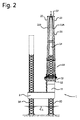
図1〜図3は、本発明の一実施形態による船舶1を示す。図1は、船舶1の側面図、図2は、船舶1の背面図、図3は、船舶1の上面図である。
1 to 3 show a
船舶1は、船体2内に4つの開口部2A、2B、2C、2Dを有する船体2を備え、開口部は、それぞれの脚3A、3B、3C、3Dを受け入れるように船体2を通って垂直に延びる。
The
各脚3A、3B、3C、3Dには、対応する脚3A、3B、3C、3Dを船体2に対して上下方向に上下動させることができる脚駆動装置4A、4B、4C、4Dが設けられ、図1および図2に示すように、船体2を水中5から持ち上げることができる。したがって、船舶1は、ジャッキアップ船舶である。船舶と共に航行するために脚が引き込まれたときの船体2に対する脚3A、3B、3C、3Dの高さは、それぞれの脚の上に破線で示されている。
Each
船舶1にはクレーン10が設けられている。クレーン10は、船体2に取り付けられたベース構造11と、旋回ベアリング12と、旋回ベアリング12を介してベース構造11に移動可能に取り付けられたクレーンハウジング13とを備え、クレーンハウジング13は、略垂直な旋回軸14の周りでベース構造11に対して旋回することができる。
A
クレーン10は、さらにブーム15を含む。ブーム15がクレーンハウジング13に移動可能に取り付けられて、ブーム15がクレーンハウジング13に対して略水平な第1枢動軸16を中心に枢動することができる。図1では、ブームは、2つの異なる角度方向、すなわち、ブーム15が水平な第1枢動軸16から離れて船舶によって支持される下方方向と、ブーム15がほぼ垂直方向である直立方向とで描かれている。
The
ブーム15は、一端でクレーンハウジングに接続され、それによって第1枢動軸16が画定される、2つのブーム脚15A、15Bを有するAフレームを備え、反対側の端部は、ハンマーヘッド構造17を介して互いに接続される。2つの端部の間では、Aフレームの剛性を高めるために、ブーム脚は、中間接続部材15Dで接続されている。
The
この実施形態におけるブーム脚は、中間部材15Dと同様にトラス構造である。ハンマーヘッド構造17は、ボックス構造でもよい。ハンマーヘッド構造のボックス構造は、それに部品を取り付けることをより容易にすることができると同時に、ねじり剛性構造が形成される。ブーム脚のトラス構造は、重量比に対して優れた剛性を提供するという利点がある。
The boom leg in this embodiment has a truss structure like the
クレーンは、クレーンハウジング13に対するブーム15の角度方向を設定するためのラフィングシステムをさらに備える。ラフィングシステムは、クレーンハウジング13上の二つのラフィングウインチ20、21と、クレーンハウジング13上の二つのラフィングウインチ20、21とブーム15との間に延びる二つのそれぞれのラフィングケーブル22、23とを含む。ラフィングインチ20とラフィングケーブル22の1つの組み合わせは、クレーン10の一方の側に配置され、ラフィングインチ21とラフィングケーブル23の他方の組み合わせは、クレーン10の反対側に配置され、それによって脚3Cの両側を通過する。
The crane further includes a luffing system for setting the angular direction of the
この実施形態では、脚3Bおよび3CにおけるAフレームのブーム脚15A、15B間の距離は、保管または輸送のために脚の上にAフレームを位置決めするのに十分なほど大きくはない。したがって、ブームは、図1および図3に示されるように、2つの脚3B、3Cの間で船体2によって支持される。しかし、図3に部分的に示すように、ブームを脚部3Cの反対側に配置することもでき、これにより、他の部品を保管するためのデッキスペースを増やすことができる。
In this embodiment, the distance between the
Aフレームの端部におけるハンマーヘッド構造17およびブーム15の近くの部品は、図4および図5により詳細に示されている。
The parts near the
図4では、Aフレームのブーム脚15A、15Bが描かれており、ブーム脚がハンマーヘッド構造17を介して互いに接続されていることが明らかに見て取れる。ハンマーヘッド構造17は、平面図で見てAフレームのブーム脚15A、15Bを越えて延びるアウトリガー17A、17Bを含む。各アウトリガー17A、17Bは、それぞれのラフィングケーブル22、23が接続されるそれぞれの滑車ブロック24、25を含み、それによってラフィングウインチ20、21によってラフィングケーブル22、23を繰り出すかまたは引き込むことによって、クレーンハウジングに対するブームの角度方向を設定することを可能にする。滑車ブロック24、25は、図5にも概略的に示されている。
In FIG. 4, the
クレーン10はさらに3つの主巻上げシステムを含む。3つの主巻上げシステムの構成要素は、同様の参照番号の後にXを付けて示され、ここでXは3つの主巻上げシステムのうちの1つを示すために1、2または3となる。
The
各主巻上げシステムは、巻上げケーブル30.1、30.2、30.3、滑車ブロック31.1、31.2、31.3、および巻上げブロック32.1、32.2、32.3を備える。各滑車ブロック31.1、31.2、31.3は、この実施形態では、それぞれの滑車回転軸33.1、33.2、33.3を中心に回転可能である複数の滑車を備える。滑車ブロック31.1、31.2、31.3は、この実施形態ではAフレームの輪郭内でハンマーヘッド構造上に配置されている、すなわち、この場合、平面図で見た列においてアウトリガー17A、17B上に並んで配置されていない。
Each main winding system comprises winding cables 30.1, 30.2, 30.3, pulley blocks 31.1, 31.2, 31.3 and winding blocks 32.1, 32.2, 32.3. . Each pulley block 31.1, 31.2, 31.3 comprises in this embodiment a plurality of pulleys that are rotatable about respective pulley rotation shafts 33.1, 33.2, 33.3. The pulley blocks 31.1, 31.2, 31.3 are arranged on the hammerhead structure within the contour of the A frame in this embodiment, i.e. in this case the
滑車ブロックの滑車回転軸33.1、33.2、33.3は、巻上げケーブルに1自由度を提供し、この自由度は、通常、重力と組み合わせて使用されて、クレーンハウジングに対するブームの角度方向とは独立して、対応する滑車ブロックより下に巻上げブロックを維持する。この実施形態では、この自由度は、例えば外側巻上げブロックについて図5に示されているように、巻上げブロックの横方向の移動を可能にするために使用される。図5では、外側巻上げブロックは、容易に40度とすることができる角度αだけ横方向に動かされる。 The pulley block pulley rotation axis 33.1, 33.2, 33.3 provides one degree of freedom for the hoisting cable, which is typically used in combination with gravity to determine the angle of the boom relative to the crane housing. Independent of direction, the hoisting block is maintained below the corresponding pulley block. In this embodiment, this degree of freedom is used to allow lateral movement of the winding block, for example as shown in FIG. 5 for the outer winding block. In FIG. 5, the outer winding block is moved laterally by an angle α that can easily be 40 degrees.
ブーム15の角度方向と無関係に巻上げブロック32.1、32.2、32.3を滑車ブロック31.1、31.2、31.3の下方に保つために、各滑車ブロック31.1、31.2、31.3は、滑車ブロック31.1,31.2,31.3の対応する滑車の滑車回転軸33.1,33.2,33.3に垂直な略水平な第2枢動軸34.1、34.2,34.3を中心に枢動可能である。
In order to keep the hoisting blocks 32.1, 32.2, 32.3 below the pulley blocks 31.1, 31.2, 31.3 independent of the angular direction of the
3つの主巻上げシステムはそれぞれ、巻上げケーブル30.1、30.2、30.3を引き込むまたは引き出すことによって巻上げブロック32.1、32.2、32.3を昇降させる巻上げウインチ35.1、35.2、35.3(図1参照)をさらに備える。 The three main hoisting systems respectively have hoisting winches 35.1, 35 that raise and lower hoisting blocks 32.1, 32.2, 32.3 by retracting or pulling hoisting cables 30.1, 30.2, 30.3. .2, 35.3 (see FIG. 1).
クレーン10のブーム15はさらに、Aフレームから延びる、すなわちこの実施形態では2つの補助巻上げシステムを担持するハンマーヘッド構造17から延びるジブ15Cを備え、補助巻上げシステムは、耐荷重が通常より小さく、滑車ブロックに対する追加の自由度は提供されないという点以外は主巻上げシステムと類似している。図4には、第1補助巻上げシステムに関連する滑車ブロック36と第2補助巻上げシステムに関連する滑車ブロック37が示されている。
The
本発明によるクレーン10の利点は、3つの主巻上げシステムが巻上げ要求に応じて様々な方法で使用され得ることである。第一の例は、図6Aおよび図6Bに示されており、図6Aは図6Bの側面図である。この例では、外側巻上げブロック32.1、32.3のみが使用されている。外側巻上げブロックは、それぞれの軸33.1、33.3を中心にして横方向に枢動され、巻上げブロック間に比較的大きな距離をとって縦構造に接続されることを可能にする。この巻上げ構造は、巻上げブロックが同時に昇降するため、同程度の荷重を支える場合に特に適している。2つの外側巻上げシステムにより、2つの自由度で巻上げられた物体の動きを制御することができる。
An advantage of the
第2の例が図7Aおよび図7Bに示されており、図7Aは、図7Bの側面図である。この例では、すべての巻上げブロックが使用される。外側巻上げブロック32.1、32.3は、図6Aおよび図6Bの例と同様に分布しているが、巻上ブロックもまた、それぞれの第2枢動軸34.1および34.2の周りに枢動される。中央巻上げブロック32.3は、図7Bの図では真っ直ぐに保たれているが、外側巻上げブロック32.1および32.3とは反対方向にあるにもかかわらず、第2枢動軸34.2を中心に枢動する。その結果、3つの主巻上げシステムは、対象物の3つの異なる場所に接続することができ、この3つの場所は、平面図で見て三角形が形成される。この巻上げ構造は、巻上げブロックが同時に昇降するため、同程度の荷重を支える場合に特に適している。この構成ではさらに、3つの自由度で巻上げられた物体の動きを制御することができる。 A second example is shown in FIGS. 7A and 7B, which is a side view of FIG. 7B. In this example, all winding blocks are used. The outer hoisting blocks 32.1, 32.3 are distributed in the same way as in the example of FIGS. 6A and 6B, but the hoisting blocks are also arranged around respective second pivot axes 34.1 and 34.2. It is pivoted by. The central hoisting block 32.3 is kept straight in the view of FIG. 7B, but despite being in the opposite direction to the outer hoisting blocks 32.1 and 32.3, the second pivot axis 34.2. Pivot around. As a result, the three main winding systems can be connected to three different locations of the object, which form a triangle when viewed in plan view. This winding structure is particularly suitable for supporting a similar load because the winding block moves up and down at the same time. In this configuration, it is also possible to control the movement of the object wound up with three degrees of freedom.
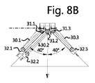
第3の例は、図8Aおよび図8Bに示されており、図8Aは、図8Bの側面図である。この例では、すべての巻上げブロックが使用されているが、外側巻上げブロックの1つ、この場合は外側巻上げブロック32.1を中央巻上げブロック32.2と組み合わせて物体の一端部を巻上げ、もう一方の外側巻上げブロック、この場合は外側巻上げブロック32.3が、物体の他端部を巻上げるために使用される。この構成は、巻上げ中に荷重が非対称であってり、非対称になったりするような状況、例えば縦構造の立ち上げ中に特に適している。 A third example is shown in FIGS. 8A and 8B, which is a side view of FIG. 8B. In this example, all hoisting blocks are used, but one end of the object is hoisted by combining one of the outer hoisting blocks, in this case the outer hoisting block 32.1 with the central hoisting block 32.2 and the other The outer hoisting block, in this case the outer hoisting block 32.3, is used for hoisting the other end of the object. This configuration is particularly suitable in situations where the load is asymmetric during winding or becomes asymmetric, for example during the startup of a vertical structure.
図8Aおよび図8Bの例に関し、中間巻上げブロック32.2に関連する滑車ブロック31.2は、他の滑車ブロック31.1および31.3よりもやや低く配置されていることがわかる。言い換えれば、Aフレームの中心面15Fは、第1枢動軸16とAフレームの長手方向軸15Gとによって広がる平面として定義されることができ、中間滑車ブロック31.2は、他の2つの外側滑車ブロック31.1および31.3よりも中心面15Fからより大きな距離で取り付けられる。この配置の利点は、大きな角度α、この実施形態では40度の角度に対して、巻上げケーブル30.1と30.2が互いに近すぎない(互いに接触したり干渉したりしない)ことであり、この場合、互いに平行である。
With respect to the example of FIGS. 8A and 8B, it can be seen that the pulley block 31.2 associated with the intermediate winding block 32.2 is arranged slightly lower than the other pulley blocks 31.1 and 31.3. In other words, the
図9〜図13を参照し、モノパイルが図1の船舶1上のクレーン10によって直立する本発明による方法を説明する。図9および図10は、船体2、脚3Aおよび3D、および脚3Dの周囲に配置されたクレーン10を有する船舶1の後側を示す。
With reference to FIGS. 9-13, the method according to the invention in which the monopile stands upright by the
船舶の船体2のデッキ2E上に、モノパイル50のスタックが略水平方向に設けられている。図9に示すように、モノパイル50は、船体2の後側を越えて延びることさえある。代わりに、モノパイルは、別の船舶、例えばバージを使用して提供されてもよい。
On the deck 2E of the hull 2 of the ship, a stack of
図9では、クレーン10のブーム15は最も近いモノパイル50、すなわち脚3Dに最も近いモノパイル50を巻上げるように位置決めされ、図10では、クレーン10のブーム15は、脚3Aに最も近いモノパイル50を巻上げるために位置決めされている。両方のモノパイル50は、平面図(図9参照)において縦構造の重心50Cとクレーン10の旋回軸14との間の直線が、縦構造50の長手方向軸50Dに対して垂直となるように、クレーン10に対して位置決めされる。
In FIG. 9, the
図11は、図8Aおよび図8Bの構成を使用してクレーン10の3つの主巻上げシステム(明瞭さのためにさらに省略されている)によって吊り下げられているモノパイル50を示している。したがって、3つの主巻上げシステムの中央巻上げブロック32.2と外側巻上げブロック32.1の1つとは、接続要素51を介してモノパイル50の上端部50Aに接続されている。
FIG. 11 shows the monopile 50 being suspended by the three main hoisting systems of the crane 10 (further omitted for clarity) using the configuration of FIGS. 8A and 8B. Accordingly, the central winding block 32.2 and one of the outer winding blocks 32.1 of the three main winding systems are connected to the
他方の外側巻上ブロック32.3は、モノパイル50の下端部50Bの周りに設けられた把持要素52を用いてモノパイル50の下端部50Bに接続されている。
The other outer hoisting block 32.3 is connected to the lower end 50B of the monopile 50 using a
恐らくは巻上げケーブル30.3の繰り出しと組み合わされて、巻上げケーブル30.1、30.2を同期して引き込むことによって、モノパイル50は直立する。図12は、直立過程の途中で斜め方向にあるモノパイル50を示し、図13は、直立後のモノパイル50を示す。図13において、巻上げブロック32.1、32.2がモノパイルの中心に接続され、巻上げブロック32.3がモノパイルの側面の把持要素に接続されると、巻上げケーブル30.1、30.2、30.3が互いに略平行となることが明確に分かる。 The monopile 50 stands upright by pulling the hoist cables 30.1, 30.2 synchronously, possibly in combination with the payout of the hoist cable 30.3. FIG. 12 shows the monopile 50 in an oblique direction during the upright process, and FIG. 13 shows the monopile 50 after upright. In FIG. 13, when the winding blocks 32.1, 32.2 are connected to the center of the monopile and the winding block 32.3 is connected to the gripping element on the side of the monopile, the winding cables 30.1, 30.2, 30 .3 are clearly parallel to each other.
直立後、モノパイルを海底55に打ち込むために、把持要素52ひいては外側巻上げブロック32.3が解放される。モノパイル50を海底55に向かって下げながら、モノパイル50は、図14に示すように、船体2から延びるガイド60によって案内されてもよい。モノパイル自体の重さによってモノパイルの一部が海底に打ち込まれる。その後、モノパイルを巻上げシステムから取り外すことができ、モノパイルをさらに海底に打ち込むための別の装置を設けることができる。
After standing upright, the gripping
図15は、以前に設置されたモノパイル50の上にタワー70を設置するためのクレーン10の使用を示す。タワーの重量がモノパイルよりも小さい場合があり、該当する場合は、タワーを直立させる場合に、クレーンは、図6Aおよび図6Bの巻上げ構成を使用することができる。タワーが重すぎる場合は、図8Aおよび図8Bの巻上げ構成を使用することができる。
FIG. 15 shows the use of the
図16は、以前に設置されたタワー70の上にナセル80を設置するためのクレーン10の使用を示す。この実施形態では、ナセルは、ナセルを第1の補助巻上げシステムによって巻上げることができるほど軽量の構成要素である。
FIG. 16 shows the use of
図17Aは、トラス構造の形態で以前に設置された他の基礎90の上にプラットフォーム100を設置するためのクレーン10の使用を示す。この実施形態では、プラットフォーム100は、複合巻上げ能力を使用するために3つ全ての巻上げシステムを必要とする重量を有する。
FIG. 17A shows the use of the
しかし、3つ全ての巻上げブロック32.1、32.2、32.3をプラットフォームに直接又は3つの巻上げブロックが直接接続されている単一の接続要素を介して間接的に接続する場合、潜在的に利用可能な全巻上げ能力を使用することは不可能である。 However, if all three winding blocks 32.1, 32.2, 32.3 are connected directly to the platform or indirectly via a single connecting element to which the three winding blocks are directly connected, the potential It is not possible to use all the hoisting capabilities that are available to the public.
したがって、これらの場合、2つの巻上げブロック、この実施形態では巻上げブロック32.1および32.3が第1中間部材110に接続される(図17B参照)。第1中間部材110と他の残りの巻上げブロック32.3は、第2中間部材120に接続されている。第2中間部材120には、プラットフォーム100に接続するための負荷コネクタ130が接続されている。巻上げブロックと中間部材との間の接続および第1および第2中間部材との間の接続は、例えばさまざまな部品間の滑車およびケーブル接続を提供することによって、プラットフォーム100の荷重が3つの昇降システムにわたってほぼ均等に分配されるようになっている。
In these cases, therefore, two winding blocks, in this embodiment winding blocks 32.1 and 32.3, are connected to the first intermediate member 110 (see FIG. 17B). The first
ここに記載された例および実施形態は特定数のウインチ、ケーブルおよび滑車の使用を開示しているが、追加の構成要素が提供されてもよいことが当業者に明らかであることに留意されたい。したがって、1本の巻上げケーブルまたはラフィングケーブルに2つのウインチを使用するか、またはウインチとケーブルをさらに組み合わせて使用するのが一般的である。言い換えれば、説明で提供される特定の数は、少なくともその特定の数を意味すると解釈されるべきである。主巻上システムの数についても同様である。3つの主巻上げシステムが記載されているが、第4および第5の主巻上げシステムが設けられてもよく、それらは本発明の範囲内に含まれる。 It should be noted that although the examples and embodiments described herein disclose the use of a specific number of winches, cables and pulleys, it will be apparent to those skilled in the art that additional components may be provided. . Therefore, it is common to use two winches for a single winding cable or luffing cable, or a combination of winches and cables. In other words, the specific number provided in the description should be interpreted to mean at least that specific number. The same applies to the number of main hoisting systems. Although three main winding systems are described, fourth and fifth main winding systems may be provided and are within the scope of the present invention.
1 船舶
2 船体
2A、2B、2C、2D 開口部
3A、3B、3C、3D 脚
4A、4B、4C、4D 脚駆動装置
10 クレーン
11 ベース構造
12 旋回ベアリング
13 クレーンハウジング
14 旋回軸
15 ブーム
15A、15B ブーム脚
15C ジブ
15D 中間部材
15F 中心面
15G 長手方向軸
16 第1枢動軸
17 ハンマーヘッド構造
17A、17B アウトリガー
20,21 ラフィングウインチ
22,23 ラフィングケーブル
24,25,36,37 滑車ブロック
50 縦構造,モノパイル
50A 上端部
50B 下端部
50D 長手方向軸
51 接続要素
52 把持要素
DESCRIPTION OF
Claims (11)
ベース構造と、
旋回ベアリングと、
前記旋回ベアリングを介して前記ベース構造に移動可能に取り付けられたクレーンハウジングであって、前記ベース構造に対して略垂直の旋回軸回りに回転することができるクレーンハウジングと、
前記クレーンハウジングに移動可能に取り付けられたブームであって、前記クレーンハウジングに対して略水平の第1枢動軸回りに枢動することができるブームと、
3つの主巻上げシステムと、
前記クレーンハウジングに対する前記ブームの角度方向を設定するためのラフィングシステムと、
を備え、
前記ブームは、2つのブーム脚を有するAフレームを備え、前記2つのブーム脚は、一端部が前記クレーンハウジングに接続され、反対の端部がハンマーヘッド構造を介して互いに接続され、
各主巻上げシステムは、
巻上げケーブルと、
滑車回転軸回りに回転可能な1または複数の滑車を有する滑車ブロックであって、前記ブームの前記ハンマーヘッド構造上に配置された滑車ブロックと、
前記巻上げケーブルによって前記滑車ブロックから吊り下げられた巻上げブロックと、
前記巻上げケーブルを引き込む、または引き出すことによって前記巻上げブロックを昇降させる巻上げウインチと、
を備え、
各主巻上げシステムの前記滑車ブロックは、前記滑車ブロックの前記1または複数の滑車の前記滑車回転軸に垂直な略水平の第2枢動軸回りに枢動可能であり、
前記3つの主巻上げシステムの前記滑車ブロックは、並んで配置され、
前記ラフィングシステムは、
前記クレーンハウジング上の2つのラフィングウインチと、
前記クレーンハウジング上の各前記2つのラフィングウインチおよび前記ブームの間に延在する2つのラフィングケーブルと、
を備え、
前記ラフィングケーブルは、平面図で見て前記Aフレームの前記ブーム脚を越えて延在する前記ハンマーヘッド構造のそれぞれのアウトリガーに接続される、クレーン。 A crane,
The base structure,
Slewing bearings,
A crane housing movably attached to the base structure via the slewing bearing, the crane housing being rotatable about a pivot axis substantially perpendicular to the base structure;
A boom movably attached to the crane housing, the boom being pivotable about a first pivot axis substantially horizontal to the crane housing;
Three main winding systems,
A luffing system for setting an angular direction of the boom with respect to the crane housing;
With
The boom includes an A-frame having two boom legs, the two boom legs having one end connected to the crane housing and opposite ends connected to each other via a hammerhead structure,
Each main hoisting system
A winding cable;
A pulley block having one or more pulleys rotatable about a pulley rotation axis, the pulley block disposed on the hammerhead structure of the boom;
A hoisting block suspended from the pulley block by the hoisting cable;
A winding winch that raises or lowers the winding block by pulling in or pulling out the winding cable;
With
The pulley block of each main hoisting system is pivotable about a substantially horizontal second pivot axis perpendicular to the pulley rotation axis of the one or more pulleys of the pulley block;
The pulley blocks of the three main winding systems are arranged side by side,
The luffing system
Two luffing winches on the crane housing;
Two luffing cables extending between each of the two luffing winches and the boom on the crane housing;
With
The crane, wherein the luffing cable is connected to each outrigger of the hammerhead structure that extends beyond the boom leg of the A-frame when viewed in plan view.
船体に少なくとも3つの開口部を有する船体であって、前記開口部は、それぞれの脚を受け入れるために前記船体を通り垂直に延在する、船体と、
前記船体の開口部ごとの脚と、
脚ごとの脚駆動装置であって、船体を水中から持ち上げることを可能にするために、対応する脚を前記船体に対して垂直方向に移動することができる、脚駆動装置と、
を備える請求項6に記載の船舶。 The ship is a jack ship, and the jack ship is
A hull having at least three openings in the hull, the openings extending vertically through the hull to receive respective legs; and
Legs for each opening of the hull;
A leg drive for each leg, the leg drive capable of moving the corresponding leg in a direction perpendicular to the hull to allow the hull to be lifted from the water;
A ship according to claim 6.
a)上端部および下端部を有する縦構造を略水平方向に提供するステップと、
b)前記3つの主巻上げシステムの中間巻上げブロック、および前記3つの主巻上げシステムの外側巻上げブロックの一方を前記縦構造の前記上端部または端部に接続するステップと、
c)前記3つの主巻上げシステムの前記外側巻上げブロックの他方を前記縦構造の前記下端部または端部に接続するステップと、
d)前記縦構造が、前記上端部が前記下端部より上の状態で略垂直の向きになるまで、前記3つの主巻上げシステムのそれぞれのウインチを操作するステップと、
を備える、方法。 A method for erecting a vertical structure using the crane according to any one of claims 1 to 5, wherein the method comprises:
a) providing a vertical structure having an upper end and a lower end in a substantially horizontal direction;
b) connecting one of the intermediate winding block of the three main winding systems and the outer winding block of the three main winding systems to the upper end or end of the vertical structure;
c) connecting the other of the outer winding blocks of the three main winding systems to the lower end or end of the longitudinal structure;
d) manipulating each winch of the three main winding systems until the vertical structure is in a substantially vertical orientation with the upper end above the lower end;
A method comprising:
c1)把持要素を提供するステップと、
c2)前記縦構造の前記下端部または端部の周りに前記把持要素を設けるステップと、
c3)前記3つの主巻上げシステムの前記外側巻上げブロックの他方を前記把持要素に接続するステップと、
備える、請求項9に記載の方法。 Step c) providing c1) a gripping element;
c2) providing the gripping element around the lower end or end of the vertical structure;
c3) connecting the other of the outer winding blocks of the three main winding systems to the gripping element;
10. The method of claim 9, comprising.
Applications Claiming Priority (3)
| Application Number | Priority Date | Filing Date | Title |
|---|---|---|---|
| NL2017468A NL2017468B1 (en) | 2016-09-15 | 2016-09-15 | Crane, vessel comprising such a crane, and a method for up-ending a longitudinal structure |
| NL2017468 | 2016-09-15 | ||
| PCT/NL2017/050602 WO2018052291A1 (en) | 2016-09-15 | 2017-09-14 | Crane, vessel comprising such a crane, and a method for up-ending a longitudinal structure |
Publications (3)
| Publication Number | Publication Date |
|---|---|
| JP2019529286A true JP2019529286A (en) | 2019-10-17 |
| JP2019529286A5 JP2019529286A5 (en) | 2020-10-01 |
| JP7038704B2 JP7038704B2 (en) | 2022-03-18 |
Family
ID=57460573
Family Applications (1)
| Application Number | Title | Priority Date | Filing Date |
|---|---|---|---|
| JP2019515469A Active JP7038704B2 (en) | 2016-09-15 | 2017-09-14 | How to make a monopile upright as the basis of a wind turbine |
Country Status (6)
| Country | Link |
|---|---|
| US (2) | US10544016B2 (en) |
| EP (2) | EP3992140A1 (en) |
| JP (1) | JP7038704B2 (en) |
| CN (2) | CN109689561B (en) |
| NL (1) | NL2017468B1 (en) |
| WO (1) | WO2018052291A1 (en) |
Families Citing this family (15)
| Publication number | Priority date | Publication date | Assignee | Title |
|---|---|---|---|---|
| NL2017776B1 (en) * | 2016-11-11 | 2018-05-24 | Itrec Bv | Marine crane vessel and method of operation |
| NL2021043B1 (en) * | 2018-06-01 | 2019-12-10 | Itrec Bv | Offshore wind turbine installation vessel and a crane for providing such a vessel and method for upending a monopile |
| NL2021651B1 (en) * | 2018-09-17 | 2020-05-07 | Tetrahedron B V | Crane vessel |
| DK180872B1 (en) * | 2019-05-02 | 2022-06-08 | Liftra Ip Aps | Self-hoisting crane system and method for hoisting a self-hoisting crane |
| US11952245B2 (en) * | 2019-06-07 | 2024-04-09 | Itrec B.V. | Hoisting crane for use on an offshore vessel and method of operation |
| NL2024563B1 (en) | 2019-12-23 | 2021-09-02 | Itrec Bv | Crane, vessel comprising such a crane, and a method for up-ending a longitudinal structure |
| NL2024562B1 (en) | 2019-12-23 | 2021-09-02 | Itrec Bv | A feeder vessel |
| GB2592595B (en) * | 2020-03-02 | 2023-04-05 | Seaway 7 Eng B V | Upending elongate structures offshore |
| CN115697885A (en) * | 2020-04-08 | 2023-02-03 | 伊特里克公司 | Ocean folding arm type crane |
| CN111874816A (en) * | 2020-06-19 | 2020-11-03 | 太重(天津)重型装备科技开发有限公司 | Crane boom and using method thereof |
| CN112374384B (en) * | 2020-11-20 | 2023-01-10 | 中船华南船舶机械广州有限公司 | Hoisting method of offshore crane |
| CN112340619B (en) * | 2020-11-20 | 2023-01-10 | 中船华南船舶机械广州有限公司 | Modular assembly method of crane |
| NL2027689B1 (en) * | 2021-03-03 | 2022-09-22 | Itrec Bv | Crane housing, crane, jack-up vessel, method |
| WO2022229436A1 (en) | 2021-04-30 | 2022-11-03 | Itrec B.V. | Installation vessel, lifting device, pile gripper, control unit and method |
| WO2023072635A1 (en) | 2021-10-28 | 2023-05-04 | Itrec B.V. | Method for installation of a monopile and installation vessel |
Citations (9)
| Publication number | Priority date | Publication date | Assignee | Title |
|---|---|---|---|---|
| JPS502150B1 (en) * | 1969-10-06 | 1975-01-23 | ||
| EP0049001A1 (en) * | 1980-09-24 | 1982-04-07 | Itrec B.V. | Hoisting device, in particular floating derrick |
| JPH01271393A (en) * | 1988-04-25 | 1989-10-30 | Shimizu Corp | Suspending jig for columnar lengthy material and suspension of columnar lengthy material using this suspending jig |
| US5580189A (en) * | 1995-12-22 | 1996-12-03 | Searex, Inc. | Jack-up rig crane |
| JPH10273289A (en) * | 1997-03-28 | 1998-10-13 | Shonan Souden Koji Kk | Cane suspension type power hoisting device |
| WO2009131442A1 (en) * | 2008-04-25 | 2009-10-29 | Itrec B.V. | Hoisting crane |
| KR20140118470A (en) * | 2013-03-29 | 2014-10-08 | 곽대진 | Floating Crane and Method for Installation Offshore Wind Tower |
| CN104444772A (en) * | 2014-11-03 | 2015-03-25 | 无锡市百顺机械厂 | Lifting tool |
| US20150219067A1 (en) * | 2012-08-30 | 2015-08-06 | High Wind N.V. | Device and Method for Assembling a Structure |
Family Cites Families (45)
| Publication number | Priority date | Publication date | Assignee | Title |
|---|---|---|---|---|
| SE394186B (en) * | 1968-06-24 | 1977-06-13 | Murmanskoe Vysshee Morekhodnoe | DEVICE AT LOAD CRANE |
| NL6911689A (en) * | 1969-08-20 | 1971-02-02 | ||
| DE2541065A1 (en) * | 1975-09-15 | 1977-03-17 | Hans Tax | HEAVY DUTY ROTATING CRANE |
| US4280628A (en) * | 1978-03-31 | 1981-07-28 | Goss John B | Anti-two block system |
| US4383616A (en) * | 1980-12-24 | 1983-05-17 | Kidde, Inc. | Luffing jib for construction crane |
| US4919393A (en) * | 1988-02-01 | 1990-04-24 | Mcdermott International, Inc. | Deepwater subsea lowering/lifting system |
| US4951924A (en) * | 1988-02-01 | 1990-08-28 | Mcdermott International, Inc. | Deepwater subsea lowering/lifting system |
| US4838522A (en) * | 1988-02-01 | 1989-06-13 | Mcdermott International Inc. | Deepwater subsea lowering/lifting system |
| US4892202A (en) * | 1988-04-28 | 1990-01-09 | Amca International Corporation | Deepwater extended hook travel attachment |
| NL1026458C2 (en) * | 2004-06-18 | 2005-12-20 | Itrec Bv | Cranes and offshore vessel. |
| EP1922280B1 (en) * | 2005-09-06 | 2011-08-10 | Gusto B.V. | Tie-back system for cranes, in particular heavy load offshore cranes |
| GB2434823A (en) * | 2006-02-06 | 2007-08-08 | Engineering Business Ltd | Transport and installation of offshore structures |
| US8540092B2 (en) * | 2007-01-17 | 2013-09-24 | Itrec B.V. | Hoisting crane with annular bearing structure |
| US20080169257A1 (en) * | 2007-01-17 | 2008-07-17 | Itrec B.V. | Hoisting crane with annular bearing structure |
| BRPI0807513B1 (en) * | 2007-02-16 | 2019-10-22 | Itrec Bv | hoisting crane and vessel. |
| US7815398B2 (en) * | 2007-03-30 | 2010-10-19 | Remedial Cayman Limited | Methods of positioning an elevating support vessel |
| US20080237175A1 (en) * | 2007-03-30 | 2008-10-02 | Remedial (Cyprus) Pcl | Extension assemblies and methods thereof |
| US20080237174A1 (en) * | 2007-03-30 | 2008-10-02 | Remedial (Cyprus) Pcl | Crane support apparatus and methods thereof |
| US20100067989A1 (en) * | 2007-03-30 | 2010-03-18 | Brown Michael D | Vessel for transporting wind turbines and methods thereof |
| US20080247827A1 (en) * | 2007-03-30 | 2008-10-09 | Remedial (Cyprus) Pcl | Work-over rig assembly and methods thereof |
| US20080237173A1 (en) * | 2007-03-30 | 2008-10-02 | Remedial (Cyprus) Pcl | Arm assembly and methods of passing a pipe from a first vessel to a second vessel using the arm assembly |
| US20080237170A1 (en) * | 2007-03-30 | 2008-10-02 | Remedial (Cyprus) Pcl | Extension Bridges and methods of tender assist |
| CN101918271B (en) * | 2007-10-11 | 2013-09-11 | 伊特雷科公司 | Vessels with roll damping mechanism |
| US8783478B2 (en) * | 2007-10-11 | 2014-07-22 | Itrec B.V. | Hoisting crane and offshore vessel |
| DE602008003297D1 (en) * | 2008-02-07 | 2010-12-16 | Itrec Bv | Boom Truck |
| EP3241733A1 (en) * | 2008-02-15 | 2017-11-08 | Itrec B.V. | Offshore drilling vessel |
| ITMI20091299A1 (en) * | 2009-07-22 | 2011-01-23 | Saipem Spa | MULTIFUNCTION VESSEL FOR DEEP WATER OPERATIONS |
| US8596700B2 (en) * | 2009-08-14 | 2013-12-03 | Mjt Holdings, Llc | Tower erection lift kit tools |
| CN102630211B (en) * | 2009-09-18 | 2015-04-15 | 伊特里克公司 | Lifting device |
| US20110221215A1 (en) * | 2010-03-12 | 2011-09-15 | Vestas Wind Systems A/S | Methods and apparatus for handling a tower section of a wind turbine with a crane |
| CN102425145B (en) * | 2011-10-27 | 2014-01-15 | 三一电气有限责任公司 | Offshore wind turbine installation platform and hoisting device thereof |
| CN202322100U (en) * | 2011-11-16 | 2012-07-11 | 中联重科股份有限公司 | Horizontal trolley luffing tower crane and jacklift sling combination device |
| US9080696B2 (en) * | 2011-12-14 | 2015-07-14 | Itrec B.V. | Marine pipelaying vessel and method for pipelaying |
| DK2797830T3 (en) * | 2011-12-30 | 2016-05-17 | Nat Oilwell Varco Lp | Dybvandskran with articulated crane arm |
| AU2013267148B9 (en) * | 2012-06-01 | 2017-04-06 | Seatrax, Inc. | System and method to determine relative velocity of crane and target load |
| CN202766146U (en) * | 2012-09-04 | 2013-03-06 | 南通润邦重机有限公司 | Large pile circling type offshore platform crane |
| CN202864750U (en) * | 2012-10-23 | 2013-04-10 | 上海航盛船舶设计有限公司 | Whole transportation and installation device of offshore wind turbines |
| SG11201504502UA (en) * | 2012-12-13 | 2015-07-30 | Nat Oilwell Varco Lp | Remote heave compensation system |
| CN203159080U (en) * | 2013-03-06 | 2013-08-28 | 三一集团有限公司 | Floating-type crane |
| NL2011922C2 (en) * | 2013-12-09 | 2015-06-11 | Itrec Bv | Hoisting crane and method for refurbishing such a hoisting crane. |
| CN104649155B (en) * | 2013-12-10 | 2017-01-11 | 中船华南船舶机械有限公司 | Seaborne cylindrical floating body recycling device |
| EP3277615B1 (en) * | 2015-03-30 | 2019-07-03 | Oil States Industries, Inc. | Crane having effectively coincident gantry and boom forces upon an upperstructure |
| CN204675608U (en) * | 2015-04-29 | 2015-09-30 | 招商局重工(江苏)有限公司 | A kind of crane barge and Multifunctional hanging hook, Multifunctional hanging hook group |
| CN105752282A (en) * | 2016-03-31 | 2016-07-13 | 中交第三航务工程局有限公司 | Self-elevating wind power generation work boat |
| WO2017217845A1 (en) | 2016-06-15 | 2017-12-21 | Itrec B.V. | A crane for wind turbine blade assembly, a vessel, a hoisting method, and an assembly method |
-
2016
- 2016-09-15 NL NL2017468A patent/NL2017468B1/en active
-
2017
- 2017-09-14 WO PCT/NL2017/050602 patent/WO2018052291A1/en unknown
- 2017-09-14 US US16/333,428 patent/US10544016B2/en active Active
- 2017-09-14 JP JP2019515469A patent/JP7038704B2/en active Active
- 2017-09-14 CN CN201780056293.7A patent/CN109689561B/en active Active
- 2017-09-14 CN CN202010811620.9A patent/CN111807239B/en active Active
- 2017-09-14 EP EP21201507.7A patent/EP3992140A1/en active Pending
- 2017-09-14 EP EP17781569.3A patent/EP3512799A1/en not_active Withdrawn
-
2019
- 2019-12-12 US US16/712,451 patent/US10894701B2/en active Active
Patent Citations (9)
| Publication number | Priority date | Publication date | Assignee | Title |
|---|---|---|---|---|
| JPS502150B1 (en) * | 1969-10-06 | 1975-01-23 | ||
| EP0049001A1 (en) * | 1980-09-24 | 1982-04-07 | Itrec B.V. | Hoisting device, in particular floating derrick |
| JPH01271393A (en) * | 1988-04-25 | 1989-10-30 | Shimizu Corp | Suspending jig for columnar lengthy material and suspension of columnar lengthy material using this suspending jig |
| US5580189A (en) * | 1995-12-22 | 1996-12-03 | Searex, Inc. | Jack-up rig crane |
| JPH10273289A (en) * | 1997-03-28 | 1998-10-13 | Shonan Souden Koji Kk | Cane suspension type power hoisting device |
| WO2009131442A1 (en) * | 2008-04-25 | 2009-10-29 | Itrec B.V. | Hoisting crane |
| US20150219067A1 (en) * | 2012-08-30 | 2015-08-06 | High Wind N.V. | Device and Method for Assembling a Structure |
| KR20140118470A (en) * | 2013-03-29 | 2014-10-08 | 곽대진 | Floating Crane and Method for Installation Offshore Wind Tower |
| CN104444772A (en) * | 2014-11-03 | 2015-03-25 | 无锡市百顺机械厂 | Lifting tool |
Also Published As
| Publication number | Publication date |
|---|---|
| US10544016B2 (en) | 2020-01-28 |
| US20190248631A1 (en) | 2019-08-15 |
| CN109689561B (en) | 2020-09-18 |
| WO2018052291A1 (en) | 2018-03-22 |
| EP3992140A1 (en) | 2022-05-04 |
| CN111807239B (en) | 2022-06-10 |
| EP3512799A1 (en) | 2019-07-24 |
| CN109689561A (en) | 2019-04-26 |
| JP7038704B2 (en) | 2022-03-18 |
| NL2017468B1 (en) | 2018-03-22 |
| US20200115197A1 (en) | 2020-04-16 |
| US10894701B2 (en) | 2021-01-19 |
| CN111807239A (en) | 2020-10-23 |
Similar Documents
| Publication | Publication Date | Title |
|---|---|---|
| JP7038704B2 (en) | How to make a monopile upright as the basis of a wind turbine | |
| CN111918832B (en) | Crane and method for positioning an object | |
| EP2275340B1 (en) | Offshore wind turbine installation | |
| JP2019529286A5 (en) | ||
| US20110221215A1 (en) | Methods and apparatus for handling a tower section of a wind turbine with a crane | |
| JP2020519514A (en) | Motion-compensated crane for use onboard a marine vessel | |
| EP2189575B1 (en) | Jack-up offshore platform and a method thereof | |
| JP2020513383A (en) | Offshore vessels, cranes for compensating wave-induced motion for use on vessels, and load carrying methods | |
| US20120027523A1 (en) | Device and method for assembling a structure at sea | |
| EP2256079B1 (en) | Device for assembling a large structure at sea | |
| EP2189574A1 (en) | Jack-up offshore platform and its use for assembling and servicing a structure at sea | |
| JP2023508370A (en) | Cranes, ships equipped with such cranes, and methods for raising elongated structures | |
| KR101401985B1 (en) | Floating crane with jack-up system for floating structure | |
| CN113825878A (en) | Vessel and method for installing a pile suitable for supporting an offshore wind turbine | |
| US20230399206A1 (en) | Offshore wind turbine assembly vessel | |
| EP3083391B1 (en) | Saddle and hook system | |
| WO2012060112A1 (en) | Ship for installing offshore wind turbine and method for installing offshore wind turbine using same | |
| NL2028124B1 (en) | installation vessel | |
| EP2472008A1 (en) | Jack-up offshore platform and its use for lifting large and heavy loads | |
| NL2028741B1 (en) | upend crane and installation vessel | |
| US11525229B2 (en) | Crane vessel | |
| WO2020122712A1 (en) | Piling frame with cut-out | |
| KR20230171890A (en) | Crane for a ship and ship having said crane | |
| KR101661905B1 (en) | Crane apparatus |
Legal Events
| Date | Code | Title | Description |
|---|---|---|---|
| A521 | Request for written amendment filed |
Free format text: JAPANESE INTERMEDIATE CODE: A523 Effective date: 20200817 |
|
| A621 | Written request for application examination |
Free format text: JAPANESE INTERMEDIATE CODE: A621 Effective date: 20200817 |
|
| A977 | Report on retrieval |
Free format text: JAPANESE INTERMEDIATE CODE: A971007 Effective date: 20210426 |
|
| A131 | Notification of reasons for refusal |
Free format text: JAPANESE INTERMEDIATE CODE: A131 Effective date: 20210628 |
|
| A601 | Written request for extension of time |
Free format text: JAPANESE INTERMEDIATE CODE: A601 Effective date: 20210927 |
|
| A521 | Request for written amendment filed |
Free format text: JAPANESE INTERMEDIATE CODE: A523 Effective date: 20211122 |
|
| TRDD | Decision of grant or rejection written | ||
| A01 | Written decision to grant a patent or to grant a registration (utility model) |
Free format text: JAPANESE INTERMEDIATE CODE: A01 Effective date: 20220207 |
|
| A61 | First payment of annual fees (during grant procedure) |
Free format text: JAPANESE INTERMEDIATE CODE: A61 Effective date: 20220308 |
|
| R150 | Certificate of patent or registration of utility model |
Ref document number: 7038704 Country of ref document: JP Free format text: JAPANESE INTERMEDIATE CODE: R150 |