JP2019526073A - Low-loss single-mode fiber with a chlorine-doped core - Google Patents
Low-loss single-mode fiber with a chlorine-doped core Download PDFInfo
- Publication number
- JP2019526073A JP2019526073A JP2019504764A JP2019504764A JP2019526073A JP 2019526073 A JP2019526073 A JP 2019526073A JP 2019504764 A JP2019504764 A JP 2019504764A JP 2019504764 A JP2019504764 A JP 2019504764A JP 2019526073 A JP2019526073 A JP 2019526073A
- Authority
- JP
- Japan
- Prior art keywords
- refractive index
- delta
- core
- cladding region
- inner cladding
- Prior art date
- Legal status (The legal status is an assumption and is not a legal conclusion. Google has not performed a legal analysis and makes no representation as to the accuracy of the status listed.)
- Pending
Links
Images


Classifications
-
- G—PHYSICS
- G02—OPTICS
- G02B—OPTICAL ELEMENTS, SYSTEMS OR APPARATUS
- G02B6/00—Light guides; Structural details of arrangements comprising light guides and other optical elements, e.g. couplings
- G02B6/02—Optical fibres with cladding with or without a coating
- G02B6/02214—Optical fibres with cladding with or without a coating tailored to obtain the desired dispersion, e.g. dispersion shifted, dispersion flattened
- G02B6/02219—Characterised by the wavelength dispersion properties in the silica low loss window around 1550 nm, i.e. S, C, L and U bands from 1460-1675 nm
- G02B6/02276—Dispersion shifted fibres, i.e. zero dispersion at 1550 nm
-
- G—PHYSICS
- G02—OPTICS
- G02B—OPTICAL ELEMENTS, SYSTEMS OR APPARATUS
- G02B6/00—Light guides; Structural details of arrangements comprising light guides and other optical elements, e.g. couplings
- G02B6/02—Optical fibres with cladding with or without a coating
- G02B6/02004—Optical fibres with cladding with or without a coating characterised by the core effective area or mode field radius
- G02B6/02009—Large effective area or mode field radius, e.g. to reduce nonlinear effects in single mode fibres
-
- G—PHYSICS
- G02—OPTICS
- G02B—OPTICAL ELEMENTS, SYSTEMS OR APPARATUS
- G02B6/00—Light guides; Structural details of arrangements comprising light guides and other optical elements, e.g. couplings
- G02B6/02—Optical fibres with cladding with or without a coating
- G02B6/028—Optical fibres with cladding with or without a coating with core or cladding having graded refractive index
- G02B6/0286—Combination of graded index in the central core segment and a graded index layer external to the central core segment
-
- G—PHYSICS
- G02—OPTICS
- G02B—OPTICAL ELEMENTS, SYSTEMS OR APPARATUS
- G02B6/00—Light guides; Structural details of arrangements comprising light guides and other optical elements, e.g. couplings
- G02B6/02—Optical fibres with cladding with or without a coating
- G02B6/036—Optical fibres with cladding with or without a coating core or cladding comprising multiple layers
- G02B6/03616—Optical fibres characterised both by the number of different refractive index layers around the central core segment, i.e. around the innermost high index core layer, and their relative refractive index difference
- G02B6/03622—Optical fibres characterised both by the number of different refractive index layers around the central core segment, i.e. around the innermost high index core layer, and their relative refractive index difference having 2 layers only
- G02B6/03627—Optical fibres characterised both by the number of different refractive index layers around the central core segment, i.e. around the innermost high index core layer, and their relative refractive index difference having 2 layers only arranged - +
-
- G—PHYSICS
- G02—OPTICS
- G02B—OPTICAL ELEMENTS, SYSTEMS OR APPARATUS
- G02B6/00—Light guides; Structural details of arrangements comprising light guides and other optical elements, e.g. couplings
- G02B6/02—Optical fibres with cladding with or without a coating
- G02B6/036—Optical fibres with cladding with or without a coating core or cladding comprising multiple layers
- G02B6/03616—Optical fibres characterised both by the number of different refractive index layers around the central core segment, i.e. around the innermost high index core layer, and their relative refractive index difference
- G02B6/03622—Optical fibres characterised both by the number of different refractive index layers around the central core segment, i.e. around the innermost high index core layer, and their relative refractive index difference having 2 layers only
- G02B6/03633—Optical fibres characterised both by the number of different refractive index layers around the central core segment, i.e. around the innermost high index core layer, and their relative refractive index difference having 2 layers only arranged - -
-
- G—PHYSICS
- G02—OPTICS
- G02B—OPTICAL ELEMENTS, SYSTEMS OR APPARATUS
- G02B6/00—Light guides; Structural details of arrangements comprising light guides and other optical elements, e.g. couplings
- G02B6/02—Optical fibres with cladding with or without a coating
- G02B6/036—Optical fibres with cladding with or without a coating core or cladding comprising multiple layers
- G02B6/03616—Optical fibres characterised both by the number of different refractive index layers around the central core segment, i.e. around the innermost high index core layer, and their relative refractive index difference
- G02B6/03638—Optical fibres characterised both by the number of different refractive index layers around the central core segment, i.e. around the innermost high index core layer, and their relative refractive index difference having 3 layers only
- G02B6/03655—Optical fibres characterised both by the number of different refractive index layers around the central core segment, i.e. around the innermost high index core layer, and their relative refractive index difference having 3 layers only arranged - + +
-
- G—PHYSICS
- G02—OPTICS
- G02B—OPTICAL ELEMENTS, SYSTEMS OR APPARATUS
- G02B6/00—Light guides; Structural details of arrangements comprising light guides and other optical elements, e.g. couplings
- G02B6/44—Mechanical structures for providing tensile strength and external protection for fibres, e.g. optical transmission cables
- G02B6/4439—Auxiliary devices
- G02B6/4471—Terminating devices ; Cable clamps
- G02B6/4478—Bending relief means
Abstract
(i)コアアルファ(αcore)>10、最大屈折率デルタΔ1max、及びCl濃度>1重量%を有する、塩素ドープシリカベースコア;(ii)上記コアを取り囲むクラッドであって:(a)内側クラッド領域であって、上記コアに隣接して接触し、屈折率デルタΔ2及び最大屈折率デルタΔ2minを有し、Δ2min<Δ1maxであり、上記内側クラッド領域は、フッ素ドープシリカと、径方向位置と共に減少する領域を有する上記屈折率デルタΔ2とを備える、内側クラッド領域;並びに(b)上記内側クラッド領域を取り囲み、屈折率デルタΔ3を有し、Δ2min<Δ3である、外側クラッド領域を備える、クラッドを備える、光ファイバ。上記ファイバは:≧9マイクロメートルの、1310nmでのモードフィールド直径MFD;≦1260nmのケーブルカットオフ;1300nm≦ゼロ分散波長≦1324nmのゼロ分散波長;及び0.5dB/turn未満の、20mmマンドレルに関する1550nmでの曲げ損失を有する。(I) a chlorine-doped silica base core having a core alpha> 10, a maximum refractive index delta Δ1max, and a Cl concentration> 1 wt%; (ii) a cladding surrounding the core: (a) an inner cladding A region adjacent to the core and having a refractive index delta Δ2 and a maximum refractive index delta Δ2min, Δ2min <Δ1max, and the inner cladding region decreases with fluorine-doped silica and radial position An inner cladding region comprising the refractive index delta Δ2 having a region; and (b) a cladding comprising the outer cladding region surrounding the inner cladding region, having a refractive index delta Δ3, and Δ2min <Δ3. , Optical fiber. The fiber: ≧ 9 micrometers, mode field diameter MFD at 1310 nm; ≦ 1260 nm cable cutoff; 1300 nm ≦ zero dispersion wavelength ≦ 1324 nm zero dispersion wavelength; and less than 0.5 dB / turn, 1550 nm for a 20 mm mandrel Has bending loss at.
Description
本出願は、米国特許法第119条の下で、2016年7月29日出願の米国仮特許出願第62/368,703号の優先権を主張するものであり、上記仮特許出願の内容は信頼できるものであり、その全体が参照により本出願に援用される。 This application claims priority from US Provisional Patent Application No. 62 / 368,703, filed July 29, 2016, under section 119 of the US Patent Act. It is reliable and is incorporated herein by reference in its entirety.
本開示は一般に、塩素ドープコアを備えるシングルモードファイバに関し、より詳細には、塩素ドープコアと、フッ素ドープトレンチ領域を有するクラッドとを備える、シングルモードファイバに関する。 The present disclosure relates generally to a single mode fiber comprising a chlorine doped core, and more particularly to a single mode fiber comprising a chlorine doped core and a cladding having a fluorine doped trench region.
本出願に引用されるいずれの参考文献が先行技術を構成することを承認するものではない。出願人は、引用されたいずれの文献の正確性及び適切性に意義を申し立てる権利を明示的に留保する。 No admission is made that any reference cited in this application constitutes prior art. Applicant expressly reserves the right to claim the accuracy and appropriateness of any cited document.
本開示のある実施形態は、光ファイバであって、上記光ファイバは:
(i)コアアルファ(αcore)>10、最大屈折率デルタΔ1max、及びCl濃度>1重量%を有する、塩素ドープシリカベースコア;
(ii)上記コアを取り囲むクラッドであって:
a.内側クラッド領域であって、フッ素ドープシリカを含み、上記コアに隣接して接触し、屈折率デルタΔ2及び最大屈折率デルタΔ2minを有し、Δ2min<Δ1maxであり、上記内側クラッド領域の上記屈折率デルタΔ2は、径方向位置と共に減少する領域を含む、内側クラッド領域;並びに
b.上記内側クラッド領域を取り囲み、屈折率デルタΔ3を有し、Δ2min<Δ3である、外側クラッド領域
を備える、クラッド
を備え、
上記光ファイバは:≧9マイクロメートルの、1310nmでのモードフィールド直径MFD;≦1260nmのケーブルカットオフ;1300nm≦ゼロ分散波長≦1324nmである、ゼロ分散波長;及び0.5dB/turn未満の、20mmマンドレルに関する1550nmでの曲げ損失を有する。
An embodiment of the present disclosure is an optical fiber, the optical fiber:
(I) a chlorine-doped silica base core having a core alpha (α core )> 10, a maximum refractive index delta Δ 1max , and a Cl concentration> 1 wt%;
(Ii) a clad surrounding the core:
a. An inner cladding region comprises fluorine-doped silica, contacts adjacent to the core has a refractive index delta delta 2 and maximum refractive index delta delta 2min, a delta 2min <delta 1max, of the inner cladding region An inner cladding region comprising a region where the refractive index delta Δ 2 decreases with radial position; and b. Surrounds the inner cladding region has a refractive index delta delta 3, a delta 2min <delta 3, an outer cladding region comprises a cladding,
The optical fiber is: ≧ 9 micrometers, mode field diameter MFD at 1310 nm; cable cutoff of ≦ 1260 nm; 1300 nm ≦ zero dispersion wavelength ≦ 1324 nm, zero dispersion wavelength; and less than 0.5 dB / turn, 20 mm It has a bending loss at 1550 nm for the mandrel.
いくつかの実施形態によると、上記コアアルファは少なくとも20である。いくつかの実施形態によると、上記コアアルファは少なくとも50である。いくつかの実施形態によると、上記コアアルファは少なくとも100である。 According to some embodiments, the core alpha is at least 20. According to some embodiments, the core alpha is at least 50. According to some embodiments, the core alpha is at least 100.
いくつかの実施形態によると、上記内側クラッド領域の上記屈折率デルタΔ2は、上記外側クラッド領域に向かって径方向に単調減少する。いくつかの実施形態によると、上記内側クラッド領域は最大屈折率デルタΔ2maxを有し、Δ3<Δ2maxである。いくつかの実施形態によると、上記内側クラッドはトレンチ勾配TS=(Δ2max−Δ2min)/(r2−r1)を有し、0.005%Δ/マイクロメートル<TS<0.2%Δ/マイクロメートルである。いくつかの実施形態によると、上記内側クラッドは、アルファ値αTを有し、0.2<αT<5である。 According to some embodiments, the refractive index delta Δ 2 of the inner cladding region monotonically decreases radially toward the outer cladding region. According to some embodiments, the inner cladding region has a maximum refractive index delta Δ 2max , and Δ 3 <Δ 2max . According to some embodiments, the inner cladding has a trench gradient TS = (Δ 2max −Δ 2 min ) / (r 2 −r 1 ), and 0.005% Δ / micrometer <TS <0.2% Δ / micrometer. According to some embodiments, the inner cladding has an alpha value α T and 0.2 <α T <5.
いくつかの実施形態によると、上記コアは、1.2重量%超、例えば1.5重量%超、1.8重量%超、2重量%超、2.5重量%超、及びいくつかの実施形態では3重量%超の塩素濃度を有する。いくつかの実施形態によると、上記コアは、1.2〜4重量%の塩素濃度を有する。 According to some embodiments, the core is greater than 1.2 wt%, such as greater than 1.5 wt%, greater than 1.8 wt%, greater than 2 wt%, greater than 2.5 wt%, and some In an embodiment, it has a chlorine concentration greater than 3% by weight. According to some embodiments, the core has a chlorine concentration of 1.2-4% by weight.
いくつかの実施形態によると、上記ファイバは、0.3dB/turn未満の、20mmマンドレルに関する1550nmでの曲げ損失、及び/又は9マイクロメートル〜9.6マイクロメートルの、1310nmでのMFDを示す。いくつかの実施形態によると、上記ファイバは、0.19dB/turn〜0.29dB/turnの、20mmマンドレルに関する1550nmでの曲げ損失を示す。 According to some embodiments, the fiber exhibits a bending loss at 1550 nm for a 20 mm mandrel of less than 0.3 dB / turn and / or an MFD at 1310 nm from 9 micrometers to 9.6 micrometers. According to some embodiments, the fiber exhibits a bending loss at 1550 nm for a 20 mm mandrel between 0.19 dB / turn and 0.29 dB / turn.
更なる特徴及び利点は、以下の「発明を実施するための形態」に記載され、またその一部は、当業者には、「発明を実施するための形態」の記載から容易に明らかとなるか、又は本明細書及び請求項並びに添付の図面に記載される実施形態を実践することにより認識されるであろう。 Additional features and advantages are described below in the Detailed Description, and some of them will be readily apparent to those skilled in the art from the Detailed Description. Or will be appreciated by practicing the embodiments described in the specification and claims and the accompanying drawings.
以上の「発明の概要」及び以下の「発明を実施するための形態」はいずれも例示的なものにすぎず、請求項の本質及び特性を理解するための概観又は枠組みを提供することを意図したものであることを理解されたい。 The foregoing “Summary of the Invention” and the following “Mode for Carrying Out the Invention” are both exemplary and are intended to provide an overview or framework for understanding the nature and characteristics of the claims. Please understand that
添付の図面は、更なる理解を提供するために含まれており、また本明細書に組み込まれて本明細書の一部を構成する。これらの図面は、1つ以上の実施形態を図示し、本記載と併せて、様々な実施形態の原理及び動作を説明する役割を果たす。 The accompanying drawings are included to provide a further understanding and are incorporated in and constitute a part of this specification. These drawings illustrate one or more embodiments and, together with the description, serve to explain the principles and operations of various embodiments.
低減衰は、光ファイバの最も重要な特性の1つである。本明細書で開示される光ファイバは、海底及び地上の長距離システムのための光ファイバケーブルにおける低減衰光ファイバとしての使用に役立つ。 Low attenuation is one of the most important characteristics of optical fibers. The optical fibers disclosed herein are useful for use as low attenuation optical fibers in fiber optic cables for submarine and terrestrial long distance systems.
「屈折率プロファイル(refractive index profile)」は、屈折率又は相対屈折率(本明細書では屈折率デルタとも呼ばれる)と、導波路ファイバ半径との間の関係である。屈折率プロファイルの各セグメントに関する半径は、略号r1、r2、r3、r4等で与えられ、小文字と大文字とは本明細書では相互交換可能なものとして使用される(例えばr1はR1と等価である)。 A “refractive index profile” is the relationship between refractive index or relative refractive index (also referred to herein as refractive index delta) and waveguide fiber radius. The radius for each segment of the refractive index profile is given by the abbreviations r 1 , r 2 , r 3 , r 4, etc., and lowercase and uppercase letters are used interchangeably herein (eg, r 1 is Equivalent to R 1 ).
特段の記載がない限り、「相対屈折率パーセント(relative refractive index percent)」は、Δ%=100×(ni 2−nc 2)/2ni 2として定義され、本明細書中で使用される場合、ncは非ドープシリカガラスの平均屈折率である。本明細書中で使用される場合、相対屈折率はΔで表され、その値は特段の記載がない限り単位「%」で与えられる。用語:相対屈折率パーセント、相対屈折率、屈折率デルタ、相対屈折率デルタ、デルタ、Δ、Δ%、%Δ、デルタ%、%デルタ及びパーセントデルタは、本明細書中では相互交換可能なものとして使用され得る。ある領域の屈折率が非ドープシリカの平均屈折率未満である場合、相対屈折率パーセントは負となり、「下降領域又は下降屈折率を有する」と表現される。ある領域の屈折率がクラッド領域の平均屈折率より大きい場合、相対屈折率パーセントは正である。本明細書中では、「アップドーパント(updopant)」は、純粋な非ドープSiO2に対して屈折率を上昇させる性質を有するドーパントであるとみなされる。本明細書中では、「ダウンドーパント(downdopant)」は、純粋な非ドープSiO2に対して屈折率を低下させる性質を有するドーパントであるとみなされる。アップドーパントの例としては、GeO2(ゲルマニア)、Al2O3、P2O5、TiO2、Cl、Brが挙げられる。ダウンドーパントの例としては、フッ素及びB2O3が挙げられる。本明細書に記載されるように、光ファイバの相対屈折率を、屈折率ncを非ドープシリカとして計算するが、同等の光ファイバ特性を得るために、光ファイバ全体の屈折率プロファイルを線形に上(又は下)にシフトさせることができる。 Unless otherwise specified, “relative refractive index percent” is defined as Δ% = 100 × (n i 2 −n c 2 ) / 2n i 2 and is used herein. Nc is the average refractive index of the undoped silica glass. As used herein, the relative refractive index is represented by Δ and its value is given in the unit “%” unless otherwise specified. Terminology: percent relative refractive index, relative refractive index, refractive index delta, relative refractive index delta, delta, Δ, Δ%,% Δ, delta%,% delta, and percentdelta are interchangeable herein. Can be used as If the refractive index of a region is less than the average refractive index of undoped silica, the relative refractive index percentage is negative and is expressed as “having a falling region or a falling refractive index”. If the refractive index of a region is greater than the average refractive index of the cladding region, the relative refractive index percentage is positive. As used herein, an “updopant” is considered to be a dopant having the property of increasing the refractive index relative to pure undoped SiO 2 . As used herein, a “downdopant” is considered to be a dopant having the property of reducing the refractive index relative to pure undoped SiO 2 . Examples of updopants include GeO 2 (germania), Al 2 O 3 , P 2 O 5 , TiO 2 , Cl, and Br. Examples of downdopants include fluorine and B 2 O 3 . As described herein, the relative refractive index of the optical fiber, but to calculate the refractive index n c as undoped silica, in order to obtain the same optical fiber characteristic, the refractive index profile of the entire optical fiber linearly It can be shifted up (or down).
導波路ファイバの「波長分散(chromatic dispersion)」(本明細書では特段の記載がない限り「分散(dispersion)」と呼ばれる)は、材料分散、導波路分散及びモード間分散の合計である。単一モード導波路ファイバの場合、モード間分散はゼロである。ゼロ分散波長は、上記分散の値がゼロとなる波長である。分散勾配は、波長に対する分散の変化率である。 The “chromatic dispersion” (referred to herein as “dispersion” unless otherwise noted) of a waveguide fiber is the sum of material dispersion, waveguide dispersion, and intermodal dispersion. In the case of a single mode waveguide fiber, the intermode dispersion is zero. The zero dispersion wavelength is a wavelength at which the dispersion value becomes zero. The dispersion gradient is the rate of change of dispersion with respect to wavelength.
「有効面積(effective area)」は、式1において:
Aeff=2π(∫f2rdr)2/(∫f4rdr) 式1
のように定義され、ここで積分の極限は0〜∞であり、fは導波路内を伝播する光に関連する電場の横断方向成分である。本明細書中で使用される場合、「有効面積」又は「Aeff」は、特段の記載がない限り、波長1550nmでの光学有効面積を指す。
The “effective area” is in Equation 1:
A eff = 2π (∫f 2 rdr) 2 / (∫f 4 rdr)
Where the limit of integration is 0 to ∞, and f is the transverse component of the electric field associated with light propagating in the waveguide. As used herein, “effective area” or “A eff ” refers to the optical effective area at a wavelength of 1550 nm, unless otherwise specified.
用語「αコアプロファイル(α‐core profile)」は、単位が「%」であるΔ(r)に関して表される、上記コアの相対屈折率プロファイルを指し、ここでrは半径であり、またΔ(r)は、等式(式2):
Δ(r)=Δ(ro)(1−[|r−ro|/(r1−ro)]αcore) 式2
に従っており、ここでroは、Δ(r)が最大となる点であり、またαコアプロファイルの始点であり、r1は、コアの外半径であり、またコアのαプロファイルの終点に対応し、コアの屈折率の最大勾配を通って引かれた接線がゼロデルタ直線と交差する場所(即ちΔ(r)%がゼロとなる点)として定義され、rはri≦r≦rfの範囲内であり、Δは上で定義されており、roはコアのαプロファイルの始点に対応し、r1はαプロファイルの終点に対応し、αcore(本明細書では「コアアルファ」とも呼ばれる)は、実数のべき指数である(本明細書ではコアアルファとも呼ばれる)。以下の議論では、αcoreの例示的な値が、本明細書に記載の実施形態の少なくともいくつかに関して提供される。
The term “α-core profile” refers to the relative refractive index profile of the core expressed in terms of Δ (r) where the unit is “%”, where r is the radius and Δ (R) is the equation (Formula 2):
Δ (r) = Δ (r o ) (1− [| r−r o | / (r 1 −r o )] α core )
Where r o is the point where Δ (r) is the maximum and is the starting point of the α core profile, r 1 is the outer radius of the core and corresponds to the end point of the core α profile Where tangent drawn through the maximum gradient of the refractive index of the core intersects the zero delta line (ie, the point where Δ (r)% is zero) and r is r i ≦ r ≦ r f Within the range, Δ is defined above, r o corresponds to the start point of the α profile of the core, r 1 corresponds to the end point of the α profile, α core (also referred to herein as “core alpha”) Is a real exponent (also referred to herein as core alpha). In the following discussion, exemplary values for α core are provided for at least some of the embodiments described herein.
用語「内側クラッドのαプロファイル(α‐profile of the inner cladding)」は、本明細書ではアルファtrench又はαTとも呼ばれ、内側クラッド領域の相対屈折率プロファイルを指し、「%」を単位とするΔ(r)に関して表され(ただしrは半径である)、これは以下の等式(式3):
Δ(r)=Δ(r2)+(Δ(r1)−Δ(r2))(1−[|r−r1|/(r2−r1)]αT) 式3
に従い、ここでr1は上で定義されており、典型的には内側クラッド領域のΔ(r)が最大になる点であり、r2は内側クラッドの外半径であり、内側クラッドの最小屈折率に関連付けられた内側クラッドの屈折率プロファイルを通って引かれた(垂直な)直線がゼロデルタ直線と交差する点(即ちΔ(r)%がゼロとなる点)に対応し、rはri≦r≦rfであり、Δは上で定義されており、riは内側クラッド領域のαプロファイルの始点であり、rfは内側クラッド領域のαプロファイルの終点であり、αTは実数のべき指数である(本明細書では内側クラッドアルファとも呼ばれる)。
The term “α-profile of the inner cladding”, also referred to herein as alpha trench or α T , refers to the relative refractive index profile of the inner cladding region, in “%” units. Expressed in terms of Δ (r), where r is the radius, this is the following equation (Equation 3):
Δ (r) = Δ (r 2 ) + (Δ (r 1 ) −Δ (r 2 )) (1− [| r−r 1 | / (r 2 −r 1 )] αT )
Where r 1 is defined above and is typically the point where Δ (r) of the inner cladding region is maximized, r 2 is the outer radius of the inner cladding, and the minimum refraction of the inner cladding. Corresponds to the point where the (vertical) straight line drawn through the refractive index profile of the inner cladding associated with the rate intersects the zero delta line (ie, the point where Δ (r)% is zero), r is r i ≦ r ≦ r f , Δ is defined above, r i is the start point of the α profile of the inner cladding region, r f is the end point of the α profile of the inner cladding region, and α T is a real number Exponent (also referred to herein as inner cladding alpha).
本明細書中で使用される場合、用語「トレンチ(trench)」は、あるクラッド領域であって、該クラッド領域に接触する隣接領域の最小屈折率よりも低い最小屈折率を有する、クラッド領域を指す。トレンチ容積VTは、式4において: As used herein, the term “trench” refers to a cladding region that has a minimum refractive index that is lower than the minimum refractive index of an adjacent region in contact with the cladding region. Point to. The trench volume V T is

のように定義され、ここでΔ3−2(r)は、径方向位置r2aと径方向位置r2との間にある所与の径方向位置rに関するΔ3−Δ2(r)であり、r2aは、中心線から径方向外向きに移動する内側クラッド領域の屈折率が最初に外側クラッド領域の屈折率と等しくなる、即ちΔr2a=Δ3となる径方向位置である(例えば図1A〜1C、2及び3を参照)。 Where Δ 3-2 (r) is Δ 3 −Δ 2 (r) for a given radial position r between the radial position r 2a and the radial position r 2. R 2a is the radial position where the refractive index of the inner cladding region moving radially outward from the centerline is initially equal to the refractive index of the outer cladding region, ie Δr 2a = Δ 3 (eg 1A-1C, 2 and 3).
モードフィールド径(MFD)はPeterman II法を用いて測定され、2w=MFDであり、またw2=(2∫f2rdr/∫[df/dr]2rdr)であり、積分の極限は0〜∞である。 The mode field diameter (MFD) is measured using the Peterman II method, 2w = MFD, and w 2 = (2∫f 2 rdr / ∫ [df / dr] 2 rdr), and the limit of integration is 0. ~ ∞.
用語「μm」及び「マイクロメートル」は、本明細書中では相互交換可能なものとして使用できる。 The terms “μm” and “micrometer” can be used interchangeably herein.
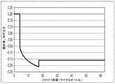
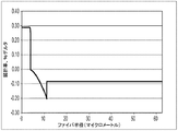
導波路ファイバの曲げ耐性は、規定された試験条件下で誘発される減衰によって;例えば規定された直径のマンドレルの周りにファイバを配備する又は巻き付けることによって;例えば直径6mm、10mm又は20mm等のマンドレルの周りに1回巻き付けて(例えば「1×10mm径マクロ曲げ損失」又は1×20mm径マクロ曲げ損失」)、1周あたりの減衰の増加を測定することによって、測定できる。 The bending resistance of a waveguide fiber is due to attenuation induced under defined test conditions; for example, by deploying or wrapping the fiber around a defined diameter mandrel; for example, a mandrel with a diameter of 6 mm, 10 mm or 20 mm, etc. Can be measured by measuring the increase in attenuation per round (for example, “1 × 10 mm diameter macro bending loss” or 1 × 20 mm diameter macro bending loss ”).
曲げ試験の1つのタイプは、側方荷重微小曲げ試験である。このいわゆる「側方荷重(lateral load)」試験(LLWM)では、規定の長さの導波路ファイバを2つの平坦なプレートの間に配置する。#70ワイヤメッシュを一方のプレートに取り付ける。既知の長さの導波路ファイバをプレート間に挟み、プレートを30ニュートンの力で押圧しながら基準減衰を測定する。次にプレートに70ニュートンの力を印加し、減衰の増加を単位dB/mで測定する。この減衰の増加は、所定の波長(典型的には1200〜1700nmの範囲内、例えば1310nm又は1550nm又は1625nm)における導波路の側方荷重減衰(単位dB/m)である。 One type of bending test is a side load microbending test. In this so-called “lateral load” test (LLWM), a specified length of waveguide fiber is placed between two flat plates. A # 70 wire mesh is attached to one plate. A waveguide fiber of known length is sandwiched between the plates, and the reference attenuation is measured while pressing the plates with a force of 30 Newtons. A force of 70 Newton is then applied to the plate and the increase in attenuation is measured in units of dB / m. This increase in attenuation is the lateral load attenuation (in dB / m) of the waveguide at a given wavelength (typically in the range of 1200-1700 nm, eg 1310 nm or 1550 nm or 1625 nm).
別のタイプの曲げ試験は、ワイヤメッシュ被覆ドラム微小曲げ試験(WMCD)である。この試験では、直径400mmのアルミニウムドラムにワイヤメッシュを巻き付ける。メッシュは引き伸ばされることなくしっかりと巻き付けられ、また孔、くぼみ又は損傷を有してはならない。ワイヤメッシュ材料の仕様:McMaster‐Carr Supply Company(オハイオ州クリーブランド)、部品番号85385T106、耐腐食タイプ304ステンレス鋼のワイヤ織布、平方インチあたりのメッシュ:165×165、ワイヤ直径0.0019インチ(0.04826mm)、開口の幅:0.0041インチ(0.10414mm)、開口面積%:44.0。規定の長さ(750メートル)の導波路ファイバを、80(+/−1)グラムの張力を印加しながら、0.050cmの巻き取りピッチで、ワイヤメッシュドラム上に1m/秒の速度で巻き付ける。上記規定の長さのファイバの端部は、張力を維持するためにテープで固定され、またファイバは交差しない。光ファイバの減衰を、所定の波長(典型的には1200〜1700nmの範囲内、例えば1310nm又は1550nm又は1625nm)で測定し;平滑なドラム上に巻き付けられた光ファイバに対して、基準減衰を測定する。この減衰の増加は、所定の波長(典型的には1200〜1700nmの範囲内、例えば1310nm又は1550nm又は1625nm)における導波路のワイヤメッシュ被覆ドラム減衰(単位dB/km)である。 Another type of bending test is the wire mesh coated drum microbending test (WMCD). In this test, a wire mesh is wound around an aluminum drum having a diameter of 400 mm. The mesh should be tightly wound without being stretched and should have no holes, indentations or damage. Wire Mesh Material Specification: McMaster-Carr Supply Company (Cleveland, Ohio), Part No. 85385T106, Corrosion Resistant Type 304 Stainless Steel Wire Woven Fabric, Mesh per Square Inch: 165 x 165, Wire Diameter 0.0019 Inch (0 0.04826 mm), opening width: 0.0041 inch (0.10414 mm), opening area%: 44.0. A specified length (750 meters) of waveguide fiber is wound on a wire mesh drum at a speed of 1 m / sec at a winding pitch of 0.050 cm while applying a tension of 80 (+/- 1) grams. . The ends of the defined length of fiber are taped to maintain tension and the fibers do not cross. Measure the attenuation of the optical fiber at a given wavelength (typically in the range of 1200-1700 nm, eg 1310 nm or 1550 nm or 1625 nm); measure the reference attenuation for an optical fiber wound on a smooth drum To do. This increase in attenuation is the wire mesh coated drum attenuation (in dB / km) of the waveguide at a given wavelength (typically in the range of 1200-1700 nm, eg 1310 nm or 1550 nm or 1625 nm).
「ピンアレイ(pin array)」曲げ試験を用いて、曲げに対する導波路ファイバの相対的な耐性を比較する。この試験を実施するために、曲げ損失が実質的に誘発されていない導波路ファイバに関して、減衰損失を測定する。次に導波路ファイバを、ピンアレイの周囲で織り上げ、減衰を再び測定する。曲げによって誘発された損失は、測定した2つの減衰の差である。ピンアレイは、平坦な表面上に1列に配設されて固定垂直位置に保持された、10個の円筒形ピンのセットである。ピンの間隔は中心間で5mmである。ピンの直径は0.67mmである。試験中、導波路ファイバをピン表面の部分に適合させるために、十分な張力を印加する。この減衰の増加は、所定の波長(典型的には1200〜1700nmの範囲内、例えば1310nm又は1550nm又は1625nm)における導波路のピンアレイ減衰(単位dB)である。 A “pin array” bend test is used to compare the relative resistance of waveguide fibers to bending. To perform this test, the attenuation loss is measured for a waveguide fiber in which no bending loss is substantially induced. The waveguide fiber is then woven around the pin array and the attenuation is measured again. The loss induced by bending is the difference between the two measured attenuations. The pin array is a set of ten cylindrical pins arranged in a row on a flat surface and held in a fixed vertical position. The pin spacing is 5 mm between the centers. The pin diameter is 0.67 mm. During testing, sufficient tension is applied to fit the waveguide fiber to the portion of the pin surface. This increase in attenuation is the pin array attenuation (in dB) of the waveguide at a given wavelength (typically in the range of 1200-1700 nm, eg 1310 nm, 1550 nm, or 1625 nm).
所与のモードに関する理論上のファイバカットオフ波長、又は「理論上のファイバカットオフ(theoretical fiber cutoff)」若しくは「理論上のカットオフ(theoretical cutoff)」は、それを超えると、導かれた光が当該モードにおいて伝播できなくなる波長である。数学的定義は、Single Mode Fiber Optics, Jeunhomme, pp. 39‐44、Marcel Dekker、New York、1990で確認でき、ここでは理論上のファイバカットオフは、モード伝播定数が外側クラッドの平面波伝播定数と等しくなる波長として説明されている。この理論上の波長は、直径の変動を有しない、無限に長く完全に真っ直ぐのファイバに当てはまる。 The theoretical fiber cutoff wavelength for a given mode, or “theoretical fiber cutoff” or “theoretical cutoff” above which the guided light Is a wavelength that cannot propagate in this mode. Mathematical definitions can be found in Single Mode Fiber Optics, Jeunhomme, pp. 39-44, Marcel Dekker, New York, 1990, where the theoretical fiber cutoff is described as the wavelength at which the mode propagation constant is equal to the plane wave propagation constant of the outer cladding. This theoretical wavelength applies to an infinitely long and perfectly straight fiber with no diameter variation.
ファイバカットオフは、標準2mファイバカットオフ試験FOTP‐80(EIA‐TIA‐455‐80)によって測定され、これによって「2mファイバカットオフ(2m fiber cutoff)」又は「測定カットオフ(measured cutoff)」としても知られる「ファイバカットオフ波長(fiber cutoff wavelength)」が得られる。FOTP‐80標準試験は、制御された曲げ量を用いて高次モードを除去するため、又はファイバのスペクトル応答をマルチモードファイバのスペクトル応答に対して正規化するために実施される。 The fiber cut-off is measured by the standard 2m fiber cut-off test FOTP-80 (EIA-TIA-455-80), which makes it a “2m fiber cutoff” or “measured cutoff”. The "fiber cut-off wavelength", also known as The FOTP-80 standard test is performed to remove higher order modes using a controlled amount of bending or to normalize the spectral response of the fiber to the spectral response of a multimode fiber.
本明細書中で使用される「ケーブル接続カットオフ波長(cabled cutoff wavelength)」又は「ケーブル接続カットオフ(cabled cutoff)」は、EIA‐TIAファイバ光学標準(EIA‐TIA Fiber Optics Standards)、即ちエレクトロニクス産業連合‐遠距離通信産業境界ファイバ光学標準(Electronics Industry Alliance ‐ Telecommunications Industry Association Fiber Optics Standards)の一部であるEIA‐445ファイバ光学試験手順に記載された22mケーブル接続カットオフ試験を意味する。 As used herein, “cable cut-off wavelength” or “cable cut-off” is EIA-TIA Fiber Optics Standards, ie, electronics. 22m cable cut off EIA-445 fiber optical test procedure, which is part of the EIA-445 fiber optical test procedure, which is part of the Electronics Industry Alliance-Telecommunications Industry Fiber Optics Standards.
本明細書中に特段の記載がない限り、光学特性(分散、分散勾配等)は、LP01モードに関して報告される。 Unless otherwise noted herein, optical properties (dispersion, dispersion slope, etc.) are reported for the LP01 mode.
いくつかの実施形態によると、光ファイバは:
(i)コアアルファ>10及び最大屈折率デルタΔ1maxを有する、塩素ドープシリカベースコア;
(ii)上記コアを取り囲むクラッドであって:
a.内側クラッド領域であって、上記コアに隣接して接触し、屈折率デルタΔ2及び最大屈折率デルタΔ2minを有し、Δ2min<Δ1maxであり、上記内側クラッド領域はフッ素(F)でドープされ、上記内側クラッド領域の上記屈折率デルタΔ2は、径方向位置と共に減少する、内側クラッド領域;及び
b.上記内側クラッド領域を取り囲み、屈折率デルタΔ3を有し、Δ2min<Δ3である、外側クラッド領域
を備える、クラッド
を備え、
上記光ファイバは:9マイクロメートル超の、1310nmでのモードフィールド直径MFD;1260nm未満のケーブルカットオフ;約1300nm〜約1324nmのゼロ分散波長;及び0.5dB/turn未満の、20mmマンドレルに関する1550nmでの曲げ損失を有する。
According to some embodiments, the optical fiber is:
(I) a chlorine-doped silica-based core having a core alpha> 10 and a maximum refractive index delta Δ1max ;
(Ii) a clad surrounding the core:
a. An inner cladding region, in contact adjacent to the core has a refractive index delta delta 2 and maximum refractive index delta delta 2min, a delta 2min <delta 1max, the inner cladding region is fluorine (F) An inner cladding region that is doped and the refractive index delta Δ 2 of the inner cladding region decreases with radial position; and b. Surrounds the inner cladding region has a refractive index delta delta 3, a delta 2min <delta 3, an outer cladding region comprises a cladding,
The optical fiber is: greater than 9 micrometers, mode field diameter MFD at 1310 nm; cable cutoff less than 1260 nm; zero dispersion wavelength from about 1300 nm to about 1324 nm; and 1550 nm for a 20 mm mandrel less than 0.5 dB / turn Bend loss.
いくつかの実施形態によると、コアはシリカガラスを含み、好ましくは1重量%超の塩素、より好ましくは1.2重量%超の塩素を含む。いくつかの実施形態では、コアは、1.5重量%超の塩素及び0.5重量%未満のフッ素を含む。 According to some embodiments, the core comprises silica glass, preferably greater than 1 wt% chlorine, more preferably greater than 1.2 wt% chlorine. In some embodiments, the core comprises greater than 1.5 wt% chlorine and less than 0.5 wt% fluorine.
いくつかの実施形態によると、コアアルファは少なくとも20(例えばα≧50又はα≧70又はα≧80又はα≧100)である。少なくともいくつかの実施形態によると、内側クラッド領域の屈折率デルタΔ2は、外側クラッド領域に向かって単調減少する(即ちファイバの中心線からの径方向距離が増大するに従って減少する)。即ちいくつかの実施形態では、内側クラッド領域のΔ2は、この領域内の半径rが大きくなるに従って、より大きく単調減少する。 According to some embodiments, the core alpha is at least 20 (eg, α ≧ 50 or α ≧ 70 or α ≧ 80 or α ≧ 100). According to at least some embodiments, the refractive index delta delta 2 of the inner cladding region, (decreases as i.e. the radial distance from the center line of the fiber increases) monotonically decreases toward the outer cladding region. That is, in some embodiments, Δ 2 of the inner cladding region decreases more and monotonically as the radius r in this region increases.
いくつかの実施形態によると、光ファイバは、屈折率デルタΔ2を有する内側クラッド領域を備え、内側クラッド領域の、径方向位置と共に減少する部分の屈折率デルタΔ2は、コアからオフセットされている(即ち内側クラッド領域はコアと直接接触しておらず、オフセット領域によってコアから隔てられている)。この光ファイバの一実施形態が図4及び5に示されており、これは例16のファイバに相当する。いくつかの実施形態によると、上記オフセット(例えばこの実施形態では、オフセットはr1とr2aとの間の距離であり、即ちオフセット=r2a−r1である)は、1マイクロメートル≦オフセット≦15マイクロメートルである。いくつかの実施形態によると、オフセットは、2マイクロメートル≦オフセット≦12マイクロメートルである。いくつかの実施形態によると、オフセットは、3マイクロメートル≦オフセット≦10マイクロメートルである。 According to some embodiments, the optical fiber includes an inner cladding region having a refractive index delta delta 2, of the inner cladding region, the refractive index delta delta 2 of the portion decreases with radial position, is offset from the core (Ie, the inner cladding region is not in direct contact with the core and is separated from the core by an offset region). One embodiment of this optical fiber is shown in FIGS. 4 and 5, which corresponds to the fiber of Example 16. According to some embodiments, the offset (eg, in this embodiment, the offset is the distance between r 1 and r 2a , ie, offset = r 2a −r 1 ) is 1 micrometer ≦ offset ≦ 15 micrometers. According to some embodiments, the offset is 2 micrometers ≦ offset ≦ 12 micrometers. According to some embodiments, the offset is 3 micrometers ≦ offset ≦ 10 micrometers.
少なくともいくつかの実施形態によると、ファイバコアは外半径r1を有し、3.0μm≦r1≦5.0μmである。例えばいくつかの実施形態では、3μm≦r1≦4μm、3μm≦r1≦4.5μm、又は3.3μm≦r1≦4.5μmである。 According to at least some embodiments, the fiber core has an outer radius r 1 and 3.0 μm ≦ r 1 ≦ 5.0 μm. For example, in some embodiments, 3 μm ≦ r 1 ≦ 4 μm, 3 μm ≦ r 1 ≦ 4.5 μm, or 3.3 μm ≦ r 1 ≦ 4.5 μm.
少なくともいくつかの実施形態によると内側クラッド領域は最大屈折率デルタΔ2maxを有し、外側クラッドの屈折率デルタはΔ2maxより小さくなる(即ちΔ3<Δ2maxである)。 According to at least some embodiments, the inner cladding region has a maximum refractive index delta Δ 2max , and the outer cladding's refractive index delta is less than Δ 2max (ie, Δ 3 <Δ 2max ).
少なくともいくつかの実施形態によると、0.1%≦Δ1max≦0.35%であり、また0.35%≦Δ2min<0%である。少なくともいくつかの実施形態によると、コアは外半径r1を有し、3μm≦r1≦4μmであり;内側クラッド領域は外半径r2を有し、6.5μm≦r2≦20μmであり、また−0.35%≦Δ2min<0%である。少なくともいくつかの実施形態では、Δ3−Δ2minは0.03%〜0.9%、例えば0.03%〜0.85%(例えば0.4%、0.5%、0.6%、0.7%、0.8%、0.85%、又はこれらの間の値)である。 According to at least some embodiments, a 0.1% ≦ Δ 1max ≦ 0.35% , also a 0.35% ≦ Δ 2min <0% . According to at least some embodiments, the core has an outer radius r 1 and 3 μm ≦ r 1 ≦ 4 μm; the inner cladding region has an outer radius r 2 and 6.5 μm ≦ r 2 ≦ 20 μm Also, −0.35% ≦ Δ 2min <0%. In at least some embodiments, Δ 3 −Δ 2 min is 0.03% to 0.9%, such as 0.03% to 0.85% (eg, 0.4%, 0.5%, 0.6%). , 0.7%, 0.8%, 0.85%, or a value between them).
内側クラッド領域2は2つの領域に挟まれている。即ち内側クラッド領域2は、コア1と外側クラッド領域3との間に挟まれている。内側クラッド領域2は、コアの最小屈折率デルタ及び外側クラッド領域3の最小屈折率デルタより小さな最小屈折率デルタΔ2minを有する。即ちΔ2minは、コア1の最小屈折率デルタ及び外側クラッド領域3の最小屈折率デルタより小さい。よって、図1A、1B、1C、2及び3の例示的実施形態では、内側クラッド領域2は、Δ2minがコア1の最小屈折率(r=r1において発生する)より小さく、かつ外側クラッド3の最小屈折率デルタより小さいため、トレンチとなる。本明細書に記載の例示的実施形態では、外側クラッドの屈折率デルタは略一定であり、即ちΔ3≒Δ3minであり、従ってΔ2min<Δ3かつΔ2min<Δ1(r1)である。
The
いくつかの実施形態によると、内側クラッド2は、トレンチ容積VTを有し、3%Δマイクロメートル2≦VT≦12%Δマイクロメートル2である(なお、トレンチ容積VTは式4によって定義される)。
According to some embodiments, the
いくつかの実施形態では、内側クラッド領域2は最大屈折率デルタΔ2maxを有し、0.03≦(Δ2max−Δ2min)≦0.6である。いくつかの実施形態では0.03≦(Δ2max−Δ2min)≦0.4である。いくつかの実施形態では0.03≦(Δ2max−Δ2min)≦0.3である。内側クラッドは外半径r2を有する。少なくともいくつかの実施形態では2≦(r2−r1)≦15であり、いくつかの実施形態では3≦(r2−r1)≦13.5であり、いくつかの実施形態では3≦(r2−r1)≦10であり、いくつかの実施形態では3≦(r2−r1)≦8.5である。いくつかの実施形態では、本明細書で開示される光ファイバは、1550nmにおいてシングルモードであり、1550nmにおいて約60マイクロメートル2超の有効面積Aeffを示し、いくつかの実施形態では60マイクロメートル2≦Aeff≦100マイクロメートル2であり、いくつかの実施形態では75マイクロメートル2≦Aeff≦90マイクロメートル2である。
In some embodiments, the
図1A、1B、1C、2及び3に示すような例示的なファイバ10は、最大屈折率デルタパーセントΔ1maxを備えるガラスコア1を含む。屈折率が下降した内側クラッド領域2はコア1を取り囲み、内側クラッド領域2は屈折率デルタパーセントΔ2minを備え、Δ1max>Δ2minである。内側クラッド領域2は好ましくは、ガラスコア1の直近に隣接する。ガラスコア1はシリカガラスを含み、好ましくは1.5重量%超の塩素及び0.5重量%未満のフッ素を含む。GeO2はシリカよりレイリー散乱が大きいため、いくつかの実施形態ではガラスコア1は、1重量パーセント未満のGeO2を含み、いくつかの実施形態では0.5重量%未満のGeO2を含み、いくつかの実施形態では0.2重量%未満のGeを含み、いくつかの実施形態ではGeO2を含まない。いくつかの実施形態では、コア1は、2重量%超の塩素でドープされたシリカガラスを含む。他のいくつかの実施形態では、コア1は、2.5重量%超の塩素でドープされたシリカガラスを含む。他のいくつかの実施形態では、コア1は、3重量%超の塩素でドープされたシリカガラスを含む。更に他の実施形態では、コア1は、2.5重量%超の塩素でドープされたシリカガラスを含み、好ましくはフッ素を基本的に含まない。内側クラッド領域2は、フッ素でドープされたシリカを含む。項Clcoreは、コア1中の塩素ドーパント量(モル%)の最大量を表し、項Finner cladは、内側クラッド領域2中のフッ素ドーパント量(モル%)の最大量を表す。いくつかの実施形態では、内側クラッド領域2中のフッ素に対するコア領域1中の塩素の重量比(WR)(即ちClcore/Finner clad)は、好ましくは1超であり、いくつかの実施形態では1.5超であり、いくつかの実施形態では2超であり、いくつかの実施形態では2.5超であり、いくつかの実施形態では3.0超である。いくつかの実施形態では、内側クラッド領域2中のフッ素に対するコア領域1中の塩素の重量比(WR)(即ちClcore/Finner clad)は、1〜25、例えば1.5〜23である。いくつかの実施形態では、1.5≦WR≦15(例えば1.6、1.75、2、2.25、3、3.3、3.5、4、5、7、8、10、11、12、又はこれらの間の値のWR)である。
An
いくつかの実施形態ではコア1は、1.5重量%超の塩素及び0.6重量%未満のフッ素、他の実施形態では2.0重量%超の塩素、他の実施形態では2.5重量%超の塩素、他の実施形態では3.0重量%超の塩素を含んでよい。コア1は、0.5重量%未満のフッ素、いくつかの実施形態では0.25重量%未満のフッ素を含んでよい。いくつかの実施形態では、コア1はフッ素を基本的に含まない。
In some embodiments, the
コア1は、約0.1%Δ〜約0.5%Δ、いくつかの実施形態では約0.12%Δ〜0.4%Δ、他の実施形態では約0.15%Δ〜0.35%Δの、最大屈折率デルタパーセントΔ1maxを有する。少なくともいくつかの実施形態では、コア半径r1は3〜5マイクロメートル、いくつかの実施形態では約3〜4マイクロメートルである。コア1は、単一セグメントの階段状屈折率プロファイルを備えてよい。上述のように、いくつかの実施形態では、コア1は10超のアルファα(例えば10≦α≦200、又は10≦α≦100、又は20≦α≦100、又は50≦α≦100、又は50≦α≦500)を示す。例えばいくつかの実施形態では、コアアルファ(即ちα)は20超かつ200以下である。
図1A、1B及び1Cに示す実施形態では、内側クラッド領域2はコア1を取り囲み、内半径r1及び外半径r2を備え、r1及びr2は、Δ2minにおける半径として定義される。内側クラッド領域2は、0.15重量%超のフッ素、いくつかの実施形態では≧0.25重量%のフッ素、いくつかの実施形態では≧0.35重量%のフッ素を含んでよく、いくつかの実施形態では2.3重量パーセント未満のフッ素、いくつかの実施形態では≧0.35重量%かつ≦1重量%のフッ素を含有する。
In the embodiment shown in FIGS. 1A, 1B and 1C, the
図1A、1B、1C、2及び3は、ファイバが、内側クラッド領域2を取り囲む外側クラッド領域3を備え、外側クラッド領域3は平均屈折率デルタΔ3を有し、Δ1max>Δ3>Δ2minである、実施形態を示す。外側クラッド領域3は最大屈折率デルタΔ3maxを有する(上述のように、図1A、1B、1C、2及び3に対応するファイバの実施形態では、外側クラッド領域3の屈折率デルタは略一定であり、従ってこれらの実施形態では、Δ3≒Δ3maxである。図1A、1B及び1Cの実施形態では、外側クラッド3の屈折率は、純シリカに対してダウンドープされている。
1A, 1B, 1C, 2 and 3, the fiber comprises an
内側クラッド領域2は、最大相対屈折率Δ2maxを有する。内側クラッド領域2は屈折率デルタ勾配(本明細書ではトレンチ勾配又はTSとも呼ばれる)を有し、TS=(Δ2max−Δ2min)/(r2−r1)であり、少なくともいくつかの実施形態では0.005%Δ/マイクロメートル<TS<0.2%Δ/マイクロメートルである。内側クラッド領域2はアルファ値αTを有し、0.2<αT<5である。
The
図2のファイバにおいて示すように、外側クラッド領域3の屈折率は、外側クラッド領域3を形成するための材料として非ドープSiO2を用いることによって達成できるように、非ドープSiO2の屈折率に等しい。図1A、1B、1C及び3のファイバでは、外側クラッド領域3の屈折率は、外側クラッド領域3を形成するための材料としてフッ素ドープSiO2を用いることによって達成できるように、非ドープSiO2の屈折率未満である。
As shown in the fiber of FIG. 2, the refractive index of the
図3のファイバの実施形態では、外側クラッド領域4(第2の外側クラッド)が外側クラッド領域3を取り囲む。このファイバの実施形態では、外側クラッド領域4の屈折率は、非ドープSiO2の屈折率に等しい(本明細書では、この実施形態において、外側クラッド領域4はシリカ外側層とも呼ばれる)。あるいはいくつかの実施形態では、外側クラッド領域4の屈折率は、外側クラッド領域4を形成するための材料としてSiONドープ又は塩素ドープSiO2を用いることによって達成できるように、非ドープSiO2の屈折率より大きくすることができる。よって上述のように、外側クラッド領域4はSiO2又はSiONからなってよい。
In the fiber embodiment of FIG. 3, the outer cladding region 4 (second outer cladding) surrounds the
これらの実施形態それぞれにおいて、内側クラッド領域2は、15マイクロメートル未満、いくつかの実施形態では2〜10マイクロメートル、いくつかの実施形態では約3〜10マイクロメートル(例えば3〜8.5マイクロメートル)の幅w(w=r2−r1)を示してよい。本明細書に記載の各実施形態では、外側クラッド領域3は、少なくとも20マイクロメートルの幅r3−r2を示す。いくつかの実施形態では、r3は30超、40マイクロメートル超、45マイクロメートル超、又は50マイクロメートル超、かつ65マイクロメートル以下であってよい。いくつかの実施形態では、r3は、30マイクロメートル超かつ50マイクロメートル未満(例えば、35マイクロメートル≦r3≦45マイクロメートル)であってよく、r4は、45マイクロメートル超又は50マイクロメートル、例えば50マイクロメートル超かつ65マイクロメートル以下(例えば62.5マイクロメートル)であってよい。好ましくは、外側クラッド領域3の(内側クラッド領域2に比べて)屈折率が高い部分は少なくとも、光ファイバを通して伝送された後の光出力が、伝送対象の光出力の90%以上となる点、より好ましくは、光ファイバを通して伝送された後の光出力が、伝送対象の光出力の95以上となる点、最も好ましくは、光ファイバを通して伝送された後の光出力が、伝送対象の光出力の98%以上となる点まで延在する。多くの実施形態では、これは、外側クラッド領域3を、少なくとも約30マイクロメートルの径方向地点まで延在させることによって達成される。いくつかの実施形態では、外側クラッド領域3は、内側クラッド領域2の塩素の量と比較した場合に、重量に関して、200ppm超、例えば400又は700又は1000ppm以上、いくつかの実施形態では好ましくは1500ppm超、いくつかの実施形態では2000ppm(0.2%)超(例えば2200ppm、2500ppm、3000ppm、4000ppm、5000ppm、6000ppm、10000ppm又はこれらの間の値)の量の塩素(Cl)を含む。
In each of these embodiments, the
以下の実施例によって、様々な実施形態を更に明らかにする。 Various embodiments will be further clarified by the following examples.
以下の表1は、例示的なファイバのモデル化された実施形態1〜4、4a及び5に関するパラメータを示す。表1に記載のファイバの実施形態1〜4、4A及び5は、図1Aの屈折率プロファイルを有するファイバに対応する。ファイバの実施形態4Aは図1Bに対応する。表1で開示されている例1〜4、4a及び5のファイバの実施形態は、塩素ドープシリカベースコア1、フッ素でドープされたシリカベース内側クラッド領域2(内側クラッドの屈折率はフッ素濃度の上昇によって径方向位置と共に減少する(より負になる))、及び内側クラッド領域2を取り囲むフッ素ドープ外側クラッド領域3を有する。外側クラッド領域3は屈折率デルタΔ3を有し、Δ2min<Δ3である。本明細書に記載の光ファイバは、外付け蒸着(OVD)、気相軸付け(VAD)、内付け化学蒸着(MCVD)及び/又はプラズマ蒸着(PCVD)プロセスによって製造できる。
Table 1 below shows the parameters for example fiber modeled embodiments 1-4, 4a and 5. Fiber embodiments 1-4, 4A and 5 listed in Table 1 correspond to fibers having the refractive index profile of FIG. 1A. Fiber embodiment 4A corresponds to FIG. 1B. The fiber embodiments of Examples 1-4, 4a and 5 disclosed in Table 1 include a chlorine-doped
表1のファイバの実施形態は、G.652/G.657仕様に適合し:9マイクロメートル超の1310nmでのMFD;1300nm≦λ0≦1324nmのゼロ分散波長λ0;1260nm未満のケーブルカットオフ;0.5dB/turn未満の、直径20mmのマンドレルに関する1550nmでの曲げ損失;及び0.01dB/turn未満の、直径30mmのマンドレルに関する1550nmでの曲げ損失を有する。例1〜5のファイバの実施形態は:塩素ドープシリカベースコア1;フッ素でドープされたシリカベース内側クラッド領域2(上記内側クラッドの屈折率(及びこれに伴って屈折率デルタ)は、径方向位置と共に減少し(より負になり)、上記内側クラッドのアルファプロファイルαTは1であり、上記内側クラッドは0.005%Δ/マイクロメートル<TS<0.2%Δ/マイクロメートルであるトレンチ勾配TS=(Δ2max−Δ2min)/(r2−r1)を有する);並びにフッ素ドープ外側クラッド領域3を有する。これらのプロファイルは、3%Δマイクロメートル2超のトレンチ容積を有する(即ちVT>3%Δマイクロメートル2である)。より具体的には、表1の実施形態では、例示的なファイバは、3%Δマイクロメートル2<VT≦12%Δマイクロメートル2を有する。
The fiber embodiments of Table 1 are described in G. 652 / G. Meets 657 specification: MFD at 1310 nm above 9 micrometers; zero dispersion wavelength λ 0 at 1300 nm ≦ λ 0 ≦ 1324 nm; cable cutoff below 1260 nm; 1550 nm for a mandrel with a diameter of 20 mm less than 0.5 dB / turn And a bending loss at 1550 nm for a 30 mm diameter mandrel of less than 0.01 dB / turn. The fiber embodiments of Examples 1-5 are: Chlorine doped
以下の表2は、例示的なファイバのモデル化された実施形態6〜9に関するパラメータを示す。例6〜8のファイバの実施形態は、図1に示す屈折率プロファイルを有する。例6〜8のファイバの実施形態は:塩素ドープシリカベースコア;フッ素でドープされたシリカベース内側クラッド領域(上記内側クラッドの屈折率は径方向位置と共に減少する(即ちF濃度の上昇によってより負になる));及びこれもまたフッ素を含むシリカベース外側クラッド領域3を有する。例9のファイバの実施形態は、図2に示す屈折率プロファイルを有する。例9のファイバの実施形態は:塩素ドープコア;フッ素でドープされたシリカベース内側クラッド領域(上記内側クラッド2の屈折率は径方向位置と共に減少する(即ちより負になる));及び基本的にシリカSiO2で構成される外側クラッド領域3を有する(即ちこの実施形態の外側クラッド領域3は基本的に純シリカであり、いずれのドーパントも含まない)。
Table 2 below shows the parameters for exemplary fiber modeled embodiments 6-9. The fiber embodiments of Examples 6-8 have the refractive index profile shown in FIG. The fiber embodiments of Examples 6-8 are: Chlorine doped silica base core; Fluorine doped silica base inner cladding region (the refractive index of the inner cladding decreases with radial position (ie, more negative with increasing F concentration) Which also has a silica-based
表2のファイバの実施形態は、G.652/G.657仕様に適合し:9マイクロメートル超の1310nmでのMFD;1300nm≦λ0≦1324nmのゼロ分散波長λ0;1260nm未満のケーブルカットオフ;並びにそれぞれ0.5dB/turn及び0.01dB/turn未満の、直径20mm及び30mmのマンドレルに関する1550nmでの曲げ損失を有する。例6〜9のファイバの実施形態は:塩素ドープシリカベースコア1;フッ素でドープされたシリカベース内側クラッド領域2(上記内側クラッドの屈折率は、径方向位置と共に減少し(より負になり)、上記内側クラッドのアルファプロファイルαTは1であり、上記内側クラッドは0.005%Δ/マイクロメートル<TS<0.2%Δ/マイクロメートルであるトレンチ勾配TS=(Δ2max−Δ2min)/(r2−r1)を有する);及びフッ素ドープ外側クラッド領域3を有する。これらのプロファイルは、3%Δマイクロメートル2超のトレンチ容積を有する。より具体的には、表2の実施形態では、例示的なファイバは、3%Δマイクロメートル2<VT≦12%Δマイクロメートル2を有する。
The fiber embodiments of Table 2 are described in G. 652 / G. Meets 657 specifications: MFD at 1310 nm above 9 micrometers; zero dispersion wavelength λ 0 at 1300 nm ≦ λ 0 ≦ 1324 nm; cable cutoff below 1260 nm; and below 0.5 dB / turn and 0.01 dB / turn, respectively With a bending loss at 1550 nm for 20 mm and 30 mm diameter mandrels. The fiber embodiments of Examples 6-9 are: Chlorine doped
以下の表3は、例示的なファイバのモデル化された実施形態10〜12に関するパラメータを示す。 Table 3 below shows the parameters for example fiber modeled embodiments 10-12.
表3のファイバの実施形態は、G.652/G.657仕様に適合し:9マイクロメートル超の1310nmでのMFD;1300nm≦λ0≦1324nmのゼロ分散波長λ0;1260nm未満のケーブルカットオフ;並びにそれぞれ0.5dB/turn及び0.01dB/turn未満の、直径20mm及び30mmのマンドレルに関する1550nmでの曲げ損失を有する。例10〜12のファイバの実施形態は:塩素ドープシリカベースコア1;フッ素でドープされたシリカベース内側クラッド領域2(上記内側クラッドの屈折率は、径方向位置と共に減少し(より負になり)、上記内側クラッドのアルファプロファイルαTは1であり、上記内側クラッドは0.005%Δ/マイクロメートル<TS<0.2%Δ/マイクロメートルであるトレンチ勾配TS=(Δ2max−Δ2min)/(r2−r1)を有する);フッ素ドープ外側クラッド領域3;及び上記第1の外側クラッドを取り囲む、非ドープシリカの第2の外側クラッドを有する。これらのプロファイルは、3%Δマイクロメートル2超のトレンチ容積を有する。より具体的には、表3の実施形態では、例示的なファイバは、3%Δマイクロメートル2<VT≦12%Δマイクロメートル2を有する。これらの例示的実施形態の第2の外側クラッドは、基本的に純シリカで作製される。
The fiber embodiments of Table 3 are described in G. 652 / G. Meets 657 specifications: MFD at 1310 nm above 9 micrometers; zero dispersion wavelength λ 0 at 1300 nm ≦ λ 0 ≦ 1324 nm; cable cutoff below 1260 nm; and below 0.5 dB / turn and 0.01 dB / turn, respectively With a bending loss at 1550 nm for 20 mm and 30 mm diameter mandrels. The fiber embodiments of Examples 10-12 are: Chlorine doped
以下の表4は、例示的なファイバのモデル化された実施形態13〜15に関するパラメータを示す。ファイバの実施形態13は図1Bに対応する。ファイバの実施形態14〜15は図1Cに対応する。
Table 4 below shows the parameters for exemplary fiber modeled embodiments 13-15.
例10〜12のファイバの実施形態は:塩素ドープシリカベースコア1;フッ素でドープされたシリカベース内側クラッド領域2(上記内側クラッドの屈折率は、径方向位置と共に減少する(より負になる));フッ素ドープ外側クラッド領域3;及び外側クラッド領域3を取り囲む追加のシリカ外側クラッド領域4(即ち第2の外側クラッド)を有する。これらのファイバの実施形態の屈折率プロファイルは、図3に示されている。例13〜15のファイバの実施形態は:塩素ドープシリカベースコア1;フッ素でドープされたシリカベース内側クラッド領域2(上記内側クラッドの屈折率は径方向位置と共に減少し(より負になり)、上記内側クラッドのアルファプロファイルαTは、例13に関しては0.3<αT<1、例14及び15に関しては1<αT<5であり、上記内側クラッドは0.005%Δ/マイクロメートル<TS<0.2%Δ/マイクロメートルであるトレンチ勾配TS=(Δ2max−Δ2min)/(r2−r1)を有する);並びにフッ素ドープ外側クラッド領域3を有する。これらのファイバの実施形態の屈折率は、図3に示されている。表4のファイバの実施形態は、G.652/G.657仕様に適合し:9マイクロメートル超の1310nmでのMFD;1300nm≦λ0≦1324nmのゼロ分散波長λ0;1260nm未満のケーブルカットオフ;並びにそれぞれ0.5dB/turn及び0.01dB/turn未満の、直径20mm及び30mmのマンドレルに関する1550nmでの曲げ損失を有する。これらのプロファイルは、3%Δマイクロメートル2超のトレンチ容積を有する。より具体的には、表4の実施形態では、例示的なファイバは、3%Δマイクロメートル2<VT≦12%Δマイクロメートル2を有する。
The fiber embodiments of Examples 10-12 are: Chlorine doped
以下の表5は、例示的なファイバのモデル化された実施形態16に関するパラメータを示す。ファイバの実施形態16(例16のファイバ)は、図4及び5に対応する。 Table 5 below shows the parameters for an exemplary fiber modeled embodiment 16. Fiber embodiment 16 (Example 16 fiber) corresponds to FIGS.
例16のファイバの実施形態は:塩素ドープシリカベースコア1;非ドープシリカを含む第1の部分及びフッ素でドープされた第2の領域を有する、シリカベース内側クラッド領域2(上記内側クラッドの屈折率は径方向位置と共に減少する(より負になる)(即ち径方向位置と共に減少する(より負になる)内側クラッド領域は、コアからオフセットされる));並びに内側クラッド領域2を取り囲むシリカ外側クラッド領域3を有する。このファイバの実施形態の屈折率プロファイルは、図5に示されている。例16のファイバの実施形態は、1であるトレンチアルファ(本明細書では内側クラッドアルファとも呼ばれる)αT、いくつかの実施形態では0.3<αT<5であるαTを有し、内側クラッドは、0.005%Δ/マイクロメートル<TS<0.2%Δ/マイクロメートルであるトレンチ勾配TS=(Δ2max−Δ2min)/(r2−r2a)を有する。径方向位置と共に減少する(より負になる)内側クラッド領域は、1マイクロメートル≦オフセット≦15マイクロメートルだけオフセットされ、より具体的にはオフセットは2マイクロメートル≦オフセット≦12マイクロメートルであり、より具体的にはオフセットは3マイクロメートル≦オフセット≦10マイクロメートルである。表5のファイバの実施形態は、G.652/G.657仕様に適合し:9マイクロメートル超の1310nmでのMFD;1300nm≦λ0≦1324nmのゼロ分散波長λ0;1260nm未満のケーブルカットオフ;並びにそれぞれ0.5dB/turn及び0.01dB/turn未満の、直径20mm及び30mmのマンドレルに関する1550nmでの曲げ損失を有する。これらのプロファイルは、3%Δマイクロメートル2超のトレンチ容積を有する。より具体的には、表5の実施形態では、例示的なファイバは、3%Δマイクロメートル2<VT≦12%Δマイクロメートル2を有する。
The fiber embodiment of Example 16 comprises: a silica-based
ファイバの実施形態1〜16は、存在するClの量が大きいため、減衰が低減されている。というのは、Clは、GeO2又はTiO2といった他のドーパントに対して、レイリー散乱損失が小さいためである。本明細書で開示された例示的なファイバの実施形態はまた、高いアルファコア(コアアルファ、α≧10)を有する。本明細書で開示される例示的な光ファイバの実施形態は、コア1と内側クラッド領域2(径方向距離の増大と共に屈折率がより負になるクラッド領域)との間に位置する更なる内側クラッド領域を有しない。即ちこの実施形態では、内側クラッド領域2はコア1に直接隣接して接触する。これにより、ファイバを容易かつ安価に製造できるようにしながら、ファイバの良好な曲げ性能の達成、他の性能要件の達成を支援する。更に本明細書で開示された実施形態は、Ge濃度が低いこと、及びコア1と内側クラッド領域2との間の粘度が一致することにより、レイリー散乱が小さい。外側クラッド領域3は、内側クラッド領域2に比べて高い屈折率を有し、これによりマクロ曲げ損失の最小化が支援される。外側クラッド領域3の平均屈折率デルタと内側クラッド領域2の最小屈折率デルタとの間の絶対差(即ち|Δ2min−Δ3|)は、0.005%Δ超、より好ましくは0.015%Δ超、更に好ましくは0.025%Δ超である。
Fiber embodiments 1-16 have reduced attenuation due to the large amount of Cl present. This is because Cl has less Rayleigh scattering loss than other dopants such as GeO 2 or TiO 2 . The exemplary fiber embodiments disclosed herein also have a high alpha core (core alpha, α ≧ 10). The exemplary optical fiber embodiments disclosed herein include a further inner side located between the
有利には、本明細書で開示されるファイバは、コアに、クラッドの粘度以下の粘度を提供する。これにより、粘度の不一致が低減されるだけでなく、CTE(熱膨張係数)の不一致も低減されるため、ファイバ内の応力が低減され、これに対応してファイバの減衰が低減される。 Advantageously, the fibers disclosed herein provide the core with a viscosity less than that of the cladding. This not only reduces viscosity mismatch, but also reduces CTE (thermal expansion coefficient) mismatch, thereby reducing stress in the fiber and correspondingly reducing fiber attenuation.
特段の記載がない限り、本明細書に記載のいずれの方法が、その複数のステップをある特定の順序で実施することを必要とするものとして解釈されることは、全く意図されていない。従って、ある方法クレームが、その複数のステップが従うべき順序を実際に列挙していない場合、又は上記複数のステップをある特定の順序に限定するべきであることが、特許請求の範囲若しくは説明中で具体的に言明されていない場合、いずれの特定の順序が推定されることは全く意図されていない。 Unless otherwise stated, it is not intended that any method described herein be interpreted as requiring that the steps be performed in a particular order. Therefore, in the claims or description that a method claim does not actually list the order in which the steps should be followed, or that the steps should be limited to a particular order. It is not intended at all that any particular order be inferred.
本発明の精神又は範囲から逸脱することなく、様々な修正及び変更を実施できることは、当業者には明らかであろう。本発明の精神及び本質を組み込んだ、本開示の実施形態の修正、組み合わせ、部分的組み合わせ及び変更は、当業者に想起され得るものであるため、本発明は、添付の請求項及びその均等物の範囲内の全てを含むものと解釈されるものとする。 It will be apparent to those skilled in the art that various modifications and variations can be made without departing from the spirit or scope of the invention. Since modifications, combinations, subcombinations and changes of the embodiments of the present disclosure that incorporate the spirit and essence of the present invention may occur to those skilled in the art, the present invention includes the appended claims and their equivalents. It shall be construed to include everything within the scope of.
以下、本発明の好ましい実施形態を項分け記載する。 Hereinafter, preferable embodiments of the present invention will be described in terms of items.
実施形態1
(i)コアアルファ(αcore)>10、最大屈折率デルタΔ1max、及びCl濃度>1重量%を有する、塩素ドープシリカベースコア;
(ii)上記コアを取り囲むクラッドであって:
a.内側クラッド領域であって、フッ素ドープシリカを含み、上記コアに隣接して接触し、屈折率デルタΔ2及び最大屈折率デルタΔ2minを有し、Δ2min<Δ1maxであり、上記内側クラッド領域の上記屈折率デルタΔ2は、径方向位置と共に減少する領域を含む、内側クラッド領域;及び
b.上記内側クラッド領域を取り囲み、屈折率デルタΔ3を有し、Δ2min<Δ3である、外側クラッド領域
を含む、クラッド
を備える、光ファイバであって、
上記光ファイバは:≧9マイクロメートルの、1310nmでのモードフィールド直径MFD;≦1260nmのケーブルカットオフ;1300nm≦ゼロ分散波長≦1324nmである、ゼロ分散波長;及び0.5dB/turn未満の、20mmマンドレルに関する1550nmでの曲げ損失を有する、光ファイバ。
(I) a chlorine-doped silica base core having a core alpha (α core )> 10, a maximum refractive index delta Δ 1max , and a Cl concentration> 1 wt%;
(Ii) a clad surrounding the core:
a. An inner cladding region comprises fluorine-doped silica, contacts adjacent to the core has a refractive index delta delta 2 and maximum refractive index delta delta 2min, a delta 2min <delta 1max, of the inner cladding region An inner cladding region comprising a region where the refractive index delta Δ 2 decreases with radial position; and b. Surrounds the inner cladding region has a refractive index delta delta 3, a delta 2min <delta 3, includes an outer cladding region comprises a clad, an optical fiber,
The optical fiber is: ≧ 9 micrometers, mode field diameter MFD at 1310 nm; cable cutoff of ≦ 1260 nm; 1300 nm ≦ zero dispersion wavelength ≦ 1324 nm, zero dispersion wavelength; and less than 0.5 dB / turn, 20 mm An optical fiber having a bending loss at 1550 nm with respect to the mandrel.
実施形態2
上記コアアルファは少なくとも20である、実施形態1に記載の光ファイバ。
The optical fiber of
実施形態3
上記コアアルファは少なくとも50である、実施形態1に記載の光ファイバ。
The optical fiber of
実施形態4
上記コアアルファは少なくとも100である、実施形態1に記載の光ファイバ。
The optical fiber of
実施形態5
上記内側クラッド領域の上記屈折率デルタΔ2は、上記外側クラッド領域に向かって径方向に単調減少する、実施形態1〜4のいずれか1つに記載の光ファイバ。
The optical fiber according to any one of
実施形態6
上記コアは外半径r1を有し、3.0マイクロメートル≦r1≦6.0マイクロメートルである、実施形態1〜5のいずれか1つに記載の光ファイバ。
Embodiment 6
Embodiment 6. The optical fiber according to any one of
実施形態7
3.3マイクロメートル≦r1≦4.5マイクロメートルである、実施形態6に記載の光ファイバ。
The optical fiber according to embodiment 6, wherein 3.3 micrometers ≦ r 1 ≦ 4.5 micrometers.
実施形態8
上記内側クラッド領域は最大屈折率デルタΔ2maxを有し、Δ3<Δ2maxである、実施形態1〜7のいずれか1つに記載の光ファイバ。
Embodiment 8
The optical fiber according to any one of Embodiments 1-7, wherein the inner cladding region has a maximum refractive index delta Δ 2max , and Δ 3 <Δ 2max .
実施形態9
上記内側クラッドは、0.005%Δ/マイクロメートル<TS<0.2%Δ/マイクロメートルであるトレンチ勾配TS=(Δ2max−Δ2min)/(r2−r1)を有する、実施形態1〜8のいずれか1つに記載の光ファイバ。
Embodiment 9
The inner cladding has a trench gradient TS = (Δ 2max −Δ 2 min ) / (r 2 −r 1 ) where 0.005% Δ / micrometer <TS <0.2% Δ / micrometer. The optical fiber according to any one of 1 to 8.
実施形態10
上記内側クラッドは、アルファ値αTを有し、0.2<αT<5である、実施形態1〜9のいずれか1つに記載の光ファイバ。
The optical fiber according to any one of
実施形態11
上記コアは、1.2重量%超の塩素濃度を有する、実施形態1〜10のいずれか1つに記載の光ファイバ。
The optical fiber according to any one of Embodiments 1-10, wherein the core has a chlorine concentration greater than 1.2 wt%.
実施形態12
上記コアは、3重量%超の塩素濃度を有する、実施形態11に記載の光ファイバ。
The optical fiber according to
実施形態13
上記外側クラッド領域はシリカ外側層に取り囲まれる、実施形態1〜12のいずれか1つに記載の光ファイバ。
The optical fiber according to any one of Embodiments 1-12, wherein the outer cladding region is surrounded by a silica outer layer.
実施形態14
Δ1maxは0.1%〜0.5%である、実施形態1〜13のいずれか1つに記載の光ファイバ。
Embodiment 14
The optical fiber according to any one of
実施形態15
Δ2minは−0.35%〜0.05%である、実施形態1〜14のいずれか1つに記載の光ファイバ。
Delta 2min is -0.35% to 0.05%, the optical fiber according to any one of
実施形態16
Δ3は−0.3%〜0.1%である、実施形態1〜15のいずれか1つに記載の光ファイバ。
Embodiment 16
Delta 3 is -0.3% to 0.1%, the optical fiber according to any one of embodiments 1-15.
実施形態17
上記1550nmでの減衰は0.17dB/km未満である、実施形態1〜16のいずれか1つに記載の光ファイバ。
Embodiment 17
The optical fiber according to any one of Embodiments 1-16, wherein the attenuation at 1550 nm is less than 0.17 dB / km.
実施形態18
上記コアは半径r1を有し、3マイクロメートル≦r1≦4.5マイクロメートルであり;
0.1%≦Δ1max≦0.35%であり;
上記内側クラッド領域は外半径r2を有し、6マイクロメートル≦r2≦18マイクロメートルであり;
−0.35%≦Δ2min<0.0%である、実施形態1〜17のいずれか1つに記載の光ファイバ。
Embodiment 18
The core has a radius r 1 and 3 micrometers ≦ r 1 ≦ 4.5 micrometers;
0.1% ≦ Δ 1max ≦ 0.35%;
The inner cladding region has an outer radius r 2 and 6 micrometers ≦ r 2 ≦ 18 micrometers;
The optical fiber according to any one of
実施形態19
上記内側クラッド領域は、3%Δマイクロメートル2〜12%Δマイクロメートル2の体積を有する、実施形態18に記載の光ファイバ。
Embodiment 19
The optical fiber according to embodiment 18, wherein the inner cladding region has a volume of 3
実施形態20
20mmマンドレルに関する1550nmでの曲げ損失は0.3dB/turn未満である、実施形態18又は19に記載の光ファイバ。
The optical fiber according to embodiment 18 or 19, wherein the bending loss at 1550 nm for a 20 mm mandrel is less than 0.3 dB / turn.
実施形態21
1310nmでのMFDは、9マイクロメートル〜9.6マイクロメートルである、実施形態18〜20のいずれか1つに記載の光ファイバ。
Embodiment 21.
The optical fiber according to any one of embodiments 18-20, wherein the MFD at 1310 nm is from 9 micrometers to 9.6 micrometers.
実施形態22
上記径方向位置と共に減少する上記内側クラッド領域の上記領域の上記屈折率デルタΔ2は、上記コアからオフセットされている、実施形態1〜21のいずれか1つに記載の光ファイバ。
Embodiment 22
The refractive index delta delta 2 of the area of the inner cladding region decreases with the radial position is offset from the core optical fiber according to any one of embodiments 1-21.
実施形態23
上記オフセットは、1マイクロメートル≦オフセット≦15マイクロメートルである、実施形態22に記載の光ファイバ。
Embodiment 23
The optical fiber according to embodiment 22, wherein the offset is 1 micrometer ≦ offset ≦ 15 micrometers.
1 コア、ガラスコア、塩素ドープシリカベースコア
2 内側クラッド領域、内側クラッド
3 外側クラッド領域、外側クラッド
4 外側クラッド領域、第2の外側クラッド
10 ファイバ
DESCRIPTION OF
Claims (10)
(ii)前記コアを取り囲むクラッドであって:
a.内側クラッド領域であって、フッ素ドープシリカを含み、前記コアに隣接して接触し、屈折率デルタΔ2及び最大屈折率デルタΔ2minを有し、Δ2min<Δ1maxであり、前記内側クラッド領域の前記屈折率デルタΔ2は、径方向位置と共に減少する領域を含む、内側クラッド領域;並びに
b.前記内側クラッド領域を取り囲み、屈折率デルタΔ3を有し、Δ2min<Δ3である、外側クラッド領域
を含む、クラッド
を備える、光ファイバであって、
前記光ファイバは:≧9マイクロメートルの、1310nmでのモードフィールド直径MFD;≦1260nmのケーブルカットオフ;1300nm≦ゼロ分散波長≦1324nmである、ゼロ分散波長;及び0.5dB/turn未満の、20mmマンドレルに関する1550nmでの曲げ損失を有する、光ファイバ。 (I) a chlorine-doped silica base core having a core alpha (α core )> 10, a maximum refractive index delta Δ 1max , and a Cl concentration> 1 wt%;
(Ii) a clad surrounding the core:
a. An inner cladding region comprises fluorine-doped silica, contacts adjacent to the core, the refractive index delta delta has a 2 and a maximum refractive index delta delta 2min, a delta 2min <delta 1max, the inner cladding region An inner cladding region comprising a region where the refractive index delta Δ 2 decreases with radial position; and b. Surrounding the inner cladding region has a refractive index delta delta 3, a delta 2min <delta 3, includes an outer cladding region comprises a clad, an optical fiber,
The optical fiber is: ≧ 9 micrometers, mode field diameter MFD at 1310 nm; cable cutoff of ≦ 1260 nm; 1300 nm ≦ zero dispersion wavelength ≦ 1324 nm, zero dispersion wavelength; and less than 0.5 dB / turn, 20 mm An optical fiber having a bending loss at 1550 nm with respect to the mandrel.
(ii)前記内側クラッドは、0.005%Δ/マイクロメートル<TS<0.2%Δ/マイクロメートルであるトレンチ勾配TS=(Δ2max−Δ2min)/(r2−r1)を有し;及び/又は
(iii)前記内側クラッドは、アルファ値αTを有し、0.2<αT<5である、請求項1〜4のいずれか1項に記載の光ファイバ。 (I) the inner cladding region has a maximum refractive index delta Δ 2max and Δ 3 <Δ 2max : and / or (ii) the inner cladding is 0.005% Δ / micrometer <TS <0. Having a trench gradient TS = (Δ 2max −Δ 2 min ) / (r 2 −r 1 ) that is 2% Δ / micrometer; and / or (iii) the inner cladding has an alpha value α T ; The optical fiber according to claim 1, wherein 0.2 <α T <5.
(ii)Δ2minは−0.35%〜0.05%であり;又は
(iii)Δ3は−0.3%〜0.1%であり;又は
(iv)前記コアは半径r1を有し、3マイクロメートル≦r1≦4.5マイクロメートルであり;0.1%≦Δ1max≦0.35%であり;前記内側クラッド領域は外半径r2を有し、6マイクロメートル≦r2≦18マイクロメートルであり;−0.35%≦Δ2min<0.0%である、請求項1〜7のいずれか1項に記載の光ファイバ。 (I) delta 1max is 0.1% to 0.5%; or (ii) delta 2min is -0.35% to 0.05%; or (iii) delta 3 is -0.3% Or (iv) the core has a radius r 1 , 3 micrometers ≦ r 1 ≦ 4.5 micrometers; 0.1% ≦ Δ 1max ≦ 0.35% The inner cladding region has an outer radius r 2 , 6 micrometers ≦ r 2 ≦ 18 micrometers; −0.35% ≦ Δ 2 min <0.0%. The optical fiber according to any one of the above.
(ii)20mmマンドレルに関する1550nmでの曲げ損失は0.3dB/turn未満であり;及び/又は
(iii)1310nmでのMFDは、9マイクロメートル〜9.6マイクロメートルである、請求項9に記載の光ファイバ。 (I) the inner cladding region has a volume of 3% Δ micrometer 2 to 12% Δ micrometer 2 ; and / or (ii) the bending loss at 1550 nm for a 20 mm mandrel is less than 0.3 dB / turn Yes; and / or (iii) The optical fiber of claim 9, wherein the MFD at 1310 nm is from 9 micrometers to 9.6 micrometers.
Applications Claiming Priority (3)
| Application Number | Priority Date | Filing Date | Title |
|---|---|---|---|
| US201662368703P | 2016-07-29 | 2016-07-29 | |
| US62/368,703 | 2016-07-29 | ||
| PCT/US2017/044155 WO2018022870A2 (en) | 2016-07-29 | 2017-07-27 | Low loss single mode fiber with chlorine doped core |
Publications (2)
| Publication Number | Publication Date |
|---|---|
| JP2019526073A true JP2019526073A (en) | 2019-09-12 |
| JP2019526073A5 JP2019526073A5 (en) | 2020-09-03 |
Family
ID=59501593
Family Applications (1)
| Application Number | Title | Priority Date | Filing Date |
|---|---|---|---|
| JP2019504764A Pending JP2019526073A (en) | 2016-07-29 | 2017-07-27 | Low-loss single-mode fiber with a chlorine-doped core |
Country Status (5)
| Country | Link |
|---|---|
| US (1) | US10094975B2 (en) |
| EP (1) | EP3491437A2 (en) |
| JP (1) | JP2019526073A (en) |
| CN (1) | CN110073257A (en) |
| WO (2) | WO2018022411A1 (en) |
Families Citing this family (14)
| Publication number | Priority date | Publication date | Assignee | Title |
|---|---|---|---|---|
| US10302857B2 (en) | 2017-05-03 | 2019-05-28 | Corning Incorporated | Low bend loss optical fiber with a germania doped core |
| US10591668B2 (en) | 2017-08-08 | 2020-03-17 | Corning Incorporated | Low bend loss optical fiber with a chlorine doped core and offset trench |
| JP2019095466A (en) * | 2017-11-17 | 2019-06-20 | 住友電気工業株式会社 | Optical fiber and slant fiber grating |
| US11067744B2 (en) | 2017-11-30 | 2021-07-20 | Corning Incorporated | Low bend loss optical fiber with step index core |
| US10564349B2 (en) | 2017-11-30 | 2020-02-18 | Corning Incorporated | Low bend loss optical fiber with graded index core |
| US10775558B2 (en) | 2018-02-05 | 2020-09-15 | Corning Incorporated | Low loss wide bandwidth optical fiber |
| EP3896038A4 (en) | 2018-12-12 | 2022-08-17 | Furukawa Electric Co., Ltd. | Optical fiber and method for manufacturing optical fiber |
| US11243348B2 (en) * | 2018-12-12 | 2022-02-08 | Corning Incorporated | High-density optical fiber ribbon with cladding-strengthened glass optical fibers in a common protective coating and fiber ribbon interconnects employing same |
| US11506835B2 (en) * | 2019-11-25 | 2022-11-22 | Corning Incorporated | Optical fiber with low macrobend loss at large bend diameter |
| US11874494B2 (en) * | 2020-03-18 | 2024-01-16 | Corning Incorporated | Reduced diameter optical fiber with improved microbending |
| US11675124B2 (en) * | 2020-06-26 | 2023-06-13 | Corning Incorporated | Optical fiber with increased bend performance |
| JP2023536451A (en) * | 2020-07-27 | 2023-08-25 | コーニング インコーポレイテッド | Low crosstalk multicore optical fiber for single mode operation |
| US11860408B2 (en) * | 2021-03-09 | 2024-01-02 | Corning Incorporated | Optical fiber for data centers |
| AU2023201002A1 (en) | 2022-03-31 | 2023-10-19 | Sterlite Technologies Limited | Optical fiber with an attenuation reduction refractive index (ri) profile |
Citations (6)
| Publication number | Priority date | Publication date | Assignee | Title |
|---|---|---|---|---|
| US20110058780A1 (en) * | 2009-06-26 | 2011-03-10 | Qingrong Han | Single-mode fiber and production method thereof |
| JP2013088818A (en) * | 2011-10-17 | 2013-05-13 | Sehf-Korea Co Ltd | Bend loss-minimized optical fiber |
| JP2013533509A (en) * | 2010-06-30 | 2013-08-22 | コーニング インコーポレイテッド | Large effective area fiber with Ge-free graded index core |
| US20140352361A1 (en) * | 2013-05-31 | 2014-12-04 | Corning Incorporated | Method for making low bend loss optical fiber preforms |
| JP2015503123A (en) * | 2011-11-30 | 2015-01-29 | コーニング インコーポレイテッド | Low bending loss optical fiber |
| WO2016007806A1 (en) * | 2014-07-10 | 2016-01-14 | Corning Incorporated | High chlorine content low attenuation optical fiber |
Family Cites Families (15)
| Publication number | Priority date | Publication date | Assignee | Title |
|---|---|---|---|---|
| US6917740B2 (en) | 2003-05-30 | 2005-07-12 | Corning Incorporated | Optical fiber having reduced viscosity mismatch |
| US7088900B1 (en) * | 2005-04-14 | 2006-08-08 | Corning Incorporated | Alkali and fluorine doped optical fiber |
| JP4999063B2 (en) * | 2006-10-19 | 2012-08-15 | 古河電気工業株式会社 | Optical fiber |
| CN101414028B (en) * | 2008-09-27 | 2010-08-11 | 长飞光纤光缆有限公司 | Novel ultraviolet transmission optical fiber and preparing method thereof |
| US9507084B2 (en) * | 2010-12-03 | 2016-11-29 | Ofs Fitel, Llc | Single-mode, bend-compensated, large-mode-area optical fibers designed to accomodate simplified fabrication and tighter bends |
| EP3505983A1 (en) | 2011-08-19 | 2019-07-03 | Corning Incorporated | Low bend loss optical fiber |
| JP5932815B2 (en) | 2011-09-30 | 2016-06-08 | 株式会社日立メディコ | Magnetic resonance imaging system |
| US8588569B2 (en) | 2011-11-30 | 2013-11-19 | Corning Incorporated | Low bend loss optical fiber |
| CN102590933B (en) * | 2012-01-10 | 2015-07-01 | 长飞光纤光缆股份有限公司 | Bending insensitive single-mode optical fiber |
| CN102540327A (en) * | 2012-01-10 | 2012-07-04 | 长飞光纤光缆有限公司 | Bent insensitive single-mode optical fiber |
| US9057817B2 (en) * | 2013-04-15 | 2015-06-16 | Corning Incorporated | Low diameter optical fiber |
| JP6268758B2 (en) * | 2013-06-10 | 2018-01-31 | 住友電気工業株式会社 | Optical fiber |
| US9658395B2 (en) | 2014-10-21 | 2017-05-23 | Ofs Fitel, Llc | Low loss optical fiber and method of making the same |
| CN104635296A (en) * | 2014-11-10 | 2015-05-20 | 江苏大学 | Long-distance laser energy transmission optical fiber |
| US9580350B2 (en) | 2014-11-19 | 2017-02-28 | Corning Incorporated | High hydroxyl TiO2-SiO2 glass |
-
2017
- 2017-07-20 WO PCT/US2017/043011 patent/WO2018022411A1/en active Application Filing
- 2017-07-26 US US15/659,955 patent/US10094975B2/en active Active
- 2017-07-27 EP EP17749071.1A patent/EP3491437A2/en not_active Withdrawn
- 2017-07-27 JP JP2019504764A patent/JP2019526073A/en active Pending
- 2017-07-27 WO PCT/US2017/044155 patent/WO2018022870A2/en unknown
- 2017-07-27 CN CN201780047161.8A patent/CN110073257A/en active Pending
Patent Citations (6)
| Publication number | Priority date | Publication date | Assignee | Title |
|---|---|---|---|---|
| US20110058780A1 (en) * | 2009-06-26 | 2011-03-10 | Qingrong Han | Single-mode fiber and production method thereof |
| JP2013533509A (en) * | 2010-06-30 | 2013-08-22 | コーニング インコーポレイテッド | Large effective area fiber with Ge-free graded index core |
| JP2013088818A (en) * | 2011-10-17 | 2013-05-13 | Sehf-Korea Co Ltd | Bend loss-minimized optical fiber |
| JP2015503123A (en) * | 2011-11-30 | 2015-01-29 | コーニング インコーポレイテッド | Low bending loss optical fiber |
| US20140352361A1 (en) * | 2013-05-31 | 2014-12-04 | Corning Incorporated | Method for making low bend loss optical fiber preforms |
| WO2016007806A1 (en) * | 2014-07-10 | 2016-01-14 | Corning Incorporated | High chlorine content low attenuation optical fiber |
Also Published As
| Publication number | Publication date |
|---|---|
| CN110073257A (en) | 2019-07-30 |
| WO2018022870A3 (en) | 2019-04-25 |
| WO2018022411A1 (en) | 2018-02-01 |
| EP3491437A2 (en) | 2019-06-05 |
| US20180031761A1 (en) | 2018-02-01 |
| US10094975B2 (en) | 2018-10-09 |
| WO2018022870A2 (en) | 2018-02-01 |
Similar Documents
| Publication | Publication Date | Title |
|---|---|---|
| JP2019526073A (en) | Low-loss single-mode fiber with a chlorine-doped core | |
| JP6218744B2 (en) | Low bending loss optical fiber | |
| JP7148407B2 (en) | low bend loss optical fiber | |
| US10274674B2 (en) | Low bend loss single mode optical fiber with chlorine updoped cladding | |
| JP6218745B2 (en) | Low bending loss optical fiber | |
| US8849082B2 (en) | Low bend loss optical fiber | |
| JP6128496B2 (en) | Low bending loss optical fiber | |
| JP2019526072A (en) | Single-mode optical fiber with chlorine-doped core and low bending loss | |
| JP2019530015A (en) | Low bending loss single mode optical fiber with a bromine up-doped cladding | |
| US9874686B2 (en) | Optical fiber with macrobend loss mitigating layer | |
| JP2014526066A5 (en) | ||
| JP7187108B2 (en) | Low bending loss optical fiber with chlorine-doped core and offset trench | |
| JP2016518620A (en) | Low bending loss optical fiber | |
| US10139561B2 (en) | Low-loss and low-bend-loss optical fiber |
Legal Events
| Date | Code | Title | Description |
|---|---|---|---|
| A521 | Request for written amendment filed |
Free format text: JAPANESE INTERMEDIATE CODE: A523 Effective date: 20200722 |
|
| A621 | Written request for application examination |
Free format text: JAPANESE INTERMEDIATE CODE: A621 Effective date: 20200722 |
|
| A977 | Report on retrieval |
Free format text: JAPANESE INTERMEDIATE CODE: A971007 Effective date: 20210629 |
|
| A131 | Notification of reasons for refusal |
Free format text: JAPANESE INTERMEDIATE CODE: A131 Effective date: 20210721 |
|
| A601 | Written request for extension of time |
Free format text: JAPANESE INTERMEDIATE CODE: A601 Effective date: 20211021 |
|
| A601 | Written request for extension of time |
Free format text: JAPANESE INTERMEDIATE CODE: A601 Effective date: 20211221 |
|
| A521 | Request for written amendment filed |
Free format text: JAPANESE INTERMEDIATE CODE: A523 Effective date: 20220120 |
|
| A02 | Decision of refusal |
Free format text: JAPANESE INTERMEDIATE CODE: A02 Effective date: 20220511 |