JP2019521738A - Surgical device having an axially reciprocating electrode assembly and method for treating a prostate - Google Patents
Surgical device having an axially reciprocating electrode assembly and method for treating a prostate Download PDFInfo
- Publication number
- JP2019521738A JP2019521738A JP2018561646A JP2018561646A JP2019521738A JP 2019521738 A JP2019521738 A JP 2019521738A JP 2018561646 A JP2018561646 A JP 2018561646A JP 2018561646 A JP2018561646 A JP 2018561646A JP 2019521738 A JP2019521738 A JP 2019521738A
- Authority
- JP
- Japan
- Prior art keywords
- electrode
- window
- tissue
- motor
- source
- Prior art date
- Legal status (The legal status is an assumption and is not a legal conclusion. Google has not performed a legal analysis and makes no representation as to the accuracy of the status listed.)
- Pending
Links
- 238000000034 method Methods 0.000 title claims abstract description 57
- 210000002307 prostate Anatomy 0.000 title claims description 21
- 238000002271 resection Methods 0.000 claims abstract description 17
- 210000001519 tissue Anatomy 0.000 claims description 157
- 238000002679 ablation Methods 0.000 claims description 62
- 239000000523 sample Substances 0.000 claims description 31
- 230000015271 coagulation Effects 0.000 claims description 26
- 238000005345 coagulation Methods 0.000 claims description 26
- 230000003213 activating effect Effects 0.000 claims description 24
- 239000012530 fluid Substances 0.000 claims description 20
- 238000004891 communication Methods 0.000 claims description 15
- 229910010293 ceramic material Inorganic materials 0.000 claims description 7
- MCMNRKCIXSYSNV-UHFFFAOYSA-N Zirconium dioxide Chemical compound O=[Zr]=O MCMNRKCIXSYSNV-UHFFFAOYSA-N 0.000 claims description 6
- 229910052581 Si3N4 Inorganic materials 0.000 claims description 3
- PNEYBMLMFCGWSK-UHFFFAOYSA-N aluminium oxide Inorganic materials [O-2].[O-2].[O-2].[Al+3].[Al+3] PNEYBMLMFCGWSK-UHFFFAOYSA-N 0.000 claims description 3
- 229910002086 ceria-stabilized zirconia Inorganic materials 0.000 claims description 3
- 229910002085 magnesia-stabilized zirconia Inorganic materials 0.000 claims description 3
- HQVNEWCFYHHQES-UHFFFAOYSA-N silicon nitride Chemical compound N12[Si]34N5[Si]62N3[Si]51N64 HQVNEWCFYHHQES-UHFFFAOYSA-N 0.000 claims description 3
- 238000010408 sweeping Methods 0.000 claims description 3
- 229910001233 yttria-stabilized zirconia Inorganic materials 0.000 claims description 3
- 238000002324 minimally invasive surgery Methods 0.000 abstract description 2
- 239000000919 ceramic Substances 0.000 description 9
- 230000004044 response Effects 0.000 description 6
- 238000000605 extraction Methods 0.000 description 4
- 238000012800 visualization Methods 0.000 description 4
- 230000009849 deactivation Effects 0.000 description 3
- 229910052751 metal Inorganic materials 0.000 description 3
- 239000002184 metal Substances 0.000 description 3
- 210000000056 organ Anatomy 0.000 description 3
- 238000011471 prostatectomy Methods 0.000 description 3
- 229910001220 stainless steel Inorganic materials 0.000 description 3
- 230000004913 activation Effects 0.000 description 2
- 238000013459 approach Methods 0.000 description 2
- 238000002405 diagnostic procedure Methods 0.000 description 2
- 238000010586 diagram Methods 0.000 description 2
- 230000000694 effects Effects 0.000 description 2
- 239000000284 extract Substances 0.000 description 2
- 230000002262 irrigation Effects 0.000 description 2
- 238000003973 irrigation Methods 0.000 description 2
- 239000000463 material Substances 0.000 description 2
- 230000007246 mechanism Effects 0.000 description 2
- 230000003287 optical effect Effects 0.000 description 2
- 239000010935 stainless steel Substances 0.000 description 2
- 239000002344 surface layer Substances 0.000 description 2
- 206010004446 Benign prostatic hyperplasia Diseases 0.000 description 1
- 208000004403 Prostatic Hyperplasia Diseases 0.000 description 1
- 208000007097 Urinary Bladder Neoplasms Diseases 0.000 description 1
- 230000008901 benefit Effects 0.000 description 1
- 210000005068 bladder tissue Anatomy 0.000 description 1
- 230000001112 coagulating effect Effects 0.000 description 1
- 238000012976 endoscopic surgical procedure Methods 0.000 description 1
- 239000012634 fragment Substances 0.000 description 1
- 230000003116 impacting effect Effects 0.000 description 1
- 238000001802 infusion Methods 0.000 description 1
- 230000000977 initiatory effect Effects 0.000 description 1
- TWNQGVIAIRXVLR-UHFFFAOYSA-N oxo(oxoalumanyloxy)alumane Chemical compound O=[Al]O[Al]=O TWNQGVIAIRXVLR-UHFFFAOYSA-N 0.000 description 1
- RVTZCBVAJQQJTK-UHFFFAOYSA-N oxygen(2-);zirconium(4+) Chemical compound [O-2].[O-2].[Zr+4] RVTZCBVAJQQJTK-UHFFFAOYSA-N 0.000 description 1
- 229920000642 polymer Polymers 0.000 description 1
- 238000002360 preparation method Methods 0.000 description 1
- 230000008569 process Effects 0.000 description 1
- 230000002463 transducing effect Effects 0.000 description 1
- WFKWXMTUELFFGS-UHFFFAOYSA-N tungsten Chemical compound [W] WFKWXMTUELFFGS-UHFFFAOYSA-N 0.000 description 1
- 229910052721 tungsten Inorganic materials 0.000 description 1
- 239000010937 tungsten Substances 0.000 description 1
- 210000003708 urethra Anatomy 0.000 description 1
- 230000000007 visual effect Effects 0.000 description 1
- 229910001928 zirconium oxide Inorganic materials 0.000 description 1
Images


Classifications
-
- A—HUMAN NECESSITIES
- A61—MEDICAL OR VETERINARY SCIENCE; HYGIENE
- A61B—DIAGNOSIS; SURGERY; IDENTIFICATION
- A61B18/00—Surgical instruments, devices or methods for transferring non-mechanical forms of energy to or from the body
- A61B18/04—Surgical instruments, devices or methods for transferring non-mechanical forms of energy to or from the body by heating
- A61B18/12—Surgical instruments, devices or methods for transferring non-mechanical forms of energy to or from the body by heating by passing a current through the tissue to be heated, e.g. high-frequency current
- A61B18/14—Probes or electrodes therefor
- A61B18/1482—Probes or electrodes therefor having a long rigid shaft for accessing the inner body transcutaneously in minimal invasive surgery, e.g. laparoscopy
-
- A—HUMAN NECESSITIES
- A61—MEDICAL OR VETERINARY SCIENCE; HYGIENE
- A61B—DIAGNOSIS; SURGERY; IDENTIFICATION
- A61B18/00—Surgical instruments, devices or methods for transferring non-mechanical forms of energy to or from the body
- A61B18/04—Surgical instruments, devices or methods for transferring non-mechanical forms of energy to or from the body by heating
- A61B18/12—Surgical instruments, devices or methods for transferring non-mechanical forms of energy to or from the body by heating by passing a current through the tissue to be heated, e.g. high-frequency current
- A61B18/1206—Generators therefor
-
- A—HUMAN NECESSITIES
- A61—MEDICAL OR VETERINARY SCIENCE; HYGIENE
- A61B—DIAGNOSIS; SURGERY; IDENTIFICATION
- A61B18/00—Surgical instruments, devices or methods for transferring non-mechanical forms of energy to or from the body
- A61B18/04—Surgical instruments, devices or methods for transferring non-mechanical forms of energy to or from the body by heating
- A61B18/12—Surgical instruments, devices or methods for transferring non-mechanical forms of energy to or from the body by heating by passing a current through the tissue to be heated, e.g. high-frequency current
- A61B18/14—Probes or electrodes therefor
- A61B18/1485—Probes or electrodes therefor having a short rigid shaft for accessing the inner body through natural openings
-
- A—HUMAN NECESSITIES
- A61—MEDICAL OR VETERINARY SCIENCE; HYGIENE
- A61B—DIAGNOSIS; SURGERY; IDENTIFICATION
- A61B18/00—Surgical instruments, devices or methods for transferring non-mechanical forms of energy to or from the body
- A61B18/04—Surgical instruments, devices or methods for transferring non-mechanical forms of energy to or from the body by heating
- A61B18/12—Surgical instruments, devices or methods for transferring non-mechanical forms of energy to or from the body by heating by passing a current through the tissue to be heated, e.g. high-frequency current
- A61B18/14—Probes or electrodes therefor
- A61B18/149—Probes or electrodes therefor bow shaped or with rotatable body at cantilever end, e.g. for resectoscopes, or coagulating rollers
-
- A—HUMAN NECESSITIES
- A61—MEDICAL OR VETERINARY SCIENCE; HYGIENE
- A61B—DIAGNOSIS; SURGERY; IDENTIFICATION
- A61B18/00—Surgical instruments, devices or methods for transferring non-mechanical forms of energy to or from the body
- A61B2018/00053—Mechanical features of the instrument of device
- A61B2018/00166—Multiple lumina
-
- A—HUMAN NECESSITIES
- A61—MEDICAL OR VETERINARY SCIENCE; HYGIENE
- A61B—DIAGNOSIS; SURGERY; IDENTIFICATION
- A61B18/00—Surgical instruments, devices or methods for transferring non-mechanical forms of energy to or from the body
- A61B2018/00053—Mechanical features of the instrument of device
- A61B2018/00184—Moving parts
- A61B2018/00196—Moving parts reciprocating lengthwise
-
- A—HUMAN NECESSITIES
- A61—MEDICAL OR VETERINARY SCIENCE; HYGIENE
- A61B—DIAGNOSIS; SURGERY; IDENTIFICATION
- A61B18/00—Surgical instruments, devices or methods for transferring non-mechanical forms of energy to or from the body
- A61B2018/00053—Mechanical features of the instrument of device
- A61B2018/00184—Moving parts
- A61B2018/00202—Moving parts rotating
- A61B2018/00208—Moving parts rotating actively driven, e.g. by a motor
-
- A—HUMAN NECESSITIES
- A61—MEDICAL OR VETERINARY SCIENCE; HYGIENE
- A61B—DIAGNOSIS; SURGERY; IDENTIFICATION
- A61B18/00—Surgical instruments, devices or methods for transferring non-mechanical forms of energy to or from the body
- A61B2018/00315—Surgical instruments, devices or methods for transferring non-mechanical forms of energy to or from the body for treatment of particular body parts
- A61B2018/00547—Prostate
-
- A—HUMAN NECESSITIES
- A61—MEDICAL OR VETERINARY SCIENCE; HYGIENE
- A61B—DIAGNOSIS; SURGERY; IDENTIFICATION
- A61B18/00—Surgical instruments, devices or methods for transferring non-mechanical forms of energy to or from the body
- A61B2018/00571—Surgical instruments, devices or methods for transferring non-mechanical forms of energy to or from the body for achieving a particular surgical effect
- A61B2018/00589—Coagulation
-
- A—HUMAN NECESSITIES
- A61—MEDICAL OR VETERINARY SCIENCE; HYGIENE
- A61B—DIAGNOSIS; SURGERY; IDENTIFICATION
- A61B18/00—Surgical instruments, devices or methods for transferring non-mechanical forms of energy to or from the body
- A61B2018/00571—Surgical instruments, devices or methods for transferring non-mechanical forms of energy to or from the body for achieving a particular surgical effect
- A61B2018/00601—Cutting
-
- A—HUMAN NECESSITIES
- A61—MEDICAL OR VETERINARY SCIENCE; HYGIENE
- A61B—DIAGNOSIS; SURGERY; IDENTIFICATION
- A61B18/00—Surgical instruments, devices or methods for transferring non-mechanical forms of energy to or from the body
- A61B2018/00571—Surgical instruments, devices or methods for transferring non-mechanical forms of energy to or from the body for achieving a particular surgical effect
- A61B2018/00607—Coagulation and cutting with the same instrument
-
- A—HUMAN NECESSITIES
- A61—MEDICAL OR VETERINARY SCIENCE; HYGIENE
- A61B—DIAGNOSIS; SURGERY; IDENTIFICATION
- A61B18/00—Surgical instruments, devices or methods for transferring non-mechanical forms of energy to or from the body
- A61B2018/0091—Handpieces of the surgical instrument or device
-
- A—HUMAN NECESSITIES
- A61—MEDICAL OR VETERINARY SCIENCE; HYGIENE
- A61B—DIAGNOSIS; SURGERY; IDENTIFICATION
- A61B18/00—Surgical instruments, devices or methods for transferring non-mechanical forms of energy to or from the body
- A61B2018/00982—Surgical instruments, devices or methods for transferring non-mechanical forms of energy to or from the body combined with or comprising means for visual or photographic inspections inside the body, e.g. endoscopes
-
- A—HUMAN NECESSITIES
- A61—MEDICAL OR VETERINARY SCIENCE; HYGIENE
- A61B—DIAGNOSIS; SURGERY; IDENTIFICATION
- A61B18/00—Surgical instruments, devices or methods for transferring non-mechanical forms of energy to or from the body
- A61B18/04—Surgical instruments, devices or methods for transferring non-mechanical forms of energy to or from the body by heating
- A61B18/12—Surgical instruments, devices or methods for transferring non-mechanical forms of energy to or from the body by heating by passing a current through the tissue to be heated, e.g. high-frequency current
- A61B18/14—Probes or electrodes therefor
- A61B2018/1475—Electrodes retractable in or deployable from a housing
-
- A—HUMAN NECESSITIES
- A61—MEDICAL OR VETERINARY SCIENCE; HYGIENE
- A61B—DIAGNOSIS; SURGERY; IDENTIFICATION
- A61B2218/00—Details of surgical instruments, devices or methods for transferring non-mechanical forms of energy to or from the body
- A61B2218/001—Details of surgical instruments, devices or methods for transferring non-mechanical forms of energy to or from the body having means for irrigation and/or aspiration of substances to and/or from the surgical site
- A61B2218/007—Aspiration
Abstract
組織切除デバイスは、ハンドルと、ハンドルに移動可能に取り付けられるシャフトアセンブリと、シャフトの遠位端に固着される筐体と、電極とを含む。電極は、窓を横断して移動するように筐体内に配置され、ハンドル内の少なくとも1つのモータは、シャフトアセンブリをハンドルに対して往復動させることと、電極を窓を横断して駆動させることとの両方を行う。一実施形態において、本発明は、最小侵襲性手技において電気外科手術切除を実施するための装置、システム、および方法を提供する。The tissue excision device includes a handle, a shaft assembly movably attached to the handle, a housing secured to the distal end of the shaft, and an electrode. The electrode is disposed within the housing for movement across the window, and at least one motor in the handle causes the shaft assembly to reciprocate relative to the handle and drive the electrode across the window. And do both. In one embodiment, the present invention provides an apparatus, system, and method for performing electrosurgical resection in a minimally invasive procedure.
Description
(関連出願への相互参照)
本願は、2016年5月24日に出願された仮出願第62/340,945号(代理人事件番号42005−709.101)の利益、および、2016年5月23日に出願された仮出願第62/340,446号(代理人事件番号42005−708.101)の利益を主張し、それらの全開示が参照によって本明細書に援用される。
(Cross-reference to related applications)
This application is based on the benefit of provisional application No. 62 / 340,945 (attorney case number 42005-709.101) filed on May 24, 2016, and provisional application filed on May 23, 2016. No. 62 / 340,446 (Attorney Case No. 42005-708.101), the entire disclosures of which are incorporated herein by reference.
(発明の背景)
(1.発明の分野)
本発明は、例えば、良性前立腺肥大症を処置するための前立腺組織の経尿道切除において、組織を患者の身体の内部から切除および除去するためのデバイスおよび方法に関する。
(Background of the Invention)
(1. Field of the Invention)
The present invention relates to devices and methods for excising and removing tissue from within a patient's body, for example, in transurethral resection of prostate tissue to treat benign prostatic hypertrophy.
電気外科手術用切断デバイスは、多くの場合、組織を切除するように配列された1つまたは複数の無線周波数(RF)切断ブレードを伴う組織抽出管腔を有するシャフトまたはスリーブを備え、組織は、次いで、多くの場合、真空補助を介して、切断窓を通して、抽出管腔の中に引き入れられ得る。ほとんどのそのような電気外科手術用組織切断デバイスは、切断窓を切除されるべき標的組織に対して手動で係合させることに依拠する。そのような手動係合は、多くの場合、十分であるが、限定されたアクセスおよび視野を有する腹腔鏡下手技等の他の場合には、標的組織は、切除に先立って可視化することが困難であり得、特に、最適標的部位が切断窓によって係合されることを保証することが困難であり得る。これらの理由から、改良された可視性と、切断前に組織に係合して組織を固定し、切断後に組織をツールから抽出する能力とを有する、改良された電気外科手術用切断ツールを提供することが望ましい。 Electrosurgical cutting devices often comprise a shaft or sleeve having a tissue extraction lumen with one or more radio frequency (RF) cutting blades arranged to ablate tissue, It can then be drawn through the cutting window and often into the extraction lumen via vacuum assistance. Most such electrosurgical tissue cutting devices rely on manually engaging the cutting window with the target tissue to be excised. Such manual engagement is often sufficient, but in other cases such as laparoscopic procedures with limited access and field of view, the target tissue is difficult to visualize prior to resection. In particular, it can be difficult to ensure that the optimal target site is engaged by the cutting window. For these reasons, an improved electrosurgical cutting tool is provided that has improved visibility and the ability to engage and fix tissue before cutting and extract tissue from the tool after cutting. It is desirable to do.
前立腺等の遠隔組織部位の切除に関して、通常、外科手術用カッタを管状導入器デバイスを通して導入することが望ましい。そのような管状導入器は、「盲目的に」、すなわち、直接光学可視化を伴わずに前進され得るが、しばしば、そのような直接可視化を試みることが望ましい。例えば、前立腺の後続切除のために、導入器シースを経尿道的に前進させながら、尿道を観察するために内視鏡を使用することが望ましい。しかしながら、いったん導入器シースが定位置に置かれ、外科手術用カッタが導入されても、依然として、組織を切除するために外科手術用カッタ上のカッタ要素を移動させる必要がある。従来、これは、典型的には、カッタアセンブリを組織切除装置上で手動で往復動させることによって遂行される。手動切除は、概して、効果的であるが、制御することが困難であり得、特に、RF電力の印加、ならびに、組織断片および残骸を吸引するための真空の印加等のような切除手技の他の側面と連係することが困難であり得る。 For resection of a remote tissue site such as the prostate, it is usually desirable to introduce a surgical cutter through a tubular introducer device. Such tubular introducers can be advanced “blindly”, ie without direct optical visualization, but often it is desirable to attempt such direct visualization. For example, it may be desirable to use an endoscope to observe the urethra while transducing the introducer sheath transurethrally for subsequent prostatectomy. However, once the introducer sheath is in place and the surgical cutter is introduced, it is still necessary to move the cutter element on the surgical cutter to remove tissue. Conventionally, this is typically accomplished by manually reciprocating the cutter assembly over the tissue excision device. Manual ablation is generally effective but can be difficult to control, especially in addition to ablation techniques such as application of RF power and application of a vacuum to aspirate tissue fragments and debris. It can be difficult to coordinate with other aspects.
これらの理由から、前立腺切除術および他の手技において組織を切除するための改良された装置、システム、および方法を提供することが望ましい。特に、限定ではないが、カッタ移動制御、切断電力制御、真空吸引制御、および同様のものの向上された連係を含む、組織切除の改良された制御を提供する、装置、システム、および方法を提供することが望ましい。これらの目的の少なくともいくつかは、以下に説明される本発明によって満たされる。 For these reasons, it is desirable to provide improved devices, systems, and methods for excising tissue in prostatectomy and other procedures. In particular, devices, systems, and methods are provided that provide improved control of tissue ablation, including but not limited to improved movement of cutter movement control, cutting power control, vacuum suction control, and the like. It is desirable. At least some of these objectives will be met by the invention described below.
(2.背景技術の記載)
関連主題を開示する共同所有の特許および公開出願は、米国特許第8,221,404号、米国特許第7,744,595号、米国特許出願公開第US2017/0105748号、米国特許出願公開第2014/0336643号、米国特許出願公開第2010/0305565号、米国特許出願公開第2007/0213704号、米国特許出願公開第2009/0270849号、および米国特許出願公開第2013/0090642号を含む。
(2. Description of background art)
Co-owned patents and published applications disclosing related subject matter are US Pat. No. 8,221,404, US Pat. No. 7,744,595, US Patent Application Publication No. US2017 / 0105748, US Patent Application Publication No. 2014. / 03366643, U.S. Patent Application Publication No. 2010/0305565, U.S. Patent Application Publication No. 2007/0213704, U.S. Patent Application Publication No. 2009/0270849, and U.S. Patent Application Publication No. 2013/0090642.
本発明は、最小侵襲性手技において電気外科手術切除を実施するための装置、システム、および方法を提供する。本装置、システム、および方法は、特に、前立腺の経尿道切除(多くの場合、TURPと称される)を実施するために好適であるが、それらはまた、種々の他の腹腔鏡下ならびに他の内視鏡下および内視鏡外科手術手技においても使用を見出す。本装置は、モータ駆動式カッタを備え、モータは、独立して、同時に、または選択的に独立してかつ同時にのいずれかにおいて、カッタのシャフトおよびカッタ電極の両方を駆動するように構成される。本システムは、シャフト、電極、ならびに、無線周波数電力供給源(例えば、切断または凝固波形、電力、タイミング等を選択することによって)、負圧源、および同等物等の他の外部構成要素の移動を連係するように構成されるデジタルまたは他のコントローラとともに、カッタを備える。本発明の方法は、前立腺切除術および他の組織切除手技のために、説明されたような装置およびシステムを使用することを含む。 The present invention provides an apparatus, system, and method for performing electrosurgical resection in a minimally invasive procedure. Although the apparatus, system, and method are particularly suitable for performing prostate transurethral resection (often referred to as TURP), they are also suitable for various other laparoscopic as well as others It will also find use in endoscopic and endoscopic surgical procedures. The apparatus comprises a motor driven cutter, wherein the motor is configured to drive both the cutter shaft and the cutter electrode either independently, simultaneously, or selectively independently and simultaneously. . The system moves shafts, electrodes, and other external components such as radio frequency power supplies (eg, by selecting cutting or coagulation waveforms, power, timing, etc.), negative pressure sources, and the like. A cutter is provided, along with a digital or other controller that is configured to work together. The methods of the present invention include using the devices and systems as described for prostatectomy and other tissue resection procedures.
第1の側面では、本発明は、ハンドルに移動可能に取り付けられ、長手方向軸を有するシャフトアセンブリを備える組織切除デバイスを提供する。筐体が、シャフトの遠位端に固着され、負圧源に流体的に結合されるように構成された窓を有する。電極は、筐体内に配置され、窓に対して移動するように構成され、ハンドル内の少なくとも1つのモータは、(1)シャフトアセンブリを軸方向ストロークでハンドルに対して移動させることと、(2)電極を窓を横断して移動させることの両方を行うように適合される。 In a first aspect, the present invention provides a tissue ablation device comprising a shaft assembly movably attached to a handle and having a longitudinal axis. A housing is secured to the distal end of the shaft and has a window configured to be fluidly coupled to a negative pressure source. The electrode is disposed within the housing and is configured to move relative to the window, and at least one motor in the handle (1) moves the shaft assembly relative to the handle in an axial stroke; ) Adapted to both move the electrode across the window.
組織切除デバイスの特定の実施形態および実施例では、少なくとも1つのモータは、シャフトアセンブリおよび電極を、同時に、すなわち、同一時間に移動させるように適合される。他の特定の実施形態および実施例では、少なくとも1つのモータは、シャフトアセンブリまたは電極のいずれかを個々に選択的に移動させるように適合される。多くの実施形態では、少なくとも1つのモータは、手技の間、同時に、および、異なる時間に個々にの両方において、シャフトアセンブリおよび電極を移動させるように適合される。さらに付加的な特定の実施例では、モータは、窓に対して固定速度または率で、例えば、1サイクル/秒(CPS)を上回る率、多くの場合、5CPSを上回る率で、電極を移動させるように適合される。モータはなおもさらに、2秒に1回を上回る率で、しばしば、1秒に1回を上回る率で、シャフトアセンブリを往復動させるように適合されてもよい。 In certain embodiments and examples of tissue ablation devices, the at least one motor is adapted to move the shaft assembly and the electrodes simultaneously, i.e., at the same time. In other specific embodiments and examples, the at least one motor is adapted to selectively move either the shaft assembly or the electrodes individually. In many embodiments, the at least one motor is adapted to move the shaft assembly and the electrode both during the procedure, simultaneously, and individually at different times. In yet additional specific embodiments, the motor moves the electrode at a fixed speed or rate relative to the window, for example at a rate greater than 1 cycle / second (CPS), often greater than 5 CPS. To be adapted. The motor may still be further adapted to reciprocate the shaft assembly at a rate of more than once every 2 seconds, often more than once every second.
シャフトおよび/または電極は、手動でおよび/または自動的に、動作させられてもよい。すなわち、ユーザは、少なくとも1つのモータを手動で始動させることにより、電極を筐体内で窓に対して移動させ、および/または、少なくとも1つのモータを手動でアクティブ化し、シャフトを軸方向ストロークにおいてハンドルに対して往復動させることが可能であり得る。手動で動作させられているときでも、組織切除デバイスは、通常、インターフェース(典型的には、無線周波数(RF)電力供給源を含む)を通して動作させられ、インターフェースは、フィードバック制御能力を有することなく、多くの場合、ストローク時間、電力レベル、RF波形、および同等物等の固定または手動で調節可能なパラメータ等の特定の動作パラメータを提供し得る。 The shaft and / or electrode may be operated manually and / or automatically. That is, the user manually activates at least one motor to move the electrode relative to the window within the housing and / or manually activates the at least one motor and handles the shaft in an axial stroke It may be possible to reciprocate relative to. Even when manually operated, the tissue ablation device is usually operated through an interface (typically including a radio frequency (RF) power source) without the interface having feedback control capability. In many cases, certain operating parameters may be provided, such as fixed or manually adjustable parameters such as stroke time, power level, RF waveform, and the like.
しかしながら、多くの場合、組織切除デバイスは、組織切除システムの一部として提供され、これはさらに、コントローラを備え、コントローラは、モータだけではなく、通常、電極に結合されたRF電源、および、筐体内の窓に結合され得る負圧源も動作させるように構成される。コントローラはさらに、自動的にまたは手動で、少なくとも1つのモータを制御することにより、電極の移動を窓に対して選択された位置に停止させるように構成または適合されてもよい。代替として、または加えて、コントローラは、電極を窓の中心に停止させるように適合されてもよい。代替として、または加えて、コントローラは、電極を窓の端部に停止させるように適合されてもよい。 However, in many cases, the tissue ablation device is provided as part of a tissue ablation system, which further comprises a controller, which is typically not only a motor, but also an RF power source coupled to an electrode, and a housing. A negative pressure source that can be coupled to a window in the body is also configured to operate. The controller may further be configured or adapted to stop the movement of the electrode at a selected position relative to the window by controlling at least one motor, either automatically or manually. Alternatively or additionally, the controller may be adapted to stop the electrode in the center of the window. Alternatively or additionally, the controller may be adapted to stop the electrode at the end of the window.
コントローラは、種々の他の異なる制御プロトコルにおいて適合されてもよい。例えば、コントローラは、少なくとも1つのモータを制御することにより、窓を横断して前後の電極の単一移動サイクルを提供するように適合されてもよい。すなわち、ユーザは、組織の制御された切断を達成するために、コントローラに、窓にわたって電極の単回通過のみを始動させることが可能であり得る。他の事例では、コントローラは、少なくとも1つのモータを制御することにより、シャフトの軸方向移動を選択された軸方向位置に停止させるように適合されてもよい。コントローラはさらに、少なくとも1つのモータを制御することにより、後退ストロークおよび/または延在ストロークにおけるシャフトの単一移動を提供するように適合されてもよい。加えて、コントローラは、通常、負圧源から筐体窓への負圧の送達を制御および連係させ、通常、同時に、少なくとも1つのモータを作動させるように構成される。 The controller may be adapted in a variety of other different control protocols. For example, the controller may be adapted to provide a single travel cycle of the front and back electrodes across the window by controlling at least one motor. That is, the user may be able to cause the controller to initiate only a single pass of the electrode across the window to achieve a controlled cut of tissue. In other cases, the controller may be adapted to stop the axial movement of the shaft at a selected axial position by controlling at least one motor. The controller may further be adapted to provide a single movement of the shaft in the reverse stroke and / or extended stroke by controlling at least one motor. In addition, the controller is typically configured to control and coordinate the delivery of negative pressure from the negative pressure source to the housing window, and to simultaneously operate at least one motor at the same time.
本発明の制御システムのさらに他の側面では、コントローラは、シャフトアセンブリの移動に応答して、負圧源を変調するように構成されてもよい。すなわち、負圧は、例えば、シャフトが延在するときのみ印加されてもよく、かつ/または、シャフトが後退されるときのみ非アクティブ化されてもよい。 In yet another aspect of the control system of the present invention, the controller may be configured to modulate the negative pressure source in response to movement of the shaft assembly. That is, negative pressure may be applied, for example, only when the shaft extends and / or deactivated only when the shaft is retracted.
本発明のシステムのなおもさらなる側面では、コントローラは、窓に対する電極の移動に応答して、負圧源を変調するように構成されてもよい。例えば、コントローラは、窓に対する電極の移動に応答して、RF源をアクティブ化または非アクティブ化するように構成されてもよい。さらに加えて、コントローラは、切断電流波形または凝固波形を電極に送達するようにRF源をアクティブ化または非アクティブ化するように構成されてもよい。 In a still further aspect of the system of the present invention, the controller may be configured to modulate the negative pressure source in response to movement of the electrode relative to the window. For example, the controller may be configured to activate or deactivate the RF source in response to electrode movement relative to the window. In addition, the controller may be configured to activate or deactivate the RF source to deliver a cutting current waveform or coagulation waveform to the electrode.
第2の側面では、組織切除システムは、ハンドルと、細長いシャフトと、電極と、コントローラとを備える。細長いシャフトは、ハンドルに往復動可能に接続され、長手方向軸に沿って作業端まで延在する。作業端は、第1の軸方向位置と第2の軸方向位置との間のストロークにおいてハンドルに対して移動可能である。電極は、シャフトの作業端に配置され、RF源に結合されるように構成される。吸引チャネルが、細長いシャフト内に形成され、シャフトの作業端内の窓と連通し、負圧源に結合されるように構成される。コントローラは、RF源および負圧源に動作可能に接続され、RF源から電極へのエネルギー送達を変調し、吸引チャネルへの負圧を変調するように構成され、圧力およびエネルギーの両方の変調は、該ストロークにおける作業端の軸方向位置に応答する。 In a second aspect, the tissue ablation system includes a handle, an elongate shaft, an electrode, and a controller. An elongate shaft is reciprocally connected to the handle and extends along the longitudinal axis to the working end. The working end is movable relative to the handle in a stroke between the first axial position and the second axial position. The electrode is disposed at the working end of the shaft and is configured to be coupled to an RF source. A suction channel is formed in the elongate shaft and is configured to communicate with a window in the working end of the shaft and to be coupled to a negative pressure source. The controller is operably connected to the RF source and the negative pressure source, and is configured to modulate energy delivery from the RF source to the electrode and to modulate the negative pressure to the suction channel, the modulation of both pressure and energy is Responsive to the axial position of the working end in the stroke.
第3の側面では、組織を切除するための本発明の方法は、細長いシャフトアセンブリを提供することを含む。細長いシャフトアセンブリは、筐体内の窓に近接する電極を含む。モータは、シャフトアセンブリを後退ストロークおよび延在ストロークにおいてハンドルに対して往復動させる。ハンドルは、電極を標的組織部位に対して位置付けるように操作され、負圧源が、作業端内の窓と連通し、組織を窓にまたは窓を通して引き入れるようにアクティブ化されてもよい。RF源が、次いで、アクティブ化され、RF電流を電極に送達し、モータは、組織を切除するためにシャフトアセンブリを後退ストロークにおいて往復動させるように制御される。随意に、モータはさらに、組織切除をもたらすように、電極を側方ストロークにおいて窓を横断して側方に往復動または別様に駆動させてもよい。 In a third aspect, the method of the present invention for ablating tissue includes providing an elongate shaft assembly. The elongate shaft assembly includes an electrode proximate to a window in the housing. The motor causes the shaft assembly to reciprocate relative to the handle during the retract and extend strokes. The handle may be manipulated to position the electrode relative to the target tissue site and a negative pressure source may be activated to communicate with the window in the working end and draw tissue into or through the window. The RF source is then activated to deliver RF current to the electrodes and the motor is controlled to reciprocate the shaft assembly in a retract stroke to ablate tissue. Optionally, the motor may further reciprocate or otherwise drive the electrode laterally across the window in a lateral stroke to effect tissue ablation.
特定の実施形態および実施例では、負圧源をアクティブ化するステップと、RF源をアクティブ化するステップと、モータを制御するステップとは、デジタルまたは他のコントローラによって実施される。本方法はさらに、負圧源を後退ストロークの近位端において非アクティブ化することを含んでもよい。本方法は、代替として、または加えて、RF源を後退ストロークの近位端において非アクティブ化することを含んでもよい。本方法は、なおもさらなる代替として、または加えて、負圧源が非アクティブ化された状態で延在ストロークを開始すること、RF源が非アクティブ化された状態で延在ストロークを開始すること、延在ストロークの一部の間、負圧源をアクティブ化すること、および/または、延在ストロークの終了部分の間、負圧をアクティブ化することを含んでもよい。 In certain embodiments and examples, activating the negative pressure source, activating the RF source, and controlling the motor are performed by a digital or other controller. The method may further include deactivating the negative pressure source at the proximal end of the retract stroke. The method may alternatively or additionally include deactivating the RF source at the proximal end of the retract stroke. The method can still be used as a further alternative or in addition to start an extended stroke with the negative pressure source deactivated and to start an extended stroke with the RF source deactivated. Activating the negative pressure source during a portion of the extended stroke and / or activating negative pressure during the end portion of the extended stroke.
以下に詳細に説明されるような本発明の特定の側面では、デバイス、システム、および方法は、随意に、内視鏡下可視化下において、前立腺を処置するために具体的に構成される。例えば、本システムは、切断波形および凝固波形の交互においてRF電流を電極に送達するように構成されるRF源と、電極を移動させるように構成されるモータと、電極を移動させるようにモータをアクティブ化しながら切断波形を送達する第1のモード、および、電極を選択された静止位置に停止させるようにモータを非アクティブ化した後に凝固波形を送達する第2のモードにおいて、モータおよびRF源を動作させるように構成されるコントローラとを備えてもよい。前立腺を処置するためのそのような方法は、吸引源と連通する窓を有する遠位部分まで長手方向軸に沿って延在するシャフトと、窓に対して移動するように適合されるモータ駆動式電極とを伴う処置デバイスを提供することを含んでもよい。窓は、標的前立腺組織に対して係合され、RF源は、組織を切除するために、電極を移動させるようにモータをアクティブ化しながら切断波形が電極に送達される第1のモードで動作させられ、その後、組織を凝固させるために、電極を選択された静止位置に停止させるようにモータを非アクティブ化した後に凝固波形が電極に送達される第2のモードで動作させられる。 In certain aspects of the invention as described in detail below, the devices, systems, and methods are specifically configured to treat the prostate, optionally under endoscopic visualization. For example, the system includes an RF source configured to deliver RF current to the electrode in alternating cutting and coagulation waveforms, a motor configured to move the electrode, and a motor to move the electrode. In a first mode of delivering a cutting waveform while activating, and in a second mode of delivering a coagulation waveform after deactivating the motor to stop the electrode in a selected rest position, the motor and RF source are And a controller configured to operate. Such a method for treating the prostate includes a shaft that extends along a longitudinal axis to a distal portion having a window in communication with an aspiration source, and a motor-driven type adapted to move relative to the window. Providing a treatment device with electrodes may be included. The window is engaged against the target prostate tissue and the RF source is operated in a first mode in which a cutting waveform is delivered to the electrode while activating the motor to move the electrode to ablate the tissue. And then operated in a second mode in which a coagulation waveform is delivered to the electrode after deactivating the motor to stop the electrode in a selected rest position to coagulate the tissue.
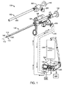
図1は、泌尿器科手技において組織を切除するために使用するための電気外科手術用組織切除システム100を図示し、システム100は、導入器スリーブまたはシース102と、ハンドヘルド単回使用組織切除デバイスまたはプローブ105とを含む。切除デバイス105は、細長いシャフトまたは延在部分110に結合されるハンドル部分108を有し、細長いシャフトまたは延在部分110は、約2mm〜7mmに及び、一変形例では、直径5mmである外径を有する。シャフト110は、長手方向軸112を中心として作業端115まで延在し、作業端115は、以下にさらに説明されるように、シャフト110およびその軸112に対して半径方向に非対称である。一変形例では、デバイスは、TURP手技(前立腺の経尿道切除)または膀胱腫瘍切除手技を実施するために適合され、したがって、シャフト部分110は、標的前立腺組織または膀胱組織に到達するための経尿道アプローチにおいて導入するために好適な長さで軸112を中心として延在する。
FIG. 1 illustrates an electrosurgical
以下に説明され、図1に示されるように、切除デバイス105は、導入器スリーブ102を通した導入のために適合される。そのような導入器スリーブ102は、図1から理解され得るように、市販の内視鏡130を受け取るように適合される。
As described below and shown in FIG. 1, the
図1−3を参照すると、概して、切除デバイス105は、オフセット組織受取窓144を有するオフセット切除筐体140に結合される遠位シャフト部分132まで延在する細長いシャフト110を有することが分かる。可動電極145は、電極145の長手方向部分149が、窓144を横断して左右に掃引し、窓144内に捕捉された組織を電気外科手術的に切除するように、ハンドル108(図1参照)内のモータ駆動式ユニット148によって駆動されるように適合される。標的組織は、組織抽出チャネル158と連通するコントローラ155内の負圧源または流出ポンプ150を用いて、窓144の中に吸引され、窓144の中に捕捉されることができ、組織抽出チャネル158は、デバイス105を通って延在し、窓144で終端する。
With reference to FIGS. 1-3, it can be seen that the
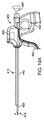
より具体的には、図2および図3を参照すると、オフセット筐体140の構成は、複数の機能を実施するように適合される。第1に、オフセット筐体140は、窓表面WS(図2に示される湾曲平面P内)をシャフト110の外側表面160から外向きに位置付け、これは、次いで、窓表面WSが、デバイスシャフト110と平行に導入される内視鏡130または他の視認手段を通して完全に可視となることを可能にする(図4A参照)。例えば、図4Aは、作業端115の概略図であり、作業表面WSは、標的組織Tと接触する。図4Aから分かるように、内視鏡130は、視野FVが作業表面WSと直接整合された状態で位置付けられ、したがって、組織切除プロセスの最適視認を可能にする。
More specifically, referring to FIGS. 2 and 3, the configuration of the offset
対照的に、図4Bは、窓表面WS'を有する従来の二重スリーブ管状カッタの作業端115'を示し、これは、切除手技の間、器官に対して押圧されると、管状切断縁と組織Tとの間の界面の内視鏡下視覚を妨害する。
In contrast, FIG. 4B shows a working
第2に、オフセット筐体140は、広面積にわたって表面組織を切除するのではなく、器官の局所領域内でより深い深度まで組織を切除するために適合される。より具体的には、図5に示されるように、筐体140のオフセット部分170は、プローブシャフト110の軸112と垂直に組織の中に押動されることができる。したがって、図5に示されるように、オフセット筐体140は、局所領域の中深くの組織を切除するために使用されることができる、これは、図4Bに示される構成を有する切除デバイスを用いては不可能である。
Second, the offset
図2および図3は、酸化ジルコニウム、酸化アルミニウム、または当技術分野において公知の類似材料等のセラミック材料からを含み得る非対称またはオフセット誘電筐体140を図示する。図2−3では、窓表面WSは、シャフト表面160から、所定の寸法Dだけオフセットされることが分かり、所定の寸法Dは、2mm〜8mmであることができ、一実施形態では、5mmオフセットを含む。
FIGS. 2 and 3 illustrate an asymmetric or offset
図2−3にさらに見られ得るように、窓144の周界の少なくとも一部の周囲の窓表面WSの幅Wは、制限された寸法、例えば、3mm未満、または2mm未満、または1mm未満であり、これは、電極145が窓144を横断して掃引するにつれて、筐体140のオフセット部分170が、デバイス軸112と垂直に組織の中に押動されることを可能にする。
As can be further seen in FIG. 2-3, the width W of the window surface WS around at least a portion of the perimeter of the
図2−3を参照すると、切除デバイス105の一変形例は、タングステンまたはステンレス鋼ワイヤであり得る電極145を有し、電極部分149は、任意の好適な率(例えば、1サイクル/秒(CPS)〜50CPSまたはそれより大きい)で窓144を横断して掃引するように適合される。図3では、電極145は、デバイスのハンドル108(図1)の中に延在する細長い近位シャフト部分176を有することを理解されたい。電極145の近位端は、モータ駆動式ユニット148に動作可能に結合され、好適な機構またはコントローラが、組織を切除するように細長い電極シャフト部分176を弧で回転させるために提供される。
Referring to FIGS. 2-3, one variation of the
図2−3から理解され得るように、電極部分149は、オフセット筐体140内の窓144を横断して、フロントガラスのワイパのように前後に移動する。いくつかの機構が、電極の所望の移動をもたらすために使用されることができる、またはモータ駆動部148は、単に、ソフトウェアによって制御され、断続的に時計回りおよび反時計回り方向に移動することができる。一変形例では、電極145の細長い近位部分176は、その長さにわたって捻転し、したがって、モータ駆動部148は、窓の匹敵する半径方向角度または弧を上回る半径方向角度を伴う弧で、電極シャフトを回転させるように適合されることができる。したがって、電極部分149は、近位電極シャフト部分176内にもたらされるある程度の捻転を補償することによって、ある程度の組織抵抗に遭遇するときでも、窓を横断して完全に前後に移動することが予期され得る。一変形例では、モータ駆動式ユニットは、10°半径方向運動〜90°半径方向運動であり得る選択された量だけ、電極シャフト部分176をその近位端において過回転させ、電極シャフト部分の捻転を補償し、電極部分149が窓144の表面を完全に横断して掃引することを保証するように適合されることができる。
As can be seen from FIGS. 2-3, the
概して、筐体140内の窓144は、30°〜180°に及ぶ電極シャフト176に対する半径方向弧を有するように構成されることができる。図6に示される、筐体140'の一変形例では、電極部分149は、剪断のように、すなわち、鋏状様式において機能するように電極部分149が窓縁182aおよび182bを通過すると、窓内に捕捉された任意の組織が切除されることを確実にするように、窓144の半径方向寸法を横断して延在する運動範囲を有することが分かる。電極部分149は、筐体140'の両側の段部186aおよび186bにわたって移動し、表面190aおよび190bに衝突することができる。表面190aおよび190bに衝突することによって、上記に説明されるように、捻転に適応するための電極シャフト176内の任意の過回転は、筐体140'内の電極部分の回転を制限することができる。さらに、図6では、電極部分149の遠位先端192は、窓144を遠位に越えて、筐体140'内の遠位段部194上に延在し、組織が遠位窓領域内の電極によって切除されることを確実にすることが分かる。
In general, the
ここで図1に戻って参照すると、切除デバイス105および内視鏡130は、導入器スリーブアセンブリまたはシース102と併用されることができることを理解されたい。図1に示されるように、導入器アセンブリ102は、コネクタ部材205に結合するように適合されるコネクタ204を伴う近位ハンドル本体202を有する。コネクタ205は、導管206をコントローラ155に結合し、単一ケーブル内に、(i)流体流出ポンプ150と連通する第1の管腔と、(ii)流体流入ポンプ225と連通する第2の管腔と、(iii)コントローラ155内またはコネクタ205内もしくはその近傍に位置付けられる圧力センサと連通する第3の管腔とを提供するように適合される。図1から分かるように、導入器スリーブ102はまた、内視鏡130を収容することができる。したがって、導入器スリーブ120は、内視鏡130(切除デバイス105を伴わずに)とともに組み立てられ、コネクタ205によって、コントローラ155に結合され、圧力感知とともに、流体源226からの潅注流体の流入と、収集リザーバ228への潅注流体の流出とを提供し、アセンブリが、組織切除手技に先立って、診断手技において使用されることを可能にすることができる。言い換えると、導入器スリーブ102は、前立腺または膀胱内の標的部位への経尿道アクセスにおいて使用するための「連続流」光学導入器として機能することができる。
Returning now to FIG. 1, it should be understood that the
導入器スリーブアセンブリ102が初期診断手技のために使用された後、内視鏡130が、アセンブリ102から除去されることができ、コネクタ205が、ハンドル本体205から接続解除されることができる。その後、導入器アセンブリ102のスリーブ部分240(図1参照)は、近位ハンドル本体204から取り外されることができ、スリーブ部分240は、患者内に残る。次に、内視鏡130およびコネクタ205は、切除デバイス105と組み立てられることができ、医師は、切除デバイス105を患者内に残っているスリーブ部分240を通して挿入し、標的部位にアクセスすることができる。組み合わせにおける切除デバイス105およびスリーブ部分204は、次いで、上記に説明されるように、コネクタ205内の管腔を通して、流体流入、流体流出、および直接圧力感知のための管腔を提供する。
After the
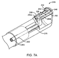
ここで図7Aに目を向けると、図6のものに類似する作業端246の遠位セラミック筐体の斜視図が、示される。本変形例では、可動電極250の遠位先端248は、拘束スロットまたはチャネル252内に制約されるように構成される。言い換えると、遠位電極先端248は、図6の変形例におけるように、自由に浮動しない。自由に浮動する遠位先端を伴う電極は、組織によって捕捉され、セラミック筐体255から離れるように持ち上げられ得ることが見出されている。したがって、本変形例では、遠位電極先端248は、制約され、組織に絡まることも、セラミック筐体および窓260から離れるように持ち上げられることもできない。図7Aの変形例は、電極250の移動を制限する弧状スロットまたはチャネル252を図示する。全ての他の点において、作業端は、前述のように機能する。さらに、遠位電極部分262およびチャネル252は、電極が、上記に説明されるように、窓260の縁264aおよび264bの上を通過することを可能にするように構成されることができる。
Turning now to FIG. 7A, a perspective view of a distal ceramic housing at a working
図7Bは、作業端266の別の変形例を示し、電極270は、274で示されるピボットまたはボア内に制約される遠位先端272を有する。本変形例では、電極270は、U形状を有し、遠位先端272は、電極シャフト部分275と整合され、アクティブ電極部分277が、前述のように、窓260に対して左右に移動することを可能にすることが分かる。
FIG. 7B shows another variation of working
図7A−7Bに示される本発明の別の側面では、電極シャフト部分275は、管状部材280を備え、これは、ステンレス鋼または類似材料等の金属ハイポチューブを含むことができる。図6に示されるような前の変形例では、電極シャフト部分は、ワイヤ要素から構成され、これは、電極が例えば高密度組織に係合されると、潜在的に、望ましくない程度まで捻転し得る。本変形例では、好適な壁厚を伴う金属ハイポチューブは、電極が移動されて高密度組織に係合しているとき、捻転に抵抗することができることが見出されている。一変形例では、管状部材280の壁厚は、少なくとも0.005インチまたは少なくとも0.010インチであることができる。
In another aspect of the invention shown in FIGS. 7A-7B, the
概して、本発明に対応する組織切除デバイスは、吸引源と連通する窓を有する遠位部分まで長手方向軸に沿って延在する細長い部材と、細長い部材内で電極作業端まで延在する中心軸を伴う電極シャフトを有する電極であって、電極作業端の一部が該中心軸からオフセットされる、電極と、電極シャフトを回転させ、電極作業端を窓に対して移動させるように構成されるモータとを備え、電極シャフトは、そのモータ駆動式移動の間、該シャフトの捻転に抵抗するように適合される管状部材を備える。さらに、管状部材は、絶縁外側表面層282を伴う金属管を備えることができる。組織管状部材は、熱収縮ポリマーを含む絶縁外側表面層を伴うステンレス鋼管であることができる。
In general, a tissue ablation device in accordance with the present invention comprises an elongated member extending along a longitudinal axis to a distal portion having a window in communication with a suction source, and a central axis extending within the elongated member to an electrode working end. An electrode having an electrode shaft, wherein a portion of the electrode working end is offset from the central axis and configured to rotate the electrode shaft and move the electrode working end relative to the window And the electrode shaft includes a tubular member adapted to resist twisting of the shaft during its motor driven movement. Further, the tubular member can comprise a metal tube with an insulating
一変形例では、電極の作業端は、窓の面積より実質的に小さい外形を有し、それによって、電極が窓に対して移動するときに、常時、窓を通した流体吸引を電極作業端の周囲にもたらす。これは、負圧源が、組織を窓界面の中に引き入れ、電極が組織を切断し、切除された組織を抽出するように、組織を界面に維持することを可能にする。一変形例では、電極作業端は、モータ駆動され、窓に対して1CPSに等しいまたはそれを上回る率で、または窓に対して10CPSに等しいまたはそれを上回る率で、移動する。前述のように、電極作業端は、少なくとも2mmまたは少なくとも4mmだけ、シャフトアセンブリから半径方向外向きにオフセットされることができる。 In one variation, the working end of the electrode has a profile that is substantially smaller than the area of the window, thereby permitting fluid suction through the window at all times as the electrode moves relative to the window. Bring around. This allows the negative pressure source to pull the tissue into the window interface and maintain the tissue at the interface such that the electrode cuts the tissue and extracts the ablated tissue. In one variation, the electrode working end is motor driven and moves at a rate equal to or greater than 1 CPS for the window or at a rate equal to or greater than 10 CPS for the window. As previously described, the electrode working end can be offset radially outward from the shaft assembly by at least 2 mm or at least 4 mm.
本発明の別の側面では、組織切除デバイスは、組織受取窓を有する遠位筐体まで延在する細長い部材と、窓を横断して移動するように構成される可動電極と、電極を移動させるように構成されるモータとを備え、電極の遠位先端は、筐体内の拘束チャネルの中で移動する。別の変形例では、組織切除デバイスは、組織受取窓を有する遠位筐体まで延在する細長い部材と、窓を横断して移動するように構成される可動電極と、電極を移動させるように構成されるモータとを備え、電極の遠位端は、枢動チャネル内で自由に浮動または枢動しない。 In another aspect of the invention, a tissue ablation device includes an elongated member extending to a distal housing having a tissue receiving window, a movable electrode configured to move across the window, and moving the electrode And the distal tip of the electrode moves within a constraining channel within the housing. In another variation, a tissue ablation device includes an elongate member extending to a distal housing having a tissue receiving window, a movable electrode configured to move across the window, and to move the electrode The distal end of the electrode does not float or pivot freely within the pivot channel.
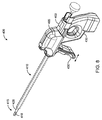
図8は、組織切除デバイス400の斜視図であり、組織切除デバイス400は、モータ駆動部405を担持するハンドル402と、ハンドルから作業端415まで延在するシャフトアセンブリ410とを含み、作業端415は、例えば、組織受取窓420と、前述のように、窓420を横断して移動するように適合されるモータ駆動式電極425とを有するセラミックまたは他の筐体418(図9Aおよび図9B)を備える。作業端415は、スリーブ428に結合され、これは、シャフトアセンブリ410内の手動またはモータ駆動式往復動のために適合される。より具体的には、デバイス400の本変形例は、図7Aのものに類似する作業端415において電極425を移動させるモータ駆動部405を提供する。さらに、本実施形態では、デバイス400は、随意に、モータ駆動部を利用して、前述のような窓420に対する電極425の移動と同時に、またはそれと交互して、作業端415をシャフトアセンブリ410に対して往復動させることができる。代替として、デバイス400は、電極425を筐体418内の窓420に対して移動させるための第1のモータと、作業端415を往復動させるための第2のモータ(図示せず)とを担持する。別の変形例では、単一モータ405は、電極移動と作業端往復動との両方を実施するように適合されることができる。図10A−10Bから分かるように、ハンドル402は、ハンドル402の静止把持部分432に対するアクチュエータ把持部430の移動によって、シャフトアセンブリ410における作業端415の手動後退および延在を可能にする。
FIG. 8 is a perspective view of the
図9Aは、図8のデバイス400の作業端415の斜視図であり、シャフトアセンブリ410の外側スリーブ442とともに担持される内視鏡440を示す。スリーブ428によって担持される作業端415は、前述の図2、図3、および図6のものに類似するが、前述の構造のいずれかを有し得る。内視鏡440は、光学部444を有し、これは、細長い部材428上の作業端415を包含し得る視野445を提供する。光エミッタ446は、内視鏡440の遠位端に示される。図9Bは、別の角度からの図9Aのデバイスの作業端の斜視図である。
FIG. 9A is a perspective view of the working
図10Aおよび図10Bは、図8の組織切除デバイス400の側面図であり、ハンドル402の静止把持部分432に対するシャフトアセンブリ410内のスリーブ428および作業端415の往復動を図示する。図10Aは、シャフトアセンブリ410およびハンドル402に対する延在ストロークの遠位端におけるスリーブ428および作業端415を示し、図10Bは、ハンドルに対する後退ストロークの近位端における作業端415およびスリーブ428を示す。本変形例では、作業端415およびスリーブ428は、内視鏡440がハンドル402内で静止したままである間、往復動するように適合される。代替実施形態では(図示せず)、作業端415およびスリーブ428は、シャフトアセンブリ410内の内視鏡440とともに、軸方向に往復動するように構成されてもよい。
10A and 10B are side views of the
図11は、本発明による方法を図示し、作業端415およびスリーブ428の後退ストロークおよび延在ストロークを示し、コントローラ450は、負圧源455をアクティブ化および非アクティブ化し、後退ストロークおよび延在ストロークの異なる部分において、RF源460から可動電極425へのRF電流の送達を生じさせる。
FIG. 11 illustrates the method according to the present invention, showing the retracting and extending strokes of the working
本発明の方法は、前述の作業端415および移動可能スリーブ428等の移動可能作業端であって、長手方向軸に沿って遠位筐体418まで延在し、遠隔負圧源455と連通する窓420等の窓を有する移動可能作業端と、窓420に対して移動するように構成される可動電極425と、電極を窓420を横断して移動させ、随意に、作業端415を軸方向ストロークにおいて往復動または別様に移動させるように適合される少なくとも1つのモータ405とを有する任意の組織切除デバイスを採用することができる。モータ駆動部405は、多くの場合、窓に対して1CPS(サイクル/秒)を上回る、本明細書で以前に述べられた率のいずれかで電極を回転発振させるように適合されることができる。随意に、モータは、少なくとも2秒に1回または少なくとも1秒に1回、スリーブ428および作業端415をハンドルに対して軸方向に往復動させるために使用されることができる。
The method of the present invention is a movable working end, such as the aforementioned working
別の変形例では、組織切除デバイスは、(1)電極に結合されるRF源460と、(2)負圧源455と、(3)電極425を移動させ、随意に、作業端415をシャフトアセンブリ410内で往復動させるための少なくとも1つのモータ405とを動作させるように構成されるコントローラ450に結合される。さらに、コントローラは、電極425の移動を窓420に対する選択された位置に停止させるために少なくとも1つのモータ駆動部を制御するように適合されてもよい。より具体的には、コントローラは、電極425を窓420の中心または窓の縁に選択的に停止させるように適合されることができる。
In another variation, the tissue ablation device (1) moves the
なおもさらなる変形例では、コントローラ450は、窓420を横断した前後の電極425の単一移動またはサイクルを提供するために少なくとも1つのモータ駆動部405を制御するように適合される。さらに別の変形例では、コントローラ450は、作業端415およびスリーブ428の移動をシャフトアセンブリ410に対する選択された軸方向位置に停止させるために少なくとも1つのモータを制御するように適合される。
In yet a further variation, the
再び図11を参照すると、コントローラ450は、後退ストロークおよび延在ストロークにおけるシャフトアセンブリの単一移動を提供するために少なくとも1つのモータ駆動部405を制御するように適合されることができる。別の実施形態では、コントローラ450は、RF源460、負圧源455、および少なくとも1つのモータ駆動部405を同時に動作させるように構成される。例えば、コントローラ450は、作業端の移動に応答して、負圧源455を変調する、または作業端の移動に応答して、RF源をアクティブ化もしくは非アクティブ化する、または窓に対する電極425の移動に応答して、負圧源を変調する、またはセラミック本体418内の窓420に対する電極425の移動に応答して、RF源をアクティブ化もしくは非アクティブ化するように適合されることができる。さらに、RF源460は、切断電流波形または凝固波形を電極に送達するように構成されることができる。
Referring again to FIG. 11, the
図11を参照すると、本発明による組織を切除する方法は、長手方向軸を有し、筐体内の窓420に近接する電極425を有する遠位筐体418を備える作業端415を担持する往復動スリーブ428を含む、アセンブリ410等の細長いシャフトアセンブリを提供することを含む。スリーブ428および作業端415は、後退ストロークおよび延在ストロークを伴って、ハンドル402の静止部分に対して移動可能である。作業端415は、標的組織部位に対して位置付けられ、作業端415内の窓420と連通する負圧源が、アクティブ化される。モータ駆動部が電極を窓を横断して移動させるときに、RF源が、アクティブ化されることにより、RF電流を電極425に送達し、作業端415が、後退ストロークにおいて移動され、それによって、負圧源が組織を窓420と接触するように引き入れるようアクティブ化されたままである間に組織を切除する。本方法はさらに、典型的には、コントローラを介して、負圧源、モータ駆動部、および典型的には、後退ストロークの近位端におけるRF源も非アクティブ化することを含んでもよい。続いて、本方法は、負圧源が非アクティブ化され、RF源も非アクティブ化された状態で延在ストロークを開始することを含んでもよい。図11から分かるように、コントローラは、延在ストロークの終了部分の間、負圧源をアクティブ化することにより、再び、窓420と接触するように組織を引き入れ、続く後退ストロークに備え、これは、次いで、励起されて発振する電極425を用いて、再び、組織を切除する。
Referring to FIG. 11, a method for excising tissue according to the present invention includes a reciprocating motion carrying a working
上記に説明される方法のステップから理解され得るように、負圧源およびRF電流送達のアクティブ化および非アクティブ化のタイミングの変形例も、可能である。別の変形例では、電極は、励起および発振され、負圧源が持続的にアクティブ化された状態で、後退ストロークおよび延在ストロークの両方において、組織を切除することができる。 As can be understood from the method steps described above, variations in the timing of activation and deactivation of the negative pressure source and RF current delivery are also possible. In another variation, the electrodes can be excised and oscillated to ablate tissue in both the retraction and extension strokes with the negative pressure source continuously activated.
別の変形例では、電極は、窓内の選択された位置に停止されることができ、凝固電流が、組織を凝固させるために、電極に送達されることができる。代替として、切断電流波形が、組織をアブレートするために、静止電極に送達されることができる。 In another variation, the electrode can be stopped at a selected position within the window and a coagulation current can be delivered to the electrode to coagulate the tissue. Alternatively, a cutting current waveform can be delivered to the stationary electrode to ablate the tissue.
図12A−12Bは、本発明の別の側面を図示し、コントローラ450およびRF源460は、電極移動の種々のモードにおいて、または電極が窓に対して静止しているとき、切断波形を伴うRF電流を電極425に、または凝固波形を伴うRF電流を電極に送達するように適合されることができる。図12A−12Bは、組織480と界面接触または係合する、図9Aまたは図11の作業端の断面図である。
12A-12B illustrate another aspect of the present invention, where the
概して、前立腺組織を処置する方法は、負圧源と連通するセラミック本体418内の窓420を有する遠位部分まで長手方向軸に沿って延在するシャフトと、窓に対して移動するように適合されるモータ駆動式電極425とを伴う処置デバイスを提供することと、窓を標的組織480と界面接触するよう位置付けることと、組織480を切除するために、電極を移動させるようモータをアクティブ化しながら、切断波形が電極に送達される第1のモードにおいて動作させること(図12A)と、その後、484に示される組織を凝固させるために、選択された静止位置に電極425を停止させるようモータを非アクティブ化した後、凝固波形が電極425に送達される第2のモードにおいて動作させること(図12B)とを含む。さらに、位置付けるステップは、シャフトを経尿道アプローチにおいて患者の前立腺の中に導入するステップが先行することができる。第1のモードは、図12Aに示されるように、電極425を窓420を横断して掃引させ、窓に界面接触する組織を切除することを含む。電極425は、窓を横断して左右に掃引するように適合されることができる、または別の変形例では、窓430内を遠位および近位に移動することができる。
In general, a method for treating prostate tissue is adapted to move relative to a window with a shaft extending along a longitudinal axis to a distal portion having a
第1のモードでは、電極425は、窓430に対して1CPSを上回る率で移動することができる。さらに、第1のモードにおける動作は、第1の負圧範囲内で吸引源をアクティブ化し、組織を窓に対してまたは窓の中に引き入れ、流体および切除された組織を窓を通して吸引することを含む。第2のモードにおける動作は、第2の負圧範囲内で吸引源をアクティブ化し、流体をシャフト内のチャネルを通して吸引することを含む。第1のモードおよび第2のモードで動作するとき、コントローラは、モータ、RF源、および負圧源を選択された様式でアクティブ化および非アクティブ化するために利用される。
In the first mode, the
別の方法では、コントローラは、電極を100CPS未満で移動させるようにモータをアクティブ化しながら、凝固波形を送達する第3のモードにおいてモータおよびRF源を動作させることができる。 Alternatively, the controller can operate the motor and RF source in a third mode that delivers a coagulation waveform while activating the motor to move the electrode below 100 CPS.
別の方法では、コントローラは、電極を選択された静止位置に停止させるようにモータを非アクティブ化した後、切断波形を送達する第4のモードにおいてモータおよびRF源を動作させることができる。 Alternatively, the controller can operate the motor and RF source in a fourth mode that delivers a cutting waveform after deactivating the motor to stop the electrode at a selected rest position.
デバイスが、静止電極を伴うモードで動作させられると、電極の選択された静止位置は、窓内の実質的中心にある。そのような中心位置は、電極の両側の周囲の流体の窓を通した吸引を可能にし、これは、凝固モードにおける電極を冷却し、切断電流が組織をアブレートするために使用されるとき、泡を除去する。 When the device is operated in a mode with a stationary electrode, the selected stationary position of the electrode is at a substantial center within the window. Such a central location allows for suction through the surrounding fluid windows on either side of the electrode, which cools the electrode in coagulation mode and when the cutting current is used to ablate tissue, Remove.
概して、組織切除デバイスは、吸引源と連通する窓を有する遠位部分まで長手方向軸に沿って延在する細長いシャフトと、窓に対して移動するように構成されるワイヤ状電極と、切断波形および凝固波形におけるRF電流を電極に送達するように構成されるRF源と、電極を移動させるように構成されるモータと、電極を移動させるようにモータをアクティブ化しながら切断波形を送達する第1のモード、および、電極を選択された静止位置に停止させるようにモータを非アクティブ化した後に凝固波形を送達する第2のモードにおいてモータおよびRF源を動作させるように構成されるコントローラとを備える。本変形例では、電極は、窓面積より小さい表面積を有し、第1動作モードおよび第2動作モードにおいて、電極の周囲で窓を通した流体吸引をもたらす。 Generally, a tissue ablation device includes an elongate shaft extending along a longitudinal axis to a distal portion having a window in communication with a suction source, a wire electrode configured to move relative to the window, and a cutting waveform And an RF source configured to deliver an RF current in the coagulation waveform to the electrode, a motor configured to move the electrode, and a first delivering a cutting waveform while activating the motor to move the electrode And a controller configured to operate the motor and RF source in a second mode that delivers a coagulation waveform after deactivating the motor to stop the electrode in a selected rest position. . In this variation, the electrode has a surface area that is smaller than the window area and provides fluid suction through the window around the electrode in the first and second modes of operation.
第1のモードにおける動作では、コントローラは、第1の負圧範囲内で吸引源をアクティブ化することができる。第2のモードにおける動作では、コントローラは、第2の負圧範囲内で吸引源をアクティブ化することができる。 In operation in the first mode, the controller can activate the suction source within the first negative pressure range. In operation in the second mode, the controller can activate the suction source within the second negative pressure range.
第3のモードで動作するとき、コントローラは、50CPS未満で電極を移動させるようにモータをアクティブ化しながら、凝固波形を送達するようにモータ駆動部およびRF源を動作させるように構成されることができる。 When operating in the third mode, the controller is configured to operate the motor driver and the RF source to deliver a coagulation waveform while activating the motor to move the electrode below 50 CPS. it can.
第4のモードで動作するとき、コントローラは、電極を選択された静止位置、例えば、窓の中心に停止させるようにモータを非アクティブ化した後、切断波形を送達するようにモータおよびRF源を動作させるように構成されることができる。 When operating in the fourth mode, the controller deactivates the motor to stop the electrode at a selected stationary position, eg, the center of the window, and then turns the motor and RF source on to deliver a cutting waveform. Can be configured to operate.
図9A、図9B、および図11から分かるように、スリーブ428の遠位部分は、窓420をその中に有する誘電体または筐体418を含む。典型的には、筐体は、セラミック材料であり、セラミック材料は、イットリア安定化ジルコニア、マグネシア安定化ジルコニア、セリア安定化ジルコニア、ジルコニア強化アルミナ、および窒化ケイ素から成る群から選択されることができる。
As can be seen from FIGS. 9A, 9B, and 11, the distal portion of the
図8、図10A、および図10Bに示されるモータ駆動部は、使い捨てであり得るか、または着脱可能であり、したがって、再使用可能であり得る。 The motor drive shown in FIGS. 8, 10A, and 10B can be disposable or detachable and therefore reusable.
上記に説明される方法のステップから理解され得るように、負圧源およびRF電流送達のアクティブ化および非アクティブ化のタイミングの変形例も、可能である。別の変形例では、電極は、負圧源が持続的にアクティブ化された状態で、後退ストロークおよび延在ストロークの両方において、組織を切除するように励起されることができる。 As can be understood from the method steps described above, variations in the timing of activation and deactivation of the negative pressure source and RF current delivery are also possible. In another variation, the electrodes can be excited to ablate tissue in both the retracting and extending strokes with the negative pressure source continuously activated.
別の変形例では、電極は、窓内の選択された位置で停止されることができ、凝固電流は、組織を凝固させるために、電極に送達されることができる。代替として、切断電流波形は、組織をアブレートするために、静止電極に送達されることができる。 In another variation, the electrode can be stopped at a selected location within the window and a coagulation current can be delivered to the electrode to coagulate the tissue. Alternatively, the cutting current waveform can be delivered to a stationary electrode to ablate tissue.
以下に詳細に説明されるような本発明の特定の側面では、デバイス、システム、および方法は、随意に、内視鏡下可視化下において、前立腺を処置するために具体的に構成される。例えば、本システムは、切断波形および凝固波形の交互においてRF電流を電極に送達するように構成されるRF源と、電極を移動させるように構成されるモータと、電極を移動させるようにモータをアクティブ化しながら切断波形を送達する第1のモード、および、電極を選択された静止位置に停止させるようにモータを非アクティブ化した後に凝固波形を送達する第2のモードにおいて、モータおよびRF源を動作させるように構成されるコントローラとを備えてもよい。前立腺を処置するためのそのような方法は、吸引源と連通する窓を有する遠位部分まで長手方向軸に沿って延在するシャフトと、窓に対して移動するように適合されるモータ駆動式電極とを伴う処置デバイスを提供することを含んでもよい。窓は、標的前立腺組織に対して係合され、RF源は、組織を切除するために、電極を移動させるようにモータをアクティブ化しながら切断波形が電極に送達される第1のモードで動作させられ、その後、組織を凝固させるために、電極を選択された静止位置に停止させるようにモータを非アクティブ化した後に凝固波形が電極に送達される第2のモードで動作させられる。
本発明は、例えば、以下を提供する。
(項目1)
組織切除プローブであって、
吸引源と連通する窓を有する遠位部分まで長手方向軸に沿って延在する細長いシャフトと、
前記窓に対して移動するように構成されたワイヤ状電極と、
切断波形および凝固波形におけるRF電流を前記電極に送達するように構成されたRF源と、
前記電極を移動させるように構成されたモータと、
前記電極を移動させるように前記モータをアクティブ化しながら切断波形を送達する第1のモード、および、前記電極を選択された静止位置に停止させるように前記モータを非アクティブ化した後に凝固波形を送達する第2のモードにおいて、前記モータおよびRF源を動作させるように構成されたコントローラと
を備える組織切除プローブ。
(項目2)
前記電極は、前記窓の面積より小さい表面積を有し、それによって、前記第1動作モードおよび第2動作モードにおいて、前記電極の周囲で前記窓を通した流体吸引をもたらす、項目1に記載の組織切除プローブ。
(項目3)
前記電極は、前記長手方向軸と平行に延在する、項目1に記載の組織切除プローブ。
(項目4)
前記第1のモードでは、前記電極は、前記窓に対して、1CPSに等しいまたはそれを上回る率で移動する、項目1に記載の組織切除プローブ。
(項目5)
前記第1のモードでは、前記電極は、前記窓に対して、1CPSを上回る率で移動する、項目1に記載の組織切除プローブ。
(項目6)
前記コントローラは、前記第1のモードにおいて、第1の負圧範囲内で前記吸引源をアクティブ化する、項目1に記載の組織切除プローブ。
(項目7)
前記コントローラは、前記第2のモードにおいて、第2の負圧範囲内で前記吸引源をアクティブ化する、項目1に記載の組織切除プローブ。
(項目8)
前記コントローラは、前記電極を100CPS未満で移動させるように前記モータをアクティブ化しながら凝固波形を送達する第3のモードにおいて、前記モータおよびRF源を動作させるように構成されている、項目1に記載の組織切除プローブ。
(項目9)
前記コントローラは、前記電極を選択された静止位置に停止させるように前記モータを非アクティブ化した後に切断波形を送達する第4のモードにおいて、前記モータおよびRF源を動作させるように構成されている、項目1に記載の組織切除プローブ。
(項目10)
前記所定の静止位置における前記電極は、前記窓の中心にある、項目1に記載の組織切除プローブ。
(項目11)
前記所定の静止位置における前記電極は、前記窓の縁に近接する、項目1に記載の組織切除プローブ。
(項目12)
前記シャフトの遠位部分は、前記窓をその中に有する誘電体を含む、項目1に記載の組織切除プローブ。
(項目13)
前記誘電体は、セラミック材料である、項目12に記載の組織切除プローブ。
(項目14)
前記セラミック材料は、イットリア安定化ジルコニア、マグネシア安定化ジルコニア、セリア安定化ジルコニア、ジルコニア強化アルミナ、および窒化ケイ素から成る群から選択される、項目13に記載の組織切除プローブ。
(項目15)
前立腺組織を処置する方法であって、
吸引源と連通する窓を有する遠位部分まで長手方向軸に沿って延在するシャフトと、前記窓に対して移動するように適合されたモータ駆動式電極とを伴う処置デバイスを提供することと、
前記窓を標的前立腺組織と界面接触させて位置付けることと、
組織を切除するために、前記電極を移動させるように前記モータをアクティブ化しながら、切断波形が前記電極に送達される第1のモードで動作させることと、
組織を凝固させるために、前記電極を選択された静止位置に停止させるように前記モータを非アクティブ化した後、凝固波形が前記電極に送達される第2のモードで動作させることと
を含む方法。
(項目16)
前記位置付けるステップは、前記シャフトを経尿道的に患者の前立腺の中に導入するステップが先行する、項目15に記載の方法。
(項目17)
前記第1のモードは、前記電極を前記窓を横断して掃引させ、前記窓に界面接触する組織を切除することを含む、項目15に記載の方法。
(項目18)
前記電極は、前記窓を横断して左右に掃引する、項目15に記載の方法。
(項目19)
前記電極は、前記窓を横断して遠位から近位に掃引する、項目15に記載の方法。
(項目20)
前記第1のモードでは、前記電極は、前記窓に対して、1CPSを上回る率で移動する、項目15に記載の方法。
(項目21)
前記第1のモードにおける動作は、第1の負圧範囲内で前記吸引源をアクティブ化することにより、組織を前記窓に対してまたは前記窓の中に引き入れ、流体および切除された組織を前記窓を通して吸引することを含む、項目15に記載の方法。
(項目22)
前記第2のモードにおける動作は、第2の負圧範囲内で吸引源をアクティブ化することにより、流体を前記シャフト内のチャネルを通して吸引することを含む、項目15に記載の方法。
(項目23)
前記第1のモードおよび第2のモードにおける動作は、前記モータ、前記RF源、および前記負圧源を所定の様式でアクティブ化および非アクティブ化するように構成されたコントローラを利用する、項目15に記載の方法。
(項目24)
前記電極の前記選択された静止位置は、前記窓を通して前記電極の両側の周囲の流体の吸引を可能にする、項目15に記載の方法。
(項目25)
組織切除デバイスであって、
ハンドルと、
前記ハンドルに移動可能に取り付けられ、長手方向軸を有するシャフトアセンブリと、
前記シャフトの遠位端に固着され、負圧源に流体的に結合されるように構成された窓を有する筐体と、
前記窓に対して移動するように前記筐体内に配置された電極と、
(1)前記シャフトアセンブリを軸方向ストロークで前記ハンドルに対して移動させることと、(2)前記電極を前記窓を横断して移動させることとの両方を行うように適合された、前記ハンドル内の少なくとも1つのモータと
を備える組織切除デバイス。
(項目26)
前記少なくとも1つのモータは、前記シャフトアセンブリおよび前記電極を同時に移動させるように適合されている、項目1に記載の組織切除デバイス。
(項目27)
前記少なくとも1つのモータは、前記シャフトアセンブリまたは前記電極のいずれかを個々に選択的に移動させるように適合されている、項目1に記載の組織切除デバイス。
(項目28)
前記少なくとも1つのモータは、前記電極を1CPSを上回って前記窓に対して移動させるように適合されている、項目1に記載の組織切除デバイス。
(項目29)
前記モータは、前記シャフトアセンブリを2秒に1回を上回って往復動させるように適合されている、項目1に記載の組織切除デバイス。
(項目30)
組織切除システムであって、
項目25に記載のデバイスと、
(1)前記電極に結合されるように構成されたRF源と、(2)負圧源と、(3)前記電極および前記シャフトアセンブリを移動させるための前記少なくとも1つのモータとを動作させるように構成されたコントローラと
を備える組織切除システム。
In certain aspects of the invention as described in detail below, the devices, systems, and methods are specifically configured to treat the prostate, optionally under endoscopic visualization. For example, the system includes an RF source configured to deliver RF current to the electrode in alternating cutting and coagulation waveforms, a motor configured to move the electrode, and a motor to move the electrode. In a first mode of delivering a cutting waveform while activating, and in a second mode of delivering a coagulation waveform after deactivating the motor to stop the electrode in a selected rest position, the motor and RF source are And a controller configured to operate. Such a method for treating the prostate includes a shaft that extends along a longitudinal axis to a distal portion having a window in communication with an aspiration source, and a motor-driven type adapted to move relative to the window. Providing a treatment device with electrodes may be included. The window is engaged against the target prostate tissue and the RF source is operated in a first mode in which a cutting waveform is delivered to the electrode while activating the motor to move the electrode to ablate the tissue. And then operated in a second mode in which a coagulation waveform is delivered to the electrode after deactivating the motor to stop the electrode in a selected rest position to coagulate the tissue.
For example, the present invention provides the following.
(Item 1)
A tissue resection probe,
An elongate shaft extending along the longitudinal axis to a distal portion having a window in communication with the suction source;
A wire electrode configured to move relative to the window;
An RF source configured to deliver an RF current in a cutting waveform and a coagulation waveform to the electrode;
A motor configured to move the electrodes;
A first mode that delivers a cutting waveform while activating the motor to move the electrode, and a coagulation waveform is delivered after the motor is deactivated to stop the electrode in a selected rest position A controller configured to operate the motor and the RF source in a second mode
A tissue excision probe comprising:
(Item 2)
The electrode of claim 1, wherein the electrode has a surface area that is smaller than an area of the window, thereby providing fluid suction through the window around the electrode in the first and second modes of operation. Tissue excision probe.
(Item 3)
The tissue ablation probe according to item 1, wherein the electrode extends parallel to the longitudinal axis.
(Item 4)
The tissue ablation probe according to item 1, wherein in the first mode, the electrode moves at a rate equal to or greater than 1 CPS relative to the window.
(Item 5)
The tissue ablation probe according to item 1, wherein in the first mode, the electrode moves at a rate of more than 1 CPS with respect to the window.
(Item 6)
The tissue ablation probe according to item 1, wherein the controller activates the suction source within a first negative pressure range in the first mode.
(Item 7)
The tissue ablation probe according to item 1, wherein the controller activates the aspiration source within a second negative pressure range in the second mode.
(Item 8)
Item 1. The controller of claim 1, wherein the controller is configured to operate the motor and RF source in a third mode that delivers a coagulation waveform while activating the motor to move the electrode below 100 CPS. Tissue excision probe.
(Item 9)
The controller is configured to operate the motor and RF source in a fourth mode that delivers a cutting waveform after deactivating the motor to stop the electrode in a selected rest position. The tissue excision probe according to Item 1.
(Item 10)
The tissue ablation probe according to item 1, wherein the electrode in the predetermined stationary position is in the center of the window.
(Item 11)
The tissue ablation probe according to item 1, wherein the electrode in the predetermined stationary position is close to an edge of the window.
(Item 12)
The tissue ablation probe according to item 1, wherein a distal portion of the shaft includes a dielectric having the window therein.
(Item 13)
13. The tissue ablation probe according to item 12, wherein the dielectric is a ceramic material.
(Item 14)
14. The tissue ablation probe according to item 13, wherein the ceramic material is selected from the group consisting of yttria stabilized zirconia, magnesia stabilized zirconia, ceria stabilized zirconia, zirconia reinforced alumina, and silicon nitride.
(Item 15)
A method of treating prostate tissue comprising:
Providing a treatment device with a shaft extending along a longitudinal axis to a distal portion having a window in communication with a suction source, and a motor driven electrode adapted to move relative to the window; ,
Positioning the window in interface contact with the target prostate tissue;
Operating in a first mode in which a cutting waveform is delivered to the electrode while activating the motor to move the electrode to ablate tissue;
Operating in a second mode in which a coagulation waveform is delivered to the electrode after deactivating the motor to stop the electrode in a selected rest position to coagulate tissue;
Including methods.
(Item 16)
16. The method of item 15, wherein the positioning step is preceded by introducing the shaft transurethrally into a patient's prostate.
(Item 17)
16. The method of item 15, wherein the first mode includes sweeping the electrode across the window and ablating tissue in interface contact with the window.
(Item 18)
16. The method of item 15, wherein the electrode sweeps left and right across the window.
(Item 19)
16. The method of item 15, wherein the electrode is swept from distal to proximal across the window.
(Item 20)
16. The method of item 15, wherein in the first mode, the electrode moves at a rate greater than 1 CPS relative to the window.
(Item 21)
The operation in the first mode is to activate the suction source within a first negative pressure range, thereby drawing tissue into or out of the window to draw fluid and ablated tissue into the window. 16. A method according to item 15, comprising aspirating through a window.
(Item 22)
16. The method of item 15, wherein the operation in the second mode includes aspirating fluid through a channel in the shaft by activating an aspiration source within a second negative pressure range.
(Item 23)
The operation in the first mode and the second mode utilizes a controller configured to activate and deactivate the motor, the RF source, and the negative pressure source in a predetermined manner. The method described in 1.
(Item 24)
16. The method of item 15, wherein the selected rest position of the electrode allows for suction of fluid around both sides of the electrode through the window.
(Item 25)
A tissue resection device,
A handle,
A shaft assembly movably attached to the handle and having a longitudinal axis;
A housing secured to the distal end of the shaft and having a window configured to be fluidly coupled to a negative pressure source;
An electrode disposed within the housing to move relative to the window;
In the handle adapted to both (1) move the shaft assembly with respect to the handle in an axial stroke and (2) move the electrode across the window And at least one motor
A tissue ablation device comprising:
(Item 26)
The tissue ablation device according to claim 1, wherein the at least one motor is adapted to move the shaft assembly and the electrode simultaneously.
(Item 27)
The tissue ablation device according to claim 1, wherein the at least one motor is adapted to selectively move either the shaft assembly or the electrodes individually.
(Item 28)
The tissue ablation device according to claim 1, wherein the at least one motor is adapted to move the electrode relative to the window above 1 CPS.
(Item 29)
The tissue ablation device according to claim 1, wherein the motor is adapted to reciprocate the shaft assembly more than once every 2 seconds.
(Item 30)
A tissue resection system,
The device of item 25;
(1) operating an RF source configured to be coupled to the electrode; (2) a negative pressure source; and (3) operating the at least one motor for moving the electrode and the shaft assembly. With configured controller
A tissue excision system comprising:
Claims (30)
吸引源と連通する窓を有する遠位部分まで長手方向軸に沿って延在する細長いシャフトと、
前記窓に対して移動するように構成されたワイヤ状電極と、
切断波形および凝固波形におけるRF電流を前記電極に送達するように構成されたRF源と、
前記電極を移動させるように構成されたモータと、
前記電極を移動させるように前記モータをアクティブ化しながら切断波形を送達する第1のモード、および、前記電極を選択された静止位置に停止させるように前記モータを非アクティブ化した後に凝固波形を送達する第2のモードにおいて、前記モータおよびRF源を動作させるように構成されたコントローラと
を備える組織切除プローブ。 A tissue resection probe,
An elongate shaft extending along the longitudinal axis to a distal portion having a window in communication with the suction source;
A wire electrode configured to move relative to the window;
An RF source configured to deliver an RF current in a cutting waveform and a coagulation waveform to the electrode;
A motor configured to move the electrodes;
A first mode that delivers a cutting waveform while activating the motor to move the electrode, and a coagulation waveform is delivered after the motor is deactivated to stop the electrode in a selected rest position And a controller configured to operate the motor and the RF source in a second mode.
吸引源と連通する窓を有する遠位部分まで長手方向軸に沿って延在するシャフトと、前記窓に対して移動するように適合されたモータ駆動式電極とを伴う処置デバイスを提供することと、
前記窓を標的前立腺組織と界面接触させて位置付けることと、
組織を切除するために、前記電極を移動させるように前記モータをアクティブ化しながら、切断波形が前記電極に送達される第1のモードで動作させることと、
組織を凝固させるために、前記電極を選択された静止位置に停止させるように前記モータを非アクティブ化した後、凝固波形が前記電極に送達される第2のモードで動作させることと
を含む方法。 A method of treating prostate tissue comprising:
Providing a treatment device with a shaft extending along a longitudinal axis to a distal portion having a window in communication with a suction source, and a motor driven electrode adapted to move relative to the window; ,
Positioning the window in interface contact with the target prostate tissue;
Operating in a first mode in which a cutting waveform is delivered to the electrode while activating the motor to move the electrode to ablate tissue;
Operating in a second mode in which a coagulation waveform is delivered to the electrode after deactivating the motor to stop the electrode in a selected rest position to coagulate tissue .
ハンドルと、
前記ハンドルに移動可能に取り付けられ、長手方向軸を有するシャフトアセンブリと、
前記シャフトの遠位端に固着され、負圧源に流体的に結合されるように構成された窓を有する筐体と、
前記窓に対して移動するように前記筐体内に配置された電極と、
(1)前記シャフトアセンブリを軸方向ストロークで前記ハンドルに対して移動させることと、(2)前記電極を前記窓を横断して移動させることとの両方を行うように適合された、前記ハンドル内の少なくとも1つのモータと
を備える組織切除デバイス。 A tissue resection device,
A handle,
A shaft assembly movably attached to the handle and having a longitudinal axis;
A housing secured to the distal end of the shaft and having a window configured to be fluidly coupled to a negative pressure source;
An electrode disposed within the housing to move relative to the window;
In the handle adapted to both (1) move the shaft assembly with respect to the handle in an axial stroke and (2) move the electrode across the window A tissue ablation device comprising at least one motor.
請求項25に記載のデバイスと、
(1)前記電極に結合されるように構成されたRF源と、(2)負圧源と、(3)前記電極および前記シャフトアセンブリを移動させるための前記少なくとも1つのモータとを動作させるように構成されたコントローラと
を備える組織切除システム。 A tissue resection system,
The device of claim 25;
(1) operating an RF source configured to be coupled to the electrode; (2) a negative pressure source; and (3) operating the at least one motor for moving the electrode and the shaft assembly. A tissue excision system comprising: a controller configured in;
Applications Claiming Priority (5)
| Application Number | Priority Date | Filing Date | Title |
|---|---|---|---|
| US201662340446P | 2016-05-23 | 2016-05-23 | |
| US62/340,446 | 2016-05-23 | ||
| US201662340945P | 2016-05-24 | 2016-05-24 | |
| US62/340,945 | 2016-05-24 | ||
| PCT/US2017/034071 WO2017205424A1 (en) | 2016-05-23 | 2017-05-23 | Surgical device having axially reciprocating electrode assembly and methods for treating prostate |
Publications (2)
| Publication Number | Publication Date |
|---|---|
| JP2019521738A true JP2019521738A (en) | 2019-08-08 |
| JP2019521738A5 JP2019521738A5 (en) | 2020-06-18 |
Family
ID=60329654
Family Applications (1)
| Application Number | Title | Priority Date | Filing Date |
|---|---|---|---|
| JP2018561646A Pending JP2019521738A (en) | 2016-05-23 | 2017-05-23 | Surgical device having an axially reciprocating electrode assembly and method for treating a prostate |
Country Status (4)
| Country | Link |
|---|---|
| US (1) | US20170333119A1 (en) |
| EP (1) | EP3463122A4 (en) |
| JP (1) | JP2019521738A (en) |
| WO (1) | WO2017205424A1 (en) |
Families Citing this family (7)
| Publication number | Priority date | Publication date | Assignee | Title |
|---|---|---|---|---|
| GB201709835D0 (en) * | 2017-06-20 | 2017-08-02 | Alesi Surgical Ltd | Surgical Assembly, system and electrode assembly |
| WO2019094643A1 (en) | 2017-11-09 | 2019-05-16 | Corinth MedTech, Inc. | Surgical devices and methods |
| WO2019152377A1 (en) | 2018-01-30 | 2019-08-08 | Hsu George Chao Chih | Surgical device and methods |
| US11849924B2 (en) | 2019-06-27 | 2023-12-26 | Covidien Lp | Tissue resecting instruments including tissue collection cartridges |
| US11413057B2 (en) | 2019-06-27 | 2022-08-16 | Covidien Lp | Tissue resecting instruments including auxiliary vacuum features |
| CN111481286B (en) * | 2020-04-23 | 2021-03-23 | 中国人民解放军陆军特色医学中心 | Wart body freezing device |
| US11571233B2 (en) | 2020-11-19 | 2023-02-07 | Covidien Lp | Tissue removal handpiece with integrated suction |
Citations (6)
| Publication number | Priority date | Publication date | Assignee | Title |
|---|---|---|---|---|
| US20050010203A1 (en) * | 1992-08-12 | 2005-01-13 | Medtronic Vidamed, Inc. | Medical probe device and method |
| US20130231652A1 (en) * | 2011-09-01 | 2013-09-05 | Arqos Surgical, Inc. | Tissue extraction devices and methods |
| US20140336643A1 (en) * | 2013-05-10 | 2014-11-13 | Arqos Surgical, Inc. | Tissue resecting devices and methods |
| JP2016004764A (en) * | 2014-06-19 | 2016-01-12 | 株式会社デンソー | Restriction structure for lamination type battery |
| JP2016508819A (en) * | 2013-03-07 | 2016-03-24 | アースロケア コーポレイション | Electrosurgical system and method |
| US20160095615A1 (en) * | 2014-10-01 | 2016-04-07 | Hermes Innovations, LLC | Surgical device and method of use |
Family Cites Families (18)
| Publication number | Priority date | Publication date | Assignee | Title |
|---|---|---|---|---|
| US6890332B2 (en) | 1999-05-24 | 2005-05-10 | Csaba Truckai | Electrical discharge devices and techniques for medical procedures |
| US7744595B2 (en) | 2000-08-01 | 2010-06-29 | Arqos Surgical, Inc. | Voltage threshold ablation apparatus |
| US8012153B2 (en) * | 2003-07-16 | 2011-09-06 | Arthrocare Corporation | Rotary electrosurgical apparatus and methods thereof |
| US6994705B2 (en) * | 2003-09-29 | 2006-02-07 | Ethicon-Endo Surgery, Inc. | Endoscopic mucosal resection device with conductive tissue stop |
| US7674263B2 (en) * | 2005-03-04 | 2010-03-09 | Gyrus Ent, L.L.C. | Surgical instrument and method |
| WO2006102124A2 (en) * | 2005-03-17 | 2006-09-28 | Stryker Corporation | Surgical tool arrangement |
| US8221404B2 (en) | 2005-03-24 | 2012-07-17 | Arqos Surgical, Inc. | Electrosurgical ablation apparatus and method |
| US8715270B2 (en) * | 2006-12-01 | 2014-05-06 | Boston Scientific Scimed, Inc. | Multi-part instrument systems and methods |
| US20090270849A1 (en) | 2008-03-17 | 2009-10-29 | Arqos Surgical Inc. | Electrosurgical Device and Method |
| US8388611B2 (en) * | 2009-01-14 | 2013-03-05 | Nxthera, Inc. | Systems and methods for treatment of prostatic tissue |
| US20130090642A1 (en) | 2011-07-06 | 2013-04-11 | Arqos Surgical, Inc. | Laparscopic tissue morcellator systems and methods |
| US8702702B1 (en) * | 2012-10-05 | 2014-04-22 | Gyrus Acmi, Inc. | Surgical cutting instrument with electromechanical cutting |
| US9486233B2 (en) * | 2013-04-26 | 2016-11-08 | Iogyn, Inc. | Tissue resecting systems and methods |
| US10314647B2 (en) * | 2013-12-23 | 2019-06-11 | Medtronic Advanced Energy Llc | Electrosurgical cutting instrument |
| WO2016171963A1 (en) * | 2015-04-21 | 2016-10-27 | Orczy-Timko Benedek | Arthroscopic devices and methods |
| CN107708591B (en) * | 2015-04-29 | 2020-09-29 | 席勒斯科技有限公司 | Medical ablation device and method of use |
| US10939933B2 (en) | 2015-10-14 | 2021-03-09 | Corinth MedTech, Inc. | Surgical device and method of use |
| US10052149B2 (en) * | 2016-01-20 | 2018-08-21 | RELIGN Corporation | Arthroscopic devices and methods |
-
2017
- 2017-05-23 WO PCT/US2017/034071 patent/WO2017205424A1/en unknown
- 2017-05-23 JP JP2018561646A patent/JP2019521738A/en active Pending
- 2017-05-23 EP EP17803456.7A patent/EP3463122A4/en not_active Withdrawn
- 2017-05-23 US US15/603,220 patent/US20170333119A1/en not_active Abandoned
Patent Citations (6)
| Publication number | Priority date | Publication date | Assignee | Title |
|---|---|---|---|---|
| US20050010203A1 (en) * | 1992-08-12 | 2005-01-13 | Medtronic Vidamed, Inc. | Medical probe device and method |
| US20130231652A1 (en) * | 2011-09-01 | 2013-09-05 | Arqos Surgical, Inc. | Tissue extraction devices and methods |
| JP2016508819A (en) * | 2013-03-07 | 2016-03-24 | アースロケア コーポレイション | Electrosurgical system and method |
| US20140336643A1 (en) * | 2013-05-10 | 2014-11-13 | Arqos Surgical, Inc. | Tissue resecting devices and methods |
| JP2016004764A (en) * | 2014-06-19 | 2016-01-12 | 株式会社デンソー | Restriction structure for lamination type battery |
| US20160095615A1 (en) * | 2014-10-01 | 2016-04-07 | Hermes Innovations, LLC | Surgical device and method of use |
Also Published As
| Publication number | Publication date |
|---|---|
| WO2017205424A1 (en) | 2017-11-30 |
| US20170333119A1 (en) | 2017-11-23 |
| EP3463122A1 (en) | 2019-04-10 |
| EP3463122A4 (en) | 2020-04-01 |
Similar Documents
| Publication | Publication Date | Title |
|---|---|---|
| JP2019521738A (en) | Surgical device having an axially reciprocating electrode assembly and method for treating a prostate | |
| US10736491B2 (en) | Surgical device and method of use | |
| US20210113262A1 (en) | Arthroscopic devices and methods | |
| US11937843B2 (en) | Arthroscopic devices and methods | |
| US20190192218A1 (en) | Surgical device and method of use | |
| US5899915A (en) | Apparatus and method for intraoperatively performing surgery | |
| US6251121B1 (en) | Apparatus and methods for intraoperatively performing surgery | |
| US6032673A (en) | Methods and devices for tissue removal | |
| US6010476A (en) | Apparatus for performing transmyocardial revascularization | |
| US20080194999A1 (en) | Ultrasonic treatment apparatus and treatment method | |
| US10492856B2 (en) | Surgical fluid management system and method of use | |
| US11944276B2 (en) | Surgical devices and methods | |
| US20230181239A1 (en) | Surgical device and methods | |
| WO1997034534A1 (en) | Method and device for tissue vaporization and extraction | |
| US20170333120A1 (en) | Surgical device having constrained electrode and method of use | |
| EP3361971B1 (en) | Surgical device | |
| US20220039640A1 (en) | Surgical device and methods | |
| US20230190358A1 (en) | Apparatus for driving a surgical end effector | |
| US20230190361A1 (en) | Surgical device and methods | |
| WO1997017028A9 (en) | Tissue resection device having a removable ablation/coagulation clip | |
| WO1997017028A1 (en) | Tissue resection device having a removable ablation/coagulation clip |
Legal Events
| Date | Code | Title | Description |
|---|---|---|---|
| A521 | Request for written amendment filed |
Free format text: JAPANESE INTERMEDIATE CODE: A523 Effective date: 20190123 |
|
| A521 | Request for written amendment filed |
Free format text: JAPANESE INTERMEDIATE CODE: A523 Effective date: 20200508 |
|
| A621 | Written request for application examination |
Free format text: JAPANESE INTERMEDIATE CODE: A621 Effective date: 20200508 |
|
| A131 | Notification of reasons for refusal |
Free format text: JAPANESE INTERMEDIATE CODE: A131 Effective date: 20210402 |
|
| A521 | Request for written amendment filed |
Free format text: JAPANESE INTERMEDIATE CODE: A523 Effective date: 20210623 |
|
| A131 | Notification of reasons for refusal |
Free format text: JAPANESE INTERMEDIATE CODE: A131 Effective date: 20210707 |
|
| A601 | Written request for extension of time |
Free format text: JAPANESE INTERMEDIATE CODE: A601 Effective date: 20211006 |
|
| A02 | Decision of refusal |
Free format text: JAPANESE INTERMEDIATE CODE: A02 Effective date: 20220218 |