JP2019518568A - Fiber-reinforced biocomposite medical implant with high mineral content - Google Patents
Fiber-reinforced biocomposite medical implant with high mineral content Download PDFInfo
- Publication number
- JP2019518568A JP2019518568A JP2018567587A JP2018567587A JP2019518568A JP 2019518568 A JP2019518568 A JP 2019518568A JP 2018567587 A JP2018567587 A JP 2018567587A JP 2018567587 A JP2018567587 A JP 2018567587A JP 2019518568 A JP2019518568 A JP 2019518568A
- Authority
- JP
- Japan
- Prior art keywords
- implant
- implant according
- fibers
- fiber
- range
- Prior art date
- Legal status (The legal status is an assumption and is not a legal conclusion. Google has not performed a legal analysis and makes no representation as to the accuracy of the status listed.)
- Pending
Links
- 239000007943 implant Substances 0.000 title claims abstract description 478
- 229910052500 inorganic mineral Inorganic materials 0.000 title claims description 75
- 239000011707 mineral Substances 0.000 title claims description 75
- 239000011173 biocomposite Substances 0.000 title claims description 73
- 229920000642 polymer Polymers 0.000 claims abstract description 179
- 239000012783 reinforcing fiber Substances 0.000 claims abstract description 79
- 239000000835 fiber Substances 0.000 claims description 252
- 239000002131 composite material Substances 0.000 claims description 110
- 210000000988 bone and bone Anatomy 0.000 claims description 95
- 239000000203 mixture Substances 0.000 claims description 92
- 239000011159 matrix material Substances 0.000 claims description 77
- 238000006731 degradation reaction Methods 0.000 claims description 53
- 230000015556 catabolic process Effects 0.000 claims description 49
- 239000002557 mineral fiber Substances 0.000 claims description 47
- 229920001577 copolymer Polymers 0.000 claims description 42
- 229920001432 poly(L-lactide) Polymers 0.000 claims description 26
- 238000002513 implantation Methods 0.000 claims description 24
- 238000004519 manufacturing process Methods 0.000 claims description 24
- 238000000034 method Methods 0.000 claims description 24
- 230000000399 orthopedic effect Effects 0.000 claims description 21
- JJTUDXZGHPGLLC-UHFFFAOYSA-N lactide Chemical group CC1OC(=O)C(C)OC1=O JJTUDXZGHPGLLC-UHFFFAOYSA-N 0.000 claims description 20
- 229920000747 poly(lactic acid) Polymers 0.000 claims description 19
- 229920002988 biodegradable polymer Polymers 0.000 claims description 18
- 239000004621 biodegradable polymer Substances 0.000 claims description 18
- RKDVKSZUMVYZHH-UHFFFAOYSA-N 1,4-dioxane-2,5-dione Chemical compound O=C1COC(=O)CO1 RKDVKSZUMVYZHH-UHFFFAOYSA-N 0.000 claims description 16
- VYPSYNLAJGMNEJ-UHFFFAOYSA-N Silicium dioxide Chemical compound O=[Si]=O VYPSYNLAJGMNEJ-UHFFFAOYSA-N 0.000 claims description 14
- 229920000331 Polyhydroxybutyrate Polymers 0.000 claims description 12
- 239000005015 poly(hydroxybutyrate) Substances 0.000 claims description 12
- RBMHUYBJIYNRLY-UHFFFAOYSA-N 2-[(1-carboxy-1-hydroxyethyl)-hydroxyphosphoryl]-2-hydroxypropanoic acid Chemical compound OC(=O)C(O)(C)P(O)(=O)C(C)(O)C(O)=O RBMHUYBJIYNRLY-UHFFFAOYSA-N 0.000 claims description 11
- 229920001434 poly(D-lactide) Polymers 0.000 claims description 11
- 229920001610 polycaprolactone Polymers 0.000 claims description 11
- 229920001897 terpolymer Polymers 0.000 claims description 11
- 229920001244 Poly(D,L-lactide) Polymers 0.000 claims description 10
- 229910004298 SiO 2 Inorganic materials 0.000 claims description 10
- OZJPLYNZGCXSJM-UHFFFAOYSA-N 5-valerolactone Chemical compound O=C1CCCCO1 OZJPLYNZGCXSJM-UHFFFAOYSA-N 0.000 claims description 9
- MUBZPKHOEPUJKR-UHFFFAOYSA-N Oxalic acid Chemical compound OC(=O)C(O)=O MUBZPKHOEPUJKR-UHFFFAOYSA-N 0.000 claims description 9
- -1 etc.) Chemical compound 0.000 claims description 9
- 238000001727 in vivo Methods 0.000 claims description 9
- XLYOFNOQVPJJNP-UHFFFAOYSA-N water Substances O XLYOFNOQVPJJNP-UHFFFAOYSA-N 0.000 claims description 8
- ALRHLSYJTWAHJZ-UHFFFAOYSA-N 3-hydroxypropionic acid Chemical compound OCCC(O)=O ALRHLSYJTWAHJZ-UHFFFAOYSA-N 0.000 claims description 7
- 229920002678 cellulose Chemical class 0.000 claims description 7
- 235000010980 cellulose Nutrition 0.000 claims description 7
- 239000000178 monomer Substances 0.000 claims description 7
- 239000000377 silicon dioxide Substances 0.000 claims description 7
- BVKZGUZCCUSVTD-UHFFFAOYSA-L Carbonate Chemical compound [O-]C([O-])=O BVKZGUZCCUSVTD-UHFFFAOYSA-L 0.000 claims description 6
- LYCAIKOWRPUZTN-UHFFFAOYSA-N Ethylene glycol Chemical compound OCCO LYCAIKOWRPUZTN-UHFFFAOYSA-N 0.000 claims description 6
- 229920000954 Polyglycolide Polymers 0.000 claims description 6
- 239000004372 Polyvinyl alcohol Substances 0.000 claims description 6
- 238000013459 approach Methods 0.000 claims description 6
- 229920000117 poly(dioxanone) Polymers 0.000 claims description 6
- 229920001184 polypeptide Polymers 0.000 claims description 6
- 239000004814 polyurethane Substances 0.000 claims description 6
- 229920002451 polyvinyl alcohol Polymers 0.000 claims description 6
- 102000004196 processed proteins & peptides Human genes 0.000 claims description 6
- 108090000765 processed proteins & peptides Proteins 0.000 claims description 6
- 229920001710 Polyorthoester Polymers 0.000 claims description 5
- 239000002253 acid Substances 0.000 claims description 5
- 239000003814 drug Substances 0.000 claims description 5
- 102000004169 proteins and genes Human genes 0.000 claims description 5
- 108090000623 proteins and genes Proteins 0.000 claims description 5
- PAPBSGBWRJIAAV-UHFFFAOYSA-N ε-Caprolactone Chemical compound O=C1CCCCCO1 PAPBSGBWRJIAAV-UHFFFAOYSA-N 0.000 claims description 5
- 229920001661 Chitosan Polymers 0.000 claims description 4
- 102000008186 Collagen Human genes 0.000 claims description 4
- 108010035532 Collagen Proteins 0.000 claims description 4
- 239000001913 cellulose Chemical class 0.000 claims description 4
- 229920001436 collagen Polymers 0.000 claims description 4
- 150000004676 glycans Chemical class 0.000 claims description 4
- 229920002674 hyaluronan Polymers 0.000 claims description 4
- 239000002745 poly(ortho ester) Substances 0.000 claims description 4
- 229920006254 polymer film Polymers 0.000 claims description 4
- 229920001282 polysaccharide Polymers 0.000 claims description 4
- 239000005017 polysaccharide Substances 0.000 claims description 4
- 229920002635 polyurethane Polymers 0.000 claims description 4
- 210000002435 tendon Anatomy 0.000 claims description 4
- YFHICDDUDORKJB-UHFFFAOYSA-N trimethylene carbonate Chemical compound O=C1OCCCO1 YFHICDDUDORKJB-UHFFFAOYSA-N 0.000 claims description 4
- KIUKXJAPPMFGSW-DNGZLQJQSA-N (2S,3S,4S,5R,6R)-6-[(2S,3R,4R,5S,6R)-3-Acetamido-2-[(2S,3S,4R,5R,6R)-6-[(2R,3R,4R,5S,6R)-3-acetamido-2,5-dihydroxy-6-(hydroxymethyl)oxan-4-yl]oxy-2-carboxy-4,5-dihydroxyoxan-3-yl]oxy-5-hydroxy-6-(hydroxymethyl)oxan-4-yl]oxy-3,4,5-trihydroxyoxane-2-carboxylic acid Chemical compound CC(=O)N[C@H]1[C@H](O)O[C@H](CO)[C@@H](O)[C@@H]1O[C@H]1[C@H](O)[C@@H](O)[C@H](O[C@H]2[C@@H]([C@@H](O[C@H]3[C@@H]([C@@H](O)[C@H](O)[C@H](O3)C(O)=O)O)[C@H](O)[C@@H](CO)O2)NC(C)=O)[C@@H](C(O)=O)O1 KIUKXJAPPMFGSW-DNGZLQJQSA-N 0.000 claims description 3
- VPVXHAANQNHFSF-UHFFFAOYSA-N 1,4-dioxan-2-one Chemical compound O=C1COCCO1 VPVXHAANQNHFSF-UHFFFAOYSA-N 0.000 claims description 3
- 229920001651 Cyanoacrylate Polymers 0.000 claims description 3
- IAYPIBMASNFSPL-UHFFFAOYSA-N Ethylene oxide Chemical compound C1CO1 IAYPIBMASNFSPL-UHFFFAOYSA-N 0.000 claims description 3
- 102000009123 Fibrin Human genes 0.000 claims description 3
- 108010073385 Fibrin Proteins 0.000 claims description 3
- 229920003171 Poly (ethylene oxide) Polymers 0.000 claims description 3
- 229920002472 Starch Chemical class 0.000 claims description 3
- 150000001875 compounds Chemical class 0.000 claims description 3
- 229940079593 drug Drugs 0.000 claims description 3
- 229960003160 hyaluronic acid Drugs 0.000 claims description 3
- 210000003127 knee Anatomy 0.000 claims description 3
- 239000001630 malic acid Substances 0.000 claims description 3
- 235000006408 oxalic acid Nutrition 0.000 claims description 3
- 239000005014 poly(hydroxyalkanoate) Substances 0.000 claims description 3
- 229920000515 polycarbonate Polymers 0.000 claims description 3
- 239000004417 polycarbonate Substances 0.000 claims description 3
- 229920000728 polyester Polymers 0.000 claims description 3
- 229920006149 polyester-amide block copolymer Polymers 0.000 claims description 3
- 229920000903 polyhydroxyalkanoate Polymers 0.000 claims description 3
- 235000019698 starch Nutrition 0.000 claims description 3
- 235000000346 sugar Nutrition 0.000 claims description 3
- 150000008163 sugars Chemical class 0.000 claims description 3
- VKSWWACDZPRJAP-UHFFFAOYSA-N 1,3-dioxepan-2-one Chemical compound O=C1OCCCCO1 VKSWWACDZPRJAP-UHFFFAOYSA-N 0.000 claims description 2
- SJDLIJNQXLJBBE-UHFFFAOYSA-N 1,4-dioxepan-2-one Chemical compound O=C1COCCCO1 SJDLIJNQXLJBBE-UHFFFAOYSA-N 0.000 claims description 2
- AOLNDUQWRUPYGE-UHFFFAOYSA-N 1,4-dioxepan-5-one Chemical compound O=C1CCOCCO1 AOLNDUQWRUPYGE-UHFFFAOYSA-N 0.000 claims description 2
- FMHKPLXYWVCLME-UHFFFAOYSA-N 4-hydroxy-valeric acid Chemical compound CC(O)CCC(O)=O FMHKPLXYWVCLME-UHFFFAOYSA-N 0.000 claims description 2
- 229910018072 Al 2 O 3 Inorganic materials 0.000 claims description 2
- 229930185605 Bisphenol Natural products 0.000 claims description 2
- OUYCCCASQSFEME-QMMMGPOBSA-N L-tyrosine Chemical compound OC(=O)[C@@H](N)CC1=CC=C(O)C=C1 OUYCCCASQSFEME-QMMMGPOBSA-N 0.000 claims description 2
- 229920002732 Polyanhydride Polymers 0.000 claims description 2
- 239000004642 Polyimide Substances 0.000 claims description 2
- 229920000388 Polyphosphate Polymers 0.000 claims description 2
- 229940061720 alpha hydroxy acid Drugs 0.000 claims description 2
- 150000001280 alpha hydroxy acids Chemical class 0.000 claims description 2
- IISBACLAFKSPIT-UHFFFAOYSA-N bisphenol A Chemical compound C=1C=C(O)C=CC=1C(C)(C)C1=CC=C(O)C=C1 IISBACLAFKSPIT-UHFFFAOYSA-N 0.000 claims description 2
- 239000011248 coating agent Substances 0.000 claims description 2
- 238000000576 coating method Methods 0.000 claims description 2
- 229920001308 poly(aminoacid) Polymers 0.000 claims description 2
- 229920001721 polyimide Polymers 0.000 claims description 2
- 239000001205 polyphosphate Substances 0.000 claims description 2
- 235000011176 polyphosphates Nutrition 0.000 claims description 2
- OUYCCCASQSFEME-UHFFFAOYSA-N tyrosine Natural products OC(=O)C(N)CC1=CC=C(O)C=C1 OUYCCCASQSFEME-UHFFFAOYSA-N 0.000 claims description 2
- BWGVNKXGVNDBDI-UHFFFAOYSA-N Fibrin monomer Chemical compound CNC(=O)CNC(=O)CN BWGVNKXGVNDBDI-UHFFFAOYSA-N 0.000 claims 1
- 229940045110 chitosan Drugs 0.000 claims 1
- 229960005188 collagen Drugs 0.000 claims 1
- 229950003499 fibrin Drugs 0.000 claims 1
- 125000002887 hydroxy group Chemical group [H]O* 0.000 claims 1
- 229920001606 poly(lactic acid-co-glycolic acid) Polymers 0.000 claims 1
- 239000000463 material Substances 0.000 description 58
- 238000012360 testing method Methods 0.000 description 29
- 210000001519 tissue Anatomy 0.000 description 24
- 206010017076 Fracture Diseases 0.000 description 21
- 239000000945 filler Substances 0.000 description 20
- 239000003733 fiber-reinforced composite Substances 0.000 description 16
- 239000012890 simulated body fluid Substances 0.000 description 16
- 230000003014 reinforcing effect Effects 0.000 description 15
- 239000003365 glass fiber Substances 0.000 description 14
- 208000010392 Bone Fractures Diseases 0.000 description 12
- 238000000338 in vitro Methods 0.000 description 12
- 239000011521 glass Substances 0.000 description 11
- 230000009467 reduction Effects 0.000 description 11
- 230000002787 reinforcement Effects 0.000 description 11
- 230000004580 weight loss Effects 0.000 description 11
- 238000000748 compression moulding Methods 0.000 description 10
- 239000004633 polyglycolic acid Substances 0.000 description 10
- 229950008885 polyglycolic acid Drugs 0.000 description 10
- 238000005452 bending Methods 0.000 description 9
- 230000001054 cortical effect Effects 0.000 description 9
- 238000013461 design Methods 0.000 description 9
- 238000011534 incubation Methods 0.000 description 9
- QORWJWZARLRLPR-UHFFFAOYSA-H tricalcium bis(phosphate) Chemical compound [Ca+2].[Ca+2].[Ca+2].[O-]P([O-])([O-])=O.[O-]P([O-])([O-])=O QORWJWZARLRLPR-UHFFFAOYSA-H 0.000 description 9
- 229910052751 metal Inorganic materials 0.000 description 8
- 239000002184 metal Substances 0.000 description 8
- 239000002952 polymeric resin Substances 0.000 description 8
- 239000012763 reinforcing filler Substances 0.000 description 8
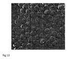
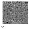
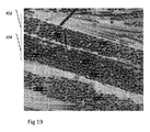
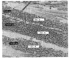
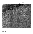
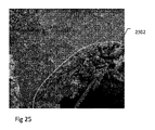
- 238000001878 scanning electron micrograph Methods 0.000 description 8
- 238000000354 decomposition reaction Methods 0.000 description 7
- 229920006237 degradable polymer Polymers 0.000 description 7
- 230000001965 increasing effect Effects 0.000 description 7
- 238000003780 insertion Methods 0.000 description 7
- 230000037431 insertion Effects 0.000 description 7
- 238000005297 material degradation process Methods 0.000 description 7
- 238000013001 point bending Methods 0.000 description 7
- 230000009286 beneficial effect Effects 0.000 description 6
- OSGAYBCDTDRGGQ-UHFFFAOYSA-L calcium sulfate Chemical compound [Ca+2].[O-]S([O-])(=O)=O OSGAYBCDTDRGGQ-UHFFFAOYSA-L 0.000 description 6
- 238000009826 distribution Methods 0.000 description 6
- 239000012634 fragment Substances 0.000 description 6
- 230000035876 healing Effects 0.000 description 6
- 238000007655 standard test method Methods 0.000 description 6
- 230000002459 sustained effect Effects 0.000 description 6
- 230000006870 function Effects 0.000 description 5
- 238000001746 injection moulding Methods 0.000 description 5
- 230000000278 osteoconductive effect Effects 0.000 description 5
- 230000002829 reductive effect Effects 0.000 description 5
- 239000011208 reinforced composite material Substances 0.000 description 5
- 239000000243 solution Substances 0.000 description 5
- 230000008961 swelling Effects 0.000 description 5
- 229920003002 synthetic resin Polymers 0.000 description 5
- 239000000654 additive Substances 0.000 description 4
- 239000011575 calcium Substances 0.000 description 4
- 239000001506 calcium phosphate Substances 0.000 description 4
- 210000003275 diaphysis Anatomy 0.000 description 4
- 239000011152 fibreglass Substances 0.000 description 4
- 229910052588 hydroxylapatite Inorganic materials 0.000 description 4
- 230000007246 mechanism Effects 0.000 description 4
- XYJRXVWERLGGKC-UHFFFAOYSA-D pentacalcium;hydroxide;triphosphate Chemical compound [OH-].[Ca+2].[Ca+2].[Ca+2].[Ca+2].[Ca+2].[O-]P([O-])([O-])=O.[O-]P([O-])([O-])=O.[O-]P([O-])([O-])=O XYJRXVWERLGGKC-UHFFFAOYSA-D 0.000 description 4
- 239000000047 product Substances 0.000 description 4
- 230000004044 response Effects 0.000 description 4
- 238000001356 surgical procedure Methods 0.000 description 4
- 238000009864 tensile test Methods 0.000 description 4
- 229920002430 Fibre-reinforced plastic Polymers 0.000 description 3
- KKCBUQHMOMHUOY-UHFFFAOYSA-N Na2O Inorganic materials [O-2].[Na+].[Na+] KKCBUQHMOMHUOY-UHFFFAOYSA-N 0.000 description 3
- 239000002250 absorbent Substances 0.000 description 3
- 230000002745 absorbent Effects 0.000 description 3
- 230000000996 additive effect Effects 0.000 description 3
- 230000008901 benefit Effects 0.000 description 3
- 239000005312 bioglass Substances 0.000 description 3
- 229910000389 calcium phosphate Inorganic materials 0.000 description 3
- 235000011010 calcium phosphates Nutrition 0.000 description 3
- 239000000919 ceramic Substances 0.000 description 3
- 229910052681 coesite Inorganic materials 0.000 description 3
- 238000010276 construction Methods 0.000 description 3
- 239000007822 coupling agent Substances 0.000 description 3
- 229910052906 cristobalite Inorganic materials 0.000 description 3
- 239000007857 degradation product Substances 0.000 description 3
- 239000011151 fibre-reinforced plastic Substances 0.000 description 3
- 230000009969 flowable effect Effects 0.000 description 3
- 230000036541 health Effects 0.000 description 3
- 238000006460 hydrolysis reaction Methods 0.000 description 3
- 230000002757 inflammatory effect Effects 0.000 description 3
- 239000011810 insulating material Substances 0.000 description 3
- 238000011068 loading method Methods 0.000 description 3
- 230000007774 longterm Effects 0.000 description 3
- 238000003754 machining Methods 0.000 description 3
- 150000002739 metals Chemical class 0.000 description 3
- 239000004632 polycaprolactone Substances 0.000 description 3
- 239000002861 polymer material Substances 0.000 description 3
- 230000008569 process Effects 0.000 description 3
- 238000011002 quantification Methods 0.000 description 3
- 239000002990 reinforced plastic Substances 0.000 description 3
- 229920005989 resin Polymers 0.000 description 3
- 239000011347 resin Substances 0.000 description 3
- 238000004626 scanning electron microscopy Methods 0.000 description 3
- 235000012239 silicon dioxide Nutrition 0.000 description 3
- 210000004872 soft tissue Anatomy 0.000 description 3
- 238000004544 sputter deposition Methods 0.000 description 3
- 229910052682 stishovite Inorganic materials 0.000 description 3
- 229910052905 tridymite Inorganic materials 0.000 description 3
- JJTUDXZGHPGLLC-IMJSIDKUSA-N 4511-42-6 Chemical compound C[C@@H]1OC(=O)[C@H](C)OC1=O JJTUDXZGHPGLLC-IMJSIDKUSA-N 0.000 description 2
- 206010061218 Inflammation Diseases 0.000 description 2
- 239000004696 Poly ether ether ketone Substances 0.000 description 2
- 238000010521 absorption reaction Methods 0.000 description 2
- 239000012620 biological material Substances 0.000 description 2
- 230000037118 bone strength Effects 0.000 description 2
- 150000004649 carbonic acid derivatives Chemical class 0.000 description 2
- 238000003776 cleavage reaction Methods 0.000 description 2
- 208000031513 cyst Diseases 0.000 description 2
- 238000005553 drilling Methods 0.000 description 2
- 238000001125 extrusion Methods 0.000 description 2
- 239000012530 fluid Substances 0.000 description 2
- 230000004927 fusion Effects 0.000 description 2
- 230000007062 hydrolysis Effects 0.000 description 2
- 230000002209 hydrophobic effect Effects 0.000 description 2
- 230000004054 inflammatory process Effects 0.000 description 2
- 150000002484 inorganic compounds Chemical class 0.000 description 2
- 229910010272 inorganic material Inorganic materials 0.000 description 2
- 210000003041 ligament Anatomy 0.000 description 2
- 230000014759 maintenance of location Effects 0.000 description 2
- 238000002844 melting Methods 0.000 description 2
- 230000008018 melting Effects 0.000 description 2
- 238000001000 micrograph Methods 0.000 description 2
- 238000000465 moulding Methods 0.000 description 2
- 229920005615 natural polymer Polymers 0.000 description 2
- 231100000252 nontoxic Toxicity 0.000 description 2
- 230000003000 nontoxic effect Effects 0.000 description 2
- 230000002138 osteoinductive effect Effects 0.000 description 2
- 230000036961 partial effect Effects 0.000 description 2
- 239000002245 particle Substances 0.000 description 2
- 229920002530 polyetherether ketone Polymers 0.000 description 2
- 229920002643 polyglutamic acid Polymers 0.000 description 2
- 239000004626 polylactic acid Substances 0.000 description 2
- 229920001343 polytetrafluoroethylene Polymers 0.000 description 2
- 239000004810 polytetrafluoroethylene Substances 0.000 description 2
- 238000007639 printing Methods 0.000 description 2
- 238000010079 rubber tapping Methods 0.000 description 2
- 230000007017 scission Effects 0.000 description 2
- 239000002904 solvent Substances 0.000 description 2
- 239000010935 stainless steel Substances 0.000 description 2
- 238000007920 subcutaneous administration Methods 0.000 description 2
- KZNICNPSHKQLFF-UHFFFAOYSA-N succinimide Chemical compound O=C1CCC(=O)N1 KZNICNPSHKQLFF-UHFFFAOYSA-N 0.000 description 2
- 238000010146 3D printing Methods 0.000 description 1
- 206010065687 Bone loss Diseases 0.000 description 1
- 229920002101 Chitin Polymers 0.000 description 1
- 208000024779 Comminuted Fractures Diseases 0.000 description 1
- 229920001634 Copolyester Polymers 0.000 description 1
- 208000037408 Device failure Diseases 0.000 description 1
- 206010030113 Oedema Diseases 0.000 description 1
- 241000283973 Oryctolagus cuniculus Species 0.000 description 1
- 206010073853 Osteochondral fracture Diseases 0.000 description 1
- 206010035148 Plague Diseases 0.000 description 1
- 229910001069 Ti alloy Inorganic materials 0.000 description 1
- RTAQQCXQSZGOHL-UHFFFAOYSA-N Titanium Chemical compound [Ti] RTAQQCXQSZGOHL-UHFFFAOYSA-N 0.000 description 1
- 229920010741 Ultra High Molecular Weight Polyethylene (UHMWPE) Polymers 0.000 description 1
- 241000607479 Yersinia pestis Species 0.000 description 1
- 206010000269 abscess Diseases 0.000 description 1
- 230000002378 acidificating effect Effects 0.000 description 1
- 150000007513 acids Chemical class 0.000 description 1
- 230000002411 adverse Effects 0.000 description 1
- 229910045601 alloy Inorganic materials 0.000 description 1
- 239000000956 alloy Substances 0.000 description 1
- PNEYBMLMFCGWSK-UHFFFAOYSA-N aluminium oxide Inorganic materials [O-2].[O-2].[O-2].[Al+3].[Al+3] PNEYBMLMFCGWSK-UHFFFAOYSA-N 0.000 description 1
- 230000000844 anti-bacterial effect Effects 0.000 description 1
- 239000004599 antimicrobial Substances 0.000 description 1
- 239000005313 bioactive glass Substances 0.000 description 1
- 239000000560 biocompatible material Substances 0.000 description 1
- 230000004071 biological effect Effects 0.000 description 1
- 229920001400 block copolymer Polymers 0.000 description 1
- 230000017531 blood circulation Effects 0.000 description 1
- 230000036770 blood supply Effects 0.000 description 1
- 239000010839 body fluid Substances 0.000 description 1
- 210000001124 body fluid Anatomy 0.000 description 1
- 210000001185 bone marrow Anatomy 0.000 description 1
- 230000010072 bone remodeling Effects 0.000 description 1
- 239000006227 byproduct Substances 0.000 description 1
- 238000005266 casting Methods 0.000 description 1
- 238000012668 chain scission Methods 0.000 description 1
- 230000008859 change Effects 0.000 description 1
- 239000003795 chemical substances by application Substances 0.000 description 1
- 230000006835 compression Effects 0.000 description 1
- 238000007906 compression Methods 0.000 description 1
- 238000012790 confirmation Methods 0.000 description 1
- 229910052593 corundum Inorganic materials 0.000 description 1
- 230000006378 damage Effects 0.000 description 1
- 239000000412 dendrimer Substances 0.000 description 1
- 229920000736 dendritic polymer Polymers 0.000 description 1
- 230000001419 dependent effect Effects 0.000 description 1
- 238000000151 deposition Methods 0.000 description 1
- 238000011161 development Methods 0.000 description 1
- 230000018109 developmental process Effects 0.000 description 1
- 238000000113 differential scanning calorimetry Methods 0.000 description 1
- 230000004064 dysfunction Effects 0.000 description 1
- 230000000694 effects Effects 0.000 description 1
- 238000010894 electron beam technology Methods 0.000 description 1
- 230000008030 elimination Effects 0.000 description 1
- 238000003379 elimination reaction Methods 0.000 description 1
- 238000005538 encapsulation Methods 0.000 description 1
- 230000003628 erosive effect Effects 0.000 description 1
- 238000002474 experimental method Methods 0.000 description 1
- 210000003414 extremity Anatomy 0.000 description 1
- 238000009730 filament winding Methods 0.000 description 1
- 238000001914 filtration Methods 0.000 description 1
- 239000006260 foam Substances 0.000 description 1
- 230000009477 glass transition Effects 0.000 description 1
- 229920000578 graft copolymer Polymers 0.000 description 1
- 230000012010 growth Effects 0.000 description 1
- 210000003128 head Anatomy 0.000 description 1
- 238000011540 hip replacement Methods 0.000 description 1
- 229920001519 homopolymer Polymers 0.000 description 1
- 230000003301 hydrolyzing effect Effects 0.000 description 1
- 125000004356 hydroxy functional group Chemical group O* 0.000 description 1
- 238000003384 imaging method Methods 0.000 description 1
- 230000006872 improvement Effects 0.000 description 1
- 238000010348 incorporation Methods 0.000 description 1
- 230000001939 inductive effect Effects 0.000 description 1
- 230000028709 inflammatory response Effects 0.000 description 1
- 238000002347 injection Methods 0.000 description 1
- 239000007924 injection Substances 0.000 description 1
- 230000010354 integration Effects 0.000 description 1
- 230000003993 interaction Effects 0.000 description 1
- 210000000936 intestine Anatomy 0.000 description 1
- 150000002500 ions Chemical class 0.000 description 1
- 238000005304 joining Methods 0.000 description 1
- 238000013150 knee replacement Methods 0.000 description 1
- 230000000670 limiting effect Effects 0.000 description 1
- 230000033001 locomotion Effects 0.000 description 1
- 238000012423 maintenance Methods 0.000 description 1
- 238000005259 measurement Methods 0.000 description 1
- 230000005226 mechanical processes and functions Effects 0.000 description 1
- 230000002503 metabolic effect Effects 0.000 description 1
- 230000004060 metabolic process Effects 0.000 description 1
- 229910001092 metal group alloy Inorganic materials 0.000 description 1
- 238000002156 mixing Methods 0.000 description 1
- 239000002113 nanodiamond Substances 0.000 description 1
- HLXZNVUGXRDIFK-UHFFFAOYSA-N nickel titanium Chemical compound [Ti].[Ti].[Ti].[Ti].[Ti].[Ti].[Ti].[Ti].[Ti].[Ti].[Ti].[Ni].[Ni].[Ni].[Ni].[Ni].[Ni].[Ni].[Ni].[Ni].[Ni].[Ni].[Ni].[Ni].[Ni] HLXZNVUGXRDIFK-UHFFFAOYSA-N 0.000 description 1
- 229910001000 nickel titanium Inorganic materials 0.000 description 1
- 239000011368 organic material Substances 0.000 description 1
- 230000002188 osteogenic effect Effects 0.000 description 1
- 230000037361 pathway Effects 0.000 description 1
- 230000000149 penetrating effect Effects 0.000 description 1
- 230000035515 penetration Effects 0.000 description 1
- 230000002085 persistent effect Effects 0.000 description 1
- 230000035790 physiological processes and functions Effects 0.000 description 1
- 229920000058 polyacrylate Polymers 0.000 description 1
- 238000012667 polymer degradation Methods 0.000 description 1
- 229920000307 polymer substrate Polymers 0.000 description 1
- 229920000193 polymethacrylate Polymers 0.000 description 1
- 229920001296 polysiloxane Polymers 0.000 description 1
- 239000000843 powder Substances 0.000 description 1
- 230000002028 premature Effects 0.000 description 1
- 238000002360 preparation method Methods 0.000 description 1
- 210000002307 prostate Anatomy 0.000 description 1
- 230000006340 racemization Effects 0.000 description 1
- 230000005855 radiation Effects 0.000 description 1
- 229920005604 random copolymer Polymers 0.000 description 1
- 239000012779 reinforcing material Substances 0.000 description 1
- 238000007634 remodeling Methods 0.000 description 1
- 230000008439 repair process Effects 0.000 description 1
- 238000011160 research Methods 0.000 description 1
- 150000003839 salts Chemical class 0.000 description 1
- 229910001220 stainless steel Inorganic materials 0.000 description 1
- 229910001256 stainless steel alloy Inorganic materials 0.000 description 1
- 230000001954 sterilising effect Effects 0.000 description 1
- 238000004659 sterilization and disinfection Methods 0.000 description 1
- 238000003860 storage Methods 0.000 description 1
- 230000007019 strand scission Effects 0.000 description 1
- 229960002317 succinimide Drugs 0.000 description 1
- 229920002994 synthetic fiber Polymers 0.000 description 1
- 210000002303 tibia Anatomy 0.000 description 1
- 230000017423 tissue regeneration Effects 0.000 description 1
- 239000010936 titanium Substances 0.000 description 1
- 229910052719 titanium Inorganic materials 0.000 description 1
- 238000004448 titration Methods 0.000 description 1
- 238000002054 transplantation Methods 0.000 description 1
- 229940078499 tricalcium phosphate Drugs 0.000 description 1
- 229910000391 tricalcium phosphate Inorganic materials 0.000 description 1
- 235000019731 tricalcium phosphate Nutrition 0.000 description 1
- 229910001845 yogo sapphire Inorganic materials 0.000 description 1
Images


Classifications
-
- A—HUMAN NECESSITIES
- A61—MEDICAL OR VETERINARY SCIENCE; HYGIENE
- A61B—DIAGNOSIS; SURGERY; IDENTIFICATION
- A61B17/00—Surgical instruments, devices or methods, e.g. tourniquets
- A61B17/56—Surgical instruments or methods for treatment of bones or joints; Devices specially adapted therefor
- A61B17/58—Surgical instruments or methods for treatment of bones or joints; Devices specially adapted therefor for osteosynthesis, e.g. bone plates, screws, setting implements or the like
- A61B17/68—Internal fixation devices, including fasteners and spinal fixators, even if a part thereof projects from the skin
- A61B17/80—Cortical plates, i.e. bone plates; Instruments for holding or positioning cortical plates, or for compressing bones attached to cortical plates
-
- A—HUMAN NECESSITIES
- A61—MEDICAL OR VETERINARY SCIENCE; HYGIENE
- A61B—DIAGNOSIS; SURGERY; IDENTIFICATION
- A61B17/00—Surgical instruments, devices or methods, e.g. tourniquets
- A61B17/56—Surgical instruments or methods for treatment of bones or joints; Devices specially adapted therefor
- A61B17/58—Surgical instruments or methods for treatment of bones or joints; Devices specially adapted therefor for osteosynthesis, e.g. bone plates, screws, setting implements or the like
- A61B17/68—Internal fixation devices, including fasteners and spinal fixators, even if a part thereof projects from the skin
- A61B17/84—Fasteners therefor or fasteners being internal fixation devices
- A61B17/86—Pins or screws or threaded wires; nuts therefor
- A61B17/866—Material or manufacture
-
- A—HUMAN NECESSITIES
- A61—MEDICAL OR VETERINARY SCIENCE; HYGIENE
- A61F—FILTERS IMPLANTABLE INTO BLOOD VESSELS; PROSTHESES; DEVICES PROVIDING PATENCY TO, OR PREVENTING COLLAPSING OF, TUBULAR STRUCTURES OF THE BODY, e.g. STENTS; ORTHOPAEDIC, NURSING OR CONTRACEPTIVE DEVICES; FOMENTATION; TREATMENT OR PROTECTION OF EYES OR EARS; BANDAGES, DRESSINGS OR ABSORBENT PADS; FIRST-AID KITS
- A61F2/00—Filters implantable into blood vessels; Prostheses, i.e. artificial substitutes or replacements for parts of the body; Appliances for connecting them with the body; Devices providing patency to, or preventing collapsing of, tubular structures of the body, e.g. stents
- A61F2/02—Prostheses implantable into the body
- A61F2/30—Joints
- A61F2/44—Joints for the spine, e.g. vertebrae, spinal discs
-
- A—HUMAN NECESSITIES
- A61—MEDICAL OR VETERINARY SCIENCE; HYGIENE
- A61L—METHODS OR APPARATUS FOR STERILISING MATERIALS OR OBJECTS IN GENERAL; DISINFECTION, STERILISATION OR DEODORISATION OF AIR; CHEMICAL ASPECTS OF BANDAGES, DRESSINGS, ABSORBENT PADS OR SURGICAL ARTICLES; MATERIALS FOR BANDAGES, DRESSINGS, ABSORBENT PADS OR SURGICAL ARTICLES
- A61L27/00—Materials for grafts or prostheses or for coating grafts or prostheses
- A61L27/28—Materials for coating prostheses
- A61L27/34—Macromolecular materials
-
- A—HUMAN NECESSITIES
- A61—MEDICAL OR VETERINARY SCIENCE; HYGIENE
- A61L—METHODS OR APPARATUS FOR STERILISING MATERIALS OR OBJECTS IN GENERAL; DISINFECTION, STERILISATION OR DEODORISATION OF AIR; CHEMICAL ASPECTS OF BANDAGES, DRESSINGS, ABSORBENT PADS OR SURGICAL ARTICLES; MATERIALS FOR BANDAGES, DRESSINGS, ABSORBENT PADS OR SURGICAL ARTICLES
- A61L27/00—Materials for grafts or prostheses or for coating grafts or prostheses
- A61L27/40—Composite materials, i.e. containing one material dispersed in a matrix of the same or different material
- A61L27/44—Composite materials, i.e. containing one material dispersed in a matrix of the same or different material having a macromolecular matrix
- A61L27/446—Composite materials, i.e. containing one material dispersed in a matrix of the same or different material having a macromolecular matrix with other specific inorganic fillers other than those covered by A61L27/443 or A61L27/46
-
- A—HUMAN NECESSITIES
- A61—MEDICAL OR VETERINARY SCIENCE; HYGIENE
- A61L—METHODS OR APPARATUS FOR STERILISING MATERIALS OR OBJECTS IN GENERAL; DISINFECTION, STERILISATION OR DEODORISATION OF AIR; CHEMICAL ASPECTS OF BANDAGES, DRESSINGS, ABSORBENT PADS OR SURGICAL ARTICLES; MATERIALS FOR BANDAGES, DRESSINGS, ABSORBENT PADS OR SURGICAL ARTICLES
- A61L27/00—Materials for grafts or prostheses or for coating grafts or prostheses
- A61L27/50—Materials characterised by their function or physical properties, e.g. injectable or lubricating compositions, shape-memory materials, surface modified materials
- A61L27/58—Materials at least partially resorbable by the body
-
- A—HUMAN NECESSITIES
- A61—MEDICAL OR VETERINARY SCIENCE; HYGIENE
- A61L—METHODS OR APPARATUS FOR STERILISING MATERIALS OR OBJECTS IN GENERAL; DISINFECTION, STERILISATION OR DEODORISATION OF AIR; CHEMICAL ASPECTS OF BANDAGES, DRESSINGS, ABSORBENT PADS OR SURGICAL ARTICLES; MATERIALS FOR BANDAGES, DRESSINGS, ABSORBENT PADS OR SURGICAL ARTICLES
- A61L31/00—Materials for other surgical articles, e.g. stents, stent-grafts, shunts, surgical drapes, guide wires, materials for adhesion prevention, occluding devices, surgical gloves, tissue fixation devices
- A61L31/12—Composite materials, i.e. containing one material dispersed in a matrix of the same or different material
- A61L31/125—Composite materials, i.e. containing one material dispersed in a matrix of the same or different material having a macromolecular matrix
- A61L31/128—Composite materials, i.e. containing one material dispersed in a matrix of the same or different material having a macromolecular matrix containing other specific inorganic fillers not covered by A61L31/126 or A61L31/127
-
- A—HUMAN NECESSITIES
- A61—MEDICAL OR VETERINARY SCIENCE; HYGIENE
- A61L—METHODS OR APPARATUS FOR STERILISING MATERIALS OR OBJECTS IN GENERAL; DISINFECTION, STERILISATION OR DEODORISATION OF AIR; CHEMICAL ASPECTS OF BANDAGES, DRESSINGS, ABSORBENT PADS OR SURGICAL ARTICLES; MATERIALS FOR BANDAGES, DRESSINGS, ABSORBENT PADS OR SURGICAL ARTICLES
- A61L31/00—Materials for other surgical articles, e.g. stents, stent-grafts, shunts, surgical drapes, guide wires, materials for adhesion prevention, occluding devices, surgical gloves, tissue fixation devices
- A61L31/14—Materials characterised by their function or physical properties, e.g. injectable or lubricating compositions, shape-memory materials, surface modified materials
- A61L31/148—Materials at least partially resorbable by the body
-
- A—HUMAN NECESSITIES
- A61—MEDICAL OR VETERINARY SCIENCE; HYGIENE
- A61F—FILTERS IMPLANTABLE INTO BLOOD VESSELS; PROSTHESES; DEVICES PROVIDING PATENCY TO, OR PREVENTING COLLAPSING OF, TUBULAR STRUCTURES OF THE BODY, e.g. STENTS; ORTHOPAEDIC, NURSING OR CONTRACEPTIVE DEVICES; FOMENTATION; TREATMENT OR PROTECTION OF EYES OR EARS; BANDAGES, DRESSINGS OR ABSORBENT PADS; FIRST-AID KITS
- A61F2/00—Filters implantable into blood vessels; Prostheses, i.e. artificial substitutes or replacements for parts of the body; Appliances for connecting them with the body; Devices providing patency to, or preventing collapsing of, tubular structures of the body, e.g. stents
- A61F2/02—Prostheses implantable into the body
- A61F2/28—Bones
- A61F2/2846—Support means for bone substitute or for bone graft implants, e.g. membranes or plates for covering bone defects
-
- A—HUMAN NECESSITIES
- A61—MEDICAL OR VETERINARY SCIENCE; HYGIENE
- A61F—FILTERS IMPLANTABLE INTO BLOOD VESSELS; PROSTHESES; DEVICES PROVIDING PATENCY TO, OR PREVENTING COLLAPSING OF, TUBULAR STRUCTURES OF THE BODY, e.g. STENTS; ORTHOPAEDIC, NURSING OR CONTRACEPTIVE DEVICES; FOMENTATION; TREATMENT OR PROTECTION OF EYES OR EARS; BANDAGES, DRESSINGS OR ABSORBENT PADS; FIRST-AID KITS
- A61F2/00—Filters implantable into blood vessels; Prostheses, i.e. artificial substitutes or replacements for parts of the body; Appliances for connecting them with the body; Devices providing patency to, or preventing collapsing of, tubular structures of the body, e.g. stents
- A61F2/02—Prostheses implantable into the body
- A61F2/30—Joints
- A61F2002/30001—Additional features of subject-matter classified in A61F2/28, A61F2/30 and subgroups thereof
- A61F2002/30003—Material related properties of the prosthesis or of a coating on the prosthesis
- A61F2002/3006—Properties of materials and coating materials
- A61F2002/30062—(bio)absorbable, biodegradable, bioerodable, (bio)resorbable, resorptive
-
- A—HUMAN NECESSITIES
- A61—MEDICAL OR VETERINARY SCIENCE; HYGIENE
- A61F—FILTERS IMPLANTABLE INTO BLOOD VESSELS; PROSTHESES; DEVICES PROVIDING PATENCY TO, OR PREVENTING COLLAPSING OF, TUBULAR STRUCTURES OF THE BODY, e.g. STENTS; ORTHOPAEDIC, NURSING OR CONTRACEPTIVE DEVICES; FOMENTATION; TREATMENT OR PROTECTION OF EYES OR EARS; BANDAGES, DRESSINGS OR ABSORBENT PADS; FIRST-AID KITS
- A61F2/00—Filters implantable into blood vessels; Prostheses, i.e. artificial substitutes or replacements for parts of the body; Appliances for connecting them with the body; Devices providing patency to, or preventing collapsing of, tubular structures of the body, e.g. stents
- A61F2/02—Prostheses implantable into the body
- A61F2/30—Joints
- A61F2002/30001—Additional features of subject-matter classified in A61F2/28, A61F2/30 and subgroups thereof
- A61F2002/30003—Material related properties of the prosthesis or of a coating on the prosthesis
- A61F2002/3006—Properties of materials and coating materials
- A61F2002/30069—Properties of materials and coating materials elastomeric
-
- A—HUMAN NECESSITIES
- A61—MEDICAL OR VETERINARY SCIENCE; HYGIENE
- A61L—METHODS OR APPARATUS FOR STERILISING MATERIALS OR OBJECTS IN GENERAL; DISINFECTION, STERILISATION OR DEODORISATION OF AIR; CHEMICAL ASPECTS OF BANDAGES, DRESSINGS, ABSORBENT PADS OR SURGICAL ARTICLES; MATERIALS FOR BANDAGES, DRESSINGS, ABSORBENT PADS OR SURGICAL ARTICLES
- A61L31/00—Materials for other surgical articles, e.g. stents, stent-grafts, shunts, surgical drapes, guide wires, materials for adhesion prevention, occluding devices, surgical gloves, tissue fixation devices
- A61L31/08—Materials for coatings
- A61L31/10—Macromolecular materials
-
- B—PERFORMING OPERATIONS; TRANSPORTING
- B29—WORKING OF PLASTICS; WORKING OF SUBSTANCES IN A PLASTIC STATE IN GENERAL
- B29C—SHAPING OR JOINING OF PLASTICS; SHAPING OF MATERIAL IN A PLASTIC STATE, NOT OTHERWISE PROVIDED FOR; AFTER-TREATMENT OF THE SHAPED PRODUCTS, e.g. REPAIRING
- B29C70/00—Shaping composites, i.e. plastics material comprising reinforcements, fillers or preformed parts, e.g. inserts
- B29C70/04—Shaping composites, i.e. plastics material comprising reinforcements, fillers or preformed parts, e.g. inserts comprising reinforcements only, e.g. self-reinforcing plastics
- B29C70/06—Fibrous reinforcements only
- B29C70/10—Fibrous reinforcements only characterised by the structure of fibrous reinforcements, e.g. hollow fibres
- B29C70/16—Fibrous reinforcements only characterised by the structure of fibrous reinforcements, e.g. hollow fibres using fibres of substantial or continuous length
- B29C70/22—Fibrous reinforcements only characterised by the structure of fibrous reinforcements, e.g. hollow fibres using fibres of substantial or continuous length oriented in at least two directions forming a two dimensional structure
Landscapes
- Health & Medical Sciences (AREA)
- Life Sciences & Earth Sciences (AREA)
- Orthopedic Medicine & Surgery (AREA)
- Animal Behavior & Ethology (AREA)
- Veterinary Medicine (AREA)
- Public Health (AREA)
- General Health & Medical Sciences (AREA)
- Engineering & Computer Science (AREA)
- Chemical & Material Sciences (AREA)
- Surgery (AREA)
- Heart & Thoracic Surgery (AREA)
- Epidemiology (AREA)
- Transplantation (AREA)
- Oral & Maxillofacial Surgery (AREA)
- Biomedical Technology (AREA)
- Vascular Medicine (AREA)
- Medicinal Chemistry (AREA)
- Dermatology (AREA)
- Neurology (AREA)
- Composite Materials (AREA)
- Molecular Biology (AREA)
- Medical Informatics (AREA)
- Nuclear Medicine, Radiotherapy & Molecular Imaging (AREA)
- Materials Engineering (AREA)
- Inorganic Chemistry (AREA)
- Cardiology (AREA)
- Textile Engineering (AREA)
- Mechanical Engineering (AREA)
- Materials For Medical Uses (AREA)
- Prostheses (AREA)
- Chemical Kinetics & Catalysis (AREA)
- Polymers & Plastics (AREA)
- Organic Chemistry (AREA)
Abstract
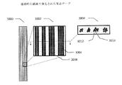
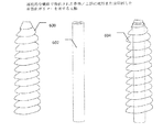
医療用インプラントであって、複数の層を含み、それぞれの層が、ポリマー及び複数の一方向に配列した連続的な強化用繊維を含む、医療用インプラント。【選択図】図32bA medical implant comprising a plurality of layers, each layer comprising a polymer and a plurality of unidirectionally arranged continuous reinforcing fibers. [Selected figure] Figure 32b
Description
背景技術
永久整形外科用インプラント材料
医療用インプラントは、金属、合金、セラミック又は分解性でかつ安定な複合材料から製造できる。耐荷重下、すなわち高強度を必要とする整形外科用途では通常、ステンレス鋼又はチタン合金が使用される。金属インプラントは、整形外科手術における使用において長年成功してきたが、合併症に対する多くのリスクも伴う。これらの材料は不活性であるが、それらはまた、インプラントの必要性が、骨折固定のような一時的な場合にも用いられる。骨折固定のための金属棒及びプレートの場合、骨結合の確認後約1年後に、器具を除去するための第2の手術が、推奨される場合がある。インプラント除去は、患者に更なるリスクが生じ、罹患率を高め、クリニックの利用可能率を占め、全体的な処置費用を増大させる。器具を除去しない場合、骨の再構築を引き起こす恐れがある。更には、このような再構築は、宿主組織のストレスシールディング又は炎症によって、骨が脆弱になる恐れがある。皮質骨の剛性及び強度と比較して金属の剛性(弾性率)及び強度が高いことによって、ストレスシールディングが生じる恐れがあるため、金属が骨を圧迫して、前立腺周囲の骨折又は骨強度の損失をもたらす恐れがある。
Background art
Implant materials for permanent orthopedic implants Medical implants can be manufactured from metals, alloys, ceramics or degradable and stable composites. Stainless steel or titanium alloys are usually used in load bearing applications, ie in orthopedic applications requiring high strength. Metal implants have been successful for many years in use in orthopedic surgery, but also carry many risks for complications. Although these materials are inert, they are also used where the need for an implant is temporary, such as fracture fixation. In the case of metal bars and plates for fracture fixation, a second surgery to remove the instrument may be recommended approximately one year after confirmation of bone attachment. Implant removal poses additional risk to the patient, increasing morbidity, accounting for clinic availability and increasing overall treatment costs. If the device is not removed, it can cause bone remodeling. Furthermore, such remodeling can lead to bone fragility due to stress shielding or inflammation of the host tissue. Due to the high stiffness (elastic modulus) and strength of the metal compared to the stiffness and strength of cortical bone, stress shielding may occur, causing the metal to compress the bone and causing fracture or bone strength around the prostate. There is a risk of loss.
従来、金属合金で構築された耐荷重医療用インプラントの例として、治療するために骨片を固定する骨折固定及び/又は骨切り術用の骨プレート、棒、スクリュー、タック、釘、クランプ及びピンが挙げられる。他の例としては、脊椎手術における椎骨癒合及び他の手術用の頸部ウェッジ、腰椎ケージ及びプレート並びにスクリューが挙げられる。 Conventionally, bone plates, rods, screws, tacks, nails, clamps and pins for bone fixation and / or osteotomy, which fix bone fragments for treatment, as an example of a load-bearing medical implant constructed of metal alloys Can be mentioned. Other examples include cervical wedges for lumbar fusion and other operations in spinal surgery, lumbar cages and plates and screws.
例えば、ポリメタクリレート(PMMA)、超高分子量ポリエチレン(UHMWPE)、ポリテトラフルオロエチレン(PTFE)、ポリエーテルエーテルケトン(PEEK)、ポリシロキサン及びアクリルポリマーに基づく、生体安定性ポリマー及びその複合材料もまた、医療用インプラントの製造に用いられてきた。これらの材料は、生分解性又は生体吸収性ではなく、そのため医療用インプラント用途に用いたとき、多くの金属と同一の限界に直面し、例えば、それらはインプラントの寿命におけるある時点でインプラントを交換又は除去するための第2の手術を必要とする場合がある。更に、これらの材料は、金属より脆弱であり(強度及び剛性が低く)、そのためそれらは、特に動的負荷を繰り返した後(すなわち、材料の疲労又はクリープにより)、機械的故障をより受けやすくなる。
既存の分解性ポリマーの医療用インプラント
For example, biostable polymers and composites thereof based on polymethacrylate (PMMA), ultra-high molecular weight polyethylene (UHMWPE), polytetrafluoroethylene (PTFE), polyetheretherketone (PEEK), polysiloxanes and acrylic polymers , Has been used in the manufacture of medical implants. These materials are not biodegradable or bioabsorbable, and thus face the same limitations as many metals when used in medical implant applications, for example, they replace the implant at some point in the life of the implant Or it may require a second surgery to remove it. Furthermore, these materials are more brittle than metals (less strength and stiffness) so they are more susceptible to mechanical failure, especially after repeated dynamic loading (ie, due to material fatigue or creep) Become.
Medical implants for existing degradable polymers
吸収性ポリマーが、吸収性インプラントの開発に用いられてきており、吸収性、生体吸収性又は生分解性インプラントと呼ばれることもある。生体適合性がある吸収性ポリマーを用いる利点は、ポリマーひいてはインプラントが、体内で吸収され、代謝系によって代謝される非毒性分解生成物を放出することである。ポリ乳酸及びポリグリコール酸及びポリジオキサンを含むポリマーは、頭蓋顔面用途などの非耐荷重性医療用インプラント用途のために整形外科プレート、棒、アンカー、ピン又はスクリューとして現在用いられている吸収性がある生体適合性材料である。これらの医療用インプラント材料は、最終的な吸収という利点を提供し、応力を骨折からの再構築に転換しながら、後に除去する必要性を排除している。しかし、現在の生体吸収性材料及びインプラントは、金属製インプラントに匹敵する機械特性を有しない。非強化の吸収性ポリマーの機械的強度及び弾性率(おおよそ3〜5GPa)は、おおよそ15〜20GPaの範囲の弾性率を有する骨折した皮質骨を支持するには不十分である(Snyder SMらは、ヒト脛骨の曲げ弾性率を約17.5GPaと測定した。Snyder SM Schneider E,Journal of Orthopedic Research,Vol.9,1991,pp.422−431)。そのため、吸収性ポリマーで構築された既存の医療用インプラントの適用には限界があり、それらの固定は通常、動き又は大きな荷重からの保護を必要とする。これらの器具は、小児患者又は成人の内果骨折、靭帯固定、顎顔面又は骨軟骨骨折などの低応力領域の固定が必要とされるとき(すなわち、非耐荷重用途)にのみ考慮される。
強化された分解性ポリマー材料
Absorbable polymers have been used in the development of absorbable implants and may be referred to as absorbable, bioabsorbable or biodegradable implants. The advantage of using a biocompatible, absorbable polymer is that the polymer and thus the implant release non-toxic degradation products that are absorbed in the body and metabolized by the metabolic system. Polymers containing polylactic acid and polyglycolic acid and polydioxane have absorbency currently used as orthopedic plates, rods, anchors, pins or screws for non-load bearing medical implant applications such as craniofacial applications It is a biocompatible material. These medical implant materials offer the advantage of ultimate absorption and eliminate the need for later removal while converting stress to reconstruction from fractures. However, current bioabsorbable materials and implants do not have mechanical properties comparable to metal implants. The mechanical strength and modulus (approximately 3 to 5 GPa) of non-reinforced absorbable polymers are insufficient to support fractured cortical bone with a modulus in the range of approximately 15 to 20 GPa (Snyder SM et al. The flexural modulus of human tibia was measured to be about 17.5 GPa, Snyder SM Schneider E, Journal of Orthopedic Research, Vol. 9, 1991, pp. 422-431). As such, the application of existing medical implants constructed of absorbable polymers is limited and their fixation usually requires protection from movement or heavy loads. These devices are only considered when fixation of a low stress area such as a capsular fracture, ligament fixation, craniofacial or osteochondral fracture of a pediatric patient or adult is required (i.e. non-load bearing applications).
Reinforced degradable polymer material
近年、強度及び剛性(弾性率)が改善された強化ポリマー材料が、導入されている。これらの生分解性複合材料は、通常繊維形態の充填剤によって強化されたポリマーを含む。複合材料では通常、比較的柔軟なマトリックス(すなわち、ポリマー)が、剛性及び強度がある強化材料と組み合わせられ、複合材料マトリックスの機械特性を向上させる。例えば、生分解性ガラス又は鉱物材料を用いて、生分解性ポリマーマトリックスの剛性及び強度を改善できる。先行技術では、このような複合材料を製造するための幾つかの試みが、報告されており、生物活性ガラス粒子、ヒドロキシアパタイト粉末又は短いガラス繊維を用いて、生分解性ポリマーの特性を向上させた。ほとんどの場合、これらの複合材料の強度及び剛性は、皮質骨より低いか又は生理学的環境で急速に分解した後に皮質骨より低くなる。そのため、これらの複合材料の大部分は、耐荷重医療用インプラント用途の使用に適さない。しかし近年、皮質骨と同等か又はそれよりも高い強度及び剛性を有する生分解性複合材料、例えば、生分解性ポリマー及び20〜70vol%のガラス繊維を含む生分解性複合材料(WO2010128039 A1)が、報告されている。例えば、繊維で強化されたポリマーで形成された、他の複合材料インプラントが、米国特許第4,750,905号、同第5,181,930号、同第5,397,358号、同第5,009,664号、同第5,064,439号、同第4,978,360号、同第7,419,714号に開示されており、その開示は、本明細書に参考として組み込まれる。
強化された分解性ポリマー材料の分解メカニズム
Recently, reinforced polymeric materials with improved strength and stiffness (modulus of elasticity) have been introduced. These biodegradable composites usually comprise polymers reinforced by fillers in the form of fibres. In composites, a relatively flexible matrix (i.e., a polymer) is usually combined with the stiffening and strength reinforcing material to improve the mechanical properties of the composite matrix. For example, biodegradable glass or mineral materials can be used to improve the stiffness and strength of the biodegradable polymer matrix. In the prior art, several attempts to produce such composites have been reported, using bioactive glass particles, hydroxyapatite powder or short glass fibers to improve the properties of biodegradable polymers The In most cases, the strength and stiffness of these composites are lower than cortical bone or lower than cortical bone after rapid degradation in the physiological environment. As such, most of these composites are not suitable for use in load bearing medical implant applications. Recently, however, biodegradable composites having strength and stiffness equal to or higher than that of cortical bone, such as biodegradable composites comprising a biodegradable polymer and 20 to 70% by volume of glass fibers (WO2010128039 A1) ,It has been reported. For example, other composite implants formed of fiber reinforced polymers are disclosed in US Patents 4,750,905, 5,181,930, 5,397,358, Nos. 5,009,664, 5,064,439, 4,978,360 and 7,419,714, the disclosures of which are incorporated herein by reference. Be
Degradation mechanism of reinforced degradable polymer material
生分解性複合材料が、骨折を固定するためなど、耐荷重医療用インプラント用途に用いられるとき、医療用インプラントの機械特性は、長期間維持されなければならない。複合材料の分解によってインプラントの強度又は剛性を早期に損失することになり、不十分な骨断片の固定の結果、不適当な骨治癒になるなど、インプラントの機能不全を生じる恐れがある。 When biodegradable composites are used for load bearing medical implant applications, such as to fix fractures, the mechanical properties of the medical implant have to be maintained for a long time. The degradation of the composite material leads to an early loss of strength or stiffness of the implant, which may lead to dysfunction of the implant, such as inadequate bone healing as a result of insufficient fixation of bone fragments.
生分解性複合材料は、体液と接触すると加水分解を開始する。この分解は、生分解性ポリマー、強化充填剤又はその双方の分解の結果であり得る。特に、このような分解は、生理学的環境などの水性環境で、無機化合物によって強化された特定の強化ポリマー材料の機械的強度及び剛性の急速な降下をもたらす恐れがある。吸収性ポリマーマトリックスが有機材料であり、充填剤が無機化合物である場合、吸収性ポリマーマトリックスと充填剤間の接着性が、水性環境におけるポリマー又は充填剤のいずれかの分解によって低下し、急速に低下し、強化されたポリマーの初期機械特性が、急速に降下し、望ましい適切な耐荷重性能よりも低くなる恐れがある。ポリマー及び充填剤の個別の分解とは別に、ポリマーと強化材界面の相互作用及び接着性が乏しいことによって水性環境で界面において早期の破損をもたらす恐れがあり、それによって、強化材がポリマーから脱離し、充填剤の強化効果が失われたとき、急速な機械特性の降下がもたらされる。 Biodegradable composites initiate hydrolysis when in contact with body fluids. This degradation may be the result of the degradation of the biodegradable polymer, the reinforcing filler or both. In particular, such degradation can lead to a rapid drop in mechanical strength and stiffness of certain reinforced polymeric materials reinforced with inorganic compounds in an aqueous environment, such as a physiological environment. If the resorbable polymer matrix is an organic material and the filler is an inorganic compound, the adhesion between the resorbable polymer matrix and the filler is reduced by the degradation of either the polymer or the filler in an aqueous environment, and rapidly The initial mechanical properties of the degraded and reinforced polymer may drop rapidly and be less than desirable adequate load bearing performance. Aside from the individual degradation of the polymer and the filler, the poor interaction and adhesion of the polymer and the reinforcement interface can lead to premature failure at the interface in an aqueous environment, whereby the reinforcement is removed from the polymer When released and the reinforcing effect of the filler is lost, a rapid drop in mechanical properties results.
Tormalaら(WO2006/114483)は、ポリマーマトリックスに2種類の強化用繊維、1種類のポリマー及び1種類のセラミックを含有する複合材料について記載しており、皮質骨の特性と同等の良好な初期の機械的結果(420+/−39MPaの曲げ強度及び21.5GPaの曲げ弾性率)を報告した。しかし、先行技術では、吸収性ガラス繊維で強化された生体吸収性複合材料は、高い初期曲げ弾性率を有するが、インビトロで急速にそれらの強度及び弾性率が、失われることが教示されている。 Tormala et al. (WO 2006/114483) describe a composite containing two reinforcing fibers, one polymer and one ceramic in a polymer matrix and has a good initial equivalent to that of cortical bone. The mechanical results (bending strength of 420 +/- 39 MPa and bending modulus of 21.5 GPa) are reported. However, the prior art teaches that bioabsorbable composites reinforced with absorbable glass fibers have a high initial flexural modulus, but their strength and modulus are rapidly lost in vitro .
ポリマーと強化材間の界面結合(共有結合など)が改善されると、強化された生体吸収性ポリマーの機械特性の保持を、水性環境において有意に長くできる(WO2010128039A1)が、ポリマー、強化材又はそれら2つの界面間における連続的な加水分解によって、機械特性は、時間の経過と共に失われることになる。骨結合は、数ヶ月以上かかる場合があるため、共有結合で強化された生体吸収性ポリマーにおける機械特性の長期の分解プロファイルであっても、耐荷重整形外科用途に使用される医療用インプラントの最適な機能には不十分である恐れがある。 Improved interfacial bonding (such as covalent bonding) between the polymer and the reinforcement can significantly prolong the retention of the mechanical properties of the reinforced bioabsorbable polymer in an aqueous environment (WO 2010 1280 39 A1) but the polymer, the reinforcement or Due to the continuous hydrolysis between the two interfaces, the mechanical properties will be lost over time. Because osteointegration may take months or more, the long-term degradation profile of the mechanical properties of covalently reinforced bioresorbable polymers is the optimum for medical implants used for load bearing orthopedic applications May not be sufficient for
強化された分解性ポリマーのインプラントにおける強度損失の一例は、自己強化ポリ−L−乳酸に関連して記載されている(Majola A et al.,Journal of Materials Science Materials in Medicine,Vol.3,1992,pp.43−47)。そこで、自己強化ポリ−L−乳酸(SR−PLLA)複合材料の棒の強度及び強度の保持がウサギの髄内及び皮下移植後に評価された。SR−PLLA棒の初期曲げ強度は、250〜271MPaであった。髄内及び皮下移植の12週間後の、SR−PLLAインプラントの曲げ強度は、100MPaだった。 An example of strength loss in implants of reinforced degradable polymers is described in connection with self-reinforcing poly-L-lactic acid (Majola A et al., Journal of Materials Science Materials in Medicine, Vol. 3, 1992 , Pp. 43-47). Thus, the strength and strength retention of the self-reinforcing poly-L-lactic acid (SR-PLLA) composite material bar was evaluated after intramedullary and subcutaneous implantation in rabbits. The initial bending strength of the SR-PLLA bar was 250 to 271 MPa. The flexural strength of the SR-PLLA implant after 12 weeks of intramedullary and subcutaneous implantation was 100 MPa.
PLA、PGA及びPCLのコポリエステル及びターポリエステルについて、医療器具用の吸収性複合材料に最適なポリマーを調整することが興味深い。モノマー比及び分子量の選択が、吸収性複合材料の強度弾性率(strength elasticity)、弾性率(modulus)、熱特性、分解率及び溶融粘度に有意に影響し、これらのポリマーの全てが、インビトロ及びインビボの双方の水性条件下で分解性であることが知られている。分解工程では2つの段階が確認されており、第1に、分解は、ポリマーの分子量を低下させるエステル結合のランダム加水分解鎖切断によって進行する。第2段階では、鎖切断に加えて測定可能な重量損失が観察される。機械特性は、大部分が失われるか、又は重量損失が始まる時点で少なくとも顕著な低下がそれらに認められる。これらのポリマーの分解速度は、ポリマー構造、つまり結晶性、分子量、ガラス転移温度、ブロック長、ラセミ化及び鎖構築に応じて異なる(Middleton JC,Tipton AJ,Biomaterials 21,2000,2335−2346)。
整形外科用インプラント内における鉱物含有量の未解決の問題
It is interesting to tailor the polymers that are optimal for absorbent composites for medical devices, for copolyesters and terpolyesters of PLA, PGA and PCL. The choice of monomer ratio and molecular weight significantly affects the strength elasticity, modulus, thermal properties, degradation rate and melt viscosity of the absorbent composite, all of these polymers in vitro and in vivo. It is known to be degradable under both aqueous conditions in vivo. Two steps have been identified in the degradation process; first, degradation proceeds by random hydrolytic chain scission of the ester bond which reduces the molecular weight of the polymer. In the second stage, measurable weight loss is observed in addition to strand scission. The mechanical properties are at least significantly reduced at the point when the majority is lost or weight loss begins. The degradation rates of these polymers differ depending on the polymer structure: crystallinity, molecular weight, glass transition temperature, block length, racemization and chain construction (Middleton JC, Tipton AJ, Biomaterials 21, 2000, 2335-2346).
Unresolved issue of mineral content in orthopedic implants
前述のように、ポリ乳酸(PLA)などの生体吸収性ポリマーから整形外科用固定インプラントを製造する試みがなされている。しかし、これらのインプラントの機械特性は、単にPLA酸性ポリマー鎖に由来している。したがって、それらの強度は限定されており(骨の強度及び弾性率の一部)、これらの生体吸収性ポリマーインプラントの酸性バースト分解工程によって、問題となる局所組織応答(嚢胞、膿瘍等)が生じた。これらのインプラントへの骨の付着は不十分だった。 As mentioned above, attempts have been made to manufacture orthopedic fixation implants from bioresorbable polymers such as polylactic acid (PLA). However, the mechanical properties of these implants are simply derived from the PLA acidic polymer chains. Therefore, their strength is limited (part of bone strength and modulus), and the acid burst degradation process of these bioabsorbable polymer implants results in problematic local tissue responses (cysts, abscesses etc) The Bone adhesion to these implants was inadequate.
製造者は、様々な鉱物組成物を生体吸収性ポリマー組成物に混合することによって、炎症性局所組織応答及び生体吸収性固定器具の骨の付着不足に対応した。鉱物組成物について、企業は骨伝導性を有する鉱物又は鉱物組成物を用いてきた。幾つかは、リン酸三カルシウムを用い、幾つかは、ヒドロキシアパタイトを用い、幾つかは、硫酸カルシウムを用い、幾つかは、これらの混合物を用いている。これらの混合組成物インプラントは、「バイオ複合材料」インプラントと呼ばれ、25〜35%の鉱物が組み込まれ、鉱物粉末はポリマー組成物に均一に分布される。 The manufacturer responded to the inflammatory local tissue response and bone adhesion failure of the bioresorbable fixation device by mixing various mineral compositions into the bioresorbable polymer composition. For mineral compositions, companies have used mineral or mineral compositions having osteoconductivity. Some use tricalcium phosphate, some use hydroxyapatite, some use calcium sulfate and some use a mixture of these. These mixed composition implants are referred to as "biocomposite" implants, which incorporate 25-35% of minerals and the mineral powder is uniformly distributed in the polymer composition.
残念なことに、これらのインプラントの機械的強度が、生体吸収性ポリマーに由来し、鉱物組成物が添加されると、インプラント内のポリマーが少ないため、これらのバイオ複合材料インプラント内の鉱物添加剤は、インプラントの機械特性を低下させる。したがって、バイオ複合材料インプラントは、完全に生体吸収性ポリマーからなる同等のインプラントよりも脆くなる傾向がある。インプラントの機械特性が不足するため、既存の25〜35%よりも多量の鉱物を用いることはできない。 Unfortunately, the mechanical strength of these implants is derived from bioresorbable polymers, and mineral additives in these biocomposite implants are due to the low amount of polymer in the implant when the mineral composition is added. Reduces the mechanical properties of the implant. Thus, biocomposite implants tend to be more brittle than comparable implants consisting entirely of bioabsorbable polymers. Due to the lack of mechanical properties of the implant, it is not possible to use more mineral than the existing 25-35%.
他方では、鉱物組成物がないと、既存のバイオ複合材料インプラントにおける長期移植の結果、問題が生じる。これらのインプラントでは、依然として生体吸収性ポリマーインプラントについて悩みである炎症性組織応答に悩まされる。例えば、バイオ複合材料組成物からなるACLインターフェランススクリュー(interference screw)について、バイオ複合材料スクリューは、炎症性反応(嚢胞、浮腫)の割合が非常に高くなることが示されている(Cox CL et al.J Bone Joint Surg Am.2014; 96:244−50)。更に、それらはあまりバイオインテグレーション(biointegration)を促進しない。この記事では、「これらの新しい世代の生体吸収性スクリューは、骨の一体化を促進するように設計されているが、孔の狭窄は認められなかった」と結論づけている。 On the other hand, without mineral composition, problems arise as a result of long-term implantation in existing biocomposite implants. These implants suffer from the inflammatory tissue response that still plagues bioabsorbable polymer implants. For example, for an ACL interference screw consisting of a biocomposite composition, the biocomposite screw has been shown to have a very high percentage of inflammatory reactions (cysts, edema) (Cox CL et al. J Bone Joint Surg Am. 2014; 96: 244-50). Furthermore, they do not promote biointegration very much. The article concludes, "These new generations of bioabsorbable screws are designed to promote bone integration, but no hole narrowing has been observed."
これらの炎症性の問題の他に、現在のバイオ複合材料スクリューもまた、十分な機械特性に欠けている(Mascarenhas et al.Arthroscopy:J Arthroscopic & Related Surg 2015:31(3):pp561−568)。この記事では、「この研究の主な発見は、膝浸出の長期化、大腿骨骨孔拡大の増加及び生体吸収性インターフェランススクリュー(Interference Screw)の使用に伴うスクリュー破損の増加である」と結論づけている。 Besides these inflammatory problems, current biocomposite screws also lack sufficient mechanical properties (Mascarenhas et al. Arthroscopy: J Arthroscopic & Related Surg 2015: 31 (3): pp 561-568) . In this article, "the main findings of this study are the prolongation of knee exudation, the increase of femoral bone foramen expansion and the increase of screw breakage with the use of a bioresorbable interference screw" I conclude.
機械的なレベルでは、バイオ複合材料インプラント内の鉱物組成物の割合レベルが高くなると、機械的結果が悪くなり、特に生体吸収性ポリマーのみからなるインプラントの機械的結果より劣る機械的結果をもたらす恐れがある。例えば、PLA系バイオ複合材料の機械特性について、β−リン酸三カルシウム(βTCP)の異なる割合の影響が考察されている(Ferri JM et al.J Composite Materials.2016;0(0):1−10)。 At the mechanical level, higher proportions of the mineral composition in the biocomposite implant may result in poor mechanical results, in particular resulting in mechanical results inferior to those of implants consisting only of bioresorbable polymers. There is. For example, the influence of different proportions of β-tricalcium phosphate (βTCP) has been considered for the mechanical properties of PLA-based biocomposites (Ferri JM et al. J Composite Materials. 2016; 0 (0): 1- 10).
この研究では、βTCPの割合が高いほどPLA−βTCPバイオ複合材料の引張強度が有意に低下することが示され、その参照を図1に示す。 In this study, it was shown that the higher the proportion of βTCP, the significantly lower the tensile strength of PLA-βTCP biocomposites, a reference of which is shown in FIG.
更に、βTCPの割合の増加によって、シャルピー衝撃エネルギーとして測定した、バイオ複合材料が吸収できるエネルギー量の有意な低下が生じる。整形外科用インプラントの重要な特性は、骨折することなく衝撃に耐える能力であるため、これは整形外科用インプラントにおいて非常に重要なパラメーターである。表2(上記の文献から引用)にこの問題を示す。 Furthermore, an increase in the fraction of βTCP results in a significant reduction in the amount of energy that the biocomposite can absorb, measured as Charpy impact energy. This is a very important parameter in orthopedic implants as an important property of orthopedic implants is their ability to withstand impact without fractures. This problem is illustrated in Table 2 (cited from the above reference).

インプラントの高い強度及び剛性が、皮質骨と同等又はそれを超えるレベルで少なくとも骨の最大治癒時間の期間維持される、耐荷重目的のための構造的固定などの耐荷重医療用インプラント用途に使用するために改善された機械特性を示す強化された生体吸収性ポリマー材料の大きな必要性がある。 Used for load-bearing medical implant applications, such as structural fixation for load-bearing purposes, where the high strength and stiffness of the implant is maintained at least as high as cortical bone for at least the maximum healing time of the bone There is a great need for an enhanced bioabsorbable polymeric material that exhibits improved mechanical properties.
必要な高い強度及び剛性を有するバイオ複合繊維強化材料の構築は、これまでのところ適切な解決策が得られていない困難な問題であることが、当該技術分野で知られている。 It is known in the art that the construction of biocomposite fiber reinforcement materials with the necessary high strength and stiffness is a difficult problem for which no suitable solution has been obtained so far.
特にこのような繊維強化複合材料のうち、多くの医療用インプラント用途に必要とされる高い強度及び剛性を達成することは、連続繊維又は短繊維若しくは長繊維強化材のいずれかからなる高い鉱物含有率を有する繊維強化材の使用を必要とし得る。これは、ポリマー又は鉱物低含有量粒子若しくは短繊維強化されたポリマーを含む複合材料から製造された医療用インプラントにこれまで用いられてきたインプラント構造、構築、設計及び製造技術とは、有意な差異を生じる。これらのインプラントは、最も一般的には射出成形を用いて又は時に3−D印刷の製造技術を用いて製造される。 Among such fiber-reinforced composite materials, achieving the high strength and stiffness required for many medical implant applications requires high mineral content from either continuous fibers or short fibers or long fiber reinforcements. It may require the use of fiber reinforcement having a rate. This is a significant difference from the implant structure, construction, design and manufacturing techniques used so far for medical implants made from composites containing polymers or low mineral content particles or short fiber reinforced polymers. Produces These implants are most commonly manufactured using injection molding or sometimes using 3-D printing manufacturing techniques.
バルク材料とは異なり、複合材料で作られた部品の特性は、部品の内部構造に大きく依存する。これは、繊維強化複合材料の機械特性が、複合材料部品の内の繊維の角度及び配向に依存することが知られている、複合材料からの部品の設計において既に確立した原理である。 Unlike bulk materials, the properties of parts made of composite materials are highly dependent on the internal structure of the part. This is an already established principle in the design of parts from composite materials where the mechanical properties of fiber reinforced composites are known to depend on the angle and orientation of the fibers within the composite parts.
従来の複合材料部品における設計の大部分は、もっぱら部品の機械特性に着目してきた。しかし、これらの部品は、恒久的な部品であり、分解性又は吸収性ではなかった。そのため、部品内の複合材料における分解又は吸収メカニズムに注意を払う必要はなかった。複合材料からなる従来の整形外科用インプラントでさえ、これらの同じ古典的な複合材料の設計原理に大いに従っている。 Most of the designs in conventional composite parts have focused exclusively on the mechanical properties of the parts. However, these parts were permanent parts and were not degradable or absorbable. Therefore, it was not necessary to pay attention to the decomposition or absorption mechanism in the composite material in the part. Even conventional orthopedic implants composed of composites largely follow these same classic composite design principles.
しかし、本発明は、生体適合性で多くの場合生体吸収性である新しい種類の複合材料からなる医療用インプラントに関する。これらの材料を用いた医療用インプラント作製における設計上の課題は、複合材料部品でこれまで検討されてきた機械特性のみだけでなくより多くの側面及びパラメーターの検討を伴う。 However, the invention relates to a medical implant consisting of a new kind of composite material which is biocompatible and often bioresorbable. The design challenges in the preparation of medical implants using these materials involve not only the mechanical properties that have been discussed in the composite parts, but also more aspects and parameters.
更に、生体吸収性繊維強化複合材料インプラントに関して、インプラント内の複合材料の分解プロファイルはまた、繊維が、器具の移植の初期及びまた体内で機能する期間にわたって、強度及び剛性の双方の強化を最初にもたらすことを確実にすることを考慮しなければならない。 Furthermore, for bioabsorbable fiber reinforced composite implants, the degradation profile of the composite within the implant also initially enhances both strength and stiffness over the period the fibers function early in the implant and also in the body of the device. You must consider making sure that it brings.
本発明における医療用インプラントの性能に非常に重要な機械特性として、曲げ、張力、せん断、圧縮及びねじり強さ及び剛性(弾性率)が挙げられる。これらの生体吸収性医療用インプラントでは、これらの特性は、時間ゼロ(すなわち、製造後のインプラントにおいて)及び体内に移植後の期間の双方で非常に重要である。繊維強化複合材料で作られた前述の部品と同様に、時間ゼロにおける機械特性は、部品内の繊維の配列及び配向に依存する。しかし、体内に移植(又は疑似的な移植)後に機械特性の大部分を維持することは、追加で異なる検討を必要とする。 Mechanical properties of great importance to the performance of the medical implant according to the invention include bending, tension, shear, compressive and torsional strength and stiffness (modulus of elasticity). In these bioabsorbable medical implants, these properties are very important both at time zero (i.e. in the implant after manufacture) and in the period after implantation in the body. As with the previously described parts made of fiber reinforced composites, the mechanical properties at time zero depend on the alignment and orientation of the fibers in the part. However, maintaining most of the mechanical properties after implantation (or simulated implantation) in the body requires additional and different considerations.
以下でより詳細に記載するように、医療用インプラントの設計に関するこのような検討として以下のパラメーター、つまり組成、成分比(特に鉱物含有率を含む)、繊維直径、繊維分布、繊維長、繊維配列及び繊維配向等を含み得る。 As discussed in more detail below, such considerations for the design of medical implants include the following parameters: composition, component ratio (including mineral content in particular), fiber diameter, fiber distribution, fiber length, fiber alignment And fiber orientation and the like.
これらのパラメーターは、本明細書に記載された医療用インプラントの性能における幾つかの追加の側面及び特性に影響を与えることができる:
1.材料分解速度(分解生成物、分解中の局所pH及びイオンレベル)
2.インプラントと周囲の局所組織の界面に影響する表面特性
3.抗菌又は骨伝導性などの生物学的作用
4.滅菌工程(エチレンオキシドガス、ガンマ又は電子線放射など)に対する応答
These parameters can influence several additional aspects and properties of the performance of the medical implant described herein:
1. Material degradation rate (decomposition products, local pH and ion levels during degradation)
2. Surface characteristics affecting interface between implant and surrounding local tissue Biological effects such as antibacterial or osteoconductive 4. Response to sterilization processes (such as ethylene oxide gas, gamma or electron beam radiation)
本発明は、少なくとも幾つかの実施形態において、それらが、持続可能な高い耐荷重の強度及び剛性を達成できるという点で従来のインプラントから大きな一歩前進である、繊維強化生体適合性複合材料からのインプラント組成物を提供することによって、これらの問題の解決策を提供する。更に、本発明の多くの実施形態では、低体積の効果的なインプラントによってこれらの高い強度レベルを更に促進する。更に、本明細書に記載されたバイオ複合材料はまた、所望によりかつ好ましくは生体吸収性である。 The present invention, in at least some embodiments, is a great step forward from conventional implants in that they can achieve sustainable high load-bearing strength and stiffness, from fiber reinforced biocompatible composites Providing an implant composition provides a solution to these problems. Furthermore, in many embodiments of the present invention, these high strength levels are further enhanced by low volume effective implants. In addition, the biocomposites described herein are also optionally and preferably bioresorbable.
したがって、本発明は、従来の手法の限界を克服し、機械的強度及び剛性を長時間維持する、繊維による強化を特徴とする、(所望により生分解性の)バイオ複合材料組成物を含む医療用インプラントを提供する。 Thus, the present invention overcomes the limitations of conventional approaches and features a fiber reinforcement, which comprises a biocomposite composition (optionally biodegradable), which maintains mechanical strength and stiffness over time. Provide an implant.
本発明は、少なくとも幾つかの実施形態では、高い鉱物含有量を有し、更に優れた機械特性を有するバイオ複合材料組成物からなる医療用インプラントを提供することによって、従来のバイオ複合材料医療用インプラントの限界を更に克服する。好ましくは、鉱物組成は、鉱物組成物で作られた強化用繊維によって提供される。 The present invention, in at least some embodiments, provides a medical implant consisting of a biocomposite composition having a high mineral content and even superior mechanical properties, for conventional biocomposite medical applications Further overcome the limitations of implants. Preferably, the mineral composition is provided by reinforcing fibers made of a mineral composition.
好ましくは、バイオ複合材料医療用インプラント中の鉱物組成物の重量パーセントは、40〜90%の範囲であり、より好ましい重量パーセントは、40%〜70%の範囲であり、より好ましくは、40%〜65%の範囲であり、更により好ましい重量パーセントは、45%〜60%の範囲である。 Preferably, the weight percent of the mineral composition in the biocomposite medical implant is in the range of 40-90%, more preferably 40% -70%, more preferably 40%. An even more preferred weight percent is in the range of 45% to 60%.
驚くべきことに、本発明者らは、このような高い鉱物含有率又は含有量によって、優れた機械特性を有するインプラントを得ることができることを見出した。 Surprisingly, the inventors have found that such high mineral content or content makes it possible to obtain an implant with excellent mechanical properties.
更に、より高い鉱物含有量を有するインプラントを構築する従来の試みは、バイオ複合材料インプラントが典型的には、射出成形されていたため失敗した。上記の高い範囲における鉱物含有量又は含有率を有する複合材料の流動特性では、射出成形はより困難である。 Furthermore, prior attempts to construct implants with higher mineral content failed because biocomposite implants were typically injection molded. Injection molding is more difficult with the flow characteristics of composites having mineral content or content in the high range described above.
これらの優先的な範囲は、生体適合性(炎症性応答の静止)及び高い機械特性間の非常に重要なバランスに由来する。前述したように、医療用インプラントにおける高い鉱物含有率は、インプラントと周辺組織、特に骨組織の生体適合性及び安全性プロファイルを増加させるのに潜在的に有益である。しかし、高すぎる鉱物含有量は、望ましくない機械特性の低下をもたらす恐れがある。インプラントの機械特性の低下が、直ちに認められる場合もある。他の場合では、高い鉱物含有量によって、インプラントが、その機械特性を加速的な速度で失い、それによって組織(特に整形外科組織)の治癒を支援するために十分なインビボの期間にわたって機械的固定を提供するその能力を失う、加速的な機械的分解工程をもたらす恐れがある。 These preferential ranges derive from the very important balance between biocompatibility (rest of the inflammatory response) and high mechanical properties. As mentioned above, high mineral content in medical implants is potentially beneficial to increase the biocompatibility and safety profile of the implant and surrounding tissue, especially bone tissue. However, mineral content that is too high can lead to an undesirable reduction in mechanical properties. A decrease in the mechanical properties of the implant may be observed immediately. In other cases, due to the high mineral content, the implant loses its mechanical properties at an accelerating rate, thereby providing mechanical fixation over an in vivo period sufficient to support healing of the tissue, particularly orthopedic tissue. Losing its ability to provide an accelerated mechanical disassembly process can result.
好ましくは本発明で使用するためのバイオ複合材料組成物の密度は、1〜2g/mLの間である。より優先的には、密度は、1.2〜1.9g/mLの間である。最も優先的には、1.4〜1.8g/mLの間である。 Preferably the density of the biocomposite composition for use in the present invention is between 1 and 2 g / mL. More preferentially, the density is between 1.2 and 1.9 g / mL. Most preferentially, it is between 1.4 and 1.8 g / mL.
好ましくは、鉱物の内容物は、鉱物組成物で作られた強化鉱物繊維で提供される。 Preferably, the mineral content is provided by reinforced mineral fibers made of a mineral composition.
所望により、本明細書の強化されたバイオ複合材料医療用インプラントと共に用いるための強化繊維の直径は、1〜100μmの範囲であり得る。好ましくは、繊維直径は、1〜20μmの範囲である。より好ましくは、繊維直径は、4〜16μmの範囲、最も好ましくは、9〜14μmの範囲である。 If desired, the diameter of the reinforcing fibers for use with the enhanced biocomposite medical implant herein may be in the range of 1 to 100 μm. Preferably, the fiber diameter is in the range of 1 to 20 μm. More preferably, the fiber diameter is in the range 4 to 16 μm, most preferably in the range 9 to 14 μm.
医療用インプラント内の繊維間における繊維直径の標準偏差は、好ましくは5μm未満、より好ましくは3μm未満及び最も好ましくは1.5μm未満である。繊維直径の均一性は、インプラント全体にわたる一貫した特性にとって有益である。 The standard deviation of the fiber diameter between fibers in the medical implant is preferably less than 5 μm, more preferably less than 3 μm and most preferably less than 1.5 μm. The uniformity of fiber diameter is beneficial for consistent properties throughout the implant.
一実施形態では、強化用繊維は、ポリマーマトリックス内部の繊維部分である。好ましくは、このような繊維部分は、平均して0.5〜20mmの長さであり、より好ましくは、繊維部分の長さは、1〜15mmの範囲、より好ましくは3〜10の範囲、及び最も好ましくは4〜8mmの範囲である。 In one embodiment, the reinforcing fibers are fiber portions within the polymer matrix. Preferably, such fiber parts are on average 0.5 to 20 mm in length, more preferably the fiber part length is in the range of 1 to 15 mm, more preferably in the range of 3 to 10, And most preferably in the range of 4-8 mm.
所望によりかつ好ましくは、上記鉱物組成物は、十分に高い量及びインプラント内に上記重量パーセントの鉱物組成物を提供するために十分に高い鉱物量で存在する強化用繊維の形態で提供される。 Optionally and preferably, the mineral composition is provided in the form of a sufficiently high amount and reinforcing fibers present in a sufficiently high mineral amount to provide the above weight percent mineral composition in the implant.
インプラントの全体的な構造は、所望により不均一及び/又は非晶質であってよい。不均一な場合、構造は、所望によりその特性において連続的であってよい。あるいは、インプラントを所望により層に分割してもよい。 The overall structure of the implant may be heterogeneous and / or amorphous, as desired. If non-uniform, the structure may be continuous in its properties, if desired. Alternatively, the implant may be divided into layers as desired.
少なくとも幾つかの実施形態によれば、複数のバイオ複合材料の層を含む医療用インプラントが提供され、前記層は、所望により生分解性であるポリマー及び複数の一方向に配列した連続強化用繊維を含む。これらの層は、所望により非晶質であるか又は配列してよい。所望によりかつ好ましくは、生分解性ポリマーは、生分解性複合材料に組み込まれる。また所望によりかつ好ましくは、繊維は、1種類以上の生体吸収性ポリマーを含むポリマーマトリックスに埋め込まれる。 According to at least some embodiments, there is provided a medical implant comprising a plurality of layers of biocomposites, said layers optionally comprising a polymer which is biodegradable and a plurality of unidirectionally arranged continuous reinforcing fibers. including. These layers may be amorphous or ordered, as desired. Optionally and preferably, the biodegradable polymer is incorporated into the biodegradable composite. Also optionally and preferably, the fibers are embedded in a polymer matrix comprising one or more bioabsorbable polymers.
少なくとも幾つかの実施形態によれば、複合材料層は、それぞれ1種類以上の複合テープからなり、前記テープが、所望により生分解性であるポリマー及び複数の一方向に配列した連続強化用繊維を含む。所望によりかつ好ましくは、生分解性ポリマーは、生分解性複合材料に組み込まれる。また所望によりかつ好ましくは、繊維は、1種類以上の生体吸収性ポリマーを含むポリマーマトリックスに埋め込まれる。 According to at least some embodiments, the composite layers each consist of one or more composite tapes, said tape optionally being a biodegradable polymer and a plurality of unidirectionally arranged continuous reinforcing fibers. Including. Optionally and preferably, the biodegradable polymer is incorporated into the biodegradable composite. Also optionally and preferably, the fibers are embedded in a polymer matrix comprising one or more bioabsorbable polymers.
所望によりかつ好ましくは、インプラント内の繊維強化生分解性複合材料は、5GPaを超える曲げ弾性率及び80MPaを超える曲げ強度を有する。 Optionally and preferably, the fiber reinforced biodegradable composite in the implant has a flexural modulus of more than 5 GPa and a flexural strength of more than 80 MPa.
好ましくは、インプラント内の繊維強化生分解性複合材料は、150〜800MPa、より好ましくは150〜400MPaの範囲の曲げ強度を有する。弾性率は、好ましくは5〜27GPa、より好ましくは16〜27GPaの範囲である。 Preferably, the fiber reinforced biodegradable composite in the implant has a flexural strength in the range of 150 to 800 MPa, more preferably 150 to 400 MPa. The modulus of elasticity is preferably in the range of 5 to 27 GPa, more preferably 16 to 27 GPa.
好ましくは、インプラント内の繊維強化複合材料は、移植の8週間後に5GPa超の弾性率及び8週間後に60MPa超の曲げ強度の強度を保持する。 Preferably, the fiber reinforced composite within the implant retains a modulus of greater than 5 GPa after 8 weeks of implantation and a flexural strength of greater than 60 MPa after 8 weeks.
好ましくは、インプラント内の繊維強化複合材料は、疑似生理学的分解の5日後に12GPa超の曲げ弾性率及び180MPa超の曲げ強度の機械特性を保持する。 Preferably, the fiber reinforced composite within the implant retains mechanical properties of a flexural modulus of more than 12 GPa and a flexural strength of more than 180 MPa after 5 days of pseudophysiological degradation.
より好ましくは、インプラント内の繊維強化複合材料は、疑似生理学的分解の5日後に10GPa超の曲げ弾性率及び120MPa超の曲げ強度の機械特性を保持する。 More preferably, the fiber reinforced composite within the implant retains mechanical properties of flexural modulus greater than 10 GPa and flexural strength greater than 120 MPa after 5 days of pseudophysiological degradation.
本明細書で使用される用語「生分解性」はまた、体内で吸収性、生体吸収性又は吸収可能である材料を意味する。 The term "biodegradable" as used herein also refers to materials that are absorbable, bioresorbable or absorbable in the body.
本発明の少なくとも幾つかの実施形態による医療用インプラントは、耐荷重整形外科用インプラント用途に適しており、適切なインプラント機能にとって持続的な機械的強度及び剛性が重要である、1種類以上のバイオ複合材料、所望により生体吸収性材料を含み、インプラントは、更にインプラントへの液体交換を制限するか又は排除する防湿コーティングからなる。 The medical implant according to at least some embodiments of the present invention is suitable for load bearing orthopedic implant applications and one or more biotypes, where sustained mechanical strength and stiffness are important for proper implant function The composite, optionally comprising a bioresorbable material, the implant further comprises a moisture-proof coating which limits or eliminates fluid exchange to the implant.
したがって、本発明は、少なくとも幾つかの実施形態によれば、耐荷重目的用の構造固定として有用な医療用インプラントを提供し、インプラントを構成する生体吸収性材料の分解を妨害した結果として持続的な機械特性を示す。 Thus, the present invention, according to at least some embodiments, provides a medical implant useful as a structural anchor for load bearing purposes, which is persistent as a result of preventing degradation of the bioabsorbable material that comprises the implant. Mechanical characteristics.
関連インプラントとして、骨固定プレート、髄内釘、関節(股関節、膝、肘)インプラント、脊椎インプラント、縫合糸アンカー、スクリュー、ピン、ワイヤー、骨ケージ及び骨折固定、腱再付着、脊椎固定、軟組織修復及び脊椎ケージ用など、このような用途のための他の器具を挙げてよい。 Related implants include bone fixation plates, intramedullary nails, joint (hips, knees, elbows) implants, spinal implants, suture anchors, screws, pins, wires, bone cage and fracture fixation, tendon reattachment, spine fixation, soft tissue repair And other devices for such applications, such as for spinal cages.
少なくとも幾つかの実施形態によれば、本発明は、バイオ複合材料組成物からなる医療用インプラントに関連する。好ましくは、バイオ複合材料組成物は、鉱物組成物によって強化された(所望により生体吸収性)ポリマーからなる。好ましくは、鉱物組成物強化材は、鉱物組成物で作られた強化用繊維によって提供される。上記のように、インプラントの鉱物含有量は、好ましくはかなり高い。 According to at least some embodiments, the present invention relates to a medical implant consisting of a biocomposite composition. Preferably, the biocomposite composition consists of a (optionally bioresorbable) polymer reinforced by a mineral composition. Preferably, the mineral composition reinforcement is provided by reinforcing fibers made of a mineral composition. As mentioned above, the mineral content of the implant is preferably relatively high.
所望により、医療用インプラント又はその一部は、多数のバイオ複合材料層からなり、それぞれの層は、一方向の強化繊維によって強化された生体吸収性ポリマーを含む。インプラントの特性は、所望によりかつ好ましくは、層組成物及び構造並びに器具に対する層の配置に従って、例えば、層方向に関して、決定される。繊維は、所望により分離したままでよいが、所望によりポリマーの幾らかの溶融が生じて層を互いに結合してもよい。 Optionally, the medical implant, or a portion thereof, comprises multiple biocomposite layers, each layer comprising a bioabsorbable polymer reinforced by unidirectional reinforcing fibers. The properties of the implant are optionally and preferably determined according to the layer composition and structure and the arrangement of the layer with respect to the device, for example with respect to the layer direction. The fibers may, if desired, remain separated but, if desired, some melting of the polymer may occur to bond the layers together.
バイオ複合材料層は、医療用インプラントの一部又は全部にわたる連続的又は半連続的層として定義でき、層は、一方向に配列した強化用繊維からなる。層は、図7、10及び20を含む、強化されたバイオ複合材料医療用インプラントの内部構造を示す幾つかの図で確認できる。 The biocomposite layer can be defined as a continuous or semi-continuous layer over part or all of the medical implant, the layer consisting of reinforcing fibers arranged in one direction. The layers can be identified in several figures showing the internal structure of the reinforced biocomposite medical implant, including FIGS. 7, 10 and 20.
好ましくは、それぞれのバイオ複合材料層の厚みを形成する、1〜100本の間の強化用繊維がある。好ましくは、それぞれの層厚み内に2〜40本の間の強化用繊維があり、最も好ましくは、4〜20本の間の強化用繊維がある。 Preferably, there are between 1 and 100 reinforcing fibers that form the thickness of each biocomposite layer. Preferably, there are between 2 and 40 reinforcing fibers within each layer thickness, and most preferably between 4 and 20 reinforcing fibers.
所望により、インプラント内の隣接する層間の方向性繊維配向は、それぞれ隣接する層が、それに隣接する層から異相(異なる角度)であるように、層間で互い違いになる。好ましくは、層間で異なる平均又はメジアン角度は、15〜75度の間、より好ましくは30〜60度の間、及び最も好ましくは40〜50度の間である。このような異相の隣接するバイオ複合材料層顕微鏡画像は、図26及び27で確認できる。 If desired, the directional fiber orientation between adjacent layers in the implant will be staggered between layers such that each adjacent layer is out of phase (different angles) from the adjacent layer. Preferably, the average or median angle that differs between the layers is between 15 and 75 degrees, more preferably between 30 and 60 degrees, and most preferably between 40 and 50 degrees. Such heterophase adjacent biocomposite layer microscopy images can be confirmed in FIGS.
好ましくは、医療用インプラント内のバイオ複合材料層は、互いにかなり接近している。より好ましくは、ある層における最後の繊維と次の層における最初の繊維との間の距離によって測定した層間の距離は、0〜200μmの間、より好ましくは0〜60μm、1〜40μmの間及び最も好ましくは2〜30μmの間である。層内の繊維と隣接する層内の繊維の良好な接近によって、それぞれの層が、隣接する層を機械的に支持することが可能になる。しかし、層間の幾らかの距離は、幾らかのポリマーが、隣接する層の繊維間に残り、したがって層を一緒に付着させ、高い機械的負荷下の層の裂開を防ぐことを可能にするため、望ましい場合がある。 Preferably, the biocomposite layers in the medical implant are in close proximity to one another. More preferably, the distance between the layers measured by the distance between the last fiber in one layer and the first fiber in the next layer is between 0 and 200 μm, more preferably between 0 and 60 μm, 1 to 40 μm and Most preferably it is between 2 and 30 μm. The close proximity of the fibers in the layer to the fibers in the adjacent layer allows each layer to mechanically support the adjacent layer. However, some distance between layers allows some polymers to remain between the fibers of adjacent layers, thus depositing the layers together and preventing the cleavage of the layer under high mechanical loading May be desirable.
所望により、本明細書の強化されたバイオ複合材料医療用インプラントと共に用いるための、強化繊維の大部分の直径は、1〜100μmの範囲である。好ましくは、繊維直径は、1〜20μmの範囲である。より好ましくは、繊維直径は、4〜16μmの範囲及び最も好ましくは9〜14μmの範囲である。 Optionally, the diameter of the majority of reinforcing fibers for use with the enhanced biocomposite medical implant herein is in the range of 1 to 100 μm. Preferably, the fiber diameter is in the range of 1 to 20 μm. More preferably, the fiber diameter is in the range of 4 to 16 μm and most preferably in the range of 9 to 14 μm.
所望により、本明細書の強化されたバイオ複合材料医療用インプラントと共に用いるための強化繊維の平均直径は、1〜100μmの範囲である。好ましくは、繊維直径は、1〜20μmの範囲である。より好ましくは、繊維直径は、4〜16μmの範囲及び最も好ましくは9〜14μmの範囲である。 Optionally, the average diameter of the reinforcing fibers for use with the enhanced biocomposite medical implant herein is in the range of 1 to 100 μm. Preferably, the fiber diameter is in the range of 1 to 20 μm. More preferably, the fiber diameter is in the range of 4 to 16 μm and most preferably in the range of 9 to 14 μm.
医療用インプラント内における繊維間の繊維直径の標準偏差は、好ましくは5μm未満、より好ましくは3μm未満及び最も好ましくは1.5μm未満である。繊維直径の均一性は、インプラント全体にわたる一貫した特性にとって有益である。 The standard deviation of fiber diameter between fibers in the medical implant is preferably less than 5 μm, more preferably less than 3 μm and most preferably less than 1.5 μm. The uniformity of fiber diameter is beneficial for consistent properties throughout the implant.
一実施形態では、強化用繊維は、ポリマーマトリックス内部の繊維部分である。好ましくは、このような繊維部分は、平均して0.5〜20mmの長さであり、より好ましくは、繊維部分の長さは、1〜15mmの範囲、より好ましくは3〜10の範囲及び最も好ましくは4〜8mmの範囲である。 In one embodiment, the reinforcing fibers are fiber portions within the polymer matrix. Preferably, such fiber portions are on average 0.5 to 20 mm in length, more preferably, the fiber portion length is in the range of 1 to 15 mm, more preferably in the range of 3 to 10 and Most preferably, it is in the range of 4 to 8 mm.
好ましくは、大部分の強化用繊維部分は、0.5〜20mmの長さであり、より好ましくは繊維部分の長さは、1〜15mmの範囲、より好ましくは3〜10の範囲及び最も好ましくは4〜8mmの範囲である。 Preferably, the majority of the reinforcing fiber parts are 0.5 to 20 mm in length, more preferably the fiber part length is in the range of 1 to 15 mm, more preferably in the range of 3 to 10 and most preferably Is in the range of 4 to 8 mm.
所望により、強化用繊維は、連続的な繊維である。前記連続的な繊維は、好ましくは5mmより長く、より好ましくは8mm、12mm、16mmより長く、最も好ましくは20mmより長い。このような連続的な繊維の顕微鏡画像は、図22で確認できる。 If desired, the reinforcing fibers are continuous fibers. The continuous fibers are preferably longer than 5 mm, more preferably longer than 8 mm, 12 mm, 16 mm and most preferably longer than 20 mm. A microscope image of such continuous fibers can be seen in FIG.
あるいは又は加えて、強化用繊維の長さは、インプラントの長さの関数として定義することができ、少なくとも一部の強化用繊維及び好ましくは大部分の強化用繊維は、医療用インプラント又はこれらの繊維からなる医療用インプラント成分の、連続長で少なくとも50%の長手方向長さである。好ましくは、一部又は大部分の強化用繊維は、医療用インプラントの、連続長で少なくとも60%の長さであり、より好ましくは医療用インプラントの、少なくとも75%の長さである。このような連続的な強化用繊維は、インプラントの大部分に構造的強化を提供できる。 Alternatively or additionally, the length of the reinforcing fibers can be defined as a function of the length of the implant, at least some of the reinforcing fibers and preferably most of the reinforcing fibers being medical implants or their implants A continuous length of at least 50% of the longitudinal length of the medical implant component consisting of fibers. Preferably, some or most of the reinforcing fibers are at least 60% continuous and at least 75% long of the medical implant, more preferably of the medical implant. Such continuous reinforcing fibers can provide structural reinforcement to the majority of the implant.
所望により、バイオ複合材料層内の隣接する強化用繊維間の距離は、0.5〜50μmの範囲であり、好ましくは、隣接する繊維間の距離は、1〜30μmの範囲、より好ましくは1〜20μmの範囲及び最も好ましくは1〜10μmの範囲である。 Optionally, the distance between adjacent reinforcing fibers in the biocomposite layer is in the range of 0.5 to 50 μm, preferably, the distance between adjacent fibers is in the range of 1 to 30 μm, more preferably 1 It is in the range of -20 μm and most preferably in the range of 1-10 μm.
好ましくは、バイオ複合材料医療用インプラント内の強化用繊維(鉱物組成物)の重量パーセントは、40〜90%の範囲であり、より好ましくは、重量パーセントは、40%〜70%の範囲、より好ましくは40%〜60%の範囲であり、更により好ましくは、重量パーセントは、45%〜60%の範囲である。 Preferably, the weight percent of reinforcing fibers (mineral composition) in the biocomposite medical implant is in the range of 40-90%, more preferably, the weight percent is in the range of 40% -70%, more preferably Preferably it is in the range 40% to 60%, and even more preferably the weight percent is in the range 45% to 60%.
好ましくは、バイオ複合材料医療用インプラント内の強化用繊維の体積パーセントは、30〜90%の範囲であり、より好ましくは体積パーセントは、40%〜70%の範囲である。 Preferably, the volume percent of reinforcing fibers in the biocomposite medical implant is in the range of 30-90%, more preferably, the volume percent is in the range of 40% to 70%.
所望により、インプラント内の複数の繊維は、一方向に配列している。所望により、配列繊維部分は、平均して5〜12mmの長さである。 Optionally, the plurality of fibers in the implant are unidirectionally arranged. Optionally, the arrayed fiber portions are 5 to 12 mm in length on average.
好ましくは、一方向に配列した繊維は、インプラントの長手方向のアクセスに配列している(長手方向軸に対して0°配列)。好ましくは、大部分の繊維は、長手方向軸で一方向に配列している。所望により、繊維の70%、80%、90%、95%超は、長手方向軸で一方向に配列している。 Preferably, the fibers arranged in one direction are arranged at the longitudinal access of the implant (0 ° alignment with respect to the longitudinal axis). Preferably, most of the fibers are aligned in one direction with the longitudinal axis. Optionally, 70%, 80%, 90%, more than 95% of the fibers are aligned in one direction with the longitudinal axis.
所望により、インプラント内の複数又は大部分の繊維は、長手方向軸で配列している。所望により、複数の繊維は、更に3つまでの追加の方向で配列している。所望により、複数の繊維は、長手方向軸に対してそれぞれ以下の配列の選択で配列している:0°、30°、−30°、45°、−45°、90°。好ましくは、複数の繊維は、長手方向軸に対してそれぞれ以下の配列の選択で配列している:0°、45°、−45°、90°。より好ましくは、複数の繊維は、長手方向軸に対してそれぞれ以下の配列の選択で配列している:0°、45°、−45°。 Optionally, the plurality or majority of fibers in the implant are aligned with the longitudinal axis. Optionally, the plurality of fibers are arranged in up to three additional directions. Optionally, the plurality of fibers are arranged in the following alignment options with respect to the longitudinal axis: 0 °, 30 °, -30 °, 45 °, -45 °, 90 °. Preferably, the plurality of fibers are arranged in the following arrangement of orientations with respect to the longitudinal axis: 0 °, 45 °, -45 °, 90 °. More preferably, the plurality of fibers are arranged in the following arrangement of choices with respect to the longitudinal axis: 0 °, 45 °, -45 °.
所望により、大部分の繊維は、インプラントの長手方向のアクセスに配列しており、複数の繊維は、長手方向軸に対してそれぞれ以下の配列で配列している:45°、−45°。 Optionally, most of the fibers are arranged at the longitudinal access of the implant, and the plurality of fibers are arranged in the following arrangement with respect to the longitudinal axis: 45 °, -45 °.
所望によりあるいは、繊維部分は、非晶質に配置される。 Optionally, the fiber portion is arranged amorphous.
インプラント内のバイオ複合材料組成物が、インプラントの機械的及びバルク特性を決定するのに重要である一方で、インプラントの表面の端に接触する特定の組成及び構造は、体内に移植後、周囲細胞及び組織がインプラントとどのように相互作用するか、この組成及び構造が大きな影響を及ぼし得るという点で特有の意義を有する。例えば、バイオ複合材料の吸収性ポリマー部分は、性質が疎水性であってよく、周辺組織をある程度はね返し、一方、バイオ複合材料の鉱物強化用繊維部分は、性質が親水性であってよく、そのため、周辺組織がインプラントに付着するか又は組織の内包成長が生じるように促進される。 While the biocomposite composition within the implant is important in determining the mechanical and bulk properties of the implant, the specific composition and structure in contact with the edge of the surface of the implant may be surrounding cells after implantation into the body And how the tissue interacts with the implant, it has particular significance in that this composition and structure can have a major impact. For example, the absorbable polymer portion of the biocomposite may be hydrophobic in nature and repel the surrounding tissue to some extent, while the mineral reinforcing fiber portion of the biocomposite may be hydrophilic in nature. The surrounding tissue adheres to the implant or is promoted to cause tissue ingrowth.
本発明について任意の実施形態では、表面における1種類の組成成分の存在(表面積のパーセント)は、インプラントのバルク組成物におけるその成分の存在(体積パーセント)よりも大きい。例えば、表面上の鉱物の量はポリマーの量より多くてもよく、又はその逆でもよい。単一の仮説によって制限されることを望むものではないが、骨としっかりと融合するためには、多くの量の鉱物が、所望によりかつ好ましくは表面上に存在するであろう。骨との融合を低下させるためには、多くの量のポリマーが、所望によりかつ好ましくは表面上に存在するであろう。好ましくは、1種類の成分について表面積の組成割合が、バイオ複合材料インプラント全体におけるその成分の体積パーセントの割合より10%超多い。より好ましくは、その割合が、30%超多く、最も好ましくは50%超多い。図25は、インプラントの内部表面の端に沿って、圧倒的な量の鉱物強化用繊維を有するバイオ複合材料の医療用インプラントの顕微鏡画像を示す。図29は、インプラントの外側表面に沿って圧倒的な量の生体吸収性ポリマーを有するバイオ複合材料の医療用インプラントの顕微鏡画像を示す。 In any of the embodiments of the present invention, the presence (percent of surface area) of one compositional component at the surface is greater than the volume percent of the component in the bulk composition of the implant. For example, the amount of mineral on the surface may be greater than the amount of polymer, or vice versa. While not wishing to be limited by a single hypothesis, a large amount of mineral will be present, as desired and preferably on the surface, in order to be firmly fused with the bone. In order to reduce bone fusion, a large amount of polymer will be optionally and preferably present on the surface. Preferably, the compositional percentage of surface area for one component is more than 10% greater than the percentage by volume of that component in the entire biocomposite implant. More preferably, the proportion is more than 30%, most preferably more than 50%. FIG. 25 shows a microscopic image of a biocomposite medical implant with an overwhelming amount of mineral reinforcing fibers along the edge of the implant's inner surface. FIG. 29 shows a microscopic image of a biocomposite medical implant with an overwhelming amount of bioabsorbable polymer along the outer surface of the implant.
所望により、医療用インプラントの一表面は、局所的に圧倒的な量の1種類のバイオ複合材料成分を有してよく、一方、異なる表面又は同一表面の異なる部分は、局所的に圧倒的な量の異なるバイオ複合材料成分を有してよい。 Optionally, one surface of the medical implant may have a local overwhelming amount of one biocomposite component, while different surfaces or different portions of the same surface may locally It may have different amounts of biocomposite components.
所望により、鉱物含有は、大部分の表面において存在しない(すなわち、インプラントの表面の大部分が、ポリマーフィルムで覆われている)。所望により、表面ポリマーフィルムは、平均して0.5〜50μm、より好ましくは5〜50μm及び最も好ましくは10〜40μmの厚みである。 Optionally, mineral content is absent at most surfaces (ie, most of the surface of the implant is covered with a polymer film). Optionally, the surface polymer film is on average 0.5 to 50 μm, more preferably 5 to 50 μm and most preferably 10 to 40 μm thick.
所望により、インプラントの表面に露出している繊維がある。所望により、露出した繊維は、1〜60%のインプラント表面を構成する。所望により、露出繊維は、10〜50%のインプラント表面を構成する。所望により、露出繊維は、15〜30%のインプラント表面を構成する。 Optionally, there are fibers exposed on the surface of the implant. Optionally, the exposed fibers constitute 1 to 60% of the implant surface. Optionally, the exposed fibers constitute 10 to 50% of the implant surface. Optionally, the exposed fibers constitute 15-30% of the implant surface.
所望により、医療用インプラントは、ネジ付きスクリュー又は他のネジ付きインプラントである。好ましくは、インプラントの外層は、繊維の方向が、ネジ部分のねじれ角に近づくような方向で配列している。好ましくは、繊維方向の配列角度は、ねじれ角の45度以内である。より好ましくは、配列角度は、ねじれ角の30度以内であり、最も好ましくは、配列角度は、15度以内である。このようにして繊維配列をねじれ角の角度に近似させることによって、ネジ部分の堅牢性を改善し、ネジ部分内の強化用繊維の裂開を防ぐごとができる。 If desired, the medical implant is a threaded screw or other threaded implant. Preferably, the outer layer of the implant is aligned in such a way that the direction of the fibers approaches the twist angle of the threaded portion. Preferably, the alignment angle in the fiber direction is within 45 degrees of the twist angle. More preferably, the alignment angle is within 30 degrees of the twist angle, and most preferably, the alignment angle is within 15 degrees. In this way, by approximating the fiber arrangement to the angle of twist angle, it is possible to improve the robustness of the thread and to prevent the tearing of the reinforcing fibers in the thread.
円形インプラントに関して、強化用繊維は、所望によりインプラントの全円形形状をとり、その周囲から逸脱することなく、インプラントの円形形状の周りで曲がってよい。好ましくは、一部又は大部分の強化用繊維は、接線の角度を形成するように、インプラントの円形形状から逸脱する。接線の角度は、固定された開始点における曲線の方向からの逸脱として定義され、固定された開始点は、繊維が、断面の円形領域の中心に接触するか又は接触するのに最も近い点である。図23は、カニューレ挿入円形ピンに対する強化用繊維の接線の角度を示す。 With respect to a circular implant, the reinforcing fibers may optionally take on the full circular shape of the implant and bend around the circular shape of the implant without departing from its circumference. Preferably, some or most of the reinforcing fibers deviate from the circular shape of the implant so as to form a tangent angle. The angle of the tangent is defined as the deviation from the direction of the curve at a fixed starting point, the fixed starting point being the point at which the fiber contacts or is closest to the center of the circular area of the cross section is there. FIG. 23 shows the angle of tangent of the reinforcing fiber to the cannulated circular pin.
好ましくは、円形医療用インプラント内の強化用繊維とインプラントにおける湾曲間の接線の角度は、90度未満、より好ましくは45度未満である。 Preferably, the angle of tangent between the reinforcing fibers in the circular medical implant and the bend in the implant is less than 90 degrees, more preferably less than 45 degrees.
好ましくは、本発明で使用するためのバイオ複合材料組成物の密度は、1〜2g/mLの間である。より優先的には、密度は、1.2〜1.9g/mLの間である。最も優先的には、1.4〜1.8g/mLの間である。
生体吸収性ポリマー
Preferably, the density of the biocomposite composition for use in the present invention is between 1 and 2 g / mL. More preferentially, the density is between 1.2 and 1.9 g / mL. Most preferentially, it is between 1.4 and 1.8 g / mL.
Bioabsorbable polymer
本発明の好ましい実施形態では、生分解性複合材料は、生体吸収性ポリマーを含む。 In a preferred embodiment of the present invention, the biodegradable composite material comprises a bioresorbable polymer.
本明細書に記載された医療用インプラントは、任意の生分解性ポリマーから作られてよい。生分解性ポリマーは、ランダムコポリマー、ブロックコポリマー又はグラフトコポリマーを含む、ホモポリマー又はコポリマーであってよい。生分解性ポリマーは、線状ポリマー、分岐状ポリマー又はデンドリマーであってよい。生分解性ポリマーは、天然起源又は合成起源であってよい。適切な生分解性ポリマーの例として、ラクチド、グリコリド、カプロラクトン、バレロラクトン、カーボネート(例えば、トリメチレンカーボネート及びテトラメチレンカーボネート等)、ジオキサノン(例えば、1,4−ジオキサノン)、δ−バレロラクトン、1,ジオキセパノン)例えば、1,4−ジオキセパン−2−オン及び1,5−ジオキセパン−2−オン)、エチレングリコール、エチレンオキシド、エステルアミド、γ−ヒドロキシバレレート(ydroxyvalerate)、β-ヒドロキシプロピオン酸、α−ヒドロキシ酸、ヒドロキシブテレート(hydroxybuterate)、ポリ(オルトエステル)、ヒドロキシアルカノエート、チロシンカーボネート、ポリイミドカーボネート、ポリ(ビスフェノールA−イミノカーボネート)及びポリ(ヒドロキノン−イミノカーボネートなどのポリイミノカーボネート、ポリウレタン、ポリ無水物、ポリマー薬物(例えば、ポリジフルニサル、ポリアスピリン及びタンパク質治療薬(並びにコポリマー並びにそれらの組合せから作られたものなどのポリマーが挙げられるが、これらに限定されない。適切な天然生分解性ポリマーとして、コラーゲン、キチン、キトサン、セルロース、ポリ(アミノ酸)、多糖類、ヒアルロン酸、腸、コポリマー並びにそれらの誘導体及び組合せから作られたものが挙げられる。 The medical implants described herein may be made of any biodegradable polymer. The biodegradable polymers may be homopolymers or copolymers, including random copolymers, block copolymers or graft copolymers. Biodegradable polymers may be linear polymers, branched polymers or dendrimers. Biodegradable polymers may be of natural or synthetic origin. Examples of suitable biodegradable polymers include lactide, glycolide, caprolactone, valerolactone, carbonates such as trimethylene carbonate and tetramethylene carbonate, dioxanones such as 1,4-dioxanone, δ-valerolactone, 1 (Dioxepanone), for example, 1,4-dioxepan-2-one and 1,5-dioxepan-2-one), ethylene glycol, ethylene oxide, ester amide, γ-hydroxyvalerate, β-hydroxypropionic acid, α -Hydroxy acid, hydroxybuterate, poly (ortho ester), hydroxy alkanoate, tyrosine carbonate, polyimide carbonate, poly (bisphenol A-imi) Polymers such as carbonates) and poly (polyquinones such as hydroquinone-iminocarbonates, polyurethanes, polyanhydrides, polymeric drugs (eg, polydiflunisal, polyaspirin and protein therapeutics (as well as those made from copolymers and combinations thereof) Suitable natural biodegradable polymers include but are not limited to collagen, chitin, chitosan, cellulose, poly (amino acids), polysaccharides, hyaluronic acid, intestines, copolymers and their derivatives and combinations thereof The thing is mentioned.
本発明によれば、生分解性ポリマーは、コポリマー又はターポリマー、例えば、ポリラクチド(PLA)、ポリ−L−ラクチド(PLLA)、ポリ−DL−ラクチド(PDLLA);ポリグリコリド(PGA);グリコリドのコポリマー、グリコリド/トリメチレンカーボネートコポリマー(PGA/TMC);ラクチド/テトラメチルグリコリドコポリマー、ラクチド/トリメチレンカーボネートコポリマー、ラクチド/d−バレロラクトンコポリマー、ラクチド/ε−カプロラクトンコポリマー、L−ラクチド/DL−ラクチドコポリマー、グリコリド/L−ラクチドコポリマー(PGA/PLLA)、ポリラクチド−co−グリコリドなどのPLAの他のコポリマー;ラクチド/グリコリド/トリメチレンカーボネートターポリマー、ラクチド/グリコリド/ε−カプロラクトンターポリマー、PLA/ポリエチレンオキシドコポリマーなどのPLAのターポリマー;ポリデプシペプチド;非対称−3,6-置換ポリ−1,4−ジオキサン−2,5−ジオン;ポリヒドロキシアルカノエート;ポリヒドロキシブチレート(PHB)など;PHB/b−ヒドロキシバレレートコポリマー(PHB/PHV);ポリ−b−ヒドロキシプロピオン酸(PHPA);ポリ−p−ジオキサノン(PDS);ポリ−d−バレロラクトン−ポリ−ε−カプロラクトン、ポリ(ε−カプロラクトン−DL−ラクチド)コポリマー;メチルメタクリレート−N−ビニルピロリドンコポリマー;ポリエステルアミド;シュウ酸のポリエステル;ポリジヒドロピラン;ポリアルキル−2−シアノアクリレート;ポリウレタン(PU);ポリビニルアルコール(PVA);ポリペプチド;ポリ−b−リンゴ酸(PMLA):ポリ−b−アルカン酸(alkanbic acid);ポリカーボネート;ポリオルトエステル;ポリリン酸塩;ポリ(エステル無水物);及びそれらの混合物;並びに糖などの天然ポリマー;デンプン、セルロース及びセルロース誘導体、多糖類、コラーゲン、キトサン、フィブリン、ヒアルロン酸(hyalyronic acid)、ポリペプチド及びタンパク質であってよい。任意の上記ポリマー及びそれらの様々な形態の混合物もまた用いてよい。
強化された生体吸収性ポリマー
According to the invention, the biodegradable polymer may be a copolymer or a terpolymer, for example polylactide (PLA), poly-L-lactide (PLLA), poly-DL-lactide (PDLLA); polyglycolide (PGA); glycolide Copolymer, glycolide / trimethylene carbonate copolymer (PGA / TMC); lactide / tetramethyl glycolide copolymer, lactide / trimethylene carbonate copolymer, lactide / d-valerolactone copolymer, lactide / ε-caprolactone copolymer, L-lactide / DL-lactide Copolymer, glycolide / L-lactide copolymer (PGA / PLLA), other copolymers of PLA such as polylactide-co-glycolide; lactide / glycolide / trimethylene carbonate terpolymer, Kuta / glycolide / ε-caprolactone terpolymer, PLA terpolymer such as PLA / polyethylene oxide copolymer; polydepsipeptide; unsymmetrical-3,6-substituted poly-1,4-dioxane-2,5-dione; polyhydroxyalkanoate Polyhydroxybutyrate (PHB) and the like; PHB / b-hydroxyvalerate copolymer (PHB / PHV); poly-b-hydroxypropionic acid (PHPA); poly-p-dioxanone (PDS); poly-d-valerolactone -Poly-ε-caprolactone, poly (ε-caprolactone-DL-lactide) copolymer, methyl methacrylate-N-vinylpyrrolidone copolymer, polyesteramide, polyester of oxalic acid, polydihydropyran, polyalkyl-2-cyanoacrylate Polyurethanes (PU); polyvinyl alcohol (PVA); polypeptides; poly-b-malic acid (PMLA): poly-b-alkanoic acids; polycarbonates; polyorthoesters; polyphosphates; And mixtures thereof; as well as natural polymers such as sugars; starches, celluloses and cellulose derivatives, polysaccharides, collagens, chitosans, fibrins, hyaluronic acids, polypeptides and proteins. Any of the above polymers and mixtures of their various forms may also be used.
Enhanced bioabsorbable polymer
本発明の少なくとも幾つかの実施形態によれば、医療用インプラントは、強化された生体吸収性ポリマー(すなわち、前述のポリマーを含み、また一般的に繊維形態で強化充填剤を組み込み、ポリマーの機械的強度を増大させた生体吸収性複合材料)を含む。 According to at least some embodiments of the present invention, a medical implant comprises a reinforced bioabsorbable polymer (i.e. comprising a polymer as described above and incorporating reinforcing fillers generally in fiber form, polymer mechanical Bioabsorbable composites) with increased mechanical strength.
本発明のより好ましい実施形態では、強化された生体吸収性ポリマーは、任意の上記生体吸収性ポリマー及び好ましくは繊維形態で強化充填剤からなる強化されたポリマー組成物である。強化充填剤は、有機又は無機(すなわち、天然又は合成)材料からなってもよい。強化充填剤は、生体吸収性ポリマーの機械特性を増大するために生分解性ガラス、セルロース系材料、ナノダイアモンド又は任意の他の当該技術分野に既知である充填剤であってよい。充填剤は、好ましくは生体吸収性ポリマー自体以外の材料又は材料の種類から作られる。しかし、それはまた、所望により生体吸収性ポリマー自体の繊維であってよい。 In a more preferred embodiment of the present invention, the reinforced bioabsorbable polymer is a reinforced polymer composition consisting of any of the above bioabsorbable polymers and a reinforcing filler, preferably in fiber form. Reinforcing fillers may consist of organic or inorganic (i.e. natural or synthetic) materials. The reinforcing filler may be biodegradable glass, cellulosic material, nano diamond or any other filler known in the art to increase the mechanical properties of the bioabsorbable polymer. The filler is preferably made of a material or type of material other than the bioresorbable polymer itself. However, it may also be fibers of the bioresorbable polymer itself, if desired.
このような強化されたポリマー組成の多くの例が既に文書化されている。例えば、ガラス繊維を連続ポリマーマトリックスに埋め込むことができる生体適合性かつ吸収性の溶融誘導ガラス組成物(EP 2 243 749 A1)、生分解性ポリマー及び20〜70vol%のガラス繊維を含む生分解性複合材料(WO2010128039 A1)、ポリマーマトリックスに埋め込むことができる吸収性及び生体適合性繊維ガラス(US 2012/0040002 A1)、生体適合性複合材料及びその使用(US 2012/0040015 A1)、充填剤としてポリ[スクシンイミド]を含有する吸収性ポリマー(EP0 671 177 B1)。
Many examples of such reinforced polymer compositions have already been documented. For example, a biocompatible and absorbable melt-inducing glass composition (EP 2 243 749 A1), which can embed glass fibers in a continuous polymer matrix, a biodegradable polymer and a biodegradable material comprising 20 to 70 vol% glass fibers Composite material (WO2010128039 A1), absorbable and biocompatible fiberglass (US 2012/0040002 A1) that can be embedded in a polymer matrix, biocompatible composite material and its use (US 2012/0040015 A1), poly as a filler Absorbent polymers containing [succinimide] (
本発明のより好ましい実施形態では、強化充填剤は、強化効果が、長時間持続されるように生体吸収性ポリマーに結合している。このような手法は、US 2012/0040002 A1及びEP 2243500B1に記載され、生体適合性ガラス、生体適合性マトリックスポリマー及び共有結合を形成することが可能なカップリング剤を含む複合材料について考察している。 In a more preferred embodiment of the invention, the reinforcing filler is attached to the bioresorbable polymer such that the reinforcing effect is sustained for a long time. Such an approach is described in US 2012/0040002 A1 and EP 2243500 B1 and discusses composite materials comprising a biocompatible glass, a biocompatible matrix polymer and a coupling agent capable of forming a covalent bond. .
上記のように、生分解性複合材料及び繊維は、生分解性複合材料の層の形態で好ましくは配置され、それぞれの層は、1種類以上の生体吸収性ポリマーからなるポリマーマトリックスに埋め込まれた一方向に配列した連続的な強化用繊維を含む。 As mentioned above, the biodegradable composite material and the fibers are preferably arranged in the form of layers of biodegradable composite material, each layer being embedded in a polymer matrix consisting of one or more bioabsorbable polymers It comprises continuous reinforcing fibers arranged in one direction.
生分解性複合材料層は、好ましくは1種類以上の生分解性複合テープからなり、それぞれのテープは、1種類以上の生体吸収性ポリマーからなるポリマーマトリックスに埋め込まれた一方向に配列した連続的な強化用繊維を含む。 The biodegradable composite layer preferably consists of one or more biodegradable composite tapes, each of which is a unidirectionally arranged continuous embedded in a polymer matrix of one or more bioabsorbable polymers. Containing various reinforcing fibers.
生分解性複合材料は、好ましくはポリマーマトリックスに組み込まれ、所望により任意の上記ポリマーを含んでよい。所望によりかつ好ましくは、それは、PLLA(ポリ−L−ラクチド)、PDLLA(ポリ−DL−ラクチド)、PLDLA、PGA(ポリ−グリコール酸)、PLGA(ポリ−ラクチド−グリコール酸)、PCL(ポリカプロラクトン)、PLLA−PCL及びそれらの組合せからなる群から選択されるポリマーを含んでよい。PLLAが用いられる場合、好ましくは、マトリックスは、少なくとも30%のPLLA、より好ましくは50%及び最も好ましくは少なくとも70%のPLLAを含む。PDLAが用いられる場合、好ましくは、マトリックスは、少なくとも5%のPDLA、より好ましくは少なくとも10%、最も好ましくは少なくとも20%のPDLAを含む。 The biodegradable composite is preferably incorporated into the polymer matrix and may optionally include any of the above-mentioned polymers. Optionally and preferably, it is PLLA (poly-L-lactide), PDLLA (poly-DL-lactide), PLDLA, PGA (poly-glycolic acid), PLGA (poly-lactide-glycolic acid), PCL (polycaprolactone) ), PLLA-PCL, and combinations thereof. If PLLA is used, preferably the matrix comprises at least 30% PLLA, more preferably 50% and most preferably at least 70% PLLA. If PDLA is used, preferably the matrix comprises at least 5% PDLA, more preferably at least 10%, most preferably at least 20% PDLA.
好ましくは、ポリマーマトリックスの固有粘度(IV)(強化用繊維と無関係)は、1.2〜2.4dl/gの範囲、より好ましくは1.5〜2.1dl/gの範囲、及び最も好ましくは1.7〜1.9dl/gの範囲である。 Preferably, the intrinsic viscosity (IV) (independent of the reinforcing fibers) of the polymer matrix is in the range of 1.2 to 2.4 dl / g, more preferably in the range of 1.5 to 2.1 dl / g, and most preferably Is in the range of 1.7 to 1.9 dl / g.
固有粘度(IV)は、分子サイズを測定するための粘度測定法である。IVは、細いキャピラリーを通る純粋溶媒の流動時間に対して、そのキャピラリーを通るポリマー溶液の流動時間に基づく。
強化用繊維
Intrinsic viscosity (IV) is a viscometric method for measuring molecular size. IV is based on the flow time of the polymer solution through the capillary relative to the flow time of the pure solvent through the thin capillary.
Reinforcing fiber
好ましくは、強化用繊維は、強化用繊維が生体吸収性ガラス繊維を含み、生体ガラス繊維複合材料とも称することができるようなシリカ系鉱物化合物からなる。 Preferably, the reinforcing fibers consist of silica-based mineral compounds such that the reinforcing fibers comprise bioabsorbable glass fibers and may also be referred to as bioglass fiber composite materials.
鉱物組成物として、β−リン酸三カルシウム、リン酸カルシウム、硫酸カルシウム、ヒドロキシアパタイト又は生体吸収性ガラス(バイオガラスとしても知られている)を挙げてよい。 The mineral composition may include beta-tricalcium phosphate, calcium phosphate, calcium sulfate, hydroxyapatite or bioresorbable glass (also known as bioglass).
追加の任意のガラス繊維組成物がLehtonen TJらによって既に記載されており(Acta Biomaterialia9(2013)4868−4877)、その全体が参照によって本明細書に含まれ;このようなガラス繊維組成物は、所望により上記組成物の代わりに又はそれに加えて用いられてよい。 Additional optional glass fiber compositions have already been described by Lehtonen TJ et al. (Acta Biomaterialia 9 (2013) 4868-4877), which is hereby incorporated by reference in its entirety; such glass fiber compositions are If desired, it may be used instead of or in addition to the above composition.
追加の任意の生体吸収性ガラス組成物は、以下の特許出願に記載され、参照することにより本明細書に全て記載されているかのように本明細書に組み込まれる:生体適合性複合材料及びその使用(WO2010122098);並びに吸収性及び生体適合性繊維ガラス組成物並びにそれらの使用(WO2010122019)。 Additional optional bioabsorbable glass compositions are described in the following patent applications and are incorporated herein as if fully described herein by reference: biocompatible composites and their Uses (WO2010122098); and absorbable and biocompatible fiberglass compositions and their use (WO2010122019).
本発明のより好ましい実施形態では、強化充填剤は、強化効果が、長時間持続されるように生体吸収性ポリマーに結合している。このような手法は、US 2012/0040002 A1及びEP 2243500B1に記載され、生体適合性ガラス、生体適合性マトリックスポリマー及び共有結合を形成することが可能なカップリング剤を含む複合材料について考察している。 In a more preferred embodiment of the invention, the reinforcing filler is attached to the bioresorbable polymer such that the reinforcing effect is sustained for a long time. Such an approach is described in US 2012/0040002 A1 and EP 2243500 B1 and discusses composite materials comprising a biocompatible glass, a biocompatible matrix polymer and a coupling agent capable of forming a covalent bond. .
生体吸収性ガラス繊維は、所望により以下のモル%範囲の酸化物組成を有してよい:
Na2O:11.0〜19.0モル%
CaO:9.0〜14.0モル%
MgO:1.5〜8.0モル%
B2O3:0.5〜3.0モル%
Al2O3:0〜0.8モル%
P2O3:0.1〜0.8モル%
SiO2:67〜73モル%
The bioabsorbable glass fibers may optionally have an oxide composition in the following mole% range:
Na 2 O: 11.0 to 19.0 mol%
CaO: 9.0 to 14.0 mol%
MgO: 1.5 to 8.0 mol%
B 2 O 3 : 0.5 to 3.0 mol%
Al 2 O 3 : 0 to 0.8 mol%
P 2 O 3 : 0.1 to 0.8 mol%
SiO 2 : 67 to 73 mol%
より好ましくは以下のモル%範囲を有してよい:
Na2O:12.0〜13.0モル%
CaO:9.0〜10.0モル%
MgO:7.0〜8.0モル%
B2O3:1.4〜2.0モル%
P2O3:0.5〜0.8モル%
SiO2:68〜70モル%
More preferably, it may have the following mole% range:
Na 2 O: 12.0 to 13.0 mol%
CaO: 9.0 to 10.0 mol%
MgO: 7.0 to 8.0 mol%
B 2 O 3 : 1.4 to 2.0 mol%
P 2 O 3 : 0.5 to 0.8 mol%
SiO 2 : 68 to 70 mol%
追加の任意のガラス繊維組成物がLehtonen TJらによって既に記載されており(Acta Biomaterialia9(2013)4868−4877)、その全体が参照によって本明細書に含まれ;このようなガラス繊維組成物は、所望により上記組成物の代わりに又はそれに加えて用いられてよい。 Additional optional glass fiber compositions have already been described by Lehtonen TJ et al. (Acta Biomaterialia 9 (2013) 4868-4877), which is hereby incorporated by reference in its entirety; such glass fiber compositions are If desired, it may be used instead of or in addition to the above composition.
追加の任意の生体吸収性ガラス組成物は、以下の特許出願に記載され、参照することにより本明細書に全て記載されているかのように本明細書に組み込まれる:生体適合性複合材料及びその使用(WO2010122098);並びに吸収性及び生体適合性繊維ガラス組成物並びにそれらの使用(WO2010122019)。
任意の追加の特徴
Additional optional bioabsorbable glass compositions are described in the following patent applications and are incorporated herein as if fully described herein by reference: biocompatible composites and their Uses (WO2010122098); and absorbable and biocompatible fiberglass compositions and their use (WO2010122019).
Optional additional features
以下の特徴及び実施形態は、所望により任意の上記特徴及び実施形態と組み合わせてよい。 The following features and embodiments may be combined with any of the above features and embodiments as desired.
強化用繊維の引張強度は、好ましくは1200〜2800MPaの範囲、より好ましくは1600〜2400MPaの範囲及び最も好ましくは1800〜2200MPaの範囲である。 The tensile strength of the reinforcing fibers is preferably in the range of 1200-2800 MPa, more preferably in the range of 1600-2400 MPa and most preferably in the range of 1800-2200 MPa.
強化用繊維の弾性率は、好ましくは30〜100GPaの範囲、より好ましくは50〜80GPaの範囲及び最も好ましくは60〜70GPaの範囲である。 The modulus of the reinforcing fibers is preferably in the range of 30 to 100 GPa, more preferably in the range of 50 to 80 GPa and most preferably in the range of 60 to 70 GPa.
繊維直径は、好ましくは6〜20μmの範囲、より好ましくは10〜18μmの範囲及び最も好ましくは14〜16μmの範囲である。 The fiber diameter is preferably in the range of 6 to 20 μm, more preferably in the range of 10 to 18 μm and most preferably in the range of 14 to 16 μm.
所望により、医療用インプラントの長手方向軸に配列した大部分の強化用繊維は、インプラントの全長の少なくとも50%、好ましくは少なくとも60%、より好ましくは少なくとも75%及び最も好ましくは少なくとも85%の長さである。 Optionally, the majority of reinforcing fibers arranged in the longitudinal axis of the medical implant have a length of at least 50%, preferably at least 60%, more preferably at least 75% and most preferably at least 85% of the total length of the implant It is.
所望により、繊維は、繊維の長さが、インプラントの長さの100%超になり得るような長手方向軸に対する角度(すなわち、対角線上)で配列してよい。所望によりかつ好ましくは、大部分の強化用繊維は、長手方向軸から90°未満、あるいは60°未満又は所望により45°未満の角度で配列される。 If desired, the fibers may be arranged at an angle (i.e., diagonally) to the longitudinal axis such that the length of the fibers can be more than 100% of the length of the implant. Optionally and preferably, the majority of reinforcing fibers are arranged at an angle of less than 90 °, alternatively less than 60 ° or optionally less than 45 ° from the longitudinal axis.
好ましくは、インプラントは、好ましくは2〜20の間の複合テープ層、より好ましくは2〜10の間の層及び最も好ましくは2〜6の間の層を含み;それぞれの層は、異なる方向で配列してよく、又は層の幾つかは、他の層と同一の方向で配列してよい。 Preferably, the implant comprises preferably between 2 and 20 composite tape layers, more preferably between 2 and 10 layers and most preferably between 2 and 6 layers; each layer in a different direction It may be aligned, or some of the layers may be aligned in the same direction as other layers.
好ましくは、少なくとも幾つかの層における繊維間の最大角度は、それぞれの層と長手方向軸における繊維間の角度より大きい。例えば、強化用繊維の1層は、配列し、長手方向軸に対して右斜めであってよく、一方、別の層は、長手方向軸に対して左斜めで配列してよい。
相溶化剤
Preferably, the maximum angle between the fibers in at least some layers is greater than the angle between the fibers in the respective layer and the longitudinal axis. For example, one layer of reinforcing fibers may be aligned and obliquely right with respect to the longitudinal axis, while another layer may be aligned left inclined with respect to the longitudinal axis.
Compatibilizer
所望によりかつ好ましくは、複合材料組成物は、更に相溶化剤を含み、例えば、WO2010122098に記載されているような相溶化剤であり、参照することにより本明細書に全て記載されているかのように本明細書に組み込まれる。
生分解性複合材料の代替形態
Optionally and preferably, the composite material composition further comprises a compatibilizer, such as a compatibilizer as described in WO2010122098, as if fully described herein by reference. Incorporated herein by reference.
Alternative forms of biodegradable composites
あるいは、生分解性複合材料は、生体吸収性ポリマーを含浸させた連続強化用繊維又は繊維束を含む、複合材料のストランドを含んでよい。好ましくは、ストランドは、直径が1cm未満である。より好ましくは、ストランドは、直径が8mm未満、5mm未満、3mm未満又は2mm未満である。 Alternatively, the biodegradable composite may comprise strands of composite comprising continuous reinforcing fibers or fiber bundles impregnated with a bioabsorbable polymer. Preferably, the strands are less than 1 cm in diameter. More preferably, the strands are less than 8 mm, less than 5 mm, less than 3 mm or less than 2 mm in diameter.
あるいは、生分解性複合材料は、連続強化用繊維の織られたメッシュを含んでよく、織られたメッシュは、生体吸収性ポリマーであらかじめ含浸されるか又は織られたメッシュは、強化用繊維からなり、続いて生体吸収性ポリマーで含浸される。 Alternatively, the biodegradable composite may comprise a woven mesh of continuous reinforcing fibers, the woven mesh being pre-impregnated with a bioabsorbable polymer or a woven mesh being from reinforcing fibers And subsequently impregnated with a bioresorbable polymer.
好ましくは、生分解性複合材料のメッシュ層は、厚みが1cm未満である。より好ましくは、含浸メッシュが、厚みが8mm未満、5mm未満、3mm未満又は2mm未満である。
鉱物含有量
Preferably, the mesh layer of the biodegradable composite material is less than 1 cm in thickness. More preferably, the impregnated mesh has a thickness of less than 8 mm, less than 5 mm, less than 3 mm or less than 2 mm.
Mineral content
本発明は、少なくとも幾つかの実施形態において、更に、鉱物含有量の割合が高く、更に優れた機械特性を有するバイオ複合材料組成物からなる医療用インプラントを提供することによって従来のバイオ複合材料医療用インプラントの限界を克服する。好ましくは、鉱物組成は、鉱物組成物で作られた強化用繊維によって提供される。 The present invention, in at least some embodiments, further provides a medical implant comprising a biocomposite composition having a high percentage of mineral content and further excellent mechanical properties. Overcome the limitations of implant implants. Preferably, the mineral composition is provided by reinforcing fibers made of a mineral composition.
好ましくは、バイオ複合材料医療用インプラント内の鉱物組成物の重量パーセントは、40〜90%の範囲であり、より好ましくは、重量パーセントは、40%〜70%の範囲であり、更により好ましくは、重量パーセントは、45%〜60%の範囲である。 Preferably, the weight percent of the mineral composition in the biocomposite medical implant is in the range of 40-90%, more preferably, the weight percent is in the range of 40% -70%, even more preferably , Weight percent is in the range of 45% to 60%.
好ましくは、本発明で用いるためのバイオ複合材料組成物の密度は、少なくとも幾つかの実施形態では、1〜2g/mLの間である。より優先的には、密度は、1.2〜1.9g/mLの間である。最も優先的には、密度は、1.4〜1.8g/mLの間である。 Preferably, the density of the biocomposite composition for use in the present invention is, in at least some embodiments, between 1 and 2 g / mL. More preferentially, the density is between 1.2 and 1.9 g / mL. Most preferentially, the density is between 1.4 and 1.8 g / mL.
強化されたバイオ複合材料医療用インプラントと共に用いるための強化繊維の直径は、1〜100μmの範囲であり得る。好ましくは、繊維直径は、1〜20μmの範囲である。より好ましくは、繊維直径は、4〜16μmの範囲である。 The diameter of reinforcing fibers for use with the reinforced biocomposite medical implant may be in the range of 1 to 100 μm. Preferably, the fiber diameter is in the range of 1 to 20 μm. More preferably, the fiber diameter is in the range of 4 to 16 μm.
医療用インプラント内における繊維間の繊維直径の標準偏差は、好ましくは5μm未満、より好ましくは3μm未満及び最も好ましくは1.5μm未満である。繊維直径の均一性は、インプラント全体にわたる一貫した特性にとって有益である。 The standard deviation of fiber diameter between fibers in the medical implant is preferably less than 5 μm, more preferably less than 3 μm and most preferably less than 1.5 μm. The uniformity of fiber diameter is beneficial for consistent properties throughout the implant.
所望によりかつ好ましくは、インプラント内の繊維強化生分解性複合材料は、5GPaを超える曲げ弾性率及び80MPaを超える曲げ強度を有する。 Optionally and preferably, the fiber reinforced biodegradable composite in the implant has a flexural modulus of more than 5 GPa and a flexural strength of more than 80 MPa.
好ましくは、インプラント内の繊維強化生分解性複合材料は、150〜800MPa、より好ましくは150〜400MPaの範囲の曲げ強度を有する。弾性率は、好ましくは5〜27GPa、より好ましくは10〜27GPaの範囲である。 Preferably, the fiber reinforced biodegradable composite in the implant has a flexural strength in the range of 150 to 800 MPa, more preferably 150 to 400 MPa. The elastic modulus is preferably in the range of 5 to 27 GPa, more preferably 10 to 27 GPa.
好ましくは、インプラント内の繊維強化複合材料は、移植の8週間後に10GPa超の弾性率及び8週間後に150MPa超の曲げ強度の強度を保持する。 Preferably, the fiber reinforced composite within the implant retains a modulus of greater than 10 GPa after 8 weeks of implantation and a flexural strength of greater than 150 MPa after 8 weeks.
本発明によれば、少なくとも幾つかの実施形態では、生分解性ポリマーは、コポリマー又はターポリマー、例えば、ポリラクチド(PLA)、ポリ−L−ラクチド(PLLA)、ポリ−DL−ラクチド(PDLLA);ポリグリコリド(PGA);グリコリドのコポリマー、グリコリド/トリメチレンカーボネートコポリマー(PGA/TMC);ラクチド/テトラメチルグリコリドコポリマー、ラクチド/トリメチレンカーボネートコポリマー、ラクチド/d−バレロラクトンコポリマー、ラクチド/ε−カプロラクトンコポリマー、L−ラクチド/DL−ラクチドコポリマー、グリコリド/L−ラクチドコポリマー(PGA/PLLA)、ポリラクチド−co−グリコリドなどのPLAの他のコポリマー;ラクチド/グリコリド/トリメチレンカーボネートターポリマー、ラクチド/グリコリド/ε−カプロラクトンターポリマー、PLA/ポリエチレンオキシドコポリマーなどのPLAのターポリマー;ポリデプシペプチド;非対称−3,6−置換ポリ−1,4−ジオキサン−2,5−ジオン;ポリヒドロキシアルカノエート;ポリヒドロキシブチレート)PHB)など;PHB/b−ヒドロキシバレレートコポリマー(PHB/PHV);ポリ−b−ヒドロキシプロピオン酸(PHPA);ポリ−p−ジオキサノン(PDS);ポリ−d−バレロラクトン−ポリ−ε−カプロラクトン、ポリ(ε−カプロラクトン−DL−ラクチド)コポリマー;メチルメタクリレート−N−ビニルピロリドンコポリマー;ポリエステルアミド;シュウ酸のポリエステル;ポリジヒドロピラン;ポリアルキル−2−シアノアクリレート;ポリウレタン(PU);ポリビニルアルコール(PVA);ポリペプチド;ポリ−b−リンゴ酸(PMLA):ポリ−b−アルカン酸(alkanbic acid);ポリカーボネート;ポリオルトエステル;ポリリン酸塩;ポリ(エステル無水物);及びそれらの混合物;並びに糖などの天然ポリマー;デンプン、セルロース及びセルロース誘導体、多糖類、コラーゲン、キトサン、フィブリン、ヒアルロン酸(hyalyronic acid)、ポリペプチド及びタンパク質であってよい。任意の上記ポリマー及びそれらの様々な形態の混合物もまた用いてよい。 According to the invention, in at least some embodiments, the biodegradable polymer is a copolymer or terpolymer, for example polylactide (PLA), poly-L-lactide (PLLA), poly-DL-lactide (PLLLA); Polyglycolide (PGA); glycolide copolymer, glycolide / trimethylene carbonate copolymer (PGA / TMC); lactide / tetramethyl glycolide copolymer, lactide / trimethylene carbonate copolymer, lactide / d-valerolactone copolymer, lactide / ε-caprolactone copolymer L-lactide / DL-lactide copolymer, glycolide / L-lactide copolymer (PGA / PLLA), other copolymers of PLA such as polylactide-co-glycolide; lactide / glycolide / trime Terpolymers of PLA such as lene carbonate terpolymer, lactide / glycolide / ε-caprolactone terpolymer, PLA / polyethylene oxide copolymer; polydepsipeptides; unsymmetrical-3,6-substituted poly-1,4-dioxane-2,5-diones (Polyhydroxyalkanoate; polyhydroxybutyrate) PHB) and the like; PHB / b-hydroxyvalerate copolymer (PHB / PHV); poly-b-hydroxypropionic acid (PHPA); poly-p-dioxanone (PDS); -D-valerolactone-poly-ε-caprolactone, poly (ε-caprolactone-DL-lactide) copolymer, methyl methacrylate-N-vinylpyrrolidone copolymer, polyesteramide, polyester of oxalic acid, polydihydropyran, Polyalkyl-2-cyanoacrylate; Polyurethane (PU); Polyvinyl alcohol (PVA); Polypeptide; Poly-b-malic acid (PMLA): Poly-b-alkanoic acid; Polycarbonate; Polyorthoester; Acid salts; poly (ester anhydrides); and mixtures thereof; and natural polymers such as sugars; starches, celluloses and cellulose derivatives, polysaccharides, collagens, chitosans, fibrins, hyaluronic acid, polypeptides and proteins May be there. Any of the above polymers and mixtures of their various forms may also be used.
生分解性複合材料は、好ましくはポリマーマトリックスに組み込まれ、所望により任意の上記ポリマーを含んでよい。所望によりかつ好ましくは、それは、PLLA(ポリ−L−ラクチド)、PDLLA(ポリ−DL−ラクチド)、PLDLA、PGA(ポリ−グリコール酸)、PLGA(ポリ−ラクチド−グリコール酸)、PCL(ポリカプロラクトン)、PLLA−PCL及びそれらの組合せからなる群から選択されるポリマーを含んでよい。PLLAが用いられる場合、好ましくは、マトリックスは、少なくとも30%のPLLA、より好ましくは50%及び最も好ましくは少なくとも70%のPLLAを含む。PDLAが用いられる場合、好ましくは、マトリックスは、少なくとも5%のPDLA、より好ましくは少なくとも10%、最も好ましくは少なくとも20%のPDLAを含む。 The biodegradable composite is preferably incorporated into the polymer matrix and may optionally include any of the above-mentioned polymers. Optionally and preferably, it is PLLA (poly-L-lactide), PDLLA (poly-DL-lactide), PLDLA, PGA (poly-glycolic acid), PLGA (poly-lactide-glycolic acid), PCL (polycaprolactone) ), PLLA-PCL, and combinations thereof. If PLLA is used, preferably the matrix comprises at least 30% PLLA, more preferably 50% and most preferably at least 70% PLLA. If PDLA is used, preferably the matrix comprises at least 5% PDLA, more preferably at least 10%, most preferably at least 20% PDLA.
好ましくは、ポリマーマトリックスの固有粘度(IV)(強化用繊維と無関係)は、1.2〜2.4dl/gの範囲、より好ましくは1.5〜2.1dl/gの範囲、及び最も好ましくは1.7〜1.9dl/gの範囲である。 Preferably, the intrinsic viscosity (IV) (independent of the reinforcing fibers) of the polymer matrix is in the range of 1.2 to 2.4 dl / g, more preferably in the range of 1.5 to 2.1 dl / g, and most preferably Is in the range of 1.7 to 1.9 dl / g.
固有粘度(IV)は、分子サイズを測定するための粘度測定法である。IVは、細いキャピラリーを通る純粋溶媒の流動時間に対して、そのキャピラリーを通るポリマー溶液の流動時間に基づく。 Intrinsic viscosity (IV) is a viscometric method for measuring molecular size. IV is based on the flow time of the polymer solution through the capillary relative to the flow time of the pure solvent through the thin capillary.
鉱物組成物として、所望によりβ−リン酸三カルシウム、リン酸カルシウム、硫酸カルシウム、ヒドロキシアパタイト又は生体吸収性ガラス(バイオガラスとしても知られている)を挙げてよい。 The mineral composition may optionally include β-tricalcium phosphate, calcium phosphate, calcium sulfate, hydroxyapatite or bioresorbable glass (also known as bioglass).
生体吸収性ガラス繊維は、所望により以下のモル%範囲の酸化物組成を有してよい:
Na2O:11.0〜19.0モル%
CaO:9.0〜14.0モル%
MgO:1.5〜8.0モル%
B2O3:0.5〜3.0モル%
Al2O3:0〜0.8モル%
P2O3:0.1〜0.8モル%
SiO2:67〜73モル%
The bioabsorbable glass fibers may optionally have an oxide composition in the following mole% range:
Na2O: 11.0 to 19.0 mol%
CaO: 9.0 to 14.0 mol%
MgO: 1.5 to 8.0 mol%
B2O3: 0.5 to 3.0 mol%
Al2O3: 0 to 0.8 mol%
P2O3: 0.1 to 0.8 mol%
SiO2: 67 to 73 mol%
より好ましくは以下のモル%範囲を有してよい:
Na2O:12.0〜13.0モル%
CaO:9.0〜10.0モル%
MgO:7.0〜8.0モル%
B2O3:1.4〜2.0モル%
P2O3:0.5〜0.8モル%
SiO2:68〜70モル%
More preferably, it may have the following mole% range:
Na2O: 12.0 to 13.0 mol%
CaO: 9.0 to 10.0 mol%
MgO: 7.0 to 8.0 mol%
B2O3: 1.4 to 2.0 mol%
P2O3: 0.5 to 0.8 mol%
SiO2: 68 to 70 mol%
追加の任意のガラス繊維組成物がLehtonen TJらによって既に記載されており(Acta Biomaterialia9(2013)4868−4877)、その全体が参照によって本明細書に含まれ;このようなガラス繊維組成物は、上記組成物の代わりに又はそれに加えて所望により用いられてよい。 Additional optional glass fiber compositions have already been described by Lehtonen TJ et al. (Acta Biomaterialia 9 (2013) 4868-4877), which is hereby incorporated by reference in its entirety; such glass fiber compositions are It may be optionally used instead of or in addition to the above composition.
追加の任意の生体吸収性ガラス組成物は、以下の特許出願に記載され、参照することにより本明細書に全て記載されているかのように本明細書に組み込まれ、本出願と共通して所有され、かつ発明者を共有しており:生体適合性複合材料及びその使用(WO2010122098);並びに吸収性及び生体適合性繊維ガラス組成物並びにそれらの使用(WO2010122019)。 Additional optional bioabsorbable glass compositions are described in the following patent applications and are incorporated herein as if fully described herein by reference, and are owned in common with the present application: And shares the inventor: a biocompatible composite material and its use (WO2010122098); and an absorbable and biocompatible fiberglass composition and their use (WO2010122019).
本発明のより好ましい実施形態では、強化充填剤は、強化効果が、長時間持続されるように生体吸収性ポリマーに結合している。このような手法は、US 2012/0040002 A1及びEP 2243500B1に記載され、生体適合性ガラス、生体適合性マトリックスポリマー及び共有結合を形成することが可能なカップリング剤を含む複合材料について考察している。 In a more preferred embodiment of the invention, the reinforcing filler is attached to the bioresorbable polymer such that the reinforcing effect is sustained for a long time. Such an approach is described in US 2012/0040002 A1 and EP 2243500 B1 and discusses composite materials comprising a biocompatible glass, a biocompatible matrix polymer and a coupling agent capable of forming a covalent bond. .
所望により、繊維は、好ましくは、大部分の強化用繊維が、長手方向軸から90°未満、あるいは60°未満又は所望により45°未満の角度で配列されるように、長手方向軸に対する角度(すなわち、対角線上)で配列してよい。
医療用インプラント複合材料の構造
Optionally, the fibers are preferably at an angle to the longitudinal axis such that most of the reinforcing fibers are arranged at an angle of less than 90 °, alternatively less than 60 ° or optionally less than 45 ° from the longitudinal axis That is, they may be arranged diagonally).
Structure of medical implant composites
インプラントとして、整形外科用ピン、スクリュー、プレート、髄内棒、股関節交換部品、膝交換部品、メッシュ等が挙げられる群から選択してよい。 The implant may be selected from the group comprising orthopedic pins, screws, plates, intramedullary rods, hip replacement parts, knee replacement parts, meshes etc.
インプラントの平均肉厚は、好ましくは0.2〜10mmの範囲、より好ましくは0.4〜5mmの範囲、より好ましくは0.5〜2mmの範囲及び最も好ましくは0.5〜1.5mmの範囲である。 The average thickness of the implant is preferably in the range 0.2 to 10 mm, more preferably in the range 0.4 to 5 mm, more preferably in the range 0.5 to 2 mm and most preferably 0.5 to 1.5 mm. It is a range.
インプラントは、好ましくは2〜20の間の複合テープ層、より好ましくは2〜10の間の層及び最も好ましくは2〜6の間の層を含む。 The implant preferably comprises between 2 and 20 composite tape layers, more preferably between 2 and 10 layers and most preferably between 2 and 6 layers.
所望により、インプラントは、強化リブ、ガセット又は支柱を含んでよい。 If desired, the implant may include reinforcing ribs, gussets or posts.
リブの基部の厚みは、好ましくは隣接している肉厚の100%未満である。より好ましくは、厚みは、85%未満及び最も好ましくは75%未満である。リブの基部の厚みは、好ましくは隣接している肉厚の20%超、より好ましくは30%超及び隣接している肉厚の最も好ましくは50%超である。 The thickness of the base of the rib is preferably less than 100% of the adjacent wall thickness. More preferably, the thickness is less than 85% and most preferably less than 75%. The thickness of the base of the rib is preferably more than 20% of the adjacent wall thickness, more preferably more than 30% and most preferably more than 50% of the adjacent wall thickness.
好ましくは、リブの高さは、隣接している肉厚の少なくとも2.0倍、より好ましくは肉厚の少なくとも3.0倍である。 Preferably, the height of the ribs is at least 2.0 times the adjacent wall thickness, more preferably at least 3.0 times the wall thickness.
強化リブの抜き勾配は、好ましくは0.2〜0.8°の間、より好ましくは0.4〜0.6°の間である。 The draft of the reinforcing ribs is preferably between 0.2 and 0.8 °, more preferably between 0.4 and 0.6 °.
好ましくは、リブ間の距離は、隣接している肉厚の少なくとも倍である。より好ましくは、隣接している肉厚の少なくとも3倍である。 Preferably, the distance between the ribs is at least twice the adjacent wall thickness. More preferably, it is at least three times the adjacent wall thickness.
好ましくは、強化リブ又は他の要素は、圧縮又は引張剛性を10%超増加させることなく、インプラントの曲げ剛性を少なくとも20%増大させる。 Preferably, the reinforcing ribs or other elements increase the flexural rigidity of the implant by at least 20% without increasing the compressive or tensile stiffness by more than 10%.
所望により、1つの軸に沿ったリブ、例えば、インプラントの長手方向軸は、インプラントの容易な挿入を容易にするために、垂直軸に沿ったリブ、例えば、インプラントの緯度軸よりも長い。 If desired, the ribs along one axis, eg, the longitudinal axis of the implant, are longer than the ribs along the vertical axis, eg, the latitudinal axis of the implant, to facilitate easy insertion of the implant.
所望により、インプラントは、スクリューに挿入するために1種類以上のボスを含んでよい。好ましくは、ボスは、セルフタッピングスクリュー用途用にスクリュー直径の2〜3倍の間である。ボスは、更に補助的なガセット又はリブを含んでよい。 If desired, the implant may include one or more bosses for insertion into the screw. Preferably, the boss is between 2 and 3 times the screw diameter for self tapping screw applications. The boss may further include auxiliary gussets or ribs.
所望により、インプラントの1つ以上の側面をテクスチャー加工してよい。 If desired, one or more sides of the implant may be textured.
所望により、インプラントは、インプラント内のスクリュー又はピン穴などの穴の周りに円形の配置で配列された連続繊維を含んでよい。
穴のあいたインプラント部品の壁
If desired, the implant may include continuous fibers arranged in a circular arrangement around holes such as screws or pin holes in the implant.
Holed implant part wall
幾つかの医療用インプラントでは、インプラントの組織への組み込みを強化し、生理学的機能におけるインプラントの適合を増大させるために、そこでインプラントを通して細胞又は組織の内包成長することが望ましい。このような内包成長を更に促進するために、本明細書に記載している医療用インプラントの壁に間隙又は穴を有することが有益である。 In some medical implants, it is desirable to encapsulate cells or tissues through the implant in order to enhance the incorporation of the implant into the tissue and to increase the fit of the implant in physiological functions. It is beneficial to have gaps or holes in the wall of the medical implant described herein to further promote such inclusion growth.
好ましくは、存在する場合、インプラントの壁におけるこのような穿孔は、インプラントの表面積の少なくとも10%、より好ましくは少なくとも20%、少なくとも30%、少なくとも40%又はインプラントの表面積の少なくとも50%を含む。 Preferably, if present, such perforations in the wall of the implant comprise at least 10%, more preferably at least 20%, at least 30%, at least 40% of the surface area of the implant or at least 50% of the surface area of the implant.
本発明の任意の一実施形態では、インプラントは、スクリューであり、ネジの孔は、穿孔を含む。 In one optional embodiment of the invention, the implant is a screw and the holes in the screw include perforations.
本発明の一実施形態では、インプラントは、複合テープ間又はインプラントを作る複合テープ内の強化用繊維間の穿孔を含む。 In one embodiment of the invention, the implant comprises perforations between the composite tapes or between reinforcing fibers in the composite tape making the implant.
好ましい実施形態では、大部分の穿孔は、強化用繊維間にあり、強化用繊維を貫通しない。
骨充填剤が充填されたケージ
In a preferred embodiment, the majority of the perforations are between the reinforcing fibers and do not penetrate the reinforcing fibers.
Bone filler filled cage
本発明における別の実施形態では、インプラントは、整形外科用インプラントを含み、インプラントは、部分的又は完全な容器を形成し、骨伝導性又は骨誘導性材料は、インプラント容器内に含まれる。 In another embodiment of the invention, the implant comprises an orthopedic implant, wherein the implant forms a partial or complete container and the osteoconductive or osteoinductive material is contained within the implant container.
好ましい実施形態では、インプラント容器は、更にインプラントケージ内に含まれる骨伝導性又は骨誘導性材料への骨内包成長の改善を可能にするために穴があけられる。 In a preferred embodiment, the implant container is further perforated to allow for the improvement of bone encapsulation in osteoconductive or osteoinductive material contained within the implant cage.
任意の一実施形態では、インプラントは、開口部又は蓋を含み、それを通して骨充填剤を導入することができ、及び/又は骨内包成長を生じさせることができる。 In one optional embodiment, the implant includes an opening or a lid through which bone filler can be introduced and / or bone ingrowth can occur.
任意の一実施形態では、インプラントは、接合部によって接合される2つ以上の分離部品又は個別部品を備え、インプラントのケージが、骨充填剤材料で充填され、続いて組み立てられるか又は閉じられて骨充填剤を内部に閉じ込めてよい。
非強化周囲材料を有する連続的な繊維で強化された構造の骨格
In an optional embodiment, the implant comprises two or more separate parts or discrete parts joined by a joint, the cage of the implant being filled with a bone filler material and subsequently assembled or closed The bone filler may be confined inside.
Framework of continuous fiber reinforced structure with non-reinforcing surrounding material
連続的な繊維で強化された生体吸収性複合材料構造は、医療用インプラントに最適な機械的強度及び剛性を提供するが、連続的な繊維で強化された複合テープから作ることができない医療用インプラントにおける追加の特徴又は層を有する特定の場合においても有益であり得る。このような場合、連続的な繊維で強化された生体吸収性複合材料構造の機械的強度をインプラントに組み込むことができるが、非強化ポリマーの追加の部分又は層を添加して、インプラントを改善するか個別調整してよい。これらの部分又は層は、好ましくは構造体にオーバーモールドするか又は構造体に3−D印刷するかのいずれかによってインプラントに添加される。 A continuous fiber reinforced bioabsorbable composite structure provides optimal mechanical strength and stiffness for medical implants but can not be made from continuous fiber reinforced composite tape It may also be beneficial in certain cases with additional features or layers in In such cases, the mechanical strength of the continuous fiber reinforced bioabsorbable composite structure can be incorporated into the implant, but an additional portion or layer of non-reinforcing polymer is added to improve the implant You may adjust individually. These parts or layers are preferably added to the implant either by overmolding on the structure or by 3-D printing on the structure.
本発明の一実施形態では、医療用インプラントは、連続的な繊維で強化された生体吸収性複合材料からなる構造支持体を備え、更に非強化ポリマー材料からなる部分又は層を含む。 In one embodiment of the present invention, a medical implant comprises a structural support of continuous fiber reinforced bioabsorbable composite material and further comprises a portion or layer of non-reinforced polymer material.
所望により、第2層は、非強化吸収性ポリマー材料からなる骨界面層として機能する。また所望により、構造支持体及び非強化ポリマー部分は、異なる製造技術を用いてそれぞれ製造される。また所望により、構造支持体は、機械加工、圧縮成形又は複合流動成形によって作られ、界面層は、射出成形又は3D印刷によって作られ;所望により、界面層は、あらかじめ作られた構造支持体上部に製造される。 Optionally, the second layer functions as a bone interface layer of non-reinforcing resorbable polymeric material. Also, if desired, the structural support and the non-reinforced polymer portion are each manufactured using different manufacturing techniques. Also optionally, the structural support is made by machining, compression molding or composite flow molding, the interface layer is made by injection molding or 3D printing; optionally, the interface layer is a preformed structural support top Manufactured in
所望により、非強化ポリマー部分は骨界面層であり、界面層の寸法は、特定患者又は患者集団の骨の幾何学的形状によって部分的又は全体的に決定される。 Optionally, the non-reinforcing polymer portion is a bone interface layer, and the dimensions of the interface layer are partially or totally determined by the geometry of the bones of a particular patient or patient population.
所望により、患者又は患者集団における骨の幾何学的形状は、X−Ray、CT、MRIなどの画像技術を通して測定することによって決定される。 Optionally, the geometry of the bone in the patient or patient population is determined by measuring through imaging techniques such as X-Ray, CT, MRI.
所望により、構造支持体の弾性率及び/又は曲げ強度は、非強化ポリマー部分のそれよりも少なくとも20%大きい。 If desired, the modulus of elasticity and / or the flexural strength of the structural support is at least 20% greater than that of the non-reinforced polymer part.
所望により、インプラント内の連続繊維で強化された複合材料は、ポリマー樹脂でコーティングされ、複合材料中の繊維上のポリマー樹脂は、流動性マトリックス樹脂よりも高いか又は低い溶融温度を有し;又は繊維上のポリマー樹脂は、流動性マトリックス樹脂よりも遅いか又は速い分解速度を有し;又は繊維上のポリマー樹脂は、流動性マトリックス樹脂よりも疎水性又は親水性が高い。 Optionally, the continuous fiber reinforced composite material in the implant is coated with a polymer resin and the polymer resin on the fibers in the composite material has a melting temperature higher or lower than the flowable matrix resin; or The polymer resin on the fiber has a slower or faster degradation rate than the flowable matrix resin; or the polymer resin on the fiber is more hydrophobic or more hydrophilic than the flowable matrix resin.
任意の一実施形態では、追加の部分又は層は、強化されたポリマーからなるが、ポリマーは、好ましくは長さが10mm未満の繊維及びより好ましくは長さが5mm未満の不連続繊維によって強化される。 In any one embodiment, the additional part or layer consists of a reinforced polymer, but the polymer is preferably reinforced by fibers less than 10 mm in length and more preferably discontinuous fibers less than 5 mm in length Ru.
任意の一実施形態では、非強化ポリマー又は不連続繊維で強化されたポリマーの追加の部分又は層は、追加で添加剤を含む。 In an optional embodiment, the additional portion or layer of the non-reinforcing polymer or the discontinuous fiber-reinforced polymer further comprises an additive.
所望により、添加剤は、βリン酸三カルシウム、リン酸カルシウム、ヒドロキシアパタイト、脱細胞化骨などの骨伝導性材料又は骨伝導性材料の組合せを含む。 Optionally, the additive comprises an osteoconductive material such as beta-tricalcium phosphate, calcium phosphate, hydroxyapatite, decellularized bone, or a combination of osteoconductive materials.
所望により、添加剤は、抗菌剤又は骨誘導剤を含む。
製造方法
Optionally, the additive comprises an anti-microbial agent or an osteogenic agent.
Production method
連続繊維で強化された生体吸収性インプラントは、所望により当該技術分野で既知の任意の方法を用いて製造してよい。方法として、圧縮成形、射出成形、押出加工、機械加工又はこれらの方法の任意の組合せが挙げられ得る。 The continuous fiber reinforced bioabsorbable implant may optionally be manufactured using any method known in the art. Methods may include compression molding, injection molding, extrusion, machining or any combination of these methods.
好ましくは、製造後のインプラントの含水量は、50%未満、より好ましくは1%未満、更により好ましくは0.4%未満、0.2%未満である。 Preferably, the water content of the implant after manufacture is less than 50%, more preferably less than 1%, even more preferably less than 0.4%, less than 0.2%.
保管中のインプラントの分解を防ぐために含水量が低いことが重要である。 Low water content is important to prevent degradation of the implant during storage.
好ましくは、製造後のインプラント内における残留モノマーの含有量は、3%未満、好ましくは2%未満及びより好ましくは1%未満である。 Preferably, the content of residual monomers in the implant after manufacture is less than 3%, preferably less than 2% and more preferably less than 1%.
単一の仮説によって制限されることを望むものではないが、鉱物含有量がバイオ複合材料インプラントに対して高い場合、モノマー成分はインプラントの機械的機能に寄与しないので、ポリマー成分は主に、非常に低いモノマー成分を有するポリマーからなることが特に重要である。
周辺組織と接触するインプラント
While not wishing to be limited by a single hypothesis, if the mineral content is high relative to the biocomposite implant, then the polymer component will be largely due to the fact that the monomer component does not contribute to the mechanical function of the implant. It is particularly important to consist of polymers having low monomer components.
Implant in contact with surrounding tissue
本発明の任意の一実施形態では、インプラントの表面積の100%未満が、周辺組織と接触している。これは、幾つかの理由により臨床的に望ましい場合がある:
1.挿入時における周辺組織との摩擦の低下、容易な挿入
2.骨接触の低下によって、骨表面の血流への干渉を低下できる。
In one optional embodiment of the invention, less than 100% of the surface area of the implant is in contact with the surrounding tissue. This may be clinically desirable for several reasons:
1. Reduction of friction with surrounding tissue during insertion, easy insertion The reduction in bone contact can reduce the bone surface interference with blood flow.
好ましい実施形態では、インプラントは、インプラントを囲む組織と接触する、高さが少なくとも0.1mmかつ高さが2mm未満の表面の突出部分を含む。 In a preferred embodiment, the implant comprises a surface protruding portion at least 0.1 mm in height and less than 2 mm in height in contact with the tissue surrounding the implant.
好ましくは、周辺組織と接触する、インプラントにおける表面積の合計パーセントは、80%未満、より好ましくは60%、50%、40%、30%未満である。
バルーン
Preferably, the total percentage of surface area at the implant in contact with surrounding tissue is less than 80%, more preferably less than 60%, 50%, 40%, 30%.
balloon
本発明の任意の一実施形態では、インプラントは、更にバルーンを備える。バルーン壁は、好ましくは強化された複合材料の1〜3の間の層からなる。
インプラントの製造
In one optional embodiment of the invention, the implant further comprises a balloon. The balloon wall preferably consists of between 1 and 3 layers of reinforced composite material.
Manufacture of implant
任意の上記生体吸収性ポリマー又は強化された生体吸収性ポリマーは、本発明と共に用いるための任意の所望の物理的形態に製造してよい。ポリマー基材は、例えば、圧縮成形、キャスティング、射出成形、引抜成形、押出加工、フィラメントワインディング、複合流動成形(CFM)、機械加工又は当業者に既知の任意の他の製造技術によって製造してよい。ポリマーは、例えば、プレート、スクリュー、釘、繊維、シート、棒、ステープル、クリップ、針、チューブ、フォーム又は医療器具に適切な任意の他の形状など、任意の形状に作ってよい。
耐荷重機械的強度
Any of the above bioabsorbable polymers or reinforced bioabsorbable polymers may be manufactured into any desired physical form for use with the present invention. The polymer substrate may be manufactured, for example, by compression molding, casting, injection molding, pultrusion, extrusion, filament winding, composite flow molding (CFM), machining or any other manufacturing technique known to one skilled in the art . The polymer may be made in any shape, such as, for example, plates, screws, nails, fibers, sheets, rods, staples, clips, needles, tubes, foams or any other shape suitable for medical devices.
Load-bearing mechanical strength
本発明は、特に骨の剛性と比較して高い強度及び剛性を必要とする医療用途に用いることができる生体吸収性複合材料に関連する。これらの医療用途は、身体によって又は身体に加えられる負荷の全部又は一部に耐える医療用インプラントを必要とし、そのため一般的に「耐荷重」用途として称することができる。これらは、骨折固定、腱再付着、関節交換、脊椎固定及び脊椎ケージが挙げられる。 The present invention relates to bioresorbable composites that can be used in medical applications, in particular requiring high strength and stiffness compared to bone stiffness. These medical applications require medical implants that bear all or part of the load applied by or to the body and can therefore be generally referred to as "load bearing" applications. These include fracture fixation, tendon reattachment, joint replacement, spinal fixation and spinal cages.
本明細書に記載の耐荷重医療用インプラントによる好ましい曲げ強度は、少なくとも100MPa、好ましくは400MPa超、より好ましくは600MPa超及び更により好ましくは800MPa超である。本発明と共に用いるための生体吸収性複合材料の弾性率(又はヤング率)は、好ましくは少なくとも6GPa、より好ましくは15GPa超及び更により好ましくは20GPa超であるが、100GPa以下、好ましくは60GPa以下である。
持続的な機械的強度
Preferred flexural strengths for the load-bearing medical implants described herein are at least 100 MPa, preferably more than 400 MPa, more preferably more than 600 MPa and even more preferably more than 800 MPa. The elastic modulus (or Young's modulus) of the bioresorbable composite material for use with the present invention is preferably at least 6 GPa, more preferably more than 15 GPa and even more preferably more than 20 GPa, but not more than 100 GPa, preferably not more than 60 GPa is there.
Sustained mechanical strength
十分な骨の治癒を可能にするために長時間にわたって機械特性(高い強度及び剛性)を維持する、本発明における生体吸収性耐荷重医療用インプラントの必要性がある。強度及び剛性は、少なくとも3ヶ月間、好ましくは少なくとも6ヶ月間及び更により好ましくは少なくとも9ヶ月間、インビボ(すなわち、生理学的環境)で好ましくは皮質骨の強度及び剛性を超え、それぞれおおよそ150〜250MPa及び15〜25GPaを維持する。 There is a need for a bioabsorbable load bearing medical implant in the present invention that maintains mechanical properties (high strength and stiffness) over time to allow sufficient bone healing. The strength and stiffness preferably exceed the strength and stiffness of cortical bone in vivo (i.e., the physiological environment), for at least three months, preferably at least six months and even more preferably at least nine months, approximately 150 to about each. Maintain 250 MPa and 15-25 GPa.
より好ましくは、曲げ強度は、400MPa超を維持し、更により好ましくは600MPa超を維持する。 More preferably, the flexural strength is maintained above 400 MPa, even more preferably above 600 MPa.
本発明の別の実施形態では、医療用インプラントの機械的強度の分解速度は、生分解性複合材料の重量損失によって測定した場合、インプラントの材料分解速度に近い。 In another embodiment of the present invention, the rate of degradation of the mechanical strength of the medical implant is close to the rate of material degradation of the implant as measured by the weight loss of the biodegradable composite.
好ましい実施形態では、インプラントは、移植の3ヶ月後にその機械的強度の50%超を維持し、一方、材料分解の50%超及びそれ故の重量損失は、移植の12ヶ月以内に生じる。 In a preferred embodiment, the implant maintains more than 50% of its mechanical strength after 3 months of implantation, while more than 50% of material degradation and hence weight loss occurs within 12 months of implantation.
好ましい実施形態では、インプラントは、移植の3ヶ月後にその機械的強度の70%超を維持し、一方、材料分解の70%超及びそれ故の重量損失は、移植の12ヶ月以内に生じる。 In a preferred embodiment, the implant maintains more than 70% of its mechanical strength after 3 months of implantation, while more than 70% of material degradation and hence weight loss occurs within 12 months of implantation.
好ましい実施形態では、インプラントは、移植の6ヶ月後にその機械的強度の50%超を維持し、一方、材料分解の50%超及びそれ故の重量損失は、移植の9ヶ月以内に生じる。 In a preferred embodiment, the implant maintains more than 50% of its mechanical strength after 6 months of implantation, while more than 50% of material degradation and hence weight loss occurs within 9 months of implantation.
好ましい実施形態では、インプラントは、移植の6ヶ月後にその機械的強度の70%超を維持し、一方、材料分解の70%超及びそれ故の重量損失は、移植の9ヶ月以内に生じる。 In a preferred embodiment, the implant maintains more than 70% of its mechanical strength after 6 months of implantation, while more than 70% of material degradation and hence weight loss occurs within 9 months of implantation.
医療用インプラントの機械的強度の低下及び材料分解(重量損失)速度は、インビボの移植後又はインビトロの疑似移植後に測定できる。インビトロの疑似移植の場合、疑似実験は、リアルタイムで又は加速劣化の基準によって実施してよい。 The decrease in mechanical strength and material degradation (weight loss) rate of the medical implant can be measured after in vivo implantation or after in vitro mock implantation. In the case of in vitro mock transplantation, the mock experiments may be performed in real time or by criteria of accelerated degradation.
本明細書で使用される「生分解性」は、インビボでの離散による分解によって破壊される材料、例えば、ポリマーを含む一般的な用語である。体内における生分解性材料の質量の減少は、宿主組織内の物理化学的条件(例えば、湿度、pH値)によって触媒される、受動的過程の結果であってよい。生分解性の好ましい実施形態では、体内における生分解性材料の質量の減少について、分解副生成物の単純なろ過のため、又は材料の代謝(「生体吸収(Bioresorption)」又は「生体吸収(Bioabsorption)」)後におけるいずれかの自然の経路を通して取り除かれ得る。いずれの場合も、質量の減少は、初期の異物の部分的又は全体的な排除をもたらし得る。好ましい実施形態では、前記生分解性複合材料は、水性環境中の高分子分解によって鎖切断する生分解性ポリマーを含む。 As used herein, "biodegradable" is a general term that includes materials, such as polymers, which are broken by discrete degradation in vivo. The decrease in mass of biodegradable material in the body may be the result of a passive process catalyzed by physicochemical conditions (eg, humidity, pH value) in the host tissue. In a preferred embodiment of the biodegradability, for the reduction of the mass of biodegradable material in the body, for simple filtration of decomposition by-products, or the metabolism of the material ("Bioresorption" or "Bioabsorption" ))) Can be removed through any natural pathway. In any case, the reduction in mass can result in partial or total elimination of the initial foreign body. In a preferred embodiment, the biodegradable composite material comprises a biodegradable polymer that cleaves by macromolecular degradation in an aqueous environment.
ポリマーは、悪影響なく身体から代謝又は取り除くことができる小さな非毒性セグメントに分解できる場合、本発明の意味の範囲内で「吸収性」である。一般的に、吸収性ポリマーは、体組織に曝されると膨潤し、加水分解し、そして分解し、有意な重量損失を生じる。加水分解反応は、場合によっては酵素的に触媒してよい。完全な生体吸収が、24ヶ月以内に生じることが好ましく、12ヶ月以内に生じることが最も好ましいが、完全な生体吸収、すなわち、完全な重量損失は、ある程度の時間がかかる場合がある。 A polymer is "absorbable" within the meaning of the present invention if it can be broken down into small nontoxic segments which can be metabolized or removed from the body without adverse effects. Generally, absorbable polymers swell, hydrolyze, and degrade when exposed to body tissue, resulting in significant weight loss. The hydrolysis reaction may optionally be catalyzed enzymatically. Complete bioabsorption preferably occurs within 24 months, most preferably within 12 months, but complete bioabsorption, ie, complete weight loss, may take some time.
用語「ポリマーの分解」は、それぞれのポリマーの分子量の低下を意味する。好ましくは本発明の範囲内で用いられるポリマーに関して、前記分解は、エステル結合の開裂による遊離水によって引き起こされる。例えば、実施例に記載されている生体材料に用いられるポリマーの分解は、バルク浸食の原理に従う。それによって、分子量の連続的な減少は、非常に顕著な質量損失に先行する。前記質量損失は、分解生成物の溶解度に起因する。水で引き起こされるポリマー分解の決定法は、分解生成物の滴定、粘度測定、示差走査熱量計(DSC)など、当該技術分野に周知である。 The term "degradation of the polymer" means a reduction in the molecular weight of the respective polymer. Preferably, for polymers used within the scope of the present invention, said degradation is caused by free water due to cleavage of the ester bond. For example, the degradation of the polymers used for the biomaterials described in the examples follows the principle of bulk erosion. Thereby, a continuous decrease in molecular weight leads to a very pronounced mass loss. The mass loss is due to the solubility of the degradation products. Methods for determining water-induced polymer degradation are well known in the art, such as titration of degradation products, viscosity measurements, differential scanning calorimetry (DSC), and the like.
本明細書で使用される用語「バイオ複合材料」は、マトリックス及び繊維の強化材によって形成される複合材料であり、マトリックス及び繊維の双方は、生体適合性及び所望により生体吸収性である。ほとんどの場合では、マトリックスは、ポリマー樹脂であり、より具体的には剛性生体吸収性ポリマーである。繊維は、所望によりかつ好ましくは異なる種類の材料(すなわち、非合成生体吸収性ポリマー)であり、所望により鉱物、セラミック、セルロース系又は他の種類の材料を含んでよい。
臨床用途
The term "biocomposite" as used herein is a composite formed by a matrix and a reinforcement of fibers, both matrix and fibers being biocompatible and optionally bioresorbable. In most cases, the matrix is a polymeric resin, more particularly a rigid bioabsorbable polymer. The fibers are optionally and preferably different types of materials (ie non-synthetic bioabsorbable polymers) and may optionally include minerals, ceramics, cellulosics or other types of materials.
Clinical use
本明細書で考察される医療用インプラントは、一般的に解剖学的関係を回復させるための骨折の整復及び固定に用いられる。このような固定は、安定な固定、骨及び周囲の軟組織への血液供給の維持並びに部品及び患者の早期の能動的モビライゼーションのうち、所望によりかつ好ましくは1つ以上、より好ましくは全てを含む。 The medical implants discussed herein are generally used for fracture reduction and fixation to restore anatomic relationships. Such fixation optionally and preferably includes one or more, more preferably all, of stable fixation, maintenance of blood supply to bone and surrounding soft tissue, and early active mobilization of parts and patients.
本発明の少なくとも幾つかの実施形態に従って記載されている材料及び概念が、以下のように関連し得る、幾つかの例示的かつ説明的で非限定的な種類の骨固定インプラントがある。
骨プレート
There are several exemplary, illustrative, non-limiting types of bone fixation implants that the materials and concepts described in accordance with at least some embodiments of the present invention may be related as follows.
Bone plate
骨プレートは、典型的には、骨を一緒に修復する治癒工程中及び/又はその後に、骨折又はその他の方法で切断された骨の異なる部分を互いにしっかりと固定して維持するために用いられる。四肢の骨は、両端に頭部を有する骨幹を含む。骨幹は、一般的に細長く、比較的円筒形の形状である。 Bone plates are typically used to keep different portions of a fractured or otherwise cut bone firmly fixed to one another during and / or after the healing process to repair the bones together. . The bones of the limbs comprise a diaphysis with heads at both ends. The diaphysis is generally elongated and relatively cylindrical in shape.
2つ以上の部分の骨を互いにしっかりと固定位置に維持するために骨折した骨の骨幹又は頭部及び骨幹に取り付けられる、骨プレートを提供することが知られている。このような骨プレートは、一般的に対向する実質的に平行な側面及び対向する側面間に広がる複数の穴を有する形状を備え、穴は、プレートを骨片に取り付けるためのピン又はスクリューの受け入れに適している。 It is known to provide a bone plate that is attached to the diaphysis or head and diaphysis of a fractured bone to maintain two or more portions of the bone in a fixed position relative to one another. Such bone plates generally have a shape having opposite substantially parallel sides and a plurality of holes extending between the opposite sides, the holes receiving pins or screws for attaching the plate to the bone piece Suitable for
骨折した骨の異なる部分を互いに固定して維持する骨プレートを適切に機能させるために、プレートは、骨片又は骨断片の位置を維持するために十分な機械的強度及び剛性でなければならない。しかし、骨プレートが、骨と周囲の軟組織間でぴったりと適合するための十分な空間があることを確実にするために薄い厚みの特性内でこれらの機械特性を達成しなければならない。骨プレートの厚みは、一般的には2.0mm〜8.0mmの範囲、より一般的には2.0mm〜4.0mmの範囲である。しかし、プレートの幅は可変である。
スクリュー
In order for the bone plate to function properly, securing different portions of the fractured bones together, the plate must be of sufficient mechanical strength and rigidity to maintain the position of the bone fragments or bone fragments. However, these mechanical properties must be achieved within thin thickness properties to ensure that the bone plate has enough space to fit snugly between the bone and the surrounding soft tissue. The thickness of the bone plate is generally in the range of 2.0 mm to 8.0 mm, more generally in the range of 2.0 mm to 4.0 mm. However, the width of the plate is variable.
screw
スクリューは、内部骨固定に用いられ、骨折の種類及びスクリューの使用方法に基づいて様々な設計がある。スクリューは、異なるサイズの骨と共に用いるために異なるサイズがある。骨折を支えるために、スクリューを単独並びにプレート、棒又は釘と共に用いることができる。骨が治癒した後、スクリューを、所定の位置に残すか又は除去してよい。 Screws are used for internal bone fixation and there are various designs based on the type of fracture and the use of the screw. The screws are of different sizes for use with bones of different sizes. Screws can be used alone as well as with plates, rods or nails to support fractures. After the bone has healed, the screw may be left in place or removed.
スクリューは、ネジ付きであるが、ねじ部分は、全部又は部分的のいずれかであり得る。スクリューとしては、圧縮スクリュー、固定スクリュー及び/又はカニューレ挿入スクリューを挙げることができる。外スクリューの直径は、0.5又は1.0mm程度の小ささであることができるが、一般的に小さな骨の固定には3.0mm未満である。大きな骨皮質用スクリューは、5.0mmまでであり得るが、海綿骨スクリューは、更に7〜8mmに達し得る。幾つかのスクリューは、セルフタッピングであり、他のねじはスクリュー挿入の前に穴あけを必要とする。カニューレ挿入スクリューの場合、中央の中空部分は、ガイドワイヤーを収容するために一般的に直径が1mmより大きい。
ワイヤー/ピン
The screw is threaded, but the threaded portion can be either fully or partially. The screws may include compression screws, fixed screws and / or cannulated screws. The diameter of the external screw can be as small as 0.5 or 1.0 mm, but generally less than 3.0 mm for small bone fixation. Large bone cortical screws can be up to 5.0 mm, while cancellous screws can reach as much as 7-8 mm. Some screws are self tapping and others require drilling before screw insertion. In the case of a cannulated screw, the central hollow portion is generally larger than 1 mm in diameter to accommodate the guide wire.
Wire / pin
ワイヤーは多くの場合、骨を元通りに一緒に固定するために用いられる。それらは多くの場合、スクリューで固定するには小さすぎる骨片を一緒に支えるために用いられる。それらは、他の形態の内部固定と組み合わせて用いることができるが、それらは、手又は足にみられるものなどの小さな骨の骨折を治療するために単独で用いることができる。ワイヤー又はピンは、骨に挿入又は穴をあけるために片側のどちらか又は両側に鋭い先端を有してよい。 Wires are often used to fix the bones together again. They are often used to hold together bone fragments too small to be screwed on. While they can be used in combination with other forms of internal fixation, they can be used alone to treat small bone fractures such as those found in the hands or feet. The wire or pin may have a sharpened tip on either or both sides for insertion or drilling into the bone.
「K−ワイヤー」は、一般的にステンレス鋼、チタン又はニチノールから作られた特定の種類のワイヤーであり、直径が0.5〜2.0mm及び長さが2〜25cmの範囲の寸法である。「スタインマンピン」は、一般に直径が2.0〜5.0mm及び長さが2〜25cmの範囲である。それでもなお、骨固定用の用語ピン及びワイヤーは、本明細書で互換的に用いられる。
アンカー
"K-wire" is a specific type of wire generally made from stainless steel, titanium or nitinol, with dimensions ranging from 0.5 to 2.0 mm in diameter and 2 to 25 cm in length . The "stein manpin" is generally in the range of 2.0 to 5.0 mm in diameter and 2 to 25 cm in length. Nevertheless, the terms pins and wires for bone fixation are used interchangeably herein.
anchor
アンカー及び特に縫合糸アンカーは、腱及び靭帯を骨に固定するための固定器具である。それらは、骨に挿入されるアンカー構造で、縫合糸が通るアンカーにおいて1つ以上のアイレット、穴又はループからなる。これは、アンカーを縫合糸に結びつけている。骨に挿入されるアンカーは、スクリューメカニズム又は干渉メカニズムであってよい。アンカーは、一般的に直径が1.0〜6.5mmの範囲である。
ケーブル、タイ、ワイヤータイ
Anchors and in particular suture anchors are fasteners for securing tendons and ligaments to bone. They are anchor structures that are inserted into bone and consist of one or more eyelets, holes or loops in the anchor through which the suture passes. This ties the anchor to the suture. The anchor inserted into the bone may be a screw mechanism or an interference mechanism. The anchors are generally in the range of 1.0 to 6.5 mm in diameter.
Cable, tie, wire tie
ケーブル、タイ又はワイヤータイは、骨を一緒に締結又は結合することによって固定を行うために用いることができる。このようなインプラントは、所望により、骨に損傷があるため又は骨内にインプラントのシャフトが存在するため、貫通スクリュー又はワイヤー/ピンを用いて固定できない骨を一緒に支え得る。一般的に、このようなケーブル又はタイのインプラントの直径は、所望により1.0mm〜2.0mmの範囲及び好ましくは1.25〜1.75mmの範囲である。ワイヤータイの幅は、所望により1〜10mmの範囲であってよい。
釘又は棒
Cables, ties or wire ties can be used to provide fixation by fastening or joining the bones together. Such an implant may support bones that can not be fixed together with penetrating screws or wires / pins, if desired, due to bone damage or the presence of the implant shaft within the bone. Generally, the diameter of such cable or tie implants is optionally in the range of 1.0 mm to 2.0 mm and preferably in the range of 1.25 to 1.75 mm. The wire tie width may optionally be in the range of 1 to 10 mm.
Nail or stick
長骨の幾つかの骨折では、骨片を一緒に支えるための最良の医療行為は、通常幾らかの骨髄を含む骨の中空の中心部を通る棒又は釘の挿入による。棒の両端におけるスクリューは、骨折を、縮み又は回転から防ぎ、また骨折が治癒するまで棒を所定の位置で支えるために用いられる。棒及びスクリューは、治癒が完了した後に骨内に残してよい。骨固定用の釘又は棒は、一般的に長さが20〜50cm及び直径が5〜20mm(好ましくは9〜16mm)である。釘又は棒の中央部における中空部分は、ガイドワイヤーを収容するために一般的に直径が1mmより大きい。 For some fractures of long bones, the best medical practice to support the bone fragments together is through the insertion of a rod or nail through the hollow center of the bone, which usually contains some bone marrow. Screws at both ends of the rod are used to prevent the fracture from shrinking or turning and to hold the rod in place until the fracture heals. The rod and screw may be left in the bone after healing is complete. Nails or bars for bone fixation are generally 20 to 50 cm in length and 5 to 20 mm (preferably 9 to 16 mm) in diameter. The hollow portion at the central portion of the nail or rod is generally larger than 1 mm in diameter to accommodate the guide wire.
任意の上記骨固定インプラントは、所望により粉砕骨折、分節骨折、癒着不良骨折、骨損失による骨折、近位端及び遠位端骨折、骨幹部骨折、骨切り術の部位等を含むがこれらに限定されない様々な骨折種類を固定するために用いてよい。
実施例#1−大径のピン
The above optional bone fixation implants optionally include but are limited to comminuted fractures, segmental fractures, adhesion failure fractures, fractures due to bone loss, proximal and distal fractures, shaft fractures, osteotomy sites, etc. May be used to fix various fracture types that are not
Example # 1-Large Diameter Pin
以下の実施例は、強化されたバイオ複合材料を有する大径の整形外科用ピンの製造について記載している。この実施例は、それぞれの種類のピンについて組成構造、幾何学的形状及び組成物に関連する、時間ゼロ(製造後)及び疑似分解後の双方における曲げ弾性率及び強度に関して、強化されたバイオ複合材料からなる異なる医療用インプラントピンが、異なる性能特性をどのように有し得るかについて示している。
材料及び方法
The following example describes the production of large diameter orthopedic pins with reinforced biocomposites. This example shows the enhanced biocomposite with respect to flexural modulus and strength both at time zero (after manufacture) and after pseudo-decomposition associated with composition structure, geometry and composition for each type of pin It shows how different medical implant pins made of materials can have different performance characteristics.
Materials and methods
それぞれ外径6mm及び5cm長の3種類のピンインプラントは、強化された複合材料を用いて製造した。複合材料は、50%w/w、70%又は85%w/wの連続的な鉱物繊維で強化されたPLDLA70/30ポリマーからなっていた。鉱物繊維組成物は、おおよそNa2O 14%、MgO 5.4%、CaO 9%、B2O3 2.3%、P2O5 1.5%、及びSiO2 67.8%w/wだった。試験試料は、中心に3mmのピンのインサートを有するか又はそれを有しないチューブ状の型に、多層の複合材料を圧縮成形することによって製造した。それぞれの層は、一方向に配列した連続的な繊維が埋め込まれたPLDLAポリマーからなっていた。インプラントの長手方向軸に対する層の配向は、インプラント内の層の数に従った反復的な方法で0°(インプラントの長手方向軸と平行)、45°、0°、−45°、0°だった。それぞれの層は、おおよそ0.18mmの厚みだった。それぞれのピン群に対して3つのピンの試料を製造した。 Three pin implants, 6 mm in outer diameter and 5 cm long, respectively, were manufactured using the reinforced composite material. The composite material consisted of 50% w / w, 70% or 85% w / w continuous mineral fiber reinforced PLDLA 70/30 polymer. Mineral fiber composition is approximately Na 2 O 14%, MgO 5.4 %, CaO 9%, B 2 O 3 2.3%, P 2 O 5 1.5%, and SiO 2 67.8% w / It was w. Test samples were produced by compression molding the multilayer composite into tube-like molds with or without a 3 mm pin insert in the center. Each layer consisted of PLDLA polymer embedded with continuous fibers arranged in one direction. The orientation of the layers relative to the longitudinal axis of the implant is 0 ° (parallel to the longitudinal axis of the implant), 45 °, 0 °, -45 °, 0 ° in an iterative manner according to the number of layers in the implant. The Each layer was approximately 0.18 mm thick. Three pin samples were made for each pin group.
インプラント試料は、曲げ強度、曲げ弾性率及び最大曲げ荷重に対して変更した標準試験法のASTM D790(Standard Test Methods for Flexural Properties of Unreinforced and Reinforced Plastics and Electrical Insulating Materials、http://www.astm.org/Standards/D790.htm,ASTM International、米国、ペンシルバニア州)に従って、引張試験システム(220Q1125−95,TestResources、米国、ミネソタ州)で試験した。試験は、最初にかつ変更したASTM F1635(Standard Test Method for in vitro Degradation Testing of Hydrolytically Degradable Polymer Resins and Fabricated Forms for Surgical Implants,http://www.astm.org/Standards/F1635.htmASTM International、米国、ペンシルバニア州)に従う疑似のインビトロ分解後に行い、試料は、疑似体液(SBF)、142Na+、5K+、1.5Mg2+、2.5Ca2+、147.8Cl−、4.2HCO3 −、1HPO4 3−、0.5SO4 2−mol/m3中において50°Cの温度で5日間、30rpmで振盪しながらインキュベートした。機械的試験は、5KNのロードセル及び3点曲げ試験用の適切な固定具を用いて実施した。試料スパンは試験開始時に40mmであり、クロスヘッド速度は、2mm/minに設定した。試料の寸法、重量及び密度を記録した。 The implant samples can be prepared according to ASTM D 790 (Standard Test Methods for Flexural Properties of Unreinforced and Reinforced Plastics and Electrical Insulating Materials, http: //www.astm. The tensile test system (220Q1125-95, TestResources, Minnesota, USA) was tested according to org / Standards / D 790. htm, ASTM International, Pennsylvania, USA. The test was first and foremost modified ASTM F1635 (Standard Test Method for In Vitro Degradability Testing of Hydrolytically Degradable Polymer Resins and Fabricated Forms for Surgical Implants, http://www.astm.org/Standards/F1635.htmASTM International, USA, After simulated in vitro degradation according to PA), samples are simulated fluid (SBF), 142 Na + , 5 K + , 1.5 Mg 2+ , 2.5 Ca 2+ , 147.8 Cl − , 4.2 HCO 3 − , 1 HPO 4 3 − 5 in 0.5SO 4 2- mol / m 3 Incubate with shaking at 30 rpm for 5 days at a temperature of 0 ° C. Mechanical testing was performed using a 5 KN load cell and a suitable fixture for 3-point bending tests. The sample span was 40 mm at the beginning of the test, and the crosshead speed was set to 2 mm / min. The sample dimensions, weight and density were recorded.
走査型電子顕微鏡(SEM)(FEI Quanta FEG250、オランダ)の画像は、Auスパッタリングを行った場合と行わない場合で、SE又はBSE検出器のいずれかを用い、幾つかの倍率でインプラント試料の断面を取得した。ImageJ(商標)(NIH Image Processing Software,http://www.imagej.nih.gov/ij/,National Institute of Health、米国、メリーランド州)を用いて、以下のパラメーターを計測又は測定した:
1.繊維間の距離
2.層間の距離
3.層あたりの繊維の数
4.繊維直径
5.湾曲に対する接線の角度
MATLAB(http://www.mathworks.com/products/matlab/,Mathworks、米国、マサチューセッツ州)を用いて、以下のパラメーターを計測又は測定した:
1.インプラント断面内の繊維の体積分布
結果
Scanning electron microscopy (SEM) (FEI Quanta FEG 250, The Netherlands) images are cross sections of implant samples at several magnifications with either SE or BSE detectors, with or without Au sputtering. I got The following parameters were measured or measured using ImageJTM (NIH Image Processing Software, http://www.imagej.nih.gov/ij/, National Institute of Health, MD, USA):
1. Distance between fibers Distance between layers3. Number of fibers per layer4. Fiber diameter 5. The following parameters were measured or measured using the angle of tangent to the curvature MATLAB (http://www.mathworks.com/products/matlab/, Mathworks, MA, USA):
1. Volume distribution of fibers in the implant cross section
表1aは、上記のように3つの異なる種類の強化された複合材料から作られたインプラントピンの機械的性能の結果を示している。これらのインプラントの構造特性を上述した製造方法によって記載し、それらの内部組成を関連画像で確認する。インプラントの内部組成物の構造に関連する幾つかのパラメーターの定量化を、表1bで確認できる。 Table 1a shows the results of the mechanical performance of implant pins made from three different types of reinforced composites as described above. The structural properties of these implants are described by the manufacturing method described above and their internal composition is confirmed in the relevant images. The quantification of some parameters related to the structure of the internal composition of the implant can be confirmed in Table 1b.
OD6mm、85%w/w繊維で製造されたフルピン試料は、おそらく繊維の層間で結合するポリマーの量が不十分なため、凝集強さが著しく不足している。これらの試料は、引張試験システムへ装填中に破損し、そのため機械特性の結果を記録しなかった。これらのピンの画像を図27及び28で確認でき、それによって、多量の繊維があり、ポリマーが存在しないことを示す。 The flupin sample produced at OD 6 mm, 85% w / w fibers is significantly lacking in cohesive strength, presumably due to the insufficient amount of polymer bonding between the layers of fibers. These samples failed during loading into the tensile testing system, so no mechanical property results were recorded. Images of these pins can be seen in FIGS. 27 and 28, thereby indicating that there is a large amount of fibers and no polymer.
表1Aで確認できるように、50℃のSBF中で5日間インキュベーションすると、分解速度が加速され、50%w/wフルピン、70%w/wフルピン及び6mm中空ピンでそれぞれ26%、53%及び41%の弾性率の低下を生じた。50℃のSBF中で5日間インキュベーションすると、分解速度が加速され、50%w/wフルピン、70%w/wフルピン及び6mm中空ピンでそれぞれ51%、62%及び45%の曲げ強度の低下を生じた。50℃のSBF中で5日間インキュベーションすると、分解速度が加速され、50%w/wフルピン、70%w/wフルピン及び6mm中空ピンでそれぞれ51%、53%及び42%の最大曲げ荷重の低下を生じた。 As can be seen in Table 1A, incubation for 5 days in 50 ° C. SBF accelerates the degradation rate to 26%, 53% and 50% w / w full pin, 70% w / w full pin and 6 mm hollow pin, respectively A reduction of 41% in modulus occurred. Incubation for 5 days in SBF at 50 ° C. accelerates the degradation rate and reduces the bending strength by 51%, 62% and 45% with 50% w / w full pin, 70% w / w full pin and 6 mm hollow pin respectively occured. Incubation for 5 days in SBF at 50 ° C. accelerates the degradation rate and reduces the maximum bending load by 50% w / w full pin, 70% w / w full pin and 6 mm hollow pin by 51%, 53% and 42% respectively Arose.
単一の仮説によって制限されることを望むものではないが、この実施例(実施例1)で確認される強化用繊維の含有量、直径、分布及び層への配置が、原因又は少なくとも有意に寄与する要因だったと考えられる。 While not wishing to be limited by a single hypothesis, the reinforcing fiber content, diameter, distribution and placement in layers identified in this example (Example 1) may be attributable or at least significantly It is considered to be a contributing factor.
特に、強化用繊維に関して、50%繊維で製造されたものと比較して、70%繊維で製造されたより強く、剛性の高い試料によって確認されるように、強化用繊維の含有量の増加が、医療用インプラントの機械特性に正に寄与し得る。しかし、70%繊維のインプラントは、機械特性をより急速に失うように思われた。したがって、これらの繊維量のそれぞれには潜在的な利益がある。ある点を超えると、過度に高い繊維含有量によって、85%繊維のピンで観察されるようにインプラントの破損を生じる恐れがある。
実施例#2−小径のピン
In particular, with regard to reinforcing fibers, an increase in the content of reinforcing fibers is observed, as confirmed by the stronger and stiffer samples produced with 70% fibers compared to those produced with 50% fibers, It can contribute positively to the mechanical properties of the medical implant. However, 70% fiber implants appeared to lose mechanical properties more rapidly. Thus, each of these fiber quantities has potential benefits. Above some point, an excessively high fiber content can result in implant failure as observed with 85% fiber pins.
Example # 2-Small diameter pin
以下の実施例は、強化されたバイオ複合材料を有する小径の整形外科用ピンの製造について記載している。この実施例は、それぞれの種類のピンについて組成構造、幾何学的形状及び組成物に関連する、時間ゼロ(製造後)及び疑似分解後(例えば、身体に挿入時)の双方における曲げ弾性率及び強度に関して、強化されたバイオ複合材料からなる異なる医療用インプラントピンが、異なる性能特性をどのように有し得るかについて示している。
材料及び方法
The following example describes the production of a small diameter orthopedic pin with a reinforced biocomposite. This example relates to the flexural modulus both at time zero (after manufacture) and after pseudo-disassembly (for example, when inserted into the body) and related to composition structure, geometry and composition for each type of pin and In terms of strength, it is shown how different medical implant pins consisting of reinforced biocomposites can have different performance characteristics.
Materials and methods
それぞれ外径2mm及び5cm長の3種類のピンインプラントは、強化された複合材料を用いて製造した。複合材料は、50%w/w又は70%w/wの連続的な鉱物繊維で強化されたPLDLA70/30ポリマーからなっていた。鉱物繊維組成物は、おおよそNa2O 14%、MgO 5.4%、CaO 9%、B2O3 2.3%、P2O5 1.5%及びSiO2 67.8%w/wだった。試験試料は、中心に1mmのピンのインサートを有するか又はそれを有しないチューブ状の型に、多層の複合材料を圧縮成形することによって製造した。それぞれの層は、一方向に配列した連続的な繊維が埋め込まれたPLDLAポリマーからなっていた。インプラントの長手方向軸に対する層の配向は、インプラント内の層の数に従って反復し、0°(インプラントの長手方向軸と平衡)、45°、0°、−45°、0°だった。それぞれの層は、おおよそ0.18mmの厚みだった。それぞれのピン群に対して3つのピンの試料を製造した。 Three pin implants, 2 mm in outer diameter and 5 cm long, respectively, were manufactured using the reinforced composite material. The composite material consisted of 50% w / w or 70% w / w continuous mineral fiber reinforced PLDLA 70/30 polymer. Mineral fiber composition is approximately Na 2 O 14%, MgO 5.4 %, CaO 9%, B 2 O 3 2.3%, P 2 O 5 1.5% and SiO 2 67.8% w / w was. The test samples were produced by compression molding the multilayer composite into tube-like molds with or without a 1 mm pin insert in the center. Each layer consisted of PLDLA polymer embedded with continuous fibers arranged in one direction. The orientation of the layers relative to the longitudinal axis of the implant was repeated according to the number of layers in the implant and was 0 ° (equilibrium with the longitudinal axis of the implant), 45 °, 0 °, -45 °, 0 °. Each layer was approximately 0.18 mm thick. Three pin samples were made for each pin group.
インプラント試料は、曲げ強度、曲げ弾性率及び最大曲げ荷重に対して変更した標準試験法のASTM D790(Standard Test Methods for Flexural Properties of Unreinforced and Reinforced Plastics and Electrical Insulating Materials,http://www.astm.org/Standards/D790.htm,ASTM International、米国、ペンシルバニア州)に従って、引張試験システム(220Q1125−95,TestResources、米国、ミネソタ州)で試験した。試験は、最初にかつ変更したASTM F1635、(Standard Test Method for in vitro Degradation Testing of Hydrolytically Degradable Polymer Resins and Fabricated Forms for Surgical Implants,http://www.astm.org/Standards/F1635.htm ASTM International、米国、ペンシルバニア州)に従う疑似のインビトロ分解後に行い、試料は、疑似体液(SBF)、142Na+、5K+、1.5Mg2+、2.5Ca2+、147.8Cl−、4.2HCO3 −、1HPO4 3−、0.5SO4 2−mol/m3中において50℃の温度で5日間、30rpmで振盪しながらインキュベートした。機械的試験は、500Nのロードセル及び3点曲げ試験用の適切な固定具を用いて実施した。試料スパンは試験開始時に40mmであり、クロスヘッド速度は、2mm/minに設定した。試料の寸法、重量及び密度を記録した。 The implant samples can be prepared according to ASTM D 790 (Standard Test Methods for Flexural Properties of Unreinforced and Reinforced Plastics and Electrical Insulating Materials, http: //www.astm. The tensile test system (220Q1125-95, TestResources, Minnesota, USA) was tested according to org / Standards / D 790. htm , ASTM International, PA, USA. The tests were conducted in the first and modified ASTM F 1635 (Standard Test Method for In vitro Degradation Testing of Hydrolytically Degradable Polymer Resins and Fabricated Forms for Surgical Implants, http://www.astm.org/Standards/F1635.htm ASTM International, After simulated in vitro degradation according to the United States, Pennsylvania), samples are simulated body fluid (SBF), 142 Na + , 5 K + , 1.5 Mg 2+ , 2.5 Ca 2+ , 147.8 Cl − , 4.2 HCO 3 − , 1 HPO 4 3, odor in 0.5SO 4 2- mol / m 3 5 days at a temperature of 50 ° C., and incubated with shaking at 30 rpm. Mechanical testing was performed using a 500 N load cell and a suitable fixture for 3-point bending tests. The sample span was 40 mm at the beginning of the test, and the crosshead speed was set to 2 mm / min. The sample dimensions, weight and density were recorded.
走査型電子顕微鏡(SEM)(FEI Quanta FEG250、オランダ)の画像は、Auスパッタリングを行った場合と行わない場合で、SE又はBSE検出器のいずれかを用い、幾つかの倍率でインプラント試料の断面を取得した。ImageJ(商標)(NIH Image Processing Software,http://www.imagej.nih.gov/ij/,National Institute of Health、米国、メリーランド州)を用いて、以下のパラメーターを計測又は測定した:
1.繊維間の距離
2.層間の距離
3.層あたりの繊維の数
4.繊維直径
5.湾曲に対する接線の角度
MATLAB(http://www.mathworks.com/products/matlab/,Mathworks、米国、マサチューセッツ州)を用いて、以下のパラメーターを計測又は測定した:
1.インプラント断面内の繊維の体積分布:ポリマーに対する繊維の割合は、画像中の繊維面積全てを合計し、画像中のインプラント断面全体の面積で割ることによって計算した。
ポリマーに対する繊維の割合=繊維の面積の合計 断面全体の面積*100
結果
Scanning electron microscopy (SEM) (FEI Quanta FEG 250, The Netherlands) images are cross sections of implant samples at several magnifications with either SE or BSE detectors, with or without Au sputtering. I got The following parameters were measured or measured using ImageJTM (NIH Image Processing Software, http://www.imagej.nih.gov/ij/, National Institute of Health, MD, USA):
1. Distance between fibers Distance between layers3. Number of fibers per layer4. Fiber diameter 5. The following parameters were measured or measured using the angle of tangent to the curvature MATLAB (http://www.mathworks.com/products/matlab/, Mathworks, MA, USA):
1. Fiber Volume Distribution in Implant Cross Section: The ratio of fibers to polymer was calculated by summing all the fiber areas in the image and dividing by the area of the entire implant cross section in the image.
Ratio of fibers to polymer = total area of fibers Total area of cross section * 100
result
表2aは、上記のように製造された3つの異なる種類の強化された複合材料インプラントピンについての機械的性能の結果を示している。これらのインプラントの構造特性を上述した製造方法によって記載し、それらの内部組成を関連画像で確認する。インプラントの内部組成物の構造に関連する幾つかのパラメーターの定量化を、表2b、c及びdで確認できる。
Table 2a shows the mechanical performance results for three different types of reinforced composite implant pins manufactured as described above. The structural properties of these implants are described by the manufacturing method described above and their internal composition is confirmed in the relevant images. The quantification of some parameters related to the structure of the internal composition of the implant can be confirmed in Tables 2b, c and d.
50℃のSBF中で5日間インキュベーションすると、分解速度が加速され、50%w/wフルピン、70%w/wフルピン及び2mm中空ピンでそれぞれ54%、27%及び73%の曲げ強度の低下を生じた。50℃のSBF中で5日間インキュベーションすると、分解速度が加速され、50%w/wフルピン、70%w/wフルピン及び2mm中空ピンでそれぞれ52%、27%及び71%の最大曲げ荷重の低下を生じた。50℃のSBF中で5日間インキュベーションすると、分解速度が加速され、70%w/wフルピン及び2mm中空の50%w/wピンでそれぞれ32%及び29%の曲げ弾性率の低下を生じた。 Incubation for 5 days in SBF at 50 ° C accelerates the degradation rate and reduces the bending strength by 54%, 27% and 73% with 50% w / w full pin, 70% w / w full pin and 2 mm hollow pin respectively occured. Incubation for 5 days in 50 ° C. SBF accelerates the degradation rate and reduces the maximum bending load by 50% w / w full pin, 70% w / w full pin and 2 mm hollow pin by 52%, 27% and 71% respectively Arose. Incubation for 5 days in SBF at 50 ° C. accelerated the degradation rate, resulting in a loss of flexural modulus of 32% and 29% at 70% w / w full pin and 2 mm hollow 50% w / w pin, respectively.
単一の仮説によって制限されることを望むものではないが、この実施例(実施例2)で確認される強化用繊維の含有量、直径、分布及び層への配置が、原因又は少なくとも有意に寄与する要因だったと考えられる。 While not wishing to be limited by a single hypothesis, the content, diameter, distribution and placement in layers of reinforcing fibers identified in this example (Example 2) may be attributable or at least significantly It is considered to be a contributing factor.
この実施例はまた、異なるインプラント部品の形態間(フルピン及びカニューレ挿入ピンの間)における潜在的な構造上の違いを示唆しており、バイオ複合材料インプラント内の強化用繊維層は、インプラントの形状及びインプラントがその製造中に曝される力に応じて、異なる手法でそれら自身を配置及び配列させることが、所望により可能になる。
実施例#3−プレート
This example also suggests potential structural differences between different implant component forms (between full pins and cannulated pins), and the reinforcing fiber layer in the biocomposite implant is the shape of the implant And depending on the forces to which the implant is exposed during its manufacture, it is optionally possible to arrange and arrange themselves in different ways.
Example # 3-Plate
以下の実施例は、強化されたバイオ複合材料を有する薄い整形外科用プレートの製造について記載している。この実施例は、それぞれの種類のプレートについて組成構造、幾何学的形状及び組成物に関連する、時間ゼロ(製造後)及び疑似分解後の双方における曲げ弾性率及び強度に関して、強化されたバイオ複合材料からなる異なる医療用インプラントプレートが、異なる性能特性をどのように有し得るかについて示している。
材料及び方法
The following example describes the production of a thin orthopedic plate having a reinforced biocomposite. This example shows the enhanced biocomposite with respect to flexural modulus and strength both at time zero (after manufacture) and after pseudo-decomposition related to composition structure, geometry and composition for each type of plate It shows how different medical implant plates of material can have different performance characteristics.
Materials and methods
それぞれ厚み2mm、幅12.8mm及び長さ6cmを有する4種類プレートインプラントを、強化された複合材料を用いて製造した。複合材料は、50%w/w又は70%w/wの連続的な鉱物繊維で強化されたPLDLA70/30ポリマーからなっていた。鉱物繊維組成物は、おおよそNa2O 14%、MgO 5.4%、CaO 9%、B2O3 2.3%、P2O5 1.5%及びSiO2 67.8%w/wだった。試験試料は、多層の複合材料を長方形の型に圧縮成形することによって製造した。それぞれの層は、一方向に配列した連続的な繊維が埋め込まれたPLDLAポリマーからなっていた。インプラントの長手方向軸に対する層の配向は、インプラント内の層の数に従って反復し、0°(インプラントの長手方向軸と平衡)、45°、0°、−45°、0°だった。それぞれの層は、おおよそ0.18mmの厚みだった。非晶質プレートでは、連続的な繊維を小片に切断し、混合して成形した。それぞれのプレート群に対して3つのプレートの試料を製造した。 Four plate implants, each having a thickness of 2 mm, a width of 12.8 mm and a length of 6 cm, were produced using the reinforced composite material. The composite material consisted of 50% w / w or 70% w / w continuous mineral fiber reinforced PLDLA 70/30 polymer. Mineral fiber composition is approximately Na 2 O 14%, MgO 5.4 %, CaO 9%, B 2 O 3 2.3%, P 2 O 5 1.5% and SiO 2 67.8% w / w was. Test samples were made by compression molding the multilayer composite into a rectangular mold. Each layer consisted of PLDLA polymer embedded with continuous fibers arranged in one direction. The orientation of the layers relative to the longitudinal axis of the implant was repeated according to the number of layers in the implant and was 0 ° (equilibrium with the longitudinal axis of the implant), 45 °, 0 °, -45 °, 0 °. Each layer was approximately 0.18 mm thick. For amorphous plates, continuous fibers were cut into small pieces, mixed and shaped. Three plate samples were produced for each plate group.
インプラント試料は、曲げ強度、曲げ弾性率及び最大曲げ荷重に対して変更した標準試験法のASTM D790(Standard Test Methods for Flexural Properties of Unreinforced and Reinforced Plastics and Electrical Insulating Materials,http://www.astm.org/Standards/D790.htm,ASTM International、米国、ペンシルバニア州)に従って、引張試験システム(220Q1125−95,TestResources、米国、ミネソタ州)で試験した。試験は、最初にかつ変更したASTM F1635、(Standard Test Method for in vitro Degradation Testing of Hydrolytically Degradable Polymer Resins and Fabricated Forms for Surgical Implants,http://www.astm.org/Standards/F1635.htm ASTM International、米国、ペンシルバニア州)に従う疑似のインビトロ分解後に行い、試料は、疑似体液(SBF)、142Na+、5K+、1.5Mg2+、2.5Ca2+、147.8Cl−、4.2HCO3 −、1HPO4 3−、0.5SO4 2−mol/m3中において50℃の温度で5日間、30rpmで振盪しながらインキュベートした。機械的試験は、5KNのロードセル及び3点曲げ試験用の適切な固定具を用いて実施した。試料スパンは試験開始時に40mmであり、クロスヘッド速度は、2mm/minに設定した。試料の寸法、重量及び密度を記録した。 The implant samples can be prepared according to ASTM D 790 (Standard Test Methods for Flexural Properties of Unreinforced and Reinforced Plastics and Electrical Insulating Materials, http: //www.astm. The tensile test system (220Q1125-95, TestResources, Minnesota, USA) was tested according to org / Standards / D 790. htm , ASTM International, PA, USA. The tests were conducted in the first and modified ASTM F 1635 (Standard Test Method for In vitro Degradation Testing of Hydrolytically Degradable Polymer Resins and Fabricated Forms for Surgical Implants, http://www.astm.org/Standards/F1635.htm ASTM International, After simulated in vitro degradation according to the United States, Pennsylvania), samples are simulated body fluid (SBF), 142 Na + , 5 K + , 1.5 Mg 2+ , 2.5 Ca 2+ , 147.8 Cl − , 4.2 HCO 3 − , 1 HPO 4 3, odor in 0.5SO 4 2- mol / m 3 5 days at a temperature of 50 ° C., and incubated with shaking at 30 rpm. Mechanical testing was performed using a 5 KN load cell and a suitable fixture for 3-point bending tests. The sample span was 40 mm at the beginning of the test, and the crosshead speed was set to 2 mm / min. The sample dimensions, weight and density were recorded.
走査型電子顕微鏡(SEM)(FEI Quanta FEG250、オランダ)の画像は、Auスパッタリングを行った場合と行わない場合で、SE又はBSE検出器のいずれかを用い、幾つかの倍率でインプラント試料の断面を取得した。ImageJ(商標)(NIH Image Processing Software,http://www.imagej.nih.gov/ij/,National Institute of Health、米国、メリーランド州)を用いて、以下のパラメーターを計測又は測定した:
1.繊維間の距離
2.層間の距離
3.層あたりの繊維の数
4.繊維直径
5.湾曲に対する接線の角度
MATLAB(http://www.mathworks.com/products/matlab/,Mathworks、米国、マサチューセッツ州)を用いて、以下のパラメーターを計測又は測定した:
1.インプラント断面内の繊維の体積分布
結果
Scanning electron microscopy (SEM) (FEI Quanta FEG 250, The Netherlands) images are cross sections of implant samples at several magnifications with either SE or BSE detectors, with or without Au sputtering. I got The following parameters were measured or measured using ImageJTM (NIH Image Processing Software, http://www.imagej.nih.gov/ij/, National Institute of Health, MD, USA):
1. Distance between fibers Distance between layers3. Number of fibers per layer4. Fiber diameter 5. The following parameters were measured or measured using the angle of tangent to the curvature MATLAB (http://www.mathworks.com/products/matlab/, Mathworks, MA, USA):
1. Volume distribution of fibers in the implant cross section
表3aは、上記のように製造された3つの異なる種類の強化された複合材料インプラントピンについての機械的性能の結果を示している。これらのインプラントの構造特性を上述した製造方法によって記載し、それらの内部組成を関連画像で確認する。インプラントの内部組成物の構造に関連する幾つかのパラメーターの定量化を、表3bで確認できる。 Table 3a shows the mechanical performance results for three different types of reinforced composite implant pins manufactured as described above. The structural properties of these implants are described by the manufacturing method described above and their internal composition is confirmed in the relevant images. The quantification of some parameters related to the structure of the internal composition of the implant can be confirmed in Table 3b.
50℃のSBF中で5日間インキュベーションすると、分解速度が加速され、50%w/wフルプレート及び70%w/wフルプレートでそれぞれ27%及び53%の曲げ弾性率の低下を生じた。50℃のSBF中で5日間インキュベーションすると、分解速度が加速され、50%w/wフルプレート及び70%w/wフルプレートでそれぞれ58%及び76%の曲げ強度の低下を生じた。 Incubation for 5 days in SBF at 50 ° C. accelerated the degradation rate, resulting in a decrease in flexural modulus of 27% and 53% for the 50% w / w full plate and the 70% w / w full plate, respectively. Incubation for 5 days in SBF at 50 ° C. accelerated the degradation rate, resulting in a 58% and 76% decrease in flexural strength for the 50% w / w and 70% w / w full plates, respectively.
50℃のSBF中で5日間インキュベーションすると、分解速度が加速され、50%フルプレートw/w及び70%w/wフルプレートでそれぞれ50%及び62%の最大曲げ荷重の低下を生じた。 Incubation for 5 days in SBF at 50 ° C. accelerated the degradation rate, resulting in a 50% and 62% reduction in maximum bending load for 50% full plate w / w and 70% w / w full plate, respectively.
この幾何学的形状及び製造方法では、繊維含有量が50%〜70w/wに増加すると、初期機械的強度が増大するが、分解工程を加速させると考えられる。 In this geometry and manufacturing method, it is believed that increasing the fiber content from 50% to 70 w / w increases initial mechanical strength but accelerates the degradation process.
非晶質プレート中に存在する短い無配向繊維と連続的な配向繊維の対比では、類似の密度及び製造条件では弾性率、曲げ強度及び最大荷重の46%、65%及び66%の低下を生じた。 The contrast between short unoriented fibers and continuous oriented fibers present in the amorphous plate results in a 46%, 65% and 66% reduction in modulus, flexural strength and maximum load at similar density and production conditions The
以下の実施例は、強化されたバイオ複合材料から製造された整形外科用インプラントの分解について記載している。この実施例は、強化されたバイオ複合材料からなる異なる医療用インプラントが、疑似分解後に材料損失及び膨潤率に関して性能特性が、どのように異なり得るかを示す。以下で意図されるように骨固定用の吸収性整形外科用インプラントは、理想的には骨が治癒するのに必要とされる期間にその強度を維持し、その後、骨に置換されるにつれて徐々に分解しその強度を失う必要がある。材料の重量損失は、分解率の指標である。膨潤率は、コンフォーメーション変化、親水性の指標並びに気孔率の指標である。双方のパラメーターの制御は、インプラント設計に重要である。
材料及び方法
The following examples describe the degradation of orthopedic implants made from reinforced biocomposites. This example shows how different medical implants consisting of reinforced biocomposites can differ in their performance characteristics with respect to material loss and swelling rate after pseudo-degradation. As intended below, the resorbable orthopedic implant for bone fixation ideally maintains its strength for the time required for the bone to heal, and then gradually as it is replaced by bone Need to break down and lose their strength. Material weight loss is an indicator of degradation rate. The swelling ratio is an indicator of conformational change, an index of hydrophilicity and an index of porosity. Control of both parameters is important for implant design.
Materials and methods
ピン及びプレートのインプラントは、実施例1〜3に記載されているように強化された複合材料を用いて製造した。複合材料は、50%w/w又は70%w/wの連続的な鉱物繊維で強化されたPLDLA70/30ポリマーからなっていた。鉱物繊維組成物は、おおよそNa2O 14%、MgO 5.4%、CaO 9%、B2O3 2.3%、P2O5 1.5%及びSiO2 67.8%w/wだった。試験試料は、多層の複合材料を適切な型に圧縮成形することによって製造した。それぞれの層は、一方向に配列した連続的な繊維が埋め込まれたPLDLAポリマーからなっていた。インプラントの長手方向軸に対する層の配向は、インプラント内の層の数に従って反復し、0°(インプラントの長手方向軸と平衡)、45°、0°、−45°、0°だった。それぞれの層は、おおよそ0.18mmの厚みだった。それぞれの群に対して3つのインプラントの試料を製造した。 Pin and plate implants were manufactured using the reinforced composite material as described in Examples 1-3. The composite material consisted of 50% w / w or 70% w / w continuous mineral fiber reinforced PLDLA 70/30 polymer. Mineral fiber composition is approximately Na 2 O 14%, MgO 5.4 %, CaO 9%, B 2 O 3 2.3%, P 2 O 5 1.5% and SiO 2 67.8% w / w was. Test samples were prepared by compression molding the multilayer composite into appropriate molds. Each layer consisted of PLDLA polymer embedded with continuous fibers arranged in one direction. The orientation of the layers relative to the longitudinal axis of the implant was repeated according to the number of layers in the implant and was 0 ° (equilibrium with the longitudinal axis of the implant), 45 °, 0 °, -45 °, 0 °. Each layer was approximately 0.18 mm thick. Three implant samples were produced for each group.
インプラント試料は、最初にかつ変更したASTM F1635に従う疑似インビトロ分解後に計量し、試料は、疑似体液内(SBF)、142Na+、5K+、1.5Mg2+、2.5Ca2+、147.8Cl−、4.2HCO3 −、1HPO4 3−、0.5SO4 2−mol/m3中において50℃の温度で5日間、30rpmで震盪しながらインキュベートした。試料は、次に真空デシケーター内で一晩乾燥し、再度計量した。材料損失パーセントを、(初期重量−乾燥重量)/初期重量*100として計算した。膨潤率は、(インキュベーション終了時の重量−乾燥重量)/乾燥重量*100として計算した。
結果
The implant samples are initially weighed and after simulated in vitro degradation according to ASTM F1635 modified, samples in simulated body fluid (SBF), 142 Na + , 5 K + , 1.5 Mg 2+ , 2.5 Ca 2 + , 147.8 Cl − , Incubate with shaking at 30 rpm for 5 days at a temperature of 50 ° C. in 4.2 HCO 3 − , 1 HPO 4 3− , 0.5SO 4 2− mol / m 3 . The sample was then dried overnight in a vacuum desiccator and weighed again. Material loss percentage was calculated as (initial weight-dry weight) / initial weight * 100. The swelling ratio was calculated as (weight at the end of incubation-dry weight) / dry weight * 100.
result
表4は、上記のように製造された異なる種類の強化された複合材料インプラントの重量測定結果を示している。 Table 4 shows the gravimetric results of different types of reinforced composite implants manufactured as described above.
2mmピン及びプレートでは、鉱物繊維の濃度が、50%〜70%に増加すると、時間の経過と共に材料損失及び膨潤率が、それぞれ約110%及び40%超増大する。相対的な材料損失によって測定される相対的な分解は、カニューレ非挿入設計のインプラントに対してカニューレ挿入インプラントが速いように思われる。 For 2 mm pins and plates, increasing the concentration of mineral fibers from 50% to 70% increases material loss and swelling over time by more than about 110% and 40%, respectively. The relative degradation, which is measured by relative material loss, appears to be faster for cannulated implants than for non-cannulated designs.
6mmピンでは、鉱物繊維の濃度が50%〜70%に増加することによって、材料損失%によって測定される分解の増大もまた引き起こす。6mmカニューレ挿入ピンでは、相対的な分解の増加によって、フルピンに対して74%の膨潤率の増大もまた注目し得る。
実施例5−鉱物含有量
At 6 mm pins, increasing the concentration of mineral fibers from 50% to 70% also causes an increase in degradation as measured by% material loss. With a 6 mm cannulation pin, due to the relative degradation increase, a 74% increase in swelling for full pin may also be noted.
Example 5-Mineral Content
目下の実施例では、50、60及び70%鉱物含有量を含むバイオ複合材料インプラント試料が示されている。これらの試料は、高い鉱物含有量及び高い機械特性の双方を有する。 In the current example, biocomposite implant samples comprising 50, 60 and 70% mineral content are shown. These samples have both high mineral content and high mechanical properties.
この実施例は、更に医療用インプラント機械特性について時間=0及び疑似生体吸収の5日後の違いを示す。多くの場合では、50%鉱物含有量を有するインプラントの機械特性(曲げ弾性率、曲げ強度及び最大荷重を含む)は、時間=0でより高い鉱物含有量を有する対応するインプラントの機械特性より低かった。しかし、疑似生体吸収の5日後、より高い鉱物含有量(60%又は70%)を有するインプラントの機械特性は、50%鉱物含有量インプラントより更に低下した。そのように、50%鉱物含有量インプラントの長期の性能は、より高い鉱物含有量のインプラントと比較して改善されるだろう。しかし、より高い鉱物含有量を用いると、初期により強いインプラントを達成できる。
方法及び材料
This example further demonstrates the difference between time = 0 and five days after simulated bioabsorption for medical implant mechanical properties. In many cases, the mechanical properties of implants with 50% mineral content (including flexural modulus, flexural strength and maximum load) are lower than those of corresponding implants with higher mineral content at time = 0 The However, after 5 days of simulated bioabsorption, the mechanical properties of implants with higher mineral content (60% or 70%) were further reduced than with 50% mineral content implants. As such, the long-term performance of the 50% mineral content implant will be improved as compared to implants of higher mineral content. However, with higher mineral content, an initially stronger implant can be achieved.
Methods and materials
3種類のバイオ複合材料インプラントを製造した:外径2mmのピン、外径6mmのピン及び長方形のプレート(60x27x1.5mm)。それぞれの試料は、長さが7cmだった。複合材料は、50%w/w、60%w/w又は70%w/wの連続的な鉱物繊維で強化されたPLDLA70/30ポリマーからなっていた。鉱物繊維組成物は、おおよそNa2O 14%、MgO 5.4%、CaO 9%、B2O3 2.3%、P2O5 1.5%及びSiO2 67.8%w/wだった。試験試料は、多層の複合材料をチューブ状の型又は長方形の型に圧縮成形することによって製造した。それぞれの層は、一方向に配列した連続的な繊維が埋め込まれたPLDLAポリマーからなっていた。インプラントの長手方向軸に対する層の配向は、インプラント内の多数の層に従って反復し、0°(インプラントの長手方向軸と平衡)、45°、0°、−45°、0°だった。それぞれの層は、おおよそ0.18mmの厚みだった。それぞれの群に対して3つの試料を製造した。3点曲げ試験で機械特性を試験した。
結果
Three biocomposite implants were manufactured: pins 2 mm OD, pins 6 mm OD and rectangular plates (60 x 27 x 1.5 mm). Each sample was 7 cm in length. The composite material consisted of 50% w / w, 60% w / w or 70% w / w continuous mineral fiber reinforced PLDLA 70/30 polymer. Mineral fiber composition is approximately Na 2 O 14%, MgO 5.4 %, CaO 9%, B 2 O 3 2.3%, P 2 O 5 1.5% and SiO 2 67.8% w / w was. Test samples were prepared by compression molding a multilayer composite into a tubular or rectangular mold. Each layer consisted of PLDLA polymer embedded with continuous fibers arranged in one direction. The orientation of the layers with respect to the longitudinal axis of the implant was repeated according to the multiple layers in the implant and were 0 ° (equilibrium with the longitudinal axis of the implant), 45 °, 0 °, -45 °, 0 °. Each layer was approximately 0.18 mm thick. Three samples were made for each group. The mechanical properties were tested in a 3-point bending test.
result
実施例6−様々な実施形態を示す追加の図面Example 6 Additional Drawings Illustrating Various Embodiments
図30は、連続的な繊維強化層からなる医療用インプラント内に層を形成するために用いることができる種類の連続的な繊維強化テープを示す。上面図(3000)は、生体吸収性ポリマーマトリックス内に単一方向で配列した強化用繊維を含む複合テープの単一の細片を示す。生体吸収性ポリマーマトリックス(3008)内に散在する強化繊維(3006)は、連続繊維で強化された複合テープの拡大上面図(3002)でより明確に確認できる。強化用繊維は、別々の繊維又は束ごとの幾つかの強化用繊維の束として存在し得る。連続的な繊維で強化されたテープ(3004)の断面図は、生体吸収性ポリマーマトリックス(3012)内に埋め込まれた配列した強化繊維(3010)の束を示す。繊維は、生体吸収性ポリマーマトリックスの表面を破らないことが好ましい。 FIG. 30 shows a type of continuous fiber reinforced tape that can be used to form a layer in a medical implant consisting of a continuous fiber reinforced layer. Top view (3000) shows a single strip of composite tape comprising reinforcing fibers aligned in a single direction within a bioabsorbable polymer matrix. Reinforcing fibers (3006) interspersed within the bioabsorbable polymer matrix (3008) can be seen more clearly in the enlarged top view (3002) of the continuous fiber reinforced composite tape. The reinforcing fibers may be present as separate fibers or bundles of several reinforcing fibers per bundle. A cross-sectional view of continuous fiber reinforced tape (3004) shows bundles of aligned reinforcing fibers (3010) embedded within a bioabsorbable polymer matrix (3012). It is preferred that the fibers do not break the surface of the bioabsorbable polymer matrix.
図31は、連続的な繊維強化テープ(200)の切取三次元図を示す。切取図は、生体吸収性ポリマーマトリックス(204)内に埋め込まれた配列した強化用繊維(202)を示す。 FIG. 31 shows a cutaway three-dimensional view of a continuous fiber reinforced tape (200). The cutaway shows aligned reinforcing fibers (202) embedded within a bioabsorbable polymer matrix (204).
図32aは、異なる角度の一方向繊維の3層からなる強化された生体吸収性複合材料シート(300)の上面図を示す。それぞれの層は、所望により図30に示す種類の連続的な繊維で強化されたテープからなり得る。拡大図(302)は、インプラント内の異なる角度における一方向繊維の層を示す。1つの層(304)は、長手方向軸に配列し、1つの層(306)は、長手方向軸の右側の角度で配列し、1つの層(308)は、長手方向軸の左側の角度で配列した。 Figure 32a shows a top view of a reinforced bioabsorbable composite sheet (300) consisting of three layers of unidirectional fibers at different angles. Each layer may optionally consist of a continuous fiber reinforced tape of the type shown in FIG. The magnified view (302) shows layers of unidirectional fibers at different angles within the implant. One layer (304) is aligned with the longitudinal axis, one layer (306) is aligned with the right angle of the longitudinal axis, and one layer (308) with the left angle of the longitudinal axis Arranged.
図32bは、異なる角度の一方向繊維の3層からなる強化された生体吸収性複合材料の構造(310)についての切取図を示す。1つの層(312)は、長手方向軸に配列し、1つの層(314)は、長手方向軸の右側の角度で配列し、1つの層(316)は、長手方向軸の左側の角度で配列した。それぞれの層は、生体吸収性ポリマーマトリックス(320)内に埋め込まれた強化された連続繊維(318)からなる。 FIG. 32 b shows a cutaway view of a reinforced bioabsorbable composite structure (310) consisting of three layers of unidirectional fibers of different angles. One layer (312) is aligned with the longitudinal axis, one layer (314) is aligned with the right angle of the longitudinal axis, and one layer (316) with the left angle of the longitudinal axis Arranged. Each layer consists of reinforced continuous fibers (318) embedded in a bioabsorbable polymer matrix (320).
図33は、連続繊維で強化された複合材料医療用インプラントの壁を示す。インプラントの壁は、互いに垂直の角度で配列した、一方向の連続繊維で強化された複合テープ層(402及び404)の2層からなる。医療用インプラントの壁は、インプラント内又はインプラントを通る組織の侵入を可能にする穿孔(406)を追加で備える。 FIG. 33 shows the wall of a continuous fiber reinforced composite medical implant. The wall of the implant consists of two layers of composite fiber layers (402 and 404) reinforced with unidirectional continuous fibers arranged at an angle perpendicular to one another. The wall of the medical implant additionally comprises perforations (406) which allow the penetration of tissue into or through the implant.
図34は、骨充填剤ケージ内に含まれる骨充填剤材料(504)に組織及び細胞の内包成長が可能になる穿孔(502)を更に含む、連続繊維で強化された複合材料医療用インプラントの壁(500)からなる骨充填剤ケージを示す。骨充填剤のケージは、所望によりケージ(506)を閉じるための別個の蓋を含む。 Figure 34 is a continuous fiber reinforced composite medical implant further including perforations (502) that allow for the ingrowth of tissue and cells into the bone filler material (504) contained within the bone filler cage. Bone filler cage consisting of walls (500) is shown. The bone filler cage optionally includes a separate lid for closing the cage (506).
図35は、2つの部分からなる医療用インプラントである、生体吸収性カニューレ挿入スクリュー(600)を示す:連続繊維で強化された生体吸収性複合材料の円筒状のコア(602)及び続いて連続繊維のコアの上に成形又は3D印刷された生体吸収性ポリマーのネジ部分(604)。これは、かなりの量又は大部分の機械的強度が、機械的支持又は構造として機能する連続繊維で強化された部分によって提供されるが、追加のインプラントの特徴は、連続的な繊維で強化されていない材料からなり、更に直接繊維で強化された複合材料に成形又は印刷できる、生体吸収性医療用インプラントの実施例である。
実施例7−鉱物含有量
Figure 35 shows a bioabsorbable cannulated screw (600), a two-part medical implant: a cylindrical core (602) of a continuous fiber reinforced bioabsorbable composite and subsequently continuous Threaded portion (604) of bioabsorbable polymer molded or 3D printed onto the core of the fiber. While this provides a significant amount or most of the mechanical strength provided by the continuous fiber reinforced portion that serves as mechanical support or structure, the additional implant features are reinforced with continuous fiber An example of a bioabsorbable medical implant that can be molded or printed directly onto a fiber reinforced composite material that is not of a material.
Example 7-Mineral Content
目下の実施例では、50、60及び70%鉱物含有量を含むバイオ複合材料インプラント試料が示されている。これらの試料は、高い鉱物含有量及び高い機械特性の双方を有する。
方法及び材料
In the current example, biocomposite implant samples comprising 50, 60 and 70% mineral content are shown. These samples have both high mineral content and high mechanical properties.
Methods and materials
3種類のバイオ複合材料インプラントを製造した:外径2mmのピン、外径6mmのピン及び長方形のプレート(60x27x1.5mm)。それぞれの試料は、長さが7cmだった。複合材料は、50%w/w、60%w/w又は70%w/wの連続的な鉱物繊維で強化されたPLDLA70/30ポリマーからなっていた。鉱物繊維組成物は、おおよそNa2O 14%、MgO 5.4%、CaO 9%、B2O3 2.3%、P2O5 1.5%及びSiO2 67.8%w/wだった。試験試料は、多層の複合材料をチューブ状の型又は長方形の型に圧縮成形することによって製造した。それぞれの層は、一方向に配列した連続的な繊維が埋め込まれたPLDLAポリマーからなっていた。インプラントの長手方向軸に対する層の配向は、インプラント内の多数の層に従って反復し、0°(インプラントの長手方向軸と平衡)、45°、0°、−45°、0°だった。それぞれの層は、おおよそ0.18mmの厚みだった。それぞれの群に対して3つの試料を製造した。3点曲げ試験で機械特性を試験した。
結果
Three biocomposite implants were manufactured: pins 2 mm OD, pins 6 mm OD and rectangular plates (60 x 27 x 1.5 mm). Each sample was 7 cm in length. The composite material consisted of 50% w / w, 60% w / w or 70% w / w continuous mineral fiber reinforced PLDLA 70/30 polymer. The mineral fiber composition was approximately 14% Na2O, 5.4% MgO, 9% CaO, 2.3% B2O3, 1.5% P2O5 and 67.8% w / w SiO2. Test samples were prepared by compression molding a multilayer composite into a tubular or rectangular mold. Each layer consisted of PLDLA polymer embedded with continuous fibers arranged in one direction. The orientation of the layers with respect to the longitudinal axis of the implant was repeated according to the multiple layers in the implant and were 0 ° (equilibrium with the longitudinal axis of the implant), 45 °, 0 °, -45 °, 0 °. Each layer was approximately 0.18 mm thick. Three samples were made for each group. The mechanical properties were tested in a 3-point bending test.
result
実施例8−鉱物含有量及び持続的な強度Example 8-Mineral Content and Sustained Strength
目下の実施例では、58%及び68%鉱物含有量を含むバイオ複合材料インプラント試料が示されている。これらの試料は、高い鉱物含有量及び高い機械特性の双方を有する。
方法及び材料
In the current example, biocomposite implant samples comprising 58% and 68% mineral content are shown. These samples have both high mineral content and high mechanical properties.
Methods and materials
バイオ複合材料の長方形のプレートインプラントを12.7x60x2.0mmの寸法で製造した。複合材料は、58%w/w又は68%w/wの鉱物繊維で強化されたPLDLA70/30ポリマーからなっていた。鉱物繊維組成物は、おおよそNa2O 14%、MgO 5.4%、CaO 9%、B2O3 2.3%、P2O5 1.5%及びSiO2 67.8%w/wだった。試験試料は、複合材料を長方形の型に圧縮成形することによって製造した。強化鉱物繊維は、繊維部分の長さが主に5〜10mmの範囲である、切断された性質だった。プレート重量は、それぞれのプレートに対して平均して2.75gだった。それぞれの群に対して10個の試料を製造した。機械特性は、ASTM D790に従って3点曲げ試験の試験をし、58%及び68%の群のそれぞれから得た5つの試料は、時間ゼロ(t=0日)で試験し、58%及び68%の群のそれぞれから得た5つの試料は、PBS中において、変更したASTM F1635(37℃、60rpmでt=5日間)に従う疑似インビトロ分解の5日後に試験した。 Biocomposite rectangular plate implants were produced with dimensions of 12.7x60x2.0 mm. The composite material consisted of 58% w / w or 68% w / w mineral fiber reinforced PLDLA 70/30 polymer. Mineral fiber composition is approximately Na 2 O 14%, MgO 5.4 %, CaO 9%, B 2 O 3 2.3%, P 2 O 5 1.5% and SiO 2 67.8% w / w was. Test samples were produced by compression molding the composite into rectangular molds. Reinforcing mineral fibers were of a cut nature, the length of the fiber portion being mainly in the range of 5 to 10 mm. The plate weight averaged 2.75 g for each plate. Ten samples were made for each group. The mechanical properties were tested in a three point bending test according to ASTM D 790, and five samples from each of the 58% and 68% groups were tested at time zero (t = 0 days), 58% and 68% Five samples from each of the following groups were tested in PBS after 5 days of simulated in vitro degradation according to modified ASTM F 1635 (37 ° C., 60 rpm, t = 5 days).
機械的試験は、5KNのロードセル及び3点曲げ試験用の適切な固定具を用いて実施した。試料スパンは試験開始時に40mmであり、クロスヘッド速度は、2mm/minに設定した。試料の寸法及び重量を記録した。
結果
Mechanical testing was performed using a 5 KN load cell and a suitable fixture for 3-point bending tests. The sample span was 40 mm at the beginning of the test, and the crosshead speed was set to 2 mm / min. The dimensions and weight of the sample were recorded.
result
58%鉱物プレートは、68%プレートよりT0でわずかに高い曲げ強度を有していた。PBS溶液中において同一の条件下で5日後、58%プレートの曲げ強度は、32%減少し、一方、68%プレートの曲げ強度は、42%減少した。この試験は、数日のみの疑似分解後に実施されたが、60%を超える繊維含有量の増大は、曲げ強度を低下させ、時間の経過と共に機械的強度の低下率を増大させることを示唆する明確な傾向がある。 The 58% mineral plate had a slightly higher flexural strength at T0 than the 68% plate. After 5 days under identical conditions in PBS solution, the flexural strength of the 58% plate was reduced by 32%, while the flexural strength of the 68% plate was reduced by 42%. This test was conducted after only a few days of pseudo-decomposition, but an increase in fiber content above 60% suggests that it reduces the flexural strength and increases the rate of decrease in mechanical strength over time There is a clear tendency.
明確にするために別個の実施形態の文脈で記載されている本発明の様々な特徴はまた、単一の実施形態を組み合わせて提供してよいことが理解されるであろう。逆に、簡潔にするために単一の実施形態の文脈で記載されている本発明の様々な特徴はまた、個別に又は任意の適切な副組合せで提供してもよい。当業者であれば、本発明は、特に本明細書で既に示され、上記されたことによって限定されないことを理解されよう。むしろ、本発明の範囲は、以後の特許請求の範囲によってのみ限定される。 It will be understood that various features of the invention, which are, for clarity, described in the context of separate embodiments, may also be provided in combination in a single embodiment. Conversely, various features of the invention which are, for brevity, described in the context of a single embodiment, may also be provided separately or in any suitable subcombination. It will be understood by those skilled in the art that the present invention is not particularly limited by what has already been shown and described herein. Rather, the scope of the present invention is limited only by the following claims.
Claims (114)
Na2O:11.0〜19.0モル%
CaO:9.0〜14.0モル%
MgO:1.5〜8.0モル%
B2O3:0.5〜3.0モル%
Al2O3:0〜0.8モル%
P2O3:0.1〜0.8モル%
SiO2:67〜73モル% The implant according to claim 5, wherein the silica-based mineral compound has a composition of at least one oxide in at least one of the following mole% ranges:
Na 2 O: 11.0 to 19.0 mol%
CaO: 9.0 to 14.0 mol%
MgO: 1.5 to 8.0 mol%
B 2 O 3 : 0.5 to 3.0 mol%
Al 2 O 3 : 0 to 0.8 mol%
P 2 O 3 : 0.1 to 0.8 mol%
SiO 2 : 67 to 73 mol%
Na2O:12.0〜13.0モル%
CaO:9.0〜10.0モル%
MgO:7.0〜8.0モル%
B2O3:1.4〜2.0モル%
P2O3:0.5〜0.8モル%
SiO2:68〜70モル% The implant according to claim 6, wherein the silica-based mineral compound has at least one oxide composition in at least one of the following mole% ranges:
Na 2 O: 12.0 to 13.0 mol%
CaO: 9.0 to 10.0 mol%
MgO: 7.0 to 8.0 mol%
B 2 O 3 : 1.4 to 2.0 mol%
P 2 O 3 : 0.5 to 0.8 mol%
SiO 2 : 68 to 70 mol%
Applications Claiming Priority (3)
| Application Number | Priority Date | Filing Date | Title |
|---|---|---|---|
| US201662354823P | 2016-06-27 | 2016-06-27 | |
| US62/354,823 | 2016-06-27 | ||
| PCT/IL2017/050707 WO2018002917A1 (en) | 2016-06-27 | 2017-06-26 | Fiber reinforced biocomposite medical implants with high mineral content |
Publications (2)
| Publication Number | Publication Date |
|---|---|
| JP2019518568A true JP2019518568A (en) | 2019-07-04 |
| JP2019518568A5 JP2019518568A5 (en) | 2020-07-30 |
Family
ID=60786965
Family Applications (1)
| Application Number | Title | Priority Date | Filing Date |
|---|---|---|---|
| JP2018567587A Pending JP2019518568A (en) | 2016-06-27 | 2017-06-26 | Fiber-reinforced biocomposite medical implant with high mineral content |
Country Status (11)
| Country | Link |
|---|---|
| US (1) | US11491264B2 (en) |
| EP (1) | EP3474913B1 (en) |
| JP (1) | JP2019518568A (en) |
| KR (1) | KR102456201B1 (en) |
| CN (1) | CN109641081A (en) |
| AU (1) | AU2017287968B2 (en) |
| CA (1) | CA3028635A1 (en) |
| FI (1) | FI3474913T3 (en) |
| IL (1) | IL263882B2 (en) |
| SG (2) | SG11201811090WA (en) |
| WO (1) | WO2018002917A1 (en) |
Families Citing this family (18)
| Publication number | Priority date | Publication date | Assignee | Title |
|---|---|---|---|---|
| US11484627B2 (en) | 2010-10-20 | 2022-11-01 | 206 Ortho, Inc. | Method and apparatus for treating bone fractures, and/or for fortifying and/or augmenting bone, including the provision and use of composite implants, and novel composite structures which may be used for medical and non-medical applications |
| US10525169B2 (en) | 2010-10-20 | 2020-01-07 | 206 Ortho, Inc. | Method and apparatus for treating bone fractures, and/or for fortifying and/or augmenting bone, including the provision and use of composite implants, and novel composite structures which may be used for medical and non-medical applications |
| WO2015095745A1 (en) | 2010-10-20 | 2015-06-25 | 206 Ortho, Inc. | Method and apparatus for treating bone fractures, and/or for fortifying and/or augmenting bone, including the provision and use of composite implants, and novel composite structures which may be used for medical and non-medical applications |
| US20120101593A1 (en) | 2010-10-20 | 2012-04-26 | BIOS2 Medical, Inc. | Implantable polymer for bone and vascular lesions |
| US11207109B2 (en) | 2010-10-20 | 2021-12-28 | 206 Ortho, Inc. | Method and apparatus for treating bone fractures, and/or for fortifying and/or augmenting bone, including the provision and use of composite implants, and novel composite structures which may be used for medical and non-medical applications |
| US11058796B2 (en) | 2010-10-20 | 2021-07-13 | 206 Ortho, Inc. | Method and apparatus for treating bone fractures, and/or for fortifying and/or augmenting bone, including the provision and use of composite implants, and novel composite structures which may be used for medical and non-medical applications |
| US11291483B2 (en) | 2010-10-20 | 2022-04-05 | 206 Ortho, Inc. | Method and apparatus for treating bone fractures, and/or for fortifying and/or augmenting bone, including the provision and use of composite implants |
| EP2819620A4 (en) | 2012-02-29 | 2015-11-04 | 206 Ortho Inc | Method and apparatus for treating bone fractures, including the use of composite implants |
| EP3795635A1 (en) | 2013-05-23 | 2021-03-24 | 206 ORTHO, Inc. | Apparatus for treating bone fractures, and/or for fortifying and/or augmenting bone, including the provision and use of composite implants |
| KR102504497B1 (en) | 2014-09-07 | 2023-02-27 | 오씨오 리미티드 | Anisotropic biocomposite material, medical implants comprising same and methods of treatment thereof |
| CA2971990C (en) | 2014-12-26 | 2023-03-28 | Orahn Preiss-Bloom | Continuous-fiber reinforced biocomposite medical implants |
| SG11201811090WA (en) | 2016-06-27 | 2019-01-30 | Ossio Ltd | Fiber reinforced biocomposite medical implants with high mineral content |
| US10722280B2 (en) * | 2017-03-29 | 2020-07-28 | Bone Solutions, Inc. | Implant of osteostimulative material |
| US11540866B2 (en) * | 2017-03-29 | 2023-01-03 | Bone Solutions, Inc. | Implant of osteostimulative material |
| CN111110404B (en) * | 2020-01-10 | 2021-04-23 | 苏州诺普再生医学有限公司 | Multi-structure bone composite support for 3D printing |
| CN112370634B (en) * | 2020-11-03 | 2023-04-25 | 山东华安生物科技有限公司 | Composite pipe and preparation method and application thereof |
| IL294542A (en) | 2021-07-19 | 2023-02-01 | Ossio Ltd | Cannulated implant delivery device with adjustable insertion depth |
| WO2023156544A1 (en) * | 2022-02-16 | 2023-08-24 | Purac Biochem B.V. | Biocompatible and resorbable composite material and method for obtaining such |
Citations (8)
| Publication number | Priority date | Publication date | Assignee | Title |
|---|---|---|---|---|
| JPH02121652A (en) * | 1988-09-17 | 1990-05-09 | Boehringer Ingelheim Kg | Equipment for joining bones and production therefor |
| WO1996009014A1 (en) * | 1994-09-20 | 1996-03-28 | Smith & Nephew Richards, Inc. | Composite threaded component and method of manufacture |
| US20100121463A1 (en) * | 2005-04-27 | 2010-05-13 | Bioretec Oy | Bioabsorbable and bioactive composite material and a method for manufacturing the composite |
| JP2010526200A (en) * | 2007-05-04 | 2010-07-29 | ベーリンガー インゲルハイム ファルマ ゲゼルシャフト ミット ベシュレンクテル ハフツング ウント コンパニー コマンディトゲゼルシャフト | Method and apparatus for purifying absorbent polyester |
| JP2012524569A (en) * | 2009-04-23 | 2012-10-18 | ビボキシド オサケユイチア | Biocompatible composite materials and uses thereof |
| US8735504B2 (en) * | 2012-05-02 | 2014-05-27 | Warsaw Orthopedic, Inc. | Methods for preparing polymers having low residual monomer content |
| WO2016035088A1 (en) * | 2014-09-07 | 2016-03-10 | Resorbium Ltd. | Anisotropic biocomposite material, medical implants comprising same and methods of treatment thereof |
| US20160113695A1 (en) * | 2010-06-07 | 2016-04-28 | Carbofix In Orthopedics LLC. | Multi-layer composite material bone screw |
Family Cites Families (93)
| Publication number | Priority date | Publication date | Assignee | Title |
|---|---|---|---|---|
| US4750905A (en) | 1985-07-10 | 1988-06-14 | Harrington Arthritis Research Center | Beam construction and method |
| US4978360A (en) | 1986-03-03 | 1990-12-18 | Zimmer, Inc. | Method of manufacturing a composite implant prosthesis |
| US5192330A (en) | 1987-01-20 | 1993-03-09 | Smith & Nephew Richards, Inc. | Orthopedic device of biocompatible polymer with oriented fiber reinforcement |
| US5064439A (en) | 1987-01-20 | 1991-11-12 | Richards Medical Company | Orthopedic device of biocompatible polymer with oriented fiber reinforcement |
| DE3734108A1 (en) | 1987-10-06 | 1989-04-20 | Mecron Med Prod Gmbh | INTERMEDIATE NAIL FOR TREATMENT OF BONE BREAKS |
| US4911718A (en) | 1988-06-10 | 1990-03-27 | University Of Medicine & Dentistry Of N.J. | Functional and biocompatible intervertebral disc spacer |
| US6171338B1 (en) | 1988-11-10 | 2001-01-09 | Biocon, Oy | Biodegradable surgical implants and devices |
| US5209888A (en) | 1988-12-16 | 1993-05-11 | Fukuvi Chemical Industry Co., Ltd. | Method for producing frp screw-like fastening elements |
| US5522817A (en) | 1989-03-31 | 1996-06-04 | United States Surgical Corporation | Absorbable surgical fastener with bone penetrating elements |
| ATE138554T1 (en) | 1990-02-14 | 1996-06-15 | Man Ceramics Gmbh | BONE IMPLANT |
| US5181930A (en) | 1991-04-10 | 1993-01-26 | Pfizer Hospital Products Group, Inc. | Composite orthopedic implant |
| US5312669A (en) | 1992-01-03 | 1994-05-17 | Becker Orthopedic Appliance Company | Thermoplastic composite reinforcement and method for orthotic, prosthetic and other devices |
| FR2709949B1 (en) | 1993-09-14 | 1995-10-13 | Commissariat Energie Atomique | Intervertebral disc prosthesis. |
| US5522904A (en) | 1993-10-13 | 1996-06-04 | Hercules Incorporated | Composite femoral implant having increased neck strength |
| US5507814A (en) | 1994-03-30 | 1996-04-16 | Northwestern University | Orthopedic implant with self-reinforced mantle |
| EP0795336B1 (en) | 1995-09-14 | 2003-06-11 | Takiron Co. Ltd. | Osteosynthetic material, composited implant material, and process for preparing the same |
| US6299649B1 (en) | 1996-06-22 | 2001-10-09 | Fu-Kuo Chang | Unbalanced prosthetic device for providing side-dependent twisting-rotational axial-loading coupling |
| US6602293B1 (en) | 1996-11-01 | 2003-08-05 | The Johns Hopkins University | Polymeric composite orthopedic implant |
| US5728098A (en) | 1996-11-07 | 1998-03-17 | Sdgi Holdings, Inc. | Multi-angle bone screw assembly using shape-memory technology |
| US6004650A (en) | 1996-12-31 | 1999-12-21 | Owens Corning Fiberglas Technology, Inc. | Fiber reinforced composite part and method of making same |
| WO1998053768A1 (en) | 1997-05-30 | 1998-12-03 | Osteobiologics, Inc. | Fiber-reinforced, porous, biodegradable implant device |
| US7541049B1 (en) | 1997-09-02 | 2009-06-02 | Linvatec Biomaterials Oy | Bioactive and biodegradable composites of polymers and ceramics or glasses and method to manufacture such composites |
| CN1089009C (en) | 1997-10-22 | 2002-08-14 | 刘建宇 | High molecular human body embedding article and its preparing process product and use |
| DE19823737C2 (en) | 1998-05-27 | 2003-05-15 | Sepitec Foundation Vaduz | Composite made of polymer or ceramic materials |
| US6200321B1 (en) | 1998-09-10 | 2001-03-13 | Hand Innovations, Inc. | Fracture fixation system |
| US6352667B1 (en) * | 1999-08-24 | 2002-03-05 | Absorbable Polymer Technologies, Inc. | Method of making biodegradable polymeric implants |
| EP1229858B1 (en) | 1999-11-01 | 2007-05-23 | Osteobiologics, Inc. | Biodegradable polymer/ceramic implant material with bimodal degradation profile |
| US7947069B2 (en) | 1999-11-24 | 2011-05-24 | University Of Washington | Medical devices comprising small fiber biomaterials, and methods of use |
| US6306140B1 (en) | 2001-01-17 | 2001-10-23 | Synthes (Usa) | Bone screw |
| CN1174716C (en) | 2001-02-28 | 2004-11-10 | 上海市黄浦区中心医院 | Multi-layer structured artificial ligament with external covered biological film |
| KR100439871B1 (en) * | 2001-04-28 | 2004-07-12 | 주식회사 메타바이오메드 | A composit materials for medical implement reinforced by nano fiber, and a process of preparing for the same |
| US6471707B1 (en) | 2001-05-11 | 2002-10-29 | Biomet | Bone screw having bioresorbable proximal shaft portion |
| US6916321B2 (en) | 2001-09-28 | 2005-07-12 | Ethicon, Inc. | Self-tapping resorbable two-piece bone screw |
| US6921402B2 (en) | 2001-12-27 | 2005-07-26 | Ethicon, Inc. | Polymer-based orthopedic screw and driver system with increased insertion torque tolerance and associated method for making and using same |
| WO2003071962A2 (en) | 2002-02-25 | 2003-09-04 | Yeung Jeffrey E | Expandable fastener with compressive grips |
| WO2005007802A2 (en) | 2002-03-15 | 2005-01-27 | The Trustees Of The University Of Pennsylvania | Fibrous composite for tissue engineering |
| SE523288C2 (en) | 2002-07-19 | 2004-04-06 | Astra Tech Ab | An implant and a method of treating an implant surface |
| JP2004160157A (en) | 2002-09-24 | 2004-06-10 | Unitika Ltd | Bone restorative material and manufacturing method therefor |
| GB0302026D0 (en) | 2003-01-29 | 2003-02-26 | Biocomposites Ltd | Bioabsorbable implant |
| CN1565396A (en) | 2003-06-09 | 2005-01-19 | 上海上材生物材料有限公司 | Artificial vertebra |
| AU2004249161B9 (en) | 2003-06-13 | 2010-04-08 | Covidien Lp | Multiple member interconnect for surgical instrument and absorbable screw fastener |
| US7153325B2 (en) | 2003-08-01 | 2006-12-26 | Ultra-Kinetics, Inc. | Prosthetic intervertebral disc and methods for using the same |
| CN1852659B (en) | 2003-10-16 | 2011-02-09 | 泰克康姆集团公司 | Reduced digestible carbohydrate food having reduced blood glucose response |
| CN101420991A (en) | 2003-11-20 | 2009-04-29 | 血管技术国际股份公司 | Polymer compositions and methods for their use |
| EP1537839A1 (en) | 2003-12-02 | 2005-06-08 | Dr. h. c. Robert Mathys Foundation | Prosthetic device for cartilage repair |
| US20050177245A1 (en) | 2004-02-05 | 2005-08-11 | Leatherbury Neil C. | Absorbable orthopedic implants |
| CA2562061C (en) | 2004-04-26 | 2011-06-21 | Bioduct Llc | Stent for avascular meniscal repair and regeneration |
| CN1299654C (en) | 2004-06-24 | 2007-02-14 | 上海交通大学 | Whole coxa thighbone prosthesis and method for making same |
| US8702716B1 (en) | 2009-09-21 | 2014-04-22 | Reva Medical Inc. | Devices, compositions and methods for bone and tissue augmentation |
| ATE464025T1 (en) | 2004-08-13 | 2010-04-15 | Setagon Inc | PRODUCTION PROCESS FOR MEDICAL DEVICES WITH NANOPOROUS LAYERS |
| US20060095134A1 (en) | 2004-10-28 | 2006-05-04 | Sdgi Holdings, Inc. | Materials, devices and methods for implantation of transformable implants |
| JP2008521560A (en) | 2004-11-30 | 2008-06-26 | オステオバイオロジクス・インコーポレーテッド | Implant and its delivery system for treating joint surface defects |
| US8535722B2 (en) | 2005-03-16 | 2013-09-17 | North Carolina State University | Functionally graded biocompatible coating and coated implant |
| US8992622B2 (en) | 2005-05-06 | 2015-03-31 | Titan Spine, Llc | Interbody spinal implant having a roughened surface topography |
| US20070150059A1 (en) | 2005-12-22 | 2007-06-28 | Depuy Spine, Inc. | Methods and devices for intervertebral augmentation using injectable formulations and enclosures |
| US20070270969A1 (en) | 2006-05-17 | 2007-11-22 | Schmid Steven R | Welded-woven materials |
| FI124017B (en) | 2006-06-30 | 2014-01-31 | Stick Tech Oy | Curing Fiber Reinforced Composites and Methods for Making Application Oriented Fiber Reinforced Composites |
| WO2008095046A2 (en) | 2007-01-30 | 2008-08-07 | Loma Vista Medical, Inc., | Biological navigation device |
| FI20075246A0 (en) | 2007-04-12 | 2007-04-12 | Bioretec Oy | Medical agent |
| WO2008148878A2 (en) | 2007-06-06 | 2008-12-11 | Innotere Gmbh | Hydraulic cement-based implant material and use thereof |
| FR2918081B1 (en) | 2007-06-27 | 2009-09-18 | Cabinet Hecke Sa | METHOD FOR IMPREGNATING FIBERS CONTINUOUS BY A COMPOSITE POLYMERIC MATRIX COMPRISING A THERMOPLASTIC POLYMER |
| JP5179124B2 (en) | 2007-09-06 | 2013-04-10 | 矢橋工業株式会社 | Bone regeneration inducing membrane and method for producing the same |
| US7998499B2 (en) | 2007-10-25 | 2011-08-16 | Collagen Matrix, Inc. | Calcium-containing bone implants |
| EP2268331A2 (en) | 2008-03-21 | 2011-01-05 | Biomimedica, Inc | Methods, devices and compositions for adhering hydrated polymer implants to bone |
| EP2331022B1 (en) | 2008-07-04 | 2017-08-30 | Dr.h.c. Robert Mathys Stiftung | Implant device |
| RU2500432C2 (en) | 2008-08-11 | 2013-12-10 | КоллЭнджин, Инк. | Biocomposites and methods for making them |
| US20100168798A1 (en) | 2008-12-30 | 2010-07-01 | Clineff Theodore D | Bioactive composites of polymer and glass and method for making same |
| US9456890B2 (en) | 2009-01-15 | 2016-10-04 | The Curators Of The University Of Missouri | Scaffold for bone and tissue repair in mammals |
| CN104188708B (en) | 2009-01-16 | 2017-07-14 | 卡波菲克斯整形有限公司 | Composite material bone implant |
| FI20095084A0 (en) | 2009-01-30 | 2009-01-30 | Pekka Vallittu | Composite and its use |
| EP2243749B1 (en) | 2009-04-23 | 2015-04-08 | PURAC Biochem BV | Resorbable and biocompatible fibre glass compositions and their uses |
| WO2010128039A1 (en) | 2009-05-07 | 2010-11-11 | Dsm Ip Assets B.V. | Biodegradable composite comprising a biodegradable polymer and a glass fiber |
| US20110098826A1 (en) | 2009-10-28 | 2011-04-28 | The Trustees Of The University Of Pennsylvania | Disc-Like Angle-Ply Structures for Intervertebral Disc Tissue Engineering and Replacement |
| US20120040137A1 (en) | 2010-07-27 | 2012-02-16 | Arsenal Medical | Fiber composite structure |
| CN101942709B (en) | 2010-09-26 | 2012-01-04 | 东华大学 | CS/PVA compound nanofibre containing multi-walled carbon nanotubes (MWNT) and preparation method thereof |
| WO2012058591A1 (en) * | 2010-10-29 | 2012-05-03 | Curators Of The University Of Missouri | Biomaterial compositions |
| TWI494076B (en) | 2011-04-18 | 2015-08-01 | Univ Nat Central | Medical drill |
| RU2609870C2 (en) | 2011-07-13 | 2017-02-06 | КАДОРЕЛЬ Катрин | Composite part to endosseous implantation and method of said part making |
| WO2013116624A1 (en) | 2012-02-03 | 2013-08-08 | The Trustees Of The University Of Pennsylvania | Aligned fibrous materials with spatially varying fiber orientation and related methods |
| US9090029B2 (en) | 2012-02-06 | 2015-07-28 | Warsaw Orthopedic, Inc. | Pultrusion process for preparing composites having low percentage of fibers and articles made from same |
| JP6258226B2 (en) | 2012-02-10 | 2018-01-10 | シンセス・ゲーエムベーハーSynthes GmbH | Porous implant materials and related methods |
| US9005286B2 (en) | 2012-02-21 | 2015-04-14 | Thierry Giorno | PLGA/HA hydroxyapatite composite bone grafts and method of making |
| US20130317555A1 (en) | 2012-05-22 | 2013-11-28 | Benvenue Medical, Inc. | Implant and system for bone repair |
| ES2582610T3 (en) | 2012-11-09 | 2016-09-14 | Karl Leibinger Medizintechnik Gmbh & Co. Kg | Bone implant of at least two different resorbable and biodegradable materials that can be combined as hybrid or composite material |
| JP6415040B2 (en) | 2013-11-29 | 2018-10-31 | キヤノン株式会社 | Image processing apparatus, image processing method, and program |
| US9179541B1 (en) | 2014-07-10 | 2015-11-03 | International Business Machines Corporation | Surface-mount connector structure for embedded optical and electrical traces |
| CA2971990C (en) | 2014-12-26 | 2023-03-28 | Orahn Preiss-Bloom | Continuous-fiber reinforced biocomposite medical implants |
| US10617458B2 (en) | 2015-12-23 | 2020-04-14 | Carbofix In Orthopedics Llc | Multi-layer composite material bone screw |
| CN109219454A (en) | 2016-03-07 | 2019-01-15 | 奥西西奥有限公司 | The Biocomposite material of surface treatment, medical implant and its treatment method comprising it |
| SG11201811090WA (en) | 2016-06-27 | 2019-01-30 | Ossio Ltd | Fiber reinforced biocomposite medical implants with high mineral content |
| EP3320877B1 (en) | 2016-11-14 | 2021-05-26 | Andreas Schwitalla | Implant made from fibre-reinforced plastic |
| US20210299332A1 (en) * | 2018-03-06 | 2021-09-30 | Dsm Ip Assets B.V. | Osteoconductive fibers, medical implant comprising such osteoconductive fibers, and methods of making |
| US11896736B2 (en) * | 2020-07-13 | 2024-02-13 | Globus Medical, Inc | Biomaterial implants and methods of making the same |
-
2017
- 2017-06-26 SG SG11201811090WA patent/SG11201811090WA/en unknown
- 2017-06-26 US US16/311,784 patent/US11491264B2/en active Active
- 2017-06-26 AU AU2017287968A patent/AU2017287968B2/en active Active
- 2017-06-26 JP JP2018567587A patent/JP2019518568A/en active Pending
- 2017-06-26 CN CN201780053086.6A patent/CN109641081A/en active Pending
- 2017-06-26 CA CA3028635A patent/CA3028635A1/en active Pending
- 2017-06-26 WO PCT/IL2017/050707 patent/WO2018002917A1/en unknown
- 2017-06-26 IL IL263882A patent/IL263882B2/en unknown
- 2017-06-26 FI FIEP17819487.4T patent/FI3474913T3/en active
- 2017-06-26 KR KR1020197001863A patent/KR102456201B1/en active IP Right Grant
- 2017-06-26 EP EP17819487.4A patent/EP3474913B1/en active Active
- 2017-06-27 SG SG10201913457VA patent/SG10201913457VA/en unknown
Patent Citations (8)
| Publication number | Priority date | Publication date | Assignee | Title |
|---|---|---|---|---|
| JPH02121652A (en) * | 1988-09-17 | 1990-05-09 | Boehringer Ingelheim Kg | Equipment for joining bones and production therefor |
| WO1996009014A1 (en) * | 1994-09-20 | 1996-03-28 | Smith & Nephew Richards, Inc. | Composite threaded component and method of manufacture |
| US20100121463A1 (en) * | 2005-04-27 | 2010-05-13 | Bioretec Oy | Bioabsorbable and bioactive composite material and a method for manufacturing the composite |
| JP2010526200A (en) * | 2007-05-04 | 2010-07-29 | ベーリンガー インゲルハイム ファルマ ゲゼルシャフト ミット ベシュレンクテル ハフツング ウント コンパニー コマンディトゲゼルシャフト | Method and apparatus for purifying absorbent polyester |
| JP2012524569A (en) * | 2009-04-23 | 2012-10-18 | ビボキシド オサケユイチア | Biocompatible composite materials and uses thereof |
| US20160113695A1 (en) * | 2010-06-07 | 2016-04-28 | Carbofix In Orthopedics LLC. | Multi-layer composite material bone screw |
| US8735504B2 (en) * | 2012-05-02 | 2014-05-27 | Warsaw Orthopedic, Inc. | Methods for preparing polymers having low residual monomer content |
| WO2016035088A1 (en) * | 2014-09-07 | 2016-03-10 | Resorbium Ltd. | Anisotropic biocomposite material, medical implants comprising same and methods of treatment thereof |
Also Published As
| Publication number | Publication date |
|---|---|
| FI3474913T3 (en) | 2024-07-29 |
| SG10201913457VA (en) | 2020-03-30 |
| US11491264B2 (en) | 2022-11-08 |
| CN109641081A (en) | 2019-04-16 |
| KR20190023079A (en) | 2019-03-07 |
| EP3474913B1 (en) | 2024-05-08 |
| EP3474913A4 (en) | 2020-03-04 |
| KR102456201B1 (en) | 2022-10-19 |
| WO2018002917A1 (en) | 2018-01-04 |
| AU2017287968A1 (en) | 2019-01-03 |
| SG11201811090WA (en) | 2019-01-30 |
| EP3474913A1 (en) | 2019-05-01 |
| IL263882B2 (en) | 2024-08-01 |
| IL263882A (en) | 2019-01-31 |
| US20190282736A1 (en) | 2019-09-19 |
| AU2017287968B2 (en) | 2022-01-20 |
| CA3028635A1 (en) | 2018-01-04 |
| IL263882B1 (en) | 2024-04-01 |
Similar Documents
| Publication | Publication Date | Title |
|---|---|---|
| KR102456201B1 (en) | Fiber-reinforced biocomposite medical implants with high mineral content | |
| KR102581716B1 (en) | Continuous-fiber reinforced biocomposite medical implants | |
| JP7430393B2 (en) | Threaded fiber reinforced biocomposite implant | |
| JP7307960B2 (en) | Fiber bundle reinforced biocomposite medical implant |
Legal Events
| Date | Code | Title | Description |
|---|---|---|---|
| A521 | Request for written amendment filed |
Free format text: JAPANESE INTERMEDIATE CODE: A523 Effective date: 20200612 |
|
| A621 | Written request for application examination |
Free format text: JAPANESE INTERMEDIATE CODE: A621 Effective date: 20200612 |
|
| A977 | Report on retrieval |
Free format text: JAPANESE INTERMEDIATE CODE: A971007 Effective date: 20210315 |
|
| A131 | Notification of reasons for refusal |
Free format text: JAPANESE INTERMEDIATE CODE: A131 Effective date: 20210323 |
|
| A601 | Written request for extension of time |
Free format text: JAPANESE INTERMEDIATE CODE: A601 Effective date: 20210617 |
|
| A521 | Request for written amendment filed |
Free format text: JAPANESE INTERMEDIATE CODE: A523 Effective date: 20210906 |
|
| A02 | Decision of refusal |
Free format text: JAPANESE INTERMEDIATE CODE: A02 Effective date: 20220201 |
|
| A521 | Request for written amendment filed |
Free format text: JAPANESE INTERMEDIATE CODE: A523 Effective date: 20220519 |
|
| C60 | Trial request (containing other claim documents, opposition documents) |
Free format text: JAPANESE INTERMEDIATE CODE: C60 Effective date: 20220519 |
|
| C11 | Written invitation by the commissioner to file amendments |
Free format text: JAPANESE INTERMEDIATE CODE: C11 Effective date: 20220531 |
|
| A911 | Transfer to examiner for re-examination before appeal (zenchi) |
Free format text: JAPANESE INTERMEDIATE CODE: A911 Effective date: 20220620 |
|
| C21 | Notice of transfer of a case for reconsideration by examiners before appeal proceedings |
Free format text: JAPANESE INTERMEDIATE CODE: C21 Effective date: 20220621 |
|
| A912 | Re-examination (zenchi) completed and case transferred to appeal board |
Free format text: JAPANESE INTERMEDIATE CODE: A912 Effective date: 20220708 |
|
| C211 | Notice of termination of reconsideration by examiners before appeal proceedings |
Free format text: JAPANESE INTERMEDIATE CODE: C211 Effective date: 20220712 |
|
| A521 | Request for written amendment filed |
Free format text: JAPANESE INTERMEDIATE CODE: A821 Effective date: 20220825 |