JP2019515457A - Plug connection device comprising at least one plug connector - Google Patents
Plug connection device comprising at least one plug connector Download PDFInfo
- Publication number
- JP2019515457A JP2019515457A JP2018557347A JP2018557347A JP2019515457A JP 2019515457 A JP2019515457 A JP 2019515457A JP 2018557347 A JP2018557347 A JP 2018557347A JP 2018557347 A JP2018557347 A JP 2018557347A JP 2019515457 A JP2019515457 A JP 2019515457A
- Authority
- JP
- Japan
- Prior art keywords
- plug
- housing
- connection
- contact element
- plug body
- Prior art date
- Legal status (The legal status is an assumption and is not a legal conclusion. Google has not performed a legal analysis and makes no representation as to the accuracy of the status listed.)
- Pending
Links
- 239000004020 conductor Substances 0.000 claims abstract description 84
- 238000003780 insertion Methods 0.000 abstract description 6
- 230000037431 insertion Effects 0.000 abstract description 6
- 239000002184 metal Substances 0.000 description 20
- 238000004873 anchoring Methods 0.000 description 10
- 230000000295 complement effect Effects 0.000 description 10
- 238000000034 method Methods 0.000 description 9
- 238000005219 brazing Methods 0.000 description 6
- 238000003466 welding Methods 0.000 description 6
- 238000004026 adhesive bonding Methods 0.000 description 5
- 238000002788 crimping Methods 0.000 description 4
- 230000005540 biological transmission Effects 0.000 description 3
- 238000005452 bending Methods 0.000 description 2
- 238000010276 construction Methods 0.000 description 2
- 230000013011 mating Effects 0.000 description 2
- 238000004080 punching Methods 0.000 description 2
- 230000008054 signal transmission Effects 0.000 description 2
- 239000000853 adhesive Substances 0.000 description 1
- 230000001070 adhesive effect Effects 0.000 description 1
- 238000006073 displacement reaction Methods 0.000 description 1
- 238000010616 electrical installation Methods 0.000 description 1
- 230000003993 interaction Effects 0.000 description 1
- 239000007769 metal material Substances 0.000 description 1
- 230000004048 modification Effects 0.000 description 1
- 238000012986 modification Methods 0.000 description 1
- 230000002093 peripheral effect Effects 0.000 description 1
- 238000003825 pressing Methods 0.000 description 1
Images


Classifications
-
- H—ELECTRICITY
- H01—ELECTRIC ELEMENTS
- H01R—ELECTRICALLY-CONDUCTIVE CONNECTIONS; STRUCTURAL ASSOCIATIONS OF A PLURALITY OF MUTUALLY-INSULATED ELECTRICAL CONNECTING ELEMENTS; COUPLING DEVICES; CURRENT COLLECTORS
- H01R9/00—Structural associations of a plurality of mutually-insulated electrical connecting elements, e.g. terminal strips or terminal blocks; Terminals or binding posts mounted upon a base or in a case; Bases therefor
- H01R9/03—Connectors arranged to contact a plurality of the conductors of a multiconductor cable, e.g. tapping connections
- H01R9/05—Connectors arranged to contact a plurality of the conductors of a multiconductor cable, e.g. tapping connections for coaxial cables
- H01R9/0524—Connection to outer conductor by action of a clamping member, e.g. screw fastening means
-
- H—ELECTRICITY
- H01—ELECTRIC ELEMENTS
- H01R—ELECTRICALLY-CONDUCTIVE CONNECTIONS; STRUCTURAL ASSOCIATIONS OF A PLURALITY OF MUTUALLY-INSULATED ELECTRICAL CONNECTING ELEMENTS; COUPLING DEVICES; CURRENT COLLECTORS
- H01R13/00—Details of coupling devices of the kinds covered by groups H01R12/70 or H01R24/00 - H01R33/00
- H01R13/73—Means for mounting coupling parts to apparatus or structures, e.g. to a wall
-
- H—ELECTRICITY
- H01—ELECTRIC ELEMENTS
- H01R—ELECTRICALLY-CONDUCTIVE CONNECTIONS; STRUCTURAL ASSOCIATIONS OF A PLURALITY OF MUTUALLY-INSULATED ELECTRICAL CONNECTING ELEMENTS; COUPLING DEVICES; CURRENT COLLECTORS
- H01R13/00—Details of coupling devices of the kinds covered by groups H01R12/70 or H01R24/00 - H01R33/00
- H01R13/40—Securing contact members in or to a base or case; Insulating of contact members
- H01R13/42—Securing in a demountable manner
- H01R13/436—Securing a plurality of contact members by one locking piece or operation
- H01R13/4361—Insertion of locking piece perpendicular to direction of contact insertion
-
- H—ELECTRICITY
- H01—ELECTRIC ELEMENTS
- H01R—ELECTRICALLY-CONDUCTIVE CONNECTIONS; STRUCTURAL ASSOCIATIONS OF A PLURALITY OF MUTUALLY-INSULATED ELECTRICAL CONNECTING ELEMENTS; COUPLING DEVICES; CURRENT COLLECTORS
- H01R24/00—Two-part coupling devices, or either of their cooperating parts, characterised by their overall structure
- H01R24/38—Two-part coupling devices, or either of their cooperating parts, characterised by their overall structure having concentrically or coaxially arranged contacts
- H01R24/40—Two-part coupling devices, or either of their cooperating parts, characterised by their overall structure having concentrically or coaxially arranged contacts specially adapted for high frequency
- H01R24/56—Two-part coupling devices, or either of their cooperating parts, characterised by their overall structure having concentrically or coaxially arranged contacts specially adapted for high frequency specially adapted to a specific shape of cables, e.g. corrugated cables, twisted pair cables, cables with two screens or hollow cables
-
- H—ELECTRICITY
- H01—ELECTRIC ELEMENTS
- H01R—ELECTRICALLY-CONDUCTIVE CONNECTIONS; STRUCTURAL ASSOCIATIONS OF A PLURALITY OF MUTUALLY-INSULATED ELECTRICAL CONNECTING ELEMENTS; COUPLING DEVICES; CURRENT COLLECTORS
- H01R4/00—Electrically-conductive connections between two or more conductive members in direct contact, i.e. touching one another; Means for effecting or maintaining such contact; Electrically-conductive connections having two or more spaced connecting locations for conductors and using contact members penetrating insulation
- H01R4/58—Electrically-conductive connections between two or more conductive members in direct contact, i.e. touching one another; Means for effecting or maintaining such contact; Electrically-conductive connections having two or more spaced connecting locations for conductors and using contact members penetrating insulation characterised by the form or material of the contacting members
- H01R4/64—Connections between or with conductive parts having primarily a non-electric function, e.g. frame, casing, rail
-
- H—ELECTRICITY
- H01—ELECTRIC ELEMENTS
- H01R—ELECTRICALLY-CONDUCTIVE CONNECTIONS; STRUCTURAL ASSOCIATIONS OF A PLURALITY OF MUTUALLY-INSULATED ELECTRICAL CONNECTING ELEMENTS; COUPLING DEVICES; CURRENT COLLECTORS
- H01R9/00—Structural associations of a plurality of mutually-insulated electrical connecting elements, e.g. terminal strips or terminal blocks; Terminals or binding posts mounted upon a base or in a case; Bases therefor
- H01R9/03—Connectors arranged to contact a plurality of the conductors of a multiconductor cable, e.g. tapping connections
- H01R9/05—Connectors arranged to contact a plurality of the conductors of a multiconductor cable, e.g. tapping connections for coaxial cables
- H01R9/0512—Connections to an additional grounding conductor
-
- H—ELECTRICITY
- H01—ELECTRIC ELEMENTS
- H01R—ELECTRICALLY-CONDUCTIVE CONNECTIONS; STRUCTURAL ASSOCIATIONS OF A PLURALITY OF MUTUALLY-INSULATED ELECTRICAL CONNECTING ELEMENTS; COUPLING DEVICES; CURRENT COLLECTORS
- H01R2103/00—Two poles
-
- H—ELECTRICITY
- H01—ELECTRIC ELEMENTS
- H01R—ELECTRICALLY-CONDUCTIVE CONNECTIONS; STRUCTURAL ASSOCIATIONS OF A PLURALITY OF MUTUALLY-INSULATED ELECTRICAL CONNECTING ELEMENTS; COUPLING DEVICES; CURRENT COLLECTORS
- H01R2201/00—Connectors or connections adapted for particular applications
- H01R2201/26—Connectors or connections adapted for particular applications for vehicles
-
- H—ELECTRICITY
- H01—ELECTRIC ELEMENTS
- H01R—ELECTRICALLY-CONDUCTIVE CONNECTIONS; STRUCTURAL ASSOCIATIONS OF A PLURALITY OF MUTUALLY-INSULATED ELECTRICAL CONNECTING ELEMENTS; COUPLING DEVICES; CURRENT COLLECTORS
- H01R9/00—Structural associations of a plurality of mutually-insulated electrical connecting elements, e.g. terminal strips or terminal blocks; Terminals or binding posts mounted upon a base or in a case; Bases therefor
- H01R9/03—Connectors arranged to contact a plurality of the conductors of a multiconductor cable, e.g. tapping connections
- H01R9/05—Connectors arranged to contact a plurality of the conductors of a multiconductor cable, e.g. tapping connections for coaxial cables
- H01R9/0527—Connection to outer conductor by action of a resilient member, e.g. spring
Landscapes
- Details Of Connecting Devices For Male And Female Coupling (AREA)
Abstract
本発明は、少なくとも1つのプラグコネクタを含むプラグ接続装置に関する。少なくとも1つのプラグコネクタは、ハウジングと、ケーブルの外側導体に接続するための少なくとも1つのプラグ本体と、ケーブルの内部導体に接続するための少なくとも1つの内導体部分とを有する。ハウジングは、少なくとも1つのプラグ本体に挿入するための少なくとも1つの受け入れ領域を有する。ハウジングに挿入して接続することができる接触要素を提供することにより、接触要素の前方領域がハウジングに挿入されたプラグ本体の外周と電気的に接触することになる。接触要素は、固定装置に電気的に接続され、ケーブルと独立して別の部材と接地接続を確立する。The invention relates to a plug connection device comprising at least one plug connector. The at least one plug connector has a housing, at least one plug body for connecting to the outer conductor of the cable, and at least one inner conductor portion for connecting to the inner conductor of the cable. The housing has at least one receiving area for insertion into at least one plug body. By providing a contact element that can be inserted into and connected to the housing, the front area of the contact element will be in electrical contact with the outer periphery of the plug body inserted in the housing. The contact element is electrically connected to the fixing device and establishes a ground connection with another member independently of the cable.
Description
本発明は、少なくとも1つのプラグコネクタを有するプラグ接続装置に関し、ここで、このプラグコネクタは、ハウジングと、ケーブルの外側導体に接続されるための少なくとも1つのプラグ本体と、ケーブルの内部導体に接続されるための少なくとも1つの内導体部分とを有し、請求項1の前文に記載された通りである。
The invention relates to a plug connection device having at least one plug connector, wherein the plug connector is connected to the housing, at least one plug body for being connected to the outer conductor of the cable, and to the inner conductor of the cable. And at least one inner conductor portion, as described in the preamble of
ケーブルの組立てにおいて、通常、その導体はプラグコネクタを用いて接続される。プラグコネクタは、プラグ、ソケットまたはアダプタであってよい。本発明の文脈において使用されるプラグコネクタという用語は、全ての変形例を示す。 In cable assembly, the conductors are usually connected using plug connectors. The plug connector may be a plug, a socket or an adapter. The term plug connector used in the context of the present invention refers to all variants.
プラグコネクタは、対応する、相補的な、他のプラグコネクタと電気的な接続を確立するために使用される。 The plug connector is used to establish an electrical connection with the corresponding, complementary, other plug connector.
ケーブルをプラグコネクタに接続するために、通常、ケーブルの外側導体に接続されるプラグ本体が提供される。プラグコネクタは、さらに、ケーブルの内部導体に接続するために提供される少なくとも1つの内導体部分を有する。現在は、内部導体または内部導体の部分の数はそれぞれ限定されず、その中で、普通のプラグコネクタ、特にHFプラグコネクタ、または同軸ケーブル用のプラグコネクタは、ほとんどの場合には、ケーブルの内部導体に接続するための内導体部分を一つだけそれぞれ有する。 In order to connect the cable to the plug connector, a plug body is usually provided which is connected to the outer conductor of the cable. The plug connector further has at least one inner conductor portion provided for connection to the inner conductor of the cable. Currently, the number of internal conductors or parts of internal conductors is not limited respectively, among which the usual plug connectors, in particular the HF plug connectors, or the plug connectors for coaxial cables, are in most cases the interior of the cable Each has only one inner conductor portion for connection to the conductor.
既知のプラグコネクタは、当該少なくとも1つのプラグ本体を挿入するためのレセプタクル(receptacle)を有するハウジングを有し、好ましくは、プラスチックのハウジングを有する。 The known plug connector comprises a housing with a receptacle for inserting the at least one plug body, preferably a plastic housing.
プラグ本体は、通常は、溶接/ろう付け、結合、クランプまたは圧着を用いる、既知の手段によってケーブルの外側導体に接続することができ、または少なくとも1つの内部導体の部分をケーブルの内部導体に接続することができる。 The plug body can be connected to the outer conductor of the cable by known means, usually using welding / brazing, bonding, clamping or crimping, or connecting at least a portion of the inner conductor to the inner conductor of the cable can do.
ケーブルのプラグコネクタとの接続を確立することができ、ここで、第1のステップにおいては、ケーブルのケーブルジャケットの部分が剥がされる。従って、外側導体が露出される。外側導体は、例えば、編組ケーブルシールド( braided cable shield)とすることができる。その後、支持スリーブを、具体的には、編組ケーブルシールドが支持スリーブを超えて伸びるように、編組ケーブルシールドに圧着する。次の操作ステップにおいて、伸びた編組ケーブルシールドを後ろに折り返して支持スリーブに置くことができる。その後、ケーブルの前端をさらに剥がすことにより、ケーブルの内部導体を露出させることができる。その後、露出されたケーブルの内部導体は、好ましくは、内導体部分がその上に圧着されるように、プラグコネクタの内導体部分に接続することができる。続いて、剥がされたケーブルの前端がプラグ本体に挿入される。好ましくは、プラグコネクタは、ケーブルの外側導体に圧着されるか、または編組ケーブルシールドに圧着され、この編組ケーブルシールドは、好ましくは、支持スリーブで折り返される。従って、プラグ本体は、圧着によって確実にケーブルの外側導体に接続され、内導体部分がプラグ本体内で保護されるように位置決めされる。 A connection of the cable with the plug connector can be established, where in a first step the cable jacket part of the cable is peeled off. Thus, the outer conductor is exposed. The outer conductor can be, for example, a braided cable shield. The support sleeve is then crimped to the braided cable shield, specifically such that the braided cable shield extends beyond the support sleeve. In the next operation step, the stretched braided cable shield can be folded back and placed on the support sleeve. Thereafter, the inner conductor of the cable can be exposed by further peeling off the front end of the cable. Thereafter, the exposed inner conductor of the cable can preferably be connected to the inner conductor portion of the plug connector such that the inner conductor portion is crimped thereon. Subsequently, the front end of the stripped cable is inserted into the plug body. Preferably, the plug connector is crimped to the outer conductor of the cable or crimped to the braided cable shield, which is preferably folded back at the support sleeve. Thus, the plug body is securely connected to the outer conductor of the cable by crimping and positioned so that the inner conductor portion is protected within the plug body.
続いて、ケーブルのケーブルジャケットは、プラグコネクタの後ろに、好ましくは、10から15mm剥がされ、金属クランプをケーブルの編組ケーブルシールドに直接圧着する。プラグが車両に使用された場合、金属クランプによって車両の車体のような信頼性のあるまたは低抵抗の接地接続をそれぞれに確立し、車両の車体がバッテリの負端子に電気的に接続される。 Subsequently, the cable jacket of the cable is peeled off, preferably 10 to 15 mm, behind the plug connector, and the metal clamp is crimped directly to the braided cable shield of the cable. When the plug is used in a vehicle, a metal clamp establishes a reliable or low resistance ground connection, such as the vehicle body of the vehicle, to electrically connect the vehicle body of the vehicle to the negative terminal of the battery.
金属クランプをケーブルに直接取り付ける編組シールドは、編組ケーブルシールドとの第1の位置での任意の可能な接触を最初に達成することができるように、ケーブルジャケットが追加の損傷を受けるという欠点を有する。 Braided shields, which attach metal clamps directly to the cable, have the disadvantage that the cable jacket is additionally damaged so that any possible contact in the first position with the braided cable shield can be achieved initially. .
本発明は、車両における使用に限定されない。ここで、車両という用語は、本発明の文脈における任意の輸送手段、特に宇宙船を含む、陸上車両、船舶または航空機を含む。 The invention is not limited to use in vehicles. Here, the term vehicle includes any vehicle in the context of the present invention, in particular a land vehicle, a ship or an aircraft, including a spacecraft.
本発明は、特定のプラグ接続装置または特定のプラグコネクタにそれぞれ限定されるものではなく、ここで、本発明は、特に組立てHFケーブルに適している。ここでのプラグコネクタは、好ましくは、HFプラグコネクタ、特にPLプラグコネクタ、BNCプラグコネクタ、TNCプラグコネクタ、SMBA(FAKRA)プラグコネクタ、Nプラグコネクタ、7/16プラグコネクタ、SMAプラグコネクタ、SMBプラグコネクタ、SMSプラグコネクタ、SMCプラグコネクタまたはSMPプラグコネクタとして構成される。 The invention is not limited to a specific plug connection device or a specific plug connector, respectively, where the invention is particularly suitable for assembled HF cables. The plug connector here is preferably an HF plug connector, particularly a PL plug connector, a BNC plug connector, a TNC plug connector, an SMBA (FAKRA) plug connector, an N plug connector, a 7/16 plug connector, an SMA plug connector, an SMB plug Configured as a connector, SMS plug connector, SMC plug connector or SMP plug connector.
プラグコネクタは、いわゆるFAKRAプラグコネクタとして構成することができ、これは、SMB接続のためのいわゆるFAKRA規格(FAKRA=Fachkreis Automobiltechnik[Automobile Expert Group])に準拠する。ここでは、プラグ本体を収容して保護するプラスチックハウジングが設けられ、そして挿入して接続する過程において、プラグ本体をプラスチックハウジングを有する別のプラグコネクタに予め挿入するために使用される。ハウジングは、マッチするハウジングだけが互いに挿入することができるように、機械的コーディングの特徴を有することができる。 The plug connector can be configured as a so-called FAKRA plug connector, which complies with the so-called FAKRA standard for SMB connections (FAKRA = Fachkreis Automobiltechnik [Automobile Expert Group]). Here, a plastic housing is provided which houses and protects the plug body, and in the process of inserting and connecting it is used to pre-insert the plug body into another plug connector having a plastic housing. The housing can have mechanical coding features so that only matching housings can be inserted into one another.
SMB接続のためのいわゆるFAKRA規格に適した、プラスチックハウジングを有する同軸プラグコネクタは、米国特許出願公開US2003/0176104A1から公知とされている。 A coaxial plug connector with a plastic housing suitable for the so-called FAKRA standard for SMB connections is known from US patent application US 2003/0176104 A1.
このタイプの同軸プラグコネクタ用のプラスチックハウジングは、FAKRAハウジングとも称され、自動車産業におけるデータ伝送ケーブルに使用される。これらのデータ伝送ケーブルは、一般的には、同軸ケーブル、または類似した方法でシールドされ、単一の導電体に基づくケーブルである。2004年10月版のDIN72594-1は、インタフェース領域におけるこのタイプのFAKRAハウジングの機械的寸法、即ち、ハウジングの軸方向部分において、二つのプラスチックハウジングの間に機械的な接続を確立するように、相補的なプラグコネクタと相互に作用する。 Plastic housings for this type of coaxial plug connector, also referred to as FAKRA housings, are used for data transmission cables in the automotive industry. These data transmission cables are generally coaxial cables or cables shielded in a similar manner and based on a single conductor. The October 2004 edition of DIN 72594-1 establishes the mechanical dimensions of this type of FAKRA housing in the interface area, ie to establish a mechanical connection between the two plastic housings in the axial part of the housing, Interact with complementary plug connectors.
本発明は、特にこのタイプのプラグコネクタに適用する。 The invention applies in particular to this type of plug connector.
プラグ本体がFAKRAハウジングのようなハウジングに挿入される場合、最適な信号伝送のために相補的なコネクタがプラグコネクタに損傷を与えることなく接続できるように、接続寸法に適切に従わなければならない。 If the plug body is inserted into a housing such as a FAKRA housing, the connection dimensions must be properly followed so that the complementary connector can be connected without damaging the plug connector for optimal signal transmission.
従来技術では、補助固定部材として知られている固定要素が、挿入されたプラグ本体を端子位置に固定するためにハウジングに挿入されることが知られている。ここでの補助固定部材は、プラグ本体の挿入方向と直交する方向にハウジングに挿入される。 In the prior art, it is known that a fixing element known as an auxiliary fixing member is inserted into the housing in order to fix the inserted plug body in the terminal position. The auxiliary fixing member here is inserted into the housing in a direction perpendicular to the insertion direction of the plug body.
既知のプラグコネクタ、特に、FAKRA規格に従うプラグコネクタが、相補型プラグコネクタへの安全で確実な接続を実現することができる。しかしながら、ケーブルの外側導体、特に、編組シールドを接触させるために、接地接続を確立するためのケーブルジャケットは追加の損傷を受けなければならないという欠点がある。なお、編組シールドへの接触及びケーブルジャケットの剥離は、組立てに相応の努力を必要とし、且つ機能的信頼性の面でリスクがある。 Known plug connectors, in particular plug connectors conforming to the FAKRA standard, can provide a safe and secure connection to the complementary plug connector. However, there is the disadvantage that in order to contact the outer conductor of the cable, in particular the braided shield, the cable jacket for establishing the ground connection has to be additionally damaged. In addition, the contact with the braided shield and the peeling of the cable jacket require a corresponding effort for assembly, and there is a risk in terms of functional reliability.
本発明は、プラグ接続装置の場合、組立てを簡略化し、機能的信頼性を向上させるという目的に基づいている。 The invention is based on the object of simplifying the assembly and improving the functional reliability in the case of plug connection devices.
この目的は、請求項1によって達成される。
This object is achieved by
他の請求項では、本発明の有利な設計実施例が説明される。 In the other claims advantageous design embodiments of the invention are described.
本発明の実施例に係るプラグ接続装置は、少なくとも1つのプラグコネクタを有する。ここでのプラグコネクタは、ハウジングと、ケーブルの外側導体に接続するための少なくとも1つのプラグ本体と、ケーブルの内部導体に接続するための少なくとも1つの内導体部分とを有する。 The plug connection device according to an embodiment of the present invention has at least one plug connector. The plug connector here has a housing, at least one plug body for connecting to the outer conductor of the cable, and at least one inner conductor portion for connecting to the inner conductor of the cable.
好ましくは、プラグ本体は、外側導体に接続するための装置を有し、そして、内導体部分は、好ましくは、ケーブルの内部導体に接続するための装置を有する。 Preferably, the plug body comprises a device for connecting to the outer conductor, and the inner conductor part preferably comprises a device for connecting to the inner conductor of the cable.
好ましくは、それぞれのプラグコネクタは、ただ一つのプラグ本体を有するが、複数のプラグ本体を一つのプラグコネクタに分配してもよい。 Preferably, each plug connector has only one plug body, but multiple plug bodies may be distributed to one plug connector.
プラグコネクタの設計実施例によると、プラグコネクタは、ケーブルの一つまたは複数の内部導体に接続するための一つまたは複数の内導体部分を有することができる。 According to a plug connector design embodiment, the plug connector can have one or more inner conductor portions for connection to one or more inner conductors of the cable.
ケーブルの内部導体に接続するためのちょうど1つの内導体部分を有する構成は、特にFAKRAプラグコネクタとして、プラグコネクタの好ましく設けられた構成に特に適する。このタイプの設計実施例は、同軸ケーブルに接続するためのプラグコネクタが設けられている場合にも特に適している。 The arrangement having exactly one inner conductor part for connection to the inner conductor of the cable is particularly suitable as a FAKRA plug connector, in particular for the preferably provided arrangement of the plug connector. This type of design embodiment is also particularly suitable when provided with a plug connector for connection to a coaxial cable.
本発明の文脈における「プラグ本体」という特徴は、それぞれの場合に一つのプラグコネクタに分配される一つのプラグ本体及び複数のプラグ本体を含むことができる。なお、特徴「内導体部分」という特徴は、ケーブルの対応する数の内部導体に接続され、一つのプラグコネクタに共通に割り当てられる一つだけの内導体部分または複数の内導体部分を有するものとして定義することができる。 The feature "plug body" in the context of the present invention may comprise one plug body and a plurality of plug bodies which are distributed in each case to one plug connector. Note that the feature “inner conductor portion” is connected to the corresponding number of inner conductors of the cable and has only one inner conductor portion or a plurality of inner conductor portions commonly assigned to one plug connector. It can be defined.
本発明の実施例によれば、ハウジングは、少なくとも1つのプラグ本体に挿入するための少なくとも1つのレセプタクルを有する。原則として、ハウジングは、複数のプラグ本体を挿入するための複数のレセプタクル有するように構成することができる。特に好ましい一つの設計実施例において、特に、ハウジングがいわゆるFAKRAハウジングである場合、一つのプラグ本体を挿入するための一つのレセプタクルのみが設けられる。しかし、本発明はこれに限定されるものではない。 According to an embodiment of the invention, the housing has at least one receptacle for insertion into at least one plug body. In principle, the housing can be configured to have a plurality of receptacles for inserting a plurality of plug bodies. In one particularly preferred design embodiment, in particular if the housing is a so-called FAKRA housing, only one receptacle for inserting one plug body is provided. However, the present invention is not limited to this.
本発明の実施例によれば、ハウジングに挿入して接続することができる接触要素であって、接触要素の前方領域がプラグ本体に電気的に接触する接触要素が提供され、接触要素は、プラグ本体の外周上においてハウジングに挿入され、ここで、接触要素は、固定装置に電気的に接続することにより、ケーブルとは独立して別の部材と接地接続を確立する。 According to an embodiment of the present invention, there is provided a contact element which can be inserted into and connected to a housing, wherein the front region of the contact element electrically contacts the plug body, the contact element being a plug It is inserted into the housing on the outer periphery of the body, wherein the contact element establishes a ground connection with another member independently of the cable by electrically connecting to the fixing device.
この解決策により、プラグ接続装置の組立てが容易にされ、機能的信頼性が改善される。 This solution facilitates the assembly of the plug connection device and improves the functional reliability.
本発明の実施例に係る解決策は、特に簡単な方法で、ケーブルの外側導体と接地リンクとの間の接続を容易にする。このため、接触要素は、ハウジング内に挿入されたプラグ本体に接触し、本発明の実施例によれば、プラグ本体は、ケーブルの外側導体に接続され、それにより、固定装置との電気的接続を確立する。このような接続を確立するために、ケーブルジャケットをハウジングの外側から剥がす必要がなくなり、接地端子クランプがケーブルの編組シールドに圧着される必要もない。本発明の実施例に係る解決策は、追加のケーブルの剥離の過程を必要とせずにハウジング内に接続を確立することを可能にする。 The solution according to embodiments of the present invention facilitates the connection between the outer conductor of the cable and the ground link in a particularly simple manner. For this purpose, the contact element contacts the plug body inserted in the housing, and according to an embodiment of the invention, the plug body is connected to the outer conductor of the cable, whereby an electrical connection with the fastening device is made Establish. There is no need to peel the cable jacket from the outside of the housing to establish such a connection, nor is the ground terminal clamp required to be crimped to the braided shield of the cable. The solution according to an embodiment of the invention makes it possible to establish a connection in the housing without the need for an additional cable stripping process.
本発明の実施例に係る解決策は、ケーブルの外側導体をプラグ本体に接続することを可能にする。ここでのプラグ本体は、別のプラグ、ケーブル等をプラグ本体に接続するためのコネクタ領域を有することができる。本発明の実施例によれば、別の部材との接地接続である追加の接続を確立するように、接触要素がプラグ本体の外周上でプラグ本体に電気的に接触することをさらに提供することができる。この別の部材は、例えば、車両接地(車体、負のバッテリ端子または同様のもの)のような接地部材であってもよい。 The solution according to an embodiment of the invention makes it possible to connect the outer conductor of the cable to the plug body. The plug body here can have a connector area for connecting another plug, a cable or the like to the plug body. According to an embodiment of the present invention, it is further provided that the contact element makes electrical contact with the plug body on the outer periphery of the plug body so as to establish an additional connection which is a ground connection with another member. Can. This other member may be, for example, a ground member such as a vehicle ground (vehicle body, negative battery terminal or the like).
本発明の実施例に係るケーブルをそれぞれ相補的なまたはマッチするプラグコネクタのプラグコネクタに接続するためのプラグコネクタは、プラグコネクタのコネクタ領域に設けることができ、例えば、ケーブルを前方(onward)ケーブルに接続するか、またはケーブルを回路基板または電気設備に接続する。ケーブルの外側導体は、追加の接地接続を達成するために、プラグ本体の外周と電気的に接触する接触要素及び固定装置によって、別の部材にさらに接続される。 A plug connector for connecting a cable according to an embodiment of the invention to the plug connector of the complementary or matching plug connector respectively can be provided in the connector area of the plug connector, for example a cable with an onward cable Or connect a cable to a circuit board or electrical installation. The outer conductor of the cable is further connected to another member by means of contact elements and fastening devices in electrical contact with the outer periphery of the plug body to achieve an additional ground connection.
従って、ケーブルの外側導体は、有利には、接触要素または固定装置によって、この別の部材に電気的に接続することができる。接地接続のため、電気信号伝送の品質を改善することができる。特に、改善されたシールドが確保され、電気的接続が全体的に改善され得る。 Thus, the outer conductor of the cable can advantageously be electrically connected to this other member by means of contact elements or fastening devices. The ground connection can improve the quality of the electrical signal transmission. In particular, improved shielding may be ensured and the electrical connection may be improved overall.
接触要素が、プラグコネクタのハウジングに挿入して接続され、別の部材への接地接続を確立するように構成されるので、補助固定部材は、接地接続と組み合わせることができる。ここでの補助固定部材は、組立ての技術者に、プラグコネクタに対するプラグ本体の正しい位置決め及び/またはプラグコネクタのハウジングに対するプラグ本体の正しい位置決めを支持するように構成することができ、補助固定部材は、好ましくは、正しい位置決めの場合のみ、挿入して接続されることができる。好ましくは、これは、接触要素を挿入して接続するための移動経路が、プラグコネクタの部分がそれぞれ対応する方法で互いに位置合わせされるか、または互いに挿入された場合のみ、完全に進入することが可能であるということによって確保される。 As the contact element is inserted into and connected to the housing of the plug connector and configured to establish a ground connection to another member, the auxiliary fixing member can be combined with the ground connection. The auxiliary fixing member here can be configured to support a technician of assembly the correct positioning of the plug body relative to the plug connector and / or the correct positioning of the plug body relative to the housing of the plug connector, the auxiliary fixing member being , Preferably only for correct positioning, can be inserted and connected. Preferably, this means that the movement paths for inserting and connecting the contact elements only fully penetrate when the parts of the plug connector are respectively aligned with one another or inserted into one another in a corresponding manner. Is secured by the fact that
固定装置は、任意の方法で構成することができる。特に、固定装置は、例えば、車両車体または他の適切な部材への接地接続を確立することのような簡単な接地接続を確立するように構成することができる。固定装置は、例えば、ねじ接続または類似する手段によって車両の地面に接続することができる。 The fixation device can be configured in any way. In particular, the fastening device can be configured to establish a simple ground connection, such as, for example, establishing a ground connection to the vehicle body or other suitable member. The fastening device can be connected to the ground of the vehicle, for example by a screw connection or similar means.
固定装置が簡単な接地接続を確立するように構成されれば十分である。固定装置自体は、別の部材、例えば、車両車体に直接固定する必要はない。固定装置は、接触要素と別の部材との間の電気的接続を、それ自体を別の部材に機械的に固定する必要なく確立するために機能することで十分である。 It is sufficient if the fastening device is configured to establish a simple ground connection. The fixing device itself does not have to be fixed directly to another member, for example the vehicle body. The fastening device is sufficient to function to establish the electrical connection between the contact element and the other member without having to mechanically lock itself to the other member.
プラグコネクタの機械的固定が提供されることにおいて、これは、選択的に、追加のケージによって実行することができる。しかしながら、本発明の一設計実施例において、固定装置自体が、固定装置がそれぞれ直接固定されるか、または固定要素によって機械的に固定されるか、または取り付けられ得るように構成することができる。ここで、接地接続を確立するために、固定または取り付けを別の部材で別々行うことができる。しかし、本発明は、これに限定されるものではない。また、プラグコネクタは、任意で且つ選択的に非導電性の構造要素上で固定装置によって固定することもできる。 In that mechanical fixation of the plug connector is provided, this can optionally be performed by an additional cage. However, in one design embodiment of the present invention, the fixation devices themselves can be configured such that the fixation devices can each be fixed directly or mechanically fixed or attached by means of a fixing element. Here, in order to establish a ground connection, fixing or mounting can be done separately with another member. However, the present invention is not limited to this. The plug connector can also be fixed by the fixing device on an optional and selectively non-conductive structural element.
本発明の実施例に係るプラグ接続装置は、特に、上述したプラグコネクタ用の任意のプラグコネクタに適用することができ、また、好ましくは、全てのHSDプラグコネクタ、FAKRAプラグコネクタ及び金属外側導体、特に、外側導体をシールドする高圧プラグコネクタに用いることができる。 The plug connection device according to the embodiments of the present invention is particularly applicable to any plug connector for the plug connector described above, and preferably, all HSD plug connectors, FAKRA plug connectors and metal outer conductors, In particular, it can be used for a high voltage plug connector that shields the outer conductor.
有利には、接触要素の前方領域は、フィットした形状でプラグ本体の外周の少なくとも一部に接続することができる。 Advantageously, the front area of the contact element can be connected to at least a part of the periphery of the plug body in a fitted shape.
フィットした形状による接続は、良好で確実な電気的の接触を確保する。なお、フィットした形状による接続は、加えて、ハウジング中のプラグ本体の補助固定部材の役割も果たし、それによって接続の寸法も確保することができる。 The fitted shape connection ensures a good and reliable electrical contact. It should be noted that the connection by the fitted shape additionally plays the role of an auxiliary fixing member of the plug body in the housing, whereby the dimensions of the connection can also be ensured.
本発明の実施例によれば、接触要素は、一定の角度でハウジングに挿入し、好ましくは、プラグ本体の長さ方向の軸線または軸方向の軸線に対してそれぞれ直交し、フィットした形状で直交するように整列してプラグ本体に接続される。それによって特に好適な補助固定部材を確立した。 According to an embodiment of the invention, the contact element is inserted into the housing at an angle, preferably orthogonal to the longitudinal axis of the plug body or to the axial axis respectively, in a fitted shape and orthogonally Aligned and connected to the plug body. Thereby a particularly suitable auxiliary fixing member is established.
原則として、プラグ本体のハウジングへの接続は、任意の方法で行うことができる。しかしながら、プラグ本体がプラグ本体の軸方向にハウジングのレセプタクルに挿入されると、特に有利である。このため、レセプタクルは、好ましくは、ハウジング中の孔、特に、軸方向の孔として構成することができる。その結果、このタイプのプラグ本体をハウジングに接続させる場合には、接触要素によって特に有利な補助固定部材を確立することができ、それによって、小さい努力によってプラグ本体がもはや不注意または自動的にハウジングから解放されることがなくなり、特に接続寸法もそれによって定義される。 In principle, the connection of the plug body to the housing can be made in any way. However, it is particularly advantageous when the plug body is inserted axially into the receptacle of the housing in the direction of the plug body. For this purpose, the receptacle can preferably be configured as a bore in the housing, in particular an axial bore. As a result, when connecting this type of plug body to the housing, a particularly advantageous auxiliary fixing member can be established by the contact element, whereby the plug body is no longer inadvertently or automatically housing with little effort. The connection dimensions are also defined by it, in particular.
ハウジングは、好ましくは、プラスチック製である。 The housing is preferably made of plastic.
有利には、プラグ本体及びレセプタクルは、プラグ本体の端子位置がハウジングのレセプタクル内に確立するように設計される。 Advantageously, the plug body and the receptacle are designed such that the terminal position of the plug body is established in the receptacle of the housing.
このタイプのプラグ本体及びレセプタクルの設計は、接触要素がハウジングに挿入される前に、プラグ本体がハウジングに位置決めされ、好ましくは、補助固定部材を確保する。 The design of this type of plug body and receptacle is such that the plug body is positioned in the housing before the contact element is inserted into the housing, preferably to secure the auxiliary fixing member.
ハウジングは、好ましくは、プラグ本体が所定の端子位置でラッチ(latch)され、このため、例えば、スナップフィット接続、特に、スナップフィット部材またはスナップフィットフックをそれぞれ使用して、プラグ本体が押し込まれることができるようになるが、プラグ本体が挿入方向とは逆に引き戻されることを防止するように設計される。 The housing is preferably such that the plug body is latched at the predetermined terminal position, so that the plug body is pushed, for example using a snap fit connection, in particular a snap fit member or snap fit hook respectively It is designed to prevent the plug body from being pulled back against the insertion direction.
ハウジングまたはそのレセプタクルは、好ましくは、当該ハウジングまたはレセプタクルがプラグ本体の主な固定部材として用いられるようにそれぞれ設計される。ここでの主な固定部材は、好ましくは、解放可能に設計される。ハウジングは、好ましくは、このタイプの主な固定部材を既に有することができるFAKRAハウジングとして構成される。 The housing or its receptacle is preferably respectively designed such that it is used as the main fixing member of the plug body. The main fixing members here are preferably designed to be releasable. The housing is preferably configured as a FAKRA housing which can already have a main fixing member of this type.
有利には、プラグコネクタは固定要素を有し、この固定要素は、ハウジングの切り欠き部に結合されて、固定要素に対するハウジングの移動が少なくとも1つの自由度で制限されるようにすることができる。 Advantageously, the plug connector has a fastening element, which can be coupled to the recess of the housing such that the movement of the housing relative to the fastening element is restricted in at least one degree of freedom. .
好ましくは、固定要素は、接触要素のように補助固定部材として用いられ、一旦当該プラグ本体が所定の端子位置に達すると、補助固定部材は、プラグ本体をハウジング中またはハウジングのレセプタクル中にそれぞれ固定する。 Preferably, the fixing element is used as an auxiliary fixing member like a contact element, and once the plug body reaches a predetermined terminal position, the auxiliary fixing member fixes the plug body in the housing or in the receptacle of the housing respectively Do.
好ましくは、固定要素は、一角度でプラグ本体に提供され、特に好ましくは、当該プラグ本体の軸方向に直交し、それによって特に有利な固定部材を生成する。 Preferably, the fastening element is provided on the plug body at an angle, particularly preferably orthogonal to the axial direction of the plug body, thereby producing a particularly advantageous fastening member.
有利には、固定要素の少なくとも一部は、ハウジングに結合されるプラグ本体の移動経路に位置する。 Advantageously, at least part of the fixing element is located in the path of movement of the plug body coupled to the housing.
特に、プラグ本体が、プラグ本体の軸方向軸線に沿う移動がハウジングのレセプタクルに押し込まれた場合、特に固定要素をハウジングに配置して結合することに適し、固定要素の一部がハウジングに結合されるプラグ本体の移動経路に位置する。これは、特に有利な方法によって実現することができ、プラグ本体が引っ込み部、凹部、溝部または凹部を有する場合、プラグ本体がレセプタクルに再び引き抜かれること及び/または更にレセプタクルに押し込まれることを防止するために、固定要素の少なくとも一部がその中に侵入することができる。 In particular, when movement of the plug body along the axial axis of the plug body is forced into the receptacle of the housing, it is particularly suitable for arranging and connecting the fixing element to the housing, part of the fixing element being connected to the housing Located in the moving path of the plug body. This can be achieved in a particularly advantageous manner, which prevents the plug body from being pulled back into the receptacle and / or further pushed into the receptacle if the plug body has a recess, recess, groove or recess. To allow at least a portion of the anchoring element to penetrate therein.
代わりに、適切ではないが、プラグ本体は、固定要素の一部によってブロックされる突出部または凸部を有してもよい。 Alternatively, although not appropriate, the plug body may have protrusions or protrusions blocked by part of the fastening element.
固定要素は、固定要素が押し込まれて、固定要素がそれぞれプラグ本体を取り付けまたは固定した場合に、固定要素が再び引き抜かれることを防止するように、ハウジングの対応する適切な凹部にラッチするラッチングフックまたは同様のものを有することができる。代わりに、ハウジングもラッチングフックを有することができ、そして、固定要素は、対応する方法で構成することができる。レセプタクルまたはハウジングは、また追加的に主な固定部材を解放した場合、選択的に再び固定要素を取り外して、プラグ本体が再びハウジングから引き出されることによって、ラッチングフックが再び解放可能になる。 The locking element is a latching hook that latches in a corresponding appropriate recess in the housing so as to prevent the locking element from being pulled out again when the locking element is pushed in and the locking element respectively mounts or locks the plug body Or you can have the same. Alternatively, the housing can also have a latching hook, and the fixing element can be configured in a corresponding manner. If the receptacle or the housing additionally releases the main locking member, the locking hook can be released again by selectively removing the locking element again and the plug body is again pulled out of the housing.
特に有利な一設計実施例において、接触要素は、プラグ本体をレセプタクルの端子位置に固定して取り付けるための補助固定部材として、固定要素と共に作用する。 In a particularly advantageous design embodiment, the contact element acts together with the fixing element as an auxiliary fixing member for fixing the plug body in the terminal position of the receptacle.
プラグ本体を固定するためには、特に有利には、プラグ本体がその外周に引っ込み部を有する場合、接触要素は、好ましくは、固定要素または固定要素の一部にそれぞれ係合することができる。ここでの引っ込み部は、環状で引っ込み部を囲むように構成することができる。 In order to fix the plug body, it is particularly advantageous if the plug body has a recess in its outer circumference, the contact elements can preferably engage in the fixing element or a part of the fixing element respectively. The recess here can be configured to be annular and surround the recess.
プラグ本体の設計によれば、プラグ本体が二つの部分または複数の部分の構造を有するように設置することができる。この場合には、接触要素及び/または固定要素の係合のための引っ込み部が、プラグ本体の二つの部分の接続点で構成することができる。 Depending on the design of the plug body, the plug body can be installed to have a two-part or multi-part construction. In this case, the recess for the engagement of the contact element and / or the fixing element can consist of the connection point of the two parts of the plug body.
接触要素とプラグ本体との間に特に適切な接続を確立するために、少なくとも接触要素の前方領域を端子クランプとして構成することができる。ここでの端子クランプは、好ましくは、プラグ本体の外周に位置するプラグ本体を少なくとも部分的に含む二つの端子クランプアームを有することができる。端子クランプは、二つのサブ環状端子クランプアームを有し、また、それぞれに横方向にまたは半径方向からプラグ本体の外周に押し出されるように設計することができる。端子クランプは、好ましくは、その間の当該端子クランプがプラグ本体の外周の少なくとも一部を係止め、それによって当該プラグ本体を固定するように設計することができる。端子クランプは、好ましくは、プラグ本体の外周が180°の環状の部分より大きい。 In order to establish a particularly suitable connection between the contact element and the plug body, at least the front area of the contact element can be configured as a terminal clamp. The terminal clamp here can preferably have two terminal clamp arms which at least partially comprise a plug body located at the outer periphery of the plug body. The terminal clamp has two sub-annular terminal clamp arms and can be designed to be pushed out laterally or radially to the outer periphery of the plug body, respectively. The terminal clamps may preferably be designed such that the terminal clamps between them lock at least a part of the outer circumference of the plug body, thereby securing the plug body. The terminal clamps are preferably such that the outer circumference of the plug body is larger than the 180 ° annular part.
接触要素の特定な設計とは独立しているが、特に、接触要素の設計実施例の場合において、前方領域は、端子クランプとして構成され、接触要素が解放可能にプラグ本体に接続されるように設置することができる。 Independent of the specific design of the contact element, but in particular in the case of the contact element design embodiment, the front region is configured as a terminal clamp so that the contact element is releasably connected to the plug body It can be installed.
有利には、固定要素は、フィットした形状で接触要素に接続する。 Advantageously, the fastening element is connected to the contact element in a fitted shape.
このため、特に、固定要素が隙間を有し、少なくとも前方領域における接触要素は端子クランプとして構成されるように設置することができる。ここでの端子クランプは、隙間を介して突出することができ、ここで、接触要素は予め張力を印加されることによって、接触要素が隙間で膨張し、またフィットした形状で隙間に接続される。この場合、特に有利には、接触要素は凹部または溝部を有し、この凹部または溝部は、隙間の領域に位置決めされることにより、固定要素の隙間の周辺は、接触要素の凹部に係合され、また、このため、フィットした形状を確立する。 For this purpose, in particular, the fastening element can have a clearance and the contact element at least in the front region can be arranged as a terminal clamp. The terminal clamp here can protrude through the gap, where the contact element is pretensioned so that the contact element expands in the gap and is connected to the gap in a fitted shape . In this case, particularly preferably, the contact element has a recess or a groove, which is positioned in the region of the gap so that the periphery of the gap of the fixing element is engaged in the recess of the contact element Also, for this, to establish a fitted shape.
端子クランプは、溝部の代わりに突起を有してもよく、隙間は、対応する相補的な方法で設計されてもよい。 The terminal clamp may have a protrusion instead of a groove and the gap may be designed in a corresponding complementary manner.
一旦、接触要素と固定要素がフィットした形状で接続された場合、一つの部材として扱うことができる。この設計実施例において、有利には、接触要素と固定装置との間の導電接続が固定要素によって確立する。この場合、固定要素は、少なくとも部分的に金属で、好ましくは、完全に金属から構成される。 Once the contact element and the fixing element are connected in the fitted shape, they can be treated as one member. In this design embodiment, the electrically conductive connection between the contact element and the fastening device is advantageously established by the fastening element. In this case, the anchoring element is at least partially made of metal, preferably completely of metal.
接触要素と固定要素は、それぞれ、特に、導電性を発現するように固定装置に接続することができる。 The contact element and the fixation element can each be connected to the fixation device, in particular, to develop conductivity.
一設計実施例において、接触要素が、固定装置との接触なしに固定装置の隙間に位置するように設置することができる。この設計実施例において、少なくとも接触要素及び固定要素が想定された方法でハウジングに導入され、接触要素がプラグ本体に電気的に接触した場合、固定要素は、固定装置に電気的に接続されるように設置することができる。この設計実施例において、固定要素は、少なくとも部分的に導電性であるように構成され、好ましくは、少なくとも部分的にまたは完全に金属から構成される。この場合、固定要素と固定装置との間の接続は、即ち、固定要素が固定装置に、例えば、スナップフィット接続または他の方法で接続されるように行うことができる。しかしながら、本発明の一設計実施例において、プラグコネクタのハウジングだけ固定装置に接続することができ、例えば、同様にスナップフィット接続または他の装置によって、固定要素がハウジングと固定装置との間に位置する。接触領域における固定要素を有する固定装置は、例えば、板状の輪郭を有することができることによって、プラグコネクタまたはそのハウジングを固定装置にそれぞれ固定した後、固定要素がハウジングと固定装置との間に係止め、特に、導電性を発現するように固定装置に接続される。従って、接触要素がプラグ本体と電気的に接触するため、固定要素と接触要素との間の導電接続、好ましくは、フィットした形状の接続に基づいて、それぞれ端子クランプまたは接触要素及び固定要素によってプラグ本体と固定装置との間の導電接続を確立する。 In one design embodiment, the contact element can be placed in the clearance of the fixation device without contact with the fixation device. In this design embodiment, at least the contact element and the fixing element are introduced into the housing in the envisaged way, such that when the contact element is in electrical contact with the plug body, the fixing element is electrically connected to the fixing device It can be installed on In this design embodiment, the anchoring element is configured to be at least partially conductive, preferably at least partially or completely of metal. In this case, the connection between the anchoring element and the anchoring device can be made, i.e. such that the anchoring element is connected to the anchoring device, for example a snap fit connection or otherwise. However, in one design embodiment of the invention, only the housing of the plug connector can be connected to the fixing device, for example by means of a snap fit connection or another device, the fixing element is located between the housing and the fixing device Do. The fastening device with the fastening element in the contact area can for example have a plate-like profile so that after fastening the plug connector or its housing respectively to the fastening device, the fastening element is engaged between the housing and the fastening device In particular, it is connected to the anchoring device so as to develop conductivity. Thus, in order for the contact element to be in electrical contact with the plug body, based on the conductive connection between the fixing element and the contact element, preferably a fitted shape connection, the plug by the terminal clamp or the contact element and the fixing element respectively Establish a conductive connection between the body and the fixation device.
このタイプの設計実施例は、実施が特に容易であり、ただ簡単な組立てステップのみ必要とする。 This type of design embodiment is particularly easy to implement and requires only a simple assembly step.
本発明の実施例によれば、さらに接触要素がフィットした形状で固定装置の隙間に挿入するように設置されるか、または固定装置と一体型になるように構成することができる。 According to an embodiment of the present invention, the contact element may be arranged to be inserted into the gap of the fastening device in a fitted shape or be configured to be integral with the fastening device.
特に、固定要素を用いて接触要素と固定要素との間に導電接続を確立する態様の代わりとして、接触要素を固定装置に直接、特に、導電接続を確立するような方法で接続することができるように設置されてもよい。このため、固定要素は、固定要素の隙間によって可能な接触要素の接続を生成する文脈において記述された同様の方法に応じて、接触要素を挿入し得る隙間を有することができる。それによって、固定装置と接触要素との間にフィットした形状及び選択的に解放可能な接続を確立する。簡単な手段で迅速かつ確実に接続を確立することができる。選択的に、接触要素が、例えば、溶接/ろう付け、接着、リベット止め等の別の方法によって固定装置に接続されるようにすることもできる。接触要素は、固定装置と一体型にするように構成されてもよい。選択的に、固定要素は、特に、接触要素および固定要素の一体型構造の場合には省略することができる。 In particular, as an alternative to the manner in which the fixation element is used to establish a conductive connection between the contact element and the fixation element, the contact element can be connected directly to the fixation device, in particular in such a way as to establish a conductive connection. It may be installed as For this purpose, the fastening element can have a gap into which the contact element can be inserted, according to the same method described in the context of creating a possible connection of the contact element by the gap of the fastening element. Thereby establishing a fitted shape and a selectively releasable connection between the anchoring device and the contact element. The connection can be established quickly and reliably by simple means. Optionally, the contact element can also be connected to the fixing device by other methods, such as, for example, welding / brazing, gluing, riveting and the like. The contact element may be configured to be integral with the fixation device. Optionally, the fastening element can be omitted, in particular in the case of an integral construction of the contact element and the fastening element.
特に、接触要素が導電性を発現するように固定装置に直接接続された場合には、固定要素の金属構造を省略することができる。この設計実施例において、固定要素がプラスチックから構成されると有利である。この設計実施例において、また、固定要素が、接触要素を挿入し、接触要素を接続するための前方領域をプラグ本体に接続する通路を有することも有利である。 In particular, if the contact element is directly connected to the fixing device so as to develop conductivity, the metal structure of the fixing element can be omitted. In this design embodiment, it is advantageous if the fastening element consists of plastic. In this design embodiment, it is also advantageous for the fastening element to have a passage for inserting the contact element and connecting the front area for connecting the contact element to the plug body.
この設計実施例において、固定要素は、まずハウジングに挿入され、例えば、ハウジング内で予め組み立てられる。この前またはこの後に、プラグハウジングは、想定された端子位置までハウジングのレセプタクルに押し込むことができる。続いて、好ましくは、記述された方法で、当該固定要素がプラグ本体のレセプタクル中の位置を固定して、好ましくは、補助固定部材として機能するまで、固定要素をさらに押し込むことができる。その上の接触要素は、任意の位置でハウジングに挿入することができ、 接触要素は、好ましくは、固定要素の通路に挿入し、当該接触要素の前方領域がプラグ本体を接続するまで接触要素が押し込まれる。 In this design embodiment, the fixing element is first inserted into the housing and preassembled, for example, in the housing. Before or after this, the plug housing can be pushed into the receptacle of the housing to the envisaged terminal position. Then, preferably, in a manner described, the fixing element can be pushed further in until the fixing element fixes its position in the receptacle of the plug body, preferably acting as an auxiliary fixing member. The contact element thereon can be inserted into the housing at any position, preferably the contact element is inserted in the passage of the fixed element until the contact area of the contact element connects the plug body Pushed in.
好ましくは、この前にフィットした形状で固定装置に接続された接触要素、及び行われるハウジングとの接続に対して、ハウジングが接触要素にクリップフィットされることが有利であり、従って、一方、好ましくは、ハウジングが固定装置に取り付けられ、他方では、プラグ本体が接触要素にクリップフィットして構成され、この接触要素は、前方領域において、好ましくは、端子クランプとして構成される。 Preferably, the housing is clipped to the contact element for this connection to the contact element connected to the fastening device in the previously fitted shape and to the housing to be made, so on the other hand, preferably The housing is mounted on the fastening device, and on the other hand the plug body is configured in a clip fit with the contact element, which in the front region is preferably configured as a terminal clamp.
もちろん、固定要素と接触要素をハウジングに接続することを他の手順で実行することができる。 Of course, the connection of the fastening element and the contact element to the housing can also be carried out in other procedures.
固定装置は、好ましくは、少なくとも部分的に金属または導電性材料からそれぞれ構成される。固定装置は、好ましくは、金属から構成される。 The fastening device is preferably at least partially made of metal or conductive material respectively. The fastening device is preferably made of metal.
接触要素は、少なくとも部分的に導電性材料から構成され、好ましくは、少なくとも部分的に金属から構成され、特に好ましくは、完全に金属から構成される。接触要素は、好ましくは、完全に端子クランプの形で構成され、端子クランプは、好ましくは、プラグ本体が確実にプラグ本体の外周に含まれるように、弾性特性を有する。 The contact element is at least partially composed of electrically conductive material, preferably at least partially composed of metal, particularly preferably completely composed of metal. The contact element is preferably configured completely in the form of a terminal clamp, which preferably has elastic properties so as to ensure that the plug body is contained on the outer circumference of the plug body.
有利には、固定装置が、プラグコネクタのハウジングを固定するための、少なくとも1つの支持具及び/または少なくとも1つのスナップフィット接続部材を有する。特に有利には、固定装置は、支持具及びスナップフィット接続部材を同時に有する。 Advantageously, the fastening device comprises at least one support and / or at least one snap fit connection member for fastening the housing of the plug connector. Particularly preferably, the fastening device comprises at the same time a support and a snap fit connection member.
スナップフィット接続部材は、例えば、ハウジングの適切な嵌合要素にスナップ嵌合し、想定の位置でハウジングを固定装置に固定するスナップフィットフックとして構成することができる。または、ハウジングは、固定装置の適切な嵌合部分に係合される一つのまたは複数のスナップフィットフックを有することもできる。固定装置の支持具は、プラグコネクタの下側を規定されたように収納するための、特に、支持するための適切な周辺突起を選択的に有する板状突起として構成することができる。 The snap-fit connection member can, for example, be configured as a snap-fit hook that snaps onto a suitable mating element of the housing and secures the housing to the locking device in the assumed position. Alternatively, the housing may have one or more snap fit hooks engaged with the appropriate mating portion of the fixation device. The support of the fastening device can be configured as a plate-like projection selectively having a suitable peripheral projection for accommodating and in particular supporting the lower side of the plug connector.
本発明の一つの改良形態において、少なくとも1つのスナップフィット接続部材が、ハウジングと固定装置との間で軸方向(または挿入方向、それぞれ)フィットした形状の接続を構成するように、少なくとも部分的にハウジング外側の溝部に侵入するように構成することができる。 In a refinement of the invention, the at least one snap-fit connection member is at least partially at least partially configured to form an axially (or respectively in the insertion direction) fitted connection between the housing and the fixing device. It can be configured to enter a groove on the outside of the housing.
二つのスナップフィット接続部材が、スナップフィットフックの方法で配置されることが好ましい。ここでのスナップフィットフックは、二つの対向する外側上のプラグコネクタのハウジングを少なくとも部分的に、好ましくは完全に含むことができる。スナップフィットフックは、プラグコネクタのハウジングの外周に押し付けられるように設計することができる。ここで、その間のスナップフィットフックは、プラグコネクタのハウジングの外周の一部をスナップ嵌合し、それによって(解放可能に)固定装置をハウジングに固定することが好ましい。 Preferably, two snap fit connecting members are arranged in the manner of snap fit hooks. The snap-fit hook here can at least partially, preferably completely, comprise the housings of the two oppositely on-out plug connectors. The snap fit hooks can be designed to be pressed against the outer periphery of the plug connector housing. Here, it is preferred that the snap fit hook between them snap-fits a part of the outer periphery of the housing of the plug connector, thereby securing (releasably) the fastening device to the housing.
固定装置は、少なくとも1つのアイレットを有することができる。固定装置と接地部材(例えば、車両接地)との間に接続を確立するように、アイレットを提供することができる。このため、例えば、ねじをアイレットに押し込むことができ、そして固定装置を対応する方法でねじ込むことができる。ここで、他の接続可能性も考えられ、特に、固定装置が地面部分から解放されることを可能にする解放可能な接続が考えられる。好ましくは、低抵抗の電気的接地接続を確立する。 The fixation device can have at least one eyelet. An eyelet can be provided to establish a connection between the securing device and the ground contact member (e.g., vehicle ground). Thus, for example, a screw can be pushed into the eyelet and the fixing device can be screwed in a corresponding manner. Here, other connection possibilities are conceivable, in particular releasable connections which allow the fastening device to be released from the ground part. Preferably, a low resistance electrical ground connection is established.
本発明の一つの改良形態において、固定装置が、別の部材との接地接続をそれぞれ確立または構成するために、接続要素を有するように特に配置することができる。接続要素は、上述したアイレットであることもできる。 In a refinement of the invention, the fastening device can be arranged in particular with a connection element in order to establish or configure a ground connection with another element, respectively. The connection element can also be an eyelet as described above.
一実施例において、固定装置は、複数の接続要素または一つの接続要素のみでそれぞれ構成することができる。 In one embodiment, the fixation device can each be composed of only a plurality of connection elements or a single connection element.
固定要素は、好ましくは、別の部材との接地接続をそれぞれ確立するために、または接続を実現するように、接続要素を有するように構成することができる。固定装置は、特に好ましくは、固定装置をハウジングに固定するための設計を有し、特に、固定装置を規定されたようにハウジングに固定し、特に、接触要素の固定と共に、固定装置がハウジング上の正確な位置決めを形成するように構成することができる。 The fixing element can preferably be configured to have a connection element, in order to establish a ground connection respectively with another member or to realize the connection. The fastening device particularly preferably has a design for fastening the fastening device to the housing, in particular fastening the fastening device in a defined manner to the housing, in particular with the fastening of the contact element, the fastening device on the housing Can be configured to form an accurate positioning of the
固定装置は、機械的に別の構造要素に固定する装置、例えば、別の部材にも固定する装置を有するように構成することができる。しかしながら、これは選択的である。主なポイントは、固定装置を機械的に別の部材に固定することではない。本発明によれば、もし固定装置の別の構造要素への固定が第1の位置で提供される場合、これは他の方法でも実現することができる。本発明によれば、固定装置が接触要素と別の部材との間に導電接続を確立するために、接触要素が導電性を発現するように固定装置に接続されるように構成することが不可欠であり、その中で接続は、接地接続である。 The securing device can be configured to have a device that mechanically secures to another structural element, for example, a device that also secures to another member. However, this is optional. The main point is not to mechanically lock the locking device to another part. According to the invention, if the fastening of the fastening device to another structural element is provided in a first position, this can also be realized in other ways. According to the invention, it is essential that in order for the fastening device to establish a conductive connection between the contact element and the other member, it is essential that the contact element be connected to the fastening device in such a way that it exhibits conductivity. In which the connection is a ground connection.
特に好ましい改良形態において、接続要素は、アースコネクタケーブルを固定装置に接続するためのクリンプ接続(crimp connection)として構成することができる。従って、別の部材への接地接続は、簡単な方法でそれぞれ確立または構成することができる。 In a particularly preferred refinement, the connection element can be configured as a crimp connection for connecting the ground connector cable to the fastening device. Thus, the ground connection to another member can be respectively established or configured in a simple manner.
固定装置と別の部材との間の電気的接続として、アースコネクタケーブルを使用するのは、取り扱いの面で特に柔軟性があることが既に証明されている。ここでのアースコネクタケーブルは、一つ、二つのまたはそれ以上の圧着端子クランプのようなクリンプ接続によって、固定装置のコネクタ領域に機械的に安定な方法で電気的に接続することができる。別の部材または接地部材にそれぞれ接続されるために、アースコネクタケーブルは、固定装置の端子に接続されていない端子には、例えば、アイレット、ケーブル足部等を有することができ、例えば、それは逆にアースコネクタケーブル上に圧着嵌合される。この場合、アースコネクタケーブルは、例えば、別の部材にねじ込まれてもよく、または別の部材の接続位置に挿入して嵌合されてもよい。 The use of a ground connector cable as an electrical connection between the fastening device and another component has already proved particularly flexible in terms of handling. The ground connector cable here can be electrically connected in a mechanically stable manner to the connector area of the fastening device by means of a crimp connection, such as one, two or more crimp terminal clamps. The ground connector cable can have, for example, an eyelet, a cable foot, etc. at the terminals not connected to the terminals of the fastening device, in order to be respectively connected to another member or a ground member, for example it is reversed Crimp-fit onto the ground connector cable. In this case, the ground connector cable may, for example, be screwed into another member or may be inserted and fitted into the connection position of another member.
アースコネクタケーブルは、接着、溶接/ろう付けまたはクランプのような別の方法で別の部材または接地部材にそれぞれ接続することもできる。アースコネクタケーブルと固定装置の接続は、他の方法によっても実現することができ、例えば、接続要素は、はんだ付け接続、接着面及び/またはクランプ面として構成することができる。 The ground connector cable can also be connected respectively to another member or to the ground member in another way, such as by gluing, welding / brazing or clamping. The connection of the ground connector cable and the fastening device can also be realized in other ways, for example, the connection element can be configured as a soldered connection, an adhesive surface and / or a clamping surface.
一つの好ましい改良形態において、特に、固定装置と、少なくとも1つのスナップフィット接続部材と、接触要素と、及び接地接続のための接続要素とを一体型に構成することができる。 In one preferred refinement, in particular, the fastening device, the at least one snap-fit connection member, the contact element and the connection element for the ground connection can be integrated.
部材を有する固定装置は、一体型の金属板として構成することが好ましい。この場合、固定装置は、パンチング及び曲げ技術によって製造することができる。 Preferably, the fastening device with the member is constructed as an integral metal plate. In this case, the fixing device can be manufactured by punching and bending techniques.
一つの改良形態において、プラグコネクタのハウジング及び固定装置は、固定装置がプラグコネクタのハウジングに挿入された場合、固定装置がプラグコネクタのハウジングの外側から突出して超えないように構成することができる。 In one refinement, the housing of the plug connector and the locking device can be configured such that when the locking device is inserted into the housing of the plug connector, the locking device does not protrude beyond the outside of the housing of the plug connector.
特に、固定装置が金属板として構成される場合、金属板は、プラグコネクタのハウジングの外周に沿って(好ましくは、ハウジングの指定された外側と同一平面上に、またはハウジングの指定された外側に対して凹んでいる)密接して担持される。従って、プラグコネクタは、コンパクトな構造を有することができ、固定装置を損傷から保護することができる。 In particular, when the fastening device is configured as a metal plate, the metal plate is preferably along the outer periphery of the housing of the plug connector (preferably flush with the designated outer side of the housing or at the designated outer side of the housing) Concealed) closely supported. Thus, the plug connector can have a compact structure and can protect the fixation device from damage.
有利には、固定装置は、複数のプラグコネクタを固定し、且つ電気的に接触するように構成される。 Advantageously, the locking device is configured to lock and make electrical contact with the plurality of plug connectors.
ここでの電気的な接触は、固定装置の一部とすることができるか、または既に記述された方法で固定装置に接続することができる接触要素によって行うことができる。 The electrical contact here can be made by a contact element which can be part of the fastening device or can be connected to the fastening device in the manner already described.
好ましくは、プラグコネクタは、それぞれ固定装置に挿入可能であるか、または固定装置に互いに平行に接続することができる。 Preferably, the plug connectors are respectively insertable in the fastening device or can be connected parallel to one another in the fastening device.
複数のプラグコネクタの固定装置を受け入れるための一つの設計実施例において、固定装置を車両接地のような接地部材に固定するための二つまたはそれ以上の接続可能性、特に、アイレットがあると有利である。 In one design embodiment for receiving a locking device of a plurality of plug connectors, it is advantageous to have two or more connectability, in particular eyelets, for fixing the locking device to a grounding member such as a vehicle ground. It is.
本発明の実施例に係る接触要素は、特に、固定要素と共に、補助固定部材のタスクまたは一般固定のタスクをそれぞれ有利に担うことができ、そして接続の寸法も確保することができ、ケーブルの外側導体と接地部材との間に接続を確立する。本発明の実施例に係るプラグ接続装置が車両に使用された場合、接地部材は、車両接地、特に、車両バッテリの負端子との間接的な電気的接続を確立するためであることができる。 The contact element according to an embodiment of the present invention, in particular together with the fixing element, can advantageously take on the task of the auxiliary fixing member or the task of the general fixing, respectively, and can also ensure the dimensions of the connection; Establish a connection between the conductor and the ground member. When the plug connection device according to an embodiment of the present invention is used in a vehicle, the grounding member can be for establishing an indirect electrical connection with the vehicle ground, in particular with the negative terminal of the vehicle battery.
本発明の実施例に係るプラグコネクタは、データ伝送ケーブル、特に、高周波用途に使用されるように特に構成することができる。 Plug connectors according to embodiments of the present invention may be particularly configured to be used for data transmission cables, in particular for high frequency applications.
以下、添付図面を参照して、原理として、本発明の例示的な実施例を説明する。 Hereinafter, an exemplary embodiment of the present invention will be described in principle with reference to the accompanying drawings.
図面は、本発明の様々な特徴が組み合わされて示された好ましい例示的な実施例を互いに示している。一つの例示的な実施例の特徴は、同じ例示的な実施例の他の特徴とは独立して実現することができ、そして当業者によって、他の例示的な実施例の特徴と組み合わせられて、さらに目的の組み合わせを形成することができる。 The drawings show one another a preferred exemplary embodiment in which the various features of the invention are shown in combination. The features of one exemplary embodiment may be realized independently of the other features of the same exemplary embodiment, and may be combined by the person skilled in the art with the features of the other exemplary embodiment. In addition, it is possible to form a desired combination.
図面において、 In the drawing,
例示的な実施例における本発明に係るプラグ接続装置は、いわゆるFAKRA規格に従って説明され、ここで、以下は本発明に必須となるそれらの特徴だけより詳細に説明される。潜在的な実施形態と変形例は、DIN72594に由来する。 The plug connection device according to the invention in an exemplary embodiment is described according to the so-called FAKRA standard, and here below only the features essential to the invention are explained in more detail. Potential embodiments and variants are derived from DIN 72594.
しかしながら、本発明及び説明される例示的な実施例は、それぞれFAKRAプラグコネクタまたはFAKRAハウジングに限定されると理解されるべきではない。本発明の実施例に係る解決策は、任意のプラグコネクタに適用可能である。 However, it should not be understood that the present invention and the described exemplary embodiments are limited to FAKRA plug connectors or FAKRA housings, respectively. The solution according to an embodiment of the present invention is applicable to any plug connector.
以下に示された図1から図14の特徴は、技術的に排除されない限り、任意の方法で互いに組み合わせることができる。 The features of FIGS. 1 to 14 shown below can be combined with one another in any way, unless technically excluded.
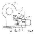
本発明は、異なる変形例で実現することができる。例示的な実施例において、例示的な方法で二つの変形例が示されている。ここでの図1から図11は、中に固定装置2及び接触要素13を互いに離間して挿入可能となるよう構成される、第1の変形例を示している。これらの図における固定装置2は、固定装置が他の構造要素/部材に機械的に固定され得るようにも構成される。図12から図14は、本発明の一つの特に好ましい変形例を示し、この変形例によって、固定装置2が接触要素13と一体型に構成される。図12から図14における固定装置2には、固定装置2を他の(任意)構造要素に機械的に構成する装置が設けられていない。しかしながら、原則としてこれも可能である。図12から図14に固定装置2と接触要素13との一体型の構造を示したが、これは必須ではない。固定装置2及び接触要素13は、別個の要素として構成することができ、電気的にのみ接続され、好ましくは、互いに機械的に接続される。
The invention can be implemented in different variants. In the exemplary embodiment, two variants are shown in an exemplary manner. FIGS. 1 to 11 here show a first variant, which is arranged so that the fixing
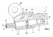
図1は、本発明の実施例に係るプラグコネクタ1と、固定装置2とを有するプラグ接続装置の垂直の長さ方向断面を示す。
FIG. 1 shows a vertical longitudinal section of a plug connection device with a
プラグコネクタ1は、ハウジング3を有し、ハウジング3は、図2から図4及び図8から図11にもより詳細に示される。ここで、これは、プラグコネクタ1のいわゆるFAKRAハウジングであることができる。
The
図13及び図14は、ハウジング3とは幾分異なるハウジング3の変形例を示しているが、好ましくは、FAKRA規格と互換性のあるように構成される。
FIGS. 13 and 14 show a variation of the
ハウジング3は、好ましくは、プラスチックから構成される。
The
プラグコネクタ1は、さらにケーブル6の外側導体5に接続されるプラグ本体4を有し、このケーブルは、図1では概略的な方法で示されている。プラグ本体4を外側導体5に接続するのは、既知の方法、例えば、溶接/ろう付け、接着、クランピングまたは圧着によって実行することができる。例示的な実施例において、プラグ本体4を外側導体5に圧着したように(図面により詳細に示していない)配置されている。このため、プラグ本体4は、複数の部分として選択的に構成することができ、プラグ本体4の少なくとも1つの部分を、好ましくは、外側導体5に圧着したように構成し、これは、好ましくは、外側導体5が露出するまでケーブル6のケーブルジャケット7が剥離することにより実行することができる。好ましくは、外側導体5は、編組シールドであることができる。その後、プラグ本体4をこの編組シールドに圧着することができる。このため、選択的に、まずは、支持スリーブ(図示せず)外側導体5に圧着し、特に、編組シールドに圧着し、その後、編組シールドチューブを支持スリーブに折り返されるようにし、また続いてプラグ本体4の部分またはプラグ本体4に接続するための接続具または一体型のプラグ本体4は、折り返した外側導体5に圧着され、または他の方法によって外側導体5に接続される。
The
プラグコネクタ1は、ケーブル6の内部導体9に接続するために設けられた少なくとも1つの内導体部分8(図4を参照)をさらに有する。ここでの接続は、例えば、溶接/ろう付け、接着、クランプまたは圧着によって実現することができる。例示的な実施例において、内導体部分8がケーブル6の内部導体9に圧着されるように配置する。好ましくは、一旦ケーブル6の外側導体5が露出され、好ましくは、後ろに向って折り畳み、プラグ本体4を外側導体5に圧着する前に、内導体部分8をケーブル6の内部導体9に接続させる。内導体部分8を内部導体9に固定するために、まず内部導体9を剥がすことができ、これは既知の手段によって行うことができる。
The
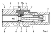
図4は、プラグ本体4内の内導体部分8の輪郭及び配置の断面を例示的な方法で示す。図1と併せて見ると、ここでは、プラグコネクタ1が、他の相補型プラグコネクタ(図示せず)を取り付けるための、及び他の相補型プラグコネクタを内導体部分8及びプラグ本体4に電気的に接続するためのコネクタを提供する方法を示す。
FIG. 4 shows, in an exemplary manner, a cross section of the contour and arrangement of the
図13及び図14に示されたプラグコネクタ1の場合、ケーブル6の外側導体5(図示せず)への接続及びケーブル6の内部導体9の内導体部分8への接続は、原則として同様または同一の方法で提供することができる。
In the case of the
例示的な実施例では、プラグ本体4は単一の内導体部分8を収容するように示されている。 もちろん、プラグ本体4は、対応する数の内部導体9に接続される複数の内導体部分8を収容することもできる。
In the exemplary embodiment, plug
なお、例示的な実施例では、プラグコネクタ1は一つのプラグ本体4を収容するように示されている。原則として、プラグコネクタ1が複数のプラグ本体4を収容するように構成することができる。例示的な実施例は、類似した方法で理解されるべきである。
It is noted that in the exemplary embodiment, the
図面から分かるように、特に、図1、図4、図8及び図13から分かるように、ハウジング3は、プラグ本体4に挿入するためのレセプタクル10を有する。例示的な実施例では、レセプタクル10は、ハウジング3の孔を通って軸方向に延びるように構成される。なお、例示的な実施例では、それぞれプラグ本体4の長さ方向の軸線に沿ってまたは軸方向Aに沿って移動することにより(図13を参照)、プラグ本体4はハウジング3またはハウジング3のレセプタクル10にそれぞれ挿入するように構成される。ここでのプラグ本体4及びレセプタクル10は、プラグ本体4がレセプタクル10中の端子位置にあるように設計される。端子位置を確立するためには、好ましくは、その端子位置にあるプラグ本体4は、知覚可能な方法でレセプタクル10にラッチするように構成される。このため、例示的な実施例では、ハウジング3は、少なくとも1つのラッチ要素11(図4を参照)を有する。ラッチ要素11は、プラグ本体に押し込まれた場合、横方向にまたは半径方向にそれぞれ屈曲し、プラグ本体4の進入を許すが、プラグ本体4の端子位置に達すると、戻って、好ましくは、跳ね返って、ラッチ要素11の前または非偏向位置に戻り、プラグ本体4が押し込み方向と逆になるように引き戻された場合、ラッチ要素11はプラグ本体4の経路を遮断する。ラッチ要素11は、好ましくは、例えば、ドライバーを押すことによって、必要な場合にハウジング3から、またはレセプタクル10から再びプラグ本体4を取り戻すことができるように、動作可能であり、したがって選択的に偏向することができるように設計することができる。
As can be seen from the drawings, and in particular, as can be seen from FIGS. 1, 4, 8 and 13, the
プラグ本体4は、好ましくは、プラグ本体4がレセプタクル10内のその端子位置に達した場合、ラッチ要素11が侵入する引っ込み部12を有する。ここで、これは、任意の溝部、凹部等であることができる。しかしながら、好ましくは、環状に囲まれる引っ込み部12の構造が既に特に適切であることが判明した。引っ込み部12は、例えば、プラグ本体4が二つのまたは複数の部分の構造を有するように製造することができ、その中、引っ込み部12がプラグ本体4の二つの部分の間の接続領域に構成することが好ましい。
The
例示的な実施例では、レセプタクル10とプラグ本体4が機械的なコーディング特徴を有することにより、ハウジング3に使用されないプラグ本体4の嵌合を機械的に防止することができる。
In the exemplary embodiment, the mechanical coding features of the
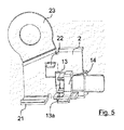
本発明の実施例によれば、ハウジング3に挿入して接続される接触要素13、接触要素13の前方領域13aがプラグ本体4に電気的に接触するようにして、ハウジング3に挿入され、当該プラグ本体4の外側周辺に配置される。ここでの接触要素13は、導電的な方法で固定装置2に接続される。それによって、別の部材24(図14を参照)への接地接続、例えば、車両の導電体部分への接続は、ケーブル6とは独立して確立することができる。図1、図7及び図12では、特に接触要素13のプラグ本体4の外側周辺を含む前方領域13aを明確に示している。図4の水平の長さ方向で示された断面は、接触要素13の前方領域13aの短い部分だけ示し、接触要素13は、断面で示されたプラグ本体4によって遮られている。
According to an embodiment of the present invention, the
図5、図7、図9、図10及び図12は、接触要素13、特に、挿入されたプラグ本体4を除いて、接触要素13の前方領域13aを示している。
5, 7, 9, 10 and 12 show the
接触要素13の固定装置2との接続は、特に図2、図6、図7、 図9、 図10及び図11から得ることができる。
The connection of the
しかしながら、図12から図14における変形例には、接触要素13は、好ましくは、上述したように、固定装置2と一体型になるように構成されている。
However, in the variant in FIGS. 12 to 14, the
例示的な実施例では、接触要素13の前方領域13aは、プラグ本体4の外側周辺の少なくとも一部にフィットした形状で接続されている。接触要素13の前方領域13aは、ここでは、端子クランプ(terminal clamp)13aとして構成されている。ここでの端子クランプ13aは、二つの端子クランプアームを有し、端子クランプアームは、好ましくは、弾性を有し、プラグ本体4の外周に接続するように構成され、当該端子クランプアームの圧力逃がし位置から偏向され、一旦、プラグ本体4の外周に接続されると、できるだけ再び跳ね返って、その間でプラグ本体4を収容または含む。
In the exemplary embodiment, the
原則として、接触要素13は、任意の位置でプラグ本体4と接触することができる。例示的な実施例では、接触要素13またはその端子クランプ13aがプラグ本体4の引っ込み部12に係合するように構成される。例示的な実施例におけるラッチ要素11も、同一の引っ込み部12に係合されるが、これは必須ではない。ここで、これらは異なる引っ込み部、凹部、溝部等であってもよい。しかしながら、共通の引っ込み部12の使用は、構造的には有利であり、したがって経済的な面でも有利である。
In principle, the
例示的な実施例では、接触要素13がハウジング3に位置するように構成され、プラグ本体4がその端子位置に達した場合、接触要素13が引っ込み部12に係合され、それによってプラグ本体4の接続の寸法も確保される。
In the exemplary embodiment, the
図1から図11から、この変形中のプラグコネクタ1は固定要素14を有し、固定要素14は、ハウジング3の隙間15(図4及び図8を参照)に結合されて、固定要素14に対するハウジング3の移動が少なくとも1つの自由度で制限されるようにすることができる。固定要素14が直接及び/または接触要素13によって固定装置2に固定された場合、ハウジング3は、固定要素14に対して少なくとも1つの自由度での移動の制限、好ましくは、少なくともプラグ本体4を押し込み及び引き出しの移動方向での制限は、特に有利である。この場合、固定装置2に対するハウジング3の移動は、好ましくは、少なくとも提出された移動方向、または長さ方向、またはハウジング3の軸方向Aにそれぞれ既に固定要素14によって制限される。
From FIGS. 1 to 11, the
固定要素14とハウジング3の隙間15とは、当該ハウジング3による移動に関して、ハウジング3は固定要素14に対してさらなる自由度でも制限するように設計されることが好ましい。なお、固定要素14が完全に隙間15に押し込まれた場合、固定要素14がハウジング3に提供される端子位置にラッチされるようにすることができる。このため、ラッチングフックを配置することができる。ラッチングフックは、好ましくは、隙間15からまたはハウジング3から再び固定要素14を取り戻すために、解放可能である。
The
固定要素14を隙間15とラッチングフックとの間にフィットした形状で収容することにより、固定要素14とハウジング3とを実質的に移動不可能に相互に接続することが得られる。
By accommodating the
特に、固定要素14の少なくとも部分14aがプラグ本体4の移動経路に伸び、プラグ本体4は、ハウジング3に結合されることが、図4の図示から得られる。本文の例示的な実施例において、固定要素14の部分14aは、引っ込み部12に伸びて、プラグ本体4をハウジング3から引き出しまたはレセプタクル10から引き出す場合、再び部分14aによってブロックされる。
In particular, it can be seen from the illustration of FIG. 4 that at least a
例示的な実施例では、接触要素13及び固定要素14の両方が、直交移動によってプラグ本体4に接続されることが示される。
In the exemplary embodiment, it is shown that both the
従って、プラグ本体4がハウジング3中の端子位置に挿入されると、接触要素13及び固定要素14は、プラグ本体4に向う方向に直角に伸びる。
Thus, when the
固定要素14の部分14aは、端子クランプ13a及びラッチ要素11と同一の引っ込み部12に伸びるが、これは選択的である。
The
特に、図2、図6、図9及び図10から分かるように、図1から11の変形例における接触要素13は、フィットした形状で固定装置2の隙間17に挿入される。接触要素13は、例えば、溶接/ろう付け、接着またはリベット止め等の任意の方法で固定装置2に接続することもできる。接触要素13は、固定装置2と組み合わせて、一つの部分または固定装置2と一体型になるよう構成されることもできる。図12から図14の変形例には一体型の構成を示した。
In particular, as can be seen from FIGS. 2, 6, 9 and 10, the
接触要素13と固定装置2との間の良好な機械的および電気的接続は、例示的な実施例に示されるフィットした形状の接続によって確立される。
A good mechanical and electrical connection between the
全ての例示的な実施例において、固定装置2及び接触要素13は、好ましくは、少なくとも部分的に導電性であるように構成され、固定装置2及び接触要素13は、好ましくは、少なくとも部分的に導電性金属製である。固定装置2及び/または接触要素13は、好ましくは、実質的に完全に金属から形成され、特に好ましくは、完全に金属から形成される。
In all the exemplary embodiments, the
接触要素13と固定装置2の隙間17とのフィットした形状の接続は、以下の面で特に有利に確立することができ、即ち、接触要素13が弾性を有し、また引っ込み部18を有するように構成され、隙間17の周辺は引っ込み部18に係合されることにより、接触要素13を隙間17に固定させる。図1から図11による例示的な実施例に示されるように、接触要素13は、好ましくは、互いに鏡対称に動作する二つの端子クランプアームを有する設計実施形態を有し、各状況において、一つの引っ込み部18を有し、隙間17の周辺は、引っ込み部18に係合され、例えば、図2に示された通りである。
The fitted-shaped connection of the
代わりに、接触要素13は、突起部を有することもでき、そしてフィットした形状の接続を確立するために、隙間17は対応して相補的な方法で構成することができる。
Alternatively, the
特に、固定要素14は、接触要素13を挿入し、接触要素13の前方領域、即ち、端子クランプ13aをプラグ本体4に接続するための通路19を有することが、図8及び図9から得られる。ハウジング3は、接触要素13を収容するためのいずれの追加の隙間も有する必要がないという利点を有するが、通路19は、簡単な方法で固定要素14に構成することができ、固定要素14は、いずれにせよ既にハウジング3の隙間15にある。そのため、本発明によれば、通路19が固定要素14に存在するため、接触要素13はハウジング3に挿入される。
In particular, it can be obtained from FIGS. 8 and 9 that the
図1から図11の例示的な実施例のおける通路19は、接触要素13の各端子クランプアームに対して一つの通路を実現するように二つの部分に構成される。
The
この実施例における固定要素14は、好ましくは、プラスチックから構成される。この実施例における固定要素14は、好ましくは、導電性ではない。
The
図7は、固定要素14の代わりの設計実施例を示す。固定要素14の比較的平坦な構造が図7に示されたが、これは現在のポイントではない。図7の例示的な実施例と上記の例示的な実施例の異なるところは、基本的に、接触要素13が固定要素14の隙間20に挿入する点である。ここでの接触要素13は、実施例で説明された方法で設計することができ、この場合、固定要素14の隙間20の周辺は、接触要素13の引っ込み部18にそれぞれ係合され、または接触要素13の端子クランプアームに接続され、端子クランプアームは、鏡対称となるように動作することで、フィットした形状で隙間20に接触要素13を収容する。
FIG. 7 shows an alternative design embodiment of the
図7に示された例示的な実施例は、接触要素13と固定装置2との間の直接接続を提供していない。図7の例示的な実施例によれば、接触要素13と固定装置2との間の電気的接続は、固定要素14によって行う。このため、固定要素14は、少なくとも部分的に導電性であり、好ましくは、少なくとも部分的に金属からなるように構成され、特に好ましくは、実質的にまたは完全に金属製である。接触要素13は、固定装置2の隙間17に緩く配置することができる。固定要素14は、例えば、スナップフィット接続によって固定装置2に接続されるように構成することができる。しかしながら、他の方法で接続することもできる。原則として、完全に固定要素14と固定装置2との間の固定接続を省略することもできる。特に、ハウジング3が固定装置2に接続された場合、固定要素14がハウジング3と固定装置2との間に嵌め合い、それによってに固定した場合、これは可能である。
The exemplary embodiment shown in FIG. 7 does not provide a direct connection between the
原則として、図7の例示的な実施例による固定要素14は、ハウジング3の隙間15に挿入されて、固定要素14に対するハウジング3の移動が少なくとも一つの自由度で制限されるようにすることができる。この場合、図7の実施例の固定要素14は、当該固定要素14が部分14aを有するように設計することもでき、固定要素14が位置決めされた場合、この部分14aがプラグ本体4の変位経路に侵入して、プラグ本体4がハウジング3に結合される。
In principle, the
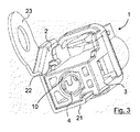
図1から図11からわかるように、固定装置2は、プラグコネクタ1のハウジング3を固定するための支持具21及び/または少なくとも1つのスナップフィット接続部材22を有することができる。図1から図11の変形例の例示的な実施例において、支持具21及びスナップフィット接続部材22が提供され、支持具21にはハウジング3の下側を支持することができ、スナップフィット接続部材22は、例示的な実施例ではスナップフィットフックとして構成される。ここでの支持具21は、ハウジング3の水平移動をさらに具体的に画定するために、固定端を有してもよい。
As can be seen from FIGS. 1 to 11, the
なお、固定装置2は、少なくとも1つのアイレット23または複数のアイレット23を有することができ、固定装置2を接地部材または車両接地または同様のものの別の部材24に電気的かつ機械的に接続するために設けることができる。
It should be noted that the
図9から図11は、複数のプラグコネクタ1を収容、固定、及び電気的に接触させるための固定装置2の設計実施例を示す。例示的な実施例では、三つのプラグコネクタ1が示されたが、本発明は、固定装置2が収容できる特定の数のプラグコネクタ1に限定されない。図9から図11の例示的な実施例において、固定装置2は、二つのアイレット23を有する。または、一つのアイレットのみまたは複数のアイレット23が設けられてもよい。なお、全ての固定装置2において、アイレット23の設計またはアイレット23の存在は、選択的である。選択的に、アイレット23は、完全に省略することができるが、有利には、固定装置2が簡単な方法で接地要素または別の部材24にそれぞれ取り付けられることが有利である。
FIGS. 9 to 11 show design embodiments of a
図1から図11の変形例の例示的な実施例から導き出すことができるように、固定要素14及び接触要素13がプラグ本体4に提供されていない限り、ハウジング3の対応する設計によってプラグ本体4を固定することができ、特に、ラッチ要素11によって実行する。これは、主な固定部材と称される。
As can be derived from the exemplary embodiment of the variant of FIGS. 1 to 11, according to the corresponding design of the
固定要素14及び/または接触要素13をその端子位置に押し込んだ後、以前にハウジング3に位置決めしたプラグ本体4は、当該固定要素14及び/または当該接触要素13によって固定することができる。これは、補助固定部材と称され、接触要素13と固定要素14との相互作用が、これに対して特に有利である。ここで、接触要素13及び固定要素14は、ハウジング3でのプラグ本体4の位置の正確な着座も、ひいては相補的なプラグコネクタへの接続のための接続の寸法(より詳細には図示せず)にも関与することができる。
After pressing the locking
図8は、いわゆるプリラッチング位置にある固定要素14を示す。固定要素14は、好ましくは、ハウジング3内に予め組立てられている。プラグ本体4を組立てるには、まずプラグ本体4をハウジング3に挿入し、続いて、プラグ本体4がハウジング3内の端子位置に到達した場合、補助固定部材14をその端子ラッチング位置に押し込む。
FIG. 8 shows the fixing
図9及び図10における例示的な方法に示されたように、プラグコネクタ1は、既に固定装置2に接続されている接触要素13に続いてクリップフィットすることができる。
As shown in the exemplary method in FIGS. 9 and 10, the
図12から図14に示された変形例では、固定要素14を省略することができる。
In the variants shown in FIGS. 12 to 14, the
図12は、固定装置2の特定の変形例を示し、当該変形例は、原則として好ましい。図13は、この変形例に適したハウジング3を示し、図14は、組立て位置にある固定装置2及びハウジング3を示す。もちろん、技術的に除外されていない限り、上記のような特徴の全てをこの変形例の特徴と組み合わることができる。
FIG. 12 shows a particular variant of the
この変形例の固定装置2は、同様に接触要素13を有するが、接触要素13は、固定装置2と一体型になるように構成することが好ましい。なお、プラグコネクタ1のハウジング3を固定するための二つのスナップフィット接続部材22が設けられ、このため、当該スナップフィット接続部材22がハウジング3を囲んでその外側に設けられる。ハウジングの外側には、溝部25が設けられ、スナップフィット接続部材22は、ハウジング3と固定装置2との間で軸方向Aに沿ってフィットした形状の接続を構成するように、溝部25に侵入することができる。スナップフィット接続部材22も、固定装置2と一体型になるように構成することが好ましい。スナップフィット接続部材22は、任意の接続要素として構成され、特に、当該スナップフィット接続部材22がハウジング3に侵入し、それによって、固定装置2とハウジング3との間に機械的関係、特に、フィットした形状及び/またはフォースフィットの接続を確立する。
The
固定装置2は、最終的に、別の部材24との接地接続を確立するための接続要素26を有する。接続要素は、現在、クリンプ接続26として構成されており、固定装置2と一体型であることが好ましい。
The fixing
別の部材24(図14を参照)の接地接続を構成するためのアースコネクタケーブル27は、好ましくは、クリンプ接続26によって固定装置2に圧着嵌合することができる。このため、アースコネクタケーブル27は、固定装置2に圧着嵌合されない端部に、好ましくは、電気的に及び機械的に別の部材24に固定するためのケーブル足部28(または同様のもの)を有することができる。
A
特に図12から図14の変形例による固定装置2は、好ましくは、薄い金属板として構成することができる。固定装置2は、パンチング及び曲げ部材として構成することができる。
In particular, the fixing
プラグコネクタ1のハウジング3と固定装置2は、当該固定装置がプラグコネクタ1のハウジング3に挿入された場合、固定装置2がプラグコネクタ1のハウジング3の外側を超えて伸びないように構成されていることが好ましく、好ましくは、凹状である。このため、図13及び14に示すように、ハウジング3は、適切な凹部及び/または溝部を有することができる。
The
Claims (20)
前記ハウジングに挿入して接続することができる接触要素であって、前記接触要素の前方領域が前記プラグ本体に電気的に接触する接触要素が提供され、前記接触要素は、前記プラグ本体の外周において前記ハウジングに挿入され、前記接触要素は、固定装置に電気的に接続することにより、前記ケーブルとは独立して別の部材と接地接続を確立するプラグ接続装置。 At least one plug connector having a housing, at least one plug body for connection to the outer conductor of the cable, and at least one inner conductor portion for connection to the inner conductor of the cable, said housing comprising: A plug connector having at least one receptacle for inserting the at least one plug body, the plug connector comprising:
A contact element which can be inserted into and connected to the housing, the front region of the contact element being in electrical contact with the plug body, the contact element being provided at the outer periphery of the plug body A plug connection device inserted into the housing, wherein the contact element electrically connects to a fixing device to establish a ground connection with another member independent of the cable.
請求項1に記載のプラグ接続装置。 The front area of the contact element may be connected in a shape fitted to at least a portion of the periphery of the plug body,
The plug connection device according to claim 1.
請求項1または2に記載のプラグ接続装置。 The plug body and the receptacle are designed to establish a terminal position of the plug body in the receptacle.
The plug connection device according to claim 1.
請求項1から3のいずれか一項に記載のプラグ接続装置。 The plug body has a recess at its outer periphery, the contact element engaging the recess.
The plug connection device according to any one of claims 1 to 3.
請求項1から4のいずれか一項に記載のプラグ接続装置。 The plug connector may have a locking element, which may be coupled to a cutout of the housing such that movement of the housing relative to the locking element is limited in at least one degree of freedom. ,
The plug connection device according to any one of claims 1 to 4.
請求項5に記載のプラグ接続装置。 At least a portion of the locking element is located in the path of movement of the plug body coupled to the housing,
The plug connection device according to claim 5.
請求項5または6に記載のプラグ接続装置。 The plug connection device according to claim 5 or 6, wherein the fixing element is connected to the contact element in a fitted shape.
請求項5から7のいずれか一項に記載のプラグ接続装置。 The contact element is electrically connected to the fixing device by the fixing element
The plug connection device according to any one of claims 5 to 7.
請求項1から8のいずれか一項に記載のプラグ接続装置。 The contact element may be inserted into the gap of the locking device in a fitted shape or be configured integral with the locking device.
The plug connection device according to any one of claims 1 to 8.
請求項5から9のいずれか一項に記載のプラグ接続装置。 The fastening element is made of plastic and has a passage for inserting into the contact element to connect the front area of the contact element to the plug body
The plug connection device according to any one of claims 5 to 9.
請求項1から10のいずれか一項に記載のプラグ接続装置。 The front area of the contact element is configured as a terminal clamp
The plug connection device according to any one of claims 1 to 10.
請求項5から11のいずれか一項に記載のプラグ接続装置。 A portion of the fixation element engages the recess.
The plug connection device according to any one of claims 5 to 11.
請求項1から12のいずれか一項に記載のプラグ接続装置。 The fastening device comprises at least one support and / or at least one snap fit connection member for fastening the housing of the plug connector.
The plug connection device according to any one of claims 1 to 12.
請求項1から13のいずれか一項に記載のプラグ接続装置。 The at least one snap fit connection member at least partially penetrates an outer groove of the housing so as to constitute a connection in an axially fitted configuration between the housing and the fixing device.
The plug connection device according to any one of claims 1 to 13.
請求項1から14のいずれか一項に記載のプラグ接続装置。 The fixation device comprises at least one eyelet,
The plug connection device according to any one of claims 1 to 14.
請求項1から15のいずれか一項に記載のプラグ接続装置。 The fastening device comprises a connection element to establish the ground connection with the other member,
The plug connection device according to any one of claims 1 to 15.
請求項16に記載のプラグ接続装置。 The connection element is configured as a crimp connection for connecting a ground connector cable to the fixing device
The plug connection device according to claim 16.
請求項16または17に記載のプラグ接続装置。 The fastening device, the at least one snap-fit connection member, the contact element and the connection element for the ground connection are integrally formed.
A plug connection device according to claim 16 or 17.
請求項1から18のいずれか一項に記載のプラグ接続装置。 The housing and the locking device of the plug connector are configured such that the locking device does not protrude outwardly beyond the housing of the plug connector when the locking device is inserted into the housing of the plug connector ,
A plug connection device according to any one of the preceding claims.
請求項1から18のいずれか一項に記載のプラグ接続装置。 The locking device is configured to lock and electrically contact a plurality of plug connectors,
A plug connection device according to any one of the preceding claims.
Applications Claiming Priority (5)
| Application Number | Priority Date | Filing Date | Title |
|---|---|---|---|
| DE102016108402.6 | 2016-05-06 | ||
| DE102016108402 | 2016-05-06 | ||
| DE102016109266.5 | 2016-05-20 | ||
| DE102016109266.5A DE102016109266A1 (en) | 2016-05-06 | 2016-05-20 | Plug connection device with at least one connector |
| PCT/EP2017/060797 WO2017191309A1 (en) | 2016-05-06 | 2017-05-05 | Plug connection device comprising at least one plug connector |
Publications (2)
| Publication Number | Publication Date |
|---|---|
| JP2019515457A true JP2019515457A (en) | 2019-06-06 |
| JP2019515457A5 JP2019515457A5 (en) | 2020-05-21 |
Family
ID=60119645
Family Applications (1)
| Application Number | Title | Priority Date | Filing Date |
|---|---|---|---|
| JP2018557347A Pending JP2019515457A (en) | 2016-05-06 | 2017-05-05 | Plug connection device comprising at least one plug connector |
Country Status (7)
| Country | Link |
|---|---|
| US (2) | US10784615B2 (en) |
| EP (2) | EP3332451B1 (en) |
| JP (1) | JP2019515457A (en) |
| KR (1) | KR102210531B1 (en) |
| CN (1) | CN108780955B (en) |
| DE (1) | DE102016109266A1 (en) |
| WO (1) | WO2017191309A1 (en) |
Families Citing this family (12)
| Publication number | Priority date | Publication date | Assignee | Title |
|---|---|---|---|---|
| DE102016109266A1 (en) * | 2016-05-06 | 2017-11-09 | Rosenberger Hochfrequenztechnik Gmbh & Co. Kg | Plug connection device with at least one connector |
| KR102614278B1 (en) * | 2016-10-17 | 2023-12-15 | 한국단자공업 주식회사 | Rf connector |
| DE102019104754A1 (en) | 2018-03-15 | 2019-09-19 | Rosenberger Hochfrequenztechnik Gmbh & Co. Kg | Outer conductor arrangement |
| EP3540865B1 (en) | 2018-03-15 | 2021-07-14 | Rosenberger Hochfrequenztechnik GmbH & Co. KG | External conductor arrangement |
| US11075488B2 (en) | 2019-11-25 | 2021-07-27 | TE Connectivity Services Gmbh | Impedance control connector with dielectric seperator rib |
| US11146010B2 (en) | 2019-12-09 | 2021-10-12 | TE Connectivity Services Gmbh | Overmolded contact assembly |
| US11011875B1 (en) | 2019-12-10 | 2021-05-18 | TE Connectivity Services Gmbh | Electrical cable braid positioning clip |
| US10978832B1 (en) | 2020-02-07 | 2021-04-13 | TE Connectivity Services Gmbh | Protection member to protect resilient arms of a contact assembly from stubbing |
| US11296464B2 (en) | 2020-02-14 | 2022-04-05 | TE Connectivity Services Gmbh | Impedance control connector |
| DE102020132962A1 (en) * | 2020-12-10 | 2022-06-15 | Harting Electric Gmbh & Co. Kg | High current connector for battery management system |
| DE202021100405U1 (en) | 2021-01-28 | 2021-02-09 | Md Elektronik Gmbh | Connector and connector assembly |
| CN214706539U (en) * | 2021-05-18 | 2021-11-12 | 康普技术有限责任公司 | External device to external device connector for wireless communication device |
Citations (11)
| Publication number | Priority date | Publication date | Assignee | Title |
|---|---|---|---|---|
| JPH0527977U (en) * | 1991-09-20 | 1993-04-09 | ヒロセ電機株式会社 | Electrical connector structure |
| JPH07312262A (en) * | 1992-12-02 | 1995-11-28 | Molex Inc | Plug receptacle type electric connector |
| JPH09147991A (en) * | 1995-11-22 | 1997-06-06 | Furukawa Electric Co Ltd:The | Earth connector for shielding wire |
| JPH1167362A (en) * | 1997-08-19 | 1999-03-09 | Harness Sogo Gijutsu Kenkyusho:Kk | Mounting structure of connector |
| JP2000021486A (en) * | 1998-07-06 | 2000-01-21 | Sumitomo Wiring Syst Ltd | Connector |
| JP2001155822A (en) * | 1999-11-29 | 2001-06-08 | Yazaki Corp | Shieled connector |
| JP2002208455A (en) * | 2001-01-04 | 2002-07-26 | Sumitomo Wiring Syst Ltd | Shield terminal |
| JP2005108756A (en) * | 2003-10-01 | 2005-04-21 | Yazaki Corp | Earth connecting structure for vehicle and assembling method of earth connecting structure for vehicle |
| DE202008014541U1 (en) * | 2008-11-03 | 2009-01-29 | Rosenberger Hochfrequenztechnik Gmbh & Co. Kg | Connector with a coding housing |
| JP2009140684A (en) * | 2007-12-05 | 2009-06-25 | Yazaki Corp | Connector |
| US8100704B1 (en) * | 2011-07-27 | 2012-01-24 | Ezconn Corporation | Coaxial cable connector assembly |
Family Cites Families (21)
| Publication number | Priority date | Publication date | Assignee | Title |
|---|---|---|---|---|
| JPS5611752Y2 (en) * | 1975-09-16 | 1981-03-17 | ||
| JPH0113344Y2 (en) * | 1984-10-03 | 1989-04-19 | ||
| US4741703A (en) * | 1986-08-12 | 1988-05-03 | Amp Incorporated | PCB mounted triaxial connector assembly |
| GB2251985B (en) * | 1991-01-16 | 1994-10-05 | Omega Engineering | A groundable electrical connector |
| JPH0527977A (en) | 1991-07-19 | 1993-02-05 | Meidensha Corp | Use rule display method for expert system |
| US5240425A (en) * | 1991-09-20 | 1993-08-31 | Hirose Electric Co., Ltd. | Electrical connector |
| EP0586841A1 (en) * | 1992-07-30 | 1994-03-16 | Reichle + De-Massari AG Elektro-Ingenieure | Printed circuit board and mounting module for connection of a shielded cable and distribution system for low-voltage installation construction |
| US20030176104A1 (en) | 2002-03-13 | 2003-09-18 | Hall John W. | Apparatus and method for electrical connector cable retention |
| US20040229516A1 (en) * | 2003-05-14 | 2004-11-18 | Shin-Nan Kan | Connector of a power source |
| US7261581B2 (en) * | 2003-12-01 | 2007-08-28 | Corning Gilbert Inc. | Coaxial connector and method |
| US7223131B2 (en) * | 2005-09-02 | 2007-05-29 | Tyco Electronics Corporation | Three position electrical connector assembly |
| JP4978784B2 (en) * | 2007-07-03 | 2012-07-18 | 住友電装株式会社 | connector |
| DE202007017309U1 (en) | 2007-12-12 | 2008-02-28 | Rosenberger Hochfrequenztechnik Gmbh & Co. Kg | coaxial |
| WO2011038387A1 (en) | 2009-09-28 | 2011-03-31 | Molex Incorporated | Shielded modular jack assembly |
| JP6086381B2 (en) * | 2013-01-28 | 2017-03-01 | 矢崎総業株式会社 | Connector structure |
| DE202014004431U1 (en) | 2014-05-27 | 2014-06-12 | Rosenberger Hochfrequenztechnik Gmbh & Co. Kg | Contact holding part with secured train protection |
| CN204067733U (en) | 2014-07-28 | 2014-12-31 | 泰科电子(上海)有限公司 | Electric connector |
| CN205026616U (en) | 2015-08-10 | 2016-02-10 | 东莞市荣文照明电气有限公司 | Improvement structure of NEMA product interface |
| DE102016109266A1 (en) * | 2016-05-06 | 2017-11-09 | Rosenberger Hochfrequenztechnik Gmbh & Co. Kg | Plug connection device with at least one connector |
| JP6708025B2 (en) * | 2016-07-04 | 2020-06-10 | 株式会社オートネットワーク技術研究所 | Shielded connector |
| TWI716662B (en) * | 2018-01-19 | 2021-01-21 | 葵谷科技實業有限公司 | Connector with latch structure |
-
2016
- 2016-05-20 DE DE102016109266.5A patent/DE102016109266A1/en not_active Withdrawn
-
2017
- 2017-05-05 JP JP2018557347A patent/JP2019515457A/en active Pending
- 2017-05-05 CN CN201780016938.4A patent/CN108780955B/en active Active
- 2017-05-05 EP EP17721686.8A patent/EP3332451B1/en active Active
- 2017-05-05 US US15/768,934 patent/US10784615B2/en active Active
- 2017-05-05 KR KR1020187026578A patent/KR102210531B1/en active IP Right Grant
- 2017-05-05 WO PCT/EP2017/060797 patent/WO2017191309A1/en active Application Filing
- 2017-05-05 EP EP20176778.7A patent/EP3719933B1/en active Active
-
2020
- 2020-08-11 US US16/990,455 patent/US11942749B2/en active Active
Patent Citations (11)
| Publication number | Priority date | Publication date | Assignee | Title |
|---|---|---|---|---|
| JPH0527977U (en) * | 1991-09-20 | 1993-04-09 | ヒロセ電機株式会社 | Electrical connector structure |
| JPH07312262A (en) * | 1992-12-02 | 1995-11-28 | Molex Inc | Plug receptacle type electric connector |
| JPH09147991A (en) * | 1995-11-22 | 1997-06-06 | Furukawa Electric Co Ltd:The | Earth connector for shielding wire |
| JPH1167362A (en) * | 1997-08-19 | 1999-03-09 | Harness Sogo Gijutsu Kenkyusho:Kk | Mounting structure of connector |
| JP2000021486A (en) * | 1998-07-06 | 2000-01-21 | Sumitomo Wiring Syst Ltd | Connector |
| JP2001155822A (en) * | 1999-11-29 | 2001-06-08 | Yazaki Corp | Shieled connector |
| JP2002208455A (en) * | 2001-01-04 | 2002-07-26 | Sumitomo Wiring Syst Ltd | Shield terminal |
| JP2005108756A (en) * | 2003-10-01 | 2005-04-21 | Yazaki Corp | Earth connecting structure for vehicle and assembling method of earth connecting structure for vehicle |
| JP2009140684A (en) * | 2007-12-05 | 2009-06-25 | Yazaki Corp | Connector |
| DE202008014541U1 (en) * | 2008-11-03 | 2009-01-29 | Rosenberger Hochfrequenztechnik Gmbh & Co. Kg | Connector with a coding housing |
| US8100704B1 (en) * | 2011-07-27 | 2012-01-24 | Ezconn Corporation | Coaxial cable connector assembly |
Also Published As
| Publication number | Publication date |
|---|---|
| EP3719933A1 (en) | 2020-10-07 |
| EP3332451A1 (en) | 2018-06-13 |
| US20190058296A1 (en) | 2019-02-21 |
| EP3719933B1 (en) | 2022-06-22 |
| CN108780955A (en) | 2018-11-09 |
| EP3332451B1 (en) | 2020-07-29 |
| DE102016109266A1 (en) | 2017-11-09 |
| US11942749B2 (en) | 2024-03-26 |
| US20200403347A1 (en) | 2020-12-24 |
| KR102210531B1 (en) | 2021-02-01 |
| WO2017191309A1 (en) | 2017-11-09 |
| KR20190002429A (en) | 2019-01-08 |
| CN108780955B (en) | 2020-06-26 |
| US10784615B2 (en) | 2020-09-22 |
Similar Documents
| Publication | Publication Date | Title |
|---|---|---|
| JP2019515457A (en) | Plug connection device comprising at least one plug connector | |
| CN107204537B (en) | Electrical connection apparatus, method of assembling a cable and assembled coaxial cable | |
| CN108475889B (en) | High-power electric connector | |
| EP3159970B1 (en) | Cable assembly, connector, and method for manufacturing cable assembly | |
| US4786260A (en) | Electrical cable assembly | |
| JP5062863B2 (en) | Small round connector assembly | |
| EP2761700B1 (en) | Shield connector and method of assembling shield connector | |
| CN106911045B (en) | Shielding connection structure | |
| US11646522B2 (en) | Male connector and connector device | |
| KR20160122796A (en) | Coaxial connector assembly | |
| CN107925183B (en) | Plug-in connector | |
| KR101701587B1 (en) | Insulating body of a plug connector | |
| JP6943175B2 (en) | Terminal fittings and connectors | |
| US8925189B2 (en) | Method for assembling an electrical connector assembly | |
| JP2009093870A (en) | Conductive member, connector with conductive member | |
| JP2001035565A (en) | Electrical connector for coaxial cable | |
| KR20180032511A (en) | Electrical cable connector with rotatable housing | |
| JP2019504460A (en) | Plug connector | |
| US6305980B2 (en) | Cable end connector having accurately positioned connection terminal therein | |
| KR102550876B1 (en) | Connector for coaxial cable | |
| US6361383B1 (en) | Cable end connector reliably positioning a shell | |
| US6447335B1 (en) | Cable end connector | |
| KR102463691B1 (en) | Connector | |
| US8388378B2 (en) | Electrical connector | |
| JP2012064536A (en) | Connector assembly |
Legal Events
| Date | Code | Title | Description |
|---|---|---|---|
| A521 | Request for written amendment filed |
Free format text: JAPANESE INTERMEDIATE CODE: A523 Effective date: 20200409 |
|
| A621 | Written request for application examination |
Free format text: JAPANESE INTERMEDIATE CODE: A621 Effective date: 20200409 |
|
| A977 | Report on retrieval |
Free format text: JAPANESE INTERMEDIATE CODE: A971007 Effective date: 20210323 |
|
| A131 | Notification of reasons for refusal |
Free format text: JAPANESE INTERMEDIATE CODE: A131 Effective date: 20210420 |
|
| A02 | Decision of refusal |
Free format text: JAPANESE INTERMEDIATE CODE: A02 Effective date: 20211130 |