JP2019512188A - Device for generating a synthetic 2D image of an enhanced depth of field of an object - Google Patents
Device for generating a synthetic 2D image of an enhanced depth of field of an object Download PDFInfo
- Publication number
- JP2019512188A JP2019512188A JP2018544159A JP2018544159A JP2019512188A JP 2019512188 A JP2019512188 A JP 2019512188A JP 2018544159 A JP2018544159 A JP 2018544159A JP 2018544159 A JP2018544159 A JP 2018544159A JP 2019512188 A JP2019512188 A JP 2019512188A
- Authority
- JP
- Japan
- Prior art keywords
- image data
- image
- data
- subject
- lateral position
- Prior art date
- Legal status (The legal status is an assumption and is not a legal conclusion. Google has not performed a legal analysis and makes no representation as to the accuracy of the status listed.)
- Pending
Links
Images


Classifications
-
- G—PHYSICS
- G02—OPTICS
- G02B—OPTICAL ELEMENTS, SYSTEMS OR APPARATUS
- G02B21/00—Microscopes
- G02B21/36—Microscopes arranged for photographic purposes or projection purposes or digital imaging or video purposes including associated control and data processing arrangements
- G02B21/365—Control or image processing arrangements for digital or video microscopes
- G02B21/367—Control or image processing arrangements for digital or video microscopes providing an output produced by processing a plurality of individual source images, e.g. image tiling, montage, composite images, depth sectioning, image comparison
-
- H—ELECTRICITY
- H04—ELECTRIC COMMUNICATION TECHNIQUE
- H04N—PICTORIAL COMMUNICATION, e.g. TELEVISION
- H04N23/00—Cameras or camera modules comprising electronic image sensors; Control thereof
- H04N23/70—Circuitry for compensating brightness variation in the scene
- H04N23/743—Bracketing, i.e. taking a series of images with varying exposure conditions
-
- H—ELECTRICITY
- H04—ELECTRIC COMMUNICATION TECHNIQUE
- H04N—PICTORIAL COMMUNICATION, e.g. TELEVISION
- H04N23/00—Cameras or camera modules comprising electronic image sensors; Control thereof
- H04N23/60—Control of cameras or camera modules
- H04N23/67—Focus control based on electronic image sensor signals
- H04N23/676—Bracketing for image capture at varying focusing conditions
-
- H—ELECTRICITY
- H04—ELECTRIC COMMUNICATION TECHNIQUE
- H04N—PICTORIAL COMMUNICATION, e.g. TELEVISION
- H04N23/00—Cameras or camera modules comprising electronic image sensors; Control thereof
- H04N23/95—Computational photography systems, e.g. light-field imaging systems
- H04N23/951—Computational photography systems, e.g. light-field imaging systems by using two or more images to influence resolution, frame rate or aspect ratio
-
- H—ELECTRICITY
- H04—ELECTRIC COMMUNICATION TECHNIQUE
- H04N—PICTORIAL COMMUNICATION, e.g. TELEVISION
- H04N23/00—Cameras or camera modules comprising electronic image sensors; Control thereof
- H04N23/95—Computational photography systems, e.g. light-field imaging systems
- H04N23/958—Computational photography systems, e.g. light-field imaging systems for extended depth of field imaging
- H04N23/959—Computational photography systems, e.g. light-field imaging systems for extended depth of field imaging by adjusting depth of field during image capture, e.g. maximising or setting range based on scene characteristics
-
- H—ELECTRICITY
- H04—ELECTRIC COMMUNICATION TECHNIQUE
- H04N—PICTORIAL COMMUNICATION, e.g. TELEVISION
- H04N25/00—Circuitry of solid-state image sensors [SSIS]; Control thereof
- H04N25/70—SSIS architectures; Circuits associated therewith
- H04N25/71—Charge-coupled device [CCD] sensors; Charge-transfer registers specially adapted for CCD sensors
- H04N25/711—Time delay and integration [TDI] registers; TDI shift registers
Abstract
本発明は、被写体の向上された被写界深度を持つ合成2D画像を生成するための装置に関するものである。画像取得ユニット20により、当該被写体の第1横方向位置における第1画像データ及び該被写体の第2横方向位置における第2画像データを取得すること(110)が記載されている。上記画像取得ユニットは、第1横方向位置における第3画像データ及び第2横方向位置における第4画像データを取得する(120)ために使用され、その場合において、第3画像データは第1画像データに対するものとは異なるダウンレンジ距離において取得される一方、第4画像データは第2画像データに対するものとは異なるダウンレンジ距離において取得される。第1横方向位置に関する第1作業画像データが生成され(130)、該生成は第1画像データ及び第3画像データを焦点合成アルゴリズムにより処理することを含む。第2横方向位置に関して第2作業画像データが生成され(140)、該生成は前記焦点合成アルゴリズムにより第2画像データ及び第4画像データを処理することを含む。画像取得の間において、第1作業画像データ及び第2作業画像データが組み合わされて(150)、当該被写体の向上された被写界深度を持つ合成2D画像を生成する。The present invention relates to an apparatus for generating a synthetic 2D image having an enhanced depth of field of an object. It is described that the image acquisition unit 20 acquires first image data at a first lateral position of the subject and second image data at a second lateral position of the subject (110). The image acquisition unit is used to acquire 120 the third image data at the first lateral position and the fourth image data at the second lateral position, in which case the third image data is the first image The fourth image data is acquired at a different down range distance than that for the second image data, while it is acquired at a different down range distance than that for the data. First working image data for a first lateral position is generated 130, which includes processing the first image data and the third image data with a focusing algorithm. Second working image data is generated 140 for a second lateral position, the generating comprising processing the second image data and the fourth image data according to the focusing algorithm. During image acquisition, the first work image data and the second work image data are combined 150 to produce a composite 2D image having an enhanced depth of field of the subject.
Description
本発明は、被写体の向上された被写界深度の合成2D画像を生成する装置、被写体の向上された被写界深度の合成2D画像を生成する方法、コンピュータプログラム要素及びコンピュータ読取可能な媒体に関する。 The present invention relates to an apparatus for generating a composite 2D image of an enhanced depth of field of an object, a method for generating a composite 2D image of an enhanced depth of field of an object, a computer program element and a computer readable medium .
撮像システムは、撮像されるべき特徴構造を中心とする被写界深度を伴う焦点を有するように配置されるもので、被写界深度により制限を受ける。しかしながら、これらも撮像されることが望まれる幾つかの特徴構造は、焦点面より当該撮像システムの近くにあり、焦点深度の外側にあり、焦点が外れることがあり得る。同様のことが、狭い焦点における特徴構造より遙か遠くにある特徴構造にも当てはまる。 The imaging system is arranged to have a focus with a depth of field centered on the feature to be imaged and is limited by the depth of field. However, some features that these are also desired to be imaged may be closer to the imaging system than the focal plane, outside the depth of focus, and out of focus. The same is true for features that are far from features at narrow focus.
被写体の、向上された被写界深度を持つ画像を生成するための改善された技術を有することが有益であろう。 It would be beneficial to have an improved technique for generating an image with improved depth of field of an object.
本発明の目的は、独立請求項の主題により解決され、更なる実施態様は従属請求項に含まれる。以下に記載される本発明の態様は、被写体の向上された被写界深度の合成2D画像を生成するための装置、被写体の向上された被写界深度の合成2D画像を生成するための方法、並びにコンピュータプログラム要素及びコンピュータ読取可能な媒体に対しても当てはまることに注意すべきである。 The object of the invention is solved by the subject matter of the independent claims, and further embodiments are contained in the dependent claims. Aspects of the invention described below are an apparatus for generating a composite 2D image of an enhanced depth of field of an object, a method for generating a composite 2D image of an enhanced depth of field of an object It should be noted that this also applies to computer program elements and computer readable media.
第1態様によれば、被写体の向上された被写界深度を持つ合成2D画像を生成するための装置が提供され、該装置は、
− 画像取得ユニットと、
− 処理ユニットと、
を有する。
According to a first aspect, there is provided an apparatus for generating a synthetic 2D image having an enhanced depth of field of an object, the apparatus comprising:
An image acquisition unit,
A processing unit,
Have.
前記画像取得ユニットは、当該被写体の第1横方向位置における第1画像データ及び該被写体の第2横方向位置における第2画像データを取得するように構成される。該画像取得ユニットは、前記第1横方向位置における第3画像データ及び前記第2横方向位置における第4画像データを取得するようにも構成され、前記第3画像データは前記第1画像データに対するものとは異なるダウンレンジ距離(down range distance)において取得され、前記第4画像データは前記第2画像データに対するものとは異なるダウンレンジ距離において取得される。前記処理ユニットは、前記第1横方向位置に関する第1作業画像データ(first working image data)を生成するように構成され、該生成は、前記第1画像データ及び前記第3画像データを焦点合成アルゴリズム(focus stacking algorithm)により処理することを含む。前記処理ユニットは、前記第2横方向位置に関する第2作業画像データを生成するように構成され、該生成は、該第2横方向位置に関する第2作業画像データを生成するために前記焦点合成アルゴリズムにより前記第2画像データ及び前記第4画像データを処理することを含む。前記処理ユニットは、画像データの取得の間において前記第1作業画像データ及び前記第2作業画像データを組み合わせて当該被写体の向上された被写界深度を持つ合成2D画像を生成するように構成される。 The image acquisition unit is configured to acquire first image data at a first lateral position of the subject and second image data at a second lateral position of the subject. The image acquisition unit is also configured to acquire third image data at the first lateral position and fourth image data at the second lateral position, the third image data being for the first image data. The fourth image data is acquired at a different down range distance than that of the second image data, and the fourth image data is acquired at a different down range distance than that for the second image data. The processing unit is configured to generate first working image data with respect to the first lateral position, the generation comprising focusing the first image data and the third image data. Processing by (focus stacking algorithm). The processing unit is configured to generate second working image data for the second lateral position, the generation comprising the focus combining algorithm to generate second working image data for the second lateral position. Processing the second image data and the fourth image data. The processing unit is configured to combine the first work image data and the second work image data during acquisition of image data to generate a composite 2D image having an enhanced depth of field of the subject. Ru.
ダウンレンジ距離とは、ダウンレンジ(射程)である距離、又は、言い換えると、当該装置若しくは該装置の特定の部分から或る距離にある距離を意味する。このように、異なるダウンレンジ距離にある被写体又は被写体の部分は、当該装置から異なる距離にある。即ち、或る被写体又は被写体の一部は、他の被写体又は当該被写体の他の部分から遠くにある。 Down-range distance means a distance that is down-range or, in other words, a distance that is some distance from the device or a particular part of the device. Thus, the subject or parts of the subject at different down range distances are at different distances from the device. That is, an object or part of an object is far from other objects or other parts of the object.
焦点合成に関する説明は、https://en.wikipedia.org/wiki/Focus_stackingなるウェブページで見付けることができる。 A description of focal composition can be found on the https://en.wikipedia.org/wiki/Focus_stacking web page.
このようにして、向上された被写界深度を持つ2D画像を“オンザフライで(その場で)”取得することができる。言い換えると、該向上された被写界深度の2D画像をストリーミングモードで取得することができる。全系列の完全な画像ファイルが、キャプチャ及び記憶され、全てが取得された後に後処理されることは必要とされず、むしろ、向上された画像は画像データが取得される際に生成される。 In this way, a 2D image with enhanced depth of field can be acquired "on the fly". In other words, the enhanced depth of field 2D image can be acquired in streaming mode. It is not required that the entire series of complete image files be captured and stored and post-processed after everything has been acquired, rather, an enhanced image is generated as image data is acquired.
言い換えると、ダウンレンジ距離がz方向に延びるものとすると、x及びy方向に延びる2D画像は、異なるx,y位置においてピントの合った特徴構造(features)を有し得、これら特徴構造は特定のx、y位置において当該画像取得ユニットの焦点深度より大きなダウンレンジ距離zの範囲にわたり焦点が合う。そして、この向上された被写界深度の2D画像はオンザフライで生成される。この特定の座標系において、zはダウンレンジ距離を示すために使用され、x及びyは該ダウンレンジ距離に対して垂直な座標に関するものである。このことは、当該装置が垂直に撮像することに限定されることを意味するものではなく、むしろ、ここでの“z”は垂直、水平又は他の軸に当てはまり得る。言い換えると、“z”は、当該装置の例の構成及び動作を説明する助けとなるように、ダウンレンジ距離を示すために使用されている。 In other words, if the down range distance extends in the z direction, 2D images extending in the x and y directions may have in-focus features at different x, y positions, which are identified Focus at an x, y position over a range of down range distance z that is greater than the depth of focus of the image acquisition unit. This enhanced depth of field 2D image is then generated on the fly. In this particular coordinate system, z is used to indicate down-range distance, and x and y relate to coordinates perpendicular to the down-range distance. This does not mean that the device is limited to imaging vertically, but rather, the "z" here may apply to vertical, horizontal or other axes. In other words, "z" is used to indicate down range distance to help explain the configuration and operation of the example device.
このようにして、画像を、向上された被写界深度の画像を生成するに際して中間画像を記憶することを要せずにオンザフライで取得することができる。更に、向上された被写界深度の画像を、当該被写体を介して当該装置の検出器の投影を、例えば横方向若しくはダウンレンジ軸に平行な方向の何れかに又は斜め等の横方向と平行との間の方向に掃引する間に取得することができる。言い換えると、向上された被写界深度の画像を、単一工程で、且つ、大きな画像バッファの必要性無しで取得することができる。 In this way, images can be acquired on the fly without the need to store intermediate images in generating images of enhanced depth of field. Furthermore, the enhanced depth-of-field image can be projected parallel to the projection of the detector of the device via the subject, for example, either in the lateral direction or in a direction parallel to the down range axis or diagonally. And can be acquired while sweeping in the direction between. In other words, an enhanced depth of field image can be obtained in a single step and without the need for a large image buffer.
一例において、前記画像取得ユニットは前記被写体の斜め断面の画像データを取得するように構成された検出器を有する。 In one example, the image acquisition unit comprises a detector configured to acquire image data of an oblique cross section of the subject.
このように、斜め断面の画像データを取得することにより、横方向スキャン(一例において、該横方向スキャンの方向は水平方向である)はダウンレンジ距離方向(例えば、垂直方向でもあり得るz方向)のデータも取得する。横方向スキャンは、第2断面が当該画像取得ユニットの光軸に対して垂直な方向において第1断面から水平に又は横方向に変位される場合にもたらされ得る。例えば、当該断面を横方向に変位させるために撮像レンズが横方向に移動され、及び/又は該断面を横方向に変位させるために被写体が当該画像取得ユニットの撮像及び取得部分に対して横方向に移動される。言い換えると、当該画像取得ユニットは被写体にわたって、異なるダウンレンジ距離及び同時に異なる横方向位置においてデータを取得するセンサによりスキャンする。一例において、当該装置は、例えば向上された被写界深度で蠅の画像を取得するための研究室環境内にあり得ると共に、上記蠅は該蠅を当該画像取得ユニットに対して横方向に移動させる移動ステージ上にある。一例において、当該装置は、それ自体が移動するシステム上に取り付けられる。例えば、当該装置は都市景観を撮影する無人飛行機(UAV)上に取り付けられ、該UAVの移動は異なる横方向位置における画像が取得されることを可能にする。当該センサは斜め断面を取得するので、当該センサは、前の取得に対して同一の横方向位置におけるものであるが異なるダウンレンジ距離におけるデータを取得することができる。一例において、当該装置は、例えば半導体電子回路のための工業用画像検査システムの一部を形成することができる。他の例において、当該装置は三脚上で回転されるパノラマカメラの一部を形成し、或る角度(例えば、360°)にわたり旋回する。該パノラマカメラは、この場合、周囲の360°のビューを向上された被写界深度で生成する。何故なら、当該センサは斜め断面をデータが同一の横方向位置において異なるダウンレンジ距離で取得されるようにして取得し、各横方向位置において最良の画像を含む画像がオンザフライで生成されることを可能にするからである。このようにして、同一の横方向位置におけるものであるが異なるダウンレンジ距離における画像データを比較して、何の画像データが最良に焦点の合った特徴構造を含んでいるかを決定することができる(当該特徴構造は当該被写体における或るダウンレンジ距離におけるものであり、ここで、例えば該被写体は都市景観の360°ビューであり得る一方、特徴構造は該360°ビュー内にある教会の前のフレスコ壁画であり得る)。次いで、当該横方向位置における最良のピントの画像データを、出現する画像に向上された被写界深度を定着させるために使用することができる。一例において、当該センサが横方向にスキャンされる間に、該センサの異なる領域が活性化され、かくして、該センサの或る領域が前記第1画像データを取得し、該センサの別の領域が前記第3画像データを取得するようにする。従って、説明したように、“横方向に”とは数学的な直線又は軸を意味するものではなく、曲線であり得るか(前記360°パノラマ掃引におけるように)又は確かに直線であり得る。 Thus, by acquiring the image data of the oblique cross section, the horizontal scan (in one example, the direction of the horizontal scan is the horizontal direction) is the down range distance direction (for example, the z direction which may be the vertical direction) Also get the data of A lateral scan may be provided if the second cross section is displaced horizontally or laterally from the first cross section in a direction perpendicular to the optical axis of the image acquisition unit. For example, the imaging lens is moved laterally to displace the cross section laterally, and / or the subject is transverse to the imaging and acquisition portion of the image acquisition unit to displace the cross section laterally. Moved to In other words, the image acquisition unit scans across the subject with sensors that acquire data at different down-range distances and simultaneously at different lateral positions. In one example, the device may be in a laboratory environment for acquiring an image of a eyelid, for example with enhanced depth of field, and the eyelid moves the eyelid laterally relative to the image acquisition unit On the moving stage. In one example, the device is mounted on a system that moves on its own. For example, the device is mounted on an unmanned aerial vehicle (UAV) that captures an urban landscape, and the movement of the UAV enables images at different lateral positions to be acquired. Because the sensor acquires oblique cross-sections, the sensor can acquire data at the same lateral position but at different down-range distances relative to the previous acquisition. In one example, the device can form part of an industrial image inspection system, for example for semiconductor electronic circuits. In another example, the device forms part of a panoramic camera that is rotated on a tripod and pivots through an angle (eg, 360 °). The panoramic camera in this case produces a 360 ° view of the surroundings with an enhanced depth of field. Because the sensor acquires oblique cross-sections such that data is acquired with different down-range distances at the same lateral position, an image containing the best image is generated on the fly at each lateral position. It is because it makes it possible. In this way, it is possible to compare image data at the same lateral position but at different down-range distances to determine what image data contains the best focused feature structure. (The feature is at a certain down range distance in the subject, where, for example, the subject can be a 360 ° view of the cityscape while the feature is in front of a church within the 360 ° view. It may be a fresco mural). The best focus image data at that lateral position can then be used to fix the enhanced depth of field to the emerging image. In one example, while the sensor is scanned laterally, different areas of the sensor are activated, such that an area of the sensor acquires the first image data and another area of the sensor The third image data is acquired. Thus, as explained, "laterally" does not mean a mathematical straight line or axis, but may be a curve (as in the 360 ° panoramic sweep) or indeed a straight line.
一例において、前記検出器は少なくとも2つの活性領域を有する2D検出器である。一例において、各活性領域は時間遅延積分(TDI)センサとして構成される。TDI検出器を設けることにより、信号対雑音比を向上させることができる。 In one example, the detector is a 2D detector having at least two active areas. In one example, each active region is configured as a time delay integration (TDI) sensor. By providing a TDI detector, the signal to noise ratio can be improved.
一例において、前記画像取得ユニットは前記第1画像データ及び前記第2画像データを取得するために前記被写体の第1断面の画像データを取得するように構成され、該画像取得ユニットは前記第3画像データ及び前記第4画像データを取得するために該被写体の第2断面の画像データを取得するよう構成される。 In one example, the image acquisition unit is configured to acquire image data of a first cross section of the subject to acquire the first image data and the second image data, and the image acquisition unit is configured to acquire the third image. It is configured to acquire image data of a second cross section of the subject in order to acquire data and the fourth image data.
言い換えると、当該画像取得ユニットは当該被写体を介してダウンレンジ方向にスキャンし、又は該被写体を介して横方向にスキャンすることができる。このように、当該被写体の横方向部分が検出器の同一の部分により又は該検出器の異なる部分により撮像されるようにして、該被写体の異なるダウンレンジ距離における画像データを取得することにより、向上された被写界深度の2D画像を“オンザフライ”で取得することができる。 In other words, the image acquisition unit can scan down through the subject or scan horizontally through the subject. In this way, it is improved by acquiring image data at different down-range distances of the subject, such that the lateral part of the subject is imaged by the same part of the detector or by different parts of the detector. A 2D image of the determined depth of field can be acquired "on the fly".
一例において、前記画像取得ユニットは前記被写体の前記第1横方向位置において且つ第1ダウンレンジ距離において前記第1画像データを取得すると同時に、該被写体の前記第2横方向位置において且つ第2ダウンレンジ距離において前記第2画像データを取得するように構成され、ここで、前記第1ダウンレンジ距離は前記第2ダウンレンジ距離とは相違し、前記画像取得ユニットは前記第1横方向位置において且つ第3ダウンレンジ距離において前記第3画像データを取得すると同時に、前記第2横方向位置において且つ第4ダウンレンジ距離において前記第4画像データを取得するように構成され、ここで、前記第3ダウンレンジ距離は前記第4ダウンレンジ距離とは相違する。 In one example, the image acquisition unit acquires the first image data at the first lateral position of the subject and at a first down range distance, and at the same time, generates a second down range at the second lateral position of the subject. The second down-range distance is different from the second down-range distance, wherein the first down-range distance is different than the second down-range distance, and the first down-range distance is At the same time as acquiring the third image data at three down range distances, it is configured to acquire the fourth image data at the second lateral position and at a fourth down range distance, wherein the third down range is obtained. The distance is different from the fourth down range distance.
言い換えると、当該画像取得ユニットはデータを異なる横方向位置において及び異なるダウンレンジ距離において同時に取得しており、次いで、同一の横方向位置におけるものであるが異なるダウンレンジ距離におけるデータは比較されて、向上された被写界深度の2D画像の生成のための作業画像として使用されるべき当該横方向位置における特徴構造の最良の画像データ(即ち、最良にピントの合ったもの)を決定することができる。このようにして、横方向における当該被写体に対する当該検出器の単一スキャン内で、画像データがダウンレンジ距離方向においても取得され、これを、全ての画像データを記憶すると共に後処理することを要せずに、向上された被写界深度の2D画像を決定するために効率的に使用することができる。言い換えると、向上された被写界深度の2D画像のオンザフライでの生成が、効率的に進行し得る。 In other words, the image acquisition unit is acquiring data at different lateral positions and at different down range distances simultaneously, and then comparing data at the same lateral position but at different down range distances, Determining the best image data (ie, best in focus) of the feature at the lateral position to be used as a working image for the generation of a 2D image of enhanced depth of field it can. In this way, within a single scan of the detector with respect to the subject in the horizontal direction, image data is also acquired in the down range distance direction and it is necessary to store and post process all image data. Without, it can be used efficiently to determine 2D images of enhanced depth of field. In other words, on-the-fly generation of 2D images of enhanced depth of field may proceed efficiently.
一例において、前記画像取得ユニットは、前記第1横方向位置において、及び、前記第2横方向位置において、ダウンレンジ距離における前記第1画像データが取得されるダウンレンジ距離と前記第2画像データが取得されるダウンレンジ距離との間の距離よりも何れも大きくはない焦点深度を有する。 In one example, at the first lateral position and at the second lateral position, the image acquisition unit is configured to acquire a down range distance at which the first image data is acquired at a down range distance and the second image data. It has a depth of focus that is not greater than the distance between the acquired down range distance.
このようにして、異なるダウンレンジ距離における画像データを当該画像取得ユニットの固有の焦点深度より大きな当該被写体のダウンレンジ距離に最適に跨がって効率的に取得することができる一方、特定の横方向位置における画像データを、当該画像取得ユニットの焦点深度より大きなダウンレンジ距離の範囲におけるものであるが、これらの横方向位置において焦点の合っている画像データを供給するように処理することができる。このように、異なるダウンレンジ距離における異なる特徴構造は全て当該向上された被写界深度を有する2D画像においてピントが合ったものとなり得、この向上された画像は、最良の画像データを決定するために取得される全ての画像データを記憶することを要せずに、オンザフライで取得することができる。 In this way, image data at different down-range distances can be efficiently acquired across the down-range distance of the subject, which is larger than the inherent depth of focus of the image acquisition unit, and on the other hand Image data at directional locations may be processed to provide image data that is in the range of down range distances greater than the depth of focus of the image acquisition unit but is in focus at these lateral locations. . Thus, different feature structures at different down range distances may all be in focus in the 2D image with the enhanced depth of field, which enhanced image is to determine the best image data. It is possible to acquire on the fly without having to store all the acquired image data.
一例において、前記被写体は前記第1画像データ及び前記第2画像データを取得するために前記画像取得ユニットの光軸に対して第1位置にある一方、該被写体は前記第3画像データ及び前記第4画像データの取得のために該光軸に対して第2位置にある。 In one example, the subject is at a first position with respect to the optical axis of the image acquisition unit to obtain the first image data and the second image data, while the subject is the third image data and the second 4 At a second position relative to the optical axis for acquisition of image data.
一例において、前記画像データは複数のカラーを有し、前記処理ユニットは画像データを前記焦点合成アルゴリズムにより該複数のカラーのうちの1以上を有する画像データに基づいて処理する。 In one example, the image data comprises a plurality of colors, and the processing unit processes the image data according to the focus combining algorithm based on the image data comprising one or more of the plurality of colors.
第2態様においては、被写体の向上された被写界深度の合成2D画像を生成する方法が提供され、該方法は、
a) 画像取得ユニットにより前記被写体の第1横方向位置における第1画像データを取得し、前記画像取得ユニットにより該被写体の第2横方向位置における第2画像データを取得するステップと、
b) 前記画像取得ユニットにより前記第1横方向位置における第3画像データを取得し、前記画像取得ユニットにより前記第2横方向位置における第4画像データを取得するステップであって、前記第3画像データは前記第1画像データに対するものとは異なるダウンレンジ距離において取得され、前記第4画像データは前記第2画像データに対するものとは異なるダウンレンジ距離において取得されるステップと、
e) 前記第1横方向位置に関する第1作業画像データを生成するステップであって、該生成するステップが前記第1画像データ及び前記第3画像データを焦点合成アルゴリズムにより処理するステップを有するステップと、
f) 前記第2横方向位置に関する第2作業画像データを生成するステップであって、該生成するステップが前記第2画像データ及び前記第4画像データを前記焦点合成アルゴリズムにより処理するステップを有するステップと、
l) 画像データの取得の間において前記第1作業画像データ及び前記第2作業画像データを組み合わせて、前記被写体の向上された被写界深度の合成2D画像を生成するステップと、
を有する。
In a second aspect, there is provided a method of generating a composite 2D image of an enhanced depth of field of an object, the method comprising:
a) acquiring first image data at a first lateral position of the subject by the image acquisition unit, and acquiring second image data at a second lateral position of the subject by the image acquisition unit;
b) acquiring third image data at the first lateral position by the image acquisition unit, and acquiring fourth image data at the second lateral position by the image acquisition unit, the third image Data is acquired at a different down range distance than that for the first image data, and the fourth image data is acquired at a different down range distance than that for the second image data;
e) generating first working image data for the first lateral position, the generating comprising processing the first image data and the third image data with a focus combining algorithm; ,
f) generating second working image data for the second lateral position, the generating comprising processing the second image data and the fourth image data according to the focus combining algorithm When,
l) combining the first work image data and the second work image data during acquisition of image data to generate a composite 2D image of the enhanced depth of field of the subject;
Have.
一例において、前記ステップa)は、前記被写体の前記第1横方向位置において且つ第1ダウンレンジ距離において前記第1画像データを取得すると同時に該被写体の前記第2横方向位置において且つ第2ダウンレンジ距離において前記第2画像データを取得するステップを有し、ここで、前記第1ダウンレンジ距離は前記第2ダウンレンジ距離とは相違し;前記ステップb)は、前記第1横方向位置において且つ第3ダウンレンジ距離において前記第3画像データを取得すると同時に前記第2横方向位置において且つ第4ダウンレンジ距離において前記第4画像データを取得するステップを有し、ここで、前記第3ダウンレンジ距離は前記第4ダウンレンジ距離とは相違する。 In one example, the step a) acquires the first image data at the first lateral position of the subject and at a first down range distance and at the same time at the second lateral position of the subject and a second down range. Acquiring the second image data at a distance, wherein the first down range distance is different from the second down range distance; and the step b) is performed at the first lateral position and Acquiring the third image data at a third down range distance and simultaneously acquiring the fourth image data at the second lateral position and at a fourth down range distance, wherein the third down range distance The distance is different from the fourth down range distance.
一例において、当該方法は、
c) 前記第1画像データに関する第1エネルギデータを計算すると共に前記第3画像データに関する第3エネルギデータを計算するステップと、
d) 前記第2画像データに関する第2エネルギデータを計算すると共に前記第4画像データに関する第4エネルギデータを計算するステップと、
を有し、
前記ステップe)は、前記第1画像データ又は前記第3画像データの何れかを前記第1作業画像として選択するステップを有し、該選択するステップは前記第1エネルギデータ及び前記第3エネルギデータの関数を含み、
前記ステップf)は、前記第2画像データ又は前記第4画像データの何れかを前記第2作業画像として選択するステップを有し、該選択するステップは前記第2エネルギデータ及び前記第4エネルギデータの関数を含み、
画像データにおける周波数情報がエネルギデータを表す。
In one example, the method comprises
c) calculating first energy data for the first image data and calculating third energy data for the third image data;
d) calculating second energy data for the second image data and calculating fourth energy data for the fourth image data;
Have
The step e) comprises the step of selecting either the first image data or the third image data as the first working image, wherein the selecting step comprises the first energy data and the third energy data Containing the functions of
The step f) comprises the step of selecting either the second image data or the fourth image data as the second working image, wherein the selecting step comprises the second energy data and the fourth energy data Containing the functions of
Frequency information in the image data represents energy data.
このようにして、向上された画像を、特定の位置において該位置における最良にピントの合った特徴構造を有するようにして効率的に生成することができる。言い換えると、ダウンレンジ距離とは無関係に当該画像にわたって、最良に焦点の合った特徴構造が、画像データに関するエネルギデータの関数として選択され、これをストリーミングモードにおいてオンザフライで実行することができる。 In this way, an enhanced image can be efficiently generated with the best in-focus features at the location. In other words, regardless of the down range distance, the best focused feature structure is selected over the image as a function of the energy data for the image data, which can be performed on the fly in streaming mode.
一例において、当該方法は、
g) 前記第1画像データが前記第1作業画像として選択される場合に第1作業エネルギデータを前記第1エネルギデータとして生成するか、又は前記第3画像データが前記第1作業画像として選択される場合に前記第1作業エネルギデータを前記第3エネルギデータとして生成するステップと、
h) 前記第2画像データが前記第2作業画像として選択される場合に第2作業エネルギデータを前記第2エネルギデータとして生成するか、又は前記第4画像データが前記第2作業画像として選択される場合に前記第2作業エネルギデータを前記第4エネルギデータとして生成するステップと、
を有する。
In one example, the method comprises
g) generating first work energy data as the first energy data when the first image data is selected as the first work image, or the third image data is selected as the first work image Generating the first work energy data as the third energy data,
h) generating second working energy data as the second energy data when the second image data is selected as the second working image, or the fourth image data is selected as the second working image Generating the second work energy data as the fourth energy data if
Have.
このようにして、当該検出器により既に掃引(又はスキャン)された領域の背後に位置する、向上された被写界深度を持つ既に生成された2D画像しか記憶されることを要さず(前記作業画像)、更新され得る該2Dの向上された画像のピクセルに関連する作業エネルギデータファイルも記憶されることを要するのみである。従って、データの記憶は最小限のものとされ、向上された被写界深度の2D画像は、向上された画像を更新するための現在取得されたエネルギデータの記憶されたエネルギデータとの比較に基づいて更に更新することができる。 In this way, it is not necessary to store only previously generated 2D images with enhanced depth of field located behind the area already swept (or scanned) by the detector (see It is only necessary that the working energy data file associated with the pixels of the 2D enhanced image, which can be updated), be stored. Thus, the storage of data is minimized and the enhanced depth of field 2D image is used to compare the currently acquired energy data with stored energy data to update the enhanced image. It can be updated further based on it.
一例において、当該方法は、
i) 前記第1横方向位置において第5画像データを取得すると共に前記第2横方向位置において第6画像データを取得するステップであって、前記第5画像データは前記第1及び第3画像データに対するものとは異なるダウンレンジ距離において取得され、前記第6画像データは前記第2及び第4画像データに対するものとは異なるダウンレンジ距離において取得されるステップと、
j) 前記第1横方向位置に関して新たな第1作業画像データを生成するステップであって、前記第5画像データ及び前記第1作業画像データを前記焦点合成アルゴリズムにより処理するステップを有し、この場合において、前記新たな第1作業画像データが該第1作業画像データとなるステップと、
k) 前記第2横方向位置に関して新たな第2作業画像データを生成するステップであって、前記第6画像データ及び前記第2作業画像データを前記焦点合成アルゴリズムにより処理するステップを有し、この場合において、前記新たな第2作業画像データが該第2作業画像データとなるステップと、
を更に有する。
In one example, the method comprises
i) acquiring fifth image data at the first lateral position and acquiring sixth image data at the second lateral position, the fifth image data being the first and third image data Acquiring at a different down-range distance than for said, and said sixth image data being acquired at a different down-range distance than for said second and fourth image data;
j) generating new first working image data with respect to the first lateral position, wherein the fifth image data and the first working image data are processed by the focus combining algorithm, In some cases, the new first work image data becoming the first work image data;
k) generating new second working image data with respect to the second lateral position, wherein the sixth image data and the second working image data are processed by the focus combining algorithm, In some cases, the new second work image data becoming the second work image data;
Furthermore, it has.
言い換えると、或る横方向位置に関する作業画像データを、当該横方向位置において取得される新たな画像データに基づいて更新して、全ての以前の画像データを記憶することを要せずに当該横方向位置における最良の画像を形成することができ、このことは、当該データが取得される間に実現することができる。当該検出器の投影(断面)が特定の横方向位置を過ぎて完全に掃引されたなら、該横方向位置において取得された最良の画像データから当該画像データが形成され、これは、個々の画像データが記憶されることを要さずにオンザフライで決定されるものであり、当該横方向位置に対して作業画像データが記憶されることが必要とされるのみである。 In other words, the work image data related to a certain lateral position is updated based on the new image data acquired at the lateral position, and it is not necessary to store all the previous image data. The best image at the directional position can be formed, which can be realized while the data is acquired. If the projection (cross-section) of the detector is completely swept past a particular lateral position, the image data is formed from the best image data acquired at the lateral position, which may be an individual image The data is determined on the fly without having to be stored, and it is only necessary that the working image data be stored for the lateral position.
他の態様によれば、前述した装置を制御するためのコンピュータプログラムであって、処理ユニットにより実行された場合に前述した方法ステップを実行するように構成されたコンピュータプログラム要素が提供される。 According to another aspect, there is provided a computer program for controlling an apparatus as described above, the computer program element being configured to perform the method steps as described above when executed by a processing unit.
他の態様によれば、上述したコンピュータプログラム要素を記憶したコンピュータ読取可能な媒体が提供される。 According to another aspect, there is provided a computer readable medium having stored thereon a computer program element as described above.
有利には、上述した態様及び例の何れかによりもたらされる利点は他の態様及び例にも等しく当てはまり、その逆でもある。 Advantageously, the advantages provided by any of the above aspects and examples apply equally to the other aspects and examples and vice versa.
上述した態様及び例は、後述する実施態様から明らかとなり、斯かる実施態様を参照して解説される。 The aspects and examples described above are apparent from the embodiments described below and are explained with reference to such embodiments.
以下、図面を参照して例示的実施態様を説明する。 Exemplary embodiments will now be described with reference to the drawings.
図1は、被写体の向上された被写界深度を持つ合成2D画像を生成するための装置10を示す。装置10は、画像取得ユニット20及び処理ユニット30を有する。画像取得ユニット20は、当該被写体の第1の横方向位置における第1画像データ及び該被写体の第2の横方向位置における第2画像データを取得するように構成される。画像取得ユニット20は、更に、前記第1横方向位置における第3画像データ及び前記第2横方向位置における第4画像データを取得するようにも構成される。第3画像データは第1画像データに対するものとは異なるダウンレンジ(射程:down range)距離において取得され、第4画像データは第2画像データに対するものとは異なるダウンレンジ距離において取得される。処理ユニット30は、第1横方向位置に関する第1作業画像データを生成するように構成され、該生成は第1画像データ及び第3画像データを焦点合成(フォーカススタッキング)アルゴリズムにより処理するステップを有する。処理ユニット30は、更に、第2横方向位置に関する第2作業画像データを生成するように構成され、該生成は第2画像データ及び第4画像データを前記焦点合成アルゴリズムにより処理して第2横方向位置に関する第2作業画像データを生成するステップを有する。該処理ユニット30は、画像取得の間において上記第1作業画像データ及び第2作業画像データを組み合わせて、当該被写体の向上された被写界深度を持つ合成2D画像を生成するように構成される。
FIG. 1 shows an
一例において、前記画像取得ユニットはカメラである。一例において、当該装置はカメラである。言い換えると、カメラは向上された被写界深度の画像を生成する自己内蔵型のユニットであり得る。また、カメラは外部処理ユニットに受け渡される画像を取得することができ、該処理ユニットが向上された被写界深度の画像を生成する。 In one example, the image acquisition unit is a camera. In one example, the device is a camera. In other words, the camera may be a self-contained unit that produces an image of enhanced depth of field. The camera can also acquire an image that is passed to an external processing unit, which generates an image of the enhanced depth of field.
ここで、前記“ダウンレンジ”方向は、前記画像取得ユニットの光軸と平行である。言い換えると、該ダウンレンジ方向は当該画像取得ユニットが撮像している方向におけるものである。これを別の方法で言い換えると、被写体が該画像取得ユニットから直に、該被写体の中心が該画像取得ユニットの視野内で横方向に移動しないようにして距離Hだけ離れるように移動される場合、該被写体はダウンレンジを距離Hだけ移動したことになる。この場合、上記横方向は当該ダウンレンジ方向に対して垂直である。 Here, the "down range" direction is parallel to the optical axis of the image acquisition unit. In other words, the down range direction is in the direction in which the image acquisition unit is imaging. In other words, if the subject is moved away from the image acquisition unit directly by the distance H such that the center of the subject does not move laterally within the field of view of the image acquisition unit The subject has moved the down range by the distance H. In this case, the lateral direction is perpendicular to the down range direction.
“ダウンレンジ距離”が特定の距離尺度を意味するものではないことが注記されるべきである。例えば、当該装置は蟻又は蠅の向上された被写界深度の合成画像を生成するために使用することができ、その場合、ダウンレンジ距離及び/又はダウンレンジ距離の差は、ミリメートルの分数、ミリメートル又はセンチメートルの程度のものであり得る。また、当該装置は花の向上された被写界深度の合成画像又は居間の画像を生成するために使用することができ、その場合、ダウンレンジ距離及び/又はダウンレンジ距離の差は、マイクロメートル、ミリメートル、センチメートル及びメートルの程度のものであり得る。また、当該装置は都市景観又は田園景色の向上された被写界深度の合成画像を生成するために使用することができる。例えば、当該装置は飛行機又は無人飛行機に取り付けることができ、該装置は下方を向いて市街の向上された被写界深度の合成画像を生成し、その場合、高層ビルの屋上及び地表面の物体に焦点が合う。このような例において、ダウンレンジ距離及びダウンレンジ距離の差は、センチメートル、メートル及び数十〜数百メートルの程度となり得る。一例において、当該装置は潜水型遠隔操作ロボットに取り付けることができ、その場合、例えば海底の画像が撮影される。他の例において、当該装置は例えば地球外の月を軌道周回する衛星に取り付けることができ、傍を飛行する際に表面を撮影する。このような例において、ダウンレンジ距離及び/又はダウンレンジ距離の差は、センチメートル、メートル、数百メートル〜キロメートルの程度となり得る。一例において、ダウンレンジ距離は前記画像取得ユニットの光軸に対し実質的に平行な方向におけるものである。 It should be noted that "down range distance" does not imply a specific distance measure. For example, the device can be used to generate a composite image of an enhanced depth of field of an ant or eyebrow, where the difference between the down range distance and / or the down range distance is a fraction of a millimeter, It may be of the order of millimeters or centimeters. Also, the device can be used to generate a composite image or living room image of enhanced depth of field of flowers, in which case the difference between the down range distance and / or the down range distance is in micrometers It may be of the order of millimeters, centimeters and meters. Also, the device can be used to generate a composite image of an enhanced depth of field of a city or rural landscape. For example, the device can be attached to an airplane or an unmanned airplane, which points downwards to produce a composite image of the enhanced depth of field of the city, in which case objects on the roof and the surface of a high-rise building Focus on In such an example, the difference between the down range distance and the down range distance may be on the order of centimeters, meters and tens to hundreds of meters. In one example, the device can be attached to a submersible teleoperated robot, in which case, for example, an image of the seabed is taken. In another example, the device can be attached, for example, to a satellite orbiting an extraterrestrial moon, imaging the surface as it flies aside. In such instances, the difference between the down range distance and / or the down range distance may be on the order of centimeters, meters, hundreds of meters to kilometers. In one example, the down range distance is in a direction substantially parallel to the optical axis of the image acquisition unit.
一例において、前記画像取得ユニットは、前記第1横方向位置において、前記第1画像データが取得されるダウンレンジ距離と前記第3画像データが取得されるダウンレンジ距離との間の範囲内の距離以下の焦点深度を有する。 In one example, the image acquisition unit is a distance within a range between a down range distance at which the first image data is acquired and a down range distance at which the third image data is acquired at the first lateral position. It has the following depth of focus.
一例において、前記第1横方向位置から第2横方向位置への移動は、当該装置のスキャン方向と実質的に平行である。ここで、スキャン方向とは、当該装置の移動、被写体の移動及び/又は当該装置の部分の移動による、該装置の被検体に対する移動を意味し得る。言い換えると、当該検出器の投影は、例えばx、y及びz方向にも移動可能な移動(平行移動)ステージによる被写体(例えば、移動ステージ上の蟻又は蠅であり得る)の横方向移動により横方向に掃引することができる。または、当該移動は当該装置の移動によるものであり得る。例えば、当該装置は該装置が飛行方向に対して垂直な方向で撮影する(例えば、ダウンレンジ方向は垂直に下方に向かうものであり得る)UAV上のものであり得、当該検出器の投影は該UAVの前進運動により掃引され得る。または、当該移動は、もし必要ならば当該検出器の適切な移動と一緒の当該画像取得ユニット内のレンズ若しくは複数のレンズの移動によるものであり得、かくして、該検出器の投影は斯かるレンズ/検出器が移動されるにつれて被写体を介して横方向に掃引される。 In one example, the movement from the first lateral position to the second lateral position is substantially parallel to the scanning direction of the device. Here, the scanning direction may mean the movement of the device relative to the subject by movement of the device, movement of the subject and / or movement of parts of the device. In other words, the projection of the detector is for example caused by lateral movement of the object (which may for example be an ant or eyebrow on the moving stage) by means of a moving (parallel) stage movable also in the x, y and z directions It can sweep in the direction. Alternatively, the movement may be by movement of the device. For example, the device may be on a UAV that the device captures in a direction perpendicular to the flight direction (e.g., the down range direction may be vertically downward) and the projection of the detector is It can be swept by the forward motion of the UAV. Alternatively, the movement may be by movement of the lens or lenses in the image acquisition unit together with the appropriate movement of the detector, if necessary, thus the projection of the detector is such a lens And sweep laterally across the subject as the detector is moved.
一例において、当該画像取得ユニットは、当該被写体の前記ダウンレンジ方向に対して実質的に垂直な(即ち、該画像取得ユニットの光軸に対して垂直な)断面の画像データを取得するよう構成された検出器40を有する。
In one example, the image acquisition unit is configured to acquire image data of a cross section substantially perpendicular to the down range direction of the subject (that is, perpendicular to the optical axis of the image acquisition unit).
一例によれば、当該画像取得ユニットは当該被写体の斜め断面の画像データを取得するように構成された検出器40を有する。
According to an example, the image acquisition unit comprises a
一例において、当該センサの領域は、例えば顕微鏡システムに関するものであるが本装置に対する適用可能性を持つ国際特許出願公開第WO2011/161594号に記載されたオートフォーカスセンサから導出される情報を用いて活性化される。言い換えると、特徴構造(フィーチャ)はダウンレンジ距離内において、該特徴構造が当該被写体内のダウンレンジ距離において変化するにつれて該特徴構造を適切に良好な合焦(ピント)度合いで取得して向上された被写界深度の画像の一部を形成するために該センサの適切な領域が活性化されることを可能にすることにより、追跡することができる。 In one example, the area of the sensor is for example active with the information derived from the autofocus sensor described in WO 2011/161594, which relates to a microscope system but has applicability to the device. Be In other words, within the down range distance, the feature structure is enhanced by acquiring the feature structure with a suitably good degree of focus as the feature structure changes in the down range distance within the subject. Tracking can be performed by allowing an appropriate area of the sensor to be activated to form part of the depth of field image.
一例において、第2断面は第1断面からダウンレンジ方向(例えば、垂直又はz方向)及び横方向(例えば、水平、x又はy方向)の両方に変位される。一例においては、撮像レンズが当該断面を変位させるためにダウンレンジ方向(例えば、垂直方向)に移動されると共に横方向に移動される。一例においては、当該断面を変位させるために被写体が前記画像取得ユニットの撮像及び取得部に対してダウンレンジ方向(例えば、垂直方向)に移動されると共に横方向に移動される。一例においては、当該断面を移動させるために、撮像レンズがダウンレンジ方向(例えば、垂直方向)に移動されると共に被写体が当該画像取得ユニットの撮像及び取得部に対して横方向に移動される。一例においては、当該断面を移動させるために、撮像レンズが横方向に移動されると共に被写体が当該画像取得ユニットの撮像及び取得部に対してダウンレンジ方向(例えば、垂直方向)に移動される。一例において、向上された焦点深度の画像を取得する前に、特徴構造又は複数の特徴構造の位置をダウンレンジ距離の関数として推定するために被写体が該被写体に跨がる異なる横方向(x,y)位置において撮像される。この場合、被写体が向上された焦点深度の画像を生成するためにスキャンされる際に、撮像レンズを異なる横方向位置においてダウンレンジ方向に(例えば、垂直に)移動させることができ、及び/又は被検体をダウンレンジ方向に(例えば、垂直方向に)、特徴構造が被写体内でダウンレンジ距離を変化させる際に該特徴構造を追跡して該特徴構造を適切に良好な合焦度合いで取得し、これにより、該特徴構造のダウンレンジ距離が当該被写体内で変化する際に向上された被写界深度の画像の一部を形成するように、移動させることができる。 In one example, the second cross section is displaced both in the down range direction (e.g., vertical or z direction) and the lateral direction (e.g., horizontal, x or y direction) from the first cross section. In one example, the imaging lens is moved in the down range direction (e.g., the vertical direction) and moved laterally to displace the cross section. In one example, the subject is moved in the down range direction (e.g., the vertical direction) and moved laterally with respect to the imaging and acquisition unit of the image acquisition unit in order to displace the cross section. In one example, in order to move the cross section, the imaging lens is moved in the down range direction (for example, the vertical direction) and the subject is moved laterally with respect to the imaging and acquisition unit of the image acquisition unit. In one example, in order to move the cross section, the imaging lens is moved in the lateral direction and the subject is moved in the down range direction (for example, the vertical direction) with respect to the imaging and acquisition unit of the image acquisition unit. In one example, prior to acquiring an image of enhanced depth of focus, different lateral directions (x, x, x) across the subject to estimate the position of the feature or features as a function of the down range distance y) Imaged at position. In this case, the imaging lens can be moved down range (e.g., vertically) at different lateral positions as the object is scanned to generate an enhanced depth of focus image and / or When the object is moved in the down range direction (for example, in the vertical direction) and the feature structure changes the down range distance in the object, the feature structure is tracked and the feature structure is appropriately acquired with a good degree of focusing. Thus, the feature can be moved to form part of an image with enhanced depth of field as the down-range distance of the feature changes within the subject.
一例においては、前記斜め断面を提供するために前記検出器が傾斜される。一例において、前記検出器は当該顕微鏡スキャナの光軸に対して傾斜される。言い換えると、通常の“非傾斜”顕微鏡構成において、被写体からの放射は、該放射が当該検出器と検出器面に対して実質的に垂直な方向で作用し合うように該検出器上に結像される。しかしながら、斜め断面を提供するように傾斜された検出器によれば、当該放射は該検出器と検出器面に対して垂直でない方向で作用し合う。 In one example, the detector is tilted to provide the oblique cross section. In one example, the detector is tilted with respect to the optical axis of the microscope scanner. In other words, in a conventional "non-tilted" microscope configuration, the radiation from the object is coupled onto the detector such that the radiation acts in a direction substantially perpendicular to the detector and the detector plane. It is an image. However, with the detector tilted to provide an oblique cross section, the radiation acts in a direction that is not perpendicular to the detector and the detector plane.
一例において、上記斜め断面は、例えばプリズムの使用により光学的に得られる。 In one example, the oblique cross section is obtained optically, for example by using a prism.
一例において、前記第1画像データ及び第3画像データは当該検出器の異なる部分により取得され、前記第2画像データ及び第4画像データは該検出器の異なる部分により取得される。 In one example, the first image data and the third image data are acquired by different parts of the detector, and the second image data and the fourth image data are acquired by different parts of the detector.
一例によれば、検出器40は少なくとも2つの活性領域を有する2D検出器である。
According to one example,
一例において、上記活性領域の各々は時間遅延積分(TDI)センサとして構成される。 In one example, each of the active regions is configured as a time delay integration (TDI) sensor.
一例において、当該検出器は例えばデジタルカメラにおいて典型的に使用されるような2D CCD検出器である。言い換えると、当該装置は、異なる態様で使用されるが、標準的検出器を使用することができ、このことは、該検出器が向上された被写界深度の画像をその場で(オンザフライで)得るために当該被写体の斜め断面の画像データを取得するように構成されることを含み得る。 In one example, the detector is a 2D CCD detector as typically used in digital cameras, for example. In other words, the device is used in a different manner, but standard detectors can be used, which allows the detector to enhance the image in depth of field in situ (on the fly And V.) may be configured to acquire image data of an oblique cross section of the subject to obtain.
一例において、当該検出器は少なくとも4つの活性領域を有する。言い換えると、被写体における該検出器の投影が横方向に移動される際に、該投影はダウンレンジ方向にも(例えば、垂直方向にも)移動することができ、その場合、2つの活性領域は前記第1、第2、第3及び第4画像データを取得することができる。しかしながら、当該検出器の投影が横方向に移動される際に該投影は同じダウンレンジ位置(例えば、垂直位置)に留まることもでき、その場合、4つの活性領域は第1、第2、第3及び第4画像データを取得することができる。 In one example, the detector has at least four active areas. In other words, when the projection of the detector on the object is moved laterally, the projection can also be moved in the down range direction (eg, also vertically), in which case the two active areas are The first, second, third and fourth image data can be acquired. However, as the projections of the detector are moved laterally, the projections may also stay at the same down range position (eg vertical position), in which case the four active areas are the first, second, second Third and fourth image data can be acquired.
TDI検出器を設けることにより、信号対雑音比を増加させることができる。 By providing a TDI detector, the signal to noise ratio can be increased.
一例において、当該検出器は少なくとも2つのライン画像を提供するように構成され、その場合、前記第1画像データは斯かるライン画像のうちの第1のものの部分組から形成され、第2画像データは斯かるライン画像のうちの第2のものの部分組から形成される。 In one example, the detector is configured to provide at least two line images, in which case the first image data is formed from a subset of the first of the line images, and the second image data is formed. Is formed from a subset of the second of such line images.
一例において、活性領域は当該被写体内の実質的に同一のダウンレンジ距離における一列の画像データを取得するように構成される。 In one example, the active area is configured to acquire a sequence of image data at substantially the same down range distance within the subject.
言い換えると、2D検出器は当該被写体の断面を取得するもので、或る範囲のx、y座標にわたり画像を取得する。複数のx座標において、該検出器はy方向に延びる複数のラインセンサを有する。該検出器が斜め断面を取得している場合も、これらラインセンサの各々は異なるz座標(ダウンレンジ距離)においてデータを取得し、当該断面が1つの軸の周りでのみ傾斜されている場合、各ライン画像は同一のダウンレンジ距離において画像データを取得することができる。ラインセンサの長さに沿う画像が利用された場合、結果として滲んだ画像となり、従ってライン画像の或る区間が利用される。しかしながら、一例において、ラインセンサに沿う画像データは合計され、次いで帯域フィルタによりフィルタ処理される(詳細については、米国特許第4141032号を参照されたい)。 In other words, the 2D detector acquires the cross section of the subject, and acquires an image over a range of x, y coordinates. At multiple x-coordinates, the detector comprises multiple line sensors extending in the y-direction. Even if the detector acquires oblique cross-sections, each of these line sensors acquires data at different z-coordinates (down range distances), and the cross-sections are inclined only around one axis, Each line image can acquire image data at the same down range distance. If an image along the length of the line sensor is used, the result will be a blurred image, and thus some sections of the line image will be used. However, in one example, the image data along the line sensor is summed and then filtered by a band-pass filter (see US Pat. No. 4,141,032 for details).
一例においては、ライン区間に沿う全ての区間が利用される。このようにして、各x,y位置において、特定のz位置(ダウンレンジ距離)において最良にピントの合った画像データを、ストリーム化される2D増強画像に、生成されている向上された焦点深度を移植するために選択することができる。 In one example, all sections along the line section are used. In this way, at each x, y position, the enhanced focus depth being generated for the best focused image data at a particular z position (down range distance) into a streamed 2D augmented image Can be selected to implant.
一例において、当該検出器は、各々が当該被写体内の異なるダウンレンジ距離における画像データを取得するように構成された3以上の活性領域を有し、その場合において、或る活性領域が当該被写体の一部を撮像するダウンレンジ距離は隣接する活性領域が該被写体の一部を撮像するダウンレンジ距離とは相違し、このダウンレンジ距離の差は少なくとも当該画像取得ユニットの焦点深度に等しい。言い換えると、当該検出器が横方向にスキャンされる際に、斯かる活性領域の各々は、特徴構造に焦点が合うであろう“層”を掃引する。というのは、この層は当該画像取得ユニットの焦点深度に等しいダウンレンジ距離又は厚さの範囲を有し、当該活性領域は該層のデータを取得するからである。例えば、当該被写体にわたって8枚の層を掃引することができ、この場合、該8枚の層はダウンレンジ距離において少なくとも当該検出器の焦点深度の8倍に等しい距離だけ延在する。言い換えると、当該検出器がダウンレンジ方向においては(例えば、垂直には)スキャンしない簡単なケースに関して該検出器が横方向にスキャンを開始する際、特定の横方向(例えば、x)位置において最初に、異なるが隣接するダウンレンジ距離において活性領域1及び2により取得された2つの画像(該検出器の断面は画像取得の間に横方向に移動されている)は、作業画像を形成する1又は2からの最良の画像と比較される。思い返すと、活性領域1及び2により撮像されているダウンレンジ距離は、少なくとも当該画像取得ユニットの固有の焦点深度に等しい距離により隔てられており、従って1つの画像における同一の横方向位置において同時に焦点が合うことはできない。当該検出器の断面は横方向に移動し、ここで、活性領域3により位置xにおいて且つ画像2に関するものとは隣接するが異なるダウンレンジ距離において取得された画像は前記作業画像と比較され、該作業画像は、そのままに留まるか又は画像3が該作業画像より良好に焦点が合っている場合は画像3となる(このように、作業画像は今や画像1、2及び3の何れかとなり得る)。当該検出器の断面は再び横方向に移動し、活性領域4により、位置xにおいてであるが、ここでも、異なる隣接したダウンレンジ距離において取得された画像が、当該作業画像と比較される。このように、8番目の活性領域により取得された画像が当該作業画像と比較され、該作業画像が該8番目の画像になるか又は該作業画像のままとなった後、位置xにおいては、画像1〜8のうちの最良に焦点が合ったものが、今や焦点の合った作業画像を形成する。上記において、活性領域は当該画像取得ユニットの焦点深度より大きく隔てられることができ、及び/又は8より多くの活性領域が存在し得る。このようにして、特徴構造を当該検出器の1つのスキャンにおいて撮像することができ、その場合において、当該被写体における該特徴構造のダウンレンジ距離は当該画像取得ユニットの固有の焦点深度より大きく変化し(即ち、1つの横方向位置における1つの時点において)、向上された被写界深度の2D画像が、作業画像のみを記憶すると共に該作業画像を目下取得されている画像と比較して、増強された画像がオンザフライで(実行しながら)取得されるようにすることにより、“層”画像の各々を保存することを要せずにもたらされる。一例において、当該装置はオートフォーカスシステムを有し、これによれば、当該断面(被写体における検出器の投影)はダウンレンジ(z)方向に(例えば、垂直に)及び横方向に(例えば、水平に)移動し、例えば、それ自体がz方向に変化する被写体を追跡するようにする。例えば、当該装置は都市上を飛行する飛行機又はUAV内にあり、道路レベルの及び高層ビルの上部の特徴構造の両方に焦点が合った画像を生成するが、該UAVは一定の海抜高度で飛行する一方、該都市は非常に丘陵的である。
In one example, the detector has three or more active areas, each configured to acquire image data at different down-range distances within the subject, in which case an active area is the subject's The down-range distance for imaging a part is different from the down-range distance for which an adjacent active area images a part of the subject, and the difference between the down-range distances is at least equal to the depth of focus of the image acquisition unit. In other words, as the detector is scanned laterally, each such active area sweeps a "layer" that will be in focus on the features. This is because this layer has a range of down range distance or thickness equal to the depth of focus of the image acquisition unit, and the active area acquires data of the layer. For example, eight layers can be swept across the subject, where the eight layers extend at a distance of at least eight times the depth of focus of the detector at a down range distance. In other words, when the detector starts scanning in the lateral direction for the simple case where the detector does not scan in the down-range direction (e.g. vertically), first at a particular lateral (e.g. x) position The two images acquired by the
一例において、当該画像取得ユニットは、当該断面が横方向に(例えば、スキャン方向に)傾斜されるようにして斜め断面が形成されるように構成される。言い換えると、検出器が1つの断面を形成する場合に該検出器の各ラインセンサは異なるx位置及び異なるダウンレンジ距離zにあるが、y座標の実質的に同一の範囲にわたって延在する。これを別の言い方にすると、各ラインセンサは当該スキャンの横方向に対して実質的に垂直であり、このようにして、当該被写体に対する該検出器の各スキャンにおいて最大のボリュームを掃引することができる。 In one example, the image acquisition unit is configured to form an oblique cross section such that the cross section is inclined laterally (e.g., in the scan direction). In other words, when the detector forms one cross section, each line sensor of the detector is at a different x position and a different down range distance z, but extends over substantially the same range of y coordinates. In other words, each line sensor is substantially perpendicular to the lateral direction of the scan, thus sweeping the largest volume in each scan of the detector for the subject it can.
一例によれば、当該画像取得ユニットは前記第1画像データ及び第2画像データを取得するために当該被写体の第1断面の画像データを取得するよう構成される。該画像取得ユニットは、更に、前記第3画像データ及び第4画像データを取得するために該被写体の第2断面の画像データを取得するようにも構成される。 According to an example, the image acquisition unit is configured to acquire image data of a first cross section of the subject to acquire the first image data and the second image data. The image acquisition unit is further configured to acquire image data of a second cross section of the subject to acquire the third image data and the fourth image data.
一例において、上記第2断面は、当該画像取得ユニットの光軸に対して平行な方向において上記第1断面からダウンレンジ方向に(例えば、垂直に)変位される。一例においては、当該断面をダウンレンジ方向に(例えば、垂直に)変位させるために撮像レンズがダウンレンジ方向(例えば、垂直方向)に移動される。一例においては、当該断面をダウンレンジ方向に(例えば、垂直に)変位させるために、被写体が当該画像取得ユニットの撮像及び取得部に対してダウンレンジ方向(例えば、垂直方向)に移動される。例えば、当該装置は、自動車の前部に取り付けられ、前方を撮影するカメラシステムの一部であり得る。該カメラシステムは、例えば運転者に対して最新の態様でヘッドアップディスプレイ上に提示される向上された画像における被写界深度より大幅に小さい固有の被写界深度を有するであろう。更に、このような向上された画像は、例えば運転者に警報が供給されることを可能にするために画像処理を用いる自動車内の処理ユニットに供給することもできる。 In one example, the second cross section is displaced in a down range direction (e.g., vertically) from the first cross section in a direction parallel to the optical axis of the image acquisition unit. In one example, the imaging lens is moved in the down range direction (e.g., the vertical direction) in order to displace the cross section in the down range direction (e.g., vertically). In one example, the subject is moved in the down range direction (e.g., the vertical direction) relative to the imaging and acquisition portion of the image acquisition unit in order to displace the cross section in the down range direction (e.g., vertically). For example, the device may be part of a camera system mounted at the front of a car and capturing the front. The camera system will for example have an intrinsic depth of field that is significantly smaller than the depth of field in the enhanced image presented on the head-up display in a current manner to the driver. Furthermore, such an enhanced image can also be provided to a processing unit in a motor vehicle that uses image processing, for example to enable the driver to be alerted.
一例において、前記第2断面は当該画像取得ユニットの光軸に対して垂直な方向において前記第1断面から水平に又は垂直に変位される。一例においては、当該断面を横方向に変位させるために撮像レンズが横方向に移動される。一例においては、当該断面を横方向に変位させるために被写体が該画像取得ユニットの撮像及び取得部に対して横方向に移動される。 In one example, the second cross section is displaced horizontally or vertically from the first cross section in a direction perpendicular to the optical axis of the image acquisition unit. In one example, the imaging lens is moved laterally to laterally displace the cross section. In one example, the subject is moved laterally relative to the imaging and acquisition portion of the image acquisition unit to laterally displace the cross section.
一例によれば、当該画像取得ユニットは、当該被写体の第1横方向位置において且つ第1ダウンレンジ距離において第1画像データを取得すると同時に、該被写体の第2横方向位置において且つ第2ダウンレンジ距離において第2画像データを取得するように構成される。第1ダウンレンジ距離は第2ダウンレンジ距離とは相違する。また、該画像取得ユニットは、第1横方向位置において且つ第3ダウンレンジ距離において第3画像データを取得すると同時に、第2横方向位置において且つ第4ダウンレンジ距離において第4画像データを取得するようにも構成される。第3ダウンレンジ距離は第4ダウンレンジ距離とは相違する。 According to an example, the image acquisition unit acquires the first image data at the first lateral position of the subject and at the first down range distance, and at the same time, at the second lateral position of the subject and the second down range It is configured to acquire second image data at a distance. The first down range distance is different from the second down range distance. Further, the image acquisition unit acquires the third image data at the first lateral position and the third down range distance, and acquires fourth image data at the second lateral position and the fourth down range distance. It is also configured. The third down range distance is different from the fourth down range distance.
一例によれば、当該画像取得ユニットは、第1横方向位置及び第2横方向位置において、ダウンレンジ距離における第1画像データが取得されるダウンレンジ距離と第2画像データが取得されるダウンレンジ距離との間の距離よりも何れも大きくはない焦点深度を有する。 According to an example, the image acquisition unit is configured to acquire, at the first lateral position and the second lateral position, a down range in which the first image data is acquired at the down range distance and a down range in which the second image data is acquired. It has a depth of focus that is neither greater than the distance between the distances.
一例によれば、当該被写体は前記第1画像データ及び第2画像データを取得するために当該画像取得ユニットの光軸に対して第1位置にある一方、該被写体は第3画像データ及び第4画像データの取得のために該光軸に対して第2位置にある。 According to an example, the subject is at a first position with respect to the optical axis of the image acquisition unit to acquire the first image data and the second image data, while the object is a third image data and a fourth image data. A second position relative to the optical axis for acquisition of image data.
一例において、当該被写体は上記光軸に関して(一例においては、対して)横方向に移動されるように構成され、その場合において、該被写体は第1及び第2画像データの取得のために第1位置にある一方、該被写体は第3及び第4画像データの取得のために第2位置にある。 In one example, the subject is configured to be moved laterally with respect to the optical axis (in one example, with respect to the other), in which case the subject is the first for acquisition of the first and second image data. While in position, the subject is in a second position for acquisition of third and fourth image data.
一例によれば、当該画像データは複数のカラーを有し、前記処理ユニットは前記焦点合成アルゴリズムにより該複数のカラーのうちの1以上を有する画像データに基づいて画像データを処理するように構成される。 According to an example, the image data comprises a plurality of colors and the processing unit is configured to process the image data based on the image data comprising one or more of the plurality of colors according to the focus combining algorithm Ru.
一例において、上記複数のカラーは赤、緑及び青であり得る。一例において、前記処理ユニットは特定のカラーに対応する画像データを処理するように構成される。例えば、撮像されている被写体は特徴的カラーを有し得、当該画像を特定のカラー又は複数のカラーに関して処理することは、当業者により理解されるように、例えばコントラストを改善する等の撮像上の利点を提供することができる。このようにして、固有の特徴構造を向上された被写界深度で取得することができる。他の例において、例えばRGB2Y処理を用いて異なるカラーチャンネルを結合することができる。このようにして、信号対雑音比を向上させることができる。また、カラー分離ステップを適用することにより、異なる最大に最適化された2D平滑化カーネルを利用することができる。 In one example, the plurality of colors may be red, green and blue. In one example, the processing unit is configured to process image data corresponding to a particular color. For example, the subject being imaged may have a characteristic color, and processing the image for a particular color or colors may be understood by those skilled in the art, for example, to improve contrast etc. Can provide the benefits of In this way, unique feature structures can be obtained with improved depth of field. In another example, different color channels can be combined using, for example, RGB2Y processing. In this way, the signal to noise ratio can be improved. Also, by applying a color separation step, different maximally optimized 2D smoothing kernels can be utilized.
一例において、前記第1作業画像データは第1画像データ又は第3画像データの何れかであり、前記第2作業画像データは第2画像データ又は第4画像データの何れかである。 In one example, the first work image data is either first image data or third image data, and the second work image data is either second image data or fourth image data.
言い換えると、特定の特徴構造の最良合焦位置が取得され、これが、生成されているストリーム化された向上された画像に移植するために用いられる。 In other words, the best focus position of a particular feature is obtained, which is used to populate the streamed enhanced image being generated.
一例において、前記処理ユニットは第1画像データに関する第1エネルギデータを計算すると共に第3画像データに関する第3エネルギデータを計算するよう構成され、前記第1作業画像を生成するステップは第1画像データ又は第3画像データの何れかを上記第1エネルギデータ及び第3エネルギデータの関数として選択するステップを有し、前記処理ユニットは第2画像データに関する第2エネルギデータを計算すると共に第4画像データに関する第4エネルギデータを計算するよう構成され、前記第2作業画像を生成するステップは第2画像データ又は第4画像データの何れかを上記第2エネルギデータ及び第4エネルギデータの関数として選択するステップを有する。 In one example, the processing unit is configured to calculate first energy data for the first image data and to calculate third energy data for the third image data, wherein generating the first working image comprises the first image data. Or selecting any of the third image data as a function of the first energy data and the third energy data, the processing unit calculating the second energy data on the second image data and the fourth image data The fourth energy data for the second energy data, wherein the step of generating the second working image selects either the second image data or the fourth image data as a function of the second energy data and the fourth energy data. Have steps.
一例においては、上記エネルギデータを計算するためにハイパスフィルタが使用される。一例において、該ハイパスフィルタはラプラシアンフィルタである。このようにして、各横方向位置において、特定のダウンレンジ距離において最良にピントの合った特徴構造を選択し、向上された被写界深度の2D画像に用いることができる。 In one example, a high pass filter is used to calculate the energy data. In one example, the high pass filter is a Laplacian filter. In this way, at each lateral position, the best in focus feature structure at a particular down range distance can be selected and used for enhanced depth of field 2D images.
一例においては、フィルタ処理の後に、平滑化処理が適用される。このようにして、ノイズを低減することができる。 In one example, a smoothing process is applied after the filtering process. In this way, noise can be reduced.
一例においては、ラプラシアンフィルタを適用するというより、取得されたデータはウェーブレットドメインに変換され、該ドメインにおいて高周波サブバンドをエネルギの表現として使用することができる。これは、iSyntax圧縮(例えば、米国特許第6711297号又は米国特許第6553141号参照)と組み合わせることができる。 In one example, rather than applying a Laplacian filter, the acquired data is transformed into the wavelet domain, where high frequency subbands can be used as a representation of energy. This can be combined with iSyntax compression (see, eg, US Pat. No. 6,711,297 or US Pat. No. 6,553,141).
一例においては、第1画像データ又は第3画像データを選択するというより、第1画像データ及び第3画像データが、該第1画像データ及び第3画像データのエネルギの分布に基づく特定の加重を用いて合成される。 In one example, rather than selecting the first image data or the third image data, the first image data and the third image data have a specific weight based on the energy distribution of the first image data and the third image data. It is synthesized using.
一例において、前記処理ユニットは、第1画像データが第1作業画像として選択される場合に第1作業エネルギデータを第1エネルギデータとして生成するか、又は第3画像データが第1作業画像として選択される場合に第1作業エネルギデータを第3エネルギデータとして生成するよう構成される一方、該処理ユニットは、第2画像データが第2作業画像として選択される場合に第2作業エネルギデータを第2エネルギデータとして生成するか、又は第4画像データが第2作業画像として選択される場合に第2作業エネルギデータを第4エネルギデータとして生成するよう構成される。 In one example, the processing unit generates the first work energy data as the first energy data when the first image data is selected as the first work image, or the third image data is selected as the first work image And the processing unit is configured to generate the second working energy data when the second image data is selected as the second working image. The second working energy data is configured to be generated as the fourth energy data when it is generated as the two energy data or when the fourth image data is selected as the second working image.
一例において、前記画像取得ユニットは第1横方向における第5画像データ及び第2横方向位置における第6画像データを取得するように構成され、その場合において、第5画像データは第1及び第3画像データに対するものとは異なるダウンレンジ距離において取得される一方、第6画像データは第2及び第4画像データに対するものとは異なるダウンレンジ距離において取得され、前記処理ユニットは第1横方向位置に関する新たな第1作業画像データを生成するように構成され、該生成は第5画像データ及び第1作業画像データを前記焦点合成アルゴリズムにより処理することを含み、その場合において上記新たな第1作業画像データが第1作業画像データとなり、当該処理ユニットは第2横方向位置に関する新たな第2作業画像データを生成するように構成され、該生成は第6画像データ及び第2作業画像データを前記焦点合成アルゴリズムにより処理することを含み、その場合において上記新たな第2作業画像データが第2作業画像データとなる。 In one example, the image acquisition unit is configured to acquire the fifth image data in the first lateral direction and the sixth image data in the second lateral position, in which case the fifth image data is the first and third image data. The sixth image data is acquired at a different down range distance than that for the second and fourth image data, while the processing unit is related to the first lateral position, while being acquired at a different down range distance than that for the image data. Configured to generate new first working image data, wherein the generating includes processing the fifth image data and the first working image data by the focus combining algorithm, in which case the new first working image The data is the first work image data, and the processing unit is the new second work image data for the second lateral position. Are configured to generate the sixth image data and the second working image data according to the focus combining algorithm, wherein the new second working image data is the second working image data. It becomes.
一例において、前記処理ユニットは第5画像データに関する第5エネルギデータを計算すると共に第6画像データに関する第6エネルギデータを計算するように構成され、その場合において、該処理ユニットは第1作業画像が第5作業画像として選択される場合に新たな第1作業エネルギデータを第5エネルギデータとして生成するか、又は第1作業画像が既存の第1作業画像として選択される場合に新たな第1作業エネルギデータを既存の第1作業エネルギデータとして生成するよう構成され、該処理ユニットは第2作業画像が第6作業画像として選択される場合に新たな第2作業エネルギデータを第6エネルギデータとして生成するか、又は第2作業画像が既存の第2作業画像として選択される場合に新たな第2作業エネルギデータを既存の第2作業エネルギデータとして生成するよう構成される。 In one example, the processing unit is configured to calculate fifth energy data for fifth image data and to calculate sixth energy data for sixth image data, wherein the processing unit is configured to calculate the first working image. A new first work energy data is generated as the fifth energy data when selected as the fifth work image, or a new first work when the first work image is selected as the existing first work image Energy data is generated as existing first working energy data, and the processing unit generates new second working energy data as sixth energy data when the second working image is selected as the sixth working image New work energy data if the second work image is selected as the existing second work image. Configured to generating a second working energy data.
一例において、特定の横方向位置における(即ち、x座標における)エネルギの合計の量が決定される。このようにして、当該被写体の奥行き範囲を決定することができる。何故なら、これは各画像におけるエネルギに関係する(例えば、各層におけるエネルギに関係する)ものであるからである。 In one example, the amount of total energy at a particular lateral position (i.e., in the x coordinate) is determined. Thus, the depth range of the subject can be determined. Because this is related to the energy in each image (e.g. related to the energy in each layer).
図2は、被写体の向上された被写界深度の合成2D画像を生成する方法100を基本的ステップで示す。該方法は、以下のものを有する。
FIG. 2 shows, in basic steps, a
取得ステップ110(ステップa)とも称する)において、画像取得ユニット20が使用されて、当該被写体の第1横方向位置における第1画像データを取得すると共に該被写体の第2横方向位置における第2画像データを取得する。
In acquisition step 110 (also referred to as step a), the
取得ステップ120(ステップb)とも称される)において、画像取得ユニット20が使用されて、第1横方向位置における第3画像データを取得すると共に第2横方向位置における第4画像データを取得し、その場合において、第3画像データは第1画像データに対するものとは異なるダウンレンジ距離において取得され、第4画像データは第2画像データに対するものとは異なるダウンレンジ距離において取得される。
In acquisition step 120 (also referred to as step b), the
生成ステップ130(ステップe)とも称する)において、第1横方向位置に関して第1作業画像データが生成され、該生成ステップは第1画像データ及び第3画像データを焦点合成アルゴリズムにより処理するステップを有する。 In a generating step 130 (also referred to as step e), first working image data is generated for the first lateral position, the generating step comprising processing the first image data and the third image data according to a focusing algorithm. .
生成ステップ140(ステップf)とも称する)において、第2横方向位置に関して第2作業画像データが生成され、該生成ステップは第2画像データ及び第4画像データを上記焦点合成アルゴリズムにより処理するステップを有する。 In the generating step 140 (also referred to as step f), second working image data is generated for the second lateral position, said generating step processing the step of processing the second image data and the fourth image data according to the above-described focus combining algorithm Have.
組み合わせステップ150(ステップl)とも称する)において、画像データの取得の間において第1作業画像データ及び第2作業画像データが組み合わされて、当該被写体の向上された被写界深度の合成2D画像を生成する。 In combination step 150 (also referred to as step l), the first working image data and the second working image data are combined during acquisition of the image data to combine the enhanced 2D image of the enhanced depth of field of the subject. Generate
一例において、前記画像取得ユニットは前記第1画像データ及び第2画像データを取得するために当該被写体の第1断面の画像データを取得するよう構成され、該画像取得ユニットは前記第3画像データ及び第4画像データを取得するために該被写体の第2断面の画像データを取得するように構成される。 In one example, the image acquisition unit is configured to acquire image data of a first cross section of the subject to acquire the first image data and the second image data, and the image acquisition unit is configured to acquire the third image data and the third image data. It is configured to acquire image data of a second cross section of the subject in order to acquire fourth image data.
一例において、当該画像取得ユニットは被写体の斜め断面の画像データを取得するように構成された検出器を有する。 In one example, the image acquisition unit comprises a detector configured to acquire image data of an oblique cross section of the subject.
一例において、該検出器は少なくとも2つの活性領域を有する2D検出器である。一例において、各々は時間遅延積分(TDI)センサとして構成される。 In one example, the detector is a 2D detector having at least two active areas. In one example, each is configured as a time delay integration (TDI) sensor.
一例によれば、ステップa)は、当該被写体の第1横方向位置において且つ第1ダウンレンジ距離において第1画像データを取得すると同時に、該被写体の第2横方向位置において且つ第2ダウンレンジ距離において第2画像データを取得するステップを有し、第1ダウンレンジ距離は第2ダウンレンジ距離とは相違する一方、ステップb)は、第1横方向位置において且つ第3ダウンレンジ距離において第3画像データを取得すると同時に、第2横方向位置において且つ第4ダウンレンジ距離において第4画像データを取得するステップを有し、第3ダウンレンジ距離は第4ダウンレンジ距離とは相違する。 According to an example, step a) acquires the first image data at a first lateral position of the subject and at a first down range distance, and at the same time at a second lateral position of the subject and a second down range distance Acquiring the second image data at the first position, and the first down range distance is different from the second down range distance, while the step b) is performed at the first lateral position and at the third down range distance. Acquiring the fourth image data at the second lateral position and at the fourth down range distance at the same time as acquiring the image data, wherein the third down range distance is different from the fourth down range distance.
一例において、当該被写体は前記第1画像データ及び第2画像データを取得するために当該画像取得ユニットの光軸に対して第1位置にある一方、該被写体は第3画像データ及び第4画像データの取得のために該光軸に対して第2位置にある。 In one example, the subject is at a first position with respect to the optical axis of the image acquisition unit to obtain the first image data and the second image data, while the subject is third image data and fourth image data. In the second position with respect to the optical axis.
一例において、当該被写体は上記光軸に対して横方向に移動されるように構成され、その場合において、該被写体は第1及び第2画像データの取得のために第1位置にある一方、該被写体は第3及び第4画像データの取得のために第2位置にある。 In one example, the subject is configured to be moved laterally relative to the optical axis, wherein the subject is in a first position for acquisition of the first and second image data, The subject is in the second position for acquisition of the third and fourth image data.
一例において、当該画像データは複数のカラーを有し、前記処理ユニットは前記焦点合成アルゴリズムにより該複数のカラーのうちの1以上を有する画像データに基づいて画像データを処理するように構成される。 In one example, the image data comprises a plurality of colors and the processing unit is configured to process the image data based on image data comprising one or more of the plurality of colors according to the focus combining algorithm.
一例において、前記第1作業画像データは第1画像データ又は第3画像データの何れかであり、前記第2作業画像データは第2画像データ又は第4画像データの何れかである。 In one example, the first work image data is either first image data or third image data, and the second work image data is either second image data or fourth image data.
一例によれば、当該方法は以下のステップを有する。 According to an example, the method comprises the following steps:
計算ステップ160(ステップc)とも称する)において、前記第1画像データに関する第1エネルギデータが計算されると共に前記第3画像データに関する第3エネルギデータが計算される。 In calculation step 160 (also referred to as step c), first energy data for the first image data is calculated and third energy data for the third image data is calculated.
計算ステップ170(ステップd)とも称する)において、前記第2画像データに関する第2エネルギデータが計算されると共に前記第4画像データに関する第4エネルギデータが計算され、その場合において、
前記ステップe)は第1画像データ又は第3画像データの何れかを第1作業画像として選択するステップを有し、該選択するステップは上記第1エネルギデータ及び第3エネルギデータの関数を有し、前記ステップf)は第2画像データ又は第4画像データの何れかを第2作業画像として選択するステップを有し、該選択するステップは上記第2エネルギデータ及び第4エネルギデータの関数を有する。思い返すと、この選択はピクセルの完全なラインに対するというより局部的(ピクセル又は数ピクセルの)レベルにおける(言い換えると、ピクセルのラインの部分に関するレベルにおける)ものであり得る。
In a calculation step 170 (also referred to as step d), second energy data for the second image data is calculated and fourth energy data for the fourth image data is calculated, in which case:
The step e) comprises the step of selecting either the first image data or the third image data as a first working image, the selecting step comprising a function of the first energy data and the third energy data , Said step f) selecting either the second image data or the fourth image data as a second working image, said selecting having a function of the second energy data and the fourth energy data . Recall that this selection may be at a more local (pixel or few pixel) level (in other words, at a level relative to a portion of the line of pixels) than for a complete line of pixels.
一例によれば、当該方法は以下のステップを有する。 According to an example, the method comprises the following steps:
生成ステップ(ステップg)とも称する)において、第1画像データが第1作業画像として選択される場合は第1作業エネルギデータが第1エネルギデータとして生成され(180)、又は第3画像データが第1作業画像として選択される場合は第1作業エネルギデータが第3エネルギデータとして生成される(190)。 In the generation step (also referred to as step g), when the first image data is selected as the first work image, the first work energy data is generated as the first energy data (180), or the third image data is the third When selected as one work image, first work energy data is generated as third energy data (190).
生成ステップ(ステップh)とも称する)において、第2画像データが第2作業画像として選択される場合は第2作業エネルギデータが第2エネルギデータとして生成され(200)、又は第4画像データが第2作業画像として選択される場合は第2作業エネルギデータが第4エネルギデータとして生成される(210)。 When the second image data is selected as the second work image in the generation step (step h), the second work energy data is generated as the second energy data (200), or the fourth image data is the fourth If two working images are selected, second working energy data is generated as fourth energy data (210).
思い返すと、当該検出器は第1画像が当該ライン画像データの部分組である等のようにしてライン画像データを取得することができ、選択は、これら画像を組み合わせて入力画像の各々から到来するピントの合った新たな作業画像を生成することができるように局部的(ピクセル)レベルで進行することができる。 In retrospect, the detector can acquire line image data such that the first image is a subset of the line image data, etc., and the selection comes from each of the input images in combination of these images It is possible to proceed at a local (pixel) level so that a new working image in focus can be generated.
一例によれば、当該方法は以下のステップを有する。 According to an example, the method comprises the following steps:
取得ステップ(ステップi)とも称する)において、第5画像データが第1横方向位置において取得される(220)と共に、第6画像データが第2横方向位置において取得され(230)、その場合において、第5画像データは第1及び第3画像データに対するものとは異なるダウンレンジ距離において取得され、第6画像データは第2及び第4画像データに対するものとは異なるダウンレンジ距離において取得される。 In the acquisition step (also referred to as step i), the fifth image data is acquired at a first lateral position (220) and the sixth image data is acquired at a second lateral position (230), in which case The fifth image data is acquired at a different down range distance than that for the first and third image data, and the sixth image data is acquired at a different down range distance than that for the second and fourth image data.
生成ステップ240(ステップj)とも称する)において、第1横方向位置に関して新たな第1作業画像データが生成され、該生成するステップは第5画像データ及び第1作業画像データを前記焦点合成アルゴリズムにより処理するステップを有し、ここで、前記新たな第1作業画像データが該第1作業画像データとなる。 In the generating step 240 (also referred to as step j), new first working image data is generated with respect to the first lateral position, and the generating step generates the fifth image data and the first working image data according to the focus combining algorithm. And processing the new first work image data as the first work image data.
生成ステップ250(ステップk)とも称する)において、第2横方向位置に関して新たな第2作業画像データが生成され、該生成するステップは第6画像データ及び第2作業画像データを前記焦点合成アルゴリズムにより処理するステップを有し、該新たな第2作業画像データが前記第2作業画像データとなる。 In the generating step 250 (also referred to as step k), new second working image data is generated with respect to the second lateral position, and the generating step generates the sixth image data and the second working image data according to the focus synthesis algorithm. And processing the new second work image data as the second work image data.
被写体の向上された被写界深度の合成2D画像を生成する装置及び方法を、図3〜図
15を参照して更に詳細に説明する。
An apparatus and method for generating a composite 2D image of the enhanced depth of field of an object will be described in more detail with reference to FIGS. 3-15.
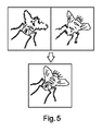
図3及び図4は、被写体の向上された被写界深度の合成2D画像を生成する当該装置及び方法により対処される問題を示す助けとなるものである。図3において、被写体は視野内に3本の木を伴う森林風景である。左側の木は当該撮像システムに近く、右側の木は該撮像システムから遠く、真ん中の木は、これら2つの間の距離にある。当該撮像システムは、被写体にピントを合わせることができる被写界深度を有するが、3本の全ての木は該撮像システムの被写界深度より大きなダウンレンジにわたって広がっている。従って、中心の木はピントが合い、両側の木はピントが外れている。同様の状況が図4に示されている。ここでは、被写体は蠅である。当該撮像システムは、該蠅のダウンレンジ方向における奥行きよりも小さな、ダウンレンジにわたって延びる被写界深度を有している。従って、該蠅の前部にピントが合っている場合、該蠅の後部、即ち該蠅の前部より当該撮像システムから更に遠い部分はピントが外れる。これが、図4に示されている。 FIGS. 3 and 4 help to illustrate the problems addressed by the present apparatus and method for generating a composite 2D image of the enhanced depth of field of an object. In FIG. 3, the subject is a forest landscape with three trees in view. The left tree is close to the imaging system, the right tree is far from the imaging system, and the middle tree is at a distance between the two. The imaging system has a depth of field that can focus on the subject, but all three trees extend over a down range that is larger than the depth of field of the imaging system. Therefore, the central tree is in focus, and the two trees are out of focus. A similar situation is shown in FIG. Here, the subject is an eyebrow. The imaging system has a depth of field extending over the down range that is smaller than the depth in the down range direction of the eyelid. Therefore, when the front of the eyelid is in focus, the back of the eyelid, ie, a portion farther from the imaging system than the front side of the eyelid is out of focus. This is illustrated in FIG.
図5は焦点合成技術の一例を概略的に示す。蠅の画像を取得するために撮像システムが使用されており、該蠅は該撮像システムの被写界深度より大きな奥行きを有している。該蠅の異なる部分が別々の画像において焦点が合うようにして、複数のデジタル画像が異なる焦点位置で取得される。1つの画像においては該蠅の前部に焦点合う一方、該蠅の後部は焦点が外れる。他の画像においては、該蠅の前のピントが外れる一方、該蠅の後部はピントが合う。言い換えると、画像の3Dの積み重ねが、各画像が特定の焦点深度における2D画像であるようにして取得される。これら画像が取得された後、これら画像は、当該蠅の何の部分が何の画像でピントが合っているかを決定するために比較することができる。次いで、異なる画像からの該蠅のピントの合った部分から複合画像が生成される。しかしながら、異なる焦点深度の全ての画像は記憶されねばならず、このことは非常に大きな画像バッファを必要とする一方、向上された画像は全ての画像が取得された後でしか決定されず、各画像は1つの奥行きに関するものでしかない。 FIG. 5 schematically illustrates an example of the focus combining technique. An imaging system is used to acquire an image of the eyelid, the eyelid having a depth greater than the depth of field of the imaging system. Multiple digital images are acquired at different focus positions, such that different portions of the eyelid are in focus in separate images. One image focuses on the front of the eyelid while the back of the eyelid is out of focus. In other images, the front of the eyelid is out of focus while the rear of the eyelid is in focus. In other words, a 3D stack of images is obtained such that each image is a 2D image at a particular depth of focus. After the images are acquired, they can be compared to determine what part of the eyelid is in focus with what image. A composite image is then generated from the in-focus portion of the eyelid from different images. However, all images of different depth of focus must be stored, which requires a very large image buffer, while the enhanced image is determined only after all images have been acquired, each Images are only about one depth.
図6は、木等の被写体を撮影する撮像システムを示す。該木の像は該撮像システムの検出器上に投影される。しかしながら、該撮像システムは当該木の奥行きより小さな被写界深度を有している。従って、当該木の奥行きの如何なる特定の領域も検出器上でピントが合って撮像することができ、該木の該被写界深度の前及び背後の領域はピントが外れる。ここでは、見る者にとり当該木の前及び後の枝が前に配置されたように見える冬期の木を想像することができる。 FIG. 6 shows an imaging system for shooting an object such as a tree. The image of the tree is projected onto a detector of the imaging system. However, the imaging system has a smaller depth of field than the depth of the tree. Thus, any particular area of the depth of the tree can be imaged in focus on the detector, and the areas before and behind the depth of field of the tree are out of focus. Here, one can imagine a winter tree which looks to the viewer as if the branches before and after the tree were arranged in front.
被写体の向上された被写界深度を持つ合成2D画像を生成するための当該装置及び方法は、画像データが取得されている際に該画像を向上された被写界深度の人工(合成)2D画像に変換するために適用することができるストリーミング焦点合成技術を備えることにより、上記問題に対処する。このことは、中間画像ファイルが記憶されることを要さずに“その場で(オンザフライで)”実行され、非常に大きな画像バッファの必要性をなくす。一例において、画像データは複数のダウンレンジ位置から同時に取得される。ここで、ダウンレンジとは、説明上の目的で、z又は奥行き方向に延びるものと見なされるが、如何なる方向に(水平に、垂直に又はこれらの間に)延びることもできる。被写体の向上された被写界深度を持つ合成2D画像を生成する当該装置及び方法を、図7〜図15を参照して詳細に説明する。 The apparatus and method for generating a synthetic 2D image having an enhanced depth of field of an object comprises an artificial 2D depth of field enhanced image when the image data is acquired. The above problems are addressed by providing a streaming focus synthesis technique that can be applied to convert to an image. This is performed "on the fly" without requiring intermediate image files to be stored, eliminating the need for very large image buffers. In one example, image data is acquired simultaneously from multiple down range locations. Here, down range is considered to extend in the z or depth direction for the purposes of illustration, but may extend in any direction (horizontally, vertically or between them). The apparatus and method of generating a composite 2D image having an enhanced depth of field of an object will be described in detail with reference to FIGS. 7-15.
図7は、被写体4の向上された被写界深度を持つ合成2D画像を生成するために使用される画像取得ユニットの一例を概略的に示す。当該被写体は、多数のダウンレンジ距離にわたって延在する特徴構造(凹凸)を有し、幾つかの特徴構造は他のものより大きなダウンレンジ距離にある。言い換えると、被写体4の特徴構造の幾つかの部分は、他のものより当該画像取得ユニットの近くにある。この画像取得ユニットは被写体4を撮像するように配置される。被写体4は静止的シーンであり得、その場合、都市環境がUAVに取り付けられた当該装置により撮影される場合のように当該画像取得ユニットが該シーンに対して移動するか、又は当該被写体が、教育現場に設けられ得る当該画像取得ユニットに対してテーブルを横方向に移動させることができる移動テーブル上に配置された蠅等の被写体であり得る。撮像経路pに沿い且つ被写体4から開始して、当該画像取得ユニットは、第1撮像レンズ22(典型的には、複数のレンズ22a,b,cから形成される)、放射を阻止するための開口21を有する。該画像取得ユニットは、第2撮像レンズ23及び2D検出器アレイ40の形態のセンサも有している。上記検出器は第1撮像レンズの光軸Oに対して傾斜され、これが、当該被写体における該検出器の斜め投影(断面)を形成する。このような斜め断面は、例えば検出器を光軸に対して傾斜させる代わりにプリズムを使用することにより、光学的に形成することもできる。他の例において、当該検出器が生物試料の斜め断面の画像データを取得するように構成されることは、顕微鏡対物レンズの光軸が検出器表面の法線に対して平行な場合に達成される。むしろ、試料ステージ自体が光軸Oに対して傾斜され、該試料は該試料の傾斜角に平行にスキャンされる。一例において、当該画像取得ユニットは、向上された被写界深度の合成画像を生成する装置10の一部を形成する。該装置10は、制御モジュール25を有し、該制御モジュールは、プロセッサ30の一部とすることができ、当該装置の動作過程及び当該被写体を撮像するためのスキャン過程を制御する(例えば、前記移動テーブルを移動させると共に検出器からの画像を取得及び処理する)。被写体4に当たる光は、散乱されて撮像レンズ22により捕捉され、レンズ23により2D検出器アレイ40上に結像される。前記光軸に対して“傾斜される”とは、被写体からの検出器に当たる放射が垂直には当たらない(前述したように、このことはセンサ自体を傾斜させることにより又は非傾斜センサの場合に光学的に達成することができる)ことを意味することに注意すべきである。
FIG. 7 schematically illustrates an example of an image acquisition unit used to generate a composite 2D image with an enhanced depth of field of subject 4. The subject has features (concavities and convexities) that extend over a large number of down range distances, with some features being at a larger down range distance than others. In other words, some parts of the feature of the subject 4 are closer to the image acquisition unit than others. The image acquisition unit is arranged to image the subject 4. The subject 4 may be a static scene, in which case the image acquisition unit moves relative to the scene as if the urban environment was photographed by the device attached to the UAV, or the subject is: The subject may be an eyelid or the like placed on a movable table that can move the table in the lateral direction with respect to the image acquisition unit that can be provided at the educational site. Along the imaging path p and starting from the subject 4, the image acquisition unit comprises a first imaging lens 22 (typically formed from a plurality of
図8は、被写体の向上された被写界深度の合成画像を生成する当該装置及び方法の一例を説明する助けとなるものである。図8は、視野に跨がって横方向に延びる被写体4を概略的に示している。該被写体は、当該視野に跨がって、該被写体における当該検出器の投影(断面5;異なる時点で取得される2つの断面5a及び5bとして示されている)を横切る位置において当該装置の焦点深度より大きな距離にわたりダウンレンジ距離が変化する。横方向位置x1において、被写体4は撮像されるべき特徴構造Aを有している。横方向位置x2において、被写体4は撮像されるべき特徴構造Bを有している。特徴構造A及びBは同じタイプの材料であり得、かくして、これら特徴構造は同様の波長帯域にわたって放射を反射するか、又は異なるように反射する点で非類似であり得る。装置10は、当業者により理解されるように、当該被写体を介して透過する光により、及び/又は該被写体から反射される光により動作しているものであり得る。装置10は、画像データが当該被写体の断面5aについて取得されるように構成される。言い換えると、当該装置の検出器の投影は、図8に示される位置(a)に位置される。当該装置は、断面5aの両側の短い距離内の特徴構造にピントが合うような焦点深度を有する。従って、断面5aに関して取得された第1画像において、組織層4は位置x1ではピントが外れ、該ピンぼけ組織はA’と称する。しかしながら、断面5aに関して取得された第1画像において、組織層4は位置x2では焦点が合い、該ピントの合った組織はBと称される。取得された画像は作業画像となる。次いで撮像レンズ22が移動され、かくして、データが必要とされる断面5は当該被写体における新たなダウンレンジ位置5bに移動される。撮像レンズ22を移動させる代わりに、被写体自体をダウンレンジ方向に移動させることもできる(図7に示される光軸Oに対して平行に、又は当該装置がダウンレンジ方向に移動される)。この第2画像において、位置x1においては、今度は、特徴構造Aにピントが合い、特徴構造Bはピントが外れる(B’)。この場合、処理ユニット(図示略)は前記作業画像を、位置x1における画像データが第1画像において取得されたものから第2画像において取得されたものに変更される(A’がAになる)一方、位置x2における画像データは変更されないように、更新する。この処理は、当該検出器に沿う複数の位置において、且つ、当該被写体を経る複数のダウンレンジ位置において実行することができる。この場合、作業画像は全ての横方向位置(x)において、当該横方向位置における最もピントの合った特徴構造により、その場で、連続的に更新される。作業画像のみが、記憶されねばならないと共に、たった今取得された画像と比較されねばならないだけで、全ての以前に取得された画像は記憶する必要はない。このようにして、当該作業画像は、焦点が合っているのみならず、当該装置の固有の焦点深度より大きな深度における特徴構造を含む。当該被写体を介してダウンレンジ方向に進行したら、全体の被写体自体を横方向に平行移動させることができ、当該処理が当該被写体の未だ撮像されていない部分に関して繰り返される。従って、当該被写体がスキャンされる間に、向上された焦点深度を持つその場での画像が生成され、このことは大量のデータを節約することを可能にする。図8に示された例において、当該被写体における検出器の投影(断面5)は光軸Oに対して垂直に示されているが、向上された被写界深度の画像を生成するための、ここに記載されるストリーミング技術は、被写体における検出器の投影が、断面5が斜めとなる(即ち、光軸Oに対して垂直でない)ものである場合にも機能することができることは明らかである。
FIG. 8 helps to illustrate an example of the apparatus and method of generating a composite image of the enhanced depth of field of an object. FIG. 8 schematically shows a subject 4 extending laterally across the field of view. The object is focused on the device at a position across the field of view and across the projection of the detector (
図9は、被写体の向上された被写界深度の合成画像を生成する当該装置及び方法の他の一例を説明する助けとなるものである。図9は、図8に示された様に被写体4を概略的に示している。この場合も、該被写体は、当該視野に跨がって、該被写体における当該検出器の投影(断面5;異なる時点で取得される2つの断面5a及び5bとして示されている)を横切る位置において当該装置の焦点深度より大きな距離にわたりダウンレンジ距離が変化する。横方向位置x1において、被写体4は撮像されるべき特徴構造Aを有している。ここで、当該装置は当該被写体の斜め断面5a,5bの画像データを取得するように構成された検出器を有している。前述したように、このことは該検出器の傾斜を介して又は光学的に達成することができる。断面5aに関して取得された第1画像(a)において、当該組織層4は位置x1においてはピントが合い、これを特徴構造Aと称する。しかしながら、断面5aの第1画像において、組織層4は位置x2では焦点が外れ、これを特徴構造B’と称する。図8に関して説明した例と同様に、取得された画像は作業画像となる。この場合、当該装置は、検出器の断面(断面5)を斜め断面5aが横方向に移動して斜め断面5bとして示されるように移動させるよう構成される。斜め断面の画像データが当該被写体内の異なる横方向位置で取得されるようにするために移動ステージが横方向に移動する。しかしながら、当業者により理解されるように、当該レンズ及び/又は検出器の移動も、この斜め断面の移動に影響を与え得る。(b)と称される新たな位置において、当該検出器は位置x1及び位置x2におけるデータを再び取得する一方、該検出器の別の部分は該データを該斜め断面が横方向にのみ移動した状況に関して取得している。該第2画像において、位置x1においては、今度は、皮膚層4はピントが外れ、取得された画像はA’と称される一方、位置x2における皮膚層4はピントが合い、これは特徴構造Bと称される。この場合、処理ユニット(図示略)は前記作業画像を、位置x1における画像データはそのままに留まる一方、位置x2における画像データが第2画像において取得されたものに変更される(B’がBになる)ように、更新する。この処理は、各々が当該被写体を介しての異なるダウンレンジ位置としい当該検出器に沿う複数の位置において実行することができる。斜め断面5が当該被写体を介して横方向にスキャンされるにつれて、作業画像は全ての横方向位置(x)において、当該横方向位置における最もピントの合った特徴構造により、その場で、連続的に更新される。作業画像のみが、記憶されねばならないと共に、たった今取得された画像と比較されねばならないだけであり、全ての以前に取得された画像は記憶する必要はない。このようにして、当該作業画像は、焦点が合っているのみならず、当該装置の固有の焦点深度より大きな深度における特徴構造を含む。当該被写体を介して横方向に進行したら、全体の被写体自体を横方向に、前のスキャン方向に対して垂直に平行移動させることができ、当該処理が当該被写体の未だ撮像されていない部分に関して繰り返される。言い換えると、当該被写体がスキャンされる間に、向上された焦点深度を持つその場での画像が生成され、このことは大量のデータを節約することを可能にする。図9において、斜め断面5はx方向に横方向にのみ移動するように示されているが、同様に、移動ステージを該斜め断面が横方向に移動するように移動させることも、撮像レンズ22を該斜め断面が横方向及びダウンレンジ方向の両方に移動するように当該光軸の方向に(ダウンレンジ方向に)移動させることもできる。このようにして、当該装置は被写体4のダウンレンジ位置の大きな偏差に追従することができる。
FIG. 9 helps to illustrate another example of the apparatus and method of generating a composite image of an enhanced depth of field of an object. FIG. 9 schematically shows the subject 4 as shown in FIG. Again, the subject crosses the field of view at a location across the projection of the detector on the subject (
図10は、被写体及び2D検出器アレイの投影を概略的に示すもので、向上された被写界深度の合成2D画像の生成のための当該装置及び方法の一例を更に説明する助けとなるものである。被写体4は、例えば当該装置を備えたUAVが飛行及び撮影している地面であり得るか、又は撮影される昆虫の特徴構造を表すものであり得、これら特徴構造はダウンレンジ方向に延びる。当該検出器の2Dアレイの投影は断面5として示されており、該断面は当該センサが実際に像を検出する被写体に対応する。デカルト座標系X’,Y,Zが示されており、当該検出器はX’軸に対して30°なる角度β’だけ傾斜されている。一例において、X’及びYは横方向(水平)面に位置する一方、Zはダウンレンジ(例えば、垂直)方向に延びている。言い換えると、当該検出器は上記横方向(水平)面から傾斜されたX−Y面内に位置し、この例において、このことは被写体に当該検出器の斜め投影を生じさせる。これらの軸は、当該検出器が光軸に沿って一直線上にある図7に示されたような概略システムに関して説明されるものであるが、当業者であれば理解するように、当該検出器が図7に示されるような垂直の向きから傾斜されることがないようにミラー又は複数のミラーを使用することもできると理解されるべきである。軸X’は横方向であり、該方向はスキャン方向であると共に、この例では、光軸Oに対して垂直である。前述したように、当該装置は潜水遠隔操作船(rov)で使用することができ、その場合、撮影される被写体は屈折率を持つ媒体内にあり得、又は被写体自体が透明であって固有屈折率を有し得る。従って、断面5は、被写体において当該検出器の傾斜角β’とは異なる角度βを形成し得る(水に半分入り半分出ている棒が空気と水との境界で曲がって見えるのと同様の態様で)。当該斜め断面5は図10に示される交差部Iにおいて被写体4と交差し、この場合、交差部Iにはピントが合う。図12を参照して更に詳細に説明するように、当該検出器はラインスキャンモードで動作される。言い換えると、一行のピクセル又は複数の隣接する行のピクセルを活性化することができ、その場合において、各行は横方向位置x’にあり、Y軸に沿って図10の頁内へと延びる。被写体4がY方向に傾斜されなかった場合、交差部IはYに沿って同一のダウンレンジ距離にあり、該交差部Iは1以上の活性化された行によりピントが合って撮像される。しかしながら、交差部Iは自身の長さに沿ってX’及びY座標が変化し得るのみならず、撮像されるべき異なる特徴構造が当該被写体のY軸方向に存在し得る。従って、図8及び図9並びに作業画像が如何にして連続的に生成されるかを振り返ると、これらの図は図10に示される被写体を介しての1つのY座標におけるスライスを表すと見なすことができる。この場合、図8及び図9を参照して説明された処理が、異なるY座標における全てのスライスに対して実行される。言い換えると、異なる斜め断面5関して取得される、異なるZ座標によるものであるが各X’,Y位置における画像データは、該X’,Y座標において最良にピントの合った特徴構造を有するように連続的に更新され、該更新は、新たな画像データが一層良いピントを有する場合は作業画像内の対応する画像を今取得された画像における画像が置換し、又は作業画像の方が良いピントを有する場合は該作業画像が当該X’,Y座標における画像に対してそのままに残存することの何れかを意味し得る。ラインスキャンモードの検出器で動作する代わりに、当該被写体の各横方向位置に関する作業画像を生成及び更新する際に上述したのと同様の態様で当該画像の適切な部分が使用されるようにして、通常のCCD検出器を利用することができる。
FIG. 10 schematically illustrates the projection of an object and a 2D detector array to help further illustrate an example of the apparatus and method for the generation of a composite 2D image of enhanced depth of field. It is. The subject 4 may, for example, be the ground on which the UAV equipped with the device is flying and shooting, or may represent the features of the insect to be shot, these features extending in the down range direction. The projection of the 2D array of the detector is shown as a
図11は、2D検出器アレイの投影5が図示された被写体4の断面を概略的に示すもので、当該装置の構成を説明する助けとなるものである。図11から分かるように、傾斜された検出器は当該被写体の斜め断面5の像を形成する。該傾斜は、スキャン方向6(横方向X’)におけるものである。X軸に沿って当該検出器はNxのピクセルを有し、当該被写体をスキャン(横)方向においてピクセル当たりΔx’でサンプリングすると共に光軸Oに平行な(垂直)方向7(Z)においてピクセル当たりΔzでサンプリングする。X方向において、各ピクセルは長さLを有する。前述したように、当該検出器は角度β’傾斜されているので、当該被写体における横方向及び軸方向サンプリングは:

図12は、向上された被写界深度の画像を生成するために使用されるデータを取得する例示的な2D検出器アレイを概略的に示す。白で示されたピクセルは、光に対して感応性であって、活性化された場合に信号取得のために使用することができ、図示されていない他のピクセルは暗電流及び信号オフセットのために使用される。図示されていない複数のピクセルは、ピクセル電子回路を示す。複数の行(又はライン)のピクセルが、個々のライン撮像検出器を形成し、該ライン撮像検出器は、図10を参照すると、1つのX’,Z座標にあり、Y軸に沿って頁内へと延びる。隣接するライン又はピクセルからなるピクセルの細条は、時間遅延積分(TDI)を用いて単一ラインのピクセル値に合成することができる。異なる例示的検出器においては異なる数のラインを合成することができ、例えば、2,3,4,5,10又はそれ以上の隣接するラインのピクセルを、TDIを用いて合成することができる。事実上、ピクセルの各細条は個々のTDIセンサとして作用することができ、これにより、信号対雑音比を改善する。このような検出器の場合、各ライン撮像検出器は、Y方向に延びる数千ものピクセルの長さを有し、これは、例えば、図10に図示されたラインIを示す。例えば、該長さは1000,2000,3000,4000,5000又は他の数のピクセルとすることができる。横方向スキャンの間において撮像レンズを移動させるために焦点アクチュエータが使用されない場合、各ライン検出器は当該被写体を一定のダウンレンジ距離において当該装置の焦点深度にわたって撮像する。前述したように、ピクセルの各細条は、TDIが起動された場合、単一のTDIブロックの複数の行を表し得る。当該検出器は、読出電子回路により分離された複数の斯かるブロックを含む。例えば、当該検出器は100,200又は300のブロックを含み得る。当該検出器は、他の数のブロックを有することもできる。当該被写体における検出器の投影である断面5に関する場合、各TDIブロックの間のz方向の距離は、撮影状況に依存して変化させることができる。従って、当該装置の固有の焦点深度にわたり、この焦点深度内に分散される複数のTDIブロックが存在し得る。当該検出器は、ブロック間のz方向の距離が可変であり得ると共に、ブロック間で変化し得るように構成することができる。これらのブロックのうちの1つ、又は、確かなことに、これらブロックのうちの該焦点深度内の複数を、特定のダウンレンジ位置における画像データを供給するために個別に使用し又は一緒に合計することができる。この場合、Xに沿う当該検出器の異なる位置における1以上のTDIブロックを、焦点深度にわたる当該被写体の異なるダウンレンジ距離に関する画像データを取得するために活性化することができる。第2のダウンレンジ距離は第1深度から少なくとも焦点深度だけ隔てられる。特定のダウンレンジ距離における焦点深度にわたる各TDIブロック又は複数のTDIブロックは、事実上、当該被写体内の画像データの層を掃引し、該層は当該装置の画像取得ユニットの固有の焦点深度に略等しい厚さを有する。従って、当該装置の固有の焦点深度の8倍に等しいダウンレンジ距離にわたって延びる被写体に関してデータを取得することは、該被写体から画像データを取得するために、当該検出器に沿う異なる位置におけるものであって、各々は異なるダウンレンジ距離及び横方向位置にあるが、自身の長さに沿っては同一のダウンレンジ距離にあるような8つの斯様なTDIブロックを使用することができることを意味する。撮像されるべき特徴構造は、この全体のダウンレンジ距離内の何処かに位置し得る(例えば、当該被写体は冬期における木であり得、該木の前部、中央及び後部における枝が撮影されるべきである)。従って、断面5が当該被写体を介して横方向に掃引される際に、これら8つのTDIブロックの各々が該被写体の同一のX’,Y位置においてではあるが、異なるダウンレンジ距離Zにおいて画像データを取得する。従って、データを取得するために使用される活性TDIブロックはデータを取得している他のTDIブロックから、データを取得していない複数のTDIブロックにより離隔され得ることに注意すべきである。これら8つのTDIブロックからの画像データを有する第1画像は、撮像される各X’,Y位置に関する画像データを有する作業画像を形成するために使用される。断面5が当該被写体内で横方向に移動される場合、画像データは、既に撮像されたX’,Y位置の大部分に関するものであるが、これらX’,Y位置に対して異なるダウンレンジ距離において取得される。図8及び図9を参照して前述したように、作業画像は当該X’,Yにおいて今まで取得された最良のピントの画像を含むように更新される。このことは、作業画像ファイルが記憶され、たった今取得された画像と比較され、必要な場合に更新されるというよりは、全ての画像データを記憶することを要せずに、オンザフライで実行することができる。これにより、合成2D画像が向上された被写界深度で生成され、その場合において、当該被写体の或るダウンレンジ距離における特徴構造及び該被写体の別のダウンレンジ距離における別の特徴構造もピントが合った状態になり得、これらダウンレンジ距離の差は当該画像取得ユニットの固有の焦点深度より大きく、従って、通常の装置(1つのダウンレンジ距離において当該撮像系の焦点深度にわたってのみデータを取得する)においては両方にピントを合わせることはできないものである。言い換えると、複数の特徴構造は、これら特徴構造が当該被写体内でダウンレンジ距離が異なって変化するとしても、焦点が合い得る。当該作業画像ファイルが新たな画像データとなるか又は元の作業画像データを維持するかを選択する代わりに、更新された作業画像を形成するために、該新たな画像データと既存の作業画像データとの加重和を用いることもできる。当該検出器はライン撮像モードで動作しているが、ライン画像に沿う個々の区域は別々に使用されることに注意すべきである。これは、ライン画像に沿う或る点における特定の特徴構造はピントが合い得る一方、該ライン画像に沿う他の点における他の特徴構造は、焦点深度の外側の別のダウンレンジ距離にあることにより、焦点が外れ得る故である。従って、もっと局部的(ピクセル)レベルでの選択がなされ、その場合、ピクセルとは、作業画像との比較を行って当該横方向位置における何のデータ(特定のX’,Y座標範囲)が最良のピント状態であるかを決定するために十分な数個のピクセルを意味し得る。互いに対して固定されるというより、データを取得するために使用されるTDIブロックは、当該検出器を上下に移動し得ると共に、互いに対しても移動し得る。データを取得するために使用されるTDIブロック間の間隔は斯かるTDIブロックが移動する際に同一に留まることができるか、又はTDIブロックの間の間隔はTDIブロックが移動する際に変化することができ、隣接するTDIブロックの間の間隔は異なるTDIブロックに関して異なって変化する。このことは、被写体を異なる解像度レベルでスキャンすると共に、該被写体全体を通して異なる解像度レベルを有するようにする能力を提供する。例えば、被写体にわたって、撮像されるべき特徴構造が主に小さなダウンレンジ距離に(当該装置の近くに)あるか又は大きなダウンレンジ距離(当該装置から遠くに)あるかの何れかであり、僅かな関心特徴構造しか中間のダウンレンジ距離にはないことがあり得る。この場合、複数のTDIブロックは、当該被写体を、これら2つ組のダウンレンジ距離にわたってスキャンすると共に中間のダウンレンジ距離にわたっては該被写体をスキャンしないように構成することができる。
FIG. 12 schematically illustrates an exemplary 2D detector array that acquires data used to generate an enhanced depth of field image. The pixels shown in white are sensitive to light and can be used for signal acquisition when activated, and other pixels not shown are due to dark current and signal offsets. Used for The plurality of pixels, not shown, represent pixel electronics. Multiple rows (or lines) of pixels form an individual line imaging detector, which, with reference to FIG. 10, is at one X ′, Z coordinate and page along the Y axis. Extend inwards. A strip of pixels consisting of adjacent lines or pixels can be combined into a single line of pixel values using time delay integration (TDI). Different numbers of lines can be synthesized at different exemplary detectors, for example, pixels of 2, 3, 4, 5, 10 or more adjacent lines can be synthesized using TDI. In fact, each strip of pixels can act as an individual TDI sensor, thereby improving the signal to noise ratio. For such detectors, each line imaging detector has a length of several thousand pixels extending in the Y direction, which for example shows line I illustrated in FIG. For example, the length may be 1000, 2000, 3000, 4000, 5000 or some other number of pixels. If the focus actuator is not used to move the imaging lens during a lateral scan, each line detector will image the subject over the depth of focus of the device at a fixed down range distance. As mentioned above, each strip of pixels may represent multiple rows of a single TDI block when TDI is activated. The detector comprises a plurality of such blocks separated by readout electronics. For example, the detector may include 100, 200 or 300 blocks. The detector can also have other numbers of blocks. With regard to the
図13は、オーバーサンプリングの一例を概略的に示すもので、向上された被写界深度の画像は中央の明瞭な領域に関して取得されねばならない。以前の図に関する説明から、当該被写体の特定の横方向ポイントに関する全ての利用可能なダウンレンジ距離における画像データは、該被写体における検出器の投影(即ち、断面5)が該ポイントを通り超えて完全にスキャンされたならば、生成することができることが明らかである。言い換えると、検出器の最初の部分が一方の極限のダウンレンジ距離における画像データを取得し、当該被写体が十分に移動された(及び/又は当該装置がスキャンした)場合、該検出器の最後の部分は他方の極限のダウンレンジ距離におけるデータを取得する。当該検出器の中間の部分は、中間のダウンレンジ距離における画像データを取得する。しかしながら、このことは、特定の領域を全ての利用可能なダウンレンジ距離にわたりスキャンするために、検出器の投影は、図13に示されるように、スキャンされるべき領域の一方の側から直ぐに開始し、スキャンされるべき領域の他方の側の直前の所で終了しなければならない。言い換えると、スキャンされるべき領域の両端に幾らかの量のオーバーサンプリングが存在する。図11に関する説明に関する場合、このようなオーバーサンプリングがどの様なものであることを要するかは容易に決定することができる。 FIG. 13 schematically illustrates an example of oversampling, wherein an enhanced depth of field image has to be acquired for a central clear area. From the description with respect to the previous figures, the image data at all available down-range distances for a particular lateral point of the subject in question is such that the projection of the detector on the subject (i.e. It is clear that if scanned, it can be generated. In other words, if the first part of the detector acquires image data at one extreme down range distance and the subject has been moved sufficiently (and / or the device has scanned), the last of the detector is The part gets data at the other extreme down range distance. An intermediate portion of the detector acquires image data at an intermediate down range distance. However, this causes the projection of the detector to start immediately from one side of the area to be scanned, as shown in FIG. 13, in order to scan a specific area over all available down range distances. Must end just before the other side of the area to be scanned. In other words, there is some amount of oversampling at both ends of the area to be scanned. With regard to the discussion of FIG. 11, it can be readily determined what such oversampling needs to be.
図14は、複数の撮像された領域又は層を概略的に示している。言い換えると、各層は、各TDIブロック(又は複数のブロック)が特定のダウンレンジ距離において当該装置の固有の焦点深度にわたり撮像するものに対応する。前述したように、当該被写体はダウンレンジ距離が大幅に変化し得る。従って、被写体の向上された被写界深度の合成2D画像を生成する際に使用されるべき像を取得する前に、該被写体の相対的に低い解像度の画像を得ることができる。これは、被写体ボリュームのz位置(ダウンレンジ距離)を推定するために使用される。言い換えると、1以上の位置(X’,Y)において、最適な焦点(Z)が決定される。次いで、ストリーミングモードにおいて向上された被写界深度の合成2D画像を生成する像の取得の間に、各位置において当該撮像レンズが光軸Oに沿って適切に移動される(又は被検体が光軸に沿って移動される)と共に、上述したデータの取得のために複数のTDIが活性化される。一例においては、撮像レンズ又は移動ステージの移動により断面5の位置を変える代わりに、TDIの位置が必要に応じて当該検出器の上下に移動される。この場合、断面5は一定の範囲のダウンレンジ距離をスキャンすることができるものとなるが、当該検出器の異なる部分がデータを取得することができる。代替例として、先行する低解像度画像を取得する代わりに、例えば国際特許出願公開第WO2011/161594号に記載されているような自己フォーカス(オートフォーカス)センサを使用することができる。このようなオートフォーカス構成において、図12に示されるような検出器自体をオートフォーカスセンサとして構成することができるか、又は別のオートフォーカスセンサを使用することができる。このことは、向上された焦点深度の画像を生成するために画像データが取得されている位置毎に、当該被写体の位置を決定し、必要に応じてTDIを活性化することができるということを意味する。その結果が図14に示され、該図はスキャンの間において別個のTDIにより撮像される被写体のダウンレンジ距離を示している。上述したように、各横方向位置において、向上された画像が特定のダウンレンジ距離における特徴構造が当該合成向上画像内に存在するようにして生成され、かくして、異なるダウンレンジ距離における(従って、異なる層における)特徴構造が結果的向上画像内に存在するようになる。上述したように、当該向上された画像は、別個の画像の全てが記憶されることを要せず、むしろ、作業画像のみが記憶されると共に今し方取得された画像と比較されることにより生成され、これにより、向上された被写界深度を持つ画像が大きな画像バッファを要せずにオンザフライで生成されることを可能にする。
FIG. 14 schematically illustrates a plurality of imaged areas or layers. In other words, each layer corresponds to what each TDI block (or blocks) images at a particular down range distance over the inherent depth of focus of the device. As described above, the subject may have a significant change in down range distance. Thus, a relatively low resolution image of the subject may be obtained prior to obtaining an image to be used in generating a composite 2D image of the subject's enhanced depth of field. This is used to estimate the z-position (down range distance) of the subject volume. In other words, the optimum focus (Z) is determined at one or more positions (X ', Y). The imaging lens is then moved appropriately along the optical axis O at each position (or the object is illuminated) during acquisition of the image to produce a composite 2D image of enhanced depth of field in streaming mode. In addition to being moved along the axis, a plurality of TDIs are activated to acquire the data described above. In one example, instead of changing the position of the
このようにして、当該システムは、被写体の異なるダウンレンジ距離にある複数の特徴構造であって、焦点の合った複数の特徴構造を有するような画像をオンザフライで生成することができる。 In this way, the system can generate on the fly an image with multiple features that are at different down-range distances of the subject and that have multiple features in focus.
焦点合成は図5を参照して簡単に説明された。図15には、向上された被写界深度の合成画像を生成する際に使用される焦点合成のための例示的ワークフローが示されている。説明の容易化のために、焦点合成は図8に示されたようなデータを取得するシステムに関して説明されるが、該焦点合成は斜め断面を提供する傾斜検出器に対しても適用可能である。以下の説明において、層とは、先にも説明されたように、当該画像取得ユニットが被写体の特定のダウンレンジ距離において該ダウンレンジ距離における焦点深度にわたり撮像しているものに関するものである。従って、当該説明は非傾斜検出器に関するものである故に、当該層は当該被写体内の同一のダウンレンジ距離にあるものであるが、上述したように、この焦点合成処理は傾斜検出器及びデータが取得される斜め断面にも等しく当てはまるものである。かくして、層nの画像が取得される。最初に、z位置nにおいて取得された入力画像のエネルギ量が決定される。該エネルギ量は平滑化処理(ノイズ量を低減するための)により後続されるハイパスフィルタ(即ち、ラプラシアンフィルタ)の適用により決定される。第2に、この算出された層nのエネルギ量は層≦(n-1)のエネルギと比較される。個々の全てのピクセルに関して、現在の層(即ち、層nの画像データ)又は合成結果(即ち、層≦(n-1)の組み合わされた画像データ:先に説明した作業画像)が使用されるべきかが決定され、この結果が図15の“層選択”である。第3に、2つのバッファ、即ち合成画像データ(即ち、層≦nの画像データ)及び合成エネルギデータ(即ち、層≦nの)、が記憶されねばならない。次いで、次の層をスキャンすることができ、当該処理は、最後の層が取得されて処理されるまで反復する。前記層選択(即ち、何の層から何の部分を選択するか)は、層nの画像データ及び合成画像≦(n-1)の画像データからの並びに同様にエネルギに関する情報を合成するために使用されることに注意すべきである。 Focus synthesis has been briefly described with reference to FIG. FIG. 15 illustrates an exemplary workflow for focus combining used in generating an enhanced depth-of-field composite image. For ease of explanation, focus combining is described with respect to a system for acquiring data as shown in FIG. 8, but the focus combining is also applicable to tilt detectors providing oblique cross sections . In the following description, the layers, as explained earlier, relate to those in which the image acquisition unit is imaging over a depth of focus at the particular down range distance of the subject. Thus, although the description relates to a non-tilt detector, the layers are at the same down-range distance within the subject, but as noted above, this focus-combing process is performed by the tilt detector and the data. The same applies to the oblique cross-sections obtained. Thus, an image of layer n is obtained. First, the amount of energy of the input image acquired at z position n is determined. The amount of energy is determined by application of a high pass filter (i.e., Laplacian filter) followed by a smoothing process (to reduce the amount of noise). Second, the calculated energy content of layer n is compared to the energy of layer ≦ (n−1). For every individual pixel, the current layer (i.e. the image data of layer n) or the composite result (i.e. the combined image data of layer <(n-1): working image described above) is used It should be decided, and the result is the "layer selection" of FIG. Third, two buffers must be stored: composite image data (i.e., layer <n image data) and composite energy data (i.e., layer <n). The next layer can then be scanned and the process repeated until the last layer is obtained and processed. The layer selection (ie, from which layer and what part to select) is to combine information from the image data of layer n and the image data of composite image ≦ (n−1) as well as energy It should be noted that it is used.
従って、一例においては、ストリーミングモードにおいて傾斜センサが焦点合成と組み合わされる。この場合、中間結果を完全に(即ち、層≦(n-1)の画像データ及び層≦(n-1)のエネルギ)記憶する必要は無く、使用される画像フィルタ(即ち、高周波フィルタ及び平滑フィルタ)のフットプリントにより決まる当該画像及びエネルギデータの限られた履歴しか必要とされない。当該傾斜センサにより新たな(傾斜)画像が取得される毎に、この画像の行当たりの(即ち、z位置当たりの)エネルギが決定される。該傾斜画像は、前述したように、Y(該画像の行)及びX’/Z(該画像の列)における面内にある。これらのエネルギ値は、以前に取得されたものと比較される。該比較は合致する(x’,y)位置に関して実行される。言い換えると、該比較は、局部レベル(上記エネルギ分析を適用することができるのに十分なピクセル)においであって、1つの画像としての全体のライン画像に対してではない。一層大きなフォーカスエネルギが見付かった場合、当該画像データは更新される。(x’,y)位置の全てのz位置が評価されたなら、該(合成された;“作業”)画像データは伝送することができる。このことは、数十GBもの中間結果を記憶する必要性をなくす一方、最終結果(即ち、向上された焦点深度層)は当該被写体の最後の部分をスキャンした後に、(依然として)すぐに利用可能となる。 Thus, in one example, a tilt sensor is combined with focus combining in streaming mode. In this case, there is no need to store the intermediate result completely (ie, image data of layer ≦ (n−1) and energy of layer ≦ (n−1)), and the image filter used (ie, high frequency filter and smooth) Only a limited history of the image and energy data is required, which is determined by the footprint of the filter. Each time a new (tilted) image is acquired by the tilt sensor, the energy per row (i.e. per z position) of this image is determined. The tilted images are in the plane at Y (rows of the image) and X '/ Z (columns of the image) as described above. These energy values are compared to those obtained previously. The comparison is performed for the matching (x ', y) position. In other words, the comparison is at the local level (pixels sufficient to be able to apply the above energy analysis) and not to the whole line image as one image. If a larger focus energy is found, the image data is updated. The (combined; "work") image data can be transmitted if all z positions of the (x ', y) position have been evaluated. While this eliminates the need to store tens of gigabytes of intermediate results, the final result (i.e. the enhanced depth of focus layer) is readily available (still) after scanning the last part of the subject It becomes.
上記処理においては、各ピクセルに対して、最適な画像層がエネルギ量により決定される(即ち、ハイパスフィルタ)。可能性のある構成例は、高周波情報を決定する前に異なるカラーチャンネルが併合される(即ち、RGB2Y処理を用いて)というものである。一代替例として、情報(即ち、外部ソースからの又は画像分析により決定された)は、特定のカラーに一層注目するように使用することができる。このことは、追加のカラー分離ステップ又はカラー逆畳み込み(デコンボリューション)ステップと組み合わせることさえできる。この場合、最適な層は、1つの(又は複数の)特定のカラーを用いた(例えば、当該画像における特定のカラーに着目した)エネルギ量により局部的に決定することができる。更に、カラー分離ステップを追加すれば、異なる2D平滑化カーネルを使用することができるようになる。例えば、被写体の特徴構造は、より小さな平滑化カーネル(σ<2)から利益を得るような大幅に小さな細部を含むものを伴い種々の寸法を有し得る。 In the above process, for each pixel, the optimal image layer is determined by the amount of energy (ie, high pass filter). A possible arrangement is that different color channels are merged (i.e. using RGB2Y processing) before determining high frequency information. As an alternative, the information (i.e. determined from an external source or determined by image analysis) can be used to focus more on a particular color. This can even be combined with an additional color separation step or a color deconvolution step. In this case, the optimal layer can be locally determined by the amount of energy (for example, focusing on a specific color in the image) using one or more specific colors. Furthermore, the addition of the color separation step allows different 2D smoothing kernels to be used. For example, the features of the subject may have different dimensions with those containing much smaller details that benefit from a smaller smoothing kernel (σ <2).
上記処理においては、ラプラシアン高周波フィルタが使用される。一代替例として、取得されたデータはウェーブレットドメインに変換することができ、該ドメインにおいて高周波副帯域をエネルギの表現として使用することができる。これはiSyntax圧縮(例えば、米国特許第6711297号及び米国特許第6553141号参照)と組み合わせることができる。 In the above process, a Laplacian high frequency filter is used. As an alternative, the acquired data can be transformed into the wavelet domain, in which high frequency sub-bands can be used as a representation of energy. This can be combined with iSyntax compression (see, eg, US Pat. Nos. 6,711,297 and 6,553,141).
上記処理において、向上された被写界深度を持つ単一の画像層への変換は、当該画像をサーバに送信するために適用することができる。単一層への変換がサーバ上で実行され、センサの出力がサーバに直接伝送されるようにすることも可能である。 In the above process, transformation to a single image layer with enhanced depth of field can be applied to send the image to the server. It is also possible that conversion to a single layer is performed on the server and the output of the sensor is transmitted directly to the server.
各ピクセルに関して最適層を選択する代わりに、複数の層のピクセル値が、当該ピクセルのエネルギの分布に基づいて特定の重み付けを用いて結合されることも可能である。 Instead of selecting the optimal layer for each pixel, it is also possible that the pixel values of multiple layers are combined with a specific weighting based on the distribution of the energy of that pixel.
各ピクセルに関して最適層を選択する代わりに、同一のz方向の傾斜センサの全ピクセルを合計することも可能である。その結果はぼやけた総和画像となるが、該画像は次いで簡単な帯域フィルタによりフィルタ処理することができる。デジタル画像の和に関する情報に関しては、米国特許第4141032号を参照されたい。 Instead of selecting the optimum layer for each pixel, it is also possible to sum all the pixels of the same z-direction tilt sensor. The result is a blurred sum image, which can then be filtered with a simple band-pass filter. See US Pat. No. 4,141,032 for information on digital image sums.
本方法は、各層のエネルギに関するものであるから、被写体の厚さを測定するために使用することもできる。 Since the method relates to the energy of each layer, it can also be used to measure the thickness of the object.
他の例示的実施態様においては、コンピュータプログラム又はコンピュータプログラム要素が提供され、該コンピュータプログラム又はコンピュータプログラム要素は、上述した実施態様の1つによる方法の方法ステップを適切なシステム上で実行するように構成されることを特徴とする。 In another exemplary embodiment, a computer program or computer program element is provided, such that the computer program or computer program element performs the method steps of the method according to one of the above described embodiments on a suitable system. It is characterized by comprising.
上記コンピュータプログラム要素は、従って、一実施態様の一部とすることもできるコンピュータユニットに記憶することができる。このコンピュータユニットは、上述した方法のステップの実行を行い又は誘起するよう構成することができる。更に、該コンピュータユニットは、前述した装置の構成要素を動作させるように構成することができる。該コンピュータユニットは、自動的に動作し及び/又はユーザの指令を実行するように構成することができる。コンピュータプログラムは、データプロセッサのワーキングメモリにロードすることができる。該データプロセッサは、このように、前述した実施態様の1つによる方法を実行するように装備することができる。 The computer program element may thus be stored in a computer unit which may also be part of an embodiment. The computer unit may be configured to perform or induce the execution of the steps of the method described above. Furthermore, the computer unit can be configured to operate the components of the device described above. The computer unit may be configured to operate automatically and / or execute user commands. A computer program can be loaded into the data processor's working memory. The data processor can thus be equipped to carry out the method according to one of the embodiments described above.
本発明の該例示的実施態様は、本発明を最初から使用するコンピュータプログラム及び更新により既存のプログラムを、本発明を使用するプログラムに変えるコンピュータプログラムの両方をカバーするものである。 The exemplary embodiment of the present invention covers both the computer program that uses the present invention from the beginning and the computer program that updates the existing program into a program that uses the present invention.
更に、前記コンピュータプログラム要素は、前述した方法の例示的実施態様の手順を満たすために必要な全てのステップを提供することができる。 Furthermore, the computer program element can provide all the steps necessary to fulfill the procedure of the exemplary embodiment of the method described above.
本発明の他の例示的実施態様によれば、CD−ROM等のコンピュータ読取可能な媒体が提供され、該コンピュータ読取可能な媒体は先の段落により説明されたコンピュータプログラム要素を記憶している。 According to another exemplary embodiment of the present invention, a computer readable medium, such as a CD-ROM, is provided, which stores the computer program element described by the preceding paragraph.
コンピュータプログラムは、光記憶媒体又は他のハードウェアと一緒に供給され若しくは他のハードウェアの一部として供給される固体媒体等の適切な媒体により記憶及び/又は分配することができるのみならず、インターネット又は他の有線若しくは無線通信システムを介してのように、他の形態で分配することもできる。 Not only can the computer program be stored and / or distributed on a suitable medium, such as a solid medium supplied with an optical storage medium or other hardware or supplied as part of another hardware, Other forms of distribution may be possible, such as via the Internet or other wired or wireless communication systems.
しかしながら、上記コンピュータプログラムは、ワールドワイドウェブ等のネットワークを介して提供することもでき、斯様なネットワークからデータプロセッサのワーキングメモリにダウンロードすることもできる。本発明の他の例示的実施態様によれば、コンピュータプログラム要素をダウンロードのために利用可能にする媒体も提供され、該コンピュータプログラム要素は本発明の前述した実施態様の1つによる方法を実行するように構成される。 However, the computer program may be provided via a network such as the World Wide Web, or may be downloaded from such a network to the working memory of the data processor. According to another exemplary embodiment of the present invention, there is also provided a medium for making a computer program element available for download, said computer program element performing a method according to one of the aforementioned embodiments of the present invention. Configured as.
本発明の実施態様は異なる主題に関して説明されていることに注意されたい。特に、幾つかの実施態様は方法のタイプの請求項に関して説明されている一方、他の実施態様は装置のタイプの請求項に関して説明されている。しかしながら、当業者であれば、上記及び以下の記載から、そうでないと明示されない限り、1つのタイプの主題に属するフィーチャの如何なる組み合わせにも加えて、異なる主題に関係するフィーチャの間の如何なる組み合わせも本出願により開示されていると見なされることが分かるであろう。しかしながら、全てのフィーチャは、斯かるフィーチャの単なる寄せ集め以上の相乗効果を提供するように組み合わせることができるものである。 It should be noted that embodiments of the present invention are described in terms of different subjects. In particular, some embodiments are described with respect to method type claims while other embodiments are described with respect to apparatus type claims. However, those skilled in the art, from the above and the following description, unless otherwise specified, in addition to any combination of features belonging to one type of subject matter, any combination between features pertaining to different subject matter It will be appreciated that it is considered as disclosed by the present application. However, all the features can be combined to provide synergy of more than just a bunch of such features.
以上、本発明を図面及び上記記載において詳細に図示及び説明したが、斯かる図示及び説明は解説的又は例示的なものであって、限定するものではないと見なされるべきである。本発明は、開示された実施態様に限定されるものではない。開示された実施態様に対する他の変形例は、当業者によれば、請求項に記載の本発明を実施するに際して図面、本開示及び従属請求項の精査から理解し、実施することができるものである。 While the present invention has been illustrated and described in detail in the drawings and foregoing description, such illustration and description are to be considered illustrative or exemplary and not restrictive. The invention is not limited to the disclosed embodiments. Other variations to the disclosed embodiments can be understood and effected by those skilled in the art from a review of the drawings, the disclosure and the dependent claims in practicing the claimed invention. is there.
尚、請求項において“有する”なる文言は他の要素又はステップを排除するものではなく、単数形は複数を排除するものではない。また、単一のプロセッサ又は他のユニットは、請求項に記載された幾つかの項目の機能を満たすことができる。また、特定の手段が互いに異なる従属請求項に記載されているという単なる事実は、これら手段の組み合わせを有利に使用することができないということを示すものではない。また、請求項における如何なる符号も当該範囲を限定するものと見なしてはならない。 In the claims, the word "comprising" does not exclude other elements or steps, and the singular does not exclude a plurality. Also, a single processor or other unit may fulfill the functions of several items recited in the claims. Also, the mere fact that certain measures are recited in mutually different dependent claims does not indicate that a combination of these measures can not be used to advantage. Also, any reference signs in the claims shall not be considered as limiting the scope.
Claims (15)
画像取得ユニットと、
処理ユニットと、
を有し、
前記画像取得ユニットは、当該被写体の第1横方向位置における第1画像データ及び該被写体の第2横方向位置における第2画像データを取得し、
前記画像取得ユニットは、前記第1横方向位置における第3画像データ及び前記第2横方向位置における第4画像データを取得し、前記第3画像データは前記第1画像データに対するものとは異なるダウンレンジ距離において取得され、前記第4画像データは前記第2画像データに対するものとは異なるダウンレンジ距離において取得され、
前記処理ユニットは、前記第1横方向位置に関する第1作業画像データを生成し、該生成は前記第1画像データ及び前記第3画像データの焦点合成アルゴリズムによる処理を含み、前記処理ユニットは、前記第2横方向位置に関する第2作業画像データを生成し、該生成は該第2横方向位置に関する第2作業画像データを生成するための前記焦点合成アルゴリズムによる前記第2画像データ及び前記第4画像データの処理を含み、
前記処理ユニットは、画像データの取得の間において、前記第1作業画像データ及び前記第2作業画像データを組み合わせて当該被写体の向上された被写界深度を持つ合成2D画像を生成する、
装置。 An apparatus for generating a synthetic 2D image having an enhanced depth of field of an object, comprising:
An image acquisition unit,
A processing unit,
Have
The image acquisition unit acquires first image data at a first lateral position of the subject and second image data at a second lateral position of the subject.
The image acquisition unit acquires third image data at the first lateral position and fourth image data at the second lateral position, and the third image data is different from that for the first image data. Acquired at a range distance, and wherein the fourth image data is acquired at a different down range distance than that for the second image data;
The processing unit generates first working image data relating to the first lateral position, the generation including processing according to a focal composition algorithm of the first image data and the third image data, the processing unit further comprising: Generating second working image data relating to a second lateral position, said generating said second image data and said fourth image according to said focus combining algorithm for generating second working image data relating to said second lateral position; Including processing of data,
The processing unit combines the first work image data and the second work image data during acquisition of image data to generate a composite 2D image having an enhanced depth of field of the subject.
apparatus.
a) 画像取得ユニットにより前記被写体の第1横方向位置における第1画像データを取得し、前記画像取得ユニットにより該被写体の第2横方向位置における第2画像データを取得するステップと、
b) 前記画像取得ユニットにより前記第1横方向位置における第3画像データを取得し、前記画像取得ユニットにより前記第2横方向位置における第4画像データを取得するステップであって、前記第3画像データを前記第1画像データに対するものとは異なるダウンレンジ距離において取得し、前記第4画像データを前記第2画像データに対するものとは異なるダウンレンジ距離において取得するステップと、
e) 前記第1横方向位置に関する第1作業画像データを生成するステップであって、該生成するステップが前記第1画像データ及び前記第3画像データを焦点合成アルゴリズムにより処理するステップを有するステップと、
f) 前記第2横方向位置に関する第2作業画像データを生成するステップであって、該生成するステップが前記第2画像データ及び前記第4画像データを前記焦点合成アルゴリズムにより処理するステップを有するステップと、
l) 画像データの取得の間において、前記第1作業画像データ及び前記第2作業画像データを組み合わせて、前記被写体の向上された被写界深度の合成2D画像を生成するステップと、
を有する、方法。 A method of generating a composite 2D image of an enhanced depth of field of an object, comprising:
a) acquiring first image data at a first lateral position of the subject by the image acquisition unit, and acquiring second image data at a second lateral position of the subject by the image acquisition unit;
b) acquiring third image data at the first lateral position by the image acquisition unit, and acquiring fourth image data at the second lateral position by the image acquisition unit, the third image Acquiring data at a different down range distance than that for the first image data, and acquiring the fourth image data at a different down range distance than that for the second image data;
e) generating first working image data for the first lateral position, the generating comprising processing the first image data and the third image data with a focus combining algorithm; ,
f) generating second working image data for the second lateral position, the generating comprising processing the second image data and the fourth image data according to the focus combining algorithm When,
l) combining the first work image data and the second work image data during acquisition of the image data to generate a composite 2D image of the enhanced depth of field of the subject;
Have a way.
d) 前記第2画像データに関する第2エネルギデータを計算し、前記第4画像データに関する第4エネルギデータを計算するステップと、
を有し、
前記生成するステップe)は、前記第1画像データ又は前記第3画像データの何れかを前記第1作業画像として選択するステップを有し、該選択するステップは前記第1エネルギデータ及び前記第3エネルギデータの関数を含み、
前記生成するステップf)は、前記第2画像データ又は前記第4画像データの何れかを前記第2作業画像として選択するステップを有し、該選択するステップは前記第2エネルギデータ及び前記第4エネルギデータの関数を含み、
画像データにおける周波数情報がエネルギデータを表す、請求項9又は請求項10に記載の方法。 c) calculating first energy data for the first image data, and calculating third energy data for the third image data;
d) calculating second energy data for the second image data, and calculating fourth energy data for the fourth image data;
Have
The generating step e) includes the step of selecting either the first image data or the third image data as the first working image, and the selecting step includes the first energy data and the third energy data. Including functions of energy data,
The generating step f) includes the step of selecting either the second image data or the fourth image data as the second working image, and the selecting step includes the second energy data and the fourth energy data. Including functions of energy data,
The method according to claim 9 or 10, wherein frequency information in the image data represents energy data.
h) 前記第2画像データが前記第2作業画像として選択される場合に第2作業エネルギデータを前記第2エネルギデータとして生成するか、又は前記第4画像データが前記第2作業画像として選択される場合に前記第2作業エネルギデータを前記第4エネルギデータとして生成するステップと、
を有する、請求項11に記載の方法。 g) generating first work energy data as the first energy data when the first image data is selected as the first work image, or the third image data is selected as the first work image Generating the first work energy data as the third energy data,
h) generating second working energy data as the second energy data when the second image data is selected as the second working image, or the fourth image data is selected as the second working image Generating the second work energy data as the fourth energy data if
The method of claim 11, comprising:
j) 前記第5画像データ及び前記第1作業画像データを前記焦点合成アルゴリズムにより処理して、前記第1横方向位置に関して新たな第1作業画像データを生成するステップであって、前記新たな第1作業画像データが該第1作業画像データとなるステップと、
k) 前記第6画像データ及び前記第2作業画像データを前記焦点合成アルゴリズムにより処理して、前記第2横方向位置に関して新たな第2作業画像データを生成するステップであって、前記新たな第2作業画像データが該第2作業画像データとなるステップと、
を更に有する、請求項9ないし12の何れか一項に記載の方法。 i) acquiring fifth image data at the first lateral position and acquiring sixth image data at the second lateral position, wherein the fifth image data is the first and third image data Acquiring at a different down-range distance than for said, and said sixth image data being acquired at a different down-range distance than for said second and fourth image data;
j) processing the fifth image data and the first work image data according to the focus combining algorithm to generate new first work image data for the first lateral position, the new 1) the step of the work image data becoming the first work image data;
k) processing the sixth image data and the second work image data according to the focus synthesis algorithm to generate new second work image data for the second lateral position, the new second 2) the step of the work image data becoming the second work image data;
The method according to any one of claims 9 to 12, further comprising
Applications Claiming Priority (3)
| Application Number | Priority Date | Filing Date | Title |
|---|---|---|---|
| EP16156767 | 2016-02-22 | ||
| EP16156767.2 | 2016-02-22 | ||
| PCT/EP2017/053998 WO2017144503A1 (en) | 2016-02-22 | 2017-02-22 | Apparatus for generating a synthetic 2d image with an enhanced depth of field of an object |
Publications (2)
| Publication Number | Publication Date |
|---|---|
| JP2019512188A true JP2019512188A (en) | 2019-05-09 |
| JP2019512188A5 JP2019512188A5 (en) | 2020-04-02 |
Family
ID=55486484
Family Applications (1)
| Application Number | Title | Priority Date | Filing Date |
|---|---|---|---|
| JP2018544159A Pending JP2019512188A (en) | 2016-02-22 | 2017-02-22 | Device for generating a synthetic 2D image of an enhanced depth of field of an object |
Country Status (6)
| Country | Link |
|---|---|
| US (1) | US20190052793A1 (en) |
| EP (1) | EP3420719A1 (en) |
| JP (1) | JP2019512188A (en) |
| CN (1) | CN108702455A (en) |
| RU (1) | RU2018133450A (en) |
| WO (1) | WO2017144503A1 (en) |
Families Citing this family (5)
| Publication number | Priority date | Publication date | Assignee | Title |
|---|---|---|---|---|
| JP6894894B2 (en) * | 2016-06-22 | 2021-06-30 | オリンパス株式会社 | Image processing device, operation method of image processing device, and operation program of image processing device |
| EP3709258B1 (en) * | 2019-03-12 | 2023-06-14 | L & T Technology Services Limited | Generating composite image from multiple images captured for subject |
| US11523046B2 (en) * | 2019-06-03 | 2022-12-06 | Molecular Devices, Llc | System and method to correct for variation of in-focus plane across a field of view of a microscope objective |
| US20210149170A1 (en) * | 2019-11-15 | 2021-05-20 | Scopio Labs Ltd. | Method and apparatus for z-stack acquisition for microscopic slide scanner |
| CN110996002B (en) * | 2019-12-16 | 2021-08-24 | 深圳市瑞图生物技术有限公司 | Microscope focusing method, device, computer equipment and storage medium |
Citations (3)
| Publication number | Priority date | Publication date | Assignee | Title |
|---|---|---|---|---|
| JP2007530995A (en) * | 2004-03-25 | 2007-11-01 | 1...リミテッド | Digital camera focusing |
| JP2011109644A (en) * | 2009-10-15 | 2011-06-02 | General Electric Co <Ge> | System and method for imaging with enhanced depth of field |
| JP2014022987A (en) * | 2012-07-19 | 2014-02-03 | Canon Inc | Semiconductor element, microscope device, and control method for microscope device |
Family Cites Families (11)
| Publication number | Priority date | Publication date | Assignee | Title |
|---|---|---|---|---|
| DE2655525C3 (en) | 1976-12-08 | 1979-05-03 | Ernst Leitz Wetzlar Gmbh, 6300 Lahn- Wetzlar | Process for expanding the depth of field beyond the limit given by conventional imaging as well as a device for carrying out this process |
| US6711297B1 (en) | 1998-07-03 | 2004-03-23 | University Of Pittsburgh - Of The Commonwealth System Of Higher Education | Methods and apparatus for dynamic transfer of image data |
| US6553141B1 (en) | 2000-01-21 | 2003-04-22 | Stentor, Inc. | Methods and apparatus for compression of transform data |
| CN1882031B (en) * | 2005-06-15 | 2013-03-20 | Ffei有限公司 | Method and equipment for forming multi-focusing images |
| US8059336B2 (en) * | 2007-05-04 | 2011-11-15 | Aperio Technologies, Inc. | Rapid microscope scanner for volume image acquisition |
| WO2009120718A1 (en) * | 2008-03-24 | 2009-10-01 | The Trustees Of Columbia University In The City Of New York | Methods, systems, and media for controlling depth of field in images |
| US20110091125A1 (en) * | 2009-10-15 | 2011-04-21 | General Electric Company | System and method for imaging with enhanced depth of field |
| JP5938401B2 (en) | 2010-06-24 | 2016-06-22 | コーニンクレッカ フィリップス エヌ ヴェKoninklijke Philips N.V. | Autofocus for scanning microscopy based on differential measurements |
| US20120098947A1 (en) * | 2010-10-20 | 2012-04-26 | David Robert Wilkes | Producing universally sharp images |
| JP5780865B2 (en) * | 2011-07-14 | 2015-09-16 | キヤノン株式会社 | Image processing apparatus, imaging system, and image processing system |
| US9489706B2 (en) * | 2012-07-02 | 2016-11-08 | Qualcomm Technologies, Inc. | Device and algorithm for capturing high dynamic range (HDR) video |
-
2017
- 2017-02-22 JP JP2018544159A patent/JP2019512188A/en active Pending
- 2017-02-22 EP EP17705665.2A patent/EP3420719A1/en not_active Withdrawn
- 2017-02-22 RU RU2018133450A patent/RU2018133450A/en not_active Application Discontinuation
- 2017-02-22 CN CN201780012678.3A patent/CN108702455A/en active Pending
- 2017-02-22 WO PCT/EP2017/053998 patent/WO2017144503A1/en active Application Filing
- 2017-02-22 US US16/078,051 patent/US20190052793A1/en not_active Abandoned
Patent Citations (3)
| Publication number | Priority date | Publication date | Assignee | Title |
|---|---|---|---|---|
| JP2007530995A (en) * | 2004-03-25 | 2007-11-01 | 1...リミテッド | Digital camera focusing |
| JP2011109644A (en) * | 2009-10-15 | 2011-06-02 | General Electric Co <Ge> | System and method for imaging with enhanced depth of field |
| JP2014022987A (en) * | 2012-07-19 | 2014-02-03 | Canon Inc | Semiconductor element, microscope device, and control method for microscope device |
Also Published As
| Publication number | Publication date |
|---|---|
| RU2018133450A3 (en) | 2020-06-05 |
| RU2018133450A (en) | 2020-03-24 |
| WO2017144503A1 (en) | 2017-08-31 |
| CN108702455A (en) | 2018-10-23 |
| EP3420719A1 (en) | 2019-01-02 |
| US20190052793A1 (en) | 2019-02-14 |
Similar Documents
| Publication | Publication Date | Title |
|---|---|---|
| JP2019512188A (en) | Device for generating a synthetic 2D image of an enhanced depth of field of an object | |
| JP7252190B2 (en) | System for generating enhanced depth-of-field synthetic 2D images of biological specimens | |
| JP5787695B2 (en) | Image acquisition device | |
| JP6570327B2 (en) | Control device, imaging device, control method, program, and storage medium | |
| JP6305053B2 (en) | Image processing apparatus, imaging apparatus, image processing method, and program | |
| US11156823B2 (en) | Digital microscope apparatus, method of searching for in-focus position thereof, and program | |
| JP2008242658A (en) | Three-dimensional object imaging apparatus | |
| CN105184784B (en) | The method that monocular camera based on movable information obtains depth information | |
| WO2006021767A2 (en) | Method and apparatus for providing optimal images of a microscope specimen | |
| Ouyang et al. | Visualization and image enhancement for multistatic underwater laser line scan system using image-based rendering | |
| JP2004021921A (en) | Topography measuring system using stereoscopic image, storage medium and program | |
| CN112866542B (en) | Focus tracking method and apparatus, electronic device, and computer-readable storage medium | |
| EP3143583B1 (en) | System and method for improved computational imaging | |
| CN114651275B (en) | Image stitching of full field of view reference images | |
| Heide et al. | Real-time hyperspectral stereo processing for the generation of 3d depth information | |
| Kudela et al. | Integration of photogrammetry within laser scanning approach | |
| JP6188750B2 (en) | Image acquisition device | |
| WO2019171691A1 (en) | Image processing device, imaging device, and image processing method | |
| WO2014010734A1 (en) | Imaging device | |
| CN112866545A (en) | Focusing control method and device, electronic equipment and computer readable storage medium | |
| CN109936692A (en) | Scattering medium image capturing system and method are worn based on epipolar-line constraint | |
| KR101602747B1 (en) | A system and method for resolution enhancement | |
| JP2001298657A (en) | Image forming method and image forming device | |
| JP2003101690A (en) | Image processing method, digital camera, and recording medium | |
| US20100253802A1 (en) | Enhanced microscan apparatus and methods |
Legal Events
| Date | Code | Title | Description |
|---|---|---|---|
| A521 | Request for written amendment filed |
Free format text: JAPANESE INTERMEDIATE CODE: A523 Effective date: 20200221 |
|
| A621 | Written request for application examination |
Free format text: JAPANESE INTERMEDIATE CODE: A621 Effective date: 20200221 |
|
| A977 | Report on retrieval |
Free format text: JAPANESE INTERMEDIATE CODE: A971007 Effective date: 20210310 |
|
| A131 | Notification of reasons for refusal |
Free format text: JAPANESE INTERMEDIATE CODE: A131 Effective date: 20210322 |
|
| A02 | Decision of refusal |
Free format text: JAPANESE INTERMEDIATE CODE: A02 Effective date: 20211019 |