JP2019509217A - Floating wind turbine and method for installing such a floating wind turbine - Google Patents
Floating wind turbine and method for installing such a floating wind turbine Download PDFInfo
- Publication number
- JP2019509217A JP2019509217A JP2018568482A JP2018568482A JP2019509217A JP 2019509217 A JP2019509217 A JP 2019509217A JP 2018568482 A JP2018568482 A JP 2018568482A JP 2018568482 A JP2018568482 A JP 2018568482A JP 2019509217 A JP2019509217 A JP 2019509217A
- Authority
- JP
- Japan
- Prior art keywords
- counterweight
- hull
- wind turbine
- balance weight
- installation
- Prior art date
- Legal status (The legal status is an assumption and is not a legal conclusion. Google has not performed a legal analysis and makes no representation as to the accuracy of the status listed.)
- Pending
Links
Images


Classifications
-
- F—MECHANICAL ENGINEERING; LIGHTING; HEATING; WEAPONS; BLASTING
- F03—MACHINES OR ENGINES FOR LIQUIDS; WIND, SPRING, OR WEIGHT MOTORS; PRODUCING MECHANICAL POWER OR A REACTIVE PROPULSIVE THRUST, NOT OTHERWISE PROVIDED FOR
- F03D—WIND MOTORS
- F03D13/00—Assembly, mounting or commissioning of wind motors; Arrangements specially adapted for transporting wind motor components
- F03D13/20—Arrangements for mounting or supporting wind motors; Masts or towers for wind motors
- F03D13/25—Arrangements for mounting or supporting wind motors; Masts or towers for wind motors specially adapted for offshore installation
-
- B—PERFORMING OPERATIONS; TRANSPORTING
- B63—SHIPS OR OTHER WATERBORNE VESSELS; RELATED EQUIPMENT
- B63B—SHIPS OR OTHER WATERBORNE VESSELS; EQUIPMENT FOR SHIPPING
- B63B21/00—Tying-up; Shifting, towing, or pushing equipment; Anchoring
- B63B21/50—Anchoring arrangements or methods for special vessels, e.g. for floating drilling platforms or dredgers
- B63B21/502—Anchoring arrangements or methods for special vessels, e.g. for floating drilling platforms or dredgers by means of tension legs
-
- B—PERFORMING OPERATIONS; TRANSPORTING
- B63—SHIPS OR OTHER WATERBORNE VESSELS; RELATED EQUIPMENT
- B63B—SHIPS OR OTHER WATERBORNE VESSELS; EQUIPMENT FOR SHIPPING
- B63B35/00—Vessels or similar floating structures specially adapted for specific purposes and not otherwise provided for
- B63B35/44—Floating buildings, stores, drilling platforms, or workshops, e.g. carrying water-oil separating devices
-
- B—PERFORMING OPERATIONS; TRANSPORTING
- B63—SHIPS OR OTHER WATERBORNE VESSELS; RELATED EQUIPMENT
- B63B—SHIPS OR OTHER WATERBORNE VESSELS; EQUIPMENT FOR SHIPPING
- B63B77/00—Transporting or installing offshore structures on site using buoyancy forces, e.g. using semi-submersible barges, ballasting the structure or transporting of oil-and-gas platforms
- B63B77/10—Transporting or installing offshore structures on site using buoyancy forces, e.g. using semi-submersible barges, ballasting the structure or transporting of oil-and-gas platforms specially adapted for electric power plants, e.g. wind turbines or tidal turbine generators
-
- B—PERFORMING OPERATIONS; TRANSPORTING
- B63—SHIPS OR OTHER WATERBORNE VESSELS; RELATED EQUIPMENT
- B63B—SHIPS OR OTHER WATERBORNE VESSELS; EQUIPMENT FOR SHIPPING
- B63B35/00—Vessels or similar floating structures specially adapted for specific purposes and not otherwise provided for
- B63B35/44—Floating buildings, stores, drilling platforms, or workshops, e.g. carrying water-oil separating devices
- B63B2035/4433—Floating structures carrying electric power plants
- B63B2035/446—Floating structures carrying electric power plants for converting wind energy into electric energy
-
- B—PERFORMING OPERATIONS; TRANSPORTING
- B63—SHIPS OR OTHER WATERBORNE VESSELS; RELATED EQUIPMENT
- B63B—SHIPS OR OTHER WATERBORNE VESSELS; EQUIPMENT FOR SHIPPING
- B63B2207/00—Buoyancy or ballast means
- B63B2207/02—Variable ballast or buoyancy
-
- F—MECHANICAL ENGINEERING; LIGHTING; HEATING; WEAPONS; BLASTING
- F05—INDEXING SCHEMES RELATING TO ENGINES OR PUMPS IN VARIOUS SUBCLASSES OF CLASSES F01-F04
- F05B—INDEXING SCHEME RELATING TO WIND, SPRING, WEIGHT, INERTIA OR LIKE MOTORS, TO MACHINES OR ENGINES FOR LIQUIDS COVERED BY SUBCLASSES F03B, F03D AND F03G
- F05B2240/00—Components
- F05B2240/90—Mounting on supporting structures or systems
- F05B2240/93—Mounting on supporting structures or systems on a structure floating on a liquid surface
-
- Y—GENERAL TAGGING OF NEW TECHNOLOGICAL DEVELOPMENTS; GENERAL TAGGING OF CROSS-SECTIONAL TECHNOLOGIES SPANNING OVER SEVERAL SECTIONS OF THE IPC; TECHNICAL SUBJECTS COVERED BY FORMER USPC CROSS-REFERENCE ART COLLECTIONS [XRACs] AND DIGESTS
- Y02—TECHNOLOGIES OR APPLICATIONS FOR MITIGATION OR ADAPTATION AGAINST CLIMATE CHANGE
- Y02E—REDUCTION OF GREENHOUSE GAS [GHG] EMISSIONS, RELATED TO ENERGY GENERATION, TRANSMISSION OR DISTRIBUTION
- Y02E10/00—Energy generation through renewable energy sources
- Y02E10/70—Wind energy
- Y02E10/72—Wind turbines with rotation axis in wind direction
-
- Y—GENERAL TAGGING OF NEW TECHNOLOGICAL DEVELOPMENTS; GENERAL TAGGING OF CROSS-SECTIONAL TECHNOLOGIES SPANNING OVER SEVERAL SECTIONS OF THE IPC; TECHNICAL SUBJECTS COVERED BY FORMER USPC CROSS-REFERENCE ART COLLECTIONS [XRACs] AND DIGESTS
- Y02—TECHNOLOGIES OR APPLICATIONS FOR MITIGATION OR ADAPTATION AGAINST CLIMATE CHANGE
- Y02E—REDUCTION OF GREENHOUSE GAS [GHG] EMISSIONS, RELATED TO ENERGY GENERATION, TRANSMISSION OR DISTRIBUTION
- Y02E10/00—Energy generation through renewable energy sources
- Y02E10/70—Wind energy
- Y02E10/727—Offshore wind turbines
Abstract
船体(1)と、船体(1)上に取り付けられた風力タービン(2))と、平衡錘懸架手段(18)によって船体(1)の下方に懸架された平衡錘(3)とを含む浮体式風力タービンについて説明する。設置方法についても説明する。平衡錘(3)は、1又は2以上の平衡錘浮力タンク(17)を含む。浮力タンク(17)の内部容積が空気で満たされている時には、平衡錘(3)の総浮力がその重量に近く又はそれよりも大きい。これにより、平衡錘は、船体(1)又は他の船からの垂直方向の支持が減少し又は無くなっても曳航/メンテナンス位置において浮かぶことができる。曳航中、船体は、実質的に広い水線面積及び浅い喫水に依拠して復原性を維持する荷船の特徴を有する。浮力タンク(17)が水で部分的に又は完全に水で一杯になると、平衡錘(3)は、平衡錘懸架手段(18)によって定められる深さの設置位置に沈む。この位置では、平衡錘が竜骨として機能して基礎を安定させる。平衡錘懸架手段(18)は、力及びモーメントの両方を別個に又はまとめて船体(1)に伝えることができ、これによって平衡錘(3)が、その設置位置にある時に船体(1)を安定化できるようになる。
【選択図】図2A floating body including a hull (1), a wind turbine (2) mounted on the hull (1), and a counterweight (3) suspended below the hull (1) by a counterweight suspension means (18). A wind turbine will be described. The installation method will also be described. The counterweight (3) includes one or more counterweight buoyancy tanks (17). When the internal volume of the buoyancy tank (17) is filled with air, the total buoyancy of the counterweight (3) is close to or greater than its weight. This allows the counterweight to float in the towing / maintenance position even if vertical support from the hull (1) or other ships is reduced or eliminated. During towing, the hull has the characteristics of a cargo ship that relies on a substantially large waterline area and shallow draft to maintain stability. When the buoyancy tank (17) is partially or completely filled with water, the counterweight (3) sinks to an installation position at a depth determined by the counterweight suspension means (18). In this position, the counterweight functions as a keel to stabilize the foundation. The counterweight suspension means (18) can transmit both forces and moments separately or collectively to the hull (1), so that the counterweight (3) is in its installed position when it is in the hull (1). It becomes possible to stabilize.
[Selection] Figure 2
Description
本発明は、風力タービンの浮体式洋上基礎、並びに浮体式洋上基礎の設置及びメンテナンス方法に関する。 The present invention relates to a floating offshore foundation for a wind turbine, and a method for installing and maintaining a floating offshore foundation.
具体的には、本発明は、船体と、船体上に取り付けられた風力タービンと、平衡錘懸架手段によって船体の下方に懸架された平衡錘とを備えた浮体式風力タービンに関する。 Specifically, the present invention relates to a floating wind turbine including a hull, a wind turbine mounted on the hull, and a counterweight suspended below the hull by a counterweight suspension means.
さらに、本発明は、船体と、船体上に取り付けられた風力タービンと、平衡錘懸架手段によって船体の下方に懸架された平衡錘とを備えた浮体式風力タービンの設置方法に関する。 Furthermore, the present invention relates to a method for installing a floating wind turbine comprising a hull, a wind turbine mounted on the hull, and a counterweight suspended below the hull by a counterweight suspension means.
さらに、本発明は、船体と、船体上に取り付けられた風力タービンと、平衡錘懸架手段によって船体の下方に懸架された平衡錘とを備えた浮体式風力タービンのメンテナンス方法に関する。 Furthermore, the present invention relates to a maintenance method for a floating wind turbine including a hull, a wind turbine mounted on the hull, and a balance weight suspended below the ship by a balance weight suspension means.
従来、洋上風力タービンは、比較的浅い水中の着床式基礎上に設置される。通常は、40〜50mの水深がこのような着床式基礎の限界と考えられている。 Conventionally, offshore wind turbines are installed on a relatively shallow underwater floor foundation. Usually, a water depth of 40-50 m is considered the limit of such a flooring foundation.
世界中の多くの海域には、洋上風力発電を望ましい程度まで展開するのに十分に適した水深50m以下の利用可能な沖合海域は存在しない。そこで、風力タービン用の浮体式基礎が必要になる。 There are no offshore waters available in many parts of the world that are well suited to deploy offshore wind power to the desired extent and are less than 50 meters deep. Therefore, a floating foundation for a wind turbine is required.
洋上風力タービンと共に使用する浮体式基礎の概念は、様々な異なるものが可能である。3つの基本概念は、円柱ブイ、半潜水型及びTLP(張力係留式プラットフォーム)である。これらの基本概念には、それぞれに利点及び制限がある。 The concept of a floating foundation for use with offshore wind turbines can vary widely. The three basic concepts are cylindrical buoy, semi-submersible and TLP (tension mooring platform). Each of these basic concepts has advantages and limitations.
円柱ブイは、バラストを併用して深喫水からの復原性を維持する。円柱ブイは、最も単純な浮体式基礎の概念であり、典型的には底部のバラストによって水中で垂直に保持される、空気を満たされた単純な浮き輪である。好適な寸法の円柱ブイは、垂直に近い姿勢を維持しながら大型風力タービンの重量及び負荷を支持することができる。通常、係留索の機能は、姿勢を維持して漂流を防ぐことのみである。円柱ブイの設計には、ピンと張った係留索からさらなる利点を得ようと模索しているものもあるが、実際にはこれらの設計は未だに試験されていない。 Cylindrical buoys maintain ballast and stability from deep drafts. Cylindrical buoys are the simplest floating foundation concept and are simple air-filled floats that are typically held vertically in water by the bottom ballast. A suitably sized cylindrical buoy can support the weight and load of a large wind turbine while maintaining a nearly vertical position. Usually, the function of the mooring line is only to maintain posture and prevent drifting. Some cylindrical buoy designs seek to gain additional benefits from taut mooring lines, but in practice, these designs have not yet been tested.
円柱ブイの概念は、その単純さによって本質的に魅力が高い。しかしながら、設置及び輸送段階中には、喫水が大きな課題を投げ掛ける。一般に、風力タービンを最終地において海洋条件下で浮体式基礎上に設置することは海水運動に起因して実現不可能であると考えられており、従って、通常、浮体式風力タービンは、波止場地域において地上クレーンを用いて、又は保護水域においてクレーン船を用いて設置される。一般に、円柱ブイは、50mを上回る、設計によっては100mをも上回る喫水を有し、このことが地上クレーンを用いた波止場地域での風力タービンの設置を事実上妨げている。従って、通常、風力タービンは、深い峡江などの保護水域においてクレーン船を用いて浮体式円柱ブイ基礎上に設置される。クレーン船を用いた風力タービンの設置を可能にするほどの深さの保護水域を見つけ出すことは、ノルウェーなどの数ヵ国では実に容易であるが、世界中の多くの海域には、このような十分な深さの利用可能な保護水域は存在しない。さらに、たとえこのような十分な深さの保護水域を領域内で実際に利用できる場合でも、多くの場合、設置地点と所望の洋上位置との間の輸送回廊に隆起部又は浅瀬が存在することにより、このような保護水域をタービンの設置に利用することは事実上妨げられてしまう。円柱ブイの深い喫水に起因するこれらの制限は、円柱ブイの概念にとって大きな問題となっている。 The concept of a cylindrical buoy is inherently attractive due to its simplicity. However, drafting poses a major challenge during the installation and transport phase. In general, it is considered impossible to install a wind turbine on a floating foundation under marine conditions in the final site due to seawater movement, and therefore usually a floating wind turbine is It is installed using a ground crane or in a protected water area using a crane ship. In general, cylindrical buoys have drafts in excess of 50 m, and in some designs in excess of 100 m, which effectively prevents the installation of wind turbines in quayside areas using ground cranes. Therefore, wind turbines are usually installed on floating cylindrical buoy foundations using crane ships in protected water areas such as deep canyons. Finding protected water areas deep enough to allow for the installation of wind turbines using crane ships is quite easy in some countries, such as Norway, but for many seas around the world, this is not enough There is no available protected water area of sufficient depth. In addition, even if such a sufficiently deep protected water area is actually available in the area, in many cases there are ridges or shallows in the transport corridor between the installation point and the desired offshore location. Therefore, the use of such a protected water area for the installation of the turbine is effectively prevented. These limitations due to the deep draft of the cylindrical buoy are a major problem for the cylindrical buoy concept.
円柱ブイ浮遊体を用いたタービン設置問題に対する1つの解決策は、円柱ブイが傾斜位に、好ましくはほぼ水平位にある間にタービンを設置することである。国際公開第2010/018359号には、このような近水平配向に基づく円柱ブイの設置方法が開示されている。この文献では、円柱ブイの底部に接続された仮浮力装置の取り付けを通じて近水平位を維持する。この構成であれば、波止場地域において地上クレーンを用いて近水平位でタービンを設置することができる。円柱ブイを所望の洋上位置まで曳航した後に、仮浮力装置を徐々に離脱させることによって最終的な垂直位に移行させる。 One solution to the turbine installation problem with a cylindrical buoy float is to install the turbine while the cylindrical buoy is in an inclined position, preferably in a substantially horizontal position. International Publication No. 2010/018359 discloses a method for installing a cylindrical buoy based on such near horizontal orientation. In this document, a near horizontal position is maintained through attachment of a temporary buoyancy device connected to the bottom of a cylindrical buoy. If it is this structure, a turbine can be installed in a near horizontal position using a ground crane in a wharf area. After the cylindrical buoy is towed to the desired offshore position, the temporary buoyancy device is gradually separated to move to the final vertical position.
国際公開第2013/048257号には、このような近水平配向に基づく円柱ブイの別の設置方法が開示されている。この文献では、円柱ブイを補助浮力装置に接続することを通じて近水平位を維持し、この接続は、円柱ブイと円柱ブイ上に取り付けられた風力タービンとの配向変化を可能にする回転結合装置を用いて行われる。タービンの設置中及び所望の位置への曳航中に配向を近水平から変化させることができる。円柱ブイを所望の洋上位置に曳航した後に、回転結合の回転を通じて最終的な垂直位に移行させることができる。 International Publication No. 2013/048257 discloses another method for installing a cylindrical buoy based on such a near horizontal orientation. In this document, a near-horizontal position is maintained by connecting a cylindrical buoy to an auxiliary buoyancy device, and this connection provides a rotary coupling device that allows a change in orientation between the cylindrical buoy and a wind turbine mounted on the cylindrical buoy. Done with. The orientation can be changed from near horizontal during installation of the turbine and towing to the desired location. After the cylindrical buoy is towed to the desired offshore position, it can be moved to the final vertical position through rotation of the rotational coupling.
国際公開第2010/018359号及び国際公開第2013/048257号に開示されている方法のような方法は、本質的に風力タービンを近水平配向で設置することを前提とするものである。しかしながら、一般にこの前提は大型風力タービンには当てはまらない。風力タービンで使用されるコントローラエンクロージャや変圧器などの重要な部品は通常の垂直配向のみに適しており、また構造部品のいくつかは、他では体験することがない異常な方向の重力荷重に対応するように大型寸法にする必要がある。潤滑油、冷却剤及びその他の流体が特殊な問題を引き起こすため、近水平配向を可能にするには、ベアリング、ギアボックス、油圧品、膨張タンクのシールを特別設計にする必要がある。これらの要因の結果、風力タービンの近水平配向に基づく円柱ブイの設置方法は一般に魅力的ではない。 Methods such as those disclosed in WO2010 / 018359 and WO2013 / 048257 are essentially premised on installing the wind turbine in a near horizontal orientation. In general, however, this assumption does not apply to large wind turbines. Critical components such as controller enclosures and transformers used in wind turbines are only suitable for normal vertical orientation, and some structural components are capable of handling unusually directed gravity loads that cannot be experienced elsewhere It is necessary to make it large in size. Lubricants, coolants, and other fluids cause special problems, so bearings, gearboxes, hydraulics, and expansion tank seals need to be specially designed to enable near-horizontal orientation. As a result of these factors, the installation method of a cylindrical buoy based on the near horizontal orientation of the wind turbine is generally not attractive.
半潜水型浮体式基礎は、比較的低い重心を確実にするバラストを併用して、中程度の喫水における広い水線面積からの復原性を得る。半潜水型の概念は、円柱ブイの概念ほど単純ではないが、喫水が浅いという利点がある。喫水が浅いことによって地上クレーンを用いた波止場地域でのタービン設置が可能であるとともに、所望の洋上位置への曳航中における課題もほとんどない。円柱ブイの概念と同様に、係留索の機能は、姿勢を維持して漂流を防ぐことのみである。 Semi-submersible floating foundations are used in combination with ballasts that ensure a relatively low center of gravity, and provide stability from a wide waterline area at moderate drafts. The semi-submersible concept is not as simple as the cylindrical buoy concept, but has the advantage of a shallow draft. Since the draft is shallow, it is possible to install a turbine in a wharf area using a ground crane, and there are almost no problems during towing to a desired offshore position. Like the cylindrical buoy concept, the mooring line functions only to maintain posture and prevent drifting.
半潜水型の概念は、比較的単純なことによって本質的に魅力が高い。しかしながら、横傾斜の結果として生じる差動浮力に基づく復原性の概念が、タービンロータに作用する大きな横力によって生じる転倒モーメントに起因してタービン運転中にかなりの横傾斜角をもたらす。 The semi-submersible concept is inherently attractive due to its relatively simple nature. However, the stability concept based on differential buoyancy as a result of side tilt results in significant side tilt angles during turbine operation due to the tipping moment caused by the large side forces acting on the turbine rotor.
国際公開第2009/131826号には、バラスト制御システムを用いてタービン運転中の横傾斜角を低減できる構成が開示されている。浮体式基礎に、基礎の安定化本体を構成する3つの主柱間で水バラストを再分配するために使用される1組のポンプ及び弁が取り付けられる。水バラストの再分配を通じて、タービンロータに作用する大きな横力によって生じる転倒モーメントを、移動可能なバラストによって生じる転倒モーメントによって逆方向に相殺することができる。 International Publication No. 2009/131826 discloses a configuration that can reduce the lateral tilt angle during turbine operation using a ballast control system. A floating foundation is fitted with a set of pumps and valves that are used to redistribute the water ballast among the three main columns that make up the stabilizing body of the foundation. Through redistribution of the water ballast, the overturning moment caused by the large lateral force acting on the turbine rotor can be counterbalanced by the overturning moment caused by the movable ballast.
国際公開第2009/131826号に開示されている構成には明らかな不利点がある。第1に、アクティブなセンサ及びポンプシステムの導入を通じて新たなレベルの複雑性がもたらされ、無人海洋構造物ではアクセス性の課題に起因してアクティブなシステムをできるだけ少なくすべきであるという基本原則に本質的に反している。第2に、再分配する必要がある質量が大きく、何百トン又は何千トンにもなるため、たとえ超大型のポンプを使用した場合でも、バランス調整システムが、通常は分単位の時定数で半静的になる。この結果、タービンロータに作用する大きな横力によって生じる転倒モーメントの過渡的変化のバランスを保つことができない。 There are obvious disadvantages to the arrangement disclosed in WO2009 / 131826. First, the basic principle is that a new level of complexity is introduced through the introduction of active sensor and pump systems, and unmanned offshore structures should have as few active systems as possible due to accessibility challenges. Is essentially against this. Second, because the mass that needs to be redistributed can be hundreds or thousands of tons, even with the use of very large pumps, the balancing system usually has a time constant in minutes. It becomes semi-static. As a result, the balance of the transient change of the overturning moment generated by the large lateral force acting on the turbine rotor cannot be maintained.
米国特許第8,118,538号には、タービンロータに作用する大きな横力によって生じる転倒モーメントに起因するタービン運転中の横傾斜角を低減する別の方法が開示されている。浮体式プラットフォームの少し下方に、基本的に竜骨として機能する平衡錘を取り付ける。さらなる実施形態では、この平衡錘が調整可能な係留索に接続されて、これらの索をピンと張る役割も果たす。 U.S. Pat. No. 8,118,538 discloses another method of reducing the lateral tilt angle during turbine operation due to a tipping moment caused by a large lateral force acting on the turbine rotor. A counterweight that basically functions as a keel is attached slightly below the floating platform. In a further embodiment, the counterweight is connected to adjustable mooring lines and also serves to pinch these lines.
米国特許第8,118,538号に開示されている構成は、横傾斜角を低減するという目的は果たすが、概説されている取り付け方法が複雑である。洋上作業は、ウインチ上の平衡錘ケーブルを平衡錘に接続した後に、平衡錘をプラットフォームの下方に降ろしてケーブルの緩みを補正することを含む。その後、組立工らがウインチストップを解放し、平衡錘をプラットフォームの下方に降ろし終えて設置を完了する。この一連の事象は、洋上でのかなりの労力を必要とし、平衡錘を安全に降ろすのに十分な能力を有するウインチをプラットフォームに取り付ける必要がある。この構成は、作業の複雑さ及びウインチのコストによって魅力に欠ける。 The arrangement disclosed in US Pat. No. 8,118,538 serves the purpose of reducing the lateral tilt angle, but the mounting method outlined is complex. Offshore work involves connecting the counterweight cable on the winch to the counterweight and then lowering the counterweight below the platform to compensate for cable slack. After that, the assemblers release the winch stop, finish the lowering of the counterweight under the platform, and complete the installation. This series of events requires considerable effort at sea and requires a winch to be attached to the platform that has sufficient capacity to safely lower the counterweight. This configuration is unattractive due to the complexity of the work and the cost of the winch.
TLP(張力係留式プラットフォーム)は、超過浮力と係留索張力との間のバランスを通じて復原性を得る。TLPの概念は、設置方法が、プラットフォームの主要浮遊部分を錨に繋がれたロープに取り付ける前に水面から一定距離だけ下方に沈めるものであるため、円柱ブイ又は半潜水型ほど単純ではない。通常、この潜水工程では、復原性を確実にするほど十分な寸法及び配分の水線面積が得られないため、プラットフォームが不安定になってしまう。 TLP (tension mooring platform) gains stability through a balance between excess buoyancy and mooring line tension. The concept of TLP is not as simple as a cylindrical buoy or semi-submersible because the installation method is that the main floating part of the platform is sunk down a certain distance from the surface of the water before attaching it to the rope connected to the anchor. Normally, this dive process does not provide a sufficient size and distribution of waterline area to ensure stability, thus making the platform unstable.
Iberdrola Ingeneria y Construccion社によるEWEA Offshore 2015会議で提示された「TLPWIND(登録商標)の事例研究(TLPWIND(R) Case Study)」には、TLPの設置における最先端の良好な概要が示されている。 The "TLPWIND (R) Case Study" presented at the EWEA Offshore 2015 meeting by Iberdrolla Ingeneriay Constrainion presents a good overview of the state of the art in TLP installation .
3つの代案が示されている。解決策Aは、底部の設置面積がプラットフォームの形状に一致する臨時設置船を含む。静水力を通じてプラットフォームと設置船とを固定する。現場での設置完了には、滑り案内及びウインチなどの相当な技術的準備が必要である。 Three alternatives are shown. Solution A includes a temporary installation vessel where the bottom installation area matches the shape of the platform. The platform and the installed ship are fixed through hydrostatic force. Completing on-site installation requires considerable technical preparation such as sliding guides and winches.
解決策Bは、プラットフォームに取り付けられた仮浮力モジュールを含む。これらの浮力モジュールは、プラットフォームに固定されている間、プラットフォームを半潜水型に変化させる。曳航中及び潜水中に水線面積を維持することによって必要な復原性が保証され、仮浮力タンクは、ロープに取り付けた後に取り外して再利用することができる。この解決策には、曳航抵抗が大幅に増加して設置のための好天期が減少するという不利点がある。さらに、仮浮力要素の取り扱い及び解除には多大な洋上作業が必要である。 Solution B includes a temporary buoyancy module attached to the platform. These buoyancy modules transform the platform into a semi-submersible while being secured to the platform. Maintaining the waterline area during towing and diving ensures the necessary stability and the temporary buoyancy tank can be removed and reused after it is attached to the rope. This solution has the disadvantage that the towing resistance is greatly increased and the weather for installation is reduced. Furthermore, handling and releasing the temporary buoyancy element requires a great deal of offshore work.
解決策Cは、曳航中にTLPを支持するU字形の半潜水船を含む。半潜水船は、設置時にTLPと共に沈められ、半潜水船上の固定構造を用いて生み出される広い水線面積を通じて復原性を維持する。この解決策には、曳航が容易であって洋上作業が安全、単純であるという利点があるが、半潜水船がかなりの寸法の専用船であることによって本質的にコストが高くなってしまうという非常に大きな欠点がある。 Solution C includes a U-shaped semi-submersible that supports the TLP during towing. Semi-submersibles are sunk with the TLP when installed and maintain stability through a large waterline area created using a fixed structure on the semi-submersible. This solution has the advantage of being easy to tow and safe and simple offshore work, but the semi-submersible is a specially sized ship that is inherently expensive. There is a very big drawback.
中国特許第103925172号には、仮浮力タンクの変形例を含む解決策が開示されている。浮遊体の構造に角型タンクを取り付けて径方向ブレース及び垂直ブレースの両方に接続することにより、仮浮力タンクが浮遊体の本体との良好な構造的接続を得ることができる。しかしながら、TLPをロープに接続した後の仮タンクの取り外しが複雑な洋上作業であり、作業中に浮遊体及び/又は仮タンクを損傷させる大きなリスクを伴うという問題が残る。さらに、専用の仮タンクに伴って追加コストも発生する。 Chinese Patent No. 103951722 discloses a solution including a variation of the temporary buoyancy tank. By attaching a square tank to the structure of the floating body and connecting it to both the radial brace and the vertical brace, the temporary buoyancy tank can obtain a good structural connection with the body of the floating body. However, removal of the temporary tank after connecting the TLP to the rope is a complicated offshore operation, and there remains a problem that it involves a great risk of damaging the floating body and / or the temporary tank during the operation. In addition, additional costs are incurred with a dedicated temporary tank.
Glosten Associates社が提供する「Pelastarの設置及びメンテナンス(Pelastar Installation and Maintenance)」という文献には、支持船を用いたTLPの設置工程が概説されている。この設置工程は、スパッド(細長い鋼製の箱)をウインチ及びケーブルシステムによって垂直に移動できるスパッドシステムの使用によって容易になる。各スパッドの下端部は、テンドンアーム(tendon arms)の窪みにロックされる先端を収容する。ロックされると、完全に組み立てられた浮体式タービン及び支持船が1つの安定したユニットとして機能して、沖合移動及び設置場所の荒海及び強風に耐えることができる。スパッドは、設置場所の上方に来ると、テンドン結合(tendon hookup)のために浮体式タービンを設置喫水に押しやる。この構成には、曳航及び設置を効率的かつ安全に実行できるという利点があるが、Iberdrolaの文献における解決策A及びCと同様に、設置船がかなりの寸法の専用船であることによって本質的にコストが高くなってしまうという非常に大きな欠点がある。 The document “Pelastar Installation and Maintenance” provided by Glosten Associates provides an overview of the TLP installation process using a support vessel. This installation process is facilitated by the use of a spud system that can move the spud (elongate steel box) vertically by a winch and cable system. The lower end of each spud houses a tip that is locked into a depression in a tendon arm. When locked, a fully assembled floating turbine and support vessel can function as one stable unit to withstand the offshore movement and the rough seas and strong winds of the installation site. When the spud comes above the installation location, it pushes the floating turbine into the installation draft for tendon hookup. This configuration has the advantage that towing and installation can be carried out efficiently and safely, but it is essentially due to the fact that the installation ship is a specially sized ship, similar to the solutions A and C in the Iberdola literature. However, there is a very big disadvantage that the cost becomes high.
国際公開第2015/181424号には、浮き台を備えた浮体式風力タービンが開示されている。この構成では、空気の充填又は注水が可能な中空の平衡錘を使用する。この構成では、下降中の復原性が不確実なため、TLPの設置が困難である。平衡錘は、設置中に使用された後には、基礎の動的応答に影響を与えるために使用されることはない。 WO 2015/181424 discloses a floating wind turbine with a buoy. In this configuration, a hollow balance weight that can be filled with air or injected with water is used. In this configuration, since the stability during descent is uncertain, it is difficult to install the TLP. The balance weight is not used to affect the dynamic response of the foundation after it has been used during installation.
いずれの先行技術文献にも、平衡錘とTLP構成との組み合わせは開示されていない。 None of the prior art documents discloses a combination of a balance weight and a TLP configuration.
本発明の目的は、浮体式洋上基礎と、上記の欠点を回避するこのような基礎の設置方法とを提供することである。 The object of the present invention is to provide a floating offshore foundation and a method for installing such a foundation which avoids the above drawbacks.
この目的は、導入部において説明した浮体式風力タービンであって、
− 平衡錘が1又は2以上の平衡錘浮力タンクを含み、
− 平衡錘浮力タンクが、内部容積が空気又は別の気体で満たされている時には平衡錘の総浮力が平衡錘の重量に近く又はそれよりも大きくなって、船体又は他の船からの垂直方向の支持が減少し又は無くなっても曳航/メンテナンス位置に浮かぶことができるような寸法を有し、
− 平衡錘浮力タンクが部分的に又は完全に水で一杯になると、平衡錘が、平衡錘懸架手段によって定められる深さの設置位置に沈み、
− 平衡錘懸架手段が、力及びモーメントの両方を別個に又はまとめて船体に伝えることができ、これによって平衡錘がその設置位置にある時に船体を安定化できるようになる、という点を特徴とする浮体式風力タービンによって達成することができる。
The purpose of this is the floating wind turbine described in the introduction,
-The counterweight includes one or more counterweight buoyancy tanks;
-When the counterweight buoyancy tank is filled with air or another gas, the total buoyancy of the counterweight will be close to or greater than the weight of the counterweight, and the vertical direction from the hull or other ship Has dimensions that allow it to float in the towing / maintenance position even if the support of the
-When the counterweight buoyancy tank is partially or completely filled with water, the counterweight sinks into the installation position at a depth determined by the counterweight suspension means;
-Characterized by the fact that the counterweight suspension means can transmit both forces and moments separately or collectively to the hull so that the hull can be stabilized when the counterweight is in its installed position. Can be achieved by a floating wind turbine.
この浮体式風力タービンは、さらなる態様において、浮体式基礎が、設置後は機能的に円柱ブイであるという点を特徴とする。 This floating wind turbine, in a further aspect, is characterized in that the floating foundation is functionally a cylindrical buoy after installation.
この浮体式風力タービンは、さらなる態様において、浮体式基礎が、設置後は機能的に半潜水型であるという点を特徴とする。 In a further aspect, this floating wind turbine is characterized in that the floating foundation is functionally semi-submersible after installation.
この浮体式風力タービンは、さらなる態様において、浮体式基礎が、設置後は機能的に張力係留式プラットフォームであるという点を特徴とする。 This floating wind turbine is in a further aspect characterized in that the floating foundation is functionally a tension mooring platform after installation.
この浮体式風力タービンは、さらなる態様において、平衡錘懸架手段が伸縮嵌め合い管を含むという点を特徴とする。 In a further aspect, this floating wind turbine is characterized in that the counterweight suspension means includes a telescopic fitting tube.
この浮体式風力タービンは、さらなる態様において、平衡錘懸架手段が中心伸縮嵌め合い管で補完され、又は中心伸縮嵌め合い管に置き換えられるという点を特徴とする。 This floating wind turbine is in a further aspect characterized in that the counterweight suspension means is supplemented by or replaced by a central telescopic fit tube.
この浮体式風力タービンは、さらなる態様において、平衡錘が多角形平衡錘として成形されて、多角形平衡錘の隅部に取り付けられた平衡錘懸架手段によって支持され、多角形平衡錘の各隅部が、平衡錘懸架手段を通じて船体上の最低限2つの別個の付着点に取り付けられるという点を特徴とする。 This floating wind turbine is further characterized in that the counterweight is shaped as a polygonal counterweight and is supported by counterweight suspension means attached to the corners of the polygonal counterweight, each corner of the polygonal counterweight being Is characterized in that it is attached to at least two separate attachment points on the hull through balanced weight suspension means.
この浮体式風力タービンは、さらなる態様において、多角形平衡錘に対する平衡錘懸架手段の取り付けが、船体の重心から船体に対する平衡錘懸架手段の取り付けまでの距離の半分以上の距離だけ多角形平衡錘の重心から分離されるという点を特徴とする。 In this further aspect, the floating wind turbine is further provided such that the balance weight suspension means is attached to the polygonal balance weight by a distance equal to or more than half of the distance from the center of gravity of the hull to the attachment of the balance weight suspension means to the hull. It is characterized by being separated from the center of gravity.
この浮体式風力タービンは、さらなる態様において、平衡錘が曳航中に船体に取り付けられるという点を特徴とする。 This floating wind turbine is in a further aspect characterized in that the counterweight is attached to the hull during towing.
この浮体式風力タービンは、さらなる態様において、浮体式基礎の静的及び動的反応を、i)平衡錘浮力タンクのバラスト、ii)船体のバラスト、及び/又はiii)平衡錘の設置深さの調整、の組み合わせを通じて設置前に調整することができるという点を特徴とする。 The floating wind turbine may further comprise static and dynamic responses of the floating foundation in i) the balance weight buoyancy tank ballast, ii) the hull ballast, and / or iii) the balance weight installation depth. It is characterized in that it can be adjusted before installation through a combination of adjustments.
この浮体式風力タービンは、さらなる態様において、浮体式基礎の静的及び動的反応を、i)平衡錘浮力タンクのバラスト、及びii)船体のバラスト、の調整の組み合わせを通じて設置後に調整することができるという点を特徴とする。 The floating wind turbine may, in a further aspect, adjust the static and dynamic response of the floating foundation after installation through a combination of i) balancing weight buoyancy tank ballast, and ii) hull ballast. It is characterized by being able to do it.
風力タービンの浮体式基礎の単純な設置方法は、第1の態様において、
− 空気又は別の気体で部分的に又は完全に満たされた平衡錘の浮力タンクを満たすステップと、
− 曳航前に平衡錘を船体に取り付けるステップと、
− 平衡錘及び船体を所望の洋上位置に曳航するステップと、
− 所望の洋上位置に到達した時に、平衡錘浮力タンクに部分的に又は完全に水を注入するステップと、
− 平衡錘が、平衡錘懸架手段によって定められる深さの設置位置に沈むのを可能にするステップと、
− 船体に力及びモーメントの両方を別個に又はまとめて伝えることができる平衡錘懸架手段によって船体に力及びモーメントを伝え、これによって平衡錘がその設置位置にある時に船体を安定化できるようにするステップと、
を含む点を特徴とする。
In a first aspect, a simple installation method of a floating foundation of a wind turbine is as follows:
Filling the buoyancy tank of the counterweight, partially or completely filled with air or another gas;
-Attaching a counterweight to the hull before towing;
-Towing the counterweight and hull to the desired offshore position;
-Partially or fully injecting water into the counterweight buoyancy tank when the desired offshore position is reached;
-Allowing the counterweight to sink to an installation position at a depth defined by the counterweight suspension means;
-Transmit the force and moment to the hull by means of a counterweight suspension which can transmit both force and moment separately or collectively to the hull so that the hull can be stabilized when the counterweight is in its installed position; Steps,
It is characterized by including
風力タービンの浮体式基礎の単純な設置方法は、さらなる態様において、
− 進水及び曳航前に、平衡錘の浮力タンクに空気又は別の気体を部分的に又は完全に満たすステップと、
− 船体及び平衡錘を所望の洋上位置に曳航するステップと、
− 所望の洋上位置に到達した時に、平衡錘を船体に取り付けるステップと、
− 平衡錘浮力タンクに部分的に又は完全に水を注入するステップと、
− 平衡錘が、平衡錘懸架手段によって定められる深さの設置位置に沈むのを可能にするステップと、
− 船体に力及びモーメントの両方を別個に又はまとめて伝えることができる平衡錘懸架手段によって船体に力及びモーメントを伝え、これによって平衡錘がその設置位置にある時に船体を安定化できるようにするステップと、
を含む点を特徴とする。
In a further aspect, a simple method of installing a wind turbine floating foundation,
-Partially or fully filling the buoyancy tank of the counterweight with air or another gas before launching and towing;
-Towing the hull and counterweight to the desired offshore position;
-Attaching a counterweight to the hull when it reaches the desired offshore position;
-Partially or completely injecting water into the counterweight buoyancy tank;
-Allowing the counterweight to sink to an installation position at a depth defined by the counterweight suspension means;
-Transmit the force and moment to the hull by means of a counterweight suspension which can transmit both force and moment separately or collectively to the hull so that the hull can be stabilized when the counterweight is in its installed position; Steps,
It is characterized by including
船体を備えた浮体式風力タービンのメンテナンス方法は、
− 平衡錘の浮力タンクに空気又は別の気体を部分的に又は完全に満たすことによって船体を設置位置からメンテナンス位置に上昇させるステップと、
− メンテナンスを実行するステップと、
− 平衡錘浮力タンクに部分的に又は完全に水を注入して船体を設置位置に下降させるステップと、
を含む点を特徴とする。
The maintenance method for a floating wind turbine with a hull is
-Raising the hull from the installation position to the maintenance position by partially or completely filling the buoyancy tank of the counterweight with air or another gas;
-Performing maintenance steps;
-Partially or completely injecting water into the counterweight buoyancy tank and lowering the hull to the installation position;
It is characterized by including
本発明は、風力タービン用の浮体式基礎に関する。この基礎は、風力タービンの質量を支持できるとともに、風力タービンの設置中及びその後の所望の洋上位置への曳航中に風力タービンの質量を支持する際に復原性を維持することもできる船体を含む。曳航中、船体は、実質的に広い水線面積及び浅い喫水に依拠して復原性を維持する荷船(艀)の特徴を有する。 The present invention relates to a floating foundation for a wind turbine. This foundation includes a hull that can support the mass of the wind turbine and also maintain stability when supporting the mass of the wind turbine during installation of the wind turbine and subsequent towing to the desired offshore location. . During towing, the hull has the characteristics of a cargo ship (reed) that relies on a substantially large waterline area and shallow draft to maintain stability.
浮体式基礎は、船体に取り付けられた別個の平衡錘をさらに含み、この平衡錘には、曳航中に船体と共に浮かぶことを可能にする浮力手段が取り付けられる。 The floating foundation further includes a separate counterweight attached to the hull, to which the buoyancy means are attached that allow it to float with the hull during towing.
浮体式基礎が所望の洋上位置に曳航されると、平衡錘を船体下方の選択位置に下降させて、船体に取り付けられた好適なコネクタによって懸架された状態に保持する。この位置では、平衡錘が竜骨として作用して基礎を安定させる。 When the floating foundation is towed to the desired offshore position, the counterweight is lowered to a selected position below the hull and held suspended by a suitable connector attached to the hull. In this position, the counterweight acts as a keel to stabilize the foundation.
本発明による基礎は、TLPの全ての利点を有するが、従来のTLPとは異なり、従来のTLPの設置に使用されていた専用船、仮浮力タンク又はその他の補助的なコストの掛かる特徴をいずれも必要とすることなく現場に曳航して適所に下降させることができる。さらに、平衡錘に起因して従来のTLPに比べて重心が低くなることにより、うねり偏位(surge excursions)中におけるロープの垂直力の大きさを低減しやすくなる。この結果、最大うねり偏位中にロープの緩みが生じるのを防ぐために必要とされる必然的なロープの予緊張を低減して、船体、ロープ及び錨のコストを節約することができる。 The foundation according to the present invention has all the advantages of TLP, but unlike conventional TLP, any special purpose ship, provisional buoyancy tank or other auxiliary costly features that were used to install conventional TLP Can be towed to the site and lowered to the right place without need. In addition, the center of gravity is lower than that of the conventional TLP due to the balance weight, which makes it easier to reduce the magnitude of the normal force of the rope during swell excursions. As a result, the inevitable rope pre-tension required to prevent rope loosening during maximum swell excursions can be reduced, saving hull, rope and dredging costs.
また、変動する風力及び波力からの刺激に対する基礎の動的反応を、従来のTLPに可能な程度よりも大きな程度まで調整することもできる。基礎の設置後に、バラスト船を必要とせずに自然周期、重心及び浮力を微調整することさえも可能である。 It is also possible to adjust the underlying dynamic response to stimuli from fluctuating wind and wave forces to a greater extent than is possible with conventional TLPs. It is even possible to fine-tune the natural cycle, center of gravity and buoyancy after the foundation is installed without the need for a ballast ship.
1つの実施形態では、場合によっては船体のさらなるバラストと合わせた平衡錘の水中重量が、船体の主要部分を水面下の特定の距離に引き寄せて浮体式基礎を荷船から円柱ブイに効果的に変化させるのに十分なものである。この実施形態では、浮体式基礎が、単純な復原性と低い流体力学的負荷とを含む円柱ブイ基礎の恩恵を享受すると同時に、通常の円柱ブイ基礎に付きものの設置及び曳航に関する問題を回避する。 In one embodiment, the underwater weight of the counterweight, possibly combined with further ballast on the hull, effectively changes the floating foundation from a cargo ship to a cylindrical buoy by pulling the main part of the hull to a specific distance below the surface of the water. It is enough to make it. In this embodiment, the floating foundation enjoys the benefits of a cylindrical buoy foundation including simple stability and low hydrodynamic loading, while avoiding the problems associated with installation and towing associated with a conventional cylindrical buoy foundation.
別の実施形態では、平衡錘の水中重量が、船体の主要部分を水面下に引き寄せるほど十分なものではではなく、場合によっては船体のさらなるバラストと合わせて、基礎に対して相当な安定化効果を発揮するのに十分なものである。これにより、浮体式基礎が、荷船から、従来の半潜水型と比べてとりわけ大きな復原力を有する半潜水型に効果的に変化する。この実施形態では、基礎が、単純な復原性と良好な作業領域を伴うアクセスの好便性とを含む半潜水型の恩恵を享受すると同時に、通常の半潜水型基礎に付きものの比較的大きな横傾斜角及び/又は能動的バラストシステムの必要性を回避する。 In another embodiment, the underwater weight of the counterweight is not sufficient to draw the main part of the hull below the surface, and in some cases combined with a further ballast of the hull, a considerable stabilizing effect on the foundation It is enough to demonstrate. As a result, the floating foundation is effectively changed from a cargo ship to a semi-submersible type that has a particularly high restoring force compared to a conventional semi-submersible type. In this embodiment, the foundation enjoys the benefits of semi-submersible, including simple stability and access convenience with a good work area, while at the same time the relatively large sideways associated with regular semi-submersible foundations. Avoid the need for tilt angles and / or active ballast systems.
さらに別の実施形態では、場合によっては船体のさらなるバラストと合わせた平衡錘の水中重量が、船体の主要部分を水面下の所望の深さに引き寄せるのに十分なものであり、その後に船体と平衡錘とを組み合わせた重量を低減することがさらに可能である。この構成により、TLPをロープに接続する工程をとりわけ効果的にすることができる。この実施形態による設置工程では、浮体式基礎が所望の洋上位置に曳航されると、平衡錘を船体下方の好適な位置に下降させて、船体に取り付けられた手段によって懸架された状態に保持することにより、平衡錘と船体とを合わせた重量が、ロープへの接続を可能にする深さまで浮力ハブを引き寄せることができるようになる。ロープへの接続後には、例えば船体の部分的な又は完全なバラスト除去(de−ballasting)によって船体と平衡錘とを合わせた重量を減少させて必要なロープの予緊張を与える。この実施形態では、基礎が、適度な寸法と、横傾斜を非常に適度な角度に制限することとを含むTLPの恩恵を享受すると同時に、従来のTLP設置方法の複雑性を回避する。 In yet another embodiment, the underwater weight of the counterweight, possibly in combination with further ballast of the hull, is sufficient to draw the main part of the hull to the desired depth below the water surface, after which It is further possible to reduce the weight combined with the balance weight. With this configuration, the step of connecting the TLP to the rope can be made particularly effective. In the installation process according to this embodiment, when the floating foundation is towed to a desired offshore position, the balance weight is lowered to a suitable position below the hull and held in a suspended state by means attached to the hull. Thus, the combined weight of the counterweight and the hull can pull the buoyancy hub to a depth that allows connection to the rope. After connection to the rope, the combined weight of the hull and counterweight is reduced, for example by partial or complete de-ballasting of the hull, to provide the necessary pre-tensioning of the rope. In this embodiment, the foundation enjoys the benefits of TLP including moderate dimensions and limiting lateral tilt to a very reasonable angle, while avoiding the complexity of conventional TLP installation methods.
この浮体式風力タービンは、さらに別の実施形態において、平衡錘が設置後に海底に存在するという点を特徴とする。 In yet another embodiment, this floating wind turbine is characterized in that the counterweight is present on the seabed after installation.
さらに別の実施形態では、船体を含む浮体式風力タービンの設置方法が、
− 平衡錘浮力タンクに水を注入するステップと、
− 所望の洋上位置に到達した時に、平衡錘が海底の設置位置に沈むのを可能にするステップと、
を含む点を特徴とする。
In yet another embodiment, a method for installing a floating wind turbine including a hull includes:
-Injecting water into the counterweight buoyancy tank;
-Allowing the counterweight to sink to the installation position on the seabed when reaching the desired offshore position;
It is characterized by including
平衡錘は、設置場所の水深と設置完了後の所望の船体の深さとの差分に対応する船体下方の位置まで下降する。 The balance weight descends to a position below the hull corresponding to the difference between the water depth at the installation location and the desired hull depth after the installation is completed.
平衡錘は、所望の位置まで下降した後に、さらにバラスト処理されて船体を水面下方の所望の深さまで引き寄せ、この段階で海底に到達する。 After the balance weight descends to a desired position, it is further ballasted to draw the hull to a desired depth below the water surface, and at this stage reaches the seabed.
この構成は、錨及びロープを予め設置しなくてよいので、とりわけ効果的なTLPの設置構成を可能にする。平衡錘は、予め設置されるTLP錨に取って代わり、平衡錘懸架手段は、予め設置されるTLPロープに取って代わる。 This configuration allows for a particularly effective TLP installation configuration, since the anchors and ropes need not be installed in advance. The counterweight replaces the pre-installed TLP rod, and the counterweight suspension means replaces the pre-installed TLP rope.
好適に構成された平衡錘及びその懸架によってTLPの横方向の動きが非常に限定されるようになり、ロープ力を低減するのに役立つだけでなく、ロープ取り付け具における精巧な屈曲継手も不要になる。 A well-configured counterweight and its suspension will greatly limit the lateral movement of the TLP, which not only helps to reduce the rope force, but also eliminates the need for elaborate flex joints in the rope attachment Become.
以下、添付図面に示す好ましい実施形態の例について説明する。 Examples of preferred embodiments shown in the accompanying drawings will be described below.
図では、同様の又は対応する要素を同じ参照番号で示す。 In the figures, similar or corresponding elements are designated with the same reference numerals.
図1に、本発明による浮体式風力タービンを示す。浮体式基礎船体1は、発電用風力タービン2を支持する。船体1の下方には平衡錘3が懸架される。
FIG. 1 shows a floating wind turbine according to the present invention. The floating
風力タービン2は、風から運動エネルギーを抽出するロータ4と、ロータを支持するとともにロータ4によって供給される回転エネルギーを電気エネルギーに変換するために必要な設備を収容するナセル5と、ナセル及びロータを支持するタワー6とを含む。
The
浮体式基礎船体1は、部分的に水線面7下に沈み、係留索8によって適所に保持される。
The floating
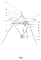
図2に、浮体式基礎船体1及び平衡錘3をさらに詳細に示す。浮体式基礎船体1は、中心支柱9と、3つの対角ブレース10と、3つの径方向ブレース11と、3つの横方向ブレース12とを含む四面体構造として実装することができる。四面体の頂点では、風力タービンタワー6を浮体式基礎船体1に接続する役割も果たす移行部品(transition piece)13において、3つの対角ブレース10が中心支柱9に接続される。四面体の底部中央では、底部ノード14において3つの径方向ブレース11が中心支柱9に接続される。四面体の底面の各隅部では、横方向ノード15において、対角ブレース10、径方向ブレース11及び横方向ブレース12が全て接続される。各横方向ノード15には、一連の船体浮力タンク16が配置される。
FIG. 2 shows the floating-
平衡錘3は、1又は2以上の平衡錘浮力タンク17を含むことができる。平衡錘3は、平衡錘懸架チェーン18によって船体1の下方に懸架される。
The
平衡錘3の平衡錘浮力タンク17は、内部容積に空気が満ちている時には平衡錘の総浮力がその重量に近付き又はそれよりも大きくなって、浮体式基礎の船体1からの支持が減少し又は無くなっても平衡錘3が浮くことができるような寸法を有する。平衡錘浮力タンク17が水で一杯になると重量が増加し、平衡錘が平衡錘懸架チェーン18によって定められる深さまで沈むようになる。平衡錘3の水中重量から平衡錘懸架チェーン18にもたらされる下向きの力の合計は、平衡錘浮力タンク17を満たす水の量を調整することによって調整することができる。
In the balance
基礎1は、海底に設置された錨に取り付けられた3つの係留索8によってその定位置に保たれる。
The
図1及び図2に示す実施形態は、機能的には円柱ブイである。(好ましくは船体浮力タンク16内に存在するあらゆる追加のバラストを含む)船体1、風力タービン2、(部分的に又は完全に)注水された平衡錘3及び平衡錘懸架チェーン18の重量を含む浮体式風力タービンの総重量は、係留索8の下向きの牽引と相まって、システムに加わる総浮力を、船体1が依然として水線面7よりも十分に下方の水中に存在する深さに水没する程度まで相殺して、最大設計海面状態条件においても船体浮力タンク16のあらゆる部分が水上に出ないことを確実にする。
The embodiment shown in FIGS. 1 and 2 is functionally a cylindrical buoy. Floating body (preferably including any additional ballast present in the hull buoyancy tank 16), including the weight of the
この実施形態では、本発明による基礎が円柱ブイの全ての利点を有するが、従来の円柱ブイの大きな喫水によって課される設置制限はない。他のあらゆる円柱ブイと同様に、完全な構造体の重心が浮力中心よりも下にあることが復原性のために必要である。 In this embodiment, the foundation according to the invention has all the advantages of a cylindrical buoy, but there are no installation restrictions imposed by the large draft of a conventional cylindrical buoy. As with all other cylindrical buoys, it is necessary for stability that the center of gravity of the complete structure is below the center of buoyancy.
図3に、本発明による浮体式風力タービンの別の実施形態を示す。この構成は、図1及び図2のものと実質的に同じであるが、ここでの基礎は機能的に半潜水型である。(好ましくは船体浮力タンク16内に存在するあらゆる追加バラストを含む)船体1、風力タービン2、(部分的に又は完全に)注水された平衡錘3及び平衡錘懸架チェーン18の重量を含む浮体式風力タービンの総重量と、係留索8の下向きの牽引との組み合わせは、システムに加わる総浮力を、静水時に船体浮力タンク16が完全に水没する程度まで相殺するほど十分ではない。
FIG. 3 shows another embodiment of a floating wind turbine according to the present invention. This configuration is substantially the same as that of FIGS. 1 and 2, but the basis here is functionally semi-submersible. Floating type, including the weight of the
この実施形態では、本発明による基礎が半潜水型の全ての利点を有するが、この実施形態ではタービンロータに作用する大きな横力によって生じる転倒モーメントが、従来の半潜水型と同様の船体浮力タンク16の差動注入だけでなく平衡錘3からの復原力によっても相殺されるので、タービン運転中の横傾斜角が大幅に低減される。
In this embodiment, the foundation according to the present invention has all the advantages of the semi-submersible type, but in this embodiment, the tipping moment generated by a large lateral force acting on the turbine rotor is the same as that of the conventional semi-submersible type hull buoyancy tank. Since it is canceled out not only by the 16 differential injections but also by the restoring force from the
さらに、本発明による基礎は、変動する風力及び波力からの刺激に対する基礎の動的反応を、従来の半潜水型に可能な程度よりも大きな程度まで調整できるというさらなる利点を有する。平衡錘浮力タンク17のバラストレベルは、基礎設計者にとってのさらなる自由度を表し、船体浮力タンク16及び平衡錘浮力タンク17のバラストレベルの調整によって傾き/ロール及びヨーの所望の自然周期の組み合わせを得ることができる。基礎の設置後に、バラスト船を必要とせずにこれらの自然周期及びその関係を微調整することさえも可能である。
Furthermore, the foundation according to the invention has the further advantage that the foundation's dynamic response to stimuli from fluctuating wind and wave forces can be adjusted to a greater extent than is possible with conventional semi-submersibles. The ballast level of the balance
図4に、本発明による浮体式風力タービンの別の実施形態を示す。船体1、タービン2及び平衡錘3の構成は図1及び図2のものと実質的に同じであるが、定位置保持構成が異なる。基礎は、海底に設置された錨にピンと張ったロープ19を通じて取り付けられ、機能的にはTLP(張力係留式プラットフォーム)である。船体1、風力タービン2、(部分的に又は完全に)注水された平衡錘3及び平衡錘懸架チェーン18の重量を含む浮体式風力タービンの総重量は、システムに加わる総浮力を、静水時に船体浮力タンク16が完全に水没して基礎が自力で水面に浮上する程度まで相殺するほど十分ではない。しかしながら、基礎は、ピンと張ったロープ19の下向きの力によって依然として水線面7よりも十分に下方の水中に存在する深さに水没して、最大設計海面状態条件においてもタンクのあらゆる部分が水上に出ないことを確実にする。
FIG. 4 shows another embodiment of a floating wind turbine according to the present invention. The configuration of the
この実施形態では、本発明による基礎が、本明細書の導入部で言及したTLPの全ての利点を有する。平衡錘3に起因して従来のTLPに比べて重心が低くなることにより、うねり偏位中におけるロープ19の垂直力の大きさを低減しやすくなる。
In this embodiment, the basis according to the invention has all the advantages of the TLP mentioned in the introduction of this description. Since the center of gravity is lower than that of the conventional TLP due to the
全ての実施形態について、変動する風力及び波力からの刺激に対する基礎の動的反応を、従来の半潜水型に可能な程度よりも大きな程度まで調整することができる。上述したように、基礎の設置後にバラスト船を必要とせずにこれらの自然周期及びその関係を微調整することさえも可能である。 For all embodiments, the underlying dynamic response to stimuli from fluctuating wind and wave forces can be adjusted to a greater extent than is possible with conventional semi-submersibles. As mentioned above, it is even possible to fine tune these natural cycles and their relationships without the need for a ballast ship after the foundation is installed.
図5に、平衡錘の好ましい実施形態を示す。平衡錘3は、取り付け金具21が取り付けられた中心タンク20を取り囲む一連の平衡錘浮力タンク17を含む。取り付け金具21は、一連の拘束具(shackle)22によって平衡錘懸架チェーン18に接続される。
FIG. 5 shows a preferred embodiment of a counterweight. The
中心平衡錘タンク20は、設置及びメンテナンス中に平衡錘3を船体1に接続するロック機構の役割を果たす中心円筒孔23を有する。
The center
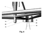
図6に、船体1における平衡錘懸架の好ましい実施形態を示す。平衡錘懸架チェーン18は、取り付け金具25に係合する拘束具24によって横方向ノード15に取り付けられる。
FIG. 6 shows a preferred embodiment of balanced weight suspension in the
前景には、連結ピン26が取り付けられた底部ノード14が見える。このピンは、平衡錘3の中心円筒孔23に収まって、設置及びメンテナンス中に平衡錘3を船体1に接続するロック装置の役割を果たす。
In the foreground, the
図7に、平衡錘懸架の異なる実施形態を示す。 FIG. 7 shows a different embodiment of a balanced weight suspension.
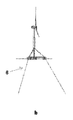
図7aには、平衡錘懸架チェーン18を伸縮嵌め合い管27に置き換えた実施形態を示す。例えば、曳航中などに平衡錘浮力タンク17に空気が満たされて平衡錘3が底部ノード11に隣接して位置している時には伸縮嵌め合い管27が部分的に収納され、平衡錘浮力タンク17に部分的に又は完全に水が満たされると、伸縮嵌め合い管27が終端限界まで延びて平衡錘3の深さを定める。
FIG. 7 a shows an embodiment in which the balance
この構成は、伸縮嵌め合い管27が、第1の実施形態の平衡錘懸架チェーン18の場合のように曳航中などに撓むことがないという利点を有する。
This configuration has the advantage that the telescopic
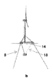
図7bには、平衡錘懸架チェーン18を中心伸縮嵌め合い管28に置き換えた、又は中心伸縮嵌め合い管28で補った実施形態を示す。例えば、曳航中などに平衡錘浮力タンク17に空気が満たされて平衡錘3が底部ノード11に隣接して位置している時には、中心伸縮嵌め合い管を中心支柱6の底部及び/又は平衡錘3の中心タンク20の中心孔23に収納することができる。平衡錘浮力タンク17に部分的に又は完全に水が満たされると、中心伸縮嵌め合い管がその終端限界まで延びて平衡錘3の深さを定める。平衡錘支持体ワイヤー又はチェーン18は、横力の支持と、結果として生じるモーメントの伝達とに寄与することができる。
FIG. 7 b shows an embodiment in which the balance
この構成は、設置及びメンテナンス過程中に中心伸縮嵌め合い管28が平衡錘3を正確に誘導するという利点を有する。
This configuration has the advantage that the center telescopic
図7cには、平衡錘3を、一連のブレース31によって互いの位置に保たれた複数の浮力タンクセット30を含む多角形として成形した実施形態を示す。例えば、曳航中などに浮力タンクセット30に空気が満たされている場合、平衡錘3は、船体1の横方向ブレース12に近接して位置する。浮力タンクセット30に部分的に又は完全に水が満たされると、平衡錘懸架チェーン18が平衡錘を支持して平衡錘3の深さを定める。
FIG. 7 c shows an embodiment in which the
この構成は、潜在的により多くの浮力タンクセット30上にバラストが分布することに起因して、第1の実施形態の単一のタンクセット15で容易に構成されるよりも平衡錘3の総重量が大きくなることにより、さらに低い重心及びさらに高度な復原性をもたらすことができるという利点を有する。
This configuration is due to the fact that the ballast is distributed over potentially more buoyancy tank sets 30, so that the total weight of the
当業者には、異なる実施形態を組み合わせてさらなる有利な解決策を提供できることが明らかであろう。 It will be apparent to those skilled in the art that different embodiments can be combined to provide further advantageous solutions.
図8に、本発明による、基礎を円柱ブイとして実装する設置シーケンスを示す。 FIG. 8 shows an installation sequence for mounting the foundation as a cylindrical buoy according to the present invention.
図8aには、曳航前の波止場地域における基礎を示す。基礎は、曳航中にもこの構成で維持される。平衡錘浮力タンク17には空気が満たされており、従って平衡錘3は浮かぶのに十分な浮力を有する。平衡錘浮力タンク17は、図4及び図6について上述した孔にピンを挿入する構成などの好適な連結構成によって、底部ノード14に隣接する便利な位置に保持される。平衡錘懸架チェーン18は、曳航中に完全な構造の喫水に影響を与えないように、好適な手段によって浮体式基礎船体1に取り付けられる。
FIG. 8a shows the foundation in the dock area before towing. The foundation is maintained in this configuration during towing. The balance
図8bには、所望の洋上位置における基礎を示す。この基礎は依然として曳航構成にあるが、この時点では既に係留索8が接続されている。平衡錘懸架チェーン18は、既に浮体式基礎船体1から切り離されている。
FIG. 8b shows the foundation at the desired offshore position. The foundation is still in the towing configuration, but at this point the
図8cには、平衡錘浮力タンク17の注水開始後の所望の洋上位置における基礎を示す。図示の段階では、既に平衡錘浮力タンク17に、平衡錘3の浮力がもはやその重量を十分に支えることができないレベルまで水が満たされている。この結果、平衡錘3は、その船体1の下方の最終位置まで沈み、平衡錘懸架チェーン18は、そのほぼ最終的な長さまで延びている。しかしながら、平衡錘3の水中重量(重量と浮力との差分)は、未だに船体1上の水線面レベルを変化させるほど十分ではない。
FIG. 8 c shows the foundation at the desired offshore position after the balanced
図8dには、所望の洋上位置における最終位置の基礎を示す。平衡錘浮力タンク17の注水は所望のレベルまで完了しており、場合によっては船体1の船体浮力タンク16内のバラストの重量が加わった平衡錘3の水中重量は、船体1を水線面未満の所望の深さまで引き寄せるのに十分である。最終的な喫水は、平衡錘浮力タンク17内のバラスト水位と船体1の船体浮力タンク16との組み合わせによって調整することができる。
FIG. 8d shows the basis for the final position at the desired offshore position. Water injection to the balance
図9に、本発明による、基礎を半潜水型として実装する設置シーケンスを示す。 FIG. 9 shows an installation sequence for mounting the foundation as a semi-submersible according to the present invention.
図9aには、曳航前の波止場地域における基礎を示す。基礎は、曳航中にもこの構成で維持される。平衡錘浮力タンク17には空気が満たされており、従って平衡錘3は浮かぶのに十分な浮力を有する。平衡錘浮力タンク17は、図4及び図6について上述した孔にピンを挿入する構成などの好適な連結構成によって、底部ノード14に隣接する便利な位置に保持される。平衡錘懸架チェーン18は、曳航中に完全な構造の喫水に影響を与えないように、好適な手段によって浮体式基礎船体1に取り付けられる。
FIG. 9a shows the foundation in the dock area before towing. The foundation is maintained in this configuration during towing. The balance
図9bには、所望の洋上位置における基礎を示す。この基礎は依然として曳航構成にあるが、この時点では既に係留索8が接続されている。平衡錘懸架チェーン18は、既に浮体式基礎船体1から切り離されている。
FIG. 9b shows the foundation at the desired offshore position. The foundation is still in the towing configuration, but at this point the
図9cには、平衡錘浮力タンク17の注水開始後の所望の洋上位置における基礎を示す。図示の段階では、既に平衡錘浮力タンク17に、平衡錘3の浮力がもはやその重量を十分に支えることができないレベルまで水が満たされている。この結果、平衡錘3は船体1の下方の最終位置まで沈み、平衡錘懸架チェーン18はほぼ最終的な長さまで延びている。しかしながら、平衡錘3の水中重量(重量と浮力との差分)は、未だに船体1上の水線面レベルを変化させるほど十分ではない。
FIG. 9 c shows the foundation at the desired offshore position after the balanced
図9dには、所望の洋上位置における最終位置の基礎を示す。平衡錘浮力タンク17の注水は所望のレベルまで完了しており、場合によっては船体1の船体浮力タンク16内のバラストの重量が加わった平衡錘3の水中重量は、一次復原性を保証すると同時に平衡錘3からのさらなる所望の復原性を達成するために、十分な残留水線面積を有することと、船体1の船体浮力タンク16の水線面上方の高さとの間の妥協点である所望の深さまで船体1を引き寄せるのに十分である。
FIG. 9d shows the basis for the final position at the desired offshore position. The water injection into the balance
図10に、本発明による、基礎をTLPとして実装する設置シーケンスを示す。 FIG. 10 shows an installation sequence for mounting the foundation as a TLP according to the present invention.
図10aには、曳航前の波止場地域における基礎を示す。基礎は、曳航中にもこの構成で維持される。平衡錘浮力タンク17には空気が満たされており、従って平衡錘3は浮かぶのに十分な浮力を有する。平衡錘浮力タンク17は、図4及び図6について上述した孔にピンを挿入する構成などの好適な連結構成によって、底部ノード14に隣接する便利な位置に保持される。平衡錘懸架チェーン18は、曳航中に完全な構造の喫水に影響を与えないように、好適な手段によって浮体式基礎船体1に取り付けられる。
FIG. 10a shows the foundation in the dock area before towing. The foundation is maintained in this configuration during towing. The balance
図10bには、平衡錘浮力タンク17の注水開始後の所望の洋上位置における基礎を示す。図示の段階では、既に平衡錘浮力タンク17に、平衡錘3の浮力がもはやその重量を十分に支えることができないレベルまで水が満たされている。この結果、平衡錘3は船体1の下方の最終位置まで沈み、平衡錘懸架チェーン18はほぼ最終的な長さまで延びている。しかしながら、平衡錘3の水中重量(重量と浮力との差分)は、未だに船体1上の水線面レベルを変化させるほど十分ではない。基礎の下方では、予め設置されたロープ19に屈曲継手(flex−joints)が取り付けられて結合の準備ができている。
FIG. 10 b shows the foundation at the desired offshore position after the balanced
図10cには、平衡錘浮力タンク17の注水が所望のレベルまで完了した後の所望の洋上位置における基礎を示す。ここでは、場合によっては船体1の船体浮力タンク16内のバラストの重量が加わった平衡錘3の水中重量が、所望の最終的な喫水よりもわずかに下方の所望の深さまで船体1を引き寄せるのに十分である。潜水工程中には、基礎が一時的に円柱ブイとして作用している。船体1は、ロープの屈曲継手の合わせ面が屈曲継手の側面よりもわずかに下方に来る位置まで下降している。
FIG. 10c shows the foundation at the desired offshore position after water injection of the
図10dには、所望の洋上位置における最終位置の基礎を示す。船体1が横に移動したため、ロープの屈曲継手の合わせ面は屈曲継手の真下に位置している。その後、平衡錘浮力タンク17及び/又は船体1の船体浮力タンク16からの水バラストの除去によって、船体1及び平衡錘3の水中重量が、ロープの屈曲継手の合わせ面が屈曲継手に結合してロープ19の所望の予張力が達成される程度まで低減している。
FIG. 10d shows the basis for the final position at the desired offshore position. Since the
図11に、本発明による、一例として円柱ブイ構成を用いた検査及びメンテナンスシーケンスを示す。 FIG. 11 shows an inspection and maintenance sequence using a cylindrical buoy configuration as an example according to the present invention.
図11aには、メンテナンス工程開始前の基礎を示す。船体1の位置は、場合によっては船体1の船体浮力タンク16内のバラストの重量が加わった平衡錘3の水中重量(重量と浮力との差分)によって水線面よりも下方の深さに維持されている。
FIG. 11a shows the basis before the start of the maintenance process. The position of the
図11bには、メンテナンス工程開始後の基礎を示す。平衡錘浮力タンク17が部分的に排気され、この時点では平衡錘3の浮力がその重量を支えるのにほぼ十分なレベルまで水で満たされている。平衡錘3は、依然としてその船体1の下方の最終位置にあるが、平衡錘3の水中重量は、もはや船体1を水中の位置に維持するほど十分ではない。この結果、船体が水面に浮上して、船体面、ボルト接続部、並びに平衡錘懸架チェーン18及び係留索8との接合部の洗浄、検査及びメンテナンスが可能になる。
FIG. 11b shows the basis after the start of the maintenance process. The
図11cには、一般的な分解修理に適した形態の基礎を示す。平衡錘浮力タンク17は、平衡錘3の浮力がその重量を支えるのに十分なレベルまで排気されている。この結果、平衡錘3が底部ノード14に隣接する曳航位置まで浮上し、船体面、ボルト接続部、及び平衡錘懸架チェーン18との接合部の洗浄、検査及びメンテナンスが可能になる。図11cに示すように、洋上メンテナンス中には、平衡錘懸架チェーン18を自然な緩んだ状態で放置しておけばよい。しかしながら、平衡錘懸架チェーン18を持ち上げて船体1の複数の付着点に接続して、チェーンからの過度の喫水を伴わずに曳航を可能にすることもできる。この構成では、完全な浮体式基礎を係留チェーン8から切り離し、主要メンテナンスのために又は最終的に退役のために再び港に曳航することができる。
FIG. 11c shows a basic form suitable for general overhaul. The balanced
図12に、本発明による、基礎をTLPとして実装して平衡錘がTLP錨の役割を果たす基礎の実施形態を示す。 FIG. 12 shows an embodiment of a foundation according to the present invention in which the foundation is implemented as a TLP and the balance weight plays the role of a TLP rod.
この構成では、平衡錘3が、図7cに関連してさらに説明したように多角形として成形される。平衡錘は、一連のブレース31によって互いの位置に保たれた複数の浮力タンクセット30を含む。例えば、曳航中などに浮力タンクセット30に空気が満たされている場合、平衡錘3は、船体1の横方向ブレース12に近接して位置する。浮力タンクセット30に部分的に又は完全に水が満たされると、平衡錘懸架チェーン18が平衡錘を支持して平衡錘3の深さを定める。この特定の実施形態では、平衡錘3の所望の深さが、設置場所の水深と設置完了後の船体1の所望の深さとの差分に対応する船体1の下方の位置にある。平衡錘は、所望の位置まで下降した後に、さらにバラスト処理されて船体を水面下方の所望の深さまで引き寄せ、この段階で平衡錘は海底32に到達する。ここでは、平衡錘が、予め設置されたTLP錨に取って代わり、平衡錘懸架手段が、予め設置されたTLPロープに取って代わる。
In this configuration, the
高い横方向の負荷容量を保証するために、タンク30の下側リムは、設置中に海底32に埋没するスカートとして設計することができる。さらに、垂直方向及び横方向の両方における負荷容量をさらに高めるために、このようなスカートの内部に吸引力を付与する手段をタンクに取り付けることができる。
In order to ensure a high lateral load capacity, the lower rim of the
この構成には複数の利点がある。 This configuration has several advantages.
第1に、この構成は、潜在的により多くの浮力タンクセット30上にバラストが分布することに起因して、第1の実施形態の単一のタンクセット15で容易に構成されるよりも平衡錘3の総重量が大きくなることにより、さらに低い重心及びさらに高度な復原性をもたらすことができるという利点を、図7cで概説した実施形態と共有する。
First, this configuration is more balanced than is easily configured with a single tank set 15 of the first embodiment due to potentially more ballast distribution over more buoyancy tank sets 30. The advantage that an increase in the total weight of the
第2に、この実施形態は、真の単一シーケンスによる設置を容易にする。船体1、平衡錘3及び懸架手段18の組み合わせが、浮体式基礎、錨及びロープ又は係留索を含む完全なユニットを形成するので、予め設置された錨、係留索、ロープなどは不要である。この結果、完全な設置を1つの単一作業として行うことができる。これによって設置コストが大幅に削減される。
Second, this embodiment facilitates installation with a true single sequence. Since the combination of the
第3に、同様に退役も単純である。錨及び係留索を含む完全な基礎は、平衡錘3のタンク30に空気を再注入することによって1つの単一作業で設置場所から浮上させることができる。これによって退役コストが大幅に削減される。
Third, retirement is simple as well. The complete foundation including the anchor and mooring lines can be lifted from the installation site in one single operation by reinjecting air into the
最後に、船体1の潜水中に復原性を保証するために必要な懸架手段18の構成の効果により、平衡錘3が海底に到達した時点で非明示的に優れた復原性がもたらされる。この基礎は、機能的にはTLPであるが、通常のTLPとは異なり、三角形構成の懸架手段が、流体力に応答する船体1の横方向の動きを防ぐ。この結果、ロープが緩むリスクが大幅に低下し、船体1及び平衡錘3に対するロープ18の方向がほぼ一定であるため、ロープ端部におけるコストの高い屈曲継手が不要になる。
Finally, the effect of the construction of the suspension means 18 necessary to ensure stability during the diving of the
この実施形態の変形例では、平衡錘が、ブレース31によって適所に保持された3又は4以上のタンクセット30を含む多角形として成形されず、図1及び図2のような単一のタンクセットとして成形される。基礎は、平衡錘3が海底に到達する位置まで沈むと、復原性が傾斜の関数であるTLPの特殊な異形になる。ここでは、平衡錘3を懸架手段18に接続する際に屈曲継手が不要にならず、風力タービン2に作用する空気力及び/又は船体1に作用する流体力の結果として、船体1は若干横方向及び斜め方向に移動するが、この変形実施形態の利点は、平衡錘3が非常に単純なままという点である。
In a variation of this embodiment, the counterweight is not molded as a polygon comprising three or more tank sets 30 held in place by
上述した好ましい実施形態及びその他の実施形態の説明は、開示する発明概念の範囲又は適用性を限定又は制限するものではない。本開示の利点と共に、本明細書に開示した1つの実施形態に関して説明した詳細は、本明細書に明示又は記載していない場合でも、本明細書に開示した他の実施形態と組み合わせ、或いは他の実施形態上で使用することができると認識されるであろう。本出願人らは、本明細書に含まれる発明概念を開示することと引き換えに、添付の特許請求の範囲によって得られる全ての特許権を所望する。従って、添付の特許請求の範囲は、以下の特許請求項の範囲又はその同等物の範囲に該当する最大限までの全ての修正及び変更を含むように意図される。 The descriptions of the preferred embodiments and other embodiments described above are not intended to limit or limit the scope or applicability of the disclosed inventive concepts. Together with the advantages of the present disclosure, details described with respect to one embodiment disclosed herein may be combined with other embodiments disclosed herein or otherwise, even if not explicitly or described herein It will be appreciated that it can be used on this embodiment. Applicants desire all patent rights afforded by the appended claims in exchange for disclosing the inventive concepts contained herein. Accordingly, the appended claims are intended to include all modifications and changes as fall within the scope of the following claims or equivalents thereof.
1 浮体式基礎船体
3 平衡錘
6 風力タービンタワー
7 水線面
8 係留索
9 中心支柱
10 対角ブレース
11 径方向ブレース
12 横方向ブレース
13 移行部品
14 底部ノード
15 横方向ノード
16 船体浮力タンク
17 平衡錘浮力タンク
18 平衡錘懸架チェーン
DESCRIPTION OF
Claims (16)
− 前記平衡錘(3)は、1又は2以上の平衡錘浮力タンク(17)を含み、
− 前記平衡錘浮力タンク(17)は、内部容積が空気又は別の気体で満たされている時には前記平衡錘(3)の総浮力が該平衡錘の重量に近く又は該重量よりも大きくなって、前記船体(1)又は他の船からの垂直方向の支持が減少し又は無くなっても曳航/メンテナンス位置に浮かぶことができるような寸法を有し、
− 前記平衡錘浮力タンク(17)が部分的に又は完全に水で一杯になると、前記平衡錘(3)は、前記平衡錘懸架手段(18)によって定められる深さの設置位置に沈み、
− 前記平衡錘懸架手段(18)は、力及びモーメントの両方を別個に又はまとめて前記船体(1)に伝えることができ、これによって前記平衡錘(3)がその設置位置にある時に前記船体(1)を安定化できるようになる、
ことを特徴とする浮体式風力タービン。 A hull (1), a wind turbine (2) mounted on the hull (1), and a counterweight (3) suspended below the hull (1) by a counterweight suspension means (18). A floating wind turbine,
The counterweight (3) comprises one or more counterweight buoyancy tanks (17);
The balance weight buoyancy tank (17) has a total buoyancy of the balance weight (3) close to or greater than the weight of the balance weight when the internal volume is filled with air or another gas; Having dimensions that allow it to float in the tow / maintenance position even if vertical support from said hull (1) or other ship is reduced or eliminated,
When the counterweight buoyancy tank (17) is partially or completely filled with water, the counterweight (3) sinks to an installation position at a depth determined by the counterweight suspension means (18);
The counterweight suspension means (18) can transmit both forces and moments separately or collectively to the hull (1), whereby the hull when the counterweight (3) is in its installed position; (1) can be stabilized,
A floating wind turbine characterized by that.
請求項1に記載の浮体式風力タービン。 The floating foundation is functionally a cylindrical buoy after installation,
The floating wind turbine according to claim 1.
請求項1に記載の浮体式風力タービン。 The floating foundation is functionally semi-submersible after installation,
The floating wind turbine according to claim 1.
請求項1に記載の浮体式風力タービン。 The floating foundation is a functionally moored platform after installation,
The floating wind turbine according to claim 1.
請求項1から4のいずれか一項に記載の浮体式風力タービン。 The balance weight suspension means (18) includes a telescopic fitting tube (27).
The floating wind turbine according to any one of claims 1 to 4.
請求項1から5のいずれか一項に記載の浮体式風力タービン。 The balance weight suspension means (18) is supplemented by or replaced by the central telescopic fitting tube (28).
The floating wind turbine according to any one of claims 1 to 5.
請求項1から6のいずれか一項に記載の浮体式風力タービン。 The balance weight (3) is shaped as a polygon and is supported by balance weight suspension means (18) attached to the corner of the polygon balance weight (3). The corners are attached to at least two separate attachment points on the hull (1) through the counterweight suspension means (18).
The floating wind turbine according to any one of claims 1 to 6.
請求項7に記載の浮体式風力タービン。 The attachment of the balance weight suspension means (18) to the polygonal balance weight (3) is the distance from the center of gravity of the hull (1) to the attachment of the balance weight suspension means (18) to the hull (1). Separated from the center of gravity of the polygonal balance weight (3) by a distance of more than half;
The floating wind turbine according to claim 7.
請求項1から8のいずれか一項に記載の浮体式風力タービン。 The counterweight (3) is attached to the hull (1) during towing,
The floating wind turbine according to any one of claims 1 to 8.
請求項1から9のいずれか一項に記載の浮体式風力タービン。 The static and dynamic reactions of the floating foundation are: i) ballast of the counterweight buoyancy tank (17), ii) ballast of the hull (1), and / or iii) depth of installation of the counterweight (3). Can be adjusted before installation through a combination of adjustment,
The floating wind turbine according to any one of claims 1 to 9.
請求項1から10のいずれか一項に記載の浮体式風力タービン。 The static and dynamic reactions of the floating foundation can be adjusted after installation through a combination of i) ballast of the counterweight buoyancy tank (17) and ii) ballast of the hull (1). ,
The floating wind turbine according to any one of claims 1 to 10.
請求項1、及び請求項4から11のいずれか一項に記載の浮体式風力タービン。 The counterweight (3) is present on the seabed (32) after installation,
The floating wind turbine according to any one of claims 1 and 4 to 11.
− 空気又は別の気体で部分的に又は完全に満たされた前記平衡錘(3)の浮力タンク(17)を満たすステップと、
− 曳航前に前記平衡錘(3)を前記船体(1)に取り付けるステップと、
− 前記平衡錘(3)及び前記船体(1)を所望の洋上位置に曳航するステップと、
− 所望の洋上位置に到達した時に、前記平衡錘浮力タンク(17)に部分的に又は完全に水を注入するステップと、
− 前記平衡錘(3)が、前記平衡錘懸架手段(18)によって定められる深さの設置位置に沈むのを可能にするステップと、
− 前記船体(1)に力及びモーメントの両方を別個に又はまとめて伝えることができる前記平衡錘懸架手段(18)によって前記船体(1)に力及びモーメントを伝え、これによって前記平衡錘(3)がその設置位置にある時に前記船体(1)を安定化できるようにするステップと、
を含むことを特徴とする方法。 A hull (1), a wind turbine (2) mounted on the hull (1), and a counterweight (3) suspended below the hull (1) by a counterweight suspension means (18). A floating wind turbine installation method,
Filling the buoyancy tank (17) of the counterweight (3) partially or completely filled with air or another gas;
-Attaching the counterweight (3) to the hull (1) before towing;
-Towing the counterweight (3) and the hull (1) to a desired offshore position;
Injecting water partially or completely into the counterweight buoyancy tank (17) when the desired offshore position is reached;
Allowing said counterweight (3) to sink to an installation position at a depth defined by said counterweight suspension means (18);
The force and moment are transmitted to the hull (1) by means of the counterweight suspension means (18) which can transmit both forces and moments separately or collectively to the hull (1), whereby the counterweight (3 ) To stabilize the hull (1) when in its installed position;
A method comprising the steps of:
− 進水及び曳航前に、前記平衡錘(3)の浮力タンク(17)に空気又は別の気体を部分的に又は完全に満たすステップと、
− 前記船体(1)及び前記平衡錘(3)を所望の洋上位置に曳航するステップと、
− 所望の洋上位置に到達した時に、前記平衡錘(3)を前記船体(1)に取り付けるステップと、
− 前記平衡錘浮力タンク(17)に部分的に又は完全に水を注入するステップと、
− 前記平衡錘(3)が、前記平衡錘懸架手段(18)によって定められる深さの設置位置に沈むのを可能にするステップと、
− 前記船体(1)に力及びモーメントの両方を別個に又はまとめて伝えることができる前記平衡錘懸架手段(18)によって前記船体(1)に力及びモーメントを伝え、これによって前記平衡錘(3)がその設置位置にある時に前記船体(1)を安定化できるようにするステップと、
を含むことを特徴とする方法。 A hull (1), a wind turbine (2) mounted on the hull (1), and a counterweight (3) suspended below the hull (1) by a counterweight suspension means (18). A floating wind turbine installation method,
Filling the buoyancy tank (17) of the counterweight (3) partially or completely with air or another gas before launching and towing;
-Towing the hull (1) and the counterweight (3) to a desired offshore position;
-Attaching the counterweight (3) to the hull (1) when reaching the desired offshore position;
-Partially or completely injecting water into the counterweight buoyancy tank (17);
Allowing said counterweight (3) to sink to an installation position at a depth defined by said counterweight suspension means (18);
The force and moment are transmitted to the hull (1) by means of the counterweight suspension means (18) which can transmit both forces and moments separately or collectively to the hull (1), whereby the counterweight (3 ) To stabilize the hull (1) when in its installed position;
A method comprising the steps of:
− 前記平衡錘浮力タンク(17)に水を注入するステップと、
− 所望の洋上位置に到達した時に、前記平衡錘(3)が海底(32)の設置位置に沈むのを可能にするステップと、
を含む、請求項13又は14に記載の方法。 The installation method is as follows:
Injecting water into the counterweight buoyancy tank (17);
-Allowing said counterweight (3) to sink to the installation position of the seabed (32) when reaching the desired offshore position;
15. The method according to claim 13 or 14, comprising:
− 前記平衡錘(3)の浮力タンク(17)に空気又は別の気体を部分的に又は完全に満たすことによって前記船体(1)を設置位置からメンテナンス位置に上昇させるステップと、
− メンテナンスを実行するステップと、
− 前記平衡錘浮力タンク(17)に部分的に又は完全に水を注入して前記船体(1)を設置位置に下降させるステップと、
を含むことを特徴とする方法。 A hull (1), a wind turbine (2) mounted on the hull (1), and a counterweight (3) suspended below the hull (1) by a counterweight suspension means (18). A maintenance method for a floating wind turbine,
-Raising the hull (1) from the installation position to the maintenance position by partially or completely filling the buoyancy tank (17) of the counterweight (3) with air or another gas;
-Performing maintenance steps;
-Partially or completely injecting water into the counterweight buoyancy tank (17) to lower the hull (1) to an installed position;
A method comprising the steps of:
Applications Claiming Priority (5)
| Application Number | Priority Date | Filing Date | Title |
|---|---|---|---|
| DKPA201670151 | 2016-03-15 | ||
| DKPA201670151 | 2016-03-15 | ||
| DKPA201670761 | 2016-09-27 | ||
| DKPA201670761 | 2016-09-27 | ||
| PCT/DK2017/050076 WO2017157399A1 (en) | 2016-03-15 | 2017-03-15 | A floating wind turbine and a method for the installation of such floating wind turbine |
Publications (1)
| Publication Number | Publication Date |
|---|---|
| JP2019509217A true JP2019509217A (en) | 2019-04-04 |
Family
ID=59851865
Family Applications (1)
| Application Number | Title | Priority Date | Filing Date |
|---|---|---|---|
| JP2018568482A Pending JP2019509217A (en) | 2016-03-15 | 2017-03-15 | Floating wind turbine and method for installing such a floating wind turbine |
Country Status (5)
| Country | Link |
|---|---|
| US (1) | US11208987B2 (en) |
| EP (1) | EP3430259B1 (en) |
| JP (1) | JP2019509217A (en) |
| CN (1) | CN109154280A (en) |
| WO (1) | WO2017157399A1 (en) |
Cited By (1)
| Publication number | Priority date | Publication date | Assignee | Title |
|---|---|---|---|---|
| JP7451674B2 (en) | 2019-07-04 | 2024-03-18 | ニューテック アーエス | Floating foundations for offshore wind turbines, systems for extracting energy from the wind and methods of installing wind turbines |
Families Citing this family (38)
| Publication number | Priority date | Publication date | Assignee | Title |
|---|---|---|---|---|
| US11660572B2 (en) * | 2017-09-22 | 2023-05-30 | Dehlsen Associates of the Pacific, Limited | Wind and wave desalination vessel |
| GB201719303D0 (en) * | 2017-11-21 | 2018-01-03 | Aep Group Ltd | Tension leg buoy |
| FR3074138B1 (en) * | 2017-11-29 | 2021-08-27 | Saipem Sa | FLOATING SUPPORT STRUCTURE FOR OFFSHORE WIND TURBINE AND METHOD OF INSTALLING A WIND TURBINE EQUIPPED WITH SUCH A SUPPORT STRUCTURE |
| CN108119315B (en) * | 2017-12-27 | 2023-11-28 | 浙江大学 | Floating type fan foundation capable of improving structural stability |
| GB2574373A (en) | 2018-05-22 | 2019-12-11 | Floating Energy Systems Ltd | Wind turbine and method for installing a wind turbine |
| DE102018117647A1 (en) * | 2018-07-20 | 2020-01-23 | Aerodyn Consulting Singapore Pte Ltd | Single Point Mooring wind turbine |
| PT3899260T (en) * | 2018-12-19 | 2023-12-28 | Single Buoy Moorings | Floating wind turbine support |
| NO345344B1 (en) * | 2019-05-21 | 2020-12-21 | Ægir Harvest As | Floating wind turbine platform |
| US10982654B1 (en) * | 2019-08-01 | 2021-04-20 | Dehlsen Associates, Llc | Yawing buoy mast for floating offshore wind turbines |
| US11591051B1 (en) | 2019-11-21 | 2023-02-28 | NuEnergy Partners, LP | Tendon support buoyancy system and method |
| JP7433859B2 (en) * | 2019-11-26 | 2024-02-20 | 三菱重工業株式会社 | Support structure for wind power generation equipment and wind power generation equipment |
| CN111271225B (en) * | 2020-03-04 | 2022-01-18 | 上海姬硕企业咨询有限公司 | Wind power and wind energy generator capable of self-adapting to wind power change and stably generating power |
| CN111271226B (en) * | 2020-03-05 | 2022-01-25 | 上海页久企业咨询有限公司 | Offshore moistureproof wind power and wind energy power generation equipment |
| CN111207732B (en) * | 2020-03-26 | 2023-03-24 | 兰州理工大学 | Gyroscope based on fluid drive |
| EP4157704A1 (en) * | 2020-05-29 | 2023-04-05 | F.Lli Righini S.r.l. | Floating structure |
| DK181207B1 (en) * | 2020-06-04 | 2023-04-28 | Stiesdal Offshore As | Positioning of a keel of a floating structure and a floating structure with keel |
| WO2021255509A1 (en) * | 2020-06-19 | 2021-12-23 | Zhiyong Yang | A floating platform with canted columns |
| CN111894812B (en) * | 2020-07-17 | 2021-11-23 | 上海电气风电集团股份有限公司 | Installation method and installation device of offshore wind turbine |
| KR102183482B1 (en) * | 2020-09-16 | 2020-11-26 | 주식회사 에이스이앤티 | Method for installing offshore floating body for wind power generation |
| US20220126957A1 (en) * | 2020-10-23 | 2022-04-28 | Entrion Wind, Inc. | Minimizing movements of offshore wind turbines |
| SE2000206A1 (en) * | 2020-11-04 | 2022-05-05 | Josok Ab | Floating wind power plant |
| GB2600927B (en) * | 2020-11-09 | 2023-02-15 | Equinor Energy As | Installing offshore floating wind turbines |
| CN112455617B (en) * | 2020-12-04 | 2022-05-31 | 清华大学 | Novel semi-submersible offshore wind power platform |
| NO346706B1 (en) * | 2021-02-08 | 2022-11-28 | Oceangrid As | Floating wind turbine construction |
| KR20230169284A (en) | 2021-04-12 | 2023-12-15 | 스티에스달 오프쇼어 에이/에스 | Offshore wind turbine systems and offshore platforms |
| DK202170169A1 (en) | 2021-04-12 | 2022-10-19 | Stiesdal Offshore As | Offshore wind turbine with a floating platform |
| FR3122222A1 (en) * | 2021-04-23 | 2022-10-28 | Dolfines | Damping device for a floating platform, in particular for a wind turbine, and platform equipped with such a device |
| KR20240032115A (en) | 2021-07-12 | 2024-03-08 | 스티에스달 오프쇼어 에이/에스 | Floating offshore support structures, their assembly methods and uses and pre-frame structures, especially for offshore wind turbines. |
| CN113942615A (en) * | 2021-08-05 | 2022-01-18 | 大连理工大学 | Floating type fan platform suitable for medium water area |
| WO2023052658A1 (en) * | 2021-10-03 | 2023-04-06 | Gazelle Wind Power Limited | Mooring system |
| WO2023156474A1 (en) | 2022-02-18 | 2023-08-24 | Heerema Marine Contractors Nederland Se | A method and system of installing a floating foundation, assembly of floating foundation and ballasting frame, and ballasting frame |
| NL2031010B1 (en) | 2022-02-18 | 2023-09-05 | Heerema Marine Contractors Nl | A method and system of installing a floating foundation, assembly of floating foundation and ballasting frame, and ballasting frame |
| NL2033898B1 (en) | 2022-02-18 | 2023-12-12 | Heerema Marine Contractors Nl | A method and system of installing a floating foundation, assembly of floating foundation and ballasting frame, and ballasting frame |
| NL2031193B1 (en) | 2022-03-09 | 2023-09-18 | Deawoo Eng & Construction Co Ltd | Marine structure and method |
| ES2956960A1 (en) * | 2022-05-26 | 2024-01-04 | Gazelle Wind Power Ltd | Anchoring system (Machine-translation by Google Translate, not legally binding) |
| CN114932983A (en) * | 2022-06-16 | 2022-08-23 | 中国华能集团清洁能源技术研究院有限公司 | Floating type photovoltaic platform on sea |
| WO2024069032A1 (en) * | 2022-09-26 | 2024-04-04 | Bluenewables Sl | Foundation device for an offshore wind turbine tower |
| CN117125205B (en) * | 2023-10-20 | 2024-03-01 | 江苏省无锡交通高等职业技术学校 | Marine unmanned ship device |
Family Cites Families (18)
| Publication number | Priority date | Publication date | Assignee | Title |
|---|---|---|---|---|
| WO2003004869A1 (en) * | 2001-07-06 | 2003-01-16 | Vestas Wind Systems A/S | Offshore wind turbine with floating foundation |
| GB0119969D0 (en) | 2001-08-16 | 2001-10-10 | Ocean Technologies Ltd | Floating offshore windtower |
| US8118538B2 (en) | 2007-09-13 | 2012-02-21 | Floating Windfarms Corporation | Offshore vertical-axis wind turbine and associated systems and methods |
| EP2222956A4 (en) | 2007-11-12 | 2013-07-31 | Oceanwind Technology Llc | Power generation assemblies |
| US7963241B2 (en) | 2008-02-19 | 2011-06-21 | Nagan Srinivasan | Dry tree semi-submersible platform for harsh environment and ultra deepwater applications |
| JP2011521820A (en) | 2008-04-23 | 2011-07-28 | プリンシプル・パワー・インコーポレーテツド | Column-stabilized offshore platform with water entrapment plate and asymmetric mooring system for offshore wind turbine support |
| GB2462602B (en) | 2008-08-11 | 2012-09-19 | Statoilhydro Asa | Method and apparatus for towing offshore wind turbines |
| ES2324276B8 (en) | 2009-03-17 | 2013-11-08 | Investigacion Y Desarrollo De Energias Renovables Marinas, S.L. | FLOATING PLATFORM FOR THE EXTRACTION OF WIND ENERGY |
| MY163459A (en) | 2009-08-26 | 2017-09-15 | Technip France | Heave stabilized barge system for floatover topsides installation |
| DE102009044278A1 (en) * | 2009-10-16 | 2011-04-21 | JÄHNIG, Jens | Floating foundation with improved bracing |
| NO332528B1 (en) | 2011-09-29 | 2012-10-08 | Windel As | Floating windmill |
| NO333691B1 (en) | 2011-12-06 | 2013-08-19 | Winddiver As | A floating wind turbine. |
| EP2639452B1 (en) | 2012-03-15 | 2017-12-13 | GE Renewable Technologies | An offshore wind turbine |
| GB2522005A (en) | 2013-11-26 | 2015-07-15 | Vodafone Ip Licensing Ltd | Mobile WiFi |
| CN103925172B (en) | 2014-04-08 | 2017-05-17 | 上海交通大学 | Integral mounting method for tension leg type offshore floating wind turbine |
| ES2555500B1 (en) | 2014-05-27 | 2016-12-13 | Sea Wind Towers Sl | Floating work and installation procedure |
| JP5798227B2 (en) | 2014-09-11 | 2015-10-21 | 三井造船株式会社 | Floating body installation method |
| CN104632549B (en) * | 2015-02-05 | 2017-09-15 | 新疆金风科技股份有限公司 | Floating type blower fan anchoring system, offshore wind turbine and its installation method |
-
2017
- 2017-03-15 EP EP17765894.5A patent/EP3430259B1/en active Active
- 2017-03-15 WO PCT/DK2017/050076 patent/WO2017157399A1/en active Application Filing
- 2017-03-15 CN CN201780029843.6A patent/CN109154280A/en active Pending
- 2017-03-15 US US16/084,817 patent/US11208987B2/en active Active
- 2017-03-15 JP JP2018568482A patent/JP2019509217A/en active Pending
Cited By (1)
| Publication number | Priority date | Publication date | Assignee | Title |
|---|---|---|---|---|
| JP7451674B2 (en) | 2019-07-04 | 2024-03-18 | ニューテック アーエス | Floating foundations for offshore wind turbines, systems for extracting energy from the wind and methods of installing wind turbines |
Also Published As
| Publication number | Publication date |
|---|---|
| EP3430259B1 (en) | 2024-03-06 |
| US11208987B2 (en) | 2021-12-28 |
| EP3430259A4 (en) | 2019-10-16 |
| EP3430259A1 (en) | 2019-01-23 |
| US20190078556A1 (en) | 2019-03-14 |
| WO2017157399A1 (en) | 2017-09-21 |
| CN109154280A (en) | 2019-01-04 |
Similar Documents
| Publication | Publication Date | Title |
|---|---|---|
| JP2019509217A (en) | Floating wind turbine and method for installing such a floating wind turbine | |
| CN106164482B (en) | Floating type down-wind turbines including floating foundation and the method for installing such wind turbine | |
| JP7014498B2 (en) | Floating wind turbine assemblies, as well as methods for mooring such floating wind turbine assemblies | |
| US8689721B2 (en) | Vertically installed spar and construction methods | |
| JP5264593B2 (en) | Fixing bottom member, tension mooring float system and installation method thereof | |
| KR101997165B1 (en) | Floating platform structure with three layered floating components, and construction method for the same | |
| EP2171159B1 (en) | Device and method for marine tower structure | |
| US20070102940A1 (en) | Vessel for transporting wind turbines, methods of moving a wind turbine, and a wind turbine for an off-shore wind farm | |
| JP2010064649A (en) | Taut mooring float and method for towing and installing taut mooring float | |
| EP1611005A2 (en) | A vessel for transporting wind turbines, methods of moving a wind turbine, and a wind turbine for an off-shore wind farm | |
| CA2916763A1 (en) | Platform for tidal turbines | |
| TW202037811A (en) | Semi-submersible type floating substructure and wind turbine offshore installation method using semi-submersible type floating substructure | |
| JP2021504630A (en) | Installation method for buoys and buoys | |
| WO2012066790A1 (en) | Ship for installing offshore wind turbines, and method for installing offshore wind turbines using same | |
| JP2014227765A (en) | Installation method for ocean wind power generation facility, and barge for ocean wind power generation facility | |
| JP2019534401A (en) | Port plant and method for mooring a floating body in a port plant | |
| EP2643525A1 (en) | Method of installing an offshore tower | |
| EP2440709B1 (en) | Buoyant stabilizing device | |
| NL2031010B1 (en) | A method and system of installing a floating foundation, assembly of floating foundation and ballasting frame, and ballasting frame | |
| NL2033898B1 (en) | A method and system of installing a floating foundation, assembly of floating foundation and ballasting frame, and ballasting frame | |
| WO2022169371A1 (en) | Floating windmill construction | |
| WO2023156474A1 (en) | A method and system of installing a floating foundation, assembly of floating foundation and ballasting frame, and ballasting frame | |
| WO2024003197A1 (en) | Assembly, transportation and installation of floating wind turbines | |
| NO20220736A1 (en) | Spar-type offshore wind turbine assembly and methods relating thereto | |
| WO2022098246A1 (en) | Installing offshore floating wind turbines |