JP2019509088A - Powder chamber and station for powder chamber - Google Patents
Powder chamber and station for powder chamber Download PDFInfo
- Publication number
- JP2019509088A JP2019509088A JP2018540868A JP2018540868A JP2019509088A JP 2019509088 A JP2019509088 A JP 2019509088A JP 2018540868 A JP2018540868 A JP 2018540868A JP 2018540868 A JP2018540868 A JP 2018540868A JP 2019509088 A JP2019509088 A JP 2019509088A
- Authority
- JP
- Japan
- Prior art keywords
- powder
- powder chamber
- chamber
- station
- functional
- Prior art date
- Legal status (The legal status is an assumption and is not a legal conclusion. Google has not performed a legal analysis and makes no representation as to the accuracy of the status listed.)
- Granted
Links
- 239000000843 powder Substances 0.000 title claims abstract description 219
- 238000005498 polishing Methods 0.000 claims abstract description 24
- 239000000203 mixture Substances 0.000 claims abstract description 23
- 230000007246 mechanism Effects 0.000 claims description 8
- 238000006073 displacement reaction Methods 0.000 claims description 2
- 239000000696 magnetic material Substances 0.000 claims 1
- 238000007789 sealing Methods 0.000 description 24
- 238000013461 design Methods 0.000 description 11
- 230000003068 static effect Effects 0.000 description 8
- 230000008901 benefit Effects 0.000 description 7
- 238000000034 method Methods 0.000 description 7
- 229920003023 plastic Polymers 0.000 description 5
- 238000007373 indentation Methods 0.000 description 4
- 239000000463 material Substances 0.000 description 3
- VTYYLEPIZMXCLO-UHFFFAOYSA-L Calcium carbonate Chemical compound [Ca+2].[O-]C([O-])=O VTYYLEPIZMXCLO-UHFFFAOYSA-L 0.000 description 2
- DHMQDGOQFOQNFH-UHFFFAOYSA-N Glycine Chemical compound NCC(O)=O DHMQDGOQFOQNFH-UHFFFAOYSA-N 0.000 description 2
- 230000006835 compression Effects 0.000 description 2
- 238000007906 compression Methods 0.000 description 2
- 238000010276 construction Methods 0.000 description 2
- 238000011109 contamination Methods 0.000 description 2
- 239000002245 particle Substances 0.000 description 2
- BVKZGUZCCUSVTD-UHFFFAOYSA-M Bicarbonate Chemical compound OC([O-])=O BVKZGUZCCUSVTD-UHFFFAOYSA-M 0.000 description 1
- UNXHWFMMPAWVPI-UHFFFAOYSA-N Erythritol Natural products OCC(O)C(O)CO UNXHWFMMPAWVPI-UHFFFAOYSA-N 0.000 description 1
- 239000004386 Erythritol Substances 0.000 description 1
- 239000004471 Glycine Substances 0.000 description 1
- UIIMBOGNXHQVGW-DEQYMQKBSA-M Sodium bicarbonate-14C Chemical compound [Na+].O[14C]([O-])=O UIIMBOGNXHQVGW-DEQYMQKBSA-M 0.000 description 1
- 229910000831 Steel Inorganic materials 0.000 description 1
- 230000004913 activation Effects 0.000 description 1
- 229910052782 aluminium Inorganic materials 0.000 description 1
- XAGFODPZIPBFFR-UHFFFAOYSA-N aluminium Chemical compound [Al] XAGFODPZIPBFFR-UHFFFAOYSA-N 0.000 description 1
- 230000005540 biological transmission Effects 0.000 description 1
- 229910000019 calcium carbonate Inorganic materials 0.000 description 1
- 235000010216 calcium carbonate Nutrition 0.000 description 1
- 238000004140 cleaning Methods 0.000 description 1
- 230000000994 depressogenic effect Effects 0.000 description 1
- 238000011161 development Methods 0.000 description 1
- 239000003814 drug Substances 0.000 description 1
- 229940079593 drug Drugs 0.000 description 1
- 230000000694 effects Effects 0.000 description 1
- UNXHWFMMPAWVPI-ZXZARUISSA-N erythritol Chemical compound OC[C@H](O)[C@H](O)CO UNXHWFMMPAWVPI-ZXZARUISSA-N 0.000 description 1
- 229940009714 erythritol Drugs 0.000 description 1
- 235000019414 erythritol Nutrition 0.000 description 1
- 210000004247 hand Anatomy 0.000 description 1
- 238000003780 insertion Methods 0.000 description 1
- 230000037431 insertion Effects 0.000 description 1
- 238000009434 installation Methods 0.000 description 1
- 230000003993 interaction Effects 0.000 description 1
- 230000013011 mating Effects 0.000 description 1
- 239000011159 matrix material Substances 0.000 description 1
- 229910052751 metal Inorganic materials 0.000 description 1
- 239000002184 metal Substances 0.000 description 1
- 238000012544 monitoring process Methods 0.000 description 1
- 239000003566 sealing material Substances 0.000 description 1
- 238000000926 separation method Methods 0.000 description 1
- 239000010959 steel Substances 0.000 description 1
- 235000019640 taste Nutrition 0.000 description 1
- 210000003813 thumb Anatomy 0.000 description 1
- 238000009827 uniform distribution Methods 0.000 description 1
Images


Classifications
-
- A—HUMAN NECESSITIES
- A61—MEDICAL OR VETERINARY SCIENCE; HYGIENE
- A61C—DENTISTRY; APPARATUS OR METHODS FOR ORAL OR DENTAL HYGIENE
- A61C3/00—Dental tools or instruments
- A61C3/02—Tooth drilling or cutting instruments; Instruments acting like a sandblast machine
- A61C3/025—Instruments acting like a sandblast machine, e.g. for cleaning, polishing or cutting teeth
-
- B—PERFORMING OPERATIONS; TRANSPORTING
- B24—GRINDING; POLISHING
- B24C—ABRASIVE OR RELATED BLASTING WITH PARTICULATE MATERIAL
- B24C3/00—Abrasive blasting machines or devices; Plants
- B24C3/02—Abrasive blasting machines or devices; Plants characterised by the arrangement of the component assemblies with respect to each other
- B24C3/06—Abrasive blasting machines or devices; Plants characterised by the arrangement of the component assemblies with respect to each other movable; portable
-
- B—PERFORMING OPERATIONS; TRANSPORTING
- B24—GRINDING; POLISHING
- B24C—ABRASIVE OR RELATED BLASTING WITH PARTICULATE MATERIAL
- B24C7/00—Equipment for feeding abrasive material; Controlling the flowability, constitution, or other physical characteristics of abrasive blasts
- B24C7/0046—Equipment for feeding abrasive material; Controlling the flowability, constitution, or other physical characteristics of abrasive blasts the abrasive material being fed in a gaseous carrier
- B24C7/0069—Equipment for feeding abrasive material; Controlling the flowability, constitution, or other physical characteristics of abrasive blasts the abrasive material being fed in a gaseous carrier with means for preventing clogging of the equipment or for preventing abrasive entering the airway
-
- B—PERFORMING OPERATIONS; TRANSPORTING
- B24—GRINDING; POLISHING
- B24C—ABRASIVE OR RELATED BLASTING WITH PARTICULATE MATERIAL
- B24C9/00—Appurtenances of abrasive blasting machines or devices, e.g. working chambers, arrangements for handling used abrasive material
-
- B—PERFORMING OPERATIONS; TRANSPORTING
- B24—GRINDING; POLISHING
- B24C—ABRASIVE OR RELATED BLASTING WITH PARTICULATE MATERIAL
- B24C1/00—Methods for use of abrasive blasting for producing particular effects; Use of auxiliary equipment in connection with such methods
- B24C1/04—Methods for use of abrasive blasting for producing particular effects; Use of auxiliary equipment in connection with such methods for treating only selected parts of a surface, e.g. for carving stone or glass
Abstract
特に粉体研磨デバイスのための粉体チャンバ(10)は、筐体(12)及び2つの機能区分(20、40)を備え、2つの機能区分(20、40)は、互いに反対側にあるように構成され、少なくとも1つの機能区分(20、40)は、空気又は粉体・空気混合物等の作動媒体のための開口(22、42)を設けるように設計され、2つの機能区分(20、40)は、粉体チャンバ(10)の係止を可能にするように設計される。2つの機能区分は、好ましくは、軸(R)に沿って配置され、回転対称である。
【選択図】図1A powder chamber (10), in particular for a powder polishing device, comprises a housing (12) and two functional sections (20, 40), the two functional sections (20, 40) being on opposite sides. The at least one functional section (20, 40) is designed to provide an opening (22, 42) for a working medium such as air or a powder / air mixture, and the two functional sections (20, 20) , 40) are designed to allow locking of the powder chamber (10). The two functional sections are preferably arranged along the axis (R) and are rotationally symmetric.
[Selection] Figure 1
Description
本発明は、特に歯科衛生において使用される粉体研磨デバイスのための粉体チャンバ、及び粉体チャンバのためのステーションに関する。 The present invention relates to a powder chamber for a powder polishing device, particularly used in dental hygiene, and a station for the powder chamber.
本明細書で説明する種類の粉体研磨デバイスは、粉体・空気混合物を使用して歯の表面をクリーニングする専門の歯科衛生において使用されるものである。公知のデバイスにおいて、必要な粉体は、粉体研磨デバイス自体の内部又は外部に配置した粉体チャンバの中において利用可能である。
例えば、EP0097288B1は、粉体容器を有する粉体研磨デバイスを開示しており、粉体容器の中に圧縮ガスを導入し、粉体容器の中に位置する粉体を旋回させ、粉体を粉体・空気混合物として、出口開口を介して取り出し可能にする。粉体容器は、粉体研磨デバイスの内側にあり、粉体は、常に上から再充填できる。しかし、粉体を粉体研磨デバイス内に直接充填するこうしたシステムは、特に異なる種類の粉体の交換が必要である場合、融通が利かない。
Powder polishing devices of the type described herein are those used in professional dental hygiene where a powder / air mixture is used to clean the tooth surface. In known devices, the required powder is available in a powder chamber located inside or outside the powder polishing device itself.
For example, EP0097288B1 discloses a powder polishing device having a powder container, a compressed gas is introduced into the powder container, the powder located in the powder container is swirled, and the powder is powdered. As a body / air mixture, it can be taken out through the outlet opening. The powder container is inside the powder polishing device and the powder can always be refilled from above. However, such a system that fills powder directly into a powder polishing device is inflexible, especially when replacement of different types of powder is required.
本出願人の開発に基づくUS7,980,923B2又はDE102012109797Bに開示されているチャンバ等、外側に配置するチャンバは、この点では利点を示すが、安全構成を一切含んでおらず、したがって、加圧下でチャンバが開放されることがある。更に、粉体チャンバを粉体研磨デバイスに接続する接続区分又は接続器は、緻密に設計されている。というのは、接続区分又は接続器は、粉体チャンバの係止手段のみならず、粉体・空気混合物を取り出す排出部も含める必要があるためである。
特に、粉体・空気混合物の取り出しに関して、こうした接続器の領域内に汚染があることが多く、このことは、例えば再充填後の粉体チャンバの取り替えは、入念な洗浄の後にしかができないことを意味する。このことは、迅速で効果的な作業を妨げる。更に、粉体チャンバの取付けには、接触母材が正確に「当たる」ことが必要であるため、技能を必要とする。
Externally placed chambers, such as the chambers disclosed in US 7,980,923 B2 or DE 102012109797B based on the applicant's development, show advantages in this respect, but do not contain any safety configuration and are therefore under pressure May open the chamber. Furthermore, the connection sections or connectors that connect the powder chamber to the powder polishing device are designed closely. This is because the connection section or connector needs to include not only the means for locking the powder chamber, but also a discharge for taking out the powder / air mixture.
In particular, with regard to the removal of the powder / air mixture, there is often contamination in the area of these connectors, which means that, for example, replacement of the powder chamber after refilling can only be done after careful cleaning. Means. This hinders quick and effective work. Furthermore, the installation of the powder chamber requires skill because the contact matrix must be “struck” accurately.
本発明の目的は、特に粉体研磨デバイスのための粉体チャンバ、粉体チャンバ又は粉体研磨デバイスのためのステーション、及び粉体研磨デバイスを動作させる方法を提供することである。本発明は、上記の欠点をなくすが、それにもかかわらず、単純で費用対効果の高い設計をもつ。 It is an object of the present invention to provide a powder chamber, in particular for a powder polishing device, a station for a powder chamber or a powder polishing device, and a method of operating a powder polishing device. The present invention eliminates the above drawbacks, but nevertheless has a simple and cost effective design.
この目的は、請求項1に記載の粉体チャンバ及び請求項11に記載のステーションによって達成される。本発明の他の利点及び特徴は、下位請求項、明細書及び添付の図面から得られる。 This object is achieved by a powder chamber according to claim 1 and a station according to claim 11. Other advantages and features of the invention result from the subclaims, the description and the attached drawings.
本発明によれば、特に歯科衛生において使用される粉体研磨デバイスのための粉体チャンバは、筐体及び2つの機能区分を備え、2つの機能区分は、実質的に互いに反対側に配置され、少なくとも1つの機能区分は、空気、特に圧縮空気又は粉体・空気混合物等の作動媒体のための開口を設けるように設計され、2つの機能区分は、粉体チャンバの係止を可能にするように設計される。本発明の一実施形態によれば、2つの機能区分は、好ましくは、軸に沿って配置され、回転対称である。 According to the present invention, a powder chamber, especially for a powder polishing device used in dental hygiene, comprises a housing and two functional sections, the two functional sections being arranged substantially opposite each other. The at least one functional section is designed to provide an opening for a working medium such as air, in particular compressed air or a powder / air mixture, and the two functional sections allow locking of the powder chamber Designed as such. According to an embodiment of the invention, the two functional sections are preferably arranged along an axis and are rotationally symmetric.
一般に、最も近い最新技術から公知の粉体チャンバは、1つの機能区分のみを有し、この1つの機能区分により、係止機能及び作動媒体の供給・取出し機能をもたらさなければならないが、上述の粉体チャンバは、2つの機能区分という利点を有し、したがって、必要な場合に2つの機能を分離する。
2つの機能区分が互いに反対側に配置されていることは、粉体チャンバを、固定、圧縮又は他の方法で操作することによって、特に力/圧力の増加により、係止、封止できるという効果を有する。様々な実施形態では、係止及び封止に必要な力、特に、有利には粉体チャンバに沿って、具体的には粉体チャンバの長尺方向に作用する閉鎖力は、約5から800Nの範囲内にある。
In general, the powder chamber known from the closest state-of-the-art has only one functional section, which should provide a locking function and a working medium supply / removal function, The powder chamber has the advantage of two functional sections, thus separating the two functions when needed.
The fact that the two functional sections are arranged opposite to each other has the effect that the powder chamber can be locked and sealed by fixing, compressing or otherwise operating, in particular by increasing force / pressure. Have In various embodiments, the force required for locking and sealing, in particular the closing force acting advantageously along the powder chamber, in particular in the longitudinal direction of the powder chamber, is about 5 to 800 N. It is in the range.
一実施形態によれば、実質的に漏斗形状の挿入体等の挿入体/粉体容器は、粉体チャンバ、特に筐体の内側に配置され、重炭酸塩粉体等の粉体を保持するように働く。一実施形態によれば、挿入体は、「2重漏斗」として設計することもでき、「2重漏斗」は、第1の漏斗形状区分で開始し、次に円筒形区分が続き、次に別の漏斗形状区分が続く。この構成は、かなり効果的に粉体の詰まり又は塞ぎを防止する。
一実施形態によれば、粉体・空気混合物を混合又は生成するように働くベンチュリ・ノズルを粉体チャンバ内に設ける。一実施形態によれば、筐体及び挿入体(及び更にはベンチュリ・ノズル)は、プラスチック材料製である。有利には、このプラスチック材料は、透明プラスチックであり、粉体充填レベルの監視を可能にする。適切には、筐体も透明であるか、又は少なくとも部分的に透明である。更に、透明であることにより、オペレータが、例えば異なる多様な味に対応する異なる色の粉体、又は粉体の粒径を認識可能にする。好適な粉体は、炭酸水素ナトリウム、炭酸カルシウム、エリスリトール及び/又はグリシンであり、好ましくは、平均粒径サイズは、10から150μmの間である。
According to one embodiment, an insert / powder container, such as a substantially funnel-shaped insert, is placed inside the powder chamber, particularly the housing, to hold a powder, such as bicarbonate powder. To work. According to one embodiment, the insert can also be designed as a “double funnel”, where the “double funnel” starts with a first funnel-shaped section, followed by a cylindrical section, then Another funnel shape section follows. This configuration prevents powder clogging or plugging quite effectively.
According to one embodiment, a venturi nozzle is provided in the powder chamber that serves to mix or produce the powder / air mixture. According to one embodiment, the housing and insert (and even the venturi nozzle) are made of a plastic material. Advantageously, this plastic material is a transparent plastic, allowing monitoring of the powder filling level. Suitably the housing is also transparent or at least partially transparent. Furthermore, the transparency allows the operator to recognize different colored powders or powder particle sizes, for example corresponding to different diverse tastes. Suitable powders are sodium bicarbonate, calcium carbonate, erythritol and / or glycine, preferably the average particle size is between 10 and 150 μm.
一実施形態によれば、筐体は、回転対称形状、即ち、円筒形であり、例えば、約5から15cmの直径を有する。一実施形態によれば、円筒形粉体チャンバは、ステーション又は対応する粉体研磨デバイス上に直立配置される。 According to one embodiment, the housing is rotationally symmetric, i.e. cylindrical, and has a diameter of, for example, about 5 to 15 cm. According to one embodiment, the cylindrical powder chamber is placed upright on a station or a corresponding powder polishing device.
ステーションに関して、一実施形態によれば、この用語は、粉体研磨デバイスという用語と同義に理解されると述べるべきである。このことは、ステーションが、動作手段、表示装置、ハンドヘルド・デバイスのため等の電気式及び機械式接続器を含み得ることを意味する。代替的に、ステーションは、粉体チャンバを収容する構成要素又は手段のみを意味することもできる。そのような設計のステーションは、おそらく、薬剤ではなく、機械式及び電気式接続器、圧力を調節する動作手段等も含み得る。 With respect to stations, it should be stated that, according to one embodiment, the term is understood synonymously with the term powder polishing device. This means that the station may include electrical and mechanical connectors, such as for operating means, display devices, handheld devices and the like. Alternatively, a station may mean only the component or means that houses the powder chamber. Stations of such design may possibly include mechanical and electrical connectors, operating means to regulate pressure, etc., rather than drugs.
一実施形態によれば、第1の機能区分は、筐体と、特に接続、分離できるように形状的・強制的に嵌合するように接続する底板形状である。第1の機能区分又は底板は、適切には(同様に)プラスチック材料製であり、プラスチック材料は、特に費用の点で有利であり、単純な様式で広範囲の設計を可能にする。筐体内又は筐体上への取付け部は、例えば適切なねじ山により、内側及び/又は外側にあることができる。しかし、例えば、底板を、適合設計した筐体又は挿入体の中にただ差し込むように、底板又は筐体を設計することも可能である。この場合、底板は、筐体又はおそらくは挿入体に少なくともわずかな圧縮応力を印加することによって係止される。
第1の機能区分は、分離できるため、筐体への都合のよいアクセスを設け、このアクセスを通じて、例えば、上記挿入体及び/又は上記ベンチュリ・ノズルを粉体チャンバ内に配置できる。適切には、アクセスは、筐体と同じ断面を有する。言い換えれば、粉体チャンバの完全な「底部」は、底部を取り外しできるように設計されている。
According to one embodiment, the first functional section is in the shape of a bottom plate that is connected to the housing in a formally and forcibly fitted manner so that it can be particularly connected and disconnected. The first functional section or bottom plate is suitably (as well) made of plastic material, which is particularly advantageous in terms of cost and allows a wide range of designs in a simple manner. The attachment in or on the housing can be inside and / or outside, for example by suitable threads. However, it is also possible to design the bottom plate or housing, for example, so that the bottom plate is simply inserted into a suitably designed housing or insert. In this case, the bottom plate is locked by applying at least a slight compressive stress to the housing or possibly the insert.
Since the first functional section can be separated, it provides convenient access to the housing, through which, for example, the insert and / or the venturi nozzle can be placed in the powder chamber. Suitably, the access has the same cross section as the housing. In other words, the complete “bottom” of the powder chamber is designed so that the bottom can be removed.
一実施形態によれば、第2の機能区分は、−特に取り外し可能な−閉鎖要素として設計され、閉鎖要素は、筐体に対し形状的・強制的に嵌合するように配置されるか又は取り付けられ、特に、留められる。一実施形態によれば、筐体は、閉鎖要素の領域で先細であり、事実上、一種のボトルネックを形成している。閉鎖要素を取り付けていない場合、アクセス、特に丸又は円形アクセスが粉体チャンバ内に同様にもたらされ、このアクセスは、約20から45mm、特に約25から35cmの直径を有する。この「ネック」又はこのより小さい断面を介して、粉体チャンバへのアクセスも設けられ、このアクセスを通じて、粉体を迅速且つ単純に充填できる。粉体チャンバは、上側領域に先細断面を有する必要はないことを述べるべきである。ここで、例えば、ねじ山により、押込み又は非押込み接続を確立することもできる。 According to one embodiment, the second functional section is designed as a closure element—especially removable—and the closure element is arranged in a shape-forced engagement with the housing or Attached, especially fastened. According to one embodiment, the housing is tapered in the area of the closure element, effectively forming a kind of bottleneck. In the absence of a closure element, access, in particular round or circular access, is likewise provided in the powder chamber, this access having a diameter of about 20 to 45 mm, in particular about 25 to 35 cm. Through this “neck” or this smaller cross-section, access to the powder chamber is also provided through which the powder can be quickly and simply filled. It should be mentioned that the powder chamber need not have a tapered cross section in the upper region. Here, for example, indentation or non-indentation connection can also be established by means of threads.
第2の機能区分は、第1の機能区分の反対側にある。したがって、適切には直立位置にある好ましい円筒形筐体に対して、下側(第1の)機能区分及び上側(第2の)機能区分と表すことも可能である。
しかし、機能区分は、左及び右の機能区分とすることもできる。というのは、係止の種類は、空間の位置に依存するのではなく、2つの機能区分の互いに対する位置に依存するためであり、機能区分は、2つの機能区分を接続する軸、例えば、粉体チャンバの回転軸に沿って又は軸に平行に力を加える筐体において、粉体チャンバを支持又は固定する等が可能になるように設計しなければならない。より一般論的には、力は、第1の機能区分から第2の機能区分への方向及び/又はもう一方の方向に印加可能である。
The second functional section is on the opposite side of the first functional section. Thus, it is also possible to represent a lower (first) functional section and an upper (second) functional section for a preferred cylindrical housing that is suitably in an upright position.
However, the functional categories can be left and right functional categories. This is because the type of locking does not depend on the position of the space, but on the position of the two functional sections relative to each other, which is the axis connecting the two functional sections, for example, The housing must be designed to support or fix the powder chamber in a housing that applies a force along or parallel to the axis of rotation of the powder chamber. More generally, the force can be applied in the direction from the first functional section to the second functional section and / or in the other direction.
適切には、2つの機能区分は、外側に、実質的に回転軸にわたって延在する圧力表面又は圧力印加表面を備え、圧力表面又は圧力印加表面は、粉体チャンバに対して圧力又は力を与えるように設計される。これらの表面は、丸く、特に円形及び/又はリング形状でもあり、適切に平坦であるか、又は実質的に平滑である。圧力/力を印加する領域の典型的なサイズは、5から15cmの範囲内である。 Suitably, the two functional sections comprise on the outside a pressure surface or pressure application surface extending substantially over the axis of rotation, the pressure surface or pressure application surface exerting pressure or force on the powder chamber Designed as such. These surfaces are round, in particular circular and / or ring-shaped and are appropriately flat or substantially smooth. The typical size of the area where the pressure / force is applied is in the range of 5 to 15 cm.
一実施形態によれば、第2の機能区分は、筐体に挿入できる栓として設計され、この栓は、円筒形に形成されるか、又は少なくとも断面は円錐形若しくは切頭円錐として形成される。そのような閉鎖要素又はそのような栓は、好ましくは回転を伴わずに挿入、取り外すことができ、筐体を保管及び取り扱う目的で確実に閉鎖するのに十分なものである。したがって、円周方向に、実質的に平滑な封止表面が達成され、封止表面は、回転対称筐体の例と共に留まるために、回転軸に向かって傾斜するか、又は平行に延在させることもできる。
一実施形態によれば、栓は、斜めに、異なる直径の領域を有する状態で設計でき、これにより、封止表面を実質的に回転軸に対して垂直に延在可能にする。有利には、栓は、片手で操作でき、片手で閉鎖要素に栓をはめ、栓を外すことを可能にする。通常はねじ接続には両手が必要であるが、上記栓は、例えば、親指で栓を簡単に押し入れ、押し出すことによって取り付けることができるため、片手操作を可能にする。
According to one embodiment, the second functional section is designed as a plug that can be inserted into the housing, which plug is formed in a cylindrical shape, or at least in cross-section is formed as a cone or a truncated cone. . Such a closure element or such a plug can preferably be inserted and removed without rotation and is sufficient to securely close the housing for storage and handling purposes. Thus, in the circumferential direction, a substantially smooth sealing surface is achieved, the sealing surface being inclined towards the axis of rotation or extending parallel to stay with the example of a rotationally symmetric housing. You can also.
According to one embodiment, the plug can be designed obliquely with regions of different diameters, thereby allowing the sealing surface to extend substantially perpendicular to the axis of rotation. Advantageously, the plug can be operated with one hand, allowing the closure element to be plugged and unplugged with one hand. Normally, both hands are required for screw connection, but the stopper can be attached by, for example, simply pushing the stopper with a thumb and pushing it out, thus allowing one-handed operation.
(特に封止表面の点で)閉鎖要素の構成及びその設計について述べたことは、底要素の設計及び構成にも適用でき、その逆も同様である。筐体と(取り外し可能)機能区分との間の封止を最適化するために、Oリングの形態の封止要素は、封止領域の設計/形態に加えて、適切な場所に設けられる。 What has been said about the construction and design of the closure element (especially in terms of the sealing surface) can also be applied to the design and construction of the bottom element and vice versa. In order to optimize the seal between the housing and the (removable) functional section, a sealing element in the form of an O-ring is provided at a suitable location in addition to the design / configuration of the sealing area.
一実施形態によれば、筐体及び第1の機能区分又は底板は、一体部品で作製することもできるが、この場合、入口又はベンチュリ・ノズルの配置が可能であるような他のアクセスを設計する必要がある。 According to one embodiment, the housing and the first functional section or bottom plate can also be made in one piece, but in this case other access is designed such that an inlet or venturi nozzle arrangement is possible. There is a need to.
一実施形態によれば、特に、粉体チャンバの係止が、一方の機能区分からもう一方の機能区分に軸に沿った力、特に、例えば回転軸に沿った力の印加によってもたらされた際に、粉体チャンバの係止により粉体チャンバが圧迫封止されるように粉体チャンバを設計し、この力は、例えば、様々な実施形態に応じて約5から800Nの範囲内にある。このことは、例えば、ユーザが閉鎖要素を筐体内又は筐体上に配置することによって、チャンバを閉鎖、封止することを意味するが、この構成は、まだ筐体/粉体チャンバを圧迫封止可能ではない。このことは、第1の機能区分又は底板に同様に、対応して適用される。
実際の圧迫封止は、粉体チャンバと、例えば、粉体チャンバ又は筐体及び機能区分を固定又は支持する、対応する構成/ステーションとの係止のみによって及ぼされる。このため、有利には、2つの機能区分は、実質的に互いに反対側に配置され、2つの機能区分の間に延在する軸に沿った粉体チャンバの支持又は固定を可能にする。適切には、力は、2つの既に述べた機能区分の力印加領域/圧力表面を介して印加される。実施形態に応じて、Oリング等の封止材/封止体を使用して圧力損失に対する封止機能を向上させることができる。
According to one embodiment, in particular, the locking of the powder chamber was effected by the application of a force along an axis, in particular a force along the axis of rotation, for example, from one functional section to the other. In some cases, the powder chamber is designed such that the powder chamber is compression sealed by locking the powder chamber, and this force is, for example, in the range of about 5 to 800 N, depending on various embodiments. . This means, for example, that the user closes and seals the chamber by placing a closure element in or on the housing, but this configuration still compresses the housing / powder chamber. It is not possible to stop. This applies correspondingly to the first functional section or bottom plate as well.
The actual compression seal is effected only by the locking of the powder chamber with the corresponding configuration / station that, for example, secures or supports the powder chamber or housing and functional section. Thus, advantageously, the two functional sections are arranged substantially opposite to each other, allowing the powder chamber to be supported or fixed along an axis extending between the two functional sections. Suitably the force is applied via the force application area / pressure surface of the two already mentioned functional sections. Depending on the embodiment, a sealing material such as an O-ring / sealing body can be used to improve the sealing function against pressure loss.
追加又は代替として、係止手段は、媒体を供給/取り出すための接続部、即ち、特に機能区分の入口/出口も(密に)結合する。 In addition or as an alternative, the locking means also couple (tightly) the connection for supplying / removing the medium, ie in particular the inlet / outlet of the functional section.
一実施形態によれば、実際には、機能区分が係止機能のみを有するように、粉体チャンバ自体をステーション内に「密に」配置することもできる。このことは、ねじ接続等の適切な押込み又は非押込み接続を介して行うことができ、この接続を通して、機能区分(複数可)は、粉体チャンバ内に配置される。 According to one embodiment, in practice, the powder chamber itself can also be “tightly” arranged in the station so that the functional section has only a locking function. This can be done via a suitable indentation or non-indentation connection, such as a screw connection, through which the functional section (s) are placed in the powder chamber.
一実施形態によれば、粉体チャンバは、約2.0から5.5バールの圧力負荷に好適に設計/構築される。最少圧力は約1バールの範囲内である一方で、最大圧力は約10バールの範囲内である。 According to one embodiment, the powder chamber is suitably designed / built for a pressure load of about 2.0 to 5.5 bar. The minimum pressure is in the range of about 1 bar, while the maximum pressure is in the range of about 10 bar.
一実施形態によれば、第1の機能区分は、媒体、特に(圧縮)空気のための入口として設計した開口を備える。一実施形態によれば、第2の機能区分は、媒体、特に空気又は粉体・空気混合物のための出口として設計した開口を備える。適切には、空気は、下から供給する一方で、粉体・空気混合物は、第2の上側機能区分を介して取り出される。したがって、適切には、粉体等が下側機能区分に溜まり、機能区分を汚染することを容易に防止できる。
上記に加えて、説明した構成は、圧縮空気を上部で取り込み、粉体・空気混合物を底部で取り出すように、完全に反対に設計することもできる。入口及び出口は、機能区分内に配置することもできる。粉体チャンバのために本明細書で選択した、−支持又は固定による−係止手段により、ステーション/粉体研磨デバイスの接続器又は接続区分は、明らかにより単純な設計にでき、開始時から残留する粉体による汚染をほぼ防止する。
According to one embodiment, the first functional section comprises an opening designed as an inlet for the medium, in particular (compressed) air. According to one embodiment, the second functional section comprises an opening designed as an outlet for a medium, in particular air or a powder / air mixture. Suitably, air is supplied from below, while the powder / air mixture is removed via the second upper functional section. Therefore, appropriately, it is possible to easily prevent powder or the like from accumulating in the lower functional section and contaminating the functional section.
In addition to the above, the described arrangement can also be designed in completely opposite, taking compressed air at the top and taking out the powder / air mixture at the bottom. The inlet and outlet can also be located in the functional section. With the locking means selected here for the powder chamber-by support or by fixation-the station / powder polishing device connector or connection section can be clearly designed to be simpler and remain from the start Contamination due to powder is almost prevented.
閉鎖要素が粉体・空気混合物のための出口を形成する場合、大きな利点であることがわかっている。というのは、これにより、例えば、断面又は向きが異なる出口を有する異なる閉鎖要素の使用により、超可変粉体チャンバ・システムを非常に迅速に提供できるためである。
一実施形態によれば、閉鎖要素の出口は、例えば、実質的に水平な穿孔穴によって、出口が閉鎖要素内の横に形成されるように設計し、穿孔穴は、一実施形態によれば、垂直穿孔穴に併合し、最終的に、粉体・空気混合物を外側に導く。最初の水平穿孔穴は、出口が、ベンチュリ・ノズルに沿って実質的に延在する主流方向にないという利点を有する。この形状又はこの経路は、作製が比較的容易である(2つの単純な穿孔穴のみ)だけでなく、自在に拡張又は適合させることもできる。
It has been found to be a great advantage if the closure element forms an outlet for the powder / air mixture. This is because, for example, the use of different closure elements with outlets with different cross-sections or orientations can provide a very variable powder chamber system very quickly.
According to one embodiment, the outlet of the closure element is designed such that the outlet is formed laterally within the closure element, for example by means of a substantially horizontal piercing hole, the piercing hole according to one embodiment , Merge into vertical perforated holes and finally lead the powder / air mixture to the outside. The first horizontal drill hole has the advantage that the outlet is not in the mainstream direction extending substantially along the venturi nozzle. This shape or this path is not only relatively easy to make (only two simple perforations), but can also be freely expanded or adapted.
好ましい実施形態によれば、粉体チャンバは、回転対称に形成され、機能区分の開口は、適切に回転軸上にある。このことは、特に、粉体チャンバの取扱いを容易にする。というのは、粉体チャンバをステーション又は粉体研磨デバイスに配置する際、オペレータは、例えば、特定の角度がステーションに対して維持される必要があるかどうかを注視する必要がないためである。機能区分が2つの開口を有する場合でさえ、これらは、一方がもう一方を環状に囲繞するように回転対称に配置できる。完全性のために、機能区分は、いくつかの接続器又は開口を備えることができ、原則として、これらは、少なくとも好ましくは回転対称設計及び構成とすべきであることを述べる。
一実施形態によれば、少なくとも1つの機能区分は、凹部/陥没部を備え、凹部/陥没部は、粉体チャンバの、特に対応する横表面を介した横への変位を防止できる。凹部/陥没部は、ステーション上で対応適合する相手部品がこの凹部/陥没部に係合するように形成され、粉体チャンバを、特に回転軸にわたっても確実に締結又は保持可能にする。一実施形態によれば、例えば、機能区分は、窪んだ凹部/湾曲部を有する。更に、中心配置陥没部は、有利には、粉体チャンバを中心に置くことを可能にする。
According to a preferred embodiment, the powder chamber is formed rotationally symmetrical and the functional section opening is suitably on the axis of rotation. This particularly facilitates handling of the powder chamber. This is because when placing a powder chamber in a station or powder polishing device, the operator does not need to watch whether a particular angle needs to be maintained relative to the station, for example. Even if the functional section has two openings, they can be arranged rotationally symmetrically so that one surrounds the other annularly. For completeness, the functional section can comprise several connectors or openings, which in principle state that they should be at least preferably in a rotationally symmetric design and configuration.
According to one embodiment, the at least one functional section comprises a recess / depression, which can prevent lateral displacement of the powder chamber, in particular via a corresponding lateral surface. The recess / depression is formed in such a way that a corresponding mating part on the station engages this recess / depression, ensuring that the powder chamber can be fastened or held, especially over the axis of rotation. According to one embodiment, for example, the functional section has a recessed / curved recess. Furthermore, the centrally located depression advantageously allows the powder chamber to be centered.
代替的に、少なくとも1つの機能区分は、少なくとも1つの突出部、又は例えば凸形突出部/突起、又は対応する湾曲部を備えることもでき、凹部/湾曲部に対する上記の説明が同様に、対応して適用される。 Alternatively, the at least one functional section can also comprise at least one protrusion, or for example a convex protrusion / protrusion, or a corresponding curve, and the above description for the recess / curve corresponds accordingly. Applied.
一実施形態によれば、作動媒体のための上記開口の1つは、機能区分の凹部/陥没部の領域(又は突起/突出部)の中心に配置される。実際の圧力表面は、開口に対して環状に回転軸に沿って位置がずれており、粉体チャンバを係止する/粉体チャンバに圧縮応力を印加するために使用される。したがって、一種の段階的又は機能的分離がもたらされ、当然、開口/アクセスを適切に封止する力を、凹部/陥没部の領域に印加しなければならない/印加できる。適切には、Oリング等の封止要素も開口/アクセスに配置する。 According to one embodiment, one of the openings for the working medium is located in the center of the functional section recess / depression area (or protrusion / protrusion). The actual pressure surface is offset along the axis of rotation annularly with respect to the opening and is used to lock the powder chamber / apply compressive stress to the powder chamber. Thus, a kind of gradual or functional separation is provided and, of course, a force to properly seal the opening / access must / can be applied to the area of the recess / depression. Suitably a sealing element such as an O-ring is also placed in the opening / access.
一実施形態によれば、粉体チャンバは、少なくとも部分的に、特に外周の周りに磁気を帯びているか、又は磁気領域若しくは区分を有する。このことにより、少なくとも部分的な囲繞磁気リングの筐体への締結を可能にする。このリングは、封止体に貼り付けるか又は第1の機能区分若しくは底板を介して支持できる。 According to one embodiment, the powder chamber is at least partially magnetized, in particular around the outer circumference, or has a magnetic region or section. This allows at least a partial go magnetic ring to be fastened to the housing. This ring can be attached to the sealing body or supported via a first functional section or bottom plate.
本発明は、特に粉体研磨デバイスのためのステーションにも関し、ステーションは、2つの実質的に反対側の接続区分、特に1つの下側接続区分及び1つの上側接続区分を備え、接続区分は、押込み又は非押込み式に保持するか、又は粉体チャンバ、特に本発明による2つの機能区分を有する粉体チャンバを配置するように設計する。
ステーションに関して、上記の説明が適用され、上記の説明に従って、ステーションは、圧力及び流速を調節する適切な動作要素を備える粉体研磨デバイス自体であってもよい。代替的に、ステーションは、上述の特徴を有する別のデバイスとの接続もでき、ステーションがそれ自体として実質的に粉体チャンバを配置、供給するようにのみ働くようにする。
The invention also relates in particular to a station for a powder polishing device, the station comprising two substantially opposite connection sections, in particular one lower connection section and one upper connection section, It is designed to be held indented or non-indented, or to arrange a powder chamber, in particular a powder chamber having two functional sections according to the invention.
With respect to the station, the above description applies, and in accordance with the above description, the station may be the powder polishing device itself with suitable operating elements to adjust the pressure and flow rate. Alternatively, the station can be connected to another device having the features described above, so that the station only serves to substantially place and supply the powder chamber as such.
一実施形態によれば、各接続区分は、粉体チャンバの適切に構成した機能区分内に係合するように設計した少なくとも1つの突出部/突起を備える。既に述べたように、ここで、機能区分は、1つ又はいくつかの適切な凹部/陥没部を適切に備える。当然、概念は、機能区分が突起/突出部を備えるように逆にすることもできる。 According to one embodiment, each connection section comprises at least one protrusion / protrusion designed to engage within a suitably configured functional section of the powder chamber. As already mentioned, here the functional section suitably comprises one or several suitable recesses / recesses. Of course, the concept can also be reversed so that the functional section comprises protrusions / protrusions.
一実施形態によれば、ステーションは、固定機構を備え、固定機構は、接続区分の少なくとも1つを、特にもう一方の機能区分の方向に移動させるように構成され、これにより、特に2つの機能区分を互いに支持又は固定することによって、粉体チャンバを係止できる。一実施形態によれば、固定機構は、空気式システムであってもよい。適切に設計した伝動装置を有する電気モータに基づく機械式システムも可能である。ユーザが手で操作できる機械式レバー・システムを備えることもできる。この場合、ユーザは、粉体チャンバをステーションに挿入した後、レバーを動かし、ステーションを手動で支持又は固定する。 According to one embodiment, the station comprises a fixing mechanism, the fixing mechanism being configured to move at least one of the connection sections, in particular in the direction of the other functional section, so that in particular two functions By supporting or securing the sections together, the powder chamber can be locked. According to one embodiment, the securing mechanism may be a pneumatic system. Mechanical systems based on electric motors with appropriately designed transmissions are also possible. A mechanical lever system that can be manually operated by the user can also be provided. In this case, after inserting the powder chamber into the station, the user moves the lever to manually support or fix the station.
適切には、ステーションは、接続区分を備える架台構造体を備える。一実施形態によれば、架台構造体は、実質的にU字形状設計のものであるか、又は弓形部として形成でき、2つの短めの「腕部」が接続区分を囲繞し、2つの腕部は、粉体チャンバに沿って、粉体チャンバのそばに実質的に延在するウェブによって接続される。このことにより、粉体チャンバへの非常に良好なアクセスを可能にし、粉体チャンバの配置を容易にする。
好ましくは、架台構造体は、架台構造体の変形を伴わずに粉体チャンバへの係止を可能にする十分な剛性を有する。適切には、架台構造体は、硬いプラスチックから作製されるが、特に、アルミニウム又は鉄鋼等の金属から作製される。有利には、架台構造体は、一種の枠組として、又は必要な剛性をもたらす適切な筋交いにより構築することもできる。
Suitably, the station comprises a gantry structure comprising connection sections. According to one embodiment, the gantry structure is of a substantially U-shaped design or can be formed as an arcuate portion, with two shorter “arms” surrounding the connection section and two arms The parts are connected by a web extending substantially alongside the powder chamber along the powder chamber. This allows very good access to the powder chamber and facilitates the placement of the powder chamber.
Preferably, the gantry structure has sufficient rigidity to enable locking to the powder chamber without deformation of the gantry structure. Suitably, the gantry structure is made of hard plastic, but in particular made of metal such as aluminum or steel. Advantageously, the gantry structure can also be constructed as a kind of framework or by suitable braces that provide the necessary rigidity.
既に述べたように、粉体チャンバは、例えば、ステーションのそれぞれの接続区分の間にチャンバを保持、係止する約5から800Nまでの外力に設計される。この外力は、粉体チャンバを係止するのに必要な力又は圧力、即ち、特に外側に印加される圧力である。そのような力は、例えば空気式デバイスの起動によって、機能区分の一方又は両方の反対側の接続区分の1つにおいて、例えば、下側接続区分の下で、1から5.5バールの圧力で印加できる。そのような圧力は、閉鎖要素が外れる及び/又は粉体がこぼれるのを防止するために、チャンバの内圧(静圧)よりも高いように設計する。 As already mentioned, the powder chamber is designed for an external force of, for example, about 5 to 800 N that holds and locks the chamber between the respective connecting sections of the station. This external force is the force or pressure required to lock the powder chamber, i.e. the pressure applied to the outside in particular. Such a force can be applied, for example, by activation of a pneumatic device, in one or both opposite connection sections of the functional section, for example under a lower connection section, at a pressure of 1 to 5.5 bar. Can be applied. Such a pressure is designed to be higher than the internal pressure (static pressure) of the chamber in order to prevent the closure element from coming off and / or spillage of the powder.
動作中、粉体チャンバは、それ自体でも(即ち、内側)加圧され、静圧と作動圧との間を区別できる。作動圧は、媒体/粉体がノズルを離れる際の粉体チャンバ内の圧力である一方で、静圧は、媒体/粉体がノズルを離れないが粉体チャンバが圧力下にある際の粉体チャンバ内の圧力である。作動圧は、通常、静圧よりも小さい。 During operation, the powder chamber is pressurized by itself (i.e., inward) to distinguish between static pressure and working pressure. The working pressure is the pressure in the powder chamber as the media / powder leaves the nozzle, while the static pressure is the powder when the media / powder does not leave the nozzle but the powder chamber is under pressure. The pressure in the body chamber. The operating pressure is usually less than the static pressure.
静圧のための典型的な値は、約2から5バールの範囲内であり、好ましくは約2.5から4.5バールの間である。作動圧のための値は、約1.5から3.5バールの範囲内であり、好ましくは約1.7から3.2バールの間である。 Typical values for static pressure are in the range of about 2 to 5 bar, preferably between about 2.5 and 4.5 bar. The value for the operating pressure is in the range of about 1.5 to 3.5 bar, preferably between about 1.7 and 3.2 bar.
静圧を急激に増大させるのではなく、例えば、1つ又は複数のステップで増大させることが有利であることが判明している。このことは、粉体チャンバ内の圧力が最初に、例えば約2バールまで増大し、次に、粉体チャンバ内の圧力が安定する一定の待機期間の後、圧力を所望の標的示度まで増大させることを意味する。好ましい実施形態では、挿入体/粉体容器は、粉体チャンバ内に配置又は挿入される。
粉体チャンバ内の圧力は、圧力が挿入体にも影響を与えるため、挿入体の構成に影響を及ぼす。粉体チャンバ内の圧力が急激に増大した場合、挿入体は、粉体チャンバに対して固定できる。静圧が段階的又は傾斜形状に増加すると、静圧を有利に相殺できる。
It has been found advantageous to increase the static pressure rather than abruptly, for example in one or more steps. This means that the pressure in the powder chamber first increases to, for example, about 2 bar, and then increases to the desired target reading after a certain waiting period when the pressure in the powder chamber stabilizes. It means that In a preferred embodiment, the insert / powder container is placed or inserted into the powder chamber.
The pressure in the powder chamber affects the configuration of the insert because the pressure also affects the insert. If the pressure in the powder chamber increases rapidly, the insert can be secured to the powder chamber. If the static pressure increases in a stepped or inclined shape, the static pressure can be advantageously offset.
代替的に、接続区分の少なくとも1つに、例えばばね機構を介して適切な様式で圧縮応力を印加することを規定でき、これにより、粉体チャンバに圧縮応力を非常に簡単に印加可能にする。この場合、粉体チャンバは、挿入時に直接固定され、更なるステップを一切必要としない。 Alternatively, it may be provided that at least one of the connection sections is applied with compressive stress in an appropriate manner, for example via a spring mechanism, which makes it possible to apply compressive stress to the powder chamber very easily. . In this case, the powder chamber is fixed directly upon insertion and does not require any further steps.
別の実施形態によれば、接続区分は互いに対して、粉体チャンバが係止されていない限り、最初は「自立」するように設計又は構成される。 According to another embodiment, the connection sections are initially designed or configured to “stand alone” relative to each other, unless the powder chamber is locked.
原則的に、粉体チャンバ及びステーションに関して、粉体チャンバの固定又は支持は、粉体チャンバの封止に影響を与えるだけでなく、ステーションの接続区分に対する粉体チャンバの機能区分の封止にも影響を与えることを本明細書で述べるべきである。したがって、機能区分の開口に対する接続区分は、適合設計された入口/出口を備える。
一実施形態によれば、例えば粉体チャンバの第1の機能区分に適合設計した下側接続区分は、粉体チャンバに空気/圧縮空気を供給するための、対応する接続部又は入口を備える。粉体チャンバの第2の機能区分に適切に適合設計した上側接続区分は、粉体・圧縮空気混合物のための、対応する出口を備える。この場合、粉体チャンバ及びその機能区分の回転対称設計は、やはり有利であり、ユーザが誤ることがほぼないため、粉体チャンバのステーション内への迅速な配置を可能にする。
In principle, with respect to the powder chamber and station, the fixing or support of the powder chamber not only affects the sealing of the powder chamber, but also seals the functional section of the powder chamber relative to the connection section of the station. The impact should be mentioned here. Thus, the connection section for the functional section opening comprises an adaptively designed inlet / outlet.
According to one embodiment, the lower connection section, eg adapted to the first functional section of the powder chamber, comprises a corresponding connection or inlet for supplying air / compressed air to the powder chamber. The upper connecting section, suitably designed to fit the second functional section of the powder chamber, has a corresponding outlet for the powder / compressed air mixture. In this case, a rotationally symmetric design of the powder chamber and its functional section is still advantageous and allows for quick placement of the powder chamber in the station, as there is little error by the user.
一実施形態によれば、両方の接続区分は、実質的に丸く、特に円形であり、対応する機能区分の直径を少なくともわずかに突出させるような寸法であり、接続区分から機能区分にかなり均一な圧力又は力の印加を可能にする。 According to one embodiment, both connection sections are substantially round, in particular circular, dimensioned to at least slightly project the diameter of the corresponding functional section and are fairly uniform from connection section to functional section. Allows the application of pressure or force.
適切には、ステーションは、粉体チャンバ上の上記磁石又は磁気リングと相互作用する磁気区分又は磁石を有する。この磁気区分又は磁石は、粉体チャンバをステーション内に配置した際に粉体チャンバを正しい位置に自動的に引き入れる。 Suitably, the station has a magnetic section or magnet that interacts with the magnet or magnetic ring on the powder chamber. This magnetic section or magnet automatically pulls the powder chamber into the correct position when the powder chamber is placed in the station.
適切には、ステーションは、例えばソケット又はボルトの形態の1つ又は複数の配置手段を備え、配置手段は、粉体チャンバの位置を決定する又は位置を合わせるように働き得る。 Suitably, the station comprises one or more positioning means, for example in the form of sockets or bolts, which positioning means may serve to determine or align the powder chamber.
一実施形態によれば、ステーションは、粉体チャンバの配置を促進するように設計した配置補助具を備え、配置補助具は、磁気領域及び少なくとも1つの配置手段を備える。 According to one embodiment, the station comprises a placement aid designed to facilitate the placement of the powder chamber, the placement aid comprising a magnetic region and at least one placement means.
本発明は、粉体研磨デバイスを動作させる方法にも言及し、方法は、粉体チャンバ、特に本発明による粉体チャンバを、ステーション、特に本発明によるステーション又は粉体研磨デバイス内に配置するステップ、粉体チャンバを固定又は支持するステップ、圧縮空気を粉体チャンバに導入するステップ、を含む。 The present invention also refers to a method of operating a powder polishing device, the method comprising placing a powder chamber, in particular a powder chamber according to the invention, in a station, in particular a station or a powder polishing device according to the invention. , Fixing or supporting the powder chamber, and introducing compressed air into the powder chamber.
したがって、本発明による方法若しくは粉体チャンバ及び/又は本発明によるステーションは、粉体チャンバの非常に安全な動作を可能にし、特に、粉体チャンバが依然として圧力下にある際に粉体チャンバがステーションから外れることを防止可能にする。
方法は、圧力が粉体チャンバから解放されている場合にのみ、粉体チャンバがステーションから解放されるように設計される。例えば、一実施形態によれば、上記固定機構は、固定機構が、粉体チャンバ内の圧力が解放された後にのみ粉体チャンバを「自由にする」ように設計する。機能区分/接続区分に対して説明した形態は、ユーザが、特に回転軸上で粉体チャンバを単に「引き出す」ことを防止する。適切には、ステーションは、システムが圧力下にあるかどうかを表示する光ユニット等を備える。
Thus, the method or powder chamber according to the invention and / or the station according to the invention allow a very safe operation of the powder chamber, in particular when the powder chamber is still under pressure. It is possible to prevent it from coming off.
The method is designed so that the powder chamber is released from the station only when the pressure is released from the powder chamber. For example, according to one embodiment, the locking mechanism is designed such that the locking mechanism “frees” the powder chamber only after the pressure in the powder chamber is released. The configuration described for the functional / connection section prevents the user from simply “drawing” the powder chamber, especially on the axis of rotation. Suitably the station comprises a light unit or the like that indicates whether the system is under pressure.
粉体チャンバに対して名前を挙げた全ての特徴及び利点は、ステーション及び方法にも適用され、その逆も同様である。 All features and advantages named for the powder chamber also apply to the station and method, and vice versa.
他の利点及び特徴は、添付の図面を参照する、本発明による粉体チャンバ及び本発明によるステーションの好ましい実施形態の以下の説明から得られる。個々の特徴は、本発明の枠組内で互いに組み合わせることができる。 Other advantages and features result from the following description of preferred embodiments of the powder chamber according to the invention and the station according to the invention with reference to the accompanying drawings. Individual features can be combined with each other within the framework of the present invention.
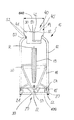
図1は、筐体12を備える粉体チャンバ10を示す。実質的に回転対称設計(回転軸Rを参照)である粉体チャンバ10は、第1の下側機能区分20及び第2の上側機能区分40を備える。上側機能区分40は、閉鎖要素41によって形成され、閉鎖要素41は、筐体12の上側先細区分によって形成されるアクセス14内に配置されている。閉鎖要素41は、2つの穿孔穴によって形成した出口42を備える。閉鎖要素41は、凹部/陥没部30も備え、凹部/陥没部30の領域には、ここではOリングの形態の封止体50が設けられている。また、閉鎖要素41は、筐体12に向かって封止要素50を介して封止されている。
筐体12と機能区分20、40との間の接触表面において、適切な封止表面又は封止壁(52)があり、封止表面又は封止壁(52)は、ここで示す実施形態では、実質的に回転軸Rに沿って又は回転軸Rにわたって延在する。筐体12の中には、挿入体18及びベンチュリ・ノズル19が設けられている。挿入体18は、筐体12に向かって適切な封止体50を介して封止されている。
下側領域では、粉体チャンバ10は、第1の機能区分20を備え、第1の機能区分20は、ここで示す実施形態では、挿入体18の内部に差し込まれ、挿入体18は、ねじ山54により筐体12に螺入されている。留意すべきは、第1の機能区分20における封止体50が、機能区分40における封止体50と同様に設計されていることである。
FIG. 1 shows a
At the contact surface between the
In the lower region, the
このことは、力又は圧力を第1の機能区分20及び第2の機能区分40に印加すると粉体チャンバ10を封止するという単純な方法である。底板21として設計した第1の機能区分20は、空気、特に圧縮空気のための入口22を備え、封止体50は、入口22に同心状に設けられている。入口22の領域では、底板21は、適切な凹部/陥没部30も備え、凹部/陥没部30は、特に、対応適合するように設計したステーション、又は対応適合するように設計した粉体研磨デバイス内に粉体チャンバ10を配置するように働く。特に、凹部/陥没部30の横表面32は、粉体チャンバ10が、例えばステーションから引き出されることを防止できる。
底板21の上には、循環磁気リング15が設けられ、循環磁気リング15は、ステーション又は粉体研磨デバイス内への粉体チャンバ10の配置を促進することを意味する。第1の機能区分20は、直径d20を有する一方で、第2の機能区分40は、直径d40を有する。最後に、これらの直径から得られるのは、力印加区分又は圧力表面20’及び40’であり、力印加区分又は圧力表面20’及び40’を介して、力/圧力が印加され、粉体チャンバ10を支持又は固定できる。
This is a simple method of sealing the
A circulating
本発明の一実施形態による開口42は、一方の機能区分20からもう一方の機能区分40に向けられる軸Rに平行な中心開口であり、粉体チャンバ10の内側に対向する、粉体と空気とを混合する混合出口44は、そのような軸Rに角度を付けて、好ましくは軸Rに直交して配置されている。
このような構成により、ベンチュリ・ノズルを出る粉体/空気混合物がそのような出口44に衝突し、不均一な流れをもたらすが、粉体/空気混合物は、そのような混合出口44を通って、混合物の均一な分配を達成できる領域で、通常は上側機能区分40の中心から離間して横方向に粉体チャンバを離れる。
The
With such a configuration, the powder / air mixture exiting the venturi nozzle impinges on such an outlet 44, resulting in a non-uniform flow, but the powder / air mixture passes through such a mixing outlet 44. , Leaving the powder chamber laterally away from the center of the upper
図2は、粉体チャンバ10を中に配置したステーション60の一実施形態を示す。この粉体チャンバ10の基本構造は、図1から既知であるものと同じであり、したがって、詳述は不要である。しかし、粉体チャンバ10の磁気リング15があり、磁気リング15は、図2では、ステーション60内に設けた磁気領域64と適切に相互作用するように示されていることに留意されたい。このことにより、粉体チャンバ10をステーション60内に容易に「引き込み」可能にする。
ステーション60は、下側接続区分61及び上側接続区分62を備え、ここに示す実施形態では、下側接続区分61及び上側接続区分62は、両方とも適切な突出部/突起65を備える。このことにより、対応設計した第1の機能区分20又は対応設計した第2の機能区分40との理想的な相互作用を可能にする。ステーションは、実質的にU字形であるため、粉体チャンバをねじ式クランプのように囲繞できる。ステーションに適切な強度/剛性を与える架台構造体は、簡単にするためにここでは図示しない。突出部/突起65、及び機能区分20、40内の対応する凹部/陥没部30は、粉体チャンバ10を正確な位置に配置及び係止又は締結可能にする。
上側接続区分62は、粉体・空気混合物の対応する出口67を備え、点線の矢印は、ステーション60が、粉体・空気混合物を取り出すための、対応する接続部又は出口を備え得ることを示すに過ぎない。ここで示すように、この取出しは、上側に導きデバイスから出すものであってもよいが、代替的に、デバイス内の任意の他の場所で外側に向けて取り出すこともできる。下側接続区分61及び/又は上側接続区分62を粉体チャンバ10の回転軸Rに沿って移動させるように設計した固定機構は、ここでは図示しない。しかし、下側接続区分61の領域の点線は、例えば、移動を底部に向け得ることを示し、これにより、粉体チャンバ10をステーション60から容易に取り外すことを可能にする。
FIG. 2 shows one embodiment of
The
The
図3は、同様に実質的にU字形状であるステーション60の斜視図を示す。下側接続区分61は、突起65を有することがわかる。粉体チャンバの一構成は、粉体チャンバを、対応する上側接続区分(ここでは図示せず)において、第2の(上側)機能区分によってステーション10に挿入し、次に、磁石64を介して、スタッド/ペグ63によって、下側接続区分61上の正確な位置に自動的に引っ張るようにできる。一方で、ユーザは正確な配置を注視する必要がない。適切には、ステーション60は、例えば、粉体チャンバが圧力下にあることを示し得る光源68も備える。光源68は、適切に透明であるか又は少なくとも部分的に透明である粉体チャンバの内部を照らすために使用することもでき、これにより、例えば、充填レベルの非常に正確な読取りを可能にする。
FIG. 3 shows a perspective view of a
10 粉体チャンバ
12 筐体
14 アクセス
15 磁気区分、磁気リング
18 挿入体
19 ベンチュリ・ノズル
20 第1の機能区分
20’ 力印加領域、圧力表面
21 底板
22 開口、入口
30 陥没部、凹部
32 横表面
40 第2の機能区分
40’ 力印加領域、圧力表面
41 閉鎖要素
42 開口、出口
44 混合物出口
50 封止体、Oリング
52 封止壁、封止表面
54 ねじ山
60 ステーション
61 下側接続区分
62 上側接続区分
63 ペグ、スタッド
64 磁気領域、磁石
65 突出部、突起
66 入口
67 出口
68 光源
d20 第1の機能区分の直径
d40 第2の機能区分の直径
R 回転軸
DESCRIPTION OF
Claims (13)
筐体(12)と、
互いに反対側に配置されて、少なくとも一方が空気又は粉体・空気混合物等の作動媒体のための開口(22、42)をなすように構成され、少なくとも一方が当該粉体チャンバ(10)を係止可能となるように構成された2つの機能区分(20、40)と、を備えたことを特徴とする、
粉体チャンバ(10)。 In particular a powder chamber (10) for a powder polishing device,
A housing (12);
Arranged on opposite sides, at least one is configured to form an opening (22, 42) for a working medium such as air or a powder / air mixture, at least one of which is associated with the powder chamber (10). Two functional sections (20, 40) configured to be able to be stopped,
Powder chamber (10).
粉体チャンバ(10)を保持するように構成され、形状的・強制的に嵌合するように接続された、互いに略反対側の2つの接続区分(61、62)を備えたことを特徴とする、
ステーション(60)。 In particular a station (60) for a powder polishing device,
It is configured to hold the powder chamber (10) and is provided with two connection sections (61, 62) substantially opposite to each other and connected to formally and forcibly mated. To
Station (60).
Applications Claiming Priority (3)
| Application Number | Priority Date | Filing Date | Title |
|---|---|---|---|
| EP16154213.9A EP3202364B1 (en) | 2016-02-04 | 2016-02-04 | Powder chamber, station for a powder chamber and method to operated a powder polishing device |
| EP16154213.9 | 2016-02-04 | ||
| PCT/EP2017/052331 WO2017134195A1 (en) | 2016-02-04 | 2017-02-03 | Powder chamber and station for a powder chamber |
Publications (2)
| Publication Number | Publication Date |
|---|---|
| JP2019509088A true JP2019509088A (en) | 2019-04-04 |
| JP6946310B2 JP6946310B2 (en) | 2021-10-06 |
Family
ID=55299386
Family Applications (1)
| Application Number | Title | Priority Date | Filing Date |
|---|---|---|---|
| JP2018540868A Active JP6946310B2 (en) | 2016-02-04 | 2017-02-03 | Powder chambers and stations for powder chambers |
Country Status (6)
| Country | Link |
|---|---|
| US (1) | US11633258B2 (en) |
| EP (2) | EP3202364B1 (en) |
| JP (1) | JP6946310B2 (en) |
| CN (1) | CN108882972B (en) |
| ES (1) | ES2881923T3 (en) |
| WO (1) | WO2017134195A1 (en) |
Families Citing this family (1)
| Publication number | Priority date | Publication date | Assignee | Title |
|---|---|---|---|---|
| DE102016118081B4 (en) * | 2016-09-26 | 2018-09-20 | Ferton Holding S.A. | Tooth cleaning system, powder container and insert for a powder container |
Citations (7)
| Publication number | Priority date | Publication date | Assignee | Title |
|---|---|---|---|---|
| US2825135A (en) * | 1956-01-10 | 1958-03-04 | William F Tilden | Self-contained abrasive applicator |
| JPS59156341A (en) * | 1983-02-18 | 1984-09-05 | カビトロン・インコ−ポレ−テツド | Tooth cleaning apparatus and method |
| US5158455A (en) * | 1990-02-09 | 1992-10-27 | Young Dental Manufacturing Company | Control unit for a scaler and a polisher |
| US20040137825A1 (en) * | 1995-08-21 | 2004-07-15 | Reuben Hertz | Method using handheld apparatus for delivery of particulate matter |
| US20050250070A1 (en) * | 2004-04-14 | 2005-11-10 | Hamman James E | Powder applicator for teeth |
| WO2007014246A2 (en) * | 2005-07-25 | 2007-02-01 | Michael Migdal | Tooth powdering device |
| JP2008229340A (en) * | 2007-03-19 | 2008-10-02 | Ferton Holding Sa | Powder jet device, powder container, insert for powder container, and dental treatment method |
Family Cites Families (15)
| Publication number | Priority date | Publication date | Assignee | Title |
|---|---|---|---|---|
| CH33251A (en) * | 1905-02-08 | 1905-11-15 | Carl Winkler | Device for clamping workpieces |
| AT75053B (en) * | 1914-06-05 | 1918-12-10 | L Schuler Fa | Electromagnetic jig. |
| NL82633C (en) * | 1949-02-24 | |||
| EP0097288B1 (en) | 1982-06-22 | 1987-05-13 | Pierre Mabille | A dental prophylactic apparatus |
| US4540365A (en) * | 1983-11-23 | 1985-09-10 | Advanced Design Corporation | Dental cleansing system |
| DE9002268U1 (en) * | 1990-02-26 | 1991-06-27 | Thera Patent Gmbh & Co. Kg Gesellschaft Fuer Industrielle Schutzrechte, 8031 Seefeld, De | |
| DE9013344U1 (en) * | 1990-09-21 | 1990-11-29 | Stahlbau Gaertig Gmbh, 4770 Soest, De | |
| US5525058A (en) * | 1992-03-27 | 1996-06-11 | American Dental Technologies, Inc. | Dental treatment system |
| DE9212671U1 (en) * | 1992-09-21 | 1992-11-26 | Bungenberg, Hans-Joachim, 5203 Much, De | |
| DE4332226A1 (en) * | 1993-09-22 | 1995-03-23 | Wassermann Dental Maschinen Gm | Dental sandblaster |
| US5503553A (en) * | 1995-04-21 | 1996-04-02 | Hines; John E. | Oral hygiene device |
| US6030212A (en) * | 1996-09-27 | 2000-02-29 | Dentsply Research & Development Corp. | Stacking reservoir and scaler system |
| JPH11104149A (en) * | 1997-09-30 | 1999-04-20 | Micron:Kk | Hand-piece for dental sandblast |
| US20130236851A1 (en) * | 2012-03-07 | 2013-09-12 | Justin E. McDonough | Oral care device |
| DE102012109797B4 (en) * | 2012-10-15 | 2015-08-06 | Ferton Holding S.A. | Powder container for a powder blasting machine |
-
2016
- 2016-02-04 EP EP16154213.9A patent/EP3202364B1/en active Active
-
2017
- 2017-02-03 US US16/075,413 patent/US11633258B2/en active Active
- 2017-02-03 JP JP2018540868A patent/JP6946310B2/en active Active
- 2017-02-03 CN CN201780019348.7A patent/CN108882972B/en active Active
- 2017-02-03 WO PCT/EP2017/052331 patent/WO2017134195A1/en active Application Filing
- 2017-02-03 EP EP17702393.4A patent/EP3410977B1/en active Active
- 2017-02-03 ES ES17702393T patent/ES2881923T3/en active Active
Patent Citations (7)
| Publication number | Priority date | Publication date | Assignee | Title |
|---|---|---|---|---|
| US2825135A (en) * | 1956-01-10 | 1958-03-04 | William F Tilden | Self-contained abrasive applicator |
| JPS59156341A (en) * | 1983-02-18 | 1984-09-05 | カビトロン・インコ−ポレ−テツド | Tooth cleaning apparatus and method |
| US5158455A (en) * | 1990-02-09 | 1992-10-27 | Young Dental Manufacturing Company | Control unit for a scaler and a polisher |
| US20040137825A1 (en) * | 1995-08-21 | 2004-07-15 | Reuben Hertz | Method using handheld apparatus for delivery of particulate matter |
| US20050250070A1 (en) * | 2004-04-14 | 2005-11-10 | Hamman James E | Powder applicator for teeth |
| WO2007014246A2 (en) * | 2005-07-25 | 2007-02-01 | Michael Migdal | Tooth powdering device |
| JP2008229340A (en) * | 2007-03-19 | 2008-10-02 | Ferton Holding Sa | Powder jet device, powder container, insert for powder container, and dental treatment method |
Also Published As
| Publication number | Publication date |
|---|---|
| EP3410977A1 (en) | 2018-12-12 |
| CN108882972A (en) | 2018-11-23 |
| EP3202364A1 (en) | 2017-08-09 |
| WO2017134195A1 (en) | 2017-08-10 |
| US20190038381A1 (en) | 2019-02-07 |
| EP3202364B1 (en) | 2022-08-10 |
| CN108882972B (en) | 2021-10-01 |
| ES2881923T3 (en) | 2021-11-30 |
| JP6946310B2 (en) | 2021-10-06 |
| US11633258B2 (en) | 2023-04-25 |
| EP3410977B1 (en) | 2021-05-05 |
Similar Documents
| Publication | Publication Date | Title |
|---|---|---|
| CA2602217C (en) | A multicomponent cartridge | |
| JP5452564B2 (en) | In-vehicle compressor unit | |
| US6273151B1 (en) | Method and system for refilling an ink cartridge | |
| JP6517701B2 (en) | Device for discharging tire sealant | |
| TWI667074B (en) | Syringe loading and unloading mechanism and device having the same | |
| JP4559540B2 (en) | Fluid container unit | |
| JP3102699B2 (en) | Refillable closed container system | |
| KR101622949B1 (en) | Compressed gas supply device | |
| ATE452834T1 (en) | DISCHARGE DEVICE WITH CLOSURE PLUG AND LOCKING RING WITH BAYONET CONNECTION MEANS | |
| PT1835997E (en) | Liquid supply cup and liner assembly for spray guns | |
| BR0308530B1 (en) | COMBINATION OF A FIRST CONTAINER AND A SECOND CONTAINER TO FORM A MINISTRY UNIT, MINISTRY UNIT, AND A CONTAINER FOR A NET SUBSTANCE | |
| JP2011235962A (en) | Dispensing device for cartridge | |
| JP2019509088A (en) | Powder chamber and station for powder chamber | |
| JPH06345151A (en) | Insertion type multiple-stringed cartridge | |
| CA3155033A1 (en) | Cartridge for a dispensing device | |
| US20040065678A1 (en) | Spraying apparatus for introducing substances into the body or applying substances onto the body | |
| US20090255960A1 (en) | Syringe with a piston | |
| KR101748601B1 (en) | Dual-barrel cartridge adaptor | |
| JP2008094462A (en) | Filling device | |
| JP2015098336A (en) | Spout and accommodation body with spout | |
| KR101779573B1 (en) | Cosmetics vessel | |
| US11207673B2 (en) | Fluid-release unit and manual metering device with at least one fluid-release unit | |
| JP2016215118A (en) | Hydrogen liquid generator | |
| JP6774081B2 (en) | A device that contains and distributes fluid substances | |
| US1106327A (en) | Fire-extinguisher. |
Legal Events
| Date | Code | Title | Description |
|---|---|---|---|
| A621 | Written request for application examination |
Free format text: JAPANESE INTERMEDIATE CODE: A621 Effective date: 20180913 |
|
| A131 | Notification of reasons for refusal |
Free format text: JAPANESE INTERMEDIATE CODE: A131 Effective date: 20190716 |
|
| A977 | Report on retrieval |
Free format text: JAPANESE INTERMEDIATE CODE: A971007 Effective date: 20190712 |
|
| A601 | Written request for extension of time |
Free format text: JAPANESE INTERMEDIATE CODE: A601 Effective date: 20191015 |
|
| A601 | Written request for extension of time |
Free format text: JAPANESE INTERMEDIATE CODE: A601 Effective date: 20191213 |
|
| A521 | Request for written amendment filed |
Free format text: JAPANESE INTERMEDIATE CODE: A523 Effective date: 20200108 |
|
| A131 | Notification of reasons for refusal |
Free format text: JAPANESE INTERMEDIATE CODE: A131 Effective date: 20200630 |
|
| A521 | Request for written amendment filed |
Free format text: JAPANESE INTERMEDIATE CODE: A523 Effective date: 20200924 |
|
| A131 | Notification of reasons for refusal |
Free format text: JAPANESE INTERMEDIATE CODE: A131 Effective date: 20210224 |
|
| A601 | Written request for extension of time |
Free format text: JAPANESE INTERMEDIATE CODE: A601 Effective date: 20210521 |
|
| A521 | Request for written amendment filed |
Free format text: JAPANESE INTERMEDIATE CODE: A523 Effective date: 20210604 |
|
| TRDD | Decision of grant or rejection written | ||
| A01 | Written decision to grant a patent or to grant a registration (utility model) |
Free format text: JAPANESE INTERMEDIATE CODE: A01 Effective date: 20210824 |
|
| A61 | First payment of annual fees (during grant procedure) |
Free format text: JAPANESE INTERMEDIATE CODE: A61 Effective date: 20210915 |
|
| R150 | Certificate of patent or registration of utility model |
Ref document number: 6946310 Country of ref document: JP Free format text: JAPANESE INTERMEDIATE CODE: R150 |
|
| RD03 | Notification of appointment of power of attorney |
Free format text: JAPANESE INTERMEDIATE CODE: R3D03 |