JP2019508333A - Recessed can end - Google Patents
Recessed can end Download PDFInfo
- Publication number
- JP2019508333A JP2019508333A JP2018545440A JP2018545440A JP2019508333A JP 2019508333 A JP2019508333 A JP 2019508333A JP 2018545440 A JP2018545440 A JP 2018545440A JP 2018545440 A JP2018545440 A JP 2018545440A JP 2019508333 A JP2019508333 A JP 2019508333A
- Authority
- JP
- Japan
- Prior art keywords
- panel
- blank
- pressure sleeve
- sleeve
- radius
- Prior art date
- Legal status (The legal status is an assumption and is not a legal conclusion. Google has not performed a legal analysis and makes no representation as to the accuracy of the status listed.)
- Abandoned
Links
Images


Classifications
-
- B—PERFORMING OPERATIONS; TRANSPORTING
- B65—CONVEYING; PACKING; STORING; HANDLING THIN OR FILAMENTARY MATERIAL
- B65D—CONTAINERS FOR STORAGE OR TRANSPORT OF ARTICLES OR MATERIALS, e.g. BAGS, BARRELS, BOTTLES, BOXES, CANS, CARTONS, CRATES, DRUMS, JARS, TANKS, HOPPERS, FORWARDING CONTAINERS; ACCESSORIES, CLOSURES, OR FITTINGS THEREFOR; PACKAGING ELEMENTS; PACKAGES
- B65D17/00—Rigid or semi-rigid containers specially constructed to be opened by cutting or piercing, or by tearing of frangible members or portions
- B65D17/02—Rigid or semi-rigid containers specially constructed to be opened by cutting or piercing, or by tearing of frangible members or portions of curved cross-section, e.g. cans of circular or elliptical cross-section
-
- B—PERFORMING OPERATIONS; TRANSPORTING
- B21—MECHANICAL METAL-WORKING WITHOUT ESSENTIALLY REMOVING MATERIAL; PUNCHING METAL
- B21D—WORKING OR PROCESSING OF SHEET METAL OR METAL TUBES, RODS OR PROFILES WITHOUT ESSENTIALLY REMOVING MATERIAL; PUNCHING METAL
- B21D22/00—Shaping without cutting, by stamping, spinning, or deep-drawing
- B21D22/20—Deep-drawing
- B21D22/22—Deep-drawing with devices for holding the edge of the blanks
-
- B—PERFORMING OPERATIONS; TRANSPORTING
- B21—MECHANICAL METAL-WORKING WITHOUT ESSENTIALLY REMOVING MATERIAL; PUNCHING METAL
- B21D—WORKING OR PROCESSING OF SHEET METAL OR METAL TUBES, RODS OR PROFILES WITHOUT ESSENTIALLY REMOVING MATERIAL; PUNCHING METAL
- B21D51/00—Making hollow objects
- B21D51/16—Making hollow objects characterised by the use of the objects
- B21D51/26—Making hollow objects characterised by the use of the objects cans or tins; Closing same in a permanent manner
- B21D51/2615—Edge treatment of cans or tins
- B21D51/2623—Curling
-
- B—PERFORMING OPERATIONS; TRANSPORTING
- B21—MECHANICAL METAL-WORKING WITHOUT ESSENTIALLY REMOVING MATERIAL; PUNCHING METAL
- B21D—WORKING OR PROCESSING OF SHEET METAL OR METAL TUBES, RODS OR PROFILES WITHOUT ESSENTIALLY REMOVING MATERIAL; PUNCHING METAL
- B21D51/00—Making hollow objects
- B21D51/16—Making hollow objects characterised by the use of the objects
- B21D51/26—Making hollow objects characterised by the use of the objects cans or tins; Closing same in a permanent manner
- B21D51/2653—Methods or machines for closing cans by applying caps or bottoms
- B21D51/2661—Sealing or closing means therefor
-
- B—PERFORMING OPERATIONS; TRANSPORTING
- B21—MECHANICAL METAL-WORKING WITHOUT ESSENTIALLY REMOVING MATERIAL; PUNCHING METAL
- B21D—WORKING OR PROCESSING OF SHEET METAL OR METAL TUBES, RODS OR PROFILES WITHOUT ESSENTIALLY REMOVING MATERIAL; PUNCHING METAL
- B21D51/00—Making hollow objects
- B21D51/16—Making hollow objects characterised by the use of the objects
- B21D51/26—Making hollow objects characterised by the use of the objects cans or tins; Closing same in a permanent manner
- B21D51/30—Folding the circumferential seam
- B21D51/32—Folding the circumferential seam by rolling
-
- B—PERFORMING OPERATIONS; TRANSPORTING
- B21—MECHANICAL METAL-WORKING WITHOUT ESSENTIALLY REMOVING MATERIAL; PUNCHING METAL
- B21D—WORKING OR PROCESSING OF SHEET METAL OR METAL TUBES, RODS OR PROFILES WITHOUT ESSENTIALLY REMOVING MATERIAL; PUNCHING METAL
- B21D51/00—Making hollow objects
- B21D51/16—Making hollow objects characterised by the use of the objects
- B21D51/38—Making inlet or outlet arrangements of cans, tins, baths, bottles, or other vessels; Making can ends; Making closures
- B21D51/383—Making inlet or outlet arrangements of cans, tins, baths, bottles, or other vessels; Making can ends; Making closures scoring lines, tear strips or pulling tabs
-
- B—PERFORMING OPERATIONS; TRANSPORTING
- B21—MECHANICAL METAL-WORKING WITHOUT ESSENTIALLY REMOVING MATERIAL; PUNCHING METAL
- B21D—WORKING OR PROCESSING OF SHEET METAL OR METAL TUBES, RODS OR PROFILES WITHOUT ESSENTIALLY REMOVING MATERIAL; PUNCHING METAL
- B21D51/00—Making hollow objects
- B21D51/16—Making hollow objects characterised by the use of the objects
- B21D51/38—Making inlet or outlet arrangements of cans, tins, baths, bottles, or other vessels; Making can ends; Making closures
- B21D51/44—Making closures, e.g. caps
-
- B—PERFORMING OPERATIONS; TRANSPORTING
- B65—CONVEYING; PACKING; STORING; HANDLING THIN OR FILAMENTARY MATERIAL
- B65D—CONTAINERS FOR STORAGE OR TRANSPORT OF ARTICLES OR MATERIALS, e.g. BAGS, BARRELS, BOTTLES, BOXES, CANS, CARTONS, CRATES, DRUMS, JARS, TANKS, HOPPERS, FORWARDING CONTAINERS; ACCESSORIES, CLOSURES, OR FITTINGS THEREFOR; PACKAGING ELEMENTS; PACKAGES
- B65D1/00—Containers having bodies formed in one piece, e.g. by casting metallic material, by moulding plastics, by blowing vitreous material, by throwing ceramic material, by moulding pulped fibrous material, by deep-drawing operations performed on sheet material
- B65D1/12—Cans, casks, barrels, or drums
- B65D1/14—Cans, casks, barrels, or drums characterised by shape
- B65D1/16—Cans, casks, barrels, or drums characterised by shape of curved cross-section, e.g. cylindrical
- B65D1/165—Cylindrical cans
-
- B—PERFORMING OPERATIONS; TRANSPORTING
- B65—CONVEYING; PACKING; STORING; HANDLING THIN OR FILAMENTARY MATERIAL
- B65D—CONTAINERS FOR STORAGE OR TRANSPORT OF ARTICLES OR MATERIALS, e.g. BAGS, BARRELS, BOTTLES, BOXES, CANS, CARTONS, CRATES, DRUMS, JARS, TANKS, HOPPERS, FORWARDING CONTAINERS; ACCESSORIES, CLOSURES, OR FITTINGS THEREFOR; PACKAGING ELEMENTS; PACKAGES
- B65D1/00—Containers having bodies formed in one piece, e.g. by casting metallic material, by moulding plastics, by blowing vitreous material, by throwing ceramic material, by moulding pulped fibrous material, by deep-drawing operations performed on sheet material
- B65D1/12—Cans, casks, barrels, or drums
- B65D1/20—Cans, casks, barrels, or drums characterised by location or arrangement of filling or discharge apertures
-
- B—PERFORMING OPERATIONS; TRANSPORTING
- B65—CONVEYING; PACKING; STORING; HANDLING THIN OR FILAMENTARY MATERIAL
- B65D—CONTAINERS FOR STORAGE OR TRANSPORT OF ARTICLES OR MATERIALS, e.g. BAGS, BARRELS, BOTTLES, BOXES, CANS, CARTONS, CRATES, DRUMS, JARS, TANKS, HOPPERS, FORWARDING CONTAINERS; ACCESSORIES, CLOSURES, OR FITTINGS THEREFOR; PACKAGING ELEMENTS; PACKAGES
- B65D17/00—Rigid or semi-rigid containers specially constructed to be opened by cutting or piercing, or by tearing of frangible members or portions
- B65D17/28—Rigid or semi-rigid containers specially constructed to be opened by cutting or piercing, or by tearing of frangible members or portions at lines or points of weakness
- B65D17/401—Rigid or semi-rigid containers specially constructed to be opened by cutting or piercing, or by tearing of frangible members or portions at lines or points of weakness characterised by having the line of weakness provided in an end wall
- B65D17/4012—Rigid or semi-rigid containers specially constructed to be opened by cutting or piercing, or by tearing of frangible members or portions at lines or points of weakness characterised by having the line of weakness provided in an end wall for opening partially by means of a tearing tab
-
- B—PERFORMING OPERATIONS; TRANSPORTING
- B65—CONVEYING; PACKING; STORING; HANDLING THIN OR FILAMENTARY MATERIAL
- B65D—CONTAINERS FOR STORAGE OR TRANSPORT OF ARTICLES OR MATERIALS, e.g. BAGS, BARRELS, BOTTLES, BOXES, CANS, CARTONS, CRATES, DRUMS, JARS, TANKS, HOPPERS, FORWARDING CONTAINERS; ACCESSORIES, CLOSURES, OR FITTINGS THEREFOR; PACKAGING ELEMENTS; PACKAGES
- B65D7/00—Containers having bodies formed by interconnecting or uniting two or more rigid, or substantially rigid, components made wholly or mainly of metal
- B65D7/12—Containers having bodies formed by interconnecting or uniting two or more rigid, or substantially rigid, components made wholly or mainly of metal characterised by wall construction or by connections between walls
- B65D7/34—Containers having bodies formed by interconnecting or uniting two or more rigid, or substantially rigid, components made wholly or mainly of metal characterised by wall construction or by connections between walls with permanent connections between walls
- B65D7/36—Containers having bodies formed by interconnecting or uniting two or more rigid, or substantially rigid, components made wholly or mainly of metal characterised by wall construction or by connections between walls with permanent connections between walls formed by rolling, or by rolling and pressing
-
- B—PERFORMING OPERATIONS; TRANSPORTING
- B65—CONVEYING; PACKING; STORING; HANDLING THIN OR FILAMENTARY MATERIAL
- B65D—CONTAINERS FOR STORAGE OR TRANSPORT OF ARTICLES OR MATERIALS, e.g. BAGS, BARRELS, BOTTLES, BOXES, CANS, CARTONS, CRATES, DRUMS, JARS, TANKS, HOPPERS, FORWARDING CONTAINERS; ACCESSORIES, CLOSURES, OR FITTINGS THEREFOR; PACKAGING ELEMENTS; PACKAGES
- B65D2517/00—Containers specially constructed to be opened by cutting, piercing or tearing of wall portions, e.g. preserving cans or tins
- B65D2517/0001—Details
- B65D2517/001—Action for opening container
- B65D2517/0014—Action for opening container pivot tab and push-down tear panel
Landscapes
- Engineering & Computer Science (AREA)
- Mechanical Engineering (AREA)
- Ceramic Engineering (AREA)
- Rigid Containers With Two Or More Constituent Elements (AREA)
- Containers Opened By Tearing Frangible Portions (AREA)
- Containers Having Bodies Formed In One Piece (AREA)
- Details Of Rigid Or Semi-Rigid Containers (AREA)
- Medicinal Preparation (AREA)
- Closures For Containers (AREA)
Abstract
容器缶端部が、凹状のドーム型状を含み、中心パネル周囲の周辺補強ビードを排除することができる。タブは、湾曲することもできる。この端部を形成するための金型及び対応する方法も提供する。
【選択図】 図2The container can end can include a concave dome shape to eliminate peripheral reinforcement beads around the central panel. The tabs can also be curved. Also provided is a mold and corresponding method for forming the end.
[Selected figure] Figure 2
Description
〔関連出願との相互参照〕
本出願は、2016年2月29日に出願された米国仮特許出願第62/301,128号の利益を主張するものであり、この文献の開示はその全体が本明細書に記載されているかのように引用により本明細書に組み入れられる。
[Cross-reference to related applications]
This application claims the benefit of US Provisional Patent Application No. 62 / 301,128, filed Feb. 29, 2016, the disclosure of which is described in its entirety herein. Are incorporated herein by reference.
食品、飲料、又はエアロゾルとして提供される製品を保持する缶などの市販の缶には、「2ピース」構成又は「3ピース」構成のものがある。従来の2ピース缶は、「DWI」としても知られている絞りしごき加工によって形成された一体成形缶体を含む。DWI加工では、金属ブランクをカップ状に絞り加工した後に、このカップを一連のリングに押し通すことによって壁部を所望の厚み及び長さにしごき加工する。しごき加工の最後には、缶をドーム加工ステーション(doming station)に押し込んで一体型缶体のドーム型底部を形成する。その後、開いた缶端部をトリミング加工し、直径をネックダウン加工し、外向きに変形させてフランジを形成する。 Commercial cans, such as cans holding products provided as food, beverages, or aerosols, are of "two-piece" or "three-piece" configuration. Conventional two-piece cans comprise a single-piece can formed by squeezing and ironing, also known as "DWI". In DWI processing, a metal blank is drawn into a cup, and then the wall is ironed to a desired thickness and length by pushing the cup through a series of rings. At the end of the ironing process, the cans are pushed into a doming station to form a domed bottom of the one-piece can. The open can end is then trimmed, necked down in diameter and deformed outwardly to form a flange.
2ピース缶の第2の部分は、端部又は蓋である。飲料缶端部は、シェルプレス内で平板からシェルを形成することによって形成される。その後、コンバージョンプレス内でリベットによってシェルにタブを取り付ける。 The second part of the two-piece can is an end or a lid. The beverage can end is formed by forming the shell from a flat plate in a shell press. Then attach the tabs to the shell by rivets in the conversion press.
最新の軽量飲料缶端部は、周辺のカール部と、カール部に対して半径方向内向き及び下向きに延びる壁部と、(上向きに開いた溝などの)補強構造と、平坦又はほぼ平坦な中心パネルとを含む。中心パネルのスコア線は、タブの作動によって開くように構成される。 Modern lightweight beverage can ends have a flat or nearly flat curled portion around the periphery, a wall extending radially inward and downward relative to the curled portion, a reinforcing structure (such as an upwardly open groove), and And a central panel. The score line of the central panel is configured to open upon actuation of the tab.
ビール用飲料缶の端部は、低温殺菌処理に耐え抜くように90psi(6.2バール)の内圧に耐えることという要件を有することが多い。炭酸清涼飲料用の飲料缶も、同様の規格を満たさなければならないことが多い。缶の端部壁と円形中心パネルとの間の補強構造(すなわち補強溝)は、内圧力に対して構造を強化するものであり、加圧された缶端部がたまに破損するのもこの場所である。 The end of the beer beverage can often has the requirement to withstand an internal pressure of 90 psi (6.2 bar) to withstand the pasteurization process. Beverage cans for carbonated soft drinks often have to meet similar specifications. The reinforcing structure between the end wall of the can and the circular central panel (i.e. the reinforcing groove) strengthens the structure against internal pressure and this is where the pressurized can end occasionally breaks It is.
従って、Crown Cork & Seal社によって市販されている、一般にSuperEnd(登録商標)と呼ばれる軽量端部である昔のB64端部、及びBall社によって市販されている、一般にCDL(商標)と呼ばれるものなどの全ての商業的に成功している炭酸飲料用の缶端部は、上向きに開いた開口溝を有する。米国特許出願第2002/0158071号(Chasteen)に開示されている「外側に延びる補強ビード」、米国特許第7,644,833号(Turner)に開示されている「チャック壁の半径方向外側に位置する部分を有する折り目」、又は国際公開第2013/057250号(Dunwoody)に開示されている「パネル壁の半径方向外端部とチャック壁構造の半径方向内端部との間に結合されたビード」の潰れた又は制限された構造などの別の補強構造も提案されている。しかしながら、最新の飲料缶端部が中心パネルの周辺部に何らかのタイプの補強構造を有することは今に始まったことではない。具体例として、B64端部の皿穴溝(countersink groove)は、比較的急傾斜した外側壁と、中心パネルに融合する比較的直立した内側壁とを含む。B64端部は、パネルの頂部からカール部の頂部までの約4mmの深さを有する。例えば米国特許第4,516,420号及び米国特許第4,549,424号(「Bulso」)には、従来の飲料缶端部を形成するための先行技術のシェルプレスが開示されている。 Thus, the old B 64 end, which is a lightweight end commonly referred to as SuperEnd®, marketed by Crown Cork & Seal, and what is commonly referred to as CDLTM, marketed by Ball, etc. All commercially successful carbonated beverage can ends of the have an open groove that opens upward. U.S. Patent Application 2002/0158071 (Chasteen) discloses "outwardly extending reinforcement beads", U.S. Patent 7,644,833 (Turner) discloses "located radially outward of the chuck wall" Or a bead joined between the radially outer end of the panel wall and the radially inner end of the chuck wall structure as disclosed in WO 2013/057250 (Dunwoody) Alternative reinforcing structures have also been proposed, such as the 'collapsed or restricted' structure. However, it is not new for modern beverage can ends to have any type of reinforcing structure around the center panel. As a specific example, the countersink groove at the B64 end includes a relatively steeply sloped outer wall and a relatively upright inner wall that merges with the central panel. The B64 end has a depth of about 4 mm from the top of the panel to the top of the curl. For example, U.S. Patent Nos. 4,516,420 and 4,549,424 ("Bulso") disclose prior art shell presses for forming conventional beverage can ends.
最も一般的な飲料缶体(呼び径)のサイズは、211(米国における従来の命名法である2+11/16インチは、最初の桁をインチとして使用し、次の2桁を1/16インチの数として使用する)又は66mm直径である。通常、端部サイズは、最も一般的なネック形成の大きさを反映した202、204又は206インチである。他の飲料缶の呼び径は58mm及び53.5mmであり、これらはそれぞれ、一般に「スリーク」缶及び「スリム缶」と呼ばれる。 The size of the most common beverage can (nominal diameter) is 211 (the conventional nomenclature in the United States, 2 + 11/16 inch, using the first digit as an inch and the next two digits as 1/16 inch) Used as a number) or 66 mm diameter. Typically, the end size is 202, 204 or 206 inches reflecting the size of the most common neck formation. The nominal diameters of the other beverage cans are 58 mm and 53.5 mm, which are generally referred to as "sleek" cans and "slim cans" respectively.
端部が加圧下にある時には若干の変形が生じると理解されているので、従来の飲料缶端部の中心パネルは、特に加圧状態では平坦又はほぼ平坦である。平坦という用語は、窪み、隆起ビーズ及び同様の表面特徴を有するパネルを含む。「ほぼ平坦」という用語は、シェルプレス及びコンバージョンプレスでの製造公差及び若干の細かい変形も含む。 It is understood that some deformation occurs when the end is under pressure, so the central panel of the conventional beverage can end is flat or nearly flat, especially under pressure. The term flat includes panels having depressions, raised beads and similar surface features. The term "substantially flat" also includes manufacturing tolerances in shell presses and conversion presses and some minor variations.
缶に端部を取り付けるには、缶体のフランジ上に端部カール部を配置した後に、チャックを継ぎ合わせることによってカール部及びフランジを変形させて従来の二重継ぎ目を形成する。金属容器の商業的継ぎ合わせ加工では、金属皺を含まない信頼性できる容器を10億個単位で生産する精度の高さが必要とされる。さらに、缶フランジの末端部と端部カール部の末端部との重なりなどの不十分な継ぎ合わせ寸法及び同様のパラメータによって、加圧下で破損が生じる可能性もある。従って、金属の継ぎ目では、継ぎ目の長さが、例えば従来のB64端部では2.55mm(+/−0.15mm)、Crown Cork & Seal社によってISE端部として市販されている軽量端部では2.50mm(+/−0.15mm)であり、継ぎ目の半径は1.0mmを上回り、継ぎ目の厚みは0.5mmを上回る。通常、継ぎ目の厚みは、端部厚の3倍+フランジ厚の2倍+自由空間として計算又は概算され、自由空間は0.13mmとして概算されることもある。さらに、本発明者らが承知している全ての商用飲料缶の継ぎ目では、端圧定格要件(end pressure rating requirements)によって缶体のフランジ厚よりも端部厚の方が大きい。 To attach the end to the can, after placing the end curl on the flange of the can, the curl and the flange are deformed by seaming the chucks to form a conventional double seam. Commercial seaming of metal containers requires a high degree of accuracy to produce one billion reliable containers that do not contain metal defects. In addition, failure may occur under pressure due to poor splice dimensions and similar parameters, such as the overlap of the end of the can flange and the end of the end curl. Thus, for metal joints, the joint length is, for example, 2.55 mm (+/- 0.15 mm) at the conventional B64 end, and at the lightweight end marketed by Crown Cork & Seal as the ISE end. The radius of the seam is greater than 1.0 mm and the thickness of the seam is greater than 0.5 mm. Typically, the thickness of the seam is calculated or approximated as 3 times the end thickness + 2 times the flange thickness + free space, and the free space may be approximated as 0.13 mm. Furthermore, for all commercial beverage can joints known to the inventors, the end thickness is greater than the flange thickness of the can due to the end pressure rating requirements.
しばしば食品の保持に使用される3ピース缶は、両末端が各端部に継ぎ合わされた円筒体を含む。通常、従来の食品端部の内圧定格は、炭酸飲料缶と同じではない。従って、通常、従来の食品缶端部は平坦であり、強化溝を有していない。 Three-piece cans, which are often used to hold food, comprise cylinders with both ends spliced to each end. Usually, the internal pressure rating of conventional food ends is not the same as carbonated beverage cans. Thus, typically the conventional food can end is flat and does not have a reinforcing groove.
3ピース缶では、しばしば矩形の薄板を圧延して継ぎ目を溶接することによって円筒体が形成される。この円筒体の各末端に端部が継ぎ合わされる。 In three-piece cans, a cylinder is often formed by rolling a rectangular sheet and welding the joints. An end is spliced to each end of the cylinder.
エアロゾル容器は3ピース缶であることが多く、円筒缶体の底部に継ぎ合わされたドーム型の下端部を含む。エアロゾル缶の端部は、飲料缶の端部よりも大幅に肉厚である。さらに、エアロゾル缶の端部は、鋼、又は(飲料缶端部によく見られる5000系アルミニウム合金と比べて)比較的延性が高いアルミニウム合金で形成される。従って、通常、エアロゾル缶の端部は、形成される材料に接するドーム型のダイ中心ブロック(domed die center block)を有するプレス機により、通常はコイニング加工によって形成され、そうでなければ最終製品が商業的に容認できない規模の皺を有するようになってしまう。 The aerosol container is often a three-piece can and includes a dome-shaped lower end joined to the bottom of a cylindrical can. The end of the aerosol can is significantly thicker than the end of the beverage can. Furthermore, the end of the aerosol can is formed of steel or an aluminum alloy having a relatively high ductility (compared to the 5000 series aluminum alloy often found at the end of a beverage can). Thus, the end of the aerosol can is usually formed by coining, usually with a press having a domed die center block in contact with the material to be formed, otherwise the final product is You will end up with commercially unacceptable scales.
缶端部が、凹状の中心パネル(すなわち、上から見た場合)を含む。この説明は、特にビール又は炭酸清涼飲料と共に使用した時に特定の利点があるタイプの飲料缶端部を対象とする。この端部構造は、食品缶端部、炭酸飲料に一般的な(90psiなどの)圧力定格よりも低い圧力定格を必要とする飲料缶、及びエアロゾルから提供される製品に使用することもできる。 The can end comprises a concave central panel (i.e. when viewed from above). This description is directed to a type of beverage can end which has particular advantages when used particularly with beer or carbonated soft drinks. This end structure can also be used for food can end, beverage cans that require a pressure rating lower than the pressure rating (such as 90 psi) typical for carbonated beverages, and products provided from aerosols.
皿穴のないドーム型パネルを有する実施形態は、シェルの重量が減少することによって継ぎ目がコンパクトになり、このため商業的に容認できる継ぎ目を形成しながら軽量化も実現できるという利点を有する。さらに、缶体を端部及び端部構造そのものに適合するようにネック形成すると、有利なヘッドスペース間隙(すなわち、端部又は注ぎ口の下側と液体の表面との間の距離)が生み出される。この端部構造は、(例えば)輸送中にゴミを捉える溝が無く、また缶からの液体が溝内に取り残されるよりもむしろ周辺部から消失して開いた缶内に戻る可能性もないため、清潔度を高める。また、(注ぎ口と継ぎ目との間に溝が存在しないため)注ぎ口を継ぎ目に近付けて配置できるので、従来の缶と比べて飲む感覚がむしろコップから飲む感覚に近くなり得る。 Embodiments having a countersunk domed panel have the advantage of reducing the weight of the shell, making the joint compact, and thus also achieving weight savings while forming a commercially acceptable joint. Furthermore, necking the can to fit the end and end structure itself creates an advantageous headspace clearance (ie, the distance between the underside of the end or spout and the surface of the liquid) . This end construction has (for example) no grooves to catch dirt during transport, and there is also no possibility that liquid from the can will disappear from the periphery and return back into the open can rather than being left in the grooves. , Improve cleanliness. Also, because the spout can be placed closer to the joint (because there is no groove between the spout and the joint), the feeling of drinking can be rather close to the feeling of drinking from a cup as compared to conventional cans.
この点、缶体上への継ぎ合わせ後に90psiの内圧に耐えることができる継ぎ合わせ前の缶端部はアルミニウム合金で形成され、好ましくは5000系合金(ただし3000系アルミニウム合金などの他の合金も可能である)が検討される。継ぎ合わせ前の缶端部は、(i)缶体のフランジと共に継ぎ合わされるように適合されたカール部構造と、(ii)カール部構造から半径方向内向きに延び、継ぎ合わせ工程中にチャックに接触するように適合されたチャック壁と、(iii)チャック壁から半径方向内向きにドーム状になったパネルと、(iv)パネル上に形成されたスコア線と、パネルに取り付けられて、ユーザによる作動に応答してスコア線を断裂させて注ぎ口を形成するように適合された(好ましくはパネルとほぼ同じ形状で湾曲した)タブ又は他の開封機能とを含む。他の開封機能としては、押ボタン、剥離式ホイルなどを挙げることができる。パネルは、チャック壁の下端部からパネル内に、間に皿穴ビードを伴わずに広がる。缶端部は、飲料缶端部であることが好ましいが、この構造は、食品缶端部又はエアロゾル製品端部にも使用することができる。 In this regard, the end of the can prior to joining that can withstand an internal pressure of 90 psi after joining on the can is made of an aluminum alloy, preferably a 5000 series alloy (but also other alloys such as a 3000 series aluminum alloy) Possible) is considered. The can end prior to joining comprises (i) a curled section structure adapted to be joined together with the flange of the can, and (ii) extend radially inward from the curled section structure and chuck during the joining process A chuck wall adapted to contact the panel, (iii) a panel domed radially inwardly from the chuck wall, (iv) a score line formed on the panel, and a panel, Includes a tab or other opening feature adapted to tear the score line in response to actuation by a user to form a spout (preferably curved approximately the same shape as the panel). Other opening functions may include push buttons, peelable foils, and the like. The panel extends from the lower end of the chuck wall into the panel without a countersink bead in between. The can end is preferably a beverage can end, but this structure can also be used for food can end or aerosol product end.
缶端部の直径は、端部の中心におけるドームの高さの10倍未満であることが好ましく、端部の中心におけるドームの高さの4〜8倍であることがさらに好ましい。本明細書で説明するように形成した端部は、0.20インチ未満の厚みの、さらに好ましくは0.18インチ未満の厚みの、好ましい実施形態では0.16mm未満の厚みの5000系合金などの軽い物とすることができる。 The diameter of the can end is preferably less than 10 times the height of the dome at the center of the end, and more preferably 4 to 8 times the height of the dome at the center of the end. The ends formed as described herein may be, for example, a 5000 series alloy having a thickness of less than 0.20 inches, more preferably less than 0.18 inches, and in a preferred embodiment less than 0.16 mm. It can be a light one.
端部のカール部は、継ぎ合わせ前の端部が1.7〜3.0mmの、好ましくは少なくとも1.8mmの積み重ね高さSを有するように構成される。カール部は、カール部構造の最も外側の地点と、カール部構造の継ぎ合わせパネルが端部のチャック壁の比較的真っ直ぐな部分をもたらすカール部上の地点との間を半径方向に水平に測定した3.5mm未満の、さらに好ましくは3.0mm未満の幅を有するように構成される。 The end curl is configured such that the end before joining has a stacking height S of 1.7 to 3.0 mm, preferably at least 1.8 mm. The curl is measured radially horizontally between the outermost point of the curl structure and the point on the curl where the seam panel of the curl results in a relatively straight portion of the end chuck wall Configured to have a width of less than 3.5 mm, more preferably less than 3.0 mm.
パネルは、端部によって定められる曲面の接線の傾きがチャック壁及びドーム型パネルの全ての中心を除く地点において非ゼロになるようなドーム型である。ドーム型パネルの断面は、パネルの中心からの半径方向位置に伴って減少する複数の半径によって形成される。例えば、チャック壁の内側のチャック壁に最も近いドーム型パネルの半径R1は0.5mm〜2mmであり、パネルの中心におけるドームの半径R4は35mm〜55mmであり、缶端部の直径は38〜52mmである。好ましくは、半径R1は0.5mm〜4mmであり、半径R2は7mm〜20mmであり、半径R3は28mm〜41mmであり、半径R4は35mm〜55mmであり、全てについて缶端部の直径は38〜52mmである。さらに好ましくは、R1、R2、R3及びR4は、0.7mm〜2.0mm、10mm〜16mm、31mm〜37mm及び40mm〜50mmであり、42mm端部では、約1.0mm、13mm、34mm及び44mmであることがさらに好ましい。 The panel is dome shaped such that the slope of the tangent of the curved surface defined by the end is non-zero at the points except the center of all of the chuck wall and dome panel. The cross section of the domed panel is formed by a plurality of radii which decrease with radial position from the center of the panel. For example, the radius R1 of the domed panel closest to the chuck wall inside the chuck wall is 0.5 mm to 2 mm, the radius R4 of the dome at the center of the panel is 35 mm to 55 mm, the diameter of the can end is 38 to It is 52 mm. Preferably, the radius R1 is 0.5 mm to 4 mm, the radius R2 is 7 mm to 20 mm, the radius R3 is 28 mm to 41 mm, the radius R4 is 35 mm to 55 mm, and the diameter of the can end is 38 for all To 52 mm. More preferably, R1, R2, R3 and R4 are 0.7 mm to 2.0 mm, 10 mm to 16 mm, 31 mm to 37 mm and 40 mm to 50 mm, and 42 mm ends are about 1.0 mm, 13 mm, 34 mm and 44 mm It is further preferred that
端部の注ぎ口及びタブの態様は、スコア線によって定められる注ぎ口が、注ぎ口の対向地点によって定められる角度で傾斜した線によって半径方向に測定した14mm〜19mmの、さらに好ましくは15mm〜17mmの直線寸法を有することを含む。チャック壁の最も内側の部分とスコア線の最も外側の部分との間に定められる水平間隙は0.6mm〜3.0mmであり、好ましくは1.0mm〜2.0mmであり、さらに好ましくは1.0mm〜1.4mmである。 The aspect of the end spout and tab is such that the spout defined by the score line is 14 mm to 19 mm, more preferably 15 mm to 17 mm, measured radially by an inclined line defined by the opposing point of the spout Including having a linear dimension of The horizontal gap defined between the innermost part of the chuck wall and the outermost part of the score line is 0.6 mm to 3.0 mm, preferably 1.0 mm to 2.0 mm, more preferably 1 It is .0 mm-1.4 mm.
チャック壁の最も内側の部分とタブヒールの最遠位部分との間に定められる斜面上で測定した指間隙Fは6mm〜15mmであり、さらに好ましくは7mm〜10mmである。 The finger gap F measured on the slope defined between the innermost part of the chuck wall and the most distal part of the tab heel is 6 mm to 15 mm, more preferably 7 mm to 10 mm.
カール部の頂部から中心におけるパネルの頂部まで(ただし、中心にリベットが存在する場合には、中心におけるドームの曲面の突出部から)を測定したドーム深さは、好ましくは5mm〜16mmであり、さらに好ましくは6mm〜10mmであり、図示のいくつかの実施形態では約8mmである。ドーム深さは、端部性能及び所望の直径パラメータを最適化するのにふさわしい原理に従って選択することができる。 The dome depth measured from the top of the curled portion to the top of the panel at the center (but from the projection of the curved surface of the dome at the center if a rivet is present at the center) is preferably 5 mm to 16 mm, More preferably, it is 6 mm to 10 mm, and in some embodiments shown it is about 8 mm. The dome depth can be selected according to principles appropriate to optimize end performance and desired diameter parameters.
本発明の態様を使用する別の実施形態は、完全開口端部(fulll aperture end)である。完全開口端部は、以下で要約する工程によって形成される、上記で要約した開けやすい端部のようなシェルと、壁部に近いパネルの外周に沿って延びるスコア線とを有する。状況によっては、完全開口端部は、本発明者らが継ぎ合わせのための間隙を含むさらに小さなリング型のFAEタブを可能にするサイズであると推測する約30mmサイズなどの、他の様式よりも小さいものにすることもできる。 Another embodiment using aspects of the present invention is a full aperture end. The fully open end has an open end-like shell, as summarized above, formed by the process summarized below, and a score line extending along the outer periphery of the panel near the wall. In some situations, the fully open end is more than other styles, such as about 30 mm in size, which we speculate to allow for a smaller ring-shaped FAE tab that includes a gap for seaming. It can also be small.
本発明の別の態様によれば、継ぎ合わせ前の端部が缶体上に継ぎ合わされる。継ぎ合わせ前の缶端部と缶体との結合体は、基部、側壁及びフランジを含む絞りしごき加工された缶体と、継ぎ合わせ前の缶端部とを含む。継ぎ合わせ前の缶端部は、フランジに係合するカール部構造と、カール部構造から半径方向内向きに延び、継ぎ合わせ工程中にチャックに接触するように適合されるチャック壁と、チャック壁から半径方向内向きにドーム状になったパネルと、パネル上に形成されたスコア線と、パネルに取り付けられて、ユーザによる作動に応答してスコア線を断裂させて注ぎ口を形成するように適合されたタブとを含む。 According to another aspect of the invention, the pre-sealing end is spliced onto the can. The combined can end and can body prior to joining includes a drawn and ironed can including a base, side walls and a flange, and a can end prior to joining. The can end prior to seaming includes a curl portion structure for engaging the flange; a chuck wall extending radially inward from the curl portion structure and adapted to contact the chuck during the seaming process; Radially inward from the panel and attached to the panel and the score line formed on the panel to tear the score line in response to actuation by the user to form the spout Including adapted tabs.
缶のネック部に近接するフランジとカール部との間の半径方向間隙は、少なくとも0.5mmである。この間隙は、端部のチャック壁において測定することができる。缶端部の軽量性を達成するために、カール部構造において測定した缶端部の厚みは、フランジの厚みよりも10%又は20%小さい。より小さなカール部に対応しながらも適切な継ぎ目を形成するのに十分な材料をもたらすことも一部目的として、缶のネック部の垂直部分の内側からフランジの最も外側のリップ部までを半径方向に測定したフランジの幅は1.8mm未満であり、好ましくは1.6mm未満であり、さらに好ましくは1.5mm未満である。また、カール部の高さは、フランジの幅よりも少なくとも0.5mm大きく、さらに好ましくは少なくとも0.2mm(又は若干でも)大きい。フランジの最も外側の先端とカール部の最も内側の先端との間を水平に測定したカール部間隙寸法は、0.4〜1.2mmである。 The radial clearance between the flange and the curl adjacent to the can neck is at least 0.5 mm. This gap can be measured at the end chuck wall. In order to achieve a light weight of the can end, the thickness of the can end measured in the curled structure is 10% or 20% less than the thickness of the flange. The radial direction from the inside of the vertical portion of the can neck to the outermost lip of the flange, also in part to provide sufficient material to create a proper seam while accommodating smaller curls The width of the flanges measured in is less than 1.8 mm, preferably less than 1.6 mm, and more preferably less than 1.5 mm. Also, the height of the curled portion is at least 0.5 mm larger, more preferably at least 0.2 mm (or slightly) larger than the width of the flange. The curled gap dimension measured horizontally between the outermost tip of the flange and the innermost tip of the curled portion is 0.4 to 1.2 mm.
端部と缶体との結合体のパネルの寸法及び構成、タブ及びスコア線、並びにその他の特徴は、継ぎ合わせ前の缶端部に関して上述した通りである。 The dimensions and configuration of the panels of the end-to-can combination, the tabs and score lines, and other features are as described above for the can end prior to splicing.
本発明の別の態様によれば、端部シェル構造の利点に一致する継ぎ目の発明態様を容器に使用することができる。これに関連して、製品を保持するための容器が、基部、側壁及びネック部を含む絞りしごき加工された缶体と、缶端部とを含む。缶端部は、カール部構造から半径方向内向きに延び、継ぎ合わせ工程中にチャックに接触するように適合されたチャック壁を含む。缶体の末端部及び端部の末端部は、約2.2mm未満の、好ましくは約2.0mmの継ぎ目高さを有する二重継ぎ目によって互いに接合される。端部は、チャック壁から半径方向内向きにドーム状になったパネルと、パネル上に形成されたスコア線と、パネルに取り付けられて、ユーザによる作動に応答してスコア線を断裂させて注ぎ口を形成するように適合されたタブとを有することができる。或いは、この容器は、エアロゾル製品の下端部とすることもできる。 According to another aspect of the invention, an inventive aspect of the seam can be used for the container, which coincides with the advantages of the end shell construction. In this regard, a container for holding the product includes a squeezed and ironed can including a base, a sidewall and a neck, and a can end. The can end extends radially inward from the curl portion structure and includes a chuck wall adapted to contact the chuck during the joining process. The ends of the can and the ends of the ends are joined together by a double seam having a seam height of less than about 2.2 mm, preferably about 2.0 mm. The ends are attached to a panel domed radially inward from the chuck wall, a score line formed on the panel, and a panel for tearing and pouring the score line in response to user actuation It can have a tab adapted to form a mouth. Alternatively, the container may be the lower end of the aerosol product.
この容器は、缶体の末端部の厚みを超えない端部の末端部の厚みと、1.1mmを超えない、さらに好ましくは0.96mmを超えない、好ましくは0.85〜0.93mmである継ぎ目の厚みとを有することが好ましい。薄い端部シェルを達成するために、継ぎ目の半径は0.6mmを超えないことが好ましく、0.55mmを超えないことがさらに好ましい。 This container has an end thickness not exceeding the thickness of the end of the can and not more than 1.1 mm, more preferably not more than 0.96 mm, preferably 0.85 to 0.93 mm. It is preferable to have a certain joint thickness. In order to achieve a thin end shell, the seam radius preferably does not exceed 0.6 mm and more preferably does not exceed 0.55 mm.
容器上の二重継ぎ目は、(i)缶体の末端部のカバーフック、端部フック、継ぎ合わせパネル及びチャック壁と、(ii)缶端部の缶体壁部及び缶体フックとを含み、缶体フックとカバーフックとの間の重複部は、好ましくは0.65〜1.2mmであり、さらに好ましくは約0.9mmである。端部及び缶体のパネルの寸法及び構成、タブ及びスコア線、並びにその他の特徴は、継ぎ合わせ前の缶端部、及び継ぎ合わせ前の缶端部と缶体のフランジとの組み合わせに関して上述した通りである。 The double seam on the container includes (i) a cover hook at the end of the can, an end hook, a seaming panel and a chuck wall, and (ii) a can wall and a can hook at the can end. The overlap between the can body hook and the cover hook is preferably 0.65 to 1.2 mm, more preferably about 0.9 mm. The dimensions and configurations of the ends and panels of the can, tabs and score lines, and other features are described above with respect to the can end prior to joining and the combination of the can end and the flange of the prior to joining. It is street.
本発明の継ぎ目を使用する容器の例では、この容器が缶体と缶端部とを含み、缶端部は、カール部構造から半径方向内向きに延び、継ぎ合わせ工程中にチャックに接触するように適合されたチャック壁と、チャック壁から半径方向内向きにドーム状になったパネルと、約2.2mm未満の継ぎ目高さを有する二重継ぎ目によって互いに接合された缶体の末端部及び端部の末端部とを含む。この端部では、スコア線及びタブは任意である。端部は、好ましくは0.20mm未満の厚みの、さらに好ましくは0.18mm未満の厚みの、好ましい実施形態では0.16mm未満の厚みのアルミニウム合金で形成される。この容器は、食品、又は高圧ガスによって提供される製品を保持することができる。 In the example of a container using the seam of the present invention, the container includes a can and a can end, the can end extending radially inward from the curled structure and contacting the chuck during the seaming process A chuck wall so adapted, a panel domed radially inward from the chuck wall, and a can end joined together by a double seam having a seam height less than about 2.2 mm and And an end portion of the end portion. At this end, score lines and tabs are optional. The end is formed of an aluminum alloy preferably having a thickness of less than 0.20 mm, more preferably less than 0.18 mm, and in a preferred embodiment less than 0.16 mm. This container can hold food or products provided by high pressure gas.
本発明の別の態様によれば、缶体との継ぎ合わせ後に85psiに耐えることができる缶端部シェルの形成方法が、
(a)端部シェル金属ブランクの周辺部付近の凹面を有する上側スリーブと凸面を有する下側スリーブとの間にブランクをクランプ固定するステップと、
(b)ブランクの上面をドーム型パンチに係合させ、パンチをブランクに対して移動させることによって、ブランクを変形させるステップと、
(c)変形させるステップ(b)におけるブランクの変形時に、ドーム型パンチの一部に向かい合う圧力スリーブアセンブリにブランクの裏側を係合させるステップと、
を含み、ステップ(b)及び(c)によって皺の形成に抵抗する。
According to another aspect of the invention, a method of forming a can end shell capable of withstanding 85 psi after joining with a can comprises:
(A) clamping the blank between an upper sleeve having a concave surface near the periphery of the end shell metal blank and a lower sleeve having a convex surface;
(B) deforming the blank by engaging the top surface of the blank with the dome shaped punch and moving the punch relative to the blank;
(C) engaging the back side of the blank with a pressure sleeve assembly facing a portion of the dome shaped punch during deformation of the blank in the deforming step (b);
To resist the formation of wrinkles according to steps (b) and (c).
この点に関し、本明細書全体を通じて、「上側(upper)」及び「下側(lower)」という用語、並びにこれらの単語の関連する形は、金型内の位置ではなく完成した端部に関連する位置を意味し、従って端部が缶上に存在する場合、上側は、端部の外側部分に関連する位置又は外側部分に向かう方向を意味し、下側は、端部の内側に関連する位置、又は内側に向かう方向を意味する。従って、本明細書で定義する金型部品及び方法ステップは、金型内での配向に関わらず端部に適用される。 In this regard, throughout the present specification, the terms "upper" and "lower" and the related forms of these words relate to the finished end rather than to the location in the mould. Position means that when the end is on the can, the upper side means the position relative to the outer part of the end or the direction towards the outer part and the lower side relates to the inside of the end It means a position or a direction inward. Thus, the mold parts and method steps defined herein apply to the ends regardless of their orientation in the mould.
係合させるステップ(c)の圧力スリーブアセンブリは、外側圧力スリーブと内側圧力スリーブとを含み、係合させるステップ(c)において、内側圧力スリーブは、パンチによる相対的移動に応答してブランクの裏側に接触し、外側圧力スリーブは、内側圧力スリーブがブランクに接触した後にブランクの裏側に接触する。内側圧力スリーブは、ドーム型パンチの対向する局所的部分の形状に一致する形状の接触面を有し、外側圧力スリーブは、ドーム型パンチの対向する部分の形状に一致する接触面を有する。 The pressure sleeve assembly of the engaging step (c) includes an outer pressure sleeve and an inner pressure sleeve, and in the engaging step (c), the inner pressure sleeve responds to the relative movement by the punch against the back side of the blank. The outer pressure sleeve contacts the back side of the blank after the inner pressure sleeve contacts the blank. The inner pressure sleeve has a contact surface shaped to conform to the shape of the opposing local portions of the dome shaped punch and the outer pressure sleeve has a contact surface conforming to the shape of the opposing portion of the dome shaped punch.
内側圧力スリーブ及び外側圧力スリーブは、係合させるステップ(c)の第1段階中に、外側圧力スリーブが相対的に静止してブランクから離間したままである間に内側圧力スリーブがパンチの相対的な下向きの移動によって押圧され、係合させるステップ(c)の第2段階中に、内側圧力スリーブ及び外側圧力スリーブのそれぞれがブランクの裏側に接触して、内側圧力スリーブ及び外側圧力スリーブのそれぞれがパンチの相対的な下向きの移動によって押圧されるように独立して押圧可能である。本明細書で使用する「押圧される(depressed)」という用語は、静止位置から圧縮されることを意味する。ばねを使用することが好ましいが、他の手段も検討される。 The inner pressure sleeve and the outer pressure sleeve are mounted relative to each other of the punch while the outer pressure sleeve remains relatively stationary and spaced from the blank during the first phase of the engaging step (c). During the second phase of the step (c) of pressing and engaging by the downward movement, each of the inner and outer pressure sleeves contacts the back side of the blank so that each of the inner and outer pressure sleeves It can be independently pressed to be pressed by the relative downward movement of the punches. The term "depressed" as used herein means compressed from a resting position. It is preferred to use a spring, but other means are also contemplated.
クランプ固定するステップ(a)は、上側スリーブと下側スリーブとの間に加わる力によって、ブランクの周辺部付近に予備カール部を形成するステップを含むことが好ましい。クランプ固定するステップ(a)は、上側スリーブと下側スリーブとの間に加わる力によって、ブランクの周辺部付近にわずかなカール部を形成するステップを含むことができる。 The clamping step (a) preferably includes the step of forming a pre-curled portion near the periphery of the blank by the force applied between the upper and lower sleeves. The clamping step (a) may include the step of forming a slight curl near the periphery of the blank by the force applied between the upper and lower sleeves.
この方法は、シェルプレス工程から出力されたブランクの周辺部をカーリング加工して、缶体フランジ上に継ぎ合わせることができる完成したカール部を形成するステップをさらに含むことが好ましい。このカーリング加工ステップは、それぞれが独自の金型内で行われる2ステップ工程であることが好ましい。 The method preferably further includes the step of curling the perimeter of the blank output from the shell pressing step to form a finished curl that can be spliced onto the can flange. This curling step is preferably a two step process, each performed in its own mold.
缶体との継ぎ合わせ後に85psiに耐えることができる缶端部シェルを形成するためのシェルプレスが、中心ドーム型パンチと、ドーム型パンチの一部の反対側に位置して、ドーム型パンチの対応する対向部分に一致する接触面を有し、接触面とドーム型パンチの対応する対向部分とが、ドーム型パンチの下向きの移動に応答して金属ブランクをドーム状に変形させるように適合されるように、ドーム型パンチの移動に応答して移動するように適合された圧力スリーブアセンブリと、ドーム型パンチの外側に同心状に位置して凹状の接触面を有する上側スリーブと、圧力スリーブの外側に同心状に位置して凸状の接触面を有する下側スリーブとを含み、下側スリーブの接触面及び上側スリーブの接触面は、ブランクの周辺部の一部をカーリング加工するように適合され、このシェルプレスは、上側スリーブの外側に同心状に位置するパンチスリーブと、下側スリーブの外側に同心状に位置する圧力パッドとをさらに含む。 A shell press for forming a can end shell capable of withstanding 85 psi after joining with the can, the center dome shaped punch and the other side of the dome shaped punch being located on the opposite side of the dome shaped punch The contact surface and the corresponding facing portion of the dome shaped punch are adapted to deform the metal blank into a dome shape in response to the downward movement of the dome shaped punch, with the contact surface coinciding with the corresponding facing portion A pressure sleeve assembly adapted to move in response to the movement of the dome-shaped punch, an upper sleeve concentrically located on the outside of the dome-shaped punch and having a concave contact surface; And a lower sleeve concentrically located on the outside and having a convex contact surface, the contact surface of the lower sleeve and the contact surface of the upper sleeve curling a portion of the periphery of the blank Is adapted to grayed processing, the shell press further includes a punch sleeve positioned concentrically on the outside of the top sleeve, and a pressure pad positioned concentrically on the outside of the lower sleeve.
圧力スリーブアセンブリは、外側圧力スリーブと内側圧力スリーブとを含む。内側圧力スリーブは、外側圧力スリーブの内側に同心状に位置し、内側圧力スリーブは、ドーム型パンチの対応する対向部分に一致する接触面を有する。外側圧力スリーブは、ドーム型パンチの対応する対向部分に一致する接触面を有する。内側圧力スリーブ及び外側圧力スリーブのそれぞれは、ドーム型パンチの下向きの移動に応答して下向きに移動可能であり、従って内側圧力スリーブ及び外側圧力スリーブは、独立して下向きに移動可能である。 The pressure sleeve assembly includes an outer pressure sleeve and an inner pressure sleeve. The inner pressure sleeve is concentrically located on the inside of the outer pressure sleeve, the inner pressure sleeve having a contact surface corresponding to the corresponding opposite portion of the dome shaped punch. The outer pressure sleeve has contact surfaces that correspond to corresponding opposing portions of the dome shaped punch. Each of the inner pressure sleeve and the outer pressure sleeve is moveable downward in response to the downward movement of the dome shaped punch so that the inner pressure sleeve and the outer pressure sleeve are independently moveable downward.
内側圧力スリーブ及び外側圧力スリーブは、外側圧力スリーブがブランクの変形部分に接触する前に内側圧力スリーブがブランクの変形部分に接触するように構成される。この金型は、圧力パッドの外側に同心状に位置する打ち抜き金型も含み、パンチスリーブ及び下側圧力パッドは、打ち抜き金型に対して垂直移動してブランクを金属シートから切断するように適合される。 The inner pressure sleeve and the outer pressure sleeve are configured such that the inner pressure sleeve contacts the deformed portion of the blank before the outer pressure sleeve contacts the deformed portion of the blank. The mold also includes a punching mold located concentrically on the outside of the pressure pad, and the punch sleeve and lower pressure pad are adapted to move vertically relative to the punching mold to cut the blank from the metal sheet Be done.
継ぎ合わせ前及び継ぎ合わせ後の缶端部の構造及び機能は、引用によりこの方法及び金型の概要に含まれる。この方法及び金型は、有意な皺を伴わずに端部シェルを形成するという目標及び特徴を有し、この有意な皺という用語は、本明細書では端部シェルの構造、機能及び継ぎ合わせの当業者によるこの用語の使用方法に一致する皺の程度を意味し、大量生産時にも商業的に受け入れられる製品を示すように意図される。この方法及び金型は、特にエアロゾルパッケージングで使用される鋼製の端部よりも延性が低いアルミニウム合金で形成された薄いシェルに適合する。 The structure and function of the can end before and after splicing are included in the outline of the method and mold by reference. The method and mold have the goal and the characteristic of forming an end shell without significant defects, the term significant defects being used herein to refer to the structure, function and seaming of the end shells. It is meant to indicate the degree of chewing which is consistent with the use of this term by those skilled in the art, and also to indicate commercially acceptable products even in mass production. The method and mold are particularly compatible with thin shells formed of an aluminum alloy which is less ductile than the steel end used in aerosol packaging.
この方法及び金型は、材料又は最終用途に関わらず使用することができ、従って特許請求の範囲に明確に示していない限り、アルミニウムブランク、鋼ブランク又はその他の金属ブランク、食品容器、飲料容器又はエアロゾル容器の最終製品を含む。さらに、矛盾なく論理的に許容される限り、本明細書で説明する製品の構造及び機能の全ての態様は、これらの金型及び方法の説明にも当てはまり、本明細書で説明する金型及び方法の全ての態様は、これらの製品の構造及び機能にも当てはまる。 This method and mold can be used regardless of the material or the end use, so unless clearly indicated in the claims, aluminum blanks, steel blanks or other metal blanks, food containers, beverage containers or Contains the final product of the aerosol container. Furthermore, to the extent it is logically acceptable without contradiction, all aspects of the structure and function of the product described herein also apply to the description of these molds and methods, and the molds described herein and All aspects of the method also apply to the structure and function of these products.
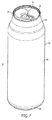
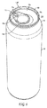
図を参照すると、パッケージ5などの容器パッケージが、飲料缶端部10及び缶体50を含む。例えば図15に示すような継ぎ合わせ前の構成の端部10は、外周のカール部12と、カール部12から半径方向内向き及び下向きに延びる、チャック壁とも呼ばれる壁部14と、壁部14の下端からなだらかに延びる、内向きに又は凹状に湾曲したパネル16とを含む。継ぎ合わせ後の端部及びいくつかの構成要素については、継ぎ合わせ後の端部10’及び継ぎ合わせ後のチャック壁14’のようにプライム記号を用いて示す。継ぎ合わせ前の端部及び継ぎ合わせ前の端部の構成要素の一部については、継ぎ合わせ前の端部10及びそのチャック壁14のようにプライム記号を含まない照合番号によって示す。後述するように、説明にとって好都合な場合には端部10の一部の構成要素を省略し、端部10の形成が終わるまでは、参照番号8及び9を用いてシェルを参照する。
Referring to the figure, a container package, such as package 5, includes a beverage can end 10 and a
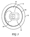
スコア線18は、タブ30による作動後に注ぎ口を形成する断裂パネル(tear panel)を形成する。缶端部技術の当業者であれば本開示に照らして理解するように、スコア線18は、従来の、ただし湾曲パネル16に適用できるような方法及び金型によって形成することができる。タブ30は、リベットアイランドにおける(好ましくは従来の)リベット20によってパネル16に取り付けられる。図示の実施形態では、タブ30が、パネル16とほぼ同じ曲率で湾曲する。タブ30は、開封中に断裂パネルに接触するノーズ32と、ユーザがタブを作動させるために把持するための対向するヒール36とを含む。
The
図5に示すように、スコア線18によって定められる注ぎ口は、開口部の対向する地点によって定められる傾斜線によって半径方向に測定した、好ましくは14mm〜19mmの、さらに好ましくは15mm〜17mmの直線寸法Pを有する。チャック壁の最も半径方向内側の部分とスコア線の最も外側の部分との間を水平に測定した間隙C(すなわち、スコア線とチャック壁との間の最小点又は最接近点)は、好ましくは0.6mm〜3.0mmであり、さらに好ましくは1.0mm〜2.0mmであり、好ましくは1.0mm〜1.4mmである。
As shown in FIG. 5, the spout defined by the
図5には、寸法DIAによって42mmの缶サイズを示しており、すなわち図5に示す端部の寸法DIAは42.0mmであり、これはネック部が延びる継ぎ目の内部に存在する壁部の外面上で測定した継ぎ合わせ後の端部の直径である。(水平に測定した)端部間のタブ長Tは、従来のタブ開封過程では最小に近い23.6mmであるが、本発明は、特許請求の範囲に明確に定めていない限りいかなるタブ寸法にも限定されるべきではない。タブヒールの最外点と継ぎ目60の壁部14’の底部との間には、ユーザがタブヒール36を使用するために指を差し込む間隙Fが傾斜直線によって定められる。指を差し込む距離Fは、好ましくは6mm〜15mmであり、さらに好ましくは6mm〜12mmであり、さらに好ましくは7mm〜10mmであり、図5では8mmである。図5の42mm端部について示す寸法は、好ましい実施形態を開示するものであり、これらの(限定ではないが、注ぎ口の寸法P、間隙寸法C、指を差し込む寸法F及びタブ長Tなどの)寸法は、42mm以外のサイズの端部にも適用することができると理解されたい。 FIG. 5 shows a can size of 42 mm by the dimension DIA, ie the dimension DIA of the end shown in FIG. 5 is 42.0 mm, which is the outer surface of the wall present inside the joint where the neck extends The diameter of the spliced end measured above. The tab length T between the ends (measured horizontally) is 23.6 mm, which is close to the minimum in the conventional tab opening process, but the invention does not limit the tab size to any tab size unless clearly defined in the claims. Nor should it be limited. Between the outermost point of the tab heel and the bottom of the wall 14 'of the joint 60, a gap F between which the user inserts a finger to use the tab heel 36 is defined by a straight line of inclination. The finger insertion distance F is preferably 6 mm to 15 mm, more preferably 6 mm to 12 mm, still more preferably 7 mm to 10 mm, and 8 mm in FIG. The dimensions shown for the 42 mm end of FIG. 5 disclose preferred embodiments and include (but are not limited to, the dimensions P of the spout, the dimension C of the gap, the dimension F of inserting the finger, the tab length T, etc. It should be understood that the dimensions can also be applied to ends of sizes other than 42 mm.
継ぎ合わせ前の端部10のパネル16は、好ましくは6mm〜12mmの、さらに好ましくは6mm〜10mmの、図示の実施形態では8mmのドーム深さDを定める。さらなる情報については表1に示す。図4Aに示すように、ドーム深さDは、カール部12の最上部からパネル16の中心の上側(或いは、中心にリベット16が位置する場合にはリベットに隣接する最下点)までを垂直に測定したものである。
The
図1に示す実施形態の缶体50は、ドーム型の基部52と一体型の側壁54とを有する絞りしごき加工(「DWI」)された缶体である。図8及び図9に示すように、基部52は、ドーム53と足部55とを含む。缶体50は、従来のDWI加工を用いて形成されることが好ましい。
The
側壁54の上端部からは、側壁54に対して直径が減少するネック部56が延びる。いくつかの実施形態では、パッケージ5のネック形成の程度を当業で周知の従来の12オンス飲料缶よりも大きくすることができると理解されたい。図15に示すように、継ぎ合わせ前の状態では、ネック部54がフランジ62で終端する。
From the upper end of the
好ましくは二重継ぎ目である継ぎ目60は、端部10と缶体50とを接合する。以下でさらに完全に説明するように、継ぎ合わせ後の状態では、カール部12の全部又は大部分が継ぎ目60を形成し、壁部14の全部又は大部分が継ぎ目60の内面を形成する。図8及び図9に示すように、継ぎ目60は、積み重ねを目的として缶の基部に挿入可能であることが好ましい。図8に示す容器パッケージは、従来の再形成された基部形状52を有する「スリム」缶50である。図8の端部10’は、基部52に内部から積み重なる42mm端部である。
A joint 60, preferably a double joint, joins the
図10に示すように、パッケージ5は、容器の液体内容物6と継ぎ目の頂部との間の鉛直高さHが10mm〜30mmであり、好ましくは14mmである。本発明は、特許請求の範囲に明確に示していない限り、寸法Hによって限定されるものではない。 As shown in FIG. 10, the package 5 has a vertical height H between the liquid content 6 of the container and the top of the joint 10 mm to 30 mm, preferably 14 mm. The invention is not limited by the dimension H, unless explicitly stated in the claims.
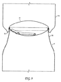
特に図1、図4A及び図4Bを参照すると、パネル16は、好ましくは上向きに開いた溝、或いは折れ曲がった又はz字形の溝などの補強構造を伴わずに、壁部14又は14’の底部からなだらかに延びる。全ての地点におけるパネル16の曲面の接線の傾きは、中心、又は傾きが負から正に変化するパネル位置を除いてゼロでないことが好ましい。従来の端部技術の当業者であれば本開示に照らして理解するように、本発明は、スコア線の伝播及びその他のパラメータを最適化するための周知の原理に従ってパネル内に形成された窪み及びビーズ(図示せず)を含む。本明細書で使用するドーム型、曲面又は凹状という用語は、このような構造を有するパネルも含むように意図される。
With particular reference to FIGS. 1, 4A and 4B, the
ドーム16の形状は、チャック壁に隣接する小さな半径から大きな中心半径までの一連の次第に増加する半径を有することが好ましい。この次第に増加するドーム半径は、曲面の深さを最小限に抑え、従って材料の使用量を最適化して浅いドーム深さを実現することができる。いくつかの構成では、この浅いドーム深さが、極薄材料で生じ得る絞り作業中の皺形成を伴わずに従来の金属成形加工を用いて端部の製造を容易に又は実現可能にすることができる。
The shape of the
図4A及び図4Bに示すように、42mmの端部サイズの例では、R1〜R4(すなわち、最も外側の半径から中心半径まで)の好ましい半径値が、1mm、13mm、34mm及び44mmである。本発明の実施形態をさらに定義するために、壁部14とパネル16との間の好ましい半径R1は、限定ではないが、(42mmサイズの端部又はその他のサイズでは)0.5mm〜4mm、好ましくは0.7mm〜2.0mmとすることができ、図示の42mmの実施形態では1.0mmとすることができる。R1は、7mm〜20mmの、好ましくは10mm〜16mmの、最も好ましくは約13mmの半径R2に融合する。R2は、28mm〜41mmの、好ましくは31mm〜37mmの、最も好ましくは約34mmの半径R3に融合する。半径R3は、好ましくは35mm〜55mmの、好ましくは40mm〜50mmの、最も好ましくは約44mmの中心ドーム半径R4に融合する。
As shown in FIGS. 4A and 4B, for the 42 mm end size example, the preferred radius values of R1 to R4 (i.e. from the outermost radius to the central radius) are 1 mm, 13 mm, 34 mm and 44 mm. In order to further define the embodiment of the present invention, the preferred radius R1 between the
上記の範囲の半径を有する缶端部は、42mmの端部サイズの好ましい実施形態のためのものである。缶端部は、38mm〜52mm又は40mm〜46mmの直径を有することもできる。さらに、本明細書に開示する端部構造の、端部直径と高さとの比率、及び継ぎ目寸法を含む一般的形状は、現在1リットルのビール缶に使用されている最大82mm直径の端部などのはるかに大きな端部で使用することもできる。本発明は、特許請求の範囲に示していない限り、特定の半径範囲又は範囲数に限定されるものではない。むしろ、ドームは、楕円とすることも、又は一連のスプラインによって形成することも、或いはその他の形状とすることもできると理解されたい。 A can end having a radius in the above range is for the preferred embodiment of 42 mm end size. The can end can also have a diameter of 38 mm to 52 mm or 40 mm to 46 mm. In addition, the general shape of the end structure disclosed herein, including the ratio of end diameter to height, and joint dimensions, is such as the end with a maximum of 82 mm diameter currently used for 1 liter beer cans, etc. It can also be used at the much larger end of The invention is not limited to any particular radius range or number of ranges unless indicated in the claims. Rather, it should be understood that the dome can be elliptical, or formed by a series of splines, or other shapes.
図14及び図24は、チャック壁14からパネル16の中心に向かって減少する好ましいR1、R2、R3及びR4の値を有する42mmサイズのカール部状のシェル形状(9)又は(10)の例示的な実施形態である。端部技術の当業者であれば理解するように、これらの特定の曲面は、46mm及び50mm端部などの他のサイズでは、本開示において説明する原理に素直に従って最適化することができる。
FIGS. 14 and 24 illustrate 42 mm sized curled shell shapes (9) or (10) with preferred R1, R2, R3 and R4 values decreasing from the
以下の表1に、有限要素解析の設計及び最適化の成果である、42mm、46mm及び50mm端部のいくつかのパラメータの値を示す。「制約」の値は、パッケージの水面上方の高さ(freeboard height)H及びドーム高さDなどのいくつかのパラメータを抑制する。「自由」の値は、解法に外的制約が適用されない最適化パラメータであり、従って本明細書に開示して特許請求する端部技術の改善の利点をより良好に反映する。

シェル厚は、5000系アルミニウム合金のミリメートル単位での開始寸法である。カットエッジ直径は、ミリメートル単位でのブランク直径である。質量は、カットエッジ直径を反映したシェルの質量である。ドーム高さは、本明細書で説明した寸法Dである。反転圧力は、ドーム型状が反転するPSI単位での計算圧力である。重量節減率(weight saving)は、Crown Cork & Seal社が「ISE」端部として市販している当業で周知の50mm端部と比べた百分率での金属重量の節減率である。シェル直径は、図5にDIAとして示すようなミリメートル単位での直径である。ドーム直径対高さは、本明細書の開示に従って形成される、本明細書に示すサイズよりも大きなサイズ及び小さなサイズの端部の割合に指針を与えるパラメータの比率である。従って、本発明者らは、缶端部の直径はドームの高さDの10倍未満であり、好ましくは高さDの4〜8倍であると推測する。 The shell thickness is the starting dimension in millimeters of 5000 series aluminum alloy. The cut edge diameter is the blank diameter in millimeters. The mass is the mass of the shell reflecting the cut edge diameter. The dome height is the dimension D described herein. Inversion pressure is the calculated pressure in PSI units where the dome shape is inverted. Weight saving is the percentage reduction in metal weight as compared to the 50 mm end well known in the art marketed by Crown Cork & Seal as the "ISE" end. The shell diameter is the diameter in millimeters as shown as DIA in FIG. Dome diameter to height is the ratio of parameters formed in accordance with the disclosure herein to provide the proportion of end portions of larger and smaller size than those shown herein. Thus, we estimate that the diameter of the can end is less than 10 times the height D of the dome, preferably 4 to 8 times the height D.
図6及び図7に、飲料缶端部10a’と缶体50とを含む完全開口容器パッケージ(full aperture container package)5Aの別の実施形態を示す。継ぎ目60、従ってカール部12及び壁部14は、第1の実施形態の缶端部10、10’について説明した通りである。従って、端部10a’に含まれるパネル16aには、壁部14’の基部に近接するパネル16aの外周部に沿ってスコア線18aが形成される。パネル16aには、リベット20aによってタブ30aが取り付けられる。図示の実施形態では、タブ30aがパネル16aとほぼ同じ曲率で湾曲することが好ましい。タブ30aは、開封中に断裂パネルに接触するノーズ32aと、ユーザがタブを作動させるために把持するための対向するヒール36aとを含む。
6 and 7 illustrate another embodiment of a full aperture container package 5A including a beverage can end 10a 'and a
タブ36aの好ましい最小長さT−aは、リング36aにリベット及び指を挿入できるように27mmである。従って、端部10a、10a’は、タブ36aの周囲に継ぎ合わせ金型のための間隙をもたらす30mmほどの小さな寸法にすることができる。
The preferred minimum length T a of the
缶体50は、第1の実施形態の容器パッケージ5について説明した通りである。また、パネル16aのドーム型状も、第1の実施形態の容器パッケージ5について説明した通りである。リベット20aがスコア線18a内に存在するので、タブ30aを作動させてパネル16aの外周に沿ってスコア線18aを完全に断裂させると、断裂パネルを容器パッケージ5aの残り部分から完全に取り除くことができる。このような構成は、完全開口端部と呼ばれる。
The
図11を参照すると、継ぎ目60は、端部10’の末端部によって形成された部分と、缶体フランジの末端部によって形成された部分とを含む。継ぎ目60を形成する端部の部分は、チャック壁14’と、継ぎ合わせパネル64と、継ぎ合わせ壁部66と、端部フック68と、カバーフック70とを含む。壁部14’と継ぎ合わせパネル64との間の接合部は、継ぎ合わせパネル半径SPRを定める。継ぎ合わせパネル64と継ぎ合わせ壁部66との間の接合部は、継ぎ合わせ壁部半径SWRを定める。継ぎ目60を形成する缶体の部分は、缶体壁部74と缶体フック76とを含む。缶体壁部74と缶体フック76との間の接合部は、缶体フック半径BHRを定める。
Referring to FIG. 11, the
壁部14’は、例えば図11及び図19に示すように、継ぎ合わせチャックの構成及び継ぎ合わせ工程に従って傾斜する。例えば、壁部14’は、継ぎ合わせ後の状態で1〜8°傾斜し、好ましくは約4°傾斜することができる。図15の継ぎ合わせ前の状態の壁部14は、完成した壁部14’をもたらすあらゆる形状又は構成とすることができ、好ましくは約4°である。
The wall portion 14 'is inclined in accordance with the configuration and the seaming process of the seaming chuck, as shown, for example, in FIGS. For example, the wall portion 14 'can be sloped 1 to 8 degrees, preferably approximately 4 degrees, in the spliced state. The
本発明の態様によれば、端部10の構造は、従来の飲料缶の二重継ぎ目よりも薄い材料の使用を可能にし、結果として小さな継ぎ目の使用を可能にする。この点、本発明者らは、缶フランジ材料の厚みよりも薄い又は同様の厚みの端部材料によって形成された二重継ぎ目を有する市販のアルミニウムパッケージを知らない。具体的に言えば、ドーム型の端部の厚みは、カール部の厚みよりも20%しか大きくなく、好ましくはカール部の厚みよりも10%未満しか大きくない。このコンパクトな形状の利点は、端部の継ぎ目半径が小さくなることによって加圧中に継ぎ目が適所に固定され、従って継ぎ目のほころびが防がれる点である。この材料は、非常に薄いのでほころびが生じやすく、従ってこの固定効果は歪み性能(buckle performance)にとって極めて重要である。
According to an aspect of the invention, the construction of the
カール部の厚みは、従来のあらゆるカール部の厚みよりも大幅に小さな0.16mmであることが好ましい。 The thickness of the curled portion is preferably 0.16 mm, which is significantly smaller than the thickness of any conventional curled portion.
さらに、継ぎ目の最上点から継ぎ目の中心線に沿って継ぎ目の最下点までを測定した継ぎ目の長さLは、2.2mm未満であることが好ましく、好ましい実施形態では約2.0mmである。壁部14’の外面及び継ぎ合わせ壁部66の外面の、継ぎ目の長手方向軸に垂直な最も広い地点で測定した継ぎ目の厚みSTは、好ましくは1.1mmを超えず、さらに好ましくは0.96mmを超えず、図示の実施形態では約0.85〜0.93mmである。継ぎ目の頂部において測定した、継ぎ合わせパネル半径SPR又は継ぎ合わせ壁部半径SWRに反映される端部継ぎ目の半径ESRは、好ましくは0.6mmを超えず、より好ましくは0.55mmを超えず、さらに好ましくは0.5mmを超えない。さらに、缶体フック76とカバーフック70との間の重なり寸法OLは0.65〜1.2mmであり、好ましくは約0.9mmである。 Furthermore, the length L of the seam, measured from the top of the seam to the lowest point of the seam along the centerline of the seam, is preferably less than 2.2 mm, and in the preferred embodiment is about 2.0 mm . The thickness ST of the seam measured at the widest point perpendicular to the longitudinal axis of the seam of the outer surface of the wall 14 'and the outer surface of the joint wall 66 preferably does not exceed 1.1 mm, more preferably 0. It does not exceed 96 mm, and in the illustrated embodiment is about 0.85 to 0.93 mm. The seam radius SPR measured at the top of the seam, or the radius ESR of the end seam reflected in the seam wall radius SWR preferably does not exceed 0.6 mm, more preferably 0.55 mm, More preferably, it does not exceed 0.5 mm. Furthermore, the overlap dimension OL between the can hook 76 and the cover hook 70 is 0.65 to 1.2 mm, preferably about 0.9 mm.
再び図15を参照すると、継ぎ合わせ前の端部10が、継ぎ合わせ工程の準備を整えて缶体50上の適所に存在する。この点、カール部12は、継ぎ合わせパネル80と周辺カール部82とを含み、端部継ぎ合わせパネル80がフランジ62の先端に接する。缶のネック部に近接するフランジとカール部との間の、好ましくはチャック壁14における最も狭い地点で測定した半径方向間隙RCは、少なくとも0.5mmである。寸法RC、及び本明細書で「半径方向」と呼ぶその他の寸法は、水平に測定したものである。
Referring again to FIG. 15, the
継ぎ合わせ前の端部10及び缶フランジ62の構成には、(先行技術と比べて)小さな継ぎ目寸法及び端部厚などの態様が反映される。フランジ幅FWは、容認できる継ぎ合わせに適した重なり寸法OLを形成するほど十分に大きい。フランジ幅FWは、ネック部56の垂直部分の内側からフランジの最も外側のリップ部63までを半径方向に測定したものであり、好ましくは1.8mmを超えず、さらに好ましくは1.6mmを超えず、好ましくは約1.5mmである。カール部構造の最も外側の地点と、カール部構造の継ぎ合わせパネルが端部のチャック壁の比較的真っ直ぐな部分をもたらすカール部上の地点との間で半径方向に水平に測定したカール部の幅寸法は、好ましくは3.5mm未満であり、さらに好ましくは3.0mm未満であり、図示の実施形態では、2.8mmである。測定を容易にするために、カール部の幅CWについては、カール部上の最も外側の地点からカール部12又は壁部14における端部の内面上の地点Pまでを半径方向に(すなわち、断面で見た時に水平に)測定することができる。
The configuration of the
カール部の高さCHは、フランジ幅FWよりも大きいことが好ましく、本発明者らは、この寸法関係は市販の飲料缶における従来の寸法関係に反すると考える。高さCHは、フランジ幅FWよりも少なくとも0.2mm大きいことが好ましく、少なくとも0.5mm大きいことがさらに好ましい。図示の実施形態では、カール部の高さが2.1mmである。フランジの最も外側の先端とカール部の最も内側の先端との間を水平に測定したカール部の間隙寸法CCは0.4〜1.2mmであり、好ましくは約0.5mmである。 The height CH of the curled portion is preferably greater than the flange width FW, and the inventors believe that this dimensional relationship is contrary to the conventional dimensional relationship in commercial beverage cans. The height CH is preferably at least 0.2 mm greater than the flange width FW, and more preferably at least 0.5 mm greater. In the illustrated embodiment, the height of the curled portion is 2.1 mm. The gap dimension CC of the curled portion measured horizontally between the outermost tip of the flange and the innermost tip of the curled portion is 0.4 to 1.2 mm, preferably about 0.5 mm.
図17及び図18に、端部10に係合して42mm端部の継ぎ目60を形成する継ぎ合わせチャック84を示す。図17には、第1の継ぎ合わせ作業時に後退した後の第1の継ぎ合わせロール86を示す。図18には、第2の継ぎ合わせ作業時に後退した後の第2の継ぎ合わせロール88を示す。図19は、継ぎ目60に係合した第2のロール88の断面図である。
17 and 18
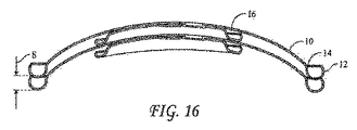
図16で最も良く分かるように、継ぎ合わせ前の端部10は、1.5〜3.0mmの、さらに好ましくは1.6〜2.2mmの、図示の実施形態では1.8mmの積み重ね高さSを有する。
As best seen in FIG. 16, the
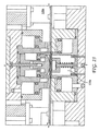
図20〜図24に示すように、シェルプレス100は、本明細書で説明した端部シェルを形成するためのツールパック110を含む。説明の便宜上、シート材料の移動に関連するもの、並びにツールパック110の移動及び位置合わせに関連するものなどのシェルプレス100の従来の部品はこの説明から省いており、シェルプレス技術の当業者であれば、ツールパック110及びシェル生産物の説明に基づいてこれらの部品を理解するであろう。端部10を形成するための金型及び工程の説明では、参照番号8は、シェルプレス100の生産物(すなわち、ドーム型シェル)を示し、参照番号9は、第1のカーリング作業後であって次の工程に入る前の完成したシェル(すなわち、カール部12、壁部14及びパネル16は有しているが、スコア線、リベット又はタブは含んでいない生産物)を示す。
As shown in FIGS. 20-24, the shell press 100 includes a
ツールパック110は、ドーム型パンチ120と、1対の圧力スリーブ130及び140と、上側スリーブ150と、ダイ中心リング160と、パンチスリーブ170と、圧力パッド180と、カットエッジ190と、ストリッパ固定具(stripper hold down tool)200とを含む。パンチ120は、パネル16の形状にほぼ一致して若干の弾性戻りを考慮するドーム型表面122を有する。図24に、計算されたシェル8の形状を示す。パンチ120の対向側には、内側圧力スリーブ130及び外側圧力スリーブ140が存在して、対応するパンチ120の部分124a及び124bの曲率及び配向に一致する接触面134及び144を有する。上側スリーブ150は、その最下端に凹状の接触面152を有する。ダイ中心リング160は、その最上端に凸状の接触面162を有する。
The
上側スリーブ150は、ダイ中心リング160と位置合わせされ、パンチ120と同心状である。ダイ中心リング160は、外側圧力スリーブ140と同心状である。パンチスリーブ170は、圧力パッド180と位置合わせされ、上側スリーブ150と同心状である。圧力パッド180は、下側スリーブ160と同心状である。
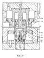
図20には、金属シートの挿入準備が整った開位置にあるツールパック110を示す。図21には、シートのあらゆる変形又は打ち抜き前の、ツールが金属シートに最初に接触する初期接触位置にあるツールパック110の上部を示す。ストリッパ固定具200は、シートに接触してカットエッジ190に逆らってシートの動きを防ぐように作用する。この位置では、パンチスリーブ170がシートに対して下降して、パンチスリーブ170とカットエッジ190とが係合することによってブランクを形成する。内側圧力スリーブ130及び外側圧力スリーブ140のばね136及び146は、静止位置又は予加重が加わった位置にある。
FIG. 20 shows the
図22には、パンチスリーブ170がカットエッジ190に対して下向きに移動して円形ブランクを形成することを示す。スリーブ150及び160の対向する接触面152及び162は、皺を減少させながら(延伸によって金属シートを薄肉化することとは区別して)ブランクを絞り加工できるように選択された力でブランクに係合する。パンチ120がシェルプレスの基部112に対して下向きに移動し、これによってブランクの裏面が内側圧力スリーブ134の接触面134に接触して、内側圧力スリーブ130の基部のばね136を圧縮するようになる。対向面134及び124aは、皺の形成を抑える力をブランクに加える。図22に示す段階では、外側圧力スリーブ140の最上部先端はブランクに接触することも、又はブランクから離間することもできるが、表面144全体は(好ましくは)未だブランクに係合しておらず、従って外側圧力スリーブばね146は、その静止位置から圧縮されていない。
FIG. 22 shows that the
図23には、パンチ120がそのストロークの最下位に来ることにより、圧力スリーブ接触面134及び144がいずれもブランクに接触して対応するばね力を加え、内側圧力スリーブのばね136が図22に示す状態に比べてさらに圧縮され、外側圧力スリーブのばね146が圧縮され、接触面152及び162に力が加わって、図24で最も良く分かるようにブランクの周辺部をシェル8の形に形成するようになる様子を示す。シェル8の外周は、上部圧力スリーブ150とダイ中心リング160との接触によって形成される湾曲構造11を有する。
In FIG. 23, with the punch 120 at the bottom of its stroke, the pressure sleeve contact surfaces 134 and 144 both contact the blank to apply a corresponding spring force and the inner
中心に開口部を有する内側圧力スリーブ130及び外側圧力スリーブ140は、端部の絞り加工中における皺の形成を抑えるのに役立つ圧縮力を与える。136及び146のばね力は、この目的に合わせて選択することもできるが、背景技術の節で説明した先行技術のドーム型成において行われるブランクの「コイニング加工」が可能なほど大きくないことが好ましい。内側圧力スリーブ130は、外側圧力スリーブ140とは無関係に上昇及び下降を行うように構成される。
The
これとは別に、本発明者らは、状況によっては(上述した2部品型圧力スリーブではなく)図25及び図26に示す単一の圧力スリーブ130aを用いて皺の形成を抑えることもできると推測する。さらに、本発明者らは、状況によってはシート又はブランクをシェルプレス110内に供給する前に予備成形部を形成することもできると推測する。図27及び図28に、周辺部に接触面121を有する中心予備成形パンチ119を含む予備成形プレス109を示す。パンチ119が下降すると、部分的絞り加工によってシート又はブランクが変形する。任意に、上述したスリーブ150及び160が部分的に又は完全に端部シェル11を形成することもできる。スコア線18を形成するためのスコアリング作業は、端部10’を形成する工程のあらゆる時点で実行することができる。
Apart from this, we can also suppress the formation of wrinkles using a
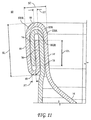
図12、図13及び図14に、シェルプレス100のシェル8をカーリング加工して完成シェルであるシェル9を形成し、これをその後にコンバージョンプレスによって端部10の形に形成する2段階カーリング工程を示す。
Referring to FIGS. 12, 13 and 14, the shell 8 of the shell press 100 is curled to form the shell 9 which is a finished shell, which is then formed into the shape of the
第1のカーリング工程のカーリング金型210Aは、上側圧力リング220aと、対向する下側圧力リング230aと、上側カーリング金型240とを含む。図12には、シェルプレス100の生産物であるシェル8を示しており、対応する上側圧力リング220aの凹状の接触面222aと下側圧力リング230aの凸状の接触面232aとの間にシェルのカール部形状11が保持される。準備位置に存在する上側カーリング金型240は、下向きに移動してシェルのカール部形状11に接触して予備カール部11’を形成するように構成される。図13には、第1の金型210Aからシェルが除去されて第2段階の金型に挿入される前の、第1段階の工程の終了を示す。
The curling mold 210A of the first curling process includes an upper pressure ring 220a, an opposing
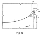
図14には、2つのカーリング加工のうちの第2の組を示す。この点、金型210Bは、上側圧力リング220bと、対向する下側圧力リング230bと、カーリング金型250とを含む。図13には、予備又は中間カール部11’を有することを含む第1のカーリング加工段階210Aの生産物である端部9を示す。準備位置に存在するカーリング金型250は、上向きに移動して、対応する上側圧力リング220bの凹状の接触面222bと下側圧力リング230bの凸状の接触面232bとの間に保持されることによって保持されている中間カール部11’に接触するように構成される。図14には、カーリング金型250がカール部12に係合してカール部12を形成した後に準備位置に後退した後の金型210Bを示す。シェル9は、金型210bから出力されるとコンバージョンプレスの準備が整っている。
FIG. 14 shows a second set of two curling processes. In this regard, the mold 210 B includes an upper pressure ring 220 b, an opposing lower pressure ring 230 b, and a curling
本明細書で説明した構成で形成された端部は、(平坦な中心パネル及び/又は皿穴溝を用いて形成された端部と比べて)ブランクサイズ及び/又は厚みが低減され、これによって端部の金属使用量の低減を可能にできるという利点を有することができる。上記の情報に加え、本発明者らは、Crown Cork & Seal社によって202サイズの202Superend(登録商標)缶端部として市販されているものなどの42mmシェルが対応する軽量端部として使用する材料重量を、たったの半分(約1.05g)程にすることができると予測する。さらに、図示の端部10は、壁部の近くに溝を有していないので注ぎ口を継ぎ目に近付けて構成することができ、状況によってはこれによって飲む過程及び/又は注ぐ過程を改善することができる。この端部は、90psiの内圧に耐える能力などの標準圧力定格にも十分に適している。
The ends formed in the configuration described herein have a reduced blank size and / or thickness (compared to the ends formed with a flat center panel and / or countersink), thereby It can have the advantage that it is possible to reduce the amount of metal used at the ends. In addition to the above information, we use the material weight that a 42 mm shell such as that marketed by Crown Cork & Seal as a 202-sized 202 Superend® can end will use as a corresponding lightweight end Is expected to be only about half (about 1.05 g). Furthermore, the
一例として、継ぎ合わせ後のパッケージ5の実施形態は、66mmサイズのDWI飲料缶50又は211サイズの缶体と継ぎ合わされた、本明細書で説明したような端部10’を含むことができる。このパッケージは、58mmサイズ又は204サイズ、及び53mmサイズ又は202サイズ缶体、並びに本明細書で参照したその他のサイズを含む。缶体サイズについての開示は、211缶、及びスリーク缶又はスリム缶とも呼ばれる缶を含む標準的な缶体サイズに対して特定の請求項を裏付けるべきであるため、本発明は、特許請求の範囲に明確に示していない限り缶体直径によって限定されるものではない。 As an example, the embodiment of the package 5 after seaming may include the end 10 'as described herein seamed with a 66 mm sized DWI beverage can 50 or 211 sized can. This package includes 58 mm size or 204 size, and 53 mm size or 202 size cans, as well as other sizes referenced herein. The present invention claims that the disclosure on can size should support specific claims against standard can sizes including 211 cans and cans also referred to as sleek cans or slim cans. It is not limited by the can diameter unless it is clearly indicated.
図29は、エアロゾル缶などの缶の基部端部10bの図である。従来アルミニウムのエアロゾル基部に使用されている材料は、厚みが0.34mm(0.0135インチ)のH19である。端部10bは、本明細書で説明した方法に従って形成することができる。端部10bは、本明細書に開示した金型及び方法を用いて形成することができる。
本発明は、本明細書に開示した特定の実施形態、又は特徴の組み合わせに限定されるものではない。限定的な意味ではなく一例として、ドーム型状は、特定の望ましいパラメータに従って選択することができる。これらの設計原理は、低炭酸清涼飲料又は食品容器などの、90psi定格を必要としない容器に使用して、端部材料が上述したものよりも薄い又は小さい直径となるようにすることもできる。 The present invention is not limited to the specific embodiments or combinations of features disclosed herein. By way of example and not limitation, the dome shape may be selected according to certain desired parameters. These design principles can also be used for containers that do not require a 90 psi rating, such as low carbonated soft drinks or food containers, such that the end material has a thinner or smaller diameter than those described above.
Claims (90)
缶体のフランジと共に継ぎ合わされるように適合されたカール部構造と、
前記カール部構造から半径方向内向きに延び、継ぎ合わせ工程中にチャックに接触するように適合されたチャック壁と、
前記チャック壁から半径方向内向きに内向きドーム状になったパネルと、
前記パネル上に形成されたスコア線と、
前記パネルに取り付けられて、ユーザによる作動に応答して前記スコア線を断裂させて注ぎ口を形成するように適合されたタブと、
を備えることを特徴とする缶端部。 A pre-joined can end formed of an aluminum alloy that can withstand an internal pressure of 90 psi after joining onto a can;
A curl structure adapted to be seamed with the flange of the can;
A chuck wall extending radially inward from the curled structure and adapted to contact the chuck during the joining process;
A radially inwardly facing dome-shaped panel from the chuck wall;
A score line formed on the panel;
A tab attached to the panel and adapted to rupture the score line to form a spout in response to actuation by a user;
A can end characterized by comprising.
請求項1に記載の缶端部。 The panel extends from the lower end of the chuck wall into the panel without a countersunk bead in between
The can end according to claim 1.
請求項2に記載の缶端部。 The diameter of the can end is less than 10 times the height of the dome at the center of the end,
The can end according to claim 2.
請求項2に記載の缶端部。 The diameter of the can end is 4 to 8 times the height of the dome at the center of the end,
The can end according to claim 2.
請求項4に記載の缶端部。 The can end is formed of an aluminum alloy having a thickness of less than 0.20 inches.
The can end part of Claim 4.
請求項4に記載の缶端部。 The can end is formed of an aluminum alloy having a thickness of less than 0.18 inches.
The can end part of Claim 4.
請求項4に記載の缶端部。 The can end is formed of an aluminum alloy having a thickness of less than 0.16 inches.
The can end part of Claim 4.
請求項2に記載の缶端部。 The can end has a stacking height S of 1.7 to 3.0 mm,
The can end according to claim 2.
請求項8に記載の缶端部。 The can end has a stacking height S of at least 1.8 mm,
The can end according to claim 8.
請求項2に記載の缶端部。 The curling structure is between the outermost point of the curling structure and a point on the curling where the seaming panel of the curling structure provides a relatively straight portion of the end chuck wall. Having a curl width of less than 3.5 mm when measured horizontally in the radial direction,
The can end according to claim 2.
請求項2に記載の缶端部。 The curling structure is between the outermost point of the curling structure and a point on the curling where the seaming panel of the curling structure provides a relatively straight portion of the end chuck wall. Having a curl width less than 3.0 mm when measured horizontally in the radial direction,
The can end according to claim 2.
請求項2に記載の缶端部。 The slope of the tangent of the curved surface defined by the can end is non-zero at all points except the chuck wall and the center of the dome-shaped panel.
The can end according to claim 2.
請求項2に記載の缶端部。 The can end is one of a beverage can end and a food can end.
The can end according to claim 2.
請求項2に記載の缶端部。 The cross section of the panel is formed by a plurality of radii which decrease with radial position from the center of the panel
The can end according to claim 2.
請求項2に記載の缶端部。 The radius R1 of the panel near the chuck wall inside the chuck wall is 0.5 mm to 2 mm, the radius R4 of the panel at the center of the panel is 35 mm to 55 mm, the diameter of the can end is 38-52 mm,
The can end according to claim 2.
請求項2に記載の缶端部。 The radius R1 of the panel closer to the chuck wall inside the chuck wall is 0.5 mm to 4 mm, the radius R2 of the panel closer to the radius R1 inside the radius R1 is 7 mm to 20 mm, the radius R The radius R3 of the panel close to the inner radius R2 is 28 mm to 41 mm, the radius R4 of the panel at the center of the panel is 35 mm to 55 mm, and the diameter of the can end is 38 to 52 mm.
The can end according to claim 2.
請求項16に記載の缶端部。 The radius R1 of the panel is 0.7 mm to 2.0 mm, the radius R2 of the panel is 10 mm to 16 mm, the radius R3 of the panel is 31 mm to 37 mm, and the radius R4 of the panel is 40 mm to 50 mm is there,
The can end according to claim 16.
請求項16に記載の缶端部。 The radius R1 of the panel is about 1.0 mm, the radius R2 of the panel is about 13 mm, the radius R3 of the panel is about 34 mm, and the radius R4 of the panel is about 44 mm.
The can end according to claim 16.
請求項2に記載の缶端部。 The panel has a diameter of 38 mm to 52 mm,
The can end according to claim 2.
請求項2に記載の缶端部。 The spout defined by the score line has a linear dimension of 14 mm to 19 mm, measured radially by an inclined line defined by the opposing point of the spout,
The can end according to claim 2.
請求項2に記載の缶端部。 The spout defined by the score line has a linear dimension of between 15 mm and 17 mm, measured radially by an inclined line defined by the opposite point of the spout,
The can end according to claim 2.
請求項2に記載の缶端部。 The horizontal gap defined between the innermost part of the chuck wall and the outermost part of the score line is 0.6 mm to 3.0 mm.
The can end according to claim 2.
請求項2に記載の缶端部。 The horizontal gap defined between the innermost part of the chuck wall and the outermost part of the score line is 1.0 mm to 2.0 mm.
The can end according to claim 2.
請求項2に記載の缶端部。 The horizontal gap defined between the innermost part of the chuck wall and the outermost part of the score line is 1.0 mm to 1.4 mm.
The can end according to claim 2.
請求項2に記載の缶端部。 The tab is concavely curved,
The can end according to claim 2.
請求項25に記載の缶端部。 The finger gap F measured on the bevel defined between the innermost part of the chuck wall and the most distal part of the tab heel is 6 mm to 15 mm.
26. The can end according to claim 25.
請求項25に記載の缶端部。 The finger gap F measured on the bevel defined between the innermost part of the chuck wall and the most distal part of the tab heel is 7 mm to 10 mm.
26. The can end according to claim 25.
請求項2に記載の缶端部。 The end before the joining has a panel depth of 5 mm to 16 mm,
The can end according to claim 2.
請求項2に記載の缶端部。 The end before seaming has a panel depth of 6 mm to 10 mm,
The can end according to claim 2.
請求項2に記載の缶端部。 The pre-sealing end has a panel depth of about 8 mm,
The can end according to claim 2.
請求項2に記載の缶端部。 The score line extends close to the wall and around the periphery of the panel, such that the end is a fully open end.
The can end according to claim 2.
請求項31に記載の缶端部。 The end is about 30 mm in size,
32. The can end according to claim 31.
基部と、側壁と、フランジとを含む、絞りしごき加工された缶体と、
継ぎ合わせ前の缶端部と、
を含み、前記缶端部は、
前記フランジに係合するカール部構造と、
前記カール部構造から半径方向内向きに延び、継ぎ合わせ工程中にチャックに接触するように適合されたチャック壁と、
前記チャック壁から半径方向内向きに内向きドーム状になったパネルと、
前記パネル上に形成されたスコア線と、
前記パネルに取り付けられて、ユーザによる作動に応答して前記スコア線を断裂させて注ぎ口を形成するように適合されたタブと、
を含む、
ことを特徴とする結合体。 A combination of the can end and the can before joining;
A drawn and ironed can comprising a base, side walls and a flange;
Can end before seaming,
The can end comprises:
A curl structure that engages the flange;
A chuck wall extending radially inward from the curled structure and adapted to contact the chuck during the joining process;
A radially inwardly facing dome-shaped panel from the chuck wall;
A score line formed on the panel;
A tab attached to the panel and adapted to rupture the score line to form a spout in response to actuation by a user;
including,
A combination characterized by
請求項33に記載の結合体。 The radial clearance between the flange and the curl adjacent to the can neck is at least 0.5 mm.
34. A conjugate according to claim 33.
請求項34に記載の結合体。 The gap is measured at the chuck wall at the end,
35. A conjugate according to claim 34.
請求項33に記載の結合体。 The thickness of the can end measured in the curled configuration is at least 10% smaller than the thickness of the flange,
34. A conjugate according to claim 33.
請求項33に記載の結合体。 The thickness of the can end measured in the curled configuration is at least 20% smaller than the thickness of the flange,
34. A conjugate according to claim 33.
請求項33に記載の結合体。 The width of the flange, measured radially from the inside of the vertical portion of the neck portion of the can to the outermost lip of the flange, is less than 1.8 mm,
34. A conjugate according to claim 33.
請求項38に記載の結合体。 The width of the flange is less than 1.6 mm,
39. The conjugate according to claim 38.
請求項38に記載の結合体。 The width of the flange is less than 1.5 mm,
39. The conjugate according to claim 38.
請求項33に記載の結合体。 The height of the curled portion is at least 0.5 mm greater than the width of the flange.
34. A conjugate according to claim 33.
請求項33に記載の結合体。 The height of the curled section is at least 0.2 mm greater than the width of the flange.
34. A conjugate according to claim 33.
請求項33に記載の結合体。 The height of the curled portion is greater than the width of the flange,
34. A conjugate according to claim 33.
請求項33に記載の結合体。 The curled gap dimension measured horizontally between the outermost tip of the flange and the innermost tip of the curled portion is 0.4 to 1.2 mm.
34. A conjugate according to claim 33.
請求項33に記載の結合体。 The panel extends from the lower end of the chuck wall into the panel without a countersunk bead in between
34. A conjugate according to claim 33.
請求項33に記載の結合体。 The diameter of the can end is less than 4 to 8 times the height of the panel at the center of the end,
34. A conjugate according to claim 33.
請求項33に記載の結合体。 The end has a stacking height S of at least 1.8 mm,
34. A conjugate according to claim 33.
請求項33に記載の結合体。 The combination is one of a beverage can package and a food can package.
34. A conjugate according to claim 33.
請求項33に記載の結合体。 The cross section of the panel is formed by a plurality of radii which decrease with radial position from the center of the panel
34. A conjugate according to claim 33.
請求項33に記載の結合体。 The can end has a diameter of 38 mm to 52 mm,
34. A conjugate according to claim 33.
請求項33に記載の結合体。 The can end is formed of a 5000 series aluminum alloy, and the can body is formed of a 3000 series aluminum alloy.
34. A conjugate according to claim 33.
基部と、側壁と、ネック部とを含む、絞りしごき加工された缶体と、
缶端部と、
を含み、前記缶端部は、
カール部構造から半径方向内向きに延び、継ぎ合わせ工程中にチャックに接触するように適合されたチャック壁と、
前記チャック壁から半径方向内向きに内向きドーム状になったパネルと、
前記パネル上に形成されたスコア線と、
前記パネルに取り付けられて、ユーザによる作動に応答して前記スコア線を断裂させて注ぎ口を形成するように適合されたタブと、
約2.2mm未満の継ぎ目高さを有する二重継ぎ目によって互いに接合された前記缶体の末端部及び前記缶端部の末端部と、
を含む、
ことを特徴とする容器。 A container for holding food,
A drawn and ironed can comprising a base, side walls and a neck;
With the can end,
The can end comprises:
A chuck wall extending radially inward from the curled structure and adapted to contact the chuck during the joining process;
A radially inwardly facing dome-shaped panel from the chuck wall;
A score line formed on the panel;
A tab attached to the panel and adapted to rupture the score line to form a spout in response to actuation by a user;
The end of the can and the end of the can end joined together by a double seam having a seam height of less than about 2.2 mm;
including,
A container characterized by
請求項52に記載容器。 The thickness of the end of the end does not exceed the thickness of the end of the can;
53. A container according to claim 52.
請求項52に記載の容器。 The thickness of the joint does not exceed 1.1 mm,
53. A container according to claim 52.
請求項52に記載の容器。 The thickness of the joint does not exceed 0.96 mm,
53. A container according to claim 52.
請求項52に記載の容器。 The thickness of the joint is 0.85 to 0.93 mm,
53. A container according to claim 52.
請求項52に記載の容器。 The length of the joint does not exceed 2.2 mm,
53. A container according to claim 52.
請求項52に記載の容器。 The joint length is about 2.0 mm,
53. A container according to claim 52.
請求項52に記載の容器。 The radius of the joint does not exceed 0.6 mm,
53. A container according to claim 52.
請求項52に記載の容器。 The radius of the joint does not exceed 0.55 mm,
53. A container according to claim 52.
請求項52に記載の容器。 The double joint comprises (i) a cover hook, an end hook, a seaming panel and a chuck wall of the end of the can, and (ii) a can wall and a can hook of the can end. The overlap between the can hook and the cover hook is 0.65 to 1.2 mm,
53. A container according to claim 52.
請求項61に記載の容器。 The overlap between the can hook and the cover hook is about 0.9 mm,
62. A container according to claim 61.
請求項52に記載の容器。 The panel extends from the lower end of the chuck wall into the panel without a countersunk bead in between
53. A container according to claim 52.
請求項52に記載の容器。 The diameter of the can end is less than 4 to 8 times the height of the panel at the center of the can end,
53. A container according to claim 52.
請求項52に記載の容器。 The can end is one of a beverage can end and a food can end.
53. A container according to claim 52.
請求項52に記載の容器。 The cross section of the panel is formed by a plurality of radii which decrease with radial position from the center of the panel
53. A container according to claim 52.
請求項52に記載の容器。 The can end has a diameter of 38 mm to 52 mm,
53. A container according to claim 52.
請求項52に記載の容器。 The can end is formed of a 5000 series aluminum alloy, and the can body is formed of a 3000 series aluminum alloy.
53. A container according to claim 52.
請求項52に記載の容器。 The vertical height at the center between the liquid content of the container and the back of the can end is 13 mm to 18 mm,
53. A container according to claim 52.
請求項52に記載の容器。 The vertical height between the liquid content of the container and the top of the seam of the can is 10 to 30 mm,
53. A container according to claim 52.
缶体と、
缶端部と、
を含み、前記缶端部は、
カール部構造から半径方向内向きに延び、継ぎ合わせ工程中にチャックに接触するように適合されたチャック壁と、
前記チャック壁から半径方向内向きに内向きドーム状になったパネルと、
約2.2mm未満の継ぎ目高さを有する二重継ぎ目によって互いに接合された前記缶体の末端部及び前記缶端部の末端部と、
を含む、
ことを特徴とする容器。 A container for holding food,
Can body,
With the can end,
The can end comprises:
A chuck wall extending radially inward from the curled structure and adapted to contact the chuck during the joining process;
A radially inwardly facing dome-shaped panel from the chuck wall;
The end of the can and the end of the can end joined together by a double seam having a seam height of less than about 2.2 mm;
including,
A container characterized by
請求項71に記載の容器。 The can end is formed of an aluminum alloy having a thickness of less than 0.20 inches.
72. A container according to claim 71.
請求項71に記載の容器。 The can end is formed of an aluminum alloy having a thickness of less than 0.18 inches.
72. A container according to claim 71.
請求項71に記載の容器。 The can end is formed of an aluminum alloy having a thickness of less than 0.16 inches.
72. A container according to claim 71.
(a)端部シェル金属ブランクの周辺部付近の凹面を有する上側スリーブと凸面を有する下側スリーブとの間で前記ブランクをクランプ固定するステップと、
(b)前記ブランクの上面をドーム型パンチに係合させ、該パンチをブランクに対して移動させることによって、前記ブランクを変形させるステップと、
(c)変形させるステップ(b)における前記ブランクの変形時に、前記ドーム型パンチの一部に向かい合う圧力スリーブアセンブリに前記ブランクの裏側を係合させるステップと、
を含み、
前記ステップ(b)及び(c)によって皺の形成に抵抗する、
ことを特徴とする方法。 A method of forming a can end shell capable of withstanding 85 psi after joining with a can, comprising:
(A) clamping the blank between an upper sleeve having a concave surface near the periphery of the end shell metal blank and a lower sleeve having a convex surface;
(B) deforming the blank by engaging the top surface of the blank with a dome shaped punch and moving the punch relative to the blank;
(C) engaging the back side of the blank with a pressure sleeve assembly facing a portion of the dome shaped punch during deformation of the blank in the deforming step (b);
Including
Resist formation of wrinkles by the steps (b) and (c),
A method characterized by
請求項75に記載の方法。 The pressure sleeve assembly of the engaging step (c) includes an outer pressure sleeve and an inner pressure sleeve, and in the engaging step (c), the inner pressure sleeve responds to relative movement by the punch Contact the back side of the blank, and the outer pressure sleeve contacts the back side of the blank after the inner pressure sleeve contacts the blank,
76. The method of claim 75.
請求項76に記載の方法。 The inner pressure sleeve has a contact surface shaped to match the shape of the opposing local portions of the dome shaped punch, and the outer pressure sleeve is a contact surface conforming to the shape of the opposing portion of the dome shaped punch Have
78. The method of claim 76.
請求項77に記載の方法。 The inner pressure sleeve and the outer pressure sleeve are associated with the inner pressure sleeve while the outer pressure sleeve remains relatively stationary and spaced from the blank during the first phase of the engaging step (c). Is pressed by the relative downward movement of the punch, and during the second phase of the engaging step (c), each of the inner and outer pressure sleeves contacts the back side of the blank Independently pressable such that each of the inner pressure sleeve and the outer pressure sleeve are pressed by the relative downward movement of the punch;
78. The method of claim 77.
請求項77に記載の方法。 Said clamping step (a) includes the step of forming a pre-curled portion near said periphery of said blank by a force exerted between said upper sleeve and said lower sleeve.
78. The method of claim 77.
請求項77に記載の方法。 Said clamping step (a) includes the step of forming a pre-curled portion near said periphery of said blank by a force exerted between said upper sleeve and said lower sleeve.
78. The method of claim 77.
請求項80に記載の方法。 Further comprising the step of curling the periphery of the blank to form a finished curl which can be spliced onto a can flange
81. The method of claim 80.
請求項77に記載の方法。 Conveying the dome-shaped shell to a curling press, wherein the curling press further comprises forming a pre-curled portion near the periphery of the blank by a force applied between an upper tool and a lower tool.
78. The method of claim 77.
請求項82に記載の方法。 Further including the step of curling the pre-curled portion by vertical movement of the curling die,
83. The method of claim 82.
請求項76に記載の方法。 The metal blank is formed of a 5000 series aluminum alloy.
78. The method of claim 76.
中心ドーム型パンチと、
前記ドーム型パンチの一部の反対側に位置する圧力スリーブアセンブリであって、前記ドーム型パンチの対応する対向部分に一致する接触面を有し、前記圧力スリーブの前記接触面と前記ドーム型パンチの前記対応する対向部分とが、前記ドーム型パンチの下向きの移動に応答して金属ブランクをドーム状に変形させるように適合されるように、前記ドーム型パンチの移動に応答して移動するように適合された、圧力スリーブアセンブリと、
前記ドーム型パンチの外側に同心状に位置して凹状の接触面を有する上側スリーブと、
前記圧力スリーブの外側に同心状に位置して凸状の接触面を有する下側スリーブであって、前記下側スリーブの接触面及び前記上側スリーブの接触面が、前記ブランクの周辺部の一部をカーリング加工するように適合された、下側スリーブと、
前記上側スリーブの外側に同心状に位置するパンチスリーブと、
前記下側スリーブの外側に同心状に位置する圧力パッドと、
を備えることを特徴とするシェルプレス。 A shell press for forming a can end shell capable of withstanding 85 psi after joining with a can,
With a central dome shaped punch,
A pressure sleeve assembly located opposite a portion of the dome shaped punch, having contact surfaces corresponding to corresponding opposite portions of the dome shaped punch, the contact surface of the pressure sleeve and the dome shaped punch Said corresponding opposing portion of said moving in response to the movement of said dome shaped punch so as to be adapted to deform the metal blank in a dome shape in response to the downward movement of said dome shaped punch Fitted with a pressure sleeve assembly,
An upper sleeve concentrically located on the outside of the dome shaped punch and having a concave contact surface;
A lower sleeve concentrically located on the outside of the pressure sleeve and having a convex contact surface, the contact surface of the lower sleeve and the contact surface of the upper sleeve being part of the periphery of the blank A lower sleeve, adapted to curling the
A punch sleeve concentrically located on the outside of the upper sleeve;
A pressure pad located concentrically on the outside of the lower sleeve;
Shell press characterized by having.
請求項85に記載のシェルプレス。 The pressure sleeve assembly includes an outer pressure sleeve and an inner pressure sleeve, the inner pressure sleeve being concentrically located inside the outer pressure sleeve, and the inner pressure sleeve being the corresponding opposite of the dome shaped punch A contact surface coinciding with a portion, the outer pressure sleeve having a contact surface coincident with a corresponding opposing portion of the dome shaped punch;
86. The shell press of claim 85.
請求項86に記載のシェルプレス。 The inner pressure sleeve and the outer pressure sleeve are each movable downward in response to the downward movement of the dome shaped punch, and the inner pressure sleeve and the outer pressure sleeve are independently movable downward. Is
87. A shell press according to claim 86.
請求項86に記載のシェルプレス。 The inner pressure sleeve and the outer pressure sleeve are configured such that the inner pressure sleeve contacts the deformed portion of the blank before the outer pressure contacts the deformed portion of the blank.
87. A shell press according to claim 86.
請求項86に記載のシェルプレス。 The shell press is adapted to form a can end shell from a 5000 series aluminum alloy blank without significant defects.
87. A shell press according to claim 86.
請求項86に記載のシェルプレス。 The punch sleeve and the lower pressure pad are further adapted to move vertically with respect to the punching die to cut the blank from the metal sheet, the punching sleeve and the lower pressure pad being arranged concentrically on the outside of the pressure pad To be
87. A shell press according to claim 86.
Applications Claiming Priority (3)
| Application Number | Priority Date | Filing Date | Title |
|---|---|---|---|
| US201662301128P | 2016-02-29 | 2016-02-29 | |
| US62/301,128 | 2016-02-29 | ||
| PCT/US2017/020024 WO2017151667A1 (en) | 2016-02-29 | 2017-02-28 | Concave can end |
Publications (2)
| Publication Number | Publication Date |
|---|---|
| JP2019508333A true JP2019508333A (en) | 2019-03-28 |
| JP2019508333A5 JP2019508333A5 (en) | 2020-04-09 |
Family
ID=58266218
Family Applications (1)
| Application Number | Title | Priority Date | Filing Date |
|---|---|---|---|
| JP2018545440A Abandoned JP2019508333A (en) | 2016-02-29 | 2017-02-28 | Recessed can end |
Country Status (14)
| Country | Link |
|---|---|
| US (1) | US10850888B2 (en) |
| EP (2) | EP3647217B1 (en) |
| JP (1) | JP2019508333A (en) |
| KR (1) | KR20180117140A (en) |
| CN (1) | CN108778939B (en) |
| AU (1) | AU2017227595A1 (en) |
| BR (1) | BR112018067364A2 (en) |
| CA (1) | CA3016212A1 (en) |
| CO (1) | CO2018010001A2 (en) |
| MX (1) | MX2018009877A (en) |
| PL (2) | PL3647217T3 (en) |
| RU (1) | RU2731858C2 (en) |
| SG (1) | SG11201806776QA (en) |
| WO (1) | WO2017151667A1 (en) |
Families Citing this family (8)
| Publication number | Priority date | Publication date | Assignee | Title |
|---|---|---|---|---|
| DE102016112953A1 (en) * | 2016-07-14 | 2018-01-18 | Gregor Anton Piech | Metallic box and associated can lid |
| USD867147S1 (en) * | 2017-06-29 | 2019-11-19 | Pepsico, Inc. | Container |
| USD946405S1 (en) | 2019-03-20 | 2022-03-22 | Ball Corporation | Metal food container |
| WO2020204688A1 (en) * | 2019-03-29 | 2020-10-08 | E6Pr, S.A.P.I. De C.V. | System for assembling an edible multi-ring can holder |
| CA3148034A1 (en) * | 2019-07-29 | 2021-02-04 | Ball Corporation | Domed container with nitrogen well and closure mechanism |
| USD982458S1 (en) | 2019-10-24 | 2023-04-04 | Ball Corporation | Metal food container |
| WO2021080612A1 (en) * | 2019-10-25 | 2021-04-29 | Silgan Containers Llc | Laminated can sealant |
| JP2023525310A (en) * | 2020-05-11 | 2023-06-15 | ストール マシーナリ カンパニー,エルエルシー | Ecology tabs, can ends, tooling and methods |
Family Cites Families (31)
| Publication number | Priority date | Publication date | Assignee | Title |
|---|---|---|---|---|
| US2971671A (en) * | 1956-10-31 | 1961-02-14 | Pabst Brewing Co | Container |
| US3394837A (en) * | 1966-09-06 | 1968-07-30 | Douglas R. Hansen | Container opening means |
| US3448887A (en) * | 1967-12-12 | 1969-06-10 | Joseph A Geiger | Container with easy-opening device |
| US3730383A (en) | 1971-07-29 | 1973-05-01 | Aluminum Co Of America | Container body and a method of forming the same |
| ZA807387B (en) * | 1979-12-08 | 1981-11-25 | Metal Box Co Ltd | Containers |
| US4516420A (en) | 1983-06-10 | 1985-05-14 | Redicon Corporation | Shell tooling |
| JPS5984734A (en) * | 1982-10-26 | 1984-05-16 | 日本製罐株式会社 | Can and its manufacture |
| US4458469A (en) * | 1983-04-25 | 1984-07-10 | Sonoco Products Company | Container with vacuum accommodating end |
| US4549424A (en) | 1983-06-10 | 1985-10-29 | Redicon Corporation | Shell tooling method |
| US4680917A (en) * | 1984-08-17 | 1987-07-21 | International Paper Company | Process for providing filled containers |
| US5149238A (en) * | 1991-01-30 | 1992-09-22 | The Stolle Corporation | Pressure resistant sheet metal end closure |
| US5344662A (en) * | 1993-03-03 | 1994-09-06 | The Procter & Gamble Company | Pressurized package containing a particulate product employing a product separator to contain the product during opening |
| US5535911A (en) * | 1994-08-29 | 1996-07-16 | Cortez; Alejandro | Opening device for cans |
| FR2735749B1 (en) * | 1995-06-22 | 1997-08-29 | Metal Box Plc | METAL BOX WITH PARTIAL OPENING, METHOD AND MACHINE FOR MANUFACTURING SUCH A BOX |
| US5804237A (en) | 1995-10-16 | 1998-09-08 | George B. Diamond | Method of and package for sterilized edible material |
| US6126034A (en) * | 1998-02-17 | 2000-10-03 | Alcan Aluminum Corporation | Lightweight metal beverage container |
| RU2156215C1 (en) | 1999-01-26 | 2000-09-20 | Иванов Александр Васильевич | Container for drinks |
| US6375029B2 (en) * | 1999-04-19 | 2002-04-23 | Alcoa Inc. | Easy-open misting container |
| US6561004B1 (en) | 1999-12-08 | 2003-05-13 | Metal Container Corporation | Can lid closure and method of joining a can lid closure to a can body |
| JP2004524229A (en) | 2001-02-26 | 2004-08-12 | ボール コーポレイション | Beverage can with reinforced beads extending outward |
| US7644833B2 (en) | 2001-08-16 | 2010-01-12 | Rexam Beverage Can Company | Can end |
| US7107928B2 (en) * | 2003-05-12 | 2006-09-19 | Ball Corporation | Selectively deformable container end closure |
| US8191726B2 (en) * | 2006-07-20 | 2012-06-05 | Crown Packaging Technology, Inc. | Can end having curved end panel surfaces |
| ES2513828T3 (en) * | 2009-11-12 | 2014-10-27 | Ardagh Mp Group Netherlands B.V. | A panel for a container, a container provided with said container and a method for manufacturing them |
| US8973777B2 (en) * | 2010-01-12 | 2015-03-10 | Crown Packaging Technology, Inc. | Beverage can with disc |
| US20120199587A1 (en) * | 2011-02-09 | 2012-08-09 | Kirk Norris | Beverage Containers, And Tabs And Lids For Use With Beverage Containers |
| GB201118284D0 (en) | 2011-10-21 | 2011-12-07 | Crown Packaging Technology Inc | Can end |
| BR112014025391B8 (en) * | 2012-04-13 | 2020-12-08 | Crown Packaging Technology Inc | can end and can set |
| US9821928B2 (en) * | 2012-05-14 | 2017-11-21 | Rexam Beverage Can Company | Can end |
| WO2013177550A1 (en) * | 2012-05-25 | 2013-11-28 | Boston Beer Corporation | Beverage delivery can |
| MX366126B (en) * | 2013-03-15 | 2019-06-27 | Crown Packaging Technology Inc | Necked beverage can having a seamed-on end. |
-
2017
- 2017-02-28 BR BR112018067364A patent/BR112018067364A2/en not_active IP Right Cessation
- 2017-02-28 AU AU2017227595A patent/AU2017227595A1/en not_active Abandoned
- 2017-02-28 WO PCT/US2017/020024 patent/WO2017151667A1/en active Application Filing
- 2017-02-28 EP EP19209851.5A patent/EP3647217B1/en active Active
- 2017-02-28 MX MX2018009877A patent/MX2018009877A/en unknown
- 2017-02-28 PL PL19209851.5T patent/PL3647217T3/en unknown
- 2017-02-28 CN CN201780014142.5A patent/CN108778939B/en active Active
- 2017-02-28 PL PL17710107T patent/PL3423366T3/en unknown
- 2017-02-28 US US15/445,709 patent/US10850888B2/en active Active
- 2017-02-28 JP JP2018545440A patent/JP2019508333A/en not_active Abandoned
- 2017-02-28 KR KR1020187027533A patent/KR20180117140A/en unknown
- 2017-02-28 SG SG11201806776QA patent/SG11201806776QA/en unknown
- 2017-02-28 RU RU2018134196A patent/RU2731858C2/en not_active IP Right Cessation
- 2017-02-28 CA CA3016212A patent/CA3016212A1/en not_active Abandoned
- 2017-02-28 EP EP17710107.8A patent/EP3423366B1/en active Active
-
2018
- 2018-09-21 CO CONC2018/0010001A patent/CO2018010001A2/en unknown
Also Published As
| Publication number | Publication date |
|---|---|
| PL3647217T3 (en) | 2022-11-28 |
| RU2731858C2 (en) | 2020-09-08 |
| EP3423366B1 (en) | 2019-11-20 |
| EP3647217A1 (en) | 2020-05-06 |
| RU2018134196A (en) | 2020-04-01 |
| CN108778939B (en) | 2021-05-25 |
| WO2017151667A1 (en) | 2017-09-08 |
| EP3423366A1 (en) | 2019-01-09 |
| CO2018010001A2 (en) | 2018-09-28 |
| US20170253371A1 (en) | 2017-09-07 |
| KR20180117140A (en) | 2018-10-26 |
| CA3016212A1 (en) | 2017-09-08 |
| SG11201806776QA (en) | 2018-09-27 |
| RU2018134196A3 (en) | 2020-07-10 |
| BR112018067364A2 (en) | 2019-01-15 |
| PL3423366T3 (en) | 2020-06-15 |
| US10850888B2 (en) | 2020-12-01 |
| EP3647217B1 (en) | 2022-08-03 |
| MX2018009877A (en) | 2018-09-11 |
| CN108778939A (en) | 2018-11-09 |
| AU2017227595A1 (en) | 2018-08-23 |
Similar Documents
| Publication | Publication Date | Title |
|---|---|---|
| JP2019508333A (en) | Recessed can end | |
| US20220063864A1 (en) | Can end | |
| US10486852B2 (en) | Can end produced from downgauged blank | |
| AU2002347836B2 (en) | Reformed can end and method therefore | |
| US7174762B2 (en) | Can end | |
| KR100862404B1 (en) | Can end member | |
| EP1857196A2 (en) | Can end for a container | |
| JP2019508333A5 (en) | ||
| JP6576047B2 (en) | Can lid |
Legal Events
| Date | Code | Title | Description |
|---|---|---|---|
| A521 | Request for written amendment filed |
Free format text: JAPANESE INTERMEDIATE CODE: A523 Effective date: 20181031 |
|
| A521 | Request for written amendment filed |
Free format text: JAPANESE INTERMEDIATE CODE: A523 Effective date: 20200302 |
|
| A621 | Written request for application examination |
Free format text: JAPANESE INTERMEDIATE CODE: A621 Effective date: 20200302 |
|
| A762 | Written abandonment of application |
Free format text: JAPANESE INTERMEDIATE CODE: A762 Effective date: 20201222 |