CN108778939B - Concave can end - Google Patents
Concave can end Download PDFInfo
- Publication number
- CN108778939B CN108778939B CN201780014142.5A CN201780014142A CN108778939B CN 108778939 B CN108778939 B CN 108778939B CN 201780014142 A CN201780014142 A CN 201780014142A CN 108778939 B CN108778939 B CN 108778939B
- Authority
- CN
- China
- Prior art keywords
- panel
- chuck wall
- container
- punch
- sleeve
- Prior art date
- Legal status (The legal status is an assumption and is not a legal conclusion. Google has not performed a legal analysis and makes no representation as to the accuracy of the status listed.)
- Active
Links
Images


Classifications
-
- B—PERFORMING OPERATIONS; TRANSPORTING
- B65—CONVEYING; PACKING; STORING; HANDLING THIN OR FILAMENTARY MATERIAL
- B65D—CONTAINERS FOR STORAGE OR TRANSPORT OF ARTICLES OR MATERIALS, e.g. BAGS, BARRELS, BOTTLES, BOXES, CANS, CARTONS, CRATES, DRUMS, JARS, TANKS, HOPPERS, FORWARDING CONTAINERS; ACCESSORIES, CLOSURES, OR FITTINGS THEREFOR; PACKAGING ELEMENTS; PACKAGES
- B65D17/00—Rigid or semi-rigid containers specially constructed to be opened by cutting or piercing, or by tearing of frangible members or portions
- B65D17/02—Rigid or semi-rigid containers specially constructed to be opened by cutting or piercing, or by tearing of frangible members or portions of curved cross-section, e.g. cans of circular or elliptical cross-section
-
- B—PERFORMING OPERATIONS; TRANSPORTING
- B21—MECHANICAL METAL-WORKING WITHOUT ESSENTIALLY REMOVING MATERIAL; PUNCHING METAL
- B21D—WORKING OR PROCESSING OF SHEET METAL OR METAL TUBES, RODS OR PROFILES WITHOUT ESSENTIALLY REMOVING MATERIAL; PUNCHING METAL
- B21D22/00—Shaping without cutting, by stamping, spinning, or deep-drawing
- B21D22/20—Deep-drawing
- B21D22/22—Deep-drawing with devices for holding the edge of the blanks
-
- B—PERFORMING OPERATIONS; TRANSPORTING
- B21—MECHANICAL METAL-WORKING WITHOUT ESSENTIALLY REMOVING MATERIAL; PUNCHING METAL
- B21D—WORKING OR PROCESSING OF SHEET METAL OR METAL TUBES, RODS OR PROFILES WITHOUT ESSENTIALLY REMOVING MATERIAL; PUNCHING METAL
- B21D51/00—Making hollow objects
- B21D51/16—Making hollow objects characterised by the use of the objects
- B21D51/26—Making hollow objects characterised by the use of the objects cans or tins; Closing same in a permanent manner
- B21D51/2615—Edge treatment of cans or tins
- B21D51/2623—Curling
-
- B—PERFORMING OPERATIONS; TRANSPORTING
- B21—MECHANICAL METAL-WORKING WITHOUT ESSENTIALLY REMOVING MATERIAL; PUNCHING METAL
- B21D—WORKING OR PROCESSING OF SHEET METAL OR METAL TUBES, RODS OR PROFILES WITHOUT ESSENTIALLY REMOVING MATERIAL; PUNCHING METAL
- B21D51/00—Making hollow objects
- B21D51/16—Making hollow objects characterised by the use of the objects
- B21D51/26—Making hollow objects characterised by the use of the objects cans or tins; Closing same in a permanent manner
- B21D51/2653—Methods or machines for closing cans by applying caps or bottoms
- B21D51/2661—Sealing or closing means therefor
-
- B—PERFORMING OPERATIONS; TRANSPORTING
- B21—MECHANICAL METAL-WORKING WITHOUT ESSENTIALLY REMOVING MATERIAL; PUNCHING METAL
- B21D—WORKING OR PROCESSING OF SHEET METAL OR METAL TUBES, RODS OR PROFILES WITHOUT ESSENTIALLY REMOVING MATERIAL; PUNCHING METAL
- B21D51/00—Making hollow objects
- B21D51/16—Making hollow objects characterised by the use of the objects
- B21D51/26—Making hollow objects characterised by the use of the objects cans or tins; Closing same in a permanent manner
- B21D51/30—Folding the circumferential seam
- B21D51/32—Folding the circumferential seam by rolling
-
- B—PERFORMING OPERATIONS; TRANSPORTING
- B21—MECHANICAL METAL-WORKING WITHOUT ESSENTIALLY REMOVING MATERIAL; PUNCHING METAL
- B21D—WORKING OR PROCESSING OF SHEET METAL OR METAL TUBES, RODS OR PROFILES WITHOUT ESSENTIALLY REMOVING MATERIAL; PUNCHING METAL
- B21D51/00—Making hollow objects
- B21D51/16—Making hollow objects characterised by the use of the objects
- B21D51/38—Making inlet or outlet arrangements of cans, tins, baths, bottles, or other vessels; Making can ends; Making closures
- B21D51/383—Making inlet or outlet arrangements of cans, tins, baths, bottles, or other vessels; Making can ends; Making closures scoring lines, tear strips or pulling tabs
-
- B—PERFORMING OPERATIONS; TRANSPORTING
- B21—MECHANICAL METAL-WORKING WITHOUT ESSENTIALLY REMOVING MATERIAL; PUNCHING METAL
- B21D—WORKING OR PROCESSING OF SHEET METAL OR METAL TUBES, RODS OR PROFILES WITHOUT ESSENTIALLY REMOVING MATERIAL; PUNCHING METAL
- B21D51/00—Making hollow objects
- B21D51/16—Making hollow objects characterised by the use of the objects
- B21D51/38—Making inlet or outlet arrangements of cans, tins, baths, bottles, or other vessels; Making can ends; Making closures
- B21D51/44—Making closures, e.g. caps
-
- B—PERFORMING OPERATIONS; TRANSPORTING
- B65—CONVEYING; PACKING; STORING; HANDLING THIN OR FILAMENTARY MATERIAL
- B65D—CONTAINERS FOR STORAGE OR TRANSPORT OF ARTICLES OR MATERIALS, e.g. BAGS, BARRELS, BOTTLES, BOXES, CANS, CARTONS, CRATES, DRUMS, JARS, TANKS, HOPPERS, FORWARDING CONTAINERS; ACCESSORIES, CLOSURES, OR FITTINGS THEREFOR; PACKAGING ELEMENTS; PACKAGES
- B65D1/00—Containers having bodies formed in one piece, e.g. by casting metallic material, by moulding plastics, by blowing vitreous material, by throwing ceramic material, by moulding pulped fibrous material, by deep-drawing operations performed on sheet material
- B65D1/12—Cans, casks, barrels, or drums
- B65D1/14—Cans, casks, barrels, or drums characterised by shape
- B65D1/16—Cans, casks, barrels, or drums characterised by shape of curved cross-section, e.g. cylindrical
- B65D1/165—Cylindrical cans
-
- B—PERFORMING OPERATIONS; TRANSPORTING
- B65—CONVEYING; PACKING; STORING; HANDLING THIN OR FILAMENTARY MATERIAL
- B65D—CONTAINERS FOR STORAGE OR TRANSPORT OF ARTICLES OR MATERIALS, e.g. BAGS, BARRELS, BOTTLES, BOXES, CANS, CARTONS, CRATES, DRUMS, JARS, TANKS, HOPPERS, FORWARDING CONTAINERS; ACCESSORIES, CLOSURES, OR FITTINGS THEREFOR; PACKAGING ELEMENTS; PACKAGES
- B65D1/00—Containers having bodies formed in one piece, e.g. by casting metallic material, by moulding plastics, by blowing vitreous material, by throwing ceramic material, by moulding pulped fibrous material, by deep-drawing operations performed on sheet material
- B65D1/12—Cans, casks, barrels, or drums
- B65D1/20—Cans, casks, barrels, or drums characterised by location or arrangement of filling or discharge apertures
-
- B—PERFORMING OPERATIONS; TRANSPORTING
- B65—CONVEYING; PACKING; STORING; HANDLING THIN OR FILAMENTARY MATERIAL
- B65D—CONTAINERS FOR STORAGE OR TRANSPORT OF ARTICLES OR MATERIALS, e.g. BAGS, BARRELS, BOTTLES, BOXES, CANS, CARTONS, CRATES, DRUMS, JARS, TANKS, HOPPERS, FORWARDING CONTAINERS; ACCESSORIES, CLOSURES, OR FITTINGS THEREFOR; PACKAGING ELEMENTS; PACKAGES
- B65D17/00—Rigid or semi-rigid containers specially constructed to be opened by cutting or piercing, or by tearing of frangible members or portions
- B65D17/28—Rigid or semi-rigid containers specially constructed to be opened by cutting or piercing, or by tearing of frangible members or portions at lines or points of weakness
- B65D17/401—Rigid or semi-rigid containers specially constructed to be opened by cutting or piercing, or by tearing of frangible members or portions at lines or points of weakness characterised by having the line of weakness provided in an end wall
- B65D17/4012—Rigid or semi-rigid containers specially constructed to be opened by cutting or piercing, or by tearing of frangible members or portions at lines or points of weakness characterised by having the line of weakness provided in an end wall for opening partially by means of a tearing tab
-
- B—PERFORMING OPERATIONS; TRANSPORTING
- B65—CONVEYING; PACKING; STORING; HANDLING THIN OR FILAMENTARY MATERIAL
- B65D—CONTAINERS FOR STORAGE OR TRANSPORT OF ARTICLES OR MATERIALS, e.g. BAGS, BARRELS, BOTTLES, BOXES, CANS, CARTONS, CRATES, DRUMS, JARS, TANKS, HOPPERS, FORWARDING CONTAINERS; ACCESSORIES, CLOSURES, OR FITTINGS THEREFOR; PACKAGING ELEMENTS; PACKAGES
- B65D7/00—Containers having bodies formed by interconnecting or uniting two or more rigid, or substantially rigid, components made wholly or mainly of metal
- B65D7/12—Containers having bodies formed by interconnecting or uniting two or more rigid, or substantially rigid, components made wholly or mainly of metal characterised by wall construction or by connections between walls
- B65D7/34—Containers having bodies formed by interconnecting or uniting two or more rigid, or substantially rigid, components made wholly or mainly of metal characterised by wall construction or by connections between walls with permanent connections between walls
- B65D7/36—Containers having bodies formed by interconnecting or uniting two or more rigid, or substantially rigid, components made wholly or mainly of metal characterised by wall construction or by connections between walls with permanent connections between walls formed by rolling, or by rolling and pressing
-
- B—PERFORMING OPERATIONS; TRANSPORTING
- B65—CONVEYING; PACKING; STORING; HANDLING THIN OR FILAMENTARY MATERIAL
- B65D—CONTAINERS FOR STORAGE OR TRANSPORT OF ARTICLES OR MATERIALS, e.g. BAGS, BARRELS, BOTTLES, BOXES, CANS, CARTONS, CRATES, DRUMS, JARS, TANKS, HOPPERS, FORWARDING CONTAINERS; ACCESSORIES, CLOSURES, OR FITTINGS THEREFOR; PACKAGING ELEMENTS; PACKAGES
- B65D2517/00—Containers specially constructed to be opened by cutting, piercing or tearing of wall portions, e.g. preserving cans or tins
- B65D2517/0001—Details
- B65D2517/001—Action for opening container
- B65D2517/0014—Action for opening container pivot tab and push-down tear panel
Landscapes
- Engineering & Computer Science (AREA)
- Mechanical Engineering (AREA)
- Ceramic Engineering (AREA)
- Rigid Containers With Two Or More Constituent Elements (AREA)
- Containers Having Bodies Formed In One Piece (AREA)
- Containers Opened By Tearing Frangible Portions (AREA)
- Details Of Rigid Or Semi-Rigid Containers (AREA)
- Closures For Containers (AREA)
- Medicinal Preparation (AREA)
Abstract
A container can end (10) includes a domed central panel (16) which is concave on the tab (30) attachment side and may forego a reinforcing bead around the periphery of the central panel. The tab (30) may also be curved. A tool and corresponding method for forming an end portion are provided.
Description
Cross Reference to Related Applications
The present invention is claimed to be entitled to united states provisional application serial No. 62/301128 filed on 29/2/2016, the disclosure of which is hereby incorporated by reference as if set forth herein in its entirety.
Background
Commercial cans, such as those used to hold food, beverages, or products dispensed as aerosols, may be of a "two-piece" or "three-piece" construction. Conventional two-piece cans include a one-piece can body formed by a drawing and ironing process, also known as drawing and wall ironing ("DWI"). The DWI process draws a metal blank into a cup shape and then pushes the cup through a series of rings that thin the wall to its desired thickness and length. At the end of the thinning process, the can is pushed into an arching station to form the bottom dome of the integrated can body. The open can end is then trimmed, necked down in diameter, and deformed outwardly to form a flange.
The second part of the two-piece can is the end or cap. Beverage can ends are formed by forming a shell from a flat sheet in a shell press. The shell then has a tab attached by a rivet in the conversion press.
Modern lightweight beverage can ends include a curl at its periphery, a wall extending radially inward and downward relative to the curl, a reinforcing structure (e.g., an upwardly open groove), and a flat or nearly flat center panel. The score in the central panel is configured to be opened by actuation of the tab.
Beverage can ends for beer typically need to withstand an internal pressure of 90psi (6.2bar) to survive the pasteurization process. Beverage cans for carbonated soft drinks must generally meet similar criteria. The reinforcing structure (i.e., reinforcing groove) between the can end wall and the circular center panel reinforces the structure against internal pressure and at this location, the pressurized can end sometimes fails.
Thus, all commercially successful can ends for carbonated beverages, such as the older B64 end, the lightweight ends sold by Crown Cork & Seal, commonly referred to as SuperEnd end, and those sold by Ball, commonly referred to as CDL end, have open upwardly open grooves. Alternative reinforcing structures have been proposed, such as the constriction or restriction structures of the "outwardly extending reinforcing bead" disclosed in patent application US2002/0158071 (chateen), "fold with portion positioned radially outside of the chuck wall" disclosed in US patent No. 7644833 (Turner) or "bead connected between the radially outer edge of the panel wall and the radially inner edge of the chuck wall structure" (dunwood) disclosed in WO2013057250 (dunwood). Modern beverage can ends typically have some type of reinforcement structure at the periphery of the center panel. For a particular example, the countersunk grooves at the ends of B64 include relatively steeply inclined outer walls, and relatively upright inner side walls that merge into the center panel. The B64 end had a depth of approximately 4mm from the top of the panel to the top of the curl. Prior art shell presses for forming conventional beverage can ends are disclosed, for example, in U.S. patent nos. 4516420 and 4549424 ("bucko").
The most common beverage can body (nominal diameter) size is 211(2 and 11/16 inches, since the conventional nomenclature in the united states is to use the first digit to represent an inch and the last two digits to represent a few sixteenth inches) or 66mm diameter. The end size is typically 202, 204 or 206 inches, which reflects the most common magnitude of necking. Other beverage cans are nominally 58mm and 53.5mm in diameter, which are generally referred to as "Slim" cans and "Slim" cans, respectively.
Conventional beverage can end center panels are flat or nearly flat, especially in their unpressurized state, as it will be appreciated that some deformation occurs when the end is under pressure. The term flat panel includes panels having recesses, raised beads, and similar surface features. The term "near flat" also encompasses tolerances and some minor distortions in shell and conversion presses.
To attach the end to the can, the end curl is placed over the flange of the can body, and then a seaming chuck deforms the curl and flange to form a conventional double seam. Conventional seaming processes for metal containers require high precision to keep billions of reliable containers free of metal wrinkles. In addition, inadequate seam dimensions, such as overlap between the end portion of the can flange and the end curl, and similar parameters, can cause failure under pressure. Thus, the metal seam has a seam length of, for example, 2.55mm (+/-0.15 mm) for a conventional B64 end and 2.50mm (+/-0.15 mm) for a lightweight end sold as its ISE end by Crown Cork & Seal, Inc., and a seam thickness of greater than 1.0mm, and a seam radius of greater than 0.5 mm. The seam thickness is typically calculated or approximated as three times the thickness of the end portion plus two times the thickness of the flange plus a free space, sometimes the free space may be approximated as 0.13 mm. Furthermore, the inventors are aware that the end thickness in all commercial beverage cans is greater than the can body flange thickness in the seam due to end pressure rating requirements.
Three-piece cans, which are commonly used to contain food, include a cylindrical body with ends sewn to each end. Conventional food ends typically do not have the same internal pressure rating as carbonated beverage cans. Thus, conventional food can ends are generally flat and do not have a reinforced groove.
In three-piece cans, the cylinder is typically formed by rolling a rectangular plate and welding the seam. The ends are sewn to each end of the cylinder.
The aerosol container is typically a three-piece can and includes a domed bottom end that is sewn to the bottom of a cylindrical can body. The aerosol can end is significantly thicker than the beverage can end. In addition, aerosol can ends are formed from steel or relatively ductile aluminum alloys (compared to the 5000 series aluminum alloys typically used for beverage can ends). Thus, aerosol can ends are typically formed by a press having a domed die center block against which the material is typically embossed, and without such a press the end product would have a commercially unacceptable amount of wrinkling.
Disclosure of Invention
The can end includes a concave central panel (i.e., as viewed from above). The description is particularly directed to beverage can ends of the type that can be used with beer or carbonated soft drinks, with particular advantages. The end structure may also be used for food can ends, beverage cans requiring pressure ratings (e.g., 90psi) lower than those common for carbonated beverages, and for products dispensed from aerosols.
Embodiments having a domed panel without counterbores have the advantage of reducing the weight of the shell, which in turn allows for more compact seams, which also provides weight savings while forming commercially acceptable seams. Furthermore, necking the can body to accommodate the end and the end structure itself creates a favorable headspace gap (i.e., the distance between the underside of the end or pour opening and the liquid surface). The end structure provides improved cleanliness because there are no grooves to capture debris (e.g., during transport) and liquid from the tank drains from the perimeter and may return to the open tank rather than becoming trapped in the grooves. And since the pour opening can be located closer to the seam (because there is no groove between the pour opening and the seam), the drinking experience is more like drinking from a glass than with conventional cans.
In this regard, an unstitched can end capable of withstanding an internal pressure of 90psi after seaming to the can body is formed of an aluminum alloy, with 5000 series alloys being contemplated (but others, such as 3000 series aluminum alloys, are permissible). An unstitched can end comprising: (i) a crimp structure adapted to be seamed with a flange of a can body; (ii) a chuck wall extending radially inward from the crimp structure, the chuck wall adapted to contact the chuck during a suturing process; (iii) an inwardly domed panel radially inward from the chuck wall; (iv) a score formed on the panel; and a tab (preferably curved in substantially the same shape as the panel) or other opening feature attached to the panel and adapted to rupture the score in response to user actuation of the tab to form the pour opening. Other opening features may include buttons, peelable foils, etc. The panel extends from the lower end of the chuck wall into the panel without a countersunk bead therebetween. The can end is preferably a beverage can end, but the structure may also be used for a food can end or an aerosol product end.
Preferably, the diameter of the can end is less than 10 times the dome height at the centre of the end, and more preferably 4 to 8 times the dome height at the centre of the end. The end formed as described herein can be made lightweight, for example from a 5000 series alloy, with a thickness of less than 0.20mm, more preferably less than 0.18mm, and in a preferred embodiment less than 0.16 mm.
The curl of the end is configured such that the unstitched end has a stack height S of between 1.7 and 3.0mm, and preferably at least 1.8 mm. The curl is configured to have a width, measured radially and horizontally, of less than 3.5mm, more preferably less than 3.0mm, between the outermost point of the curl and a point on the curl at a relatively straight portion of the chuck wall at the seam panel producing end of the curl.
The panel is domed such that the slope of a tangent to the curve defined by the end at each point of the chuck wall and domed panel is non-zero except at the center. The panel dome is formed by a plurality of radii in cross section that decrease with radial position from the center of the panel. For example, the panel dome radius R1 on the inside and proximal side of the chuck wall is between 0.5mm and 2mm, the dome radius R4 at the center of the panel is between 35mm and 55mm, and the can end diameter is between 38 and 52 mm. Preferably, the radius R1 is between 0.5mm and 4mm, the radius R2 is between 7mm and 20mm, the radius R3 is between 28mm and 41mm, the radius R4 is between 35mm and 55mm, and the overall can end diameter is between 38mm and 52 mm. More preferably, R1, R2, R3 and R4 are between 0.7mm and 2.0mm, 10mm and 16mm, 31mm and 37mm, and 40mm and 50mm, and more preferably about 1.0mm, 13mm, 34mm and 44mm for a 42mm tip.
Aspects of the end pour opening and the tab include a pour opening defined by a score having a linear dimension measured radially by a line inclined at an angle defined by opposing points of the pour opening of between 14mm and 19mm, more preferably between 15mm and 17 mm. The horizontal gap defined between the innermost portion of the chuck wall and the outermost portion of the score is between 0.6mm and 3.0mm, preferably between 1.0mm and 2.0mm, and more preferably between 1.0mm and 1.4 mm.
The finger gap F defined between the innermost part of the chuck wall and the outermost part of the pull ring heel, measured on a diagonal line, is between 6mm and 15mm, more preferably between 7mm and 10 mm.
The dome depth, measured from the top of the curl to the top of the panel at the center (but if the rivet is at the center, the projection of the curve of the dome from the center), is preferably between 5mm and 16mm, more preferably between 6mm and 10mm, and in some embodiments is shown to be about 8 mm. The dome depth may be selected according to principles consistent with optimizing tip performance and desired diameter parameters.
Another embodiment using aspects of the present invention is a full aperture end. The fully open end has a shell similar to the easy open end outlined above and is formed by the process outlined below and has a score extending around the perimeter of the panel proximal to the wall. In some cases, the fully open end can be made to a smaller size than other types, such as a size of about 30mm, which the inventors estimate is a size that allows a smaller loop type FAE tab to have clearance for the seam.
According to another aspect of the invention, the unstitched end is stitched to the can body. The combination of the unstitched can end and the can body comprises: a drawn and ironed can body comprising a base, a sidewall, and a flange; and an unstitched can end. The unstitched can end includes a curl structure engaged with the flange; a chuck wall extending radially inward from the crimp structure, the chuck wall adapted to contact the chuck during a suturing process; an inwardly domed panel radially inward from the chuck wall; a score formed on the panel; and a tab attached to the panel and adapted to rupture the score to form a pour opening in response to a user actuating the tab.
The radial gap between the flange proximal to the neck of the can and the curl is at least 0.5 mm. The gap can be measured at the chuck wall of the end. Consistent with the lightweight nature of the can end, the thickness of the can end measured at the curl is at least 10% or 20% thinner than the thickness of the flange. Partially accommodating the smaller curl and also providing sufficient material to form a suitable seam, the flange width measured radially from the inside of the vertical portion of the neck of the can to the outermost lip of the flange is less than 1.8mm, preferably less than 1.6mm and more preferably less than 1.5 mm. Also, the height of the curl is greater than the width of the flange, e.g., at least 0.5mm greater, more preferably at least 0.2mm greater (or not at all). The crimp gap size measured horizontally between the outermost lip of the flange and the innermost tip of the crimp is between 0.4mm and 1.2 mm.
Panel size and configuration, tabs and scores, and other features for combining the end and can body are as described above with respect to the unstitched can end.
According to another aspect of the invention, the container may use the inventive aspects of the seam in keeping with the advantages of the end shell structure. In this aspect, a container for containing a product includes: a drawn and ironed can body comprising a base, a sidewall, and a neck; and a can end. The can end includes: a chuck wall extending radially inward from the crimp, the chuck wall adapted to contact the chuck during a suturing process. The end portion of the can body and the end portion of the end are joined together by a double seam having a seam height of less than about 2.2mm and preferably about 2.0 mm. The end portion may have an inwardly domed panel radially inward from the chuck wall; a score formed on the panel; and a tab attached to the panel and adapted to rupture the score to form a pour opening in response to user actuation of the tab. Alternatively, the container may be a bottom end for the aerosol product.
The container preferably has a thickness of the end portion of the end which is no greater than the thickness of the end portion of the can body, and a seam thickness which is no greater than 1.1mm, more preferably no greater than 0.96m, and preferably between 0.85 and 0.93 mm. In line with the thin end shells, the seam radius is preferably no greater than 0.6mm, more preferably no greater than 0.55 mm.
A double seam on a container comprising: (i) a lid hook, an end hook, a seaming panel, and a chuck wall of a terminal portion of the can body, and (ii) a body wall and a body hook of the can end; and the overlap between the body hook and the lid hook is preferably between 0.65 and 1.2mm, more preferably about 0.9 mm. Panel size and configuration, tabs and scores, and other features of the end and can body are as described above with respect to the combination of the unstitched can end and can body flange.
For an example of a container using the seam of the present invention, the container comprises a can body and a can end, comprising: a chuck wall extending radially inward from the crimp structure, the chuck wall adapted to contact the chuck during a suturing process; an inwardly domed panel radially inward from the chuck wall; a terminal portion of the can body and a terminal portion of the end joined together by a double seam having a seam height of less than about 2.2 mm. For this end, the score and tab are optional. The end portions are preferably formed of an aluminium alloy which is less than 0.20mm thick, more preferably less than 0.18mm thick and in a preferred embodiment less than 0.16mm thick. The container may contain an edible product or a product dispensed by a pusher.
According to another aspect of the invention, a method of forming a can end shell capable of withstanding 85psi after seaming to a can body comprises the steps of:
(a) sandwiching the end shell metal blank between an upper sleeve having a concave surface and a lower sleeve having a convex surface near the periphery of the blank;
(b) deforming the blank by engaging an upper surface of the blank with a dome shaped punch and moving the punch relative to the blank; and
(c) engaging an underside of the blank with a pressure sleeve assembly opposite a portion of the dome punch while the blank is deformed in the deforming step (b);
whereby steps (b) and (c) resist wrinkling.
In this regard and throughout the specification, the terms "upper" and "lower" and related terms refer to a position relative to the finished end such that when the end is on the can, upper refers to a position relative to or in a direction towards the outside of the end and lower refers to a position relative to or in a direction towards the inside of the end, and not a position in the tool. Accordingly, the tool components and method steps defined herein are applicable to the end regardless of its orientation in the tool.
The pressure sleeve assembly of the joining step (c) includes an outer pressure sleeve and an inner pressure sleeve, and in the joining step (c), the inner pressure sleeve contacts an underside of the billet in response to relative movement by the punch, and the outer pressure sleeve contacts the underside of the billet after the inner pressure sleeve contacts the billet. The inner pressure sleeve has a contact surface with a shape that matches the shape of the opposing partial portion of the dome punch, and the outer pressure sleeve has a contact surface that matches the shape of the opposing portion of the dome punch.
The inner and outer pressure sleeves are independently depressible such that during a first phase of the joining step (c), the inner pressure sleeve is depressed by relative downward movement of the punch while the outer pressure sleeve remains relatively stationary and spaced from the billet, and during a second phase of the joining step (c), each of the inner and outer pressure sleeves contacts an underside of the billet and each of the inner and outer pressure sleeves is depressed by relative downward movement of the punch. The term "depressed" as used herein means pressed from its rest position. Preferably, a spring is used, but other means are conceivable.
Preferably, the clamping step (a) comprises forming the pre-crimp near the periphery of the blank by applying a force between the upper sleeve and the lower sleeve. The clamping step (a) may comprise forming a slight curl near the periphery of the blank by applying a force between the upper sleeve and the lower sleeve.
Preferably the method includes the step of crimping the periphery of the blank, the blank being output from the shell press process to form a finished crimp that can be seamed onto a can body flange. The crimping step is preferably a two-step process, each process being formed in its own tool.
A shell press for forming a can end shell capable of withstanding 85psi after seaming to a can body, the shell press comprising: a central dome shaped punch; a pressure sleeve assembly located opposite a portion of the dome punch, the pressure sleeve having a contact surface that mates with a corresponding opposing portion of the dome punch, the pressure sleeve adapted to move in response to movement of the dome punch such that the pressure sleeve contact surface and the corresponding opposing portion of the dome punch are adapted to deform the metal blank into a dome in response to downward movement of the dome punch; an upper sleeve concentrically located outside the dome punch, the upper sleeve having a concave contact surface; a lower sleeve concentrically located outside the pressure sleeve, the lower sleeve having a convex contact surface; the lower sleeve contact surface and the upper sleeve contact surface are adapted to curl a portion of the perimeter of the blank; a punch sleeve concentrically located outside the upper sleeve; and a pressure pad concentrically located outside the lower sleeve.
The pressure sleeve assembly includes an outer pressure sleeve and an inner pressure sleeve. An inner pressure sleeve is concentrically located inside the outer pressure sleeve, and the inner pressure sleeve has a contact surface that matches a corresponding opposing portion of the dome punch. The outer pressure sleeve has a contact surface that mates with a corresponding opposing portion of the dome punch. Each of the inner and outer pressure sleeves is downwardly movable in response to downward movement of the dome punch such that the inner and outer pressure sleeves are independently downwardly movable.
The inner pressure sleeve and the outer pressure sleeve are configured such that the inner pressure sleeve contacts the deformed portion of the billet before the outer pressure contacts the deformed portion of the billet. The tool further includes a punch tool concentrically located outside of the pressure pad, wherein the punch sleeve and the lower pressure pad are adapted to move vertically relative to the punch tool to cut the blank from the metal sheet.
The structure and function of the unseamed and seamed can ends are included in this summary of the method and tool by reference. The method and tool have the objective and features of forming the end shell without significance, as used herein, which means a degree of wrinkling consistent with the wording used by those familiar with end shell structure, function and sewing, and is meant to represent a commercially acceptable product when mass produced. The method and tool are particularly suitable for thin shells formed from aluminium alloys which are less ductile than steel ends used in aerosol packages.
The methods and tools may be used regardless of the material or end use, and thus include aluminum, steel, or other metal blanks for the end product of a food, beverage, or aerosol container, unless specifically recited in the claims. Moreover, all aspects of the structure and function of the products described herein apply to the description of the tools and methods, and all aspects of the tools and methods described herein apply to the structure and function of the products, to the extent permitted by consistency and logic.
Drawings
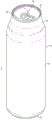
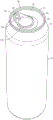
FIG. 1 is a perspective view of a can and can body package illustrating an embodiment of the present invention;
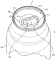
FIG. 2 is an enlarged perspective view of a portion of the package embodiment of FIG. 1;
FIG. 3 is a top view of the package embodiment of FIG. 1;
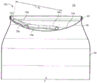
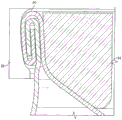
FIG. 4A is an enlarged cross-sectional view of a portion of the package embodiment of FIG. 1;
FIG. 4B is an enlarged cross-sectional view of the end with the can body member and tab and score removed for clarity;
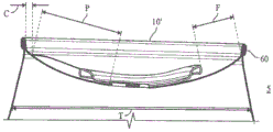
FIG. 5 is an enlarged cross-sectional view of a portion of the package embodiment of FIG. 1;
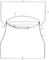
fig. 6 is a perspective view of another embodiment of a beverage can package showing a fully open end;
FIG. 7 is an enlarged partial cross-sectional view of the package of FIG. 6;
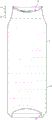
FIG. 8 is a view of the stacked containers shown in FIG. 1;
FIG. 9 is an enlarged view of a portion of FIG. 8;
FIG. 10 is a cross-sectional view of the package showing the beverage contents;
FIG. 11 is an enlarged cross-sectional view of a seam used in the embodiment of FIG. 1, in accordance with aspects of the present invention;
FIG. 12 is a cross-sectional view of the end shell clamped into the first crimping process tool, the end shell not yet deformed during crimping;
FIG. 13 is a view of the end shell shown in FIG. 12 after it has been deformed into a pre-crimp during a first crimping process and is ready for removal from the first set of tooling;
FIG. 14 is a view of the end shell shown in FIG. 13 after a second crimping process forms a pre-crimp into a crimp;
FIG. 15 is an enlarged view of the curl of the can end engaged with the can body flange;
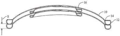
FIG. 16 is a cross-sectional view of an unstitched can end in a stacked configuration;
FIG. 17 illustrates the can end curl and can body flange after a first seaming operation;
FIG. 18 shows the can end curl and can body flange after the second seaming operation;
FIG. 19 is another view of the can end and flange at the completion of the seaming process;
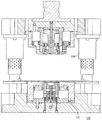
FIG. 20 is a side and partial cross-sectional view of the shell press tool assembly shown in the open kit position;
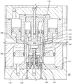
FIG. 21 is a view of the shell press tool of FIG. 20 showing initial contact of the tool with the metal sheet;
FIG. 22 is a view of the shell press tool of FIG. 20 showing partial deformation of the metal blank;
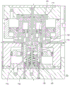
FIG. 23 is a view of the shell press tool of FIG. 20 showing further deformation of the metal blank;
FIG. 24 is an enlarged cross-sectional view of a portion of the tool engaged with the end;
FIG. 25 is a side and partial cross-sectional view of the second embodiment of the shell press tool assembly showing initial contact of the tool with the metal sheet;
FIG. 26 is an enlarged view of a pressure sleeve member of the shell press tool assembly of FIG. 25;
FIG. 27 is a side and partial cross-sectional view of an alternative process of forming a preform in a metal sheet or blank prior to the shell forming process, showing initial contact of the tool with the metal sheet;
fig. 28 is an enlarged view of components of the preform tool assembly of fig. 27;
figure 29 is a schematic view of a can end suitable for use with an aerosol can package.
Detailed Description
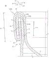
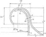
Referring to the drawings, a container package such as package 5 includes a beverage can end 10 and a can body 50. End 10 includes, in its unstitched configuration (e.g., as shown in fig. 15), a curl 12 at its outer periphery, a wall 14, sometimes referred to as a chuck wall, extending radially inward and downward from curl 12, and an inward or concave curved panel 16 extending smoothly from a lower end of wall 14. The sewn ends and some of the components are indicated by using superscript designations, e.g., sewn end 10 'and sewn chuck wall 14'. The unstitched end and some of its components of the unstitched end are indicated by reference numerals without superscript indications, such as the unstitched end 10 and its chuck wall 14. As will be described below, some components of the end 10 are omitted for ease of illustration, and reference numerals 8 and 9 are used to designate the shell before they ultimately form the end 10.
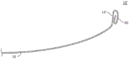
The tear panel is formed by a score 18, which score 18 forms a pour opening upon actuation by the tab 30. The score 18 may be formed by conventional methods and tools, but is suitable for use in bending the panel 16, as will be understood by those familiar with can end inspection of the present disclosure. Tab 30 is attached to panel 16 by rivet 20 (preferably conventional) at the rivet island. In the illustrated embodiment, the tab 30 is curved with substantially the same curvature as the panel 16. The tab 30 includes a nose 32 for contacting the tear panel during the opening process, and an opposing heel 36 for grasping by a user to actuate the tab.
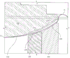
As shown in fig. 5, the pour opening defined by the score 18 has a linear dimension P, measured radially by an inclined line and defined by opposite points of the opening, preferably between 14mm and 19mm, more preferably between 15mm and 17 mm. The clearance C between the radially innermost portion of the chuck wall and the outermost portion of the score (i.e., the minimum or closest point between the score and the chuck wall) measures horizontally preferably between 0.6mm and 3.0mm, more preferably between 1.0mm and 2.0mm, and preferably between 1.0mm and 1.4 mm.
The dimension of the can of 42mm is shown in fig. 5 by the dimension DIA, i.e. the dimension DIA of the end shown in fig. 5 is 42.0mm, which is the diameter of the seamed end measured on the outside surface of the wall, which is the inside in the seam from which the neck extends. The end-to-end tab length T is 23.6mm (measured horizontally) which is near a minimum value during conventional tab opening, but the invention should not be limited to any tab size unless specifically noted in the claims. The finger access clearance F for a user to access the tab heel 36 is defined by the inclined straight line between the outermost point on the tab heel and the bottom of the wall 14' of the seam 60. The finger access distance F is preferably between 6mm and 15mm, more preferably between 6mm and 12mm, more preferably between 7mm and 10mm, and is 8mm as shown in fig. 5. The preferred embodiment is disclosed with respect to the dimensions provided for the 42mm end of fig. 5, and it is understood that the dimensions (such as, without limitation, pour opening dimension P, gap dimension C, finger access dimension F, and tab length T) may also be applicable to ends of dimensions other than 42 mm.
The panel 16 of the unstitched end 10 defines a dome depth D which is preferably between 6mm and 12mm, more preferably between 6mm and 10mm, and in the embodiment shown in the drawings is 8 mm. Additional information provided in table 1. As shown in fig. 4A, the dome depth D is measured vertically at the center from the uppermost portion of the curl 12 to the upper side of the panel 16 (or near the lowest point of the rivet if the rivet 16 is at the center).
The can body 50 in the embodiment shown in fig. 1 is a drawn and wall ironed ("DWI") body having a domed base 52 and an integral sidewall 54. As shown in fig. 8 and 9, the base 52 includes a dome 53 and a foot 55. Preferably, the can body 50 is formed using a conventional DWI process.
A neck 56 having a reduced diameter relative to the sidewall 54 extends from an upper end of the sidewall 54. It should be understood that the size of the constriction of the package 5 may be greater in some embodiments than a conventional 12 ounce beverage can, as is known in the art. In the unstitched state, as shown in fig. 15, the neck 54 terminates in a flange 62.
A seam 60, preferably a double seam, joins the end 10 and the body 50. In the sewn condition, as described more fully below, all or a majority of curl 12 forms seam 60 and all or a majority of wall 14 forms the inside surface of seam 60. Preferably, as shown in fig. 8 and 9, the seam 60 may be inserted into the base of the can for stacking purposes. The container package shown in fig. 8 is a "slim" can 50 having a conventional reformed base profile 52. The end 10' in fig. 8 is a 42mm end that is stacked internally on the base 52.
As shown in fig. 10, the package 5 has a vertical height H between the liquid content 6 of the container and the top of the seam, which is between 10mm and 30mm, preferably 14 mm. The present invention is not intended to be limited by dimension H unless explicitly recited in the claims.
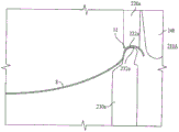
Referring specifically to fig. 1,4A and 4B, the panel 16 preferably extends smoothly from the bottom of the wall 14 or 14' preferably without reinforcing structure, such as an upwardly opening groove or a folded or z-shaped groove. Preferably, the slope of the tangent to the curve of the panel 16 at each point is not zero except at the center or at the panel where the slope changes from negative to positive. As will be understood by those familiar with conventional end techniques in view of this disclosure, the present invention encompasses recesses and beads formed in a panel (not shown) for optimizing score propagation and other parameters in accordance with known principles. A panel having this structure is intended to be encompassed by the terms dome, curved or concave as used herein.
The dome 16 profile preferably includes a series of progressively increasing radii from a minimum radius alongside the chuck wall to a large central radius. The increasing dome radius minimizes the depth of the curve, thus optimizing material use, and providing a shallow dome depth. The shallow dome depth may in some configurations make it easier or feasible to manufacture the end using conventional metal forming processes without wrinkling during the drawing operation, which may occur in very thin materials.
As shown in fig. 4A and 4B, for the example of a 42mm end dimension, the preferred radius values for R1 through R4 (i.e., from the outermost radius to the center radius) are 1, 13, 34, and 44 mm. For purposes of further defining embodiments of the present invention, a preferred radius R1 between wall 14 and panel 16 may not be limited to a range between 0.5mm and 4mm (for 42mm sized ends or other sizes), preferably 0.7mm to 2.0mm, and is shown as 1.0mm in the 42mm embodiment. R1 merges into a radius R2, the radius R2 being between 7mm and 20mm, preferably 10mm to 16mm, and most preferably about 13 mm. R2 merges into a radius R3, R3 is between 28mm and 41mm, preferably 31mm to 37mm, and most preferably about 34 mm. Radius R3 merges into dome radius R4 at the center, and dome radius R4 is preferably between 35mm and 55mm, preferably between 40mm and 50mm, and most preferably about 44 mm.
Can ends having the above radius ranges are for the preferred embodiment of the 42mm end size. The can end may also have a diameter of between 38mm and 52mm, or between 40mm and 46 mm. Furthermore, the overall shape of the end structures disclosed herein, including the end diameter to height ratio and seam size, can be used in conjunction with much larger ends, such as ends up to and including 82mm diameter are currently used for 1 liter beer cans. The invention is not limited to a particular radius range or number of ranges unless otherwise indicated in the claims. Rather, it should be understood that the dome may be elliptical, or formed from a series of splines or other shapes.
Fig. 14 and 24 are exemplary embodiments of a 42mm sized crimped shell profile (9) or (10) with preferred values of R1, R2, R3 and R4, the radius decreasing from the chuck wall 14 to the center of the panel 16. The particular curve may be used for other sizes, such as 46mm to 50mm ends, which may be optimized in a straightforward manner in accordance with the principles described in this disclosure, as will be appreciated by those familiar with can end technology.
Table 1 below provides values for some of the parameters for the 42mm, 46mm and 50mm ends that are the product of finite element analysis design and optimization. The "constrained" value controls parameters such as the freeboard height H and dome height D of the package. The "free" value is an optimized parameter without external constraints applied to the solution, and thus better reflects the improved benefits of the final techniques disclosed and claimed herein.
TABLE 1
Results of finite element analysis

The shell thickness is 5000 series aluminum alloy starting specification in millimeters. The trim diameter is the diameter of the blank in millimeters. The mass is the shell mass reflecting the cut edge diameter. The dome height is dimension D as described herein. The reversal pressure is the PSI calculated pressure at which the dome profile reverses. The weight savings is the percentage metal weight savings compared to the 50mm end of Crown Cork & Seal sold as its "ISE" end (which is well known in the art). As shown by DIA in fig. 5, the shell diameter is the diameter in millimeters. The dome diameter to height ratio is the ratio of these parameters, which provides guidance on the proportion of ends (having dimensions greater and less than those described in this specification) formed according to the disclosure herein. Thus, the inventors estimate that the diameter of the can end is less than 10 times the height D of the dome, and preferably 4 to 8 times the height D.
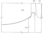
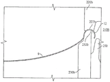
Fig. 6 and 7 illustrate another embodiment of a fully open container package 5A including a beverage can end 10a' and a can body 50. Seam 60, and thus curl 12 and wall 14, is a can end 10,10' as described in the first embodiment. End 10a 'thus includes a panel 16a having a score 18a formed about its periphery proximal to the base of wall 14'. Tab 30a is attached to panel 16a by rivet 20 a. In the illustrated embodiment, the tab 30a is preferably curved at substantially the same curvature as the panel 16 a. The tab 30a includes a nose 32a for contacting the tear panel during the opening process, and an opposing ring 36a for grasping by a user to actuate the tab.
The preferred minimum length T-a of the tab 36a is 27mm to allow for insertion of rivets and fingers into the tab 36 a. Thus, the ends 10a,10a' can be made as small as about 30mm, which provides clearance around the pull ring 36a for a suturing tool.
As described, the can body 50 is used for the container package 5 of the first embodiment. Also, as noted, the domed profile of panel 16a is for container package 5 of the first embodiment. Since rivet 20a is within score 18a, the actuation of tab 30a and the rupturing of score 18a around the perimeter of panel 16a allows the tear panel to be completely removed from the remainder of container package 5 a. This configuration is referred to as a fully open end.
Referring to fig. 11, seam 60 includes a portion formed by the terminal portion of end 10' and a portion formed by the terminal portion of the can body flange. The portion forming the end of seam 60 includes chuck wall 14', sewn panel 64, sewn wall 66, end hook 68, and cover hook 70. The junction between the wall 14' and the stitched panel 64 defines a stitched panel radius SPR. The junction between the stitched panel 64 and the stitched wall 66 defines a stitched wall radius SWR. The portion of the can body forming seam 60 includes body wall 74 and body hook 76. The junction between the body wall 74 and the body hook 76 defines a body hook radius BHR.
For example, the wall 14' as shown in FIGS. 11 and 19 is angled according to the suture chuck configuration and the suturing process. For example, the wall 14' may be inclined 1 to 8 degrees, and preferably about 4 degrees, in the sewn condition. The wall 14 in its unstitched state in fig. 15 may be any shape or configuration that results in a finished wall 14', and is preferably about 4 degrees.
The construction of the end 10, in accordance with aspects of the present invention, allows for the use of thinner materials, which in turn allows for the use of a smaller than conventional beverage can double seam. In this regard, the inventors are unaware of any commercial aluminum package having a double seam formed from end material that is thinner or has a similar thickness as can flange material. Specifically, the domed end is no more than 20% thicker than the curl, and preferably less than 10% thicker than the curl. The benefit of this compact geometry is that the end seam radius is small and locks the seam in place during pressing, thereby preventing the seam from unraveling. The locking effect is critical to buckle performance since the material is very thin and therefore more easily dispersed.
Preferably, the crimp thickness is 0.16mm and is substantially less than any crimp thickness of any conventional end.
Further, the seam length L, measured from the uppermost point of the seam along the seam centerline to the lowermost point on the seam, is preferably less than 2.2mm, and in a preferred embodiment is about 2.0 mm. The seam thickness ST, measured perpendicular to the longitudinal axis of the seam at the widest point of the outer side surfaces of the wall 14' and the seam wall 66, is preferably no greater than 1.1mm, more preferably no greater than 0.96mm, and in the illustrated embodiment the dimension ST is about 0.85 to 0.93 mm. The end seam radius ESR, measured at the top of the seam and reflected by the stitched panel radius SPR or the stitched wall radius SWR, is preferably no greater than 0.6mm, more preferably no greater than 0.55mm, and even more preferably no greater than 0.5 mm. Further, the overlap dimension OL between the body hook 76 and the lid hook 70 is between 0.65 and 1.2mm, and preferably about 0.9 mm.
Referring again to fig. 15, the unstitched end 10 is in place on the can body 50, ready for the seaming process. In this aspect, the curl 12 includes a stitched panel 80 and a peripheral curl 82 such that the end stitched panel 80 is in contact with the tip of the flange 62. The radial clearance RC between the flange proximal to the neck of the can and the curl, measured at its narrowest point and preferably at the chuck wall 14, is at least 0.5 mm. Dimension RC and other dimensions referred to herein as "radial" are measured horizontally.
The aspects of smaller seam size and end thickness (compared to the prior art), etc., are reflected in the unsewn configuration of the end 10 and can flange 62. The flange width FW is large enough to form a sufficient overlap dimension OL for acceptable seaming. The flange width FW is measured radially from the inside of the vertical portion of the neck 56 to the outermost lip 63 of the flange and is preferably no greater than 1.8mm, more preferably no greater than 1.6mm, and preferably about 1.5 mm. The curl width dimension measured radially and horizontally between the outermost point of the curl and a point on the curl at a relatively straight portion of the chuck wall where the seaming panel of the curl creates an end is preferably less than 3.5mm, more preferably less than 3.0mm, and in the embodiment shown is 2.8 mm. For ease of measurement, the curl width CW may be measured radially from the outermost point on the curl (i.e., horizontally when viewed in cross-section) to a point P on the inside surface of the end at the curl 12 or wall 14.
The height CH of the curl is preferably greater than the flange width FW, which the inventors believe is contrary to conventional dimensional relationships in commercial beverage cans. Preferably, the height CH is at least 0.2mm greater than the flange width FW, and more preferably greater than at least 0.5 mm. In the illustrated embodiment, the crimp height is 2.1 mm. The crimp gap dimension CC measured horizontally between the outermost tip of the flange and the innermost tip of the crimp is between 0.4 and 1.2mm, and preferably about 0.5 mm.
Figures 17 and 18 show a stitching chuck 84 engaged with end 10 to form seam 60 for a 42mm end. Fig. 17 shows the first stitching roller 86 after it has retracted during the first stitching operation. Fig. 18 shows the second stitching roller 88 after it has been retracted during the second stitching operation. Fig. 19 is a cross-sectional view of second roller 88 engaged with seam 60.
As best shown in FIG. 16, the unstitched ends 10 have a stack height S of between 1.5 and 3.0mm, more preferably between 1.6 and 2.2mm, and in the illustrated embodiment 1.8 mm.
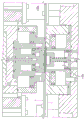
As shown in fig. 20-24, the shell press 100 includes a kit 110 for forming an end shell as described herein. For ease of description, conventional portions of the shell press 100, such as those relating to moving sheet material, and those relating to moving and aligning the toolkit 110, are omitted from this description and will be understood by those familiar with the shell press technology based on the description of the toolkit 110 and the shell product. To illustrate the tooling and process for forming the end 10, reference numeral 8 will refer to the product of the shell press 100 (i.e., the domed shell) and reference numeral 9 will refer to the finished shell after the first crimping operation but before entering the next process (i.e., the product has the crimps 12, the wall 14, and the panel 16, but does not include scores, rivets, or tabs).
The kit 110 includes a dome punch 120, a pair of pressure sleeves 130 and 140, an upper sleeve 150, a die center ring 160, a punch sleeve 170, a pressure pad 180, a trim 190, and a peel inhibitor tool 200. The punch 120 has a domed surface 122 that substantially matches the profile of the panel 16, allowing for some spring back. The calculated profile of the shell 8 is shown in fig. 24. The inner and outer pressure sleeves 130, 140 oppose the punch 120 and have contact surfaces 134, 144 that match the curvature and orientation of the corresponding portions 124a, 124b of the punch 120. The upper sleeve 150 has a concave contact surface 152 at its lowermost end. The die center ring 160 has a convex contact surface 162 on its uppermost end.
The upper sleeve 150 is aligned with the die center ring 160 and is concentric with the punch 120. The die center ring 160 is concentric with the outer pressure sleeve 140. The punch sleeve 170 is aligned with the pressure pad 180 and concentric with the upper sleeve 150. The pressure pad 180 is concentric with the lower sleeve 160.
Fig. 20 shows the kit 110 in an open position ready for insertion into a metal panel. Fig. 21 shows the upper portion of the kit 110 in its initial contact position, where the tool first contacts the metal sheet prior to any deformation or die cutting of the sheet. The peel inhibitor 200 contacts the sheet to act on the cut edge 190 to prevent movement of the sheet. In this position, the punch sleeve 170 is moved downward relative to the plate to form a blank when the punch sleeve 170 and the trim 190 are engaged together. The springs 136 and 146 of the inner and outer pressure sleeves 130 and 140 are in their rest or preloaded positions.
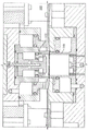
Fig. 22 shows the punch sleeve 170 moved downward relative to the trim 190 to form a circular blank. The opposing contact surfaces 152 and 162 of the sleeves 150 and 160 engage the blank with a force selected to allow drawing of the blank (as distinguished from thinning of the sheet metal by drawing) while reducing wrinkling. The punch 120 moves downward relative to the base 112 of the shell press so that the underside of the blank contacts the contact surface 134 of the inner pressure sleeve 134 to compress the spring 136 at the base of the inner pressure sleeve 130. The opposing surfaces 134 and 124a apply a force to the blank for reducing wrinkling. At the stage shown in fig. 22, the uppermost tip of the outer pressure sleeve 140 may contact, or may be spaced from, the blank, but the entire surface 144 (preferably) has not yet engaged the blank, and thus the outer pressure sleeve spring 146 has not been compressed from its rest position.
Fig. 23 shows the punch 120 at the bottom of its stroke, with the two pressure sleeve contact surfaces 134 and 144 in contact with the blank to apply their respective spring forces, the inner pressure sleeve spring 136 further compressed relative to the view shown in fig. 22, the outer pressure sleeve spring 146 compressed, and the forces applied to the contact surfaces 152 and 162 to form the periphery of the blank into the shell 8, as best shown in fig. 24. The perimeter of the shell 8 has a curved structure 11 as formed by the contact of the upper pressure sleeve 150 and the die center ring 160.
The inner pressure sleeve 130 and outer pressure sleeve 140 (with the opening in the center) provide a compressive force that helps reduce wrinkling during drawing of the ends. The spring force of 136 and 146 may be selected for this purpose, but is preferably not large enough to "coin" the blank, which occurs in the prior art dome formation described in the background section. The inner pressure sleeve 130 is configured to move up and down independently of the outer pressure sleeve 140.
Alternatively, the inventors estimate that a single pressure sleeve 130a as shown in fig. 25 and 26 may be used in some cases (rather than a two-piece pressure sleeve as described above) to reduce wrinkling. Further, the inventors estimate that in some cases, the preform may be formed prior to feeding the sheet or blank into the shell press 110. Fig. 27 and 28 show a preform press 109 including a central preform punch 119 having a contact surface 121 at its periphery. When the punch 119 is moved downward, the plate or blank is deformed by partial drawing. Alternatively, the sleeves 150 and 160 as described above may partially or completely form the end shell 11. The scoring operation used to form the score 18 may be formed at any point in the process used to form the end 10'.
Fig. 12,13 and 14 illustrate a two-stage crimping process to crimp the shell 8 of the shell press 100 to form the shell 9, the shell 9 being the finished shell and then being formed into the end 10 by the conversion press.
Crimping tool 210A of the first crimping process includes an upper pressure ring 220A, an opposing lower pressure ring 230A, and an upper crimping tool 240. The shell 8 is the product of the shell press 100, which is shown in fig. 12, such that the shell crimp geometry 11 is retained between the corresponding concave contact surface 222a of the upper pressure ring 220a and the convex contact surface 232a of the lower pressure ring 230 a. The upper crimping tool 240 is in its ready position where it is configured to move down to contact the shell crimping geometry 11 to produce the pre-crimp 11'. Fig. 13 shows the end of the first stage process before the shell is removed from the first tool 210A and inserted into the second stage tool.
Fig. 14 shows the second set of two crimping processes. In this regard, tool 210B includes an upper pressure ring 220B, an opposing lower pressure ring 230B, and a crimping tool 250. Fig. 13 shows end 9, which is the product of first crimping stage 210A, including having a pre-crimp or intermediate crimp 11'. The crimping tool 250 is in its ready position where it is configured to move upwardly to contact the intermediate crimp 11', the intermediate crimp 11' being held between the corresponding concave contact surface 222B of the upper pressure ring 220B and the convex contact surface 232B of the lower pressure ring 230B. Fig. 14 shows the tool 210B after the crimping tool 250 is retracted to its ready position after engaging and forming the crimp 12. The shell 9, which is the output from the tool 210b, is ready for the conversion press.
The end formed in the configurations described herein may have the advantage of reduced blank size and/or reduced thickness (as compared to an end formed with a flat center panel and/or countersunk grooves), which may allow for reduced metal usage of the end. In addition to the above information, the inventors predict that a 42mm shell may use only about half the weight of material (about 1.05g) as the corresponding lightweight end, such as can ends sold by Crown Cork & Seal as 202 size 202 Superend. Furthermore, because the end 10 shown in the figures has no groove near the wall, the pouring opening can be configured closer to the seam, which in some cases may improve the drinking and/or pouring process. The tip is also well suited for atmospheric ratings, such as being able to withstand 90psi internal pressure.
For example, a seamed embodiment of a package 5 may include an end 10' as described herein seamed together with a DWI beverage can 50 having a 66mm size or 211 size can body. The package also includes a can body of 58mm size or 204 size and 53mm size or 202 size and other sizes described herein. The invention is not limited by the diameter of the can body unless explicitly set forth in the claims, as the disclosure of can body dimensions is to support specific requirements for standard can body dimensions, including 211 cans and those sometimes referred to as slim or slim cans.
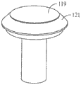
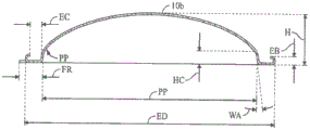
Figure 29 is a view of the end 10b of the base for a can, such as an aerosol can. A typical material for the aluminum aerosol base is H19, which is 0.34mm (0.0135 inches) thick. The end 10b may be formed according to the methods described herein. The end 10b may be formed using the tools and methods disclosed herein.
TABLE 2
Aerosol tip size

The present invention is not limited to the specific embodiments or combinations of features disclosed herein. For one example, without intending to be limiting, the dome profile may be selected according to certain desired parameters. The design principles may also be applied to containers that do not require a 90psi rating, such as low carbon soft drink or food containers, so that the end material may be thinner or smaller in diameter than described above.
Claims (84)
1. An unseamed can end capable of withstanding an internal pressure of 90psi after seaming to a can body, the can end comprising:
a crimp structure adapted to be seamed with a flange of the can body;
a chuck wall extending radially inward from the crimp structure, the chuck wall adapted to contact a chuck during the suturing process;
a concave domed panel extending radially inward from the chuck wall without a countersink bead therebetween, wherein a slope of a tangent to a curve defined by the can end at each point of the chuck wall and the domed panel is non-zero except at the center;
a score formed on the panel; and
a tab attached to the concave side of the panel and adapted to rupture the score to form a pour opening in response to actuation of the tab by a user.
2. The can end of claim 1, wherein the diameter of the can end is less than 10 times the height of the dome at the center of the end.
3. The can end of claim 1 wherein the diameter of the can end is between 4 and 8 times the height of the dome at the center of the end.
4. The can end of claim 3 formed from an aluminum alloy that is less than 0.20 inches thick.
5. The can end of claim 3 formed from an aluminum alloy that is less than 0.18 inches thick.
6. The can end of claim 3 formed from an aluminum alloy that is less than 0.16 inches thick.
7. The can end of claim 1 having a stack height S of between 1.7mm and 3.0 mm.
8. The can end of claim 7, wherein the can end has a stack height S of at least 1.8 mm.
9. The can end of claim 1 wherein the curl structure has a curl width of less than 3.5mm, measured radially and horizontally between an outermost point of the curl structure and a point on the curl where a seaming panel of the curl structure produces a relatively straight portion of the chuck wall of the end.
10. The can end of claim 1 wherein the curl structure has a curl width of less than 3.0mm, measured radially and horizontally between an outermost point of the curl structure and a point on the curl where a seaming panel of the curl structure produces a relatively straight portion of a chuck wall of the end.
11. The can end of claim 1 wherein the can end is any one of a beverage can end and a food can end.
12. The can end of claim 1, wherein the panel is formed in cross section from a plurality of radii that decrease with radial position from a center of the panel.
13. The can end of claim 1 wherein the panel radius R1 of the inner and proximal sides of the chuck wall is between 0.5mm and 2mm, the panel radius R4 at the center of the panel is between 35mm and 55mm, and the can end diameter is between 38mm and 52 mm.
14. The can end of claim 1 wherein the panel radius R1 on the inner side and proximate side of the chuck wall is between 0.5mm and 4mm, the panel radius R2 on the inner side and proximate side of radius R1 is between 7mm and 20mm, the panel radius R3 on the inner side and proximate side of radius R2 is between 28mm and 41mm, the panel radius R4 at the center of the panel is between 35mm and 55mm, and the can end diameter is between 38mm and 52 mm.
15. The can end of claim 14 wherein the panel radius R1 is between 0.7mm and 2.0mm, the panel radius R2 is between 10mm and 16mm, the panel radius R3 is between 31mm and 37mm, and the panel radius R4 is between 40mm and 50 mm.
16. The can end of claim 14 wherein the panel radius R1 is about 1.0mm, the panel radius R2 is about 13mm, the panel radius R3 is about 34mm, and the panel radius R4 is about 44 mm.
17. The can end of claim 1 wherein the panel has a diameter of between 38mm and 52 mm.
18. The can end of claim 1, wherein the pour opening defined by the score has a linear dimension, measured radially from a line, of between 14mm and 19mm, the line being inclined at an angle defined by opposing points of the pour opening.
19. The can end of claim 1, wherein the pour opening defined by the score has a linear dimension, measured radially from a line, of between 15mm and 17mm, the line being inclined at an angle defined by opposing points of the pour opening.
20. The can end of claim 1, wherein a horizontal gap defined between an innermost portion of the chuck wall and an outermost portion of the score is between 0.6mm and 3.0 mm.
21. The can end of claim 1, wherein a horizontal gap defined between an innermost portion of the chuck wall and an outermost portion of the score is between 1.0mm and 2.0 mm.
22. The can end of claim 1, wherein a horizontal gap defined between an innermost portion of the chuck wall and an outermost portion of the score is between 1.0mm and 1.4 mm.
23. The can end of claim 1 wherein the tab is concavely curved.
24. The can end of claim 23 wherein a finger gap F defined between an innermost portion of the chuck wall and a distal-most portion of the tab heel, measured on a diagonal, is between 6mm and 15 mm.
25. The can end of claim 23 wherein a finger gap F defined between an innermost portion of the chuck wall and a distal-most portion of the tab heel, measured on a diagonal, is between 7mm and 10 mm.
26. The can end of claim 1 wherein the unseamed end has a panel depth of between 5mm and 16 mm.
27. The can end of claim 1 wherein the unseamed end has a panel depth of between 6mm and 10 mm.
28. The can end of claim 1 wherein the unseamed end has a panel depth of about 8 mm.
29. The can end of claim 1, wherein the score extends around a perimeter of the panel proximate the chuck wall such that the end is a fully open end.
30. The can end of claim 29 wherein the end is about 30mm in size.
31. A combination of an unstitched can end and a can body, comprising:
a drawn and ironed can body comprising a base, a sidewall, and a flange; and
an unstitched can end comprising:
a crimp structure engaged with the flange;
a chuck wall extending radially inward and downward from the crimp structure, the chuck wall adapted to contact a chuck during the suturing process;
a concave domed panel extending radially inward from the chuck wall, wherein the panel extends from a lower end of the chuck wall without a countersink bead therebetween, wherein a slope of a tangent to a curve defined by the can end at each point of the chuck wall and the domed panel is non-zero except at the center;
a score formed on the panel; and
a tab attached to the concave side of the panel and adapted to rupture the score to form a pour opening in response to actuation of the tab by a user.
32. The combination of claim 31, wherein a radial gap between the flange proximal to the neck of the canister and the crimp is at least 0.5 mm.
33. The combination of claim 32, wherein the gap is measured at a chuck wall of the end portion.
34. The combination of claim 31 wherein the thickness of the can end measured at the curl is at least 10% less than the thickness of the bead.
35. The combination of claim 31 wherein the thickness of the can end measured at the curl is at least 20% less than the thickness of the bead.
36. A combination according to claim 31, wherein the flange width measured radially from the inner side of the vertical portion of the neck of the can to the outermost lip of the flange is less than 1.8 mm.
37. The combination of claim 36, wherein the flange width is less than 1.6 mm.
38. The combination of claim 36, wherein the flange width is less than 1.5 mm.
39. The combination of claim 31, wherein the height of the curl is at least 0.5mm greater than the width of the flange.
40. The combination of claim 31, wherein the height of the curl is at least 0.2mm greater than the width of the flange.
41. The combination of claim 31, wherein the height of the curl is greater than the width of the flange.
42. The combination of claim 31 wherein a crimp gap dimension measured horizontally between an outermost tip of the flange and an innermost tip of the crimp is between 0.4mm and 1.2 mm.
43. The combination of claim 31 wherein the diameter of the can end is less than between 4 and 8 times the height of the panel at the center of the end.
44. The combination of claim 31, wherein the end portion has a stack height S of at least 1.8 mm.
45. The combination of claim 31 wherein the combination is any one of a beverage can package and a food can package.
46. The combination of claim 31, wherein the panel is formed in cross section from a plurality of radii that decrease with radial position from the center of the panel.
47. The combination of claim 31 wherein the can end has a diameter of between 38mm and 52 mm.
48. The combination of claim 31 wherein the can end is formed from a 5000 series aluminum alloy and the can body is formed from a 3000 series aluminum alloy.
49. A container for containing an edible product, the container comprising:
a drawn and ironed can body comprising a base, a sidewall, and a neck;
a can end, comprising:
a chuck wall extending radially inward from the crimp structure, the chuck wall adapted to contact the chuck during a suturing process;
a concave domed panel extending radially inward from the chuck wall, wherein the panel extends from a lower end of the chuck wall without a countersink bead therebetween, wherein the domed panel is formed by a plurality of radii in cross-section that decrease with radial position from a center of the panel to a curved portion inboard and proximal of the chuck wall;
a score formed on the panel; and
a tab attached to the concave side of the panel and adapted to rupture the score to form a pour opening in response to actuation of the tab by a user; and
the end portion of the can body and the end portion of the can end are joined together by a double seam having a seam height of less than 2.2 mm.
50. The container of claim 49, wherein a thickness of the terminal portion of the end is no greater than a thickness of the terminal portion of the can body.
51. The container of claim 49, wherein the seam thickness is no greater than 1.1 mm.
52. The container of claim 49, wherein the seam thickness is no greater than 0.96 mm.
53. The container of claim 49, wherein the seam thickness is between 0.85mm and 0.93 mm.
54. The container of claim 49, wherein the seam length is no greater than 2.2 mm.
55. The container of claim 49, wherein the seam length is about 2.0 mm.
56. The container of claim 49, wherein the seam radius is no greater than 0.6 mm.
57. The container of claim 49, wherein the seam radius is no greater than 0.55 mm.
58. The container of claim 49, wherein the double seam comprises: (i) a lid hook, an end hook, a seaming panel, and a chuck wall of a terminal portion of the can body, and (ii) a body wall and a body hook of a can end; the overlap between the body hook and the cover hook is between 0.65mm and 1.2 mm.
59. The container of claim 58, wherein the overlap between the body hook and the lid hook is about 0.9 mm.
60. The container of claim 49, wherein the diameter of the can end is less than between 4 and 8 times the height of the panel at the center of the can end.
61. The container of claim 49, wherein the can end is any one of a beverage can end and a food can end.
62. The container of claim 49 wherein the can end has a diameter of between 38mm and 52 mm.
63. The container of claim 49 wherein the can end is formed from a 5000 series aluminum alloy and the can body is formed from a 3000 series aluminum alloy.
64. The container of claim 49 wherein the vertical height between the liquid contents of the container and the underside of the can end at its centre is between 13mm and 18 mm.
65. The container of claim 49, wherein the vertical height between the liquid contents of the container and the top of the double seam is between 10mm and 30 mm.
66. A container for containing an edible product, the container comprising:
a can body;
a can end, comprising:
a chuck wall extending radially inward from the crimp structure, the chuck wall adapted to contact the chuck during a suturing process;
a concave domed panel extending radially inward from the chuck wall, wherein the panel extends from a lower end of the chuck wall without a countersink bead therebetween, wherein the domed panel is formed by a plurality of radii in cross-section that decrease with radial position from a center of the panel to a curved portion inboard and proximal of the chuck wall; and
a tab attached to the concave side of the panel;
the terminal portion of the can body and the terminal portion of the end are joined together by a double seam having a seam height of less than 2.2 mm.
67. The container of claim 66, wherein the can end is formed from an aluminum alloy that is less than 0.20 inches thick.
68. The container of claim 66, wherein the can end is formed from an aluminum alloy that is less than 0.18 inches thick.
69. The container of claim 66, wherein the can end is formed from an aluminum alloy that is less than 0.16 inches thick.
70. A method of forming a can end shell according to claim 1, the method comprising the steps of:
(a) sandwiching an end shell metal blank between an upper sleeve having a concave surface and a lower sleeve having a convex surface near the periphery of the blank;
(b) deforming the blank by engaging an upper surface of the blank with a dome punch and moving the punch relative to the blank; and
(c) engaging an underside of the billet with a pressure sleeve assembly opposite a portion of the dome punch while the billet is deformed in deforming step (b);
whereby the engagement of the upper surface of the blank with the dome punch of step (b) and the engagement of the underside of the blank with the pressure sleeve assembly of step (c) exert a force on the blank, thereby reducing wrinkling.
71. The method of claim 70 wherein the pressure sleeve assembly of the joining step (c) includes an outer pressure sleeve and an inner pressure sleeve, and in the joining step (c), the inner pressure sleeve contacts an underside of the billet in response to relative movement by the punch, and the outer pressure sleeve contacts the underside of the billet after the inner pressure sleeve contacts the billet.
72. The method as set forth in claim 71 wherein the inner pressure sleeve has a contact surface having a shape that matches a shape of an opposing partial portion of the dome punch and the outer pressure sleeve has a contact surface that matches a shape of an opposing portion of the dome punch.
73. The method of claim 72 wherein the inner and outer pressure sleeves are independently depressible such that during the first stage of the joining step (c) the inner pressure sleeve is depressed by relative downward movement of the punch while the outer pressure sleeve remains relatively stationary and spaced from the billet, and during the second stage of the joining step (c) each of the inner and outer pressure sleeves contacts an underside of the billet and each of the inner and outer pressure sleeves is depressed by relative downward movement of the punch.
74. The method of claim 72, wherein step (a) comprises forming a pre-crimp near the periphery of the blank by applying a force between the upper sleeve and the lower sleeve.
75. The method of claim 74 further comprising the step of crimping the periphery of the blank to form a finished crimp that can be seamed onto a can body flange.
76. The method of claim 72, further comprising the steps of: the domed shell is conveyed to a crimping press, and in the crimping press, a pre-crimp is formed near the periphery of the blank by applying a force between an upper tool and a lower tool.
77. The method of claim 76, further comprising the step of crimping the pre-roll by vertical movement of a crimping die.
78. The method of claim 71, wherein the metal blank is formed from a 5000 series aluminum alloy.
79. A shell press for forming a can end shell according to claim 1, the shell press comprising:
a central dome shaped punch;
a pressure sleeve assembly located opposite a portion of the dome punch, the pressure sleeve having a contact surface that mates with a corresponding opposing portion of the dome punch, the pressure sleeve adapted to move in response to movement of the dome punch such that the pressure sleeve contact surface and the corresponding opposing portion of the dome punch are adapted to deform a metal blank into a dome in response to downward movement of the dome punch;
an upper sleeve concentrically located outside the dome punch, the upper sleeve having a concave contact surface;
a lower sleeve concentrically located outside the pressure sleeve, the lower sleeve having a convex contact surface; said lower sleeve contact surface and said upper sleeve contact surface are adapted to curl a portion of the perimeter of said blank;
a punch sleeve concentrically located outside the upper sleeve; and
a pressure pad concentrically located outside the lower sleeve.
80. The shell press as recited in claim 79 wherein the pressure sleeve assembly comprises an outer pressure sleeve and an inner pressure sleeve, the inner pressure sleeve being concentrically located inside the outer pressure sleeve, the inner pressure sleeve having a contact surface that mates with a corresponding opposing portion of the dome punch, the outer pressure sleeve having a contact surface that mates with a corresponding opposing portion of the dome punch.
81. The shell press as recited in claim 80 wherein each of the inner and outer pressure sleeves is downwardly movable in response to downward movement of the dome punch, the inner and outer pressure sleeves being independently downwardly movable.
82. The shell press as recited in claim 80 wherein the inner and outer pressure sleeves are configured such that the inner pressure sleeve contacts the deformed portion of the billet before the outer pressure sleeve contacts the deformed portion of the billet.
83. The shell press of claim 80, wherein the shell press is adapted to form a can end shell from a blank of 5000 series aluminum alloy such that contact between the pressure sleeve assembly and the dome punch and the blank applies a force to the blank to form the can end shell without substantial wrinkling.
84. The shell press as recited in claim 80 further comprising a punch tool concentrically located outside of the pressure pad, wherein the punch sleeve and the pressure pad are adapted to move vertically relative to the punch tool to cut the billet from the metal sheet.
Applications Claiming Priority (3)
| Application Number | Priority Date | Filing Date | Title |
|---|---|---|---|
| US201662301128P | 2016-02-29 | 2016-02-29 | |
| US62/301,128 | 2016-02-29 | ||
| PCT/US2017/020024 WO2017151667A1 (en) | 2016-02-29 | 2017-02-28 | Concave can end |
Publications (2)
| Publication Number | Publication Date |
|---|---|
| CN108778939A CN108778939A (en) | 2018-11-09 |
| CN108778939B true CN108778939B (en) | 2021-05-25 |
Family
ID=58266218
Family Applications (1)
| Application Number | Title | Priority Date | Filing Date |
|---|---|---|---|
| CN201780014142.5A Active CN108778939B (en) | 2016-02-29 | 2017-02-28 | Concave can end |
Country Status (14)
| Country | Link |
|---|---|
| US (1) | US10850888B2 (en) |
| EP (2) | EP3647217B1 (en) |
| JP (1) | JP2019508333A (en) |
| KR (1) | KR20180117140A (en) |
| CN (1) | CN108778939B (en) |
| AU (1) | AU2017227595A1 (en) |
| BR (1) | BR112018067364A2 (en) |
| CA (1) | CA3016212A1 (en) |
| CO (1) | CO2018010001A2 (en) |
| MX (1) | MX2018009877A (en) |
| PL (2) | PL3423366T3 (en) |
| RU (1) | RU2731858C2 (en) |
| SG (1) | SG11201806776QA (en) |
| WO (1) | WO2017151667A1 (en) |
Families Citing this family (8)
| Publication number | Priority date | Publication date | Assignee | Title |
|---|---|---|---|---|
| DE102016112953A1 (en) * | 2016-07-14 | 2018-01-18 | Gregor Anton Piech | Metallic box and associated can lid |
| USD867147S1 (en) * | 2017-06-29 | 2019-11-19 | Pepsico, Inc. | Container |
| USD946405S1 (en) | 2019-03-20 | 2022-03-22 | Ball Corporation | Metal food container |
| WO2020204688A1 (en) * | 2019-03-29 | 2020-10-08 | E6Pr, S.A.P.I. De C.V. | System for assembling an edible multi-ring can holder |
| CA3148034A1 (en) * | 2019-07-29 | 2021-02-04 | Ball Corporation | Domed container with nitrogen well and closure mechanism |
| USD982458S1 (en) | 2019-10-24 | 2023-04-04 | Ball Corporation | Metal food container |
| WO2021080612A1 (en) * | 2019-10-25 | 2021-04-29 | Silgan Containers Llc | Laminated can sealant |
| US20210347526A1 (en) * | 2020-05-11 | 2021-11-11 | Stolle Machinery Company, Llc | Ecology tab, can end, tooling and method |
Citations (6)
| Publication number | Priority date | Publication date | Assignee | Title |
|---|---|---|---|---|
| US3730383A (en) * | 1971-07-29 | 1973-05-01 | Aluminum Co Of America | Container body and a method of forming the same |
| US4626157A (en) * | 1979-12-08 | 1986-12-02 | Metal Box Public Limited Company | Methods of making containers |
| WO1997000743A1 (en) * | 1995-06-22 | 1997-01-09 | Carnaudmetalbox Plc | Container |
| US5804237A (en) * | 1995-10-16 | 1998-09-08 | George B. Diamond | Method of and package for sterilized edible material |
| RU2156215C1 (en) * | 1999-01-26 | 2000-09-20 | Иванов Александр Васильевич | Container for drinks |
| US6126034A (en) * | 1998-02-17 | 2000-10-03 | Alcan Aluminum Corporation | Lightweight metal beverage container |
Family Cites Families (25)
| Publication number | Priority date | Publication date | Assignee | Title |
|---|---|---|---|---|
| US2971671A (en) * | 1956-10-31 | 1961-02-14 | Pabst Brewing Co | Container |
| US3394837A (en) * | 1966-09-06 | 1968-07-30 | Douglas R. Hansen | Container opening means |
| US3448887A (en) * | 1967-12-12 | 1969-06-10 | Joseph A Geiger | Container with easy-opening device |
| US4516420A (en) | 1983-06-10 | 1985-05-14 | Redicon Corporation | Shell tooling |
| JPS5984734A (en) * | 1982-10-26 | 1984-05-16 | 日本製罐株式会社 | Can and its manufacture |
| US4458469A (en) * | 1983-04-25 | 1984-07-10 | Sonoco Products Company | Container with vacuum accommodating end |
| US4549424A (en) | 1983-06-10 | 1985-10-29 | Redicon Corporation | Shell tooling method |
| US4680917A (en) * | 1984-08-17 | 1987-07-21 | International Paper Company | Process for providing filled containers |
| US5149238A (en) * | 1991-01-30 | 1992-09-22 | The Stolle Corporation | Pressure resistant sheet metal end closure |
| US5344662A (en) * | 1993-03-03 | 1994-09-06 | The Procter & Gamble Company | Pressurized package containing a particulate product employing a product separator to contain the product during opening |
| US5535911A (en) * | 1994-08-29 | 1996-07-16 | Cortez; Alejandro | Opening device for cans |
| US6375029B2 (en) * | 1999-04-19 | 2002-04-23 | Alcoa Inc. | Easy-open misting container |
| US6561004B1 (en) * | 1999-12-08 | 2003-05-13 | Metal Container Corporation | Can lid closure and method of joining a can lid closure to a can body |
| PL363684A1 (en) | 2001-02-26 | 2004-11-29 | Ball Corporation | Beverage can end with outwardly extending reinforcing bead |
| US7644833B2 (en) | 2001-08-16 | 2010-01-12 | Rexam Beverage Can Company | Can end |
| WO2004101369A2 (en) | 2003-05-12 | 2004-11-25 | Ball Corporation | Selectively deformable container end closure |
| US8191726B2 (en) * | 2006-07-20 | 2012-06-05 | Crown Packaging Technology, Inc. | Can end having curved end panel surfaces |
| ES2513828T3 (en) | 2009-11-12 | 2014-10-27 | Ardagh Mp Group Netherlands B.V. | A panel for a container, a container provided with said container and a method for manufacturing them |
| RU2557518C2 (en) * | 2010-01-12 | 2015-07-20 | Краун Пэкэджинг Текнолоджи, Инк. | Can for beverage with disc |
| US20120199587A1 (en) * | 2011-02-09 | 2012-08-09 | Kirk Norris | Beverage Containers, And Tabs And Lids For Use With Beverage Containers |
| GB201118284D0 (en) | 2011-10-21 | 2011-12-07 | Crown Packaging Technology Inc | Can end |
| CN104334463B (en) * | 2012-04-13 | 2017-10-17 | 皇冠包装技术公司 | For the structure and method for controlling fragrance to discharge using the encapsulation fragrance on vessel |
| US9821928B2 (en) * | 2012-05-14 | 2017-11-21 | Rexam Beverage Can Company | Can end |
| US9162794B2 (en) * | 2012-05-25 | 2015-10-20 | Boston Beer Corporation | Beverage delivery can |
| US10246218B2 (en) * | 2013-03-15 | 2019-04-02 | Crown Packaging Technology, Inc. | Necked beverage can having a seamed-on end |
-
2017
- 2017-02-28 PL PL17710107T patent/PL3423366T3/en unknown
- 2017-02-28 CN CN201780014142.5A patent/CN108778939B/en active Active
- 2017-02-28 WO PCT/US2017/020024 patent/WO2017151667A1/en active Application Filing
- 2017-02-28 CA CA3016212A patent/CA3016212A1/en not_active Abandoned
- 2017-02-28 AU AU2017227595A patent/AU2017227595A1/en not_active Abandoned
- 2017-02-28 JP JP2018545440A patent/JP2019508333A/en not_active Abandoned
- 2017-02-28 BR BR112018067364A patent/BR112018067364A2/en not_active IP Right Cessation
- 2017-02-28 SG SG11201806776QA patent/SG11201806776QA/en unknown
- 2017-02-28 PL PL19209851.5T patent/PL3647217T3/en unknown
- 2017-02-28 MX MX2018009877A patent/MX2018009877A/en unknown
- 2017-02-28 RU RU2018134196A patent/RU2731858C2/en not_active IP Right Cessation
- 2017-02-28 KR KR1020187027533A patent/KR20180117140A/en unknown
- 2017-02-28 EP EP19209851.5A patent/EP3647217B1/en active Active
- 2017-02-28 EP EP17710107.8A patent/EP3423366B1/en active Active
- 2017-02-28 US US15/445,709 patent/US10850888B2/en active Active
-
2018
- 2018-09-21 CO CONC2018/0010001A patent/CO2018010001A2/en unknown
Patent Citations (6)
| Publication number | Priority date | Publication date | Assignee | Title |
|---|---|---|---|---|
| US3730383A (en) * | 1971-07-29 | 1973-05-01 | Aluminum Co Of America | Container body and a method of forming the same |
| US4626157A (en) * | 1979-12-08 | 1986-12-02 | Metal Box Public Limited Company | Methods of making containers |
| WO1997000743A1 (en) * | 1995-06-22 | 1997-01-09 | Carnaudmetalbox Plc | Container |
| US5804237A (en) * | 1995-10-16 | 1998-09-08 | George B. Diamond | Method of and package for sterilized edible material |
| US6126034A (en) * | 1998-02-17 | 2000-10-03 | Alcan Aluminum Corporation | Lightweight metal beverage container |
| RU2156215C1 (en) * | 1999-01-26 | 2000-09-20 | Иванов Александр Васильевич | Container for drinks |
Also Published As
| Publication number | Publication date |
|---|---|
| JP2019508333A (en) | 2019-03-28 |
| BR112018067364A2 (en) | 2019-01-15 |
| SG11201806776QA (en) | 2018-09-27 |
| CN108778939A (en) | 2018-11-09 |
| US10850888B2 (en) | 2020-12-01 |
| RU2018134196A (en) | 2020-04-01 |
| RU2731858C2 (en) | 2020-09-08 |
| KR20180117140A (en) | 2018-10-26 |
| WO2017151667A1 (en) | 2017-09-08 |
| CO2018010001A2 (en) | 2018-09-28 |
| EP3647217A1 (en) | 2020-05-06 |
| EP3423366A1 (en) | 2019-01-09 |
| EP3423366B1 (en) | 2019-11-20 |
| CA3016212A1 (en) | 2017-09-08 |
| AU2017227595A1 (en) | 2018-08-23 |
| PL3423366T3 (en) | 2020-06-15 |
| MX2018009877A (en) | 2018-09-11 |
| RU2018134196A3 (en) | 2020-07-10 |
| PL3647217T3 (en) | 2022-11-28 |
| US20170253371A1 (en) | 2017-09-07 |
| EP3647217B1 (en) | 2022-08-03 |
Similar Documents
| Publication | Publication Date | Title |
|---|---|---|
| CN108778939B (en) | Concave can end | |
| US7174762B2 (en) | Can end | |
| US8104319B2 (en) | Method of forming a can end | |
| US11174069B2 (en) | Can end | |
| US10486852B2 (en) | Can end produced from downgauged blank | |
| AU2002347836B2 (en) | Reformed can end and method therefore | |
| EP1755967B1 (en) | Can end with tab for improved accessibility | |
| US6772900B2 (en) | Can end | |
| WO2022235743A1 (en) | Method for forming a beverage can end shell |
Legal Events
| Date | Code | Title | Description |
|---|---|---|---|
| PB01 | Publication | ||
| PB01 | Publication | ||
| SE01 | Entry into force of request for substantive examination | ||
| SE01 | Entry into force of request for substantive examination | ||
| GR01 | Patent grant | ||
| GR01 | Patent grant |