JP2019508209A - Exercise equipment - Google Patents
Exercise equipment Download PDFInfo
- Publication number
- JP2019508209A JP2019508209A JP2018566620A JP2018566620A JP2019508209A JP 2019508209 A JP2019508209 A JP 2019508209A JP 2018566620 A JP2018566620 A JP 2018566620A JP 2018566620 A JP2018566620 A JP 2018566620A JP 2019508209 A JP2019508209 A JP 2019508209A
- Authority
- JP
- Japan
- Prior art keywords
- support element
- exercise
- attached
- wall
- movable
- Prior art date
- Legal status (The legal status is an assumption and is not a legal conclusion. Google has not performed a legal analysis and makes no representation as to the accuracy of the status listed.)
- Pending
Links
Images


Classifications
-
- A—HUMAN NECESSITIES
- A63—SPORTS; GAMES; AMUSEMENTS
- A63B—APPARATUS FOR PHYSICAL TRAINING, GYMNASTICS, SWIMMING, CLIMBING, OR FENCING; BALL GAMES; TRAINING EQUIPMENT
- A63B21/00—Exercising apparatus for developing or strengthening the muscles or joints of the body by working against a counterforce, with or without measuring devices
- A63B21/00058—Mechanical means for varying the resistance
- A63B21/00065—Mechanical means for varying the resistance by increasing or reducing the number of resistance units
-
- A—HUMAN NECESSITIES
- A63—SPORTS; GAMES; AMUSEMENTS
- A63B—APPARATUS FOR PHYSICAL TRAINING, GYMNASTICS, SWIMMING, CLIMBING, OR FENCING; BALL GAMES; TRAINING EQUIPMENT
- A63B21/00—Exercising apparatus for developing or strengthening the muscles or joints of the body by working against a counterforce, with or without measuring devices
- A63B21/02—Exercising apparatus for developing or strengthening the muscles or joints of the body by working against a counterforce, with or without measuring devices using resilient force-resisters
- A63B21/04—Exercising apparatus for developing or strengthening the muscles or joints of the body by working against a counterforce, with or without measuring devices using resilient force-resisters attached to static foundation, e.g. a user
- A63B21/0407—Anchored at two end points, e.g. installed within an apparatus
- A63B21/0428—Anchored at two end points, e.g. installed within an apparatus the ends moving relatively by linear reciprocation
-
- A—HUMAN NECESSITIES
- A63—SPORTS; GAMES; AMUSEMENTS
- A63B—APPARATUS FOR PHYSICAL TRAINING, GYMNASTICS, SWIMMING, CLIMBING, OR FENCING; BALL GAMES; TRAINING EQUIPMENT
- A63B21/00—Exercising apparatus for developing or strengthening the muscles or joints of the body by working against a counterforce, with or without measuring devices
- A63B21/02—Exercising apparatus for developing or strengthening the muscles or joints of the body by working against a counterforce, with or without measuring devices using resilient force-resisters
- A63B21/055—Exercising apparatus for developing or strengthening the muscles or joints of the body by working against a counterforce, with or without measuring devices using resilient force-resisters extension element type
- A63B21/0552—Elastic ropes or bands
- A63B21/0555—Details of the rope or band, e.g. shape or colour coding
-
- A—HUMAN NECESSITIES
- A63—SPORTS; GAMES; AMUSEMENTS
- A63B—APPARATUS FOR PHYSICAL TRAINING, GYMNASTICS, SWIMMING, CLIMBING, OR FENCING; BALL GAMES; TRAINING EQUIPMENT
- A63B21/00—Exercising apparatus for developing or strengthening the muscles or joints of the body by working against a counterforce, with or without measuring devices
- A63B21/15—Arrangements for force transmissions
- A63B21/151—Using flexible elements for reciprocating movements, e.g. ropes or chains
- A63B21/154—Using flexible elements for reciprocating movements, e.g. ropes or chains using special pulley-assemblies
-
- A—HUMAN NECESSITIES
- A63—SPORTS; GAMES; AMUSEMENTS
- A63B—APPARATUS FOR PHYSICAL TRAINING, GYMNASTICS, SWIMMING, CLIMBING, OR FENCING; BALL GAMES; TRAINING EQUIPMENT
- A63B21/00—Exercising apparatus for developing or strengthening the muscles or joints of the body by working against a counterforce, with or without measuring devices
- A63B21/16—Supports for anchoring force-resisters
- A63B21/1618—Supports for anchoring force-resisters on a door or a door frame
- A63B21/1645—Supports for anchoring force-resisters on a door or a door frame for anchoring on a door
-
- A—HUMAN NECESSITIES
- A63—SPORTS; GAMES; AMUSEMENTS
- A63B—APPARATUS FOR PHYSICAL TRAINING, GYMNASTICS, SWIMMING, CLIMBING, OR FENCING; BALL GAMES; TRAINING EQUIPMENT
- A63B21/00—Exercising apparatus for developing or strengthening the muscles or joints of the body by working against a counterforce, with or without measuring devices
- A63B21/16—Supports for anchoring force-resisters
- A63B21/169—Supports for anchoring force-resisters for anchoring on or against a wall
-
- A—HUMAN NECESSITIES
- A63—SPORTS; GAMES; AMUSEMENTS
- A63B—APPARATUS FOR PHYSICAL TRAINING, GYMNASTICS, SWIMMING, CLIMBING, OR FENCING; BALL GAMES; TRAINING EQUIPMENT
- A63B21/00—Exercising apparatus for developing or strengthening the muscles or joints of the body by working against a counterforce, with or without measuring devices
- A63B21/40—Interfaces with the user related to strength training; Details thereof
- A63B21/4027—Specific exercise interfaces
- A63B21/4033—Handles, pedals, bars or platforms
- A63B21/4035—Handles, pedals, bars or platforms for operation by hand
-
- A—HUMAN NECESSITIES
- A63—SPORTS; GAMES; AMUSEMENTS
- A63B—APPARATUS FOR PHYSICAL TRAINING, GYMNASTICS, SWIMMING, CLIMBING, OR FENCING; BALL GAMES; TRAINING EQUIPMENT
- A63B21/00—Exercising apparatus for developing or strengthening the muscles or joints of the body by working against a counterforce, with or without measuring devices
- A63B21/40—Interfaces with the user related to strength training; Details thereof
- A63B21/4041—Interfaces with the user related to strength training; Details thereof characterised by the movements of the interface
- A63B21/4047—Pivoting movement
-
- A—HUMAN NECESSITIES
- A63—SPORTS; GAMES; AMUSEMENTS
- A63B—APPARATUS FOR PHYSICAL TRAINING, GYMNASTICS, SWIMMING, CLIMBING, OR FENCING; BALL GAMES; TRAINING EQUIPMENT
- A63B23/00—Exercising apparatus specially adapted for particular parts of the body
- A63B23/035—Exercising apparatus specially adapted for particular parts of the body for limbs, i.e. upper or lower limbs, e.g. simultaneously
- A63B23/03516—For both arms together or both legs together; Aspects related to the co-ordination between right and left side limbs of a user
- A63B23/03525—Supports for both feet or both hands performing simultaneously the same movement, e.g. single pedal or single handle
-
- A—HUMAN NECESSITIES
- A63—SPORTS; GAMES; AMUSEMENTS
- A63B—APPARATUS FOR PHYSICAL TRAINING, GYMNASTICS, SWIMMING, CLIMBING, OR FENCING; BALL GAMES; TRAINING EQUIPMENT
- A63B23/00—Exercising apparatus specially adapted for particular parts of the body
- A63B23/035—Exercising apparatus specially adapted for particular parts of the body for limbs, i.e. upper or lower limbs, e.g. simultaneously
- A63B23/12—Exercising apparatus specially adapted for particular parts of the body for limbs, i.e. upper or lower limbs, e.g. simultaneously for upper limbs or related muscles, e.g. chest, upper back or shoulder muscles
- A63B23/1209—Involving a bending of elbow and shoulder joints simultaneously
-
- A—HUMAN NECESSITIES
- A63—SPORTS; GAMES; AMUSEMENTS
- A63B—APPARATUS FOR PHYSICAL TRAINING, GYMNASTICS, SWIMMING, CLIMBING, OR FENCING; BALL GAMES; TRAINING EQUIPMENT
- A63B2210/00—Space saving
- A63B2210/50—Size reducing arrangements for stowing or transport
-
- A—HUMAN NECESSITIES
- A63—SPORTS; GAMES; AMUSEMENTS
- A63B—APPARATUS FOR PHYSICAL TRAINING, GYMNASTICS, SWIMMING, CLIMBING, OR FENCING; BALL GAMES; TRAINING EQUIPMENT
- A63B2225/00—Miscellaneous features of sport apparatus, devices or equipment
- A63B2225/09—Adjustable dimensions
- A63B2225/093—Height
Abstract
運動器具が、第1及び第2の端部間に延びる細長い支持要素を含む。支持要素は、ドア又は壁面に係合してこれらのドア又は壁面に支持要素を取り付けるように第1及び第2の端部の各々に配置された取り付け部材を有する。抵抗発生アセンブリが、支持要素に取り付けられた固定部材を含む。支持要素には、支持要素に沿って固定部材に対して移動可能な可動部材を取り付けることができる。固定部材と可動部材との間には、弾性部材を取り外し可能に取り付けることができる。弾性部材は、固定部材に対する可動部材の移動によって弾性的に変形することによって抵抗を生じる。可動部材には、可動部材と共に移動可能な滑車が取り付けられ、支持要素には別の滑車が取り付けられる。滑車には、固定部材に対する可動部材の移動をもたらす手動操作可能なケーブルが係合する。方法も開示する。【選択図】図1AThe exercise device includes an elongated support element extending between the first and second ends. The support element has mounting members disposed at each of the first and second ends to engage the door or wall and attach the support element to the door or wall. The resistance generating assembly includes a fixed member attached to the support element. The support element can be mounted with a movable member movable relative to the fixed member along the support element. The elastic member can be removably attached between the fixed member and the movable member. The elastic member generates resistance by elastically deforming due to the movement of the movable member relative to the fixed member. Attached to the moveable member is a pulley that is moveable with the moveable member, and another support is attached to the support element. The pulleys are engaged by a manually operable cable that provides for movement of the movable member relative to the fixed member. A method is also disclosed. [Selected figure] Figure 1A
Description
〔関連出願との相互参照〕
本出願は、2016年3月7日に出願された米国仮特許出願第62/304,528号に対する優先権を主張するものであり、この文献の内容は全体が引用により本明細書に組み入れられる。
[Cross-reference to related applications]
This application claims priority to US Provisional Patent Application No. 62 / 304,528, filed March 7, 2016, the contents of which are incorporated herein by reference in its entirety. .
本出願は、一般に運動器具に関する。 The present application relates generally to exercise equipment.
抵抗運動又は荷重負荷運動を行うための様々な器具が存在する。これらの器具の中には、家庭内又はホテル室内などの非ジム施設で使用できるものもある。 There are various instruments for performing resistance or load-bearing movements. Some of these devices can be used in non-gym facilities such as in the home or in a hotel room.
従来の重量負荷器具又はホームジムは、重くて運びにくいことが多い。多くの狭いアパート又は家庭、キャンピングカー、ホテルの部屋などは、これらの構造を支持することができない。これらの「家庭用」器具の使用及び利用可能性は、サイズ、空間及び重量の制約によって妨げられる。 Conventional weight load devices or home gyms are often heavy and difficult to carry. Many narrow apartments or homes, campers, hotel rooms, etc. can not support these structures. The use and availability of these "domestic" devices are hampered by size, space and weight constraints.
梱包して1つの部屋から別の部屋へ、又は1つの場所から別の場所へ移動できる器具を提供することが知られている。これらの従来の器具には、設置又は組み立てが困難であり、向きを変更することができず、重すぎて又は大きすぎて容易に輸送できないことによって使用する気が失せてしまうものもある。 It is known to provide an implement that can be packaged and moved from one room to another or from one place to another. Some of these conventional devices are difficult to install or assemble, can not be reoriented, and are disappointing to use due to being too heavy or too large to be easily transported.
さらに、効果的なウェイトトレーニングのためには、継続的に抵抗又は負荷を高める必要がある。多くの家庭用器具は、追加できる抵抗量が制限されることによって有用性が限られている。 Furthermore, for effective weight training, it is necessary to continuously increase resistance or load. Many household appliances have limited utility due to the limited amount of resistance that can be added.
1つの態様では、運動器具であって、第1の端部と第2の端部との間に延びる細長い支持要素と、抵抗発生アセンブリとを備え、支持要素が、第1及び第2の端部の各々に配置された取り付け部材を有し、各取り付け部材が、ドア又は壁面に係合してドア又は壁面に支持要素を取り付けるようにドア又は壁面に取り付け可能であり、抵抗発生アセンブリが、支持要素に固定して取り付けられた固定部材と、支持要素に取り付けられ、支持要素に沿って固定部材に対して移動可能な可動部材と、固定部材と可動部材とに取り外し可能に取り付けられて固定部材と可動部材との間に延び、固定部材に対する可動部材の移動によって弾性的に変形することによって抵抗を生じる少なくとも1つの弾性部材と、複数の滑車とを含み、滑車のうちの少なくとも1つが、可動部材に取り付けられて可動部材と共に移動可能であり、滑車のうちの少なくとも別の1つが支持要素に取り付けられ、固定部材に対する可動部材の移動をもたらす手動操作可能なケーブルが滑車に係合する運動器具を提供する。 In one aspect, the exercise apparatus comprises an elongated support element extending between the first end and the second end, and a resistance generating assembly, the support element comprising the first and second ends. A mounting member arranged on each of the parts, each mounting member being attachable to the door or wall to engage the door or wall to mount the support element to the door or wall, the resistance generating assembly being A fixed member fixedly attached to the support element, a movable member attached to the support element, movable relative to the fixed member along the support element, and removably fixed to the fixed member and the movable member At least one elastic member extending between the member and the movable member and generating resistance by elastically deforming due to the movement of the movable member relative to the fixed member; At least one is attached to the movable member and movable with the movable member, at least one other of the pulleys is attached to the support element, and the manually operable cable providing movement of the movable member relative to the fixed member to the pulley Providing an exercise device to engage.
別の態様では、ドア又は壁面に運動器具を取り付ける方法であって、ドア又は壁面に細長い支持要素を取り付けるステップと、支持要素に沿って支持要素の固定要素に対して移動可能な部材を、固定要素に対する部材の移動によって弾性的に変形した時に抵抗を生じる少なくとも1つの弾性部材に連結するステップと、部材及び支持要素を、固定要素に対する部材の移動をもたらす手動操作可能なケーブルに連結するステップとを含む方法を提供する。 In another aspect, a method of attaching an exercise device to a door or wall, the steps of attaching an elongate support element to the door or wall and securing a movable member relative to a fixed element of the support along the support element. Coupling to the at least one elastic member that produces resistance when elastically deformed by movement of the member relative to the element; and coupling the member and the support element to a manually operable cable that causes movement of the member relative to the fixed element. Provide a way that includes
ここで添付図を参照する。 Reference is now made to the attached drawings.
図1Aに運動器具10を示す。運動器具10は、1又は2以上の個人が心血管治療計画又はウェイトトレーニング計画の一部としての抵抗運動のために使用することができる。後述するように、運動器具10の実施形態は、容易に輸送できるように分解して保管することができる。運動器具10は、ドア又は壁などの支持面に対する取り付け又は取り外しも可能である。従って、運動器具10(又は単純に「器具10」)は、素早く組み立ててあらゆる好適な部屋に設置できる自己完結型運動器具として使用することができ、このような空間は一般に「ホームジム」と呼ばれる。
The
器具10は、好適な支持面に取り付けることができる支持要素20と、支持要素20と協働してトレーニング運動にとって望ましい抵抗をもたらす抵抗発生アセンブリ30とを含む。
The
支持要素20は、器具10の主要部(corpus)であり、器具10に構造をもたらす。支持要素20は、ドア、ドア枠、ドアアーチ、壁又はこれらのいずれかの部分などの支持面に対して着脱され、これによって器具10を支持面に取り付けることもできる。図示の実施形態では、支持要素20が垂直に配向される。別の実施形態では、支持要素20、従って器具10が水平に配向される。さらに別の実施形態では、支持要素20、従って器具10が、水平面に対して一定角度で配向される。
The
支持要素20は、必要な耐負荷能力を器具10に提供し、器具10の使用時に発生する負荷及び力に器具10が耐えることを可能にする。図示の実施形態における支持要素20は、その重量を最小化するために長さに沿って少なくとも部分的に中空であるが、他の構成の支持構造20も可能である。本明細書では、支持要素20が円筒形の断面形状を有し、中空内部を有する密閉構造であるものとして図示し説明しているが、他の断面形状を有することもできる。従って、本明細書における「支持管20」という記載は、支持要素20を壁付きの管状構造であることに限定するものではない。例えば、別の実施形態では、支持要素20がレールである。後述する別の実施形態では、支持要素20が非円形の断面形状を有する。
The
引き続き図1Aを参照すると、支持管20は、第1の端部21と対向する第2の端部22との間に延びる長手方向軸を有する細長い物体である。第1及び第2の端部21、22は、支持管20を支持面に寄せて設置した時に対向する支持管20の先端である。図1Aの実施形態では、支持管20が、支持管20を伸縮させるように相対的に摺動できる部分を有するという点で伸縮自在である。具体的に言えば、支持管20は、1又は2以上の内管20Aと外管20Bとを含む。1又は2以上の内管20Aは、外管20B内で摺動自在に移動して支持管20の長さを伸縮させることができる。外管20Bの内面には、内管20Aに係合してこれらの相対的移動を容易にする金属ブッシュを接続することができる。外管20Bに対する内管20Aの位置は、所望の長さで固定することができる。図示の実施形態では、内管20Aが、支持管20の長手方向軸に沿って離間するスロット20Dに挿入可能な付勢式突起部(biaseable prong)20Cを有する。内管20Aを外管20B内で摺動自在に移動させるための他の機構も本開示の範囲に含まれる。これにより、ユーザは支持管20の長さを選択することができ、例えば支持管20をドアの長さに適合させることができる。内側及び外管20A、20Bは、これらが同じ長さを占めている時などに支持管20を折り畳み可能にすることができる。このような折り畳み式構成では、第1及び第2の端部21、22を互いに近づけて、支持管20を容易に輸送できるように保管しておくことができる。
Still referring to FIG. 1A, the
第1及び第2の端部21、22の各々は、取り付け部材23を有する。各取り付け部材23は、支持面に対する係合及び係合解除が可能である。各取り付け部材23は、支持面に係合することによって支持面に取り付けられ又は固定され、これによって支持管20の支持面への取り付けを可能にすることができる。
Each of the first and second ends 21, 22 has a mounting member 23. Each mounting member 23 is capable of engaging and disengaging with the support surface. Each attachment member 23 may be attached or secured to the support surface by engaging the support surface, thereby enabling attachment of the
従って、取り付け部材23は、このような機能性が可能なあらゆる好適な物体とすることができると理解されるであろう。例えば、取り付け部材23は、フック、ストラップ、クランプ、ブラケット、又は支持面に係合して取り付けられる他の好適な器具とすることができる。各取り付け部材23は、支持面に係合することによって支持面に取り外し可能に取り付けられ又は固定される。各取り付け部材23が支持面に取り外し可能に取り付けられる実施形態では、取り付け部材23によって支持管20(従って、器具10)を異なるタイプの支持面上で使用することができる。このような構成では、各取り外し可能な取り付け部材23が器具10の可搬性を可能にすることができる。
Thus, it will be understood that the attachment member 23 can be any suitable object capable of such functionality. For example, the mounting member 23 can be a hook, a strap, a clamp, a bracket, or any other suitable device that is mounted in engagement with the support surface. Each mounting member 23 is removably attached or fixed to the support surface by engaging the support surface. In embodiments where each mounting member 23 is removably mounted to the support surface, the mounting member 23 allows the support tube 20 (and thus the instrument 10) to be used on different types of support surfaces. In such a configuration, each removable attachment member 23 may allow for portability of the
図1Aの実施形態では、各取り付け部材23が、ドアフレーム又はドア枠に対する支持管20の取り付け及び取り外しを行うための調整式クランプ24を含む。クランプ24は、支持管20の第1又は第2の端部21、22に取り付けられたC型ブラケット24Aを有する。C型ブラケット24Aの遠位端は、回転式ねじロッド24Bを貫通させて受け取るための穴を有する。ロッド24Bの一端はノブ24Cを有し、ロッド24Bの他端は接触パッド24Dを有する。接触パッド24Dは、ドアフレームに引っかき傷又はマークが付くのを防ぐように、ゴムなどの比較的軟質の材料で形成し、又はこのような材料でコーティングすることができる。
In the embodiment of FIG. 1A, each mounting member 23 includes an
各クランプ24をドアフレームに固定するには、ユーザがノブ24Cを回す。これにより、ねじロッド24BがC型ブラケット24Aの穴を通じて、接触パッド24Dがドアフレームに係合するまでC型ブラケット24Aの近位端に向かって前進するようになる。ユーザは、接触パッド24Dとドアフレームの表面との間に強い摩擦嵌めが形成されるまでノブ24Cを締め続ける。このようにして各クランプ24をドアフレームに取り付けると、器具10を使用することができる。器具10は、同様にクランプ24をドアフレームから取り外すことによってドアフレームから取り外すことができる。他の構成の取り付け部材23も可能であり、本開示の範囲に含まれる。
To secure each
図示の実施形態では、各取り付け部材23が支持管20に枢動可能に取り付けられる。これによってユーザは、器具10を使用してトレーニング運動を行いながら支持管20の所望の配向を選択することができる。また、これによって支持管20が枢動又は旋回することにより、ユーザが行っているトレーニング運動と、支持管20に加わっている力とに応答してその配向を調整することもできる。従って、ユーザは、このような枢動機能によって、器具10の特定の場所に関連する空間的制約及び取り付け上の制約を克服することができる。この枢動機能は、多くの異なる方法で実現することができる。
In the illustrated embodiment, each mounting member 23 is pivotally mounted to the
例えば、図1Aに示すように、各クランプ24のC型ブラケット24Aは、枢動ブラケット24Eに接続される。枢動ブラケット24Eは、支持管20の第1及び第2の端部21、22の各々に枢動可能に接続されて、各ブラケット24Eの枢動軸24Fを中心とする枢動ブラケット24Eと支持管20との間の相対的な枢動を可能にする。通常、枢動軸24Fは、互いに整列するとともに、支持管20の長手方向軸に対して平行である。
For example, as shown in FIG. 1A, the C-
引き続き図1Aを参照すると、抵抗発生アセンブリ30(又は単純に「アセンブリ30」)は、必要に応じてユーザが抵抗を増減することを可能にする。以下でさらに詳細に説明するように、この抵抗の増減は容易に行うことができ、そのために比較的重いフリーウェイトを使用する必要がない。
With continued reference to FIG. 1A, resistance generating assembly 30 (or simply “
アセンブリ30は、支持管20に固定された固定部材31を含む。固定部材31は固定要素であり、支持管20に対して移動することができない。従って、あらゆる好適な形を取ることができる。図1Aの実施形態では、固定部材31が、支持管20の第1及び第2の端部21、22間の外面の周囲に取り付けることができる中空の外側管体31Aを含む。支持管20の外面に沿った外側管体31Aの位置は、ユーザが外側管体31Aを支持管20のどこかに位置付け、支持管20に対してその位置を固定できるように調整可能である。外側管体31Aは、以下でさらに詳細に説明する、抵抗要素を受け取るための1又は2以上のフック31Bを有する。他の構成の固定部材31も可能である。例えば、別の実施形態では、固定部材31が、支持管20に一体化して抵抗要素を受け取ることができる、支持管20の外面からの突出部又は延長部である。
The
アセンブリ30は、可動部材32も含む。可動部材32は、支持管20に沿って摺動自在に移動できるように支持管20に取り付けられる。具体的に言えば、図示のように、可動部材32は、支持管20に沿って方向Dに摺動自在に移動することができる。以下でさらに詳細に説明するように、ユーザは、トレーニング運動を行うことによって可動部材32の移動を引き起こす。可動部材32は、固定部材31に対して(すなわち、固定部材31に向かって、及び固定部材31から離れて)移動することができ、これによって抵抗要素が抵抗を発生できるようになる。
The
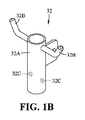
図1A及び図1Bの実施形態では、可動部材32が、支持管20の第1及び第2の端部21、22間の外面の周囲に取り付けられた中空の移動可能な外側本体32Aを含む。外側本体32Aは、その内面に、支持管20の外面に係合して支持管20に沿って外側本体32Aを移動させる1又は2以上の回転部材32Cを有する。図示の実施形態では、回転部材32Cが軸受であるが、他の構成の回転部材32Cも本開示の範囲に含まれる。支持管20の外面に沿った外側本体32Aの位置は、ユーザが行っているトレーニング運動に応答して外側本体32Aが支持管20に沿って摺動するにつれて変化する。外側本体32Aは、抵抗要素を受け取るための1又は2以上のフック32Bを有する。他の構成の可動部材32も可能であり、本開示の範囲に含まれる。
In the embodiment of FIGS. 1A and 1B, the
アセンブリ30は、1又は2以上の抵抗発生要素も含む。各抵抗発生要素は、弾性的に変形することに応答して抵抗を生じる弾性部材33である。図1Aに示す実施形態では、弾性部材33が1又は2以上の弾性帯33Aを含む。各弾性帯33Aは、弾性変形する弾性部材である。各弾性帯33Aの変形に対する抵抗が、トレーニング運動に必要な抵抗を生じる。各弾性帯33Aは、弾性変形するあらゆる好適なポリマー材料で形成することができる。各弾性帯33Aが同じ抵抗負荷を生じることもでき、又は異なる抵抗負荷を生じる弾性帯33Aを使用することもできる。ある実施形態では、弾性帯33Aが、その異なる抵抗値を示すように視覚的な表示を有し、記号を付けられ、又は別様にマークを付けられる。例えば、弾性帯33Aは、所与の色が特定の抵抗値を示すように色分けすることができる。別の実施形態では、弾性部材33のうちの1つ又は2つ以上がばねを含む。
各弾性帯33Aは、固定部材及び可動部材31、32間に延び、これらの部材に取り外し可能に取り付けることができる。換言すれば、各弾性帯33Aは、固定部材31と可動部材32とを連結する。図示の実施形態では、弾性帯33Aの一方の端部が可動部材32のフック32Bの周囲に取り付けられ、他方の端部が固定部材31のフック31Bの周囲に取り付けられる。従って、可動部材32がユーザによって支持管20に沿って固定部材31から離れて方向Dに移動すると、可動部材32と固定部材31との間の距離が増加する。この結果、固定部材及び可動部材31、32を連結する各弾性帯33Aが延び、これによって抵抗が生じるようになる。
Each elastic band 33A extends between the fixed member and the
従って、ユーザは、トレーニングにとって望ましい抵抗を弾性帯33Aによって容易に修正できるようになると理解することができる。例えば、ユーザは、ウェイトトレーニングなどのために大きな抵抗を受けたいと望む場合、固定部材及び可動部材31、32のフック31B、32Bの周囲に多くの弾性帯33Aを単純に追加すればよい。同様に、ユーザは、心血管訓練などのために小さな抵抗を受けたいと望む場合、1又は2以上の弾性帯33Aを単純に取り外し、又は弾性帯33Aを抵抗の小さなものに交換すればよい。
Accordingly, the user can understand that the resistance desired for training can be easily corrected by the elastic band 33A. For example, the user may simply add many elastic bands 33A around the
この手法は、摺動マウントにフリーウェイトを追加する必要があるいくつかの先行技術の運動器具にも引けを取らない。このような抵抗修正法は、比較的重いフリーウェイトを操作する必要があるので面倒である。さらに、比較的重いウェイトを操作することにより、ウェイトが落下して怪我をしたり、或いはウェイトの移動中に誰かにぶつかってしったりするリスクが増す。機械が構造的応力を受けるまで及び/又は不具合を生じるまでにどれほどの追加重量を支持できるかにも限界がある。さらに、このような抵抗修正法では、ユーザがトレーニング中に利用できる異なるフリーウェイトを有している必要がある。トレーニングに利用できる好適な量のフリーウェイトを常に準備しておくのは面倒であり、コストが掛かり、可能性も低く、機械の可搬性も低下する。 This approach is comparable to some prior art exercise devices that require the addition of free weights to the sliding mount. Such resistance correction is cumbersome as it requires the manipulation of relatively heavy free weights. In addition, manipulating the relatively heavy weights increases the risk that the weights may fall and cause injury or may bump into someone while moving the weights. There is also a limit to how much additional weight can be supported before the machine is subjected to structural stresses and / or failure. Furthermore, such resistance correction methods require the user to have different free weights available during training. It is cumbersome, always costly, less likely, and less portable for machines, always having a suitable amount of free weights available for training.
対照的に、本明細書で開示する弾性帯33Aは、フリーウェイトに比べて重量がわずかであり、保管が容易であり、容易に大量輸送することができる。従って、弾性帯33Aを固定部材及び可動部材31、32と共に使用すると、フリーウェイトに関連する上述した不便さ及び潜在的な危険を伴わずに器具10の抵抗を素早く増減することができる。
In contrast, the elastic bands 33A disclosed herein are lighter in weight than free weights, easy to store, and can be easily mass shipped. Thus, the use of elastic band 33A with fixed and
引き続き図1Aを参照すると、アセンブリ30は、可動部材32を移動させることによって器具10を動作させ、所望の抵抗を生じてアセンブリ30に力を作用させるケーブル及び滑車システムも含む。具体的に言えば、アセンブリ30は、複数の滑車34と手動操作可能なケーブル35とを含む。1つ又は2つ以上の滑車34Aは可動部材32上に位置し、可動部材32と共に移動する。滑車34Aは、ケーブル35によって滑車34Aが動くことによって可動部材32を移動させることができる。残りの滑車34のうちの1つ又は2つ以上は支持管20に取り付けられ、本明細書では参照番号34Bで示す。図示の実施形態では、支持管の滑車34Bが、支持管20に対して適所に固定されたまま移動しない。
Still referring to FIG. 1A, the
手動操作可能なケーブル35は、滑車34を支持管20に、互いに、そして運動用付属品40を介してユーザに連結する。「手動操作可能な」という表現は、ユーザの動作によってケーブルが引っ張られて移動することを意味する。図1Aの実施形態では、ケーブル35の第1の端部35Aが支持管20に取り付けられ、ケーブル35の第2の端部35Bが運動用付属品40に取り付けられる。図示の実施形態では、ケーブル35が単一のケーブル35である。別の実施形態では、ケーブル35が2又は3以上のケーブル部分で構成される。
A manually
次に、図2A及び図2Bを参照しながら器具10の動作についてさらに詳細に説明する。
The operation of the
図2Aに、固定部材31及び可動部材32のフック31B、32Bの周囲に取り付けられた2つの弾性帯33Aを示す。ケーブル35の第1の端部35Aは支持管20に取り付けられ、第2の端部35Bは運動用付属品40に取り付けられる。ケーブル35は、その第2の端部35B及び運動用付属品40から延びて第1の支持管滑車34Bに巻き付き、その後に第2の支持管滑車34B(図2Bを参照)に向かって第2の支持管滑車34Bに巻き付き、その後に可動部材滑車34Aに向かって可動部材滑車34Aに巻き付き、最後に支持管20における第1の端部35Aで終端する。他の構成のケーブル及び滑車システムも本開示の範囲に含まれる。図2A及び図2Bに示す単一のケーブル35は、容易に保管されて支持管20と運動用付属品40の両方に容易に取り付けられ、器具10の構成要素に容易に巻き回される。
In FIG. 2A, two elastic bands 33A attached around the
図2Aに示すようにトレーニング運動が行われていない時には、弾性帯33Aが弾性変形せずに抵抗は発生しない。図2Bに示すようにトレーニング運動が行われている時には、弾性帯33Aが変形して抵抗が発生する。 As shown in FIG. 2A, when the training exercise is not performed, the elastic band 33A is not elastically deformed and no resistance occurs. When a training exercise is performed as shown in FIG. 2B, the elastic band 33A is deformed to generate resistance.
具体的に言えば、この実施形態では、ユーザが器具10から離れる方向に運動用付属品40を引き寄せると、ケーブル35を引き付けることになる。ケーブル及び滑車システムは、(図2Bに示すように)移動部材32を固定部材31に対して方向Dに沿って移動させる。この結果、弾性帯33Aが弾性変形し、これによって運動用付属品40の引き寄せに対する所望の抵抗が生じる。
Specifically, in this embodiment, as the user pulls on the
図3に、別の実施形態による運動器具110を示しており、ここでは図1A〜図2Bの実施形態のものと同様の要素を同じ参照番号によって識別し、従ってこれらについてはさらに説明しない。器具110の抵抗発生アセンブリ130は、滑車34を収容するための複数の滑車ハウジング136を含む。各取り付け部材123は、壁取り付け部123Aと、枢動ブラケット124Eと、ロック機構150とを含む。支持要素120は、2又は3以上の相互接続された伸長部分125を含む。以下、これらの器具110の特徴についてさらに詳細に説明する。
FIG. 3 shows an
図4A及び図4Bに、滑車34を収容するための滑車ハウジング136を示す。図4Aに示す滑車ハウジング136は、支持要素120の第1及び/又は第2の端部21、22に配置されて適所に固定される。図4Bに示す滑車ハウジング136は可動部材132の一部であり、可動部材132と共に移動可能である。各滑車ハウジング136は、滑車ハウジング136内に配置されたケーブルガイド137を有する。ケーブルガイド137は滑車34から離間して、滑車34との間に間隙138を定める。ケーブルガイド137と滑車34との間の間隙138には、手動操作可能なケーブル35が位置する。ケーブルガイド137は、滑車ハウジング136に固定されてケーブル35が滑車34から外れるのを防ぐ構造である。図4Bを参照すると、可動部材132の可動体132Aは滑車ハウジング136である。可動体132Aは、滑車ハウジング136に固定して取り付けられたトラック132Dを含む。トラック132Dは、支持要素120に係合して可動体132を支持要素120に沿って移動させるホイール132Eを有する。
A
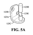
図5A及び図5Bを参照すると、取り付け部材123の少なくとも一方は、貫通穴126を有する枢動ブラケット124Aを含む。枢動ブラケット124Aは、その第1又は第2の端部21、22の一方において支持機構120に取り付けられる。取り付け部材123は、ドア又は壁面に取り付け可能な壁取り付け部123Aを含む。壁取り付け部123AはL字形ブラケットであり、第2の壁部123Cと直角に相互接続された第1の壁部123Bを有する。第1の壁部123Bは、第1の壁部123Bを、従って壁取り付け部123Aと枢動ブラケット124Aとを壁面に取り付けることができるように、締結具を受け取るための開口部を有する。第2の壁部123Cは、第2の壁部123Cの1又は2以上の面から突出する取り付けピン123Dを有する。図示の実施形態では、第2の壁部123Cの1つの面のみから取り付けピン123Dが延びる。別の実施形態では、第2の壁部123Cの両面から取り付けピン123D又は別個の取り付けピン123Dが逆方向に延びる。図5Bに示すように、取り付けピン123Dは、枢動ブラケット124Aの貫通穴126に挿入することができる。貫通穴126を通じて取り付けピン123Dを挿入すると、支持要素120が壁取り付け部123Aに枢動可能に取り付けられる。
Referring to FIGS. 5A and 5B, at least one of the mounting
ある実施形態では、取り付け部材123が、支持要素120が壁取り付け部123Aから意図せず外れるのを防ぐロック機構150を有する。このような機能を実現するロック機構150は多くの異なる構成が可能であり、これらも本開示の範囲に含まれる。図6A及び図6Bに示す実施形態では、ロック機構150が、枢動ブラケット124Aの開口部162に挿通できる押し込み部材161を含む。取り付けピン123Dは、取り付けピン123Dの残り部分よりも小さな半径の薄肉部分123Eを有する。押し込み部材161は、その一部に沿って溝部163を有する。図6Aに示すようなロック位置では、取り付けピン123Dが枢動ブラケット124Aの貫通穴126から外れるのが防がれる。ロック位置に移行させるには、ユーザが押し込み部材161を枢動ブラケット124Aの開口部162に押し込む。これにより、押し込み部材161の溝部163が移動して取り付けピン123Dの薄肉部分123Eと整列しないようになる。図6Bに示すようなロック解除位置では、取り付けピン123Dを枢動ブラケット124Aの貫通穴126から取り外すことができる。ロック解除位置に移行させるには、ユーザが押し込み部材161を枢動ブラケット124Aの開口部162から少なくとも部分的に引っ張り出す。これにより、押し込み部材161の溝部163が移動して取り付けピン123Dの薄肉部分123Eと整列するようになる。
In one embodiment, the mounting
図7に、上述したクランプ124の別の実施形態を示す。図示の実施形態では、クランプ124が枢動ブラケット124Aに取り付けられる。別の実施形態では、クランプ124が壁取り付け部123Aに取り付けられる。このような実施形態では、クランプ124が、壁取り付け部123Aの取り付けピン123Dに係合するための開口部を有する。
FIG. 7 shows another embodiment of the
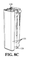
図8Aを参照すると、支持要素120の相互接続された伸長部分125は、ユーザによる器具110の素早い組み立て及び分解を可能にするように互いに取り外し可能に取り付けられる。このような機能を実現する伸長部分125は多くの異なる構成が可能であり、これらも本開示の範囲に含まれる。図8Aに示す実施形態では、伸長部分125の1つが、隣接する伸長部分125の対応する開口部に摩擦嵌めされるスリーブ127を有する。全ての伸長部分125間には、これらの伸長部分125を互いに結合する弾性支持ケーブル128が延びる。ユーザは、支持要素120を保管又は輸送のために分解したいと望む場合、各伸長部分125を隣接する伸長部分125から単純に分離する。伸長部分125は弾性支持ケーブル128によって互いに連結されているので、支持部分125は、互いに対して位置付け、積み重ね、折り畳み、又は別様に配置して保管及び/又は輸送を容易にすることができる。例えば、図8A及び図8Bに示すように、支持ケーブル128によって連結された伸長部分125を隣り合わせに配置すると、これらの伸長部分125が占める空間が最小になる。支持ケーブル128は、伸長部分125が分離又は誤配置される可能性を下げる。
Referring to FIG. 8A, the
図1Aを参照して、運動器具10をドア又は壁面に取り付ける方法も開示する。この方法は、細長い支持要素20をドア又は壁面に取り付けるステップと、少なくとも1つの弾性部材33を用いて可動部材32を固定部材31に連結するステップとを含む。この方法は、手動操作可能なケーブル35を用いて可動部材32と支持機構20とを連結するステップを含む。ケーブル35は、固定部材31に対する移動部材32の移動をもたらす。
Referring to FIG. 1A, a method of attaching
上記の内容に照らせば、本明細書に開示する器具10、100は、その少なくともいくつかの実施形態において、容易に輸送でき、容易に保管され、使用のために容易にドア又は壁に寄せて設置される、抵抗に基づく運動器具10、100であると理解することができる。器具10、100は、垂直配向又は水平配向、或いはこれらの間のあらゆる配向で取り付けることができる。器具10、100は、ユーザが比較的軽量の容易に保管できる弾性帯33Aを追加して器具の抵抗を容易に増加できるようにすることによって、心血管運動及び/又はウェイトトレーニング運動を容易にする。支持管20の旋回能力は、様々な身体部分に対して行うべき多くの異なるタイプのトレーニング運動を可能にする。
In light of the above, the
弾性帯33Aは、空間効率及び重量効率の両方に優れる。これらの弾性帯33Aは輸送が容易であり、従って器具10、110の可搬性を高める。 The elastic band 33A is excellent in both space efficiency and weight efficiency. These elastic bands 33A are easy to transport and thus enhance the portability of the device 10,110.
支持管20、固定部材31及び可動部材32の構成材料は、比較的軽量とすることができる。これによって器具10、110の総重量が減少し、場合によっては10ポンド未満の重量にすることができる。
The constituent materials of the
運動用付属品40は、本明細書では特定の構成を有するように示しているが、ケーブル35に連結して器具10、110と共に使用できるあらゆる好適な付属品40とすることができる。好適な運動用付属品40のいくつかの非限定的な例としては、ハンドルバー、トレッドミル、ローイングエレメント及びレッグエクステンション又はレッグカールベンチが挙げられる。また、運動用付属品40は、あらゆる所望のトレーニング運動を行うために支持管20に対する様々な位置及び様々な配向で使用することができる。
Although the
さらに、支持管20を取り付ける支持面は、ドア又はドアフレームとして図示し説明しているが、使用中に器具10、110を支持するためのあらゆる好適な表面とすることができる。非限定的な例としては、壁、ドア枠及びドアフレームが挙げられる。
Furthermore, the support surface to which the
上記の説明は例示にすぎず、当業者であれば、開示した本発明の範囲から逸脱することなく説明した実施形態に変更を加えることもできると認識するであろう。当業者には、本開示を再検討すれば、本発明の範囲に含まれるさらに他の修正が明らかになるであろうが、このような修正も添付の特許請求の範囲に含まれるように意図される。 The above description is merely exemplary, and those skilled in the art will recognize that changes can be made to the described embodiments without departing from the scope of the disclosed invention. Further modifications within the scope of the present invention will become apparent to a person skilled in the art upon reviewing the present disclosure, but such modifications are intended to be included within the scope of the appended claims. Be done.
10 運動器具
20 支持要素
20A 内管
20B 外管
20C 付勢式突起部
20D スロット
21 第1の端部
22 第2の端部
23 取り付け部材
24 クランプ
24A C型ブラケット
24B ロッド
24C ノブ
24D 接触パッド
24E 枢動ブラケット
30 抵抗発生アセンブリ
31 固定部材
31A 外側管体
31B フック
32 可動部材
32A 外側本体
32B フック
33 弾性部材
33A 弾性帯
34 滑車
34A 可動部材滑車
34B 支持管滑車
35 ケーブル
35A 第1の端部
35B 第2の端部
40 運動用付属品
DESCRIPTION OF
Claims (22)
第1の端部と第2の端部との間に延びる細長い支持要素と、
抵抗発生アセンブリと、を備え、
前記支持要素は、前記第1及び第2の端部の各々に配置された取り付け部材を有し、各取り付け部材は、ドア又は壁面に係合して該ドア又は壁面に前記支持要素を取り付けるように前記ドア又は壁面に取り付け可能であり、
前記抵抗発生アセンブリは、
前記支持要素に固定して取り付けられた固定部材と、
前記支持要素に取り付けられ、該支持要素に沿って前記固定部材に対して移動可能な可動部材と、
前記固定部材と前記可動部材とに取り外し可能に取り付けられて前記固定部材と前記可動部材との間に延び、前記固定部材に対する前記可動部材の移動によって弾性的に変形することによって抵抗を生じる少なくとも1つの弾性部材と、
複数の滑車と、を含み、
前記滑車のうちの少なくとも1つは、前記可動部材に取り付けられて該可動部材と共に移動可能であり、前記滑車のうちの少なくとも別の1つは前記支持要素に取り付けられ、前記固定部材に対する前記可動部材の移動をもたらす手動操作可能なケーブルが前記滑車に係合している、運動器具。 Exercise equipment,
An elongated support element extending between the first end and the second end;
And a resistance generating assembly,
The support element has a mounting member disposed at each of the first and second ends, each mounting member engaging a door or wall to mount the support element on the door or wall Can be attached to the door or wall,
The resistance generating assembly is
A fixing member fixedly attached to the support element;
A movable member attached to the support element and movable relative to the fixed member along the support element;
At least one of releasably attached to the fixed member and the movable member and extending between the fixed member and the movable member to generate resistance by being elastically deformed by the movement of the movable member with respect to the fixed member. Two elastic members,
Including multiple pulleys,
At least one of the pulleys is attached to the movable member and movable with the movable member, and at least another one of the pulleys is attached to the support element and the movable relative to the fixed member An exercise apparatus, wherein a manually operable cable for causing movement of a member is engaged with the pulley.
前記L字形ブラケットの第1の壁部は、前記ドア又は壁面に取り付け可能であり、前記L字形ブラケットの第2の壁部は、該第2の壁部の少なくとも1つの面から突出する取り付けピンを有し、該取り付けピンは、前記枢動ブラケットの前記貫通穴に挿入されて、前記支持要素を前記壁取り付け部に枢動可能に取り付け可能である、請求項1〜5のいずれか1項に記載の運動器具。 At least one of the attachment members includes a pivoting bracket having a through hole attached to the support element and a wall attachment having an L-shaped bracket attachable to the door or wall.
A first wall of the L-bracket is attachable to the door or wall, and a second wall of the L-bracket is a mounting pin projecting from at least one face of the second wall The mounting pin according to any one of the preceding claims, wherein the mounting pin is inserted into the through hole of the pivoting bracket to pivotally attach the support element to the wall mounting portion. Exercise equipment as described in.
前記ドア又は壁面に細長い支持要素を取り付けるステップと、
前記支持要素に沿って該支持要素の固定要素に対して移動可能な部材を、前記固定要素に対する前記部材の移動によって弾性的に変形した時に抵抗を生じる少なくとも1つの弾性部材に連結するステップと、
前記部材及び前記支持要素を、前記固定要素に対する前記部材の移動をもたらす手動操作可能なケーブルに連結するステップと、
を含むことを特徴とする方法。 A method of attaching exercise equipment to a door or wall,
Attaching an elongate support element to the door or wall;
Coupling a movable member relative to a fixed element of the support element along the support element to at least one elastic member that provides resistance when elastically deformed by the movement of the member relative to the fixed element;
Coupling the member and the support element to a manually operable cable that causes movement of the member relative to the fixed element;
A method characterized by comprising.
Applications Claiming Priority (3)
| Application Number | Priority Date | Filing Date | Title |
|---|---|---|---|
| US201662304528P | 2016-03-07 | 2016-03-07 | |
| US62/304,528 | 2016-03-07 | ||
| PCT/CA2017/050300 WO2017152275A1 (en) | 2016-03-07 | 2017-03-06 | Exercise apparatus |
Publications (1)
| Publication Number | Publication Date |
|---|---|
| JP2019508209A true JP2019508209A (en) | 2019-03-28 |
Family
ID=59789965
Family Applications (1)
| Application Number | Title | Priority Date | Filing Date |
|---|---|---|---|
| JP2018566620A Pending JP2019508209A (en) | 2016-03-07 | 2017-03-06 | Exercise equipment |
Country Status (9)
| Country | Link |
|---|---|
| US (2) | US11123596B2 (en) |
| EP (2) | EP3881908A1 (en) |
| JP (1) | JP2019508209A (en) |
| KR (1) | KR20180118184A (en) |
| CN (1) | CN109069898B (en) |
| CA (1) | CA3016804A1 (en) |
| ES (1) | ES2886262T3 (en) |
| SG (1) | SG11201807424VA (en) |
| WO (1) | WO2017152275A1 (en) |
Families Citing this family (9)
| Publication number | Priority date | Publication date | Assignee | Title |
|---|---|---|---|---|
| IT201600093772A1 (en) * | 2016-09-19 | 2018-03-19 | Silvano Zanetti | GINNICO APPARATUS FOR THE PERFORMANCE OF FREE-BODY EXERCISES |
| WO2018195587A1 (en) * | 2017-04-28 | 2018-11-01 | Fitpac Pty Ltd | Resistance device |
| US10413770B2 (en) * | 2017-07-03 | 2019-09-17 | Norman Paul Gustafson | Power arc exercise device |
| US11052280B1 (en) * | 2018-05-10 | 2021-07-06 | NV Athletics, LLC | Weight bearing exercise system |
| US11247092B2 (en) * | 2019-02-24 | 2022-02-15 | Kevin Albert Garcia | Portable full body workout system |
| GB202013410D0 (en) * | 2020-08-27 | 2020-10-14 | Obsidian Int Ltd | Exercise apparatus |
| USD953450S1 (en) * | 2021-06-29 | 2022-05-31 | Yiwu Chaochen Sporting Goods Co., Ltd. | Wall mounted arm and pull up exerciser |
| USD953449S1 (en) * | 2021-06-29 | 2022-05-31 | Yiwu Chacchen Sporting Goods Co., Ltd. | Wall mounted arm strength exerciser |
| US20230009261A1 (en) * | 2021-07-12 | 2023-01-12 | Francis Noble Kelly | Adjustable exercise equipment |
Family Cites Families (83)
| Publication number | Priority date | Publication date | Assignee | Title |
|---|---|---|---|---|
| US254108A (en) | 1882-02-28 | Apparatus | ||
| FR541324A (en) | 1921-09-20 | 1922-07-26 | Improvements to chamber gymnastics equipment | |
| US1620910A (en) | 1923-02-15 | 1927-03-15 | Harry E Minnich | Exercising device |
| US1538844A (en) | 1923-03-13 | 1925-05-19 | Mary Weimar | Progressive exerciser |
| US1633124A (en) | 1925-10-28 | 1927-06-21 | Roy H Noe | Exercising apparatus |
| US1749544A (en) | 1928-02-13 | 1930-03-04 | Pagano Joseph | Exercising apparatus |
| US2930614A (en) | 1954-08-06 | 1960-03-29 | Judson C Mcintosh | Body exercising device |
| US2977120A (en) * | 1959-06-30 | 1961-03-28 | Wesley B Morris | Exercising device |
| US3427023A (en) | 1966-04-19 | 1969-02-11 | Diversified Prod | Handle for stretchable exercising device |
| US3863521A (en) | 1971-10-26 | 1975-02-04 | Carlisle Corp | Adjustable handlebars |
| US3861675A (en) * | 1973-10-26 | 1975-01-21 | Robert Thorenz Hopper | Swimmer training device |
| GB1475447A (en) | 1974-07-03 | 1977-06-01 | Geisselbrecht W | Gymnastic exercise appliance |
| US4072309A (en) | 1976-06-21 | 1978-02-07 | Wilson Jerry Lee | Multi-purpose exercise device |
| US4402504A (en) * | 1981-05-19 | 1983-09-06 | Christian Robert J | Wall mounted adjustable exercise device |
| US4492375A (en) | 1982-08-16 | 1985-01-08 | Contractor Equipment Manufacturers, Inc. | Resilient type exercising device with removable weights |
| CH665777A5 (en) * | 1984-09-17 | 1988-06-15 | Maurice Chillier | MECHANOTHERAPY APPARATUS. |
| US4582320A (en) | 1984-09-21 | 1986-04-15 | Shaw James H | Exercise equipment |
| US4685670A (en) * | 1984-10-01 | 1987-08-11 | Harold Zinkin | Elastic tension exercising apparatus with multiple pass cable and pulley |
| US4621805A (en) | 1985-07-29 | 1986-11-11 | Chen Yi S | Handle structure for an exercycle |
| US5135216A (en) | 1991-01-29 | 1992-08-04 | Proform Fitness Products, Inc. | Modular resistance assembly for exercise machines |
| CA1284666C (en) | 1986-08-01 | 1991-06-04 | Robert S. Hinds | Exercise apparatus |
| US4830365A (en) * | 1987-08-12 | 1989-05-16 | March Craig J | Home fitness gym |
| FR2629071B1 (en) | 1988-03-22 | 1991-03-15 | Produits Refractaires | REACTIVE ZIRCONIUM OXIDE AND ITS PREPARATION |
| US5144859A (en) | 1989-02-22 | 1992-09-08 | Malone Robert D | Multiple position swivel for handlebars |
| US5029850A (en) | 1989-08-21 | 1991-07-09 | Verimark (Proprietary) Limited | Exercising apparatus |
| US5050869A (en) | 1990-06-07 | 1991-09-24 | Frate Richard A | Portable exercise machine |
| US5722922A (en) | 1991-01-23 | 1998-03-03 | Icon Health & Fitness, Inc. | Aerobic and anaerobic exercise machine |
| US5242353A (en) | 1991-11-13 | 1993-09-07 | Dayco Products, Inc. | Biasing means, components therefor and methods of making same |
| US5616111A (en) | 1993-04-30 | 1997-04-01 | Randolph; Lucian | Exoskeletal exercise system |
| US5387171A (en) | 1994-01-14 | 1995-02-07 | National Barbell Supply, Inc. | Variable resistance band exercise machine |
| US5468205A (en) | 1994-11-02 | 1995-11-21 | Mcfall; Michael | Portable door mounted exercise apparatus |
| US5603681A (en) | 1995-10-23 | 1997-02-18 | Olschansky; Brad | Portable multi-exercise system |
| US5885196A (en) | 1996-11-25 | 1999-03-23 | Kordun, Ltd. | Multiple elastic cable exercise device |
| US5820529A (en) * | 1997-04-25 | 1998-10-13 | Mitchell Weintraub | Dual operational exercise resistance device |
| US5842939A (en) * | 1997-05-27 | 1998-12-01 | Act Labs Ltd. | Portable sporting goal framework and net |
| US6042523A (en) | 1997-06-06 | 2000-03-28 | Graham; Gary A. | Therapeutic exercise apparatus and method |
| US6015371A (en) * | 1998-12-24 | 2000-01-18 | Davitt; Christopher | Exercise mechanism |
| US6319179B1 (en) | 1998-12-28 | 2001-11-20 | Robert Sylvester Hinds | Single spine elastic cord exercise assembly |
| US6926650B2 (en) | 1999-03-11 | 2005-08-09 | Balanced Body, Inc. | Collapsible reformer exercise apparatus |
| US7163500B2 (en) | 2003-11-25 | 2007-01-16 | Balanced Body, Inc. | Reformer exercise apparatus anchor bar assembly |
| US6142919A (en) * | 1999-04-12 | 2000-11-07 | Jorgensen; Adam A. | Multi-purpose low profile physical exercising device |
| US20010046928A1 (en) * | 2000-03-06 | 2001-11-29 | Nette Terry Van | Variable resistance exercise device |
| TW518243B (en) * | 2000-03-30 | 2003-01-21 | Tessema D Shifferaw | Improved apparatus and methods for abdominal muscle and gluteal muscle exercise |
| TW453207U (en) | 2001-01-18 | 2001-09-01 | Superweigh Entpr Co Ltd | Multifunctional exercise machine |
| US6494817B2 (en) * | 2001-02-20 | 2002-12-17 | Victoria Jo Whited Lake | Portable exercising device |
| DE10136402C2 (en) | 2001-07-26 | 2003-07-31 | Fraunhofer Ges Forschung | Physically active patch and method of manufacture |
| US20030069112A1 (en) * | 2001-10-09 | 2003-04-10 | Patrick Williams | Exercise machine |
| CA2466435C (en) * | 2001-11-13 | 2009-03-17 | Keiser Corporation | Exercise apparatus |
| US7250022B2 (en) | 2002-06-14 | 2007-07-31 | Dalebout William T | Exercise device with centrally mounted resistance rod |
| US7806805B2 (en) | 2003-10-27 | 2010-10-05 | Stamina Products, Inc. | Exercise apparatus with resilient foot support |
| US6676576B1 (en) | 2003-01-21 | 2004-01-13 | Ying-Ching Wu | Adjustable pull exerciser |
| US7291100B2 (en) | 2003-02-20 | 2007-11-06 | Alliance Design & Design Development Group, Inc. | Exercise equipment resistance unit |
| US20050113223A1 (en) | 2003-11-24 | 2005-05-26 | Dovner Edward R. | Exercise device with elastic resistance |
| DE102004013737A1 (en) | 2004-03-18 | 2005-10-06 | Peter Kindermann | Unit for training muscles/muscle groups comprises a vertical support unit with two receiving units that are fixed on a wall a distance apart and have assembly aids for cables/deviating rollers for a force displacement unit/tension unit |
| CN2805828Y (en) | 2005-08-01 | 2006-08-16 | 吴盈庆 | Rope-pulling body-building device |
| US20070105696A1 (en) | 2005-11-09 | 2007-05-10 | Castel J C | Method and apparatus for physical therapy exercise |
| DK1979057T3 (en) | 2006-01-30 | 2011-08-15 | Balanced Body Inc | An exercise apparatus |
| US7572212B2 (en) * | 2007-01-05 | 2009-08-11 | Daniel T. Cassidy | Portable weightlifting apparatus |
| SE532229C2 (en) | 2007-11-29 | 2009-11-17 | Tomas Svenberg | Dumbbell |
| SE0702656L (en) | 2007-11-29 | 2009-05-30 | Tomas Svenberg | Dumbbell |
| US7857736B2 (en) | 2008-03-25 | 2010-12-28 | Merrithew Corporation | Adjustable reformer |
| US20140031182A1 (en) * | 2008-08-19 | 2014-01-30 | Darren Donofrio | Wall-Mounted Home Fitness Training Equipment |
| CN201768299U (en) | 2009-11-13 | 2011-03-23 | 曾俊明 | Damping device of sports equipment |
| US20120142503A1 (en) * | 2010-12-02 | 2012-06-07 | Mardig Sevadjian | Pulley Apparatus for Resistance Exercises |
| US9609925B2 (en) | 2011-02-04 | 2017-04-04 | Lekisport Ag | Folding pole, in particular for nordic walking |
| US8485951B1 (en) * | 2011-08-02 | 2013-07-16 | Frederick R. Adams | Vehicle mounted multi-position resistance tube exercise apparatus |
| US8485950B2 (en) * | 2011-08-02 | 2013-07-16 | Frederick R. Adams | Multi-position resistance tube exercise apparatus |
| US8562494B2 (en) | 2012-01-19 | 2013-10-22 | Karl Thomas | Portable exercise device and method of using the same |
| US9345922B2 (en) | 2012-01-23 | 2016-05-24 | Kasper Allison | Strength training system and method having elastic resistance and suspension devices |
| US20160074691A1 (en) | 2012-05-08 | 2016-03-17 | Frog Fitness, Inc. | Resistance device, system, and method for use with an exercise apparatus |
| US20170144009A1 (en) | 2012-05-08 | 2017-05-25 | Frog Fitness, Inc. | Resistance Member Assembly, System, and Method for use with an Exercise Apparatus |
| US20140141948A1 (en) | 2012-09-18 | 2014-05-22 | Rockit Body Pilates, Llc | Pilates reformer |
| US9028381B2 (en) | 2012-10-16 | 2015-05-12 | Michael J. Mestemaker | Door-mounted fitness device with removable pulley members |
| CN104936659A (en) | 2012-10-26 | 2015-09-23 | 古金控股有限公司 | Freestanding selectable free weight assembly |
| CN203075534U (en) | 2013-02-28 | 2013-07-24 | 山东体育学院 | Training instrument capable of regulating waist resistance |
| US9555278B2 (en) | 2013-03-15 | 2017-01-31 | Arqfx Outdoor Fitness Systems, Llc | Strength training and stretching system and resistance band assembly for use therewith |
| US9005086B1 (en) | 2013-08-28 | 2015-04-14 | Douglas L. Hermann | Portable rowing machine |
| US9339682B2 (en) * | 2013-11-08 | 2016-05-17 | Kiio Inc. | Mountable exercise apparatus |
| CN203763761U (en) | 2014-04-10 | 2014-08-13 | 张仲甫 | Pulling rope exercising device structure |
| US9675832B2 (en) | 2015-01-06 | 2017-06-13 | Prism Fitness, Inc. | Interchangeable resistance tube assembly |
| US10661112B2 (en) | 2016-07-25 | 2020-05-26 | Tonal Systems, Inc. | Digital strength training |
| CN106218788B (en) | 2016-08-31 | 2019-02-01 | 杭州速控软件有限公司 | The corner of electrodynamic balance vehicle is adjustable manipulation handle |
| US20200289866A1 (en) * | 2019-03-14 | 2020-09-17 | Gvoich Fitness Systems | Dual Balance Spring Tower Apparatus and Method of Using Same |
-
2017
- 2017-03-06 WO PCT/CA2017/050300 patent/WO2017152275A1/en active Application Filing
- 2017-03-06 EP EP21166064.2A patent/EP3881908A1/en active Pending
- 2017-03-06 KR KR1020187028112A patent/KR20180118184A/en unknown
- 2017-03-06 ES ES17762372T patent/ES2886262T3/en active Active
- 2017-03-06 EP EP17762372.5A patent/EP3426359B1/en active Active
- 2017-03-06 JP JP2018566620A patent/JP2019508209A/en active Pending
- 2017-03-06 US US16/082,316 patent/US11123596B2/en active Active
- 2017-03-06 CA CA3016804A patent/CA3016804A1/en active Pending
- 2017-03-06 SG SG11201807424VA patent/SG11201807424VA/en unknown
- 2017-03-06 CN CN201780027697.3A patent/CN109069898B/en active Active
-
2021
- 2021-03-30 US US17/217,243 patent/US11819727B2/en active Active
Also Published As
| Publication number | Publication date |
|---|---|
| KR20180118184A (en) | 2018-10-30 |
| ES2886262T3 (en) | 2021-12-16 |
| WO2017152275A1 (en) | 2017-09-14 |
| CN109069898B (en) | 2021-09-21 |
| CN109069898A (en) | 2018-12-21 |
| US20210283455A1 (en) | 2021-09-16 |
| EP3881908A1 (en) | 2021-09-22 |
| EP3426359B1 (en) | 2021-05-05 |
| EP3426359A1 (en) | 2019-01-16 |
| US11123596B2 (en) | 2021-09-21 |
| US20190111305A1 (en) | 2019-04-18 |
| SG11201807424VA (en) | 2018-09-27 |
| EP3426359A4 (en) | 2019-11-20 |
| CA3016804A1 (en) | 2017-09-14 |
| US11819727B2 (en) | 2023-11-21 |
Similar Documents
| Publication | Publication Date | Title |
|---|---|---|
| JP2019508209A (en) | Exercise equipment | |
| US10857413B2 (en) | Apparatus, kit, and method for performing strap-based exercises | |
| US20130178338A1 (en) | Extending Pull-Up Bar | |
| US7878956B2 (en) | Exercise apparatus | |
| US7998045B2 (en) | Exercise chair | |
| US8286926B1 (en) | Collapsible leg assembly | |
| US7988605B1 (en) | Exercise machine | |
| US20050130814A1 (en) | Exercise apparatus with reconfigurable frame, resistance system, and platform | |
| US20120202661A1 (en) | Reformer Apparatus Having Integral Ergonomic Purchase Translatable into Deployed and Stowed Positions | |
| CA2436231A1 (en) | Exercise device | |
| EP3126016B1 (en) | Exercise device | |
| US9884220B2 (en) | Potable cable resistance pulley exercise equipment and related methods | |
| US20080081748A1 (en) | Exercise equipment adapted for use with a chair | |
| JP2021527461A (en) | Weightless traction system | |
| US20220168611A1 (en) | Adjustable pull-up bar | |
| US10201467B2 (en) | Surgical accessory interface device | |
| US11052280B1 (en) | Weight bearing exercise system | |
| CN111686402B (en) | Exercise method and apparatus | |
| US11571603B2 (en) | Multi-function foldable exercise equipment | |
| WO2022167855A1 (en) | Gym apparatus | |
| US10137326B2 (en) | Exercise device |