JP2019505774A - Device and method for handling liquids - Google Patents
Device and method for handling liquids Download PDFInfo
- Publication number
- JP2019505774A JP2019505774A JP2018531481A JP2018531481A JP2019505774A JP 2019505774 A JP2019505774 A JP 2019505774A JP 2018531481 A JP2018531481 A JP 2018531481A JP 2018531481 A JP2018531481 A JP 2018531481A JP 2019505774 A JP2019505774 A JP 2019505774A
- Authority
- JP
- Japan
- Prior art keywords
- cavity
- liquid
- chamber
- conduit
- port
- Prior art date
- Legal status (The legal status is an assumption and is not a legal conclusion. Google has not performed a legal analysis and makes no representation as to the accuracy of the status listed.)
- Pending
Links
Images


Classifications
-
- B—PERFORMING OPERATIONS; TRANSPORTING
- B01—PHYSICAL OR CHEMICAL PROCESSES OR APPARATUS IN GENERAL
- B01L—CHEMICAL OR PHYSICAL LABORATORY APPARATUS FOR GENERAL USE
- B01L3/00—Containers or dishes for laboratory use, e.g. laboratory glassware; Droppers
- B01L3/50—Containers for the purpose of retaining a material to be analysed, e.g. test tubes
- B01L3/502—Containers for the purpose of retaining a material to be analysed, e.g. test tubes with fluid transport, e.g. in multi-compartment structures
- B01L3/5027—Containers for the purpose of retaining a material to be analysed, e.g. test tubes with fluid transport, e.g. in multi-compartment structures by integrated microfluidic structures, i.e. dimensions of channels and chambers are such that surface tension forces are important, e.g. lab-on-a-chip
- B01L3/50273—Containers for the purpose of retaining a material to be analysed, e.g. test tubes with fluid transport, e.g. in multi-compartment structures by integrated microfluidic structures, i.e. dimensions of channels and chambers are such that surface tension forces are important, e.g. lab-on-a-chip characterised by the means or forces applied to move the fluids
-
- B—PERFORMING OPERATIONS; TRANSPORTING
- B01—PHYSICAL OR CHEMICAL PROCESSES OR APPARATUS IN GENERAL
- B01D—SEPARATION
- B01D17/00—Separation of liquids, not provided for elsewhere, e.g. by thermal diffusion
- B01D17/02—Separation of non-miscible liquids
- B01D17/0217—Separation of non-miscible liquids by centrifugal force
-
- B—PERFORMING OPERATIONS; TRANSPORTING
- B01—PHYSICAL OR CHEMICAL PROCESSES OR APPARATUS IN GENERAL
- B01F—MIXING, e.g. DISSOLVING, EMULSIFYING OR DISPERSING
- B01F31/00—Mixers with shaking, oscillating, or vibrating mechanisms
- B01F31/10—Mixers with shaking, oscillating, or vibrating mechanisms with a mixing receptacle rotating alternately in opposite directions
-
- B—PERFORMING OPERATIONS; TRANSPORTING
- B01—PHYSICAL OR CHEMICAL PROCESSES OR APPARATUS IN GENERAL
- B01F—MIXING, e.g. DISSOLVING, EMULSIFYING OR DISPERSING
- B01F33/00—Other mixers; Mixing plants; Combinations of mixers
- B01F33/30—Micromixers
-
- B—PERFORMING OPERATIONS; TRANSPORTING
- B01—PHYSICAL OR CHEMICAL PROCESSES OR APPARATUS IN GENERAL
- B01F—MIXING, e.g. DISSOLVING, EMULSIFYING OR DISPERSING
- B01F33/00—Other mixers; Mixing plants; Combinations of mixers
- B01F33/80—Mixing plants; Combinations of mixers
- B01F33/81—Combinations of similar mixers, e.g. with rotary stirring devices in two or more receptacles
- B01F33/811—Combinations of similar mixers, e.g. with rotary stirring devices in two or more receptacles in two or more consecutive, i.e. successive, mixing receptacles or being consecutively arranged
-
- B—PERFORMING OPERATIONS; TRANSPORTING
- B01—PHYSICAL OR CHEMICAL PROCESSES OR APPARATUS IN GENERAL
- B01F—MIXING, e.g. DISSOLVING, EMULSIFYING OR DISPERSING
- B01F35/00—Accessories for mixers; Auxiliary operations or auxiliary devices; Parts or details of general application
- B01F35/71—Feed mechanisms
- B01F35/717—Feed mechanisms characterised by the means for feeding the components to the mixer
- B01F35/71725—Feed mechanisms characterised by the means for feeding the components to the mixer using centrifugal forces
-
- B—PERFORMING OPERATIONS; TRANSPORTING
- B01—PHYSICAL OR CHEMICAL PROCESSES OR APPARATUS IN GENERAL
- B01F—MIXING, e.g. DISSOLVING, EMULSIFYING OR DISPERSING
- B01F35/00—Accessories for mixers; Auxiliary operations or auxiliary devices; Parts or details of general application
- B01F35/71—Feed mechanisms
- B01F35/717—Feed mechanisms characterised by the means for feeding the components to the mixer
- B01F35/71735—Feed mechanisms characterised by the means for feeding the components to the mixer using grippers
-
- B—PERFORMING OPERATIONS; TRANSPORTING
- B01—PHYSICAL OR CHEMICAL PROCESSES OR APPARATUS IN GENERAL
- B01L—CHEMICAL OR PHYSICAL LABORATORY APPARATUS FOR GENERAL USE
- B01L3/00—Containers or dishes for laboratory use, e.g. laboratory glassware; Droppers
- B01L3/50—Containers for the purpose of retaining a material to be analysed, e.g. test tubes
- B01L3/502—Containers for the purpose of retaining a material to be analysed, e.g. test tubes with fluid transport, e.g. in multi-compartment structures
- B01L3/5027—Containers for the purpose of retaining a material to be analysed, e.g. test tubes with fluid transport, e.g. in multi-compartment structures by integrated microfluidic structures, i.e. dimensions of channels and chambers are such that surface tension forces are important, e.g. lab-on-a-chip
- B01L3/502723—Containers for the purpose of retaining a material to be analysed, e.g. test tubes with fluid transport, e.g. in multi-compartment structures by integrated microfluidic structures, i.e. dimensions of channels and chambers are such that surface tension forces are important, e.g. lab-on-a-chip characterised by venting arrangements
-
- F—MECHANICAL ENGINEERING; LIGHTING; HEATING; WEAPONS; BLASTING
- F04—POSITIVE - DISPLACEMENT MACHINES FOR LIQUIDS; PUMPS FOR LIQUIDS OR ELASTIC FLUIDS
- F04B—POSITIVE-DISPLACEMENT MACHINES FOR LIQUIDS; PUMPS
- F04B13/00—Pumps specially modified to deliver fixed or variable measured quantities
- F04B13/02—Pumps specially modified to deliver fixed or variable measured quantities of two or more fluids at the same time
-
- F—MECHANICAL ENGINEERING; LIGHTING; HEATING; WEAPONS; BLASTING
- F04—POSITIVE - DISPLACEMENT MACHINES FOR LIQUIDS; PUMPS FOR LIQUIDS OR ELASTIC FLUIDS
- F04B—POSITIVE-DISPLACEMENT MACHINES FOR LIQUIDS; PUMPS
- F04B19/00—Machines or pumps having pertinent characteristics not provided for in, or of interest apart from, groups F04B1/00 - F04B17/00
- F04B19/006—Micropumps
-
- F—MECHANICAL ENGINEERING; LIGHTING; HEATING; WEAPONS; BLASTING
- F04—POSITIVE - DISPLACEMENT MACHINES FOR LIQUIDS; PUMPS FOR LIQUIDS OR ELASTIC FLUIDS
- F04F—PUMPING OF FLUID BY DIRECT CONTACT OF ANOTHER FLUID OR BY USING INERTIA OF FLUID TO BE PUMPED; SIPHONS
- F04F1/00—Pumps using positively or negatively pressurised fluid medium acting directly on the liquid to be pumped
- F04F1/06—Pumps using positively or negatively pressurised fluid medium acting directly on the liquid to be pumped the fluid medium acting on the surface of the liquid to be pumped
-
- B—PERFORMING OPERATIONS; TRANSPORTING
- B01—PHYSICAL OR CHEMICAL PROCESSES OR APPARATUS IN GENERAL
- B01F—MIXING, e.g. DISSOLVING, EMULSIFYING OR DISPERSING
- B01F2101/00—Mixing characterised by the nature of the mixed materials or by the application field
- B01F2101/2202—Mixing compositions or mixers in the medical or veterinary field
-
- B—PERFORMING OPERATIONS; TRANSPORTING
- B01—PHYSICAL OR CHEMICAL PROCESSES OR APPARATUS IN GENERAL
- B01L—CHEMICAL OR PHYSICAL LABORATORY APPARATUS FOR GENERAL USE
- B01L2200/00—Solutions for specific problems relating to chemical or physical laboratory apparatus
- B01L2200/06—Fluid handling related problems
- B01L2200/0605—Metering of fluids
-
- B—PERFORMING OPERATIONS; TRANSPORTING
- B01—PHYSICAL OR CHEMICAL PROCESSES OR APPARATUS IN GENERAL
- B01L—CHEMICAL OR PHYSICAL LABORATORY APPARATUS FOR GENERAL USE
- B01L2200/00—Solutions for specific problems relating to chemical or physical laboratory apparatus
- B01L2200/06—Fluid handling related problems
- B01L2200/0621—Control of the sequence of chambers filled or emptied
-
- B—PERFORMING OPERATIONS; TRANSPORTING
- B01—PHYSICAL OR CHEMICAL PROCESSES OR APPARATUS IN GENERAL
- B01L—CHEMICAL OR PHYSICAL LABORATORY APPARATUS FOR GENERAL USE
- B01L2200/00—Solutions for specific problems relating to chemical or physical laboratory apparatus
- B01L2200/06—Fluid handling related problems
- B01L2200/0684—Venting, avoiding backpressure, avoid gas bubbles
-
- B—PERFORMING OPERATIONS; TRANSPORTING
- B01—PHYSICAL OR CHEMICAL PROCESSES OR APPARATUS IN GENERAL
- B01L—CHEMICAL OR PHYSICAL LABORATORY APPARATUS FOR GENERAL USE
- B01L2200/00—Solutions for specific problems relating to chemical or physical laboratory apparatus
- B01L2200/16—Reagents, handling or storing thereof
-
- B—PERFORMING OPERATIONS; TRANSPORTING
- B01—PHYSICAL OR CHEMICAL PROCESSES OR APPARATUS IN GENERAL
- B01L—CHEMICAL OR PHYSICAL LABORATORY APPARATUS FOR GENERAL USE
- B01L2300/00—Additional constructional details
- B01L2300/08—Geometry, shape and general structure
- B01L2300/0803—Disc shape
-
- B—PERFORMING OPERATIONS; TRANSPORTING
- B01—PHYSICAL OR CHEMICAL PROCESSES OR APPARATUS IN GENERAL
- B01L—CHEMICAL OR PHYSICAL LABORATORY APPARATUS FOR GENERAL USE
- B01L2300/00—Additional constructional details
- B01L2300/08—Geometry, shape and general structure
- B01L2300/0803—Disc shape
- B01L2300/0806—Standardised forms, e.g. compact disc [CD] format
-
- B—PERFORMING OPERATIONS; TRANSPORTING
- B01—PHYSICAL OR CHEMICAL PROCESSES OR APPARATUS IN GENERAL
- B01L—CHEMICAL OR PHYSICAL LABORATORY APPARATUS FOR GENERAL USE
- B01L2300/00—Additional constructional details
- B01L2300/08—Geometry, shape and general structure
- B01L2300/0861—Configuration of multiple channels and/or chambers in a single devices
- B01L2300/0883—Serpentine channels
-
- B—PERFORMING OPERATIONS; TRANSPORTING
- B01—PHYSICAL OR CHEMICAL PROCESSES OR APPARATUS IN GENERAL
- B01L—CHEMICAL OR PHYSICAL LABORATORY APPARATUS FOR GENERAL USE
- B01L2300/00—Additional constructional details
- B01L2300/14—Means for pressure control
-
- B—PERFORMING OPERATIONS; TRANSPORTING
- B01—PHYSICAL OR CHEMICAL PROCESSES OR APPARATUS IN GENERAL
- B01L—CHEMICAL OR PHYSICAL LABORATORY APPARATUS FOR GENERAL USE
- B01L2400/00—Moving or stopping fluids
- B01L2400/04—Moving fluids with specific forces or mechanical means
- B01L2400/0403—Moving fluids with specific forces or mechanical means specific forces
- B01L2400/0409—Moving fluids with specific forces or mechanical means specific forces centrifugal forces
Landscapes
- Chemical & Material Sciences (AREA)
- Engineering & Computer Science (AREA)
- Chemical Kinetics & Catalysis (AREA)
- Health & Medical Sciences (AREA)
- Mechanical Engineering (AREA)
- General Engineering & Computer Science (AREA)
- Analytical Chemistry (AREA)
- General Health & Medical Sciences (AREA)
- Hematology (AREA)
- Clinical Laboratory Science (AREA)
- Dispersion Chemistry (AREA)
- Physics & Mathematics (AREA)
- Thermal Sciences (AREA)
- Automatic Analysis And Handling Materials Therefor (AREA)
- Physical Or Chemical Processes And Apparatus (AREA)
Abstract
【解決手段】液体をハンドリングするためのデバイスおよび方法が提供される。デバイスおよび方法は、例えばマイクロ流体デバイス上で、遠心力を利用して、液体の流れを駆動し、液体の混合、計量およびシークエンシングのうちの1つ以上を助ける。
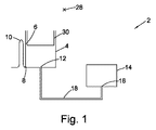
【選択図】図1Devices and methods for handling liquids are provided. The devices and methods utilize centrifugal forces, for example on microfluidic devices, to drive liquid flow and aid in one or more of liquid mixing, metering and sequencing.
[Selection] Figure 1
Description
本発明は、液体をハンドリングするためのデバイスに関し、詳細には、1種以上の液体の混合、試薬の再懸濁、および/または検出チャンバの充填のためのデバイスに関する。より詳細には、限定するものではないが、本発明は、マイクロ流体デバイス、例えば遠心マイクロ流体デバイスに関する。 The present invention relates to devices for handling liquids, and in particular to devices for mixing one or more liquids, resuspending reagents, and / or filling a detection chamber. More particularly, but not exclusively, the present invention relates to microfluidic devices, such as centrifugal microfluidic devices.
「ラボオンディスク」デバイスとして知られるデバイスにより、ある体積の液体を混合、シーケンシング、および制御できる。デバイスを回転軸を中心に回転させることにより、遠心力の作用下で、そのようなデバイスを液体が流れることができる。あるいは、デバイス内の液体の流れは、他の手段、例えば圧力駆動流および毛細管駆動流によって、誘導される場合もある。 Devices known as “lab-on-disk” devices allow a volume of liquid to be mixed, sequenced, and controlled. By rotating the device about the axis of rotation, liquid can flow through such a device under the action of centrifugal force. Alternatively, the liquid flow within the device may be induced by other means, such as pressure driven flow and capillary driven flow.
「ラボオンディスク」デバイス上での液体の処理は、液体の混合、例えば2種以上の成分を含む液体の混合、または液体中の1種以上の乾燥試薬の再懸濁を必要とする場合がある。特にマイクロ流体デバイスの場合、2種の液体同士、または液体と乾燥試薬との混合を効果的に実現することは、特にマイクロ流体デバイスで典型的に使用される少量の液体を取り扱う場合には、困難であり得る。したがって、このようなデバイスにおける液体の効果的な混合を容易にする構造を有することが有用である。 Processing liquids on “lab-on-disk” devices may require mixing of the liquids, for example, mixing liquids containing two or more components, or resuspending one or more dry reagents in the liquid. is there. Particularly in the case of microfluidic devices, the effective realization of the mixing of two liquids or between a liquid and a dry reagent is especially when handling small amounts of liquids typically used in microfluidic devices. Can be difficult. Accordingly, it is useful to have a structure that facilitates effective mixing of liquids in such devices.
本開示の各実施態様は、独立請求項に記載してある。さらに、実施形態の任意の特徴は、従属請求項に記載してある。 Each embodiment of the disclosure is set forth in the independent claims. Furthermore, optional features of the embodiments are described in the dependent claims.
一部の実施形態では、液体をハンドリングするためのデバイスが提供され、デバイスは、回転軸を中心に回転するように構成される。デバイスは、第1の空洞を備え、第1の空洞は、例えばチャンバ、チャネル、またはチャネルからなるネットワークとすることができる。第1の空洞は、遠位部分の半径方向内側にある近位部分を含む。第1の空洞は、遠位部分に配置された第1のポートを含む。デバイスは、第2の空洞をさらに備え、第2の空洞は、例えば、チャンバ、チャネルまたはチャネルからなるネットワークとすることができ、かつ遠位部分の半径方向内側にある近位部分を含む。第2の空洞は、遠位部分に配置された第2のポートを含む。第1の導管構造体は、第1のポートと第2のポートとを接続して、それらの間に液体の流れを案内する。第2のポートは、第1のポートの半径方向外側にある。第2の空洞は、液体が第2の空洞内に流入すると、第2の空洞内に気体塊が閉じ込められ、気体の圧力が上昇するように構成される。つまり、第2の空洞内外への唯一の流体流路は、第2のポートを介する流路である。 In some embodiments, a device for handling liquid is provided, and the device is configured to rotate about an axis of rotation. The device comprises a first cavity, which can be for example a chamber, a channel or a network of channels. The first cavity includes a proximal portion that is radially inward of the distal portion. The first cavity includes a first port disposed in the distal portion. The device further comprises a second cavity, which can be, for example, a chamber, a channel or a network of channels, and includes a proximal portion that is radially inward of the distal portion. The second cavity includes a second port disposed in the distal portion. The first conduit structure connects the first port and the second port and guides the flow of liquid therebetween. The second port is radially outward of the first port. The second cavity is configured such that when a liquid flows into the second cavity, a gas mass is confined in the second cavity and the gas pressure increases. That is, the only fluid flow path into and out of the second cavity is a flow path through the second port.
使用時には、予備段階として、第1の空洞内に液体を移送する。これは、遠心力の作用下、または毛細管作用などによって行うことができる。デバイスを回転すると、第1の空洞内の液体は、第1の空洞から第1のポートを介して導管構造体内に、場合によっては第2の空洞内に流出する。第2の空洞内外への唯一の流体流路が第2のポートを介する流体流路となるように第2の空洞を構成することによって、液体が第1の導管構造体を経て第2の空洞に向けて流れるにつれて、第1の導管構造体および第2の空洞に存在する気体が変位し、第2の空洞内に閉じ込められる。液体が流れるにつれて、閉じ込められた気体の圧力は、気体の圧力が液体の遠心圧力と均衡するまで上昇する。その後、デバイスが減速または停止され、遠心圧が低下すると、閉じ込められていた気体は膨張し、液体を第1の導管構造体に沿って押し戻し、一部の実施形態では、第1の空洞内まで押し戻す。液体を混合するために、この加速および減速プロセスを繰り返すことができる。 In use, liquid is transferred into the first cavity as a preliminary step. This can be done under the action of centrifugal force or by capillary action. As the device is rotated, the liquid in the first cavity flows out of the first cavity through the first port into the conduit structure and possibly into the second cavity. By configuring the second cavity such that the only fluid flow path into and out of the second cavity is the fluid flow path through the second port, the liquid passes through the first conduit structure to the second cavity. Gas flowing in the first conduit structure and the second cavity is displaced and trapped in the second cavity. As the liquid flows, the pressure of the trapped gas rises until the gas pressure balances the liquid centrifugal pressure. Thereafter, when the device is decelerated or stopped and the centrifugal pressure is reduced, the trapped gas expands and pushes the liquid back along the first conduit structure, and in some embodiments, into the first cavity. Push back. This acceleration and deceleration process can be repeated to mix the liquid.
第1の空洞は、上記の流れまたは混合構成に関係しない他のポート、入口、または出口を備えてもよいことを理解されたい。 It should be understood that the first cavity may include other ports, inlets, or outlets that are not related to the flow or mixing configuration described above.
一部の実施形態では、デバイスは、下流側空洞と、第1の空洞の出口ポートを下流側空洞の入口に接続する出口導管と、を備える。下流側空洞は、例えば、チャンバとすることができる。出口導管は、出口ポートの半径方向内側に第1の屈曲部まで延び、かつ第1の屈曲部の半径方向外側に下流側空洞の入口まで延びる。第1の屈曲部は、第1の空洞の半径方向最外部分の半径方向内側に配置され、かつ第1の空洞の半径方向最内部分の半径方向外側に配置される。 In some embodiments, the device comprises a downstream cavity and an outlet conduit connecting the outlet port of the first cavity to the inlet of the downstream cavity. The downstream cavity can be, for example, a chamber. The outlet conduit extends radially inward of the outlet port to the first bend and extends radially outward of the first bend to the downstream cavity inlet. The first bent portion is disposed radially inward of the radially outermost portion of the first cavity and radially outward of the radially innermost portion of the first cavity.
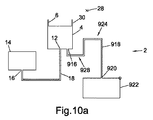
有利なことに、本構造体は、第1の空洞から下流側空洞内に移送される液体の体積の制御を助ける。第2の空洞内の圧力と遠心力との間の平衡のおかげで、第1の空洞内における液位を制御でき、以下に詳述するように、下流側空洞への液体の流入開始(第1の空洞内の液体が第1の屈曲部を乗り越える時間)と、体積(その後、第1の空洞に存在する液体)と、の両方とも制御できる。この概念については、図10a〜図10gを参照しながらより詳細に説明する。 Advantageously, the structure helps control the volume of liquid that is transferred from the first cavity into the downstream cavity. Thanks to the balance between the pressure in the second cavity and the centrifugal force, the liquid level in the first cavity can be controlled and the beginning of the flow of liquid into the downstream cavity (first Both the liquid in one cavity gets over the first bend) and the volume (the liquid present in the first cavity thereafter) can be controlled. This concept will be described in more detail with reference to FIGS. 10a to 10g.
一部の実施形態では、出口導管は、出口ポートの半径方向外側に第2の屈曲部まで延び、かつ第2の屈曲部の半径方向内側に第1の屈曲部まで延びる。このような実施形態では、第1の屈曲部は、第2の屈曲部の下流にある。他の実施形態では、第1の屈曲部は、第2の屈曲部の上流にある。 In some embodiments, the outlet conduit extends radially outward of the outlet port to a second bend and extends radially inward of the second bend to the first bend. In such an embodiment, the first bend is downstream of the second bend. In other embodiments, the first bend is upstream of the second bend.
有利なことに、結果として生じるU字形屈曲部は、第1の動作の後にサイフォンの再プライミングのリスクを低減する(すなわち、液体が下流側空洞に移送された後、液体が出口導管の頂部を乗り越えるのを防止する)。典型的には、半径方向外側のU字形屈曲部は、液体が下流側空洞に移送された後も液体で満たされたままであり、したがって、後のプロトコルにおけるさらなる加速および減速の際に、液体が、内側の屈曲部および外側の屈曲部(すなわち、第1の屈曲部および第2の屈曲部)の両方にさらに再プライミングされるのを阻止する。 Advantageously, the resulting U-shaped bend reduces the risk of siphon re-priming after the first action (i.e., after the liquid has been transferred to the downstream cavity, the liquid will flow over the top of the outlet conduit). To prevent getting over). Typically, the radially outer U-shaped bend remains filled with liquid after the liquid has been transferred to the downstream cavity, so that the liquid can be further accelerated and decelerated in later protocols. , Preventing further repriming of both the inner and outer bends (ie, the first bend and the second bend).
一部の実施形態では、第1の空洞は、出口導管の第1の屈曲部の半径方向内側および外側に延びる第1の半径方向領域と、第1の空洞の出口ポートが配置される第1の半径方向領域の半径方向外側にある第2の半径方向領域と、を有する。第1の半径方向領域における第1の空洞の断面積は、第2の半径方向領域における第1の空洞の断面積よりも小さい。この構造体は、図10fを参照して以下に詳述するように、液体が第1の空洞から下流側空洞に移送される時間のより良い制御を助ける。一部の実施形態では、第1の半径方向領域における第1の空洞の断面積は、第1の空洞内に配置された1つ以上のピラーによって、第2の半径方向領域における第1の空洞の断面積に対して減らされる。代替的または追加的に、第1の半径方向領域における第1の空洞の断面積は、一部の実施形態では、第1の半径方向領域における第1の空洞の円周方向の広がりの減少によって、および/または第1の半径方向領域における第1の空洞の深さ(すなわち、回転軸に平行な第1の空洞の寸法)の減少によって、第2の半径方向領域における第1の空洞の断面積に対して減らされる。例えば、第1の領域と第2の領域との間の第1の空洞の円周方向の広がりの段階的変化、および/または第1の領域と第2の領域との間の第1の空洞の深さの段階的変化があり得る。一部の実施形態では、出口導管の第1の屈曲部の半径方向内側の第1の半径方向領域の半径方向の広がりは、第2の半径方向領域の半径方向の広がりよりも短い。 In some embodiments, the first cavity has a first radial region extending radially inward and outward of the first bend of the outlet conduit and a first cavity in which the outlet port of the first cavity is disposed. And a second radial region that is radially outward of the radial region. The cross-sectional area of the first cavity in the first radial region is smaller than the cross-sectional area of the first cavity in the second radial region. This structure helps to better control the time during which liquid is transferred from the first cavity to the downstream cavity, as described in detail below with reference to FIG. 10f. In some embodiments, the cross-sectional area of the first cavity in the first radial region is the first cavity in the second radial region by one or more pillars disposed in the first cavity. Reduced to the cross-sectional area of Alternatively or additionally, the cross-sectional area of the first cavity in the first radial region is, in some embodiments, due to a decrease in the circumferential extent of the first cavity in the first radial region. And / or by reducing the depth of the first cavity in the first radial region (ie, the dimension of the first cavity parallel to the axis of rotation), the breaking of the first cavity in the second radial region. Reduced to area. For example, a step change in the circumferential extent of the first cavity between the first region and the second region, and / or the first cavity between the first region and the second region There can be a gradual change in the depth. In some embodiments, the radial extent of the first radial region radially inward of the first bend of the outlet conduit is shorter than the radial extent of the second radial region.
一部の実施形態では、出口ポートは、第1のポートとは別個のポートであり得る。他の実施形態では、第1のポートと出口ポートとは同一であり、例えば、第1の空洞は、(第1の導管構造体を介して)第2の空洞と、(出口導管を介して)下流側空洞と、の両方と流体連通する単一のポートを備え得る。 In some embodiments, the exit port may be a separate port from the first port. In other embodiments, the first port and the outlet port are the same, for example, the first cavity is (via the first conduit structure) the second cavity (via the outlet conduit). A) a single port in fluid communication with both the downstream cavity.
言い換えれば、一部の実施形態では、液体をハンドリングするためのデバイスが提供され、デバイスは、回転軸を中心に回転するように構成され、第1のポートを有する第1の通気孔付きチャンバと、第2のポートを有する第2の通気孔なしチャンバと、を備える。第1の通気孔付きチャンバおよび第2の通気孔なしチャンバのそれぞれは、遠位部分の半径方向内側にある近位部分を含む。第1のポートおよび第2のポートは、第1のチャンバおよび第2のチャンバのそれぞれの遠位部分に配置され、第2のポートは、第1のポートの半径方向外側にある。デバイスは、第1のポートと第2のポートとを接続して、それらの間に液体の流れを案内する第1の導管構造体を備える。 In other words, in some embodiments, a device for handling liquid is provided, the device configured to rotate about an axis of rotation and having a first vented chamber having a first port; , And a second ventless chamber having a second port. Each of the first vented chamber and the second ventless chamber includes a proximal portion that is radially inward of the distal portion. The first port and the second port are disposed at respective distal portions of the first chamber and the second chamber, and the second port is radially outward of the first port. The device comprises a first conduit structure that connects the first port and the second port and guides the flow of liquid therebetween.
一部の実施形態では、デバイスは、下流側通気孔付きチャンバと、第1の通気孔付きチャンバの出口ポートを下流側通気孔付きチャンバの入口に接続する出口導管と、を備える。出口導管は、出口ポートの半径方向内側に第1の屈曲部まで延び、かつ第1の屈曲部の半径方向外側に下流側通気孔付きチャンバの入口まで延びる。第1の屈曲部は、第1の通気孔付きチャンバの半径方向最外部分の半径方向内側に配置され、かつ第1の通気孔付きチャンバの半径方向最内部分の半径方向外側に配置される。 In some embodiments, the device comprises a downstream vented chamber and an outlet conduit that connects the outlet port of the first vented chamber to the inlet of the downstream vented chamber. The outlet conduit extends radially inward of the outlet port to the first bend and extends radially outward of the first bend to the inlet of the downstream vented chamber. The first bent portion is disposed radially inward of the radially outermost portion of the first vented chamber and radially outward of the radially innermost portion of the first vented chamber. .
本明細書で使用される場合、「通気孔付き(vented)」および「通気孔なし(unvented)」という用語は、通気孔付きチャンバが、デバイスの外部の雰囲気に接続される、または通気孔付きのチャンバのそれぞれの入口ポートおよび出口ポートを液体が流入または流出する際に圧力が平衡し得るような閉鎖空気回路に接続されるように使用されることを理解されたい。反対に、通気孔なしチャンバは、外部空気にも閉鎖空気回路にも接続されずに、液体が通気孔なしチャンバの任意の入口および出口を満たすと、通気孔なしチャンバの内外へのそれぞれの流量になんらかの差があれば、通気孔なしチャンバ内の気体の圧力は変化する。言い換えれば、通気孔なしチャンバでは、通気孔なしチャンバ内外への唯一の流体流路は、デバイスの液体流れの回路の一部である、1つ以上の液体ポートを通る流体流路である。 As used herein, the terms “vented” and “unvented” refer to a vented chamber connected to the atmosphere outside the device or vented. It should be understood that the inlet and outlet ports of each of the chambers are used to be connected to a closed air circuit such that the pressure can be balanced as liquid enters or exits. Conversely, a ventless chamber is not connected to either external air or a closed air circuit, and each flow into and out of the ventless chamber when liquid fills any inlet and outlet of the ventless chamber. If there is any difference, the pressure of the gas in the ventless chamber will change. In other words, in a ventless chamber, the only fluid flow path into and out of the ventless chamber is the fluid flow path through one or more liquid ports that are part of the device liquid flow circuit.
本明細書で言及される空洞は、場合によって、通気孔付き、または通気孔なしとして記載され得ることを理解されたい。例えば、上述した第2の空洞は、「通気孔なし」と記載される場合があり、一部の実施形態では、第1の空洞および下流側空洞は、「通気孔付き」と記載される場合がある。 It should be understood that the cavities referred to herein may be described as vented or non-vented as the case may be. For example, the second cavity described above may be described as “without vents”, and in some embodiments, the first and downstream cavities are described as “with vents”. There is.
一部の実施形態では、通気孔なしチャンバは、入口および出口用に単一のポートのみを有する。液体がこのポートを満たしたならば、液体がチャンバに入ると、チャンバ内の気体の圧力が上昇する。 In some embodiments, the ventless chamber has only a single port for the inlet and outlet. If the liquid fills this port, the gas pressure in the chamber will rise as the liquid enters the chamber.
一部の実施形態では、第2の空洞の第2のポートは、第2の空洞の半径方向最外部分に配置される。上述のように、液体は、遠心力の作用下で、第1の空洞から第1の導管構造体に沿って流れる。第2の空洞に入るために十分遠くに進んだ場合、第2の空洞に対する第2のポートの位置が意味を持ってくる。第2のポートが第2の空洞の半径方向最外部分に配置されることには、第2の空洞が液体で満たされる場合に、第2の空洞が半径方向最外部分から半径方向内側に充填されるという意味がある。その結果、第2の空洞内の気体は、第2の空洞に入る液体によってさらに半径方向内側に変位する。言い換えれば、第2の空洞が充填される際に、第2のポートと閉じ込められた気体塊との間に常に液体が存在する。その後、デバイスが減速または停止した場合、気体は膨張し、最初に空洞を出るのは(いかなる気体でもなく)液体である。言い換えれば、空気によるガスバラストが維持され、液体を空にするまでは、空気が第2の空洞から逃れることはできない。 In some embodiments, the second port of the second cavity is located at the radially outermost portion of the second cavity. As described above, the liquid flows from the first cavity along the first conduit structure under the action of centrifugal force. When traveling far enough to enter the second cavity, the position of the second port relative to the second cavity makes sense. The second port is located in the radially outermost part of the second cavity so that when the second cavity is filled with liquid, the second cavity is filled radially inward from the radially outermost part. There is a meaning of being. As a result, the gas in the second cavity is displaced further radially inward by the liquid entering the second cavity. In other words, there is always liquid between the second port and the trapped gas mass when the second cavity is filled. Later, when the device slows down or stops, the gas expands and it is the liquid (not any gas) that initially exits the cavity. In other words, air cannot escape from the second cavity until the gas ballast by air is maintained and the liquid is emptied.
上述のように、第2のポートは、第1のポートの半径方向外側にある。第2のポートが第1のポートの半径方向外側にあるように、第2の空洞を第1の空洞に対して位置決めするための可能な方法が複数ある。一部の実施形態では、第2の空洞は、第1の空洞の半径方向外側にあり得る。言い換えれば、第2の空洞の半径方向最内部分は、第1の空洞の半径方向最外部分の半径方向外側に配置され得る。一部の実施形態では、第2の空洞は、第1のポートの半径方向外側にあり得る。言い換えれば、第2の空洞の半径方向最内部分は、第1のポートの半径方向外側に配置され得る。 As described above, the second port is radially outward of the first port. There are several possible ways to position the second cavity relative to the first cavity such that the second port is radially outward of the first port. In some embodiments, the second cavity can be radially outward of the first cavity. In other words, the radially innermost portion of the second cavity can be disposed radially outward of the radially outermost portion of the first cavity. In some embodiments, the second cavity can be radially outward of the first port. In other words, the radially innermost portion of the second cavity may be located radially outward of the first port.
同様に、第1の空洞の半径方向の広がりと第2の空洞の半径方向の広がりとの間にいくらかの重なりが存在してもよい。上述のように、一部の実施形態では、第1の空洞および第2の空洞はそれぞれ、それぞれの空洞の遠位部分の半径方向内側に近位部分を含む。一部の実施形態では、第2の空洞の遠位部分は、第1の空洞の半径方向外側にあり得る。一部の実施形態では、第2の空洞の一部分は、第1の空洞の少なくとも一部分の半径方向外側にあり得る。一部の実施形態では、第2のポートは、第1の空洞の一部分の半径方向外側にあり得る。特に、第2のポートは、第1の空洞の近位部分の半径方向外側であってもよく、場合により、第1の空洞の遠位部分の半径方向外側であってもよい。 Similarly, there may be some overlap between the radial extent of the first cavity and the radial extent of the second cavity. As described above, in some embodiments, the first cavity and the second cavity each include a proximal portion radially inward of the distal portion of the respective cavity. In some embodiments, the distal portion of the second cavity can be radially outward of the first cavity. In some embodiments, a portion of the second cavity can be radially outward of at least a portion of the first cavity. In some embodiments, the second port can be radially outward of a portion of the first cavity. In particular, the second port may be radially outward of the proximal portion of the first cavity and optionally may be radially outward of the distal portion of the first cavity.
一部の実施形態では、第1の空洞は第1の複数のポートを備え、第1の複数のポートは第1のポートを含む。導管構造体は、第1の複数のポートを第2の空洞に接続する。上述のように、液体は、デバイスを加速および減速することによって、導管構造体を通って第1の空洞と第2の空洞との間で前後に移動できる。複数のポートを有するように第1の空洞を構成することにより、液体が導管構造体から第1の空洞に逆流するとき、複数のポートを介して液体が流れる。(1つだけではなく)複数のポートにおいて液体を空洞内に強制的に戻すことは、液体内での複数の分割事象および再結合事象による混合が促進されるため、液体のさらなる混合を助ける。一部の実施形態では、第1のポートまたは複数のポートは、第1の空洞の遠位部分、例えば第1の空洞の半径方向最外部分に配置される。 In some embodiments, the first cavity comprises a first plurality of ports, and the first plurality of ports includes a first port. The conduit structure connects the first plurality of ports to the second cavity. As described above, the liquid can move back and forth through the conduit structure between the first cavity and the second cavity by accelerating and decelerating the device. By configuring the first cavity to have a plurality of ports, the liquid flows through the plurality of ports when the liquid flows back from the conduit structure to the first cavity. Forcing liquid back into the cavity at multiple ports (rather than just one) facilitates further mixing of the liquid as it facilitates mixing due to multiple split and recombination events within the liquid. In some embodiments, the first port or ports are located at the distal portion of the first cavity, eg, the radially outermost portion of the first cavity.
一部の実施形態では、第1の複数のポートのうちの2つ以上が互いに隣接して、例えば第1の空洞の同じ壁に配置され得る。これは、例えば、空洞の半径方向遠位の壁であってもよい。 In some embodiments, two or more of the first plurality of ports may be disposed adjacent to each other, eg, on the same wall of the first cavity. This may be, for example, the radially distal wall of the cavity.
一部の実施形態では、第2の空洞は第2の複数のポートを備え、第2の複数のポートは第2のポートを含む。導管構造体は、第2の複数のポートを第1の空洞に接続する。上述したのと同様に、複数のポートを有するように第2の空洞を構成することは、液体の混合をさらに助ける。一部の実施形態では、第2の複数のポートは、第2の空洞の遠位部分、例えば第2の空洞の半径方向最外部分に配置され得る。第1の空洞および第2の空洞の一方または両方が複数のポートを有し得ることを理解されたい。一部の実施形態では、上述のように、第1の空洞および第2の空洞の一方または両方が1つのポートのみを有することができる。 In some embodiments, the second cavity comprises a second plurality of ports, and the second plurality of ports includes a second port. The conduit structure connects the second plurality of ports to the first cavity. As described above, configuring the second cavity to have multiple ports further aids in mixing the liquid. In some embodiments, the second plurality of ports may be disposed at a distal portion of the second cavity, eg, a radially outermost portion of the second cavity. It should be understood that one or both of the first cavity and the second cavity can have multiple ports. In some embodiments, as described above, one or both of the first cavity and the second cavity can have only one port.
一部の実施形態では、第1の導管構造体は、共通導管部分を備え、共通導管部分は、使用時に、第1の複数のポートのうちの2つ以上、および/または第2の複数のポートのうちの2つ以上からの液体の流れが、共通導管部分において結合されるように構成される。例えば、一部の実施形態では、第1の空洞から第2の空洞に移送されるあらゆる液体が、共通部分を通って流れる。特に、一部の実施形態では、第1の複数のポートおよび第2の複数のポートを介して第1の空洞から第2の空洞に移送されるあらゆる液体が、共通導管部分を通って流れる。導管構造体は、(複数のポートを有するのが第1の空洞および第2の空洞のいずれかである場合に、複数のポートを有するのがどちらであるかに応じて)その端部の一方または両方において、分岐構造体を含み得る。言い換えれば、共通の導管構造体は、その端部の一方または両方において複数の導管部分に分岐できる。各導管部分は、第1の空洞または第2の空洞のポートと連通していてもよい。複数のポートを有する第1の空洞の例を取ると、導管構造体は、第1の複数のポートのうちの1つとそれぞれ連通する複数の導管部分を含むことができる。これらの導管部分は、例えば単一チャネルであり得る、共通導管部分に接続される。言い換えれば、第1の空洞の複数のポートのいくつかまたはすべてを第2の空洞に接続するために、共通部分は、どのような方法でも、複数の導管部分に分岐できる。第2の空洞が複数の導管を有する実施形態では、導管構造体は、第2の空洞において、第2の空洞のポートのいくつかまたはすべてと連絡する、同様の分岐構造体を有することができる。 In some embodiments, the first conduit structure comprises a common conduit portion, wherein the common conduit portion is in use two or more of the first plurality of ports and / or the second plurality of ports. Liquid flows from two or more of the ports are configured to be coupled at the common conduit portion. For example, in some embodiments, any liquid that is transferred from the first cavity to the second cavity flows through the common portion. In particular, in some embodiments, any liquid that is transferred from the first cavity to the second cavity via the first plurality of ports and the second plurality of ports flows through the common conduit portion. The conduit structure has one of its ends (depending on which of the first and second cavities has a plurality of ports, depending on which one has a plurality of ports) Or in both, it may contain a branched structure. In other words, a common conduit structure can branch into multiple conduit portions at one or both of its ends. Each conduit portion may be in communication with a port of the first cavity or the second cavity. Taking the example of a first cavity having a plurality of ports, the conduit structure may include a plurality of conduit portions each in communication with one of the first plurality of ports. These conduit portions are connected to a common conduit portion, which may be a single channel, for example. In other words, in order to connect some or all of the plurality of ports of the first cavity to the second cavity, the common part can be branched into the plurality of conduit parts in any way. In embodiments where the second cavity has a plurality of conduits, the conduit structure may have a similar branching structure in the second cavity that communicates with some or all of the ports of the second cavity. .
一部の実施形態では、第1の導管構造体は、複数の導管部分に分岐する単一のチャネルを含むことができる。一部の実施形態では、導管部分のうちの2つ以上が、2つ以上の導管部分の下流において、単一チャネルに再結合できる。一部の実施形態では、液体の混合をさらに促進するために、第1の導管構造体は、複数の導管部分に分岐し、単一のチャネルへと再結合する単一のチャネルを含むことができる。しかしながら、同様に、第1の空洞および第2の空洞の両方とも複数のポートを有する実施形態では、導管構造体は、第1の空洞の1つのポートを第2の空洞の1つのポートにそれぞれ接続する複数の個別チャネルまたは導管を含むことができる。第1の空洞および第2の空洞のポートの数は、異なっていても同じであってもよい。空洞同士でポートの数が異なる場合、第1の空洞のポートと第2の空洞のポートとを接続するために、導管構造体は、任意の数の導管部分に分岐できる。 In some embodiments, the first conduit structure can include a single channel that branches into multiple conduit portions. In some embodiments, two or more of the conduit portions can recombine into a single channel downstream of the two or more conduit portions. In some embodiments, to further facilitate mixing of the liquid, the first conduit structure may include a single channel that branches into multiple conduit portions and recombines into a single channel. it can. However, similarly, in embodiments in which both the first cavity and the second cavity have multiple ports, the conduit structure may cause one port of the first cavity to each one port of the second cavity. Multiple individual channels or conduits can be included to connect. The number of ports in the first cavity and the second cavity may be different or the same. If the cavities have different numbers of ports, the conduit structure can be branched into any number of conduit sections to connect the ports of the first cavity and the second cavity.
一部の実施形態では、1種以上の試薬、例えば乾燥試薬が、第1の空洞、第2の空洞、および第1の導管構造体のうちの1つ以上に収容される。 In some embodiments, one or more reagents, such as dry reagents, are contained in one or more of the first cavity, the second cavity, and the first conduit structure.
一部の実施形態では、第2の空洞は、1種以上の試薬を収容する。例えば、第2の空洞は、1種以上の乾燥試薬を収容し得る。よって、液体を第2の空洞に入れ、試薬と混合させることもできるし、乾燥試薬の場合には、それらを再懸濁させることもできる。次いで、1種以上の試薬を液体と混合するために、上述のように、液体を空洞間で前後に移動させることができる。 In some embodiments, the second cavity contains one or more reagents. For example, the second cavity can contain one or more dry reagents. Thus, the liquid can be placed in the second cavity and mixed with the reagent, or in the case of dry reagents, they can be resuspended. The liquid can then be moved back and forth between the cavities as described above to mix one or more reagents with the liquid.
一部の実施形態では、第2の空洞は、1種以上の乾燥試薬の半径方向外側にある部分を含む。言い換えれば、第2の空洞の1つ以上のポートと1種以上の乾燥試薬との間に、試薬を含まない、第2の空洞の半径方向の広がりが存在する。このようにして、液体は、1種以上の試薬と接触するのに十分なほど第2の空洞内において進むことなく、第2の空洞に入れることができる。特に、液体は、混合するために、第1の回転周波数と第2の回転周波数との間でデバイスを加速および減速させることによって、第1の空洞と第2の空洞との間を1回以上前後に移動させることができる。その後、デバイスは、第1の回転周波数よりも大きい第3の回転周波数で回転させ、これにより、液体が第2の空洞内にさらに(特に、第2の空洞内でさらに半径方向内側に)押し込まれて、1種以上の乾燥試薬と接触し、1種以上の乾燥試薬が液体中に再懸濁されるようにすることができる。追加的または代替的に、第1の空洞は、例えば乾燥試薬などの1種以上の試薬を収容できる。 In some embodiments, the second cavity includes a portion that is radially outward of one or more dry reagents. In other words, there is a radial extension of the second cavity that does not contain a reagent between one or more ports of the second cavity and the one or more dry reagents. In this way, liquid can enter the second cavity without proceeding in the second cavity enough to contact one or more reagents. In particular, the liquid is mixed more than once between the first cavity and the second cavity by accelerating and decelerating the device between a first rotation frequency and a second rotation frequency for mixing. It can be moved back and forth. The device is then rotated at a third rotational frequency that is greater than the first rotational frequency so that the liquid is pushed further into the second cavity (especially further radially inward within the second cavity). In contact with one or more dry reagents such that the one or more dry reagents are resuspended in the liquid. Additionally or alternatively, the first cavity can contain one or more reagents such as, for example, dry reagents.
上述の実施形態はそれぞれ、液体が第2の空洞内に流入すると、第2の空洞内に気体塊が閉じ込められ、気体の圧力が上昇するように構成される第2の空洞を有するものとして説明してきた。上述のように、そのような空洞は、チャネルからなるネットワークを含み得る。そのような実施形態では、第1の導管構造体は、第1の空洞の第1のポート(または第1の複数のポート)を、チャネルからなるネットワークの第2のポート(または第2の複数のポート)に接続する。チャネルからなるネットワークは、液体がチャネルからなるネットワーク内に流入すると、チャネルからなるネットワーク内に気体塊が閉じ込められ、気体の圧力が上昇するように構成される。 Each of the above embodiments is described as having a second cavity configured such that when a liquid flows into the second cavity, the gas mass is confined in the second cavity and the pressure of the gas is increased. I have done it. As described above, such a cavity may include a network of channels. In such an embodiment, the first conduit structure includes a first port (or first plurality of ports) of the first cavity as a second port (or second plurality of ports) of a network of channels. Port). The channel network is configured such that when a liquid flows into the channel network, a gas mass is confined in the channel network and the gas pressure increases.
チャネルからなるネットワークは、半径方向に整列した第1の複数の導管と、円周方向に整列した第2の複数の導管と、を含むことができる。第1の複数の導管および第2の複数の導管は、複数の点で互いに交差し得る。言い換えれば、導管は、格子状の構造を有し得る。 The network of channels can include a first plurality of radially aligned conduits and a second plurality of circumferentially aligned conduits. The first plurality of conduits and the second plurality of conduits may intersect each other at a plurality of points. In other words, the conduit may have a lattice-like structure.
一部の実施形態では、半径方向に整列した導管と第1の円周方向に整列した導管との交点は、半径方向に整列した導管と第1の円周方向に整列した導管に隣接する第2の円周方向に整列した導管との交点からオフセットされ得る。 In some embodiments, the intersection of the radially aligned conduit and the first circumferentially aligned conduit is adjacent to the radially aligned conduit and the first circumferentially aligned conduit. It can be offset from the intersection of two circumferentially aligned conduits.
上述の実施形態に合致する方法は、液体を混合する、または液体中において1種以上の乾燥試薬を再懸濁させるために、第1の空洞とチャネルからなるネットワークとの間で液体を前後に移動させるための実施形態で利用できる。 A method consistent with the above-described embodiments is that the liquid is moved back and forth between the first cavity and the network of channels to mix the liquid or resuspend one or more dry reagents in the liquid. It can be used in the embodiment for moving.
先に簡単に触れたように、液体が第2の空洞に入るために、構造体を十分に進む場合、デバイスが減速または停止して液体が第2の空洞から押し出されるときに、いくらかの液体が第2の空洞内に保持されると有利な場合がある。特に、これは、混合された後の液体の一部分に対してさらなる処理を実行するために行われ得る。例えば、液体の透過スペクトルまたは反射スペクトルの取得、または測光法により、例えば、液体を撮像したり、液体の特性を測定したりできる。以下、第2の空洞(または空気によるガスバラスト構造体)内において液体の一部分を保持することを助ける、様々な構造体および空洞形状について説明する。 As briefly mentioned above, if the liquid is advanced sufficiently to enter the second cavity, some liquid will be generated when the device is decelerated or stopped and the liquid is pushed out of the second cavity. May be advantageously retained in the second cavity. In particular, this can be done to perform further processing on a portion of the liquid after it has been mixed. For example, the liquid can be imaged or the characteristics of the liquid can be measured by obtaining a transmission spectrum or a reflection spectrum of the liquid or by photometry. The following describes various structures and cavity shapes that help retain a portion of the liquid in the second cavity (or gas ballast structure with air).
一部の実施形態では、第2の空洞は、液体保持部分を含む。液体保持部分と第2のポートとの間に配置された第2の空洞の壁の少なくとも一部は、半径方向内側に延びる。したがって有利なことに、少なくとも液体が遠心力の作用下にある場合、液体保持部分にある液体が第2の空洞を出るために克服する必要がある、ポテンシャル障壁が存在する。一部の実施形態では、第2の空洞の壁は、第2のポートから半径方向外側に延びる。 In some embodiments, the second cavity includes a liquid holding portion. At least a portion of the wall of the second cavity disposed between the liquid holding portion and the second port extends radially inward. Thus, advantageously, there is a potential barrier that must be overcome in order for the liquid in the liquid holding portion to exit the second cavity, at least when the liquid is under the action of centrifugal force. In some embodiments, the wall of the second cavity extends radially outward from the second port.
第1の例では、第2の空洞の壁は、半径方向内側に延びて、第2のポートに接続する。壁は、第2の空洞の半径方向遠位の壁から半径方向内側に直接延びて、第2のポートに接続できる。言い換えれば、ポートは、第2の空洞の遠位部分と近位部分との間の側壁にある。よって、空洞の半径方向最外部分にある液体は、第2の空洞を出るために、遠心力の作用に対して半径方向内側に流れる必要がある。 In the first example, the wall of the second cavity extends radially inward and connects to the second port. The wall can extend directly radially inward from the radially distal wall of the second cavity and connect to the second port. In other words, the port is in the sidewall between the distal and proximal portions of the second cavity. Thus, the liquid in the radially outermost part of the cavity needs to flow radially inward with respect to the action of centrifugal force in order to exit the second cavity.
第2の例では、第2の空洞は、混合部をさらに備える。液体保持部分は、混合部分の半径方向内側に第1の半径方向位置まで延び、かつ第1の半径方向位置の半径方向外側に液体保持部分まで延びる、第2の空洞の壁の一部分によって、混合部分から分離される。これは、液体保持部分と第2のポートとの間にポテンシャル障壁を設ける別の方法である。この構成では、第2のポートは、例えば第2の空洞の半径方向最外部分に構成された混合部上に配置される。第2の空洞内の液位が第1の半径方向位置(上記参照)に達すると、液体は、液体保持部分内にオーバーフローする。よって、デバイスが減速または停止し、液体が閉じ込められた気体の膨張によって第2の空洞から押し出される場合にも、液体は、依然として液体保持部分に保持される。 In the second example, the second cavity further includes a mixing unit. The liquid holding portion is mixed by a portion of the wall of the second cavity that extends radially inward of the mixing portion to a first radial position and extends radially outward of the first radial position to the liquid holding portion. Separated from the part. This is another way of providing a potential barrier between the liquid holding portion and the second port. In this configuration, the second port is disposed on a mixing section configured, for example, in the radially outermost portion of the second cavity. When the liquid level in the second cavity reaches the first radial position (see above), the liquid overflows into the liquid holding portion. Thus, when the device slows down or stops and the liquid is pushed out of the second cavity by the expansion of the trapped gas, the liquid is still held in the liquid holding portion.
一部の実施形態では、第2の空洞は検出チャンバである。特に、検出チャンバの外面の少なくとも一部は、特に液体が保持される領域において、表面に入射する一条の光線を透過するように構成されてもよい。例えば、表面は透明であっても半透明であってもよい。 In some embodiments, the second cavity is a detection chamber. In particular, at least a portion of the outer surface of the detection chamber may be configured to transmit a single ray incident on the surface, particularly in the region where the liquid is retained. For example, the surface may be transparent or translucent.
一部の実施形態では、第2の空洞は、第1の部分とオーバーフロー部とを備え、オーバーフロー部は、第1の部分から半径方向内側に第1の半径方向位置まで延び、かつ第1の半径方向位置の半径方向外側にオーバーフロー部まで延びる、第2の空洞の壁の一部分によって、第1の部分と隔てられ得る。よって、液体が第2の空洞内に流入して充填する場合、液位が第1の半径方向位置に到達すると、液体はオーバーフロー部に流入する。このようにして、明確に定められた体積の液体が第1部分に保持される。 In some embodiments, the second cavity comprises a first portion and an overflow portion, the overflow portion extending radially inward from the first portion to a first radial position, and the first portion It may be separated from the first part by a portion of the wall of the second cavity that extends radially outward of the radial position to the overflow. Therefore, when the liquid flows into the second cavity and is filled, the liquid flows into the overflow portion when the liquid level reaches the first radial position. In this way, a well-defined volume of liquid is retained in the first part.
第1の部分は、近位部分の半径方向外側に遠位部分を有し、遠位部分は、近位部分よりも大きい、円周方向の広がりを有する。これは、同じ半径方向の広がりを有する第2の空洞に対して、第1の部分(より広くは第2の空洞)の体積をより大きくするためである(半径方向の広がりは、特に半径方向において、デバイス上の空間が限られていることにより制限され得る)。近位部分と遠位部分との間の円周方向の広がりには、段階的な変化がある。 The first portion has a distal portion radially outward of the proximal portion, and the distal portion has a greater circumferential extent than the proximal portion. This is to increase the volume of the first portion (more broadly the second cavity) relative to a second cavity having the same radial extent (radial extent is particularly radial). Can be limited by limited space on the device). There is a step change in the circumferential extent between the proximal and distal portions.
第1の部分も同様に他の形状を有し得ることを理解されたい。例えば、第1の部分の円周方向の広がりは、半径方向に直線的に増加してもよい。 It should be understood that the first portion may have other shapes as well. For example, the circumferential extent of the first portion may increase linearly in the radial direction.
上述の実施形態は、液体を第1の空洞と第2の空洞との間で前後に移動させることによって液体の混合を助ける。本開示の原理はまた、液体を第2の空洞内外へ移動させ、また第3の空洞内外に移動させるためにも適用できる。例えば、これは、液体の第1の部分を第1の試薬と混合し、その後の検出プロセスのために第2の空洞(例えば、チャンバ)に移し、液体の第2の部分を第2の試薬と混合し、その後の検出プロセスのために第3の空洞(例えば、チャンバ)に移すために利用され得る。 The above-described embodiments assist in mixing the liquid by moving the liquid back and forth between the first cavity and the second cavity. The principles of the present disclosure can also be applied to move liquid into and out of the second cavity and into and out of the third cavity. For example, this mixes a first portion of liquid with a first reagent and transfers it to a second cavity (eg, a chamber) for a subsequent detection process, and transfers the second portion of liquid to a second reagent. And can be utilized to transfer to a third cavity (eg, chamber) for subsequent detection processes.
この目的のために、デバイスは以下のように構成できる。つまり、デバイスは、第1の導管構造体および第2の空洞に関連して上述したような、さらなる導管構造体と空洞とを備える。 For this purpose, the device can be configured as follows. That is, the device comprises additional conduit structures and cavities as described above in connection with the first conduit structure and the second cavity.
一部の実施形態では、デバイスは、第3のポートを有する第3の空洞をさらに備え、第3の空洞は、遠位部分の半径方向内側にある近位部分を有する。デバイスは、第1の空洞と第3のポートとの間に流体流路を提供する第2の導管構造体をさらに備える。第2の導管構造体は、第1の導管構造体から完全に別個であってもよいし、2つの導管構造体は、重なっていてもよい。例えば、第2の導管構造体は、第1の導管構造体から続いてもよいし、別の方法で接続されてもよい。一部の実施形態では、第1の空洞からの液体が第1の導管構造体の少なくとも一部分を介して第2の導管構造体に流れるように、第2の導管構造体が第1の導管構造体に接続される。あるいは、第1の導管構造体および第2の導管構造体はそれぞれ、第1の空洞上のポートまたはポート群に接続されてもよく、そうでない場合、互いに分離されてもよい。例えば、第2の導管構造体は、第1のポートを第3のポートに接続して、それらの間に流体流路を提供できる。 In some embodiments, the device further comprises a third cavity having a third port, the third cavity having a proximal portion that is radially inward of the distal portion. The device further comprises a second conduit structure that provides a fluid flow path between the first cavity and the third port. The second conduit structure may be completely separate from the first conduit structure, or the two conduit structures may overlap. For example, the second conduit structure may continue from the first conduit structure or may be connected in another manner. In some embodiments, the second conduit structure is in the first conduit structure such that liquid from the first cavity flows to the second conduit structure through at least a portion of the first conduit structure. Connected to the body. Alternatively, the first conduit structure and the second conduit structure may each be connected to a port or group of ports on the first cavity, or otherwise separated from each other. For example, the second conduit structure can connect a first port to a third port and provide a fluid flow path therebetween.
デバイスは、第3の空洞内外への唯一の流体流路が第3のポートを経由する流体流路であるように構成される。言い換えれば、第3の空洞は、液体が第3の空洞内に流入すると、第3の空洞内に気体塊が閉じ込められ、気体の圧力が上昇するように構成される。第3のポートは、第1のポートの半径方向外側にある。第3のポートは、一部の実施形態では、第3の空洞の遠位部分に配置されてもよい。他の実施形態では、第3のポートは、第3の空洞の近位部分に配置されてもよい。例えば、第3のポートは、第3の空洞の半径方向最内部分に配置されてもよい。 The device is configured such that the only fluid flow path into and out of the third cavity is the fluid flow path through the third port. In other words, the third cavity is configured such that when a liquid flows into the third cavity, a gas mass is confined in the third cavity and the pressure of the gas increases. The third port is radially outward of the first port. The third port may be located in a distal portion of the third cavity in some embodiments. In other embodiments, the third port may be located in a proximal portion of the third cavity. For example, the third port may be located in the radially innermost portion of the third cavity.
第3の空洞は、液体保持部分を備え、液体保持部分と第3のポートとの間に配置された第3の空洞の壁の少なくとも一部は、半径方向内側に延びる。一部の実施形態では、第3の空洞の壁は、第3のポートから半径方向外側に延びる。 The third cavity includes a liquid holding portion, and at least a portion of the wall of the third cavity disposed between the liquid holding portion and the third port extends radially inward. In some embodiments, the wall of the third cavity extends radially outward from the third port.
第3の空洞は、液体保持部分を有する限り、第2の空洞に関連して上述した方法のいずれかで構成できる。特に、第3の空洞の壁は、第3のポートから半径方向外側に延び得る。同様に、第2の導管構造体は、第1の導管構造体に関連して上述した方法のいずれかで構成できる。 The third cavity can be configured in any of the ways described above in connection with the second cavity as long as it has a liquid holding portion. In particular, the wall of the third cavity may extend radially outward from the third port. Similarly, the second conduit structure can be constructed in any of the ways described above in connection with the first conduit structure.
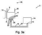
一部の実施形態では、デバイスは、第1の導管構造体と第2の導管構造体との間にサイフォンを備えることができる。サイフォンは、上流側の半径方向内側に延びる部分と、下流側の半径方向外側に延びる部分と、上流部分と下流部分との間の頂部と、を備える。サイフォンは、サイフォンの頂部が第1の空洞内の液位の半径方向内側にあるように構成される。これを実現するために、サイフォンの頂部は、第1の空洞の半径方向最内部分の半径方向内側に配置されてもよい。サイフォンは、デバイスが停止するまで、すなわちもはや回転されなくなるまで、液体の流れを止めるために使用され得る。この利点は、デバイスが第2の空洞と第3の空洞との両方を有する実施形態では、液体が第2の空洞の内外に移動してそれを混合することができ、その際、サイフォンバルブによって、液体が第3の空洞に到達するのを阻止することである。次いで、デバイスを停止または減速させて、サイフォンをプライミングすることができ、次いで、液体を、上述の方法に沿って、第3の空洞内外に、前後に移送することができる。このようにして、液体の一部(または場合により、異なる空洞からの液体)を、直列に配置された試薬と順次混合することができる。サイフォンをプライミングできるようにするために、第2の導管構造体は、通気孔を備える。 In some embodiments, the device can comprise a siphon between the first conduit structure and the second conduit structure. The siphon includes a portion extending radially inward on the upstream side, a portion extending radially outward on the downstream side, and a top portion between the upstream portion and the downstream portion. The siphon is configured such that the top of the siphon is radially inward of the liquid level in the first cavity. To achieve this, the top of the siphon may be located radially inward of the radially innermost portion of the first cavity. The siphon can be used to stop the flow of liquid until the device stops, i.e. no longer rotated. This advantage is that in embodiments where the device has both a second cavity and a third cavity, the liquid can move in and out of the second cavity and mix it with the siphon valve. , Preventing the liquid from reaching the third cavity. The device can then be stopped or decelerated to prime the siphon, and liquid can then be transferred back and forth in and out of the third cavity along the method described above. In this way, a portion of the liquid (or possibly liquid from different cavities) can be mixed sequentially with the reagents arranged in series. In order to allow the siphon to be primed, the second conduit structure comprises a vent.
特に、一部の実施形態では、第1の導管構造体および第2の導管構造体の一方または両方が、1種以上の試薬を収容する第1の試薬チャンバを備える。第1の試薬チャンバは、近位部分の半径方向外側にある遠位部分を含む。第1の試薬チャンバは第1のポートを有し、第1のポートを介して、試薬チャンバは、第1のチャンバからの液体で充填される。試薬チャンバの第1のポートは、遠位部分に配置される。例えば、第1のポートは、試薬チャンバの半径方向最外部分に配置され得る。 In particular, in some embodiments, one or both of the first conduit structure and the second conduit structure comprises a first reagent chamber that contains one or more reagents. The first reagent chamber includes a distal portion that is radially outward of the proximal portion. The first reagent chamber has a first port, through which the reagent chamber is filled with liquid from the first chamber. The first port of the reagent chamber is located at the distal portion. For example, the first port can be located at the radially outermost portion of the reagent chamber.
試薬チャンバのポートを試薬チャンバの遠位、例えば半径方向最外部分に配置することは、半径方向最外部分から第2の空洞または空気によるガスバラスト構造体を充填することに関連して上述したのと同様の理由により有利である。 Placing the reagent chamber port distal to the reagent chamber, eg, radially outermost, as described above in connection with filling the second cavity or air gas ballast structure from the radially outermost portion. It is advantageous for the same reason.
つまり、試薬チャンバに遠位、例えば半径方向最外部分から液体を充填することは、試薬チャンバ内に存在する気体が半径方向内側に変位することを意味する。次いで、デバイスが減速または停止され、第2の空洞(または空気によるガスバラスト構造体)に閉じ込められた気体が膨張し、液体を導管構造体に戻すと、気体は構造体の一方の「端部」に保持される。言い換えれば、液体は、単一の連続した液柱として維持され、液柱に分断がなく、また、気体塊が液体によって隔てられたより小さい塊に分解されることもない。ただし、液体の中にはいくらかの気泡が存在する場合があり、これらは液体と共に前後に移送され得る。 That is, filling the reagent chamber with liquid from the distal, for example, radially outermost portion, means that the gas present in the reagent chamber is displaced radially inward. The device is then decelerated or stopped and the gas confined in the second cavity (or air gas ballast structure) expands and returns the liquid to the conduit structure, causing the gas to move to one “end” of the structure. Is held. In other words, the liquid is maintained as a single continuous liquid column, the liquid column is unbroken, and the gas mass is not broken down into smaller masses separated by the liquid. However, there may be some bubbles in the liquid, which can be transferred back and forth with the liquid.
一部の実施形態では、デバイスは第2の試薬チャンバをさらに備える。第1の試薬チャンバと第2の試薬チャンバとを備えた第1の導管構造体の例を取ると、第2の試薬チャンバは、第1の導管構造体によって、第1の試薬チャンバと直列に接続される。液体の流れに関して、液体は、第1の空洞から第1の導管構造体内へ、第1の試薬チャンバを通り、第1の導管構造体の別の部分へ流れ、次いで、第2の試薬チャンバを通り、場合により第1の導管構造体をさらに経て、場合により第2の空洞内に流れる。第2の試薬チャンバは、第1の試薬チャンバに関連して上述したように構成できる。 In some embodiments, the device further comprises a second reagent chamber. Taking the example of a first conduit structure with a first reagent chamber and a second reagent chamber, the second reagent chamber is in series with the first reagent chamber by the first conduit structure. Connected. With respect to liquid flow, the liquid flows from the first cavity into the first conduit structure, through the first reagent chamber, to another portion of the first conduit structure, and then through the second reagent chamber. And optionally further through the first conduit structure and possibly into the second cavity. The second reagent chamber can be configured as described above in connection with the first reagent chamber.
一部の実施形態では、デバイスを第1の回転周波数で回転させ、遠心力の作用下で液体を第1試薬チャンバに流入させ、そこで第1の試薬チャンバ内の1種以上の試薬を液体中に再懸濁させ得る。次いで、液体が第1の空洞内に押し戻されるようにデバイスを減速または停止させることができ、加速および減速プロセスが繰り返されて、液体を1種以上の試薬と混合する。次いで、液体をさらに導管構造体に沿って第2の試薬チャンバ内に押しやるように、デバイスをさらに加速させ、そこで第2の試薬チャンバ内の1種以上の試薬を液体中に再懸濁させ得る。次いで、加速および減速のさらなる混合ステップを実行できる。このようにして、(第1の試薬チャンバ内の)第1の試薬または第1の試薬セットに続いて、(第2の試薬チャンバ内の)第2の試薬または第2の試薬セットを連続的に再懸濁することができる。 In some embodiments, the device is rotated at a first rotational frequency, causing liquid to flow into the first reagent chamber under the action of centrifugal force, where one or more reagents in the first reagent chamber are in the liquid. Can be resuspended. The device can then be decelerated or stopped so that the liquid is pushed back into the first cavity, and the acceleration and deceleration process is repeated to mix the liquid with one or more reagents. The device can then be further accelerated to push the liquid further along the conduit structure into the second reagent chamber, where one or more reagents in the second reagent chamber can be resuspended in the liquid. . Then further mixing steps of acceleration and deceleration can be performed. In this way, the first reagent or first reagent set (in the first reagent chamber) is followed by the second reagent or second reagent set (in the second reagent chamber) sequentially. Can be resuspended.
一部の実施形態では、代わりに、第2の試薬チャンバは、第1の導管構造体の分岐によって、第1の試薬チャンバと並列に接続できる。例えば、第1の導管構造体は、それぞれが試薬チャンバを含む2つの並列な導管部分に分岐する共通導管部分を含むことができる。液体の流れに関して、液体は、第1の空洞から第1の導管構造体内に流れる。液体の一部は、第1の導管部分に入り、第1の試薬チャンバを通って流れ、液体の別の部分は、第2の導管部分に入り、第2のチャンバを流れる。一部の実施形態において、2つの並列な導管構造体は、試薬チャンバの他方の側の単一の共通導管部分に再結合できる。あるいは、2つの導管部分は、第2の空洞の2つの別個のポートに取り付けられてもよいし、2つの別個の空洞に接続されてもよい。 In some embodiments, the second reagent chamber can alternatively be connected in parallel with the first reagent chamber by a branch of the first conduit structure. For example, the first conduit structure can include a common conduit portion that branches into two parallel conduit portions each including a reagent chamber. With respect to liquid flow, liquid flows from the first cavity into the first conduit structure. A portion of the liquid enters the first conduit portion and flows through the first reagent chamber, and another portion of the liquid enters the second conduit portion and flows through the second chamber. In some embodiments, two parallel conduit structures can be recombined into a single common conduit portion on the other side of the reagent chamber. Alternatively, the two conduit portions may be attached to two separate ports of the second cavity or connected to two separate cavities.
同様に、一部の実施形態では、第2の導管構造体は、上述のように第1の試薬チャンバと、場合により、第1の試薬チャンバと直列または並列に接続された第2の試薬チャンバと、を含むことができる。デバイスは、導管構造体によって、互いに並列および/または直列に接続され得る任意の数の試薬チャンバを備えることができることを理解されたい。追加的または代替的に、試薬、特に乾燥試薬は、構造体の他の場所に供給されてもよい。例えば、導管構造体のチャネル状部分は、1種以上の試薬を収容できる。また、上述または後述の任意の実施形態は、本明細書に記載されたいずれかの方法(または他の方法)で1つ以上の試薬チャンバを含むことができることも理解されたい。例えば、第1の空洞および第2の空洞の一方または両方が複数のポートを有する実施形態、および/または第1の空洞が(後述のような)混合、計量およびオーバーフロー部を有する実施形態は、説明されているように1つ以上の試薬チャンバを備え得る。それらはまた、第1の空洞に対して任意の場所に配置されたチャネル、導管、チャネルからなるネットワークまたはチャンバのいずれであるかに関わらず、任意の種類の空気によるガスバラスト構造体と共に使用されてもよい。 Similarly, in some embodiments, the second conduit structure includes a first reagent chamber, as described above, and optionally a second reagent chamber connected in series or in parallel with the first reagent chamber. And can be included. It should be understood that the device can comprise any number of reagent chambers that can be connected in parallel and / or in series by the conduit structure. Additionally or alternatively, reagents, particularly dry reagents, may be supplied elsewhere in the structure. For example, the channel-like portion of the conduit structure can contain one or more reagents. It should also be understood that any of the embodiments described above or below may include one or more reagent chambers in any of the methods described herein (or other methods). For example, embodiments in which one or both of the first cavity and the second cavity have a plurality of ports, and / or embodiments in which the first cavity has a mixing, metering and overflow section (as described below) One or more reagent chambers may be provided as described. They are also used with any type of air-based gas ballast structure, whether it is a channel, conduit, network of channels or chambers located anywhere relative to the first cavity. May be.
一部の実施形態では、第1の導管構造体および第2の導管構造体の一方または両方が蛇行導管を備えてもよい。言い換えれば、導管構造体は、蛇行形状を形成するように複数の屈曲部を備えた部分を有する。この構成は、導管の長さがより長く、これにより、液体の混合が改善されることを意味する。1つ以上の試薬チャンバと同様に、この特徴はまた、本明細書に記載される他の任意の特徴と組み合わせることもできる。一部の実施形態では、1種以上の乾燥試薬が蛇行導管内に供給される。 In some embodiments, one or both of the first conduit structure and the second conduit structure may comprise a serpentine conduit. In other words, the conduit structure has a portion with a plurality of bent portions so as to form a meandering shape. This arrangement means that the length of the conduit is longer, which improves the mixing of the liquid. As with one or more reagent chambers, this feature can also be combined with any other feature described herein. In some embodiments, one or more dry reagents are provided in the serpentine conduit.
一部の実施形態では、第1の導管構造体は1種以上の乾燥試薬を含み、第1の導管構造体は1種以上の試薬の上流にある部分を含む。 In some embodiments, the first conduit structure includes one or more dry reagents and the first conduit structure includes a portion upstream of the one or more reagents.
上述の構造体は、液体を第2の空洞に流入させるためにデバイスを十分に高い回転速度で回転させる方法に適した実施形態に関する。ただし、液体は、単に、第1の空洞外へ移して導管構造体内へ移し、次いで、導管構造体外へ移して第1の空洞内に戻すだけで混合することもでき、つまり、液体を混合するのに、必ずしも第2の空洞内外に移送する必要はない。 The structure described above relates to an embodiment suitable for a method of rotating the device at a sufficiently high rotational speed to allow liquid to flow into the second cavity. However, the liquid can also be mixed simply by moving out of the first cavity and into the conduit structure and then moving out of the conduit structure and back into the first cavity, i.e. mixing the liquid. However, it is not always necessary to transfer the inside and outside of the second cavity.
前後移動による混合が行われるためには、空気によるガスバラストとして気体が作用するように液体の下流にある構造体に気体を閉じ込めなければならない。空気によるガスバラストを収容するように作用する空気によるガスバラスト構造体は、任意の形状をとることができ、第1の空洞に対して任意の場所に配置することができる。これは、例えば、チャンバであってもよいが、遠端で閉鎖されたチャネル状構造体またはチャネルからなるネットワークであってもよい。上述のように、一部の実施形態では、同じ空洞は、空気によるガスバラストを収容するためと、液体収容空洞としてと、の両方の機能を有する。 In order for mixing by back-and-forth movement to occur, the gas must be trapped in a structure downstream of the liquid so that the gas acts as a gas ballast with air. The air gas ballast structure that acts to accommodate the air gas ballast can take any shape and can be placed at any location relative to the first cavity. This may be, for example, a chamber or a network of channel-like structures or channels closed at the far end. As described above, in some embodiments, the same cavity functions both to accommodate air gas ballast and as a liquid-containing cavity.
一部の実施形態では、液体をハンドリングするためのデバイスが提供される。デバイスは、回転軸を中心に回転するように構成される。デバイスは、遠位部分の半径方向内側にある近位部分を含む第1の空洞を備える。第1の空洞は、第1の空洞の遠位部分に配置された第1の複数のポートを含む。デバイスは、液体が第1の複数のポートから流出するときに、ある体積の気体が空気によるガスバラスト構造体内に閉じ込められ、気体の圧力が増加するように構成された、空気によるガスバラスト構造体をさらに備える。一部の実施形態では、空気によるガスバラスト構造体は、第1の空洞からの液体の流れによって変位された流体を収容するように構成され得る。 In some embodiments, a device for handling liquid is provided. The device is configured to rotate about the axis of rotation. The device comprises a first cavity that includes a proximal portion that is radially inward of the distal portion. The first cavity includes a first plurality of ports disposed at a distal portion of the first cavity. The device comprises an air gas ballast structure configured such that when a liquid exits the first plurality of ports, a volume of gas is confined within the air gas ballast structure and the pressure of the gas is increased. Is further provided. In some embodiments, the gas ballast structure with air may be configured to contain fluid displaced by the flow of liquid from the first cavity.
あるいは、第1の空洞は、単一のポートのみを同様に含み得る。この場合、導管構造体は、第1のポートを第2のポートに接続して、それらの間に流体流路を提供する。 Alternatively, the first cavity may include only a single port as well. In this case, the conduit structure connects the first port to the second port and provides a fluid flow path therebetween.
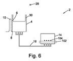
一部の実施形態では、空気によるガスバラスト構造体は検出チャンバである。一部の実施形態では、デバイスは、第1の複数のポートを空気によるガスバラスト構造体に接続する第1の導管構造体をさらに備え得る。一部の実施形態では、第1の導管構造体は、共通導管部分を備え、共通導管部分は、使用時に、第1の複数のポートのうちの2つ以上からの液体の流れが、共通導管部分において結合されるように構成される。 In some embodiments, the air gas ballast structure is a detection chamber. In some embodiments, the device may further comprise a first conduit structure connecting the first plurality of ports to the air gas ballast structure. In some embodiments, the first conduit structure includes a common conduit portion that, in use, allows liquid flow from two or more of the first plurality of ports to be common conduit portions. Configured to be joined in portions.
上記のデバイスは、原則として、第1の空洞と第2の空洞とを備えるデバイスに関連して上述したのと同様の方法で使用できる。つまり、デバイスが第1の回転周波数で回転されるとき、液体は、遠心力の作用下で、第1の複数のポートを介して第1の空洞から流出する。気体は、空気によるガスバラスト構造体に閉じ込められ、液体が第1の空洞から流出すると、空気によるガスバラスト構造体内に閉じ込められた気体の圧力が上昇する。次いで、デバイスは、第2の回転速度まで減速(または停止)され、空気によるガスバラスト構造体内の気体が膨張し、その結果、液体は、第1の空洞に向けて、場合により第1の空洞内に押し戻される。液体は、空気によるガスバラスト構造体に入っても入らなくてもよい。液体を混合するために、この加速および減速プロセスを複数回繰り返すことができる。 The device described above can in principle be used in a manner similar to that described above in connection with a device comprising a first cavity and a second cavity. That is, when the device is rotated at the first rotational frequency, the liquid flows out of the first cavity through the first plurality of ports under the action of centrifugal force. The gas is trapped in the gas ballast structure by air, and when the liquid flows out from the first cavity, the pressure of the gas trapped in the gas ballast structure by air increases. The device is then decelerated (or stopped) to a second rotational speed, and the gas in the gas ballast structure with air expands so that the liquid is directed toward the first cavity and possibly the first cavity. Pushed back in. The liquid may or may not enter the gas ballast structure with air. This acceleration and deceleration process can be repeated multiple times to mix the liquid.
有利なことに、複数のポートを有するように第1の空洞を構成することにより、液体の混合が改善される。第1の空洞および第2の空洞を有する実施形態に関連して上述したように、液体が複数のポートを通って第1の空洞内に押し戻されると、1つのポートを介して空洞に入る液体は、隣接するポートを介して入る液体と相互作用する。 Advantageously, the mixing of the liquid is improved by configuring the first cavity to have a plurality of ports. Liquid that enters the cavity through one port when liquid is pushed back into the first cavity through the plurality of ports, as described above in connection with the embodiment having the first cavity and the second cavity. Interacts with liquid entering through adjacent ports.
一部の場合、液体が上述の方法のいずれかで混合されると、混合液体の具体的な体積を計量することが望ましい場合がある。そのため、一部の実施形態は、そのような計量を提供する構造体を提供する。このために、一部の実施形態では、第1の空洞は、混合部と、計量部と、オーバーフロー部と、を備える。混合部、計量部およびオーバーフロー部は、それぞれの半径方向位置に向かって半径方向内側に延び、かつそれぞれの半径方向位置から半径方向外側に延びる第1の空洞の壁のそれぞれの部分によって互いに分離される。第1の空洞の近位部分と、半径方向内側に延びる壁の半径方向最内部分と、の間に配置された部分間に流体流路が存在する。第1のポートまたは第1の複数のポートは、混合部に配置される。計量部は、出口ポートにおいて接続された出口導管を有し、ポートおよび/または導管は、計量部が充填されている間に計量部に液体を保持するように構成される。例えば、計量部分の出口は、サイフォンバルブ構造体または他のバルブ構造体を含む導管と連通していてもよい。液体は、デバイスの回転周波数を制御することによって、これらの構造体を所望の時間に通過して流れさせることができる。したがって、第1の空洞の計量部が液体で満たされ、明確に定められた体積の液体を収容したならば、液体の体積を他の構造体の下流に流すことができる。 In some cases, it may be desirable to meter the specific volume of the mixed liquid once the liquid is mixed in any of the ways described above. As such, some embodiments provide a structure that provides such a metric. For this purpose, in some embodiments, the first cavity comprises a mixing section, a metering section, and an overflow section. The mixing portion, the metering portion and the overflow portion are separated from each other by respective portions of the wall of the first cavity extending radially inward toward the respective radial position and extending radially outward from the respective radial position. The A fluid flow path exists between the portion disposed between the proximal portion of the first cavity and the radially innermost portion of the radially extending wall. The first port or the first plurality of ports is arranged in the mixing unit. The metering section has an outlet conduit connected at the outlet port, the port and / or conduit being configured to hold liquid in the metering section while the metering section is being filled. For example, the outlet of the metering portion may be in communication with a conduit containing a siphon valve structure or other valve structure. Liquid can flow through these structures at a desired time by controlling the rotational frequency of the device. Thus, if the metering portion of the first cavity is filled with liquid and contains a well-defined volume of liquid, the volume of liquid can flow downstream of other structures.
使用時に、(上述のように)液体が、第2の空洞または空気によるガスバラスト構造体内で上昇した気体圧力によって、第1の空洞内に押し戻されるようにデバイスが減速された場合、液体が計量部にオーバーフローし、続いてオーバーフロー部に流入するように、大量の液体が第1の空洞内に戻ることができるようにデバイスは十分に減速され得る。計量部は、明確に規定された容積を有しており、したがって、明確に規定された体積の液体を、液体の体積の残りから隔離できる。次いで、この明確に規定された体積は、例えば、特定の液体濃度を得るために、賦形剤(希釈剤としても知られる)と混合することができる。 In use, if the device is slowed down (as described above) so that the liquid is pushed back into the first cavity by the gas pressure raised in the second cavity or gas ballast structure with air (as described above) The device can be sufficiently slowed down so that a large amount of liquid can return into the first cavity so that it overflows into the part and then into the overflow part. The metering part has a well-defined volume, so that a well-defined volume of liquid can be isolated from the rest of the volume of liquid. This well-defined volume can then be mixed with an excipient (also known as a diluent), for example, to obtain a specific liquid concentration.
一部の実施形態では、混合部と計量部とは同じ部分であり得る。言い換えれば、第1の空洞は、それぞれの半径方向位置に向かって半径方向内側に延び、かつそれぞれの半径方向位置から半径方向外側に延びる第1の空洞の壁の部分によって互いに分離される、混合部およびオーバーフロー部を備え得る。第1のポートまたは第1の複数のポートと同様に、混合部は、出口ポートにおいて接続された出口導管を有し、ポートおよび/または導管は、混合部分が充填されている間に混合部分に液体を保持するように構成される。例えば、混合部分の出口は、サイフォンバルブ構造体または他のバルブ構造体を含む導管と連通していてもよい。このように、デバイスが減速または停止し、結果として液体が第1の空洞内に押し戻された場合、その一部がオーバーフロー部にオーバーフローし、明確に規定された体積の液体が混合部分に残る。液体は、デバイスの回転周波数を制御することによって、出口ポートおよび出口導管を介して、第1の空洞から所望の時間に流出させることができる。 In some embodiments, the mixing section and the metering section can be the same part. In other words, the first cavities extend radially inward toward the respective radial position and are separated from each other by portions of the walls of the first cavity extending radially outward from the respective radial position. Section and overflow section. Similar to the first port or the first plurality of ports, the mixing portion has an outlet conduit connected at the outlet port, the port and / or conduit being in the mixing portion while the mixing portion is being filled. Configured to hold liquid. For example, the outlet of the mixing portion may be in communication with a conduit that includes a siphon valve structure or other valve structure. Thus, if the device decelerates or stops and, as a result, liquid is pushed back into the first cavity, a portion of it overflows into the overflow section, leaving a well-defined volume of liquid in the mixing section. Liquid can flow out of the first cavity at a desired time via the outlet port and outlet conduit by controlling the rotational frequency of the device.
したがって、第1の空洞の混合部が液体で満たされ、明確に定められた体積の液体を収容したならば、液体の体積を他の構造体の下流に流すことができる。 Thus, if the mixing portion of the first cavity is filled with liquid and contains a well-defined volume of liquid, the volume of liquid can flow downstream of other structures.
液体が第1の空洞内に移動して戻り、計量部およびオーバーフロー部内にオーバーフローできる限り、第1の空洞のこの構成、すなわち、混合部、計量部およびオーバーフロー部を含む第1の空洞は、本明細書に記載された複数の他の特徴と組み合わせることができる。例えば、第1の空洞のこの特定の構成は、混合部分に配置された複数のポートを含むことができる。これは、第1の空洞に対して任意の場所に配置され、なんらかの方法で形成された空気によるガスバラスト構造体を有する実施形態と組み合わせてもよい。第1の空洞は、上述のように第2の空洞と流体連通することができ、第2の空洞は、また上述のように、複数のポートを含んでも含まなくてもよい。導管構造体はまた、上述のように、1つ以上の試薬チャンバを含むことができる。 As long as the liquid can move back into the first cavity and overflow into the metering part and the overflow part, this configuration of the first cavity, i.e. the first cavity including the mixing part, the metering part and the overflow part, is It can be combined with a number of other features described in the specification. For example, this particular configuration of the first cavity can include a plurality of ports disposed in the mixing portion. This may be combined with an embodiment having an air gas ballast structure located anywhere with respect to the first cavity and formed in some way. The first cavity can be in fluid communication with the second cavity as described above, and the second cavity can also include or not include a plurality of ports as described above. The conduit structure may also include one or more reagent chambers as described above.
液体の混合(または液体中の1種以上の試薬の再懸濁)を改善するように構成されたさらなる構造体についても説明する。一部の実施形態では、第1の導管構造体は、複数の導管部分に分岐するチャネルを含むことができる。次いで、複数の導管部分のうちの2つ以上が、2つ以上の導管部分の下流において、単一チャネルに再結合できる。このタイプの構造体は、液体の分割および再結合を(場合により繰り返して)助け、これにより、液体の混合および/または液体中の1種以上の乾燥試薬の再懸濁を促進する。 Additional structures configured to improve liquid mixing (or resuspension of one or more reagents in the liquid) are also described. In some embodiments, the first conduit structure can include a channel that branches into a plurality of conduit portions. Then, two or more of the plurality of conduit portions can recombine into a single channel downstream of the two or more conduit portions. This type of structure assists in liquid splitting and recombination (possibly repeated), thereby facilitating liquid mixing and / or resuspension of one or more dry reagents in the liquid.
他の実施形態では、導管部分は、それ自体が、1つ以上のチャネルに再結合する(または再結合しない)さらなるサブ分岐に分岐することができる。 In other embodiments, the conduit portion can branch into further sub-branches that recombine (or do not recombine) to one or more channels.
一部の実施形態では、第2の導管構造体は、代替的または追加的に、上述の方法のいずれかで複数の導管部分に分岐するチャネルを含むことができる。 In some embodiments, the second conduit structure can alternatively or additionally include a channel that branches into multiple conduit portions in any of the manners described above.
さらなる実施態様では、液体をハンドリングするためのデバイスが提供され、デバイスは、回転軸を中心に回転するように構成される。デバイスは、出口ポートを備える第1の空洞と、遠位部分の半径方向内側にある近位部分を含む第2の空洞と、を備える。第2の空洞は、遠位部分に配置された第2のポートを有し、第2の空洞は、第2のポートを介して第1の空洞から液体を受けるように構成される。第2の空洞は、液体が第1の空洞から第2の空洞内に流入すると、第2の空洞内に気体塊が閉じ込められ、気体の圧力が上昇するように構成される。デバイスは、下流側空洞と、第1の空洞の出口ポートを下流側空洞の入口に接続する出口導管と、をさらに備える。出口導管は、出口ポートの半径方向内側に第1の屈曲部まで延び、かつ第1の屈曲部の半径方向外側に下流側空洞の入口まで延びる。第1の屈曲部は、第1の空洞の半径方向最外部分の半径方向内側に配置され、かつ第1の空洞の半径方向最内部分の半径方向外側に配置される。 In a further embodiment, a device for handling liquid is provided and the device is configured to rotate about an axis of rotation. The device comprises a first cavity comprising an outlet port and a second cavity comprising a proximal portion radially inward of the distal portion. The second cavity has a second port disposed in the distal portion, and the second cavity is configured to receive liquid from the first cavity via the second port. The second cavity is configured such that when a liquid flows from the first cavity into the second cavity, a gas mass is confined in the second cavity and the gas pressure increases. The device further comprises a downstream cavity and an outlet conduit connecting the outlet port of the first cavity to the inlet of the downstream cavity. The outlet conduit extends radially inward of the outlet port to the first bend and extends radially outward of the first bend to the downstream cavity inlet. The first bent portion is disposed radially inward of the radially outermost portion of the first cavity and radially outward of the radially innermost portion of the first cavity.
有利なことに、本構造体は、第1の空洞から下流側空洞内に移送される液体の体積の制御を助ける。第2の空洞内の圧力と遠心力との間の平衡のおかげで、第1の空洞内における液位を制御でき、以下に、特に図10fを参照して詳述するように、開始(第1の空洞内の液体が屈曲部を乗り越える時間)と、体積(その後、第1の空洞に存在する液体)と、の両方とも制御できる。 Advantageously, the structure helps control the volume of liquid that is transferred from the first cavity into the downstream cavity. Thanks to the balance between the pressure in the second cavity and the centrifugal force, the liquid level in the first cavity can be controlled and started (as described in detail below with particular reference to FIG. 10f). Both the time for the liquid in one cavity to get over the bend) and the volume (the liquid present in the first cavity thereafter) can be controlled.
一部の実施形態では、出口導管は、出口ポートの半径方向外側に第2の屈曲部まで延び、かつ第2の屈曲部の半径方向内側に第1の屈曲部まで延びる。 In some embodiments, the outlet conduit extends radially outward of the outlet port to a second bend and extends radially inward of the second bend to the first bend.
一部の実施形態では、第2のポートは、第2の空洞の半径方向最外部分にある。 In some embodiments, the second port is at the radially outermost portion of the second cavity.
一部の実施形態では、第1の空洞および第2の空洞の一方または両方に1種以上の試薬が収容される。一部の実施形態では、第2の空洞は、1種以上の試薬の半径方向外側にある部分を含む。 In some embodiments, one or more reagents are contained in one or both of the first cavity and the second cavity. In some embodiments, the second cavity includes a portion that is radially outward of one or more reagents.
一部の実施形態では、第2の空洞は、液体保持部分を備え、液体保持部分と第2のポートとの間に配置された第2の空洞の壁の少なくとも一部は、半径方向内側に延びる。
一部の実施形態では、第2の空洞の壁は、第2のポートから半径方向外側に延びる。一部の実施形態では、第2の空洞は検出チャンバである。一部の実施形態では、第2の空洞は、第1の部分とオーバーフロー部とを備え、オーバーフロー部は、第1の部分から半径方向内側に第1の半径方向位置まで延び、かつ第1の半径方向位置の半径方向外側にオーバーフロー部まで延びる、第2の空洞の壁の一部分によって、第1の部分と隔てられる。
In some embodiments, the second cavity comprises a liquid retaining portion, and at least a portion of the wall of the second cavity disposed between the liquid retaining portion and the second port is radially inward. Extend.
In some embodiments, the wall of the second cavity extends radially outward from the second port. In some embodiments, the second cavity is a detection chamber. In some embodiments, the second cavity comprises a first portion and an overflow portion, the overflow portion extending radially inward from the first portion to a first radial position, and the first portion Separated from the first portion by a portion of the wall of the second cavity, extending radially outward of the radial position to the overflow portion.
一部の実施形態では、デバイスはマイクロ流体デバイスである。疑義を避けるために、本明細書で言及される場合、用語「マイクロ流体」とは、1mm未満の少なくとも1つの寸法を有するリザーバまたはチャネルなどの流体要素を有するデバイスを意味する。デバイスは、ナノリットルからマイクロリットルのスケールの体積の液体をハンドリングするように構成され得る。液体の例としては、全血、血漿、血清および尿が挙げられる。可能な試薬の例としては、粒子、緩衝液、塩、糖、生物学的に活性な要素(抗体、酵素など)およびポリマーが挙げられる。一部の実施形態では、デバイスは、ディスクであり得る。 In some embodiments, the device is a microfluidic device. For the avoidance of doubt, as referred to herein, the term “microfluidic” means a device having a fluidic element such as a reservoir or channel having at least one dimension of less than 1 mm. The device may be configured to handle nanoliter to microliter scale volumes of liquid. Examples of liquids include whole blood, plasma, serum and urine. Examples of possible reagents include particles, buffers, salts, sugars, biologically active elements (antibodies, enzymes, etc.) and polymers. In some embodiments, the device can be a disk.
一部の実施形態では、デバイス内の液体の流れを駆動する方法が提供される。本方法は、第1の回転周波数でデバイスを回転させて、デバイスの第1の通気孔付き空洞内に、また第1の空洞および/または第2の通気孔なし空洞と連通する第1の導管構造体に、液体を移送する、ステップを含む。本方法は、第1の回転周波数未満の第2の回転周波数でデバイスを回転させて、第2の空洞から第1の空洞内に少なくとも一部の液体を移送して戻し、第1の空洞から第1の空洞と連通する下流側空洞に少なくとも一部の液体を移送する、ステップをさらに含む。 In some embodiments, a method for driving a flow of liquid in a device is provided. The method rotates a device at a first rotational frequency to communicate within a first vented cavity of the device and with a first cavity and / or a second ventless cavity. Transferring the liquid to the structure. The method rotates the device at a second rotational frequency less than the first rotational frequency to transfer at least some liquid back from the second cavity into the first cavity and from the first cavity. The method further includes transferring at least a portion of the liquid to a downstream cavity in communication with the first cavity.
このようにして、計量された体積の液体を下流側チャンバに移すことによって、計量された体積の液体を、第1の空洞および第2の空洞内にある、ある体積の液体から分離できる。言い換えれば、本方法は、液体の体積を計量するために使用できる。 In this way, by transferring the metered volume of liquid to the downstream chamber, the metered volume of liquid can be separated from the volume of liquid in the first and second cavities. In other words, the method can be used to meter the volume of a liquid.
有利なことに、タイミングを制御するには、デバイスを減速させるが、デバイスを停止する必要はない。 Advantageously, controlling the timing slows the device, but does not require stopping the device.
本方法は、例えば上述の構造体を使用して実施でき、上述の構造体では、第1の空洞が、第1の空洞の半径方向最外部分の半径方向内側にあり、かつ第1の空洞の半径方向最内部分の面の外側にある第1の屈曲部を有する導管によって、下流側空洞に接続される。 The method can be performed using, for example, the structure described above, wherein the first cavity is radially inward of the radially outermost portion of the first cavity and the first cavity. Is connected to the downstream cavity by a conduit having a first bend that is outside the face of the radially innermost portion.
一部の実施形態では、本方法は、第1の回転周波数でデバイスを回転させた後、かつ第2の回転周波数でデバイスを回転させる前に、液体を混合するために、第3の回転周波数で、その後第4の回転周波数でデバイスを回転させるステップを含む。第3の回転周波数および第4の回転周波数は、第2の回転周波数よりも大きく、第4の回転周波数は、第3の回転周波数よりも大きい。第3の周波数は、第1の周波数と同じであっても異なっていてもよい。 In some embodiments, the method includes a third rotational frequency to mix the liquid after rotating the device at the first rotational frequency and before rotating the device at the second rotational frequency. And then rotating the device at a fourth rotational frequency. The third rotation frequency and the fourth rotation frequency are greater than the second rotation frequency, and the fourth rotation frequency is greater than the third rotation frequency. The third frequency may be the same as or different from the first frequency.
第3の回転周波数と第4の回転周波数との間で回転周波数を変化させる際に、第1の空洞と、第1の空洞と連通している導管構造体との間で、以下に詳述するように、第2の空洞内の気体の圧力と遠心力との相互作用により、液体が前後に移動され得る。この液体の前後移動は、液体または複数種の液体の混合を助け得る。 In changing the rotational frequency between the third rotational frequency and the fourth rotational frequency, a detailed description will be given below between the first cavity and the conduit structure in communication with the first cavity. Thus, the liquid can be moved back and forth by the interaction between the pressure of the gas in the second cavity and the centrifugal force. This back-and-forth movement of the liquid can assist in mixing the liquid or liquids.
一部の実施形態では、本方法は、第1の空洞から下流側空洞内へ液体を移送し始めた後、第1の空洞から下流側空洞内へ移送される液体の体積を制御するために、第2の回転周波数とは異なる第5の回転周波数でデバイスを回転させるステップを含む。
第5の回転周波数は、第2の回転周波数より大きくして、移送される体積を減らしてもよいし、第2の回転周波数未満として、移送される体積を増やしてもよい。よって、有利なことに、計量される体積は、デバイスの回転速度を制御することによって制御できる。
In some embodiments, the method is for controlling the volume of liquid transferred from the first cavity into the downstream cavity after beginning to transfer liquid from the first cavity into the downstream cavity. , Rotating the device at a fifth rotational frequency different from the second rotational frequency.
The fifth rotation frequency may be greater than the second rotation frequency to reduce the volume transferred or less than the second rotation frequency to increase the volume transferred. Thus, advantageously, the metered volume can be controlled by controlling the rotational speed of the device.
計量の方法と同様に、本開示によって、これから説明するように、デバイス内の液体を混合する方法が提供される。 Similar to the metering method, the present disclosure provides a method of mixing the liquid in the device as will be described.
一部の実施形態では、デバイス内の液体を混合する方法が提供される。デバイス内の液体を混合することは、2種以上の液体または液体の2種以上の成分を混合することを含み得る。本方法は、液柱を複数の液柱に分割させるためにデバイスを回転させるステップと、液柱を再結合させるために回転周波数を変更するステップと、を含む。一部の実施形態では、液柱を再結合させるために回転周波数を変更するステップは、回転周波数を下げるステップを含む。一部の実施形態では、液柱を再結合させるために回転周波数を変更するステップは、回転周波数を上げるステップを含む。一部の実施形態では、液柱を複数の液柱に分割させるためにデバイスを回転させるステップと、液柱を再結合させるために回転周波数を変更するステップと、の間において、デバイスは停止されない(すなわち、デバイスの回転周波数はゼロに下がらない)。 In some embodiments, a method for mixing a liquid in a device is provided. Mixing the liquids in the device can include mixing two or more liquids or two or more components of a liquid. The method includes rotating the device to divide the liquid column into a plurality of liquid columns and changing the rotational frequency to recombine the liquid columns. In some embodiments, changing the rotational frequency to recombine the liquid column includes lowering the rotational frequency. In some embodiments, changing the rotational frequency to recombine the liquid column includes increasing the rotational frequency. In some embodiments, the device is not stopped between rotating the device to divide the liquid column into a plurality of liquid columns and changing the rotational frequency to recombine the liquid column. (That is, the rotational frequency of the device does not drop to zero).
言い換えれば、一部の実施形態では、本方法は、液柱を複数の液柱に分割させるために第1の回転周波数でデバイスを回転させるステップと、液柱を再結合させるために第2の回転周波数でデバイスを回転させるステップと、を含む。一部の実施形態では、第1の回転周波数は第2の回転周波数よりも大きい。他の実施形態では、第2の回転周波数は第1の回転周波数よりも大きい。一部の実施形態では、第1の回転周波数でデバイスを回転させるステップと、第2の回転周波数でデバイスを回転させるステップとの間において、デバイスは停止されない(すなわち、回転周波数がゼロに下がらない)。 In other words, in some embodiments, the method includes rotating the device at a first rotational frequency to divide the liquid column into a plurality of liquid columns and a second to recombine the liquid columns. Rotating the device at a rotational frequency. In some embodiments, the first rotational frequency is greater than the second rotational frequency. In other embodiments, the second rotational frequency is greater than the first rotational frequency. In some embodiments, the device is not stopped (ie, the rotational frequency does not drop to zero) between rotating the device at the first rotational frequency and rotating the device at the second rotational frequency. ).
本方法は、共通導管部分を空洞の複数のポート(または複数の導管部分)に接続する導管構造体の一端または両端に「分岐」部分を有する導管構造体を含む、上述の実施形態のうちの1つ以上の構造体を使用して実施することができる。同様に、本方法は、第1の導管構造体および第2の導管構造体の一方または両方が、複数の導管部分に分岐し、その後、単一のチャネルに再結合する、チャネルを含む、上述の実施形態のうちの1つ以上の構造体を使用して実施することができる。本方法は、液体が構造体内を前後に移動するときに液体の流れを分割して再結合することができる任意の構造体を使用して実施できる。 The method of any of the preceding embodiments, comprising a conduit structure having a “branch” portion at one or both ends of the conduit structure connecting the common conduit portion to a plurality of ports (or multiple conduit portions) in the cavity. One or more structures can be implemented. Similarly, the method includes a channel wherein one or both of the first conduit structure and the second conduit structure branches into a plurality of conduit portions and then recombines into a single channel, as described above. Can be implemented using one or more of the embodiments. The method can be performed using any structure that can split and recombine the flow of liquid as it moves back and forth through the structure.
一部の実施形態では、デバイス内において、液体を混合し、液体中に1種以上の乾燥試薬を再懸濁させる方法が提供される。本方法は、液体を混合するために、第1の回転周波数で、次いで第1の回転周波数未満の第2の回転周波数でデバイスを回転させるステップを含む。本方法は、液体中に1種以上の試薬を再懸濁するために、第1の回転周波数よりも大きい第3の回転周波数でデバイスを回転させるステップをさらに含む。本方法は、第1の空洞以外の構造体のどこかに、例えば、特に第2の空洞(または空気によるガスバラスト構造体)が1種以上の試薬の半径方向外側にある部分を有する、第2の空洞(または空気によるガスバラスト構造体)に、または1つ以上の試薬チャンバに、試薬が供給される、上述の実施形態のうちの1つ以上を使用して実施できる。1種以上の試薬はまた、導管構造体内に、例えば、チャネルに、または1つ以上の試薬チャンバに供給することもできる。一部の実施形態では、液体を混合するステップは、液体中に1種以上の乾燥試薬を再懸濁させるステップを含み得る。換言すれば、本方法は、1種以上の乾燥試薬(または乾燥試薬群)を直列に再懸濁するために使用できる。 In some embodiments, a method is provided for mixing a liquid and resuspending one or more dry reagents in the liquid within the device. The method includes rotating the device at a first rotational frequency and then at a second rotational frequency less than the first rotational frequency to mix the liquid. The method further includes rotating the device at a third rotational frequency greater than the first rotational frequency to resuspend the one or more reagents in the liquid. The method includes a portion somewhere in the structure other than the first cavity, for example, where the second cavity (or gas ballast structure with air) in particular has a portion that is radially outward of one or more reagents. It can be implemented using one or more of the embodiments described above, in which reagents are supplied to two cavities (or gas ballast structures with air) or to one or more reagent chambers. One or more reagents can also be supplied into the conduit structure, eg, to a channel, or to one or more reagent chambers. In some embodiments, mixing the liquid can include resuspending one or more dry reagents in the liquid. In other words, the method can be used to resuspend one or more dry reagents (or groups of dry reagents) in series.
一部の実施形態では、デバイス内において、液体を混合し、液体の体積を計量する方法が提供される。本方法は、第1の回転周波数でデバイスを回転させて、デバイスの第1の空洞内に、また第1の空洞と連通する導管構造体に、液体を移送する、ステップを含む。本方法は、第2の回転周波数でデバイスを回転させて、第1の空洞内に、液体の一部分を液体の残りの部分から分離する、ステップをさらに含む。第2の回転周波数は、第1の回転周波数未満である。本方法は、第1の空洞が混合部、計量部およびオーバーフロー部(または混合部およびオーバーフロー部のみ)を含む、上述の実施形態のうちの1つ以上を使用して実施できる。一部の実施形態では、液体の一部分を液体の残りの部分から分離するステップは、明確に規定された体積の液体を液体の残りから分離するステップを含む。 In some embodiments, a method is provided for mixing liquids and measuring the volume of liquids in a device. The method includes rotating the device at a first rotational frequency to transfer liquid into the first cavity of the device and into a conduit structure in communication with the first cavity. The method further includes rotating the device at a second rotational frequency to separate a portion of the liquid from the remaining portion of the liquid within the first cavity. The second rotation frequency is less than the first rotation frequency. The method can be performed using one or more of the above-described embodiments, wherein the first cavity includes a mixing section, a metering section, and an overflow section (or only a mixing section and an overflow section). In some embodiments, separating the portion of the liquid from the remaining portion of the liquid includes separating a well-defined volume of liquid from the remaining portion of the liquid.
一部の実施形態では、デバイス内において、液体を混合し、液体の体積を計量する方法は、第1の周波数でデバイスを回転させた後、かつ第2の回転周波数でデバイスを回転させる前に、液体を混合するために、第3の回転周波数で、その後第4の回転周波数でデバイスを回転させるステップを含む。第3の回転周波数は、第1の回転周波数未満かつ第2の回転周波数よりも大きく、第4の回転周波数は、第3の回転周波数よりも大きい。疑義を避けるために、4つの回転周波数の順序は次のとおりである。
−第1の回転周波数
−第3の回転周波数
−第4の回転周波数
−第2の回転周波数
In some embodiments, the method of mixing liquid and metering the volume of liquid in the device is performed after rotating the device at a first frequency and before rotating the device at a second rotational frequency. Rotating the device at a third rotational frequency and then at a fourth rotational frequency to mix the liquid. The third rotation frequency is less than the first rotation frequency and greater than the second rotation frequency, and the fourth rotation frequency is greater than the third rotation frequency. To avoid doubt, the order of the four rotational frequencies is as follows.
-1st rotation frequency-3rd rotation frequency-4th rotation frequency-2nd rotation frequency
上述のように、一部の実施形態では、液体を混合するステップは、液体中に1種以上の乾燥試薬を再懸濁させるステップを含み得る。 As described above, in some embodiments, mixing the liquid may include resuspending one or more dry reagents in the liquid.
一部の実施形態では、デバイス内において、異なる密度の複数の成分(別の方法では分画またはフレーズとも呼ばれる)に液体を分離する方法が提供される。本方法は、第1の空洞から第2の空洞に液体を流入させ、第2の空洞内のある体積の気体の圧力を増加させるように、デバイスを回転させるステップを含む。本方法は、異なる密度の複数の成分に液体を分離するために、デバイスを回転させるステップをさらに含む。本方法はまた、液体の少なくとも一部分を第2の空洞から流出させるように、デバイスを減速する(または遅くする)ステップを含む。第2の空洞から流出する液体の部分は、液体の成分のうちの1つの一部分である。言い換えれば、液体の成分のうちの1つの一部分が第2の空洞から流出させられる。 In some embodiments, a method is provided in a device for separating a liquid into multiple components of different densities (also referred to as fractions or phrases in another method). The method includes rotating the device to cause liquid to flow from the first cavity into the second cavity and increase the pressure of a volume of gas in the second cavity. The method further includes rotating the device to separate the liquid into multiple components of different densities. The method also includes decelerating (or slowing down) the device so that at least a portion of the liquid flows out of the second cavity. The portion of the liquid that flows out of the second cavity is a portion of one of the liquid components. In other words, a portion of one of the liquid components is drained from the second cavity.
そのような方法は、液体が第2の空洞(または空気によるガスバラスト)に流入すると、第2の空洞内の気体塊の圧力が上昇する、上述の構造体のいずれかを使用して利用できる。このようにして、遠心力の作用下で、第2の空洞(または空気によるガスバラスト)に液体を流入させ、それによって、第2の空洞内の気体の圧力が上昇させ得る。次いで、デバイスを回転させて、異なる密度の成分に液体を分離させることができる。次位で、デバイスを減速または停止させて、第2の空洞内の気体を膨張させ、それにより、液体の成分の1つのうちの少なくとも一部分を第2の空洞から押し戻すことができる。 Such a method can be utilized using any of the structures described above, where when liquid flows into the second cavity (or gas ballast with air), the pressure of the gas mass in the second cavity increases. . In this way, liquid can flow into the second cavity (or gas ballast with air) under the action of centrifugal force, thereby increasing the pressure of the gas in the second cavity. The device can then be rotated to separate the liquid into components of different densities. In the next order, the device can be decelerated or stopped to expand the gas in the second cavity, thereby pushing at least a portion of one of the liquid components back from the second cavity.
一部の実施形態では、第2の空洞のポートは、2つの成分のうちの軽い方の少なくとも一部分が、デバイスから押し戻され、2つの成分のうちの高密度な方が第2の空洞に保持されるように、第2の空洞の一部の半径方向内側に、特に、液体の2つの成分間の境界面の半径方向位置の半径方向内側に配置されてもよい。 In some embodiments, the port of the second cavity is such that at least a portion of the lighter of the two components is pushed back from the device and the denser of the two components is retained in the second cavity. As such, it may be arranged radially inward of a part of the second cavity, in particular radially inward of the radial position of the interface between the two components of the liquid.
一部の実施形態では、上述の方法を使用して、ある体積の血液を細胞形質成分と血漿とに分離し、次いで、ある体積の血漿を第2の空洞から流出させ、細胞形質成分を第2の空洞内に保持できる。 In some embodiments, the method described above is used to separate a volume of blood into a cytoplasmic component and plasma, and then a volume of plasma is drained from the second cavity, Can be held in two cavities.
上述した特徴および実施形態のうちの多くが、複数の異なる方法で組み合わせることができることを理解されたい。上述の特徴の組み合わせを含む特定の実施形態を以下に示す。 It should be understood that many of the features and embodiments described above can be combined in a number of different ways. Specific embodiments including combinations of the above features are shown below.
一部の実施形態では、デバイスが、第1のポートを有する第1の空洞と、第2のポートを有する第2の空洞と、を備える。第2のポートは、第1のポートの半径方向外側にあってもよい。第1のポートおよび第2のポートは、第1の導管構造体によって接続される。第2の空洞は、上述のように、液体保持部分を含む。特に、第2の空洞の壁は、第2のポートから半径方向外側に延び得る。第2の空洞は、液体が第2の空洞内に流入すると、第2の空洞内に気体塊が閉じ込められ、気体の圧力が上昇するように構成される。つまり、第2の空洞内外への唯一の流体流路は、第2のポートを介する流路であるように、第2の空洞は構成される。第1の導管構造体は、上述のように、1つ以上の試薬チャンバを含む。特に、第1の導管構造体は、1種以上の試薬を収容する第1の試薬チャンバを備える。第1の試薬チャンバは、近位部分の半径方向外側にある遠位部分を含む。第1の試薬チャンバは第1のポートを有し、第1のポートを介して、試薬チャンバは、第1の空洞からの液体で充填される。試薬チャンバの第1のポートは、チャンバの遠位部分に配置される。例えば、第1のポートは、試薬チャンバの半径方向最外部分に配置され得る。同様に、導管構造体は、いかなる試薬チャンバも含まなくてもよく、その代わりに蛇行導管を含んでもよい。一部の実施形態では、蛇行導管は、1種以上の乾燥試薬を収容し得る。 In some embodiments, the device comprises a first cavity having a first port and a second cavity having a second port. The second port may be radially outward of the first port. The first port and the second port are connected by a first conduit structure. The second cavity includes a liquid holding portion as described above. In particular, the wall of the second cavity may extend radially outward from the second port. The second cavity is configured such that when a liquid flows into the second cavity, a gas mass is confined in the second cavity and the gas pressure increases. That is, the second cavity is configured such that the only fluid flow path into and out of the second cavity is the flow path through the second port. The first conduit structure includes one or more reagent chambers as described above. In particular, the first conduit structure comprises a first reagent chamber that contains one or more reagents. The first reagent chamber includes a distal portion that is radially outward of the proximal portion. The first reagent chamber has a first port through which the reagent chamber is filled with liquid from the first cavity. The first port of the reagent chamber is located at the distal portion of the chamber. For example, the first port can be located at the radially outermost portion of the reagent chamber. Similarly, the conduit structure may not include any reagent chamber, but may instead include a serpentine conduit. In some embodiments, the serpentine conduit may contain one or more dry reagents.
一部の実施形態では、デバイスは、近位部分の半径方向外側に遠位部分を有する第1の空洞を備える。第1の空洞は、第1の空洞の遠位部分に配置された第1の複数のポートを含む。例えば、第1の複数のポートは、第1の空洞の半径方向最外部分に配置され得る。デバイスは、近位部分の半径方向外側に遠位部分を有する第2の空洞をさらに備える。第2の空洞は、第2の空洞の遠位部分に配置された第2の複数のポートを含む。例えば、第2の複数のポートは、第2の空洞の半径方向最外部分に配置され得る。第2の空洞は、液体が第2の空洞内に流入すると、第2の空洞内に気体塊が閉じ込められ、気体の圧力が上昇するように構成される。つまり、第2の空洞内外への唯一の流体流路は、第2の複数のポートを介する流路であるように、第2の空洞は構成される。デバイスは、第1の複数のポートを第2の複数のポートに接続し、その間に流体流路を提供する導管構造体をさらに含む。導管構造体は、共通導管部分を備え、第1の空洞で複数の導管部分に分岐している。各導管部分は、第1の複数のポートのそれぞれ1つに接続される。導管構造体は、第2の空洞で同じ分岐構造を含む。 In some embodiments, the device comprises a first cavity having a distal portion radially outward of the proximal portion. The first cavity includes a first plurality of ports disposed at a distal portion of the first cavity. For example, the first plurality of ports may be located at the radially outermost portion of the first cavity. The device further comprises a second cavity having a distal portion radially outward of the proximal portion. The second cavity includes a second plurality of ports disposed at a distal portion of the second cavity. For example, the second plurality of ports may be disposed on the radially outermost portion of the second cavity. The second cavity is configured such that when a liquid flows into the second cavity, a gas mass is confined in the second cavity and the gas pressure increases. That is, the second cavity is configured such that the only fluid flow path into and out of the second cavity is a flow path through the second plurality of ports. The device further includes a conduit structure connecting the first plurality of ports to the second plurality of ports and providing a fluid flow path therebetween. The conduit structure includes a common conduit portion and branches into a plurality of conduit portions at a first cavity. Each conduit portion is connected to a respective one of the first plurality of ports. The conduit structure includes the same branch structure in the second cavity.
一部の実施形態では、液体をハンドリングするためのデバイスが提供され、デバイスは、回転軸を中心に回転して、デバイス内で液体の流れを駆動するように構成される。デバイスは、それぞれ液体を収容するためのチャンバおよび導管を備える。チャンバは、上流の液体ハンドリング構造体に接続された入口ポートを有して、上流の液体ハンドリング構造体から液体を受け取る。チャンバはまた、導管に接続された出口ポートを有する。導管は、出口ポートから頂部まで半径方向内側に延び、頂部から半径方向外側に延びる。チャンバは、頂部の半径方向内側に延びる。チャンバは、頂部の半径方向内側および外側に延びる第1の半径方向領域と、出口ポートが配置される第1の半径方向領域の半径方向外側にある第2の半径方向領域と、を有する。第1の半径方向領域におけるチャンバの断面積は、第2の半径方向領域におけるチャンバの断面積よりも小さい。この構造体は、図20を参照して以下に詳述するように、導管がプライミングされる(すなわち、液体が導管の頂部を超えて流れる)時間のより良い制御を助ける。一部の実施形態では、第1の半径方向領域におけるチャンバの断面積は、チャンバ内に配置された1つ以上のピラーによって、第2の半径方向領域におけるチャンバの断面積に対して減らされる。代替的または追加的に、第1の半径方向領域におけるチャンバの断面積は、一部の実施形態では、第1の半径方向領域におけるチャンバの円周方向の広がりの減少によって、および/または第1の半径方向領域におけるチャンバの深さ(すなわち、回転軸に平行なチャンバの寸法)の減少によって、第2の半径方向領域におけるチャンバの断面積に対して減らされる。例えば、第1の領域と第2の領域との間のチャンバの円周方向の広がりの段階的変化、および/または第1の領域と第2の領域との間のチャンバの深さの段階的変化があり得る。一部の実施形態では、頂部の半径方向内側の第1の半径方向領域の半径方向の広がりは、第2の半径方向領域の半径方向の広がりよりも短い。 In some embodiments, a device for handling liquid is provided, and the device is configured to rotate about an axis of rotation to drive the flow of liquid within the device. Each device comprises a chamber and a conduit for containing a liquid. The chamber has an inlet port connected to the upstream liquid handling structure and receives liquid from the upstream liquid handling structure. The chamber also has an outlet port connected to the conduit. The conduit extends radially inward from the outlet port to the top and extends radially outward from the top. The chamber extends radially inward of the top. The chamber has a first radial region extending radially inward and outward of the top and a second radial region radially outward of the first radial region in which the outlet port is disposed. The cross-sectional area of the chamber in the first radial region is smaller than the cross-sectional area of the chamber in the second radial region. This structure helps to better control the time that the conduit is primed (ie, the liquid flows over the top of the conduit), as described in detail below with reference to FIG. In some embodiments, the cross-sectional area of the chamber in the first radial region is reduced relative to the cross-sectional area of the chamber in the second radial region by one or more pillars disposed in the chamber. Alternatively or additionally, the cross-sectional area of the chamber in the first radial region may, in some embodiments, be reduced by reducing the circumferential extent of the chamber in the first radial region and / or the first Is reduced with respect to the cross-sectional area of the chamber in the second radial region by reducing the depth of the chamber in the radial region (ie, the dimension of the chamber parallel to the axis of rotation). For example, a gradual change in the circumferential extent of the chamber between the first region and the second region, and / or a gradual change in the depth of the chamber between the first region and the second region. There can be changes. In some embodiments, the radial extent of the first radial region radially inward of the top is shorter than the radial extent of the second radial region.
疑義を避けるために、本明細書で使用する場合、用語「半径方向」は、デバイスの回転軸に対するものとして理解されたい。液体の混合とは、2種以上の異なる液体(例えば、サンプルおよび賦形剤)を含む液体体積の混合、または液体と懸濁液中の粒子との混合(例えば、全血、ラテックスビーズまたは他のナノ粒子懸濁液)を指す場合がある。さらに、特に乾燥試薬の再懸濁のための、1種以上の液体と、1種以上の乾燥試薬との混合を指す場合もある。「上流」および「下流」という用語の使用は、遠心力の作用下での液体の流れに関するものとして理解されたい。用語「空気によるガスバラスト」の使用は、空洞に閉じ込められた、ある体積の空気を指し、体積は、空洞を制限している固体表面と、少なくとも1つの液体壁またはプラグと、によって画定されると理解されたい。空洞は、流体が収容または案内され得るデバイスの内部の空の空間であると理解されたい。空洞の一例はチャンバである。空洞は、チャネルからなるネットワークによって定義することもできる。空洞のさらなる例は、単一のチャネル(例えば、一端で閉じられたチャネル、すなわち行き止まりのあるチャネル)、分岐チャネル、マルチチャンバ配置、またはそれらの組み合わせである。実施形態に応じて、上述の空洞のいずれも、任意の適切な形態、例えば、チャンバ、チャネルからなるネットワーク、または上述のもののいずれか、もしくは上述のものの任意の組み合わせをとることができる。用語「導管構造体」は、使用時に流体が流れる構造体であると理解されたい。例えば、導管は、2つ以上のポートを接続して、それらの間の流体の流れを案内できる。導管構造体は、液体塊を分断させずに、第1のポートと第2のポートとの間で液体塊を案内する構造体であると理解されたい。換言すれば、液体は、いかなる分断もない、単一の連続した塊として導管構造体によって導かれる。異なる角度から見れば、液体は、導管構造体内を第1のポートから第2のポートへと進み、その際、単一のメニスカスが導管内を進む。当然のことながら、この説明は閉じ込められた気体のない液体にも当てはまることを理解されたい。気体塊または気泡が、液体が前進する際に液体に閉じ込められた場合、対応する複数のメニスカスは、当然のことながら、液体とともに前進する。 For the avoidance of doubt, as used herein, the term “radial” should be understood as relative to the axis of rotation of the device. A liquid mixture is a mixture of liquid volumes containing two or more different liquids (eg, samples and excipients), or a mixture of liquid and particles in suspension (eg, whole blood, latex beads or other) Nanoparticle suspension). Furthermore, it may refer to the mixing of one or more liquids and one or more dry reagents, particularly for resuspension of the dry reagents. The use of the terms “upstream” and “downstream” should be understood as relating to the flow of liquid under the action of centrifugal force. The use of the term “gas ballast with air” refers to a volume of air confined in a cavity, the volume being defined by a solid surface that limits the cavity and at least one liquid wall or plug. Please understand. A cavity is to be understood as an empty space inside a device where fluid can be contained or guided. An example of a cavity is a chamber. A cavity can also be defined by a network of channels. Further examples of cavities are a single channel (eg, a channel closed at one end, ie a dead end channel), a branch channel, a multi-chamber arrangement, or a combination thereof. Depending on the embodiment, any of the above cavities can take any suitable form, eg, a network of chambers, channels, or any of the above, or any combination of the above. The term “conduit structure” should be understood as a structure through which fluid flows in use. For example, a conduit can connect two or more ports to guide fluid flow between them. It should be understood that the conduit structure is a structure that guides the liquid mass between the first port and the second port without disrupting the liquid mass. In other words, the liquid is guided by the conduit structure as a single continuous mass without any disruption. Viewed from a different angle, the liquid travels through the conduit structure from the first port to the second port, with a single meniscus traveling through the conduit. Of course, it should be understood that this description also applies to confined gasless liquids. If a gas mass or bubble is trapped in the liquid as it is advanced, the corresponding meniscus will of course advance with the liquid.
一部の実施形態では、デバイスは、回転軸を画定し、かつ回転要素に結合されてデバイスの回転を駆動するように構成された機構を備える。例えば、デバイスは、マイクロ流体ディスクなどの遠心ディスクであってもよい。ディスク状などのデバイスは、駆動システムのスピンドルと係合するように構成された中心孔を備え、スピンドルは、スピンドルの回転を駆動するためのモータに結合され、これにより、係合したデバイスの回転を駆動する。 In some embodiments, the device comprises a mechanism that defines an axis of rotation and is coupled to the rotating element to drive rotation of the device. For example, the device may be a centrifugal disc such as a microfluidic disc. A device such as a disk has a central hole configured to engage with the spindle of the drive system, and the spindle is coupled to a motor for driving the rotation of the spindle, thereby rotating the engaged device. Drive.
ここで、添付の図面を参照して、各実施形態を例として詳述する。
図1を参照すると、マイクロ流体デバイス2は、回転軸28を中心に回転するように構成される。デバイス2は、第1の空洞、具体的には第1のチャンバ4を備える。第1のチャンバ4は、液体がチャンバ4に導入される入口6を含む。チャンバ4は、サイフォンバルブ10と連通する出口8を有する。第1のチャンバ4はまた、第1のポート12を有する。
Referring to FIG. 1, the
デバイス2は、第2のポート16を有する、第2の空洞、具体的には第2のチャンバ14をさらに備える。導管構造体18は、第1のポートと第2のポートとの間に液体の流れを案内するために、第1のポート12を第2のポート16に接続する。第2のポート16は、第1のポート12の半径方向外側にある。
The
第1のポートおよび第2のポートは、第1のチャンバおよび第2のチャンバの半径方向最外部分にそれぞれ配置される。しかしながら、一部の実施形態では、第1のポートおよび第2のポートは、第1のチャンバおよび第2のチャンバの半径方向最外部分に配置されない場合もあり、代わりに、第1のチャンバおよび第2のチャンバのそれぞれの半径方向最内部分の半径方向外側にあるチャンバ上の任意の位置に配置できる。言い換えれば、第1のチャンバおよび第2のチャンバは、第1のチャンバおよび第2のチャンバのそれぞれの遠位部分の半径方向内側にあるそれぞれの近位部分を含み、その際、第1のポートおよび第2のポートがそれぞれ第1のチャンバおよび第2のチャンバの遠位部分に配置され得る。 The first port and the second port are respectively disposed at radially outermost portions of the first chamber and the second chamber. However, in some embodiments, the first port and the second port may not be located in the radially outermost portion of the first chamber and the second chamber; instead, the first chamber and It can be located anywhere on the chamber that is radially outward of the respective radially innermost portion of the second chamber. In other words, the first chamber and the second chamber include respective proximal portions that are radially inward of respective distal portions of the first chamber and the second chamber, wherein the first port And a second port may be disposed in a distal portion of the first chamber and the second chamber, respectively.
デバイス2は、第2のチャンバ14内外への唯一の流体流路が第2のポート16を経由する流体流路であるように構成される。よって、第2のチャンバ14は、通気孔なしであり得る、すなわち、通気孔を備えていない。反対に、第1のチャンバ4は、気体が通気孔を介して第1のチャンバ4の内外に流れることができるように、通気孔30を備える。通気孔30は、大気または内部空気回路と連通していてもよい。
The
図1に示すようなデバイスを使用して液体を混合し、デバイス内で液体が流れる方法を図2a〜図2cを参照して説明する。 A method of mixing liquid using a device as shown in FIG. 1 and flowing the liquid in the device will be described with reference to FIGS.
図2aを参照すると、第1のステップとして、液体32が入口6を介して第1のチャンバ4に導入され、導管構造体18および第2のチャンバ14内にある体積の気体100を通気孔30から遮断する。
Referring to FIG. 2 a, as a first step, a liquid 32 is introduced into the
図2bを参照すると、次いで、デバイス2は第1の回転周波数まで加速される。これにより、液体は遠心力の作用下で、第1のポート12を介して第1のチャンバ4から導管構造体18に流れる。液体が導管構造体18内に流入すると、導管構造体18内の気体は、導管構造体に流入する液体によって変位し、導管構造体に沿って第2のチャンバ14内に押しやられる。液体が流れると、気体が圧縮され、チャンバ14に閉じ込められた気体の圧力が上昇する。圧力上昇した気体100は、ドットの密度を上げて描かれている。
Referring to FIG. 2b, the
液体が導管構造体18を前進する程度は、以下、すなわち、
−絶対位置、例えば半径方向位置、および第1のチャンバおよび第2のチャンバおよび導管構造体の相対的寸法、
−デバイスが加速される第1の回転周波数、
−液体の体積、
そして場合により、他の要因に依存する。上述の特徴は、導管構造体18を液体がどれだけ前進するかを制御するために選択および調整され得る。
The degree to which the liquid advances through the
-Absolute position, e.g. radial position, and relative dimensions of the first and second chambers and the conduit structure;
A first rotational frequency at which the device is accelerated,
The volume of the liquid,
And depending on the case, it depends on other factors. The features described above can be selected and adjusted to control how much liquid advances through the
一部の実施形態では、液体は、第2のポート16を介して第2のチャンバ14に入ることができる。他の実施形態では、液体前面は、第2のチャンバ14に入ることなく、導管構造体18内をいくらか進むだけであり得る。同様に、液体の全体積が、第1のチャンバ4から導管構造体18に(および場合により第2のチャンバ14に)移送される場合もある。あるいは、第1のチャンバ4内に導入された液体の一部分のみが、第1のチャンバから導管構造体18内に移送され、残りの液体体積が第1のチャンバ4に残る場合もある。同様に、液体の一部、ほとんど、またはすべてが第2のチャンバ14に入ることができる。
In some embodiments, liquid can enter the
デバイスが第1の回転周波数で回転されると、液体に作用する遠心力が第2のチャンバ14内の気体を圧縮するように作用する。図2cを参照すると、次いで、デバイスは、第1の回転周波数未満の第2の回転周波数に減速される、または停止される。これにより、液体に作用する遠心力が低減(または除去)され、その結果、第2のチャンバ14内の気体が膨張し、液体を導管構造体18中に押し戻す。ここでも、第1のチャンバ、第2のチャンバ、および導管構造体の相対的な寸法、液体の体積、ならびに第2の回転周波数(上述したようにゼロであり得る)に依存して、液体の全体積は、第1のチャンバ4内に押し戻され得る、または(デバイスを非ゼロ周波数で回転させながら)液体の一部分のみが第1のチャンバ4に再入可能であり、その際、残りの液体体積は導管構造体18内に残る。
When the device is rotated at the first rotational frequency, the centrifugal force acting on the liquid acts to compress the gas in the
デバイスを加速および減速するこのプロセスは、1回以上繰り返すことができる。液体を前後に移動させる際に、特にチャンバから狭い導管に移動させ、次いで再び同じチャンバまたは別のチャンバ内に戻す場合、液体は混合される。 This process of accelerating and decelerating the device can be repeated one or more times. When moving the liquid back and forth, the liquid is mixed, especially if it is moved from the chamber to a narrow conduit and then back into the same or another chamber.
上述のように、第2のポート16は、第1のポート12の半径方向外側に配置される。これは、以下に説明するように、遠心力の作用下で、第2のチャンバ14の充填を助けるためである。
As described above, the
第1のチャンバおよび第2のチャンバは、連通する容器として機能し、遠心力の作用下で、第1のチャンバおよび第2のチャンバの両方が通気孔を有する場合、第1のチャンバ4(または導管18aの部分)内の液位は、第2のチャンバ14(または導管部分18b)内の液位と釣り合う。上述したように、第2のチャンバ14内外へ流れる唯一の流体流路は、第2のポート16を介する流体流路であるため、第2のチャンバにおける気体の圧力の上昇からの追加の寄与がある。したがって、第1のチャンバおよび導管部分18a内の液柱に作用する遠心力が、第2のチャンバ14内の気体の圧力に釣り合う、平衡点になる。しかしながら、第2のチャンバ14の容積は、液体の少なくとも一部が第2のチャンバに入るまで、この平衡点に到達しないように、十分に大きくなるように選択することができる。第2のポート16が第1のポート12の半径方向外側にあるように第2のポート16を配置することによって、液体32の少なくとも一部で第2のチャンバ14を充填することも容易になる。上述したように、液体の混合は、液体を前後に移動させることによって、特に液体32をチャンバ(第1のチャンバまたは第2のチャンバのいずれか)から狭い導管(すなわち、導管構造体18)に移動させ、次いで、再び(第1のチャンバまたは第2のチャンバのいずれかに)流出させることによって実現される。
The first chamber and the second chamber function as containers that communicate with each other, and when both the first chamber and the second chamber have vent holes under the action of centrifugal force, the first chamber 4 (or The liquid level in the portion of the
第2のポートを第2のチャンバ14の半径方向最外部分に配置することは、以下の様々な理由で有利である。このように第2のチャンバに対して第2のポートを配置することにより、液体は、液体に作用する遠心力が作用する方向とは反対の方向に第2のチャンバを充填する(上記のように、第1のチャンバおよび導管部分18a内の液柱に作用する遠心力の結果として、液体が第2のチャンバ内に押し込まれる)。このように第2のチャンバを充填した結果、第2のチャンバ内の気体が半径方向内側に押し出される。例えば、第2のポートが、第2のチャンバの半径方向内側部分に配置された場合、液体は、第2のチャンバに入り、チャンバの半径方向最外部分まで流れ、そこに存在する気体を変位させ、その結果、気体は、チャンバ内でさらに半径方向内側に移動する。液体は気体よりも密度が高いので、液体に作用する遠心力は気体に作用する遠心力よりも大きい(物体に作用する遠心力は質量に比例するため)。
Placing the second port in the radially outermost portion of the
その後、デバイスの回転周波数を下げた場合、第2のチャンバ内の気体(チャンバ内の液体の半径方向内側であり、第2のポートに近い)は、第2のポートを介して第2のチャンバから導管構造体18内へと流出する。このとき、液体は、第2のチャンバ14に閉じ込められ、導管18および第1のチャンバ4内に戻らない。第2のポートが半径方向外側(または半径方向最外側)の位置にあるときのように、デバイスの加速および減速によって、その液体を前後に(それを混合するために)移送することが促進されない。
Thereafter, when the rotational frequency of the device is lowered, the gas in the second chamber (which is radially inward of the liquid in the chamber and close to the second port) passes through the second port through the second chamber. Out into the
言い換えれば、第2のチャンバの半径方向最外部分に第2のポートを配置することにより、チャンバが液体で満たされるときに、第2のチャンバ内の気体が第2のポートから隔てられる。その結果、気体が膨張すると、気体が第2のチャンバから出る前に、液体が、第2のポートを介して、半径方向外側に第2のチャンバ外へ押し出される。 In other words, by placing the second port in the radially outermost portion of the second chamber, the gas in the second chamber is separated from the second port when the chamber is filled with liquid. As a result, when the gas expands, the liquid is pushed out of the second chamber radially outward through the second port before the gas exits the second chamber.
第1のポート12は、第1のチャンバの半径方向最外部分に配置される。これは、遠心力の作用の下で、第1のチャンバ内の液体が第1のポート12を介してチャンバを出ることができることと、液体が第1のチャンバに閉じ込められないことと、を確実にするのを助けるのに有利である。言い換えれば、第1のポートをこのように配置することにより、第1のチャンバ4を空にすることが(これが望ましい場合)容易になる。
The
図3aおよび図3bを参照すると、液体の効果的な混合を促進するためのさらなる手段を提供する構造体が提供され、構造体において、デバイス2の第1の空洞、具体的にはチャンバ4が第1の複数のポート20を含み、導管構造体18が複数の導管部分22を含み、複数の導管部分22のそれぞれが、第1の複数のポート20のうちの対応するポートに接続される。導管構造体18は、共通導管部分24および多岐管構造体26をさらに含む。第1の複数のポート20は、複数の導管部分22、多岐管構造体26および共通導管部分24を介して、第2のポート16に接続される。言い換えれば、共通導管部分24は複数の導管部分22に分岐し、それぞれが複数のポート20のうちの1つに接続される。一部の実施形態では、多岐管構造体26は、介在する導管部分22なしで、第1の複数のポート20に直接接続され得る。
With reference to FIGS. 3a and 3b, a structure is provided that provides further means for promoting effective mixing of the liquid, wherein the first cavity of the
図3aに示すようなデバイスを使用する方法は、図1に示すデバイスに関する方法と同じである。デバイスは、第1の回転周波数まで加速されて、チャンバ4から導管構造体18内へ、場合により第2のチャンバ14内へと液体を流す。次いで、液体の少なくとも一部が、チャンバ14内に蓄積された圧力によって第1のチャンバ4内に押し戻されるように、デバイスは第2の回転周波数まで減速される(または停止される)。第1のチャンバ4から導管構造体18内へ流れる際に、液体は複数の導管部分22内に流入する。次いで、液体は多岐管構造体26を介して共通導管部分24内に流入する。
The method of using the device as shown in FIG. 3a is the same as that for the device shown in FIG. The device is accelerated to a first rotational frequency to flow liquid from the
図4を参照すると、第2の空洞、具体的には第2のチャンバ14は、ポート20について上述したように、導管構造体18に接続された複数のポート34を含むことができる。同様に、図5を参照すると、第1の空洞および第2の空洞(具体的には第1のチャンバおよび第2のチャンバ)の両方が複数のポートを備えてもよく、導管構造体は共通導管部分24の両端で分岐構造体を含んでもよい。
Referring to FIG. 4, the second cavity, specifically the
図6を参照すると、第2の空洞、具体的には第2のチャンバ14は、1種以上の乾燥試薬104を含むことができる。デバイス2が回転され、液体が第2のチャンバ14に入ると、液体は乾燥試薬104と接触する。一部の実施形態では、1種以上の試薬104は、1種以上の乾燥試薬104の半径方向外側にある第2のチャンバの一部分102が存在するように配置されてもよい。これは、液体を第2のチャンバ内の試薬と混合する前に、上記の方法に沿って液体を前後に移送する予備工程を可能にするためである。
Referring to FIG. 6, the second cavity, specifically the
具体的には、液体前面が導管または第2のチャンバ内で前進する程度は、デバイスが回転する周波数に依存し、これは、液体が構造体内でどれだけ進んでいるかを制御するために制御できる。これの1つの利点は、デバイス内において液体が1種以上の試薬と接触する時間を制御できることである。このことは、第2のチャンバ14内において第2のポート(または第2の複数のポート)の半径方向内側に試薬を配置することによって達成される。液体前面が第2のチャンバ内で十分に遠くに進んで1種以上の試薬に到達するということがないように回転速度が制御される場合、試薬と接触せずに、液体は第1のチャンバと第2のチャンバとの間で前後に移送され得る。
Specifically, the degree to which the liquid front advances in the conduit or the second chamber depends on the frequency at which the device rotates, and this can be controlled to control how much the liquid is moving in the structure. . One advantage of this is that the time during which the liquid contacts the one or more reagents in the device can be controlled. This is accomplished by placing the reagent in the
このようにして、第1の回転周波数と第1の回転周波数未満の第2の回転周波数との間でデバイスを加速および減速することによって、液体を最初に混合することができる。次いで、デバイスは、第1の回転速度よりも速い第3の回転速度までさらに加速されて、液体が第1の回転周波数でなされたよりも第2のチャンバ内でさらに半径方向内側に進んで、乾燥試薬と接触するようにする。その後、デバイスを加速および減速させて、溶液をさらに混合できる。 In this way, the liquid can be initially mixed by accelerating and decelerating the device between a first rotational frequency and a second rotational frequency less than the first rotational frequency. The device is then further accelerated to a third rotational speed that is faster than the first rotational speed, so that the liquid travels further radially inward in the second chamber than was made at the first rotational frequency, and dried. Make contact with reagents. The device can then be accelerated and decelerated to further mix the solution.
図6に示す実施形態では、第1のチャンバと第2のチャンバとの両方が複数のポートを有する。しかしながら、第1のチャンバおよび第2のチャンバの一方または両方は、ただ1つ、または複数のポートしか有さず、第1のチャンバおよび第2のチャンバの一方または両方は、1種以上の乾燥試薬を収容し得る。 In the embodiment shown in FIG. 6, both the first chamber and the second chamber have a plurality of ports. However, one or both of the first chamber and the second chamber have only one or more ports, and one or both of the first chamber and the second chamber are one or more dry Reagents can be accommodated.
第1のチャンバおよび第2のチャンバおよびそれらのそれぞれのポートの具体的な構成は、特に、液体を第2のチャンバに入れる状況での混合を容易にするという観点から、これまで説明してきた。しかしながら、上述のように、液体は第2のチャンバに必ずしも進入する必要はなく、第1のチャンバ4と導管構造体18との間で前後に、すなわち、第1のチャンバ内外に依然として移送して、混合できる。このように、第2のチャンバの位置および構成ならびにそのポートの配置は、例えば空間を節約するために、またはデバイス上に存在し得る他の構造体の周りに嵌まるために、複数の異なる方法で配置することができる。
Specific configurations of the first chamber and the second chamber and their respective ports have been described so far, particularly in terms of facilitating mixing in situations where liquids enter the second chamber. However, as mentioned above, the liquid does not necessarily enter the second chamber and is still transferred back and forth between the
図7aおよび図7bを参照すると、第1の空洞、具体的には第1のチャンバ4および導管構造体に対する第2の空洞、具体的には第2のチャンバ14の他の構成が記載されている。図7aに示す実施形態では、第2のチャンバ14は、第1のチャンバ4の半径方向外側に配置される。第2のチャンバ14のポート16は、第2のチャンバの半径方向最内部分に配置されている。一部の実施形態では、第2のポート16は、第2のチャンバ14の他の場所に配置できる。遠心力の作用下で、第1のチャンバ4内の液体は、第1の複数のポート20から導管構造体18内に流出する。液体が流れると、第2のチャンバ14に閉じ込められた気体の圧力が蓄積される。デバイスが減速または停止されると、第2のチャンバ14内の蓄積された気体圧力は、導管構造体18内の液体を第1のチャンバ4内に押し戻す。
With reference to FIGS. 7a and 7b, other configurations of the first cavity, specifically the second chamber for the
図7bに示す実施形態では、第2の空洞、具体的には第2のチャンバ14は、第1のチャンバ4の半径方向内側に配置される。上述のように、図7aを参照すると、液体は遠心力の作用下で導管構造体18に入り、デバイスが減速または停止すると、液体は第2のチャンバ14内の過圧によって第1のチャンバ4に押し戻される。
In the embodiment shown in FIG. 7 b, the second cavity, specifically the
一部の状況では、明確に規定された体積の液体を液体の残りから分離することが望ましい場合がある。図8aを参照すると、混合された後、一定分量の取得(明確に規定された体積の液体の分離)を助ける構造体が記載されている。このような構造体では、第1の空洞、具体的には第1のチャンバ4は、混合部78と、計量部80と、オーバーフロー部82と、を備える。上述の実施形態で説明したように、第1のチャンバ4はまた、入口6と通気孔30とを備える。
In some situations, it may be desirable to separate a well-defined volume of liquid from the rest of the liquid. Referring to FIG. 8a, a structure is described that assists in obtaining an aliquot (separation of a well-defined volume of liquid) after mixing. In such a structure, the first cavity, specifically, the
第1のチャンバ4の混合部、計量部およびオーバーフロー部は、第1のチャンバの壁の部分84、86によって分離される。部分84は、混合部から半径方向内側に第1の半径方向位置まで延び、かつ第1の半径方向位置から半径方向外側に計量部まで延びる。部分86は、計量部から半径方向内側に第2の半径方向位置まで延び、かつ第2の半径方向位置から半径方向外側にオーバーフロー部82まで延びる。第1の半径方向位置と第2の半径方向位置とは同じであっても異なっていてもよい。第2の半径方向位置は、第1の半径方向位置と同じである、または半径方向外側にある。
The mixing part, the metering part and the overflow part of the
いずれの場合も、計量部80に収容可能な液体の体積(液体がオーバーフロー部82内へとオーバーフローする前、または混合部78内に戻される前)は、第2の半径方向位置と、計量部80の形状および寸法と、によって判定される。計量部80は、導管90と連通する出口88を含む。計量部80は、計量部が充填されている間に液体を保持するように構成される。例えば、導管90は、バルブが乗り越えられるまで液体がさらに下流に流れることを防止するサイフォンバルブまたは他のバルブを備えてもよい。
In any case, the volume of the liquid that can be accommodated in the measuring unit 80 (before the liquid overflows into the
つまり、サイフォンバルブは、デバイスが回転される際に毛細管サイフォン内の液柱に作用する遠心力のために毛細管サイフォンを通過する導管内の流れを止めるように構成されている。次いで、デバイスを、停止させ、または毛細管作用によりサイフォンの頂部を通過して液体を引き出すのに十分になるまで減速させる。このようにしてサイフォンがプライミングされると、つまり、サイフォンの頂部を通過して液体が引き出されると、デバイスの回転を再開してサイフォン効果を用いて液体を引き出すことができる。このように、サイフォンはバルブとして機能し、デバイスが最初に回転されるときに流れを遮断し、デバイスの回転を短時間停止または遅くすることによって開くことができる。 That is, the siphon valve is configured to stop the flow in the conduit passing through the capillary siphon due to the centrifugal force acting on the liquid column in the capillary siphon as the device is rotated. The device is then stopped or decelerated until it is sufficient to draw liquid through the top of the siphon by capillary action. When the siphon is primed in this way, that is, when the liquid is drawn out through the top of the siphon, the device can resume rotation and draw the liquid using the siphon effect. In this way, the siphon functions as a valve and can be opened by interrupting the flow when the device is first rotated and stopping or slowing the rotation of the device for a short time.
一部の上述の実施形態のように、第1のチャンバ4は、第1の導管構造体18に接続されたポート12を有する。ポート12は、混合部78に設けられる。
As in some of the above-described embodiments, the
図8bを参照すると、デバイスは、第2の空洞、具体的には第2のチャンバ14をさらに備え、第2のチャンバ14は、その半径方向最外部分に配置されたポート16を有する。上述のように、ポート16は、第2のチャンバ14の半径方向最内部分の半径方向外側にある第2のチャンバ14の任意の場所に配置することができる。言い換えれば、ポート16は、チャンバ14の半径方向最内部分以外の第2のチャンバ14の任意の場所に配置することができる。第2のチャンバ14は、第2のチャンバ内外への唯一の流体流路がポート16を経由する流体流路であるように構成される。例えば、第2のチャンバ14は、通気孔なしであり得る。
Referring to FIG. 8b, the device further comprises a second cavity, specifically a
一部の実施形態では、上述したように、液体は第2のチャンバに入らない場合もある。この場合、第2のチャンバのポートは、第2のチャンバの任意の場所に配置することができる。 In some embodiments, as described above, the liquid may not enter the second chamber. In this case, the port of the second chamber can be located anywhere in the second chamber.
ここで、第1のチャンバ4の部分間の液体の流れを、図8aおよび図8bを参照して説明する。
Here, the flow of the liquid between the parts of the
使用時には、第1のステップとして、デバイス2を回転させて、遠心力の作用下で入口6を介して第1のチャンバ4に液体を移送する。液体は、混合部78内に流入し、その後、導管構造体18内に流入する。液体が導管構造体18内に流入すると、気体は導管構造体18に沿って変位し、さらに第2のチャンバ14内に変位し、そこで閉じ込められる。オーバーフロー部82にオーバーフローする前の第1のチャンバの混合部78および計量部80に収容され得る総体積よりも大きい液体体積が混合部78、第1の導管構造体18、および場合によっては第2のチャンバ14内に収容されるまで、デバイスは回転される。
In use, as a first step, the
次いで、デバイス2を減速または停止させ、その結果、第2のチャンバ内の気体が膨張できるようになり、これにより、導管構造体18に沿って第1のチャンバ4に向けて液体を押し戻す。デバイス2の回転周波数は、第1のチャンバ4内の液位が水準910を超えて進まず(図8aおよび図8b参照)、したがって計量部80内にオーバーフローしないように制御される。
The
次いで、液体を混合するために、導管構造体18に沿って前後に、場合により第1のチャンバおよび第2のチャンバ内外に液体を移動させるために、デバイス2を1回以上加速および減速できる。液体が十分に混合されると、デバイス2はさらに減速される。ここでも、第2のチャンバに閉じ込められた気体が膨張し、導管構造体に沿って第1のチャンバ4に液体を押し戻す。デバイスは、混合部および計量部に収容され得る液体の総体積よりも大きな体積の液体を第1のチャンバ4に戻すことができるように、十分に減速される。その結果、液体は、水準910を越えて進み、計量部80内、その後オーバーフロー部82内にオーバーフローする。上述のように、計量部は、計量部が充填される際に液体を保持するように構成される。
The
液体は、計量部80からオーバーフロー部82内へとオーバーフローし、その結果、計量部80内の液体は、明確に規定された体積を有する。次いで、この体積は、出口88を介して計量部(および第1のチャンバ4)から抽出され、デバイス内のさらなるプロセスで使用され得る。
The liquid overflows from the
図9を参照すると、血液を血漿と細胞形質成分とに分離する(または多相液体を異なる濃度の複数の相に分離する)のを助けるように構成された構造体が記載されている。この構造は、回転軸28を中心に回転するように構成されたデバイス2上に設けられている。第1の空洞、具体的にはチャンバ4は、サンプル注入口804と連通しており、サンプル注入口804を介して、例えば血液サンプルが、例えばユーザによってデバイスに挿入される。第1のチャンバ4は、オーバーフロー部806を含む。オーバーフロー部806は、半径方向内側に第1の半径方向位置まで延び、その後、第1の半径方向位置から半径方向外側にオーバーフロー部806まで延びる、第1のチャンバ4の壁の一部分によって、第1のチャンバ4の残りの部分から分離される。オーバーフロー部は、正確な体積の血液の計量を助けるために設けられている。第1のチャンバ4は、第1の導管部分842に接続されたポート828を有する。第1の導管部分は、蛇行部832を含む。第1の導管部分842は、接合部814において、第2の導管部分826に接続され、第2の導管部分826は、第2の空洞、具体的には第2のチャンバ14のポート810に接続される。
第2のチャンバ14は、分離部808と、オーバーフロー部800と、を備え、オーバーフロー部800は、複数の支持ピラー802を含む。オーバーフロー部800は、分離部808から半径方向内側に第2の半径方向位置まで延び、その後、第2の半径方向位置から半径方向外側にオーバーフロー部800まで延びる、第2のチャンバの壁の一部分812によって、第2のチャンバ14の分離部808から分離される。分離部808は、第2の部分840の半径方向外側に第1の部分838を有し、第1の部分838は、第2の部分840よりも大きい、円周方向の広がりを有する。第1の部分と第2の部分との間の円周方向の広がりには、段階的な変化がある。第2の部分の円周範囲がより大きいのは、同じ半径方向の広がりを有する第2のチャンバに対して、分離部(より広くは第2のチャンバ14)の体積をより大きくするためである(半径方向の広がりは、特に半径方向において、デバイス2上の空間が限られていることにより制限され得る)。分離部も同様に他の形状を有し得ることを理解されたい。例えば、分離部の円周方向の広がりは、オーバーフロー部800の円周方向の広がりと同様に、半径方向に直線的に増加してもよい。
Referring to FIG. 9, a structure is described that is configured to help separate blood into plasma and cytoplasmic components (or separate a multiphase liquid into multiple phases of different concentrations). This structure is provided on the
The
第1の導管部分842と第2の導管部分826とは、接合部814において第3の導管部分818に接続される。第3の導管部分818は、計量チャンバ816のポート830に接続されている。このようにして、第2の導管部分および第3の導管部分は、第2のチャンバ14と計量チャンバ816との間に流体連通経路を提供する。ポート830は、ポート828と同じ径方向位置にあるが、ポート828の半径方向内側にあってもよいし、ポート828の半径方向外側にあってもよい。ポート830は、第1の回転周波数で回転する場合に、液体が導管構造体842、826を介して第2のチャンバ14内に流れ、ポート830を通って流れないように配置される。
計量チャンバ816はまた、計量部822から半径方向内側に第3の半径方向位置まで延び、その後、第3の半径方向位置から半径方向外側にオーバーフロー部820まで延びる、計量チャンバの壁の一部分によって、計量部822から分離されるオーバーフロー部820を有する。部分822はまた、出口導管836に接続された出口ポート834を含む。
The
第1のチャンバ4および計量チャンバ816のそれぞれは、内部空気回路824に接続されている。
Each of the
一部の実施形態では、デバイス2は、オーバーフロー部800、806、および820のうちの1つ以上を含まない場合があることを理解されたい。特に、第2のチャンバ14は、オーバーフロー部800を含まない場合がある。そのような実施形態では、ポート810が細胞形質成分と血漿との界面の半径方向内側に位置する限り、第2のチャンバ14内において、血液サンプルは依然として各成分へと分離され得る。
It should be understood that in some embodiments,
図9a、図9b、図9c、および図9dを参照して、図9に示されるような構造体内の液体の流れを説明する。 With reference to FIGS. 9a, 9b, 9c and 9d, the flow of liquid in the structure as shown in FIG. 9 will be described.
第1のステップとして、サンプル、例えば血液サンプルが、例えばユーザによって、注入口804を介してデバイス2に挿入される。すると、血液サンプルは、図9aに示すように、第1のチャンバ4内に流入する。
As a first step, a sample, for example a blood sample, is inserted into the
図9bを参照すると、次いで、デバイス2は、第1の回転周波数で回転され、遠心力の作用下で、ある体積のサンプルがオーバーフロー部806内にオーバーフローし、第1のチャンバ4に保持された部分が第1の導管部分842内を第2のチャンバ14に向けて流れる。液体が流れると、第1の導管構造体内の気体が導管構造体に沿って奥へ変位する。液体が接合部814を通過すると、液体の流れによって変位した気体はもはや(内部空気回路824に接続されている)計量チャンバ816内へと逃げることができなくなる。そのため、液体が接合部814を通過すると、気体は第2のチャンバ14に閉じ込められ、液体が流れるにつれて、第2のチャンバ14に閉じ込められた気体の圧力が上昇する。次いで、第2のチャンバ内の気体が膨張し、これにより第2の導管部分826に沿って液体を押し戻すように、デバイスを減速または停止させることができる。第2の導管部分826に沿って液体を前後に移動させるために、この加速および減速プロセスを繰り返すことができる。一部の実施形態では、第2の導管部分826は、1種以上の乾燥試薬を収容でき、1種以上の乾燥試薬を液体中に再懸濁させるために、前後の動きが有利であり得る。ただし、減速および再加速のステップは任意であり、実行されない場合があることを理解されたい。
Referring to FIG. 9 b, the
遠心力の作用下で、液体は第2のチャンバ14に流入し、液体の一部はオーバーフロー部800にオーバーフローする。
Under the action of centrifugal force, the liquid flows into the
図9cを参照すると、血液の成分を分離するためにデバイス2が回転される。遠心力の作用下で、より高密度である細胞形質成分は、第2のチャンバ14の半径方向最外部分に沈降し、血漿は、細胞形質成分の半径方向内側に沈降する。
Referring to FIG. 9c,
第2のチャンバ14のポート810は、細胞形質成分と血漿との間の界面の半径方向内側に配置されるように構成される。様々な計量段階がオーバーフロー部806、800によって助けられ、第2のチャンバ14の分離部808内の血液の体積が分かる。したがって、デバイスは、第2のチャンバ14のポート810の位置が、細胞形質成分と血漿との界面の半径方向内側になるように設計することができる。特に、ポート810は、細胞から構成され得る部分が最大である血液サンプルで、既知体積の血液について、細胞形質成分と血漿との界面の仮想位置の半径方向内側に配置される。
The
図9dを参照すると、次いで、デバイスは減速または停止され、第2のチャンバ14に閉じ込められた気体が膨張する。その結果、ポート810の半径方向内側にある分離部808内のあらゆる液体が、第2の導管部分826内に押し戻される。有利なことに、第2のチャンバ14から押し出された液体は血漿であり、細胞形質成分は、第2のチャンバ14のポート810の半径方向外側の部分に閉じ込められる。
Referring to FIG. 9d, the device is then decelerated or stopped, and the gas trapped in the
第2のチャンバ14のオーバーフロー部800内の液体もまた、第2のチャンバ内に閉じ込められ、閉じ込められた気体の膨張によって第2のチャンバから押し戻されることはない。
The liquid in the
上述のように、血漿は、第2のチャンバ14外、さらに第2の導管部分826内へと押し出される。接合部814において、血漿は、その後、第1の導管部分842内に流れ込み、第1のチャンバ4に戻るように流れ、また計量チャンバ816に向けて第3の導管部分818内に流れ込む。有利なことに、第1の導管部分842の流体力学的抵抗は、第3の導管部分818の流体力学的抵抗よりも大きくなるように構成される。これは、例えば、蛇行部832を使用するなどして、導管842の断面を縮小することによって、または導管842を長くすることによって容易にされる。そのため、液体が第1のチャンバ4に到達する前に、液体は計量チャンバ816に到達する。
As described above, the plasma is pushed out of the
液体は、計量チャンバ816の部分822に入り、ある体積の液体がオーバーフロー部820にオーバーフローする。このように、明確に規定された体積の血漿が部分822に保持され、デバイス内におけるさらなるプロセスに使用できる。
Liquid enters
この構造体は、上述または後述の任意の他の構造体と組み合わせることができることを理解されたい。例えば、図9を参照して説明した構造体を使用して、本明細書に記載の方法のいずれかに従って、後に別の液体または1種以上の乾燥試薬と混合することができる、明確に規定された体積の血漿を分離できる。 It should be understood that this structure can be combined with any other structure described above or below. For example, the structure described with reference to FIG. 9 may be used to clearly define which can be subsequently mixed with another liquid or one or more dry reagents according to any of the methods described herein. A volume of plasma can be separated.
上述の構造体は、血液サンプルをその成分に分離することに関連して説明してきたが、多相液体を異なる密度の様々な相に分離するためにも同様に使用できる。上述の構造体は、液体中に懸濁した粒子を沈降させるためにも使用できる。 Although the above-described structure has been described in connection with separating a blood sample into its components, it can be used as well to separate a multiphase liquid into various phases of different densities. The structure described above can also be used to settle particles suspended in a liquid.
上述のように、本開示に記載された原理のいくつかは、液体の体積を計量するために使用されてもよい。言い換えれば、この原理は、明確に規定された体積の液体を、それよりも多量の液体から抽出するために使用され得る。有利なことに、抽出される体積は、デバイスの回転周波数を制御することによって制御できる。ここで、この目的のために使用され得る一部のデバイスおよび方法を、図10a〜図10gを参照して説明する。 As mentioned above, some of the principles described in this disclosure may be used to meter the volume of a liquid. In other words, this principle can be used to extract a well-defined volume of liquid from a larger volume of liquid. Advantageously, the volume extracted can be controlled by controlling the rotational frequency of the device. Some devices and methods that can be used for this purpose will now be described with reference to FIGS. 10a-10g.
図10aを参照すると、第1のチャンバ4は、計量サイフォンとして作用する出口導管918に接続され、例えば図1に示すサイフォンバルブ10に置き換わる出口ポート916を備えることができる。一部の実施形態では、出口ポート916は、図10aに示すように、第1のチャンバ4の半径方向最外部分に配置される。他の実施形態では、出口ポート916は、液体が遠心力によって駆動されて出口ポート916を通り抜けることができるように、第1のチャンバ4の他の場所、例えば、第1のチャンバ4の側壁に配置される。
Referring to FIG. 10a, the
出口導管918は、下流側空洞、特に下流側チャンバ922の入口920に接続される。出口導管918は、第1の屈曲部924を含む。第1の屈曲部は、半径方向において、第1のチャンバ4の半径方向最外部分と、第1のチャンバ4の半径方向最内部分と、の間に配置される。出口導管はまた、第1のチャンバ4の出口ポート916の半径方向外側に配置された第2の屈曲部928を含む。
The
一部の実施形態では、導管918は、出口ポート916から半径方向外側に第2の屈曲部928まで延び、かつ第2の屈曲部928から半径方向内側に第1の屈曲部924まで延びる。出口導管918は、第1の屈曲部924から半径方向に外側に下流側チャンバ922の入口920まで延びる。よって、第2の屈曲部は第1の屈曲部の上流にある。他の実施形態では、第2の屈曲部は、第1の屈曲部の下流にある。下流側チャンバ922は通気孔を有する。
In some embodiments, the
図10b、図10c、および図10dを参照して、図10aに示す構造体内の遠心力駆動の液体の流れを説明する。 With reference to FIGS. 10b, 10c, and 10d, the flow of centrifugally driven liquid in the structure shown in FIG. 10a will be described.
まず、上流の液体ハンドリング構造体(チャンバなど)から入口6を介して第1のチャンバ4内に液体を移送するために、デバイス2は、第1の回転周波数で回転される。液体は、導管構造体18および第2のチャンバ14内において、ある体積の気体を通気孔30から遮断する。液体はまた、第1のチャンバ4から出口導管918に入り、第1のチャンバ4内の液位と同じ液位まで出口導管918を充填する。第1のチャンバ4内の液位が出口導管918の第1の屈曲部924の半径方向最内部分の半径方向外側にあるように、構造体(特に、例えば、第1のチャンバ4、入口6、出口導管918など)の寸法が構成される、および/またはデバイスの回転周波数が選択される。このように、液体は出口導管に入るが、出口導管918の第1の屈曲部924を横断しない。
First, to transfer liquid from an upstream liquid handling structure (such as a chamber) via the inlet 6 and into the
図10bを参照すると、液体は遠心力の引き続く作用下で、第1のポート12を介して第1のチャンバ4から導管構造体18に流れる。第1のチャンバ4から液体が導管構造体18内にさらに流入すると、導管構造体18内の気体は、導管構造体に流入する液体によって変位し、導管構造体に沿って第2のチャンバ14内に押しやられる。第2のチャンバ14に向けて液体が流れると、気体が圧縮され、チャンバ14に閉じ込められた気体の圧力が上昇する。
Referring to FIG. 10b, liquid flows from the
図10cを参照すると、次いで、デバイスは、第1の回転周波数未満の第2の回転周波数に減速される。その結果、第2のチャンバ14および導管構造体18に閉じ込められた気体が膨張し、第1の導管構造体18に沿って第1のチャンバ4内に液体を押し戻す。その結果、第1のチャンバ4内の液体の充填水準が上昇する。第2の回転周波数が十分に高く、第1のチャンバ4内の充填水準が出口導管918の第1の屈曲部924の半径方向最内部分の半径方向外側の水準に維持される場合、液体は第1の屈曲部を横断しない。次いで、第1のチャンバ4から第1の導管構造体18内に液体を押し戻して、閉じ込められた気体を再び圧縮するために、回転周波数を再び上昇させることができる。
Referring to FIG. 10c, the device is then decelerated to a second rotational frequency that is less than the first rotational frequency. As a result, the gas trapped in the
液体を前後に移動させて、例えば液体を混合するために、このように回転周波数を複数回減少および増加させることができる。このように混合することは、例えば図3a、図3b、図4、図5、図6、図7a、および図7bを参照して説明した実施形態に従って、第1のチャンバ4および第2のチャンバ14の一方または両方が複数のポートを有する場合に、特に効果的である。一部の実施形態では、この混合工程を省略することができる。
In order to move the liquid back and forth, for example to mix the liquid, the rotational frequency can thus be reduced and increased multiple times. Mixing in this way is, for example, according to the embodiment described with reference to FIGS. 3 a, 3 b, 4, 5, 6, 7 a and 7 b, the
デバイスが、第1のチャンバ4内の液位が出口導管918の第1の屈曲部924の半径方向内側(または少なくとも同じ半径方向位置)まで上昇するのに十分低い回転周波数までデバイスが減速される場合、導管構造体18(および場合により第2のチャンバ14)から第1のチャンバ4内に液体が移動した結果、出口導管918内の液体は、結果として発生するサイフォン作用により、屈曲部924を横断し、下流側チャンバ922内に流れ込む。
The device is decelerated to a rotational frequency low enough that the liquid level in the
液体は、液体出口916に液体がなくなるまで、遠心力の作用下で、第1のチャンバ4から下流側チャンバ922内へと流れ続ける。以下に説明するように、液体出口916に液体がなくなる瞬間、また結果として、出口導管918内の液体が導管構造体18内の液体から分離される瞬間は、デバイス2の回転周波数を制御することによって制御できる。
The liquid continues to flow from the
出口導管918内の液体が第1の屈曲部924を横切ると、デバイス2の回転周波数は、次のいずれかとなり得る。
−一定の値で維持される、
−増加させる、または
−減少させる。
When the liquid in the
-Maintained at a constant value,
-Increase or-Decrease.
回転周波数が一定の値に維持される場合、遠心力の作用下で、第1のチャンバ4から下流側チャンバ922内へと液体が流れる。液体が第1のチャンバ4から流出すると、上流側チャンバ、導管構造体18、および液体が第2のチャンバ14に存在する場合は第2のチャンバの液柱が下がる。したがって、この減少した液柱に作用する遠心力は、閉じ込められた気体の圧力とはもはや釣り合わず、したがって、液体は、導管構造体18から第1のチャンバ4内に移動して戻って、圧力を平衡させる。このプロセスは、一定の周波数での回転下で続けられ、その際、液体は、第1のチャンバ4から下流側チャンバ内に移動し、かつ液体は、導管構造体18から第1のチャンバ4内に移動して戻る。
When the rotational frequency is maintained at a constant value, liquid flows from the
出口ポート916の半径方向内側にある上流側チャンバ4内に液体が存在する(そして一定速度で回転が継続される)限り、液体は、上流側チャンバ4から下流側チャンバ922内に流れる。第1のチャンバ4に逆流して上流側チャンバの液位を上げるために利用できる、導管構造体18および第2のチャンバ16内に存在する液体の体積は有限であるため、上流側チャンバ4の液体は最終的になくなる。しかしながら、回転が継続される限り、一部の液体は、導管構造体18(および場合によっては第2のチャンバ14)に保持される。
As long as liquid is present in the
第1のチャンバ4の液体がなくなる時点で、導管構造体18内の液体(および場合により第2のチャンバ16内の液体)は、もはや出口導管918内の液体に接続されず、出口ポート916には、液体がなく、その結果、空気が、第1のチャンバ4から出口導管918に入る。出口ポート916が、第1のチャンバ4の半径方向最外部分に配置されず、その代わりに、第1のチャンバ4の半径方向内側、例えばチャンバ4の側壁に配置される実施形態では、このことは、第1のチャンバ4内の液位が出口ポートの半径方向位置を下回ると発生することを理解されたい。
When the liquid in the
液体が第1の屈曲部924を横切り、デバイス2の回転周波数を増加させた場合、より多くの液体が第1のチャンバ4から第1の導管構造体18内に流れ、第2のチャンバ14に閉じ込められた気体がさらに圧縮される。それと同時に、液体はまた、第1のチャンバ4から下流側チャンバ922内へと流れる。したがって、第1のチャンバ4内の液体充填水準は、回転周波数が一定の値に維持されるシナリオと比べると、より速く低下する。その結果、導管構造体18内の液体と出口導管918内の液体とがより早く分離される(そして、上流側チャンバ14から出口導管918に空気が入る)。したがって、全体では、回転周波数が一定の値に維持されるシナリオに比べて、第1のチャンバ4から下流側チャンバ内への液体の移送量が少なくなる。このようにして、第1のチャンバ4から下流側チャンバ922に移送される液体の量は、回転周波数を増加させることによって減少させることができる。
If liquid crosses the
下流側チャンバ922への液体の移動速度が、回転周波数を増加させた場合により高くなり得ることと、構造体の設計(例えば、構造体の寸法の選択)、および例えば計算またはシミュレーションによる、様々な回転周波数の決定において、このことを考慮する必要があることと、を理解されたい。
The speed of liquid movement into the
液体が第1の屈曲部924を横切り、デバイス2の回転周波数を減少させた場合、第2のチャンバ14に閉じ込められた気体が膨張し、第1の導管構造体18内の液体が第1のチャンバ4内に押し戻される。このように、液体が第1のチャンバ4から下流側チャンバ922内に流れると、第1のチャンバ4内の液体は、第2のチャンバからの液体で補充される(回転周波数が一定のレベルに維持される場合よりも速くなる)。したがって、第1のチャンバ4内の液体の充填水準は、維持することも、増加させることも、減少させることもできる(ただし、減少されるのではなく一定の値に維持される場合よりも遅い回転周波数で)。その結果、出口ポート916から液体がなくなる瞬間が先に延ばされ、全体で、より多くの液体が第1のチャンバ4から下流側チャンバ4内に移される。このようにして、第1のチャンバ4から下流側チャンバ922に移送される液体の量は、回転周波数を減少させることによって増加させることができる。ここでも、下流側チャンバ922への液体の移動速度が、回転周波数を減少させた場合により低くなり得ることと、構造体の設計(例えば、構造体の寸法の選択)、および例えば計算による、様々な回転周波数の決定において、このことを考慮する必要があることと、を理解されたい。
When the liquid crosses the
下流側チャンバ922内に移送される液体の体積は、デバイスの回転プロトコル(周波数および場合により各周波数での時間)を制御することによって制御できる。このようにして、説明された構造体は、可変体積計量構造体として機能する。
The volume of liquid transferred into the
本明細書に記載された様々な特徴は、上述の可変体積計量構造体と組み合わせて実施することができ、その一部の例は、以下の通りであることを理解されたい。
−図3a、図3b、図4、および図5を参照して説明したような第1のチャンバおよび第2のチャンバの一方または両方の複数のポート
−図6を参照して説明したような第2のチャンバ内の試薬
−図7aおよび図7bを参照して説明したような第2のチャンバの様々な構成
−図11a、図11b、および図11cを参照して説明したような試薬(複数可)
−図12を参照して説明したような蛇行構造体
−図13、図14、または図15を参照して説明したような第2のチャンバ内の液体保持部分
−図16、図17、図18、図19a、または図19bを参照して説明した構造体のいずれか
It should be understood that various features described herein can be implemented in combination with the variable volume metering structures described above, some examples of which are as follows.
A plurality of ports in one or both of the first chamber and the second chamber as described with reference to FIGS. 3a, 3b, 4 and 5; Reagents in the two chambers-Various configurations of the second chamber as described with reference to Figures 7a and 7b-Reagent (s) as described with reference to Figures 11a, 11b and 11c )
A serpentine structure as described with reference to FIG. 12 a liquid holding portion in the second chamber as described with reference to FIG. 13, FIG. 14 or FIG. , Any of the structures described with reference to FIG. 19a or FIG. 19b
ここで、図10eを参照して、図10a、図10b、図10c、および図10dを参照して上述した構造体の実装について説明する。類似の部品には類似の参照番号が付されている。第1のチャンバ4は、上流の液体ハンドリング構造体(図示せず)に接続された入口6と、内部空気回路(図示せず)に接続された通気孔30と、を備える。
Here, the mounting of the structure described above with reference to FIGS. 10a, 10b, 10c, and 10d will be described with reference to FIG. 10e. Similar parts have similar reference numbers. The
第1のチャンバ4は、複数のポート12a、12b、12c、12d、12e、および12fを備える。ポートは、第1の導管構造体18に接続されている。複数のポートのそれぞれは、半径方向に整列した導管部分に接続され、これらの導管部分は、それぞれが円周方向に整列した導管部分1002に接続される。次に、導管部分1002は、フォーク構造体1000に接続され、フォーク構造体1000は、共通導管部分1006に接続される。共通導管部分1006は、第2の円周方向に整列した導管部分1008に接続され、導管部分1008は、複数の半径方向に整列した導管部分に接続され、導管部分のそれぞれは、第2のチャンバ14の複数のポート16a、16b、16c、16d、および16eのうちの1つに接続される。次に、導管構造体18は、基本的に、図3a、図3b、図4、および図5を参照して説明した構造体と同様の方法で構成されている。第1のチャンバ4の出口ポート916は、第1の屈曲部924と第2の屈曲部928とを含む出口導管918に接続される。出口導管918は、下流側チャンバ922の入口920に接続される。デバイス2は、第1のチャンバ4から下流側チャンバ922内への液体の流れによって変位する気体が第1のチャンバ4に入ることができるようにする、空気チャネル1010をさらに備える。一部の実施形態では、デバイス2が空気チャネル1010を備える代わりに、第1のチャンバ4および下流側チャンバ922のそれぞれが、デバイス2の外部の大気と連通していてもよい。他の実施形態では、上流側チャンバ4および下流側チャンバ922は、内部空気回路に接続される。
The
本明細書に記載されている液体ハンドリング構造体(様々なチャンバ、空洞、導管など)は、基板に成形または型押しされる。次いで、カバーフォイルが基板に取り付けられてチャンバおよび他の構造体を形成する。第1のチャンバ4、第2のチャンバ14、および下流側チャンバ922のそれぞれは、基板(キャリアディスクと呼ぶ場合もある)に封止されたカバーフォイルを支持するための複数のピラー1012を含む。ピラーは、ディスクの一方の面から他方の面へ、回転軸に平行または略平行に延びる。
The liquid handling structures described herein (various chambers, cavities, conduits, etc.) are molded or stamped into the substrate. A cover foil is then attached to the substrate to form the chamber and other structures. Each of the
図10eと同様の符号が同様の要素に付けられ、明確にするためにピラー1012が省略されている図10fを参照してこれから説明する別の実装では、ピラー1012の一部が延長されたピラー1014に置き換えられ、その結果、屈曲部924の領域において、間に岩盤にできる割れ目のような空間が残り、これにより、第1のチャンバ4の第1の領域であって、延長されたピラー1014とその間の空間とによって第1のチャンバ4の断面が狭まる、第1の領域と、半径方向において、延長されたピラー1014とポート12a〜12fとの間にある第1のチャンバ4の第2の領域と、の間の差が強調される(明確にするために一部のみに符号を付けてある)。これは、導管918のプライミングの一貫した制御を容易にする。それは、第2の領域と比較して、第1のチャンバ4内の液体の充填水準が、第1の領域の第1のチャンバ4内の液体体積に対してより敏感であるためである。言い換えれば、液体が第1のチャンバ4に移されると、最初はチャンバ4の第2の領域(ピラー1014の半径方向外側)を満たし、液体がチャンバ4の円周方向のすべての広がりを占めるために、チャンバ4を充填するにつれて、チャンバ4内の液体の充填水準は、比較的ゆっくりと上昇する。充填水準がチャンバ4の第1の領域に達すると(つまり、ピラー1014の半径方向の位置に達するまで上昇した場合)、チャンバ4内の液体の充填水準は、(液体が第1のチャンバ4の第2の領域にのみ存在した場合の液体の充填水準の上昇する速度と比較して)より速く上昇する。このようにして、第2の領域と比較して、チャンバ4内の充填水準が、第1の領域の第1のチャンバ4内の液体体積に対してより敏感になる。
In another implementation that will now be described with reference to FIG. 10f in which like elements are labeled like elements in FIG. 10e and the
図10eの実施形態と比較して、図10fの第2の領域は、第1のチャンバ4の体積の大部分を占めることが分かり、その結果、導管918(第2の領域)および液体で満たされると、導管918が体積のわずかな変化(第1の領域)により確実かつ迅速にプライミングされるトリガ領域をプライミングすることなく比較的安全に、液体体積が第1のチャンバ4の内外に移動できる領域が存在する。
Compared to the embodiment of FIG. 10e, it can be seen that the second region of FIG. 10f occupies the majority of the volume of the
図10aから図10fを参照して説明した原理を利用し、特に図10eまたは図10fのトリガ領域内で組み合わせることができるデバイスのさらなる実施形態を、図10gを参照して以下に説明する。図10gに示す構造体は、図10aに示す構造体と共通の複数の特徴を有するが、ある意味で異なり、このことを以下に説明する。(図10aと図10gとの間で)類似の部品には類似の符号が付されており、これらの類似の部品の説明はここでは繰り返さない。 A further embodiment of a device that makes use of the principles described with reference to FIGS. 10a to 10f and that can be combined in particular in the trigger region of FIG. 10e or FIG. 10f is described below with reference to FIG. 10g. The structure shown in FIG. 10g has a number of features in common with the structure shown in FIG. Like parts (between FIGS. 10a and 10g) are given like reference numerals and the description of these like parts will not be repeated here.
図10aに示すデバイスは、第1のチャンバ4と、第2のチャンバ14と、第1のチャンバと第2のチャンバとを接続する導管構造体18と、を備える。図10gの実施形態では、デバイス2は、第1の空洞5と、第2の空洞15と、を備える。第1の空洞と第2の空洞とは、ポート13によって接続され、かつ共通壁17によって分離されている。実際には、第1の空洞5は、図10aに示す構造体の第1のチャンバ4の機能を果たし、第2の空洞15は、第2チャンバ14の機能を果たすが、図10aの構造体の導管構造体18は省略されている。
The device shown in FIG. 10a comprises a
図10gに示すデバイス内の液体の流れは、図10aに示すデバイスの液体の流れとほとんど同じである。使用時には、デバイス2を回転させて、入口6を介して第1の空洞5に液体を移す。一部の液体は、第1の空洞から第2の空洞15に流れ、第2の空洞15内において、ある体積の気体を密閉する。一部の液体は、第1の空洞5から出口導管918に流れ、第1の空洞5内の液位と同じ液位まで出口導管918を充填する。
The liquid flow in the device shown in FIG. 10g is almost the same as the liquid flow in the device shown in FIG. 10a. In use, the
遠心力の作用下で、液体が第1の空洞5内に移送され続けると、より多くの液体が第1の空洞から第2の空洞15内に押し込まれ、したがって、第2の空洞内に閉じ込められた気体の圧力が上昇する。第1の空洞5が充填されるにつれて、第1の空洞5内の液位(ひいては、出口導管918内の液位)は、出口導管918の第1の屈曲部924の半径方向内側に上昇しないことが保証される。
As the liquid continues to be transferred into the first cavity 5 under the action of centrifugal force, more liquid is pushed from the first cavity into the
その後、デバイスの回転周波数を減少させる。その結果、第2の空洞15内に閉じ込められた気体は膨張し、第2の空洞15内の液体を第1の空洞5内に押し戻す。これにより、第1の空洞内の液位が上昇する。デバイスが、第1の空洞5内の液位が出口導管918の第1の屈曲部924の半径方向内側(または少なくとも同じ半径方向位置)まで上昇するのに十分低い回転周波数までデバイスが減速される場合、出口導管918内の液体は、結果として発生するサイフォン作用により、屈曲部を横断し、下流側チャンバ922内に流れ込む。
Thereafter, the rotational frequency of the device is decreased. As a result, the gas trapped in the
図10b、図10c、および図10dを参照して上述したように、下流側チャンバ922内に移送される液体の体積は、デバイス2の回転周波数を制御することによって制御できる。
As described above with reference to FIGS. 10 b, 10 c, and 10 d, the volume of liquid transferred into the
図10aから図10gに示すデバイスおよび方法は、液体の体積の計量に関する。上述の実施形態のいずれかまたはすべてに適用可能であり得るが、計量実施形態に必ずしも限定されるものではない、追加の構造体および方法を以下に説明する。 The devices and methods shown in FIGS. 10a to 10g relate to liquid volume metering. Additional structures and methods are described below that may be applicable to any or all of the above-described embodiments, but are not necessarily limited to metering embodiments.
本明細書に記載された様々な特徴は、上述の可変体積計量構造体と組み合わせて実施することができ、その一部の例は、以下の通りであることを理解されたい。
−図3a、図3b、図4、および図5を参照して説明したような第1のチャンバおよび第2のチャンバの一方または両方の複数のポート
−図6を参照して説明したような第2のチャンバ内の試薬
−図7aおよび図7bを参照して説明したような第2のチャンバの様々な構成
−図11a、図11b、および図11cを参照して説明したような試薬(複数可)
−図12を参照して説明したような蛇行構造体
−図13、図14、または図15を参照して説明したような第2のチャンバ内の液体保持部分
−図16、図17、図18、図19a、または図19bを参照して説明した構造体のいずれか
It should be understood that various features described herein can be implemented in combination with the variable volume metering structures described above, some examples of which are as follows.
A plurality of ports in one or both of the first chamber and the second chamber as described with reference to FIGS. 3a, 3b, 4 and 5; Reagents in the two chambers-Various configurations of the second chamber as described with reference to Figures 7a and 7b-Reagent (s) as described with reference to Figures 11a, 11b and 11c )
A serpentine structure as described with reference to FIG. 12 a liquid holding portion in the second chamber as described with reference to FIG. 13, FIG. 14 or FIG. , Any of the structures described with reference to FIG. 19a or FIG. 19b
図11aを参照すると、導管構造体18は、第1の試薬チャンバ36を含み得る。試薬チャンバは、第1の試薬チャンバ36の半径方向最外部分に配置された第1のポート38を有する。第1の試薬チャンバ36は、1種以上の乾燥試薬40を収容する。
With reference to FIG. 11 a, the
上述のように、液体は、第1の空洞、具体的には第1のチャンバ4から導管構造体18に沿って流出する。試薬チャンバ36のポート38の位置により、試薬チャンバ36は、半径方向最外部分から半径方向内側に充填される。そのため、導管構造体18および第2の空洞、具体的には第2のチャンバ14内の気体は、液体の流れによってさらに半径方向内側に押される。
As mentioned above, the liquid flows out of the first cavity, specifically the
図11bを参照すると、導管構造体は、第1の試薬チャンバ36と、第2の試薬チャンバ42と、を含み得る。第2の試薬チャンバ42は、第2の試薬チャンバ42の半径方向最外部分に配置された第2のポート44を有する。第2の試薬チャンバ42は、1種以上の乾燥試薬46を収容する。第2の試薬チャンバ42内の1種以上の試薬46は、第1の試薬チャンバ36内の1種以上の試薬40と同じであっても異なっていてもよい。試薬の例は、粒子、緩衝液、塩、糖、生物学的に活性な要素(抗体、酵素など)およびポリマーである。
With reference to FIG. 11 b, the conduit structure may include a
図11bに示すように、第2の試薬チャンバ42は、第1の試薬チャンバ36と直列に導管構造体18によって接続される。そのため、第1の空洞、具体的にはチャンバ4からの液体は、導管構造体18の第1の部分を通って第1の試薬チャンバ36内に流入し、次いで導管構造体18の第2の部分を通って第2の試薬チャンバ42内に流入する。
As shown in FIG. 11 b, the
図11cを参照すると、一部の実施形態では、第2の試薬チャンバ42は、導管構造体18の分岐によって、第1の試薬チャンバ36と並列に接続されている。具体的には、導管構造体18は、第1の分岐48と、第2の分岐50と、に分岐する。第1の試薬チャンバは、第1の分岐48上に配置され、第2の試薬チャンバは、第2の分岐50上に配置される。
Referring to FIG. 11 c, in some embodiments, the
第1のチャンバ4から導管構造体18を通って流れる液体は、第1の分岐48と第2の分岐50とを同時に、続いて第1の試薬チャンバ36と第2の試薬チャンバ42とを同時に充填する。上述のように、第1の試薬チャンバおよび第2の試薬チャンバは、1種以上の試薬を収容できる。これらは、チャンバ同士で同じであっても異なっていてもよい。
図12を参照すると、導管構造体18は、蛇行導管52を含み得る。言い換えれば、導管構造体18の一部分が、複数の屈曲部を含み得る。蛇行部分はまた、蛇行形状を有するものとして説明できる。
The liquid flowing from the
Referring to FIG. 12, the
そのような蛇行導管の目的は、液体が導管に沿って流れるときに液体を混合することである。導管内の多数の屈曲によって容易になる、より長い経路のおかげで、導管内にどの時点においてもより多くの体積の液体を収容できる。これは、液体が第2の空洞、具体的には第2チャンバに入らないようにデバイスが構成されている場合に特に有利である。そのような実施形態の2つの例が図7aおよび図7bに示されており、これらの実施形態では、図12に示すように、導管構造体18は蛇行導管を備えていてもよい。
The purpose of such a serpentine conduit is to mix the liquid as it flows along the conduit. Thanks to the longer path facilitated by multiple bends in the conduit, more volume of liquid can be accommodated in the conduit at any time. This is particularly advantageous when the device is configured so that liquid does not enter the second cavity, specifically the second chamber. Two examples of such embodiments are shown in FIGS. 7a and 7b, in which these
一部の実施形態では、導管構造体18は、1種以上の試薬、例えば1種以上の乾燥試薬を収容できる。これらは、蛇行導管52および/または導管構造体18の他の場所に配置できる。
In some embodiments, the
上述のように、デバイスは、遠心力の作用下で、液体が第1のチャンバから導管構造体内に流れるように回転される。複数の要因に応じて、液体は第2のチャンバに入る場合も入らない場合もある。液体が第2のチャンバに入る場合、第2のチャンバ内になんらかの液体を保持することが望ましい場合がある。特に、第2のチャンバは、検出チャンバとして構成され得る。保持された液体および/またはその特性を検出することができる。 As described above, the device is rotated so that liquid flows from the first chamber into the conduit structure under the action of centrifugal force. Depending on a number of factors, the liquid may or may not enter the second chamber. If liquid enters the second chamber, it may be desirable to retain some liquid in the second chamber. In particular, the second chamber can be configured as a detection chamber. The retained liquid and / or its properties can be detected.
図12〜図14を参照すると、第2のチャンバ内になんらかの液体が保持される実施形態が記載されている。 With reference to FIGS. 12-14, an embodiment is described in which some liquid is retained in the second chamber.
これらの実施形態は、上述の実施形態と共通の一部の特徴(例えば、第1のチャンバおよび第1のポート)を有し、これらの特徴については、ここでは繰り返し説明しない。特に図3a、図3b、図8a、図8b、図11a、図11b、図11c、および図12に関連する上述の開示は、これから記載する実施形態に同様に適用可能であり、特定の実施形態においてそれと一致することを理解されたい。 These embodiments have some features in common with the above-described embodiments (eg, the first chamber and the first port), and these features will not be repeated here. In particular, the above disclosure relating to FIGS. 3 a, 3 b, 8 a, 8 b, 11 a, 11 b, 11 c, and 12 is equally applicable to the embodiments to be described, and specific embodiments Should be understood to be consistent with that.
図13を参照すると、第2の空洞、具体的には第2のチャンバ14は、ポート16の半径方向外側に液体保持部分56を含む。したがって、液体保持部分と第2のポート16との間に配置された第2のチャンバ14の壁54は、第2のチャンバ14の半径方向最外部分の半径方向内側にポート16まで延びる。
Referring to FIG. 13, the second cavity, specifically the
上述の実施形態のように、第2のチャンバ14は、第2のチャンバ14へ出入りする唯一の流体流路が第2のポート16を経由する流体流路であるように構成され、したがって、空気によるガスバラストを収容するように構成された、空気によるガスバラスト構造体として機能する。
As in the embodiment described above, the
一部の実施形態では、第2のチャンバ14は、検出チャンバとして構成される。特に、第2のチャンバ14の外面は、一条の光線を透過するように構成されている。例えば、外面は透明であっても半透明であってもよい。一部の実施形態では、デバイス2はまた、液体保持部分56の両側に配置された一対のプリズム500を備える。これらは、プリズムのうちの一方に入射するデバイス2の面外からの一条の光線を、一対のプリズムの他方に当たるように、デバイス2の面内に方向付けるように構成されている。次いで、一条の光線は、測定するディスクの面外に方向付けられる。
In some embodiments, the
第1の導管構造体18は、図11aを参照して上述したように、1種以上の乾燥試薬40を収容する第1の試薬チャンバ36を備える。一部の実施形態では、第1の導管構造体は、例えば図9bおよび図9cを参照して説明したように、複数の試薬チャンバを含むことができる。しかしながら、同様に、一部の実施形態では、導管構造体18は、いかなる試薬チャンバも含まない。導管構造体18のチャネル状部分は、1種以上の乾燥試薬を収容できる(または収容しなくてもよい)。
The
次に、図13に示すように、デバイス内の液体の流れを説明する。上述の実施形態の場合と同様に、デバイス2は、第1の回転周波数で回転され、その結果、液体は、第1のチャンバ4から導管構造体18内に流出する。液体が導管構造体18を経て試薬チャンバ36内に流入すると、第2のチャンバ14の内部に閉じ込められた気体の圧力が上昇する。デバイス2の回転周波数は、液体が第2のチャンバ14に入るのを防止するように制御される。
Next, the flow of the liquid in the device will be described as shown in FIG. As in the above embodiment, the
次いで、デバイスは、第2の回転周波数(これは、ゼロであってもよい)まで減速され、第2のチャンバ14内に蓄積された圧力の結果として、液体が第1のチャンバ4内に押し戻される。特に液体中において試薬チャンバ36内の1種以上の試薬を再懸濁するために、第1のチャンバ4と導管構造体18との間で液体を複数回前後に移動させるために、加速および減速のこのプロセスを繰り返すことができる。
The device is then decelerated to a second rotational frequency (which may be zero) and liquid is pushed back into the
1回以上の加速および減速プロセスを行った後、第1の回転速度よりも大きい第3の回転速度でデバイスを回転させる。第1の(より低い)回転速度よりも第3の回転速度のときに、液体に作用する遠心力は、より大きい。その結果、液体は、導管構造体18内をさらに奥に押しやられ、第2のチャンバ14内に押し込まれる。液体は、第2のチャンバの半径方向最外部分(すなわち、液体保持部分)まで流れ、チャンバが充填され始める。
After performing one or more acceleration and deceleration processes, the device is rotated at a third rotational speed that is greater than the first rotational speed. The centrifugal force acting on the liquid is greater at the third rotational speed than the first (lower) rotational speed. As a result, the liquid is pushed further into the
その後、デバイス2は、再び減速(または停止)される。第2のチャンバ14内に蓄積された圧力は、導管構造体18内にあるあらゆる液体を第1のチャンバに向けて押し戻す。しかしながら、第2のポートの半径方向外側(すなわち、液体保持部分56内)の第2のチャンバ14内のいかなる液体も、ここで第2のチャンバ内の壁部分54によって捕捉され、第1のチャンバ4に向けて逆流しない。その代わりに、第2のチャンバ14内にここで閉じ込められている液体と同じ体積を有する、ある体積の空気が、第2のポート16を介して第2のチャンバから逃げる。
Thereafter, the
第2のチャンバ14内の液体の一部分を保持することは、第2のチャンバ14が検出チャンバとして使用される場合に有利である。よって、第2の(検出)チャンバ14に保持された液体の特性を測定することができる。例えば、上述のように、デバイス2が一対のプリズム500を備える実施形態では、保持された液体を通して光を照射し、チャンバから出る光の強度を測定できる。このようにして、液体の透過スペクトルが測定される、または単一または複数の測光測定が実行され、液体の1つ以上の特性が判定され得る。他の実施形態では、検出チャンバ内の液体を撮像することができる。液体の特性は、他の手段によって同様に測定できる。例えば、チャンバ14を囲む表面は、液体保持部分56の領域において透明であり、一条の光線は、図面の面に垂直に液体を通過する(例えば、測光または撮像のために)。
Retaining a portion of the liquid in the
一部の用途では、液体が1種以上の試薬と混合されたならば、液体の透過スペクトルを測定することが望ましい場合がある。図13に示す実施形態の導管構造体18は、特に図11aから図11cを参照して上述した方法のいずれかで1種以上の試薬チャンバを備えることができる、または試薬を導管18自体に供給することができる。
In some applications, it may be desirable to measure the transmission spectrum of a liquid once the liquid has been mixed with one or more reagents. The
一部の場合、液体の第1の部分をある試薬または試薬群と混合し、液体のその部分を第1の検出チャンバに導き、液体の第2の部分を別の試薬または試薬群と混合し、液体のこの部分を別の検出チャンバに導くことが望ましい場合がある。 In some cases, a first portion of liquid is mixed with a reagent or group of reagents, that portion of liquid is directed to a first detection chamber, and a second portion of liquid is mixed with another reagent or group of reagents. It may be desirable to direct this portion of liquid to another detection chamber.
図14を参照すると、液体の異なる部分と異なる(または同じ)試薬との混合、およびこれらの部分の異なる検出チャンバへの方向付けを容易にする構造体が記載されている。デバイス2は、第1の空洞、具体的には第1のチャンバ4と、第1の導管構造体18と、第2の空洞、具体的には第2のチャンバ14と、試薬チャンバ36と(これらの機能については上述したため、ここでは繰り返し説明しない)、に加えて、第3の空洞、具体的には第3のチャンバ58をさらに備えることができる。第3のチャンバ58は、第1のチャンバと第3のチャンバとの間の液体の流れを案内するために、接合部68において第1の導管構造体18の一部分に接続された第2の導管構造体64に接続されている。第3のチャンバ58は、ポート60を有し、ポート60の半径方向外側にある液体保持部分62と、ポート60の半径方向内側の部分と、を含む。第2の導管構造体は、1種以上の試薬を収容する第2の試薬チャンバ70を含む。
Referring to FIG. 14, a structure is described that facilitates mixing different portions of liquid with different (or the same) reagents and directing these portions to different detection chambers. The
第2の導管構造体64は、気体が通気孔を介して第2の導管構造体64から逃げることができるように通気孔66を有する。通気孔66は、例えば内部空気回路と連通していてもよい。通気孔66は、液体が第2の導管構造体64に確実に到達するのを助ける。
The
図14を参照して説明したように、構造内の液体の流れをここで説明する。デバイス2は、第1の回転速度で回転され、その結果、第1のチャンバ4内の液体は、チャンバからポート12を介して第1の導管構造体18内に流出する。液体が流れるにつれて、導管構造体内の気体は変位し、通気孔66から逃げる。液体は、位置68で導管接合部に到達すると、第1の導管構造体18に沿って第2のチャンバ14に向けて流れ続け、第2の導管構造体64内にも流れる。液体が位置68を通過して導管構造体18の部分72に流入したならば、第2のチャンバ14内の気体と通気孔66との間の流体流路はもはや存在しない。そのため、液体が第1のチャンバ14に向けて流れるにつれて、第2のチャンバ14内の気体の圧力が上昇する。
As described with reference to FIG. 14, the flow of liquid in the structure will now be described. The
一方、液体はまた、第2の導管構造体64に沿って流れ、同様に、液体が第2の導管構造体の分岐74に入ったならば、第3のチャンバ58内の気体の圧力が上昇し始める。
On the other hand, the liquid also flows along the
次いで、デバイス2を第2の回転速度まで減速(または停止)させ、その結果、第2のチャンバおよび第3のチャンバ内の気体が膨張できるようになり、これにより、それぞれの導管構造体内に液体を押し戻す。導管部分72、74と試薬チャンバ36、70との間で液柱をそれぞれ移動させるために、加速および減速のこのプロセスを繰り返すことができる。試薬チャンバ36内の試薬と混合された液体が、チャンバ70内の試薬と混合された液体と接触することを防止するために、これらの液体が、それぞれの導管部分72,74外へ移動して、第1のチャンバ4に向けて戻らないように、デバイス2の回転周波数を制御することができる。
The
液体がそれぞれの試薬と十分に混合されたならば、デバイス2は、第1の回転周波数よりも高い第3の回転周波数に加速される。これにより、液体が第2のチャンバおよび第3のチャンバ内にそれぞれ移送される。液体は、それぞれの液体保持部分56、62内に流入する。その後、デバイスが減速または停止された場合、それぞれのチャンバ内の気体は、それぞれのポートを介して逃げることができ、液体は、それぞれのチャンバの液体保持部分に閉じ込められる。次いで、第2のチャンバおよび第3のチャンバ内の液体は、例えば、液体の透過スペクトルを測定することによって、または測光を行うことによって、画像化することができる、または液体の特性を測定することができる。
If the liquid is well mixed with the respective reagents, the
上述のように、デバイス2が加速および減速されると、それぞれの導管部分72、74内の液体が同時に前後に移動する。しかしながら、一部の状況では、最初に液体の一部分を第1の試薬と混合し、得られた液体の特性を測定し、その後、液体の別の部分を第2の試薬と混合し、得られた液体の特性を測定することが望ましい場合がある。
As described above, when the
図15を参照すると、これを容易にする構造体が記載されている。この構造体は、図14を参照して説明した構造体と類似しているため、共通の構造要素については、ここでは繰り返し説明しない。図12および図14に示す構造体の違いは、図15に示す実施形態では、デバイス2が、第1の導管構造体18と第2の導管構造体64との間にサイフォンバルブ76を備えることにある。
Referring to FIG. 15, a structure that facilitates this is described. Since this structure is similar to the structure described with reference to FIG. 14, common structural elements will not be described repeatedly here. The difference between the structures shown in FIGS. 12 and 14 is that, in the embodiment shown in FIG. 15, the
デバイス内の液体の流れを図15を参照してここで説明する。液体は、チャンバ4から第1の導管構造体18内へと流出する。68における接合部において、液体は導管部分72内へと第2のチャンバ14に向けて流れ、また下流では、サイフォンバルブ76に向けて流れる。しかしながら、液体の流れはサイフォンバルブ76に達すると停止する。
The liquid flow in the device will now be described with reference to FIG. The liquid flows from the
デバイス2は、導管部分72内に液体を押し戻すように、第2の回転速度まで減速される。デバイスの回転周波数が、サイフォン76をプライミングするのに十分なまでに減少しない限り、液体はサイフォン76の上流に保持される。次いで、デバイスを加速および減速させて、導管部分72内の液体を前後に移動させて、第1の試薬チャンバ36内の試薬と混合することができる。これまでのように、次いで、デバイス2をさらに加速して、液体を第2のチャンバ14内に移送することができる。
一方、上述したように、デバイスの回転周波数が、サイフォン76をプライミングするのに十分なまでに減少しない限り、液体はサイフォン76の上流に保持される。例えば、検出プロセスが第2のチャンバ14内の液体に対して実行されると、液体に作用する遠心力が、サイフォン76内に液体を引き込むように作用する毛管力をもはや上回らないように、デバイスは、十分に減速され得る。その結果、サイフォンは、プライミングされ、液体は、サイフォン76の頂部を超えて流れることができる。液体がサイフォン76の頂部を横切ったならば、デバイスは再び加速されて、液体を第2の導管構造体64内に、そして第3のチャンバ58に向けて押し進める。次いで、加速および減速プロセスを繰り返して、チャンバ70内の試薬と液体を混合し、その後、検出のために第3のチャンバ58内にその液体を移す。
On the other hand, as described above, the liquid is retained upstream of the siphon 76 unless the rotational frequency of the device is reduced enough to prime the siphon 76. For example, when a detection process is performed on the liquid in the
図16を参照すると、液体を混合する、または液体中に1種以上の乾燥試薬を再懸濁させるように構成された複数の構造体A、B、C、D、E、およびFが記載されている。この構造体A〜Fは、回転軸28を中心に回転するように構成されたデバイス2上に設けられている。構造体A〜Fのそれぞれは、以下のように複数の特徴を共通に有する。各構造体は、第1の空洞、具体的には第1のチャンバ600を備え、第1のチャンバ600は、液体を第1のチャンバ600内に導入する入口604と、通気孔602と、を備える。各構造体A〜Fは、第2のポート610を有する、第2の空洞、具体的にはチャンバ606をさらに備える。各構造体はまた、第2のポート610を介して、第1のチャンバ600と第2のチャンバ606との間に流体流路を提供する導管構造体608を有する。各構造体A〜Fの第2のチャンバ606の両側は、プリズム612である。これらのプリズムは、使用時に、一対のプリズムのうちの第1のプリズムが、第1のプリズムに入射するデバイス2の面外からの一条の光線を、第2のチャンバ606の一部分を通して(ひいては、チャンバのその部分に存在するあらゆる液体を通して)、一対のプリズムのうちの第2のプリズムに方向付けるように構成されている。次いで、第2のプリズムは、一条の光線を方向付けて、デバイス2の面から、一条の光線を測定できる場所へ返す。
Referring to FIG. 16, a plurality of structures A, B, C, D, E, and F configured to mix a liquid or resuspend one or more dry reagents in the liquid are described. ing. The structures A to F are provided on the
構造体A、B、C、D、およびEのそれぞれの第1のチャンバ600は、複数のポート614を含む。複数のポート614のそれぞれは、それぞれの導管部分616に接続され、これらの導管部分は、多岐管618に接続される。明確にするために、各構造体A〜F上の複数のポートのうちの1つに符号をつけ、各構造体A〜Fの導管部分のうちの1つに符号を付けてある。
Each
構造体Fの第1のチャンバ600は、単一のポート620を有する。一部の実施形態では、構造体A〜Fのいずれかの第1のチャンバ600は、単一のポート620または複数のポート614のいずれかを有し得ることを理解されたい。
The
構造体AおよびFの第2のポート610は、第2のチャンバ606の半径方向最内部分に配置される。構造体B、C、D、およびEの第2のポート610は、第2のチャンバ606の半径方向最内部分と半径方向最外部分との間にある第2のチャンバ606の壁に配置されている。一部の実施形態では、構造体A〜Fのいずれかが、これらの方法のいずれかで構成された第2のポートを有する第2のチャンバを有し得ることを理解されたい。
The
各構造体A〜Fもまた、混合構造体を有する。構造体Aから始めると、導管構造体608は、第1の分岐構造体622と、第1の分岐構造体622と直列に接続された第2の分岐構造体624と、を含む。分岐構造体622は、分岐構造体624の半径方向外側にある。第1の分岐構造体および第2の分岐構造体のそれぞれは、第1の多岐管626および第2の多岐管628を備える。第1の多岐管および第2の多岐管は、複数の導管部分630によって接続されている。言い換えれば、導管構造体608は、複数の導管部分に分岐し、その後、再び1つのチャネルに再結合する。特徴622、624、626、628、および630のそれぞれのうちの1つは、明確にするために構造体A上に符号を付けてある。
Each structure A-F also has a mixed structure. Beginning with structure A, the
構造体Fは構造体Aとほぼ同じ特徴を有する。しかしながら、上述のように、構造体Aの第1のチャンバ600は複数のポートを有するが、構造体Fの第1のチャンバ600は単一の第1ポートのみを有する。
The structure F has almost the same characteristics as the structure A. However, as described above, the
構造体Bもまた、直列に接続された第1の分岐構造体および第2の分岐構造体(622および624)を含む。構造体Bでは、第1の分岐構造体および第2の分岐構造体は、同じ半径方向位置を有し、円周方向に互いに隣接している。構造体Dは、構造体Bとほぼ同じ特徴を有するが、構造体Dでは、それぞれの第1の多岐管および第2の多岐管は、複数の導管部分632によって接続され、その一部は第1の多岐管626の複数のポートを第2の多岐管628の単一のポートに接続する。導管部分の一部は、第1の多岐管上の複数のポートを第2の多岐管上の複数のポートに接続する。言い換えれば、導管構造体608は、複数の導管部分に分岐し、その一部は、複数のサブ分岐へと分岐する。これらの分岐およびサブ分岐は、その後、単一のチャネルに再結合する。
Structure B also includes a first branch structure and a second branch structure (622 and 624) connected in series. In the structure B, the first branch structure and the second branch structure have the same radial position and are adjacent to each other in the circumferential direction. Structure D has substantially the same characteristics as structure B, but in structure D, each first manifold and second manifold are connected by a plurality of
構造体Eも構造体Bとほぼ同じ特徴を有するが、第1の分岐構造体および第2の分岐構造体の第1の多岐管および第2の多岐管626および628の接続の仕方がわずかに異なる。特に、多岐管を接続する導管は、異なる幅および深さを有する。
The structure E has almost the same characteristics as the structure B, but the first manifold and the
構造体Cは、第1の分岐構造体622および第2の分岐構造体624を含む。各分岐構造体は、第1の多岐管626および第2の多岐管628を備える。第1の多岐管および第2の多岐管は、第1の多岐管626から半径方向内側に、円周方向に延びる導管部分650まで延びる第1の複数の導管部分を含む、それぞれの導管配置によって接続される。各導管構成は、円周方向に延びる導管部分650から半径方向内側に第2の多岐管628まで延びる第2の複数の導管部分をさらに含む。
The structure C includes a
図17を参照して、上述の実施形態の実施態様を組み込んだデバイス2の十分に詳細なレイアウトについてここで説明する。デバイス2は、回転軸28を中心に回転するように構成されるディスクとして提供される。
With reference to FIG. 17, a sufficiently detailed layout of
デバイス2は、以下の特徴を有する。
−血液サンプルをデバイス2内に導入する入口700
−分離チャンバ702
−分離チャンバ702に接続されたオーバーフロー部704
−入口700とオーバーフロー部704とが接続された空気回路706
−複数のポート712を有する第1のチャンバ710(明確にするためにその一部のみに符号を付けてある)
−第1のチャンバ710を分離チャンバ702に接続するサイフォン708
−チャネルからなるネットワーク714
−第1のチャンバ710をチャネルからなるネットワーク714に接続する第1の導管構造体716
−例えば緩衝液を含むブリスターパックを破裂させるための構造体718ブリスターパックは、カバーフォイル(後述)に取り付けられる。
−ブリスターパックから緩衝液を受けるためのチャンバ720
−チャンバ720を第1のチャンバ710に接続するサイフォン722
−一連の部分726a、726b、726c、および726dを有するチャンバ726
−チャンバ726に接続された検出チャンバ728
−一対のプリズム730、チャンバ728の両側
−4つの検出チャンバ732a、732b、732c、および732d、それぞれが、それぞれの導管構造体734a、734b、734c、および734dによってチャンバ726のそれぞれの部分に接続される。導管構造体734a〜dのそれぞれが蛇行部分を含み、蛇行部分は、それぞれ1種以上の乾燥試薬を内側に塗布される。
−4対のプリズム736a、736b、736c、および736d、プリズムは、それぞれ検出チャンバ732a〜dの両側に配置される
The
An
-Separation chamber 702
An
An
A
A siphon 708 connecting the
A
A
A
A
A siphon 722 connecting the
A
A
A pair of
-4 pairs of
これらの構造体は、基板内に成形または型押しされる。次いで、カバーフォイルが基板に取り付けられてチャンバおよび他の構造体を形成する。上に列挙したチャンバのそれぞれは、基板(キャリアディスクと呼ぶ場合もある)に封止されたカバーフォイルを支持するための複数のピラー110を含む。
These structures are molded or stamped into the substrate. A cover foil is then attached to the substrate to form the chamber and other structures. Each of the chambers listed above includes a plurality of
次に、デバイス2を通る液体の流れを説明する。上述のように、デバイス2は、緩衝溶液を含むブリスターパックを破裂させるための構造体718を備える。ブリスターパックは、デバイス2に取り付けられるカバーフォイルに取り付けられる。動作中、圧力は、例えばユーザによってブリスターパックに加えられ、ブリスターパックを構造体718に対して破裂させる。ある体積の血液も、例えばユーザによって、入口700を介してデバイス2に導入される。次いで、デバイス2を回転軸28を中心に回転させ、遠心力の作用下で、分離チャンバ702内に血液サンプルを流入させる。ある体積の血液サンプルがオーバーフローチャンバ704内にオーバーフローする。また、遠心力の作用下で、ブリスターパックからの緩衝液は、チャンバ720の半径方向遠位部分に流れる。
Next, the flow of liquid through the
次いで、分離チャンバ702内の血液をその成分、すなわち、血漿および細胞形質成分に分離するために、デバイス2を回転させる。
The
次いで、サイフォン722、708をプライミングできるようにするために、デバイスを減速させる(または停止させる)。サイフォンがプライミングされたならば、ある体積の血漿を、分離チャンバ702から第1のチャンバ710に移送し、またある体積の緩衝液を、チャンバ720から第1のチャンバ710に移送するために、デバイスを再度回転させる(またはデバイス2の回転周波数を上昇させる)。すると、この段階で、第1のチャンバ710内に緩衝液と血漿との溶液が存在する。次いで、第1のチャンバ710内の液体を、導管構造体716内に、その後チャネルからなるネットワーク714内に移送させるために、デバイスの回転周波数を増加させる。チャネルからなるネットワークは通気孔がないため、液体が導管構造体716内、その後チャネルからなるネットワーク714内に流入すると、チャネルからなるネットワーク内部の気体の圧力が上昇する。
The device is then decelerated (or stopped) so that the
チャネルからなるネットワーク714は、円周方向に整列された複数のチャネル900(円周方向に整列したチャネルとも呼ばれる)と、半径方向に整列し、隣接する円周方向に整列したチャネルを接続する複数の導管部分902と、を含む。第1の円周方向に整列したチャネル900aを第2の円周方向に整列したチャネル900bに接続する、第1の一式の半径方向に整列した導管部分の円周方向位置は、第2の円周方向に整列したチャネル900bを第3の円周方向に整列したチャネル900cに接続する、第2の一式の半径方向に整列した導管部分の円周方向位置からずらされている。半径方向に最外の円周方向に整列したチャネルは、導管構造体716に接続された入口904を有する。
The
一部の実施形態では、チャネル900は、厳密に整列されていなくてもよく、実質的に位置合わせされていてもよいし、全く位置合わせされていなくてもよい。一部の実施形態では、チャネル900のサブセットは整列されてもよく、チャネル900のさらなるサブセットは厳密に整列されなくてもよい。同様に、一部の実施形態では、導管部分902は互いにオフセットしていなくてもよく、完全にまたは部分的に整列されていてもよい。一部の実施形態では、導管部分902のサブセットがオフセットされてもよく、導管部分902のさらなるサブセットが完全にまたは部分的に整列されてもよい。
In some embodiments, the
次いで、デバイスは、チャネルからなるネットワーク714に閉じ込められた気体が膨張し、第1のチャンバ710内に液体を押し戻すように、再び減速される(または停止する)。液体を前後に移動させて、液体を混合するために、この加速および減速プロセスを繰り返すことができる。
The device is then decelerated (or stopped) again so that the gas trapped in the
次いで、サイフォン724をプライミングできるようにするために、デバイスをさらに減速させる。サイフォンがプライミングされたならば、緩衝液と血漿との混合溶液をチャンバ726に移すために、デバイス2の回転周波数を増加させる。溶液は部分726a内へ流入し、その後、部分726b、726c、および726d、さらに部分728内にオーバーフローする。
The device is then further decelerated to allow the siphon 724 to be primed. Once the siphon is primed, the rotational frequency of
デバイスは回転され続け、したがって、液体は導管構造体734a、734b、734c、および734d内に流入する。ここで、液体は、導管構造体に収容される1種以上の試薬に遭遇する。検出チャンバ732a、732b、732c、および732dは通気孔なしであるため、液体が流れるにつれて、検出チャンバ内の気体の圧力が上昇する。このようにして、液体中にそれぞれ1種以上の乾燥試薬を再懸濁させるために、部分726a〜dと導管部分734a〜dとの間で液体を前後に移動させるために、デバイスは、上述の方法に沿って加速および減速できる。
The device continues to rotate and thus liquid flows into the
次いで、導管構造体734aからdに沿ってさらに検出チャンバ732a〜d内に液体を進ませるために、デバイス2の回転周波数をさらに上昇させる。その後、検出チャンバ内の液体容積に対して検出プロセスを実行することができる。検出プロセスはまた、部分728の液体容積に対して実行することもできる。部分728の液体は試薬と混合されないため、例えば、較正プロセスにおける使用のために測定することができる。
The rotational frequency of
図18を参照すると、さらなるデバイスレイアウトが示されている。デバイスレイアウトの複数の機能は、図17に示されているものと共通であり、類似の部品は図17のように符号が付けられている。共通の機能については、ここでは詳しく説明しない。 Referring to FIG. 18, a further device layout is shown. A plurality of functions of the device layout are common to those shown in FIG. 17, and similar parts are labeled as shown in FIG. Common functions will not be described in detail here.
図16と図18とに示すようなレイアウト間の違いは、図18のレイアウトが図9で説明したような構造体を含むことにある。類似の部品は図9のように符号が付けられており、ここでは繰り返し説明しない。 The difference between the layouts as shown in FIGS. 16 and 18 is that the layout of FIG. 18 includes a structure as described in FIG. Similar parts are labeled as in FIG. 9 and will not be described again here.
出口導管836は、複数のポート712を介して第1のチャンバ710に接続される。このようにして、図9に示すような分離構造体に関連して上述した方法を使用して、例えばユーザによって、デバイス2に投入された血液サンプルから、ある体積の血漿を分離し、次いで、第1の導管構造体912内に誘導されて、第1のチャンバ710からの液体と組み合わせることができる。(例えば、第1の導管構造体716に収容され得る)1種以上の乾燥試薬は、例えば、第1のチャンバ710とチャネルからなるネットワーク714との間で液体を前後に移動させることによって再懸濁させることができる。次いで、液体は、上述のように、液体の1つ以上の特性が測定され得る、検出チャンバ732a、732b、732c、および732d内に導かれ得る。
図16と図18とのレイアウト間の別の違いは、チャネルからなるネットワーク714の構造にある。チャネルからなるネットワークのチャネルは、異なる深さおよび幅を有し、異なる点で接続される。
Another difference between the layouts of FIGS. 16 and 18 is the structure of the
図19aおよび図19bを参照して、上述の実施形態の実施態様を組み込んだデバイス2のさらに十分に詳細なレイアウトについてここで説明する。デバイス2は、回転軸28を中心に回転するように構成されるディスクとして提供される。
With reference to FIGS. 19a and 19b, a more fully detailed layout of the
図5に概略的に示す3つの構造がレイアウトに存在する。 There are three structures in the layout schematically shown in FIG.
第1のこのような構造は、以下を備える。
第1のチャンバ4a
第2のチャンバ14a
第1の複数のポート20a
第2の複数のポート34a
第1の導管構造体18a
The first such structure comprises:
First plurality of
Second plurality of
第2の構造は、以下を備える。
第1のチャンバ4b
第2のチャンバ14b
第1の複数のポート20b
第2の複数のポート34b
第1の導管構造体18b
The second structure comprises:
First plurality of ports 20b
Second plurality of
第3の構造は、以下を備える。
第1のチャンバ4c
第2のチャンバ14c
第1の複数のポート20c
第2の複数のポート34c
第1の導管構造体18c
The third structure comprises:
First plurality of
Second plurality of
First conduit structure 18c
これらの構造体は、基板内に成形または型押しされる。次いで、カバーフォイルが基板に取り付けられてチャンバおよび他の構造体を形成する。上に列挙したチャンバのそれぞれは、基板(キャリアディスクと呼ぶ場合もある)に封止されたカバーフォイルを支持するための複数のピラー110を含む。
These structures are molded or stamped into the substrate. A cover foil is then attached to the substrate to form the chamber and other structures. Each of the chambers listed above includes a plurality of
デバイス2はまた、以下のような複数の他の構造体を備える。
−例えば液体試薬または賦形剤を含むブリスターパックを破裂させるための構造体112。ブリスターパックは、カバーフォイルに取り付けられる。
−各検出チャンバの両側のプリズム116を有する複数の検出チャンバ114。上述のように、これらは一条の光線を方向付けて、ディスクの面内の液体を通すために使用される。
−細胞を溶解するための溶解チャンバ118
−他の構造、例えばチャンバ間で液体を移送するための複数の毛細管サイフォン120。
The
A
A plurality of
A
-A plurality of capillary siphons 120 for transferring liquid between other structures, for example chambers.
上述のように、デバイス2は、緩衝溶液を含むブリスターパックを破裂させるための構造体112を備える。ブリスターパックは、デバイス2に取り付けられるカバーフォイルに取り付けられる。動作中、圧力は、ユーザによってブリスターパックに加えられ、ブリスターパックを構造体112に対して破裂させる。また、ある体積の血液が、例えばユーザによって、毛細管作用により充填される、入口300(サンプル処理試薬を収容してもよい)を介して、デバイス2内に、さらに遠心力によってサンプル処理チャンバ118内に導入される。ブリスターパックからの、試薬も含み得る液体溶液は、チャンバ402内に流入するが、キャピラリーバルブ404によってチャンバ402から流出することが防止される。キャピラリーバルブ404は、回転周波数閾値で克服されるように構成される。言い換えれば、デバイスがこの回転周波数閾値で回転される場合、液体がチャンバ402からチャンバ406に流される。次いで、デバイスは、サイフォン400をプライミングすることを可能にするように減速(または停止)され、液体は、構造体118から、サイフォン400を介してチャンバ4c内に、新たに回転されて移送される。緩衝液も、サイフォン408を介してチャンバ4cに移される。
As described above, the
チャンバ4cにおいて、ブリスターパックからの緩衝液は、構造体118からの処理されたサンプルと接触する。血漿と緩衝液とを混合するために、2つの液体が導管構造体18Cを介してチャンバ4cと14cとの間で前後に移送される。上述のように、液体がチャンバ4Cからチャンバ14c内へと流出すると、チャンバ14c内の気体圧力が上昇する。次いで、チャンバ14c内の気体が膨張し、液体をチャンバ4c内に押し戻すように、デバイスを減速または停止させる。上述の実施形態の一部と同様に、チャンバ4cは複数のポート20Cを有し、チャンバ14Cは複数のポート34Cを有する。上述のように、これは液体の混合を容易にする。
In
血漿と緩衝液とが十分に混合され、結果として得られる液体を形成したならば、得られた液体をチャンバ4cからサイフォン412を介してチャンバ410に移す。その後、液体の一部分がチャンバ410からサイフォン414を介してチャンバ4bに移送される。チャンバ4bにおいて、得られた液体は、ブリスターパックからデバイス内に導入された別の体積の緩衝液と接触する。この体積の試薬をブリスターパックからチャンバ4bに到達させる液体の流れについてここで説明する。
Once the plasma and buffer are thoroughly mixed to form the resulting liquid, the resulting liquid is transferred from
上述のように、緩衝液は、ブリスターパックからチャンバ402内に流れ、その後、キャピラリーバルブ404を介してチャンバ406内に流入する。ここから、緩衝液はまた、チャンバ416内にもオーバーフローする。次いで、緩衝液は、サイフォン420を介してチャンバ418内に移され、その後、サイフォン424を介してチャンバ422内に移される。その後、緩衝液は、サイフォン426を介してチャンバ4bに移送される。ここで、チャンバ410からの結果として得られる液体と接触する。
As described above, the buffer solution flows from the blister pack into the
ここで、混合のさらなるステップが必要とされる。このため、液体は、チャンバ4cおよび14cに関して説明したように、それらを混合するために、導管構造体18bを介してディスクの回転周波数を変化させることによって、チャンバ4bと14bとの間で前後に移送される。チャンバ14bは複数のポート34Bを有し、チャンバ4bは複数のポート20Bを有する。液体が十分に混合されたならば、得られた液体をチャンバ4bからサイフォン914を介してチャンバ428に移し、その後、構造体430を介してチャンバ4a内に移す。ここから、チャンバ4aと14aとの間で液体を前後に移動させることによって混合のさらなるステップが実行される。
Here, a further step of mixing is required. For this reason, the liquid can be moved back and forth between
液体が混合されたならば、液体は、サイフォン434を介して検出チャンバ114内に移される。上述のように、プリズム116は、検出チャンバの両側に配置されて、ディスクの面外から、プリズム116のうちの一方に入射する一条の光線を、検出チャンバ、ひいては検出チャンバ内114の液体を通して、一対のプリズム116のうちの他方に導く。次いで、第2のプリズムは、一条の光線を方向付けて、面から、一条の光線を測定する場所へ返す。
Once the liquid has been mixed, the liquid is transferred into the
上述のように、ブリスターパックからの緩衝液は、チャンバ402内に流入し、次いでチャンバ406に流入し、そこでチャンバ416にオーバーフローする。緩衝液はまた、チャンバ部分440内に流れ込み、その後、チャンバ部分442内に流れ込む。次いで、緩衝液は、検出チャンバ444を充填する。他の検出チャンバ114と同様に、チャンバ444はまた、その両側にプリズム446を有する。次いで、血漿および緩衝液の混合物について得られたものと同じ、(既知の)緩衝液の測定値を取ることによって、較正プロセスを実行できる。
As described above, the buffer from the blister pack flows into
次いで、較正された測定値を使用して、血液サンプルの1つ以上の特性を定量化することができる。 The calibrated measurement can then be used to quantify one or more characteristics of the blood sample.
図19bはまた、図19aに示すレイアウトを示す。 FIG. 19b also shows the layout shown in FIG. 19a.
間に岩盤にできる割れ目のような空間を有する複数のピラーを含む構造体が、調整可能な計量の文脈で図10eおよび図10fを参照して説明された(すなわち、液の体積および液体が計量される時間が計量される計量は、デバイスの回転周波数を制御することによって制御できる)。間に岩盤にできる割れ目のような空間を有するこのようなピラーは、(調節可能な計量を容易にする特徴を含む)図10eおよび図10fを参照して説明された特徴の一部とは独立に使用でき、有利であることを理解されたい。調節可能な計量と併せて使用される、岩盤にできる割れ目のような空間を有するピラーの例は、図10eおよび図10fを参照して説明された。調節可能な計量なしで、岩盤にできる割れ目のような空間を有するピラーの実装の例は、ここで図20を参照して説明する。 A structure comprising a plurality of pillars with a crack-like space in between is described with reference to FIGS. 10e and 10f in the context of adjustable metering (i.e. liquid volume and liquid metering). The metered time that is metered can be controlled by controlling the rotational frequency of the device). Such pillars with a crack-like space between them can be independent of some of the features described with reference to FIGS. 10e and 10f (including features that facilitate adjustable metering). It should be understood that it can be used and advantageous. An example of a pillar having a crack-like space used in conjunction with an adjustable metric has been described with reference to FIGS. 10e and 10f. An example of the implementation of a pillar having a crack-like space in the rock without an adjustable metric will now be described with reference to FIG.
デバイス2は、上流の液体ハンドリングチャンバから液体を受けるための上流側液体ハンドリングチャンバ(図示せず)に接続された入口ポート(図示せず)を有するチャンバ1016を備える。チャンバ1016は、導管1020に接続された出口ポート1018を含む。導管1020は、出口ポート1018の半径方向内側に頂部1022まで延びる。チャンバ1016は、図20に示す概念的破線1026の半径方向内側にある第1の半径方向領域1024を含む。チャンバ1016はまた、破線1026の半径方向外側にある第2の半径方向領域1028を含む。第1の半径方向領域は、第2の半径方向領域の断面積よりも小さい断面積を有する。この断面の減少は、部分的には、第1の半径方向領域におけるチャンバ1016の円周方向の広がりの縮小によって実現され、一部は、チャンバ1016内に配置されるピラー1030によって実現される。一部の実施形態では、この断面積の減少は、(ピラー1030の使用を伴わない)チャンバ1016のみの円周方向の広がりの減少によって実現されてもよいし、あるいはチャンバ1016の円周方向の広がりを減少させずに、ピラーのみの使用によって実現されてもよい(例えば、図10fに示すように)。任意の数のピラーを使用できることを理解されたい。代替的または追加的に、断面積の減少は、回転軸に平行な、チャンバの深さの減少によって実現されてもよい。
チャンバ1016内にはまた、ピラー1032(明確にするために、その一部のみに符号が付けられている)が配置されている。これらのピラーは、チャンバ1016の側壁と共にチャンバ1016を画定する2つの軸方向に離間した表面を支持するという点で、チャンバ1016を支持している。ピラー1032は、ピラー1032の近傍のチャンバ1016の断面積が縮小されるという効果を有することを理解されたい。
Also disposed within the
本明細書で説明される特徴およびオプションは、図10fに示す実施形態にも適用されることを理解されたい。 It should be understood that the features and options described herein also apply to the embodiment shown in FIG.
第1の半径方向領域の断面積は、第1の半径方向領域を横切る、例えば、第1の半径方向領域を横切る円周方向または接線方向である。同様に、第2の半径方向領域の断面積は、第2の半径方向領域を横切る、例えば、第2の半径方向領域を横切る円周方向または接線方向である。 The cross-sectional area of the first radial region is transverse to the first radial region, for example, circumferential or tangential across the first radial region. Similarly, the cross-sectional area of the second radial region is transverse to the second radial region, eg, circumferential or tangential across the second radial region.
使用中、液体は、チャンバ1016の入口ポートを介して、上流の液体ハンドリング構造体から(いずれも図示せず)チャンバ1016内に移される。これは、遠心力の作用下、毛細管作用、または任意の他の手段によって行うことができる。液体はまた、チャンバ1016から導管1020に入る。チャンバ1016が充填されるにつれて、チャンバ1016内の液位が上昇する(すなわち、半径方向内側に移動する)。最初に、液体は、第1の半径方向領域より大きな円周方向断面を有する第2の半径方向領域を充填する。したがって、液体がより大きな断面積に充填されるため、チャンバ1016内の液体の充填水準は最初はゆっくりと上昇する。チャンバ1016内の液体の充填水準が上昇する(すなわち、半径方向内側に移動する)と、チャンバ1016の断面積が減少する。断面積の減少は、一部がピラー1032によってもたらされ、一部がピラー1030によってもたらされる。したがって、充填水準が上昇する速度が増加する。液体の水準がさらに上昇するにつれて、充填水準がピラー1032の半径方向内側にあり、充填水準が上昇する速度が減少すると、チャンバ1016の断面積が再び増加する。充填水準が、チャンバ1016の円周方向の広がりが減少する(すなわち、チャンバ1016の円周方向の広がりの段階的変化)点に達すると、チャンバ1016の断面積が大幅に減少し、その後、第1の半径方向領域の円周方向断面がより小さいことに起因して、液位がはるかに迅速に上昇する。チャンバ1016内の液位が上昇すると、導管1020内の液位も上昇する。
In use, liquid is transferred from the upstream liquid handling structure (none shown) into the
チャンバ1016内の液位が、導管1020の頂部1022の半径方向位置に達すると、導管1020内の液体は、頂部を乗り越え、下流に流れる。上述のようにチャンバ1016を構成することによって(円周方向断面が異なる2つの半径方向領域で)、液体が頂部1022を乗り越える点をより正確に制御することができる。説明される構造体は、チャンバ1016の充填水準が、第2の領域1028と比較して、第1の領域1024におけるチャンバ1016の液体体積により敏感であるため、導管1020のプライミングの一貫した制御を容易にする。有利なことに、導管1020をプライミングすることなく、比較的安全にチャンバ1016(特にチャンバ1016の第2の半径方向領域)に液体を移送することができる。第1の半径方向領域は、一旦液体で充填されると、導管1020が液体積の変化をほとんど伴わずに確実かつ迅速にプライミングされるトリガ領域として働く。
When the liquid level in the
図21を参照して、デバイス2とともに使用するように構成されたシステムについて説明する。システム208は、デバイス2の中心穴を通って突出するように構成されたスピンドル210を含む。スピンドル210は、スピンドル210、ひいてはデバイス2を回転させるように構成されたモータ200に接続される。モータ200は、プロセッサ202に接続され、プロセッサ202によって制御される。プロセッサ202は、メモリ204に接続される。プロセッサ202はまた、検出システム206に接続され、検出システム206を制御する。検出システム206に対するデバイス2の特定の回転構成では、検出システム206は、検出チャンバ、例えば上述の第2のチャンバ14と整列するように構成される。
With reference to FIG. 21, a system configured for use with
実施形態の上述の説明は単なる例示であり、記載された特徴の様々な修正、改変および並置が当業者には想到されるはずである。したがって、上述の説明は、本発明の実施形態を例示する目的でなされ、添付の特許請求の範囲に規定されている、本発明を限定するものではないことは明らかである。 The above description of the embodiments is exemplary only, and various modifications, alterations, and juxtapositions of the described features will occur to those skilled in the art. Accordingly, the foregoing description is made for the purpose of illustrating embodiments of the invention and is not intended to limit the invention, as defined by the appended claims.
Claims (58)
第1のポートを有する第1の空洞であって、前記第1の空洞が、遠位部分の半径方向内側にある近位部分を含む、第1の空洞と、
第2のポートを有する第2の空洞であって、前記第2の空洞が、遠位部分の半径方向内側にある近位部分を含む、第2の空洞と、
前記第1のポートと前記第2のポートとを接続して、それらの間に液体の流れを案内する、第1の導管構造体と、
を備え、
前記第1のポートおよび前記第2のポートが、前記第1の空洞および前記第2の空洞のそれぞれの遠位部分に配置され、
前記第2のポートが、前記第1のポートの半径方向外側にあり、
前記第2の空洞が、液体が前記第2の空洞内に流入すると、前記第2の空洞内に気体塊が閉じ込められ、前記気体の圧力が上昇するように構成される、デバイス。 A device for handling liquid, wherein the device is configured to rotate about a rotation axis, the device comprising:
A first cavity having a first port, the first cavity including a proximal portion radially inward of a distal portion;
A second cavity having a second port, the second cavity including a proximal portion radially inward of the distal portion;
A first conduit structure connecting the first port and the second port to guide a flow of liquid therebetween;
With
The first port and the second port are disposed in respective distal portions of the first cavity and the second cavity;
The second port is radially outward of the first port;
The device, wherein the second cavity is configured such that when a liquid flows into the second cavity, a gas mass is confined in the second cavity and the pressure of the gas increases.
前記第1の空洞の出口ポートを前記下流側空洞の入口に接続する出口導管であって、前記出口導管が、前記出口ポートの半径方向内側に第1の屈曲部まで延び、かつ前記第1の屈曲部の半径方向外側に前記下流側空洞の入口まで延び、前記第1の屈曲部が、前記第1の空洞の半径方向最外部分の半径方向内側に配置され、かつ前記第1の空洞の半径方向最内部分の半径方向外側に配置される、出口導管と、
を備える、請求項1に記載のデバイス。 A downstream cavity;
An outlet conduit connecting an outlet port of the first cavity to an inlet of the downstream cavity, the outlet conduit extending radially inward of the outlet port to a first bend, and the first conduit Extending radially outward of the bend to the inlet of the downstream cavity, the first bend is disposed radially inward of the radially outermost portion of the first cavity, and of the first cavity An outlet conduit disposed radially outward of the radially innermost portion;
The device of claim 1, comprising:
前記第1の半径方向領域における前記第1の空洞の断面積が、前記第2の半径方向領域における前記第1の空洞の断面積よりも小さい、請求項2または請求項3に記載のデバイス。 The first cavity is disposed with a first radial region extending radially inward and outward of the first bend of the outlet conduit, and the outlet port of the first cavity. A second radial region radially outward of the radial region;
The device according to claim 2 or 3, wherein a cross-sectional area of the first cavity in the first radial region is smaller than a cross-sectional area of the first cavity in the second radial region.
前記第1の空洞と前記第3のポートとの間に流体流路を提供する第2の導管構造体と、
を備え、
前記第3の空洞内外への唯一の流体流路が、前記第3のポートを経由する流体流路であり、
前記第3のポートが、前記第1のポートの半径方向外側にある、請求項1から19のいずれか一項に記載のデバイス。 A third cavity having a third port, the third cavity having a proximal portion radially inward of the distal portion;
A second conduit structure providing a fluid flow path between the first cavity and the third port;
With
The only fluid flow path into and out of the third cavity is the fluid flow path through the third port;
20. A device according to any one of the preceding claims, wherein the third port is radially outward of the first port.
前記第1の試薬チャンバが第1のポートを有し、使用時に、前記試薬チャンバが、前記第1のポートを介して充填され、前記試薬チャンバの前記第1のポートが、前記第1の試薬チャンバの前記遠位部分に配置される、請求項1から25のいずれか一項に記載のデバイス。 A first reagent wherein one or both of the first conduit structure and the second conduit structure has a distal portion radially outward of a proximal portion and contains one or more reagents A chamber,
The first reagent chamber has a first port, and when used, the reagent chamber is filled via the first port, and the first port of the reagent chamber is the first reagent. 26. A device according to any one of the preceding claims, which is arranged at the distal portion of the chamber.
第1の複数のポートを有する第1の空洞であって、前記第1の空洞が、遠位部分の半径方向内側にある近位部分を含む、第1の空洞と、
空気によるガスバラスト構造体であって、液体が第1の複数のポートから流出すると、前記空気によるガスバラスト構造体内にある体積の気体が閉じ込められ、前記気体の圧力が上昇するように構成される、空気によるガスバラスト構造体と、
を備え、
前記第1の複数のポートが、前記第1の空洞の遠位部分に配置される、デバイス。 A device for handling liquid, wherein the device is configured to rotate about an axis of rotation;
A first cavity having a first plurality of ports, the first cavity including a proximal portion radially inward of a distal portion;
A gas ballast structure by air, and configured such that when a liquid flows out from the first plurality of ports, a volume of gas in the gas ballast structure by air is confined and the pressure of the gas increases. Gas ballast structure by air,
With
The device, wherein the first plurality of ports is disposed at a distal portion of the first cavity.
混合部と、
計量部と、
オーバーフロー部と、
を備え、
前記混合部、前記計量部および前記オーバーフロー部が、それぞれの半径方向位置に向かって半径方向内側に延び、かつ前記それぞれの半径方向位置から半径方向外側に延びる前記第1の空洞の壁のそれぞれの部分によって互いに分離され、
前記第1の空洞の前記近位部分と、前記半径方向内側に延びる壁の半径方向最内部分と、の間に配置された部分間に流体流路が存在し、
前記第1のポートまたは第1の複数のポートが、前記混合部に配置され、前記計量部が出口ポートを有し、前記計量部が、前記計量部が充填されている間に前記計量部に液体を保持するように構成される、請求項1から32のいずれか一項に記載のデバイス。 The first cavity is
A mixing section;
A weighing unit;
An overflow section;
With
The mixing portion, the metering portion, and the overflow portion extend radially inward toward a respective radial position and each of the walls of the first cavity extending radially outward from the respective radial position. Separated from each other by parts,
A fluid flow path exists between a portion disposed between the proximal portion of the first cavity and a radially innermost portion of the radially inwardly extending wall;
The first port or the first plurality of ports are arranged in the mixing unit, the measuring unit has an outlet port, and the measuring unit is connected to the measuring unit while the measuring unit is filled. 33. A device according to any one of the preceding claims, configured to hold a liquid.
第1のポートを有する第1の通気孔付きチャンバであって、前記第1の通気孔付きチャンバが、遠位部分の半径方向内側にある近位部分を含む、第1の通気孔付きチャンバと、
第2のポートを有する第2の通気孔なしチャンバであって、前記第2の通気孔なしチャンバが、遠位部分の半径方向内側にある近位部分を含む、第2の通気孔なしチャンバと、
前記第1のポートと前記第2のポートとを接続して、それらの間に液体の流れを案内する、第1の導管構造体と、
を備え、
前記第1のポートおよび前記第2のポートが、前記第1のチャンバおよび前記第2のチャンバのそれぞれの遠位部分に配置され、
前記第2のポートが、前記第1のポートの半径方向外側にある、デバイス。 A device for handling liquid, wherein the device is configured to rotate about a rotation axis, the device comprising:
A first vented chamber having a first port, wherein the first vented chamber includes a proximal portion radially inward of a distal portion; ,
A second ventless chamber having a second port, wherein the second ventless chamber includes a proximal portion radially inward of the distal portion; ,
A first conduit structure connecting the first port and the second port to guide a flow of liquid therebetween;
With
The first port and the second port are disposed at respective distal portions of the first chamber and the second chamber;
The device, wherein the second port is radially outward of the first port.
前記第1の通気孔付きチャンバの出口ポートを前記下流側通気孔付きチャンバの入口に接続する出口導管であって、
前記出口導管が、前記出口ポートの半径方向内側に第1の屈曲部まで延び、かつ前記第1の屈曲部の半径方向外側に前記下流側通気孔付きチャンバの入口まで延び、
前記第1の屈曲部が、前記第1の通気孔付きチャンバの半径方向最外部分の半径方向内側に配置され、かつ前記第1の通気孔付きチャンバの半径方向最内部分の半径方向外側に配置される、出口導管と、
を備える、請求項37に記載のデバイス。 A downstream vented chamber;
An outlet conduit connecting an outlet port of the first vented chamber to an inlet of the downstream vented chamber;
The outlet conduit extends radially inward of the outlet port to a first bend and radially outward of the first bend to the inlet of the downstream vented chamber;
The first bent portion is disposed radially inward of the radially outermost portion of the first vented chamber and radially outward of the radially innermost portion of the first vented chamber. An outlet conduit disposed; and
38. The device of claim 37, comprising:
第1のポートを有する通気孔付き空洞と、
遠位部分の半径方向内側にある近位部分を含む通気孔なし空洞であって、前記通気孔なし空洞が、前記第1の空洞から液体を受けるために前記遠位部分に配置された第2のポートを有する、通気孔なし空洞と、
下流側空洞と、
前記第1のポートを前記下流側空洞の入口に接続する出口導管であって、前記出口導管が、前記第1のポートの半径方向内側に第1の屈曲部まで延び、かつ前記第1の屈曲部の半径方向外側に前記下流側空洞の前記入口まで延び、前記第1の屈曲部が、前記通気孔付き空洞の半径方向最外部分の半径方向内側に配置され、かつ前記通気孔付き空洞の半径方向最内部分の半径方向外側に配置される、出口導管と、
を備える、デバイス。 A device for handling liquid, wherein the device is configured to rotate about an axis of rotation;
A vented cavity having a first port;
A ventless cavity including a proximal portion radially inward of the distal portion, wherein the ventless cavity is disposed in the distal portion for receiving liquid from the first cavity. A ventless cavity with a port of
A downstream cavity;
An outlet conduit connecting the first port to an inlet of the downstream cavity, the outlet conduit extending radially inward of the first port to a first bend and the first bend Extending radially outward of the downstream portion to the inlet of the downstream cavity, wherein the first bend is disposed radially inward of the radially outermost portion of the vented cavity and of the vented cavity. An outlet conduit disposed radially outward of the radially innermost portion;
A device comprising:
第1の回転周波数で前記デバイスを回転させて、前記デバイスの第1の空洞から、前記第1の空洞に連通する前記デバイスの第2の空洞内に液体を移送する、ステップと、
前記第1の回転周波数未満の第2の回転周波数で前記デバイスを回転させて、液体を前記第2の空洞から前記第1の空洞に戻し、前記第1の空洞から、前記第1の空洞に連通する下流側空洞に液体を移送する、ステップと、
を含む、方法。 A method of driving a liquid flow within a device, the method comprising:
Rotating the device at a first rotational frequency to transfer liquid from a first cavity of the device into a second cavity of the device in communication with the first cavity;
Rotating the device at a second rotational frequency less than the first rotational frequency to return liquid from the second cavity to the first cavity and from the first cavity to the first cavity Transferring liquid to a communicating downstream cavity; and
Including a method.
前記液体を混合するために、第3の回転周波数で、その後第4の回転周波数で前記デバイスを回転させるステップであって、
前記第3の回転周波数が前記第2の回転周波数よりも大きく、
前記第4の回転周波数が前記第3の回転周波数よりも大きい、ステップ
を含む、請求項42に記載の方法。 After rotating the device at the first rotational frequency and before rotating the device at the second rotational frequency,
Rotating the device at a third rotational frequency and then at a fourth rotational frequency to mix the liquid,
The third rotation frequency is greater than the second rotation frequency;
43. The method of claim 42, comprising the step of the fourth rotational frequency being greater than the third rotational frequency.
液柱を複数の液柱に分割させるためにデバイスを回転させるステップと、前記液柱を再結合させるために回転周波数を変更するステップと、
を含む、方法。 A method of mixing a liquid in a device, the method comprising:
Rotating the device to divide the liquid column into a plurality of liquid columns; changing the rotational frequency to recombine the liquid columns;
Including a method.
前記回転周波数を下げるステップ
を含む、請求項46に記載の方法。 Changing the rotational frequency, the step comprising:
The method of claim 46, comprising reducing the rotational frequency.
前記回転周波数を上げるステップ
を含む、請求項46に記載の方法。 Changing the rotational frequency, the step comprising:
47. The method of claim 46, comprising increasing the rotational frequency.
第1の回転周波数で、次に前記第1の回転周波数未満の第2の回転周波数で前記デバイスを回転させて、前記液体を混合するステップと、
前記第1の回転周波数よりも大きい第3の回転周波数で前記デバイスを回転させて、前記1種以上の乾燥試薬を前記液体中に再懸濁させる、ステップと、
を含む、方法。 A method of mixing liquids and resuspending one or more dry reagents in the liquid in a device, the method comprising:
Rotating the device at a first rotational frequency and then at a second rotational frequency less than the first rotational frequency to mix the liquid;
Rotating the device at a third rotational frequency greater than the first rotational frequency to resuspend the one or more dry reagents in the liquid;
Including a method.
第1の回転周波数で前記デバイスを回転させて、前記デバイスの第1の空洞内に、また前記第1の空洞に連通する第2の空洞内に、液体を移送する、ステップと、
第2の回転周波数で前記デバイスを回転させて、前記第1の空洞内に、前記液体の一部分を前記液体の残りの部分から分離する、ステップであって、前記第2の回転周波数が前記第1の回転周波数未満である、ステップと、
を含む、方法。 A method of mixing the liquid in a device and measuring the volume of the liquid, the method comprising:
Rotating the device at a first rotational frequency to transfer liquid into a first cavity of the device and into a second cavity communicating with the first cavity;
Rotating the device at a second rotational frequency to separate a portion of the liquid from the remaining portion of the liquid into the first cavity, wherein the second rotational frequency is the first rotational frequency. A step that is less than one rotational frequency;
Including a method.
前記液体を混合するために、第3の回転周波数で、その後第4の回転周波数で前記デバイスを回転させるステップであって、
前記第3の回転周波数が前記第1の回転周波数未満であり、かつ前記第2の回転周波数よりも大きく、
前記第4の回転周波数が前記第3の回転周波数よりも大きい、ステップ
をさらに含む、請求項51または52に記載の方法。 After rotating the device at the first rotational frequency and before rotating the device at the second rotational frequency,
Rotating the device at a third rotational frequency and then at a fourth rotational frequency to mix the liquid,
The third rotation frequency is less than the first rotation frequency and greater than the second rotation frequency;
53. The method of claim 51 or 52, further comprising the step of the fourth rotational frequency being greater than the third rotational frequency.
前記デバイスを回転させて、第1の空洞から第2の空洞内に液体を流入させ、前記第2の空洞内のある体積の気体の圧力を上昇させる、ステップと、
前記デバイスを回転させて、異なる密度の複数の成分に前記液体を分離する、ステップと、
前記デバイスを減速させて、前記液体の少なくとも一部分を前記第2の空洞から流出させる、ステップと、
を含む、方法。 A method of separating a liquid into a plurality of components of different densities in a device, the method comprising
Rotating the device to cause liquid to flow from the first cavity into the second cavity, increasing the pressure of a volume of gas in the second cavity;
Rotating the device to separate the liquid into a plurality of components of different densities;
Decelerating the device to allow at least a portion of the liquid to flow out of the second cavity;
Including a method.
前記デバイスが、液体を収容するためのチャンバと導管とを備え、
前記チャンバが、前記上流側液体ハンドリング構造体から液体を受けるための上流側液体ハンドリング構造体に接続された入口ポートを有し、
前記チャンバが、前記導管に接続された出口ポートを有し、
前記導管が、前記出口ポートから頂部まで半径方向内側に延び、かつ前記頂部から半径方向外側に延び、
前記チャンバが、前記頂部の半径方向内側に延び、
前記チャンバが、前記頂部の半径方向内側および外側に延びる第1の半径方向領域と、前記出口ポートが配置される前記第1の半径方向領域の半径方向外側にある第2の半径方向領域と、を有し、
前記第1の半径方向領域における前記チャンバの断面積が、前記第2の半径方向領域における前記チャンバの断面積よりも小さい、デバイス。 A device for handling liquid, wherein the device is configured to rotate about an axis of rotation to drive a flow of liquid within the device;
The device comprises a chamber and a conduit for containing a liquid;
The chamber has an inlet port connected to an upstream liquid handling structure for receiving liquid from the upstream liquid handling structure;
The chamber has an outlet port connected to the conduit;
The conduit extends radially inward from the outlet port to the top and radially outward from the top;
The chamber extends radially inward of the top;
A first radial region in which the chamber extends radially inward and outward of the top, and a second radial region that is radially outward of the first radial region in which the outlet port is disposed; Have
The device wherein a cross-sectional area of the chamber in the first radial region is smaller than a cross-sectional area of the chamber in the second radial region.
Applications Claiming Priority (9)
| Application Number | Priority Date | Filing Date | Title |
|---|---|---|---|
| GBGB1522227.6A GB201522227D0 (en) | 2015-12-16 | 2015-12-16 | A device and method for handling liquid |
| PT109036 | 2015-12-16 | ||
| GB1522227.6 | 2015-12-16 | ||
| PT10903615 | 2015-12-16 | ||
| PT10966016 | 2016-10-07 | ||
| PT109660 | 2016-10-07 | ||
| GBGB1617080.5A GB201617080D0 (en) | 2016-10-07 | 2016-10-07 | A device and method for handling liquid |
| GB1617080.5 | 2016-10-07 | ||
| PCT/EP2016/081320 WO2017103029A1 (en) | 2015-12-16 | 2016-12-15 | A device and method for handling liquid |
Publications (2)
| Publication Number | Publication Date |
|---|---|
| JP2019505774A true JP2019505774A (en) | 2019-02-28 |
| JP2019505774A5 JP2019505774A5 (en) | 2019-09-26 |
Family
ID=57737705
Family Applications (1)
| Application Number | Title | Priority Date | Filing Date |
|---|---|---|---|
| JP2018531481A Pending JP2019505774A (en) | 2015-12-16 | 2016-12-15 | Device and method for handling liquids |
Country Status (5)
| Country | Link |
|---|---|
| US (2) | US10661276B2 (en) |
| EP (1) | EP3389866B1 (en) |
| JP (1) | JP2019505774A (en) |
| CN (1) | CN107427829A (en) |
| WO (1) | WO2017103029A1 (en) |
Families Citing this family (11)
| Publication number | Priority date | Publication date | Assignee | Title |
|---|---|---|---|---|
| JP6100234B2 (en) | 2011-03-28 | 2017-03-22 | バイオサーフィット、 ソシエダッド アノニマ | Liquid switching, dosing and pumping |
| EP3389866B1 (en) | 2015-12-16 | 2021-06-30 | Biosurfit, S.A. | A device and method for handling liquid |
| US11815440B2 (en) * | 2016-05-02 | 2023-11-14 | Danmarks Tekniske Universitet | Method for preparing a substrate by applying a sample to be analysed |
| JP2019522561A (en) | 2016-06-09 | 2019-08-15 | バイオサーフィット、 ソシエダッド アノニマ | Liquid handling apparatus for rotating liquid flow and method of using the apparatus |
| CN107796933A (en) * | 2017-10-10 | 2018-03-13 | 绍兴普施康生物科技有限公司 | Micro-fluidic centrifugation disc and Hemostasis examination method |
| EP3812773A4 (en) * | 2018-06-20 | 2021-08-11 | PHC Holdings Corporation | Substrate for sample analysis |
| US11045912B2 (en) | 2019-06-18 | 2021-06-29 | Hamilton Sundstrand Corporation | Method of fabricating an oscillating heat pipe |
| EP4244512A4 (en) | 2020-11-16 | 2024-01-17 | Siemens Healthcare Diagnostics Inc | Valve for microfluidic device |
| DE102021208891B3 (en) | 2021-08-13 | 2022-10-13 | Hahn-Schickard-Gesellschaft für angewandte Forschung e.V. | Fluid vacuum switching |
| WO2023192125A1 (en) * | 2022-03-30 | 2023-10-05 | Illumina, Inc. | Well assemblies and related systems and methods |
| DE102022203875B3 (en) | 2022-04-20 | 2023-06-15 | Hahn-Schickard-Gesellschaft für angewandte Forschung e.V. | HANDLING TWO VOLUMES OF LIQUID |
Family Cites Families (16)
| Publication number | Priority date | Publication date | Assignee | Title |
|---|---|---|---|---|
| US4892708A (en) * | 1987-07-01 | 1990-01-09 | Miles Inc. | Fluid separation and processing device |
| US6235531B1 (en) | 1993-09-01 | 2001-05-22 | Abaxis, Inc. | Modified siphons for improved metering precision |
| US20010055812A1 (en) * | 1995-12-05 | 2001-12-27 | Alec Mian | Devices and method for using centripetal acceleration to drive fluid movement in a microfluidics system with on-board informatics |
| EP1284818B1 (en) * | 2000-05-15 | 2006-11-22 | Tecan Trading AG | Bidirectional flow centrifugal microfluidic devices |
| US7238269B2 (en) | 2003-07-01 | 2007-07-03 | 3M Innovative Properties Company | Sample processing device with unvented channel |
| JP4427459B2 (en) * | 2005-01-18 | 2010-03-10 | 株式会社日立ハイテクノロジーズ | Chemical analysis apparatus and chemical analysis cartridge |
| US7998708B2 (en) * | 2006-03-24 | 2011-08-16 | Handylab, Inc. | Microfluidic system for amplifying and detecting polynucleotides in parallel |
| KR101335727B1 (en) | 2007-08-22 | 2013-12-04 | 삼성전자주식회사 | Centrifugal force-based disk type microfluidic device for blood chemistry analysis |
| US20090075801A1 (en) * | 2007-09-19 | 2009-03-19 | Dalibor Hodko | Counter-centrifugal force device |
| KR101722548B1 (en) * | 2010-01-29 | 2017-04-03 | 삼성전자주식회사 | Centrifugal Micro-fluidic Device and Method for detecting analytes from liquid specimen |
| BR112013024496A2 (en) * | 2011-03-24 | 2016-12-27 | Biosurfit Sa | Liquid flow sequence control in microfluidic device |
| DE102012202775B4 (en) | 2012-02-23 | 2016-08-25 | Hahn-Schickard-Gesellschaft für angewandte Forschung e.V. | FLUIDIKMODUL, DEVICE AND METHOD FOR PUMPING A LIQUID |
| DE102013203293B4 (en) | 2013-02-27 | 2016-01-21 | Hahn-Schickard-Gesellschaft für angewandte Forschung e.V. | Apparatus and method for conducting a liquid through a first or second outlet channel |
| DE102013219929B4 (en) * | 2013-10-01 | 2015-07-30 | Albert-Ludwigs-Universität Freiburg | Fluidic module, apparatus and method for aliquoting a fluid |
| CN105675894B (en) * | 2014-11-20 | 2017-10-20 | 绍兴普施康生物科技有限公司 | Gas type microfluidic test device and its operation method |
| EP3389866B1 (en) | 2015-12-16 | 2021-06-30 | Biosurfit, S.A. | A device and method for handling liquid |
-
2016
- 2016-12-15 EP EP16822429.3A patent/EP3389866B1/en active Active
- 2016-12-15 WO PCT/EP2016/081320 patent/WO2017103029A1/en active Application Filing
- 2016-12-15 US US15/532,083 patent/US10661276B2/en active Active
- 2016-12-15 CN CN201680012465.6A patent/CN107427829A/en active Pending
- 2016-12-15 JP JP2018531481A patent/JP2019505774A/en active Pending
-
2019
- 2019-06-20 US US16/447,462 patent/US11285479B2/en active Active
Also Published As
| Publication number | Publication date |
|---|---|
| EP3389866A1 (en) | 2018-10-24 |
| WO2017103029A1 (en) | 2017-06-22 |
| EP3389866B1 (en) | 2021-06-30 |
| US11285479B2 (en) | 2022-03-29 |
| US10661276B2 (en) | 2020-05-26 |
| US20180280969A1 (en) | 2018-10-04 |
| US20190299206A1 (en) | 2019-10-03 |
| CN107427829A (en) | 2017-12-01 |
Similar Documents
| Publication | Publication Date | Title |
|---|---|---|
| US11285479B2 (en) | Device and method for handling liquid | |
| US9908116B2 (en) | Control of liquid flow sequence on microfluidic device | |
| CN101520454B (en) | Centrifugal fluid analyzer rotor | |
| JP5908917B2 (en) | A microfluidic test carrier for allocating a certain volume of liquid to partial volumes | |
| CN110650801B (en) | Centrifugal pneumatic switching of liquids | |
| JP2010019852A (en) | Microfluidic device for measuring liquid | |
| JPH0224470B2 (en) | ||
| US11458472B2 (en) | Liquid flow control | |
| JP2007232674A (en) | Centrifugal separation device and centrifugal separation method | |
| KR20140022399A (en) | Systems and methods for volumetric metering on a sample processing device | |
| JP7293196B2 (en) | Apparatus for mixing fluids in a capillary-driven fluid system | |
| US11964274B2 (en) | Device and method for handling liquid | |
| US10307756B2 (en) | Capillary junction |
Legal Events
| Date | Code | Title | Description |
|---|---|---|---|
| A521 | Request for written amendment filed |
Free format text: JAPANESE INTERMEDIATE CODE: A523 Effective date: 20190809 |
|
| A621 | Written request for application examination |
Free format text: JAPANESE INTERMEDIATE CODE: A621 Effective date: 20190809 |
|
| A977 | Report on retrieval |
Free format text: JAPANESE INTERMEDIATE CODE: A971007 Effective date: 20200831 |
|
| A131 | Notification of reasons for refusal |
Free format text: JAPANESE INTERMEDIATE CODE: A131 Effective date: 20200908 |
|
| A02 | Decision of refusal |
Free format text: JAPANESE INTERMEDIATE CODE: A02 Effective date: 20210406 |