JP2019505304A - Apparatus and method for placing a suture - Google Patents

Apparatus and method for placing a suture Download PDF

Info

Publication number
JP2019505304A
JP2019505304A JP2018539946A JP2018539946A JP2019505304A JP 2019505304 A JP2019505304 A JP 2019505304A JP 2018539946 A JP2018539946 A JP 2018539946A JP 2018539946 A JP2018539946 A JP 2018539946A JP 2019505304 A JP2019505304 A JP 2019505304A
Authority
JP
Japan
Prior art keywords
curved needle
suturing device
distal
longitudinal axis
needle
Prior art date
Legal status (The legal status is an assumption and is not a legal conclusion. Google has not performed a legal analysis and makes no representation as to the accuracy of the status listed.)
Pending
Application number
JP2018539946A
Other languages
Japanese (ja)
Other versions
JP2019505304A5 (en
Inventor
クルド、マーク、エフ
アンダーソン、デイヴィッド、グレッグ
サラビア、ジェイミー、イー
ビュールマン、エリック
タッパー、ジェイ、ピー
ジョンソン、ジェンス
リー、アン、アール
ウンルー、キャサリン、マーガレット
Original Assignee
デュラ・タップ、エルエルシー
Priority date (The priority date is an assumption and is not a legal conclusion. Google has not performed a legal analysis and makes no representation as to the accuracy of the date listed.)
Filing date
Publication date
Application filed by デュラ・タップ、エルエルシー filed Critical デュラ・タップ、エルエルシー
Publication of JP2019505304A publication Critical patent/JP2019505304A/en
Publication of JP2019505304A5 publication Critical patent/JP2019505304A5/ja
Pending legal-status Critical Current

Links

Images

Classifications

    • AHUMAN NECESSITIES
    • A61MEDICAL OR VETERINARY SCIENCE; HYGIENE
    • A61BDIAGNOSIS; SURGERY; IDENTIFICATION
    • A61B17/00Surgical instruments, devices or methods, e.g. tourniquets
    • A61B17/04Surgical instruments, devices or methods, e.g. tourniquets for suturing wounds; Holders or packages for needles or suture materials
    • A61B17/06Needles ; Sutures; Needle-suture combinations; Holders or packages for needles or suture materials
    • A61B17/062Needle manipulators
    • A61B17/0625Needle manipulators the needle being specially adapted to interact with the manipulator, e.g. being ridged to snap fit in a hole of the manipulator
    • AHUMAN NECESSITIES
    • A61MEDICAL OR VETERINARY SCIENCE; HYGIENE
    • A61BDIAGNOSIS; SURGERY; IDENTIFICATION
    • A61B17/00Surgical instruments, devices or methods, e.g. tourniquets
    • A61B17/04Surgical instruments, devices or methods, e.g. tourniquets for suturing wounds; Holders or packages for needles or suture materials
    • A61B17/0469Suturing instruments for use in minimally invasive surgery, e.g. endoscopic surgery
    • AHUMAN NECESSITIES
    • A61MEDICAL OR VETERINARY SCIENCE; HYGIENE
    • A61BDIAGNOSIS; SURGERY; IDENTIFICATION
    • A61B17/00Surgical instruments, devices or methods, e.g. tourniquets
    • A61B17/04Surgical instruments, devices or methods, e.g. tourniquets for suturing wounds; Holders or packages for needles or suture materials
    • A61B17/06Needles ; Sutures; Needle-suture combinations; Holders or packages for needles or suture materials
    • A61B17/06004Means for attaching suture to needle
    • AHUMAN NECESSITIES
    • A61MEDICAL OR VETERINARY SCIENCE; HYGIENE
    • A61BDIAGNOSIS; SURGERY; IDENTIFICATION
    • A61B17/00Surgical instruments, devices or methods, e.g. tourniquets
    • A61B17/04Surgical instruments, devices or methods, e.g. tourniquets for suturing wounds; Holders or packages for needles or suture materials
    • A61B17/06Needles ; Sutures; Needle-suture combinations; Holders or packages for needles or suture materials
    • A61B17/06066Needles, e.g. needle tip configurations
    • A61B17/06109Big needles, either gripped by hand or connectable to a handle
    • AHUMAN NECESSITIES
    • A61MEDICAL OR VETERINARY SCIENCE; HYGIENE
    • A61BDIAGNOSIS; SURGERY; IDENTIFICATION
    • A61B17/00Surgical instruments, devices or methods, e.g. tourniquets
    • A61B17/04Surgical instruments, devices or methods, e.g. tourniquets for suturing wounds; Holders or packages for needles or suture materials
    • A61B17/06Needles ; Sutures; Needle-suture combinations; Holders or packages for needles or suture materials
    • A61B17/062Needle manipulators
    • AHUMAN NECESSITIES
    • A61MEDICAL OR VETERINARY SCIENCE; HYGIENE
    • A61BDIAGNOSIS; SURGERY; IDENTIFICATION
    • A61B17/00Surgical instruments, devices or methods, e.g. tourniquets
    • A61B17/04Surgical instruments, devices or methods, e.g. tourniquets for suturing wounds; Holders or packages for needles or suture materials
    • A61B17/06Needles ; Sutures; Needle-suture combinations; Holders or packages for needles or suture materials
    • A61B17/06114Packages or dispensers for needles or sutures
    • AHUMAN NECESSITIES
    • A61MEDICAL OR VETERINARY SCIENCE; HYGIENE
    • A61BDIAGNOSIS; SURGERY; IDENTIFICATION
    • A61B17/00Surgical instruments, devices or methods, e.g. tourniquets
    • A61B2017/00681Aspects not otherwise provided for
    • A61B2017/00738Aspects not otherwise provided for part of the tool being offset with respect to a main axis, e.g. for better view for the surgeon
    • AHUMAN NECESSITIES
    • A61MEDICAL OR VETERINARY SCIENCE; HYGIENE
    • A61BDIAGNOSIS; SURGERY; IDENTIFICATION
    • A61B17/00Surgical instruments, devices or methods, e.g. tourniquets
    • A61B2017/00831Material properties
    • A61B2017/00867Material properties shape memory effect
    • AHUMAN NECESSITIES
    • A61MEDICAL OR VETERINARY SCIENCE; HYGIENE
    • A61BDIAGNOSIS; SURGERY; IDENTIFICATION
    • A61B17/00Surgical instruments, devices or methods, e.g. tourniquets
    • A61B2017/00831Material properties
    • A61B2017/00946Material properties malleable
    • AHUMAN NECESSITIES
    • A61MEDICAL OR VETERINARY SCIENCE; HYGIENE
    • A61BDIAGNOSIS; SURGERY; IDENTIFICATION
    • A61B17/00Surgical instruments, devices or methods, e.g. tourniquets
    • A61B17/04Surgical instruments, devices or methods, e.g. tourniquets for suturing wounds; Holders or packages for needles or suture materials
    • A61B17/0469Suturing instruments for use in minimally invasive surgery, e.g. endoscopic surgery
    • A61B2017/0472Multiple-needled, e.g. double-needled, instruments
    • AHUMAN NECESSITIES
    • A61MEDICAL OR VETERINARY SCIENCE; HYGIENE
    • A61BDIAGNOSIS; SURGERY; IDENTIFICATION
    • A61B17/00Surgical instruments, devices or methods, e.g. tourniquets
    • A61B17/04Surgical instruments, devices or methods, e.g. tourniquets for suturing wounds; Holders or packages for needles or suture materials
    • A61B17/0469Suturing instruments for use in minimally invasive surgery, e.g. endoscopic surgery
    • A61B2017/0474Knot pushers
    • AHUMAN NECESSITIES
    • A61MEDICAL OR VETERINARY SCIENCE; HYGIENE
    • A61BDIAGNOSIS; SURGERY; IDENTIFICATION
    • A61B17/00Surgical instruments, devices or methods, e.g. tourniquets
    • A61B17/04Surgical instruments, devices or methods, e.g. tourniquets for suturing wounds; Holders or packages for needles or suture materials
    • A61B17/06Needles ; Sutures; Needle-suture combinations; Holders or packages for needles or suture materials
    • A61B2017/06052Needle-suture combinations in which a suture is extending inside a hollow tubular needle, e.g. over the entire length of the needle
    • AHUMAN NECESSITIES
    • A61MEDICAL OR VETERINARY SCIENCE; HYGIENE
    • A61BDIAGNOSIS; SURGERY; IDENTIFICATION
    • A61B17/00Surgical instruments, devices or methods, e.g. tourniquets
    • A61B17/04Surgical instruments, devices or methods, e.g. tourniquets for suturing wounds; Holders or packages for needles or suture materials
    • A61B17/06Needles ; Sutures; Needle-suture combinations; Holders or packages for needles or suture materials
    • A61B2017/06057Double-armed sutures, i.e. sutures having a needle attached to each end
    • AHUMAN NECESSITIES
    • A61MEDICAL OR VETERINARY SCIENCE; HYGIENE
    • A61BDIAGNOSIS; SURGERY; IDENTIFICATION
    • A61B17/00Surgical instruments, devices or methods, e.g. tourniquets
    • A61B17/04Surgical instruments, devices or methods, e.g. tourniquets for suturing wounds; Holders or packages for needles or suture materials
    • A61B17/06Needles ; Sutures; Needle-suture combinations; Holders or packages for needles or suture materials
    • A61B17/06066Needles, e.g. needle tip configurations
    • A61B2017/0608J-shaped

Abstract

縫合装置は、細長い本体、操作部及び湾曲した針ホルダを具える。細長い本体は長手方向軸に沿って延びる末端部分を具える。操作部は第1動作位置と第2動作位置の間を操作可能である。湾曲した針ホルダは、細長い本体の末端部分から延びる、又は細長い本体の末端部分の一部として設けられる。湾曲した針ホルダは、最遠位先端を有する末端部を具え、湾曲した針通路及び最遠位先端と近接する遠位開口を画定する。湾曲した針ホルダが長手方向軸から離れて曲がり始める位置と、細長い本体が長手方向軸から離れて曲がり始める位置又は細長い本体がハンドルと連結される位置のいずれかの間の長手方向軸と平行に測定された距離は、約10cm〜20cmの間である。最遠位先端は、長手方向軸と直交する方向に、7mm未満の距離分長手方向軸からずれていてもよい。The suturing device includes an elongated body, an operating portion, and a curved needle holder. The elongate body includes a distal portion that extends along the longitudinal axis. The operation unit can operate between the first operation position and the second operation position. The curved needle holder extends from the distal portion of the elongated body or is provided as part of the distal portion of the elongated body. The curved needle holder includes a distal end having a distal most tip and defines a curved needle passage and a distal opening proximate to the distal most tip. Parallel to the longitudinal axis between either the position where the curved needle holder begins to bend away from the longitudinal axis and the position where the elongated body begins to bend away from the longitudinal axis or the elongated body is coupled to the handle The measured distance is between about 10 cm and 20 cm. The distal most tip may be offset from the longitudinal axis by a distance of less than 7 mm in a direction orthogonal to the longitudinal axis.

Description

本願は、引用することによってその全体が明示的に一体化される2016年2月5日に出願された米国仮特許出願番号第62/291,602号の優先権を主張するものである。   This application claims priority from US Provisional Patent Application No. 62 / 291,602, filed February 5, 2016, which is expressly incorporated by reference in its entirety.

本発明は、全体として、手術、及び縫合糸の配置に関し、より詳しくは、組織、例えば、脊髄手術中に生じる硬膜の損傷の縫合修復のための装置、及び方法に関する。   The present invention relates generally to surgery and suture placement, and more particularly to an apparatus and method for suture repair of tissue, eg, dural injury that occurs during spinal surgery.

硬膜の裂傷(硬膜損傷)は、脊髄手術中に比較的普通に起こる。硬膜損傷の発生率は、手術によって異なり、例えば、腰部手術等のような外科修復手術では、さらなる課題でありえる。また、例えば、患者を合併症に導き得る脳脊髄液(CSF)漏出を妨げる、すなわち防ぐべく、硬膜を略防水密閉にすることが望まれる。   Dura tears (dura injuries) occur relatively commonly during spinal surgery. The incidence of dural damage varies from surgery to surgery and can be a further challenge in surgical repair procedures such as, for example, lumbar surgery. It is also desirable to make the dura mater substantially waterproof and sealed, for example, to prevent, ie prevent, cerebrospinal fluid (CSF) leakage that can lead to complications for the patient.

縫合糸を用いる外科的縫合技術は、硬膜修復への1つのアプローチである。しかしながら、いくつかの例では、これらの技術は、解剖学的制約、CSF又は血液による視覚化の妨害、及び神経根糸への近接により、実行するのが困難になり得る。いくつかの例では、例えば、管形反応器のような最小侵襲技術を用いる場合に、これらの課題は更に難しくなり得る。このような例では、外科医は硬膜損傷を修復しないことを選択してもよいし、又は、従来の縫合具を用いて硬膜損傷を修復することを試みてもよい。この種の器具及び装置は、制限されることがあり、いくつかの例では、障害物を回避するため、及び/又は、組織を通る針及び縫合糸を通りやすくするために、操作性を欠くことがある。その結果、硬膜の外科修復は、時間がかかり、高価な場合がある。   Surgical suture techniques using sutures are one approach to dural repair. However, in some examples, these techniques can be difficult to perform due to anatomical constraints, obstruction of visualization by CSF or blood, and proximity to nerve root threads. In some instances, these challenges can be made more difficult when using minimally invasive techniques such as, for example, a tubular reactor. In such an example, the surgeon may choose not to repair the dural injury, or may attempt to repair the dural injury using conventional suture tools. Such instruments and devices may be limited and in some instances lack operability to avoid obstacles and / or to facilitate the passage of needles and sutures through tissue. Sometimes. As a result, surgical repair of the dura mater can be time consuming and expensive.

前述した点から、手術用の小さな皮膚開口を介してなされる最小侵襲外科手術に用いられる本発明の縫合装置は、細長い本体、操作部及び湾曲した針ホルダを具える。細長い本体は長手方向軸に沿って延びる末端部分を具える。操作部は、細長い本体と相互に作用し、第1動作位置と第2動作位置の間を操作可能である。湾曲した針ホルダは、細長い本体の末端部分から延びる、又は細長い本体の末端部分の一部として設けられる。湾曲した針ホルダは、最遠位先端を有する末端部を具え、湾曲した針通路及び最遠位先端と近接する遠位開口を画定する。湾曲した針通路は、操作部が第1動作位置にある場合に、付随の湾曲した針の少なくとも一部を受入れるように構成される。湾曲した針ホルダが長手方向軸から離れて曲がり始める位置と、細長い本体が長手方向軸から離れて曲がり始める位置又は細長い本体がハンドルと連結される位置のいずれかの間の長手方向軸と平行に測定された距離は、約10cm〜20cmの間である。   In view of the foregoing, the suturing device of the present invention used for minimally invasive surgery performed through a small surgical skin opening comprises an elongated body, an operating portion and a curved needle holder. The elongate body includes a distal portion that extends along the longitudinal axis. The operation unit interacts with the elongated main body and is operable between the first operation position and the second operation position. The curved needle holder extends from the distal portion of the elongated body or is provided as part of the distal portion of the elongated body. The curved needle holder includes a distal end having a distal most tip and defines a curved needle passage and a distal opening proximate to the distal most tip. The curved needle passage is configured to receive at least a portion of the associated curved needle when the operating portion is in the first operating position. Parallel to the longitudinal axis between either the position where the curved needle holder begins to bend away from the longitudinal axis and the position where the elongated body begins to bend away from the longitudinal axis or the elongated body is coupled to the handle The measured distance is between about 10 cm and 20 cm.

手術用の小さな皮膚開口を介してなされる最小侵襲外科手術に用いられる本発明の他の例の縫合装置は、細長い本体、操作部及び湾曲した針ホルダを具える。細長い本体は長手方向軸に沿って延びる末端部分を具える。操作部は、細長い本体と相互に作用し、第1動作位置と第2動作位置の間を操作可能である。湾曲した針ホルダは、細長い本体の末端部分から延びる、又は細長い本体の末端部分の一部として設けられる。湾曲した針ホルダは、最遠位先端を有する末端部を具え、湾曲した針通路及び最遠位先端と近接する遠位開口を画定する。湾曲した針通路は、操作部が第1動作位置にある場合に、付随の湾曲した針の少なくとも一部を受入れるように構成される。最遠位先端は、長手方向軸と直交する方向に、7mm未満の距離分長手方向軸からずれている。   Another example of a suturing device of the present invention used in minimally invasive surgery performed through a small surgical skin opening comprises an elongate body, an operating portion and a curved needle holder. The elongate body includes a distal portion that extends along the longitudinal axis. The operation unit interacts with the elongated main body and is operable between the first operation position and the second operation position. The curved needle holder extends from the distal portion of the elongated body or is provided as part of the distal portion of the elongated body. The curved needle holder includes a distal end having a distal most tip and defines a curved needle passage and a distal opening proximate to the distal most tip. The curved needle passage is configured to receive at least a portion of the associated curved needle when the operating portion is in the first operating position. The distal most tip is offset from the longitudinal axis by a distance of less than 7 mm in a direction perpendicular to the longitudinal axis.

損傷組織を修復するための縫合装置を操作する方法についても記載する。方法には、第1針と縫合装置に搭載された第1針に連結された縫合糸を有する少なくとも1つの縫合装置を手術用の小さな皮膚開口に挿入することが含まれる。方法にはさらに、組織を通って損傷の第1側の組織の内側の下に少なくとも1つの縫合装置の第1最遠位先端を配置することが含まれる。方法にはさらに、内側から外側に向かって組織を通って第1針の第1端部を前進させるために、少なくとも1つの縫合装置上の操作部を操作することが含まれる。   A method of operating a suturing device for repairing damaged tissue is also described. The method includes inserting at least one suture device having a first needle and a suture coupled to the first needle mounted on the suture device into a small surgical skin opening. The method further includes placing a first distal most tip of at least one suturing device through the tissue and below the inside of the tissue on the first side of the injury. The method further includes manipulating an operating portion on the at least one suturing device to advance the first end of the first needle through the tissue from the inside to the outside.

図1は、縫合装置の斜視図。FIG. 1 is a perspective view of a suturing device.

図2は、図1の縫合装置の下部の断面図及び損傷組織の概略図。2 is a cross-sectional view of the lower part of the suturing device of FIG. 1 and a schematic view of damaged tissue.

図3は、図1の縫合装置の下部の他の断面図。図3Aは図3の円で囲まれた部分の拡大図。FIG. 3 is another cross-sectional view of the lower part of the suturing apparatus of FIG. 1. 3A is an enlarged view of a portion surrounded by a circle in FIG.

図4は、2つの縫合装置、縫合糸保持構造、及びノットプッシャーを具える縫合キットの斜視図。FIG. 4 is a perspective view of a suturing kit including two suturing devices, a suture holding structure, and a knot pusher.

図5乃至7は、図1の縫合装置の操作部の変形形態の下部の斜視図。5 to 7 are perspective views of a lower part of a modified form of the operation unit of the suturing device of FIG.

図8は、図1の縫合装置の上部の断面図。図8Aは図8の円で囲まれた部分の拡大図。FIG. 8 is a cross-sectional view of the upper portion of the suturing device of FIG. 1. FIG. 8A is an enlarged view of a portion surrounded by a circle in FIG.

図9は、断面で示された管形反応器の隣にある図1の縫合装置の側面図。FIG. 9 is a side view of the suturing device of FIG. 1 next to the tubular reactor shown in cross section.

図10は、図1の縫合装置の下部の他の断面図。FIG. 10 is another cross-sectional view of the lower part of the suturing device of FIG. 1.

図11は、図1の縫合装置の下部の斜視図であり、縫合装置の細長い本体から取外された針ホルダが示されている。11 is a perspective view of the lower portion of the suturing device of FIG. 1 showing the needle holder removed from the elongate body of the suturing device.

図12は、図1の縫合装置の針ホルダの1つの変形形態の下部の断面図の概略図。12 is a schematic diagram of a lower cross-sectional view of one variation of the needle holder of the suturing device of FIG.

図13は、図1の縫合装置の針ホルダの他の変形形態の下部の断面図の概略図。FIG. 13 is a schematic view of a cross-sectional view of the lower part of another modification of the needle holder of the suturing device of FIG. 1.

図14は、図13の変形形態の縫合装置の下部の斜視図であり、図14Aは、図14の円で囲まれた部分の拡大図。14 is a perspective view of a lower part of the suturing device of the modified embodiment of FIG. 13, and FIG. 14A is an enlarged view of a portion surrounded by a circle of FIG.

図15は、細長い本体の1つの変形形態、及び縫合装置の針ホルダの1つの変形形態を示す側面図。FIG. 15 is a side view showing one variation of the elongated body and one variation of the needle holder of the suturing device.

図16は、図15に示される針ホルダの変形形態の下部の断面図。FIG. 16 is a cross-sectional view of the lower part of a modified form of the needle holder shown in FIG.

図17は、縫合装置の別の実施例であり、図17Aは、図17の円で囲まれた部分の拡大図。FIG. 17 is another embodiment of the suturing device, and FIG. 17A is an enlarged view of a portion surrounded by a circle in FIG. 17.

図1には、脊髄手術中に生じ得る硬膜の損傷を縫合するために有用な縫合装置10の実施例が示されているが、縫合装置10は、他のタイプの外科手術で用いられてもよい。縫合装置10は、全体として、操作部12、細長い本体14、及び針ホルダ16を具える。縫合装置10は、管形反応器又は他の小さな手術用の皮膚開口を介してなされる最小侵襲外科手術中に特に有用であり、縫合される対象組織24に対して、図2に示される針20及び縫合糸22を正確に配置する。図2に示される対象組織24は、損傷を有する硬膜嚢の一部である。また、縫合装置10は、他の外科手術でも役立ち得る。   Although FIG. 1 shows an example of a suturing device 10 useful for suturing dural damage that may occur during spinal surgery, the suturing device 10 is used in other types of surgical procedures. Also good. The suturing device 10 includes an operation unit 12, an elongated main body 14, and a needle holder 16 as a whole. The suturing device 10 is particularly useful during minimally invasive surgery made through a tubular reactor or other small surgical skin opening, and the needle shown in FIG. 20 and suture 22 are positioned accurately. The target tissue 24 shown in FIG. 2 is part of a dural sac that has an injury. The suturing device 10 can also be useful in other surgical procedures.

図2を参照して、示された実施例の針20は、尖った第1端部30、及び第1端部30の反対側にある第2端部32を有する湾曲した針である。針20は、既知の材料から作られる市販の湾曲した針と類似していてもよい。針20は、湾曲した針半径34を有して形成されてもよい。針20は、針20が針ホルダ16内に配置される場合には図2の湾曲した曲線を描き、針ホルダ16から抜けた後にはまっすぐになることができるような展性、又は可撓性材料から形成されてもよい。針20は、例えば、一直線のような、他の形状をとってもよい。また、針20は、縫合糸22の一部として形成されてもよく、例えば、針20は人体の組織を通過するのに適するように構成された縫合糸22の剛性端であってもよい。操作部12を操作することで、針ホルダ16に対して送り方向36(図3)に針20が動く。針20は、図3に示される収納位置から、図2に示される針20が針ホルダ16から取外された解放状態へと移動する。解放状態にある場合、外科医は、例えば鉗子で針20を掴み、針20及び縫合糸22を引っ張ってもよい。   With reference to FIG. 2, the needle 20 of the illustrated embodiment is a curved needle having a pointed first end 30 and a second end 32 opposite the first end 30. Needle 20 may be similar to commercially available curved needles made from known materials. The needle 20 may be formed with a curved needle radius 34. The needle 20 is malleable or flexible so that it can draw the curved curve of FIG. 2 when the needle 20 is placed in the needle holder 16 and can straighten after removal from the needle holder 16. It may be formed from a material. Needle 20 may take other shapes, for example, a straight line. The needle 20 may also be formed as part of the suture 22, for example, the needle 20 may be a rigid end of the suture 22 that is adapted to pass through human tissue. By operating the operation unit 12, the needle 20 moves in the feed direction 36 (FIG. 3) with respect to the needle holder 16. The needle 20 moves from the storage position shown in FIG. 3 to a released state in which the needle 20 shown in FIG. 2 is removed from the needle holder 16. When in the released state, the surgeon may grasp the needle 20 with forceps, for example, and pull the needle 20 and suture 22.

図2に戻って参照して、縫合糸22は針20と連結され、針20の第2端部32から延びる。縫合糸22は、針20の第2端部32にかしめられてもよい。縫合糸22は、他の従来技術で針20と連結されてもよい。縫合糸22は、既知の縫合糸製造業者から入手してもよい。縫合糸22の直径の平均は針20の第2端部32の外径と非常に近似していてもよく、例えば、縫合糸22の直径の平均は針20の第2端部32の外径の90%乃至110%でもよい。   Referring back to FIG. 2, the suture 22 is coupled to the needle 20 and extends from the second end 32 of the needle 20. The suture 22 may be crimped to the second end 32 of the needle 20. The suture 22 may be coupled to the needle 20 by other conventional techniques. The suture 22 may be obtained from known suture manufacturers. The average diameter of the suture 22 may be very similar to the outer diameter of the second end 32 of the needle 20. For example, the average diameter of the suture 22 may be the outer diameter of the second end 32 of the needle 20. It may be 90% to 110%.

操作部12は、第1動作位置と第2動作位置の間を操作可能である。図1と図4を比較して解るように、示された実施例の操作部12は、図1に示された第1動作位置と図4に示された第2動作位置の間を移動可能である。第1動作位置から第2動作位置に向かう操作部12の移動により、針ホルダ16に対して送り方向36(図3)に針20が動き、これにより、図2に示される針20が針ホルダ16から取外される解放状態に向かって針20が動く。   The operation unit 12 can be operated between the first operation position and the second operation position. As can be understood by comparing FIG. 1 and FIG. 4, the operation unit 12 of the illustrated embodiment is movable between the first operating position shown in FIG. 1 and the second operating position shown in FIG. It is. The movement of the operation unit 12 from the first operation position toward the second operation position causes the needle 20 to move in the feed direction 36 (FIG. 3) with respect to the needle holder 16, whereby the needle 20 shown in FIG. The needle 20 moves toward the release state where it is removed from 16.

図1に戻って参照して、示された実施例では、操作部12は、ボタン50、棒であってもよい管52、及びワイヤ54(図2)を具える。示された実施例では、ボタン50は管52と連結され、さらにワイヤ54に連結される。又は、ボタン50は、管52無しでワイヤ54と連結されてもよい。また、ボタン50は細長い通路を有しない棒と連結されてもよく、棒はワイヤ54と連結されてもよい。示された実施例では、操作部12は、ワイヤ54で構成される可撓性部分を具え、それはニチノールから作られてもよい。操作部12が第1動作位置から第2動作位置に移動すると、可撓性部分が針ホルダ16内で曲がるように構成される。   Referring back to FIG. 1, in the illustrated embodiment, the operating portion 12 includes a button 50, a tube 52, which may be a bar, and a wire 54 (FIG. 2). In the embodiment shown, button 50 is connected to tube 52 and further to wire 54. Alternatively, the button 50 may be connected to the wire 54 without the tube 52. Further, the button 50 may be connected to a bar that does not have an elongated passage, and the bar may be connected to the wire 54. In the embodiment shown, the operating part 12 comprises a flexible part composed of a wire 54, which may be made from nitinol. The flexible portion is configured to bend in the needle holder 16 when the operation unit 12 moves from the first operation position to the second operation position.

操作部12が第1動作位置と第2動作位置の間を移動する場合、管(又は棒)52は細長い本体14に受入れられ、細長い本体14対して移動する。示された実施例では、管52は、長手方向軸56(図2)に沿って移動する。示された実施例の長手方向軸56は、直線であるが、例えば、細長い本体14が曲がっている場合等は、長手方向軸は曲線であってもよい。管52は、示された実施例ではワイヤ54を受入れる細長い通路58を具える。又は、ワイヤ54は、管52の替わりの棒の末端から延びてもよく、ボタン50と連結される。管52は、例えば硬質プラスチック又は金属のような剛性材料から作られ、ワイヤ54より堅い。   When the operating unit 12 moves between the first operating position and the second operating position, the tube (or bar) 52 is received by the elongated body 14 and moves relative to the elongated body 14. In the illustrated embodiment, the tube 52 moves along the longitudinal axis 56 (FIG. 2). Although the longitudinal axis 56 of the illustrated embodiment is a straight line, the longitudinal axis may be curved, for example when the elongated body 14 is bent. The tube 52 includes an elongate passage 58 that receives the wire 54 in the illustrated embodiment. Alternatively, the wire 54 may extend from the end of the alternative bar of the tube 52 and is connected to the button 50. The tube 52 is made of a rigid material such as hard plastic or metal and is stiffer than the wire 54.

図1に戻って参照して、ボタン50は、第1動作位置から第2動作位置に向かって操作部12を動かすべく外科医の指、すなわち親指によって、押下げられるように構成された操作者接触面60を具える。ボタン50はまた、長手方向軸56に沿って操作者接触面60から間隔を置いて配置されたハンドル接触面62を具える。ボタン50はさらに、長手方向軸56の周りを回転する面に沿う外面64、及び外科医が簡単に縫合装置10を操作でき、長手方向軸56の周りで縫合装置を回転させることができる長さ部分(spans)を操作者接触面60とハンドル接触面62の間に具える。ボタン50は管52(又は棒)及びワイヤ54と連結され、長手方向軸56に沿ったボタン50の移動により、長手方向軸56に沿って管52(又は棒)及びワイヤ54が移動する。   Referring back to FIG. 1, the button 50 is an operator contact configured to be depressed by a surgeon's finger or thumb to move the operating portion 12 from the first operating position toward the second operating position. A surface 60 is provided. The button 50 also includes a handle contact surface 62 that is spaced from the operator contact surface 60 along the longitudinal axis 56. The button 50 further includes an outer surface 64 along a surface that rotates about the longitudinal axis 56 and a length portion that allows the surgeon to easily manipulate the suturing device 10 and rotate the suturing device about the longitudinal axis 56. (Spans) is provided between the operator contact surface 60 and the handle contact surface 62. Button 50 is coupled to tube 52 (or rod) and wire 54, and movement of button 50 along longitudinal axis 56 causes tube 52 (or rod) and wire 54 to move along longitudinal axis 56.

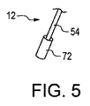
図2を参照して、送り方向36に針20を移動させるために操作部12を(図1及び3に示される)第1動作位置から(図2及び4に示される)第2動作位置に向かって移動させると、示された実施例ではワイヤ54の遠位端に位置する操作部12の末端70は、針20の第2端部32と接する。操作部12の下部を示す図5を参照して、操作部12は、末端部にプラスチックから作られてもよい遠位管72を具えてもよい。示されるように、遠位管72は、ワイヤ54と連結される。遠位管72の外径は細長い本体14及び/又は針ホルダ16の内径と略等しくてもよいが、遠位管72が細長い本体14及び針ホルダ16内を自由に移動できる程度に小さい。操作部12の末端部の他の構成が図6に示され、操作部12は球状遠位端74を具える。示されるように、球状遠位端74は、ワイヤ54に設けられてもよい。球状遠位端74の外径は、細長い本体14及び/又は針ホルダ16の内径に略等しくてよい。図7にも、操作部12の末端部が示され、操作部12はポケット76を遠位端に具える。ポケット76は、針20の第2端部32を受入れるように構成される。ポケット76はまた、縫合糸22を受入れるように構成されてもよい。ポケット76は、針20が針ホルダ16を通って送り方向36に送られる間、針20の第2端部32を固定する弾性材料で形成されてもよい。   Referring to FIG. 2, in order to move the needle 20 in the feed direction 36, the operating unit 12 is moved from the first operating position (shown in FIGS. 1 and 3) to the second operating position (shown in FIGS. 2 and 4). When moved toward, the distal end 70 of the operating portion 12, which in the illustrated embodiment is located at the distal end of the wire 54, contacts the second end 32 of the needle 20. With reference to FIG. 5 showing the lower part of the operating part 12, the operating part 12 may comprise a distal tube 72 which may be made of plastic at the end. As shown, distal tube 72 is coupled with wire 54. The outer diameter of the distal tube 72 may be approximately equal to the inner diameter of the elongate body 14 and / or needle holder 16, but is small enough to allow the distal tube 72 to move freely within the elongate body 14 and needle holder 16. Another configuration of the distal end of the operating portion 12 is shown in FIG. 6, and the operating portion 12 includes a spherical distal end 74. As shown, a spherical distal end 74 may be provided on the wire 54. The outer diameter of the spherical distal end 74 may be approximately equal to the inner diameter of the elongated body 14 and / or the needle holder 16. Also shown in FIG. 7 is the distal end of the operating section 12, which includes a pocket 76 at the distal end. The pocket 76 is configured to receive the second end 32 of the needle 20. Pocket 76 may also be configured to receive suture 22. The pocket 76 may be formed of an elastic material that secures the second end 32 of the needle 20 while the needle 20 is fed through the needle holder 16 in the feed direction 36.

送り方向36に針20を動かすために他のタイプの操作部が使用されてもよい。例えば、図3に示される収納位置から図2に示される解放状態まで針20を動かすために、圧搾空気を満たした機構による空圧が用いられてもよい。針20を動かすために他のタイプの機械的な操作部が用いられてもよい。例えば、収納位置から解放状態に向かって針20を動かすために、針20と接するローラーがモーターによって駆動されてもよい。さらに、縫合装置10がロボットのエンドエフェクタと連結するロボットを用いて針20が配置されてもよいし、操作部及び縫合装置10がエンドエフェクタと連結するように構成されてもよい。このように、ボタン50、管52及びワイヤ54を含む操作部12は、収納位置から解放状態に向かって針20を動かすために考えられた単なる操作部ではない。   Other types of controls may be used to move the needle 20 in the feed direction 36. For example, in order to move the needle 20 from the storage position shown in FIG. 3 to the released state shown in FIG. 2, air pressure by a mechanism filled with compressed air may be used. Other types of mechanical controls may be used to move the needle 20. For example, in order to move the needle 20 from the storage position toward the released state, a roller that contacts the needle 20 may be driven by a motor. Furthermore, the needle 20 may be disposed using a robot in which the suturing device 10 is coupled to the end effector of the robot, or the operation unit and the suturing device 10 may be configured to be coupled to the end effector. Thus, the operation unit 12 including the button 50, the tube 52, and the wire 54 is not a simple operation unit that is considered for moving the needle 20 from the storage position toward the released state.

図1に戻って参照して、縫合装置10はまた、細長い本体14と連結されるハンドル90を具える。例えば、回転又は並進移動のようなハンドル90の移動により細長い本体14が同じように移動できるように、ハンドル90は細長い本体14の基端部分92と連結し、細長い本体14に固定される。   Referring back to FIG. 1, the suturing device 10 also includes a handle 90 that is coupled to the elongated body 14. For example, the handle 90 is coupled to the proximal portion 92 of the elongate body 14 and secured to the elongate body 14 so that movement of the handle 90, such as rotation or translation, can move in the same way.

図8及び8Aを参照して、ハンドル90は、細長い本体14の基端部分92が受入れられる細長い孔94を具える。細長い孔94は、基端面96から末端面98まで延び、長手方向軸56と一致する。ハンドル90はまた、基端面96と末端面98の間を延びる外側面102を画定する。外側面102は、長手方向軸56の周りを回転する面に沿う。示された実施例では、外側面102は、双曲面である。基端面96及び末端面98と隣接するハンドル90の外径は、基端面96と末端面98から等距離のハンドル90の外径より小さい。これにより、ハンドル90は、縫合装置10を操作するために外科医が容易にハンドル90を握ることが可能な窪みのある輪郭となる。   With reference to FIGS. 8 and 8A, the handle 90 includes an elongated hole 94 into which the proximal portion 92 of the elongated body 14 is received. The elongated hole 94 extends from the proximal surface 96 to the distal surface 98 and coincides with the longitudinal axis 56. The handle 90 also defines an outer surface 102 that extends between the proximal surface 96 and the distal surface 98. The outer surface 102 is along a surface that rotates about the longitudinal axis 56. In the illustrated embodiment, the outer surface 102 is a hyperboloid. The outer diameter of the handle 90 adjacent to the proximal end surface 96 and the distal end surface 98 is smaller than the outer diameter of the handle 90 equidistant from the proximal end surface 96 and the distal end surface 98. Thus, the handle 90 has a recessed profile that allows a surgeon to easily grasp the handle 90 to operate the suturing device 10.

長手方向軸56に直交する横断面において、ハンドル90は円形である必要がないので、長手方向軸56に直交して測定された幅と呼ばれ得る、ハンドル90の最大外径は、10〜20mmであってよい。示された実施例では、ハンドル90は、12mm未満の長手方向軸56に直交して測定された幅Wを有する。図9には、縫合装置10の隣にある、長さTRL及び内径TRDを有する管形反応器TRの断面図が示される。最小侵襲脊椎外科手術で用いられる一般的な管形反応器は、14mm〜22mmの間で測定される内径(例えば、図9の内径TRDとして示される)を有する。ハンドル90の最大幅はあまり大きくないが、外科手術中、特に外科医が管形反応器又は管形反応器以外の他の小さな手術用の皮膚開口を介して手術をする際に、外科医の視界を妨げる。図9に示されるように、ボタン50は、ハンドル90の最大幅と等しい最大幅を有する。外科手術中の外科医の視界を妨げないように、ボタン50の最大幅を制限することも望まれる。従って、長手方向軸56に直交して測定されたボタン50の最大幅は、ハンドル90の最大幅の90%から110%の間であってもよい。   Since the handle 90 need not be circular in cross-section perpendicular to the longitudinal axis 56, the maximum outer diameter of the handle 90, which can be referred to as the width measured perpendicular to the longitudinal axis 56, is 10-20 mm. It may be. In the example shown, the handle 90 has a width W measured perpendicular to the longitudinal axis 56 of less than 12 mm. FIG. 9 shows a cross-sectional view of a tubular reactor TR having a length TRL and an inner diameter TRD next to the suturing device 10. A typical tubular reactor used in minimally invasive spinal surgery has an inner diameter that is measured between 14 mm and 22 mm (eg, shown as inner diameter TRD in FIG. 9). Although the maximum width of the handle 90 is not very large, the surgeon's field of view is visible during surgery, especially when the surgeon operates through a tubular reactor or other small surgical skin opening other than a tubular reactor. Hinder. As shown in FIG. 9, the button 50 has a maximum width equal to the maximum width of the handle 90. It is also desirable to limit the maximum width of the button 50 so as not to obstruct the surgeon's view during the surgical procedure. Accordingly, the maximum width of the button 50 measured perpendicular to the longitudinal axis 56 may be between 90% and 110% of the maximum width of the handle 90.

ハンドル90は、他の形状であってもよい。例えば、必要に応じて、ハンドル90は、ピストルのグリップの形であってもよい。   The handle 90 may have other shapes. For example, if desired, the handle 90 may be in the form of a pistol grip.

示された実施例に戻って、及び図9を参照して、操作部12が第1動作位置にある場合、ボタン50はハンドル90からずれている。より詳しくは、ボタン50のハンドル接触面62は、ハンドル90の基端面96から、長手方向軸56と平行して測定された距離dずれている。操作部12が第2動作位置にある場合、これはボタン50のハンドル接触面62がハンドル90の基端面96に接する場合であってもよく、この場合に、操作部12の末端70が針ホルダ16の中に留まるように距離dが構成されてもよい。必要に応じて、操作部12が第2動作位置にある場合に、操作部12の末端70が針ホルダ16から延びるように距離dが構成されてもよい。   Returning to the illustrated embodiment and with reference to FIG. 9, the button 50 is offset from the handle 90 when the operating portion 12 is in the first operating position. More specifically, the handle contact surface 62 of the button 50 is offset from the proximal end surface 96 of the handle 90 by a distance d measured in parallel with the longitudinal axis 56. When the operation unit 12 is in the second operation position, this may be a case where the handle contact surface 62 of the button 50 is in contact with the proximal end surface 96 of the handle 90. In this case, the distal end 70 of the operation unit 12 is the needle holder. The distance d may be configured to remain within 16. If necessary, the distance d may be configured such that the distal end 70 of the operation unit 12 extends from the needle holder 16 when the operation unit 12 is in the second operating position.

図1に戻って参照して、示された実施例の細長い本体14は、カニューレ(cannula)形である。図2を参照して、細長い本体14は外面118を有し、それは表面が滑らかで、操作部12の一部を受入れるトラック120を画定する。示された実施例では、細長い本体14はカニューレで、トラック120は操作部12の管52及びワイヤ54を受入れるルーメン(lumen)である。細長い本体14は、その他の形状であってもよく、例えば、トラックは管52及びワイヤ54を囲む必要がなく、U字形状であってもよい。示された実施例では、細長い本体14は、長手方向軸56に直交する横断面が円であるが、例えば、長手方向軸56に直交する横断面が多角形又はU字型のような、他の形状であってもよい。細長い本体14は、基端部分92及び末端部分122を具える。示された実施例では、針ホルダ16は、細長い本体14に受入れられて連結され、末端部分122から延びる。又は、針ホルダ16は、細長い本体14の末端部分122の一部として設けられてもよい。示された実施例では、細長い本体14は、金属から作られ、長手方向軸56に沿って延びる。示された実施例の細長い本体14は、剛性材料から作られるが、外科医が外科手術中に、人体に挿入するのに好ましい形に細長い本体14の少なくとも一部を曲げることができるように、必要に応じて、細長い本体14の少なくとも一部は展性又は可撓性材料から作られてもよい。示された実施例では、細長い本体14の外径は、基端部分92と末端部分122の間で一定である。外径は3.5mm未満でもよく、これにより、外科手術中の外科医の視界を良好にする非常にスリムな装置となる。   Referring back to FIG. 1, the elongate body 14 of the illustrated embodiment is cannula shaped. With reference to FIG. 2, the elongated body 14 has an outer surface 118 that is smooth in surface and defines a track 120 that receives a portion of the operating portion 12. In the illustrated embodiment, the elongate body 14 is a cannula and the track 120 is a lumen that receives the tube 52 and wire 54 of the operating portion 12. The elongated body 14 may have other shapes, for example, the track need not surround the tube 52 and the wire 54 and may be U-shaped. In the illustrated embodiment, the elongate body 14 is circular in cross section perpendicular to the longitudinal axis 56, but other cross sections perpendicular to the longitudinal axis 56 are polygonal or U-shaped, for example. The shape may also be The elongate body 14 includes a proximal portion 92 and a distal portion 122. In the illustrated embodiment, the needle holder 16 is received and coupled to the elongate body 14 and extends from the distal portion 122. Alternatively, the needle holder 16 may be provided as part of the distal portion 122 of the elongated body 14. In the illustrated embodiment, the elongate body 14 is made of metal and extends along the longitudinal axis 56. The elongate body 14 of the illustrated embodiment is made from a rigid material, but is necessary so that at least a portion of the elongate body 14 can be bent into a preferred shape for insertion into the human body during surgery. Accordingly, at least a portion of the elongated body 14 may be made from a malleable or flexible material. In the illustrated embodiment, the outer diameter of the elongated body 14 is constant between the proximal portion 92 and the distal portion 122. The outer diameter may be less than 3.5 mm, which results in a very slim device that provides good visibility for the surgeon during surgery.

針ホルダ16は、末端部分122から離れて延びるか又は細長い本体14の末端部分122の一部として設けられている。図10を参照すると、針ホルダ16は、中空管状部材である。示された実施例では、長手方向軸56と一致する針ホルダ16の基端部130は、細長い本体14内に受入れられるが、例えば、細長い本体14と針ホルダ16はともに管状の支持構造を有する材料から作られてもよく、針ホルダ16は細長い本体14の一部として形成されてもよい。別の構成では、細長い本体14及び針ホルダ16は、クラムシェル型構造で連結された断面が全体としてU字型の細長い材料から形成されてもよい。示された実施例の針ホルダ16は、縫合装置10がその末端でJ型のフック構造を有することができるように、一定の半径に全体として沿う湾曲した針ホルダである。   Needle holder 16 extends away from distal portion 122 or is provided as part of distal portion 122 of elongated body 14. Referring to FIG. 10, the needle holder 16 is a hollow tubular member. In the illustrated embodiment, the proximal end 130 of the needle holder 16 that coincides with the longitudinal axis 56 is received within the elongate body 14, but, for example, both the elongate body 14 and the needle holder 16 have a tubular support structure. It may be made from a material and the needle holder 16 may be formed as part of the elongated body 14. In another configuration, the elongate body 14 and the needle holder 16 may be formed from an elongate material that is generally U-shaped in cross-section connected by a clamshell type structure. The needle holder 16 in the illustrated embodiment is a curved needle holder that generally follows a certain radius so that the suturing device 10 can have a J-shaped hook structure at its distal end.

示された実施例では、針ホルダ16は、細長い本体14から取外し可能であることを意図していないが、別の構成では、針ホルダ16は、例えば、摩擦係合又はバヨネット接続のような機械的な接続によって細長い本体14と選択的に連結されてもよい。図11には、細長い本体14から分離された針ホルダ16が示される。このような実施例では、針ホルダ16は、細長い本体14の末端部分122に取外し可能に連結される。例えば、突部132が、針ホルダ16の基端部130に設けられてもよい。突部132は、細長い本体14の末端部分122に設けられた凹部134に嵌入する。針ホルダ16と細長い本体14を取外し可能に連結するために、複数の突部132及び凹部134が設けられてもよい。   In the illustrated embodiment, the needle holder 16 is not intended to be removable from the elongate body 14, but in other configurations, the needle holder 16 is a machine such as, for example, a frictional engagement or bayonet connection. May be selectively coupled to the elongated body 14 by a general connection. FIG. 11 shows the needle holder 16 separated from the elongated body 14. In such an embodiment, needle holder 16 is removably coupled to distal portion 122 of elongate body 14. For example, the protrusion 132 may be provided on the proximal end portion 130 of the needle holder 16. The protrusion 132 fits into a recess 134 provided in the end portion 122 of the elongated body 14. A plurality of protrusions 132 and recesses 134 may be provided to detachably connect the needle holder 16 and the elongated body 14.

図9に戻って参照して、ハンドル90の末端面98から湾曲した針ホルダ16が長手方向軸56から離れて曲がり始める位置138までの、長手方向軸56と平行に測定された距離L1は、10cm〜20cmの間である。換言すると、湾曲した針ホルダ16が長手方向軸56から離れて曲がり始める場所と、細長い本体14がハンドル90と連結される場所の間の長手方向軸56と平行に測定された距離L1が約10cm〜約20cmの間である。示された実施例では、距離L1は、約13cmである。最小侵襲脊椎手術中に用いられる一般的な管形反応器は、(例えば、図9の長さTRLとして示されるように)3cm〜9cmの長さを有する。縫合装置が扱い難くない状態で外科医が針ホルダ16を操作できる程度に針ホルダ16は対象組織に対して近いが、距離L1によって外科医は管形反応器の中に細長い本体14及び針ホルダ16を挿入させることができるので、管形反応器とハンドル90を接触させることなく針ホルダ16を対象組織と接触させることができる。距離L1があまりに長い場合、針ホルダ16の操作はより難しくなる。   Referring back to FIG. 9, the distance L1 measured parallel to the longitudinal axis 56 from the distal face 98 of the handle 90 to the position 138 where the curved needle holder 16 begins to bend away from the longitudinal axis 56 is It is between 10 cm and 20 cm. In other words, the distance L1 measured parallel to the longitudinal axis 56 between the location where the curved needle holder 16 begins to bend away from the longitudinal axis 56 and the location where the elongated body 14 is coupled to the handle 90 is about 10 cm. ~ About 20 cm. In the example shown, the distance L1 is about 13 cm. A typical tubular reactor used during minimally invasive spine surgery has a length of 3 cm to 9 cm (eg, as shown as length TRL in FIG. 9). Although the needle holder 16 is close to the target tissue to the extent that the surgeon can manipulate the needle holder 16 without the suture device being unwieldy, the distance L1 allows the surgeon to place the elongated body 14 and needle holder 16 into the tubular reactor. Since it can be inserted, the needle holder 16 can be brought into contact with the target tissue without bringing the tubular reactor and the handle 90 into contact. If the distance L1 is too long, the operation of the needle holder 16 becomes more difficult.

図10及び11を参照して、針ホルダ16は、最遠位先端142を有する末端部140を具える。針ホルダ16は、トラック120及び遠位開口146と連通する針通路144を画定する。遠位開口146は、長手方向軸56から順方向にずれている。図10を参照して、最遠位先端142は、長手方向軸56と直交する方向に、7mm未満の距離L2分長手方向軸56からずれている。上述した通り、最小侵襲脊髄手術において用いられる一般的な管形反応器の直径の測定値は、14mm〜22mmである。長手方向軸56と直交する方向に長手方向軸56からずらした最遠位先端142と長手方向軸56の間に7mm未満の間隔を設けることによって、外科医は、管形反応器の中心軸CAに沿って細長い本体14を配置することができ、管形反応器の側面に接触することなく中心軸CAの周りを縫合装置10を回転させることができる。針ホルダ16は、例えば、損傷組織中に最遠位先端142を配置しやすくするために最遠位先端142の周り等、針ホルダ16の少なくとも一部を外科医が所望の形状に曲げることができるように、展性又は可撓性材料から作られてもよい。   With reference to FIGS. 10 and 11, the needle holder 16 includes a distal end 140 having a distal most tip 142. Needle holder 16 defines a needle passage 144 that communicates with track 120 and distal opening 146. The distal opening 146 is offset from the longitudinal axis 56 in the forward direction. Referring to FIG. 10, the distal most tip 142 is offset from the longitudinal axis 56 by a distance L2 of less than 7 mm in a direction orthogonal to the longitudinal axis 56. As described above, the diameter measurement of a typical tubular reactor used in minimally invasive spinal cord surgery is 14 mm to 22 mm. By providing a distance of less than 7 mm between the distal most tip 142 and the longitudinal axis 56 offset from the longitudinal axis 56 in a direction perpendicular to the longitudinal axis 56, the surgeon is placed in the central axis CA of the tubular reactor. An elongate body 14 can be disposed along and the suturing device 10 can be rotated about the central axis CA without contacting the side of the tubular reactor. The needle holder 16 may allow the surgeon to bend at least a portion of the needle holder 16 into a desired shape, for example, around the distal-most tip 142 to facilitate placement of the distal-most tip 142 in the damaged tissue. As such, it may be made from malleable or flexible materials.

示された実施例では、針ホルダ16の末端部140は、最遠位先端142から送り方向36と反対の方向にずらされた位置で針ホルダ16から針20の第2端部32を取外すことができるように構成される。針ホルダ16の末端部140は、針20の第2端部32が針ホルダ16から取外される位置と近接する遠位開口146の境界の一部を形成するオフセット端150を具える。図2に戻って参照して、針20が送り方向36に送られると、針20の第1端部30は、対象組織24の内側26から対象組織24の外側28に向かって対象組織24を通ってもよい。しかしながら、針20の第2端部32は、針ホルダ16から取外される前に針ホルダ16の最遠位先端142を通過する必要はない。遠位開口146のこの様な構成により、針20の第2端部32を遠位開口146に挿入し、針ホルダ16に対して送り方向36とは反対の方向に針20を動かすことによって、針通路144への針20及び縫合糸22の搭載が容易となる。遠位開口146の構成はさらに、針20の第1端部30が対象組織24を通過する場合に縫合糸22を通過するかもしれないという可能性を減らす。   In the embodiment shown, the distal end 140 of the needle holder 16 removes the second end 32 of the needle 20 from the needle holder 16 at a position offset from the distal most tip 142 in a direction opposite to the feed direction 36. It is configured to be able to. The distal end 140 of the needle holder 16 includes an offset end 150 that forms part of the boundary of the distal opening 146 proximate to the location where the second end 32 of the needle 20 is removed from the needle holder 16. Referring back to FIG. 2, when the needle 20 is fed in the feed direction 36, the first end 30 of the needle 20 moves the target tissue 24 from the inner side 26 of the target tissue 24 toward the outer side 28 of the target tissue 24. You can pass. However, the second end 32 of the needle 20 need not pass through the most distal tip 142 of the needle holder 16 before being removed from the needle holder 16. With such a configuration of the distal opening 146, by inserting the second end 32 of the needle 20 into the distal opening 146 and moving the needle 20 in a direction opposite to the feed direction 36 relative to the needle holder 16, The needle 20 and the suture thread 22 can be easily mounted on the needle passage 144. The configuration of the distal opening 146 further reduces the possibility that the first end 30 of the needle 20 may pass through the suture 22 when passing through the target tissue 24.

図11に詳細に示されるように、遠位開口146は円形ではない。図10を参照して、線152は、オフセット端150及び最遠位先端142と交差する。線152は、送り方向36が線152と交差する送り方向36上の点に対して描かれた接線に対して90°ずれている。故に、遠位開口146は、斜めであると考えられてもよい。非円形の遠位開口146であったとしても、針20が(図3に示される)収納位置にある場合、針20の第1端部30は、最遠位先端142から針通路144の内側(図3の下方)に入れられる。最遠位先端142は丸くてもよく(図11参照。)、これにより、針20の(尖った)第1端部30で対象組織24を捕えることなく、外科医は、最遠位先端142で、対象組織24の内側26の対象組織24をつかむ、すなわち、「引っ掛け」、対象組織24に刻み目をつけることができる。また、丸いボールが、最遠位先端142に設けられてもよい。これによって、縫合装置10は、既知の外科手術で用いられる神経フックと同様に用いられることが可能である。   As shown in detail in FIG. 11, distal opening 146 is not circular. With reference to FIG. 10, line 152 intersects offset end 150 and distal most tip 142. Line 152 is offset by 90 ° with respect to a tangent line drawn with respect to a point on feed direction 36 where feed direction 36 intersects line 152. Thus, the distal opening 146 may be considered oblique. Even if it is a non-circular distal opening 146, when the needle 20 is in the stowed position (shown in FIG. 3), the first end 30 of the needle 20 extends from the distal most tip 142 to the inside of the needle passage 144. (Below FIG. 3). The distal-most tip 142 may be round (see FIG. 11), which allows the surgeon at the distal-most tip 142 without capturing the target tissue 24 at the (pointed) first end 30 of the needle 20. The target tissue 24 inside the target tissue 24 can be grabbed, ie “hooked”, and the target tissue 24 can be scored. A round ball may also be provided at the most distal tip 142. Thereby, the suturing device 10 can be used in the same manner as a nerve hook used in a known surgical operation.

針ホルダ16の末端部140は、針20の第2端部32を最遠位先端142からずれた場所で針ホルダ16から取外すことができるように、他の構成で形成されてもよい。例えば、図17に示される切欠きが最遠位先端142の近くに設けられてもよい。末端部140の構成は、縫合装置10からの針20の配置を容易にするだけでなくて、縫合装置10への針20及び縫合糸22の搭載を容易にする。   The distal end 140 of the needle holder 16 may be formed in other configurations so that the second end 32 of the needle 20 can be removed from the needle holder 16 at a location offset from the distal most tip 142. For example, the notch shown in FIG. 17 may be provided near the most distal tip 142. The configuration of the distal end 140 not only facilitates the placement of the needle 20 from the suturing device 10, but also facilitates the loading of the needle 20 and suture 22 onto the suturing device 10.

図10を参照して、示された実施例の針通路144は曲がっていて、針通路144の中心線(midline)に沿って測定された湾曲した針通路半径160に沿う。湾曲した針20の湾曲した半径34が図2に示され、湾曲した針通路半径160と同程度であるが、同一である必要はない。湾曲した針半径34が湾曲した針通路半径160と一致しないことによって、針20が収納位置から解放状態へ移動するにつれて、針20は針ホルダ16の一部の移動経路に沿って針ホルダ16の内面162と接してもよい。針20が収納位置から解放状態へ移動するにつれて、針20は針ホルダ16の主要な移動経路に沿って針ホルダ16の内面162と接してもよい。湾曲した針通路半径160と一致する湾曲した針半径34を有しないことによって、例えば輸送中、針20と針ホルダ16の内面162間の摩擦が、針ホルダ16の中に針20を保持するのを助ける。針20が収納位置にある場合、針20は針20の長さ又は弧長に沿って最低3つの異なる位置、例えば、図16に示される、第1位置164、第2位置166及び第3位置168のような位置において針ホルダ16の内面162と接してもよい。第1位置164は、最遠位先端142の下で最遠位先端142と隣合って位置する。第2位置166は、針20の弧長の真ん中近くに位置する。第3位置168は、湾曲した針ホルダ16が長手方向軸56から離れて曲がり始める位置138の隣に位置する。また、針20は針通路144の内径の少なくとも40%である最大外径を有してもよく、これにより、針通路144の中の針20の保持が容易になる。また、針20は、針通路144の内径の90%以下の外径を有してもよく、これにより、針通路144が針20及び縫合糸22を収容することができる。   Referring to FIG. 10, the needle passage 144 of the illustrated embodiment is curved and follows a curved needle passage radius 160 measured along the midline of the needle passage 144. The curved radius 34 of the curved needle 20 is shown in FIG. 2 and is comparable to, but need not be the same as, the curved needle passage radius 160. Because the curved needle radius 34 does not coincide with the curved needle passage radius 160, the needle 20 moves along the partial movement path of the needle holder 16 as the needle 20 moves from the retracted position to the released state. It may be in contact with the inner surface 162. As the needle 20 moves from the retracted position to the released state, the needle 20 may contact the inner surface 162 of the needle holder 16 along the main travel path of the needle holder 16. By not having a curved needle radius 34 that coincides with the curved needle passage radius 160, friction between the needle 20 and the inner surface 162 of the needle holder 16 holds the needle 20 in the needle holder 16, for example during transport. Help. When the needle 20 is in the retracted position, the needle 20 is at least three different positions along the length or arc length of the needle 20, such as the first position 164, the second position 166, and the third position shown in FIG. You may contact the inner surface 162 of the needle holder 16 at a position such as 168. The first position 164 is located adjacent to the distal-most tip 142 below the distal-most tip 142. The second position 166 is located near the middle of the arc length of the needle 20. The third position 168 is located next to the position 138 where the curved needle holder 16 begins to bend away from the longitudinal axis 56. The needle 20 may also have a maximum outer diameter that is at least 40% of the inner diameter of the needle passage 144, which facilitates the holding of the needle 20 in the needle passage 144. Further, the needle 20 may have an outer diameter that is 90% or less of the inner diameter of the needle passage 144, so that the needle passage 144 can accommodate the needle 20 and the suture thread 22.

針ホルダ16の内面162は、収納位置から解放状態に向かう針20の移動を促すために、電解研磨されてもよい。さらに、ゲル又は他の潤滑油が針通路144に設けられてもよい。ゲル又は潤滑油は、針ホルダ16の針通路144の中に針20を保持することに役立ち、縫合装置10に針20を配置する間の針20と内面162の間の摩擦を減少させるのにも役立つ。図16を参照して、針保持172は、例えば輸送中のような、製造後、使用前に針通路144に針20を保持するために設けられてもよい。針保持172は、発泡材又は類似の弾性材料から作られてもよく、遠位開口146を覆う。殺菌処理の助けとなるべく、針保持172が連続気泡発泡材(open cell form)から作られることが望ましい場合もある。針保持172は遠位開口146に挿入されてもよいし、又は、針保持172が(図16に破線で示されている)容器を具え、遠位開口146を覆うために針ホルダ16に嵌込まれてもよい。縫合装置10が縫合装置10を保持するパッケージカード(backer card)に詰込まれる際に、針保持172は直接パッケージカードに取付けられてもよいし、又は、パッケージカードに一体化されてもよい。   The inner surface 162 of the needle holder 16 may be electropolished to facilitate movement of the needle 20 from the stowed position toward the released state. In addition, gel or other lubricating oil may be provided in the needle passage 144. The gel or lubricant helps to hold the needle 20 in the needle passage 144 of the needle holder 16 and reduces friction between the needle 20 and the inner surface 162 during placement of the needle 20 in the suturing device 10. Also useful. Referring to FIG. 16, a needle holder 172 may be provided to hold the needle 20 in the needle passage 144 after manufacture and before use, such as during shipping. Needle holder 172 may be made of a foam or similar elastic material and covers distal opening 146. In some cases, it may be desirable for the needle holder 172 to be made from an open cell foam to aid in the sterilization process. The needle holder 172 may be inserted into the distal opening 146 or the needle holder 172 comprises a container (shown in phantom in FIG. 16) and fits into the needle holder 16 to cover the distal opening 146. May be included. When the suturing device 10 is packed into a package card that holds the suturing device 10, the needle holder 172 may be attached directly to the package card or may be integrated into the package card.

他の構成では、操作部12のワイヤ54は、針20の配置を容易にするために、湾曲した針通路半径160と同様の曲線半径に沿って予め歪ませておいてもよい。上述した通り、ポケット76(図7)又は類似の装置は、針20が針ホルダ16を通って送り方向36に送られる間針20の第2端部32を固定する、弾性材料から形成されてもよい。例えば、ポケット76(又は類似の装置)は、内面162によってポケット76に力が加えられるような外径を有してもよいので、ポケット76は、針20が解放状態になるまで、すなわち、針ホルダ16から完全に取外されるまで、針20の第2端部32に摩擦係合する。このように、操作部12の末端70のポケット76(又は類似の装置)は、選択的に針20と連結又は分離され、これにより外科医は、針20が解放状態前の送り方向36に移動した後、針ホルダ16の中に針20を戻すことができる。   In other configurations, the wire 54 of the operating portion 12 may be pre-distorted along a curved radius similar to the curved needle passage radius 160 to facilitate placement of the needle 20. As described above, the pocket 76 (FIG. 7) or similar device is formed of an elastic material that secures the second end 32 of the needle 20 while the needle 20 is fed through the needle holder 16 in the feed direction 36. Also good. For example, the pocket 76 (or similar device) may have an outer diameter such that a force is applied to the pocket 76 by the inner surface 162, so that the pocket 76 remains open until the needle 20 is released, i.e., the needle. Frictionally engages the second end 32 of the needle 20 until it is completely removed from the holder 16. In this manner, the pocket 76 (or similar device) at the distal end 70 of the operating portion 12 is selectively connected or disconnected from the needle 20 so that the surgeon has moved the needle 20 in the feed direction 36 prior to release. Later, the needle 20 can be returned into the needle holder 16.

示された実施例では、針ホルダ16は、縫合装置10の遠位範囲を画定する。円を描く必要はないが、針ホルダ16の外径174は、細長い本体14の末端部122の外径176と略同じ又はそれより小さい。また、針ホルダ16の外径174は、最遠位先端142から針ホルダ16が細長い本体14に移行するところまで一定、又は略一定である。縫合装置10の遠位範囲は、示された実施例では湾曲していて、針ホルダ16に沿う位置178であり、位置178の接線は、長手方向軸56に対して直交する。一定又は略一定の外径174を有する針ホルダ16が、接線が長手方向軸56に対して直交する針ホルダ16の外面180の位置178に縫合装置10の遠位範囲を具えることによって、硬膜嚢で見られるような神経を避け、対象組織24の内側26のちょうど下(図2参照)に届く非常にスリムな縫合装置10がもたらされる。   In the illustrated embodiment, needle holder 16 defines the distal extent of suturing device 10. Although it is not necessary to draw a circle, the outer diameter 174 of the needle holder 16 is substantially the same or smaller than the outer diameter 176 of the distal end 122 of the elongated body 14. Further, the outer diameter 174 of the needle holder 16 is constant or substantially constant from the most distal tip 142 until the needle holder 16 moves to the elongated body 14. The distal extent of the suturing device 10 is curved in the illustrated embodiment and is a position 178 along the needle holder 16, and the tangent of the position 178 is orthogonal to the longitudinal axis 56. A needle holder 16 having a constant or substantially constant outer diameter 174 includes a distal region of the suturing device 10 at a position 178 on the outer surface 180 of the needle holder 16 whose tangent is perpendicular to the longitudinal axis 56. A very slim suturing device 10 is provided that avoids nerves such as found in the membrane capsule and reaches just below the inner side 26 of the target tissue 24 (see FIG. 2).

針ホルダ16の外面180は、湾曲した針通路半径160と同じ半径に沿って延び、180°より短い弧長に沿い、図10に示された実施例では、湾曲した針ホルダ16が長手方向軸56から離れて針ホルダ16の最遠位先端142に向かって曲がり始める位置138から測定して、180°よりも約40°小さい(すなわち、約140°より小さい。)。針ホルダ16は、例えば、図16も参照して、90°より大きくて180°より小さい弧長に沿って延びてもよい。この構成によっても、縫合装置10は、外科手術で用いられる神経フックと同じように作用することができる。針ホルダ16の弧長は、針20の弧長と少なくとも同じ長さであってよい。例えば、針ホルダ16の弧長は、針20の弧長よりも5から25%長くてもよく、示された実施例では、針ホルダ16の弧長は針20の弧長よりも約15%長い。他の構成では、針ホルダ16は、20°より大きくて190°より小さい弧長に沿って延びてもよい。   The outer surface 180 of the needle holder 16 extends along the same radius as the curved needle passage radius 160, along an arc length shorter than 180 °, and in the embodiment shown in FIG. 10, the curved needle holder 16 has a longitudinal axis. Measured from a position 138 that begins to bend away from 56 and toward the distal most distal tip 142 of the needle holder 16 is about 40 ° less than 180 ° (ie, less than about 140 °). Needle holder 16 may extend along an arc length greater than 90 ° and less than 180 °, for example, also referring to FIG. Even with this configuration, the suturing device 10 can act in the same manner as a nerve hook used in a surgical operation. The arc length of the needle holder 16 may be at least as long as the arc length of the needle 20. For example, the arc length of the needle holder 16 may be 5 to 25% longer than the arc length of the needle 20, and in the illustrated embodiment, the arc length of the needle holder 16 is about 15% greater than the arc length of the needle 20. long. In other configurations, the needle holder 16 may extend along an arc length that is greater than 20 ° and less than 190 °.

上述したとおり、遠位開口146は、第1動作位置から第2動作位置の方へ移動する場合に、示された実施例において操作部12の大半が沿って移動する軸である長手方向軸56からずれている。示された縫合装置10はなめらかな装置であり、これにより硬膜嚢の損傷の修復に役立つ。例として、長手方向軸56及び湾曲した針通路半径160が存在する第1平面について検討する。この第1平面は、図2の断面がとられた平面である。第1平面と直交し、長手方向軸56に平行で、最遠位先端142から最も離れた細長い本体14の外面118に沿った線と交差する第2平面について検討する。この第2平面は、図2が印刷されたページと直交し、細長い本体14の外面118に沿った線と交差する一方で、長手方向軸56の右側にずれている。示された実施例では、縫合装置10の末端部分の働く構成要素は、この第2平面の前方(図2の左)である。例えば、細長い本体14の末端部122は、第2の平面の後方(図2の右)に曲がっていない。末端部122が最小侵襲脊椎手術で用いられる管形反応器に挿入される場合に、この種の構成が役に立つ。   As described above, the distal opening 146 is a longitudinal axis 56 that is the axis along which most of the operating portion 12 moves in the illustrated embodiment as it moves from the first operating position toward the second operating position. It is off. The illustrated suturing device 10 is a smooth device that helps repair dural sac damage. As an example, consider a first plane in which a longitudinal axis 56 and a curved needle passage radius 160 exist. This first plane is a plane from which the cross section of FIG. 2 is taken. Consider a second plane that is orthogonal to the first plane, parallel to the longitudinal axis 56, and intersecting a line along the outer surface 118 of the elongate body 14 furthest from the distal-most tip 142. This second plane is perpendicular to the page on which FIG. 2 is printed and intersects a line along the outer surface 118 of the elongate body 14 while being offset to the right of the longitudinal axis 56. In the embodiment shown, the working component of the distal portion of the suturing device 10 is in front of this second plane (left in FIG. 2). For example, the distal end 122 of the elongated body 14 is not bent behind the second plane (right of FIG. 2). This type of configuration is useful when the distal end 122 is inserted into a tubular reactor used in minimally invasive spinal surgery.

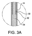
図3には、図1及び図3に示される針20が針通路144に受入れられ操作部12が第1動作位置にある場合の、遠位開口146を通って延びる縫合糸22の少なくとも一部が示される。細長い本体14又は針ホルダ16が長手方向軸56に対して閉断面を有する場合、遠位開口146を通って縫合糸22を延ばせるということは役立つ。しかしながら、細長い本体14又は針ホルダ16が、例えば、U字型のような開断面を有する場合、縫合糸22は遠位開口146を通って延びることができず、替わりに、縫合糸22は、細長い本体14の中で細長い本体14に沿って延びることができる。示された実施例に戻って参照して、針20が針通路144に受入れられ操作部12が第1動作位置にある場合、縫合糸22の少なくとも一部は、針20と針ホルダ16の内面162の間を針20の第2端部32から遠位開口146の方へ針通路144に沿って延びる。   FIG. 3 illustrates at least a portion of the suture 22 extending through the distal opening 146 when the needle 20 shown in FIGS. 1 and 3 is received in the needle passage 144 and the operating portion 12 is in the first operating position. Is shown. If the elongate body 14 or needle holder 16 has a closed cross-section relative to the longitudinal axis 56, it is helpful to be able to extend the suture 22 through the distal opening 146. However, if the elongate body 14 or needle holder 16 has an open cross section, such as a U-shape, for example, the suture 22 cannot extend through the distal opening 146; instead, the suture 22 It can extend along the elongated body 14 within the elongated body 14. Referring back to the illustrated embodiment, when the needle 20 is received in the needle passage 144 and the operating portion 12 is in the first operating position, at least a portion of the suture 22 is the inner surface of the needle 20 and the needle holder 16. 162 extends from the second end 32 of the needle 20 toward the distal opening 146 along the needle passage 144.

図4を参照して、針ホルダ16の遠位開口146から延びる縫合糸22を有することによって、2本のアームによる縫合が縫合装置10とともに用いられてもよい。例えば、図4には、縫合糸22が、第1針とも言う縫合糸22の第1端にある針20と、縫合糸22の第1端の反対側の第2端にある第2針20aを有する2本のアームによる縫合であることが示されている。第1針20は縫合装置10(以下、第1縫合装置と言う。)に搭載され、第2針20aは同一の縫合装置10a(以下、第2縫合装置10aと言う。)に搭載されている。   With reference to FIG. 4, two arm suturing may be used with suturing device 10 by having suture 22 extending from distal opening 146 of needle holder 16. For example, in FIG. 4, the suture 22 is a needle 20 at the first end of the suture 22, also referred to as a first needle, and a second needle 20 a at the second end opposite the first end of the suture 22. It is shown to be a suture with two arms having The first needle 20 is mounted on the suturing device 10 (hereinafter referred to as the first suturing device), and the second needle 20a is mounted on the same suturing device 10a (hereinafter referred to as the second suturing device 10a). .

図12には、上述した針ホルダ16とは異なる針ホルダが示され、針ホルダ216は、キーウェイ(keyway)220を具える。キーウェイ220の追加以外は、針ホルダ216は、針ホルダ16と同一であってよい。故に、針ホルダ216が針ホルダ16と同一、又は類似である場合、同じ符号が用いられる。キーウェイ220は、針通路144からずれている。針20が針通路144に受入れられ、操作部12が第1動作位置にある場合、縫合糸22の少なくとも一部(図3参照)は、針20と針ホルダ216の内面162の間を針20の第2端部32から遠位開口146の方へキーウェイ220に沿って延びてもよい。キーウェイ220は縫合糸22のための空間を具えてもよいし、針20がキーウェイ220に嵌込まれないように適当に形作られてもよいが、その替わり、針20は、図12に示されるようにキーウェイ220の上に配置される針通路144内で保持される。   FIG. 12 shows a needle holder that is different from the needle holder 16 described above, and the needle holder 216 includes a keyway 220. The needle holder 216 may be the same as the needle holder 16 except for the addition of the keyway 220. Thus, if the needle holder 216 is the same as or similar to the needle holder 16, the same reference numerals are used. The keyway 220 is offset from the needle passage 144. When the needle 20 is received in the needle passage 144 and the operation unit 12 is in the first operation position, at least a part of the suture thread 22 (see FIG. 3) is interposed between the needle 20 and the inner surface 162 of the needle holder 216. The second end 32 may extend along the keyway 220 toward the distal opening 146. The keyway 220 may include a space for the suture 22 and may be suitably shaped so that the needle 20 does not fit into the keyway 220, but instead the needle 20 is shown in FIG. As shown, it is held in a needle passage 144 that is positioned over the keyway 220.

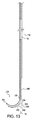
図13及び図14には、上述した針ホルダ16とは異なる他の針ホルダが示され、針ホルダ226は、ノットプッシャー228を具える。ノットプッシャー228の追加以外は、針ホルダ226は、針ホルダ16と同一であってよい。故に、針ホルダ226が針ホルダ16と同一、又は類似である場合、同じ符号が用いられる。図13及び図14に示された変形形態の針ホルダでは、縫合装置10は、細長い本体14の少なくとも一部及び針ホルダ226と連結され、細長い本体14の少なくとも一部及び針ホルダ226から延びるノットプッシャー228を具える。示された実施例では、ノットプッシャー228は、針ホルダ226の一部として形成される。図14を参照して、針ホルダ226は、細長い本体14の末端部122と取外し可能に連結されてもよい。また、ノットプッシャー228は、細長い本体14の少なくとも一部及び針ホルダ226と取外し可能に連結される別の構成要素として作られてもよい。   13 and 14 show another needle holder different from the needle holder 16 described above, and the needle holder 226 includes a knot pusher 228. The needle holder 226 may be the same as the needle holder 16 except for the addition of the knot pusher 228. Thus, if the needle holder 226 is the same as or similar to the needle holder 16, the same reference numerals are used. In the variation of the needle holder shown in FIGS. 13 and 14, the suturing device 10 is coupled to at least a portion of the elongate body 14 and the needle holder 226 and extends from at least a portion of the elongate body 14 and the needle holder 226. A pusher 228 is provided. In the illustrated embodiment, the knot pusher 228 is formed as part of the needle holder 226. Referring to FIG. 14, the needle holder 226 may be removably coupled to the distal end 122 of the elongate body 14. The knot pusher 228 may also be made as a separate component that is removably coupled to at least a portion of the elongate body 14 and the needle holder 226.

図13及び図14に示された実施例では、ノットプッシャー228は、下凹曲面232を具える。下凹曲面232は、外科医によって縫合される組織に結び目を摺動させるべく、縫合糸22に結ばれた結び目を押下げることができるように構成される。下凹曲面232は、最遠位先端142が長手方向軸56からずれているのと同じ方向に細長い本体14の長手方向軸56からずれている屈曲234を具える。   In the embodiment shown in FIGS. 13 and 14, the knot pusher 228 includes a downwardly concave curved surface 232. The lower concave curved surface 232 is configured such that the knot tied to the suture 22 can be depressed to slide the knot against the tissue sutured by the surgeon. The lower concave curved surface 232 includes a bend 234 that is offset from the longitudinal axis 56 of the elongate body 14 in the same direction that the distal-most tip 142 is offset from the longitudinal axis 56.

図13に示されるように側面から見ると、ノットプッシャー228は全体として三角形である。示された実施例をより詳しく説明すると、ノットプッシャー228は針ホルダ226の外面180から延び、外面180は湾曲している。ノットプッシャー228はまた、外側面238を具える。外側面238は、針ホルダ226が長手方向軸56から離れて曲がり始める位置138と丸くてもよい角240の間を細長い本体14の長手方向軸56に平行で、細長い本体14の長手方向軸56からずれている面に沿って延びる。細長い本体14の長手方向軸56に対して直角に測定された外側面238と最遠位先端142の間の最大の距離は10mm未満であり、これにより、縫合装置10を上記の一般的な管形反応器に正確に嵌着することができる。上述した通り、長手方向軸56及び湾曲した針通路半径160(図10参照。)の両方がある第1平面について検討する。この第1平面は、図13の断面がとられた平面である。第1平面と直交し、長手方向軸56に平行で、最遠位先端142から最も離れた細長い本体14の外面118に沿った線と交差する第2平面について検討する。この第2平面は、図13が印刷されたページと直交し、細長い本体14の外面118に沿った線と交差する一方で、長手方向軸56の右側にずれている。示された実施例では、ノットプッシャー228は、最遠位先端142から離れる方向に向かって第2平面を越えて延びることはない。外科医が片側、すなわち、1つの損傷組織(例えば、図2の左側)について手術をしている場合に、ノットプッシャー228が損傷組織の反対側(図2の右側)に引っ掛かりそうにないという点で、これは有益である。   When viewed from the side as shown in FIG. 13, the knot pusher 228 is generally triangular. More specifically, the illustrated embodiment shows that the knot pusher 228 extends from the outer surface 180 of the needle holder 226, and the outer surface 180 is curved. The knot pusher 228 also includes an outer surface 238. The outer surface 238 is parallel to the longitudinal axis 56 of the elongate body 14 between the position 138 where the needle holder 226 begins to bend away from the longitudinal axis 56 and a corner 240 that may be rounded, and the longitudinal axis 56 of the elongate body 14. It extends along the surface that is offset from. The maximum distance between the outer surface 238 and the distal most tip 142, measured perpendicular to the longitudinal axis 56 of the elongate body 14, is less than 10 mm, which allows the suturing device 10 to be It can be accurately fitted to the shape reactor. As discussed above, consider a first plane that has both a longitudinal axis 56 and a curved needle passage radius 160 (see FIG. 10). This first plane is a plane from which the cross section of FIG. 13 is taken. Consider a second plane that is orthogonal to the first plane, parallel to the longitudinal axis 56, and intersecting a line along the outer surface 118 of the elongate body 14 furthest from the distal-most tip 142. This second plane is perpendicular to the page on which FIG. 13 is printed and intersects a line along the outer surface 118 of the elongated body 14 while being offset to the right of the longitudinal axis 56. In the illustrated embodiment, the knot pusher 228 does not extend beyond the second plane in a direction away from the distal most tip 142. If the surgeon is operating on one side, ie one damaged tissue (eg, the left side of FIG. 2), the knot pusher 228 is unlikely to get caught on the opposite side of the damaged tissue (the right side of FIG. 2). This is beneficial.

図14を参照して、くぎ抜きのような構成であってもよい凹部242が、ノットプッシャー228の角240に設けられてもよい。下凹曲面232と同様に、外科医によって縫合される組織に結び目を摺動させるべく、縫合糸22に結ばれた結び目を押下げることができるように構成されてもよい。   Referring to FIG. 14, a recess 242 that may be configured like a nail punch may be provided at a corner 240 of the knot pusher 228. Similar to the lower concave curved surface 232, the knot tied to the suture 22 may be configured to be depressed so as to slide the knot against the tissue sutured by the surgeon.

図15及び図16には上述された縫合装置10とは異なる縫合装置310が示される。この変形例では、操作部312は、ロボットのエンドエフェクタの一部と連結される、又は一部として設けられるように構成されることによって操作部12とは異なり、細長い本体314はバヨネット構造を有することによって細長い本体14とは異なり、針ホルダ316はより短い弧長を有することによって針ホルダ16と異なる。   15 and 16 show a suturing device 310 different from the suturing device 10 described above. In this modification, the operation unit 312 is configured to be connected to or provided as a part of the end effector of the robot, unlike the operation unit 12, and the elongated body 314 has a bayonet structure. Unlike the elongated body 14, the needle holder 316 differs from the needle holder 16 by having a shorter arc length.

上述した通り、操作部312は管52(又は棒)及びワイヤ54を具えてもよいが、操作部312は上記のボタン50を具える必要はない。上記と同じ方法で管52(又は棒)及びワイヤ54は細長い本体314に対して移動するが、ボタン50を動かして管52(又は棒)及びワイヤ54を動かす替わりに、ロボット(図示せず。)が、操作部312に取付けられて、ロボットのエンドエフェクタとして操作部312を作動させてもよい。操作部312は、(例えば)ロボット手首に取付けてもよい操作部本体308を具え、ロボットは、対象組織を縫合すべく縫合装置310と作動するようにプログラムされてもよい。操作部本体308がロボットに取付けられる場合、ロボットが細長い本体314に対して上記と同じ方法で管52(又は棒)及びワイヤ54を動かしてもよい。   As described above, the operation unit 312 may include the tube 52 (or rod) and the wire 54, but the operation unit 312 does not need to include the button 50 described above. The tube 52 (or rod) and wire 54 move relative to the elongated body 314 in the same manner as described above, but instead of moving the button 50 to move the tube 52 (or rod) and wire 54, a robot (not shown). ) May be attached to the operation unit 312 to operate the operation unit 312 as an end effector of the robot. The operation unit 312 includes an operation unit main body 308 that may be attached to a robot wrist (for example), and the robot may be programmed to operate with the suturing device 310 to suture the target tissue. When the operation unit body 308 is attached to the robot, the robot may move the tube 52 (or bar) and the wire 54 with respect to the elongated body 314 in the same manner as described above.

図15を参照して、示された実施例の細長い本体314は、細長い本体14と類似のカニューレ形である。細長い本体314は、滑らかで、操作部312の一部を受入れる(図15及び図16では見えないが、トラック120と類似の)トラックを画定する外面318を有する。上記の実施例と同様に、細長い本体314はカニューレで、トラックは操作部312の管52及びワイヤ54を受入れるルーメンである。トラックは管52及びワイヤ54を囲む必要がなく、U字形状であってもよい。図15の実施例では、細長い本体314の最長寸法に対して直交する細長い本体314の断面は円形であるが、細長い本体314は多角形又はU字型のような、他の形状であってもよい。   Referring to FIG. 15, the elongate body 314 in the illustrated embodiment is cannulated similar to the elongate body 14. The elongate body 314 is smooth and has an outer surface 318 that defines a track (similar to the track 120 that is not visible in FIGS. 15 and 16) that receives a portion of the operating portion 312. Similar to the previous embodiment, the elongate body 314 is a cannula and the track is a lumen that receives the tube 52 and wire 54 of the operating portion 312. The track need not surround tube 52 and wire 54 and may be U-shaped. In the example of FIG. 15, the cross section of the elongate body 314 perpendicular to the longest dimension of the elongate body 314 is circular, but the elongate body 314 may have other shapes, such as a polygon or U shape. Good.

細長い本体314は、基端部分320及び末端部分322を具える。基端部分320は操作部本体308と連結される、又は、必要に応じて、細長い本体14がハンドル90と連結されるのと同じ方法で基端部分320はハンドル90と連結されてもよい。基端部分320がハンドル90と連結される実施例において、ボタン50は図8及び図8Aと同様に管52(又は棒)と連結されてもよく、操作部312は上記の操作部12と同じ方法で作動してもよい。また、ピストルのグリップ型のハンドルが、操作部本体308の替わりに細長い本体314に取付けられてもよい。   The elongate body 314 includes a proximal portion 320 and a distal portion 322. The proximal portion 320 may be coupled to the operating portion body 308 or, if desired, the proximal portion 320 may be coupled to the handle 90 in the same manner that the elongated body 14 is coupled to the handle 90. In the embodiment in which the proximal end portion 320 is connected to the handle 90, the button 50 may be connected to the tube 52 (or bar) as in FIGS. 8 and 8A, and the operation unit 312 is the same as the operation unit 12 described above. May work in any way. A pistol grip-type handle may be attached to the elongated main body 314 instead of the operation section main body 308.

図15に示されるように、針ホルダ316は、細長い本体314に受入れられ、細長い本体314と連結され、末端部分322から延びる。又は、針ホルダ316は、細長い本体314の末端部分322の一部として設けられてもよい。細長い本体314は、剛性金属材料から作られるが、必要に応じて、外科医が外科手術中に人体に挿入するために、細長い本体314の少なくとも一部を所望の構成に曲げることができるように、細長い本体314の少なくとも一部は、展性又は可撓性材料から作られてもよい。示された実施例では、細長い本体314の外径は、基端部分320と末端部分322の間で一定である。外径は3.5mm未満でもよく、これにより、外科手術中の外科医の視界を良好にする非常にスリムな装置となる。   As shown in FIG. 15, the needle holder 316 is received in the elongated body 314, is coupled to the elongated body 314, and extends from the distal portion 322. Alternatively, the needle holder 316 may be provided as part of the distal portion 322 of the elongate body 314. The elongate body 314 is made from a rigid metal material, but if desired, at least a portion of the elongate body 314 can be bent into a desired configuration for insertion into the human body during a surgical procedure. At least a portion of the elongate body 314 may be made from a malleable or flexible material. In the illustrated embodiment, the outer diameter of the elongate body 314 is constant between the proximal portion 320 and the distal portion 322. The outer diameter may be less than 3.5 mm, which results in a very slim device that provides good visibility for the surgeon during surgery.

細長い本体314は、バヨネット構造を有する。細長い本体314は、基端部分320と末端部分322の間に位置する中間部分328を具える。基端部分320は、基端部長手方向軸330に沿って延びる。末端部分322は、基端部長手方向軸330から順方向にずれている末端部長手方向軸332に沿って延びる。示された実施例では、末端部長手方向軸332は、基部端部分長手方向軸330から約25mmずれている。基端部分320は近位屈曲336を通って中間部328に移行し、中間部328は遠位屈曲338を通って末端部分322に移行する。示された実施例では、近位屈曲336及び遠位屈曲338はともに、内側に135度曲げられる。   The elongated body 314 has a bayonet structure. The elongate body 314 includes an intermediate portion 328 located between the proximal portion 320 and the distal portion 322. The proximal portion 320 extends along the proximal longitudinal axis 330. The distal portion 322 extends along a distal longitudinal axis 332 that is forwardly offset from the proximal longitudinal axis 330. In the illustrated embodiment, the distal longitudinal axis 332 is offset from the proximal end portion longitudinal axis 330 by approximately 25 mm. Proximal portion 320 passes through proximal bend 336 to intermediate portion 328, and intermediate portion 328 passes through distal bend 338 to distal portion 322. In the illustrated embodiment, both the proximal bend 336 and the distal bend 338 are bent 135 degrees inward.

末端部長手方向軸332と平行に測定された、遠位屈曲338が末端部分322に移行する場所(すなわち、末端部長手方向軸332上の末端部分322の近位端)と、最遠位先端142の間の距離L3は10cmから20cmの間である。また、末端部長手方向軸332と平行に測定された、遠位屈曲338が末端部分322に移行する場所と、針ホルダ316が末端部長手方向軸332から離れて曲がり始める場所との間の距離L3aも、10cmから20cmの間である。換言すると、末端部長手方向軸332と平行に測定された、湾曲した針ホルダ16が末端部長手方向軸332から離れて曲がり始める場所と、細長い本体314が末端部長手方向軸332から離れて曲がり始める場所(例えば、末端部長手方向軸332上の末端部分322の近位端の近く)の間の距離L3aは、約10cmから約20cmの間である。示された実施例では、距離L3は約12.5cmであり、距離L3aは約12cmである。距離L3及びL3aによって、外科医は細長い本体314及び針ホルダ316の末端部分322を一般的に用いられる管形反応器に挿入することができ、中間部分328及び基端部分320を管形反応器に入れることなく、針ホルダ316を対象組織に接触させることができる。距離L3及びL3aがあまりに長い場合、針ホルダ316の操作はより難しくなる。基端部分320は、最遠位先端142が末端部分322からずれている方向とは反対方向の後方向に末端部分322からずれている。これにより、(図15には示されていないが、基端部分320に沿う何れの場所ででも細長い本体314と連結される)ハンドル90は末端部長手方向軸332からずれ、外科医の手及びハンドル90によって管形反応器を介する視界が妨げられない。   Where the distal bend 338 transitions to the distal portion 322, measured parallel to the distal longitudinal axis 332 (ie, the proximal end of the distal portion 322 on the distal longitudinal axis 332), and the most distal tip The distance L3 between 142 is between 10 cm and 20 cm. Also, the distance between the location where the distal bend 338 transitions to the end portion 322 and the location where the needle holder 316 begins to bend away from the end longitudinal axis 332, measured parallel to the end longitudinal axis 332. L3a is also between 10 cm and 20 cm. In other words, where the curved needle holder 16 begins to bend away from the distal longitudinal axis 332, measured parallel to the distal longitudinal axis 332, and the elongated body 314 is bent away from the distal longitudinal axis 332. The distance L3a between where to begin (eg, near the proximal end of the distal portion 322 on the distal longitudinal axis 332) is between about 10 cm and about 20 cm. In the example shown, the distance L3 is about 12.5 cm and the distance L3a is about 12 cm. The distances L3 and L3a allow the surgeon to insert the elongate body 314 and the distal portion 322 of the needle holder 316 into a commonly used tubular reactor and the intermediate portion 328 and proximal portion 320 to the tubular reactor. The needle holder 316 can be brought into contact with the target tissue without insertion. If the distances L3 and L3a are too long, the operation of the needle holder 316 becomes more difficult. Proximal portion 320 is offset from distal portion 322 in a backward direction opposite to the direction in which distal-most tip 142 is offset from distal portion 322. This causes the handle 90 (not shown in FIG. 15 but coupled to the elongate body 314 anywhere along the proximal portion 320) to be offset from the distal longitudinal axis 332 and the surgeon's hand and handle 90 does not impede the view through the tubular reactor.

図15及び図16には上記の針ホルダ16とは異なる変形形態の針ホルダが示され、針ホルダ316は、針ホルダ16より小さい弧長を有する。より小さい弧長を有すること以外は、針ホルダ316は、針ホルダ16と同一であってよい。故に、針ホルダ316が針ホルダ16と同一、又は類似である場合、同じ符号が用いられる。図16に示される針ホルダ316の変形形態に関して、最遠位先端142は、末端部長手方向軸332から直交する方向に、5mm未満の距離L4分末端部長手方向軸332からずれている。針ホルダ316は、針ホルダ316が最遠位先端142の方に末端部長手方向軸332から離れて曲がり始める位置138から約110°の半径範囲に沿って延びる。針ホルダ316は針ホルダ16より弧長が短いので、針20が(図3に示される)収納位置にある場合、針20の第1端部30(図2及び図3参照。)は遠位開口146を越えて外側に延びることができる。しかしながら、(図3に示されている位置と同様の)収納位置にある場合、第1端部30は最遠位先端を越えて延びていない。従って、ホルダ316を有する縫合装置10は、針20の(尖った)第1端30針で対象組織を捕えることなく、神経フックのように用いられることが可能である。   15 and 16 show a modified needle holder different from the needle holder 16 described above, and the needle holder 316 has a smaller arc length than the needle holder 16. The needle holder 316 may be identical to the needle holder 16 except having a smaller arc length. Thus, if the needle holder 316 is the same as or similar to the needle holder 16, the same reference numerals are used. With respect to the variation of the needle holder 316 shown in FIG. 16, the distal most tip 142 is offset from the distal longitudinal axis 332 by a distance L4 of less than 5 mm in a direction orthogonal to the distal longitudinal axis 332. Needle holder 316 extends along a radial range of about 110 ° from position 138 where needle holder 316 begins to bend away from distal longitudinal axis 332 toward distal most tip 142. Since the needle holder 316 has a shorter arc length than the needle holder 16, the first end 30 (see FIGS. 2 and 3) of the needle 20 is distal when the needle 20 is in the retracted position (shown in FIG. 3). It can extend outward beyond the opening 146. However, when in the stowed position (similar to the position shown in FIG. 3), the first end 30 does not extend beyond the most distal tip. Therefore, the suturing device 10 having the holder 316 can be used like a nerve hook without capturing the target tissue with the (pointed) first end 30 needle of the needle 20.

図4には、2本のアームの縫合糸22、少なくとも一つの縫合装置10、10a、及び縫合糸保持構造210を具えて設けられてもよい縫合糸キット200が示されている。第2縫合装置10aは、第1縫合装置とすべての態様において同一であるため、詳述しない。縫合糸保持構造210は、縫合糸を保持するために一般的に用いられる既知のレーストラック型と類似していてもよい。ノットプッシャー350は縫合キット200に設けられてもよい。また、例えば、図4に示されている針ホルダ16bのような追加の針ホルダが、キット200に設けられてもよい。針ホルダ16b及び他の針ホルダ(図示せず)のようなこれらの追加の針ホルダが追加の(湾曲した針20と同様な)湾曲した針及び追加の(縫合糸22と同様な)縫合糸とともに搭載されてもよい。また、針ホルダ16bのような針ホルダから延びる縫合糸22に連結されてもよい外科パッチ352がキット200に設けられてもよい。図17には、2本のアームの縫合糸22、少なくとも一つの縫合装置410、及び縫合糸保持構造210を具えて設けられてもよい縫合キット400の他の実施例が示されている。図4に示される実施例では、第1縫合装置10及び第2縫合装置10aは、お互いに独立した器具である。これに対して、図17の示される実施例では、縫合装置410は、2本の本体を有するデザインであってもよい。さらに、複数の縫合装置が、複数の縫合糸保持構造にとともに各キットに設けられてもよい。   FIG. 4 shows a suture kit 200 that may be provided with two arms of suture 22, at least one suture device 10, 10a, and a suture holding structure 210. The second suturing device 10a is the same as the first suturing device in all aspects and will not be described in detail. The suture retaining structure 210 may be similar to known racetrack types commonly used to hold sutures. The knot pusher 350 may be provided in the suturing kit 200. Further, for example, an additional needle holder such as the needle holder 16b shown in FIG. These additional needle holders, such as needle holder 16b and other needle holders (not shown), add additional curved needles (similar to curved needle 20) and additional sutures (similar to suture 22). May be mounted together. The kit 200 may also be provided with a surgical patch 352 that may be coupled to a suture 22 extending from a needle holder such as the needle holder 16b. FIG. 17 illustrates another embodiment of a suturing kit 400 that may be provided with two arms of suture 22, at least one suturing device 410, and suture retaining structure 210. In the embodiment shown in FIG. 4, the first suturing device 10 and the second suturing device 10a are instruments that are independent of each other. In contrast, in the embodiment shown in FIG. 17, the suturing device 410 may be a design having two bodies. Further, a plurality of suturing devices may be provided in each kit together with a plurality of suture holding structures.

図17を参照して、縫合装置410は、第1操作部412、第2操作部412a、第1細長い本体414、第2細長い本体414a、第1針ホルダ416及び第2針ホルダ416aを具える。図17に示される縫合装置410はまた、外科手術中、図2に示される対象組織と同様の縫合されるべき対象組織に対して第1針20(図17では視認されないが、図2に示される方法と同じ方法で第1針ホルダ416内に配置されている。)、第2針20a、及び縫合糸22を正確に配置するのに役立つ。図17に示される針20、20aは上述されている。各針ホルダ416、416aは、上記の針ホルダ16と同一であってもよい。しかしながら、図17で示された実施例では、第1針ホルダ416は、第2針ホルダ416aの隣に配置され、第2針ホルダ416aに連結される。また、各針ホルダ416、416aは、針ホルダ416、416aから針20、20aを容易に解放でき、ホルダ416、416aに針20、20aを容易に搭載できる切欠き418、418aをそれぞれ具える。第1針ホルダ416は、溶接、接着、又は機械的に第2針ホルダ416aに固定されてもよい。各細長い本体414、414aは、上記の細長い本体14と同一であってもよい。しかしながら、図17に示される実施例では、第1細長い本体414は、第2細長い本体414aの隣に配置され、第2細長い本体414aと連結される。第1細長い本体414は、溶接、接着、又は機械的に第2細長い本体414aに固定されてもよい。   Referring to FIG. 17, the suturing device 410 includes a first operation unit 412, a second operation unit 412a, a first elongate body 414, a second elongate body 414a, a first needle holder 416, and a second needle holder 416a. . 17 also includes a first needle 20 (not visible in FIG. 17 but shown in FIG. 2) against a target tissue to be sutured similar to the target tissue shown in FIG. 2 during surgery. In the first needle holder 416 in the same manner as described above), and helps to position the second needle 20a and the suture 22 accurately. The needles 20 and 20a shown in FIG. 17 have been described above. Each needle holder 416, 416a may be the same as the needle holder 16 described above. However, in the embodiment shown in FIG. 17, the first needle holder 416 is located next to the second needle holder 416a and is coupled to the second needle holder 416a. The needle holders 416 and 416a include notches 418 and 418a that can easily release the needles 20 and 20a from the needle holders 416 and 416a, respectively, and can easily mount the needles 20 and 20a on the holders 416 and 416a. The first needle holder 416 may be fixed to the second needle holder 416a by welding, bonding, or mechanically. Each elongated body 414, 414a may be identical to the elongated body 14 described above. However, in the embodiment shown in FIG. 17, the first elongate body 414 is disposed next to the second elongate body 414a and is coupled to the second elongate body 414a. The first elongate body 414 may be secured to the second elongate body 414a by welding, gluing, or mechanically.

縫合装置410はまた、細長い本体414、414aと連結されるハンドル440を具える。上記のハンドル90と同様に、ハンドル440は、例えば、回転又は並進移動のようなハンドル440の動きによって各細長い本体414、414aが同じ動きをするように、各細長い本体414、414aの基端部分と連結され、各細長い本体414、414aに固定される。ハンドル440は、各細長い本体414、414aの基端部分が受入れられる細長い孔442を具える。ハンドル440は、上記のハンドル90と比較して他の構造を採り、全体としてT字状である。細長い孔442は、基端面444から末端面446まで延び、各細長い本体414、414aの最長寸法方向と平行な長手方向軸448と一致する。   The suturing device 410 also includes a handle 440 coupled to the elongated body 414, 414a. Similar to the handle 90 described above, the handle 440 is a proximal portion of each elongate body 414, 414a such that each elongate body 414, 414a moves the same due to movement of the handle 440, such as, for example, rotation or translation. And fixed to each elongated body 414, 414a. The handle 440 includes an elongated hole 442 that receives a proximal portion of each elongated body 414, 414a. The handle 440 adopts another structure as compared with the handle 90 described above, and has a T-shape as a whole. The elongated hole 442 extends from the proximal surface 444 to the distal surface 446 and coincides with a longitudinal axis 448 parallel to the longest dimension of each elongated body 414, 414a.

各操作部412、412aは、上記の操作部12と同様に作動する。第1操作部412は、ボタン450、棒でもよい管452、及び図17では視認されないが、上記のワイヤ54と同様なワイヤを具える。同様に、第2操作部412aは、ボタン450a、棒でもよい管452a、及び図17では視認されないが、上記のワイヤ54と同様なワイヤを具える。   The operation units 412 and 412a operate in the same manner as the operation unit 12 described above. The first operation unit 412 includes a button 450, a tube 452 that may be a bar, and a wire similar to the wire 54 that is not visible in FIG. Similarly, the second operation unit 412a includes a button 450a, a tube 452a that may be a bar, and a wire that is not visually recognized in FIG.

第1操作部412は、第2操作部412aと同一である。したがって、第2操作部412aが同様に第2細長い本体414a及び第2針ホルダ416aと協働するという理解の下、第1操作部412は第1細長い本体414及び第1針ホルダ416に対して詳細に後述される。第1操作部412の第1管452(又は棒)及び第1のワイヤ(視認されず。)は、第1細長い本体414に受入れられ、上記の操作部12と同様に第1細長い本体414に対して第1動作位置と第2動作位置の間を移動する。第1管452は長手方向軸448と平行な方向に移動する。ワイヤ(視認されず。)は第1針20の第2端部32(図2参照。)と接して、収納位置から解放状態の方へ針20を前進させる。ボタン450、450aは上記のボタン50と異なるが、操作部412、412aは上記の操作部12と同じ方法で作動してもよい。従って、操作部412、412aの作動を、さらに詳しく記載しない。   The first operation unit 412 is the same as the second operation unit 412a. Accordingly, with the understanding that the second operating portion 412a cooperates with the second elongate body 414a and the second needle holder 416a, the first operating portion 412 moves relative to the first elongate body 414 and the first needle holder 416. Details will be described later. The first tube 452 (or rod) and the first wire (not visible) of the first operation unit 412 are received by the first elongate body 414, and the first elongate body 414 is similar to the operation unit 12 described above. On the other hand, it moves between the first operating position and the second operating position. The first tube 452 moves in a direction parallel to the longitudinal axis 448. The wire (not visible) contacts the second end 32 (see FIG. 2) of the first needle 20 and advances the needle 20 from the retracted position toward the released state. Although the buttons 450 and 450a are different from the button 50 described above, the operation units 412 and 412a may operate in the same manner as the operation unit 12 described above. Therefore, the operation of the operation units 412 and 412a will not be described in further detail.

図4及び図13ともに、2本のアームの縫合糸、少なくとも一つの縫合装置、及び縫合糸保持構造を具える縫合キットを開示する。両方の実施例において、少なくとも一つの縫合装置は、患者に挿入されるように構成された部分を具える。   4 and 13 disclose a suturing kit comprising two arm sutures, at least one suturing device, and a suture retaining structure. In both embodiments, the at least one suturing device comprises a portion configured to be inserted into the patient.

図4に示される実施例では、第1針ホルダ16及び第1細長い本体14は、第2縫合装置10aから物理的に分離されている第1縫合装置10の一部である。しかしながら、2本のアームの縫合糸が縫合装置10、10aの両方と連結されるように、第2縫合装置10aには、図2に示される方法と同様の方法で第2針20a及び縫合糸22が搭載される。図4に示される第2縫合装置10aを具える替わりに、縫合キット200は、操作部12、細長い本体14、及び少なくとも2つの針ホルダ16を具えてよく、これにより、図11と同様に細長い本体14から針ホルダ16がはずれる。または、針ホルダ16のうちの1つが細長い本体14と連結されてもよく、針20と縫合糸22をそれぞれ搭載する追加の針ホルダ16が縫合キット200に設けられてもよい。図17に示される実施例では、第1針ホルダ416、第1細長い本体414、第2針ホルダ416a、及び第2細長い本体414aは、同じ縫合装置410の部品である。   In the embodiment shown in FIG. 4, the first needle holder 16 and the first elongate body 14 are part of the first suturing device 10 that is physically separated from the second suturing device 10a. However, the second suturing device 10a has a second needle 20a and a suture in a manner similar to that shown in FIG. 2 so that the sutures of the two arms are coupled to both the suturing devices 10, 10a. 22 is mounted. Instead of having the second suturing device 10a shown in FIG. 4, the suturing kit 200 may comprise an operating portion 12, an elongated body 14, and at least two needle holders 16, thereby elongated similarly to FIG. The needle holder 16 is detached from the main body 14. Alternatively, one of the needle holders 16 may be coupled to the elongate body 14 and additional needle holders 16 carrying the needle 20 and suture 22 respectively may be provided in the suturing kit 200. In the example shown in FIG. 17, the first needle holder 416, the first elongate body 414, the second needle holder 416a, and the second elongate body 414a are part of the same suturing device 410.

上述の実施例のそれぞれにおいて、縫合糸保持構造210は、縫合糸22の第1端部と第2端部の間の縫合糸22の少なくとも一部を保持する。両方の実施例では、外科手術中、患者に挿入されないように、縫合糸保持構造210は、例えば、縫合装置10、10a又は縫合装置410のような少なくとも1つの縫合装置から分離されている。換言すれば、縫合糸保持構造210、故に縫合糸の多くは、外科手術中、患者の体外にある。細長い本体14から外れたもう1つの針ホルダを有する図4に示される縫合キット200、及び図17に示される縫合キット400の両方とも(図17に模式的に示されているのみの)シールパッケージ460を具えてもよく、シールパッケージ460には、縫合糸22、図4の第1縫合装置10及び第2縫合装置10a又は図17の縫合装置410のような少なくとも1つの縫合装置、並びに縫合糸保持構造210が包含される。   In each of the embodiments described above, the suture retaining structure 210 retains at least a portion of the suture 22 between the first end and the second end of the suture 22. In both embodiments, the suture retaining structure 210 is separated from at least one suturing device such as, for example, the suturing device 10, 10a or the suturing device 410 so that it is not inserted into the patient during a surgical procedure. In other words, the suture retaining structure 210, and hence much of the suture, is outside the patient's body during the surgery. Both the suturing kit 200 shown in FIG. 4 and the suturing kit 400 shown in FIG. 17 with another needle holder off the elongate body 14 (only schematically shown in FIG. 17) are sealed packages. 460, and seal package 460 includes suture 22, at least one suturing device, such as first suturing device 10 and second suturing device 10a of FIG. 4 or suturing device 410 of FIG. A holding structure 210 is included.

損傷組織を修復するための縫合装置を操作する方法は、上記の縫合装置10、10a及び410を参照して後述するが、当該方法は、図12−16に示される異なる構成の縫合装置及び/又は変形形態を用いて実施されてもよく、これらの変形形態については、関連個所で言及する。医師は、図9に示された管形反応器TRのような管形反応器、又は他の小さな皮膚開口に縫合装置10を挿入してもよい。図2を参照して、医師は、対象組織24の損傷の第1側(図2の左方向)の対象組織24の内側26の下に縫合装置10の最遠位先端142を配置してもよい。図2に示された対象組織24は硬膜嚢であり、硬膜嚢は透明なので示されていないが、脊髄を囲む硬膜の覆いである。対象組織24の内側26の下に最遠位先端142がある状態で、医師は、針20の第2端部32及び縫合糸22が縫合装置10から取外されるまで、縫合装置10上の操作部12を動かして内側26から外側28の方へ対象組織24を通って針20の第1端部30を前進させる。それから、医師は、患者の体内(及び硬膜嚢内)から縫合装置10を取除き、針20を掴み、対象組織24に形成された孔を通して針20とともに縫合糸22を引っ張ってもよい。それから、医師は、例えば、縫合装置の中に搭載された第2針20a及び第2針20aに取付けられた縫合糸22の反対側の末端を有する図4に示される第2縫合装置10aのような、他の縫合装置を手に取り、第2縫合装置10aを管形反応器TR(図9)又は他の小さな皮膚開口に挿入してもよい。医師は、図2に示される最遠位先端142と同じ第2縫合装置10aの最遠位先端を、対象組織24の損傷の第2側(図2の右方向)の対象組織24の内側26の下に配置してもよい。対象組織24の内側26の下に第2縫合装置10aの最遠位先端がある状態で、医師は、第2針20aの第2端部及び縫合糸22が第2縫合装置10aから取外されるまで、第2縫合装置10a上の操作部12a(図4)を動かして内側26から外側28の方へ対象組織24を通って第2針20aの(尖った)第1端部を前進させる。それから、医師は、患者の体内(及び硬膜嚢内)から第2縫合装置10aを取除き、第2針20aを掴み、対象組織24に形成された孔を通して第2針20aとともに縫合糸22を引っ張ってもよい。それから、医師は、損傷を閉じるために、従来の方法で縫合糸22に結び目を作り、損傷が適切に閉じられるまで、この処理は繰り返されてよい。   A method of manipulating a suturing device for repairing damaged tissue will be described below with reference to suturing devices 10, 10a and 410 described above, which includes different configurations of suturing devices and / or shown in FIGS. 12-16. Or it may be implemented using variants, which are mentioned in the relevant places. The physician may insert the suturing device 10 into a tubular reactor, such as the tubular reactor TR shown in FIG. 9, or other small skin opening. Referring to FIG. 2, the physician may place the distal most tip 142 of the suturing device 10 under the inner side 26 of the target tissue 24 on the first side (leftward in FIG. 2) of damage to the target tissue 24. Good. The target tissue 24 shown in FIG. 2 is a dural sac, and since the dural sac is transparent, it is not shown, but is a dura wrap surrounding the spinal cord. With the distal-most tip 142 below the inner side 26 of the target tissue 24, the physician is on the suturing device 10 until the second end 32 of the needle 20 and the suture 22 are removed from the suturing device 10. The operating portion 12 is moved to advance the first end 30 of the needle 20 through the target tissue 24 from the inner side 26 toward the outer side 28. The physician may then remove the suturing device 10 from the patient's body (and within the dural sac), grab the needle 20, and pull the suture 22 along with the needle 20 through a hole formed in the target tissue 24. Then, the physician may, for example, have a second needle 20a mounted in the suturing device and a second suturing device 10a shown in FIG. 4 having the opposite end of the suture 22 attached to the second needle 20a. Alternatively, another suturing device may be picked up and the second suturing device 10a may be inserted into the tubular reactor TR (FIG. 9) or other small skin opening. The doctor moves the distal most distal end of the second suturing device 10a, which is the same as the distal most distal tip 142 shown in FIG. You may arrange below. With the distal end of the second suturing device 10a under the inner side 26 of the target tissue 24, the physician removes the second end of the second needle 20a and the suture 22 from the second suturing device 10a. Until the first stitched portion of the second needle 20a is advanced through the target tissue 24 from the inner side 26 toward the outer side 28 by moving the operating portion 12a (FIG. 4) on the second suturing device 10a. . Then, the doctor removes the second suturing device 10a from the patient's body (and within the dural sac), grasps the second needle 20a, and pulls the suture 22 together with the second needle 20a through the hole formed in the target tissue 24. May be. The physician may then tie a suture 22 in a conventional manner to close the injury and the process may be repeated until the injury is properly closed.

2台の異なる縫合装置10及び10aを使用する替わりに、医師は、第1縫合装置10のみを使用してもよい。この例では、第2針20aは、第1針20として縫合糸22の反対端に連結されたままであるが、第2針20aは、縫合装置に予め搭載されない。その替わりに、第2針20aは縫合装置から自由である。そして、第1針が第1縫合装置10で使用された後、第2針20aは第1縫合装置10に搭載される。それ故、医師は、上記と同じ方法で縫合装置10に第1針20を配置し、患者から縫合装置10を取外す。それから、医師は、第2動作位置から第1動作位置に操作部12を引き戻す。第2針20aが図3の第1針20のために示された収納位置に戻るまで、第2針20a取付けられた縫合糸22を有する第2針20aは遠位開口146を通って、針通路144に挿入される。他の構成では、針20が針ホルダ16に搭載されている一方で、操作部12は第2動作位置のままでもよい。例えば、操作部12は、針20を収納位置に簡単に引入れてもよい。1つの例として、ポケット76(図7参照。)が針20の第2端部32を掴んでもよく、第2動作位置から第1動作位置への操作部12の移動により、収納位置の方へ針20が引っ張られてもよい。示された実施例及び図3に示されたような実施例に戻って参照して、縫合糸22の一部は、遠位開口146及び縫合装置10の外側に延びたままである。医師が上記の第2縫合装置10aを操作した方法と同じ方法で、医師は縫合装置10に搭載された第2針20aを具える縫合装置10を操作する。   Instead of using two different suturing devices 10 and 10a, the physician may use only the first suturing device 10. In this example, the second needle 20a remains connected to the opposite end of the suture 22 as the first needle 20, but the second needle 20a is not pre-loaded on the suturing device. Instead, the second needle 20a is free from the suturing device. Then, after the first needle is used in the first suturing device 10, the second needle 20 a is mounted on the first suturing device 10. Therefore, the doctor places the first needle 20 on the suturing device 10 in the same manner as described above, and removes the suturing device 10 from the patient. Then, the doctor pulls back the operation unit 12 from the second operation position to the first operation position. The second needle 20a with the suture 22 attached to the second needle 20a passes through the distal opening 146 until the second needle 20a returns to the retracted position shown for the first needle 20 of FIG. It is inserted into the passage 144. In another configuration, while the needle 20 is mounted on the needle holder 16, the operation unit 12 may remain in the second operating position. For example, the operation unit 12 may easily draw the needle 20 into the storage position. As an example, a pocket 76 (see FIG. 7) may grip the second end 32 of the needle 20 and move toward the stowed position by moving the operating portion 12 from the second operating position to the first operating position. The needle 20 may be pulled. Referring back to the illustrated embodiment and the embodiment as shown in FIG. 3, a portion of the suture 22 remains extending outside the distal opening 146 and the suturing device 10. The doctor operates the suturing apparatus 10 including the second needle 20a mounted on the suturing apparatus 10 in the same manner as the doctor operates the second suturing apparatus 10a.

医師は、同様の方法で縫合装置410を用いてもよい。医師は、図17では特に言及していないが図11の最遠位先端142と同様な構成を有する最遠位先端を、対象組織の損傷の第1側(例えば、左)の対象組織の内側の下の縫合装置410の第1針ホルダ416に配置してもよい。対象組織の内側の下の縫合装置410の第1針ホルダに最遠位先端がある状態で、医師は、第1針の第2端部及び縫合糸22が縫合装置410から取外されるまで、縫合装置410上の操作部412を動かして内側から外側の方へ対象組織を通って第1針の第1端部(第1針ホルダ内に搭載されているので図17では視認できない。)を前進させる。それから、医師は、縫合装置410を長手方向軸448の周りで回転させ、損傷の第2側の対象組織の内側の下の縫合装置410の第2針ホルダ416aに最遠位先端を配置してもよい。対象組織の内側の下の縫合装置410の第2針ホルダ416aに最遠位先端がある状態で、医師は、第2針20aの第2端部及び縫合糸22が縫合装置410から取外されるまで、縫合装置410上の操作部412aを動かして内側から外側の方へ対象組織を通って第2針20aの第1端部を前進させる。それから、医師は、患者の体内(及び硬膜嚢内)から縫合装置410を取除き、針20、20aを掴み、対象組織に形成された孔を通して針20、20aとともに縫合糸22を引っ張ってもよい。それから、医師は、損傷を閉じるために、従来の方法で縫合糸22に結び目を作り、損傷が適切に閉じられるまで、この処理は繰り返されてよい。   The physician may use the suturing device 410 in a similar manner. Although not specifically mentioned in FIG. 17, the physician places the distal-most tip having a configuration similar to the distal-most tip 142 of FIG. 11 inside the target tissue on the first side (eg, left) of the target tissue damage. It may be arranged in the first needle holder 416 of the lower suturing device 410. With the distal most tip in the first needle holder of the suturing device 410 below the inside of the target tissue, the physician will remove the second end of the first needle and the suture 22 from the suturing device 410. Then, the operating portion 412 on the suturing device 410 is moved to pass the target tissue from the inside to the outside, and the first end of the first needle (because it is mounted in the first needle holder, it cannot be visually recognized in FIG. 17). Move forward. The physician then rotates the suturing device 410 about the longitudinal axis 448 and places the distal most tip on the second needle holder 416a of the suturing device 410 below the target tissue on the second side of the injury. Also good. With the distal most tip on the second needle holder 416a of the suturing device 410 below the inside of the target tissue, the physician removes the second end of the second needle 20a and the suture 22 from the suturing device 410. Until the first end portion of the second needle 20a is advanced from the inner side toward the outer side through the target tissue. The physician may then remove the suturing device 410 from the patient's body (and within the dural sac), grasp the needles 20, 20a, and pull the suture 22 along with the needles 20, 20a through the hole formed in the target tissue. . The physician may then tie a suture 22 in a conventional manner to close the injury and the process may be repeated until the injury is properly closed.

縫合装置10、310、410の構成により、医師は、硬膜嚢の損傷を修復し、硬膜嚢内の多くの神経を避けることができる。縫合装置10、310、410は、医師が内側26の丁度下で対象組織24を掴むことができる所望のJフック構造を有し、最遠位先端142により、医師は、針20又は20aが対象組織を通過するところを視覚的に表示するための操作より前に、対象組織24をくぼませることができる。縫合装置10、310、410のJフック構造により、医師が対象組織24の内側26の下に最遠位先端142を配置する場合、細長い本体14、314、又は414、414aは、水平線と比較して垂直線により近い方向に保たれてもよい。例えば図9及び15を参照して、細長い本体314の少なくとも末端部分322は、最遠位先端142を配置する一方で、中心軸CAと直交する方向と比較して、管形反応器TRの中心軸CAと平行に近い方向に保たれてもよい。脊髄手術の間、患者は通常うつ伏せで、医師は患者の上から手術を行うので、このことは特に役立つ。縫合装置10及び410のJフック構造により、医師が対象組織24を通って針20又は20aを前進させる場合に、針20又は20aは医師に向かって前進し、これにより、医師は針を見ることができる。縫合装置10又は410のどちらかを使用する場合、縫合糸22の少なくとも一部は患者の体外にある。縫合糸22のごく一部だけが縫合装置10又は410内に受入れられるので、縫合装置10又は410は、他の既知の縫合装置と比較してより小さく作られてもよく、これにより、縫合装置10、410は硬膜嚢の損傷を修復するのに非常に役立つ。   The configuration of the suturing devices 10, 310, 410 allows the physician to repair the dural sac damage and avoid many nerves in the dural sac. The suturing device 10, 310, 410 has a desired J-hook structure that allows the physician to grasp the target tissue 24 just below the inner side 26, with the distal most tip 142 allowing the physician to target the needle 20 or 20a. The target tissue 24 can be recessed prior to an operation for visually displaying where it passes through the tissue. Due to the J-hook structure of the suturing device 10, 310, 410, the elongate body 14, 314, or 414, 414a is compared to the horizontal line when the physician places the distal most tip 142 below the inner side 26 of the target tissue 24. And may be kept closer to the vertical line. For example, referring to FIGS. 9 and 15, at least the distal portion 322 of the elongate body 314 places the distal most tip 142 while comparing the center of the tubular reactor TR with respect to the direction orthogonal to the central axis CA. It may be maintained in a direction close to parallel to the axis CA. This is particularly useful during spinal surgery because the patient is usually prone and the doctor performs the operation from above the patient. Due to the J-hook structure of the suturing devices 10 and 410, when the physician advances the needle 20 or 20a through the target tissue 24, the needle 20 or 20a is advanced toward the physician so that the physician sees the needle. Can do. When using either the suturing device 10 or 410, at least a portion of the suture 22 is outside the patient's body. Since only a small portion of the suture 22 is received within the suturing device 10 or 410, the suturing device 10 or 410 may be made smaller compared to other known suturing devices, thereby providing a suturing device. 10,410 is very useful for repairing dural sac damage.

縫合装置を操作する方法として、硬膜嚢の内部から外側に針20を通すことが説明されたが、縫合装置10、310及び410が、他の方法、例えば、外側から内側に組織を通って針20を通すために用いられてもよい。また、縫合装置10、310及び410は、硬膜嚢以外の組織を縫合するために用いられてもよい。   Although the method of operating the suturing device has been described as passing the needle 20 from the inside of the dural sac to the outside, the suturing devices 10, 310 and 410 can be used in other ways, for example, through the tissue from the outside to the inside. It may be used to pass the needle 20. The suturing devices 10, 310, and 410 may also be used for suturing tissues other than the dural sac.

縫合装置を組立てる方法は、上記の縫合装置10を参照して後述するが、図12−17に示された異なる構成の縫合装置及び/又は変形形態を用いて行われてもよい。方法には、針20に取付けられた縫合糸22を有する針20を、遠位開口146を通って、縫合装置10の細長い本体14と連結され、又は縫合装置10の細長い本体14と連結されるように構成された針ホルダ16の針通路144に挿入されることが含まれる。縫合装置を組立てる場合には、針20は、送り方向36(図3参照。)と反対方向の挿入方向に向かって針通路144の中に挿入される。方法にはさらに、針ホルダ16の内面162が針20と摩擦係合することが含まれ、これにより、針20の(尖った)第1端部30は、遠位開口146から内側に向かって、又は縫合装置10の最遠位先端142の下にずらされた状態を保つことができる。針20を挿入することにはさらに、針20の第2端部32を挿入すること、縫合糸22の一部が針20と内面162(図3参照。)の間の針通路144に沿って延びるように縫合糸22を折畳むことが含まれてもよい。方法にはさらに、針ホルダ16に挿入された針20及び遠位開口146の外に延びる縫合糸22を有する針ホルダ16をパッケージ(密閉されたパッケージ460は図17に模式的に示されている。)に配置する方法と、パッケージを密閉することが含まれてもよい。方法にはさらに、針通路144に針20を挿入する前に密閉されたパッケージから針ホルダ16が取外されることが含まれてもよい。従って、針20は、必要に応じて、製造施設の替わりに手術室又は外科施設において針通路144に挿入されてもよい。針20が収納位置(図3及び16参照。)にある場合に、針ホルダ16の内面162と摩擦係合することには、針20に沿って少なくとも3つの異なる位置で針ホルダ16の内面162と接することが更に含まれてもよい。針20が収納位置にある場合に、図16に示される第1位置164、第2位置166及び第3位置168で、針20は針ホルダ16の内面162と接してもよい。   The method of assembling the suturing device will be described later with reference to the suturing device 10 described above, but may be performed using differently configured suturing devices and / or variations shown in FIGS. 12-17. The method includes connecting a needle 20 having a suture 22 attached to the needle 20 with the elongate body 14 of the suturing device 10 through the distal opening 146 or with the elongate body 14 of the suturing device 10. It is included to be inserted into the needle passage 144 of the needle holder 16 configured as described above. When assembling the suturing device, the needle 20 is inserted into the needle passage 144 in the insertion direction opposite to the feed direction 36 (see FIG. 3). The method further includes frictionally engaging the inner surface 162 of the needle holder 16 with the needle 20 so that the (pointed) first end 30 of the needle 20 is directed inwardly from the distal opening 146. Or can be kept offset under the distal most distal tip 142 of the suturing device 10. Inserting the needle 20 further includes inserting the second end 32 of the needle 20 and a portion of the suture 22 along the needle passage 144 between the needle 20 and the inner surface 162 (see FIG. 3). Folding suture 22 to extend may be included. The method further includes packaging the needle holder 16 with the needle 20 inserted into the needle holder 16 and the suture 22 extending out of the distal opening 146 (sealed package 460 is schematically shown in FIG. .) May be included and sealing the package. The method may further include removing the needle holder 16 from the sealed package prior to inserting the needle 20 into the needle passage 144. Accordingly, the needle 20 may be inserted into the needle passage 144 in an operating room or surgical facility instead of a manufacturing facility, as needed. To frictionally engage the inner surface 162 of the needle holder 16 when the needle 20 is in the retracted position (see FIGS. 3 and 16), the inner surface 162 of the needle holder 16 at at least three different positions along the needle 20. May be further included. When the needle 20 is in the storage position, the needle 20 may contact the inner surface 162 of the needle holder 16 at the first position 164, the second position 166, and the third position 168 shown in FIG.

縫合装置10を組立てる方法には、縫合装置10の針通路144に遠位開口146を通って、針20に取付けられた縫合糸22を有する針20を挿入することも含まれてもよい。方法にはさらに、遠位開口146及び縫合装置10の外側に延びる縫合糸22の一部を保持することが含まれてもよい。上述したとおり、針20を挿入することには、針20の第2端部32を挿入すること、縫合糸22の一部が針20と内面162(図3を参照)の間の針通路144に沿って延びるように縫合糸22を折り畳むことが含まれてもよい。図12にはキー溝220を具える変形形態が示される。方法にはさらに、縫合装置10の針通路144に遠位開口146を通って針20を挿入する間に、縫合糸22をキー溝220に挿入することが含まれてもよい。針20に取付けられた縫合糸22を有する針20を挿入することにはさらに、針20が針通路144を画定する縫合装置10の内面162と摩擦係合するまで、針20を針通路144に押込むことが含まれてもよい。針20に取付けられた縫合糸22を有する針20を挿入することにはさらに、針20の第2端部32を挿入すること、針20と針通路144を画定する縫合装置10の内面162(図3を参照)の間に一部の縫合22が針通路144に沿って延びるような縫合糸22を折り畳むことが含まれてもよい。   The method of assembling the suturing device 10 may also include inserting the needle 20 having the suture 22 attached to the needle 20 through the distal opening 146 into the needle passage 144 of the suturing device 10. The method may further include retaining the distal opening 146 and a portion of the suture 22 that extends outside the suturing device 10. As described above, inserting the needle 20 includes inserting the second end 32 of the needle 20, and a needle passage 144 between a portion of the suture 22 between the needle 20 and the inner surface 162 (see FIG. 3). Folding the suture 22 to extend along the line. FIG. 12 shows a variant with a keyway 220. The method may further include inserting the suture 22 into the keyway 220 while inserting the needle 20 through the distal opening 146 into the needle passage 144 of the suturing device 10. Inserting the needle 20 having the suture 22 attached to the needle 20 further causes the needle 20 to enter the needle passage 144 until the needle 20 frictionally engages the inner surface 162 of the suturing device 10 defining the needle passage 144. Pushing may be included. Inserting the needle 20 having the suture 22 attached to the needle 20 further includes inserting the second end 32 of the needle 20, the inner surface 162 of the suturing device 10 defining the needle 20 and the needle passage 144 ( Folding suture 22 such that a portion of suture 22 extends along needle passage 144 (see FIG. 3) may be included.

上記の開示、変形形態、その他の特徴及び機能、すなわち、それらの改変又は変更が望ましく結びつけられて、他の異なる多くのシステム、又は応用例になり得るということが理解されるであろう。また、1つ実施例の構成要素が、上記の他の実施例で用いられてもよい。また、現時点では思いつかない、若しくは想定外の様々な代替、修正、変更、又は改良が当業者によって後になされるであろうが、それもまた、添付の請求項に含まれることが意図されている。   It will be appreciated that the above disclosure, variations, and other features and functions, i.e., modifications or changes thereof, may be desirably combined into many other different systems or applications. Also, the components of one embodiment may be used in the other embodiments described above. In addition, various alternatives, modifications, changes, or improvements that are not currently conceivable or unexpected may be made by those skilled in the art, which are also intended to be included in the appended claims .

Claims (46)

手術用の小さな皮膚開口を介してなされる最小侵襲外科手術に用いられる縫合装置であって、
長手方向軸に沿って延びる末端部分を具える細長い本体と、
前記細長い本体と相互に作用し、第1動作位置と第2動作位置の間を操作可能な操作部と、
前記細長い本体の末端部分から延びる、又は前記細長い本体の末端部分の一部として設けられ、最遠位先端を有する末端部を含み、湾曲した針通路及び前記最遠位先端と近接する遠位開口を画定する湾曲した針ホルダを具え、前記湾曲した針通路が前記操作部が前記第1動作位置にある場合に、付随の湾曲した針の少なくとも一部を受入れるように構成され、
前記湾曲した針ホルダが前記長手方向軸から離れて曲がり始める位置と、前記細長い本体が前記長手方向軸から離れて曲がり始める位置又は前記細長い本体がハンドルと連結される位置のいずれかの間の前記長手方向軸と平行に測定された距離が、10cm〜20cmの間である、
縫合装置。
A suturing device used in minimally invasive surgery performed through a small surgical skin opening,
An elongated body comprising a distal portion extending along the longitudinal axis;
An operating portion that interacts with the elongated body and is operable between a first operating position and a second operating position;
A distal opening that extends from or is part of the end portion of the elongate body, includes a distal end having a distal most tip, and a curved needle passage and proximate the distal end A curved needle holder that is configured to receive at least a portion of the associated curved needle when the operating portion is in the first operating position;
The position between the position where the curved needle holder begins to bend away from the longitudinal axis, the position where the elongate body begins to bend away from the longitudinal axis, or the position where the elongate body is coupled to a handle. The distance measured parallel to the longitudinal axis is between 10 cm and 20 cm,
Suture device.
前記最遠位先端が、前記長手方向軸と直交する方向に、7mm未満の距離分前記長手方向軸からずれている、請求項1の縫合装置。   The suturing device of claim 1, wherein the distal-most tip is offset from the longitudinal axis by a distance of less than 7 mm in a direction orthogonal to the longitudinal axis. 前記湾曲した針通路が、前記湾曲した針ホルダが前記長手方向軸から離れて曲がり始める位置と前記最遠位先端の間の140°よりも小さい弧長に沿う湾曲した針通路半径を有する、請求項2の縫合装置。   The curved needle passage has a curved needle passage radius along an arc length of less than 140 ° between a position where the curved needle holder begins to bend away from the longitudinal axis and the distal-most tip. Item 2. The suturing device according to item 2. 前記湾曲した針通路が、前記湾曲した針ホルダが前記長手方向軸から離れて曲がり始める位置と前記最遠位先端の間の110°よりも小さい弧長に沿う湾曲した針通路半径を有する、請求項2の縫合装置。   The curved needle passage has a curved needle passage radius along an arc length of less than 110 degrees between the position at which the curved needle holder begins to bend away from the longitudinal axis and the distal-most tip. Item 2. The suturing device according to item 2. 前記湾曲した針ホルダの最大外径が前記細長い本体の最大外径以下である、請求項1の縫合装置。   The suturing device of claim 1, wherein a maximum outer diameter of the curved needle holder is less than or equal to a maximum outer diameter of the elongated body. 前記湾曲した針ホルダが前記長手方向軸から離れて曲がり始める位置と、前記細長い本体が前記長手方向軸から離れて曲がり始める位置又は前記細長い本体が前記ハンドルと連結される位置のいずれかの間の前記細長い本体及び前記湾曲した針ホルダの外径が、3.5mm未満である、請求項1の縫合装置。   Between a position where the curved needle holder begins to bend away from the longitudinal axis, a position where the elongated body begins to bend away from the longitudinal axis, or a position where the elongated body is coupled to the handle. The suturing device of claim 1, wherein an outer diameter of the elongate body and the curved needle holder is less than 3.5 mm. 前記ハンドルが、前記長手方向軸に直交して測定された最大幅Wを有し、該幅Wが12mm以下である、請求項1の縫合装置。   The suturing device of claim 1, wherein the handle has a maximum width W measured perpendicular to the longitudinal axis, the width W being 12 mm or less. 前記湾曲した針ホルダが前記長手方向軸から離れて曲がり始める位置と、前記細長い本体が前記長手方向軸から離れて曲がり始める位置又は前記細長い本体がハンドルと連結される位置のいずれかの間の前記長手方向軸と平行に測定された前記距離が、13cm未満である、請求項1の縫合装置。   The position between the position where the curved needle holder begins to bend away from the longitudinal axis, the position where the elongate body begins to bend away from the longitudinal axis, or the position where the elongate body is coupled to a handle. The suturing device of claim 1, wherein the distance measured parallel to the longitudinal axis is less than 13 cm. 前記細長い本体がバヨネット構造を有する、請求項1の縫合装置。   The suturing device of claim 1, wherein the elongate body has a bayonet structure. 前記操作部が外科医の指、すなわち親指によって押下げられるように構成された操作者接触面を有するボタンを具え、該ボタンが前記長手方向軸に直交して測定された前記ハンドルの最大幅Wの90乃至110%の前記長手方向軸に直交して測定された最大幅を有する、請求項1の縫合装置。   The operating portion comprises a button having an operator contact surface configured to be depressed by a surgeon's finger, i.e., a thumb, the button having a maximum width W of the handle measured perpendicular to the longitudinal axis. The suturing device of claim 1, having a maximum width measured perpendicular to the longitudinal axis of 90-110%. 前記操作部が可撓性のワイヤを具え、前記ボタンが移動することによって前記ワイヤが移動するように前記ボタンが前記ワイヤと操作可能に連結される、請求項10の縫合装置。   The suturing device according to claim 10, wherein the operation portion includes a flexible wire, and the button is operably connected to the wire so that the wire moves when the button moves. 前記湾曲した針ホルダが前記細長い本体と取外し可能に連結される、請求項1の縫合装置。   The suturing device of claim 1, wherein the curved needle holder is removably coupled to the elongated body. 尖った第1端部、及び第2端部を有する湾曲した針を具え、該湾曲した針が前記湾曲した針通路に受入れられ、
前記湾曲した針と連結された縫合糸とを具える、請求項1の縫合装置。
Comprising a curved needle having a pointed first end and a second end, the curved needle being received in the curved needle passage;
The suturing device of claim 1, comprising a suture coupled to the curved needle.
前記湾曲した針が前記湾曲した針通路に受入れられ、前記操作部が前記第1動作位置にある場合、前記縫合糸の少なくとも一部が前記遠位開口を通って延びる、請求項13の縫合装置。   The suturing device of claim 13, wherein when the curved needle is received in the curved needle passage and the operating portion is in the first operating position, at least a portion of the suture extends through the distal opening. . 前記湾曲した針が前記湾曲した針通路の内径の少なくとも40%である最大外径を有し、前記最大外径が前記湾曲した針通路の内径の90%以下である、請求項13の縫合装置。   14. The suturing device of claim 13, wherein the curved needle has a maximum outer diameter that is at least 40% of the inner diameter of the curved needle passage, and the maximum outer diameter is 90% or less of the inner diameter of the curved needle passage. . 前記湾曲した針ホルダが前記湾曲した針の弧長よりも5〜25%長い弧長を有する、請求項15の縫合装置。   16. The suturing device of claim 15, wherein the curved needle holder has an arc length that is 5-25% longer than the arc length of the curved needle. 前記湾曲した針通路が、前記湾曲した針ホルダが前記長手方向軸から離れて曲がり始める位置と前記最遠位先端の間の140°よりも小さい弧長に沿う湾曲した針通路半径を有する、請求項16の縫合装置。   The curved needle passage has a curved needle passage radius along an arc length of less than 140 ° between a position where the curved needle holder begins to bend away from the longitudinal axis and the distal-most tip. Item 16. The suturing device according to item 16. 前記湾曲した針通路が、前記湾曲した針ホルダが前記長手方向軸から離れて曲がり始める位置と前記最遠位先端の間の110°よりも小さい弧長に沿う湾曲した針通路半径を有する、請求項16の縫合装置。   The curved needle passage has a curved needle passage radius along an arc length of less than 110 degrees between the position at which the curved needle holder begins to bend away from the longitudinal axis and the distal-most tip. Item 16. The suturing device according to item 16. 前記湾曲した針が前記湾曲した針通路に受入れられ、前記操作部が前記第1動作位置にある場合、前記縫合糸の少なくとも一部が、前記湾曲した針と前記湾曲した針ホルダの内面の間を前記湾曲した針の第2端部から前記遠位開口に向かって前記湾曲した針通路に沿って延びる、請求項15の縫合装置。   When the curved needle is received in the curved needle passage and the operation portion is in the first operating position, at least a part of the suture is between the curved needle and the inner surface of the curved needle holder. 16. The suturing device of claim 15, wherein the suture device extends from the second end of the curved needle along the curved needle passageway toward the distal opening. 前記遠位開口が円形ではない、請求項1の縫合装置。   The suturing device of claim 1, wherein the distal opening is not circular. 手術用の小さな皮膚開口を介してなされる最小侵襲外科手術に用いられる縫合装置であって、
長手方向軸に沿って延びる末端部分を具える細長い本体と、
前記細長い本体と相互に作用し、第1動作位置と第2動作位置の間を操作可能な操作部と、
前記細長い本体の末端部分から延びる、又は前記細長い本体の末端部分の一部として設けられ、最遠位先端を有する末端部を含み、湾曲した針通路及び前記最遠位先端と近接する遠位開口を画定する湾曲した針ホルダを具え、前記湾曲した針通路が前記操作部が前記第1動作位置にある場合に、付随の湾曲した針の少なくとも一部を受入れるように構成され、
前記最遠位先端が、前記長手方向軸と直交する方向に、7mm未満の距離分前記長手方向軸からずれている、
縫合装置。
A suturing device used in minimally invasive surgery performed through a small surgical skin opening,
An elongated body comprising a distal portion extending along the longitudinal axis;
An operating portion that interacts with the elongated body and is operable between a first operating position and a second operating position;
A distal opening that extends from or is part of the end portion of the elongate body, includes a distal end having a distal most tip, and a curved needle passage and proximate the distal end A curved needle holder that is configured to receive at least a portion of the associated curved needle when the operating portion is in the first operating position;
The distal most tip is offset from the longitudinal axis by a distance of less than 7 mm in a direction orthogonal to the longitudinal axis;
Suture device.
前記湾曲した針ホルダが前記長手方向軸から離れて曲がり始める位置と、前記細長い本体が前記長手方向軸から離れて曲がり始める位置又は前記細長い本体がハンドルと連結される位置のいずれかの間の前記長手方向軸と平行に測定された距離が、10cm〜20cmの間である、請求項21の縫合装置。   The position between the position where the curved needle holder begins to bend away from the longitudinal axis, the position where the elongate body begins to bend away from the longitudinal axis, or the position where the elongate body is coupled to a handle. The suturing device of claim 21, wherein the distance measured parallel to the longitudinal axis is between 10 cm and 20 cm. 前記湾曲した針通路が、前記湾曲した針ホルダが前記長手方向軸から離れて曲がり始める位置と前記最遠位先端の間の140°よりも小さい弧長に沿う湾曲した針通路半径を有する、請求項21の縫合装置。   The curved needle passage has a curved needle passage radius along an arc length of less than 140 ° between a position where the curved needle holder begins to bend away from the longitudinal axis and the distal-most tip. Item 21. The suturing device according to item 21. 前記湾曲した針通路が、前記湾曲した針ホルダが前記長手方向軸から離れて曲がり始める位置と前記最遠位先端の間の110°よりも小さい弧長に沿う湾曲した針通路半径を有する、請求項21の縫合装置。   The curved needle passage has a curved needle passage radius along an arc length of less than 110 degrees between the position at which the curved needle holder begins to bend away from the longitudinal axis and the distal-most tip. Item 21. The suturing device according to item 21. 前記湾曲した針ホルダの最大外径が前記細長い本体の最大外径以下である、請求項21の縫合装置。   The suturing device of claim 21, wherein a maximum outer diameter of the curved needle holder is less than or equal to a maximum outer diameter of the elongated body. 前記湾曲した針ホルダが前記長手方向軸から離れて曲がり始める位置と、前記細長い本体が前記長手方向軸から離れて曲がり始める位置又は前記細長い本体が前記ハンドルと連結される位置のいずれかの間の前記細長い本体及び前記湾曲した針ホルダの外径が、3.5mm未満である、請求項21の縫合装置。   Between a position where the curved needle holder begins to bend away from the longitudinal axis, a position where the elongated body begins to bend away from the longitudinal axis, or a position where the elongated body is coupled to the handle. The suturing device of claim 21, wherein the elongate body and the curved needle holder have an outer diameter of less than 3.5 mm. 前記ハンドルが、前記長手方向軸に直交して測定された最大幅Wを有し、該幅Wが12mm以下である、請求項26の縫合装置。   27. The suturing device of claim 26, wherein the handle has a maximum width W measured perpendicular to the longitudinal axis, the width W being 12 mm or less. 前記湾曲した針ホルダが前記長手方向軸から離れて曲がり始める位置と、前記細長い本体が前記長手方向軸から離れて曲がり始める位置又は前記細長い本体がハンドルと連結される位置のいずれかの間の前記長手方向軸と平行に測定された前記距離が、13cm未満である、請求項21の縫合装置。   The position between the position where the curved needle holder begins to bend away from the longitudinal axis, the position where the elongate body begins to bend away from the longitudinal axis, or the position where the elongate body is coupled to a handle. The suturing device of claim 21, wherein the distance measured parallel to the longitudinal axis is less than 13 cm. 前記細長い本体がバヨネット構造を有する、請求項21の縫合装置。   The suturing device of claim 21, wherein the elongate body has a bayonet structure. 前記操作部が外科医の指、すなわち親指によって押下げられるように構成された操作者接触面を有するボタンを具え、該ボタンが前記長手方向軸に直交して測定された前記ハンドルの最大幅Wの90乃至110%の前記長手方向軸に直交して測定された最大幅を有する、請求項21の縫合装置。   The operating portion comprises a button having an operator contact surface configured to be depressed by a surgeon's finger, i.e., a thumb, the button having a maximum width W of the handle measured perpendicular to the longitudinal axis. The suturing device of claim 21, having a maximum width measured perpendicular to the longitudinal axis of 90-110%. 前記操作部が可撓性のワイヤを具え、前記ボタンが移動することによって前記ワイヤが移動するように前記ボタンが前記ワイヤと操作可能に連結される、請求項30の縫合装置。   31. The suturing device according to claim 30, wherein the operating portion includes a flexible wire, and the button is operably connected to the wire so that the wire moves when the button moves. 前記湾曲した針ホルダが前記細長い本体と取外し可能に連結される、請求項21の縫合装置。   The suturing device of claim 21, wherein the curved needle holder is removably coupled to the elongate body. 尖った第1端部、及び第2端部を有する湾曲した針を具え、該湾曲した針が前記湾曲した針通路に受入れられ、
前記湾曲した針と連結された縫合糸とを具える、請求項21の縫合装置。
Comprising a curved needle having a pointed first end and a second end, the curved needle being received in the curved needle passage;
The suturing device of claim 21, comprising a suture coupled to the curved needle.
前記湾曲した針が前記湾曲した針通路に受入れられ、前記操作部が前記第1動作位置にある場合、前記縫合糸の少なくとも一部が前記遠位開口を通って延びる、請求項33の縫合装置。   34. The suturing device of claim 33, wherein when the curved needle is received in the curved needle passage and the operating portion is in the first operating position, at least a portion of the suture extends through the distal opening. . 前記湾曲した針が前記湾曲した針通路の内径の少なくとも40%である最大外径を有し、前記最大外径が前記湾曲した針通路の内径の90%以下である、請求項33の縫合装置。   34. The suturing device of claim 33, wherein the curved needle has a maximum outer diameter that is at least 40% of an inner diameter of the curved needle passage, and the maximum outer diameter is 90% or less of the inner diameter of the curved needle passage. . 前記湾曲した針ホルダが前記湾曲した針の弧長よりも5〜25%長い弧長を有する、請求項35の縫合装置。   36. The suturing device of claim 35, wherein the curved needle holder has an arc length that is 5-25% longer than an arc length of the curved needle. 前記湾曲した針通路が、前記湾曲した針ホルダが前記長手方向軸から離れて曲がり始める位置と前記最遠位先端の間の140°よりも小さい弧長に沿う湾曲した針通路半径を有する、請求項36の縫合装置。   The curved needle passage has a curved needle passage radius along an arc length of less than 140 ° between a position where the curved needle holder begins to bend away from the longitudinal axis and the distal-most tip. Item 36. The suturing device according to item 36. 前記湾曲した針通路が、前記湾曲した針ホルダが前記長手方向軸から離れて曲がり始める位置と前記最遠位先端の間の110°よりも小さい弧長に沿う湾曲した針通路半径を有する、請求項36の縫合装置。   The curved needle passage has a curved needle passage radius along an arc length of less than 110 degrees between the position at which the curved needle holder begins to bend away from the longitudinal axis and the distal-most tip. Item 36. The suturing device according to item 36. 前記湾曲した針が前記湾曲した針通路に受入れられ、前記操作部が前記第1動作位置にある場合、前記縫合糸の少なくとも一部が、前記湾曲した針と前記湾曲した針ホルダの内面の間を前記湾曲した針の第2端部から前記遠位開口に向かって前記湾曲した針通路に沿って延びる、請求項35の縫合装置。   When the curved needle is received in the curved needle passage and the operation portion is in the first operating position, at least a part of the suture is between the curved needle and the inner surface of the curved needle holder. 36. The suturing device of claim 35, extending from the second end of the curved needle along the curved needle passageway toward the distal opening. 損傷組織を修復するための縫合装置を操作する方法であって、
第1針と前記縫合装置に搭載された前記第1針に連結された縫合糸を有する少なくとも1つの縫合装置を手術用の小さな皮膚開口に挿入することと、
前記組織を通って損傷の第1側の組織の内側の下に前記少なくとも1つの縫合装置の第1最遠位先端を配置すること、
前記内側から外側に向かって前記組織を通って前記第1針の第1端部を前進させるために、前記少なくとも1つの縫合装置上の操作部を操作することを含む、
方法。
A method of operating a suturing device for repairing damaged tissue comprising:
Inserting at least one suturing device having a first needle and a suture coupled to the first needle mounted on the suturing device into a small skin opening for surgery;
Placing a first most distal tip of the at least one suturing device through the tissue and below the interior of the first side of the lesion;
Manipulating an operating portion on the at least one suturing device to advance the first end of the first needle through the tissue from the inside to the outside,
Method.
第2針と前記縫合装置に搭載された前記第2針に連結された縫合糸を有する前記少なくとも1つの縫合装置の第1最遠位先端及び第2最遠位先端を前記損傷の第2側の組織の内側の下に配置することと、
前記第2針の反対側の第2端部及び縫合糸が前記少なくとも1つの縫合装置から取外されるまで、前記内側から外側に向かって前記組織を通って前記第2針を前進させるために、前記少なくとも1つの縫合装置上の操作部を操作することをさらに含む、請求項40の方法。
A first and second most distal tip of the at least one suturing device having a second needle and a suture coupled to the second needle mounted on the suturing device on the second side of the injury Placed under the inside of the tissue,
For advancing the second needle through the tissue from the inside to the outside until the second end opposite the second needle and the suture are removed from the at least one suturing device. 41. The method of claim 40, further comprising manipulating an operating portion on the at least one suturing device.
前記最遠位先端を配置する場合に、前記縫合糸の少なくとも一部が患者の体外にある、請求項41の方法。   42. The method of claim 41, wherein at least a portion of the suture is outside the patient's body when placing the distal most tip. 前記少なくとも1つの縫合装置が細長い本体を具え、前記第1最遠位先端を配置することが、前記第1最遠位先端を配置する間、前記細長い本体の少なくとも末端部分を、手術用の小さな皮膚開口の中心軸に対して直交する方向と比較して平行に近い方向に保つことをさらに含む、請求項40の方法。   The at least one suturing device comprises an elongate body and placing the first most distal tip causes the at least end portion of the elongate body to be surgically small during placement of the first most distal tip. 41. The method of claim 40, further comprising maintaining a direction near parallel as compared to a direction orthogonal to the central axis of the skin opening. 前記操作部を操作することが、前記細長い本体の末端部分に向かって、前記組織を通る湾曲した路に沿って前記第1針を前進させるために、前記操作部を操作することをさらに含む、請求項43の方法。   Manipulating the manipulator further comprises manipulating the manipulator to advance the first needle along a curved path through the tissue toward the distal portion of the elongated body. 44. The method of claim 43. 前記第1最遠位先端を配置することが、前記第1最遠位先端が前記損傷の前記第1側の組織の前記内側からずれてはいるが前記内側の下にくるまで前記組織を通って前記第1最遠位先端を挿入すること、前記操作部を操作する前に前記縫合装置の前記長手方向軸の周りで前記縫合装置を回転させることを含む、請求項40の方法。   Placing the first most distal tip passes through the tissue until the first most distal tip is offset from the inside of the tissue on the first side of the lesion but below the inside. 41. The method of claim 40, comprising inserting the first distal most tip and rotating the suturing device about the longitudinal axis of the suturing device prior to manipulating the manipulator. 前記操作部を操作する前に、前記組織の外側にくぼみが見えるように、第1最遠位先端で組織をくぼませることをさらに含む、請求項40の方法。   41. The method of claim 40, further comprising indenting tissue at the first distal most tip such that a depression is visible outside the tissue prior to manipulating the manipulator.
JP2018539946A 2016-02-05 2016-11-22 Apparatus and method for placing a suture Pending JP2019505304A (en)

Applications Claiming Priority (3)

Application Number Priority Date Filing Date Title
US201662291602P 2016-02-05 2016-02-05
US62/291,602 2016-02-05
PCT/US2016/063304 WO2017136026A1 (en) 2016-02-05 2016-11-22 Devices and methods for suture placement

Publications (2)

Publication Number Publication Date
JP2019505304A true JP2019505304A (en) 2019-02-28
JP2019505304A5 JP2019505304A5 (en) 2019-11-14

Family

ID=59499875

Family Applications (5)

Application Number Title Priority Date Filing Date
JP2018540036A Active JP6957484B2 (en) 2016-02-05 2016-11-22 Equipment and methods for placing sutures
JP2018540037A Pending JP2019505307A (en) 2016-02-05 2016-11-22 Apparatus and method for placing a suture
JP2018539946A Pending JP2019505304A (en) 2016-02-05 2016-11-22 Apparatus and method for placing a suture
JP2018540029A Pending JP2019505305A (en) 2016-02-05 2016-11-22 Apparatus and method for placing a suture
JP2021107336A Abandoned JP2021154161A (en) 2016-02-05 2021-06-29 Devices and methods for suture placement

Family Applications Before (2)

Application Number Title Priority Date Filing Date
JP2018540036A Active JP6957484B2 (en) 2016-02-05 2016-11-22 Equipment and methods for placing sutures
JP2018540037A Pending JP2019505307A (en) 2016-02-05 2016-11-22 Apparatus and method for placing a suture

Family Applications After (2)

Application Number Title Priority Date Filing Date
JP2018540029A Pending JP2019505305A (en) 2016-02-05 2016-11-22 Apparatus and method for placing a suture
JP2021107336A Abandoned JP2021154161A (en) 2016-02-05 2021-06-29 Devices and methods for suture placement

Country Status (8)

Country Link
US (7) US11284885B2 (en)
EP (4) EP3410950A4 (en)
JP (5) JP6957484B2 (en)
KR (4) KR20180108661A (en)
CN (4) CN108601587A (en)
AU (4) AU2016391619B2 (en)
CA (4) CA3013064A1 (en)
WO (6) WO2017136022A1 (en)

Families Citing this family (13)

* Cited by examiner, † Cited by third party
Publication number Priority date Publication date Assignee Title
US11284885B2 (en) * 2016-02-05 2022-03-29 Durastat Llc Devices and methods for suture placement
US10779812B2 (en) * 2017-07-20 2020-09-22 Durastat Llc Devices and methods for suture placement
US10835236B2 (en) * 2017-09-07 2020-11-17 Durastat Llc Suturing kit and package
US20190133573A1 (en) * 2017-11-03 2019-05-09 Dura Tap Llc Suturing kit
US10639030B2 (en) * 2017-12-06 2020-05-05 Durastat Llc Suturing device having adjustable distal end
US10687800B2 (en) * 2017-12-14 2020-06-23 Durastat Llc Suturing device having stabilizing mechanism
US10709443B2 (en) 2018-03-01 2020-07-14 Durastat Llc Devices and methods for suture placement
US11259810B2 (en) * 2018-06-18 2022-03-01 Xiros Limited Device, assembly and method for use in tendon repair
CN109512478A (en) * 2018-12-28 2019-03-26 西安交通大学 A kind of method meniscus suture instrument from outside to inside
CN110279446A (en) * 2019-07-31 2019-09-27 王朝晖 Suture feed-through device
US20220183674A1 (en) * 2020-12-11 2022-06-16 NeuroFine Corp. Vessel closure devices and methods
CN112690902A (en) * 2021-03-25 2021-04-23 成都博恩思医学机器人有限公司 Electric hook structure
CN114191015B (en) * 2021-12-28 2024-03-26 杭州锐健马斯汀医疗器材有限公司 Meniscus suturing device and application method thereof

Citations (3)

* Cited by examiner, † Cited by third party
Publication number Priority date Publication date Assignee Title
JPH0833635A (en) * 1994-03-02 1996-02-06 Laurus Medical Corp Sutural apparatus
US20100057109A1 (en) * 2008-08-28 2010-03-04 Claude Clerc Endoscopic suturing device
US20140236194A1 (en) * 2013-02-15 2014-08-21 Lmk Research, Llc Spinal dural repair instruments and methods for using same

Family Cites Families (96)

* Cited by examiner, † Cited by third party
Publication number Priority date Publication date Assignee Title
US1822330A (en) 1930-01-13 1931-09-08 Ainslie George Suturing instrument
US2579192A (en) * 1950-08-15 1951-12-18 George H Sciaroni Suturing instrument
US2897820A (en) * 1956-10-23 1959-08-04 Tauber Robert Surgical needle guiding instrument
US4258713A (en) * 1979-07-23 1981-03-31 Wardlaw Stephen C Automatic disposable hypodermic syringe
EP0140557A3 (en) 1983-09-12 1986-09-03 Edward Lee Blackwood Surgical instrument
US5425445A (en) * 1989-08-01 1995-06-20 United States Surgical Corporation Retainer for a combined surgical suture-needle device
US5154283A (en) 1990-08-13 1992-10-13 United States Surgical Corporation Molded suture retainer
US5129511A (en) * 1989-08-01 1992-07-14 United States Surgical Corporation Package for a combined surgical suture-needle device
US5368595A (en) 1990-09-06 1994-11-29 United States Surgical Corporation Implant assist apparatus
DK166600B1 (en) 1991-01-17 1993-06-21 Therkel Bisgaard TOOL USE TOUCH BY SUTURING IN DEEP OPERATING OPENINGS OR BODY SPACES
US5242458A (en) 1991-10-15 1993-09-07 Ethicon, Inc. Suture needle holder for endoscopic use
US5391174A (en) * 1991-11-29 1995-02-21 Weston; Peter V. Endoscopic needle holders
US5180385A (en) * 1992-05-21 1993-01-19 Sidney Sontag Suturing assembly and method
US6048351A (en) * 1992-09-04 2000-04-11 Scimed Life Systems, Inc. Transvaginal suturing system
US5364408A (en) 1992-09-04 1994-11-15 Laurus Medical Corporation Endoscopic suture system
US5578044A (en) 1992-09-04 1996-11-26 Laurus Medical Corporation Endoscopic suture system
US5713910A (en) * 1992-09-04 1998-02-03 Laurus Medical Corporation Needle guidance system for endoscopic suture device
US7060077B2 (en) * 1992-09-04 2006-06-13 Boston Scientific Scimed, Inc. Suturing instruments and methods of use
US5449367A (en) * 1993-08-02 1995-09-12 Kadry; Othman Pre-tied knot for surgical use and method of using same
US5375717A (en) * 1993-08-31 1994-12-27 Ethicon, Inc. Foldable package for endoscopic components and the like
WO1995011630A1 (en) 1993-10-25 1995-05-04 Children's Medical Center Corporation Retractable suture needle with self-contained driver
US5454819A (en) 1994-03-17 1995-10-03 Nusurg Medical, Inc. Spring biased laparoscopic surgical needle holder
JP3526609B2 (en) * 1994-03-31 2004-05-17 テルモ株式会社 Suture instrument
US5531763A (en) 1994-10-07 1996-07-02 United States Surgical Corporation Suture cinching apparatus
US5665096A (en) 1995-03-07 1997-09-09 Yoon; Inbae Needle driving apparatus and methods of suturing tissue
US5540705A (en) * 1995-05-19 1996-07-30 Suturtek, Inc. Suturing instrument with thread management
ATE222076T1 (en) * 1995-06-07 2002-08-15 Medtronic Inc WOUND CLOSURE DEVICE
US5817107A (en) 1995-12-28 1998-10-06 Schaller; Guenter Grasping instrument with a guided-on, attachable modified knot pusher
US5860992A (en) * 1996-01-31 1999-01-19 Heartport, Inc. Endoscopic suturing devices and methods
US5741276A (en) 1996-03-28 1998-04-21 Innovative Surgical Instruments Apparatus for facilitating the performance of surgical procedures such as the placement of sutures, ligatures and the like
US5830220A (en) * 1997-03-13 1998-11-03 Wan; Shaw P. Suturing instrument
AU744956B2 (en) * 1998-03-20 2002-03-07 Boston Scientific Limited Endoscopic suture systems
US6045561A (en) * 1998-06-23 2000-04-04 Orthopaedic Biosystems Ltd., Inc. Surgical knot manipulator
AU5924099A (en) * 1998-12-31 2000-07-24 Jeffrey E. Yeung Tissue fastening devices and delivery means
DE10038576C1 (en) 2000-08-03 2002-05-02 Storz Karl Gmbh & Co Kg Medical instrument with removable tool
US7842050B2 (en) * 2001-02-26 2010-11-30 Diduch David R Suture passing devices
FR2824253B1 (en) 2001-05-04 2005-02-18 Francis Navarro INTRUMENT FOR CLOSING BY SUTURE SUBCUTANEOUS AN ORIFICE REALIZED IN THE ABDOMINAL WALL OF A PATIENT
US20040249394A1 (en) * 2001-08-06 2004-12-09 Arthrex, Inc. Compact suture punch with malleable needle
US7112208B2 (en) * 2001-08-06 2006-09-26 Morris John K Compact suture punch with malleable needle
US6719764B1 (en) 2001-08-24 2004-04-13 Scimed Life Systems, Inc. Forward deploying suturing device and methods of use
WO2003038246A2 (en) * 2001-10-19 2003-05-08 Robert Bosch Gmbh Hydraulic actuator for a gas exchange valve
US7122039B2 (en) 2002-05-01 2006-10-17 Boston Scientific Scimed, Inc. Tying knots
US6984237B2 (en) 2002-05-22 2006-01-10 Orthopaedic Biosystems Ltd., Inc. Suture passing surgical instrument
EP1511429B1 (en) * 2002-06-12 2009-07-22 Boston Scientific Limited Suturing instruments
US6936054B2 (en) 2002-07-22 2005-08-30 Boston Scientific Scimed, Inc. Placing sutures
US7041111B2 (en) * 2002-08-02 2006-05-09 Boston Scientific Scimed, Inc. Placing sutures
EP1682215B1 (en) * 2003-10-24 2008-12-24 Cardiac Pacemakers, Inc. Myocardial lead attachment system
US7993354B1 (en) 2010-10-01 2011-08-09 Endoevolution, Llc Devices and methods for minimally invasive suturing
US7635353B2 (en) 2004-09-22 2009-12-22 St. Jude Medical, Atrial Fibrillation Division, Inc. Transseptal puncture needles and needle assemblies
EP1804677B1 (en) 2004-09-27 2018-01-03 Nobles Medical Technologies, Inc. Handle for suturing apparatus
US9463012B2 (en) * 2004-10-26 2016-10-11 P Tech, Llc Apparatus for guiding and positioning an implant
US7981125B1 (en) * 2004-10-29 2011-07-19 Endoscopic Technologies, Inc. Surgical knot pusher and cutter
US7608108B2 (en) * 2005-04-29 2009-10-27 Jmea Corporation Tissue repair system
US20060282088A1 (en) 2005-06-08 2006-12-14 Ryan Timothy J Apparatus and methods for delivering sutures
US20060293699A1 (en) * 2005-06-28 2006-12-28 Boston Scientific Scimed, Inc Low profile suturing instrument
US8696688B2 (en) * 2006-02-02 2014-04-15 Biomet Sports Medicine, Llc Method and apparatus for passing a flexible strand
JP4533858B2 (en) * 2006-03-09 2010-09-01 オリンパスメディカルシステムズ株式会社 Ligation device
WO2007123610A2 (en) * 2006-03-22 2007-11-01 Pierce Instruments, Inc. Surgical end effector apparatus and method
US8702729B2 (en) 2006-10-13 2014-04-22 Boston Scientific Scimed, Inc. Placing multiple sutures
US8784439B1 (en) * 2006-11-28 2014-07-22 Stephen V. Ward Percutaneous medical procedures and devices for closing vessels using mechanical closures
EP1958574B1 (en) 2007-02-13 2011-10-12 Arthrex, Inc. Suture passing instrument
US8100922B2 (en) * 2007-04-27 2012-01-24 Ethicon Endo-Surgery, Inc. Curved needle suturing tool
US8663253B2 (en) * 2007-07-03 2014-03-04 Ceterix Orthopaedics, Inc. Methods of meniscus repair
US20100130990A1 (en) * 2007-07-03 2010-05-27 Saliman Justin D Methods of suturing and repairing tissue using a continuous suture passer device
EP2211725A4 (en) * 2007-11-05 2015-04-01 Ceterix Orthopedics Inc Suture passing instrument and method
WO2009151815A1 (en) 2008-06-11 2009-12-17 Boston Scientific Scimed, Inc. Suturing instrument and method for uterine preservation
US8679136B2 (en) * 2008-06-17 2014-03-25 Apollo Endosurgery, Inc. Needle capture device
US20100113873A1 (en) * 2008-11-06 2010-05-06 Takayuki Suzuki Suturing device and suturing system
US9226747B2 (en) * 2009-02-17 2016-01-05 T.A.G. Medical Devices-Agriculture Cooperative Ltd. Medical implement for manipulating sutures particularly useful in arthroscopic surgery
US20110106124A1 (en) 2009-06-16 2011-05-05 Marc Beauchamp Method and apparatus for arthroscopic rotator cuff repair using transosseous tunnels
US9011454B2 (en) * 2009-11-09 2015-04-21 Ceterix Orthopaedics, Inc. Suture passer with radiused upper jaw
EP2515767B1 (en) 2009-12-22 2015-09-30 Cook Medical Technologies LLC Medical devices and methods for suturing tissue
JP2011194162A (en) 2010-03-23 2011-10-06 Olympus Corp Anastomosis device and method of extruding anastomosis needle
US8679135B2 (en) * 2010-05-25 2014-03-25 Biomet Sports Medicine, Llc Method and apparatus for passing a suture
US10405850B2 (en) * 2010-09-10 2019-09-10 Pivot Medical, Inc. Method and apparatus for passing suture through tissue
US10123794B2 (en) * 2010-09-10 2018-11-13 Pivot Medical, Inc. Method and apparatus for passing suture through tissue
EP3150130B1 (en) * 2010-10-13 2019-07-03 Synthes GmbH Apparatus for guiding a suture thread
AU2012225668A1 (en) 2011-03-07 2013-10-10 Passer Stitch, Llc Suture passing devices and methods
CA2844771C (en) 2011-08-14 2020-06-30 SafePath Medical, Inc. Apparatus and method for suturing tissue
US10265062B2 (en) * 2012-02-07 2019-04-23 Arthrocare Corporation Surgical instrument for manipulating and passing suture
US9451952B2 (en) 2012-03-22 2016-09-27 Boston Scientific Scimed, Inc. Suturing device
US9839480B2 (en) * 2012-07-09 2017-12-12 Covidien Lp Surgical adapter assemblies for use between surgical handle assembly and surgical end effectors
US9486209B2 (en) * 2012-12-13 2016-11-08 Ethicon Endo-Surgery, Llc Transmission for driving circular needle
US9125645B1 (en) 2013-03-11 2015-09-08 Ethicon Endo-Surgery, Inc. Reciprocating needle drive without cables
BR112015023988A2 (en) * 2013-03-18 2017-07-18 Mininvasive Ltd method and system of arthroscopic bone suture and channel and system and device for arthroscopic bone suture and channel
WO2014169215A2 (en) * 2013-04-11 2014-10-16 University Of Utah Research Foundation Self-closing laparoscopic port
WO2015014909A1 (en) * 2013-07-30 2015-02-05 Deshayes-Devonec Simone Surgical device and method for treatment of female urinary incontinence under local anesthesia
CA2920546A1 (en) * 2013-08-16 2015-02-19 Suture Concepts Inc. Method and apparatus for closing a fissure in the annulus of an intervertebral disc, and/or for effecting other anatomical repairs and/or fixations
US11284885B2 (en) * 2016-02-05 2022-03-29 Durastat Llc Devices and methods for suture placement
US10463362B2 (en) * 2017-04-18 2019-11-05 Durastat Llc Devices and methods for suture placement
US10610215B2 (en) * 2017-07-11 2020-04-07 Durastat Llc Devices and methods for suture placement
US10736623B2 (en) * 2017-07-20 2020-08-11 Durastat Llc Devices and methods for suture placement
US10639030B2 (en) * 2017-12-06 2020-05-05 Durastat Llc Suturing device having adjustable distal end
US10687800B2 (en) * 2017-12-14 2020-06-23 Durastat Llc Suturing device having stabilizing mechanism
US10617410B2 (en) * 2018-01-04 2020-04-14 Durastat Llc Suturing device having needle capture capabilities
US10709443B2 (en) * 2018-03-01 2020-07-14 Durastat Llc Devices and methods for suture placement

Patent Citations (3)

* Cited by examiner, † Cited by third party
Publication number Priority date Publication date Assignee Title
JPH0833635A (en) * 1994-03-02 1996-02-06 Laurus Medical Corp Sutural apparatus
US20100057109A1 (en) * 2008-08-28 2010-03-04 Claude Clerc Endoscopic suturing device
US20140236194A1 (en) * 2013-02-15 2014-08-21 Lmk Research, Llc Spinal dural repair instruments and methods for using same

Also Published As

Publication number Publication date
US10842483B2 (en) 2020-11-24
US11090042B2 (en) 2021-08-17
CA3013064A1 (en) 2017-08-10
CA3013068A1 (en) 2017-08-10
JP2021154161A (en) 2021-10-07
JP6957484B2 (en) 2021-11-02
US20190021726A1 (en) 2019-01-24
CN108601589A (en) 2018-09-28
US11857179B2 (en) 2024-01-02
CA3013062C (en) 2023-12-12
JP2019505306A (en) 2019-02-28
WO2017136022A1 (en) 2017-08-10
AU2016391619B2 (en) 2021-08-12
WO2017136023A1 (en) 2017-08-10
CN108601587A (en) 2018-09-28
CA3013062A1 (en) 2017-08-10
US10888314B2 (en) 2021-01-12
KR20180111847A (en) 2018-10-11
KR20180108659A (en) 2018-10-04
AU2016391619A1 (en) 2018-08-23
EP3410948A1 (en) 2018-12-12
AU2016391958A1 (en) 2018-08-23
EP3410948A4 (en) 2019-11-27
CN108601588A (en) 2018-09-28
EP3410950A4 (en) 2019-10-30
KR20180108661A (en) 2018-10-04
CA3013066A1 (en) 2017-08-10
JP2019505305A (en) 2019-02-28
WO2017136024A1 (en) 2017-08-10
AU2016391959A1 (en) 2018-08-23
US10952722B2 (en) 2021-03-23
KR20180108660A (en) 2018-10-04
US10918379B2 (en) 2021-02-16
EP3410950A1 (en) 2018-12-12
EP3410945A4 (en) 2019-10-09
JP2019505307A (en) 2019-02-28
US20190029673A1 (en) 2019-01-31
WO2017136026A1 (en) 2017-08-10
US20220167969A1 (en) 2022-06-02
US20190053798A1 (en) 2019-02-21
CN108601585A (en) 2018-09-28
EP3410949A4 (en) 2019-10-09
EP3410949A1 (en) 2018-12-12
US20190029669A1 (en) 2019-01-31
US11284885B2 (en) 2022-03-29
WO2017136025A1 (en) 2017-08-10
US20190008506A1 (en) 2019-01-10
WO2017136027A1 (en) 2017-08-10
EP3410945A1 (en) 2018-12-12
AU2016391961A1 (en) 2018-08-23
US20190038278A1 (en) 2019-02-07

Similar Documents

Publication Publication Date Title
JP2019505304A (en) Apparatus and method for placing a suture
WO2018165246A1 (en) Loading fixture for a suturing device and method for loading same

Legal Events

Date Code Title Description
A521 Request for written amendment filed

Free format text: JAPANESE INTERMEDIATE CODE: A523

Effective date: 20191003

A621 Written request for application examination

Free format text: JAPANESE INTERMEDIATE CODE: A621

Effective date: 20191003

A131 Notification of reasons for refusal

Free format text: JAPANESE INTERMEDIATE CODE: A131

Effective date: 20200914

A977 Report on retrieval

Free format text: JAPANESE INTERMEDIATE CODE: A971007

Effective date: 20200918

A02 Decision of refusal

Free format text: JAPANESE INTERMEDIATE CODE: A02

Effective date: 20210408