JP2019504783A - Barrier complex - Google Patents
Barrier complex Download PDFInfo
- Publication number
- JP2019504783A JP2019504783A JP2018540034A JP2018540034A JP2019504783A JP 2019504783 A JP2019504783 A JP 2019504783A JP 2018540034 A JP2018540034 A JP 2018540034A JP 2018540034 A JP2018540034 A JP 2018540034A JP 2019504783 A JP2019504783 A JP 2019504783A
- Authority
- JP
- Japan
- Prior art keywords
- barrier
- polymer
- layer
- transfer layer
- barrier composite
- Prior art date
- Legal status (The legal status is an assumption and is not a legal conclusion. Google has not performed a legal analysis and makes no representation as to the accuracy of the status listed.)
- Pending
Links
Images


Classifications
-
- B—PERFORMING OPERATIONS; TRANSPORTING
- B32—LAYERED PRODUCTS
- B32B—LAYERED PRODUCTS, i.e. PRODUCTS BUILT-UP OF STRATA OF FLAT OR NON-FLAT, e.g. CELLULAR OR HONEYCOMB, FORM
- B32B27/00—Layered products comprising a layer of synthetic resin
- B32B27/06—Layered products comprising a layer of synthetic resin as the main or only constituent of a layer, which is next to another layer of the same or of a different material
- B32B27/08—Layered products comprising a layer of synthetic resin as the main or only constituent of a layer, which is next to another layer of the same or of a different material of synthetic resin
-
- B—PERFORMING OPERATIONS; TRANSPORTING
- B32—LAYERED PRODUCTS
- B32B—LAYERED PRODUCTS, i.e. PRODUCTS BUILT-UP OF STRATA OF FLAT OR NON-FLAT, e.g. CELLULAR OR HONEYCOMB, FORM
- B32B27/00—Layered products comprising a layer of synthetic resin
- B32B27/06—Layered products comprising a layer of synthetic resin as the main or only constituent of a layer, which is next to another layer of the same or of a different material
- B32B27/10—Layered products comprising a layer of synthetic resin as the main or only constituent of a layer, which is next to another layer of the same or of a different material of paper or cardboard
-
- B—PERFORMING OPERATIONS; TRANSPORTING
- B32—LAYERED PRODUCTS
- B32B—LAYERED PRODUCTS, i.e. PRODUCTS BUILT-UP OF STRATA OF FLAT OR NON-FLAT, e.g. CELLULAR OR HONEYCOMB, FORM
- B32B27/00—Layered products comprising a layer of synthetic resin
- B32B27/16—Layered products comprising a layer of synthetic resin specially treated, e.g. irradiated
-
- B—PERFORMING OPERATIONS; TRANSPORTING
- B32—LAYERED PRODUCTS
- B32B—LAYERED PRODUCTS, i.e. PRODUCTS BUILT-UP OF STRATA OF FLAT OR NON-FLAT, e.g. CELLULAR OR HONEYCOMB, FORM
- B32B27/00—Layered products comprising a layer of synthetic resin
- B32B27/30—Layered products comprising a layer of synthetic resin comprising vinyl (co)polymers; comprising acrylic (co)polymers
- B32B27/306—Layered products comprising a layer of synthetic resin comprising vinyl (co)polymers; comprising acrylic (co)polymers comprising vinyl acetate or vinyl alcohol (co)polymers
-
- B—PERFORMING OPERATIONS; TRANSPORTING
- B32—LAYERED PRODUCTS
- B32B—LAYERED PRODUCTS, i.e. PRODUCTS BUILT-UP OF STRATA OF FLAT OR NON-FLAT, e.g. CELLULAR OR HONEYCOMB, FORM
- B32B27/00—Layered products comprising a layer of synthetic resin
- B32B27/32—Layered products comprising a layer of synthetic resin comprising polyolefins
-
- B—PERFORMING OPERATIONS; TRANSPORTING
- B32—LAYERED PRODUCTS
- B32B—LAYERED PRODUCTS, i.e. PRODUCTS BUILT-UP OF STRATA OF FLAT OR NON-FLAT, e.g. CELLULAR OR HONEYCOMB, FORM
- B32B27/00—Layered products comprising a layer of synthetic resin
- B32B27/34—Layered products comprising a layer of synthetic resin comprising polyamides
-
- B—PERFORMING OPERATIONS; TRANSPORTING
- B32—LAYERED PRODUCTS
- B32B—LAYERED PRODUCTS, i.e. PRODUCTS BUILT-UP OF STRATA OF FLAT OR NON-FLAT, e.g. CELLULAR OR HONEYCOMB, FORM
- B32B27/00—Layered products comprising a layer of synthetic resin
- B32B27/36—Layered products comprising a layer of synthetic resin comprising polyesters
-
- B—PERFORMING OPERATIONS; TRANSPORTING
- B32—LAYERED PRODUCTS
- B32B—LAYERED PRODUCTS, i.e. PRODUCTS BUILT-UP OF STRATA OF FLAT OR NON-FLAT, e.g. CELLULAR OR HONEYCOMB, FORM
- B32B29/00—Layered products comprising a layer of paper or cardboard
- B32B29/002—Layered products comprising a layer of paper or cardboard as the main or only constituent of a layer, which is next to another layer of the same or of a different material
- B32B29/005—Layered products comprising a layer of paper or cardboard as the main or only constituent of a layer, which is next to another layer of the same or of a different material next to another layer of paper or cardboard layer
-
- B—PERFORMING OPERATIONS; TRANSPORTING
- B32—LAYERED PRODUCTS
- B32B—LAYERED PRODUCTS, i.e. PRODUCTS BUILT-UP OF STRATA OF FLAT OR NON-FLAT, e.g. CELLULAR OR HONEYCOMB, FORM
- B32B37/00—Methods or apparatus for laminating, e.g. by curing or by ultrasonic bonding
- B32B37/12—Methods or apparatus for laminating, e.g. by curing or by ultrasonic bonding characterised by using adhesives
-
- B—PERFORMING OPERATIONS; TRANSPORTING
- B32—LAYERED PRODUCTS
- B32B—LAYERED PRODUCTS, i.e. PRODUCTS BUILT-UP OF STRATA OF FLAT OR NON-FLAT, e.g. CELLULAR OR HONEYCOMB, FORM
- B32B7/00—Layered products characterised by the relation between layers; Layered products characterised by the relative orientation of features between layers, or by the relative values of a measurable parameter between layers, i.e. products comprising layers having different physical, chemical or physicochemical properties; Layered products characterised by the interconnection of layers
- B32B7/02—Physical, chemical or physicochemical properties
- B32B7/025—Electric or magnetic properties
-
- B—PERFORMING OPERATIONS; TRANSPORTING
- B32—LAYERED PRODUCTS
- B32B—LAYERED PRODUCTS, i.e. PRODUCTS BUILT-UP OF STRATA OF FLAT OR NON-FLAT, e.g. CELLULAR OR HONEYCOMB, FORM
- B32B7/00—Layered products characterised by the relation between layers; Layered products characterised by the relative orientation of features between layers, or by the relative values of a measurable parameter between layers, i.e. products comprising layers having different physical, chemical or physicochemical properties; Layered products characterised by the interconnection of layers
- B32B7/04—Interconnection of layers
- B32B7/06—Interconnection of layers permitting easy separation
-
- B—PERFORMING OPERATIONS; TRANSPORTING
- B32—LAYERED PRODUCTS
- B32B—LAYERED PRODUCTS, i.e. PRODUCTS BUILT-UP OF STRATA OF FLAT OR NON-FLAT, e.g. CELLULAR OR HONEYCOMB, FORM
- B32B7/00—Layered products characterised by the relation between layers; Layered products characterised by the relative orientation of features between layers, or by the relative values of a measurable parameter between layers, i.e. products comprising layers having different physical, chemical or physicochemical properties; Layered products characterised by the interconnection of layers
- B32B7/04—Interconnection of layers
- B32B7/12—Interconnection of layers using interposed adhesives or interposed materials with bonding properties
-
- C—CHEMISTRY; METALLURGY
- C08—ORGANIC MACROMOLECULAR COMPOUNDS; THEIR PREPARATION OR CHEMICAL WORKING-UP; COMPOSITIONS BASED THEREON
- C08J—WORKING-UP; GENERAL PROCESSES OF COMPOUNDING; AFTER-TREATMENT NOT COVERED BY SUBCLASSES C08B, C08C, C08F, C08G or C08H
- C08J7/00—Chemical treatment or coating of shaped articles made of macromolecular substances
- C08J7/04—Coating
- C08J7/048—Forming gas barrier coatings
-
- B—PERFORMING OPERATIONS; TRANSPORTING
- B32—LAYERED PRODUCTS
- B32B—LAYERED PRODUCTS, i.e. PRODUCTS BUILT-UP OF STRATA OF FLAT OR NON-FLAT, e.g. CELLULAR OR HONEYCOMB, FORM
- B32B2250/00—Layers arrangement
- B32B2250/02—2 layers
-
- B—PERFORMING OPERATIONS; TRANSPORTING
- B32—LAYERED PRODUCTS
- B32B—LAYERED PRODUCTS, i.e. PRODUCTS BUILT-UP OF STRATA OF FLAT OR NON-FLAT, e.g. CELLULAR OR HONEYCOMB, FORM
- B32B2255/00—Coating on the layer surface
- B32B2255/10—Coating on the layer surface on synthetic resin layer or on natural or synthetic rubber layer
-
- B—PERFORMING OPERATIONS; TRANSPORTING
- B32—LAYERED PRODUCTS
- B32B—LAYERED PRODUCTS, i.e. PRODUCTS BUILT-UP OF STRATA OF FLAT OR NON-FLAT, e.g. CELLULAR OR HONEYCOMB, FORM
- B32B2255/00—Coating on the layer surface
- B32B2255/12—Coating on the layer surface on paper layer
-
- B—PERFORMING OPERATIONS; TRANSPORTING
- B32—LAYERED PRODUCTS
- B32B—LAYERED PRODUCTS, i.e. PRODUCTS BUILT-UP OF STRATA OF FLAT OR NON-FLAT, e.g. CELLULAR OR HONEYCOMB, FORM
- B32B2255/00—Coating on the layer surface
- B32B2255/20—Inorganic coating
-
- B—PERFORMING OPERATIONS; TRANSPORTING
- B32—LAYERED PRODUCTS
- B32B—LAYERED PRODUCTS, i.e. PRODUCTS BUILT-UP OF STRATA OF FLAT OR NON-FLAT, e.g. CELLULAR OR HONEYCOMB, FORM
- B32B2255/00—Coating on the layer surface
- B32B2255/20—Inorganic coating
- B32B2255/205—Metallic coating
-
- B—PERFORMING OPERATIONS; TRANSPORTING
- B32—LAYERED PRODUCTS
- B32B—LAYERED PRODUCTS, i.e. PRODUCTS BUILT-UP OF STRATA OF FLAT OR NON-FLAT, e.g. CELLULAR OR HONEYCOMB, FORM
- B32B2255/00—Coating on the layer surface
- B32B2255/26—Polymeric coating
-
- B—PERFORMING OPERATIONS; TRANSPORTING
- B32—LAYERED PRODUCTS
- B32B—LAYERED PRODUCTS, i.e. PRODUCTS BUILT-UP OF STRATA OF FLAT OR NON-FLAT, e.g. CELLULAR OR HONEYCOMB, FORM
- B32B2255/00—Coating on the layer surface
- B32B2255/28—Multiple coating on one surface
-
- B—PERFORMING OPERATIONS; TRANSPORTING
- B32—LAYERED PRODUCTS
- B32B—LAYERED PRODUCTS, i.e. PRODUCTS BUILT-UP OF STRATA OF FLAT OR NON-FLAT, e.g. CELLULAR OR HONEYCOMB, FORM
- B32B2307/00—Properties of the layers or laminate
- B32B2307/20—Properties of the layers or laminate having particular electrical or magnetic properties, e.g. piezoelectric
- B32B2307/21—Anti-static
-
- B—PERFORMING OPERATIONS; TRANSPORTING
- B32—LAYERED PRODUCTS
- B32B—LAYERED PRODUCTS, i.e. PRODUCTS BUILT-UP OF STRATA OF FLAT OR NON-FLAT, e.g. CELLULAR OR HONEYCOMB, FORM
- B32B2307/00—Properties of the layers or laminate
- B32B2307/20—Properties of the layers or laminate having particular electrical or magnetic properties, e.g. piezoelectric
- B32B2307/212—Electromagnetic interference shielding
-
- B—PERFORMING OPERATIONS; TRANSPORTING
- B32—LAYERED PRODUCTS
- B32B—LAYERED PRODUCTS, i.e. PRODUCTS BUILT-UP OF STRATA OF FLAT OR NON-FLAT, e.g. CELLULAR OR HONEYCOMB, FORM
- B32B2307/00—Properties of the layers or laminate
- B32B2307/30—Properties of the layers or laminate having particular thermal properties
-
- B—PERFORMING OPERATIONS; TRANSPORTING
- B32—LAYERED PRODUCTS
- B32B—LAYERED PRODUCTS, i.e. PRODUCTS BUILT-UP OF STRATA OF FLAT OR NON-FLAT, e.g. CELLULAR OR HONEYCOMB, FORM
- B32B2307/00—Properties of the layers or laminate
- B32B2307/40—Properties of the layers or laminate having particular optical properties
-
- B—PERFORMING OPERATIONS; TRANSPORTING
- B32—LAYERED PRODUCTS
- B32B—LAYERED PRODUCTS, i.e. PRODUCTS BUILT-UP OF STRATA OF FLAT OR NON-FLAT, e.g. CELLULAR OR HONEYCOMB, FORM
- B32B2307/00—Properties of the layers or laminate
- B32B2307/50—Properties of the layers or laminate having particular mechanical properties
- B32B2307/536—Hardness
-
- B—PERFORMING OPERATIONS; TRANSPORTING
- B32—LAYERED PRODUCTS
- B32B—LAYERED PRODUCTS, i.e. PRODUCTS BUILT-UP OF STRATA OF FLAT OR NON-FLAT, e.g. CELLULAR OR HONEYCOMB, FORM
- B32B2307/00—Properties of the layers or laminate
- B32B2307/50—Properties of the layers or laminate having particular mechanical properties
- B32B2307/546—Flexural strength; Flexion stiffness
-
- B—PERFORMING OPERATIONS; TRANSPORTING
- B32—LAYERED PRODUCTS
- B32B—LAYERED PRODUCTS, i.e. PRODUCTS BUILT-UP OF STRATA OF FLAT OR NON-FLAT, e.g. CELLULAR OR HONEYCOMB, FORM
- B32B2307/00—Properties of the layers or laminate
- B32B2307/50—Properties of the layers or laminate having particular mechanical properties
- B32B2307/554—Wear resistance
-
- B—PERFORMING OPERATIONS; TRANSPORTING
- B32—LAYERED PRODUCTS
- B32B—LAYERED PRODUCTS, i.e. PRODUCTS BUILT-UP OF STRATA OF FLAT OR NON-FLAT, e.g. CELLULAR OR HONEYCOMB, FORM
- B32B2307/00—Properties of the layers or laminate
- B32B2307/50—Properties of the layers or laminate having particular mechanical properties
- B32B2307/584—Scratch resistance
-
- B—PERFORMING OPERATIONS; TRANSPORTING
- B32—LAYERED PRODUCTS
- B32B—LAYERED PRODUCTS, i.e. PRODUCTS BUILT-UP OF STRATA OF FLAT OR NON-FLAT, e.g. CELLULAR OR HONEYCOMB, FORM
- B32B2307/00—Properties of the layers or laminate
- B32B2307/70—Other properties
- B32B2307/714—Inert, i.e. inert to chemical degradation, corrosion
- B32B2307/7145—Rot proof, resistant to bacteria, mildew, mould, fungi
-
- B—PERFORMING OPERATIONS; TRANSPORTING
- B32—LAYERED PRODUCTS
- B32B—LAYERED PRODUCTS, i.e. PRODUCTS BUILT-UP OF STRATA OF FLAT OR NON-FLAT, e.g. CELLULAR OR HONEYCOMB, FORM
- B32B2307/00—Properties of the layers or laminate
- B32B2307/70—Other properties
- B32B2307/724—Permeability to gases, adsorption
- B32B2307/7242—Non-permeable
- B32B2307/7244—Oxygen barrier
-
- B—PERFORMING OPERATIONS; TRANSPORTING
- B32—LAYERED PRODUCTS
- B32B—LAYERED PRODUCTS, i.e. PRODUCTS BUILT-UP OF STRATA OF FLAT OR NON-FLAT, e.g. CELLULAR OR HONEYCOMB, FORM
- B32B2307/00—Properties of the layers or laminate
- B32B2307/70—Other properties
- B32B2307/724—Permeability to gases, adsorption
- B32B2307/7242—Non-permeable
- B32B2307/7246—Water vapor barrier
-
- B—PERFORMING OPERATIONS; TRANSPORTING
- B32—LAYERED PRODUCTS
- B32B—LAYERED PRODUCTS, i.e. PRODUCTS BUILT-UP OF STRATA OF FLAT OR NON-FLAT, e.g. CELLULAR OR HONEYCOMB, FORM
- B32B2307/00—Properties of the layers or laminate
- B32B2307/70—Other properties
- B32B2307/728—Hydrophilic
-
- B—PERFORMING OPERATIONS; TRANSPORTING
- B32—LAYERED PRODUCTS
- B32B—LAYERED PRODUCTS, i.e. PRODUCTS BUILT-UP OF STRATA OF FLAT OR NON-FLAT, e.g. CELLULAR OR HONEYCOMB, FORM
- B32B2307/00—Properties of the layers or laminate
- B32B2307/70—Other properties
- B32B2307/73—Hydrophobic
-
- B—PERFORMING OPERATIONS; TRANSPORTING
- B32—LAYERED PRODUCTS
- B32B—LAYERED PRODUCTS, i.e. PRODUCTS BUILT-UP OF STRATA OF FLAT OR NON-FLAT, e.g. CELLULAR OR HONEYCOMB, FORM
- B32B2307/00—Properties of the layers or laminate
- B32B2307/70—Other properties
- B32B2307/732—Dimensional properties
-
- B—PERFORMING OPERATIONS; TRANSPORTING
- B32—LAYERED PRODUCTS
- B32B—LAYERED PRODUCTS, i.e. PRODUCTS BUILT-UP OF STRATA OF FLAT OR NON-FLAT, e.g. CELLULAR OR HONEYCOMB, FORM
- B32B2307/00—Properties of the layers or laminate
- B32B2307/70—Other properties
- B32B2307/748—Releasability
-
- B—PERFORMING OPERATIONS; TRANSPORTING
- B32—LAYERED PRODUCTS
- B32B—LAYERED PRODUCTS, i.e. PRODUCTS BUILT-UP OF STRATA OF FLAT OR NON-FLAT, e.g. CELLULAR OR HONEYCOMB, FORM
- B32B2457/00—Electrical equipment
-
- B—PERFORMING OPERATIONS; TRANSPORTING
- B32—LAYERED PRODUCTS
- B32B—LAYERED PRODUCTS, i.e. PRODUCTS BUILT-UP OF STRATA OF FLAT OR NON-FLAT, e.g. CELLULAR OR HONEYCOMB, FORM
- B32B2457/00—Electrical equipment
- B32B2457/10—Batteries
-
- B—PERFORMING OPERATIONS; TRANSPORTING
- B32—LAYERED PRODUCTS
- B32B—LAYERED PRODUCTS, i.e. PRODUCTS BUILT-UP OF STRATA OF FLAT OR NON-FLAT, e.g. CELLULAR OR HONEYCOMB, FORM
- B32B2457/00—Electrical equipment
- B32B2457/20—Displays, e.g. liquid crystal displays, plasma displays
-
- B—PERFORMING OPERATIONS; TRANSPORTING
- B32—LAYERED PRODUCTS
- B32B—LAYERED PRODUCTS, i.e. PRODUCTS BUILT-UP OF STRATA OF FLAT OR NON-FLAT, e.g. CELLULAR OR HONEYCOMB, FORM
- B32B2457/00—Electrical equipment
- B32B2457/20—Displays, e.g. liquid crystal displays, plasma displays
- B32B2457/206—Organic displays, e.g. OLED
Landscapes
- Chemical & Material Sciences (AREA)
- Health & Medical Sciences (AREA)
- Chemical Kinetics & Catalysis (AREA)
- Medicinal Chemistry (AREA)
- Polymers & Plastics (AREA)
- Organic Chemistry (AREA)
- Laminated Bodies (AREA)
- Adhesives Or Adhesive Processes (AREA)
- Electroluminescent Light Sources (AREA)
Abstract
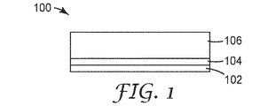
本発明は、(a)ガスバリア性フィルムと、(b)ガスバリア性フィルム上に配置されたポリマー転写層と、(c)ガスバリア性フィルムの反対側の、ポリマー転写層上に配置された剥離ライナーと、を備える、バリア複合体に関する。 The present invention includes (a) a gas barrier film, (b) a polymer transfer layer disposed on the gas barrier film, and (c) a release liner disposed on the polymer transfer layer on the opposite side of the gas barrier film. And a barrier composite.
Description
本発明は、電子デバイス、又は電子デバイスのコンポーネントを水分及び酸素から保護するのに有用なバリア複合体に関する。 The present invention relates to barrier composites useful for protecting electronic devices or components of electronic devices from moisture and oxygen.
多くの有機又は無機の薄膜デバイスは、水分及び酸素に曝されて劣化しやすい。このようなデバイス、特に手持ち式デバイスは、典型的には、それらを水分及び酸素との接触から保護するためにガラスにより封入されている。しかしながら、手持ち式デバイスの市場は、より薄く、より軽く、湾曲している、折り畳み可能でさえある形態因子に向けてトレンド化されているが、ガラスはデバイスの可撓性を大きく損なう。したがって、ポリエチレンテレフタレート(polyethylene terephthalate、PET)フィルム基材などの可撓性ポリマーフィルム上へ堆積されるバリアフィルム層が、これらの非平面の及び可撓性の形態因子のために、より高い関心を得ている。しかしながら、これらの、ますます薄く、非平面の及び可撓性の形態因子は、バリアフィルムの性能及びそれらの機械的耐久性に、より大きい要求を与える。 Many organic or inorganic thin film devices are susceptible to degradation when exposed to moisture and oxygen. Such devices, particularly handheld devices, are typically encapsulated with glass to protect them from contact with moisture and oxygen. However, while the market for handheld devices is trending towards thinner, lighter, curved, even foldable form factors, glass greatly impairs device flexibility. Therefore, barrier film layers deposited on flexible polymer films such as polyethylene terephthalate (PET) film substrates are of greater interest due to these non-planar and flexible form factors. It has gained. However, these increasingly thin, non-planar and flexible form factors place greater demands on the performance of barrier films and their mechanical durability.
PETフィルムは、現在、バリアフィルム層を支持するための好ましい基材ではあるが、構造体が、より薄くより薄くと作製されているので、それらは機械的及び熱的安定性を損なうおそれがある。加えて、PETの本来的な高屈折率(すなわちn>1.6)の性質、短い波長での光吸収の性質、及び複屈折の性質は、手持ち式デバイスの成功への鍵であることが多い光電子的性能を損なうおそれがある。 PET films are currently the preferred substrate for supporting the barrier film layer, but as structures are made thinner and thinner, they can compromise mechanical and thermal stability. . In addition, the inherent high refractive index (ie, n> 1.6) nature, light absorption nature, and birefringence nature of PET can be key to the success of handheld devices. Many optoelectronic performances may be impaired.
上記に鑑み、我々は、当技術分野に、機械的耐久性又は光学的性能を損なうことなく、より薄い、バリア構造体への必要性があることを認める。 In view of the above, we recognize that there is a need in the art for thinner barrier structures without compromising mechanical durability or optical performance.
端的には、一態様では、本発明は、(a)ガスバリア性フィルムと、(b)ガスバリア性フィルム上に配置されたポリマー転写層と、(c)ガスバリア性フィルムの反対側の、ポリマー転写層上に配置された剥離ライナーと、を備える、バリア複合体を提供する。 Briefly, in one aspect, the invention provides (a) a gas barrier film, (b) a polymer transfer layer disposed on the gas barrier film, and (c) a polymer transfer layer on the opposite side of the gas barrier film. And a release liner disposed thereon.
別の態様においては、本発明は、(a)第1のポリマー転写層上に配置された第1のガスバリア性フィルムを含む第1のバリア複合体と、(b)第2のポリマー転写層上に配置された第2のガスバリア性フィルムを含む第2のバリア複合体と、(c)第1のガスバリア性フィルムと第2のガスバリア性フィルムとの間に配置された架橋ポリマー層を含む層とを備える、二重バリア複合体を提供する。 In another aspect, the present invention provides (a) a first barrier composite comprising a first gas barrier film disposed on a first polymer transfer layer, and (b) on a second polymer transfer layer. A second barrier composite comprising a second gas barrier film disposed on the substrate, and (c) a layer comprising a crosslinked polymer layer disposed between the first gas barrier film and the second gas barrier film. A double barrier composite is provided.
更に別の態様においては、本発明は、薄膜デバイスを封入する二重バリア複合体を備える、封入された薄膜デバイスを提供する。 In yet another aspect, the present invention provides an encapsulated thin film device comprising a double barrier composite that encapsulates the thin film device.
なおも別の態様においては、本発明は、1%の引張ひずみにおいてバリア不良を示さない、ガスバリア性フィルム及びポリマー転写層上に配置されたポリマー転写層を備える、バリア複合体を提供する。 In yet another aspect, the present invention provides a barrier composite comprising a gas barrier film and a polymer transfer layer disposed on the polymer transfer layer that does not exhibit a barrier failure at 1% tensile strain.
なおも別の態様においては、本発明は、1%の引張ひずみでの100,000サイクル後にバリア不良を示さない、ガスバリア性フィルム及びポリマー転写層上に配置されたポリマー転写層を備えるバリア複合体を提供する。 In yet another aspect, the present invention provides a barrier composite comprising a gas barrier film and a polymer transfer layer disposed on the polymer transfer layer that does not exhibit a barrier failure after 100,000 cycles at 1% tensile strain. I will provide a.
本発明はまた、薄膜デバイスを封入する方法であって、(a)ガスバリア性フィルム、ガスバリア性フィルム上に配置されたポリマー転写層、及びガスバリア性フィルムの反対側の、ポリマー転写層上に配置された剥離ライナーを含むバリア複合体を準備する工程と、(b)薄膜デバイスを準備する工程と、(c)バリア複合体を薄膜デバイスに接着させる工程と、を含む、方法も提供する。 The present invention is also a method for encapsulating a thin film device, comprising: (a) a gas barrier film, a polymer transfer layer disposed on the gas barrier film, and a polymer transfer layer on the opposite side of the gas barrier film. There is also provided a method comprising the steps of: providing a barrier composite comprising a release liner; (b) preparing a thin film device; and (c) adhering the barrier composite to the thin film device.
本発明は、更に、薄膜デバイスを封入する方法であって、(a)(i)第1のポリマー転写層上に配置された第1のガスバリア性フィルム、及び第1のポリマー転写層の反対側に配置された第1の剥離ライナーを含む、第1のバリア複合体と、(ii)第2のポリマー転写層上に配置された第2のガスバリア性フィルム、及び第2のポリマー転写層の反対側に配置された第2の剥離ライナーを含む、第2のバリア複合体と、(iii)第1のガスバリア性フィルムと第2のガスバリア性フィルムとの間に配置された架橋ポリマー層を含む層と、を備える二重バリア複合体を準備する工程と、(b)薄膜デバイスを準備する工程と、(c)第1の剥離ライナーを除去する工程と、(d)二重バリア複合体を薄膜デバイスへ接着する工程とを含む、方法も提供する。 The present invention further provides a method for encapsulating a thin film device comprising: (a) (i) a first gas barrier film disposed on a first polymer transfer layer; and an opposite side of the first polymer transfer layer. A first barrier composite comprising a first release liner disposed on the substrate, and (ii) a second gas barrier film disposed on the second polymer transfer layer, and opposite the second polymer transfer layer A second barrier composite comprising a second release liner disposed on the side, and (iii) a layer comprising a crosslinked polymer layer disposed between the first gas barrier film and the second gas barrier film A step of preparing a double barrier composite comprising: (b) a step of preparing a thin film device; (c) a step of removing the first release liner; and (d) a thin film of the double barrier composite. Adhering to the device The method is also provided.
本発明のバリア複合体は、光電子デバイス上に転写されて、水分及び酸素からの保護のための「無基材」のバリアの解決法を提供することができる。このように、バリア複合体は、性能を損なうことなく、より薄い光電子デバイスを製造するために使用され得る。いくつかの実施形態においては、本発明のバリア複合体は、例えば、約50ミクロン厚未満、約25ミクロン厚未満、又は更に約10ミクロン厚未満である。 The barrier composites of the present invention can be transferred onto optoelectronic devices to provide a “substrate-free” barrier solution for protection from moisture and oxygen. In this way, the barrier composite can be used to produce thinner optoelectronic devices without compromising performance. In some embodiments, the barrier composite of the present invention is, for example, less than about 50 microns thick, less than about 25 microns thick, or even less than about 10 microns thick.
加えて、本発明のバリア複合体は、それらが無基材バリアを組み込んだデバイスにより経験される、曲げ剛性及び剪断応力の低減へと至らせ得る機械的有利性を提供することができる。いくつかの実施形態においては、本発明のバリア複合体は、例えば、約10GPa未満、約5GPa未満、約3GPa未満、約2GPa未満、又は更に約1.5GPa未満のヤング率を有する。 In addition, the barrier composites of the present invention can provide mechanical advantages that can lead to reduced bending stiffness and shear stress experienced by devices that incorporate a substrate-free barrier. In some embodiments, the barrier composites of the invention have a Young's modulus, for example, less than about 10 GPa, less than about 5 GPa, less than about 3 GPa, less than about 2 GPa, or even less than about 1.5 GPa.
ガスバリア性フィルム
本発明のバリア複合体は、ガスバリア性フィルムを備える。ガスバリア性フィルムは、酸素に対する低透過性を有するものであり、食品、電子機器及び医薬製品などの物品が、酸素との接触により劣化することを防ぐ助けとなるように使用することができる。典型的には、食品グレードのガスバリア性フィルムは、20℃及び相対湿度65%において、約1cm3/m2/日未満の酸素透過率を有する。好ましくは、このガスバリア性フィルムはまた、水分に対するバリア特性も有する。いくつかの実施形態においては、ガスバリア性フィルムは、約0.3ミクロン〜約10ミクロン、又は約1ミクロン〜約8ミクロンの厚さを有する。
Gas barrier film The barrier composite of the present invention comprises a gas barrier film. The gas barrier film has a low permeability to oxygen, and can be used to help prevent articles such as foods, electronic devices and pharmaceutical products from being deteriorated by contact with oxygen. Typically, food grade gas barrier films have an oxygen transmission rate of less than about 1 cm 3 / m 2 / day at 20 ° C. and 65% relative humidity. Preferably, the gas barrier film also has moisture barrier properties. In some embodiments, the gas barrier film has a thickness of about 0.3 microns to about 10 microns, or about 1 micron to about 8 microns.
ポリマーガスバリア性フィルムの例としては、エチルビニルアルコールコポリマー(ethyl vinyl alcohol copolymer、EVOH)フィルム、例えばポリエチレンEVOHフィルム及びポリプロピレンEVOHフィルム;ポリアミドフィルム、例えば共押出ポリアミド/ポリエチレンフィルム、共押出ポリプロピレン/ポリアミド/ポリプロピレンフィルム;並びにポリエチレンフィルム、例えば低密度、中密度若しくは高密度ポリエチレンフィルム及び共押出ポリエチレン/エチルビニルアセテートフィルムが挙げられる。ポリマーガスバリア性フィルムはまた、例えば、そのポリマーフィルム上にアルミニウムなどの金属の薄層をコーティングして金属化もされ得る。 Examples of polymer gas barrier films include ethyl vinyl alcohol copolymer (EVOH) films such as polyethylene EVOH films and polypropylene EVOH films; polyamide films such as coextruded polyamide / polyethylene films, coextruded polypropylene / polyamide / polypropylene. And polyethylene films such as low density, medium density or high density polyethylene films and coextruded polyethylene / ethyl vinyl acetate films. The polymer gas barrier film can also be metallized, for example, by coating a thin layer of metal such as aluminum on the polymer film.
無機ガスバリア性フィルムの例としては、酸化ケイ素、窒化ケイ素、酸窒化ケイ素、酸化アルミニウム、酸化ケイ素アルミニウムを含むフィルム、ダイヤモンド様フィルム、ダイヤモンド様ガラス、及びアルミニウム箔などの箔が挙げられる。 Examples of the inorganic gas barrier film include foils such as silicon oxide, silicon nitride, silicon oxynitride, aluminum oxide, a film containing silicon oxide aluminum, diamond-like film, diamond-like glass, and aluminum foil.
好ましくは、このガスバリア性フィルムは、可撓性である。一部の用途に関しては、ガスバリア性フィルムが可視光透過性であることもまた好ましい。本明細書で使用されるとき、用語「可視光透過性」とは、少なくとも約80%、好ましくは少なくとも約88%又は90%の、スペクトルの可視部分(例えば、400nm〜700nm)にわたる平均透過率を有することを意味する。 Preferably, the gas barrier film is flexible. For some applications, it is also preferred that the gas barrier film is visible light transmissive. As used herein, the term “visible light transmission” refers to an average transmission over the visible portion of the spectrum (eg, 400 nm to 700 nm) of at least about 80%, preferably at least about 88% or 90%. It means having.
一部の用途に関しては、水分及び酸素からの保護が必要とされる。特に繊細な用途に関しては、「超バリアフィルム」が必須となり得る。超バリアフィルムは、典型的には、23℃及び90%RHで約0.005cc/m2/日未満の酸素透過率、並びに23℃及び90%RHで約0.005g/m2/日未満の水蒸気透過率を有する。一部の超バリアフィルムは、ポリマー層同士の間に配置された可視光透過性無機層を備える、多層フィルムである。好適な超バリアフィルムの1つの例は、熱安定化ポリエチレンテレフタレート(heat−stabilized polyethylene terephthalate、HSPET)以上のガラス転移温度(Tg)を有するポリマー同士の間に配置された、可視光透過性無機バリア層を備えるものである。いくつかの実施形態においては、無機層は、約2nm〜約40nm、又は約3nm〜約30nmの厚さを有する。いくつかの実施形態においては、ポリマー層は、約100nm〜約1500nm、又は約300nm〜約1100nmの厚さを有する。 For some applications, protection from moisture and oxygen is required. Especially for delicate applications, “super barrier film” may be essential. The ultra-barrier film typically has an oxygen transmission rate of less than about 0.005 cc / m 2 / day at 23 ° C. and 90% RH, and less than about 0.005 g / m 2 / day at 23 ° C. and 90% RH. The water vapor permeability is as follows. Some super-barrier films are multilayer films comprising a visible light transmissive inorganic layer disposed between polymer layers. One example of a suitable super-barrier film is a visible light transmissive inorganic barrier disposed between polymers having a glass transition temperature (Tg) greater than or equal to heat-stabilized polyethylene terephthalate (HSPET). A layer is provided. In some embodiments, the inorganic layer has a thickness of about 2 nm to about 40 nm, or about 3 nm to about 30 nm. In some embodiments, the polymer layer has a thickness of about 100 nm to about 1500 nm, or about 300 nm to about 1100 nm.
HSPET以上のTgを有する、様々なポリマーを用いることができる。好適な高Tgポリマーを形成する、蒸着可能なモノマーが特に好ましい。好ましくは、第1のポリマー層は、PMMAを上回るTg、より好ましくは少なくとも約110℃のTg、更により好ましくは少なくとも約150℃のTg、最も好ましくは少なくとも約200℃のTgを有する。第1の層を形成するために使用可能な特に好ましいモノマーとしては、ウレタンアクリレート(例えば、双方ともSartomer Co.から市販の、CN−968、Tg=約84℃、及びCN−983、Tg=約90℃)、イソボルニルアクリレート(例えば、Sartomer Co.から市販のSR−506、Tg=約88℃)、ジペンタエリスリトールペンタアクリレート(例えば、Sartomer Co.から市販のSR−399、Tg=約90℃)、スチレンとブレンドされたエポキシアクリレート(例えば、Sartomer Co.から市販のCN−120S80、Tg=約95℃)、ジ−トリメチロールプロパンテトラアクリレート(例えば、Sartomer Co.から市販のSR−355、Tg=約98℃)、ジエチレングリコールジアクリレート(例えば、Sartomer Co.から市販のSR−230、Tg=約100℃)、1,3−ブチレングリコールジアクリレート(例えば、Sartomer Co.から市販のSR−212、Tg=約101℃)、ペンタアクリレートエステル(例えば、Sartomer Co.から市販のSR−9041、Tg=約102℃)、ペンタエリスリトールテトラアクリレート(例えば、Sartomer Co.から市販のSR−295、Tg=約103℃)、ペンタエリスリトールトリアクリレート(例えば、Sartomer Co.から市販のSR−444、Tg=約103℃)、エトキシル化(3)トリメチロールプロパントリアクリレート(例えば、Sartomer Co.から市販のSR−454、Tg=約103℃)、エトキシル化(3)トリメチロールプロパントリアクリレート(例えば、Sartomer Co.から市販のSR−454HP、Tg=約103℃)、アルコキシル化三官能アクリレートエステル(例えば、Sartomer Co.から市販のSR−9008、Tg=約103℃)、ジプロピレングリコールジアクリレート(例えば、Sartomer Co.から市販のSR−508、Tg=約104℃)、ネオペンチルグリコールジアクリレート(例えば、Sartomer Co.から市販のSR−247、Tg=約107℃)、エトキシル化(4)ビスフェノールジメタクリレート(例えば、Sartomer Co.から市販のCD−450、Tg=約108℃)、シクロヘキサンジメタノールジアクリレートエステル(例えば、Sartomer Co.から市販のCD−406、Tg=約110℃)、イソボルニルメタクリレート(例えば、Sartomer Co.から市販のSR−423、Tg=約110℃)、環状ジアクリレート(例えば、Sartomer Co.から市販のSR−833、Tg=約186℃)、及びトリス(2−ヒドロキシエチル)イソシアヌレートトリアクリレート(例えば、Sartomer Co.から市販のSR−368、Tg=約272℃)、上述したメタクリレートのアクリレート、並びに上述のアクリレートのメタクリレートが挙げられる。 Various polymers having a Tg greater than or equal to HSPET can be used. Particularly preferred are vapor depositable monomers that form suitable high Tg polymers. Preferably, the first polymer layer has a Tg greater than PMMA, more preferably a Tg of at least about 110 ° C, even more preferably a Tg of at least about 150 ° C, and most preferably a Tg of at least about 200 ° C. Particularly preferred monomers that can be used to form the first layer include urethane acrylates (eg, CN-968, both commercially available from Sartomer Co., Tg = about 84 ° C., and CN-983, Tg = about 90 ° C.), isobornyl acrylate (eg SR-506 commercially available from Sartomer Co., Tg = about 88 ° C.), dipentaerythritol pentaacrylate (eg SR-399 commercially available from Sartomer Co., Tg = about 90 ° C), epoxy acrylate blended with styrene (eg CN-120S80 commercially available from Sartomer Co., Tg = about 95 ° C.), di-trimethylolpropane tetraacrylate (eg SR-355 commercially available from Sartomer Co., Tg = about 98 ° C.) Tylene glycol diacrylate (eg SR-230 commercially available from Sartomer Co., Tg = about 100 ° C.), 1,3-butylene glycol diacrylate (eg SR-212 commercially available from Sartomer Co., Tg = about 101 ° C. ), Pentaacrylate esters (eg, SR-9041, commercially available from Sartomer Co., Tg = about 102 ° C.), pentaerythritol tetraacrylate (eg, SR-295, commercially available from Sartomer Co., Tg = about 103 ° C.), penta Erythritol triacrylate (eg SR-444 commercially available from Sartomer Co., Tg = about 103 ° C.), ethoxylated (3) trimethylolpropane triacrylate (eg SR-4 commercially available from Sartomer Co.) 4, Tg = about 103 ° C.), ethoxylated (3) trimethylolpropane triacrylate (eg, SR-454HP commercially available from Sartomer Co., Tg = about 103 ° C.), alkoxylated trifunctional acrylate ester (eg, Sartomer Co Commercially available SR-9008, Tg = about 103 ° C.), dipropylene glycol diacrylate (eg, SR-508 available from Sartomer Co., Tg = about 104 ° C.), neopentyl glycol diacrylate (eg, Sartomer Co Commercially available from SR-247, Tg = about 107 ° C.), ethoxylated (4) bisphenol dimethacrylate (eg, CD-450 commercially available from Sartomer Co., Tg = about 108 ° C.), cyclohexanedimethanol diaqua Rate esters (e.g., Sartomer Co. Commercially available CD-406, Tg = about 110 ° C.), isobornyl methacrylate (eg, SR-423 commercially available from Sartomer Co., Tg = about 110 ° C.), cyclic diacrylate (eg, commercially available from Sartomer Co. SR-833, Tg = about 186 ° C.), and tris (2-hydroxyethyl) isocyanurate triacrylate (eg, SR-368 commercially available from Sartomer Co., Tg = about 272 ° C.), the acrylate of the methacrylate described above, and Mention may be made of the acrylate methacrylates mentioned above.
第1のポリマー層は、基材にモノマー又はオリゴマーの層を適用して、その層を架橋し、その場でポリマーを形成することによって形成することができ、例えば、放射線架橋性モノマーのフラッシュ蒸発及び蒸着に続けて、例えば電子ビーム装置、UV光源、放電装置、又は他の好適なデバイスを使用して架橋することによって、形成することができる。支持体を冷却することによって、コーティング効率を向上させることができる。このモノマー又はオリゴマーはまた、ロールコーティング(例えば、グラビアロールコーティング)又はスプレーコーティング(例えば、静電スプレーコーティング)などの従来のコーティング方法を使用して基材に適用し、次いで、上記のように架橋することもできる。第1のポリマー層はまた、オリゴマー又はポリマーを溶媒中に含有する層を適用し、そのように適用された層を乾燥させて、その溶媒を除去することによっても、形成することができる。プラズマ重合もまた、昇温でガラス状態を有するポリマー層を提供する場合には用いることができ、この場合、ガラス転移温度は、HSPETのガラス転移温度以上である。最も好ましくは、第1のポリマー層は、例えば、米国特許第4,696,719号(Bischoff)、同第4,722,515号(Ham)、同第4,842,893号(Yializisら)、同第4,954,371号(Yializis)、同第5,018,048号(Shawら)、同第5,032,461号(Shawら)、同第5,097,800号(Shawら)、同第5,125,138号(Shawら)、同第5,440,446号(Shawら)、同第5,547,908号(Furuzawaら)、同第6,045,864号(Lyonsら)、同第6,231,939号(Shawら)及び同第6,214,422号(Yializis)で;PCT国際公開第00/26973号(Delta V Technologies,Inc.)で;D.G.Shaw and M.G.Langlois「A New Vapor Deposition Process for Coating Paper and Polymer Webs」(6th International Vacuum Coating Conference(1992))で;D.G.Shaw and M.G.Langlois「A New High Speed Process for Vapor Depositing Acrylate Thin Films:An Update」(Society of Vacuum Coaters 36th Annual Technical Conference Proceedings(1993))で;D.G.Shaw and M.G.Langlois「Use of Vapor Deposited Acrylate Coatings to Improve the Barrier Properties of Metallized Film」(Society of Vacuum Coaters 37th Annual Technical Conference Proceedings(1994))で;D.G.Shaw,M.Roehrig,M.G.Langlois and C.Sheehan「Use of Evaporated Acrylate Coatings to Smooth the Surface of Polyester and Polypropylene Film Substrates」(RadTech(1996))で;J.Affinito,P.Martin,M.Gross,C.Coronado and E.Greenwell「Vacuum deposited polymer/metal multilayer films for optical application」(Thin Solid Films 270,43−48(1995))で;並びに、J.D.Affinito、M.E.Gross,C.A.Coronado,G.L.Graff,E.N.Greenwell and P.M.Martin「Polymer−Oxide Transparent Barrier Layers」(Society of Vacuum Coaters 39th Annual Technical Conference Proceedings(1996))で説明されているように、フラッシュ蒸発及び蒸着の後に続けて、その場で架橋することによって形成される。 The first polymer layer can be formed by applying a monomer or oligomer layer to the substrate, crosslinking the layer, and forming the polymer in situ, for example, flash evaporation of radiation crosslinkable monomer. And following vapor deposition, it can be formed, for example, by crosslinking using an electron beam device, UV light source, discharge device, or other suitable device. By cooling the support, the coating efficiency can be improved. This monomer or oligomer is also applied to the substrate using conventional coating methods such as roll coating (eg, gravure roll coating) or spray coating (eg, electrostatic spray coating) and then crosslinked as described above. You can also The first polymer layer can also be formed by applying a layer containing an oligomer or polymer in a solvent, drying the layer so applied and removing the solvent. Plasma polymerization can also be used when providing a polymer layer having a glassy state at elevated temperature, in which case the glass transition temperature is above the glass transition temperature of HSPET. Most preferably, the first polymer layer is, for example, U.S. Pat. Nos. 4,696,719 (Bischoff), 4,722,515 (Ham), 4,842,893 (Yializis et al.). 4,954,371 (Yializis), 5,018,048 (Shaw et al.), 5,032,461 (Shaw et al.), 5,097,800 (Shaw et al.). ), 5,125,138 (Shaw et al.), 5,440,446 (Shaw et al.), 5,547,908 (Furuzawa et al.), 6,045,864 ( Lyons et al., 6,231,939 (Shaw et al.) And 6,214,422 (Yializis); PCT International Publication No. 00/26973 (Delta V Techn). Ologies, Inc.); G. Shaw and M.M. G. In Langlois “A New Vapor Deposition Process for Coating Paper and Polymer Webs” (6th International Vacuum Coating Conference (1992)); G. Shaw and M.M. G. Langlois "A New High Speed Process for Vapor Deposition Acrylate Thin Films: An Update" (Society of Vacuum Coins 36th Annual Tecn. G. Shaw and M.M. G. Langlois “Use of Vapor Deposited Acrylate Coatings to Improve the Barrier Properties of Metalized Films 94 (Society of Vaccum Coates). G. Shaw, M .; Roehrig, M.C. G. Langlois and C.L. See Shean, “Use of Evaporated Coatings to Smooth the Surface of Polymer and Polypropylene Film Substrates” (RadTech (1996)); Affinito, P.A. Martin, M.M. Gross, C.I. Coronado and E.M. Greenwell "Vacuum deposited polymer / metal multilayer film for optical application" (Thin Solid Films 270, 43-48 (1995)); D. Affinito, M.M. E. Gross, C.I. A. Coronado, G .; L. Graff, E .; N. Greenwell and P.M. M.M. As described in Martin “Polymer-Oxide Transparent Barrier Layers” (Society of Vacuum Coater 39th Annual Technical Conference Processings (1996)), followed by evaporation and subsequent evaporation as described in .
各ポリマー層の平滑性及び連続性、並びに、下に存在する層に対する接着性は、好ましくは、適切な前処理によって向上される。好ましい前処理レジメンは、好適な反応性雰囲気又は非反応性雰囲気の存在下での放電(例えば、プラズマ、グロー放電、コロナ放電、誘電体バリア放電、又は大気圧放電)、化学的前処理又は火炎前処理を用いるものである。これらの前処理は、下に存在する層の表面を、その後に続けて適用されるポリマー層の形成に対して、より受け入れやすいものにするために役立つ。プラズマ前処理が特に好ましい。この高Tgのポリマー層とは異なる組成を有し得る、別個の接着促進層もまた、下に存在する層の上に利用することにより、層間接着性を向上させることができる。この接着促進層は、例えば、別個のポリマー層とすることができ、又は、金属、金属酸化物、金属窒化物若しくは金属酸窒化物の層などの金属含有層とすることもできる。この接着促進層は、数nm(例えば、1又は2nm)〜約50nmの厚さを有してもよく、所望であれば、より厚くすることもできる。 The smoothness and continuity of each polymer layer, as well as the adhesion to the underlying layer, is preferably improved by a suitable pretreatment. Preferred pretreatment regimens are discharges in the presence of a suitable reactive or non-reactive atmosphere (eg plasma, glow discharge, corona discharge, dielectric barrier discharge, or atmospheric pressure discharge), chemical pretreatment or flame. Pre-processing is used. These pretreatments serve to make the surface of the underlying layer more acceptable for subsequent polymer layer formation. Plasma pretreatment is particularly preferred. A separate adhesion promoting layer, which can have a different composition than the high Tg polymer layer, can also be utilized over the underlying layer to improve interlayer adhesion. This adhesion promoting layer can be, for example, a separate polymer layer, or it can be a metal-containing layer such as a metal, metal oxide, metal nitride or metal oxynitride layer. The adhesion promoting layer may have a thickness of a few nm (eg, 1 or 2 nm) to about 50 nm, and can be thicker if desired.
第1のポリマー層の所望の化学組成及び厚さは、支持層の性質及び表面トポグラフィーに部分的に依存することになる。厚さは、後続の第1の無機バリア層を適用することが可能な平滑で無欠陥の表面を提供するのに十分であることが好ましい。例えば、第1のポリマー層は、数nm(例えば、2又は3nm)〜約5μmの厚さを有してもよく、所望であれば、より厚くすることもできる。 The desired chemical composition and thickness of the first polymer layer will depend in part on the nature and surface topography of the support layer. The thickness is preferably sufficient to provide a smooth, defect-free surface on which a subsequent first inorganic barrier layer can be applied. For example, the first polymer layer may have a thickness of a few nm (eg, 2 or 3 nm) to about 5 μm, and can be thicker if desired.
HSPET以上のTgを有するポリマー層により隔てられている、1つ以上の可視光透過性無機バリア層が、この第1のポリマー層の上に存在する。これらの層は、それぞれ、「第1の無機バリア層」、「第2の無機バリア層」及び「第2のポリマー層」と称される場合がある。所望であれば、更なる無機バリア層及びポリマー層が存在してもよく、それにはHSPET以上のTgを有さないポリマー層が含まれる。しかしながら、好ましくは、隣接する無機バリア層の各対は、HSPET以上のTgを有するポリマー層(1つ又は複数)によってのみ隔てられ、より好ましくは、PMMA以上のTgを有するポリマー層(1つ又は複数)によってのみ隔てられる。 One or more visible light transmissive inorganic barrier layers are present on the first polymer layer separated by a polymer layer having a Tg greater than or equal to HSPET. These layers may be referred to as “first inorganic barrier layer”, “second inorganic barrier layer”, and “second polymer layer”, respectively. If desired, additional inorganic barrier layers and polymer layers may be present, including polymer layers that do not have a Tg greater than HSPET. Preferably, however, each pair of adjacent inorganic barrier layers is separated only by the polymer layer (s) having a Tg greater than or equal to HSPET, more preferably the polymer layer (one or more) having a Tg greater than or equal to PMMA. Separated only by).
これらの無機バリア層は、同じものである必要はない。様々な無機バリア材料を用いることができる。好ましい無機バリア材料としては、金属酸化物、金属窒化物、金属炭化物、金属酸窒化物、金属酸ホウ化物、及びこれらの組み合わせが挙げられ、例えば、シリカなどの酸化ケイ素、アルミナなどの酸化アルミニウム、チタニアなどの酸化チタン、酸化ケイ素アルミニウム、酸化インジウム、酸化スズ、酸化インジウムスズ(indium tin oxide、「ITO」)、酸化タンタル、酸化ジルコニウム、酸化ニオビウム、炭化ホウ素、炭化タングステン、炭化ケイ素、窒化アルミニウム、窒化ケイ素、窒化ホウ素、酸窒化アルミニウム、酸窒化ケイ素、酸窒化ホウ素、酸ホウ化ジルコニウム、酸ホウ化チタン、及びこれらの組み合わせが挙げられる。酸化インジウムスズ、酸化ケイ素、酸化アルミニウム、酸化ケイ素アルミニウム、及びこれらの組み合わせが、特に好ましい無機バリア材料である。ITOは、各元素成分の相対的な割合を適切に選択することにより導電性になり得る、特殊なクラスのセラミック材料の一例である。無機バリア層は、好ましくは、スパッタリング(例えば、陰極スパッタリング又は平面マグネトロンスパッタリング)、蒸発(例えば、抵抗又は電子ビーム蒸発)、化学蒸着、原子的層堆積、めっきなどの、フィルム金属化技術で用いられる技術を使用して形成される。最も好ましくは、無機バリア層は、スパッタリング、例えば反応性スパッタリングを使用して形成される。無機層が、スパッタリングなどの高エネルギー堆積技術により形成される場合に、従来の化学蒸着の方法などの低エネルギー技術と比べて、バリア特性が向上することが観察されている。各無機バリア層の平滑性及び連続性、並びに、下に存在する層に対する接着性は、第1のポリマー層に関して上述されたものなどの前処理(例えば、プラズマ前処理)により、向上させることができる。 These inorganic barrier layers need not be the same. A variety of inorganic barrier materials can be used. Preferred inorganic barrier materials include metal oxides, metal nitrides, metal carbides, metal oxynitrides, metal oxyborides, and combinations thereof, for example, silicon oxide such as silica, aluminum oxide such as alumina, Titanium oxide such as titania, silicon aluminum oxide, indium oxide, tin oxide, indium tin oxide (“ITO”), tantalum oxide, zirconium oxide, niobium oxide, boron carbide, tungsten carbide, silicon carbide, aluminum nitride, Examples include silicon nitride, boron nitride, aluminum oxynitride, silicon oxynitride, boron oxynitride, zirconium oxyboride, titanium oxyboride, and combinations thereof. Indium tin oxide, silicon oxide, aluminum oxide, silicon aluminum oxide, and combinations thereof are particularly preferred inorganic barrier materials. ITO is an example of a special class of ceramic materials that can be made conductive by appropriate selection of the relative proportions of each elemental component. Inorganic barrier layers are preferably used in film metallization techniques such as sputtering (eg, cathode sputtering or planar magnetron sputtering), evaporation (eg, resistance or electron beam evaporation), chemical vapor deposition, atomic layer deposition, plating, etc. Formed using technology. Most preferably, the inorganic barrier layer is formed using sputtering, such as reactive sputtering. It has been observed that when the inorganic layer is formed by a high energy deposition technique such as sputtering, the barrier properties are improved compared to low energy techniques such as conventional chemical vapor deposition methods. The smoothness and continuity of each inorganic barrier layer and the adhesion to the underlying layer can be improved by pretreatment (eg, plasma pretreatment) such as those described above for the first polymer layer. it can.
これらの無機バリア層は、同じ厚さを有する必要はない。各無機バリア層の所望の化学組成及び厚さは、下に存在する層の性質及び表面トポグラフィーに、並びにそのバリアアセンブリの所望の光学特性に部分的に依存することになる。これらの無機バリア層は、好ましくは、連続的となるように十分に厚いものであり、かつ、そのバリアアセンブリ並びにアセンブリを含む物品が、所望の程度の可視光透過率及び可撓性を有することを確実にするように、十分に薄いものである。好ましくは、各無機バリア層の物理的厚さ(光学的厚さではなく)は、約3〜約150nm、より好ましくは約4〜約75nmである。 These inorganic barrier layers need not have the same thickness. The desired chemical composition and thickness of each inorganic barrier layer will depend in part on the nature and surface topography of the underlying layer and on the desired optical properties of the barrier assembly. These inorganic barrier layers are preferably sufficiently thick to be continuous, and the barrier assembly and the article comprising the assembly have the desired degree of visible light transmission and flexibility. It is thin enough to ensure Preferably, the physical thickness (not the optical thickness) of each inorganic barrier layer is from about 3 to about 150 nm, more preferably from about 4 to about 75 nm.
第1の無機バリア層と第2の無機バリア層と任意の更なる無機バリア層とを隔てる第2のポリマー層は、同じものである必要はなく、全てが同じ厚さを有する必要もない。様々な第2のポリマー層材料を用いることができる。好ましい第2のポリマー層材料としては、第1のポリマー層に関して上述されたものが挙げられる。好ましくは、第2のポリマー層(1つ又は複数)は、第1のポリマー層に関して上述されたように、フラッシュ蒸発及び蒸着に続けてその場で架橋することにより適用される。好ましくは、上述されたものなどの前処理(例えば、プラズマ前処理)もまた、第2のポリマー層の形成の前に用いられる。第2のポリマー層(1つ又は複数)の所望の化学組成及び厚さは、下に横たわる層(1つ又は複数)の性質及び表面トポグラフィーに部分的に依存することになる。第2のポリマー層の厚さは、後続の無機バリア層を適用することが可能な平滑で無欠陥の表面を提供するのに十分であることが好ましい。典型的には、第2のポリマー層(1つ又は複数)は、第1のポリマー層よりも薄い厚さを有してもよい。例えば、第2のポリマー層のそれぞれは、約5nm〜約10μmの厚さを有してもよく、所望であれば、より厚くすることもできる。 The second polymer layer that separates the first inorganic barrier layer, the second inorganic barrier layer, and any further inorganic barrier layers need not be the same, and need not all have the same thickness. A variety of second polymer layer materials can be used. Preferred second polymer layer materials include those described above for the first polymer layer. Preferably, the second polymer layer (s) is applied by cross-linking in situ following flash evaporation and deposition, as described above for the first polymer layer. Preferably, a pretreatment (eg, plasma pretreatment) such as those described above is also used prior to the formation of the second polymer layer. The desired chemical composition and thickness of the second polymer layer (s) will depend in part on the nature and surface topography of the underlying layer (s). The thickness of the second polymer layer is preferably sufficient to provide a smooth, defect-free surface to which a subsequent inorganic barrier layer can be applied. Typically, the second polymer layer (s) may have a thickness that is less than the first polymer layer. For example, each of the second polymer layers may have a thickness of about 5 nm to about 10 μm, and can be thicker if desired.
可撓性の可視光透過性超バリアフィルム及びそれらの製造は、例えば、米国特許第7,940,004号(Padiyathら)で説明されており、これは参照により本明細書に組み込まれる。 Flexible visible light transmissive ultra-barrier films and their manufacture are described, for example, in US Pat. No. 7,940,004 (Padiyath et al.), Which is incorporated herein by reference.
市販の超バリアフィルムとしては、例えば、3M Companyより入手可能なFTB 3−50及びFTB 3−125が挙げられる。 Examples of commercially available super barrier films include FTB 3-50 and FTB 3-125 available from 3M Company.
ポリマー転写層
本発明のバリア複合体は、ガスバリア性フィルム上に配置されたポリマー転写層を備える。好適なポリマー転写層は、ガスバリア性フィルムへの良好な接着性を有する。ポリマー転写層はまた、バリア複合体の処理及び移送中にはライナーがそのままの場所にあるが、剥離ライナーが意図的に除去されるときにはライナーがきれいにとれる(すなわち剥離する)ように、剥離ライナーに適切に接着されるべきである。好ましくは、ポリマー転写層は、それ自体を支持できるが割れに抵抗するのに十分可撓性なままであるように、機械的に堅牢である。いくつかの実施形態においては、ポリマー転写層は、バリア複合体に耐久性を提供することができる。ポリマー転写層は、典型的には、コーティング物(例えば溶液コーティングされた)として提供され、自立層又はフィルムではない。いくつかの実施形態においては、転写層は、約0.1ミクロン〜約8ミクロン、又は約0.5ミクロン〜6ミクロンの厚さを有する。
Polymer transfer layer The barrier composite of the present invention comprises a polymer transfer layer disposed on a gas barrier film. Suitable polymer transfer layers have good adhesion to gas barrier films. The polymer transfer layer can also be applied to the release liner so that the liner remains in place during processing and transfer of the barrier composite, but when the release liner is intentionally removed, the liner can be removed (ie, peeled). Should be properly glued. Preferably, the polymer transfer layer is mechanically robust so that it can support itself but remains sufficiently flexible to resist cracking. In some embodiments, the polymer transfer layer can provide durability to the barrier composite. The polymer transfer layer is typically provided as a coating (eg, solution coated) and is not a free standing layer or film. In some embodiments, the transfer layer has a thickness of about 0.1 microns to about 8 microns, or about 0.5 microns to 6 microns.
いくつかの実施形態においては、ポリマー転写層は、国際公開第2013/116103号(Kolbら)及び国際公開第2013/116302号(Kolbら)に記載のように作製することができ、これらは参照により本明細書に組み込まれる。例えば、ポリマー転写層を作製する方法は、一般に、(1)ラジカル硬化性プレポリマー及び(任意選択の)溶媒を含むコーティング溶液を提供すること、(2)この溶液をコーティング装置に供給すること、(3)このコーティング溶液を、多くのコーティング技術のうちの1つにより剥離ライナーに適用すること、(4)コーティングから(任意選択の)溶媒を実質的に除去すること、(5)制御された量の阻害剤ガス(例えば酸素)の存在下で材料を重合し、構造化表面をもたらすこと、並びに(6)乾燥させた重合化コーティングを、例えば追加の熱、可視光、紫外線(ultraviolet、UV)、又は電子ビーム硬化により任意選択で後処理することを含むことができる。 In some embodiments, the polymer transfer layer can be made as described in WO 2013/116103 (Kolb et al.) And WO 2013/116302 (Kolb et al.), Which are referenced Is incorporated herein by reference. For example, a method for making a polymer transfer layer generally includes: (1) providing a coating solution comprising a radical curable prepolymer and (optional) solvent; (2) supplying the solution to a coating apparatus; (3) applying this coating solution to the release liner by one of many coating techniques, (4) substantially removing (optional) solvent from the coating, (5) controlled. Polymerizing the material in the presence of an amount of inhibitor gas (eg, oxygen) to provide a structured surface, and (6) drying the polymerized coating to produce additional heat, visible light, ultraviolet, UV, ), Or optionally post-treatment by electron beam curing.
本明細書に記載の重合性材料は、フリーラジカル硬化性プレポリマーを含む。例示的なフリーラジカル硬化性プレポリマーとしては、ラジカル重合を介して重合する(硬化する)ことになる、モノマー、オリゴマー、ポリマー及び樹脂が挙げられる。好適なフリーラジカル硬化性プレポリマーとしては、(メタ)アクリレート、ポリエステル(メタ)アクリレート、ウレタン(メタ)アクリレート、エポキシ(メタ)アクリレート及びポリエーテル(メタ)アクリレート、シリコーン(メタ)アクリレート及びフッ素化メタ(アクリレート)が挙げられる。 The polymerizable material described herein includes a free radical curable prepolymer. Exemplary free radical curable prepolymers include monomers, oligomers, polymers and resins that will polymerize (harden) via radical polymerization. Suitable free radical curable prepolymers include (meth) acrylate, polyester (meth) acrylate, urethane (meth) acrylate, epoxy (meth) acrylate and polyether (meth) acrylate, silicone (meth) acrylate and fluorinated meta (Acrylate).
例示的なラジカル硬化性基としては、(メタ)アクリレート基、オレフィン性炭素−炭素二重結合、アリルオキシ基、α−メチルスチレン基、スチレン基、(メタ)アクリルアミド基、ビニルエーテル基、ビニル基、アリル基、及びこれらの組み合わせが挙げられる。典型的には、重合性材料はフリーラジカル重合性基を含む。いくつかの実施形態においては、重合性材料は、アクリレート及びメタクリレートモノマー、特に多官能性(メタ)アクリレート、二官能性(メタ)アクリレート、単官能性(メタ)アクリレート、及びこれらの組み合わせを含む。 Exemplary radical curable groups include (meth) acrylate groups, olefinic carbon-carbon double bonds, allyloxy groups, α-methylstyrene groups, styrene groups, (meth) acrylamide groups, vinyl ether groups, vinyl groups, allyls. Groups, and combinations thereof. Typically, the polymerizable material includes free radical polymerizable groups. In some embodiments, the polymerizable material comprises acrylate and methacrylate monomers, particularly multifunctional (meth) acrylates, difunctional (meth) acrylates, monofunctional (meth) acrylates, and combinations thereof.
いくつかの例示的な実施形態においては、重合性組成物は、少なくとも1つのモノマー又はオリゴマーの多官能性(メタ)アクリレートを含む。典型的には、多官能性(メタ)アクリレートは、トリ(メタ)アクリレート及び/又はテトラ(メタ)アクリレートである。いくつかの実施形態においては、より高い官能性モノマー及び/又はオリゴマーの(メタ)アクリレートが用いられてもよい。多官能性(メタ)アクリレートの混合物もまた使用されてもよい。 In some exemplary embodiments, the polymerizable composition comprises at least one monomeric or oligomeric multifunctional (meth) acrylate. Typically, the multifunctional (meth) acrylate is tri (meth) acrylate and / or tetra (meth) acrylate. In some embodiments, higher functionality monomers and / or oligomeric (meth) acrylates may be used. Mixtures of polyfunctional (meth) acrylates may also be used.
例示的な多官能性(メタ)アクリレートモノマーとしては、ポリオールマルチ(メタ)アクリレートが挙げられる。そのような化合物は、典型的には、3〜10個の炭素原子を含有する、脂肪族トリオール及び/又はテトラオールから調製される。好適な多官能性(メタ)アクリレートの例は、トリメチロールプロパントリアクリレート、ジ(トリメチロールプロパン)テトラアクリレート、ペンタエリスリトールテトラアクリレート、ペンタエリスリトールトリアクリレート、相当するメタクリレート、及びポリオールのアルコキシル化(通常はエトキシル化)誘導体の(メタ)アクリレートである。多官能性モノマーの例としては、Sartomer Co.,Exton,PAから商品名「SR−295」、「SR−444」、「SR−399」、「SR−355」、「SR494」、「SR−368」、「SR−351」、「SR492」、「SR350」、「SR415」、「SR454」、「SR499」「501」、「SR502」及び「SR9020」で、並びにSurface Specialties,Smyrna,GAから「PETA−K」、「PETIA」及び「TMPTA−N」で入手可能なものが挙げられる。多官能性(メタ)アクリレートモノマーは、構造化表面に、耐久性及び硬度を付与することができる。 Exemplary multifunctional (meth) acrylate monomers include polyol multi (meth) acrylate. Such compounds are typically prepared from aliphatic triols and / or tetraols containing from 3 to 10 carbon atoms. Examples of suitable multifunctional (meth) acrylates are trimethylolpropane triacrylate, di (trimethylolpropane) tetraacrylate, pentaerythritol tetraacrylate, pentaerythritol triacrylate, the corresponding methacrylate, and alkoxylation of polyols (usually (Ethoxylated) derivative (meth) acrylate. Examples of multifunctional monomers include Sartomer Co. , Exton, PA, trade names “SR-295”, “SR-444”, “SR-399”, “SR-355”, “SR494”, “SR-368”, “SR-351”, “SR492” , "SR350", "SR415", "SR454", "SR499", "501", "SR502", and "SR9020", and from Surface Specialties, Smyrna, GA "PETA-K", "PETIA" and "TMPTA- N ”is available. Polyfunctional (meth) acrylate monomers can impart durability and hardness to the structured surface.
いくつかの例示的な実施形態においては、重合性組成物は少なくとも1つのモノマー又はオリゴマーの二官能性(メタ)アクリレートを含む。例示的な二官能性(メタ)アクリレートモノマーとしては、ジオール二官能性(メタ)アクリレートが挙げられる。そのような化合物は典型的に、2〜10個の炭素原子を含有する脂肪族ジオールから調製される。好適な二官能性(メタ)アクリレートの例は、エチレングリコールジアクリレート、1,6−ヘキサンジオールジアクリレート、1,12−ドデカンジオールジメタクリレート、シクロヘキサンジメタノールジアクリレート、1,4ブタンジオールジアクリレート、ジエチレングリコールジアクリレート、ジエチレングリコールジメタクリレート、1,6−ヘキサンジオールジメタクリレート、ネオペンチルグリコールジアクリレート、ネオペンチルグリコールジメタクリレート及びジプロピレングリコールジアクリレートである。 In some exemplary embodiments, the polymerizable composition comprises at least one monomeric or oligomeric bifunctional (meth) acrylate. Exemplary bifunctional (meth) acrylate monomers include diol bifunctional (meth) acrylates. Such compounds are typically prepared from aliphatic diols containing 2 to 10 carbon atoms. Examples of suitable bifunctional (meth) acrylates are ethylene glycol diacrylate, 1,6-hexanediol diacrylate, 1,12-dodecanediol dimethacrylate, cyclohexanedimethanol diacrylate, 1,4 butanediol diacrylate, Diethylene glycol diacrylate, diethylene glycol dimethacrylate, 1,6-hexanediol dimethacrylate, neopentyl glycol diacrylate, neopentyl glycol dimethacrylate and dipropylene glycol diacrylate.
二官能性ポリエーテルからの二官能性(メタ)アクリレートもまた有用である。例としては、ポリエチレングリコールジ(メタ)アクリレート及びポリプロピレングリコールジ(メタ)アクリレートが挙げられる。 Also useful are bifunctional (meth) acrylates from bifunctional polyethers. Examples include polyethylene glycol di (meth) acrylate and polypropylene glycol di (meth) acrylate.
いくつかの例示的な実施形態においては、重合性組成物は、少なくとも1つのモノマー又はオリゴマーの単官能性(メタ)アクリレートを含む。例示的な単官能性(メタ)アクリレート及び他のラジカル硬化性モノマーとしては、スチレン、α−メチルスチレン、置換スチレン、ビニルエステル、ビニルエーテル、N−ビニル−2−ピロリドン、(メタ)アクリルアミド、N−置換(メタ)アクリルアミド、オクチル(メタ)アクリレート、イソ−オクチル(メタ)アクリレート、ノニルフェノールエトキシレート(メタ)アクリレート、イソノニル(メタ)アクリレート、イソボルニル(メタ)アクリレート、2−(2−エトキシ−エトキシ)エチル(メタ)アクリレート、2−エチルヘキシル(メタ)アクリレート、ラウリル(メタ)アクリレート、ブタンジオールモノ(メタ)アクリレート、β−カルボキシエチル(メタ)アクリレート、イソブチル(メタ)アクリレート、2−ヒドロキシエチル(メタ)アクリレート、(メタ)アクリロニトリル、無水マレイン酸、イタコン酸、イソデシル(メタ)アクリレート、ドデシル(メタ)アクリレート、n−ブチル(メタ)アクリレート、メチル(メタ)アクリレート、ヘキシル(メタ)アクリレート、(メタ)アクリル酸、N−ビニルカプロラクタム、ステアリル(メタ)アクリレート、ヒドロキシ官能性ポリカプロラクトンエステル(メタ)アクリレート、ヒドロキシエチル(メタ)アクリレート、ヒドロキシメチル(メタ)アクリレート、ヒドロキシプロピル(メタ)アクリレート、ヒドロキシイソプロピル(メタ)アクリレート、ヒドロキシブチル(メタ)アクリレート、ヒドロキシイソブチル(メタ)アクリレート、テトラヒドロフルフリル(メタ)アクリレート、及びこれらの組み合わせが挙げられる。単官能性(メタ)アクリレートは、例えば、プレポリマー組成物の粘度及び官能性を調節するのに有用である。 In some exemplary embodiments, the polymerizable composition comprises at least one monomeric or oligomeric monofunctional (meth) acrylate. Exemplary monofunctional (meth) acrylates and other radical curable monomers include styrene, α-methyl styrene, substituted styrene, vinyl esters, vinyl ethers, N-vinyl-2-pyrrolidone, (meth) acrylamide, N- Substituted (meth) acrylamide, octyl (meth) acrylate, iso-octyl (meth) acrylate, nonylphenol ethoxylate (meth) acrylate, isononyl (meth) acrylate, isobornyl (meth) acrylate, 2- (2-ethoxy-ethoxy) ethyl (Meth) acrylate, 2-ethylhexyl (meth) acrylate, lauryl (meth) acrylate, butanediol mono (meth) acrylate, β-carboxyethyl (meth) acrylate, isobutyl (meth) acrylate, 2-hydroxy Droxyethyl (meth) acrylate, (meth) acrylonitrile, maleic anhydride, itaconic acid, isodecyl (meth) acrylate, dodecyl (meth) acrylate, n-butyl (meth) acrylate, methyl (meth) acrylate, hexyl (meth) acrylate, (Meth) acrylic acid, N-vinylcaprolactam, stearyl (meth) acrylate, hydroxy-functional polycaprolactone ester (meth) acrylate, hydroxyethyl (meth) acrylate, hydroxymethyl (meth) acrylate, hydroxypropyl (meth) acrylate, hydroxy Isopropyl (meth) acrylate, hydroxybutyl (meth) acrylate, hydroxyisobutyl (meth) acrylate, tetrahydrofurfuryl (meth) acrylate And combinations thereof. Monofunctional (meth) acrylates are useful, for example, to adjust the viscosity and functionality of the prepolymer composition.
オリゴマー材料はまた、本明細書に記載しているサブマイクロメートル粒子を含む材料を作製するために有用である。オリゴマー材料は、バルクの光学特性及び耐久性を、硬化された組成物に付与する。代表的な二官能性オリゴマーとしては、エトキシル化(30)ビスフェノールAジアクリレート、ポリエチレングリコール(600)ジメタクリレート、エトキシル化(2)ビスフェノールAジメタクリレート、エトキシル化(3)ビスフェノールAジアクリレート、エトキシル化(4)ビスフェノールAジメタクリレート、エトキシル化(6)ビスフェノールAジメタクリレート、ポリエチレングリコール(600)ジアクリレートが挙げられる。 Oligomeric materials are also useful for making materials that include the sub-micrometer particles described herein. The oligomeric material imparts bulk optical properties and durability to the cured composition. Typical bifunctional oligomers include ethoxylated (30) bisphenol A diacrylate, polyethylene glycol (600) dimethacrylate, ethoxylated (2) bisphenol A dimethacrylate, ethoxylated (3) bisphenol A diacrylate, ethoxylated (4) Bisphenol A dimethacrylate, ethoxylated (6) bisphenol A dimethacrylate, polyethylene glycol (600) diacrylate.
典型的な有用な二官能性オリゴマー及びオリゴマー配合物としては、Sartomer Co.から商品名「CN−120」、「CN−104」、「CN−116」、「CN−117」で、及びCytec Surface Specialties,Smyrna,GAから「EBECRYL 1608」、「EBECRYL 3201」、「EBECRYL 3700」、「EBECRYL 3701」、「EBECRYL 608」で入手可能なものが挙げられる。他の有用なオリゴマー及びオリゴマー配合物としては、Sartomer Co.から商品名「CN−2304」、「CN−115」、「CN−118」、「CN−119」、「CN−970A60」、「CN−972」、「CN−973A80」及び「CN−975」で、並びにCytec Surface Specialtiesから「EBECRYL 3200」、「EBECRYL 3701」、「EBECRYL 3302」、「EBECRYL 3605」、「EBECRYL 608」で入手可能なものが挙げられる。 Typical useful bifunctional oligomers and oligomer formulations include Sartomer Co. From “CN-120”, “CN-104”, “CN-116”, “CN-117”, and Cytec Surface Specialties, Smyrna, GA from “EBECRYL 1608”, “EBECRYL 3201”, “EBECRYL 3700” ”,“ EBECRYL 3701 ”,“ EBECRYL 608 ”. Other useful oligomers and oligomer formulations include Sartomer Co. Product names “CN-2304”, “CN-115”, “CN-118”, “CN-119”, “CN-970A60”, “CN-972”, “CN-973A80” and “CN-975” As well as those available from Cytec Surface Specialties in “EBECRYL 3200”, “EBECRYL 3701”, “EBECRYL 3302”, “EBECRYL 3605”, and “EBECRYL 608”.
ポリマー転写層は、官能性ポリマー材料、例えば耐候性ポリマー材料、疎水性ポリマー材料、親水性ポリマー材料、帯電防止ポリマー材料、防汚性ポリマー材料、電磁遮蔽用導電性ポリマー材料、抗菌性ポリマー材料、形状記憶ポリマー材料又は耐摩耗性ポリマー材料から作製することができる。官能性親水性又は帯電防止ポリマーマトリックスは、親水性アクリレート、例えばヒドロキシエチルメタクリレート(hydroxyethyl methacrylate、HEMA)、ヒドロキシエチルアクリレート(hydroxyethyl acrylate、HEA)、異なるポリエチレングリコール(polyethylene glycol、PEG)分子量を有するポリ(エチレングリコール)アクリレート、及び他の親水性アクリレート(例えば3−ヒドロキシプロピルアクリレート、3−ヒドロキシプロピルメタクリレート、2−ヒドロキシ−3−メタクリルオキシプロピルアクリレート、及び2−ヒドロキシ−3−アクリルオキシプロピルアクリレート)を含む。 The polymer transfer layer is a functional polymer material such as a weather resistant polymer material, a hydrophobic polymer material, a hydrophilic polymer material, an antistatic polymer material, an antifouling polymer material, a conductive polymer material for electromagnetic shielding, an antibacterial polymer material, It can be made from a shape memory polymeric material or an abrasion resistant polymeric material. Functional hydrophilic or antistatic polymer matrices are hydrophilic acrylates such as hydroxyethyl methacrylate (HEMA), hydroxyethyl acrylate (HEA), poly (polyethylene glycol, PEG) with different molecular weights. Ethylene glycol) acrylate, and other hydrophilic acrylates such as 3-hydroxypropyl acrylate, 3-hydroxypropyl methacrylate, 2-hydroxy-3-methacryloxypropyl acrylate, and 2-hydroxy-3-acryloxypropyl acrylate .
いくつかの実施形態においては、溶媒は、例えば放射線硬化性プレポリマーの分解温度を超えない温度で乾燥することによって、組成物から除去することができる。 In some embodiments, the solvent can be removed from the composition by, for example, drying at a temperature that does not exceed the decomposition temperature of the radiation curable prepolymer.
例示的な溶媒としては、線状、分岐及び環状の炭化水素、アルコール、ケトン、及びプロピレングリコールエーテル(例えば、1−メトキシ−2−プロパノール)を含むエーテル、イソプロピルアルコール、エタノール、トルエン、酢酸エチル、2−ブタノン、酢酸ブチル、メチルイソブチルケトン、メチルエチルケトン、シクロヘキサノン、アセトン、芳香族炭化水素、イソホロン、ブチロラクトン、N−メチルピロリドン、テトラヒドロフラン、エステル(例えば、ラクテート、アセテート、プロピレングリコールモノメチルエーテルアセテート(propylene glycol monomethyl ether acetate、PM acetate)、ジエチレングリコールエチルエーテルアセテート(diethylene glycol ethyl ether acetate、DE acetate)、エチレングリコールブチルエーテルアセテート(ethylene glycol butyl ether acetate、EB acetate)、ジプロピレングリコールモノメチルエーテルアセテート(dipropylen)、ジプロピレングリコールモノメチルエーテルアセテート(dipropylen)、ジプロピレングリコールモノメチルエーテルアセテート(dipropylene glycol monomethyl acetate、DPM acetate)、イソ−アルキルエステル、イソヘキシルアセテート、イソヘプチルアセテート、イソオクチルアセテート、イソノニルアセテート、イソデシルアセテート、イソドデシルアセテート、イソトリデシルアセテート、及び他のイソ−アルキルエステル)、水、並びにこれらの組み合わせが挙げられる。 Exemplary solvents include linear, branched and cyclic hydrocarbons, alcohols, ketones, and ethers including propylene glycol ethers (eg, 1-methoxy-2-propanol), isopropyl alcohol, ethanol, toluene, ethyl acetate, 2-butanone, butyl acetate, methyl isobutyl ketone, methyl ethyl ketone, cyclohexanone, acetone, aromatic hydrocarbon, isophorone, butyrolactone, N-methylpyrrolidone, tetrahydrofuran, ester (eg, lactate, acetate, propylene glycol monomethyl ether acetate (propylene glycol monomethyl ether ether acetate, PM acetate, diethylene glycol ethyl ether acetate, DE acetate, ethylene glycol butyrate Ethylene glycol butyl ether acetate (EB acetate), dipropylene glycol monomethyl ether acetate (dipropylen), dipropylene glycol monomethyl ether acetate (dipropylen), dipropylene glycol monomethyl acetate (DPM acetate), iso -Alkyl esters, isohexyl acetate, isoheptyl acetate, isooctyl acetate, isononyl acetate, isodecyl acetate, isododecyl acetate, isotridecyl acetate, and other iso-alkyl esters), water, and combinations thereof It is done.
第1の溶液はまた、連鎖移動剤を含んでもよい。連鎖移動剤は、重合前のモノマー混合物に可溶性であることが好ましい。好適な連鎖移動剤の例としては、トリエチルシラン及びメルカプタンが挙げられる。 The first solution may also include a chain transfer agent. The chain transfer agent is preferably soluble in the monomer mixture before polymerization. Examples of suitable chain transfer agents include triethylsilane and mercaptans.
いくつかの実施形態においては、重合性組成物は、上記プレポリマーの混合物を含む。ラジカル硬化性組成物の望ましい特性としては、典型的には、粘度、官能性、表面張力、収縮及び屈折率が挙げられる。硬化性組成物の望ましい特性としては、機械特性(例えば、弾性率、強度及び硬度)、熱特性(例えば、ガラス転移温度及び融点)並びに光学特性(例えば、透過率、屈折率及びヘイズ)が挙げられる。 In some embodiments, the polymerizable composition comprises a mixture of the prepolymers. Desirable properties of radically curable compositions typically include viscosity, functionality, surface tension, shrinkage and refractive index. Desirable properties of the curable composition include mechanical properties (eg, elastic modulus, strength and hardness), thermal properties (eg, glass transition temperature and melting point) and optical properties (eg, transmittance, refractive index and haze). It is done.
得られた表面構造は、硬化性プレポリマー組成物により影響を受けることが観察される。例えば、異なるモノマーは、同じ条件下で硬化された場合、異なる表面ナノ構造をもたらす。異なる表面構造は、例えば、異なる%反射率、ヘイズ及び透過率をもたらすことができる。 It is observed that the resulting surface structure is affected by the curable prepolymer composition. For example, different monomers result in different surface nanostructures when cured under the same conditions. Different surface structures can provide different% reflectivity, haze and transmittance, for example.
得られた表面ナノ構造は、フリーラジカル硬化性プレポリマー組成物により促進されることが観察される。例えば、特定のモノ−、ジ−及びマルチ−メタ(アクリレート)を組み込むと、同じ条件下で処理された場合でも、好ましいコーティング特性(例えば、%反射率、ヘイズ、透過率、スチールウール引っ掻き抵抗性など)を示す表面ナノ構造をもたらすことができる。逆に、異なる比及び/又は異なるプレポリマーはまた、同様の処理条件下での表面ナノ構造を形成する能力をもたらすことができる。 It is observed that the resulting surface nanostructures are promoted by the free radical curable prepolymer composition. For example, when incorporating certain mono-, di- and multi-meth (acrylates), even when processed under the same conditions, favorable coating properties (eg,% reflectance, haze, transmittance, steel wool scratch resistance) Etc.) can be produced. Conversely, different ratios and / or different prepolymers can also provide the ability to form surface nanostructures under similar processing conditions.
ラジカル硬化性プレポリマーの成分割合は、変化することができる。この組成物は、例えば、所望のコーティング表面特性、バルク特性、並びにコーティングの及び硬化の条件に依存することがある。 The component proportion of the radical curable prepolymer can vary. This composition may depend, for example, on the desired coating surface properties, bulk properties, and coating and curing conditions.
いくつかの実施形態においては、ラジカル硬化性プレポリマーはハードコート材料である。 In some embodiments, the radical curable prepolymer is a hardcoat material.
いくつかの実施形態においては、ポリマー転写層はサブマイクロメートル粒子を含む。サブマイクロメートル粒子は、ポリマー転写層に、耐久性及び/又は表面構造を付与することができる。 In some embodiments, the polymer transfer layer comprises submicrometer particles. The submicrometer particles can impart durability and / or surface structure to the polymer transfer layer.
ポリマー転写層中に分散されたサブマイクロメートル粒子は、1マイクロメートル未満の最大寸法を有する。サブマイクロメートル粒子としては、サブマイクロメートル粒子(例えばナノスフェア及びナノチューブ)が挙げられる。サブマイクロメートル粒子は、会合されるか非会合されるか、又はこれらの両方であり得る。サブマイクロメートル粒子は、球状、又は様々な他の形状を有することができる。例えば、サブマイクロメートル粒子は、伸長されることができ、アスペクト比の範囲を有することができる。いくつかの実施形態においては、サブマイクロメートル粒子は、無機のサブマイクロメートル粒子、有機の(例えばポリマーの)サブマイクロメートル粒子、有機のサブマイクロメートル粒子と無機のサブマイクロメートル粒子との組み合わせとすることができる。例示的な一実施形態においては、サブマイクロメートル粒子は、多孔性粒子、中空粒子、中実粒子、又はこれらの組み合わせとすることができる。 The submicrometer particles dispersed in the polymer transfer layer have a maximum dimension of less than 1 micrometer. Sub-micrometer particles include sub-micrometer particles (eg, nanospheres and nanotubes). The sub-micrometer particles can be associated or unassociated, or both. The sub-micrometer particles can have a spherical shape or various other shapes. For example, submicrometer particles can be elongated and have a range of aspect ratios. In some embodiments, the sub-micrometer particles are inorganic sub-micrometer particles, organic (eg, polymeric) sub-micrometer particles, a combination of organic and inorganic sub-micrometer particles, and can do. In one exemplary embodiment, the sub-micrometer particles can be porous particles, hollow particles, solid particles, or a combination thereof.
いくつかの実施形態においては、サブマイクロメートル粒子は、5nm〜1000nm(いくつかの実施形態においては、20nm〜750nm、50nm〜500nm、75nm〜300nm、又は更には100nm〜200nm)の範囲である。サブマイクロメートル粒子は、約10nm〜約1000nmの範囲の平均径を有する。(ナノメートルサイズのものを含む)サブマイクロメートル粒子は、例えば、炭素、金属、金属酸化物(例えば、SiO2、ZrO2、TiO2、ZnO、ケイ酸マグネシウム、酸化インジウムスズ、酸化アンチモンスズ)、炭化物(例えば、SiC及びWC)、窒化物、ホウ化物、ハロゲン化物、フッ化炭素固形物(例えば、ポリ(テトラフルオロエチレン))、カーボネート(例えば、炭酸カルシウム)、並びにこれらの混合物を含むことができる。いくつかの実施形態においては、サブマイクロメートル粒子は、SiO2粒子、ZrO2粒子、TiO2粒子、ZnO粒子、Al2O3粒子、炭酸カルシウム粒子、ケイ酸マグネシウム粒子、酸化インジウムスズ粒子、酸化アンチモンスズ粒子、ポリ(テトラフルオロエチレン)粒子、又は炭素粒子のうちの少なくとも1つを含む。金属酸化物粒子は、完全に凝結され得る。金属酸化物粒子は、結晶質とすることができる。 In some embodiments, the sub-micrometer particles range from 5 nm to 1000 nm (in some embodiments, 20 nm to 750 nm, 50 nm to 500 nm, 75 nm to 300 nm, or even 100 nm to 200 nm). The submicrometer particles have an average diameter in the range of about 10 nm to about 1000 nm. Sub-micrometer particles (including those of nanometer size) are, for example, carbon, metal, metal oxide (eg, SiO 2 , ZrO 2 , TiO 2 , ZnO, magnesium silicate, indium tin oxide, antimony tin oxide) , Carbides (eg, SiC and WC), nitrides, borides, halides, fluorocarbon solids (eg, poly (tetrafluoroethylene)), carbonates (eg, calcium carbonate), and mixtures thereof Can do. In some embodiments, the sub-micrometer particles are SiO 2 particles, ZrO 2 particles, TiO 2 particles, ZnO particles, Al 2 O 3 particles, calcium carbonate particles, magnesium silicate particles, indium tin oxide particles, oxidized At least one of antimony tin particles, poly (tetrafluoroethylene) particles, or carbon particles is included. The metal oxide particles can be fully condensed. The metal oxide particles can be crystalline.
いくつかの実施形態においては、サブマイクロメートル粒子は、多峰性分布を有する。いくつかの実施形態においては、サブマイクロメートル粒子は、二峰性分布を有する。 In some embodiments, the sub-micrometer particles have a multimodal distribution. In some embodiments, the submicrometer particles have a bimodal distribution.
例示的なシリカは、例えば、Nalco Chemical Co.,Naperville,ILから商品名「NALCO COLLOIDAL SILICA」で、例えば製品2326、2727、2329、2329K、及び2329 PLUSで入手可能である。例示的なヒュームドシリカとしては、例えば、Evonik Degusa Co.,Parsippany,NJから商品名「AEROSIL series OX−50」、並びに製品番号−130、−150及び−200で、並びにCabot Corp.,Tuscola,ILから商品名「CAB−O−SPERSE 2095」、「CAB−O−SPERSE A105」及び「CAB−O−SIL M5」で入手可能なものが挙げられる。例示的な他のコロイド状シリカは、例えばNissan Chemicalsから商品名「MP1040」、「MP2040」、「MP3040」及び「MP4540」で入手可能である。 Exemplary silicas include, for example, Nalco Chemical Co. , Naperville, IL under the trade name “NALCO COLLOIDAL SILICA”, for example in the products 2326, 2727, 2329, 2329K and 2329 PLUS. Exemplary fumed silicas include, for example, Evonik Degusa Co. , Parsippany, NJ under the trade designation "AEROSIL series OX-50" and product numbers -130, -150 and -200, and Cabot Corp. , Tuscola, IL available under the trade names “CAB-O-SPERSE 2095”, “CAB-O-SPERSE A105” and “CAB-O-SIL M5”. Other exemplary colloidal silicas are available from, for example, Nissan Chemicals under the trade designations “MP1040”, “MP2040”, “MP3040”, and “MP4540”.
いくつかの実施形態においては、サブマイクロメートル粒子は表面改質される。好ましくは、表面処理は、サブマイクロメートル粒子が重合性樹脂中に十分に分散され、実質的に均質な組成物をもたらすように、サブマイクロメートル粒子を安定化させる。いくつかの実施形態においては、サブマイクロメートル粒子は、安定化されたサブマイクロメートル粒子が、硬化中に、重合性樹脂と共重合できるか、又は同樹脂と反応できるように、表面処理剤によって、その表面の少なくとも一部にわたって改質され得る。 In some embodiments, the submicrometer particles are surface modified. Preferably, the surface treatment stabilizes the sub-micrometer particles such that the sub-micrometer particles are well dispersed in the polymerizable resin, resulting in a substantially homogeneous composition. In some embodiments, the sub-micrometer particles are added by a surface treatment agent so that the stabilized sub-micrometer particles can copolymerize or react with the polymerizable resin during curing. Can be modified over at least a portion of its surface.
いくつかの実施形態においては、サブマイクロメートル粒子は、表面処理剤で処理される。一般に、表面処理剤は、粒子表面に結合(共有結合、イオン結合、又は強力な物理吸着による結合)することになる第1の末端部と、粒子に樹脂との相溶性をもたらす及び/又は硬化時に樹脂と反応する第2の末端部とを有する。表面処理剤の例としては、アルコール、アミン、カルボン酸、スルホン酸、ホスホン酸、シラン及びチタネートが挙げられる。好ましいタイプの処理剤は、部分的には、金属酸化物表面の化学的性質により決定される。シランが、シリカ及び他のシリカ系粒子には好ましい。シラン及びカルボン酸が、ジルコニアなどの金属酸化物には好ましい。 In some embodiments, the submicrometer particles are treated with a surface treatment agent. Generally, the surface treatment agent provides compatibility between the first end that will bind to the particle surface (covalent bond, ionic bond, or strong physisorption bond) and the resin to the particle and / or cure. It sometimes has a second end that reacts with the resin. Examples of the surface treatment agent include alcohol, amine, carboxylic acid, sulfonic acid, phosphonic acid, silane, and titanate. The preferred type of treating agent is determined in part by the chemical nature of the metal oxide surface. Silane is preferred for silica and other silica-based particles. Silanes and carboxylic acids are preferred for metal oxides such as zirconia.
表面改質は、モノマーとの混合に続いて又は混合後のいずれかで行うことができる。シランの場合、樹脂内へ組み込む前に、シランと、サブマイクロメートル粒子又はサブマイクロメートル粒子表面とを、反応させるのが好ましい。表面改質剤の必要量は、粒径、粒子タイプ、改質剤の分子量、及び改質剤のタイプなど、いくつかの要素に依存する。 Surface modification can be performed either following mixing with the monomer or after mixing. In the case of silane, it is preferred to react the silane with the submicrometer particles or the submicrometer particle surface prior to incorporation into the resin. The required amount of surface modifier depends on several factors such as particle size, particle type, modifier molecular weight, and modifier type.
ラジカル共重合性基を有さない表面処理剤の例示的な実施形態としては、イソオクチルトリ−メトキシ−シラン、N−(3−トリエトキシシリルプロピル)メトキシエトキシ−エトキシエチルカルバメート、N−(3−トリエトキシシリルプロピル)メトキシエトキシエトキシエチルカルバメート、フェニルトリメトキシシラン、n−オクチルトリメトキシシラン、ドデシルトリメトキシシラン、オクタデシルトリメトキシシラン、プロピルトリメトキシシラン、ヘキシルトリメトキシ−シラン、3−グリシドキシプロピルトリメトキシシラン、オレイン酸、ステアリン酸、ドデカン酸、2−(2−(2−メトキシエトキシ)エトキシ)酢酸(methoxyethoxy ethoxy acetic acid、MEEAA)、2−(2−メトキシエトキシ)酢酸、メトキシフェニル酢酸などの化合物、及びこれらの混合物が挙げられる。例示的な1種のシラン表面改質剤は、例えば、Momentive Performance Materials,Wilton,CTから商品名「SILQUEST A1230」で入手可能である。 Illustrative embodiments of surface treating agents that do not have a radical copolymerizable group include isooctyltri-methoxy-silane, N- (3-triethoxysilylpropyl) methoxyethoxy-ethoxyethylcarbamate, N- (3 -Triethoxysilylpropyl) methoxyethoxyethoxyethylcarbamate, phenyltrimethoxysilane, n-octyltrimethoxysilane, dodecyltrimethoxysilane, octadecyltrimethoxysilane, propyltrimethoxysilane, hexyltrimethoxy-silane, 3-glycidoxy Propyltrimethoxysilane, oleic acid, stearic acid, dodecanoic acid, 2- (2- (2-methoxyethoxy) ethoxy) acetic acid (MEEAA), 2- (2-methoxyethoxy) acetic acid, methoxyphenyl Compounds such as acids, and mixtures thereof. One exemplary silane surface modifier is available, for example, from Momentive Performance Materials, Wilton, CT under the trade designation “SILQUEST A1230”.
硬化性樹脂とラジカル共重合する、表面処理剤の例示的な実施形態には、3−(メタクリロイルオキシ)プロピルトリメトキシシラン、3−アクリルオキシ−プロピルトリメトキシシラン、3−(メタクリルロイルオキシ)プロピルトリエトキシシラン、3−(メタクリロイルオキシ)−プロピルメチルジメトキシシラン、3−(アクリロイルオキシプロピル)メチルジメトキシシラン、3−(メタクリロイルオキシ)プロピルジメチルエトキシシラン、ビニルジメチルエトキシシラン、ビニルメチルジアセトキシシラン、ビニルメチルジエトキシシラン、ビニルトリアセトキシシラン、ビニルトリエトキシシラン、ビニルトリイソプロポキシシラン、ビニルトリメトキシシラン、ビニルトリフェノキシシラン、ビニルトリ−t−ブトキシシラン、ビニルトリス−イソブトキシシラン、ビニルトリイソプロペンオキシシラン、ビニルトリス(2−メトキシエトキシ)シラン、スチリルエチルトリメトキシシラン、メルカプトプロピルトリメトキシシラン、アクリル酸、メタクリル酸、β−カルボキシエチルアクリレートの化合物、及びこれらの混合物が挙げられる。 Exemplary embodiments of surface treatment agents that radically copolymerize with curable resins include 3- (methacryloyloxy) propyltrimethoxysilane, 3-acryloxy-propyltrimethoxysilane, 3- (methacryloyloxy) propyl. Triethoxysilane, 3- (methacryloyloxy) -propylmethyldimethoxysilane, 3- (acryloyloxypropyl) methyldimethoxysilane, 3- (methacryloyloxy) propyldimethylethoxysilane, vinyldimethylethoxysilane, vinylmethyldiacetoxysilane, vinyl Methyldiethoxysilane, vinyltriacetoxysilane, vinyltriethoxysilane, vinyltriisopropoxysilane, vinyltrimethoxysilane, vinyltriphenoxysilane, vinyltri-t-butoxy , Vinyltris-isobutoxysilane, vinyltriisopropeneoxysilane, vinyltris (2-methoxyethoxy) silane, styrylethyltrimethoxysilane, mercaptopropyltrimethoxysilane, acrylic acid, methacrylic acid, β-carboxyethyl acrylate, And mixtures thereof.
表面改質剤をサブマイクロメートル粒子に(例えば、粉末又はコロイド状分散液の形態で)添加すること、及び表面改質剤をサブマイクロメートル粒子と反応させることを含む各種の方法が、サブマイクロメートル粒子の表面を改質するのに利用可能である。他の有用な表面改質の方法は、例えば、米国特許第2,801,185号(Iler)及び同第4,522,958号(Dasら)に記載されている。 Various methods including adding a surface modifier to the submicrometer particles (eg, in the form of a powder or colloidal dispersion) and reacting the surface modifier with the submicrometer particles are submicron. It can be used to modify the surface of metric particles. Other useful surface modification methods are described, for example, in US Pat. Nos. 2,801,185 (Iler) and 4,522,958 (Das et al.).
コロイド状分散液中のサブマイクロメートル粒子の表面改質は、各種の方法で実現させることができる。典型的には、その方法は、無機分散液の、表面改質剤との混合を包含する。任意選択で、共溶媒(例えば、1−メトキシ−2−プロパノール、エタノール、イソプロパノール、エチレングリコール、N,N−ジメチルアセトアミド及び1−メチル−2−ピロリジノン)を、この時点で添加することができる。共溶媒は、表面改質剤の溶解性、並びに表面改質されたサブマイクロメートル粒子の分散を向上させることができる。無機分散液及び表面改質剤を含む混合物は、その後、室温又は高温で混合して又は混合せずに反応させる。例示的な1つの方法においては、この混合物は、約85〜100℃で約16時間反応させて表面改質分散液をもたらすことができる。例示的な別の方法においては、金属酸化物が表面改質される場合、金属酸化物の表面処理は、粒子表面への酸性分子の吸着を包含することができる。重金属酸化物の表面改質は、好ましくは、室温で行われる。 Surface modification of the submicrometer particles in the colloidal dispersion can be realized by various methods. Typically, the method involves mixing an inorganic dispersion with a surface modifier. Optionally, co-solvents (eg 1-methoxy-2-propanol, ethanol, isopropanol, ethylene glycol, N, N-dimethylacetamide and 1-methyl-2-pyrrolidinone) can be added at this point. Cosolvents can improve the solubility of the surface modifier as well as the dispersion of the surface modified submicrometer particles. The mixture comprising the inorganic dispersion and the surface modifier is then reacted with or without mixing at room temperature or elevated temperature. In one exemplary method, the mixture can be reacted at about 85-100 ° C. for about 16 hours to provide a surface modified dispersion. In another exemplary method, when the metal oxide is surface modified, the surface treatment of the metal oxide can include adsorption of acidic molecules to the particle surface. The surface modification of the heavy metal oxide is preferably performed at room temperature.
ZrO2の、シランでの表面改質は、酸性条件下又は塩基性条件下で達成することができる。一実施例において、シランは、酸性条件下で、好適な期間、加熱される。そのとき、分散液は、アンモニア水(又は他の塩基)と合わされる。この方法は、ZrO2表面からの酸対イオンの除去、並びにシランでの反応を可能にする。例示的な別の方法においては、サブマイクロメートル粒子は、分散液から沈殿され、液相から分離される。 Surface modification of ZrO 2 with silane can be achieved under acidic or basic conditions. In one example, the silane is heated for a suitable period under acidic conditions. The dispersion is then combined with aqueous ammonia (or other base). This method allows the removal of acid counter ions from the ZrO 2 surface as well as the reaction with silane. In another exemplary method, the submicrometer particles are precipitated from the dispersion and separated from the liquid phase.
次いで、表面改質サブマイクロメートル粒子は、様々な方法において、ラジカル硬化性プレポリマー内に組み込まれ得る。いくつかの実施形態においては、樹脂が表面改質分散液に添加され、続けて水及び共溶媒(使用される場合)を蒸発を介して除去して、このように、ラジカル硬化性プレポリマー中に分散した表面改質サブマイクロメートル粒子を残留させることにより、溶媒交換手法が使用される。蒸発の工程は、例えば、蒸留、回転蒸発、又は炉乾燥により達成可能である。 The surface modified submicrometer particles can then be incorporated into the radical curable prepolymer in a variety of ways. In some embodiments, the resin is added to the surface modified dispersion followed by removal of water and co-solvent (if used) via evaporation, thus in the radical curable prepolymer. A solvent exchange technique is used by leaving the surface modified submicrometer particles dispersed in the solution. The step of evaporation can be accomplished, for example, by distillation, rotary evaporation, or oven drying.
いくつかの実施形態においては、表面改質サブマイクロメートル粒子は、水不混和性溶媒内に抽出され、続けて、そのように所望であれば、溶媒交換され得る。 In some embodiments, the surface modified submicrometer particles can be extracted into a water immiscible solvent followed by solvent exchange if so desired.
表面改質サブマイクロメートル粒子をラジカル硬化性プレポリマー中に組み込むための例示的な別の方法としては、表面改質サブマイクロメートル粒子を粉末に乾燥させ、続けて、ラジカル硬化性プレポリマー材料を添加して、その中にサブマイクロメートル粒子を分散させることが挙げられる。この方法における乾燥の工程は、この系に好適な従来の手段(例えば、炉乾燥、ギャップ乾燥、スプレー乾燥及び回転蒸発)により達成することができる。 Another exemplary method for incorporating surface modified submicrometer particles into a radical curable prepolymer is to dry the surface modified submicrometer particles into a powder followed by radical curable prepolymer material. Adding and dispersing the submicrometer particles therein may be mentioned. The drying step in this method can be accomplished by conventional means suitable for this system (eg oven drying, gap drying, spray drying and rotary evaporation).
いくつかの実施形態においては、コーティング溶液は、ラジカル硬化性プレポリマー及び表面改質されたサブマイクロメートル粒子を、溶媒又は溶媒混合物と合わせることにより生成される。コーティング溶液は、ラジカル硬化性組成物のコーティングを容易にする。 In some embodiments, the coating solution is generated by combining the radical curable prepolymer and surface modified submicrometer particles with a solvent or solvent mixture. The coating solution facilitates coating of the radical curable composition.
コーティング溶液は、例えば、所望のコーティング溶媒を、上述したように調製されたラジカル硬化性プレポリマー及びサブマイクロメートル粒子の組成物に添加することにより得ることができる。 The coating solution can be obtained, for example, by adding the desired coating solvent to the radical curable prepolymer and submicrometer particle composition prepared as described above.
例示的な一実施形態においては、コーティング溶液は、表面改質サブマイクロメートル粒子をコーティング溶媒へ溶媒交換し、続けてラジカル硬化性プレポリマーを添加することにより調製され得る。 In one exemplary embodiment, the coating solution can be prepared by solvent exchange of the surface modified submicrometer particles to the coating solvent followed by the addition of the radical curable prepolymer.
例示的な別の実施形態においては、コーティング溶液は、表面改質サブマイクロメートル粒子を、粉末に乾燥させることにより調製することができる。次いで、この粉末は、所望のコーティング溶媒に分散される。この方法における乾燥の工程は、この系に好適な従来の手段(例えば、炉乾燥、ギャップ乾燥、スプレー乾燥及び回転蒸発)により達成することができる。この分散は、例えば、混合超音波処理、粉砕、微小流動化により促進することができる。 In another exemplary embodiment, the coating solution can be prepared by drying the surface modified submicrometer particles into a powder. This powder is then dispersed in the desired coating solvent. The drying step in this method can be accomplished by conventional means suitable for this system (eg oven drying, gap drying, spray drying and rotary evaporation). This dispersion can be facilitated by, for example, mixed sonication, grinding, and microfluidization.
表面改質剤は、得られる表面構造に影響を及ぼすことが観察される。更に、サブマイクロメートル粒子の表面改質剤は、コーティングのバルク特性及び表面構造に影響を及ぼすことが観察される。表面改質剤は、サブマイクロメートル粒子と、ラジカル硬化性プレポリマー及び溶媒系との相溶性を調節するのに使用することができる。これは、例えば、放射性硬化性組成物の透明度及び粘度に影響を及ぼすことが観察される。加えて、改質されたサブマイクロメートル粒子の、ポリマーコーティング物へと硬化する能力は、硬化中の第1の領域のレオロジーに影響を及ぼすことが観察される。粘度及びゲル化点は、得られる表面構造に影響を及ぼす。 It is observed that the surface modifier affects the resulting surface structure. Furthermore, it is observed that the surface modifier of the submicrometer particles affects the bulk properties and surface structure of the coating. Surface modifiers can be used to adjust the compatibility of the submicrometer particles with the radical curable prepolymer and solvent system. This is observed, for example, to affect the transparency and viscosity of the radiation curable composition. In addition, it is observed that the ability of the modified sub-micrometer particles to cure into a polymer coating affects the rheology of the first region during curing. Viscosity and gel point influence the resulting surface structure.
いくつかの実施形態においては、表面改質剤の組み合わせが有用である場合がある。いくつかの実施形態においては、表面改質剤の組み合わせが有用である場合があり、例えば、ここで、作用剤のうちの少なくとも1つは、ラジカル硬化性プレポリマーと共重合可能な官能基を有する。ラジカル重合性と非ラジカル重合性との有用な比は、100:0〜0:100を含む。ラジカル重合性の表面改質剤と非ラジカル重合性の表面改質剤との例示的な組み合わせは、例えば、Momentive Performance Materialsから商品名「SILQUEST A1230」で入手可能な3−(メタクリロイルオキシ)プロピルトリメトキシシラン(methacryloyloxy propyltrimethoxysilane、MPS)及びシラン表面改質剤である。例示的な表面改質剤の組み合わせとしては、MPS:A1230のモル比100:0、75:25、50:50及び25:75が挙げられる。 In some embodiments, a combination of surface modifiers may be useful. In some embodiments, a combination of surface modifiers may be useful, for example, where at least one of the agents has a functional group copolymerizable with the radical curable prepolymer. Have. Useful ratios of radical polymerizability and non-radical polymerizability include 100: 0 to 0: 100. An exemplary combination of a radically polymerizable surface modifier and a non-radically polymerizable surface modifier is, for example, 3- (methacryloyloxy) propyltrimethyl available from Momentive Performance Materials under the trade designation “SILQUEST A1230”. It is methoxysilane (methacryloyloxy propyltrimethoxysilane, MPS) and a silane surface modifier. Exemplary surface modifier combinations include MPS: A1230 molar ratios of 100: 0, 75:25, 50:50 and 25:75.
サブマイクロメートル粒子の、ラジカル硬化性プレポリマーに対する重量比は、表面構造に影響を及ぼすことが観察される。表面構造は、臨界バインダー濃度を下回る比で形成され得る。すなわち、バインダーが少ない組成物は、表面構造を得るために必要とされない。これは、高い自由度の配合を可能にし、ポリマーバインダーが制限されている系を上回る、より高い耐久性も与える。これはまた、ある範囲のコーティング厚さに容易にアクセス可能にするのも観察される。 It is observed that the weight ratio of submicrometer particles to radical curable prepolymer affects the surface structure. The surface structure can be formed at a ratio below the critical binder concentration. That is, a composition with less binder is not required to obtain a surface structure. This allows for a high degree of freedom and also provides higher durability over systems where the polymer binder is limited. This is also observed to allow easy access to a range of coating thicknesses.
得られた表面ナノ構造は、サブマイクロメートル粒子の、組成物中のラジカル硬化性プレポリマーに対する重量比に影響を受けることが観察される。例えば、重量比(例えば、10:90、30:70、50:50、70:30など)を調節することにより、同じ条件下で処理された場合でも、好ましいコーティング特性(例えば、%反射率、ヘイズ、透過率、スチールウール引っ掻き抵抗性、表面粗さなど)を呈する表面ナノ構造がもたらされ得る。 It is observed that the resulting surface nanostructure is affected by the weight ratio of submicrometer particles to the radical curable prepolymer in the composition. For example, by adjusting the weight ratio (eg, 10:90, 30:70, 50:50, 70:30, etc.), even when processed under the same conditions, preferred coating properties (eg,% reflectance, Surface nanostructures can be provided that exhibit haze, transmission, steel wool scratch resistance, surface roughness, etc.
表面改質サブマイクロメートルシリカ粒子の、ラジカル硬化性プレポリマーに対する重量比は、粒子荷重の測定である。典型的には、表面改質サブマイクロメートル粒子は、約10:90〜80:20(いくつかの実施形態においては、例えば、20:80〜70:30)の範囲の量で、ポリマー転写層中に存在する。 The weight ratio of surface modified submicrometer silica particles to radical curable prepolymer is a measure of particle loading. Typically, the surface modified submicrometer particles are in an amount ranging from about 10:90 to 80:20 (in some embodiments, for example, 20:80 to 70:30) in the polymer transfer layer. Present in.
硬化性プレポリマー組成物は、熱硬化、光硬化(化学線による硬化)、又は電子ビーム硬化などの従来技術を使用して重合可能である。例示的な一実施形態においては、樹脂は、紫外線(UV)又は可視光にそれを露光することにより光重合される。従来の硬化剤又は触媒が、重合性組成物中に使用されてもよく、組成物中の官能基(1つ又は複数)に基づいて選択されてもよい。複数の硬化官能基が使用される場合、複数の硬化剤又は触媒が必要となる場合がある。熱硬化、光硬化及び電子ビーム硬化などの硬化技術のうちの1つ以上を組み合わせることは、本開示の範囲内である。 The curable prepolymer composition can be polymerized using conventional techniques such as thermal curing, photocuring (curing with actinic radiation), or electron beam curing. In one exemplary embodiment, the resin is photopolymerized by exposing it to ultraviolet (UV) or visible light. Conventional curing agents or catalysts may be used in the polymerizable composition and may be selected based on the functional group (s) in the composition. If multiple curing functional groups are used, multiple curing agents or catalysts may be required. It is within the scope of this disclosure to combine one or more of curing techniques such as thermal curing, light curing and electron beam curing.
光開始剤などの反応開始剤は、第2の溶液中に存在するプレポリマーの重合を促進するのに有効な量で使用することができる。光開始剤の量は、例えば、反応開始剤のタイプ、反応開始剤の分子量、得られるナノ構造化材料の意図された用途、並びに使用される処理温度及び化学線の波長を含む重合の方法に応じて様々であってもよい。有用な光開始剤としては、例えば、Ciba Specialty Chemicalsから、それぞれ「IRGACUR 184」及び「IRGACUR 819」を含む商品名「IRGACURE」、並びに「DAROCURE」で入手可能なものが挙げられる。 An initiator such as a photoinitiator can be used in an amount effective to promote polymerization of the prepolymer present in the second solution. The amount of photoinitiator depends on the method of polymerization including, for example, the type of initiator, the molecular weight of the initiator, the intended use of the resulting nanostructured material, and the processing temperature and wavelength of actinic radiation used. It may vary depending on the situation. Useful photoinitiators include, for example, those available from Ciba Specialty Chemicals under the trade designations “IRGACURE” and “DAROCURE”, including “IRGACUR 184” and “IRGACUR 819”, respectively.
いくつかの実施形態においては、例えば、この方法の種々の区域における重合を制御するために、開始剤と開始剤タイプとの混合物を使用することができる。一実施形態においては、任意選択の後処理重合は、熱的に生成されたフリーラジカル開始剤を必要とする熱開始重合であってもよい。他の実施形態においては、任意選択の後処理重合は、光開始剤を必要とする化学線開始重合であってもよい。後処理光開始剤は、溶液中のポリマーを重合するのに使用した光開始剤と同一であっても異なっていてもよい。 In some embodiments, a mixture of initiators and initiator types can be used, for example, to control polymerization in various areas of the process. In one embodiment, the optional post-treatment polymerization may be a thermally initiated polymerization that requires a thermally generated free radical initiator. In other embodiments, the optional post-treatment polymerization may be actinic radiation initiated polymerization that requires a photoinitiator. The post-treatment photoinitiator can be the same or different from the photoinitiator used to polymerize the polymer in solution.
光開始剤の濃度は、コーティングの表面構造における影響を有することが観察される。光開始剤は、重合速度に影響を及ぼすことが観察される。ゲル化点に、及びこの第1の領域の粘度における対応する増加に、到達するために必要とされる時間は、影響を受ける。いくつかの実施形態においては、光開始剤の濃度は、総固形物の0.25〜10重量%(いくつかの実施形態においては、0.5〜5重量%、又は更には1〜4重量%)の範囲にある。 It is observed that the concentration of photoinitiator has an effect on the surface structure of the coating. It is observed that the photoinitiator affects the polymerization rate. The time required to reach the gel point and the corresponding increase in the viscosity of this first region is affected. In some embodiments, the concentration of photoinitiator is 0.25-10% by weight of the total solids (in some embodiments, 0.5-5%, or even 1-4% by weight). %).
表面ナノ構造は、フリーラジカル硬化性プレポリマー組成物に添加される光開始剤の量により促進されることが観察される。例えば、異なる量の光開始剤を組み込むと、同じ条件下で処理された場合でも、好ましいコーティング特性(例えば、%反射率、ヘイズ、透過率、スチールウール引っ掻き抵抗性など)を呈する表面ナノ構造をもたらすことができる。 It is observed that the surface nanostructure is promoted by the amount of photoinitiator added to the free radical curable prepolymer composition. For example, incorporating different amounts of photoinitiator can produce surface nanostructures that exhibit favorable coating properties (eg,% reflectance, haze, transmittance, steel wool scratch resistance, etc.) even when processed under the same conditions. Can bring.
表面ナノ構造を形成する方法は、フリーラジカル硬化性プレポリマー組成物に添加される光開始剤の量により促進されることが観察される。例えば、異なる量の光開始剤を組み込むと、好ましい処理条件(例えば、ウェブ速度、阻害剤ガスの濃度、化学線など)を呈する表面ナノ構造をもたらすことができる。 It is observed that the method of forming surface nanostructures is facilitated by the amount of photoinitiator added to the free radical curable prepolymer composition. For example, incorporation of different amounts of photoinitiator can result in surface nanostructures that exhibit favorable processing conditions (eg, web speed, concentration of inhibitor gas, actinic radiation, etc.).
表面平滑剤が、材料(溶液)に添加されてもよい。平滑剤は、ポリマー転写層の平滑化に使用されるのが好ましい。例としては、シリコーン系平滑剤、アクリル系平滑剤、及びフッ素含有平滑剤が挙げられる。例示的な一実施形態においては、シリコーン系平滑剤は、ポリオキシアルキレン基が付加されるポリジメチルシロキサン骨格を含む。 A surface smoothing agent may be added to the material (solution). The smoothing agent is preferably used for smoothing the polymer transfer layer. Examples include silicone leveling agents, acrylic leveling agents, and fluorine-containing leveling agents. In one exemplary embodiment, the silicone leveling agent includes a polydimethylsiloxane backbone to which polyoxyalkylene groups are added.
得られる表面ナノ構造は、フリーラジカル硬化性プレポリマー組成物への添加剤により促進されることが観察される。例えば、特定の低表面エネルギー材料を組み込むと、好ましいコーティング特性(例えば、%反射率、ヘイズ、透過率、スチールウール引っ掻き抵抗性など)を呈する表面ナノ構造をもたらすことができる。 It is observed that the resulting surface nanostructures are promoted by additives to the free radical curable prepolymer composition. For example, the incorporation of certain low surface energy materials can result in surface nanostructures that exhibit favorable coating properties (eg,% reflectance, haze, transmittance, steel wool scratch resistance, etc.).
いくつかの実施形態においては、低表面エネルギー添加剤(例えば、Evonik Goldschimdt Corporation,Hopewell,VAから商品名「TEGORAD 2250」で入手可能なもの、及び米国特許出願公開第2010/0310875号(Haoら)においてコポリマーBとして調製されるパーフルオロポリエーテル含有コポリマー(perfluoropolyether containing copolymer、HFPO)が、例えば、0.01重量%〜5重量%(いくつかの実施形態においては、0.05重量%〜1重量%又は更には、0.01重量%〜1重量%)の範囲で添加されてもよい。 In some embodiments, low surface energy additives (such as those available under the trade designation “TEGORAD 2250” from Evonik Goldschmidt Corporation, Hopewell, VA, and US Patent Application Publication No. 2010/0310875 (Hao et al.). Perfluoropolyether containing copolymer (HFPO) prepared as copolymer B at, for example, 0.01 wt% to 5 wt% (in some embodiments 0.05 wt% to 1 wt%) % Or even 0.01% by weight to 1% by weight).
ポリマー転写層が無欠陥コーティングをもたらすことが望ましい。いくつかの実施形態においては、コーティング処理中に現れ得る欠陥としては、光学品質、ヘイズ、粗さ、シワ、陥凹形成、脱ぬれなどが挙げられる。これらの欠陥は、表面平滑剤を用いて最少限にすることができる。例示的な平滑剤としては、Evonik Goldschimdt Corporationから商品名「TEGORAD」で入手可能なものが挙げられる。フルオロ系界面活性剤などの界面活性剤を重合性組成物中に含ませることができ、それは例えば、表面張力を低下させ、ぬれを改善し、より平滑なコーティングを可能にし、コーティングの欠陥をより少なくするためである。 It is desirable for the polymer transfer layer to provide a defect-free coating. In some embodiments, defects that may appear during the coating process include optical quality, haze, roughness, wrinkles, recess formation, dewetting, and the like. These defects can be minimized using a surface smoothing agent. Exemplary smoothing agents include those available from Evonik Goldschmidt Corporation under the trade name “TEGORAD”. Surfactants such as fluorosurfactants can be included in the polymerizable composition, which, for example, reduces surface tension, improves wetting, allows for a smoother coating, and reduces coating defects. This is to reduce it.
剥離ライナー
ポリマー転写層は、剥離ライナー上にコーティングすることができる。いくつかの実施形態においては、剥離ライナーは、PETフィルム上に剥離材料を含む。適切な剥離コーティングは、利用されるポリマー転写層に依存することになる。上に挙げたように、ポリマー転写層は、バリア複合体の処理及び移送中にはライナーがそのままの場所にあるが、剥離ライナーが意図的に除去されるときにはライナーがきれいにとれる(すなわち剥離する)ように、剥離ライナーに適切に接着されるべきである。
Release liner The polymer transfer layer can be coated on the release liner. In some embodiments, the release liner includes a release material on the PET film. A suitable release coating will depend on the polymer transfer layer utilized. As noted above, the polymer transfer layer remains in place while the barrier composite is being processed and transported, but the liner is clean (ie, peels) when the release liner is intentionally removed. As such, it should be properly bonded to the release liner.
有用な剥離ライナーは、例えば、米国特許出願第2009/0000727号(Kumarら)に記載されており、これは、参照により本明細書に組み込む。そのような剥離ライナーは、20℃及び周波数1Hzにおいて約1×102Pa〜約3×106Paの剪断貯蔵弾性率を有する剥離材料前駆体を照射する(例えば、UV線又は電子ビームを使用して)ことにより形成することができる。剥離材料(照射後)は、ぬれ張力25.4mN/mを有するメタノール及び水の混合溶液(容積比90:10)を使用して測定して、15°以上の接触角を有する。好適な剥離材料前駆体の例は、上述した範囲内の剪断貯蔵弾性率を有する、例えばポリ(メタ)アクリルエステル、ポリオレフィン又はポリビニルエーテルなどのポリマーを含む。 Useful release liners are described, for example, in US Patent Application No. 2009/0000727 (Kumar et al.), Which is incorporated herein by reference. Such a release liner irradiates a release material precursor having a shear storage modulus of about 1 × 10 2 Pa to about 3 × 10 6 Pa at 20 ° C. and a frequency of 1 Hz (eg, using UV radiation or an electron beam) Can be formed. The release material (after irradiation) has a contact angle of 15 ° or more as measured using a mixed solution of methanol and water (volume ratio 90:10) having a wetting tension of 25.4 mN / m. Examples of suitable release material precursors include polymers, such as poly (meth) acrylic esters, polyolefins or polyvinyl ethers, having a shear storage modulus within the ranges described above.
有用な剥離材料前駆体の例は、2種のアクリルモノマー成分を有するコポリマーであり、それらは例えば、約12〜約30個の炭素原子を有するアルキル基を含有する(メタ)アクリレート(以後、「第1のアルキル(メタ)アクリレート」と称する)、及び1〜約12個の炭素原子を有するアルキル基を含有する(メタ)アクリレート(以後、「第2のアルキル(メタ)アクリレート」と称する)である。 Examples of useful release material precursors are copolymers having two acrylic monomer components, for example (meth) acrylates containing alkyl groups having from about 12 to about 30 carbon atoms (hereinafter “ A first alkyl (meth) acrylate ”) and a (meth) acrylate containing an alkyl group having 1 to about 12 carbon atoms (hereinafter referred to as a“ second alkyl (meth) acrylate ”) is there.
第1のアルキル(メタ)アクリレートは、剥離材料の表面エネルギーの低下を助ける約12〜約30個の炭素原子を有する、比較的長いアルキル側鎖を含有する。したがって、第1のアルキル(メタ)アクリレートは、剥離材料に低い剥離強度を付与するように作用する。第1のアルキル(メタ)アクリレートは、典型的には、極性基(例えば、カルボキシル基、ヒドロキシル基、又は窒素若しくはリン含有極性基)を側鎖上に含有しない。したがって、第1のアルキル(メタ)アクリレートは、低温においてのみでなく、比較的高い温度に曝露された後でさえ、剥離材料に、比較的低い剥離強度を付与することができる。 The first alkyl (meth) acrylate contains relatively long alkyl side chains having from about 12 to about 30 carbon atoms that help reduce the surface energy of the release material. Accordingly, the first alkyl (meth) acrylate acts to impart a low peel strength to the release material. The first alkyl (meth) acrylate typically does not contain polar groups (eg, carboxyl groups, hydroxyl groups, or nitrogen or phosphorus containing polar groups) on the side chain. Thus, the first alkyl (meth) acrylate can impart relatively low peel strength to the release material not only at low temperatures, but even after being exposed to relatively high temperatures.
長鎖アルキル基を有する第1のアルキル(メタ)アクリレートの好ましい例としては、ラウリル(メタ)アクリレート、セチル(メタ)アクリレート、(イソ)オクタデシル(メタ)アクリレート及びベヘニル(メタ)アクリレートが挙げられる。第1のアルキル(メタ)アクリレートは、典型的には、第1のアルキル(メタ)アクリレートと第2のアルキル(メタ)アクリレートとの総量に基づいて、約10重量%〜約90重量%の量で存在する。 Preferable examples of the first alkyl (meth) acrylate having a long-chain alkyl group include lauryl (meth) acrylate, cetyl (meth) acrylate, (iso) octadecyl (meth) acrylate and behenyl (meth) acrylate. The first alkyl (meth) acrylate is typically in an amount of about 10 wt% to about 90 wt%, based on the total amount of the first alkyl (meth) acrylate and the second alkyl (meth) acrylate. Exists.
第2のアルキル(メタ)アクリレートは、1〜約12個の炭素原子を有する比較的短いアルキル側鎖を含有する。この比較的短いアルキル側鎖は、剥離材料のガラス転移温度を約30℃以下に低下させる。次に、剥離材料前駆体の結晶化度が低下し、更には剪断貯蔵弾性率も低下する。 The second alkyl (meth) acrylate contains a relatively short alkyl side chain having from 1 to about 12 carbon atoms. This relatively short alkyl side chain lowers the glass transition temperature of the release material to about 30 ° C. or less. Next, the crystallinity of the release material precursor is reduced, and the shear storage modulus is also reduced.
一実施形態において、12個の炭素原子を含有するアルキル基を含む第2のアルキル(メタ)アクリレートは、12個の炭素原子を有する第1のアルキル(メタ)アクリレートと同一である。この場合、他の成分が存在しない限り、剥離材料は、ホモポリマーを含有する剥離材料前駆体から形成することができる。 In one embodiment, the second alkyl (meth) acrylate comprising an alkyl group containing 12 carbon atoms is the same as the first alkyl (meth) acrylate having 12 carbon atoms. In this case, the release material can be formed from a release material precursor containing a homopolymer, unless other components are present.
更に、第2のアルキル(メタ)アクリレートは、典型的には、側部上に極性基を含有しない。したがって、第1のアルキル(メタ)アクリレートと同様、第2のアルキル(メタ)アクリレートは、低温においてのみでなく、比較的高温においても比較的低い剥離強度を付与する。 Furthermore, the second alkyl (meth) acrylate typically does not contain polar groups on the sides. Thus, like the first alkyl (meth) acrylate, the second alkyl (meth) acrylate imparts a relatively low peel strength not only at low temperatures but also at relatively high temperatures.
短鎖アルキル基を有する第2の(メタ)アクリレートの好ましい例としては、ブチル(メタ)アクリレート、ヘキシル(メタ)アクリレート、オクチル(メタ)アクリレート及びラウリル(メタ)アクリレートが挙げられる。第2のアルキル(メタ)アクリレートは、典型的には、第1のアルキル(メタ)アクリレートと第2のアルキル(メタ)アクリレートとの総量に基づいて、約10重量%〜約90重量%の量で存在する。 Preferable examples of the second (meth) acrylate having a short-chain alkyl group include butyl (meth) acrylate, hexyl (meth) acrylate, octyl (meth) acrylate and lauryl (meth) acrylate. The second alkyl (meth) acrylate is typically in an amount of about 10 wt% to about 90 wt%, based on the total amount of the first alkyl (meth) acrylate and the second alkyl (meth) acrylate. Exists.
第1及び/又は第2のアルキル(メタ)アクリレートは、2−ヘプチルウンデシルアクリレート、2−エチルヘキシル(メタ)アクリレート又はイソノニル(メタ)アクリレートのような分岐側鎖を有する(メタ)アクリレートであってもよい。分岐側鎖を有する(メタ)アクリレートは、結晶化度を低下させ、したがって剪断貯蔵弾性率及び表面エネルギーを低下させる。約8〜約30個の炭素原子を有する分岐アルキル基を含むアルキル(メタ)アクリレートのモノマー成分からなるホモポリマーは、剥離材料前駆体として有用であり得る。例えば、2−ヘプチルウンデシルアクリレートのホモポリマーは、得られる剥離材料の表面エネルギー及び剪断貯蔵弾性率が低下し得る観点から、好ましい剥離材料前駆体である。線状アルキル基を含むアルキル(メタ)アクリレートのモノマー成分と、約8〜約30個の炭素原子を有する分岐アルキル基を含むアルキル(メタ)アクリレートのモノマー成分とを含むコポリマーも、剥離材料前駆体として有用であり得る。例えば、アクリル酸ステアリルとアクリル酸イソステアリルとのコポリマーも、得られる剥離材料の表面エネルギー及び剪断貯蔵弾性率が低下し得る観点から、好ましい剥離材料前駆体である。 The first and / or second alkyl (meth) acrylate is a (meth) acrylate having a branched side chain such as 2-heptylundecyl acrylate, 2-ethylhexyl (meth) acrylate or isononyl (meth) acrylate. Also good. (Meth) acrylates with branched side chains reduce crystallinity and thus reduce shear storage modulus and surface energy. Homopolymers consisting of monomeric components of alkyl (meth) acrylates containing branched alkyl groups having from about 8 to about 30 carbon atoms can be useful as release material precursors. For example, a homopolymer of 2-heptylundecyl acrylate is a preferred release material precursor from the viewpoint that the surface energy and shear storage modulus of the obtained release material can be reduced. A copolymer comprising a monomer component of alkyl (meth) acrylate containing linear alkyl groups and a monomer component of alkyl (meth) acrylate containing branched alkyl groups having from about 8 to about 30 carbon atoms is also a release material precursor. As useful. For example, a copolymer of stearyl acrylate and isostearyl acrylate is also a preferred release material precursor from the viewpoint that the surface energy and shear storage modulus of the resulting release material can be reduced.
好ましい剥離材料前駆体は、アルキル(メタ)アクリレートの、重合開始剤の存在下での重合により得ることができる。重合開始剤は、重合をもたらすことができる限り、特に限定されない。有用な重合開始剤の例としては、2,2’−アゾビスイソブチロニトリル、2,2’−アゾビス(2−メチルブチロニトリル)及び2,2’−アゾビス(2−メチルバレロニトリルなどのアゾビス化合物、並びに過酸化ベンゾイル及び過酸化ラウロイルなどの過酸化物が挙げられる。いくつかの重合開始剤が市販されており、例えばWako Pure Chemical Industries,Ltd.(日本、大阪)からV−60及びV−59として入手可能な2,2’−アゾビスイソブチロニトリル及び2,2’−アゾビス(2−メチルブチロニトリル)がある。重合開始剤の量は様々であり得るが、重合開始剤は、典型的には、モノマーの重量に基づいて、約0.005重量%〜約0.5重量%の量で使用される。 A preferred release material precursor can be obtained by polymerization of alkyl (meth) acrylate in the presence of a polymerization initiator. The polymerization initiator is not particularly limited as long as it can cause polymerization. Examples of useful polymerization initiators include 2,2′-azobisisobutyronitrile, 2,2′-azobis (2-methylbutyronitrile), 2,2′-azobis (2-methylvaleronitrile, etc. Azobis compounds, and peroxides such as benzoyl peroxide and lauroyl peroxide, several polymerization initiators are commercially available, such as V-60 from Wako Pure Chemical Industries, Ltd. (Osaka, Japan). And 2,2′-azobisisobutyronitrile and 2,2′-azobis (2-methylbutyronitrile) available as V-59, although the amount of polymerization initiator can vary, Initiators are typically used in amounts of about 0.005% to about 0.5% by weight, based on the weight of the monomer.
上述したアルキル(メタ)アクリレートの重合は、任意の公知の方法により行うことができる。例えば、アルキル(メタ)アクリレートを溶媒中に溶解し、溶液中でアルキル(メタ)アクリレートを重合させることを含む、溶液重合法を使用することができる。ポリマー溶液は、直接取り出して、重合の完了後に使用することができる。この場合、使用される溶媒は特に限定されない。好適な溶媒のいくつかの例としては、酢酸エチル、メチルエチルケトン及びヘプタンが挙げられる。連鎖移動剤はまた、分子量を制御するために溶媒中へ組み込まれてもよい。重合性組成物の溶液重合は、典型的には、窒素のような不活性ガスの雰囲気下にて、約50℃〜約100°の反応温度で約3〜約24時間行われてもよい。 The above-described polymerization of the alkyl (meth) acrylate can be performed by any known method. For example, a solution polymerization method can be used that involves dissolving an alkyl (meth) acrylate in a solvent and polymerizing the alkyl (meth) acrylate in solution. The polymer solution can be taken directly and used after completion of the polymerization. In this case, the solvent used is not particularly limited. Some examples of suitable solvents include ethyl acetate, methyl ethyl ketone and heptane. Chain transfer agents may also be incorporated into the solvent to control molecular weight. Solution polymerization of the polymerizable composition may typically be performed under an inert gas atmosphere such as nitrogen at a reaction temperature of about 50 ° C. to about 100 ° for about 3 to about 24 hours.
剥離材料前駆体がポリ(メタ)アクリレートの場合、剥離材料ポリマーは、典型的には約100,000〜約2,000,000の重量平均分子量を有する。重量平均分子量が約100,000未満の場合、剥離強度が増大できる一方、重量分子平均分子量が約2,000,000を越えると、合成中にポリマー溶液の粘度が増大してポリマー溶液の取り扱いを比較的困難にすることがある。 When the release material precursor is poly (meth) acrylate, the release material polymer typically has a weight average molecular weight of about 100,000 to about 2,000,000. When the weight average molecular weight is less than about 100,000, the peel strength can be increased. On the other hand, when the weight average molecular weight exceeds about 2,000,000, the viscosity of the polymer solution increases during the synthesis, and the polymer solution is handled. May be relatively difficult.
上述した物理的特性が得られる限り、剥離材料はポリオレフィンから構成され得る。ポリオレフィンは、約2〜約12個の炭素原子を有するオレフィンモノマーから形成され得る。有用なオレフィンモノマーの例としては、エチレン、プロピレン、1−ブテン、1−ペンテン、1−ヘキセン、1−ヘプテン、1−オクテン、1−ノネン、1−デセン、1−ウンデセン、1−ドデセンなどの線状オレフィン、並びに4−メチル−1−ペンテン、5−メチル−1−ヘキセン、4−メチル−1−ヘキセン、7−メチル−1−オクテン及び8−メチル−1−ノネンなどの分岐オレフィンが挙げられる。しかしながら、エチレン又はプロピレンのホモポリマー、すなわちポリエチレン及びポリプロピレンは、一般に、それらの結晶化度により、剪断貯蔵弾性率の物理的特性を満足させることができない。したがって、エチレン、プロピレンなどを使用する場合、剪断貯蔵弾性率は、典型的には、例えば1−ブテン、1−オクテンなどとの共重合により低下する。 The release material can be composed of polyolefin as long as the physical properties described above are obtained. Polyolefins can be formed from olefin monomers having from about 2 to about 12 carbon atoms. Examples of useful olefin monomers include ethylene, propylene, 1-butene, 1-pentene, 1-hexene, 1-heptene, 1-octene, 1-nonene, 1-decene, 1-undecene, 1-dodecene and the like. Linear olefins and branched olefins such as 4-methyl-1-pentene, 5-methyl-1-hexene, 4-methyl-1-hexene, 7-methyl-1-octene and 8-methyl-1-nonene. It is done. However, homopolymers of ethylene or propylene, ie polyethylene and polypropylene, generally cannot satisfy the physical properties of shear storage modulus due to their crystallinity. Thus, when using ethylene, propylene, etc., the shear storage modulus is typically reduced by copolymerization with, for example, 1-butene, 1-octene, and the like.
コポリマー構造に関しては、結晶化度を低下させる観点から、ランダムコポリマーが好ましい。しかしながら、コポリマーが結晶性を有する場合であっても、剪断貯蔵弾性率が許容可能であればブロックコポリマーを使用することができる。重量平均分子量は、典型的には、約100,000〜約2,000,000である。高い分子量を有するポリオレフィンは、例えば、イオン重合、好ましくは配位アニオン重合などの従来の公知の重合方法により製造することができる。 With respect to the copolymer structure, a random copolymer is preferred from the viewpoint of reducing the crystallinity. However, even if the copolymer is crystalline, block copolymers can be used if the shear storage modulus is acceptable. The weight average molecular weight is typically from about 100,000 to about 2,000,000. Polyolefins having a high molecular weight can be produced by conventional known polymerization methods such as ionic polymerization, preferably coordination anionic polymerization.
有用な市販のポリオレフィンの例としては、JSR Corporation(日本、東京)からEP01P及びEP912Pとして入手可能なエチレン/プロピレンコポリマー、並びにDow ChemicalからEngage(商標)8407として入手可能なエチレン/オクテンコポリマーが挙げられる。 Examples of useful commercially available polyolefins include ethylene / propylene copolymers available as EP01P and EP912P from JSR Corporation (Tokyo, Japan) and ethylene / octene copolymers available as Engage ™ 8407 from Dow Chemical. .
剥離材料前駆体はまた、上述した特性を有するポリビニルエーテルであってもよい。ポリビニルエーテルのための出発モノマーの例としては、n−ブチルビニルエーテル、2−ヘキシルビニルエーテル、ドデシルビニルエーテル及びオクタデシルビニルエーテルなどの線状又は分岐ビニルエーテルが挙げられる。しかしながら、例えば、ポリオクタデシルビニルエーテルは、上述した、剪断貯蔵弾性率に関する物理的特性を満足させない。したがって、オクタデシルビニルエーテルを使用する場合、剪断貯蔵弾性率は、典型的には、例えば2−エチルヘキシルビニルエーテルとの共重合により低下する。 The release material precursor may also be a polyvinyl ether having the properties described above. Examples of starting monomers for polyvinyl ether include linear or branched vinyl ethers such as n-butyl vinyl ether, 2-hexyl vinyl ether, dodecyl vinyl ether and octadecyl vinyl ether. However, for example, polyoctadecyl vinyl ether does not satisfy the physical properties relating to the shear storage modulus described above. Thus, when using octadecyl vinyl ether, the shear storage modulus is typically reduced by copolymerization with, for example, 2-ethylhexyl vinyl ether.
コポリマー構造に関しては、結晶化度を低下させる観点から、ランダムコポリマーが好ましい。しかしながら、コポリマーが結晶性を有する場合であっても、剪断貯蔵弾性率が許容可能であればブロックコポリマーを使用することができる。重量平均分子量は、典型的には、約100,000〜約2,000,000である。ポリビニルエーテルは、イオン重合、例えばカチオン重合などにより製造することができる。 With respect to the copolymer structure, a random copolymer is preferred from the viewpoint of reducing the crystallinity. However, even if the copolymer is crystalline, block copolymers can be used if the shear storage modulus is acceptable. The weight average molecular weight is typically from about 100,000 to about 2,000,000. Polyvinyl ether can be produced by ionic polymerization, such as cationic polymerization.
剥離材料前駆体は、ライナー基材、好ましくはポリエステル、ポリオレフィン又は紙を含むライナー基材上に提供されてもよい。次いで、剥離材料前駆体は、例えば電子ビーム又は紫外線を使用することにより、放射処理に供してもよい。剥離材料前駆体は、一般に、カルボキシル基、ヒドロキシル基又はアミド基などの極性官能基を全く有さない。したがって、剥離材料前駆体は、ライナー基材に対する固着が乏しいと予想されるであろう。しかしながら、剥離材料前駆体中に極性官能基が存在しないにもかかわらず、ライナー基材と剥離材料との間の固着は、放射での処理により増強され得る。 The release material precursor may be provided on a liner substrate, preferably a liner substrate comprising polyester, polyolefin or paper. The release material precursor may then be subjected to radiation treatment, for example by using an electron beam or ultraviolet light. The release material precursor generally has no polar functional groups such as carboxyl groups, hydroxyl groups or amide groups. Thus, the release material precursor would be expected to have poor adhesion to the liner substrate. However, despite the absence of polar functional groups in the release material precursor, adhesion between the liner substrate and the release material can be enhanced by treatment with radiation.
剥離ライナーは、以下のように製造することができる。剥離材料前駆体の溶液を、例えば、酢酸エチル、酢酸ブチル、メチルエチルケトン、メチルイソブチルケトン、ヘキサン、ヘプタン、トルエン、キシレン及び塩化メチレンのうちの少なくとも1つを含有する希釈剤で希釈した後、所定の厚さにコーティングし、それによりライナー基材上に剥離材料前駆体層を形成することができる。希釈剤は、溶液重合に使用される溶媒と同一であっても異なっていてもよい。 The release liner can be manufactured as follows. The solution of the release material precursor is diluted with a diluent containing at least one of, for example, ethyl acetate, butyl acetate, methyl ethyl ketone, methyl isobutyl ketone, hexane, heptane, toluene, xylene, and methylene chloride. It can be coated to a thickness, thereby forming a release material precursor layer on the liner substrate. The diluent may be the same as or different from the solvent used in the solution polymerization.
使用できるライナー基材の例としては、ポリエステル(例えば、ポリエチレンテレフタレート、ポリエチレンナフタレート又はポリブチレンテレフタレートのフィルム)及びポリオレフィンなどのプラスチック、並びに紙が挙げられる。剥離材料前駆体の厚さは、ライナー基材のタイプに依存するが、一般に約0.01〜約1μm(好ましくは約0.05〜約0.5μm)である。 Examples of liner substrates that can be used include polyesters (eg, polyethylene terephthalate, polyethylene naphthalate or polybutylene terephthalate films) and plastics such as polyolefins, and paper. The thickness of the release material precursor depends on the type of liner substrate, but is generally about 0.01 to about 1 μm (preferably about 0.05 to about 0.5 μm).
剥離材料前駆体は、例えば電子ビーム又は紫外線で照射されてもよい。電子ビームを使用する場合、照射は、典型的には、窒素などの不活性ガス中で行われる。そこへの吸収線量は、剥離材料前駆体の層の厚さ及び組成に依存し、通常は約1〜約100kGyである。紫外線が使用される場合、剥離材料前駆体層の照射エネルギーは、通常、約10〜約300mJ/cm2(好ましくは、約20〜約150mJ/cm2)である。 The release material precursor may be irradiated with, for example, an electron beam or ultraviolet rays. When using an electron beam, irradiation is typically performed in an inert gas such as nitrogen. The absorbed dose there depends on the layer thickness and composition of the release material precursor and is usually about 1 to about 100 kGy. When ultraviolet light is used, the irradiation energy of the release material precursor layer is usually about 10 to about 300 mJ / cm 2 (preferably about 20 to about 150 mJ / cm 2 ).
別の有用な剥離材料前駆体の例は、紫外線照射によって活性化され得る基(「紫外線活性基」とも呼ばれる)を有するポリ(メタ)アクリレートエステルを含み、20℃及び周波数1Hzにおける剪断貯蔵弾性率が約1×10²〜約3×10⁶Paであるアクリル剥離剤前駆体である。アクリル剥離剤前駆体は、紫外線放射で照射された後、ぬれ張力25.4mN/mを有するメタノール及び水の混合溶液(容積比90:10)に対して約15°以上の接触角を有する。 Another example of a useful release material precursor includes a poly (meth) acrylate ester having a group that can be activated by UV irradiation (also referred to as an “UV active group”), and a shear storage modulus at 20 ° C. and a frequency of 1 Hz. Is an acrylic release agent precursor that is about 1 × 10 2 to about 3 × 10 6 Pa. After being irradiated with ultraviolet radiation, the acrylic release agent precursor has a contact angle of about 15 ° or more with respect to a mixed solution of methanol and water (volume ratio 90:10) having a wetting tension of 25.4 mN / m.
アクリル剥離剤前駆体は、紫外線活性基を有するポリ(メタ)アクリレートエステルなどのポリマーを含むポリマー組成物であってもよい。ポリ(メタ)アクリレートは、例えば、上述したような第1のアルキル(メタ)アクリレート、上述したような第2のアルキル(メタ)アクリレート、及び紫外線活性基を有する(メタ)アクリレートエステルから形成されるコポリマーである。 The acrylic release agent precursor may be a polymer composition containing a polymer such as a poly (meth) acrylate ester having an ultraviolet active group. The poly (meth) acrylate is formed from, for example, a first alkyl (meth) acrylate as described above, a second alkyl (meth) acrylate as described above, and a (meth) acrylate ester having an ultraviolet active group. A copolymer.
アクリル剥離剤前駆体のための、長いアルキル側鎖を含有する好ましい第1のアルキル(メタ)アクリレートとしては、ラウリル(メタ)アクリレート、セチル(メタ)アクリレート、ステアリル(メタ)アクリレート及びベヘニル(メタ)アクリレートが挙げられる。 Preferred first alkyl (meth) acrylates containing long alkyl side chains for the acrylic release agent precursor include lauryl (meth) acrylate, cetyl (meth) acrylate, stearyl (meth) acrylate and behenyl (meth). An acrylate is mentioned.
コポリマーは、典型的には、第1のアルキル(メタ)アクリレートと第2のアルキル(メタ)アクリレートとの総重量に基づいて、約10〜約90%の量の第1のアルキル(メタ)アクリレート又は第2のアルキル(メタ)アクリレートを含有する。 The copolymer is typically a first alkyl (meth) acrylate in an amount of about 10 to about 90%, based on the total weight of the first alkyl (meth) acrylate and the second alkyl (meth) acrylate. Or a second alkyl (meth) acrylate.
ポリ(メタ)アクリレートエステルは、約8〜約30個の炭素原子を有する分岐アルキル基を有するアルキル(メタ)アクリレートと、紫外線活性基を有する(メタ)アクリレートエステルとを含有するモノマー成分からも誘導することができる。分岐アルキル基を有する好適なアルキル(メタ)アクリレートの例としては、2−エチルヘキシル(メタ)アクリレート、2−ヘキシルドデシルアクリレート、2−ヘプチルウンデシルアクリレート、2−オクチルデシルアクリレート及びイソノニル(メタ)アクリレートが挙げられる。 The poly (meth) acrylate ester is also derived from a monomer component containing an alkyl (meth) acrylate having a branched alkyl group having about 8 to about 30 carbon atoms and a (meth) acrylate ester having an ultraviolet active group. can do. Examples of suitable alkyl (meth) acrylates having branched alkyl groups include 2-ethylhexyl (meth) acrylate, 2-hexyldecyl acrylate, 2-heptylundecyl acrylate, 2-octyldecyl acrylate and isononyl (meth) acrylate. Can be mentioned.
分岐側鎖を有するこうした(メタ)アクリレートは、結晶化度を低下させることにより、剪断貯蔵弾性率及び表面エネルギーを低下させることができる。そのため、アクリル剥離剤前駆体は、約8〜約30個の炭素原子を有する分岐アルキル基を有する場合、上述した第1のアルキル(メタ)アクリレート及び第2のアルキル(メタ)アクリレートなどの2種の成分を含有する必要はない。例えば、2−ヘキシルデシルアクリレート又は2−オクチルデシルアクリレートのポリマーは、剥離剤の表面エネルギーを低下させることができる。 Such (meth) acrylates having branched side chains can reduce shear storage modulus and surface energy by reducing crystallinity. Therefore, when the acrylic release agent precursor has a branched alkyl group having about 8 to about 30 carbon atoms, two types such as the first alkyl (meth) acrylate and the second alkyl (meth) acrylate described above are used. It is not necessary to contain these components. For example, a polymer of 2-hexyldecyl acrylate or 2-octyldecyl acrylate can reduce the surface energy of the release agent.
典型的には、モノマー成分は、側鎖上に極性基を全く有さない。しかしながら、モノマー成分は、例えば、アクリル剥離剤前駆体が上述したような剪断貯蔵弾性率を有する限りは、側鎖上に極性官能基を有してもよい。 Typically, the monomer component has no polar groups on the side chain. However, the monomer component may have a polar functional group on the side chain as long as, for example, the acrylic release agent precursor has a shear storage modulus as described above.
ポリ(メタ)アクリレートエステルは、紫外線活性基を有する。この紫外線活性基は、紫外線放射での照射により、アクリル剥離剤前駆体中にフリーラジカルを生成することができる。生成されたフリーラジカルは、アクリル剥離剤前駆体の架橋、及びライナー基材に対する接着を促進し、ライナー基材と剥離剤との間の接着の改善をもたらす。好ましくは、紫外線活性基を有する(メタ)アクリレートエステルの量は、ポリ(メタ)アクリレートエステル単位当たり約0.01〜約1重量%の範囲内にある。 The poly (meth) acrylate ester has an ultraviolet active group. This UV active group can generate free radicals in the acrylic release agent precursor upon irradiation with UV radiation. The free radicals generated promote cross-linking of the acrylic release agent precursor and adhesion to the liner substrate, resulting in improved adhesion between the liner substrate and the release agent. Preferably, the amount of (meth) acrylate ester having an ultraviolet active group is in the range of about 0.01 to about 1 weight percent per poly (meth) acrylate ester unit.
紫外線活性基は特に限定されないが、好ましくはベンゾフェノン又はアセトフェノンに由来する。紫外線活性基の、ポリ(メタ)アクリレートエステルへの導入は、モノマー成分として紫外線活性基を有する(メタ)アクリレートエステルを組み込み、(メタ)アクリレートエステルを含有するモノマー成分を重合させることにより行うことができる。 Although the ultraviolet active group is not particularly limited, it is preferably derived from benzophenone or acetophenone. The introduction of the ultraviolet active group into the poly (meth) acrylate ester is carried out by incorporating a (meth) acrylate ester having an ultraviolet active group as a monomer component and polymerizing the monomer component containing the (meth) acrylate ester. it can.
アクリル剥離剤前駆体のポリマーは、好ましくは約100,000〜約2,000,000の範囲内の重量平均分子量を有する。 The acrylic release agent precursor polymer preferably has a weight average molecular weight in the range of about 100,000 to about 2,000,000.
上述したモノマー成分を重合開始剤の存在下で重合させて、アクリル剥離剤前駆体を形成することができる。好ましくは、重合は溶液重合である。溶液重合は、典型的には、モノマー成分が重合開始剤と共に溶媒に溶解された状態で、窒素などの不活性ガスの雰囲気下にて約50℃〜約100℃で行うことができる。例えば酢酸エチル、メチルエチルケトン又はヘプタンなどの溶媒を使用することができる。任意選択で、ポリマーの分子量は、連鎖移動剤を溶媒に添加することにより制御され得る。 The monomer component described above can be polymerized in the presence of a polymerization initiator to form an acrylic release agent precursor. Preferably the polymerization is a solution polymerization. The solution polymerization can be typically performed at about 50 ° C. to about 100 ° C. in an atmosphere of an inert gas such as nitrogen with the monomer component dissolved in a solvent together with the polymerization initiator. For example, a solvent such as ethyl acetate, methyl ethyl ketone or heptane can be used. Optionally, the molecular weight of the polymer can be controlled by adding a chain transfer agent to the solvent.
重合開始剤は特に限定されない。例えば、2,2’−アゾビスイソブチロニトリル、2,2’−アゾビス(2−メチルブチロニトリル)又は2,2’−アゾビス(2,4−ジメチルバレロニトリル)、ジメチル2,2’−アゾビス(2−メチルプロピオネート)などのアゾビス化合物、及び過酸化ベンゾイル又は過酸化ラウロイルなどの過酸化物を重合開始剤として使用することができる。重合開始剤は、モノマー成分の総重量に基づいて、0.005〜0.5重量%の範囲内の量で使用されることが好ましい。
The polymerization initiator is not particularly limited. For example, 2,2′-azobisisobutyronitrile, 2,2′-azobis (2-methylbutyronitrile) or 2,2′-azobis (2,4-dimethylvaleronitrile),
上述したようなアクリル剥離剤前駆体は、前駆体がライナー基材上にコーティングされた後、紫外線放射での照射によりアクリル剥離剤へと変換される。典型的には、アクリル剥離剤は、ライナー基板上で、厚さ0.01〜1μmの範囲内で形成される。アクリル剥離剤は、一般に、アクリル剥離剤前駆体でコーティングした後に、紫外線での照射により得られる。国際公開第01/64805号及び/又はKOKAI(日本の未審査特許公開)第2001−240775号に開示されているように、アクリル剥離剤が典型的には極性官能基を有さなくても、アクリル剥離剤は紫外線放射での照射によりライナー基材に接着する。ライナー基材は、例えばポリエステル若しくはポリオレフィン(例えば、ポリエチレンテレフタレート、ポリエチレンナフタレート若しくはポリブチレンテレフタレート)などのプラスチック、又は紙から作製されたフィルムであってもよい。ライナー基材の好ましい厚さは、約10〜約300μmの範囲内にある。 The acrylic release agent precursor as described above is converted to an acrylic release agent by irradiation with ultraviolet radiation after the precursor is coated on the liner substrate. Typically, the acrylic release agent is formed on the liner substrate within a thickness range of 0.01 to 1 μm. The acrylic release agent is generally obtained by coating with an acrylic release agent precursor and then irradiation with ultraviolet rays. As disclosed in WO 01/64805 and / or KOKAI (Japanese unexamined patent publication) No. 2001-240775, the acrylic release agent typically does not have polar functional groups, The acrylic release agent adheres to the liner substrate by irradiation with ultraviolet radiation. The liner substrate may be a film made from plastic, such as polyester or polyolefin (eg, polyethylene terephthalate, polyethylene naphthalate or polybutylene terephthalate), or paper. The preferred thickness of the liner substrate is in the range of about 10 to about 300 μm.
通常、アクリル剥離剤前駆体は、上述したような溶液重合により製造され、ポリマー溶液の状態で存在する。したがって、ライナー基材は、バーコーターなどのコーティング手段を使用して、典型的には約0.01〜約1μm(好ましくは0.05〜0.5μm)の範囲内の厚さでポリマー溶液をコーティングすることができる。必要であれば、ポリマー溶液は、希釈剤で希釈した後に、所定の粘度が達成されるまで適用され得る。希釈剤の例としては、酢酸エチル、酢酸ブチル、メチルエチルケトン、メチルイソブチルケトン、ヘキサン、ヘプタン、トルエン、キシレン及び塩化メチレンが挙げられる。 Usually, the acrylic release agent precursor is produced by solution polymerization as described above and exists in the state of a polymer solution. Thus, the liner substrate is typically coated with a polymer solution at a thickness in the range of about 0.01 to about 1 μm (preferably 0.05 to 0.5 μm) using a coating means such as a bar coater. Can be coated. If necessary, the polymer solution can be applied after dilution with a diluent until a predetermined viscosity is achieved. Examples of diluents include ethyl acetate, butyl acetate, methyl ethyl ketone, methyl isobutyl ketone, hexane, heptane, toluene, xylene and methylene chloride.
上述したように適用されたアクリル剥離剤前駆体は、紫外線放射での照射により、アクリル剥離剤へと変換される。紫外線放射での照射の線量は、ポリ(メタ)アクリレートのタイプ及び構造に応じて様々であるが、通常、10〜150mJ/cm2の範囲内の低い線量とすることができる。 The acrylic release agent precursor applied as described above is converted to an acrylic release agent by irradiation with ultraviolet radiation. The dose of irradiation with ultraviolet radiation varies depending on the type and structure of the poly (meth) acrylate, but can usually be a low dose in the range of 10 to 150 mJ / cm 2 .
バリア複合体
本発明のバリア複合体は、有機及び無機の薄膜デバイスを水分及び酸素から保護するための無基板バリアとして使用することができる。例えば、図1に例示するように、ガスバリア性フィルム102、ポリマー転写層104及び剥離ライナー106を備えるバリア複合体100は、転写されて、例えば別のフィルム、ガラス、又はOLEDなどの光電子デバイスに接着することができる。
Barrier Composite The barrier composite of the present invention can be used as a substrate-free barrier for protecting organic and inorganic thin film devices from moisture and oxygen. For example, as illustrated in FIG. 1, a
図2に例示される二重バリア複合体などの二重バリア複合体もまた、利用することができる。二重バリア複合体500は、(a)第1のポリマー転写層104上に配置された第1のガスバリア性フィルム102を含む第1のバリア複合体100、(b)第2のポリマー転写層204上に配置された第2のガスバリア性フィルム202を含む第2のバリア複合体200、及び(c)第1のガスバリア性フィルム102と第2のガスバリア性フィルム202との間に配置された架橋ポリマー層508を含む層を備える。二重バリア複合体は、任意選択で、上述したものなどの剥離ライナー(106、206)を、ポリマー転写層のいずれか又は双方の上に有することができる。
A double barrier composite such as the double barrier composite illustrated in FIG. 2 can also be utilized. The
架橋ポリマー層は、例えば、チオール−エン、(メタ)アクリレート、エポキシ又は他の光学的に透明な重合性の系を含む、UVの、熱の、又はさもなければ架橋性のポリマー材料とすることができる。いくつかの実施形態においては、架橋ポリマー層は、約10℃又はそれよりも高いTgを有する。いくつかの実施形態においては、架橋ポリマー層は、約100kPa又はそれよりも高い剪断弾性率を有する。いくつかの実施形態においては、架橋ポリマー層は、約2ミクロン〜約200ミクロン、又は2ミクロン〜約100ミクロンの厚さを有する。 The cross-linked polymer layer should be a UV, thermal, or otherwise cross-linkable polymeric material including, for example, thiol-enes, (meth) acrylates, epoxies or other optically clear polymerizable systems. Can do. In some embodiments, the crosslinked polymer layer has a Tg of about 10 ° C. or higher. In some embodiments, the crosslinked polymer layer has a shear modulus of about 100 kPa or higher. In some embodiments, the crosslinked polymer layer has a thickness of about 2 microns to about 200 microns, or 2 microns to about 100 microns.
架橋ポリマー層のための有用な材料は、例えば、同時係属出願第62/232071号(Eckertら)、第62/256764号(Chakrabortyら)、第62/148212号(Qiuら)、第62/195434号(Qiuら)、第62/080488号(Qiuら)及び第62/148212号(Qiuら)に記載されており、これらは参照により本明細書により組み込む。 Useful materials for the cross-linked polymer layer are described, for example, in co-pending applications 62/232071 (Eckert et al.), 62/256 664 (Chakborborty et al.), 62/148212 (Qiu et al.), 62/195434. No. (Qiu et al.), 62/080488 (Qiu et al.) And 62/148212 (Qiu et al.), Which are hereby incorporated by reference.
架橋ポリマー層のための有用な材料は、ウレタンアクリレートオリゴマー及びアクリレートモノマーと、光重合開始剤とのブレンドから形成することができる。いくつかの実施形態においては、このブレンドは、ウレタンアクリレートオリゴマー:アクリレートモノマーが約65:35である。 Useful materials for the crosslinked polymer layer can be formed from blends of urethane acrylate oligomers and acrylate monomers and a photoinitiator. In some embodiments, the blend is about 65:35 urethane acrylate oligomer: acrylate monomer.
一部の実施形態、例えば図3に例示する実施形態においては、架橋ポリマー層510は、水分及び酸素に感受性のある材料、例えば量子ドット512を含む。現在、量子ドットフィルム構造体は、バリア層でコーティングされた2つのPETフィルムの間に量子ドットマトリックス層を含む。本発明の無基板バリア複合体は、実質的に(例えば50%)より薄い量子ドット物品を提供する。加えて、本発明の量子ドット物品は、同じ量子ドットマトリックス厚を有する従来の量子ドットフィルム構造体よりも光出力が効率的である。
In some embodiments, such as the embodiment illustrated in FIG. 3, the
いくつかの実施形態においては、架橋ポリマー層は、銀ナノワイヤ又はカーボンナノチューブのような導電性粒子、乾燥剤ナノ粒子、ゲッターナノ粒子、種々のサイズ及び組成のナノ粒子(上述のような)、UV遮断分子、ヒンダードアミン光安定剤(hindered amine light stabilizers、HALS)又は非HALSなどのUV安定分子、光拡散ナノ粒子、色吸収又は光吸収などの光学効果を変更する化学染料などのうちの1種以上を含む。 In some embodiments, the crosslinked polymer layer comprises conductive particles such as silver nanowires or carbon nanotubes, desiccant nanoparticles, getter nanoparticles, nanoparticles of various sizes and compositions (as described above), UV One or more of blocking molecules, UV stable molecules such as hindered amine light stabilizers (HALS) or non-HALS, light diffusing nanoparticles, chemical dyes that modify optical effects such as color absorption or light absorption, etc. including.
本発明のバリア複合体は、接着剤を使用して、別のフィルム、基板又は光電子デバイスに転写され得る。例えば、バリア複合体は、タッチセンサ、銀ナノワイヤ、透明導電性酸化物、偏光子、熱安定化基板、カバーウィンドウフィルム、薄膜デバイスなどを含む基板に転写することができる。エンドユーズのために適切な光学特性(例えば、光学的に透明)を有する任意の有用な接着剤が利用されてもよい。例えば、ホットメルト接着剤、UV硬化接着剤、感圧性粘着剤(pressure sensitive adhesive、PSA)、熱硬化性接着剤、熱可塑性又はバリア接着剤を、利用することができる。 The barrier composite of the present invention can be transferred to another film, substrate or optoelectronic device using an adhesive. For example, the barrier composite can be transferred to a substrate including touch sensors, silver nanowires, transparent conductive oxides, polarizers, heat stabilized substrates, cover window films, thin film devices, and the like. Any useful adhesive that has the appropriate optical properties (eg, optically clear) for the end use may be utilized. For example, hot melt adhesives, UV curable adhesives, pressure sensitive adhesives (PSA), thermosetting adhesives, thermoplastic or barrier adhesives can be utilized.
有用なバリア接着剤としては、米国特許第8,232,350号(Fujitaら)及び同時係属出願第62/206044号(Johnsonら)に記載のものなどのポリイソブチレン樹脂を含む接着性組成物が挙げられる。 Useful barrier adhesives include adhesive compositions comprising polyisobutylene resins such as those described in US Pat. No. 8,232,350 (Fujita et al.) And co-pending application 62/206044 (Johnson et al.). Can be mentioned.
有用な接着剤の例としては、3M Ultra−Clean Laminating Adhesive 501FL及びOptically Clear Adhesive 8141(双方とも3M Company(St.Paul,MN)から入手可能)などのアクリレートから作製されるPSA、Kraton Corporation(Houston,TX)からのKRATON styrenic block copolymersなどのゴム、Rhodia Silicones(Lyon,France)からのRHODOTAK 343などのシリコーン、並びに米国特許第5,112,882号(Babuら)に記載の、ポリ(1−ヘキセン)、ポリ(1−オクテン)及びポリ(4−エチル−1−オクテン)などのポリオレフィン;米国特許第5,672,400号(Hansenら)に記載の粘着付与されたポリアミド−ポリエーテルコポリマーの非荷重バージョンなどのホットメルト接着剤、及び米国特許第5,061,549号に記載の熱可塑性ポリマー接着性フィルム;硬化性接着剤、熱硬化、及び架橋している系、例えば米国特許第5,362,421号に記載のエポキシ/熱可塑性ブレンドの非荷重バージョン;米国特許第5,744,557号(McCormickら)に記載のシアン酸エステル/エチレン性不飽和半IPN;並びに国際公開際97/43352号に記載のエポキシ/アクリレート組成物が挙げられる。感圧性接着剤とホットメルトと硬化性接着剤との種々の組合せが、本発明の実践において有用であり得る。 Examples of useful adhesives include PSA, KratonCortonHorton (St. Paul, MN) made from acrylates such as 3M Ultra-Clean Laminating Adhesive 501FL and Optically Clear Adhesive 8141, both available from 3M Company (St. Paul, MN). , TX) rubbers such as KRATON stylic block copolymers, silicones such as RHODOTAK 343 from Rhodia Silicones (Lyon, France), and poly (1- 1) described in US Pat. No. 5,112,882 (Babu et al.). Hexene), poly (1-octene) and poly (4-ethyl-1-octene) Fins; hot melt adhesives such as unloaded versions of tackified polyamide-polyether copolymers as described in US Pat. No. 5,672,400 (Hansen et al.), And as described in US Pat. No. 5,061,549 Thermoplastic polymer adhesive films of: curable adhesives, thermoset, and cross-linked systems such as unloaded versions of epoxy / thermoplastic blends described in US Pat. No. 5,362,421; US Pat. , 744,557 (McCormick et al.); And the epoxy / acrylate compositions described in WO 97/43352. Various combinations of pressure sensitive adhesives, hot melts and curable adhesives may be useful in the practice of the present invention.
本発明のバリア複合体は、OLEDを保護するのに特に適しており、その理由は、それらが、OLEDの性能を損なう、本質的に高い屈折率(すなわちn>1.6)、短波長での光吸収、及び複屈折性を有するPETを含まないためである。本発明のバリア複合体は、薄くて可撓性である。いくつかの実施形態においては、本発明のバリア複合体は、引張ひずみ1%で、引張ひずみ2%で、又は更に引張ひずみ3%で、バリア不良を示さない。いくつかの実施形態においては、本発明のバリア複合体は、引張ひずみ1%での、又は更に引張ひずみ2%での100,000サイクル後に、バリア不良を示さない。本発明のバリア複合体の各成分は、約1.65未満の屈折率、400nmから700nmの間(約88%よりも多い)の光透過率を有し、非複屈折性である。本明細書で使用されるとき、「非複屈折性」は、複屈折が、薄膜デバイスを保護するために使用されるため、バリアスタック中で観察されないことを意味する。 The barrier composites of the present invention are particularly suitable for protecting OLEDs because they inherently have a high refractive index (ie, n> 1.6), short wavelengths, which impairs OLED performance. This is because it does not contain PET having light absorption and birefringence. The barrier composite of the present invention is thin and flexible. In some embodiments, the barrier composite of the present invention does not exhibit a barrier failure at 1% tensile strain, 2% tensile strain, or even 3% tensile strain. In some embodiments, the barrier composites of the present invention do not exhibit barrier failure after 100,000 cycles at 1% tensile strain, or even 2% tensile strain. Each component of the barrier composite of the present invention has a refractive index of less than about 1.65, a light transmission between 400 nm and 700 nm (greater than about 88%), and is non-birefringent. As used herein, “non-birefringence” means that birefringence is not observed in the barrier stack because it is used to protect thin film devices.
封入された薄膜デバイス
本発明のバリア複合体は、薄膜デバイスを酸素及び水分から保護するのに使用することができる。例示的な薄層フィルムとしては、OLEDディスプレイ及び固体素子照明、太陽セル、電気泳動ディスプレイ及びエレクトロクロミックディスプレイ、薄膜電池、量子ドットデバイス、センサ、並びに他の有機電子デバイスが挙げられる。バリア複合体は、酸素及び水分からの保護、並びに可撓性及び良好な光透過率が必要とされる用途に、特に適している。
Encapsulated thin film devices The barrier composites of the present invention can be used to protect thin film devices from oxygen and moisture. Exemplary thin layer films include OLED displays and solid state lighting, solar cells, electrophoretic displays and electrochromic displays, thin film batteries, quantum dot devices, sensors, and other organic electronic devices. Barrier composites are particularly suitable for applications that require protection from oxygen and moisture, as well as flexibility and good light transmission.
本発明のバリア複合体は、光電子デバイス上に転写されて水分及び酸素から保護するための「無基板」バリアを提供することができる。このように、バリア複合体は、性能を損なうことなく、より薄い光電子デバイスを製造するために使用することができる。いくつかの実施形態においては、本発明のバリア複合体は、約50ミクロン未満、約25ミクロン未満、又は更には約10ミクロン未満の厚さである。バリア複合体は、約200ミクロン未満、約100ミクロン未満、又は更には約50ミクロン未満の厚さを有する、封入された薄膜光電子デバイスを製造するのに使用することができる。いくつかの実施形態においては、封入された薄膜デバイスは、約10ミクロン〜約200ミクロン厚、又は約20ミクロン〜約120ミクロン厚、又は更には約60ミクロン〜約90ミクロン厚である。 The barrier composites of the present invention can provide a “substrate free” barrier to be transferred onto optoelectronic devices to protect them from moisture and oxygen. Thus, the barrier composite can be used to produce thinner optoelectronic devices without compromising performance. In some embodiments, the barrier composites of the present invention are less than about 50 microns, less than about 25 microns, or even less than about 10 microns thick. The barrier composite can be used to produce an encapsulated thin film optoelectronic device having a thickness of less than about 200 microns, less than about 100 microns, or even less than about 50 microns. In some embodiments, the encapsulated thin film device is about 10 microns to about 200 microns thick, or about 20 microns to about 120 microns thick, or even about 60 microns to about 90 microns thick.
上で検討されたように、本発明のバリア複合体は、OLEDを保護するのに特に適している。本発明は、典型的には可撓性OLEDデバイス上に直接堆積されたいくつかの又はすべての薄膜封入層を置き換えるために、可撓性OLEDへ適用され得る。可撓性OLEDを封入する現在の製造方法は、以下に記載する方法に従う。 As discussed above, the barrier composites of the present invention are particularly suitable for protecting OLEDs. The present invention can be applied to flexible OLEDs to replace some or all thin film encapsulation layers typically deposited directly on flexible OLED devices. Current manufacturing methods for encapsulating flexible OLEDs follow the method described below.
ケイ素の、酸化物、窒化物若しくは酸窒化物、又はアルミニウムから構成される第1の薄膜バリア層を、スパッタ堆積の方法により、又はプラズマ強化化学蒸着(chemical vapor deposition、CVD)の方法により、のいずれかで、真空下、OLEDの頂部に堆積させる。次いで、中間の単一バリア層で封入した可撓性OLEDを、真空から移送して出し、乾燥した窒素ガスの連続流れをパージすることにより水蒸気及び酸素が非常に低いレベルに制御されているところの雰囲気から隔てられている空間の領域中へ移送して入れる。次いで、中間の薄膜封入OLEDを、インクジェットプリントヘッドのバンクの下に位置させ、紫外線硬化されたアクリレートモノマーの層及び光開始剤を、第1の薄膜バリアの頂部へ適用する。次いで、中間に封入された可撓性OLEDを、環境的に制御した第2の領域に移送し、紫外線ランプのバンクの下に載置し、所定の時間、動かないように保持させ、液体インクジェットしたアクリレート材料が平らになるようにし、硬化前に高度に平滑化された表面を提供する。次に、アクリレートモノマー層を、紫外光を作動させることにより、その場所で硬化させる。次いで、中間に封入した可撓性OLEDを、第2の真空チャンバに移送し、ここで、ケイ素の、第2の酸化物、窒化物若しくは酸窒化物、又はアルミニウムを、スパッタリング又はプラズマ強化化学蒸着により堆積させて、封入の方法を完了する。次いで、封入した薄膜OLEDを、雰囲気圧力にサイクルさせ、後続の円偏波及びタッチセンサ積層の方法に移送して、可撓性OLEDディスプレイを完成させる。 A first thin film barrier layer composed of silicon, oxide, nitride or oxynitride, or aluminum is formed by a sputter deposition method or a plasma enhanced chemical vapor deposition (CVD) method. Either is deposited on top of the OLED under vacuum. The flexible OLED encapsulated with an intermediate single barrier layer is then removed from the vacuum and purged with a continuous flow of dry nitrogen gas where water vapor and oxygen are controlled to very low levels. Into a space area separated from the atmosphere. The intermediate thin film encapsulated OLED is then positioned under the bank of the inkjet printhead and a layer of UV cured acrylate monomer and a photoinitiator are applied to the top of the first thin film barrier. The flexible OLED encapsulated in the middle is then transferred to an environmentally controlled second region, placed under a bank of UV lamps, held stationary for a predetermined time, and liquid inkjet The resulting acrylate material is flattened to provide a highly smoothed surface prior to curing. The acrylate monomer layer is then cured in place by activating ultraviolet light. The intermediate encapsulated flexible OLED is then transferred to a second vacuum chamber where a silicon second oxide, nitride or oxynitride, or aluminum is sputtered or plasma enhanced chemical vapor deposition. To complete the encapsulation method. The encapsulated thin film OLED is then cycled to ambient pressure and transferred to the subsequent circular polarization and touch sensor stacking method to complete the flexible OLED display.
本発明のバリア層を他の表面及び基板に転写することの有用性は、本明細書における実施例により明示されており、インクジェットの方法と薄膜堆積の方法との2つの工程を、単一の積層の工程に置き換えることを通じて、可撓性OLEDを封入する簡略で低コストな方法へと至らせる。先の薄膜封入層を、転写バリア層で置き換えると、可撓性OLEDのメーカーをいくつかの方法において利することが、本発明により可能になった。例えば、封入の方法のコストは、追加の高価なインクジェット及びプラズマ強化化学蒸着ツールを購入する必要性が減ることにより大きく下げることができる。転写バリア積層の方法はまた、部分的な又は完全に一体化されたOLEDのトップ側としての、光抽出、偏光フィルム、コーティング、タッチセンサフィルム及び可撓性カバーウィンドウフィルムなどの他の機能品への転写バリアの積層により、更にコストを下げる経路を提供する。加えて、転写バリア複合体は、他の機能品を得るために、印刷、溶液コーティング又は蒸着を介して直接処理され得る。他の機能品を、転写可能なバリア層と一体化させることにより、OLEDのメーカーは、パネル作製の方法を能率化するための多くの選択肢を得る。 The usefulness of transferring the barrier layer of the present invention to other surfaces and substrates is demonstrated by the examples herein, where two steps, an inkjet method and a thin film deposition method, are performed in a single step. By replacing the lamination process, a simple and low-cost method of encapsulating the flexible OLED is achieved. Replacing the previous thin film encapsulation layer with a transfer barrier layer has made it possible to take advantage of the manufacturer of flexible OLEDs in several ways. For example, the cost of the encapsulation method can be greatly reduced by reducing the need to purchase additional expensive ink jet and plasma enhanced chemical vapor deposition tools. The method of transfer barrier lamination can also be applied to other functional products such as light extraction, polarizing films, coatings, touch sensor films and flexible cover window films as the top side of partially or fully integrated OLEDs. A stack of transfer barriers provides a route for further cost reduction. In addition, the transfer barrier composite can be processed directly through printing, solution coating or vapor deposition to obtain other functional products. By integrating other functional products with a transferable barrier layer, OLED manufacturers have many options for streamlining the panel fabrication methods.
以下の実施例により、本発明の目的及び利点を更に例示するが、これらの実施例で列挙される特定の材料及びその量、並びに他の条件及び詳細は、本発明を不当に限定するものと解釈されるべきではない。

試験方法
水分バリア性能
水分バリア性能を、以下で説明するように、カルシウム腐食試験を使用して測定した。最初に、金属カルシウムの薄い不透明な反射層(約100nm厚)を、早期の腐食を防ぐための不活性環境内で、スライドガラス上へ熱蒸発させた。同時に、バリア接着剤のシートをバリアフィルムスタックに積層して、試験用試料とした。次いで、接着剤を有する試料を、カルシウムコーティングしたスライドガラスに積層した。次いで、スライドを、温度60℃及び相対湿度(relative humidity、RH)90%を有する制御された環境に曝露する。このスライドを、環境への曝露の間に、高分解能光スキャナを使用して異なる時点で検査した。水分が保護層を貫通するにつれ、それは金属のカルシウムを腐食させ、不透明な金属カルシウムを透明な酸化カルシウムへと変換した。光学スキャナは、この反応を、スライドの光学濃度の損失として解釈し、この性質を水蒸気透過率(water vapor transmission rate、WVTR)と相関させた。いくつかのサンプルのWVTRもまた、MOCON PERMATRAN−W(登録商標)700 WVTR testing system(MOCON Inc.,Minneapolis,MNから市販)を使用して測定した。直径4インチの試料を、コーティングされたフィルムのシートから切り出して計器内に装填し、この計器を、WVTRの定常状態測定値が得られるまで、50℃の100%RHで、フィルムの一方の面を検証するように設定した。この計器の検出下限値は、約0.005g/m2/日である。
Test Method Moisture Barrier Performance Moisture barrier performance was measured using a calcium corrosion test as described below. Initially, a thin opaque reflective layer of metal calcium (about 100 nm thick) was thermally evaporated onto a glass slide in an inert environment to prevent premature corrosion. At the same time, a sheet of barrier adhesive was laminated on the barrier film stack to provide a test sample. The sample with the adhesive was then laminated to a glass glass slide. The slide is then exposed to a controlled environment having a temperature of 60 ° C. and a relative humidity (RH) of 90%. The slide was examined at different time points using a high resolution optical scanner during exposure to the environment. As moisture penetrated the protective layer, it corroded metallic calcium and converted opaque metallic calcium into transparent calcium oxide. The optical scanner interpreted this response as a loss of optical density of the slide and correlated this property with the water vapor transmission rate (WVTR). Several sample WVTRs were also measured using a MOCON PERMATRAN-W® 700 WVTR testing system (commercially available from MOCON Inc., Minneapolis, Minn.). A 4 inch diameter sample was cut from a sheet of coated film and loaded into the instrument, and the instrument was placed on one side of the film at 100% RH at 50 ° C. until a steady state measurement of WVTR was obtained. Was set to verify. The lower limit of detection of this instrument is about 0.005 g / m 2 / day.
水分バリア不良試験での引張ひずみ
そこで水分バリアが保護しそこなった引張ひずみは、耐屈曲耐久性の予測であり、ひずみみが大きいことは耐久性が大きいことを示している。水分バリア不良での引張ひずみを、バリア物品を2milのPET基板へ接合させ、この複合体を幅1インチ×長さ8.5インチの切片へ切り出すことにより評価する。切片を、グリップから4インチ離して万能試験機において把持する。グリップを、予め選択したひずみに達するまで50mm/分の速度で引き抜き、そこでひずみみ(百分離で表わす)をε=(インチでの伸び/4インチ)×100と定義する。予め選択したひずみに達するときに、検体をグリップから取り外し、水分バリアを、上述したように評価する。そこでバリア不良が発生したひずみを、制御された環境への曝露75時間で少なくとも約50%の光学濃度の損失が起きたところの引っ張りひずみであると定義する。
Tensile strain in a moisture barrier failure test The tensile strain that the moisture barrier has failed to protect is a prediction of bending durability, and a large strain indicates a high durability. Tensile strain due to poor moisture barrier is assessed by bonding the barrier article to a 2 mil PET substrate and cutting the composite into 1 inch wide by 8.5 inch long sections. The section is gripped in a universal testing machine 4 inches away from the grip. The grip is withdrawn at a rate of 50 mm / min until a preselected strain is reached, where the strain (expressed in hundreds of separations) is defined as ε = (elongation in inches / 4 inches) × 100. When the preselected strain is reached, the specimen is removed from the grip and the moisture barrier is evaluated as described above. Thus, the strain at which a barrier failure has occurred is defined as the tensile strain where at least about 50% loss of optical density has occurred during 75 hours of exposure to the controlled environment.
別の試験では、検体を、予め選択したひずみと0%ひずみとの間を繰り返しサイクルさせた。100,000サイクルで、検体をグリップから外し、水分バリアを、先に記載したように評価する。不良を、制御された環境への曝露75時間で少なくとも約50%の光学濃度の損失が起きたところの引っ張りひずみであると定義する。 In another test, the specimen was cycled repeatedly between a preselected strain and 0% strain. At 100,000 cycles, the specimen is removed from the grip and the moisture barrier is evaluated as described above. A failure is defined as a tensile strain where an optical density loss of at least about 50% occurred in 75 hours of exposure to a controlled environment.
動的折り畳み試験
バリア複合体の層3(以下に記載)を、ポリエチレンテレフタレートフィルムの1mil厚のシートに、1mil厚の光学的に透明な接着剤(3M(商標)Optically Clear Adhesive 8146−1)を使用して積層した。次いで、バリア複合体の転写層から剥離ライナーを取り外し、ポリエチレンテレフタレートフィルムの2mil厚のシートを、露出した転写層に、1mil厚の光学的に透明な接着剤の別の片を使用して積層した。このバリア積層体を、長さ4’’×幅4’’に切り出して試験に適した試料を得た。試料を、1個の固定台と1つの折り畳みテーブルを有する動的折り畳み装置において、1milのPET側を下にして載置した。折り畳みテーブルは、折り曲げ半径1.6mmで180°(すなわち、試料は曲がっていない)〜0°(すなわち、試料は折り畳まれている)で回転し、これは、折り畳みテーブルの2つの隣接する剛性プレート同士の間の折り畳み状態(0°)の隙間により求められる。試験速度を約30サイクル/分とし、試験の持続期間を1,000サイクルとした。動的折り畳み試験は室温で行った。この試験における不良(積層剥離、座屈など)を観察して記録し、折り畳み後の試料の水分バリア性能を、MOCON PERMATRAN−W(登録商標)700 systemを使用して測定した。動的折り畳み試験におけるバリア積層体の試料の性能は、被着体のタイプ及び厚さに強く依存する。
Dynamic Folding Test Barrier composite layer 3 (described below) was applied to a 1 mil thick sheet of polyethylene terephthalate film with a 1 mil thick optically clear adhesive (3M ™ Optically Clear Adhesive 8146-1). Used to laminate. The release liner was then removed from the transfer layer of the barrier composite and a 2 mil sheet of polyethylene terephthalate film was laminated to the exposed transfer layer using another piece of 1 mil thick optically clear adhesive. . This barrier laminate was cut into a length of 4 ″ × width 4 ″ to obtain a sample suitable for the test. The sample was placed with a 1 mil PET side down in a dynamic folding apparatus having one fixed base and one folding table. The folding table rotates from 180 ° (ie, the sample is not bent) to 0 ° (ie, the sample is folded) with a folding radius of 1.6 mm, which is the two adjacent rigid plates of the folding table. It is calculated | required by the clearance gap of the folded state (0 degree) between each other. The test speed was about 30 cycles / min and the duration of the test was 1,000 cycles. The dynamic folding test was performed at room temperature. Defects (delamination, buckling, etc.) in this test were observed and recorded, and the moisture barrier performance of the sample after folding was measured using a MOCON PERMATRAN-W (registered trademark) 700 system. The performance of the barrier laminate sample in the dynamic folding test is strongly dependent on the type and thickness of the adherend.
光学遅延量試験
M2000 ellipsometer(J.A.Woollam)を、試料を測定するのに使用した。試料を、バリア接着剤で、スライドグラスに積層した。試料を、水平位置で、両面のScotch(登録商標)Tape(3M Company)を使用して開口部へ適用した。透過した光の遅延量を、WVase32及びRetMeasソフトウェアを使用して算出した。遅延量を、−50°→+50°で変化する一連の試料傾斜で、10工程で3回測定した。遅延量を、400〜1000nmの波長範囲にわたって測定し、波長441.7nm、533.6nm及び631.8nmでの値を更に分析した。
Optical Delay Test M2000 ellipsometer (JA Woollam) was used to measure the sample. The sample was laminated to a slide glass with a barrier adhesive. The sample was applied to the opening in a horizontal position using a double-sided Scotch® Tape (3M Company). The amount of transmitted light delay was calculated using WVase32 and RetMeas software. The amount of delay was measured 3 times in 10 steps with a series of sample tilts varying from −50 ° to + 50 °. The amount of delay was measured over the wavelength range of 400-1000 nm and the values at wavelengths 441.7 nm, 533.6 nm and 631.8 nm were further analyzed.
表面改質ナノ粒子を作製する方法
実施例中の全ての部、百分率、比などは、特に明記しない限り、重量による。
Methods for Making Surface Modified Nanoparticles All parts, percentages, ratios, etc. in the examples are by weight unless otherwise specified.
75nmの表面改質シリカ粒子の調製
1−メトキシ−2−プロパノール(225.76g)、3−(メタクリロイルオキシ)プロピルトリメトキシシラン(3.18g)及びラジカル阻害剤溶液(5%DI水溶液中0.11g)を、商品名Nalco 2329(Nalco Company,Bedford Park,IL)で得た、シリカ含有量40.49%の球状シリカナノ粒子の分散液(200.05g)と、撹拌しながら混合した。溶液を80℃まで加熱し、ガラス瓶内で16時間、その温度で維持した。表面改質コロイド状分散液を更に処理して水を除去し、シリカの濃度を増大させた。
Preparation of 75 nm surface-modified silica particles 1-methoxy-2-propanol (225.76 g), 3- (methacryloyloxy) propyltrimethoxysilane (3.18 g) and radical inhibitor solution (0. 11 g) was mixed with a dispersion (200.05 g) of spherical silica nanoparticles obtained under the trade name Nalco 2329 (Nalco Company, Bedford Park, IL) with a silica content of 40.49%. The solution was heated to 80 ° C. and maintained at that temperature in a glass bottle for 16 hours. The surface modified colloidal dispersion was further treated to remove water and increase the concentration of silica.
100nmの表面改質シリカ粒子の調製
1−メトキシ−2−プロパノール(500.21g)、3−(メタクリロイルオキシ)プロピルトリメトキシシラン(6.33g)及びラジカル阻害剤溶液(5%DI水溶液中0.22g)を、シリカ含有量37.65%の二重イオン交換球状シリカナノ粒子の分散液(450.03g)(Nissan Chemical America Corporation,Houston,TXからの商品名Nissan MP1040で得た)と、撹拌しながら混合した。(二重イオン交換による前処理を以下に記載する)。溶液を油浴中で90℃まで加熱し、3口丸底フラスコ中、16時間、その温度を保持した。表面改質コロイド状分散液を更に処理して水を除去し、シリカの濃度を増大させた。
Preparation of 100 nm surface-modified silica particles 1-methoxy-2-propanol (500.21 g), 3- (methacryloyloxy) propyltrimethoxysilane (6.33 g) and a radical inhibitor solution (0. 22 g) was stirred with a dispersion (450.03 g) of double ion exchange spherical silica nanoparticles with silica content 37.65% (obtained under the trade name Nissan MP 1040 from Nissan Chemical America Corporation, Houston, TX). While mixing. (Pretreatment by double ion exchange is described below). The solution was heated to 90 ° C. in an oil bath and maintained at that temperature in a 3 neck round bottom flask for 16 hours. The surface modified colloidal dispersion was further treated to remove water and increase the concentration of silica.
75nmの表面改質ナノ粒子の溶媒交換
上述した75nmの表面改質シリカナノ粒子を、以下の方法で更に処理した:1リットルの丸底フラスコに、表面改質分散液(425.30g)を装入した。水及び1−メトキシ−2−プロパノールを、回転蒸発を介して除去し、最終重量272.63gを得た。追加量の1−メトキシ−2−プロパノール(182.54g)をフラスコに装入し、水及び1−メトキシ−2−プロパノールを再度、回転蒸発を介して除去し、最終重量173.99gを得た。溶液を1ミクロンのフィルターでろ過した。得られた固形分は、47.22重量%であった。
Solvent exchange of 75 nm surface modified nanoparticles The above 75 nm surface modified silica nanoparticles were further treated in the following manner: 1 liter round bottom flask was charged with surface modified dispersion (425.30 g). did. Water and 1-methoxy-2-propanol were removed via rotary evaporation to give a final weight of 272.63 g. An additional amount of 1-methoxy-2-propanol (182.54 g) was charged to the flask and water and 1-methoxy-2-propanol were again removed via rotary evaporation to give a final weight of 173.99 g. . The solution was filtered through a 1 micron filter. The solid content obtained was 47.22% by weight.
100nmの表面改質ナノ粒子の溶媒交換
上述した100nmの表面改質シリカ粒子を、以下の方法で更に処理した:1リットルの丸底フラスコに表面改質分散液の一部(454.92g)を装入した。水及び1−メトキシ−2−プロパノールを、回転蒸発を介して除去すると、最終重量272gとなった。追加量の1−メトキシ−2−プロパノール(228g)をフラスコに装入し、水及び1−メトキシ−2−プロパノールを再度、回転蒸発を介して除去すると、最終重量186.18gとなった。溶液を1ミクロンのフィルターでろ過し、プラスチック製のNalgeneボトル中に回収した。1リットルの丸底フラスコに、残りの表面改質分散液(496g)を装入した。水及び1−メトキシ−2−プロパノールを回転蒸発を介して除去すると、最終重量223gとなった。追加量の1−メトキシ−2−プロパノール(228g)をフラスコに装入し、水及び1−メトキシ−2−プロパノールを再度、回転蒸発を介して除去すると、最終重量183.41gとなった。1−メトキシ−2−プロパノール(5.7g)を回転蒸発させた溶液へ添加した。溶液を1ミクロンのフィルターでろ過し、第1のバッチと合わせた。得られた固形分は、46.68重量%であった。
Solvent exchange of 100 nm surface modified nanoparticles The 100 nm surface modified silica particles described above were further treated in the following manner: a portion of the surface modified dispersion (454.92 g) was added to a 1 liter round bottom flask. I was charged. Water and 1-methoxy-2-propanol were removed via rotary evaporation to a final weight of 272 g. An additional amount of 1-methoxy-2-propanol (228 g) was charged to the flask and water and 1-methoxy-2-propanol were again removed via rotary evaporation to a final weight of 186.18 g. The solution was filtered through a 1 micron filter and collected in a plastic Nalgene bottle. A 1 liter round bottom flask was charged with the remaining surface modified dispersion (496 g). Water and 1-methoxy-2-propanol were removed via rotary evaporation to a final weight of 223 g. An additional amount of 1-methoxy-2-propanol (228 g) was charged to the flask and water and 1-methoxy-2-propanol were again removed via rotary evaporation to a final weight of 183.41 g. 1-Methoxy-2-propanol (5.7 g) was added to the rotary evaporated solution. The solution was filtered through a 1 micron filter and combined with the first batch. The obtained solid content was 46.68% by weight.
二重イオン交換によるナノ粒子の前処理方法
非官能化シリカナノ粒子100nmを、表面改質前に、以下のように前処理した:Dowex Monosphere 550Aイオン交換樹脂(50.08g)を、非官能化シリカナノ粒子(1000.8g、pH=9.09)の受領時のゾルと混合し、15分間撹拌させた。ゾルはpH=10.95に達した。イオン交換樹脂を、処理したナノ粒子ゾルから分離して、第2のイオン交換の工程のために準備した。アンバーライトIR120(H)イオン交換樹脂を、アニオン交換シリカナノ粒子ゾル中へ混合し、20分間撹拌させた。ゾルはpH=2.65に達した。アンバーライトイオン交換樹脂を、処理したシリカナノ粒子ゾルから分離した。水酸化アンモニウム(3g)と水(17g)とをビーカー中で一緒に混合した。二重イオン交換シリカナノ粒子ゾルを、それを安定させるために、およそ75%のベース溶液と混合して、最終pH=9.24を得た。得られた二重イオン交換ゾルの固形分は、37.65%であった。このゾルの450gのアリコートを、上述したように、100nmの粒子の表面改質に使用した。
Nanoparticle Pretreatment Method by Double Ion Exchange
バリア複合体の構造体
プレポリマーブレンドを、1,6−ヘキサンジオールジアクリレートとプロポキシル化(3)トリメチロールプロパントリアクリレートと(それぞれ「SR238」及び「SR492」)を重量比65:35で合わせて作製した。75nmの表面改質シリカ粒子溶液(622.9グラム@45.3重量%の固形物)、プレポリマーブレンド(230.89グラム)、1−メトキシ−2−プロパノール(2583.02グラム)、Irgacure 184(15.44グラム)及びTegorad 2250(1.04グラム)を一緒に混合して、粒子:プレポリマーの重量比が55:45である転写層コーティング溶液を形成した(約15重量%の総固形物、及び総固形物に基づいて約3重量%のPI)。
Barrier Composite Structure The prepolymer blend was combined with 1,6-hexanediol diacrylate and propoxylated (3) trimethylolpropane triacrylate (“SR238” and “SR492” respectively) in a weight ratio of 65:35. Made. 75 nm surface modified silica particle solution (622.9 grams @ 45.3 wt% solids), prepolymer blend (230.89 grams), 1-methoxy-2-propanol (2583.02 grams), Irgacure 184 (15.44 grams) and Tegorad 2250 (1.04 grams) were mixed together to form a transfer layer coating solution with a particle: prepolymer weight ratio of 55:45 (approximately 15 wt% total solids). And about 3 wt.% PI based on total solids).
次いで、転写層コーティング溶液を国際公開第2013/116103号(Kolbら)及び国際公開第2013/116302号(Kolbら)に記載の方法と同様の方法で、コーティングし、処理した。コーティング溶液を、20グラム/分の速度で、10インチ(25.4cm)幅のスロットタイプコーティングダイに供給した。溶液を2milの非シリコーン非フッ素化(non−silicone non−fluorinated、NSNF)剥離ライナー上にコーティングした後、次いでそれを3ゾーン空気浮上炉を通過させ、ここで各ゾーンは、長さおよそ6.5フィート(2m)であり、130°F(54℃)に設定した。ライナーを、30フィート/分(15.24cm/秒)の速度で移動させ、約5〜6ミクロンのウェットコーティング厚を達成した。最後に、乾燥したコーティング物を、酸素濃度5500ppmの、UV光源(Fusion UV Systems Inc.,Gaithersburg MDからのModel VSP/1600)を備えたガスパージしたUV光硬化チャンバに、Hバルブを使用して入れた。この、乾燥させて硬化したコーティング物を、以下の方法における転写層として使用した。 The transfer layer coating solution was then coated and processed in the same manner as described in WO 2013/116103 (Kolb et al.) And WO 2013/116302 (Kolb et al.). The coating solution was fed at a rate of 20 grams / minute into a 10 inch (25.4 cm) wide slot type coating die. After the solution was coated onto a 2 mil non-silicone non-fluorinated (NSNF) release liner, it was then passed through a three-zone air flotation furnace, where each zone was approximately 6. It was 5 feet (2 m) and was set to 130 ° F. (54 ° C.). The liner was moved at a speed of 30 feet / min (15.24 cm / sec) to achieve a wet coating thickness of about 5-6 microns. Finally, the dried coating is placed in a gas purged UV photocuring chamber with an oxygen concentration of 5500 ppm equipped with a UV light source (Model VSP / 1600 from Fusion UV Systems Inc., Gaithersburg MD) using an H bulb. It was. This dried and cured coating was used as a transfer layer in the following method.
上述した転写層の微粒子側を、ポリマー基層(層1)、無機酸化ケイ素アルミニウム(SiAlOx)、バリア層(層2)及び保護ポリマー層(層3)を備えたスタックで、米国特許第5,440,446号(Shawら)及び第7,018,713号(Padiyathら)に記載のコーターと同様の真空コーター中でコーティングして、バリア複合体を調製した。個々の層を以下のように形成した。 The fine particle side of the transfer layer described above is a stack comprising a polymer base layer (layer 1), inorganic silicon aluminum oxide (SiAlOx), a barrier layer (layer 2) and a protective polymer layer (layer 3). No. 446 (Shaw et al.) And No. 7,018,713 (Padiyath et al.) Were coated in a vacuum coater similar to that described above to prepare a barrier composite. Individual layers were formed as follows.
層1(ポリマー基層):上述した、転写層でコーティングしたNSNF剥離ライナーを、ロールツーロール真空処理チャンバ内に装填した。このチャンバを、2.9×10⁻⁵トールの圧力まで脱気した。16フィート/分(8.13cm/秒)のウェブ速度を、コーティングドラムと接している裏側(NSNF剥離ライナーのコーティングしていない側)を維持している間保持し、フィルムの表側の表面(転写層)を窒素プラズマで、プラズマ力0.02kWで処理した。次いで、フィルムの表側の表面を、トリシクロデカンジメタノールジアクリレートモノマー(Sartomer USA,Exton,PAから商品名「SR−833s」で得た)でコーティングした。モノマーを、コーティング前に20ミリトールの減圧下で脱気し、Irgacure 184と、SR833s:Irgacure 184の比95:5で合わせ、シリンジポンプ中に装填し、周波数60kHzで作動する超音波噴霧器を通して、500°F(260℃)に維持した加熱した気化チャンバ中へ流速1.33mL/分で圧送した。得られたモノマー気化流れをフィルム表面上に集め、水銀アマルガムUVバルブ(Model MNIQ 150/54 XL,Heraeus,Newark NJ)からの紫外線照射への曝露により架橋させて、およそ750nm厚のポリマー基層を形成した。 Layer 1 (polymer base layer): The NSNF release liner coated with the transfer layer described above was loaded into a roll-to-roll vacuum processing chamber. The chamber was evacuated to a pressure of 2.9 × 10 −5 Torr. A web speed of 16 ft / min (8.13 cm / sec) was maintained while maintaining the back side (the uncoated side of the NSNF release liner) in contact with the coating drum, and the front side surface of the film (transfer) Layer) was treated with nitrogen plasma with a plasma power of 0.02 kW. The front side surface of the film was then coated with tricyclodecane dimethanol diacrylate monomer (obtained from Sartomer USA, Exton, PA under the trade designation “SR-833s”). The monomer was degassed under a reduced pressure of 20 millitorr before coating, combined with Irgacure 184 and SR833s: Irgacure 184 ratio 95: 5, loaded into a syringe pump and passed through an ultrasonic nebulizer operating at a frequency of 60 kHz. Pumped into a heated vaporization chamber maintained at ° F (260 ° C) at a flow rate of 1.33 mL / min. The resulting monomer vapor stream is collected on the film surface and cross-linked by exposure to ultraviolet radiation from a mercury amalgam UV bulb (Model MNIQ 150/54 XL, Heraeus, Newark NJ) to form a polymer base layer approximately 750 nm thick. did.
層2(無機層):ポリマー基層の堆積及び架橋の直後に、フィルムの裏面を依然としてドラムと接触させた状態で、ポリマー基層の上部に、SiAlOx層をスパッタ堆積させた。交流(alternating current、AC)60kWの電源(Fort Collins,COのAdvanced Energy Industries,Inc.,から得た)を使用して、2つの90%Si/10%のAlのスパッタリングターゲット(Biddeford,MEのSoleras Advanced Coatings USから得た)を収容する一対の回転性陽極を制御した。スパッタ堆積の間、ガス質量流れ制御装置からの酸素流速シグナルを、比例−積分−微分の制御ループに関する入力として使用して、陽極への所定の力を維持した。スパッタリング条件は、AC電力16kW、600V、スパッタ圧4.0ミリトールで毎分350標準立方センチメートル(standard cubic centimeter per minute、sccm)のアルゴンと190sccmの酸素とを含有するガス混合物とした。これにより、ポリマー基層(層1)の上部に堆積した18〜28nm厚のSiAlOx層を得た。 Layer 2 (inorganic layer): Immediately after deposition and crosslinking of the polymer base layer, a SiAlOx layer was sputter deposited on top of the polymer base layer with the back side of the film still in contact with the drum. Using an alternating current (AC) 60 kW power source (obtained from Advanced Energy Industries, Inc., Fort Collins, CO), two 90% Si / 10% Al sputtering targets (Biddeford, ME A pair of rotatable anodes (obtained from Soleras Advanced Coatings US) were controlled. During sputter deposition, the oxygen flow rate signal from the gas mass flow controller was used as an input for a proportional-integral-derivative control loop to maintain a predetermined force on the anode. The sputtering conditions were an AC power of 16 kW, 600 V, a sputtering pressure of 4.0 millitorr, and a gas mixture containing 350 standard cubic centimeter per minute (sccm) of argon and 190 sccm of oxygen. As a result, a SiAlOx layer having a thickness of 18 to 28 nm deposited on the polymer base layer (layer 1) was obtained.
層3(保護ポリマー層):SiAlOx層の堆積の直後に、フィルムを依然としてドラムと接触させた状態で、第2のアクリレートを、層1と同じ一般条件、ただし以下の例外あり、を使用してコーティングして架橋した。ここで例外とは、保護ポリマー層は3重量%のN−(n−ブチル)−3−アミノプロピルトリメトキシシラン(Essen,DEのEvonikからDYNASYLAN 1189として得た)、及び3重量%のIrgacure 184を含有させ、その残部をSartomer SR833sとした。光学遅延量を、上述した手順に従って測定し、データを図5に示す。
Layer 3 (Protective polymer layer): Immediately after deposition of the SiAlOx layer, with the film still in contact with the drum, the second acrylate was used using the same general conditions as
マトリックスを更に含むバリア複合体
チオール−エン(thiol−ene、TE)マトリックス溶液を、TEMPIC32.3グラムと、TAIC15.8グラムと、TPO−L0.4グラムとを混合して調製した。この溶液を、実施例1で提供したバリア複合体の層3上に、コーティング厚およそ100μmでナイフコーティングし、次いで2milのPETフィルムに積層した。この構造体を、1J/cm2の化学線へ、持続期間およそ1秒で曝露した(Heraeus Noblelight Fusion UV D−Bulb)。次いで、バリア複合体の頂部上のNSNF剥離ライナーを取り外した。光透過率、ヘイズ、透明性及び水蒸気透過率を、実施例2について、例えば米国特許第8,922,733号(Wheatleyら)に記載の手順に従って測定した。結果を表2に示す。光学遅延量を、上述した手法に従って測定し、データを図5に示す。
Barrier complex further comprising a matrix A thiol-ene (TE) matrix solution was prepared by mixing 32.3 grams of TEMPIC, 15.8 grams of TAIC, and 0.4 grams of TPO-L. This solution was knife coated with a coating thickness of approximately 100 μm onto layer 3 of the barrier composite provided in Example 1 and then laminated to a 2 mil PET film. The structure was exposed to 1 J / cm 2 actinic radiation for approximately 1 second in duration (Heraeus Noblelight Fusion UV D-Bulb). The NSNF release liner on the top of the barrier composite was then removed. Light transmittance, haze, transparency, and water vapor transmission were measured for Example 2 according to the procedure described in, for example, US Pat. No. 8,922,733 (Wheatley et al.). The results are shown in Table 2. The optical delay amount was measured according to the above-described method, and the data is shown in FIG.
プレポリマーブレンドを、1,6−ヘキサンジオールジアクリレートとプロポキシル化(3)トリメチロールプロパントリアクリレートと(それぞれ「SR238」及び「SR492」)を重量比65:35で合わせて作製した。改質粒子溶液(1100.03グラム@46.61重量%の固形物)、上記のプレポリマーブレンド(314.79グラム)、1−メトキシ−2−プロパノール(1406.62グラム)、Irgacure 184(8.55グラム)及びTegorad 2250(1.7グラム)を一緒に混合して、粒子:プレポリマーの重量比が55:45(約15重量%の総固形物、及び総固形物に基づいて約3重量%のPI)である転写層コーティング溶液を形成した。 A prepolymer blend was made by combining 1,6-hexanediol diacrylate and propoxylated (3) trimethylolpropane triacrylate (“SR238” and “SR492” respectively) in a weight ratio of 65:35. Modified particle solution (1100.03 grams @ 46.61 wt% solids), prepolymer blend (314.79 grams), 1-methoxy-2-propanol (1406.62 grams), Irgacure 184 (8 .55 grams) and Tegorad 2250 (1.7 grams) are mixed together to a particle: prepolymer weight ratio of 55:45 (about 15 weight percent total solids and about 3 based on total solids). A transfer layer coating solution was formed that was (% by weight PI).
上述した転写層コーティング溶液を、42グラム/分の速度で、10インチ(25.4cm)幅のスロットタイプのコーティングダイに供給した。溶液を2milのNSNF剥離ライナー上にコーティングした後、次いでそれを3ゾーン空気浮上炉を通過させ、ここで各ゾーンは、長さおよそ6.5フィート(2m)であり、130°F(54℃)に設定した。この基材を、30フィート/分(15.24cm/秒)の速度で移動させ、約11〜12ミクロンのウェットコーティング厚を達成した。最後に、乾燥したコーティング物を、酸素濃度1960ppmの、UV光源(Fusion UV Systems Inc.からのModel VSP/I600)を備えたガスパージしたUV光硬化チャンバに、Hバルブを使用して入れた。この、乾燥させて硬化したコーティング物を、以下の方法における転写層として使用した。 The transfer layer coating solution described above was fed to a 10 inch (25.4 cm) wide slot type coating die at a rate of 42 grams / minute. After the solution was coated onto a 2 mil NSNF release liner, it was then passed through a three-zone air flotation furnace, where each zone was approximately 6.5 feet (2 meters) long and 130 ° F. (54 ° C. ). The substrate was moved at a speed of 30 feet / min (15.24 cm / sec) to achieve a wet coating thickness of about 11-12 microns. Finally, the dried coating was placed into a gas purged UV photocuring chamber equipped with a UV light source (Model VSP / I600 from Fusion UV Systems Inc.) with an oxygen concentration of 1960 ppm using an H bulb. This dried and cured coating was used as a transfer layer in the following method.
上述した転写層の微粒子側を、ポリマー基層(層1)、無機酸化ケイ素アルミニウム(SiAlOx)、バリア層(層2)及び保護ポリマー層(層3)のスタックで、真空コーター中でコーティングしてバリア複合体を調製した。個々の層を、以下のように形成した。 The fine particle side of the transfer layer is coated with a stack of polymer base layer (layer 1), inorganic silicon aluminum oxide (SiAlOx), barrier layer (layer 2) and protective polymer layer (layer 3) in a vacuum coater. A complex was prepared. Individual layers were formed as follows.
層1(ポリマー基層):上述したフィルムを、ロールツーロール真空処理チャンバ内に装填した。このチャンバを、2×10⁻⁵トールの圧力まで脱気した。16フィート/分(8.13cm/秒)のウェブ速度を、コーティングドラムと接しているフィルムの裏側(NSNF剥離ライナーのコーティングしていない側)を維持している間保持し、フィルムの表側の表面(転写層)を窒素プラズマで、プラズマ力0.02kWで処理した。次いで、フィルムの表側の表面を、トリシクロデカンジメタノールジアクリレートモノマー(Sartomer USA,Exton,PAから商品名「SR−833s」で得た)でコーティングした。モノマーを、コーティング前に、20ミリトールの減圧下で脱気し、シリンジポンプに装填し、周波数60kHzで作動する超音波噴霧器を通して、500°F(260℃)に維持した加熱した気化チャンバ中へ流速1.33mL/分で圧送した。得られたモノマー気化流れをフィルム表面上に集め、これを、7.0kV及び4mAで作動するマルチフィラメント電子ビーム硬化銃を使用して電子ビーム架橋して、およそ750nm厚のポリマー基層を形成した。 Layer 1 (polymer base layer): The film described above was loaded into a roll-to-roll vacuum processing chamber. The chamber was evacuated to a pressure of 2 × 10 −5 Torr. A web speed of 16 feet / minute (8.13 cm / sec) is maintained while maintaining the back side of the film in contact with the coating drum (the uncoated side of the NSNF release liner), and the surface on the front side of the film The (transfer layer) was treated with nitrogen plasma at a plasma power of 0.02 kW. The front side surface of the film was then coated with tricyclodecane dimethanol diacrylate monomer (obtained from Sartomer USA, Exton, PA under the trade designation “SR-833s”). Before coating, the monomer was degassed under a reduced pressure of 20 millitorr, loaded into a syringe pump, passed through an ultrasonic nebulizer operating at a frequency of 60 kHz, and flowed into a heated vaporization chamber maintained at 500 ° F. (260 ° C.). Pumped at 1.33 mL / min. The resulting monomer vapor stream was collected on the film surface, which was electron beam cross-linked using a multifilament electron beam curing gun operating at 7.0 kV and 4 mA to form a polymer base layer approximately 750 nm thick.
層2(無機層):ポリマー基層の堆積及び架橋の直後に、フィルムの裏面を依然としてドラムと接触させた状態で、ポリマー基層の上部に、SiAlOx層をスパッタ堆積させた。交流(AC)60kW電源(Advanced Energy Industries,Inc.,Fort Collins,COから得た)を使用して、2つの90%Si/10%のAlのスパッタリングターゲット(Biddeford,MEのSoleras Advanced Coatings USから得た)を収容する一対の回転性陽極を制御した。スパッタ堆積の間、ガス質量流れ制御装置からの酸素流速シグナルを、比例−積分−微分の制御ループに関する入力として使用して、陽極への所定の電力を維持した。スパッタリング条件は、AC電力16kW、600V、スパッタ圧4.4トールにて毎分350標準立方センチメートル(sccm)のアルゴンと195sccmの酸素とを含有するガス混合物とした。これにより、ポリマー基層の上部に堆積した18〜28nm厚のSiAlOx層を得た。 Layer 2 (inorganic layer): Immediately after deposition and crosslinking of the polymer base layer, a SiAlOx layer was sputter deposited on top of the polymer base layer with the back side of the film still in contact with the drum. Using an alternating current (AC) 60 kW power source (obtained from Advanced Energy Industries, Inc., Fort Collins, CO), two 90% Si / 10% Al sputtering targets (from Soleras Advanced Coatings US, Biddeford, ME) A pair of rotary anodes containing the obtained was controlled. During sputter deposition, the oxygen flow rate signal from the gas mass flow controller was used as an input for a proportional-integral-derivative control loop to maintain a predetermined power to the anode. The sputtering conditions were a gas mixture containing 350 standard cubic centimeters per minute (sccm) of argon and 195 sccm of oxygen at an AC power of 16 kW, 600 V, a sputtering pressure of 4.4 Torr. As a result, a SiAlOx layer having a thickness of 18 to 28 nm deposited on the upper part of the polymer base layer was obtained.
層3(保護ポリマー層):SiAlOx層の堆積の直後に、フィルムを依然としてドラムと接触させた状態で、第2のアクリレートを、層1と同じ一般条件、ただし以下の例外あり、を使用してコーティングして架橋した。ここで例外とは、(1)電子ビーム架橋を、7.0kV及び10mAで作動するマルチフィラメント電子ビーム硬化銃を使用して実施した。(2)保護ポリマー層は、3重量%のN−(n−ブチル)−3−アミノプロピルトリメトキシシラン(Essen,DEのEvonikからのDYNASYLAN 1189として得た)を含有させ、残部はSARTOMER SR833sとした。
Layer 3 (Protective polymer layer): Immediately after deposition of the SiAlOx layer, with the film still in contact with the drum, the second acrylate was used using the same general conditions as
上記バリア複合体の試料を切り出し、米国特許第8,232,350号(Fujitaら)に記載の透明の可撓性バリア接着剤の層に積層した。この積層した構造体を使用して、米国特許第8,232,350号に記載のように、ガラススライド上に予め堆積しておいたカルシウム金属パッドを封入し、ここで、カルシウム封入のすべての工程は、窒素不活性グローブボックス内で実施した。積層した構造体をカルシウム上に一旦確保したら、カルシウムパッドを封入している無基材のバリア材料/バリア接着積層体のすぐ後方に残して、NSNF剥離ライナーPETフィルムを剥がして除去した。第2のカルシウムパッドもまた、NSNF剥離ライナーを決まった場所に残して、バリア複合体で封入した。 A sample of the barrier composite was cut out and laminated to the layer of transparent flexible barrier adhesive described in US Pat. No. 8,232,350 (Fujita et al.). This laminated structure is used to encapsulate a calcium metal pad pre-deposited on a glass slide as described in US Pat. No. 8,232,350, where all of the calcium encapsulated The process was performed in a nitrogen inert glove box. Once the laminated structure was secured on the calcium, the NSNF release liner PET film was peeled away, leaving just behind the non-substrate barrier material / barrier adhesive laminate encapsulating the calcium pad. The second calcium pad was also encapsulated with the barrier composite leaving the NSNF release liner in place.
高解像度フラットベッドスキャナを使用して、封入したカルシウムパッドの初期画像を生成した。次いで、試料を60℃/90%RH環境のチャンバ内へ載置し、ここでそれらを215時間エージングし、次いで再度スキャンした。封入したパッドの初期画像及び215時間画像を、3M製品FTB3−50(10−3g/m2日のWVTR性能、50ミクロン厚の、透明の可撓性バリア)バリアフィルム、及び同じ接着剤で封入したカルシウムパッドからなる対照の試料と比較した。画像は、エージング215時間後の対照と比べたとき、差がほとんどない状態から差が全くない状態までであることが明らかになった。このことは、本発明のバリア性能が、室温で10−5〜10−3g/m2日の範囲内にあると推定される現行の製品のバリア性能と少なくとも同様に良好であったことを示唆している。 A high resolution flatbed scanner was used to generate an initial image of the encapsulated calcium pad. The samples were then placed in a chamber at 60 ° C./90% RH where they were aged for 215 hours and then scanned again. Initial and 215 hour images of encapsulated pad with 3M product FTB3-50 ( 10-3 g / m 2 day WVTR performance, 50 micron thick, transparent flexible barrier) barrier film, and the same adhesive Comparison with a control sample consisting of an encapsulated calcium pad. The image was found to be from little to no difference when compared to the control after 215 hours of aging. This indicates that the barrier performance of the present invention was at least as good as that of current products estimated to be in the range of 10 −5 to 10 −3 g / m 2 days at room temperature. Suggests.
光学濃度の損失データを、表1で、対照(FTB3−50)の、及びこの実施例(決まった場所にライナーあり及びライナーなし)からの試料について、初期の画像及び215時間画像を報告している。光学濃度の損失が少ないほど、耐水蒸気透過性が良好であることを意味する。
無基板の量子ドット強化フィルム(quantum dot enhancement film、QDEF)の調製
チオール−エン(TE)マトリックスを、TEMPIC32.3グラムとTAIC15.8グラムとTPO−L0.4グラムとを混合して調製した。乾燥した、窒素のみの環境で、赤色の量子ドット濃縮物0.41グラムと緑色の量子ドット濃縮物1.59グラムとをこのマトリックスに添加し、コウレスブレードで5分間混合した。溶液を、上の実施例3で作製した2つのバリア複合体のうちの1つについて、その層3側の上にナイフコーティングし、コーティング厚をおよそ100μmとした。次いで、2つのバリア複合体を、層3側で、互いに向き合うように積層した。構造体を、200mJ/cm2の化学線へ、持続期間30秒で曝露した(Clearstone Technologies,Hopkins MNからのCF200,UV−LEDを使用して、385nm、100〜240V、6.0〜3.5A、及び50〜60Hzで作動)。次いで、NSNF剥離ライナーを構造体のそれぞれの側から除去し、110μm厚の無基板の量子ドットフィルム(QDEF)を得た。
Preparation of substrate-free quantum dot enhancement film (QDEF) A thiol-ene (TE) matrix was prepared by mixing 32.3 grams of TEMPIC, 15.8 grams of TAIC, and 0.4 grams of TPO-L. In a dry, nitrogen-only environment, 0.41 grams of red quantum dot concentrate and 1.59 grams of green quantum dot concentrate were added to the matrix and mixed for 5 minutes with a Cowles blade. The solution was knife coated on the layer 3 side of one of the two barrier composites made in Example 3 above to a coating thickness of approximately 100 μm. Next, the two barrier composites were laminated on the layer 3 side so as to face each other. The structure was exposed to actinic radiation of 200 mJ / cm 2 for 30 seconds duration (385 nm, 100-240 V, 6.0-3. 3 using CF200, UV-LED from Clearstone Technologies, Hopkins MN). 5A and 50-60 Hz operation). Next, the NSNF release liner was removed from each side of the structure to obtain a 110 μm-thick substrateless quantum dot film (QDEF).
比較例
210μm厚のQDEFフィルムの調製
実施例4からのTEマトリックスを使用して、このマトリックスを、2つのFTB3−M−50バリアフィルムのうちの1つの上にナイフコーティングし、コーティング厚をおよそ100μmとした。次いで、2つのバリアフィルムを、TEマトリクス溶液をそれらの間にして積層した。この構造体を、200mJ/cm2の化学線へ、持続期間30秒で曝露した(Clearstone Technologies,Hopkins MNからのCF200 UV−LEDを使用して、385nm、100〜240V、6.0〜3.5A、及び50〜60Hzで作動)。
Comparative Example Preparation of 210 μm Thick QDEF Film Using the TE matrix from Example 4, this matrix was knife coated onto one of two FTB3-M-50 barrier films and the coating thickness was approximately 100 μm. It was. The two barrier films were then laminated with the TE matrix solution between them. The structure was exposed to actinic radiation of 200 mJ / cm 2 for a duration of 30 seconds (385 nm, 100-240 V, 6.0-3. 3 using CF200 UV-LED from Clearstone Technologies, Hopkins MN). 5A and 50-60 Hz operation).
実施例4及び比較例の光学特性
次いで、実施例4及び比較例からの構造体からの試料を試験した。測定値としては、輝度、色(白色点CIE1931座標)、緑色及び赤色の双方の量子ドット(PWL−G及びPWL−R)に対するピーク波長、及び軸効率が挙げられる。試料に垂直な軸上で測定した青色光の吸収量に対する、試料により発光された赤色及び緑色の相対的な出力として、軸効率を求めた。色及び輝度を、40ニット及びcross−BEF(3M Companyから)を測定する青色(450nm)拡散光源を使用して測定した。PR−650分光光度計(Photo Research,Chatsworth CAから)を使用して、放射輝度スペクトルを収集した。BEF4−GT−90(3M Companyから)の2枚のシートを試料の頂部上に置き、それは、拡散光源の頂部にあった。測定手順は、更に、米国仮特許出願62/232071(Eckertら)に、今は2016年9月23日に出願されたPCT出願US2016/053339に、記載されている。
Optical Properties of Example 4 and Comparative Example Samples from the structures from Example 4 and Comparative Example were then tested. Measurement values include brightness, color (white point CIE1931 coordinates), peak wavelength for both green and red quantum dots (PWL-G and PWL-R), and axial efficiency. The axial efficiency was determined as the relative output of red and green light emitted by the sample with respect to the amount of blue light absorption measured on the axis perpendicular to the sample. Color and brightness were measured using a blue (450 nm) diffuse light source measuring 40 nits and cross-BEF (from 3M Company). Radiance spectra were collected using a PR-650 spectrophotometer (from Photo Research, Chatsworth CA). Two sheets of BEF4-GT-90 (from 3M Company) were placed on top of the sample, which was on top of the diffuse light source. The measurement procedure is further described in US Provisional Patent Application No. 62/232071 (Eckert et al.) And now in PCT Application US2016 / 053339 filed on September 23, 2016.
試料を、作製時の状態で初期に試験し、次いでエージング加速後に試験した。一組の試料を、85℃においてエージングし、100時間後及び500時間後に試験した。別のセットを、65℃及び相対湿度95%においてエージングし、100時間後及び500時間後に試験した。測定値を表3で報告する。 Samples were tested initially at the time of production and then after aging acceleration. A set of samples were aged at 85 ° C. and tested after 100 hours and after 500 hours. Another set was aged at 65 ° C. and 95% relative humidity and tested after 100 hours and after 500 hours. The measured values are reported in Table 3.
2つのバリアフィルムスタックを準備した。最初に、プレポリマーブレンドを、1,6−ヘキサンジオールジアクリレートとプロポキシル化(3)トリメチロールプロパントリアクリレートと(それぞれ「SR238」及び「SR492」)を重量比65:35で合わせて作製した。75nmの表面改質粒子溶液(1320.02グラム@45.3重量%の固形物)、上記プレポリマーブレンド(489.27グラム)、1−メトキシ−2−プロパノール(1814.76グラム)、Irgacure 184(32.73グラム)及びTegorad 2250(2.19グラム)を一緒に混合して、転写層コーティング溶液を形成した(約30重量%の総固形物、及び総固形物に基づいて3重量%のPI、粒子:プレポリマーの重量比55:45)。 Two barrier film stacks were prepared. First, a prepolymer blend was made by combining 1,6-hexanediol diacrylate and propoxylated (3) trimethylolpropane triacrylate (“SR238” and “SR492” respectively) in a weight ratio of 65:35. . 75 nm surface modified particle solution (1320.02 grams @ 45.3% by weight solids), prepolymer blend (489.27 grams), 1-methoxy-2-propanol (1814.76 grams), Irgacure 184 (32.73 grams) and Tegorad 2250 (2.19 grams) were mixed together to form a transfer layer coating solution (about 30 weight percent total solids, and 3 weight percent based on total solids). PI, particle: prepolymer weight ratio 55:45).
上述した転写層コーティング溶液を、42グラム/分の速度で、10インチ(25.4cm)幅のスロットタイプのコーティングダイに供給した。溶液を2mil厚のNSNF剥離ライナー上にコーティングした後、次いでそれを3ゾーン空気浮上炉を通過させ、ここで各ゾーンは、長さおよそ6.5フィート(2m)であり、130°F(54℃)に設定した。この基材を、30フィート/分(15.24cm/秒)の速度で移動させ、約11〜12ミクロンのウェットコーティング厚を達成した。最後に、乾燥したコーティング物を、酸素濃度5500ppmの、UV光源(Fusion UV Systems Inc.からのModel VSP/I600)を備えたガスパージしたUV光硬化チャンバに、Hバルブを使用して入れた。この、乾燥させて硬化したコーティング物を、以下の方法における転写層として使用した。 The transfer layer coating solution described above was fed to a 10 inch (25.4 cm) wide slot type coating die at a rate of 42 grams / minute. After the solution was coated onto a 2 mil thick NSNF release liner, it was then passed through a three-zone air flotation furnace where each zone was approximately 6.5 feet (2 m) long and 130 ° F. (54 ° C). The substrate was moved at a speed of 30 feet / min (15.24 cm / sec) to achieve a wet coating thickness of about 11-12 microns. Finally, the dried coating was placed into a gas purged UV photocuring chamber with a 5500 ppm oxygen concentration equipped with a UV light source (Model VSP / I600 from Fusion UV Systems Inc.) using an H bulb. This dried and cured coating was used as a transfer layer in the following method.
次いでバリアフィルムスタックを、3つの層から組み立てた。層1を形成するために、上述したフィルムをロールツーロール真空処理チャンバに装填した。チャンバを、2×10⁻⁵トールの圧力まで脱気した。16フィート/分(8.13cm/秒)のウェブ速度を、コーティングドラムと接しているフィルムの裏側(NSNF剥離ライナーのコーティングしていない側)を維持している間保持し、フィルムの表側の表面(転写層側)を窒素プラズマで、プラズマ力0.02kWで処理した。次いで、フィルムの表側の表面を、トリシクロデカンジメタノールジアクリレートモノマー(Sartomer USA,Exton,PAから商品名「SR−833s」で得た)でコーティングした。モノマーを、コーティング前に20ミリトールの減圧下で脱気し、Irgacure 184と、SR833s:Irgacure 184の比95:5で合わせ、シリンジポンプ中に装填し、周波数60kHzで作動する超音波噴霧器を通して、500°F(260℃)に維持した加熱気化チャンバ中へ流速1.33mL/分で圧送した。得られたモノマー気化流れをフィルム表面上に集め、水銀アマルガムUVバルブ(Model MNIQ 150/54 XL,Heraeus)からの紫外線照射への曝露により架橋させて、およそ750nm厚のポリマー基層を形成した。
The barrier film stack was then assembled from three layers. To
ポリマー基層の堆積及び架橋の直後に、フィルムの裏面を依然としてドラムと接触させた状態で、層2を、SiAlOx層として形成し、ポリマー基層の上部にスパッタ堆積させた。交流(AC)60kWの電源(Fort Collins,COのAdvanced Energy Industries,Inc.,から得た)を使用して、2つの90%Si/10%のAlのスパッタリングターゲット(Biddeford,MEのSoleras Advanced Coatings USから得た)を収容する一対の回転性陽極を制御した。スパッタ堆積の間、ガス質量流れ制御装置からの酸素流速シグナルを、比例−積分−微分の制御ループに関する入力として使用して、陽極への所定の電力を維持した。スパッタリング条件は、AC電力16kW、600V、スパッタ圧3.8ミリトールで毎分350標準立方センチメートル(sccm)のアルゴンと212sccmの酸素とを含有するガス混合物とした。これにより、層1の上部に堆積された18〜28nm厚のSiAlOx層を得た。
Immediately after deposition and crosslinking of the polymer base layer,
SiAlOx層の堆積の直後に、フィルムを依然としてドラムと接触させた状態で、第2のアクリレートを、層1と同じ一般条件、ただし以下の例外あり、を使用してコーティングし架橋して、層3を形成した。ここで例外とは、保護ポリマー層は3重量%のN−(n−ブチル)−3−アミノプロピルトリメトキシシラン(Essen,DEのEvonikからDYNASYLAN 1189として得た)及び3重量%のIrgacure 184を含有させ、残部をSartomer SR833sとした。
Immediately after deposition of the SiAlOx layer, with the film still in contact with the drum, the second acrylate was coated and crosslinked using the same general conditions as
次いで、別個の第2のバリア複合体を形成した。プレポリマーブレンドを、1,6−ヘキサンジオールジアクリレートとプロポキシル化(3)トリメチロールプロパントリアクリレートと(それぞれ「SR238」及び「SR492」)を重量比65:35で合わせて作製した。75nmの表面改質粒子溶液(1320.02グラム@45.3重量%の固形物)、上記プレポリマーブレンド(489.27グラム)、1−メトキシ−2−プロパノール(1814.76グラム)、Irgacure 184(32.73グラム)及びTegorad 2250(2.19グラム)を一緒に混合して、コーティング溶液を形成した(約30重量%の総固形物、及び総固形物に基づいて3重量%のPI、粒子:プレポリマーの重量比55:45)。 A separate second barrier complex was then formed. A prepolymer blend was made by combining 1,6-hexanediol diacrylate and propoxylated (3) trimethylolpropane triacrylate (“SR238” and “SR492” respectively) in a weight ratio of 65:35. 75 nm surface modified particle solution (1320.02 grams @ 45.3% by weight solids), prepolymer blend (489.27 grams), 1-methoxy-2-propanol (1814.76 grams), Irgacure 184 (32.73 grams) and Tegorad 2250 (2.19 grams) were mixed together to form a coating solution (about 30 wt% total solids, and 3 wt% PI based on total solids, Particle: prepolymer weight ratio 55:45).
上述した転写層コーティング溶液を、42グラム/分の速度で、10インチ(25.4cm)幅のスロットタイプのコーティングダイに供給した。溶液を2mil厚のNSNF剥離ライナー上にコーティングした後、次いでそれを3ゾーン空気浮上炉を通過させ、ここで各ゾーンは、長さおよそ6.5フィート(2m)であり、130°F(54℃)に設定した。この基材を、30フィート/分(15.24cm/秒)の速度で移動させ、約11〜12ミクロンのウェットコーティング厚を達成した。最後に、乾燥したコーティング物を、酸素濃度5500ppmの、UV光源(Fusion UV Systems Inc.からのModel VSP/I600)を備えたガスパージしたUV光硬化チャンバに、Hバルブを使用して入れた。この、乾燥させて硬化したコーティング物を、以下の方法における転写層として使用した。 The transfer layer coating solution described above was fed to a 10 inch (25.4 cm) wide slot type coating die at a rate of 42 grams / minute. After the solution was coated onto a 2 mil thick NSNF release liner, it was then passed through a three-zone air flotation furnace where each zone was approximately 6.5 feet (2 m) long and 130 ° F. (54 ° C). The substrate was moved at a speed of 30 feet / min (15.24 cm / sec) to achieve a wet coating thickness of about 11-12 microns. Finally, the dried coating was placed into a gas purged UV photocuring chamber with a 5500 ppm oxygen concentration equipped with a UV light source (Model VSP / I600 from Fusion UV Systems Inc.) using an H bulb. This dried and cured coating was used as a transfer layer in the following method.
次いで、バリア複合体を、前のように形成した。層1を形成するために、上述したフィルムをロールツーロール真空処理チャンバ中に装填した。このチャンバを、2.9×10⁻⁵トールの圧力まで脱気した。16フィート/分(8.13cm/秒)のウェブ速度を、コーティングドラムと接しているフィルムの裏側(NSNF剥離ライナーのコーティングしていない側)を維持している間保持し、フィルムの表側の表面(転写層)を窒素プラズマで、プラズマ力0.02kWで処理した。次いで、フィルムの表側の表面を、トリシクロデカンジメタノールジアクリレートモノマー(Sartomer USA,Exton,PAから商品名「SR−833s」で得た)でコーティングした。モノマーを、コーティング前に20ミリトールの減圧下で脱気し、Irgacure 184と、SR833s:Irgacure 184の比95:5で合わせ、シリンジポンプ中に装填し、周波数60kHzで作動する超音波噴霧器を通して、500°F(260℃)に維持した加熱気化チャンバ中へ流速1.33mL/分で圧送した。得られたモノマー気化流れをフィルム表面上に集め、水銀アマルガムUVバルブ(Model MNIQ 150/54 XL,Heraeus)からの紫外線照射への曝露により架橋させて、およそ750nm厚のポリマー基層を形成した。
The barrier composite was then formed as before. To
ポリマー基層の堆積及び架橋の直後に、フィルムの裏面を依然としてドラムと接触させた状態で、層2を、SiAlOx層として形成し、ポリマー基層の上部にスパッタ堆積させた。交流(AC)60kWの電源(Fort Collins,COのAdvanced Energy Industries,Inc.,から得た)を使用して、2つの90%Si/10%のAlのスパッタリングターゲット(Biddeford,MEのSoleras Advanced Coatings USから得た)を収容する一対の回転性陽極を制御した。スパッタ堆積の間、ガス質量流れ制御装置からの酸素流速シグナルを、比例−積分−微分の制御ループに関する入力として使用して、陽極への所定の電力を維持した。スパッタリング条件は、AC電力16kW、600V、スパッタ圧4.0ミリトールで毎分350標準立方センチメートル(sccm)のアルゴンと190sccmの酸素とを含有するガス混合物とした。これにより、層1の上部に堆積した18〜28nm厚のSiAlOx層を得た。
Immediately after deposition and crosslinking of the polymer base layer,
SiAlOx層の堆積の直後に、フィルムを依然としてドラムと接触させた状態で、第2のアクリレートを、層1と同じ一般条件、ただし以下の例外あり、を使用してコーティングして架橋することで、層3を形成した。ここで例外とは、保護ポリマー層に、3重量%のN−(n−ブチル)−3−アミノプロピルトリメトキシシラン(Evonik,Essen,DEのからDYNASYLAN 1189として得た)、及び3重量%のIrgacure 184を含有させ、残部をSartomer SR833sとした。
Immediately after the deposition of the SiAlOx layer, with the film still in contact with the drum, the second acrylate is coated and crosslinked using the same general conditions as
チオール−エンマトリックス溶液を、実施例2にあるように調製し、上記2つのバリア複合体のうちの1つについて、その層3側の上に、50ミクロン厚でナイフコーティングした。次いで、外装面と、それらの間にあるチオール−エンのマトリックスとの上に、2つのバリア複合体をNSNF剥離ライナーで積層した。この構造体を、1J/cm2の化学線へ、持続期間およそ1秒で曝露した(Heraeus Noblelight Fusion UV D−Bulb)。NSNF剥離ライナーを、両側から除去した。 A thiol-ene matrix solution was prepared as in Example 2 and knife coated at 50 microns thickness on the layer 3 side for one of the two barrier composites. The two barrier composites were then laminated with NSNF release liner on the exterior surface and the thiol-ene matrix between them. The structure was exposed to 1 J / cm 2 actinic radiation for approximately 1 second in duration (Heraeus Noblelight Fusion UV D-Bulb). The NSNF release liner was removed from both sides.
次いで、この構造体についての光及び水分バリア性能を評価した。透過率、ヘイズ及び透明度を、実施例2にあるように、BYK HazeGard(BYK−Gardner,Columbia MDから入手可能)を使用して測定した。390〜700nmからの平均透過率も求めた。水分の性能を、Permatran 700を使用して、先に記載したように測定した。結果を表2に提示する。比較のため、同様の試験を、実施例2の構造体で、並びに通常のPETで行った。PETについての、及び実施例2及び5の構造体についての、波長350〜800nmの光透過率を図4に示す。
二重バリア複合体を、実施例5のように、ただしNSNF剥離ライナーのうちの1つを決まった場所に残して、構成した。剥離ライナーを伴うバリア接着剤(実施例3に記載の)を、露出したスタック(NSNF剥離ライナーのうちの1つを除去することにより、まさに露出した側−NSNF剥離ライナーが依然として決まった場所にあるスタックと反対側)に積層した。この構造体は、OLEDなどの水分感受性デバイスを封入するのに使用することができる。 A double barrier composite was constructed as in Example 5, but leaving one of the NSNF release liners in place. Barrier adhesive with a release liner (as described in Example 3) is exposed to the exposed stack (by removing one of the NSNF release liners, the exposed side-NSNF release liner is still in place) It was laminated on the opposite side of the stack. This structure can be used to encapsulate moisture sensitive devices such as OLEDs.
単層バリア複合体の製造
プレポリマーブレンドを、プロポキシル化(2)ネオペンチルグリコールジアクリレートと、Sartomerにより供給された専売の脂肪族ウレタンアクリレートオリゴマーと(それぞれ、商品名SR9003B及びCN991)を重量比80:20で合わせて作製した。上述した75nmの表面改質シリカ粒子分散液(610.00グラム@47.2重量%の固形物)、プレポリマーブレンド(672.29グラム)、1−メトキシ−2−プロパノール(575.22グラム)、イソプロピルアルコール(1342.02グラム)、Irgacure 184(光開始剤、19.40グラム)及びTegorad 2250(0.98グラム)を一緒に混合してコーティング溶液を形成した(約30重量%の総固形物、及び総固形物に基づいて2重量%の光開始剤)。コーティング溶液に、75nmの表面改質シリカ粒子とプレポリマーブレンドとを質量比30:70で含有させた。次いで、コーティング溶液を、国際公開第2013/116103号(Kolbら)及び国際公開第2013/116302号(Kolbら)に記載の方法と同様の方法でコーティングし、処理した。コーティング溶液を、36グラム/分の速度で、10インチ(25.4cm)幅のスロットタイプのコーティングダイに供給した。溶液を2mil厚の非シリコーン非フッ素化(NSNF)剥離ライナー上にコーティングした後、コーティングした剥離ライナーを3ゾーン空気浮上炉を通過させ、ここで各ゾーンは、長さおよそ6.5フィート(2m)であり、それぞれ、150°F(65.5℃)、190°F(87.8℃)及び220°F(104.4℃)に設定した。剥離ライナーを、30フィート/分(15.24cm/秒)の速度で移動させ、約9〜10ミクロンのウェットコーティング厚を達成した。最後に、乾燥させたコーティング物を、100ppm未満の酸素濃度を有してUV光源(Fusion UV Systems Inc.,Gaithersburg MDからのModel VSP/I600)を備えた、窒素パージしたUV光硬化チャンバに、Hバルブを使用して入れた。この乾燥させて硬化したコーティング物を、以下の方法における転写層として使用した。上述した構造体の転写層を、ポリマー基層(層1)、無機酸化ケイ素アルミニウム(SiAlOx)、バリア層(層2)及び保護ポリマー層(層3)で、米国特許5,440,446号(Shawら)及び米国特許7,018,713号(Padiyathら)に記載のコーターと同様の真空コーター中で連続してコーティングして、可撓性バリア複合体を調製した。個々の層を、以下のように形成した:層1(ポリマー基層):上述した、転写層でコーティングしたNSNF剥離ライナーを、ロールツーロール真空処理チャンバ中に装填した。チャンバを、圧力2.2×10−5トールまで脱気した。16フィート/分(8.13cm/秒)のウェブ速度を、コーティングドラムと接している裏側(NSNF剥離ライナーのコーティングしていない側)を維持している間保持し、表側の表面(転写層)を窒素プラズマで、プラズマ力0.02kWで処理した。次いで、表側の表面を、トリシクロデカンジメタノールジアクリレートモノマー(Sartomer USA,Exton,PAから商品名「SR833s」で得た)でコーティングした。コーティング前に、SR833sモノマーを、20ミリトールの減圧下で脱気し、Irgacure 184と、SR833s:Irgacure 184の重量比99:1で合わせた。次いで、このモノマー混合物をシリンジポンプ中に装填し、周波数60kHzで作動する超音波噴霧器を通して、500°F(260℃)に維持した加熱気化チャンバ中に、流速0.83mL/分で圧送した。得られたモノマー気化流れを転写層の表面上に集め、水銀アマルガムUVバルブ(Model MNIQ 150/54 XL,Heraeus,Newark NJ)からの紫外線照射に曝露することにより架橋して、およそ470nm厚のポリマー基層を形成した。層2(無機層):ポリマー基層の堆積及び架橋の直後に、剥離ライナーの裏側を依然としてドラムと接触させた状態で、SiAlOx層を、ポリマー基層の上部にスパッタ堆積した。交流(AC)60kWの電源(Advanced Energy Industries,Inc.,Fort Collins,COから得た)を使用して、2つの90%Si/10%のAlのスパッタリングターゲット(Soleras Advanced Coatings US,Biddeford,MEから得た)を収容する一対の回転性陽極を制御した。スパッタ堆積の間、ガス質量流れ制御装置からの酸素流速シグナルを、比例−積分−微分の制御ループに関する入力として使用して、陽極への所定の電力を維持した。スパッタリング条件は、AC電力16kW、600V、スパッタ圧2.4ミリトールで毎分350標準立方センチメートル(sccm)のアルゴンと212sccmの酸素とを含有するガス混合物とした。これにより、ポリマー基層(層1)の上部に堆積した18〜28nm厚のSiAlOx層を得た。層3(保護ポリマー層):SiAlOx層の堆積の直後に、剥離ライナーを依然としてドラムと接触させた状態で、第2のアクリレートを、層1と同じ一般条件、ただし以下の例外あり、を使用してコーティングし架橋した。ここで例外とは、保護ポリマー層に、3重量%のN−(n−ブチル)−3−アミノプロピルトリメトキシシラン(Evonik,Essen,DEからのDYNASYLAN 1189として得た)、及び1重量%のIrgacure 184を含有させ、残部をSartomer SR833sとした。モノマー混合物を、流速1.77mL/分にて供給し、およそ1000nm厚の頂部ポリマー層を得た。
Manufacture of single-layer barrier composites The prepolymer blend was mixed with propoxylated (2) neopentyl glycol diacrylate and proprietary aliphatic urethane acrylate oligomers supplied by Sartomer (trade names SR9003B and CN991 respectively). 80:20. 75 nm surface modified silica particle dispersion (610.00 grams@47.2 wt% solids), prepolymer blend (672.29 grams), 1-methoxy-2-propanol (575.22 grams) as described above. , Isopropyl alcohol (1342.02 grams), Irgacure 184 (photoinitiator, 19.40 grams) and Tegrad 2250 (0.98 grams) were mixed together to form a coating solution (approximately 30 wt% total solids And 2 wt% photoinitiator based on total solids). The coating solution contained 75 nm surface modified silica particles and prepolymer blend at a mass ratio of 30:70. The coating solution was then coated and processed in the same manner as described in WO 2013/116103 (Kolb et al.) And WO 2013/116302 (Kolb et al.). The coating solution was fed into a 10 inch (25.4 cm) wide slot type coating die at a rate of 36 grams / minute. After the solution was coated onto a 2 mil thick non-silicone non-fluorinated (NSNF) release liner, the coated release liner was passed through a three-zone air flotation furnace where each zone was approximately 6.5 feet (2 m) long. ) At 150 ° F. (65.5 ° C.), 190 ° F. (87.8 ° C.) and 220 ° F. (104.4 ° C.), respectively. The release liner was moved at a speed of 30 feet / minute (15.24 cm / second) to achieve a wet coating thickness of about 9-10 microns. Finally, the dried coating was placed in a nitrogen purged UV photocuring chamber with a UV light source (Model VSP / I600 from Fusion UV Systems Inc., Gaithersburg MD) with an oxygen concentration of less than 100 ppm. Entered using H-bulb. This dried and cured coating was used as a transfer layer in the following method. The transfer layer of the above-described structure is a polymer base layer (layer 1), inorganic silicon aluminum oxide (SiAlOx), barrier layer (layer 2), and protective polymer layer (layer 3). And a continuous coating in a vacuum coater similar to the coater described in US Pat. No. 7,018,713 (Padiyath et al.) To prepare a flexible barrier composite. The individual layers were formed as follows: Layer 1 (polymer base layer): The NSNF release liner coated with the transfer layer described above was loaded into a roll-to-roll vacuum processing chamber. The chamber was evacuated to a pressure of 2.2 × 10 −5 Torr. A web speed of 16 ft / min (8.13 cm / sec) is maintained while maintaining the back side (the uncoated side of the NSNF release liner) in contact with the coating drum, the front side surface (transfer layer) Was treated with nitrogen plasma at a plasma power of 0.02 kW. The front side surface was then coated with tricyclodecane dimethanol diacrylate monomer (obtained from Sartomer USA, Exton, PA under the trade designation “SR833s”). Prior to coating, SR833s monomer was degassed under a reduced pressure of 20 mTorr and combined with Irgacure 184 and SR833s: Irgacure 184 weight ratio 99: 1. The monomer mixture was then loaded into a syringe pump and pumped through an ultrasonic nebulizer operating at a frequency of 60 kHz into a heated vaporization chamber maintained at 500 ° F. (260 ° C.) at a flow rate of 0.83 mL / min. The resulting monomer vapor stream is collected on the surface of the transfer layer and cross-linked by exposure to UV radiation from a mercury amalgam UV bulb (Model MNIQ 150/54 XL, Heraeus, Newark NJ) to give a polymer of approximately 470 nm thickness. A base layer was formed. Layer 2 (Inorganic layer): Immediately after deposition and crosslinking of the polymer base layer, a SiAlOx layer was sputter deposited on top of the polymer base layer with the back side of the release liner still in contact with the drum. Using an alternating current (AC) 60 kW power supply (obtained from Advanced Energy Industries, Inc., Fort Collins, CO), two 90% Si / 10% Al sputtering targets (Soleras Advanced Coatings US, Bideford, ME) A pair of rotary anodes containing the obtained). During sputter deposition, the oxygen flow rate signal from the gas mass flow controller was used as an input for a proportional-integral-derivative control loop to maintain a predetermined power to the anode. The sputtering conditions were an AC power of 16 kW, 600 V, a sputtering pressure of 2.4 mTorr, and a gas mixture containing 350 standard cubic centimeters per minute (sccm) of argon and 212 sccm of oxygen. As a result, a SiAlOx layer having a thickness of 18 to 28 nm deposited on the polymer base layer (layer 1) was obtained. Layer 3 (Protective polymer layer): Immediately after the deposition of the SiAlOx layer, the second acrylate was used with the same general conditions as
上述したような動的折り畳み試験を、このバリア複合体を使用して行った。このバリア複合体で作製して動的折り畳み試験に供したバリア積層体と、対照のバリア積層体試料(折り畳み試験には供していない)との水分バリア性能を、上述したように、Mocon Permatran−W(登録商標)700 systemを使用して評価した。データを表4に提示し、このデータは、WVTRにおいて検出可能な増加なしに、バリア積層体が折り畳み試験を乗り越えたことを示す。
二層バリア複合体の製造
Sartomerにより供給された専売の三官能性脂肪族ウレタンアクリレートオリゴマーと、イソボルニルアクリレートと(それぞれ、商品名CN929及びSR506a)のプレポリマーブレンドを、重量比65.5:35.5で混合した。プレポリマーブレンド(1980グラム)とメチルエチルケトン(2000グラム)と光開始剤2,4,6−トリメチルベンゾイルフェニルリン酸エチルエステル20グラムとを一緒に混合して、マトリックス層コーティング溶液(約50重量%の総固形物、及び総固形物に基づいて1重量%の光開始剤)を形成した。上述したマトリックス層コーティング溶液を、35グラム/分の速度で、10インチ(25.4cm)幅のスロットタイプのコーティングダイに供給した。溶液を実施例7のバリア複合体の層3上にコーティングした後、次いでそれを3ゾーン空気浮上炉を通過させ、ここで各ゾーンは、長さおよそ6.5フィート(2m)であり、それぞれ、150°F(65.5℃)、160°F(71.1℃)及び170°F(76.7℃)で設定した。剥離ライナーを、30フィート/分(15.24cm/秒)の速度で移動させて、約10〜12ミクロンのウェットコーティング厚を達成した。マトリックス層コーティング物が一旦乾燥したら、実施例7の第2のバリア複合体の層3を、乾燥したマトリックス層コーティング物上に積層して、非硬化積層体を形成した。最後に、非硬化性積層体を、酸素濃度100ppm未満の、UV光源(Fusion UV Systems Inc.からのModel VSP/I600)を備えた窒素パージしたUV光硬化チャンバに、Dバルブを使用して入れ、硬化性二層バリア複合体を製造した。
Manufacture of bilayer barrier composites A prepolymer blend of proprietary trifunctional aliphatic urethane acrylate oligomer supplied by Sartomer and isobornyl acrylate (trade names CN929 and SR506a, respectively), with a weight ratio of 65.5: Mixed at 35.5. A prepolymer blend (1980 grams), methyl ethyl ketone (2000 grams) and 20 grams of
バリア接着剤を更に含むバリア積層体
Escorez 5300水素化石油炭化水素樹脂を、ExxonMobil Chemical Company(Houston,TX)から購入した。(i)400,000g/mol(Oppanol B50 SF)、(ii)800,000g/mol(Oppanol B80)、の式量を有するポリイソブテンを、BASF(Florham Park,NJ)から得た。トルエンを、VWR International(Radnor,PA)から購入した。SKC−02N剥離ライナーのロールを、SKC Haas(Seoul,Korea)から購入した。Aldrich 634182酸化カルシウムのナノ粉末を、Sigma−Aldrich(Saint Louis,MO)から購入した。疎水性に改質した20nmのシリカを、2016年6月16日に出願された米国仮特許出願第62/351,086号の方法を使用して得た。
A barrier laminate Escorez 5300 hydrogenated petroleum hydrocarbon resin further comprising a barrier adhesive was purchased from ExxonMobil Chemical Company (Houston, TX). Polyisobutene having a formula weight of (i) 400,000 g / mol (Oppanol B50 SF), (ii) 800,000 g / mol (Opanol B80) was obtained from BASF (Florham Park, NJ). Toluene was purchased from VWR International (Radnor, PA). A roll of SKC-02N release liner was purchased from SKC Haas (Seoul, Korea). Aldrich 634182 calcium oxide nanopowder was purchased from Sigma-Aldrich (Saint Louis, Mo.). Hydrophobically modified 20 nm silica was obtained using the method of US Provisional Patent Application No. 62 / 351,086, filed June 16, 2016.
実施例7に記載のバリア積層体を、2016年6月16日に出願された米国仮特許出願第62/351086号に記載のタイプのバリア接着剤に積層した。バリア接着剤溶液を、10ガロンのRoss triple−shaft VersaMix混合機を使用して作製した。バリア接着剤溶液を作製するために、Aldrichの酸化カルシウムのナノ粉末粒子(カタログNo.634182)0.1ポンド、及び疎水性に改質された20nmのシリカ粒子(米国仮特許出願第62/351,086号に記載)0.5ポンドを、トルエン40ポンドと共に混合機へ添加した。粒子を、ローターステーターミキサ、高剪断ミキサ及びアンカーブレードを使用して1時間分散させた。粒子が分散したときに、Oppanol B80ポリイソブテン4.7ポンド、Oppanol B50ポリイソブテン2.35ポンド及びEscorez 5300粘着付与剤2.35ポンドを、混合機へ添加した。Oppanol B80及びOppanol B50を、1’’の立方体にダイシングし、その後、混合機へ添加した。溶液を、ローターステーターミキサ、高剪断ミキサ及びアンカーブレードを使用して、樹脂(ポリイソブテン及び粘着付与剤)が均質になるまで混合し、これは20時間かかった。 The barrier laminate described in Example 7 was laminated to a barrier adhesive of the type described in US Provisional Patent Application No. 62 / 351,086, filed June 16, 2016. The barrier adhesive solution was made using a 10 gallon Ross triple-shaft VersaMix mixer. 0.1 pounds of Aldrich calcium oxide nanopowder particles (Catalog No. 634182) and hydrophobically modified 20 nm silica particles (US Provisional Patent Application No. 62/351) to make a barrier adhesive solution. , 086) was added to the blender along with 40 pounds of toluene. The particles were dispersed for 1 hour using a rotor stator mixer, a high shear mixer and an anchor blade. When the particles were dispersed, 4.7 pounds of Opanol B80 polyisobutene, 2.35 pounds of Oppanol B50 polyisobutene and 2.35 pounds of Escorez 5300 tackifier were added to the blender. Opanol B80 and Opanol B50 were diced into 1 '' cubes and then added to the mixer. The solution was mixed using a rotor stator mixer, high shear mixer and anchor blade until the resin (polyisobutene and tackifier) was homogeneous, which took 20 hours.
次いで、バリア接着剤溶液を、5.0cc/rev Zenith pumpを使用し、50umのフィルターを通して圧送し、B&M Dieコーティングヘッドを備えたSKC−02N剥離ライナーの剥離側上にコーティングした。次いで、コーティングした剥離ライナーを、150°Fにてギャップ乾燥機を通過させ、第1の炉のゾーンは176°F、第2の炉のゾーンは248°F、及び第3の炉のゾーンは248°Fとした。トルエンを炉の中で除去し、表5に示す組成を有するバリア接着組成物を剥離ライナー上に残した。
炉を通過させた後に得られたバリア接着剤の乾燥厚さは、12ミクロンであった。乾燥後、実施例7の単層バリア複合体の保護層(層3)の表面を、ニップを通してバリア接着剤に積層し、バリア接着剤へ更に積層されたバリア積層体を備える製品を得た。 The dry thickness of the barrier adhesive obtained after passing through the furnace was 12 microns. After drying, the surface of the protective layer (layer 3) of the single-layer barrier composite of Example 7 was laminated to the barrier adhesive through the nip to obtain a product comprising the barrier laminate further laminated to the barrier adhesive.
実施例8及び9についての光学特性及びWVTRの測定
実施例8及び9のバリア複合体の光学的性質を、実施例5で上述したBYK Haze Guardを使用して測定した。実施例9をガラスに積層し、残ったNSNF剥離ライナーを除去し、その後、分析した。WVTRデータを、水分バリア性能において上述したPERMATRAN W 700を使用して測定し、表6で報告する。
バリア接着剤を更に含む二層バリア複合体
NSNF剥離ライナーのうちの1つの層を、実施例8の二層バリア複合体からオンラインで除去し、転写層のうちの1つを露出させる。露出した転写層を、ニップを通じて、露出した乾燥バリア接着剤(実施例9に記載)に積層し、バリア接着剤に更に積層した二層バリア積層体を含む製品を得た。
Bi-layer barrier composite further comprising a barrier adhesive One layer of the NSNF release liner is removed online from the bi-layer barrier composite of Example 8 to expose one of the transfer layers. The exposed transfer layer was laminated to the exposed dry barrier adhesive (described in Example 9) through the nip to obtain a product comprising a two-layer barrier laminate further laminated to the barrier adhesive.
本明細書中に引用している刊行物の完全な開示は、それぞれが個々に組み込まれたかのように、その全体が参照により組み込まれる。本発明に対する様々な修正及び変更が、本発明の範囲及び趣旨から逸脱することなしに、当業者には明らかとなる。本発明は、本明細書に記載された例示的な実施形態及び実施例により不当に限定されることを意図するものではなく、そのような実施例及び実施形態は、例としてのみ提示されており、本発明の範囲は、本明細書で以下の通り記載される特許請求の範囲によってのみ限定されることが意図されていることを理解されたい。
The complete disclosures of the publications cited herein are incorporated by reference in their entirety as if each were individually incorporated. Various modifications and alterations to this invention will become apparent to those skilled in the art without departing from the scope and spirit of this invention. The present invention is not intended to be unduly limited by the exemplary embodiments and examples described herein, which examples and embodiments are presented by way of example only. It should be understood that the scope of the present invention is intended to be limited only by the claims set forth herein below.
Claims (52)
(b)前記ガスバリア性フィルム上に配置されたポリマー転写層と、
(c)前記ガスバリア性フィルムの反対側の、前記ポリマー転写層上に配置された剥離ライナーと、
を備える、バリア複合体。 (A) a gas barrier film;
(B) a polymer transfer layer disposed on the gas barrier film;
(C) a release liner disposed on the polymer transfer layer on the opposite side of the gas barrier film;
A barrier composite.
前記剥離材料前駆体は、20℃及び周波数1Hzにおいて測定したときに約1×10²〜約3×10⁶Paの剪断貯蔵弾性率を有し、前記剥離材料は、25.4mN/mのぬれ張力を有するメタノール及び水(容積比90:10)の混合溶液を使用して測定して15°以上の接触角を有する、
請求項1〜9のいずれか一項に記載のバリア複合体。 The release liner includes a release material formed by irradiating a release material precursor,
The release material precursor has a shear storage modulus of about 1 × 10 2 to about 3 × 10 6 Pa when measured at 20 ° C. and a frequency of 1 Hz, and the release material has a wetness of 25.4 mN / m. Having a contact angle of 15 ° or more as measured using a mixed solution of tensioned methanol and water (volume ratio 90:10),
The barrier complex according to any one of claims 1 to 9.
(b)第2のポリマー転写層上に配置された第2のガスバリア性フィルムを含む第2のバリア複合体と、
(c)前記第1のガスバリア性フィルムと前記第2のガスバリア性フィルムとの間に配置された架橋ポリマー層を含む層と
を備える、二重バリア複合体。 (A) a first barrier composite comprising a first gas barrier film disposed on the first polymer transfer layer;
(B) a second barrier composite comprising a second gas barrier film disposed on the second polymer transfer layer;
(C) A double barrier composite comprising: a cross-linked polymer layer disposed between the first gas barrier film and the second gas barrier film.
(a)ガスバリア性フィルム、前記ガスバリア性フィルム上に配置されたポリマー転写層、及び前記ガスバリア性フィルムの反対側の、前記ポリマー転写層上に配置された剥離ライナーを含むバリア複合体を準備する工程と、
(b)薄膜デバイスを準備する工程と、
(c)前記バリア複合体を前記薄膜デバイスに接着させる工程と、
を含む、方法。 A method for encapsulating a thin film device comprising:
(A) preparing a barrier composite comprising a gas barrier film, a polymer transfer layer disposed on the gas barrier film, and a release liner disposed on the polymer transfer layer on the opposite side of the gas barrier film When,
(B) preparing a thin film device;
(C) adhering the barrier composite to the thin film device;
Including a method.
(a)
(i)第1のポリマー転写層上に配置された第1のガスバリア性フィルム、及び前記第1のポリマー転写層の反対側に配置された第1の剥離ライナーを含む、第1のバリア複合体と、
(ii)第2のポリマー転写層上に配置された第2のガスバリア性フィルム、及び前記第2のポリマー転写層の反対側に配置された第2の剥離ライナーを含む、第2のバリア複合体と、
(iii)前記第1のガスバリア性フィルムと前記第2のガスバリア性フィルムとの間に配置された架橋ポリマー層を含む層と、
を備える二重バリア複合体を準備する工程と、
(b)薄膜デバイスを準備する工程と、
(c)前記第1の剥離ライナーを除去する工程と、
(d)前記二重バリア複合体を前記薄膜デバイスへ接着する工程と
を含む、方法。 A method for encapsulating a thin film device comprising:
(A)
(I) a first barrier composite comprising a first gas barrier film disposed on the first polymer transfer layer and a first release liner disposed on the opposite side of the first polymer transfer layer. When,
(Ii) a second barrier composite comprising a second gas barrier film disposed on the second polymer transfer layer and a second release liner disposed on the opposite side of the second polymer transfer layer. When,
(Iii) a layer including a crosslinked polymer layer disposed between the first gas barrier film and the second gas barrier film;
Providing a double barrier composite comprising:
(B) preparing a thin film device;
(C) removing the first release liner;
(D) adhering the double barrier composite to the thin film device.
A barrier composite comprising a gas barrier film and the polymer transfer layer disposed on the polymer transfer layer that does not exhibit barrier failure after 100,000 cycles at 1% tensile strain.
Applications Claiming Priority (3)
| Application Number | Priority Date | Filing Date | Title |
|---|---|---|---|
| US201662289420P | 2016-02-01 | 2016-02-01 | |
| US62/289,420 | 2016-02-01 | ||
| PCT/US2017/015937 WO2017136382A1 (en) | 2016-02-01 | 2017-02-01 | Barrier composites |
Publications (2)
| Publication Number | Publication Date |
|---|---|
| JP2019504783A true JP2019504783A (en) | 2019-02-21 |
| JP2019504783A5 JP2019504783A5 (en) | 2020-03-12 |
Family
ID=59499984
Family Applications (1)
| Application Number | Title | Priority Date | Filing Date |
|---|---|---|---|
| JP2018540034A Pending JP2019504783A (en) | 2016-02-01 | 2017-02-01 | Barrier complex |
Country Status (8)
| Country | Link |
|---|---|
| US (1) | US20190091976A1 (en) |
| EP (1) | EP3411226A1 (en) |
| JP (1) | JP2019504783A (en) |
| KR (1) | KR20180101599A (en) |
| CN (1) | CN108602309B (en) |
| SG (1) | SG11201806570SA (en) |
| TW (1) | TW201800230A (en) |
| WO (1) | WO2017136382A1 (en) |
Families Citing this family (10)
| Publication number | Priority date | Publication date | Assignee | Title |
|---|---|---|---|---|
| US20180072023A1 (en) * | 2016-09-09 | 2018-03-15 | ACPO, Ltd. | Multiple-Layer Flexible Film And The Method Of Making The Same |
| US10756306B2 (en) | 2016-10-28 | 2020-08-25 | 3M Innovative Properties Company | Nanostructured article |
| CN107958960B (en) * | 2017-11-16 | 2019-12-13 | 武汉华星光电半导体显示技术有限公司 | Packaging film and display device |
| WO2019116188A1 (en) * | 2017-12-12 | 2019-06-20 | 3M Innovative Properties Company | Composite film, protective cover for an electronic device, and methods of making the same |
| CN113396260A (en) * | 2018-08-31 | 2021-09-14 | 泰克斯蒂勒材料公司 | Multifunctional system for passive heat and water management |
| US11034123B2 (en) * | 2018-10-07 | 2021-06-15 | Grainpro Inc. | Lightweight hermetic storage systems and methods for dry agricultural commodities |
| CN109686857B (en) * | 2018-12-14 | 2021-01-26 | 云谷(固安)科技有限公司 | Display device and packaging method thereof |
| CN113905894A (en) | 2019-05-31 | 2022-01-07 | 3M创新有限公司 | Patterned transfer article |
| JP2021116993A (en) | 2020-01-29 | 2021-08-10 | 株式会社神戸製鋼所 | Aluminum fin material, heat exchanger, air conditioner, and method of manufacturing the aluminum fin material |
| US11932000B2 (en) | 2021-03-23 | 2024-03-19 | Whirlpool Corporation | Refrigerator having a membrane |
Citations (6)
| Publication number | Priority date | Publication date | Assignee | Title |
|---|---|---|---|---|
| JP2006525152A (en) * | 2003-04-02 | 2006-11-09 | スリーエム イノベイティブ プロパティズ カンパニー | Flexible high temperature ultra barrier |
| WO2007125834A1 (en) * | 2006-04-25 | 2007-11-08 | Asahi Glass Company, Limited | Mold release film for semiconductor resin mold |
| JP2010532284A (en) * | 2007-06-29 | 2010-10-07 | スリーエム イノベイティブ プロパティズ カンパニー | Hard coat layer on release liner |
| WO2013018602A1 (en) * | 2011-08-03 | 2013-02-07 | リンテック株式会社 | Gas barrier adhesive sheet, method for producing same, electronic member, and optical member |
| JP2015511254A (en) * | 2012-02-01 | 2015-04-16 | スリーエム イノベイティブ プロパティズ カンパニー | Nanostructured material and method for producing the same |
| JP2016525234A (en) * | 2013-07-24 | 2016-08-22 | スリーエム イノベイティブ プロパティズ カンパニー | Adhesive barrier film structure |
Family Cites Families (8)
| Publication number | Priority date | Publication date | Assignee | Title |
|---|---|---|---|---|
| US6800378B2 (en) * | 1998-02-19 | 2004-10-05 | 3M Innovative Properties Company | Antireflection films for use with displays |
| US6413645B1 (en) * | 2000-04-20 | 2002-07-02 | Battelle Memorial Institute | Ultrabarrier substrates |
| JP2001293833A (en) * | 2000-04-11 | 2001-10-23 | Teijin Ltd | Gas barrier polyester film |
| MY151817A (en) * | 2006-08-18 | 2014-07-14 | Asahi Glass Co Ltd | Release film for semiconductor resin molds |
| JP5270755B2 (en) * | 2008-06-02 | 2013-08-21 | スリーエム イノベイティブ プロパティズ カンパニー | Adhesive encapsulating composition and electronic device made thereof |
| EP2357078A4 (en) * | 2008-12-12 | 2012-10-10 | Lintec Corp | Laminate, method for producing same, electronic device member, and electronic device |
| KR101461346B1 (en) * | 2010-07-27 | 2014-11-14 | 코니카 미놀타 가부시키가이샤 | Gas barrier film, process for production of gas barrier film, and electronic device |
| TWI552883B (en) * | 2011-07-25 | 2016-10-11 | Lintec Corp | Gas barrier film laminates and electronic components |
-
2017
- 2017-02-01 EP EP17748037.3A patent/EP3411226A1/en not_active Withdrawn
- 2017-02-01 CN CN201780009026.4A patent/CN108602309B/en not_active Expired - Fee Related
- 2017-02-01 US US16/073,319 patent/US20190091976A1/en not_active Abandoned
- 2017-02-01 SG SG11201806570SA patent/SG11201806570SA/en unknown
- 2017-02-01 JP JP2018540034A patent/JP2019504783A/en active Pending
- 2017-02-01 WO PCT/US2017/015937 patent/WO2017136382A1/en active Application Filing
- 2017-02-01 KR KR1020187024597A patent/KR20180101599A/en unknown
- 2017-02-02 TW TW106103570A patent/TW201800230A/en unknown
Patent Citations (6)
| Publication number | Priority date | Publication date | Assignee | Title |
|---|---|---|---|---|
| JP2006525152A (en) * | 2003-04-02 | 2006-11-09 | スリーエム イノベイティブ プロパティズ カンパニー | Flexible high temperature ultra barrier |
| WO2007125834A1 (en) * | 2006-04-25 | 2007-11-08 | Asahi Glass Company, Limited | Mold release film for semiconductor resin mold |
| JP2010532284A (en) * | 2007-06-29 | 2010-10-07 | スリーエム イノベイティブ プロパティズ カンパニー | Hard coat layer on release liner |
| WO2013018602A1 (en) * | 2011-08-03 | 2013-02-07 | リンテック株式会社 | Gas barrier adhesive sheet, method for producing same, electronic member, and optical member |
| JP2015511254A (en) * | 2012-02-01 | 2015-04-16 | スリーエム イノベイティブ プロパティズ カンパニー | Nanostructured material and method for producing the same |
| JP2016525234A (en) * | 2013-07-24 | 2016-08-22 | スリーエム イノベイティブ プロパティズ カンパニー | Adhesive barrier film structure |
Also Published As
| Publication number | Publication date |
|---|---|
| KR20180101599A (en) | 2018-09-12 |
| WO2017136382A1 (en) | 2017-08-10 |
| US20190091976A1 (en) | 2019-03-28 |
| EP3411226A1 (en) | 2018-12-12 |
| CN108602309A (en) | 2018-09-28 |
| TW201800230A (en) | 2018-01-01 |
| CN108602309B (en) | 2022-04-12 |
| SG11201806570SA (en) | 2018-08-30 |
Similar Documents
| Publication | Publication Date | Title |
|---|---|---|
| CN108602309B (en) | Barrier composite | |
| JP7040864B2 (en) | Nanostructured articles | |
| EP3097441B1 (en) | Lamination transfer films for forming antireflective structures | |
| JP6685987B2 (en) | Nanostructured material and method for producing the same | |
| CN107848254B (en) | Gas barrier film, the transfer method of gas barrier film, Wavelength conversion film, the phase difference film with gas barrier layer and organic EL layer stack | |
| US20090000727A1 (en) | Hardcoat layers on release liners | |
| JP6298042B2 (en) | Article and production method thereof | |
| KR20140124805A (en) | Nanostructured materials and methods of making the same | |
| WO2016125479A1 (en) | Wavelength conversion member, backlight unit comprising same, liquid crystal display device, and wavelength conversion member manufacturing method | |
| JP2011504828A (en) | Hard coat film for graphic substrate | |
| US10988631B2 (en) | Gas barrier film and method of producing a gas barrier film | |
| KR102202929B1 (en) | Barrier film having light-dffusing property | |
| TWI712507B (en) | Barrier film, electrical element and electronic element | |
| WO2018110272A1 (en) | Gas barrier film and organic el device | |
| WO2018207508A1 (en) | Gas barrier film and method for producing gas barrier film | |
| JPWO2018163923A1 (en) | Release film for green sheet formation | |
| WO2017068938A1 (en) | Gas barrier film and method for producing gas barrier film | |
| WO2017130568A1 (en) | Gas barrier film and method for producing gas barrier film | |
| JP2015074160A (en) | Gas barrier film |
Legal Events
| Date | Code | Title | Description |
|---|---|---|---|
| A521 | Request for written amendment filed |
Free format text: JAPANESE INTERMEDIATE CODE: A523 Effective date: 20200128 |
|
| A621 | Written request for application examination |
Free format text: JAPANESE INTERMEDIATE CODE: A621 Effective date: 20200128 |
|
| A977 | Report on retrieval |
Free format text: JAPANESE INTERMEDIATE CODE: A971007 Effective date: 20201216 |
|
| A131 | Notification of reasons for refusal |
Free format text: JAPANESE INTERMEDIATE CODE: A131 Effective date: 20201222 |
|
| A601 | Written request for extension of time |
Free format text: JAPANESE INTERMEDIATE CODE: A601 Effective date: 20210317 |
|
| A02 | Decision of refusal |
Free format text: JAPANESE INTERMEDIATE CODE: A02 Effective date: 20210817 |