JP2019504601A - Vacuum pump drive device with two frequency converters - Google Patents
Vacuum pump drive device with two frequency converters Download PDFInfo
- Publication number
- JP2019504601A JP2019504601A JP2018536889A JP2018536889A JP2019504601A JP 2019504601 A JP2019504601 A JP 2019504601A JP 2018536889 A JP2018536889 A JP 2018536889A JP 2018536889 A JP2018536889 A JP 2018536889A JP 2019504601 A JP2019504601 A JP 2019504601A
- Authority
- JP
- Japan
- Prior art keywords
- frequency converter
- frequency
- motor
- vacuum pump
- input voltage
- Prior art date
- Legal status (The legal status is an assumption and is not a legal conclusion. Google has not performed a legal analysis and makes no representation as to the accuracy of the status listed.)
- Pending
Links
Images
Classifications
-
- H—ELECTRICITY
- H02—GENERATION; CONVERSION OR DISTRIBUTION OF ELECTRIC POWER
- H02P—CONTROL OR REGULATION OF ELECTRIC MOTORS, ELECTRIC GENERATORS OR DYNAMO-ELECTRIC CONVERTERS; CONTROLLING TRANSFORMERS, REACTORS OR CHOKE COILS
- H02P27/00—Arrangements or methods for the control of AC motors characterised by the kind of supply voltage
- H02P27/04—Arrangements or methods for the control of AC motors characterised by the kind of supply voltage using variable-frequency supply voltage, e.g. inverter or converter supply voltage
-
- H—ELECTRICITY
- H02—GENERATION; CONVERSION OR DISTRIBUTION OF ELECTRIC POWER
- H02P—CONTROL OR REGULATION OF ELECTRIC MOTORS, ELECTRIC GENERATORS OR DYNAMO-ELECTRIC CONVERTERS; CONTROLLING TRANSFORMERS, REACTORS OR CHOKE COILS
- H02P23/00—Arrangements or methods for the control of AC motors characterised by a control method other than vector control
- H02P23/26—Power factor control [PFC]
-
- F—MECHANICAL ENGINEERING; LIGHTING; HEATING; WEAPONS; BLASTING
- F04—POSITIVE - DISPLACEMENT MACHINES FOR LIQUIDS; PUMPS FOR LIQUIDS OR ELASTIC FLUIDS
- F04B—POSITIVE-DISPLACEMENT MACHINES FOR LIQUIDS; PUMPS
- F04B49/00—Control, e.g. of pump delivery, or pump pressure of, or safety measures for, machines, pumps, or pumping installations, not otherwise provided for, or of interest apart from, groups F04B1/00 - F04B47/00
- F04B49/06—Control using electricity
- F04B49/065—Control using electricity and making use of computers
-
- F—MECHANICAL ENGINEERING; LIGHTING; HEATING; WEAPONS; BLASTING
- F04—POSITIVE - DISPLACEMENT MACHINES FOR LIQUIDS; PUMPS FOR LIQUIDS OR ELASTIC FLUIDS
- F04D—NON-POSITIVE-DISPLACEMENT PUMPS
- F04D25/00—Pumping installations or systems
- F04D25/02—Units comprising pumps and their driving means
- F04D25/06—Units comprising pumps and their driving means the pump being electrically driven
-
- F—MECHANICAL ENGINEERING; LIGHTING; HEATING; WEAPONS; BLASTING
- F04—POSITIVE - DISPLACEMENT MACHINES FOR LIQUIDS; PUMPS FOR LIQUIDS OR ELASTIC FLUIDS
- F04D—NON-POSITIVE-DISPLACEMENT PUMPS
- F04D27/00—Control, e.g. regulation, of pumps, pumping installations or pumping systems specially adapted for elastic fluids
- F04D27/001—Testing thereof; Determination or simulation of flow characteristics; Stall or surge detection, e.g. condition monitoring
-
- H—ELECTRICITY
- H02—GENERATION; CONVERSION OR DISTRIBUTION OF ELECTRIC POWER
- H02P—CONTROL OR REGULATION OF ELECTRIC MOTORS, ELECTRIC GENERATORS OR DYNAMO-ELECTRIC CONVERTERS; CONTROLLING TRANSFORMERS, REACTORS OR CHOKE COILS
- H02P27/00—Arrangements or methods for the control of AC motors characterised by the kind of supply voltage
- H02P27/04—Arrangements or methods for the control of AC motors characterised by the kind of supply voltage using variable-frequency supply voltage, e.g. inverter or converter supply voltage
- H02P27/047—V/F converter, wherein the voltage is controlled proportionally with the frequency
Abstract
【課題】電気モータの電力損失を低減するように簡単な方法で同期可能な2つの周波数変換器を備えた、真空ポンプの電動駆動装置を提供する。【解決手段】真空ポンプのロータを駆動する電気モータ12と、電気モータ12に接続された第1の周波数変換器であって、この電気モータ12を駆動するためのモータ入力電圧を電源供給電圧から生成する第1の周波数変換器16と、可変周波数のモータ入力電圧を、モータをこのモータ入力電圧の周波数で駆動させるために、電源供給電圧から生成する少なくとも1つの第2の周波数変換器18とを備える。第2の周波数変換器18には、第1の周波数変換器16によって生成されたモータ入力電圧とこれに対応するモータ入力電流のいずれか一方または両方を測定するために設けられた測定装置24が、この第2の周波数変換器18を第1の周波数変換器16と同期させるために、設けられている。【選択図】図1An electric drive device for a vacuum pump having two frequency converters that can be synchronized in a simple manner so as to reduce the power loss of an electric motor. An electric motor 12 for driving a rotor of a vacuum pump, and a first frequency converter connected to the electric motor 12, wherein a motor input voltage for driving the electric motor 12 is derived from a power supply voltage. A first frequency converter 16 to generate, and at least one second frequency converter 18 to generate a variable frequency motor input voltage from a power supply voltage to drive the motor at the frequency of the motor input voltage; Is provided. The second frequency converter 18 has a measuring device 24 provided for measuring either or both of the motor input voltage generated by the first frequency converter 16 and the corresponding motor input current. The second frequency converter 18 is provided to synchronize with the first frequency converter 16. [Selection] Figure 1
Description
本発明は、真空ポンプの電動駆動装置に関する。 The present invention relates to an electric drive device for a vacuum pump.
真空ポンプの電動駆動装置は、典型的に、電気モータを備える。当該電気モータは、当該モータに供給されるモータ入力電圧に従って、真空ポンプのロータを駆動するのに必要なトルクを生成する。可変の周波数及び電圧からなるそのモータ入力電圧は、電圧供給網から電源供給電圧を供給される周波数変換器によって生成される。 The electric drive of a vacuum pump typically includes an electric motor. The electric motor generates the torque necessary to drive the rotor of the vacuum pump according to the motor input voltage supplied to the motor. The motor input voltage of variable frequency and voltage is generated by a frequency converter that is supplied with a power supply voltage from a voltage supply network.
真空ポンプの電動駆動装置に対して、電気モータで生じる電力損失が、重要な設計基準となる。電力損失の大きさが、真空ポンプの性能を決める。ポンプの駆動装置の所与の構造体積あたりの電力損失が、できる限り低く抑えられ、モータの機械性能が最大限に高められることの実現が図られている。 The power loss caused by the electric motor becomes an important design criterion for the electric drive device of the vacuum pump. The magnitude of the power loss determines the performance of the vacuum pump. It has been realized that the power loss per given structural volume of the pump drive is kept as low as possible and the mechanical performance of the motor is maximized.
この目的のために、ポンプの駆動装置の電気モータを、互いに同期される2つの周波数変換器を用いて動作させることが知られている。一方の周波数変換器はモータ巻線の一方の端部に接続されて、他方の周波数変換器は当該モータ巻線の反対側の端部に接続される。 For this purpose, it is known to operate the electric motor of the pump drive using two frequency converters that are synchronized with each other. One frequency converter is connected to one end of the motor winding and the other frequency converter is connected to the opposite end of the motor winding.
これら2つの周波数変換器の同期のために当該2つの周波数変換器は、当該周波数変換器同士の同期に必要なデータのやり取りに用いる、相互に接続された制御部を有している。2つの周波数変換器を備えるこのような同期駆動装置は、例えば非特許文献1等に記載されている。 In order to synchronize these two frequency converters, the two frequency converters have mutually connected control units used for exchanging data necessary for synchronization between the frequency converters. Such a synchronous drive device including two frequency converters is described in Non-Patent Document 1, for example.
この他にも、2つの周波数変換器同士を、(両方の周波数変換器を制御する)単一の共通の制御部のみでこれら2つの周波数変換器を動作させることによって同期することが知られている。 In addition, it is known to synchronize two frequency converters by operating these two frequency converters with only a single common controller (which controls both frequency converters). Yes.
本発明の目的は、電気モータの電力損失を低減するように簡単な方法で同期可能な2つの周波数変換器を備えた、真空ポンプの電動駆動装置を提供することである。 It is an object of the present invention to provide an electric drive device for a vacuum pump comprising two frequency converters that can be synchronized in a simple manner so as to reduce the power loss of the electric motor.
本発明にかかる真空ポンプの駆動装置は、請求項1に記載の構成により定められる。 The vacuum pump driving device according to the present invention is defined by the configuration described in claim 1.
これによれば、第2の周波数変換器に、第1の周波数変換器によって生成された電気モータのモータ入力電圧および/または第1の周波数変換器によって生成された電気モータのモータ電流を検出するように構成された測定装置が設けられている。前記第2の周波数変換器は、前記第1の周波数変換器と同期して駆動されるために、前記測定装置によって測定された信号に従ってモータ入力電圧を生成するように構成されている。このため、本発明は、これら2つの周波数変換器によって生成されるモータ入力電圧同士の同期を、当該周波数変換器同士の同期のための直接的なデータリンクを2つの当該周波数変換器間に又は2つの当該周波数変換器のそれぞれの制御部間に必要とすることなく簡単に行うことができる。好ましくは、前記周波数変換器間には、当該周波数変換器同士の同期のためのそのようなデータリンクが存在していない。具体的に述べると、両方の周波数変換器を制御する共通の制御部が設けられていない。むしろ、各周波数変換器がそれ自体の制御部を有しており、かつ、当該制御部間ではこれら周波数変換器同士の同期のためのデータがやり取りされない。 According to this, the motor input voltage of the electric motor generated by the first frequency converter and / or the motor current of the electric motor generated by the first frequency converter is detected by the second frequency converter. A measuring device configured as described above is provided. The second frequency converter is configured to generate a motor input voltage according to a signal measured by the measuring device in order to be driven in synchronization with the first frequency converter. For this reason, the present invention makes it possible to synchronize the motor input voltages generated by these two frequency converters, and to establish a direct data link for synchronization between the two frequency converters between the two frequency converters. This can be done easily without the need between the respective control units of the two frequency converters. Preferably, there is no such data link between the frequency converters for synchronization between the frequency converters. Specifically, there is no common control unit for controlling both frequency converters. Rather, each frequency converter has its own control unit, and data for synchronization between these frequency converters is not exchanged between the control units.
前記第1の周波数変換器は、調節可能な周波数を有する可変なモータ入力電圧を生成する。前記電気モータは、このモータ入力電圧に従って、前記真空ポンプのロータを駆動するための駆動トルクを生成する。なお、前記第1の周波数変換器は、前記第2の周波数変換器の出力電圧についての情報を(これら周波数変換器間の接続ラインや、測定装置から)受け取らない。 The first frequency converter generates a variable motor input voltage having an adjustable frequency. The electric motor generates a driving torque for driving the rotor of the vacuum pump according to the motor input voltage. The first frequency converter does not receive information about the output voltage of the second frequency converter (from a connection line between these frequency converters or a measuring device).
前記測定装置は、前記第1の周波数変換器によって生成されたモータ入力電圧および/または前記第1の周波数変換器によって生成されたモータ入力電流を検出するように構成されている。なお、当該測定装置は前記第2の周波数変換器へと、好ましくは前記第2の周波数変換器の制御部へと、測定信号を当該第2の周波数変換器に送信するように電気的に又は電子的に又は光学的に接続されている。当該信号からは、前記第1の周波数変換器のモータ入力電圧又はモータ入力電流の周波数と大きさとが求められることができる。前記第2の周波数変換器、好ましくは前記第2の周波数変換器の制御部は、前記第1の周波数変換器によって生成されて且つ上記のようにして求められた出力電圧に従ってモータ入力電圧を生成するように構成されており、このモータ入力電圧の周波数及び大きさは、測定されたモータ電流に合わせられる(同期される)。 The measuring device is configured to detect a motor input voltage generated by the first frequency converter and / or a motor input current generated by the first frequency converter. Note that the measurement device is electrically connected to the second frequency converter, preferably to the control unit of the second frequency converter so that a measurement signal is transmitted to the second frequency converter. It is connected electronically or optically. From the signal, the frequency and magnitude of the motor input voltage or motor input current of the first frequency converter can be obtained. The control unit of the second frequency converter, preferably the second frequency converter generates a motor input voltage according to the output voltage generated by the first frequency converter and obtained as described above. The frequency and magnitude of this motor input voltage is matched (synchronized) with the measured motor current.
前記第1の周波数変換器によって生成されたモータ入力電圧は前記電気モータの電気巻線の一方の端部に印加され、同時に、前記第2の周波数変換器のモータ入力電圧は当該モータ巻線の反対側の端部に印加される。 The motor input voltage generated by the first frequency converter is applied to one end of the electric winding of the electric motor, and at the same time, the motor input voltage of the second frequency converter is applied to the motor winding. Applied to the opposite end.
具体的に述べると、本発明にかかる2つの周波数変換器は本発明にかかる測定装置と共に、複数の電気モータを駆動するように構成されてもよく、且つ、当該複数の電気モータに接続されていてもよい。また、前記第2の周波数変換器の他に少なくとも1つのさらなる周波数変換器が設けられて、当該さらなる周波数変換器も前記第2の周波数変換器の前記測定装置を介して前記第1の周波数変換器と同期されるという構成が考えられる。変形例として、それぞれのさらなる周波数変換器が、当該それぞれのさらなる周波数変換器ごとの測定装置を、前記第1の周波数変換器又は当該第1の周波数変換器とは別の周波数変換器との同期動作を可能にするように具備してもよい。なお、例えば、第3の周波数変換器を当該第3の周波数変換器自体の測定装置を介して前記第2の周波数変換器と同期させることが可能となる。 Specifically, the two frequency converters according to the present invention may be configured to drive a plurality of electric motors together with the measuring apparatus according to the present invention, and are connected to the plurality of electric motors. May be. Further, in addition to the second frequency converter, at least one further frequency converter is provided, and the further frequency converter is also connected to the first frequency converter via the measuring device of the second frequency converter. It can be considered that the device is synchronized with the device. As a variant, each further frequency converter synchronizes the measuring device for each further frequency converter with the first frequency converter or a frequency converter different from the first frequency converter. It may be provided to allow operation. For example, the third frequency converter can be synchronized with the second frequency converter via the measuring device of the third frequency converter itself.
以下では、本発明の実施形態について、図1を参照しながら詳細に説明する。 Hereinafter, an embodiment of the present invention will be described in detail with reference to FIG.
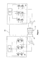
真空ポンプの駆動装置(ドライブ)の電気モータを、参照符号12が付されたブロックとして概略的に図示する。図示では、電気モータ12を示す当該ブロック内には、三相U,V,Wのモータ巻線が描かれている。
An electric motor of a vacuum pump drive is schematically illustrated as a block labeled 12. In the figure, three-phase U, V, and W motor windings are drawn in the block showing the
前記モータ巻線の一方の端部、すなわち、図1の左側の端部は、三相電気接続ライン14を介して第1の周波数変換器16に接続されている。前記モータ巻線の反対側の端部、すなわち、図1の右側の端部は、別の三相電気接続ラインを介して第2の周波数変換器18に接続されている。2つの周波数変換器16,18はそれぞれ、制御部20,22を有している。2つの周波数変換器16,18間にも2つの制御部20,22間にも、データリンクは存在していない。
One end of the motor winding, that is, the left end in FIG. 1 is connected to the
両方の周波数変換器16,18はそれぞれ、三つのモータ相U,V,Wのそれぞれに2個ずつ振り当てられた6個のトランジスタを有している。言い換えれば、2個の第1のトランジスタが第1のモータ相Uに電気的に接続されており、2個の第2のトランジスタが第2のモータ相Vに電気的に接続されており、2個の第3のトランジスタが第3のモータ相Wに電気的に接続されている。全てのトランジスタは、図示しない電源電圧網の供給電圧に電気的に接続されている。さらに、第1の周波数変換器16の全てのトランジスタは制御部20に接続されており、第2の周波数変換器18の全てのトランジスタは第2の制御部22に接続されている。
Both
第1の周波数変換器16と電気モータ12の間の接続ライン14には、測定装置24が配置されている。当該測定装置は、第1の周波数変換器16により生成されたモータ入力電圧を制御ライン14上で、かつ/あるいは、第1の周波数変換器16により生成されたモータ入力電流および/またはモータ入力電圧を電気接続ライン14上で測定する。
A
測定装置24は測定ライン26を介して制御部22へと、測定信号を第2の周波数変換器18の当該制御部22に送信するように接続されている。当該測定信号は、ライン14上での前記モータ入力電圧および/または前記モータ電流の周波数と大きさとについての情報を含む。
The
制御部22を有する周波数変換器18は、モータ入力電圧を測定装置24の前記測定信号に従って接続ライン14上に生成するように構成されている。これにより、第2の周波数変換器18と電気モータ12との間の接続ライン14上における、第2の周波数変換器18のモータ入力電圧が、第1の周波数変換器16と電気モータ12の間の接続ライン14上における、第1の周波数変換器16のモータ入力電圧と同期される。
The
2つの周波数変換器16,18間には、具体的に述べると当該2つの周波数変換器16,18の制御部20,22間には、直接の接続が存在していない。2つの周波数変換器16,18が、それぞれ、電気モータ12の前記モータ巻線の対応する端部に、そのモータ入力電圧を生成する。なお、第1の周波数変換器16は、第2の周波数変換器18の出力電圧についての情報を有していない。しかし、第2の周波数変換器18は、第1の周波数変換器16により生成されたモータ入力電圧についての情報を、測定装置24を介して有している。
More specifically, there is no direct connection between the
2つの周波数変換器16,18が真空ポンプを駆動するために、本発明に従った様式で少なくとも1つの電気モータ12に接続されて且つ当該少なくとも1つの電気モータ12によって制御されることにより、当該電気モータで生じる電力損失を低減できる。電気モータ12は、各周波数変換器16,18の所与の供給電圧で、従来の接続構成よりも高いモータ入力電圧が生成されるように接続されている。
The two
周波数変換器16は、電気モータを制御する従来の周波数変換器又はインバータであり、かつ、当該電気モータを制御又はフィードバック制御するための制御又はフィードバック制御構造を有している。
The
本発明の際立った特徴は、2つの制御部20,22間に、周波数変換器16,18の同期のためのデータリンクが存在していないという点である。存在し得るのは、他の目的の接続、例えばステータス検出、エラー処理等のための接続のみである。第1の周波数変換器16の回転磁界との第2の周波数変換器18の同期は、前記電気モータに接続された測定装置24によって可能となる。なお、測定装置24は、機械式の速度又は位置エンコーダではなく、電気モータ12における接続ライン14上での前記電圧および/または前記電流の実際の電気的値を測定する測定システムのみで形成されている。
The distinguishing feature of the present invention is that there is no data link for synchronization of the
2つの周波数変換器16,18の接続構成が本発明にかかる接続構成とされることで、同じ電源供給電圧で且つしかも標準的な部品(周波数変換器、測定装置24)を用いて、当該2つの周波数変換器16,18の出力電圧を最大57パーセント増加させることができる。これにより、同じ駆動電力でも、より高いモータ電圧を実現できるか又は電気モータ12の電力損失を低減できる、電気モータ12の設計が可能となる。
Since the connection configuration of the two
Claims (5)
前記電気モータ(12)に接続された第1の周波数変換器であって、当該電気モータ(12)を駆動するためのモータ入力電圧を電源供給電圧から生成するように構成された第1の周波数変換器(16)と、
前記モータを前記モータ入力電圧の周波数で駆動させるために、可変周波数モータ入力電圧を電源供給電圧から生成するように構成された少なくとも1つの第2の周波数変換器(18)と、
を備える、真空ポンプの駆動装置において、
前記第2の周波数変換器(18)には、前記第1の周波数変換器(16)によって生成された前記モータ入力電圧とこれに対応するモータ入力電流のいずれか一方または両方を測定するために設けられた測定装置(24)が、当該第2の周波数変換器(18)を前記第1の周波数変換器(16)と同期させるために、設けられていることを特徴とする、真空ポンプの駆動装置。 An electric motor (12) for driving the rotor of the vacuum pump;
A first frequency converter connected to the electric motor (12), the first frequency configured to generate a motor input voltage for driving the electric motor (12) from a power supply voltage A converter (16);
At least one second frequency converter (18) configured to generate a variable frequency motor input voltage from a power supply voltage to drive the motor at a frequency of the motor input voltage;
In a vacuum pump drive device comprising:
The second frequency converter (18) is used to measure either or both of the motor input voltage generated by the first frequency converter (16) and the corresponding motor input current. A vacuum pump, characterized in that a provided measuring device (24) is provided to synchronize the second frequency converter (18) with the first frequency converter (16). Drive device.
Applications Claiming Priority (3)
| Application Number | Priority Date | Filing Date | Title |
|---|---|---|---|
| DE202016000217.2U DE202016000217U1 (en) | 2016-01-13 | 2016-01-13 | Vacuum pump drive with two frequency converters |
| DE202016000217.2 | 2016-01-13 | ||
| PCT/EP2016/082569 WO2017121611A1 (en) | 2016-01-13 | 2016-12-23 | Vacuum pump drive having two frequency converters |
Publications (2)
| Publication Number | Publication Date |
|---|---|
| JP2019504601A true JP2019504601A (en) | 2019-02-14 |
| JP2019504601A5 JP2019504601A5 (en) | 2019-11-21 |
Family
ID=55358931
Family Applications (1)
| Application Number | Title | Priority Date | Filing Date |
|---|---|---|---|
| JP2018536889A Pending JP2019504601A (en) | 2016-01-13 | 2016-12-23 | Vacuum pump drive device with two frequency converters |
Country Status (8)
| Country | Link |
|---|---|
| US (1) | US20190028051A1 (en) |
| EP (1) | EP3403326A1 (en) |
| JP (1) | JP2019504601A (en) |
| KR (1) | KR20180104632A (en) |
| CN (1) | CN108684215A (en) |
| DE (1) | DE202016000217U1 (en) |
| SG (1) | SG11201805834XA (en) |
| WO (1) | WO2017121611A1 (en) |
Families Citing this family (2)
| Publication number | Priority date | Publication date | Assignee | Title |
|---|---|---|---|---|
| DE102016215786A1 (en) * | 2016-08-23 | 2018-03-01 | Robert Bosch Gmbh | Control device for an electric machine, electric drive system and method for controlling an electric machine |
| CN112725939A (en) * | 2020-12-31 | 2021-04-30 | 荣成碳纤维科技有限公司 | Double-frequency-conversion system of spinning solution delivery pump and control method |
Citations (3)
| Publication number | Priority date | Publication date | Assignee | Title |
|---|---|---|---|---|
| JP2006266248A (en) * | 2004-04-27 | 2006-10-05 | Osaka Vacuum Ltd | Vacuum pump |
| JP2009273348A (en) * | 2008-04-07 | 2009-11-19 | Mitsubishi Electric Corp | Motor drive device, refrigerating air conditioner and motor drive method |
| US20150035284A1 (en) * | 2013-08-02 | 2015-02-05 | General Electric Company | Power conversion system and method |
Family Cites Families (12)
| Publication number | Priority date | Publication date | Assignee | Title |
|---|---|---|---|---|
| GB630313A (en) * | 1946-07-18 | 1949-10-11 | Igranic Electric Co Ltd | Improvements in or relating to crane hoists driven by alternating current motors |
| JPS55111677A (en) * | 1979-02-20 | 1980-08-28 | Toshiba Corp | System for starting commutatorless motor |
| JPS5963999A (en) * | 1982-10-05 | 1984-04-11 | Meidensha Electric Mfg Co Ltd | Line followup operating method for motor group |
| US4849870A (en) * | 1988-01-25 | 1989-07-18 | Westinghouse Electric Corp. | Method of operating a-c drive with parallel connected d-c link power converters |
| DE8810279U1 (en) * | 1988-08-12 | 1988-10-06 | Siemens Ag, 1000 Berlin Und 8000 Muenchen, De | |
| US6051952A (en) * | 1997-11-06 | 2000-04-18 | Whirlpool Corporation | Electric motor speed and direction controller and method |
| WO2003073185A2 (en) * | 2002-02-28 | 2003-09-04 | Zetacon Corporation | Predictive control system and method |
| US7154237B2 (en) * | 2005-01-26 | 2006-12-26 | General Motors Corporation | Unified power control method of double-ended inverter drive systems for hybrid vehicles |
| DE102005026062A1 (en) * | 2005-06-07 | 2007-04-12 | Kühn, Walter, Prof. Dr. Ing. | Virtual rotary mass for use in railroad network, has self-commutated pulse width modulated inverter, which is operated by electronic circuit or software, where inverter supplies power from power station to three-phase power system |
| DE102006027716B3 (en) * | 2006-06-15 | 2008-01-24 | Lenze Drive Systems Gmbh | Control with inverters with low switching losses |
| US8353174B1 (en) * | 2008-10-03 | 2013-01-15 | Johnson Controls Technology Company | Control method for vapor compression system |
| US9093929B2 (en) * | 2012-12-17 | 2015-07-28 | Infineon Technologies Ag | Circuit arrangements and methods for operating an electrical machine |
-
2016
- 2016-01-13 DE DE202016000217.2U patent/DE202016000217U1/en not_active Expired - Lifetime
- 2016-12-23 EP EP16819936.2A patent/EP3403326A1/en not_active Withdrawn
- 2016-12-23 CN CN201680078963.0A patent/CN108684215A/en active Pending
- 2016-12-23 US US16/069,711 patent/US20190028051A1/en not_active Abandoned
- 2016-12-23 JP JP2018536889A patent/JP2019504601A/en active Pending
- 2016-12-23 KR KR1020187021591A patent/KR20180104632A/en unknown
- 2016-12-23 WO PCT/EP2016/082569 patent/WO2017121611A1/en active Application Filing
- 2016-12-23 SG SG11201805834XA patent/SG11201805834XA/en unknown
Patent Citations (3)
| Publication number | Priority date | Publication date | Assignee | Title |
|---|---|---|---|---|
| JP2006266248A (en) * | 2004-04-27 | 2006-10-05 | Osaka Vacuum Ltd | Vacuum pump |
| JP2009273348A (en) * | 2008-04-07 | 2009-11-19 | Mitsubishi Electric Corp | Motor drive device, refrigerating air conditioner and motor drive method |
| US20150035284A1 (en) * | 2013-08-02 | 2015-02-05 | General Electric Company | Power conversion system and method |
Also Published As
| Publication number | Publication date |
|---|---|
| KR20180104632A (en) | 2018-09-21 |
| WO2017121611A1 (en) | 2017-07-20 |
| DE202016000217U1 (en) | 2016-02-02 |
| EP3403326A1 (en) | 2018-11-21 |
| CN108684215A (en) | 2018-10-19 |
| SG11201805834XA (en) | 2018-08-30 |
| US20190028051A1 (en) | 2019-01-24 |
Similar Documents
| Publication | Publication Date | Title |
|---|---|---|
| US10734875B2 (en) | Rotary electric machine and rotary electric machine controller | |
| KR102272044B1 (en) | Apparatus and method of driving a plurality of permanent magnet synchronous motors using single inverter | |
| US9488497B2 (en) | Current control apparatus for three-phase rotary machine | |
| JP2019504601A (en) | Vacuum pump drive device with two frequency converters | |
| JPWO2019098217A1 (en) | Inverter control board | |
| JP2016510971A (en) | Electric motor | |
| JP2006345686A (en) | Method to operate electric rotating machine, and equipment to implement its method | |
| JP6767213B2 (en) | Inverter controller and motor drive system | |
| US20120249034A1 (en) | Position sensing circuit for brushless motors | |
| JP2011217574A (en) | Wind power generation system, and device and method for controlling rotating machine | |
| GB2520260A (en) | Method and apparatus for control of switched reluctance motors | |
| US9825568B2 (en) | Drive system | |
| JP3259441B2 (en) | Vector controller for induction motor | |
| JP2007215369A (en) | Motor driving controller | |
| US9876456B2 (en) | Brushless electrical machine | |
| KR20180090567A (en) | Motor driving apparatus and electric vehicle including the same | |
| US10498273B2 (en) | Externally modulated independent speed variable frequency generator | |
| Zhong | Speed-sensorless AC Ward Leonard drive systems | |
| JP5807832B1 (en) | Phase generator for induction motor | |
| CN213661485U (en) | Multi-axis servo driving system | |
| JP2005039891A (en) | Control unit of synchronous machine | |
| JP2017017953A (en) | Winding change system and linear motor | |
| CN101465617A (en) | Vector control technology and device for power unit cascade type high voltage frequency changer | |
| JP2014117132A (en) | Motor Drive device | |
| RU121670U1 (en) | SHORT-CLOSED ROTOR ASYNCHRONOUS ELECTRIC MOTORS |
Legal Events
| Date | Code | Title | Description |
|---|---|---|---|
| A521 | Request for written amendment filed |
Free format text: JAPANESE INTERMEDIATE CODE: A523 Effective date: 20191008 |
|
| A621 | Written request for application examination |
Free format text: JAPANESE INTERMEDIATE CODE: A621 Effective date: 20191008 |
|
| A977 | Report on retrieval |
Free format text: JAPANESE INTERMEDIATE CODE: A971007 Effective date: 20200916 |
|
| A131 | Notification of reasons for refusal |
Free format text: JAPANESE INTERMEDIATE CODE: A131 Effective date: 20201006 |
|
| A02 | Decision of refusal |
Free format text: JAPANESE INTERMEDIATE CODE: A02 Effective date: 20210427 |