JP2019219599A - Image formation device and image formation system - Google Patents
Image formation device and image formation system Download PDFInfo
- Publication number
- JP2019219599A JP2019219599A JP2018118525A JP2018118525A JP2019219599A JP 2019219599 A JP2019219599 A JP 2019219599A JP 2018118525 A JP2018118525 A JP 2018118525A JP 2018118525 A JP2018118525 A JP 2018118525A JP 2019219599 A JP2019219599 A JP 2019219599A
- Authority
- JP
- Japan
- Prior art keywords
- image forming
- cutting
- image
- unit
- sheet
- Prior art date
- Legal status (The legal status is an assumption and is not a legal conclusion. Google has not performed a legal analysis and makes no representation as to the accuracy of the status listed.)
- Pending
Links
Images


Classifications
-
- B—PERFORMING OPERATIONS; TRANSPORTING
- B42—BOOKBINDING; ALBUMS; FILES; SPECIAL PRINTED MATTER
- B42C—BOOKBINDING
- B42C19/00—Multi-step processes for making books
- B42C19/02—Multi-step processes for making books starting with single sheets
-
- G—PHYSICS
- G03—PHOTOGRAPHY; CINEMATOGRAPHY; ANALOGOUS TECHNIQUES USING WAVES OTHER THAN OPTICAL WAVES; ELECTROGRAPHY; HOLOGRAPHY
- G03G—ELECTROGRAPHY; ELECTROPHOTOGRAPHY; MAGNETOGRAPHY
- G03G15/00—Apparatus for electrographic processes using a charge pattern
- G03G15/65—Apparatus which relate to the handling of copy material
- G03G15/6517—Apparatus for continuous web copy material of plain paper, e.g. supply rolls; Roll holders therefor
- G03G15/6523—Cutting
-
- B—PERFORMING OPERATIONS; TRANSPORTING
- B42—BOOKBINDING; ALBUMS; FILES; SPECIAL PRINTED MATTER
- B42C—BOOKBINDING
- B42C9/00—Applying glue or adhesive peculiar to bookbinding
- B42C9/0006—Applying glue or adhesive peculiar to bookbinding by applying adhesive to a stack of sheets
- B42C9/0012—Applying glue or adhesive peculiar to bookbinding by applying adhesive to a stack of sheets with a roller
- B42C9/0018—Applying glue or adhesive peculiar to bookbinding by applying adhesive to a stack of sheets with a roller for binding stacks of sheets one at the time
- B42C9/0025—Applying glue or adhesive peculiar to bookbinding by applying adhesive to a stack of sheets with a roller for binding stacks of sheets one at the time and subsequently applying a cover
-
- B—PERFORMING OPERATIONS; TRANSPORTING
- B65—CONVEYING; PACKING; STORING; HANDLING THIN OR FILAMENTARY MATERIAL
- B65H—HANDLING THIN OR FILAMENTARY MATERIAL, e.g. SHEETS, WEBS, CABLES
- B65H35/00—Delivering articles from cutting or line-perforating machines; Article or web delivery apparatus incorporating cutting or line-perforating devices, e.g. adhesive tape dispensers
- B65H35/0006—Article or web delivery apparatus incorporating cutting or line-perforating devices
- B65H35/0073—Details
- B65H35/008—Arrangements or adaptations of cutting devices
- B65H35/0086—Arrangements or adaptations of cutting devices using movable cutting elements
-
- B—PERFORMING OPERATIONS; TRANSPORTING
- B65—CONVEYING; PACKING; STORING; HANDLING THIN OR FILAMENTARY MATERIAL
- B65H—HANDLING THIN OR FILAMENTARY MATERIAL, e.g. SHEETS, WEBS, CABLES
- B65H37/00—Article or web delivery apparatus incorporating devices for performing specified auxiliary operations
- B65H37/04—Article or web delivery apparatus incorporating devices for performing specified auxiliary operations for securing together articles or webs, e.g. by adhesive, stitching or stapling
-
- G—PHYSICS
- G03—PHOTOGRAPHY; CINEMATOGRAPHY; ANALOGOUS TECHNIQUES USING WAVES OTHER THAN OPTICAL WAVES; ELECTROGRAPHY; HOLOGRAPHY
- G03G—ELECTROGRAPHY; ELECTROPHOTOGRAPHY; MAGNETOGRAPHY
- G03G15/00—Apparatus for electrographic processes using a charge pattern
- G03G15/55—Self-diagnostics; Malfunction or lifetime display
- G03G15/553—Monitoring or warning means for exhaustion or lifetime end of consumables, e.g. indication of insufficient copy sheet quantity for a job
-
- B—PERFORMING OPERATIONS; TRANSPORTING
- B42—BOOKBINDING; ALBUMS; FILES; SPECIAL PRINTED MATTER
- B42C—BOOKBINDING
- B42C1/00—Collating or gathering sheets combined with processes for permanently attaching together sheets or signatures or for interposing inserts
- B42C1/12—Machines for both collating or gathering and permanently attaching together the sheets or signatures
Landscapes
- Physics & Mathematics (AREA)
- General Physics & Mathematics (AREA)
- Engineering & Computer Science (AREA)
- Textile Engineering (AREA)
- Folding Of Thin Sheet-Like Materials, Special Discharging Devices, And Others (AREA)
- Paper Feeding For Electrophotography (AREA)
Abstract
Description
本発明は、画像が形成された用紙を集積した用紙束の製本を行う製本装置を備えた画像形成装置に関する。 The present invention relates to an image forming apparatus provided with a bookbinding apparatus that performs bookbinding of a sheet bundle in which sheets on which images are formed are stacked.
複写機等の画像形成装置は、画像形成後の用紙に製本等の後処理を行う後処理装置が取り付け可能となっているものがある。製本は、例えば複数枚の用紙からなる用紙束の1辺に糊付けする糊付処理、糊付面以外の辺を断裁する断裁処理等の処理により行われる。用紙束は、糊付処理によりばらけないようにまとめられ、断裁処理により所定のサイズに形成される。画像形成装置は、断裁処理による断裁屑が所定量を超えた断裁屑満載状態を検知した場合に、画像形成処理を中断する(特許文献1)。これにより、断裁屑が溢れて散乱することが未然に防止される。画像形成装置は、断裁屑が満載になったことをユーザに報知し、断裁屑が除去されると画像形成処理を再開する。 2. Description of the Related Art Some image forming apparatuses such as copiers can be equipped with a post-processing apparatus that performs post-processing such as bookbinding on paper after image formation. Bookbinding is performed by, for example, a gluing process for gluing one side of a sheet bundle including a plurality of sheets, a cutting process for cutting a side other than the glued surface, and the like. The sheet bundle is put together by a gluing process so as not to be separated, and formed into a predetermined size by a cutting process. The image forming apparatus interrupts the image forming process when it detects a state in which the trimming waste due to the trimming process exceeds a predetermined amount. This prevents the cutting waste from overflowing and scattering. The image forming apparatus notifies the user that the cutting waste is full and restarts the image forming process when the cutting waste is removed.
画像形成装置は、断裁屑満載状態で画像形成処理を中断するために、ダウンタイムが発生して生産性が低下する。ユーザは、生産性の低下をできるだけ少なくするために、断裁屑が満載になった場合に、画像形成装置の報知に応じて直ちに断裁屑を除去して、断裁屑満載状態を解除する。しかしながら、ユーザが即座に断裁屑を除去しても、ダウンタイムの発生自体を抑止することは困難である。 Since the image forming apparatus interrupts the image forming process in a state where the cutting waste is full, downtime occurs and productivity is reduced. In order to minimize the decrease in productivity, when the cutting waste becomes full, the user immediately removes the cutting waste in response to the notification of the image forming apparatus, and releases the cutting waste full state. However, even if the user immediately removes the cutting waste, it is difficult to suppress the occurrence of downtime itself.
本発明は、上記の問題に鑑み、断裁屑が満載になったときのダウンタイムの発生を抑止する画像形成装置を提供することを主たる課題とする。 SUMMARY OF THE INVENTION In view of the above problems, it is a main object of the present invention to provide an image forming apparatus that suppresses occurrence of downtime when cutting waste becomes full.
本発明の画像形成装置は、用紙に画像を形成する画像形成手段と、複数枚の前記用紙で構成される用紙束を製本し、前記用紙束の所定の辺を断裁する製本手段と、前記断裁により生じた断裁屑を回収する屑箱と、前記屑箱に回収された前記断裁屑の満載状態を検知する検知手段と、画像を形成されるべき用紙の前記用紙束における順位が所定の順位以前であれば、前記検知手段が前記満載状態を検知することに応じた前記画像形成手段による画像形成処理の中断を行わず、前記順位が前記所定の順位以降であれば、前記検知手段が前記満載状態を検知することに応じて前記画像形成手段による画像形成処理を中断させる制御手段と、を備えることを特徴とする。 The image forming apparatus according to the present invention includes: an image forming unit that forms an image on a sheet; a bookbinding unit that binds a sheet bundle including a plurality of the sheets and cuts a predetermined side of the sheet bundle; A waste box that collects the cutting waste generated by the above, a detecting unit that detects a full load state of the cutting waste collected in the waste box, and the order of the sheets on which an image is to be formed in the sheet bundle is earlier than a predetermined order. If the detection means does not interrupt the image forming process by the image forming means in response to the detection of the full load state, and if the order is equal to or higher than the predetermined order, the detection means may be And control means for interrupting the image forming process by the image forming means in response to detecting the state.
本発明によれば、断裁屑が満載になったときのダウンタイムの発生を抑止することができる。 ADVANTAGE OF THE INVENTION According to this invention, generation | occurrence | production of the downtime when a cutting waste becomes full can be suppressed.
本発明の画像形成装置について、図面を参照しながら説明する。 An image forming apparatus according to the present invention will be described with reference to the drawings.
(全体構成)
図1は、本実施形態の画像形成装置を含んで構成される画像形成システムの構成図である。画像形成システムは、画像形成装置10と、後処理装置の例であるくるみ製本装置500及びフィニッシャ装置400と、を含む。画像形成装置10は、原稿から画像を読み取るイメージリーダ200と、読み取った画像を用紙に形成するプリンタ350と、操作表示装置600と、を備える。イメージリーダ200には、原稿を給送する原稿給送装置100が取り付けられる。
(overall structure)
FIG. 1 is a configuration diagram of an image forming system including the image forming apparatus of the present embodiment. The image forming system includes an
(画像形成装置)
画像形成装置10は、用紙に画像を形成する。くるみ製本装置500は、画像形成装置10から画像形成後の複数枚の用紙を受け取り、製本処理を行う。くるみ製本装置500は、受け取った用紙に製本を行わない場合に、受け取った用紙をそのままフィニッシャ装置400へ搬送する。フィニッシャ装置400は、くるみ製本装置500を介して画像形成装置10から受け取った用紙に、所定の後処理を行って排出する。フィニッシャ装置400は、用紙に対して束としての加工、例えば束排出処理、綴じ処理、折り処理、製本処理等の後処理を行う。
(Image forming device)
The
原稿給送装置100は、読み取られる面を上向きにして原稿が載置される原稿トレイ101及び排紙トレイ112を備える。原稿給送装置100は、原稿トレイ101に載置された原稿を先頭頁から順に給紙する。給紙された原稿は、湾曲したパスを介して、イメージリーダ200の読取位置が設けられるプラテンガラス102上を搬送され、排紙トレイ112へ排出される。
The
イメージリーダ200は、プラテンガラス102、スキャナユニット104、光学系、及びイメージセンサ109を備える。光学系は、ミラー106、107、及びレンズ108を含む。スキャナユニット104は、ランプ103及びミラー105を備える。プラテンガラス102に設けられる読取位置は、ランプ103が光を照射する位置であり、固定されている。スキャナユニット104は、原稿がプラテンガラス102の読取位置を通過する際にランプ103により光を原稿へ照射する。原稿による反射光は、ミラー105、106、107を介してレンズ108に導かれる。レンズ108は、反射光をイメージセンサ109の撮像面に結像する。イメージセンサ109は、結像した反射光を電気信号に変換することで原稿画像を表す画像データを生成する。イメージリーダ200は、このように原稿から画像を読み取る。イメージリーダ200は、生成した画像データをプリンタ350へ送信する。原稿の搬送方向に対して直交する方向が主走査方向、原稿の搬送方向が副走査方向となる。
The
以上のような構成のイメージリーダ200は、イメージセンサ109により、原稿が読取位置を通過する際に主走査方向に1ラインずつ原稿画像を読み取る。その間、原稿は、原稿給送装置100により搬送される。そのためにイメージリーダ200は、原稿の画像全体を読み取ることができる。この読取方法を第1読取方式という。
The
また、イメージリーダ200は、原稿給送装置100を使用しないで原稿を読み取ることもできる。この場合、ユーザがプラテンガラス102上に原稿を載置する。イメージリーダ200は、スキャナユニット104を副走査方向に移動させながら原稿を読み取る。この読取方式を第2読取方式という。
Further, the
プリンタ350は、用紙に画像を形成するための感光ドラム111、露光器110、ポリゴンミラー119、現像器113、転写部116、及び定着器117を備える。露光器110は、イメージリーダ200から取得した画像データに基づいて変調したレーザ光を出力する。該レーザ光は、ポリゴンミラー119により走査されながら感光ドラム111上に照射される。感光ドラム111は、走査されたレーザ光に応じた静電潜像が形成される。なお露光器110は、第2読取方式では、正立画像(鏡像ではない画像)が形成されるようにレーザ光を出力する。感光ドラム111上の静電潜像は、現像器113から供給される現像剤によって現像剤像として可視化される。
The
プリンタ350は、画像が形成される用紙を収納する上カセット114及び下カセット115を備える。用紙は、上カセット114或いは下カセット115から搬送経路へ給紙される。図示の例では、上カセット114と下カセット115とには、異なるサイズの用紙が収納される。印刷ジョブに応じたサイズの用紙が給紙される。上カセット114には、搬送経路へ用紙を給紙するためのピックアップローラ127が設けられる。下カセット115には、搬送経路へ用紙を給紙するためのピックアップローラ128が設けられる。搬送経路には、給紙された用紙を搬送するために、給紙ローラ129、130、縦パスローラ136、及びレジストローラ126が設けられる。給紙ローラ129、130及び縦パスローラ136は、給紙された用紙をレジストローラ126まで搬送する。用紙の搬送方向でレジストローラ126の上流側には、レジ前センサ132が設けられる。レジ前センサ132が用紙の先端を検知し、用紙がレジストローラ126まで到達すると、用紙の搬送が一旦停止する。
The
プリンタ350は、画像が形成される用紙が載置される手差しトレイ125を備える。手差しトレイ125には、用紙をレジストローラ126まで搬送するためのピックアップローラ137が設けられる。手差しトレイ125は、用紙の有無を検知するための手差しトレイ用紙検知センサ133を備える。手差しトレイ125から給紙された用紙も、レジストローラ126まで到達すると搬送が一旦停止する。
The
レジストローラ126は、停止の際に用紙の先端部にループを形成させることで、斜行補正を行う。ループは、回転が停止したレジストローラ126に対してシートの先端が突き当たり、その後、シートが所定量搬送されることで形成される。レジストローラ126は、斜行補正後に、露光器110によるレーザ光の照射開始と同期したタイミングで用紙の搬送を再開する。用紙は、感光ドラム111と転写部116との間に搬送される。転写部116は、感光ドラム111に形成された現像剤像を用紙に転写する。
The
現像剤像が転写された用紙は、転写部116から定着器117へ搬送される。定着器117は、用紙を加熱及び加圧することで、用紙に現像剤像を定着させる。定着器117を通過した用紙は、搬送経路に設けられるフラッパ121及び排出ローラ118を介してプリンタ350から画像形成装置10の外部へ排出される。本実施形態では、画像形成装置10の外部へ排出された用紙は、くるみ製本装置500へ搬送される。
The sheet on which the developer image has been transferred is transported from the
画像形成面が下向きになる状態(フェイスダウン)で用紙を排出する場合、プリンタ350は、フラッパ121を切り替えて、定着器117を通過した用紙を反転パス122へ一旦搬送する。プリンタ350は、用紙の後端がフラッパ121を通過した後に、用紙をスイッチバックさせて排出ローラ118により機外へ排出する。このようにフェイスダウンで用紙を排出する形態を反転排紙と呼ぶ。反転排紙は、複数ページの画像を先頭ページから順に形成する際に行われる、反転排紙により、排出後の用紙の順序が昇順になる。反転排紙は、例えば原稿給送装置100を使用して読み取った画像を形成するとき、又は外部のコンピュータから取得した画像データに応じた画像を形成するとき等に行われる。
When the paper is discharged with the image forming surface facing downward (face down), the
なお、OHP用紙等の硬い用紙に画像を形成する場合、該用紙は、反転パス122へ搬送されることなく、画像形成面を上向きにした状態(フェイスアップ)で排出ローラ118により排出される。用紙両面へ画像形成を行う場合、プリンタ350は、用紙を反転パス122へ搬送した後に両面搬送パス124へ搬送する。用紙は、両面搬送パス124を介してレジストローラ126へ再度給紙される。これは両面循環制御とよばれる。両面に画像が形成された用紙は、反転パス122に導かれることなく排出ローラ118により排出される。
When an image is formed on hard paper such as OHP paper, the paper is discharged by the
(制御系統)
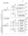
図2は、画像形成装置10及びくるみ製本装置500の動作を制御する制御系統の説明図である。
(Control system)
FIG. 2 is an explanatory diagram of a control system that controls operations of the
画像形成装置10は、CPU(Central Processing Unit)801、ROM(Read Only Memory)802、及びRAM(Random Access Memory)803を備える。CPU801は、ROM802に格納されたコンピュータプログラムを、RAM803を作業領域に用いて実行することで、画像形成装置10の動作を制御する。RAM803は、一部の記憶領域が電源オフ時にもデータが消去されないバックアップRAMとなっている。CPU801には、画像処理部805、画像メモリ806、入出力ポート804、操作表示装置600、及び通信インタフェース(IF)807が接続される。
The
画像処理部805は、イメージリーダ200或いは外部装置から取得した画像データに所定の画像処理を行い、形成する画像の位置、濃度、色合い等の補正を行う。画像メモリ806は、補正後の画像データを格納する。CPU801は、補正後の画像データに基づいて露光器110の発光制御を行う。入出力ポート804は、モータ、クラッチ等の各種負荷や、用紙の位置を検知するセンサ等が接続される。CPU801は、入出力ポート804を介して順次入出力の制御を行い、画像形成処理を実行する。例えばCPU801は、センサの検知結果に応じて用紙の搬送位置を検知し、検知した用紙の搬送位置に応じて負荷の制御を行うことで、用紙の搬送処理や画像形成処理を行う。
The image processing unit 805 performs predetermined image processing on image data acquired from the
操作表示装置600は、ユーザによる指示を受け付けるための入力装置及びユーザへ各種情報を提供する出力装置を備えるユーザインタフェースである。図3は、操作表示装置600の例示図である。操作表示装置600は、入力装置としてスタートキー602、ストップキー603、テンキー604〜612、614、IDキー613、クリアキー615、及びリセットキー616等を備える。スタートキー602は、画像形成動作を開始するための入力キーである。ストップキー603は、画像形成動作を中断するための入力キーである。テンキー604〜612、614は、部数設定等を行うための入力キーである。操作表示装置600は、出力装置としてタッチパネルが形成された表示部620を備える。表示部620は、画面上にソフトウェアキーを表示可能である。
The
通信IF807は、くるみ製本装置500及びフィニッシャ装置400との間の通信制御を行う。CPU801は、通信IF807を介してくるみ製本装置500と通信可能である。
The communication IF 807 controls communication between the
くるみ製本装置500は、CPU901、ROM902、及びRAM903を備える。CPU901は、ROM902に格納されたコンピュータプログラムを、RAM903を作業領域に用いて実行することで、くるみ製本装置500の動作を制御する。RAM903は、一部の記憶領域が電源オフ時にもデータが消去されないバックアップRAMとなっている。CPU901には、用紙積載部904、糊付部905、接着部906、断裁部907、製本排出部908、及び通信IF909が接続される。
The
通信IF909は、画像形成装置10及びフィニッシャ装置400との間の通信制御を行う。CPU901は、通信IF909を介して画像形成装置10と通信可能である。CPU901は、CPU801の指示に応じて、用紙積載部904、糊付部905、接着部906、断裁部907、及び製本排出部908の動作を制御する。
The communication IF 909 controls communication between the
(くるみ製本装置)
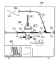
図4は、くるみ製本装置500の構成図である。上記の通り、くるみ製本装置500は、用紙積載部904、糊付部905、接着部906、断裁部907、及び製本排出部908を備える。用紙積載部904は、製本モードで画像形成装置10から排出された複数枚の用紙Pを積載して用紙束540を作成する。糊付部905は、用紙束540に対して糊付けを行う。接着部906は、糊付けされた用紙束に表紙を接着する。これにより冊子570が作成される。断裁部907は、冊子570の端面の整合を行うために、冊子570の糊付面以外の3方向の辺を断裁する。3方向が断裁されることで製本が完了する。製本排出部908は、完成した冊子570を排出する。製本処理の一連の流れについて説明する。
(Case binding equipment)
FIG. 4 is a configuration diagram of the
用紙積載部904は、用紙を積載する用紙積載トレイ520を備える。用紙積載トレイ520には、製本モードで画像形成装置10から排出された複数枚の用紙Pが積載される。積載された複数枚の用紙Pが用紙束540となる。くるみ製本装置500は、画像形成装置10から排出された用紙Pを用紙積載部904へ搬送するための搬送ローラ505、506、507、508、及び積載部排出ローラ509を備える。用紙Pは、搬送ローラ505、506、507、508、及び積載部排出ローラ509により搬送されて、用紙積載トレイ520に排紙され、整合されて用紙束540となる。
The
用紙積載トレイ520に1つの用紙束540を構成するすべての用紙が積載されると、用紙束540は、不図示の把持部材により糊付部905へ移動する。糊付部905は、糊容器525、糊塗布ローラ524、及び糊塗布ローラ制御モータ522を備える。糊付部905は、用紙束540の下側面に糊を塗布する。接着部906は、糊付けされた用紙束540に、画像形成装置10から排出された表紙を接着して冊子570を作成する。接着部906は、冊子570をトリムグリッパ512へ受け渡す。冊子570は、トリムグリッパ512により断裁部907に搬送される。断裁部907は、カッター制御モータ527及びカッター528を備える。断裁部907は、カッター制御モータ527によりカッター528を水平方向へ移動させ、冊子570の断裁を行う。断裁により生じる断裁屑が落下する位置には断裁屑受け箱533が設けられる。そのために断裁屑は、断裁屑受け箱533の中に落下する。断裁屑受け箱533の断裁屑は、一連の断裁動作が終了すると断裁屑箱532に回収される。断裁部907による断裁が終了した冊子570は、断裁部907から製本排出部908へ搬送されて排出される。
When all the sheets constituting one
製本モード時には、くるみ製本装置500は、以上のような一連の製本動作を行う。くるみ製本装置500は、製本モードの他に製本を行わずにフィニッシャ装置400へ用紙Pを搬送する排出モードでも動作することができる。製本モード、排出モード等の動作モードは、例えば操作表示装置600を用いてユーザにより設定される。画像形成装置10のCPU801は、動作モードをくるみ製本装置500のCPU901へ送信することで、くるみ製本装置500の動作モードを設定する。
In the bookbinding mode, the
用紙の搬送方向で搬送ローラ505の下流側には、切換フラッパ521が設けられる。切換フラッパ521は、搬送ローラ505により搬送される用紙Pを用紙積載トレイ520とフィニッシャ装置400とのいずれかに選択的に導く。製本モード以外の動作モードでは、切換フラッパ521は、用紙Pをフィニッシャ装置400側へ導く。この場合、用紙Pは、搬送ローラ505、510、511、513、514、及び排紙ローラ515によってフィニッシャ装置400へ搬送される。
A switching
製本モード時のくるみ製本装置500内の用紙Pの搬送順について説明する。図5、図6、図7、図8は、製本モード時のくるみ製本装置500内の用紙Pの搬送順の説明図である。
The transport order of the paper P in the
図5は、用紙Pが画像形成装置10から用紙積載部904へ搬送される場合を示す。くるみ製本装置500は、画像形成装置10から排出された用紙Pを搬送ローラ505により受け取り、搬送パス501へ導く。用紙Pが用紙束の中紙である場合、搬送ローラ505により受け取った用紙Pは、切換フラッパ521により搬送パス502へ導かれる。搬送パス502では、用紙Pは、搬送ローラ506、507、508、及び積載部排出ローラ509により用紙積載部904へ搬送される。用紙Pは、積載部排出ローラ509から用紙積載トレイ520へ排出される。中紙となる用紙Pのすべてが用紙積載トレイ520へ排出されると、図6に示すように、中紙の用紙束540が糊付けグリッパ523によりグリップされる。グリップされた用紙束540は、用紙積載部904から糊付部905の上方へ束の状態で移動する。
FIG. 5 illustrates a case where the sheet P is transported from the
糊付部905の上方へ移動した中紙の用紙束540は、図7に示すように糊付けグリッパ523にグリップされた状態で垂直な方向に回転される。回転により、用紙束540の背表紙となる側面が糊付部905に対向して位置する。その後、糊容器525及び糊塗布ローラ524が用紙束540に沿って移動することで、用紙束540の端部(背表紙となる側面)に糊付けが行われる。
The
この間、表紙Pcが画像形成装置10から排出され、くるみ製本装置500へ取り込まれる。搬送ローラ505により受け取った表紙Pcは、切換フラッパ521により搬送パス501から搬送パス503へと導かれて、搬送ローラ510、511、513により搬送される。搬送パス503は、搬送ローラ513の下流側に図示しないセンサが設けられる。図8に示すように、表紙Pcは、先端部が該センサに検知されてから所定距離搬送された後、搬送が停止される。表紙Pcは、搬送パス503で停止した時点で、後端が切換フラッパ521を抜ける大きさとなっている。
During this time, the cover Pc is discharged from the
連続して用紙束540を作成する場合、表紙Pcが搬送パス503にある間であっても、切換フラッパ521は、用紙Pを搬送パス502へ搬送するように切り換えられる。これによりくるみ製本装置500は、次の用紙束540に対する中紙を画像形成装置10から受け取り、搬送パス501から搬送パス502を経由して用紙積載トレイ520へ搬送することができる。
When the
(糊付部)
図9は、糊付部905の構成説明図である。図10は、糊付部905の動作説明図である。糊付部905は、上記の通り、用紙束540をグリップする糊付けグリッパ523、糊を貯蔵する糊容器525、用紙束に糊を塗布する糊塗布ローラ524、及び糊塗布ローラ制御モータ522を備える。糊容器525、糊塗布ローラ524、及び糊塗布ローラ制御モータ522は、糊付けユニット580を構成する。
(Glued part)
FIG. 9 is an explanatory diagram of the configuration of the
糊塗布ローラ524は、糊容器525に浸漬されており、糊塗布ローラ制御モータ522により常に回転している状態にある。用紙束540は、糊付けグリッパ523によって直立状態にグリップされる。糊付けユニット580は、直立状態の用紙束540の下側面の長手方向に、用紙束540に並行するように移動する。
The
糊の塗布は糊付けユニット580の往復動により行われる。図10に示すように、糊付けユニット580は、くるみ製本装置500の背面側の初期位置から移動を開始し、くるみ製本装置500の前面の所定の位置で停止する。このとき、糊付けユニット580による用紙束540の下側面への糊付けは行われない。用紙束540への糊付けは、糊付けユニット580がくるみ製本装置500の前面から背面へ移動する際に行われる。糊付けユニット580は、所定の位置で停止して用紙束540の下側面に糊塗布ローラ524が当接する位置まで上昇する。この状態で糊付けユニット580がくるみ製本装置500の前面から背面へ移動することで、糊塗布ローラ524により用紙束540の下側面に糊が塗布される。
The glue is applied by reciprocating the
(接着部)
図11、図12は、接着部906の説明図である。
図11(a)は接着部906の断面を表している。接着部906は、搬送ガイド560、561、加圧部材563、折り部材562、564を備える。搬送ガイド560、561は、画像形成装置10から供給された表紙Pcを搬送パス503を介して受け取り、所定の位置に停止させる。加圧部材563は、表紙Pcを用紙束540の糊塗布面に圧接する。折り部材562、564は、表紙Pcにより用紙束540をくるむ。
(Adhesive part)
11 and 12 are explanatory diagrams of the
FIG. 11A shows a cross section of the
図11(a)では、糊付部905による用紙束540への糊付け動作終了後、糊付けグリッパ523が用紙束540をグリップしたまま糊付部905から下降してくる。用紙束540は、搬送ガイド560、561によって水平方向に用意された表紙Pcに糊塗布面を接着させる。図11(b)では、用紙束540の糊塗布面の接着後に、糊付けグリッパ523がさらに下降する。これにより、加圧部材563上に載置された表紙Pcの接着部が用紙束540の糊塗布面に圧接される。なお、用紙束540の下降による糊塗布面の圧接を行う前に、搬送ガイド560上部及び搬送ガイド561上部は、上方に退避する。これにより搬送ガイド560上部及び搬送ガイド561上部による用紙束540への干渉が防止される。
In FIG. 11A, after the gluing operation on the
表紙Pcを用紙束540に接着した後に、折り部材562、564、搬送ガイド560下部、及び搬送ガイド561下部が、加圧部材563の斜め上方向に上昇する(図11(c))。つまり折り部材562、564、搬送ガイド560下部、及び搬送ガイド561下部が、破線位置から実線位置まで図11(c)の矢印方向に移動する。折り部材562、564が斜め上方向へ上昇することで、表紙Pcは、上方に押し上げられて糊塗布面の側縁部から湾曲され、用紙束540をくるむ。くるみ処理は、このように行われる。
After the cover Pc is adhered to the
表紙Pcのくるみ処理終了後、折り部材562、564、搬送ガイド560下部、搬送ガイド561下部は、破線位置から実線位置まで退避する(図11(d))。同時に加圧部材563は、水平方向に移動する。加圧部材563の水平移動により、表紙Pcによりくるまれた用紙束540である冊子570の下降可能な空間が確保される。冊子570は、下端がトリムグリッパ512のトリムユニット受け渡しローラ565、566に当接する位置まで、糊付けグリッパ523により下降する(図11(e))。
After the wrapping process of the cover Pc is completed, the
冊子570を下降させた糊付けグリッパ523は、冊子570のグリップを解除する(図12(a))。同時に、冊子570は、トリムユニット受け渡しローラ565、566によって下方向に搬送される。下方向に搬送される冊子570は、所定の位置で停止する(図12(b))。トリムグリッパ512は、停止した冊子570をグリップする。冊子570は、トリムグリッパ512により断裁部907の位置まで下降される(図12(c))。この際、水平方向に移動していた加圧部材563は表紙Pcの接着部の圧接を行える位置に戻される。
The
(断裁部)
図13は、断裁部907の説明図である。断裁部907は、カッター528を有し、トリムグリッパ512により移動した冊子570の端部を断裁する。断裁部907は、トリムグリッパ512、カッター528、及び断裁屑受け箱533が連動して断裁を行う。
(Cutting department)
FIG. 13 is an explanatory diagram of the
冊子570に対する断裁動作は、小口、及び天地の3辺に対して行われる。冊子570は、接着部906から背表紙端部を下側にして移動される。そのために冊子570は、断裁の際に回転させられる。断裁部907は、図13(a)に示すようにトリムグリッパ512を90度回転させ、冊子570の向きを90度回転させた後に地辺の断裁を行う。次に、断裁部907は、トリムグリッパ512を同一方向に90度回転させて小口の断裁を行う。更に、断裁部907は、トリムグリッパ512を90度回転させて天辺の断裁を行う。以上により、冊子570の背表紙部以外の端部の断裁が終了する。
The cutting operation for the
断裁動作時に断裁部907は、図13(b)に示すように、カッター528による断裁を行う前に、冊子570の下方の断裁屑が落下する位置に断裁屑受け箱533を移動する。その後、断裁部907は、カッター528を冊子570に対して出没させて、一辺に対する断裁を行う。図13(c)に示すように、断裁屑は冊子570の下方で待ち受けている断裁屑受け箱533に収納される。断裁後、図13(d)に示すように、カッター528は逆方向に駆動され退避位置へと移動する。断裁屑受け箱533も退避位置へと移動する。
During the cutting operation, the
図14は、断裁時の冊子570の状態の説明図である。断裁後の冊子570は、背表紙部を下方にして製本排出部908へ搬送される。そのために断裁完了後に、トリムグリッパ512は、冊子を更に90度回転させる。
FIG. 14 is an explanatory diagram of the state of the
断裁屑受け箱533は、断裁動作を行っていないときの退避位置と、断裁動作中の屑受け位置との間を移動する。断裁屑受け箱533の退避位置は、断裁屑箱532の上方である。図15は、断裁屑の排出動作の説明図である。図示するように、断裁屑受け箱533の底板部は開放可能な構成である。断裁屑受け箱533は、退避位置に移動すると底板部が開放され、内部の断裁屑を断裁屑箱532へ放出する。
The cutting
断裁屑箱532は、断裁屑満載検知センサ535を備える。断裁屑満載検知センサ535は、断裁屑箱532内の断裁屑が満載になったことを検知する。断裁屑が満載になると、画像形成装置10は、画像形成動作を中断し、断裁屑を取り除く旨のメッセージを操作表示装置600に表示する。画像形成装置10は、断裁屑満載検知センサ535が断裁屑の満載が解除されたことを検知することで、画像形成動作を再開する。
The cutting
(製本排出部)
図16は、製本排出部908の説明図である。
図16(a)は、製本排出部908の構成を示す。製本排出部908は、トリムグリッパ512によりグリップされた冊子570の搬送を行う製本排出部入口ローラ516及び搬送された冊子570を一時積載する製本積載板529を備える。製本排出部908は、更に、冊子570を縦方向に支持する製本支持板530、積載安定板534、及び製本支持板530を水平方向に移動させる排出搬送ベルト531を備える。
(Bookbinding discharge section)
FIG. 16 is an explanatory diagram of the
FIG. 16A illustrates a configuration of the
断裁処理終了後の冊子570は、トリムグリッパ512によって断裁部907の直下に設けられる製本排出部入口ローラ516へ受け渡される。トリムグリッパ512は、冊子570の支持を解除して製本排出部入口ローラ516へ受け渡すと、接着部906の所定の位置へ移動する。製本排出部入口ローラ516は、冊子570を製本積載板529へ搬送する。このとき製本積載板529は右方向に倒れている。冊子570は製本排出部入口ローラ516によって製本積載板529に積載される。
The
冊子570が積載されると、製本積載板529は、起立して冊子570を縦にする。冊子570は、製本支持板530と積載安定板534とにより立てた状態で支持される(図16(b))。その後、製本支持板530は、排出搬送ベルト531によって移動し、次の冊子571が搬送されてきた場合の排出スペースを確保する(図16(c))。製本積載板529が図16(a)、16(b)のように再度動作することで、冊子570の隣に次の冊子571が立てた状態で収納される(図16(d))。
When the
(用紙の受渡順位判断)
図17は、くるみ製本装置500により製本される冊子の模式図である。この冊子は、5枚の中紙P1〜P5と、1枚の表紙P6により構成される。本実施形態では、上述したように中紙が先、表紙が後の順で、画像形成装置10からくるみ製本装置500へ用紙が受け渡される。そのために5枚の中紙P1〜P5と1枚の表紙P6との場合、P1→P2→P3→P4→P5→P6の順に画像形成装置10からくるみ製本装置500へ用紙が受け渡されることになる。画像形成装置10のCPU801は、中紙の枚数に基づいて、画像形成装置10からくるみ製本装置500へ受け渡される各用紙の用紙束内における順位(受渡順位)を判断可能である。
(Determining the delivery order of paper)
FIG. 17 is a schematic diagram of a booklet bound by the
(画像形成処理の実行判断)
画像形成装置10は、断裁屑満載検知センサ535による検知結果と画像形成装置10からくるみ製本装置500への用紙の受渡順位に応じて、画像形成処理の実行可否を判断する。図18は、画像形成処理の実行可否を判断する処理を表すフローチャートである。この処理は、用紙毎に、画像形成開始時に行われる。
(Execution determination of image forming processing)
The
画像形成装置10のCPU801は、図17で説明した通り、画像形成前の用紙に対して用紙束内における受渡順位を判断する(S791)。ここでCPU801は、該用紙が用紙束内における最終順位、即ち該用紙が表紙であるか否かを判断する。受渡順位が最終順位以前である場合(S791:N)、CPU801は、用紙が中紙であると判断する。この場合、CPU801は、画像形成装置10による該用紙への画像形成処理の実行が可能であると判断する(S794)。
As described with reference to FIG. 17, the
順位が最終順位である場合(S791:Y)、CPU801は、断裁屑満載検知センサ535が断裁屑満載検知状態であるか否かを判断する(S792)。CPU801は、断裁屑満載検知センサ535の検知結果をくるみ製本装置500から取得して、この判断を行う。断裁屑満載検知状態ではない場合(S792:N)、CPU801は、画像形成装置10による該用紙への画像形成処理の実行が可能であると判断する(S794)。断裁屑満載検知状態である場合(S792:Y)、CPU801は、画像形成装置10による該用紙への画像形成処理を中断すると判断する(S793)。即ち、CPU801は、受渡順位が最終順位の用紙に対して画像形成を行う前に、断裁屑満載検知センサ535が断裁屑箱532内に断裁屑が満載であるか否かを判断し、最終順位の用紙でなければ、断裁屑箱532が満載であるか否かの判断を行わない。CPU801は、断裁屑箱532が満載であることが検知されていれば、画像形成処理を中断する。
If the ranking is the final ranking (S791: Y), the
図19は、製本ジョブ時の処理流れ図である。図19では、3束の用紙束に対してくるみ製本を行って3冊の冊子を作成する場合の画像形成装置10及びくるみ製本装置500の処理の流れを示す。
FIG. 19 is a processing flow chart at the time of a bookbinding job. FIG. 19 shows the flow of processing performed by the
まず、画像形成装置10は1束目の用紙束の中紙への画像形成を行い(S711)、続いて1束目の用紙束の表紙への画像形成を行う(S712)。くるみ製本装置500の用紙積載部904は、1束目の用紙束の積載処理を行う(S721)。そして、1束目の用紙束の積載処理が終了すると、糊付部905は、1束目の用紙束の糊付処理を行う(S731)。その後、接着部906は1束目の用紙束の接着処理を行う(S741)。断裁部907は1束目の用紙束の断裁処理を行う(S751)。製本排出部908は1束目の用紙束による1冊目の冊子の排出処理を行う(S761)。
First, the
糊付部905による1束目の用紙束の糊付処理(S731)に並行して、画像形成装置10は2束目の用紙束の中紙への画像形成を行う(S713)。用紙積載部904は2束目の用紙束の積載処理を行う(S722)。断裁部907による1束目の用紙束の断裁処理(S751)に並行して、画像形成装置10は2束目の用紙束の表紙への画像形成を行う(S714)。糊付部905は、2束目の用紙束の糊付処理を行う(S732)。その後、接着部906は2束目の用紙束の接着処理を行う(S742)。断裁部907は2束目の用紙束の断裁処理を行う(S752)。製本排出部908は2束目の用紙束による2冊目の冊子の排出処理を行う(S762)。
In parallel with the pasting process of the first bundle of sheets by the pasting unit 905 (S731), the
2束目の用紙束の表紙の画像形成が終了すると、画像形成装置10は3束目の用紙束の中紙への画像形成を行う(S715)。用紙積載部904は3束目の用紙束の積載処理を行う(S723)。断裁部907による2束目の用紙束の断裁処理(S752)に並行して、画像形成装置10は3束目の用紙束の表紙の画像形成を行う(S716)。糊付部905は3束目の用紙束の糊付処理を行う(S733)。その後、接着部906は3束目の用紙束の接着処理を行う(S743)。断裁部907は3束目の用紙束の断裁処理を行う(S753)。製本排出部908は3束目の用紙束による3冊目の冊子の排出処理を行う(S763)。
When the image formation of the cover of the second sheet bundle is completed, the
計3束の各用紙に対する画像形成処理の実行可否を判断する処理を、図18及び図19を用いて説明する。図19では、断裁屑満載検知センサ535は、1束目の用紙束の断裁処理(S751)の後(t1)に断裁屑が満載であることを検知した状態となり(S772)、その直後に(t2)ユーザにより屑が捨てられ、満載状態が解除される(S773)。
The process of determining whether or not to execute the image forming process on each of the three bundles of sheets will be described with reference to FIGS. In FIG. 19, the cutting waste full
CPU801は、図19のS711の処理時に、画像形成装置10からくるみ製本装置500へ受け渡される用紙の受渡順位を判断する(S791)。中紙は、画像形成装置10からくるみ製本装置500へ受け渡されるが、最終順位の用紙ではない(S791:N)。そのためにCPU801は、断裁屑満載検知状態に基づく画像形成処理の中断を判断せず、画像形成処理を実行すると決定する(S794)。
The
一方、図19のS712の処理時には、表紙が画像形成装置10からくるみ製本装置500へ受け渡されるが最終順位であるために(S791:Y)、CPU801は、断裁屑満載検知状態を判断する(S792)。このとき、図19のS771に示すように、断裁屑満載検知センサ535は断裁屑満載検知状態ではない(S792:N)。そのためにCPU801は、画像形成処理を実行すると判断する(S794)。
CPU801は、S713及びS714の処理時にも、2束目の用紙束の中紙及び表紙となる用紙について、1束目と同様な判断を行う。
On the other hand, at the time of the processing of S712 in FIG. 19, the cover is delivered from the
The
次に、図19のS715の処理時に3束目の用紙束の中紙への画像形成中に断裁屑満載検知センサ535により断裁屑満載検知状態になったことが検知されている。しかし、中紙は、画像形成装置10からくるみ製本装置500へ受け渡されるが、最終順位ではない(S791:N)ため、CPU801は、断裁屑満載検知状態に基づく画像形成処理の中断を行うことなく、画像形成処理を続行する(S794)。
Next, during the processing of S715 in FIG. 19, it is detected by the cutting dust full
仮に、用紙束内における受渡順位に拘わらず、断裁屑満載検知センサ535の検知結果だけで画像形成処理の中断を判断する場合は、中紙の画像形成中に断裁屑が満載状態になると画像形成処理が中断される。例えば3束目の用紙束の中紙の画像形成中(S715)に断裁屑が満載状態となると(t1)、3束目の用紙束の中紙の画像形成中に画像形成処理が中断されてしまう。ユーザが即座に断裁屑を取り除いて断裁屑満載検知センサ535が満載状態を検知しなくなった(t2)としても、すでに開始されている中断処理により不要なダウンタイムが発生する。
If it is determined that the image forming process is to be interrupted only by the detection result of the cutting waste full
これに対して本実施形態では、用紙束内における受渡順位を判断し、最終順位以外の用紙に対しては、断裁屑満載検知状態に基づく画像形成処理の中断を判断しない。そのために断裁屑満載時にユーザが即座に断裁屑を取り除いて断裁屑満載状態が解除された場合、画像形成の中断処理が開始されていないために、画像形成処理を中断することなく印刷ジョブを継続することが可能となる。その結果、不要なダウンタイムの発生を防止することができる。 On the other hand, in the present embodiment, the delivery order in the sheet bundle is determined, and the interruption of the image forming process based on the cutting waste full detection state is not determined for sheets other than the final order. Therefore, when the user removes the trimmings immediately when the trimmings are full and the trimmings full state is released, the print job is continued without interrupting the image forming process because the image forming interrupting process has not been started. It is possible to do. As a result, unnecessary downtime can be prevented from occurring.
以上のように画像形成装置10は、画像形成を行う用紙が中紙であれば、断裁屑満載検知センサ535が断裁屑箱532の満載状態を検知しても画像形成処理を続行する。その後、表紙への画像形成開始前までに断裁屑満載検知センサ535が断裁屑箱532の満載状態を検知しなくなっていれば、画像形成装置10は、表紙への画像形成を続行する。断裁屑満載検知センサ535が断裁屑箱532の満載状態を検知したままであれば、画像形成装置10は、表紙への画像形成を中断する。なお、くるみ製本装置500が断裁を行っていない製本動作中に断裁屑箱532に回収された断裁屑は、ユーザにより除去可能である。
As described above, if the sheet on which the image is to be formed is a middle sheet, the image forming process is continued even if the cutting waste full
以上説明したように本実施形態の画像形成装置10は、画像形成を行うすべての用紙に対して、画像形成処理の実行可否を、断裁屑の満載状態と画像形成を行う用紙の用紙束内の受渡順位と、に基づいて判断する。画像形成装置10は、所定の受渡順位以降の用紙に画像形成を行うときに、断裁屑が満載であれば画像形成処理を中断する。そのためにユーザが断裁屑の満載時に即座に対応の処理を行って満載状態を解除した場合、不要な画像形成処理の中断が行われない。その結果、印刷ジョブが継続され、ダウンタイムの発生が未然に防止される。なお、以上の説明では、画像形成装置10とくるみ製本装置500とをそれぞれ独立した別装置として説明したが、これらは一体に構成されていてもよい。
As described above, the
Claims (9)
複数枚の前記用紙で構成される用紙束を製本し、前記用紙束の所定の辺を断裁する製本手段と、
前記断裁により生じた断裁屑を回収する屑箱と、
前記屑箱に回収された前記断裁屑の満載状態を検知する検知手段と、
画像を形成されるべき用紙の前記用紙束における順位が所定の順位以前であれば、前記検知手段が前記満載状態を検知することに応じた前記画像形成手段による画像形成処理の中断を行わず、前記順位が前記所定の順位以降であれば、前記検知手段が前記満載状態を検知することに応じて前記画像形成手段による画像形成処理を中断させる制御手段と、を備えることを特徴とする、
画像形成装置。 Image forming means for forming an image on paper;
Bookbinding means for binding a sheet bundle composed of a plurality of the sheets, and cutting a predetermined side of the sheet bundle;
A waste box for collecting cutting waste generated by the cutting,
Detecting means for detecting a full load state of the cutting waste collected in the waste box,
If the order of the sheets on which an image is to be formed in the sheet bundle is earlier than a predetermined order, the image forming process is not interrupted by the image forming unit according to the detection unit detecting the full load state, Control means for interrupting the image forming process by the image forming means in response to the detection means detecting the full load state if the rank is equal to or later than the predetermined rank.
Image forming device.
請求項1記載の画像形成装置。 If the order of the sheets on which an image is to be formed in the sheet bundle is not the final order, the control unit interrupts the image forming process by the image forming unit in response to the detection unit detecting the full load state. Is not performed,
The image forming apparatus according to claim 1.
請求項1又は2記載の画像形成装置。 When the order in the sheet bundle is equal to or later than the predetermined order, the control unit interrupts the image forming process by the image forming unit in response to the detection unit detecting the full load state, If the full load state is not detected, the image forming process is continued by the image forming unit,
The image forming apparatus according to claim 1.
前記制御手段は、画像を形成される前記用紙が前記中紙であれば、前記検知手段が前記満載状態を検知しても前記画像形成手段による画像形成処理を続行させ、その後、前記表紙への画像形成開始前までに前記検知手段が前記満載状態を検知しなくなっていれば、前記表紙への画像形成を続行させ、前記検知手段が前記満載状態を検知したままであれば、前記表紙への画像形成を中断させることを特徴とする、
請求項1〜3のいずれか1項記載の画像形成装置。 The image forming unit, after forming an image on a sheet serving as a middle sheet of the sheet bundle, forms an image on a sheet serving as a cover,
If the sheet on which an image is formed is the middle sheet, the control unit causes the image forming unit to continue the image forming process even if the detecting unit detects the full load state. If the detecting means has not detected the full-load state before the start of image formation, the image forming on the cover is continued.If the detecting means keeps detecting the full-load state, the detection on the cover is continued. Characterized by interrupting image formation,
The image forming apparatus according to claim 1.
請求項4記載の画像形成装置。 The bookbinding unit performs bookbinding by wrapping the sheet bundle with the cover.
The image forming apparatus according to claim 4.
前記画像形成手段から受け取った複数枚の用紙を積載して前記用紙束を作成する積載手段と、
前記用紙束の前記所定の辺を断裁する断裁手段と、
前記断裁により生じた前記断裁屑が落下する位置に設けられ、前記断裁手段による断裁動作が終了すると前記屑箱に該断裁屑を放出する屑受け箱と、
断裁後に前記用紙束を排出する排出手段と、を備えることを特徴とする、
請求項1〜6のいずれか1項記載の画像形成装置。 The bookbinding means,
Loading means for loading the plurality of sheets received from the image forming means to create the sheet bundle,
Cutting means for cutting the predetermined side of the sheet bundle;
A dust receiving box that is provided at a position where the cutting waste generated by the cutting falls and that releases the cutting waste to the waste box when the cutting operation by the cutting unit is completed;
Discharging means for discharging the sheet bundle after cutting,
The image forming apparatus according to claim 1.
前記用紙束の所定の辺に糊付けを行う糊付手段と、
前記糊付けされた前記用紙束に表紙を接着する接着手段と、を備え、
前記断裁手段は、前記表紙が接着された前記用紙束の前記糊付けが行われていない3辺を断裁し、
前記屑受け箱は、前記断裁手段による3辺への断裁動作が終了すると前記屑箱に該断裁屑を放出することを特徴とする、
請求項7記載の画像形成装置。 The bookbinding means,
Gluing means for gluing a predetermined side of the sheet bundle,
Bonding means for bonding a cover to the glued sheet bundle,
The cutting unit cuts three sides of the sheet bundle to which the cover is adhered, where the gluing is not performed,
The dust receiving box discharges the cutting waste to the waste box when the cutting operation to three sides by the cutting means is completed,
The image forming apparatus according to claim 7.
用紙に画像を形成する画像形成手段と、
画像を形成されるべき用紙の前記用紙束における順位が所定の順位以前であれば、前記検知手段が前記満載状態を検知することに応じた前記画像形成手段による画像形成処理の中断を行わず、前記順位が前記所定の順に以降であれば、前記検知手段が前記満載状態を検知することに応じて前記画像形成手段による画像形成処理を中断させる制御手段と、を備えることを特徴とする、
画像形成システム。 A bookbinding unit that binds a sheet bundle obtained by bundling a plurality of sheets and cuts a predetermined side of the sheet bundle, a waste box that collects cutting waste generated by the cutting, and a waste box that is collected in the waste box. A detection unit for detecting a full load state of the cutting waste, and an image forming apparatus connected to a bookbinding apparatus including:
Image forming means for forming an image on paper;
If the order of the sheets on which an image is to be formed in the sheet bundle is earlier than a predetermined order, the image forming process is not interrupted by the image forming unit according to the detection unit detecting the full load state, Control means for interrupting image forming processing by the image forming means in response to the detection means detecting the full load state, if the order is later than the predetermined order.
Image forming system.
Priority Applications (2)
| Application Number | Priority Date | Filing Date | Title |
|---|---|---|---|
| JP2018118525A JP2019219599A (en) | 2018-06-22 | 2018-06-22 | Image formation device and image formation system |
| US16/442,675 US10926568B2 (en) | 2018-06-22 | 2019-06-17 | Image forming apparatus |
Applications Claiming Priority (1)
| Application Number | Priority Date | Filing Date | Title |
|---|---|---|---|
| JP2018118525A JP2019219599A (en) | 2018-06-22 | 2018-06-22 | Image formation device and image formation system |
Publications (2)
| Publication Number | Publication Date |
|---|---|
| JP2019219599A true JP2019219599A (en) | 2019-12-26 |
| JP2019219599A5 JP2019219599A5 (en) | 2021-08-26 |
Family
ID=68981315
Family Applications (1)
| Application Number | Title | Priority Date | Filing Date |
|---|---|---|---|
| JP2018118525A Pending JP2019219599A (en) | 2018-06-22 | 2018-06-22 | Image formation device and image formation system |
Country Status (2)
| Country | Link |
|---|---|
| US (1) | US10926568B2 (en) |
| JP (1) | JP2019219599A (en) |
Citations (5)
| Publication number | Priority date | Publication date | Assignee | Title |
|---|---|---|---|---|
| JP2003292229A (en) * | 2002-04-03 | 2003-10-15 | Sharp Corp | Discharging mechanism and processing device for sheet |
| JP2006199428A (en) * | 2005-01-20 | 2006-08-03 | Konica Minolta Business Technologies Inc | Post-processing device and image forming device |
| JP2008068352A (en) * | 2006-09-13 | 2008-03-27 | Canon Finetech Inc | Sheet cutter, bookbinding apparatus having the same, and image formation device |
| JP2009040523A (en) * | 2007-08-06 | 2009-02-26 | Canon Inc | Image forming system and image forming apparatus |
| JP2011212827A (en) * | 2010-04-02 | 2011-10-27 | Duplo Corp | Sheet processing device |
Family Cites Families (8)
| Publication number | Priority date | Publication date | Assignee | Title |
|---|---|---|---|---|
| JP3336203B2 (en) * | 1995-09-25 | 2002-10-21 | 株式会社リコー | Sheet processing apparatus and sheet processing method |
| JP2003182868A (en) * | 2001-12-13 | 2003-07-03 | Nisca Corp | Paper feeding device and image forming device |
| US20030215275A1 (en) * | 2002-03-12 | 2003-11-20 | Masahiro Tamura | Sheet finisher with a punching unit |
| US7387059B2 (en) * | 2003-11-28 | 2008-06-17 | Nisca Corporation | Sheet punching apparatus, sheet finishing apparatus, and image forming apparatus |
| JP4446880B2 (en) * | 2004-03-17 | 2010-04-07 | 株式会社リコー | Paper processing apparatus and image forming system |
| JP2007313571A (en) * | 2006-05-23 | 2007-12-06 | Konica Minolta Business Technologies Inc | Sheet cutting device and image formation system |
| JP5361351B2 (en) | 2007-12-07 | 2013-12-04 | キヤノン株式会社 | Sheet processing apparatus, image forming apparatus, and image forming system |
| JP2017213643A (en) * | 2016-05-31 | 2017-12-07 | キヤノン株式会社 | Cutting device and image formation device |
-
2018
- 2018-06-22 JP JP2018118525A patent/JP2019219599A/en active Pending
-
2019
- 2019-06-17 US US16/442,675 patent/US10926568B2/en active Active
Patent Citations (5)
| Publication number | Priority date | Publication date | Assignee | Title |
|---|---|---|---|---|
| JP2003292229A (en) * | 2002-04-03 | 2003-10-15 | Sharp Corp | Discharging mechanism and processing device for sheet |
| JP2006199428A (en) * | 2005-01-20 | 2006-08-03 | Konica Minolta Business Technologies Inc | Post-processing device and image forming device |
| JP2008068352A (en) * | 2006-09-13 | 2008-03-27 | Canon Finetech Inc | Sheet cutter, bookbinding apparatus having the same, and image formation device |
| JP2009040523A (en) * | 2007-08-06 | 2009-02-26 | Canon Inc | Image forming system and image forming apparatus |
| JP2011212827A (en) * | 2010-04-02 | 2011-10-27 | Duplo Corp | Sheet processing device |
Also Published As
| Publication number | Publication date |
|---|---|
| US10926568B2 (en) | 2021-02-23 |
| US20190389237A1 (en) | 2019-12-26 |
Similar Documents
| Publication | Publication Date | Title |
|---|---|---|
| JP4747138B2 (en) | Image forming system and image forming apparatus | |
| JP4702026B2 (en) | Image forming apparatus and method of controlling image forming apparatus | |
| JP4878231B2 (en) | Sheet processing device | |
| JP5464790B2 (en) | Bookbinding system and bookbinding apparatus | |
| US8260162B2 (en) | Image forming apparatus and control method for the same | |
| JP5925157B2 (en) | Sheet stacking apparatus, sheet processing apparatus, and image forming apparatus | |
| US7590380B2 (en) | Bookbinding apparatus and bookbinding method | |
| JP4054822B2 (en) | Sheet conveying system, control method therefor, control program, and storage medium | |
| JP4878232B2 (en) | Sheet processing apparatus and image forming system | |
| JP4123204B2 (en) | Paper post-processing apparatus and control method thereof | |
| JP2019116334A (en) | Sheet discharge device and image forming device | |
| JP2019219599A (en) | Image formation device and image formation system | |
| JP2005204148A (en) | Image forming method and apparatus | |
| US20080303200A1 (en) | Image forming system | |
| JP2005079613A (en) | Image forming apparatus | |
| JP2019085250A (en) | Paper loading device and image formation system | |
| JP4285359B2 (en) | Image forming system and conveyance control method in image forming system | |
| JP3581612B2 (en) | Image forming device | |
| JP4944929B2 (en) | Post-processing apparatus and post-processing system | |
| JP7222191B2 (en) | Image forming apparatus and program | |
| JP5578933B2 (en) | Sheet processing apparatus and image forming system | |
| JP2016188119A (en) | Sheet post-processing device and image formation system having the same | |
| JP4259451B2 (en) | Image forming system and post-processing apparatus | |
| JP2008094024A (en) | Image forming system | |
| JPH10186959A (en) | Image forming device |
Legal Events
| Date | Code | Title | Description |
|---|---|---|---|
| A521 | Request for written amendment filed |
Free format text: JAPANESE INTERMEDIATE CODE: A523 Effective date: 20210618 |
|
| A621 | Written request for application examination |
Free format text: JAPANESE INTERMEDIATE CODE: A621 Effective date: 20210618 |
|
| A977 | Report on retrieval |
Free format text: JAPANESE INTERMEDIATE CODE: A971007 Effective date: 20220311 |
|
| A131 | Notification of reasons for refusal |
Free format text: JAPANESE INTERMEDIATE CODE: A131 Effective date: 20220322 |
|
| A521 | Request for written amendment filed |
Free format text: JAPANESE INTERMEDIATE CODE: A523 Effective date: 20220519 |
|
| A02 | Decision of refusal |
Free format text: JAPANESE INTERMEDIATE CODE: A02 Effective date: 20220705 |