JP2019211083A - Two-stage transmission for electric automobile - Google Patents
Two-stage transmission for electric automobile Download PDFInfo
- Publication number
- JP2019211083A JP2019211083A JP2019113255A JP2019113255A JP2019211083A JP 2019211083 A JP2019211083 A JP 2019211083A JP 2019113255 A JP2019113255 A JP 2019113255A JP 2019113255 A JP2019113255 A JP 2019113255A JP 2019211083 A JP2019211083 A JP 2019211083A
- Authority
- JP
- Japan
- Prior art keywords
- clutch
- armature
- electromagnetic coil
- engaged
- rotation
- Prior art date
- Legal status (The legal status is an assumption and is not a legal conclusion. Google has not performed a legal analysis and makes no representation as to the accuracy of the status listed.)
- Pending
Links
- 230000005540 biological transmission Effects 0.000 title claims abstract description 68
- 230000007246 mechanism Effects 0.000 claims abstract description 22
- 230000033001 locomotion Effects 0.000 claims description 24
- 229920001971 elastomer Polymers 0.000 abstract 1
- 239000000806 elastomer Substances 0.000 abstract 1
- 230000009467 reduction Effects 0.000 description 42
- 230000002093 peripheral effect Effects 0.000 description 10
- 238000010586 diagram Methods 0.000 description 6
- 230000004907 flux Effects 0.000 description 6
- 230000035939 shock Effects 0.000 description 6
- 239000003638 chemical reducing agent Substances 0.000 description 5
- 230000006872 improvement Effects 0.000 description 3
- 238000000034 method Methods 0.000 description 3
- 238000009434 installation Methods 0.000 description 2
- 238000000926 separation method Methods 0.000 description 2
- 230000008901 benefit Effects 0.000 description 1
- 239000000969 carrier Substances 0.000 description 1
- 230000006866 deterioration Effects 0.000 description 1
- 230000000694 effects Effects 0.000 description 1
- 230000005484 gravity Effects 0.000 description 1
- 230000001050 lubricating effect Effects 0.000 description 1
- 239000010687 lubricating oil Substances 0.000 description 1
- 239000000463 material Substances 0.000 description 1
- 230000008569 process Effects 0.000 description 1
Images


Classifications
-
- F—MECHANICAL ENGINEERING; LIGHTING; HEATING; WEAPONS; BLASTING
- F16—ENGINEERING ELEMENTS AND UNITS; GENERAL MEASURES FOR PRODUCING AND MAINTAINING EFFECTIVE FUNCTIONING OF MACHINES OR INSTALLATIONS; THERMAL INSULATION IN GENERAL
- F16D—COUPLINGS FOR TRANSMITTING ROTATION; CLUTCHES; BRAKES
- F16D27/00—Magnetically- or electrically- actuated clutches; Control or electric circuits therefor
- F16D27/10—Magnetically- or electrically- actuated clutches; Control or electric circuits therefor with an electromagnet not rotating with a clutching member, i.e. without collecting rings
- F16D27/108—Magnetically- or electrically- actuated clutches; Control or electric circuits therefor with an electromagnet not rotating with a clutching member, i.e. without collecting rings with axially movable clutching members
- F16D27/112—Magnetically- or electrically- actuated clutches; Control or electric circuits therefor with an electromagnet not rotating with a clutching member, i.e. without collecting rings with axially movable clutching members with flat friction surfaces, e.g. discs
- F16D27/115—Magnetically- or electrically- actuated clutches; Control or electric circuits therefor with an electromagnet not rotating with a clutching member, i.e. without collecting rings with axially movable clutching members with flat friction surfaces, e.g. discs with more than two discs, e.g. multiple lamellae
-
- B—PERFORMING OPERATIONS; TRANSPORTING
- B60—VEHICLES IN GENERAL
- B60L—PROPULSION OF ELECTRICALLY-PROPELLED VEHICLES; SUPPLYING ELECTRIC POWER FOR AUXILIARY EQUIPMENT OF ELECTRICALLY-PROPELLED VEHICLES; ELECTRODYNAMIC BRAKE SYSTEMS FOR VEHICLES IN GENERAL; MAGNETIC SUSPENSION OR LEVITATION FOR VEHICLES; MONITORING OPERATING VARIABLES OF ELECTRICALLY-PROPELLED VEHICLES; ELECTRIC SAFETY DEVICES FOR ELECTRICALLY-PROPELLED VEHICLES
- B60L15/00—Methods, circuits, or devices for controlling the traction-motor speed of electrically-propelled vehicles
- B60L15/20—Methods, circuits, or devices for controlling the traction-motor speed of electrically-propelled vehicles for control of the vehicle or its driving motor to achieve a desired performance, e.g. speed, torque, programmed variation of speed
- B60L15/2054—Methods, circuits, or devices for controlling the traction-motor speed of electrically-propelled vehicles for control of the vehicle or its driving motor to achieve a desired performance, e.g. speed, torque, programmed variation of speed by controlling transmissions or clutches
-
- F—MECHANICAL ENGINEERING; LIGHTING; HEATING; WEAPONS; BLASTING
- F16—ENGINEERING ELEMENTS AND UNITS; GENERAL MEASURES FOR PRODUCING AND MAINTAINING EFFECTIVE FUNCTIONING OF MACHINES OR INSTALLATIONS; THERMAL INSULATION IN GENERAL
- F16D—COUPLINGS FOR TRANSMITTING ROTATION; CLUTCHES; BRAKES
- F16D13/00—Friction clutches
- F16D13/22—Friction clutches with axially-movable clutching members
- F16D13/38—Friction clutches with axially-movable clutching members with flat clutching surfaces, e.g. discs
- F16D13/52—Clutches with multiple lamellae ; Clutches in which three or more axially moveable members are fixed alternately to the shafts to be coupled and are pressed from one side towards an axially-located member
-
- F—MECHANICAL ENGINEERING; LIGHTING; HEATING; WEAPONS; BLASTING
- F16—ENGINEERING ELEMENTS AND UNITS; GENERAL MEASURES FOR PRODUCING AND MAINTAINING EFFECTIVE FUNCTIONING OF MACHINES OR INSTALLATIONS; THERMAL INSULATION IN GENERAL
- F16D—COUPLINGS FOR TRANSMITTING ROTATION; CLUTCHES; BRAKES
- F16D27/00—Magnetically- or electrically- actuated clutches; Control or electric circuits therefor
- F16D27/10—Magnetically- or electrically- actuated clutches; Control or electric circuits therefor with an electromagnet not rotating with a clutching member, i.e. without collecting rings
- F16D27/108—Magnetically- or electrically- actuated clutches; Control or electric circuits therefor with an electromagnet not rotating with a clutching member, i.e. without collecting rings with axially movable clutching members
- F16D27/112—Magnetically- or electrically- actuated clutches; Control or electric circuits therefor with an electromagnet not rotating with a clutching member, i.e. without collecting rings with axially movable clutching members with flat friction surfaces, e.g. discs
-
- F—MECHANICAL ENGINEERING; LIGHTING; HEATING; WEAPONS; BLASTING
- F16—ENGINEERING ELEMENTS AND UNITS; GENERAL MEASURES FOR PRODUCING AND MAINTAINING EFFECTIVE FUNCTIONING OF MACHINES OR INSTALLATIONS; THERMAL INSULATION IN GENERAL
- F16D—COUPLINGS FOR TRANSMITTING ROTATION; CLUTCHES; BRAKES
- F16D27/00—Magnetically- or electrically- actuated clutches; Control or electric circuits therefor
- F16D27/10—Magnetically- or electrically- actuated clutches; Control or electric circuits therefor with an electromagnet not rotating with a clutching member, i.e. without collecting rings
- F16D27/118—Magnetically- or electrically- actuated clutches; Control or electric circuits therefor with an electromagnet not rotating with a clutching member, i.e. without collecting rings with interengaging jaws or gear teeth
-
- F—MECHANICAL ENGINEERING; LIGHTING; HEATING; WEAPONS; BLASTING
- F16—ENGINEERING ELEMENTS AND UNITS; GENERAL MEASURES FOR PRODUCING AND MAINTAINING EFFECTIVE FUNCTIONING OF MACHINES OR INSTALLATIONS; THERMAL INSULATION IN GENERAL
- F16H—GEARING
- F16H3/00—Toothed gearings for conveying rotary motion with variable gear ratio or for reversing rotary motion
- F16H3/44—Toothed gearings for conveying rotary motion with variable gear ratio or for reversing rotary motion using gears having orbital motion
- F16H3/46—Gearings having only two central gears, connected by orbital gears
- F16H3/48—Gearings having only two central gears, connected by orbital gears with single orbital gears or pairs of rigidly-connected orbital gears
- F16H3/52—Gearings having only two central gears, connected by orbital gears with single orbital gears or pairs of rigidly-connected orbital gears comprising orbital spur gears
- F16H3/54—Gearings having only two central gears, connected by orbital gears with single orbital gears or pairs of rigidly-connected orbital gears comprising orbital spur gears one of the central gears being internally toothed and the other externally toothed
-
- F—MECHANICAL ENGINEERING; LIGHTING; HEATING; WEAPONS; BLASTING
- F16—ENGINEERING ELEMENTS AND UNITS; GENERAL MEASURES FOR PRODUCING AND MAINTAINING EFFECTIVE FUNCTIONING OF MACHINES OR INSTALLATIONS; THERMAL INSULATION IN GENERAL
- F16H—GEARING
- F16H61/00—Control functions within control units of change-speed- or reversing-gearings for conveying rotary motion ; Control of exclusively fluid gearing, friction gearing, gearings with endless flexible members or other particular types of gearing
- F16H61/04—Smoothing ratio shift
-
- H—ELECTRICITY
- H02—GENERATION; CONVERSION OR DISTRIBUTION OF ELECTRIC POWER
- H02K—DYNAMO-ELECTRIC MACHINES
- H02K7/00—Arrangements for handling mechanical energy structurally associated with dynamo-electric machines, e.g. structural association with mechanical driving motors or auxiliary dynamo-electric machines
- H02K7/10—Structural association with clutches, brakes, gears, pulleys or mechanical starters
- H02K7/12—Structural association with clutches, brakes, gears, pulleys or mechanical starters with auxiliary limited movement of stators, rotors or core parts, e.g. rotors axially movable for the purpose of clutching or braking
-
- B—PERFORMING OPERATIONS; TRANSPORTING
- B60—VEHICLES IN GENERAL
- B60L—PROPULSION OF ELECTRICALLY-PROPELLED VEHICLES; SUPPLYING ELECTRIC POWER FOR AUXILIARY EQUIPMENT OF ELECTRICALLY-PROPELLED VEHICLES; ELECTRODYNAMIC BRAKE SYSTEMS FOR VEHICLES IN GENERAL; MAGNETIC SUSPENSION OR LEVITATION FOR VEHICLES; MONITORING OPERATING VARIABLES OF ELECTRICALLY-PROPELLED VEHICLES; ELECTRIC SAFETY DEVICES FOR ELECTRICALLY-PROPELLED VEHICLES
- B60L15/00—Methods, circuits, or devices for controlling the traction-motor speed of electrically-propelled vehicles
-
- B—PERFORMING OPERATIONS; TRANSPORTING
- B60—VEHICLES IN GENERAL
- B60L—PROPULSION OF ELECTRICALLY-PROPELLED VEHICLES; SUPPLYING ELECTRIC POWER FOR AUXILIARY EQUIPMENT OF ELECTRICALLY-PROPELLED VEHICLES; ELECTRODYNAMIC BRAKE SYSTEMS FOR VEHICLES IN GENERAL; MAGNETIC SUSPENSION OR LEVITATION FOR VEHICLES; MONITORING OPERATING VARIABLES OF ELECTRICALLY-PROPELLED VEHICLES; ELECTRIC SAFETY DEVICES FOR ELECTRICALLY-PROPELLED VEHICLES
- B60L2240/00—Control parameters of input or output; Target parameters
- B60L2240/40—Drive Train control parameters
- B60L2240/42—Drive Train control parameters related to electric machines
- B60L2240/421—Speed
-
- B—PERFORMING OPERATIONS; TRANSPORTING
- B60—VEHICLES IN GENERAL
- B60L—PROPULSION OF ELECTRICALLY-PROPELLED VEHICLES; SUPPLYING ELECTRIC POWER FOR AUXILIARY EQUIPMENT OF ELECTRICALLY-PROPELLED VEHICLES; ELECTRODYNAMIC BRAKE SYSTEMS FOR VEHICLES IN GENERAL; MAGNETIC SUSPENSION OR LEVITATION FOR VEHICLES; MONITORING OPERATING VARIABLES OF ELECTRICALLY-PROPELLED VEHICLES; ELECTRIC SAFETY DEVICES FOR ELECTRICALLY-PROPELLED VEHICLES
- B60L2240/00—Control parameters of input or output; Target parameters
- B60L2240/40—Drive Train control parameters
- B60L2240/42—Drive Train control parameters related to electric machines
- B60L2240/423—Torque
-
- F—MECHANICAL ENGINEERING; LIGHTING; HEATING; WEAPONS; BLASTING
- F16—ENGINEERING ELEMENTS AND UNITS; GENERAL MEASURES FOR PRODUCING AND MAINTAINING EFFECTIVE FUNCTIONING OF MACHINES OR INSTALLATIONS; THERMAL INSULATION IN GENERAL
- F16D—COUPLINGS FOR TRANSMITTING ROTATION; CLUTCHES; BRAKES
- F16D11/00—Clutches in which the members have interengaging parts
- F16D11/02—Clutches in which the members have interengaging parts disengaged by a contact of a part mounted on the clutch with a stationarily-mounted member
- F16D11/04—Clutches in which the members have interengaging parts disengaged by a contact of a part mounted on the clutch with a stationarily-mounted member with clutching members movable only axially
-
- F—MECHANICAL ENGINEERING; LIGHTING; HEATING; WEAPONS; BLASTING
- F16—ENGINEERING ELEMENTS AND UNITS; GENERAL MEASURES FOR PRODUCING AND MAINTAINING EFFECTIVE FUNCTIONING OF MACHINES OR INSTALLATIONS; THERMAL INSULATION IN GENERAL
- F16D—COUPLINGS FOR TRANSMITTING ROTATION; CLUTCHES; BRAKES
- F16D11/00—Clutches in which the members have interengaging parts
- F16D11/14—Clutches in which the members have interengaging parts with clutching members movable only axially
-
- F—MECHANICAL ENGINEERING; LIGHTING; HEATING; WEAPONS; BLASTING
- F16—ENGINEERING ELEMENTS AND UNITS; GENERAL MEASURES FOR PRODUCING AND MAINTAINING EFFECTIVE FUNCTIONING OF MACHINES OR INSTALLATIONS; THERMAL INSULATION IN GENERAL
- F16D—COUPLINGS FOR TRANSMITTING ROTATION; CLUTCHES; BRAKES
- F16D23/00—Details of mechanically-actuated clutches not specific for one distinct type
- F16D23/12—Mechanical clutch-actuating mechanisms arranged outside the clutch as such
- F16D2023/123—Clutch actuation by cams, ramps or ball-screw mechanisms
-
- F—MECHANICAL ENGINEERING; LIGHTING; HEATING; WEAPONS; BLASTING
- F16—ENGINEERING ELEMENTS AND UNITS; GENERAL MEASURES FOR PRODUCING AND MAINTAINING EFFECTIVE FUNCTIONING OF MACHINES OR INSTALLATIONS; THERMAL INSULATION IN GENERAL
- F16D—COUPLINGS FOR TRANSMITTING ROTATION; CLUTCHES; BRAKES
- F16D27/00—Magnetically- or electrically- actuated clutches; Control or electric circuits therefor
- F16D27/004—Magnetically- or electrically- actuated clutches; Control or electric circuits therefor with permanent magnets combined with electromagnets
-
- F—MECHANICAL ENGINEERING; LIGHTING; HEATING; WEAPONS; BLASTING
- F16—ENGINEERING ELEMENTS AND UNITS; GENERAL MEASURES FOR PRODUCING AND MAINTAINING EFFECTIVE FUNCTIONING OF MACHINES OR INSTALLATIONS; THERMAL INSULATION IN GENERAL
- F16D—COUPLINGS FOR TRANSMITTING ROTATION; CLUTCHES; BRAKES
- F16D27/00—Magnetically- or electrically- actuated clutches; Control or electric circuits therefor
- F16D27/12—Clutch systems with a plurality of electro-magnetically-actuated clutches
-
- F—MECHANICAL ENGINEERING; LIGHTING; HEATING; WEAPONS; BLASTING
- F16—ENGINEERING ELEMENTS AND UNITS; GENERAL MEASURES FOR PRODUCING AND MAINTAINING EFFECTIVE FUNCTIONING OF MACHINES OR INSTALLATIONS; THERMAL INSULATION IN GENERAL
- F16H—GEARING
- F16H61/00—Control functions within control units of change-speed- or reversing-gearings for conveying rotary motion ; Control of exclusively fluid gearing, friction gearing, gearings with endless flexible members or other particular types of gearing
- F16H61/04—Smoothing ratio shift
- F16H2061/0425—Bridging torque interruption
- F16H2061/0429—Bridging torque interruption by torque supply with a clutch in parallel torque path
-
- F—MECHANICAL ENGINEERING; LIGHTING; HEATING; WEAPONS; BLASTING
- F16—ENGINEERING ELEMENTS AND UNITS; GENERAL MEASURES FOR PRODUCING AND MAINTAINING EFFECTIVE FUNCTIONING OF MACHINES OR INSTALLATIONS; THERMAL INSULATION IN GENERAL
- F16H—GEARING
- F16H61/00—Control functions within control units of change-speed- or reversing-gearings for conveying rotary motion ; Control of exclusively fluid gearing, friction gearing, gearings with endless flexible members or other particular types of gearing
- F16H61/04—Smoothing ratio shift
- F16H2061/0474—Smoothing ratio shift by smoothing engagement or release of positive clutches; Methods or means for shock free engagement of dog clutches
-
- F—MECHANICAL ENGINEERING; LIGHTING; HEATING; WEAPONS; BLASTING
- F16—ENGINEERING ELEMENTS AND UNITS; GENERAL MEASURES FOR PRODUCING AND MAINTAINING EFFECTIVE FUNCTIONING OF MACHINES OR INSTALLATIONS; THERMAL INSULATION IN GENERAL
- F16H—GEARING
- F16H2200/00—Transmissions for multiple ratios
- F16H2200/003—Transmissions for multiple ratios characterised by the number of forward speeds
- F16H2200/0034—Transmissions for multiple ratios characterised by the number of forward speeds the gear ratios comprising two forward speeds
-
- F—MECHANICAL ENGINEERING; LIGHTING; HEATING; WEAPONS; BLASTING
- F16—ENGINEERING ELEMENTS AND UNITS; GENERAL MEASURES FOR PRODUCING AND MAINTAINING EFFECTIVE FUNCTIONING OF MACHINES OR INSTALLATIONS; THERMAL INSULATION IN GENERAL
- F16H—GEARING
- F16H2200/00—Transmissions for multiple ratios
- F16H2200/20—Transmissions using gears with orbital motion
- F16H2200/2002—Transmissions using gears with orbital motion characterised by the number of sets of orbital gears
- F16H2200/2005—Transmissions using gears with orbital motion characterised by the number of sets of orbital gears with one sets of orbital gears
-
- F—MECHANICAL ENGINEERING; LIGHTING; HEATING; WEAPONS; BLASTING
- F16—ENGINEERING ELEMENTS AND UNITS; GENERAL MEASURES FOR PRODUCING AND MAINTAINING EFFECTIVE FUNCTIONING OF MACHINES OR INSTALLATIONS; THERMAL INSULATION IN GENERAL
- F16H—GEARING
- F16H2200/00—Transmissions for multiple ratios
- F16H2200/20—Transmissions using gears with orbital motion
- F16H2200/203—Transmissions using gears with orbital motion characterised by the engaging friction means not of the freewheel type, e.g. friction clutches or brakes
- F16H2200/2035—Transmissions using gears with orbital motion characterised by the engaging friction means not of the freewheel type, e.g. friction clutches or brakes with two engaging means
-
- F—MECHANICAL ENGINEERING; LIGHTING; HEATING; WEAPONS; BLASTING
- F16—ENGINEERING ELEMENTS AND UNITS; GENERAL MEASURES FOR PRODUCING AND MAINTAINING EFFECTIVE FUNCTIONING OF MACHINES OR INSTALLATIONS; THERMAL INSULATION IN GENERAL
- F16H—GEARING
- F16H2200/00—Transmissions for multiple ratios
- F16H2200/20—Transmissions using gears with orbital motion
- F16H2200/203—Transmissions using gears with orbital motion characterised by the engaging friction means not of the freewheel type, e.g. friction clutches or brakes
- F16H2200/2064—Transmissions using gears with orbital motion characterised by the engaging friction means not of the freewheel type, e.g. friction clutches or brakes using at least one positive clutch, e.g. dog clutch
-
- F—MECHANICAL ENGINEERING; LIGHTING; HEATING; WEAPONS; BLASTING
- F16—ENGINEERING ELEMENTS AND UNITS; GENERAL MEASURES FOR PRODUCING AND MAINTAINING EFFECTIVE FUNCTIONING OF MACHINES OR INSTALLATIONS; THERMAL INSULATION IN GENERAL
- F16H—GEARING
- F16H2200/00—Transmissions for multiple ratios
- F16H2200/20—Transmissions using gears with orbital motion
- F16H2200/203—Transmissions using gears with orbital motion characterised by the engaging friction means not of the freewheel type, e.g. friction clutches or brakes
- F16H2200/2066—Transmissions using gears with orbital motion characterised by the engaging friction means not of the freewheel type, e.g. friction clutches or brakes using one freewheel mechanism
-
- F—MECHANICAL ENGINEERING; LIGHTING; HEATING; WEAPONS; BLASTING
- F16—ENGINEERING ELEMENTS AND UNITS; GENERAL MEASURES FOR PRODUCING AND MAINTAINING EFFECTIVE FUNCTIONING OF MACHINES OR INSTALLATIONS; THERMAL INSULATION IN GENERAL
- F16H—GEARING
- F16H2200/00—Transmissions for multiple ratios
- F16H2200/20—Transmissions using gears with orbital motion
- F16H2200/2079—Transmissions using gears with orbital motion using freewheel type mechanisms, e.g. freewheel clutches
- F16H2200/2082—Transmissions using gears with orbital motion using freewheel type mechanisms, e.g. freewheel clutches one freewheel mechanisms
-
- F—MECHANICAL ENGINEERING; LIGHTING; HEATING; WEAPONS; BLASTING
- F16—ENGINEERING ELEMENTS AND UNITS; GENERAL MEASURES FOR PRODUCING AND MAINTAINING EFFECTIVE FUNCTIONING OF MACHINES OR INSTALLATIONS; THERMAL INSULATION IN GENERAL
- F16H—GEARING
- F16H2200/00—Transmissions for multiple ratios
- F16H2200/20—Transmissions using gears with orbital motion
- F16H2200/2094—Transmissions using gears with orbital motion using positive clutches, e.g. dog clutches
-
- F—MECHANICAL ENGINEERING; LIGHTING; HEATING; WEAPONS; BLASTING
- F16—ENGINEERING ELEMENTS AND UNITS; GENERAL MEASURES FOR PRODUCING AND MAINTAINING EFFECTIVE FUNCTIONING OF MACHINES OR INSTALLATIONS; THERMAL INSULATION IN GENERAL
- F16H—GEARING
- F16H2200/00—Transmissions for multiple ratios
- F16H2200/20—Transmissions using gears with orbital motion
- F16H2200/2097—Transmissions using gears with orbital motion comprising an orbital gear set member permanently connected to the housing, e.g. a sun wheel permanently connected to the housing
-
- H—ELECTRICITY
- H02—GENERATION; CONVERSION OR DISTRIBUTION OF ELECTRIC POWER
- H02K—DYNAMO-ELECTRIC MACHINES
- H02K33/00—Motors with reciprocating, oscillating or vibrating magnet, armature or coil system
- H02K33/02—Motors with reciprocating, oscillating or vibrating magnet, armature or coil system with armatures moved one way by energisation of a single coil system and returned by mechanical force, e.g. by springs
-
- Y—GENERAL TAGGING OF NEW TECHNOLOGICAL DEVELOPMENTS; GENERAL TAGGING OF CROSS-SECTIONAL TECHNOLOGIES SPANNING OVER SEVERAL SECTIONS OF THE IPC; TECHNICAL SUBJECTS COVERED BY FORMER USPC CROSS-REFERENCE ART COLLECTIONS [XRACs] AND DIGESTS
- Y02—TECHNOLOGIES OR APPLICATIONS FOR MITIGATION OR ADAPTATION AGAINST CLIMATE CHANGE
- Y02T—CLIMATE CHANGE MITIGATION TECHNOLOGIES RELATED TO TRANSPORTATION
- Y02T10/00—Road transport of goods or passengers
- Y02T10/60—Other road transportation technologies with climate change mitigation effect
- Y02T10/62—Hybrid vehicles
-
- Y—GENERAL TAGGING OF NEW TECHNOLOGICAL DEVELOPMENTS; GENERAL TAGGING OF CROSS-SECTIONAL TECHNOLOGIES SPANNING OVER SEVERAL SECTIONS OF THE IPC; TECHNICAL SUBJECTS COVERED BY FORMER USPC CROSS-REFERENCE ART COLLECTIONS [XRACs] AND DIGESTS
- Y02—TECHNOLOGIES OR APPLICATIONS FOR MITIGATION OR ADAPTATION AGAINST CLIMATE CHANGE
- Y02T—CLIMATE CHANGE MITIGATION TECHNOLOGIES RELATED TO TRANSPORTATION
- Y02T10/00—Road transport of goods or passengers
- Y02T10/60—Other road transportation technologies with climate change mitigation effect
- Y02T10/64—Electric machine technologies in electromobility
-
- Y—GENERAL TAGGING OF NEW TECHNOLOGICAL DEVELOPMENTS; GENERAL TAGGING OF CROSS-SECTIONAL TECHNOLOGIES SPANNING OVER SEVERAL SECTIONS OF THE IPC; TECHNICAL SUBJECTS COVERED BY FORMER USPC CROSS-REFERENCE ART COLLECTIONS [XRACs] AND DIGESTS
- Y02—TECHNOLOGIES OR APPLICATIONS FOR MITIGATION OR ADAPTATION AGAINST CLIMATE CHANGE
- Y02T—CLIMATE CHANGE MITIGATION TECHNOLOGIES RELATED TO TRANSPORTATION
- Y02T10/00—Road transport of goods or passengers
- Y02T10/60—Other road transportation technologies with climate change mitigation effect
- Y02T10/72—Electric energy management in electromobility
Abstract
Description
この発明は電気自動車用2段変速機に関するものである。 The present invention relates to a two-stage transmission for an electric vehicle.
電動機を動力とする自動車(Electric Vehicle:EV)においてはエンジンと動力を切替え若しくは共用するハイブリッド車においても純粋に電動機の駆動力だけで走行するものでも電動機の動力の車軸側への伝達は回転軸上に別段変速機を設けず、電動機の回転を走行に適した適当な回転数に落とす減速機だけを設けるものが普通であった。これは、電動機においては無回転域から駆動トルクを発生させることができ、使用可能な回転域が広いし、また、構造が簡単ということがEVの重要なセールスポイントであることから、構造を複雑化させる変速機を設けるまでもない、といった事情によるものである。 In an electric vehicle (EV) powered by an electric motor, even in a hybrid vehicle that switches or shares power with an engine, even if it travels purely only with the driving force of the electric motor, the transmission of the electric power from the electric motor to the axle side is the rotation axis It is usual to provide only a speed reducer that reduces the rotation of the electric motor to an appropriate number of rotations suitable for traveling without providing a separate transmission on the top. This is because the drive torque can be generated from the non-rotating range in the electric motor, the usable rotating range is wide, and the simple structure is an important selling point of EV, so the structure is complicated. This is due to the fact that there is no need to provide a transmission to be realized.
しかしながら、EVにおいても、変速機を利用するメリットはあり、それは、電動機といえども車速の全域で高効率を維持することは困難であり、特に、車両の高車速運転域においては、電動機の回転数が大きくなるため効率悪化があり、そのための改善として、2段の変速機を電動機と減速機との間に配置し、効率の悪化する車両の高車速運転域において、2段の変速機における低減速比側を使用することにより、電動機の回転数を下げて車両の高車速運転を行うことができ、電動機の高効率の使用域を広げることができる。この種の2段の変速機としては、特許文献1では電磁式の第1クラッチ及び同じく電磁式の第2クラッチを設け、低速域では第1クラッチにより第1減速部を介し電動機の回転を出力側に伝え、高車速運転域では第2クラッチにより第2減速部を介し電動機の回転を出力側に伝え、同じ電動機の回転数に対し、第1クラッチ減速部で減速された回転数より第2減速部で減速された回転数を大きくしている。そのため、高車速運転域では低速域と比較して減速比としてはより小さな値となるため、減速比が小さい分、電動機の回転を下げて高速走行を行なうことができ効率を高めることができ、全車速域に亘り効率を高めることができる。
However, even in EVs, there is a merit of using a transmission, and it is difficult to maintain high efficiency over the entire vehicle speed even for an electric motor. In particular, in the high vehicle speed operation region of a vehicle, the rotation of the electric motor is difficult. As the number increases, there is a deterioration in efficiency. As an improvement for this, a two-stage transmission is arranged between the electric motor and the speed reducer. By using the low reduction ratio side, the number of rotations of the electric motor can be lowered and the vehicle can be operated at a high vehicle speed, and the high-efficiency usage range of the electric motor can be expanded. As this type of two-stage transmission, in
従来技術の場合、低速域での大きな減速比(1速)と高車速運転域での小さな減速比(2速)との2段変速を行なっているが、大小のどちらの減速比でも電磁クラッチの係合により夫々の減速比を確保するようにしている。そのため、どちらの減速比においても電磁クラッチ係合維持のための電磁力が必要であり、その分電力消費量が増大し、バッテリへの負担となる。EVにおいては、使用頻度の多い低速域での電力消費量を節約することがバッテリへの負荷を軽減のため必要であり、この点でも従来構造のものは改善が希求されていた。また、従来は夫々のクラッチのための2個の電磁アクチュエータ(アーマチュア)の設置が必要であり、変速機のサイズの増大要因であり、大型化によりレイアウトの制約が出て来るなどの欠点を招くことになる。 In the case of the prior art, a two-speed shift is performed with a large reduction ratio (first speed) in a low speed range and a small reduction ratio (second speed) in a high vehicle speed operation range. The respective reduction ratios are ensured by the engagement. Therefore, an electromagnetic force for maintaining the engagement of the electromagnetic clutch is required at any reduction ratio, and the power consumption is increased by that amount, which imposes a burden on the battery. In EV, it is necessary to reduce power consumption in a low-speed range where the frequency of use is high, in order to reduce the load on the battery. In this respect as well, improvement of the conventional structure has been demanded. Conventionally, it is necessary to install two electromagnetic actuators (armatures) for each of the clutches, which is an increase factor of the size of the transmission, and causes a drawback such as a layout restriction due to an increase in size. It will be.
本発明は以上の問題点に鑑みてなされたものであり、電気自動車用の2段変速機において電磁アクチュエータを一つで済ますことができ、電力消費の負荷軽減及びレイアウト制約の解消を目的とする。 SUMMARY OF THE INVENTION The present invention has been made in view of the above-described problems, and it is possible to use only one electromagnetic actuator in a two-stage transmission for an electric vehicle. .
車輪駆動に電動機を使用する車両において、この発明の電動機出力軸上に配置される2段変速機は、
車体側に固定されたハウジングと、
ハウジング内に配置され、円周方向に間隔をおいて配置された複数のピニオンを回転自在に軸支して構成されるキャリアと、キャリアと回転中心を共通しピニオンに噛合する第1の歯車と、キャリアと回転中心を共通しピニオンに噛合する第1の歯車とは異なった歯数の第2の歯車とからなる3回転要素を備えた遊星歯車機構と、
弾性体と、
電磁コイルと、
入力軸に沿って移動可能にかつ入力軸と共に回転され、弾性体により第1の方向へ移動付勢され、電磁コイルに生じた電磁力により第1の方向と反対方向に移動付勢される弾性体により第1の方向へ移動付勢され、電磁コイルに生じた電磁力により第1の方向と反対の第2の方向に移動付勢されるアーマチュアと、
電磁コイル非通電時は、前記弾性体の弾性力によるアーマチュアの前記第1の方向への移動により締結され、電磁コイル通電時は、電磁力により弾性力に抗したアーマチュアの前記第2の方向への移動により非締結となる第1のクラッチと、
電磁コイル通電による電磁力下、弾性力に抗したアーマチュアの前記第2の方向への移動により締結され、電磁コイルの非通電時は弾性力によるアーマチュアの前記第1の方向への移動により非締結とされる第2のクラッチとを備え、
遊星歯車機構の第1の回転要素としてのリングギヤ若しくはサンギヤはハウジングに固定され、残りの回転要素である第2、第3の回転要素及び入力側及び出力側間における第1のクラッチ及び第2のクラッチの配置は、第1及び第2のクラッチの一方のクラッチの締結、第1及び第2のクラッチの他方のクラッチ非締結により、入力側の回転要素と出力側の回転要素との回転数が等速に、第1及び第2のクラッチの前記一方のクラッチの非締結、前記他方のクラッチの締結で入力側の回転要素と出力側の回転要素は同一回転方向でかつ非等速となるようにされ、
かつ電磁コイル非通電による弾性力下でのアーマチュアの前記第1の方向への移動により第1のクラッチが締結、第2のクラッチが非締結とされる第1の場合と、電磁コイル通電により弾性力に抗した電磁力下でのアーマチュアの前記第2の方向への移動による第1のクラッチが非締結、第2のクラッチが締結される第2の場合を比較したとき、第1の場合が第2の場合と較べて入力側に対して出力側がより減速となるようにされる。
In a vehicle using an electric motor for wheel driving, a two-stage transmission arranged on the electric motor output shaft of the present invention is:
A housing fixed to the vehicle body side;
A carrier arranged in the housing and rotatably supported by a plurality of pinions arranged at intervals in the circumferential direction; and a first gear having a common rotation center with the carrier and meshing with the pinion A planetary gear mechanism having a three-rotation element comprising a second gear having a different number of teeth from the first gear that has a common rotation center with the carrier and meshes with the pinion;
An elastic body,
An electromagnetic coil;
Elasticity movable along the input shaft and rotated together with the input shaft, moved and urged in the first direction by the elastic body, and moved and urged in the direction opposite to the first direction by the electromagnetic force generated in the electromagnetic coil An armature that is moved and urged in a first direction by the body and moved and urged in a second direction opposite to the first direction by an electromagnetic force generated in the electromagnetic coil;
When the electromagnetic coil is not energized, the armature is fastened by the movement of the armature in the first direction due to the elastic force of the elastic body. When the electromagnetic coil is energized, the armature resists the elastic force due to the electromagnetic force in the second direction. A first clutch that is disengaged by movement of
Fastened by movement of the armature against the elastic force in the second direction under electromagnetic force due to energization of the electromagnetic coil, and unfastened by movement of the armature in the first direction by elastic force when the electromagnetic coil is not energized A second clutch,
The ring gear or the sun gear as the first rotating element of the planetary gear mechanism is fixed to the housing, and the second and third rotating elements that are the remaining rotating elements, the first clutch and the second clutch between the input side and the output side The arrangement of the clutch is such that the rotation speed between the input side rotation element and the output side rotation element is determined by engagement of one of the first and second clutches and non-engagement of the other clutch of the first and second clutches. When the one clutch of the first and second clutches is not fastened and the other clutch is fastened at a constant speed, the input side rotary element and the output side rotary element are in the same rotational direction and have a non-constant speed. And
In the first case where the first clutch is engaged and the second clutch is not engaged by the movement of the armature in the first direction under the elastic force due to the non-energization of the electromagnetic coil; When comparing the second case where the first clutch is disengaged and the second clutch is fastened due to the movement of the armature in the second direction under the electromagnetic force against the force, the first case is Compared to the second case, the output side is further decelerated with respect to the input side.
第1のクラッチはドグクラッチであり、第2のクラッチは摩擦クラッチであることが好ましい。また、特に好ましい構成としては、ドグクラッチは、アーマチュアの一体部分である第1部分と、そのハウジングを含めた遊星歯車機構側の一体部分である第2部分とから成り、アーマチュアの第1の方向への移動により第1部分と第2部分とが係合され、ドグクラッチは締結され、アーマチュアの第2の方向への移動により第1部分と第2部分とが離間され、ドグクラッチは非締結となる。また、アーマチュアは、その一体部分としての、摩擦クラッチ駆動部を備え、アーマチュアの第1の方向への移動においては、摩擦クラッチ駆動部は摩擦クラッチの対向面から離間され、摩擦クラッチは非締結となり、アーマチュアの第2の方向への移動により摩擦クラッチは締結に至るようにされる。
本発明の変速機の構造においては、2個のクラッチのシーソー的な締結及び非締結により2段変速を実現しているが、この場合、部品公差等に関わらず確実な切替動作を確保するため第1速から第2速、第2速から第1速切替の際に2個のクラッチが非締結状態となる中間状態を設けざるを得ない。この中間状態は極めて短時間であるが、トルク抜けにより変速ショックを生じ得る。このようなトルク抜け対策のため、前記中間状態において、電動機側の回転軸の駆動力の出力軸側への伝達を確保するワンウエイクラッチを設けることができる。
このようなワンウエイクラッチとしては、切替時において入力軸の回転を出力側に出力側の回転が落ちないように伝達するような使い方と、ワンウエイクラッチを固定すべき回転要素であるリングギヤ若しくはサンギヤ間に配置し、切替時にリングギヤ若しくはサンギヤをハウジング側にロックすることにより動力伝達を確保する使い方とがある。
The first clutch is preferably a dog clutch, and the second clutch is preferably a friction clutch. In a particularly preferred configuration, the dog clutch includes a first part that is an integral part of the armature and a second part that is an integral part on the planetary gear mechanism side including the housing, and is directed in the first direction of the armature. The first part and the second part are engaged with each other by the movement, the dog clutch is fastened, the movement of the armature in the second direction separates the first part and the second part, and the dog clutch is not fastened. The armature also includes a friction clutch drive unit as an integral part thereof. When the armature moves in the first direction, the friction clutch drive unit is separated from the opposing surface of the friction clutch, and the friction clutch is not engaged. The friction clutch is brought into engagement by movement of the armature in the second direction.
In the structure of the transmission according to the present invention, the two-speed transmission is realized by engaging and disengaging the two clutches in the seesaw. In this case, in order to ensure a reliable switching operation regardless of component tolerances and the like. When switching from the first speed to the second speed and from the second speed to the first speed, an intermediate state where the two clutches are in the non-engaged state must be provided. Although this intermediate state is extremely short, a shift shock can occur due to torque loss. In order to prevent such torque loss, a one-way clutch that ensures transmission of the driving force of the rotating shaft on the motor side to the output shaft side in the intermediate state can be provided.
As such a one-way clutch, there is a method of transmitting the rotation of the input shaft to the output side so that the rotation of the output side does not drop at the time of switching, and between a ring gear or a sun gear which is a rotating element to which the one-way clutch should be fixed. There is a method of securing power transmission by arranging and locking the ring gear or sun gear to the housing side at the time of switching.
この発明の2段変速機は、電磁コイル非通電による弾性力下での第1のクラッチの締結、第2のクラッチの非締結の第1の場合が、電磁コイル通電による弾性力に抗した第1のクラッチの非締結、第2のクラッチの締結の第2の場合と比較してより入力側に対して出力側が減速となるようにされる。そのため、第1の場合を低速域に割り当て、第2の場合を高車速運転域に割り当てることにより、低速の常用運転域では第1のクラッチ係合に電力を要せず、電力消費効率を高め、他方、高車速運転域では、減速比が小さくなるため、その分電動機の回転を下げ効率の高いところで動作させることができるため、この点でも電力消費効率の向上に繋げることができる。また、電磁力に応じたアーマチュアの前後の(第1の方向又は第2の方向の)動き、即ち、ワンモーションだけで、第1のクラッチ及び第2のクラッチの係脱が可能であり、効率的な切替動作の実現が可能である。また、高車速域で電動機の回転を下げ、電動機の効率を高めることで、最高車速域での性能を高めることができると共に最高速の増大を図ることができる。 In the two-stage transmission of the present invention, the first case where the first clutch is engaged under the elastic force due to the non-energization of the electromagnetic coil and the first case where the second clutch is not engaged are resistant to the elastic force due to the electromagnetic coil energization. The output side is decelerated with respect to the input side as compared with the second case of non-engagement of the first clutch and second engagement of the second clutch. Therefore, by assigning the first case to the low speed region and assigning the second case to the high vehicle speed operation region, power is not required for the first clutch engagement in the low speed normal operation region, and the power consumption efficiency is increased. On the other hand, since the reduction ratio is small in the high vehicle speed operation region, the rotation of the motor can be reduced accordingly and the motor can be operated at a high efficiency, which can also lead to an improvement in power consumption efficiency. In addition, the first and second clutches can be engaged and disengaged with only one motion of the armature before and after (in the first direction or the second direction) according to the electromagnetic force, which is efficient. Switching operation can be realized. Further, by reducing the rotation of the electric motor at a high vehicle speed range and increasing the efficiency of the electric motor, it is possible to improve the performance at the maximum vehicle speed range and increase the maximum speed.
また、低速域での動力伝達に、アーマチュアと一体化したドグクラッチを使用することにより、問題となるような変速ショックを生じさせることなく、簡単な構成で高効率の動力伝達が可能となり、この点でも低速域でのエネルギ効率を高めることができ、また部品点数削減によるコスト上の優位性を高めることができる。
また、ワンウエイクラッチの設置により切替時のトルク抜けを防止し、これも運転者が知覚し得る変速ショックの軽減を図ることができる点において優れている。
In addition, by using a dog clutch integrated with the armature for power transmission in the low speed range, high-efficiency power transmission can be achieved with a simple configuration without causing a problem of shifting shock. However, the energy efficiency in the low speed range can be increased, and the cost advantage by reducing the number of parts can be increased.
Further, the installation of the one-way clutch prevents torque loss at the time of switching, which is also excellent in that the shift shock that can be perceived by the driver can be reduced.
図1はこの発明の電気自動車の駆動トレーンを模式化して示しており、2は走行用の電動機(モーター)、4はこの発明の2段変速機、6は減速機、8はディファレンシャル、9は車輪を示す。減速機6は噛合するギヤを筐体に収容して構成され、電動機2の高回転を車輪9による走行に適した回転数に減速するため設置され、2段変速機4を設置しない通常の電気自動車の場合、減速機6における減速比の設定は8付近の値であり、これは、常用される低車速運転において電動機2が高効率の回転数域で動作させるため適しているが、この設定の場合、高車速運転で電動機の回転が上がり過ぎて効率が良くなくなるため、2段変速機4を設置している。後述の第1の実施形態では、第1段は2.4の減速比、第2段は1.0(直結)の設定であり、減速機6の減速比を仮に3.41とした場合のトータルの減速比は2.4×3.41=8.18となり、従来の2段変速機の無い場合のトータルの減速比程度の値となる。また、第2段での運転の場合は、トータルとして、1.0×3.41=3.41の減速比での運転となり、減速比が小さくなる分、高車速運転域において、電動機2を従来より低回転の効率の良い回転域で運転させることが可能となる。
FIG. 1 schematically shows a drive train of an electric vehicle according to the present invention, wherein 2 is an electric motor (motor) for traveling, 4 is a two-stage transmission according to the present invention, 6 is a reduction gear, 8 is a differential, and 9 is a differential. Show wheels. The reduction gear 6 is configured by housing a meshing gear in a housing, installed to reduce the high rotation speed of the
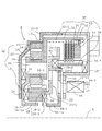
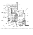
図2はこの発明の電気自動車用の2段変速機の断面図であり、中心線Lの上側半分が画かれている。10はハウジングであり、別体の溶接されるカバー10´とで内部に本発明の二段変速機4の構成部を収容する閉鎖された空洞部(歯車の噛合部の潤滑のための潤滑油が収容される)を形成する。遊星歯車機構12はハウジング10内に配置され、円周方向に間隔をおいて配置された複数のピニオン14を回転自在に軸支して構成されるキャリア16と、キャリアと回転中心を共通しピニオンに噛合するサンギヤ18と、キャリアと回転中心を共通しピニオンに噛合するリングギヤ20とからなる3回転要素を備えている。各ピニオン14をキャリア16に軸支するためピン21(キャリア16に固着)が設けられ、22はニードルベアリングを示す。
FIG. 2 is a cross-sectional view of the two-stage transmission for an electric vehicle of the present invention, in which the upper half of the center line L is drawn.
アーマチュア26(図3−図5)は、本発明のこの実施形態では、後述ドグクラッチ(28)の一体部分であり、また、後述摩擦クラッチ30の駆動部の一体部分でもあり、後述の電磁コイル(46)のオンオフだけで、換言すれば、ワンモーションで、ドグクラッチ28及び摩擦クラッチ30のシーソー的な係脱切替動作が可能となっている。アーマチュア26は全体として環状円板形状をなし、内周に円周方向に等間隔に8個配置され、夫々がサンギヤ18に向けて軸方向に延びるクラッチ突部26-1と、中間部において、円周方向に等間隔に8個複数配置され、夫々がクラッチ突部26-1と反対方向に軸方向に延びる支持部26-2と、クラッチ突部26-1と反対方向に軸方向に延びる外周の筒状部26-3と、筒状部26-3の端部において半径方向に延びるフランジ部26-4(摩擦クラッチ駆動部)とを形成する。
In this embodiment of the present invention, the armature 26 (FIGS. 3 to 5) is an integral part of a dog clutch (28) which will be described later, and an integral part of a drive part of a friction clutch 30 which will be described later. 46) In other words, the
遊星歯車機構12のサンギヤ18(図6−図8)は外周にピニオン14の歯部14-1と噛合する歯部18-1を形成する。サンギヤ18のアーマチュア26との対向面に円周方向に離間して8個のクラッチ凹部18-2が形成され、サンギヤ18の8個のクラッチ凹部18-2は、アーマチュア26の8個のクラッチ突部26-1と夫々対向するように配置され、8組の対向するクラッチ突部26-1とクラッチ凹部18-2とがこの実施形態の発明のドグクラッチ28を構成する。即ち、クラッチ突部26-1とクラッチ凹部18-2とは軸方向の向き合う方向の相対移動により相互に噛合うことにより回転方向に一体化(ドグクラッチは締結)され、軸方向の離間方向の相対移動で、クラッチ突部26-1とクラッチ凹部18-2との係合は解除(ドグクラッチは非締結)される。
The sun gear 18 (FIGS. 6 to 8) of the
キャリア16は回転中心に筒状部16-1を形成しており、筒状部16-1は内周面にスプライン歯16-1aを形成し、このスプライン歯16-1aに車軸側(ディファレンシャル)への図示しない出力軸がスプライン嵌合される。アーマチュア26は径方向に中間部に遊星歯車機構12から離間側に軸方向に突出する支持部26-2を円周方向に等間隔に6個形成している。支持部26-2は、後述のように多板摩擦クラッチ30の内筒と協働することによりアーマチュア26を回転中心と同軸支持すると共にアーマチュア26を入力軸と一体回転させる機能を持つ。また、アーマチュア26は、その一体構成部分として、外周部に摩擦クラッチの駆動部26-4を形成する。
The
多板摩擦クラッチ30はハウジング10内に配置され、外筒32と、外筒32の摺動溝32-1に摺動自在に設けたドリブンプレート34と、内筒36と、内筒36の摺動溝36-1に摺動自在に設けたドライブプレート38と、ドリブンプレート34の両面に固着したクラッチフエーシング40と、外筒32の摺動溝32-1に摺動自在に設けられ、スナップリング42によって係止される受圧板43とから構成される。ドリブンプレート34、ドライブプレート38と、クラッチフエーシング40よりなるクラッチパックを挟んで受圧板43の反対側において、アーマチュア26の摩擦クラッチ駆動部26-4が位置され、アーマチュア26の軸方向の移動下、その駆動部26-4により多板摩擦クラッチ30の係脱が行なわれる。また、外筒32は、遊星歯車機構12側の壁面部32-2がキャリア16に固定されるピン21に固定され、外筒32とキャリア16とは一体連結されている。
The
多板摩擦クラッチ30の内筒36は、アーマチュア26に対向した保持円板39と一体化され、保持円板39は内周側に回転軸と同芯な中央筒状部39-1とを形成し、中央筒状部39-1の内周面のスプライン溝39-1aに電動機側の回転軸がスプライン嵌合される。また、保持円板39は、外周付近に円周方向に等間隔に形成されたアーマチュア案内用の6個の開口39-2を有しており、この6個の開口39-2にアーマチュア26の夫々の支持部26-2が摺動自在に嵌合されており、アーマチュア26はクラッチ保持板39に軸方向に摺動可能に支持されている。
The
弾性体44(コイルスプリングや板状体ばね等)はアーマチュア26と保持円板39間に配置され、弾性体44をコイルスプリングにより構成した場合は間隔をおいて適当な数が設置される。弾性体44はアーマチュア26を図の左方にクラッチ突部26-1とクラッチ凹部18-2とが係合するように付勢している。そして、弾性体44のこの付勢力の方向は、多板摩擦クラッチ30については、ドリブンプレート34に対するドライブプレート38の締結を解放(多板摩擦クラッチ30を非締結)する。
The elastic bodies 44 (coil springs, plate-like body springs, etc.) are arranged between the
そして、電磁コイル46はカバー10´の内側に配置され、かつ電磁コイル46は、その通電により生ずる磁束経路におけるカバー10´の磁束通過孔10-1’及び保持円板39の磁束通過孔39-3を介してアーマチュア26と対向するように設置されている。従って、電磁コイル46の通電により生ずる磁束はアーマチュア26をして弾性体44に抗して図2において右行させ、この際、アーマチュア26は支持部26-2が保持円板39の開口39-2の案内で右行され、クラッチ突部26-1がクラッチ凹部18-2から離脱され、ドグクラッチ28は非締結状態をとると同時に、摩擦クラッチ駆動部26-4 により受圧板43との間でドリブンプレート34とドライブプレート38とがクラッチフエーシング40を介して挟着された多板摩擦クラッチ30は締結状態となる。これを図9に示す。47は電磁コイル46への通電用のワイヤハーネスを示す。
尚、スラスト受けのための軸受52, 54, 56が適所に配置されている。
The
Incidentally,
第1の実施形態における2段変速機4の動作を説明すると、図2においては、電磁コイル46は通電されず、弾性体44の弾性力によってドグクラッチ28は締結、多板摩擦クラッチ30は非締結となる。走行用電動機からの回転駆動力は、遊星歯車機構12のリングギヤ20が車体に固定されたハウジング10に拘束されているため、電動機からの回転は、電動機側回転軸とスプライン溝39-1aにて嵌合する保持円板39より、開口39-2と支持部26-2との係合部よりアーマチュア26に、次いで、ドグクラッチ28の係合部(26-1, 18-2)より遊星歯車機構12のサンギヤ18に伝達される。他方、遊星歯車機構12のリングギヤ20は車体側のハウジング10に固定であるため、サンギヤ18の回転に対して歯数に応じた減速比でキャリア16に回転駆動力が伝わり、キャリア16の回転によりスプライン26-1aにスプライン嵌合する出力軸が回転駆動される。このときの入力軸(サンギヤ18)に対する出力軸(キャリア16)の回転比は、周知のように、サンギヤの歯数Zs、リングギヤの歯数ZrとしたときZs/(Zs+Zr)、即ち、減速となり、歯数によるが2.4等の減速比とすることができる。
The operation of the two-stage transmission 4 according to the first embodiment will be described. In FIG. 2, the
電磁コイル46が通電されると、電磁コイル46に生ずる磁束はアーマチュア26を弾性体44の弾性力に抗して図2の右方に移動させ、アーマチュア26は図9に示す位置を取る。このとき、ドグクラッチ28の突起部26-1はサンギヤ18の凹部18-2から抜け、ドグクラッチは非締結状態となる。他方、アーマチュア26の駆動部26-4は、受圧板43との間でドリブンプレート34をクラッチフエーシング40を介してドライブプレート38を挟着し、多板摩擦クラッチ30は締結状態となる。電動機からの回転は、保持円板39より、ドライブプレート38, クラッチフエーシング40、ドリブンプレート34より外筒32に、キャリア16に伝達する。即ち、この場合、キャリア16はサンギヤ18と一体となってキャリア16の回転によりスプライン16-1aにスプライン嵌合する出力軸が回転駆動される。即ち、出力軸は入力軸と同一回転速度(変速比は1.0)で回転する。
When the
この実施形態では、車両の低車速運転時は、変速機4は図2の第1段の減速比(=2.4)にて運転し、図1で説明したように、トータルの減速比は減速機6の減速比を仮に3.41とすると2.4×3.41=8.18となり、従来と同程度のトータル減速比であり、そのため、常用運転で高い電動機効率を得ることができ、しかも、ドグクラッチ28は弾性体44の弾性力により締結状態を得ることができ電磁コイル46の通電をしなくてすむ為、常用運転域での一層の高エネルギ効率を得ることができる。また、高車速運転時は電磁コイル46を通電することにより、ドグクラッチ28は非締結と、多板摩擦クラッチ30は締結状態(変速機4は第2段の変速比(=2.4))となり、出力軸は入力軸と同一速度で回転し、高車速運転時の電動機の高効率の運転状態を確保することができる。即ち、このとき、図1で説明したように、トータルの減速比は1.0×3.41(減速機6の減速比)=3.41の減速比での運転となり、トータルの減速比が小さくなる分、高車速運転域において、電動機2を従来より低回転のより効率の良い回転域で運転させることが可能となる。
In this embodiment, when the vehicle is driven at a low vehicle speed, the transmission 4 is operated at the first reduction gear ratio (= 2.4) in FIG. 2, and the total reduction gear ratio is reduced as described in FIG. If the reduction ratio of 6 is 3.41, it becomes 2.4 × 3.41 = 8.18, which is the same total reduction ratio as before, so that high motor efficiency can be obtained in normal operation, and the
図2の実施形態において、等速(図9)から減速(図2)に移行するとき、電磁コイル46の通電が解除されると弾性体44の弾性力は、アーマチュア26をサンギヤ18側に付勢し、その瞬間において、ドグクラッチ28を構成するアーマチュア26の突起部26-1とサンギヤ18の凹部18-2とは非整列であっても、減速下サンギヤ18とアーマチュア26との間に生ずる相対回転は、弾性体44の弾性力下凹部18-2と突起部26-1とを整列に至らしめ、弾性力下で凹部18-2に対して突起部26-1は嵌合し、図2に示すようにドグクラッチ28は締結状態を取るに至る。これは、幾分かの変速ショックを伴うことになるが、減速運転中であることから、実用上問題となることはない。
In the embodiment of FIG. 2, when shifting from the constant speed (FIG. 9) to the deceleration (FIG. 2), when the energization of the
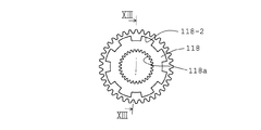
図10−図13はこの発明の第2に実施形態の2段変速機104を示し、遊星歯車機構112はリングギヤ20がハウジング10に固定される構造は同様であるが、出力軸への連結はキャリア16からサンギヤ18に変更される。即ち、サンギヤ18は内周に歯部18aが形成され、サンギヤ18のこの歯部18aは、車軸側(ディファレンシャル)への図示しない出力軸に噛合する。サンギヤ18のアーマチュア26のクラッチ係合部26-1とサンギヤ18のクラッチ凹部18-2とから成るドグクラッチ128の構成は第1の実施形態のドグクラッチ28と同様である。他の部分は図2の第1の実施形態と同様であり、同一部品には同一符号により表し、説明は省略する。
FIGS. 10 to 13 show a two-
第2の実施形態における変速機104の動作を説明すると、電磁コイル46の非通電時は、弾性体44の弾性力によってドグクラッチ128は締結、多板摩擦クラッチ30は非締結となる。走行用電動機からの回転は、図示しない電動機回転軸とスプライン39-1aにて噛合する保持円板39より、開口39-2と支持部26-2との係合部よりアーマチュア26に、次いで、ドグクラッチ128の係合部(26-1, 18-2)より遊星歯車機構112のサンギヤ18に伝達される。サンギヤ18はその内周の歯部18aが図示しない出力軸に噛合する。そのため、入力軸の回転は1対1で出力軸に伝達され、このときの変速比は1.0となる。尚、キャリア16も同一速度で回転する。
The operation of the
電磁コイル46が通電されると、電磁力下、弾性体44の弾性力に抗してドグクラッチ128の突起部26-1はサンギヤ18のクラッチ凹部18-2から抜け、ドグクラッチは非締結状態となる。また、クラッチ30は第1の実施形態と同様締結状態となる。電動機からの回転は、保持円板39より、ドライブプレート38, クラッチフエーシング40、ドリブンプレート34より外筒32に、キャリア16に伝達する。キャリア16の回転によりサンギヤ18が回転駆動され、歯部18aに噛合する出力軸が回転駆動される。即ち、このときの出力軸の回転は入力軸の回転数より増速となり、変速機の増速比は、周知のように、サンギヤの歯数Zs、リングギヤの歯数Zrとしたとき(Zs+Zr)/Zsとなる。
When the
この実施形態では、車両の低車速運転時は、電磁コイル46を徐電し、入力軸の回転は1対1で出力軸に伝達される。また、車両の高車速運転時は電磁コイル46を通電し、入力軸と出力軸の回転比は増速となる。同一の入力軸回転数に対して、出力軸の回転数は車両の低車速運転時が高車速運転時より低くなり、この関係は第1の実施形態と同様である。低車速運転時には第1の実施形態との比較では入出力が1対1であるため、第1の実施形態のような減速(減速比=2.4)ではないため、そのままでは、同一入力回転数に対しては出力側の回転数は高くなるが、図1の減速機6の減速比を第1の実施形態の値より大きな値とする(減速機6の出力側ギヤ径を大きくする)ことによりトータルの減速比を第1の実施形態の想定値8.18と同等にすることが可能となり、第1の実施形態と同様、常用の運転域である低車速運転時に車両駆動電動機のより高い回転数を使用することができ、また、低速荷運転時にドグクラッチによる弾性体44を利用した締結のため、電磁コイル46の通電をしなくすむ為、常用運転域での一層の高エネルギ効率を得ることができるという同等の効果を奏することができる。
In this embodiment, when the vehicle is driven at a low vehicle speed, the
また、高車速運転においては、変速機104は増速(増速比2.4)であるが、減速機6の減速比が大きくなっているため、トータルの減速比は第1の実施形態(仮の値で3.41)と同等となり、同様に、高車速運転を、電動機2の低回転速度域で行うことができるため、高車速運転における電動機の効率を高めることができる。
In high vehicle speed operation, the
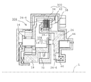
図14は、本発明の別の実施形態の2段変速機204を示し、この実施形態では1速用のクラッチ228も2速用のクラッチ230も共に多板摩擦クラッチとなっている。遊星歯車機構20は、第1の実施形態と同様に円周方向に間隔をおいて配置された複数のピニオン14を回転自在に軸支して構成されるキャリア16と、キャリア16と回転中心を共通しピニオン14に噛合するサンギヤ18と、キャリアと回転中心を共通しピニオンに噛合するリングギヤ20とからなる3回転要素を備えており、各ピニオン14をキャリア16に軸支するためピン21(キャリア16に固着)が設けられ、リングギヤ20が外周においてケース側(この場合はカバー10´)に固着した構成は同様であるが、遊星歯車機構20はケースの入力側に設置され、サンギヤ18の内歯が入力軸にスプライン嵌合する構成が相違する。
FIG. 14 shows a two-
1速用の多板摩擦クラッチ228はドライブプレート210と、ドリブンプレート212と、ドライブプレート210の両面に固着したクラッチフエーシング214と、ドライブプレート210を摺動自在に保持する内側クラッチドラム216と、ドリブンプレート212を摺動自在に保持する外側クラッチドラム218からなり、内側クラッチドラム216はキャリア16に固定されるピン21と一体連結される。弾性体244は、クラッチ駆動プレート226のクラッチ駆動部226-1を介して多板摩擦クラッチ228を締結方向に付勢するように設置される。
The first-speed
2速用の多板摩擦クラッチ230は、ドライブプレート232とドリブンプレート234とドライブプレート232の両面に固着したクラッチフエーシング236と、ドライブプレート232を摺動自在に保持する内側クラッチドラム238と、ドリブンプレート234を摺動自在に保持する外側クラッチドラム240からなり、内側クラッチドラム238はサンギヤ18と一体回転するように連結される。弾性体244は、クラッチ駆動プレート226のクラッチ駆動部226-2と対向位置するが、弾性体244により常態ではクラッチ駆動部226-2は離間位置され、多板摩擦クラッチ230は非締結状態に位置する。そして、電磁コイル246は、外側クラッチドラム218との一体回転部分である出力プレート250に形成される磁束通過孔250-1を介して、クラッチ駆動プレート226と対向位置する。また、出力プレート250は内周に出力軸との嵌合のためのスプライン部250-2を形成している。
The
この第3の実施形態における電気自動車用変速機の動作においては、1速時は電磁コイル246は非通電となり、弾性体244の弾性力によって第1摩擦クラッチ228は締結、第2の摩擦クラッチ230は非締結となり、入力軸の回転はサンギヤ18より、ピニオン14、キャリア16及び第1摩擦クラッチ228、出力プレート250を介して出力軸に伝達され、この場合に出力軸は入力軸に対して減速となり、減速比は第1の実施形態と同様、サンギヤの歯数Zs、リングギヤの歯数ZrとしたときZs/(Zs+Zr)となる。
In the operation of the electric vehicle transmission according to the third embodiment, the
2速時は電磁コイル246が通電される、電磁コイル246に生ずる電磁力は、アーマチュア226を弾性体244の弾性力に抗して図14の左方に移動させ、クラッチ駆動部226-1はクラッチ板212から離間位置され、第1クラッチ228を非締結とし、電磁コイル246に生ずる電磁力はクラッチ駆動部226-2をして弾性体244の弾性力に抗して第2クラッチ230を締結させるべく駆動する。このとき、入力軸の回転は第2クラッチ230を介してそのまま出力軸に伝わり、このときの回転比は1.0となる。
In the second speed, the
この第3の実施形態では、車両の低車速運転時は、減速となり、そのため車両駆動電動機のより高い回転数において低車速運転を行なうことができ、常用運転で高い電動機効率を得ることができ、しかも、弾性体244の弾性力により締結状態を得ることができ電磁コイル246の通電をしなくすむ為、常用運転域でのエネルギ効率を高めることができる。また、高速時は電磁コイル246を通電することにより、入出力の同一速度が得られ、変速機204の変速比が上がった分、電動機2の回転を下げて高車速運転を行うことができ、電動機2が高効率の状態で高速走行が可能となるという第1の実施形態と同等の動作が実現される。
In this third embodiment, the vehicle is decelerated during low vehicle speed operation, so that low vehicle speed operation can be performed at a higher rotational speed of the vehicle drive motor, and high motor efficiency can be obtained during regular operation. Moreover, since the fastening state can be obtained by the elastic force of the
本発明実施形態(例えば図1−図9に示す第1の実施形態)において、電磁力により駆動されるアーマチュア26の直線移動によりドグクラッチ28と摩擦クラッチ30を切り替えることにより2段変速を行う場合、2個のクラッチが同時に係合状態を取ることは回避する必要があり、理想的には2個のクラッチの一方の締結と他方の非締結が同時的に起こるようにすることは不可能ではないが、部品の公差を考慮すると、第1速(図2)から第2速(図9)、第2速から第1速切替の際に2個のクラッチが共に非締結状態となる中間状態を設けざるを得ない。2個のクラッチが非締結状態となる中間状態は時間的には極めて短時間であるが、駆動側の電動機回転軸の回転が従動側である車輪側に伝達されない所謂トルク抜けの状態となり、運転者には変速ショックとなる。以下の実施形態はワンウエイクラッチを使用することにより、この問題点の解消を図った構成となっている。
In the embodiment of the present invention (for example, the first embodiment shown in FIGS. 1 to 9), when the two-speed shift is performed by switching the
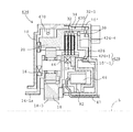
図15及び図16はこの発明の第4の実施形態の2段変速機304を示し、変速機による低車速運転と高車速運転との切替方式は基本的には第1の実施形態の2段変速機4と同様であり、ドグクラッチ328と多板摩擦クラッチ330とを備え、ドグクラッチ328は、アーマチュア26の一体部分であり、保持円板39の開口39-2を挿通される係合部26-1と、サンギヤ18の一体延長部に形成される係合孔18-2とから構成され、多板摩擦クラッチ330は、アーマチュア26の一体部分である駆動部26-4と外筒32に係止される受圧板43間に配置され、キャリア16の一体部分である外筒32に摺動自在なドリブンプレート34と、保持円板39の一体部分である内筒36に摺動自在なドライブプレート38と、ドリブンプレート34の両面に固着したクラッチフエーシング40から成るクラッチパックを具備している。そして、この実施形態では前記したアーマチュア26の直線移動による第1速から第2速、第2速から第1速切替の際のトルク抜け対策として、ワンウエイクラッチ70がサンギヤ18の一体部分である筒状部18-3と保持円板39(第1の実施形態と同様電動機回転軸にスプライン39-1にて嵌合される)の筒状部39-1間に配置される。
FIGS. 15 and 16 show a two-
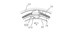
ワンウエイクラッチ70は、公知のこの実施形態では図17にカム式のものとして模式的に示す。このワンウエイクラッチは具体的には日本精工株式会社製のFWE-BRB型のものを同社のカタログ(https://www.jp.nsk.com/app01/jp/ctrg/index.cgi?gr=dn&pno=4601a)を参考に模式的に表したものであるが、カム式のワンウエイクラッチに限定する意図はなく、スプラグ型、ローラ型やその他の適切な方式のものを採用可能である。図17に示すこの実施形態のカム式のワンウエイクラッチ70は、インナレースを保持円板39の筒状部39-1に、アウタレースをサンギヤ18の一体部分である筒状部18-3として、原理的に描かれている。周知のように、ワンウエイクラッチはインナレース及びアウタレースを含めたユニットとして構成されるが、この発明においては、ワンウエイクラッチ70の詳細構成如は発明の本旨と直接的に関係しないため、説明の簡明のため、原理的な構成として図示したものである。カム式のワンウエイクラッチ70においては、円周方向に間隔を置いた多数のカム72(その一個のみ図示)を保持環74に保持し、カム72を無端のガータスプリング76(カム72に形成され、半径外方に開放した溝を挿通される)にて弾性力下で回転付勢するように構成される。カム72は、時計方向fの回転においてはインナレース(筒状部39-1)とアウタレース(筒状部18-3)間とで突っ張りとなり直線lに沿って内周及び外周において対向面に当接する(ロック状態をとる)。これに対し反時計方向の回転に対しては突っ張りが外れるような形状をなす。ガータスプリング76のばね力は、図17においてカム72の重心が直線lより幾分右側にずれていることと相まってカム72をロック状態を取るように時計方向に回転するように付勢している。
In this known embodiment, the one-way clutch 70 is schematically shown as a cam type in FIG. Specifically, this one-way clutch is FWE-BRB type manufactured by NSK Ltd. (https://www.jp.nsk.com/app01/jp/ctrg/index.cgi?gr=dn&pno = 4601a), but is not intended to be limited to the cam-type one-way clutch, and a sprag type, roller type, or other appropriate type can be used. The cam type one-
この第4の実施形態の変速機304の動作を説明すると、低車速運転時には、図15に示すように、ドグクラッチ328の締結により、サンギヤ18とアーマチュア26と保持円板39とは一体回転し、保持円板39の中央筒状部39-1とサンギヤ18の筒状部18-3との間に位置するワンウエイクラッチ70も同一速度で一体回転し、この場合はワンウエイクラッチ70は機能的には存在しないのと同じである。
The operation of the
低車速運転から高車速運転への切替のため電磁コイル46の電磁力下アーマチュア26は、そのスプリング加圧部26-6がスプリング44を押圧し、スプリング44の変形下図15において右方に移動され、係合部26-1は係合孔18-2から抜去され、ドグクラッチ328は非締結となるが、ドグクラッチ328は非締結の直後において、摩擦クラッチ330も非締結の上記した中間状態が一瞬存在する。この瞬間、図2の第1の実施形態の場合、サンギヤ18は駆動源(電動機回転軸)かち切り放されるため、駆動トルクが消失するため、変速ショックとなり得る。これに対し、この図15の実施形態にあっては、ドグクラッチ328が非締結となった瞬間において、図17に示すように、電動機回転軸の矢印a方向の回転(保持円板39の中央筒状部39-1(ワンウエイクラッチのインナレース)の回転)に対してカム72は突っ張り方向(時計方向)の力を受け、サンギヤ18の筒状部18-3(ワンウエイクラッチのアウタレース)をロックし、電動機回転軸の矢印a方向の回転(保持円板39の中央筒状部39-1の同方向の回転)がサンギヤ18,即ち、車輪側に伝達されるため、トルク抜けが生じない。そして、アーマチュア26の図15の右方向移動継続により摩擦クラッチ330が図16に示す締結状態(高車速運転)に至り、高車速運転に移行後に電動機出力軸の回転の増大により、サンギヤ18、即ち、図17に示すサンギヤ18の筒状部18-3の回転a´の回転数が電動機回転軸の矢印a方向の回転(保持円板39の中央筒状部39-1の回転数)より大きくなると、カム72は、ガータスプリング76のばね力に抗して反時計方向に回動し、その突っ張り機能は消失され、ワンウエイクラッチ70のロックは外れ、換言すれば、ワンウエイクラッチ70はフリーに回転することになる。
In order to switch from low vehicle speed operation to high vehicle speed operation, the
電磁コイル46の通電を解除することにより、アーマチュア26をスプリング44の弾性力下アーマチュア26を図16の状態から図15の状態に向け左方向に移動させ,高車速運転から低車速運転に切替る過程においても、摩擦クラッチ330もドグクラッチ328も非締結の状態(トルク抜け)が一瞬生じ得るが、この際、車輪側のサンギヤ18(サンギヤ18の筒状部18-3)の回転が電動機回転軸の回転(矢印a)より落ちようとすると、図17のワンウエイクラッチ70において、カム72はスプリング下突っ張り方向 (矢印f)に回動付勢され、サンギヤ18の筒状部18-3は電動機回転軸側の保持円板39の中央筒状部39-1に対してロックされ、電動機回転がワンウエイクラッチ70を介して車輪側に伝達され、この場合においてもクラッチ切替時のトルク抜けを防止するように機能する。そして、ドグクラッチ328が完全締結に至ることにより保持円板39の中央筒状部39-1とサンギヤ18の筒状部18-3との間に位置するワンウエイクラッチ70も同一速度で一体回転し、変速機は第1速となり、この際ワンウエイクラッチ70も同一速度で一体回転する。
By deenergizing the
図18及び図19は低車速運転と高車速運転との切替時のトルク抜け対策を施したこの発明の第5の実施形態の2段変速機404を示し、この第5の実施形態の2段変速機404は低車速運転はリングギヤ20を固定したギヤ比2.4の減速での運転、高車速運転はサンギヤ18とリングギヤ20を一体回転させることによるギヤ比1.0での等速運転を行う点で図2−図9の第1の実施形態、図14の第3の実施形態、図15−図16の第4の実施形態と同様である。そして、リングギヤ20のハウジング10に対する選択的な拘束を行うためのワンウエイクラッチ470を設けた点が特徴となる。
FIGS. 18 and 19 show a two-
この第5の実施形態の2速変速機404の構成を説明すると、アーマチュア426は円周方向の内歯426-1を備え、ハウジング10に固定されるカバー10´に円周方向の外歯10’-1が形成され、この内歯426-1と外歯10’-1とがドグクラッチ428を構成する。アーマチュア426の外周部426-4が摩擦クラッチ430の駆動部を構成し、また、アーマチュア426の外周部426-4は摩擦クラッチ430の外筒32におけるドリブンディスク34の摺動溝32-1に摺動自在に係合している。電磁コイル46の取り付けのため、電磁石保持枠82は非磁性体より成るカバー10´に固定される。この実施形態ではサンギヤ18は内周のスプライン18-3が図示しない電動機回転軸にスプライン嵌合し、電動機回転駆動力がサンギヤ18に伝達される。サンギヤ18の後端筒状部18-4がこの実施形態における摩擦クラッチ430の内筒となり、ドライブプレート38が設けられる。キャリア16が内周のスプライン16-1aにより車輪側の出力軸にスプライン嵌合することは第1の実施形態と同様である。
The structure of the
この第5の実施形態において、第1速と第2速間の速度切替の際のトルク抜け防止のためのワンウエイクラッチ470はリングギヤ20(図20の模式図においてワンウエイクラッチ470のインナレースとして機能する)とハウジング10(同模式図においてワンウエイクラッチ470のアウタレースとして機能する)との間に配置される。そして。図20に示すように、ワンウエイクラッチ470のカム472は第4の実施形態のワンウエイクラッチ70のカム47とは向きが反対であり、スプリング力下でのカム472の反時計方向の回転f´がインナレース(ハウジング10)とアウタレース(リングギヤ20)との間の突っ張りとなる配置である。
In the fifth embodiment, the one-
第5の実施形態の動作を説明すると、低速時には、電磁コイル46の非通電により、スプリング44によってアーマチュア426は図18においてカバー10´に当接する位置まで押圧され、アーマチュア426の内歯426-1とカバー10´の外歯10’-1とは噛合しており、ドグクラッチ428は締結状態(摩擦クラッチ430は非締結状態)をとり、アーマチュア426は固定化され、アーマチュア426の外周部426-4が摩擦クラッチ430の外筒32に摺動溝32-1と係合していることにより、リングギヤ20はカバー10´、即ち、ハウジング10に固定化される。そのため、サンギヤ18に噛合する電動機回転軸の回転はキャリア16に取り出され、このときは、変速比は第1の実施形態と同様2.4といった減速となり、このとき、ワンウエイクラッチ470はインナレース側もアウタレース側も固定のままである。機能的にはワンウエイクラッチ470は設置が無いのと同じである。
The operation of the fifth embodiment will be described. At low speed, the
低車速運転(図18)から高車速運転(図19)の切替時に,ドグクラッチ428の非締結でかつ摩擦クラッチ430が完全締結に至らない状態が一瞬生じ得、このときリングギヤ20は一瞬フリーとなり、電動機の回転軸の回転方向aと反対方向(トルク抜け方向)に戻ろうとするが、ワンウエイクラッチ470のカム472はこのような動きに対してはロックするように働き、即ち、リングギヤ20のハウジング10に対するロックは継続し、電動機の回転軸の回転をサンギヤ18及びキャリア16を介して車輪側に伝達するように機能し、トルク抜けを防止する。摩擦クラッチ430が完全締結状態となれば、リングギヤ20は電動機回転軸の回転方向(矢印a)と同一方向に1.0の変速比で車輪側に伝わり、このときワンウエイクラッチ470は空転となる。
When switching from a low vehicle speed operation (FIG. 18) to a high vehicle speed operation (FIG. 19), a state may occur where the
また、高車速運転(図19)から低車速運転(図18)への切替時には、摩擦クラッチ430の非締結でドグクラッチ428が未だ入らないことにより、一瞬拘束を外れたトルク抜けの状態となり得るが、このときも、ワンウエイクラッチ470は、カム472が突っ張りとして機能し、リングギヤ20はロックされるため、ドグクラッチ428が締結状態となるまでの間入力側の電動機の回転を出力側の車輪に伝えることができる。ドグクラッチ428が完全締結に至ると、リングギヤ20はハウジング10と一体化し、ギヤ比2.4といった減速比にて電動機回転軸の回転はキャリア16より取り出され、このときワンウエイクラッチ470は機能的には無いのと一緒になる。
Further, at the time of switching from high vehicle speed operation (FIG. 19) to low vehicle speed operation (FIG. 18), since the
以上の第1実施形態かち第5実施形態においては、リングギヤ固定により第1速と第2速との切替を行っていたが、遊星歯車の仕組みから、入力側と出力側とを同一方向に回転させつつギヤ比を変えることはサンギヤ固定でも可能である。因みに、キャリア固定では入力軸と出力軸は反対方向の回転となるため、電気自動車用の2段変速機としては適当でない。以下の第6の実施形態はリングギヤ固定方式への本発明の適用例であり、またワンウエイクラッチによるトルク抜け防止機能をも兼備させたものとなっている。 In the first embodiment to the fifth embodiment described above, the first gear and the second gear are switched by fixing the ring gear. However, due to the mechanism of the planetary gear, the input side and the output side are rotated in the same direction. The gear ratio can be changed while the sun gear is fixed. By the way, when the carrier is fixed, the input shaft and the output shaft rotate in opposite directions, so that it is not suitable as a two-stage transmission for an electric vehicle. The following sixth embodiment is an application example of the present invention to the ring gear fixing system, and also has a function of preventing torque loss by a one-way clutch.
図21はこの第6の実施形態の2段変速機504を示しており、この実施形態の2段変速機504においては、遊星歯車機構のサンギヤ18は、後方に延び、摩擦クラッチ530の内筒536と一体に連結されており、摩擦クラッチ530の内筒536とハウジング10の筒状部10-1にワンウエイクラッチ570が配置される。また、この実施形態では、リングギヤ入力、キャリア出力となっている。即ち、リングギヤ20に前端側において連結部材86が固定され、連結部材86の内周スプライン86-1が図示しない電動機回転軸(入力軸)にスプライン嵌合により連結され、遊星歯車機構のキャリア16は内側筒状部16-1のスプライン16-1aが図示しない車輪側出力軸にスプライン嵌合により連結される。キャリア16は後端(16´)側において、摩擦クラッチ530の外筒532を形成する。キャリア16の内側筒状部16-1はベアリング85によってサンギヤ18を回転可能に支持する構造となっている。摩擦クラッチ530を構成するドリブンプレート34、ドライブプレート38、クラッチフエーシング40から成るクラッチパックの構成は従前の実施形態と同様である。この実施形態では、アーマチュア526は、内筒536の後方への筒状延長部536-1の端部における櫛状突起部536-1aがアーマチュア526の内周部の円周方向に離間配置された支持孔526-3に嵌挿されることにより軸方向に摺動可能に支持される。また、この実施形態におけるドグクラッチ528はアーマチュア526の係合孔526-2とハウジング10の係合突起10-2とから構成される。電磁コイル46は保持枠82に保持され、保持枠82は、非磁性の支持部材83によってハウジング10に支持される。尚、この実施形態ではハウジング10とで変速機の全体を被覆する筐体を構成するカバーの図示は省略されている。
この実施形態のワンウエイクラッチ570は模式的に図23のように表すことができ、インナレース側のハウジング10の筒状部10-1とアウタレース側の摩擦クラッチ530の内筒536(サンギヤ18)との間にカム572が配置され、カム572は図17と同様時計方向の回転よってインナレースとアウタレース間の突っ張りとなるようにガータスプリング76によりばね付勢されている。電動機回転軸の回転方向は従前の実施形態と同様、矢印aのように反時計方向となっている。
FIG. 21 shows the two-
The one-
この第6の実施形態の2段変速機504の動作を説明すると、低車速運転時は、電磁コイル46は非通電であり、スプリング44によりアーマチュア526は図21のように左方に駆動され、ドグクラッチ528はアーマチュア526の係合孔526-2がハウジング10の係合突起10-2と係合した締結状態をとり、アーマチュア26は固定状態となる。そのため、サンギヤ18も、一体の筒状延長部536-1が櫛状突起部536-1aにおいてアーマチュア526の支持孔526-3に嵌挿していることから、ハウジング側に固定状態とされる。このとき、摩擦クラッチ530は駆動部526-4が摩擦板から離間した非締結状態であるから、連結部材86よりリングギヤ20に入力された電動機回転軸の回転は同一方向の回転としてピニオン14を介してキャリア16に伝達され、キャリア16の回転はスプライン16-1aに噛合する図示しない車輪側出力軸に伝達される。このとき、入力軸(リングギヤ20)に対する出力軸(キャリア16)の回転比は、周知のように、サンギヤの歯数Zs、リングギヤの歯数ZrとしたときZr /(Zs+ Zr)、即ち、減速となり、歯数の選定により適当な減速比とすることができる。このとき,その間にワンウエイクラッチ570を配置する配置される内筒536(サンギヤ18からの延長部)もハウジング10の係合突起10-2も固定であるから、ワンウエイクラッチ570は無いのと同一である(インナレース側もアウタレース側も固定となる)。
The operation of the two-
高車速運転時は、電磁コイル46は通電され、電磁力によりスプリング44に抗しアーマチュア526は図22のように右方に駆動され、ドグクラッチ528はアーマチュア526の係合孔526-2からハウジング10の係合突起10-2が抜けた非締結状態をとり、他方、摩擦クラッチ530は、駆動部526-4により、ドライブプレート38がドリブンプレート34とクラッチフエーシング40を介して係合した締結状態をとる。そのため、遊星歯車機構のサンギヤ18、リングギヤ20、キャリア16は一体となって回転し、電動機回転軸の回転は1対1で車輪側に伝達され、変速機504の変速比としては低車速運転と比べて高車速運転は高ギヤ比で行われ、その分電動機の回転数を抑えた状態で、高車速運転を行うことができ、最高速に対して余裕をもって高車速運転を行うことができる(高車速を得ることができる)。このときのワンウエイクラッチ570(図23)の動作は、内筒536即ちサンギヤ18の回転が矢印a方向(カム572の,突っ張り方向fと反対方向)であるため、空転となる。
During high vehicle speed operation, the
低車速運転(図21)から高車速運転(図22)の切替時に、ドグクラッチ528も摩擦クラッチ530も非締結の状態が一瞬生じ得るが、このとき、トルク抜け(アウタレース側のサンギヤ18の電動機回転方向aと反対方向の回転)に対して、ワンウエイクラッチ570は、カム572がそのような後退を阻止し、即ち、アウタレース側をハウジング側にロックし、その結果、電動機回転軸の回転が車輪側に伝わることができるため、摩擦クラッチ530が完全締結に至るまでのトルク抜けを防止する。摩擦クラッチ530が完全締結状態となれば、サンギヤ18の回転(電動機回転方向aと同方向)によりワンウエイクラッチ570は空転状態となる。
When switching from the low vehicle speed operation (FIG. 21) to the high vehicle speed operation (FIG. 22), the
また、高車速運転(図22)から低車速運転(図21)への切替時にも、摩擦クラッチ530もドグクラッチ528も非締結の状態が一瞬生じ得るが、このときのトルク抜け(アウタレース側が電動機回転軸の回転方向と反対方向に後退しようとすること)に対しても、ワンウエイクラッチ570は、カム572がそのような後退を阻止し、即ち、アウタレース側をハウジング側にロックし、その結果、電動機回転軸の回転が車輪側に伝わることができるため、ドグクラッチ528が完全締結に至るまでのトルク抜けを防止する。
Further, even when switching from high vehicle speed operation (FIG. 22) to low vehicle speed operation (FIG. 21), the
2…走行用電動機
4, 104, 204, 304, 504…2段変速機
6…減速機
10…ハウジング
12…遊星歯車機構
14…ピニオン
16…キャリア
18…サンギヤ
18-2…クラッチ凹部
20…リングギヤ
26…アーマチュア
26-1…クラッチ突部
26-4…フランジ部(摩擦クラッチ駆動部)
28, 328, 428, 528…ドグクラッチ
30, 430, 530…多板摩擦クラッチ
34…ドリブンプレート
36…内筒
38…ドライブプレート
40…クラッチフエーシング
43…受圧板
44…弾性体
46…電磁コイル
70, 470, 570…ワンウエイクラッチ
72, 472, 572…カム
228…1速用多段摩擦クラッチ
230…2速用多段摩擦クラッチ
2 ... Electric motor for traveling
4, 104, 204, 304, 504 ... Two-speed transmission 6 ...
18-2 ...
26-1 ... Clutch protrusion
26-4… Flange part (friction clutch drive part)
28, 328, 428, 528 ... Dog clutch
30, 430, 530 ... Multi-plate friction clutch 34 ... Driven
70, 470, 570 ... one-way clutch
72, 472, 572 ...
Claims (3)
車体側に固定されたハウジングと、
ハウジング内に配置され、円周方向に間隔をおいて配置された複数のピニオンを回転自在に軸支して構成されるキャリアと、キャリアと回転中心を共通しピニオンに噛合する第1の歯車と、キャリアと回転中心を共通しピニオンに噛合する第1の歯車とは異なった歯数の第2の歯車とからなる3回転要素を備えた遊星歯車機構と、
弾性体と、
電磁コイルと、
入力軸に沿って移動可能でかつ入力軸と共に回転され、弾性体により第1の方向へ移動付勢され、電磁コイルに生じた電磁力により第1の方向と反対の第2の方向に移動付勢されるアーマチュアと、
電磁コイル非通電時は、前記弾性体の弾性力によるアーマチュアの前記第1の方向への移動により締結され、電磁コイル通電時は、電磁力により弾性力に抗したアーマチュアの前記第2の方向への移動により非締結となる第1のクラッチと、
電磁コイル通電による電磁力下、弾性力に抗したアーマチュアの前記第2の方向への移動により締結され、電磁コイルの非通電時は弾性力によるアーマチュアの前記第1の方向への移動により非締結とされる第2のクラッチとを備え、
遊星歯車機構の第1の回転要素としてのリングギヤ若しくはサンギヤはハウジング側に固定可能とされ、残りの回転要素である第2、第3の回転要素及び入力側及び出力側間における第1のクラッチ及び第2のクラッチの配置は、第1及び第2のクラッチの一方のクラッチの締結、第1及び第2のクラッチの他方のクラッチ非締結により、入力側回転要素と出力側回転要素との回転数が等速に、第1及び第2のクラッチの前記一方のクラッチの非締結、前記他方のクラッチの締結で入力側の回転要素と出力側の回転要素は同一回転方向でかつ非等速となるようにされ、
かつ電磁コイル非通電による弾性力下でのアーマチュアの前記第1の方向への移動により第1のクラッチが締結、第2のクラッチが非締結とされる第1の場合と、電磁コイル通電により弾性力に抗した電磁力下でのアーマチュアの前記第2の方向への移動による第1のクラッチが非締結、第2のクラッチが締結される第2の場合を比較したとき、第1の場合が第2の場合と較べて入力側に対して出力側がより減速となるようにされ、
第1の場合と第2の場合間での切替時におけるトルク抜けを防止するためのワンウエイクラッチを更に備えた電動駆動車用2段変速機。 A two-stage transmission arranged on an output shaft of a motor in a vehicle that uses the motor for driving wheels,
A housing fixed to the vehicle body side;
A carrier arranged in the housing and rotatably supported by a plurality of pinions arranged at intervals in the circumferential direction; and a first gear having a common rotation center with the carrier and meshing with the pinion A planetary gear mechanism having a three-rotation element comprising a second gear having a different number of teeth from the first gear that has a common rotation center with the carrier and meshes with the pinion;
An elastic body,
An electromagnetic coil;
It can move along the input shaft and is rotated together with the input shaft, is moved and urged in the first direction by the elastic body, and is moved in the second direction opposite to the first direction by the electromagnetic force generated in the electromagnetic coil. Armed armature,
When the electromagnetic coil is not energized, the armature is fastened by the movement of the armature in the first direction due to the elastic force of the elastic body. When the electromagnetic coil is energized, the armature resists the elastic force due to the electromagnetic force in the second direction. A first clutch that is disengaged by movement of
Fastened by movement of the armature against the elastic force in the second direction under electromagnetic force due to energization of the electromagnetic coil, and unfastened by movement of the armature in the first direction by elastic force when the electromagnetic coil is not energized A second clutch,
The ring gear or sun gear as the first rotating element of the planetary gear mechanism can be fixed to the housing side, and the second and third rotating elements that are the remaining rotating elements, the first clutch between the input side and the output side, and The arrangement of the second clutch is such that the number of rotations of the input side rotation element and the output side rotation element is determined by the engagement of one of the first and second clutches and the non-engagement of the other clutch of the first and second clutches. However, when the one clutch of the first and second clutches is not engaged and the other clutch is engaged, the input-side rotating element and the output-side rotating element have the same rotational direction and non-constant speed. Was
In the first case where the first clutch is engaged and the second clutch is not engaged by the movement of the armature in the first direction under the elastic force due to the non-energization of the electromagnetic coil, and the elasticity when the electromagnetic coil is energized. When comparing the second case where the first clutch is disengaged and the second clutch is fastened due to the movement of the armature in the second direction under the electromagnetic force against the force, the first case is Compared to the second case, the output side is more decelerated with respect to the input side ,
Further 2-speed transmission for electric whether dynamic vehicle equipped with a one-way clutch for preventing loss torque at the time of switching between the first case and the second case.
Applications Claiming Priority (2)
| Application Number | Priority Date | Filing Date | Title |
|---|---|---|---|
| JP2018106548 | 2018-06-02 | ||
| JP2018106548 | 2018-06-02 |
Related Parent Applications (1)
| Application Number | Title | Priority Date | Filing Date |
|---|---|---|---|
| JP2019520173A Division JP6545921B1 (en) | 2018-06-02 | 2018-11-30 | Two-speed transmission for electric vehicles |
Publications (2)
| Publication Number | Publication Date |
|---|---|
| JP2019211083A true JP2019211083A (en) | 2019-12-12 |
| JP2019211083A5 JP2019211083A5 (en) | 2021-11-18 |
Family
ID=68698772
Family Applications (1)
| Application Number | Title | Priority Date | Filing Date |
|---|---|---|---|
| JP2019113255A Pending JP2019211083A (en) | 2018-06-02 | 2019-06-19 | Two-stage transmission for electric automobile |
Country Status (4)
| Country | Link |
|---|---|
| US (1) | US11396913B2 (en) |
| JP (1) | JP2019211083A (en) |
| CN (1) | CN112204271B (en) |
| WO (1) | WO2019230021A1 (en) |
Families Citing this family (1)
| Publication number | Priority date | Publication date | Assignee | Title |
|---|---|---|---|---|
| FI129927B (en) * | 2021-10-28 | 2022-11-15 | Motiomax Oy | An electromechanical system |
Citations (1)
| Publication number | Priority date | Publication date | Assignee | Title |
|---|---|---|---|---|
| JPS59172853U (en) * | 1983-05-06 | 1984-11-19 | トヨタ自動車株式会社 | Electric vehicle transmission |
Family Cites Families (11)
| Publication number | Priority date | Publication date | Assignee | Title |
|---|---|---|---|---|
| JPH0631239Y2 (en) * | 1986-09-24 | 1994-08-22 | 株式会社東洋精機製作所 | Speed change mechanism |
| JP2006234062A (en) * | 2005-02-24 | 2006-09-07 | Ishikawajima Harima Heavy Ind Co Ltd | Reversible two-stage transmission |
| JP5568229B2 (en) | 2008-10-06 | 2014-08-06 | Ntn株式会社 | Electric motor drive device |
| TW201217669A (en) * | 2010-10-25 | 2012-05-01 | Sun Race Sturmey Archer Inc | Speed changing apparatus |
| DE102011010086A1 (en) * | 2011-02-01 | 2012-08-02 | Audi Ag | Arrangement with a planetary gear for motor vehicle, motor vehicle and method for operating a planetary gear |
| CN103442924B (en) * | 2011-03-23 | 2016-02-03 | 丰田自动车株式会社 | Vehicle driving apparatus |
| JP2013245736A (en) * | 2012-05-24 | 2013-12-09 | Aisin Seiki Co Ltd | Transmission for electric vehicle |
| WO2014017438A1 (en) * | 2012-07-23 | 2014-01-30 | 本田技研工業株式会社 | Vehicular power transmission device |
| US10781891B2 (en) * | 2014-09-16 | 2020-09-22 | Means Industries, Inc. | Drive system including a transmission and magnetic coupling device for an electric vehicle |
| JP6517502B2 (en) * | 2014-12-02 | 2019-05-22 | 株式会社Ihiエアロスペース | Two-speed transmission |
| DE102019104030A1 (en) * | 2019-02-18 | 2020-08-20 | Schaeffler Technologies AG & Co. KG | Spur gear differential |
-
2018
- 2018-11-30 US US17/043,797 patent/US11396913B2/en active Active
- 2018-11-30 CN CN201880094072.3A patent/CN112204271B/en active Active
- 2018-11-30 WO PCT/JP2018/044209 patent/WO2019230021A1/en unknown
-
2019
- 2019-06-19 JP JP2019113255A patent/JP2019211083A/en active Pending
Patent Citations (1)
| Publication number | Priority date | Publication date | Assignee | Title |
|---|---|---|---|---|
| JPS59172853U (en) * | 1983-05-06 | 1984-11-19 | トヨタ自動車株式会社 | Electric vehicle transmission |
Also Published As
| Publication number | Publication date |
|---|---|
| US11396913B2 (en) | 2022-07-26 |
| US20210071721A1 (en) | 2021-03-11 |
| CN112204271B (en) | 2023-09-26 |
| CN112204271A (en) | 2021-01-08 |
| WO2019230021A1 (en) | 2019-12-05 |
Similar Documents
| Publication | Publication Date | Title |
|---|---|---|
| JP6545921B1 (en) | Two-speed transmission for electric vehicles | |
| CN212685116U (en) | Electric drive axle | |
| CN103813922B (en) | Driver element with motor | |
| JP5842998B2 (en) | Vehicle transmission | |
| WO2013125682A1 (en) | Motor drive device for vehicles | |
| WO2013180086A1 (en) | Friction engagement device | |
| EP2584228A1 (en) | Motor drive apparatus for vehicle, and automobile | |
| KR20050020640A (en) | Clutch and synchronizer having permanent magnet actuators | |
| JP2023041927A (en) | Power transmission path switching device | |
| JP7427670B2 (en) | Two-speed transmission for electric drive vehicles | |
| WO2019230021A1 (en) | Two-step transmission for electric vehicle | |
| US5267917A (en) | Rotary element engaging device for an automatic transmission | |
| US20220136601A1 (en) | Power transmission device | |
| JP2011058534A (en) | Motor drive device for vehicle, and automobile | |
| JP2023016209A (en) | drive | |
| JP2021014198A (en) | In-wheel motor type drive unit | |
| WO2021092678A1 (en) | Active double eclutch module | |
| JP2012225365A (en) | Vehicle transmission | |
| CN115052777A (en) | Transmission and two-gear bridge driving system | |
| JP7243929B2 (en) | 2 speed transmission | |
| JP4231963B2 (en) | Automatic transmission power transmission device | |
| US11892065B2 (en) | Drivetrain component | |
| JP2012225364A (en) | Transmission for electric vehicle | |
| JP2010216613A (en) | Driving device for vehicle | |
| JP4802042B2 (en) | One-way clutch support structure |
Legal Events
| Date | Code | Title | Description |
|---|---|---|---|
| A521 | Request for written amendment filed |
Free format text: JAPANESE INTERMEDIATE CODE: A523 Effective date: 20211008 |
|
| A621 | Written request for application examination |
Free format text: JAPANESE INTERMEDIATE CODE: A621 Effective date: 20211008 |
|
| A977 | Report on retrieval |
Free format text: JAPANESE INTERMEDIATE CODE: A971007 Effective date: 20220825 |
|
| A131 | Notification of reasons for refusal |
Free format text: JAPANESE INTERMEDIATE CODE: A131 Effective date: 20220830 |
|
| A02 | Decision of refusal |
Free format text: JAPANESE INTERMEDIATE CODE: A02 Effective date: 20230228 |