JP2019209341A - Welding equipment - Google Patents

Welding equipment Download PDF

Info

Publication number
JP2019209341A
JP2019209341A JP2018105895A JP2018105895A JP2019209341A JP 2019209341 A JP2019209341 A JP 2019209341A JP 2018105895 A JP2018105895 A JP 2018105895A JP 2018105895 A JP2018105895 A JP 2018105895A JP 2019209341 A JP2019209341 A JP 2019209341A
Authority
JP
Japan
Prior art keywords
gear
torch
welding
annular
turning
Prior art date
Legal status (The legal status is an assumption and is not a legal conclusion. Google has not performed a legal analysis and makes no representation as to the accuracy of the status listed.)
Granted
Application number
JP2018105895A
Other languages
Japanese (ja)
Other versions
JP7064386B2 (en
Inventor
武 大江
Takeshi Oe
武 大江
聡 箕輪
Satoshi Minowa
聡 箕輪
考洋 天本
Takahiro Amamoto
考洋 天本
Current Assignee (The listed assignees may be inaccurate. Google has not performed a legal analysis and makes no representation or warranty as to the accuracy of the list.)
Toshiba Plant Systems and Services Corp
Original Assignee
Toshiba Plant Systems and Services Corp
Priority date (The priority date is an assumption and is not a legal conclusion. Google has not performed a legal analysis and makes no representation as to the accuracy of the date listed.)
Filing date
Publication date
Application filed by Toshiba Plant Systems and Services Corp filed Critical Toshiba Plant Systems and Services Corp
Priority to JP2018105895A priority Critical patent/JP7064386B2/en
Publication of JP2019209341A publication Critical patent/JP2019209341A/en
Application granted granted Critical
Publication of JP7064386B2 publication Critical patent/JP7064386B2/en
Active legal-status Critical Current
Anticipated expiration legal-status Critical

Links

Images

Abstract

To provide welding equipment that can secure exactness of welding for small-diameter piping undoubtedly and for middle/large-diameter piping in particular with sufficient working accuracy and can be easily reduced in size and weight, and accordingly allows for improvement of convenience of handling.SOLUTION: Welding equipment 1 comprises: an annular base part 2 fixed to an outer periphery of a cylindrical object 200a to be welded; a plurality of gears which are arranged annularly along the base part 2 and mesh with each other alternately; a turning base 5 which is fixed to the turning gears, can freely move in a circumferential direction of the base part 2 and supports a welding head 3; a plurality of electric motors each individually generating driving force to be transmitted to the gears; a rotation sensor that detects rotational angles of output shafts of the electric motors; and a control part which, on the basis of the rotational angles detected by the rotation sensor, controls driving or stop of the plurality of electric motors to thereby synchronize a plurality of annular gear rows at uniform velocity and rotate the gear rows or rotate gear rows at different velocities in non-synchronized manner.SELECTED DRAWING: Figure 1

Description

本発明に係る実施形態は溶接装置に関する。   Embodiments according to the present invention relate to a welding apparatus.

環状に並んで交互に噛み合う複数の第一ギヤおよび複数の第二ギヤを含む環状ギヤ列を複数列有する歯車列機構と、それぞれの環状ギヤ列の第一ギヤに個別に噛み合わされる内歯を有する複数の弧状の被動ギヤと、複数の被動ギヤを同じ角速度で同期して移動させ、または複数の被動ギヤに角速度差を生じさせる差動歯車機構(いわゆるデファレンシャルギヤ)と、を備える溶接装置が知られている。   A gear train mechanism having a plurality of annular gear trains including a plurality of first gears and a plurality of second gears alternately meshed in a ring, and internal teeth individually meshed with the first gears of the respective annular gear trains A welding apparatus comprising: a plurality of arcuate driven gears; and a differential gear mechanism (a so-called differential gear) that moves the plurality of driven gears synchronously at the same angular speed or causes a difference in angular speed between the plurality of driven gears. Are known.

特開2016−159357号公報Japanese Patent Laid-Open No. 2006-159357

複数の被動ギヤを同じ角速度で同期して移動させ、または複数の被動ギヤに角速度差を生じさせる差動歯車機構は、搭載するための相応の容積を要する。また、差動歯車機構は、相応の重量を有する。   A differential gear mechanism that moves a plurality of driven gears synchronously at the same angular velocity or causes a difference in angular velocity between the plurality of driven gears requires a corresponding volume for mounting. The differential gear mechanism has a corresponding weight.

そのため、従来の溶接装置は、装置の小型化が阻害されたり、装置の軽量化が阻害されたり、被溶接物への装着作業が困難になったりする。   Therefore, in the conventional welding apparatus, the downsizing of the apparatus is hindered, the weight reduction of the apparatus is hindered, and the mounting work to the workpiece is difficult.

そこで、本発明は、小口径配管においては無論、中大口径においては格別に十分な加工精度による溶接の正確性を確保できるとともに、小型化、軽量化が図りやすく、ひいては取り扱いの利便性を向上可能な溶接装置を提供することを目的とする。   Therefore, the present invention, of course, can ensure welding accuracy with exceptionally high processing accuracy for medium-diameter pipes, and can be easily reduced in size and weight, thus improving the convenience of handling. The object is to provide a possible welding device.

前記の課題を解決するため本発明の実施形態に係る溶接装置は、筒形状の被溶接物の外周に固定される環状の基部と、前記基部に沿って環状に並んで交互に噛み合う複数の第一ギヤおよび複数の第二ギヤを含む環状ギヤ列を複数列有する歯車列機構と、いずれかの前記環状ギヤ列の前記第一ギヤに噛み合わされる内歯を有する弧状の旋回ギヤと、前記旋回ギヤに固定されて前記基部の周方向へ移動自在であって溶接ヘッドを支える旋回台と、前記環状ギヤ列毎に少なくとも1つ設けられて、前記第一ギヤへ伝達される駆動力をそれぞれ個別に発生させる複数の電動機と、前記環状ギヤ列毎に、前記電動機の出力軸、前記第一ギヤ、および前記第二ギヤのいずれかの回転角度を検出する回転角度検出器と、前記回転角度検出器が検出した回転角度に基づいて、前記複数の電動機の駆動または停止を制御して前記複数の環状ギヤ列を等速度に同期させて回転させ、または異なる速度で非同期に回転させる制御部と、を備えている。   In order to solve the above problems, a welding apparatus according to an embodiment of the present invention includes an annular base portion that is fixed to the outer periphery of a cylindrical workpiece, and a plurality of second bases that are alternately meshed with each other along the base portion. A gear train mechanism having a plurality of annular gear trains including one gear and a plurality of second gears; an arcuate swivel gear having internal teeth meshed with the first gear of any of the annular gear trains; A swivel base that is fixed to a gear and is movable in the circumferential direction of the base and supports the welding head, and at least one for each annular gear train is provided, and a driving force transmitted to the first gear is individually provided. A rotation angle detector for detecting a rotation angle of any of the output shaft of the motor, the first gear, and the second gear for each of the annular gear trains; and the rotation angle detection Rotation angle detected by the instrument Based on, and includes a control unit for rotating asynchronously by the plurality of controlling the drive or stoppage of the motor is rotated in synchronization with the constant speed of the plurality of annular gear train or different speeds.

本発明の実施形態に係る溶接装置を示す正面図。The front view which shows the welding apparatus which concerns on embodiment of this invention. 本発明の実施形態に係る溶接装置を示す側面図。The side view which shows the welding apparatus which concerns on embodiment of this invention. 本発明の実施形態に係る溶接装置を示す背面図。The rear view which shows the welding apparatus which concerns on embodiment of this invention. 本発明の実施形態に係る溶接装置の駆動機構を示す正面図。The front view which shows the drive mechanism of the welding apparatus which concerns on embodiment of this invention. 本発明の実施形態に係る溶接装置の駆動機構を示す断面図。Sectional drawing which shows the drive mechanism of the welding apparatus which concerns on embodiment of this invention. 本発明の実施形態に係る溶接装置の旋回台と駆動機構との関係を示す概念図。The conceptual diagram which shows the relationship between the swivel of the welding apparatus which concerns on embodiment of this invention, and a drive mechanism. 本発明の実施形態に係る溶接装置の旋回台と駆動機構との関係を示す概念図。The conceptual diagram which shows the relationship between the swivel of the welding apparatus which concerns on embodiment of this invention, and a drive mechanism. 本発明の実施形態に係る溶接装置の旋回台と駆動機構との関係を示す概念図。The conceptual diagram which shows the relationship between the swivel of the welding apparatus which concerns on embodiment of this invention, and a drive mechanism. 本発明の実施形態に係る溶接装置のウォームギヤ機構を示す断面図。Sectional drawing which shows the worm gear mechanism of the welding apparatus which concerns on embodiment of this invention. 本実施形態に係る溶接装置の溶接ヘッドを示す平断面図。The plane sectional view showing the welding head of the welding device concerning this embodiment. 本実施形態に係る溶接装置のワイヤ送給機構の一部を示す図。The figure which shows a part of wire feed mechanism of the welding apparatus which concerns on this embodiment. 本実施形態に係る溶接装置のワイヤ送給機構の一部を示す図。The figure which shows a part of wire feed mechanism of the welding apparatus which concerns on this embodiment. 本実施形態に係る溶接装置のパージガス供給経路を示す縦断面図。The longitudinal cross-sectional view which shows the purge gas supply path | route of the welding apparatus which concerns on this embodiment. 本実施形態に係る溶接装置のパージガス供給経路を示す横断面図。The cross-sectional view which shows the purge gas supply path | route of the welding apparatus which concerns on this embodiment. 本実施形態に係る溶接装置のパージガス供給経路の動作を説明する断面図。Sectional drawing explaining operation | movement of the purge gas supply path | route of the welding apparatus which concerns on this embodiment. 本実施形態に係る溶接装置のパージガス供給経路の動作を説明する断面図。Sectional drawing explaining operation | movement of the purge gas supply path | route of the welding apparatus which concerns on this embodiment. 本実施形態に係る溶接装置の電力供給部を示す平断面図。The cross-sectional view which shows the electric power supply part of the welding apparatus which concerns on this embodiment.

本発明に係る溶接装置の実施形態について図1から図17を参照して説明する。なお、複数の図面中、同一または相当する構成には同一の符号が付されている。   An embodiment of a welding apparatus according to the present invention will be described with reference to FIGS. In addition, the same code | symbol is attached | subjected to the same or equivalent structure in several drawing.

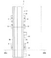
図1は、本発明の実施形態に係る溶接装置を示す正面図である。   FIG. 1 is a front view showing a welding apparatus according to an embodiment of the present invention.

図2は、本発明の実施形態に係る溶接装置を示す側面図である。   FIG. 2 is a side view showing the welding apparatus according to the embodiment of the present invention.

図3は、本発明の実施形態に係る溶接装置を示す背面図である。   FIG. 3 is a rear view showing the welding apparatus according to the embodiment of the present invention.

図1から図3に示す本実施形態に係る溶接装置1は、筒形状の一対の被溶接物200a、200bを溶接して一体化させる。一対の筒形状の被溶接物200a、200bは、例えば配管であり、端部に突合せ継手を備えている。溶接装置1は、この継手を溶接して一対の被溶接物200a、200bを一体化させる。なお、説明を容易にするために溶接装置1は、被溶接物200a側に固定されて被溶接物200a、200b間の継手を溶接する態様とするが、被溶接物200b側に固定されて被溶接物200a、200b間の継手を溶接することもできる。   The welding apparatus 1 according to this embodiment shown in FIGS. 1 to 3 welds and integrates a pair of cylindrical workpieces 200a and 200b. The pair of cylindrical workpieces 200a and 200b are, for example, pipes, and have butt joints at the ends. The welding apparatus 1 welds this joint to integrate the pair of workpieces 200a and 200b. For ease of explanation, the welding apparatus 1 is fixed to the workpiece 200a side and welds the joint between the workpieces 200a and 200b, but is fixed to the workpiece 200b side and fixed. A joint between the weldments 200a and 200b can also be welded.

溶接装置1は、被溶接物200aの外周に固定される環状の基部2と、基部2の周方向へ移動自在であって溶接ヘッド3を支える旋回台5と、旋回台5の駆動力を発生させる複数の電動機6と、基部2に並設されて、溶接ヘッド3へ電力を供給する環状の電力供給部7と、を備えている。   The welding apparatus 1 generates an annular base 2 fixed to the outer periphery of the workpiece 200a, a swivel 5 that is movable in the circumferential direction of the base 2 and supports the welding head 3, and generates a driving force for the swivel 5 A plurality of electric motors 6 to be provided, and an annular power supply unit 7 that is provided in parallel to the base 2 and supplies electric power to the welding head 3.

基部2は、被溶接物200aの外周に固定されて溶接装置1全体を支えている。基部2の内径寸法は、被溶接物200aの外径寸法より大きく、被溶接物200aは、基部2の内側であって円形の空間に配置されている。   The base 2 is fixed to the outer periphery of the workpiece 200a and supports the entire welding apparatus 1. The inner diameter dimension of the base portion 2 is larger than the outer diameter dimension of the workpiece 200a, and the workpiece 200a is disposed inside the base portion 2 and in a circular space.

また、基部2は、正面および背面それぞれの内周縁部に配置されて、基部2の径方向へ出没自在な複数(例えば5つ)のクランプ8を備えている。複数のクランプ8は、基部2の周方向へ略等間隔に配置されている。クランプ8は、基部2の内径よりも被溶接物200a側へ移動して、基部2の内径よりも小径な被溶接物200aに接して溶接装置1全体を支えている。   The base 2 includes a plurality of (for example, five) clamps 8 that are arranged on the inner peripheral edge of each of the front and back surfaces and that can freely protrude and retract in the radial direction of the base 2. The plurality of clamps 8 are arranged at substantially equal intervals in the circumferential direction of the base 2. The clamp 8 moves to the workpiece 200 a side with respect to the inner diameter of the base portion 2 and contacts the workpiece 200 a having a smaller diameter than the inner diameter of the base portion 2 to support the entire welding apparatus 1.

基部2は、周方向において複数の部分、例えば2つの半円弧部2a、2bに分割されている。溶接装置1は、この基部2の分割構造によって、被溶接物200aの外周に配置自在である。溶接装置1は、基部2を分割することによって、被溶接物200aへ容易に着脱できる。   The base portion 2 is divided into a plurality of portions, for example, two semicircular arc portions 2a and 2b in the circumferential direction. The welding device 1 can be arranged on the outer periphery of the workpiece 200a by the divided structure of the base 2. The welding apparatus 1 can be easily attached to and detached from the workpiece 200a by dividing the base 2.

また、基部2は、半円弧部2a、2bを連結して固定する固定機構12を備えている。固定機構12は、基部2の正面および背面のそれぞれであって、半円弧部2a、2bの分割面の近傍に配置されている。   In addition, the base portion 2 includes a fixing mechanism 12 that connects and fixes the semicircular arc portions 2a and 2b. The fixing mechanism 12 is disposed on the front surface and the back surface of the base portion 2 and in the vicinity of the split surfaces of the semicircular arc portions 2a and 2b.

旋回台5は、溶接ヘッド3を支えるトーチホルダ13を備えている。旋回台5は、基部2の外周縁部に沿って被溶接物200aおよび被溶接物200bの周囲を旋回し、溶接ヘッド3を移動させる。トーチホルダ13は、被溶接物200a、200bの口径や溶接ヘッド3の寸法にもよるが、基部2の円周長さに比べて極めて小さく、溶接装置1の重量軽減に寄与している。   The swivel 5 includes a torch holder 13 that supports the welding head 3. The swivel 5 swivels around the workpiece 200a and the workpiece 200b along the outer peripheral edge of the base 2 and moves the welding head 3. The torch holder 13 is extremely small compared to the circumferential length of the base 2 and contributes to weight reduction of the welding apparatus 1, although depending on the diameters of the workpieces 200 a and 200 b and the dimensions of the welding head 3.

複数の電動機6は、例えば、旋回台5の駆動力を発生させる旋回用電動機15と、溶接トーチ19を被溶接物200a、200bの長手方向(配管の延び方向)へ移動させる駆動力を発生させるトーチ縦動電動機16と、溶接トーチ19を被溶接物200a、200bへ近づけたり、遠ざけたりする駆動力を発生させるトーチ遠近電動機17と、溶接トーチ19へワイヤを送給するワイヤ送給電動機18と、を含んでいる。なお、溶接トーチ19の被溶接物200a、200bの長手方向(配管の延び方向)への移動を、溶接トーチ19の縦動移動と呼ぶ。また、これら旋回用電動機15、トーチ縦動電動機16、トーチ遠近電動機17、およびワイヤ送給電動機18は、それぞれ1つであっても良いし、複数あっても良い。   The plurality of electric motors 6 generate, for example, a driving electric motor 15 that generates a driving force for the swivel base 5 and a driving force that moves the welding torch 19 in the longitudinal direction of the workpieces 200a and 200b (the direction in which the pipe extends). A torch longitudinal motor 16, a torch perspective motor 17 that generates a driving force that moves the welding torch 19 closer to or away from the workpieces 200 a and 200 b, and a wire feeding and feeding motor 18 that feeds a wire to the welding torch 19. , Including. In addition, the movement to the to-be-welded object 200a, 200b of the welding torch 19 to the longitudinal direction (pipe extension direction) is called the longitudinal movement movement of the welding torch 19. Further, each of the turning electric motor 15, the torch longitudinal motor 16, the torch perspective motor 17, and the wire feeding / feeding motor 18 may be one or plural.

電力供給部7は、基部2と同様に環状である。電力供給部7は、環状の基部2の正面側に、同心状に配置されている。電力供給部7は、溶接ヘッド3へ電力を供給する電源供給導体9が挿し通される電源用貫通孔11と、電源供給導体9を被溶接物200aに接地させる接地電極片(図示省略)と、を備えている。なお、図2では、電力供給部7は、省略されている。   The power supply unit 7 is annular like the base unit 2. The power supply unit 7 is arranged concentrically on the front side of the annular base 2. The power supply unit 7 includes a power supply through hole 11 through which a power supply conductor 9 for supplying power to the welding head 3 is inserted, and a ground electrode piece (not shown) for grounding the power supply conductor 9 to the workpiece 200a. It is equipped with. In FIG. 2, the power supply unit 7 is omitted.

また、電力供給部7は、基部2と同様に、周方向において複数の部分、例えば2つの半円弧部7a、7bに分割されている。電力供給部7は、少なくとも基部2の分割面の同一面上で分割されている。電力供給部7は、基部2の分割面の同一面上で分割されている限り、基部2の分割面とは異なる箇所でさらに分割されていても良い。溶接装置1は、この電力供給部7の分割構造によって、被溶接物200aの外周に配置自在である。溶接装置1は、電力供給部7を分割することによって、被溶接物200aへ容易に着脱できる。   Similarly to the base 2, the power supply unit 7 is divided into a plurality of portions, for example, two semicircular arc portions 7a and 7b in the circumferential direction. The power supply unit 7 is divided at least on the same plane of the division plane of the base 2. As long as the power supply unit 7 is divided on the same plane of the division surface of the base 2, it may be further divided at a location different from the division surface of the base 2. The welding device 1 can be arranged on the outer periphery of the workpiece 200a by the divided structure of the power supply unit 7. The welding apparatus 1 can be easily attached to and detached from the workpiece 200a by dividing the power supply unit 7.

固定機構12は、基部2とともに電力供給部7の半円弧部7a、7bを連結して固定する。なお、固定機構12は、基部2の固定機構12とは別個の固定機構(図示省略)を備えていても良い。この固定機構は、基部2の固定機構12と同じ構造を有していても良いし、異なる機構を有していても良い。   The fixing mechanism 12 connects and fixes the semicircular arc portions 7 a and 7 b of the power supply unit 7 together with the base 2. The fixing mechanism 12 may include a fixing mechanism (not shown) that is separate from the fixing mechanism 12 of the base 2. This fixing mechanism may have the same structure as the fixing mechanism 12 of the base 2 or may have a different mechanism.

なお、溶接装置1は、溶接ヘッド3とともに旋回台5に支持されて送給前のワイヤを巻き付けておくリール(図示省略)と、ワイヤを被溶接物200a、200bの継手へ導くワイヤガイド(図示省略)と、を備えている。   The welding apparatus 1 includes a reel (not shown) that is supported by the swivel 5 together with the welding head 3 and winds the wire before feeding, and a wire guide (not shown) that guides the wire to the joint of the workpieces 200a and 200b. (Omitted).

溶接ヘッド3は、被溶接物200a、200bの継手をアーク溶接で接合する。具体的には、ティグ溶接(TIG溶接:Tungsten Inert Gas welding)、マグ溶接(MAG溶接:Metal Active Gas welding)、ミグ溶接(MIG溶接:Metal Inert Gas welding)など各種のアーク溶接に好適な溶接トーチ19が適宜選択されて、溶接ヘッド3に装着されている。   The welding head 3 joins the joints of the workpieces 200a and 200b by arc welding. Specifically, welding torches suitable for various types of arc welding such as TIG welding (TIGsten Inert Gas welding), MAG welding (MAG Active: Metal Active Gas welding), and MIG welding (MIG Welding: Metal Inert Gas welding). 19 is appropriately selected and attached to the welding head 3.

次に、溶接装置1の駆動機構について詳細に説明する。   Next, the drive mechanism of the welding apparatus 1 will be described in detail.

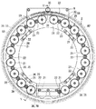
図4は、本発明の実施形態に係る溶接装置の駆動機構を示す正面図である。   FIG. 4 is a front view showing a drive mechanism of the welding apparatus according to the embodiment of the present invention.

図5は、図4のV−V線において、本発明の実施形態に係る溶接装置の駆動機構を示す断面図である。   FIG. 5 is a cross-sectional view showing the drive mechanism of the welding apparatus according to the embodiment of the present invention, taken along line VV in FIG.

図4および図5に示すように、本実施形態に係る溶接装置1は、筒形状の被溶接物200aの外周に固定される環状の基部2と、基部2に沿って環状に並んで交互に噛み合う複数の第一ギヤ21および複数の第二ギヤ22を含む環状ギヤ列23を複数列有する歯車列機構25と、いずれかの環状ギヤ列23の第一ギヤ21に噛み合わされる内歯27を有する弧状の旋回ギヤ28と、旋回ギヤ28に固定されて基部2の周方向へ移動自在であって溶接ヘッド3を支える旋回台5と、旋回台5に往復動自在に保持されて他のいずれかの環状ギヤ列23の第一ギヤ21に噛み合わされる内歯31、および外歯32を有する弧状の往復動ギヤ33と、旋回台5に支持されて往復動ギヤ33の外歯32に噛み合わされて溶接ヘッド3へ動力を伝達する動力伝達ギヤ35と、環状ギヤ列23それぞれの第一ギヤ21へ伝達される駆動力をそれぞれ個別に発生させる複数の電動機6と、を備えている。   As shown in FIG. 4 and FIG. 5, the welding apparatus 1 according to this embodiment includes an annular base 2 fixed to the outer periphery of a cylindrical workpiece 200 a and alternately arranged in a ring along the base 2. A gear train mechanism 25 having a plurality of annular gear trains 23 including a plurality of meshed first gears 21 and a plurality of second gears 22, and an internal tooth 27 meshed with the first gear 21 of any of the annular gear trains 23. An arcuate swivel gear 28, a swivel base 5 fixed to the swivel gear 28 and movable in the circumferential direction of the base 2 and supporting the welding head 3, and a swivel base 5 reciprocally held by the swivel base 5 An arc-shaped reciprocating gear 33 having inner teeth 31 and outer teeth 32 meshed with the first gear 21 of the annular gear train 23, and meshed with the outer teeth 32 of the reciprocating gear 33 supported by the swivel 5. To transmit power to the welding head 3 A transmission gear 35, and a plurality of electric motor 6 for the driving force transmitted to the first gear 21 of each annular gear train 23 is generated individually and.

また、溶接装置1は、複数の電動機6それぞれと複数の環状ギヤ列23それぞれの第一ギヤ21との間に介在する減速機、例えばウォームギヤ機構36を備えている。   In addition, the welding apparatus 1 includes a reduction gear, for example, a worm gear mechanism 36 interposed between each of the plurality of electric motors 6 and each of the first gears 21 of each of the plurality of annular gear trains 23.

基部2は、正面に配置される環状の正面面板37と、背面側に配置される環状の背面面板38と、を備えている。正面面板37および背面面板38は、アルミニウム製、アルミニウム合金製、または繊維強化プラスチック(Fiber-Reinforced Plastics、FRP)製である。正面面板37および背面面板38は、炭素繊維強化プラスチック(Carbon Fiber Reinforced Plastic、CFRP)製であれば、なお良い。正面面板37および背面面板38は、略同じ内外径形状を有して、環状ギヤ列23が配置される隙間を隔てて対向している。正面面板37および背面面板38は、それぞれの内面(相互に対向し合う面)側に旋回台5を案内する環状の案内溝39を有している。   The base 2 includes an annular front face plate 37 disposed on the front surface, and an annular rear face plate 38 disposed on the rear face side. The front face plate 37 and the back face plate 38 are made of aluminum, aluminum alloy, or fiber-reinforced plastics (FRP). The front face plate 37 and the back face plate 38 are preferably made of carbon fiber reinforced plastic (CFRP). The front face plate 37 and the back face plate 38 have substantially the same inner and outer diameter shapes, and face each other with a gap in which the annular gear train 23 is disposed. The front face plate 37 and the back face plate 38 have an annular guide groove 39 for guiding the swivel base 5 on the inner surface (surfaces facing each other) side.

歯車列機構25は、複数の電動機6が発生させる動力をそれぞれの環状ギヤ列23によって旋回ギヤ28または往復動ギヤ33へ伝達して旋回台5の移動、被溶接物200a、200bに対する溶接トーチ19の遠近移動、溶接トーチ19の縦動移動、およびワイヤの送給を行う。そこで、環状ギヤ列23は複数ある。具体的には、環状ギヤ列23は、旋回用電動機15から旋回ギヤ28へ動力を伝達する旋回用ギヤ列45と、トーチ縦動電動機16からトーチ縦動用往復動ギヤ56へ動力を伝達するトーチ縦動用ギヤ列46と、トーチ遠近電動機17からトーチ遠近用往復動ギヤ57へ動力を伝達するトーチ遠近用ギヤ列47と、ワイヤ送給電動機18からワイヤ送給用往復動ギヤ58へ動力を伝達するワイヤ用ギヤ列48と、を含んでいる。   The gear train mechanism 25 transmits the power generated by the plurality of electric motors 6 to the swivel gear 28 or the reciprocating gear 33 through the respective annular gear trains 23 to move the swivel 5 and to weld torches 19 to the workpieces 200a and 200b. , The longitudinal movement of the welding torch 19 and the feeding of the wire. Therefore, there are a plurality of annular gear trains 23. Specifically, the annular gear train 23 transmits the power from the swing motor 15 to the swing gear 28, and the torch transmits the power from the torch longitudinal motion motor 16 to the torch longitudinal motion reciprocating gear 56. Power is transmitted to the longitudinal gear train 46, the torch perspective gear train 47 that transmits power from the torch perspective motor 17 to the torch perspective reciprocating gear 57, and the wire feeding power supply motor 18 to the wire feeding reciprocating gear 58. And a gear train for wire 48.

環状ギヤ列23、つまり、旋回用ギヤ列45、トーチ縦動用ギヤ列46、トーチ遠近用ギヤ列47、およびワイヤ用ギヤ列48のそれぞれは、交互に噛み合う複数の第一ギヤ21および複数の第二ギヤ22によって駆動力を伝える。それぞれの環状ギヤ列23の第一ギヤ21および第二ギヤ22は、アルミニウム製、アルミニウム合金製、または合成樹脂製である。第一ギヤ21および第二ギヤ22に合成樹脂を用いる場合には、耐熱性を有すれば、なお良い。それぞれの環状ギヤ列23の第一ギヤ21および第二ギヤ22は、同一回転軸線上に配置されて、基部2の正面面板37および背面面板38に挟み込まれている。旋回用ギヤ列45は、最も背面面板38よりに配置され、次いでトーチ縦動用ギヤ列46、トーチ遠近用ギヤ列47の順に正面面板37に近づき、ワイヤ用ギヤ列48は、最も正面面板37よりに配置されている。   Each of the annular gear train 23, that is, the turning gear train 45, the torch longitudinal gear train 46, the torch distance gear train 47, and the wire gear train 48, includes a plurality of first gears 21 and a plurality of first gears 21 that are alternately meshed. The driving force is transmitted by the two gears 22. The first gear 21 and the second gear 22 of each annular gear train 23 are made of aluminum, aluminum alloy, or synthetic resin. In the case where synthetic resin is used for the first gear 21 and the second gear 22, it is even better if they have heat resistance. The first gear 21 and the second gear 22 of each annular gear train 23 are arranged on the same rotational axis and are sandwiched between the front face plate 37 and the back face plate 38 of the base 2. The turning gear train 45 is arranged closest to the rear face plate 38, and then approaches the front face plate 37 in the order of the torch longitudinal movement gear train 46 and the torch distance gear train 47, and the wire gear train 48 is located closest to the front face plate 37. Is arranged.

それぞれの環状ギヤ列23は、基部2の全周に渡って旋回台5を駆動自在な好適な間隔で第一ギヤ21を配置している。第二ギヤ22は、第一ギヤ21よりも小径である。第二ギヤ22は、隣り合う第一ギヤ21の間に配置されて動力を伝達する。なお、第二ギヤ22は、全ての第一ギヤ21間にあっても良いし、本実施形態のように円周上の1箇所を間引かれていても良い。また、第二ギヤ22は、複数箇所で間引かれていても良い。   In each annular gear train 23, the first gears 21 are arranged at suitable intervals so that the swivel 5 can be driven over the entire circumference of the base 2. The second gear 22 has a smaller diameter than the first gear 21. The second gear 22 is disposed between the adjacent first gears 21 and transmits power. The second gear 22 may be between all the first gears 21, or may be thinned out at one place on the circumference as in the present embodiment. The second gear 22 may be thinned out at a plurality of locations.

複数の大径な第一ギヤ21の回転中心線は、環状の基部2の同心円を描いて配置されている。複数の小径な第二ギヤ22の回転中心線は、環状の基部2の同心円を描いて配置されており、かつ、それぞれの回転中心線は、隣り合う一対の第一ギヤ21の回転中心線を結ぶ線分上に配置されている。   The rotation center lines of the plurality of large-diameter first gears 21 are arranged so as to draw concentric circles of the annular base 2. The rotation center lines of the plurality of small-diameter second gears 22 are arranged so as to draw concentric circles of the annular base 2, and each rotation center line is a rotation center line of a pair of adjacent first gears 21. It is placed on the connecting line segment.

第二ギヤ22は、一つ置きに第一ギヤ21と第二ギヤ22とのバックラッシを実質的にゼロにする寸法を有している。また、第二ギヤ22は、他の一つ置きに第一ギヤ21と第二ギヤ22との間にゼロより大きいバックラッシを有している。換言すると、第二ギヤ22は、第一ギヤ21と第二ギヤ22とのバックラッシを実質的にゼロにする寸法を有するものと、第一ギヤ21と第二ギヤ22との間にゼロより大きいバックラッシを有するものとが交互に配置されている。他方、全ての第一ギヤ21は、実質的に同じ寸法を有している。   The second gear 22 has a dimension that makes the backlash between the first gear 21 and the second gear 22 substantially zero every other one. The second gear 22 has a backlash greater than zero between the first gear 21 and the second gear 22 every other one. In other words, the second gear 22 is larger than zero between the first gear 21 and the second gear 22 having a dimension that makes the backlash between the first gear 21 and the second gear 22 substantially zero. Those having backlash are alternately arranged. On the other hand, all the first gears 21 have substantially the same dimensions.

なお、環状ギヤ列23は、第二ギヤ22と第一ギヤ21との寸法関係を逆転させてもよい。すなわち、第一ギヤ21は、一つ置きに第一ギヤ21と第二ギヤ22とのバックラッシを実質的にゼロにする寸法を有しており、他の一つ置きに第一ギヤ21と第二ギヤ22との間にゼロより大きいバックラッシを有していてもよい。換言すると、第一ギヤ21は、第一ギヤ21と第二ギヤ22とのバックラッシを実質的にゼロにする寸法を有するものと、第一ギヤ21と第二ギヤ22との間にゼロより大きいバックラッシを有するものとが交互に配置されていても良い。この場合、全ての第二ギヤ22は、実質的に同じ寸法を有することになる。   The annular gear train 23 may reverse the dimensional relationship between the second gear 22 and the first gear 21. That is, the first gear 21 has a dimension that makes the backlash between the first gear 21 and the second gear 22 substantially zero every other one, and the first gear 21 and the second gear 22 every other one. A backlash greater than zero may be provided between the two gears 22. In other words, the first gear 21 is larger than zero between the first gear 21 and the second gear 22 having a dimension that makes the backlash between the first gear 21 and the second gear 22 substantially zero. Those having backlash may be alternately arranged. In this case, all the second gears 22 have substantially the same dimensions.

つまり、第一ギヤ21および第二ギヤ22のいずれか一方は、一つ置きに第一ギヤ21と第二ギヤ22とのバックラッシを実質的にゼロにする寸法を有し、他の一つ置きに第一ギヤ21と第二ギヤ22との間にゼロより大きいバックラッシを有している。換言すると、第一ギヤ21および第二ギヤ22のいずれか一方は、第一ギヤ21と第二ギヤ22とのバックラッシを実質的にゼロにする寸法を有するものと、第一ギヤ21と第二ギヤ22との間にゼロより大きいバックラッシを有するものとが交互に配置されている。そして、第一ギヤ21および第二ギヤ22のいずれか他方は、全て実質的に同じ寸法を有している。   That is, any one of the first gear 21 and the second gear 22 has such a dimension that the backlash between the first gear 21 and the second gear 22 is substantially zero every other one. The first gear 21 and the second gear 22 have a backlash greater than zero. In other words, one of the first gear 21 and the second gear 22 has a dimension that makes the backlash between the first gear 21 and the second gear 22 substantially zero, and the first gear 21 and the second gear 22. Those having a backlash greater than zero are alternately arranged with the gear 22. The other one of the first gear 21 and the second gear 22 has substantially the same dimensions.

そして、環状ギヤ列23の第一ギヤ21と旋回ギヤ28の内歯27とは、バックラッシを実質的にゼロにする寸法関係にある。また、環状ギヤ列23の第一ギヤ21と往復動ギヤ33の内歯31とも、バックラッシを実質的にゼロにする寸法関係にある。ただし、第一ギヤ21と第二ギヤ22とのバックラッシを実質的にゼロにするものとゼロより大きいバックラッシを有するものとを、第一ギヤ21側に混在させる場合には、内歯27と内歯31とは転移量が大きい方の第一ギヤ21に応じて寸法を調整され、かつ、転移量が大きい方の第一ギヤ21が常時、少なくとも1つは噛み合わされていることが好ましい。   The first gear 21 of the annular gear train 23 and the internal teeth 27 of the swivel gear 28 have a dimensional relationship that makes backlash substantially zero. The first gear 21 of the annular gear train 23 and the inner teeth 31 of the reciprocating gear 33 are also in a dimensional relationship that makes backlash substantially zero. However, when the first gear 21 and the second gear 22 have substantially zero backlash and those having a backlash greater than zero on the first gear 21 side, the inner teeth 27 and the inner gear 27 It is preferable that the size of the tooth 31 is adjusted according to the first gear 21 having the larger transfer amount, and at least one of the first gears 21 having the larger transfer amount is always meshed.

旋回台5は、基部2の案内溝39に嵌め込まれるころ部59を備えている。ころ部59は、第一ギヤ21の回転によって旋回ギヤ28に生じる径方向外側の力に抗して旋回台5を支えている。   The swivel base 5 includes a roller portion 59 that is fitted into the guide groove 39 of the base portion 2. The roller portion 59 supports the swivel 5 against the radially outer force generated in the swivel gear 28 by the rotation of the first gear 21.

また、旋回台5は、基部2の接線方向へ延びて広がるトーチ設置面61を有している。   In addition, the swivel 5 has a torch installation surface 61 that extends in the tangential direction of the base 2 and spreads.

動力伝達ギヤ35は、トーチ縦動用往復動ギヤ56の外歯32に噛み合わされるトーチ縦動用動力伝達ギヤ66、トーチ遠近用往復動ギヤ57の外歯32に噛み合わされるトーチ遠近用動力伝達ギヤ67、およびワイヤ送給用往復動ギヤ58の外歯32に噛み合わされるワイヤ送給用動力伝達ギヤ68を含んでいる。   The power transmission gear 35 includes a torch longitudinal power transmission gear 66 meshed with the external teeth 32 of the torch longitudinal reciprocating gear 56 and a torch distance power transmission gear meshed with the external teeth 32 of the torch distance reciprocating gear 57. 67, and a wire feeding power transmission gear 68 that meshes with the external teeth 32 of the wire feeding reciprocating gear 58.

複数の電動機6は、環状ギヤ列23ごとに少なくとも1つずつ設けられて、環状ギヤ列23の第一ギヤ21へ伝達される駆動力をそれぞれ個別に発生させる。つまり、少なくとも1つの旋回用電動機15が旋回用ギヤ列45に接続され、少なくとも1つのトーチ縦動電動機16がトーチ縦動用ギヤ列46に接続され、少なくとも1つのトーチ遠近電動機17がトーチ遠近用ギヤ列47に接続され、少なくとも1つのワイヤ送給電動機18がワイヤ用ギヤ列48に接続されている。複数の電動機6は、環状ギヤ列23ごとに複数設けられていても良い。つまり、複数の旋回用電動機15が旋回用ギヤ列45に接続され、複数のトーチ縦動電動機16がトーチ縦動用ギヤ列46に接続され、複数のトーチ遠近電動機17がトーチ遠近用ギヤ列47に接続され、複数のワイヤ送給電動機18がワイヤ用ギヤ列48に接続されていていても良い。   The plurality of electric motors 6 are provided at least one for each annular gear train 23 and individually generate driving force transmitted to the first gear 21 of the annular gear train 23. That is, at least one turning motor 15 is connected to the turning gear train 45, at least one torch longitudinal motion motor 16 is connected to the torch longitudinal movement gear train 46, and at least one torch perspective motor 17 is connected to the torch perspective gear. Connected to the row 47, at least one wire feeding / feeding motive 18 is connected to the wire gear row 48. A plurality of electric motors 6 may be provided for each annular gear train 23. That is, the plurality of turning electric motors 15 are connected to the turning gear train 45, the plurality of torch longitudinal motion motors 16 are connected to the torch longitudinal movement gear train 46, and the plurality of torch perspective motors 17 are connected to the torch perspective gear train 47. A plurality of wire feeding / feeding motives 18 may be connected to the wire gear train 48.

また、環状ギヤ列23の第二ギヤ22が複数箇所で間引かれている場合、つまり、電動機6からある1つの第二ギヤ22に駆動力を与えても第一ギヤ21の全てを駆動させられない場合には、動力を伝え合うことが可能な第一ギヤ21および第二ギヤ22の組み合わせごとに、少なくとも1つの電動機6が設けられる。換言すると、複数の電動機6は、環状ギヤ列23において、互いに噛み合わされる第一ギヤ21および第二ギヤ22の組み合わせごとに少なくとも1つずつ設けられていれば良い。   Further, when the second gear 22 of the annular gear train 23 is thinned out at a plurality of locations, that is, even if a driving force is applied from the electric motor 6 to one second gear 22, all of the first gear 21 is driven. Otherwise, at least one electric motor 6 is provided for each combination of the first gear 21 and the second gear 22 that can transmit power. In other words, the plurality of electric motors 6 may be provided at least one for each combination of the first gear 21 and the second gear 22 meshed with each other in the annular gear train 23.

旋回用電動機15は、ウォームギヤ機構36を介して旋回用ギヤ列45の第一ギヤ21に接続されていても良いし、ウォームギヤ機構36を介して旋回用ギヤ列45の第二ギヤ22に接続されていても良いし、ウォームギヤ機構36を介して旋回用ギヤ列45の第一ギヤ21に接続されているものと旋回用ギヤ列45の第二ギヤ22に接続されていているものとが混在していても良い。トーチ縦動電動機16、トーチ遠近電動機17、およびワイヤ送給電動機18についても旋回用電動機15と同様である。   The turning electric motor 15 may be connected to the first gear 21 of the turning gear train 45 via the worm gear mechanism 36 or connected to the second gear 22 of the turning gear train 45 via the worm gear mechanism 36. Alternatively, there may be a mixture of those connected to the first gear 21 of the turning gear train 45 and those connected to the second gear 22 of the turning gear train 45 via the worm gear mechanism 36. May be. The torch longitudinal motor 16, the torch perspective motor 17, and the wire feeding / feeding motor 18 are the same as the turning motor 15.

ウォームギヤ機構36は、旋回用電動機15の駆動力を旋回用ギヤ列45へ伝達する旋回用ウォームギヤ機構75と、トーチ縦動電動機16の駆動力をトーチ縦動用ギヤ列46へ伝達するトーチ縦動用ウォームギヤ機構76と、トーチ遠近電動機17の駆動力をトーチ遠近用ギヤ列47へ伝達するトーチ遠近用ウォームギヤ機構77と、ワイヤ送給電動機18の駆動力をワイヤ用ギヤ列48へ伝達するワイヤ用差動歯車ウォームギヤ機構78と、を含んでいる。   The worm gear mechanism 36 includes a turning worm gear mechanism 75 that transmits the driving force of the turning electric motor 15 to the turning gear train 45, and a torch longitudinal movement worm gear that transmits the driving force of the torch longitudinal movement motor 16 to the torch longitudinal movement gear train 46. A mechanism 76, a torch perspective worm gear mechanism 77 that transmits the driving force of the torch perspective motor 17 to the torch perspective gear train 47, and a wire differential that transmits the driving force of the wire feed / motive device 18 to the wire gear train 48. A gear worm gear mechanism 78.

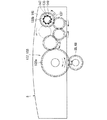
図6は、本発明の実施形態に係る溶接装置の旋回台と駆動機構との関係を示す概念図である。   FIG. 6 is a conceptual diagram showing the relationship between the swivel and the drive mechanism of the welding apparatus according to the embodiment of the present invention.

図6に示すように、本実施形態に係る溶接装置1の旋回ギヤ28は、環状ギヤ列23、具体的には旋回用ギヤ列45の第一ギヤ21の外周に噛み合わされている。旋回ギヤ28は、旋回用ギヤ列45の第一ギヤ21の回転によって基部2の周方向へ移動して旋回台5の推進力を発生させる。旋回ギヤ28は、少なくとも1つの第一ギヤ21に噛み合っていれば良い。   As shown in FIG. 6, the turning gear 28 of the welding apparatus 1 according to the present embodiment is meshed with the outer periphery of the first gear 21 of the annular gear train 23, specifically, the turning gear train 45. The swivel gear 28 moves in the circumferential direction of the base portion 2 by the rotation of the first gear 21 of the swivel gear train 45 and generates the propulsive force of the swivel base 5. The turning gear 28 only needs to mesh with at least one first gear 21.

なお、旋回ギヤ28は、図4および図6に二点鎖線で示すように、環状にひと続きの環形ギヤであっても良い。旋回ギヤ28は、基部2や電力供給部7と同様に、周方向において複数の部分、例えば2つの半円弧部(図示省略)に分割されている。つまり、旋回ギヤ28は、中心角が180度以下の弧状ギヤ部材を複数有している。溶接装置1は、この旋回ギヤ28の分割構造によって、被溶接物200aの外周に配置自在である。溶接装置1は、旋回ギヤ28を分割することによって、被溶接物200aへ容易に着脱できる。   The swivel gear 28 may be a ring-shaped continuous ring gear as indicated by a two-dot chain line in FIGS. 4 and 6. Similar to the base 2 and the power supply unit 7, the swivel gear 28 is divided into a plurality of portions, for example, two semicircular arc portions (not shown) in the circumferential direction. That is, the turning gear 28 has a plurality of arc-shaped gear members having a central angle of 180 degrees or less. The welding device 1 can be arranged on the outer periphery of the workpiece 200a by the divided structure of the turning gear 28. The welding apparatus 1 can be easily attached to and detached from the workpiece 200a by dividing the swivel gear 28.

また、旋回ギヤ28は、例えばアルミニウム製、アルミニウム合金製、繊維強化プラスチック(Fiber-Reinforced Plastics、FRP)製、または炭素繊維強化プラスチック(Carbon Fiber Reinforced Plastic、CFRP)製の芯材に、芯材とは異なる素材、例えばアルミニウム製、アルミニウム合金製、繊維強化プラスチック(Fiber-Reinforced Plastics、FRP)製、炭素繊維強化プラスチック(Carbon Fiber Reinforced Plastic、CFRP)製、またはポリアセタールコポリマー(PolyacetalmPolyoxymethylene、POM)製の内歯27を接着等で固定した部材である。往復動ギヤ33も、旋回ギヤ28と同様な構造を有している。なお、旋回ギヤ28の内歯27、および往復動ギヤ33の内歯33はいずれも、環状の芯材に対して飛び飛び(ひと続きではない、離散的な)に設けられていてもよい。換言すると、旋回ギヤ28は、芯材の周方向へ分割された複数の内歯27を備えていても良く、往復動ギヤ33は、芯材の周方向へ分割された複数の内歯33を備えていても良い。これら複数の内歯27、33のそれぞれは、芯材の周方向へ等間隔に並んでいることが好ましい。   The swivel gear 28 is made of, for example, a core made of aluminum, aluminum alloy, fiber-reinforced plastics (FRP), or carbon fiber reinforced plastic (CFRP). Are made of different materials, such as aluminum, aluminum alloy, fiber-reinforced plastics (FRP), carbon fiber reinforced plastic (CFRP), or polyacetal copolymer (Polyacetalm Polyoxymethylene, POM) This is a member in which the teeth 27 are fixed by bonding or the like. The reciprocating gear 33 also has the same structure as the turning gear 28. Note that both the internal teeth 27 of the swivel gear 28 and the internal teeth 33 of the reciprocating gear 33 may be provided so as to be jumped (not continuous but discrete) with respect to the annular core material. In other words, the turning gear 28 may include a plurality of inner teeth 27 divided in the circumferential direction of the core material, and the reciprocating gear 33 includes a plurality of inner teeth 33 divided in the circumferential direction of the core material. You may have. Each of the plurality of internal teeth 27 and 33 is preferably arranged at equal intervals in the circumferential direction of the core material.

図7および図8は、本発明の実施形態に係る溶接装置の旋回台と駆動機構との関係を示す概念図である。   7 and 8 are conceptual diagrams showing the relationship between the swivel and the drive mechanism of the welding apparatus according to the embodiment of the present invention.

図7および図8に示すように、本実施形態に係る溶接装置1のトーチ縦動用往復動ギヤ56は、旋回台5によって移動範囲を規制される一方で、トーチ縦動用ギヤ列46の第一ギヤ21に噛み合わされる内歯31によって基部2の周方向へ移動すると同時に、旋回台5に対しても移動する。   As shown in FIGS. 7 and 8, the reciprocating gear 56 for torch longitudinal movement of the welding apparatus 1 according to the present embodiment is restricted in the movement range by the swivel 5, while the first of the torch longitudinal movement gear train 46. The inner teeth 31 meshed with the gear 21 move in the circumferential direction of the base 2 and simultaneously move with respect to the swivel base 5.

トーチ縦動用往復動ギヤ56は、円弧形状に沿って延びる案内穴79を有している。トーチ縦動用往復動ギヤ56は、案内穴79に配置される案内棒81によって、旋回台5に支持されている。案内棒81は、第一ギヤ21の回転によって移動するトーチ縦動用往復動ギヤ56に生じる径方向外側の力に抗してトーチ縦動用往復動ギヤ56を支えている。   The torch longitudinal movement reciprocating gear 56 has a guide hole 79 extending along an arc shape. The reciprocating gear 56 for longitudinal movement of the torch is supported on the turntable 5 by a guide rod 81 disposed in the guide hole 79. The guide rod 81 supports the reciprocating gear 56 for torch longitudinal movement against the radially outward force generated in the reciprocating gear 56 for torch longitudinal movement that moves as the first gear 21 rotates.

そして、トーチ縦動用往復動ギヤ56の移動は、内歯31もろとも外歯32を移動させ、外歯32に噛み合わされるトーチ縦動用動力伝達ギヤ66を回転させる。   The movement of the reciprocating gear 56 for torch longitudinal movement moves the outer teeth 32 together with the inner teeth 31 and rotates the torch longitudinal power transmission gear 66 meshed with the outer teeth 32.

トーチ縦動用動力伝達ギヤ66は、トーチ縦動用往復動ギヤ56、つまり往復動ギヤ33の往動および復動にしたがって二方向へ回転される。   The torch longitudinal movement power transmission gear 66 is rotated in two directions according to the forward and backward movements of the torch longitudinal movement reciprocating gear 56, that is, the reciprocating gear 33.

なお、トーチ遠近用ギヤ列47の第一ギヤ21に噛み合わされるトーチ遠近用往復動ギヤ57およびワイヤ用ギヤ列48の第一ギヤ21に噛み合わされるワイヤ送給用往復動ギヤ58は、トーチ縦動用ギヤ列46の第一ギヤ21に噛み合わされるトーチ縦動用往復動ギヤ56と同じ構造を採用しているので説明を省略する。同様にトーチ遠近用動力伝達ギヤ67およびワイヤ送給用動力伝達ギヤ68についてもトーチ縦動用動力伝達ギヤ66と同じ構造を採用しているので説明を省略する。   Note that the torch distance reciprocating gear 57 meshed with the first gear 21 of the torch distance gear train 47 and the wire feeding reciprocating gear 58 meshed with the first gear 21 of the wire gear train 48 include a torch. Since the same structure as the reciprocating gear 56 for torch longitudinal movement meshed with the first gear 21 of the longitudinal gear train 46 is employed, the description thereof is omitted. Similarly, since the torch longitudinal power transmission gear 67 and the wire feeding power transmission gear 68 have the same structure as the torch longitudinal movement power transmission gear 66, the description thereof will be omitted.

溶接装置1は、旋回用ギヤ列45、トーチ縦動用ギヤ列46、トーチ遠近用ギヤ列47およびワイヤ用ギヤ列48の回転を連携させることによって、旋回台5の移動、溶接トーチ19の縦動移動、溶接トーチ19の遠近移動およびワイヤの送給を行う。   The welding device 1 moves the swivel base 5 and moves the welding torch 19 in a longitudinal manner by coordinating the rotation of the turning gear train 45, the torch longitudinal motion gear train 46, the torch perspective gear train 47 and the wire gear train 48. Movement, distance movement of the welding torch 19 and wire feeding are performed.

具体的には、旋回用ギヤ列45、トーチ縦動用ギヤ列46、トーチ遠近用ギヤ列47およびワイヤ用ギヤ列48の第一ギヤ21が同速度で同方向へ回転すると、旋回台5は移動する一方、溶接トーチ19の縦動移動、溶接トーチ19の遠近移動およびワイヤの送給は停止する。これは、旋回用ギヤ列45、トーチ縦動用ギヤ列46、トーチ遠近用ギヤ列47およびワイヤ用ギヤ列48の第一ギヤ21が同速度で同方向へ回転することによって、旋回ギヤ28と往復動ギヤ33との移動が同期し、ひいては動力伝達ギヤ35が旋回台5に対して相対的に停止するためである。   Specifically, when the first gear 21 of the turning gear train 45, the torch longitudinal motion gear train 46, the torch distance gear train 47, and the wire gear train 48 rotates in the same direction at the same speed, the swivel 5 moves. On the other hand, the longitudinal movement of the welding torch 19, the distance movement of the welding torch 19 and the feeding of the wire are stopped. This is because the first gear 21 of the turning gear train 45, the torch longitudinal gear train 46, the torch distance gear train 47 and the wire gear train 48 rotates in the same direction at the same speed, thereby reciprocating with the turning gear 28. This is because the movement with the moving gear 33 is synchronized, and consequently the power transmission gear 35 stops relative to the swivel base 5.

ここで、旋回用ギヤ列45およびトーチ縦動用ギヤ列46に着目する。   Here, attention is paid to the turning gear train 45 and the torch longitudinal motion gear train 46.

旋回用ギヤ列45およびトーチ縦動用ギヤ列46が相対的に異なる速度で回転すると、相互の回転速度差によって、旋回ギヤ28ひいては旋回台5に対してトーチ縦動用往復動ギヤ56が移動し、ひいてはトーチ縦動用動力伝達ギヤ66が回転して溶接ヘッド3を縦動移動させる。なお、溶接トーチ19が縦動移動するか否かは、旋回用ギヤ列45およびトーチ縦動用ギヤ列46の相対的な回転速度差が生じているか否かによるものであって、旋回台5が移動しているか否かにはよらない。旋回用ギヤ列45およびトーチ遠近用ギヤ列47の組合せであっても、旋回用ギヤ列45およびワイヤ用ギヤ列48の組合せであっても、同様に作用する。   When the turning gear train 45 and the torch longitudinal movement gear train 46 rotate at relatively different speeds, the torch longitudinal movement reciprocating gear 56 moves with respect to the turning gear 28 and consequently the turntable 5 due to the difference in rotational speed between them. As a result, the torch longitudinal movement power transmission gear 66 rotates to move the welding head 3 in the longitudinal movement. Whether or not the welding torch 19 moves vertically depends on whether or not there is a relative rotational speed difference between the turning gear train 45 and the torch longitudinal moving gear train 46. It does not depend on whether or not you are moving. The combination of the turning gear train 45 and the torch perspective gear train 47 and the combination of the turning gear train 45 and the wire gear train 48 operate in the same manner.

なお、往復動ギヤ33(トーチ縦動用往復動ギヤ56、トーチ遠近用往復動ギヤ57、およびワイヤ送給用往復動ギヤ58)の原点位置は、案内穴79のいずれかの端部79a、79bに案内棒81が突き当たり、電動機6の駆動が阻止された状態を基準として設定される。例えば、電動機6としてステッピングモーター(Stepper Motor)を採用する場合には、案内穴79のいずれか一方の端部79aに案内棒81が突き当たった状態から案内穴79のいずれか他方の端部79bに案内棒81が突き当たった状態に到達するまで電動機6にパルス電力を入力し、このときのパルス電力のパルス数を計数し、案内穴79のいずれかの端部79a、79bから計数値の2分の1に相当するパルス数を電動機6に入力した位置を往復動ギヤ33の原点位置に設定する。また、案内穴79のいずれかの端部79a、79bから予め定めるパルス数を電動機6に入力した位置を往復動ギヤ33の原点位置に設定することもできる。なお、案内穴79のいずれかの端部79a、79bに案内棒81が突き当たり、電動機6の駆動が阻止された状態であるか否かは、電動機6の駆動回路側で検知することができる。   Note that the origin position of the reciprocating gear 33 (the torch longitudinal reciprocating gear 56, the torch distance reciprocating gear 57, and the wire feeding reciprocating gear 58) is the end 79a, 79b of one of the guide holes 79. It is set on the basis of the state where the guide rod 81 hits and the drive of the electric motor 6 is prevented. For example, when a stepper motor is used as the electric motor 6, the guide rod 81 comes into contact with any one end 79 a of the guide hole 79 from the other end 79 b of the guide hole 79. Pulse power is input to the electric motor 6 until the guide rod 81 reaches the abutted state, the number of pulses of the pulse power at this time is counted, and the counted value is 2 minutes from either end 79a, 79b of the guide hole 79. The position where the number of pulses corresponding to 1 is input to the electric motor 6 is set as the origin position of the reciprocating gear 33. Further, the position where a predetermined number of pulses are input to the electric motor 6 from either end 79 a or 79 b of the guide hole 79 can be set as the origin position of the reciprocating gear 33. In addition, it can be detected on the drive circuit side of the electric motor 6 whether or not the guide rod 81 hits one of the end portions 79a and 79b of the guide hole 79 and the electric motor 6 is prevented from being driven.

また、往復動ギヤ33(トーチ縦動用往復動ギヤ56、トーチ遠近用往復動ギヤ57、およびワイヤ送給用往復動ギヤ58)は、図4、図7、および図8に二点鎖線で示すように、旋回ギヤ28と同様に、環状にひと続きの環形ギヤであっても良い。往復動ギヤ33は、基部2、電力供給部7、および旋回ギヤ28と同様に、周方向において複数の部分、例えば2つの半円弧部(図示省略)に分割されている。つまり、往復動ギヤ33は、中心角が180度以下の弧状ギヤ部材を複数有している。溶接装置1は、この往復動ギヤ33の分割構造によって、被溶接物200aの外周に配置自在である。溶接装置1は、往復動ギヤ33を分割することによって、被溶接物200aへ容易に着脱できる。   The reciprocating gear 33 (the torch longitudinal reciprocating gear 56, the torch distance reciprocating gear 57, and the wire feeding reciprocating gear 58) is indicated by a two-dot chain line in FIG. 4, FIG. 7, and FIG. Thus, like the swivel gear 28, it may be a ring gear that is continuous in an annular shape. The reciprocating gear 33 is divided into a plurality of portions, for example, two semicircular arc portions (not shown) in the circumferential direction, like the base portion 2, the power supply portion 7, and the turning gear 28. That is, the reciprocating gear 33 has a plurality of arc-shaped gear members having a central angle of 180 degrees or less. The welding apparatus 1 can be arranged on the outer periphery of the workpiece 200a by the split structure of the reciprocating gear 33. The welding apparatus 1 can be easily attached to and detached from the workpiece 200 a by dividing the reciprocating gear 33.

また、往復動ギヤ33が環形ギヤの場合には、溶接装置1は、案内穴79および案内棒81による往復動ギヤ33の保持に代えて、往復動ギヤ33が基部2の径方向外側へ移動することを規制し、かつ往復動ギヤ33のそれぞれに噛み合わされる環状ギヤ列23の第一ギヤ21へ往復動ギヤ33を一括して押さえ付けて、これらを保持する外殻バンド82(保持枠体)を備えていることが好ましい。   When the reciprocating gear 33 is an annular gear, the welding apparatus 1 moves the reciprocating gear 33 radially outward of the base 2 instead of holding the reciprocating gear 33 by the guide hole 79 and the guide rod 81. And the outer shell band 82 (holding frame) holding the reciprocating gear 33 collectively against the first gear 21 of the annular gear train 23 meshed with each of the reciprocating gears 33. Body).

外殻バンド82は、旋回ギヤ28、および往復動ギヤ33を一括して環形ギヤの状態に束ねて保持している。外殻バンド82は、正面面板37および背面面板38の外周部に巻き付けられるようにして正面面板37と背面面板38とを隔てる空間を閉ざし、かつこの空間の最も外側に配置されている往復動ギヤ33を一括して、摺動可能に保持する。外殻バンド82は、旋回台5に固定されて、旋回台5とともに移動する。外殻バンド82は、往復動ギヤ33を、基部2の周方向において一方向へ移動することを可能にする。つまり、往復動ギヤ33は、基部2の周方向において往復移動可能(時計回りおよび反時計回りに移動可能)である一方で、時計回り、または反時計回りに連続して何周も回転することが可能になる。   The outer shell band 82 holds the swivel gear 28 and the reciprocating gear 33 in a bundled state in an annular gear. The outer shell band 82 is wrapped around the outer peripheral portions of the front face plate 37 and the rear face plate 38 so as to close a space separating the front face plate 37 and the rear face plate 38 and is a reciprocating gear disposed at the outermost side of this space. 33 are collectively held slidably. The outer band 82 is fixed to the turntable 5 and moves together with the turntable 5. The outer band 82 allows the reciprocating gear 33 to move in one direction in the circumferential direction of the base 2. In other words, the reciprocating gear 33 can reciprocate in the circumferential direction of the base 2 (movable clockwise and counterclockwise), and can rotate continuously in a clockwise or counterclockwise direction. Is possible.

外殻バンド82は、基部2の周方向において旋回台5の一方の端部82aから他方の端部82bへ連続するひと続きの帯状体である。外殻バンド82は、基部2、および電力供給部7と同様に、周方向において複数の部分、例えば2つの半円弧部(図示省略)に分割されている。溶接装置1は、この外殻バンド82の分割構造によって、被溶接物200aの外周に配置自在である。溶接装置1は、外殻バンド82を分割することによって、被溶接物200aへ容易に着脱できる。外殻バンド82は、旋回用ギヤ列45の第一ギヤ21に旋回ギヤ28を押さえ付けていても良い。   The outer shell band 82 is a continuous band-like body that continues from one end 82 a of the swivel base 5 to the other end 82 b in the circumferential direction of the base 2. Similarly to the base 2 and the power supply unit 7, the outer shell band 82 is divided into a plurality of portions, for example, two semicircular arc portions (not shown) in the circumferential direction. The welding device 1 can be arranged on the outer periphery of the workpiece 200a by the split structure of the outer shell band 82. The welding apparatus 1 can be easily attached to and detached from the workpiece 200a by dividing the outer shell band 82. The outer shell band 82 may press the turning gear 28 against the first gear 21 of the turning gear train 45.

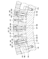
図9は、本発明の実施形態に係る溶接装置のウォームギヤ機構を示す断面図である。   FIG. 9 is a sectional view showing a worm gear mechanism of the welding apparatus according to the embodiment of the present invention.

図9に示すように、本実施形態に係る溶接装置1の旋回用ウォームギヤ機構75は、旋回用電動機15の出力軸101に回転一体のねじ歯車102(ウォーム103)と、旋回用ギヤ列45の第一ギヤ21に回転一体のギヤ107と、を備えている。旋回用ウォームギヤ機構75は、ねじ歯車102へ入力される旋回用電動機15の駆動力をギヤ107で旋回用ギヤ列45へ伝達する。   As shown in FIG. 9, the turning worm gear mechanism 75 of the welding apparatus 1 according to this embodiment includes a screw gear 102 (worm 103) that is integrally rotated with the output shaft 101 of the turning electric motor 15, and a turning gear train 45. The first gear 21 is provided with a rotation-integrated gear 107. The turning worm gear mechanism 75 transmits the driving force of the turning electric motor 15 input to the screw gear 102 to the turning gear train 45 by the gear 107.

トーチ縦動用ウォームギヤ機構76は、トーチ縦動電動機16の出力軸112に回転一体のねじ歯車113(ウォーム113)と、トーチ縦動用ギヤ列46の第一ギヤ21に回転一体のギヤ115と、を備えている。トーチ縦動用ウォームギヤ機構76は、ねじ歯車113へ入力されるトーチ縦動電動機16の駆動力をギヤ115でトーチ縦動用ギヤ列46へ伝達する。   The torch longitudinal motion worm gear mechanism 76 includes a screw gear 113 (worm 113) that is integrally rotated with the output shaft 112 of the torch longitudinal motion motor 16, and a gear 115 that is integrally rotated with the first gear 21 of the gear train 46 for torch longitudinal motion. I have. The torch longitudinal motion worm gear mechanism 76 transmits the driving force of the torch longitudinal motion motor 16 input to the screw gear 113 to the torch longitudinal motion gear train 46 through the gear 115.

第一ギヤ21に回転一体のギヤ107、115は、はす歯歯車であることが好ましい。   The gears 107 and 115 that are integrally rotated with the first gear 21 are preferably helical gears.

旋回用ウォームギヤ機構75およびトーチ縦動用ウォームギヤ機構76を含むウォームギヤ機構36のそれぞれも、同様である。つまり、旋回用ウォームギヤ機構75、トーチ遠近用ウォームギヤ機構77、およびワイヤ用ウォームギヤ機構78は、トーチ縦動用ウォームギヤ機構76と同じ構成を備えている。   The same applies to each of the worm gear mechanisms 36 including the turning worm gear mechanism 75 and the torch longitudinal movement worm gear mechanism 76. That is, the turning worm gear mechanism 75, the torch distance worm gear mechanism 77, and the wire worm gear mechanism 78 have the same configuration as the torch longitudinal movement worm gear mechanism 76.

また、溶接装置1は、電動機6の出力軸112、環状ギヤ列23の第一ギヤ21、および環状ギヤ列23の第二ギヤ22のいずれかの回転角度を検出する回転センサ92(回転角度検出器)を備えている。回転センサ92は、環状ギヤ列23毎に設けられている。つまり、回転センサ92は、旋回用電動機15の出力軸101、旋回用ギヤ列45の第一ギヤ21、および旋回用ギヤ列45の第二ギヤ22のいずれかの回転角度を検出する旋回用回転センサ93と、トーチ縦動電動機16の出力軸112、トーチ縦動用ギヤ列46の第一ギヤ21、およびトーチ縦動用ギヤ列46の第二ギヤ22のいずれかの回転角度を検出するトーチ縦動用回転センサ95と、トーチ遠近電動機17の出力軸(図示省略)、トーチ遠近用ギヤ列47の第一ギヤ21、およびトーチ遠近用ギヤ列47の第二ギヤ22のいずれかの回転角度を検出するトーチ遠近用回転センサ(図示省略)と、ワイヤ送給電動機18の出力軸(図示省略)、ワイヤ用ギヤ列48の第一ギヤ21、およびワイヤ用ギヤ列48の第二ギヤ22のいずれかの回転角度を検出するワイヤ用回転センサ(図示省略)と、を含んでいる。   The welding apparatus 1 also includes a rotation sensor 92 (rotation angle detection) that detects the rotation angle of any one of the output shaft 112 of the electric motor 6, the first gear 21 of the annular gear train 23, and the second gear 22 of the annular gear train 23. Equipment). The rotation sensor 92 is provided for each annular gear train 23. In other words, the rotation sensor 92 detects the rotation angle of any one of the output shaft 101 of the turning electric motor 15, the first gear 21 of the turning gear train 45, and the second gear 22 of the turning gear train 45. For the torch longitudinal movement detecting the rotation angle of the sensor 93, the output shaft 112 of the torch longitudinal movement motor 16, the first gear 21 of the torch longitudinal movement gear train 46, and the second gear 22 of the torch longitudinal motion gear train 46. The rotation angle of any one of the rotation sensor 95, the output shaft (not shown) of the torch perspective motor 17, the first gear 21 of the torch perspective gear train 47, and the second gear 22 of the torch perspective gear train 47 is detected. A rotation sensor (not shown) for torch / near perspective, an output shaft (not shown) of the wire feeding / feeding motive 18, the first gear 21 of the wire gear train 48, and the second gear 22 of the wire gear train 48. A wire rotation sensor for detecting the Kano rotation angle (not shown), includes a.

さらに、溶接装置1は、回転センサ92(旋回用回転センサ93、トーチ縦動用回転センサ95、トーチ遠近用回転センサ、およびワイヤ用回転センサ)が検出した回転角度に基づいて、複数の電動機6の駆動または停止を制御して複数の環状ギヤ列23を等速度に同期させて回転させ、または異なる速度で非同期に回転させる制御部99を備えている。   Furthermore, the welding apparatus 1 uses the rotation angles detected by the rotation sensors 92 (the rotation sensor 93 for turning, the rotation sensor 95 for torch longitudinal movement, the rotation sensor for torch distance, and the rotation sensor for wires) of the plurality of electric motors 6. A control unit 99 that controls driving or stopping to rotate the plurality of annular gear trains 23 in synchronism with a constant speed or asynchronously rotates at different speeds is provided.

制御部99は、マイクロプロセッサ(図示省略)、およびマイクロプロセッサが実行する各種演算プログラム、パラメータなどを記憶する記憶装置(図示省略)を備えている。制御部99は、それぞれの電動機6(旋回用電動機15、トーチ縦動電動機16、トーチ遠近電動機17、およびワイヤ送給電動機18)と、それぞれの回転センサ92(旋回用回転センサ93、トーチ縦動用回転センサ95、トーチ遠近用回転センサ、およびワイヤ用回転センサ)とに電気的に接続されている。   The control unit 99 includes a microprocessor (not shown) and a storage device (not shown) that stores various calculation programs, parameters, and the like executed by the microprocessor. The control unit 99 includes each motor 6 (turning motor 15, torch longitudinal motor 16, torch perspective motor 17, and wire feed motor 18) and each rotation sensor 92 (turning rotation sensor 93, torch longitudinal movement). A rotation sensor 95, a torch perspective rotation sensor, and a wire rotation sensor).

制御部99は、マイクロプロセッサで実行される自動溶接プログラムに従って電動機6および溶接トーチ19を制御することによって一対の被溶接物200a、200bを溶接して一体化させる。   The control unit 99 welds and integrates the pair of workpieces 200a and 200b by controlling the electric motor 6 and the welding torch 19 according to an automatic welding program executed by the microprocessor.

ここで先ず、旋回用電動機15と旋回用ギヤ列45との関係について説明する。   First, the relationship between the turning electric motor 15 and the turning gear train 45 will be described.

旋回用電動機15が発生させる駆動力は、出力軸101に回転一体のねじ歯車102から、ねじ歯車102に噛み合わされるギヤ107を経て旋回用ギヤ列45の第一ギヤ21へ伝達される。   The driving force generated by the turning electric motor 15 is transmitted from the screw gear 102 that is rotated and integrated with the output shaft 101 to the first gear 21 of the turning gear train 45 through the gear 107 that is meshed with the screw gear 102.

次いで、トーチ縦動電動機16とトーチ縦動用ギヤ列46との関係について説明する。   Next, the relationship between the torch longitudinal motion motor 16 and the torch longitudinal motion gear train 46 will be described.

トーチ縦動電動機16が発生させる駆動力は、出力軸112に回転一体のねじ歯車113から、ねじ歯車113に噛み合わされるギヤ115を経てトーチ縦動用ギヤ列46の第一ギヤ21へ伝達される。   The driving force generated by the torch longitudinal motor 16 is transmitted from the screw gear 113 that is integrally rotated with the output shaft 112 to the first gear 21 of the torch longitudinal gear train 46 through the gear 115 that is meshed with the screw gear 113. .

そして、制御部99は、回転センサ92(旋回用回転センサ93、トーチ縦動用回転センサ95)が出力する検出結果に基づいて電動機6(旋回用電動機15、トーチ縦動電動機16)を運転し、旋回用ギヤ列45の第一ギヤ21とトーチ従動用ギヤ列46の第一ギヤ21とを同じ角速度(回転数)で回転させる。同じ角速度で回転する旋回用ギヤ列45の第一ギヤ21およびトーチ従動用ギヤ列46の第一ギヤ21は、旋回ギヤ28とトーチ縦動用往復動ギヤ56とを同じ角速度で同期して移動させ、溶接トーチ19の従動移動を阻止しながら旋回台5を移動させる。また、制御部99は、回転センサ92(旋回用回転センサ93、トーチ縦動用回転センサ95)が出力する検出結果に基づいて電動機6(旋回用電動機15、トーチ縦動電動機16)を運転し、旋回用ギヤ列45の第一ギヤ21とトーチ従動用ギヤ列46の第一ギヤ21とを異なる角速度(回転数)で回転させる。異なる角速度で回転する旋回用ギヤ列45の第一ギヤ21およびトーチ従動用ギヤ列46の第一ギヤ21は、旋回ギヤ28とトーチ縦動用往復動ギヤ56との間に角速度差を生じさせて、溶接トーチ19の縦動移動と同時に旋回台5の移動、つまり溶接トーチ19の旋回を両立させる。さらに、制御部99は、回転センサ92(旋回用回転センサ93、トーチ縦動用回転センサ95)が出力する検出結果に基づいて旋回用電動機15を停止させた状態でトーチ縦動電動機16を単独で運転し、旋回用ギヤ列45の第一ギヤ21を停止させたまま、トーチ従動用ギヤ列46の第一ギヤ21を回転させる。旋回用ギヤ列45の第一ギヤ21が停止したまま、回転するトーチ従動用ギヤ列46の第一ギヤ21は、旋回ギヤ28とトーチ縦動用往復動ギヤ56との間に角速度差を生じさせて、旋回台5の旋回を阻止した状態で溶接トーチ19を縦動移動させる。   Then, the control unit 99 operates the electric motor 6 (the turning electric motor 15 and the torch longitudinal movement motor 16) based on the detection result output from the rotation sensor 92 (the turning rotation sensor 93 and the torch longitudinal movement rotation sensor 95). The first gear 21 of the turning gear train 45 and the first gear 21 of the torch driven gear train 46 are rotated at the same angular velocity (number of rotations). The first gear 21 of the turning gear train 45 and the first gear 21 of the torch driven gear train 46 rotating at the same angular velocity move the turning gear 28 and the torch longitudinal reciprocating gear 56 synchronously at the same angular velocity. The swivel base 5 is moved while preventing the welding torch 19 from being driven. Further, the control unit 99 operates the electric motor 6 (the electric motor 15 for turning, the electric motor 16 for torch movement) based on the detection result output by the rotation sensor 92 (the rotation sensor 93 for turning, the rotation sensor 95 for torch longitudinal movement), The first gear 21 of the turning gear train 45 and the first gear 21 of the torch driven gear train 46 are rotated at different angular velocities (rotations). The first gear 21 of the turning gear train 45 and the first gear 21 of the torch driven gear train 46 that rotate at different angular velocities cause an angular velocity difference between the turning gear 28 and the torch longitudinal reciprocating gear 56. Simultaneously with the longitudinal movement of the welding torch 19, the movement of the swivel base 5, that is, the turning of the welding torch 19 is made compatible. Further, the control unit 99 independently operates the torch longitudinal motion motor 16 in a state where the swing motor 15 is stopped based on the detection result output by the rotation sensor 92 (the rotation sensor 93 and the torch longitudinal motion rotation sensor 95). The first gear 21 of the torch driven gear train 46 is rotated while the first gear 21 of the turning gear train 45 is stopped. While the first gear 21 of the turning gear train 45 is stopped, the first gear 21 of the rotating torch driven gear train 46 causes an angular velocity difference between the turning gear 28 and the reciprocating gear 56 for torch longitudinal motion. Thus, the welding torch 19 is moved longitudinally in a state where the swivel 5 is prevented from turning.

なお、トーチ遠近用ウォームギヤ機構77およびワイヤ用ウォームギヤ機構78については、トーチ縦動用ウォームギヤ機構76と同じ構造を採用しているので説明を省略する。つまり、溶接装置1は、旋回用電動機15およびトーチ遠近電動機17を適宜の出力で同時に回転させることによって、旋回用ギヤ列45の第一ギヤ21とトーチ遠近用ギヤ列47の第一ギヤ21とを同じ角速度で回転させて、溶接トーチ19の遠近移動を阻止しながら旋回台5を移動させる。また、溶接装置1は、旋回用電動機15およびトーチ遠近電動機17を適宜の出力で同時に回転させることによって、旋回用ギヤ列45の第一ギヤ21とトーチ遠近用ギヤ列47の第一ギヤ21との間に角速度差を生じさせて、溶接トーチ19の遠近移動と同時に旋回台5の移動、つまり溶接トーチ19の旋回を両立させる。さらに、溶接装置1は、旋回用電動機15およびワイヤ送給電動機18を適宜の出力で同時に回転させることによって、旋回用ギヤ列45の第一ギヤ21とワイヤ用ギヤ列48の第一ギヤ21とを同じ角速度で回転させて、ワイヤの送給を阻止しながら旋回台5を移動させる。また、溶接装置1は、旋回用電動機15およびワイヤ送給電動機18を適宜の出力で同時に回転させることによって、旋回用ギヤ列45の第一ギヤ21とワイヤ用ギヤ列48の第一ギヤ21との間に角速度差を生じさせて、ワイヤの送給と同時に旋回台5の移動、つまり溶接ヘッド3、ひいては溶接トーチ19の旋回を両立させる。   Since the torch longitudinal worm gear mechanism 77 and the wire worm gear mechanism 78 have the same structure as the torch longitudinal movement worm gear mechanism 76, description thereof will be omitted. That is, the welding apparatus 1 simultaneously rotates the turning electric motor 15 and the torch perspective electric motor 17 with appropriate outputs, thereby causing the first gear 21 of the turning gear train 45 and the first gear 21 of the torch perspective gear train 47 to Are rotated at the same angular velocity to move the swivel 5 while preventing the welding torch 19 from moving in the near and far directions. Further, the welding apparatus 1 simultaneously rotates the turning electric motor 15 and the torch perspective electric motor 17 with appropriate outputs, so that the first gear 21 of the turning gear train 45 and the first gear 21 of the torch perspective gear train 47 An angular velocity difference is generated between the two, and the movement of the swivel 5 at the same time as the welding torch 19 is moved, that is, the turning of the welding torch 19 is made compatible. Further, the welding apparatus 1 simultaneously rotates the turning electric motor 15 and the wire feeding / feeding motive motor 18 with appropriate outputs, so that the first gear 21 of the turning gear train 45 and the first gear 21 of the wire gear train 48 are Are rotated at the same angular velocity to move the swivel 5 while preventing the wire from being fed. Further, the welding apparatus 1 rotates the turning electric motor 15 and the wire feeding / feeding power supply 18 at the same time with appropriate outputs, so that the first gear 21 of the turning gear train 45 and the first gear 21 of the wire gear train 48 are An angular velocity difference is generated between the two, and the movement of the swivel 5 at the same time as the feeding of the wire, that is, the swiveling of the welding head 3 and consequently the welding torch 19 are made compatible.

次に、本実施形態に係る溶接装置の溶接ヘッドについて説明する。   Next, the welding head of the welding apparatus according to the present embodiment will be described.

図10は、本実施形態に係る溶接装置の溶接ヘッドを示す平断面図である。   FIG. 10 is a plan sectional view showing a welding head of the welding apparatus according to the present embodiment.

図11および図12は、本実施形態に係る溶接装置のワイヤ送給機構の一部を示す図である。   11 and 12 are views showing a part of the wire feeding mechanism of the welding apparatus according to the present embodiment.

図10から図12に示すように、本実施形態に係る溶接装置1の溶接ヘッド3は、溶接トーチ19を縦動移動させるトーチ縦動移動機構126と、溶接トーチ19を遠近移動させるトーチ遠近移動機構127と、溶接トーチ19へワイヤを供給するワイヤ送給機構128と、を備えている。   As shown in FIGS. 10 to 12, the welding head 3 of the welding apparatus 1 according to the present embodiment includes a torch longitudinal movement mechanism 126 that causes the welding torch 19 to move longitudinally, and a torch perspective movement that causes the welding torch 19 to move far and near. A mechanism 127 and a wire feeding mechanism 128 that supplies a wire to the welding torch 19 are provided.

トーチ縦動移動機構126は、動力伝達ギヤ35のうちトーチ縦動用動力伝達ギヤ66から伝達される駆動力によって作動し、溶接トーチ19を縦動移動させる。   The torch longitudinal movement mechanism 126 is actuated by the driving force transmitted from the torch longitudinal movement power transmission gear 66 of the power transmission gear 35 to move the welding torch 19 in the longitudinal direction.

トーチ遠近移動機構127は、動力伝達ギヤ35のうちトーチ遠近用動力伝達ギヤ67から伝達される駆動力によって作動し、溶接トーチ19を遠近移動させる。   The torch distance moving mechanism 127 is operated by the driving force transmitted from the torch distance power transmission gear 67 in the power transmission gear 35 to move the welding torch 19 in the distance direction.

ワイヤ送給機構128は、動力伝達ギヤ35のうちワイヤ送給用動力伝達ギヤ68から伝達される駆動力によって作動し、溶接トーチ19へワイヤを供給する。   The wire feeding mechanism 128 is operated by a driving force transmitted from the wire feeding power transmission gear 68 of the power transmission gear 35, and supplies the wire to the welding torch 19.

ところで、弧状の旋回ギヤ28や、弧状の往復動ギヤ33は、旋回台5、ひいては溶接ヘッド3に対して往復動する。つまり、ワイヤ送給用動力伝達ギヤ68へ動力を伝達するワイヤ送給用往復動ギヤ58は、旋回台5、ひいては溶接ヘッド3に対して往復動する。そのため、ワイヤ送給用動力伝達ギヤ68は、正転と逆転とを周期的に繰り返すことになる。つまり、ワイヤを供給するためにはワイヤ送給用往復動ギヤ58の往復動であって、ワイヤ送給用動力伝達ギヤ68の周期的な正転と逆転との繰り返しを、ワイヤを送給し続けるための一方向の回転、つまり正転および逆転のいずれかの回転に変換する必要がある。   By the way, the arcuate swivel gear 28 and the arcuate reciprocating gear 33 reciprocate with respect to the swivel 5 and eventually the welding head 3. That is, the wire feeding reciprocating gear 58 that transmits power to the wire feeding power transmission gear 68 reciprocates with respect to the swivel base 5 and consequently the welding head 3. Therefore, the wire feed power transmission gear 68 periodically repeats forward rotation and reverse rotation. In other words, in order to supply the wire, the reciprocating motion of the wire feeding reciprocating gear 58 is the reciprocating motion of the wire feeding power transmission gear 68. It is necessary to convert the rotation into one direction to continue, that is, one of forward rotation and reverse rotation.

そこで、ワイヤ送給機構128は、動力伝達ギヤ35の回転方向を維持して伝達する正転ギヤ系列131、および動力伝達ギヤ35の回転方向を逆転させて伝達する逆転ギヤ系列132を有する伝達機構133と、伝達機構133によって駆動される軸135と、正転ギヤ系列131の回転を一方向のみ軸135へ伝達する第一ワンウェイクラッチ136、および逆転ギヤ系列132の回転を第一ワンウェイクラッチ136が伝達する回転の逆方向のみ軸135へ伝達する第二ワンウェイクラッチ137を有して軸135を一方向へのみ回転させるダブルクラッチ機構138と、を備えている。ここで言う動力伝達ギヤ35は、ワイヤ送給用動力伝達ギヤ68である。   Therefore, the wire feeding mechanism 128 has a forward rotation gear series 131 that transmits while maintaining the rotation direction of the power transmission gear 35, and a transmission mechanism that has a reverse rotation gear series 132 that transmits the rotation direction of the power transmission gear 35 in the reverse direction. 133, the shaft 135 driven by the transmission mechanism 133, the first one-way clutch 136 that transmits the rotation of the forward rotation gear train 131 to the shaft 135 in only one direction, and the first one-way clutch 136 that rotates the reverse rotation gear train 132. A double clutch mechanism 138 that has a second one-way clutch 137 that transmits to the shaft 135 only in the direction opposite to the rotation to transmit, and rotates the shaft 135 only in one direction. The power transmission gear 35 referred to here is a wire-feeding power transmission gear 68.

なお、図11は正転ギヤ系列131を示し、図12は逆転ギヤ系列132を示している。ここで、正転ギヤ系列131および逆転ギヤ系列132の各ギヤについて、反時計回りを正転と表現し、時計回りを逆転と表現する。   FIG. 11 shows the forward rotation gear series 131, and FIG. 12 shows the reverse rotation gear series 132. Here, for each gear of the forward rotation gear series 131 and the reverse rotation gear series 132, the counterclockwise rotation is expressed as normal rotation, and the clockwise rotation is expressed as reverse rotation.

正転ギヤ系列131の第一段ギヤ131aと逆転ギヤ系列132の第一段ギヤ132aとは回転一体化されている。したがって、正転ギヤ系列131の第一段ギヤ131aおよび逆転ギヤ系列132の第一段ギヤ132aは、いずれか一方が動力伝達ギヤ35、つまりワイヤ送給用動力伝達ギヤ68に噛み合わされていれば良い。   The first stage gear 131a of the forward rotation gear series 131 and the first stage gear 132a of the reverse rotation gear series 132 are rotationally integrated. Accordingly, if one of the first gear 131a of the forward gear series 131 and the first gear 132a of the reverse gear series 132 is meshed with the power transmission gear 35, that is, the power transmission gear 68 for wire feeding, good.

正転ギヤ系列131は、第一ワンウェイクラッチ136を介して軸135に支持される正転系列最終段ギヤ131bを含む偶数個のギヤを含んでいる。したがって、正転ギヤ系列131は、動力伝達ギヤ35、つまりワイヤ送給用動力伝達ギヤ68の回転方向を保って正転系列最終段ギヤ131bを回転させる。   The forward rotation gear series 131 includes an even number of gears including the forward rotation series last gear 131 b supported by the shaft 135 via the first one-way clutch 136. Therefore, the forward rotation gear series 131 rotates the forward rotation series last stage gear 131b while maintaining the rotation direction of the power transmission gear 35, that is, the wire feeding power transmission gear 68.

逆転ギヤ系列132は、第二ワンウェイクラッチ137を介して軸135に支持される逆転系列最終段ギヤ132bを含む奇数個のギヤを含んでいる。したがって、逆転ギヤ系列132は、動力伝達ギヤ35、つまりワイヤ送給用動力伝達ギヤ68の回転方向を反転させて逆転系列最終段ギヤ132bを回転させる。   The reverse gear series 132 includes an odd number of gears including the reverse series last stage gear 132 b supported by the shaft 135 via the second one-way clutch 137. Therefore, the reverse gear series 132 reverses the rotational direction of the power transmission gear 35, that is, the wire feeding power transmission gear 68, and rotates the reverse series final gear 132b.

換言すれば、ワイヤ送給用動力伝達ギヤ68が正転すれば正転系列最終段ギヤ131bは正転して逆転系列最終段ギヤ132bは逆転する一方、ワイヤ送給用動力伝達ギヤ68が逆転すれば正転系列最終段ギヤ131bは逆転して逆転系列最終段ギヤ132bは正転する関係にある。正転系列最終段ギヤ131bと逆転系列最終段ギヤ132bとは、互いに逆方向へ回転する。   In other words, if the wire feed power transmission gear 68 rotates forward, the forward rotation series final gear 131b rotates forward and the reverse rotation series final gear 132b rotates reversely, while the wire feed power transmission gear 68 rotates reverse. Then, the forward rotation series last gear 131b is reversely rotated, and the reverse rotation series last gear 132b is in a forward rotation relationship. The forward rotation series last gear 131b and the reverse rotation series last gear 132b rotate in directions opposite to each other.

そして、第一ワンウェイクラッチ136は、正転系列最終段ギヤ131bが正転している場合には正転系列最終段ギヤ131bと軸135とを接続して駆動力を伝達する一方(図11中の実線矢)、正転系列最終段ギヤ131bが逆転している場合には正転系列最終段ギヤ131bと軸135との接続を解除して正転系列最終段ギヤ131bを空転させる(図11中の二点鎖線矢)。同じく、第二ワンウェイクラッチ137は、逆転系列最終段ギヤ132bが正転している場合には逆転系列最終段ギヤ132bと軸135とを接続して駆動力を伝達する一方(図12中の実線矢)、逆転系列最終段ギヤ132bが逆転している場合には逆転系列最終段ギヤ132bと軸135との接続を解除して逆転系列最終段ギヤ132bを空転させる(図12中の二点鎖線矢)。   The first one-way clutch 136 transmits the driving force by connecting the forward rotation series last gear 131b and the shaft 135 when the forward rotation series last gear 131b is rotating forward (in FIG. 11). ), When the forward rotation series last gear 131b is rotating in reverse, the forward rotation series last gear 131b is disconnected from the shaft 135 to idle the forward rotation series last gear 131b (FIG. 11). Middle two-dot chain arrow). Similarly, the second one-way clutch 137 transmits the driving force by connecting the reverse rotation series final gear 132b and the shaft 135 when the reverse rotation series final gear 132b is rotating forward (solid line in FIG. 12). Arrow) When the reverse rotation series final gear 132b is rotating in reverse, the reverse rotation series final gear 132b is disconnected from the shaft 135 to cause the reverse rotation series final gear 132b to idle (two-dot chain line in FIG. 12). arrow).

また、動力伝達ギヤ35、つまりワイヤ送給用動力伝達ギヤ68の回転方向に着目して説明すると、ワイヤ送給用動力伝達ギヤ68が正転している場合には、第一ワンウェイクラッチ136は、正転している正転系列最終段ギヤ131bと軸135とを接続して駆動力を伝達する一方(図11中の実線矢)、第二ワンウェイクラッチ137は、逆転している逆転系列最終段ギヤ132bと軸135との接続を解除して逆転系列最終段ギヤ132bを空転させる(図12中の二点鎖線矢)。他方、ワイヤ送給用動力伝達ギヤ68が逆転している場合には、第一ワンウェイクラッチ136は、逆転している正転系列最終段ギヤ131bと軸135との接続を解除して正転系列最終段ギヤ131bを空転させる一方(図11中の二点鎖線矢)、第二ワンウェイクラッチ137は、正転している逆転系列最終段ギヤ132bと軸135とを接続して駆動力を伝達する(図12中の実線矢)。   Further, the description will be made by paying attention to the rotational direction of the power transmission gear 35, that is, the wire feeding power transmission gear 68. When the wire feeding power transmission gear 68 is rotating forward, the first one-way clutch 136 is The forward rotation series final stage gear 131b and the shaft 135 are connected to each other to transmit the driving force (solid arrow in FIG. 11), while the second one-way clutch 137 The connection between the step gear 132b and the shaft 135 is released, and the reverse rotation series last step gear 132b is idled (two-dot chain arrow in FIG. 12). On the other hand, when the wire feed power transmission gear 68 is reversely rotated, the first one-way clutch 136 releases the connection between the reversely rotated forward rotation last gear 131b and the shaft 135 and rotates forward. While the final gear 131b is idled (two-dot chain arrow in FIG. 11), the second one-way clutch 137 connects the reverse rotation final gear 132b and the shaft 135 that are rotating in the forward direction to transmit the driving force. (Solid line arrow in FIG. 12).

このダブルクラッチ機構138の働きによって、軸135は、一方向、ここでは正転方向のみへ回転する。   By the action of the double clutch mechanism 138, the shaft 135 rotates only in one direction, here, the forward rotation direction.

第一ワンウェイクラッチ136および第二ワンウェイクラッチ137は、軸135の一方の端部に設けられている。第一ワンウェイクラッチ136および第二ワンウェイクラッチ137は、同様の構造を有している。第一ワンウェイクラッチ136および第二ワンウェイクラッチ137は、スプラグ式であっても良いし、カム式(あるいはローラー式)であっても良い。例えばローラー式の第一ワンウェイクラッチ136および第二ワンウェイクラッチ137は、アウターレース(外輪、図示省略)と、ローラー147と、スプリング148と、を含んでいる。アウターレースは、内側にカム面を有するポケット149を備えている。ポケット149にはローラー147が配置されている。スプリング148のばね力は、ローラー147を外輪のカム面と軸135の外周面に接触させている。軸135に対して外輪が一方向に回転(本実施形態においては正転)する場合には、軸135の外周面とカム面との間にローラー147が挟まり込んで接触面圧が高くなり、抵抗になって駆動力を伝達する。軸135に対して外輪が他方向に回転(本実施形態においては逆転)する場合には、ローラー147と軸135の外周面、およびローラー147とカム面との接触面圧が低くなり、滑って駆動力の伝達を遮断する。   The first one-way clutch 136 and the second one-way clutch 137 are provided at one end of the shaft 135. The first one-way clutch 136 and the second one-way clutch 137 have the same structure. The first one-way clutch 136 and the second one-way clutch 137 may be a sprag type or a cam type (or a roller type). For example, the roller-type first one-way clutch 136 and the second one-way clutch 137 include an outer race (outer ring, not shown), a roller 147, and a spring 148. The outer race includes a pocket 149 having a cam surface inside. A roller 147 is disposed in the pocket 149. The spring force of the spring 148 brings the roller 147 into contact with the cam surface of the outer ring and the outer peripheral surface of the shaft 135. When the outer ring rotates in one direction with respect to the shaft 135 (forward rotation in the present embodiment), the roller 147 is sandwiched between the outer peripheral surface of the shaft 135 and the cam surface, and the contact surface pressure increases. It becomes resistance and transmits driving force. When the outer ring rotates in the other direction with respect to the shaft 135 (reverse rotation in the present embodiment), the contact surface pressure between the roller 147 and the outer peripheral surface of the shaft 135 and between the roller 147 and the cam surface becomes low and slips. Cut off the transmission of driving force.

軸135の他方の端部には、ワイヤ送給ローラー146が回転一体に設けられている。ワイヤ送給ローラー146は、軸135の回転によって駆動され、溶接トーチ19へワイヤを供給する。軸135はワイヤ送給機構128の働きによって一方向に回転し、ひいてはワイヤ送給ローラー146も一方向に回転して溶接トーチ19へワイヤを供給する。   A wire feed roller 146 is provided at the other end of the shaft 135 so as to rotate together. The wire feeding roller 146 is driven by the rotation of the shaft 135 and supplies the wire to the welding torch 19. The shaft 135 rotates in one direction by the action of the wire feeding mechanism 128, and the wire feeding roller 146 also rotates in one direction to supply the wire to the welding torch 19.

なお、旋回ギヤ28、および往復動ギヤ33が環状にひと続きの環形ギヤの場合には、溶接装置1は、旋回ギヤ28、および往復動ギヤ33を一方向へ回転させ続けることができる。つまり、旋回ギヤ28、および往復動ギヤ33が環状にひと続きの環形ギヤの場合には、ワイヤ送給用動力伝達ギヤ68へ動力を伝達するワイヤ送給用往復動ギヤ58は、旋回台5、ひいては溶接ヘッド3に対して一方向へ回転し続けることができる。そのため、ワイヤ送給用動力伝達ギヤ68は、正転または逆転を連続することができる。つまり、旋回ギヤ28、および往復動ギヤ33が環状にひと続きの環形ギヤの場合には、溶接装置1は、ダブルクラッチ機構138を用いることなく、ワイヤ送給用動力伝達ギヤ68から軸135へ直接的にワイヤ送給用動力伝達ギヤ68の回転を伝達して、ワイヤを送給し続けることができる。換言すると、旋回ギヤ28、および往復動ギヤ33が環状にひと続きの環形ギヤの場合には、軸135にダブルクラッチ機構138を介することなく、直接的に固定される最終段ギヤ(図示省略)へ直接的にワイヤ送給用動力伝達ギヤ68の回転を伝達して、ワイヤを送給し続けることができる。   In the case where the revolving gear 28 and the reciprocating gear 33 are annular ring gears, the welding apparatus 1 can continue to rotate the revolving gear 28 and the reciprocating gear 33 in one direction. That is, in the case where the turning gear 28 and the reciprocating gear 33 are ring-shaped continuous ring gears, the wire feeding reciprocating gear 58 that transmits power to the wire feeding power transmission gear 68 is provided on the swivel base 5. As a result, it can continue to rotate in one direction with respect to the welding head 3. Therefore, the wire feed power transmission gear 68 can continue normal rotation or reverse rotation. That is, in the case where the turning gear 28 and the reciprocating gear 33 are ring-shaped continuous ring gears, the welding apparatus 1 does not use the double clutch mechanism 138 and moves from the wire-feeding power transmission gear 68 to the shaft 135. The rotation of the wire feed power transmission gear 68 can be directly transmitted to continue feeding the wire. In other words, when the revolving gear 28 and the reciprocating gear 33 are annular gears that are continuously connected to each other, a final gear (not shown) that is directly fixed to the shaft 135 without the double clutch mechanism 138. The rotation of the wire feed power transmission gear 68 can be directly transmitted to the wire to continue feeding the wire.

次に、本実施形態に係る溶接装置のパージガス供給経路について説明する。   Next, the purge gas supply path of the welding apparatus according to this embodiment will be described.

図13は、本実施形態に係る溶接装置のパージガス供給経路を示す縦断面図である。   FIG. 13 is a longitudinal sectional view showing a purge gas supply path of the welding apparatus according to the present embodiment.

図14は、本実施形態に係る溶接装置のパージガス供給経路を示す横断面図である。   FIG. 14 is a cross-sectional view showing a purge gas supply path of the welding apparatus according to the present embodiment.

図15および図16は、本実施形態に係る溶接装置のパージガス供給経路の動作を説明する断面図である。   15 and 16 are cross-sectional views for explaining the operation of the purge gas supply path of the welding apparatus according to the present embodiment.

図13に示すように、本実施形態に係る溶接装置1の電力供給部7は、基部2の正面面板37に設けられている。電力供給部7および旋回台5は、パージガス供給経路151を備えている。   As shown in FIG. 13, the power supply unit 7 of the welding apparatus 1 according to this embodiment is provided on the front face plate 37 of the base 2. The power supply unit 7 and the swivel base 5 are provided with a purge gas supply path 151.

パージガス供給経路151は、電力供給部7のハウジング150に設けられるガス供給口152と、ハウジング150の内外を繋げるガス導入路153と、ハウジング150に設けられるガス溜部155と、を備えている。   The purge gas supply path 151 includes a gas supply port 152 provided in the housing 150 of the power supply unit 7, a gas introduction path 153 that connects the inside and outside of the housing 150, and a gas reservoir 155 provided in the housing 150.

ハウジング150は、環状の基部2に同心状に配置されている。ハウジング150は、少なくとも基部2の分割面の同一面上で分割されている。ハウジング150は、基部2の分割面の同一面上で分割されている限り、基部2の分割面とは異なる箇所でさらに分割されていても良い。なお、パージガス供給経路151は、分割されたハウジング150毎に独立している。つまり、ガス溜部155は、ハウジング150の端面に設けられる閉塞板(図示省略)で閉じられている。   The housing 150 is disposed concentrically on the annular base 2. The housing 150 is divided at least on the same surface of the dividing surface of the base 2. As long as the housing 150 is divided on the same plane of the dividing surface of the base 2, the housing 150 may be further divided at a location different from the dividing surface of the base 2. Note that the purge gas supply path 151 is independent for each of the divided housings 150. That is, the gas reservoir 155 is closed by a closing plate (not shown) provided on the end surface of the housing 150.

ガス導入路153は、ガス供給口152に流れ込むパージガスをハウジング150へと導く流路である。ガス導入路153は、分割されたハウジング150毎に設けられている。   The gas introduction path 153 is a flow path that guides the purge gas flowing into the gas supply port 152 to the housing 150. The gas introduction path 153 is provided for each of the divided housings 150.

ガス溜部155は、旋回台5を臨む方向へ開放される溝状の空間である。ガス溜部155は、ハウジング150の全周に渡って環状に設けられている。   The gas reservoir 155 is a groove-like space that is opened in a direction facing the swivel base 5. The gas reservoir 155 is provided in an annular shape over the entire circumference of the housing 150.

また、パージガス供給経路151は、全周に渡って配置される複数のガス流出口156を有する環状の弁座体157と、複数のガス流出口156のそれぞれを開閉させる複数の弁体158と、旋回台5が移動範囲のいずれの場所に移動しても、複数のガス流出口156のうち少なくとも一つに繋がるガス流路159を有して旋回台5に設けられる弧状のガス中継体161と、ガス中継体161に繋がるガス流出口156を閉ざす弁体158を開くバルブ駆動機構162と、を備えている。   The purge gas supply path 151 includes an annular valve seat body 157 having a plurality of gas outlets 156 arranged over the entire circumference, a plurality of valve bodies 158 for opening and closing each of the plurality of gas outlets 156, An arc-shaped gas relay body 161 provided on the swivel base 5 having a gas flow path 159 connected to at least one of the plurality of gas outlets 156, regardless of where the swivel base 5 moves. And a valve drive mechanism 162 that opens a valve body 158 that closes a gas outlet 156 connected to the gas relay body 161.

弁座体157は、ハウジング150のガス溜部155を塞ぐ蓋の役割を担っている。弁座体157は、溶接トーチ19へ電力を供給する電路の一部でもあり、導体である。弁座体157は、ハウジング150に固定されているが、弁座体157とハウジング150との隙間からパージガスが漏洩することを防ぎ、かつ弁座体157とハウジング150との電気的な絶縁を図るために、弁座体157とハウジング150との間には、絶縁体のシール板163が挟み込まれている。   The valve seat body 157 serves as a lid that closes the gas reservoir 155 of the housing 150. The valve seat body 157 is also a part of an electric circuit that supplies electric power to the welding torch 19 and is a conductor. Although the valve seat body 157 is fixed to the housing 150, the purge gas is prevented from leaking from the gap between the valve seat body 157 and the housing 150, and the valve seat body 157 and the housing 150 are electrically insulated. Therefore, an insulating seal plate 163 is sandwiched between the valve seat body 157 and the housing 150.

弁座体157の内周面は、ハウジング150のガス溜部155を塞ぐ一方、ガス流出口156の弁座165を兼ねている。弁座165は、弁座体157の内周に設けられる円形の凹部である。   The inner peripheral surface of the valve seat body 157 closes the gas reservoir 155 of the housing 150 and also serves as the valve seat 165 of the gas outlet 156. The valve seat 165 is a circular recess provided on the inner periphery of the valve seat body 157.

弁座体157の外周面は、旋回台5側に固定されるガス中継体161に接触している。   The outer peripheral surface of the valve seat body 157 is in contact with the gas relay body 161 fixed to the swivel base 5 side.

弁体158は、ハウジング150のガス溜部155内に配置されている。弁体158は、ウレタンゴム製であって円柱形状を有し、弁座165に対する接触部分である先端部に半球形状を有している。弁体158は、ガス溜部155内に設けられる弁体保持枠体166、弁体保持枠体166に固定される弁軸167、および弁軸167に摺動自在に設けられるガイドブッシュ168によって保持されている。また、弁体158は、コイルバネ169から作用するばね力によってガス流出口156を閉ざす方向に押さえ付けられている。   The valve body 158 is disposed in the gas reservoir 155 of the housing 150. The valve body 158 is made of urethane rubber, has a cylindrical shape, and has a hemispherical shape at a tip portion that is a contact portion with respect to the valve seat 165. The valve body 158 is held by a valve body holding frame body 166 provided in the gas reservoir 155, a valve shaft 167 fixed to the valve body holding frame body 166, and a guide bush 168 provided slidably on the valve shaft 167. Has been. Further, the valve body 158 is pressed in the direction of closing the gas outlet 156 by the spring force acting from the coil spring 169.

弁体保持枠体166は、ハウジング150に締結部材170で固定される一方で、弁座体157を締結部材171でハウジング150に固定する固定具の役割を果たしている。弁座体157と正面面板37との電気的な絶縁を図るために、弁体保持枠体166も絶縁体である。弁体保持枠体166は、複数の弁体158を保持して弧状に延びている。弁体保持枠体166は、ガス流出口156ごとにハウジング150の全周に渡って配置される弁体158と同じく、ハウジング150の全周に渡って複数、設けられている。弁座体157は、ハウジング150の分割を阻害しないよう、ハウジング150の分割に応じて分割されており、ハウジング150ごと、周方向において複数の部分に分割して被溶接物の外周に配置自在である。   The valve body holding frame body 166 serves as a fixture for fixing the valve seat body 157 to the housing 150 with the fastening member 171 while being fixed to the housing 150 with the fastening member 170. In order to electrically insulate the valve seat body 157 and the front face plate 37, the valve body holding frame body 166 is also an insulator. The valve body holding frame 166 holds the plurality of valve bodies 158 and extends in an arc shape. A plurality of valve body holding frame bodies 166 are provided over the entire circumference of the housing 150 in the same manner as the valve bodies 158 arranged over the entire circumference of the housing 150 for each gas outlet 156. The valve seat body 157 is divided according to the division of the housing 150 so that the division of the housing 150 is not hindered, and the housing 150 can be divided into a plurality of parts in the circumferential direction and arranged on the outer periphery of the workpiece. is there.

なお、弁体保持枠体166は、弁座体157の内周面に接してこれを支える一方で、弁体158の直径よりも幅狭でありガス流出口156へ流れ込むパージガスを阻害しない。   The valve body holding frame body 166 is in contact with and supports the inner peripheral surface of the valve seat body 157, while being narrower than the diameter of the valve body 158 and does not hinder the purge gas flowing into the gas outlet 156.

弁軸167は、弁体158の中心線に沿って弁体保持枠体166に締結されている。   The valve shaft 167 is fastened to the valve body holding frame body 166 along the center line of the valve body 158.

ガイドブッシュ168は、弁体158に固定されている。ガイドブッシュ168は、バルブ駆動機構162に連動して弁体158を開閉させる。   The guide bush 168 is fixed to the valve body 158. The guide bush 168 opens and closes the valve body 158 in conjunction with the valve drive mechanism 162.

コイルバネ169は、弁軸167およびガイドブッシュ168に差し込まれて弁体158と弁体保持枠体166との間に挟み込まれている。   The coil spring 169 is inserted into the valve shaft 167 and the guide bush 168 and is sandwiched between the valve body 158 and the valve body holding frame body 166.

ガス中継体161は、溶接トーチ19へ電力を供給する電路の一部でもあり、導体である。弁座体157およびガス中継体161は、相互に接触し合う導体であって溶接トーチ19へ電力を供給する電路の一部を担っている。弁座体157およびガス中継体161は、旋回台5が基部2の周囲を旋回する最中も電気的に接続されて導通を保っている。つまり、弁座体157およびガス中継体161は、被溶接物200a、200bに対して静止状態にある基部2側から被溶接物200a、200bに対して旋回する溶接ヘッド3へ電力を供給する。   The gas relay body 161 is also a part of an electric circuit that supplies electric power to the welding torch 19 and is a conductor. The valve seat body 157 and the gas relay body 161 are conductors that are in contact with each other and serve as a part of an electric circuit that supplies power to the welding torch 19. The valve seat body 157 and the gas relay body 161 are electrically connected and kept conductive while the swivel base 5 swivels around the base portion 2. That is, the valve seat body 157 and the gas relay body 161 supply electric power to the welding head 3 that turns with respect to the workpieces 200a and 200b from the base 2 side that is stationary with respect to the workpieces 200a and 200b.

ガス中継体161は、絶縁体のホルダー172を介して旋回台5に固定されている。ガス中継体161は、旋回台5の一部であってホルダー172とともに基部2の周囲を旋回する。ガス中継体161の内周面は、弁座体157の外周面に臨み、旋回台5が移動範囲のいずれの場所に移動しても、複数のガス流出口156のうち少なくとも一つに覆い被さっている。   The gas relay body 161 is fixed to the swivel 5 via an insulator holder 172. The gas relay body 161 is a part of the turntable 5 and turns around the base 2 together with the holder 172. The inner peripheral surface of the gas relay body 161 faces the outer peripheral surface of the valve seat body 157 and covers at least one of the plurality of gas outlets 156 regardless of where the swivel base 5 moves. ing.

ガス流路159は、ガス中継体161の内周面から外周面へと延びており、ホルダー172および旋回台5内のガス室173、およびガス室173に接続されるガスチューブ(図示省略)を経て溶接トーチ19へパージガスを供給する。   The gas flow path 159 extends from the inner peripheral surface of the gas relay body 161 to the outer peripheral surface, and includes a gas chamber 173 in the holder 172 and the swivel base 5, and a gas tube (not shown) connected to the gas chamber 173. Then, purge gas is supplied to the welding torch 19.

バルブ駆動機構162は、旋回台5の移動場所においてガス中継体161が覆い被さってガス流路159に繋がるガス流出口156を開放する。なお、旋回台5が移動してきておらず、ガス中継体161が覆い被さっていないガス流出口156は、コイルバネ169に押さえ付けられる弁体158によって閉じられている。   The valve drive mechanism 162 opens the gas outlet 156 that is covered with the gas relay body 161 and connected to the gas flow path 159 at the moving place of the swivel base 5. It should be noted that the gas outlet 156 that is not moved by the swivel base 5 and is not covered by the gas relay body 161 is closed by a valve body 158 that is pressed against the coil spring 169.

バルブ駆動機構162は、旋回台5の移動にともなってガス中継体161に接触して回転して弁体158を開くカム175を備えている。カム175は、弁座体157に摺動ブッシュ176を介して回転自在に支えられるバルブ開閉棒177に設けられており、バルブ開閉棒177の一部を切り欠いた半円形のカム面を有している。弁体158が弁座165を閉じている状態において、カム175は、半円形のカム面の弦部分をガイドブッシュ168の先端に当てている。他方、カム175は、バルブ開閉棒177の回転、ひいてはカム面の回転にともなって弁体158を弁座165から浮き上がらせる。   The valve drive mechanism 162 includes a cam 175 that rotates in contact with the gas relay body 161 as the swivel base 5 moves to open the valve body 158. The cam 175 is provided on a valve opening / closing rod 177 that is rotatably supported by the valve seat body 157 via a sliding bush 176, and has a semicircular cam surface in which a part of the valve opening / closing rod 177 is notched. ing. In a state in which the valve body 158 closes the valve seat 165, the cam 175 has the chord portion of the semicircular cam surface applied to the tip of the guide bush 168. On the other hand, the cam 175 lifts the valve body 158 from the valve seat 165 in accordance with the rotation of the valve opening / closing rod 177 and consequently the rotation of the cam surface.

バルブ開閉棒177は、弁座体157の両側面を貫いて延びている。バルブ開閉棒177の両自由端部は、弁座体157の側面から突出している。バルブ開閉棒177の一方の自由端部には、スイングアーム178が設けられている。スイングアーム178は、バルブ開閉棒177の径方向、かつ基部2の径外方向に向いている。   The valve opening / closing rod 177 extends through both side surfaces of the valve seat body 157. Both free ends of the valve opening / closing rod 177 protrude from the side surface of the valve seat body 157. A swing arm 178 is provided at one free end of the valve opening / closing rod 177. The swing arm 178 faces the radial direction of the valve opening / closing rod 177 and the radial direction of the base 2.

また、バルブ駆動機構162は、旋回台5に設けられるスイングガイド179を備えている。スイングガイド179は、旋回台5の移動方向に傾いた傾斜面を有して旋回台から基部2側へ向かって突出する台形状または三角形状の山部である。スイングガイド179のうち傾斜面の一部、および山の頂上に相当する台形の上底または三角形の頂点は、旋回台5の旋回移動にともなって、スイングアーム178に干渉する軌道上を移動する干渉領域である。   Further, the valve drive mechanism 162 includes a swing guide 179 provided on the swivel base 5. The swing guide 179 is a trapezoidal or triangular peak having an inclined surface inclined in the moving direction of the swivel base 5 and projecting from the swivel base toward the base 2 side. A part of the inclined surface of the swing guide 179 and the top of the trapezoid corresponding to the top of the mountain or the apex of the triangle is an interference that moves on the trajectory that interferes with the swing arm 178 as the swivel 5 rotates. It is an area.

つまり、バルブ駆動機構162は、旋回台5の移動に同期してスイングガイド179の傾斜面をスイングアーム178に接触させ、スイングガイド179の山の頂上に相当する台形の上底または三角形の頂点を含んだ干渉領域によってスイングアーム178を倒し込み、バルブ開閉棒177を回転させ、ひいてはカム175を回転させて弁体158を弁座165から浮き上がらせてパージガスを流通させる(図15)。また、バルブ駆動機構162は、旋回台5が移動してスイングガイド179とスイングアーム178との干渉が解消されると、弁座165を弁体158で閉じてパージガスの流通を遮断させる。これは、スイングガイド179とスイングアーム178との干渉が解消されることによって、コイルバネ169のばね力が弁体158を弁座165に押し付ける作用によるものである。弁体158を弁座165へ押し付けるばね力は、カム175を回転させてバルブ開閉棒177およびスイングアーム178を復帰させる(図13、図14、図16)。   That is, the valve drive mechanism 162 makes the inclined surface of the swing guide 179 contact the swing arm 178 in synchronization with the movement of the swivel base 5, and sets the trapezoidal upper base or triangular apex corresponding to the top of the mountain of the swing guide 179. The swing arm 178 is brought down by the included interference region, the valve opening / closing rod 177 is rotated, and the cam 175 is rotated, so that the valve body 158 is lifted from the valve seat 165 and the purge gas is circulated (FIG. 15). Further, when the swivel base 5 moves and the interference between the swing guide 179 and the swing arm 178 is eliminated, the valve drive mechanism 162 closes the valve seat 165 with the valve body 158 to block the purge gas flow. This is due to the action of the spring force of the coil spring 169 pressing the valve body 158 against the valve seat 165 by eliminating the interference between the swing guide 179 and the swing arm 178. The spring force that presses the valve element 158 against the valve seat 165 rotates the cam 175 to return the valve opening / closing rod 177 and the swing arm 178 (FIGS. 13, 14, and 16).

次に、本実施形態に係る溶接装置の電力供給部について説明する。   Next, the power supply unit of the welding apparatus according to this embodiment will be described.

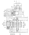
図17は、本実施形態に係る溶接装置の電力供給部を示す縦断面図である。   FIG. 17 is a longitudinal sectional view showing a power supply unit of the welding apparatus according to the present embodiment.

図17に示すように、本実施形態に係る溶接装置1の電力供給部7は、ハウジング150の内外を貫通する電源供給導体9を備えている。電源供給導体9は、ハウジング150の電源用貫通孔11を通じてハウジング150内の電路の一部を兼ねる弁座体157に電気的に接続されている。電源供給導体9は、複数、例えば3つに分割されて断面積を確保されている。それぞれの縦断電路182は、絶縁体のシース183に覆われている。   As shown in FIG. 17, the power supply unit 7 of the welding apparatus 1 according to this embodiment includes a power supply conductor 9 that penetrates the inside and outside of the housing 150. The power supply conductor 9 is electrically connected to the valve seat 157 that also serves as a part of the electric path in the housing 150 through the power supply through hole 11 of the housing 150. The power supply conductor 9 is divided into a plurality of, for example, three to ensure a cross-sectional area. Each longitudinal circuit 182 is covered with an insulating sheath 183.

電路の一部を兼ねるガス中継体161は、旋回台5とガス中継体161との間に設けられるコイルバネ185によって、弁座体157に押し付けられている。コイルバネ185は、ガス中継体161と弁座体157との導通の安定を図っている。   The gas relay body 161 that also serves as a part of the electric path is pressed against the valve seat body 157 by a coil spring 185 provided between the swivel base 5 and the gas relay body 161. The coil spring 185 stabilizes the conduction between the gas relay body 161 and the valve seat body 157.

なお、電力供給部7は、被溶接物200a、200bの長手方向に沿って、基部2の正面側(正面面板37)に重ねて多段に配置することができる。例えば、ハウジング150を多段階に重ねて配置しても良く、またそれぞれの個別に弁座体157を収容する多数のパージガス供給経路151を有する一体型ハウジング(図示省略)を正面面板37に設けても良い。また、パージガス供給経路151は、いずれか1つの電力供給部7に設けられていれば良く、パージガス供給経路151を備えていない電力供給部7があっても良い。パージガス供給経路151を備えていない電力供給部7は、パージガス供給経路151を備える電力供給部7に比べて極めて簡潔に構成される。   In addition, the electric power supply part 7 can be arrange | positioned in multiple stages on the front side (front surface board 37) of the base 2 along the longitudinal direction of the to-be-welded object 200a, 200b. For example, the housing 150 may be arranged in multiple stages, and an integrated housing (not shown) having a plurality of purge gas supply passages 151 for accommodating the valve seats 157 individually is provided on the front face plate 37. Also good. The purge gas supply path 151 may be provided in any one of the power supply units 7, and there may be a power supply unit 7 that does not include the purge gas supply path 151. The power supply unit 7 that does not include the purge gas supply path 151 has a very simple configuration compared to the power supply unit 7 that includes the purge gas supply path 151.

本実施形態に係る溶接装置1は、環状ギヤ列23毎に、電動機6の出力軸、環状ギヤ列23の第一ギヤ21、および環状ギヤ列23の第二ギヤ22のいずれかの回転角度を検出する回転センサ92と、回転センサ92が検出した回転角度に基づいて、複数の電動機6の駆動または停止を制御して複数の環状ギヤ列23を等速度に同期させて回転させ、または異なる速度で非同期に回転させる制御部99と、を備えている。つまり、溶接装置1は、従来の溶接装置における差動歯車機構を用いることなく、環状ギヤ列23を等速度に同期させて回転させ、または異なる速度で非同期に回転させる。そのため、溶接装置1は、従来の溶接装置に比べて小型化、軽量化が図られる。   The welding apparatus 1 according to the present embodiment sets the rotation angle of any one of the output shaft of the electric motor 6, the first gear 21 of the annular gear train 23, and the second gear 22 of the annular gear train 23 for each annular gear train 23. Based on the rotation sensor 92 to be detected and the rotation angle detected by the rotation sensor 92, the driving or stopping of the plurality of electric motors 6 is controlled to rotate the plurality of annular gear trains 23 in synchronism with each other or at different speeds. And a control unit 99 that rotates asynchronously. That is, the welding apparatus 1 rotates the annular gear train 23 in synchronism with a constant speed or asynchronously at different speeds without using the differential gear mechanism in the conventional welding apparatus. Therefore, the welding apparatus 1 can be reduced in size and weight as compared with the conventional welding apparatus.

また、本実施形態に係る溶接装置1は、環状ギヤ列23毎に複数の電動機6を備えている。そのため、本実施形態に係る溶接装置1は、1つの電動機6で環状ギヤ列23を駆動する場合に比べて、より小出力の電動機6を適用することができる。例えば、溶接装置1は、同口径の被溶接物200a、200bに対してより小出力の電動機6を適用することが可能であり、単一の電動機6での駆動が困難な大口径の被溶接物200a、200bに対して複数の電動機6で対応することが可能である。   In addition, the welding apparatus 1 according to this embodiment includes a plurality of electric motors 6 for each annular gear train 23. Therefore, the welding apparatus 1 according to the present embodiment can apply the electric motor 6 with a smaller output as compared with the case where the annular gear train 23 is driven by the single electric motor 6. For example, the welding apparatus 1 can apply the electric motor 6 with a smaller output to the workpieces 200a and 200b having the same diameter, and the large-diameter welding to be driven by the single electric motor 6 is difficult. The objects 200a and 200b can be handled by a plurality of electric motors 6.

したがって、本実施形態に係る溶接装置1によれば、小口径配管においては無論、中大口径においては格別に十分な加工精度による溶接の正確性を確保できるとともに、小型化、軽量化が図りやすく、ひいては取り扱いの利便性を向上できる。   Therefore, according to the welding apparatus 1 according to the present embodiment, it is possible to secure welding accuracy with exceptionally sufficient machining accuracy for small-diameter pipes and for medium and large-diameters, and it is easy to reduce the size and weight. As a result, the convenience of handling can be improved.

本発明のいくつかの実施形態を説明したが、これらの実施形態は、例として提示したものであり、発明の範囲を限定することは意図していない。これら新規な実施形態は、その他の様々な形態で実施されることが可能であり、発明の要旨を逸脱しない範囲で、種々の省略、置き換え、変更を行うことができる。これら実施形態やその変形は、発明の範囲や要旨に含まれるとともに、特許請求の範囲に記載された発明とその均等の範囲に含まれる。   Although several embodiments of the present invention have been described, these embodiments are presented by way of example and are not intended to limit the scope of the invention. These novel embodiments can be implemented in various other forms, and various omissions, replacements, and changes can be made without departing from the scope of the invention. These embodiments and modifications thereof are included in the scope and gist of the invention, and are included in the invention described in the claims and the equivalents thereof.

1 溶接装置
2 基部
2a、2b 基部の半円弧部
3 溶接ヘッド
5 旋回台
6 電動機
7 電力供給部
7a、7b 電力供給部の半円弧部
8 クランプ
9 電源供給導体
11 電源用貫通孔
12 固定機構
13 トーチホルダ
15 旋回用電動機
16 トーチ縦動電動機
17 トーチ遠近電動機
18 ワイヤ送給電動機
19 溶接トーチ
21 第一ギヤ
22 第二ギヤ
23 環状ギヤ列
25 歯車列機構
27 内歯
28 旋回ギヤ
31 内歯
32 外歯
33 往復動ギヤ
35 動力伝達ギヤ
36 差動歯車機構
37 正面面板
38 背面面板
39 案内溝
45 旋回用ギヤ列
46 トーチ縦動用ギヤ列
47 トーチ遠近用ギヤ列
48 ワイヤ用ギヤ列
56 トーチ縦動用往復動ギヤ
57 トーチ遠近用往復動ギヤ
58 ワイヤ送給用往復動ギヤ
59 ころ部
61 トーチ設置面
66 トーチ縦動用動力伝達ギヤ
67 トーチ遠近用動力伝達ギヤ
68 ワイヤ送給用動力伝達ギヤ
75 旋回用ウォームギヤ機構
76 トーチ縦動用ウォームギヤ機構
77 トーチ遠近用ウォームギヤ機構
78 ワイヤ用ウォームギヤ機構
79 案内穴
79a、79b 案内穴の端部
81 案内棒
82 外殻バンド
82a、82b 外殻バンドの端部
82 デファレンシャルケース
83 リングギヤ
85 ピニオンシャフト
86 ピニオンギヤ
87、88 サイドギヤ
89 ドライブシャフト
91 ドライブギヤ
92 回転センサ
99 制御部
101 出力軸
102、103 ギヤ
105 軸
106、107、108、109、111 ギヤ
112 出力軸
113、115 ギヤ
126 トーチ縦動移動機構
127 トーチ遠近移動機構
128 ワイヤ送給機構
131 正転ギヤ系列
132 逆転ギヤ系列
131a 第一段ギヤ
132a 第一段ギヤ
131b 正転系列最終段ギヤ
132b 逆転系列最終段ギヤ
133 伝達機構
135 軸
136 第一ワンウェイクラッチ
137 第二ワンウェイクラッチ
138 ダブルクラッチ機構
146 ワイヤ送給ローラー
147 ローラー
148 スプリング
149 ポケット
150 ハウジング
151 パージガス供給経路
152 ガス供給口
153 ガス導入路
155 ガス溜部
156 ガス流出口
157 弁座体
158 弁体
159 ガス流路
161 ガス中継体
162 バルブ駆動機構
163 シール板
165 弁座
166 弁体保持枠体
167 弁軸
168 ガイドブッシュ
169 コイルバネ
170 締結部材
171 締結部材
172 ホルダー
173 ガス室
175 カム
176 摺動ブッシュ
177 バルブ開閉棒
178 スイングアーム
179 スイングガイド
181 電源供給系統
182 縦断電路
183 シース
185 コイルバネ
200a、200b 被溶接物
DESCRIPTION OF SYMBOLS 1 Welding apparatus 2 Base part 2a, 2b Semicircular arc part of base 3 Welding head 5 Turntable 6 Electric motor 7 Electric power supply part 7a, 7b Semicircular arc part of electric power supply part 8 Clamp 9 Power supply conductor 11 Power supply through-hole 12 Fixing mechanism 13 Torch holder 15 Turning motor 16 Torch longitudinal motor 17 Torch perspective motor 18 Wire feed motor 19 Welding torch 21 First gear 22 Second gear 23 Annular gear train 25 Gear train mechanism 27 Internal teeth 28 Turning gear 31 Internal teeth 32 External teeth 33 Reciprocating gear 35 Power transmission gear 36 Differential gear mechanism 37 Front face plate 38 Back face plate 39 Guide groove 45 Turning gear train 46 Torch longitudinal motion gear train 47 Torch distance gear train 48 Wire gear train 56 Torch longitudinal motion reciprocating motion Gear 57 Torch distance reciprocating gear 58 Wire feeding reciprocating gear 59 Roller portion 61 Torch installation surface 66 Torch longitudinal power Reach gear 67 Power transmission gear for torch distance 68 Power transmission gear for feeding wire 75 Worm gear mechanism for turning 76 Worm gear mechanism for torch longitudinal movement 77 Worm gear mechanism for torch distance 78 Worm gear mechanism for wire 79 Guide holes 79a, 79b Ends of guide holes 81 Guide rod 82 Outer shell band 82a, 82b Outer shell end 82 Differential case 83 Ring gear 85 Pinion shaft 86 Pinion gear 87, 88 Side gear 89 Drive shaft 91 Drive gear 92 Rotation sensor 99 Control unit 101 Output shaft 102, 103 Gear 105 Shaft 106, 107, 108, 109, 111 Gear 112 Output shaft 113, 115 Gear 126 Torch longitudinal movement mechanism 127 Torch distance movement mechanism 128 Wire feed mechanism 131 Forward rotation gear series 132 Reverse rotation gear series 13 a first gear 132a first gear 131b forward rotation last gear 132b reverse rotation last gear 133 transmission mechanism 135 shaft 136 first one-way clutch 137 second one-way clutch 138 double clutch mechanism 146 wire feed roller 147 roller 148 Spring 149 Pocket 150 Housing 151 Purge gas supply path 152 Gas supply port 153 Gas introduction path 155 Gas reservoir 156 Gas outlet 157 Valve body 158 Valve body 159 Gas flow path 161 Gas relay body 162 Valve drive mechanism 163 Seal plate 165 Valve seat 166 Valve body holding frame 167 Valve shaft 168 Guide bush 169 Coil spring 170 Fastening member 171 Fastening member 172 Holder 173 Gas chamber 175 Cam 176 Sliding bush 177 Valve opening / closing rod 178 Swing arm 179 Swing guide 181 Power supply system 182 Longitudinal circuit 183 Sheath 185 Coil springs 200a, 200b Workpiece

Claims (2)

筒形状の被溶接物の外周に固定される環状の基部と、
前記基部に沿って環状に並んで交互に噛み合う複数の第一ギヤおよび複数の第二ギヤを含む環状ギヤ列を複数列有する歯車列機構と、
いずれかの前記環状ギヤ列の前記第一ギヤに噛み合わされる内歯を有する弧状の旋回ギヤと、
前記旋回ギヤに固定されて前記基部の周方向へ移動自在であって溶接ヘッドを支える旋回台と、
前記環状ギヤ列毎に少なくとも1つ設けられて、前記第一ギヤへ伝達される駆動力をそれぞれ個別に発生させる複数の電動機と、
前記環状ギヤ列毎に、前記電動機の出力軸、前記第一ギヤ、および前記第二ギヤのいずれかの回転角度を検出する回転角度検出器と、
前記回転角度検出器が検出した回転角度に基づいて、前記複数の電動機の駆動または停止を制御して前記複数の環状ギヤ列を等速度に同期させて回転させ、または異なる速度で非同期に回転させる制御部と、を備える溶接装置。
An annular base fixed to the outer periphery of the cylindrical workpiece,
A gear train mechanism having a plurality of annular gear trains including a plurality of first gears and a plurality of second gears alternately meshed in line along the base portion;
An arcuate swivel gear having internal teeth meshed with the first gear of any of the annular gear trains;
A swivel base fixed to the swivel gear and movable in the circumferential direction of the base and supporting the welding head;
A plurality of electric motors provided at least one for each of the annular gear trains and individually generating driving forces transmitted to the first gear;
A rotation angle detector for detecting a rotation angle of any one of the output shaft of the electric motor, the first gear, and the second gear for each annular gear train;
Based on the rotation angle detected by the rotation angle detector, the driving or stopping of the plurality of electric motors is controlled to rotate the plurality of annular gear trains in synchronism with a constant speed, or to rotate asynchronously at different speeds. And a control unit.
前記複数の電動機は、前記環状ギヤ列毎に複数設けられている請求項1に記載の溶接装置。 The welding apparatus according to claim 1, wherein a plurality of the plurality of electric motors are provided for each of the annular gear trains.
JP2018105895A 2018-06-01 2018-06-01 Welding equipment Active JP7064386B2 (en)

Priority Applications (1)

Application Number Priority Date Filing Date Title
JP2018105895A JP7064386B2 (en) 2018-06-01 2018-06-01 Welding equipment

Applications Claiming Priority (1)

Application Number Priority Date Filing Date Title
JP2018105895A JP7064386B2 (en) 2018-06-01 2018-06-01 Welding equipment

Publications (2)

Publication Number Publication Date
JP2019209341A true JP2019209341A (en) 2019-12-12
JP7064386B2 JP7064386B2 (en) 2022-05-10

Family

ID=68846175

Family Applications (1)

Application Number Title Priority Date Filing Date
JP2018105895A Active JP7064386B2 (en) 2018-06-01 2018-06-01 Welding equipment

Country Status (1)

Country Link
JP (1) JP7064386B2 (en)

Cited By (2)

* Cited by examiner, † Cited by third party
Publication number Priority date Publication date Assignee Title
CN112008793A (en) * 2020-08-25 2020-12-01 浙江百力塑业有限公司 Spraying-free plastic shell fixture with strong universality and accurate positioning
CN117139977A (en) * 2023-10-27 2023-12-01 中国建筑第五工程局有限公司 Auxiliary welding equipment for building embedded parts

Citations (2)

* Cited by examiner, † Cited by third party
Publication number Priority date Publication date Assignee Title
JP2013184176A (en) * 2012-03-06 2013-09-19 Toshiba Plant Systems & Services Corp Welding apparatus
JP2016159357A (en) * 2015-03-05 2016-09-05 東芝プラントシステム株式会社 Welding apparatus

Patent Citations (2)

* Cited by examiner, † Cited by third party
Publication number Priority date Publication date Assignee Title
JP2013184176A (en) * 2012-03-06 2013-09-19 Toshiba Plant Systems & Services Corp Welding apparatus
JP2016159357A (en) * 2015-03-05 2016-09-05 東芝プラントシステム株式会社 Welding apparatus

Cited By (3)

* Cited by examiner, † Cited by third party
Publication number Priority date Publication date Assignee Title
CN112008793A (en) * 2020-08-25 2020-12-01 浙江百力塑业有限公司 Spraying-free plastic shell fixture with strong universality and accurate positioning
CN117139977A (en) * 2023-10-27 2023-12-01 中国建筑第五工程局有限公司 Auxiliary welding equipment for building embedded parts
CN117139977B (en) * 2023-10-27 2024-02-06 中国建筑第五工程局有限公司 Auxiliary welding equipment for building embedded parts

Also Published As

Publication number Publication date
JP7064386B2 (en) 2022-05-10

Similar Documents

Publication Publication Date Title
JP5823319B2 (en) Welding equipment
US9399561B2 (en) Drive roll carrier for welding wire feeder
JP6348089B2 (en) Welding equipment
JP6664645B2 (en) Welding equipment
JPS6050546B2 (en) automatic welding equipment
JP7064386B2 (en) Welding equipment
KR102403864B1 (en) Orbital pipe welding apparatus
CA1230247A (en) Internal pipe welding apparatus
JP6468513B2 (en) Welding equipment
JP2019209342A (en) Welding equipment
JPS6051950B2 (en) automatic welding equipment
AU2019378560B2 (en) Device for the orbital processing of non-rotating joints and pipe ends
US4372474A (en) Full function in-place weld head
JP6579306B2 (en) Welding equipment
KR101987724B1 (en) Apparatus for welding
JP6383129B2 (en) Welding equipment
GB2482693A (en) Pipe Welding Apparatus
JP6149245B2 (en) Welding equipment
KR100742629B1 (en) Carbon dioxide welding machine
JP2016026888A (en) Power transmission device and welding device using the same
CN215966805U (en) Wire feeding device for electric arc additive manufacturing and welding equipment
US11919109B2 (en) Welding devices
JP7082807B2 (en) Welding torch movement mechanism and welding equipment equipped with this
CN103495798A (en) Gun-barrel device applied to rectangular coordinate system welding robot
CN107283081B (en) Swing angle adjustable composite welding assembly

Legal Events

Date Code Title Description
A621 Written request for application examination

Free format text: JAPANESE INTERMEDIATE CODE: A621

Effective date: 20210521

A977 Report on retrieval

Free format text: JAPANESE INTERMEDIATE CODE: A971007

Effective date: 20220316

TRDD Decision of grant or rejection written
A01 Written decision to grant a patent or to grant a registration (utility model)

Free format text: JAPANESE INTERMEDIATE CODE: A01

Effective date: 20220405

A61 First payment of annual fees (during grant procedure)

Free format text: JAPANESE INTERMEDIATE CODE: A61

Effective date: 20220422

R150 Certificate of patent or registration of utility model

Ref document number: 7064386

Country of ref document: JP

Free format text: JAPANESE INTERMEDIATE CODE: R150