JP2019208656A - Seat heater equipped with sensor - Google Patents
Seat heater equipped with sensor Download PDFInfo
- Publication number
- JP2019208656A JP2019208656A JP2018105293A JP2018105293A JP2019208656A JP 2019208656 A JP2019208656 A JP 2019208656A JP 2018105293 A JP2018105293 A JP 2018105293A JP 2018105293 A JP2018105293 A JP 2018105293A JP 2019208656 A JP2019208656 A JP 2019208656A
- Authority
- JP
- Japan
- Prior art keywords
- sensor
- support
- heater
- region
- seat heater
- Prior art date
- Legal status (The legal status is an assumption and is not a legal conclusion. Google has not performed a legal analysis and makes no representation as to the accuracy of the status listed.)
- Pending
Links
- 239000000463 material Substances 0.000 claims abstract description 81
- 239000004020 conductor Substances 0.000 claims abstract description 54
- 239000000758 substrate Substances 0.000 claims description 57
- 238000010438 heat treatment Methods 0.000 claims description 41
- 229910052751 metal Inorganic materials 0.000 claims description 15
- 239000002184 metal Substances 0.000 claims description 15
- 239000011888 foil Substances 0.000 claims description 13
- 230000001681 protective effect Effects 0.000 claims description 8
- 230000015572 biosynthetic process Effects 0.000 claims description 3
- 238000009434 installation Methods 0.000 abstract description 7
- 238000001514 detection method Methods 0.000 abstract description 6
- 239000000835 fiber Substances 0.000 description 32
- 239000010410 layer Substances 0.000 description 26
- 229920005989 resin Polymers 0.000 description 19
- 239000011347 resin Substances 0.000 description 19
- 238000000034 method Methods 0.000 description 14
- 239000011230 binding agent Substances 0.000 description 9
- 239000010949 copper Substances 0.000 description 8
- 239000002923 metal particle Substances 0.000 description 8
- 230000004048 modification Effects 0.000 description 8
- 238000012986 modification Methods 0.000 description 8
- 239000004745 nonwoven fabric Substances 0.000 description 7
- RYGMFSIKBFXOCR-UHFFFAOYSA-N Copper Chemical compound [Cu] RYGMFSIKBFXOCR-UHFFFAOYSA-N 0.000 description 6
- 238000000576 coating method Methods 0.000 description 6
- 239000003365 glass fiber Substances 0.000 description 6
- 229920000139 polyethylene terephthalate Polymers 0.000 description 6
- 239000005020 polyethylene terephthalate Substances 0.000 description 6
- 229910052802 copper Inorganic materials 0.000 description 5
- 238000010586 diagram Methods 0.000 description 5
- -1 polyethylene terephthalate Polymers 0.000 description 5
- 239000002759 woven fabric Substances 0.000 description 5
- OKTJSMMVPCPJKN-UHFFFAOYSA-N Carbon Chemical compound [C] OKTJSMMVPCPJKN-UHFFFAOYSA-N 0.000 description 4
- LFQSCWFLJHTTHZ-UHFFFAOYSA-N Ethanol Chemical compound CCO LFQSCWFLJHTTHZ-UHFFFAOYSA-N 0.000 description 4
- 239000004952 Polyamide Substances 0.000 description 4
- BQCADISMDOOEFD-UHFFFAOYSA-N Silver Chemical compound [Ag] BQCADISMDOOEFD-UHFFFAOYSA-N 0.000 description 4
- 239000000853 adhesive Substances 0.000 description 4
- 239000012790 adhesive layer Substances 0.000 description 4
- 229920002647 polyamide Polymers 0.000 description 4
- 229920000728 polyester Polymers 0.000 description 4
- 229920001721 polyimide Polymers 0.000 description 4
- 229910052709 silver Inorganic materials 0.000 description 4
- 239000004332 silver Substances 0.000 description 4
- KFZMGEQAYNKOFK-UHFFFAOYSA-N Isopropanol Chemical compound CC(C)O KFZMGEQAYNKOFK-UHFFFAOYSA-N 0.000 description 3
- OKKJLVBELUTLKV-UHFFFAOYSA-N Methanol Chemical compound OC OKKJLVBELUTLKV-UHFFFAOYSA-N 0.000 description 3
- 239000004642 Polyimide Substances 0.000 description 3
- 229910052799 carbon Inorganic materials 0.000 description 3
- 229920001971 elastomer Polymers 0.000 description 3
- 238000010292 electrical insulation Methods 0.000 description 3
- 239000003822 epoxy resin Substances 0.000 description 3
- 230000020169 heat generation Effects 0.000 description 3
- 239000012212 insulator Substances 0.000 description 3
- 239000007788 liquid Substances 0.000 description 3
- 230000000149 penetrating effect Effects 0.000 description 3
- 229920000647 polyepoxide Polymers 0.000 description 3
- 230000008569 process Effects 0.000 description 3
- 239000005060 rubber Substances 0.000 description 3
- 125000006850 spacer group Chemical group 0.000 description 3
- 125000000391 vinyl group Chemical group [H]C([*])=C([H])[H] 0.000 description 3
- 229920002554 vinyl polymer Polymers 0.000 description 3
- 238000009941 weaving Methods 0.000 description 3
- 244000126211 Hericium coralloides Species 0.000 description 2
- 239000004698 Polyethylene Substances 0.000 description 2
- 239000004743 Polypropylene Substances 0.000 description 2
- 229920000297 Rayon Polymers 0.000 description 2
- 230000001070 adhesive effect Effects 0.000 description 2
- 229920006231 aramid fiber Polymers 0.000 description 2
- 229920006038 crystalline resin Polymers 0.000 description 2
- 238000013461 design Methods 0.000 description 2
- 239000011810 insulating material Substances 0.000 description 2
- HJOVHMDZYOCNQW-UHFFFAOYSA-N isophorone Chemical compound CC1=CC(=O)CC(C)(C)C1 HJOVHMDZYOCNQW-UHFFFAOYSA-N 0.000 description 2
- 229920001778 nylon Polymers 0.000 description 2
- 238000007645 offset printing Methods 0.000 description 2
- 229920000573 polyethylene Polymers 0.000 description 2
- 239000011112 polyethylene naphthalate Substances 0.000 description 2
- 229920001155 polypropylene Polymers 0.000 description 2
- 239000002964 rayon Substances 0.000 description 2
- COBPKKZHLDDMTB-UHFFFAOYSA-N 2-[2-(2-butoxyethoxy)ethoxy]ethanol Chemical compound CCCCOCCOCCOCCO COBPKKZHLDDMTB-UHFFFAOYSA-N 0.000 description 1
- NQBXSWAWVZHKBZ-UHFFFAOYSA-N 2-butoxyethyl acetate Chemical compound CCCCOCCOC(C)=O NQBXSWAWVZHKBZ-UHFFFAOYSA-N 0.000 description 1
- 239000004925 Acrylic resin Substances 0.000 description 1
- 229920000178 Acrylic resin Polymers 0.000 description 1
- 229920000049 Carbon (fiber) Polymers 0.000 description 1
- 229920000181 Ethylene propylene rubber Polymers 0.000 description 1
- 239000004831 Hot glue Substances 0.000 description 1
- 229920000459 Nitrile rubber Polymers 0.000 description 1
- 239000005062 Polybutadiene Substances 0.000 description 1
- 229920000180 alkyd Polymers 0.000 description 1
- 239000000956 alloy Substances 0.000 description 1
- 229910045601 alloy Inorganic materials 0.000 description 1
- WUOACPNHFRMFPN-UHFFFAOYSA-N alpha-terpineol Chemical compound CC1=CCC(C(C)(C)O)CC1 WUOACPNHFRMFPN-UHFFFAOYSA-N 0.000 description 1
- 229910052782 aluminium Inorganic materials 0.000 description 1
- XAGFODPZIPBFFR-UHFFFAOYSA-N aluminium Chemical compound [Al] XAGFODPZIPBFFR-UHFFFAOYSA-N 0.000 description 1
- 239000003125 aqueous solvent Substances 0.000 description 1
- 239000004760 aramid Substances 0.000 description 1
- 210000001217 buttock Anatomy 0.000 description 1
- 239000004917 carbon fiber Substances 0.000 description 1
- 230000008859 change Effects 0.000 description 1
- 238000013329 compounding Methods 0.000 description 1
- 230000008602 contraction Effects 0.000 description 1
- 239000011889 copper foil Substances 0.000 description 1
- 230000007423 decrease Effects 0.000 description 1
- SQIFACVGCPWBQZ-UHFFFAOYSA-N delta-terpineol Natural products CC(C)(O)C1CCC(=C)CC1 SQIFACVGCPWBQZ-UHFFFAOYSA-N 0.000 description 1
- 239000002612 dispersion medium Substances 0.000 description 1
- 238000005485 electric heating Methods 0.000 description 1
- 238000000605 extraction Methods 0.000 description 1
- 239000004744 fabric Substances 0.000 description 1
- 238000005187 foaming Methods 0.000 description 1
- 239000011521 glass Substances 0.000 description 1
- PCHJSUWPFVWCPO-UHFFFAOYSA-N gold Chemical compound [Au] PCHJSUWPFVWCPO-UHFFFAOYSA-N 0.000 description 1
- 239000010931 gold Substances 0.000 description 1
- 229910052737 gold Inorganic materials 0.000 description 1
- 229910002804 graphite Inorganic materials 0.000 description 1
- 239000010439 graphite Substances 0.000 description 1
- 238000007646 gravure printing Methods 0.000 description 1
- LNEPOXFFQSENCJ-UHFFFAOYSA-N haloperidol Chemical compound C1CC(O)(C=2C=CC(Cl)=CC=2)CCN1CCCC(=O)C1=CC=C(F)C=C1 LNEPOXFFQSENCJ-UHFFFAOYSA-N 0.000 description 1
- 230000006872 improvement Effects 0.000 description 1
- 238000001764 infiltration Methods 0.000 description 1
- 230000008595 infiltration Effects 0.000 description 1
- 238000007641 inkjet printing Methods 0.000 description 1
- 238000009413 insulation Methods 0.000 description 1
- 238000003475 lamination Methods 0.000 description 1
- WABPQHHGFIMREM-UHFFFAOYSA-N lead(0) Chemical compound [Pb] WABPQHHGFIMREM-UHFFFAOYSA-N 0.000 description 1
- 238000002844 melting Methods 0.000 description 1
- 230000008018 melting Effects 0.000 description 1
- 239000012528 membrane Substances 0.000 description 1
- 239000007769 metal material Substances 0.000 description 1
- 239000000203 mixture Substances 0.000 description 1
- 239000011368 organic material Substances 0.000 description 1
- 239000003960 organic solvent Substances 0.000 description 1
- 238000000059 patterning Methods 0.000 description 1
- 239000005011 phenolic resin Substances 0.000 description 1
- 150000002989 phenols Chemical class 0.000 description 1
- 238000007747 plating Methods 0.000 description 1
- 229920002857 polybutadiene Polymers 0.000 description 1
- 239000009719 polyimide resin Substances 0.000 description 1
- 229920005672 polyolefin resin Polymers 0.000 description 1
- 238000007639 printing Methods 0.000 description 1
- 238000012545 processing Methods 0.000 description 1
- 125000004805 propylene group Chemical group [H]C([H])([H])C([H])([*:1])C([H])([H])[*:2] 0.000 description 1
- 230000000630 rising effect Effects 0.000 description 1
- 238000007650 screen-printing Methods 0.000 description 1
- 229920002379 silicone rubber Polymers 0.000 description 1
- 239000002904 solvent Substances 0.000 description 1
- 238000005507 spraying Methods 0.000 description 1
- 229920003051 synthetic elastomer Polymers 0.000 description 1
- 239000005061 synthetic rubber Substances 0.000 description 1
- 229940116411 terpineol Drugs 0.000 description 1
- 229920002725 thermoplastic elastomer Polymers 0.000 description 1
- 229920001187 thermosetting polymer Polymers 0.000 description 1
- 238000012546 transfer Methods 0.000 description 1
- 229920006337 unsaturated polyester resin Polymers 0.000 description 1
- 210000000689 upper leg Anatomy 0.000 description 1
- 238000004804 winding Methods 0.000 description 1
Images


Classifications
-
- B—PERFORMING OPERATIONS; TRANSPORTING
- B60—VEHICLES IN GENERAL
- B60N—SEATS SPECIALLY ADAPTED FOR VEHICLES; VEHICLE PASSENGER ACCOMMODATION NOT OTHERWISE PROVIDED FOR
- B60N2/00—Seats specially adapted for vehicles; Arrangement or mounting of seats in vehicles
- B60N2/002—Seats provided with an occupancy detection means mounted therein or thereon
-
- A—HUMAN NECESSITIES
- A47—FURNITURE; DOMESTIC ARTICLES OR APPLIANCES; COFFEE MILLS; SPICE MILLS; SUCTION CLEANERS IN GENERAL
- A47C—CHAIRS; SOFAS; BEDS
- A47C7/00—Parts, details, or accessories of chairs or stools
- A47C7/62—Accessories for chairs
-
- A—HUMAN NECESSITIES
- A47—FURNITURE; DOMESTIC ARTICLES OR APPLIANCES; COFFEE MILLS; SPICE MILLS; SUCTION CLEANERS IN GENERAL
- A47C—CHAIRS; SOFAS; BEDS
- A47C7/00—Parts, details, or accessories of chairs or stools
- A47C7/62—Accessories for chairs
- A47C7/72—Adaptations for incorporating lamps, radio sets, bars, telephones, ventilation, heating or cooling arrangements or the like
- A47C7/74—Adaptations for incorporating lamps, radio sets, bars, telephones, ventilation, heating or cooling arrangements or the like for ventilation, heating or cooling
-
- B—PERFORMING OPERATIONS; TRANSPORTING
- B60—VEHICLES IN GENERAL
- B60N—SEATS SPECIALLY ADAPTED FOR VEHICLES; VEHICLE PASSENGER ACCOMMODATION NOT OTHERWISE PROVIDED FOR
- B60N2/00—Seats specially adapted for vehicles; Arrangement or mounting of seats in vehicles
- B60N2/56—Heating or ventilating devices
- B60N2/5678—Heating or ventilating devices characterised by electrical systems
- B60N2/5685—Resistance
Landscapes
- Engineering & Computer Science (AREA)
- Aviation & Aerospace Engineering (AREA)
- Transportation (AREA)
- Mechanical Engineering (AREA)
- Surface Heating Bodies (AREA)
- Chair Legs, Seat Parts, And Backrests (AREA)
- Seats For Vehicles (AREA)
Abstract
Description
本発明は、センサ付きシートヒータに関するものである。 The present invention relates to a seat heater with a sensor.
自動車のシートに搭載されるシートヒータとして、多孔質体と、当該多孔質体に間隔を空けて配置された一対の電極と、当該電極間に設けられたPTC抵抗体と、を備えた面状発熱抵抗体が知られている(例えば特許文献1参照)。 As a seat heater mounted on a seat of an automobile, a planar shape including a porous body, a pair of electrodes arranged at intervals in the porous body, and a PTC resistor provided between the electrodes A heating resistor is known (see, for example, Patent Document 1).
また、自動車のシートに搭載される着座センサとして、接点セルをそれぞれ有する一対の可撓性フィルムと、開口を有するスペーサと、を備えており、開口を介して接点セルを相互に対向させるように可撓フィルムとスペーサを積層して構成されたものが知られている(例えば特許文献2参照)。 Moreover, as a seating sensor mounted on the seat of an automobile, a pair of flexible films each having a contact cell and a spacer having an opening are provided, and the contact cells are opposed to each other through the opening. A structure in which a flexible film and a spacer are laminated is known (for example, see Patent Document 2).
上記のシートヒータと着座センサの両方をシートに設置する場合、これらは積層された状態でシート内に埋設されるが、シートヒータと着座センサの大きさが相違するため、この積層により凹凸が生じる。そして、この凹凸により乗員に不快感を与えてしまうのを防止するために、当該凹凸を吸収するのに十分な厚さを有するワディングがシートヒータの上に重ねられている。しかしながら、このワディングによって、シート表面からシートヒータまでの距離が広がることからシートヒータの消費電力が増加してしまうと共に、シート表面から着座センサまでの距離も広がることから着座センサの検知精度が低下してしまう、という問題がある。 When both the seat heater and the seating sensor are installed on the seat, they are embedded in the seat in a stacked state. However, since the sizes of the seat heater and the seating sensor are different, the stacking causes unevenness. . In order to prevent the occupant from feeling uncomfortable due to the unevenness, a wadding having a thickness sufficient to absorb the unevenness is overlaid on the seat heater. However, this wading increases the power consumption of the seat heater because the distance from the seat surface to the seat heater increases, and the distance from the seat surface to the seating sensor also increases, so the detection accuracy of the seating sensor decreases. There is a problem that.
また、上記の着座センサはシートパッドに貼り付けられるが、着座センサはシートパッドと比較して硬く、また、着座センサの表面は平滑であるのに対してシートパッドの表面は座面形状に成形されている。そのため、着座センサをシートパッドに設置し難い、という問題もある。 Also, the seating sensor is affixed to the seat pad, but the seating sensor is harder than the seat pad, and the seating sensor surface is smooth, whereas the seatpad surface is shaped into a seating surface. Has been. Therefore, there is also a problem that it is difficult to install the seating sensor on the seat pad.
本発明が解決しようとする課題は、省電力化及びセンサの検出精度の向上を図ると共に、設置作業性に優れたセンサ付きシートヒータを提供することである。 Problem to be solved by the invention is providing the seat heater with a sensor excellent in installation workability | operativity while aiming at power saving and the improvement of the detection accuracy of a sensor.
[1]本発明に係るセンサ付きシートヒータは、複数の貫通孔を有するコア基材を含むシート状の支持体と、前記支持体の第1の領域に設けられたセンサ部と、前記支持体において前記第1の領域とは異なる第2の領域に設けられたヒータ部と、を備えており、前記センサ部は、第1の導体部を含み、前記ヒータ部は、前記支持体に設けられた第2の導体部を含むセンサ付きシートヒータである。 [1] A sheet heater with a sensor according to the present invention includes a sheet-like support including a core substrate having a plurality of through holes, a sensor unit provided in a first region of the support, and the support A heater portion provided in a second region different from the first region, wherein the sensor portion includes a first conductor portion, and the heater portion is provided on the support. And a sensor-equipped seat heater including a second conductor portion.
[2]上記発明において、前記支持体は、前記コア基材の一部を覆っている絶縁層を含み、前記第1の領域は、前記支持体において前記絶縁層が前記コア基材を覆っている領域であり、前記第2の領域は、前記支持体において前記絶縁層が前記コア基材を覆っていない領域であり、前記第1の導体部は、前記絶縁層上に設けられ、前記第2の導体部は、前記コア基材を覆っていると共に前記貫通孔内にも存在していてもよい。 [2] In the above invention, the support includes an insulating layer covering a part of the core substrate, and the first region includes the insulating layer covering the core substrate in the support. The second region is a region where the insulating layer does not cover the core substrate in the support, and the first conductor portion is provided on the insulating layer, The two conductor portions may cover the core base material and also exist in the through hole.
[3]上記発明において、前記支持体は、前記第1の領域に形成された開口を有しており、前記第1の導体部は、第1の基板に保持された第1の電極と、第2の基板に保持された第2の電極と、を含み、前記第1及び前記第2の電極が前記開口を介して相互に対向するように、前記第1の基板が前記支持体の第1の主面に積層されていると共に、前記第2の基板が前記支持体の第2の主面に積層されていてもよい。 [3] In the above invention, the support has an opening formed in the first region, and the first conductor portion includes a first electrode held on a first substrate, A second electrode held by a second substrate, wherein the first substrate is a second electrode of the support so that the first and second electrodes face each other through the opening. And the second substrate may be laminated on the second main surface of the support.
[4]上記発明において、前記第1の導体部は、前記開口を囲むように前記第1の主面に形成された第1の接続部と、前記開口を囲むように前記第2の主面に形成された第2の接続部と、を含み、前記第1の電極の外縁部は、前記第1の接続部と接触しており、前記第2の電極の外縁部は、前記第2の接続部と接触していてもよい。 [4] In the above invention, the first conductor portion includes a first connection portion formed on the first main surface so as to surround the opening, and the second main surface so as to surround the opening. A second connection portion formed on the first electrode, an outer edge portion of the first electrode being in contact with the first connection portion, and an outer edge portion of the second electrode being in contact with the second connection portion. It may be in contact with the connecting portion.
[5]上記発明において、前記支持体は、前記第1の領域と前記第2の領域との間に、前記コア基材のみから構成される第3の領域を有しており、前記コア基材は、前記第3の領域で前記センサ部と前記ヒータ部の間から露出していてもよい。 [5] In the above invention, the support has a third region composed only of the core base material between the first region and the second region, and the core group The material may be exposed from between the sensor unit and the heater unit in the third region.
[6]上記発明において、前記第2の導体部は、相互に対向する一対の対向配線部を含み、前記ヒータ部は、前記第2の導体部よりも電気的抵抗の高い発熱抵抗体を含み、前記発熱抵抗体は、前記対向配線部の間に設けられた介在部分を含み、前記介在部分は、前記コア基材を覆っていてもよい。 [6] In the above invention, the second conductor portion includes a pair of opposing wiring portions facing each other, and the heater portion includes a heating resistor having a higher electrical resistance than the second conductor portion. The heating resistor may include an interposition portion provided between the opposing wiring portions, and the interposition portion may cover the core base material.
[7]上記発明において、前記第2の導体部は、前記貫通孔を介して前記コア基材を貫通して前記コア基材の両面を覆っており、前記発熱抵抗体の前記介在部分も、前記貫通孔を介して前記コア基材を貫通して前記コア基材の両面を覆っていてもよい。 [7] In the above invention, the second conductor portion penetrates the core base material through the through hole and covers both surfaces of the core base material, and the interposed portion of the heating resistor is also You may penetrate the said core base material through the said through-hole, and may cover both surfaces of the said core base material.
[8]上記発明において、前記発熱抵抗体は、前記対向配線部を覆うと共に前記介在部分と一体的に形成された被覆部分を含んでもよい。 [8] In the above invention, the heating resistor may include a covering portion that covers the counter wiring portion and is integrally formed with the interposition portion.
[9]上記発明において、前記ヒータ部は、前記対向配線部の間に前記介在部分が設けられていない非形成部分を有してもよい。 [9] In the above invention, the heater portion may have a non-formed portion where the interposition portion is not provided between the opposing wiring portions.
[10]上記発明において、前記第2の導体部は、前記対向配線部と一体的に形成された給電配線部と、前記給電配線部と重複するように設けられた金属箔又は金属線と、を含んでもよい。 [10] In the above invention, the second conductor portion includes a power supply wiring portion formed integrally with the counter wiring portion, a metal foil or a metal wire provided so as to overlap the power supply wiring portion, May be included.
[11]上記発明において、前記センサ付きシートヒータは、前記センサ部及び前記ヒータ部を覆うように前記支持体の両面に積層された第1及び第2の保護部材を備え、前記支持体は、前記コア基材のみから構成される第4の領域を前記支持体の外縁部に有しており、前記第1及び前記第2の保護部材の外縁部は、前記第4の領域で前記支持部材に固定されていてもよい。 [11] In the above invention, the seat heater with sensor includes first and second protective members laminated on both surfaces of the support body so as to cover the sensor section and the heater section, and the support body includes: It has the 4th field constituted only by the core base material in the outer edge part of the support, and the outer edge part of the 1st and 2nd protection members is the support member in the 4th field. It may be fixed to.
本発明によれば、センサ部とヒータ部が同一の支持体に設けられているので、ワディングを薄くしてヒータ及びセンサからシート表面までの距離を狭めることができ、省電力化及びセンサの検出精度の向上を図ることができる。 According to the present invention, since the sensor unit and the heater unit are provided on the same support, it is possible to reduce the distance from the heater and the sensor to the sheet surface by thinning the padding, thereby saving power and detecting the sensor. The accuracy can be improved.
また、本発明によれば、センサ部とヒータ部が同一の支持体に設けられていると共に、複数の貫通孔を有するコア基材を含む支持体にセンサ部が設けられているので、センサ部を含めたセンサ付きシートヒータの設置作業性も優れている。 According to the present invention, the sensor unit and the heater unit are provided on the same support, and the sensor unit is provided on the support including a core base material having a plurality of through holes. The installation workability of the sensor-equipped seat heater including is excellent.
以下、本発明の実施形態を図面に基づいて説明する。 Hereinafter, embodiments of the present invention will be described with reference to the drawings.
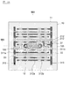
図1A及び図1Bは本実施形態におけるセンサ付きシートヒータを示す図、図2A及び図2Bは本実施形態において支持体に導体部を形成した状態を示す図、図3A及び図3Bは本実施形態においてヒータ部を形成した状態を示す図、図4A及び図4Bは本実施形態においてセンサ部を形成した状態を示す図、図5は本実施形態における第1の配線板を示す図である。 1A and 1B are diagrams showing a sensor-equipped seat heater in the present embodiment, FIGS. 2A and 2B are diagrams showing a state in which a conductor is formed on a support in the present embodiment, and FIGS. 3A and 3B are diagrams showing the present embodiment. FIG. 4A and FIG. 4B are diagrams illustrating a state in which a sensor unit is formed in the present embodiment, and FIG. 5 is a diagram illustrating a first wiring board in the present embodiment.
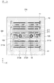
本実施形態におけるセンサ付きシートヒータ1は、図1A〜図5に示すように、支持体10と、センサ部20と、ヒータ部30と、保護部材41,42と、を備えている。このセンサ付きシートヒータ1は、自動車等の車両のシート100のシートクッション110(図11参照)に埋設されて使用される。センサ部20は、乗員の着座に応じてシートクッション110を介して印加される圧力を検出する着座センサであり、この検出信号に基づいてシート100への乗員の着座の有無の判定が行われる。ヒータ部30は、通電によって発熱抵抗体32(後述)を抵抗加熱することで乗員を加温する。なお、乗員の着座の有無の判定結果は、シートベルト着用要求やシートヒータのオン/オフ判断に用いられる。
As shown in FIGS. 1A to 5, the sensor-equipped
支持体10は、柔軟なシート状の部材であり、コア基材11と、絶縁層12と、から構成されている。
The
図6は本実施形態におけるコア基材を示す部分拡大平面図、図7は本実施形態におけるコア基材の変形例を示す部分拡大平面図である。 FIG. 6 is a partially enlarged plan view showing a core substrate in the present embodiment, and FIG. 7 is a partially enlarged plan view showing a modification of the core substrate in the present embodiment.
コア基材11は、図6に示すように、織糸111,112を平織りで織り込むことで製織された織布であり、柔軟性を有している。このコア基材11を構成する織糸は、縦方向に延在する経糸111と、当該経糸111に実質的に直交する方向(すなわち横方向)に延在する緯糸112と、を含んでいる。
As shown in FIG. 6, the
上記のように、コア基材11は、織糸111,112を格子状に織ることで形成されているため、複数の貫通孔(バスケットホール)114を有している。この貫通孔114は、経糸111と緯糸112によって囲まれた隙間(網の目)であり、コア基材11を当該コア基材11の厚さ方向に貫通している。複数の貫通孔114は、実質的に同一の形状を有すると共に実質的に同一の開口面積を有しており、平面視においてコア基材11に規則的且つ均一に配置されている。
As described above, since the
経糸111は、実質的に同一の直径を有する10〜200本程度の絶縁性繊維111aを束ねてそれぞれ構成されている。同様に、緯糸112も、実質的に同一の直径を有する10〜200本程度の絶縁性繊維112aを束ねてそれぞれ構成されている。本実施形態における絶縁性繊維111a,112aはいずれもガラス繊維から構成されており、1〜20μm程度の実質的に同一の直径を有している。
The
特に限定されないが、こうしたコア基材11の一例として、以下の構成を例示することができる。すなわち、経糸111の絶縁性繊維111aが7μm程度の直径を有するガラス繊維で構成されており、それぞれの経糸111は、200本程度の絶縁性繊維111aを束ねて構成されている。緯糸112の絶縁性繊維112aも7μm程度の直径を有するガラス繊維で構成されており、それぞれの緯糸112は、200本程度の絶縁性繊維112aを束ねて構成されている。これらの織糸111,112を織り込むことで、0.1mm程度の厚さを有する織布(ガラスクロス)が製織されている。このコア基材11では、経糸111の密度が横方向25mmあたり60本程度となり、緯糸112の密度も横方向25mm当たり60本程度となるように、織糸111,112が平織りで織り込まれている。こうした仕様のコア基材11には、20μm×20μm程度の矩形の開口形状を有する多数の貫通孔114が0.3mm程度のピッチで存在する。
Although not particularly limited, the following configuration can be exemplified as an example of the
なお、絶縁性繊維111a,112aは、電気絶縁性及び柔軟性を有していれば、上記のガラス繊維に特に限定されない。例えば、ナイロン繊維、レーヨン繊維、ポリエステル繊維、ポリアミド繊維、ビニル繊維、アラミド繊維等の樹脂繊維で、絶縁性繊維111a,112aを構成してもよい。また、支持体10が相互に積層された複数のコア基材11を有していてもよい。
Insulating
なお、コア基材11Bとして、上記の織布に代えて、図7に示すような不織布を用いてもよい。
As the
このコア基材11Bは、図7に示すように、ランダムに配向された多数の絶縁性繊維113を相互に結合することで形成されたシート状の不織布から構成されている。本例における繊維113は、5〜15μm程度の直径を有するガラス繊維である。絶縁性繊維113を結合するバインダとしては、アクリル樹脂やエポキシ樹脂を主成分とした樹脂材料を例示することができる。このバインダは、絶縁性繊維113同士を交点で相互に接着している。そのため、絶縁性繊維113同士の間には空隙が形成されており、このコア基材11Bには、上面から下面に直線状に貫通する多数の貫通孔114が形成されている。このコア基材11Bは、50〜100μm程度の厚さを有していると共に、75〜90%程度の空隙率を有している。なお、コア基材11Bの厚さは特に限定されず、例えば30μm以下の厚さを有していてもよい。
As shown in FIG. 7, the
なお、絶縁性繊維113は、電気絶縁性及び柔軟性を有していれば、上記のガラス繊維に特に限定されない。例えば、ナイロン繊維、レーヨン繊維、ポリエステル繊維、ポリアミド繊維、ビニル繊維、アラミド繊維等の樹脂繊維で、絶縁性繊維113を構成してもよい。また、支持体10が相互に積層された複数のコア基材11Bを有していてもよい。
Insulating
特に図示しないが、上記の織布や不織布に代えて、スポンジ等の連続気泡構造を有する多孔質体をコア基材11として用いてもよい。この多孔質体は、上面から下面に貫通する多数の貫通孔を有しており、樹脂やゴムなどの有機材料を発泡処理することで形成することができる。
Although not particularly illustrated, a porous body having an open cell structure such as a sponge may be used as the
本実施形態における支持体10は、図1B、図2B、図3B及び図4Bに示すように、4つの領域101〜104を有している。
The
第1の領域101は、センサ部20が設けられている領域である。これに対し、第2の領域102は、第1の領域101とは別の領域であり、ヒータ部30が設けられている領域である。本実施形態では、この第2の領域102は、第1の領域101を囲んでおり、すなわち、ヒータ部30はセンサ部20を囲んでいる。第3の領域103は、第1の領域101と第2の領域102の間の領域であり、すなわち、センサ部20とヒータ部30の間の領域である。第4の領域104は、第2の領域102を囲う支持体10の外縁部である。
The
本実施形態では、第1の領域101に絶縁層12が設けられているのに対し、第2〜第4の領域104には絶縁層12が設けられていない。上述のように、第1の領域101にはセンサ部20が設けられ、第2の領域102にはヒータ部30が設けられているのに対し、第3の領域103及び第4の領域104は、コア基材11のみから構成されている。また、第1の領域101には、支持体10を貫通する開口105が形成されている。後述するように、この開口105を介してセンサ部20の一対の電極223,233が相互に対向している。
In the present embodiment, the insulating
絶縁層12は、図2A及び図2Bに示すように、コア基材11に直接形成されており、コア基材11の表面を覆っていると共に、コア基材11の貫通孔114を閉塞している。この絶縁層12は、ポリイミド系樹脂やエポキシ系樹脂等の樹脂材料から構成されており、電気絶縁性を有している。この絶縁層12は、センサ部20の第1の導体部21を形成する前に予め形成されており、例えば、液状樹脂をコア基材11の第2の領域102に塗布して含浸させた後に硬化処理を行うことで形成されている。
As shown in FIGS. 2A and 2B, the insulating
液状樹脂の塗布方法としては、特に限定されないが、接触塗布法又は非接触塗布法のいずれを用いてもよい。接触塗布法の具体例としては、スクリーン印刷、グラビア印刷、オフセット印刷、グラビアオフセット印刷、フレキソ印刷等を例示することができる。一方、非接触塗布法の具体例としては、インクジェット印刷、スプレー塗布法、ディスペンス塗布法、ジェットディスペンス法等を例示することができる。また、液状樹脂の硬化方法としては、特に限定されないが、加熱処理や紫外線照射処理等を例示することができる。 Although it does not specifically limit as a coating method of liquid resin, Either a contact coating method or a non-contact coating method may be used. Specific examples of the contact coating method include screen printing, gravure printing, offset printing, gravure offset printing, flexographic printing, and the like. On the other hand, specific examples of the non-contact coating method include inkjet printing, spray coating method, dispense coating method, jet dispensing method and the like. Moreover, it does not specifically limit as a hardening method of liquid resin, A heat processing, an ultraviolet irradiation process, etc. can be illustrated.
この絶縁層12の表面は、コア基材11の表面と比較して平坦になっており、この絶縁層12によって第1の領域101における支持体10の表面の凹凸が平滑化されている。このため、本実施形態では、センサ部20の接続部211,212のパターン形状や厚さを均一化することができ接続部211,212を高い精度で形成することができる。また、この絶縁層12は、コア基材11の貫通孔114を閉塞している。このため、センサ部20の接続部211,212を形成する際に、導電性ペーストがコア基材11の反対面に浸透してしまい導通してしまうことが防止されている。
The surface of the insulating
なお、特に図示しないが、ポリイミド(PI)やポリエチレンテレフタレート(PET)等からなる電気絶縁性を有するフィルムを、粘着層(又は接着層)を介してコア基材11に貼り付けることで、絶縁層12を形成してもよい。なお、フィルムからなる絶縁層12を、コア基材11の一方面のみに設けてもよい。
Although not particularly illustrated, an insulating layer is formed by sticking an electrically insulating film made of polyimide (PI), polyethylene terephthalate (PET) or the like to the
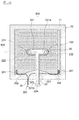
センサ部20は、図4A及び図4Bに示すように、支持体10の第1の領域101に設けられており、接続部211,212と、第1の配線板22と、第2の配線板23と、を備えている。接続部211,212は、絶縁層12上に直接形成されており、支持体10の両面に設けられている。これに対し、第1の配線板22は、第1の領域101の支持体10の上面に積層されていると共に、第2の配線板23は、第1の領域101の支持体10の下面に積層されている。
As shown in FIG. 4A and FIG. 4B, the
第1の接続部211は、図2A及び図2Bに示すように、絶縁層12の上面に設けられている。また、第2の接続部212は、絶縁層12の下面に設けられている。第1及び第2の接続部211,212はいずれも、支持体10の開口105を囲むように設けられた環状形状を有している。この接続部211,212は、支持体10の絶縁層12によって相互に電気的に絶縁されている。
The first connecting
接続部211,212は、例えば、銅(Cu)或いは銀(Ag)等を主成分とする導電性金属粒子と、バインダ樹脂とから構成されており、導電性を有している。なお、接続部211,212が、複数種の導電性金属粒子を含有していてもよい。
The
この接続部211,212は、支持体10に塗布した導電性ペーストを加熱して焼成することで形成されている。なお、この接続部211,212は、ヒータ部30の第2の導体部31(後述)と同時に形成されるが、この接続部211,212は絶縁層12上に形成されるため、導電性ペーストがコア基材11内に浸透(浸潤)することはない。一方、ヒータ部30の第2の導体部31はコア基材11に直接形成されるため、導電性ペーストがコア基材11に浸透(浸潤)して貫通孔114内にも存在することとなる。
The
接続部211,212を形成するための導電性ペーストは、導電性金属粒子と、当該導電性金属粒子を均一に分散するバインダ樹脂と、を含有した溶液である。導電性金属粒子の具体例としては、例えば、銅(Cu)、銀(Ag)、カーボン(C)等を主成分とする導電性金属粒子を例示することができる。バインダ樹脂としては、多価フェノール化合物、フェノール樹脂、アルキッド樹脂、不飽和ポリエステル樹脂、エポキシ樹脂などの熱硬化性樹脂の1種または2種以上の樹脂混合を例示することができる。このとき、バインダ樹脂には水系溶媒、あるいはエタノール、メタノール、2−プロパノールなどのアルコール類、イソホロン、テルピネオール、トリエチレングリコールモノブチルエーテル、ブチルセロソルブアセテートなどの有機系溶媒を分散媒として適量配合される。なお、この溶媒の配合量は、導電性金属粒子のサイズ、形状や製膜条件等に応じて適宜調整される。
The conductive paste for forming the
導電性ペーストを支持体10に塗布する方法としては、特に限定されないが、上述の接触塗布法又は非接触塗布法のいずれを用いてもよい。また、導電性ペーストを硬化させるための熱源としては、特に限定されないが、電熱オーブン、赤外線オーブン、遠赤外炉(IR)、近赤外炉(NIR)、レーザ照射装置等を例示することができ、これらを組み合わせた熱処理であってもよい。
The method for applying the conductive paste to the
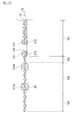
第1の配線板22は、いわゆるメンブレン基板であり、図4A〜図5に示すように、第1の基板221と、第1の電極222と、第1の引出配線223と、コネクタ224と、カバーレイ225と、を備えている。
The
第1の基板221は、例えば、ポリエチレンテレフタレート(PET)やポリエチレンナフタレート(PEN)等の可撓性を有する絶縁性材料から構成されている。この第1の基板221は、本体部分221aとテール部221bから構成される略T字形状を有している。
The
第1の電極222は、円形の平面形状を有しており、第1の基板221の本体部分221aの両端に設けられ第1の基板221に保持されている。第1の引出配線223は、第1の電極222から導出して、テール部分221bの端部までそれぞれ延在している。コネクタ224は、テール部分221bの端部に実装されており、第1の引出配線223がコネクタ224に電気的に接続されている。特に図示しないが、コネクタ224には、センサ部20のオン/オフ信号に基づいてシート100への乗員の着座の判定を行う判定回路が電気的に接続される。なお、テール部221b及び第1の引出配線223に代えて、例えば電線を用いて、第1の電極222とコネクタ224を接続してもよい。
The
第1の電極222と第1の引出配線223は、銀ペーストや銅ペーストやカーボンペースト等の導電性ペーストを、第1の基材221上に塗布して硬化させることで形成されている。導電性ペーストを第1の基板221に塗布する方法としては、特に限定されないが、上述の接触塗布法又は非接触塗布法のいずれを用いてもよい。また、導電性ペーストを硬化させるための熱源としては、上述のものを用いることができる。
The
この第1の配線板22は、第1の基板221の本体部分221aが支持体10の第1の領域101に対向するように、支持体10の上面に積層されている。この際、第1の電極222が、支持体10の開口105に対向していると共に、当該第1の電極222の外縁部が、支持体10上に形成された第1の接続部211と接触しており、第1の電極222は第1の接続部211を介して支持体10に設けられている。また、第1の基板221の本体部分221aは、粘着層226を介して支持体10に固定されている。
The
これに対し、第1の基板221のテール部分221bはカバーレイ225で覆われており、支持体10に固定されておらず非拘束な状態となっている。このカバーレイ225は、第1の基板221と同様に、例えば、ポリエチレンテレフタレート(PET)やポリエチレンナフタレート(PEN)等の可撓性を有する絶縁性材料から構成されている。
On the other hand, the
第2の配線板23も、上述の第1の配線板22と同様に、第2の基板231と、第2の電極232と、第1の引出配線と、コネクタと、カバーレイと、を備えている。図4Bに示すように、この第2の配線板23は、第2の基板231の本体部分が支持体10の第1の領域101に対向するように、支持体10の下面に積層されている。この際、第2の電極232が、支持体10の開口105に対向していると共に、当該第2の電極232の外縁部が、支持体10上に形成された第2の接続部212と接触しており、第2の電極232は第2の接続部221を介して支持体10に設けられている。また、第2の基板231の本体部分は、粘着層236を介して支持体10に固定されている。一方、第2の基板231のテール部分はカバーレイで覆われており、支持体10に固定されておらず非拘束な状態となっている。なお、センサ部20の回路構成によっては、第2の配線板23の第2の基板231がテール部分を有していなくてもよい。
Similarly to the
本実施形態における接続部211,212及び電極222,232が、本発明における第1の導体部の一例に相当する。すなわち、本実施形態では、接続部211,212が支持体10に直接設けられていると共に、電極222,232が当該接続部211,212を介して支持体10に設けられている。
The
なお、第1の接続部211を絶縁体で形成してもよいし、第2の接続部212を絶縁体で形成してもよい。この場合には、第1の電極222が、第1の接続部211介して絶縁層12上に設けられ、第2の電極232が、第2の接続部212を介して絶縁層12上に設けられる。すなわち、この例では、絶縁体である接続部211,212は支持体10の一部を構成し、当該支持体10に電極222,232が設けられており、電極222,232が本発明における第1の導体部の一例に相当する。
Note that the
以上のように、本実施形態では、第1の配線板22の第1の電極222と第2の配線板23の第2の電極232とは、支持体10の開口105を介して相互に対向しており、支持体10が着座センサ(圧力センサ)のスペーサとして機能している。このため、シート100に乗員が着座していない時は、支持体10によって第1及び第2の電極222,232間の間隔が維持されて、第1及び第2の電極222,232が電気的に絶縁されているため、センサ部20から判定回路にオフ信号が出力される。
As described above, in the present embodiment, the
これに対し、シート100への乗員の着座に伴って第1の配線板22が第2の配線板23に向かって押圧されると、支持体10の開口105を介して第1及び第2の電極222,232が相互に接触する。これにより、第1及び第2の電極222,232が電気的に導通し、コネクタ224を介して判定回路にオン信号が出力される。この際、本実施形態では、支持体10の開口105の周囲に第1及び第2の接続部211,212が設けられているので、第1及び第2の配線板22,23への押圧に伴う支持体10の変形の抑制が図られている。
On the other hand, when the
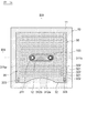
ヒータ部30は、図3A及び図3Bに示すように、支持体10の第2の領域102に設けられており、第2の導体部31と発熱抵抗体32を備えている。第2の導体部31は、支持体10のコア基材11に直接形成されており、コア基材11の貫通孔114内に存在していると共に、コア基材11の両面に設けられている。発熱抵抗体32も同様に、支持体10のコア基材11に直接形成されており、コア基材11の貫通孔114内に存在していると共に、コア基材11の両面に設けられている。
As shown in FIGS. 3A and 3B, the
第2の導体部31は、図2A及び図2Bに示すように、給電配線部311a,311bと、対向配線部312a,312bと、を備えている。
As shown in FIGS. 2A and 2B, the
第1の給電配線部311aは、第2の領域102の一方端(図中の左端)の近傍に配置されており、Y方向に沿って延在している。同様に、第2の給電配線部311bも、第2の領域102の他方端(図中の右端)の近傍に配置されており、Y方向に沿って延在している。
The first power
第1の給電配線部311aからは、複数の第1の対向配線部312aが枝分かれしている。この複数の第1の対向配線部312aは、第1の給電配線部311aの延在方向(Y方向)に沿って実質的に等間隔に配置されており、第1の給電配線部311aから第2の給電配線部311bに向かって櫛歯状に突出している。
A plurality of first opposing
第2の給電配線部311bからも、複数の第2の対向配線部312bが枝分かれしている。この複数の第2の対向配線部312bは、第2の給電配線部311bの延在方向(Y方向)に沿って実質的に等間隔に配置されており、第2の給電配線部311bから第1の給電配線部311aに向かって櫛歯状に突出している。
A plurality of second opposing wiring
そして、第1の対向配線部312aと第2の対向配線部312bは、交互に配置されており、所定の間隔を空けて相互に対向している。なお、第1の対向配線部312aの先端と第2の給電配線部311bとの間にも所定の間隔が形成されていると共に、第2の対向配線部312bの先端と第1の給電配線部311aとの間にも所定の間隔が形成されている。
The first opposing
本実施形態では、発熱抵抗体32と直接接触して抵抗加熱に寄与する対向配線部312a,312bと、対向配線部312a,312bへの給電に寄与する給電配線部311a,311bとを分けることで、発熱エリアの多様な形状に対応することが可能となっており、設計の自由度の向上が図られている。
In the present embodiment, the opposing
なお、給電配線部311a,311bや対向配線部312a,312bの平面形状は、上記に特に限定されず、任意に設定することができる。例えば、対向配線部312a,312bの間隔がほぼ一定に維持されているのであれば、給電配線部311a,311bの平面形状を曲線形状としたり蛇行形状としてもよいし、対向配線部312a,312bの平面形状を曲線形状としたり蛇行形状としてもよい。
Note that the planar shapes of the power
この第2の導体部31は、上述の接続部211,212と同様に、例えば、銅(Cu)或いは銀(Ag)等を主成分とする導電性金属粒子と、バインダ樹脂とから構成されており、導電性を有している。本実施形態では、この第2の導体部31は、上述の接続部211,212と同時に形成されるが、特にこれに限定されず、第2の導体部31を接続部211,212とは別の工程で形成してもよい。
The
上述のように、この第2の導体部31は、コア基材11に直接形成されており、導電性ペーストをコア基材11に塗布した際に当該導電性ペーストがコア基材11に浸透(浸潤)する。このため、第2の導体部31は、貫通孔114内にも存在しており、貫通孔114を介してコア基材11を貫通しコア基材11の両面を覆っている。なお、第2の導体部31が、コア基材11の片面のみを覆っていてもよい。
As described above, the
発熱抵抗体32は、電圧が印加されることで発熱する抵抗体であり、第2の導体部31を覆うように支持体10の第2の領域102の全域に設けられている。この発熱抵抗体32は、抵抗体ペーストをコア基材11に塗布して硬化させることで形成されている。この発熱抵抗体32は、上述の第2の導体部31と同様に、コア基材11に直接形成されており、抵抗体ペーストをコア基材11に塗布した際に当該抵抗体ペーストがコア基材11の貫通孔114内にも存在することとなる。このため、発熱抵抗体32は、貫通孔114内にも存在しており、貫通孔114を介してコア基材11を貫通してコア基材11の両面を覆っている。なお、発熱抵抗体32が、コア基材11の片面のみを覆っていてもよい。
The
本実施形態における抵抗体ペーストは、高抵抗導電性ペーストである。こうした抵抗体ペーストの具体例としては、結晶性樹脂と、バインダ樹脂と、導電体と、を含有したペーストを例示することができる。結晶性樹脂としては、例えば、ポリオレフィン系樹脂やビニル系樹脂を例示することができる。バインダ樹脂としては、例えば、イソプロピレンゴム、ブタジエンゴム、ニトリルゴム、エチレンプロピレンゴム、シリコンゴム等の合成ゴム、或いは、熱可塑性エラストマ等を例示することができる。導電体としては、カーボンやグラファイト等を例示することができる。 The resistor paste in the present embodiment is a high resistance conductive paste. As a specific example of such a resistor paste, a paste containing a crystalline resin, a binder resin, and a conductor can be exemplified. Examples of the crystalline resin include polyolefin resins and vinyl resins. Examples of the binder resin include synthetic rubbers such as isopropylene rubber, butadiene rubber, nitrile rubber, ethylene propylene rubber, and silicon rubber, or thermoplastic elastomers. Examples of the conductor include carbon and graphite.
抵抗体ペーストをコア基材11に塗布する方法としては、特に限定されないが、上述の接触塗布法又は非接触塗布法のいずれを用いてもよい。また、抵抗体ペーストを硬化させるための熱源としては、上述の導電性ペーストを硬化させるものと同様のものを用いることができる。
A method of applying the resistor paste to the
この発熱抵抗体32は、コア基材11に形成された第2の導体部31と直接接触しており、介在部分321と被覆部分322を含んでいる。
The
介在部分321は、相互に対向している対向配線部312a,312bの間に介在している部分であり、発熱に寄与する部分である。この介在部分321は、貫通孔114内にも存在しており、貫通孔114を介してコア基材11を貫通してコア基材11の両面を覆っている。
The intervening
これに対し、被覆部分322は、介在部分321の間に介在している部分であり、対向配線部312a,312bを覆うことで当該対向配線部312a,312bを保護する機能を有している。介在部分321と被覆部分322とは一体的に形成されている。
On the other hand, the covering
図3Aに示すように、発熱抵抗体32において給電配線部311a,311bの端部に対応する部分に開口323が形成されており、この開口323を介して給電配線部311a,311bの端部が発熱抵抗体32から露出している。そして、図4Aに示すように、この開口323を介して、給電配線部311a,311bにワイヤハーネス35の圧着端子351が接続されている。この圧着端子351には電線352の一端が接続されており、当該電線352の他端にはコネクタ353が接続されている。このヒータ部30は、ワイヤハーネス35のコネクタ353を介して、特に図示しない電力供給源に接続されている。
As shown in FIG. 3A, an
そして、ワイヤハーネス35を介して電力供給源から電力が供給されると、第1の対向配線部312aと第2の対向配線部312bとの間に生じた電位差によって、発熱抵抗体32の介在部分321に電流が流れ、抵抗加熱によって当該介在部分321が発熱する。
Then, when power is supplied from the power supply source via the
この際、本実施形態では、第2の導体部31がコア基材11の貫通孔114内に存在していると共にコア基材11の両面に設けられているので、第2の導体部31の大きな断面積が確保されている。このため、ヒータ面積が大きくなることに伴って配線が長くなった場合であっても、第2の導体部31の電気抵抗値の上昇を緩和すると共に、ヒータ部30全域における給電量の平準化を図ることができる。
At this time, in the present embodiment, since the
また、本実施形態では、発熱抵抗体32の介在部分321が貫通孔114内に存在していると共にコア基材11の両面に設けられているので、発熱抵抗体32の大きな断面積が確保されており、昇温速度の向上や発熱の均一化を図ることができる。また、発熱抵抗体32が表裏対称の構造を有しているので、センサ付きシートヒータ1の熱変形に対する耐性の向上を図ることもできる。
Further, in the present embodiment, since the interposed
さらに、本実施形態では、被覆部分322が対向配線部312a,312bを覆っているので、当該対向配線部311a,312bが保護されている。また、この被覆部分322が介在部分321と一体的に形成されているので、コア基材11に対する第2の導体部31の固着力の向上や第2の導体部31と発熱抵抗体32との接触面積の増加を図ることもできる。
Furthermore, in this embodiment, since the covering
上述のように、支持体10は、センサ部20が設けられた第1の領域101と、ヒータ部30が設けられた第2の領域102との間に、コア基材11のみから構成された第3の領域103を有している。この第3の領域103では、センサ部20とヒータ部30の間からコア基材11が露出している。
As described above, the
本実施形態では、センサ部20とヒータ部30との間にコア基材11のみを設けて、この第3の領域103を遮熱帯として機能させている。これにより、ヒータ部30からセンサ部20への伝熱を抑制するができ、センサ部20の検出精度の安定化を図ることができる。一例を挙げれば、幅5mmの第3の領域103を設けることで、ヒータ部30を80℃まで発熱させた際に、センサ部20の温度を40℃未満に抑制することができる。
In the present embodiment, only the
図8A及び図8Bは本実施形態におけるヒータ部の第1変形例を示す平面図及び断面図である。なお、この図8A及び図8Bは、上述の図2A及び図2Bにそれぞれ対応する図であり、ヒータ部30や保護部材41,42は図8A及び図8Bには図示されていない。
8A and 8B are a plan view and a cross-sectional view showing a first modification of the heater portion in the present embodiment. 8A and 8B correspond to FIGS. 2A and 2B, respectively, and the
なお、図8A及び図8Bに示すように、第2の導体部31が、帯状の金属箔33を備えていてもよい。この金属箔33は、例えば、銅、アルミニウム、或いは、それらの合金等の導電性に優れた金属材料から構成されており、特に限定されないが、35μm程度の厚さを有している。なお、金属箔33に代えて、極細線ワイヤ、或いは、樹脂繊維に金属箔を巻き付けた導電糸を用いてもよい。
In addition, as shown to FIG. 8A and 8B, the
この金属箔33は、第2の導体部31の給電配線部311a,311bと重複するように設けられている。この金属箔33は、給電配線部311a,311bを形成する前に第2の領域102のコア基材11上に配置されており、金属箔33を覆うようにコア基材11上に給電配線部311a,311bを形成することで、金属箔33と給電配線部311a,311bが接続されている。なお、この場合には、発熱抵抗体32の開口323に加えて、給電配線部311a,311bにも開口313を形成しておくことで、ワイヤハーネス35の電線352を金属箔33に直接ハンダ接続してもよい。
The
こうした金属箔33を給電配線部311a,311bと重ねておくことで、ヒータ面積が大きくなることに伴って配線が長くなった場合であっても、給電配線部311a,311bの電気抵抗値の上昇を一層緩和すると共に、ヒータ部30全域における給電量の平準化を一層図ることができる。
By superimposing the
図9A及び図9Bは本実施形態におけるヒータ部の第2変形例を示す平面図及び断面図である。なお、この図9A及び図9Bは、上述の図3A及び図3Bにそれぞれ対応する図であり、保護部材41,42は図9A及び図9Bには図示されていない。
9A and 9B are a plan view and a cross-sectional view showing a second modification of the heater section in the present embodiment. 9A and 9B correspond to FIGS. 3A and 3B, respectively, and the
ヒータ部30が、図9A及び図9Bに示すように、相互に対向する対向配線部312a,312bの間に発熱抵抗体32が形成されていない非形成部分34を有していてもよい。この非形成部分34からは、支持体10のコア基材11が露出している。この非形成部分34によって、相互に対向する対向配線部312a,312bの間の電気的な導通が遮断されているため、非形成部分34では発熱が生じない。
As shown in FIGS. 9A and 9B, the
図9A及び図9Bに示す例では、ヒータ部30の図中上側の領域にスリット状の4つの非形成部分34が設けられており、これらの非形成部分34は、全体として、略半円形の形状を有している。この非形成部分34は、乗員の大腿部の間の間隙に対応しており、発熱抵抗体32において加温不要箇所に対応する部分の発熱を禁止している。すなわち、本例では、ヒータ部30において発熱するエリアの形状を加温必要箇所の形状に近似させることで、省電力化を図っている。なお、非形成部分34の形状は、特に限定されない。
In the example shown in FIGS. 9A and 9B, four slit-shaped
また、この非形成部分34では、介在部分31が形成されておらずコア基材11のみが存在しているので、発熱抵抗部32の柔軟性も向上する。
Further, in the
図10は本実施形態におけるセンサ部の変形例を示す断面図である。なお、この図10には、保護部材41,42が図示されていない。
FIG. 10 is a cross-sectional view showing a modification of the sensor unit in the present embodiment. In FIG. 10, the
図10に示すように、センサ素子50を支持体10の貫通孔114に挿入して、第1及び第2の配線板22,23の第1及び第2の電極222,232の間にセンサ素子50を介在させてもよい。このセンサ素子50は、その上下面に電極を有しており、これらの電極が第1及び第2の電極222,232に電気的に接続されている。こうしたセンサ素子50の一例としては、圧力変化を連続的に検出することができる感圧ゴムやピエゾ素子等を例示することができる。
As shown in FIG. 10, the
なお、図10に示す例では、第1及び第2の配線板22,23は、いわゆるフレキシブルプリント配線板である。すなわち、この第1及び第2の配線板22,23は、例えば、第1及び第2の基板221,231はポリイミドから構成されており、第1及び第2の電極222,232は銅箔をパターニングすることで形成されている。さらに、本例では、センサ素子50と電極222,232との接続信頼性を確保するために、第1及び第2の電極222,232が金めっき層で被覆されている。
In the example shown in FIG. 10, the first and
図1A及び図1Bに戻り、第1及び第2の保護部材41,42は、支持体10の全面を覆っており、第4の領域104で当該支持体10のコア基材11に貼り付けられている。すなわち、本実施形態のセンサ付きシートヒータ1は、保護部材41,42がコア基材11に固定されることで形成された固定部43をその外縁部に有している。なお、センサ付きシートヒータ1が第1及び第2の保護部材41,42を備えていなくてもよい。
Returning to FIG. 1A and FIG. 1B, the first and
こうした保護部材41,42の一例としては、例えば、ポリエステル繊維からなる厚さ1.0mm程度のニードルフェルト(不織布)を例示することができる。また、保護部材41,42をコア基材11に貼り付ける接着剤としては、例えば、シリコン系樹脂等の接着剤を例示することができる。
As an example of
なお、保護部材41,42として、ポリエステル以外の繊維からなる不織布、或いは、織布を用いてもよい。例えば、シートクッション110のシート表皮120側の保護部材41として、熱伝導性の高いカーボン繊維を含む不織布を用いてもよい。これにより、ヒータ稼働時の熱伝搬ロスを低減して加温性能を高めることができる。因みに、上側の保護部材41が十分なクッション性を有している場合には、シート表皮120下のワディング140を不要としてもよい。
In addition, as the
また、シートクッション110のシートパッド130側の保護部材42として、摩擦係数の大きな表面を有する不織布を用いてもよい。これにより、シートパット130に対するセンサ付きシートヒータ1の密着性を高めることができ、センサ付きシートヒータ1の設置作業性の更なる向上を図ることができる。
Further, as the
なお、接着剤を用いずに、ポリプロピレン(PP)、ポリエチレン(PE)、ポリアミド(PA)等の熱溶融接着性を有する繊維を用いて保護部材41,42を構成し、当該保護部材41,42を部分的に溶融させることで、保護部材41,42をコア基材11に貼り付けてもよい。
In addition, without using an adhesive agent, the
この固定部43では、第1及び第2の保護部材41,42がコア基材11に貼り付けられているので、コア基材11によって第1及び第2の保護部材41,42の伸縮が抑制される。このため、例えば、粘着材等を用いずに、この固定部43でセンサ付きシートヒータ1をシート100のシート表皮120の裏面に直接縫い付けることができるので、センサ付きシートヒータ1の取付位置の精度向上や使用時の位置ズレの抑制を図ることができる。
In the fixing
図11は本実施形態におけるセンサ付きシートヒータの設置例を示す断面図である。 FIG. 11 is a cross-sectional view showing an installation example of the sensor-equipped seat heater in the present embodiment.
以上に説明したセンサ付きシートヒータ1は、図11に示すように、自動車等の車両のシート100に設置される。このシート100は、例えば、当該シート100に着座した乗員の臀部を支持するシートクッション110と、乗員の背部を支持するシートバック150と、を備えている。また、シートバック150には、乗員の頭部を支持するヘッドレスト160が装着されている。
The sensor-equipped
上述のように、このセンサ付きシートヒータ1のセンサ部20は、シート100への乗員の着座に伴って第1の配線板22が第2の配線板23に向かって押圧されると、第1及び第2の電極222,232が電気的に導通し、コネクタ224を介して判定回路にオン信号を出力する。この際、本実施形態では、センサ部20とヒータ部30が同一の支持体10に設けられており、積層による凹凸が生じていないので、ワディング140を薄くしても乗員に不快感を与えてしまうことがない。そのため、シート100の表面からセンサ部20までの距離Dを狭めることができる、センサ部20の検出精度の向上を図ることができる。
As described above, when the
また、このセンサ付きシートヒータ1のヒータ部30は、上述のように、対向配線部321a,321bへの通電によって発熱抵抗体32を抵抗加熱することで乗員を加温する。この際、本実施形態では、センサ部20とヒータ部30が同一の支持体10に設けられているので、ワディング140を薄くしてシート100の表面からヒータ部30までの距離Dを狭めることができる。これにより、熱伝搬ロスが低減され、ヒータ部30によって乗員を効率的に加温することができるので、省電力化を図ることができる。
Further, as described above, the
また、本実施形態では、センサ部20とヒータ部30が同一の支持体10に設けられていると共に、この支持体10が多数の貫通孔を有するコア基材11を有している。このため、センサ部20を含めたセンサ付きシートヒータ1に設置作業の作業性向上が図られている。
Moreover, in this embodiment, while the
なお、以上説明した実施形態は、本発明の理解を容易にするために記載されたものであって、本発明を限定するために記載されたものではない。したがって、上記の実施形態に開示された各要素は、本発明の技術的範囲に属する全ての設計変更や均等物をも含む趣旨である。 The embodiment described above is described for facilitating the understanding of the present invention, and is not described for limiting the present invention. Therefore, each element disclosed in the above embodiment is intended to include all design changes and equivalents belonging to the technical scope of the present invention.
例えば、上述の実施形態では、車両のシート100に設置するセンサ付きシートヒータについて説明したが、センサ付きシートヒータ1の用途は、特に車両に限定されず、例えば、車両以外で使用される座席やベッド等に用いられてもよい。
For example, in the above-described embodiment, the sensor-equipped seat heater installed on the
また、上述の実施形態では、センサ部20が着座センサを構成する例について説明したが、特にこれに限定されない。例えば、センサ部20が静電容量センサ等を構成してもよい。
Moreover, although the above-mentioned embodiment demonstrated the example in which the
また、上述の実施形態では、接続部211,212と電極222,232で第1の導体部を構成したが、特にこれに限定されない。例えば、支持体10上に直接形成された導体パターンのみで、第1の導体部を構成してもよい。この場合には、センサ部20が第1の基板221や第2の基板231を備えていなくてもよい。
Moreover, in the above-mentioned embodiment, although the 1st conductor part was comprised with the
1…センサ付きシートヒータ
10…支持体
101〜104…第1〜第4の領域
105…開口
11,11B…コア基材
111…経糸
111a…絶縁性繊維
112…緯糸
112a…絶縁性繊維
113…絶縁性繊維
114…貫通孔
12…絶縁層
20…センサ部
211…第1の接続部
212…第2の接続部
22…第1の配線板
221…第1の基板
221a…本体部分
221b…テール部分
222…第1の電極
223…第1の引出配線
224…コネクタ
225…カバーレイ
226…粘着層
23…第2の配線板
231…第2の基板
232…第2の電極
236…粘着層
30…ヒータ部
31…第2の導体部
311a,311b…給電配線部
312a,312b…対向配線部
313…開口
32…発熱抵抗体
321…介在部分
322…被覆部分
323…開口
33…金属箔
34…非形成部分
35…ワイヤハーネス
351…圧着端子
352…電線
353…コネクタ
41,42…第1,第2の保護部材
43…固定部
50…センサ素子
100…シート
110…シートクッション
120…シート表皮
130…シートパッド
140…ワディング
150…シートバック
160…ヘッドレスト
DESCRIPTION OF
Claims (11)
前記支持体の第1の領域に設けられたセンサ部と、
前記支持体において前記第1の領域とは異なる第2の領域に設けられたヒータ部と、を備えており、
前記センサ部は、第1の導体部を含み、
前記ヒータ部は、前記支持体に設けられた第2の導体部を含むセンサ付きシートヒータ。 A sheet-like support including a core substrate having a plurality of through holes;
A sensor unit provided in a first region of the support;
A heater portion provided in a second region different from the first region in the support, and
The sensor part includes a first conductor part,
The heater unit is a sensor-equipped seat heater including a second conductor unit provided on the support.
前記支持体は、前記コア基材の一部を覆っている絶縁層を含み、
前記第1の領域は、前記支持体において前記絶縁層が前記コア基材を覆っている領域であり、
前記第2の領域は、前記支持体において前記絶縁層が前記コア基材を覆っていない領域であり、
前記第1の導体部は、前記絶縁層上に設けられ、
前記第2の導体部は、前記コア基材を覆っていると共に前記貫通孔内にも存在しているセンサ付きシートヒータ。 The sensor-equipped seat heater according to claim 1,
The support includes an insulating layer covering a part of the core substrate,
The first region is a region where the insulating layer covers the core substrate in the support,
The second region is a region where the insulating layer does not cover the core substrate in the support,
The first conductor portion is provided on the insulating layer,
The sensor-equipped seat heater, wherein the second conductor portion covers the core substrate and is also present in the through hole.
前記支持体は、前記第1の領域に形成された開口を有しており、
前記第1の導体部は、
第1の基板に保持された第1の電極と、
第2の基板に保持された第2の電極と、を含み、
前記第1及び前記第2の電極が前記開口を介して相互に対向するように、前記第1の基板が前記支持体の第1の主面に積層されていると共に、前記第2の基板が前記支持体の第2の主面に積層されているセンサ付きシートヒータ。 A seat heater with a sensor according to claim 1 or 2,
The support has an opening formed in the first region;
The first conductor portion is
A first electrode held on a first substrate;
A second electrode held on a second substrate,
The first substrate is laminated on the first main surface of the support so that the first and second electrodes face each other through the opening, and the second substrate is A sensor-equipped seat heater laminated on the second main surface of the support.
前記第1の導体部は、
前記開口を囲むように前記第1の主面に形成された第1の接続部と、
前記開口を囲むように前記第2の主面に形成された第2の接続部と、を含み、
前記第1の電極の外縁部は、前記第1の接続部と接触しており、
前記第2の電極の外縁部は、前記第2の接続部と接触しているセンサ付きシートヒータ。 The sensor-equipped seat heater according to claim 3,
The first conductor portion is
A first connection portion formed on the first main surface so as to surround the opening;
A second connecting portion formed on the second main surface so as to surround the opening,
An outer edge portion of the first electrode is in contact with the first connection portion;
A sensor-equipped seat heater in which an outer edge portion of the second electrode is in contact with the second connection portion.
前記支持体は、前記第1の領域と前記第2の領域との間に、前記コア基材のみから構成される第3の領域を有しており、
前記コア基材は、前記第3の領域で前記センサ部と前記ヒータ部の間から露出しているセンサ付きシートヒータ。 It is a seat heater with a sensor as described in any one of Claims 1-4,
The support has a third region composed only of the core base material between the first region and the second region,
The core base material is a seat heater with a sensor which is exposed from between the sensor unit and the heater unit in the third region.
前記第2の導体部は、相互に対向する一対の対向配線部を含み、
前記ヒータ部は、前記第2の導体部よりも電気的抵抗の高い発熱抵抗体を含み、
前記発熱抵抗体は、前記対向配線部の間に設けられた介在部分を含み、
前記介在部分は、前記コア基材を覆っているセンサ付きシートヒータ。 It is a seat heater with a sensor according to any one of claims 1 to 5,
The second conductor portion includes a pair of opposing wiring portions facing each other,
The heater part includes a heating resistor having a higher electrical resistance than the second conductor part,
The heating resistor includes an interposition portion provided between the opposing wiring portions,
The intervening portion is a seat heater with a sensor that covers the core base material.
前記第2の導体部は、前記貫通孔を介して前記コア基材を貫通して前記コア基材の両面を覆っており、
前記発熱抵抗体の前記介在部分も、前記貫通孔を介して前記コア基材を貫通して前記コア基材の両面を覆っているセンサ付きシートヒータ。 The sensor-equipped seat heater according to claim 6,
The second conductor portion penetrates the core base material through the through hole and covers both surfaces of the core base material,
The sensor-equipped seat heater in which the intervening portion of the heating resistor also penetrates the core base material through the through hole and covers both surfaces of the core base material.
前記発熱抵抗体は、前記対向配線部を覆うと共に前記介在部分と一体的に形成された被覆部分を含むセンサ付きシートヒータ。 The seat heater with a sensor according to claim 6 or 7,
The heating resistor is a seat heater with a sensor that includes a covering portion that covers the counter wiring portion and is integrally formed with the interposition portion.
前記ヒータ部は、前記対向配線部の間に前記介在部分が設けられていない非形成部分を有するセンサ付きシートヒータ。 It is a seat heater with a sensor as described in any one of Claims 6-8,
The heater part with a sensor which has a non-formation part in which the interposition part is not provided between the counter wiring parts.
前記第2の導体部は、
前記対向配線部と一体的に形成された給電配線部と、
前記給電配線部と重複するように設けられた金属箔又は金属線と、を含むセンサ付きシートヒータ。 It is a seat heater with a sensor as described in any one of Claims 6-9,
The second conductor portion is
A power supply wiring portion formed integrally with the opposing wiring portion;
A sheet heater with a sensor, including a metal foil or a metal wire provided so as to overlap the power supply wiring portion.
前記センサ付きシートヒータは、前記センサ部及び前記ヒータ部を覆うように前記支持体の両面に積層された第1及び第2の保護部材を備え、
前記支持体は、前記コア基材のみから構成される第4の領域を前記支持体の外縁部に有しており、
前記第1及び前記第2の保護部材の外縁部は、前記第4の領域で前記支持部材に固定されているセンサ付きシートヒータ。 It is a seat heater with a sensor as described in any one of Claims 1-10,
The seat heater with sensor includes first and second protective members laminated on both surfaces of the support so as to cover the sensor portion and the heater portion,
The support has a fourth region composed only of the core substrate at the outer edge of the support,
A seat heater with a sensor, wherein outer edges of the first and second protection members are fixed to the support member in the fourth region.
Priority Applications (2)
| Application Number | Priority Date | Filing Date | Title |
|---|---|---|---|
| JP2018105293A JP2019208656A (en) | 2018-05-31 | 2018-05-31 | Seat heater equipped with sensor |
| PCT/JP2019/011476 WO2019230145A1 (en) | 2018-05-31 | 2019-03-19 | Sensor-equipped seat heater |
Applications Claiming Priority (1)
| Application Number | Priority Date | Filing Date | Title |
|---|---|---|---|
| JP2018105293A JP2019208656A (en) | 2018-05-31 | 2018-05-31 | Seat heater equipped with sensor |
Publications (1)
| Publication Number | Publication Date |
|---|---|
| JP2019208656A true JP2019208656A (en) | 2019-12-12 |
Family
ID=68696914
Family Applications (1)
| Application Number | Title | Priority Date | Filing Date |
|---|---|---|---|
| JP2018105293A Pending JP2019208656A (en) | 2018-05-31 | 2018-05-31 | Seat heater equipped with sensor |
Country Status (2)
| Country | Link |
|---|---|
| JP (1) | JP2019208656A (en) |
| WO (1) | WO2019230145A1 (en) |
Family Cites Families (2)
| Publication number | Priority date | Publication date | Assignee | Title |
|---|---|---|---|---|
| JP2003109803A (en) * | 2001-09-28 | 2003-04-11 | Matsushita Electric Ind Co Ltd | Flexible ptc sheetlike heating element and its manufacturing method |
| JP4902283B2 (en) * | 2006-07-13 | 2012-03-21 | アイシン精機株式会社 | Seat heater |
-
2018
- 2018-05-31 JP JP2018105293A patent/JP2019208656A/en active Pending
-
2019
- 2019-03-19 WO PCT/JP2019/011476 patent/WO2019230145A1/en active Application Filing
Also Published As
| Publication number | Publication date |
|---|---|
| WO2019230145A1 (en) | 2019-12-05 |
Similar Documents
| Publication | Publication Date | Title |
|---|---|---|
| JP4362786B2 (en) | Capacitance sensor for film seating detection | |
| JP2008269914A (en) | Flat heating element | |
| US10960732B2 (en) | Heater device | |
| US9420640B2 (en) | Electrical heating device | |
| KR20200072317A (en) | Sheet type heating element and armrest for vehicle door including the same | |
| WO2019230146A1 (en) | Seat heater | |
| CN109952810B (en) | Radiant heating device | |
| CN113545167A (en) | Flexible and stretchable electric heater based on conductive fabric material and manufacturing method thereof | |
| JPH10335051A (en) | Toilet seat heater | |
| KR101970796B1 (en) | Heating mat having selective heating system | |
| JP2004055219A (en) | Seat heater | |
| WO2019230145A1 (en) | Sensor-equipped seat heater | |
| US11873213B2 (en) | Electrostatic-type transducer and manufacturing method thereof | |
| JP5444886B2 (en) | Skin material for vehicle seats | |
| JPH1197160A (en) | Sheet heater | |
| KR102037836B1 (en) | Heating pad used in seat for vehicle and method for manufacturing thereof | |
| JP2007227280A (en) | Flexible ptc heating element | |
| WO2022190267A1 (en) | Planar heat-generating body | |
| CN113647118B (en) | Electrostatic transducer and electrostatic transducer unit | |
| CN112703817A (en) | Robust printed heater connection for automotive applications | |
| JPS6230304Y2 (en) | ||
| JP5516614B2 (en) | Planar heating element | |
| JP2011004936A (en) | Skin material of vehicle seat | |
| JP4729862B2 (en) | Planar heating element | |
| KR101401539B1 (en) | a heat transfer sheet for preventing electromagneticwave |