JP2019205346A - Sheet conveying device, document reading device, and image forming apparatus - Google Patents
Sheet conveying device, document reading device, and image forming apparatus Download PDFInfo
- Publication number
- JP2019205346A JP2019205346A JP2019124007A JP2019124007A JP2019205346A JP 2019205346 A JP2019205346 A JP 2019205346A JP 2019124007 A JP2019124007 A JP 2019124007A JP 2019124007 A JP2019124007 A JP 2019124007A JP 2019205346 A JP2019205346 A JP 2019205346A
- Authority
- JP
- Japan
- Prior art keywords
- motor
- current component
- winding
- rotor
- degree
- Prior art date
- Legal status (The legal status is an assumption and is not a legal conclusion. Google has not performed a legal analysis and makes no representation as to the accuracy of the status listed.)
- Abandoned
Links
Images


Classifications
-
- Y—GENERAL TAGGING OF NEW TECHNOLOGICAL DEVELOPMENTS; GENERAL TAGGING OF CROSS-SECTIONAL TECHNOLOGIES SPANNING OVER SEVERAL SECTIONS OF THE IPC; TECHNICAL SUBJECTS COVERED BY FORMER USPC CROSS-REFERENCE ART COLLECTIONS [XRACs] AND DIGESTS
- Y02—TECHNOLOGIES OR APPLICATIONS FOR MITIGATION OR ADAPTATION AGAINST CLIMATE CHANGE
- Y02P—CLIMATE CHANGE MITIGATION TECHNOLOGIES IN THE PRODUCTION OR PROCESSING OF GOODS
- Y02P70/00—Climate change mitigation technologies in the production process for final industrial or consumer products
- Y02P70/10—Greenhouse gas [GHG] capture, material saving, heat recovery or other energy efficient measures, e.g. motor control, characterised by manufacturing processes, e.g. for rolling metal or metal working
Landscapes
- Control Or Security For Electrophotography (AREA)
- Delivering By Means Of Belts And Rollers (AREA)
- Control Of Ac Motors In General (AREA)
- Paper Feeding For Electrophotography (AREA)
Abstract
【課題】回転子を所定速度で回転させる期間に所定速度に対応する所定の励磁電流成分の値を設定することに起因して消費電力が増大することを抑制できるモータの駆動を制御するシート搬送装置を提供する。【解決手段】モータで搬送ローラを駆動している期間のうち、連結部材を連結する期間、つまり巻線を貫く磁束の強度を弱める弱め界磁を行う必要がある期間にのみ、巻線に流れる駆動電流の励磁電流成分の値を制御することによって巻線を貫く磁束の強度を弱める弱め界磁を行うことで、消費電力が増大することを抑制する。【選択図】図10PROBLEM TO BE SOLVED: To suppress the increase of power consumption due to setting a value of a predetermined exciting current component corresponding to a predetermined speed during a period in which a rotor is rotated at a predetermined speed. Provide a device. SOLUTION: In a period in which a motor drives a conveyance roller, a current flows in a winding only during a period in which a connecting member is coupled, that is, a period in which field weakening that weakens the strength of a magnetic flux passing through the winding needs to be performed. By controlling the value of the exciting current component of the drive current to perform the field weakening that weakens the strength of the magnetic flux passing through the winding, it is possible to suppress an increase in power consumption. [Selection diagram] Fig. 10
Description
本発明は、モータの駆動を制御するシート搬送装置、原稿読取装置及び画像形成装置に関する。 The present invention relates to a sheet conveying apparatus, a document reading apparatus, and an image forming apparatus that control driving of a motor.
従来、モータを制御する方法として、モータの回転子の回転位相を基準とした回転座標系における電流値を制御することによってモータを制御するベクトル制御と称される制御方法が知られている。具体的には、例えば、回転子の指令位相と実際の回転位相との偏差が小さくなるように電流値を制御する位相フィードバック制御を行うことによってモータを制御する。また、回転子の指令速度と実際の回転速度との偏差が小さくなるように電流値を制御する速度フィードバック制御を行うことによってモータを制御する手法もある。 2. Description of the Related Art Conventionally, as a method for controlling a motor, a control method called vector control for controlling a motor by controlling a current value in a rotating coordinate system based on the rotational phase of the rotor of the motor is known. Specifically, for example, the motor is controlled by performing phase feedback control for controlling the current value so that the deviation between the rotor command phase and the actual rotation phase is small. There is also a method of controlling the motor by performing speed feedback control for controlling the current value so that the deviation between the command speed of the rotor and the actual rotation speed becomes small.
ベクトル制御を用いると、モータの巻線に供給する駆動電流は、回転子が回転するためのトルクを発生させる電流成分(トルク電流成分)と、巻線を貫く磁束の強度に影響する電流成分(励磁電流成分)とに分けて制御される。回転子にかかる負荷トルクの変化に応じてトルク電流成分の値が制御されることによって、回転に必要なトルクが効率的に発生するこの結果、余剰トルクに起因したモータ音の増大や消費電力の増大が抑制される。また、従来問題とされていた、回転子にかかる負荷トルクがモータの巻線に供給した駆動電流に対応した出力トルクを超えて、回転子が入力信号に同期しない制御不能な状態(脱調状態)になることが抑制される。 When vector control is used, the drive current supplied to the motor winding is divided into a current component (torque current component) that generates torque for rotating the rotor and a current component that affects the strength of the magnetic flux passing through the winding ( The excitation current component is controlled separately. By controlling the value of the torque current component according to the change in the load torque applied to the rotor, the torque necessary for rotation is efficiently generated. As a result, an increase in motor noise and power consumption due to excess torque are generated. Increase is suppressed. In addition, the load torque applied to the rotor, which has been considered a problem in the past, exceeds the output torque corresponding to the drive current supplied to the motor windings, and the rotor is not synchronized with the input signal. ) Is suppressed.
モータの各相の巻線には、回転子が回転することによって誘起電圧が発生する。モータの巻線に誘起電圧が発生すると、モータの巻線に印加できる電圧が小さくなってしまう。具体的には、例えば、モータの巻線に電圧を印加する電源の電圧が24Vである場合、電源電圧(24V)から該巻線に発生した誘起電圧を減算した電圧が巻線に印加できる電圧となる。従って、該巻線に誘起電圧が発生することによって、巻線に印加できる電圧が24Vよりも小さくなってしまう。誘起電圧の大きさは、回転子の回転速度が速くなればなるほど大きくなる。したがって、回転子の回転速度が速くなればなるほど、モータの巻線に印加できる電圧は小さくなる。モータの巻線に印加できる電圧が小さくなると、回転子に与えることができるトルク(出力可能トルク)も小さくなってしまう。 An induced voltage is generated in the winding of each phase of the motor as the rotor rotates. When an induced voltage is generated in the motor winding, the voltage that can be applied to the motor winding is reduced. Specifically, for example, when the voltage of the power supply that applies a voltage to the motor winding is 24V, a voltage that can be applied to the winding by subtracting the induced voltage generated in the winding from the power supply voltage (24V) It becomes. Therefore, when an induced voltage is generated in the winding, the voltage that can be applied to the winding becomes smaller than 24V. The magnitude of the induced voltage increases as the rotational speed of the rotor increases. Therefore, the higher the rotational speed of the rotor, the smaller the voltage that can be applied to the motor windings. When the voltage that can be applied to the windings of the motor decreases, the torque that can be applied to the rotor (outputtable torque) also decreases.
特許文献1では、回転子の回転速度が速度閾値以上である場合に、励磁電流成分の値を該回転速度に対応する負の値に制御することによって、モータの巻線を貫く磁束の強度を弱める構成(弱め界磁)が述べられている。なお、回転速度と励磁電流成分の値との対応関係は1対1の関係である。即ち、所定の回転速度に対しては所定の励磁電流成分の値が設定される。弱め界磁を行うと、巻線に発生する誘起電圧の大きさを低減することができる。この結果、巻線に印加できる電圧が小さくなることを抑制することができ、出力可能トルクが小さくなることを防ぐことができる。なお、励磁電流成分の値が負の値であって且つ絶対値が大きいほど、出力可能トルクが小さくなることをより防ぐことができる。 In Patent Document 1, when the rotational speed of the rotor is equal to or higher than the speed threshold, the intensity of the magnetic flux penetrating the motor winding is controlled by controlling the value of the excitation current component to a negative value corresponding to the rotational speed. A weakening configuration (weakening field) is described. The correspondence relationship between the rotation speed and the value of the excitation current component is a one-to-one relationship. That is, a value of a predetermined excitation current component is set for a predetermined rotation speed. When the field weakening is performed, the magnitude of the induced voltage generated in the winding can be reduced. As a result, it is possible to suppress the voltage that can be applied to the windings from being reduced, and to prevent the outputable torque from being reduced. In addition, it can prevent that output possible torque becomes small, so that the value of an exciting current component is a negative value and an absolute value is large.
記録媒体や原稿等のシートを搬送するシート搬送装置においては、シートを搬送する搬送ローラ等の負荷が複数個設けられており、モータ1個で複数個の負荷を駆動する場合がある。このような場合、例えば、クラッチを用いてモータと負荷とを連結させたり離間させたりすることによって、負荷を駆動する。 In a sheet conveying apparatus that conveys a sheet such as a recording medium or a document, a plurality of loads such as a conveying roller that conveys the sheet are provided, and a plurality of loads may be driven by one motor. In such a case, for example, the load is driven by connecting or separating the motor and the load using a clutch.
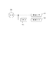
図1は、モータと負荷としての搬送ローラとの構成を示すブロック図である。図1に示すように、搬送ローラ701はモータ509によって駆動される。また、モータ509と搬送ローラ702は、クラッチ700によって連結及び離間される。
FIG. 1 is a block diagram illustrating a configuration of a motor and a conveyance roller as a load. As shown in FIG. 1, the
クラッチ700によるモータ509と搬送ローラ702との連結及び離間は、モータ509の回転子が所定速度で(一定速度で)回転している状態で行われる。即ち、モータ509の回転子が所定速度で回転する期間においては、モータ509と搬送ローラ702とが連結していない期間とモータ509と搬送ローラ702とが連結している期間とがある。モータ509と搬送ローラ702とが離間しており、モータ509が搬送ローラ701を駆動している場合、モータ509の回転子には搬送ローラ701に対応する負荷トルクがかかる。また、モータ509が搬送ローラ701を駆動している状態で、モータ509と搬送ローラ702とが連結されると、モータ509の回転子には搬送ローラ701に対応する負荷トルクだけでなく、搬送ローラ702に対応する負荷トルクもかかる。したがって、モータと搬送ローラ702とがクラッチによって連結される際には、回転子にかかる負荷トルクは増大する。このように、モータ509に連結される負荷が多くなればなるほど、モータの回転子を所定速度で回転させる際に回転子にかかる負荷トルクは大きくなる。また、回転子が所定速度で回転する期間においては、巻線に発生する誘起電圧に起因して出力可能トルクが小さくなる。したがって、回転子が所定速度で回転する期間において、モータに負荷が連結されることに起因して回転子にかかる負荷トルクが出力可能トルクを超えてしまう可能性がある。回転子にかかる負荷トルクが出力可能トルクを超えた場合には、回転子を回転させることができなくなってしまう。
The coupling and separation of the
前記特許文献1に記載されている構成においては、回転速度と励磁電流成分の値との対応関係は1対1の関係である。したがって、回転子が所定速度で回転する期間においては、所定速度に対応する所定の励磁電流成分の値が設定される。 In the configuration described in Patent Document 1, the correspondence between the rotation speed and the value of the excitation current component is a one-to-one relationship. Therefore, during a period in which the rotor rotates at a predetermined speed, a value of a predetermined excitation current component corresponding to the predetermined speed is set.
前述したように、回転子が所定速度で回転する期間においては、モータと負荷とが連結されている期間における負荷トルクはモータと負荷とが連結されていない期間における負荷トルクよりも大きい。即ち、クラッチにより負荷と連結又は離間されるモータの制御に特許文献1の構成を適用する場合、負荷トルクが出力可能トルクを超えないよう、モータと負荷とが連結されている期間における負荷トルクを考慮して励磁電流成分の値が設定される必要がある。 As described above, during the period in which the rotor rotates at a predetermined speed, the load torque in the period in which the motor and the load are connected is larger than the load torque in the period in which the motor and the load are not connected. That is, when applying the configuration of Patent Document 1 to control a motor that is connected to or separated from a load by a clutch, the load torque during the period in which the motor and the load are connected is set so that the load torque does not exceed the outputable torque. The value of the excitation current component needs to be set in consideration.
励磁電流成分の値の絶対値が大きければ大きいほど、モータの巻線に供給する電流は大きくなる。したがって、モータと負荷とが連結されている期間における負荷トルクを考慮して励磁電流成分の値が設定されると、モータと負荷とが連結されていない期間においては、不要な電流を巻線に供給してしまう。この結果、消費電力が増大してしまう。 The larger the absolute value of the exciting current component value, the larger the current supplied to the motor winding. Therefore, if the value of the excitation current component is set in consideration of the load torque during the period in which the motor and the load are connected, an unnecessary current is passed to the winding during the period in which the motor and the load are not connected. I will supply. As a result, power consumption increases.
上記課題に鑑み、本発明は、モータの制御を効率的に行うことを目的とする。 In view of the above problems, an object of the present invention is to efficiently control a motor.
上記課題を解決するために、本発明は、
シートを搬送する搬送部と、
前記搬送部を駆動するモータと、
前記モータの駆動力が前記搬送部に伝達される第1状態と、前記モータの駆動が前記搬送部に伝達されない第2状態と、を切り替える連結部材と、
前記モータの回転子の回転位相を決定する位相決定手段と、
前記モータの巻線に流れる駆動電流を検出する検出手段と、
前記検出手段によって検出された駆動電流のトルク電流成分の値と前記トルク電流成分の目標値との偏差が小さくなるように前記巻線に流れる駆動電流を制御し、前記巻線に流れる駆動電流の励磁電流成分の値を制御することによって前記巻線を貫く磁束の強度を弱める弱め界磁を行う制御手段と、
を有し、
前記トルク電流成分は、前記位相決定手段によって決定された回転位相を基準とする回転座標系において表される電流成分であって前記回転子にトルクを発生させる電流成分であり、
前記励磁電流成分は、前記回転座標系において表される電流成分であって前記巻線を貫く磁束の強度に影響する電流成分であって、
前記制御手段は、前記回転子の目標位相を表す指令位相と前記位相決定手段によって決定された回転位相との偏差が小さくなるように前記トルク電流成分の目標値を設定し、
前記制御手段は、前記モータを制御している期間中に、前記連結部材が前記第2状態である第1タイミングにおいて前記弱め界磁の程度を第1の程度から前記第1の程度よりも大きい第2の程度に変更することを特徴とする。
In order to solve the above problems, the present invention provides:
A transport unit for transporting the sheet;
A motor for driving the transport unit;
A connecting member that switches between a first state in which the driving force of the motor is transmitted to the transport unit and a second state in which the drive of the motor is not transmitted to the transport unit;
Phase determining means for determining the rotational phase of the rotor of the motor;
Detecting means for detecting a driving current flowing in the winding of the motor;
The drive current flowing through the winding is controlled such that the deviation between the torque current component value of the drive current detected by the detection means and the target value of the torque current component is small, and the drive current flowing through the winding is controlled. Control means for performing field weakening to weaken the strength of magnetic flux passing through the winding by controlling the value of the excitation current component;
Have
The torque current component is a current component that is expressed in a rotating coordinate system based on the rotational phase determined by the phase determining means, and is a current component that generates torque in the rotor,
The excitation current component is a current component that is represented in the rotating coordinate system and affects the strength of the magnetic flux passing through the winding,
The control means sets the target value of the torque current component so that the deviation between the command phase representing the target phase of the rotor and the rotational phase determined by the phase determination means is small,
The control means increases the degree of the field weakening from the first degree to the first degree at the first timing when the connecting member is in the second state during the period of controlling the motor. It changes to the 2nd grade, It is characterized by the above-mentioned.
本発明によれば、モータの制御を効率的に行うことができる。 According to the present invention, the motor can be controlled efficiently.
以下に図面を参照して、本発明の好適な実施の形態を説明する。ただし、この実施の形態に記載されている構成部品の形状及びそれらの相対配置などは、この発明が適用される装置の構成や各種条件により適宜変更されるべきものであり、この発明の範囲が以下の実施の形態に限定される趣旨のものではない。なお、以下の説明においては、モータ制御装置が画像形成装置に設けられる場合について説明するが、モータ制御装置が設けられるのは画像形成装置に限定されるわけではない。例えば、モータ制御装置は記録媒体や原稿等のシートを搬送するシート搬送装置にも用いられる。 Hereinafter, preferred embodiments of the present invention will be described with reference to the drawings. However, the shape of the component parts described in this embodiment and the relative arrangement thereof should be appropriately changed according to the configuration of the apparatus to which the present invention is applied and various conditions, and the scope of the present invention is limited. It is not intended to be limited to the following embodiments. In the following description, a case where the motor control device is provided in the image forming apparatus will be described, but the motor control device is not limited to the image forming apparatus. For example, the motor control device is also used in a sheet conveying device that conveys a sheet such as a recording medium or a document.
〔第1実施形態〕
[画像形成装置]
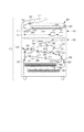
図2は、本実施形態で用いられるシート搬送装置を有するモノクロの電子写真方式の複写機(以下、画像形成装置と称する)100の構成を示す断面図である。なお、画像形成装置は複写機に限定されず、例えば、ファクシミリ装置、印刷機、プリンタ等であっても良い。また、記録方式は、電子写真方式に限らず、例えば、インクジェット等であっても良い。更に、画像形成装置の形式はモノクロ及びカラーのいずれの形式であっても良い。
[First Embodiment]
[Image forming apparatus]
FIG. 2 is a cross-sectional view showing a configuration of a monochrome electrophotographic copying machine (hereinafter referred to as an image forming apparatus) 100 having a sheet conveying apparatus used in the present embodiment. The image forming apparatus is not limited to a copying machine, and may be, for example, a facsimile machine, a printing machine, a printer, or the like. The recording method is not limited to the electrophotographic method, and may be, for example, an ink jet. Further, the format of the image forming apparatus may be either monochrome or color.
以下に、図2を用いて、画像形成装置100の構成および機能について説明する。画像形成装置100は、原稿給送装置201、読取装置202及び画像印刷装置301を有する。
The configuration and function of the
原稿給送装置201の原稿積載部203に積載された原稿は、給紙ローラ204によって1枚ずつ給紙され、搬送ガイド206に沿って読取装置202の原稿ガラス台214上に搬送される。更に、原稿は、搬送ベルト208によって一定速度で搬送されて、排紙ローラ205によって不図示の排紙トレイへ排紙される。読取装置202の読取位置において照明209によって照明された原稿画像からの反射光は、反射ミラー210、211、212からなる光学系によって画像読取部101に導かれ、画像読取部101によって画像信号に変換される。画像読取部101は、レンズ、光電変換素子であるCCD、CCDの駆動回路等で構成される。画像読取部101から出力された画像信号は、ASIC等のハードウェアデバイスで構成される画像処理部112によって各種補正処理が行われた後、画像印刷装置301へ出力される。前述の如くして、原稿の読取が行われる。即ち、原稿給送装置201及び読取装置202は、原稿読取装置として機能する。
The originals stacked on the original stacking
また、原稿の読取モードとして、第1読取モードと第2読取モードがある。第1読取モードは、一定速度で搬送される原稿の画像を、所定の位置に固定された照明系209及び光学系によって読み取るモードである。第2読取モードは、読取装置202の原稿ガラス214上に載置された原稿の画像を、一定速度で移動する照明系209及び光学系によって読み取るモードである。通常、シート状の原稿の画像は第1読取モードで読み取られ、本や冊子等の綴じられた原稿の画像は第2読取モードで読み取られる。
Further, there are a first reading mode and a second reading mode as document reading modes. The first reading mode is a mode in which an image of a document conveyed at a constant speed is read by an
画像印刷装置301の内部には、シート収納トレイ302、304が設けられている。シート収納トレイ302、304には、それぞれ異なる種類の記録媒体を収納することができる。例えば、シート収納トレイ302にはA4サイズの普通紙が収納され、シート収納トレイ304にはA4サイズの厚紙が収納される。なお、記録媒体とは、画像形成装置によって画像が形成されるものであって、例えば、用紙、樹脂シート、布、OHPシート、ラベル等が記録媒体に含まれる。
Inside the
シート収納トレイ302に収納された記録媒体は、給紙ローラ303によって給送されて、搬送ローラ306によってレジストレーションローラ308へ送り出される。また、シート収納トレイ304に収納された記録媒体は、給紙ローラ305によって給送されて、搬送ローラ307及び306によってレジストレーションローラ308へ送り出される。なお、図2に示すように、搬送ローラ306の上流側及び下流側には、記録媒体の有無を検知するシートセンサ330、331が設けられている。シートセンサ330、331の用途については後述する。なお、本実施形態におけるシートセンサは、光学式センサであるが、これに限定されるものではなく、例えば、フラグセンサ等であっても良い。
The recording medium stored in the
読取装置202から出力された画像信号は、半導体レーザ及びポリゴンミラーを含む光走査装置311に入力される。また、感光ドラム309は、帯電器310によって外周面が帯電される。感光ドラム309の外周面が帯電された後、読取装置202から光走査装置311に入力された画像信号に応じたレーザ光が、光走査装置311からポリゴンミラー及びミラー312、313を経由し、感光ドラム309の外周面に照射される。この結果、感光ドラム309の外周面に静電潜像が形成される。なお、感光ドラムの帯電には、例えば、コロナ帯電器や帯電ローラを用いた帯電方法が用いられる。
The image signal output from the
続いて、静電潜像が現像器314内のトナーによって現像され、感光ドラム309の外周面にトナー像が形成される。感光ドラム309に形成されたトナー像は、感光ドラム309と対向する位置(転写位置)に設けられた転写帯電器315によって記録媒体に転写される。この際、レジストレーションローラ308は、トナー像にタイミングを合わせて、記録媒体を転写位置へ送り込む。
Subsequently, the electrostatic latent image is developed with toner in the developing
前述の如くして、トナー像が転写された記録媒体は、搬送ベルト317によって定着器318へ送り込まれ、定着器318によって加熱加圧されて、トナー像が記録媒体に定着される。このようにして、画像形成装置100によって記録媒体に画像が形成される。
As described above, the recording medium to which the toner image has been transferred is sent to the
片面印刷モードで画像形成が行われる場合は、定着器318を通過した記録媒体は、排紙ローラ319、324によって、不図示の排紙トレイへ排紙される。また、両面印刷モードで画像形成が行われる場合は、定着器318によって記録媒体の第1面に定着処理が行われた後に、記録媒体は、排紙ローラ319、搬送ローラ320、及び反転ローラ321によって、反転パス325へと搬送される。その後、記録媒体は、搬送ローラ322、323によって再度レジストレーションローラ308へと搬送され、前述した方法で記録媒体の第2面に画像が形成される。その後、記録媒体は排紙ローラ319、324によって不図示の排紙トレイへ排紙される。
When image formation is performed in the single-sided printing mode, the recording medium that has passed through the fixing
また、第1面に画像形成された記録媒体がフェースダウンで画像形成装置100の外部へ排紙される場合は、定着器318を通過した記録媒体を、排紙ローラ319を通って搬送ローラ320へ向かう方向へ搬送される。その後、記録媒体の後端が搬送ローラ320のニップ部を通過する直前に搬送ローラ320の回転が反転することによって、記録媒体の第1面が下向きになった状態で、記録媒体が排紙ローラ324を経由して、画像形成装置100の外部へ排出される。
When the recording medium on which the image is formed on the first surface is discharged face-down to the outside of the
以上が画像形成装置100の構成および機能についての説明である。なお、本発明における負荷とはモータによって駆動される対象物である。例えば、給紙ローラ204、303、305、レジストレーションローラ308及び排紙ローラ319等の各種ローラ(搬送ローラ)や感光ドラム309、搬送ベルト208、317、照明系209及び光学系等は本発明における負荷に対応する。本実施形態のモータ制御装置は、これら負荷を駆動するモータに適用することができる。
The above is the description of the configuration and functions of the
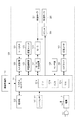
図3は、画像形成装置100の制御構成の例を示すブロック図である。図3に示すように、画像形成装置100には電源1が備えられている。電源1は交流電源(AC)に接続されており、画像形成装置100の内部の各種装置は電源1から出力される電力によって稼働する。また、システムコントローラ151は、図3に示すように、CPU151a、ROM151b、RAM151cを備えている。また、システムコントローラ151は、画像処理部112、操作部152、アナログ・デジタル(A/D)変換器153、高圧制御部155、モータ制御装置157、クラッチ700、シートセンサ330、331、センサ類159、ACドライバ160と接続されている。システムコントローラ151は、接続された各ユニットとの間でデータやコマンドの送受信をすることが可能である。
FIG. 3 is a block diagram illustrating an example of a control configuration of the
CPU151aは、ROM151bに格納された各種プログラムを読み出して実行することによって、予め定められた画像形成シーケンスに関連する各種シーケンスを実行する。
The
RAM151cは記憶デバイスである。RAM151cには、例えば、高圧制御部155に対する設定値、モータ制御装置157に対する指令値及び操作部152から受信される情報等の各種データが格納される。
The RAM 151c is a storage device. The RAM 151c stores various data such as a set value for the high-
システムコントローラ151は、画像処理部112における画像処理に必要となる、画像形成装置100の内部に設けられた各種装置の設定値データを画像処理部112に送信する。更に、システムコントローラ151は、センサ類159等からの信号を受信して、受信した信号に基づいて高圧制御部155の設定値を設定する。高圧制御部155は、システムコントローラ151によって設定された設定値に応じて、高圧ユニット156(帯電器310、現像器314、転写帯電器315等)に必要な電圧を供給する。
The
図3に示すように、本実施形態におけるモータ509は、複数個の負荷を駆動する。具体的には、例えば、モータ509は搬送ローラ307と搬送ローラ306とを駆動する。モータ509と搬送ローラ306は、クラッチ700によって連結、離間される。即ち、クラッチ700は連結部材として機能する。モータ509と搬送ローラ306とがクラッチ700によって連結されると、モータ509は搬送ローラ307と搬送ローラ306とを駆動することができる。また、モータ509と搬送ローラ306とが離間されると、モータ509は搬送ローラ307のみを駆動する。なお、クラッチによる連結、離間は、モータ509の回転子が所定速度で(一定速度で)回転する状態において行われるものとする。本実施形態におけるクラッチは、電磁力によって連結、離間を行う電磁クラッチであるものとするが、これに限定されるものではなく、モータと負荷とを連結、離間させてモータの駆動力を負荷に伝達させる構成であればよい。
As shown in FIG. 3, the
システムコントローラ151は、シートセンサ330、331の検知結果に基づいて、クラッチ700を制御する。クラッチ700は、CPU151aから出力される信号に応じてモータ509と搬送ローラ306とを連結、離間する。また、モータ制御装置157は、CPU151aから出力された指令に応じて、モータ509を制御する。なお、図3においては、モータ509は、搬送ローラ306と搬送ローラ307とを駆動する構成となっているが、これに限定されるものではない。例えば、搬送ローラ306、307だけでなく、その他の負荷を駆動する構成であっても良い。また、図3においては、負荷を駆動するモータとしてモータ509のみが記載されているが、実際には、画像形成装置には複数個のモータが設けられているものとする。また、モータ制御装置1個で複数個のモータを制御する構成であっても良い。更に、図3においては、モータ制御装置が1個しか設けられていないが、実際には、複数個のモータ制御装置が設けられているものとする。
The
電源1はモータ制御装置157に設けられたフルブリッジ回路50に電圧Vccを供給する。なお、フルブリッジ回路50については後述する。
The power supply 1 supplies the voltage Vcc to the
A/D変換器153は、定着ヒータ161の温度を検出するためのサーミスタ154が検出した検出信号を受信し、検出信号をアナログ信号からデジタル信号に変換してシステムコントローラ151に送信する。システムコントローラ151は、A/D変換器153から受信したデジタル信号に基づいて、ACドライバ160の制御を行う。ACドライバ160は、定着ヒータ161の温度が定着処理を行うために必要な温度となるように定着ヒータ161を制御する。なお、定着ヒータ161は、定着処理に用いられるヒータであり、定着器318に含まれる。
The A /
システムコントローラ151は、使用する記録媒体の種類(以下、紙種と称する)等の設定をユーザが行うための操作画面を、操作部152に設けられた表示部に表示するように、操作部152を制御する。システムコントローラ151は、ユーザが設定した情報を操作部152から受信し、ユーザが設定した情報に基づいて画像形成装置100の動作シーケンスを制御する。また、システムコントローラ151は、画像形成装置の状態を示す情報を操作部152に送信する。なお、画像形成装置の状態を示す情報とは、例えば、画像形成枚数、画像形成動作の進行状況、画像印刷装置301及び原稿給送装置201におけるシートのジャムや重送等に関する情報である。操作部152は、システムコントローラ151から受信した情報を表示部に表示する。
The
前述の如くして、システムコントローラ151は、画像形成装置100の動作シーケンスを制御する。
As described above, the
[ベクトル制御]
次に、本実施形態におけるモータ制御装置について説明する。本実施形態におけるモータ制御装置は、ベクトル制御によってモータを制御する。
[Vector control]
Next, the motor control device in the present embodiment will be described. The motor control device in the present embodiment controls the motor by vector control.
まず、図4及び図5を用いて、本実施形態におけるモータ制御装置157がベクトル制御を行う方法について説明する。なお、以下の説明におけるモータには、モータの回転子の回転位相を検出するためのロータリエンコーダなどのセンサは設けられていないが、ロータリエンコーダなどのセンサが設けられている構成であっても良い。
First, a method in which the
図4は、A相(第1相)とB相(第2相)との2相から成るステッピングモータ(以下、モータと称する)509と、d軸及びq軸によって表される回転座標系との関係を示す図である。図4では、静止座標系において、A相の巻線に対応した軸であるα軸と、B相の巻線に対応した軸であるβ軸とが定義されている。また、図4では、回転子402に用いられている永久磁石の磁極によって作られる磁束の方向に沿ってd軸が定義され、d軸から反時計回りに90度進んだ方向(d軸に直交する方向)に沿ってq軸が定義されている。α軸とd軸との成す角度はθと定義され、回転子402の回転位相は角度θによって表される。ベクトル制御では、回転子402の回転位相θを基準とした回転座標系が用いられる。具体的には、ベクトル制御では、巻線に流れる駆動電流に対応する電流ベクトルの、回転座標系における電流成分であって、回転子にトルクを発生させるq軸成分(トルク電流成分)と巻線を貫く磁束の強度に影響するd軸成分(励磁電流成分)とが用いられる。
FIG. 4 shows a stepping motor (hereinafter referred to as a motor) 509 having two phases of A phase (first phase) and B phase (second phase), and a rotating coordinate system represented by d-axis and q-axis. It is a figure which shows the relationship. In FIG. 4, an α axis that is an axis corresponding to the A phase winding and a β axis that is an axis corresponding to the B phase winding are defined in the stationary coordinate system. In FIG. 4, the d axis is defined along the direction of the magnetic flux created by the magnetic poles of the permanent magnets used in the
ベクトル制御とは、回転子の目標位相を表す指令位相と実際の回転位相との偏差が小さくなるようにトルク電流成分の値と励磁電流成分の値とを制御する位相フィードバック制御を行うことによってモータを制御する制御方法である。また、回転子の目標速度を表す指令速度と実際の回転速度との偏差が小さくなるようにトルク電流成分の値と励磁電流成分の値とを制御する速度フィードバック制御を行うことによってモータを制御する方法もある。 Vector control is a motor that performs phase feedback control that controls the value of the torque current component and the value of the excitation current component so that the deviation between the command phase representing the target phase of the rotor and the actual rotation phase is small. It is the control method which controls. In addition, the motor is controlled by performing speed feedback control that controls the value of the torque current component and the value of the excitation current component so that the deviation between the command speed representing the target speed of the rotor and the actual rotation speed becomes small. There is also a method.
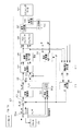
図5は、モータ509を制御するモータ制御装置157の構成の例を示すブロック図である。
FIG. 5 is a block diagram illustrating an example of the configuration of the
図5に示すように、モータ制御装置157は、ベクトル制御を行う回路として、位相制御器502、電流制御器503、座標逆変換器505、座標変換器511、モータの巻線に駆動電流を供給するPWMインバータ506等を有する。座標変換器511は、モータ509のA相及びB相の巻線に流れる駆動電流に対応する電流ベクトルを、α軸及びβ軸で表される静止座標系からq軸及びd軸で表される回転座標系に座標変換する。この結果、巻線に流れる駆動電流は、回転座標系における電流値であるq軸成分の電流値(q軸電流)とd軸成分の電流値(d軸電流)とによって表される。なお、q軸電流は、モータ509の回転子402にトルクを発生させるトルク電流に相当する。また、d軸電流は、モータ509の巻線を貫く磁束の強度に影響する励磁電流に相当し、回転子402のトルクの発生には寄与しない。モータ制御装置157は、q軸電流及びd軸電流をそれぞれ独立に制御することができる。この結果、モータ制御装置157は、回転子402にかかる負荷トルクに応じてq軸電流を制御することによって、回転子402が回転するために必要なトルクを効率的に発生させることができる。
As shown in FIG. 5, the
モータ制御装置157は、モータ509の回転子402の回転位相θを後述する方法により決定し、その決定結果に基づいてベクトル制御を行う。CPU151aは、モータ509の回転子402の目標位相を表す指令位相θ_refを生成し、所定の時間周期で指令位相θ_refをモータ制御装置157へ出力する。
The
減算器101は、モータ509の回転子402の回転位相θと指令位相θ_refとの偏差を演算し、該偏差を位相制御器502に出力する。
The
位相制御器502は、比例制御(P)、積分制御(I)、微分制御(D)に基づいて、減算器101から出力された偏差が小さくなるように、q軸電流指令値(目標値)iq_refを生成して出力する。具体的には、位相制御器502は、P制御、I制御、D制御に基づいて減算器101から出力された偏差が0になるように、q軸電流指令値iq_refを生成して出力する。なお、P制御とは、制御する対象の値を指令値と推定値との偏差に比例する値に基づいて制御する制御方法である。また、I制御とは、制御する対象の値を指令値と推定値との偏差の時間積分に比例する値に基づいて制御する制御方法である。また、D制御とは、制御する対象の値を指令値と推定値との偏差の時間変化に比例する値に基づいて制御する制御方法である。本実施形態における位相制御器502は、PID制御に基づいてq軸電流指令値iq_refを生成しているが、これに限定されるものではない。例えば、位相制御器502は、PI制御に基づいてq軸電流指令値iq_refを生成しても良い。
The
モータ509のA相及びB相の巻線に流れる駆動電流は、電流検出器507、508によって検出され、その後、A/D変換器510によってアナログ値からデジタル値へと変換される。
Drive currents flowing in the A-phase and B-phase windings of the
A/D変換器510によってアナログ値からデジタル値へと変換された駆動電流の電流値は、静止座標系における電流値iα及びiβとして、図4に示す電流ベクトルの位相θeを用いて次式によって表される。なお、電流ベクトルの位相θeは、α軸と電流ベクトルとの成す角度と定義される。また、Iは電流ベクトルの大きさを示す。
iα=I*cosθe (1)
iβ=I*sinθe (2)
The current value of the driving current converted from the analog value to the digital value by the A /
iα = I * cos θe (1)
iβ = I * sin θe (2)
これらの電流値iα及びiβは、座標変換器511と誘起電圧決定器512に入力される。
These current values iα and iβ are input to the coordinate
座標変換器511は、次式によって、静止座標系における電流値iα及びiβを回転座標系におけるq軸電流の電流値iq及びd軸電流の電流値idに変換する。
id= cosθ*iα+sinθ*iβ (3)
iq=−sinθ*iα+cosθ*iβ (4)
The coordinate
id = cos θ * iα + sin θ * iβ (3)
iq = −sin θ * iα + cos θ * iβ (4)
減算器102には、位相制御器502から出力されたq軸電流指令値iq_refと座標変換器511から出力された電流値iqとが入力される。減算器102は、q軸電流指令値iq_refと電流値iqとの偏差を演算し、該偏差を電流制御器503に出力する。
The
また、減算器103には、界磁制御器540から出力されたd軸電流指令値(目標値)id_refと座標変換器511から出力された電流値idとが入力される。減算器103は、d軸電流指令値id_refと電流値idとの偏差を演算し、該偏差を電流制御器503に出力する。なお、界磁制御器540については後述する。
Also, the
電流制御器503は、PID制御に基づいて、前記偏差がそれぞれ小さくなるように駆動電圧Vq及びVdを生成する。具体的には、電流制御器503は、前記偏差がそれぞれ0になるように駆動電圧Vq及びVdを生成して座標逆変換器505に出力する。即ち、電流制御器503は、生成手段として機能する。なお、本実施形態における電流制御器503は、PID制御に基づいて駆動電圧Vq及びVdを生成しているが、これに限定されるものではない。例えば、電流制御器503は、PI制御に基づいて駆動電圧Vq及びVdを生成しても良い。
The
座標逆変換器505は、電流制御器503から出力された回転座標系における駆動電圧Vq及びVdを、次式によって、静止座標系における駆動電圧Vα及びVβに逆変換する。
Vα=cosθ*Vd−sinθ*Vq (5)
Vβ=sinθ*Vd+cosθ*Vq (6)
The coordinate
Vα = cos θ * Vd−sin θ * Vq (5)
Vβ = sin θ * Vd + cos θ * Vq (6)
座標逆変換器505は、逆変換された駆動電圧Vα及びVβを誘起電圧決定器512及びPWMインバータ506に出力する。
The coordinate
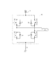
PWMインバータ506は、フルブリッジ回路を有している。図6は、PWMインバータ506に設けられているフルブリッジ回路50の構成の例を示す図である。前述したように、フルブリッジ回路50には、電源1から電圧Vccが供給されている。また、フルブリッジ回路50には、スイッチング素子としてのFET Q1乃至Q4、モータ509の巻線L1等が設けられている。
The
FET Q1乃至Q4は座標逆変換器505から入力された駆動電圧Vα及びVβに基づくPWM信号よって駆動される。その結果、巻線L1には電源1から電圧が印加される。この結果、駆動電圧Vα及びVβに応じた駆動電流iα及びiβが巻線L1に供給される。即ち、PWMインバータ506は、供給手段として機能する。なお、本実施形態においては、PWMインバータはフルブリッジ回路を有しているが、ハーフブリッジ回路等であっても良い。また、フルブリッジ回路は、モータ509のA相とB相それぞれに対応して設けられている。なお、電源はA相、B相にそれぞれ一つずつ設けられているものとするが、この限りではない。また、図6における巻線L1は、実際には、モータ509に設けられている巻線である。
The FETs Q1 to Q4 are driven by a PWM signal based on the drive voltages Vα and Vβ input from the coordinate
次に、回転位相θの決定方法について説明する。回転子402の回転位相θの決定には、回転子402の回転によってモータ509のA相及びB相の巻線に誘起される誘起電圧Eα及びEβの値が用いられる。誘起電圧の値は誘起電圧決定器512によって決定(算出)される。具体的には、誘起電圧Eα及びEβは、A/D変換器510から誘起電圧決定器512に入力された電流値iα及びiβと、座標逆変換器505から誘起電圧決定器512に入力された駆動電圧Vα及びVβとから、次式によって決定される。
Eα=Vα−R*iα−L*diα/dt (7)
Eβ=Vβ−R*iβ−L*diβ/dt (8)
Next, a method for determining the rotational phase θ will be described. For the determination of the rotational phase θ of the
Eα = Vα−R * iα−L * diα / dt (7)
Eβ = Vβ−R * iβ−L * diβ / dt (8)
ここで、Rは巻線レジスタンス、Lは巻線インダクタンスである。巻線レジスタンスR及び巻線インダクタンスLの値は使用されているモータ509に固有の値であり、ROM151b又はモータ制御装置157に設けられたメモリ(不図示)等に予め格納されている。
Here, R is winding resistance, and L is winding inductance. The values of the winding resistance R and the winding inductance L are values specific to the
誘起電圧決定器512によって決定された誘起電圧Eα及びEβは位相決定器513に出力される。
The induced voltages Eα and Eβ determined by the induced
位相決定器513は、誘起電圧決定器512から出力された誘起電圧Eαと誘起電圧Eβとの比に基づいて、次式によってモータ509の回転子402の回転位相θを決定する。
θ=tan^−1(−Eβ/Eα) (9)
The
θ = tan ^ −1 (−Eβ / Eα) (9)
なお、本実施形態においては、位相決定器513は、式(9)に基づく演算を行うことによって回転位相θを決定したが、この限りではない。例えば、誘起電圧Eα及び誘起電圧Eβと誘起電圧Eα及び誘起電圧Eβとに対応する回転位相θとの関係を示すテーブルをROM151b等に記憶しておき、前記テーブルを参照することによって回転位相θを決定してもよい。
In the present embodiment, the
前述の如くして得られた回転子402の回転位相θは、加算器101、座標逆変換器505及び座標変換器511に入力される。
The rotation phase θ of the
その後、モータ制御装置157は上述の制御を繰り返し行う。
Thereafter, the
以上のように、本実施形態におけるモータ制御装置157は、指令位相θ_refと回転位相θとの偏差が小さくなるように回転座標系における電流値を制御する位相フィードバック制御を用いたベクトル制御を行う。ベクトル制御を行うことによって、モータが脱調状態となることや、余剰トルクに起因してモータ音が増大すること及び消費電力が増大することを抑制することができる。また、位相フィードバック制御を行うことによって、回転子の回転位相が所望の位相になるように回転子の回転位相を制御することができる。したがって、画像形成装置において、回転子の回転位相を精度よく制御する必要がある負荷(例えばレジストレーションローラ)を駆動するモータに位相フィードバック制御によるベクトル制御が適用されることによって、記録媒体への画像形成が適切に行われる。
As described above, the
[弱め界磁]
次に、弱め界磁について説明する。前述したように、モータの各相の巻線には、回転子が回転することによって誘起電圧が発生する。モータの巻線に誘起電圧が発生すると、モータの巻線に印加できる電圧(以下、使用可能電圧と称する)が小さくなってしまう。具体的には、例えば、電源1から出力される電圧値がVccである場合、使用可能電圧Vα´及びVβ´は、各相の巻線に誘起電圧が発生することに起因して、以下の式(10)及び(11)に示す値に制限されてしまう。
Vα´=Vcc−eα (10)
Vβ´=Vcc−eβ (11)
[Weak field]
Next, the field weakening will be described. As described above, an induced voltage is generated in the winding of each phase of the motor as the rotor rotates. When an induced voltage is generated in the motor winding, the voltage that can be applied to the motor winding (hereinafter referred to as usable voltage) is reduced. Specifically, for example, when the voltage value output from the power supply 1 is Vcc, the usable voltages Vα ′ and Vβ ′ are as follows due to the generation of induced voltages in the windings of each phase. It will be limited to the values shown in equations (10) and (11).
Vα ′ = Vcc−eα (10)
Vβ ′ = Vcc−eβ (11)
ここで、eαは正弦波状に変化する誘起電圧Eαの振幅を示す。また、eβは正弦波状に変化する誘起電圧Eβの振幅を示す。 Here, eα represents the amplitude of the induced voltage Eα that changes sinusoidally. Further, eβ represents the amplitude of the induced voltage Eβ that changes in a sinusoidal shape.
また、回転子が回転することによって各相の巻線に発生する誘起電圧の振幅eは、回転子の回転速度が大きくなればなるほど大きくなる。即ち、回転子の回転速度が速くなればなるほど、使用可能電圧は小さくなる。使用可能電圧が小さくなると、回転子に与えることができるトルク(以下、出力可能トルクと称する)も小さくなってしまう。 In addition, the amplitude e of the induced voltage generated in the winding of each phase as the rotor rotates increases as the rotational speed of the rotor increases. That is, the usable voltage decreases as the rotational speed of the rotor increases. When the usable voltage decreases, the torque that can be applied to the rotor (hereinafter referred to as “outputtable torque”) also decreases.
誘起電圧は、巻線を貫く磁束が変化することに伴って発生する。したがって、回転子の磁束よりも弱い磁束が巻線を貫くように励磁電流成分を制御することによって、巻線に発生する誘起電圧の大きさが増大することを抑制することができる。具体的には、励磁電流成分を負の値に制御することによって、見かけ上、回転子の磁束よりも弱い磁束が巻線を貫くようにする。この結果、巻線に発生する誘起電圧の大きさが増大することを抑制することができ、使用可能電圧Vα´及びVβ´が小さくなることを抑制することができる。その結果、出力可能トルクが小さくなることを抑制することができる。以上のような手法は、弱め界磁と称される。なお、励磁電流成分が負の値であって且つ絶対値が大きいほど、出力可能トルクが小さくなることをより抑制することができる。 The induced voltage is generated as the magnetic flux passing through the winding changes. Therefore, it is possible to suppress an increase in the magnitude of the induced voltage generated in the winding by controlling the exciting current component so that a magnetic flux weaker than the magnetic flux of the rotor penetrates the winding. Specifically, by controlling the exciting current component to a negative value, a magnetic flux that apparently is weaker than the magnetic flux of the rotor penetrates the winding. As a result, an increase in the magnitude of the induced voltage generated in the winding can be suppressed, and the usable voltages Vα ′ and Vβ ′ can be suppressed from decreasing. As a result, it is possible to suppress a decrease in outputable torque. Such a method is called field weakening. In addition, it can suppress more that output possible torque becomes small, so that an exciting current component is a negative value and an absolute value is large.
次に、本実施形態における弱め界磁について説明する。本実施形態では、以下の構成をモータ制御装置157に適用することによって、消費電力が増大することを抑制する。
Next, the field weakening in this embodiment will be described. In the present embodiment, an increase in power consumption is suppressed by applying the following configuration to the
<弱め界磁を行う条件1>
本実施形態におけるモータ制御装置157は、以下の2つの条件を満たす場合に弱め界磁を行う。
<Condition 1 for field weakening>
The
まず、弱め界磁を行うための1つ目の条件について説明する。 First, the first condition for performing field weakening will be described.
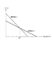
図7は、出力可能トルクTと回転子の回転速度ωとの関係を示す図である。図7には、d軸電流を0に制御した場合のトルクT−回転速度ω特性(破線)とd軸電流を負の値に制御した場合のトルクT−回転速度ω特性(実線)が示されている。なお、図7に示すトルク−回転数特性は、本実施形態における一例であり、これに限定されるものではない。 FIG. 7 is a diagram showing the relationship between the outputtable torque T and the rotational speed ω of the rotor. FIG. 7 shows a torque T-rotational speed ω characteristic (broken line) when the d-axis current is controlled to 0 and a torque T-rotational speed ω characteristic (solid line) when the d-axis current is controlled to a negative value. Has been. The torque-rotational speed characteristics shown in FIG. 7 are an example in the present embodiment, and the present invention is not limited to this.
図7に示すように、回転速度ωがω0未満である(ω<ω0)場合は、d軸電流を負の値に制御する場合における出力可能トルクTよりもd軸電流を0に制御する場合における出力可能トルクTのほうが大きい。即ち、回転速度ωがω0未満である(ω<ω0)場合は、弱め界磁を行う場合よりも弱め界磁を行わない場合のほうがより大きなトルクを回転子に与えることができる。 As shown in FIG. 7, when the rotational speed ω is less than ω0 (ω <ω0), the d-axis current is controlled to 0 rather than the outputtable torque T when the d-axis current is controlled to a negative value. The output possible torque T at is larger. That is, when the rotational speed ω is less than ω0 (ω <ω0), a larger torque can be applied to the rotor when the field weakening is not performed than when the field weakening is performed.
また、図7に示すように、回転速度ωがω0より大きい(ω>ω0)場合は、d軸電流を0に制御する場合における出力可能トルクTよりもd軸電流を負の値に制御する場合における出力可能トルクTのほうが大きい。即ち、回転速度ωがω0より大きい(ω>ω0)場合は、弱め界磁を行わない場合よりも弱め界磁を行う場合のほうがより大きなトルクを回転子に与えることができる。 Also, as shown in FIG. 7, when the rotational speed ω is greater than ω0 (ω> ω0), the d-axis current is controlled to a negative value rather than the outputtable torque T when the d-axis current is controlled to 0. In this case, the output possible torque T is larger. That is, when the rotational speed ω is larger than ω0 (ω> ω0), a larger torque can be applied to the rotor when the field weakening is performed than when the field weakening is not performed.
以上のように、回転速度ωがω0未満である(ω<ω0)場合は、弱め界磁を行う場合よりも弱め界磁を行わない場合のほうがより大きなトルクを回転子に与えることができる。また、回転速度ωがω0より大きい(ω>ω0)場合は、弱め界磁を行わない場合よりも弱め界磁を行う場合のほうがより大きなトルクを回転子に与えることができる。 As described above, when the rotational speed ω is less than ω0 (ω <ω0), a larger torque can be applied to the rotor when the field weakening is not performed than when the field weakening is performed. When the rotational speed ω is greater than ω0 (ω> ω0), a larger torque can be applied to the rotor when the field weakening is performed than when the field weakening is not performed.
したがって、本実施形態においては、回転子の回転速度がω0以上であることを、弱め界磁を行う1つ目の条件とする。 Therefore, in the present embodiment, the first condition for performing field weakening is that the rotational speed of the rotor is ω0 or more.
図5に示すように、本実施形態においては、CPU151aは、指令位相θ_refの時間変化に基づいて、指令速度ω_refの代わりとなる回転速度ω_ref´を算出し、界磁制御器540に出力する。なお、回転速度ω_ref´の算出には、以下の式(12)が用いられる。
ω=dθ/dt (12)
As shown in FIG. 5, in the present embodiment, the
ω = dθ / dt (12)
界磁制御器540は、回転速度ω_ref´が以下の式(13)を満たすか否かを判断する。なお、速度閾値ωth(=ω0)は、メモリ540aに記憶されているものとする。
ω_ref´≧ωth (13)
The
ω_ref ′ ≧ ωth (13)
<弱め界磁を行う条件2>
しかしながら、式(13)のみを、弱め界磁を行う条件としてしまうと、前述したように、モータ509と搬送ローラ306とが連結されていない期間においては、不要な電流を巻線に供給してしまう。この結果、消費電力が増大してしまう。
<Condition 2 for field weakening>
However, if only the expression (13) is used as a condition for performing field weakening, an unnecessary current is supplied to the winding during the period in which the
次に、弱め界磁を行うための2つ目の条件について説明する。 Next, the second condition for performing field weakening will be described.
前述したように、回転子が所定速度で回転する期間において、モータ509と搬送ローラ306とが連結されている期間における負荷トルクはモータ509と搬送ローラ306とが連結されていない期間における負荷トルクよりも大きい。即ち、モータ509と搬送ローラ306とが連結されている期間においては、モータ509と搬送ローラ306とが連結されていない期間よりも大きな出力可能トルクが必要となる。
As described above, during the period in which the rotor rotates at a predetermined speed, the load torque in the period in which the
図2において説明したように、記録媒体が搬送される搬送方向において搬送ローラ306の上流側の所定位置には、記録媒体の有無を検知する330が設けられている。また、前記搬送方向において搬送ローラ307の下流側の第2所定位置には、記録媒体の有無を検知するシートセンサ331が設けられている。CPU151aには、シートセンサ330、331の検知結果が入力される。
As described in FIG. 2, 330 is provided at a predetermined position upstream of the
本実施形態においては、記録媒体の先端をシートセンサ330が検知すると(記録媒体の先端がシートセンサ330に到達すると)、モータ制御装置157は弱め界磁を開始する。そして、シートセンサ330が記録媒体の先端を検知してから所定時間t_onが経過すると、CPU151aは、モータ509と搬送ローラ306とを連結するようにクラッチ700を制御する。この結果、モータ509と搬送ローラ306とが連結される。また、記録媒体の後端がシートセンサ331を通過すると(シートセンサ331が記録媒体を検知しなくなると)、CPU151aは、モータ509と搬送ローラ306とを離間するようにクラッチ700を制御する。この結果、モータ509と搬送ローラ306とが離間される。そして、記録媒体の後端がシートセンサ331を通過してから所定時間t_offが経過すると、弱め界磁を終了する。即ち、モータ509と搬送ローラ306とが連結されている期間において弱め界磁を行い、モータ509と搬送ローラ306とが連結されていない期間においては、弱め界磁を行わない。この結果、励磁電流成分の値を0以外の値に設定することに起因して消費電力が増大することを抑制することができる。
In the present embodiment, when the
<弱め界磁を行う具体的な方法>
次に、弱め界磁を行う具体的な方法について説明する。
<Specific method of field weakening>
Next, a specific method for performing field weakening will be described.
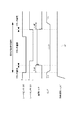
図8は、本実施形態における弱め界磁制御のタイムチャートを示す図である。界磁制御器540は、回転子の回転速度ω_ref´がωth以上の所定速度である期間のうち、シートセンサ330が記録媒体の先端を検知するまでの期間(シートセンサ331が‘H’である期間)は、d軸電流指令値として0Aを出力する。即ち、弱め界磁は行われない。
FIG. 8 is a diagram showing a time chart of field weakening control in the present embodiment. The
その後、回転速度ω_ref´が所定速度である状態で、シートセンサ330が記録媒体の先端を検知する(シートセンサ331が‘H’から‘L’になる)と、CPU151aは、d軸電流指令値の値を切り替える切替信号を界磁制御器540に出力する。界磁制御器540は、切替信号に応じて、出力するd軸電流指令値id_refを0Aから徐々に変化させることによって負の値(例えば−0.3A)に切り替える。この結果、弱め界磁が行われる。なお、設定されるid_refの値が負の値であり且つ絶対値が大きすぎると、回転子である永久磁石から発生する磁界を過剰に弱めてしまい、結果として、回転子に発生させるトルクが小さくなってしまう。また、設定されるid_refの値が負の値であり且つ絶対値が0に近い値であると、回転子である永久磁石から発生する磁界を弱めることができず、結果として、巻線に発生する誘起電圧を低減することができなくなってしまう。前記負の値は、以上のようなことを考慮して予め実験等に基づいて決定されている。また、d軸電流指令値id_refは、メモリ540aに記憶されており、界磁制御器540はメモリ540aに記憶されている値をd軸電流指令値id_refとして出力する。
Thereafter, when the
そして、シートセンサ330が記録媒体の先端を検知してから所定時間t_onが経過すると、CPU151aは、モータ509と搬送ローラ306とを連結するようにクラッチ700を制御する。この結果、モータ509と搬送ローラ306とが連結される。
When a predetermined time t_on elapses after the
そして、記録媒体が搬送ローラ306によって搬送されると、シートセンサ331が記録媒体の先端を検知する(シートセンサ330が‘H’から‘L’になる)。更に記録媒体が搬送され、記録媒体の後端がシートセンサ331を通過する(シートセンサ330が‘L’から‘H’になる)と、CPU151aは、モータ509と搬送ローラ306とを離間するようにクラッチ700を制御する。この結果、モータ509と搬送ローラ306とが離間される。
When the recording medium is conveyed by the conveying
記録媒体の後端がシートセンサ331を通過してから所定時間t_offが経過すると、CPU151aは、切替信号を界磁制御器540に出力する。界磁制御器540は、切替信号に応じて、出力するd軸電流指令値id_refを負の値(例えば−0.3A)から徐々に変化させることによって0Aに切り替える。この結果、弱め界磁が終了される。
When a predetermined time t_off elapses after the trailing edge of the recording medium passes through the sheet sensor 331, the
その後、CPU151aは、上述の制御を繰り返し行う。
Thereafter, the
なお、本実施形態においては、d軸電流指令値id_refを徐々に変化させることによって切り替えているが、これに限定されるものではなく、例えば、0Aから−3Aに直接切り替えても良い。また、−3Aから0Aに直接切り替えても良い。 In the present embodiment, the switching is performed by gradually changing the d-axis current command value id_ref. However, the present invention is not limited to this. For example, the switching may be performed directly from 0A to −3A. Moreover, you may switch directly from -3A to 0A.
また、本実施形態においては、回転子の回転速度が所定速度である状態でクラッチの連結、離間が行われるように、予め画像形成動作のシーケンスで定められている。即ち、回転子が加速している最中及び減速している最中にクラッチの連結、離間が行われることが無いように予め画像形成動作のシーケンスで定められている。したがって、本実施形態においては、回転子が加速している最中及び減速している最中は、d軸電流指令値は0であるものとする。 In the present embodiment, the sequence of the image forming operation is determined in advance so that the clutch is connected and disconnected while the rotation speed of the rotor is a predetermined speed. That is, the image forming operation sequence is determined in advance so that the clutch is not connected or disconnected while the rotor is accelerating or decelerating. Therefore, in this embodiment, it is assumed that the d-axis current command value is 0 while the rotor is accelerating and decelerating.
なお、シートセンサ330は、可能な限り搬送ローラ306に近い位置に設けられる。この結果、弱め界磁を行う期間を可能な限り短縮することができ、消費電力が増大することを抑制することができる。但し、シートセンサ330が搬送ローラ306に近すぎると、モータ509と搬送ローラ306との連結が行われるまでにd軸電流指令値id_refの切り替えが間に合わない可能性がある。この結果、負荷トルクが出力可能トルクを超えてしまう可能性がある。シートセンサ330が設けられる位置及び所定時間t_onは、以上のようなことを考慮して設定される。なお、所定時間t_onは予めROM151bに記憶されているものとする。
Note that the
また、所定時間t_offは、可能な限り短い時間に設定される。この結果、弱め界磁を行う期間を可能な限り短縮することができ、消費電力が増大することを抑制することができる。但し、所定時間t_offが短すぎると、モータ509と搬送ローラ306とが離間されることによって生じる回転子にかかる負荷トルクの変動が比較的大きい状態で弱め界磁を終了してしまう可能性がある。この結果、負荷トルクが出力可能トルクを超えてしまう可能性がある。シートセンサ331が設けられる位置及び所定時間t_offは、以上のようなことを考慮して設定される。なお、所定時間t_offは予めROM151bに記憶されているものとする。
The predetermined time t_off is set to the shortest possible time. As a result, the period during which field weakening is performed can be shortened as much as possible, and an increase in power consumption can be suppressed. However, if the predetermined time t_off is too short, there is a possibility that the field weakening may end in a state where the fluctuation of the load torque applied to the rotor caused by the separation of the
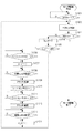
図9は、弱め界磁制御を行う方法を説明するフローチャートである。以下、図10を用いて、弱め界磁制御を行う方法を説明する。このフローチャートの処理は、CPU151aによって実行される。
FIG. 9 is a flowchart for explaining a method of performing field weakening control. Hereinafter, a method of performing field weakening control will be described with reference to FIG. The processing of this flowchart is executed by the
まず、S1001において、CPU151aからモータ制御装置157にenable信号‘H’が出力されると、モータ制御装置157はCPU151aから出力される指令に基づいてモータ509の駆動制御を開始する。enable信号とは、モータ制御装置157の稼働を許可又は禁止する信号である。enable信号が‘L(ローレベル)’である場合は、CPU151aはモータ制御装置157の稼働を禁止する。即ち、モータ制御装置157によるモータ509の制御は終了される。また、enable信号が‘H(ハイレベル)’である場合は、CPU151aはモータ制御装置157の稼働を許可して、モータ制御装置157はCPU151aから出力される指令に基づいてモータ509の駆動制御を行う。
First, in S1001, when the enable signal 'H' is output from the
次に、S1002において、モータ制御装置157はベクトル制御を行う。その後、S1003において、CPU151aがモータ制御装置157にenable信号‘L’を出力した場合は、モータ制御装置157はモータ509の駆動を終了する。また、S1003おいて、CPU151aがモータ制御装置157にenable信号‘H’を出力した場合は、モータ制御装置157は処理をS1004に進める。
Next, in S1002, the
その後、S1004において、界磁制御器540は、d軸電流指令値id_refとして0Aを出力する。即ち、弱め界磁は行われない。
Thereafter, in S1004, the
次に、S1005において、回転速度ω_ref´が速度閾値ωth未満である場合は、処理は再びS1002に戻り、ベクトル制御が継続される。なお、弱め界磁は行われない。 Next, in S1005, when the rotational speed ω_ref ′ is less than the speed threshold ωth, the process returns to S1002 and the vector control is continued. In addition, field weakening is not performed.
また、S1005において、回転速度ω_ref´が速度閾値ωth以上である場合は、処理はS1006に進む。 In S1005, when the rotational speed ω_ref ′ is equal to or higher than the speed threshold ωth, the process proceeds to S1006.
S1006において、シートセンサ330が記録媒体の先端を検知すると、S1007において、CPU151aは、切替信号を界磁制御器540に出力する。界磁制御器540は、切替信号に応じて、出力するd軸電流指令値id_refを0Aから負の値(例えば−0.3A)に切り替える。この結果、弱め界磁が行われる。
When the
その後、S1008において、シートセンサ330が記録媒体の先端を検知してから所定時間t_onが経過すると、S1009において、CPU151aは、モータ509と搬送ローラ306とを連結するようにクラッチ700を制御する。この結果、モータ509と搬送ローラ306とが連結される。
Thereafter, when a predetermined time t_on elapses after the
その後、S1010において、搬送ローラ306によって搬送された記録媒体の先端をシートセンサ331が検知することによって、シートセンサ331が‘L’となる。そして、S1011において、搬送ローラ306によって搬送されている記録媒体の後端がシートセンサ331を通過すると、S1012において、CPU151aは、モータ509と搬送ローラ306とを離間するようにクラッチ700を制御する。この結果、モータ509と搬送ローラ306とが離間される。
After that, in S1010, the sheet sensor 331 detects the leading edge of the recording medium conveyed by the conveying
そして、S1013において、記録媒体の後端がシートセンサ331を通過してから所定時間t_offが経過すると、S1014において、CPU151aは、切替信号を界磁制御器540に出力する。界磁制御器540は、切替信号に応じて、出力するd軸電流指令値id_refを負の値(例えば−0.3A)から0Aに切り替える。この結果、弱め界磁が終了される。その後、処理は再びS1002に戻り、ベクトル制御が継続される。
In S1013, when a predetermined time t_off elapses after the trailing edge of the recording medium passes the sheet sensor 331, the
以降、CPU151aがモータ制御装置157にenable信号‘L’を出力するまで、モータ制御装置157は前述した制御を繰り返し行い、モータ509を制御する。
Thereafter, until the
以上のように、本実施形態においては、弱め界磁を行う必要がある期間にのみ弱め界磁を行う。具体的には、回転子の回転速度ω_ref´が速度閾値ωth以上の所定速度である期間のうち、モータ509と搬送ローラ306とが連結されている期間においてのみ弱め界磁を行う。なお、本実施形態においては、回転子の回転速度が所定速度である状態でクラッチの連結、離間が行われるように、予め画像形成動作のシーケンスで定められている。即ち、回転子が加速している最中及び減速している最中にクラッチの連結、離間が行われることが無いように予め画像形成動作のシーケンスで定められている。したがって、本実施形態においては、回転子の回転速度が所定速度よりも遅い速度である期間、即ち、回転子が加速している最中及び減速している期間は、d軸電流指令値id_refは0であるものとする。この結果、モータを駆動する期間における弱め界磁を行う期間を短縮することができ、消費電力が増大することを抑制することができる。即ち、回転子を所定速度で回転させる期間に所定速度に対応する所定の励磁電流成分の値を設定することに起因して消費電力が増大することを抑制することができる。
As described above, in the present embodiment, the field weakening is performed only during the period in which the field weakening needs to be performed. Specifically, the field weakening is performed only during the period in which the
なお、本実施形態においては、クラッチの制御を行うタイミングは、シートセンサ330、331の検知結果に基づいて決定されているが、例えば、予め設定されている画像形成装置の動作シーケンスに基づいて決定されても良い。また、モータに出力されるパルス数に基づいて決定されても良い。更に、例えば、記録媒体の搬送を停止する指示をユーザが操作部152を用いてCPU151aに送信し、CPU151aが指示に応じてクラッチの離間制御を行う構成であっても良い。この結果、モータの駆動力を搬送ローラに伝達しないようにすることができ、記録媒体の搬送を停止することができる。
In this embodiment, the timing for controlling the clutch is determined based on the detection results of the
また、本実施形態においては、メモリ540aに記憶されているd軸電流指令値id_refは0Aと−3.0Aであったが、これに限定されるものではなく、3個以上の値が記憶されていても良い。この場合、例えば、どの値を用いるかを示す信号をCPU151aが界磁制御器540に出力し、界磁制御器540は信号に基づいて、出力するd軸電流指令値id_refを切り替える。
In the present embodiment, the d-axis current command value id_ref stored in the
なお、本実施形態においては、シートセンサ330、331の検知結果に基づいて、弱め界磁の制御を行ったが、この限りではない。例えば、搬送ローラ306の駆動を開始してからクラッチ700がモータ509と搬送ローラ306とを連結させる前の所定のタイミングまでの所定時間T1が経過すると弱め界磁を開始する。また、搬送ローラ306の駆動を開始してからクラッチ700がモータ509と搬送ローラ306とを離間させた後の第2の所定のタイミングまでの所定時間T2が経過すると弱め界磁を終了する。以上のような構成であっても良い。なお、前記所定のタイミング及び第2の所定のタイミングは、予め設定されている画像形成装置の動作シーケンスに基づいて決定されるものとする。また、モータに出力されるパルス数に基づいて前記所定のタイミング及び第2の所定のタイミングを決定しても良い。
In the present embodiment, the field weakening control is performed based on the detection results of the
また、本実施形態では、回転子の回転速度が速度閾値以上の所定速度である期間のうち、モータ509と搬送ローラ306とが連結されている期間以外の期間においてはd軸電流指令値を0Aとしたが、0A以外の値に設定しても良い。具体的には、回転子の回転速度が速度閾値以上の所定速度である期間のうち、モータ509と搬送ローラ306とが連結されている期間において設定されているd軸電流指令値としての負の値よりも大きい値であればよい。即ち、回転速度が速度閾値以上の所定速度である期間のうち、モータ509と搬送ローラ306とが連結されている期間以外の期間において巻線を貫く磁束が、モータ509と搬送ローラ306とが連結されている期間において巻線を貫く磁束よりも強ければよい。但し、可能な限り0Aに近い値に設定されるほうが効果的に消費電力の増大を抑制することができる。
In the present embodiment, the d-axis current command value is set to 0 A in a period other than the period in which the
また、本実施形態においては、d軸電流指令値id_refの値は、予め実験等によって得られた値であるものとしたが、この限りではない。例えば、界磁制御器540が、回転子の回転速度ω_ref´に基づいてd軸電流指令値id_refの値を変える構成であっても良い。具体的には、界磁制御器540は、回転速度ω_ref´が大きければ大きいほどd軸電流指令値id_refの値をより小さく設定する構成であっても良い。この結果、巻線に発生する誘起電圧が回転速度の増大に伴って大きくなることを抑制することができる。
In the present embodiment, the value of the d-axis current command value id_ref is a value obtained in advance through experiments or the like, but is not limited thereto. For example, the
また、弱め界磁を行う場合におけるd軸電流指令値は、弱め界磁を行うことによって巻線に発生する誘起電圧が小さくなったとしても、回転子の回転位相を精度よく決定することができるような値に設定されるものとする。 Further, the d-axis current command value when the field weakening is performed can accurately determine the rotation phase of the rotor even if the induced voltage generated in the winding is reduced by performing the field weakening. It shall be set to such a value.
本実施形態においては、モータと搬送ローラとをクラッチによって連結、離間する構成において弱め界磁制御を適用したが、搬送ローラに限らず、その他の負荷を連結、離間する構成に本実施形態を適用しても良い。 In this embodiment, the field weakening control is applied in the configuration in which the motor and the conveyance roller are connected and separated by the clutch. However, the present embodiment is not limited to the conveyance roller and is applied to a configuration in which other loads are connected and separated. Also good.
また、本実施形態では、速度閾値ωthをω0に設定したが、これに限定されるものではない。例えば、速度閾値ωthをω0よりも小さい値に設定しても良いし、速度閾値ωthをω0よりも大きい値に設定しても良い。 In the present embodiment, the speed threshold ωth is set to ω0, but the present invention is not limited to this. For example, the speed threshold ωth may be set to a value smaller than ω0, and the speed threshold ωth may be set to a value larger than ω0.
また、本実施形態においては、負荷を駆動するモータとしてステッピングモータが用いられているが、DCモータ等の他のモータであっても良い。また、モータは2相モータである場合に限らず、3相モータ等の他のモータであっても本実施形態を適用することができる。 In this embodiment, a stepping motor is used as a motor for driving a load, but another motor such as a DC motor may be used. Further, the embodiment is not limited to the case where the motor is a two-phase motor, and may be another motor such as a three-phase motor.
なお、本実施形態におけるベクトル制御では、位相フィードバック制御を行うことによってモータ509を制御しているが、これに限定されるものではない。例えば、回転子402の回転速度ωをフィードバックしてモータ509を制御する構成であっても良い。具体的には、図10に示すように、モータ制御装置内部に速度決定器515を設け、CPU151aが回転子の目標速度を表す指令速度ω_refを出力する。また、モータ制御装置内部に速度制御器500及び速度決定器515を設け、速度決定器515が位相決定器513から出力された回転位相θの時間変化に基づいて回転速度ωを決定する。速度の決定には、式(12)が用いられるものとする。そして、CPU151aは回転子の目標速度を表す指令速度ω_refを出力する。更に、モータ制御装置内部に速度制御器500を設け、速度制御器500が回転速度ωと指令速度ω_refとの偏差が小さくなるように、q軸電流指令値iq_refを生成して出力する構成とする。このような速度フィードバック制御を行うことによって、モータ509を制御する構成であっても良い。このような構成においては回転速度をフィードバックしているため、回転子の回転速度が所定の速度になるように制御することができる。したがって、画像形成装置において、記録媒体への画像形成を適切に行うために回転速度を一定速度に制御する必要がある負荷(例えば、感光ドラム、搬送ベルト等)を駆動するモータに速度フィードバック制御を用いたベクトル制御を適用する。この結果、記録媒体への画像形成を適切に行うことができる。
In the vector control in the present embodiment, the
また、本実施形態においては、回転子として永久磁石が用いられているが、これに限定されるものではない。 Moreover, in this embodiment, although the permanent magnet is used as a rotor, it is not limited to this.
100 画像形成装置
157 モータ制御装置
307 搬送ローラ
402 回転子
502 位相制御器
509 ステッピングモータ
513 位相決定器
540 界磁制御器
DESCRIPTION OF
Claims (16)
前記搬送部を駆動するモータと、
前記モータの駆動力が前記搬送部に伝達される第1状態と、前記モータの駆動が前記搬送部に伝達されない第2状態と、を切り替える連結部材と、
前記モータの回転子の回転位相を決定する位相決定手段と、
前記モータの巻線に流れる駆動電流を検出する検出手段と、
前記検出手段によって検出された駆動電流のトルク電流成分の値と前記トルク電流成分の目標値との偏差が小さくなるように前記巻線に流れる駆動電流を制御し、前記巻線に流れる駆動電流の励磁電流成分の値を制御することによって前記巻線を貫く磁束の強度を弱める弱め界磁を行う制御手段と、
を有し、
前記トルク電流成分は、前記位相決定手段によって決定された回転位相を基準とする回転座標系において表される電流成分であって前記回転子にトルクを発生させる電流成分であり、
前記励磁電流成分は、前記回転座標系において表される電流成分であって前記巻線を貫く磁束の強度に影響する電流成分であって、
前記制御手段は、前記回転子の目標位相を表す指令位相と前記位相決定手段によって決定された回転位相との偏差が小さくなるように前記トルク電流成分の目標値を設定し、
前記制御手段は、前記モータを制御している期間中に、前記連結部材が前記第2状態である第1タイミングにおいて前記弱め界磁の程度を第1の程度から前記第1の程度よりも大きい第2の程度に変更することを特徴とするシート搬送装置。 A transport unit for transporting the sheet;
A motor for driving the transport unit;
A connecting member that switches between a first state in which the driving force of the motor is transmitted to the transport unit and a second state in which the drive of the motor is not transmitted to the transport unit;
Phase determining means for determining the rotational phase of the rotor of the motor;
Detecting means for detecting a driving current flowing in the winding of the motor;
The drive current flowing through the winding is controlled such that the deviation between the torque current component value of the drive current detected by the detection means and the target value of the torque current component is small, and the drive current flowing through the winding is controlled. Control means for performing field weakening to weaken the strength of magnetic flux passing through the winding by controlling the value of the excitation current component;
Have
The torque current component is a current component that is expressed in a rotating coordinate system based on the rotational phase determined by the phase determining means, and is a current component that generates torque in the rotor,
The excitation current component is a current component that is represented in the rotating coordinate system and affects the strength of the magnetic flux passing through the winding,
The control means sets the target value of the torque current component so that the deviation between the command phase representing the target phase of the rotor and the rotational phase determined by the phase determination means is small,
The control means increases the degree of the field weakening from the first degree to the first degree at the first timing when the connecting member is in the second state during the period of controlling the motor. The sheet conveying apparatus is changed to a second degree.
前記搬送部を駆動するモータと、
前記モータの駆動力が前記搬送部に伝達される第1状態と、前記モータの駆動が前記搬送部に伝達されない第2状態と、を切り替える連結部材と、
前記モータの回転子の回転位相を決定する位相決定手段と、
前記回転子の回転速度を決定する速度決定手段と、
前記モータの巻線に流れる駆動電流を検出する検出手段と、
前記検出手段によって検出された駆動電流のトルク電流成分の値と前記トルク電流成分の目標値との偏差が小さくなるように前記巻線に流れる駆動電流を制御し、前記巻線に流れる駆動電流の励磁電流成分の値を制御することによって前記巻線を貫く磁束の強度を弱める弱め界磁を行う制御手段と、
を有し、
前記トルク電流成分は、前記位相決定手段によって決定された回転位相を基準とする回転座標系において表される電流成分であって前記回転子にトルクを発生させる電流成分であり、
前記励磁電流成分は、前記回転座標系において表される電流成分であって前記巻線を貫く磁束の強度に影響する電流成分であって、
前記制御手段は、前記回転子の目標速度を表す指令速度と前記速度決定手段によって決定された回転速度との偏差が小さくなるように前記トルク電流成分の目標値を設定し、
前記制御手段は、前記モータを制御している期間中に、前記連結部材が前記第2状態である第1タイミングにおいて前記弱め界磁の程度を第1の程度から前記第1の程度よりも大きい第2の程度に変更することを特徴とするシート搬送装置。 A transport unit for transporting the sheet;
A motor for driving the transport unit;
A connecting member that switches between a first state in which the driving force of the motor is transmitted to the transport unit and a second state in which the drive of the motor is not transmitted to the transport unit;
Phase determining means for determining the rotational phase of the rotor of the motor;
Speed determining means for determining the rotational speed of the rotor;
Detecting means for detecting a driving current flowing in the winding of the motor;
The drive current flowing through the winding is controlled such that the deviation between the torque current component value of the drive current detected by the detection means and the target value of the torque current component is small, and the drive current flowing through the winding is controlled. Control means for performing field weakening to weaken the strength of magnetic flux passing through the winding by controlling the value of the excitation current component;
Have
The torque current component is a current component that is expressed in a rotating coordinate system based on the rotational phase determined by the phase determining means, and is a current component that generates torque in the rotor,
The excitation current component is a current component that is represented in the rotating coordinate system and affects the strength of the magnetic flux passing through the winding,
The control means sets the target value of the torque current component so that the deviation between the command speed representing the target speed of the rotor and the rotational speed determined by the speed determination means is small,
The control means increases the degree of the field weakening from the first degree to the first degree at the first timing when the connecting member is in the second state during the period of controlling the motor. The sheet conveying apparatus is changed to a second degree.
前記励磁電流成分の目標値が前記第1の値である場合における前記弱め界磁の程度は、前記励磁電流成分の目標値が前記第2の値である場合における前記弱め界磁の程度よりも小さいことを特徴とする請求項7に記載のシート搬送装置。 When the target value of the exciting current component is the first value in the direction of the magnetic flux of the rotor, the intensity of the magnetic flux generated due to the exciting current component is the target value of the exciting current component is the first value. Smaller than the intensity of magnetic flux generated due to the excitation current component in the case of the second value smaller than the value of 1,
The degree of field weakening when the target value of the exciting current component is the first value is greater than the degree of field weakening when the target value of the exciting current component is the second value. The sheet conveying apparatus according to claim 7, wherein the sheet conveying apparatus is small.
前記連結部材を制御する第2制御手段と、
前記搬送部が前記シートを搬送する搬送方向において前記搬送部のニップ部よりも上流側に設けられ、前記シートの有無を検知する検知手段と、
を有し、
前記第1タイミングは、前記検知手段が前記シートの先端を検知したタイミングであり、
前記第2制御手段は、前記第1タイミングから所定時間が経過したタイミングにおいて、前記連結部材が前記第2状態から前記第1状態になるように前記連結部材を制御することを特徴とする請求項1乃至9のいずれか一項に記載のシート搬送装置。 The sheet conveying apparatus is
Second control means for controlling the connecting member;
A detecting unit provided upstream of a nip portion of the conveying unit in a conveying direction in which the conveying unit conveys the sheet; and detecting the presence or absence of the sheet;
Have
The first timing is a timing at which the detection means detects the leading edge of the sheet,
The said 2nd control means controls the said connection member so that the said connection member may become the said 1st state from the said 2nd state in the timing which predetermined time passed from the said 1st timing. The sheet conveying apparatus according to any one of 1 to 9.
前記積載部に積載された原稿を搬送する搬送部と、
前記搬送部によって搬送された原稿を読み取る読取部と、
負荷を駆動するモータと、
前記モータの駆動力が前記負荷に伝達される第1状態と、前記モータの駆動が前記負荷に伝達されない第2状態と、を切り替える連結部材と、
前記モータの回転子の回転位相を決定する位相決定手段と、
前記モータの巻線に流れる駆動電流を検出する検出手段と、
前記検出手段によって検出された駆動電流のトルク電流成分の値と前記トルク電流成分の目標値との偏差が小さくなるように前記巻線に流れる駆動電流を制御し、前記巻線に流れる駆動電流の励磁電流成分の値を制御することによって前記巻線を貫く磁束の強度を弱める弱め界磁を行う制御手段と、
を有し、
前記トルク電流成分は、前記位相決定手段によって決定された回転位相を基準とする回転座標系において表される電流成分であって前記回転子にトルクを発生させる電流成分であり、
前記励磁電流成分は、前記回転座標系において表される電流成分であって前記巻線を貫く磁束の強度に影響する電流成分であって、
前記制御手段は、前記回転子の目標位相を表す指令位相と前記位相決定手段によって決定された回転位相との偏差が小さくなるように前記トルク電流成分の目標値を設定し、
前記制御手段は、前記モータを制御している期間中に、前記連結部材が前記第2状態である第1タイミングにおいて前記弱め界磁の程度を第1の程度から前記第1の程度よりも大きい第2の程度に変更することを特徴とする原稿読取装置。 A loading section on which documents are loaded;
A transport unit for transporting a document loaded on the stack unit;
A reading unit for reading a document conveyed by the conveyance unit;
A motor driving the load;
A connecting member that switches between a first state in which the driving force of the motor is transmitted to the load and a second state in which the driving of the motor is not transmitted to the load;
Phase determining means for determining the rotational phase of the rotor of the motor;
Detecting means for detecting a driving current flowing in the winding of the motor;
The drive current flowing through the winding is controlled such that the deviation between the torque current component value of the drive current detected by the detection means and the target value of the torque current component is small, and the drive current flowing through the winding is controlled. Control means for performing field weakening to weaken the strength of magnetic flux passing through the winding by controlling the value of the excitation current component;
Have
The torque current component is a current component that is expressed in a rotating coordinate system based on the rotational phase determined by the phase determining means, and is a current component that generates torque in the rotor,
The excitation current component is a current component that is represented in the rotating coordinate system and affects the strength of the magnetic flux passing through the winding,
The control means sets the target value of the torque current component so that the deviation between the command phase representing the target phase of the rotor and the rotational phase determined by the phase determination means is small,
The control means increases the degree of the field weakening from the first degree to the first degree at the first timing when the connecting member is in the second state during the period of controlling the motor. A document reading apparatus characterized by changing to a second degree.
前記積載部に積載された原稿を搬送する搬送部と、
前記搬送部によって搬送された原稿を読み取る読取部と、
負荷を駆動するモータと、
前記モータの駆動力が前記負荷に伝達される第1状態と、前記モータの駆動が前記負荷に伝達されない第2状態と、を切り替える連結部材と、
前記モータの回転子の回転位相を決定する位相決定手段と、
前記回転子の回転速度を決定する速度決定手段と、
前記モータの巻線に流れる駆動電流を検出する検出手段と、
前記検出手段によって検出された駆動電流のトルク電流成分の値と前記トルク電流成分の目標値との偏差が小さくなるように前記巻線に流れる駆動電流を制御し、前記巻線に流れる駆動電流の励磁電流成分の値を制御することによって前記巻線を貫く磁束の強度を弱める弱め界磁を行う制御手段と、
を有し、
前記トルク電流成分は、前記位相決定手段によって決定された回転位相を基準とする回転座標系において表される電流成分であって前記回転子にトルクを発生させる電流成分であり、
前記励磁電流成分は、前記回転座標系において表される電流成分であって前記巻線を貫く磁束の強度に影響する電流成分であって、
前記制御手段は、前記回転子の目標速度を表す指令速度と前記速度決定手段によって決定された回転速度との偏差が小さくなるように前記トルク電流成分の目標値を設定し、
前記制御手段は、前記モータを制御している期間中に、前記連結部材が前記第2状態である第1タイミングにおいて前記弱め界磁の程度を第1の程度から前記第1の程度よりも大きい第2の程度に変更することを特徴とする原稿読取装置。 A loading section on which documents are loaded;
A transport unit for transporting a document loaded on the stack unit;
A reading unit for reading a document conveyed by the conveyance unit;
A motor driving the load;
A connecting member that switches between a first state in which the driving force of the motor is transmitted to the load and a second state in which the driving of the motor is not transmitted to the load;
Phase determining means for determining the rotational phase of the rotor of the motor;
Speed determining means for determining the rotational speed of the rotor;
Detecting means for detecting a driving current flowing in the winding of the motor;
The drive current flowing through the winding is controlled such that the deviation between the torque current component value of the drive current detected by the detection means and the target value of the torque current component is small, and the drive current flowing through the winding is controlled. Control means for performing field weakening to weaken the strength of magnetic flux passing through the winding by controlling the value of the excitation current component;
Have
The torque current component is a current component that is expressed in a rotating coordinate system based on the rotational phase determined by the phase determining means, and is a current component that generates torque in the rotor,
The excitation current component is a current component that is represented in the rotating coordinate system and affects the strength of the magnetic flux passing through the winding,
The control means sets the target value of the torque current component so that the deviation between the command speed representing the target speed of the rotor and the rotational speed determined by the speed determination means is small,
The control means increases the degree of the field weakening from the first degree to the first degree at the first timing when the connecting member is in the second state during the period of controlling the motor. A document reading apparatus characterized by changing to a second degree.
前記積載部に積載された記録媒体を搬送する搬送部と、
前記搬送部によって搬送された記録媒体に画像を形成する画像形成部と、
負荷を駆動するモータと、
前記モータの駆動力が前記負荷に伝達される第1状態と、前記モータの駆動が前記負荷に伝達されない第2状態と、を切り替える連結部材と、
前記モータの回転子の回転位相を決定する位相決定手段と、
前記モータの巻線に流れる駆動電流を検出する検出手段と、
前記検出手段によって検出された駆動電流のトルク電流成分の値と前記トルク電流成分の目標値との偏差が小さくなるように前記巻線に流れる駆動電流を制御し、前記巻線に流れる駆動電流の励磁電流成分の値を制御することによって前記巻線を貫く磁束の強度を弱める弱め界磁を行う制御手段と、
を有し、
前記トルク電流成分は、前記位相決定手段によって決定された回転位相を基準とする回転座標系において表される電流成分であって前記回転子にトルクを発生させる電流成分であり、
前記励磁電流成分は、前記回転座標系において表される電流成分であって前記巻線を貫く磁束の強度に影響する電流成分であって、
前記制御手段は、前記回転子の目標位相を表す指令位相と前記位相決定手段によって決定された回転位相との偏差が小さくなるように前記トルク電流成分の目標値を設定し、
前記制御手段は、前記モータを制御している期間中に、前記連結部材が前記第2状態である第1タイミングにおいて前記弱め界磁の程度を第1の程度から前記第1の程度よりも大きい第2の程度に変更することを特徴とする画像形成装置。 A loading section on which a recording medium is loaded;
A transport unit for transporting the recording medium loaded on the stack unit;
An image forming unit for forming an image on the recording medium conveyed by the conveying unit;
A motor driving the load;
A connecting member that switches between a first state in which the driving force of the motor is transmitted to the load and a second state in which the driving of the motor is not transmitted to the load;
Phase determining means for determining the rotational phase of the rotor of the motor;
Detecting means for detecting a driving current flowing in the winding of the motor;
The drive current flowing through the winding is controlled such that the deviation between the torque current component value of the drive current detected by the detection means and the target value of the torque current component is small, and the drive current flowing through the winding is controlled. Control means for performing field weakening to weaken the strength of magnetic flux passing through the winding by controlling the value of the excitation current component;
Have
The torque current component is a current component that is expressed in a rotating coordinate system based on the rotational phase determined by the phase determining means, and is a current component that generates torque in the rotor,
The excitation current component is a current component that is represented in the rotating coordinate system and affects the strength of the magnetic flux passing through the winding,
The control means sets the target value of the torque current component so that the deviation between the command phase representing the target phase of the rotor and the rotational phase determined by the phase determination means is small,
The control means increases the degree of the field weakening from the first degree to the first degree at the first timing when the connecting member is in the second state during the period of controlling the motor. An image forming apparatus that is changed to a second degree.
前記積載部に積載された記録媒体を搬送する搬送部と、
前記搬送部によって搬送された記録媒体に画像を形成する画像形成部と、
負荷を駆動するモータと、
前記モータの駆動力が前記負荷に伝達される第1状態と、前記モータの駆動が前記負荷に伝達されない第2状態と、を切り替える連結部材と、
前記モータの回転子の回転位相を決定する位相決定手段と、
前記回転子の回転速度を決定する速度決定手段と、
前記モータの巻線に流れる駆動電流を検出する検出手段と、
前記検出手段によって検出された駆動電流のトルク電流成分の値と前記トルク電流成分の目標値との偏差が小さくなるように前記巻線に流れる駆動電流を制御し、前記巻線に流れる駆動電流の励磁電流成分の値を制御することによって前記巻線を貫く磁束の強度を弱める弱め界磁を行う制御手段と、
を有し、
前記トルク電流成分は、前記位相決定手段によって決定された回転位相を基準とする回転座標系において表される電流成分であって前記回転子にトルクを発生させる電流成分であり、
前記励磁電流成分は、前記回転座標系において表される電流成分であって前記巻線を貫く磁束の強度に影響する電流成分であって、
前記制御手段は、前記回転子の目標速度を表す指令速度と前記速度決定手段によって決定された回転速度との偏差が小さくなるように前記トルク電流成分の目標値を設定し、
前記制御手段は、前記モータを制御している期間中に、前記連結部材が前記第2状態である第1タイミングにおいて前記弱め界磁の程度を第1の程度から前記第1の程度よりも大きい第2の程度に変更することを特徴とする画像形成装置。 A loading section on which a recording medium is loaded;
A transport unit for transporting the recording medium loaded on the stack unit;
An image forming unit for forming an image on the recording medium conveyed by the conveying unit;
A motor driving the load;
A connecting member that switches between a first state in which the driving force of the motor is transmitted to the load and a second state in which the driving of the motor is not transmitted to the load;
Phase determining means for determining the rotational phase of the rotor of the motor;
Speed determining means for determining the rotational speed of the rotor;
Detecting means for detecting a driving current flowing in the winding of the motor;
The drive current flowing through the winding is controlled such that the deviation between the torque current component value of the drive current detected by the detection means and the target value of the torque current component is small, and the drive current flowing through the winding is controlled. Control means for performing field weakening to weaken the strength of magnetic flux passing through the winding by controlling the value of the excitation current component;
Have
The torque current component is a current component that is expressed in a rotating coordinate system based on the rotational phase determined by the phase determining means, and is a current component that generates torque in the rotor,
The excitation current component is a current component that is represented in the rotating coordinate system and affects the strength of the magnetic flux passing through the winding,
The control means sets the target value of the torque current component so that the deviation between the command speed representing the target speed of the rotor and the rotational speed determined by the speed determination means is small,
The control means increases the degree of the field weakening from the first degree to the first degree at the first timing when the connecting member is in the second state during the period of controlling the motor. An image forming apparatus that is changed to a second degree.
Priority Applications (1)
| Application Number | Priority Date | Filing Date | Title |
|---|---|---|---|
| JP2019124007A JP2019205346A (en) | 2019-07-02 | 2019-07-02 | Sheet conveying device, document reading device, and image forming apparatus |
Applications Claiming Priority (1)
| Application Number | Priority Date | Filing Date | Title |
|---|---|---|---|
| JP2019124007A JP2019205346A (en) | 2019-07-02 | 2019-07-02 | Sheet conveying device, document reading device, and image forming apparatus |
Related Parent Applications (1)
| Application Number | Title | Priority Date | Filing Date |
|---|---|---|---|
| JP2017022465A Division JP6552532B2 (en) | 2017-02-09 | 2017-02-09 | Sheet conveying apparatus and image forming apparatus |
Publications (2)
| Publication Number | Publication Date |
|---|---|
| JP2019205346A true JP2019205346A (en) | 2019-11-28 |
| JP2019205346A5 JP2019205346A5 (en) | 2020-01-16 |
Family
ID=68727531
Family Applications (1)
| Application Number | Title | Priority Date | Filing Date |
|---|---|---|---|
| JP2019124007A Abandoned JP2019205346A (en) | 2019-07-02 | 2019-07-02 | Sheet conveying device, document reading device, and image forming apparatus |
Country Status (1)
| Country | Link |
|---|---|
| JP (1) | JP2019205346A (en) |
-
2019
- 2019-07-02 JP JP2019124007A patent/JP2019205346A/en not_active Abandoned
Similar Documents
| Publication | Publication Date | Title |
|---|---|---|
| US10439531B2 (en) | Sheet conveying apparatus and image forming apparatus | |
| JP2018186597A (en) | Motor control device, sheet transfer device and image forming apparatus | |
| JP6647262B2 (en) | Motor control device, sheet transport device, document reading device, and image forming device | |
| JP6552532B2 (en) | Sheet conveying apparatus and image forming apparatus | |
| JP6328172B2 (en) | Motor control apparatus, sheet conveying apparatus, and image forming apparatus | |
| JP6980555B2 (en) | Motor control device, sheet transfer device and image forming device | |
| JP2018207733A (en) | Motor controller, sheet transfer device, script feeder, script reader and image formation device | |
| JP6498227B2 (en) | Sheet conveying apparatus and image forming apparatus | |
| JP2019187069A (en) | Motor control device, sheet carrying device, and image forming device | |
| JP6728433B2 (en) | Motor control device, sheet conveying device, document reading device, and image forming device | |
| JP6720046B2 (en) | Motor control device, sheet conveying device, document reading device, and image forming device | |
| JP6812505B2 (en) | Sheet transfer device, document feeding device, document reading device and image forming device | |
| JP2019205346A (en) | Sheet conveying device, document reading device, and image forming apparatus | |
| JP2020174526A (en) | Motor control device, sheet transfer device, document reader and image forming device | |
| JP6849729B2 (en) | Motor control device, sheet transfer device and image forming device | |
| JP7301556B2 (en) | Motor control device and image forming device | |
| JP2020078236A (en) | Motor control device, sheet conveying device, document reading device, and image forming apparatus | |
| JP7034727B2 (en) | Motor control device, sheet transfer device and image forming device | |
| JP2018076154A (en) | Image forming apparatus | |
| JP2018104168A (en) | Sheet carrier device | |
| JP2018121400A (en) | Motor control device, sheet conveyance device, and image forming apparatus | |
| JP6789851B2 (en) | Motor control device, sheet transfer device, document reader and image forming device | |
| JP2023107295A (en) | Motor control device, sheet conveying device and image forming device | |
| JP2018087076A (en) | Sheet conveying device | |
| JP2023144982A (en) | Sheet conveyance device and image-forming device |
Legal Events
| Date | Code | Title | Description |
|---|---|---|---|
| A621 | Written request for application examination |
Free format text: JAPANESE INTERMEDIATE CODE: A621 Effective date: 20190702 |
|
| A521 | Written amendment |
Free format text: JAPANESE INTERMEDIATE CODE: A523 Effective date: 20191114 |
|
| A762 | Written abandonment of application |
Free format text: JAPANESE INTERMEDIATE CODE: A762 Effective date: 20200313 |