JP2019204653A - Electric wire with terminal - Google Patents
Electric wire with terminal Download PDFInfo
- Publication number
- JP2019204653A JP2019204653A JP2018098480A JP2018098480A JP2019204653A JP 2019204653 A JP2019204653 A JP 2019204653A JP 2018098480 A JP2018098480 A JP 2018098480A JP 2018098480 A JP2018098480 A JP 2018098480A JP 2019204653 A JP2019204653 A JP 2019204653A
- Authority
- JP
- Japan
- Prior art keywords
- pair
- single core
- core wire
- wire
- barrel
- Prior art date
- Legal status (The legal status is an assumption and is not a legal conclusion. Google has not performed a legal analysis and makes no representation as to the accuracy of the status listed.)
- Pending
Links
Images


Classifications
-
- H—ELECTRICITY
- H01—ELECTRIC ELEMENTS
- H01R—ELECTRICALLY-CONDUCTIVE CONNECTIONS; STRUCTURAL ASSOCIATIONS OF A PLURALITY OF MUTUALLY-INSULATED ELECTRICAL CONNECTING ELEMENTS; COUPLING DEVICES; CURRENT COLLECTORS
- H01R4/00—Electrically-conductive connections between two or more conductive members in direct contact, i.e. touching one another; Means for effecting or maintaining such contact; Electrically-conductive connections having two or more spaced connecting locations for conductors and using contact members penetrating insulation
- H01R4/10—Electrically-conductive connections between two or more conductive members in direct contact, i.e. touching one another; Means for effecting or maintaining such contact; Electrically-conductive connections having two or more spaced connecting locations for conductors and using contact members penetrating insulation effected solely by twisting, wrapping, bending, crimping, or other permanent deformation
- H01R4/18—Electrically-conductive connections between two or more conductive members in direct contact, i.e. touching one another; Means for effecting or maintaining such contact; Electrically-conductive connections having two or more spaced connecting locations for conductors and using contact members penetrating insulation effected solely by twisting, wrapping, bending, crimping, or other permanent deformation by crimping
- H01R4/183—Electrically-conductive connections between two or more conductive members in direct contact, i.e. touching one another; Means for effecting or maintaining such contact; Electrically-conductive connections having two or more spaced connecting locations for conductors and using contact members penetrating insulation effected solely by twisting, wrapping, bending, crimping, or other permanent deformation by crimping for cylindrical elongated bodies, e.g. cables having circular cross-section
- H01R4/184—Electrically-conductive connections between two or more conductive members in direct contact, i.e. touching one another; Means for effecting or maintaining such contact; Electrically-conductive connections having two or more spaced connecting locations for conductors and using contact members penetrating insulation effected solely by twisting, wrapping, bending, crimping, or other permanent deformation by crimping for cylindrical elongated bodies, e.g. cables having circular cross-section comprising a U-shaped wire-receiving portion
- H01R4/185—Electrically-conductive connections between two or more conductive members in direct contact, i.e. touching one another; Means for effecting or maintaining such contact; Electrically-conductive connections having two or more spaced connecting locations for conductors and using contact members penetrating insulation effected solely by twisting, wrapping, bending, crimping, or other permanent deformation by crimping for cylindrical elongated bodies, e.g. cables having circular cross-section comprising a U-shaped wire-receiving portion combined with a U-shaped insulation-receiving portion
-
- H—ELECTRICITY
- H01—ELECTRIC ELEMENTS
- H01R—ELECTRICALLY-CONDUCTIVE CONNECTIONS; STRUCTURAL ASSOCIATIONS OF A PLURALITY OF MUTUALLY-INSULATED ELECTRICAL CONNECTING ELEMENTS; COUPLING DEVICES; CURRENT COLLECTORS
- H01R13/00—Details of coupling devices of the kinds covered by groups H01R12/70 or H01R24/00 - H01R33/00
- H01R13/02—Contact members
- H01R13/10—Sockets for co-operation with pins or blades
- H01R13/11—Resilient sockets
- H01R13/114—Resilient sockets co-operating with pins or blades having a square transverse section
-
- H—ELECTRICITY
- H01—ELECTRIC ELEMENTS
- H01R—ELECTRICALLY-CONDUCTIVE CONNECTIONS; STRUCTURAL ASSOCIATIONS OF A PLURALITY OF MUTUALLY-INSULATED ELECTRICAL CONNECTING ELEMENTS; COUPLING DEVICES; CURRENT COLLECTORS
- H01R43/00—Apparatus or processes specially adapted for manufacturing, assembling, maintaining, or repairing of line connectors or current collectors or for joining electric conductors
- H01R43/04—Apparatus or processes specially adapted for manufacturing, assembling, maintaining, or repairing of line connectors or current collectors or for joining electric conductors for forming connections by deformation, e.g. crimping tool
- H01R43/048—Crimping apparatus or processes
Abstract
Description
本明細書によって開示される技術は、単芯線に端子が圧着された端子付き電線に関する。 The technique disclosed by this specification is related with the electric wire with a terminal by which the terminal was crimped | bonded to the single core wire.
従来の端子の一例として、特開平8−37052号公報(下記特許文献1)に記載の雌形端子が知られている。この雌形端子は、複数の金属素線からなる芯線に圧着されるワイヤバレルと、芯線の外周を覆う絶縁被覆に圧着されるインシュレーションバレルと、を備える。
As an example of a conventional terminal, a female terminal described in JP-A-8-37052 (
上記の技術によれば、ワイヤバレルが芯線に圧着された状態において、ワイヤバレルの先端部は複数の金属素線の間に入り込む。これにより、一対のワイヤバレルの先端部寄りの部分には、一対のワイヤバレル同士が互いに接触する接触面が形成される。この接触面において発生する摩擦力により、一対のワイヤバレルが開いてしまうことが抑制されるようになっている。特に、比較的に温度変化が大きな場所のように、高温時における膨張と、低温時における収縮とが繰り返される場合に、有効である。 According to the above technique, the tip of the wire barrel enters between the plurality of metal wires in a state where the wire barrel is pressure-bonded to the core wire. Thereby, the contact surface where a pair of wire barrels mutually contact is formed in the part near the front-end | tip part of a pair of wire barrel. The frictional force generated on the contact surface prevents the pair of wire barrels from opening. This is particularly effective when expansion at a high temperature and contraction at a low temperature are repeated as in a place where the temperature change is relatively large.
しかしながら、上記の技術を単芯線に圧着される端子に単純に適用した場合、以下のような問題を生じる虞がある。単芯線にワイヤバレルを圧着した場合、ワイヤバレルの先端部は、単芯線の中に入り込みにくい。芯線が複数の金属素線からなる場合と異なり、単芯線にはワイヤバレルの先端部が入り込む隙間が存在しないからである。このため、一対のワイヤバレルの先端部寄りの部分に、一対のワイヤバレル同士が互いに接触する接触面が形成されないか、又は、接触面が形成された場合でも、十分な摩擦力が発生する程度の面積を有しない場合がある。 However, when the above technique is simply applied to a terminal crimped to a single core wire, the following problems may occur. When a wire barrel is crimped to a single core wire, the tip of the wire barrel is less likely to enter the single core wire. This is because, unlike the case where the core wire is composed of a plurality of metal strands, the single core wire has no gap into which the tip of the wire barrel enters. For this reason, a contact surface where the pair of wire barrels are in contact with each other is not formed in the portion near the tip of the pair of wire barrels, or even if a contact surface is formed, a sufficient frictional force is generated. May not have the area.
このような場合、比較的に温度変化が大きな場所で使用されると、高温時には一対のワイヤバレル同士は互いに接近しあう方向に膨張する。一方、低温時には一対のワイヤバレルは互いに離間する方向にする収縮してしまう。すると、元来、接触面が形成されないか、又は、接触面が形成された場合でも十分な面積を有していないため、一対のワイヤバレル同士は、摩擦力によって単芯線に圧着された形態を保持できなくなる虞がある。この結果、単芯線とワイヤバレルとの間の接圧が低下し、接触抵抗が増加するという問題があった。 In such a case, when used in a place where the temperature change is relatively large, the pair of wire barrels expand in the direction of approaching each other at a high temperature. On the other hand, at a low temperature, the pair of wire barrels contract in a direction away from each other. Then, since the contact surface is not originally formed or does not have a sufficient area even when the contact surface is formed, the pair of wire barrels has a form in which the pair of wire barrels are crimped to the single core wire by friction force. There is a risk that it cannot be held. As a result, there is a problem that the contact pressure between the single core wire and the wire barrel is reduced, and the contact resistance is increased.
本明細書に開示された技術は上記のような事情に基づいて完成されたものであって、単芯線とワイヤバレルとの間の接圧が低下することを抑制する端子を提供することを目的とする。 The technology disclosed in this specification has been completed based on the above-described circumstances, and an object thereof is to provide a terminal that suppresses a decrease in contact pressure between a single core wire and a wire barrel. And
本明細書で開示される端子付き電線は、金属製の単芯線と、前記単芯線に圧着される端子と、を備えた端子付き電線であって、前記端子は、前記単芯線が載置される底板部と、前記底板部の両側縁から上方に突出すると共に前記単芯線に圧着される一対のバレル部と、を有しており、前記一対のバレル部は、前記底板部の両側縁から上方に突出する一対の側壁部と、前記一対の側壁部の上端から下方に折り返された一対の折り返し片と、を備え、前記一対の折り返し片は、それぞれ、前記単芯線に上方から接触する第1接触部と、前記第1接触部よりも上方の位置において前記一対の折り返し片同士が接触する第2接触部と、前記一対の側壁部の内面と接触する第3接触部と、を有している。 The electric wire with a terminal disclosed in the present specification is an electric wire with a terminal including a metal single core wire and a terminal to be crimped to the single core wire, and the single core wire is placed on the terminal. And a pair of barrel portions that protrude upward from both side edges of the bottom plate portion and are crimped to the single core wire, the pair of barrel portions from both side edges of the bottom plate portion. A pair of side wall portions protruding upward, and a pair of folded pieces folded downward from the upper ends of the pair of side wall portions, each of the pair of folded pieces contacting the single core wire from above. A first contact portion; a second contact portion where the pair of folded pieces contact each other at a position above the first contact portion; and a third contact portion which contacts the inner surfaces of the pair of side wall portions. ing.
一対の折り返し片同士は第2接触部において接触しているので、第2接触部において発生する摩擦力により、一対のバレル部が単芯線に圧着された形状を保持することができる。
また、一対のバレル部は、上方に突出する一対の側壁部と、下方に折り返された一対の折り返し片とを有するので、一対のバレル部が温度変化によって膨張又は収縮の方向は、上下方向となっている。このため、温度変化があっても、一対のバレル部同士は、接近又は離間する方向に膨張又は収縮することが抑制されるようになっている。この結果、一対のバレル部同士が、第2接触部の面積が小さくなる方向に膨張又は収縮することが抑制されるので、一対のバレル部が単芯線に圧着された形状を保持することができる。
更に、一対の折り返し片と、一対の側壁部とは第3接触部において接触しているので、第3接触部において発生する摩擦力により、一対の折り返し片と、一対の側壁部とが、温度変化によって膨張又は収縮することが抑制されるようになっている。これにより、一対のバレル部が単芯線に圧着された形状を保持することができる。
以上により、一対のバレル部が単芯線に圧着された形状を保持することができるので、バレル部の単芯線への接圧が維持され、バレル部と単芯線との間の接触抵抗の増加を抑制できる。
Since the pair of folded pieces are in contact with each other at the second contact portion, the shape in which the pair of barrel portions are pressure-bonded to the single core wire can be maintained by the frictional force generated at the second contact portion.
Further, since the pair of barrel portions has a pair of side wall portions protruding upward and a pair of folded pieces folded downward, the direction of expansion or contraction of the pair of barrel portions due to temperature change is the vertical direction. It has become. For this reason, even if there exists a temperature change, it is suppressed that a pair of barrel parts expand or contract in the direction which approaches or spaces apart. As a result, the pair of barrel portions are prevented from expanding or contracting in the direction in which the area of the second contact portion is reduced, so that the shape in which the pair of barrel portions are crimped to the single core wire can be maintained. .
Furthermore, since the pair of folded pieces and the pair of side wall portions are in contact with each other at the third contact portion, the pair of folded pieces and the pair of side wall portions are heated by the frictional force generated at the third contact portion. Expansion or contraction due to the change is suppressed. Thereby, a shape by which a pair of barrel part was crimped | bonded to the single core wire can be hold | maintained.
As described above, the shape in which the pair of barrel portions are crimped to the single core wire can be maintained, so that the contact pressure of the barrel portion to the single core wire is maintained, and the contact resistance between the barrel portion and the single core wire is increased. Can be suppressed.
また、前記底板部に載置された前記単芯線の軸線方向と直交する方向における前記底板部の幅寸法Wは、前記一対の側壁部の厚さ寸法Tの4倍に設定されている構成としても良い。 Further, the width dimension W of the bottom plate part in a direction orthogonal to the axial direction of the single core wire placed on the bottom plate part is set to be four times the thickness dimension T of the pair of side wall parts. Also good.
上記の構成によれば、一対の側壁部の間に、一対の折り返し片が収まるように単芯線に圧着されることで、底板部の幅寸法Wの範囲内に、バレル部を構成する上下方向に延びる厚さ寸法Tの金属板が、最大4個分、幅方向に並ぶこととなる。これにより、端子を大型化することなく、バレル部と単芯線との間の接触抵抗の増加を抑制できる。 According to said structure, the up-down direction which comprises a barrel part in the range of the width dimension W of a bottom-plate part is crimped | bonded to a single core wire so that a pair of folding piece may be settled between a pair of side wall parts. A maximum of four metal plates having a thickness dimension T extending in the width direction are arranged in the width direction. Thereby, the increase in the contact resistance between a barrel part and a single core wire can be suppressed, without enlarging a terminal.
また、前記底板部に載置された前記単芯線の軸線方向と直交する方向における前記底板部の幅寸法Wは、前記一対の側壁部の厚さ寸法Tを6倍したものと、同じか、又は小さく設定されている構成としても良い。 Further, the width dimension W of the bottom plate portion in a direction orthogonal to the axial direction of the single core wire placed on the bottom plate portion is the same as the thickness dimension T of the pair of side wall portions, which is 6 times greater, Or it is good also as a structure set small.
また、前記一対の折り返し片は、前記一対の側壁部の上端から下方に折り返された一対の第1折り返し片と、前記一対の第1折り返し片の下端部から上方に折り返され、前記一対の側壁部と前記一対の第1折り返し片との間に位置する一対の第2折り返し片と、を備えた構成としても良い。 The pair of folded pieces are folded back upward from the lower end portions of the pair of first folded pieces and the pair of first folded pieces folded downward from the upper ends of the pair of side wall portions. It is good also as a structure provided with a pair of 2nd folding piece located between a part and said pair of 1st folding piece.
上記の構成によれば、一対の側壁部の間に、一対の第1折り返し片、及び、一対の第2折り返し片が収まるように単芯線に圧着されることで、底板部の幅寸法Wの範囲内に、バレル部を構成する上下方向に延びる厚さ寸法Tの金属板が、最大6個分、幅方向に並ぶこととなる。これにより、底板部に載置された単芯線の軸線方向と直交する方向について、一対の側壁部と一対の第1折り返し片と一対の第2折り返し片とは、強い力で圧縮され、第2接触部及び第3接触部において発生する摩擦力を大きくすることができる。この結果、一対のバレル部が単芯線に圧着された形状を保持することができるので、バレル部の単芯線への接圧が維持され、バレル部と単芯線との間の接触抵抗の増加を抑制できる。 According to said structure, it is crimped | bonded to a single core wire so that a pair of 1st folding piece and a pair of 2nd folding piece may fit between a pair of side wall parts, and the width dimension W of a baseplate part is Within the range, a maximum of six metal plates having a thickness dimension T extending in the vertical direction constituting the barrel portion are arranged in the width direction. Accordingly, the pair of side wall portions, the pair of first folded pieces, and the pair of second folded pieces are compressed with a strong force in a direction orthogonal to the axial direction of the single core wire placed on the bottom plate portion, and the second The frictional force generated at the contact portion and the third contact portion can be increased. As a result, since the pair of barrel portions can hold the shape crimped to the single core wire, the contact pressure of the barrel portion to the single core wire is maintained, and the contact resistance between the barrel portion and the single core wire is increased. Can be suppressed.
本明細書に開示される端子付き電線によれば、単芯線とバレル部との間の接圧が低下することを抑制することができる。 According to the terminal-attached electric wire disclosed in the present specification, it is possible to suppress a decrease in contact pressure between the single core wire and the barrel portion.
<実施形態1>
図1から図3を参照して本実施形態を説明する。以降の説明では、図1から図3のX方向を前方、Y方向を右方、Z方向を上方とする。
<
The present embodiment will be described with reference to FIGS. In the following description, the X direction in FIGS. 1 to 3 is the front, the Y direction is the right, and the Z direction is the upper.
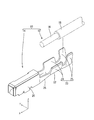
本実施形態の端子付き電線10は、図1に示すように、単芯電線12と、単芯電線12に圧着される端子14と、を備えている。
As shown in FIG. 1, the electric wire with
単芯電線12は、銅合金製の単芯線16と、単芯線16を覆う絶縁被覆部18と、から構成されており、単芯電線12の先端部は、被覆が剥かれて単芯線16が露出している。ここで、単芯線16は、極細径(例えば、断面積が0.05平方ミリメートル程度)の芯線である。
The single-core
端子14は、雌型端子であって、銅合金製の板金をプレス加工及び折曲げ加工することにより形成されており、相手側の雄型端子(図示せず)が嵌合される箱状の本体部20と、本体部20の後方に設けられ、単芯電線12が載置される板状の底板部22と、単芯電線12に圧着される圧着部23と、本体部20と底板部22とを連結する連結部26と、を備えている。
The
圧着部23は、底板部22の両端縁から上方に突出し、単芯線16の先端部が圧着される一対のワイヤバレル部(バレル部)24と、ワイヤバレル部24の後方に配され、絶縁被覆部18が圧着される一対のインシュレーションバレル部25と、から構成されている。
The crimping
一対のワイヤバレル部24は、オープンバレル形式であって、図2に示すように、底板部22の両側縁から上方に突出する一対の側壁部28を備えている。単芯線16が一対のワイヤバレル部24に圧着される際は、圧着機によって、図3に示すように、一対の側壁部28は上端から下方に折り返され、これにより形成された一対の折り返し片30によって、単芯線16は上方から押圧される。また、一対の側壁部28は、圧着機によって、内方に変位され、単芯線16は、一対の側壁部28によって両側方から押圧される。以上により、単芯線16は、一対のワイヤバレル部24に圧着される。圧着前の単芯線16の断面積S1と、圧縮後の単芯線16の断面積S2との比率S2/S1は、0.8〜0.9程度となっている。
The pair of
単芯線16が一対のワイヤバレル部24に圧着された状態では、一対の折り返し片30の先端縁32は、単芯線16に上方から接触しており、第1接触部34とされる。
In a state where the
また、一対の折り返し片30の互いに対向する面は、互いに接触しており、第2接触部36とされる。このとき、一対の折り返し片30は、上方から下方に向けて折り返されていることから、第2接触部36も上下方向に延びて形成されている。
Moreover, the mutually opposing surfaces of the pair of folded
また、一対の折り返し片30の第2接触部36側の面と反対側の面は、対向する側壁部28の内面にそれぞれ接触しており、第3接触部38とされる。このとき、第3接触部38は、一対の折り返し片30の先端部寄り(即ち、一対の折り返し片30の先端縁32側)に位置している。
Further, the surface of the pair of folded
単芯線16が一対のワイヤバレル部24に圧着された状態においては、一対の側壁部28の間に、一対の折り返し片30が収まっており、底板部22の左右方向の幅寸法W1は、一対の側壁部28の厚さ寸法T1の4倍程度となっている。このように、幅寸法W1の範囲内に、ワイヤバレル部24を構成する2つの側壁部28と、2つの折り返し片30とが並ぶように圧着されるようになっているので、端子14の幅方向の寸法が大きくなることが抑制される。
In a state where the
次に、本実施形態の作用について説明する。
端子付き電線10が高温環境下に置かれると単芯線16は熱膨張し、これによって、一対のワイヤバレル部24は上方に押し上げられる。しかしながら、一対のワイヤバレル部24のそれぞれの折り返し片30は、第2接触部36により互いに接触しており、さらに、一対の折り返し片30は、第3接触部38により一対の側壁部28とそれぞれ接触している。このため、第2接触部36及び第3接触部38において発生する摩擦力により、一対のワイヤバレル部24の上方への変位は抑制される。特に、第2接触部36は、上述の通り上下方向に長く形成されていることから、従来のように、バレルの先端部のみが接触する構成と比較して第2接触部36において発生する摩擦力は大きくなっている。以上により、一対のワイヤバレル部24が単芯線16の熱膨張により押し上げられることが抑制される。
Next, the operation of this embodiment will be described.
When the terminal-attached
また、高温環境から常温環境に戻った際に、熱膨張した単芯線16は収縮し、一対のワイヤバレル部24は下方に変位しようとするが、第2接触部36及び第3接触部38において発生する摩擦力により、一対のワイヤバレル部24の下方への変位は規制される。
Further, when returning from the high temperature environment to the normal temperature environment, the thermally expanded
このように、温度変化によって単芯線16が膨張又は収縮する際に、一対のワイヤバレル部24が変位する方向は、上下方向となっているため、温度変化があっても、一対のワイヤバレル部24同士は、接近又は離間する方向(左右方向)に膨張又は収縮することが抑制される。この結果、一対のワイヤバレル部24同士が、第2接触部36及び第3接触部38の接触面積が小さくなる方向に変位することが抑制されるため、一対のワイヤバレル部24が単芯線16に圧着された状態を保持することができ、ワイヤバレル部24の単芯線16への接圧が維持され、ワイヤバレル部24と単芯線16との間の接触抵抗の増加を抑制することができる。
As described above, when the
以上のように本実施形態によれば、一対の折り返し片30同士は第2接触部36において接触しているので、第2接触部36において発生する摩擦力により、一対のワイヤバレル部(バレル部)24が単芯線16に圧着された形状を保持することができる。
また、一対のワイヤバレル部(バレル部)24は、上方に突出する一対の側壁部28と、下方に折り返された一対の折り返し片30とを有するので、一対のワイヤバレル部(バレル部)24が温度変化によって膨張又は収縮の方向は、上下方向となっている。このため、温度変化があっても、一対のワイヤバレル部(バレル部)24同士は、接近又は離間する方向に膨張又は収縮することが抑制されるようになっている。この結果、一対のワイヤバレル部(バレル部)24同士が、第2接触部36の面積が小さくなる方向に膨張又は収縮することが抑制されるので、一対のワイヤバレル部(バレル部)24が単芯線16に圧着された形状を保持することができる。
更に、一対の折り返し片30と、一対の側壁部28とは第3接触部38において接触しているので、第3接触部38において発生する摩擦力により、一対の折り返し片30と、一対の側壁部28とが、温度変化によって膨張又は収縮することが抑制されるようになっている。これにより、一対のワイヤバレル部(バレル部)24が単芯線16に圧着された形状を保持することができる。
以上により、一対のワイヤバレル部(バレル部)24が単芯線16に圧着された形状を保持することができるので、ワイヤバレル部(バレル部)24の単芯線16への接圧が維持され、ワイヤバレル部(バレル部)24と単芯線16との間の接触抵抗の増加を抑制できる。
As described above, according to the present embodiment, since the pair of folded
Moreover, since a pair of wire barrel part (barrel part) 24 has a pair of
Furthermore, since the pair of folded
As described above, since the pair of wire barrel portions (barrel portions) 24 can hold the shape crimped to the
また、一対の側壁部28の間に、一対の折り返し片30が収まるように単芯線16に圧着されることで、底板部22の幅寸法W1の範囲内に、ワイヤバレル部(バレル部)24を構成する上下方向に延びる厚さ寸法T1の金属板が、最大4個分、幅方向に並ぶこととなる。これにより、端子14を大型化することなく、ワイヤバレル部(バレル部)24と単芯線16との間の接触抵抗の増加を抑制できる。
Further, the wire barrel portion (barrel portion) 24 is within the range of the width dimension W <b> 1 of the
<実施形態2>
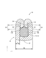
図4を参照して本実施形態の端子付き電線10Aを説明する。
実施形態1では、単芯線16が一対のワイヤバレル部24に圧着される際は、一対の側壁部28を下方に1回折り返す構成としていたが、実施形態2では、単芯線16が一対のワイヤバレル部24Aに圧着される際は、一対の側壁部28Aを下方に1回折り返し、さらにその先端を上方に1回折り返す構成としている。その他の構成は、実施形態1と同じ構成となっている。
<Embodiment 2>
The terminal-attached
In the first embodiment, when the
単芯線16が一対のワイヤバレル部24Aに圧着される際は、一対の側壁部28Aは上端から下方に折り返され、これにより、一対の第1折り返し片40が形成される。さらに一対の第1折り返し片40の先端を単芯線16に押し当てると、一対の第1折り返し片40の先端は単芯線の中に入り込むことなく、一対の第1折り返し片40の先端を単芯線16に押し当てた際の反力により一対の第1折り返し片40の先端は上方に折り返され、これにより、一対の第2折り返し片42が形成される。一対の第2折り返し片42は、一対の第1折り返し片40の下端部と連なる一対の折り返し基端部44を介して上方に折り返されており、一対の側壁部28と一対の第1折り返し片40との間に位置している。
When the
単芯線16が一対のワイヤバレル部24Aに圧着された状態では、一対の第2折り返し片42の折り返し基端部44は、単芯線16に上方から接触する第1接触部34Aとされる。また、一対の第1折り返し片40の互いに対向する面は、互いに接触する第2接触部36Aとされる。このとき、第2接触部36Aは、第1接触部34Aよりも上方に位置している。また、一対の第2折り返し片42のうち、一対の側壁部28に接触する部分は、第3接触部38Aとされる。このとき、第3接触部38Aは、第2折り返し片42の先端部寄り(即ち、一対の第2折り返し片42の上端側)に位置している。また、一対の第2折り返し片42のうち、一対の第1折り返し片40と接触する部分は、第4接触部46とされる。
In a state where the
単芯線16が一対のワイヤバレル部24Aに圧着された状態においては、一対の側壁部28Aの間に、一対の第1折り返し片40及び一対の第2折り返し片42が収まっており、底板部22Aの左右方向の幅寸法W2は、一対の側壁部28Aの厚さ寸法T2の6倍程度となっている。このように、底板部22Aの幅寸法W2の範囲内に2つの一対の側壁部28、2つの第1折り返し片40、及び、2つの第2折り返し片42が並ぶように圧着されるようになっているので、一対の側壁部28、一対の第1折り返し片40、及び一対の第2折り返し片42は、強い力で圧縮され、第2接触部36A及び第3接触部38Aにおいて発生する摩擦力を、実施形態1の構成よりも、大きくすることができる。この結果、一対のワイヤバレル部24Aが単芯線16に圧着された形状を保持することができるので、ワイヤバレル部24の単芯線16への接圧が維持され、ワイヤバレル部24と単芯線16との間の接触抵抗の増加を抑制できる。
In a state where the
以上のように本実施形態によれば、一対の側壁部28の間に、一対の第1折り返し片40、及び、一対の第2折り返し片42が収まるように単芯線16に圧着されることで、底板部22の幅寸法W2の範囲内に、バレル部を構成する上下方向に延びる厚さT2の金属板が、最大6個分、幅方向に並ぶこととなる。これにより、底板部22に載置された単芯線16の軸線方向と直交する方向について、一対の側壁部28と一対の第1折り返し片40と一対の第2折り返し片42とは、強い力で圧縮され、第2接触部36及び第3接触部38において発生する摩擦力を大きくすることができる。この結果、一対のワイヤバレル部(バレル部)24が単芯線16に圧着された形状を保持することができるので、ワイヤバレル部(バレル部)24の単芯線16への接圧が維持され、ワイヤバレル部(バレル部)24と単芯線16との間の接触抵抗の増加を抑制できる。
As described above, according to the present embodiment, the pair of first folded
<他の実施形態>
本明細書によって開示される技術は上記記述及び図面によって説明した実施形態に限定されるものではなく、例えば次のような種々の態様も含まれる。
(1)上記実施形態において、端子14は雌型端子である構成としたが、雄型端子に対して適用しても良い。
(2)上記実施形態において、単芯線16は極細径である構成としたが、一般的な径(例えば、断面積が0.5平行ミリメートル程度)のものに適用しても良い。
(3)上記実施形態において、単芯電線12は、絶縁被覆部18を有する構成としたが、絶縁被覆部18を有しない裸電線としても良い。
<Other embodiments>
The technology disclosed in the present specification is not limited to the embodiments described with reference to the above description and drawings, and includes, for example, the following various aspects.
(1) In the above embodiment, the terminal 14 is a female terminal, but may be applied to a male terminal.
(2) In the above-described embodiment, the
(3) In the above-described embodiment, the single-core
10,10A:端子付き電線
14:端子
16:単芯線
22,22A:底板部
24,24A:ワイヤバレル部(バレル部)
28,28A:側壁部
30:折り返し片
32:先端縁
34,34A:第1接触部
36,36A:第2接触部
38,38A:第3接触部
40:第1折り返し片
42:第2折り返し片
44:折り返し基端部
W1:幅寸法
T1:厚さ寸法
W2:幅寸法
T2:厚さ寸法
10, 10A: Electric wire with terminal 14: Terminal 16:
28, 28A: Side wall portion 30: Folded piece 32:
Claims (4)
前記単芯線に圧着される端子と、を備えた端子付き電線であって、
前記端子は、前記単芯線が載置される底板部と、前記底板部の両側縁から上方に突出すると共に前記単芯線に圧着される一対のバレル部と、を有しており、
前記一対のバレル部は、
前記底板部の両側縁から上方に突出する一対の側壁部と、
前記一対の側壁部の上端から下方に折り返された一対の折り返し片と、を備え、
前記一対の折り返し片は、それぞれ、前記単芯線に上方から接触する第1接触部と、前記第1接触部よりも上方の位置において前記一対の折り返し片同士が接触する第2接触部と、前記一対の側壁部の内面と接触する第3接触部と、を有している端子付き電線。 Single core wire,
A terminal with a terminal crimped to the single core wire,
The terminal includes a bottom plate portion on which the single core wire is placed, and a pair of barrel portions that protrude upward from both side edges of the bottom plate portion and are crimped to the single core wire,
The pair of barrel portions is
A pair of side wall portions projecting upward from both side edges of the bottom plate portion;
A pair of folded pieces folded downward from the upper ends of the pair of side wall portions,
Each of the pair of folded pieces includes a first contact portion that comes into contact with the single core wire from above, a second contact portion that contacts the pair of folded pieces at a position above the first contact portion, and A terminal-attached electric wire having a third contact portion that contacts the inner surfaces of the pair of side wall portions.
Priority Applications (4)
| Application Number | Priority Date | Filing Date | Title |
|---|---|---|---|
| JP2018098480A JP2019204653A (en) | 2018-05-23 | 2018-05-23 | Electric wire with terminal |
| PCT/JP2019/019451 WO2019225458A1 (en) | 2018-05-23 | 2019-05-16 | Terminal-attached electric wire |
| CN201980033860.6A CN112154572A (en) | 2018-05-23 | 2019-05-16 | Electric wire with terminal |
| US17/054,223 US20210159613A1 (en) | 2018-05-23 | 2019-05-16 | Wire with terminal |
Applications Claiming Priority (1)
| Application Number | Priority Date | Filing Date | Title |
|---|---|---|---|
| JP2018098480A JP2019204653A (en) | 2018-05-23 | 2018-05-23 | Electric wire with terminal |
Publications (2)
| Publication Number | Publication Date |
|---|---|
| JP2019204653A true JP2019204653A (en) | 2019-11-28 |
| JP2019204653A5 JP2019204653A5 (en) | 2020-12-03 |
Family
ID=68616668
Family Applications (1)
| Application Number | Title | Priority Date | Filing Date |
|---|---|---|---|
| JP2018098480A Pending JP2019204653A (en) | 2018-05-23 | 2018-05-23 | Electric wire with terminal |
Country Status (4)
| Country | Link |
|---|---|
| US (1) | US20210159613A1 (en) |
| JP (1) | JP2019204653A (en) |
| CN (1) | CN112154572A (en) |
| WO (1) | WO2019225458A1 (en) |
Cited By (1)
| Publication number | Priority date | Publication date | Assignee | Title |
|---|---|---|---|---|
| WO2024024769A1 (en) * | 2022-07-27 | 2024-02-01 | 住友電装株式会社 | Terminal metal fitting |
Families Citing this family (1)
| Publication number | Priority date | Publication date | Assignee | Title |
|---|---|---|---|---|
| JP6858896B1 (en) * | 2020-02-21 | 2021-04-14 | 株式会社デルタプラス | Crimping connection terminal |
Family Cites Families (19)
| Publication number | Priority date | Publication date | Assignee | Title |
|---|---|---|---|---|
| GB1382811A (en) * | 1971-01-11 | 1975-02-05 | Post Office | Clips |
| JPS5138085A (en) * | 1974-09-27 | 1976-03-30 | Yazaki Corp | TANSHIKANAGU |
| US4142771A (en) * | 1974-10-16 | 1979-03-06 | Amp Incorporated | Crimp-type terminal |
| JPS521489A (en) * | 1975-06-24 | 1977-01-07 | Yazaki Corp | Press-attached terminal for aluminium wire |
| JPS55120080U (en) * | 1979-02-16 | 1980-08-25 | ||
| JPS5627666Y2 (en) * | 1980-05-19 | 1981-07-01 | ||
| JP5103137B2 (en) * | 2007-11-01 | 2012-12-19 | 株式会社オートネットワーク技術研究所 | Crimp terminal, electric wire with terminal, and manufacturing method thereof |
| JP4922897B2 (en) * | 2007-11-02 | 2012-04-25 | 株式会社オートネットワーク技術研究所 | Crimp terminal, electric wire with terminal, and manufacturing method thereof |
| JP2009123622A (en) * | 2007-11-16 | 2009-06-04 | Yazaki Corp | Crimping terminal for aluminum wire |
| JP5707735B2 (en) * | 2009-07-24 | 2015-04-30 | 住友電装株式会社 | Electric wire with terminal fitting and method of manufacturing electric wire with terminal fitting |
| JP5695987B2 (en) * | 2011-07-01 | 2015-04-08 | 矢崎総業株式会社 | Single core wire and terminal crimping structure of single core wire |
| JP5904355B2 (en) * | 2011-08-02 | 2016-04-13 | 矢崎総業株式会社 | Single-core wire terminal crimping structure |
| JP5902414B2 (en) * | 2011-08-08 | 2016-04-13 | 矢崎総業株式会社 | Manufacturing method of terminal crimped wire |
| JP5682547B2 (en) * | 2011-12-12 | 2015-03-11 | 株式会社オートネットワーク技術研究所 | Terminal fitting |
| AT516375B1 (en) * | 2014-12-04 | 2016-05-15 | Gebauer & Griller | Cable contact system and method for electrically connecting a cable to a contact piece |
| JP6225313B2 (en) * | 2016-03-04 | 2017-11-08 | 株式会社デルタプラス | Crimp connection terminal and manufacturing method thereof |
| JP6786312B2 (en) * | 2016-09-05 | 2020-11-18 | 矢崎総業株式会社 | Crimping terminal |
| CN107946782B (en) * | 2016-10-13 | 2020-07-28 | 矢崎总业株式会社 | Terminal-equipped electric wire, method for manufacturing terminal-equipped electric wire, and terminal crimping device |
| JP6434950B2 (en) * | 2016-10-13 | 2018-12-05 | 矢崎総業株式会社 | Terminal crimping device |
-
2018
- 2018-05-23 JP JP2018098480A patent/JP2019204653A/en active Pending
-
2019
- 2019-05-16 CN CN201980033860.6A patent/CN112154572A/en active Pending
- 2019-05-16 WO PCT/JP2019/019451 patent/WO2019225458A1/en active Application Filing
- 2019-05-16 US US17/054,223 patent/US20210159613A1/en not_active Abandoned
Cited By (1)
| Publication number | Priority date | Publication date | Assignee | Title |
|---|---|---|---|---|
| WO2024024769A1 (en) * | 2022-07-27 | 2024-02-01 | 住友電装株式会社 | Terminal metal fitting |
Also Published As
| Publication number | Publication date |
|---|---|
| WO2019225458A1 (en) | 2019-11-28 |
| CN112154572A (en) | 2020-12-29 |
| US20210159613A1 (en) | 2021-05-27 |
Similar Documents
| Publication | Publication Date | Title |
|---|---|---|
| JP5815352B2 (en) | Female terminal | |
| JPH10233251A (en) | Integrally constituted contact spring | |
| US7458864B2 (en) | Electrical plug connector having an internal leaf spring | |
| JP2010003467A (en) | Terminal fitting, and wire with terminal | |
| US20100035485A1 (en) | terminal fitting | |
| WO2019225458A1 (en) | Terminal-attached electric wire | |
| TW201031056A (en) | Contact and electrical connector | |
| JP2005353524A (en) | Connection terminal | |
| JP5403788B2 (en) | Crimping structure of crimping barrel, crimping terminal and crimping device | |
| JP2017220392A (en) | Electric wire with terminal | |
| JP5099225B2 (en) | Terminal fittings and electric wires with terminal fittings | |
| JP6074336B2 (en) | Aluminum wire connection structure | |
| WO2014073287A1 (en) | Male terminal | |
| JP2010010000A (en) | Terminal metal fixture and wire with terminal | |
| JP2017208211A (en) | Terminal-equipped electric wire | |
| JPH0883636A (en) | Female terminal metal | |
| JP2010080189A (en) | Terminal fitting and electric wire with terminal fitting | |
| JP2010010086A (en) | Terminal metal fixture and wire with terminal | |
| JP2010073442A (en) | Terminal fitting and electric wire with terminal fitting | |
| JP6409078B2 (en) | Electric connection terminal structure | |
| JP5294668B2 (en) | Crimp structure of terminal against electric wire | |
| JP2005166594A (en) | Structure of female terminal | |
| WO2011129332A1 (en) | Terminal bracket | |
| JP7215933B2 (en) | Connecting terminal | |
| JP2001126798A (en) | Male contact |
Legal Events
| Date | Code | Title | Description |
|---|---|---|---|
| A621 | Written request for application examination |
Free format text: JAPANESE INTERMEDIATE CODE: A621 Effective date: 20200827 |
|
| A521 | Written amendment |
Free format text: JAPANESE INTERMEDIATE CODE: A523 Effective date: 20201021 |
|
| A131 | Notification of reasons for refusal |
Free format text: JAPANESE INTERMEDIATE CODE: A131 Effective date: 20210720 |
|
| A521 | Written amendment |
Free format text: JAPANESE INTERMEDIATE CODE: A523 Effective date: 20210901 |
|
| A02 | Decision of refusal |
Free format text: JAPANESE INTERMEDIATE CODE: A02 Effective date: 20211026 |