JP2019203379A - Fitting - Google Patents

Fitting Download PDF

Info

Publication number
JP2019203379A
JP2019203379A JP2019143473A JP2019143473A JP2019203379A JP 2019203379 A JP2019203379 A JP 2019203379A JP 2019143473 A JP2019143473 A JP 2019143473A JP 2019143473 A JP2019143473 A JP 2019143473A JP 2019203379 A JP2019203379 A JP 2019203379A
Authority
JP
Japan
Prior art keywords
upper frame
shoji
frame
indoor side
piece
Prior art date
Legal status (The legal status is an assumption and is not a legal conclusion. Google has not performed a legal analysis and makes no representation as to the accuracy of the status listed.)
Granted
Application number
JP2019143473A
Other languages
Japanese (ja)
Other versions
JP2019203379A5 (en
JP6675034B2 (en
Inventor
龍大 佐野
Ryusuke Sano
龍大 佐野
屋敷 亮
Akira Yashiki
亮 屋敷
新作 増山
Shinsaku Masuyama
新作 増山
Current Assignee (The listed assignees may be inaccurate. Google has not performed a legal analysis and makes no representation or warranty as to the accuracy of the list.)
Sankyo Tateyama Inc
Original Assignee
Sankyo Tateyama Inc
Priority date (The priority date is an assumption and is not a legal conclusion. Google has not performed a legal analysis and makes no representation as to the accuracy of the date listed.)
Filing date
Publication date
Application filed by Sankyo Tateyama Inc filed Critical Sankyo Tateyama Inc
Priority to JP2019143473A priority Critical patent/JP6675034B2/en
Publication of JP2019203379A publication Critical patent/JP2019203379A/en
Publication of JP2019203379A5 publication Critical patent/JP2019203379A5/ja
Application granted granted Critical
Publication of JP6675034B2 publication Critical patent/JP6675034B2/en
Active legal-status Critical Current
Anticipated expiration legal-status Critical

Links

Images

Landscapes

  • Wing Frames And Configurations (AREA)
  • Hinge Accessories (AREA)

Abstract

To provide a fitting capable of preventing a sash from coming off a frame, even when it is unlatched from a head of an upper part of the sash.SOLUTION: A fitting comprises a frame 1, and a sash 3 that is provided to be slidable along a head and a sill. The frame 1 has an anti-coming-off component 6 provided almost throughout the length of the head 4, on the indoor side of the head 4. The anti-coming-off component 6 has an anti-coming-off piece 7 hanging below a lower edge of the head 4, on the indoor side of an indoor side wall 5 of the head 4.SELECTED DRAWING: Figure 1

Description

本発明は、上下枠に沿って摺動する障子を備える建具に関する。   The present invention relates to a joinery including a shoji that slides along an upper and lower frame.

引戸式のサッシの障子は、上枠と下枠間に上下けんどん式に建て込んでいるが、障子が下がると、障子上部の上枠のレールとの掛かりが無くなり、外障子が室外側に、内障子が室内側に外れるおそれがあった。   The sliding door type sash shoji is built up and down between the upper frame and the lower frame, but when the shoji is lowered, the upper frame of the shoji is no longer hooked and the outer shoji is placed outside the room. There was a risk that the shoji could be removed indoors.

本発明は以上に述べた実情に鑑み、障子上部の上枠との掛かりが無くなったときでも、障子が枠から外れるのを防止できる建具の提供を目的とする。   In view of the situation described above, an object of the present invention is to provide a fitting capable of preventing the shoji from coming off the frame even when the upper frame of the shoji is no longer hooked.

上記の課題を達成するために請求項1記載の発明による建具は、枠と、上下枠に沿って摺動可能に設けた障子とを備え、枠は、上枠の室内側に外れ止め部品が上枠の略全長に亘って設けてあり、外れ止め部品は、上枠の室内側壁の室内側に上枠の下縁よりも下方に垂下する外れ止め片を有することを特徴とする。   In order to achieve the above object, a joinery according to the first aspect of the present invention includes a frame and a shoji that is slidably provided along the upper and lower frames, and the frame has an anti-slip component on the indoor side of the upper frame. It is provided over substantially the entire length of the upper frame, and the anti-slip component has a non-slip piece that hangs downward from the lower edge of the upper frame on the indoor side of the indoor side wall of the upper frame.

請求項2記載の発明による建具は、枠と、上下枠に沿って摺動可能に設けた障子とを備え、枠は、上枠に外れ止め部品が設けてあり、外れ止め部品は、上枠の室外側壁の室内側面に当接して上框の室外側に垂下する外れ止め片を有する略L形断面の長尺部材であり、上枠のレールよりも室外側の上枠と障子との間の隙間に配置され、上枠の内周面に取付けてあることを特徴とする。   A fitting according to a second aspect of the present invention includes a frame and a shoji that is slidably provided along the upper and lower frames. The frame is provided with a detachment prevention component on the upper frame, and the detachment prevention component is provided on the upper frame. It is a long member having a substantially L-shaped cross section having a retaining piece that abuts against the indoor side surface of the outdoor wall of the upper wall and hangs down to the outdoor side of the upper collar, and is located between the upper frame of the outdoor frame and the shoji screen rather than the rail of the upper frame It is arrange | positioned in the clearance gap and is attached to the internal peripheral surface of an upper frame, It is characterized by the above-mentioned.

請求項1記載の発明による建具は、上枠の室内側に外れ止め部品が上枠の略全長に亘って設けてあり、外れ止め部品は、上枠の室内側壁の室内側に上枠の下縁よりも下方に垂下する外れ止め片を有するので、障子が下がって障子上部の上枠との掛かりが無くなったときに、障子が上枠の長手方向のどの位置にあっても障子が室内側に外れるのを確実に防止できる。外れ止め部品は、上枠の室内側に設けるので、取付けがしやすい。   In the fitting according to the first aspect of the present invention, the anti-separation part is provided on the indoor side of the upper frame over the substantially entire length of the upper frame, and the anti-separation part is provided on the indoor side of the indoor side wall of the upper frame and below the upper frame. Because it has a locking piece that hangs downward from the edge, when the shoji is lowered and the upper frame of the shoji is no longer hooked, the shoji is located indoors no matter where the shoji is in the longitudinal direction of the upper frame. Can be reliably prevented. Since the anti-separation part is provided on the indoor side of the upper frame, it is easy to install.

請求項2記載の発明による建具は、上枠に外れ止め部品が設けてあり、外れ止め部品は、上枠の室外側壁の室内側面に当接して上框の室外側に垂下する外れ止め片を有する略L形断面の長尺部材であり、上枠のレールよりも室外側の上枠と障子との間の隙間に配置され、上枠の内周面に取付けてあるので、障子が下がって障子上部の上枠との掛かりが無くなったときに、障子が室外側に外れるのを確実に防止できる。外れ止め部品は、既存の枠にそのまま取付け可能であり、施工性が良い。   In the fitting according to the second aspect of the present invention, the upper frame is provided with a detachment prevention component, and the detachment prevention component is provided with a detachment prevention piece that comes into contact with the indoor side surface of the outdoor side wall of the upper frame and hangs down to the outdoor side of the upper collar. It is a long member with a substantially L-shaped cross section, and is disposed in the gap between the upper frame outside the outdoor frame and the shoji, rather than the rail of the upper frame, and is attached to the inner peripheral surface of the upper frame, so the shoji is lowered When the hook with the upper frame on the upper side of the shoji disappears, the shoji can be reliably prevented from coming out of the outdoor side. The anti-separation part can be attached to an existing frame as it is, and the workability is good.

本発明の建具の第1実施形態を示す縦断面図である。It is a longitudinal cross-sectional view which shows 1st Embodiment of the fitting of this invention. 同建具の内障子が下がったときの状態を示す縦断面図である。It is a longitudinal cross-sectional view which shows a state when the inner shoji of the fitting has fallen. 内障子を上下枠間に建て込むときの状態を示す縦断面図である。It is a longitudinal cross-sectional view which shows the state when installing a naive child between upper and lower frames. 本発明の建具の第2実施形態を示す縦断面図である。It is a longitudinal cross-sectional view which shows 2nd Embodiment of the fitting of this invention. 本発明の建具の第3実施形態を示す縦断面図である。It is a longitudinal cross-sectional view which shows 3rd Embodiment of the fitting of this invention. (a)は第3実施形態の建具の外れ止め部品の側面図、(b)は同平面図である。(A) is a side view of the anti-detachment component of the joinery of 3rd Embodiment, (b) is the same top view. 同外れ止め部品の取付け手順を示す室内側正面図である。It is a room inner side front view which shows the attachment procedure of the same non-stop part. 本発明の建具の第4実施形態を示す縦断面図である。It is a longitudinal cross-sectional view which shows 4th Embodiment of the fitting of this invention. 同建具の内障子が下がったときの状態を示す縦断面図である。It is a longitudinal cross-sectional view which shows a state when the inner shoji of the fitting has fallen. 内障子を上下枠間に建て込むときの状態を示す縦断面図である。It is a longitudinal cross-sectional view which shows the state when installing a naive child between upper and lower frames. 第4実施形態の建具の変形例を示す縦断面図である。It is a longitudinal cross-sectional view which shows the modification of the fitting of 4th Embodiment. 本発明の建具の第5実施形態を示す縦断面図である。It is a longitudinal cross-sectional view which shows 5th Embodiment of the fitting of this invention. 同建具の室外側正面図である。It is an outdoor front view of the fitting. 同建具の外れ止め部品の取付け手順を示す室外側正面図である。It is an outdoor side front view which shows the attachment procedure of the coming-off prevention component of the fitting. 同建具の外障子が下がったときの状態を示す縦断面図である。It is a longitudinal cross-sectional view which shows a state when the external shoji of the joint fitting falls.

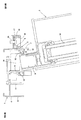
以下、本発明の実施の形態を図面に基づいて説明する。図1は、本発明の建具の第1実施形態を示している。この建具は、ビル用の引違い窓に適用したものであって、躯体(図示省略)の開口部に取付けられる枠1と、枠1内に引違い状に開閉自在に設けた外障子2と内障子3を備える。
枠1は、上枠4と下枠と左右の縦枠を四周枠組みして構成してある。外障子2と内障子3は、上框9と下框と戸先框と召合せ框とを四周框組みし、その内側に複層ガラス36を嵌め込んで構成してある。
Hereinafter, embodiments of the present invention will be described with reference to the drawings. FIG. 1 shows a first embodiment of the joinery of the present invention. This joinery is applied to a sliding window for a building, and includes a frame 1 that is attached to an opening of a housing (not shown), and a shroud 2 that can be opened and closed in a sliding manner in the frame 1. It is equipped with the inner shoji 3.
The frame 1 is constituted by an upper frame 4, a lower frame, and left and right vertical frames formed by a four-round frame. The outer shoji 2 and inner shoji 3 are constructed by assembling an upper eave 9, a lower eave, a door-end eaves, and a summon eaves four times, and a multi-layer glass 36 is fitted therein.

上枠4は、図1に示すように、室外側端部に室外側壁8を垂下して設けてあり、室外側壁8の室内側に外障子2の上部を案内するレール11が垂下して設けてある。さらに上枠4は、室内外方向の中間に中間垂下片13を有し、室内側端部に室内側壁5が垂下して設けてあり、中間垂下片13と室内側壁5との間の溝14に内障子3の上部を案内している。中間垂下片13と室内側壁5の下部には、室外側に向けてタイト材15が設けてあり、各タイト材15が外障子2の室内側面と内障子3の室内側面にそれぞれ当接している。また上枠4は、額縁等に重ねてねじ止めされるアングル16が室内側に突出して設けてある。   As shown in FIG. 1, the upper frame 4 is provided with an outdoor side wall 8 suspended from the outdoor end, and a rail 11 for guiding the upper part of the shoji 2 is suspended from the indoor side of the outdoor side wall 8. It is. Further, the upper frame 4 has an intermediate hanging piece 13 in the middle of the indoor / outdoor direction, and an indoor side wall 5 is provided at the indoor side end portion, and a groove 14 between the intermediate hanging piece 13 and the indoor side wall 5 is provided. The upper part of the inner shoji 3 is guided. A tight material 15 is provided at the lower part of the intermediate hanging piece 13 and the indoor side wall 5 toward the outdoor side, and each tight material 15 is in contact with the indoor side surface of the external shoji 2 and the indoor side surface of the internal shroud 3 respectively. . In addition, the upper frame 4 is provided with an angle 16 that is screwed on a frame or the like so as to protrude to the indoor side.

上枠4の室内側には、図1に示すように、外れ止め部品6が上枠4の略全長に亘って設けてある。外れ止め部品6は、ベース材17と目板18の二部材からなる。ベース材17は、上枠4の室内側壁5の室内側面に当接して配置される外れ止め片7と、上枠4のアングル16を覆うカバー片19と、カバー片19の室内側端部に垂下する垂下片20とを有する略コ字形断面となっている。外れ止め片7は、上枠4の室内側壁5の下縁よりも下方まで垂下しており、上枠4の室内側壁5の下縁に係止する係止部21と、下端部に室外側に突出する突部22を有している。外れ止め片7と垂下片20には、目板18が係止する係止突条23,23が対向して設けてある。ベース材17は、外れ止め片7を上枠4の室内側壁5の室内側に当接すると共に、カバー片19を上枠4のアングル16の内周側に重ね、下方からのねじ24でアングル16と共締めして躯体に取付けてある。目板18は、一対の脚部25,25を有し、脚部25,25をベース材17の係止突条23,23に弾発的に係止して取付けられ、アングル16及びベース材17を躯体に取付けているねじ24を隠している。   On the indoor side of the upper frame 4, as shown in FIG. 1, a detachment prevention component 6 is provided over substantially the entire length of the upper frame 4. The anti-separation component 6 includes two members, a base material 17 and a eye plate 18. The base material 17 is provided with a locking piece 7 disposed in contact with the indoor side surface of the indoor side wall 5 of the upper frame 4, a cover piece 19 that covers the angle 16 of the upper frame 4, and an indoor side end of the cover piece 19. It has a substantially U-shaped cross section having a hanging piece 20 that hangs down. The retaining piece 7 hangs down below the lower edge of the indoor side wall 5 of the upper frame 4, a locking portion 21 that locks to the lower edge of the indoor side wall 5 of the upper frame 4, and the outdoor side at the lower end portion. It has the protrusion part 22 protruding. Locking ridges 23, 23 that lock the eye plate 18 are provided on the detachment prevention piece 7 and the hanging piece 20 so as to face each other. The base material 17 abuts the stopper piece 7 on the indoor side of the indoor side wall 5 of the upper frame 4 and overlaps the cover piece 19 on the inner peripheral side of the angle 16 of the upper frame 4. And fastened together with the housing. The eye plate 18 has a pair of leg portions 25, 25 and is attached by elastically locking the leg portions 25, 25 to the locking protrusions 23, 23 of the base material 17. The screw 24 that attaches 17 to the housing is hidden.

図2は、地震等による躯体の下がりなど、何らかの原因で内障子3が下がったときの状態を示している。このように本建具は、内障子3が下がって内障子3上部の上枠4との掛かりが無くなったときに、上枠4の室内側に設けた外れ止め部品6の外れ止め片7に内障子3の上部が引っ掛かることで、内障子3が室内側に外れるのを防止することができる。
図3は、内障子3を上下枠間に建て込むときの状態を示している。同図に示すように、内障子3を室外側に倒すことで、外れ止め片7が垂下していても支障なく内障子3を建て込むことができる。
FIG. 2 shows a state in which the inner shoji 3 is lowered for some reason, such as a fall of the enclosure due to an earthquake or the like. As described above, the present fitting is not attached to the locking piece 7 of the locking part 6 provided on the indoor side of the upper frame 4 when the hook 3 is lowered and the upper frame 4 is not hooked on the upper frame 4. When the upper part of the shoji 3 is caught, it is possible to prevent the inner shoji 3 from coming out indoors.
FIG. 3 shows a state where the inner shoji 3 is built between the upper and lower frames. As shown in the figure, by tilting the inner shoji 3 to the outdoor side, the inner shoji 3 can be built without any trouble even if the retaining piece 7 is suspended.

以上に述べたように本建具は、上枠4の室内側に外れ止め部品6が上枠4の略全長に亘って設けてあり、外れ止め部品6は、上枠4の室内側壁5の室内側に上枠4の下縁よりも下方に垂下する外れ止め片7を有するので、内障子3が下がって内障子3上部の上枠4との掛かりが無くなったときに、内障子3が上枠4の長手方向のどの位置にあっても内障子3が室内側に外れるのを確実に防止できる。外れ止め部品6は、上枠4の室内側に設けるので取付けが容易であり、既存のサッシの上枠4に後付けすることも容易である。また、外れ止め部品6により上枠4のアングル16を躯体に固定しているねじ24を隠したので、室内から上枠4を見上げたときにねじ24が見えず、意匠性が向上する。
外れ止め片7を上枠4の室内側壁5の室内側に当接して設けたことで、内障子3が下がって上枠4との掛かりが無くなったときに、外れ止め片7を内障子3上部を上枠4の長手方向に沿って案内するサブレールとして機能させられる。また、外れ止め片7が内障子3に風圧(正圧)を受けたときの補強となる。
外れ止め片7に上枠4の室内側壁5の下縁に係止する係止部21を有することで、外れ止め部品6を取付ける際に、係止部21を上枠4の室内側壁5の下縁に係止させ、外れ止め部品6の位置合わせができる。外れ止め片7の下端部に室外側に突出する突部22を有していることで、外れ止め片7を内障子3側に近付けて配置できると共に、内障子3が下がって上枠4との掛かりが無くなったときに、外れ止め片7の突部22の先端で内障子3と線接触するため、内障子3を摺動させやすい。
外れ止め部品6を上枠4の室内側壁5とアングル16に沿って設け、アングル16に内周側からのねじ24で取付けたことで、外れ止め片7で内障子3を受けたときに、ねじ24が荷重を引き抜き力ではなくせん断力で受けるため、外れ止め部品6の取付強度が高い。
外れ止め部品6を樹脂製とした場合には、断熱性が向上すると共に、結露を防止できる。
As described above, in the present fitting, the anti-slip component 6 is provided over the substantially entire length of the upper frame 4 on the indoor side of the upper frame 4, and the anti-skid component 6 is provided in the chamber of the indoor side wall 5 of the upper frame 4. Since it has a retaining piece 7 that hangs downward from the lower edge of the upper frame 4 on the inner side, when the inner limb 3 is lowered and the upper frame 4 on the upper portion of the inner limb 3 is not hooked, the inner limb 3 is It is possible to reliably prevent the inner shoji 3 from coming out indoors at any position in the longitudinal direction of the frame 4. Since the stopper 6 is provided on the indoor side of the upper frame 4, it is easy to mount and can be easily attached to the upper frame 4 of the existing sash. Further, since the screw 24 that fixes the angle 16 of the upper frame 4 to the housing is hidden by the anti-separation component 6, the screw 24 is not visible when the upper frame 4 is looked up from the room, and the design is improved.
Since the stopper piece 7 is provided in contact with the indoor side of the indoor side wall 5 of the upper frame 4, the stopper piece 7 is attached to the inner frame 3 when the inner armature 3 is lowered and is not engaged with the upper frame 4. It functions as a subrail that guides the upper portion along the longitudinal direction of the upper frame 4. In addition, the detachment prevention piece 7 is reinforced when the impeller 3 receives wind pressure (positive pressure).
Since the locking part 21 has the locking part 21 that locks to the lower edge of the indoor side wall 5 of the upper frame 4, the locking part 21 is attached to the indoor side wall 5 of the upper frame 4 when attaching the locking part 6. It is possible to align the position of the anti-separation component 6 by engaging with the lower edge. By having the protrusion 22 projecting to the outdoor side at the lower end portion of the stopper piece 7, the stopper piece 7 can be placed close to the side of the inner shroud 3, and the inner shroud 3 is lowered and the upper frame 4. When there is no longer the hook, the tip of the protrusion 22 of the come-off prevention piece 7 is in line contact with the inner impingement 3 so that the inner impingement 3 can be easily slid.
When the retaining part 6 is provided along the indoor side wall 5 and the angle 16 of the upper frame 4 and is attached to the angle 16 with the screw 24 from the inner peripheral side, Since the screw 24 receives the load with a shearing force instead of a pulling force, the attachment strength of the anti-separation component 6 is high.
When the anti-separation component 6 is made of resin, the heat insulation is improved and condensation can be prevented.

図4は、本発明に係る建具の第2実施形態を示している。本実施形態は、外れ止め部品6のベース材17が、上枠4のアングル16を覆うカバー片19を有しないものとなっており、外れ止め片7を室内側からのねじ26で上枠4の室内側壁5に固定してあり、ベース材17に室内側から取付けた目板18にてねじ26を隠している。
本実施形態も第1実施形態と同様に、内障子3が室内側に外れるのを防止する効果がある。本実施形態によれば、上枠4にアングル16を有しない場合でも外れ止め部品6を取付けることができる。
FIG. 4 shows a second embodiment of the joinery according to the present invention. In this embodiment, the base material 17 of the locking part 6 does not have the cover piece 19 that covers the angle 16 of the upper frame 4, and the locking element 7 is attached to the upper frame 4 with the screw 26 from the indoor side. The screw 26 is concealed by a plate 18 attached to the base material 17 from the indoor side.
Similar to the first embodiment, this embodiment also has an effect of preventing the inner shoji 3 from coming off indoors. According to this embodiment, even when the upper frame 4 does not have the angle 16, the detachment prevention component 6 can be attached.

図5は、本発明に係る建具の第3実施形態を示している。本実施形態は、外れ止め部品6は単一の部品で構成され、上枠4のアングル16を覆うカバー片19が上壁27と下壁28とで二重に構成され、上壁27とアングル16との間と、上壁27と下壁28との間に空間が設けてある。上壁27には、図6に示すように、大径部29aと小径部29bとを左右方向に隣接して有するダルマ穴29が形成してある。
上枠4のアングル16を躯体に固定しているねじ24は、図5に示すように、ねじ頭24aにくびれ部30を有する段付きねじとなっている。
この外れ止め部品6の取付け方を説明すると、図7(a)に示すように、上枠4のアングル16を段付きねじ24で躯体にあらかじめ固定した上で、ねじ24のねじ頭24aをダルマ穴29の大径部29aに通過させつつ外れ止め部品6をアングル16に下から当てがう。その後、外れ止め部品6を上枠4の長手方向に沿ってスライドさせ、すると段付きねじ24のねじ頭24aのくびれ部30がダルマ穴29の小径部29bに係止し、外れ止め部品6が上枠4から離脱不能に固定される。
FIG. 5 shows a third embodiment of the joinery according to the present invention. In the present embodiment, the locking member 6 is constituted by a single part, the cover piece 19 that covers the angle 16 of the upper frame 4 is constituted by the upper wall 27 and the lower wall 28, and the upper wall 27 and the angle are 16, and a space is provided between the upper wall 27 and the lower wall 28. As shown in FIG. 6, the upper wall 27 is formed with a dharma hole 29 having a large-diameter portion 29a and a small-diameter portion 29b adjacent to each other in the left-right direction.
As shown in FIG. 5, the screw 24 fixing the angle 16 of the upper frame 4 to the housing is a stepped screw having a constricted portion 30 on the screw head 24a.
7A, the angle 16 of the upper frame 4 is fixed to the housing in advance with a stepped screw 24, and the screw head 24a of the screw 24 is connected to the dharma as shown in FIG. The stopper 6 is applied to the angle 16 from below while passing through the large-diameter portion 29a of the hole 29. Thereafter, the locking part 6 is slid along the longitudinal direction of the upper frame 4, and then the constricted part 30 of the screw head 24 a of the stepped screw 24 is locked to the small diameter part 29 b of the Dalma hole 29, and the locking part 6 is The upper frame 4 is fixed so as not to be detached.

上記の第3実施形態も、第1実施形態と同様に、内障子3が室内側に外れるのを防止する効果がある。また、上枠4のアングル16を固定しているねじ24が外れ止め部品6で隠れるので、意匠性が向上する。   Similar to the first embodiment, the third embodiment also has an effect of preventing the inner shoji 3 from coming off indoors. In addition, since the screw 24 fixing the angle 16 of the upper frame 4 is hidden by the detachment prevention component 6, the design is improved.

図8は、本発明に係る建具の第4実施形態を示している。本実施形態は、外れ止め部品6が略コ字形断面のベース材17と、ベース材17の室内側壁の下端部に水平な軸部31で回動可能に設けた外れ止め片7とで構成されている。ベース材17は、上枠4のアングル16の内周側に重ね、下方からのねじ24でアングル16と共締めしてある。ベース材17の室外側壁は、下縁が上枠4の室内側壁5の下縁よりも高い位置にあり、室内側に外れ止め片7のための鉤状の係止部32が設けてある。外れ止め片7は、ベース材17の室内側壁と連続するように下方に垂下しており、上端部室内側に設けた突起33がベース材17の溝34に係止して、その姿勢に保持されている。また外れ止め片7は、上記のように下方に垂下した状態から室内側には回動不能であり、軸部31を支点に室外側にのみ回動可能となっている。   FIG. 8 shows a fourth embodiment of the joinery according to the present invention. In this embodiment, the locking member 6 includes a base member 17 having a substantially U-shaped cross section, and a locking member 7 provided at the lower end portion of the indoor side wall of the base member 17 so as to be rotatable by a horizontal shaft portion 31. ing. The base material 17 is overlapped on the inner peripheral side of the angle 16 of the upper frame 4 and is fastened together with the angle 16 with a screw 24 from below. The lower side wall of the outdoor side wall of the base member 17 is located higher than the lower edge of the indoor side wall 5 of the upper frame 4, and a hook-like locking portion 32 for the slip-off preventing piece 7 is provided on the indoor side. The stopper piece 7 hangs downward so as to be continuous with the indoor side wall of the base member 17, and a projection 33 provided on the inner side of the upper end portion of the base member 17 is engaged with the groove 34 of the base member 17 and is held in that posture. ing. Further, the slip-off preventing piece 7 cannot be rotated indoors from the state of hanging downward as described above, and can only be rotated outward with the shaft portion 31 as a fulcrum.

図9は、何らかの原因で内障子3が下がったときの状態を示している。このように本建具は、内障子3が下がって内障子3上部の上枠4との掛かりが無くなったときに、上枠4の室内側に設けた外れ止め部品6の外れ止め片7に内障子3の上部が引っ掛かることで、内障子3が室内側に外れるのを防止することができる。
図10は、内障子3を上下枠間に建て込むときの状態を示している。このときは同図に示すように、外れ止め片7を軸部31を支点に室外側に回動させてベース材17の係止部32に係止させることで、外れ止め片7が上枠4の下縁より飛び出さない状態にできる。これにより内障子3を上下枠間に建て込む作業が一層容易に行える。なお、必ずしも外れ止め片7を室外側に回動させて係止部32に係止させてなくても、内障子3の上部が外れ止め片7に当たれば外れ止め片7は室外側に回動するため、内障子3を建て込むことができる。また、外れ止めが不要なときにも、同様に外れ止め片7を室外側に回動させて係止部32に係止させておくことで、外れ止め片7が目障りにならない。またこのとき、上枠4のアングル16を躯体に固定しているねじ24が外れ止め片7で隠れるので、意匠性が向上する。外れ止め片7は、障子3に合わせて長さ・形状の異なるものに付け替えることができる。
FIG. 9 shows a state in which the inner shoji 3 is lowered for some reason. As described above, the present fitting is not attached to the locking piece 7 of the locking part 6 provided on the indoor side of the upper frame 4 when the hook 3 is lowered and the upper frame 4 is not hooked on the upper frame 4. When the upper part of the shoji 3 is caught, it is possible to prevent the inner shoji 3 from coming out indoors.
FIG. 10 shows a state when the inner shoji 3 is built between the upper and lower frames. At this time, as shown in the figure, the anti-slip piece 7 is rotated to the outside of the room with the shaft portion 31 as a fulcrum and is locked to the lock portion 32 of the base member 17 so that the anti-lock piece 7 is secured to the upper frame. 4 can be prevented from protruding from the lower edge. Thereby, the operation | work which builds the inner shoji 3 between an up-and-down frame can be performed still more easily. Even if the locking piece 7 is not necessarily rotated to the outside of the door and locked to the locking portion 32, the locking piece 7 will rotate to the outside of the door if the upper part of the inner limb 3 hits the locking piece 7. Because it moves, the inner shoji 3 can be built. In addition, even when the stopper is not necessary, the stopper 7 is not obstructed by rotating the stopper 7 to the outdoor side and locking it with the locking portion 32. At this time, the screw 24 that fixes the angle 16 of the upper frame 4 to the housing is hidden by the come-off prevention piece 7, so that the design is improved. The stopper piece 7 can be replaced with one having a different length and shape in accordance with the shoji 3.

図11は、第4実施形態の建具の変形例を示している。本実施形態は、外れ止め片7の軸部31が係合する係合部35と、外れ止め片7を室外側に回動させたときに係止する係止部32を上枠4に一体的に設け、別体のベース材17を無くしたものである。   FIG. 11 shows a modification of the joinery of the fourth embodiment. In this embodiment, the upper frame 4 is integrally formed with an engaging portion 35 that engages with the shaft portion 31 of the locking member 7 and a locking portion 32 that locks when the locking member 7 is rotated outward. The separate base material 17 is eliminated.

図12,13は、本発明に係る建具の第5実施形態を示している。これまでに説明した実施形態は内障子3が室内側に外れるのを防止するものであったが、本実施形態は外障子2が室外側に外れるのを防止するものである。
本実施形態の建具は、上枠4に外れ止め部品10が設けてあり、外れ止め部品10は、上枠4の室外側壁8の室内側面に当接して上框9の室外側に垂下する外れ止め片12と、上枠4の内周面4aに当接する取付片37とを有する略L形断面の長尺部材であり、上枠4のレール11よりも室外側の上枠4と外障子2との間の隙間に配置され、取付片37を下方からのねじ38で上枠4の内周面4aに取付けてある。外れ止め片12は、上枠4の室外側壁8の下縁に沿ってクランク状に曲がった係止部39を有し、係止部39を上枠4の室外側壁8の下縁に係止している。外れ止め片12の係止部39より上の部分12aは、上枠4の室外側壁8の室内側面に当接しており、係止部39より下の部分12bは、室外側面が上枠4の室外側壁8の室外側面と面一になっている。外れ止め片12の下端部には、室内側に向けて突出する突部40を有している。
外れ止め部品10は、図13に示すように、上枠4の略全長に亘って設けてある。また外れ止め部品10は、室外側から見て左側に位置する左部材10aと、室外側から見て右側に位置する右部材10cと、左部材10aと右部材10cの間に位置する中間部材10bの3つに分割されている。なお、外障子2は閉鎖した状態で室外側から見て右側に位置し、内障子3は閉鎖した状態で室外側から見て左側に位置しており、右部材10cは外障子2の横幅よりも少し短く、左部材10aは内障子3の横幅よりも少し短くなっている。
12 and 13 show a fifth embodiment of a joinery according to the present invention. Although the embodiment described so far has been intended to prevent the inner shoji 3 from coming off indoors, the present embodiment is intended to prevent the outer shoji 2 from coming off the outdoor side.
In the joinery of this embodiment, the upper frame 4 is provided with a detachment prevention component 10, and the detachment prevention component 10 comes off against the indoor side surface of the outdoor side wall 8 of the upper frame 4 and hangs down to the outdoor side of the upper collar 9. It is a long member having a substantially L-shaped cross section having a stop piece 12 and a mounting piece 37 that abuts against the inner peripheral surface 4a of the upper frame 4. The attachment piece 37 is attached to the inner peripheral surface 4a of the upper frame 4 with a screw 38 from below. The stopper piece 12 has a locking portion 39 bent in a crank shape along the lower edge of the outdoor side wall 8 of the upper frame 4, and the locking portion 39 is locked to the lower edge of the outdoor side wall 8 of the upper frame 4. doing. The portion 12 a above the locking portion 39 of the come-off prevention piece 12 is in contact with the indoor side surface of the outdoor side wall 8 of the upper frame 4, and the portion 12 b below the locking portion 39 has the outdoor side surface of the upper frame 4. It is flush with the outdoor side surface of the outdoor side wall 8. At the lower end of the stopper piece 12, there is a protrusion 40 that protrudes toward the indoor side.
As shown in FIG. 13, the anti-separation component 10 is provided over substantially the entire length of the upper frame 4. The anti-separation component 10 includes a left member 10a positioned on the left side when viewed from the outdoor side, a right member 10c positioned on the right side when viewed from the outdoor side, and an intermediate member 10b positioned between the left member 10a and the right member 10c. It is divided into three. The external shoji 2 is located on the right side when viewed from the outdoor side in the closed state, the internal shoji 3 is located on the left side when viewed from the outdoor side in the closed state, and the right member 10c is from the lateral width of the external obstacle 2 Is slightly shorter, and the left member 10a is slightly shorter than the lateral width of the inner shoji 3.

次に、外れ止め部品10の取付け手順を説明する。まず、図14(a)に示すように、内外障子2,3を閉鎖した状態として、外れ止め部品10の左部材10aを取付ける。このとき、室外側から見て左半分には外障子2が無いから、左部材10aは上枠4に下方より容易に取付けできる。次に、図14(b)に示すように、外障子2を室外側から見て左側にスライドさせて外障子2を全開とし、外障子2の戸先側より上枠4と外障子2との隙間に外れ止め部品10の中間部材10bを差し入れ、下方からねじ38を打って固定する。ねじ38を打つ際に外障子2が邪魔なときは、邪魔にならない位置まで外障子2をスライドさせればよい。その後、図14(c)に示すように、外障子2を全開にした状態で、外れ止め部品10の右部材10cを取付ける。   Next, the attachment procedure of the detachment prevention component 10 will be described. First, as shown in FIG. 14 (a), the left member 10a of the locking part 10 is attached with the inner and outer shoji 2, 3 closed. At this time, the left half 10a is not attached to the left half as viewed from the outdoor side, so the left member 10a can be easily attached to the upper frame 4 from below. Next, as shown in FIG. 14 (b), the external shoji 2 is slid to the left when viewed from the outdoor side to fully open the external shoji 2, and the upper frame 4 and the external shoji 2 The intermediate member 10b of the locking member 10 is inserted into the gap, and a screw 38 is hit from below to fix. If the external obstacle 2 is in the way when the screw 38 is hit, the external obstacle 2 may be slid to a position where it does not get in the way. Then, as shown in FIG.14 (c), the right member 10c of the locking part 10 is attached in the state which opened the outer shoji 2 fully.

上記の手順は、外れ止め部品10を室外側から取付ける場合であるが、外障子2と内障子3を適宜スライドさせつつ分割された外れ止め部品10a,10b,10cを順次取付けることで、外れ止め部品10を室内側から取付けることも可能である。
また外れ止め部品10は、同じ長さに二分割したもの、不均一の長さに二分割したものであってもよい。
The above procedure is a case where the locking part 10 is attached from the outside of the room, but the locking parts 10a, 10b, and 10c that have been divided while sequentially sliding the outer shoji 2 and the inner shingle 3 are attached in order to prevent the locking. It is also possible to attach the component 10 from the indoor side.
The anti-separation component 10 may be divided into two parts having the same length or divided into two parts having a non-uniform length.

図15は、何らかの原因で外障子2が下がったときの状態を示している。このように本建具は、外障子2が下がって外障子2上部の上枠4との掛かりが無くなったときに、上枠4に設けた外れ止め部品10の外れ止め片12に外障子2の上部が引っ掛かることで、外障子2が室外側に外れるのを防止することができる。   FIG. 15 shows a state when the external shoji 2 is lowered for some reason. As described above, when the outer screen 2 is lowered and the upper frame 4 is not engaged with the upper frame 4 of the outer screen 2, the present joinery is attached to the locking piece 12 of the locking device 10 provided on the upper frame 4. When the upper part is caught, it is possible to prevent the external shoji 2 from coming off the outdoor side.

以上に述べたように本実施形態の建具は、上枠4に外れ止め部品10が設けてあり、外れ止め部品10は、上枠4の室外側壁8の室内側面に当接して上框9の室外側に垂下する外れ止め片12を有する略L形断面の長尺部材であり、上枠4のレール11よりも室外側の上枠4と外障子2との間の隙間に配置され、上枠4の内周面4aに取付けてあるので、外障子2が下がって外障子2上部の上枠4との掛かりが無くなったときに、外障子4が室外側に外れるのを確実に防止できる。外れ止め部品10は、既存の枠1にそのまま取付け可能であり、また、障子2,3を枠1から取外すことなく取付けできるので、施工性が良い。また外れ止め部品10は、上枠4の内周に取付けるため、躯体の状況に左右されることなく取付けでき、後付けが容易である。外れ止め部品10は、上枠4の略全長に亘って設けてあるので、外障子2が上枠4の長手方向のどの位置にあっても、外障子2が室外側に外れるのを防止できる。
外れ止め部品10が長手方向に複数に分割してあれば、障子2,3を適宜スライドさせることで外れ止め部品10の取付け時に障子2,3が邪魔にならず、外れ止め部品10の取付けが一層容易になる。
外れ止め部品10は、障子2,3を閉鎖した状態では室内側からは見えず、室外側からも上枠4の室外側壁8に隠れてほとんど見えないので、建具の意匠性に影響を与えない。さらに、外れ止め片12にクランク状に曲がる係止部39を設け、係止部39より下の部分12bの室外側面を上枠4の室外側壁8の室外側面と面一にしたので、上枠4の室外側壁8と外れ止め片12との間に段差が生じず、意匠性が向上する。外れ止め部品10の取付けの際、外れ止め片12の係止部39を上枠4の室外側壁8の下縁に係止させることで、外れ止め部品10の位置合わせができる。外れ止め片12の下端部に室内側に突出する突部40を有していることで、外障子2が下がって上枠4との掛かりが無くなったときに、外れ止め片12の突部40の先端で外障子2と線接触するため、外障子2を摺動させやすい。
外れ止め片12が上枠4の室外側壁8の室内側に当接していることで、外障子2が下がって外障子2の上部が外れ止め片12に引っ掛かったときに、外れ止め片12が室外側に曲がろうとするのを上枠4の室外側壁8が規制するため、外障子2の外れを防止する効果が高い。また、外れ止め片12を上枠4の室外側壁8の室内側に当接して配置したことで、外れ止め片12が外障子2に風圧(負圧)を受けたときの補強になる。
As described above, in the joinery of the present embodiment, the upper frame 4 is provided with the anti-slip component 10, and the anti-skid component 10 contacts the indoor side surface of the outdoor side wall 8 of the upper frame 4 and It is a long member having a substantially L-shaped cross section having a locking piece 12 that hangs down to the outdoor side, and is disposed in a gap between the upper frame 4 on the outdoor side of the upper frame 4 and the outer screen 2 than the rail 11 of the upper frame 4. Since it is attached to the inner peripheral surface 4a of the frame 4, it is possible to reliably prevent the external obstacle 4 from coming off the outdoor side when the external obstacle 2 is lowered and the upper frame 4 on the upper part of the external obstacle 2 is not hooked. . The detachment prevention part 10 can be attached to the existing frame 1 as it is, and can be attached without removing the shoji 2 and 3 from the frame 1, so that workability is good. Further, since the anti-separation component 10 is attached to the inner periphery of the upper frame 4, it can be attached without being influenced by the state of the casing, and can be easily retrofitted. Since the anti-slip component 10 is provided over substantially the entire length of the upper frame 4, it can be prevented that the outer screen 2 comes off the outdoor side regardless of the position of the outer screen 2 in the longitudinal direction of the upper frame 4. .
If the locking part 10 is divided into a plurality in the longitudinal direction, the sliding elements 2 and 3 are appropriately slid so that the sliding elements 2 and 3 do not get in the way when the locking part 10 is mounted. It becomes easier.
The stopper 10 is not visible from the indoor side when the shoji 2 and 3 are closed, and is hardly visible from the outdoor side because it is hidden behind the outdoor wall 8 of the upper frame 4 and does not affect the design of the joinery. . Furthermore, the locking portion 39 that bends in a crank shape is provided in the locking piece 12, and the outdoor side surface of the portion 12 b below the locking portion 39 is flush with the outdoor side surface of the outdoor side wall 8 of the upper frame 4. No step is generated between the outdoor wall 8 and the anti-disengagement piece 12, and the design is improved. At the time of attachment of the locking part 10, the locking part 39 of the locking part 12 is locked to the lower edge of the outdoor wall 8 of the upper frame 4, so that the locking part 10 can be aligned. By having the protrusion 40 protruding to the indoor side at the lower end of the stopper piece 12, the protrusion 40 of the stopper piece 12 can be removed when the outer screen 2 is lowered and the upper frame 4 is not hooked. Since the end of the line makes line contact with the outer shoji 2, the outer shoji 2 can be easily slid.
Since the stopper piece 12 is in contact with the indoor side of the outdoor side wall 8 of the upper frame 4, when the outer obstacle 2 is lowered and the upper portion of the outer obstacle 2 is caught by the stopper piece 12, the stopper piece 12 is Since the outdoor side wall 8 of the upper frame 4 regulates to bend to the outdoor side, the effect of preventing the external shoji 2 from coming off is high. In addition, the stopper piece 12 is disposed in contact with the indoor side of the outdoor side wall 8 of the upper frame 4, so that the stopper piece 12 is reinforced when the outer obstacle 2 receives wind pressure (negative pressure).

以上に説明した第5実施形態は引違い窓の場合であったが、片引き窓や両袖片引き窓などの場合は、引戸障子をFIX側に寄せることで、外れ止め部品10を分割しなくても引戸障子の幅分の外れ止め部品10を取付けることができる。   The fifth embodiment described above is a case of a sliding window, but in the case of a sliding window or a double-sleeved sliding window, the sliding stopper 10 can be moved to the FIX side, so that the detachment prevention component 10 does not have to be divided. It is also possible to attach the stopper 10 for the width of the sliding door shoji.

本発明は以上に述べた実施形態に限定されない。外れ止め部品の形状、材質は、適宜変更することができる。外れ止め部品は、上枠の全長に亘って設けてなくてもよく、少なくとも障子閉鎖時に障子が位置する範囲の全部又は一部に設けてあればよい。実施形態は、内障子用の外れ止め部品と外障子用の外れ止め部品のどちらか一方を備えるものであったが、内障子用の外れ止め部品と外障子用の外れ止め部品の両方を備えるものであってもよい。本発明の建具は、引違い窓に限らず、片引き窓や引き込み窓に適用することもできる。   The present invention is not limited to the embodiments described above. The shape and material of the stopper parts can be changed as appropriate. The anti-slip component may not be provided over the entire length of the upper frame, and may be provided at least in the whole or part of the range where the shoji is located when the shoji is closed. The embodiment is provided with either one of a locking part for a shingles or a locking part for a shingles, but has both a locking part for a shingles and a locking part for a shingles. It may be a thing. The joinery of the present invention is not limited to sliding windows, but can also be applied to single-drawing windows and pull-in windows.

1 枠
2 外障子(障子)
3 内障子(障子)
4 上枠
5 上枠の室内側壁
6 外れ止め部品(内障子用)
7 外れ止め片
8 上枠の室外側壁
9 上框
10 外れ止め部品(外障子用)
11 レール
12 外れ止め片
1 Frame 2 Shoji shoji
3 inner shoji (shoji)
4 Upper frame 5 Indoor side wall of upper frame 6 Detachment parts (for shoji)
7 Locking piece 8 Outdoor wall of upper frame 9 Upper collar 10 Locking parts (for shoji)
11 Rail 12 Stopper

Claims (2)

枠と、上下枠に沿って摺動可能に設けた障子とを備え、枠は、上枠の室内側に外れ止め部品が上枠の略全長に亘って設けてあり、外れ止め部品は、上枠の室内側壁の室内側に上枠の下縁よりも下方に垂下する外れ止め片を有することを特徴とする建具。   A frame and a shoji that is slidable along the upper and lower frames, and the frame is provided with an anti-slip part over the entire length of the upper frame on the interior side of the upper frame. A joinery comprising a slip-off preventing piece that hangs downward from the lower edge of the upper frame on the indoor side of the indoor side wall of the frame. 枠と、上下枠に沿って摺動可能に設けた障子とを備え、枠は、上枠に外れ止め部品が設けてあり、外れ止め部品は、上枠の室外側壁の室内側面に当接して上框の室外側に垂下する外れ止め片を有する略L形断面の長尺部材であり、上枠のレールよりも室外側の上枠と障子との間の隙間に配置され、上枠の内周面に取付けてあることを特徴とする建具。   A frame and a shoji provided so as to be slidable along the upper and lower frames, the frame is provided with an anti-slip part on the upper frame, and the anti-slip part is in contact with the indoor side surface of the outdoor side wall of the upper frame. It is a long member having a substantially L-shaped cross section having a retaining piece that hangs down to the outdoor side of the upper collar, and is disposed in the gap between the upper frame outside the outdoor frame and the shoji, rather than the rail of the upper frame, A fitting that is attached to a peripheral surface.
JP2019143473A 2019-08-05 2019-08-05 Joinery Active JP6675034B2 (en)

Priority Applications (1)

Application Number Priority Date Filing Date Title
JP2019143473A JP6675034B2 (en) 2019-08-05 2019-08-05 Joinery

Applications Claiming Priority (1)

Application Number Priority Date Filing Date Title
JP2019143473A JP6675034B2 (en) 2019-08-05 2019-08-05 Joinery

Related Parent Applications (1)

Application Number Title Priority Date Filing Date
JP2016047856A Division JP6647928B2 (en) 2016-03-11 2016-03-11 Joinery

Publications (3)

Publication Number Publication Date
JP2019203379A true JP2019203379A (en) 2019-11-28
JP2019203379A5 JP2019203379A5 (en) 2020-02-27
JP6675034B2 JP6675034B2 (en) 2020-04-01

Family

ID=68726439

Family Applications (1)

Application Number Title Priority Date Filing Date
JP2019143473A Active JP6675034B2 (en) 2019-08-05 2019-08-05 Joinery

Country Status (1)

Country Link
JP (1) JP6675034B2 (en)

Also Published As

Publication number Publication date
JP6675034B2 (en) 2020-04-01

Similar Documents

Publication Publication Date Title
JP2017160729A (en) Fitting
JP5237198B2 (en) sash
JP2019203379A (en) Fitting
KR100691406B1 (en) Structure of safety window for building
JP2013023948A (en) Sill and fittings
JP6491500B2 (en) Screen door
JP2015232218A (en) sash
JP4526039B2 (en) Joinery
KR20130051327A (en) Water tighten panel for window frame
KR101916378B1 (en) Screens prevent the flow structure
JP2018105103A (en) Door sheave and fitting
JP6652395B2 (en) How to prevent self-propelled fixtures and screen doors
JP2018053440A (en) Door structure
JP4936218B2 (en) The framework structure of the heel bone to the sash frame
JP6423299B2 (en) Sash with screen door
KR102081268B1 (en) Hinge structure of casement type mosquito net
JP6885723B2 (en) shutter
JP4069423B2 (en) Bottom frame structure of flat sash
KR200224382Y1 (en) Window with security grate
KR20170075270A (en) Window with excellent wind pressure resisting property
JP2018105105A (en) Fitting
KR20180004525A (en) Insulation assembly for connecting windows structre
JP4439821B2 (en) Opening structure
JP2017179811A (en) Fitting
JP2017044023A (en) Fitting

Legal Events

Date Code Title Description
A621 Written request for application examination

Free format text: JAPANESE INTERMEDIATE CODE: A621

Effective date: 20190828

A521 Written amendment

Free format text: JAPANESE INTERMEDIATE CODE: A523

Effective date: 20200114

A871 Explanation of circumstances concerning accelerated examination

Free format text: JAPANESE INTERMEDIATE CODE: A871

Effective date: 20200122

A975 Report on accelerated examination

Free format text: JAPANESE INTERMEDIATE CODE: A971005

Effective date: 20200228

TRDD Decision of grant or rejection written
A01 Written decision to grant a patent or to grant a registration (utility model)

Free format text: JAPANESE INTERMEDIATE CODE: A01

Effective date: 20200303

A61 First payment of annual fees (during grant procedure)

Free format text: JAPANESE INTERMEDIATE CODE: A61

Effective date: 20200309

R150 Certificate of patent or registration of utility model

Ref document number: 6675034

Country of ref document: JP

Free format text: JAPANESE INTERMEDIATE CODE: R150