JP2019201493A - Multilevel power conversion device and control method therefor - Google Patents
Multilevel power conversion device and control method therefor Download PDFInfo
- Publication number
- JP2019201493A JP2019201493A JP2018095009A JP2018095009A JP2019201493A JP 2019201493 A JP2019201493 A JP 2019201493A JP 2018095009 A JP2018095009 A JP 2018095009A JP 2018095009 A JP2018095009 A JP 2018095009A JP 2019201493 A JP2019201493 A JP 2019201493A
- Authority
- JP
- Japan
- Prior art keywords
- voltage command
- command value
- output voltage
- value
- phase
- Prior art date
- Legal status (The legal status is an assumption and is not a legal conclusion. Google has not performed a legal analysis and makes no representation as to the accuracy of the status listed.)
- Pending
Links
Images


Abstract
Description
本発明は、 マルチレベル電力変換装置の制御方法に関する。 The present invention relates to a control method for a multilevel power conversion device.
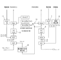
図8に、従来のマルチレベル電力変換装置とその制御構成を示す。図8に示すようにマルチレベル電力変換装置は、三相の順変換器相モジュール1と三相の逆変換器相モジュール2と各相共通の直流モジュール3と、を備える。順変換器相モジュール1と逆変換器相モジュール2は直流モジュール3を介して接続するBTB(Back to Back)構成としている。順変換器相モジュール1は系統4に接続され、逆変換器相モジュール2はモータなどの誘導性負荷5に接続される。
FIG. 8 shows a conventional multilevel power converter and its control configuration. As shown in FIG. 8, the multilevel power conversion apparatus includes a three-phase forward
この回路は第1,第2直流リンクキャパシタCdc1、Cdc2をそれぞれ2Eの電圧、第1,第2フライングキャパシタFC1、FC2をそれぞれEの電圧に制御することで、5つの電位(2E、E、0、−E、−2E)を生成する。 This circuit controls the first and second DC link capacitors Cdc1 and Cdc2 to a voltage of 2E, and the first and second flying capacitors FC1 and FC2 to a voltage of E, respectively, so that five potentials (2E, E, 0 , -E, -2E).
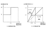
次に、その電位を逆変換器相モジュール2が選択して5レベルを出力する。変調方式はキャリア比較方式のPWM(Pulse Width Modulation)を用い、5レベル電力変換装置の場合、図9に示すように4つのキャリア信号を用いている。
Next, the
図8の順変換器PWM制御部PWM1,逆変換器PWM制御部PWM2では、各キャリア信号と正弦波状の電圧指令との比較を行い、順変換器相モジュール1,逆変換器相モジュール2内のスイッチング素子をオンオフさせる信号を生成する。
The forward converter PWM control unit PWM1 and the reverse converter PWM control unit PWM2 in FIG. 8 compare each carrier signal with a sinusoidal voltage command, and in the forward
図9に出力電圧指令値0.5、出力電圧指令値1.0の時の逆変換器相モジュール2の出力電圧指令値(正弦波)とキャリア信号(三角波)、出力電圧(パルス波形)、出力電流のシミュレーション波形を示す。可変速運転時に、出力されるレベル数は、出力電圧指令値に応じて変化し、出力電圧指令値0.5以下の場合は3レベルの電圧が出力され、出力電圧指令値1.0の場合に5レベルの電圧が出力される。
FIG. 9 shows the output voltage command value (sine wave) and carrier signal (triangular wave), output voltage (pulse waveform), output voltage command value of the inverse
このとき、図9(c)に示すように、出力電圧指令値0.5の場合は、出力電流に高調波成分が含まれていることがわかる。この高調波成分は電流制御部ACRの不安定性を引き起こす。 At this time, as shown in FIG. 9C, it can be seen that in the case of the output voltage command value 0.5, a harmonic component is included in the output current. This harmonic component causes instability of the current control unit ACR.
一方、図9(f)に示すように、出力電圧指令値1.0の場合は、出力電流が正弦波に近い波形となり、高調波成分は軽減され、電流制御部ACRの不安定性は軽減する。 On the other hand, as shown in FIG. 9F, when the output voltage command value is 1.0, the output current has a waveform close to a sine wave, the harmonic component is reduced, and the instability of the current control unit ACR is reduced. .
以上示したようなことから、マルチレベル電力変換装置において、出力電流の高調波による制御の不安定性を低減させることが課題となる。 As described above, in the multilevel power conversion device, it becomes a problem to reduce the instability of the control due to the harmonics of the output current.
本発明は、前記従来の問題に鑑み、案出されたもので、その一態様は、各相共通の直流モジュールと、前記直流モジュールに接続された三相の順変換器相モジュールと、前記直流モジュールに接続された三相の逆変換器相モジュールと、を備え、前記順変換器相モジュールと前記逆変換器相モジュールにおいてPWM制御を行うマルチレベル電力変換装置であって、補正前出力電圧指令値が、前記逆変換器相モジュールの出力電圧が変化する閾値以下の場合、出力電圧指令値を前記補正前出力電圧指令値の2倍の値として算出し、前記補正前出力電圧指令値が、前記逆変換器相モジュールの出力電圧が変化する閾値より大きい場合、前記補正前出力電圧指令値を出力電圧指令値とする出力電圧指令発生器と、前記出力電圧指令値とキャリア信号との比較によりPWM制御を行う逆変換器PWM制御部と、前記補正前出力電圧指令値が前記閾値以下の場合、直流電圧指令値を通常の直流電圧指令値の1/2の値として算出し、前記補正前出力電圧指令値が前記閾値より大きい場合、直流電圧指令値を通常の値として算出する直流電圧指令発生器と、前記直流電圧指令発生器が算出する前記直流電圧指令値に基づいてPWM制御を行う順変換器PWM制御部と、を備えたことを特徴とする。 The present invention has been devised in view of the conventional problems, and one aspect thereof is a DC module common to each phase, a three-phase forward converter phase module connected to the DC module, and the DC A multi-level power converter that performs PWM control in the forward converter phase module and the inverse converter phase module, the output voltage command before correction When the value is equal to or less than a threshold value at which the output voltage of the inverse converter phase module changes, the output voltage command value is calculated as a value twice the uncorrected output voltage command value, and the uncorrected output voltage command value is When the output voltage of the inverse converter phase module is greater than a change threshold, an output voltage command generator having the pre-correction output voltage command value as an output voltage command value, the output voltage command value and a carrier signal When the output voltage command value before correction is equal to or less than the threshold value, the DC voltage command value is calculated as a half value of the normal DC voltage command value. When the output voltage command value before correction is larger than the threshold, based on the DC voltage command generator that calculates the DC voltage command value as a normal value and the DC voltage command value calculated by the DC voltage command generator And a forward converter PWM controller for performing PWM control.
また、その一態様として、前記直流電圧指令発生器は、前記補正前出力電圧指令値が前記閾値よりも大きく所定値以下の場合、直流電圧指令値を通常の値として算出する代わりに前記補正前出力電圧指令値の増加に応じて前記直流電圧指令値を徐々に増加させ、前記所定値で通常の直流電圧指令値とし、前記出力電圧指令発生器は、前記補正前出力電圧指令値が前記閾値より大きく前記所定値以下の場合、前記補正前出力電圧指令値を出力電圧指令値とする代わりに、前記逆変換器相モジュールの出力電圧が前記補正前出力電圧指令値と同じ値となるように、前記直流電圧指令値の値に応じて前記出力電圧指令値を補正することを特徴とする。 Further, as one aspect thereof, when the output voltage command value before correction is greater than the threshold value and equal to or less than a predetermined value, the DC voltage command generator generates the pre-correction instead of calculating the DC voltage command value as a normal value. The DC voltage command value is gradually increased in response to an increase in the output voltage command value to obtain a normal DC voltage command value at the predetermined value, and the output voltage command generator has the uncorrected output voltage command value as the threshold value. If it is greater than or equal to the predetermined value, instead of using the output voltage command value before correction as the output voltage command value, the output voltage of the inverse converter phase module is the same value as the output voltage command value before correction. The output voltage command value is corrected according to the value of the DC voltage command value.
また、他の態様として、各相共通の直流モジュールと、前記直流モジュールに接続された三相の順変換器相モジュールと、前記直流モジュールに接続された三相の逆変換器相モジュールと、を備え、前記順変換器相モジュールと前記逆変換器相モジュールにおいてPWM制御を行うマルチレベル電力変換装置であって、補正前出力電圧指令値が、前記逆変換器相モジュールの出力電圧のレベル数が変化する閾値以下の場合は通常のキャリア信号の半分の振幅である第1キャリア信号と前記補正前出力電圧指令値との比較によりPWM制御を行い、前記補正前出力電圧指令値が前記閾値よりも大きい場合は通常のキャリア信号の振幅である第2キャリア信号と前記補正前出力電圧指令値との比較によりPWM制御を行う逆変換器PWM制御部と、前記補正前出力電圧指令値が前記閾値以下の場合、前記直流電圧指令値を通常の1/2の値とし、前記補正前出力電圧指令値が前記閾値よりも大きい場合、直流電圧指令値を通常の値として算出する直流電圧指令発生器と、前記直流電圧指令発生器が算出する前記直流電圧指令値に基づいてPWM制御を行う順変換器PWM制御部と、を備えたことを特徴とする。 Further, as another aspect, a DC module common to each phase, a three-phase forward converter phase module connected to the DC module, and a three-phase reverse converter phase module connected to the DC module, A multi-level power converter that performs PWM control in the forward converter phase module and the reverse converter phase module, wherein the output voltage command value before correction is the number of levels of the output voltage of the reverse converter phase module. When the value is not more than the changing threshold, PWM control is performed by comparing the first carrier signal having an amplitude half that of a normal carrier signal and the output voltage command value before correction, and the output voltage command value before correction is greater than the threshold value. An inverse converter PWM control unit that performs PWM control by comparing the second carrier signal, which is the amplitude of a normal carrier signal, with the pre-correction output voltage command value when larger, When the output voltage command value before correction is less than or equal to the threshold value, the DC voltage command value is set to a half of the normal value. When the output voltage command value before correction is larger than the threshold value, the DC voltage command value is set to normal. And a forward converter PWM control unit that performs PWM control based on the DC voltage command value calculated by the DC voltage command generator.
本発明によれば、マルチレベル電力変換装置において、出力電流の高調波による制御の不安定性を低減させることが可能となる。 ADVANTAGE OF THE INVENTION According to this invention, in a multilevel power converter device, it becomes possible to reduce the instability of the control by the harmonic of output current.
以下、本願発明におけるマルチレベル電力変換装置の実施形態1〜3を図1〜図7に基づいて詳述する。 Hereinafter, the first to third embodiments of the multilevel power conversion device according to the present invention will be described in detail with reference to FIGS.
[実施形態1]
図1に本実施形態1におけるマルチレベル電力変換装置の制御ブロック構成を示す。主回路構成は図8と同様のものを想定しているが、図8以外の主回路構成の電力変換装置にも本実施形態1は適用可能である。
[Embodiment 1]
FIG. 1 shows a control block configuration of the multilevel power conversion device according to the first embodiment. Although the main circuit configuration is assumed to be the same as that in FIG. 8, the first embodiment can be applied to a power conversion device having a main circuit configuration other than that in FIG. 8.
速度検出器6は、誘導性負荷(モータ)5の速度検出値ωr_detを検出する。速度制御部ASR(Automatic Speed Regulator)は速度指令値ωr_refと速度検出値ωr_detが一致するようにモータの回転速度を制御するものである。この出力結果をq軸インバータ電流指令値Iq_inv_refとし、d軸インバータ電流指令値Id_inv_refとともに逆変換器電流制御部ACR2(Automatic Current Regulator)の目標値とする。 The speed detector 6 detects a speed detection value ωr_det of the inductive load (motor) 5. A speed control unit ASR (Automatic Speed Regulator) controls the rotational speed of the motor so that the speed command value ωr_ref and the detected speed value ωr_det coincide. The output result is set as a q-axis inverter current command value Iq_inv_ref, and is set as a target value of the inverse converter current control unit ACR2 (Automatic Current Regulator) together with the d-axis inverter current command value Id_inv_ref.
逆変換器相モジュール2の三相の出力電流検出値は、第1三相二相変換部7において、d軸インバータ電流検出値Id_inv_det,q軸インバータ電流検出値Iq_inv_detに変換される。
The three-phase output current detection value of the inverse
逆変換器電流制御部ACR2は、d軸インバータ電流指令値Id_inv_ref,q軸インバータ電流指令値Iq_inv_refと、d軸インバータ電流検出値Id_inv_det,q軸インバータ電流検出値Iq_inv_detの偏差に基づいて、d軸出力電圧指令値,q軸出力電圧指令値を算出する。 The inverse converter current control unit ACR2 outputs a d-axis output based on a deviation between the d-axis inverter current command value Id_inv_ref, the q-axis inverter current command value Iq_inv_ref, the d-axis inverter current detection value Id_inv_det, and the q-axis inverter current detection value Iq_inv_det. The voltage command value and the q-axis output voltage command value are calculated.
第1二相三相変換部8は、d軸出力電圧指令値,q軸出力電圧指令値を三相の補正前出力電圧指令値に変換する。出力電圧指令発生器9は、補正前出力電圧指令値に基づいて出力電圧指令値を算出する。直流電圧指令発生器10は補正前出力電圧指令値に基づいて直流電圧指令値Vdc_refを算出する。出力電圧指令発生器9、直流電圧指令発生器10の処理については後述する。
The first two-phase three-
逆変換器PWM制御部PWM2は、出力電圧指令値と4つのキャリア信号との比較を行い、逆変換器相モジュール2のスイッチング素子をオンオフさせる信号を生成する。
The inverse converter PWM control unit PWM2 compares the output voltage command value with the four carrier signals, and generates a signal for turning on and off the switching elements of the inverse
直流電圧制御部AVR(Automatic Voltage Regulator)は、直流電圧検出値Vdc_1(第1直流リンクキャパシタCdc1の印加電圧)、Vdc_2(第2直流リンクキャパシタCdc2の印加電圧)と目標とする直流電圧指令値Vdc_refの差分から第1,第2直流リンクキャパシタCdc1,Cdc2に注入すべきd軸整流器電流指令値Id_rec_refを算出する。 The DC voltage control unit AVR (Automatic Voltage Regulator) includes DC voltage detection values Vdc_1 (application voltage of the first DC link capacitor Cdc1), Vdc_2 (application voltage of the second DC link capacitor Cdc2) and a target DC voltage command value Vdc_ref. The d-axis rectifier current command value Id_rec_ref to be injected into the first and second DC link capacitors Cdc1 and Cdc2 is calculated from the difference between the two.
このd軸整流器電流指令値Id_rec_refは、q軸整流器電流指令値Iq_rec_refとともに順変換器電流制御部ACR1(Automatic Current Regulator)の目標値とする。なお、q軸整流器電流指令値Iq_rec_refは、順変換器相モジュール1の入力力率指令に従って設定する(入力力率指令=1の場合は、Iq_rec_ref=0とする)。 The d-axis rectifier current command value Id_rec_ref is set as a target value of the forward converter current control unit ACR1 (Automatic Current Regulator) together with the q-axis rectifier current command value Iq_rec_ref. The q-axis rectifier current command value Iq_rec_ref is set according to the input power factor command of the forward converter phase module 1 (when the input power factor command = 1, Iq_rec_ref = 0).
順変換器相モジュール1の三相の電流検出値は、第2三相二相変換部11において、d軸整流器電流検出値Id_rec_det,q軸整流器電流検出値Iq_rec_detに変換される。
The three-phase current detection value of the forward
順変換器電流制御部ACR1は、d軸整流器電流指令値Id_rec_ref,q軸整流器電流指令値Iq_rec_refと、d軸整流器電流検出値Id_rec_det,q軸整流器電流検出値Iq_rec_detの偏差に基づいて、d軸整流器電圧指令値,q軸整流器電圧指令値を算出する。 The forward converter current control unit ACR1 is based on the deviation of the d-axis rectifier current command value Id_rec_ref, the q-axis rectifier current command value Iq_rec_ref, the d-axis rectifier current detection value Id_rec_det, and the q-axis rectifier current detection value Iq_rec_det. The voltage command value and the q-axis rectifier voltage command value are calculated.
第2二相三相変換部12は、d軸整流器電圧指令値,q軸整流器電圧指令値を三相の整流器電圧指令値に変換する。順変換器PWM制御部PWM1は、三相の整流器電圧指令値と4つのキャリア信号との比較を行い、順変換器相モジュール1のスイッチング素子をオンオフさせる信号を生成する。
The second two-phase / three-
次に、直流電圧指令発生器10、出力電圧指令発生器9について説明する。 逆変換器相モジュール2の出力電圧のレベル数が変化する補正前出力電圧指令値0.5を閾値として直流電圧指令値Vdc_refと出力電圧指令値を変更し、1レベルの電位を変える。これにより、5レベル領域を0.25≦補正前出力電圧指令の範囲に広げる。
Next, the DC
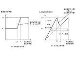
直流電圧指令発生器10は、図2(a)に示すように、補正前出力電圧指令値が閾値0.5以下の領域では、直流電圧指令値Vdc_refをEとする。これにより、補正前出力電圧指令値が0.5以下の領域の直流リンク電圧(図8のCdc1、Cdc2の印加電圧)は、補正前出力電圧指令値が閾値0.5よりも大きい領域の直流リンク電圧(通常の直流電圧指令値)の1/2になる。
As shown in FIG. 2A, the DC
補正前出力電圧指令値が0.5を超えた領域においては、図8に示す従来技術と同様に直流電圧指令値Vdc_refを通常の値である2Eとする。 In the region where the pre-correction output voltage command value exceeds 0.5, the DC voltage command value Vdc_ref is set to 2E, which is a normal value, as in the prior art shown in FIG.
出力電圧指令発生器9は、図2(b)に示すように、補正前出力電圧指令値が閾値0.5以下の領域は、出力電圧指令値を補正前出力電圧指令値の2倍とする。また、補正前出力電圧指令値が閾値0.5よりも大きい領域では、出力電圧指令値=補正前出力電圧指令値とする。 As shown in FIG. 2B, the output voltage command generator 9 sets the output voltage command value to twice the pre-correction output voltage command value when the output voltage command value before correction is less than or equal to the threshold value 0.5. . Further, in a region where the output voltage command value before correction is larger than the threshold value 0.5, output voltage command value = output voltage command value before correction.
この直流電圧指令値Vdc_refと出力電圧指令値の補正によって、補正前出力電圧指令値が0.25〜0.5の領域での出力電圧指令値は0.5〜1.0となる。よって、図9からわかるように、出力電圧指令値は4つのキャリア信号すべてと交差するようになる。 By correcting the DC voltage command value Vdc_ref and the output voltage command value, the output voltage command value in the region where the pre-correction output voltage command value is 0.25 to 0.5 is 0.5 to 1.0. Therefore, as can be seen from FIG. 9, the output voltage command value crosses all four carrier signals.
図3(a),(b)に実施形態1における出力電圧指令値0.5の場合の出力電圧,出力電流を示す。本実施形態1では、補正前出力電圧指令値が0.25〜0.5(出力電圧指令値0.5〜1.0)の領域において、出力電圧指令値が4つのキャリア信号全てと交差するため、図3(a)に示すような5レベルの電圧を出力できるようになる。 3A and 3B show the output voltage and output current when the output voltage command value is 0.5 in the first embodiment. In the first embodiment, in the region where the output voltage command value before correction is 0.25 to 0.5 (output voltage command value 0.5 to 1.0), the output voltage command value intersects with all four carrier signals. Therefore, it becomes possible to output a five-level voltage as shown in FIG.
よって、図3(b)に示すように、0.25≦補正前出力電圧指令値≦0.5における出力電流の高調波成分の低減が可能となる。 Therefore, as shown in FIG. 3B, the harmonic component of the output current can be reduced when 0.25 ≦ pre-correction output voltage command value ≦ 0.5.
また、補正前出力電圧指令値が閾値0.5以下の領域では、直流電圧指令値Vdc_refを1/2とし、出力電圧指令値を2倍としているため、逆変換器相モジュール2の出力電圧(図8の誘導性負荷5への印加電圧)の値は、補正前出力電圧指令値と同じ電圧となる。
In the region where the output voltage command value before correction is less than or equal to the threshold value 0.5, the DC voltage command value Vdc_ref is halved and the output voltage command value is doubled. The value of the voltage applied to the
すなわち、5レベルの領域を増加させるため、出力電圧指令値を大きくしているが、逆変換器相モジュール2の出力電圧が補正前出力電圧指令値と同じ値となるように、直流電圧指令値Vdc_refを小さくしている。
That is, the output voltage command value is increased in order to increase the five-level region, but the DC voltage command value is set so that the output voltage of the inverse
以上示したようなことから、本実施形態1によれば、 マルチレベル電力変換装置において、補正前出力電圧指令値が閾値0.5以下の場合、直流電圧指令値および出力電圧指令値を補正することにより、5レベル領域を広げることが可能となる。よって、出力電圧指令値が0.25〜0.5以下の場合、出力電圧波形指令値が正弦波に近づくため、出力電流の高調波が軽減され、制御の不安定性も低減される。 As described above, according to the first embodiment, in the multilevel power conversion device, when the output voltage command value before correction is equal to or less than the threshold value 0.5, the DC voltage command value and the output voltage command value are corrected. This makes it possible to expand the five-level region. Therefore, when the output voltage command value is 0.25 to 0.5 or less, the output voltage waveform command value approaches a sine wave, so that harmonics of the output current are reduced and control instability is also reduced.
[実施形態2]
図4に本実施形態2における直流電圧指令値および出力電圧指令値を示し、図5に本実施形態2におけるマルチレベル電力変換装置の制御ブロック図を示す。図1と同様の箇所については同じ符号を付して、その説明を省略する。
[Embodiment 2]
FIG. 4 shows a DC voltage command value and an output voltage command value in the second embodiment, and FIG. 5 shows a control block diagram of the multilevel power conversion device in the second embodiment. The same parts as those in FIG. 1 are denoted by the same reference numerals, and the description thereof is omitted.
実際には第1,第2直流リンクキャパシタCdc1,Cdc2の充電時間や直流電圧制御部AVRの応答時間によっても直流電圧が目標値に達するまでに時間を要する。このことを考慮すると、図2(a)のような直流電圧指令値Vdc_refの急峻な変化は制御の安定上、好ましくない。 Actually, it takes time for the DC voltage to reach the target value depending on the charging time of the first and second DC link capacitors Cdc1 and Cdc2 and the response time of the DC voltage controller AVR. Considering this, a steep change in the DC voltage command value Vdc_ref as shown in FIG. 2A is not preferable in terms of control stability.
よって、直流電圧指令発生器10は、図4(a)に示すように、補正前出力電圧指令値が閾値0.5より大きい領域において、直流電圧指令値Vdc_refを補正前出力電圧指令値の変化に応じて徐々に増加させる。さらに、出力電圧指令発生器9は、この直流電圧指令値Vdc_refに基づき、出力電圧指令値を生成する。
Therefore, as shown in FIG. 4A, the DC
図4(b)に示す補正前出力電圧指令値x=閾値0.5〜所定値aにおける出力電圧指令値yは、以下の(1)式となる。なお、所定値aは、直流電圧指令値Vdc_refが2Eに到達するときの補正前出力電圧指令値である。 The output voltage command value y when the pre-correction output voltage command value x = threshold value 0.5 to the predetermined value a shown in FIG. 4B is expressed by the following equation (1). The predetermined value a is an output voltage command value before correction when the DC voltage command value Vdc_ref reaches 2E.

(1)式について説明する。図4(a)に示す補正前出力電圧指令値x=閾値0.5〜所定値aの期間の直流電圧指令値Vdc_ref=zは、以下の(2)式となる。 The expression (1) will be described. The DC voltage command value Vdc_ref = z in the period from the pre-correction output voltage command value x = threshold value 0.5 to the predetermined value a shown in FIG. 4A is expressed by the following equation (2).
本実施形態2における逆変換器相モジュール2の出力電圧の値を、従来方式の場合と同値にするためには、以下の(3)式が成立しなければならない。すなわち、逆変換器相モジュール2の出力電圧が補正前出力電圧指令値と同じ値となるように、直流電圧指令値Vdc_refの値に応じて出力電圧指令値を調整している。
In order to make the value of the output voltage of the
(2)式と(3)式より、(1)式が導きだされる。以上示したように、本実施形態2によれば実施形態1と同様の作用効果を奏する。また、直流電圧指令値Vdc_refのVdc_ref急峻な変化を抑制し、制御を安定させることが可能となる。 Equation (1) is derived from Equation (2) and Equation (3). As described above, according to the second embodiment, the same effects as those of the first embodiment can be obtained. In addition, a steep change in Vdc_ref of DC voltage command value Vdc_ref can be suppressed, and control can be stabilized.
なお、本実施形態2では、補正前出力電圧指令値x=閾値0.5〜所定値aの期間の直流電圧指令値Vdc_ref=zが(2)式に示すような一次関数となっている例である。これを二次以上の関数や階段状のステップ入力等に置き換えても、本実施形態2と同様の効果が得られる。 In the second embodiment, an example in which the DC voltage command value Vdc_ref = z in the period from the pre-correction output voltage command value x = threshold value 0.5 to the predetermined value a is a linear function as shown in the equation (2) is shown. It is. Even if this is replaced with a quadratic or higher order function or a stepped step input, the same effect as in the second embodiment can be obtained.
[実施形態3]
図6に、本実施形態3における逆変換器相モジュール2のキャリア信号を示す。図6に示すように、本実施形態3では、補正前出力電圧指令値に応じて逆変換器相モジュール2のキャリア振幅を変更している。図6(b)に示すキャリア信号Bは従来技術や実施形態1,2のキャリア信号と同じ振幅である。図6(a)に示すキャリア信号Aはキャリア信号Bの半分の振幅となる。なお、順変換器相モジュール1のキャリア信号の振幅の変更は行わない。
[Embodiment 3]
FIG. 6 shows a carrier signal of the
図7に本実施形態3における制御ブロック図を示す。図1と同様の箇所については、同じ符号を付してその説明を省略する。上述した実施形態1,2では出力電圧指令値を変更することで、5レベル電圧を出力する領域を広げていたが、本実施形態3では、図6に示すように4つのキャリア信号の振幅を出力電圧指令値(=補正前出力電圧指令値)に応じて変更する。 FIG. 7 shows a control block diagram in the third embodiment. The same parts as those in FIG. 1 are denoted by the same reference numerals and the description thereof is omitted. In the first and second embodiments described above, the output voltage command value is changed to expand the region for outputting the five-level voltage. However, in the third embodiment, the amplitudes of the four carrier signals are set as shown in FIG. It changes according to the output voltage command value (= output voltage command value before correction).
図7に示すように、スイッチ13により、補正前出力電圧指令値≦0.5ではキャリア信号Aを選択し、補正前出力電圧指令値>0.5ではキャリア信号Bを選択する。直流電圧指令値Vdc_refは、実施形態1と同様、図2(a)に従う。他の動作は、図1と同じである。
As shown in FIG. 7, the
本実施形態3によれば、補正前出力電圧指令値が0.25〜0.5の領域において出力電圧指令値(=補正前出力電圧指令値)とキャリア信号Aの4つの全てのキャリア信号とが交差するようになるため、5レベル電圧を出力できる。 According to the third embodiment, all four carrier signals of the output voltage command value (= pre-correction output voltage command value) and carrier signal A in the region where the output voltage command value before correction is 0.25 to 0.5, Can cross, so that a 5-level voltage can be output.
さらに、補正前出力電圧指令値≦0.5の領域では、直流リンク電圧を1/2になるように制御し、4つのキャリア信号の振幅を1/2にしているため、逆変換器相モジュール2の出力電圧(図8の誘導性負荷5への印加電圧)の値は、補正前出力電圧指令値と同じ電圧となる。
Furthermore, in the region of the output voltage command value before correction ≦ 0.5, the DC link voltage is controlled to be halved, and the amplitude of the four carrier signals is halved. The value of the output voltage 2 (the voltage applied to the
よって、本実施形態3では、実施形態1と同様の効果を得ることができる。 Therefore, in the third embodiment, the same effect as in the first embodiment can be obtained.
以上、本発明において、記載された具体例に対してのみ詳細に説明したが、本発明の技術思想の範囲で多彩な変形および修正が可能であることは、当業者にとって明白なことであり、このような変形および修正が特許請求の範囲に属することは当然のことである。 Although the present invention has been described in detail only for the specific examples described above, it is obvious to those skilled in the art that various changes and modifications are possible within the scope of the technical idea of the present invention. Such variations and modifications are naturally within the scope of the claims.
例えば、実施形態1〜3では、図8の主回路構成の5レベル電力変換装置を例として説明したが、図8以外の主回路構成の変換器にも本発明は適用可能である。また、例として、5レベル電力変換装置を記載しているが、5レベルよりも多いマルチレベル電力変換装置にも適用可能である。例えば9レベル電力変換装置では、図6や図9に示すキャリア信号を8つに増やすことで、本発明を適用できる。 For example, in the first to third embodiments, the five-level power conversion device having the main circuit configuration in FIG. 8 has been described as an example, but the present invention can also be applied to converters having main circuit configurations other than those in FIG. Moreover, although the 5-level power converter device is described as an example, it is applicable to a multi-level power converter device having more than 5 levels. For example, in a 9-level power converter, the present invention can be applied by increasing the number of carrier signals shown in FIGS. 6 and 9 to eight.
また、図1、5、7、8では速度制御部ASRがある構成を説明しているが、速度制御部ASRがない構成でも本発明は適用できる。さらに、第1三相二相変換器7、第1二相三相変換器8、第2三相二相変換器11、第2二相三相変換器12を備えない(つまりd軸q軸電流への変換を行わない)構成においても、本発明は適用できる。
1, 5, 7, and 8 describe the configuration with the speed control unit ASR, but the present invention can be applied to a configuration without the speed control unit ASR. Further, the first three-phase two-
1…順変換器相モジュール
2…逆変換器相モジュール
3…直流モジュール
4…系統
5…誘導性負荷
6…速度検出器
7…第1三相二相変換器
8…第1二相三相変換器
9…出力電圧指令発生器
10…直流電圧指令発生器
11…第2三相二相変換器
12…第2二相三相変換器
DESCRIPTION OF
Claims (5)
補正前出力電圧指令値が、前記逆変換器相モジュールの出力電圧が変化する閾値以下の場合、出力電圧指令値を前記補正前出力電圧指令値の2倍の値として算出し、前記補正前出力電圧指令値が、前記逆変換器相モジュールの出力電圧が変化する閾値より大きい場合、前記補正前出力電圧指令値を出力電圧指令値とする出力電圧指令発生器と、
前記出力電圧指令値とキャリア信号との比較によりPWM制御を行う逆変換器PWM制御部と、
前記補正前出力電圧指令値が前記閾値以下の場合、直流電圧指令値を通常の直流電圧指令値の1/2の値として算出し、前記補正前出力電圧指令値が前記閾値より大きい場合、直流電圧指令値を通常の値として算出する直流電圧指令発生器と、
前記直流電圧指令発生器が算出する前記直流電圧指令値に基づいてPWM制御を行う順変換器PWM制御部と、
を備えたことを特徴とするマルチレベル電力変換装置。 A DC module common to each phase; a three-phase forward converter phase module connected to the DC module; and a three-phase reverse converter phase module connected to the DC module; and the forward converter phase A multi-level power converter that performs PWM control in a module and the inverter phase module,
When the output voltage command value before correction is equal to or less than a threshold value for changing the output voltage of the inverse converter phase module, the output voltage command value is calculated as a value twice the output voltage command value before correction, and the output before correction When the voltage command value is larger than a threshold value at which the output voltage of the inverse converter phase module changes, an output voltage command generator that uses the pre-correction output voltage command value as an output voltage command value;
An inverse converter PWM controller that performs PWM control by comparing the output voltage command value and a carrier signal;
When the output voltage command value before correction is less than or equal to the threshold value, the DC voltage command value is calculated as a half value of the normal DC voltage command value, and when the output voltage command value before correction is greater than the threshold value, A DC voltage command generator for calculating the voltage command value as a normal value;
A forward converter PWM controller that performs PWM control based on the DC voltage command value calculated by the DC voltage command generator;
A multi-level power conversion device comprising:
前記補正前出力電圧指令値が前記閾値よりも大きく所定値以下の場合、直流電圧指令値を通常の値として算出する代わりに前記補正前出力電圧指令値の増加に応じて前記直流電圧指令値を徐々に増加させ、前記所定値で通常の直流電圧指令値とし、
前記出力電圧指令発生器は、
前記補正前出力電圧指令値が前記閾値より大きく前記所定値以下の場合、前記補正前出力電圧指令値を出力電圧指令値とする代わりに、前記逆変換器相モジュールの出力電圧が前記補正前出力電圧指令値と同じ値となるように、前記直流電圧指令値の値に応じて前記出力電圧指令値を補正することを特徴とする請求項1記載のマルチレベル電力変換装置。 The DC voltage command generator is
When the output voltage command value before correction is greater than the threshold value and less than or equal to a predetermined value, the DC voltage command value is set according to the increase in the output voltage command value before correction instead of calculating the DC voltage command value as a normal value. Increasing gradually, to the normal DC voltage command value at the predetermined value,
The output voltage command generator is
When the pre-correction output voltage command value is greater than the threshold value and less than or equal to the predetermined value, instead of using the pre-correction output voltage command value as an output voltage command value, the output voltage of the inverse converter phase module is the pre-correction output The multilevel power converter according to claim 1, wherein the output voltage command value is corrected according to the value of the DC voltage command value so as to be the same value as the voltage command value.
補正前出力電圧指令値が、前記逆変換器相モジュールの出力電圧のレベル数が変化する閾値以下の場合は通常のキャリア信号の半分の振幅である第1キャリア信号と前記補正前出力電圧指令値との比較によりPWM制御を行い、前記補正前出力電圧指令値が前記閾値よりも大きい場合は通常のキャリア信号の振幅である第2キャリア信号と前記補正前出力電圧指令値との比較によりPWM制御を行う逆変換器PWM制御部と、
前記補正前出力電圧指令値が前記閾値以下の場合、前記直流電圧指令値を通常の1/2の値とし、前記補正前出力電圧指令値が前記閾値よりも大きい場合、直流電圧指令値を通常の値として算出する直流電圧指令発生器と、
前記直流電圧指令発生器が算出する前記直流電圧指令値に基づいてPWM制御を行う順変換器PWM制御部と、
を備えたことを特徴とするマルチレベル電力変換装置。 A DC module common to each phase; a three-phase forward converter phase module connected to the DC module; and a three-phase reverse converter phase module connected to the DC module; and the forward converter phase A multi-level power converter that performs PWM control in a module and the inverter phase module,
When the output voltage command value before correction is equal to or less than the threshold value at which the number of levels of the output voltage of the inverse converter phase module changes, the first carrier signal having half the amplitude of the normal carrier signal and the output voltage command value before correction When the output voltage command value before correction is larger than the threshold, the PWM control is performed by comparing the second carrier signal having the normal carrier signal amplitude with the output voltage command value before correction. An inverse converter PWM controller for performing
When the output voltage command value before correction is less than or equal to the threshold value, the DC voltage command value is set to a half of the normal value. When the output voltage command value before correction is larger than the threshold value, the DC voltage command value is set to normal. DC voltage command generator to calculate as the value of
A forward converter PWM controller that performs PWM control based on the DC voltage command value calculated by the DC voltage command generator;
A multi-level power conversion device comprising:
出力電圧指令発生器が、補正前出力電圧指令値が前記逆変換器相モジュールの出力電圧が変化する閾値以下の場合、出力電圧指令値を前記補正前出力電圧指令値の2倍の値として算出し、前記補正前出力電圧指令値が、前記逆変換器相モジュールの出力電圧が変化する閾値より大きい場合、前記補正前出力電圧指令値を出力電圧指令値とし、
逆変換器PWM制御部が、前記出力電圧指令値とキャリア信号との比較によりPWM制御を行い、
直流電圧指令発生器が、前記補正前出力電圧指令値が前記閾値以下の場合、直流電圧指令値を通常の直流電圧指令値の1/2の値として算出し、前記補正前出力電圧指令値が前記閾値よりも大きい場合、直流電圧指令値を通常の値として算出し、
順変換器PWM制御部が、前記直流電圧指令発生器が算出する前記直流電圧指令値に基づいてPWM制御を行うことを特徴とするマルチレベル電力変換装置の制御方法。 A multi-level power converter comprising: a DC module common to each phase; a three-phase forward converter phase module connected to the DC module; and a three-phase reverse converter phase module connected to the DC module Control method,
The output voltage command generator calculates the output voltage command value as a value twice the pre-correction output voltage command value when the pre-correction output voltage command value is less than or equal to the threshold value at which the output voltage of the inverse converter phase module changes. When the output voltage command value before correction is larger than a threshold for changing the output voltage of the inverse converter phase module, the output voltage command value before correction is set as an output voltage command value,
The inverse converter PWM control unit performs PWM control by comparing the output voltage command value and the carrier signal,
When the output voltage command value before correction is equal to or less than the threshold value, the DC voltage command generator calculates the DC voltage command value as a half value of the normal DC voltage command value, and the output voltage command value before correction is If greater than the threshold, calculate the DC voltage command value as a normal value,
A forward converter PWM control unit performs PWM control based on the DC voltage command value calculated by the DC voltage command generator.
逆変換器PWM制御部が、補正前出力電圧指令値が前記逆変換器相モジュールの出力電圧のレベル数が変化する閾値以下の場合は通常のキャリア信号の半分の振幅である第1キャリア信号と前記補正前出力電圧指令値との比較によりPWM制御を行い、前記補正前出力電圧指令値が前記閾値よりも大きい場合は通常のキャリア信号の振幅である第2キャリア信号と前記補正前出力電圧指令値との比較によりPWM制御を行い、
直流電圧指令発生器が、前記補正前出力電圧指令値が前記閾値以下の場合、前記直流電圧指令値を通常の1/2の値とし、前記補正前出力電圧指令値が前記閾値よりも大きい場合、直流電圧指令値を通常の値として算出し、
順変換器PWM制御部が、前記直流電圧指令発生器が算出する前記直流電圧指令値に基づいてPWM制御を行うことを特徴とするマルチレベル電力変換装置の制御方法。 A multi-level power converter comprising: a DC module common to each phase; a three-phase forward converter phase module connected to the DC module; and a three-phase reverse converter phase module connected to the DC module Control method,
The inverse converter PWM control unit, when the output voltage command value before correction is equal to or less than a threshold value for changing the number of levels of the output voltage of the inverse converter phase module, PWM control is performed by comparison with the pre-correction output voltage command value, and when the pre-correction output voltage command value is larger than the threshold value, the second carrier signal that is the amplitude of a normal carrier signal and the pre-correction output voltage command PWM control is performed by comparing with the value,
When the DC voltage command generator has the output voltage command value before correction equal to or lower than the threshold value, the DC voltage command value is set to a half of the normal value, and the output voltage command value before correction is larger than the threshold value. , Calculate the DC voltage command value as a normal value,
A forward converter PWM control unit performs PWM control based on the DC voltage command value calculated by the DC voltage command generator.
Priority Applications (1)
| Application Number | Priority Date | Filing Date | Title |
|---|---|---|---|
| JP2018095009A JP2019201493A (en) | 2018-05-17 | 2018-05-17 | Multilevel power conversion device and control method therefor |
Applications Claiming Priority (1)
| Application Number | Priority Date | Filing Date | Title |
|---|---|---|---|
| JP2018095009A JP2019201493A (en) | 2018-05-17 | 2018-05-17 | Multilevel power conversion device and control method therefor |
Publications (1)
| Publication Number | Publication Date |
|---|---|
| JP2019201493A true JP2019201493A (en) | 2019-11-21 |
Family
ID=68612587
Family Applications (1)
| Application Number | Title | Priority Date | Filing Date |
|---|---|---|---|
| JP2018095009A Pending JP2019201493A (en) | 2018-05-17 | 2018-05-17 | Multilevel power conversion device and control method therefor |
Country Status (1)
| Country | Link |
|---|---|
| JP (1) | JP2019201493A (en) |
Cited By (1)
| Publication number | Priority date | Publication date | Assignee | Title |
|---|---|---|---|---|
| WO2022168310A1 (en) * | 2021-02-08 | 2022-08-11 | 東芝三菱電機産業システム株式会社 | Drive system and control device for drive system |
-
2018
- 2018-05-17 JP JP2018095009A patent/JP2019201493A/en active Pending
Cited By (1)
| Publication number | Priority date | Publication date | Assignee | Title |
|---|---|---|---|---|
| WO2022168310A1 (en) * | 2021-02-08 | 2022-08-11 | 東芝三菱電機産業システム株式会社 | Drive system and control device for drive system |
Similar Documents
| Publication | Publication Date | Title |
|---|---|---|
| EP2437389B1 (en) | DC-link voltage balancing system and method for multilevel converters | |
| US7068526B2 (en) | PWM inverter device | |
| JPH05227796A (en) | Controller for power converter | |
| EP1921740A2 (en) | Power converter control | |
| JP2016082786A (en) | Neutral point clamp type power conversion device and control method therefor | |
| US11218107B2 (en) | Control device for power converter | |
| Naumanen et al. | Compensation of DC link voltage variation of a multilevel series-connected H-bridge inverter | |
| JP2016208820A (en) | Offset voltage generator of three-phase inverter and three-phase inverter control device | |
| JP2009201248A (en) | Clamp power conversion apparatus | |
| JP6131360B1 (en) | Power converter | |
| JP2017118643A (en) | Self-excited reactive power compensator | |
| WO2016114330A1 (en) | Five-level power conversion device and control method | |
| JPWO2020105133A1 (en) | Power converter | |
| JPH03107373A (en) | Power converter and control method thereof | |
| JP2019201493A (en) | Multilevel power conversion device and control method therefor | |
| JP3796881B2 (en) | 3-level inverter control method and apparatus | |
| JP7367662B2 (en) | Power converter and power converter control method | |
| JP2019054569A (en) | Three-level power converter | |
| JP2017153277A (en) | Self-excited reactive power compensation apparatus | |
| US11923759B2 (en) | Power conversion apparatus and driving method for power conversion apparatus | |
| JPH10164856A (en) | Controller for tri-level inverter/tri-level converter | |
| JP6754022B1 (en) | Power converter | |
| JP2020114049A (en) | Power conversion device, railway vehicle and power conversion device control method | |
| JP2019097366A (en) | Method for suppressing and controlling leakage current of power converter | |
| JP7356395B2 (en) | power converter |