JP2019199321A - Filament unwinding device - Google Patents
Filament unwinding device Download PDFInfo
- Publication number
- JP2019199321A JP2019199321A JP2018094348A JP2018094348A JP2019199321A JP 2019199321 A JP2019199321 A JP 2019199321A JP 2018094348 A JP2018094348 A JP 2018094348A JP 2018094348 A JP2018094348 A JP 2018094348A JP 2019199321 A JP2019199321 A JP 2019199321A
- Authority
- JP
- Japan
- Prior art keywords
- filament
- bobbin
- touch roll
- unwinding
- support arm
- Prior art date
- Legal status (The legal status is an assumption and is not a legal conclusion. Google has not performed a legal analysis and makes no representation as to the accuracy of the status listed.)
- Pending
Links
Images

Landscapes
- Tension Adjustment In Filamentary Materials (AREA)
Abstract
Description
本発明は、フィラメントが巻回されているボビンからフィラメントを巻き出すためのフィラメント巻き出し装置に関する。 The present invention relates to a filament unwinding device for unwinding a filament from a bobbin around which the filament is wound.
耐圧構造材を製造するための装置の一つとして、フィラメントが巻回されているボビンからフィラメントを一定の張力で巻き出し、巻き出したフィラメントをマンドレルの外周面に巻き付けて耐圧構造材を製造するようにしたフィラメントワインディング装置が知られている。フィラメントワインディング装置は、大別して、フィラメント巻き出し装置とフィラメント巻き付け装置とで構成される。 As one of the devices for manufacturing a pressure-resistant structural material, the filament is unwound at a constant tension from a bobbin around which the filament is wound, and the wound filament is wound around the outer peripheral surface of the mandrel to manufacture the pressure-resistant structural material. Such a filament winding apparatus is known. The filament winding apparatus is roughly divided into a filament unwinding apparatus and a filament winding apparatus.
フィラメント巻き出し装置は、通常、フィラメントが巻回されたボビンを回転駆動するボビン回転駆動部と、前記ボビン回転駆動部の回転速度を制御する回転速度制御部と、前記ボビンから巻き出されたフィラメントに一定の張力を付与するための揺動するダンサと、を備える。 The filament unwinding apparatus generally includes a bobbin rotation drive unit that rotationally drives a bobbin around which the filament is wound, a rotation speed control unit that controls the rotation speed of the bobbin rotation drive unit, and a filament that is unwound from the bobbin And a swinging dancer for applying a constant tension to.
フィラメント巻き出し装置において、ボビンの外径は、フィラメントが巻回されているボビンからフィラメントが巻き出されていくことで、連続的に変化する。ダンサによる張力制御を正確に行うためには、ボビンから巻き出されるときのフィラメントの巻き出し速度を正確に制御する必要があり、そのためには、ボビン回転駆動部によるボビンの回転速度をボビンの外径の変化に応じて正確に制御することが必要となる。 In the filament unwinding device, the outer diameter of the bobbin continuously changes as the filament is unwound from the bobbin around which the filament is wound. In order to accurately control the tension by the dancer, it is necessary to accurately control the filament unwinding speed when unwinding from the bobbin. For this purpose, the bobbin rotation speed by the bobbin rotation drive unit is controlled by the outside of the bobbin. It is necessary to control accurately according to the change in diameter.
従来法では、ボビンの変化する外径をレーザ変位センサを用いて測定することが行われる。また、特許文献1には、新しいボビンを取り付けた際、フィラメントが巻回されている個所のボビン径を自動的に検出することができる、フィラメント巻き出し装置が記載されている。より具体的には、新しいボビンがボビン回転駆動部に取り付けられた際に、ダンサを経由させて巻き出されたフィラメントの先端がダンサの先で固定されて、フィラメントが張られている状態を維持しながら、制御部からボビンを回転させてダンサを揺動させ、制御部にて、ダンサの長さLDとダンサの揺動角度θ1とボビンの回転角度θaとに基づいて、ボビン回転駆動部に取り付けられたボビンのボビン径を求めるようにしている。制御部は、算出したボビン径に基づいて、フィラメントの残量表示と、ボビン回転駆動部による巻き出し開始時の初期パラメータの設定を行うと記載されている。
In the conventional method, the changing outer diameter of the bobbin is measured using a laser displacement sensor.
前記したレーザ変位センサを用いてボビン外径を測定する方法は、フィラメントの巻き出しに伴うボビン外径の漸減に対処可能であるが、フィラメントが炭素繊維の場合、黒体のレーザ検出精度が悪くなる不都合があり、また、フィラメントが樹脂を含浸させたプリプレグである場合、樹脂の乱反射の影響を受けるために、高い測定精度が得られない不都合がある。 The method of measuring the bobbin outer diameter using the laser displacement sensor described above can cope with the gradual decrease in the bobbin outer diameter accompanying unwinding of the filament, but when the filament is carbon fiber, the black body laser detection accuracy is poor. In addition, when the filament is a prepreg impregnated with a resin, there is an inconvenience that high measurement accuracy cannot be obtained due to the influence of irregular reflection of the resin.
特許文献1に記載される方法では、ボビンがセットされた時点でのボビン外径の算出は可能であるが、フィラメントの巻き出しに伴うボビン外径の漸減に対する対処は十分でなく、巻き出しに伴うボビン外径の減少にあわせてボビンの巻き出し速度を適切に制御することはできない。
In the method described in
本発明は、上記のような事情に鑑みてなされたものであり、フィラメントの巻き出しに伴うボビン外径の漸減にあわせてボビンからのフィラメントの巻き出し速度を適切に制御することができるようにしたフィラメント巻き出し装置を提供することを課題とする。 The present invention has been made in view of the above circumstances so that the unwinding speed of the filament from the bobbin can be appropriately controlled as the bobbin outer diameter gradually decreases as the filament unwinds. It is an object of the present invention to provide a filament unwinding device.
本発明によるフィラメント巻き出し装置は、フィラメントが巻回されたボビンを回転駆動するボビン回転駆動部と、前記ボビン回転駆動部の回転速度を制御する回転速度制御部と、前記ボビンから巻き出されたフィラメントに一定の張力を付与するための揺動するダンサと、を備えたフィラメント巻き出し装置であって、前記フィラメント巻き出し装置は、前記ボビンに巻回されたフィラメント表面と接触することのできるタッチロールと、前記タッチロールを前記ボビンに巻回されたフィラメント表面に接触した位置とフィラメント表面から離間した位置との間で揺動可能に支持する支持アームと、前記支持アームを前記タッチロールがボビンに巻回されたフィラメント表面と接触する方向に付勢する付勢部材と、前記タッチロールの位置または前記支持アームの傾斜角度を検出する検出部と、をさらに備え、前記回転速度制御部は前記検出部の検出値に基づいて前記ボビン回転駆動部の回転速度を制御する、ことを特徴とする。 The filament unwinding device according to the present invention includes a bobbin rotation driving unit that rotationally drives a bobbin around which the filament is wound, a rotation speed control unit that controls the rotation speed of the bobbin rotation driving unit, and the bobbin that has been unwound from the bobbin. A filament unwinding device comprising a swinging dancer for applying a constant tension to the filament, wherein the filament unwinding device can come into contact with the surface of the filament wound around the bobbin A roll, a support arm that supports the touch roll so as to be swingable between a position in contact with the filament surface wound around the bobbin and a position spaced from the filament surface, and the touch roll is supported by the touch roll. An urging member for urging in a direction in contact with the filament surface wound around the position of the touch roll; Or a detection unit that detects an inclination angle of the support arm, and the rotation speed control unit controls a rotation speed of the bobbin rotation driving unit based on a detection value of the detection unit. To do.
本発明によるフィラメント巻き出し装置では、タッチロールは、ボビンからフィラメントが巻き出されていく全工程で、ボビンに巻回されたフィラメント表面と接触している。そのために、タッチロールの位置あるいはタッチロールを揺動自在に支持する支持アームの傾斜角度を検出し、その検出値から演算することで、検出時点でのボビン外径を正確に求めることができる。また、前記検出は、ボビンからのフィラメントの巻き出し開始時から巻き出し終了時まで、連続して行うことができる。そのために、本発明によるフィラメント巻き出し装置では、フィラメントの巻き出しに伴うボビン外径の漸減にあわせてボビンからのフィラメントの巻き出し速度を適切にかつ連続的に制御することが可能となる。 In the filament unwinding device according to the present invention, the touch roll is in contact with the surface of the filament wound around the bobbin in all steps of unwinding the filament from the bobbin. Therefore, the bobbin outer diameter at the time of detection can be accurately obtained by detecting the position of the touch roll or the tilt angle of the support arm that supports the touch roll in a swingable manner and calculating the detected value. The detection can be continuously performed from the start of unwinding of the filament from the bobbin to the end of unwinding. Therefore, in the filament unwinding apparatus according to the present invention, the unwinding speed of the filament from the bobbin can be appropriately and continuously controlled as the bobbin outer diameter gradually decreases as the filament is unwound.
以下、本発明を実施するための形態を、図面を参照して説明する。 Hereinafter, embodiments for carrying out the present invention will be described with reference to the drawings.
図1は、本実施の形態によるフィラメント巻き出し装置10を備えるフィラメントワインディング装置100の全体構成を示している。フィラメントワインディング装置100は、フィラメント巻き出し装置10と、フィラメント巻き出し装置10から送り出されるフィラメント1を被巻き付け体であるマンドレル2に巻き付けるためのフィラメント巻き付け装置40とで構成される。
FIG. 1 shows an overall configuration of a
フィラメント巻き付け装置40は、マンドレル2の回転軸3の方向に対して略垂直に巻き付けるフープ巻きや、マンドレル2の回転軸3の方向に対して所定の角度で巻き付けるヘリカル巻き等により、フィラメント1をマンドレル2に巻き付ける装置であり、従来知られたものである。
The
フィラメント巻き出し装置10も、その基本的構成は従来知られたものであってよい。図示の実施の形態でのフィラメント巻き出し装置10は、フィラメント1が巻回されたボビン11と、該ボビン11を回転駆動するボビン回転駆動部12とを備える。フィラメント巻き出し装置10は、さらに、ボビン11から巻き出されたフィラメント1に一定の張力を付与するための機構として、揺動する巻き出しダンサ13と上下移動するアクティブダンサ14とを備える。さらに、その後流側には、ニップ15とやはり揺動する巻き取りダンサ16を備える。また、それらの間には、適所に支持ロールや案内ロール17が配置されている。
The basic configuration of the filament unwinding
ボビン11から巻き出されたフィラメント1は、張力制御を受けながら、それらダンサや案内ロール等を通過して、フィラメント巻き付け装置40に案内される。フィラメント巻き出し装置10では、各ダンサに所定のトルクを与え、そこを通過するフィラメント1に張力を付加する。その際に、揺動する巻き出しダンサ13および巻き取りダンサ16での振れ角が常に定位置を保つように、ボビン11の巻き出し軸の回転速度を制御することで、張力制御が実施される。
The
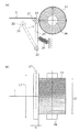
本実施の形態によるフィラメント巻き出し装置10は、フィラメント1が巻回されたボビン11に近接した位置に、円筒状のタッチロール20を備える。図2に示すように、タッチロール20の中心軸21は、ボビン11の回転軸19と平行になっている。なお、図2(a)は側面図、図2(b)は上面図である。
The filament unwinding
図2(b)に示すように、タッチロール20の軸方向の長さL1は、ボビン巻き出し範囲L2よりも長いことが好ましい。一例としてと、L2=300mmの場合、L1=350mm程度であるが好ましい。タッチロール20の直径αは、フィラメント1の巻き出し抵抗に影響がなく、かつフィラメント1の絡み付きが発生しない範囲で適切に設定すればよい。好ましくは、α=30mm程度である。
As shown in FIG.2 (b), it is preferable that the axial length L1 of the
タッチロール20は、固定支点22に揺動自在に一端が支持された支持アーム23の他端側に回動自在に取り付けられている。そして、支持アーム23は、先端側がボビン11の方に向けて揺動する方向に、適宜の付勢部材(例えばばね部材24)によって常時付勢されている。また、支持アーム23は、揺動端側に取り付けたタッチロール20が、前記付勢力によって、ボビン11に巻回されたフィラメント1の表面と常時、すなわち、フィラメント1の巻き出し開始から巻き出しの終了まで、接触することのできる位置に配置されている。
The
上記の構成であり、タッチロール20は、ボビン11に巻回されたフィラメント1の巻き出し開始時において、ボビン11の回転軸19から最も遠い位置にあり、フィラメント1が巻き出されていくにつれて次第に回転軸19に近づいていき、フィラメント1の終端が巻き出される時点で、ボビン11の回転軸19に最も接近した位置となる。
The
フィラメント巻き出し装置10は、さらに、タッチロール20の位置を検出する位置センサ31および支持アーム23の傾斜角度を検出する角度センサ32からなる検出部33を備え、検出部33からの信号は、ボビン回転駆動部12の回転速度を制御する回転速度制御部30に送られる。
The filament unwinding
位置センサ31は、例えば、ボビン11の回転軸19の中心を基準位置としたときのタッチロール20の座標位置を検出する。角度センサ32は、例えば、ボビン11に巻回されたフィラメント1の巻き出し開始時に、タッチロール20が巻回されたフィラメント表面に接触した位置にあるときの支持アーム23の傾斜角度位置を基準角度とし、フィラメント1が巻き出されていくにつれて次第にタッチロール20がボビン11の回転軸19の側に近づいていくときの支持アーム23の角度変化を検出する。支持アーム23の長さは一定であり、角度センサ32からの角度信号によっても、ボビン11の回転軸19の中心を基準位置としたときのタッチロール20の座標位置を演算することができる。この場合には、位置センサ31は、省略可能である。
For example, the position sensor 31 detects the coordinate position of the
回転速度制御部30は、位置センサ31または角度センサ32からの信号を受け、タッチロール20がボビン11に巻回されたフィラメント1の表面と接触している箇所と、ボビン11の回転軸19の中心との間の距離を演算し、そこから、その時点でのボビン11の直径を算出する。そして、そのときのボビン外径の周速が所定の速度となるようにボビン回転速度を演算する。演算結果を回転速度信号としてボビン回転駆動部12に発信し、ボビン回転駆動部12は、ボビン11を所要の回転速度で回転させる。
The rotation
前記のように、タッチロール20は、ボビン11に巻回されたフィラメント1の表面とフィラメント1の巻き出し開始から巻き出しの終了まで常に接触している。そのために、本実施の形態によるフィラメント巻き出し装置10では、フィラメント1の巻き出しによって漸減していくボビン11の外径を、常時かつ連続的に検出可能であり、その検出結果に基づいて、ボビン11の回転速度を連続的にかつ適切に制御することが可能となる。
As described above, the
なお、タッチロール20は、フィラメント1がボビン11から巻き出されるときの高さ規制具として機能させることもできる。ただし、タッチロール20の高さ位置は、揺動する支持アーム23の傾斜角度に依存する。そして、フィラメント1の巻き出し開始から巻き出しの終了までの支持アーム23の揺動角度の大小は、支持アーム23の長さに逆比例する。したがって、タッチロール20にフィラメント1がボビン11から巻き出されるときの高さ規制具としての機能を持たせるには、より長さの長い支持アーム23を用いることが望ましい。
The
1…フィラメント、
2…マンドレル、
3…回転軸、
10…フィラメント巻き出し装置、
11…ボビン、
12…ボビン回転駆動部、
13…揺動する巻き出しダンサ、
16…揺動する巻き取りダンサ、
19…ボビンの回転軸、
20…円筒状のタッチロール、
21…タッチロールの中心軸、
22…固定支点、
23…支持アーム、
24…ばね部材(付勢部材)、
30…回転速度制御部、
31…位置センサ、
32…角度センサ、
33…検出部、
40…フィラメント巻き付け装置、
100…フィラメントワインディング装置。
1 ... Filament,
2 ... Mandrel,
3 ... Rotation axis,
10 ... Filament unwinding device,
11 ... Bobbin,
12 ... Bobbin rotation drive unit,
13 ... swinging unwinder,
16 ... Oscillating winding dancer,
19 ... rotating shaft of bobbin,
20 ... cylindrical touch roll,
21 ... The center axis of the touch roll,
22 ... Fixed fulcrum,
23. Support arm,
24 ... Spring member (biasing member),
30: Rotational speed control unit,
31 ... Position sensor,
32 ... An angle sensor,
33 ... detection part,
40. Filament winding device,
100: Filament winding device.
Claims (1)
前記ボビン回転駆動部の回転速度を制御する回転速度制御部と、
前記ボビンから巻き出されたフィラメントに一定の張力を付与するための揺動するダンサと、
を備えたフィラメント巻き出し装置であって、
前記フィラメント巻き出し装置は、
前記ボビンに巻回されたフィラメント表面と接触することのできるタッチロールと、
前記タッチロールを前記ボビンに巻回されたフィラメント表面に接触した位置とフィラメント表面から離間した位置との間で揺動可能に支持する支持アームと、
前記支持アームを前記タッチロールが前記ボビンに巻回されたフィラメント表面と接触する方向に付勢する付勢部材と、
前記タッチロールの位置または前記支持アームの傾斜角度を検出する検出部と、
をさらに備え、
前記回転速度制御部は前記検出部の検出値に基づいて前記ボビン回転駆動部の回転速度を制御する、
ことを特徴とするフィラメント巻き出し装置。 A bobbin rotation drive unit that rotationally drives the bobbin around which the filament is wound;
A rotation speed control unit for controlling the rotation speed of the bobbin rotation drive unit;
A swinging dancer for applying a constant tension to the filament unwound from the bobbin;
A filament unwinding device comprising:
The filament unwinding device is:
A touch roll capable of contacting a filament surface wound around the bobbin;
A support arm that supports the touch roll so as to be swingable between a position in contact with the filament surface wound around the bobbin and a position spaced from the filament surface;
A biasing member that biases the support arm in a direction in which the touch roll comes into contact with a filament surface wound around the bobbin;
A detection unit for detecting a position of the touch roll or an inclination angle of the support arm;
Further comprising
The rotation speed control unit controls the rotation speed of the bobbin rotation driving unit based on a detection value of the detection unit;
A filament unwinding device.
Priority Applications (1)
| Application Number | Priority Date | Filing Date | Title |
|---|---|---|---|
| JP2018094348A JP2019199321A (en) | 2018-05-16 | 2018-05-16 | Filament unwinding device |
Applications Claiming Priority (1)
| Application Number | Priority Date | Filing Date | Title |
|---|---|---|---|
| JP2018094348A JP2019199321A (en) | 2018-05-16 | 2018-05-16 | Filament unwinding device |
Publications (1)
| Publication Number | Publication Date |
|---|---|
| JP2019199321A true JP2019199321A (en) | 2019-11-21 |
Family
ID=68611243
Family Applications (1)
| Application Number | Title | Priority Date | Filing Date |
|---|---|---|---|
| JP2018094348A Pending JP2019199321A (en) | 2018-05-16 | 2018-05-16 | Filament unwinding device |
Country Status (1)
| Country | Link |
|---|---|
| JP (1) | JP2019199321A (en) |
Cited By (2)
| Publication number | Priority date | Publication date | Assignee | Title |
|---|---|---|---|---|
| WO2023106396A1 (en) | 2021-12-10 | 2023-06-15 | 東レ株式会社 | Fiber bundle drawing device, method for drawing out fiber bundle, and method for manufacturing fiber composite material |
| CN117686356A (en) * | 2024-02-02 | 2024-03-12 | 长盛(廊坊)科技有限公司 | Carbon fiber unwinding testing device and testing method thereof |
Citations (2)
| Publication number | Priority date | Publication date | Assignee | Title |
|---|---|---|---|---|
| JPH02279218A (en) * | 1989-04-20 | 1990-11-15 | Seibu Electric & Mach Co Ltd | Residual quantity detecting device for wire electrode |
| JP2015024888A (en) * | 2013-07-25 | 2015-02-05 | 株式会社ジェイテクト | Filament winding method and filament winding device |
-
2018
- 2018-05-16 JP JP2018094348A patent/JP2019199321A/en active Pending
Patent Citations (2)
| Publication number | Priority date | Publication date | Assignee | Title |
|---|---|---|---|---|
| JPH02279218A (en) * | 1989-04-20 | 1990-11-15 | Seibu Electric & Mach Co Ltd | Residual quantity detecting device for wire electrode |
| JP2015024888A (en) * | 2013-07-25 | 2015-02-05 | 株式会社ジェイテクト | Filament winding method and filament winding device |
Cited By (4)
| Publication number | Priority date | Publication date | Assignee | Title |
|---|---|---|---|---|
| WO2023106396A1 (en) | 2021-12-10 | 2023-06-15 | 東レ株式会社 | Fiber bundle drawing device, method for drawing out fiber bundle, and method for manufacturing fiber composite material |
| KR20240118768A (en) | 2021-12-10 | 2024-08-05 | 도레이 카부시키가이샤 | Fiber bundle extraction device, fiber bundle extraction method, and manufacturing method of fiber composite material |
| CN117686356A (en) * | 2024-02-02 | 2024-03-12 | 长盛(廊坊)科技有限公司 | Carbon fiber unwinding testing device and testing method thereof |
| CN117686356B (en) * | 2024-02-02 | 2024-04-16 | 长盛(廊坊)科技有限公司 | Carbon fiber unwinding testing device and testing method thereof |
Similar Documents
| Publication | Publication Date | Title |
|---|---|---|
| KR102523109B1 (en) | Fiber tension control device and tension control method using the same | |
| JP6404018B2 (en) | Filament winding method and filament winding apparatus | |
| JP2007190697A (en) | Filament winding apparatus | |
| JP2019199321A (en) | Filament unwinding device | |
| TW201702169A (en) | Wire rod take-up device | |
| JP2015178403A (en) | Yarn winding machine and winding method | |
| JP2010235332A (en) | Optical fiber reeling device and method for reeling optical fiber | |
| JP2010042904A (en) | Yarn winding machine | |
| JP2002145527A (en) | Winder for especially delicate winding material | |
| JP2004360166A (en) | Device and method for regulating tension of running web | |
| JP2005255359A (en) | Filament winding device | |
| JP3171031U (en) | Turret winder cutting device | |
| JP3455737B2 (en) | Fishing line unit and fishing line winding device | |
| JP4134122B2 (en) | Reel tape winding device and winding method | |
| JP4162000B2 (en) | Yarn length measuring device for yarn winding device | |
| KR20180089948A (en) | Parallel Winding Device and Method | |
| CN111132918B (en) | Yarn winding machine | |
| JP2011088189A (en) | Device and method for controlling tension of rolled stock | |
| JP2004115170A (en) | Wire rewinding device | |
| JPH09329514A (en) | Wire tension detecting device | |
| JP3522868B2 (en) | Winding / rewinding control device | |
| JPH1160003A (en) | Take-up device | |
| JP7336825B2 (en) | Winding device and winding method | |
| TWI847002B (en) | Winding device and winding method | |
| JP2018192652A (en) | Filament winding apparatus |
Legal Events
| Date | Code | Title | Description |
|---|---|---|---|
| A621 | Written request for application examination |
Free format text: JAPANESE INTERMEDIATE CODE: A621 Effective date: 20210126 |
|
| A977 | Report on retrieval |
Free format text: JAPANESE INTERMEDIATE CODE: A971007 Effective date: 20211110 |
|
| A131 | Notification of reasons for refusal |
Free format text: JAPANESE INTERMEDIATE CODE: A131 Effective date: 20211116 |
|
| A02 | Decision of refusal |
Free format text: JAPANESE INTERMEDIATE CODE: A02 Effective date: 20220510 |