JP2019194567A - Thermal compensation vibrator manufacturing method - Google Patents
Thermal compensation vibrator manufacturing method Download PDFInfo
- Publication number
- JP2019194567A JP2019194567A JP2019034093A JP2019034093A JP2019194567A JP 2019194567 A JP2019194567 A JP 2019194567A JP 2019034093 A JP2019034093 A JP 2019034093A JP 2019034093 A JP2019034093 A JP 2019034093A JP 2019194567 A JP2019194567 A JP 2019194567A
- Authority
- JP
- Japan
- Prior art keywords
- balance wheel
- vibrating body
- spring
- selecting
- manufacturing
- Prior art date
- Legal status (The legal status is an assumption and is not a legal conclusion. Google has not performed a legal analysis and makes no representation as to the accuracy of the status listed.)
- Granted
Links
Images
Classifications
-
- G—PHYSICS
- G04—HOROLOGY
- G04B—MECHANICALLY-DRIVEN CLOCKS OR WATCHES; MECHANICAL PARTS OF CLOCKS OR WATCHES IN GENERAL; TIME PIECES USING THE POSITION OF THE SUN, MOON OR STARS
- G04B17/00—Mechanisms for stabilising frequency
- G04B17/04—Oscillators acting by spring tension
- G04B17/045—Oscillators acting by spring tension with oscillating blade springs
-
- B—PERFORMING OPERATIONS; TRANSPORTING
- B81—MICROSTRUCTURAL TECHNOLOGY
- B81B—MICROSTRUCTURAL DEVICES OR SYSTEMS, e.g. MICROMECHANICAL DEVICES
- B81B3/00—Devices comprising flexible or deformable elements, e.g. comprising elastic tongues or membranes
- B81B3/0064—Constitution or structural means for improving or controlling the physical properties of a device
- B81B3/0081—Thermal properties
-
- G—PHYSICS
- G04—HOROLOGY
- G04B—MECHANICALLY-DRIVEN CLOCKS OR WATCHES; MECHANICAL PARTS OF CLOCKS OR WATCHES IN GENERAL; TIME PIECES USING THE POSITION OF THE SUN, MOON OR STARS
- G04B17/00—Mechanisms for stabilising frequency
- G04B17/04—Oscillators acting by spring tension
- G04B17/06—Oscillators with hairsprings, e.g. balance
- G04B17/063—Balance construction
-
- G—PHYSICS
- G04—HOROLOGY
- G04B—MECHANICALLY-DRIVEN CLOCKS OR WATCHES; MECHANICAL PARTS OF CLOCKS OR WATCHES IN GENERAL; TIME PIECES USING THE POSITION OF THE SUN, MOON OR STARS
- G04B17/00—Mechanisms for stabilising frequency
- G04B17/04—Oscillators acting by spring tension
- G04B17/06—Oscillators with hairsprings, e.g. balance
- G04B17/066—Manufacture of the spiral spring
-
- G—PHYSICS
- G04—HOROLOGY
- G04B—MECHANICALLY-DRIVEN CLOCKS OR WATCHES; MECHANICAL PARTS OF CLOCKS OR WATCHES IN GENERAL; TIME PIECES USING THE POSITION OF THE SUN, MOON OR STARS
- G04B17/00—Mechanisms for stabilising frequency
- G04B17/20—Compensation of mechanisms for stabilising frequency
- G04B17/22—Compensation of mechanisms for stabilising frequency for the effect of variations of temperature
- G04B17/227—Compensation of mechanisms for stabilising frequency for the effect of variations of temperature composition and manufacture of the material used
-
- G—PHYSICS
- G04—HOROLOGY
- G04B—MECHANICALLY-DRIVEN CLOCKS OR WATCHES; MECHANICAL PARTS OF CLOCKS OR WATCHES IN GENERAL; TIME PIECES USING THE POSITION OF THE SUN, MOON OR STARS
- G04B17/00—Mechanisms for stabilising frequency
- G04B17/32—Component parts or constructional details, e.g. collet, stud, virole or piton
- G04B17/34—Component parts or constructional details, e.g. collet, stud, virole or piton for fastening the hairspring onto the balance
-
- G—PHYSICS
- G04—HOROLOGY
- G04B—MECHANICALLY-DRIVEN CLOCKS OR WATCHES; MECHANICAL PARTS OF CLOCKS OR WATCHES IN GENERAL; TIME PIECES USING THE POSITION OF THE SUN, MOON OR STARS
- G04B18/00—Mechanisms for setting frequency
- G04B18/04—Adjusting the beat of the pendulum, balance, or the like, e.g. putting into beat
Abstract
Description
本発明は、時計振動体、及び振動体を含む時計ムーブメントと時計自体に関する。最後に、本発明は、当該振動体の製造方法に関する。 The present invention relates to a timepiece vibration body, a timepiece movement including the vibration body, and the timepiece itself. Finally, the present invention relates to a method for manufacturing the vibrator.
機械式小型時計の調整は、少なくとも1つの機械式振動体に依拠し、機械式振動体は一般的には、てん輪と呼ばれるフライホイールと、ひげぜんまいまたは単に渦巻きと呼ばれる螺旋形に巻かれたぜんまいを含む。渦巻きは、一端をてん輪の心棒に、他端をてん輪の心棒がその上で旋回する受などの時計の固定部分に、固定されてもよい。従来の機械式小型時計のムーブメントが備えるひげぜんまいは、多くは螺旋に巻かれる、好ましくは長方形断面の弾性金属ブレードまたはシリコン製ブレードの形状を取る。巻かれたてん輪は、その均等位置(または死点)周りに振動する。てん輪が当該位置を離れると、渦巻きを装填する。これにより、てん輪を均等位置に戻しやすくするために、てん輪に作用する戻しトルクが発生する。てん輪は、一定の速度を、ひいては一定の運動エネルギーを獲得したことにより、その死点を超えて、渦巻きの対抗トルクがてん輪を止めて反対方向に回転させるまで移動する。このように、渦巻きは、てん輪の振動周期を調整する。 The adjustment of a mechanical small watch relies on at least one mechanical vibrator, which is typically wound into a flywheel called a balance wheel and a spiral called a balance spring or simply a spiral. Includes mainspring. The spiral may be fixed at one end to the balance of the balance wheel and at the other end to a fixed portion of the watch, such as a receiver on which the balance of the balance is pivoted. The mainspring of the movement of a conventional mechanical small watch takes the form of an elastic metal blade or a silicon blade, preferably of a rectangular cross-section, which is wound in a spiral. The wound balance wheel vibrates around its equal position (or dead center). When the balance wheel leaves the position, the spiral is loaded. Thereby, in order to make it easy to return the balance wheel to the uniform position, a return torque acting on the balance wheel is generated. The balance wheel gains a constant speed, and thus a constant kinetic energy, so that it moves beyond its dead center until the counter torque of the spiral stops the balance wheel and rotates it in the opposite direction. In this way, the spiral adjusts the vibration period of the balance wheel.
機械式小型時計の正確性は、てん輪と渦巻きで形成される振動体の振動の規則性に左右される。その振動は、てん輪の慣性と渦巻きの剛性により設定され、正確性を持って所定の周波数を達成するためには、例えばぜんまいの剛性に影響を与える調節要素を用いたり、所定の渦巻きと特定のてん輪と適切に組み合わせるなど、いくつかの方法がある。このような組み合わせは、必要な調節を限定することをも可能にする。 The accuracy of a mechanical type small timepiece depends on the regularity of vibration of a vibrating body formed by a balance wheel and a spiral. The vibration is set by the inertia of the balance wheel and the stiffness of the spiral, and in order to achieve a predetermined frequency with accuracy, for example, using an adjustment element that affects the stiffness of the mainspring or identifying the predetermined spiral There are several ways to properly combine it with the balance wheel. Such a combination also makes it possible to limit the necessary adjustments.
しかしながら、温度が変化すると、渦巻きとてん輪のそれぞれの熱膨張が当該振動体の性質を修正し、ひいては小型時計の正確性を乱す。 However, when the temperature changes, the thermal expansion of each of the spirals and the balance wheel corrects the properties of the vibrating body and thus disturbs the accuracy of the small timepiece.
温度による振動体の機能的変化を減少させ、さらには防止することを試みる従来技術の解決策が存在する。1つのアプローチは、渦巻きの角度剛性に対応しており、てん輪上の渦巻きにより発揮される戻しトルクCと、てん輪の慣性モーメントIの、以下の関係による比によって決まる当該振動体の固有振動数fを検討する。

前述の等式を温度に関して微分することにより、振動体の固有振動数の熱的変動が得られ、当該熱変動は以下の等式で表される。
αsとαbは、それぞれ振動体の渦巻きとてん輪の熱膨張係数である。
By differentiating the above equation with respect to temperature, a thermal fluctuation of the natural frequency of the vibrating body is obtained, and the thermal fluctuation is expressed by the following equation.
α s and α b are the thermal expansion coefficients of the spiral and balance wheel of the vibrating body, respectively.
さまざまな従来技術の解決策は、振動体を熱補償するために、この目的に適したCTEの渦巻きを選択することで、振動体の熱係数CTの値をゼロにすることを試みる。 Various prior art solutions attempt to zero the value of the thermal coefficient CT of the vibrator by selecting a CTE vortex suitable for this purpose in order to thermally compensate the vibrator.
本発明の目的は、所定の振動数を確実に達成するために、振動体の熱補償を保証するだけでなく、てん輪とその角度戻しばねの組み合わせを向上させる、部品組み合わせ方法を用いて得られた時計振動体を提供することである。 The object of the present invention is obtained by using a component combination method that not only guarantees thermal compensation of the vibrating body but also improves the combination of the balance wheel and its angle return spring in order to reliably achieve a predetermined frequency. It is to provide a watch vibration body.
このため、本発明は、時計振動体が熱補償される一方、いかなる調整も必要とせずに、または少なくとも最低限の調整しか必要とせずに、所定の周波数で振動するよう、温度に基づく角度剛性の変化が異なる少なくとも2つの別個の部分の配置を含む角度戻しばねの、既知の慣性を有するてん輪との関連づけにより時計振動体を形成することを含む。 For this reason, the present invention provides a temperature-based angular stiffness so that the watch vibrator is thermally compensated while vibrating at a predetermined frequency without any adjustment or at least with minimal adjustment. Forming a timepiece vibrator by associating an angle return spring comprising an arrangement of at least two separate parts with different variations of the balance wheel with a known inertia.
このため、本発明は、てん輪と、平行に配置された少なくとも2つのばね部分とから構成される時計振動体の製造方法であって、前記製造方法は、
− 任意で、事前にてん輪の素材とばね部分の素材を選択するステップと、
a. 前記振動体の周波数fを選択するステップと、その後
b. 前記てん輪の前記慣性と前記ばね部分の前記角度剛性が、選択された周波数fの振動体の形成を可能にし、温度の係数としての前記ばね部分の角度剛性の変化が前記振動体を熱補償可能にするよう、てん輪とばね部分を選択するステップと、
c. 選択されたばね部分を選択されたてん輪と組み立てるステップ
を含む、振動体の製造方法に関する。
For this reason, the present invention is a method of manufacturing a timepiece vibrating body including a balance wheel and at least two spring portions arranged in parallel, and the manufacturing method includes:
-Optionally selecting a material for the pre-rotating wheel and a material for the spring part;
a. Selecting a frequency f of the vibrating body; and b. The inertia of the balance wheel and the angular stiffness of the spring portion enable the formation of a vibrating body with a selected frequency f, and the change in angular stiffness of the spring portion as a coefficient of temperature thermally compensates the vibrating body. Selecting the balance wheel and spring part to allow
c. The present invention relates to a method of manufacturing a vibrating body, comprising assembling a selected spring portion with a selected balance wheel.
ばね部分を選択するステップ(b)は、少なくとも2つのバッチまたは既存のばね部分の少なくとも2つの組から最適なばね部分を選定することを含むまたは選択することからなる。 The step (b) of selecting a spring part comprises or comprises selecting an optimal spring part from at least two batches or at least two sets of existing spring parts.
一実施形態によれば、方法は、
− てん輪とひげぜんまいの部分の素材を選択するステップと、ここで当該部分は場合によっては異なる素材製である、
− 振動体の周波数fを選択するステップと、
− てん輪の慣性Iを測定または推定するステップと、
− 前記ばねの各部分iの角度剛性Ciを、
− それぞれの角度剛性が計算された値Ciに近似するばね部分iを選択するステップと、
− 少なくとも2つの選択されたばねの部分をてん輪と組み立てるステップ
を含む。
According to one embodiment, the method comprises:
-Selecting a material for the balance wheel and the hairspring part, where the part is possibly made of a different material;
-Selecting the frequency f of the vibrator;
-Measuring or estimating the inertia I of the balance wheel;
The angular stiffness Ci of each part i of the spring,
-Selecting a spring part i whose respective angular stiffness approximates the calculated value Ci;
-Assembling at least two selected spring parts with the balance wheel.
本発明はまた、当該方法を用いて得られた時計振動体と、時計自体にも関する。 The present invention also relates to a timepiece vibrator obtained by using the method and the timepiece itself.
本発明はより詳細には請求項に定義される。 The invention is more particularly defined in the claims.
本発明の対象、特徴、及び利点は、添付の図面を参照して与えられる、特定の非限定的実施形態についての以下の説明において、より詳細に説明される。 Objects, features, and advantages of the present invention will be described in more detail in the following description of specific non-limiting embodiments, given with reference to the accompanying drawings.
本発明の目的は、調節を必要としないかもしくは非常にわずかな調整しか必要としない、熱補償振動体を提供することである。このため、振動体の熱係数(CT)が0に限りなく近い値であり、このため、当該振動体の振動が温度とは無関係にまたはほぼ無関係になる値を達成する解決策、また「てん輪」と呼ばれるフライホイールと、事前に選択され設定される、必要な振動数を保証する戻しばねの組み合わせの解決策が、求められる。 It is an object of the present invention to provide a thermally compensated oscillator that requires no adjustment or very little adjustment. For this reason, the thermal coefficient (CT) of the vibrating body is a value as close to zero as possible, and therefore, a solution that achieves a value at which the vibration of the vibrating body becomes independent or almost independent of temperature, There is a need for a solution that combines a flywheel, called a “ring”, with a pre-selected and set return spring that guarantees the required frequency.
以後説明する本発明の実施形態は、温度にかかわらず振動体の選択された固有振動数を保証するため、所定のてん輪に、より具体的には熱補償振動体を得るためにその慣性が測定されたてん輪に結合される角度戻しばねを形成するよう選択される、少なくとも2つの別個の角度戻しばね部分を関連付けることにより得られる、振動体の構造に基づく。 The embodiments of the present invention to be described hereinafter have the inertia to obtain a predetermined balance wheel, more specifically, a heat-compensated vibrator, in order to guarantee the selected natural frequency of the vibrator regardless of temperature. Based on the structure of the vibrator obtained by associating at least two separate angle return spring portions selected to form an angle return spring coupled to the measured balance wheel.
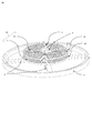
本発明は、時計振動体がてん輪−ぜんまい組立体の形状を取る、図1に示す一実施形態を用いてより詳細に説明される。振動体の角度戻しばね10は、「二重渦巻き」の形状を取り、2つの渦巻き11、12の平行配置を含む。「平行」の表現は、2つの渦巻きのそれぞれを、一方ではてん輪の心棒5へ、例えば1つまたは2つのコレット6を用いて取付け、他方ではてんぷ受へ、例えばそれぞれの末端15、16に接続された1つまたは2つのスタッドを用いて取付けることを意味する。この角度戻しばねは、アーム2により心棒5に接続されるフライホイールまたはてん輪1へ作用する。これら部品は、全体で機械式振動体を形成する。
The invention will be explained in more detail with the aid of an embodiment shown in FIG. 1 in which the watch vibrator takes the form of a balance wheel-spring assembly. The vibrating body
本実施形態において、角度戻しばねのそれぞれの別個の部分は、1つ以上の巻または巻セグメントを含む、渦巻きまたは渦巻きセグメントから形成される。「巻」の文言は、約360°の円弧にわたり延長する渦巻きのセグメントを定義し、「巻セグメント」の文言は、360°より小さい円弧にわたり延長するセグメントを定義する。加えて、本発明の実施形態の各渦巻き、巻または巻セグメントは、渦巻きに巻かれて、好ましくは長方形の断面の、弾性ブレードの形状を取る。eは厚みを表し、hは長方形断面の高さを表す。加えて、Lは渦巻き、巻または巻セグメントの曲線長さを表す。曲線長さは、巻の中立素分上の、2つの曲線の横軸間の分離として定義される。最後に、rは、てん輪の回転半径を表し、mはその質量を表す。 In this embodiment, each separate portion of the angle return spring is formed from a spiral or spiral segment that includes one or more turns or winding segments. The term “wind” defines a spiral segment that extends over an arc of about 360 ° and the term “wind segment” defines a segment that extends over an arc that is less than 360 °. In addition, each swirl, turn or turn segment of an embodiment of the present invention is wound into a swirl and takes the form of an elastic blade, preferably of rectangular cross section. e represents the thickness, and h represents the height of the rectangular cross section. In addition, L represents the curvilinear length of the spiral, winding or winding segment. The curve length is defined as the separation between the horizontal axes of the two curves on the neutral element of the winding. Finally, r represents the turning radius of the balance wheel and m represents its mass.
渦巻きの組は、同一素材製の渦巻き、巻または巻セグメントからなる。渦巻き、巻または巻セグメントのバッチは、形状の製作公差内で同一と見做すことができる渦巻き、巻または巻セグメントの組である。 A set of spirals consists of spirals, windings or winding segments made of the same material. A batch of spirals, windings or winding segments is a set of spirals, windings or winding segments that can be considered identical within the manufacturing tolerances of the shape.
ここで、「素材」の文言は、単一の均一な素材、または所定の配置の素材の組み合わせに由来する複合素材のいずれかを意味するために用いられる。非限定的な例として、所定の厚さの酸化シリコンで全ての面が被膜された単結晶シリコン製の渦巻きは、複合素材と見做される。 Here, the term “material” is used to mean either a single uniform material or a composite material derived from a combination of materials in a predetermined arrangement. As a non-limiting example, a single crystal silicon spiral coated on all sides with a predetermined thickness of silicon oxide is considered a composite material.
平行に配置された2つの渦巻き(または巻または巻セグメント)の場合、熱補償への渦巻きの貢献は、その戻しトルクへの、このため角度剛性への相対的寄与で重み付けされる。 In the case of two spirals (or windings or winding segments) arranged in parallel, the contribution of the spiral to the thermal compensation is weighted by its relative contribution to its return torque and thus to the angular stiffness.
戻しばねの戻しトルクは、2つの渦巻きのトルクの合計である。振動体の固有振動数fは、以下の式で記載することができる。
一般に、等式(1)は以下のようになる。
In general, equation (1) becomes:
慣性Iと、純粋な屈曲のため定義される角度剛性Ciは、以下の通り計算される。
![]()
Eiは渦巻きiの素材の弾性率であり、eiは渦巻きiのブレードの厚さであり、hiは渦巻きiのブレードの高さであり、liは渦巻きiの曲線長さである。
The inertia I and the angular stiffness Ci defined for pure bending are calculated as follows:
![]()
Ei is the elastic modulus of the material of spiral i, ei is the thickness of the blade of spiral i, hi is the height of the blade of spiral i, and li is the curve length of spiral i.
温度依存の項であるIとCiを導入し、等式(1)を温度について微分すると、整理後には以下の等式が得られる。
渦巻きの場合、等式(2)は、以下のようになる。
均一且つ等方性の素材を考察する場合、または各素材について適切な見かけの膨張係数を用いる場合、素材の熱膨張係数α=1/x*dx/dTは、上で定義された方向x(r、L、e及びh)について同一である。更に、もしCTEの項が弾性係数1/E.dE/dTの熱係数として定義された場合、前述の等式は以下の通り単純化することができる。
当該第1実施形態は2つの渦巻き(i=2)を含むため、前述の等式は以下の通りになる。
てん輪の素材が定義されると、αbalの値が既知数となり、等式(3)を満たす結果を、平面[C1;C2]の平面上の直線で表すことができる。このため、当該等式を満たす解C1, C2の組は多数存在する。当業者であれば、当該等式の解が得られるように、てん輪及び渦巻き(または巻または巻セグメント)の素材を適切に選択することができる。 When the balance wheel material is defined, the value of α bal becomes a known number, and the result satisfying equation (3) can be represented by a straight line on the plane [C 1 ; C 2 ]. For this reason, there are many pairs of solutions C 1 and C 2 that satisfy the equation. A person skilled in the art can appropriately select the material of the balance wheel and the spiral (or winding or winding segment) so that the solution of the equation can be obtained.
てん輪の慣性が既知の場合、所定の平面において、等式(1)を用いて、等式(1)が0に等しく設定された場合の等式(1)の解に対応する他の直線を描くことが可能になる。単にこれら2本の直線の交点に対応する角度剛性C1及びC2を有する渦巻き部分を選択し、これら2つの部分を、その後振動体を形成するためにてん輪と組み立てることができる、渦巻きを形成するために組立てることにより、必要な周波数で振動する、熱補償振動体の製造を保証する。 When the inertia of the balance wheel is known, in a given plane, using equation (1), another straight line corresponding to the solution of equation (1) when equation (1) is set equal to 0 It becomes possible to draw. Simply select the spiral part with the angular stiffnesses C1 and C2 corresponding to the intersection of these two straight lines, and then form these two parts that can then be assembled with the wheel to form a vibrating body. Assembling for this purpose guarantees the production of a heat-compensated vibrator that vibrates at the required frequency.
異方性素材の、例えばシリコンの場合、熱係数は、素材への応力の結晶方向に応じて変化し、このため渦巻きの(または巻のまたは巻セグメントの)長さにわたり変化する。同様に、酸化ケイ素など不均一素材の場合、熱係数はブレードの断面の内部で変化する。このため当業者に既知の同等または見かけCTEを、異方性及びまたは不均一素材製の渦巻きまたは巻または巻セグメントについて検討することができる。 In the case of an anisotropic material, for example silicon, the thermal coefficient varies depending on the crystal direction of the stress on the material and thus varies over the length of the spiral (or of the winding or winding segment). Similarly, for non-uniform materials such as silicon oxide, the thermal coefficient changes within the blade cross section. Thus, equivalent or apparent CTEs known to those skilled in the art can be considered for spirals or windings or winding segments made of anisotropic and / or non-uniform materials.
例えば、てん輪がCuBe2製の場合、CuBe2の熱膨張は正(+17ppm/℃)であるため、2つの渦巻きの素材を、等式をゼロにするために少なくとも2つの項CTE+αsのうちの1つが正となるように、具体的には2つの項CTE+αsの少なくとも1つが、等式をゼロにするために、少なくとも2×αbalよりも高くなるように、選択することが必要である。単に2つの渦巻きの寸法を、特にその角度剛性を調節することにより、求める結果を、すなわち振動体の熱補償を得ることができる。
For example, if the balance wheel is made of
例として、4Hzで振動する振動体において、最初に、測定された慣性が14.28mg・cm2であるCuBe2製のてん輪を検討する。次に、{100}平面に開裂され、Emean=148GPa、α=2.6ppm/℃、CTE=−64.3ppm/℃、150ミクロンの高さ、150mmの有効長、36.5μmに近い厚さの性質と寸法を持つ単結晶シリコン製の渦巻きS1のバッチを検討する。加えて、E=72.4GPa、α=0.382ppm/℃、CTE=210ppm/℃であり、第1バッチの渦巻きと同一寸法であり、振動体を製造するためにてん輪に平行に取付けられる性質と寸法を持つ非晶質SiO2製の渦巻きの第2バッチS2を検討する。4Hzの周波数は、2つの渦巻きのバッチから、角度剛性C1が5.97×10−7Nm(厚さ36.445μmに相当する)である第1渦巻きS1aと、角度剛性C2が3.05×10−7Nm(厚さ36.975μmに相当する)である第2渦巻きS2aとを選択することで得られる。これら2つの渦巻きは、渦巻きを形成するために取付けられ、その後てん輪に取付けられて、4Hzの周波数で振動する熱補償振動体を形成する。 As an example, consider a balance wheel made of CuBe2 having a measured inertia of 14.28 mg · cm 2 in a vibrating body that vibrates at 4 Hz. Next, cleaved into the {100} plane, Emean = 148 GPa, α = 2.6 ppm / ° C., CTE = −64.3 ppm / ° C., 150 micron height, 150 mm effective length, thickness close to 36.5 μm. Consider a batch of single crystal silicon spiral S1 having the following properties and dimensions: In addition, E = 72.4 GPa, α = 0.382 ppm / ° C., CTE = 210 ppm / ° C., the same dimensions as the first batch of swirls, and mounted parallel to the wheel for producing the vibrating body. Consider a second batch S2 of amorphous SiO 2 spiral with properties and dimensions. A frequency of 4 Hz is obtained from a batch of two spirals, a first spiral S1a having an angular stiffness C1 of 5.97 × 10 −7 Nm (corresponding to a thickness of 36.445 μm), and an angular stiffness C2 of 3.05 ×. It is obtained by selecting the second spiral S2a that is 10 −7 Nm (corresponding to a thickness of 36.975 μm). These two vortices are attached to form a vortex and then attached to the balance wheel to form a thermally compensated oscillator that vibrates at a frequency of 4 Hz.
上で定義した複合素材について、CTEは、当業者に既知の方法で、使用された素材それぞれのCTEから計算され、各種素材の形状配置により重みづけされる。 For the composite material defined above, the CTE is calculated from the CTE of each used material in a manner known to those skilled in the art and is weighted by the shape arrangement of the various materials.
等式(3)で与えられる振動体の熱係数は、整理後、以下の通りCTE2+3α2の目的値を定義することを可能にする。
このため、渦巻きについてその剛性と温度の関数としての剛性変化(CTE+3α)が知られれば、CTをゼロに等しくすることができる第2渦巻きを選択することが可能になる。2つの渦巻きは、その後、目的の周波数を得るために、適切な慣性のてん輪と組むことが可能になる。 Thus, if the stiffness change (CTE + 3α) as a function of stiffness and temperature is known for the spiral, it is possible to select a second spiral that can make CT equal to zero. The two spirals can then be combined with the appropriate inertia balance to obtain the desired frequency.
複合素材製の例として、CuBe2製で測定慣性が14.12mg・cm2であるてん輪からなる4Hzで振動する振動体について、単結晶シリコン製の渦巻きSiのバッチを検討する。渦巻きは、{100}平面に開裂され、全ての面を3.5μmの厚さの非晶質酸化シリコンの層でコーティングされ、157ミクロンの高さと有効長150mmと39μmに近い厚さとを有する複合渦巻きが形成される。渦巻きの角度剛性はそれぞれ測定され、全ての渦巻きは4.5×10⁻⁷Nmに近い範囲に位置される。
これら複合渦巻きのCTEは、シリコンと非晶質酸化シリコンのCTE値と、渦巻きの形状(シリコンと酸化物のそれぞれの厚さ)から計算することができる。
4Hzの周波数は、複合渦巻きの当該バッチの中から、角度剛性C1が4.8665×10⁻⁷Nmである第1渦巻きと、角度剛性C2が4.0533×10⁻⁷Nmである第2渦巻きとを選択することにより得られる。これら2つの渦巻きは、渦巻きを形成するため組み立てられ、その後渦巻きはてん輪と組み立てられて、4Hzの周波数で振動する熱補償振動体を形成する。
As an example of a composite material, a batch of spiral Si made of single crystal silicon is examined for a vibrating body that vibrates at 4 Hz made of a balance wheel made of CuBe 2 and having a measurement inertia of 14.12 mg · cm 2 . The spiral is cleaved into the {100} plane, coated on all sides with a layer of amorphous silicon oxide with a thickness of 3.5 μm, a composite with a height of 157 microns, an effective length of 150 mm and a thickness close to 39 μm A swirl is formed. The angular stiffness of the vortex is measured respectively, and all the vortices are located in a range close to 4.5 × 10 −7 Nm.
The CTE of these composite spirals can be calculated from the CTE values of silicon and amorphous silicon oxide, and the spiral shapes (thicknesses of silicon and oxide).
The frequency of 4 Hz is a first spiral having an angular stiffness C1 of 4.8665 × 10 −7 Nm and a second spiral having an angular stiffness C2 of 4.0533 × 10 −7 Nm. Can be obtained by selecting. These two vortices are assembled to form a vortex, and then the vortex is assembled with a balance wheel to form a thermally compensated oscillator that vibrates at a frequency of 4 Hz.
要約すれば、本発明の当該実施形態は、てん輪と、平行に配置される少なくとも2つの戻しばね部分iで構成される時計振動体の製造方法に基づき、当該方法は、以下のステップを含む。
− てん輪とひげぜんまいの部分の素材を選択するステップと、ここで当該部分は場合により異なる素材製である、
− 振動体の周波数fを選択するステップと、
− てん輪の慣性Iを測定、推定または評価するステップと、
−
− 少なくとも2つのぜんまいの選択部分とてん輪とを組み立てるステップ。
In summary, the embodiment of the present invention is based on a method of manufacturing a timepiece vibrating body composed of a balance wheel and at least two return spring portions i arranged in parallel. The method includes the following steps: .
-Selecting the material of the balance wheel and hairspring part, where the part is made of a different material in some cases,
-Selecting the frequency f of the vibrator;
-Measuring, estimating or evaluating the inertia I of the balance wheel;
−
Assembling at least two selected mainsprings and a balance wheel;
当然、上記の等式(2’)を0に等しくし、所望の周波数で振動する熱補償振動体を得るための、寸法が異なる2つの渦巻きとてん輪の平行の配置には多数の可能性が存在する。 Naturally, there are a number of possibilities for the parallel arrangement of two spirals and balance wheels of different dimensions in order to make the above equation (2 ′) equal to 0 and to obtain a thermally compensated oscillator that vibrates at the desired frequency. Exists.
第1実施形態の一つの変形例は、少なくとも2つの渦巻きのバッチから選択され、戻しばねの3つの別個の部分を形成する、3つの渦巻きの平行の配置で形成される振動体の角度戻しばねに基づく。この変形例は振動体の調整を完全に不要にすることを可能にするため、及びまたは性質及びまたは寸法が著しく異なるぜんまい部分を組み合わせることを可能にするためだけでなく、温度の関数としての熱係数の変化の符号が逆である素材の使用の場合に有益な二次熱補償を達成するために、ぜんまい部分の組み合わせの数を増加することを可能にする。 One variant of the first embodiment is an angular return spring of a vibrating body formed from a parallel arrangement of three spirals, selected from a batch of at least two spirals and forming three separate parts of the return spring. based on. This variant not only makes it possible to completely eliminate the adjustment of the vibrating body and / or to allow the combination of spring parts with significantly different properties and / or dimensions, but also as a function of temperature. In order to achieve secondary heat compensation that is beneficial in the case of the use of materials with opposite sign of coefficient change, it is possible to increase the number of mainspring combinations.
このため、本発明は、所定の振動周波数を正確さを持って達成し、その後の調節を制限または回避するため、てん輪と渦巻きとの組み合わせの柔軟性を向上させることで、高性能な時計振動体の製造を可能にし、温度変化にもかかわらず所定の振動周波数を維持する振動体を形成する、という利点を有する。 For this reason, the present invention achieves a predetermined vibration frequency with accuracy, and limits or avoids subsequent adjustments, so that the flexibility of the combination of the balance wheel and the spiral is improved, thereby improving the performance of the high-performance timepiece. This has the advantage of allowing the manufacture of a vibrating body and forming a vibrating body that maintains a predetermined vibration frequency despite temperature changes.
当然、本発明は上述の実施形態や、説明した実施例や、上述の簡単な等式に限定されない。本発明は、特に3つ以上の別個の戻しばね部分を含んでもよい。 Of course, the present invention is not limited to the embodiments described above, the examples described, or the simple equations described above. The present invention may particularly include three or more separate return spring portions.
更に、戻しばねの別個の部分は、同一平面状に配置されてもされなくてもよい。例えば巻または巻セグメントの形状を取る戻しばねの少なくとも1つの別個の部分のブレードは、あらゆる形状の断面を有してもよく、前述の実施形態のように長方形でなくてもよい。加えて、当該断面は、その長さ全てで一定に維持されてもよく、反対に変更してもよい。最後に、戻しばねの別個の部分は、前述の実施例で予測されたように、渦巻きの形状を取ってもよく、変形例として他のあらゆる形状、具体的には直線状ブレードの形状を取ってもよい。 Further, the separate portions of the return spring may or may not be coplanar. The blades of at least one separate part of the return spring, for example in the form of a winding or winding segment, may have a cross section of any shape and may not be rectangular as in the previous embodiments. In addition, the cross section may remain constant throughout its length, or may be changed in the opposite direction. Finally, the separate part of the return spring may take the form of a spiral, as predicted in the previous embodiment, and could take any other shape, in particular a straight blade. May be.
最後に、戻しばねの別個の部分とは、所定の配置に位置され、全体で戻しばねを形成する2つ以上の別個の要素を意味する。当該配置において、振動体に熱補償効果を提供するよう、別個の部分は同じ戻しばね機能に補完的方法で参加する。別個の部分は、熱補償効果と、振動体の周波数の正確な選択を組み合わせるように、選択される。これら別個の部分は、あらゆる締結手段により互いに取付けられ、または単に近接して位置される。いずれにせよ、別個の部分は、所定のフライホイールと作用可能なように、また単一の時計振動体を形成するように、配置される。このため、別個の部分は、2つの区域が異なる素材を含んでいたとしても、単に一体に形成され、分離不能及びまたはモノリシックである所定のばねの単なる2つの区域ではない。 Finally, a separate part of the return spring means two or more separate elements that are located in a predetermined arrangement and together form a return spring. In this arrangement, the separate parts participate in the same return spring function in a complementary manner so as to provide a thermal compensation effect for the vibrator. The separate part is selected to combine the thermal compensation effect and the exact selection of the frequency of the vibrator. These separate parts are attached to each other by any fastening means or simply located close together. In any case, the separate parts are arranged to be able to work with a given flywheel and to form a single watch oscillator. Thus, the separate parts are not just two areas of a given spring that are simply formed in one piece, inseparable and / or monolithic, even though the two areas contain different materials.
このため、熱補償振動体を製造するために、少なくとも2つの渦巻きを組み合わせることが可能になり、振動体の周波数を調整するために2つの渦巻きを1つの特定のてん輪と組み合わせることが可能になる。 This makes it possible to combine at least two spirals to produce a thermally compensated oscillator, and to combine two spirals with one specific balance wheel to adjust the frequency of the oscillator Become.
てん輪は、前述の実施形態で示すように、既知の方法で、例えば銅ベリリウム合金(単にCuBe2合金とも呼ばれる)製である。変形例として、てん輪は他の素材が使用されてもよい。 The balance wheel is made of a known method, for example, a copper beryllium alloy (also simply referred to as a CuBe2 alloy) as shown in the above-described embodiment. As a modification, other materials may be used for the balance wheel.
有利には、角度戻しばねの少なくとも2つの別個の部分は、2つの異なる素材製である。別個の部分は一体に形成されてもよい。単一の素材製でもよく、複数の異なる素材を含んでもよく、例えば異なる素材製の区域を含んでもよい。 Advantageously, the at least two separate parts of the angle return spring are made of two different materials. The separate parts may be integrally formed. It may be made of a single material, may include a plurality of different materials, for example, may include areas made of different materials.
いずれにせよ、本発明の戻しばねは、当該時計戻しばねを含む発振体が熱補償されるよう、その熱の係数としての、項CTE+3αsで表わされる角度剛性Ciの変化が関連するてん輪の熱膨張を補償する、少なくとも2つの別個の部分を含む。 In any case, the return spring of the present invention has a heat of the balance wheel associated with a change in the angular stiffness Ci represented by the term CTE + 3αs as a coefficient of heat so that the oscillator including the timepiece return spring is thermally compensated. It includes at least two separate parts that compensate for expansion.
当然、戻しばねの別個の部分はその他の素材製であってもよい。好ましくは、磁場に曝された部品の残留磁化に関連するムーブメントの混乱を避けるため、磁場に不感の素材が好まれる。 Of course, the separate part of the return spring may be made of other materials. Preferably, a magnetic field insensitive material is preferred to avoid movement disruptions associated with the remanent magnetization of components exposed to the magnetic field.
少なくとも戻しばねの1つの別個の部分の全部または一部は、その向きが不問である単結晶シリコン、ポリシリコン、非晶質シリコン、石英、非晶質酸化シリコン、ドーパントのタイプと濃度が不問であるドープシリコン、多孔質シリコン、ヤング率の熱係数(以下のCTE)が正であるFe−Ni基合金、及びまたはNb−Zr−O合金を含んでもよい。 At least all or part of one separate part of the return spring may be of any type and concentration of single crystal silicon, polysilicon, amorphous silicon, quartz, amorphous silicon oxide, dopant, whose orientation is not questioned. It may include some doped silicon, porous silicon, Fe—Ni based alloy having a positive Young's modulus thermal coefficient (hereinafter CTE), and / or Nb—Zr—O alloy.
少なくとも戻しばねの1つの別個の部分は、1以上の等方性素材を含んでもよい。変形例として、戻しばねの別個の部分は、その熱係数が素材への応力の結晶方向に応じて変化し、このため渦巻きの長さにわたり変化する異方性素材を、例えばシリコンを含んでもよい。シリコンは、例えば、酸化シリコンの層で被膜されてもよい。酸化シリコンのように非均一素材の場合、熱係数は、戻しばねのブレードの断面の内部で変化する。当業者には既知の、項dC/dTまたは同等または見かけCTEが、異方性及びまたは非均一素材製の別個の戻しばね部分について検討され、前述の計算はこれを基に適用可能に維持される。 At least one separate portion of the return spring may include one or more isotropic materials. As a variant, the separate part of the return spring may comprise an anisotropic material whose thermal coefficient changes according to the crystallographic direction of the stress on the material and thus varies over the length of the spiral, for example silicon. . The silicon may be coated with a layer of silicon oxide, for example. In the case of non-uniform materials, such as silicon oxide, the thermal coefficient varies within the cross section of the return spring blade. The term dC / dT or equivalent or apparent CTE, known to those skilled in the art, is considered for a separate return spring portion made of anisotropic and / or non-homogeneous material, and the above calculations are maintained based on this. The
上述の実施形態は、上述の順番で実行される各種ステップを定義する。しかしながら、本発明は、変形例として、特に説明したステップのいくつかの順番を逆転することからなる異なるアプローチを用いて実施されてもよい。 The above-described embodiments define various steps that are executed in the order described above. However, the invention may alternatively be implemented using a different approach consisting of reversing several orders of the steps specifically described.
特に、説明した方法は、事前にてん輪を選択しその慣性Iをその後測定または推定することを含み、または反対に事前に選択された慣性Iのてん輪を構成または選択することを含み、その後選択したてん輪に適切な戻しばねを構成するためにばね部分を選択する。 In particular, the described method includes selecting a pre-rotation wheel and then measuring or estimating its inertia I, or conversely configuring or selecting a pre-selected inertia I balance wheel, and thereafter A spring portion is selected to construct a return spring appropriate for the selected balance wheel.
変形例として、戻しばねまたは戻しばねの少なくとも一部分を最初に選択して、その後適切なてん輪を選択しても良い。 As a variant, the return spring or at least a part of the return spring may be selected first and then the appropriate balance wheel.
加えて、てん輪とばね部分の素材は、同様に、以下のステップの実施の成功を保証するよう、有利には当業者に既知の天然特性を有する素材の中から事前に選択される。しかしながら、変形例として、素材は、てん輪及びまたはばね部分の寸法といった他のパラメータの選択の事後にまたは同時に選択されても良い。 In addition, the material of the balance wheel and the spring part is likewise advantageously pre-selected from materials having natural properties known to those skilled in the art so as to ensure the success of the following steps. However, as a variant, the material may be selected after or simultaneously with the selection of other parameters such as the balance wheel and / or spring part dimensions.
このため、てん輪と、平行に配置された少なくとも2つのばね部分とから構成される時計振動体の、以下のステップを含む製造方法に基づき、多数の他の実施形態を定義することができる。
a. 振動体の周波数fを選択するステップと、
b. てん輪の慣性とばね部分の角度剛性が、選択した周波数fの振動体の形成を可能にするよう、また温度の係数としてのばね部分の角度剛性の変化が振動体を熱補償可能にするよう、てん輪とばね部分を選択するステップと、
c. 選択されたばね部分と選択されたてん輪とを組み立てるステップ。
For this reason, many other embodiments can be defined on the basis of a manufacturing method including the following steps of a timepiece vibrating body composed of a balance wheel and at least two spring portions arranged in parallel.
a. Selecting the frequency f of the vibrator;
b. The inertia of the balance wheel and the angular stiffness of the spring part make it possible to form a vibrating body with a selected frequency f, and the change in the angular stiffness of the spring part as a coefficient of temperature allows the vibrator to be thermally compensated. Selecting the balance wheel and spring part;
c. Assembling the selected spring portion and the selected balance wheel.
この方法は、有利には、てん輪とばね部分との素材を選択することからなる事前ステップを含む。 This method advantageously includes a pre-step consisting of selecting the material of the balance wheel and the spring part.
選択するステップ(b)は、有利には、慣性Iのてん輪と、以下の等式を順守する角度剛性Ciのばね部分とを選択することを含む。
このため本発明は、所定の発振周波数を正確に達成するために、てん輪と渦巻きの組み合わせの柔軟性を高めることで、高性能な時計発振器の製造を可能にするという利点を有する。この柔軟性は、新たな時計配置のそれぞれについて特定の製造を必要とすることなく、あらゆる順番で、及びまたはあらゆる順番の組み合わせで、てん輪及びまたは現存のバッチの中からばね部分を選択する能力により増加される。当然、変形例として、本発明で定義された性質に応じて、てん輪及びまたはばね部分の全部または一部を具体的に製造することで、本発明を実施することが可能である。 For this reason, the present invention has the advantage of enabling the production of a high-performance timepiece oscillator by increasing the flexibility of the combination of the balance wheel and the spiral in order to accurately achieve a predetermined oscillation frequency. This flexibility allows the ability to select spring parts from the balance wheel and / or existing batches in any order and / or in any order combination without requiring specific manufacture for each new watch arrangement. Is increased by Naturally, as a variant, it is possible to implement the invention by specifically producing all or part of the balance wheel and / or the spring part according to the properties defined in the invention.
本発明はまた、上述の振動体を含む、時計ムーブメントと、例えば小型時計、腕時計といった時計にも関する。 The present invention also relates to a timepiece movement including the above-described vibrator and a timepiece such as a small timepiece or a wristwatch.
1 てん輪
2 アーム
5 心棒
6 コレット
10 角度戻しばね
11 渦巻き
12 渦巻き
15 末端
16 末端
1
Claims (17)
a. 前記振動体の周波数fを選択するステップと、
b. 前記てん輪の前記慣性と前記ばね部分の前記角度剛性が、選択された周波数fの振動体の形成を可能にし、温度の係数としての前記ばね部分の角度剛性の変化が前記振動体を熱補償可能にするよう、少なくとも2つのバッチまたは既存のばね部分の少なくとも2つの組から最適なばね部分を選定することで、てん輪とばね部分を選択するステップと、
c. 選択されたばね部分と選択されたてん輪とを組み立てるステップ
を含む、振動体の製造方法。 A method for manufacturing a timepiece vibrating body comprising a balance wheel and at least two spring portions arranged in parallel, wherein the manufacturing method comprises:
a. Selecting the frequency f of the vibrator;
b. The inertia of the balance wheel and the angular stiffness of the spring portion enable the formation of a vibrating body with a selected frequency f, and the change in angular stiffness of the spring portion as a coefficient of temperature thermally compensates the vibrating body. Selecting a balance wheel and spring portion by selecting an optimal spring portion from at least two batches or at least two sets of existing spring portions to enable;
c. A method of manufacturing a vibrating body, comprising assembling a selected spring portion and a selected balance wheel.
請求項1に記載の振動体の製造方法。 Including a pre-step consisting of selecting a material for the balance wheel and the spring portion,
The method for manufacturing a vibrating body according to claim 1.
請求項1または2に記載の振動体の製造方法。 Step (b), which is the selecting step, includes a balance wheel of inertia I,
The method for manufacturing a vibrating body according to claim 1.
請求項1から3のいずれか一項に記載の振動体の製造方法。 The balance wheel is made of CuBe2.
The manufacturing method of the vibrating body as described in any one of Claim 1 to 3.
請求項1から4のいずれか一項に記載の振動体の製造方法。 The step (b) of selecting the spring part consists of selecting at least two spring parts in which the sign of the change in angular stiffness Ci as a function of temperature is reversed,
The manufacturing method of the vibrating body as described in any one of Claim 1 to 4.
請求項1から5のいずれか一項に記載の振動体の製造方法。 The spring portion has single crystal silicon, polysilicon, amorphous silicon, quartz, amorphous silicon oxide, doped silicon whose dopant type and concentration are unquestioned, and positive CTE, in particular, the crystal direction of which is unquestioned. Made of a material selected from Fe-Ni based alloys and / or Nb-Zr-O alloys,
The manufacturing method of the vibrating body as described in any one of Claim 1 to 5.
請求項1から6のいずれか一項に記載の振動体の製造方法。 The spring portion takes the form of a wound segment or one or more turns, a straight blade, or a combination of turns and straight blades of a turn segment, and / or one or more spring parts have a cross-section that varies over their length. ,
The manufacturing method of the vibrating body as described in any one of Claim 1 to 6.
前記てん輪の慣性Iを選択するステップと、その後
問題の値Iと等しいまたは近似する慣性のてん輪を選択するステップと、その後
前記ばねの各部分iの角度剛性Ciを、
それぞれの角度剛性が角度剛性値Ciに近似するばね部分を選択するステップ
を含む、
請求項1から7のいずれか一項に記載の振動体の製造方法。 The selecting step (b) includes:
Selecting the inertia I of the balance wheel, then selecting a balance wheel of inertia equal to or close to the value I in question, and then the angular stiffness C i of each part i of the spring,
The manufacturing method of the vibrating body as described in any one of Claim 1 to 7.
てん輪を選択し、その慣性Iを測定または推定するステップと、その後
前記ばねの各部分iの角度剛性Ciを、
それぞれの角度剛性が角度剛性値Ciに近似するばね部分を選択するステップ
を含む、
請求項1から7のいずれか一項に記載の振動体の製造方法。 Step (b), which is the step of selecting,
Selecting a balance wheel and measuring or estimating its inertia I, then the angular stiffness C i of each part i of the spring,
The manufacturing method of the vibrating body as described in any one of Claim 1 to 7.
請求項10に記載の振動体。 At least two of the spring portions have a change in which the sign of the change in angular stiffness Ci as a function of temperature is opposite;
The vibrator according to claim 10.
請求項10または11に記載の振動体。 In particular, single crystal silicon, polycrystal, amorphous silicon, quartz, amorphous silicon oxide whose crystal orientation is unquestioned, doped silicon whose dopant type and concentration are uncertain, and Fe-Ni group having positive CTE Comprising at least two spring portions made of a material selected from an alloy and / or an Nb-Zr-O alloy;
The vibrating body according to claim 10 or 11.
請求項10から12のいずれか一項に記載の振動体。 The at least two separate parts take the form of a hairspring, a straight blade, or a combination of a hairspring, a winding and a straight blade;
The vibrating body according to any one of claims 10 to 12.
請求項10から13のいずれか一項に記載の振動体。 Including at least one discrete portion having a cross-section that varies over the length of the discrete portion;
The vibrator according to any one of claims 10 to 13.
請求項10から14のいずれか一項に記載の振動体。 Comprising at least two separate parts, including blades arranged in parallel and located in the same plane;
The vibrator according to any one of claims 10 to 14.
請求項10から15のいずれか一項に記載の振動体。 An angle return spring comprising at least two separate parts arranged in parallel and comprising at least two attachments to the balance wheel mandrel and / or at least two attachments to the frame of the watch movement;
The vibrating body according to any one of claims 10 to 15.
Applications Claiming Priority (2)
| Application Number | Priority Date | Filing Date | Title |
|---|---|---|---|
| EP18159522.4A EP3534222A1 (en) | 2018-03-01 | 2018-03-01 | Method for producing a thermally compensated oscillator |
| EP18159522.4 | 2018-03-01 |
Publications (2)
| Publication Number | Publication Date |
|---|---|
| JP2019194567A true JP2019194567A (en) | 2019-11-07 |
| JP7253405B2 JP7253405B2 (en) | 2023-04-06 |
Family
ID=61557093
Family Applications (1)
| Application Number | Title | Priority Date | Filing Date |
|---|---|---|---|
| JP2019034093A Active JP7253405B2 (en) | 2018-03-01 | 2019-02-27 | Manufacturing method of thermally compensated vibrating body |
Country Status (4)
| Country | Link |
|---|---|
| US (1) | US20190271946A1 (en) |
| EP (1) | EP3534222A1 (en) |
| JP (1) | JP7253405B2 (en) |
| CN (1) | CN110221531A (en) |
Families Citing this family (1)
| Publication number | Priority date | Publication date | Assignee | Title |
|---|---|---|---|---|
| EP3839644A1 (en) * | 2019-12-20 | 2021-06-23 | Nivarox-FAR S.A. | Flexible timepiece component, in particular for oscillator mechanism, and clockwork comprising such a component |
Citations (7)
| Publication number | Priority date | Publication date | Assignee | Title |
|---|---|---|---|---|
| JP2006507454A (en) * | 2002-11-25 | 2006-03-02 | セーエスエーエム サントル スイス ドュレクトロニック エ ドゥ ミクロテクニック エスアー | Clock balance spring and manufacturing method thereof |
| EP2063325A2 (en) * | 2007-11-20 | 2009-05-27 | Richemont International S.A. | Mechanical watch movement |
| JP2011064687A (en) * | 2009-09-21 | 2011-03-31 | Rolex Sa | Flat balance spring for horological balance and balance wheel/balance spring assembly |
| CH705127A2 (en) * | 2011-06-16 | 2012-12-31 | Nivarox Sa | Resonator for use in clock element, has springs, where material of one spring comprises thermoelastic coefficient that varies in direction opposite to direction of thermoelastic coefficient of another material of another spring |
| JP2013140161A (en) * | 2012-01-05 | 2013-07-18 | Montres Breguet Sa | Balance spring with two hairsprings and improved isochronism |
| JP2013543131A (en) * | 2010-11-18 | 2013-11-28 | ニヴァロックス−ファー ソシエテ アノニム | How to adjust the frequency of the watch subassembly |
| EP3088969A1 (en) * | 2016-03-17 | 2016-11-02 | Sigatec SA | Thermocompensated hairspring and method of production thereof |
Family Cites Families (9)
| Publication number | Priority date | Publication date | Assignee | Title |
|---|---|---|---|---|
| EP1837722B1 (en) * | 2006-03-24 | 2016-02-24 | ETA SA Manufacture Horlogère Suisse | Micro-mechanical component in an insulating material and method of manufacture thereof |
| EP2104006B1 (en) * | 2008-03-20 | 2010-07-14 | Nivarox-FAR S.A. | Single-body double spiral and method for manufacturing same |
| DE602008006057D1 (en) * | 2008-07-04 | 2011-05-19 | Swatch Group Res & Dev Ltd | Coupled resonators for clock |
| US8147127B2 (en) * | 2008-12-18 | 2012-04-03 | Manufacture Roger Dubuis S.A. | Fixation of a spiral spring in a watch movement |
| CH703414A2 (en) * | 2010-07-09 | 2012-01-13 | Montres Breguet Sa | Balance spring for forming sprung balance resonator of mechanical watch, has hair springs whose curves correspond to specific relation so as to reduce displacements of center of mass of balance spring during contraction and expansion |
| EP3159746B1 (en) * | 2015-10-19 | 2018-06-06 | Rolex Sa | Heavily doped silicon hairspring for timepiece |
| EP3182215A1 (en) * | 2015-12-14 | 2017-06-21 | Novasort SA | Oscillating system for timepiece |
| EP3181939B1 (en) * | 2015-12-18 | 2019-02-20 | CSEM Centre Suisse d'Electronique et de Microtechnique SA - Recherche et Développement | Method for manufacturing a hairspring with predetermined stiffness by adding material |
| EP3252545B1 (en) * | 2016-06-03 | 2019-10-16 | The Swatch Group Research and Development Ltd. | Timepiece mechanism with balance wheel inertia adjustment |
-
2018
- 2018-03-01 EP EP18159522.4A patent/EP3534222A1/en active Pending
-
2019
- 2019-02-22 US US16/282,560 patent/US20190271946A1/en active Pending
- 2019-02-27 JP JP2019034093A patent/JP7253405B2/en active Active
- 2019-03-01 CN CN201910156090.6A patent/CN110221531A/en active Pending
Patent Citations (7)
| Publication number | Priority date | Publication date | Assignee | Title |
|---|---|---|---|---|
| JP2006507454A (en) * | 2002-11-25 | 2006-03-02 | セーエスエーエム サントル スイス ドュレクトロニック エ ドゥ ミクロテクニック エスアー | Clock balance spring and manufacturing method thereof |
| EP2063325A2 (en) * | 2007-11-20 | 2009-05-27 | Richemont International S.A. | Mechanical watch movement |
| JP2011064687A (en) * | 2009-09-21 | 2011-03-31 | Rolex Sa | Flat balance spring for horological balance and balance wheel/balance spring assembly |
| JP2013543131A (en) * | 2010-11-18 | 2013-11-28 | ニヴァロックス−ファー ソシエテ アノニム | How to adjust the frequency of the watch subassembly |
| CH705127A2 (en) * | 2011-06-16 | 2012-12-31 | Nivarox Sa | Resonator for use in clock element, has springs, where material of one spring comprises thermoelastic coefficient that varies in direction opposite to direction of thermoelastic coefficient of another material of another spring |
| JP2013140161A (en) * | 2012-01-05 | 2013-07-18 | Montres Breguet Sa | Balance spring with two hairsprings and improved isochronism |
| EP3088969A1 (en) * | 2016-03-17 | 2016-11-02 | Sigatec SA | Thermocompensated hairspring and method of production thereof |
Also Published As
| Publication number | Publication date |
|---|---|
| JP7253405B2 (en) | 2023-04-06 |
| CN110221531A (en) | 2019-09-10 |
| US20190271946A1 (en) | 2019-09-05 |
| EP3534222A1 (en) | 2019-09-04 |
Similar Documents
| Publication | Publication Date | Title |
|---|---|---|
| JP4515913B2 (en) | Clock balance spring and manufacturing method thereof | |
| JP5613056B2 (en) | Mechanical vibrator with optimized thermoelastic coefficient | |
| TWI685592B (en) | A torque-restoring element, mechanical oscillator made thereof and method of forming such a torque-restoring element | |
| JP5851135B2 (en) | Hairspring for balance oscillating body of watch part and method for manufacturing the same | |
| JP4805560B2 (en) | Spring balance resonator adjusted for temperature change | |
| US8393783B2 (en) | Hairspring for a balance wheel/hairspring resonator | |
| CN102023558B (en) | Flat hairspring for a clock balance wheel and balance wheel -hairspring assembly | |
| JP5400093B2 (en) | Temperature compensated resonator with first and second order coefficients | |
| RU2551478C2 (en) | Helical spring | |
| US9016932B2 (en) | Resonator thermocompensated by a shape-memory metal | |
| US10310451B2 (en) | Ceramic temperature-compensated resonator | |
| US8322914B2 (en) | Silicon overcoil balance spring | |
| JP2013525743A (en) | A vibrator with at least primary and secondary temperature corrections | |
| TW200426547A (en) | Sprung balance spiral resonator and method for manufacturing the same | |
| US20110037537A1 (en) | Thermocompensated mechanical resonator | |
| JP2008501967A (en) | Temperature-compensated roof / spring spring oscillator | |
| JP6869689B2 (en) | A balance spring for watches made of highly concentrated silicon | |
| US20130135974A1 (en) | Balance spring and method for manufacturing same | |
| JP2019194567A (en) | Thermal compensation vibrator manufacturing method | |
| JP3222608U (en) | Angle return spring for heat-compensated vibrator | |
| JP2013210386A (en) | Mechanical oscillator having optimized thermal elastic coefficient | |
| JP2023086667A (en) | Piezoelectric balance spring, and method for manufacturing balance spring | |
| CN115176206A (en) | Silicon timepiece component for a timepiece |
Legal Events
| Date | Code | Title | Description |
|---|---|---|---|
| A621 | Written request for application examination |
Free format text: JAPANESE INTERMEDIATE CODE: A621 Effective date: 20220128 |
|
| A977 | Report on retrieval |
Free format text: JAPANESE INTERMEDIATE CODE: A971007 Effective date: 20220831 |
|
| A131 | Notification of reasons for refusal |
Free format text: JAPANESE INTERMEDIATE CODE: A131 Effective date: 20221004 |
|
| A521 | Request for written amendment filed |
Free format text: JAPANESE INTERMEDIATE CODE: A523 Effective date: 20221222 |
|
| TRDD | Decision of grant or rejection written | ||
| A01 | Written decision to grant a patent or to grant a registration (utility model) |
Free format text: JAPANESE INTERMEDIATE CODE: A01 Effective date: 20230228 |
|
| A61 | First payment of annual fees (during grant procedure) |
Free format text: JAPANESE INTERMEDIATE CODE: A61 Effective date: 20230327 |
|
| R150 | Certificate of patent or registration of utility model |
Ref document number: 7253405 Country of ref document: JP Free format text: JAPANESE INTERMEDIATE CODE: R150 |