JP2019193045A - Device and method for error rate estimation - Google Patents
Device and method for error rate estimation Download PDFInfo
- Publication number
- JP2019193045A JP2019193045A JP2018082467A JP2018082467A JP2019193045A JP 2019193045 A JP2019193045 A JP 2019193045A JP 2018082467 A JP2018082467 A JP 2018082467A JP 2018082467 A JP2018082467 A JP 2018082467A JP 2019193045 A JP2019193045 A JP 2019193045A
- Authority
- JP
- Japan
- Prior art keywords
- error rate
- noise
- voltage
- waveform
- period
- Prior art date
- Legal status (The legal status is an assumption and is not a legal conclusion. Google has not performed a legal analysis and makes no representation as to the accuracy of the status listed.)
- Granted
Links
Images


Abstract
Description
本発明は、エラーレート推定装置、及び、エラーレート推定方法に関する。 The present invention relates to an error rate estimation device and an error rate estimation method.
現在、通信線と第1の電源線と第2の電源線とを含む3芯ケーブルにより複数の設備機器を相互に接続し、簡単な構成で通信と電力の供給とを実現する技術が知られている。この技術では、複数の設備機器は、第1の電源線と第2の電源線とを介して、交流電源から交流電力の供給を受ける。また、複数の設備機器は、通信線と第2の電源線とを用いたベースバンド伝送により相互に通信する。 Currently, a technology is known in which a plurality of equipment is connected to each other by a three-core cable including a communication line, a first power supply line, and a second power supply line, and communication and power supply are realized with a simple configuration. ing. In this technique, a plurality of facility devices are supplied with AC power from an AC power supply via a first power supply line and a second power supply line. The plurality of equipment devices communicate with each other by baseband transmission using the communication line and the second power supply line.
例えば、特許文献1には、このような3芯ケーブルにより相互に接続された室外機及び室内機を備える空気調和装置が記載されている。特許文献1に記載された技術では、通信線と第1の電源線と第2の電源線との距離が非常に近くなるため、第1の電源線から通信線に誘導ノイズが誘導されることがある。このような誘導ノイズが発生すると、信号波形が歪み、ベースバンド伝送におけるエラーレートが高くなる。ここで、例えば、安定したベースバンド伝送が実現可能か否かを判断するために、エラーレートを知りたいという要望がある。
For example,
しかしながら、特許文献1には、エラーレートを推定する技術は全く記載されていない。また、例えば、3芯ケーブルの種類及び長さからエラーレートを推定する方法では、推定の精度を高めることができない可能性が高い。このため、エラーレートを精度良く推定する技術が望まれている。
However,
本発明は、上記問題に鑑みてなされたものであり、エラーレートを精度良く推定するエラーレート推定装置、及び、エラーレート推定方法を提供することを目的とする。 The present invention has been made in view of the above problems, and an object thereof is to provide an error rate estimation device and an error rate estimation method for accurately estimating an error rate.
上記目的を達成するために、本発明に係るエラーレート推定装置は、
通信線と第1の電源線と第2の電源線とにより相互に接続され、前記第1の電源線と前記第2の電源線とを介して交流電源から交流電力の供給を受ける複数の設備機器による前記通信線と前記第2の電源線とを用いたベースバンド伝送におけるエラーレートを推定するエラーレート推定装置であって、
前記通信線と前記第2の電源線との間の電圧の波形を測定する波形測定手段と、
前記波形測定手段により測定された前記電圧の波形である測定電圧波形から、前記第1の電源線から前記通信線に誘導された誘導ノイズの幅であるノイズ幅と、前記誘導ノイズが誘導された周期であるノイズ周期とを測定するノイズ測定手段と、
前記ノイズ測定手段により測定された前記ノイズ幅と前記ノイズ周期とに基づいて、前記エラーレートを推定するエラーレート推定手段と、
前記エラーレート推定手段により推定された前記エラーレートを示す情報を表示する表示手段と、を備える。
In order to achieve the above object, an error rate estimation apparatus according to the present invention provides:
A plurality of facilities connected to each other by a communication line, a first power line, and a second power line and receiving AC power from an AC power source via the first power line and the second power line An error rate estimation device for estimating an error rate in baseband transmission using the communication line and the second power line by a device,
Waveform measuring means for measuring a waveform of a voltage between the communication line and the second power supply line;
From the measured voltage waveform which is the waveform of the voltage measured by the waveform measuring means, a noise width which is a width of induced noise induced from the first power supply line to the communication line, and the induced noise are induced. A noise measuring means for measuring a noise period which is a period;
Error rate estimating means for estimating the error rate based on the noise width and the noise period measured by the noise measuring means;
Display means for displaying information indicating the error rate estimated by the error rate estimation means.
本発明では、通信線と第2の電源線との間の電圧の波形から、第1の電源線から通信線に誘導された誘導ノイズの幅であるノイズ幅と、誘導ノイズが誘導された周期であるノイズ周期と、が測定され、ノイズ幅とノイズ周期とに基づいて、エラーレートが推定される。従って、本発明によれば、エラーレートを精度良く推定することができる。 In the present invention, from the waveform of the voltage between the communication line and the second power supply line, the noise width, which is the width of the induced noise induced from the first power supply line to the communication line, and the period in which the induced noise is induced. Are measured, and the error rate is estimated based on the noise width and the noise period. Therefore, according to the present invention, the error rate can be estimated with high accuracy.
本発明の実施形態を、図面を参照して説明する。 Embodiments of the present invention will be described with reference to the drawings.
(実施形態1)
まず、図1を参照して、本発明の実施形態1に係るエラーレート推定装置100が適用される通信システム1000について説明する。通信システム1000は、エラーレートの推定対象となる通信システムである。通信システム1000は、設備機器200と設備機器300とケーブル500とを備え、設備機器200と設備機器300とがケーブル500を介してベースバンド伝送により相互に通信する通信システムである。本実施形態では、通信システム1000は、室外機と室内機とが相互に通信しながら空調対象の空間の空調を実行する空調システムであるものとする。
(Embodiment 1)
First, a
設備機器200は、ケーブル500を介して設備機器300と通信する機器である。本実施形態では、設備機器200は、室外機であるものとする。設備機器300は、ケーブル500を介して設備機器200と通信する機器である。本実施形態では、設備機器300は、室内機であるものとする。ケーブル500は、通信線501と電源線502と電源線503とを芯線として有する3芯ケーブルである。通信線501は、ベースバンド伝送における信号電圧が印加される電線である。電源線502は、交流電源400における電源電位に設定される電線である。電源線502は、第1の電源線に対応する。電源線503は、交流電源400における接地電位に設定される電線である。電源線503は、第2の電源線に対応する。
The
設備機器200と設備機器300とは、通信線501と電源線502と電源線503とにより相互に接続される。設備機器200と設備機器300とは、電源線502と電源線503とを介して交流電源400から交流電力の供給を受ける。設備機器200と設備機器300とは、通信線501と電源線503とを用いてベースバンド伝送により相互に通信する。
The
交流電源400は、電源線502と電源線503とを介して、設備機器200と設備機器300とに交流電力を供給する。この交流電力における交流電圧の実効値は、例えば、100V又は200Vである。また、この交流電力の周波数は、例えば、50Hz又は60Hzである。交流電源400は、例えば、電力会社により提供される商用電源である。
The AC
ここで、図2を参照して、設備機器200における通信機能に関わる構成について簡単に説明する。なお、設備機器300における通信機能に関わる構成は、基本的に、設備機器200における通信機能に関わる構成と同様であるため、説明を省略する。図2に示すように、設備機器200は、通信機能に関わる構成として、交流負荷201と、直流電源202と、通信モジュール203とを備える。
Here, with reference to FIG. 2, the structure regarding the communication function in the
交流負荷201は、電源線502と電源線503とを介して供給される交流電力を動力源とする負荷である。交流負荷201は、例えば、冷媒を圧縮する圧縮機、又は、空気を送風する送風機である。直流電源202は、電源線502と電源線503とを介して供給される交流電力を直流電力に変換し、直流の電源電圧であるVccを生成する電源である。Vccは、例えば、24V、12V、又は、5Vである。直流電源202は、例えば、整流回路と平滑回路と変圧回路とを備える。
The
通信モジュール203は、直流電源202により生成された直流の電源電圧を用いて、通信相手の通信モジュールと通信する。通信モジュール203は、送信回路204と受信回路205とを備える。送信回路204は、送信対象のフレームを構成するビットパターンに従って、通信線501と電源線503との間に印加する電圧を切り替えることにより、送信対象のフレームを送信する回路である。受信回路205は、通信線501と電源線503との間の電圧を測定することにより、受信対象のフレームを構成するビットパターンを特定し、受信対象のフレームを受信する回路である。
The
本実施形態では、ベースバンド伝送における伝送路符号としてNRZ(Non Return to Zero)を用いるNRZ方式を採用するものとする。NRZ方式では、1ビット分の符号を表す期間(以下、適宜「1ビット期間」という。)は、通信線501と電源線503との間の電圧は、V1(V)又は0(V)に維持される。なお、本実施形態では、電源線503は接地電位に設定されるため、通信線501は、V1(V)の電位又は接地電位に設定される。また、本実施形態では、通信速度は、625bps(bit per second)であるものとする。
In the present embodiment, it is assumed that an NRZ method using NRZ (Non Return to Zero) as a transmission line code in baseband transmission is adopted. In the NRZ system, the voltage between the
次に、エラーレート推定装置100について説明する。まず、図3を参照して、エラーレート推定装置100の物理的な構成について説明する。エラーレート推定装置100は、物理的には、CPU(Central Processing Unit)11、ROM(Read Only Memory)12、RAM(Random Access Memory)13、フラッシュメモリ14、RTC(Real Time Clock)15、タッチスクリーン16、A/D(Analog/Digital)変換器17、通信インターフェース18を備える。エラーレート推定装置100が備える各構成要素は、バスを介して相互に接続される。
Next, the error
CPU11は、エラーレート推定装置100の全体の動作を制御する。なお、CPU11は、ROM12に格納されているプログラムに従って動作し、RAM13をワークエリアとして使用する。ROM12には、エラーレート推定装置100の全体の動作を制御するためのプログラム及びデータが記憶される。RAM13は、CPU11のワークエリアとして機能する。つまり、CPU11は、RAM13にプログラム及びデータを一時的に書き込み、これらのプログラム及びデータを適宜参照する。
The CPU 11 controls the overall operation of the error
フラッシュメモリ14は、各種の情報を記憶する不揮発性メモリである。RTC15は、計時用のデバイスである。RTC15は、例えば、電池を内蔵し、エラーレート推定装置100の電源がオフの間も計時を継続する。RTC15は、例えば、水晶発振子を備える発振回路を備える。
The
タッチスクリーン16は、ユーザによりなされたタッチ操作を検知し、検知の結果を示す信号をCPU11に供給する。また、タッチスクリーン16は、CPU11などから供給された画像信号に基づく画像を表示する。このように、タッチスクリーン16は、エラーレート推定装置100のユーザインターフェースとして機能する。
The
A/D変換器17は、アナログ信号をデジタル信号に変換する。通信インターフェース18は、エラーレート推定装置100を通信ネットワークに接続するためのインターフェースである。エラーレート推定装置100は、通信ネットワークを介して通信ネットワークに接続された各種の装置と通信することが可能である。通信インターフェース18は、例えば、NIC(Network Interface Card)などのLAN(Local Area Network)インターフェースを備える。
The A /
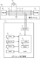
次に、図1を参照して、エラーレート推定装置100の機能について説明する。エラーレート推定装置100は、通信線501と電源線502と電源線503とにより相互に接続された設備機器200及び設備機器300による通信線501と電源線503とを用いたベースバンド伝送におけるエラーレートを推定する。エラーレート推定装置100は、通信線501と電源線503との間の電圧の波形に基づいて、ビットエラーレートを推定し、更に、ビットエラーレートに基づいて、フレームエラーレートを推定する。ビットエラーレートは、1ビットの符号が誤って伝送される確率である。フレームエラーレートは、1つのフレームが備える複数ビットの符号のうち少なくとも1つの符号が誤って伝送される確率である。以下、適宜、ビットエラーレートとフレームエラーレートとを総称する場合、単に、エラーレートという。
Next, the function of the error
通信システム1000では、通信線501と電源線502と電源線503とが1つのケーブル500にまとめられ、交流電力の供給に用いられる電源線502及び電源線503のうち電源線503が通信線501とともに通信に用いられる。このため、通信システム1000では、電力供給と通信とに用いられる電線の総数が少なく、簡単な構成で電力供給と通信とが実現される。
In the
しかしながら、通信システム1000では、通信線501と電源線502と電源線503との距離が非常に近い。このため、例えば、電源線502と電源線503との間に印加された交流電圧により、電源線502から通信線501に誘導ノイズが誘導される可能性が高い。この誘導ノイズの影響により、通信線501の電位が変動し、その結果、エラーレートが上昇する可能性がある。一方、エラーレートが高すぎる場合、何らかの対策を講じることが望ましい。そこで、エラーレート推定装置100は、エラーレートを推定し、何らかの対策を講じるべきか否かを判断する材料として、エラーレートを示す情報を表示する。
However, in the
図1に示すように、エラーレート推定装置100は、機能的には、波形測定部101と、ノイズ測定部103とエラーレート推定部104とを備える制御部102と、記憶部105と、操作受付部106と、表示部107と、通信部108と、を備える。波形測定部101は、例えば、波形測定手段に対応する。ノイズ測定部103は、例えば、ノイズ測定手段に対応する。エラーレート推定部104は、例えば、エラーレート推定手段に対応する。
As shown in FIG. 1, the error
波形測定部101は、通信線501と電源線503との間の電圧の波形を測定する。波形測定部101は、例えば、通信線501と電源線503とに接続されたプローブから供給される電圧信号を予め定められたサンプリング周期でサンプリングすることにより、上記電圧の波形を測定する。この電圧の波形を、以下、適宜、「測定電圧波形」という。測定電圧波形を示す情報は、波形測定部101から制御部102に供給され、制御部102により記憶部105に保存される。波形測定部101の機能は、例えば、A/D変換器17の機能により実現される。
The
制御部102は、エラーレート推定装置100の全体を制御する。また、制御部102は、エラーレート推定処理における演算量の多い処理を実行する。制御部102の機能は、例えば、CPU11とROM12とRAM13とが協働することにより実現される。
The
ノイズ測定部103は、測定電圧波形から、ノイズ幅とノイズ周期とを測定する。このノイズ幅は、電源線502から通信線501に誘導された誘導ノイズの幅である。このノイズ周期は、この誘導ノイズが誘導された周期である。なお、電源線502と電源線503とに接続される交流電源400が商用電源である場合、商用電源の周期に対応する周期で、誘導ノイズが発生すると考えられる。典型的には、交流電圧における正のピークと負のピークとにおいて、誘導ノイズが発生すると考えられる。この場合、ノイズ周期は、交流電源400の周期の半分の値となる。
The
ただし、通信システム1000が設置された環境、通信モジュール203の種類、ケーブル500の種類、及び、ケーブル500の長さなどの条件によっては、交流電圧における正のピークと負のピークとのうちの一方のピークのみで誘導ノイズが発生したり、1つのピークに対して2つ以上の誘導ノイズが発生したり、交流電源400の周期の整数倍の周期で誘導ノイズが発生したりする可能性も考えられる。そこで、エラーレート推定装置100が、交流電源400の周期を特定可能な場合であっても、上記条件に応じたノイズ周期を測定することが望ましい。
However, depending on the environment in which the
また、ノイズ幅は、通信システム1000が設置された環境、通信モジュール203の種類、ケーブル500の種類、及び、ケーブル500の長さなどの条件に依存すると考えられる。そこで、エラーレート推定装置100は、上記条件に応じたノイズ幅を測定する。一方、上記条件が変わらなければ、ノイズ周期とノイズ幅とが変わらない可能性が高い。このため、測定されたノイズ周期と測定されたノイズ幅とに基づいて推定されたエラーレートは、上記条件が変わらなければ有効であると考えられる。
Further, the noise width is considered to depend on conditions such as the environment in which the
なお、ノイズ周期にばらつきがある場合、例えば、測定された複数のノイズ周期の平均値を採用することができる。また、ノイズ幅にばらつきがある場合、例えば、測定された複数のノイズ幅の平均値を採用することができる。ノイズ測定部103の機能は、例えば、CPU11とROM12とRAM13とが協働することにより実現される。
In addition, when there exists dispersion | variation in a noise period, the average value of the measured several noise period is employable, for example. Further, when the noise width varies, for example, an average value of a plurality of measured noise widths can be employed. The function of the
エラーレート推定部104は、ノイズ測定部103により推定されたノイズ幅とノイズ周期とに基づいて、エラーレートを推定する。なお、基本的に、ノイズ周期が短いほどエラーレートが高くなり、ノイズ幅が広いほどエラーレートが高くなると考えられる。また、基本的に、ノイズ幅は、誘導ノイズ全体のうち、ビット判定に影響を及ぼす程度の振幅を有する部分の幅である。エラーレート推定部104の機能は、例えば、CPU11とROM12とRAM13とが協働することにより実現される。
The error
記憶部105は、エラーレート推定処理に関する各種の情報を記憶する。例えば、記憶部105は、通信システム1000において採用されているビット判定方法を示す情報、通信システム1000により送受信されるフレームのビットパターン及び送信タイミングを示す情報、通信速度を示す情報、及び、エラーレートを示す情報を記憶する。記憶部105の機能は、例えば、フラッシュメモリ14の機能により実現される。
The
操作受付部106は、エラーレート推定処理に関する各種の操作をユーザから受け付ける。例えば、操作受付部106は、エラーレート推定処理の開始を指示する操作、通信システム1000において採用されているビット判定方法を指定する操作、通信システム1000により送受信されるフレームのビットパターン及び送信タイミングを指定する操作、通信速度を指定する操作、及び、エラーレートを示す情報の表示を指示する操作を、ユーザから受け付ける。操作受付部106の機能は、例えば、タッチスクリーン16の機能により実現される。
The
表示部107は、エラーレート推定処理に関する各種の情報を表示する。例えば、表示部107は、エラーレート推定部104により推定されたエラーレートを示す情報を表示する。また、表示部107は、操作受付部106により各種の操作を受け付けるための画面を表示する。表示部107の機能は、例えば、CPU11とタッチスクリーン16とが協働することにより実現される。
The
通信部108は、エラーレート推定処理に関する各種の情報を、通信ネットワークに接続された各種の装置との間で、送受信する。例えば、通信部108は、ビット判定方法を示す情報、送受信されるフレームのビットパターン及び送信タイミングを示す情報、及び、通信速度を示す情報を、設備機器200、設備機器300、又は、設備機器200と設備機器300とを制御する制御装置から受信する。また、例えば、通信部108は、エラーレートを示す情報を、通信ネットワークに接続された表示装置に送信する。通信部108の機能は、例えば、CPU11と通信インターフェース18とが協働することにより実現される。
The
ここで、エラーレート推定部104は、ノイズ幅と、ノイズ周期と、ベースバンド伝送において採用されるビット判定方法と、に基づいて、ベースバンド伝送におけるビットエラーレートを推定する。また、エラーレート推定部104は、ビットエラーレートと、フレーム長と、に基づいて、フレームエラーレートを推定する。フレーム長は、1フレームに含まれるビット数である。例えば、エラーレート推定部104は、以下に示す式(1)に基づいて、フレームエラーレートを算出する。なお、FERはフレームエラーレートを表し、BERはビットエラーレートを表し、Nはフレーム長を表す。
FER=1−(1−BER)^N・・・(1)
Here, the error
FER = 1- (1-BER) ^ N (1)
表示部107は、ビットエラーレートとフレームエラーレートとのうち少なくとも一方のエラーレートを示す情報を表示する。つまり、表示部107は、ビットエラーレートのみを示す情報を表示してもよいし、フレームエラーレートのみを示す情報を表示してもよいし、ビットエラーレートとフレームエラーレートとの双方を示す情報を表示してもよい。また、表示部107は、フレーム長毎にフレームエラーレートを示す情報を表示してもよい。
The
ここで、設備機器200と設備機器300とのうち送信側の設備機器は、第1の電圧と第1の電圧よりも低い電圧である第2の電圧とのうちいずれか一方の電圧を、通信線501と電源線503との間に印加する。第1の電圧は、例えば、5Vである。第2の電圧は、例えば、0Vである。設備機器200と設備機器300とのうち受信側の設備機器は、通信線501と電源線503との間の電圧と、閾値電圧との比較結果からビット判定する。閾値電圧は、第1の電圧と第2の電圧との中間の電圧である。閾値電圧は、例えば、2.5Vである。例えば、受信側の設備機器は、通信線501と電源線503との間の電圧が閾値電圧を超える場合、ビットが‘1’であると判定し、通信線501と電源線503との間の電圧が閾値電圧を超えない場合、ビットが‘0’であると判定する。
Here, the transmission-side facility device among the
ノイズ測定部103は、差分波形において、マージン電圧を超える振幅を有する期間をノイズ期間に設定する。そして、ノイズ測定部103は、このノイズ期間の長さをノイズ幅として測定し、このノイズ期間の周期をノイズ周期として測定する。差分波形は、測定電圧波形と印加電圧波形との差分の波形である。印加電圧波形は、送信側の設備機器により通信線501と電源線503との間に印加された電圧の波形である。マージン電圧は、第1の電圧と閾値電圧との差分の電圧であり、第2の電圧と閾値電圧との差分の電圧でもある。例えば、第1の電圧が5Vであり、第2の電圧が0Vであり、閾値電圧が2.5Vである場合、マージン電圧は2.5Vである。
The
図4と図5と図6とを参照して、測定電圧波形と印加電圧波形と差分波形とについて説明する。まず、図5に示すように、印加電圧波形は、送信するビットパターンに従って1ビット期間毎に第1の電圧又は第2の電圧を有する波形である。Tbitは、1ビット期間を表す。Vthは、閾値電圧を表す。V1は、第1の電圧である5Vを表す。0Vは、第2の電圧を表す。図5には、印加電圧波形が、‘0’、‘1’、‘0’、‘1’、‘1’、‘0’、‘1’という7ビットのビットパターン通りに電圧が印加された様子が示されている。なお、図5において、下向きの矢印は、受信側の設備機器においてビットレベルを判定する位置(以下、適宜「判定位置」という。)を示している。本実施形態では、図5に示すように、1ビット当たり1回だけビットレベルを判定する例について説明する。なお、判定位置は、1ビット期間における中心であるものとする。受信側の設備機器は、例えば、フレームの最初のビットであるスタートビットの検出位置から、判定位置を特定することができる。 The measurement voltage waveform, the applied voltage waveform, and the difference waveform will be described with reference to FIGS. 4, 5, and 6. First, as shown in FIG. 5, the applied voltage waveform is a waveform having a first voltage or a second voltage for each bit period in accordance with the bit pattern to be transmitted. Tbit represents one bit period. Vth represents a threshold voltage. V1 represents the first voltage of 5V. 0V represents the second voltage. In FIG. 5, the applied voltage waveform is applied in accordance with a 7-bit bit pattern of “0”, “1”, “0”, “1”, “1”, “0”, “1”. The situation is shown. In FIG. 5, a downward arrow indicates a position (hereinafter referred to as “determination position” as appropriate) for determining the bit level in the receiving-side equipment. In the present embodiment, as shown in FIG. 5, an example in which the bit level is determined only once per bit will be described. Note that the determination position is assumed to be the center in one bit period. For example, the receiving-side equipment can specify the determination position from the detection position of the start bit that is the first bit of the frame.
なお、エラーレート推定装置100は、送信側の設備機器が送信するフレームのビットパターンを特定することができれば、印加電圧波形を特定することができる。例えば、記憶部105にこのビットパターンを示す情報が記憶されている場合、エラーレート推定装置100は、このビットパターンを示す情報に基づいて、印加電圧波形を特定することができる。或いは、エラーレート推定装置100は、測定電圧波形から印加電圧波形を推定してもよい。つまり、誘導ノイズの波形は、基本的に、正方向又は負の方向に山なりの形状であり、印加電圧波形のように矩形状の波形ではなく、ある程度推定可能な形状であると推定されるためである。
In addition, if the error
また、エラーレート推定装置100は、アイドル状態を検出し、アイドル状態において測定電圧波形を取得してもよい。この場合、印加電圧波形は、0Vの電圧が継続した電圧波形となる。なお、アイドル状態は、設備機器200及び設備機器300のいずれもフレームを送信していない状態であり、設備機器200及び設備機器300により通信線501と電源線503との間に電圧が印加されていない状態である。
Further, the error
図4に示すように、測定電圧波形は、印加電圧波形に、誘導ノイズの電圧の波形であるノイズ波形を加算した波形である。本実施形態では、2つの電圧波形の時間軸を合わせて各電圧波形に含まれる電圧を加算して1つの電圧波形を得ることを、2つの電圧波形を加算するという。また、2つの電圧波形の時間軸を合わせて各電圧波形に含まれる電圧を減算して1つの電圧波形を得ることを、2つの電圧波形の差分をとるという。 As shown in FIG. 4, the measured voltage waveform is a waveform obtained by adding a noise waveform that is a voltage waveform of induced noise to the applied voltage waveform. In the present embodiment, obtaining one voltage waveform by adding the voltages included in each voltage waveform by aligning the time axes of the two voltage waveforms is referred to as adding two voltage waveforms. Also, obtaining one voltage waveform by subtracting the voltage contained in each voltage waveform with the time axes of the two voltage waveforms aligned is referred to as taking the difference between the two voltage waveforms.
図4に、Bit3と表記された1ビット期間において正の誘導ノイズが誘導され、Bit6と表記された1ビット期間において負の誘導ノイズが誘導された例を示す。ここで、Bit3と表記された1ビット期間では、送信側の設備機器により通信線501と電源線503との間に印加された電圧は0Vである。また、Bit3と表記された1ビット期間における判定位置における正の誘導ノイズの振幅が、マージン電圧であるVmよりも大きいV2である。この場合、Bit3と表記された1ビット期間における判定位置における測定電圧波形上の電圧は、閾値電圧であるVthよりも大きいV2となる。従って、受信側の設備機器は、Bit3と表記された1ビット期間におけるビット判定において、符号が‘1’であると誤判定する。
FIG. 4 shows an example in which positive induced noise is induced in a 1-bit period expressed as Bit3 and negative induced noise is induced in a 1-bit period expressed as Bit6. Here, in the 1-bit period expressed as Bit3, the voltage applied between the
一方、Bit6と表記された1ビット期間では、送信側の設備機器により通信線501と電源線503との間に印加された電圧は0Vである。また、Bit6と表記された1ビット期間における判定位置における負の誘導ノイズの振幅が、マージン電圧であるVmよりも大きいV3である。この場合、Bit6と表記された1ビット期間における判定位置における測定電圧波形上の電圧は、−Vthよりも小さい−V3となる。しかしながら、−V3がVthよりも小さい電圧であることにかわりはないため、受信側の設備機器は、Bit6と表記された1ビット期間におけるビット判定において、符号が‘0’であると正しく判定する。
On the other hand, in the 1-bit period expressed as Bit6, the voltage applied between the
このように、判定位置における誘導ノイズの振幅がマージン電圧よりも大きい場合、誤判定されるか否かは、符号の値と誘導ノイズの正負との関係による。具体的には、符号が‘1’で誘導ノイズが正である場合、及び、符号が‘0’で誘導ノイズが負である場合、誤判定されない。一方、符号が‘1’で誘導ノイズが負である場合、及び、符号が‘0’で誘導ノイズが正である場合、誤判定される。本実施形態では、正の誘導ノイズが発生する確率と負の誘導ノイズが発生する確率とが同じであり、符号が‘1’である確率と符号が‘0’である確率とが同じであるものとみなし、判定位置における誘導ノイズの振幅がマージン電圧よりも大きい場合、50%の確率で誤判定されるものとみなす。一方、判定位置における誘導ノイズの振幅がマージン電圧よりも小さい場合、誤判定されない。 As described above, when the amplitude of the induced noise at the determination position is larger than the margin voltage, whether or not an erroneous determination is made depends on the relationship between the sign value and the sign of the induced noise. Specifically, when the sign is ‘1’ and the induced noise is positive, and when the sign is ‘0’ and the induced noise is negative, no erroneous determination is made. On the other hand, when the sign is ‘1’ and the induced noise is negative, and when the sign is ‘0’ and the induced noise is positive, an erroneous determination is made. In the present embodiment, the probability that a positive induced noise occurs is the same as the probability that a negative induced noise occurs, and the probability that the sign is “1” and the probability that the sign is “0” are the same. If the amplitude of the induced noise at the determination position is larger than the margin voltage, it is determined that the determination is erroneous with a probability of 50%. On the other hand, when the amplitude of the induced noise at the determination position is smaller than the margin voltage, no erroneous determination is made.
図6に示すように、差分波形は、測定電圧波形と印加電圧波形との差分の波形であり、誘導ノイズの電圧の波形である。差分波形において、マージン電圧であるVmを超える振幅を有する期間であるPn1及びPn2がノイズ期間である。Pn1は、t1からt2までの期間である。Pn2は、t3からt4までの期間である。そして、Pn1及びPn2の長さがノイズ幅として求められる。なお、Pn1の長さとPn2の長さとが異なる場合、Pn1の長さとPn2の長さとの平均値がノイズ幅として求められる。また、Pn1の中心からPn2の中心までの長さであるTnがノイズ周期として求められる。なお、3つ以上のノイズ期間が検出された場合、隣接するノイズ期間の中心間の長さの平均値をノイズ周期として採用することができる。 As shown in FIG. 6, the difference waveform is a difference waveform between the measurement voltage waveform and the applied voltage waveform, and is a voltage waveform of induced noise. In the differential waveform, Pn1 and Pn2 which are periods having an amplitude exceeding the margin voltage Vm are noise periods. Pn1 is a period from t1 to t2. Pn2 is a period from t3 to t4. And the length of Pn1 and Pn2 is calculated | required as a noise width. When the length of Pn1 and the length of Pn2 are different, the average value of the length of Pn1 and the length of Pn2 is obtained as the noise width. Also, Tn, which is the length from the center of Pn1 to the center of Pn2, is obtained as the noise period. When three or more noise periods are detected, the average value of the lengths between the centers of adjacent noise periods can be adopted as the noise period.
ここで、上述したように、受信側の設備機器は、通信線501と電源線503との間の電圧と閾値電圧とを1つのビットに対して1回比較し、1回の比較結果からビット判定する。エラーレート推定部104は、部分波形の先頭から部分波形の末尾に至るまで、判定位置を予め定められたシフト量だけシフトさせながら、判定位置がノイズ期間と重なるか否かを判定したときに、判定位置とノイズ期間とが重なると判定される割合の半分の割合を、ビットエラーレートとして推定する。部分波形は、差分波形のうちノイズ周期分の波形である。
Here, as described above, the receiving-side equipment compares the voltage between the
図7に部分波形を示す。ここでは、差分波形のうちt1からt3までの期間の波形を部分波形として採用する。ただし、部分波形は、差分波形から抽出されるノイズ周期分の波形であればよい。例えば、部分波形は、差分波形のうちt2からt4までの期間の波形でもよい。図7に示すように、部分波形には1つのノイズ期間が含まれる。そして、判定位置がノイズ期間と重なる場合、50%の確率で誤判定される。一方、判定位置がノイズ期間と重ならない場合、誤判定されない。 FIG. 7 shows a partial waveform. Here, the waveform of the period from t1 to t3 among the differential waveforms is adopted as the partial waveform. However, the partial waveform may be a waveform corresponding to the noise period extracted from the differential waveform. For example, the partial waveform may be a waveform in a period from t2 to t4 in the differential waveform. As shown in FIG. 7, the partial waveform includes one noise period. If the determination position overlaps with the noise period, an erroneous determination is made with a probability of 50%. On the other hand, when the determination position does not overlap with the noise period, no erroneous determination is made.
なお、差分波形は、部分波形の繰り返しであることが予想される。従って、1つの部分波形において、判定位置をシフトしながら判定位置とノイズ期間とが重なるか否かを判定することにより、ビットエラーレートを見積もることが可能である。例えば、シフト量をノイズ周期の1/1000にした場合、1000個の判定位置において判定位置とノイズ期間とが重なるか否かを判定し、1000回分の判定結果が得られる。ここで、例えば、1000回の判定のうち4回だけ、判定位置とノイズ期間とが重なると判定されるものとする。この場合、4個の判定位置のうち50%の判定位置、つまり、2個の判定位置において、誤判定されると推定される。従って、この場合、ビットエラーレートは、0.002と推定される。 Note that the difference waveform is expected to be a repetition of a partial waveform. Accordingly, it is possible to estimate the bit error rate by determining whether or not the determination position and the noise period overlap while shifting the determination position in one partial waveform. For example, when the shift amount is 1/1000 of the noise period, it is determined whether or not the determination position and the noise period overlap at 1000 determination positions, and 1000 determination results are obtained. Here, for example, it is assumed that it is determined that the determination position and the noise period overlap only 4 times out of 1000 determinations. In this case, it is estimated that an erroneous determination is made at 50% of the four determination positions, that is, at the two determination positions. Therefore, in this case, the bit error rate is estimated to be 0.002.
次に、図8に示すフローチャートを参照して、エラーレート推定装置100が実行するエラーレート推定処理について説明する。エラーレート推定処理は、エラーレート推定装置100の電源が投入されると開始される。
Next, an error rate estimation process executed by the error
まず、エラーレート推定装置100は、通信関連情報を取得する(ステップS101)。例えば、エラーレート推定装置100は、操作受付部106を介して、ユーザから通信関連情報を取得する。あるいは、エラーレート推定装置100は、通信部108を介して、通信ネットワークに接続された各種の装置から通信関連情報を取得する。通信関連情報は、例えば、設備機器200又は設備機器300が送信するフレームのビットパターン及び送信タイミングを示す情報、通信速度を示す情報、又は、ビット判定方法を示す情報である。ビット判定方法は、例えば、1つのビットに対して設けられる判定位置の個数である。ななお、判定位置の個数が複数である場合、例えば、多数決判定により、ビットの符号が判定される。
First, the error
エラーレート推定装置100は、ステップS101の処理を完了すると、電圧波形を測定する(ステップS102)。例えば、エラーレート推定装置100は、波形測定部101を制御して、電圧波形を測定する。エラーレート推定装置100は、ステップS102の処理を完了すると、電圧波形を測定した期間がアイドル状態であるか否かを判別する(ステップS103)。エラーレート推定装置100は、測定電圧波形に基づいて、アイドル状態であるか否かを判別することができる。
When the error
エラーレート推定装置100は、アイドル状態であると判別すると(ステップS103:YES)、アイドル状態における印加電圧波形を特定する(ステップS104)。この印加電圧波形は、0Vの電圧が継続した電圧波形である。エラーレート推定装置100は、アイドル状態でないと判別すると(ステップS103:NO)、ビットパターンを特定する(ステップS105)。なお、印加電圧波形は、基本的に、矩形波の組み合わせであり、誘導ノイズの電圧波形は、基本的に、矩形ではない。従って、エラーレート推定装置100は、測定電圧波形から、印加電圧波形と誘導ノイズの電圧波形とを分離することは可能である。なお、誘導ノイズの電圧波形は、差分波形である。
When it is determined that the error
エラーレート推定装置100は、ステップS105の処理を完了すると、ビットパターンから印加電圧波形を特定する(ステップS106)。エラーレート推定装置100は、ステップS104の処理又はステップS106の処理を完了すると、差分波形を特定する(ステップS107)。
When the error
エラーレート推定装置100は、ステップS107の処理を完了すると、ノイズ期間を特定する(ステップS108)。エラーレート推定装置100は、ステップS108の処理を完了すると、ノイズ幅を特定する(ステップS109)。エラーレート推定装置100は、ステップS109の処理を完了すると、ノイズ周期を特定する(ステップS110)。
When the error
エラーレート推定装置100は、ステップS110の処理を完了すると、ビットエラーレートを推定する(ステップS111)。例えば、エラーレート推定装置100は、差分波形から抽出された部分波形と、ノイズ幅と、ノイズ周期とに基づいて、ビットエラーレートを推定する。エラーレート推定装置100は、ステップS111の処理を完了すると、上述した式(1)を用いて、フレームエラーレートを推定する(ステップS112)。エラーレート推定装置100は、ステップS112の処理を完了すると、エラーレートを表示する(ステップS113)。
When the error
図9に、エラーレートを示す情報を表示する画面である表示画面800を示す。表示画面800は、ビットエラーレートとフレームエラーレートとを示す情報を提示する画面である。表示画面800は、フレーム長毎にフレームエラーレートを示す情報を提示する画面であってもよい。エラーレート推定装置100は、ステップS113の処理を完了すると、エラーレート推定処理を完了する。
FIG. 9 shows a
以上説明したように、本実施形態では、通信線501と電源線503との間の電圧の波形から、電源線502から通信線501に誘導された誘導ノイズの幅であるノイズ幅と、誘導ノイズが誘導された周期であるノイズ周期と、が測定され、ノイズ幅とノイズ周期とに基づいて、エラーレートが推定される。従って、本実施形態によれば、エラーレートを精度良く推定することができる。
As described above, in the present embodiment, the noise width that is the width of the induced noise induced from the
(実施形態2)
実施形態1では、ビット判定のための比較が1ビットに対して1回である例について説明した。本発明においては、ビット判定のための比較が1ビットに対して複数回であってもよい。本実施形態では、ビット判定のための比較が1ビットに対して3回である例について説明する。なお、エラーレート推定装置100における判定回数は、設備機器200及び設備機器300における判定回数と同じであれば、エラーレートの推定精度の向上が期待できる。
(Embodiment 2)
In the first embodiment, the example in which the comparison for bit determination is performed once for one bit has been described. In the present invention, comparison for bit determination may be performed a plurality of times for one bit. In the present embodiment, an example in which comparison for bit determination is performed three times for one bit will be described. If the number of determinations in the error
本実施形態では、受信側の設備機器は、通信線501と電源線503との間の電圧と閾値電圧とを1つのビットに対して複数回比較し、複数回の比較結果を用いた多数決判定によりビット判定する。
In this embodiment, the receiving-side equipment compares the voltage between the
ここで、エラーレート推定部104は、部分波形の先頭から部分波形の末尾に至るまで、複数の判定位置を予め定められたシフト量だけシフトさせながら、複数の判定位置のうち過半数の判定位置がノイズ期間と重なるか否かを判定したときに、過半数の判定位置がノイズ期間と重なると判定される割合の半分の割合を、ビットエラーレートとして推定する。
Here, the error
図10に、1つのビットに対する判定位置として、t11で示される判定位置と、t12で示される判定位置と、t13で示される判定位置との3つの判定位置が設定された例を示す。なお、図10では、部分波形を簡略化し、t1からt2までの期間がノイズ期間であり、t2からt3までの期間が非ノイズ期間であることを模式的に示している。 FIG. 10 shows an example in which three determination positions of a determination position indicated by t11, a determination position indicated by t12, and a determination position indicated by t13 are set as determination positions for one bit. In FIG. 10, the partial waveform is simplified, and it is schematically shown that the period from t1 to t2 is a noise period, and the period from t2 to t3 is a non-noise period.
t11で示される判定位置とt12で示される判定位置とはノイズ期間と重なり、t13で示される判定位置はノイズ期間と重ならない。従って、図10に示す判定位置群では、過半数の判定位置がノイズ期間と重なると判定される。以後、判定位置群を、予め定められたシフト量だけシフトして、同様に多数決判定される。例えば、シフト量がノイズ周期の1/1000である場合、1000回の多数決判定がなされる。そして、過半数の判定位置がノイズ期間と重なると判定された割合の半分の割合が、ビットエラーレートとして推定される。 The determination position indicated by t11 and the determination position indicated by t12 overlap with the noise period, and the determination position indicated by t13 does not overlap with the noise period. Therefore, in the determination position group shown in FIG. 10, it is determined that a majority of the determination positions overlap with the noise period. Thereafter, the determination position group is shifted by a predetermined shift amount, and the majority decision is similarly made. For example, when the shift amount is 1/1000 of the noise period, the majority decision is made 1000 times. Then, a rate that is half of the rate at which the majority of the determination positions are determined to overlap the noise period is estimated as the bit error rate.
なお、エラーレート推定装置100における判定位置の個数及び間隔は、設備機器200及び設備機器300における判定位置の間隔及び間隔と同じであることが好適である。このように、エラーレート推定装置100と設備機器200と設備機器300とで、ビットの判定条件を合わせることにより、ビットエラーレートの推定精度が高まることが期待できる。
Note that the number and interval of determination positions in the error
(変形例)
以上、本発明の実施形態を説明したが、本発明を実施するにあたっては、種々の形態による変形及び応用が可能である。本発明において、上記実施形態において説明した構成、機能、動作のどの部分を採用するのかは任意である。また、本発明において、上述した構成、機能、動作のほか、更なる構成、機能、動作が採用されてもよい。
(Modification)
As mentioned above, although embodiment of this invention was described, when implementing this invention, a deformation | transformation and application with a various form are possible. In the present invention, which part of the configuration, function, and operation described in the above embodiment is adopted is arbitrary. Further, in the present invention, in addition to the configuration, function, and operation described above, further configuration, function, and operation may be employed.
例えば、実施形態1では、通信線501と電源線502と電源線503とが1つの3芯ケーブル500に含まれる例について説明した。本発明は、通信線501と電源線502と電源線503とが別々のケーブルに含まれている場合にも適用可能である。かかる構成においても、通信線501と電源線502と電源線503との距離が近ければ、電源線502から通信線501に誘導ノイズが誘導されることがあるためである。
For example, in the first embodiment, an example in which the
実施形態1では、通信システム1000が空調システムであり、設備機器200が室外機であり、設備機器300が室内機である例について説明した。本発明において、通信システム1000は、空調システムに限定されないことは勿論である。例えば、通信システム1000が照明システムであり、設備機器200が照明制御装置であり、設備機器300が照明装置であってもよい。
In the first embodiment, an example in which the
本発明に係るエラーレート推定装置100の動作を規定する動作プログラムを既存のパーソナルコンピュータ又は情報端末装置に適用することで、当該パーソナルコンピュータ等を本発明に係るエラーレート推定装置100として機能させることも可能である。また、このようなプログラムの配布方法は任意であり、例えば、CD−ROM(Compact Disk Read-Only Memory)、DVD(Digital Versatile Disk)、メモリカードなどのコンピュータ読み取り可能な記録媒体に格納して配布してもよいし、インターネットなどの通信ネットワークを介して配布してもよい。
By applying an operation program that defines the operation of the error
本発明は、本発明の広義の精神と範囲を逸脱することなく、様々な実施形態及び変形が可能とされるものである。また、上述した実施形態は、本発明を説明するためのものであり、本発明の範囲を限定するものではない。つまり、本発明の範囲は、実施形態ではなく、特許請求の範囲によって示される。そして、特許請求の範囲内及びそれと同等の発明の意義の範囲内で施される様々な変形が、本発明の範囲内とみなされる。 Various embodiments and modifications can be made to the present invention without departing from the broad spirit and scope of the present invention. Further, the above-described embodiment is for explaining the present invention, and does not limit the scope of the present invention. That is, the scope of the present invention is shown not by the embodiments but by the claims. Various modifications within the scope of the claims and within the scope of the equivalent invention are considered to be within the scope of the present invention.
本発明は、複数の設備機器が通信線と一対の電源線とで相互に接続された通信システムに適用可能である。 The present invention is applicable to a communication system in which a plurality of facility devices are connected to each other by a communication line and a pair of power supply lines.
11 CPU、12 ROM、13 RAM、14 フラッシュメモリ、15 RTC、16 タッチスクリーン、17 A/D変換器、18 通信インターフェース、100 エラーレート推定装置、101 波形測定部、102 制御部、103 ノイズ測定部、104 エラーレート推定部、105 記憶部、106 操作受付部、107 表示部、108 通信部、200,300 設備機器、201 交流負荷、202 直流電源、203 通信モジュール、204 送信回路、205 受信回路、400 交流電源、500 ケーブル、501 通信線、502,503 電源線、800 表示画面、1000 通信システム
11 CPU, 12 ROM, 13 RAM, 14 Flash memory, 15 RTC, 16 Touch screen, 17 A / D converter, 18 Communication interface, 100 Error rate estimation device, 101 Waveform measurement unit, 102 Control unit, 103
Claims (7)
前記通信線と前記第2の電源線との間の電圧の波形を測定する波形測定手段と、
前記波形測定手段により測定された前記電圧の波形である測定電圧波形から、前記第1の電源線から前記通信線に誘導された誘導ノイズの幅であるノイズ幅と、前記誘導ノイズが誘導された周期であるノイズ周期とを測定するノイズ測定手段と、
前記ノイズ測定手段により測定された前記ノイズ幅と前記ノイズ周期とに基づいて、前記エラーレートを推定するエラーレート推定手段と、
前記エラーレート推定手段により推定された前記エラーレートを示す情報を表示する表示手段と、を備える、
エラーレート推定装置。 A plurality of facilities connected to each other by a communication line, a first power line, and a second power line and receiving AC power from an AC power source via the first power line and the second power line An error rate estimation device for estimating an error rate in baseband transmission using the communication line and the second power line by a device,
Waveform measuring means for measuring a waveform of a voltage between the communication line and the second power supply line;
From the measured voltage waveform which is the waveform of the voltage measured by the waveform measuring means, a noise width which is a width of induced noise induced from the first power supply line to the communication line, and the induced noise are induced. A noise measuring means for measuring a noise period which is a period;
Error rate estimating means for estimating the error rate based on the noise width and the noise period measured by the noise measuring means;
Display means for displaying information indicating the error rate estimated by the error rate estimation means,
Error rate estimation device.
前記表示手段は、前記エラーレート推定手段により推定された前記ビットエラーレートと、前記ビットエラーレートから推定されるフレームエラーレートとのうち少なくとも一方のエラーレートを示す情報を表示する、
請求項1に記載のエラーレート推定装置。 The error rate estimation means estimates a bit error rate in the baseband transmission based on the noise width and the noise period,
The display means displays information indicating an error rate of at least one of the bit error rate estimated by the error rate estimation means and a frame error rate estimated from the bit error rate;
The error rate estimation apparatus according to claim 1.
請求項2に記載のエラーレート推定装置。 The error rate estimation means estimates the frame error rate based on the bit error rate and a frame length that is the number of bits included in one frame.
The error rate estimation apparatus according to claim 2.
前記複数の設備機器のうち受信側の設備機器は、前記通信線と前記第2の電源線との間の電圧と、前記第1の電圧と前記第2の電圧との中間の電圧である閾値電圧と、の比較結果からビット判定し、
前記ノイズ測定手段は、前記測定電圧波形と、前記送信側の設備機器により前記通信線と前記第2の電源線との間に印加された電圧の波形である印加電圧波形と、の差分の波形である差分波形において、前記第1の電圧と前記閾値電圧との差分の電圧であるマージン電圧を超える振幅を有する期間をノイズ期間として、前記ノイズ期間の長さを前記ノイズ幅として測定し、前記ノイズ期間の周期を前記ノイズ周期として測定する、
請求項2又は3に記載のエラーレート推定装置。 Of the plurality of facility devices, the transmission-side facility device uses either the first voltage or the second voltage that is lower than the first voltage as the communication line and the first voltage. Between the two power lines,
Among the plurality of facility devices, the facility device on the receiving side is a threshold value that is a voltage between the communication line and the second power supply line and an intermediate voltage between the first voltage and the second voltage. The bit is judged from the comparison result with the voltage,
The noise measuring means is a difference waveform between the measured voltage waveform and an applied voltage waveform that is a waveform of a voltage applied between the communication line and the second power line by the transmission-side equipment. In the difference waveform, a period having an amplitude exceeding a margin voltage, which is a difference voltage between the first voltage and the threshold voltage, is measured as a noise period, and the length of the noise period is measured as the noise width, Measuring the period of the noise period as the noise period;
The error rate estimation apparatus according to claim 2 or 3.
前記エラーレート推定手段は、前記差分波形のうち前記ノイズ周期分の波形である部分波形の先頭から前記部分波形の末尾に至るまで、判定位置を予め定められたシフト量だけシフトさせながら、前記判定位置が前記ノイズ期間と重なるか否かを判定したときに、前記判定位置と前記ノイズ期間とが重なると判定される割合の半分の割合を、前記ビットエラーレートとして推定する、
請求項4に記載のエラーレート推定装置。 The receiving-side facility device compares the voltage between the communication line and the second power supply line and the threshold voltage once for one bit, and determines the bit from the result of one comparison,
The error rate estimation means shifts the determination position by a predetermined shift amount from the beginning of a partial waveform that is a waveform corresponding to the noise period of the difference waveform to the end of the partial waveform, and performs the determination. When it is determined whether or not the position overlaps with the noise period, a ratio of half of the ratio determined that the determination position and the noise period overlap is estimated as the bit error rate.
The error rate estimation apparatus according to claim 4.
前記エラーレート推定手段は、前記差分波形のうち前記ノイズ周期分の波形である部分波形の先頭から前記部分波形の末尾に至るまで、複数の判定位置を予め定められたシフト量だけシフトさせながら、前記複数の判定位置のうち過半数の判定位置が前記ノイズ期間と重なるか否かを判定したときに、前記過半数の判定位置が前記ノイズ期間と重なると判定される割合の半分の割合を、前記ビットエラーレートとして推定する、
請求項4に記載のエラーレート推定装置。 The receiving-side equipment compares the voltage between the communication line and the second power supply line and the threshold voltage a plurality of times for one bit, and makes a majority decision using a plurality of comparison results. The bit is judged by
The error rate estimation means shifts a plurality of determination positions by a predetermined shift amount from the beginning of a partial waveform that is a waveform corresponding to the noise period of the difference waveform to the end of the partial waveform, When determining whether or not a majority of the determination positions of the plurality of determination positions overlap with the noise period, a ratio of half of the ratio determined that the majority of determination positions overlap with the noise period is the bit. Estimate as error rate,
The error rate estimation apparatus according to claim 4.
前記通信線と前記第2の電源線との間の電圧の波形を測定し、
測定された前記電圧の波形である測定電圧波形から、前記第1の電源線から前記通信線に誘導された誘導ノイズの幅であるノイズ幅と、前記誘導ノイズが誘導された周期であるノイズ周期とを測定し、
測定された前記ノイズ幅と前記ノイズ周期とに基づいて、前記エラーレートを推定する、
エラーレート推定方法。 A plurality of facilities connected to each other by a communication line, a first power line, and a second power line and receiving AC power from an AC power source via the first power line and the second power line An error rate estimation method for estimating an error rate in baseband transmission using the communication line and the second power line by a device,
Measuring a voltage waveform between the communication line and the second power line;
A noise width that is a width of induced noise induced from the first power supply line to the communication line from a measured voltage waveform that is a waveform of the measured voltage, and a noise period that is a period in which the induced noise is induced And measure
Estimating the error rate based on the measured noise width and the noise period;
Error rate estimation method.
Priority Applications (1)
| Application Number | Priority Date | Filing Date | Title |
|---|---|---|---|
| JP2018082467A JP7175100B2 (en) | 2018-04-23 | 2018-04-23 | Error rate estimation device and error rate estimation method |
Applications Claiming Priority (1)
| Application Number | Priority Date | Filing Date | Title |
|---|---|---|---|
| JP2018082467A JP7175100B2 (en) | 2018-04-23 | 2018-04-23 | Error rate estimation device and error rate estimation method |
Publications (2)
| Publication Number | Publication Date |
|---|---|
| JP2019193045A true JP2019193045A (en) | 2019-10-31 |
| JP7175100B2 JP7175100B2 (en) | 2022-11-18 |
Family
ID=68390981
Family Applications (1)
| Application Number | Title | Priority Date | Filing Date |
|---|---|---|---|
| JP2018082467A Active JP7175100B2 (en) | 2018-04-23 | 2018-04-23 | Error rate estimation device and error rate estimation method |
Country Status (1)
| Country | Link |
|---|---|
| JP (1) | JP7175100B2 (en) |
Citations (3)
| Publication number | Priority date | Publication date | Assignee | Title |
|---|---|---|---|---|
| JP2010096658A (en) * | 2008-10-17 | 2010-04-30 | Honda Motor Co Ltd | Device and method for evaluating noise environment |
| JP2014202459A (en) * | 2013-04-09 | 2014-10-27 | 三菱電機株式会社 | Air conditioner |
| JP2016161188A (en) * | 2015-02-27 | 2016-09-05 | ジョンソンコントロールズ ヒタチ エア コンディショニング テクノロジー(ホンコン)リミテッド | Air conditioner system and program |
-
2018
- 2018-04-23 JP JP2018082467A patent/JP7175100B2/en active Active
Patent Citations (3)
| Publication number | Priority date | Publication date | Assignee | Title |
|---|---|---|---|---|
| JP2010096658A (en) * | 2008-10-17 | 2010-04-30 | Honda Motor Co Ltd | Device and method for evaluating noise environment |
| JP2014202459A (en) * | 2013-04-09 | 2014-10-27 | 三菱電機株式会社 | Air conditioner |
| JP2016161188A (en) * | 2015-02-27 | 2016-09-05 | ジョンソンコントロールズ ヒタチ エア コンディショニング テクノロジー(ホンコン)リミテッド | Air conditioner system and program |
Also Published As
| Publication number | Publication date |
|---|---|
| JP7175100B2 (en) | 2022-11-18 |
Similar Documents
| Publication | Publication Date | Title |
|---|---|---|
| EP2619879B1 (en) | Disaggregation apparatus for identifying an appliance in an electrical network | |
| US10992188B2 (en) | Wireless power transmitter | |
| KR101250243B1 (en) | Apparatus and Method for Measuring the Length of a Pipe | |
| JP7175136B2 (en) | Wiring length measuring device and wiring length measuring method | |
| US20170070793A1 (en) | Apparatus and method for obtaining power usage information | |
| EP3109645A1 (en) | Current measurement device, control method and control program for same, recording medium, and power measurement device | |
| US20140100805A1 (en) | Status estimation apparatus, status estimation method | |
| JP2017201298A (en) | Energy demand-amount estimation method, estimation device and estimation program | |
| JP5859026B2 (en) | Energy usage estimation device and energy usage estimation method | |
| JP6045621B2 (en) | Connection relationship identification system and connection relationship identification method | |
| CN111103554B (en) | Power failure detection method, device, circuit system and computer storage medium | |
| CN109738740B (en) | Attraction-type power supply device, output control method, medium, and electronic device | |
| JP2010181159A (en) | Device for measuring electric power | |
| JP2019193045A (en) | Device and method for error rate estimation | |
| JP6263818B2 (en) | Controller and device state determination system using the same | |
| US20160266182A1 (en) | Operation apparatus | |
| US20120313432A1 (en) | Power distribution system connecting apparatus | |
| CN104951635B (en) | A kind of transformer noise predictor method for determining noise at full capacity | |
| JP6045524B2 (en) | AC corrosion risk measurement evaluation method and measurement evaluation system for buried metal bodies | |
| JP2009168726A (en) | Electric power measuring device | |
| KR20230145210A (en) | Wireless power systems with shared induction-loss scaling factors | |
| JP2015040317A (en) | Method of measuring cathode corrosion protection condition of buried pipeline | |
| KR101337384B1 (en) | Communication apparatus and terminal for powerline system, and communication method for the same | |
| KR101632931B1 (en) | Method and system for measuring based on two wire power line communication using low voltage | |
| JP6417152B2 (en) | Device power estimation method and system |
Legal Events
| Date | Code | Title | Description |
|---|---|---|---|
| A621 | Written request for application examination |
Free format text: JAPANESE INTERMEDIATE CODE: A621 Effective date: 20210127 |
|
| A131 | Notification of reasons for refusal |
Free format text: JAPANESE INTERMEDIATE CODE: A131 Effective date: 20220329 |
|
| A521 | Request for written amendment filed |
Free format text: JAPANESE INTERMEDIATE CODE: A523 Effective date: 20220526 |
|
| TRDD | Decision of grant or rejection written | ||
| A01 | Written decision to grant a patent or to grant a registration (utility model) |
Free format text: JAPANESE INTERMEDIATE CODE: A01 Effective date: 20221011 |
|
| A61 | First payment of annual fees (during grant procedure) |
Free format text: JAPANESE INTERMEDIATE CODE: A61 Effective date: 20221108 |
|
| R150 | Certificate of patent or registration of utility model |
Ref document number: 7175100 Country of ref document: JP Free format text: JAPANESE INTERMEDIATE CODE: R150 |