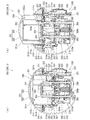
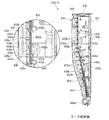
[1.パチンコ機の全体構造]
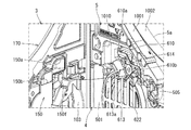
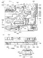
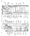
本発明の一実施形態であるパチンコ機1について、図面を参照して詳細に説明する。まず、図1乃至図12を参照して本実施形態のパチンコ機1の全体構成について説明する。図1は本発明の一実施形態であるパチンコ機の正面図である。図2はパチンコ機の右側面図であり、図3はパチンコ機の左側面図であり、図4はパチンコ機の背面図である。図5はパチンコ機を右前から見た斜視図であり、図6はパチンコ機を左前から見た斜視図であり、図7はパチンコ機を後ろから見た斜視図である。図8は演出操作ユニットの押圧操作部が上昇位置の時のパチンコ機の正面図であり、図9は演出操作ユニットの押圧操作部が上昇位置の時のパチンコ機を右前から見た斜視図である。また、図10は、本体枠から扉枠を開放させると共に、外枠から本体枠を開放させた状態で前から見たパチンコ機の斜視図である。図11はパチンコ機を扉枠、遊技盤、本体枠、及び外枠に分解して前から見た分解斜視図であり、図12はパチンコ機を扉枠、遊技盤、本体枠、及び外枠に分解して後ろから見た分解斜視図である。
[1. Overall structure of pachinko machine]
A pachinko machine 1 according to an embodiment of the present invention will be described in detail with reference to the drawings. First, the overall configuration of the pachinko machine 1 according to the present embodiment will be described with reference to FIGS. FIG. 1 is a front view of a pachinko machine according to an embodiment of the present invention. 2 is a right side view of the pachinko machine, FIG. 3 is a left side view of the pachinko machine, and FIG. 4 is a rear view of the pachinko machine. 5 is a perspective view of the pachinko machine viewed from the right front, FIG. 6 is a perspective view of the pachinko machine viewed from the left front, and FIG. 7 is a perspective view of the pachinko machine viewed from the rear. FIG. 8 is a front view of the pachinko machine when the pressing operation unit of the effect operation unit is in the raised position, and FIG. 9 is a perspective view of the pachinko machine when the pressing operation unit of the effect operation unit is in the raised position as viewed from the right front. is there. FIG. 10 is a perspective view of the pachinko machine viewed from the front with the door frame opened from the body frame and the body frame opened from the outer frame. 11 is an exploded perspective view of the pachinko machine as seen from the front after disassembling the door frame, game board, main body frame, and outer frame. FIG. 12 shows the pachinko machine as a door frame, game board, main body frame, and outer frame. FIG.
本実施形態のパチンコ機1は、遊技ホールの島設備(図示しない)に設置される枠状の外枠2と、外枠2の前面を開閉可能に閉鎖する扉枠3と、扉枠3を開閉可能に支持していると共に外枠2に開閉可能に取付けられている本体枠4と、本体枠4に前側から着脱可能に取付けられると共に扉枠3を通して遊技者側から視認可能とされ遊技者によって遊技球B(図89を参照)が打込まれる遊技領域5aを有した遊技盤5と、を備えている。
A pachinko machine 1 according to the present embodiment includes a frame-shaped outer frame 2 installed in an island facility (not shown) of a game hall, a door frame 3 that closes the front surface of the outer frame 2 so that it can be opened and closed, and a door frame 3. A main body frame 4 that is supported so as to be opened and closed, and is attached to the outer frame 2 so as to be openable and closable, and is detachably attached to the main body frame 4 from the front side, and is visible from the player side through the door frame 3. And a game board 5 having a game area 5a into which a game ball B (see FIG. 89) is driven.
外枠2は、正面視の形状が上下に延びた四角形の枠に形成されている。外枠2は、左右に離間しており上下に延びている外枠左組立体10及び外枠右組立体20と、外枠左組立体10及び外枠右組立体20の上端同士を連結している外枠上部材30と、外枠左組立体10及び外枠右組立体20の下端同士を連結している外枠下組立体40と、外枠上部材30の上面左端に取付けられている外枠上ヒンジ組立体50と、外枠左組立体10の右側面下部と外枠下組立体40の上面左端に取付けられている外枠下ヒンジ部材60と、を備えている。
The outer frame 2 is formed in a rectangular frame whose shape in front view extends vertically. The outer frame 2 connects the upper ends of the outer frame left assembly 10 and the outer frame right assembly 20 that are spaced apart from each other and extend vertically, and the upper ends of the outer frame left assembly 10 and the outer frame right assembly 20. The outer frame upper member 30, the outer frame lower assembly 40 that connects the lower ends of the outer frame left assembly 10 and the outer frame right assembly 20, and the upper left end of the outer frame upper member 30. An outer frame upper hinge assembly 50, and a lower right side surface of the outer frame left assembly 10 and an outer frame lower hinge member 60 attached to the upper left end of the outer frame lower assembly 40.
外枠2は、パチンコ機1が設置される遊技ホールの島設備に取付けられ、外枠上ヒンジ組立体50と外枠下ヒンジ部材60とによって、本体枠4の本体枠上ヒンジ部材510と本体枠下ヒンジ組立体520とを同軸上で回転可能に支持して、本体枠4を正面視左側を中心にして前方へ開閉可能に取付けるためのものである。
The outer frame 2 is attached to the island facility of the game hall where the pachinko machine 1 is installed, and the main frame upper hinge member 510 and the main body of the main body frame 4 by the outer frame upper hinge assembly 50 and the outer frame lower hinge member 60. The lower frame hinge assembly 520 is rotatably supported on the same axis, and the main body frame 4 is attached so as to be openable and closable forward with the left side as viewed from the front.
また、扉枠3は、本体枠4を閉じた時に、外枠下組立体40が、本体枠4における基板ユニット620のスピーカユニット620aと協働して、本体枠スピーカ622のエンクロージャ624の一部を形成し、本体枠スピーカ622の後方へ出力されたサウンドを、位相反転させて前方へ放射することで、より重低音のサウンドを遊技者に聴かせることができるものである。
Further, the door frame 3 is configured such that when the main body frame 4 is closed, the outer frame lower assembly 40 cooperates with the speaker unit 620a of the board unit 620 in the main body frame 4 to form a part of the enclosure 624 of the main body frame speaker 622. The sound output to the rear of the main body frame speaker 622 is inverted in phase and radiated forward, so that the player can hear a deeper bass sound.
扉枠3は、遊技球Bが打込まれる遊技盤5の遊技領域5aを前側から視認可能に閉鎖し、遊技領域5a内に打込むための遊技球Bを貯留すると共に、貯留している遊技球Bを遊技領域5a内へ打込むために遊技者が操作するハンドル195を備えているものである。また、扉枠3は、パチンコ機1の前面全体を装飾するものである。
The door frame 3 closes the game area 5a of the game board 5 into which the game ball B is to be visibly viewed from the front side, stores the game balls B to be shot into the game area 5a, and stores the stored games. A handle 195 operated by the player for driving the ball B into the game area 5a is provided. The door frame 3 decorates the entire front surface of the pachinko machine 1.
また、扉枠3は、ハンドル195とは別に遊技者が操作可能な演出操作部301を備えており、遊技者参加型演出が実行された際に、遊技者が演出操作部301を操作することで遊技者が演出に参加できるようになり、遊技球Bによる遊技に加えて、演出操作部301の操作によっても遊技者を楽しませることができるようにしている。
Further, the door frame 3 includes an effect operation unit 301 that can be operated by the player separately from the handle 195. When the player participation type effect is executed, the player operates the effect operation unit 301. Thus, the player can participate in the production, and in addition to the game by the game ball B, the player can also be entertained by operating the production operation unit 301.
本体枠4は、後部が外枠2の枠内に挿入可能とされると共に遊技盤5の外周を支持可能とされた枠状の本体枠ベースユニット500と、本体枠4を外枠2に対して開閉可能に取付けると共に扉枠3を開閉可能に取付けるための本体枠上ヒンジ部材510及び本体枠下ヒンジ組立体520と、本体枠ベースユニット500を補強している本体枠補強フレーム530と、遊技盤5の遊技領域5a内に遊技球Bを打込むための球発射装置540と、遊技ホールの島設備から供給される遊技球Bを受取る払出ベースユニット550と、払出ベースユニット550で受取った遊技球Bを遊技者側へ払出すための払出ユニット560と、パチンコ機1の電源投入を行うことができる電源スイッチ630aを備える電源基板630のほかに払出制御基板633を有している基板ユニット620と、本体枠ベース501に取付けられた遊技盤5の後側を覆う裏カバー640と、外枠2と本体枠4、及び扉枠3と本体枠4の間を施錠する施錠ユニット650と、を備えている。
The main body frame 4 has a frame-shaped main body frame base unit 500 whose rear portion can be inserted into the frame of the outer frame 2 and can support the outer periphery of the game board 5, and the main body frame 4 with respect to the outer frame 2. The main body frame upper hinge member 510 and the main body frame lower hinge assembly 520 for attaching the door frame 3 so that the door frame 3 can be opened and closed, the main body frame reinforcing frame 530 reinforcing the main body frame base unit 500, and the game A ball launcher 540 for driving the game ball B into the game area 5a of the board 5, a payout base unit 550 for receiving the game ball B supplied from the island facility of the game hall, and a game received by the payout base unit 550 A payout control board 63 in addition to a payout unit 560 for paying out the ball B to the player side and a power supply board 630 provided with a power switch 630a capable of powering on the pachinko machine 1. Between the outer frame 2 and the main body frame 4, and between the door frame 3 and the main body frame 4, the board unit 620, the back cover 640 covering the rear side of the game board 5 attached to the main body frame base 501. A locking unit 650 for locking.
本体枠4は、遊技球Bを打込むことで遊技が行われる遊技領域5aを有した遊技盤5を保持すると共に、遊技球Bを遊技者側へ払出したり、遊技に使用された遊技球Bをパチンコ機1の後方(遊技ホールの島設備側)へ排出したり、するためのものである。本体枠4は、前方が開放された箱状に形成されており、内部に前方から遊技盤5が着脱可能に収容される。また、本体枠4は、正面左辺側前端の上下において、遊技ホールの島設備に取付けられる枠状の外枠2に開閉可能に取付けられると共に、開放された前面側が閉鎖されるように扉枠3が開閉可能に取付けられる。
The main body frame 4 holds a game board 5 having a game area 5a in which a game is played by hitting the game ball B, and also pays out the game ball B to the player side or uses the game ball B used in the game. Is discharged to the rear of the pachinko machine 1 (island equipment side of the game hall). The main body frame 4 is formed in a box shape with the front opened, and a game board 5 is detachably accommodated therein from the front. In addition, the main body frame 4 is attached to the frame-like outer frame 2 attached to the island facility of the game hall at the top and bottom of the front left side front end so as to be opened and closed, and the door frame 3 is closed so that the opened front side is closed. Can be opened and closed.
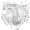
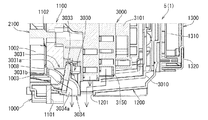
遊技盤5は、遊技者の操作によって遊技球Bが行われる遊技領域5aと、遊技領域5aの外周を区画し外形が正面視略四角形状とされた前構成部材1000と、前構成部材1000の後側に取付けられており遊技領域5aの後端を区画する板状の遊技パネル1100と、遊技パネル1100の後側下部に取付けられている基板ホルダ1200と、基板ホルダ1200の後面に取付けられており主制御基板1310及び設定変更基板1311を有している主制御ユニット1300と、主制御基板1310からの制御信号に基づいて遊技状況を表示する機能表示ユニット1400と、遊技パネル1100の後側に配置されている周辺制御ユニット1500(図12を参照)と、正面視において遊技領域5aの中央に配置されており所定の演出画像を表示可能な演出表示装置1600と、遊技パネル1100の前面に取付けられる表ユニット2000と、遊技パネル1100の後面に取付けられる裏ユニット3000と、を備えている。裏ユニット3000には、遊技状態に応じて可動演出や発光演出を行うことが可能な各種の演出ユニットを備えている。
The game board 5 includes a game area 5a in which a game ball B is played by a player's operation, a front component member 1000 that defines the outer periphery of the game area 5a and has a substantially rectangular shape in front view, and the front component member 1000 A plate-like gaming panel 1100 that is attached to the rear side and divides the rear end of the gaming area 5a, a board holder 1200 that is attached to the lower rear side of the gaming panel 1100, and a board holder 1200 that is attached to the rear surface of the board holder 1200. A main control unit 1300 having a cage main control board 1310 and a setting change board 1311, a function display unit 1400 for displaying a game status based on a control signal from the main control board 1310, and a rear panel of the game panel 1100 Peripheral control unit 1500 (see FIG. 12) arranged and a predetermined effect image arranged in the center of the game area 5a in front view A performance display device 1600 capable of displaying includes a table unit 2000 attached to the front of the gaming panel 1100, a back unit 3000 attached to the rear surface of the gaming panel 1100, the. The back unit 3000 includes various effect units capable of performing a movable effect and a light emission effect according to the gaming state.
遊技盤5の遊技領域5a内には、遊技球Bと当接し所定のゲージ配列で植設されている複数の障害釘Nと、遊技球Bの受入れ又は通過により遊技者に対して所定の特典(例えば、所定数の遊技球Bの払出し)を付与する一般入賞口2001、第一始動口2002、普通入賞口2003、第二始動口2004、及び大入賞口2005と、を備えている。障害釘Nは、遊技パネル1100の前面に植設されている。一般入賞口2001、第一始動口2002、普通入賞口2003、第二始動口2004、及び大入賞口2005は、表ユニット2000に備えられている。
In the game area 5a of the game board 5, a plurality of obstacle nails N that are in contact with the game balls B and are planted in a predetermined gauge arrangement, and a predetermined privilege for the player by accepting or passing the game balls B A general winning port 2001, a first starting port 2002, a normal winning port 2003, a second starting port 2004, and a big winning port 2005 for giving (for example, paying out a predetermined number of game balls B) are provided. The obstacle nail N is planted on the front surface of the game panel 1100. The general winning opening 2001, the first starting opening 2002, the normal winning opening 2003, the second starting opening 2004, and the big winning opening 2005 are provided in the front unit 2000.
遊技盤5の遊技領域5a内には、遊技者がハンドルユニット180のハンドル195を操作することで、遊技球Bを打込むことができる。これにより、遊技球Bが、遊技領域5a内の一般入賞口2001、第一始動口2002、普通入賞口2003、第二始動口2004、及び大入賞口2005等に、受入れられたり通過したりするように、遊技者に対してハンドル195の打込操作を楽しませることができる。
The player can drive the game ball B into the game area 5 a of the game board 5 by operating the handle 195 of the handle unit 180. As a result, the game ball B is received or passed through the general winning port 2001, the first starting port 2002, the normal winning port 2003, the second starting port 2004, the big winning port 2005, etc. in the game area 5a. As described above, the player can enjoy the operation of driving the handle 195.
また、遊技盤5は、遊技領域5a内に遊技球Bを打込むことで変化する遊技状態に応じて、演出表示装置1600に所定の演出画像を表示させたり、導光板演出ユニット3100、裏前演出ユニット3200、等により発光演出を行わせたりして、遊技者を楽しませることができる。
In addition, the game board 5 displays a predetermined effect image on the effect display device 1600 according to the game state changed by driving the game ball B into the game area 5a, or the light guide plate effect unit 3100, in front of the game area 5a. A player can be entertained by performing a light emission effect by the effect unit 3200 or the like.
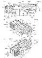
[2.外枠の全体構成]
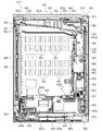
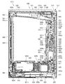
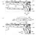
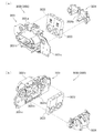
パチンコ機1の外枠2について、図13乃至図18を参照して説明する。図13はパチンコ機における外枠の正面図であり、図14は外枠の背面図であり、図15は外枠の右側面図である。また、図16は外枠を前から見た斜視図であり、図17は外枠を後ろから見た斜視図である。図18は、外枠を主な部材毎に分解して前から見た分解斜視図である。外枠2は、遊技ホール等のパチンコ機1が設置される島設備(図示は省略)に取付けられるものである。外枠2は、正面視の形状が上下に延びた四角形の枠に形成されている。
[2. Overall structure of outer frame]
The outer frame 2 of the pachinko machine 1 will be described with reference to FIGS. 13 is a front view of the outer frame in the pachinko machine, FIG. 14 is a rear view of the outer frame, and FIG. 15 is a right side view of the outer frame. FIG. 16 is a perspective view of the outer frame as viewed from the front, and FIG. 17 is a perspective view of the outer frame as viewed from the rear. FIG. 18 is an exploded perspective view in which the outer frame is disassembled for each main member and viewed from the front. The outer frame 2 is attached to an island facility (not shown) where the pachinko machine 1 such as a game hall is installed. The outer frame 2 is formed in a square frame whose shape in front view extends vertically.
外枠2は、図示するように、左右に離間しており上下に延びている外枠左組立体10及び外枠右組立体20と、外枠左組立体10及び外枠右組立体20の上端同士を連結している外枠上部材30と、外枠左組立体10及び外枠右組立体20の下端同士を連結している外枠下組立体40と、外枠上部材30の上面左端に取付けられている外枠上ヒンジ組立体50と、外枠左組立体10の右側面下部と外枠下組立体40の上面左端に取付けられている外枠下ヒンジ部材60と、を備えている。
As shown in the figure, the outer frame 2 includes an outer frame left assembly 10 and an outer frame right assembly 20 that are separated from each other and extend vertically, and an outer frame left assembly 10 and an outer frame right assembly 20. The outer frame upper member 30 that connects the upper ends, the outer frame lower assembly 40 that connects the lower ends of the outer frame left assembly 10 and the outer frame right assembly 20, and the upper surface of the outer frame upper member 30 An outer frame upper hinge assembly 50 attached to the left end, a lower right side surface of the outer frame left assembly 10, and an outer frame lower hinge member 60 attached to the upper left end of the outer frame lower assembly 40. ing.
外枠2は、本体枠4を閉じた時に、外枠下組立体40が、本体枠4における基板ユニット620のスピーカユニット620aと協働して、本体枠スピーカ622のエンクロージャ624の一部を形成していると共に、本体枠スピーカ622の後方へ出力されたサウンドを、位相反転させて前方へ放射することができるものである。
In the outer frame 2, when the main body frame 4 is closed, the outer frame lower assembly 40 forms a part of the enclosure 624 of the main body frame speaker 622 in cooperation with the speaker unit 620 a of the board unit 620 in the main body frame 4. In addition, the sound output to the rear of the main body frame speaker 622 can be radiated forward by phase inversion.
外枠2は、外枠上ヒンジ組立体50が、本体枠4の本体枠上ヒンジ部材510を着脱可能に支持することができる。外枠2は、外枠上ヒンジ組立体50と外枠下ヒンジ部材60とによって、本体枠4の本体枠上ヒンジ部材510と本体枠下ヒンジ組立体520とを同軸上で回転可能に支持することができ、本体枠4を正面視左側を中心にして前方へ開閉可能に取付けることができる。
In the outer frame 2, the outer frame upper hinge assembly 50 can detachably support the main body frame upper hinge member 510 of the main body frame 4. The outer frame 2 supports the main body frame upper hinge member 510 and the main body frame lower hinge assembly 520 of the main body frame 4 so as to be coaxially rotatable by the outer frame upper hinge assembly 50 and the outer frame lower hinge member 60. The main body frame 4 can be attached so as to be openable and closable forward with the left side of the front view as the center.
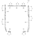
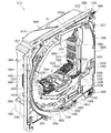
[2−1.外枠左組立体及び外枠右組立体]
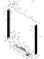
外枠2の外枠左組立体10及び外枠右組立体20について、主に図19を参照して詳細に説明する。図19は、外枠の外枠左組立体及び外枠右組立体を夫々分解して前から見た分解斜視図である。外枠2の外枠左組立体10及び外枠右組立体20は、夫々が上下に延びており、互いに左右に離間して配置されている。外枠左組立体10及び外枠右組立体20は、本体枠4の本体枠上ヒンジ部材510及び本体枠下ヒンジ組立体520を同軸上で回転可能に支持して、外枠2に対して本体枠4を開閉可能に取付けるためのものである。
[2-1. Outer frame left assembly and outer frame right assembly]
The outer frame left assembly 10 and the outer frame right assembly 20 of the outer frame 2 will be described in detail mainly with reference to FIG. FIG. 19 is an exploded perspective view in which the outer frame left assembly and the outer frame right assembly of the outer frame are disassembled and viewed from the front. The outer frame left assembly 10 and the outer frame right assembly 20 of the outer frame 2 extend vertically and are spaced apart from each other on the left and right. The outer frame left assembly 10 and the outer frame right assembly 20 support the body frame upper hinge member 510 and the body frame lower hinge assembly 520 of the body frame 4 so as to be rotatable coaxially with respect to the outer frame 2. It is for attaching the main body frame 4 so that opening and closing is possible.
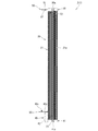
まず、外枠左組立体10は、前後方向が一定の幅(奥行)で上下に延びている外枠左部材11と、外枠左部材11の右側面上端に取付けられている左上連結部材12と、外枠左部材11の右側面下端に取付けられている左下連結部材13と、を備えている。
First, the outer frame left assembly 10 includes an outer frame left member 11 that extends vertically with a constant width (depth) in the front-rear direction, and an upper left connecting member 12 that is attached to the upper right side of the outer frame left member 11. And a lower left connecting member 13 attached to the lower end of the right side surface of the outer frame left member 11.
外枠左部材11は、一定の断面形状で上下に延びており、アルミ合金の押出型材によって形成されている。外枠左部材11は、左側面における前後方向を三等分したうちの後側の部位において平坦状に右方へ窪んでいる凹部11aと、右側面における凹部11aとは反対側の部位から右方へ膨出している膨出部11bと、膨出部11bを上下に貫通している空洞部11cと、を備えている。外枠左部材11は、凹部11aや膨出部11bによって、強度・剛性が高められていると共に、空洞部11cによって、重量が軽減されている。
The outer frame left member 11 extends vertically with a constant cross-sectional shape, and is formed of an extruded material of aluminum alloy. The outer frame left member 11 has a concave portion 11a that is flattened to the right in the rear portion of the left and right sides of the front and rear direction, and a right portion from a portion on the right side opposite to the concave portion 11a. A bulging portion 11b that bulges in the direction and a hollow portion 11c that penetrates the bulging portion 11b vertically. The outer frame left member 11 is enhanced in strength and rigidity by the concave portion 11a and the bulging portion 11b, and weight is reduced by the hollow portion 11c.
また、外枠左部材11は、左右両側面において、上下に延びた複数の溝が形成されている。左側面の複数の溝は、V字状に形成されており、右側面の複数の溝は、半円形状に形成されている。外枠左部材11は、後述する外枠右組立体20の外枠右部材21と左右対称形状に形成されている。
The outer frame left member 11 is formed with a plurality of grooves extending vertically on both left and right side surfaces. The plurality of grooves on the left side surface are formed in a V shape, and the plurality of grooves on the right side surface are formed in a semicircular shape. The outer frame left member 11 is formed symmetrically with an outer frame right member 21 of an outer frame right assembly 20 described later.
左上連結部材12は、外枠左部材11の上端と外枠上部材30の左端とを連結するためのものである。左上連結部材12は、水平に延びた平板状の水平固定部12aと、水平固定部12aの左辺における前後方向の中間から上方へ延出している平板状の上横固定部12bと、水平固定部12aの左辺における上横固定部12bの前後両側から下方へ延出している平板状の一対の下横固定部12cと、を備えている。左上連結部材12は、平板状の金属板を屈曲させて形成されている。
The upper left connecting member 12 is for connecting the upper end of the outer frame left member 11 and the left end of the outer frame upper member 30. The upper left connecting member 12 includes a horizontally extending flat plate-like horizontal fixing portion 12a, a flat upper plate fixing portion 12b extending from the middle in the front-rear direction on the left side of the horizontal fixing portion 12a, and a horizontal fixing portion. A pair of flat horizontal lower fixing portions 12c extending downward from both front and rear sides of the upper horizontal fixing portion 12b on the left side of 12a. The upper left connecting member 12 is formed by bending a flat metal plate.
左上連結部材12は、後側の下横固定部12cを外枠左部材11の空洞部11c内に挿入させると共に、水平固定部12aを外枠左部材11の上端に当接させ、更に、前側及び後側の下横固定部12cを外枠左部材11の右側面に当接させた状態で、外枠左部材11の左側面の外側から下横固定部12cにビスを捩じ込むことで、外枠左部材11に取付けられる。また、左上連結部材12は、水平固定部12aを外枠上部材30の左端側の下面に当接させると共に、上横固定部12bを外枠上部材30の左側面の切欠部30a内に挿入させた状態で、水平固定部12a及び上横固定部12bを通して外枠上部材30にビスを捩じ込むことで、外枠上部材30に取付けられる。
The upper left connecting member 12 has the rear lower horizontal fixing portion 12c inserted into the hollow portion 11c of the outer frame left member 11, the horizontal fixing portion 12a brought into contact with the upper end of the outer frame left member 11, and the front side Further, by screwing a screw into the lower horizontal fixing portion 12c from the outside of the left side surface of the outer frame left member 11 in a state where the rear lower fixing portion 12c is in contact with the right side surface of the outer frame left member 11. It is attached to the outer frame left member 11. In addition, the upper left connecting member 12 causes the horizontal fixing portion 12a to abut the lower surface of the outer frame upper member 30 on the left end side, and the upper horizontal fixing portion 12b is inserted into the left notch 30a of the outer frame upper member 30. In this state, the screw is screwed into the outer frame upper member 30 through the horizontal fixing portion 12a and the upper horizontal fixing portion 12b, so that the outer frame upper member 30 is attached.
左下連結部材13は、外枠左部材11の下端と外枠下組立体40(外枠下部材41)の左端とを連結するためのものである。左下連結部材13は、水平に延びた平板状の水平固定部13aと、水平固定部13aの左辺から上方へ延出していると共に水平固定部13aよりも後方へ延出している平板状の上横固定部13bと、上横固定部13bの下辺における水平固定部13aよりも後側の部位から下方へ延出している平板状の下横固定部13cと、上横固定部13bの後辺から右方へ短く延出している平板状の当接部13dと、を備えている。左下連結部材13は、平板状の金属板を屈曲させて形成されている。
The lower left connecting member 13 is for connecting the lower end of the outer frame left member 11 and the left end of the outer frame lower assembly 40 (outer frame lower member 41). The lower left connecting member 13 includes a horizontally extending flat plate-like horizontal fixing portion 13a, and a flat plate-like upper and horizontal portion extending upward from the left side of the horizontal fixing portion 13a and extending rearward from the horizontal fixing portion 13a. The fixing portion 13b, a flat plate-like lower horizontal fixing portion 13c extending downward from the rear side of the horizontal fixing portion 13a on the lower side of the upper horizontal fixing portion 13b, and the right side from the rear side of the upper horizontal fixing portion 13b And a flat plate-like contact portion 13d extending short in the direction. The lower left connecting member 13 is formed by bending a flat metal plate.
左下連結部材13は、当接部13dの後面を外枠左部材11の膨出部11bの前面に当接させると共に、上横固定部13bの左側面を外枠左部材11の右側面に当接させ、水平固定部13aの下面を外枠左部材11の下端と一致させた状態で、外枠左部材11の左側面の外側から上横固定部13bにビスを捩じ込むことで、外枠左部材11に取付けられる。また、左下連結部材13は、水平固定部13aを外枠下部材41の左端側の上面に当接させると共に、下横固定部13cを外枠下部材41の左側面の切欠部41aに挿入させた状態で、水平固定部13a及び下横固定部13cを通して外枠下部材41にビスを捩じ込むことで、外枠下部材41に取付けられる。
The lower left connecting member 13 abuts the rear surface of the abutting portion 13d on the front surface of the bulging portion 11b of the outer frame left member 11, and abuts the left side surface of the upper horizontal fixing portion 13b on the right side surface of the outer frame left member 11. The screw is screwed into the upper horizontal fixing portion 13b from the outside of the left side surface of the outer frame left member 11 in a state where the lower surface of the horizontal fixing portion 13a is aligned with the lower end of the outer frame left member 11, It is attached to the frame left member 11. The lower left connecting member 13 causes the horizontal fixing portion 13a to abut on the upper surface on the left end side of the outer frame lower member 41 and allows the lower horizontal fixing portion 13c to be inserted into the notch portion 41a on the left side surface of the outer frame lower member 41. In this state, the screw is screwed into the outer frame lower member 41 through the horizontal fixing portion 13a and the lower horizontal fixing portion 13c, thereby being attached to the outer frame lower member 41.
次に、外枠右組立体20は、前後方向が一定の幅(奥行)で上下に延びている外枠右部材21と、外枠右部材21の左側面上端に取付けられている右上連結部材22と、外枠右部材21の左側面下端に取付けられている右下連結部材23と、外枠右部材21の左側面上部に取付けられている上鉤掛部材24と、外枠右部材21の左側面下部に取付けられている下鉤掛部材25と、を備えている。
Next, the outer frame right assembly 20 includes an outer frame right member 21 that extends vertically with a constant width (depth) in the front-rear direction, and an upper right connecting member that is attached to the upper left end of the outer frame right member 21. 22, a lower right connecting member 23 attached to the lower left side lower end of the outer frame right member 21, an upper hook member 24 attached to the upper left side of the outer frame right member 21, and the outer frame right member 21. And a lower hook member 25 attached to the lower part of the left side surface.
外枠右部材21は、一定の断面形状で上下に延びており、アルミ合金の押出型材によって形成されている。外枠右部材21は、右側面における前後方向を三等分したうちの後側の部位において平坦状に左方へ窪んでいる凹部21aと、左側面における凹部21aとは反対側の部位から左方へ膨出している膨出部21bと、膨出部21bを上下に貫通している空洞部21cと、を備えている。外枠右部材21は、凹部21aや膨出部21bによって、強度・剛性が高められていると共に、空洞部21cによって、重量が軽減されている。
The outer frame right member 21 extends vertically with a constant cross-sectional shape, and is formed of an aluminum alloy extrusion mold. The outer frame right member 21 has a concave portion 21a that is recessed leftward in a flat shape in a rear portion of the right and left sides of the front and rear direction, and a left portion from a portion on the left side opposite to the concave portion 21a. A bulging portion 21b that bulges in the direction, and a hollow portion 21c that vertically penetrates the bulging portion 21b. The outer frame right member 21 is increased in strength and rigidity by the concave portion 21a and the bulging portion 21b, and the weight is reduced by the hollow portion 21c.
また、外枠右部材21は、左右両側面において、上下に延びた複数の溝が形成されている。右側面の複数の溝は、V字状に形成されており、左側面の複数の溝は、半円形状に形成されている。外枠右部材21は、外枠左組立体10の外枠左部材11と左右対称形状に形成されている。
The outer frame right member 21 has a plurality of grooves extending vertically on both left and right side surfaces. The plurality of grooves on the right side surface are formed in a V shape, and the plurality of grooves on the left side surface are formed in a semicircular shape. The outer frame right member 21 is formed symmetrically with the outer frame left member 11 of the outer frame left assembly 10.
右上連結部材22は、外枠右部材21の上端と外枠上部材30の右端とを連結するためのものである。右上連結部材22は、水平に延びた平板状の水平固定部22aと、水平固定部22aの右辺における前後方向の中間から上方へ延出している平板状の上横固定部22bと、水平固定部22aの右辺における上横固定部22bの前後両側から下方へ延出している平板状の一対の下横固定部22cと、を備えている。右上連結部材22は、平板状の金属板を屈曲させて形成されている。
The upper right connecting member 22 is for connecting the upper end of the outer frame right member 21 and the right end of the outer frame upper member 30. The upper right connecting member 22 includes a horizontally extending flat plate-like horizontal fixing portion 22a, a flat upper plate fixing portion 22b extending from the middle in the front-rear direction on the right side of the horizontal fixing portion 22a, and a horizontal fixing portion. A pair of flat horizontal lower fixing portions 22c extending downward from both front and rear sides of the upper horizontal fixing portion 22b on the right side of 22a. The upper right connecting member 22 is formed by bending a flat metal plate.
右上連結部材22は、後側の下横固定部22cを外枠右部材21の空洞部21c内に挿入させると共に、水平固定部22aを外枠右部材21の上端に当接させ、更に、前側及び後側の下横固定部22cを外枠右部材21の左側面に当接させた状態で、外枠右部材21の右側面の外側から下横固定部22cにビスを捩じ込むことで、外枠右部材21に取付けられる。また、右上連結部材22は、水平固定部22aを外枠上部材30の右端側の下面に当接させると共に、上横固定部22bを外枠上部材30の右側面の切欠部30a内に挿入させた状態で、水平固定部22a及び上横固定部22bを通して外枠上部材30にビスを捩じ込むことで、外枠上部材30に取付けられる。
The upper right connecting member 22 has the rear lower horizontal fixing portion 22c inserted into the hollow portion 21c of the outer frame right member 21, the horizontal fixing portion 22a abutted against the upper end of the outer frame right member 21, and the front side Further, by screwing a screw into the lower horizontal fixing portion 22c from the outside of the right side surface of the outer frame right member 21 in a state where the rear lower fixing portion 22c is in contact with the left side surface of the outer frame right member 21. The outer frame right member 21 is attached. Further, the upper right connecting member 22 makes the horizontal fixing portion 22a abut on the lower surface on the right end side of the outer frame upper member 30, and the upper horizontal fixing portion 22b is inserted into the notch portion 30a on the right side surface of the outer frame upper member 30. In this state, the screw is screwed into the outer frame upper member 30 through the horizontal fixing portion 22a and the upper horizontal fixing portion 22b, thereby being attached to the outer frame upper member 30.
右下連結部材23は、外枠右部材21の下端と外枠下組立体40(外枠下部材41)の右端とを連結するためのものである。右下連結部材23は、水平に延びた平板状の水平固定部23aと、水平固定部23aの右辺から上方へ延出していると共に水平固定部23aよりも後方へ延出している平板状の上横固定部23bと、上横固定部23bの下辺における水平固定部23aよりも後側の部位から下方へ延出している平板状の下横固定部23cと、上横固定部23bの後辺から左方へ短く延出している平板状の当接部23dと、を備えている。右下連結部材23は、平板状の金属板を屈曲させて形成されている。
The lower right connecting member 23 is for connecting the lower end of the outer frame right member 21 and the right end of the outer frame lower assembly 40 (outer frame lower member 41). The lower right connecting member 23 includes a horizontally extending flat plate-like horizontal fixing portion 23a, and a flat plate-like upper portion extending upward from the right side of the horizontal fixing portion 23a and extending backward from the horizontal fixing portion 23a. From the lateral fixing portion 23b, the flat lower lateral fixing portion 23c extending downward from the rear side of the horizontal fixing portion 23a on the lower side of the upper lateral fixing portion 23b, and the rear side of the upper lateral fixing portion 23b And a flat plate-like contact portion 23d extending short to the left. The lower right connecting member 23 is formed by bending a flat metal plate.
右下連結部材23は、当接部23dの後面を外枠右部材21の膨出部21bの前面に当接させると共に、上横固定部23bの右側面を外枠右部材21の左側面に当接させ、水平固定部23aの下面を外枠右部材21の下端と一致させた状態で、外枠右部材21の右側面の外側から上横固定部23bにビスを捩じ込むことで、外枠右部材21に取付けられる。また、右下連結部材23は、水平固定部23aを外枠下部材41の右端側の上面に当接させると共に、下横固定部23cを外枠下部材41の右側面の切欠部41aに挿入させた状態で、水平固定部23a及び下横固定部23cを通して外枠下部材41にビスを捩じ込むことで、外枠下部材41に取付けられる。
The lower right connecting member 23 abuts the rear surface of the abutting portion 23d on the front surface of the bulging portion 21b of the outer frame right member 21, and the right side surface of the upper lateral fixing portion 23b on the left side surface of the outer frame right member 21. The screw is screwed into the upper lateral fixing portion 23b from the outside of the right side surface of the outer frame right member 21 with the lower surface of the horizontal fixing portion 23a being in contact with the lower end of the outer frame right member 21, It is attached to the outer frame right member 21. Further, the lower right connecting member 23 causes the horizontal fixing portion 23a to abut on the upper surface on the right end side of the outer frame lower member 41, and the lower horizontal fixing portion 23c is inserted into the cutout portion 41a on the right side surface of the outer frame lower member 41. In this state, the screw is screwed into the outer frame lower member 41 through the horizontal fixing portion 23a and the lower horizontal fixing portion 23c, thereby being attached to the outer frame lower member 41.
上鉤掛部材24及び下鉤掛部材25は、後述する本体枠4における施錠ユニット650の外枠用鉤653が掛止されるものである。上鉤掛部材24は、前後方向に一定の幅で上下に延びており外枠右部材21の左側面に取付けられる平板状の取付部24aと、取付部24aの前辺から左方へ延出しており上側の外枠用鉤653が掛止される平板状の掛止片部24bと、を備えている。
The upper hook member 24 and the lower hook member 25 are for hooking an outer frame hook 653 of the locking unit 650 in the main body frame 4 described later. The upper hook member 24 extends vertically with a constant width in the front-rear direction, and is attached to the left side surface of the outer frame right member 21 and extends leftward from the front side of the attachment portion 24a. And a flat plate-like hooking piece 24b on which the outer upper frame flange 653 is hooked.
下鉤掛部材25は、前後方向に一定の幅で上下に延びており外枠右部材21の左側面に取付けられる平板状の取付部25aと、取付部25aの前辺から左方へ延出しており下側の外枠用鉤653が掛止される平板状の掛止片部25bと、掛止片部25bを前後に貫通しており下側の外枠用鉤653が挿通可能な挿通口25cと、を備えている。
The lower hook member 25 extends vertically with a certain width in the front-rear direction, and is attached to the left side surface of the outer frame right member 21 and extends leftward from the front side of the attachment portion 25a. A flat plate-like latching piece 25b to which the lower outer frame hook 653 is hooked, and an insertion through which the lower outer frame hook 653 can be inserted through the hooking piece 25b in the front-rear direction And a mouth 25c.
[2−2.外枠上部材]
外枠2の外枠上部材30について、主に図18を参照して詳細に説明する。外枠上部材30は、左右に離間している外枠左組立体10及び外枠右組立体20の上端同士を連結するためのものである。外枠上部材30は、前後方向の幅が、外枠左部材11及び外枠右部材21の前後方向と略同じ幅で、上下方向の厚さが一定で、左右方向に延びており、木材によって形成されている。外枠上部材30は、左右方向の長さが、後述する外枠下組立体40の外枠下部材41の左右方向の長さと同じに形成されている。
[2-2. Outer frame member]
The outer frame upper member 30 of the outer frame 2 will be described in detail mainly with reference to FIG. The outer frame upper member 30 is for connecting the upper ends of the outer frame left assembly 10 and the outer frame right assembly 20 that are separated from each other in the left-right direction. The outer frame upper member 30 has a width in the front-rear direction that is substantially the same as the front-rear direction of the outer frame left member 11 and the outer frame right member 21, has a constant vertical thickness, and extends in the left-right direction. Is formed by. The outer frame upper member 30 is formed such that the length in the left-right direction is the same as the length in the left-right direction of the outer frame lower member 41 of the outer frame lower assembly 40 described later.
外枠上部材30は、左右両側面における前後方向の中央において、上下に貫通した状態で左右方向中央側へ夫々窪んでいる切欠部30aを備えている。これら左右両端の切欠部30aには、左上連結部材12の上横固定部12b及び右上連結部材22の上横固定部22bが夫々挿入された状態で取付けられる。
The outer frame upper member 30 includes notches 30a that are recessed toward the center in the left-right direction in a state of penetrating vertically in the center in the front-rear direction on both left and right side surfaces. The upper horizontal fixing portion 12b of the upper left connecting member 12 and the upper horizontal fixing portion 22b of the upper right connecting member 22 are respectively attached to the cutout portions 30a at both left and right ends.
また、外枠上部材30は、左側端部において、上面と前面が一般面よりも窪んだ取付段部30bを備えている。この取付段部30bには、後述する外枠上ヒンジ組立体50が取付けられる。
Further, the outer frame upper member 30 includes an attachment step portion 30b whose upper surface and front surface are recessed from the general surface at the left end. The outer frame hinge assembly 50 described later is attached to the attachment step 30b.
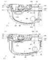
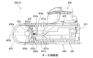
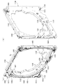
[2−3.外枠下組立体]
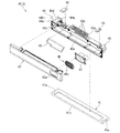
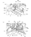
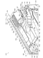
外枠2の外枠下組立体40について、主に図20を参照して詳細に説明する。図20は、外枠の外枠下組立体を分解して前から見た分解斜視図である。外枠下組立体40は、左右に離間している外枠左組立体10及び外枠右組立体20の下端同士を連結すると共に、パチンコ機1において扉枠3よりも下側を閉鎖して装飾するためのものである。
[2-3. Outer frame assembly]
The outer frame lower assembly 40 of the outer frame 2 will be described in detail mainly with reference to FIG. FIG. 20 is an exploded perspective view of the outer frame lower assembly of the outer frame as seen from the front. The outer frame lower assembly 40 connects the lower ends of the outer frame left assembly 10 and the outer frame right assembly 20 that are separated from each other to the left and right, and closes the lower side of the door frame 3 in the pachinko machine 1. It is for decoration.
外枠下組立体40は、左右に離間している外枠左組立体10及び外枠右組立体20の下端同士を連結しており左右に延びている外枠下部材41と、外枠下部材41の前方に配置されており外枠下部材41に沿って左右に延びていると共に後方が開放されている箱状の幕板前部材42と、幕板前部材42の後側に取付けられていると共に外枠下部材41の上面に取付けられており前方が開放されている左右に延びた箱状の幕板後部材43と、幕板後部材43の上面における左端に形成されている球噛防止機構44と、を備えている。
The outer frame lower assembly 40 connects the lower ends of the outer frame left assembly 10 and the outer frame right assembly 20 which are separated from each other to the left and right, and an outer frame lower member 41 extending left and right. A box-shaped curtain plate front member 42 that is disposed in front of the member 41, extends left and right along the outer frame lower member 41, and is open to the rear, and is attached to the rear side of the curtain plate front member 42. A box-shaped curtain plate rear member 43 that is attached to the upper surface of the outer frame lower member 41 and that extends to the left and right, and a ball engagement prevention formed at the left end of the upper surface of the curtain plate rear member 43. And a mechanism 44.
外枠下部材41は、前後方向の幅が、外枠左部材11及び外枠右部材21の前後方向と略同じ幅で、上下方向の厚さが一定で、左右方向に延びており、木材によって形成されている。外枠下部材41は、左右方向の長さが、外枠上部材30の左右方向の長さと同じに形成されている。
The outer frame lower member 41 has a width in the front-rear direction that is substantially the same as the front-rear direction of the outer frame left member 11 and the outer frame right member 21, has a constant vertical thickness, and extends in the left-right direction. Is formed by. The outer frame lower member 41 is formed to have the same length in the left-right direction as the length of the outer frame upper member 30 in the left-right direction.
外枠下部材41は、左右両側面における前後方向の中央において、上下に貫通した状態で左右方向中央側へ夫々窪んでいる切欠部41aを備えている。これら左右両端の切欠部41aには、左下連結部材13の下横固定部13c及び右下連結部材23の下横固定部23cが夫々挿入された状態で取付けられる。これにより、外枠左部材11及び外枠右部材21の下端同士を連結することができる。
The outer frame lower member 41 includes notches 41a that are recessed toward the center in the left-right direction in a state of penetrating vertically in the center in the front-rear direction on both left and right side surfaces. The left and right cutouts 41a are attached with the lower horizontal fixing portion 13c of the lower left connecting member 13 and the lower horizontal fixing portion 23c of the lower right connecting member 23 inserted respectively. Thereby, the lower ends of the outer frame left member 11 and the outer frame right member 21 can be connected to each other.
また、外枠下部材41は、上面から凹んでおり、幕板後部材43の下部が挿入される凹部41bを備えている。凹部41bは、左右に延びていると共に、前後方向中央の後ろ寄りの位置から前端側へ抜けている。この凹部41bにより、幕板前部材42及び幕板後部材43により形成される幕板内部空間40aの容積を可及的に広くしている。
Further, the outer frame lower member 41 is recessed from the upper surface and includes a recess 41b into which the lower part of the curtain plate rear member 43 is inserted. The concave portion 41b extends to the left and right, and extends from the position closer to the rear of the center in the front-rear direction to the front end side. By this recess 41b, the volume of the curtain plate internal space 40a formed by the curtain plate front member 42 and the curtain plate rear member 43 is made as large as possible.
幕板前部材42は、左右方向の長さが外枠下部材41と同じ長さに延びており、高さに対して前後方向の奥行が短い横長の直方体状の箱状に形成されており、後側の全面が開放されている。幕板前部材42は、開放されている後側を、幕板後部材43によって閉鎖することで、幕板後部材43と協働して本体枠スピーカ622のエンクロージャ624の一部となる幕板内部空間40aを形成する。幕板前部材42は、右端付近の前面において、前後に貫通していると共に左右に延びている長孔状の開口部42aを備えている。
The curtain plate front member 42 has a lateral length that is the same as the length of the outer frame lower member 41, and is formed in a horizontally-long rectangular parallelepiped box shape whose depth in the front-rear direction is short with respect to the height. The entire rear side is open. The curtain plate front member 42 closes the opened rear side by the curtain plate rear member 43, thereby cooperating with the curtain plate rear member 43 to be a part of the enclosure 624 of the main body frame speaker 622. A space 40a is formed. The curtain plate front member 42 is provided with a long hole-like opening 42a that penetrates in the front-rear direction and extends to the left and right in the front surface near the right end.
幕板後部材43は、左右方向の長さが外枠下部材41よりも若干短く延びており、前方が開放された箱状に形成されている。幕板後部材43は、前面に幕板前部材42を取付けることで、幕板前部材42と協働して本体枠スピーカ622のエンクロージャ624の一部となる幕板内部空間40aを形成する。幕板後部材43は、上面における左右方向中央部において、左右に延びていると共に上方へ突出しており幕板内部空間40aと連通している筒状の接続筒部43aを有している。接続筒部43aは、上端が、幕板後部材43の一般的な上面と一致している前端側から後方へ向かうほど上方へ位置するように傾斜している。本実施形態では、接続筒部43aの上端は、45度の角度で傾斜している。
The curtain plate rear member 43 has a length in the left-right direction that is slightly shorter than the outer frame lower member 41, and is formed in a box shape with the front open. The curtain plate rear member 43 has a curtain plate front member 42 attached to the front surface to form a curtain plate internal space 40a that becomes a part of the enclosure 624 of the body frame speaker 622 in cooperation with the curtain plate front member 42. The curtain plate rear member 43 has a cylindrical connecting cylinder portion 43a that extends in the left and right direction and protrudes upward at the center portion in the horizontal direction on the upper surface and communicates with the curtain plate internal space 40a. The connecting cylinder portion 43a is inclined so that the upper end is positioned upward as it goes rearward from the front end side that coincides with the general upper surface of the curtain plate rear member 43. In the present embodiment, the upper end of the connection tube portion 43a is inclined at an angle of 45 degrees.
この接続筒部43aは、左右方向の長さが、幕板後部材43全体の約1/3の長さに形成されていると共に、前後方向の奥行が、幕板後部材43全体の奥行よりも若干短く形成されている。接続筒部43a内には、前端側と後端側とを結ぶ複数のリブ43bが備えられている。この接続筒部43aの上端には、外枠2に対して本体枠4を閉じた時に、本体枠4における基板ユニット620のスピーカユニット620aにおけるスピーカカバー621の接続部621cが接続されて、スピーカユニット620aの内部空間と連通した状態となり、エンクロージャ624を形成する。
The connecting cylinder portion 43a is formed so that the length in the left-right direction is about 1/3 of the entire curtain plate rear member 43, and the depth in the front-rear direction is larger than the depth of the entire curtain plate rear member 43. Is also slightly shorter. A plurality of ribs 43b connecting the front end side and the rear end side are provided in the connection cylinder portion 43a. When the main body frame 4 is closed with respect to the outer frame 2, the connection portion 621c of the speaker cover 621 of the substrate unit 620 of the main body frame 4 is connected to the upper end of the connection cylinder portion 43a. The enclosure 624 is formed in communication with the internal space of 620a.
球噛防止機構44は、幕板後部材43の上面における左端において、外枠下ヒンジ部材60の部位に遊技球Bが滞留することで、外枠2と本体枠4との間に遊技球Bが挟まれるのを防止するためのものである。
The ball biting prevention mechanism 44 is configured such that the game ball B stays at a portion of the outer frame lower hinge member 60 at the left end on the upper surface of the curtain plate rear member 43, so that the game ball B is placed between the outer frame 2 and the main body frame 4. This is to prevent pinching.
球噛防止機構44は、幕板後部材43の上面における左端に形成されており、後述する外枠下ヒンジ部材60が際されるように平坦に形成された載置部44aと、載置部44aの左端において上方へ向かって開口している第一排出口44bと、載置部44aにおける第一排出口44bよりも右方で上方へ向かって開口している第二排出口44cと、載置部44aの後辺及び右辺から上方へ延出している立壁部44dと、立壁部44dの上端から前方へ突出していると共に上面が後方へ向かうに従って上方に位置するように傾斜している上端突出部44eと、を備えている。
The ball biting prevention mechanism 44 is formed at the left end on the upper surface of the curtain plate rear member 43, and a mounting portion 44a formed flat so that an outer frame lower hinge member 60 described later is confronted, and a mounting portion A first discharge port 44b that opens upward at the left end of 44a, a second discharge port 44c that opens upward to the right of the first discharge port 44b in the mounting portion 44a, An upright wall portion 44d extending upward from the rear side and the right side of the placement portion 44a, and an upper end protrusion that protrudes forward from the upper end of the upright wall portion 44d and is inclined so that the upper surface is located upward as it goes rearward. Part 44e.
第一排出口44bは、後述する外枠下ヒンジ部材60の排出孔60dと一致する位置に形成されている。第一排出口44b及び第二排出口44cは、遊技球Bが通過可能な大きさに形成されている。第一排出口44b及び第二排出口44cは、幕板内部空間40aとは連通しておらず、幕板後部材43の後面に開口している。従って、第一排出口44b及び第二排出口44cに進入した遊技球Bを、幕板後部材43の後方へ排出することができる。
The 1st discharge port 44b is formed in the position which corresponds with the discharge hole 60d of the outer frame lower hinge member 60 mentioned later. The 1st discharge port 44b and the 2nd discharge port 44c are formed in the magnitude | size which the game ball B can pass. The first discharge port 44 b and the second discharge port 44 c do not communicate with the curtain plate internal space 40 a and are opened on the rear surface of the curtain plate rear member 43. Therefore, the game ball B that has entered the first discharge port 44 b and the second discharge port 44 c can be discharged to the rear of the curtain plate rear member 43.
この球噛防止機構44は、球噛防止機構44は、外枠下ヒンジ部材60と後述する本体枠下ヒンジ組立体520との間の隙間を通して、ピアノ線等の不正な工具が挿入された場合、載置部44aの後端から立上っている立壁部44dにより、不正な工具の侵入を阻止することができる。仮に、不正な工具の先端が立壁部44dに当接することで、上方へ曲がったとしても、立壁部44dの上端に備えられている前方へ突出した上端突出部44eに当接し、これ以上の侵入を阻止することができる。従って、外枠下ヒンジ部材60の部位を介して、不正行為が行われるのを防止することができる。
This ball biting prevention mechanism 44 is a case where an illegal tool such as a piano wire is inserted through a gap between the outer frame lower hinge member 60 and a main body frame lower hinge assembly 520 described later. Intrusion of an unauthorized tool can be prevented by the standing wall portion 44d rising from the rear end of the placement portion 44a. Even if the tip of an unauthorized tool contacts the standing wall 44d and bends upward, it contacts the upper end protruding part 44e provided at the upper end of the standing wall 44d and further intrudes. Can be prevented. Therefore, it is possible to prevent an illegal act from being performed through the portion of the outer frame lower hinge member 60.
ところで、載置部44aの後端に立壁部44dを備えた場合、外枠2に対して本体枠4を開けた時に、何らかの理由により載置部44a上に落下した遊技球Bが、立壁部44dによって外枠2の後方への移動が阻止されるため、載置部44a上に遊技球Bが滞留し易くなる。そして、載置部44a上に遊技球Bが滞留していると、外枠2に対して本体枠4を閉じる際に、外枠2と本体枠4との間に遊技球Bが挟み込まれてしまい、本体枠4を閉じることができなくなる問題が発生する。
By the way, when the standing wall portion 44d is provided at the rear end of the placement portion 44a, when the main body frame 4 is opened with respect to the outer frame 2, the game ball B dropped on the placement portion 44a for some reason is Since the rearward movement of the outer frame 2 is prevented by 44d, the game ball B is likely to stay on the placement portion 44a. If the game ball B stays on the mounting portion 44 a, the game ball B is sandwiched between the outer frame 2 and the main body frame 4 when the main body frame 4 is closed with respect to the outer frame 2. Therefore, there arises a problem that the main body frame 4 cannot be closed.
これに対して、本実施形態の球噛防止機構44では、外枠下ヒンジ部材60上や載置部44a上に落下した遊技球Bを、外枠下ヒンジ部材60の排出孔60dと第一排出口44bを通して、又は、第二排出口44cを通して、遊技球Bを幕板後部材43の後方(外枠2の後方)へ排出することができ、外枠2と本体枠4との間に遊技球Bが挟まれるのを防止することができる。
On the other hand, in the ball biting prevention mechanism 44 of the present embodiment, the game ball B dropped on the outer frame lower hinge member 60 or the placement portion 44a is transferred to the discharge hole 60d of the outer frame lower hinge member 60 and the first. The game ball B can be discharged to the rear of the curtain plate rear member 43 (rear of the outer frame 2) through the discharge port 44b or the second discharge port 44c, and between the outer frame 2 and the main body frame 4. It is possible to prevent the game ball B from being caught.
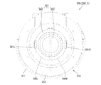
外枠下組立体40は、幕板前部材42及び幕板後部材43の上面に左右に離間して配置されている一対の案内部材45と、幕板前部材42の開口部42aを後側から閉鎖している平板状のグリル部材46と、グリル部材46を挟んで開口部42aを閉鎖するように幕板前部材42の内部に取付けられており前後に延びた二つの円筒を有したポート部材47と、幕板後部材43の接続筒部43aの上端に配置される枠状のシール部材48と、を備えている。
The outer frame lower assembly 40 closes the pair of guide members 45 disposed on the upper surfaces of the curtain plate front member 42 and the curtain plate rear member 43 so as to be separated from each other on the left and right sides, and the opening 42a of the curtain plate front member 42 from the rear side. A flat grill member 46, and a port member 47 having two cylinders attached to the front of the curtain plate front member 42 so as to close the opening 42a across the grill member 46 and extending in the front-rear direction. And a frame-shaped seal member 48 disposed at the upper end of the connecting tube portion 43a of the curtain plate rear member 43.
一対の案内部材45は、外枠2に対して本体枠4を閉じた時に、扉枠3の下端が当接するものである。案内部材45は、摩擦抵抗の低い低摩擦材料によって形成されており、本体枠4の下端を滑り易くして、開閉を容易にしている。
The pair of guide members 45 are configured such that the lower end of the door frame 3 comes into contact with the outer frame 2 when the main body frame 4 is closed. The guide member 45 is made of a low friction material having a low frictional resistance, and makes the lower end of the main body frame 4 easy to slide to facilitate opening and closing.
グリル部材46は、左右方向へ延びた帯板状で、上下方向へ間隔をあけて設けられている複数の羽根部46bを有している。羽根部46bは、前端側が後端側よりも高くなるように、傾斜した状態で設けられている(図47を参照)。このグリル部材46は、羽根部46b同士の間の隙間を通して、幕板前部材42の内部(幕板内部空間40a)と外部とを通気可能に連通させている。
The grill member 46 has a strip shape extending in the left-right direction, and has a plurality of blade portions 46 b provided at intervals in the up-down direction. The blade portion 46b is provided in an inclined state so that the front end side is higher than the rear end side (see FIG. 47). The grill member 46 communicates the interior (curtain plate internal space 40a) of the curtain plate front member 42 with the outside through a gap between the blade portions 46b.
ポート部材47は、二つの円筒により、グリル部材46における羽根部46b同士の間の隙間を介して幕板内部空間40a(エンクロージャ624)と外枠2の前方とを連通させている。ポート部材47は、二つの円筒が、所定の内径で所定の長さに形成されており、ヘルムホルツ共鳴の原理により本体枠スピーカ622から後方(エンクロージャ624内)へ発せられた低音を共振・増幅させて、豊かな低音を外枠2の前方(遊技者側)へ放射することができる。つまり、本実施形態では、本体枠スピーカ622のエンクロージャ624がバスレフ型とされており、遊技者に対して重低音を聞かせることができる。
The port member 47 communicates the curtain plate internal space 40 a (enclosure 624) and the front of the outer frame 2 through a gap between the blade portions 46 b of the grill member 46 by two cylinders. The port member 47 has two cylinders that are formed with a predetermined inner diameter and a predetermined length. The port member 47 resonates and amplifies a bass sound emitted backward (inside the enclosure 624) from the main body frame speaker 622 based on the principle of Helmholtz resonance. Thus, a rich bass can be radiated to the front (player side) of the outer frame 2. That is, in this embodiment, the enclosure 624 of the main body frame speaker 622 is a bass-reflex type, and a player can hear a heavy bass.
シール部材48は、外枠2に対して本体枠4を閉じた時に、接続筒部43aの上端と本体枠4におけるスピーカカバー621の接続部621cの下端との間に挟まれて圧縮されるものであり、接続筒部43aと接続部621cとの間から本体枠スピーカ622のエンクロージャ624内の音が漏れるのを防止するものである。
When the main body frame 4 is closed with respect to the outer frame 2, the seal member 48 is sandwiched and compressed between the upper end of the connection cylinder portion 43 a and the lower end of the connection portion 621 c of the speaker cover 621 in the main body frame 4. Thus, the sound in the enclosure 624 of the main body frame speaker 622 is prevented from leaking between the connection tube portion 43a and the connection portion 621c.
本実施形態のグリル部材46によれば、本体枠スピーカ622により幕板内部空間40aから外部へ放出される空気振動を、傾斜している複数の羽根部46bにより、斜め上前方のハンドルカバーユニット290におけるハンドルカバー295の下側の切欠開口部295bを通してハンドルユニット180が収容されているハンドルカバーベース291の前筒部291a内へ向けさせることができる。これにより、遊技者が、ハンドルカバー295(ハンドルカバーベース291の前筒部291a)の内側に手指を突っ込んで、ハンドル195を回転操作(遊技球Bの打込装置)している時に、本体枠スピーカ622を振動させて前筒部291a内へ風を送ることで、遊技者を驚かせることができ、これまでにない演出を行うことができる。
According to the grill member 46 of the present embodiment, the handle cover unit 290 that is obliquely upward and forward is caused by the plurality of inclined blade portions 46b to cause the air vibration released from the curtain inner space 40a to the outside by the main body frame speaker 622. Can be directed through the notch opening 295b on the lower side of the handle cover 295 into the front cylinder 291a of the handle cover base 291 in which the handle unit 180 is accommodated. As a result, when the player pushes his / her finger inside the handle cover 295 (front cylinder portion 291a of the handle cover base 291) and rotates the handle 195 (game ball B driving device), the main body frame By vibrating the speaker 622 and sending the wind into the front tube portion 291a, the player can be surprised and an unprecedented performance can be performed.
また、ポート部材47を前方へ向かって開口させていることから、グリル部材46の複数の羽根部46bを通ってポート部材47から放出される音圧の一部が、前方へ放出されることとなるため、本パチンコ機1の前方に着座している遊技者や、本パチンコ機1が設置されている遊技ホール内を回遊している他の遊技者に対しても、ポート部材47から放出される演出サウンドが聞えることとなり、演出サウンドによっても遊技者の関心を引付けることができ、遊技者に対する訴求力の高いパチンコ機1を提供することができる。
Further, since the port member 47 is opened forward, a part of the sound pressure discharged from the port member 47 through the plurality of blade portions 46b of the grill member 46 is discharged forward. Therefore, it is also released from the port member 47 to a player sitting in front of the pachinko machine 1 and other players who are traveling in the game hall where the pachinko machine 1 is installed. Thus, the pachinko machine 1 that can attract the player's interest by the effect sound and has high appeal to the player can be provided.
また、本体枠4に設けられている本体枠スピーカ622のエンクロージャ624に対して、ポート部材47を外枠2の外枠下組立体40に設けていることから、エンクロージャ624の容積を大きくすることができるため、より重低音の演出サウンドを出力することができ、遊技者を楽しませて興趣の低下を抑制させることができる。
Further, since the port member 47 is provided in the outer frame lower assembly 40 of the outer frame 2 with respect to the enclosure 624 of the main body frame speaker 622 provided in the main body frame 4, the volume of the enclosure 624 is increased. Therefore, it is possible to output a production sound with a deeper bass, and to entertain the player and to suppress a decrease in interest.
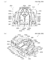
[2−4.外枠上ヒンジ組立体]
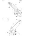
外枠2の外枠上ヒンジ組立体50について、主に図21を参照して詳細に説明する。図21(a)は外枠の外枠上ヒンジ組立体を分解して前上から見た分解斜視図であり、(b)は(a)を前下から見た分解斜視図である。外枠上ヒンジ組立体50は、外枠左組立体10の上端と外枠上部材30の左端に取付けられるものであり、外枠2に対して本体枠4をヒンジ回転可能に取付けるためのものである。外枠上ヒンジ組立体50は、外枠左部材11の凹部11aの上端と外枠上部材30の取付段部30bとに取付けられる外枠上ヒンジ部材51と、外枠上ヒンジ部材51に取付けられているロック部材52と、ロック部材52を外枠上ヒンジ部材51に取付けている取付ビス53と、を備えている。
[2-4. Hinge assembly on outer frame]
The outer frame hinge assembly 50 of the outer frame 2 will be described in detail mainly with reference to FIG. FIG. 21A is an exploded perspective view of the outer frame upper hinge assembly of the outer frame as seen from the front top, and FIG. 21B is an exploded perspective view of FIG. The outer frame upper hinge assembly 50 is attached to the upper end of the outer frame left assembly 10 and the left end of the outer frame upper member 30, and is used to attach the main body frame 4 to the outer frame 2 so as to be rotatable. It is. The outer frame upper hinge assembly 50 is attached to the outer frame upper hinge member 51 attached to the upper end of the recess 11a of the outer frame left member 11 and the mounting step 30b of the outer frame upper member 30, and attached to the outer frame upper hinge member 51. And a mounting screw 53 that attaches the locking member 52 to the hinge member 51 on the outer frame.
外枠上ヒンジ部材51は、水平に延びた平板状で外枠上部材30の取付段部30bの上面に取付けられる上固定部51aと、上固定部51aの前辺から前方へ延出している平板状の前方延出部51bと、前方延出部51bの右辺の途中から前方へ向かうに従って前方延出部51bの左右中央へ延びており上下に貫通している軸受溝51cと、上固定部51aの左辺から下方へ延びている平板状の横固定部51dと、前方延出部51bの左辺から前辺を周って軸受溝51cが開口している部位までの端縁から下方へ延びており横固定部51dと連続している平板状の端縁壁部51eと、を備えている。外枠上ヒンジ部材51は、金属板をプレス成型により打抜き・屈曲させて形成されている。外枠上ヒンジ部材51は、軸受溝51c内において、本体枠上ヒンジ部材510の後述する本体枠上ヒンジピン512を回転可能に支持することができる。
The outer frame upper hinge member 51 is a flat plate extending horizontally, and is attached to the upper surface of the mounting step 30b of the outer frame upper member 30 and extends forward from the front side of the upper fixed portion 51a. A flat front extending portion 51b, a bearing groove 51c extending vertically from the middle of the right side of the front extending portion 51b to the front and penetrating vertically, and an upper fixing portion A flat plate-like lateral fixing portion 51d extending downward from the left side of 51a, and extending downward from an edge from the left side of the front extending portion 51b to the portion where the bearing groove 51c is opened around the front side. And a flat end edge wall portion 51e that is continuous with the cage lateral fixing portion 51d. The outer frame hinge member 51 is formed by punching and bending a metal plate by press molding. The outer frame hinge member 51 can rotatably support a body frame hinge pin 512, which will be described later, of the body frame hinge member 510 in the bearing groove 51c.
ロック部材52は、前後に延びている帯板状のロック本体52aと、ロック本体52aの後端から右方へ突出している操作片52bと、ロック本体52aの後端から左方へ延びた後に斜め左前方へ延びている弾性変形可能な棒状の弾性部52cと、ロック本体52aの後端付近で上下に貫通している取付孔52dと、を備えている。ロック部材52は、合成樹脂によって形成されている。ロック部材52は、取付ビス53によって、外枠上ヒンジ部材51における前方延出部51bの下面で、軸受溝51cよりも後側の部位に回動可能に取付けられる。
The lock member 52 includes a band-shaped lock body 52a extending in the front-rear direction, an operation piece 52b protruding rightward from the rear end of the lock body 52a, and extending leftward from the rear end of the lock body 52a. An elastically deformable rod-like elastic portion 52c extending obliquely left front and an attachment hole 52d penetrating vertically near the rear end of the lock body 52a are provided. The lock member 52 is made of synthetic resin. The lock member 52 is pivotally attached to the rear side of the bearing groove 51c on the lower surface of the front extending portion 51b of the outer frame upper hinge member 51 by the mounting screw 53.
ロック部材52は、外枠上ヒンジ部材51に取付けた状態で、ロック本体52aが、平面視で軸受溝51cを遮ることができると共に、前端付近の右側面が、外枠上ヒンジ部材51の端縁壁部51eにおける軸受溝51cの開口まで延びている部位と当接可能となるように前方へ延びている。また、ロック本体52aの後端から左方へ延びている弾性部52cの先端は、外枠上ヒンジ部材51における端縁壁部51eの内周面に当接している。このロック部材52は、弾性部52cの付勢力によって取付孔52dを中心に、前端が左方へ回動する方向に付勢されている。従って、通常の状態では、ロック部材52のロック本体52aの前端付近の右側面が、端縁壁部51eに当接している。この状態では、軸受溝51cにおけるロック本体52aよりも前側の部位に、本体枠上ヒンジ部材510の本体枠上ヒンジピン512を収容可能な空間が形成される。
When the lock member 52 is attached to the outer frame hinge member 51, the lock body 52a can block the bearing groove 51c in a plan view, and the right side surface near the front end is the end of the outer frame hinge member 51. The edge wall portion 51e extends forward so as to be able to come into contact with a portion extending to the opening of the bearing groove 51c. Further, the tip of the elastic portion 52 c extending leftward from the rear end of the lock main body 52 a is in contact with the inner peripheral surface of the edge wall portion 51 e of the outer frame upper hinge member 51. The lock member 52 is urged by the urging force of the elastic portion 52c in the direction in which the front end rotates leftward about the attachment hole 52d. Accordingly, in a normal state, the right side surface of the lock member 52 near the front end of the lock body 52a is in contact with the edge wall portion 51e. In this state, a space capable of accommodating the body frame upper hinge pin 512 of the body frame upper hinge member 510 is formed in a portion of the bearing groove 51c on the front side of the lock body 52a.
このロック部材52は、操作片52bを操作することで、弾性部52cの付勢力に抗してロック本体52aを回動させることができる。そして、操作片52bの操作によって、ロック本体52aを、その前端が左方へ移動する方向へ回動させることで、平面視において軸受溝51cからロック本体52aを後退させることができ、軸受溝51cが全通している状態とすることができる。これにより、軸受溝51c内に本体枠上ヒンジピン512を挿入したり、軸受溝51c内から本体枠上ヒンジピン512を外したりすることができる。
The lock member 52 can rotate the lock body 52a against the urging force of the elastic portion 52c by operating the operation piece 52b. Then, by operating the operation piece 52b, the lock body 52a is rotated in a direction in which the front end thereof moves to the left, whereby the lock body 52a can be retracted from the bearing groove 51c in a plan view, and the bearing groove 51c Can pass through. Thereby, the hinge pin 512 on the body frame can be inserted into the bearing groove 51c, or the hinge pin 512 on the body frame can be removed from the bearing groove 51c.
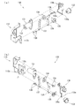
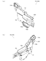
[2−5.外枠下ヒンジ部材]
外枠2の外枠下ヒンジ部材60について、主に図18を参照して詳細に説明する。外枠下ヒンジ部材60は、水平に延びた平板状の水平部60aと、水平部60aの左辺において前後方向中央よりも後側の部位から上方へ立上っている平板状の立上部60bと、水平部60aの前端付近から上方へ突出している外枠下ヒンジピン60cと、水平部60aを上下に貫通しており遊技球Bが一つのみ通過可能な大きさの排出孔60dと、を備えている。この外枠下ヒンジ部材60は、金属板をプレス成型により打抜き・屈曲させて形成されている。
[2-5. Outer frame lower hinge member]
The outer frame lower hinge member 60 of the outer frame 2 will be described in detail mainly with reference to FIG. The outer frame lower hinge member 60 includes a horizontally extending flat plate-like horizontal portion 60a, and a flat plate-like upright portion 60b rising upward from a rear side portion of the left side of the horizontal portion 60a from the center in the front-rear direction. An outer frame lower hinge pin 60c projecting upward from the vicinity of the front end of the horizontal portion 60a, and a discharge hole 60d that penetrates the horizontal portion 60a vertically and allows only one game ball B to pass therethrough. ing. The outer frame lower hinge member 60 is formed by punching and bending a metal plate by press molding.
外枠下ヒンジ部材60の水平部60aは、平面視において、左辺を底辺とした台形に形成されている。外枠下ヒンジピン60cは、円柱状で、上下方向中央よりも上部が、上端が窄まった円錐台状に形成されている。この外枠下ヒンジピン60cは、水平部60aの前端付近における左寄りの位置に取付けられている。排出孔60dは、水平部60aにおいて、立上部60bの前後方向中央の部位と接し、水平部60aの左辺から右方へ逆U字状に延びるように形成されている。この排出孔60dは、外枠下組立体40における球噛防止機構44の第一排出口44bと、略同じ大きさに形成されている。
The horizontal portion 60a of the outer frame lower hinge member 60 is formed in a trapezoidal shape with the left side as the bottom in plan view. The outer frame lower hinge pin 60c has a cylindrical shape, and is formed in a truncated cone shape whose upper end is narrower than the center in the vertical direction. The outer frame lower hinge pin 60c is attached to the left position near the front end of the horizontal portion 60a. In the horizontal portion 60a, the discharge hole 60d is in contact with the central portion in the front-rear direction of the upright portion 60b, and is formed to extend in an inverted U shape from the left side of the horizontal portion 60a to the right. The discharge hole 60d has substantially the same size as the first discharge port 44b of the ball engagement prevention mechanism 44 in the outer frame lower assembly 40.
外枠下ヒンジ部材60は、外枠2に組立てた状態で、水平部60aの後部が、外枠下組立体40における幕板後部材43の載置部44a上に載置され、図示しないビスによって幕板後部材43に固定されている。また、立上部60bが、外枠左部材11の右側面における膨出部11bよりも前側の部位に、図示しないビスによって取付けられている。この外枠下ヒンジ部材60は、外枠下ヒンジピン60cを、本体枠4の本体枠下ヒンジ組立体520における外枠用下ヒンジ孔521aに挿通させることで、外枠上ヒンジ部材51と協働して本体枠4を開閉可能に取付けることができる。
When the outer frame lower hinge member 60 is assembled to the outer frame 2, the rear portion of the horizontal portion 60 a is mounted on the mounting portion 44 a of the curtain plate rear member 43 in the outer frame lower assembly 40. Is fixed to the curtain plate rear member 43. Further, the upright portion 60b is attached to a portion of the right side surface of the outer frame left member 11 in front of the bulging portion 11b with a screw (not shown). The outer frame lower hinge member 60 cooperates with the outer frame upper hinge member 51 by inserting the outer frame lower hinge pin 60 c into the outer frame lower hinge hole 521 a in the main body frame lower hinge assembly 520 of the main body frame 4. Thus, the main body frame 4 can be attached so as to be opened and closed.
また、外枠2を組立てた状態では、排出孔60dが、外枠下組立体40における球噛防止機構44の第一排出口44bと一致している。これにより、水平部60a上の遊技球Bを、排出孔60d及び第一排出口44bを通して、外枠2の後方へ落下(排出)させることができる。詳述すると、外枠2に対して本体枠4を閉じる時に、外枠2と本体枠4との間に落下した遊技球Bが、本体枠4が閉じられるのに従って、外枠2と本体枠4との間が徐々に狭くなることから、間隔が広い後方側へ転動とすることとなり、排出孔60dから排出させることができる。この際に、排出孔60dが、パチンコ機1に組立てた状態で、外枠2に対して本体枠4を閉じた時に、本体枠4の後端と略同じとなる位置に形成されているため、外枠2と本体枠4との間に落下した遊技球Bを、排出孔60dから排出させることで本体枠4よりも後側へ転動するのを阻止し易くすることができ、外枠下ヒンジ部材60の部位に遊技球Bが留まり難くすることができる。
Further, in a state where the outer frame 2 is assembled, the discharge hole 60 d coincides with the first discharge port 44 b of the ball engagement prevention mechanism 44 in the outer frame lower assembly 40. Thereby, the game ball B on the horizontal portion 60a can be dropped (discharged) to the rear of the outer frame 2 through the discharge hole 60d and the first discharge port 44b. More specifically, when the main body frame 4 is closed with respect to the outer frame 2, the game balls B that have fallen between the outer frame 2 and the main body frame 4 are closed as the main body frame 4 is closed. 4 is gradually narrowed, so that the gap is rolled to the rear side with a wide interval, and can be discharged from the discharge hole 60d. At this time, the discharge hole 60d is formed at a position that is substantially the same as the rear end of the main body frame 4 when the main body frame 4 is closed with respect to the outer frame 2 in a state assembled to the pachinko machine 1. The game ball B dropped between the outer frame 2 and the main body frame 4 can be easily prevented from rolling to the rear side of the main body frame 4 by being discharged from the discharge hole 60d. It is possible to make it difficult for the game ball B to stay on the lower hinge member 60.
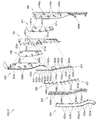
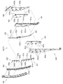
[3.扉枠の全体構成]
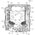
パチンコ機1の扉枠3について、主に図22乃至図30を参照して詳細に説明する。図22はパチンコ機における扉枠の正面図であり、図23は扉枠の背面図であり、図24は扉枠の左側面図であり、図25は扉枠の右側面図である。図26は扉枠を右前から見た斜視図であり、図27は扉枠を左前から見た斜視図であり、図28は扉枠を後ろから見た斜視図である。図29は扉枠を主な部材毎に分解して前から見た分解斜視図であり、図30は扉枠を主な部材毎に分解して後ろから見た分解斜視図である。
[3. Overall structure of door frame]
The door frame 3 of the pachinko machine 1 will be described in detail mainly with reference to FIGS. 22 is a front view of the door frame in the pachinko machine, FIG. 23 is a rear view of the door frame, FIG. 24 is a left side view of the door frame, and FIG. 25 is a right side view of the door frame. FIG. 26 is a perspective view of the door frame as viewed from the right front, FIG. 27 is a perspective view of the door frame as viewed from the left front, and FIG. 28 is a perspective view of the door frame as viewed from the rear. FIG. 29 is an exploded perspective view in which the door frame is disassembled for each main member and viewed from the front, and FIG. 30 is an exploded perspective view in which the door frame is disassembled for each main member and viewed from the rear.
扉枠3は、外枠2の枠内と略同じ大きさで正面視において上下に延びた四角形に形成されており、本体枠4を介して外枠2の枠内を前側から開閉可能に取付けられている。扉枠3は、遊技球Bが打込まれる遊技盤5の遊技領域5aを前側から視認可能に閉鎖し、遊技領域5a内に打込むための遊技球Bを貯留すると共に、貯留している遊技球Bを遊技領域5a内へ打込むために遊技者が操作するハンドル195を備えているものである。また、扉枠3は、パチンコ機1の前面全体を装飾するものである。
The door frame 3 is formed in a quadrangle that is substantially the same size as the inside of the outer frame 2 and extends vertically when viewed from the front, and is attached to the inside of the outer frame 2 via the main body frame 4 so that it can be opened and closed from the front side. It has been. The door frame 3 closes the game area 5a of the game board 5 into which the game ball B is to be visibly viewed from the front side, stores the game balls B to be shot into the game area 5a, and stores the stored games. A handle 195 operated by the player for driving the ball B into the game area 5a is provided. The door frame 3 decorates the entire front surface of the pachinko machine 1.
扉枠3は、正面視の外形が上下に延びた四角形で枠状の扉枠ベースユニット100と、扉枠ベースユニット100に着脱可能に取付けられており本体枠4に取付けられた遊技盤5の遊技領域5aを前方から視認可能に閉鎖しているガラスユニット160と、ガラスユニット160の下部を後側から覆うように扉枠ベースユニット100に取付けられている防犯カバー170と、扉枠ベースユニット100の前面右下隅に取付けられているハンドルユニット180と、ハンドルユニット180の外周を覆うハンドルカバーユニット290と、扉枠ベースユニット100の前面下部に取付けられている皿ユニット200と、皿ユニット200の上側で扉枠ベースユニット100の前面左部に取付けられている扉枠左サイドユニット420と、皿ユニットの上側で扉枠ベースユニット100の前面右部に取付けられている扉枠右サイドユニット430と、扉枠左サイドユニット420及び扉枠右サイドユニット430の上側で扉枠ベースユニット100の前面上部に取付けられている扉枠トップユニット450と、を備えている。
The door frame 3 is a quadrangular and frame-like door frame base unit 100 whose front view extends vertically, and is detachably attached to the door frame base unit 100 and includes a game board 5 attached to the main body frame 4. A glass unit 160 that closes the game area 5a so as to be visible from the front, a security cover 170 attached to the door frame base unit 100 so as to cover the lower part of the glass unit 160 from the rear side, and the door frame base unit 100 A handle unit 180 attached to the lower right corner of the front surface of the door, a handle cover unit 290 covering the outer periphery of the handle unit 180, a dish unit 200 attached to the lower front part of the door frame base unit 100, and an upper side of the dish unit 200 The door frame left side unit 420 attached to the front left part of the door frame base unit 100, and the tray unit The door frame right side unit 430 attached to the front right part of the door frame base unit 100 on the upper side of the door frame, and the front surface of the door frame base unit 100 on the upper side of the door frame left side unit 420 and the door frame right side unit 430. And a door frame top unit 450 attached to the upper part.
扉枠ベースユニット100は、正面視の外形が上下に延びた四角形(長方形)に形成されており前後に貫通している扉窓101aを有した扉枠ベース101と、扉枠ベース101の後側で背面視右下隅に取付けられているスピーカダクト103と、扉枠ベース101の後側の下部における背面視右端付近に取付けられている扉枠主中継基板104と、扉枠主中継基板104の背面視左方に取付けられている扉枠副中継基板105と、扉枠副中継基板105の背面視左方に取付けられているハンドル後中継基板106と、扉枠主中継基板104と扉枠副中継基板105の一部とを後側から被覆する扉枠中継基板カバー107と、ハンドル後中継基板106を後側から被覆するハンドル後中継基板カバー108と、配線ケーブルを被覆するケーブルカバー109と、を備えている。
The door frame base unit 100 includes a door frame base 101 having a door window 101a that is formed in a quadrilateral (rectangular shape) whose front view extends vertically, and penetrates forward and backward, and the rear side of the door frame base 101. The speaker duct 103 attached to the lower right corner in the rear view, the door frame main relay board 104 attached in the vicinity of the right end in the rear view at the lower part of the rear side of the door frame base 101, and the rear face of the door frame main relay board 104 The door frame sub-relay board 105 attached to the left side of the view, the rear handle relay board 106 attached to the left side of the door frame sub-relay board 105, the door frame main relay board 104, and the door frame sub-relay. A door frame relay board cover 107 that covers a part of the board 105 from the rear side, a post-handle relay board cover 108 that covers the rear handle relay board 106 from the rear side, and a cable that covers the wiring cable It includes a cover 109, a.
また、扉枠ベースユニット100は、扉枠ベース101の後側に取付けられている枠状の扉枠補強ユニット110と、扉枠補強ユニット110に取付けられている扉枠上ヒンジ組立体120及び扉枠下ヒンジ部材125と、扉枠補強ユニット110に取付けられている開閉用のシリンダ錠130と、扉枠ベース101の後側でハンドル後中継基板106の上方に取付けられている球送給ユニット140と、扉枠ベース101の後側の下部における背面視右側に取付けられているファールカバーユニット150と、を備えている。
The door frame base unit 100 includes a frame-shaped door frame reinforcing unit 110 attached to the rear side of the door frame base 101, a door frame upper hinge assembly 120 and a door attached to the door frame reinforcing unit 110. A frame lower hinge member 125, an opening / closing cylinder lock 130 attached to the door frame reinforcement unit 110, and a ball feeding unit 140 attached to the rear side of the door frame base 101 and above the rear handle relay board 106. And a foul cover unit 150 attached to the right side of the rear view of the lower part of the rear side of the door frame base 101.
扉枠補強ユニット110は、扉枠ベース101の後側に取付けられることで、扉枠ベース101を補強して剛性を付与するものである。扉枠上ヒンジ組立体120及び扉枠下ヒンジ部材125は、扉枠3を本体枠4に対して開閉可能に取付けるためのものである。シリンダ錠130は、本体枠4の施錠ユニット650と協働して、扉枠3と本体枠4との開閉、及び、外枠2と本体枠4との開閉施錠に使用されるものである。
The door frame reinforcing unit 110 is attached to the rear side of the door frame base 101 to reinforce the door frame base 101 and give rigidity. The door frame upper hinge assembly 120 and the door frame lower hinge member 125 are for attaching the door frame 3 to the main body frame 4 so as to be openable and closable. The cylinder lock 130 is used for opening and closing the door frame 3 and the main body frame 4 and for opening and closing the outer frame 2 and the main body frame 4 in cooperation with the locking unit 650 of the main body frame 4.
また、球送給ユニット140は、上皿201内の遊技球Bを一つずつ本体枠4の球発射装置540へ供給するためのものである。ファールカバーユニット150は、球発射装置540により発射されて遊技盤5の遊技領域5a内に到達しなかった遊技球B(ファール球)を、下皿202に誘導すると共に、払出装置580から払出された遊技球Bを、上皿201又は下皿202に誘導するためのものである。
The ball feeding unit 140 is for supplying the game balls B in the upper plate 201 to the ball launching device 540 of the main body frame 4 one by one. The foul cover unit 150 guides the game ball B (foul ball) that has been launched by the ball launcher 540 and has not reached the game area 5a of the game board 5 to the lower plate 202, and is delivered from the payout device 580. The game ball B is for guiding the game ball B to the upper plate 201 or the lower plate 202.
ガラスユニット160は、透明なガラス板162を有しており扉枠ベース101の扉窓101aを閉鎖している。防犯カバー170は、ガラスユニット160の下部を後方から覆うように扉枠ベース101に取付けられている。ハンドルユニット180は、遊技者が回転操作可能なハンドル195を備えており、ハンドルユニット180は、外周を覆うハンドルカバーユニット290とを操作することで、上皿201内の遊技球Bを、球発射装置540によって遊技盤5の遊技領域5a内に打込む遊技を行うためのものである。
The glass unit 160 has a transparent glass plate 162 and closes the door window 101 a of the door frame base 101. The security cover 170 is attached to the door frame base 101 so as to cover the lower part of the glass unit 160 from behind. The handle unit 180 includes a handle 195 that can be rotated by the player. The handle unit 180 operates the handle cover unit 290 that covers the outer periphery, thereby launching the game ball B in the upper plate 201. This is for playing a game that is driven into the game area 5a of the game board 5 by the device 540.
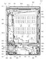
[3−1.扉枠ベースユニットの全体構成]
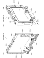
扉枠3の扉枠ベースユニット100について、主に図31乃至図33を参照して詳細に説明する。図31(a)は扉枠の扉枠ベースユニットを前から見た斜視図であり、(b)は扉枠ベースユニットを後ろから見た斜視図である。図32は扉枠ベースユニットを主な部材毎に分解して前から見た分解斜視図であり、図33は扉枠ベースユニットを主な部材毎に分解して後ろから見た分解斜視図である。
[3-1. Overall configuration of door frame base unit]
The door frame base unit 100 of the door frame 3 will be described in detail mainly with reference to FIGS. 31 to 33. FIG. 31A is a perspective view of the door frame base unit of the door frame as viewed from the front, and FIG. 31B is a perspective view of the door frame base unit as viewed from the rear. FIG. 32 is an exploded perspective view of the main part of the door frame base unit as seen from the front, and FIG. 33 is an exploded perspective view of the main part of the door frame base unit as seen from the rear. is there.
扉枠ベースユニット100は、正面視左辺側が本体枠4に対してヒンジ回転可能に取付けられ、本体枠4の前面を開閉可能に閉鎖していると共に、本体枠4に取付けられている遊技盤5の遊技領域5aを前方から視認可能としている。扉枠ベースユニット100は、外形が上下に延びた四角形で平板状の扉枠ベース101と、扉枠ベース101の後側で背面視右下隅に取付けられているスピーカダクト103と、を備えている。
The door frame base unit 100 is attached to the main body frame 4 so that the left side of the door frame can be hinge-rotated, closes the front surface of the main body frame 4 so that it can be opened and closed, and is attached to the main body frame 4. The game area 5a is visible from the front. The door frame base unit 100 includes a rectangular and flat door frame base 101 whose outer shape extends vertically, and a speaker duct 103 mounted on the rear side of the door frame base 101 in the lower right corner when viewed from the back. .
また、扉枠ベースユニット100は、扉枠ベース101の後側の下部における背面視右端付近に取付けられている扉枠主中継基板104と、扉枠ベース101の後側の下部における扉枠主中継基板104の背面視左方に取付けられている扉枠副中継基板105と、扉枠ベース101の後側の下部における扉枠副中継基板105の背面視左方に取付けられているハンドル後中継基板106と、扉枠ベース101の後側に取付けられており扉枠主中継基板104と扉枠副中継基板105の一部とを後側から被覆する扉枠中継基板カバー107と、扉枠ベース101の後側に取付けられておりハンドル後中継基板106を後側から被覆するハンドル後中継基板カバー108と、扉枠ベース101の後側に取付けられており配線ケーブルを被覆するケーブルカバー109と、を備えている。
Further, the door frame base unit 100 includes a door frame main relay board 104 attached near the right end in rear view in the lower part of the rear side of the door frame base 101, and a door frame main relay in the lower part of the rear side of the door frame base 101. A door frame sub-relay board 105 attached to the left side of the board 104 in the rear view, and a handle rear relay board attached to the left side of the door frame sub-relay board 105 in the lower part on the rear side of the door frame base 101. 106, a door frame relay board cover 107 which is attached to the rear side of the door frame base 101 and covers the door frame main relay board 104 and a part of the door frame sub relay board 105 from the rear side, and the door frame base 101. A rear handle relay board cover 108 that is attached to the rear side and covers the rear handle relay board 106 from the rear side, and a case that is attached to the rear side of the door frame base 101 and covers the wiring cable. And Burukaba 109, and a.
更に、扉枠ベースユニット100は、扉枠ベース101の後側に取付けられている枠状の扉枠補強ユニット110と、扉枠補強ユニット110に取付けられている扉枠上ヒンジ組立体120及び扉枠下ヒンジ部材125と、扉枠補強ユニット110に取付けられている開閉用のシリンダ錠130と、扉枠ベース101の後側でハンドル後中継基板106の上方に取付けられている球送給ユニット140と、扉枠ベース101の後側の下部における背面視右側に取付けられているファールカバーユニット150と、を備えている。
Further, the door frame base unit 100 includes a frame-shaped door frame reinforcing unit 110 attached to the rear side of the door frame base 101, a door frame upper hinge assembly 120 and a door attached to the door frame reinforcing unit 110. A frame lower hinge member 125, an opening / closing cylinder lock 130 attached to the door frame reinforcement unit 110, and a ball feeding unit 140 attached to the rear side of the door frame base 101 and above the rear handle relay board 106. And a foul cover unit 150 attached to the right side of the rear view of the lower part of the rear side of the door frame base 101.
この扉枠ベースユニット100には、前面下隅にハンドルユニット180及びハンドルカバーユニット290が、扉窓101aの下側前面に皿ユニット200が、扉窓101aの左外側前面に扉枠左サイドユニット420が、扉窓101aの右外側前面に扉枠右サイドユニット430が、扉窓101aの上外側前面に扉枠トップユニット450が、夫々取付けられるものである。
The door frame base unit 100 has a handle unit 180 and a handle cover unit 290 at the lower front corner, a dish unit 200 at the lower front surface of the door window 101a, and a door frame left side unit 420 at the left outer front surface of the door window 101a. The door frame right side unit 430 is attached to the right outer front of the door window 101a, and the door frame top unit 450 is attached to the upper outer front of the door window 101a.
また、扉枠ベースユニット100には、扉窓101aを後方から閉鎖するようにガラスユニット160が取付けられると共に、ガラスユニット160の下部を後方から覆うように透明な防犯カバー170が取付けられるものである。
In addition, a glass unit 160 is attached to the door frame base unit 100 so as to close the door window 101a from the rear, and a transparent security cover 170 is attached so as to cover the lower part of the glass unit 160 from the rear. .
[3−1a.扉枠ベース]
扉枠3における扉枠ベースユニット100の扉枠ベース101について、主に図31乃至図33を参照して詳細に説明する。扉枠ベース101は、正面視の外形が上下に延びた四角形(長方形)に形成されている。扉枠ベース101は、前後に貫通しており、正面視における内周形状が上下に延びた略四角形に形成された扉窓101aを備えている。扉窓101aは、内周を形成している上辺及び左右両辺が、扉枠ベース101の外周辺に夫々接近しており、内周を形成している下辺が、扉枠ベース101の下端から上下方向の約1/3の高さに位置している。このように、扉枠ベース101は、前後に貫通している扉窓101aにより全体が枠状に形成されている。この扉枠ベース101は、合成樹脂により一体成形されている。
[3-1a. Door frame base]
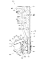
The door frame base 101 of the door frame base unit 100 in the door frame 3 will be described in detail mainly with reference to FIGS. 31 to 33. The door frame base 101 is formed in a quadrangle (rectangular shape) whose outer shape in front view extends vertically. The door frame base 101 is provided with a door window 101a that penetrates in the front-rear direction and is formed in a substantially quadrilateral shape whose inner peripheral shape in the front view extends vertically. In the door window 101a, the upper side and the left and right sides forming the inner periphery are respectively close to the outer periphery of the door frame base 101, and the lower side forming the inner periphery is up and down from the lower end of the door frame base 101. It is located at a height of about 1/3 of the direction. Thus, the door frame base 101 is entirely formed in a frame shape by the door window 101a penetrating in the front-rear direction. The door frame base 101 is integrally formed of synthetic resin.
扉枠ベース101は、前面における正面視右下隅に形成されており左端側が右端側よりも前方へやや突出するように傾斜しているハンドル取付座面101b(図42等を参照)と、ハンドル取付座面101bと扉窓101aとの間で前後に貫通して扉枠補強ユニット110のシリンダ取付フレーム115が挿入されるシリンダ挿通孔101dと、シリンダ挿通孔101d及びハンドル取付座面101bの正面視左側で前後に貫通しており球送給ユニット140の進入口141a及び球抜口141bを前方に臨ませるための球送給開口101eと、を備えている。
The door frame base 101 is formed in the lower right corner of the front view on the front surface, and has a handle mounting seat surface 101b (see FIG. 42 and the like) inclined so that the left end side protrudes slightly forward from the right end side. A cylinder insertion hole 101d through which the cylinder mounting frame 115 of the door frame reinforcing unit 110 is inserted between the seat surface 101b and the door window 101a in the front-rear direction, and a left side in front view of the cylinder insertion hole 101d and the handle mounting seat surface 101b. And a ball feeding opening 101e for allowing the entrance 141a and the ball outlet 141b of the ball feeding unit 140 to face forward.
また、扉枠ベース101は、左右方向中央より左寄りで且つハンドル取付座面101bと略同じ高さで前後に貫通しておりファールカバーユニット150の球放出口150dを前方に臨ませる下皿用球通過口101fと、正面視左端付近で扉窓101aの下辺に隣接するように前後に貫通しておりファールカバーユニット150の貫通球通路150aを前方に臨ませる上皿用球通過口101gと、扉窓101aの内周に沿って後面から前方へ向かって窪み、ガラスユニット160のガラス枠161が挿入されるガラスユニット取付部101hと、を備えている。
Also, the door frame base 101 is located on the left side of the center in the left-right direction and penetrates back and forth at substantially the same height as the handle mounting seat surface 101b, and the ball for the lower dish facing the ball discharge port 150d of the foul cover unit 150 to the front. A passage opening 101f, a bowl passage opening 101g for an upper dish that penetrates forward and backward so as to be adjacent to the lower side of the door window 101a near the left end in front view, and faces the through-ball passage 150a of the foul cover unit 150 forward, A glass unit mounting portion 101h that is recessed forward from the rear surface along the inner periphery of the window 101a and into which the glass frame 161 of the glass unit 160 is inserted.
また、扉枠ベース101は、正面視左下隅(上皿用球通過口101gの下方)に形成されており前後に貫通した縦長の複数のスリット101iを、備えている。複数のスリット101iの後側にスピーカダクト103が取付けられる。また、複数のスリット101iは、パチンコ機1を組立てた状態で、前方に皿ユニット200における皿ユニットベース211のスピーカ口211bが位置していると共に、後方に本体枠4のスピーカユニット620aにおける本体枠スピーカ622が位置しており、本体枠スピーカ622からの音を前方へ放射することができる。
Further, the door frame base 101 includes a plurality of vertically long slits 101i that are formed in the lower left corner of the front view (below the upper plate ball passage opening 101g) and penetrate forward and backward. A speaker duct 103 is attached to the rear side of the plurality of slits 101i. In addition, the plurality of slits 101i are located in the state in which the pachinko machine 1 is assembled, the speaker port 211b of the dish unit base 211 in the dish unit 200 is located in front, and the body frame in the speaker unit 620a of the body frame 4 in the rear. The speaker 622 is located, and the sound from the body frame speaker 622 can be radiated forward.
更に、扉枠ベース101は、扉窓101aの下方でハンドル取付座面101bの上方において、前後に貫通している貫通孔101jを備えている。この貫通孔101jは、扉枠ベースユニット100側と皿ユニット200側とを接続する配線ケーブル(図示は省略)が挿通されるものであり、後述する扉枠補強ユニット110における中間補強フレーム114の貫通部114bと一致するように形成されている。
Further, the door frame base 101 includes a through-hole 101j penetrating in the front-rear direction below the door window 101a and above the handle mounting seat surface 101b. The through-hole 101j is inserted through a wiring cable (not shown) that connects the door frame base unit 100 side and the dish unit 200 side, and passes through the intermediate reinforcing frame 114 in the door frame reinforcing unit 110 described later. It is formed so as to coincide with the portion 114b.
[3−1b.スピーカダクト]
扉枠ベースユニット100のスピーカダクト103について、主に図31乃至図33を参照して詳細に説明する。このスピーカダクト103は、筒状に形成されており、扉枠ベース101の後側において複数のスリット101iが形成されている部位に取付けられる。スピーカダクト103は、パチンコ機1を組立てた状態で、筒状の部位の後端が、本体枠4の本体枠スピーカ622の前方に位置している。これにより、本体枠4の本体枠スピーカ622から放射(出力)された音(サウンド)を、拡散させることなく前方へ誘導することができ、扉枠ベース101の複数のスリット101i及び皿ユニット200の皿ユニットベース211におけるスピーカ口211bを通して、パチンコ機1の前方(遊技者側)へ良好に誘導することができる。
[3-1b. Speaker duct]
The speaker duct 103 of the door frame base unit 100 will be described in detail mainly with reference to FIGS. The speaker duct 103 is formed in a cylindrical shape, and is attached to a portion where a plurality of slits 101 i are formed on the rear side of the door frame base 101. The rear end of the cylindrical part of the speaker duct 103 is located in front of the main body frame speaker 622 of the main body frame 4 in a state where the pachinko machine 1 is assembled. Thereby, the sound (sound) radiated (output) from the body frame speaker 622 of the body frame 4 can be guided forward without being diffused, and the plurality of slits 101 i of the door frame base 101 and the dish unit 200 can be guided. Through the speaker port 211b in the dish unit base 211, it is possible to satisfactorily guide to the front (player side) of the pachinko machine 1.
また、スピーカダクト103は、筒状の部位の下方の後面に、接続ケーブル503を保持するケーブルホルダ103aを備えている。ケーブルホルダ103aは、扉枠中継基板カバー107よりも正面視左方に配置されており、扉枠主中継基板104及び扉枠副中継基板105に接続されている接続ケーブル503を、扉枠3の左端側へ延びるように保持している。
In addition, the speaker duct 103 includes a cable holder 103a that holds the connection cable 503 on the rear surface below the cylindrical portion. The cable holder 103 a is arranged on the left side of the front view of the door frame relay board cover 107, and the connection cable 503 connected to the door frame main relay board 104 and the door frame sub relay board 105 is connected to the door frame 3. It is held so as to extend to the left end side.
[3−1c.扉枠主中継基板・扉枠副中継基板・ハンドル後中継基板]
扉枠ベースユニット100の扉枠主中継基板104、扉枠副中継基板105、ハンドル後中継基板106について、主に図32及び図33等を参照して説明する。扉枠主中継基板104は、外形が上下に延びた四角形に形成されており、扉枠ベース101の後側の下部における背面視右下隅に取付けられる。扉枠主中継基板104は、ハンドル後中継基板106と本体枠4の基板ユニット620におけるインターフェイス基板635との接続を中継するためのものであり、本体枠4から延びている接続ケーブル503(図82及び図83を参照)の一部が接続される。
[3-1c. Door frame main relay board / door frame sub relay board / handle rear relay board]
The door frame main relay board 104, the door frame sub relay board 105, and the post-handle relay board 106 of the door frame base unit 100 will be described with reference mainly to FIGS. The door frame main relay board 104 is formed in a quadrangle whose outer shape extends vertically, and is attached to the lower right corner of the rear side of the door frame base 101 in the rear view. The door frame main relay board 104 is for relaying the connection between the post-handle relay board 106 and the interface board 635 in the board unit 620 of the main body frame 4, and a connection cable 503 extending from the main body frame 4 (FIG. 82). And a part of (see FIG. 83) are connected.
扉枠副中継基板105は、外形が、上下に延びた四角形の上部の正面視右側に左右に延びた四角形が組み合された逆L字状に形成されており、上下に延びているが扉枠主中継基板104の背面視左方に隣接するように、扉枠ベース101の後側に取付けられている。扉枠副中継基板105は、ハンドルユニット180のハンドル装飾基板184、皿ユニット200の皿ユニット中継基板214、扉枠左サイドユニット420の扉枠左サイド上装飾基板422及び扉枠左サイド下装飾基板423、扉枠右サイドユニット430の扉枠右サイド上装飾基板432及び扉枠右サイド下装飾基板433、扉枠トップユニット450の扉枠トップ中継基板等と、本体枠4のインターフェイス基板635との接続を中継するためのものであり、本体枠4から延びている接続ケーブル503の残りが接続される。
The door frame sub-relay substrate 105 is formed in an inverted L shape in which a quadrangle extending left and right is combined on the right side of the front of the upper part of the quadrangle extending up and down. The frame main relay board 104 is attached to the rear side of the door frame base 101 so as to be adjacent to the left in the rear view. The door frame sub relay board 105 includes a handle decoration board 184 of the handle unit 180, a dish unit relay board 214 of the dish unit 200, a door frame left side upper decoration board 422 and a door frame left side lower decoration board of the door frame left side unit 420. 423, the door frame right side upper decorative board 432 and the door frame right side lower decorative board 433 of the door frame right side unit 430, the door frame top relay board of the door frame top unit 450, and the interface board 635 of the main body frame 4. The relay is for relaying the connection, and the remainder of the connection cable 503 extending from the main body frame 4 is connected.
扉枠主中継基板104及び扉枠副中継基板105は、接続端子が後方へ向かって突出するように、扉枠ベース101に取付けられる。扉枠主中継基板104及び扉枠副中継基板105は、扉枠ベースユニット100を組立てた状態で、扉枠主中継基板104と扉枠副中継基板105の上下に延びている部位とが、扉枠中継基板カバー107によって後側が被覆された状態となり、扉枠副中継基板105の残りの部位が、ファールカバーユニット150によって後側が被覆された状態となる。
The door frame main relay board 104 and the door frame sub relay board 105 are attached to the door frame base 101 so that the connection terminals protrude rearward. The door frame main relay board 104 and the door frame sub relay board 105 are configured so that the door frame base relay board 104 and a portion extending vertically from the door frame sub relay board 105 in the state where the door frame base unit 100 is assembled are doors. The rear side is covered with the frame relay board cover 107, and the remaining part of the door frame sub-relay board 105 is covered with the foul cover unit 150.
ハンドル後中継基板106は、外形が左右に延びた四角形に形成されており、扉枠ベース101の後側における球送給開口101eの下方でハンドル取付座面101bの後側に取付けられる。ハンドル後中継基板106は、扉枠主中継基板104とハンドルユニット180のハンドル回転検知センサ189、ハンドルタッチセンサ192、単発ボタン操作センサ194、及び球送給ユニット140の球送給ソレノイド145との接続を中継するためのものである。ハンドル後中継基板106は、扉枠ベースユニット100を組立てた状態で、ハンドル後中継基板カバー108によって後側が被覆された状態となる。
The post-handle relay substrate 106 is formed in a quadrangle whose outer shape extends to the left and right, and is attached to the rear side of the handle attachment seat surface 101 b below the ball feed opening 101 e on the rear side of the door frame base 101. The post-handle relay board 106 connects the door frame main relay board 104 to the handle rotation detection sensor 189 of the handle unit 180, the handle touch sensor 192, the single button operation sensor 194, and the ball feed solenoid 145 of the ball feed unit 140. It is for relaying. The rear handle relay board 106 is in a state where the rear side is covered by the rear handle relay board cover 108 in a state where the door frame base unit 100 is assembled.
[3−1d.扉枠中継基板カバー・ハンドル後中継基板カバー・ケーブルカバー]
扉枠ベースユニット100の扉枠中継基板カバー107、ハンドル後中継基板カバー108、及びケーブルカバー109について、主に図31乃至図33を参照して説明する。扉枠中継基板カバー107は、扉枠ベース101の後側に取付けることで、扉枠主中継基板104と扉枠副中継基板105の一部(逆L字状の上下に延びている部位)の後側を被覆するものである。扉枠中継基板カバー107は、前方及び正面視左方が開放された箱状に形成されている。扉枠ベースユニット100に組立てた状態では、後側を被覆している扉枠主中継基板104及び扉枠副中継基板105の接続端子が扉枠中継基板カバー107の内部に露出しており、開放されている左側から接続ケーブル503を内部に挿入して、それら端子に接続することができる。
[3-1d. Door frame relay board cover, rear relay board cover, cable cover]
The door frame relay board cover 107, the post-handle relay board cover 108, and the cable cover 109 of the door frame base unit 100 will be described mainly with reference to FIGS. The door frame relay board cover 107 is attached to the rear side of the door frame base 101, so that part of the door frame main relay board 104 and the door frame sub relay board 105 (parts extending upside down in an inverted L shape). The rear side is covered. The door frame relay board cover 107 is formed in a box shape with the front and the left in front view opened. When assembled in the door frame base unit 100, the connection terminals of the door frame main relay board 104 and the door frame sub relay board 105 covering the rear side are exposed inside the door frame relay board cover 107 and opened. The connection cable 503 can be inserted into the terminal from the left side and connected to these terminals.
ハンドル後中継基板カバー108は、ハンドル後中継基板106の後側を被覆するように扉枠ベース101の後側に取付けられるものである。ケーブルカバー109は、扉枠補強ユニット110における中間補強フレーム114の後側に取付けられ、扉枠主中継基板104と皿ユニット200の球貸操作ユニット220とを接続する配線ケーブル(図示は省略)を被覆するためのものである。ケーブルカバー109は、左右に延びた箱状に形成されており、前面の左端付近と下面の左右方向中央に、配線ケーブルを通すための開口が形成されている。
The post-handle relay board cover 108 is attached to the rear side of the door frame base 101 so as to cover the rear side of the post-handle relay board 106. The cable cover 109 is attached to the rear side of the intermediate reinforcing frame 114 in the door frame reinforcing unit 110, and is a wiring cable (not shown) that connects the door frame main relay board 104 and the ball lending operation unit 220 of the dish unit 200. It is for coating. The cable cover 109 is formed in a box shape extending left and right, and an opening for passing a wiring cable is formed in the vicinity of the left end of the front surface and the center of the lower surface in the left-right direction.
[3−1e.扉枠補強ユニット]
扉枠ベースユニット100の扉枠補強ユニット110について、主に図31乃至図33を参照して詳細に説明する。扉枠補強ユニット110は、扉枠ベース101の後側に取付けられることで、平板状の扉枠ベース101を補強して、扉枠ベースユニット100に剛性を付与している。扉枠補強ユニット110は、左右に離間して配置されている上下に延びた左補強フレーム111及び右補強フレーム112と、左補強フレーム111及び右補強フレーム112の上端同士を連結している左右に延びた上補強フレーム113と、左補強フレーム111の下端から上寄りの位置に左端側が取付けられており右補強フレーム112付近まで右方へ延びた中間補強フレーム114と、中間補強フレーム114の右端と右補強フレーム112とを連結しているシリンダ取付フレーム115と、右補強フレーム112の後側に上下に離間して複数取付けられており本体枠4の施錠ユニット650の扉枠用鉤652が掛止される鉤掛部材116と、を備えている。
[3-1e. Door frame reinforcement unit]
The door frame reinforcing unit 110 of the door frame base unit 100 will be described in detail mainly with reference to FIGS. 31 to 33. The door frame reinforcing unit 110 is attached to the rear side of the door frame base 101 to reinforce the flat door frame base 101 and give the door frame base unit 100 rigidity. The door frame reinforcing unit 110 has left and right left and right reinforcing frames 111 and 112 that are spaced apart from each other and are connected to the left and right reinforcing frames 111 and 112. An extended upper reinforcing frame 113, an intermediate reinforcing frame 114 attached to the upper end position from the lower end of the left reinforcing frame 111 and extending rightward to the vicinity of the right reinforcing frame 112, and a right end of the intermediate reinforcing frame 114 A cylinder mounting frame 115 that connects the right reinforcing frame 112 and a plurality of the cylinder mounting frame 115 that are mounted on the rear side of the right reinforcing frame 112 so as to be spaced apart from each other vertically. The hook member 116 is provided.
左補強フレーム111及び右補強フレーム112は、左右方向が一定の幅で、扉枠ベース101の上下の高さと略同じ長さで上下に延びている。右補強フレーム112には、上下方向に離間しており、前後方向に貫通している複数の挿通孔が形成されている。これら挿通孔は、本体枠4に対して扉枠3を閉めた時に、施錠ユニット650の扉枠用鉤652の先端が挿通される。上補強フレーム113は、上下方向が一定の幅で、扉枠ベース101の左右の幅と略同じ長さで左右に延びている。
The left reinforcing frame 111 and the right reinforcing frame 112 have a constant width in the left-right direction and extend vertically with substantially the same length as the vertical height of the door frame base 101. The right reinforcing frame 112 is formed with a plurality of insertion holes that are spaced apart in the vertical direction and penetrate in the front-rear direction. When the door frame 3 is closed with respect to the main body frame 4, these insertion holes are inserted through the ends of the door frame collars 652 of the locking unit 650. The upper reinforcing frame 113 has a constant width in the vertical direction and extends to the left and right with substantially the same length as the left and right widths of the door frame base 101.
中間補強フレーム114は、上下方向が上補強フレーム113の上下の幅よりも広い幅で左右に延びている。中間補強フレーム114は、左端付近において上端から下方へ四角く切欠かれた切欠部114aと、右端付近において前後に貫通している貫通部114bと、を有している。切欠部114aは、扉枠ベース101の上皿用球通過口101gと、貫通部114bは、扉枠ベース101の貫通孔101jと、夫々一致する位置に形成されている。
The intermediate reinforcing frame 114 extends from side to side with a width that is wider in the vertical direction than the vertical width of the upper reinforcing frame 113. The intermediate reinforcing frame 114 has a cutout portion 114a that is squarely cut downward from the upper end near the left end, and a through portion 114b that penetrates forward and backward near the right end. The cutout portion 114a is formed at a position where the upper frame ball passage port 101g of the door frame base 101 and the through portion 114b coincide with the through hole 101j of the door frame base 101, respectively.
シリンダ取付フレーム115は、左右に離間して配置されており正面視において上下に延びた四角形の平板状に形成されている一対の後片部と、一対の後片部の対面している夫々の辺から前方へ平板状に延出している一対の側片部と、一対の前方延出部の前端の辺同士を連結している平板状の前片部と、を備えている。このシリンダ取付フレーム115は、平面視の形状が前方へ突出した凸形状に形成されている。シリンダ取付フレーム115は、左側の後片部が中間補強フレーム114の右端に取付けられ、右側の後片部が右補強フレーム112に取付けられる。このシリンダ取付フレーム115は、前片部にシリンダ錠130が取付けられる。
The cylinder mounting frame 115 is spaced apart from the left and right, and a pair of rear piece portions formed in a rectangular flat plate shape extending vertically in a front view and a pair of rear piece portions facing each other. A pair of side piece portions extending in a flat plate shape from the side to the front side and a flat plate-like front piece portion for connecting the sides of the front ends of the pair of front extension portions are provided. The cylinder mounting frame 115 is formed in a convex shape whose shape in plan view protrudes forward. The cylinder mounting frame 115 has a left rear piece attached to the right end of the intermediate reinforcing frame 114 and a right rear piece attached to the right reinforcing frame 112. A cylinder lock 130 is attached to the front piece of the cylinder attachment frame 115.
鉤掛部材116は、右補強フレーム112の後側において、前後に貫通している挿通孔の部位に取付けられている。これら鉤掛部材116は、施錠ユニット650の扉枠用鉤652が掛止される。
The hook member 116 is attached to a portion of the insertion hole penetrating forward and backward on the rear side of the right reinforcing frame 112. These hook members 116 are hooked with door frame hooks 652 of the locking unit 650.
扉枠補強ユニット110を構成している左補強フレーム111、右補強フレーム112、上補強フレーム113、中間補強フレーム114、シリンダ取付フレーム115、及び鉤掛部材116は、金属板をプレス成型によって打抜き・屈曲することで形成されている。これらは、リベットによって組立てられている。
The left reinforcing frame 111, the right reinforcing frame 112, the upper reinforcing frame 113, the intermediate reinforcing frame 114, the cylinder mounting frame 115, and the hook member 116 constituting the door frame reinforcing unit 110 are formed by stamping a metal plate by press molding. It is formed by bending. These are assembled by rivets.
扉枠補強ユニット110は、左補強フレーム111、右補強フレーム112、及び上補強フレーム113が、扉枠ベース101の左辺、右辺、及び上辺に沿うように組立てられていると共に、中間補強フレーム114が、扉枠ベース101の扉窓101aの下方に位置するように組立てられている。
In the door frame reinforcing unit 110, a left reinforcing frame 111, a right reinforcing frame 112, and an upper reinforcing frame 113 are assembled along the left side, right side, and upper side of the door frame base 101, and an intermediate reinforcing frame 114 is provided. The door frame base 101 is assembled to be positioned below the door window 101a.
扉枠補強ユニット110は、図示しない複数のビスにより扉枠ベース101の後側に取付けられる。この扉枠補強ユニット110は、扉枠ベース101に取付けた状態で、中間補強フレーム114の切欠部114a及び貫通部114bが、扉枠ベース101の上皿用球通過口101g及び貫通孔101jと一致した状態となると共に、シリンダ取付フレーム115が、扉枠ベース101のシリンダ挿通孔101dに挿入された状態となる。
The door frame reinforcing unit 110 is attached to the rear side of the door frame base 101 with a plurality of screws (not shown). When the door frame reinforcing unit 110 is attached to the door frame base 101, the cutout portion 114a and the through portion 114b of the intermediate reinforcing frame 114 coincide with the upper plate ball passing port 101g and the through hole 101j of the door frame base 101. In addition, the cylinder mounting frame 115 is inserted into the cylinder insertion hole 101d of the door frame base 101.
[3−1f.扉枠上ヒンジ組立体]
扉枠ベースユニット100の扉枠上ヒンジ組立体120について、主に図31乃至図33を参照して説明する。扉枠上ヒンジ組立体120は、扉枠補強ユニット110の正面視左上隅に取付けられる。扉枠上ヒンジ組立体120は、扉枠3を、扉枠下ヒンジ部材125と協働して本体枠4に対してヒンジ回転可能に取付けるためのものである。扉枠上ヒンジ組立体120は、扉枠補強ユニット110に取付けられるヒンジブラケット121と、ヒンジブラケット121に上下方向へ移動可能に取付けられる扉枠上ヒンジピン122と、扉枠上ヒンジピン122に取付けられる鍔部材123と、扉枠上ヒンジピン122を上方へ移動するように付勢しているロックバネ124と、を備えている。
[3-1f. Hinge assembly on door frame]
The door frame upper hinge assembly 120 of the door frame base unit 100 will be described mainly with reference to FIGS. 31 to 33. The door frame hinge assembly 120 is attached to the upper left corner of the door frame reinforcing unit 110 when viewed from the front. The door frame upper hinge assembly 120 is for attaching the door frame 3 to the main body frame 4 so as to be capable of hinge rotation in cooperation with the door frame lower hinge member 125. The hinge assembly 120 on the door frame is attached to the hinge bracket 121 attached to the door frame reinforcement unit 110, the door frame hinge pin 122 attached to the hinge bracket 121 so as to be movable in the vertical direction, and the door frame hinge pin 122. A member 123 and a lock spring 124 that urges the door frame upper hinge pin 122 to move upward are provided.
ヒンジブラケット121は、正面視四角形の平板状の取付片121aと、取付片121aの上辺及び下辺から前方へ延出している平板状の突出片121bと、を備えている。ヒンジブラケット121は、取付片121aが扉枠補強ユニット110に取付けられる。ヒンジブラケット121は、金属板を屈曲させて形成されている。
The hinge bracket 121 includes a flat plate-like mounting piece 121a having a rectangular shape in front view, and a flat plate-like protruding piece 121b extending forward from the upper and lower sides of the mounting piece 121a. The hinge bracket 121 has an attachment piece 121 a attached to the door frame reinforcement unit 110. The hinge bracket 121 is formed by bending a metal plate.
扉枠上ヒンジピン122は、円柱状の金属棒をL字状に屈曲させたものである。扉枠上ヒンジピン122は、扉枠上ヒンジ組立体120に組立てた状態で、上下に延びている部位が、ヒンジブラケット121における一対の突出片121bの前端付近において下方から貫通し、上端が上側の突出片121bよりも上方へ延び出していると共に、水平に延びている部位が下側の突出片121bの下面に当接している。扉枠上ヒンジピン122は、上端が本体枠4の本体枠上ヒンジ部材510における上ヒンジ本体511の扉枠用上ヒンジ孔511aに回転可能に挿通される。
The hinge pin 122 on the door frame is obtained by bending a cylindrical metal rod into an L shape. When the hinge pin 122 on the door frame is assembled to the hinge assembly 120 on the door frame, the vertically extending portion penetrates from below in the vicinity of the front ends of the pair of protruding pieces 121b in the hinge bracket 121, and the upper end is on the upper side. The part that extends upward from the protruding piece 121b and that extends horizontally is in contact with the lower surface of the lower protruding piece 121b. The upper hinge pin 122 of the door frame is rotatably inserted into the upper hinge hole 511a for the door frame of the upper hinge main body 511 in the main body frame upper hinge member 510 of the main body frame 4.
鍔部材123は、Eリングとされており、扉枠上ヒンジピン122における一対の突出片121bの間となる部位に取付けられている。ロックバネ124は、コイル状に形成されており、鍔部材123とヒンジブラケット121における下側の突出片121bとの間において扉枠上ヒンジピン122の上下に延びている部位の周りに被せられている。このロックバネ124により、鍔部材123を介して扉枠上ヒンジピン122が上方へ付勢されている。
The eaves member 123 is an E-ring, and is attached to a portion between the pair of protruding pieces 121b in the hinge pin 122 on the door frame. The lock spring 124 is formed in a coil shape, and covers a portion extending vertically between the upper hinge pin 122 on the door frame between the flange member 123 and the lower protruding piece 121b of the hinge bracket 121. The lock spring 124 biases the door frame upper hinge pin 122 upward through the flange member 123.
扉枠上ヒンジ組立体120は、扉枠上ヒンジピン122がロックバネ124により上方へ付勢された状態となっており、扉枠上ヒンジピン122における下端の水平に延びている部位が下側の突出片121bの下面に当接することで、これ以上の上方への移動が規制されている。この状態では、扉枠上ヒンジピン122の上端が、上側の突出片121bの上面よりも所定量上方に突出している。
The door frame hinge assembly 120 is such that the door frame hinge pin 122 is biased upward by the lock spring 124, and the horizontally extending portion at the lower end of the door frame hinge pin 122 is the lower protruding piece. By contacting the lower surface of 121b, further upward movement is restricted. In this state, the upper end of the hinge pin 122 on the door frame protrudes a predetermined amount above the upper surface of the upper protruding piece 121b.
扉枠上ヒンジ組立体120は、扉枠上ヒンジピン122における下端の水平に延びている部位を、ロックバネ124の付勢力に抗してその部位を下方へ移動させると、扉枠上ヒンジピン122を全体的に下方へ移動させることができ、扉枠上ヒンジピン122の上端を、上側の突出片121bの上面よりも下方へ没入させることができる。従って、扉枠上ヒンジ組立体120は、扉枠上ヒンジピン122の上端を、本体枠上ヒンジ部材510の扉枠用上ヒンジ孔511aに対して下方から挿入させたり、下方へ抜いたりすることができる。これにより、扉枠上ヒンジピン122の上端を、本体枠上ヒンジ部材510の扉枠用上ヒンジ孔511aに挿入させることで、扉枠3の正面視上部左端を、本体枠4に対してヒンジ回転可能に支持させることができる。
When the part of the door frame hinge pin 120 that extends horizontally at the lower end of the door frame hinge assembly 120 is moved downward against the urging force of the lock spring 124, the door frame upper hinge pin 122 is moved as a whole. The upper end of the hinge pin 122 on the door frame can be immersed below the upper surface of the upper protruding piece 121b. Therefore, the door frame hinge assembly 120 can insert the upper end of the door frame hinge pin 122 into the door frame upper hinge hole 511a of the main body frame hinge member 510 from below or pull it downward. it can. As a result, the upper left end of the door frame 3 is hinge-rotated with respect to the main body frame 4 by inserting the upper end of the upper hinge pin 122 of the door frame into the upper hinge hole 511a for the door frame of the main body frame hinge member 510. It can be supported as possible.
また、扉枠上ヒンジ組立体120は、扉枠上ヒンジピン122における上下に延びている部位が、後述する扉枠下ヒンジ部材125の扉枠下ヒンジピン126と同軸上に位置している。これにより、扉枠上ヒンジピン122と扉枠下ヒンジピン126とによって、扉枠3を本体枠4に対して良好な状態でヒンジ回転させることができる。
Further, in the door frame hinge assembly 120, the vertically extending portion of the door frame hinge pin 122 is positioned coaxially with the door frame lower hinge pin 126 of the door frame lower hinge member 125 described later. Thereby, the door frame 3 can be hinge-rotated in a favorable state with respect to the main body frame 4 by the door frame upper hinge pin 122 and the door frame lower hinge pin 126.
[3−1g.扉枠下ヒンジ部材]
扉枠ベースユニット100の扉枠下ヒンジ部材125について、主に図31乃至図33を参照して説明する。扉枠下ヒンジ部材125は、扉枠補強ユニット110の正面視左下隅に取付けられる。扉枠下ヒンジ部材125は、扉枠3を、扉枠上ヒンジ組立体120と協働して本体枠4に対してヒンジ回転可能に取付けるためのものである。
[3-1 g. Hinge member under door frame]
The door frame lower hinge member 125 of the door frame base unit 100 will be described mainly with reference to FIGS. 31 to 33. The door frame lower hinge member 125 is attached to the lower left corner of the door frame reinforcing unit 110 when viewed from the front. The door frame lower hinge member 125 is for attaching the door frame 3 to the main body frame 4 so as to be capable of hinge rotation in cooperation with the door frame upper hinge assembly 120.
扉枠下ヒンジ部材125は、扉枠補強ユニット110に取付けられ正面視四角形で平板状の取付片125aと、取付片125aの下辺から前方へ延出している平板状の突出片125bと、突出片125bの前端付近の下面から下方へ突出している扉枠下ヒンジピン126(図22等を参照)と、を備えている。
The door frame lower hinge member 125 is attached to the door frame reinforcing unit 110 and has a rectangular flat plate-like mounting piece 125a, a flat plate-like protruding piece 125b extending forward from the lower side of the mounting piece 125a, and a protruding piece. And a door frame lower hinge pin 126 (see FIG. 22 and the like) protruding downward from the lower surface near the front end of 125b.
扉枠下ヒンジ部材125の取付片125a及び突出片125bは、金属板を屈曲させて形成されている。扉枠下ヒンジピン126は、円柱状の金属棒で、下端部の外周にテーパ状の面取りが施されている。この扉枠下ヒンジピン126は、扉枠ベースユニット100に組立てた状態で、突出片125bにおける扉枠上ヒンジ組立体120の扉枠上ヒンジピン122の上下に延びている部位と同軸上となる部位に取付けられている。
The attachment piece 125a and the protruding piece 125b of the door frame lower hinge member 125 are formed by bending a metal plate. The door frame lower hinge pin 126 is a cylindrical metal rod, and the outer periphery of the lower end is tapered chamfered. The door frame lower hinge pin 126 is coaxial with the portion of the protruding piece 125b that extends vertically above the door frame hinge pin 122 of the door frame hinge assembly 120 in the assembled state in the door frame base unit 100. Installed.
この扉枠下ヒンジ部材125は、扉枠下ヒンジピン126を本体枠下ヒンジ組立体520の扉枠用下ヒンジ孔522aに挿入することで、扉枠3を本体枠4に対してヒンジ回転可能に支持することができる。
The door frame lower hinge member 125 is configured such that the door frame 3 can be rotated with respect to the body frame 4 by inserting the door frame lower hinge pin 126 into the door frame lower hinge hole 522a of the body frame lower hinge assembly 520. Can be supported.
[3−1h.シリンダ錠]
扉枠3の扉枠ベースユニット100におけるシリンダ錠130について、主に図34乃至図36を参照して詳細に説明する。図34(a)は扉枠のシリンダ錠を前から見た斜視図であり、(b)は(a)のシリンダ錠を後ろ前から見た斜視図であり、(c)は従来のパチンコ機におけるシリンダ錠を前から見た斜視図であり、(d)は(a)のシリンダ錠を後ろから見た斜視図である。図35(a)は図34(a)のシリンダ錠を分解して前から見た分解斜視図であり、(b)は図34(a)のシリンダ錠を分解して後ろから見た分解斜視図である。図36(a)は図34(a)のシリンダ錠の可動機構を正面から示す説明図であり、(b)は(a)の状態から反時計回りの方向へ90度回転させた状態で示すシリンダ錠の説明図であり、(c)は(a)の状態から時計回りの方向へ90度回転させた状態で示すシリンダ錠の説明図である。
[3-1h. Cylinder lock]
The cylinder lock 130 in the door frame base unit 100 of the door frame 3 will be described in detail mainly with reference to FIGS. 34 to 36. FIG. 34 (a) is a perspective view of the cylinder lock of the door frame as viewed from the front, (b) is a perspective view of the cylinder lock of (a) as viewed from the front, and (c) is a conventional pachinko machine. It is the perspective view which looked at the cylinder lock from the front, (d) is the perspective view which looked at the cylinder lock of (a) from the back. FIG. 35 (a) is an exploded perspective view of the cylinder lock of FIG. 34 (a) disassembled and viewed from the front, and FIG. 35 (b) is an exploded perspective view of the cylinder lock of FIG. FIG. FIG. 36 (a) is an explanatory view showing the movable mechanism of the cylinder lock of FIG. 34 (a) from the front, and FIG. 36 (b) shows the state rotated 90 degrees counterclockwise from the state of (a). It is explanatory drawing of a cylinder lock, (c) is explanatory drawing of the cylinder lock shown in the state rotated 90 degree | times to the clockwise direction from the state of (a).
シリンダ錠130は、扉枠補強ユニット110のシリンダ取付フレーム115に取付けられ、本体枠4の施錠ユニット650と協働して、扉枠3と本体枠4との開閉、及び、外枠2と本体枠4との開閉施錠に使用されるものである。シリンダ錠130は、前後に延びた円柱状のシリンダ本体131と、シリンダ本体131の前端面に形成されている鍵穴132と、シリンダ本体131の後方に設けられており鍵穴132に挿入された正規の鍵を回転させると一緒に回転する回転伝達部材133と、を備えている。
The cylinder lock 130 is attached to the cylinder mounting frame 115 of the door frame reinforcement unit 110 and cooperates with the locking unit 650 of the main body frame 4 to open and close the door frame 3 and the main body frame 4 and to the outer frame 2 and the main body. It is used for opening and closing locking with the frame 4. The cylinder lock 130 includes a cylindrical cylinder body 131 extending in the front-rear direction, a key hole 132 formed in the front end surface of the cylinder body 131, and a regular key inserted in the key hole 132 provided at the rear of the cylinder body 131. And a rotation transmission member 133 that rotates together with the rotation of the key.
シリンダ錠130のシリンダ本体131は、シリンダ取付フレーム115の前片部を後方から貫通して後端が前片部に取付けられている。回転伝達部材133は、後方が開放された円筒状(詳しくは、後方へ向かうに従って直径が大きくなる円錐筒状)に形成されており、中心軸を挟んで対向した位置に後端から前方へ向かって切欠かれた一対の切欠部を有している。回転伝達部材133は、本体枠4における施錠ユニット650の伝達シリンダ654が後方から挿入されるように形成されており、伝達シリンダ654の一対の突起が一対の切欠部内に挿入されることで、回転伝達部材133(鍵穴132に挿入された鍵)の回転を、伝達シリンダ654に伝達させて回転させることができる。
The cylinder main body 131 of the cylinder lock 130 has a rear end attached to the front piece through the front piece of the cylinder attachment frame 115 from behind. The rotation transmitting member 133 is formed in a cylindrical shape with an open rear side (specifically, a conical cylinder shape whose diameter increases toward the rear side), and moves from the rear end to the front side at a position facing the center axis. It has a pair of notches cut out. The rotation transmission member 133 is formed so that the transmission cylinder 654 of the locking unit 650 in the main body frame 4 is inserted from behind, and the pair of protrusions of the transmission cylinder 654 are inserted into the pair of notches to rotate. The rotation of the transmission member 133 (the key inserted into the keyhole 132) can be transmitted to the transmission cylinder 654 and rotated.
更に詳述すると、シリンダ錠130は、シリンダ本体131の後端側に設けられており鍵穴132に挿入された正規の鍵を回転させると一緒に回転する第一カム部材134と、シリンダ取付フレーム115におけるシリンダ本体131よりも下方の部位で前後方向の軸周りに対して回転可能に取付けられている第二カム部材135と、上端側が第一カム部材134における回転中心よりも右方の部位で回転可能に取付けられていると共に下端側が第二カム部材135における回転中心よりも右方の部位で回転可能に取付けられている帯板状の第一アーム136と、上端側が第一カム部材134における回転中心よりも下方の部位で回転可能に取付けられていると共に下端側が第二カム部材135における回転中心よりも下方の部位で回転可能に取付けられている帯板状の第二アーム137と、を備えている。
More specifically, the cylinder lock 130 is provided on the rear end side of the cylinder body 131 and rotates together with a first cam member 134 that rotates together with a regular key inserted in the key hole 132, and a cylinder mounting frame 115. The second cam member 135 is attached to the lower part of the cylinder body 131 so as to be rotatable about the longitudinal axis, and the upper end of the second cam member 135 is rotated to the right of the rotation center of the first cam member 134. The first arm 136 in the form of a band plate that is attached so as to be rotatable at the lower end side of the second cam member 135 at the right side of the center of rotation, and the upper end side is rotated at the first cam member 134. It is rotatably mounted at a position below the center and the lower end side can be rotated at a position below the rotation center of the second cam member 135. A second arm 137 strip-shaped mounted, and a.
また、シリンダ錠130は、第二カム部材135(回転伝達部材133)を除いてシリンダ本体131、第一カム部材134、第一アーム136、及び第二アーム137を後方から覆うようにシリンダ取付フレーム115に取付けられている後カバー138と、第一アーム136及び第二アーム137の夫々の上下両端側を、夫々第一カム部材134や第二カム部材135に対して回転可能に取付けているリベット139と、を備えている。
Further, the cylinder lock 130 has a cylinder mounting frame so as to cover the cylinder body 131, the first cam member 134, the first arm 136, and the second arm 137 from the rear except for the second cam member 135 (rotation transmission member 133). 115, a rear cover 138 attached to 115, and the upper and lower ends of each of the first arm 136 and the second arm 137 are rotatably attached to the first cam member 134 and the second cam member 135, respectively. 139.
第一カム部材134は、第一アーム136の上端側が後面側に取付けられていると共に、第二アーム137の上端側が前面側に取付けられている。第二カム部材135は、シリンダ取付フレーム115により後側から回転可能に取付けられており、シリンダ取付フレーム115の前面を挟んだ後側に、回転伝達部材133が一体回転可能に取付けられている。第二カム部材135は、第一アーム136の下端側が前面側に取付けられていると共に、第二アーム137の下端側が第一アーム136よりも前方で前面側に取付けられている。
The first cam member 134 has an upper end side of the first arm 136 attached to the rear side, and an upper end side of the second arm 137 attached to the front side. The second cam member 135 is rotatably attached from the rear side by the cylinder attachment frame 115, and the rotation transmission member 133 is attached to the rear side across the front surface of the cylinder attachment frame 115 so as to be integrally rotatable. The second cam member 135 has a lower end side of the first arm 136 attached to the front side, and a lower end side of the second arm 137 attached to the front side in front of the first arm 136.
第一カム部材134及び第二カム部材135は、夫々において、第一アーム136が取付けられる部位と、第二アーム137が取付けられる部位とが、夫々の回転軸を中心に90度の角度で離隔している。また、第一カム部材134及び第二カム部材135は、夫々において、第一アーム136が取付けられる部位が、第二アーム137が取付けられる部位よりも、回転中心から遠ざかった位置に設けられている。
In each of the first cam member 134 and the second cam member 135, the part to which the first arm 136 is attached and the part to which the second arm 137 are attached are separated from each other at an angle of 90 degrees around the respective rotation axes. is doing. Further, in each of the first cam member 134 and the second cam member 135, the part to which the first arm 136 is attached is provided at a position farther from the center of rotation than the part to which the second arm 137 is attached. .
後カバー138は、左右両側面の下端から外方へ円柱状に突出した軸部138aが、シリンダ取付フレーム115のL字状の係止スリット115bに係止された状態で、上端側が図示しないビスにより、シリンダ取付フレーム115に着脱可能に取付けられている。
The rear cover 138 has a shaft portion 138a projecting in a cylindrical shape outward from the lower ends of the left and right side surfaces and is locked to an L-shaped locking slit 115b of the cylinder mounting frame 115, and the upper end side is not shown. Thus, the cylinder mounting frame 115 is detachably mounted.
このシリンダ錠130は、シリンダ取付フレーム115、シリンダ本体131、回転伝達部材133、第一カム部材134、第二カム部材135、第一アーム136、及び第二アーム137が、金属により形成されている。
In this cylinder lock 130, a cylinder mounting frame 115, a cylinder body 131, a rotation transmission member 133, a first cam member 134, a second cam member 135, a first arm 136, and a second arm 137 are formed of metal. .
シリンダ錠130は、扉枠3に組立てた状態で、シリンダ本体131の前端が扉枠右サイドユニット430のシリンダ挿通口440bの前端と略一致した状態となる。
When the cylinder lock 130 is assembled to the door frame 3, the front end of the cylinder main body 131 is substantially aligned with the front end of the cylinder insertion port 440 b of the door frame right side unit 430.
ここで、従来のシリンダ錠130Aについて説明する。従来のシリンダ錠130Aは、図34(c)及び(d)に示すように、シリンダ本体131が、シリンダ取付フレーム115Aの前片部を後方から貫通して後端が前片部に取付けられている。このシリンダ錠130Aは、シリンダ本体131の軸芯上に回転伝達部材133が設けられている。
Here, the conventional cylinder lock 130A will be described. In the conventional cylinder lock 130A, as shown in FIGS. 34 (c) and 34 (d), the cylinder body 131 penetrates the front piece portion of the cylinder mounting frame 115A from the rear and the rear end is attached to the front piece portion. Yes. The cylinder lock 130 </ b> A is provided with a rotation transmission member 133 on the axis of the cylinder body 131.
続いて、本実施形態のシリンダ錠130の作動について説明する。従来のシリンダ錠130は、図34(c)及び(d)に示すように、シリンダ本体131の軸芯上に回転伝達部材133が設けられているのに対して、本実施形態のシリンダ錠130は、図34(a)及び(b)等に示すように、シリンダ本体131の軸芯から下方へ離隔した位置に回転伝達部材133が設けられている。
Subsequently, the operation of the cylinder lock 130 of the present embodiment will be described. As shown in FIGS. 34 (c) and 34 (d), the conventional cylinder lock 130 is provided with a rotation transmission member 133 on the axial center of the cylinder body 131, whereas the cylinder lock 130 of the present embodiment. As shown in FIGS. 34A and 34B and the like, a rotation transmission member 133 is provided at a position spaced downward from the axis of the cylinder body 131.
このシリンダ錠130は、通常の状態では、図36(a)に示すように、第一アーム136の上下両端側が、第一カム部材134及び第二カム部材135の夫々において、夫々の回転中心の右方の部位に取付けられていると共に、第二アーム137の上下両端側が、第一カム部材134及び第二カム部材135の夫々において、夫々の回転中心の下方の部位に取付けられている。シリンダ本体131では、正規の鍵によって、通常の状態から、時計回りの方向、及び反時計回りの方向へ、夫々90度の角度で回転することができる。
In the normal state, the cylinder lock 130 has upper and lower ends of the first arm 136 at the center of rotation of the first cam member 134 and the second cam member 135, respectively, as shown in FIG. The upper and lower ends of the second arm 137 are attached to the lower part of the respective rotation centers in the first cam member 134 and the second cam member 135, respectively. The cylinder body 131 can be rotated at an angle of 90 degrees from the normal state to the clockwise direction and the counterclockwise direction by a regular key.
この状態で、鍵穴132に挿入した鍵により、シリンダ本体131のシリンダを介して第一カム部材134を反時計回りの方向へ回転させると、第一アーム136及び第二アーム137が上方へ移動することとなる。この際に、第一アーム136では、上端側が第一カム部材134の回転中心の右方に取付けられているため、第一アーム136により第二カム部材135を反時計回りの方向へ回転させようとする力が大きく作用するのに対して、第二アーム137では、上端側が第一カム部材134の回転中心の下方に取付けられているため、第二アーム137からは第二カム部材135を反時計回りの方向へ回転させようとする力が殆ど作用しない。
In this state, when the first cam member 134 is rotated counterclockwise through the cylinder of the cylinder main body 131 by the key inserted into the key hole 132, the first arm 136 and the second arm 137 move upward. It will be. At this time, since the upper end side of the first arm 136 is attached to the right of the rotation center of the first cam member 134, the first arm 136 will rotate the second cam member 135 counterclockwise. On the other hand, the second arm 137 has the upper end attached below the rotation center of the first cam member 134, so that the second arm 137 has the second cam member 135 counteracted. The force to rotate in the clockwise direction hardly acts.
このようにして、第一カム部材134が、通常の状態から反時計回りの方向へ回転すると、主に第一アーム136を介して力が伝達されて、第二カム部材135が反時計回りの方向へ回転し、第二カム部材135と一緒に回転伝達部材133が回転することとなる。この第一カム部材134の反時計回りの方向への回転により上方へ作用する力は、第一アーム136及び第二アーム137が第一カム部材134に取付けられている部位と、第一カム部材134の回転中心との間の左右方向の距離に比例している。そのため、第一カム部材134が、通常の状態から反時計回りの方向へ回転するのに従って、第一アーム136では上方へ作用する力が小さくなるのに対して、第二アーム137では上方へ作用する力が大きくなる。
Thus, when the first cam member 134 rotates counterclockwise from the normal state, the force is transmitted mainly through the first arm 136, and the second cam member 135 rotates counterclockwise. The rotation transmitting member 133 is rotated together with the second cam member 135. The force acting upward by the rotation of the first cam member 134 in the counterclockwise direction is a portion where the first arm 136 and the second arm 137 are attached to the first cam member 134, and the first cam member. It is proportional to the distance in the left-right direction between the center of rotation 134. Therefore, as the first cam member 134 rotates counterclockwise from the normal state, the force acting upward on the first arm 136 decreases, whereas the force acting upward on the second arm 137 acts. The power to do is increased.
従って、第一カム部材134が、通常の状態から反時計回りの方向への回転角度が45度を越えると、第一アーム136よりも第二アーム137の方が上方へ作用する力が大きくなり、主に第二アーム137を介して、第二カム部材135が反時計回りの方向へ回転することとなる。そして、鍵穴132に挿入した鍵を、通常の状態から、反時計回りの方向へ90度の角度まで回転させることができる(図36(b)を参照)。
Therefore, when the rotation angle of the first cam member 134 in the counterclockwise direction from the normal state exceeds 45 degrees, the force acting on the second arm 137 upward is greater than the first arm 136. The second cam member 135 rotates in the counterclockwise direction mainly through the second arm 137. Then, the key inserted into the keyhole 132 can be rotated from the normal state to an angle of 90 degrees counterclockwise (see FIG. 36B).
なお、鍵により、通常の状態から反時計回りの方向へ90度回転させた状態から、時計回りの方向へ90度回転させて通常の状態に復帰させる際には、上記とは逆の作用により動作することとなる。
When the key is rotated 90 degrees counterclockwise from the normal state and returned to the normal state by rotating 90 degrees clockwise, the reverse action is performed. Will work.
一方、通常の状態から、鍵穴132に挿入した鍵により、シリンダ本体131のシリンダを介して第一カム部材134を時計回りの方向へ回転させると、上端側が第一カム部材134の回転中心の右方に取付けられている第一アーム136が下方へ移動すると共に、上端側が第一カム部材134の回転中心の下方に取付けられている第二アーム137が上方へ移動することとなる。この際に、第一アーム136では、上端側が第一カム部材134の回転中心の右方に取付けられているため、第一アーム136により第二カム部材135を時計回りの方向へ回転させようとする力が大きく作用するのに対して、第二アーム137では、上端側が第一カム部材134の回転中心の下方に取付けられているため、第二アーム137からは第二カム部材135を時計回りの方向へ回転させようとする力が殆ど作用しない。
On the other hand, when the first cam member 134 is rotated clockwise through the cylinder of the cylinder body 131 by the key inserted into the keyhole 132 from the normal state, the upper end side is the right of the rotation center of the first cam member 134. The first arm 136 attached to the upper side moves downward, and the second arm 137 attached at the upper end below the rotation center of the first cam member 134 moves upward. At this time, since the upper end of the first arm 136 is attached to the right of the rotation center of the first cam member 134, the first arm 136 tries to rotate the second cam member 135 in the clockwise direction. On the other hand, the second arm 137 has the upper end attached below the center of rotation of the first cam member 134, so that the second arm 137 rotates the second cam member 135 clockwise. Almost no force acts to rotate in the direction of.
このようにして、第一カム部材134が、通常の状態から時計回りの方向へ回転すると、主に第一アーム136を介して力が伝達されて、第二カム部材135が時計回りの方向へ回転し、第二カム部材135と一緒に回転伝達部材133が回転することとなる。第一アーム136及び第二アーム137による第一カム部材134の回転を第二カム部材135に伝達する力は、第一アーム136及び第二アーム137が第一カム部材134に取付けられている部位と、第一カム部材134の回転中心との間の左右方向の距離に比例している。そのため、第一カム部材134が、通常の状態から時計回りの方向へ回転するのに従って、第一アーム136では第二カム部材135を回転させようとする力が小さくなるのに対して、第二アーム137では第二カム部材135を回転させようとする力が大きくなる。
Thus, when the first cam member 134 rotates in the clockwise direction from the normal state, the force is transmitted mainly through the first arm 136, and the second cam member 135 moves in the clockwise direction. The rotation transmission member 133 is rotated together with the second cam member 135. The force for transmitting the rotation of the first cam member 134 by the first arm 136 and the second arm 137 to the second cam member 135 is a portion where the first arm 136 and the second arm 137 are attached to the first cam member 134. And the distance in the left-right direction between the first cam member 134 and the center of rotation. Therefore, as the first cam member 134 rotates in the clockwise direction from the normal state, the force to rotate the second cam member 135 decreases in the first arm 136, whereas the second cam member 134 decreases in the second direction. In the arm 137, the force for rotating the second cam member 135 is increased.
従って、第一カム部材134が、通常の状態から時計回りの方向への回転角度が45度を越えると、第一アーム136よりも第二アーム137の方が第二カム部材135を回転させようとする力が大きくなり、主に第二アーム137を介して、第二カム部材135が時計回りの方向へ回転することとなる。そして、鍵穴132に挿入した鍵を、通常の状態から、時計回りの方向へ90度の角度まで回転させることができる(図36(c)を参照)。
Therefore, when the first cam member 134 has a rotation angle in the clockwise direction from the normal state exceeding 45 degrees, the second arm 137 will rotate the second cam member 135 rather than the first arm 136. Thus, the second cam member 135 rotates in the clockwise direction mainly through the second arm 137. Then, the key inserted into the keyhole 132 can be rotated from the normal state to an angle of 90 degrees in the clockwise direction (see FIG. 36C).
なお、鍵により、通常の状態から時計回りの方向へ90度回転させた状態から、時計回りの方向へ90度回転させて通常の状態に復帰させる際には、上記とは逆の作用により動作することとなる。
When the key is rotated 90 degrees clockwise from the normal state to return to the normal state by rotating 90 degrees clockwise, the operation is reversed. Will be.
このように、本実施形態のシリンダ錠130によれば、第一カム部材134と第二カム部材135とを、互いに90度の角度で位相させて取付けた第一アーム136と第二アーム137とで連結して、回転を伝達させるようにしているため、第一カム部材134(鍵穴132に挿入された鍵)がどの回転位置にあっても、第一アーム136及び第二アーム137の少なくとも一方により回転を伝達させて、第二カム部材135(回転伝達部材133)を回転させることができ、扉枠3や本体枠4の施錠や開錠を良好なものとすることができる。
Thus, according to the cylinder lock 130 of the present embodiment, the first arm 136 and the second arm 137 that are attached with the first cam member 134 and the second cam member 135 being phased at an angle of 90 degrees with each other. Are connected to transmit the rotation, so that at least one of the first arm 136 and the second arm 137 regardless of the rotation position of the first cam member 134 (the key inserted into the key hole 132). Thus, the rotation can be transmitted to rotate the second cam member 135 (rotation transmission member 133), and the door frame 3 and the main body frame 4 can be locked and unlocked satisfactorily.
また、本実施形態のシリンダ錠130によれば、回転伝達機構としての第一アーム136及び第二アーム137により回転を伝達させることで、シリンダ本体131の軸芯に対して、回転伝達部材133(本体枠4における施錠ユニット650の伝達シリンダ654)の軸芯を、異なる位置に設けることができるため、施錠ユニット650を変更しなくても、扉枠3におけるシリンダ本体131の位置を任意の位置に変更することが可能となり、扉枠3の装飾の邪魔にならない部位にシリンダ本体131(鍵穴132)を設けることができ、扉枠3の装飾性の高いパチンコ機1を提供することができる。
Further, according to the cylinder lock 130 of the present embodiment, the rotation transmission member 133 (with respect to the axis of the cylinder body 131 is transmitted by transmitting the rotation by the first arm 136 and the second arm 137 as the rotation transmission mechanism. Since the axis of the transmission cylinder 654 of the locking unit 650 in the main body frame 4 can be provided at different positions, the position of the cylinder main body 131 in the door frame 3 can be set to an arbitrary position without changing the locking unit 650. The cylinder main body 131 (key hole 132) can be provided in a portion that does not interfere with the decoration of the door frame 3, and the pachinko machine 1 having a high decorative property of the door frame 3 can be provided.
また、上述したように、扉枠3においてシリンダ本体131の位置を変更しても、本体枠4における施錠ユニット650を変更する必要がないため、施錠ユニット650を流用することができ、パチンコ機1にかかるコストの増加を抑制させることができる。
Further, as described above, even if the position of the cylinder main body 131 is changed in the door frame 3, it is not necessary to change the locking unit 650 in the main body frame 4, so that the locking unit 650 can be diverted, and the pachinko machine 1 An increase in cost can be suppressed.
ところで、従来のシリンダ錠130Aでは、シリンダ本体131の後方に回転伝達部材133が設けられているため、当該構成を知見している不正行為者が、前方からシリンダ本体131の後方へ工具を挿入し、当該工具により回転伝達部材133を不正に回転させることで、扉枠3を開けて不正行為を行う恐れがある。これに対して、本実施形態のシリンダ錠130は、シリンダ本体131の軸芯(後方)から離れた位置に回転伝達部材133を設けていることから、シリンダ本体131の後方に工具を挿入して回転伝達部材133を回転させようとしても、当該部位に回転伝達部材133が存在していないため、回転伝達部材133を回転させることができず、扉枠3や本体枠4等を開けた不正行為が行われることを防止することができる。
By the way, in the conventional cylinder lock 130A, since the rotation transmission member 133 is provided behind the cylinder body 131, an unauthorized person who knows the configuration inserts a tool from the front to the rear of the cylinder body 131. Rotating the rotation transmitting member 133 with the tool illegally may open the door frame 3 and perform an illegal act. On the other hand, the cylinder lock 130 of the present embodiment has the rotation transmitting member 133 provided at a position away from the axis (rear) of the cylinder body 131, so that a tool is inserted behind the cylinder body 131. Even if the rotation transmission member 133 is to be rotated, the rotation transmission member 133 cannot be rotated because the rotation transmission member 133 does not exist in the part, and the door frame 3, the main body frame 4 and the like are opened. Can be prevented.
更に、シリンダ錠130において、第一アーム136に対して第二アーム137が、第一カム部材134及び第二カム部材135において90度の回転角度で離間した部位同士を連結しているため、第一アーム136又は第二アーム137の一方の第一カム部材134及び第二カム部材135に取付けられている部位が、第一カム部材134の中心と第二カム部材135の中心とを結んだ直線上に位置しても、第一アーム136又は第二アーム137の他方が、第一カム部材134の中心と第二カム部材135の中心とを結んだ直線から最も離れた部位同士を連結している状態となる。従って、第一アーム136又は第二アーム137の一方が、第一カム部材134及び第二カム部材135の死点に位置することで、第一カム部材134からの回転を第二カム部材135へ伝達させることができなくても、第一アーム136又は第二アーム137の他方が、第一カム部材134からの回転を第二カム部材135へ伝達させることができるため、第一カム部材134の回転に大きな抵抗がかかることはなく、鍵穴132に挿入されている鍵を滑らかに回転させることができ、開錠・施錠を容易に行うことができると共に、鍵穴に挿入された鍵を無理に回転させられることを回避させることができ、鍵の破損を防止することができる。
Further, in the cylinder lock 130, the second arm 137 connects the first cam member 134 and the second cam member 135 that are separated from each other at a rotation angle of 90 degrees. A portion where one arm 136 or second arm 137 is attached to one of the first cam member 134 and the second cam member 135 is a straight line connecting the center of the first cam member 134 and the center of the second cam member 135. Even if it is located above, the other side of the first arm 136 or the second arm 137 connects the parts farthest from the straight line connecting the center of the first cam member 134 and the center of the second cam member 135. It becomes a state. Accordingly, one of the first arm 136 and the second arm 137 is positioned at the dead point of the first cam member 134 and the second cam member 135, so that the rotation from the first cam member 134 is transferred to the second cam member 135. Even if it cannot be transmitted, the other of the first arm 136 or the second arm 137 can transmit the rotation from the first cam member 134 to the second cam member 135. There is no great resistance to rotation, the key inserted in the keyhole 132 can be smoothly rotated, unlocking and locking can be easily performed, and the key inserted in the keyhole is forcibly rotated. It is possible to prevent the key from being broken and to prevent the key from being damaged.
また、第一アーム136と第二アーム137の二つのアームで鍵穴132に挿入された鍵の回転を偏芯した位置に設けられている回転伝達部材133へ伝達させるようにしているため、何らかの理由により一方のアームが破損しても、残りのアームにより回転を伝達させることができ、信頼性の高いシリンダ錠130を有したパチンコ機1を提供することができる。
Further, since the rotation of the key inserted into the keyhole 132 by the two arms of the first arm 136 and the second arm 137 is transmitted to the rotation transmitting member 133 provided at an eccentric position, for some reason. Thus, even if one arm is broken, rotation can be transmitted by the remaining arm, and the pachinko machine 1 having the highly reliable cylinder lock 130 can be provided.
また、滑らかな棒状(帯板状)の第一アーム136及び第二アーム137により、鍵穴132に挿入された鍵の回転を偏芯した位置に設けられている回転伝達部材133へ伝達させるようにしているため、ギアにより回転を伝達させるようにした場合では、工具の先端をギアの歯に引掛けることでギアが回転して回転伝達部材133が回転させられてしまう恐れがあるが、第一アーム136及び第二アーム137を表面が滑らかな棒状としていることで、工具の先端を第一アーム136や第二アーム137に引っ掛かり難くすることができ、第一アーム136や第二アーム137が動かされることで回転伝達部材133が回転させられてしまうことを回避させることができ、施錠ユニット650が不正に操作されて扉枠3や本体枠4が開錠させられてしまうことを確実に防止することができる。
Further, the rotation of the key inserted into the key hole 132 is transmitted to the rotation transmitting member 133 provided at an eccentric position by the smooth rod-shaped (band plate-shaped) first arm 136 and second arm 137. Therefore, when the rotation is transmitted by the gear, there is a possibility that the gear is rotated and the rotation transmitting member 133 is rotated by hooking the tip of the tool on the gear teeth. Since the arms 136 and the second arm 137 have rod shapes with smooth surfaces, it is possible to make it difficult for the tool tip to be caught by the first arm 136 and the second arm 137, and the first arm 136 and the second arm 137 are moved. The rotation transmitting member 133 can be prevented from rotating, and the locking unit 650 is illegally operated to unlock the door frame 3 and the main body frame 4. It can be reliably prevented from being provided.
なお、本実施形態のシリンダ錠130では、第一カム部材134の回転を第二カム部材135へ伝達させる回転伝達機構として、第一アーム136と第二アーム137とを用いたものを示したが、これに限定するものではなく、例えば、複数の歯車を用いた回転伝達機構、歯車とラックギアを用いた回転伝達機構、スプロケットとチェーンを用いた回転伝達機構、プーリとベルトを用いた回転伝達機構、等としても良い。
In the cylinder lock 130 of the present embodiment, a mechanism using the first arm 136 and the second arm 137 as a rotation transmission mechanism for transmitting the rotation of the first cam member 134 to the second cam member 135 is shown. For example, the rotation transmission mechanism using a plurality of gears, the rotation transmission mechanism using a gear and a rack gear, the rotation transmission mechanism using a sprocket and a chain, and the rotation transmission mechanism using a pulley and a belt. , Etc.
[3−1i.球送給ユニット]
扉枠ベースユニット100の球送給ユニット140について、主に図37及び図38を参照して詳細に説明する。図37(a)は扉枠ベースユニットの球送給ユニットを前から見た斜視図であり、(b)は球送給ユニットを後ろから見た斜視図である。図38(a)は球送給ユニットを分解して前から見た分解斜視図であり、(b)は球送給ユニットの後ケースと不正防止部材を外して後から見た分解斜視図である。球送給ユニット140は、皿ユニット200の上皿201から供給される遊技球Bを一つずつ本体枠4の球発射装置540へ供給することができると共に、上皿201内に貯留された遊技球Bを、上皿球抜ボタン222の操作によって下皿202へ抜くことができるものである。
[3-1i. Ball feeding unit]
The ball feeding unit 140 of the door frame base unit 100 will be described in detail mainly with reference to FIGS. FIG. 37A is a perspective view of the door frame base unit as viewed from the front, and FIG. 37B is a perspective view of the ball supply unit as viewed from behind. FIG. 38A is an exploded perspective view of the ball feeding unit as seen from the front, and FIG. 38B is an exploded perspective view of the ball feeding unit as seen from the rear after removing the rear case and the fraud prevention member. is there. The ball feeding unit 140 can supply the game balls B supplied from the upper plate 201 of the plate unit 200 one by one to the ball launching device 540 of the main body frame 4, and games stored in the upper plate 201. The ball B can be extracted to the lower plate 202 by operating the upper plate ball extraction button 222.
球送給ユニット140は、皿ユニット200の上皿201から遊技球Bが供給され前後方向に貫通している進入口141a、及び進入口141aの下側に開口する球抜口141bを有し後方が開放された箱状の前カバー141と、前カバー141の後端を閉鎖すると共に前方が開放された箱状で、前後方向に貫通している前カバー141の進入口141aから進入した遊技球Bを球発射装置540へ供給するための打球供給口142aを有した後カバー142と、後カバー142及び前カバー141の間で前後方向へ延びた軸周りに回動可能に軸支され前カバー141の後側で進入口141aと球抜口141bとの間を仕切る仕切部143aを有した球抜部材143と、球抜部材143の仕切部143a上の遊技球Bを一つずつ後カバー142の打球供給口142aへ送り、前カバー141と後カバー142との間で上下方向へ延びた軸周りに回動可能に支持された球送給部材144と、球送給部材144を回動させる球送給ソレノイド145と、を備えている。
The ball feeding unit 140 has an entrance 141a through which the game ball B is supplied from the upper plate 201 of the tray unit 200 and penetrates in the front-rear direction, and a ball outlet 141b that opens below the entrance 141a. A box-shaped front cover 141 with the door opened, and a game ball that has entered the front entrance 141a of the front cover 141 penetrating in the front-rear direction in a box shape with the front end closed and the rear end of the front cover 141 closed. A rear cover 142 having a hitting ball supply port 142a for supplying B to the ball launcher 540, and a front cover that is pivotally supported around an axis extending in the front-rear direction between the rear cover 142 and the front cover 141. The ball removal member 143 having a partition portion 143a for partitioning the entrance 141a and the ball outlet 141b on the rear side of the 141, and the game balls B on the partition portion 143a of the ball removal member 143 one by one in the rear cover 14 , The ball feeding member 144 supported so as to be rotatable about an axis extending in the vertical direction between the front cover 141 and the rear cover 142, and the ball feeding member 144 are rotated. A ball feeding solenoid 145.
この球送給ユニット140は、図示するように、正面視で、球送給部材144が進入口141aの右側に配置されており、球送給部材144の左側に球抜部材143が、球送給部材144の右側に球送給ソレノイド145が夫々配置されている。
As shown in the figure, the ball feeding unit 140 has a ball feeding member 144 arranged on the right side of the entrance 141a in front view, and a ball pulling member 143 on the left side of the ball feeding member 144. A ball feeding solenoid 145 is arranged on the right side of the feeding member 144.
球送給ユニット140の前カバー141は、正面視で球抜口141bの左側に、球抜部材143の回転中心に対して同心円状に形成された円弧状のスリット141cを備えており、このスリット141cから後述する球抜部材143の作動棹143cが前方へ延びだすようになっている。また、前カバー141は、進入口141aの上縁から上側が上方へ延びだしており、扉枠3を組立てた際に、上皿球抜後ユニット240における後ベース241の球送給誘導路241b及び球抜誘導路241cの上流端側の後方へ開放されている部位を後側から閉鎖するように形成されている。
The front cover 141 of the ball feeding unit 140 includes an arc-shaped slit 141c formed concentrically with the rotation center of the ball pulling member 143 on the left side of the ball pulling port 141b in a front view. An operating rod 143c of a ball pulling member 143 described later extends from 141c to the front. Further, the front cover 141 extends upward from the upper edge of the entrance 141a, and when the door frame 3 is assembled, the ball feeding guide path 241b of the rear base 241 in the unit 240 after removing the upper bowl ball is assembled. And it is formed so that the site | part opened to the back of the upstream end side of the ball extraction guide path 241c may be closed from the rear side.
球抜部材143は、進入口141aよりも下側で進入口141aと球抜口141bとの間を仕切り上面が球送給部材144の方向へ向かって低くなる仕切部143aと、仕切部143aの球送給部材144とは反対側の端部から下方へ延出すると共に上下方向の中間付近から球抜口141bの下側中央へ向かってく字状に屈曲し下端が前後方向へ延びた軸周りに回動可能に支持される回動棹部143bと、回動棹部143bの上端から前方へ向かって突出する棒状の作動棹143cと、作動棹143cよりも下側で回動棹部143bの側面から仕切部143aとは反対側へ突出した錘部143dと、を備えている。球抜部材143の作動棹143cは、前カバー141に形成された円弧状のスリット141cを通して前方へ突出するように形成されている(図37(a)を参照)。作動棹143cは、扉枠ベース101の球送給開口101eを介して皿ユニット200の上皿球抜ボタン222の押圧操作によって下方へ移動する上皿球抜スライダ242の作動伝達部242bの上端(上面)と当接する。
The ball pulling member 143 has a partition portion 143a that divides the entrance 141a and the ball discharge port 141b below the entrance 141a and has an upper surface that becomes lower toward the ball feeding member 144, and a partition 143a Around the axis that extends downward from the end opposite to the ball feeding member 144, bends in the shape of a letter from the middle in the vertical direction toward the lower center of the ball outlet 141b, and the lower end extends in the front-rear direction A pivot rod 143b that is pivotally supported by the pivot rod 143b, a rod-shaped actuation rod 143c that protrudes forward from the upper end of the pivot rod 143b, and a pivot rod 143b below the actuation rod 143c. A weight portion 143d protruding from the side surface to the opposite side of the partition portion 143a. The operating rod 143c of the ball pulling member 143 is formed so as to protrude forward through an arc-shaped slit 141c formed in the front cover 141 (see FIG. 37A). The operating rod 143c is connected to the upper end of the operation transmitting portion 242b of the upper dish ball removal slider 242 that moves downward by pressing the upper dish ball removal button 222 of the dish unit 200 through the ball feeding opening 101e of the door frame base 101. Abut the top surface.
球送給部材144は、進入口141a及び球抜部材143の仕切部143aの方を向き上下方向へ延びた回転軸芯を中心とした平面視が扇状の遮断部144aと、遮断部144aの後端から回転軸芯側へ円弧状に窪んだ球保持部144bと、球保持部144bの後端から下方へ延出する棒状の棹部144cと、を備えている。球送給部材144における遮断部144aと球保持部144bは、夫々回転軸芯を中心とした約180゜の角度範囲内に隣接して形成されている。また、球送給部材144の球保持部144bは、一つの遊技球Bを保持可能な大きさとされている。球送給部材144は、球送給ソレノイド145の駆動によって回転軸芯と偏芯した位置に配置された棹部144cが左右方向へ移動させられることで、回転軸芯周りに回動する。
The ball feeding member 144 has a fan-shaped blocking portion 144a and a rear portion of the blocking portion 144a in plan view with the rotation axis extending in the vertical direction facing the entrance 141a and the partitioning portion 143a of the ball pulling member 143. A sphere holding portion 144b that is recessed in an arc shape from the end toward the rotating shaft core side, and a rod-shaped flange portion 144c that extends downward from the rear end of the sphere holding portion 144b are provided. The blocking portion 144a and the ball holding portion 144b of the ball feeding member 144 are formed adjacent to each other within an angle range of about 180 ° with the rotation axis as the center. In addition, the ball holding portion 144b of the ball feeding member 144 has a size that can hold one game ball B. The ball feeding member 144 rotates around the rotation axis when the collar 144c arranged at a position eccentric from the rotation axis is moved in the left-right direction by driving the ball feeding solenoid 145.
この球送給部材144は、遮断部144aが仕切部143aの方向を向くと同時に球保持部144bが打球供給口142aと連通した方向を向いた供給位置と、球保持部144bが仕切部143aの方向へ向いた保持位置との間で回動するようになっている。球送給部材144が供給位置の時には、球保持部144bに保持された遊技球Bが、打球供給口142aから球発射装置540へ供給されると共に、進入口141aから仕切部143a上に進入した遊技球Bが、遮断部144aによって球保持部144b(打球供給口142a)側への移動が遮断されて仕切部143a上に留まった状態となる。一方、球送給部材144が保持位置へ回動すると、球保持部144bが仕切部143aの方向を向くと共に、球保持部144bの棹部144c側の端部が打球供給口142aを閉鎖した状態となり、仕切部143a上の遊技球Bが一つだけ球保持部144b内に保持される。
The ball feeding member 144 includes a supply position in which the blocking portion 144a faces the direction of the partition portion 143a and at the same time the ball holding portion 144b communicates with the hitting ball supply port 142a, and the ball holding portion 144b of the partition portion 143a. It rotates between the holding position facing in the direction. When the ball feeding member 144 is in the supply position, the game ball B held by the ball holding portion 144b is supplied from the hitting ball supply port 142a to the ball launching device 540 and enters the partition portion 143a from the entrance 141a. The game ball B is blocked from moving toward the ball holding portion 144b (hit ball supply port 142a) by the blocking portion 144a and stays on the partition portion 143a. On the other hand, when the ball feeding member 144 rotates to the holding position, the ball holding portion 144b faces the partition portion 143a, and the end of the ball holding portion 144b on the side of the flange 144c closes the hitting ball supply port 142a. Thus, only one game ball B on the partition portion 143a is held in the ball holding portion 144b.
また、球送給ユニット140は、球送給ソレノイド145の駆動(通電)によって先端が上下方向へ揺動する球送給作動棹146と、球送給作動棹146における上下方向へ揺動する先端の動きによって前後方向へ延びた軸周りに回動すると共に、球送給部材144を上下方向へ延びた軸周りに回動させる球送給クランク147と、を備えている。
The ball feeding unit 140 includes a ball feeding operation rod 146 whose tip is swung in the vertical direction by driving (energizing) the ball feeding solenoid 145 and a tip which is swung in the vertical direction in the ball feeding operation rod 146. And a ball feeding crank 147 that rotates around the axis extending in the front-rear direction and rotates the ball feeding member 144 around the axis extending in the vertical direction.
球送給作動棹146は、球送給ソレノイド145の下方の部位に鉄板146aを備えている。球送給作動棹146は、左右に延びており、球送給クランク147とは反対側の端部(右端部)が前後に延びた軸周りに回転可能に前カバー141及び後カバー142に取付けられている。球送給作動棹146は、球送給ソレノイド145が駆動されると、発生する磁力によって鉄板146aが球送給ソレノイド145の方(上方)へ引寄せられ、右端部を中心にして球送給クランク147に近い左端部側が上方へ移動するように回動する。その後、球送給ソレノイド145の駆動が解除されると、磁力が消滅することによって鉄板146aの自重が作用して、右端部を中心にして球送給クランク147に近い左端部側が下方へ移動するように回動して初めの状態に復帰する。これにより、球送給作動棹146は、球送給ソレノイド145によって、球送給クランク147に近い左端部(先端)が上下方向に揺動することとなる。
The ball feeding operation rod 146 includes an iron plate 146 a at a portion below the ball feeding solenoid 145. The ball feeding operation rod 146 extends to the left and right, and is attached to the front cover 141 and the rear cover 142 so that the end (right end) opposite to the ball feeding crank 147 can rotate around an axis extending forward and backward. It has been. When the ball feeding solenoid 145 is driven, the ball feeding operation rod 146 draws the iron plate 146a toward the ball feeding solenoid 145 (upward) by the generated magnetic force, and feeds the ball around the right end. It rotates so that the left end side close to the crank 147 moves upward. Thereafter, when the driving of the ball feeding solenoid 145 is released, the magnetic force disappears and the weight of the iron plate 146a acts, so that the left end side near the ball feeding crank 147 moves downward with the right end portion as the center. And return to the initial state. As a result, the ball feeding operation rod 146 is swung vertically by the ball feeding solenoid 145 at the left end (tip) near the ball feeding crank 147.
球送給クランク147は、球送給作動棹146の上下動する先端と係合可能とされ左右方向へ延びた係合部147aと、係合部147aの球送給作動棹146と係合する側とは反対側に配置され前カバー141と後カバー142との間で前後方向へ延びた軸周りに回動可能に軸支される軸部147bと、軸部147bから上方へ延出しており、球送給部材144における回動中心に対して偏芯した位置から下方へ突出する棒状の棹部144c(図38(b)を参照)と係合する伝達部147cと、を備えている。
The ball feeding crank 147 engages with the tip of the ball feeding operating rod 146 that moves up and down and engages with the engaging portion 147a extending in the left-right direction and the ball feeding operating rod 146 of the engaging portion 147a. A shaft portion 147b that is disposed on the opposite side to the side and is pivotally supported around a shaft extending in the front-rear direction between the front cover 141 and the rear cover 142, and extends upward from the shaft portion 147b. The ball feeding member 144 includes a transmission portion 147c that engages with a rod-shaped flange portion 144c (see FIG. 38B) that protrudes downward from a position eccentric with respect to the rotation center.
この球送給ユニット140は、球送給ソレノイド145の駆動により球送給作動棹146の先端(左端)を上方へ移動させることで、球送給作動棹146を介して球送給クランク147を前後に延びた軸周りに回動させることができる。
The ball feeding unit 140 moves the tip (left end) of the ball feeding operation rod 146 upward by driving the ball feeding solenoid 145, thereby moving the ball feeding crank 147 through the ball feeding operation rod 146. It can be rotated around an axis extending in the front-rear direction.
球送給ユニット140は、球送給ソレノイド145の非駆動時(通常時)では、球送給作動棹146が球送給ソレノイド145の下端から離れて先端が下方へ位置した状態となり、この状態では球送給部材144が供給位置に位置した状態となる。また、球送給ソレノイド145の駆動時では、球送給作動棹146が球送給ソレノイド145の下端に吸引されて先端(左端)が上方へ位置した状態となり、球送給部材144が保持位置へ回動する。つまり、球送給ソレノイド145が駆動される(ONの状態)と、球送給部材144が遊技球Bを一つ受入れ、球送給ソレノイド145の駆動が解除される(OFFの状態)と、球送給部材144が受入れた遊技球Bを球発射装置540側へ送る(供給する)ことができる。この球送給ユニット140における球送給ソレノイド145の駆動は、払出制御基板633の発射制御部633b(図166を参照)により発射ソレノイド542の駆動制御と同期して制御される。
When the ball feeding solenoid 145 is not driven (normal time), the ball feeding unit 140 is in a state where the ball feeding operating rod 146 is separated from the lower end of the ball feeding solenoid 145 and the tip is positioned downward. Then, the ball feeding member 144 is in the supply position. When the ball feeding solenoid 145 is driven, the ball feeding operating rod 146 is attracted to the lower end of the ball feeding solenoid 145 so that the tip (left end) is positioned upward, and the ball feeding member 144 is held. To turn. That is, when the ball feeding solenoid 145 is driven (ON state), the ball feeding member 144 receives one game ball B and the driving of the ball feeding solenoid 145 is released (OFF state). The game ball B received by the ball feeding member 144 can be sent (supplied) to the ball launcher 540 side. The driving of the ball feeding solenoid 145 in the ball feeding unit 140 is controlled in synchronization with the driving control of the firing solenoid 542 by the firing control unit 633b (see FIG. 166) of the payout control board 633.
また、球送給ユニット140は、回動可能に軸支されている球抜部材143か、錘部143dによって正面視反時計周りの方向へ回転するようなモーメントがかかるようになっている。しかしながら、球抜部材143の前方へ突出している作動棹143cが、皿ユニット200の上皿球抜ボタン222の押圧操作によって動作する上皿球抜スライダ242の作動伝達部242bの上端と当接することで、その回動が規制されているため、通常の状態では、球抜部材143の仕切部143aが進入口141aと球抜口141bとの間に位置して仕切っており、球抜口141b側へ遊技球Bが侵入することはない。
Further, the ball feeding unit 140 is applied with a moment that rotates in a counterclockwise direction when viewed from the front by a ball pulling member 143 that is pivotally supported or a weight portion 143d. However, the operating rod 143c protruding forward of the ball removal member 143 comes into contact with the upper end of the operation transmitting portion 242b of the upper plate ball removal slider 242 that is operated by pressing the upper plate ball removal button 222 of the dish unit 200. Therefore, in the normal state, the partitioning part 143a of the ball extraction member 143 is positioned and partitioned between the entrance 141a and the ball extraction port 141b, and the ball extraction port 141b side. The game ball B does not enter.
そして、遊技者が、皿ユニット200の上皿球抜ボタン222を下方へ押圧操作すると、上皿球抜スライダ242が作動伝達部242bと共に下方へスライドし、作動伝達部242bの下方への移動に伴って作動棹143cも相対的に下方へ移動することとなる。作動伝達部242bと共に作動棹143cが下方へ移動すると、球抜部材143が正面視反時計周りの方向へ回動し、仕切部143aが進入口141aと球抜口141bとの間から移動して仕切りが解除される。これにより、進入口141aから進入した遊技球Bが、球抜口141b側へ落下し、球抜口141bから皿ユニット200における上皿球抜後ユニット240の球抜誘導路241cへと排出され、下皿球供給口211cを介して下皿202へ排出(供給)させることができる。
Then, when the player presses the upper dish ball removal button 222 downward, the upper dish ball removal slider 242 slides downward together with the operation transmission unit 242b, and the operation transmission unit 242b moves downward. Along with this, the operating rod 143c also moves relatively downward. When the operating rod 143c moves downward together with the operation transmitting portion 242b, the ball removing member 143 rotates counterclockwise when viewed from the front, and the partition portion 143a moves from between the entrance 141a and the ball exit 141b. The partition is released. Thereby, the game ball B that has entered from the entrance 141a falls to the ball outlet 141b side, and is discharged from the ball outlet 141b to the ball outlet guide path 241c of the unit 240 after removing the upper dish ball in the dish unit 200, It can be discharged (supplied) to the lower dish 202 through the lower dish ball supply port 211c.
なお、球抜部材143の作動棹143cが当接する作動伝達部242bが形成されている上皿球抜スライダ242は、バネによって上方へ付勢されているので、仕切部143a上に遊技球Bが勢い良く供給されても、その衝撃を、作動棹143cを介してバネによって吸収させることができ、球抜部材143等が破損するのを防止することができると共に、遊技球Bが仕切部143aで跳ね返るのを防止することができる。
The upper dish ball removal slider 242 formed with the action transmitting portion 242b with which the operation rod 143c of the ball removal member 143 contacts is biased upward by a spring, so that the game ball B is placed on the partition portion 143a. Even if vigorously supplied, the impact can be absorbed by the spring via the operating rod 143c, and the ball pulling member 143 and the like can be prevented from being damaged, and the game ball B is separated by the partition portion 143a. It can be prevented from bouncing back.
また、球送給ユニット140は、後カバー142における打球供給口142aの背面視で右上に前方へ窪んだ矩形状の取付凹部142b(図38(b)等を参照)が形成されていると共に、その取付凹部142b内に不正防止部材148が取付けられている。球送給ユニット140の不正防止部材148は、工具鋼やステンレス等の硬質の金属板により形成されており、後カバー142の取付凹部142b内に対して後側から脱着可能に取付けられている。
In addition, the ball feeding unit 140 has a rectangular mounting recess 142b (see FIG. 38 (b) and the like) that is recessed to the upper right in the rear view of the hitting ball supply port 142a in the rear cover 142, A tamper-proof member 148 is mounted in the mounting recess 142b. The fraud prevention member 148 of the ball feeding unit 140 is formed of a hard metal plate such as tool steel or stainless steel, and is detachably attached to the inside of the attachment concave portion 142b of the rear cover 142 from the rear side.
不正防止部材148は、正面視の外形が左右に延びた長方形状に形成されており、右辺から左方へ所定距離の間において、上下方向略中央で上下に分離している上片部148a及び下片部148bと、上片部148a及び下片部148bの互いに対向している辺の先端側(正面視右端側)でC面取り状に夫々形成されている傾斜部148cと、を備えている。不正防止部材148の上片部148aは、不正防止部材148の一般面に対して、正面視右端が後方へ突出するように屈曲させられている。下片部148bは、不正防止部材148の一般面と同一面上に延びている。これにより、平面視において、上片部148aと下片部148bとによって、右方に向かうに従って広がるV字状の溝を形成している。
The fraud preventing member 148 is formed in a rectangular shape whose front view extends to the left and right, and has an upper piece 148a that is vertically separated at a substantially vertical center at a predetermined distance from the right side to the left. A lower piece 148b, and an inclined portion 148c formed in a C-chamfered shape on the distal end side (right end side in front view) of the sides of the upper piece 148a and the lower piece 148b facing each other. . The upper piece 148a of the fraud prevention member 148 is bent with respect to the general surface of the fraud prevention member 148 so that the right end in front view protrudes backward. The lower piece 148b extends on the same plane as the general surface of the tamper-proof member 148. Thus, in plan view, the upper piece 148a and the lower piece 148b form a V-shaped groove that expands toward the right.
不正防止部材148は、後カバー142の取付凹部142bに取付けられることで、上片部148aと下片部148bとで形成されるV字状の溝が、打球供給口142a内と連通した状態となる。
The fraud prevention member 148 is attached to the attachment recess 142b of the rear cover 142, so that the V-shaped groove formed by the upper piece 148a and the lower piece 148b communicates with the inside of the hit ball supply port 142a. Become.
この不正防止部材148によれば、紐を取付けた不正な遊技球Bを、上皿から球送給ユニット140を介して球発射装置540により遊技領域5a内に打込み、不正な遊技球Bに取付けられた紐を操作して、不正な遊技球Bを第一始動口2002等に出し入れさせるような不正行為が行われる際に、球発射装置540により発射(打球)された不正な遊技球Bの勢いによって、不正な遊技球Bに取付けられた紐を、上片部148aと下片部148bとの間に挿入させた上で、上片部148aと下片部148bとによって形成されたV字状の狭くなった部位により切断させることができ、紐を取付けた不正な遊技球Bを用いた不正行為が行われるのを防止することができる。
According to the fraud prevention member 148, the illegal game ball B with the string attached is driven into the game area 5a from the upper plate via the ball feeding unit 140 into the game area 5a and attached to the illegal game ball B. When a fraudulent act is performed by operating the laced string to cause an illegal game ball B to be taken in and out of the first starting port 2002, etc., the illegal game ball B launched (hit) by the ball launcher 540 A string attached to the illegal game ball B by momentum is inserted between the upper piece 148a and the lower piece 148b, and then formed into a V-shape formed by the upper piece 148a and the lower piece 148b. It can be cut by the narrowed portion, and it is possible to prevent an illegal act using an illegal game ball B to which a string is attached.
[3−1j.ファールカバーユニット]
扉枠ベースユニット100のファールカバーユニット150について、主に図39及び図40を参照して詳細に説明する。図39(a)は扉枠ベースユニットのファールカバーユニットを前から見た斜視図であり、(b)はファールカバーユニットを後ろから見た斜視図である。また、図40は、蓋部材を外した状態のファールカバーユニットの正面図である。ファールカバーユニット150は、扉枠ベース101の後側の下部における背面視右側に取付けられている。ファールカバーユニット150は、球発射装置540により発射されて遊技盤5の遊技領域5a内に到達しなかった遊技球B(ファール球)を、下皿202に誘導すると共に、払出装置580から払出された遊技球Bを、上皿201又は下皿202に誘導するためのものである。ファールカバーユニット150は、図示するように、扉枠ベース101の後側に取付けられ前側が開放された浅い箱状のユニット本体151と、ユニット本体151の前面に取付けられている平板状の蓋部材152と、を備えている。
[3-1j. Foul cover unit]
The foul cover unit 150 of the door frame base unit 100 will be described in detail mainly with reference to FIGS. FIG. 39A is a perspective view of the door cover base unit as viewed from the front, and FIG. 39B is a perspective view of the foul cover unit as viewed from behind. FIG. 40 is a front view of the foul cover unit with the lid member removed. The foul cover unit 150 is attached to the right side in the rear view in the lower part of the rear side of the door frame base 101. The foul cover unit 150 guides the game ball B (foul ball) that has been launched by the ball launcher 540 and has not reached the game area 5a of the game board 5 to the lower plate 202, and is delivered from the payout device 580. This is for guiding the game ball B to the upper plate 201 or the lower plate 202. As shown in the figure, the foul cover unit 150 includes a shallow box-shaped unit main body 151 attached to the rear side of the door frame base 101 and opened on the front side, and a flat lid member attached to the front surface of the unit main body 151. 152.
ファールカバーユニット150は、正面視左上隅において前後に貫通しており本体枠4の下部満タン球経路ユニット610の下部通常払出通路610aと皿ユニット200の上皿球供給口211aとを連通させる貫通球通路150aと、貫通球通路150aの正面視右下側で後方へ向かって開口しており本体枠4の下部満タン球経路ユニット610の下部満タン払出通路610bと連通可能な満タン球受口150bと、を備えている。
The foul cover unit 150 penetrates back and forth in the upper left corner when viewed from the front and penetrates the lower normal payout passage 610a of the lower full ball path unit 610 of the main body frame 4 and the upper dish ball supply port 211a of the dish unit 200. A full sphere receiver that opens to the rear on the lower right side of the front passage of the through ball passage 150a and the through ball passage 150a and that can communicate with the lower full tank discharge passage 610b of the lower full ball passage unit 610 of the main body frame 4. And a mouth 150b.
また、ファールカバーユニット150は、満タン球受口150bの正面視右側で上方へ向かって開口しており本体枠4の球発射装置540により発射されにも関わらず遊技領域5a内へ到達しなかった遊技球B(ファール球)を受けるファール球受口150cと、正面視右下隅付近で前方へ向かって開口しており満タン球受口150b及びファール球受口150cに受入れられた遊技球Bを前方へ放出すると共に皿ユニット200の下皿球供給口211cと連通する球放出口150dと、を備えている。
Further, the foul cover unit 150 is opened upward on the right side of the full ball receiving port 150b when viewed from the front, and does not reach the game area 5a despite being fired by the ball launcher 540 of the main body frame 4. A game ball B that receives the game ball B (foul ball) and a game ball B that opens forward near the lower right corner of the front view and is received in the full ball reception port 150b and the foul ball reception port 150c. And a ball discharge port 150d communicating with the lower dish ball supply port 211c of the dish unit 200.
更に、ファールカバーユニット150は、ユニット本体151及び蓋部材152によって、満タン球受口150b及びファール球受口150cと球放出口150dとの間に形成されており所定量の遊技球Bを貯留可能な広さを有している貯留通路150eを、備えている。
Further, the foul cover unit 150 is formed between the full ball receiving port 150b and the foul ball receiving port 150c and the ball discharge port 150d by the unit main body 151 and the lid member 152, and stores a predetermined amount of game balls B. A storage passage 150e having a possible size is provided.
貫通球通路150aは、ユニット本体151と蓋部材152の両方に跨って形成されている。満タン球受口150b及びファール球受口150cは、ユニット本体151に形成されている。球放出口150dは、蓋部材152に形成されている。貯留通路150eは、ユニット本体151と蓋部材152とで形成されている。
The penetrating sphere passage 150 a is formed across both the unit main body 151 and the lid member 152. The full tank receiving port 150b and the foul ball receiving port 150c are formed in the unit main body 151. The ball discharge port 150d is formed in the lid member 152. The storage passage 150e is formed by the unit main body 151 and the lid member 152.
また、ファールカバーユニット150は、貯留通路150eの内壁の一部を構成しており下端が回動可能にユニット本体151及び蓋部材152に取付けられている平板状の可動片153と、可動片153の貯留通路150eから遠ざかる方向への回動を検知する満タン検知センサ154と、可動片153を貯留通路150e側へ付勢しているバネ155と、を備えている。
Further, the foul cover unit 150 constitutes a part of the inner wall of the storage passage 150e, and has a flat plate-like movable piece 153 attached to the unit main body 151 and the lid member 152 so that the lower end thereof is rotatable, and the movable piece 153. A full tank detection sensor 154 that detects rotation in a direction away from the storage passage 150e, and a spring 155 that biases the movable piece 153 toward the storage passage 150e.
このファールカバーユニット150は、皿ユニット200の下皿202内が遊技球Bで一杯になって、球放出口150dから遊技球Bが下皿202側へ放出されなくなると、貯留通路150e内にある程度の数の遊技球Bを貯留することができる。そして、貯留通路150e内にある程度の数の遊技球Bが貯留されると、遊技球Bの重さによって可動片153の上端がバネ155の付勢力に抗して貯留通路150eから遠ざかる方向へ移動するように可動片153が回動し、その回動が満タン検知センサ154によって検知される。これにより、下皿202が遊技球Bで満タンになっていると判断することができるため、満タン検知センサ154により満タンが検知されると、これ以上の遊技球Bの払出しを停止させると共に、その旨を遊技者や遊技ホールの係員等に報知して、下皿202の満タンを解消させるように促すことができる。
When the inside of the lower plate 202 of the dish unit 200 is filled with the game ball B and the game ball B is not released from the ball discharge port 150d to the lower plate 202 side, the foul cover unit 150 is somewhat in the storage passage 150e. The number of game balls B can be stored. When a certain number of game balls B are stored in the storage passage 150e, the upper end of the movable piece 153 moves away from the storage passage 150e against the biasing force of the spring 155 by the weight of the game balls B. Thus, the movable piece 153 rotates, and the rotation is detected by the full tank detection sensor 154. Accordingly, since it can be determined that the lower tray 202 is full of the game balls B, when the full tank detection sensor 154 detects the full tank, the payout of the game balls B beyond this is stopped. At the same time, it is possible to notify the player, a staff member of the game hall, and the like so as to prompt the player to cancel the full tank 202.
また、ファールカバーユニット150は、ユニット本体151の後側で貫通球通路150aの下側に取付けられており、本体枠4の後述する払出ユニット560における下部満タン球経路ユニット610の払出通路開閉扉613の作動突部613aが当接可能な扉開閉当接部150fを備えている(図90を参照)。扉開閉当接部150fは、後面が下方へ向かうに従って前方へ移動するように傾斜している。この扉開閉当接部150fに払出通路開閉扉613の作動突部613aが当接することで、払出通路開閉扉613を回動させて下部通常払出通路610a及び下部満タン払出通路610bの下流端(前側開口)を開放させることができる。
The foul cover unit 150 is attached to the rear side of the unit main body 151 and below the through ball passage 150a, and the payout passage opening / closing door of the lower full ball path unit 610 in the payout unit 560 (to be described later) of the main body frame 4. A door opening / closing contact portion 150f with which the operation protrusion 613a of 613 can contact is provided (see FIG. 90). The door opening / closing contact portion 150f is inclined so that the rear surface moves forward as it goes downward. When the operating protrusion 613a of the discharge passage opening / closing door 613 contacts the door opening / closing contact portion 150f, the discharge passage opening / closing door 613 is rotated so that the downstream end of the lower normal discharge passage 610a and the lower full tank discharge passage 610b ( The front opening) can be opened.
[3−2.ガラスユニット]
扉枠3におけるガラスユニット160について、主に図29及び図30等を参照して詳細に説明する。ガラスユニット160は、扉枠ベースユニット100における扉枠ベース101の扉窓101aを閉鎖するように、後方からガラスユニット取付部101h内に挿入されて着脱可能に取付けられている。このガラスユニット160は、扉枠3を本体枠4に対して閉めた時に、本体枠4に取付けられている遊技盤5の遊技領域5aを遊技者側(前方)から視認可能とすると共に、遊技領域5aの前方を閉鎖するものである。
[3-2. Glass unit]
The glass unit 160 in the door frame 3 will be described in detail mainly with reference to FIGS. 29 and 30. The glass unit 160 is inserted into the glass unit mounting portion 101h from the rear side and is detachably mounted so as to close the door window 101a of the door frame base 101 in the door frame base unit 100. When the door frame 3 is closed with respect to the main body frame 4, the glass unit 160 makes the game area 5a of the game board 5 attached to the main body frame 4 visible from the player side (front) and The front of the region 5a is closed.
ガラスユニット160は、扉枠ベース101の扉窓101aの内周形状よりも大きくガラスユニット取付部101hに取付可能な枠状のガラス枠161と、ガラス枠161の枠内を閉鎖し外周がガラス枠161に取付けられている透明な二つのガラス板162と、扉枠ベースユニット100における扉枠ベース101の後側に回転可能に取付けられガラス枠161を扉枠ベース101に取付けるための一対のガラスユニット取付部材163と、を備えている。
The glass unit 160 has a frame-shaped glass frame 161 that is larger than the inner peripheral shape of the door window 101a of the door frame base 101 and can be attached to the glass unit mounting portion 101h, and the outer periphery of the glass unit 161 is closed. Two transparent glass plates 162 attached to 161 and a pair of glass units for attaching the glass frame 161 to the door frame base 101 rotatably attached to the rear side of the door frame base 101 in the door frame base unit 100. An attachment member 163.
ガラス枠161は、正面視左右上隅よりも下側の位置から外方へ平板状に延出している一対の取付片161aと、下端から下方へ突出していると共に下辺に沿って延びている帯板状の係止片161bと、を有している。ガラス枠161の取付片161aは、ガラスユニット取付部材163の突出部163bと当接可能とされている。係止片161bは、扉枠ベース101と扉枠補強ユニット110の中間補強フレーム114との間の空間内に挿入可能とされている(図96を参照)。二つのガラス板162は、ガラス枠161の前端側と後端側とに夫々取付けられており、互いの間に空間が形成されるように前後に離間している(図96を参照)。
The glass frame 161 has a pair of attachment pieces 161a extending outwardly from a position below the upper left and right upper corners in a front view, and a band extending downward from the lower end and extending along the lower side. A plate-like locking piece 161b. The attachment piece 161 a of the glass frame 161 can be brought into contact with the protruding portion 163 b of the glass unit attachment member 163. The locking piece 161b can be inserted into a space between the door frame base 101 and the intermediate reinforcing frame 114 of the door frame reinforcing unit 110 (see FIG. 96). The two glass plates 162 are respectively attached to the front end side and the rear end side of the glass frame 161, and are separated from each other in the front-rear direction so that a space is formed between them (see FIG. 96).
ガラスユニット取付部材163は、扉枠ベース101の後側で前後に延びた軸線周りに対して回転可能に取付けられる円盤状の基部163aと、基部163aから回転軸線に対して直角方向へ棒状に突出している突出部163bと、を有している。ガラスユニット取付部材163は、扉枠ベース101の後面における扉窓101aの四隅のうち上側の二つの隅の外側に、夫々回転可能に取付けられる。
The glass unit mounting member 163 is a disc-shaped base portion 163a that is rotatably attached to an axis extending in the front-rear direction on the rear side of the door frame base 101, and protrudes in a bar shape from the base portion 163a in a direction perpendicular to the rotation axis. And a protruding portion 163b. The glass unit attachment member 163 is rotatably attached to the outside of the upper two corners of the four corners of the door window 101a on the rear surface of the door frame base 101.
ガラスユニット160を扉枠ベース101に取付けるには、まず、扉枠ベース101に取付けられているガラスユニット取付部材163を、突出部163bが基部163aよりも上方に位置するように回転させた状態とする。そして、扉枠ベース101の後側から、ガラスユニット160のガラス枠161の係止片161bを、扉枠ベース101と扉枠補強ユニット110の中間補強フレーム114との間の隙間に上方から挿入した上で、ガラス枠161の前端を扉枠ベース101のガラスユニット取付部101hの後面に当接させる。その後、ガラスユニット取付部材163を、突出部163bが基部163aよりも下方に位置するように回転させて、突出部163bをガラス枠161の取付片161aの後面と当接させる。これにより、ガラスユニット160が扉枠ベース101に取付けられる。
To attach the glass unit 160 to the door frame base 101, first, the glass unit attachment member 163 attached to the door frame base 101 is rotated so that the protruding portion 163b is positioned above the base portion 163a. To do. Then, from the rear side of the door frame base 101, the locking piece 161b of the glass frame 161 of the glass unit 160 is inserted from above into the gap between the door frame base 101 and the intermediate reinforcing frame 114 of the door frame reinforcing unit 110. The front end of the glass frame 161 is brought into contact with the rear surface of the glass unit mounting portion 101 h of the door frame base 101. Thereafter, the glass unit mounting member 163 is rotated so that the protruding portion 163b is positioned below the base portion 163a, and the protruding portion 163b is brought into contact with the rear surface of the mounting piece 161a of the glass frame 161. Thereby, the glass unit 160 is attached to the door frame base 101.
ガラスユニット160を扉枠ベース101から取外す場合は、上記と逆の手順により、取外すことができる。これにより、ガラスユニット160は、扉枠ベース101(扉枠ベースユニット100)に対して着脱可能となっている。
When removing the glass unit 160 from the door frame base 101, the glass unit 160 can be removed by a procedure reverse to the above. Thereby, the glass unit 160 is detachable with respect to the door frame base 101 (door frame base unit 100).
なお、ガラスユニット160では、ガラスユニット取付部材163の突出部163bが、基部163aよりも下方に位置している回転位置の時に、突出部163bによりガラス枠161の後方への移動を規制しているため、ガラスユニット取付部材163に振動等が作用しても、突出部163bが基部163aよりも上方となるように位置へ回転することはない。従って、ガラス枠161の後方への移動の規制が自然に解除されることはなく、ガラスユニット160が扉枠ベース101から自然に外れることはない。
In the glass unit 160, when the protruding portion 163b of the glass unit mounting member 163 is in the rotational position positioned below the base portion 163a, the rearward movement of the glass frame 161 is restricted by the protruding portion 163b. Therefore, even if vibration or the like acts on the glass unit mounting member 163, the protruding portion 163b does not rotate to a position so as to be above the base portion 163a. Therefore, the restriction | limiting of the movement to the back of the glass frame 161 is not cancelled | released naturally, and the glass unit 160 does not remove | deviate from the door frame base 101 naturally.
[3−3.防犯カバー]
扉枠3における防犯カバー170について、主に図29及び図30等を参照して詳細に説明する。防犯カバー170は、ガラスユニット160の後面下部を覆うように扉枠ベースユニット100の後側に取付けられ、透明な合成樹脂により形成されている。防犯カバー170は、外周が所定形状に形成された平板状の本体部171と、本体部171の外周縁に沿って後方へ短く突出した平板状の後方突片172と、左右に離間して配置され本体部171よりも前方に突出し、扉枠ベース101の後側に係止可能とされている一対の係止片173と、を備えている。
[3-3. Security cover]
The crime prevention cover 170 in the door frame 3 will be described in detail mainly with reference to FIGS. 29 and 30. The security cover 170 is attached to the rear side of the door frame base unit 100 so as to cover the lower rear portion of the glass unit 160, and is formed of a transparent synthetic resin. The security cover 170 is arranged with a flat plate-like main body portion 171 whose outer periphery is formed in a predetermined shape, a flat plate-like rear protruding piece 172 that protrudes rearward along the outer peripheral edge of the main body portion 171, and a left-right separated space. And a pair of locking pieces 173 that protrude forward from the main body 171 and can be locked to the rear side of the door frame base 101.
防犯カバー170の本体部171は、扉枠ベースユニット100に取付けた状態で下端がガラスユニット160の下端よりも下方へ突出するように形成されている。また、本体部171は、上端が、パチンコ機1に組立てた状態で、遊技盤5における遊技領域5aの下端に沿った形状に形成されている。詳述すると、本体部171の上端は、後述する前構成部材1000の内レール1002の一部、アウト誘導部1003、右下レール1004の一部、及び右レール1005に沿った形状に形成されており、パチンコ機1に組立てた状態で遊技領域5a内に突出しないように形成されている。
The main body 171 of the security cover 170 is formed so that the lower end protrudes below the lower end of the glass unit 160 in a state of being attached to the door frame base unit 100. The main body 171 is formed in a shape along the lower end of the game area 5 a in the game board 5 with the upper end assembled in the pachinko machine 1. More specifically, the upper end of the main body 171 is formed in a shape along a part of an inner rail 1002 of the front constituent member 1000 to be described later, a part of the out guiding part 1003, a part of the lower right rail 1004, and the right rail 1005. The pachinko machine 1 is assembled so as not to protrude into the game area 5a.
後方突片172は、本体部171の外周縁の略全周に亘って形成されている。従って、防犯カバー170は、本体部171と後方突片172とによって、後方へ開放された浅い箱状に形成されており、強度・剛性が高くなっている。また、後方突片172は、本体部171の外周縁とは異なる本体部171の後面の一部からも後方に突出している。この本体部171の後面の一部から後方に突出している後方突片172は、パチンコ機1に組立てた状態で遊技盤5の前構成部材1000における外レール1001の一部と沿うように形成されている。
The rear protrusion 172 is formed over substantially the entire circumference of the outer peripheral edge of the main body 171. Therefore, the security cover 170 is formed in a shallow box shape opened rearward by the main body portion 171 and the rear protrusion 172, and has high strength and rigidity. Further, the rear protrusion 172 protrudes rearward from a part of the rear surface of the main body 171 different from the outer peripheral edge of the main body 171. The rear protrusion 172 protruding rearward from a part of the rear surface of the main body 171 is formed so as to be along a part of the outer rail 1001 in the front component member 1000 of the game board 5 in a state assembled to the pachinko machine 1. ing.
なお、後方突片172は、パチンコ機1に組立てた状態で、遊技盤5における外レール1001と内レール1002との間に位置する部位には形成されていない。これにより、外レール1001と内レール1002との間を通る遊技球B(球発射装置540により発射された遊技球B)が、防犯カバー170の後方突片172に当接することはなく、遊技領域5a内への遊技球Bの打込みを阻害することはない。
Note that the rear protrusion 172 is not formed in a portion located between the outer rail 1001 and the inner rail 1002 in the game board 5 in a state assembled to the pachinko machine 1. Thereby, the game ball B (the game ball B launched by the ball launcher 540) passing between the outer rail 1001 and the inner rail 1002 does not contact the rear protrusion 172 of the crime prevention cover 170, and the game area The game ball B is not hindered into the 5a.
一対の係止片173は、扉枠ベースユニット100(スピーカダクト103及びケーブルカバー109)の後側に弾性係止される。これにより、防犯カバー170は、扉枠ベースユニット100に対して容易に着脱することができる。
The pair of locking pieces 173 are elastically locked to the rear side of the door frame base unit 100 (the speaker duct 103 and the cable cover 109). Thereby, the security cover 170 can be easily attached to and detached from the door frame base unit 100.
防犯カバー170は、パチンコ機1に組立てた状態で、本体部171の前面がガラスユニット160の後面(ガラス枠161の後端)と当接し、本体部171の下辺から後方へ突出している部位を除いた後方突片172が、前構成部材1000の防犯凹部1009内に挿入された状態となる。また、防犯カバー170は、本体部171の下辺から後方に突出している後方突片172が、前構成部材1000の下面と接するように前構成部材1000の前面よりも後方へ突出している状態となる。これにより、防犯カバー170と遊技盤5(前構成部材1000)との間が、防犯カバー170の後方突片172と前構成部材1000の防犯凹部1009とによって複雑に屈曲した状態となるため、遊技盤5の前面下方より防犯カバー170と前構成部材1000との間を通してピアノ線等の不正な工具を遊技領域5a内に侵入させようとしても、後方突片172や防犯凹部1009に阻まれることとなり、遊技領域5a内への不正な工具の侵入を阻止することができる。
When the security cover 170 is assembled to the pachinko machine 1, the front surface of the main body portion 171 is in contact with the rear surface of the glass unit 160 (the rear end of the glass frame 161) and protrudes backward from the lower side of the main body portion 171. The removed rear protrusion 172 is inserted into the security recess 1009 of the front component member 1000. Further, the security cover 170 is in a state in which the rear protrusion 172 protruding rearward from the lower side of the main body 171 protrudes rearward from the front surface of the front structural member 1000 so as to contact the lower surface of the front structural member 1000. . Accordingly, the space between the security cover 170 and the game board 5 (the front component member 1000) is complicatedly bent by the rear protruding piece 172 of the security cover 170 and the security recess portion 1009 of the front component member 1000. Even if an unauthorized tool such as a piano wire enters the game area 5a through the space between the security cover 170 and the front structural member 1000 from below the front surface of the board 5, it will be blocked by the rear protrusion 172 and the security recess 1009. The unauthorized tool can be prevented from entering the game area 5a.
[3−4.ハンドルユニット及びハンドルカバーユニット]
扉枠3におけるハンドルユニット180及びハンドルカバーユニット290について、主に図41乃至図47等を参照して詳細に説明する。図41(a)は扉枠におけるハンドルユニット及びハンドルカバーユニットの部位を示す拡大正面図であり、(b)は扉枠におけるハンドルユニット及びハンドルカバーユニットの部位を示す拡大斜視図である。図42はハンドルカバーユニットを分解して前から見た分解斜視図であり、図43はハンドルカバーユニットを分解して後ろから見た分解斜視図である。図44はハンドルユニットを分解して前から見た分解斜視図であり、図45はハンドルユニットを分解して後ろから見た分解斜視図である。図46は、図41(a)におけるイ−イ線で切断した断面図である。図47は、図1におけるア−ア線で切断した断面図である。なお、図46では、外枠2及び本体枠4を省略した扉枠3のみの断面図としている。
[3-4. Handle unit and handle cover unit]
The handle unit 180 and the handle cover unit 290 in the door frame 3 will be described in detail with reference mainly to FIGS. FIG. 41A is an enlarged front view showing parts of the handle unit and the handle cover unit in the door frame, and FIG. 41B is an enlarged perspective view showing parts of the handle unit and the handle cover unit in the door frame. 42 is an exploded perspective view of the handle cover unit as seen from the front, and FIG. 43 is an exploded perspective view of the handle cover unit as seen from the back. FIG. 44 is an exploded perspective view of the handle unit as seen from the front, and FIG. 45 is an exploded perspective view of the handle unit as seen from the back. FIG. 46 is a cross-sectional view taken along the line II in FIG. 47 is a cross-sectional view taken along the line AA in FIG. Note that FIG. 46 is a sectional view of only the door frame 3 in which the outer frame 2 and the main body frame 4 are omitted.
本実施形態のハンドルユニット180は、外周を覆うハンドルカバーユニット290と一緒に、扉枠ベースユニット100及び皿ユニット200に取付けられ、遊技者が操作することで、上皿201内の遊技球Bを遊技盤5の遊技領域5a内に打込むことができるものである。
The handle unit 180 of the present embodiment is attached to the door frame base unit 100 and the dish unit 200 together with the handle cover unit 290 that covers the outer periphery, and the player operates the game ball B in the upper dish 201 by operating it. The game board 5 can be driven into the game area 5a.
まず、ハンドルユニット180について説明する。ハンドルユニット180は、後述するハンドルカバーユニット290のハンドルカバーベース291を介して後端が扉枠ベース101のハンドル取付座面101bに取付けられるハンドルベース181と、ハンドルベース181の前端に回転可能に取付けられるハンドル195と、ハンドル195の後側に取付けられ後述するハンドルカバーベース291に案内される複数のハンドルガイド196と、ハンドル195の前端側の中央を覆うようにハンドルベース181に取付けられる円盤状のカバー台座183と、カバー台座183の前側に取付けられており前面に複数のLED184aが実装されているハンドル装飾基板184と、ハンドル装飾基板184の前側を覆うようにカバー台座183に取付けられているハンドル前レンズ185と、を備えている。
First, the handle unit 180 will be described. The handle unit 180 has a handle base 181 whose rear end is attached to the handle mounting seat surface 101b of the door frame base 101 via a handle cover base 291 of the handle cover unit 290 described later, and is rotatably attached to the front end of the handle base 181. A handle 195, a plurality of handle guides 196 attached to the rear side of the handle 195 and guided by a handle cover base 291 to be described later, and a disk-like shape attached to the handle base 181 so as to cover the center of the front end side of the handle 195 Cover base 183, handle decoration board 184 attached to the front side of cover base 183 and having a plurality of LEDs 184a mounted on the front surface, and handle attached to cover base 183 so as to cover the front side of handle decoration board 184 Front lens 185 , And a.
また、ハンドルユニット180は、ハンドル195の後側でハンドルベース181の前面に取付けられるインナーベース186と、前端にハンドル195が取付けられると共にインナーベース186とハンドルベース181とによって回転可能に取付けられ外周に駆動ギア部187aを有している軸部材187と、軸部材187の駆動ギア部187aと噛合している伝達ギア188と、伝達ギア188と一体回転する検知軸189aを有しハンドルベース181とインナーベース186との間に挟持されているハンドル回転検知センサ189と、を備えている。
In addition, the handle unit 180 has an inner base 186 attached to the front surface of the handle base 181 on the rear side of the handle 195, a handle 195 attached to the front end, and is rotatably attached to the outer periphery by the inner base 186 and the handle base 181. A shaft member 187 having a drive gear portion 187a, a transmission gear 188 meshing with the drive gear portion 187a of the shaft member 187, a detection shaft 189a rotating integrally with the transmission gear 188, and a handle base 181 and an inner And a handle rotation detection sensor 189 sandwiched between the base 186 and the base 186.
更に、ハンドルユニット180は、一端側がハンドルベース181に取付けられると共に他端側がハンドル195に取付けられハンドル195を初期回転位置(正面視で反時計周りの方向への回転端)へ復帰させるように付勢しているハンドル復帰バネ190と、一端側がインナーベース186に取付けられると共に他端側が伝達ギア188に取付けられ伝達ギア188を介してハンドル回転検知センサ189の検知軸189aを正面視で時計回りの方向へ付勢している補助バネ191と、を備えている。
Furthermore, the handle unit 180 has one end attached to the handle base 181 and the other end attached to the handle 195 so that the handle 195 is returned to the initial rotation position (rotation end in the counterclockwise direction when viewed from the front). One end side is attached to the inner base 186 and the other end side is attached to the transmission gear 188, and the detection shaft 189a of the handle rotation detection sensor 189 is rotated clockwise in front view via the transmission gear 188. And an auxiliary spring 191 biasing in the direction.
また、ハンドルユニット180は、インナーベース186の後方でハンドルベース181に取付けられているハンドルタッチセンサ192と、先端側がハンドルベース181の前端外周面の正面視おける左側から外方に突出していると共に基端側がインナーベース186の後方でハンドルベース181に前後に延びた軸周りに回転可能に取付けられている単発ボタン193と、単発ボタン193の押圧操作を検知しハンドルベース181に取付けられている単発ボタン操作センサ194と、を備えている。
The handle unit 180 includes a handle touch sensor 192 attached to the handle base 181 at the rear of the inner base 186, and a distal end projecting outward from the left side of the front end outer peripheral surface of the handle base 181 as viewed from the front. A single button 193 which is attached to the handle base 181 so as to be rotatable around an axis extending rearward and forward on the handle base 181 at the end side behind the inner base 186, and a single button attached to the handle base 181 by detecting the pressing operation of the single button 193 And an operation sensor 194.
ハンドルユニット180のハンドルベース181は、前後に延びた円筒状の基部181aと、基部181aの前端から半径方向へ突出している円盤状の前端部181bと、円筒状の基部181aの外周面から窪んでいると共に軸方向に延びており周方向へ不等間隔で三つ形成されている溝部181cと、を備えている。ハンドルベース181の基部181aは、外径がハンドルカバーユニット290におけるハンドルカバーベース291の後筒部291cの内径よりも若干小さく形成されている。また、三つの溝部181cは、後述するハンドルカバーベース291の三つの突条291dと対応した位置に形成されている。従って、三つの溝部181cを三つの突条291dと一致させた状態で、基部181aをハンドルカバーベース291の後筒部291c内に挿入させることができると共に、三つの溝部181c内に夫々突条291dが挿入されることで、ハンドルベース181がハンドルカバーベース291に対して相対回転不能な状態となる。
The handle base 181 of the handle unit 180 includes a cylindrical base 181a extending in the front-rear direction, a disk-shaped front end 181b projecting radially from the front end of the base 181a, and a recess from the outer peripheral surface of the cylindrical base 181a. And three groove portions 181c that extend in the axial direction and are formed at irregular intervals in the circumferential direction. The base portion 181 a of the handle base 181 is formed so that the outer diameter is slightly smaller than the inner diameter of the rear cylinder portion 291 c of the handle cover base 291 in the handle cover unit 290. The three groove portions 181c are formed at positions corresponding to three protrusions 291d of the handle cover base 291 to be described later. Accordingly, the base 181a can be inserted into the rear cylinder 291c of the handle cover base 291 with the three grooves 181c aligned with the three protrusions 291d, and the protrusions 291d are respectively inserted into the three grooves 181c. Is inserted, the handle base 181 becomes unable to rotate relative to the handle cover base 291.
ハンドル195は、円盤状の中央ハブ部195aと、中央ハブ部195aから周方向へ間隔をあけて放射状に外方へ延出している複数(ここでは三つ)のスポーク部195bと、複数のスポーク部195bの先端同士を連結している円環状の外周リング部195cと、回転軸(軸部材187)を中心として円弧状に延びていると共に中央ハブ部195aを前後方向に貫通している二つのスリット195dと、スリット195dよりも回転中心に対して内側の位置から後方に突出しておりハンドル復帰バネ190の他端側が係止される係止突起195eと、を備えている。中央ハブ部195aの外径は、従来のパチンコ機のハンドル一般外周面の外径と略同じである。
The handle 195 includes a disc-shaped central hub portion 195a, a plurality (three in this case) of spoke portions 195b extending radially outward from the central hub portion 195a at intervals in the circumferential direction, and a plurality of spokes An annular outer ring portion 195c that connects the tips of the portions 195b, and two that extend in an arc shape around the rotation shaft (shaft member 187) and penetrate the central hub portion 195a in the front-rear direction A slit 195d, and a locking projection 195e that protrudes rearward from a position inside the rotation center of the slit 195d and that locks the other end of the handle return spring 190 are provided. The outer diameter of the central hub portion 195a is substantially the same as the outer diameter of the handle outer peripheral surface of a conventional pachinko machine.
ハンドル195の三つのスポーク部195bは、ハンドル195がフリーの状態(回転させていない状態)で、中央ハブ部195aから水平に左方へ延出した一つのスポーク部195bを中心として、時計回り及び反時計回りの方向へ夫々120度の角度の部位から二つのスポーク部195bが延出している。三つのスポーク部195bは、中央ハブ部195aと外周リング部195cとの間に遊技者の指が挿入可能な隙間が形成されるような長さで延出している。
The three spoke portions 195b of the handle 195 are clockwise and centered around one spoke portion 195b extending horizontally from the central hub portion 195a in a state where the handle 195 is free (not rotated). Two spoke portions 195b extend from the portions of 120 degrees in the counterclockwise direction. The three spoke portions 195b extend to such a length that a gap into which a player's finger can be inserted is formed between the central hub portion 195a and the outer ring portion 195c.
ハンドル195の外周リング部195cは、中央ハブ部195aの中心と同軸上に設けられている。外周リング部195cは、U字のアール側を前方へ向けた一定の断面形状で円環状に形成されている。
The outer peripheral ring portion 195c of the handle 195 is provided coaxially with the center of the central hub portion 195a. The outer peripheral ring portion 195c is formed in an annular shape with a constant cross-sectional shape with the U-shaped rounded side facing forward.
このハンドル195は、全体が透光性を有するように形成されていると共に、部分的に中央ハブ部195aから外周リング部195cまで電気的に連続したメッキ部が施されている。これにより、外周リング部195cのみに触れた状態でも、ハンドルタッチセンサ192によりハンドル195のタッチが検知されるようになっている。従って、外周リング部195cを回しても、遊技球Bを打込むことができる。
The handle 195 is formed so as to be transparent as a whole, and is provided with a plating portion that is partially electrically continuous from the central hub portion 195a to the outer ring portion 195c. As a result, even when only the outer ring portion 195c is touched, the touch of the handle 195 is detected by the handle touch sensor 192. Therefore, the game ball B can be driven even if the outer peripheral ring portion 195c is rotated.
ハンドルガイド196は、ハンドル195の中心側へ向かって開放されたコ字状のガイド部196aと、ガイド部196aの前端から中心側へ延出している平板状の取付ステー196bと、を有している。三つのハンドルガイド196は、ガイド部196aがハンドル195における外周リング部195cの後方に位置するように、取付ステー196bがハンドル195のスポーク部195bの後側に取付けられる。ハンドルガイド196は、ガイド部196aの内部に、後述するハンドルカバーベース291のガイド片291gが挿入されることで、前後方向への移動が規制される。
The handle guide 196 includes a U-shaped guide portion 196a that is open toward the center side of the handle 195, and a flat mounting stay 196b that extends from the front end of the guide portion 196a toward the center side. Yes. The three handle guides 196 are attached to the rear side of the spoke portion 195b of the handle 195 so that the guide portion 196a is located behind the outer peripheral ring portion 195c of the handle 195. The handle guide 196 is restricted from moving in the front-rear direction by inserting a guide piece 291g of a handle cover base 291 described later into the guide portion 196a.
カバー台座183は、ハンドル195における中央ハブ部195a外径よりも小径の円盤状に形成されており、後面から後方へ突出している三つの取付ボス183aを備えている。三つの取付ボス183aは、ハンドル195のスリット195dを前方から貫通してハンドルベース181の前面に取付けられる。カバー台座183の取付ボス183aが、ハンドル195のスリット195dを貫通していることから、取付ボス183aがスリット195dの周方向端部に当接することとなり、ハンドル195の回転角度を規制している。本例では、ハンドル195を、約120度の回転角度の範囲内で回転させることができる。
The cover base 183 is formed in a disk shape having a smaller diameter than the outer diameter of the central hub portion 195a of the handle 195, and includes three mounting bosses 183a protruding rearward from the rear surface. The three mounting bosses 183a are attached to the front surface of the handle base 181 through the slit 195d of the handle 195 from the front. Since the mounting boss 183a of the cover base 183 passes through the slit 195d of the handle 195, the mounting boss 183a comes into contact with the circumferential end of the slit 195d, thereby restricting the rotation angle of the handle 195. In this example, the handle 195 can be rotated within a range of a rotation angle of about 120 degrees.
ハンドル装飾基板184は、中心に1個と、中間の円周上に周方向へ一定の間隔をあけた3個と、外周に沿って周方向へ一定の間隔をあけた6個、の合計10個のLED184a(フルカラーLED)が、三重の同心円状に実装されている。これらのLED184aは、中心の1個と、中間の3個と、及び、外周の左上の2個と、外周の右上の2個と、外周の下側の2個と、の5組に分けられている(図72を参照)。このハンドル装飾基板184には、各LED184aを発光させるための固有のアドレスを有した24ビットのLEDドライバ184bが実装されている。このLEDドライバ184bは、最大で24系統まで制御することができ、5組に分けられた10個のLED184aを夫々フルカラーで発光できるように、1組に対して3系統の合計15系統で制御するようにしている。
There are a total of 10 handle decoration substrates 184, one at the center, three spaced apart on the middle circumference in the circumferential direction, and six spaced apart along the outer circumference in the circumferential direction. The LEDs 184a (full color LEDs) are mounted in a triple concentric shape. These LEDs 184a are divided into five groups: one at the center, three in the middle, two at the upper left of the outer periphery, two at the upper right of the outer periphery, and two at the lower side of the outer periphery. (See FIG. 72). On the handle decoration board 184, a 24-bit LED driver 184b having a unique address for causing each LED 184a to emit light is mounted. The LED driver 184b can control up to 24 systems, and controls a total of 15 systems of 3 systems per group so that 10 LEDs 184a divided into 5 groups can each emit light in full color. I am doing so.
このハンドル装飾基板184には、図示は省略するが、LED184a及びLEDドライバ184bを駆動するための電力を供給する2本の電力線(1本はアース線)と、周辺制御基板1510からのコマンド及びアドレス等の信号を受信するための1本の制御信号線と、LEDドライバ184bを周辺制御基板1510と同期させるための1本のクロック線と、の4本の電線からなる配線ケーブルが接続されている。そして、このハンドル装飾基板184のLEDドライバ184bでは、周辺制御基板1510(演出制御基板)から制御信号線を介して当該アドレス宛のコマンドを受信すると、そのコマンドに応じて、5組に分けられた10個のLED184aを、各組毎に適宜の色と強さで発光させることができる。
Although not shown in the figure, the handle decoration board 184 includes two power lines (one is a ground line) for supplying power for driving the LED 184a and the LED driver 184b, and commands and addresses from the peripheral control board 1510. Are connected to one control signal line for receiving signals such as, and one clock line for synchronizing the LED driver 184b with the peripheral control board 1510. . When the LED driver 184b of the handle decoration board 184 receives a command addressed to the address from the peripheral control board 1510 (production control board) via the control signal line, the LED driver 184b is divided into five groups according to the command. Ten LEDs 184a can emit light with appropriate color and intensity for each group.
このように、このハンドル装飾基板184では、LEDドライバ184bを有していることから、接続される配線ケーブルを構成している電線の数よりも多い数のLED184aの発光を、個別(ここでは組毎)に制御することができるため、電線の数を低減させることができ、電気配線にかかる構成を簡略化することができる。
As described above, since the handle decoration board 184 has the LED driver 184b, the LED 184a having a larger number of light emission than the number of electric wires constituting the wiring cable to be connected is individually (here, set). Therefore, the number of electric wires can be reduced, and the configuration related to the electric wiring can be simplified.
ハンドル前レンズ185は、前面が前方へ丸く膨出しており、透光性を有している。ハンドル前レンズ185は、内部に、透明な部材で立体的に形成されたレンズ部材が備えられている。このハンドル前レンズ185は、ハンドル装飾基板184の前面のLEDを適宜発光させることで、発光装飾させられる。
The front lens 185 has a front surface that bulges forward and has translucency. The front lens 185 includes a lens member that is three-dimensionally formed of a transparent member. The front lens 185 is decorated with light emission by appropriately emitting the LED on the front surface of the handle decoration substrate 184.
ハンドル回転検知センサ189は、可変抵抗器とされており、ハンドル195を回転させると、軸部材187及び伝達ギア188を介してハンドル回転検知センサ189の検知軸189aが回転する。この検知軸189aの回転角度に応じてハンドル回転検知センサ189の内部抵抗が変化する。従って、ハンドル195を回転させてハンドル回転検知センサ189の内部抵抗を変化させると、その内部抵抗に応じて後述する球発射装置540における発射ソレノイド542の駆動力が変化することとなり、ハンドル195の回転角度に応じた強さで、遊技球Bを遊技領域5a内へ打込むことができる。
The handle rotation detection sensor 189 is a variable resistor. When the handle 195 is rotated, the detection shaft 189 a of the handle rotation detection sensor 189 rotates via the shaft member 187 and the transmission gear 188. The internal resistance of the handle rotation detection sensor 189 changes according to the rotation angle of the detection shaft 189a. Therefore, when the handle 195 is rotated to change the internal resistance of the handle rotation detection sensor 189, the driving force of the firing solenoid 542 in the ball launching device 540 described later changes according to the internal resistance, and the rotation of the handle 195 The game ball B can be driven into the game area 5a with a strength according to the angle.
ハンドルタッチセンサ192は、ハンドルユニット180に作用する静電気を検知するものであり、遊技者がハンドル195に接触することで、遊技者から作用する静電気を検知し、遊技者のハンドル195への接触を検出する。そして、ハンドルタッチセンサ192が遊技者の接触を検出している時に、ハンドル195を回動させると、ハンドル回転検知センサ189の検知が受付けられ、ハンドル195の回転角度に応じた強さで発射ソレノイド542の駆動が制御されて、遊技球Bを打込むことができる。
The handle touch sensor 192 detects static electricity acting on the handle unit 180. When the player touches the handle 195, the static electricity acting on the player is detected, and the player touches the handle 195. To detect. If the handle 195 is rotated while the handle touch sensor 192 detects a player's contact, the detection of the handle rotation detection sensor 189 is accepted, and the firing solenoid has a strength corresponding to the rotation angle of the handle 195. The drive of 542 is controlled and the game ball B can be driven.
従って、遊技者がハンドル195に触れずに、何らかの方法でハンドル195を回転させて遊技球Bを遊技領域5a内に打込もうとしても、ハンドルタッチセンサ192が遊技者の接触を検知していないことから、発射ソレノイド542は駆動されず、遊技球Bを打込むことができないようになっている。これにより、遊技者が本来とは異なる方法でハンドル195を回転させて遊技が行われるのを防止することができ、パチンコ機1を設置する遊技ホールに係る負荷(負担)を軽減させることができる。
Therefore, even if the player does not touch the handle 195 and tries to drive the game ball B into the game area 5a by rotating the handle 195 in some way, the handle touch sensor 192 does not detect the player's contact. Therefore, the firing solenoid 542 is not driven and the game ball B cannot be driven. Thereby, it is possible to prevent the player from playing the game by rotating the handle 195 in a different way from the original, and to reduce the load (burden) on the game hall where the pachinko machine 1 is installed. .
単発ボタン操作センサ194は、遊技者による単発ボタン193の押圧操作を検知するものである。この単発ボタン操作センサ194が単発ボタンの193の操作を検知すると、払出制御基板633の発射制御部633bによって発射ソレノイド542の駆動が停止させられる。従って、遊技者がハンドル195を回転操作中に単発ボタンの193を押圧操作すると、ハンドル195の回転操作を戻さなくても、遊技球Bの発射を一時的に停止させることができると共に、単発ボタン193の押圧操作を解除することで、単発ボタン193を操作する前の打込強さで再び遊技球Bを遊技領域5a内に打込むことができる。
The single button operation sensor 194 detects a pressing operation of the single button 193 by the player. When the single button operation sensor 194 detects the operation of the single button 193, the driving of the firing solenoid 542 is stopped by the firing control unit 633b of the payout control board 633. Therefore, when the player presses the single button 193 while rotating the handle 195, the player can temporarily stop the game ball B without returning the rotary operation of the handle 195, and the single button By releasing the pressing operation of 193, the game ball B can be driven again into the game area 5a with the driving strength before operating the single button 193.
次に、ハンドルカバーユニット290について説明する。ハンドルカバーユニット290は、ハンドルユニット180におけるハンドル195よりも後側の外周を覆い、後端が扉枠ベース101のハンドル取付座面101bに取付けられるハンドルカバーベース291と、ハンドルカバーベース291の外周を覆い、後端が皿ユニット200の皿ユニット本体252に取付けられるインナー292と、インナー292の前側に設けられており、前面に複数のLED293aが実装されている円環状のハンドルカバー装飾基板293と、ハンドルカバー装飾基板293を前方から覆っている円環状の基板カバー294と、インナー292の外周を覆い、後端が皿ユニット200の皿ユニット本体252に取付けられるハンドルカバー295と、を備えている。
Next, the handle cover unit 290 will be described. The handle cover unit 290 covers the outer periphery behind the handle 195 in the handle unit 180, and the handle cover base 291 attached to the handle mounting seat surface 101 b of the door frame base 101 at the rear end, and the outer periphery of the handle cover base 291. An inner handle 292 whose rear end is attached to the dish unit main body 252 of the dish unit 200, an annular handle cover decoration board 293 provided on the front side of the inner 292, and having a plurality of LEDs 293a mounted on the front surface; An annular substrate cover 294 that covers the handle cover decorative substrate 293 from the front, and a handle cover 295 that covers the outer periphery of the inner 292 and whose rear end is attached to the dish unit main body 252 of the dish unit 200 are provided.
ハンドルカバーベース291は、ハンドル195の外周リング部195cの内径と略同じ内径で前後に延びた筒状の前筒部291aと、前筒部291aの後端から前方へ向かうに従って内径が小さくなるように延びている中壁部291bと、中壁部291bを貫通しハンドルベース181の基部181aを挿入可能な内径で前後に延びている筒状の後筒部291cと、後筒部291cの内周から内側へ突出していると共に前後に延びており、周方向におけるハンドルベース181の溝部181cと対応した位置に複数(ここでは三つ)設けられている突条291dと、を備えている。
The handle cover base 291 has a cylindrical front tube portion 291a that extends back and forth with an inner diameter that is substantially the same as the inner diameter of the outer peripheral ring portion 195c of the handle 195, and an inner diameter that decreases toward the front from the rear end of the front tube portion 291a. An inner wall portion 291b that extends through the inner wall portion, a cylindrical rear tube portion 291c that passes through the inner wall portion 291b and extends forward and backward with an inner diameter that allows insertion of the base portion 181a of the handle base 181, and an inner periphery of the rear tube portion 291c And a plurality of (three in this case) ridges 291d provided at positions corresponding to the grooves 181c of the handle base 181 in the circumferential direction.
また、ハンドルカバーベース291は、前筒部291aの外周の前端よりも後側の部位から外方へ延出しているフランジ部291eと、フランジ部291eの途中から前筒部291aの前端と同じ位置まで前方へ突出している円筒状の外筒部291fと、前筒部291aの前端とフランジ部291eとの間の部位において、前筒部291aから外方へ突出しているガイド片291gと、前筒部291aの下部において貫通している開口部291hと、を備えている。
Further, the handle cover base 291 has a flange portion 291e extending outward from a rear side portion of the front end of the outer periphery of the front tube portion 291a, and the same position as the front end of the front tube portion 291a from the middle of the flange portion 291e. A cylindrical outer tube portion 291f protruding forward, a guide piece 291g protruding outward from the front tube portion 291a at a portion between the front end of the front tube portion 291a and the flange portion 291e, and the front tube And an opening 291h penetrating in the lower portion of the portion 291a.
ハンドルカバーベース291の中壁部291bは、前筒部291aの後端から前後方向の中央付近まで断面が外方へ膨らんだ円弧状に延びている。後筒部291cは、後端が扉枠ベース101のハンドル取付座面101bに取付けられる。この後筒部291cは、ハンドルベース181の基部181aと同じ長さに形成されており、内部にハンドルベース181の基部181aが挿入される。三つの突条291dは、ハンドルベース181の三つの溝部181cと対応しており、溝部181c内に挿入されることで、ハンドルベース181を相対回転不能とすることができる。外筒部291fは、フランジ部291eの径方向の中央よりも外側の位置から前方へ延出している。このハンドルカバーベース291では、フランジ部291eの前面と外筒部291fの外周面とを繋ぐように三角形状のリブが周方向へ複数設けられている。
The middle wall portion 291b of the handle cover base 291 extends in a circular arc shape whose cross section swells outward from the rear end of the front tube portion 291a to the vicinity of the center in the front-rear direction. The rear cylinder portion 291c is attached to the handle attachment seat surface 101b of the door frame base 101 at the rear end. The rear cylinder portion 291c is formed to have the same length as the base portion 181a of the handle base 181, and the base portion 181a of the handle base 181 is inserted therein. The three protrusions 291d correspond to the three groove portions 181c of the handle base 181 and are inserted into the groove portions 181c, so that the handle base 181 cannot be rotated relative to each other. The outer cylinder part 291f extends forward from a position outside the radial center of the flange part 291e. In the handle cover base 291, a plurality of triangular ribs are provided in the circumferential direction so as to connect the front surface of the flange portion 291e and the outer peripheral surface of the outer cylinder portion 291f.
ガイド片291gは、前筒部291aの外周と外筒部291fの内周との間の中央から前筒部291a寄りの位置まで、前筒部291aの外周から突出している。ガイド片291gは、約110度の範囲の長さで周方向へ延びており、10度の角度の間隔をあけて、周方向へ三つ設けられている。このガイド片291g同士の間を通して、ハンドルユニット180におけるハンドルガイド196のガイド部196aの後端側を、ガイド片291gよりも後方へ挿入してハンドル195を回転させることで、コ字状のガイド部196a内にガイド片291gを位置させて、ガイド部196a(ハンドル195)の前後方向への移動を規制することができる。
The guide piece 291g protrudes from the outer periphery of the front tube portion 291a from the center between the outer periphery of the front tube portion 291a and the inner periphery of the outer tube portion 291f to a position closer to the front tube portion 291a. The guide pieces 291g extend in the circumferential direction with a length in the range of about 110 degrees, and are provided in the circumferential direction with an interval of an angle of 10 degrees. Through the space between the guide pieces 291g, the rear end side of the guide portion 196a of the handle guide 196 in the handle unit 180 is inserted rearward of the guide piece 291g, and the handle 195 is rotated, whereby a U-shaped guide portion. The guide piece 291g can be positioned in 196a to restrict the movement of the guide portion 196a (handle 195) in the front-rear direction.
開口部291hは、前後方向が前筒部291aの後端からフランジ部291e付近までの長さで、周方向が約90度の角度の範囲の大きさで、前筒部291aを貫通している。
The opening 291h has a length from the rear end of the front tube portion 291a to the vicinity of the flange portion 291e in the front-rear direction and a size in the range of an angle of about 90 degrees in the circumferential direction, and penetrates the front tube portion 291a. .
インナー292は、ハンドルカバーベース291の前筒部291aの外径よりも若干大きい内径でフランジ部291eよりも大きい外径の円環状の基部292aと、基部292aの外周縁から後方へ延出している脚部292bと、脚部292bの後端から基部292a付近まで切欠かれており、周方向へ離隔して設けられている複数(ここでは四つ)の切欠部292cと、を有している。基部292aは、前方からハンドルカバーベース291の前筒部291aが挿入されて、フランジ部291eの後方に位置する。脚部292bは、外側へ膨らむような湾曲状に延出しており、後端が皿ユニット200の皿ユニット本体252に取付けられる。切欠部292cは、脚部292bにおける上下の部位と左右の部位に夫々設けられている。
The inner 292 extends rearwardly from an annular base 292a having an inner diameter slightly larger than the outer diameter of the front tube portion 291a of the handle cover base 291 and an outer diameter larger than the flange portion 291e, and an outer peripheral edge of the base portion 292a. The leg 292b has a plurality of (four in this case) notches 292c that are notched from the rear end of the leg 292b to the vicinity of the base 292a and spaced apart in the circumferential direction. The base portion 292a is positioned behind the flange portion 291e with the front tube portion 291a of the handle cover base 291 inserted from the front. The leg portion 292 b extends in a curved shape that bulges outward, and the rear end is attached to the dish unit main body 252 of the dish unit 200. The notch 292c is provided in each of the upper and lower portions and the left and right portions of the leg portion 292b.
ハンドルカバー装飾基板293は、ハンドルカバーベース291の前筒部291aの外径よりも若干大きい内径でフランジ部291eと同じ外径の円環状に形成されている。ハンドルカバー装飾基板293は、12個のLED293aと、各LED293aを発光させるための固有のアドレスを有したLEDドライバ293bと、が実装されている。12個のLED293a(フルカラーLED)は、周方向へ間隔をあけて一列に設けられている。これら12個のLED293aは、中心から左下の2個と、左側の2個と、左上の2個と、右上の2個と、右側の2個と、右下の2個と、の6組に分けられている(図72を参照)。LEDドライバ293bは、最大で24系統まで制御することができ、6組に分けられた10個のLED293aを夫々フルカラーで発光できるように、1組に対して3系統の合計18系統で制御するようにしている。
The handle cover decorative substrate 293 is formed in an annular shape having an inner diameter slightly larger than the outer diameter of the front cylinder portion 291a of the handle cover base 291 and the same outer diameter as the flange portion 291e. On the handle cover decorative board 293, 12 LEDs 293a and an LED driver 293b having a unique address for causing each LED 293a to emit light are mounted. The twelve LEDs 293a (full color LEDs) are provided in a line at intervals in the circumferential direction. These twelve LEDs 293a are divided into six groups: two at the lower left from the center, two at the left, two at the upper left, two at the upper right, two at the right, and two at the lower right. (See FIG. 72). The LED driver 293b can control up to 24 systems, and controls the total of 18 systems of 3 systems per group so that 10 LEDs 293a divided into 6 groups can each emit full color. I have to.
このハンドルカバー装飾基板293には、図示は省略するが、LED293a及びLEDドライバ293bを駆動するための電力を供給する2本の電力線(1本はアース線)と、周辺制御基板1510からのコマンド及びアドレス等の信号を受信するための1本の制御信号線と、LEDドライバ293bを周辺制御基板1510と同期させるための1本のクロック線と、の4本の電線からなる配線ケーブルが接続されている。そして、このハンドルカバー装飾基板293のLEDドライバ293bでは、周辺制御基板1510(演出制御基板)から制御信号線を介して当該アドレス宛のコマンドを受信すると、そのコマンドに応じて、6組に分けられた12個のLED293aを、各組毎に適宜の色と強さで発光させることができる。
Although not shown in the figure, the handle cover decorative board 293 includes two power lines (one is a ground line) for supplying power for driving the LED 293a and the LED driver 293b, commands from the peripheral control board 1510, and A wiring cable consisting of four electric wires, one control signal line for receiving a signal such as an address and one clock line for synchronizing the LED driver 293b with the peripheral control board 1510, is connected. Yes. When the LED driver 293b of the handle cover decoration board 293 receives a command addressed to the address from the peripheral control board 1510 (production control board) via the control signal line, the LED driver 293b is divided into six groups according to the command. Further, the 12 LEDs 293a can be made to emit light with an appropriate color and intensity for each group.
基板カバー294は、ハンドルカバーベース291の前筒部291aの外径よりも若干大きい内径でインナー292の基部292aの外径と略同じ外径の円環状の前板部294aと、前板部294aの外周縁が後方へ短く延出している筒状の側板部294bと、を有している。この基板カバー294は、前板部294aがハンドルカバーベース291のフランジ部291eとハンドルカバー装飾基板293との間に位置し、側板部294bがインナー292の基部292aまで延びている。
The substrate cover 294 includes an annular front plate portion 294a having an inner diameter slightly larger than the outer diameter of the front cylinder portion 291a of the handle cover base 291 and an outer diameter substantially the same as the outer diameter of the base portion 292a of the inner 292, and the front plate portion 294a. A cylindrical side plate portion 294b whose outer peripheral edge extends short rearward. The board cover 294 has a front plate portion 294 a located between the flange portion 291 e of the handle cover base 291 and the handle cover decorative substrate 293, and a side plate portion 294 b extending to the base portion 292 a of the inner 292.
ハンドルカバー295は、前端にハンドルカバーベース291の外筒部291fの外径と同じ内形の前孔295aを有し、後方へ向かうに従って膨出するような紡錘台(かまくら型、或いは、お椀型、等)の筒状に形成されており、後端から前方へ向かって切欠かれた切欠開口部295bが周方向へ複数(ここでは四つ)設けられている。ハンドルカバー295は、インナー292の外周を覆うように形成されており、複数の切欠開口部295bが切欠部292cと一致するように形成されている。ハンドルカバー295の後端は、インナー292を介して皿ユニット200の皿ユニット本体252に取付けられる。
The handle cover 295 has a front hole 295a having the same inner diameter as the outer diameter of the outer cylinder portion 291f of the handle cover base 291 at the front end, and a spindle base (kamakura type or bowl type) that bulges toward the rear. , Etc.), and a plurality of (here, four) cutout openings 295b cut out from the rear end toward the front are provided in the circumferential direction. The handle cover 295 is formed so as to cover the outer periphery of the inner 292, and the plurality of notch openings 295b are formed so as to coincide with the notches 292c. The rear end of the handle cover 295 is attached to the dish unit main body 252 of the dish unit 200 via the inner 292.
ハンドルカバー295は、色や透光性(光の透過率)の異なる合成樹脂により2色成形されている。詳述すると、ハンドルカバー295は、内側層3aと外側層3bとの2種類の樹脂により2色成形されており、内側層3aの一部が外側層3bを貫通して外側面に現れることで、円形や放射状の模様が形成されている。つまり、ハンドルカバー295の表面に表れている円形や放射状の模様は、内側層3aであり、円形や放射状の模様は外側層3bの裏側で繋がっている(図71(a)を参照)。なお、ハンドルカバー295を成形する際に、内側層3aを先に射出成形しても良いし、外側層3bを先に射出成形しても良い。
The handle cover 295 is molded in two colors with synthetic resins having different colors and translucency (light transmittance). More specifically, the handle cover 295 is molded in two colors with two types of resin, that is, the inner layer 3a and the outer layer 3b, and a part of the inner layer 3a penetrates the outer layer 3b and appears on the outer surface. A circular or radial pattern is formed. That is, the circular or radial pattern appearing on the surface of the handle cover 295 is the inner layer 3a, and the circular or radial pattern is connected on the back side of the outer layer 3b (see FIG. 71 (a)). When forming the handle cover 295, the inner layer 3a may be injection molded first, or the outer layer 3b may be injection molded first.
本実施形態のハンドルユニット180及びハンドルカバーユニット290は、図46等に示すように、パチンコ機1に組立てた状態で、ハンドルカバーベース291の前筒部291aの内部に、ハンドルユニット180におけるハンドル195よりも後側の部位が挿入されていると共に、ハンドルカバーユニット290よりも前方側にハンドル195やハンドル前レンズ185等が位置している。ハンドルユニット180のハンドルベース181の後端は、ハンドルカバーユニット290におけるハンドルカバーベース291の後筒部291cの後端を閉鎖している部位を挟んだ状態で、扉枠ベース101のハンドル取付座面101bに取付けられている。
As shown in FIG. 46 and the like, the handle unit 180 and the handle cover unit 290 of the present embodiment are assembled in the pachinko machine 1 and inside the front cylinder portion 291a of the handle cover base 291, the handle 195 in the handle unit 180. The rear part is inserted, and the handle 195, the front handle lens 185, and the like are positioned in front of the handle cover unit 290. The rear end of the handle base 181 of the handle unit 180 is a handle mounting seating surface of the door frame base 101 with a portion of the handle cover unit 290 closing the rear end of the rear cylinder portion 291c of the handle cover base 291 interposed therebetween. 101b.
このハンドルユニット180のハンドル195は、中央の中央ハブ部195aが、ハンドルベース181により回転可能に支持されている。また、ハンドル195は、中央ハブ部195aの外側の外周リング部195cが、その後側に取付けられているハンドルガイド196によりハンドルカバーユニット290により回転可能に支持されている。このハンドルガイド196は、ガイド部196aの後端側が、ハンドルカバーベース291における前筒部291aと外筒部291fとの間で、且つ、フランジ部291eとガイド片291gとの間に挿入(係止)されており、前後方向(軸方向)への移動が規制された状態で、回転可能に支持されている。
The handle 195 of the handle unit 180 has a central hub portion 195a at the center supported by a handle base 181 so as to be rotatable. In addition, the handle 195 has an outer peripheral ring portion 195c outside the central hub portion 195a that is rotatably supported by a handle cover unit 290 by a handle guide 196 attached to the rear side thereof. The handle guide 196 is inserted (locked) on the rear end side of the guide portion 196a between the front tube portion 291a and the outer tube portion 291f of the handle cover base 291 and between the flange portion 291e and the guide piece 291g. And is supported rotatably in a state where movement in the front-rear direction (axial direction) is restricted.
ハンドル195、及び、ハンドルカバーユニット290におけるハンドルカバーベース291、インナー292、基板カバー294、ハンドルカバー295は、透光性を有するように形成されており、ハンドルカバー装飾基板293のLED293aを発光させることで、ハンドル195の外周リング部195cを発光装飾させることができる他に、ハンドルカバーベース291(前筒部291a)の内部や、ハンドルカバー295、等も発光装飾させることができる。
The handle cover base 291, the inner 292, the board cover 294, and the handle cover 295 in the handle 195 and the handle cover unit 290 are formed to have translucency, and cause the LED 293 a of the handle cover decoration board 293 to emit light. Thus, the outer peripheral ring portion 195c of the handle 195 can be decorated with light emission, and the interior of the handle cover base 291 (front cylinder portion 291a), the handle cover 295, and the like can be decorated with light emission.
ハンドルカバーユニット290は、ハンドルカバー295及びインナー292に、互いに一致する切欠開口部295b及び切欠部292cを有しているため、外側から見た時に、左右両側と下側に、ハンドルカバーベース291の前筒部291aの内部と連通する穴が開いているように見せることができる。これにより、遊技者に対して、ハンドル195の中央ハブ部195aと外周リング部195cとの間を通してハンドルカバーベース291の前筒部291aの内部に手(指)を突っ込む精神的な不安を和らげることができる。
Since the handle cover unit 290 has a notch opening 295b and a notch 292c that coincide with each other in the handle cover 295 and the inner 292, when viewed from the outside, the handle cover unit 290 has the handle cover base 291 on the left and right sides and the lower side. It can be seen that a hole communicating with the inside of the front tube portion 291a is opened. Thereby, the mental anxiety to thrust a hand (finger) into the inside of the front cylinder part 291a of the handle cover base 291 through the space between the central hub part 195a of the handle 195 and the outer peripheral ring part 195c is relieved. Can do.
なお、ハンドルカバー295の上側の切欠開口部295b(インナー292の上側の切欠部292c)は、皿右装飾ユニット275と扉枠右サイドユニット430とによって閉鎖されている。
Note that the upper notch opening 295 b (the upper notch 292 c of the inner 292) of the handle cover 295 is closed by the dish right decoration unit 275 and the door frame right side unit 430.
本実施形態のハンドルカバーユニット290は、ハンドルユニット180の後側が挿入されているハンドルカバーベース291の前筒部291aの内部が、開口部291hを通して、インナー292及びハンドルカバー295の夫々の下側の切欠部292c及び切欠開口部295bと連通している(図47を参照)。これにより、ハンドル195の中央ハブ部195aと外周リング部195cとの間の隙間を通して、飲み物等の液体や遊技球B等がハンドルカバーベース291の前筒部291a内へ侵入しても、下側の開口部291h、切欠部292c、及び切欠開口部295bを介してハンドルカバーユニット290の下方へ排出させることができる。
In the handle cover unit 290 of the present embodiment, the inside of the front cylinder portion 291a of the handle cover base 291 into which the rear side of the handle unit 180 is inserted passes through the opening portion 291h, and the lower side of each of the inner 292 and the handle cover 295. It communicates with the notch 292c and the notch opening 295b (see FIG. 47). As a result, even if liquid such as a drink or game ball B enters the front tube portion 291a of the handle cover base 291 through the gap between the central hub portion 195a and the outer ring portion 195c of the handle 195, the lower side The opening 291h, the notch 292c, and the notch opening 295b can be discharged below the handle cover unit 290.
また、ハンドルカバー295の左右両側の切欠開口部295b内に、液体や遊技球Bが侵入した場合は、前筒部291aとインナー292の脚部292bとの間の隙間を通って、下側の切欠開口部295bから下方へ排出することができる。
Further, when liquid or game ball B has entered the notch openings 295b on the left and right sides of the handle cover 295, it passes through the gap between the front cylindrical portion 291a and the leg portion 292b of the inner 292, and the lower side It can discharge | emit below from the notch opening part 295b.
また、ハンドルカバーベース291の開口部291h、インナー292の下側の切欠部292c、及びハンドルカバー295の下側の切欠開口部295bは、図47に示すように、外枠2の外枠下組立体40におけるグリル部材46の羽根部46bの傾斜方向の延長線上に設けられている。これにより、本体枠スピーカ622の振動により羽根部46bを介してグリル部材46から斜め上前方へ放出された風(風圧)を、開口部291h、切欠部292c、及び切欠開口部295bを通して、前筒部291a内へ進入させることができる。従って、遊技者が、ハンドルカバー295(ハンドルカバーベース291の前筒部291a)の内側に手指を突っ込んで、ハンドル195を回転操作(遊技球Bの打込装置)している時に、本体枠スピーカ622を振動させて前筒部291a内へ風を送ることで、遊技者を驚かせることができ、これまでにない演出を行うことができる。
Further, as shown in FIG. 47, the opening 291h of the handle cover base 291, the lower notch 292c of the inner 292, and the lower notch 295b of the lower handle cover 295 are formed on the outer frame 2 as shown in FIG. The three-dimensional body 40 is provided on an extension line in the inclination direction of the blade portion 46 b of the grill member 46. As a result, the wind (wind pressure) discharged obliquely upward and forward from the grill member 46 through the blade portion 46b due to the vibration of the main body frame speaker 622 passes through the opening 291h, the notch 292c, and the notch opening 295b. It can be made to enter the portion 291a. Accordingly, when the player pushes his / her finger inside the handle cover 295 (front cylinder portion 291a of the handle cover base 291) and rotates the handle 195 (game ball B driving device), the main frame speaker The player can be surprised by vibrating the 622 and sending the wind into the front cylinder portion 291a, and an unprecedented performance can be performed.
更に、ハンドルカバー295に切欠開口部295bを有しているため、扉枠3や本体枠4を開ける際に、右側の切欠開口部295bに指を掛けて引っ張ることができ、扉枠3等を開放する時の取っ手とすることができる。
Further, since the handle cover 295 has a notch opening 295b, when opening the door frame 3 or the body frame 4, the right notch opening 295b can be hooked and pulled, It can be used as a handle when opening.
また、ハンドル195では、外周リング部195cまでメッキ部が施されているため、ハンドルタッチセンサ192がハンドル195のタッチを検知することができ、外周リング部195cだけに触れた状態でも、遊技球Bを打込むことができる。
In addition, since the handle 195 has a plated portion up to the outer ring portion 195c, the handle touch sensor 192 can detect the touch of the handle 195, and the game ball B can be touched only by touching the outer ring portion 195c. Can be typed.
また、ハンドルカバー295に切欠開口部295bを有しているため、ハンドル195の外周リング部195cと切欠開口部295bとに指を掛けて掴むようにすることで、ハンドル195の回転位置を簡単に固定することができ、手をひねり続けていなくても一定の強さで遊技球Bを遊技領域5a内へ打込み続けることができる。このように、多様な方法でハンドル195を回転させて遊技球Bを打込むことができるため、遊技者に適した打込操作を選択可能なパチンコ機1を提供することができる。
In addition, since the handle cover 295 has a notch opening 295b, the rotational position of the handle 195 can be easily adjusted by placing a finger on the outer ring portion 195c and the notch opening 295b of the handle 195 and grasping it. It is possible to fix the game ball B into the game area 5a with a certain strength even if the hand is not continuously twisted. As described above, since the game ball B can be driven by rotating the handle 195 by various methods, the pachinko machine 1 capable of selecting a driving operation suitable for the player can be provided.
このハンドルユニット180は、扉枠ベース101のハンドル取付座面101bに対して、ハンドルカバーユニット290(ハンドルカバーベース291)を介して取付けられる。この扉枠ベース101のハンドル取付座面101bは、平面視において、右端側が左端側よりも後方に位置するように傾斜しており、外側(開放側)を向いているため、ハンドルカバーベース291を介して取付けられるハンドルユニット180も平面視で外側に傾斜(換言すると、パチンコ機1の前面に直交する線に対してその先端部がパチンコ機1の外側に向かうように傾斜している。)して扉枠3に取付固定される。これにより、遊技者がハンドルユニット180のハンドル195が握り易く、違和感がなく回動操作を行わせることができる。
The handle unit 180 is attached to the handle attachment seating surface 101b of the door frame base 101 via a handle cover unit 290 (handle cover base 291). The handle mounting seat surface 101b of the door frame base 101 is inclined so that the right end side is located rearward of the left end side in plan view and faces the outside (open side). The handle unit 180 that is attached to the pachinko machine 1 is also inclined to the outside in a plan view (in other words, the front end of the pachinko machine 1 is inclined to the outside of the pachinko machine 1 with respect to a line orthogonal to the front surface of the pachinko machine 1). Are attached and fixed to the door frame 3. Accordingly, the player can easily grip the handle 195 of the handle unit 180, and can perform a turning operation without feeling uncomfortable.
このように、本実施形態のハンドルユニット180及びハンドルカバーユニット290によれば、左辺側を軸芯にして開閉可能に設けられ、遊技盤5の遊技領域5aを前方から視認可能に閉鎖している扉枠3における右下隅に、円盤状の中央ハブ部195aと、中央ハブ部195aから放射状に突出している複数のスポーク部195bと、複数のスポーク部195bの先端同士を繋いでいる円環状の外周リング部195cと、を有するハンドル195を設けていると共に、外周リング部195cから後方へ延びているような筒状のハンドルカバーユニット290を設けているため、従来のパチンコ機におけるハンドルが設けられている部位に、これまでに見たこともないような形態のハンドル195とハンドルカバーユニット290とが見えることとなり、遊技者に対して強いインパクトを与えることができ、遊技者の関心を強く引付けさせることができると共に、遊技者に対して本パチンコ機1での遊技に対する意欲を高めさせることができ、本パチンコ機1が設置されている遊技ホール内を回遊している遊技者に対し、遊技するパチンコ機として本パチンコ機1を選択させ易くすることができる。
Thus, according to the handle unit 180 and the handle cover unit 290 of the present embodiment, the left side is provided as an axis that can be opened and closed, and the game area 5a of the game board 5 is closed so as to be visible from the front. In the lower right corner of the door frame 3, a disc-shaped central hub portion 195a, a plurality of spoke portions 195b projecting radially from the central hub portion 195a, and an annular outer periphery connecting the tips of the plurality of spoke portions 195b A handle 195 having a ring portion 195c and a cylindrical handle cover unit 290 extending rearward from the outer ring portion 195c are provided, so that a handle in a conventional pachinko machine is provided. The handle 195 and the handle cover unit 290 that have never been seen before can be seen in Therefore, it is possible to give a strong impact to the player, to attract the player's interest, and to increase the player's willingness to play with the pachinko machine 1 The pachinko machine 1 can be easily selected as a pachinko machine to be played by a player who is traveling in the game hall in which the pachinko machine 1 is installed.
また、ハンドル195における中央ハブ部195aと外周リング部195cとの間を通して遊技者の指をハンドルカバーユニット290(ハンドルカバーベース291の前筒部291a)内へ挿入可能としていることから、遊技者が遊技領域5aに遊技球Bを打込むためにハンドル195を操作する際に、遊技者がハンドル195の中央ハブ部195aを掴むと、遊技者の指がハンドルカバーユニット290内に挿入された状態となるため、ハンドル195の操作に対して、従来のパチンコ機のハンドルとは異なった感覚を遊技者に付与することができ、新感覚の遊技球Bの打込操作により遊技者を楽しませて興趣の低下を抑制させることができる。
In addition, since the player's finger can be inserted into the handle cover unit 290 (the front cylinder portion 291a of the handle cover base 291) through the central hub portion 195a and the outer peripheral ring portion 195c of the handle 195, the player can When operating the handle 195 to drive the game ball 5 into the game area 5a, when the player grasps the central hub portion 195a of the handle 195, the player's finger is inserted into the handle cover unit 290. Therefore, it is possible to give the player a sense different from the handle of the conventional pachinko machine with respect to the operation of the handle 195, and to entertain and entertain the player by driving the game ball B with a new sense. Can be suppressed.
そして、遊技者がハンドル195を操作している時に、本体枠4の基板ユニット620Aにおけるスピーカユニット620aに設けられている本体枠スピーカ622から演出サウンドを出力させると、本体枠スピーカ622の振動によりスピーカボックス623によるエンクロージャ624内の空気が振動し、エンクロージャ624と連通している外枠2における外枠下組立体40の幕板内部空間40a及びポート部材47を通してエンクロージャ624内の空気の振動が音圧(音風)として前方へ放出される。この際に、ポート部材47の前端に設けられているグリル部材46の複数の羽根部46bにより、本体枠スピーカ622からの音圧(音風)を、ハンドルカバー295の切欠開口部295b及びハンドルカバーベース291の開口部291hを通してハンドルカバーユニット290内(ハンドルカバーベース291の前筒部291a内)へ誘導することができ、中央ハブ部195aと外周リング部195cとの間を通してハンドルカバーユニット290内に指を挿入した状態でハンドル195を操作している遊技者の指に対して、音圧による刺激を付与することができる。従って、遊技領域5a内における遊技状態に応じて、ハンドルカバーユニット290内に挿入されている遊技者の手指に、切欠開口部295b及び開口部291hを通してポート部材47からの音圧を供給することで、遊技者を驚かせたり、チャンスの到来を予感させたり、ハンドル操作の操作量を変更させたり、することができ、遊技者を楽しませることができると共に、遊技者を飽きさせ難くすることができ、遊技に対する興趣の低下を抑制させることができる。
Then, when the player operates the handle 195, if a production sound is output from the main body frame speaker 622 provided in the speaker unit 620a of the board unit 620A of the main body frame 4, the speaker is caused by the vibration of the main body frame speaker 622. The air in the enclosure 624 is vibrated by the box 623, and the vibration of the air in the enclosure 624 is transmitted through the curtain inner space 40 a of the outer frame lower assembly 40 and the port member 47 in the outer frame 2 communicating with the enclosure 624. It is emitted forward as (sound wind). At this time, the plurality of blade portions 46b of the grill member 46 provided at the front end of the port member 47 allows the sound pressure (sound wind) from the body frame speaker 622 to be transmitted to the notch opening 295b of the handle cover 295 and the handle cover. It can be guided into the handle cover unit 290 (in the front tube portion 291a of the handle cover base 291) through the opening 291h of the base 291 and into the handle cover unit 290 through between the central hub portion 195a and the outer peripheral ring portion 195c. Stimulation by sound pressure can be applied to the finger of the player who is operating the handle 195 with the finger inserted. Therefore, sound pressure from the port member 47 is supplied to the player's fingers inserted in the handle cover unit 290 through the notch opening 295b and the opening 291h according to the game state in the game area 5a. , Can surprise the player, make it possible to foresee the arrival of a chance, change the operation amount of the steering wheel operation, can entertain the player, and make it difficult for the player to get bored It is possible to suppress a decrease in interest in games.
また、切欠開口部295b及び開口部291hを通してハンドルカバーユニット290(ハンドルカバーベース291の前筒部291a)内に本体枠スピーカ622からの音圧(音風)を供給することができるため、ハンドルカバーユニット290内を涼しくすることができ、ハンドル195を操作している遊技者の手指まわりの環境を快適にすることで、遊技者にかかるストレスを緩和させて遊技に対する興趣の低下を抑制させることができる。
Further, since the sound pressure (sound wind) from the main body frame speaker 622 can be supplied into the handle cover unit 290 (the front tube portion 291a of the handle cover base 291) through the notch opening 295b and the opening 291h, the handle cover The inside of the unit 290 can be cooled, and the environment around the fingers of the player who is operating the handle 195 can be made comfortable, so that the stress on the player can be alleviated and the lowering of interest in the game can be suppressed. it can.
また、上述したように、中央ハブ部195aと外周リング部195cとの間を通してハンドルカバーユニット290内に指を挿入した状態でハンドル195を操作している遊技者の指に対して、ハンドル195やハンドルカバーユニット290が設けられている扉枠3とは異なる外枠2の外枠下組立体40に設けられたポート部材47から前方へ放出される音圧(音風)を、グリル部材46の複数の羽根部46bにより誘導して刺激を付与するようにしているため、ハンドル195に振動装置を設けるようにした場合と比較して、ハンドル195に設けられている各種のセンサ(ハンドル回転検知センサ189、ハンドルタッチセンサ192、単発ボタン操作センサ194、等)や軸受機構等にダメージを与えることはなく、ハンドルユニット180を破損し難くすることが可能となり、ハンドルユニット180の破損により遊技者に不快感を与えてしまうことを回避させることができ、遊技者の遊技に対する興趣の低下を抑制させることができる。
Further, as described above, the handle 195 or the finger of the player who operates the handle 195 with the finger inserted into the handle cover unit 290 through between the central hub portion 195a and the outer ring portion 195c. The sound pressure (sound wind) discharged forward from the port member 47 provided in the outer frame lower assembly 40 of the outer frame 2 different from the door frame 3 provided with the handle cover unit 290 is transmitted to the grill member 46. Since the stimulation is given by being guided by the plurality of blade portions 46b, various sensors (handle rotation detection sensors) provided on the handle 195 are compared with the case where the vibration device is provided on the handle 195. 189, the handle touch sensor 192, the single button operation sensor 194, etc.) and the bearing mechanism are not damaged. It is possible to make it difficult to break the 180, it can be avoided that uncomfortable feeling to the player by the breakage of the handle unit 180, a drop in interest in the game of the player can be suppressed.
更に、ハンドル195に、中央ハブ部195a、スポーク部195b、及び外周リング部195cを有するようにしていることから、ハンドル195が自動車のステアリングホイールのような外観となるため、従来のパチンコ機のハンドルとは外観が大きく異なっていても、遊技者に対してハンドル195の操作が従来のパチンコ機と同様であることを直感的に認識させることが可能となる。従って、本パチンコ機1を初めて見た遊技者であっても、戸惑わせることなく本パチンコ機1のハンドル195を操作させることができ、遊技者を躊躇させることなく遊技するパチンコ機として本パチンコ機1を選択させ易くすることができる。
Further, since the handle 195 has a central hub portion 195a, a spoke portion 195b, and an outer ring portion 195c, the handle 195 looks like a steering wheel of an automobile. Even if the appearance is greatly different, it is possible for the player to intuitively recognize that the operation of the handle 195 is the same as that of a conventional pachinko machine. Therefore, even a player who has seen the pachinko machine 1 for the first time can operate the handle 195 of the pachinko machine 1 without being confused, and the pachinko machine can be operated without hesitation of the player. The machine 1 can be easily selected.
また、ハンドル195の中央ハブ部195aと外周リング部195cとの間を通して遊技者の指を挿入可能なハンドルカバーユニット290の外周面の下側を向いている部位に切欠開口部295b及び開口部291hを設けていることから、前方からハンドルカバーユニット290(ハンドルカバーベース291の前筒部291a)内を見た時に、開口部291h及び下側の切欠開口部295bを通してハンドルカバーユニット290よりも下方が見えることとなり、筒状のハンドルカバーユニット290に対して開放感を付与することができるため、ハンドルカバーユニット290に指を挿入することに対する遊技者の不安感を軽減させることができ、遊技者を躊躇させることなくハンドル195を操作させることができる。
Further, a notch opening 295b and an opening 291h are provided at portions facing the lower side of the outer peripheral surface of the handle cover unit 290 through which the player's fingers can be inserted through the central hub portion 195a and the outer peripheral ring portion 195c of the handle 195. Therefore, when the inside of the handle cover unit 290 (the front cylinder portion 291a of the handle cover base 291) is viewed from the front, the lower side of the handle cover unit 290 is below the opening portion 291h and the lower notch opening portion 295b. Since it can be seen and a feeling of opening can be given to the cylindrical handle cover unit 290, the player's anxiety about inserting a finger into the handle cover unit 290 can be reduced, and the player can The handle 195 can be operated without causing a heel.
また、ハンドルカバーユニット290の外周面における下側を向いている部位に、貫通している切欠開口部295b及び開口部291hを設けていると共に、外枠2(外枠下組立体40)のポート部材47を前方へ向かって開口させているため、ハンドルカバーユニット290内に飲み物等の液体や遊技球B等が入っても、下側の切欠開口部295b及び開口部291hから下方へ排出させることができると共に、切欠開口部295b及び開口部291hから下方へ排出された液体等をポート部材47内に入り難くすることができる。
Further, a notch opening 295b and an opening 291h are provided in a portion facing the lower side on the outer peripheral surface of the handle cover unit 290, and a port of the outer frame 2 (outer frame lower assembly 40) is provided. Since the member 47 is opened forward, even if a liquid such as a drink or a game ball B enters the handle cover unit 290, the member 47 is discharged downward from the lower notch opening 295b and the opening 291h. In addition, the liquid or the like discharged downward from the notch opening 295b and the opening 291h can be made difficult to enter the port member 47.
更に、ハンドル195に、中央ハブ部195a、スポーク部195b、及び外周リング部195cを有するようにしていると共に、前端の径が外周リング部195cと同じ径のハンドルカバーユニット290のハンドルカバー295に複数の切欠開口部295bを設けるようにしているため、中央ハブ部195aにより従来のパチンコ機のハンドルと同じようなに手で掴んで操作したり、スポーク部195bにより指だけで操作したり、外周リング部195cにより自動車のステアリングホイールのような操作をしたり、外周リング部195cと切欠開口部295bとに指を掛けて掴むような操作をしたり、外周リング部195cを跨ぐようにしてハンドルカバーユニット290の内側と外側とを指で摘むような操作をしたりすることができ、多彩な遊技球Bの打込操作(ハンドル操作)が可能なパチンコ機1を提供することができる。従って、遊技状態や遊技者の状態等に応じて、遊技者が操作し易い方法で遊技球Bを遊技領域5aへ打込むことができ、遊技者を飽きさせ難くすることができると共に、遊技者に遊技球Bの打込操作を楽しませることができ、遊技に対する興趣の低下を抑制させることができる。
Further, the handle 195 includes a central hub portion 195a, a spoke portion 195b, and an outer ring portion 195c, and the handle cover 295 of the handle cover unit 290 having the same diameter as the outer ring portion 195c has a plurality of front end diameters. Since the notch opening 295b is provided, the center hub portion 195a can be operated by grasping with a hand like a handle of a conventional pachinko machine, the spoke portion 195b can be operated only with a finger, The steering wheel cover unit 195c can be operated like a steering wheel of an automobile, can be operated by placing a finger on the outer ring part 195c and the notch opening part 295b, or can be held across the outer ring part 195c. You can do operations like picking the inside and outside of the 290 with your fingers Can be various hammering operation of the gaming balls B (steering) provides pachinko machine 1 as possible. Accordingly, the game ball B can be driven into the game area 5a by a method that is easy for the player to operate according to the game state, the player's state, etc., and the player can be made less tired. It is possible to entertain the game ball B, and to suppress a decrease in interest in the game.
また、ハンドル195の外周リング部195cと切欠開口部295bとに指を掛けて掴むようにしたり、外周リング部195cを跨ぐようにしてハンドルカバーユニット290の内側と外側とを指で摘むようにしたりすることで、ハンドル195の操作位置を固定することが可能となる。従って、従来のパチンコ機のハンドルと同様のハンドル操作に加えて、従来のパチンコ機では成し得ないハンドル操作も行うことができるため、遊技者に対して多彩なハンドル操作を提供することができ、ハンドル操作を楽しませて遊技者を飽きさせ難くすることができる。
Also, the handle 195 can be gripped by placing a finger on the outer ring portion 195c and the notch opening 295b, or the finger can grip the inner side and the outer side of the handle cover unit 290 across the outer ring portion 195c. As a result, the operation position of the handle 195 can be fixed. Therefore, in addition to handle operations similar to those of conventional pachinko machines, handle operations that cannot be achieved with conventional pachinko machines can also be performed, so a variety of handle operations can be provided to players. It is possible to make the player difficult to get bored by making the handle operation enjoyable.
また、ハンドルカバーユニット290の前端の径を、ハンドル195における外周リング部195cの径と同じとしているため、ハンドルカバーユニット290が外周リング部195cから後方へ延びているような形態となり、ハンドルカバーユニット290がハンドル195と一体となっているような外観とすることができ、見栄えを良くして遊技者の関心を引付けることが可能なパチンコ機1とすることができる。
Further, since the diameter of the front end of the handle cover unit 290 is the same as the diameter of the outer peripheral ring portion 195c in the handle 195, the handle cover unit 290 extends rearward from the outer peripheral ring portion 195c. The pachinko machine 1 can have an appearance such that the 290 is integrated with the handle 195 and can be attractive and attract the player's interest.
また、ハンドルカバーユニット290の前端の径が外周リング部195cと同じ径であるため、ハンドルカバーユニット290の上下方向の寸法が必要以上に大きくなることを抑制することが可能となり、ハンドルカバーユニット290により遊技領域5a(扉窓101a)が上方へ圧迫されることを抑制することで、遊技領域5aが狭くなることを回避させることができ、相対的に遊技領域5aを大きくすることができると共に、大きな遊技領域5aにより本パチンコ機1を目立たせることができ、遊技者の関心を強く引付けられる訴求力の高いパチンコ機1とすることができる。
Further, since the diameter of the front end of the handle cover unit 290 is the same as that of the outer peripheral ring portion 195c, it is possible to suppress the vertical dimension of the handle cover unit 290 from becoming larger than necessary, and the handle cover unit 290 By suppressing the game area 5a (door window 101a) from being pressed upward by the above, it is possible to avoid the game area 5a from becoming narrower and relatively enlarge the game area 5a, The pachinko machine 1 can be made conspicuous by the large game area 5a, and the pachinko machine 1 with high appeal that can attract the player's interest can be obtained.
更に、ハンドルカバー装飾基板293のLED293aを適宜発光させることで、ハンドルカバーユニット290(ハンドルカバーベース291の前筒部291a内やハンドルカバー295)やハンドル195の外周リング部195cを発光装飾させることができるため、遊技者がハンドル195を操作していても、遊技者の手によってハンドルカバー295や外周リング部195cの発光装飾が遮られることはなく、ハンドルカバー295や外周リング部195cを目立たせることができ、遊技者の関心を強く引付けることが可能な訴求力の高いパチンコ機1を提供することができる。
Furthermore, the LED 293a of the handle cover decoration board 293 is appropriately illuminated, so that the handle cover unit 290 (in the front cylinder portion 291a of the handle cover base 291 and the handle cover 295) and the outer peripheral ring portion 195c of the handle 195 are illuminated. Therefore, even when the player operates the handle 195, the light emission decoration of the handle cover 295 and the outer ring portion 195c is not blocked by the player's hand, and the handle cover 295 and the outer ring portion 195c are made conspicuous. The pachinko machine 1 with high appealing power that can strongly attract the player's interest can be provided.
また、扉枠3におけるヒンジ側とは反対側の右下隅にハンドル195を設けていると共に、ハンドルカバーユニット290のハンドルカバー295における外周面の右側を向いている部位に切欠開口部295bを設けているため、当該切欠開口部295bを、扉枠3を開閉させる時の取っ手に用いることができる。従って、扉枠3に見栄えが悪くなるような取っ手を設ける必要が無く、扉枠3の見栄えを良くすることができる。
A handle 195 is provided at the lower right corner of the door frame 3 opposite to the hinge side, and a notch opening 295b is provided at a portion facing the right side of the outer peripheral surface of the handle cover 295 of the handle cover unit 290. Therefore, the notch opening 295b can be used as a handle when the door frame 3 is opened and closed. Therefore, it is not necessary to provide a handle that makes the appearance of the door frame 3 worse, and the appearance of the door frame 3 can be improved.
また、ハンドルカバーユニット290(ハンドルカバーベース291)に、ハンドル195の外周リング部195c(ハンドルガイド196)を、周方向へ回転可能に支持すると共に、前後方向への移動を規制するフランジ部291e及びガイド片291gを有するようにしており、ハンドル195の外周リング部195cが前方へ引っ張られても、ガイド片291g等によって外周リング部195cの前方への移動を規制することができるため、外周リング部195cや、外周リング部195cと中央ハブ部195aとを繋いでいるスポーク部195bが変形することはなく、ハンドル195が破損してしまうことを防止することができる。
The handle cover unit 290 (handle cover base 291) supports a peripheral ring portion 195c (handle guide 196) of the handle 195 so as to be rotatable in the circumferential direction and a flange portion 291e for restricting movement in the front-rear direction, and The guide piece 291g is provided, and even when the outer ring portion 195c of the handle 195 is pulled forward, the forward movement of the outer ring portion 195c can be restricted by the guide piece 291g or the like. The spoke portion 195b that connects the outer ring portion 195c and the central hub portion 195a is not deformed, and the handle 195 can be prevented from being damaged.
また、ハンドルタッチセンサ192により遊技者がハンドル195に触れていることを検知した上で、ハンドル195の操作を受付けて遊技球Bを打込むようにしているため、スポーク部195bや外周リング部195cのみに触れた状態でハンドル195を操作しても遊技球Bを打込むことができ、上述したような多彩な打込操作(ハンドル操作)が可能なパチンコ機1とすることができると共に、遊技者がハンドル195に触れていない状態での遊技球Bの打込みを阻止することができ、道具を用いたハンドル操作が行われることを防止して遊技ホール側の負担を軽減させることができる。
In addition, since the handle touch sensor 192 detects that the player is touching the handle 195 and accepts the operation of the handle 195 to hit the game ball B, only the spoke part 195b and the outer ring part 195c are used. Even if the handle 195 is operated in the touched state, the game ball B can be driven, and the pachinko machine 1 capable of various driving operations (handle operations) as described above can be obtained. It is possible to prevent the game ball B from being driven in a state where the handle 195 is not touched, and it is possible to prevent the handle operation using the tool from being performed and to reduce the burden on the game hall side.
[3−5.皿ユニットの全体構成]
扉枠3における皿ユニット200について、主に図48及び図49を参照して詳細に説明する。図48は扉枠の皿ユニットを見た斜視図であり、図49は皿ユニットを後ろから見た斜視図である。皿ユニット200は、扉枠ベースユニット100の扉枠ベース101の前面における扉窓101aよりも下側の部位に取付けられる。皿ユニット200は、遊技領域5a内に打込むための遊技球Bを貯留する上皿201と、上皿201の下側に配置されており上皿201やファールカバーユニット150から供給される遊技球Bを貯留可能な下皿202と、を備えている。
[3-5. Overall configuration of pan unit]
The dish unit 200 in the door frame 3 will be described in detail mainly with reference to FIGS. 48 and 49. FIG. 48 is a perspective view of the door frame as viewed from the tray unit, and FIG. 49 is a perspective view of the tray unit as viewed from behind. The dish unit 200 is attached to a portion below the door window 101 a on the front surface of the door frame base 101 of the door frame base unit 100. The tray unit 200 has an upper plate 201 for storing a game ball B to be driven into the game area 5a, and a game ball that is disposed below the upper plate 201 and is supplied from the upper plate 201 or the foul cover unit 150. And a lower tray 202 capable of storing B.
皿ユニット200は、上皿201を有しており扉枠ベースユニット100の扉枠ベース101の前面に取付けられている皿ベースユニット210と、皿ベースユニット210の前面に取付けられており下皿202を有している皿装飾ユニット250と、皿装飾ユニット250及び皿ベースユニット210の前面に取付けられており遊技者が操作可能な演出操作ユニット300と、を備えている。
The dish unit 200 includes an upper dish 201, a dish base unit 210 attached to the front surface of the door frame base 101 of the door frame base unit 100, and a lower dish 202 attached to the front surface of the dish base unit 210. And a stage operation unit 300 that is attached to the front surface of the dish decoration unit 250 and the dish base unit 210 and can be operated by the player.
皿ベースユニット210は、左右に延びた平板状の皿ユニットベース211と、皿ユニットベース211の前面上部に取付けられ上皿201を有している上皿本体212と、上皿本体212の右方に取付けられており前方へ突出している取付ベース(図示は省略)と、取付ベースの右方に取付けられている皿ユニット中継基板(図示は省略)と、取付ベースの上面に取付けられている球貸操作ユニット220と、取付ベースの下方に取付けられている上皿球抜前ユニット(図示は省略)と、上皿球抜前ユニットの後方に取付けられている上皿球抜後ユニット240と、を備えている。
The dish base unit 210 includes a plate-shaped dish unit base 211 extending in the left and right direction, an upper dish body 212 having an upper dish 201 attached to the upper front of the dish unit base 211, and a right side of the upper dish body 212. A mounting base (not shown) that is attached to the front and that protrudes forward, a dish unit relay board (not shown) that is attached to the right of the mounting base, and a ball that is attached to the upper surface of the mounting base A lending operation unit 220, a unit before removing the upper plate ball (not shown) attached below the mounting base, and a unit 240 after removing the upper plate ball attached behind the unit before removing the upper plate ball, It has.
皿装飾ユニット250は、皿ユニットベース211の前面下部に取付けられており下皿202を有している下皿本体251と、下皿本体251の外周を覆うように皿ユニットベース211の前面に取付けられる皿ユニット本体252と、下皿本体251の下面に取付けられている下皿球抜ユニット260と、皿ユニット本体252の前面上部に左右に離間して夫々取付けられている皿左装飾ユニット270及び皿右装飾ユニット275と、を備えている。
The dish decoration unit 250 is attached to the front lower portion of the dish unit base 211 and is attached to the front surface of the dish unit base 211 so as to cover the lower dish body 251 having the lower dish 202 and the outer periphery of the lower dish body 251. A dish unit main body 252, a lower dish ball removal unit 260 attached to the lower surface of the lower dish body 251, a dish left decoration unit 270 attached to the upper part of the front surface of the dish unit body 252 at left and right sides, respectively. A dish-right decoration unit 275.
演出操作ユニット300は、遊技者が操作可能な演出操作部301として、遊技者が接触操作可能な接触操作部302と、遊技者が押圧操作可能な押圧操作部303と、を備えている。演出操作ユニット300は、外面が球形状の演出操作部カバーユニット310と、演出操作部カバーユニット310に内に収容され皿装飾ユニット250の前面に取付けられる操作部ベース315と、操作部ベース315の上面に取付けられている円環状の演出操作部外周装飾基板320と、演出操作部外周装飾基板320の上方を覆っている外周基板カバー325と、操作部ベース315の後側に取付けられている操作部中継基板ユニット330と、を備えている。
The effect operation unit 300 includes, as the effect operation unit 301 that can be operated by the player, a contact operation unit 302 that can be operated by the player and a press operation unit 303 that can be pressed by the player. The production operation unit 300 includes a production operation unit cover unit 310 having a spherical outer surface, an operation unit base 315 that is accommodated in the production operation unit cover unit 310 and attached to the front surface of the dish decoration unit 250, and an operation unit base 315. An annular stage operation unit outer periphery decorative substrate 320 attached to the upper surface, an outer peripheral substrate cover 325 covering the upper part of the effect operation unit outer periphery decorative substrate 320, and an operation attached to the rear side of the operation unit base 315. A partial relay board unit 330.
また、演出操作ユニット300は、演出操作部カバーユニット310から上方へ突出可能とされており演出操作部301が設けられている演出操作部ユニット350と、操作部ベース315に取付けられており演出操作部ユニット350を昇降可能に支持している演出操作部昇降機構360と、演出操作部昇降機構360による演出操作部ユニット350の上方への突出力を調整する突出力調整機構380と、を備えている。
The production operation unit 300 can be projected upward from the production operation unit cover unit 310 and is attached to the production operation unit unit 350 provided with the production operation unit 301 and the operation unit base 315. A production operation unit elevating mechanism 360 that supports the production unit unit 350 so as to be movable up and down, and a projecting output adjustment mechanism 380 that adjusts the projecting output of the production operation unit unit 350 by the production operation unit elevating mechanism 360. Yes.
皿ユニット200は、全体が前方へ膨出しており、左右方向中央において演出操作部301の上面が斜め上前方を向くように演出操作ユニット300が配置されており、上面における演出操作ユニット300の左側に上皿201が演出操作ユニット300の右側に球貸操作ユニット220が配置されていると共に、上皿201の下側で演出操作ユニット300の左側に下皿202が配置されている。
The entire plate unit 200 bulges forward, and the rendering operation unit 300 is arranged so that the upper surface of the rendering operation unit 301 faces obliquely upward and forward in the center in the left-right direction, and the left side of the rendering operation unit 300 on the upper surface. In addition, a ball lending operation unit 220 is disposed on the right side of the effect operation unit 300, and a lower plate 202 is disposed on the left side of the effect operation unit 300 below the upper plate 201.
[3−5a.上皿]
皿ユニット200の上皿201について、主に図48及び図49等を参照して詳細に説明する。上皿201は、皿ユニットベース211と上皿本体212とによって形成されており、正面視左右の中央より左側の方が大きく前方へ膨出し、上方へ開放された容器状に形成されている。上皿201(上皿本体212)は、扉枠3の左右方向の幅に対して左端から右方へ約1/3の部位が最も前方に膨出している。上皿201は、最も膨出した部位から正面視右方へ向かうに従って、前端が後方へ後退しており、前後方向の奥行が遊技球Bの外径よりも若干大きい誘導通路部201a(図73を参照)を有している。上皿201は、誘導通路部201aを含む底面の全体が、右端側が低くなるように傾斜しており、誘導通路部201aの正面視右端側が、球貸操作ユニット220の下方へ潜り込んでいる。
[3-5a. Top plate]
The upper plate 201 of the plate unit 200 will be described in detail mainly with reference to FIGS. 48 and 49. The upper plate 201 is formed by a plate unit base 211 and an upper plate body 212, and is formed in a container shape in which the left side is larger than the center of the left and right sides when viewed from the front and is bulged forward and opened upward. The upper plate 201 (upper plate main body 212) has a portion of about 1/3 bulging forward from the left end to the right with respect to the width of the door frame 3 in the left-right direction. As the upper plate 201 moves from the most bulged portion to the right in the front view, the front end retreats backward, and the depth of the front-rear direction is slightly larger than the outer diameter of the game ball B (see FIG. 73). For example). The upper plate 201 is inclined so that the entire bottom surface including the guide passage portion 201a is lowered on the right end side, and the right end side in front view of the guide passage portion 201a is under the ball lending operation unit 220.
上皿201は、皿ユニット200に組立てた状態で、その底面が、皿ユニットベース211の上皿球供給口211aよりも下側の位置から上皿球送給口(図示は省略)の上端に対して遊技球Bの外径よりも若干下側の位置へ向かって低くなるように傾斜している。これにより、上皿球供給口211aから前方へ放出された遊技球Bが、上皿201内に受けられて貯留させることができると共に、受けられた遊技球Bを誘導通路部201aの右端側から上皿球送給口を通って球送給ユニット140側へ供給させることができる。
When the upper plate 201 is assembled to the plate unit 200, the bottom surface of the upper plate 201 extends from a position below the upper plate ball supply port 211a of the plate unit base 211 to the upper end of the upper plate ball supply port (not shown). On the other hand, it inclines so that it may become slightly lower toward the position below the outer diameter of the game ball B. Thereby, the game ball B released forward from the upper plate ball supply port 211a can be received and stored in the upper plate 201, and the received game ball B can be stored from the right end side of the guide passage portion 201a. It can be supplied to the ball feeding unit 140 through the upper bowl feeding port.
なお、誘導通路部201aには、パチンコ機1において電気的に接地(アース)されている金属製のアース金具が備えられており、遊技球Bが接触(転動)することで、遊技球Bに帯電した静電気を除去させることができる。
The guide passage portion 201a is provided with a metal grounding metal that is electrically grounded (grounded) in the pachinko machine 1, and the game ball B comes into contact with (rolls) the game ball B. It is possible to remove static electricity charged on the surface.
[3−5b.下皿]
皿ユニット200の下皿202について、主に図48及び図50等を参照して詳細に説明する。図50(a)は扉枠において下皿球供給口の部位で水平に切断して要部を示す断面図であり、(b)は従来の扉枠において(a)と同じ部位を切断して要部を示す断面図である。下皿202は、上皿201の下方で、正面視おいて皿ユニット200(扉枠3)の左右方向中央よりも左側に配置されている。下皿202は、下皿本体251と皿ユニットベース211とで形成されている。下皿202は、遊技球Bを貯留可能な容器状に形成されており、底壁に上下に貫通し遊技球Bを排出可能とされた下皿球抜孔202aを備えている。下皿202の下皿球抜孔202aは、下皿球抜ユニット260の下皿球抜蓋265によって開閉可能に閉鎖されている。
[3-5b. Lower plate]
The lower plate 202 of the plate unit 200 will be described in detail with reference mainly to FIG. 48 and FIG. FIG. 50A is a cross-sectional view showing the main part of the door frame cut horizontally at the part of the lower tray ball supply port, and FIG. It is sectional drawing which shows the principal part. The lower plate 202 is disposed below the upper plate 201 and on the left side of the center of the plate unit 200 (door frame 3) in the left-right direction when viewed from the front. The lower plate 202 is formed by the lower plate body 251 and the plate unit base 211. The lower tray 202 is formed in a container shape that can store the game balls B, and includes a lower tray ball hole 202a that penetrates the bottom wall in the vertical direction so that the game balls B can be discharged. The lower dish ball extraction hole 202a of the lower dish 202 is closed by a lower dish ball extraction lid 265 so as to be opened and closed.
下皿202は、平面視の形状が左右に延びた略四角形に形成されており、左右方向中央より左側の前端が右側よりも前方へ突出している。下皿202は、上下に貫通している下皿球抜孔202aが、右端付近の前端付近に配置されている。この下皿202は、底面が下皿球抜孔202aへ向かって低くなるように傾斜している。下皿202の下皿球抜孔202aは、皿ユニット200に組立てた状態で、下皿球供給口211cの前方に対して左寄りで演出操作ユニット300の下方に位置している。
The lower plate 202 is formed in a substantially quadrilateral shape in plan view extending left and right, and the front end on the left side from the center in the left-right direction protrudes forward from the right side. In the lower plate 202, a lower plate ball hole 202a penetrating vertically is arranged near the front end near the right end. The lower dish 202 is inclined such that the bottom surface becomes lower toward the lower dish ball hole 202a. The lower dish ball extraction hole 202a of the lower dish 202 is positioned to the left of the front of the lower dish ball supply port 211c and below the effect operation unit 300 in a state assembled to the dish unit 200.
下皿202は、下皿球抜孔202aを閉鎖している状態で、下皿球供給口211cから前方へ放出された遊技球Bを貯留することができると共に、下皿球抜孔202aを開放することで貯留されている遊技球Bを皿ユニット200の下方(例えば、ドル箱)へ排出させることができる。また、下皿202の下皿球抜孔202aが開放されている状態では、下皿球抜孔202aが下皿球供給口211cの前方に配置されていることから、下皿球供給口211cから前方へ放出された遊技球Bを、最短距離の移動で速やかに下皿球抜孔202aから下方へ排出させることができる。
The lower dish 202 can store the game ball B released forward from the lower dish ball supply port 211c in a state in which the lower dish ball hole 202a is closed, and open the lower dish ball hole 202a. Can be discharged to the lower side of the dish unit 200 (for example, a dollar box). Further, in the state where the lower dish ball hole 202a is opened, the lower dish ball hole 202a is disposed in front of the lower dish ball supply port 211c, and therefore forward from the lower plate ball supply port 211c. The released game ball B can be quickly discharged downward from the lower dish ball hole 202a by movement of the shortest distance.
ここで、従来のパチンコ機では、図50(b)に示すように、ファールカバーユニット150の球放出口150dと連通している皿ベースユニット210における皿ユニットベース211の下皿球供給口211jに対して、その中心軸線上の前方に下皿202の下皿球抜孔202bを設けている。そして、球放出口150dから前方へ放出された遊技球Bが、真直ぐに下皿球抜孔202bへ向かうように、下皿球供給口211jを前方へ真直ぐに延びた筒状としている。これにより、下皿球供給口211jから前方へ放出された遊技球Bを、最短距離の移動で速やかに下皿球抜孔202bから下方へ排出させることができるようにしている。
Here, in the conventional pachinko machine, as shown in FIG. 50 (b), the lower plate ball supply port 211 j of the plate unit base 211 in the plate base unit 210 communicating with the ball discharge port 150 d of the foul cover unit 150 is provided. On the other hand, a lower dish ball hole 202b of the lower dish 202 is provided in front of the central axis. And the lower tray ball supply port 211j is made into the cylinder shape extended straight ahead so that the game ball B discharge | released ahead from the ball discharge port 150d may go straight to the lower tray ball | bowl hole 202b. Accordingly, the game ball B released forward from the lower dish ball supply port 211j can be quickly discharged downward from the lower dish ball hole 202b by movement of the shortest distance.
ところで、下皿球供給口211jにより遊技球Bを下皿球抜孔202bへ向かって真直ぐに誘導させるようにした場合、下皿球抜孔202bが下皿球抜蓋265により閉鎖されていると、下皿球抜孔202bや下皿球供給口211jが下皿202の右端付近に設けられていることから、下皿202内の中央よりも右側の領域において、遊技球Bの貯留が集中してしまう恐れがある。そして、下皿202内の右側の領域に集中した遊技球Bが、下皿球供給口211jの前を塞いでしまうと、ファールカバーユニット150の貯留通路150e内から遊技球Bが下皿202側へ放出されなくなることで、満タン検知センサ154が作動して、下皿202内の左側の領域にまだ余裕があるのにも関わらず、下皿202が満タンであると判定されてしまう恐れがある。
By the way, when the game ball B is guided straight toward the lower dish ball hole 202b by the lower dish ball supply port 211j, if the lower dish ball hole 202b is closed by the lower dish ball hole 265, Since the dishball hole 202b and the lower dishball supply port 211j are provided in the vicinity of the right end of the lower dish 202, the storage of the game balls B may concentrate in a region on the right side of the center in the lower dish 202. There is. Then, when the game balls B concentrated in the right region in the lower plate 202 block the front of the lower plate ball supply port 211j, the game balls B are moved from the storage passage 150e of the foul cover unit 150 to the lower plate 202 side. Is not released, the full tank detection sensor 154 is activated, and it may be determined that the lower dish 202 is full even though there is still room in the left side area in the lower dish 202. There is.
これに対して、本実施形態では、図50(a)に示すように、下皿球供給口211cの左側の側壁を、斜め左前方へ延びるように傾斜させている。詳述すると、下皿球供給口211cにおける左側の側壁を、下皿球抜孔202aの真後ろとなる部位では皿ユニットベース211の前面との間の距離が、少なくとも一つの遊技球Bが流通可能な距離となるように、斜め左前方へ傾斜させている。
On the other hand, in this embodiment, as shown in FIG. 50A, the left side wall of the lower dish ball supply port 211c is inclined so as to extend obliquely to the left front. More specifically, at least one game ball B can circulate at a distance between the left side wall of the lower dish ball supply port 211c and the front surface of the dish unit base 211 at a position directly behind the lower dish ball hole 202a. It is inclined diagonally to the left front so as to be a distance.
また、本実施形態では、図50に示すように、下皿球抜孔202aを、下皿球供給口211cの後端(球放出口150d)の中心軸線(一点鎖線で示す線)よりも左方へ移動させている。
Further, in the present embodiment, as shown in FIG. 50, the lower dish ball extraction hole 202a is located on the left side of the center axis (line indicated by the alternate long and short dash line) of the rear end (sphere discharge port 150d) of the lower dish ball supply port 211c. Has been moved to.
これにより、下皿球抜孔202aを左方へ移動させることで、下皿202の最も低くなっている部位(下皿球抜孔202aの部位)が、左方へ移動することとなり、下皿球抜孔202aが閉鎖されている状態で、遊技球Bが下皿202内の右側に集中して貯留されることを低減させることができる。そして、下皿202内において、下皿球抜孔202aの部位から複数の遊技球Bが貯留されて、下皿202の後端(皿ユニットベース211の前面)に到達しても、下皿球供給口211cの左側の側壁が斜めに延びて下皿202の後端との間に遊技球Bが流通可能な隙間を形成しているため、ファールカバーユニット150(球放出口150d)や上皿球抜後ユニット240(球抜誘導路241c)から下皿球供給口211c側へ放出された遊技球Bを、斜めに延びた左側の側壁に沿って下皿202内の左側へ誘導して放出させることができ、下皿202内の全体に遊技球Bをきちんと貯留させることができる。
Accordingly, by moving the lower dish ball hole 202a to the left, the lowest part of the lower dish 202 (the part of the lower dish ball hole 202a) moves to the left, and the lower dish ball hole is opened. It is possible to reduce that the game balls B are concentrated and stored on the right side in the lower plate 202 in a state where the 202a is closed. Then, even if a plurality of game balls B are stored in the lower plate 202 from the portion of the lower plate ball hole 202a and reach the rear end of the lower plate 202 (the front surface of the plate unit base 211), the lower plate ball is supplied. Since the left side wall of the mouth 211c extends obliquely and forms a gap through which the game ball B can flow between the rear end of the lower plate 202, the foul cover unit 150 (ball discharge port 150d) and the upper plate ball The game ball B released from the unit 240 (ball extraction guide path 241c) to the lower dish ball supply port 211c side is guided and released to the left side in the lower dish 202 along the left side wall extending obliquely. The game ball B can be properly stored in the entire lower plate 202.
従って、下皿202内において遊技球Bを貯留できる領域が十分に残っているのにも関わらず、満タン検知センサ154が作動して満タンが報知されてしまうことを防止することができる。
Therefore, it is possible to prevent the full tank detection sensor 154 from operating and notifying that the full tank is informed even though there is a sufficient area where the game ball B can be stored in the lower dish 202.
[3−5c.皿ベースユニット]
皿ユニット200における皿ベースユニット210について、主に図48及び図49を参照して詳細に説明する。皿ベースユニット210は、扉枠ベースユニット100の前面下部に取付けられ左右に延びた平板状の皿ユニットベース211と、皿ユニットベース211の前面上部に取付けられ上皿201を有している上皿本体212と、皿ユニットベース211の後面で右下隅付近に取付けられている皿ユニット中継基板214と、を備えている。
[3-5c. Dish base unit]
The dish base unit 210 in the dish unit 200 will be described in detail mainly with reference to FIGS. The dish base unit 210 is a flat dish unit base 211 attached to the lower front part of the door frame base unit 100 and extending left and right, and an upper dish attached to the upper front part of the dish unit base 211 and having an upper dish 201. A main body 212 and a dish unit relay board 214 attached near the lower right corner on the rear surface of the dish unit base 211 are provided.
また、皿ベースユニット210は、皿ユニットベース211の前面の上部に取付けられている球貸操作ユニット220と、球貸操作ユニット220の下方で皿ユニットベース211の前面に取付けられている上皿球抜前ユニット(図示は省略)と、上皿球抜前ユニットの後方で皿ユニットベース211の後側に取付けられている上皿球抜後ユニット240と、を備えている。
The dish base unit 210 includes a ball lending operation unit 220 attached to the upper part of the front surface of the dish unit base 211, and an upper dish ball attached to the front surface of the dish unit base 211 below the ball lending operation unit 220. A pre-pull unit (not shown), and a post-pull ball removal unit 240 attached to the rear side of the plate unit base 211 behind the pre-pull ball removal unit.
[3−5c−1.皿ユニットベース]
皿ベースユニット210の皿ユニットベース211について、主に図48及び図49を参照して詳細に説明する。皿ユニットベース211は、扉枠ベースユニット100の扉枠ベース101の前面における扉窓101aの下方に取付けられ、扉枠ベース101の全幅に亘って左右に延びた平板状(後方が開放された浅い箱状)に形成されている。
[3-5c-1. Dish unit base]
The dish unit base 211 of the dish base unit 210 will be described in detail mainly with reference to FIGS. The dish unit base 211 is attached to the lower side of the door window 101a on the front surface of the door frame base 101 of the door frame base unit 100, and extends to the left and right over the entire width of the door frame base 101 (shallow with the rear open). It is formed in a box shape.
皿ユニットベース211は、正面視左上隅付近で前後に貫通していると共に後方へ筒状に延びている上皿球供給口211aと、上皿球供給口211aの下方で前後に貫通しており前側にパンチングメタルが取付けられているスピーカ口211bと、正面視左右中央に対して左寄りの下部において前後に貫通していると共に後方へ筒状に延びている下皿球供給口211cと、下皿球供給口211cの後方へ筒状に延びている部位の右側壁において遊技球Bが通過可能な大きさに切欠かれている切欠部211dと、下皿球供給口211cの正面視右上側で前後に貫通していると共に上下に延びており上部が上皿本体212の右端に位置する上皿球送給口(図示は省略)と、を備えている。
The dish unit base 211 penetrates back and forth in the vicinity of the upper left corner when viewed from the front, and penetrates back and forth below the upper dish ball supply port 211a extending in a cylindrical shape to the rear and the upper dish ball supply port 211a. A speaker opening 211b having a punching metal attached to the front side, a lower dish ball supply opening 211c penetrating forward and backward in a lower left portion with respect to the center of the left and right sides when viewed from the front, and extending rearward in a cylindrical shape; A notch 211d that is cut out in a size that allows the game ball B to pass through the right side wall of a portion that extends in a cylindrical shape to the rear of the ball supply port 211c, and front and rear in the upper right side of the lower dish ball supply port 211c And an upper dish ball feeding port (not shown) whose upper part extends vertically and is located at the right end of the upper dish main body 212.
皿ユニットベース211の上皿球供給口211aは、扉枠3に組立てた状態で、前端が上皿201の後壁に開口し、筒状の後端が扉枠ベース101の上皿用球通過口101gを前側から貫通してファールカバーユニット150の貫通球通路150aの前端と接続している。これにより、払出ユニット560の払出装置580から払出された遊技球Bが、上皿球供給口211aを通って上皿201内に供給(払出)される。
The upper tray ball supply port 211a of the tray unit base 211 is assembled to the door frame 3, the front end opens on the rear wall of the upper plate 201, and the cylindrical rear end passes through the upper tray ball of the door frame base 101. The opening 101g penetrates from the front side and is connected to the front end of the through ball passage 150a of the foul cover unit 150. Thereby, the game ball B paid out from the payout device 580 of the payout unit 560 is supplied (paid out) into the upper plate 201 through the upper plate ball supply port 211a.
下皿球供給口211cは、扉枠3に組立てた状態で、前端が下皿202の後壁に開口し、筒状の後端が扉枠ベース101の下皿用球通過口101fを前側から貫通してファールカバーユニット150の球放出口150dの前端と接続している。これにより、ファールカバーユニット150の貯留通路150e内を流通する遊技球Bが、下皿球供給口211cを通って下皿202内に供給される。また、下皿球供給口211cの筒状に延びている部位に形成されている切欠部211dには、上皿球抜後ユニット240の後ベース241における球抜誘導路241cの下流端が接続されている。これにより、上皿201に貯留されている遊技球Bが、上皿球抜ボタン222の操作により、上皿球送給口、球送給ユニット140の進入口141a及び球抜口141b、上皿球抜後ユニット240の球送給誘導路241b及び球抜誘導路241c、及び切欠部211dを介して、下皿球供給口211cから下皿202内に排出される。
The lower tray ball supply port 211c is assembled to the door frame 3 and has a front end that opens to the rear wall of the lower plate 202, and a cylindrical rear end that opens the lower tray ball passage port 101f of the door frame base 101 from the front side. It penetrates and is connected to the front end of the ball outlet 150 d of the foul cover unit 150. As a result, the game balls B flowing in the storage passage 150e of the foul cover unit 150 are supplied into the lower plate 202 through the lower plate ball supply port 211c. Further, the downstream end of the ball removal guide path 241c in the rear base 241 of the unit 240 after removing the upper plate ball is connected to the notch 211d formed in the cylindrical portion of the lower plate ball supply port 211c. ing. As a result, the game ball B stored in the upper plate 201 is moved by the operation of the upper plate ball removal button 222, the upper plate ball feeding port, the entrance 141a and the ball outlet 141b of the ball feeding unit 140, and the upper plate. After the ball removal, the ball 240 is discharged from the lower dish ball supply port 211c into the lower dish 202 through the ball feeding guidance path 241b and the ball withdrawal guidance path 241c of the unit 240 and the notch 211d.
上皿球送給口は、皿ベースユニット210に組立てた状態で、上皿球抜後ユニット240における後ベース241の球受口(図示は省略)の前方に位置しており、上皿201内の遊技球Bが、上皿球抜後ユニット240の球受口から球送給誘導路241bへ供給される。
The upper tray ball feeding port is located in front of the ball receiving port (not shown) of the rear base 241 in the unit 240 after removing the upper tray ball in a state assembled to the tray base unit 210. The game balls B are supplied from the ball receiving port of the unit 240 to the ball feeding guide path 241b after removing the upper plate ball.
[3−5c−2.上皿本体]
皿ベースユニット210の上皿本体212について、主に図48及び図49等を参照して詳細に説明する。上皿本体212は、皿ユニットベース211の前面に取付けられ、皿ユニットベース211と協働して上皿201を形成するものである。上皿本体212は、上方及び後方が開放された容器状(皿状)に形成されている。上皿本体212は、左右に延びており、正面視左右の中央より左側の方が大きく前方へ膨出している。上皿本体212は、最も前方へ膨出した部位から正面視右方へ向かうに従って、前端が後方へ後退しており、前後方向の奥行が遊技球Bの外径よりも若干大きい幅に形成されている。上皿本体212の底面は、右端が最も低くなるように傾斜している。上皿本体212は、右端付近の上方が閉鎖されている。
[3-5c-2. Upper plate body]
The upper plate body 212 of the plate base unit 210 will be described in detail with reference mainly to FIGS. The upper plate body 212 is attached to the front surface of the plate unit base 211 and forms the upper plate 201 in cooperation with the plate unit base 211. The upper plate body 212 is formed in a container shape (dish shape) whose upper and rear sides are open. The upper plate body 212 extends to the left and right, and the left side is larger than the center of the left and right when viewed from the front, and bulges forward. The upper plate body 212 has a front end that is retracted rearward from the most bulged portion toward the right in front view, and the depth in the front-rear direction is formed to be slightly larger than the outer diameter of the game ball B. ing. The bottom surface of the upper plate body 212 is inclined so that the right end is lowest. The upper plate body 212 is closed at the upper part near the right end.
上皿本体212は、皿ユニット200に組立てた状態で、右端付近の上方が閉鎖されている部位が、球貸操作ユニット220の下方に潜り込むように取付けられている。また、上皿本体212は、上部における左右方向の中間部に、演出操作ユニット取付部212aが形成されており、この演出操作ユニット取付部212aに演出操作ユニット300の一部が取付けられる。
The upper plate body 212 is attached so that a portion where the upper portion near the right end is closed in a state where the upper plate main body 212 is assembled to the plate unit 200 lies under the ball lending operation unit 220. Further, the upper plate body 212 has an effect operation unit mounting portion 212a formed at an intermediate portion in the left-right direction at the upper portion, and a part of the effect operation unit 300 is attached to the effect operation unit mounting portion 212a.
[3−5c−3.皿ユニット中継基板]
皿ベースユニット210の皿ユニット中継基板214は、扉枠ベースユニット100における扉枠副中継基板105と、皿左装飾基板273、皿右装飾基板278、及び操作部中継基板332との接続を中継するためのものである。皿ユニット中継基板214は、皿ユニットベース211の後面における右下隅付近に取付けられる。この皿ユニット中継基板214は、皿ユニットベース211に取付けた状態では、後面が皿ユニットベース211の後側に臨んでいる。
[3-5c-3. Plate unit relay board]
The dish unit relay board 214 of the dish base unit 210 relays the connection between the door frame sub-relay board 105 in the door frame base unit 100, the dish left decorative board 273, the dish right decorative board 278, and the operation unit relay board 332. Is for. The dish unit relay board 214 is attached near the lower right corner of the rear surface of the dish unit base 211. When the dish unit relay board 214 is attached to the dish unit base 211, the rear surface faces the rear side of the dish unit base 211.
[3−5c−4.球貸操作ユニット]
皿ベースユニット210の球貸操作ユニット220について、主に図51を参照して説明する。図51は、扉枠の皿ユニットにおける球貸操作ユニットの部位を拡大して示す平面図である。この球貸操作ユニット220は、上皿201に貯留されている遊技球Bを下皿202へ排出したり、パチンコ機1に隣接して設けられた球貸機(図示は省略)に対して現金やプリペイドカードを投入した上で、所定数の遊技球Bを皿ユニット200の上皿201内へ貸出したり、球貸機に投入された現金やプリペイドカードの残量を表示したり、球貸機に投入された現金やプリペイドカードを貸出された遊技球Bの分を差し引いて返却したり、音量を調節したり、光量を調節したり、するためのものである。
[3-5c-4. Ball rental operation unit]
The ball lending operation unit 220 of the dish base unit 210 will be described mainly with reference to FIG. FIG. 51 is an enlarged plan view showing a part of the ball lending operation unit in the tray unit of the door frame. The ball lending operation unit 220 discharges the game balls B stored in the upper plate 201 to the lower plate 202 or cashes a ball lending machine (not shown) provided adjacent to the pachinko machine 1. Or a prepaid card, and a predetermined number of game balls B are lent out into the upper plate 201 of the dish unit 200, or the remaining amount of cash or prepaid card inserted into the ball lending machine is displayed. This is for subtracting and returning the game balls B from which the rented cash and prepaid cards have been lent, adjusting the volume, and adjusting the amount of light.
球貸操作ユニット220は、皿ユニットベース211の前面の上部に取付けられるベース部221と、ベース部221の上面の左端付近に配置されている上皿球抜ボタン222と、ベース部221の上面における上皿球抜ボタン222の右方に配置されており透光性を有した円盤状の球貸操作ベース223と、球貸操作ベース223の前部左側に配置されている球貸ボタン224と、球貸操作ベース223の前部右側に配置されている返却ボタン225と、球貸操作ベース223の後部下方に配置されている球貸表示部226と、ベース部221の外側で球貸ボタン224の前方に配置されている音量調節ボタン227と、音量調節ボタン227の左側に配置されている光量調節ボタン228と、を備えている。
The ball lending operation unit 220 includes a base part 221 attached to the upper part of the front surface of the dish unit base 211, an upper dish ball removal button 222 disposed near the left end of the upper surface of the base part 221, and an upper surface of the base part 221. A disc-shaped ball lending operation base 223 which is arranged on the right side of the upper dish ball removal button 222 and has translucency; a ball lending button 224 which is arranged on the left side of the front part of the ball lending operation base 223; The return button 225 disposed on the right side of the front portion of the ball lending operation base 223, the ball lending display portion 226 disposed below the rear portion of the ball lending operation base 223, and the ball lending button 224 outside the base portion 221. A volume adjustment button 227 disposed in front and a light amount adjustment button 228 disposed on the left side of the volume adjustment button 227 are provided.
上皿球抜ボタン222は、ベース部221の上面から円柱状に上方へ突出しており、遊技者が押圧操作することで下方へ移動することができる。球貸ボタン224は、円形状に形成されており、上面に「玉」の文字が施されている。返却ボタン225は、三角形状に形成されている。球貸表示部226は、三つの7セグメントLEDと一つの砲弾型LEDにより構成されており、発光している状態で透明な球貸操作ベース223を通して遊技者側から良好に視認することができる。
The upper dish ball removal button 222 protrudes upward in a cylindrical shape from the upper surface of the base portion 221, and can be moved downward by a player pressing. The ball lending button 224 is formed in a circular shape, and has a “ball” character on its upper surface. The return button 225 is formed in a triangular shape. The ball lending display unit 226 is composed of three 7-segment LEDs and one bullet-type LED, and can be visually recognized from the player side through the transparent ball lending operation base 223 in a light-emitting state.
球貸操作ユニット220は、上皿球抜ボタン222を押圧操作することで、上皿201に貯留されている遊技球Bを下皿へ排出することができる。また、球貸機に現金や残金のあるプリペイドカードを投入した上で、球貸ボタン224を押圧操作すると、所定数の遊技球Bが上皿201に供給される。返却ボタン225を押圧操作すると、球貸機に投入されている現金やプリペイドカードに対して、貸出された遊技球Bの分を差し引いて返却する。球貸表示部226には、球貸機に投入されている現金やプリペイドカードの残量が表示される。また、球貸表示部226には、球貸機が故障した時にエラーコードが表示される。
The ball lending operation unit 220 can discharge the game balls B stored in the upper plate 201 to the lower plate by pressing the upper plate ball removal button 222. Further, when a prepaid card with cash or balance is inserted into the ball lending machine and the ball lending button 224 is pressed, a predetermined number of game balls B are supplied to the upper plate 201. When the return button 225 is pressed, the game balls B that have been rented are deducted and returned to the cash or prepaid card that has been put into the ball lending machine. In the ball lending display unit 226, the remaining amount of cash or prepaid card that has been put into the ball lending machine is displayed. The ball lending display unit 226 displays an error code when the ball lending machine breaks down.
音量調節ボタン227は、扉枠3のトップ中央スピーカ及びトップサイドスピーカと、本体枠4の低音用の本体枠スピーカ622から出力される音楽、音声、効果音、等の演出用のサウンドの音量を調節するためのものである。この音量調節ボタン227は、二つの円を組合せたような双円形のひょうたん型に形成されている。音量調節ボタン227は、一方(上側)の円の中心に「+」の文字が、他方(下側)の円の中心に「−」の文字が夫々施されていると共に、二つの円の間の部位に、スピーカから音が出ているような絵柄が施されている。音量調節ボタン227は、「+」側の円の直径が、「−」側の円の直径よりも大きく形成されている。この音量調節ボタン227は、「+」側を押圧すると音量が大きくなり、「−」側を押圧すると音量が小さくなる。
The volume control button 227 controls the volume of sound for production such as music, voice, sound effects, etc. output from the top center speaker and the top side speaker of the door frame 3 and the main frame speaker 622 for the low sound of the main body frame 4. It is for adjusting. The volume control button 227 is formed in a double circular gourd shape in which two circles are combined. The volume control button 227 has a “+” character in the center of one (upper) circle and a “−” character in the center of the other (lower) circle, and between the two circles. A pattern that sounds from the speaker is applied to the part. The volume adjustment button 227 is formed such that the diameter of the circle on the “+” side is larger than the diameter of the circle on the “−” side. The volume adjustment button 227 increases in volume when the “+” side is pressed, and decreases in volume when the “−” side is pressed.
光量調節ボタン228は、扉枠3や遊技盤5に設けられている各種の装飾基板のLEDの光量や、演出表示装置1600の表示画面の明るさを調節するためのものである。この光量調節ボタン228は、二つの円を組合せたような双円形のひょうたん型に形成されている。光量調節ボタン228は、一方(上側)の円の中心に「+」の文字が、他方(下側)の円の中心に「−」の文字が夫々施されていると共に、二つの円の間の部位に、電球の絵柄が施されている。光量調節ボタン228は、「+」側の円の直径が、「−」側の円の直径よりも大きく形成されている。この光量調節ボタン228は、「+」側を押圧すると明るくなり、「−」側を押圧すると暗くなる。
The light amount adjustment button 228 is for adjusting the light amount of the LED of various decorative boards provided in the door frame 3 and the game board 5 and the brightness of the display screen of the effect display device 1600. The light amount adjustment button 228 is formed in a bicyclic gourd shape in which two circles are combined. The light intensity adjustment button 228 has a character “+” at the center of one (upper) circle and a character “−” at the center of the other (lower) circle. The pattern of the light bulb is given to the part. The light amount adjustment button 228 is formed such that the diameter of the circle on the “+” side is larger than the diameter of the circle on the “−” side. The light amount adjustment button 228 becomes bright when the “+” side is pressed, and dark when the “−” side is pressed.
音量調節ボタン227と光量調節ボタン228は、互いに異なる色(例えば、音量調節ボタン227を白色、光量調節ボタン228を黒色、)とされており、遊技者が間違え難いようにしている。
The volume adjustment button 227 and the light amount adjustment button 228 are different from each other (for example, the volume adjustment button 227 is white and the light amount adjustment button 228 is black), so that it is difficult for the player to make a mistake.
ところで、演出操作部301の接触操作部302や押圧操作部303を用いて音量や光量を調節するようにした場合、演出操作部301の操作を必要とする遊技者参加型演出が実行されていない時に、演出操作部301を適宜操作して音量や光量等を調節するための設定用のメニューを演出表示装置1600に表示させて調節する項目を選択した上で、接触操作部302を操作して音量の大きさや光量の明るさ等を変更することとなり、音量や光量を調節するのに手間(時間)がかかることとなる。これに対して、本実施形態によれば、音量調節ボタン227や光量調整ボタン228を操作することで、音量や光量を直接(ダイレクト)に調節することができ、音量や光量の調節にかかる手間を簡略化して短時間で調節することが可能なパチンコ機1を提供することができる。
By the way, when the volume and the light amount are adjusted using the contact operation unit 302 and the press operation unit 303 of the effect operation unit 301, the player participation type effect that requires the operation of the effect operation unit 301 is not executed. In some cases, the display operation unit 301 is appropriately operated to display a setting menu for adjusting the volume, the amount of light, etc. on the effect display device 1600, and an item to be adjusted is selected, and then the contact operation unit 302 is operated. The volume and brightness of the light amount are changed, and it takes time (time) to adjust the volume and light amount. On the other hand, according to this embodiment, by operating the volume adjustment button 227 and the light amount adjustment button 228, the volume and the light amount can be directly adjusted, and it is troublesome to adjust the volume and the light amount. Thus, the pachinko machine 1 that can be adjusted in a short time can be provided.
[3−5c−5.上皿球抜後ユニット]
皿ベースユニット210における上皿球抜前ユニット及び上皿球抜後ユニット240について、主に図49を参照して詳細に説明する。上皿球抜後ユニット240は、球貸操作ユニット220の上皿球抜ボタン222が押圧操作された時に、球送給ユニット140と協働して、上皿201内に貯留されている遊技球Bを下皿202へ排出させるためのものである。
[3-5c-5. Unit after removing the top plate ball]
The unit before removing the upper dish ball and the unit 240 after removing the upper dish ball in the dish base unit 210 will be described in detail mainly with reference to FIG. After the upper plate ball removal unit 240, the game balls stored in the upper plate 201 cooperate with the ball feeding unit 140 when the upper plate ball removal button 222 of the ball lending operation unit 220 is pressed. This is for discharging B to the lower plate 202.
上皿球抜後ユニット240は、上皿球送給口を後方から閉鎖するように皿ユニットベース211の後面に取付けられる後ベース241と、後ベース241の前面に上下方向へスライド可能に取付けられている上皿球抜スライダ242と、上皿球抜スライダ242を上方へ付勢しているバネ(図示は省略)と、後ベース241の後側に取付けられている後カバー244と、を備えている。
The post-top ball removal unit 240 is attached to the rear surface of the plate unit base 211 so as to close the upper plate ball feeding port from the rear, and is attached to the front surface of the rear base 241 so as to be slidable in the vertical direction. And a rear cover 244 attached to the rear side of the rear base 241. The upper tray ball removal slider 242, a spring (not shown) that urges the upper dish ball removal slider 242 upward. ing.
後ベース241は、上皿球抜スライダ242をスライド可能に取付ける部位から上方へ突出していると共に前方へ向かって開口しており遊技球Bが通過可能な球受口(図示は省略)と、球受口に受入れられた遊技球Bを後ベース241の後面において下方へ誘導した後に後方へ誘導する球送給誘導路241bと、後ベース241の後面において球送給誘導路241bよりも下側の位置から遊技球Bを下方へ誘導した後に背面視右方へ誘導する球抜誘導路241cと、を備えている。
The rear base 241 protrudes upward from a portion where the upper tray ball removal slider 242 is slidably attached and opens forward, and a ball receiving opening (not shown) through which the game ball B can pass, A ball feeding guide path 241b that guides the game ball B received in the receiving port downward on the rear surface of the rear base 241 and then guides it backward, and a rear surface of the rear base 241 that is lower than the ball feeding guide path 241b. A ball extraction guide path 241c that guides the game ball B from the position downward and then guides it to the right in the rear view.
球受口は、皿ベースユニット210に組立てた状態で、上皿201の誘導通路部201a下流端(正面視右端)において、皿ユニットベース211の上皿球送給口を通して前方へ向かって開口する位置に形成されている。球送給誘導路241bは、扉枠3に組立てた状態で、下部の後方に球送給ユニット140の進入口141aが位置するように形成されている。これにより、上皿201に供給された遊技球Bが、球受口及び球送給誘導路241bを通って球送給ユニット140の進入口141aに進入するようになっている。
The ball receiving opening is opened forward through the upper plate ball feeding port of the plate unit base 211 at the downstream end (right end in front view) of the guide passage portion 201a of the upper plate 201 in a state assembled to the plate base unit 210. Formed in position. The ball feeding guide path 241b is formed so that the entrance 141a of the ball feeding unit 140 is located behind the lower part in a state assembled to the door frame 3. Thus, the game ball B supplied to the upper plate 201 enters the entrance 141a of the ball feeding unit 140 through the ball receiving port and the ball feeding guide path 241b.
球抜誘導路241cの左右に延びている部位は、上皿球抜スライダ242をスライド可能に取付けている部位よりも背面視右方へ突出していると共に、背面視右端側が低くなるように傾斜しており、背面視右側面に開口している。球抜誘導路241cの左右に延びている部位は、後側が後カバー244によって閉鎖される。球抜誘導路241cは、扉枠3に組立てた状態で、球送給誘導路241bの下方で上下に延びている部位の上部が、球送給ユニット140の球抜口141bの前方に位置すると共に、左右に延びている部位の背面視右端が皿ユニットベース211における下皿球供給口211cの切欠部211dに接続されるように形成されている。これにより、球送給ユニット140の球抜口141bから排出された遊技球Bは、球抜誘導路241c及び切欠部211dを介して下皿球供給口211cから下皿202内へ放出される。
The part extending to the left and right of the ball extraction guide path 241c protrudes to the right in the rear view, and inclines so that the right end side in the rear view is lower than the part where the upper dish ball removal slider 242 is slidably attached. It opens on the right side when viewed from the back. The rear side of the portion extending to the left and right of the ball extraction guide path 241 c is closed by the rear cover 244. The ball extraction guide path 241c is assembled to the door frame 3, and the upper portion of the portion extending vertically below the ball supply guide path 241b is located in front of the ball extraction opening 141b of the ball supply unit 140. At the same time, the right end of the portion extending in the left-right direction as viewed from the back is connected to the notch 211 d of the lower dish ball supply port 211 c in the dish unit base 211. Thereby, the game ball B discharged from the ball outlet 141b of the ball feeding unit 140 is discharged into the lower plate 202 from the lower tray ball supply port 211c through the ball outlet guide path 241c and the notch 211d.
上皿球抜スライダ242は、正面視の形状が四角形に形成されており、左上隅から前方へ突出している作動受部(図示は省略)と、作動受部の後側となる後面から後方へ突出している作動伝達部242bと、を備えている。作動受部は、上面が平坦に形成されている。また、作動伝達部242bは、上面が後方へ向かうに従って下方へ位置するように傾斜しており、上面の後端と繋がるように下面が水平に延びている。
The upper tray ball removal slider 242 has a quadrangular shape in front view, and an operation receiving portion (not shown) that protrudes forward from the upper left corner and a rear surface that is the rear side of the operation receiving portion from the rear. And an operation transmission portion 242b that protrudes. The operation receiving portion has a flat upper surface. Further, the operation transmitting portion 242b is inclined so that the upper surface is positioned downward as it goes rearward, and the lower surface extends horizontally so as to be connected to the rear end of the upper surface.
上皿球抜スライダ242は、扉枠3に組立てた状態で、作動受部が、皿ユニットベース211を後側から貫通して前方へ突出していると共に、作動受部の上面に上皿球抜ボタン222の下端が当接している。また、上皿球抜スライダ242は、扉枠3に組立てた状態で、作動伝達部242bが、後ベース241の後方に突出していると共に、上面に球送給ユニット140の球抜部材143における作動棹143cが当接している。
When the upper dish ball removal slider 242 is assembled to the door frame 3, the operation receiving part penetrates the dish unit base 211 from the rear side and protrudes forward, and the upper dish ball removal slider 242 is formed on the upper surface of the operation receiving part. The lower end of the button 222 is in contact. Further, in the state where the upper dish ball removal slider 242 is assembled to the door frame 3, the operation transmitting portion 242 b protrudes rearward of the rear base 241, and the operation at the ball removal member 143 of the ball feeding unit 140 is on the upper surface. The collar 143c is in contact.
バネは、上端が後ベース241に取付けられていると共に、下端が上皿球抜スライダ242に取付けられており、上皿球抜スライダ242を上方へ付勢している。従って、上皿球抜スライダ242は、バネの付勢力により上方への移動端に位置しており、バネの付勢力に抗することで下方へ移動することができる。
The spring has an upper end attached to the rear base 241 and a lower end attached to the upper dish ball removal slider 242, and urges the upper dish ball removal slider 242 upward. Therefore, the upper tray ball removal slider 242 is positioned at the upward moving end by the biasing force of the spring, and can move downward by resisting the biasing force of the spring.
上皿球抜後ユニット240は、バネの付勢力により、上皿球抜スライダ242が上方への移動端に位置させていると共に、上皿球抜スライダ242の作動受部を介して上皿球抜ボタン222を上方への移動端に位置させている。また、バネの付勢力により、上皿球抜スライダ242が上方への移動端に位置させていることから、作動伝達部242bの上面に当接している作動棹143cの下方への移動を阻止しており、球抜部材143の仕切部143aを進入口141aと球抜口141bとの間に位置させて、両者の間を仕切っている。
In the unit 240 after removing the upper dish ball, the upper dish ball removing slider 242 is positioned at the upward movement end by the biasing force of the spring, and the upper dish ball is removed via the operation receiving portion of the upper dish ball removing slider 242. The removal button 222 is positioned at the upward movement end. Further, since the upper tray ball removal slider 242 is positioned at the upward moving end by the biasing force of the spring, the downward movement of the operating rod 143c that is in contact with the upper surface of the operation transmitting portion 242b is prevented. The partition portion 143a of the ball extraction member 143 is positioned between the entrance 141a and the ball extraction port 141b to partition the both.
従って、上皿球抜ボタン222を押圧していない状態では、球送給ユニット140において進入口141aと球抜口141bとの間が仕切られており、上皿201から球受口へ送られた遊技球Bを、進入口141a及び球送給部材144を介して打球供給口142aから球発射装置540側へ送ることができる。
Therefore, in a state where the upper plate ball removal button 222 is not pressed, the ball feeding unit 140 separates the entrance 141a and the ball removal port 141b from the upper plate 201 and sends them to the ball receiving port. The game ball B can be sent from the hitting ball supply port 142a to the ball launching device 540 side via the entrance 141a and the ball feeding member 144.
一方、上皿球抜ボタン222を、バネの付勢力に抗して下方へ押圧すると、上皿球抜スライダ242が下方へ移動し、上皿球抜スライダ242の作動伝達部242bの上面に当接している球抜部材143の作動棹143cが下方へ移動できるようになり、球抜部材143の錘部143dの荷重により球抜部材143が回動して仕切部143aが進入口141aと球抜口141bとの間から後退する。これにより、上皿201から球受口及び球送給誘導路241bを通って進入口141aに進入した遊技球Bが、進入口141aの下方に開口している球抜口141bから前方へ排出されることとなる。そして、球抜口141bから前方へ排出された遊技球Bは、球抜誘導路241cを通って切欠部211dから下皿球供給口211c内へ誘導された後に、下皿球供給口211cから下皿202内へ放出され、上皿201内の遊技球Bが下皿202内へ排出されることとなる。
On the other hand, when the upper dish ball removal button 222 is pressed downward against the biasing force of the spring, the upper dish ball removal slider 242 moves downward and hits the upper surface of the operation transmitting portion 242b of the upper dish ball removal slider 242. The operating rod 143c of the ball pulling member 143 that is in contact with the ball pulling member 143 can move downward, and the ball pulling member 143 is rotated by the load of the weight portion 143d of the ball pulling member 143 so that the partition portion 143a and the ball inlet 141a Retreat from between the mouth 141b. Thereby, the game ball B that has entered the entrance 141a from the upper plate 201 through the ball receiving port and the ball feeding guide path 241b is discharged forward from the ball outlet 141b that opens below the entrance 141a. The Rukoto. Then, the game ball B discharged forward from the ball outlet 141b is guided from the notch 211d into the lower dish ball supply port 211c through the ball extraction guide path 241c, and then lowered from the lower dish ball supply port 211c. It is discharged into the tray 202, and the game ball B in the upper tray 201 is discharged into the lower tray 202.
上皿球抜ボタン222の下方への押圧を解除すると、バネの付勢力により上皿球抜スライダ242が上方へ移動し、上皿球抜ボタン222が上昇すると共に、作動伝達部242bと当接している作動棹143cにより球抜部材143が回動して進入口141aと球抜口141bとの間に仕切部143aが位置して元の状態に復帰することとなる。
When the downward pressing of the upper dish ball removal button 222 is released, the upper dish ball removal slider 242 is moved upward by the biasing force of the spring, and the upper dish ball removal button 222 is lifted and is in contact with the operation transmitting portion 242b. The ball extraction member 143 is rotated by the operating rod 143c, and the partition portion 143a is positioned between the entrance 141a and the ball extraction port 141b to return to the original state.
このように、上皿球抜後ユニット240によって、上皿201内の遊技球Bを、球送給ユニット140を介して球発射装置540側へ送給したり、下皿202側へ排出したりすることができる。
In this way, the unit ball 240 after the upper plate ball is removed allows the game ball B in the upper plate 201 to be fed to the ball launcher 540 side via the ball feeding unit 140 or discharged to the lower plate 202 side. can do.
[3−5d.皿装飾ユニット]
皿ユニット200における皿装飾ユニット250について、主に図22乃至図48等を参照して詳細に説明する。皿装飾ユニット250は、下皿202を有しており皿ベースユニット210の前面に取付けられると共に、左右方向中央に前方から演出操作ユニット300が取付けられるものである。皿装飾ユニット250は、皿ユニット200の略全体を装飾している。
[3-5d. Dish decoration unit]
The dish decoration unit 250 in the dish unit 200 will be described in detail mainly with reference to FIGS. The dish decoration unit 250 has a lower dish 202 and is attached to the front surface of the dish base unit 210, and the effect operation unit 300 is attached to the center in the left-right direction from the front. The dish decoration unit 250 decorates substantially the entire dish unit 200.
皿装飾ユニット250は、皿ユニットベース211の前面下部に取付けられ皿ユニットベース211と協働して下皿202を形成する下皿本体251と、下皿本体251の外周を覆うように皿ユニットベース211の前面に取付けられる皿ユニット本体252と、下皿本体251の下面に取付けられている下皿球抜ユニット260と、皿ユニット本体252の前面上部に左右に離間して夫々取付けられている皿左装飾ユニット270及び皿右装飾ユニット275と、を備えている。
The dish decoration unit 250 is attached to the lower front portion of the dish unit base 211 and cooperates with the dish unit base 211 to form the lower dish 202. The dish unit base covers the outer periphery of the lower dish body 251. 211, a tray unit main body 252 attached to the front surface of the lower plate body 211, a lower dish ball removing unit 260 attached to the lower surface of the lower plate body 251 A left decoration unit 270 and a dish right decoration unit 275.
[3−5d−1.下皿本体]
皿装飾ユニット250における下皿本体251について、主に図48及び図50等を参照して詳細に説明する。下皿本体251は、皿ベースユニット210の皿ユニットベース211と協働して下皿202を形成するものである。下皿本体251は、左右に延びていると共に、上方及び後方が開放された容器状(皿状)に形成されている。この下皿本体251は、皿ユニットベース211の前面下部における左右方向中央より左側の部位に、開放されている後方が閉鎖されるように取付けられる。
[3-5d-1. Lower plate body]
The lower plate body 251 in the plate decoration unit 250 will be described in detail with reference mainly to FIGS. The lower dish body 251 forms the lower dish 202 in cooperation with the dish unit base 211 of the dish base unit 210. The lower dish main body 251 is formed in a container shape (dish shape) that extends to the left and right and is open at the top and rear. The lower plate body 251 is attached to a portion on the left side of the center in the left-right direction in the lower front portion of the plate unit base 211 so that the opened rear side is closed.
下皿本体251は、平面視の形状が左右に延びた略四角形に形成されており、左右方向中央より左側の前端が右側よりも前方へ突出している。下皿本体251には、平面視において、右端の前端付近において、上下に貫通している下皿球抜孔202aが形成されている。下皿本体251は、底面が、下皿球抜孔202aへ向かって低くなるように傾斜している。下皿球抜孔202aは、下皿球抜ユニット260の下皿球抜蓋265によって開閉可能に閉鎖される。
The lower dish main body 251 is formed in a substantially quadrangular shape whose plan view extends to the left and right, and the front end on the left side from the center in the left-right direction protrudes forward from the right side. The lower dish main body 251 is formed with a lower dish ball hole 202a penetrating vertically in the vicinity of the front end of the right end in plan view. The lower plate body 251 is inclined so that the bottom surface becomes lower toward the lower plate ball hole 202a. The lower dish ball extraction hole 202a is closed by the lower dish ball extraction unit 260 so that it can be opened and closed.
下皿本体251は、皿装飾ユニット250に組立てた状態で、外周と下面の一部とが皿ユニット本体252に覆われた状態となる。また、下皿本体は、皿ユニット200に組立てた状態で、底面が皿ユニットベース211の下皿球供給口211cよりも下方に位置していると共に、下皿球抜孔202aが下皿球供給口211cの前方に位置している。これにより、下皿球供給口211cから前方へ放出された遊技球Bを、貯留することができる。
The lower dish body 251 is in a state where the outer periphery and a part of the lower surface are covered with the dish unit body 252 in a state where the lower dish body 251 is assembled to the dish decoration unit 250. The bottom plate body is assembled to the plate unit 200, and the bottom surface is positioned below the lower plate ball supply port 211c of the plate unit base 211, and the lower plate ball discharge hole 202a has the lower plate ball supply port. It is located in front of 211c. Thereby, the game ball | bowl B discharge | released ahead from the lower tray ball supply port 211c can be stored.
[3−5d−2.皿ユニット本体]
皿装飾ユニット250における皿ユニット本体252について、主に図48及び図49等を参照して詳細に説明する。皿ユニット本体252は、皿ベースユニット210における皿ユニットベース211の前面に取付けられ、皿ユニット200の前面を装飾するものである。皿ユニット本体252は、上部側では左右方向の中央が前方へ突出するように膨出しており、下部側では左右方向の左側が前方へ突出するように膨出している。また、皿ユニット本体252は、上面が、左右方向の中央が最も低くなるように湾曲している。皿ユニット本体252は、後方へ開放された箱状に形成されている。
[3-5d-2. Plate unit body]
The dish unit main body 252 in the dish decoration unit 250 will be described in detail mainly with reference to FIGS. 48 and 49. The dish unit main body 252 is attached to the front surface of the dish unit base 211 in the dish base unit 210 and decorates the front surface of the dish unit 200. The dish unit main body 252 bulges so that the center in the left-right direction protrudes forward on the upper side, and bulges so that the left side in the left-right direction protrudes forward on the lower side. Further, the upper surface of the dish unit main body 252 is curved so that the center in the left-right direction is lowest. The dish unit main body 252 is formed in a box shape opened rearward.
皿ユニット本体252は、上部において左右両端から左右方向中央へ向かうに従って前方へ膨出していると共に下方へ延びており左右に離間している上部サイド膨出部252aと、下部において左右方向中央より左側が下皿本体251の外周を被覆するように前方へ膨出している下部前面装飾部252bと、を備えている。
The dish unit main body 252 has an upper side bulging portion 252a that bulges forward and extends downward from the left and right ends toward the center in the left and right direction at the upper part, and a left side from the center in the left and right direction at the lower part. Is provided with a lower front decorative portion 252b that bulges forward so as to cover the outer periphery of the lower plate body 251.
左右の上部サイド膨出部252aは、夫々の前面に皿左装飾ユニット270及び皿右装飾ユニット275が取付けられる。
The left and right upper side bulging portions 252a have the dish left decoration unit 270 and the dish right decoration unit 275 attached to the front surfaces thereof.
皿ユニット本体252は、左側の上部サイド膨出部252aと下部前面装飾部252bとの間で前後に貫通している下皿開口部252dが形成されている。下皿開口部252dは、遊技者の手指が挿入可能な大きさで、左方へ向かうに従って上下が広くなるように形成されている。下皿開口部252dは、下皿本体251と左側の上部サイド膨出部252aの下面とによって、前後に延びた筒状に形成されている。
The dish unit main body 252 is formed with a lower dish opening 252d penetrating back and forth between the left upper side bulging part 252a and the lower front decoration part 252b. The lower dish opening 252d has such a size that the player's fingers can be inserted, and is formed so that the upper and lower sides become wider toward the left. The lower dish opening 252d is formed in a cylindrical shape extending in the front-rear direction by the lower dish body 251 and the lower surface of the left upper side bulging part 252a.
更に、図示は省略するが、皿ユニット本体252は、左右方向中央となる一対の上部サイド膨出部252aの間に形成されており演出操作ユニット300が取付けられる演出操作ユニット取付部を備えている。演出操作ユニット取付部は、皿ユニット本体252の左右方向の幅の約1/3の幅に形成されている。
Furthermore, although illustration is omitted, the plate unit main body 252 is provided between a pair of upper side bulging portions 252a that are the center in the left-right direction, and includes an effect operation unit attachment portion to which the effect operation unit 300 is attached. . The effect operation unit mounting portion is formed to have a width of about 1/3 of the width in the left-right direction of the dish unit main body 252.
皿ユニット本体252は、皿ユニット200に組立てた状態で、皿ベースユニット210の前面を全体的に覆うように形成されており、下皿開口部252dを通してスピーカ口211bが前方へ臨んだ状態となる。
The dish unit main body 252 is formed so as to cover the entire front surface of the dish base unit 210 when assembled in the dish unit 200, and the speaker port 211b faces forward through the lower dish opening 252d. .
[3−5d−3.下皿球抜ユニット]
皿装飾ユニット250における下皿球抜ユニット260について、主に図27及び図50等を参照して詳細に説明する。下皿球抜ユニット260は、下皿本体251の下面に取付けられ、下皿球抜孔202aを開閉させることで、下皿202に遊技球Bを貯留させたり、下皿202から遊技球Bを排出させたりするためのものである。
[3-5d-3. Lower dish ball removal unit]
The lower dish ball removal unit 260 in the dish decoration unit 250 will be described in detail mainly with reference to FIGS. The lower dish ball removal unit 260 is attached to the lower surface of the lower dish body 251, and opens and closes the lower dish ball removal hole 202 a to store the game ball B in the lower dish 202 or discharge the game ball B from the lower dish 202. It is for letting you do.
下皿球抜ユニット260は、下皿球抜ボタン263と、下皿球抜ボタン263の操作により貫通孔を開閉する下皿球抜蓋265と、を備えている。
The lower dish ball removal unit 260 includes a lower dish ball removal button 263 and a lower dish ball removal lid 265 that opens and closes the through hole by operating the lower dish ball removal button 263.
下皿球抜ユニット260は、皿装飾ユニット250に組立てた状態で、下皿球抜ボタン263が、皿ユニット本体252における下部前面装飾部252bの前面と一致していると共に、下皿球抜蓋265が下皿球抜孔202aを閉鎖している。この通常の状態では、下皿球抜孔202aが下皿球抜蓋265によって閉鎖されており、下皿202に遊技球Bを貯留させることができる。
When the lower dish ball removal unit 260 is assembled to the dish decoration unit 250, the lower dish ball removal button 263 is coincident with the front surface of the lower front decoration part 252b of the dish unit body 252, and the lower dish ball removal cover 265 closes the lower dish ball hole 202a. In this normal state, the lower dish ball extraction hole 202 a is closed by the lower dish ball extraction cover 265, and the game ball B can be stored in the lower dish 202.
通常の状態において、下皿球抜ボタン263を後方へ押圧すると、下皿球抜蓋265が移動して、下皿球抜孔202aが開いた状態となり、下皿球抜孔202aを通して下皿202内の遊技球Bを皿ユニット200の下方へ排出させることができる。
In a normal state, when the lower dish ball removal button 263 is pressed backward, the lower dish ball removal lid 265 moves and the lower dish ball removal hole 202a is opened, and the lower dish ball removal hole 202a is opened, and the lower dish ball removal hole 202a is opened. The game ball B can be discharged below the dish unit 200.
なお、下皿球抜ボタン263の押圧により下皿球抜蓋265を移動させると、下皿球抜蓋265が移動したままの状態となり、下皿球抜孔202aが開放されたままの状態で維持され、下皿202内の遊技球Bを連続して下方へ排出させることができる。
When the lower dish ball removal cover 265 is moved by pressing the lower dish ball removal button 263, the lower dish ball removal cover 265 remains in the moved state, and the lower dish ball removal hole 202a is kept open. Thus, the game balls B in the lower tray 202 can be continuously discharged downward.
この状態から下皿球抜孔202aを閉鎖するには、下部前面装飾部252bの前面よりも後退している下皿球抜ボタン263を後方へ押圧した後に押圧を放すと、下皿球抜蓋265が通常の状態の位置に復帰し、下皿球抜孔202aが閉鎖された状態となる。これにより、下皿202内に遊技球Bを貯留させることができる。
In order to close the lower dish ball extraction hole 202a from this state, when the lower dish ball extraction button 263 that is retracted from the front surface of the lower front decoration part 252b is pressed backward and then released, the lower dish ball extraction cover 265 is released. Returns to the normal position, and the lower dish ball hole 202a is closed. Thereby, the game ball B can be stored in the lower dish 202.
[3−5d−4.皿左装飾ユニット及び皿右装飾ユニット]
皿装飾ユニット250における皿左装飾ユニット270及び皿右装飾ユニット275について、主に図48等を参照して詳細に説明する。皿左装飾ユニット270及び皿右装飾ユニット275は、皿ユニット本体252の上部サイド膨出部252aにおける前面の上部に取付けられる。皿左装飾ユニット270及び皿右装飾ユニット275は、皿ユニット200の上部で演出操作ユニット300の左右両側を装飾するものである。
[3-5d-4. Dish left decorative unit and Dish right decorative unit]
The dish left decoration unit 270 and the dish right decoration unit 275 in the dish decoration unit 250 will be described in detail mainly with reference to FIG. The dish left decoration unit 270 and the dish right decoration unit 275 are attached to the upper part of the front surface of the upper side bulging portion 252a of the dish unit main body 252. The dish left decoration unit 270 and the dish right decoration unit 275 decorate the left and right sides of the rendering operation unit 300 at the upper part of the dish unit 200.
皿左装飾ユニット270は、半円筒状で左右に延びており透光性を有している皿左装飾体271と、皿左装飾体271を貫通している透光性を有した皿左装飾レンズ272と、皿左装飾レンズ272の後側に設けられており前面に複数のLEDが実装されている皿左装飾基板273と、を備えている。
The dish left decoration unit 270 is a semi-cylindrical shape that extends left and right and has translucency. The dish left decoration body 271 has a translucency, and the dish left decoration body 271 penetrates the dish left decoration body 271. A lens 272 and a dish left decorative substrate 273 provided on the rear side of the dish left decorative lens 272 and having a plurality of LEDs mounted on the front surface thereof.
皿左装飾体271は、左端から右端へ向かうに従って、前方へ移動すると共に下方へ移動するように曲線状に延びており、左側の上部サイド膨出部252aの上部に取付けられる。皿左装飾体271は、前方へ膨出した半円弧が、左端では中心軸が斜め左上に延びていると共に、右端では中心軸が左右に延びており、半円筒が捩れているような形状に形成されている。この皿左装飾体271は、乳白色に形成されている。
The dish left decorative body 271 extends in a curved shape so as to move forward and move downward as it goes from the left end to the right end, and is attached to the upper portion of the left upper side bulging portion 252a. The dish left decorative body 271 has a semicircular arc that bulges forward, with the center axis extending obliquely to the upper left at the left end and the center axis extending left and right at the right end, so that the half cylinder is twisted. Is formed. The dish left decorative body 271 is formed in milky white.
皿左装飾レンズ272は、皿左装飾体271の前面と一致した状態でその長手方向へ延びている。皿左装飾基板273に実装されている複数のLEDは、フルカラーLEDとされており、発光させることで、皿左装飾体271を発光装飾させることができる。
The dish left decorative lens 272 extends in the longitudinal direction in a state of being coincident with the front surface of the dish left decorative body 271. The plurality of LEDs mounted on the dish left decorative substrate 273 are full-color LEDs, and the dish left decorative body 271 can be decorated with light emission by emitting light.
皿左装飾ユニット270は、扉枠3に組立てた状態で、左端が扉枠左サイドユニット420の下端と連続している。皿左装飾ユニット270は、皿左装飾体271において長手方向の途中にリブを有していないことから、皿左装飾基板273の複数のLEDを発光させると、皿左装飾体271の前面全体を略均一に発光装飾させることができ、蛍光灯が埋め込まれているように見せることができる。
The dish left decoration unit 270 is assembled to the door frame 3, and the left end is continuous with the lower end of the door frame left side unit 420. The dish left decorative unit 270 does not have a rib in the longitudinal direction of the dish left decorative body 271. Therefore, when the plurality of LEDs on the dish left decorative substrate 273 are caused to emit light, the entire front surface of the dish left decorative body 271 is displayed. The light emission can be decorated almost uniformly, and it can be seen that a fluorescent lamp is embedded.
皿右装飾ユニット275は、半円筒状で左右に延びており透光性を有している皿右装飾体276と、皿右装飾体276を貫通している透光性を有した皿右装飾レンズ277と、皿右装飾レンズ277の後側に設けられており前面に複数のLEDが実装されている皿右装飾基板278と、を備えている。
The dish right decoration unit 275 is a semi-cylindrical shape that extends to the left and right and has translucency. The dish right decoration body 276, and the dish right decoration body 276 that penetrates the dish right decoration body 276. A lens 277 and a dish right decorative substrate 278 provided on the rear side of the dish right decorative lens 277 and having a plurality of LEDs mounted on the front surface thereof are provided.
皿右装飾体276は、右端から左端へ向かうに従って、前方へ移動すると共に下方へ移動するように曲線状に延びており、右側の上部サイド膨出部252aの上部に取付けられる。皿右装飾体276は、前方へ膨出した半円弧が、右端では中心軸が斜め右上に延びていると共に、左端では中心軸が左右に延びており、半円筒が捩れているような形状に形成されている。この皿右装飾体276は、乳白色に形成されている。
The dish-right decorative body 276 extends in a curved shape so as to move forward and move downward as it goes from the right end to the left end, and is attached to the upper portion of the right upper side bulging portion 252a. The dish-right decorative body 276 has a semicircular arc that bulges forward, with the central axis extending diagonally to the upper right at the right end, and the central axis extending left and right at the left end, so that the semicylinder is twisted. Is formed. The dish right decorative body 276 is formed in milky white.
皿右装飾レンズ277は、皿右装飾体276の前面と一致した状態でその長手方向へ延びている。皿右装飾基板278に実装されている複数のLEDは、フルカラーLEDとされており、発光させることで、皿右装飾体276を発光装飾させることができる。
The dish-right decorative lens 277 extends in the longitudinal direction in a state of being coincident with the front surface of the dish-right decorative body 276. The plurality of LEDs mounted on the dish-right decoration board 278 are full-color LEDs, and the dish-right decoration body 276 can be illuminated and decorated by emitting light.
皿右装飾ユニット275は、扉枠3に組立てた状態で、右端が扉枠右サイドユニット430の下端と連続している。皿右装飾ユニット275は、皿右装飾体276において長手方向の途中にリブを有していないことから、皿右装飾基板278の複数のLEDを発光させると、皿右装飾体276の前面全体を略均一に発光装飾させることができ、蛍光灯が埋め込まれているように見せることができる。
In the state where the dish right decoration unit 275 is assembled to the door frame 3, the right end is continuous with the lower end of the door frame right side unit 430. Since the dish right decoration unit 275 does not have a rib in the middle of the longitudinal direction in the dish right decoration body 276, when the plurality of LEDs on the dish right decoration board 278 emit light, the entire front surface of the dish right decoration body 276 is removed. The light emission can be decorated almost uniformly, and it can be seen that a fluorescent lamp is embedded.
皿左装飾ユニット270及び皿右装飾ユニット275は、扉枠3に組立てた状態で、皿装飾ユニット250の皿ユニット本体252における上部サイド膨出部252aの前端よりも一部が上方へ突出しており、上部サイド膨出部252aとの間で皿左装飾ユニット270及び皿右装飾ユニット275側が高くなった段差を形成することができる。これにより、皿左装飾ユニット270及び皿右装飾ユニット275と上部サイド膨出部252aとの段差を利用して、遊技者が指を引掛けることができ、上皿201内の遊技球Bを均したり、後述する演出操作部301を操作したり、する際の指掛りとすることができる。また、皿左装飾ユニット270及び皿右装飾ユニット275と上部サイド膨出部252aとの段差により、上部サイド膨出部252a上の遊技球Bが、前方へ流出することを防止することができる。
The dish left decoration unit 270 and the dish right decoration unit 275 are partly projected upward from the front end of the upper side bulging portion 252a of the dish unit main body 252 of the dish decoration unit 250 in a state assembled to the door frame 3. A step with the dish left decoration unit 270 and the dish right decoration unit 275 side raised can be formed between the upper side bulging part 252a. Accordingly, the player can hook his / her finger using the step between the dish left decoration unit 270 and the dish right decoration unit 275 and the upper side bulging portion 252a, and the game ball B in the upper dish 201 is leveled. Can be used as a finger hook when operating the production operation unit 301 described later. Further, the game balls B on the upper side bulging portion 252a can be prevented from flowing forward by the steps between the dish left decorative unit 270 and the dish right decorative unit 275 and the upper side bulging portion 252a.
[3−5e.演出操作ユニットの全体構成]
皿ユニット200における演出操作ユニット300の全体構成について、主に図52乃至図56等を参照して詳細に説明する。図52(a)は演出操作ボタンを上方へ向けた状態で演出操作ユニットを前から見た斜視図であり、(b)は(a)の演出操作ユニットを後ろから見た斜視図である。図53は演出操作ユニットを主な部材毎に分解して前上から見た分解斜視図であり、図54は演出操作ユニットを主な部材毎に分解して前下から見た分解斜視図である。図55(a)は演出操作部ユニットが下降位置で昇降バネ下保持部材が上方へ移動端の位置の状態の演出操作ユニットの断面図であり、(b)は(a)の状態から演出操作部ユニットが上昇位置へ移動した状態の演出操作ユニットの断面図である。図56は、演出操作部ユニットが下降位置で昇降バネ下保持部材が下方へ移動端の位置の状態の演出操作ユニットの断面図である。
[3-5e. Overall structure of production operation unit]
The overall configuration of the rendering operation unit 300 in the dish unit 200 will be described in detail mainly with reference to FIGS. FIG. 52A is a perspective view of the rendering operation unit viewed from the front with the rendering operation button facing upward, and FIG. 52B is a perspective view of the rendering operation unit of FIG. FIG. 53 is an exploded perspective view of the production operation unit broken down into main members and viewed from above. FIG. 54 is an exploded perspective view of the production operation unit broken down into main components and viewed from the front bottom. is there. FIG. 55A is a cross-sectional view of the effect operation unit in a state in which the effect operation unit unit is in the lowered position and the lifting spring lower holding member is at the position of the moving end, and FIG. 55B is an effect operation from the state of FIG. It is sectional drawing of the production operation unit of the state which the part unit moved to the raise position. FIG. 56 is a cross-sectional view of the effect operation unit in a state in which the effect operation unit is in the lowered position and the lifting spring lower holding member is in the position of the moving end downward.
演出操作ユニット300は、皿ユニット200における左右方向中央に備えられており、皿ユニット200を装飾していると共に、遊技者参加型演出が実行された際に遊技者が操作して演出に参加することができるものである。演出操作ユニット300は、皿ベースユニット210と皿装飾ユニット250とに取付けられている。
The production operation unit 300 is provided at the center of the plate unit 200 in the left-right direction, decorates the plate unit 200, and participates in the production by the player operating when the player participation type production is executed. It is something that can be done. The production operation unit 300 is attached to the dish base unit 210 and the dish decoration unit 250.
演出操作ユニット300は、遊技者が操作可能な演出操作部301を備えている。演出操作部301は、遊技者が接触操作可能な接触操作部302と、遊技者が押圧操作可能な押圧操作部303と、から構成され、遊技者の操作を受付けたり、演出操作部301を可動(振動)させたりすることができ、遊技者に対して遊技球Bの打込操作だけでなく、遊技中の演出にも参加することができるようにするものである。演出操作部301は、接触操作部302が押圧操作部303の上部に設けられている。演出操作部301は、接触操作部302及び押圧操作部303が、演出操作ユニット300の外径に対して約5/8の大きさの直径の円形状に形成されている。
The effect operation unit 300 includes an effect operation unit 301 that can be operated by a player. The production operation unit 301 includes a contact operation unit 302 that can be operated by a player and a press operation unit 303 that can be operated by the player. The production operation unit 301 can accept the player's operation or move the production operation unit 301. (Vibration) can be performed and the player can participate not only in the operation of driving the game ball B but also in an effect during the game. In the effect operation unit 301, a contact operation unit 302 is provided above the pressing operation unit 303. In the effect operation unit 301, the contact operation unit 302 and the press operation unit 303 are formed in a circular shape having a diameter of about 5/8 with respect to the outer diameter of the effect operation unit 300.
演出操作ユニット300は、皿ユニット200の左右方向中央の前面に設けられ外形が球状の演出操作部カバーユニット310と、演出操作部カバーユニット310が外側に取付けられており皿装飾ユニット250の前面に取付けられる操作部ベース315と、操作部ベース315の上面に設けられており演出操作部カバーユニット310の上部(ユニット上カバー312)を発光装飾させるための複数のLED320aが実装されている演出操作部外周装飾基板320と、演出操作部外周装飾基板320を上方から覆うように操作部ベース315に取付けられている外周基板カバー325と、操作部ベース315の後面に取付けられている操作部中継基板ユニット330と、を備えている。
The effect operation unit 300 is provided on the front surface in the center in the left-right direction of the dish unit 200, and the effect operation part cover unit 310 having a spherical outer shape and the effect operation part cover unit 310 are attached to the outside. An operation unit base 315 to be attached, and an effect operation unit which is provided on the upper surface of the operation unit base 315 and is mounted with a plurality of LEDs 320a for emitting and decorating the upper part (unit upper cover 312) of the effect operation unit cover unit 310 The outer periphery decorative board 320, the outer peripheral board cover 325 attached to the operation part base 315 so as to cover the effect operation part outer periphery decorative board 320 from above, and the operation part relay board unit attached to the rear surface of the operation part base 315 330.
また、演出操作ユニット300は、演出操作部301を有している演出操作部ユニット350と、演出操作部ユニット350を昇降させる演出操作部昇降機構360と、演出操作部ユニット350の突出力を調整する突出力調整機構380と、を備えている。演出操作部ユニット350は、演出操作部昇降機構360により、演出操作部カバーユニット310の上面から上方へ進退可能に設けられている。
The production operation unit 300 also adjusts the production operation unit unit 350 having the production operation unit 301, the production operation unit lifting mechanism 360 that raises and lowers the production operation unit unit 350, and the sudden output of the production operation unit unit 350. And a projecting output adjusting mechanism 380. The effect operation unit 350 is provided so as to be able to advance and retreat upward from the upper surface of the effect operation unit cover unit 310 by the effect operation unit lifting mechanism 360.
[3−5e−1.演出操作部カバーユニット]
演出操作ユニット300の演出操作部カバーユニット310について、主に図53乃至図56等を参照して詳細に説明する。演出操作部カバーユニット310は、操作部ベース315を介して、皿装飾ユニット250の皿ユニット本体252の演出操作ユニット取付部に取付けられる。演出操作部カバーユニット310は、皿ユニット200の左右方向中央で演出操作ユニット300の外周(演出操作部ユニット350の周囲)を装飾するものである。
[3-5e-1. Production operation unit cover unit]
The production operation unit cover unit 310 of the production operation unit 300 will be described in detail mainly with reference to FIGS. The effect operation unit cover unit 310 is attached to the effect operation unit attachment part of the dish unit main body 252 of the dish decoration unit 250 via the operation part base 315. The effect operation unit cover unit 310 decorates the outer periphery of the effect operation unit 300 (around the effect operation unit unit 350) at the center in the left-right direction of the dish unit 200.
演出操作部カバーユニット310は、上方及び後方へ開放された半球状のユニット下カバー311と、ユニット下カバー311の上方に設けられ演出操作部301が挿通される挿通口312aを有した円環状のユニット上カバー312と、を備えている。ユニット下カバー311は、操作部ベース315の前方及び下方を覆うように半球状に形成されている。ユニット上カバー312は、ユニット下カバー311の外面と連続するように形成されている。つまり、演出操作部カバーユニット310は、外面が略球形に形成されている。因みに、本実施形態の演出操作部カバーユニット310は、直径が216mmの球形状である。
The effect operation unit cover unit 310 has an annular shape having a hemispherical unit lower cover 311 that is opened upward and rearward, and an insertion port 312a that is provided above the unit lower cover 311 and through which the effect operation unit 301 is inserted. A unit upper cover 312. The unit lower cover 311 is formed in a hemispherical shape so as to cover the front and lower sides of the operation unit base 315. The unit upper cover 312 is formed so as to be continuous with the outer surface of the unit lower cover 311. That is, the production operation unit cover unit 310 has an outer surface that is substantially spherical. Incidentally, the effect operation unit cover unit 310 of the present embodiment has a spherical shape with a diameter of 216 mm.
演出操作部カバーユニット310は、円環状のユニット上カバー312の軸線が、上方へ向かうに従って前方へ位置するように、傾斜した状態で取付けられる。本実施形態では、鉛直線に対して約18度(18.65度)の角度で傾斜している。
The effect operation unit cover unit 310 is attached in an inclined state so that the axis of the annular unit upper cover 312 is positioned forward as it goes upward. In this embodiment, it is inclined at an angle of about 18 degrees (18.65 degrees) with respect to the vertical line.
演出操作部カバーユニット310は、扉枠3に組立てた状態で、その前端が扉枠3の前端となっており、扉枠ベース101の前面からユニット下カバー311の前端までの距離が、扉枠ベース101の左右方向の全幅の約1/2の距離となっている。
When the production operation unit cover unit 310 is assembled to the door frame 3, its front end is the front end of the door frame 3, and the distance from the front surface of the door frame base 101 to the front end of the unit lower cover 311 is the door frame. The distance is about 1/2 of the full width of the base 101 in the left-right direction.
演出操作部カバーユニット310は、少なくともユニット上カバー312が透光性を有しており、後述する演出操作部外周装飾基板320の複数のLEDの発光により、発光装飾させることができる。
The effect operation unit cover unit 310 has at least the unit upper cover 312 having translucency, and can be decorated by emitting light from a plurality of LEDs of the effect operation unit outer periphery decorative substrate 320 described later.
演出操作部カバーユニット310は、皿ユニット200に組立てた状態で、前端が、上皿201や下皿202よりも前方へ大きく突出している。また、演出操作部カバーユニット310は、ユニット下カバー311の左右両側から皿左装飾体271及び皿右装飾体276が外方へ延出するように接続されている。これにより、演出操作ユニット300を目立たせていると共に、一体的な装飾により見栄えを良くしている。
In the state in which the effect operation unit cover unit 310 is assembled to the dish unit 200, the front end protrudes more forward than the upper dish 201 and the lower dish 202. In addition, the production operation unit cover unit 310 is connected so that the dish left decorative body 271 and the dish right decorative body 276 extend outward from the left and right sides of the unit lower cover 311. Thereby, the production operation unit 300 is made conspicuous, and the appearance is improved by the integral decoration.
[3−5e−2.操作部ベース]
演出操作ユニット300の操作部ベース315について、主に図53乃至図56等を参照して詳細に説明する。操作部ベース315は、後側が皿ベースユニット210における上皿本体212の演出操作ユニット取付部212aに取付けられる。操作部ベース315は、前方と下方がユニット下カバー311により覆われていると共に、上方がユニット上カバー312及び演出操作部301により覆われている。操作部ベース315は、上方が開放された容器状に形成されている。
[3-5e-2. Operation unit base]
The operation unit base 315 of the effect operation unit 300 will be described in detail mainly with reference to FIGS. The operation unit base 315 is attached to the rendering operation unit attachment part 212 a of the upper plate body 212 in the dish base unit 210 on the rear side. The operation unit base 315 is covered with a unit lower cover 311 at the front and lower sides, and is covered with the unit upper cover 312 and the effect operation unit 301 at the upper side. The operation unit base 315 is formed in a container shape with the top opened.
操作部ベース315は、上方が開放された略立方体の箱状の本体部315aと、本体部の上端から外方へ延出しており外周が円形状に形成されているフランジ部315bと、を備えている。本体部315aは、内部に演出操作部ユニット350が収容される。また、本体部315aは、底壁に後述する演出操作部ユニット350における演出操作部昇降機構360の一対のガイドシャフト362と中央シャフト366の下端が取付けられる。また、本体部315aは、底壁の上面において、突出力調整機構380の調整スクリュー384の下端側を回転可能に支持している。更に、本体部315aの後壁の後面に、操作部中継基板ユニット330の基板ベース331が取付けられる。
The operation portion base 315 includes a substantially cubic box-shaped main body portion 315a that is open at the top, and a flange portion 315b that extends outward from the upper end of the main body portion and has a circular outer periphery. ing. The main body 315a accommodates the effect operation unit 350. Further, the lower end of the pair of guide shafts 362 and the central shaft 366 of the effect operation unit lifting mechanism 360 in the effect operation unit unit 350 described later is attached to the main body 315a. Further, the main body 315a rotatably supports the lower end side of the adjustment screw 384 of the projecting output adjustment mechanism 380 on the upper surface of the bottom wall. Further, the substrate base 331 of the operation unit relay substrate unit 330 is attached to the rear surface of the rear wall of the main body 315a.
フランジ部315bは、上面に演出操作部外周装飾基板320が載置される。また、フランジ部315bは、演出操作部外周装飾基板320を挟むように、円環状の外周基板カバー325が取付けられる。外周基板カバー325にユニット上カバー312が取付けられている。
On the upper surface of the flange portion 315b, the effect operation portion outer periphery decorative substrate 320 is placed. In addition, an annular outer peripheral substrate cover 325 is attached to the flange portion 315b so as to sandwich the effect operation portion outer peripheral decorative substrate 320. A unit upper cover 312 is attached to the outer peripheral substrate cover 325.
操作部ベース315は、演出操作ユニット300に組立てた状態で、フランジ部315bの上面が、ユニット下カバー311の上面に対して略同一面上に位置している。
In the state where the operation unit base 315 is assembled to the effect operation unit 300, the upper surface of the flange unit 315 b is positioned substantially on the same plane as the upper surface of the unit lower cover 311.
[3−5e−3.操作部中継基板ユニット]
演出操作ユニット300の操作部中継基板ユニット330について、主に図53乃至図56等を参照して詳細に説明する。操作部中継基板ユニット330は、操作部ベース315の後面に取付けられている。操作部中継基板ユニット330は、操作部ベース315における本体部315aの後面に取付けられる基板ベース331と、基板ベース331の後面に取付けられる操作部中継基板332と、操作部中継基板332を後方から覆うように基板ベース331に取付けられる基板カバー333と、を備えている。
[3-5e-3. Operation unit relay board unit]
The operation unit relay board unit 330 of the effect operation unit 300 will be described in detail with reference mainly to FIGS. The operation unit relay board unit 330 is attached to the rear surface of the operation unit base 315. The operation unit relay board unit 330 covers the substrate base 331 attached to the rear surface of the main body 315a of the operation unit base 315, the operation unit relay board 332 attached to the rear surface of the substrate base 331, and the operation unit relay board 332 from the rear. A substrate cover 333 attached to the substrate base 331 as described above.
操作部中継基板332は、演出操作部外周装飾基板320(前装飾基板321及び後装飾基板322)、ボタン外装飾基板355、振動モータ356、接触検知センサ本体358、ボタン中装飾基板364、操作ボタン昇降駆動モータ367、押圧検知センサ373、昇降検知センサ374、突出力検知センサ375、及び突出力調整駆動モータ381と、皿ベースユニット210の皿ユニット中継基板214との接続を中継している。
The operation unit relay board 332 includes an effect operation unit outer periphery decoration board 320 (a front decoration board 321 and a rear decoration board 322), a button outside decoration board 355, a vibration motor 356, a contact detection sensor main body 358, a button inside decoration board 364, and an operation button. The lift drive motor 367, the press detection sensor 373, the lift detection sensor 374, the bump output detection sensor 375, and the bump output adjustment drive motor 381 are connected to the plate unit relay board 214 of the plate base unit 210.
[3−5e−4.演出操作部ユニット]
演出操作ユニット300における演出操作部ユニット350について、主に図53乃至図56等を参照して詳細に説明する。演出操作部ユニット350は、演出操作部カバーユニット310におけるユニット上カバー312の挿通口312aから外方へ臨むように設けられており、接触操作部302や押圧操作部303として機能することができるものである。
[3-5e-4. Production control unit]
The production operation unit 350 in the production operation unit 300 will be described in detail mainly with reference to FIGS. The effect operation unit 350 is provided to face outward from the insertion port 312a of the unit upper cover 312 in the effect operation unit cover unit 310, and can function as the contact operation unit 302 and the press operation unit 303. It is.
演出操作部ユニット350は、上端側が閉鎖されている有底筒状のボタン本体351と、ボタン本体351内の上部に取付けられている円盤状の接触検知体352と、下方からボタン本体351内に挿入されている円筒状のボタンスリーブ353と、ボタンスリーブ353の下端に取付けられており演出操作部昇降機構360により昇降可能に支持される円盤状のボタンベース354と、ボタンベース354の上方に配置されており上面に複数のLED355aが実装されている円環状のボタン外装飾基板355と、を備えている。
The production operation unit 350 includes a bottomed cylindrical button body 351 whose upper end is closed, a disk-shaped contact detector 352 attached to the upper part of the button body 351, and the button body 351 from below. A cylindrical button sleeve 353 that is inserted, a disk-shaped button base 354 that is attached to the lower end of the button sleeve 353 and is supported by the effect operation unit elevating mechanism 360 so as to be movable up and down, and disposed above the button base 354 And an annular non-button decoration board 355 on which a plurality of LEDs 355a are mounted.
また、演出操作部ユニット350は、ボタン本体351とボタンスリーブ353との間に配置されている振動モータ356と、振動モータ356をボタンスリーブ353に取付けているモータカバー357と、接触検知体352と接続されておりボタンスリーブ353の外周に取付けられる接触検知センサ本体358と、を備えている。
In addition, the rendering operation unit 350 includes a vibration motor 356 disposed between the button body 351 and the button sleeve 353, a motor cover 357 that attaches the vibration motor 356 to the button sleeve 353, and a contact detector 352. And a contact detection sensor main body 358 attached to the outer periphery of the button sleeve 353.
ボタン本体351は、全体が透明に形成されている。ボタン本体351は、上方へ膨出するように湾曲している円盤状の上面部351aと、上面部351aの外周から下方へ延出している筒状の筒状部351bと、筒状部351bの下端から下方へ突出している係止部351cと、を有している。上面部351aは、演出操作部カバーユニット310の球状の表面と同じ直径の球面の一部を構成する形状に形成されている。この上面部351aには、外径の約1/2の直径に形成されている円形の装飾が施されている。上面部351a(筒状部351b)の外径(直径)は、演出操作部カバーユニット310の直径の約5/8である。筒状部351bの長さ(高さ)は、上面部351aの直径の約5/8である。係止部351cは、筒状部の351bの周方向へ等間隔に四つ設けられている。係止部351cは、ボタンベース354に係止される。因みに、本実施形態のボタン本体351は、直径が約127mmである。
The button body 351 is entirely transparent. The button main body 351 includes a disc-shaped upper surface portion 351a that is curved so as to bulge upward, a cylindrical tubular portion 351b that extends downward from the outer periphery of the upper surface portion 351a, and a tubular portion 351b. And a locking portion 351c protruding downward from the lower end. The upper surface portion 351a is formed in a shape that forms a part of a spherical surface having the same diameter as the spherical surface of the effect operation unit cover unit 310. The upper surface portion 351a is provided with a circular decoration formed to have a diameter that is approximately ½ of the outer diameter. The outer diameter (diameter) of the upper surface portion 351a (cylindrical portion 351b) is about 5/8 of the diameter of the effect operation portion cover unit 310. The length (height) of the cylindrical portion 351b is about 5/8 of the diameter of the upper surface portion 351a. Four locking portions 351c are provided at equal intervals in the circumferential direction of the cylindrical portion 351b. The locking portion 351c is locked to the button base 354. Incidentally, the button main body 351 of the present embodiment has a diameter of about 127 mm.
接触検知体352は、外周が円形で、外周から一定の幅の内側が上方へ膨出した皿状に形成されている。接触検知体352は、ボタン本体351の上面部351aにおける円形の装飾の下方の部位で、上方へ斜めに膨出しその内側が平坦に形成されている。これにより、接触検知体352がボタン本体351の装飾の一部のように見えるようになっている。接触検知体352は、外周縁の左右両端と後端から下方へ延出した平板状の下方延出片352aを有している。接触検知体352は、ボタン本体351の上面部351aの下面に取付けられている。接触検知体352は、パンチングメタルにより形成されている。接触検知体352は、パンチングメタルの複数の孔により、全体の面積に対する静電容量が抑制されており、誤検知が防止されている。また、接触検知体352をパンチングメタルとしているため、下方に設けられているボタン中装飾基板364のLED364aからの光を上方へ透過させることができ、ボタン本体351の上面部351aの中央部分を良好な状態で発光装飾させることができる。
The contact detection body 352 is formed in a dish shape in which the outer periphery is circular and the inner side of the constant width bulges upward from the outer periphery. The contact detection body 352 is a portion below the circular decoration on the upper surface portion 351a of the button main body 351, and bulges obliquely upward, and the inside thereof is formed flat. Thereby, the contact detection body 352 looks like a part of the decoration of the button main body 351. The contact detector 352 has a flat plate-like downwardly extending piece 352a extending downward from the left and right ends and the rear end of the outer peripheral edge. The contact detector 352 is attached to the lower surface of the upper surface portion 351a of the button body 351. The contact detector 352 is formed of punching metal. In the contact detector 352, the electrostatic capacity with respect to the entire area is suppressed by the plurality of holes of the punching metal, and erroneous detection is prevented. Further, since the contact detector 352 is made of punching metal, the light from the LED 364a of the button decoration board 364 provided below can be transmitted upward, and the center portion of the upper surface portion 351a of the button body 351 is excellent. It is possible to decorate with light emission in any state.
接触検知体352は、接触検知センサ本体358における接続コネクタの外部電極端子に接続されている。これにより、接触検知体352が静電容量を検知するためのセンサ電極として機能することができ、ボタン本体351の上面や側面への被検知対象(遊技者の手)接触や接近を検知することができる。つまり、接触検知体352と接触検知センサ本体358とで、ボタン本体351を接触操作部302として機能させることができる。
The contact detection body 352 is connected to the external electrode terminal of the connection connector in the contact detection sensor main body 358. Thereby, the contact detector 352 can function as a sensor electrode for detecting capacitance, and detects contact or approach of a detection target (player's hand) to the upper surface or side surface of the button body 351. Can do. That is, the button body 351 can function as the contact operation unit 302 with the contact detection body 352 and the contact detection sensor body 358.
ボタンスリーブ353は、上下に延びた筒状のスリーブ本体353aと、スリーブ本体353aの下端から外方へ延出している円環状のフランジ部353bと、を有している。ボタンスリーブ353は、全体が透明に形成されている。スリーブ本体353aは、外径がボタン本体351の内径の約4/7であり、長さがボタン本体351の筒状部351bの長さと略同じである。ボタンスリーブ353は、フランジ部353bを通して、ボタン外装飾基板355の複数のLED355aからの光を上方へ透過させることができる。
The button sleeve 353 has a cylindrical sleeve main body 353a extending vertically and an annular flange portion 353b extending outward from the lower end of the sleeve main body 353a. The button sleeve 353 is entirely transparent. The sleeve main body 353a has an outer diameter that is about 4/7 of the inner diameter of the button main body 351, and a length that is substantially the same as the length of the cylindrical portion 351b of the button main body 351. The button sleeve 353 can transmit the light from the plurality of LEDs 355a of the non-button decorative substrate 355 upward through the flange portion 353b.
ボタンベース354は、ボタン本体351の外径と略同じ直径の円盤状であり、ボタン本体351の開放されている下端側を閉鎖するようにボタン本体351の下端に取付けられている。ボタンベース354は、中心に対して対称となる部位で上下に貫通している一対のガイド孔354aと、中心において上下に貫通している中央孔354bと、中央孔の内面から中心へ向かって突出している一対の案内ピン354cと、を備えている。一対のガイド孔354aは、夫々演出操作部昇降機構360のガイドシャフト362が摺動可能に挿入される。中央孔354bは、昇降カム部材371が通過可能な大きさの内径に形成されている。一対の案内ピン354cは、同一軸芯上で互いに対向していると共に、軸芯周りに回転可能に取付けられている。
The button base 354 has a disk shape having a diameter substantially the same as the outer diameter of the button body 351, and is attached to the lower end of the button body 351 so as to close the opened lower end side of the button body 351. The button base 354 protrudes from the inner surface of the center hole toward the center with a pair of guide holes 354a passing vertically in a portion that is symmetrical with respect to the center, a center hole 354b penetrating vertically in the center. A pair of guide pins 354c. The pair of guide holes 354a are slidably inserted into the guide shafts 362 of the effect operation unit elevating mechanism 360, respectively. The central hole 354b is formed to have an inner diameter that allows the elevating cam member 371 to pass therethrough. The pair of guide pins 354c face each other on the same axis, and are rotatably attached around the axis.
ボタンベース354は、下方へ延出しており、演出操作部昇降機構360の押圧検知センサ373により検知される平板状の検知片354dを、更に有している。ボタンベース354は、ボタン本体351の係止部351cが外周面に係止される。ボタンベース354は、一対のガイド孔354aに一対のガイドシャフト362が挿通されることで、上下方向へ昇降可能に案内される。また、ボタンベース354は、一対の案内ピン354cが、昇降カム部材371のカム部371aに案内されることで、上下方向へ移動させられる。ボタンベース354は、下面に、演出操作部昇降機構360の一対の昇降バネ365の上端が当接しており、一対の昇降バネ365により上方へ付勢されている。
The button base 354 extends downward and further includes a flat plate-like detection piece 354d that is detected by the press detection sensor 373 of the effect operation unit elevating mechanism 360. As for the button base 354, the latching | locking part 351c of the button main body 351 is latched by the outer peripheral surface. The button base 354 is guided to be movable up and down by inserting a pair of guide shafts 362 through the pair of guide holes 354a. Further, the button base 354 is moved in the vertical direction by the pair of guide pins 354 c being guided by the cam portion 371 a of the elevating cam member 371. The upper end of the pair of lifting springs 365 of the effect operation unit lifting mechanism 360 is in contact with the lower surface of the button base 354 and is urged upward by the pair of lifting springs 365.
ボタン外装飾基板355は、上面に複数のLED355aが実装されている。複数のLED355aは、同心円の二重の円周上に列設されている。詳述すると、複数のLED355aは、ボタンスリーブ353のスリーブ本体353aよりもやや外側の部位と、フランジ部353bの幅の中央付近の部位と、に設けられている。ボタン外装飾基板355のLED355aを適宜発光させることで、ボタン本体351の上面における接触検知体352よりも外側の部位と、ボタン本体351の側面(周面)とを発光装飾させることができる。
A plurality of LEDs 355a are mounted on the upper surface of the button outside decorative board 355. The plurality of LEDs 355a are arranged in a concentric double circumference. More specifically, the plurality of LEDs 355a are provided at a portion slightly outside the sleeve main body 353a of the button sleeve 353 and a portion near the center of the width of the flange portion 353b. By appropriately emitting light from the LED 355a of the button decoration board 355, a portion of the upper surface of the button body 351 outside the contact detector 352 and a side surface (peripheral surface) of the button body 351 can be decorated with light emission.
振動モータ356は、回転軸に偏芯した錘が取付けられており、錘を回転させることで振動を発生させることができるものである。振動モータ356は、回転軸が左右方向へ延びるように配置されている。換言すると、振動モータ356は、演出操作部301の進退方向に対して直交する方向へ回転軸が延びるように配置されている。また、振動モータ356は、演出操作部301(演出操作部ユニット350)を上下方向へ案内する一対のガイドシャフト362を通る直線上の部位に設けられている。これにより、振動モータ356からの振動を演出操作部301へ良好に伝達させることができる。また、振動モータ356による振動により、一対のガイド孔354a(一対のガイドシャフト362)への影響を軽減させることができる。
The vibration motor 356 has an eccentric weight attached to the rotation shaft, and can generate vibration by rotating the weight. The vibration motor 356 is disposed such that the rotation shaft extends in the left-right direction. In other words, the vibration motor 356 is arranged so that the rotation axis extends in a direction orthogonal to the advancing / retreating direction of the effect operation unit 301. Moreover, the vibration motor 356 is provided in the site | part on the straight line which passes along a pair of guide shaft 362 which guides the effect operation part 301 (effect operation part unit 350) to an up-down direction. Thereby, the vibration from the vibration motor 356 can be satisfactorily transmitted to the effect operation unit 301. The influence on the pair of guide holes 354a (the pair of guide shafts 362) can be reduced by the vibration of the vibration motor 356.
接触検知センサ本体358は、静電容量センサである。接触検知センサ本体358は、詳細な図示は省略するが、サージ保護回路、発信回路、検波平滑回路、及び比較回路等を有したセンサICと、出力回路と、センサICや出力回路に電力を供給する定電圧回路と、センサ電極と、接続コネクタと、を有している。接触検知センサ本体358は、内部に有しているセンサ電極の静電容量を検知することができる。また、接触検知センサ本体358の接続コネクタは、センサ電極と接続されている外部電極端子を有しており、当該外部電極端子が接触検知体352に接続されている。つまり、接触検知センサ本体358は、接触検知体352を外部のセンサ電極として機能させることができるものである。接触検知センサ本体358は、センサ電極で静電容量を検知するとともに、外部抵抗で設定される所定の静電容量を越えたときにON信号を出力するものである。なお、本実施形態では、所定の静電容量を超えたときにON信号を出力するものであるが、静電容量の大小に応じて複数段階の信号を出力するものであっても良い。
The contact detection sensor main body 358 is a capacitance sensor. Although detailed illustration is omitted, the contact detection sensor main body 358 supplies power to the sensor IC having a surge protection circuit, a transmission circuit, a detection smoothing circuit, a comparison circuit, and the like, an output circuit, and the sensor IC and the output circuit. A constant voltage circuit, a sensor electrode, and a connector. The contact detection sensor main body 358 can detect the capacitance of the sensor electrode provided inside. The connection connector of the contact detection sensor main body 358 has an external electrode terminal connected to the sensor electrode, and the external electrode terminal is connected to the contact detection body 352. That is, the contact detection sensor main body 358 can cause the contact detection body 352 to function as an external sensor electrode. The contact detection sensor main body 358 detects an electrostatic capacity with a sensor electrode and outputs an ON signal when a predetermined electrostatic capacity set by an external resistance is exceeded. In this embodiment, an ON signal is output when a predetermined capacitance is exceeded, but a signal of a plurality of stages may be output according to the size of the capacitance.
本実施形態の演出操作部ユニット350は、ボタン本体351の上面部351aの下面に、接触検知センサ本体358により静電容量を検知するためのセンサ電極として機能させられる接触検知体352が設けられているため、接触検知体352を介してボタン本体351の上面への被検知対象(遊技者の手)接触や接近を検知することができる。また、演出操作部ユニット350の接触検知体352は、下方へ延出している複数の下方延出片352aを有しているため、演出操作部ユニット350を上方へ突出させた状態で、ボタン本体351の側面への被検知対象(遊技者の手)接触や接近を検知することができる。このようなことから、演出操作部ユニット350は、接触検知体352と接触検知センサ本体358とで、ボタン本体351を接触操作部302として機能させることができる。
In the presentation operation unit 350 according to this embodiment, a contact detection body 352 that functions as a sensor electrode for detecting capacitance by the contact detection sensor main body 358 is provided on the lower surface of the upper surface portion 351a of the button main body 351. Therefore, it is possible to detect contact or approach of the detection target (player's hand) to the upper surface of the button main body 351 via the contact detector 352. In addition, since the contact detection body 352 of the effect operation unit 350 has a plurality of downward extending pieces 352a extending downward, the button main body in a state in which the effect operation unit 350 protrudes upward. It is possible to detect a detection target (player's hand) contact or approach to the side surface of 351. For this reason, the rendering operation unit 350 can cause the button body 351 to function as the contact operation unit 302 with the contact detection body 352 and the contact detection sensor body 358.
この演出操作部ユニット350は、演出操作部昇降機構360により上下方向へ昇降可能に支持されている。演出操作部ユニット350は、最も下方へ移動した状態(通常の状態)では、ボタン本体351の上面部351aが、演出操作部カバーユニット310のユニット上カバー312の上面と一致しており、演出操作ユニット300が一つの球体に見えるようになっている。そして、演出操作部ユニット350を、演出操作部昇降機構360により通常の状態から上方へ移動させた状態では、ボタン本体351の上面部351aがユニット上カバー312の上面よりも上方へ突出した状態となり、昇降バネ365の付勢力に抗して下方へ押圧することで、押圧操作部303として機能することができる。
The effect operation unit 350 is supported by the effect operation unit elevating mechanism 360 so as to be moved up and down. In the state where the effect operation unit 350 is moved downward (normal state), the upper surface 351a of the button main body 351 coincides with the upper surface of the unit upper cover 312 of the effect operation unit cover unit 310. The unit 300 can be seen as one sphere. When the effect operation unit 350 is moved upward from the normal state by the effect operation unit lifting mechanism 360, the upper surface 351a of the button body 351 protrudes upward from the upper surface of the unit upper cover 312. By pressing downward against the urging force of the elevating spring 365, it can function as the pressing operation unit 303.
詳述すると、演出操作部ユニット350は、最も下方へ移動した状態(通常の状態)では、押圧してもこれ以上下方へ移動することはなく、押圧操作を行うことができない状態となっている。この通常の状態では、ボタンベース354の検知片354dが、演出操作部昇降機構360の押圧検知センサ373により検知されている。そして、演出操作部昇降機構360により演出操作部ユニット350を通常の状態よりも上方へ移動させた状態にすると、ボタンベース354の検知片354dが押圧検知センサ373から離れ、非検知の状態となる。そして、演出操作部ユニット350の上面を下方へ押圧し、昇降バネ365の付勢力に抗して演出操作部ユニット350を下方の移動端まで下降させると、ボタンベース354の検知片354dが押圧検知センサ373により検知される。これにより、演出操作部ユニット350(押圧操作部303)の押圧操作が検知される。
More specifically, in the state where the effect operation unit 350 is moved downward (normal state), even if it is pressed, it does not move any further downward, and the pressing operation cannot be performed. . In this normal state, the detection piece 354d of the button base 354 is detected by the press detection sensor 373 of the effect operation unit elevating mechanism 360. When the production operation unit unit 350 is moved upward from the normal state by the production operation unit elevating mechanism 360, the detection piece 354d of the button base 354 is separated from the press detection sensor 373 and becomes a non-detection state. . When the top surface of the production operation unit 350 is pressed downward and the production operation unit 350 is lowered to the lower moving end against the urging force of the elevating spring 365, the detection piece 354d of the button base 354 detects the pressure. Detected by sensor 373. Thereby, the pressing operation of the rendering operation unit 350 (the pressing operation unit 303) is detected.
また、演出操作部ユニット350は、パンチングメタルからなる接触検知体352の上方をボタン本体351で覆っているため、接触操作部302を操作する際に、滑らかな球状のボタン本体351の上面に触れることとなり、複数の孔による凹凸を有したパンチングメタルの表面を遊技者が直接触れることはなく、遊技者に対して接触操作部302を滑らかに操作させることができる。また、接触検知体352をボタン本体351で覆っているため、ボタン本体351の表面(上面)に、微細な凹凸や複数の筋等を形成することで、接触操作部302に対して任意の触感を付与させることが可能となり、接触操作部302に対する設計自由度を高めることができ、より遊技者を楽しませられるパチンコ機1を提供することができる。
In addition, since the effect operation unit 350 covers the upper part of the contact detection body 352 made of punching metal with the button main body 351, when the contact operation unit 302 is operated, the upper surface of the smooth spherical button main body 351 is touched. In other words, the player does not directly touch the surface of the punching metal having irregularities due to the plurality of holes, and the player can smoothly operate the contact operation unit 302. In addition, since the contact detection body 352 is covered with the button body 351, an arbitrary tactile sensation with respect to the contact operation unit 302 is formed by forming fine irregularities, a plurality of streaks, etc. on the surface (upper surface) of the button body 351. It is possible to provide a pachinko machine 1 that can increase the degree of freedom of design for the contact operation unit 302 and that can make the player more entertained.
なお、上記では、ボタン本体351を透明なものとしたが、これに限定するものではなく、ボタン本体351を通して下方側が視認し難い、不透明、又は、半透明なものとしても良い。これにより、ボタン本体351を通してパンチングメタルからなる接触検知体352が見え辛くなるため、演出操作部ユニット350の見栄えを良くすることができる。また、ボタン本体351を不透明なものとした場合、透光性を有するようにすることが望ましい。これにより、下方に設けられているボタン外装飾基板355のLED355aやボタン中装飾基板364のLED364a等からの光により、ボタン本体351を発光装飾させることができ、ボタン本体351の発光演出により遊技者を楽しませることができる。
In the above description, the button body 351 is transparent. However, the present invention is not limited to this, and the button body 351 may be opaque or semi-transparent because it is difficult to visually recognize the lower side through the button body 351. This makes it difficult to see the contact detection body 352 made of punching metal through the button body 351, so that the presentation operation unit unit 350 can be improved in appearance. Further, when the button main body 351 is opaque, it is desirable to have translucency. As a result, the button body 351 can be illuminated with light from the LED 355a of the button outside decoration board 355 and the LED 364a of the button inside decoration board 364, etc. provided below, and the player can be illuminated by the light emission effect of the button body 351. Can be entertained.
[3−5e−5.演出操作部昇降機構]
演出操作ユニット300における演出操作部昇降機構360について、主に図53乃至図56等を参照して詳細に説明する。演出操作部昇降機構360は、操作部ベース315に取付けられており、演出操作部ユニット350を昇降させることができるものである。演出操作部昇降機構360は、演出操作部ユニット350の下方で操作部ベース315の本体部315a内に取付けられており外周が略円形状の昇降機構ベース361と、昇降機構ベース361の中心軸を対称に配置されており下端が操作部ベース315の本体部315aの底壁に取付けられていると共に上端が操作部ベース315及びボタンベース354を貫通して上方へ延出している円柱状の一対のガイドシャフト362と、一対のガイドシャフト362の上端同士を連結しており外周がボタンスリーブ353の内径よりも小さい円盤状の上部ベース363と、上部ベース363の上面に取付けられており上方へ光を照射可能な複数のLED364aが実装されているボタン中装飾基板364と、を備えている。
[3-5e-5. Production control unit lifting mechanism]
The production operation unit elevating mechanism 360 in the production operation unit 300 will be described in detail mainly with reference to FIGS. The production operation unit elevating mechanism 360 is attached to the operation unit base 315 and can raise and lower the production operation unit unit 350. The effect operation unit elevating mechanism 360 is attached in the main body 315a of the operation unit base 315 below the effect operation unit unit 350, and the elevating mechanism base 361 having a substantially circular outer periphery, and the center axis of the elevating mechanism base 361. A pair of cylindrical shapes that are arranged symmetrically and whose lower ends are attached to the bottom wall of the main body 315a of the operation unit base 315 and whose upper ends extend upward through the operation unit base 315 and the button base 354. The guide shaft 362 is connected to the upper ends of the pair of guide shafts 362 and the outer periphery is smaller than the inner diameter of the button sleeve 353. The upper base 363 is attached to the upper surface of the upper base 363 and emits light upward. A button interior decoration board 364 on which a plurality of LEDs 364a that can be irradiated are mounted.
また、演出操作部昇降機構360は、一対のガイドシャフト362が夫々挿通されておりボタンベース354を上方へ付勢している一対の昇降バネ365と、昇降機構ベース361及びボタンベース354の中心において上下に貫通しており下端が本体部315aの底壁に取付けられていると共に上端が上部ベース363に取付けられている中央シャフト366と、を備えている。
In addition, the production operation unit elevating mechanism 360 includes a pair of elevating springs 365 through which a pair of guide shafts 362 are inserted to urge the button base 354 upward, and at the centers of the elevating mechanism base 361 and the button base 354. A central shaft 366 penetrating vertically and having a lower end attached to the bottom wall of the main body 315a and an upper end attached to the upper base 363.
更に、演出操作部昇降機構360は、昇降機構ベース361の下面に回転軸が上方へ突出するように取付けられている操作ボタン昇降駆動モータ367と、操作ボタン昇降駆動モータ367の回転軸に取付けられている平歯車状の昇降駆動ギア368と、昇降駆動ギア368と噛合しており昇降機構ベース361の上側に回転可能に取付けられている平歯車状の従動ギア369と、従動ギア369により回転させられ中央シャフト366が挿通されて回転可能に取付けられている昇降カム駆動ギア部材370と、を備えている。
Further, the effect operation unit elevating mechanism 360 is attached to the operation button elevating drive motor 367 attached to the lower surface of the elevating mechanism base 361 so that the rotary shaft protrudes upward, and to the rotary shaft of the operation button elevating drive motor 367. A spur gear-like elevating drive gear 368, a spur gear-like driven gear 369 that meshes with the elevating drive gear 368 and is rotatably attached to the upper side of the elevating mechanism base 361, and is rotated by the driven gear 369. And an elevating cam drive gear member 370 that is rotatably inserted with a central shaft 366 inserted therethrough.
また、演出操作部昇降機構360は、昇降カム駆動ギア部材370と下端が連結されていると共に中央シャフト366が挿通されて回転可能に取付けられており回転することでボタンベース354を昇降させる昇降カム部材371と、昇降駆動ギア368、従動ギア369、及び昇降カム駆動ギア部材370を上方から覆うように昇降機構ベース361の上側に取付けられている円盤状のギアカバー372と、を備えている。
In addition, the effect operation unit elevating mechanism 360 is connected to the elevating cam drive gear member 370 and the lower end, and the central shaft 366 is inserted and rotatably attached. The elevating cam elevates the button base 354 by rotating. A member 371 and a disk-like gear cover 372 attached to the upper side of the lifting mechanism base 361 so as to cover the lifting drive gear 368, the driven gear 369, and the lifting cam drive gear member 370 from above.
また、演出操作部昇降機構360は、昇降機構ベース361に取付けられており押圧操作部303の押圧操作を検知する押圧検知センサ373と、昇降機構ベース361に取付けられており昇降カム駆動ギア部材370(昇降カム部材371)の回転位置を検知することで演出操作部ユニット350の昇降を検知する昇降検知センサ374と、昇降機構ベース361に取付けられており突出力調整機構380の昇降バネ下保持部材385の昇降を検知することで演出操作部ユニット350の突出力を検知する突出力検知センサ375と、を備えている。
Further, the effect operation unit elevating mechanism 360 is attached to the elevating mechanism base 361 and a press detection sensor 373 that detects the pressing operation of the pressing operation unit 303 and the elevating mechanism base 361 and the elevating cam drive gear member 370. A lift detection sensor 374 that detects the lift of the rendering operation unit 350 by detecting the rotational position of the (lift cam member 371), and a lift spring lower holding member of the bump output adjustment mechanism 380 that is attached to the lift mechanism base 361. And a bump output detection sensor 375 that detects the bump output of the rendering operation unit 350 by detecting the elevation of 385.
昇降機構ベース361は、円盤状に形成されているベース本体361aと、ベース本体361aから下方へ突出している複数の脚部361bと、ベース本体361aを貫通しており一対のガイドシャフト362と共に昇降バネ365が通過可能な一対の貫通孔361cと、を備えている。昇降機構ベース361のベース本体361aは、外径が、操作部ベース315における本体部315aの内周径よりも若干小さい大きさに形成されている。ベース本体361aには、従動ギア369、昇降カム駆動ギア部材370、ギアカバー372、押圧検知センサ373、及び突出力検知センサ375が、上面に取付けられている。また、ベース本体361aには、操作ボタン昇降駆動モータ367、昇降検知センサ374、及び突出力調整駆動モータ381が、下面に取付けられている。昇降機構ベース361は、脚部361bの下端が操作部ベース315における本体部315aの底壁に取付けられる。これにより、操作部ベース315の本体部315aの底壁と昇降機構ベース361のベース本体361aとの間に、突出力調整機構380が配置される空間が形成されている。一対の貫通孔361cは、昇降機構ベース361のベース本体361aにおいて、中心から前方及び後方へ、ベース本体361aの直径の半分の距離の位置に夫々設けられている。
The lifting mechanism base 361 includes a base body 361a formed in a disk shape, a plurality of legs 361b protruding downward from the base body 361a, and a lifting spring together with a pair of guide shafts 362 passing through the base body 361a. A pair of through holes 361c through which 365 can pass. The base body 361 a of the lifting mechanism base 361 is formed so that the outer diameter is slightly smaller than the inner peripheral diameter of the main body 315 a in the operation unit base 315. A driven gear 369, a lift cam drive gear member 370, a gear cover 372, a pressure detection sensor 373, and a collision output detection sensor 375 are attached to the base body 361a on the upper surface. In addition, an operation button lifting drive motor 367, a lift detection sensor 374, and a projecting output adjustment drive motor 381 are attached to the lower surface of the base body 361a. In the lifting mechanism base 361, the lower end of the leg portion 361 b is attached to the bottom wall of the main body portion 315 a in the operation portion base 315. Thereby, a space in which the projecting output adjustment mechanism 380 is disposed is formed between the bottom wall of the main body 315a of the operation unit base 315 and the base main body 361a of the lifting mechanism base 361. The pair of through-holes 361c are respectively provided in the base body 361a of the lifting mechanism base 361 at positions that are half the diameter of the base body 361a from the center to the front and rear.
一対のガイドシャフト362は、昇降機構ベース361のベース本体361aにおいて、中心から前方及び後方へ、ベース本体361aの直径の半分の距離の位置に設けられている一対の貫通孔361cを貫通している。中央シャフト366は、昇降機構ベース361のベース本体361aの中心を貫通している。一対のガイドシャフト362及び中央シャフト366は、夫々の下端が操作部ベース315における本体部315aの底壁に取付けられていると共に、夫々の上端が上部ベース363に取付けられている。一対のガイドシャフト362及び中央シャフト366は、金属棒によって形成されている。
The pair of guide shafts 362 passes through a pair of through holes 361c provided at a position half the diameter of the base body 361a from the center to the front and rear in the base body 361a of the lifting mechanism base 361. . The central shaft 366 passes through the center of the base body 361 a of the lifting mechanism base 361. Each of the pair of guide shafts 362 and the central shaft 366 has a lower end attached to the bottom wall of the main body 315 a of the operation unit base 315 and an upper end attached to the upper base 363. The pair of guide shafts 362 and the central shaft 366 are formed of metal bars.
上部ベース363は、外径が昇降機構ベース361のベース本体361aの外径の約1/2の大きさに形成されている。上部ベース363は、下方へ突出している下突部を有している。上部ベース363は、下突部をギアカバー372の上突部に当接させることにより、上部ベース363と昇降機構ベース361との間に、昇降カム部材371を収容可能な空間を形成することができる。
The upper base 363 is formed so that the outer diameter is about ½ of the outer diameter of the base main body 361 a of the lifting mechanism base 361. The upper base 363 has a lower protrusion that protrudes downward. The upper base 363 can form a space in which the elevating cam member 371 can be accommodated between the upper base 363 and the elevating mechanism base 361 by bringing the lower protruding portion into contact with the upper protruding portion of the gear cover 372. it can.
ボタン中装飾基板364は、上面に実装されている複数のLED364aがフルカラーLEDとされている。ボタン中装飾基板364は、複数のLED364aを適宜発光させることで、ボタン本体351の上面の中央部分を発光装飾させることができる。
A plurality of LEDs 364a mounted on the upper surface of the button interior decoration board 364 are full-color LEDs. The in-button decoration board 364 can make the central part of the upper surface of the button main body 351 be decorated by emitting light by appropriately emitting the plurality of LEDs 364a.
一対の昇降バネ365は、コイルスプリングとされており、夫々においてガイドシャフト362が挿通されている。一対の昇降バネ365は、下端が突出力調整機構380の昇降バネ下保持部材385に当接していると共に、上端がボタンベース354に当接している。
The pair of elevating springs 365 are coil springs, and a guide shaft 362 is inserted through each of them. The pair of elevating springs 365 has lower ends in contact with the elevating spring lower holding member 385 of the projecting output adjustment mechanism 380 and upper ends in contact with the button base 354.
昇降カム駆動ギア部材370は、従動ギア369と噛合する平歯車状のギア部370aと、ギア部370aから上方へ突出しており昇降カム部材371の下端が連結される連結部370bと、ギア部370aから下方へ筒状に突出していると共に対向している二箇所が切欠かれており昇降検知センサ374により検知される昇降検知片370cと、を備えている。昇降カム駆動ギア部材370は、ギア部370aの中心に中央シャフト366が挿入されることで、回転可能に取付けられる。
The raising / lowering cam drive gear member 370 includes a spur gear-like gear portion 370a that meshes with the driven gear 369, a connecting portion 370b that protrudes upward from the gear portion 370a and to which the lower end of the raising / lowering cam member 371 is connected, and a gear portion 370a. And a lift detection piece 370c which is notched at two locations facing each other and is detected by a lift detection sensor 374. The raising / lowering cam drive gear member 370 is rotatably attached by inserting the central shaft 366 into the center of the gear portion 370a.
昇降カム部材371は、円柱状に形成されており、中心に中央シャフト366が挿通されることで、回転可能に取付けられる。昇降カム部材371は、ギアカバー372を貫通しており、上部ベース363と昇降機構ベース361との間に設けられている。昇降カム部材371は、円柱状の外周面において周方向へ180度離間しており、外方へ突出している一対のカム部371aを備えている。一対のカム部371aは、ボタンベース354の案内ピン354cを案内するものである。
The elevating cam member 371 is formed in a columnar shape, and is attached rotatably by inserting a central shaft 366 in the center. The lifting cam member 371 passes through the gear cover 372 and is provided between the upper base 363 and the lifting mechanism base 361. The elevating cam member 371 includes a pair of cam portions 371a that are 180 degrees apart in the circumferential direction on the columnar outer peripheral surface and project outward. The pair of cam portions 371a guide the guide pins 354c of the button base 354.
カム部371aは、下端付近において軸芯に対して直角方向へ延びている第一カム371bと、第一カム371bの中間で上方へ窪んでいる係止部371cと、第一カム371bの一方の端部から軸芯と平行に上方へ延びている第二カム371dと、第一カム371bの第二カム371dとは反対側の端部から螺旋状に上方へ延びている第三カム371eと、を備えている(図55等を参照)。第二カム371dと第三カム371eは、同じ高さまで上方へ延びており、隣接するカム部371a同士の間では、ボタンベース354の案内ピン354cの直径よりも小さい距離で離間している。
The cam portion 371a includes a first cam 371b extending in a direction perpendicular to the shaft center in the vicinity of the lower end, a locking portion 371c recessed upward in the middle of the first cam 371b, and one of the first cam 371b. A second cam 371d extending upward in parallel with the axis from the end, and a third cam 371e extending spirally upward from the end of the first cam 371b opposite to the second cam 371d, (See FIG. 55 and the like). The second cam 371d and the third cam 371e extend upward to the same height, and are separated by a distance smaller than the diameter of the guide pin 354c of the button base 354 between the adjacent cam portions 371a.
また、昇降カム部材371は、下端に昇降カム駆動ギア部材370の連結部370bと連結する被連結部371fを備えている。
The elevating cam member 371 includes a connected portion 371f that is connected to the connecting portion 370b of the elevating cam drive gear member 370 at the lower end.
昇降カム部材371は、カム部371aの第二カム371dが、昇降カム部材371の平面視において反時計回りの方向へ回転させた時に、第一カム371bの後端側から上方へ延出するように形成されている。昇降カム部材371は、回転することで、カム部371aによりボタンベース354の案内ピン354cを案内することができ、昇降バネ365により上方へ付勢されているボタンベース354(演出操作部ユニット350)を昇降させることができる。
The lifting cam member 371 extends upward from the rear end side of the first cam 371b when the second cam 371d of the cam portion 371a is rotated counterclockwise in a plan view of the lifting cam member 371. Is formed. The elevating cam member 371 can be rotated to guide the guide pin 354c of the button base 354 by the cam portion 371a, and the button base 354 biased upward by the elevating spring 365 (effect operation unit unit 350). Can be moved up and down.
ギアカバー372は、昇降バネ365及び昇降カム部材371が通過可能な貫通孔を有している。また、ギアカバー372は、上部ベース363の下突部と対面する部位に、上方へ突出している上突部を有している。ギアカバー372は、上突部を上部ベース363の下突部の下端に当接させることにより、上部ベース363と昇降機構ベース361との間に、昇降カム部材371を収容可能な空間を形成することができる。
The gear cover 372 has a through hole through which the elevating spring 365 and the elevating cam member 371 can pass. The gear cover 372 has an upper protrusion protruding upward at a portion facing the lower protrusion of the upper base 363. The gear cover 372 forms a space in which the elevating cam member 371 can be accommodated between the upper base 363 and the elevating mechanism base 361 by bringing the upper protruding portion into contact with the lower end of the lower protruding portion of the upper base 363. be able to.
押圧検知センサ373は、演出操作部ユニット350におけるボタンベース354の検知片354dを検知することで、演出操作部ユニット350(押圧操作部303)の押圧操作を検知するものである。押圧検知センサ373は、演出操作部ユニット350が最も下方へ移動した状態(通常の状態)では、ボタンベース354の検知片354dを常時検知している。この押圧検知センサ373は、演出操作部昇降機構360により演出操作部ユニット350を通常の状態よりも上方へ移動させると、ボタンベース354の検知片354dが離れるため、非検知の状態となる。そして、押圧検知センサ373は、演出操作部ユニット350の上面が下方へ押圧されて、昇降バネ365の付勢力に抗して演出操作部ユニット350が下方の移動端まで下降させると、ボタンベース354の検知片354dを検知し、演出操作部ユニット350(押圧操作部303)の押圧操作を検知することができる。
The press detection sensor 373 detects the pressing operation of the rendering operation unit 350 (pressing operation unit 303) by detecting the detection piece 354d of the button base 354 in the rendering operation unit unit 350. The press detection sensor 373 always detects the detection piece 354d of the button base 354 when the effect operation unit 350 is moved downward (normal state). When the effect operation unit unit 350 is moved upward from the normal state by the effect operation unit raising / lowering mechanism 360, the press detection sensor 373 is not detected because the detection piece 354d of the button base 354 is separated. When the upper surface of the effect operation unit 350 is pressed downward and the effect operation unit 350 is lowered to the lower moving end against the urging force of the elevating spring 365, the press detection sensor 373 has a button base 354. The detection piece 354d can be detected, and the pressing operation of the effect operation unit 350 (the pressing operation unit 303) can be detected.
昇降検知センサ374は、昇降カム駆動ギア部材370の昇降検知片370cを検知することで、昇降カム駆動ギア部材370の連結部370bに連結されている被連結部371fを介して、昇降カム部材371の回転位置を検知している。
The elevation detection sensor 374 detects the elevation detection piece 370c of the elevation cam drive gear member 370, and thereby the elevation cam member 371 is connected to the connection portion 371f connected to the connection portion 370b of the elevation cam drive gear member 370. The rotational position of is detected.
突出力検知センサ375は、突出力調整機構380における昇降バネ下保持部材385の検知片385dを検知するものである。
The bump output detection sensor 375 detects the detection piece 385d of the lifting spring lower holding member 385 in the bump output adjustment mechanism 380.
演出操作部昇降機構360は、前後に並んだ一対のガイドシャフト362によりボタンベース354を介して演出操作部ユニット350を昇降可能に支持することができると共に、一対の昇降バネ365によりボタンベース354を介して演出操作部ユニット350を上方へ付勢することができる。また、演出操作部昇降機構360は、操作ボタン昇降駆動モータ367により昇降カム部材371を回転させることで、演出操作部ユニット350(演出操作部301)を、演出操作部カバーユニット310に対して昇降させることができる。また、演出操作部昇降機構360は、ボタン中装飾基板364に実装されている複数のLED364aを適宜発光させることで、ボタン本体351の上面の中央部分を発光装飾させることができる。
The production operation unit elevating mechanism 360 can support the production operation unit unit 350 so as to be movable up and down via a button base 354 by a pair of guide shafts 362 arranged in front and rear, and the button base 354 by a pair of elevating springs 365. The production operation unit 350 can be urged upward via this. In addition, the effect operation unit elevating mechanism 360 rotates the elevating cam member 371 by the operation button elevating drive motor 367 to move the effect operation unit unit 350 (the effect operation unit 301) up and down with respect to the effect operation unit cover unit 310. Can be made. In addition, the effect operation unit elevating mechanism 360 can make the central portion of the upper surface of the button main body 351 be decorated with light emission by appropriately causing the plurality of LEDs 364a mounted on the button decoration board 364 to emit light.
演出操作部昇降機構360は、通常の状態では、昇降カム部材371の下端側に設けられている係止部371cに、ボタンベース354の案内ピン354cが係止されている(図55(a)を参照)。この通常の状態では、ボタンベース354を介して演出操作部ユニット350が下方への移動端に位置しており、演出操作部ユニット350(押圧操作部303)を下方へ押圧しても、演出操作部ユニット350は下方へ移動することはない。従って、通常の状態では、押圧操作部303の押圧操作が検知されない。また、通常の状態では、演出操作部ユニットカバー310におけるユニット上カバー312の表面(上面)と、演出操作部ユニット350におけるボタン本体351の上面とが、一致しており、演出操作部ユニットカバー310とボタン本体351とで一つの球体を形成している。
In the normal state, the effect operation unit elevating mechanism 360 has the guide pin 354c of the button base 354 engaged with the engaging portion 371c provided on the lower end side of the elevating cam member 371 (FIG. 55A). See). In this normal state, the production operation unit 350 is located at the lower end of movement via the button base 354, and the production operation is performed even if the production operation unit 350 (press operation unit 303) is pressed downward. The unit 350 does not move downward. Therefore, in a normal state, the pressing operation of the pressing operation unit 303 is not detected. In a normal state, the surface (upper surface) of the unit upper cover 312 in the effect operation unit unit cover 310 and the upper surface of the button main body 351 in the effect operation unit unit 350 coincide with each other. And the button body 351 form one sphere.
通常の状態(演出操作部ユニット350が下降位置の状態)で、操作ボタン昇降駆動モータ367により昇降駆動ギア368を平面視において反時計回りの方向へ回転させると、昇降駆動ギア368と噛合している従動ギア369を介して昇降カム駆動ギア部材370が平面視反時計回りの方向へ回転し、昇降カム駆動ギア部材370と連結されている昇降カム部材371も同じ方向へ回転することとなる。この昇降カム部材371が反時計回りの方向へ回転すると、図55(a)において正面に見えているカム部371aが右方へ移動することとなり、ボタンベース354の案内ピン354cが、係止部371cから第一カム371bにおける係止部371cの左方の部位へ転動すると共に、案内ピン354cを介してボタンベース354が昇降バネ365の付勢力に抗して僅かに下方へ移動する。
When the elevation drive gear 368 is rotated counterclockwise in a plan view by the operation button elevation drive motor 367 in the normal state (the production operation unit unit 350 is in the lowered position), it engages with the elevation drive gear 368. The lift cam drive gear member 370 rotates in the counterclockwise direction in plan view via the driven gear 369, and the lift cam member 371 connected to the lift cam drive gear member 370 also rotates in the same direction. When the elevating cam member 371 rotates in the counterclockwise direction, the cam portion 371a seen in the front in FIG. 55A moves to the right, and the guide pin 354c of the button base 354 is engaged with the locking portion. While rolling from 371c to the left portion of the locking portion 371c in the first cam 371b, the button base 354 moves slightly downward against the urging force of the elevating spring 365 via the guide pin 354c.
そして、昇降カム部材371の回転に伴って、第一カム371bに沿って相対的に左方へ転動する案内ピン354cが、第一カム371bの左端から第二カム371d側へ位置すると、第二カム371dが第一カム371bに対して垂直に上方へ延びていることから、昇降バネ365の付勢力により案内ピン354cが第二カム371dに沿って上方へ移動することとなり、案内ピン354cと一緒にボタンベース354が上昇して、演出操作部ユニット350が上昇位置の状態となる。この状態では、押圧検知センサ373から検知片354dが離れるため、押圧検知センサ373が非検知の状態となっている。
When the guide pin 354c that rolls relatively to the left along the first cam 371b with the rotation of the lifting cam member 371 is positioned from the left end of the first cam 371b to the second cam 371d side, Since the two cams 371d extend vertically upward with respect to the first cam 371b, the urging force of the elevating spring 365 moves the guide pin 354c upward along the second cam 371d, and the guide pin 354c Together, the button base 354 is raised, and the effect operation unit 350 is in the raised position. In this state, since the detection piece 354d is separated from the pressure detection sensor 373, the pressure detection sensor 373 is in a non-detection state.
なお、昇降バネ365の下端が当接している突出力調整機構380の昇降バネ下保持部材385は、詳細は後述するが、突出力調整駆動モータ381により上下方向の様々な位置に移動させることができる。そして、昇降バネ下保持部材385の上下方向の位置に応じて、昇降バネ365の圧縮量を変化させることができるため、昇降バネ365の圧縮量に応じた突出力で演出操作部ユニット350を上昇位置へ突出させることができる。
The lifting spring lower holding member 385 of the projecting output adjusting mechanism 380 with which the lower end of the elevating spring 365 is in contact can be moved to various vertical positions by the projecting output adjusting drive motor 381, as will be described in detail later. it can. Since the amount of compression of the lifting spring 365 can be changed according to the vertical position of the lifting spring lower holding member 385, the effect operation unit unit 350 is lifted by a projecting output corresponding to the amount of compression of the lifting spring 365. Can be projected into position.
演出操作部ユニット350が上昇位置の状態では、図55(b)に示すように、ボタンベース354の案内ピン354cが、一方のカム部371aの第二カム371dと残りのカム部371aの第三カム371eとに接した状態となっている。この状態で、操作ボタン昇降駆動モータ367の駆動が一旦停止される。
In the state where the effect operation unit 350 is in the raised position, as shown in FIG. 55 (b), the guide pin 354c of the button base 354 has the second cam 371d of one cam portion 371a and the third of the remaining cam portions 371a. It is in contact with the cam 371e. In this state, the driving of the operation button lifting / lowering drive motor 367 is temporarily stopped.
演出操作部ユニット350が上昇位置の状態では、ボタンベース354の上面が上部ベース363の下面に当接しており、ボタンベース354のこれ以上の上方への移動が規制されている。また、演出操作部ユニット350が上昇位置の状態では、演出操作部ユニット350(演出操作部301)全体が上方へ移動していると共に、ボタン本体351の上面部351aがユニット上カバー312の上面よりも上方へ突出している。
When the effect operation unit 350 is in the raised position, the upper surface of the button base 354 is in contact with the lower surface of the upper base 363, and further upward movement of the button base 354 is restricted. In addition, when the effect operation unit 350 is in the raised position, the entire effect operation unit 350 (the effect operation unit 301) is moved upward, and the upper surface 351a of the button main body 351 is moved from the upper surface of the unit upper cover 312. Also protrudes upward.
この上昇位置の状態で、演出操作部ユニット350のボタン本体351(押圧操作部303)を、昇降バネ365の付勢力よりも強い力で下方へ押圧した場合、演出操作部ユニット350が昇降バネ365の付勢力に抗して下方へ移動し、ボタンベース354がギアカバー372に当接することとなる。ボタンベース354がギアカバー372に当接することで、ボタンベース354が下降位置の状態となり、ボタンベース354と共に演出操作部ユニット350(押圧操作部303)も下降位置の状態となる。
When the button main body 351 (the pressing operation unit 303) of the effect operation unit 350 is pressed downward with a force stronger than the urging force of the elevating spring 365 in the raised position, the effect operating unit 350 is moved up and down. Accordingly, the button base 354 comes into contact with the gear cover 372. When the button base 354 comes into contact with the gear cover 372, the button base 354 is in the lowered position, and the effect operation unit 350 (the pressing operation unit 303) is also in the lowered position together with the button base 354.
このように、ボタンベース354がギアカバー372に当接すると、ボタンベース354から下方へ突出している検知片354dが、押圧検知センサ373に検知された状態となり、演出操作部ユニットのボタン本体351(押圧操作部303)の押圧が検知される。
As described above, when the button base 354 contacts the gear cover 372, the detection piece 354d protruding downward from the button base 354 is detected by the press detection sensor 373, and the button main body 351 ( The pressing of the pressing operation unit 303) is detected.
演出操作部ユニット350(押圧操作部303)を、上昇位置から下降位置へ戻すには、操作ボタン昇降駆動モータ367により、昇降カム部材371を平面視反時計回りの方向へ回転させると、図55(b)において、ボタンベース354の案内ピン354cの左上と当接している第三カム371eが、右方(案内ピン354cの方向)へ移動することとなるため、第三カム371eによって案内ピン354cが下方へ押圧され、案内ピン354cを介してボタンベース354が昇降バネ365の付勢力に抗して下方へ移動することとなる。
In order to return the effect operation unit 350 (press operation unit 303) from the raised position to the lowered position, the raising / lowering cam member 371 is rotated counterclockwise by the operation button raising / lowering drive motor 367 as shown in FIG. In (b), since the third cam 371e that is in contact with the upper left of the guide pin 354c of the button base 354 moves to the right (in the direction of the guide pin 354c), the third cam 371e causes the guide pin 354c to move. Is pressed downward, and the button base 354 moves downward against the urging force of the elevating spring 365 via the guide pin 354c.
なお、演出操作部ユニット350を下降位置へ戻す際に、突出力調整機構380の突出力調整駆動モータ381により昇降バネ下保持部材385を下方へ移動させて、昇降バネ365の圧縮量を小さくした状態とする(図56を参照)。これにより、演出操作部ユニット350を上方へ付勢している昇降バネ365の付勢力が弱くなるため、ボタンベース354の案内ピン354cを介して昇降カム部材371の第三カム371eに作用する力も弱くなり、昇降カム部材371を回転させる操作ボタン昇降駆動モータ367にかかる負荷を軽減させることができ、操作ボタン昇降駆動モータ367の破損(故障)を低減させることができる。また、操作ボタン昇降駆動モータ367として、トルクの低い安価なものを用いることができる。
In addition, when returning the production operation unit 350 to the lowered position, the lifting spring lower holding member 385 is moved downward by the protruding output adjustment drive motor 381 of the protruding output adjustment mechanism 380 to reduce the compression amount of the lifting spring 365. A state is set (see FIG. 56). As a result, the urging force of the elevating spring 365 that urges the effect operating unit 350 upward is weakened, so that the force acting on the third cam 371e of the elevating cam member 371 via the guide pin 354c of the button base 354 is also increased. The load on the operation button lifting / lowering drive motor 367 for rotating the lifting / lowering cam member 371 can be reduced, and the damage (failure) of the operation button lifting / lowering drive motor 367 can be reduced. Further, as the operation button lifting / lowering drive motor 367, an inexpensive one having a low torque can be used.
そして、昇降カム部材371の回転に伴って案内ピン354cが第三カム371eの下端から第一カム371b側へ移動すると、ボタンベース354の下方への移動が停止し、案内ピン354cが第一カム371bに沿って転動する。その後、案内ピン354cが第一カム371bの途中の係止部371cの位置に到達すると、昇降バネ365の付勢力により案内ピン354cが上方へ窪んだ係止部371c内に挿入されると共に、操作ボタン昇降駆動モータ367による昇降カム部材371の回転を停止させることで、演出操作部ユニット350が元の下降位置の状態となる。
When the guide pin 354c moves from the lower end of the third cam 371e toward the first cam 371b with the rotation of the lifting cam member 371, the downward movement of the button base 354 is stopped, and the guide pin 354c is moved to the first cam. Roll along 371b. Thereafter, when the guide pin 354c reaches the position of the locking portion 371c in the middle of the first cam 371b, the guide pin 354c is inserted into the locking portion 371c recessed upward by the urging force of the elevating spring 365, and the operation By stopping the rotation of the lift cam member 371 by the button lift drive motor 367, the effect operation unit unit 350 is in the original lowered position.
なお、上記では、演出操作部昇降機構360において、操作ボタン昇降駆動モータ367により昇降カム部材371を反時計回りの方向へ回転させることにより、ボタンベース354の案内ピン354cを、第一カム371b(係止部371c)から第二カム371dへ移動させて、ボタンベース354(ボタン本体351)を下降位置から上昇位置へ一気に突出させる例を説明したが、ボタンベース354の案内ピン354cが昇降カム部材371の係止部371cに係止されてボタン本体351(演出操作部ユニット350)が下降位置に移動している通常の状態において、操作ボタン昇降駆動モータ367により昇降カム部材371を平面視において時計回りの方向へ回転させるようにしても良い。因みに、本実施形態における演出操作部昇降機構360によるボタン本体351(演出操作部ユニット350)の昇降距離は、約40mmである。
In the above, in the effect operation unit elevating mechanism 360, the operation cam elevating drive motor 367 rotates the elevating cam member 371 in the counterclockwise direction, whereby the guide pin 354c of the button base 354 is moved to the first cam 371b ( The example in which the button base 354 (button body 351) is moved from the lowered position to the raised position at a stretch by moving from the locking portion 371c) to the second cam 371d has been described. However, the guide pin 354c of the button base 354 is a lifting cam member. In a normal state where the button main body 351 (the effect operation unit unit 350) is moved to the lowered position by being engaged with the engagement portion 371c of the 371, the operation cam elevating drive motor 367 causes the elevating cam member 371 to be watched in a plan view. You may make it rotate in the surrounding direction. Incidentally, the lifting distance of the button body 351 (the rendering operation unit 350) by the rendering operation unit lifting mechanism 360 in the present embodiment is about 40 mm.
通常の状態で昇降カム部材371を時計周りの方向へ回転させると、案内ピン354cが第一カム371bから第三カム371eへ移動し、昇降バネ365の付勢力により案内ピン354cが第三カム371eに沿って上方へ移動することとなる。そして、案内ピン354cが第三カム371eの途中の位置の時に、昇降カム部材371の回転を停止させると、ボタン本体351を下降位置と上昇位置との間の任意の位置で上方への突出を停止させることができる。そして、ボタン本体351を下降位置よりも上方の位置へ突出させることで、昇降バネ365の付勢力に抗してボタン本体351を下方へ押圧することが可能となり、ボタン本体351を押圧操作部303として機能させることができる。
When the elevating cam member 371 is rotated clockwise in the normal state, the guide pin 354c moves from the first cam 371b to the third cam 371e, and the guide pin 354c is moved by the urging force of the elevating spring 365 to the third cam 371e. Will move upward along the line. If the rotation of the elevating cam member 371 is stopped when the guide pin 354c is in the middle of the third cam 371e, the button body 351 protrudes upward at an arbitrary position between the lowered position and the raised position. Can be stopped. Then, by projecting the button main body 351 to a position above the lowered position, the button main body 351 can be pressed downward against the urging force of the elevating spring 365, and the button main body 351 can be pressed. Can function as.
なお、第三カム371eによりボタン本体351を上方へ突出させる際には、突出力調整機構380の昇降バネ下保持部材385を下方へ移動させて、昇降バネ365の付勢力を弱くしておくことが望ましい。これにより、昇降カム部材371(操作ボタン昇降駆動モータ367)の回転にかかる負荷を軽減させることができると共に、ボタン本体351の押圧操作の操作感を軽くすることができる。
When the button body 351 is protruded upward by the third cam 371e, the lowering spring lower holding member 385 of the protrusion output adjusting mechanism 380 is moved downward to weaken the biasing force of the lifting spring 365. Is desirable. Accordingly, it is possible to reduce the load applied to the rotation of the lift cam member 371 (the operation button lift drive motor 367), and it is possible to lighten the operation feeling of the pressing operation of the button body 351.
このように、昇降カム部材371の回転位置に応じて、ボタン本体351(演出操作部ユニット350)の突出量を変化させることができるため、遊技状態に応じて(例えば、第一始動口2002や第二始動口2004への遊技球Bの受入れにより抽選される特別抽選結果に応じて)、ボタン本体351の突出量を異ならせることで、遊技に対する期待度を遊技者に示唆させることができる。
Thus, since the protrusion amount of the button main body 351 (the effect operation unit unit 350) can be changed according to the rotational position of the elevating cam member 371, according to the gaming state (for example, the first start port 2002, By varying the amount of protrusion of the button main body 351 according to the special lottery result drawn by receiving the game ball B into the second starting port 2004, it is possible to make the player expect the game.
なお、昇降カム部材371の第三カム371eの途中に、案内ピン354cを係止可能な浅い凹部を少なくとも一つ設けるようにしても良い。これにより、同じ突出量の位置へ安定してボタン本体351(演出操作部ユニット350)を突出させることができ、突出量のバラツキを防止することができる。また、第三カム371eの途中の少なくとも一か所に凹部を設けるようにした場合、凹部に案内ピン354cが係止されることで、操作ボタン昇降駆動モータ367により昇降カム部材371を回転停止させ続ける必要が無く、操作ボタン昇降駆動モータ367にかかる負荷を軽減させることができる。
It should be noted that at least one shallow recess capable of locking the guide pin 354c may be provided in the middle of the third cam 371e of the elevating cam member 371. Thereby, the button main body 351 (effect operation unit 350) can be stably projected to the position of the same protrusion amount, and variation in the protrusion amount can be prevented. Further, when a recess is provided in at least one place in the middle of the third cam 371e, the operation cam lift drive motor 367 stops the lifting cam member 371 by stopping the guide pin 354c in the recess. There is no need to continue, and the load on the operation button lift drive motor 367 can be reduced.
[3−5e−6.突出力調整機構]
演出操作ユニット300における突出力調整機構380について、主に図53乃至図56等を参照して説明する。突出力調整機構380は、演出操作部ユニット350を上方へ付勢している昇降バネ365の圧縮量を変化させることで、演出操作部ユニット350(押圧操作部303)が上方へ突出する勢い(突出力)を変化させることができるものである。突出力調整機構380は、操作部ベース315における本体部315aの底壁と、昇降機構ベース361のベース本体361aとの間に設けられている。
[3-5e-6. Impact output adjustment mechanism]
The impact output adjustment mechanism 380 in the effect operation unit 300 will be described with reference mainly to FIGS. The projecting output adjustment mechanism 380 changes the amount of compression of the elevating spring 365 that biases the effect operation unit 350 upward, and thus the effect operation unit 350 (press operation unit 303) projects upward ( (Sudden output) can be changed. The projecting output adjusting mechanism 380 is provided between the bottom wall of the main body 315 a in the operation unit base 315 and the base main body 361 a of the elevating mechanism base 361.
突出力調整機構380は、昇降機構ベース361のベース本体361aの下面に取付けられている突出力調整駆動モータ381と、突出力調整駆動モータ381の回転軸に取付けられている平歯車状のピニオンギア382と、ピニオンギア382と噛合しておりベース本体361aの下面に回転可能に取付けられている伝達ギア383と、伝達ギア383と噛合している平歯車状のギア部384a、及びギア部384aから下方へ円柱状に延出しており外周にスパイラル状の溝が形成されているスクリュー部384bを有しており、中央シャフト366が挿通されて回転可能に支持されている調整スクリュー384と、調整スクリュー384のスクリュー部384bと噛合しており一対のガイドシャフト362が貫通していると共に一対の昇降バネ365の下端が当接している昇降バネ下保持部材385と、を備えている。
The bump output adjusting mechanism 380 includes a bump output adjusting drive motor 381 attached to the lower surface of the base body 361a of the lifting mechanism base 361, and a spur gear-like pinion gear attached to the rotating shaft of the bump output adjusting drive motor 381. 382, a transmission gear 383 meshed with the pinion gear 382 and rotatably attached to the lower surface of the base body 361a, a spur gear-shaped gear portion 384a meshed with the transmission gear 383, and a gear portion 384a An adjustment screw 384 that extends downward in a cylindrical shape and has a screw portion 384b in which a spiral groove is formed on the outer periphery, and is rotatably supported with a central shaft 366 inserted therethrough, and an adjustment screw 384 is engaged with the screw portion 384b, the pair of guide shafts 362 penetrates, and the pair of ascending The lower end of the spring 365 is provided with an elevating unsprung holding member 385 abutting the.
突出力調整駆動モータ381は、昇降機構ベース361のベース本体361aの下面との間に隙間が形成されるように、ベース本体361aの下面に取付けられている。突出力調整駆動モータ381は、ベース本体361aとの間の隙間に回転軸が突出している。
The projecting output adjustment drive motor 381 is attached to the lower surface of the base body 361a so that a gap is formed between the lowering mechanism base 361 and the lower surface of the base body 361a. The projecting output adjusting drive motor 381 has a rotating shaft projecting in the gap between the base body 361a.
調整スクリュー384は、上下が、操作部ベース315における本体部315aの底壁から、昇降機構ベース361のベース本体361aまでに亘る長さに形成されている。調整スクリュー384のスクリュー部384bは、ギア部384aよりも大きい直径の円柱状に形成されている。
The adjustment screw 384 has a length that extends from the bottom wall of the main body 315 a of the operation unit base 315 to the base main body 361 a of the lifting mechanism base 361. The screw portion 384b of the adjusting screw 384 is formed in a cylindrical shape having a larger diameter than the gear portion 384a.
昇降バネ下保持部材385は、前後に延びている本体部385aと、本体部385aの中央で上下に貫通しておりスクリュー部384bと螺合している螺合孔385bと、本体部385aの前後両端に設けられており昇降バネ365の下端を収容可能な下方へ凹んだバネ保持凹部385cと、本体部385aの前端から上方へ延出している平板状の検知片385dと、を有している。昇降バネ下保持部材385は、一対のバネ保持凹部385cの中央において、ガイドシャフト362が夫々貫通している。検知片385dは、演出操作部昇降機構360の突出力検知センサ375により検知される。
The elevating spring lower holding member 385 includes a main body portion 385a extending in the front-rear direction, a screw-engagement hole 385b penetrating vertically in the center of the main body portion 385a and screwing into the screw portion 384b, and the front-rear direction of the main body portion 385a. A spring holding recess 385c that is provided at both ends and is recessed downward to accommodate the lower end of the lifting spring 365, and a flat detection piece 385d extending upward from the front end of the main body 385a. . The elevating spring lower holding member 385 has a guide shaft 362 penetrating therethrough at the center of the pair of spring holding recesses 385c. The detection piece 385d is detected by the collision output detection sensor 375 of the effect operation unit elevating mechanism 360.
突出力調整機構380は、突出力調整駆動モータ381によりピニオンギア382を回転させると、伝達ギア383及びギア部384aを介して調整スクリュー384を中央シャフト366の周りに回転させることができる。そして、突出力調整機構380は、突出力調整駆動モータ381により調整スクリュー384を回転させることで、スクリュー部384bと噛合している螺合孔385bにより昇降バネ下保持部材385を上下方向へ移動させることができる。
When the pinion gear 382 is rotated by the bump output adjusting drive motor 381, the bump output adjusting mechanism 380 can rotate the adjusting screw 384 around the central shaft 366 via the transmission gear 383 and the gear portion 384a. Then, the projecting output adjusting mechanism 380 rotates the adjusting screw 384 by the projecting output adjusting drive motor 381 to move the elevating spring lower holding member 385 in the vertical direction through the screwing hole 385b engaged with the screw portion 384b. be able to.
突出力調整機構380は、昇降バネ下保持部材385を上方へ移動させると、バネ保持凹部385cに保持されている昇降バネ365の下端が上方へ移動することとなり、昇降バネ365の圧縮量が大きくなる。一方、昇降バネ下保持部材385を下方へ移動させると、バネ保持凹部385cに保持されている昇降バネ365の下端が下方へ移動することとなり、昇降バネ365の圧縮量が小さくなる(図56を参照)。つまり、昇降バネ下保持部材385を上方へ移動させると、昇降バネ365による演出操作部ユニット350を上方へ付勢する付勢力を大きくすることができ、昇降バネ下保持部材385を下方へ移動させると、昇降バネ365による演出操作部ユニット350を上方へ付勢する付勢力を小さくすることができる。これにより、突出力調整機構380によって、演出操作部ユニット350の上方への突出力を調整することができる。
When the thrust output adjusting mechanism 380 moves the lifting spring lower holding member 385 upward, the lower end of the lifting spring 365 held by the spring holding recess 385c moves upward, and the compression amount of the lifting spring 365 is large. Become. On the other hand, when the elevating spring lower holding member 385 is moved downward, the lower end of the elevating spring 365 held in the spring holding recess 385c is moved downward, and the compression amount of the elevating spring 365 is reduced (see FIG. 56). reference). That is, when the lifting / lowering spring lower holding member 385 is moved upward, the urging force for biasing the effect operating unit 350 by the lifting / lowering spring 365 can be increased, and the lifting / lowering spring lower holding member 385 is moved downward. And the urging | biasing force which urges | biases the effect operation part unit 350 by the raising / lowering spring 365 can be made small. Thereby, the sudden output adjustment mechanism 380 can adjust the sudden output upward of the effect operation unit 350.
昇降バネ下保持部材385の検知片385dは、昇降バネ下保持部材385を最も上昇させた時に、突出力検知センサ375により検知される。つまり、昇降バネ365の圧縮量が最も大きくなる状態の時に、検知片385dが突出力検知センサ375により検知される。これにより、突出力調整駆動モータ381により昇降バネ下保持部材385を上方へ移動させている時に、突出力検知センサ375が検知片385dを検知すると、突出力調整駆動モータ381による昇降バネ下保持部材385の上方への移動を停止させるようにすることで、昇降バネ365のこれ以上の圧縮を防止することができ、突出力調整機構380の破損を防止することができる。
The detection piece 385d of the lifting / lowering spring holding member 385 is detected by the collision output detection sensor 375 when the lifting / lowering spring lower holding member 385 is raised most. That is, the detection piece 385d is detected by the collision output detection sensor 375 when the compression amount of the elevating spring 365 is maximized. As a result, when the lift output lower holding member 385 is moved upward by the bump output adjustment drive motor 381, if the bump output detection sensor 375 detects the detection piece 385d, the lift spring lower holding member by the bump output adjustment drive motor 381 is detected. By stopping the upward movement of 385, further compression of the elevating spring 365 can be prevented, and damage to the projecting output adjusting mechanism 380 can be prevented.
また、突出力調整機構380は、上述したように、演出操作部ユニット350の突出力を適宜調整することができるため、演出操作部ユニット350が下降位置の状態で、接触検知体352によりボタン本体351への被検知対象(例えば、遊技者の手指等)の接触又は接近を検知して、演出操作部昇降機構360により演出操作部ユニット350を突出させて被検知対象に当接させるようにした時に、昇降バネ下保持部材385の上下方向の位置を適宜選択してボタン本体351の突出力を異ならせるようにしても良い。これにより、ボタン本体351が上方へ突出した時に、遊技者の手指等にかかる強さを異ならせることができるため、ボタン本体351が強く当接すると、遊技者に対して何か良いことがあるのではないかと思わせることができ、遊技者の遊技に対する期待感を高めさせることができる。従って、突出力調整機構380によれば、遊技状態に応じて(例えば、第一始動口2002や第二始動口2004への遊技球Bの受入れにより抽選される特別抽選結果に応じて)、ボタン本体351の突出力を強くしたり弱くしたりすることにより、遊技に対する期待度を遊技者に示唆させることができる。
Further, as described above, the projecting output adjusting mechanism 380 can appropriately adjust the projecting output of the effect operating unit 350, so that the button body is moved by the contact detector 352 when the effect operating unit 350 is in the lowered position. 351 detects the contact or approach of a detection target (for example, a player's finger) to 351, and causes the presentation operation unit lifting mechanism 360 to project the presentation operation unit unit 350 to contact the detection target. At times, the vertical output position of the lifting / lowering spring lower holding member 385 may be appropriately selected so that the projecting output of the button body 351 is different. Thereby, when the button main body 351 protrudes upward, the strength applied to the player's fingers and the like can be made different. Therefore, if the button main body 351 abuts strongly, something may be good for the player. It can be thought that it is, and the expectation with respect to a game of a player can be raised. Therefore, according to the sudden output adjustment mechanism 380, the button is selected according to the game state (for example, according to the special lottery result that is drawn by receiving the game ball B at the first start port 2002 or the second start port 2004). By increasing or decreasing the impact output of the main body 351, it is possible to make the player indicate the degree of expectation for the game.
ところで、バネの付勢力を変化させる方法として、バネに捩れを加えることにより付勢力を変化させることが考えられる。しかしながら、演出操作部ユニット350を突出させるためには圧縮されたバネ(圧縮コイルバネ)を用いる必要があり、圧縮コイルバネに捩れを加えて付勢力を変化させるようにすると、本来の使用とは異なる無理な応力が圧縮コイルバネに作用することとなり、内部組織が早期に劣化して破損してしまう恐れがある。これに対して、本実施形態の突出力調整機構380では、昇降バネ下保持部材385の上下方向への移動により昇降バネ365の圧縮量を変化させることで、演出操作部ユニット350の突出力(付勢力)を調整するようにしているため、昇降バネ365に無理な応力が作用することはなく、昇降バネ365が早期に劣化してしまうことを低減させることができ、演出操作部ユニット350を長期に亘って安定的に突出させることができる。
By the way, as a method of changing the urging force of the spring, it is conceivable to change the urging force by applying a twist to the spring. However, it is necessary to use a compressed spring (compression coil spring) in order to project the effect operation unit 350, and if the urging force is changed by twisting the compression coil spring, it is impossible to use it. Stress acts on the compression coil spring, and there is a risk that the internal tissue will deteriorate early and be damaged. On the other hand, in the projecting output adjusting mechanism 380 of the present embodiment, the projecting output of the effect operating unit 350 is changed by changing the compression amount of the lifting spring 365 by the vertical movement of the lifting spring lower holding member 385. Urging force) is adjusted, so that excessive stress does not act on the lifting spring 365, and it is possible to reduce the deterioration of the lifting spring 365 at an early stage. It can project stably over a long period of time.
[3−5e−7.演出操作ユニットの作用]
次に、演出操作ユニット300の作用について、主に図57及び図58等を参照して詳細に説明する。図57は、演出操作ユニットを押圧操作部の押圧方向から見た平面図において演出操作部外周装飾基板、ボタン外装飾基板、及びボタン内装飾基板の位置関係を示す説明図である。図58(a)は通常の状態で示す皿ユニットの正面図であり、(b)は演出操作部ユニットが上昇位置の時の皿ユニットの正面図である。演出操作ユニット300は、全体が球状に形成されており、上面に遊技者が操作可能な演出操作部301を備えている。演出操作部301は、遊技者の手等の接触や接近による操作が可能な接触操作部302と、押圧操作が可能な押圧操作部303とで構成されている。接触操作部302は、押圧操作部303(ボタン本体351)の上部に設けられている。
[3-5e-7. Effect of production operation unit]
Next, the operation of the effect operation unit 300 will be described in detail mainly with reference to FIGS. 57 and 58. FIG. 57 is an explanatory diagram showing a positional relationship among the effect operation unit outer periphery decorative board, the button outer decorative board, and the button inner decorative board in a plan view of the effect operation unit viewed from the pressing direction of the pressing operation unit. FIG. 58A is a front view of the dish unit shown in a normal state, and FIG. 58B is a front view of the dish unit when the effect operation unit is in the raised position. The effect operation unit 300 is formed in a spherical shape as a whole, and includes an effect operation unit 301 that can be operated by a player on the upper surface. The effect operation unit 301 includes a contact operation unit 302 that can be operated by touching or approaching a player's hand or the like, and a pressing operation unit 303 that can perform a pressing operation. The contact operation unit 302 is provided above the pressing operation unit 303 (button body 351).
演出操作ユニット300は、上方へ突出可能な押圧操作部303(演出操作部ユニット350)の突出方向が、鉛直方向に対して上方が前方へ位置するように傾斜した状態で皿ユニット200に組立てられている。つまり、演出操作部301の中央が、球状の演出操作ユニット300の頂点よりも前方に位置している。これにより、本パチンコ機1の前方に着座した遊技者から、演出操作部301が見え易くなっている。
The effect operation unit 300 is assembled to the dish unit 200 in a state where the protruding direction of the pressing operation unit 303 (effect operation unit unit 350) that can protrude upward is inclined so that the upper side is positioned forward with respect to the vertical direction. ing. That is, the center of the effect operation unit 301 is located in front of the top of the spherical effect operation unit 300. Thereby, it is easy to see the production operation unit 301 from the player seated in front of the pachinko machine 1.
演出操作ユニット300は、通常の状態では、押圧操作部303(演出操作部ユニット350)が下降位置の状態となっており、演出操作部ユニット350のボタン本体351の湾曲している上面が、演出操作部カバーユニット310の球面状の表面と一致している。また、通常の状態では、押圧操作部303を下方へ押圧しても、押圧操作部303(演出操作部ユニット350)が下方へ移動することはない。従って、通常の状態では、遊技者に対して演出操作ユニット300が単なる球状の装飾体のように見え、操作可能なものであることを認識させ難くしている。
In the production operation unit 300, in a normal state, the pressing operation unit 303 (production operation unit unit 350) is in the lowered position, and the curved upper surface of the button main body 351 of the production operation unit unit 350 is produced. It coincides with the spherical surface of the operation unit cover unit 310. Further, in a normal state, even if the pressing operation unit 303 is pressed downward, the pressing operation unit 303 (effect operation unit unit 350) does not move downward. Therefore, in a normal state, it is difficult for the player to recognize that the production operation unit 300 looks like a simple spherical decorative body and can be operated.
演出操作ユニット300は、図57に示すように、押圧操作部303(演出操作部ユニット350)の外周を囲んでいるユニット上カバー312の下方に演出操作部外周装飾基板320が配置されていると共に、押圧操作部303の外縁付近の内側に円環状のボタン外装飾基板355と、更にその内側にボタン中装飾基板364とが配置されている。演出操作ユニット300は、ボタン中装飾基板364を中心にして、ボタン外装飾基板355、演出操作部外周装飾基板320の順に、外方へ配置されている。なお、ボタン中装飾基板364とボタン外装飾基板355の内側のLED355aは、接触検知体352の下方に配置されているが、接触検知体352がパンチングメタルにより形成されていることで透光性を有しているため、それらからの光を上方(遊技者側)へ良好に透過させることができる。
As shown in FIG. 57, the effect operation unit 300 includes an effect operation portion outer periphery decorative board 320 disposed below a unit upper cover 312 that surrounds the outer periphery of the pressing operation portion 303 (effect operation portion unit 350). An annular button outer decoration board 355 is arranged inside the vicinity of the outer edge of the pressing operation portion 303, and a button inner decoration board 364 is arranged further inside. The effect operation unit 300 is arranged outwardly in the order of the button outside decoration board 355 and the effect operation section outer periphery decoration board 320 with the button inside decoration board 364 as the center. The LED 355a on the inside of the button decoration board 364 and the button decoration board 355 is disposed below the contact detection body 352. However, the contact detection body 352 is made of punching metal so as to be translucent. Since it has, the light from them can be favorably permeate | transmitted upwards (player side).
演出操作ユニット300は、演出操作部外周装飾基板320のLED320aにより、環状のユニット上カバー312を発光装飾させることができる。また、ボタン外装飾基板355のLED355aにより、ボタン本体351の上面の周縁付近と外周面とを発光装飾させることができる。更に、ボタン中装飾基板364のLED364aにより、ボタン本体351の上面の中央部分を発光装飾させることができる。
The effect operation unit 300 can decorate the annular unit upper cover 312 with light emission by the LEDs 320a of the effect operation portion outer periphery decorative substrate 320. Further, the LED 355a of the button outside decorative substrate 355 can be used to decorate the vicinity of the periphery of the upper surface of the button body 351 and the outer peripheral surface. Further, the LED 364a of the button interior decoration board 364 can be used to decorate the central portion of the upper surface of the button body 351 with light emission.
演出操作部外周装飾基板320の複数のLED320a、ボタン外装飾基板355の複数のLED355a、及びボタン中装飾基板364の複数のLED364aは、夫々において円周上に列設されているため、周方向へ順次発光させることで、押圧操作部303の中央を中心にして光が回転するような発光演出を遊技者に見せることができる。また、複数のLED320a、LED355a、及びLED363aは、同心円状に配置されているため、押圧操作部303の中央から外側へ光が広がるような発光演出や、外側から押圧操作部303の中央へ光が収束するような発光演出を遊技者に見せることができる。
Since the plurality of LEDs 320a of the effect operation portion outer periphery decorative substrate 320, the plurality of LEDs 355a of the button outer decorative substrate 355, and the plurality of LEDs 364a of the button inner decorative substrate 364 are arranged in a circle on the circumference, respectively, in the circumferential direction. By sequentially emitting light, it is possible to show the player a light-emitting effect in which light rotates around the center of the pressing operation unit 303. Further, since the plurality of LEDs 320a, LED355a, and LED363a are arranged concentrically, light emission effects such that light spreads from the center of the pressing operation unit 303 to the outside, or light from the outside to the center of the pressing operation unit 303 is performed. It is possible to show the player a light emission effect that converges.
演出操作ユニット300は、通常の状態では、図58(a)に示すように、押圧操作部303(演出操作部ユニット350)が、その上面をユニット上カバー312の表面と一致させた下降位置の状態となっている。この状態では、押圧操作部303の押圧操作が不能な状態となっている。一方、接触操作部302では、実行される遊技者参加型演出に応じて、接触操作を可能にすることができる。
In the normal state, the rendering operation unit 300 is in a lowered position in which the pressing operation unit 303 (the rendering operation unit 350) has its upper surface coincided with the surface of the unit upper cover 312 as shown in FIG. It is in a state. In this state, the pressing operation of the pressing operation unit 303 is impossible. On the other hand, the contact operation unit 302 can enable a contact operation according to the player participation type effect to be executed.
押圧操作部303(演出操作部ユニット350)を突出させていない通常の状態での演出(遊技者参加型演出)としては、例えば、演出操作ユニット300の上面に触れるように促す演出画像を演出表示装置1600に表示したり、音声や効果音等を出力したりする。そして、接触検知体352によりボタン本体351への接触(又は接近)を検知したら、次の演出段階へ移行させる。なお、接触を検知した時に、ボタン外装飾基板355のLED355aやボタン中装飾基板364のLED364aの発光によりボタン本体351を発光装飾させることで、遊技者に対して接触操作が受付けられたことを認識させることができ、接触操作部302に対する操作感を付与させるようにしても良い。この際に、ボタン本体351の発光色や、発光輝度、発光パターン等により、遊技(例えば、「大当り」遊技のような遊技者が有利となる有利遊技状態の発生)に対する期待度を遊技者に示唆させるようにしても良い。
As an effect (player participation type effect) in a normal state where the pressing operation unit 303 (the effect operation unit 350) is not projected, for example, an effect image that prompts the user to touch the upper surface of the effect operation unit 300 is displayed. The information is displayed on the device 1600, and voice, sound effects, and the like are output. And if the contact detection body 352 detects the contact (or approach) to the button main body 351, it will shift to the next production stage. When contact is detected, the button body 351 is illuminated with the light emitted from the LED 355a of the button outside decoration board 355 and the LED 364a of the button inside decoration board 364, thereby recognizing that the player has received a contact operation. The touch operation unit 302 may be given a feeling of operation. At this time, the player is given a degree of expectation for a game (for example, an occurrence of an advantageous game state that is advantageous to a player such as a “hit” game) by the light emission color, light emission luminance, light emission pattern, etc. of the button body 351. It may be suggested.
或いは、接触検知体352によりボタン本体351への接触(又は接近)を検知した時に、振動モータ356の駆動によりボタン本体351を振動させるようにしても良い。これにより、接触操作部302に対する操作感を付与することができ、遊技者に対して接触操作が受付けられたことを強く認識させることができる。なお、この際に、振動モータ356により強い振動を与えたり、弱い振動を与えたり、所定のリズムを有した振動を与えたりすることにより、遊技に対する期待度を遊技者に示唆させるようにしても良い。
Alternatively, when the contact detector 352 detects contact (or approach) to the button body 351, the button body 351 may be vibrated by driving the vibration motor 356. Thereby, the operation feeling with respect to the contact operation part 302 can be provided, and it can be made to recognize strongly that the contact operation was received with respect to the player. It should be noted that at this time, by giving strong vibration, weak vibration, or vibration having a predetermined rhythm by the vibration motor 356, the player may be expected to expect the game. good.
また、通常の状態での演出(遊技者参加型演出)としては、演出操作ユニット300の上面に触れるように促す演出画像を演出表示装置1600に表示したり、音声や効果音等を出力したりした後に、接触検知体352によりボタン本体351の上面に対して遊技者(の手や指)の接触を検知したら、演出操作部昇降機構360によりボタン本体351(演出操作部ユニット350)を、昇降バネ365の付勢力により上方へ突出(ポップアップ)させる。詳述すると、通常の状態で、操作ボタン昇降駆動モータ367により、昇降カム部材371を平面視において反時計回りの方向へ回転させると、ボタンベース354の案内ピン354cがカム部371a(第一カム371b)から外れて、一対の昇降バネ365の付勢力により、ボタンベース354と共に演出操作部ユニット350(ボタン本体351、押圧操作部303)が勢いよく上方へ突出して上昇位置の状態となる(図55(b)を参照)。この上昇位置の状態では、ボタン本体351の上面がユニット上カバー312の上面よりも大きく上方に位置しており、ボタン本体351が上方へ突出している。そして、上記のようにボタン本体351が上方へ突出することにより、ボタン本体351に触れた手指が、ボタン本体351と共に上方へ押上げられるため、遊技者を大いに驚かせることができ、遊技者の関心を強く引付けさせることができる。
In addition, as an effect in a normal state (player participation type effect), an effect image that prompts the user to touch the upper surface of the effect operation unit 300 is displayed on the effect display device 1600, or voice or sound effects are output. After that, when the contact detecting body 352 detects the contact of the player (hand or finger) with respect to the upper surface of the button body 351, the button body 351 (effect operation unit unit 350) is moved up and down by the effect operation unit lifting mechanism 360. The spring 365 is projected (popped up) by the urging force of the spring 365. More specifically, when the raising / lowering cam member 371 is rotated counterclockwise in a plan view by the operation button raising / lowering drive motor 367 in a normal state, the guide pin 354c of the button base 354 is moved to the cam portion 371a (first cam). 371b), and the urging force of the pair of lifting springs 365, together with the button base 354, the effect operation unit 350 (button body 351, pressing operation unit 303) vigorously protrudes upward to enter the raised position (FIG. 55 (b)). In the raised position, the upper surface of the button main body 351 is positioned higher than the upper surface of the unit upper cover 312 and the button main body 351 protrudes upward. Since the button main body 351 protrudes upward as described above, the finger touching the button main body 351 is pushed upward together with the button main body 351, which can greatly surprise the player, It can attract interest.
その後、ボタン本体351(押圧操作部303)を押圧操作させる演出へ移行し、遊技者に対して押圧操作部303の押圧操作を楽しませる。詳述すると、ボタン本体351(押圧操作部303)が上昇位置の状態で、ボタン本体351を昇降バネ365の付勢力に抗して下方へ押圧すると、ボタン本体351(演出操作部ユニット350)が下方へ移動し、ボタン本体351の上面がユニット上カバー312の上面と同一面上となると共に、ボタンベース354の検知片354dが押圧検知センサ373により検知される。これにより、ボタン本体351(押圧操作部303)の押圧操作が検知されることとなり、押圧操作を契機として演出を変化させて、遊技者参加型演出により遊技者を楽しませることができる。
Thereafter, the process proceeds to an effect of pressing the button body 351 (pressing operation unit 303), and the player can enjoy the pressing operation of the pressing operation unit 303. More specifically, when the button main body 351 (press operation unit 303) is in the raised position and the button main body 351 is pressed downward against the urging force of the elevating spring 365, the button main body 351 (effect operation unit unit 350) is The button body 351 moves downward, the upper surface of the button body 351 is flush with the upper surface of the unit upper cover 312, and the detection piece 354 d of the button base 354 is detected by the press detection sensor 373. Thereby, the pressing operation of the button body 351 (the pressing operation unit 303) is detected, and the player can be entertained by the player participation type effect by changing the effect with the pressing operation as a trigger.
なお、上記の演出の際に、突出力調整機構380により、ボタン本体351を突出させる突出力(勢い)を強くしたり弱くしたりすることで、突出力の強弱によって遊技に対する期待度を遊技者に示唆させるようにしても良い。また、ボタン本体351のポップアップ時や押圧操作時に、振動モータ356によりボタン本体351を振動させるようにしても良い。
In addition, in the above-described production, the sudden output adjustment mechanism 380 increases or decreases the sudden output (momentum) that causes the button main body 351 to protrude, so that the player can increase the degree of expectation for the game by the strength of the sudden output. You may make it suggest. Further, the button body 351 may be vibrated by the vibration motor 356 when the button body 351 is popped up or pressed.
演出操作部ユニット350を突出させる演出において、接触検知体352により、遊技者の手指等が、上方へ突出するボタン本体351の移動範囲内(突出範囲内)に接近したことを検知した時に、ボタン本体351(演出操作部ユニット350)を上方へ突出させるようにしても良い。これにより、遊技者の手指等に、ボタン本体351が当接して衝撃が与えられるため、遊技者をビックリさせることができ、遊技者の関心を強く引付けさせることができる。この場合でも、突出力調整機構380により、ボタン本体351が突出かる突出力を強くしたり弱くしたりして、突出力の強弱により遊技に対する期待度を遊技者に示唆させるようにしても良い。
In the effect of projecting the effect operation unit 350, when the contact detection body 352 detects that the player's finger or the like has approached the moving range (within the protruding range) of the button main body 351 protruding upward, The main body 351 (effect operation unit 350) may be protruded upward. As a result, the button body 351 comes into contact with the player's fingers and the like and an impact is applied, so that the player can be surprised and the player's interest can be strongly attracted. Even in this case, the impact output adjustment mechanism 380 may increase or decrease the impact output from which the button main body 351 protrudes, and may allow the player to indicate the degree of expectation for the game based on the strength of the impact output.
また、演出操作部ユニット350を突出させる演出において、接触検知体352により、遊技者の手指等が、上方へ突出するボタン本体351の突出範囲外で、突出したボタン本体351から所定距離の範囲内に接近したことを検知した時に、ボタン本体351(演出操作部ユニット350)を上方へ突出させるようにしても良い。これにより、遊技者の手指等に、ボタン本体351の突出により発生する風圧を当てることができるため、遊技者を驚かせることができ、遊技者の関心を強く引付けさせることができる。この場合でも、突出力調整機構380により、ボタン本体351が突出かる突出力を強くしたり弱くしたりして、遊技者の手指等に当る風圧の強弱により遊技に対する期待度を遊技者に示唆させるようにしても良い。
Further, in the effect of causing the effect operation unit 350 to protrude, the contact detection body 352 allows the player's fingers and the like to be outside the protruding range of the button main body 351 protruding upward and within a predetermined distance from the protruding button main body 351. When it is detected that the button has been approached, the button main body 351 (the production operation unit 350) may be protruded upward. Thereby, since the wind pressure generated by the protrusion of the button main body 351 can be applied to the player's fingers and the like, the player can be surprised and the player's interest can be strongly attracted. Even in this case, the projecting output adjusting mechanism 380 increases or decreases the projecting output from which the button body 351 projects, and suggests the player's expectation for the game by the strength of the wind pressure hitting the player's fingers. You may do it.
更に、演出操作部ユニット350を突出させる演出として、接触検知体352による遊技者の手指等の検知に関わらず、ボタン本体351(演出操作部ユニット350)を上方へ突出させるようにしても良い。この際に、突出力調整機構380により、強い突出力でボタン本体351を突出させると、ボタン本体351が勢い良く突出して音(突出音)が発生するため、突出音により遊技者を驚かせることができる。また、突出力調整機構380により、弱い突出力でボタン本体351を突出させると、ボタン本体351が静かに突出することから、遊技者に対してボタン本体351の突出に気付かせ難くすることができ、いつの間にかボタン本体351が突出していることで遊技者を驚かせることができる。
Further, as an effect for causing the effect operation unit 350 to protrude, the button main body 351 (the effect operation unit 350) may be protruded upward regardless of detection of the player's finger or the like by the contact detector 352. At this time, if the button body 351 protrudes with a strong output by the sudden output adjustment mechanism 380, the button body 351 protrudes vigorously and a sound (protruding sound) is generated. Can do. Further, when the button body 351 is projected with a weak projecting output by the projecting output adjusting mechanism 380, the button body 351 projects gently, so that it is difficult for the player to notice the projecting of the button body 351. The player can be surprised by the fact that the button body 351 protrudes without notice.
演出操作部ユニット350(ボタン本体351)を突出させた後の演出としては、突出力調整機構380により昇降バネ365の付勢力を弱くして、ボタン本体351(押圧操作部303)を、一般的な押圧ボタンと同様の押圧操作させるような演出を実行するようにしても良い。或いは、突出力調整機構380により昇降バネ365の付勢力を強くして、遊技者に対して、強い力でボタン本体351を押圧させるような演出を実行するようにしても良い。
As an effect after projecting the effect operation unit 350 (button body 351), the urging force of the elevating spring 365 is weakened by the projecting output adjustment mechanism 380, and the button body 351 (press operation unit 303) is generally used. An effect such as a pressing operation similar to that of a pressing button may be executed. Alternatively, the urging force of the elevating spring 365 may be strengthened by the projecting output adjustment mechanism 380, and an effect may be executed such that the player presses the button body 351 with a strong force.
また、演出操作部ユニット350(ボタン本体351)を突出させた後の演出としては、突出しているボタン本体351に対して接触操作させるような演出を実行するようにしても良い。この際に、接触検知体352には、下方へ延出した下方延出片352aを有しているため、ボタン本体351の側面を接触操作させるようにしても良い。また、この際に、突出力調整機構380により昇降バネ365の付勢力を強くしておくことが望ましく、これにより、突出しているボタン本体351を動き難くすることができ、ボタン本体351(接触操作部302)の接触操作を行い易いものとすることができる。
Further, as an effect after projecting the effect operation unit 350 (button body 351), an effect of performing a contact operation on the protruding button body 351 may be executed. At this time, since the contact detection body 352 has a downwardly extending piece 352a extending downward, the side surface of the button main body 351 may be contacted. At this time, it is desirable to increase the biasing force of the elevating spring 365 by the projecting output adjusting mechanism 380, so that the protruding button body 351 can be made difficult to move, and the button body 351 (contact operation) Part 302) can be easily operated.
なお、演出操作部ユニット350を突出させる演出として、上記では、演出操作部昇降機構360において、操作ボタン昇降駆動モータ367により昇降カム部材371を反時計回りの方向へ回転させることにより、ボタンベース354の案内ピン354cを、第一カム371b(係止部371c)から第二カム371dへ移動させて、ボタンベース354(ボタン本体351)を下降位置から上昇位置へ一気に突出させる例を示したが、これに限定するものではない。
As an effect for projecting the effect operation unit 350, the button base 354 is rotated by rotating the elevating cam member 371 counterclockwise by the operation button elevating drive motor 367 in the effect operation unit elevating mechanism 360. The guide pin 354c is moved from the first cam 371b (locking portion 371c) to the second cam 371d, and the button base 354 (button body 351) is projected from the lowered position to the raised position at a stretch. However, the present invention is not limited to this.
例えば、ボタンベース354の案内ピン354cが昇降カム部材371の係止部371cに係止されてボタン本体351(演出操作部ユニット350)が下降位置に移動している通常の状態において、操作ボタン昇降駆動モータ367により昇降カム部材371を平面視において時計回りの方向へ回転させることにより、案内ピン354cを第一カム371bから第三カム371eへ移動させ、第三カム371eの途中で昇降カム部材371の回転を停止させて、ボタン本体351を下降位置と上昇位置との間の位置で上方への突出を停止させるようにしても良い。この際に、突出力調整機構380の昇降バネ下保持部材385を下方へ移動させて、昇降バネ365の付勢力を弱くしておく。
For example, in the normal state where the guide pin 354c of the button base 354 is locked to the locking portion 371c of the lifting cam member 371 and the button main body 351 (the effect operation unit 350) is moved to the lowered position, the operation button is lifted and lowered. By rotating the elevating cam member 371 clockwise in plan view by the drive motor 367, the guide pin 354c is moved from the first cam 371b to the third cam 371e, and the elevating cam member 371 is in the middle of the third cam 371e. The button body 351 may be stopped from projecting upward at a position between the lowered position and the raised position. At this time, the lifting spring lower holding member 385 of the projecting output adjusting mechanism 380 is moved downward to weaken the biasing force of the lifting spring 365.
このように、昇降カム部材371の第三カム371eによりボタン本体351を途中まで突出させるようにした場合でも、ボタン本体351を押圧操作することができ、ボタン本体351を押圧操作部303として機能させて、遊技者参加型演出を遊技者に楽しませることができる。この場合、昇降カム部材371の回転位置に応じて、ボタン本体351の上方へ突出量を異ならせることができるため、ボタン本体351の突出量に応じて、遊技に対する期待度を示唆させることができ、遊技者を楽しませることができる。
Thus, even when the button main body 351 is projected halfway by the third cam 371 e of the elevating cam member 371, the button main body 351 can be pressed and the button main body 351 can function as the pressing operation portion 303. Thus, the player can entertain the player-participation type production. In this case, the amount of protrusion upward of the button main body 351 can be varied according to the rotational position of the lift cam member 371, so that the degree of expectation for the game can be suggested according to the amount of protrusion of the button main body 351. , Can entertain the player.
更に、突出させた演出操作部ユニット350(ボタン本体351)を押圧操作させる演出として、演出操作部ユニット350を突出させた後に、昇降バネ下保持部材385を下方へ移動させて昇降バネ365の圧縮を最小の状態にする。これにより、昇降バネ365の付勢力が最弱の状態となっているため、軽い(弱い)力で演出操作部ユニット350を押圧操作することができ、押圧操作の操作性を高めて押圧操作を楽しませることができる。また、演出操作部ユニット350(ボタン本体351)を押圧操作させる演出として、抽選された特別抽選結果に応じて、昇降バネ下保持部材385を上下方向の適宜の位置にして昇降バネ365の付勢力を最強から最弱までの何れかの強さとするようにしても良い。これにより、遊技者に演出操作部ユニット350を強く押させたり弱く押させたりすることができるため、演出操作部ユニット350の操作力の違いにより遊技者を楽しませることができると共に、より多彩な演出を提示することができ、遊技者を飽きさせ難くすることができる。
Further, as an effect of pressing the projected operation unit 350 (button body 351), after the effect operation unit 350 is protruded, the lifting spring lower holding member 385 is moved downward to compress the lifting spring 365. To the minimum state. Thereby, since the urging force of the elevating spring 365 is in the weakest state, it is possible to press the production operation unit 350 with a light (weak) force, and to improve the operability of the pressing operation. Can be entertained. Further, as an effect of pressing the effect operation unit 350 (button main body 351), the lifting spring 365 is biased by setting the lifting spring lower holding member 385 to an appropriate position in the vertical direction according to the lottery result. May be any strength from the strongest to the weakest. As a result, the player can push the effect operation unit 350 strongly or weakly, so that the player can be entertained by the difference in the operation force of the effect operation unit 350, and more versatile. An effect can be presented, and it can be made difficult to get the player bored.
また、演出操作ユニット300を用いた演出として、接触操作部302(ボタン本体351)への遊技者の手指等の接触に対して複数の接触段階(接近段階)で検知できるように、接触検知体352の静電容量に応じた複数段階の閾値を設け、各段階に応じて演出を変化させるようにしても良い。つまり、遊技者の手指等がボタン本体351(接触検知体352)へ接近するに従って、接触検知体352の静電容量が大きくなることに着目し、その静電容量の大小に対して複数の閾値を設けることで多段階に検知して、演出に活用するようにしても良い。具体的には、例えば、遊技者の手指等がボタン本体351から所定距離以上離れている段階、遊技者の手指等がボタン本体351から所定距離以内でボタン本体351に接触していない段階、遊技者の手指等がボタン本体351に接触している段階、等に分けて、夫々の段階に応じて演出を変化させることで、一つの接触検知センサ本体358でも多彩な演出を遊技者に提示することができ、遊技者を飽きさせ難くして興趣の低下を抑制させることができる。
Further, as an effect using the effect operation unit 300, a contact detection body can be detected in a plurality of contact stages (approaching stages) with respect to the contact of the player's finger or the like to the contact operation unit 302 (button body 351). A plurality of levels of thresholds may be provided according to the capacitance of 352, and the production may be changed according to each level. That is, paying attention to the fact that the capacitance of the contact detection body 352 increases as the player's finger or the like approaches the button body 351 (contact detection body 352), a plurality of threshold values are set for the magnitude of the capacitance. May be detected in multiple stages and used for production. Specifically, for example, a stage where the player's fingers are away from the button body 351 by a predetermined distance or more, a stage where the player's fingers are not in contact with the button body 351 within a predetermined distance from the button body 351, a game The player's fingers etc. are in contact with the button body 351, etc., and various effects are presented to the player even with one contact detection sensor body 358 by changing the effects according to each stage. It is possible to prevent the player from getting bored and to suppress the decrease in interest.
なお、上記の実施形態では、演出操作ユニット300の通常の状態として、図55(a)に示すように、演出操作部ユニット350(ボタン本体351)を下降位置にすると共に、昇降バネ下保持部材385を上方へ移動させた状態を示したが、これに限定するものではなく、図56(a)に示すように、演出操作部ユニット350を下降位置にすると共に、昇降バネ下保持部材385を下方へ移動させた状態としても良い。これにより、通常の状態において、昇降バネ365が強く圧縮されていないため、昇降バネ365が早期に劣化(疲労)することを抑制させることができる。また、強く圧縮された昇降バネ365の付勢力により、ボタンベース354や昇降バネ下保持部材385が早期に劣化(疲労)することを抑制させることができる。
In the above embodiment, as the normal state of the effect operation unit 300, as shown in FIG. 55 (a), the effect operation unit 350 (button body 351) is set to the lowered position, and the lifting spring lower holding member Although the state in which 385 is moved upward is shown, the present invention is not limited to this, and as shown in FIG. 56 (a), the production operation unit unit 350 is set to the lowered position, and the lifting spring lower holding member 385 is It is good also as the state moved below. Thereby, since the raising / lowering spring 365 is not strongly compressed in a normal state, it can suppress that the raising / lowering spring 365 deteriorates (fatigue) at an early stage. In addition, the button base 354 and the lifting spring lower holding member 385 can be prevented from deteriorating (fatigue) at an early stage by the urging force of the lifting spring 365 that is strongly compressed.
このように、本実施形態の演出操作ユニット300によれば、様々なパターンの遊技者参加型演出に用いることができるため、多彩な演出を遊技者に楽しませることができ、遊技者を飽きさせ難くして興趣の低下を抑制させることができる。
Thus, according to the production operation unit 300 of the present embodiment, since it can be used for player participation type production of various patterns, various productions can be enjoyed by the player, and the player is bored. It can be difficult to suppress the decline of interest.
ところで、演出操作ユニット300は、球形状の演出操作部カバーユニット310の上部に、円環状(二つの円弧を合わせた)の演出操作部外周装飾基板320が設けられていると共に、演出操作部外周装飾基板320よりも内側において昇降する演出操作部ユニット350に接触検知センサ本体358が設けられている。また、演出操作部ユニット350のボタンスリーブ353の内部には、位置が固定されているボタン中装飾基板364が設けられている。この接触検知センサ本体358には、静電容量を検知するためのセンサ電極が設けられているため、演出操作部ユニット350を下降位置から上昇位置へ移動させると、接触検知センサ本体358(センサ電極)が演出操作部外周装飾基板320やボタン中装飾基板364に接近することとなり、演出操作部外周装飾基板320やボタン中装飾基板364の接近によりセンサ電極の静電容量が変化して接触検知センサ本体358が誤検知してしまう恐れがある。
By the way, the production operation unit 300 is provided with an annular (with two arcs) production operation unit outer periphery decorative board 320 provided on the upper part of the spherical production operation unit cover unit 310 and the production operation unit outer periphery. A contact detection sensor main body 358 is provided in the effect operation unit 350 that moves up and down inside the decorative substrate 320. In addition, inside the button sleeve 353 of the effect operation unit 350, a button interior decoration board 364 whose position is fixed is provided. Since the contact detection sensor main body 358 is provided with sensor electrodes for detecting capacitance, when the presentation operation unit 350 is moved from the lowered position to the raised position, the contact detection sensor main body 358 (sensor electrode) ) Approaches the effect operation unit outer periphery decorative substrate 320 and the button inner decoration substrate 364, and the proximity of the effect operation unit outer periphery decorative substrate 320 and the button inner decorative substrate 364 changes the capacitance of the sensor electrode, thereby detecting the contact detection sensor. The main body 358 may be erroneously detected.
そこで、演出操作部外周装飾基板320と接触検知センサ本体358との間、及び、ボタン中装飾基板364と接触検知センサ本体358との間に、グランド(GND)に接続された導電性を有するシールド(例えば、パンチングメタル、金属板、エキスパンドメタル、金網、金属線、金属箔、等)を設けるようにしても良い。これにより、演出操作部ユニット350を上下に移動させることで、接触検知センサ本体358と、演出操作部外周装飾基板320やボタン中装飾基板364との距離が変化しても、接触検知センサ本体358と、演出操作部外周装飾基板320やボタン中装飾基板364との間に、接触検知センサ本体358からの距離が変化しないグランド(GND)に接続されたシールドにより、演出操作部外周装飾基板320やボタン中装飾基板364の接近による静電容量の変化の影響を低減させることができ、接触検知センサ本体358における誤検知を防止することができる。
Therefore, a conductive shield connected to the ground (GND) between the effect operation unit outer periphery decorative board 320 and the contact detection sensor main body 358 and between the button inside decoration board 364 and the contact detection sensor main body 358. (For example, punching metal, metal plate, expanded metal, wire mesh, metal wire, metal foil, etc.) may be provided. Thereby, even if the distance between the contact detection sensor main body 358 and the effect operation portion outer periphery decorative board 320 or the button inside decorative board 364 is changed by moving the effect operation section unit 350 up and down, the contact detection sensor main body 358 is changed. And the effect operation unit outer periphery decorative substrate 320 and the button inner decorative substrate 364 by a shield connected to a ground (GND) whose distance from the contact detection sensor main body 358 does not change. It is possible to reduce the influence of the change in capacitance due to the proximity of the decorative board 364 in the button, and prevent erroneous detection in the contact detection sensor main body 358.
[3−5f.皿ユニットの別の実施形態]
続いて、上記とは異なる実施形態の皿ユニット200について、主に図59乃至図61等を参照して説明する。図59は、演出操作ユニットの演出操作部ユニットにおいて接触検知体を複数設けた例を示す演出操作部ユニットの平面図である。図60(a)は一つの接触検知センサ本体に複数の接触検知体を接続した例を模式的に示す説明図であり、(b)は(a)において接触検知センサ本体と複数の接触検知体との間に切換部を設けた例を模式的に示す説明図であり、(c)は皿ユニットの皿左装飾ユニット、皿右装飾ユニット、及び演出操作ユニット等を前後方向へ進退可能とし演出操作ユニット等の前側と後側に接触検知体を設けた例を示す説明図である。図61(a)は装飾性を有した接触検知体の一例を示す説明図であり、(b)は演出操作ユニットの別の実施形態を模式的に示す説明図である。なお、図59乃至図61では、上記と同様の構成部分については、同一の符号を付している。
[3-5f. Another embodiment of dish unit]
Subsequently, a dish unit 200 of an embodiment different from the above will be described mainly with reference to FIGS. 59 to 61 and the like. FIG. 59 is a plan view of an effect operation unit showing an example in which a plurality of contact detectors are provided in the effect operation unit of the effect operation unit. FIG. 60A is an explanatory view schematically showing an example in which a plurality of contact detection bodies are connected to one contact detection sensor main body, and FIG. 60B is a diagram showing a contact detection sensor main body and a plurality of contact detection bodies in FIG. FIG. 6C is an explanatory diagram schematically showing an example in which a switching unit is provided between the front and rear, and (c) is a stage unit in which a dish left decoration unit, a dish right decoration unit, a presentation operation unit, and the like can be moved forward and backward. It is explanatory drawing which shows the example which provided the contact detection body in the front side and rear side, such as an operation unit. FIG. 61 (a) is an explanatory view showing an example of a contact detector having a decorative property, and FIG. 61 (b) is an explanatory view schematically showing another embodiment of the effect operation unit. 59 to 61, the same components as those described above are denoted by the same reference numerals.
図59に示す実施形態は、演出操作部ユニット350のボタン本体351の下側において、接触検知体352を、接触検知体左390Lと接触検知体右390Rとの左右に分割したものとしていると共に、接触検知体左390L及び接触検知体右390Rの夫々に対して、接触検知センサ本体左391L及び接触検知センサ本体右391Rを接続するようにしたものである。この実施形態によれば、ボタン本体351の上面において、例えば、遊技者が手指等を左側から右側へ移動させるようにした場合、まず、遊技者の手指等がボタン本体351の左側に位置すると、接触検知体左390Lの静電容量が変化して接触検知センサ本体左391Lが検知となると共に接触検知体右390Rの静電容量は変化することはなく接触検知センサ本体右391Rは非検知のままとなる。そして、遊技者の手指等がボタン本体351の中央に移動すると、接触検知体左390L及び接触検知体右390Rの両方の静電容量が変化することで接触検知センサ本体左391L及び接触検知センサ本体右391Rの両方が検知となる。更に、遊技者の手指等がボタン本体351の右側に移動すると、接触検知体左390Lの静電容量が元に戻り接触検知センサ本体左391Lが非検知となると共に接触検知体右390Rの静電容量が変化しており接触検知センサ本体右391Rが検知したままとなる。
In the embodiment shown in FIG. 59, the contact detection body 352 is divided into the left and right of the contact detection body left 390L and the contact detection body right 390R on the lower side of the button main body 351 of the effect operation unit unit 350. The contact detection sensor body left 391L and the contact detection sensor body right 391R are connected to the contact detection body left 390L and the contact detection body right 390R, respectively. According to this embodiment, on the upper surface of the button body 351, for example, when the player moves his / her fingers etc. from the left side to the right side, first, when the player's fingers etc. are located on the left side of the button body 351, The capacitance of the left side 390L of the contact detection body changes to detect the left side 391L of the main body of the touch detection sensor, and the right side of the right side 391R of the touch detection sensor body 391R remains undetected. It becomes. When the player's finger or the like moves to the center of the button body 351, the capacitances of both the contact detection body left 390L and the contact detection body right 390R change, so that the contact detection sensor body left 391L and the contact detection sensor body Both right 391Rs are detected. Further, when the player's finger or the like moves to the right side of the button body 351, the electrostatic capacity of the contact detection body left 390L is restored, the contact detection sensor body left 391L becomes undetected, and the electrostatic of the contact detection body right 390R. The capacitance has changed, and the contact detection sensor main body right 391R remains detected.
このように、接触検知体左390L及び接触検知体右390Rによる接触検知センサ本体左391L及び接触検知センサ本体右391Rの検知・非検知の組合せとその変化のバターンにより、遊技者の手指等の動きを検知することができる。これにより、より多彩な動きの接触操作を検知することができ、接触操作部302に対して多彩な接触操作を行わせることが可能な遊技者参加型演出を遊技者に提示することができると共に、接触操作部302を操作する遊技者参加型演出をより楽しませることができる。なお、接触検知体を増設すれば、更に複雑な動作を検知できるようになる。
In this way, the movement of the player's fingers, etc., by the combination of detection / non-detection of the contact detection sensor main body left 391L and the contact detection sensor main body right 391R by the contact detection body left 390L and the contact detection body right 390R and the change pattern Can be detected. Accordingly, it is possible to detect a contact operation with a variety of movements and to present a player participation type effect capable of causing the contact operation unit 302 to perform a variety of contact operations. In addition, it is possible to more entertain the player-participation type effect that operates the contact operation unit 302. If more contact detectors are added, more complex operations can be detected.
図60(a)に示す実施形態は、一つの接触検知センサ本体392に対して、複数の接触検知体393を接続した例である。この実施形態によれば、複数の接触検知体393を、互いに異なる複数の箇所に夫々設けた状態で、一つの接触検知センサ本体392により、何れかの接触検知体393において人体等の接触を検知することができる。
The embodiment shown in FIG. 60A is an example in which a plurality of contact detection bodies 393 are connected to one contact detection sensor main body 392. According to this embodiment, in a state where a plurality of contact detection bodies 393 are provided at a plurality of different locations, one contact detection body 392 detects contact of a human body or the like in any one of the contact detection bodies 393. can do.
例えば、複数の接触検知体393を、ボタン本体351の内側(下側)に分散配置することで、遊技者の手指等がボタン本体351の表面の何れの部位に接触しても、何れかの接触検知体393により接触を検知することができ、接触操作部302への接触に対する検知精度を高めることができる。
For example, by disposing a plurality of contact detection bodies 393 on the inner side (lower side) of the button main body 351, no matter which part of the surface of the button main body 351 touches any part of the surface of the button main body 351, The contact can be detected by the contact detector 393, and the detection accuracy for the contact with the contact operation unit 302 can be increased.
また、複数の接触検知体393を、パチンコ機1における遊技者に触れられたくない部位(例えば、遊技者が怪我をする恐れのある部位、他の遊技者に対して迷惑をかけてしまう恐れのある部位、不正行為が行われる恐れのある部位、等)に設けるようにして、何れかの接触検知体393において人体等を検知した時に、注意や警告等を報知するようにしても良い。
In addition, a plurality of contact detectors 393 may be placed on a part of the pachinko machine 1 that the player does not want to touch (for example, a part where the player may be injured or other players may be annoyed) It may be provided in a certain part, a part where a fraudulent act may be performed, etc., and when any human body or the like is detected by any of the contact detection bodies 393, a caution or warning may be notified.
また、図60(b)に示す実施形態は、一つの接触検知センサ本体392と複数の接触検知体393との間に、何れかの接触検知体393のみを接触検知センサ本体392と接続させる切換部394を設けた例である。この実施形態によれば、切換部394により複数のうちの何れかの接触検知体352に接続を切換えることで、所望の部位(接触検知体352)のみにおける人体等の接触を検知することができる。なお、切換部394としては、「リレーやトランジスタによるスイッチング回路により切換えるもの」、「その他の電子回路により切換えるもの」、「可動部材(例えば、図60(c)に示すような可動する皿左装飾ユニット270、皿右装飾ユニット275、及び演出操作ユニット300)の移動に伴って切換わるもの」、等が挙げられる。
In the embodiment shown in FIG. 60B, switching is performed such that only one of the contact detection bodies 393 is connected to the contact detection sensor body 392 between one contact detection sensor body 392 and a plurality of contact detection bodies 393. This is an example in which a portion 394 is provided. According to this embodiment, by switching the connection to any one of the plurality of contact detection bodies 352 by the switching unit 394, it is possible to detect contact of a human body or the like only at a desired site (contact detection body 352). . Note that the switching unit 394 includes “things to be switched by a switching circuit using a relay or transistor”, “things to be switched by another electronic circuit”, “movable member (for example, a movable left plate decoration as shown in FIG. 60C). And the like which are switched in accordance with the movement of the unit 270, the dish right decoration unit 275, and the rendering operation unit 300).
例えば、演出操作部301(接触操作部302)において、複数の接触検知体393を分散配置し、各接触検知体393により検知される部位を順番に触れさせるような遊技者参加型演出を実行した時に、接触検知センサ本体392と接続される接触検知体393を切換部394により触れる順番で切換えて、当該接触検知体393により遊技者の手指等が接触したか否かを検知するようにしても良い。これにより、複数の接触検知体393によるゲーム性の高い遊技者参加型演出を遊技者に提示することができ、遊技者を楽しませて興趣の低下を抑制させることができる。
For example, in the production operation unit 301 (contact operation unit 302), a plurality of contact detection bodies 393 are distributed and a player participation type production is performed in which the parts detected by each contact detection body 393 are touched in order. Sometimes, the contact detection body 393 connected to the contact detection sensor main body 392 is switched by the switching unit 394 in the order of touching, and the contact detection body 393 detects whether or not the player's finger or the like has touched. good. Thereby, it is possible to present a player-participation-type production with high gameability by the plurality of contact detectors 393 to the player, and to entertain the player and to suppress a decrease in interest.
また、図60(c)に示すように、皿左装飾ユニット270、皿右装飾ユニット275、及び演出操作ユニット300を、前方へ進退できるようにした場合、演出操作ユニット300の前面側に第一接触検知体393aを設けると共に、皿左装飾ユニット270、皿右装飾ユニット275、及び演出操作ユニット300の後側に第二接触検知体393bを設け、演出操作ユニット300等を前方へ突出させる時には、切換部394により第一接触検知体393aと接触検知センサ本体392とを接続し、演出操作ユニット300等を後退させる時には、切換部394により第二接触検知体393bと接触検知センサ本体392とを接続するように切換えるようにしても良い。
In addition, as shown in FIG. 60C, when the dish left decoration unit 270, the dish right decoration unit 275, and the effect operation unit 300 can be moved forward and backward, the first operation is performed on the front side of the effect operation unit 300. When providing the contact detection body 393a and providing the second contact detection body 393b on the rear side of the dish left decoration unit 270, the dish right decoration unit 275, and the effect operation unit 300, and projecting the effect operation unit 300 and the like forward, When the switching unit 394 connects the first contact detection body 393a and the contact detection sensor main body 392 and retracts the presentation operation unit 300, the switching unit 394 connects the second contact detection body 393b and the contact detection sensor main body 392. You may make it switch so.
これにより、演出操作ユニット300等を前方へ突出(移動)させる時に、第一接触検知体393aにより遊技者の接触又は接近を検知して、演出操作ユニット300等の前方への移動を停止させるようにする。これにより、演出操作ユニット300等が本パチンコ機1の前方に着座している遊技者を無用に圧迫してしまうことを防止することができ、遊技者に不快感を与えてしまうことを回避させることができる。
Thus, when the production operation unit 300 or the like is projected (moved) forward, the contact or approach of the player is detected by the first contact detector 393a, and the forward movement of the production operation unit 300 or the like is stopped. To. As a result, it is possible to prevent the production operation unit 300 or the like from unnecessarily squeezing the player seated in front of the pachinko machine 1 and to avoid discomforting the player. be able to.
一方、演出操作ユニット300等を前方へ突出させると、演出操作ユニット300等の後側には隙間が形成される場合があり、その隙間に遊技者の手指等が挿入されている状態で、演出操作ユニット300等を初めの位置へ後退させると、遊技者の手指等が挟まれて怪我をしてしまう恐れがある。そこで、この実施形態では、前方へ移動させた演出操作ユニット300等を後方へ移動させる際に、切換部394により第二接触検知体393bが接触検知センサ本体392に接続されるように切換える。そして、第二接触検知体393bにより遊技者の手指等を検知した場合には、演出操作ユニット300等の後方への移動を停止させ、演出操作ユニット300等の後側から手指等を離させる旨の案内を遊技者に報知し、第二接触検知体393bが非検知の状態でのみ演出操作ユニット300等を後方へ移動させて最初の状態に復帰させる。これにより、演出操作ユニット300等の後側の隙間により、遊技者が怪我をしてしまうことを防止することができ、パチンコ機1の安全性を高めることができる。
On the other hand, when the production operation unit 300 or the like is protruded forward, a gap may be formed on the rear side of the production operation unit 300 or the like, and the player's fingers or the like are inserted in the gap. If the operation unit 300 or the like is moved back to the initial position, the player's fingers or the like may be pinched and injured. Therefore, in this embodiment, when the rendering operation unit 300 moved forward is moved backward, the switching unit 394 switches so that the second contact detection body 393b is connected to the contact detection sensor main body 392. When the player's finger or the like is detected by the second contact detector 393b, the backward movement of the effect operation unit 300 or the like is stopped, and the finger or the like is released from the rear side of the effect operation unit 300 or the like. Is notified to the player, and only when the second contact detector 393b is not detected, the effect operation unit 300 or the like is moved backward to return to the initial state. Thereby, it is possible to prevent the player from being injured by the gap on the rear side of the production operation unit 300 and the like, and the safety of the pachinko machine 1 can be improved.
また、図61(a)に示す実施形態は、遊技者の手指等の接触を検知する接触検知体395の外形を星形として、装飾性(意匠性)を有するようにしたものである。なお、装飾性を有した接触検知体395の形状は、星形に限定するものではなく、円形状、多角形状、幾何学模様の形状、所定のキャラクタを模した形状、所定のアイテムを模した形状、所定のロゴを模した形状、額縁状の形状、等としても良い。これにより、透明なボタン本体351を通して見える接触検知体395が装飾性(意匠性)を有しているため、接触検知体395自身によりボタン本体351ひいてはパチンコ機1の見栄えを良くすることができ、遊技者に対する訴求力高いパチンコ機1を提供することができる。
In the embodiment shown in FIG. 61 (a), the outer shape of the contact detector 395 that detects the contact of the player's finger or the like is used as a star shape so as to have decoration (designability). In addition, the shape of the touch detection body 395 having a decorative property is not limited to a star shape, but a circular shape, a polygonal shape, a geometric pattern shape, a shape imitating a predetermined character, or a predetermined item. It may be a shape, a shape imitating a predetermined logo, a frame shape, or the like. Thereby, since the contact detection body 395 seen through the transparent button main body 351 has a decorative property (designability), the touch detection body 395 itself can improve the appearance of the button main body 351 and thus the pachinko machine 1. The pachinko machine 1 with high appeal to the player can be provided.
更に、上記の実施形態では、接触検知体352をパンチングメタルにより形成したものを示したが、これに限定するものではなく、接触検知体を、金属板、エキスパンドメタル、金網、金属線、メッキ、金属蒸着、箔押し、等により形成するようにしても良く、上記と同様の作用効果を奏することができる。なお、接触検知体は、遊技者の手指等が直接触れないように、透明な表面部材の裏面側に設けることが望ましく、接触検知体の摩耗を回避させることができると共に、表面部材により触感を滑らかなものとすることができる。
Furthermore, in the above embodiment, the contact detection body 352 is formed by punching metal. However, the present invention is not limited to this, and the contact detection body may be a metal plate, expanded metal, wire mesh, metal wire, plating, You may make it form by metal vapor deposition, foil stamping, etc., and there can exist an effect similar to the above. In addition, it is desirable to provide the contact detector on the back side of the transparent surface member so that the player's fingers or the like do not touch it directly. It can be smooth.
更に、上記の実施形態では、接触検知体352の下方にボタン中装飾基板364(LED364a)を設けたものを示したが、これに限定するものではなく、図61(b)に示すように、透明な表面部材396の下側に接触検知体397を設けると共に、その下方に装飾体398を設けるようにしても良い。これにより、表面部材396及び接触検知体397を通して装飾体398が見えることで、表面部材396が設けられている演出操作ユニットの装飾性を高めることができ、パチンコ機1の見栄えを良くすることができる。
Further, in the above-described embodiment, the button decoration board 364 (LED 364a) is provided below the contact detector 352. However, the present invention is not limited to this, and as shown in FIG. A contact detector 397 may be provided below the transparent surface member 396, and a decorative body 398 may be provided below the contact detector 397. Thereby, the decorative body 398 can be seen through the surface member 396 and the contact detection body 397, so that the decorativeness of the effect operation unit provided with the surface member 396 can be improved, and the appearance of the pachinko machine 1 can be improved. it can.
なお、図61(b)の実施形態において、接触検知体397を金属蒸着により形成し、通常の状態では、接触検知体397の金属光沢により下方に設けられている装飾体398が視認できないようにし、表面部材396への接触の検知等により接触検知体397の下方に設けたLEDにより装飾体398を照明することで、表面部材396及び接触検知体397を通して装飾体398が視認できるようにしても良い。
In the embodiment of FIG. 61 (b), the contact detection body 397 is formed by metal vapor deposition, and in a normal state, the decoration body 398 provided below is made invisible due to the metallic luster of the contact detection body 397. The decoration body 398 can be visually recognized through the surface member 396 and the contact detection body 397 by illuminating the decoration body 398 with an LED provided below the contact detection body 397 by detecting contact with the surface member 396. good.
また、接触検知体352を、遊技者から認識不能に形成するようにしても良い。ここで、認識不能な接触検知体としては、「透明な部材により形成したもの」、「ボタン本体等の表面部材の装飾と一体的に見えるように形成したもの」、等が挙げられる。これにより、当該接触検知体352が設けられている演出操作部301では、接触検知体352を認識できないことから、遊技者に対して手指等の接触を検知したり接触操作したりするものではないと錯覚させることができるため、例えば、所定の遊技者参加型演出が実行されて、遊技者の手指等がボタン本体351に接触又は接近した時に、演出操作部昇降機構360によりボタン本体351を上方へ突出させることで、遊技者が初めて接触検知体352(接触操作部302)の存在に気付くこととなり、遊技者を大いに驚かせることができ、遊技者を楽しませて興趣の低下を抑制させることができる。
Moreover, you may make it form the contact detection body 352 unrecognizable from a player. Here, examples of the contact detector that cannot be recognized include “a member formed of a transparent member”, “a member formed so as to be seen integrally with a decoration of a surface member such as a button body”, and the like. As a result, the production operation unit 301 provided with the contact detection body 352 cannot recognize the contact detection body 352, and therefore does not detect or perform contact operation with a finger on the player. Therefore, for example, when a predetermined player participation type effect is executed and a player's finger or the like touches or approaches the button body 351, the effect operation unit lifting mechanism 360 moves the button body 351 upward. By projecting to the side, the player will first notice the presence of the contact detector 352 (contact operation unit 302), which can greatly surprise the player, entertain the player, and suppress a decrease in interest. Can do.
[3−6.扉枠左サイドユニット]
扉枠3における扉枠左サイドユニット420について、主に図62乃至図65等を参照して詳細に説明する。図62(a)は扉枠の扉枠左サイドユニットの正面図であり、(b)は扉枠左サイドユニットを前から見た斜視図であり、(c)は扉枠左サイドユニットを後ろから見た斜視図である。図63は扉枠左サイドユニットを分解して前から見た分解斜視図であり、図64は扉枠左サイドユニットを分解して後ろから見た分解斜視図である。図65は、図62(a)においてウ−ウ線で切断した断面図である。扉枠左サイドユニット420は、皿ユニット200の上側で扉枠ベースユニット100の前面左部に取付けられており、正面視において遊技領域5aの左外側を装飾するものである。
[3-6. Door frame left side unit]
The door frame left side unit 420 in the door frame 3 will be described in detail with reference mainly to FIGS. 62A is a front view of the door frame left side unit of the door frame, FIG. 62B is a perspective view of the door frame left side unit viewed from the front, and FIG. 62C is the rear view of the door frame left side unit. It is the perspective view seen from. FIG. 63 is an exploded perspective view of the door frame left side unit as seen from the front, and FIG. 64 is an exploded perspective view of the door frame left side unit as seen from the back. FIG. 65 is a cross-sectional view taken along the line Wu in FIG. The door frame left side unit 420 is attached to the front left part of the door frame base unit 100 on the upper side of the dish unit 200, and decorates the left outer side of the game area 5a in front view.
扉枠左サイドユニット420は、扉枠ベースユニット100の扉枠ベース101の前面における扉窓101aの左外側に取付けられる扉枠左サイドベース421と、扉枠左サイドベース421の前面の上部に取付けられており前面に一定の間隔をあけて上下に設設された複数の第一LED422aが実装されている扉枠左サイド上装飾基板422と、扉枠左サイドベース421の前面の下部に取付けられており前面に一定の間隔をあけて上下に設設された複数の第一LED423aが実装されている扉枠左サイド下装飾基板423と、扉枠左サイド上装飾基板422の前側を覆うように扉枠左サイドベース421に取付けられている左サイド上リフレクタ424と、扉枠左サイド下装飾基板423の前側を覆うように扉枠左サイドベース421に取付けられている左サイド下リフレクタ425と、左サイド上リフレクタ424及び左サイド下リフレクタ425の前側を覆うように扉枠左サイドベース421に取付けられている扉枠左サイド装飾体426と、を備えている。
The door frame left side unit 420 is attached to the door frame left side base 421 attached to the left outer side of the door window 101a on the front surface of the door frame base 101 of the door frame base unit 100 and the upper part of the front surface of the door frame left side base 421. The door frame left side upper decorative substrate 422 on which a plurality of first LEDs 422a are installed vertically with a certain interval on the front surface, and the door frame left side base 421 are attached to the lower part of the front surface. The door frame left side lower decorative substrate 423 on which a plurality of first LEDs 423a installed vertically with a predetermined interval are mounted on the front surface and the front side of the door frame left side upper decorative substrate 422 are covered. The door frame left side base 42 so as to cover the left side upper reflector 424 attached to the door frame left side base 421 and the front side of the door frame left side lower decorative substrate 423. A left side lower reflector 425 attached to the left side upper reflector 424 and a door frame left side decorative body 426 attached to the door frame left side base 421 so as to cover the front side of the left side upper reflector 424 and the left side lower reflector 425. I have.
また、扉枠左サイドユニット420は、扉枠左サイド上装飾基板422の第一LED422aからの光を前方へ導光する左サイド上導光部材427と、扉枠左サイド下装飾基板423における上下方向の中央よりも上側の第一LED423aからの光を前方へ導光する左サイド中導光部材428と、扉枠左サイド下装飾基板423における上下方向の中央よりも下側の第一LED423aからの光を前方へ導光する左サイド下導光部材429と、を備えている。
The door frame left side unit 420 includes a left side upper light guide member 427 that guides light from the first LED 422a of the door frame left side upper decorative board 422 forward, and an upper and lower sides of the door frame left side lower decorative board 423. The left side middle light guide member 428 that guides light from the first LED 423a above the center in the direction forward, and the first LED 423a below the center in the vertical direction of the door frame left side lower decorative substrate 423. And a left side lower light guide member 429 for guiding the light forward.
扉枠左サイドベース421は、上下に延びており前方へ開放された箱状に形成されている。扉枠左サイドベース421は、色や透光性(光の透過率)の異なる合成樹脂により2色成形されている。詳述すると、扉枠左サイドベース421は、上記のハンドルカバー295と同様に、内側層3aと外側層3bとの2種類の樹脂により2色成形されており、内側層3aの一部が外側層3bを貫通して外側面に現れることで、円形や放射状の模様が形成されている。つまり、扉枠左サイドベース421の表面に表れている円形や放射状の模様は、内側層3aであり、円形や放射状の模様は外側層3bの裏側で繋がっている(図71(a)を参照)。なお、扉枠左サイドベース421を成形する際に、内側層3aを先に射出成形しても良いし、外側層3bを先に射出成形しても良い。
The door frame left side base 421 is formed in a box shape extending vertically and opened forward. The door frame left side base 421 is molded in two colors using synthetic resins having different colors and translucency (light transmittance). More specifically, the door frame left side base 421 is molded in two colors with two types of resin, that is, the inner layer 3a and the outer layer 3b, like the handle cover 295 described above, and a part of the inner layer 3a is formed on the outer side. A circular or radial pattern is formed by appearing on the outer surface through the layer 3b. That is, the circular or radial pattern appearing on the surface of the door frame left side base 421 is the inner layer 3a, and the circular or radial pattern is connected on the back side of the outer layer 3b (see FIG. 71 (a)). ). When molding the door frame left side base 421, the inner layer 3a may be injection molded first, or the outer layer 3b may be injection molded first.
扉枠左サイド上装飾基板422は、上下に延びた帯板状に形成されている。扉枠左サイド上装飾基板422の前面には、上下方向へ一定の間隔をあけて複数の第一LED422aが実装されていると共に、第一LED422a同士の間に上下に並んで二つずつ第二LED422bが実装されている。また、扉枠左サイド上装飾基板422には、第一LED422a及び第二LED422bを発光させるための固有のアドレスを有した24ビットのLEDドライバ422cが実装されている。
The door frame left side upper decorative substrate 422 is formed in a strip shape extending vertically. A plurality of first LEDs 422a are mounted on the front surface of the upper decorative substrate 422 on the left side of the door frame at a certain interval in the vertical direction, and the second LEDs are arranged in a row vertically between the first LEDs 422a. An LED 422b is mounted. On the door frame left side upper decorative board 422, a 24-bit LED driver 422c having a unique address for causing the first LED 422a and the second LED 422b to emit light is mounted.
この扉枠左サイド上装飾基板422では、第一LED422aが4個、第二LED422bが8個、の合計12個のフルカラーLEDが実装されている。また、上下両側に第二LED422bが設けられている第一LED422aは、それら第二LED422b同士の中央(間の中心)に設けられている。また、少なくとも第二LED422bは、前面に対して垂直方向の光軸を中心として130度の角度の範囲で光を照射可能な広角のトップビュータイプのLEDである。
On the door frame left side upper decorative substrate 422, a total of 12 full-color LEDs, four first LEDs 422a and eight second LEDs 422b, are mounted. In addition, the first LED 422a in which the second LEDs 422b are provided on both the upper and lower sides is provided at the center (center between) the second LEDs 422b. In addition, at least the second LED 422b is a wide-angle top-view type LED that can irradiate light within a range of an angle of 130 degrees around the optical axis in the direction perpendicular to the front surface.
扉枠左サイド上装飾基板422では、図72に示すように、4個の第一LED422aが、上の2個と残りの2個の2組に分けられている。また、8個の第二LED422bは、上の2個と、上より3個目から5個目までの3個と、上より6個目から8個目までの3個と、の3組に分けられている。LEDドライバ422cは、最大で24系統まで制御することができ、2組に分けられた4個の第一LED422aと、3組に分けられた8個の第二LED422bとを、夫々フルカラーで発光できるように、1組に対して3系統の合計15系統で制御するようにしている。
In the door frame left side upper decorative board 422, as shown in FIG. 72, the four first LEDs 422a are divided into two sets of the upper two and the remaining two. In addition, the eight second LEDs 422b are divided into three groups: two from the top, three from the third to the fifth from the top, and three from the sixth to the eighth from the top. It is divided. The LED driver 422c can control up to 24 systems, and can emit four first LEDs 422a divided into two sets and eight second LEDs 422b divided into three sets in full color, respectively. As described above, a total of 15 systems of 3 systems are controlled for one set.
この扉枠左サイド上装飾基板422には、図示は省略するが、第一LED422a、第二LED422b、及びLEDドライバ422cを駆動するための電力を供給する2本の電力線(1本はアース線)と、周辺制御基板1510からのコマンド及びアドレス等の信号を受信するための1本の制御信号線と、LEDドライバ422cを周辺制御基板1510と同期させるための1本のクロック線と、の4本の電線からなる配線ケーブルが接続されている。そして、この扉枠左サイド上装飾基板422のLEDドライバ422cでは、周辺制御基板1510(演出制御基板)から制御信号線を介して当該アドレス宛のコマンドを受信すると、そのコマンドに応じて、2組に分けられた4個の第一LED422aと、3組に分けられた8個の第二LED422bとを、各組毎に適宜の色と強さで発光させることができる。
Although not shown, the door frame left side upper decorative substrate 422 has two power lines (one is a ground line) that supplies power for driving the first LED 422a, the second LED 422b, and the LED driver 422c. And one control signal line for receiving signals such as commands and addresses from the peripheral control board 1510 and one clock line for synchronizing the LED driver 422c with the peripheral control board 1510. A wiring cable consisting of a wire is connected. In the LED driver 422c of the door frame left side upper decorative board 422, when a command addressed to the address is received from the peripheral control board 1510 (effect control board) via the control signal line, two sets are received according to the command. The four first LEDs 422a divided into three groups and the eight second LEDs 422b divided into three groups can be made to emit light with an appropriate color and intensity for each group.
扉枠左サイド下装飾基板423は、上下に延びた帯板状に形成されており、右辺側が凸凹に形成されている。扉枠左サイド下装飾基板423の前面には、上下方向へ一定の間隔をあけて複数の第一LED423aが実装されていると共に、第一LED423a同士の間に上下に並んで二つずつ第二LED423bが実装されている。また、扉枠左サイド下装飾基板423には、第一LED423a及び第二LED423bを発光させるための固有のアドレスを有した24ビットのLEDドライバ423cが実装されている。
The door frame left side lower decorative substrate 423 is formed in a strip shape extending vertically, and the right side is formed to be uneven. A plurality of first LEDs 423a are mounted on the front surface of the lower decorative substrate 423 on the left side of the door frame with a certain interval in the vertical direction, and the second LEDs are arranged in a row vertically between the first LEDs 423a. An LED 423b is mounted. The door frame left side lower decorative board 423 is mounted with a 24-bit LED driver 423c having a unique address for causing the first LED 423a and the second LED 423b to emit light.
この扉枠左サイド下装飾基板423では、第一LED423aが6個、第二LED423bが12個、の合計18個のフルカラーLEDが実装されている。また、上下両側に第二LED423bが設けられている第一LED423aは、それら第二LED423b同士の中央(間の中心)に設けられている。また、少なくとも第二LED423bは、前面に対して垂直方向の光軸を中心として130度の角度の範囲で光を照射可能な広角のトップビュータイプのLEDである。
On the door frame left side lower decorative substrate 423, a total of 18 full-color LEDs, which are six first LEDs 423a and twelve second LEDs 423b, are mounted. In addition, the first LED 423a in which the second LEDs 423b are provided on both the upper and lower sides is provided in the center (center between) the second LEDs 423b. In addition, at least the second LED 423b is a wide-angle top-view type LED that can irradiate light in an angle range of 130 degrees around the optical axis in the direction perpendicular to the front surface.
扉枠左サイド下装飾基板423では、図72に示すように、6個の第一LED423aが、上から2個ずつ順番に一組として3組に分けられている。また、12個の第二LED423bは、上より1個目から3個目までの3個と、上より4個目から6個目までの3個と、上より7個目から9個目までの3個と、上より10個目から12個目まで3個と、の4組に分けられている。LEDドライバ423cは、最大で24系統まで制御することができ、3組に分けられた6個の第一LED423aと、4組に分けられた12個の第二LED423bとを、夫々フルカラーで発光できるように、1組に対して3系統の合計21系統で制御するようにしている。
In the door frame left side lower decorative board 423, as shown in FIG. 72, the six first LEDs 423a are divided into three sets in order of two from the top. In addition, the 12 second LEDs 423b are 3 from the first to the third from the top, three from the fourth to the sixth from the top, and from the seventh to the ninth from the top Are divided into four groups, three from the top and three from the tenth to the twelfth. The LED driver 423c can control up to 24 systems, and can emit six first LEDs 423a divided into three groups and twelve second LEDs 423b divided into four groups in full color, respectively. As described above, a total of 21 systems of 3 systems are controlled for one set.
この扉枠左サイド下装飾基板423には、図示は省略するが、第一LED423a、第二LED423b、及びLEDドライバ423cを駆動するための電力を供給する2本の電力線(1本はアース線)と、周辺制御基板1510からのコマンド及びアドレス等の信号を受信するための1本の制御信号線と、LEDドライバ423cを周辺制御基板1510と同期させるための1本のクロック線と、の4本の電線からなる配線ケーブルが接続されている。そして、この扉枠左サイド下装飾基板423のLEDドライバ423cでは、周辺制御基板1510(演出制御基板)から制御信号線を介して当該アドレス宛のコマンドを受信すると、そのコマンドに応じて、3組に分けられた6個の第一LED423aと、4組に分けられた12個の第二LED423bとを、各組毎に適宜の色と強さで発光させることができる。
Although not shown, the door frame left side lower decorative substrate 423 has two power lines (one is a ground line) that supplies power for driving the first LED 423a, the second LED 423b, and the LED driver 423c. And one control signal line for receiving signals such as commands and addresses from the peripheral control board 1510 and one clock line for synchronizing the LED driver 423c with the peripheral control board 1510. A wiring cable consisting of a wire is connected. When the LED driver 423c of the door frame left side lower decorative board 423 receives a command addressed to the address from the peripheral control board 1510 (effect control board) via the control signal line, three sets are set according to the command. The six first LEDs 423a divided into four groups and the twelve second LEDs 423b divided into four groups can be made to emit light with an appropriate color and intensity for each group.
左サイド上リフレクタ424は、扉枠左サイド上装飾基板422に実装されている第二LED422bと対応する位置に前後に貫通している貫通孔424aが形成されていると共に、第一LED422aと対応する位置に前後に延びた筒状の保持筒424bが形成されている。左サイド上リフレクタ424は、貫通孔424a周りの後端が、扉枠左サイド上装飾基板422の前面に当接するように形成されていると共に、貫通孔424aの前面側の周りが、前方へ向かって広がる皿状に形成されている。これにより、第二LED422bからの光を前方へ広く拡散させることができる。
The left side upper reflector 424 has a through-hole 424a penetrating in the front-rear direction at a position corresponding to the second LED 422b mounted on the door frame left side upper decorative board 422, and also corresponds to the first LED 422a. A cylindrical holding cylinder 424b extending in the front-rear direction is formed at the position. The left side upper reflector 424 is formed so that the rear end around the through hole 424a abuts the front surface of the door frame left side upper decorative substrate 422, and the front side of the through hole 424a faces forward. It is shaped like a plate that spreads out. Thereby, the light from the second LED 422b can be widely diffused forward.
左サイド上リフレクタ424の保持筒424bは、後述する左サイド上導光部材427の円柱状の導光軸部427aが挿入されることで、導光軸部427aを前後方向へ真直ぐに保持するものである。この保持筒424bは、貫通孔424a同士の間の中央に設けられている。これにより、保持筒424bを貫通して前方へ突出した左サイド上導光部材427の導光軸部427aにおいて、その上下両側の貫通孔424aより臨んだ扉枠左サイド上装飾基板422の第二LED422bからの光が、導光軸部427aに対して上下両側から均等な光量で照射されることとなり、扉枠左サイド装飾体426の裏側に導光軸部427aの影が写ることを回避させることができる。
The holding cylinder 424b of the left side upper reflector 424 holds the light guide shaft portion 427a straight in the front-rear direction by inserting a cylindrical light guide shaft portion 427a of the left side upper light guide member 427 described later. It is. The holding cylinder 424b is provided at the center between the through holes 424a. Thereby, in the light guide shaft portion 427a of the left side upper light guide member 427 that protrudes forward through the holding cylinder 424b, the second of the door frame left side upper decorative substrate 422 facing the through holes 424a on both the upper and lower sides thereof. The light from the LED 422b is irradiated with an equal amount of light from the upper and lower sides to the light guide shaft portion 427a, and the shadow of the light guide shaft portion 427a is prevented from being reflected on the back side of the door frame left side decorative body 426. be able to.
また、左サイド上リフレクタ424では、貫通孔424a同士の間の中央(中央線上)に、扉枠左サイドベース421に取付けるための取付孔が設けられている。これにより、取付孔に挿通されたビスの頭部の影が、扉枠左サイド装飾体426の裏側に写らないようになっている。
In the left side upper reflector 424, an attachment hole for attaching to the door frame left side base 421 is provided at the center (on the center line) between the through holes 424a. Thereby, the shadow of the head of the screw inserted through the mounting hole is not reflected on the back side of the door frame left side decorative body 426.
左サイド下リフレクタ425は、扉枠左サイド下装飾基板423に実装されている第二LED423bと対応する位置に前後に貫通している貫通孔425aが形成されていると共に、第一LED423aと対応する位置に前後に延びた筒状の保持筒425bが形成されている。左サイド下リフレクタ425は、貫通孔425a周りの後端が、扉枠左サイド下装飾基板423の前面に当接するように形成されていると共に、貫通孔425aの前面側の周りが、前方へ向かって広がる皿状に形成されている。これにより、第二LED423bからの光を前方へ広く拡散させることができる。
The left side lower reflector 425 has a through-hole 425a penetrating in the front-rear direction at a position corresponding to the second LED 423b mounted on the door frame left side lower decorative board 423, and also corresponds to the first LED 423a. A cylindrical holding cylinder 425b extending back and forth is formed at the position. The left side lower reflector 425 is formed so that the rear end around the through hole 425a is in contact with the front surface of the door frame left side lower decorative substrate 423, and the front side of the through hole 425a faces forward. It is shaped like a plate that spreads out. Thereby, the light from the second LED 423b can be widely diffused forward.
左サイド下リフレクタ425の保持筒425bは、後述する左サイド中導光部材428の円柱状の導光軸部428aや左サイド下導光部材429の円柱状の導光軸部429aが挿入されることで、それら導光軸部428aや導光軸部429aを前後方向へ真直ぐに保持するものである。この保持筒425bは、貫通孔425a同士の間の中央に設けられている。これにより、保持筒425bを貫通して前方へ突出した左サイド中導光部材428の導光軸部428aや左サイド下導光部材429の導光軸部429aにおいて、その上下両側の貫通孔425aより臨んだ扉枠左サイド下装飾基板423の第二LED423bからの光が、導光軸部428aや導光軸部429aに対して上下両側から均等な光量で照射されることとなり、扉枠左サイド装飾体426の裏側に導光軸部428aや導光軸部429aの影が写ることを回避させることができる。
In the holding cylinder 425b of the left side lower reflector 425, a columnar light guide shaft portion 428a of the left side middle light guide member 428 described later and a columnar light guide shaft portion 429a of the left side lower light guide member 429 are inserted. Thus, the light guide shaft portion 428a and the light guide shaft portion 429a are held straight in the front-rear direction. The holding cylinder 425b is provided at the center between the through holes 425a. Accordingly, in the light guide shaft portion 428a of the left side middle light guide member 428 and the light guide shaft portion 429a of the left side lower light guide member 429 that protrudes forward through the holding cylinder 425b, the through holes 425a on both upper and lower sides thereof. The light from the second LED 423b of the door frame left side lower decorative substrate 423 that is more exposed to the light guide shaft portion 428a and the light guide shaft portion 429a is irradiated with an equal amount of light from both the upper and lower sides. Shadows of the light guide shaft portion 428a and the light guide shaft portion 429a on the back side of the side decorative body 426 can be avoided.
また、左サイド下リフレクタ425では、貫通孔425a同士の間の中央(中央線上)に、扉枠左サイドベース421に取付けるための取付孔が設けられている。これにより、取付孔に挿通されたビスの頭部の影が、扉枠左サイド装飾体426の裏側に写らないようになっている。
Further, in the left side lower reflector 425, an attachment hole for attaching to the door frame left side base 421 is provided at the center (on the center line) between the through holes 425a. Thereby, the shadow of the head of the screw inserted through the mounting hole is not reflected on the back side of the door frame left side decorative body 426.
扉枠左サイド装飾体426は、透光性を有した乳白色に形成されている。扉枠左サイド装飾体426は、前方へ膨出した半円弧が上下に延びた形態に形成されている。これにより、扉枠左サイド装飾体426は、後方へ開放された半チューブ状に形成されている。この扉枠左サイド装飾体426は、左右方向の幅の中心に沿って上下方向へ一定の間隔で前後に貫通している複数の開口部426aを有している。複数の開口部426aは、左サイド上リフレクタ424の保持筒424b、及び左サイド下リフレクタ425の保持筒425bと対応した位置に設けられている。これら開口部426aには、左サイド上導光部材427の導光軸部427a、左サイド中導光部材428の導光軸部428a、及び左サイド下導光部材429の導光軸部429a、の夫々の先端が、後方から挿入される。この扉枠左サイド装飾体426は、扉枠左サイドベース421よりも光の透過率の高い合成樹脂により形成されている。また、扉枠左サイド装飾体426は、複数の開口部426aを避けるように、円弧状に窪んだ一定の形状で、左右方向の幅の中心に沿って延びている装飾部426bを、更に有している。
The door frame left side decorative body 426 is formed in milky white having translucency. The door frame left side decorative body 426 is formed in a form in which a semicircular arc bulging forward extends vertically. Thereby, the door frame left side decorative body 426 is formed in a semi-tube shape opened rearward. The door frame left side decorative body 426 has a plurality of openings 426a penetrating back and forth at regular intervals in the vertical direction along the center of the width in the left-right direction. The plurality of openings 426 a are provided at positions corresponding to the holding cylinder 424 b of the left side upper reflector 424 and the holding cylinder 425 b of the left side lower reflector 425. In these openings 426a, a light guide shaft portion 427a of the left side upper light guide member 427, a light guide shaft portion 428a of the left side middle light guide member 428, and a light guide shaft portion 429a of the left side lower light guide member 429, Each tip of is inserted from behind. The door frame left side decorative body 426 is formed of a synthetic resin having a higher light transmittance than the door frame left side base 421. Further, the door frame left side decorative body 426 further has a decorative portion 426b that extends along the center of the width in the left-right direction in a certain shape that is recessed in an arc shape so as to avoid the plurality of openings 426a. is doing.
左サイド上導光部材427は、円柱状に前後に延びた四つの導光軸部427aと、四つの導光軸部427aの下端同士を連結しているランナー部427bと、を有しており、透明な素材により形成されている。四つの導光軸部427aは、左サイド上リフレクタ424の四つの保持筒424bと対応するように上下に一定の間隔で設けられている。また、導光軸部427aは、保持筒424bの内径と略同じ直径で前後に延びている。各導光軸部427aは、左サイド上リフレクタ424の保持筒424bを後側から貫通して、扉枠左サイド装飾体426の対応している開口部426aに挿入され、先端面が扉枠左サイド装飾体426の表面と一致した状態となる。この左サイド上導光部材427は、導光軸部427aにより、扉枠左サイド上装飾基板422の第一LED422aからの光を前方へ誘導して、先端から外方へ照射することができ、扉枠左サイド装飾体426の開口部426aを明るく発光させることができる。
The left side upper light guide member 427 includes four light guide shaft portions 427a extending in the front-rear direction in a columnar shape, and a runner portion 427b connecting the lower ends of the four light guide shaft portions 427a. It is made of a transparent material. The four light guide shaft portions 427 a are provided at regular intervals in the vertical direction so as to correspond to the four holding cylinders 424 b of the left side upper reflector 424. In addition, the light guide shaft portion 427a extends in the front-rear direction with substantially the same diameter as the inner diameter of the holding cylinder 424b. Each light guide shaft portion 427a penetrates the holding cylinder 424b of the left side upper reflector 424 from the rear side and is inserted into the corresponding opening 426a of the door frame left side decorative body 426, and the front end surface is the left side of the door frame. It will be in the state corresponded with the surface of the side decoration body 426. FIG. The left side upper light guide member 427 can guide the light from the first LED 422a of the door frame left side upper decorative substrate 422 forward by the light guide shaft portion 427a and irradiate it from the tip to the outside. The opening 426a of the door frame left side decorative body 426 can be brightly illuminated.
左サイド中導光部材428は、円柱状に前後に延びた三つの導光軸部428aと、三つの導光軸部428aの下端同士を連結しているランナー部428bと、を有しており、透明な素材により形成されている。三つの導光軸部428aは、左サイド下リフレクタ425の上側三つの保持筒425bと対応するように上下に一定の間隔で設けられている。また、導光軸部428aは、保持筒425bの内径と略同じ直径で前後に延びている。各導光軸部428aは、左サイド下リフレクタ425の保持筒425bを後側から貫通して、扉枠左サイド装飾体426の対応している開口部426aに挿入され、先端面が扉枠左サイド装飾体426の表面と一致した状態となる。この左サイド中導光部材428は、導光軸部428aにより、扉枠左サイド下装飾基板423の第一LED423aからの光を前方へ誘導して、先端から外方へ照射することができ、扉枠左サイド装飾体426の開口部426aを明るく発光させることができる。
The left side middle light guide member 428 has three light guide shaft portions 428a that extend in the front-rear direction in a columnar shape, and a runner portion 428b that connects the lower ends of the three light guide shaft portions 428a. It is made of a transparent material. The three light guide shaft portions 428 a are provided at regular intervals in the vertical direction so as to correspond to the upper three holding cylinders 425 b of the left side lower reflector 425. In addition, the light guide shaft portion 428a extends in the front-rear direction with a diameter substantially the same as the inner diameter of the holding cylinder 425b. Each light guide shaft portion 428a penetrates the holding cylinder 425b of the left side lower reflector 425 from the rear side and is inserted into the corresponding opening 426a of the door frame left side decorative body 426, and the front end surface is the left side of the door frame. It will be in the state corresponded with the surface of the side decoration body 426. FIG. The left side middle light guide member 428 can guide the light from the first LED 423a of the door frame left side lower decorative substrate 423 forward by the light guide shaft portion 428a and irradiate it from the tip to the outside. The opening 426a of the door frame left side decorative body 426 can be brightly illuminated.
左サイド下導光部材429は、円柱状に前後に延びた三つの導光軸部429aと、三つの導光軸部429aの下端同士を連結しているランナー部429bと、を有しており、透明な素材により形成されている。三つの導光軸部429aは、左サイド下リフレクタ425の下側の三つの保持筒425bと対応するように上下に一定の間隔で設けられている。また、導光軸部429aは、保持筒425bの内径と略同じ直径で前後に延びている。各導光軸部429aは、左サイド下リフレクタ425の保持筒425bを後側から貫通して、扉枠左サイド装飾体426の対応している開口部426aに挿入され、先端面が扉枠左サイド装飾体426の表面と一致した状態となる。この左サイド下導光部材429は、導光軸部429aにより、扉枠左サイド下装飾基板423の第一LED423aからの光を前方へ誘導して、先端から外方へ照射することができ、扉枠左サイド装飾体426の開口部426aを明るく発光させることができる。
The left side lower light guide member 429 includes three light guide shaft portions 429a extending in the front-rear direction in a columnar shape, and a runner portion 429b connecting the lower ends of the three light guide shaft portions 429a. It is made of a transparent material. The three light guide shaft portions 429a are provided at regular intervals in the vertical direction so as to correspond to the three holding cylinders 425b on the lower side of the left side lower reflector 425. The light guide shaft portion 429a extends in the front-rear direction with a diameter substantially the same as the inner diameter of the holding cylinder 425b. Each light guide shaft portion 429a penetrates the holding cylinder 425b of the left side lower reflector 425 from the rear side and is inserted into the corresponding opening 426a of the door frame left side decorative body 426, and the front end surface is on the left side of the door frame. It will be in the state corresponding to the surface of the side decoration body 426. FIG. The left side lower light guide member 429 can guide the light from the first LED 423a of the door frame left side lower decorative substrate 423 forward by the light guide shaft portion 429a and irradiate it from the tip to the outside. The opening 426a of the door frame left side decorative body 426 can be brightly illuminated.
本実施形態の扉枠左サイドユニット420は、扉枠左サイドベース421における円形や放射状の模様の部位の色が、ハンドルカバー295における円形や放射状の模様の部位の色と同じ色に形成されていると共に、扉枠左サイドベース421における円形や放射状の模様の外側の部位の色が、ハンドルカバー295における円形や放射状の模様の外側の部位の色と同じ色に形成されている。
In the door frame left side unit 420 of the present embodiment, the color of the circular or radial pattern portion of the door frame left side base 421 is formed to be the same color as the color of the circular or radial pattern portion of the handle cover 295. In addition, the color of the outer portion of the circular or radial pattern in the door frame left side base 421 is formed in the same color as the color of the outer portion of the circular or radial pattern in the handle cover 295.
本実施形態の扉枠左サイドユニット420は、上下方向の中央より上側の部位が、下側の部位よりも前方へやや突出していると共に下端付近が右側に緩く湾曲している。この扉枠左サイドユニット420は、上端が扉窓101aよりも上方で扉枠上ヒンジ組立体120の下側に位置し、下端が扉窓101aよりも下方で皿ベースユニット210の皿ユニットベース211におけるスピーカ口211bの上側に位置している。また、扉枠左サイドユニット420は、上部が扉枠トップユニット450の左外側に位置している。扉枠左サイドユニット420は、扉枠3に組立てた状態で、扉枠ベース101の扉窓101aの左外側を装飾しており、円柱状の蛍光灯が埋め込まれているように見せている。
In the door frame left side unit 420 of the present embodiment, a portion above the center in the vertical direction slightly protrudes forward from the lower portion, and the vicinity of the lower end is gently curved to the right. The door frame left side unit 420 has an upper end positioned above the door window 101a and below the door frame hinge assembly 120, and a lower end positioned below the door window 101a and the dish unit base 211 of the dish base unit 210. Is located above the speaker opening 211b. Further, the upper part of the door frame left side unit 420 is positioned on the left outer side of the door frame top unit 450. The door frame left side unit 420 decorates the left outer side of the door window 101a of the door frame base 101 in the assembled state with the door frame 3, and it looks as if a columnar fluorescent lamp is embedded.
本実施形態の扉枠左サイドユニット420によれば、扉枠左サイド装飾体426の前面よりも後方へある程度離れた位置に、扉枠左サイド上装飾基板422及び扉枠左サイド下装飾基板423を設けているため、それらに実装されている第二LED422b及び第二LED423bからの光が十分に広がった状態で、扉枠左サイド装飾体426の裏側に照射されることとなるため、扉枠左サイド装飾体426を均一に発光装飾させることができる。
According to the door frame left side unit 420 of the present embodiment, the door frame left side upper decorative substrate 422 and the door frame left side lower decorative substrate 423 are located at a position somewhat rearward from the front surface of the door frame left side decorative body 426. Because the light from the second LED 422b and the second LED 423b mounted on them is sufficiently spread, the back side of the door frame left side decorative body 426 is irradiated. The left side decorative body 426 can be decorated with light emission uniformly.
また、扉枠左サイド装飾体426の前面から後方へ離れた位置に設けられている扉枠左サイド上装飾基板422の第一LED422a及び扉枠左サイド下装飾基板423の第一LED423aからの光を、左サイド上導光部材427の導光軸部427a、左サイド中導光部材428の導光軸部428a、及び左サイド下導光部材429の導光軸部429aにより前方へ誘導(導光)して、扉枠左サイド装飾体426の開口部426aの部位を、その他の部位よりも点状に明るく発光させることができる。
Further, the light from the first LED 422a of the door frame left side upper decorative board 422 and the first LED 423a of the door frame left side lower decorative board 423 provided at a position rearward from the front surface of the door frame left side decorative body 426. Is guided forward by the light guide shaft portion 427a of the left side upper light guide member 427, the light guide shaft portion 428a of the left side middle light guide member 428, and the light guide shaft portion 429a of the left side lower light guide member 429. Light), and the portion of the opening 426a of the door frame left side decorative body 426 can be made to emit light brighter in a dot-like manner than other portions.
また、扉枠左サイド上装飾基板422の第一LED422a及び扉枠左サイド下装飾基板423の第一LED423aと、左サイド上導光部材427の導光軸部427a、左サイド中導光部材428の導光軸部428a及び左サイド下導光部材429の導光軸部429aとを、隣接している二つの第二LED422b及び第二LED423b同士の間の中央に設けている。これにより、導光軸部427a、導光軸部428a及び導光軸部429aに対して、両側の第二LED422bや第二LED423bから均等な光量で光が照射されることとなるため、扉枠左サイド装飾体426に後方から導光軸部427a、導光軸部428a及び導光軸部429aの影が投影されても、当該影が見え辛くなり、扉枠左サイド装飾体426をムラなく面状に発光装飾させることができる。
Also, the first LED 422a of the door frame left side upper decorative substrate 422, the first LED 423a of the door frame left side lower decorative substrate 423, the light guide shaft portion 427a of the left side upper light guide member 427, and the left side middle light guide member 428. The light guide shaft portion 428a and the light guide shaft portion 429a of the left side lower light guide member 429 are provided in the center between the two adjacent second LED 422b and second LED 423b. As a result, the light guide shaft portion 427a, the light guide shaft portion 428a, and the light guide shaft portion 429a are irradiated with light from the second LED 422b and the second LED 423b on both sides with an equal amount of light. Even when the shadows of the light guide shaft portion 427a, the light guide shaft portion 428a, and the light guide shaft portion 429a are projected on the left side decorative body 426 from the rear, the shadows are difficult to see, and the door frame left side decorative body 426 is made even. Light emission decoration can be made in a planar shape.
更に、扉枠左サイド装飾体426に、複数の開口部426a同士を繋ぐように左右方向の幅の中心に沿って延びている装飾部426bを有するようにしている。これにより、仮に、第二LED422bや第二LED423bからの光により導光軸部427a、導光軸部428a及び導光軸部429aの影が、扉枠左サイド装飾体426に投影されたとしても、当該影が投影される部位に、装飾部426bを有しているため、導光軸部427a、導光軸部428a及び導光軸部429aの影を判り辛くすることができ、扉枠左サイド装飾体426の発光装飾における見栄えを良くすることができる。
Furthermore, the door frame left side decorative body 426 has a decorative portion 426b extending along the center of the width in the left-right direction so as to connect the plurality of openings 426a. Thereby, even if the shadows of the light guide shaft portion 427a, the light guide shaft portion 428a, and the light guide shaft portion 429a are projected on the door frame left side decorative body 426 by the light from the second LED 422b and the second LED 423b. Since the decoration portion 426b is provided at the portion where the shadow is projected, the shadow of the light guide shaft portion 427a, the light guide shaft portion 428a, and the light guide shaft portion 429a can be difficult to understand, and the door frame left The appearance of the side decoration 426 in the light emitting decoration can be improved.
[3−7.扉枠右サイドユニット]
次に、扉枠3における扉枠右サイドユニット430について、主に図66乃至図70等を参照して詳細に説明する。図66(a)は扉枠の扉枠右サイドユニットの正面図であり、(b)は扉枠右サイドユニットの右側面図であり、(c)は扉枠右サイドユニットを前から見た斜視図であり、(d)は扉枠右サイドユニットを後ろから見た斜視図である。図67は扉枠右サイドユニットを分解して前から見た分解斜視図であり、図68は扉枠右サイドユニットを分解して後ろから見た分解斜視図である。図69は、図66(a)においてエ−エ線で切断した断面図である。図70は、図66(a)においてオ−オ線で切断した断面図である。扉枠右サイドユニット430は、皿ユニット200の上側で扉枠ベースユニット100の前面右部に取付けられており、正面視において遊技領域5aの右外側を装飾するものである。
[3-7. Door frame right side unit]
Next, the door frame right side unit 430 in the door frame 3 will be described in detail mainly with reference to FIGS. 66 to 70 and the like. 66A is a front view of the door frame right side unit of the door frame, FIG. 66B is a right side view of the door frame right side unit, and FIG. 66C is a front view of the door frame right side unit. It is a perspective view, (d) is the perspective view which looked at the door frame right side unit from back. FIG. 67 is an exploded perspective view of the door frame right side unit as seen from the front, and FIG. 68 is an exploded perspective view of the door frame right side unit as seen from the back. FIG. 69 is a cross-sectional view taken along the air line in FIG. FIG. 70 is a cross-sectional view taken along the line O in FIG. The door frame right side unit 430 is attached to the right front portion of the door frame base unit 100 on the upper side of the dish unit 200, and decorates the right outer side of the game area 5a in front view.
扉枠右サイドユニット430は、扉枠ベースユニット100の扉枠ベース101の前面における扉窓101aの右外側に取付けられる扉枠右サイドベース431と、扉枠右サイドベース431の前面の上部に取付けられており前面に一定の間隔をあけて上下に設設された複数の第一LED432aが実装されている扉枠右サイド上装飾基板432と、扉枠右サイドベース431の前面の下部に取付けられており前面に一定の間隔をあけて上下に設設された複数の第一LED433aが実装されている扉枠右サイド下装飾基板433と、扉枠右サイド上装飾基板432及び扉枠右サイド下装飾基板433の前側を覆うように扉枠右サイドベース431に取付けられている右サイドリフレクタ434と、右サイドリフレクタ434の前側を覆うように扉枠右サイドベース431に取付けられている扉枠右サイド装飾体435と、を備えている。
The door frame right side unit 430 is attached to the door frame right side base 431 attached to the right outer side of the door window 101a on the front surface of the door frame base 101 of the door frame base unit 100 and the upper part of the front surface of the door frame right side base 431. The door frame right side upper decorative board 432 on which a plurality of first LEDs 432a are installed on the front face with a certain interval are mounted on the front face, and the door frame right side base 431 is attached to the lower part of the front face. And a door frame right side lower decorative substrate 433 on which a plurality of first LEDs 433a installed on the front and lower sides with a certain interval are mounted, the door frame right side upper decorative substrate 432, and the door frame right side lower The right side reflector 434 attached to the door frame right side base 431 so as to cover the front side of the decorative substrate 433 and the front side of the right side reflector 434 are covered. It is provided with a door frame right side decorative body 435 which is attached to the door frame right side base 431, to.
また、扉枠右サイドユニット430は、扉枠右サイド上装飾基板432の第一LED423aからの光を前方へ導光する右サイド上導光部材436と、扉枠右サイド下装飾基板433の第一LED433aからの光を前方へ導光する右サイド下導光部材437と、を備えている。
The door frame right side unit 430 also includes a right side upper light guide member 436 that guides light from the first LED 423a of the door frame right side upper decorative board 432 forward, and a door frame right side lower decorative board 433 first. A right-side lower light guide member 437 that guides light from one LED 433a forward.
更に、扉枠右サイドユニット430は、扉枠右サイドベース431の左側面を覆うように覆い取付けられ、所定形状で左右に貫通している複数の装飾孔438aを有している扉枠右サイド左側面装飾体438と、扉枠右サイド左側面装飾体438と扉枠右サイドベース431との間に設けられており、扉枠右サイド左側面装飾体438の装飾孔438aを閉鎖するように嵌合される装飾部439aを有した透光性を有する右サイド左レンズ439と、扉枠右サイドベース431の右側面を覆うように覆い取付けられ、所定形状で左右に貫通している複数の装飾孔440aを有している扉枠右サイド右側面装飾体440と、扉枠右サイド右側面装飾体440と扉枠右サイドベース431との間に設けられており、扉枠右サイド右側面装飾体440の装飾孔440aを閉鎖するように嵌合される装飾部441aを有した透光性を有する右サイド右レンズ441と、を備えている。
Furthermore, the door frame right side unit 430 is covered and attached so as to cover the left side surface of the door frame right side base 431, and has a plurality of decorative holes 438a penetrating left and right in a predetermined shape. It is provided between the left side decorative body 438, the door frame right side left side decorative body 438, and the door frame right side base 431 so as to close the decorative hole 438a of the door frame right side left side decorative body 438. A plurality of light-transmitting right side left lenses 439 having decorative portions 439a to be fitted and a right side surface of the door frame right side base 431 so as to cover the right side surface and penetrating left and right in a predetermined shape. The door frame right side right side decorative body 440 having the decorative hole 440a, and the door frame right side right side decorative body 440 and the door frame right side base 431 are provided. Decorative body 44 Includes a right side right lens 441, a having a decorative hole 440a translucent having a decorative portion 441a which is fitted to close the.
扉枠右サイドベース431は、左右が略一定の幅で上下に延びている。また、扉枠右サイドベース431は、後端側が、全高に亘って垂直に延びており、前端側が、上端から下方へ略真っ直ぐに上下方向の中央付近まで延びたところで、後側へ湾曲して斜め後方へ延びた後に、下部付近で垂直方向へ湾曲して下端まで垂直に延びている。
The door frame right side base 431 extends vertically with a substantially constant width on the left and right. Further, the door frame right side base 431 has a rear end side that extends vertically over the entire height, and a front end side that curves straight from the upper end downward to the vicinity of the center in the vertical direction, and then curves to the rear side. After extending obliquely rearward, it curves in the vertical direction near the lower part and extends vertically to the lower end.
扉枠右サイドベース431は、扉枠右サイド左側面装飾体438の装飾孔438a及び扉枠右サイド右側面装飾体440の装飾孔440a(右サイド左レンズ439の装飾部439a及び右サイド右レンズ441の装飾部441a)が設けられている高さの部位に、左右の側面側から窪んでおり前方へ前端まで延びている複数のリフレクタ部431aを有している。これらリフレクタ部431aは、装飾部439a及び装飾部441aの内側となる後端側が側面側へ向かって傾斜していると共に、底面が湾曲している。
The door frame right side base 431 includes a decoration hole 438a of the door frame right side left side decorative body 438 and a decoration hole 440a of the door frame right side right side decorative body 440 (the decorative portion 439a of the right side left lens 439 and the right side right lens). A plurality of reflector portions 431a that are recessed from the left and right side surfaces and extend forward to the front end are provided at a height portion where the decorative portion 441a) of 441 is provided. The reflector portions 431a have rear end sides that are inside the decorative portion 439a and the decorative portion 441a incline toward the side surface and have a curved bottom surface.
また、扉枠右サイドベース431は、扉枠右サイド左側面装飾体438及び扉枠右サイド右側面装飾体440において前後方向の中央よりも後側に設けられている装飾孔438a及び装飾孔440a(右サイド左レンズ439の装飾部439a及び右サイド右レンズ441の装飾部441a)と対応しているリフレクタ部431aが、装飾部439a及び装飾部441aの内側となる部位を除いた前側の部位が、左右方向へ貫通している(左右の側面から凹んで互いに繋がっている)。
The door frame right side base 431 includes a decoration hole 438a and a decoration hole 440a provided on the rear side of the center in the front-rear direction in the door frame right side left side decoration body 438 and the door frame right side right side decoration body 440. The reflector part 431a corresponding to the (decoration part 439a of the right side left lens 439 and the decoration part 441a of the right side right lens 441) is a front part excluding the part inside the decoration part 439a and the decoration part 441a. , Penetrating in the left-right direction (recessed from the left and right side surfaces and connected to each other).
これら、扉枠右サイドベース431のリフレクタ部431aは、後述する扉枠右サイド上装飾基板432の第三LED432c及び扉枠右サイド下装飾基板433の第三LED433cから後方へ照射された光を左右方向へ反射して、右サイド左レンズ439の装飾部439a及び右サイド右レンズ441の装飾部441aを発光装飾させるものである(図70等を参照)。
These reflector portions 431a of the door frame right side base 431 right and left light irradiated backward from the third LED 432c of the door frame right side upper decorative substrate 432 and the third LED 433c of the door frame right side lower decorative substrate 433, which will be described later. Reflecting in the direction, the decorative portion 439a of the right side left lens 439 and the decorative portion 441a of the right side right lens 441 are illuminated and decorated (see FIG. 70 and the like).
扉枠右サイド上装飾基板432は、上下に延びた帯板状に形成されている。扉枠右サイド上装飾基板432の前面には、上下方向へ一定の間隔をあけて複数の第一LED432aが実装されていると共に、第一LED432a同士の間に上下に並んで二つずつ第二LED432bが実装されている。また、扉枠右サイド上装飾基板432の後面には、上下方向へ間隔をあけて複数の第三LED432cが実装されている。更に、扉枠右サイド上装飾基板432には、第一LED432a、第二LED432b、及び第三LED432cを発光させるための固有のアドレスを有した24ビットのLEDドライバ432dが実装されている。
The door frame right side upper decorative substrate 432 is formed in a strip shape extending vertically. A plurality of first LEDs 432a are mounted on the front surface of the upper decorative board 432 on the right side of the door frame with a certain interval in the vertical direction, and the second LEDs are arranged two by two vertically between the first LEDs 432a. An LED 432b is mounted. In addition, a plurality of third LEDs 432c are mounted on the rear surface of the door frame right side upper decorative substrate 432 with an interval in the vertical direction. Further, a 24-bit LED driver 432d having a unique address for causing the first LED 432a, the second LED 432b, and the third LED 432c to emit light is mounted on the door frame right side upper decorative board 432.
この扉枠右サイド上装飾基板432では、第一LED432aが4個、第二LED432bが8個、第三LED432cが4個、の合計16個のフルカラーLEDが実装されている。また、上下両側に第二LED432bが設けられている第一LED432aは、それら第二LED432b同士の中央(間の中心)に設けられている。また、少なくとも第二LED432b及び第三LED432cは、前面に対して垂直方向の光軸を中心として130度の角度の範囲で光を照射可能な広角のトップビュータイプのLEDである。
On the door frame right side upper decorative substrate 432, a total of 16 full-color LEDs, four first LEDs 432a, eight second LEDs 432b, and four third LEDs 432c, are mounted. In addition, the first LED 432a in which the second LEDs 432b are provided on both the upper and lower sides is provided in the center (center between) the second LEDs 432b. In addition, at least the second LED 432b and the third LED 432c are wide-angle top-view type LEDs that can irradiate light in an angle range of 130 degrees around the optical axis in the direction perpendicular to the front surface.
扉枠右サイド上装飾基板432では、図72に示すように、4個の第一LED432aが、上の2個と残りの2個の2組に分けられている。また、8個の第二LED432bは、上の2個と、上より3個目から5個目までの3個と、上より6個目から8個目までの3個と、の3組に分けられている。更に、4個の第三LED432cは、上の2個と残りの2個の2組に分けられている。
In the door frame right side upper decorative substrate 432, as shown in FIG. 72, the four first LEDs 432a are divided into two sets of the upper two and the remaining two. In addition, the eight second LEDs 432b are divided into three groups: two from the top, three from the third to the fifth from the top, and three from the sixth to the eighth from the top. It is divided. Further, the four third LEDs 432c are divided into two sets, the upper two and the remaining two.
この扉枠右サイド上装飾基板432は、第一LED432aが2組、第二LED432bが3組、第三LED432cが2組、に夫々分けられていることから、各第一LED432a、第二LED432b、及び第三LED432cを夫々フルカラーで発光させるため、1組に対して3系統の合計21系統である。これに対して、扉枠右サイド上装飾基板432のLEDドライバ432dは、最大で24系統まで制御することができることから、上記の21系統に加えて、後述する扉枠右サイド下装飾基板433における2組に分けられている第三LED433cの上側の1組分3系統の合計24系統を制御するようにしている。
Since this door frame right side upper decorative board 432 is divided into two sets of the first LED 432a, three sets of the second LED 432b, and two sets of the third LED 432c, respectively, the first LED 432a, the second LED 432b, In order to cause the third LED 432c to emit light in full color, there are a total of 21 systems of 3 systems per set. On the other hand, since the LED driver 432d of the door frame right side upper decorative board 432 can control up to 24 systems, in addition to the 21 systems described above, in the door frame right side lower decorative board 433 described later. A total of 24 systems of three systems for one set on the upper side of the third LED 433c divided into two groups are controlled.
この扉枠右サイド上装飾基板432には、図示は省略するが、第一LED432a、第二LED432b、第三LED432c、扉枠右サイド下装飾基板433の上の2個の第三LED433c、及びLEDドライバ432dを駆動するための電力を供給する2本の電力線(1本はアース線)と、周辺制御基板1510からのコマンド及びアドレス等の信号を受信するための1本の制御信号線と、LEDドライバ432dを周辺制御基板1510と同期させるための1本のクロック線と、の4本の電線からなる配線ケーブルが接続されている。そして、この扉枠右サイド上装飾基板432のLEDドライバ432dでは、周辺制御基板1510(演出制御基板)から制御信号線を介して当該アドレス宛のコマンドを受信すると、そのコマンドに応じて、2組に分けられた4個の第一LED432aと、3組に分けられた8個の第二LED432bと、2組に分けられた4個の第三LED432cと、扉枠右サイド下装飾基板433において2組分けられたうちの上側の組の2個の第三LED433cとを、各組毎に適宜の色と強さで発光させることができる。
Although not shown, the door frame right side upper decorative board 432 includes a first LED 432a, a second LED 432b, a third LED 432c, two third LEDs 433c on the door frame right side lower decorative board 433, and an LED. Two power lines for supplying power for driving the driver 432d (one is a ground line), one control signal line for receiving signals such as commands and addresses from the peripheral control board 1510, and an LED A wiring cable composed of four electric wires, one clock line for synchronizing the driver 432d with the peripheral control board 1510, is connected. When the LED driver 432d of the upper decorative board 432 on the right side of the door frame receives a command addressed to the address from the peripheral control board 1510 (effect control board) via the control signal line, two sets are received according to the command. Four first LEDs 432a divided into three groups, eight second LEDs 432b divided into three groups, four third LEDs 432c divided into two groups, and 2 on the lower decorative board 433 on the right side of the door frame. The two third LEDs 433c in the upper group among the groups can be made to emit light with an appropriate color and intensity for each group.
扉枠右サイド下装飾基板433は、上下に延びた帯板状に形成されている。扉枠右サイド下装飾基板433の前面には、上下方向へ一定の間隔をあけて複数の第一LED433aが実装されていると共に、第一LED433a同士の間に上下に並んで二つずつ第二LED433bが実装されている。また、扉枠右サイド下装飾基板433の後面には、上下に間隔をあけて複数の第三LED433cが実装されている。更に、扉枠右サイド下装飾基板433には、第一LED433a、第二LED433b、及び第三LED433cを発光させるための固有のアドレスを有した24ビットのLEDドライバ433dが実装されている。
The door frame right side lower decorative substrate 433 is formed in a strip shape extending vertically. A plurality of first LEDs 433a are mounted on the front surface of the lower decorative substrate 433 on the right side of the door frame with a certain interval in the vertical direction, and the second LEDs are arranged in a row vertically between the first LEDs 433a. An LED 433b is mounted. A plurality of third LEDs 433c are mounted on the rear surface of the door frame right side lower decorative substrate 433 with a space in the vertical direction. Furthermore, a 24-bit LED driver 433d having a unique address for causing the first LED 433a, the second LED 433b, and the third LED 433c to emit light is mounted on the door frame right side lower decorative board 433.
この扉枠右サイド下装飾基板433では、第一LED433aが6個、第二LED433bが12個、第三LED433cが4個、の合計22個のフルカラーLEDが実装されている。また、上下両側に第二LED433bが設けられている第一LED433aは、それら第二LED433b同士の中央(間の中心)に設けられている。また、少なくとも第二LED433b及び第三LED433cは、前面に対して垂直方向の光軸を中心として130度の角度の範囲で光を照射可能な広角のトップビュータイプのLEDである。
In the door frame right side lower decorative substrate 433, a total of 22 full-color LEDs are mounted, including six first LEDs 433a, twelve second LEDs 433b, and four third LEDs 433c. In addition, the first LED 433a in which the second LEDs 433b are provided on both the upper and lower sides is provided in the center (center between) the second LEDs 433b. In addition, at least the second LED 433b and the third LED 433c are wide-angle top-view type LEDs that can irradiate light in an angle range of 130 degrees around the optical axis in the direction perpendicular to the front surface.
扉枠右サイド下装飾基板433では、図72に示すように、6個の第一LED433aが、上から2個ずつ順番に一組として3組に分けられている。また、12個の第二LED433bは、上より1個目から3個目までの3個と、上より4個目から6個目までの3個と、上より7個目から9個目までの3個と、上より10個目から12個目まで3個と、の4組に分けられている。更に、4個の第三LED433cは、上の2個と残りの2個の2組に分けられている。
In the door frame right side lower decorative substrate 433, as shown in FIG. 72, the six first LEDs 433a are divided into three sets in order of two from the top. In addition, twelve second LEDs 433b are three from the first to the third from the top, three from the fourth to the sixth from the top, and from the seventh to the ninth from the top Are divided into four groups, three from the top and three from the tenth to the twelfth. Further, the four third LEDs 433c are divided into two sets, the upper two and the remaining two.
この扉枠右サイド下装飾基板433は、第一LED433aが3組、第二LED433bが4組、第三LED433cが2組、に夫々分けられていることから、各第一LED433a、第二LED433b、及び第三LED433cを夫々フルカラーで発光させるため、1組に対して3系統の合計27系統である。これに対して、扉枠右サイド下装飾基板433のLEDドライバ433dは、最大で24系統までしか制御できないため、扉枠右サイド下装飾基板433では、2組に分けられている第三LED433cのうち上側の1組分3系統を、扉枠右サイド上装飾基板432のLEDドライバ432dに制御させ、残りの24系統(前側の第一LED433a及び第二LED433bの全部と、後側の第三LED433cの下側の2個)を、扉枠右サイド下装飾基板433のLEDドライバ433dが制御するようにしている。これにより、LEDドライバの数の増加を抑制することができる。
Since the door frame right side lower decorative board 433 is divided into three sets of the first LED 433a, four sets of the second LED 433b, and two sets of the third LED 433c, respectively, the first LED 433a, the second LED 433b, In order to cause the third LED 433c to emit light in full color, there are a total of 27 systems of 3 systems per set. On the other hand, since the LED driver 433d of the door frame right side lower decorative board 433 can control only up to 24 systems, the door frame right side lower decorative board 433 has the third LED 433c divided into two sets. Among them, the upper one set of three systems is controlled by the LED driver 432d of the door frame right side upper decorative board 432, and the remaining 24 systems (all of the first LED 433a and the second LED 433b on the front side and the third LED 433c on the rear side). LED driver 433d of the door frame right side lower decorative board 433 is controlled. Thereby, the increase in the number of LED drivers can be suppressed.
この扉枠右サイド下装飾基板433には、図示は省略するが、第一LED433a、第二LED433b、下の2個の第三LED433c、及びLEDドライバ433dを駆動するための電力を供給する2本の電力線(1本はアース線)と、周辺制御基板1510からのコマンド及びアドレス等の信号を受信するための1本の制御信号線と、LEDドライバ433dを周辺制御基板1510と同期させるための1本のクロック線と、の4本の電線からなる配線ケーブルが接続されている。そして、この扉枠右サイド下装飾基板433のLEDドライバ433dでは、周辺制御基板1510(演出制御基板)から制御信号線を介して当該アドレス宛のコマンドを受信すると、そのコマンドに応じて、3組に分けられた6個の第一LED433aと、4組に分けられた12個の第二LED433bと、2組に分けられたうちの下側の組の2個の第三LED433cとを、各組毎に適宜の色と強さで発光させることができる。
Although not shown, the door frame right side lower decorative board 433 supplies two electric power for driving the first LED 433a, the second LED 433b, the lower two third LEDs 433c, and the LED driver 433d. Power lines (one is a ground line), one control signal line for receiving signals such as commands and addresses from the peripheral control board 1510, and 1 for synchronizing the LED driver 433d with the peripheral control board 1510. A wiring cable composed of four clock wires and four electric wires is connected. Then, in the LED driver 433d of the door frame right side lower decorative board 433, when a command addressed to the address is received from the peripheral control board 1510 (effect control board) via the control signal line, three sets are received according to the command. 6 first LEDs 433a divided into four groups, twelve second LEDs 433b divided into four groups, and two third LEDs 433c in the lower group among the two groups. Light can be emitted with an appropriate color and intensity every time.
右サイドリフレクタ434は、扉枠右サイド上装飾基板432の第二LED432b及び扉枠右サイド下装飾基板433の第二LED433bと対応する位置に前後に貫通している貫通孔434aが形成されていると共に、第一LED432a及び第一LED433aと対応する位置に前後に延びた筒状の保持筒434bが形成されている。右サイドリフレクタ434は、貫通孔434a周りの後端が、扉枠右サイド上装飾基板432や扉枠右サイド下装飾基板433の前面に当接するように形成されていると共に、貫通孔434aの前面側の周りが、前方へ向かって広がる皿状に形成されている。これにより、第二LED432b及び第二LED433bからの光を前方へ広く拡散させることができる。
The right side reflector 434 is formed with a through-hole 434a penetrating back and forth at a position corresponding to the second LED 432b of the door frame right side upper decorative substrate 432 and the second LED 433b of the door frame right side lower decorative substrate 433. At the same time, a cylindrical holding cylinder 434b extending back and forth is formed at a position corresponding to the first LED 432a and the first LED 433a. The right side reflector 434 is formed such that the rear end around the through hole 434a is in contact with the front surfaces of the door frame right side upper decorative substrate 432 and the door frame right side lower decorative substrate 433, and the front surface of the through hole 434a. The periphery of the side is formed in a dish shape that spreads forward. Thereby, the light from the second LED 432b and the second LED 433b can be widely diffused forward.
右サイドリフレクタ434の保持筒434bは、後述する右サイド上導光部材436の円柱状の導光軸部436aや右サイド下導光部材437の円柱状の導光軸部437aが挿入されることで、導光軸部436aや導光軸部437aを前後方向へ真直ぐに保持するものである。この保持筒434bは、貫通孔434a同士の間の中央に設けられている。これにより、保持筒434bを貫通して前方へ突出した導光軸部436aや導光軸部437aにおいて、その上下両側の貫通孔434aより臨んだ扉枠右サイド上装飾基板432の第二LED432bや扉枠右サイド下装飾基板433の第二LED433bからの光が、導光軸部436aや導光軸部437aに対して上下両側から均等な光量で照射されることとなり、扉枠右サイド装飾体435の裏側に導光軸部436aや導光軸部437aの影が写ることを回避させることができる。
A holding tube 434b of the right side reflector 434 is inserted with a columnar light guide shaft portion 436a of a right side upper light guide member 436 and a columnar light guide shaft portion 437a of a right side lower light guide member 437, which will be described later. Thus, the light guide shaft portion 436a and the light guide shaft portion 437a are held straight in the front-rear direction. The holding cylinder 434b is provided at the center between the through holes 434a. Accordingly, in the light guide shaft portion 436a and the light guide shaft portion 437a protruding forward through the holding cylinder 434b, the second LED 432b of the door frame right side upper decorative substrate 432 facing the through holes 434a on both upper and lower sides thereof The light from the second LED 433b of the door frame right side lower decorative substrate 433 is irradiated with an equal amount of light from the upper and lower sides to the light guide shaft portion 436a and the light guide shaft portion 437a. It is possible to avoid shadows of the light guide shaft portion 436a and the light guide shaft portion 437a appearing on the back side of 435.
また、右サイドリフレクタ434では、貫通孔434a同士の間の中央(中央線上)に、扉枠右サイドベース431に取付けるための取付孔が設けられている。これにより、取付孔に挿通されたビスの頭部の影が、扉枠右サイド装飾体435の裏側に写らないようになっている。
In the right side reflector 434, an attachment hole for attachment to the door frame right side base 431 is provided at the center (on the center line) between the through holes 434a. Thereby, the shadow of the head of the screw inserted through the mounting hole is not reflected on the back side of the door frame right side decorative body 435.
扉枠右サイド装飾体435は、透光性を有した乳白色に形成されている。扉枠右サイド装飾体435は、前方へ膨出した半円弧が上下に延びた形態に形成されている。これにより、扉枠右サイド装飾体435は、後方へ開放された半チューブ状に形成されている。この扉枠右サイド装飾体435は、左右方向の幅の中心に沿って上下方向へ一定の間隔で前後に貫通している複数の開口部435aを有している。複数の開口部435aは、右サイドリフレクタ434の保持筒434bと対応した位置に設けられている。これら開口部435aには、右サイド上導光部材436の導光軸部436a、及び右サイド下導光部材437の導光軸部437a、の夫々の先端が、後方から挿入される。この扉枠右サイド装飾体435は、扉枠右サイド左側面装飾体438や扉枠右サイド右側面装飾体440よりも光の透過率の高い合成樹脂により形成されている。扉枠右サイド装飾体435は、扉枠左サイド装飾体426と光の透過率が同じである。また、扉枠右サイド装飾体435は、複数の開口部435aを避けるように、円弧状に窪んだ一定の形状で、左右方向の幅の中心に沿って延びている装飾部435bを、更に有している。
The door frame right side decorative body 435 is formed in milky white having translucency. The door frame right side decorative body 435 is formed in a form in which a semicircular arc bulging forward extends vertically. Thereby, the door frame right side decorative body 435 is formed in a semi-tube shape opened rearward. The door frame right side decorative body 435 has a plurality of openings 435a penetrating back and forth at regular intervals in the vertical direction along the center of the width in the left-right direction. The plurality of openings 435 a are provided at positions corresponding to the holding cylinder 434 b of the right side reflector 434. The front ends of the light guide shaft portion 436a of the right side upper light guide member 436 and the light guide shaft portion 437a of the right side lower light guide member 437 are inserted into the openings 435a from the rear. The door frame right side decorative body 435 is formed of a synthetic resin having higher light transmittance than the door frame right side left side decorative body 438 and the door frame right side right side decorative body 440. The door frame right side decorative body 435 has the same light transmittance as the door frame left side decorative body 426. Further, the door frame right side decorative body 435 further includes a decorative portion 435b that extends along the center of the width in the left-right direction and has a certain shape that is recessed in an arc shape so as to avoid the plurality of openings 435a. is doing.
右サイド上導光部材436は、円柱状に前後に延びた四つの導光軸部436aと、四つの導光軸部436aの下端同士を連結しているランナー部436bと、を有しており、透明な素材により形成されている。四つの導光軸部436aは、右サイドリフレクタ434の上から四つの保持筒434bと対応するように上下に一定の間隔で設けられている。また、導光軸部436aは、保持筒434bの内径と略同じ直径で前後に延びている。各導光軸部436aは、右サイドリフレクタ434の保持筒434bを後側から貫通して、扉枠右サイド装飾体435の対応している開口部435aに挿入され、先端面が扉枠右サイド装飾体435の表面と一致した状態となる。この右サイド上導光部材436は、導光軸部436aにより、扉枠右サイド上装飾基板432の第一LED432aからの光を前方へ誘導して、先端から外方へ照射することができ、扉枠右サイド装飾体435の開口部435aを明るく発光させることができる。
The right side upper light guide member 436 has four light guide shaft portions 436a extending in the front-rear direction in a columnar shape, and a runner portion 436b connecting the lower ends of the four light guide shaft portions 436a. It is made of a transparent material. The four light guide shaft portions 436a are provided at regular intervals in the vertical direction so as to correspond to the four holding cylinders 434b from above the right side reflector 434. The light guide shaft portion 436a extends in the front-rear direction with a diameter substantially the same as the inner diameter of the holding cylinder 434b. Each light guide shaft portion 436a penetrates the holding cylinder 434b of the right side reflector 434 from the rear side and is inserted into the corresponding opening 435a of the door frame right side decorative body 435, and the front end surface is the right side of the door frame. The surface matches the surface of the decorative body 435. The right side upper light guide member 436 can guide the light from the first LED 432a of the door frame right side upper decorative substrate 432 forward by the light guide shaft portion 436a, and irradiate it from the tip to the outside. The opening 435a of the door frame right side decorative body 435 can be made to emit light brightly.
右サイド下導光部材437は、円柱状に前後に延びた六つの導光軸部437aと、六つの導光軸部437aの下端同士を連結しているランナー部437bと、を有しており、透明な素材により形成されている。六つの導光軸部437aは、右サイドリフレクタ434の下から六つの保持筒434bと対応するように上下に一定の間隔で設けられている。また、導光軸部437aは、保持筒434bの内径と略同じ直径で前後に延びている。各導光軸部437aは、右サイドリフレクタ434の保持筒434bを後側から貫通して、扉枠右サイド装飾体435の対応している開口部435aに挿入され、先端面が扉枠右サイド装飾体435の表面と一致した状態となる。この右サイド下導光部材437は、導光軸部437aにより、扉枠右サイド下装飾基板433の第一LED433aからの光を前方へ誘導して、先端から外方へ照射することができ、扉枠右サイド装飾体435の開口部435aを明るく発光させることができる。
The right side lower light guide member 437 includes six light guide shaft portions 437a extending in the front and rear in a columnar shape, and a runner portion 437b connecting the lower ends of the six light guide shaft portions 437a. It is made of a transparent material. The six light guide shaft portions 437a are provided at regular intervals vertically from the bottom of the right side reflector 434 so as to correspond to the six holding cylinders 434b. The light guide shaft portion 437a extends in the front-rear direction with a diameter substantially the same as the inner diameter of the holding cylinder 434b. Each light guide shaft portion 437a penetrates the holding cylinder 434b of the right side reflector 434 from the rear side and is inserted into the corresponding opening 435a of the door frame right side decorative body 435, and the front end surface is the right side of the door frame. The surface matches the surface of the decorative body 435. The right side lower light guide member 437 can guide the light from the first LED 433a of the door frame right side lower decorative substrate 433 forward by the light guide shaft portion 437a, and can irradiate from the tip to the outside. The opening 435a of the door frame right side decorative body 435 can be made to emit light brightly.
扉枠右サイド左側面装飾体438は、上下に延びた板状に形成されており、所定形状(放射状の模様形状)に左右方向へ貫通した複数の装飾孔438aを有している。扉枠右サイド左側面装飾体438は、前端側が扉枠右サイド装飾体435の後端に沿った形状に形成されている。扉枠右サイド左側面装飾体438は、色や透光性(光の透過率)の異なる合成樹脂により2色成形されている。詳述すると、扉枠右サイド左側面装飾体438は、上記のハンドルカバー295や扉枠左サイドベース421と同様に、内側層3aと外側層3bとの2種類の樹脂により2色成形されており、内側層3aの一部が外側層3bを貫通して外側面に現れることで、円形や放射状の模様が形成されている。つまり、扉枠右サイド左側面装飾体438の表面に表れている円形や放射状の模様の一部は、内側層3aであり、円形や放射状の模様は外側層3bの裏側で繋がっている(図71(a)を参照)。なお、扉枠右サイド左側面装飾体438を成形する際に、内側層3aを先に射出成形しても良いし、外側層3bを先に射出成形しても良い。
The door frame right side left side decorative body 438 is formed in a plate shape extending vertically, and has a plurality of decorative holes 438a penetrating in a horizontal direction in a predetermined shape (radial pattern shape). The door frame right side left side decorative body 438 has a front end formed in a shape along the rear end of the door frame right side decorative body 435. The door frame right side left side decorative body 438 is molded in two colors with synthetic resins having different colors and translucency (light transmittance). More specifically, the door frame right side left side decorative body 438 is molded in two colors by two types of resins, that is, the inner layer 3a and the outer layer 3b, like the handle cover 295 and the door frame left side base 421. In addition, a part of the inner layer 3a penetrates the outer layer 3b and appears on the outer surface, so that a circular or radial pattern is formed. That is, a part of the circular or radial pattern appearing on the surface of the door frame right side left side decorative body 438 is the inner layer 3a, and the circular or radial pattern is connected to the back side of the outer layer 3b (see FIG. 71 (a)). When molding the door frame right side left side decorative body 438, the inner layer 3a may be injection molded first, or the outer layer 3b may be injection molded first.
右サイド左レンズ439は、扉枠右サイド左側面装飾体438の内側(右側)の面に沿った平板状に形成されており、左方へ突出して扉枠右サイド左側面装飾体438の装飾孔438aに内側(右側)から嵌合する装飾部439aを有している。装飾部439aは、装飾孔438aに嵌合させた状態で、表面が扉枠右サイド左側面装飾体438の外側(左側)の面と一致する(図70を参照)。この右サイド左レンズ439は、扉枠右サイド左側面装飾体438よりも光の透過率の高い合成樹脂により形成されている。この右サイド左レンズ439の装飾部439aは、扉枠右サイドベース431におけるリフレクタ部431aの左方に位置しており、扉枠右サイド上装飾基板432の第三LED432cや扉枠右サイド下装飾基板433の第三LED433cからの光により発光装飾することができる。
The right side left lens 439 is formed in a flat plate shape along the inner (right side) surface of the door frame right side left side decorative body 438, and protrudes leftward to decorate the door frame right side left side decorative body 438. The hole 438a has a decorative portion 439a fitted from the inside (right side). The surface of the decorative portion 439a matches the outer (left) surface of the door frame right side left side decorative body 438 in a state where the decorative portion 439a is fitted in the decorative hole 438a (see FIG. 70). The right side left lens 439 is formed of a synthetic resin having a higher light transmittance than the door frame right side left side decorative body 438. The decoration part 439a of the right side left lens 439 is located to the left of the reflector part 431a in the door frame right side base 431, and the third LED 432c of the door frame right side upper decoration board 432 and the door frame right side lower decoration. Light emission decoration can be performed by the light from the third LED 433c of the substrate 433.
また、右サイド左レンズ439は、扉枠右サイド左側面装飾体438における内側層3aと同じ色に形成されている。これにより、組立てた状態では、扉枠右サイド左側面装飾体438の装飾孔438aから臨んでいる装飾部439aが、扉枠右サイド左側面装飾体438において2色成形されている放射状の模様の部位と同じように見え、第三LED432cや第三LED433cにより発光装飾される装飾部439aの部位との見分けが付き難くなっている。
The right side left lens 439 is formed in the same color as the inner layer 3a in the door frame right side left side decorative body 438. As a result, in the assembled state, the decorative portion 439a facing the decorative hole 438a of the door frame right side left side decorative body 438 has a radial pattern formed in two colors on the door frame right side left side decorative body 438. It looks the same as the part, and it is difficult to distinguish it from the part of the decoration part 439a that is decorated with light emission by the third LED 432c and the third LED 433c.
扉枠右サイド右側面装飾体440は、上下に延びた板状に形成されており、所定形状(放射状の模様形状)に左右方向へ貫通した複数の装飾孔440aを有している。また、扉枠右サイド右側面装飾体440は、シリンダ錠130のシリンダ本体131における前端に鍵穴132を有した円筒状の部位が挿入されるシリンダ挿通口440bを有している。この扉枠右サイド右側面装飾体440は、上下方向が扉枠3の全高と略同じに形成されている。また、扉枠右サイド右側面装飾体440は、上端からシリンダ挿通口440bまでの前端側が、扉枠右サイド装飾体435の後端に沿った形状に形成されている。
The door frame right side right side decorative body 440 is formed in a plate shape extending vertically, and has a plurality of decorative holes 440a penetrating in a horizontal direction in a predetermined shape (radial pattern shape). Further, the door frame right side right side decorative body 440 has a cylinder insertion port 440b into which a cylindrical portion having a key hole 132 is inserted at the front end of the cylinder main body 131 of the cylinder lock 130. The door frame right side right side decorative body 440 is formed so that the vertical direction is substantially the same as the overall height of the door frame 3. Further, the door frame right side right side decorative body 440 is formed such that the front end side from the upper end to the cylinder insertion port 440b is along the rear end of the door frame right side decorative body 435.
扉枠右サイド右側面装飾体440は、色や透光性(光の透過率)の異なる合成樹脂により2色成形されている。詳述すると、扉枠右サイド右側面装飾体440は、上記のハンドルカバー295や扉枠左サイドベース421、及び扉枠右サイド左側面装飾体438と同様に、内側層3aと外側層3bとの2種類の樹脂により2色成形されており、内側層3aの一部が外側層3bを貫通して外側面に現れることで、円形や放射状の模様が形成されている。つまり、扉枠右サイド右側面装飾体440の表面に表れている円形や放射状の模様の一部は、内側層3aであり、円形や放射状の模様は外側層3bの裏側で繋がっている(図71(a)を参照)。なお、扉枠右サイド右側面装飾体440を成形する際に、内側層3aを先に射出成形しても良いし、外側層3bを先に射出成形しても良い。
The door frame right side right side decorative body 440 is molded in two colors with synthetic resins having different colors and translucency (light transmittance). More specifically, the door frame right side right side decorative body 440 is similar to the handle cover 295, door frame left side base 421, and door frame right side left side decorative body 438. Are formed in two colors, and a part of the inner layer 3a penetrates the outer layer 3b and appears on the outer surface, thereby forming a circular or radial pattern. That is, a part of the circular or radial pattern appearing on the surface of the door frame right side right side decorative body 440 is the inner layer 3a, and the circular or radial pattern is connected to the back side of the outer layer 3b (see FIG. 71 (a)). When molding the door frame right side right side decorative body 440, the inner layer 3a may be injection molded first, or the outer layer 3b may be injection molded first.
右サイド右レンズ441は、扉枠右サイド右側面装飾体440のシリンダ挿通口440bよりも上側の内側(右側)の面に沿った平板状に形成されており、右方へ突出して扉枠右サイド右側面装飾体440の装飾孔440aに内側(左側)から嵌合する装飾部441aを有している。装飾部441aは、装飾孔440aに嵌合させた状態で、表面が扉枠右サイド右側面装飾体440の外側(右側)の面と一致する(図70を参照)。この右サイド右レンズ441は、扉枠右サイド右側面装飾体440よりも光の透過率の高い合成樹脂により形成されている。この右サイド右レンズ441の装飾部441aは、扉枠右サイドベース431におけるリフレクタ部431aの右方に位置しており、扉枠右サイド上装飾基板432の第三LED432cや扉枠右サイド下装飾基板433の第三LED433cからの光により発光装飾することができる。
The right side right lens 441 is formed in a flat plate shape along the inner (right side) surface above the cylinder insertion port 440b of the door frame right side right side decorative body 440, and protrudes rightward to project the right side of the door frame. A decoration portion 441a that fits into the decoration hole 440a of the side right side decorative body 440 from the inside (left side) is provided. The decoration portion 441a is fitted in the decoration hole 440a, and the surface thereof coincides with the outer (right side) surface of the door frame right side right side decorative body 440 (see FIG. 70). The right side right lens 441 is formed of a synthetic resin having a higher light transmittance than the door frame right side right side decorative body 440. The decoration part 441a of the right side right lens 441 is located to the right of the reflector part 431a in the door frame right side base 431, and the third LED 432c of the door frame right side upper decoration board 432 and the door frame right side lower decoration. Light emission decoration can be performed by the light from the third LED 433c of the substrate 433.
また、右サイド右レンズ441は、扉枠右サイド右側面装飾体440における内側層3aと同じ色に形成されている。これにより、組立てた状態では、扉枠右サイド右側面装飾体440の装飾孔440aから臨んでいる装飾部441aが、扉枠右サイド右側面装飾体440において2色成形されている放射状の模様の部位と同じように見え、第三LED432cや第三LED433cにより発光装飾される装飾部441aの部位との見分けが付き難くなっている。
The right side right lens 441 is formed in the same color as the inner layer 3a in the door frame right side right side decorative body 440. Thereby, in the assembled state, the decorative portion 441a facing the decorative hole 440a of the door frame right side right side decorative body 440 has a radial pattern formed in two colors on the door frame right side right side decorative body 440. It looks the same as the part, and it is difficult to distinguish it from the part of the decorative part 441a that is decorated with light emission by the third LED 432c and the third LED 433c.
本実施形態の扉枠右サイドユニット430は、扉枠右サイド左側面装飾体438及び扉枠右サイド右側面装飾体440における円形や放射状の模様の部位の色が、ハンドルカバー295や扉枠左サイドベース421における円形や放射状の模様の部位の色と同じ色に形成されていると共に、扉枠右サイド左側面装飾体438及び扉枠右サイド右側面装飾体440における円形や放射状の模様の外側の部位の色が、ハンドルカバー295や扉枠左サイドベース421における円形や放射状の模様の外側の部位の色と同じ色に形成されている。
In the door frame right side unit 430 of the present embodiment, the color of the circular or radial pattern portion in the door frame right side left side decorative body 438 and the door frame right side right side decorative body 440 is the handle cover 295 or the door frame left side. The side base 421 is formed in the same color as the color of the circular or radial pattern portion, and outside the circular or radial pattern in the door frame right side left side decorative body 438 and the door frame right side right side decorative body 440. The color of this part is formed in the same color as the color of the part outside the circular or radial pattern in the handle cover 295 or the door frame left side base 421.
本実施形態の扉枠右サイドユニット430は、上下方向の中央より上側の部位が、反対側の扉枠左サイドユニット420における同じ高さの部位よりも前方へ大きく突出している。この扉枠右サイドユニット430は、扉枠3の上端から下端までと略同じ高さに形成されている。扉枠右サイドユニット430は、上部が、扉枠トップユニット450の右外側に位置している。
In the door frame right side unit 430 of the present embodiment, the portion above the center in the vertical direction protrudes more forward than the portion of the same height in the door frame left side unit 420 on the opposite side. The door frame right side unit 430 is formed at substantially the same height from the upper end to the lower end of the door frame 3. The upper part of the door frame right side unit 430 is located on the right outer side of the door frame top unit 450.
扉枠右サイドユニット430は、扉枠3に組立てた状態で、扉枠ベース101の扉窓101aの右外側を装飾しており、扉枠右サイド装飾体435の部位が円柱状の蛍光灯が埋め込まれているように見える。
The door frame right side unit 430 decorates the right outer side of the door window 101a of the door frame base 101 in a state assembled to the door frame 3, and the portion of the door frame right side decorative body 435 is a columnar fluorescent lamp. Looks like it's embedded.
扉枠右サイドユニット430は、上から略半部の高さの部位までが前方へ大きく突出しており、衝立を形成している。これにより、遊技ホールの島設備において、右側に隣接して設けられているパチンコ機の前方に着座している遊技者から、扉窓101a(遊技領域5a)内を視認し辛くしている。従って、扉枠右サイドユニット430を衝立状に形成していることから、近隣に位置している遊技者の視線を遮ることができるため、他の遊技者から遊技領域5aの全体を見え辛くすることができ、他の遊技者から見られているような感じを受け難くすることで他の遊技者に気兼ねすることなく遊技を行わせることができる。
The door frame right side unit 430 protrudes greatly from the top to a portion having a substantially half height, and forms a partition. This makes it difficult for the player sitting in front of the pachinko machine provided adjacent to the right side in the island facility of the game hall to visually recognize the inside of the door window 101a (game area 5a). Therefore, since the door frame right side unit 430 is formed in a partition shape, it is possible to block the line of sight of a player located in the vicinity, making it difficult for other players to see the entire game area 5a. It is possible to make it possible to play a game without hesitation of other players by making it difficult to receive a feeling as seen from other players.
本実施形態の扉枠右サイドユニット430によれば、扉枠右サイド装飾体435の前面よりも後方へある程度離れた位置に、扉枠右サイド上装飾基板432及び扉枠右サイド下装飾基板433を設けているため、それらに実装されている第二LED432b及び第二LED433bからの光が十分に広がった状態で、扉枠右サイド装飾体435の裏側に照射されることとなるため、扉枠右サイド装飾体435を均一に発光装飾させることができる。
According to the door frame right side unit 430 of the present embodiment, the door frame right side upper decorative substrate 432 and the door frame right side lower decorative substrate 433 are located at a position somewhat away from the front surface of the door frame right side decorative body 435. Since the light from the second LED 432b and the second LED 433b mounted on them is sufficiently spread, the back side of the door frame right side decorative body 435 is irradiated, so the door frame The right side decorative body 435 can be illuminated and decorated uniformly.
また、扉枠右サイドユニット430は、扉枠右サイド装飾体435の前面から後方へ離れた位置に設けられている扉枠右サイド上装飾基板432の第一LED432a及び扉枠右サイド下装飾基板433の第一LED433aからの光を、右サイド上導光部材436の導光軸部436a及び右サイド下導光部材437の導光軸部437aにより前方へ誘導(導光)して、扉枠右サイド装飾体435の開口部435aの部位を、その他の部位よりも点状に明るく発光させることができる。
Further, the door frame right side unit 430 includes the first LED 432a of the door frame right side upper decorative substrate 432 and the door frame right side lower decorative substrate that are provided rearward from the front surface of the door frame right side decorative body 435. The light from the first LED 433a of 433 is guided (light-guided) forward by the light guide shaft portion 436a of the right side upper light guide member 436 and the light guide shaft portion 437a of the right side lower light guide member 437, and then the door frame. The part of the opening 435a of the right side decorative body 435 can be made to emit light brighter in a spot shape than other parts.
更に、扉枠右サイドユニット430は、扉枠右サイド上装飾基板432の第三LED432c及び扉枠右サイド下装飾基板433の第三LED433cを発光させることで、扉枠右サイドベース431のリフレクタ部431aを介して、扉枠右サイド左側面装飾体438の装飾孔438aに嵌め込まれている右サイド左レンズ439の装飾部439a、及び扉枠右サイド右側面装飾体440の装飾孔440aに嵌め込まれている右サイド右レンズ441の装飾部441aを、発光装飾させることができる。また、衝立状の扉枠右サイドユニット430の左右の側面の一部(装飾部439a及び装飾部441aの部位)を発光装飾させることができるため、他の遊技者に対して本パチンコ機1を目立たせることができ、遊技者に対する訴求力の高いパチンコ機1を提供することができる。
Further, the door frame right side unit 430 causes the third LED 432c of the door frame right side upper decorative substrate 432 and the third LED 433c of the door frame right side lower decorative substrate 433 to emit light, thereby reflecting the reflector portion of the door frame right side base 431. 431a is inserted into the decoration part 439a of the right side left lens 439 fitted into the decoration hole 438a of the door frame right side left side decoration body 438 and the decoration hole 440a of the door frame right side right side decoration body 440. The decorative portion 441a of the right side right lens 441 can be decorated with light emission. In addition, since part of the left and right side surfaces (parts of the decoration part 439a and the decoration part 441a) of the screen-like door frame right side unit 430 can be illuminated and decorated, this pachinko machine 1 is provided to other players. The pachinko machine 1 that can be conspicuous and has high appeal to the player can be provided.
また、本実施形態の扉枠右サイドユニット430によれば、扉枠右サイド上装飾基板432の前面側の第一LED432a及び第二LED432bと、扉枠右サイド下装飾基板433の前面側の第一LED433a及び第二LED433bとで、前端側の扉枠右サイド装飾体435を発光装飾させるようにしていると共に、扉枠右サイド上装飾基板432の後面側の第三LED432cと、扉枠右サイド下装飾基板433の後面側の第三LED433cとで、扉枠右サイド装飾体435よりも後側の扉枠右サイド左側面装飾体438及び扉枠右サイド右側面装飾体440を発光装飾させるようにしているため、扉枠右サイド上装飾基板432及び扉枠右サイド下装飾基板433の存在により、第一LED432a、第二LED432b、第一LED433a、第二LED433bからの光が、後側の扉枠右サイド左側面装飾体438及び扉枠右サイド右側面装飾体440を照射して発光装飾させたり、第三LED432c及び第三LED433cからの光が、前側の扉枠右サイド装飾体435を照射して発光装飾させたり、することを防止することができる。これにより、扉枠右サイド装飾体435と、その後側の扉枠右サイド左側面装飾体438及び扉枠右サイド右側面装飾体440とを、完全に独立させて発光装飾させることができるため、より演出効果の高い発光演出を遊技者に提示することが可能なパチンコ機1を提供することができる。
Further, according to the door frame right side unit 430 of the present embodiment, the first LED 432a and the second LED 432b on the front side of the door frame right side upper decorative substrate 432, and the front side of the door frame right side lower decorative substrate 433 The one LED 433a and the second LED 433b are used to light-decorate the door frame right side decorative body 435 on the front end side, and the third LED 432c on the rear surface side of the door frame right side upper decorative substrate 432 and the door frame right side With the third LED 433c on the rear surface side of the lower decorative substrate 433, the door frame right side left side decorative body 438 and the door frame right side right side decorative body 440 on the rear side of the door frame right side decorative body 435 are illuminated and decorated. Because of the presence of the door frame right side upper decorative board 432 and the door frame right side lower decorative board 433, the first LED 432a, the second LED 432b, The light from the ED 433a and the second LED 433b irradiates and decorates the rear door frame right side left side decorative body 438 and the door frame right side right side decorative body 440, or from the third LED 432c and the third LED 433c. It is possible to prevent the light from irradiating and decorating the front door frame right side decorative body 435. Thereby, the door frame right side decorative body 435, the rear door frame right side left side decorative body 438, and the door frame right side right side decorative body 440 can be decorated with light emission independently. The pachinko machine 1 capable of presenting the player with a light-emitting effect having a higher effect can be provided.
また、扉枠右サイドユニット430は、扉枠右サイド上装飾基板432の第一LED432a及び扉枠右サイド下装飾基板433の第一LED433aと、右サイド上導光部材436の導光軸部436a及び右サイド下導光部材437の導光軸部437aとを、隣接している二つの第二LED432b及び第二LED433b同士の間の中央に設けている。これにより、導光軸部436a及び導光軸部437aに対して、両側の第二LED432bや第二LED433bから均等な光量で光が照射されることとなるため、扉枠右サイド装飾体435に後方から導光軸部436a及び導光軸部437aの影が投影されても、当該影が見え辛くなり、扉枠右サイド装飾体435をムラなく面状に発光装飾させることができる。
The door frame right side unit 430 includes a first LED 432a of the door frame right side upper decorative substrate 432, a first LED 433a of the door frame right side lower decorative substrate 433, and a light guide shaft portion 436a of the right side upper light guide member 436. And the light guide shaft part 437a of the right side lower light guide member 437 is provided in the center between two adjacent second LEDs 432b and second LEDs 433b. Accordingly, light is emitted from the second LED 432b and the second LED 433b on both sides to the light guide shaft portion 436a and the light guide shaft portion 437a with an equal amount of light, so that the door frame right side decorative body 435 is irradiated. Even if the shadows of the light guide shaft portion 436a and the light guide shaft portion 437a are projected from the rear, the shadow becomes difficult to see, and the door frame right side decorative body 435 can be illuminated and decorated in a planar shape without unevenness.
更に、扉枠右サイドユニット430は、扉枠右サイド装飾体435に、複数の開口部435a同士を繋ぐように左右方向の幅の中心に沿って延びている装飾部435bを有するようにしている。これにより、仮に、第二LED432bや第二LED433bからの光により導光軸部436a及び導光軸部437aの影が、扉枠右サイド装飾体435に投影されたとしても、当該影が投影される部位に、装飾部435bを有しているため、導光軸部436a及び導光軸部437aの影を判り辛くすることができ、扉枠右サイド装飾体435の発光装飾における見栄えを良くすることができる。
Further, the door frame right side unit 430 has a decoration part 435b extending along the center of the width in the left-right direction so as to connect the plurality of opening parts 435a to the door frame right side decoration body 435. . Thereby, even if the shadow of the light guide shaft portion 436a and the light guide shaft portion 437a is projected on the door frame right side decorative body 435 by the light from the second LED 432b or the second LED 433b, the shadow is projected. Since the decoration portion 435b is provided at the portion to be illuminated, the shadows of the light guide shaft portion 436a and the light guide shaft portion 437a can be made difficult to understand, and the appearance of the light emission decoration of the door frame right side decoration body 435 is improved. be able to.
[3−8.扉枠トップユニット]
扉枠3における扉枠トップユニット450について、主に図29及び図30等を参照して説明する。扉枠トップユニット450は、扉枠左サイドユニット420及び扉枠右サイドユニット430の夫々の上部の間に挟まれるように扉枠ベースユニット100の前面上部に取付けられるものである。
[3-8. Door frame top unit]
The door frame top unit 450 in the door frame 3 will be described with reference mainly to FIGS. 29 and 30. The door frame top unit 450 is attached to the upper front portion of the door frame base unit 100 so as to be sandwiched between the upper portions of the door frame left side unit 420 and the door frame right side unit 430.
扉枠トップユニット450は、扉枠ベースユニット100の扉枠ベース101の前面における扉窓101aよりも上側に取付けられる扉枠トップベース451と、扉枠トップベース451の左右両側と前面上部を覆うように扉枠トップベース451に取付けられているトップ上カバー452と、トップ上カバー452の前端に取付けられている扉枠トップ装飾体453と、扉枠トップ装飾体453の下端と扉枠トップベース451の下端とを連結している扉枠トップ底板(図示は省略)と、を備えている。
The door frame top unit 450 covers the door frame top base 451 attached to the upper side of the door window 101a on the front surface of the door frame base 101 of the door frame base unit 100, the left and right sides of the door frame top base 451, and the front upper part. The top upper cover 452 attached to the door frame top base 451, the door frame top decorative body 453 attached to the front end of the top upper cover 452, the lower end of the door frame top decorative body 453, and the door frame top base 451. A door frame top bottom plate (not shown) connecting the lower end of the door frame.
また、扉枠トップユニット450は、扉枠トップ装飾体453の後方でトップ上カバー452の前面中央に取付けられており前面に複数のLEDが実装されている扉枠トップ中央装飾基板455と、扉枠トップ装飾体453の後方でトップ上カバー452の前面における扉枠トップ中央装飾基板455の左方に取付けられており前面に複数のLEDが実装されている扉枠トップ左装飾基板456と、扉枠トップ装飾体453の後方でトップ上カバー452の前面における扉枠トップ中央装飾基板455の右方に取付けられており前面に複数のLEDが実装されている扉枠トップ右装飾基板457と、を備えている(図72を参照)。
The door frame top unit 450 includes a door frame top central decorative substrate 455 that is attached to the front center of the top upper cover 452 behind the door frame top decorative body 453 and has a plurality of LEDs mounted on the front surface. A door frame top left decorative substrate 456 mounted on the left side of the door frame top central decorative substrate 455 on the front surface of the top upper cover 452 behind the frame top decorative body 453, and a plurality of LEDs mounted on the front surface; A door frame top right decorative board 457 that is attached to the right of the door frame top central decorative board 455 on the front surface of the top upper cover 452 behind the frame top decorative body 453 and has a plurality of LEDs mounted on the front face. (See FIG. 72).
また、扉枠トップユニット450は、扉枠トップベース451の前面に設けられている一対のトップ中央スピーカ(図示は省略)と、一対のトップ中央スピーカの左右両外側に設けられている一対のトップサイドスピーカ(図示は省略)と、トップ中央スピーカ及びトップサイドスピーカの前方を覆うように扉枠トップ装飾体453の下側に取付けられているトップ下カバー465と、扉枠トップベース451の前面の右端付近に取付けられている扉枠トップ中継基板(図示は省略)と、扉枠トップベース451の上方を覆うようにトップ上カバー452に取付けられている扉枠トップ天板468と、を備えている。
The door frame top unit 450 includes a pair of top center speakers (not shown) provided on the front surface of the door frame top base 451 and a pair of tops provided on the left and right outer sides of the pair of top center speakers. A side speaker (not shown), a top lower cover 465 attached to the lower side of the door frame top decorative body 453 so as to cover the front of the top center speaker and the top side speaker, and a front surface of the door frame top base 451 A door frame top relay board (not shown) attached near the right end, and a door frame top top plate 468 attached to the top upper cover 452 so as to cover the upper side of the door frame top base 451. Yes.
扉枠トップベース451は、扉枠左サイドユニット420と扉枠右サイドユニット430との間の距離と略同じ長さで左右に延びている。トップ上カバー452は、平面視において、半円弧状に前方へ突出しており、後端から前方へ向かって大きく切欠かれた開口部452aを有している。この開口部452aは、扉枠トップ天板468によって閉鎖される。
The door frame top base 451 extends to the left and right at substantially the same length as the distance between the door frame left side unit 420 and the door frame right side unit 430. The top upper cover 452 protrudes forward in a semicircular arc shape in plan view, and has an opening 452a that is largely cut away from the rear end toward the front. The opening 452a is closed by a door frame top top plate 468.
扉枠トップ装飾体453は、透光性を有した乳白色に形成されている。扉枠トップ装飾体453は、平面視おいて、トップ上カバー452の前端に沿うように、半円弧状に左右に延びている。また、扉枠トップ装飾体453は、上下方向の中央が前方へ突出するように前面が半円弧状に形成されている。これにより、扉枠トップ装飾体453は、後方へ開放された半チューブ状に形成されている。
The door frame top decorative body 453 is formed in a milky white color having translucency. The door frame top decorative body 453 extends left and right in a semicircular arc shape along the front end of the top upper cover 452 in plan view. The door frame top decorative body 453 has a front surface formed in a semicircular arc shape so that the center in the vertical direction protrudes forward. Thereby, the door frame top decorative body 453 is formed in a semi-tubular shape opened rearward.
扉枠トップ中央装飾基板455は、左右に延びた帯板状に形成されている。扉枠トップ中央装飾基板455は、前面に実装されている複数のLED455aが、フルカラーLEDとされている。この扉枠トップ中央装飾基板455は、複数のLED455aを適宜発光させることで、扉枠トップ装飾体453の中央部分を発光装飾させることができる。
The door frame top center decorative board 455 is formed in a strip shape extending in the left-right direction. In the door frame top center decorative board 455, a plurality of LEDs 455a mounted on the front surface are full-color LEDs. The door frame top center decorative board 455 can light-decorate the central portion of the door frame top decorative body 453 by appropriately emitting light from the plurality of LEDs 455a.
扉枠トップ左装飾基板456は、左右に延びた帯板状に形成されている。扉枠トップ左装飾基板456は、前面に実装されている複数のLED456aが、フルカラーLEDとされている。この扉枠トップ左装飾基板456は、複数のLED456aを適宜発光させることで、扉枠トップ装飾体453の左部分を発光装飾させることができる。
The door frame top left decorative substrate 456 is formed in a strip shape extending left and right. In the door frame top left decorative substrate 456, a plurality of LEDs 456a mounted on the front surface are full-color LEDs. This door frame top left decorative board 456 can make the left part of the door frame top decorative body 453 emit light by appropriately emitting a plurality of LEDs 456a.
扉枠トップ右装飾基板457は、左右に延びた帯板状に形成されている。扉枠トップ右装飾基板457は、前面に実装されている複数のLED457aが、フルカラーLEDとされている。この扉枠トップ右装飾基板457は、複数のLED457aを適宜発光させることで、扉枠トップ装飾体453の右部分を発光装飾させることができる。
The door frame top right decorative substrate 457 is formed in a band plate shape extending left and right. In the door frame top right decorative substrate 457, a plurality of LEDs 457a mounted on the front surface are full-color LEDs. This door frame top right decorative board 457 can light-decorate the right part of the door frame top decorative body 453 by appropriately emitting light from the plurality of LEDs 457a.
一対のトップ中央スピーカは、左右に離隔して設けられている。一対のトップ中央スピーカは、フルレンジスピーカとされており、広い周波数帯域で音声や音楽等のサウンドを出力するものである。一対のトップサイドスピーカは、ツイータとされており、音声や音楽等のサウンドの高音域を出力するものである。
The pair of top center speakers are provided apart from each other on the left and right. The pair of top center speakers are full-range speakers and output sounds such as voice and music in a wide frequency band. The pair of top side speakers is a tweeter and outputs a high frequency range of sounds such as voice and music.
トップ下カバー465は、無数の貫通孔を有した金属板からなるパンチングメタルによって形成されている。トップ下カバー465を通して、トップ中央スピーカやトップサイドスピーカから出力されたサウンドが、前方且つ下方へ向けて放射される。
The top lower cover 465 is formed of a punching metal made of a metal plate having countless through holes. Through the top lower cover 465, the sound output from the top center speaker or the top side speaker is radiated forward and downward.
扉枠トップ中継基板は、扉枠トップ中央装飾基板455、扉枠トップ左装飾基板456、扉枠トップ右装飾基板457、トップ中央スピーカ、及びトップサイドスピーカと、扉枠ベースユニット100の扉枠副中継基板105との接続を中継するためのものである。
The door frame top relay board includes a door frame top center decorative board 455, a door frame top left decorative board 456, a door frame top right decorative board 457, a top center speaker, a top side speaker, and a door frame base unit 100. This is for relaying the connection with the relay board 105.
扉枠トップ天板468は、トップ上カバー452の開口部452aを閉鎖するものであり、前端がトップ上カバー452に係止されると共に、後端が扉枠ベースユニット100に取付けられる。
The door frame top top plate 468 closes the opening 452 a of the top upper cover 452, the front end is locked to the top upper cover 452, and the rear end is attached to the door frame base unit 100.
扉枠トップユニット450は、扉枠3に組立てた状態で、扉枠ベース101の扉窓101aの上外側を装飾している。扉枠トップユニット450は、扉枠トップ装飾体453の左右両端が、扉枠左サイド装飾体426及び扉枠右サイド装飾体435の上部の内側よりも後方の部位へ前方から沈み込むように接続されている。また、扉枠トップユニット450は、一対のトップ中央スピーカ及び一対のトップサイドスピーカによって、音声や音楽等のサウンドを遊技者側へ出力することができる。
The door frame top unit 450 decorates the upper and outer sides of the door window 101 a of the door frame base 101 in a state assembled to the door frame 3. The door frame top unit 450 is connected so that the left and right ends of the door frame top decorative body 453 sink from the front to the rear part of the upper side of the door frame left side decorative body 426 and the door frame right side decorative body 435. Has been. Further, the door frame top unit 450 can output sound such as voice and music to the player side by a pair of top center speakers and a pair of top side speakers.
[3−9.扉枠の装飾]
次に、扉枠3の装飾(外装)について、主に図22乃至図28、及び図71等を参照して詳細に説明する。図71(a)は扉枠において2色成形の外側層を不透明にした状態で示す扉枠右サイドユニットの右側面図であり、(b)は(a)において内側層をそのままにして外側層を透明にした状態で示す扉枠右サイドユニットの右側面図である。扉枠3は、図示するように、正面視中央に、ガラスユニット160の透明なガラス板162によって閉鎖されている上下に延びた略四角形の扉窓101aを有している。扉枠3は、皿ユニット200の皿左装飾体271、皿右装飾体276、演出操作ユニット300のユニット上カバー312及びボタン本体351、扉枠左サイドユニット420の扉枠左サイド装飾体426、扉枠右サイドユニット430の扉枠右サイド装飾体435、及び扉枠トップユニット450の扉枠トップ装飾体453によって、扉窓101aの外周が全周に亘って囲まれている。
[3-9. Door frame decoration]
Next, the decoration (exterior) of the door frame 3 will be described in detail with reference mainly to FIGS. 22 to 28 and FIG. FIG. 71 (a) is a right side view of the door frame right side unit shown with the two-color molded outer layer made opaque in the door frame, and FIG. 71 (b) is an outer layer with the inner layer left as it is in FIG. It is a right view of the door frame right side unit shown in the state made transparent. As shown in the figure, the door frame 3 has a substantially rectangular door window 101a extending in the vertical direction and closed by a transparent glass plate 162 of the glass unit 160 at the center in front view. The door frame 3 includes a dish left decorative body 271 and a dish right decorative body 276 of the dish unit 200, a unit upper cover 312 and a button body 351 of the rendering operation unit 300, a door frame left side decorative body 426 of the door frame left side unit 420, The outer periphery of the door window 101a is surrounded by the door frame right side decorative body 435 of the door frame right side unit 430 and the door frame top decorative body 453 of the door frame top unit 450 over the entire periphery.
扉窓101aの外周を囲っている皿左装飾体271、皿右装飾体276、扉枠左サイド装飾体426、扉枠右サイド装飾体435、及び扉枠トップ装飾体453は、半チューブ状に形成されているため、扉窓101aの全周が蛍光灯で囲まれているような装飾を遊技者に見せることができる。
The dish left decorative body 271, the dish right decorative body 276, the door frame left side decorative body 426, the door frame right side decorative body 435, and the door frame top decorative body 453 surrounding the outer periphery of the door window 101 a are formed in a semi-tube shape. Since it is formed, it is possible to show the player a decoration in which the entire periphery of the door window 101a is surrounded by a fluorescent lamp.
扉枠3では、扉窓101aの外周を囲っている皿左装飾体271、皿右装飾体276、ユニット上カバー312、扉枠左サイド装飾体426、扉枠右サイド装飾体435、及び扉枠トップ装飾体453の後方又は下方に、皿左装飾基板273、皿右装飾基板278、演出操作部外周装飾基板320、扉枠左サイド上装飾基板422及び扉枠左サイド下装飾基板423、扉枠右サイド上装飾基板432及び扉枠右サイド下装飾基板433、扉枠トップ中央装飾基板455、扉枠トップ左装飾基板456、及び扉枠トップ右装飾基板457が配置されているため、それら装飾基板のLEDを適宜発光させることで、扉窓101aの外周全体を発光装飾させたり、扉窓101aの外周に沿って光が移動するように発光演出を遊技者に見せたり、することができる。
In the door frame 3, the dish left decorative body 271, the dish right decorative body 276, the unit upper cover 312, the door frame left side decorative body 426, the door frame right side decorative body 435, and the door frame surrounding the outer periphery of the door window 101a. Behind or below the top decorative body 453, a dish left decorative board 273, a dish right decorative board 278, a production operation unit outer peripheral decorative board 320, a door frame left side upper decorative board 422, a door frame left side lower decorative board 423, and a door frame. Since the right side upper decorative substrate 432 and the door frame right side lower decorative substrate 433, the door frame top center decorative substrate 455, the door frame top left decorative substrate 456, and the door frame top right decorative substrate 457 are arranged, these decorative substrates are arranged. By appropriately emitting the LED, the entire outer periphery of the door window 101a is decorated with light emission, or the light emission effect is shown to the player so that the light moves along the outer periphery of the door window 101a. Door can be.
扉枠3の皿ユニット200では、左右方向の中央に、上皿201の前後方向の距離よりも直径が大きい球形状の演出操作ユニット300が取付けられている。これにより、皿ユニット200において、大きな球形状の演出操作ユニット300が中央に位置しているため、見た目のインパクトを高めることができ、演出操作ユニット300の演出操作部301(接触操作部302や押圧操作部303)を目立たせることができる。
In the dish unit 200 of the door frame 3, a spherical effect operation unit 300 having a diameter larger than the distance in the front-rear direction of the upper dish 201 is attached to the center in the left-right direction. Thereby, since the large spherical production operation unit 300 is located in the center of the dish unit 200, the impact of appearance can be increased, and the production operation unit 301 (the contact operation unit 302 or the press operation unit) of the production operation unit 300 can be increased. The operation unit 303) can be made conspicuous.
また、通常の状態では、演出操作部301としてのボタン本体351の上面が、ユニット上カバー312の上面と連続するように一致していることで、一つの球体を形成しているため、遊技者に対して演出操作部301(ボタン本体351)が操作可能であるものと認識させ難くすることができると共に、巨大な球体からなる演出操作ユニット300により、遊技者に対して、一見して他のパチンコ機とは異なるパチンコ機1であることを認識させることができ、遊技者の関心を強く引付けさせることができると共に、遊技者に対する訴求力を高めることができ、遊技するパチンコ機として本パチンコ機1を選択させ易くすることができる。
Further, in a normal state, since the upper surface of the button body 351 as the effect operation unit 301 is aligned with the upper surface of the unit upper cover 312, a single sphere is formed. It is possible to make it difficult to recognize that the operation unit 301 (button main body 351) can be operated, and to the player by using the operation unit 300 composed of a huge sphere, The pachinko machine 1 can be recognized as being different from the pachinko machine, and the player's interest can be strongly attracted, and the appeal power to the player can be enhanced. The machine 1 can be easily selected.
また、皿ユニット200において、演出操作ユニット300の演出操作部301の中央(中心)を、球状の演出操作ユニット300の頂点よりも前方に位置させているため、演出操作部301(接触操作部302や押圧操作部303)の上面が本パチンコ機1の前方に着座した遊技者の頭(顔)の方向を向くこととなる。従って、皿ユニット200の中央に設けられている巨大な球体が演出操作部301であると認識した遊技者に対して、演出操作部301の全容を見え易くすることができ、演出操作部301を大きく見せることができる。また、遊技者に対して巨大な球体状の演出操作部301を操作してみたいと強く思わせることができ、演出操作部301を操作する遊技者参加型演出の実行に対する期待感を高めさせることができると共に、遊技者参加型演出が実行された時に、遊技者に対して能動的に演出操作部301を操作させることができ、演出操作部301の操作により遊技者参加型演出を楽しませて興趣の低下を抑制させることができる。
Further, in the dish unit 200, the center (center) of the rendering operation unit 301 of the rendering operation unit 300 is positioned in front of the apex of the spherical rendering operation unit 300, and therefore the rendering operation unit 301 (contact operation unit 302). And the upper surface of the pressing operation unit 303) face the head (face) of the player seated in front of the pachinko machine 1. Accordingly, the player who has recognized that the giant sphere provided in the center of the dish unit 200 is the production operation unit 301 can easily see the entire content of the production operation unit 301. Can look big. In addition, it is possible to make the player strongly want to operate the giant sphere-shaped production operation unit 301, and to increase the expectation for the execution of the player participation type production that operates the production operation unit 301. At the same time, when the player participation type production is executed, the player can actively operate the production operation unit 301, and the operation of the production operation unit 301 makes the player participatory production entertaining. The decrease can be suppressed.
続いて、本実施形態の扉枠3の外装は、図2乃至図5等に示すように、その外表面に複数の円形や放射状の模様が施されている。図71では、扉枠3の外装の一部として、扉枠右サイドユニット430を例として示している。
Subsequently, as shown in FIGS. 2 to 5 and the like, the exterior of the door frame 3 of the present embodiment has a plurality of circular and radial patterns on its outer surface. In FIG. 71, the door frame right side unit 430 is shown as an example as a part of the exterior of the door frame 3.
詳述すると、扉枠3の外装として、外表面に施されている複数の円形や放射状の模様は、色や透光性(光の透過率)の異なる2種類の合成樹脂を用いて2色成形により形成されている。扉枠3における模様が施されている外装の部位は、内側層3aと外側層3bとの2種類の樹脂により2色成形されており、内側層3aの一部が外側層3bを貫通して外側面に現れることで、円形や放射状の模様が形成されている。
Specifically, as the exterior of the door frame 3, a plurality of circular and radial patterns on the outer surface are two colors using two types of synthetic resins having different colors and translucency (light transmittance). It is formed by molding. The exterior part of the door frame 3 on which the pattern is applied is molded in two colors with two types of resin, the inner layer 3a and the outer layer 3b, and a part of the inner layer 3a penetrates the outer layer 3b. A circular or radial pattern is formed by appearing on the outer surface.
例えば、扉枠右サイドユニット430を例に説明すると、図71(a)に示すように、内側層3aにハニカム状の模様を施し、外側層3bを不透明にすると、円形の模様の部位に内側層3aのハニカム状の模様が見え、模様以外の部位は不透明な外側層3bが見えることとなり、円形や放射状の模様が強調された外観の外装となる。
For example, the door frame right side unit 430 will be described as an example. As shown in FIG. 71 (a), when the inner layer 3a has a honeycomb pattern and the outer layer 3b is opaque, The honeycomb-like pattern of the layer 3a can be seen, and the opaque outer layer 3b can be seen in portions other than the pattern, so that the outer appearance of the circular or radial pattern is emphasized.
これに対して、図71(b)に示すように、外側層3bを透明にすると、外側層3bを通して内側層3aに施されているハニカム状の模様が見えるようになり、相対的に円形や放射状の模様が見え辛くなる。つまり、内側層3aに施されているハニカム状の模様が強調された外観の外装となる。
On the other hand, as shown in FIG. 71 (b), when the outer layer 3b is made transparent, a honeycomb-like pattern applied to the inner layer 3a through the outer layer 3b can be seen. The radial pattern is difficult to see. That is, it becomes the exterior of the appearance in which the honeycomb pattern applied to the inner layer 3a is emphasized.
なお、図71では、外装の一部として2色成形されている扉枠右サイド右側面装飾体440において、装飾孔440aに嵌め込まれている装飾部441aが右サイド右レンズ441の一部として、扉枠右サイド右側面装飾体440とは異なる別部材としているため、外側層3bを透明にしても、装飾孔440a(装飾部441a)の模様は変化しない。
In FIG. 71, in the door frame right side right side decorative body 440 molded in two colors as a part of the exterior, the decorative portion 441a fitted in the decorative hole 440a is a part of the right side right lens 441. Since it is a different member from the door frame right side right side decorative body 440, even if the outer layer 3b is transparent, the pattern of the decorative hole 440a (decorating portion 441a) does not change.
このように、本実施形態によれば、扉枠3の外装を構成している主な部材を、2色成形により形成しているため、内側層3aと外側層3bとに用いられる材料(合成樹脂)の色や光の透過率等を適宜選択して組み合わせることにより、形状はそのままでも見栄えを大きく異ならせることができる。
Thus, according to this embodiment, since the main members constituting the exterior of the door frame 3 are formed by two-color molding, the materials used for the inner layer 3a and the outer layer 3b (synthesis) By appropriately selecting and combining the color of the resin), the light transmittance, and the like, the appearance can be greatly varied even with the shape as it is.
従って、例えば、マイナーチェンジ等の時に、外側層3bを透明にして内側層3aの模様を見えるようにすることで、コストをかけることなくパチンコ機1の外装を変更させることができる。
Therefore, for example, by making the outer layer 3b transparent so that the pattern of the inner layer 3a can be seen at the time of a minor change or the like, the exterior of the pachinko machine 1 can be changed without cost.
或いは、製造ロット毎に内側層3aと外側層3bの色等を変更し、異なるロットのパチンコ機1を同一の遊技ホールに出荷して島設備に設置させることで、カラフルな感じにして遊技者に対する訴求力を高めさせたりすることができる。
Or, by changing the color of the inner layer 3a and the outer layer 3b for each production lot, shipping pachinko machines 1 of different lots to the same game hall and installing them in the island facilities, the player feels colorful Can increase the appeal power against.
なお、上記の実施形態では、2色成形したものを示したが、これに限定するものではなく、3色成形や4色成形等の多色成型としても良い。具体的には、上記の実施形態では、2色成形の扉枠右サイド右側面装飾体440に、右サイド右レンズ441を組み合わせて外装を構成したものを示したが、3色成形として、扉枠右サイド右側面装飾体440と右サイド右レンズ441とを一体に形成するようにしても良い。
In the above embodiment, the two-color molding is shown. However, the present invention is not limited to this, and a multi-color molding such as a three-color molding or a four-color molding may be used. Specifically, in the above embodiment, the two-color molded door frame right side right side decorative body 440 and the right side right lens 441 are combined to form the exterior. The frame right side right side decorative body 440 and the right side right lens 441 may be integrally formed.
また、上記の実施形態では、円形や放射状の模様を形成したものを示したが、これに限定するものではなく、様々な形状の模様を形成するようにしても良い。
In the above-described embodiment, a circular or radial pattern is shown. However, the present invention is not limited to this, and various patterns may be formed.
このように、本実施形態のパチンコ機1によれば、扉枠3における遊技領域5aが前方へ臨む扉窓101aの外側に設けられるハンドルカバー295、扉枠左サイドベース421、扉枠右サイド左側面装飾体438及び扉枠右サイド右側面装飾体440等装飾体を、光透過率の異なる二つの合成樹脂により2色成形(多色成形)すると共に、当該2色成形により水玉模様の装飾を施すようにしていることから、装飾体を所望の形状に形成すると同時に、装飾体に対して所望の装飾が施されることとなるため、従来のパチンコ機の装飾体のように、所望の形状に形成した上で塗装等により所望の装飾を施す必要が無く、装飾にかかる手間を省略してコストの増加を抑制させることができる。
Thus, according to the pachinko machine 1 of the present embodiment, the handle cover 295, the door frame left side base 421, and the door frame right side left side provided on the outside of the door window 101a in which the game area 5a in the door frame 3 faces forward. The decorative body such as the surface decorative body 438 and the door frame right side right side decorative body 440 is molded in two colors (multicolor molding) with two synthetic resins having different light transmittances, and the two-color molding is used to decorate the polka dot pattern. Since the decorative body is formed into a desired shape and at the same time the desired decoration is applied to the decorative body, the desired shape is obtained as in the conventional decorative body of a pachinko machine. In addition, it is not necessary to apply a desired decoration by painting or the like, and the labor for decoration can be omitted to suppress an increase in cost.
また、装飾体の装飾を2色成形により形成しているため、使用する合成樹脂の色を変更することで、装飾体の見栄え(外観)を簡単に変更することができる。詳述すると、2色成形により水玉模様の装飾を形成する場合、水玉模様の円の内側を構成している内側層3aと、円の外側を構成している外側層3bと、を夫々光透過率の異なる同じ色で形成した場合、内側層3aと外側層3bとが同じ色であることから水玉模様の円が見え辛くなり、水玉模様の装飾が施されていないような外観となる。一方、水玉模様の円の内側を構成している内側層3aを白色に、円の外側を構成している外側層3bを桃色にした場合、内側層3aと外側層3bとの色の違いにより水玉模様の円が明確に見えるようになり、桃色の地に白の水玉模様の装飾が施されている外観となる。このように、装飾体を形成する際に、使用する合成樹脂の光透過率(色を含む)を適宜選択することで、装飾体の外観を容易に変更することができ、外観の変更にかかるコストを抑制させることができる。
Moreover, since the decoration of the decorative body is formed by two-color molding, the appearance (appearance) of the decorative body can be easily changed by changing the color of the synthetic resin to be used. More specifically, when forming a polka dot decoration by two-color molding, light is transmitted through the inner layer 3a constituting the inside of the polka dot circle and the outer layer 3b constituting the outside of the circle, respectively. When formed in the same color with different rates, the inner layer 3a and the outer layer 3b are the same color, so that the polka dot circle becomes difficult to see and the polka dot decoration is not applied. On the other hand, when the inner layer 3a constituting the inner side of the polka dot circle is white and the outer layer 3b constituting the outer side of the circle is pink, due to the color difference between the inner layer 3a and the outer layer 3b. The polka dot circle can be seen clearly, and the appearance is a white polka dot decoration on a pink background. As described above, when the decorative body is formed, the appearance of the decorative body can be easily changed by appropriately selecting the light transmittance (including color) of the synthetic resin to be used. Cost can be suppressed.
また、上述したように、装飾体を形成する際に、使用する合成樹脂の光透過率(色を含む)を適宜選択することで、装飾体の外観を容易に変更することができることから、製造ロット毎に使用する合成樹脂の組合せを変更し、異なるロットの本パチンコ機1を同一の遊技ホールに出荷して島設備において一列に設置させるようにした場合、当該島設備をカラフルな感じにすることができるため、遊技ホール内を回遊している遊技者に対して強いインパクトを与えることができ、遊技者を誘引可能な訴求力の高いパチンコ機1を提供することができる。
In addition, as described above, when the decorative body is formed, the appearance of the decorative body can be easily changed by appropriately selecting the light transmittance (including color) of the synthetic resin to be used. When the combination of synthetic resins used for each lot is changed and the pachinko machines 1 of different lots are shipped to the same game hall and installed in a row in the island facility, the island facility is made colorful. Therefore, a strong impact can be given to a player who is traveling in the game hall, and a highly appealing pachinko machine 1 that can attract the player can be provided.
更に、扉枠3における遊技領域5aが前方へ臨む扉窓101aよりも外側の部位に、光透過率の異なる複数の合成樹脂により2色成形された装飾を有するハンドルカバー295、扉枠左サイドベース421、扉枠右サイド左側面装飾体438、及び扉枠右サイド右側面装飾体440等の装飾体を設けているため、当該装飾体により扉窓101aの外側を装飾して見栄えを良くすることができる。
Furthermore, a handle cover 295 having a decoration molded in two colors with a plurality of synthetic resins having different light transmittances at a portion outside the door window 101a where the game area 5a faces forward in the door frame 3, a door frame left side base 421, the door frame right side left side decorative body 438, and the door frame right side right side decorative body 440 are provided, so that the exterior of the door window 101a is decorated with the decorative body to improve the appearance. Can do.
また、2色成形されている装飾体の外側層3bを、残りの内側層3aよりも光透過率の低い合成樹脂で形成しているため、外側層3bを通して内側層3aを見え難くすることができ、相対的に内側層3aにより構成される装飾(水玉模様)の境界が明確に見えるようになり、装飾をハッキリ見えるようにすることができる。
Moreover, since the outer layer 3b of the decorative body molded in two colors is formed of a synthetic resin having a light transmittance lower than that of the remaining inner layer 3a, the inner layer 3a may be difficult to see through the outer layer 3b. The boundary of the decoration (polka dot pattern) constituted by the inner layer 3a can be seen clearly, and the decoration can be clearly seen.
また、外側層3bの光透過率を残りの内側層3aよりも低くしていることから、外側層3bを通して内側層3aを見え難くすることができるため、初期モデルでは、外側層3bを光透過率の低いものとして内側層3aが外側から透けて見えないようにし、モデルチェンジの際に、外側層3bに光透過率の高い合成樹脂を使用して、内側層3aが透けて見えるようにすることで、装飾体の装飾の見方を大きく変化させることができ、装飾体の形状を変更することなく外観(装飾)を容易に変更することができる。
Further, since the light transmittance of the outer layer 3b is lower than that of the remaining inner layer 3a, it is possible to make the inner layer 3a difficult to see through the outer layer 3b. The inner layer 3a is not seen through from the outside as a low rate, and the inner layer 3a is seen through by using a synthetic resin having a high light transmittance for the outer layer 3b during the model change. Thus, the way of viewing the decoration of the decorative body can be greatly changed, and the appearance (decoration) can be easily changed without changing the shape of the decorative body.
また、上述したように、光透過率の低い外側層3bにより、内側層3aを見え難くすることができることから、内側層3aの表面に模様(形状による模様、塗装や印刷やシールの貼り付け等による模様)を施し、初期モデルでは、光透過率の低い不透明な外側層3bにより、外側層3bを通して内側層3aの模様が透けて見えないようにし、モデルチェンジの際に、外側層3bに透明な合成樹脂を使用することで、内側層3aの模様が透けて見えるようにすることができるため、装飾体の形状を変更することなく、装飾体の外観(装飾)を大きく変更することができ、モデルチェンジにかかるコストの増加を抑制させることができる。
Further, as described above, the outer layer 3b having a low light transmittance can make the inner layer 3a difficult to see, so that a pattern (pattern depending on the shape, painting, printing, sticking of a seal, etc.) In the initial model, the pattern of the inner layer 3a is made transparent through the outer layer 3b by the opaque outer layer 3b having a low light transmittance, and the outer layer 3b is transparent when the model is changed. By using a simple synthetic resin, the pattern of the inner layer 3a can be seen through, so that the appearance (decoration) of the decorative body can be greatly changed without changing the shape of the decorative body. , Increase in cost for model change can be suppressed.
更に、扉枠右サイド左側面装飾体438及び扉枠右サイド右側面装飾体440の内側に、光を照射可能な扉枠右サイド上装飾基板432の第三LED432c及び扉枠右サイド下装飾基板433の第三LED433cを備えていると共に、内側層3aを他よりも光透過率の高い合成樹脂で形成しているため、扉枠右サイド左側面装飾体438及び扉枠右サイド右側面装飾体440の内側に設けられている第三LED432c及び第三LED433cを発光させると、扉枠右サイド左側面装飾体438及び扉枠右サイド右側面装飾体440の表面に形成されている装飾のうち内側層3aの部位(水玉の部位)を明るく発光装飾させることができ、遊技領域5aが臨む扉窓101aの外側を発光装飾させることで、見栄えを良くすることができると共に、遊技者に扉枠右サイド左側面装飾体438及び扉枠右サイド右側面装飾体440の発光装飾を楽しませることができ、遊技者の興趣の低下を抑制させることができる。
Further, inside the door frame right side left side decorative body 438 and the door frame right side right side decorative body 440, the third LED 432c of the door frame right side upper decorative substrate 432 and the door frame right side lower decorative substrate capable of irradiating light. Since the third LED 433c of 433 is provided and the inner layer 3a is formed of a synthetic resin having a higher light transmittance than the others, the door frame right side left side decorative body 438 and the door frame right side right side decorative body When the third LED 432c and the third LED 433c provided on the inner side of 440 are caused to emit light, the inner side of the decoration formed on the surface of the door frame right side left side decorative body 438 and the door frame right side right side decorative body 440 The part of the layer 3a (the part of the polka dots) can be brightly decorated, and the appearance can be improved by decorating the outside of the door window 101a facing the game area 5a. Both the player to be able to entertain emission decoration door frame right side left side decorative body 438 and the door frame right side right side decorative body 440, a decrease in the player's interest can be suppressed.
また、外側層3bの光透過率によっては、内側層3aを通して外側層3bに照射された第三LED432c及び第三LED433cからの光によって、外側層3bも発光装飾させることができるため、扉枠右サイド左側面装飾体438及び扉枠右サイド右側面装飾体440全体を発光装飾させることができ、扉枠右サイド左側面装飾体438及び扉枠右サイド右側面装飾体440を綺麗に見せて遊技者の関心を強く引付けることが可能な訴求力の高いパチンコ機1とすることができる。
Further, depending on the light transmittance of the outer layer 3b, the outer layer 3b can also be decorated with light emitted from the third LED 432c and the third LED 433c irradiated to the outer layer 3b through the inner layer 3a. The side left side decorative body 438 and the door frame right side right side decorative body 440 can be illuminated and decorated, and the door frame right side left side decorative body 438 and the door frame right side right side decorative body 440 can be clearly shown. The pachinko machine 1 with high appealing power that can attract the person's attention strongly can be obtained.
また、上述したように、扉枠右サイド左側面装飾体438及び扉枠右サイド右側面装飾体440等の装飾体の装飾が、光透過率の異なる複数の合成樹脂の2色成形(多色成形)により形成されているため、表面までの層の数や、使用している合成樹脂の光透過率の違い等によって、第三LED432c及び第三LED433c等のLED(発光手段)を発光させていない時に見える装飾と、LEDを発光させている時に見える装飾とを、異ならせることができ、装飾が変化することで、遊技者の関心を強く引付けさせることができる。詳述すると、例えば、多色成形として2色成形を例に説明すると、内側層3aにおいて、外側層3bにより覆われる部位に所定の形状の孔を形成するようにした場合、LEDを発光させていない状態では、内側層3aにおける表面に露出している部位のみが見える。一方、LEDを発光させると、内側層3aにおける孔が形成されている部位では、内側層3aを通さずにLEDからの光が外側層3bに直接照射されるため、外側層3bの表面に内側層3aの孔の形状が見えるようになり、内側層3aにおける表面に露出している部位と孔の部位とが見えることとなり、LEDを発光させていない時とは異なる装飾が見えることとなる。或いは、例えば、内側層3aを黄色に、外側層3bを青色とした場合、LEDを黄色に発光させると、表面の装飾における内側層3aの部位のみが発光装飾される。一方、LEDを緑色(又は白色)に発光させると、表面における内側層3aの部位と外側層3bの部位の両方が発光装飾されるため、LEDにおいて発光させる光の色によって、装飾体における発光装飾される部位を異ならせることができ、発光装飾される装飾を変化させることができる。このように、LEDの発光により、装飾体の装飾を異ならせることができるため、遊技者の関心を強く引付けることができ、遊技者を楽しませることができる。また、遊技状態に応じてLEDを発光させるようにすることで、装飾体の装飾の変化により、遊技者に対して、チャンスの到来や打込操作の変更(例えば、「右打ち」)等を示唆させるようにすることができ、多彩な演出が可能なパチンコ機1を提供することができる。
Further, as described above, the decorations of the decorative bodies such as the door frame right side left side decorative body 438 and the door frame right side right side decorative body 440 are molded in two colors (multicolor) of a plurality of synthetic resins having different light transmittances. The LED (light emitting means) such as the third LED 432c and the third LED 433c is caused to emit light depending on the number of layers up to the surface and the difference in light transmittance of the synthetic resin used. The decoration that can be seen when there is no LED can be different from the decoration that can be seen when the LED is lit, and the player's interest can be strongly attracted by changing the decoration. More specifically, for example, in the case of two-color molding as an example of multicolor molding, when a hole having a predetermined shape is formed in a portion covered by the outer layer 3b in the inner layer 3a, the LED is caused to emit light. In the absence, only a portion exposed on the surface of the inner layer 3a is visible. On the other hand, when the LED is caused to emit light, light from the LED is directly irradiated to the outer layer 3b without passing through the inner layer 3a in the portion where the hole is formed in the inner layer 3a. The shape of the hole in the layer 3a can be seen, the part exposed on the surface of the inner layer 3a and the part of the hole can be seen, and the decoration different from that when the LED is not emitting light can be seen. Alternatively, for example, when the inner layer 3a is yellow and the outer layer 3b is blue, when the LED emits light in yellow, only the portion of the inner layer 3a in the decoration on the surface is illuminated. On the other hand, when the LED emits light in green (or white), both the inner layer 3a portion and the outer layer 3b portion on the surface are lit and decorated, so that the luminescent decoration on the decorative body depends on the color of light emitted from the LED. It is possible to change the parts to be illuminated, and to change the decoration to be luminescent. In this way, the decoration of the decorative body can be made different by the light emission of the LED, so that the player's interest can be strongly attracted and the player can be entertained. Further, by causing the LED to emit light according to the gaming state, a change in the decoration of the decorative body may cause the player to have an opportunity or change the driving operation (for example, “right-handed”). The pachinko machine 1 which can be made to suggest and can produce various productions can be provided.
また、扉窓101a(遊技領域5a)の左右両外側に設けられている扉枠左サイド装飾体426と扉枠右サイド装飾体435の夫々の前後方向の突出量を異ならせていることから、本パチンコ機1を左前方から見た時と右前方から見た時の印象(見え方)を異ならせることができるため、本パチンコ機1が設置されている遊技ホール内において、回遊している遊技者が一旦は本パチンコ機1の前方を通り過ぎても反対側から本パチンコ機1に接近した際に、先の回遊の時とは見え方が異なることで本パチンコ機1への関心を引付けさせることができ、遊技するパチンコ機1を選択するために遊技ホール内を回遊している遊技者を本パチンコ機1へ誘引することが可能な訴求力の高いパチンコ機1とすることができる。
In addition, since the amount of protrusion in the front-rear direction of the door frame left side decorative body 426 and the door frame right side decorative body 435 provided on the left and right outer sides of the door window 101a (game area 5a) is different, Since this pachinko machine 1 can be viewed from the left front and from the right front, the impression (how it looks) can be made different, so that the pachinko machine 1 is traveling in the game hall where the pachinko machine 1 is installed. Even if a player passes the front of the pachinko machine 1 once and approaches the pachinko machine 1 from the opposite side, the player will be interested in the pachinko machine 1 because the appearance is different from the previous tour. The pachinko machine 1 can be attached to the pachinko machine 1 and can be attracted to the pachinko machine 1 in order to select the pachinko machine 1 to be played. .
[3−10.扉枠におけるLEDの配置と系統]
次に、扉枠3に設けられている各LEDの配置と制御の系統について、主に図72及び図73等を参照して詳細に説明する。図72は扉枠の各装飾基板を示す正面図であり、図73は扉枠の演出操作ユニットの部位の装飾基板を示す平面図である。扉枠3は、図72に示すように、正面視において右下隅に、遊技者が回転操作することで遊技球Bを遊技盤5の遊技領域5a内へ打込むハンドル195が設けられている。このハンドル195は、中央ハブ部195aと、中央ハブ部195aが外方へ延出している三つのスポーク部195bと、各スポーク部195bの先端同士を繋いでいる円環状の外周リング部195cと、を有しており、自動車のハンドル(ステアリング)と類似した外観を呈している。
[3-10. LED arrangement and system in the door frame]
Next, the arrangement and control system of the LEDs provided on the door frame 3 will be described in detail with reference mainly to FIGS. 72 and 73. FIG. 72 is a front view showing each decorative board of the door frame, and FIG. 73 is a plan view showing the decorative board at the portion of the door frame effect operation unit. As shown in FIG. 72, the door frame 3 is provided with a handle 195 for driving the game ball B into the game area 5a of the game board 5 when the player rotates it in the lower right corner when viewed from the front. The handle 195 includes a central hub portion 195a, three spoke portions 195b from which the central hub portion 195a extends outward, an annular outer ring portion 195c that connects the tips of the spoke portions 195b, It has an appearance similar to that of an automobile steering wheel.
ハンドル195は、中央ハブ部195aの前側がハンドル前レンズ185により覆われており、ハンドル前レンズ185と中央ハブ部195aとの間に、前面に複数のLED184aが実装されているハンドル装飾基板184が設けられている。また、ハンドル195の外周リング部195cの後方に、前面に複数のLED293aが実装されているハンドルカバー装飾基板293が設けられている。
In the handle 195, the front side of the central hub portion 195a is covered with a front handle lens 185, and a handle decorative board 184 having a plurality of LEDs 184a mounted on the front surface is provided between the front handle lens 185 and the central hub portion 195a. Is provided. A handle cover decorative board 293 having a plurality of LEDs 293a mounted on the front surface is provided behind the outer peripheral ring portion 195c of the handle 195.
ハンドル装飾基板184は、中心に1個と、中間の円周上に周方向へ一定の間隔をあけた3個と、外周に沿って周方向へ一定の間隔をあけた6個、の合計10個のLED184a(フルカラーLED)が、三重の同心円状に実装されている。これらのLED184aは、中心の1個と、図72において破線で結ばれている中間の3個と、及び夫々が破線で結ばれている、外周の左上の2個と、外周の右上の2個と、外周の下側の2個と、の5組に分けられている。これら5組に分けられたLED184aは、LEDドライバ184bにより15系統で制御されており、各組のLED184aが、適宜色のフルカラーで発光することができる。
There are a total of 10 handle decoration substrates 184, one at the center, three spaced apart on the middle circumference in the circumferential direction, and six spaced apart along the outer circumference in the circumferential direction. The LEDs 184a (full color LEDs) are mounted in a triple concentric shape. These LEDs 184a have one in the center, three in the middle connected by a broken line in FIG. 72, two at the upper left of the outer periphery and two at the upper right of the outer periphery, each connected by a broken line. And two sets on the lower side of the outer periphery. The LEDs 184a divided into these five groups are controlled in 15 systems by the LED driver 184b, and each group of LEDs 184a can emit light in a full color as appropriate.
一方、ハンドルカバー装飾基板293には、12個のLED293aが周方向へ間隔をあけて一列に設けられている。これら12個のLED293aは、図72において破線で結んでいるように、中心から左下の2個と、左側の2個と、左上の2個と、右上の2個と、右側の2個と、右下の2個と、の6組に分けられている。これら6組に分けられたLED293aは、LEDドライバ293bにより18系統で制御されており、各組のLED293aが、適宜色のフルカラーで発光することができる。
On the other hand, on the handle cover decorative substrate 293, 12 LEDs 293a are provided in a row at intervals in the circumferential direction. As these twelve LEDs 293a are connected with a broken line in FIG. 72, two from the center to the lower left, two to the left, two to the upper left, two to the upper right, two to the right, It is divided into six sets, two in the lower right. The LEDs 293a divided into these 6 sets are controlled by 18 systems by the LED driver 293b, and each set of LEDs 293a can emit light in full color as appropriate.
このように、ハンドル195には、ハンドル装飾基板184とハンドルカバー装飾基板293とが設けられているため、ハンドル195を中心にして光が回転するような発光演出や、ハンドル195の中心へ向かって光が集中するような発光演出や、ハンドル195の外側へ向かって光が広がるような発光演出を、遊技者に見せることができる。また、ハンドルカバー装飾基板293のLED293aにより、ハンドルカバー295の外側や内側を発光装飾させることができる。
As described above, since the handle decoration board 184 and the handle cover decoration board 293 are provided on the handle 195, a light emission effect in which light rotates around the handle 195, or toward the center of the handle 195. It is possible to show the player a light-emitting effect in which light is concentrated and a light-emitting effect in which light spreads toward the outside of the handle 195. In addition, the outer side and the inner side of the handle cover 295 can be decorated with light emission by the LED 293a of the handle cover decoration substrate 293.
また、扉枠3は、図示するように、正面視中央に、ガラスユニット160の透明なガラス板162によって閉鎖されている上下に延びた略四角形の扉窓101aを有している。扉枠3は、皿ユニット200の皿左装飾体271、皿右装飾体276、演出操作ユニット300、扉枠左サイドユニット420の扉枠左サイド装飾体426、扉枠右サイドユニット430の扉枠右サイド装飾体435、及び扉枠トップユニット450の扉枠トップ装飾体453によって、扉窓101aの外周が全周に亘って囲まれている。
Moreover, the door frame 3 has the substantially square door window 101a extended in the up-down direction closed by the transparent glass plate 162 of the glass unit 160 in the front view center so that it may show in figure. The door frame 3 includes a dish left decorative body 271 of the dish unit 200, a dish right decorative body 276, a rendering operation unit 300, a door frame left side decorative body 426 of the door frame left side unit 420, and a door frame of the door frame right side unit 430. The outer periphery of the door window 101a is surrounded by the right side decorative body 435 and the door frame top decorative body 453 of the door frame top unit 450 over the entire periphery.
扉窓101aの外周を囲っている皿左装飾体271、皿右装飾体276、扉枠左サイド装飾体426、扉枠右サイド装飾体435、及び扉枠トップ装飾体453は、半チューブ状に形成されているため、扉窓101aの略全周が蛍光灯で囲まれているような装飾を遊技者に見せることができる。
The dish left decorative body 271, the dish right decorative body 276, the door frame left side decorative body 426, the door frame right side decorative body 435, and the door frame top decorative body 453 surrounding the outer periphery of the door window 101 a have a semi-tubular shape. Since it is formed, it is possible to show the player a decoration in which almost the entire periphery of the door window 101a is surrounded by a fluorescent lamp.
この扉枠3では、図72に示すように、扉窓101aの外周を囲っている皿左装飾体271の後方の皿左装飾基板273、皿右装飾体276の後方の皿右装飾基板278、扉枠左サイド装飾体426の後方の扉枠左サイド上装飾基板422及び扉枠左サイド下装飾基板423、扉枠右サイド装飾体435の後方の扉枠右サイド上装飾基板432及び扉枠右サイド下装飾基板433、扉枠トップ装飾体453の後方の扉枠トップ中央装飾基板455及び扉枠トップ左装飾基板456及び扉枠トップ右装飾基板457が、前方へ向けて設けられている。
In this door frame 3, as shown in FIG. 72, a dish left decorative board 273 behind the dish left decorative body 271 surrounding the outer periphery of the door window 101a, a dish right decorative board 278 behind the dish right decorative body 276, Door frame left side upper decorative substrate 422 and door frame left side lower decorative substrate 423 behind door frame left side decorative body 426, door frame right side upper decorative substrate 432 and door frame right behind door frame right side decorative body 435 A side lower decorative substrate 433, a door frame top central decorative substrate 455, a door frame top left decorative substrate 456, and a door frame top right decorative substrate 457 provided behind the door frame top decorative body 453 are provided forward.
詳述すると、皿左装飾基板273には、左右方向へ一列に並んで前面に実装されている4個のLED273aと、LED273aと後述する皿右装飾基板278のLED273aとを発光させるためのLEDドライバ(図示は省略)と、を備えている。これら4個のLED273aは、図72において破線で結んでいるように、左の2個と、右の2個と、の2組に分けられている。これら2組に分けられたLED273aは、LEDドライバにより6系統で制御されており、各組のLED273aが、適宜色のフルカラーで発光することができる。
More specifically, the left-side decorative board 273 has an LED driver for emitting four LEDs 273a mounted on the front surface in a line in the left-right direction, and an LED 273a and an LED 273a of the right-side decorative board 278 described later. (Illustration is omitted). These four LEDs 273a are divided into two sets, two on the left and two on the right, as shown by the broken lines in FIG. The LEDs 273a divided into these two sets are controlled by the LED driver in six systems, and each set of LEDs 273a can emit light in full color as appropriate.
皿右装飾基板278には、左右方向へ一列に並んで前面に実装されている4個のLED278aを備えている。これら4個のLED278aは、図72において破線で結んでいるように、左の2個と、右の2個と、の2組に分けられている。これら2組に分けられたLED278aは、皿左装飾基板273のLEDドライバにより6系統で制御されており、各組のLED278aが、適宜色のフルカラーで発光することができる。
The dish-right decorative substrate 278 includes four LEDs 278a that are mounted on the front surface in a line in the left-right direction. These four LEDs 278a are divided into two sets, two on the left and two on the right, as shown by the broken line in FIG. The LEDs 278a divided into these two groups are controlled by six systems by the LED driver of the dish left decorative board 273, and each group of LEDs 278a can emit light in full color as appropriate.
扉枠左サイド上装飾基板422には、上下方向へ一定の間隔をあけて実装されている4個の第一LED422aと、第一LED422a同士の間に上下に並んで二つずつ実装されている8個の第二LED422bと、合計12個の第一LED422a及び第二LED422bを発光させるためLEDドライバ422cと、を備えている。第一LED422a及び第二LED422bは、前面に実装されている。扉枠左サイド上装飾基板422の4個の第一LED422aは、図72において二点鎖線で結んでいるように、上の2個と残りの2個の2組に分けられている。また、8個の第二LED422bは、図72において一点鎖線で結んでいるように、上の2個と、上より3個目から5個目までの3個と、上より6個目から8個目までの3個と、の3組に分けられている。2組に分けられた4個の第一LED422aと、3組に分けられた8個の第二LED422bとは、LEDドライバ422cにより15系統で制御されており、各組の第一LED422aや第二LED422bが、適宜色のフルカラーで発光することができる。
On the door frame left side upper decorative substrate 422, four first LEDs 422a mounted at regular intervals in the vertical direction and two each mounted side by side vertically between the first LEDs 422a. Eight second LEDs 422b and an LED driver 422c for emitting a total of twelve first LEDs 422a and second LEDs 422b are provided. The first LED 422a and the second LED 422b are mounted on the front surface. The four first LEDs 422a on the upper decorative board 422 on the left side of the door frame are divided into two sets, the upper two and the remaining two, as connected by a two-dot chain line in FIG. In addition, as shown in FIG. 72, the eight second LEDs 422b are connected to the upper two, three from the third to the fifth from the top, and from the sixth to the eighth from the top. It is divided into three groups, up to three. The four first LEDs 422a divided into two sets and the eight second LEDs 422b divided into three sets are controlled in 15 systems by the LED driver 422c, and the first LED 422a and the second LED of each set are controlled. The LED 422b can emit light in a full color as appropriate.
扉枠左サイド下装飾基板423には、上下方向へ一定の間隔をあけて実装されている6個の第一LED423aと、第一LED423a同士の間に上下に並んで二つずつ実装されている12個の第二LED423bと、合計18個の第一LED423a及び第二LED423bを発光させるためのLEDドライバ423cと、を備えている。第一LED423a及び第二LED423bは、前面に実装されている。6個の第一LED423aは、図72において二点鎖線で結んでいるように、上から2個ずつ順番に一組として3組に分けられている。また、12個の第二LED423bは、図72において一点鎖線で結んでいるように、上より1個目から3個目までの3個と、上より4個目から6個目までの3個と、上より7個目から9個目までの3個と、上より10個目から12個目まで3個と、の4組に分けられている。3組に分けられた6個の第一LED423aと、4組に分けられた12個の第二LED423bとは、LEDドライバ423cにより21系統で制御されており、各組の第一LED423aや第二LED423bが、適宜色のフルカラーで発光することができる。
On the door frame left side lower decorative substrate 423, six first LEDs 423a mounted at regular intervals in the vertical direction, and two each side by side are mounted between the first LEDs 423a. There are twelve second LEDs 423b and an LED driver 423c for causing a total of eighteen first LEDs 423a and second LEDs 423b to emit light. The first LED 423a and the second LED 423b are mounted on the front surface. As shown in FIG. 72, the six first LEDs 423a are divided into three sets as a set in order of two from the top, as connected by a two-dot chain line in FIG. In addition, as shown in FIG. 72, the twelve second LEDs 423b are three from the first to the third from the top, and from the top to the third from the fourth to the sixth. In addition, it is divided into four groups, three from the seventh to the ninth from the top and three from the tenth to the twelfth from the top. Six first LEDs 423a divided into three sets and twelve second LEDs 423b divided into four sets are controlled in 21 systems by an LED driver 423c, and the first LED 423a and the second LED of each set are controlled. The LED 423b can emit light in a full color as appropriate.
扉枠右サイド上装飾基板432には、上下方向へ一定の間隔をあけて前面に実装されている4個の第一LED432aと、第一LED432a同士の間に上下に並んで二つずつ前面に実装されている8個の第二LED432bと、上下方向へ間隔をあけて後面に実装されている4個の第三LED432cと、を備えている。また、扉枠右サイド上装飾基板432は、合計16個の第一LED432a、第二LED432b、第三LED432cと、扉枠右サイド下装飾基板433の2個の第三LED433cとを、発光させるためのLEDドライバ432dを備えている。4個の第一LED432aは、図72において二点鎖線で結んでいるように、上の2個と残りの2個の2組に分けられている。また、8個の第二LED432bは、図72において一点鎖線で結んでいるように、上の2個と、上より3個目から5個目までの3個と、上より6個目から8個目までの3個と、の3組に分けられている。更に、4個の第三LED432cは図72において一点鎖線で結んでいるように、上の2個と残りの2個の2組に分けられている。2組に分けられた第一LED432aと、3組に分けられた第二LED432bと、2組に分けられた第三LED432cと、扉枠右サイド下装飾基板433における2組に分けられた第三LED433cのうちの上側の1組の第三LED433cとは、LEDドライバ432dにより24系統で制御されており、各組の第一LED432a、第二LED432b、第三LED432c、第三LED433cが、適宜色のフルカラーで発光することができる。
On the door frame right side upper decorative substrate 432, four first LEDs 432a mounted on the front surface with a certain interval in the vertical direction, and two first LEDs 432a arranged vertically between the first LED 432a on the front surface. Eight second LEDs 432b are mounted, and four third LEDs 432c are mounted on the rear surface at intervals in the vertical direction. Further, the door frame right side upper decorative board 432 emits light in total for the first LED 432a, the second LED 432b, the third LED 432c, and the two third LEDs 433c of the door frame right side lower decorative board 433. LED driver 432d. The four first LEDs 432a are divided into two sets, the upper two and the remaining two, as connected by a two-dot chain line in FIG. In addition, as shown in FIG. 72, the eight second LEDs 432b are connected to the upper two, three from the third to the fifth from the top, and from the sixth to the eighth from the top. It is divided into three groups, up to three. Further, the four third LEDs 432c are divided into two sets, the upper two and the remaining two, as shown in FIG. 1st LED 432a divided into 2 sets, 2nd LED 432b divided into 3 sets, 3rd LED 432c divided into 2 sets, and 3rd divided into 2 sets in door frame right side lower decoration board 433 Of the LEDs 433c, the upper set of the third LEDs 433c is controlled in 24 systems by the LED driver 432d, and the first LED 432a, the second LED 432b, the third LED 432c, and the third LED 433c of each set are appropriately colored. It can emit light in full color.
扉枠右サイド下装飾基板433には、上下方向へ一定の間隔をあけて前面に実装されている6個の第一LED433aと、第一LED433a同士の間に上下に並んで二つずつ前面に実装されている12個の第二LED433bと、上下方向へ間隔をあけて後面に実装されている4個の第三LED433cと、第一LED433a、第二LED433b、下側の2個の第三LED433cを発光させるためのLEDドライバ433dと、を備えている。6個の第一LED433aは、図72において二点鎖線で結んでいるように、上から2個ずつ順番に一組として3組に分けられている。また、12個の第二LED433bは、図72において一点鎖線で結んでいるように、上より1個目から3個目までの3個と、上より4個目から6個目までの3個と、上より7個目から9個目までの3個と、上より10個目から12個目まで3個と、の4組に分けられている。更に、後側の4個の第三LED433cは、図72において破線で結んでいるように、上の2個と残りの2個の2組に分けられている。3組に分けられた6個の第一LED433aと、4組に分けられた12個の第二LED433bと、2組に分けられたうちの下側の1組の2個の第三LED433cとは、LEDドライバ433dにより24系統で制御されており、各組の第一LED433a、第二LED433b、第三LED433cが、適宜色のフルカラーで発光することができる。
The door frame right side lower decorative substrate 433 has six first LEDs 433a mounted on the front surface with a certain interval in the vertical direction, and two front-to-back surfaces arranged side by side between the first LEDs 433a. Twelve second LEDs 433b that are mounted, four third LEDs 433c that are mounted on the rear surface with a space in the vertical direction, a first LED 433a, a second LED 433b, and two lower third LEDs 433c LED driver 433d for emitting light. As shown in FIG. 72, the six first LEDs 433a are divided into three sets as one set in order of two from the top, as connected by a two-dot chain line in FIG. In addition, as shown in FIG. 72, the twelve second LEDs 433b are three from the first to the third from the top, and from the top to the third from the fourth to the sixth. In addition, it is divided into four groups, three from the seventh to the ninth from the top and three from the tenth to the twelfth from the top. Furthermore, the rear four third LEDs 433c are divided into two sets, the upper two and the remaining two, as shown by the broken line in FIG. Six first LEDs 433a divided into three sets, twelve second LEDs 433b divided into four sets, and one set of two third LEDs 433c on the lower side among the two sets The LED driver 433d is controlled in 24 systems, and each set of the first LED 433a, the second LED 433b, and the third LED 433c can emit light in full color as appropriate.
本実施形態では、扉窓101aの左側に設けられている扉枠左サイド上装飾基板422及び扉枠左サイド下装飾基板423と、扉窓101aの右側に設けられている扉枠右サイド上装飾基板432及び扉枠右サイド下装飾基板433とが、扉窓101aの左右方向中央を境にして、左右非対称の形状に形成されている。また、扉枠左サイド上装飾基板422及び扉枠左サイド下装飾基板423と、扉枠右サイド上装飾基板432及び扉枠右サイド下装飾基板433とは、前後方向の形状も互いに異なっている。
In the present embodiment, the door frame left side upper decorative board 422 and the door frame left side lower decorative board 423 provided on the left side of the door window 101a, and the door frame right side upper decoration provided on the right side of the door window 101a. The board 432 and the door frame right side lower decorative board 433 are formed in a left-right asymmetric shape with the center in the left-right direction of the door window 101a as a boundary. Further, the door frame left side upper decorative substrate 422 and the door frame left side lower decorative substrate 423, and the door frame right side upper decorative substrate 432 and the door frame right side lower decorative substrate 433 are also different from each other in the front-rear direction. .
なお、扉枠左サイド上装飾基板422及び扉枠左サイド下装飾基板423と、扉枠右サイド上装飾基板432及び扉枠右サイド下装飾基板433とは、夫々の前面に実装されている第一LED422a、第二LED422b、第一LED423a、第二LED423bと、第一LED432a、第二LED432b、第一LED433a、第二LED433bとの数が、互いに同じであると共に、配置及び系統(図72において一点鎖線や二点鎖線で結んだ系統)が左右対称に設けられている。これにより、発光演出を行うためのLEDの点灯パターンのデータの作成を容易なものとすることができる。
The door frame left side upper decorative substrate 422 and the door frame left side lower decorative substrate 423, the door frame right side upper decorative substrate 432, and the door frame right side lower decorative substrate 433 are mounted on the respective front surfaces. The number of the first LED 422a, the second LED 422b, the first LED 423a, the second LED 423b, the first LED 432a, the second LED 432b, the first LED 433a, the second LED 433b is the same as each other, and the arrangement and system (one point in FIG. 72). A system connected by a chain line or a two-dot chain line) is provided symmetrically. Thereby, it is possible to easily create data of LED lighting patterns for performing a light emission effect.
扉枠トップ中央装飾基板455には、左右方向へ間隔をあけて前面に実装されている6個のLED455aと、LED455aと扉枠トップ左装飾基板456のLED456a及び扉枠トップ右装飾基板457のLED457aとを発光させるためのLEDドライバ(図示は省略)と、を備えている。6個のLED455aは、図72において破線で結んでいるように、左から2個ずつの3組に分けられている。3組に分けられた6個のLED455aは、LEDドライバにより9系統で制御されており、各組のLED455aが、適宜色のフルカラーで発光することができる。
The door frame top center decorative board 455 has six LEDs 455a mounted on the front face with a space in the left-right direction, the LED 455a and the LED 456a of the door frame top left decorative board 456, and the LED 457a of the door frame top right decorative board 457. And an LED driver (not shown). The six LEDs 455a are divided into three sets of two from the left as shown by the broken line in FIG. The six LEDs 455a divided into three sets are controlled by nine systems by an LED driver, and each set of LEDs 455a can emit light in full color as appropriate.
扉枠トップ左装飾基板456には、左右方向へあけて前面に実装されている4個のLED456aを、備えている。4個のLED456aは、図72において破線で結んでいるように、左側の2個と右側の2個との2組に分けられている。2組に分けられた4個のLED456aは、扉枠トップ中央装飾基板455のLEDドライバにより、6系統で制御されており、各組のLED456aが、適宜色のフルカラーで発光することができる。
The door frame top left decorative substrate 456 includes four LEDs 456a that are mounted on the front surface in the left-right direction. The four LEDs 456a are divided into two sets, two on the left side and two on the right side, as shown by the broken line in FIG. The four LEDs 456a divided into two sets are controlled by six systems by the LED driver of the door frame top center decorative board 455, and each set of LEDs 456a can emit light in full color as appropriate.
扉枠トップ右装飾基板457には、左右方向へあけて前面に実装されている4個のLED457aを、備えている。4個のLED457aは、図72において破線で結んでいるように、左側の2個と右側の2個との2組に分けられている。2組に分けられた4個のLED457aは、扉枠トップ中央装飾基板455のLEDドライバにより、6系統で制御されており、各組のLED457aが、適宜色のフルカラーで発光することができる。
The door frame top right decorative substrate 457 is provided with four LEDs 457a that are mounted on the front surface in the left-right direction. The four LEDs 457a are divided into two sets of two on the left side and two on the right side as connected by a broken line in FIG. The four LEDs 457a divided into two groups are controlled by six systems by the LED driver of the door frame top center decorative board 455, and each group of LEDs 457a can emit light in full color as appropriate.
本実施形態の扉枠3によれば、扉枠左サイド上装飾基板422の第一LED422a、扉枠左サイド下装飾基板423の第一LED423a、扉枠右サイド上装飾基板432の第一LED432a、及び扉枠右サイド下装飾基板433の第一LED433aからの光が、左サイド上導光部材427の導光軸部427a、左サイド中導光部材428の導光軸部428a、左サイド下導光部材429の導光軸部429a、右サイド上導光部材436の導光軸部436a、及び右サイド下導光部材437の導光軸部437aにより、扉枠左サイド装飾体426の開口部426aや扉枠右サイド装飾体435の開口部435aまで誘導されて、外方(前方)へ照射される。これにより、扉枠左サイド装飾体426や扉枠右サイド装飾体435の前面において、点状に明るく発光する発光演出を遊技者に見せることができ、これまでのパチンコ機にはない点状にきらりとスポット発光する発光演出により、遊技者を「ハッ」とさせることができる。
According to the door frame 3 of the present embodiment, the first LED 422a of the door frame left side upper decorative substrate 422, the first LED 423a of the door frame left side lower decorative substrate 423, the first LED 432a of the door frame right side upper decorative substrate 432, The light from the first LED 433a of the door frame right side lower decorative substrate 433 is guided by the light guide shaft portion 427a of the left side upper light guide member 427, the light guide shaft portion 428a of the left side middle light guide member 428, and the left side lower guide. The opening portion of the door frame left side decorative body 426 is formed by the light guide shaft portion 429a of the optical member 429, the light guide shaft portion 436a of the right side upper light guide member 436, and the light guide shaft portion 437a of the right side lower light guide member 437. 426a and the door frame right side decorative body 435 are guided to the opening 435a and irradiated outward (forward). As a result, the player can show the player a light emitting effect that emits bright light in a dotted manner on the front side of the door frame left side decorative body 426 and the door frame right side decorative body 435. The player can be made to “ha” by the light emitting effect of spot light emission.
また、扉枠3では、扉窓101aの外周を囲んでいる皿左装飾基板273のLED273a、皿右装飾基板278のLED278a、扉枠左サイド上装飾基板422の第二LED422b、扉枠左サイド下装飾基板423の第二LED423b、扉枠右サイド上装飾基板432の第二LED432b、扉枠右サイド下装飾基板433の第二LED433b、扉枠トップ中央装飾基板455のLED455a、扉枠トップ左装飾基板456のLED456a、及び扉枠トップ右装飾基板457のLED457aを、適宜発光させることにより、扉窓101aの外周全体を発光装飾させたり、扉窓101aの外周に沿って光が移動するように発光演出を遊技者に見せたり、することができる。
Moreover, in the door frame 3, the LED 273a of the dish left decorative board 273 surrounding the outer periphery of the door window 101a, the LED 278a of the dish right decorative board 278, the second LED 422b of the door frame left side upper decorative board 422, and the door frame left side lower The second LED 423b of the decorative substrate 423, the second LED 432b of the door frame right side upper decorative substrate 432, the second LED 433b of the door frame right side lower decorative substrate 433, the LED 455a of the door frame top central decorative substrate 455, and the door frame top left decorative substrate. The LED 456a of the 456 and the LED 457a of the door frame top right decorative board 457 are appropriately lit so that the entire outer periphery of the door window 101a is decorated with light emission, or light is emitted so that the light moves along the outer periphery of the door window 101a. Can be shown to the player.
つまり、扉枠3では、図72において二点鎖線で結ばれているLEDの系統により、扉枠左サイド装飾体426や扉枠右サイド装飾体435の前面において、スポット発光する発光演出を実行することができ、図72において一点鎖線で結ばれているLEDの系統により、扉枠左サイド装飾体426や扉枠右サイド装飾体435が面状に発光(面発光)する発光演出を実行することができる。
That is, in the door frame 3, a light emitting effect of spot light emission is executed on the front surface of the door frame left side decorative body 426 and the door frame right side decorative body 435 by the LED system connected by a two-dot chain line in FIG. 72, the door frame left side decorative body 426 and the door frame right side decorative body 435 emit light in a planar shape (surface light emission) by the LED system connected by the alternate long and short dash line in FIG. Can do.
また、扉枠3によれば、第一LED422a、第一LED423a、第一LED432a、及び第一LED433aからの光を、導光軸部427a、導光軸部428a、導光軸部429a、導光軸部436a、及び導光軸部437aにより、扉枠左サイド装飾体426の開口部426aや扉枠右サイド装飾体435の開口部435aに挿入されている前端まで導光して、そこから前方へ照射しているため、扉枠左サイド装飾体426や扉枠右サイド装飾体435の一般面と比較して、開口部426a及び開口部435aの部位を高輝度で明るくスポット発光させることができる。この際に、扉枠左サイド装飾体426及び扉枠右サイド装飾体435が、遊技領域5aが臨む扉窓101aよりも外側に配置されているため、扉枠左サイド装飾体426の開口部426a及び扉枠右サイド装飾体435の開口部435aの部位を高輝度でスポット発光させても、その眩しさにより扉窓101aから臨む遊技領域5a内が見え辛くなることはなく、扉窓101aを通して遊技領域5a内の遊技球Bや演出画像や装飾体等を良好な状態で視認させることができる。
Moreover, according to the door frame 3, the light from the first LED 422a, the first LED 423a, the first LED 432a, and the first LED 433a is guided to the light guide shaft portion 427a, the light guide shaft portion 428a, the light guide shaft portion 429a, and the light guide. By the shaft portion 436a and the light guide shaft portion 437a, light is guided to the front end inserted into the opening portion 426a of the door frame left side decorative body 426 and the opening portion 435a of the door frame right side decorative body 435, and then forward. As compared with the general surfaces of the door frame left side decorative body 426 and the door frame right side decorative body 435, the portions of the opening 426a and the opening 435a can be spot-lit with high brightness and brightness. . At this time, since the door frame left side decorative body 426 and the door frame right side decorative body 435 are disposed outside the door window 101a facing the game area 5a, the opening 426a of the door frame left side decorative body 426 is provided. And even if the portion of the opening 435a of the door frame right side decorative body 435 is spot-lighted with high brightness, the inside of the game area 5a facing the door window 101a does not become difficult to see due to the glare, and the game is played through the door window 101a. The game ball B, the effect image, the decorative body, and the like in the area 5a can be viewed in a good state.
また、扉枠3によれば、扉枠左サイド装飾体426及び扉枠右サイド装飾体435を、扉窓101a(遊技領域5a)よりも前方へ突出させていると共に、高輝度でスポット発光する開口部426a及び開口部435aを、前方へ突出した扉枠左サイド装飾体426及び扉枠右サイド装飾体435の前端となる尾根の部位(平面視において前方へ円弧状に突出している前端を結んだ上下方向の線上)に設けているため、スポット発光の光が後方側(扉窓101a側)へ照射されることはない。従って、扉枠左サイド装飾体426及び扉枠右サイド装飾体435におけるスポット発光の光が、扉窓101aに設けられているガラス板162により遊技者側へ反射して、扉窓101aの後方の遊技領域5a内が見え辛くなることはないと共に、高輝度でスポット発光させることで他の遊技者の関心を本パチンコ機1へ向けさせることができる。
Further, according to the door frame 3, the door frame left side decorative body 426 and the door frame right side decorative body 435 protrude forward from the door window 101a (game area 5a), and spot light is emitted with high brightness. The opening 426a and the opening 435a are connected to the front end of the door frame left side decorative body 426 and the door frame right side decorative body 435 protruding forward (the front end protruding in an arc shape forward in plan view). Since it is provided on the vertical line, spot light is not irradiated to the rear side (door window 101a side). Therefore, the spot emission light in the door frame left side decorative body 426 and the door frame right side decorative body 435 is reflected to the player side by the glass plate 162 provided in the door window 101a, and is behind the door window 101a. The inside of the game area 5a does not become difficult to see, and the spotlight is emitted with high brightness, so that the interest of other players can be directed to the pachinko machine 1.
更に、扉枠3によれば、スポット発光する部位を、扉枠3における扉窓101aよりも外側で前方へ突出している扉枠左サイド装飾体426及び扉枠右サイド装飾体435に設けているため、スポット発光する部位がパチンコ機1の外周付近と略同じ位置となる。そのため、本パチンコ機1の前方に遊技者が着座していても、スポット発光する部位が遊技者よりも外側に位置するため、当該遊技者がスポット発光の光を遮ることはない。これにより、扉枠左サイド装飾体426及び扉枠右サイド装飾体435においてスポット発光させると、本パチンコ機1の前方に着座していない他の遊技者からも高輝度のスポット発光の光が見えることとなるため、他の遊技者に対して本パチンコ機1の存在をアピールすることができ、遊技者の関心を強く引付けることができると共に、遊技するパチンコ機を選択するために遊技ホール内を回遊している遊技者を本パチンコ機1へ誘引することが可能な訴求力の高いパチンコ機1とすることができる。
Further, according to the door frame 3, the spot light emitting portions are provided in the door frame left side decorative body 426 and the door frame right side decorative body 435 that protrude forward from the door window 101 a in the door frame 3. For this reason, the spot emitting portion is located at substantially the same position as the vicinity of the outer periphery of the pachinko machine 1. Therefore, even if a player is seated in front of the pachinko machine 1, the spot light emitting portion is located outside the player, and therefore the player does not block the spot light. Thus, when spot light is emitted from the door frame left side decorative body 426 and the door frame right side decorative body 435, high brightness spot light can be seen from other players who are not seated in front of the pachinko machine 1. Therefore, the presence of the pachinko machine 1 can be appealed to other players, and the player's interest can be strongly attracted, and the pachinko machine to be played can be selected in the game hall. The pachinko machine 1 having high appealing power capable of attracting a player traveling around the machine to the pachinko machine 1 can be obtained.
なお、扉枠左サイド装飾体426や扉枠右サイド装飾体435の前面をスポット発光させるためのスポット用LED(第一LED422a、第一LED423a、第一LED432a、第一LED433a)を挟んだ両側の面用LED(第二LED422b、第二LED423b、第二LED432b、第二LED433b)は、同一の系統に属するようにすることが望ましい。これにより、スポット用LEDの光を誘導する導光ピン(導光軸部427a、導光軸部428a、導光軸部429a、導光軸部436a、及び導光軸部437a)を挟んだ両側の面用LEDが同一の点灯態様となるため、導光ピンの両側から同じタイミングで同じ光量の光が照射されることとなり、扉枠左サイド装飾体426や扉枠右サイド装飾体435において導光ピンの影をより一層見え難くすることができる。
The spot LED (first LED 422a, first LED 423a, first LED 432a, first LED 433a) for spot light emission on the front surface of the door frame left side decorative body 426 and the door frame right side decorative body 435 is disposed on both sides. It is desirable that the surface LEDs (second LED 422b, second LED 423b, second LED 432b, second LED 433b) belong to the same system. Thus, both sides sandwiching the light guide pins (light guide shaft portion 427a, light guide shaft portion 428a, light guide shaft portion 429a, light guide shaft portion 436a, and light guide shaft portion 437a) for guiding the light of the spot LED. Since the surface LEDs have the same lighting mode, the same amount of light is irradiated from both sides of the light guide pin at the same timing, and the light is guided in the door frame left side decorative body 426 and the door frame right side decorative body 435. The shadow of the optical pin can be made more difficult to see.
更に、扉枠3は、図73に示すように、演出操作ユニット300の演出操作部301における接触操作部302の下方に設けられており、上面に31個のLED320aが実装されている円環状の演出操作部外周装飾基板320を備えている。この演出操作部外周装飾基板320は、31個のLED320aを発光させるための2個のLEDドライバを、備えている。演出操作部外周装飾基板320は、前装飾基板321と後装飾基板322の二つに分割されている。
Further, as shown in FIG. 73, the door frame 3 is provided below the contact operation unit 302 in the effect operation unit 301 of the effect operation unit 300, and has an annular shape on which 31 LEDs 320a are mounted. An effect operation unit outer periphery decorative substrate 320 is provided. The effect operation unit outer periphery decorative board 320 includes two LED drivers for causing the 31 LEDs 320a to emit light. The effect operation unit outer periphery decorative substrate 320 is divided into a front decorative substrate 321 and a rear decorative substrate 322.
演出操作部外周装飾基板320における前装飾基板321には、31個のLED320aのうち18個のLED320aが実装されている。前装飾基板321の18個のLED320aは、6個が内周に近い円周上で間隔をあけて設けられており、3個が内周と外周との中間の円周上で間隔をあけて設けられており、残りの9個が外周に近い円周上で間隔をあけて設けられている。
Eighteen LEDs 320a out of 31 LEDs 320a are mounted on the front decorative substrate 321 in the effect operation unit outer periphery decorative substrate 320. Sixteen LEDs 320a of the front decorative substrate 321 are provided with a gap on the circumference close to the inner circumference, and three with a gap on the circumference between the inner circumference and the outer circumference. The remaining nine are provided at intervals on the circumference close to the outer periphery.
演出操作部外周装飾基板320における後装飾基板322には、残りの13個のLED320aが実装されている。後装飾基板322の13個のLED320aは、4個が内周に近い円周上で円弧の両端付近で間隔をあけて2個ずつ設けられており、3個が内周と外周との中間の円周上で間隔をあけて設けられており、残りの6個が外周に近い円周上で円弧の両端付近で間隔をあけて3個ずつ設けられている。
The remaining thirteen LEDs 320a are mounted on the rear decoration board 322 of the effect operation section outer periphery decoration board 320. Thirteen LEDs 320a on the rear decoration board 322 are provided two by two on the circumference close to the inner circumference and spaced near both ends of the arc, and three are intermediate between the inner circumference and the outer circumference. The remaining six pieces are provided on the circumference at intervals, and the remaining six pieces are provided on the circumference close to the outer periphery at intervals near both ends of the arc.
前装飾基板321の18個のLED320aは、図73において一点鎖線で繋いでいるように、内側の円周上の6個が周方向へ2個ずつの3組、中間の円周上の3個が夫々1個ずつの3組、外側の円周上の9個が周方向へ3個ずつの3組、の合計9組に分けられている。また、後装飾基板322の18個のLED320aは、図73において一点鎖線で繋いでいるように、内側の円周上の4個が両端付近の2個ずつの2組、中間の円周上の3個が夫々1個ずつの3組、外側の円周上の9個が両端付近の3個ずつの2組、の合計7組に分けられている。つまり、演出操作部外周装飾基板320では、31個のLED320aが、16組に分けられている。これら16組に分けられたLED320aは、2個のLEDドライバにより48系統で制御されており、各組のLED320aが、適宜色のフルカラーで発光することができる。
As shown in FIG. 73, the 18 LEDs 320a on the front decorative board 321 are connected by a one-dot chain line in FIG. 73, three on the inner circumference, two in the circumferential direction, and three on the middle circumference. Are divided into 9 sets, 3 sets of 1 each, and 9 sets on the outer circumference, 3 sets of 3 sets in the circumferential direction. Further, as shown in FIG. 73, the 18 LEDs 320a on the back decoration board 322 are connected on the inner circumference by two sets of two on the inner circumference, two on the inner circumference, as shown in FIG. Three groups are divided into three groups, one set of three, and nine groups on the outer circumference are divided into two groups of three groups near the both ends. That is, in the effect operation unit outer periphery decorative substrate 320, 31 LEDs 320a are divided into 16 sets. The LEDs 320a divided into these 16 sets are controlled by 48 systems by two LED drivers, and each set of LEDs 320a can emit light in a full color as appropriate.
この演出操作部外周装飾基板320によれば、31個、48系統のLED320aを適宜発光させることで、演出操作部301において光が回転するような発光演出や、光が中心へ集中するような発光演出や、光が外側へ広がるような発光演出を遊技者に見せることができる。
According to the effect operation portion outer periphery decorative substrate 320, the light emission effect in which the light is rotated in the effect operation portion 301 or the light is concentrated in the center by appropriately emitting light of the 31 and 48 LEDs 320a. It is possible to show the player an effect or a light emission effect in which light spreads outward.
更に、扉枠3によると、遊技領域5aが臨む扉窓101aの左右方向の一方と他方の夫々の外側に、互いに前後方向の突出量が異なるように扉窓101aに沿って上下に延びている扉枠左サイドユニット420の扉枠左サイド装飾体426と扉枠右サイドユニット430の扉枠右サイド装飾体435とが設けられており、扉枠左サイド装飾体426と扉枠右サイド装飾体435の夫々の後方に複数の第一LED422aと第二LED422bとが実装されている扉枠左サイド上装飾基板422と複数の第一LED423aと第二LED423bが実装されている扉枠左サイド下装飾基板423、及び複数の第一LED432aと第二LED432bが実装されている扉枠右サイド上装飾基板432と複数の第一LED433aと第二LED433bが実装されている扉枠右サイド下装飾基板433とが設けられていると共に、第一LED422a、第一LED423a、第一LED432a、第一LED433aからの光を扉枠左サイド装飾体426や扉枠右サイド装飾体435の前面付近まで誘導して前方へ照射する左サイド上導光部材427の導光軸部427a、左サイド中導光部材428の導光軸部428a、左サイド下導光部材429の導光軸部429a、右サイド上導光部材436の導光軸部436a、及び右サイド下導光部材437の導光軸部437aを設けているため、扉枠左サイド上装飾基板422、扉枠左サイド下装飾基板423、扉枠右サイド上装飾基板432、扉枠右サイド下装飾基板433の第二LED422b、第二LED423b、第二LED432b、第二LED433bを発光させることで扉枠左サイド装飾体426及び扉枠右サイド装飾体435を面状に発光装飾(面発光)させることができ、扉枠左サイド上装飾基板422、扉枠左サイド下装飾基板423、扉枠右サイド上装飾基板432、扉枠右サイド下装飾基板433の第一LED422a、第一LED423a、第一LED432a、第一LED433aを発光させると、前方へ照射された光が柱状の導光軸部427a、導光軸部428a、導光軸部429a、導光軸部436a、導光軸部437aにより扉枠左サイド装飾体426及び扉枠右サイド装飾体435の前面付近まで誘導された後に、それらの前端(前端面)から前方へ放射されることとなり、扉枠左サイド装飾体426及び扉枠右サイド装飾体435における導光軸部427a、導光軸部428a、導光軸部429a、導光軸部436a、導光軸部437aの先端と対応している部位を点状に発光装飾(スポット発光)させることができる。
Furthermore, according to the door frame 3, it extends vertically along the door window 101a so that the amount of protrusion in the front-rear direction is different from the outside of one of the left and right directions of the door window 101a where the game area 5a faces. A door frame left side decorative body 426 of the door frame left side unit 420 and a door frame right side decorative body 435 of the door frame right side unit 430 are provided, and the door frame left side decorative body 426 and the door frame right side decorative body are provided. A door frame left side upper decorative substrate 422 in which a plurality of first LEDs 422a and second LEDs 422b are mounted behind each of 435, and a door frame left side lower decoration in which a plurality of first LEDs 423a and second LEDs 423b are mounted. A board frame 423, a door frame right side upper decorative board 432 on which a plurality of first LEDs 432a and second LEDs 432b are mounted, a plurality of first LEDs 433a and second LEDs 4 3b is mounted on the door frame right side lower decorative substrate 433, and the light from the first LED 422a, the first LED 423a, the first LED 432a, and the first LED 433a is used for the door frame left side decorative body 426 and the door. The light guide shaft portion 427a of the left side upper light guide member 427 that guides to the front side of the frame right side decorative body 435 and irradiates forward, the light guide shaft portion 428a of the left side middle light guide member 428, and the left side lower light guide. Since the light guide shaft portion 429a of the member 429, the light guide shaft portion 436a of the right side upper light guide member 436, and the light guide shaft portion 437a of the right side lower light guide member 437 are provided, the door frame left side upper decorative substrate 422, door frame left side lower decorative board 423, door frame right side upper decorative board 432, door frame right side lower decorative board 433, second LED 422b, second LED 423b, second LED 432. The second LED 433b emits light, so that the door frame left side decorative body 426 and the door frame right side decorative body 435 can be illuminated in a planar shape (surface light emission), and the door frame left side upper decorative substrate 422, the door frame When the first LED 422a, the first LED 423a, the first LED 432a, and the first LED 433a of the left side lower decorative substrate 423, the door frame right side upper decorative substrate 432, and the door frame right side lower decorative substrate 433 are caused to emit light, they are irradiated forward. The light guide shaft portion 427a, the light guide shaft portion 428a, the light guide shaft portion 429a, the light guide shaft portion 436a, and the light guide shaft portion 437a of the columnar light are used to form the door frame left side decorative body 426 and the door frame right side decorative body 435. After being guided to the vicinity of the front surface, it is emitted forward from the front end (front end surface) thereof, and is guided in the door frame left side decorative body 426 and the door frame right side decorative body 435. The portions corresponding to the tips of the optical axis portion 427a, the light guide shaft portion 428a, the light guide shaft portion 429a, the light guide shaft portion 436a, and the light guide shaft portion 437a can be lit in a spot shape. .
従って、扉枠左サイド上装飾基板422、扉枠左サイド下装飾基板423、扉枠右サイド上装飾基板432、扉枠右サイド下装飾基板433の第一LED422aと第二LED422b、第一LED423aと第二LED423b、第一LED432aと第二LED432b、及び第一LED433aと第二LED433b、を適宜発光させることで、遊技領域5a(扉窓101a)よりも外側に設けられている扉枠左サイド装飾体426及び扉枠右サイド装飾体435の全体を面状に発光装飾させたり、扉枠左サイド装飾体426及び扉枠右サイド装飾体435の一部を点状に発光装飾させたり、扉枠左サイド装飾体426及び扉枠右サイド装飾体435の全体を面状に発光装飾させつつ一部を点状に発光装飾させたり、することができるため、多彩な発光演出を遊技者に見せることができ、遊技者を飽きさせ難くすると共に楽しませて遊技に対する興趣の低下を抑制させることができる。
Therefore, the door frame left side upper decorative substrate 422, the door frame left side lower decorative substrate 423, the door frame right side upper decorative substrate 432, the door frame right side lower decorative substrate 433, the first LED 422a, the second LED 422b, and the first LED 423a The door frame left side decorative body provided outside the game area 5a (door window 101a) by causing the second LED 423b, the first LED 432a and the second LED 432b, and the first LED 433a and the second LED 433b to emit light appropriately. 426 and the door frame right side decorative body 435 are entirely decorated with light emission, a part of the door frame left side decoration body 426 and the door frame right side decoration body 435 is light emitting decorated, or the door frame left side decoration body 435 The entire side decorative body 426 and door frame right side decorative body 435 can be decorated in a light emitting manner while part of the side decorative body 435 is illuminated in a planar shape. Because, it is possible to show the variety of emission effect to the player, it entertained while hardly get bored the player can be suppressed a decrease in interest in the game.
この際に、扉枠左サイド上装飾基板422及び扉枠左サイド下装飾基板423の複数の第一LED422a、第二LED422b、第一LED423a、第二LED423bが分けられている系統と、扉枠右サイド上装飾基板432及び扉枠右サイド下装飾基板433の複数の第一LED432a、第二LED432b、第一LED433a、第二LED433bが分けられている系統と、を互いに左右対称としていると共に、夫々において複数の第一LED422a、第一LED423a、第一LED432a、第一LED433aと、複数の第二LED422b、第二LED423b、第二LED432b、第二LED433bと、を互いに異なる系統としているため、扉枠左サイド装飾体426側の第一LED422a、第二LED422b、第一LED423a、第二LED423bと、扉枠右サイド装飾体435側の第一LED432a、第二LED432b、第一LED433a、第二LED433bとの点灯パターンのデータを作成する際に、例えば、扉枠左サイド装飾体426側用のデータを、扉枠右サイド装飾体435側用のデータに流用したり、扉枠左サイド装飾体426側と扉枠右サイド装飾体435側とで同じような流れのデータとしたり、することが可能となることから、点灯パターンのデータの作成にかかる手間を容易なものとすることができ、(同じ作成時間では)より複雑な点灯パターンのデータを構築し易くなり、点灯パターンの多彩な発光演出を遊技者に見せることができると共に、演出効果の高い多彩な発光演出を遊技者に見せることができ、扉窓101aの左右両外側の扉枠左サイド装飾体426及び扉枠右サイド装飾体435における発光演出に対して十分な演出効果を発揮させ得るパチンコ機1を提供することができる。
At this time, a system in which the first LED 422a, the second LED 422b, the first LED 423a, and the second LED 423b of the door frame left side upper decorative substrate 422 and the door frame left side lower decorative substrate 423 are separated, and the door frame right A system in which the first LED 432a, the second LED 432b, the first LED 433a, and the second LED 433b of the side upper decorative board 432 and the door frame right side lower decorative board 433 are separated from each other, and Since the plurality of first LEDs 422a, the first LED 423a, the first LED 432a, the first LED 433a and the plurality of second LEDs 422b, the second LED 423b, the second LED 432b, and the second LED 433b are different systems, the left side of the door frame The first LED 422a and the second LED 4 on the decorative body 426 side When creating lighting pattern data of 2b, the first LED 423a, the second LED 423b, and the first LED 432a, the second LED 432b, the first LED 433a, and the second LED 433b on the door frame right side decorative body 435 side, for example, the door The data for the frame left side decorative body 426 side is diverted to the data for the door frame right side decorative body 435 side, or similar on the door frame left side decorative body 426 side and the door frame right side decorative body 435 side. Since it is possible to use flow data, it is possible to simplify the process of creating lighting pattern data, and to construct more complicated lighting pattern data (with the same creation time). This makes it easy to show the player a variety of lighting effects with lighting patterns, as well as show the player a variety of lighting effects with high effects. , It is possible to provide a pachinko machine 1 capable of exhibiting a sufficient performance effect against emission effect at the door frame left side decorative body 426 and the door frame right side decorative body 435 left and right outer sides of Tobiramado 101a.
また、第一LED422a、第一LED423a、第一LED432a、第一LED433aを間にして設けられている二つの第二LED422b、第二LED423b、第二LED432b、第二LED433bを、同じ系統としていることから、第一LED422a、第一LED423a、第一LED432a、第一LED433a(導光軸部427a、導光軸部428a、導光軸部429a、導光軸部436a、導光軸部437a)を挟むように設けられている二つの第二LED422b、第二LED423b、第二LED432b、第二LED433bが必ず同時に点灯することとなるため、導光軸部427a、導光軸部428a、導光軸部429a、導光軸部436a、導光軸部437aの両側から光が照射されることで、夫々の第二LED422b、第二LED423b、第二LED432b、第二LED433bからの光による導光軸部427a、導光軸部428a、導光軸部429a、導光軸部436a、導光軸部437aの影が打ち消されるように薄くなり、扉枠左サイド装飾体426や扉枠右サイド装飾体435に投影される導光軸部427a、導光軸部428a、導光軸部429a、導光軸部436a、導光軸部437aの影を見え辛くすることができ、扉枠左サイド装飾体426や扉枠右サイド装飾体435をムラなく面状に発光装飾させることができる。
In addition, since the second LED 422b, the second LED 423b, the second LED 432b, and the second LED 433b provided between the first LED 422a, the first LED 423a, the first LED 432a, and the first LED 433a are in the same system. The first LED 422a, the first LED 423a, the first LED 432a, and the first LED 433a (light guide shaft portion 427a, light guide shaft portion 428a, light guide shaft portion 429a, light guide shaft portion 436a, light guide shaft portion 437a) are sandwiched. Since the two second LEDs 422b, the second LED 423b, the second LED 432b, and the second LED 433b provided in the LED are always turned on at the same time, the light guide shaft portion 427a, the light guide shaft portion 428a, the light guide shaft portion 429a, By irradiating light from both sides of the light guide shaft portion 436a and the light guide shaft portion 437a, The shadows of the light guide shaft portion 427a, the light guide shaft portion 428a, the light guide shaft portion 429a, the light guide shaft portion 436a, and the light guide shaft portion 437a by the light from the second LED 422b, the second LED 423b, the second LED 432b, and the second LED 433b The light guide shaft portion 427a, the light guide shaft portion 428a, the light guide shaft portion 429a, the light guide shaft portion 436a, which are thinned to be canceled and projected onto the door frame left side decorative body 426 and the door frame right side decorative body 435, The shadow of the light guide shaft part 437a can be made difficult to see, and the door frame left side decorative body 426 and the door frame right side decorative body 435 can be illuminated and decorated in a uniform manner.
また、第二LED422b、第二LED423b、第二LED432b、第二LED433bにより面状に発光装飾する扉枠左サイド装飾体426及び扉枠右サイド装飾体435が、第一LED422a、第一LED423a、第一LED432a、第一LED433aにより導光軸部427a、導光軸部428a、導光軸部429a、導光軸部436a、導光軸部437aの前端に対応する部位を点状に発光装飾させることができるため、面状に発光しつつ部分的に点状に発光するような、これまでのパチンコ機では見ることができなかった発光演出を遊技者に見せることができ、点状に明るく発光する発光演出等により遊技者の関心を強く引付けさせることができると共に、これまでのパチンコ機にはない点状にきらりとスポット発光する発光演出により、遊技者を「ハッ」とさせることができ、遊技者に対する訴求力の高いパチンコ機1とすることができる。
In addition, the door frame left side decoration body 426 and the door frame right side decoration body 435 which are decorated with light emission in a planar shape by the second LED 422b, the second LED 423b, the second LED 432b, and the second LED 433b are the first LED 422a, the first LED 423a, A portion corresponding to the front end of the light guide shaft portion 427a, the light guide shaft portion 428a, the light guide shaft portion 429a, the light guide shaft portion 436a, and the light guide shaft portion 437a is decorated with light emission in a dot shape by the one LED 432a and the first LED 433a. Because it is possible to show the player a light-emitting effect that could not be seen with conventional pachinko machines, such as emitting light partially in a spot shape while emitting light in a planar shape, it emits brightly in a dot shape The player's interest can be strongly attracted by lighting effects, etc., and spot light can be emitted in a spot like a conventional pachinko machine. The emission effect, the player can be a "hash" can be a pachinko machine 1 high appeal against the player.
更に、左右方向の一方側(左側)の扉枠左サイド上装飾基板422及び扉枠左サイド下装飾基板423と、他方側(右側)の扉枠右サイド上装飾基板432及び扉枠右サイド下装飾基板433とを、互いに左右非対称の形状としていることから、一見して扉枠左サイド上装飾基板422、扉枠左サイド下装飾基板423、扉枠右サイド上装飾基板432、及び扉枠右サイド下装飾基板433を見分けることができるため、パチンコ機1の組立作業において組み付ける扉枠左サイド上装飾基板422、扉枠左サイド下装飾基板423、扉枠右サイド上装飾基板432、及び扉枠右サイド下装飾基板433を間違えてしまうことを回避させることができ、組立ての作業性を向上させてコストの増加を抑制させることができる。
Furthermore, the door frame left side upper decorative substrate 422 and the door frame left side lower decorative substrate 423 on one side (left side) in the left and right direction, and the door frame right side upper decorative substrate 432 and door door right side lower on the other side (right side). Since the decoration board 433 is asymmetric to each other, the door frame left side upper decoration board 422, the door frame left side lower decoration board 423, the door frame right side upper decoration board 432, and the door frame right Since the side lower decorative board 433 can be distinguished, the door frame left side upper decorative board 422, the door frame left side lower decorative board 423, the door frame right side upper decorative board 432, and the door frame to be assembled in the assembly operation of the pachinko machine 1 It is possible to prevent the right side lower decorative board 433 from being mistaken, to improve the assembly workability and to suppress the increase in cost.
[3−11.装飾基板の識別]
続いて、扉枠3を例にして本パチンコ機1におけるLEDが実装されている各種の装飾基板の識別について、主に図74等を参照して詳細に説明する。図74は、扉枠の扉窓の周囲に設けられている各装飾基板を示す背面図である。ここでは、扉枠3における扉窓101aの周囲に設けられている皿左装飾基板273、皿右装飾基板278、扉枠左サイド上装飾基板422、扉枠左サイド下装飾基板423、扉枠右サイド上装飾基板432、扉枠右サイド下装飾基板433、扉枠トップ中央装飾基板455、扉枠トップ左装飾基板456、及び扉枠トップ右装飾基板457、を例にして詳細に説明する。
[3-11. Identification of decorative board]
Next, identification of various decorative boards on which LEDs are mounted in the pachinko machine 1 will be described in detail with reference to FIG. FIG. 74 is a rear view showing each decorative board provided around the door window of the door frame. Here, a dish left decorative board 273, a dish right decorative board 278, a door frame left side upper decorative board 422, a door frame left side lower decorative board 423, and a door frame right provided on the door frame 3 around the door window 101a. The side upper decorative substrate 432, the door frame right side lower decorative substrate 433, the door frame top central decorative substrate 455, the door frame top left decorative substrate 456, and the door frame top right decorative substrate 457 will be described in detail as examples.
本実施形態のパチンコ機1では、LEDが実装されている装飾基板に、白色の基板を用いており、当該装飾基板に取付けられる白色以外のLEDドライバや接続コネクタ等は、基板の後面側に取付けるようにしている。これにより、装飾基板の前面に実装されているLEDからの光を、前方側へ反射させて前方の装飾体等をより明るく発光装飾させることができるようにしていると共に、前方(遊技者側)から装飾基板を目立ち難いものとしている。
In the pachinko machine 1 according to the present embodiment, a white substrate is used as a decoration board on which LEDs are mounted, and LED drivers and connection connectors other than white attached to the decoration board are attached to the rear surface side of the board. I am doing so. Thereby, the light from the LED mounted on the front surface of the decorative board can be reflected to the front side so that the front decorative body and the like can be brightened and decorated, and the front side (player side). The decorative board is made inconspicuous.
なお、白色の装飾基板は、白色のソルダーレジスト(保護材)がコーティングされているものであっても良いし、基板の板材そのものが白色のものであっても良い。
The white decorative substrate may be coated with a white solder resist (protective material), or the substrate material itself may be white.
パチンコ機1では、多くの装飾基板を有していることから、夫々の装飾基板を容易に識別できるように、各装飾基板の後面に互いに異なる識別部7が施されている(図74を参照)。この識別部7は、漢字や仮名、アルファベット、記号、数字、型番、等の文字による文字識別部7aと、互いに異なった色(図74において、濃淡の異なる網掛けで示す)による色識別部7bと、を有している。
Since the pachinko machine 1 has many decorative boards, different identification portions 7 are provided on the rear surface of each decorative board so that each decorative board can be easily identified (see FIG. 74). ). The identification unit 7 is different from the character identification unit 7a using characters such as kanji, kana, alphabet, symbol, number, model number, and the like, and the color identification unit 7b using different colors (indicated by different shades in FIG. 74). And have.
詳述すると、文字識別部7aとして、皿左装飾基板273では「下左」の文字が、皿右装飾基板278では「下右」の文字が、扉枠左サイド上装飾基板422では「左上」の文字が、扉枠左サイド下装飾基板423では「左下」の文字が、扉枠右サイド上装飾基板432では「右上」の文字が、扉枠右サイド下装飾基板433では「右下」の文字が、扉枠トップ中央装飾基板455では「上中」の文字が、扉枠トップ左装飾基板456では「上左」の文字が、扉枠トップ右装飾基板457では「上右」の文字が、夫々施されている。
Specifically, as the character identification unit 7 a, the character “lower left” is displayed on the dish left decorative substrate 273, the character “lower right” is displayed on the dish right decorative substrate 278, and the character “upper left” is displayed on the door frame left side upper decorative substrate 422. Of the door frame left side lower decorative substrate 423, the character “upper right” of the door frame right side upper decorative substrate 432, and the character “lower right” of the door frame right side lower decorative substrate 433. The letters “upper middle” on the door frame top center decorative board 455, the letters “upper left” on the door frame top left decorative board 456, and the letters “upper right” on the door frame top right decorative board 457. , Each has been given.
また、色識別部7bは、装飾基板毎に異なる色としており、後面の略前面に亘って施されている。なお、本実施形態では、図74に示すように、色識別部7bが、後面の全面ではなく、装飾基板に実装されるLED等のハンダ付けの妨げとならないように部分的に施されている。
Moreover, the color identification part 7b is made into a different color for every decoration board | substrate, and is given over the substantially front surface of the rear surface. In the present embodiment, as shown in FIG. 74, the color identification portion 7b is partially applied so as not to hinder the soldering of LEDs or the like mounted on the decorative substrate, not the entire rear surface. .
識別部7は、印刷(シルク印刷)、シールの貼り付け、塗料の塗布、等によって装飾基板に施されている。
The identification unit 7 is applied to the decorative substrate by printing (silk printing), sticking a seal, applying a paint, and the like.
なお、上記では、扉枠3における扉窓101aの周りに設けられている装飾基板を例に説明したが、ハンドルユニット180、演出操作ユニット300、及び遊技盤5、等に設けられている各種の装飾基板に対しても、文字識別部7aや色識別部7b等の識別部7を設けるようにしても良い。
In the above description, the decorative board provided around the door window 101a in the door frame 3 has been described as an example. However, various types of boards provided in the handle unit 180, the rendering operation unit 300, the game board 5, and the like are described. An identification unit 7 such as a character identification unit 7a or a color identification unit 7b may be provided on the decorative substrate.
また、上記の実施形態では、識別部7として、文字識別部7aと色識別部7bとの両方を施したものを示したが、これに限定するものではなく、文字識別部7aのみとしても良いし、色識別部7bのみとしても良い。
In the above embodiment, the identification unit 7 is provided with both the character identification unit 7a and the color identification unit 7b. However, the present invention is not limited to this, and only the character identification unit 7a may be used. However, only the color identification unit 7b may be used.
本実施形態のパチンコ機1によれば、LEDが実装されている装飾基板に識別部7(文字識別部7aや色識別部7b)を設けているため、似たような形状の装飾基板を容易に区別することができ、組立作業の際に間違った装飾基板を組み付けてしまうことを防止することができると共に、組立ての作業性を向上させることができる。
According to the pachinko machine 1 of the present embodiment, since the identification unit 7 (the character identification unit 7a and the color identification unit 7b) is provided on the decoration board on which the LED is mounted, a decoration board having a similar shape can be easily formed. Thus, it is possible to prevent the wrong decorative board from being assembled during the assembly operation, and to improve the assembly workability.
また、パチンコ機1によれば、識別部7を装飾基板の後面に設けているため、装飾基板の前面側を可能な限り白色とすることができ、装飾基板の前面に実装されているLEDからの光を、装飾基板の前面で前方側へ反射させて前方の装飾体等をより明るく発光装飾させることができると共に、装飾基板を前方(遊技者側)から目立ち難くすることができ、見栄えを良くすることができる。
Moreover, according to the pachinko machine 1, since the identification part 7 is provided on the rear surface of the decorative substrate, the front side of the decorative substrate can be made as white as possible, and the LED mounted on the front surface of the decorative substrate can be used. Can be reflected on the front side of the decoration board to the front side to make the front decoration body brighter and decorated, and the decoration board can be made inconspicuous from the front side (player side) Can be better.
更に、パチンコ機1によれば、識別部7としての色識別部7bを、装飾基板の略全体に亘って施すようにしているため、装飾基板の一部を見ただけで所望(所望の色)の装飾基板であるか否かを認識することができる。従って、組立て等の際に、複数種類の装飾基板が重なっているような状態でも、装飾基板の一部が見えていれば、所望の装飾基板を容易に見つけることができ、組立作業にかかる手間を簡略化することができる。
Furthermore, according to the pachinko machine 1, since the color identification unit 7b as the identification unit 7 is provided over substantially the entire decorative substrate, a desired (desired color) can be obtained only by looking at a part of the decorative substrate. It is possible to recognize whether it is a decorative substrate. Therefore, even when a plurality of types of decorative boards overlap each other during assembly or the like, if a part of the decorative board is visible, the desired decorative board can be easily found, and the labor involved in the assembly work is reduced. Can be simplified.
また、パチンコ機1によれば、装飾基板毎に色識別部7bの色を異ならせているため、組立て時において、一つのパチンコ機1に必要な装飾基板を用意する際に、同じ色の色識別部7bが施された装飾基板がある場合には、同じ装飾基板が重複して用意されていることを簡単に認識することができる。或いは、用意した装飾基板の色識別部7bにおいて色が足りない場合には、用意されていない装飾基板があることを簡単に認識することができる。従って、パチンコ機1の組立てに必要な装飾基板を用意する際に、余分に装飾基板を用意してしまったり、用意した装飾基板が足りなかったり、していることを簡単に認識することができるため、確実に必要な分だけ装飾基板を用意することができ、組立て時における段取りのし易いパチンコ機1とすることができる。従って、パチンコ機1の組立作業をスムーズに行うことができ、組立てにかかる時間を短縮してコストの増加を抑制させることができる。
Further, according to the pachinko machine 1, since the color of the color identification unit 7b is different for each decoration board, when preparing the decoration board necessary for one pachinko machine 1 at the time of assembly, the same color When there is a decorative substrate provided with the identification unit 7b, it can be easily recognized that the same decorative substrate is prepared in duplicate. Alternatively, when there is not enough color in the color identification unit 7b of the prepared decorative board, it can be easily recognized that there is a decorative board that is not prepared. Therefore, when preparing a decorative board necessary for assembling the pachinko machine 1, it is possible to easily recognize that an extra decorative board is prepared or that the prepared decorative board is insufficient. For this reason, it is possible to reliably prepare the decorative board for the necessary amount, and the pachinko machine 1 that is easy to set up during assembly can be obtained. Therefore, the assembly work of the pachinko machine 1 can be performed smoothly, the time required for the assembly can be shortened, and the increase in cost can be suppressed.
また、パチンコ機1によれば、装飾基板の後面に、他の基板と区別するための識別部7としての文字識別部7aが施されているため、作業者が文字識別部7aの文字を読むことで、当該装飾基板がどの部位のものであるのかを容易に知ることができ、上述と同様の作用効果を奏することができる。
Moreover, according to the pachinko machine 1, since the character identification part 7a as the identification part 7 for distinguishing from another board | substrate is given to the rear surface of the decoration board | substrate, an operator reads the character of the character identification part 7a. Thus, it is possible to easily know which part the decorative substrate belongs to, and the same effects as described above can be achieved.
更に、パチンコ機1によれば、各装飾基板の前面及び後面を白色としていると共に、後面に識別部7を設けているため、装飾基板の前方に設けられている、装飾体の透明度が高くても、前方(遊技者側)から装飾基板を目立ち難いものとすることができ、装飾体の見栄えを良くすることができると共に、装飾基板の白色の前面によりLEDからの光を前方へ反射させることが可能となり、装飾体をより明るく発光装飾させることができ、演出効果の高い発光演出により遊技者を楽しませて興趣の低下を抑制させることができる。
Furthermore, according to the pachinko machine 1, since the front and rear surfaces of each decorative board are white, and the identification portion 7 is provided on the rear face, the transparency of the decorative body provided in front of the decorative board is high. However, the decorative board can be made inconspicuous from the front (player side), the appearance of the decorative body can be improved, and the light from the LED is reflected forward by the white front surface of the decorative board. It is possible to brighten and decorate the decorative body, and the player can be entertained by the light-emitting effect having a high effect, thereby suppressing the decrease in interest.
また、パチンコ機1によれば、LEDドライバ等の機能部品を、装飾基板の後面に設けており、前方(遊技者側)から機能部品を見えないようにしているため、装飾体を通して機能部品が見えることで見栄えが悪くなることを回避させることができ、装飾体(遊技機)の見栄えを良くすることができる。また、装飾基板の後面に設けることで機能部品を見えないようしているため、目立たないように機能部品を白色(又は黄色)に着色する必要が無く、素のままで機能部品を用いることができ、機能部品に着色する手間を省略してパチンコ機1にかかるコストの増加を抑制させることができる。
In addition, according to the pachinko machine 1, functional components such as LED drivers are provided on the rear surface of the decorative board so that the functional components are not seen from the front (player side). It is possible to prevent the appearance from deteriorating by being visible, and to improve the appearance of the decorative body (game machine). Moreover, since the functional component is made invisible by being provided on the rear surface of the decorative substrate, it is not necessary to color the functional component white (or yellow) so that it is not noticeable, and the functional component can be used as it is. It is possible to reduce the cost of the pachinko machine 1 by omitting the trouble of coloring the functional parts.
[4.本体枠の全体構成]
パチンコ機1における本体枠4の全体構成について、主に図75乃至図81を参照して詳細に説明する。図75はパチンコ機における本体枠の正面図であり、図76はパチンコ機における本体枠の背面図である。図77は本体枠を右前から見た斜視図であり、図78は本体枠を左前から見た斜視図であり、図79は本体枠を後ろから見た斜視図である。図80は本体枠を主な部材毎に分解して前から見た分解斜視図であり、図81は本体枠を主な部材毎に分解して後ろから見た分解斜視図である。
[4. Overall structure of main frame]
The overall configuration of the main body frame 4 in the pachinko machine 1 will be described in detail mainly with reference to FIGS. 75 to 81. 75 is a front view of the main body frame in the pachinko machine, and FIG. 76 is a rear view of the main body frame in the pachinko machine. 77 is a perspective view of the main body frame as viewed from the right front, FIG. 78 is a perspective view of the main body frame as viewed from the left front, and FIG. 79 is a perspective view of the main body frame as viewed from the rear. FIG. 80 is an exploded perspective view of the main body frame disassembled for each main member and viewed from the front, and FIG. 81 is an exploded perspective view of the main body frame disassembled for each main member and viewed from the rear.
本体枠4は、遊技球Bを打込むことで遊技が行われる遊技領域5aを有した遊技盤5を保持すると共に、遊技球Bを遊技者側へ払出したり、遊技に使用された遊技球Bをパチンコ機1の後方(遊技ホールの島設備側)へ排出したり、するためのものである。本体枠4は、図示するように、前方が開放された箱状に形成されており、内部に前方から遊技盤5が着脱可能に収容される。本体枠4は、正面左辺側前端の上下において、遊技ホールの島設備に取付けられる枠状の外枠2に開閉可能に取付けられると共に、開放された前面側が閉鎖されるように扉枠3が開閉可能に取付けられる。
The main body frame 4 holds a game board 5 having a game area 5a in which a game is played by hitting the game ball B, and also pays out the game ball B to the player side or uses the game ball B used in the game. Is discharged to the rear of the pachinko machine 1 (island equipment side of the game hall). As shown in the figure, the main body frame 4 is formed in a box shape with the front opened, and the game board 5 is detachably accommodated therein from the front. The body frame 4 is attached to the frame-like outer frame 2 attached to the island equipment of the game hall at the top and bottom of the front left side front end so that it can be opened and closed, and the door frame 3 is opened and closed so that the opened front side is closed Mounted as possible.
本体枠4は、後部が外枠2の枠内に挿入可能とされると共に遊技盤5の外周を支持可能とされた枠状の本体枠ベースユニット500と、本体枠ベースユニット500の正面視左側の上端に取付けられ外枠2の外枠上ヒンジ組立体50に回転可能に取付けられると共に扉枠3の扉枠上ヒンジ組立体120が回転可能に取付けられる本体枠上ヒンジ部材510と、本体枠ベースユニット500の正面視左側の下端に取付けられ外枠2の外枠下ヒンジ部材60に回転可能に取付けられると共に扉枠3の扉枠下ヒンジ部材125が回転可能に取付けられる本体枠下ヒンジ組立体520と、を備えている。
The main body frame 4 has a frame-shaped main body frame base unit 500 whose rear portion can be inserted into the frame of the outer frame 2 and can support the outer periphery of the game board 5, and the left side of the main body frame base unit 500 in front view. A main body frame upper hinge member 510, which is rotatably attached to the outer frame hinge assembly 50 of the outer frame 2 and is rotatably mounted to the door frame hinge assembly 120 of the door frame 3, and the main body frame. A body frame lower hinge assembly that is attached to the lower end of the base unit 500 on the left side when viewed from the front and is rotatably attached to the outer frame lower hinge member 60 of the outer frame 2 and the door frame lower hinge member 125 of the door frame 3 is rotatably attached. A solid body 520.
また、本体枠4は、本体枠ベースユニット500の正面視左側面に取付けられる本体枠補強フレーム530と、本体枠ベースユニット500の前面下部に取付けられており遊技盤5の遊技領域5a内に遊技球Bを打込むための球発射装置540と、本体枠ベースユニット500の後側における正面視上辺及び左辺に沿って取付けられている逆L字状の払出ベースユニット550と、払出ベースユニット550の後側に取付けられており遊技者側へ遊技球Bを払出すための払出ユニット560と、本体枠ベースユニット500の後面下部に取付けられている基板ユニット620と、本体枠ベースユニット500の後側に開閉可能に取付けられ本体枠ベース501に取付けられた遊技盤5の後側を覆う裏カバー640と、本体枠ベースユニット500の正面視右側面に取付けられており外枠2と本体枠4、及び扉枠3と本体枠4の間を施錠する施錠ユニット650と、を備えている。
The main body frame 4 is attached to the main body frame reinforcing frame 530 attached to the left side of the main body frame base unit 500 when viewed from the front, and is attached to the lower front portion of the main body frame base unit 500. A ball launcher 540 for driving a ball B, an inverted L-shaped payout base unit 550 attached along the front side and the left side on the rear side of the main body frame base unit 500, and a payout base unit 550 A payout unit 560 attached to the rear side for paying out the game ball B to the player side, a board unit 620 attached to the lower rear portion of the main body frame base unit 500, and a rear side of the main body frame base unit 500 A back cover 640 that covers the rear side of the game board 5 attached to the main body frame base 501 so as to be openable and closable, and the main body frame base unit 5 0 viewed from the front right side with an installed and the outer frame 2 and the main frame 4, and the door frame 3 and the locking unit 650 for locking between the body frame 4, and a.
本体枠ベースユニット500は、正面視の形状が上下に延びた長方形の枠状に形成されている本体枠ベース501と、扉枠3側と接続するための接続ケーブル503を案内する接続ケーブル案内部材502と、遊技盤5を着脱可能に保持するための遊技盤ロック部材505と、を備えている。
The main body frame base unit 500 is a connection cable guide member for guiding a main body frame base 501 formed in a rectangular frame shape whose front view extends vertically, and a connection cable 503 for connection to the door frame 3 side. 502 and a game board lock member 505 for detachably holding the game board 5 are provided.
払出ベースユニット550は、本体枠ベースユニット500の本体枠ベース501の後側に取付けられる払出ベース551と、払出ベース551に取付けられており左右に延びた箱状で上方へ開放されている球タンク552と、球タンク552の左側に取付けられており上方へ開放された溝状に左方へ延びているタンクレール553と、タンクレール553の上端に取付けられている第一レールカバー554と、第一レールカバー554から正面視左方に離間してタンクレール553の上端に取付けられている第二レールカバー555と、第一レールカバー554と第二レールカバー555の間の位置でタンクレール553の上端に取付けられている球整流部材556と、タンクレール553の下流側端に取付けられている球止部材557と、を備えている。
The payout base unit 550 includes a payout base 551 attached to the rear side of the main body frame base 501 of the main body frame base unit 500, and a ball tank attached to the payout base 551 and extending upward in the shape of a box extending left and right. 552, a tank rail 553 attached to the left side of the ball tank 552 and extending leftward in a groove shape opened upward, a first rail cover 554 attached to the upper end of the tank rail 553, A second rail cover 555 that is attached to the upper end of the tank rail 553 so as to be separated from the one rail cover 554 to the left in a front view, and between the first rail cover 554 and the second rail cover 555, A ball straightening member 556 attached to the upper end, and a ball stop member 557 attached to the downstream end of the tank rail 553; It is equipped with a.
払出ユニット560は、タンクレール553からの遊技球Bを蛇行状に下方へ誘導する球誘導ユニット570と、球誘導ユニット570により誘導された遊技球Bを払出制御基板633からの指示に基づいて一つずつ払出す払出装置580と、払出装置580を通った遊技球Bを下方へ誘導する上部満タン球経路ユニット600と、上部満タン球経路ユニット600を通った遊技球Bを扉枠3側又は基板ユニット620側へ誘導する下部満タン球経路ユニット610と、を備えている。
The payout unit 560 is based on instructions from the payout control board 633 for the ball guide unit 570 for guiding the game ball B from the tank rail 553 downward in a meandering manner and the game ball B guided by the ball guide unit 570. The payout device 580 for paying out one by one, the upper full ball path unit 600 for guiding the game ball B passing through the payout device 580 downward, and the game ball B passing through the upper full ball path unit 600 on the door frame 3 side Alternatively, a lower full sphere path unit 610 for guiding to the substrate unit 620 side is provided.
基板ユニット620は、本体枠ベースユニット500の本体枠ベース501に取付けられるスピーカユニット620aと、本体枠ベース501の後面に取付けられるベースユニット620bと、ベースユニット620bの後側に取付けられている電源ユニット620cと、電源ユニット620cの後側に取付けられている払出制御ユニット620dと、スピーカユニット620aの後面に取付けられているインターフェイスユニット620eと、を備えている。
The board unit 620 includes a speaker unit 620a attached to the main body frame base 501 of the main body frame base unit 500, a base unit 620b attached to the rear surface of the main body frame base 501, and a power supply unit attached to the rear side of the base unit 620b. 620c, a payout control unit 620d attached to the rear side of the power supply unit 620c, and an interface unit 620e attached to the rear surface of the speaker unit 620a.
施錠ユニット650は、本体枠ベース501に取付けられるユニットベース651と、ユニットベース651から前方へ突出しており扉枠3と係止可能な複数の扉枠用鉤652と、ユニットベース651から後方へ突出しており外枠2と係止可能な複数の外枠用鉤653と、扉枠用鉤652又は外枠用鉤653を上下方向へ移動させる伝達シリンダ654と、扉枠用鉤652を下方へ付勢していると共に外枠用鉤653を上方へ付勢している錠バネ655と、外枠用鉤653を下方へ移動させる外枠用開錠レバー656と、を備えている。
The locking unit 650 includes a unit base 651 attached to the main body frame base 501, a plurality of door frame flanges 652 that protrude forward from the unit base 651 and can be locked to the door frame 3, and protrude rearward from the unit base 651. A plurality of outer frame collars 653 that can be locked with the outer frame 2, a transmission cylinder 654 for moving the door frame collar 652 or the outer frame collar 653 in the vertical direction, and a door frame collar 652 attached downward. A lock spring 655 that is energized and urges the outer frame collar 653 upward, and an outer frame unlocking lever 656 that moves the outer frame collar 653 downward.
[4−1.本体枠ベースユニット]
本体枠4における本体枠ベースユニット500について、主に図75乃至図83等を参照して詳細に説明する。図82(a)は本体枠における正面左下隅を示す拡大斜視図であり、(b)は本体枠に対して扉枠を開いた時の本体枠の正面左下隅を示す拡大斜視図である。図83は、本体枠に対する扉枠の開閉時における本体枠の接続ケーブル案内部材の動作を示す説明図である。本体枠ベースユニット500は、前方から後部が外枠2の枠内に挿入されると共に、前方から挿入された遊技盤5の外周を保持するものである。
[4-1. Body frame base unit]
The main body frame base unit 500 in the main body frame 4 will be described in detail with reference mainly to FIGS. 82A is an enlarged perspective view showing the front lower left corner of the main body frame, and FIG. 82B is an enlarged perspective view showing the front lower left corner of the main body frame when the door frame is opened with respect to the main body frame. FIG. 83 is an explanatory view showing the operation of the connection cable guide member of the main body frame when the door frame is opened and closed with respect to the main body frame. The main body frame base unit 500 has a rear portion inserted into the frame of the outer frame 2 from the front and holds the outer periphery of the game board 5 inserted from the front.
本体枠ベースユニット500は、正面視の形状が上下に延びた長方形の枠状に形成されている本体枠ベース501と、本体枠ベース501の前面における左下隅に取付けられており接続ケーブル503を案内する接続ケーブル案内部材502と、本体枠ベース501の前面下部に前後に延びた軸周りに回転可能に取付けられており遊技盤5を着脱可能に保持するための遊技盤ロック部材505と、を備えている。
The main body frame base unit 500 is attached to the lower left corner of the front surface of the main body frame base 501, and the main body frame base 501 is formed in a rectangular frame shape whose front view extends vertically, and guides the connection cable 503. A connecting cable guide member 502, and a game board lock member 505 that is rotatably attached to the lower part of the front surface of the main body frame base 501 about an axis extending in the front-rear direction and holds the game board 5 in a detachable manner. ing.
本体枠ベースユニット500の本体枠ベース501は、正面視の形状が上下に延びた長方形に形成されているベース本体501aと、ベース本体501aの上端よりやや下側の位置から全高の約3/4の高さの範囲で前後に貫通しており遊技盤5が前側から挿入される遊技盤挿入口501bと、遊技盤挿入口501bの下辺を形成しており遊技盤5が載置される遊技盤載置部501cと、遊技盤載置部501cの左右方向中央から上方へ突出しており遊技盤5の下端の左右及び後方への移動を規制する遊技盤規制部501dと、を備えている。
The main body frame base 501 of the main body frame base unit 500 has a base main body 501a formed in a rectangle whose front view extends vertically, and about 3/4 of the total height from a position slightly below the upper end of the base main body 501a. A game board insertion slot 501b through which the game board 5 is inserted from the front side and a lower side of the game board insertion slot 501b and the game board 5 is placed. A placement unit 501c and a game board restricting part 501d that protrudes upward from the center in the left-right direction of the game board placement part 501c and restricts the movement of the lower end of the game board 5 to the left, right, and rear are provided.
また、本体枠ベース501は、ベース本体501aの前面における遊技盤載置部501cの正面視右下側で後方へ窪んでおり球発射装置540を取付けるための発射装置取付部501eと、発射装置取付部501eの正面視右側で前後に貫通しており施錠ユニット650の伝達シリンダ654が挿通されるシリンダ挿通口501fと、遊技盤載置部501cの正面視左下側で前後に貫通しており基板ユニット620におけるスピーカユニット620aの本体枠スピーカ622を前方へ臨ませる円形状のスピーカ用開口部501gと、本体枠ベース501は、スピーカ用開口部501gの下方で後方へ窪んでいると共に左右に延びており接続ケーブル案内部材502が取付けられるケーブル取付凹部501hと、ケーブル取付凹部501hの正面視右端上部において前後に貫通しているケーブル挿通口501iと、を備えている。
Moreover, the main body frame base 501 is recessed rearward at the lower right side of the front view of the game board mounting portion 501c on the front surface of the base main body 501a, and a launching device mounting portion 501e for mounting the ball launching device 540, and a launching device mounting Cylinder insertion port 501f that penetrates forward and backward on the right side of the front view of the portion 501e and through which the transmission cylinder 654 of the locking unit 650 is inserted, and penetrates back and forth on the lower left side of the game board mounting portion 501c in front view. A circular speaker opening 501g facing the front of the main body frame speaker 622 of the speaker unit 620a in 620, and a main body frame base 501 are recessed rearward and below the speaker opening 501g. The cable mounting recess 501h to which the connection cable guide member 502 is mounted and the cable mounting recess 501h And a, a cable insertion hole 501i extending through the front and rear at the right end upper viewing.
更に、本体枠ベース501は、ベース本体501aにおける遊技盤挿入口501bの正面視右辺から後方へ板状に延出しており、右側面に施錠ユニット650が取付けられると共に、後端に裏カバー640が回動可能に取付けられる後方延出部501jと、ベース本体501aの後面における正面視左端の上下両端部付近に形成されており、本体枠上ヒンジ部材510及び本体枠下ヒンジ組立体520を取付けるための上ヒンジ取付部501k及び下ヒンジ取付部501lと、を備えている。
Further, the main body frame base 501 extends in a plate shape rearward from the right side of the game board insertion slot 501b in the base main body 501a, and a locking unit 650 is attached to the right side, and a back cover 640 is provided at the rear end. It is formed in the vicinity of the upper and lower ends of the rear end of the base body 501a at the left end in front view on the rear surface of the base main body 501a for attaching the main body frame upper hinge member 510 and the main body frame lower hinge assembly 520. The upper hinge attaching part 501k and the lower hinge attaching part 501l are provided.
また、本体枠ベース501は、ベース本体501aの前面における施錠ユニット650の伝達シリンダ654が挿通されるシリンダ挿通口501fの下方の位置に、本体枠4に対する扉枠3の開放を検出するための扉枠開放スイッチが取り付けられている。扉枠開放スイッチは、本体枠4に対して扉枠3が開かれる(開放される)と、その押圧が解除されて扉枠3の開放を検出することができるようになっている。扉枠開放スイッチからの検出信号は、払出制御基板633を介して、主制御基板1310へ入力されている。また、本体枠ベース501は、扉枠開放スイッチが取り付けられた位置よりも下方のベース本体501aの後面において、外枠2に対する本体枠4の開放を検出するための本体枠開放スイッチが取り付けられている。本体枠開放スイッチは、外枠2に対して本体枠4が開かれる(開放される)と、その押圧が解除されて本体枠4の開放を検出することができるようになっている。本体枠開放スイッチからの検出信号は、払出制御基板633を介して、主制御基板1310へ入力されている。
The main body frame base 501 is a door for detecting the opening of the door frame 3 with respect to the main body frame 4 at a position below the cylinder insertion port 501f through which the transmission cylinder 654 of the locking unit 650 is inserted on the front surface of the base main body 501a. A frame opening switch is attached. When the door frame 3 is opened (opened) with respect to the main body frame 4, the door frame opening switch is released from being pressed and can detect the opening of the door frame 3. A detection signal from the door frame opening switch is input to the main control board 1310 via the payout control board 633. The main body frame base 501 is provided with a main body frame opening switch for detecting the opening of the main body frame 4 with respect to the outer frame 2 on the rear surface of the base main body 501a below the position where the door frame opening switch is attached. Yes. When the main body frame 4 is opened (opened) with respect to the outer frame 2, the main body frame opening switch can release the pressure and detect the opening of the main body frame 4. A detection signal from the main body frame opening switch is input to the main control board 1310 via the payout control board 633.
本体枠ベース501には、前面における遊技盤載置部501cの下方でスピーカ用開口部501gの右方の位置に、遊技盤ロック部材505が前後に延びた軸周りに回転可能に取付けられる。遊技盤ロック部材505は、遊技盤挿入口501bに挿通された遊技盤5の前方への移動を規制可能とすることで、遊技盤挿入口501bに挿入された遊技盤5を着脱可能としている。
A game board lock member 505 is attached to the main body frame base 501 at a position below the game board mounting part 501c on the front side and to the right of the speaker opening 501g so as to be rotatable around an axis extending in the front-rear direction. The game board lock member 505 allows the game board 5 inserted into the game board insertion slot 501b to be detachable by enabling the forward movement of the game board 5 inserted through the game board insertion slot 501b to be restricted.
本体枠ベース501のケーブル取付凹部501hは、下ヒンジ取付部501lの右端側からスピーカ用開口部501gよりも右方で遊技盤ロック部材505が取付けられ部位の下方の位置まで左右方向に延びている。ケーブル取付凹部501hは、接続ケーブル案内部材502を収容可能な大きさに形成されており、接続ケーブル案内部材502の右端側を上下に延びた軸周りに回転可能に取付けることができる。
The cable mounting recess 501h of the main body frame base 501 extends in the left-right direction from the right end side of the lower hinge mounting portion 501l to the right side of the speaker opening 501g to the position below the portion where the game board lock member 505 is mounted. . The cable attachment recess 501h is formed in a size that can accommodate the connection cable guide member 502, and can be attached to the right end side of the connection cable guide member 502 so as to be rotatable around an axis extending vertically.
本体枠ベースユニット500の接続ケーブル案内部材502は、左右に延びた平板状の案内本体502aと、案内本体502aの上下両辺において夫々前方へ突出していると共に案内本体502aの右端よりも右方へ延出している帯板状の一対の枠片502bと、一対の枠片502bの右端同士を連結している円柱状の取付軸502cと、案内本体502aの上下両端において前後に貫通していると共に左右方向へ列設されている複数の貫通孔502dと、を備えている。
The connection cable guide member 502 of the main body frame base unit 500 has a flat plate-like guide main body 502a extending to the left and right, and protrudes forward on both the upper and lower sides of the guide main body 502a and extends to the right from the right end of the guide main body 502a. A pair of strip-shaped frame pieces 502b, a columnar mounting shaft 502c that connects the right ends of the pair of frame pieces 502b, and through the front and rear at both upper and lower ends of the guide body 502a and left and right A plurality of through holes 502d arranged in a direction.
接続ケーブル案内部材502は、左右方向の長さが、本体枠ベース501のケーブル取付凹部501hの左右方向の長さよりも若干短い長さとされており、ケーブル取付凹部501h内に収容可能な大きさに形成されている。接続ケーブル案内部材502は、取付軸502cが、ケーブル取付凹部501h内における右端付近において上下に延びた軸周りに回転可能に取付けられる。これにより、接続ケーブル案内部材502は、左端側が前方へ突出するように回動(ヒンジ回転)することができる。
The connecting cable guide member 502 has a length in the left-right direction that is slightly shorter than the length in the left-right direction of the cable mounting recess 501h of the main body frame base 501, and has a size that can be accommodated in the cable mounting recess 501h. Is formed. The connection cable guide member 502 is attached so that the attachment shaft 502c can rotate around an axis extending vertically near the right end in the cable attachment recess 501h. Thereby, the connection cable guide member 502 can be rotated (hinged) so that the left end side protrudes forward.
この接続ケーブル案内部材502は、接続ケーブル503を案内するためのものである。接続ケーブル503は、複数の配線コードからなり、一方の端部が基板ユニット620のインターフェイス基板635に接続されると共に、反対側の端部が扉枠3の扉枠主中継基板104及び扉枠副中継基板105に接続される。
The connection cable guide member 502 is for guiding the connection cable 503. The connection cable 503 is composed of a plurality of wiring cords, one end of which is connected to the interface board 635 of the board unit 620, and the other end is the door frame main relay board 104 and the door frame sub-board of the door frame 3. Connected to the relay board 105.
続いて、接続ケーブル案内部材502による作用効果について説明する。接続ケーブル案内部材502は、図83等に示すように、本体枠ベース501に対して、左右方向における扉枠3をヒンジ回転可能に取付ける側(左側)とは反対側の端部(右側端部)が、扉枠3のヒンジ軸と平行に延びた軸周りに回転可能に取付けられる。
Then, the effect by the connection cable guide member 502 is demonstrated. As shown in FIG. 83 and the like, the connection cable guide member 502 has an end portion (right end portion) opposite to a side (left side) on which the door frame 3 is attached to the main body frame base 501 so as to be capable of hinge rotation. ) Is rotatably mounted around an axis extending in parallel with the hinge axis of the door frame 3.
そして、本体枠4のインターフェイス基板635と扉枠3の扉枠主中継基板104及び扉枠副中継基板105とを接続する接続ケーブル503は、インターフェイス基板635に接続されている側が、接続ケーブル案内部材502の案内本体502aの右方から左方へ延びるように案内本体502aの前面に当接させた状態で、案内本体502aの上下両端側に形成されている複数の貫通孔502dのうち左右方向が同じ位置の一組の貫通孔502dに挿通した結束バンド504により、案内本体502aと一緒に締付けられることで、案内本体502aに取付けられる。
The connection cable 503 that connects the interface board 635 of the main body frame 4 to the door frame main relay board 104 and the door frame sub relay board 105 of the door frame 3 is connected to the interface board 635 on the side connected to the connection cable guide member. The left and right directions of the plurality of through-holes 502d formed on the upper and lower ends of the guide body 502a are in contact with the front surface of the guide body 502a so as to extend from the right to the left of the guide body 502a. It is attached to the guide body 502a by being tightened together with the guide body 502a by a binding band 504 inserted through a set of through holes 502d at the same position.
本体枠4の接続ケーブル案内部材502は、パチンコ機1に組立て扉枠3を本体枠4に対して閉じた状態で、扉枠3の扉枠主中継基板104及び扉枠副中継基板105の後方に位置している(図83(a)を参照)。この状態では、接続ケーブル503が、接続ケーブル案内部材502から左方へ延び出した後、下ヒンジ取付部501lの前方で曲げ返されて扉枠3のケーブルホルダ103aを通って扉枠中継基板カバー107内へ延出している。扉枠3のケーブルホルダ103aは、接続ケーブル案内部材502の左端よりも左方に配置されている。
The connection cable guide member 502 of the main body frame 4 is assembled to the pachinko machine 1 and the rear side of the door frame main relay board 104 and the door frame sub relay board 105 of the door frame 3 with the door frame 3 closed with respect to the main body frame 4. (See FIG. 83 (a)). In this state, after the connection cable 503 extends leftward from the connection cable guide member 502, the connection cable 503 is bent back in front of the lower hinge mounting portion 501 l and passes through the cable holder 103 a of the door frame 3 to open the door frame relay board cover. It extends into 107. The cable holder 103 a of the door frame 3 is disposed on the left side of the left end of the connection cable guide member 502.
この状態で、扉枠3を本体枠4に対して開くようにヒンジ回転させると、接続ケーブル案内部材502の左端側が、接続ケーブル503における扉枠3に取付けられている側によって前方へ引っ張られ、接続ケーブル案内部材502が右端の取付軸502cを中心にして回動することとなる。この際に、本実施形態では、扉枠3の開角度αと、接続ケーブル案内部材502の開角度βとの関係が、 α/2≧β (望ましくは、α/3≧β) を満たすように形成されている(図83(b)を参照)。
In this state, if the door frame 3 is hinge-rotated so as to open with respect to the main body frame 4, the left end side of the connection cable guide member 502 is pulled forward by the side attached to the door frame 3 in the connection cable 503, The connection cable guide member 502 rotates about the right end mounting shaft 502c. At this time, in this embodiment, the relationship between the opening angle α of the door frame 3 and the opening angle β of the connection cable guide member 502 satisfies α / 2 ≧ β (preferably α / 3 ≧ β). (See FIG. 83B).
接続ケーブル案内部材502の開角度βは、扉枠3が閉じている状態(扉枠3の開角度αが0度の状態)では、0度となっている。接続ケーブル案内部材502の開角度βは、扉枠3を開いて開角度αが大きくなるに従って、大きくなるが、開角度αがある程度(例えば、約90度)よりも大きくなると、増加が停止するように推移する。本実施形態では、開角度βの最大角度が、45度未満とされている。
The opening angle β of the connection cable guide member 502 is 0 degrees when the door frame 3 is closed (when the opening angle α of the door frame 3 is 0 degrees). The opening angle β of the connection cable guide member 502 increases as the door frame 3 is opened and the opening angle α increases. However, the increase stops when the opening angle α becomes larger than a certain degree (for example, about 90 degrees). It changes as follows. In this embodiment, the maximum angle of the open angle β is less than 45 degrees.
このように、扉枠3を開けた時に、接続ケーブル案内部材502の左端側が、本体枠ベース501よりも前方へ移動するように接続ケーブル案内部材502が回動するため、接続ケーブル案内部材502に接続ケーブル503が案内されることで、扉枠3と本体枠4との間で接続ケーブル503が垂れ下がってしまうのを防止することができる。
Thus, when the door frame 3 is opened, the connection cable guide member 502 rotates so that the left end side of the connection cable guide member 502 moves forward from the main body frame base 501. By guiding the connection cable 503, it is possible to prevent the connection cable 503 from hanging between the door frame 3 and the main body frame 4.
開いた扉枠3を閉める時には、接続ケーブル503における扉枠3に取付けられている部位が相対的に後方へ移動することとなるため、接続ケーブル503によって接続ケーブル案内部材502の左端側が後方へ押圧され、接続ケーブル案内部材502が取付軸502cを中心にして左端側が後方へ移動するように回動することとなる。この際に、接続ケーブル案内部材502が、45度未満の開角度βで開いているため、接続ケーブル案内部材502が扉枠3の閉じる方向への移動を阻害することはなく、扉枠3をスムーズに閉めることができる。また、接続ケーブル503が接続ケーブル案内部材502に案内されているため、扉枠3を閉める際に、接続ケーブル503が扉枠3と本体枠4との間に挟まれることはなく、接続ケーブル503に不具合が生じるのを防止することができる。
When the opened door frame 3 is closed, the portion of the connection cable 503 attached to the door frame 3 moves relatively rearward, so that the left end side of the connection cable guide member 502 is pushed rearward by the connection cable 503. Then, the connection cable guide member 502 rotates so that the left end side moves rearward about the attachment shaft 502c. At this time, since the connection cable guide member 502 is opened at an open angle β of less than 45 degrees, the connection cable guide member 502 does not hinder the door frame 3 from moving in the closing direction, and the door frame 3 It can be closed smoothly. Further, since the connection cable 503 is guided by the connection cable guide member 502, the connection cable 503 is not sandwiched between the door frame 3 and the main body frame 4 when the door frame 3 is closed. It is possible to prevent a malfunction from occurring.
また、本体枠4に対して扉枠3を閉じた時に、接続ケーブル案内部材502に案内されている接続ケーブル503を、180度折返していることから、接続ケーブル503の折返している部位に、折り癖を付けることができる。これにより、扉枠3を開くことで、接続ケーブル503の180度折返されている部位が開くように変化した時に、折り癖により接続ケーブル503に対して閉じようとする力が作用することとなるため、扉枠3を閉じる際に、その折り癖により接続ケーブル503(接続ケーブル案内部材502)が開く方向へ移動するのを阻止することができると共に、接続ケーブル503(接続ケーブル案内部材502)を閉じる方向へ誘導させることができ、扉枠3を円滑に閉じさせることができる。
Further, when the door frame 3 is closed with respect to the main body frame 4, the connection cable 503 guided by the connection cable guide member 502 is folded back by 180 degrees, so that the connection cable 503 is folded at the folded portion. You can attach a heel. As a result, when the door frame 3 is opened and the portion of the connection cable 503 that is folded back 180 degrees is changed to open, a force to close the connection cable 503 due to folding is applied. Therefore, when the door frame 3 is closed, it is possible to prevent the connection cable 503 (connection cable guide member 502) from moving in the opening direction due to its folding, and to connect the connection cable 503 (connection cable guide member 502). The door frame 3 can be guided in the closing direction, and the door frame 3 can be smoothly closed.
更に、扉枠3側において、折返されている接続ケーブル503を接続ケーブル案内部材502の先端よりも扉枠上ヒンジピン122及び扉枠下ヒンジピン126の中心軸(軸芯)に近い位置でケーブルホルダ103aによって保持していることから、本体枠4に対して扉枠3を閉じる際に、ケーブルホルダ103aによって保持されている接続ケーブル503により、接続ケーブル案内部材502の先端側を扉枠上ヒンジピン122及び扉枠下ヒンジピン126の中心軸(軸芯)側へ引寄せることができる。
Further, on the door frame 3 side, the folded connection cable 503 is positioned closer to the center axis (axial center) of the door frame upper hinge pin 122 and the door frame lower hinge pin 126 than the tip of the connection cable guide member 502. Therefore, when the door frame 3 is closed with respect to the main body frame 4, the connection cable guide member 502 holds the distal end side of the connection cable guide member 502 with the door frame upper hinge pin 122 and the door frame 3. The door frame lower hinge pin 126 can be pulled toward the central axis (axial core) side.
また、本実施形態では、接続ケーブル案内部材502の回転中心を通り、扉枠上ヒンジピン122及び扉枠下ヒンジピン126の中心軸(軸芯)を中心として、スピーカダクト103におけるケーブルホルダ103aよりも扉枠上ヒンジピン122及び扉枠下ヒンジピン126の中心軸(軸芯)側で後方へ突出している部位(押圧部)を通る円に接する接線と、本体枠4の前面と交差する角度が、45度以下となるように構成している。これにより、これにより、本体枠4に対して扉枠3を閉じる時に、押圧部が接続ケーブル503に当接することにより、接続ケーブル503を介して開いている接続ケーブル案内部材502の先端側を閉じる方向へ押圧することができるため、扉枠3の閉方向への移動に伴って接続ケーブル案内部材502をスムーズに閉じさせることができ、扉枠3を確実に閉じることができる。また、扉枠3の開閉に伴って回転(開閉)する接続ケーブル案内部材502の最大開角度βを、45度以下とすることができるため、扉枠3を閉じる際に、接続ケーブル案内部材502を閉じる方向へ確実に回転させることができ、上述と同様の作用効果を奏することができる。
In the present embodiment, the door passes more than the cable holder 103a in the speaker duct 103 around the center axis (axial axis) of the hinge pin 122 on the door frame and the hinge pin 126 on the door frame through the rotation center of the connection cable guide member 502. The angle at which the tangent line that touches the circle passing through the portion (pressing portion) protruding rearward on the central axis (axial center) side of the upper hinge pin 122 and the lower door hinge pin 126 intersects the front surface of the main body frame 4 is 45 degrees. The configuration is as follows. Accordingly, when the door frame 3 is closed with respect to the main body frame 4, the pressing portion abuts on the connection cable 503, thereby closing the distal end side of the connection cable guide member 502 opened via the connection cable 503. Therefore, the connection cable guide member 502 can be smoothly closed with the movement of the door frame 3 in the closing direction, and the door frame 3 can be reliably closed. Further, since the maximum opening angle β of the connection cable guide member 502 that rotates (opens and closes) when the door frame 3 is opened and closed can be set to 45 degrees or less, the connection cable guide member 502 is closed when the door frame 3 is closed. Can be reliably rotated in the closing direction, and the same effect as described above can be obtained.
[4−2.本体枠上ヒンジ部材]
本体枠4における本体枠上ヒンジ部材510について、主に図80及び図81等を参照して詳細に説明する。本体枠上ヒンジ部材510は、本体枠ベースユニット500の本体枠ベース501における上ヒンジ取付部501kに取付けられ、外枠2の外枠上ヒンジ組立体50に回転可能に取付けられると共に、扉枠3の扉枠上ヒンジ組立体120を回転可能に取付けるものである。
[4-2. Hinge member on main body frame]
The main body frame upper hinge member 510 in the main body frame 4 will be described in detail mainly with reference to FIGS. The main body frame upper hinge member 510 is attached to the upper hinge attachment portion 501k of the main body frame base 501 of the main body frame base unit 500, is rotatably attached to the outer frame upper hinge assembly 50 of the outer frame 2, and the door frame 3 The door frame hinge assembly 120 is rotatably mounted.
本体枠上ヒンジ部材510は、水平に延びた平板状の板材の後部が下方へL字状に折り曲げられている上ヒンジ本体511と、上ヒンジ本体511の前端から上方へ円柱状に突出しており外枠上ヒンジ組立体50に軸支される本体枠上ヒンジピン512と、を備えている。上ヒンジ本体511は、水平に延びた部位における本体枠上ヒンジピン512の正面視左側で上下方向に貫通しており扉枠上ヒンジ組立体120を軸支するための扉枠用上ヒンジ孔511aを備えている。
The main body frame upper hinge member 510 has an upper hinge main body 511 in which a rear portion of a horizontally extending flat plate member is bent downward in an L shape, and protrudes in a cylindrical shape upward from the front end of the upper hinge main body 511. And a hinge pin 512 on the body frame that is pivotally supported by the hinge assembly 50 on the outer frame. The upper hinge main body 511 penetrates in the vertical direction on the left side when viewed from the front of the main body frame upper hinge pin 512 in a horizontally extending portion, and has a door frame upper hinge hole 511a for pivotally supporting the door frame upper hinge assembly 120. I have.
本体枠上ヒンジ部材510は、上ヒンジ本体511における下方へ折り曲げられて上下に延びている部位が、本体枠ベースユニット500の本体枠ベース501における上ヒンジ取付部501kに取付けられる。本体枠上ヒンジ部材510は、本体枠上ヒンジピン512が、外枠上ヒンジ組立体50における外枠上ヒンジ部材51の軸受溝51c内に挿入されて軸支される。上ヒンジ本体511の扉枠用上ヒンジ孔511aには、扉枠3の扉枠上ヒンジ組立体120における扉枠上ヒンジピン122が下方から回転可能に挿入される。
The body frame upper hinge member 510 is attached to the upper hinge mounting portion 501k of the main body frame base 501 of the main body frame base unit 500 at a portion that is bent downward and extends vertically in the upper hinge main body 511. The body frame upper hinge member 510 is pivotally supported by the body frame upper hinge pin 512 being inserted into the bearing groove 51 c of the outer frame hinge member 51 in the outer frame hinge assembly 50. The door frame upper hinge pin 122 in the door frame upper hinge assembly 120 of the door frame 3 is rotatably inserted into the door frame upper hinge hole 511a of the upper hinge body 511 from below.
この本体枠上ヒンジ部材510は、本体枠下ヒンジ組立体520と協働して、本体枠4を外枠2に対してヒンジ回転可能に取付けることができると共に、本体枠4に対して扉枠3をヒンジ回転可能に取付けることができる。
The body frame upper hinge member 510 cooperates with the body frame lower hinge assembly 520 to attach the body frame 4 to the outer frame 2 so as to be capable of hinge rotation, and to the body frame 4 as a door frame. 3 can be hingedly mounted.
[4−3.本体枠下ヒンジ組立体]
本体枠4における本体枠下ヒンジ組立体520について、主に図80及び図81等を参照して詳細に説明する。本体枠下ヒンジ組立体520は、本体枠ベースユニット500の本体枠ベース501における下ヒンジ取付部501lに取付けられ、外枠2の外枠下ヒンジ部材60に回転可能に取付けられると共に、扉枠3の扉枠下ヒンジ部材125が回転可能に取付けられる。
[4-3. Body frame lower hinge assembly]
The main body frame lower hinge assembly 520 in the main body frame 4 will be described in detail mainly with reference to FIGS. The main body frame lower hinge assembly 520 is attached to the lower hinge attachment portion 501l of the main body frame base 501 of the main body frame base unit 500, is rotatably attached to the outer frame lower hinge member 60 of the outer frame 2, and the door frame 3 The door frame lower hinge member 125 is rotatably attached.
本体枠下ヒンジ組立体520は、水平に延びた平板状の板材の後部が上方へL字状に折り曲げられている下ヒンジ第一本体521と、下ヒンジ第一本体521の上側に配置されており水平に延びた平板状の板材の後部が上方へL字状に折り曲げられている下ヒンジ第二本体522と、を備えている。本体枠下ヒンジ組立体520は、下ヒンジ第一本体521の水平に延びている部位から上方へ間隔をあけて下ヒンジ第二本体522の水平に延びている部位が配置されていると共に、下ヒンジ第一本体521の垂直に延びている部位の前面に、下ヒンジ第二本体522の垂直に延びている部位が当接している。
The main body frame lower hinge assembly 520 is disposed above the lower hinge first main body 521 and a lower hinge first main body 521 in which a rear portion of a flat plate member extending horizontally is bent upward in an L shape. And a lower hinge second main body 522 in which a rear portion of a flat plate member extending horizontally is bent upward in an L shape. The main body frame lower hinge assembly 520 is provided with a portion of the lower hinge second main body 522 extending horizontally from a portion of the lower hinge first main body 521 extending horizontally and spaced downward. The vertically extending portion of the lower hinge second main body 522 is in contact with the front surface of the vertically extending portion of the first hinge main body 521.
下ヒンジ第一本体521は、水平に延びている部位の前端付近で上下に貫通しており外枠2の外枠下ヒンジ部材60における外枠下ヒンジピン60cが下方から挿入される外枠用下ヒンジ孔521aを有している。外枠用下ヒンジ孔521aは、本体枠上ヒンジ部材510の本体枠上ヒンジピン512と同軸上に形成されている。
The lower hinge first main body 521 vertically penetrates in the vicinity of the front end of the horizontally extending portion, and the outer frame lower hinge pin 60c in the outer frame lower hinge member 60 of the outer frame 2 is inserted from below. A hinge hole 521a is provided. The outer frame lower hinge hole 521a is formed coaxially with the body frame upper hinge pin 512 of the body frame upper hinge member 510.
下ヒンジ第二本体522は、水平に延びている部位の前端付近で上下に貫通しており扉枠3の扉枠下ヒンジ部材125の扉枠下ヒンジピン126が上方から挿入される扉枠用下ヒンジ孔522aと、水平に延びている部位の左辺における扉枠用下ヒンジ孔522aよりも後側の位置から上方へ延出しており扉枠3の回動範囲を規制するための規制片522bと、を備えている。扉枠用下ヒンジ孔522aは、本体枠上ヒンジ部材510の上ヒンジ本体511における扉枠用上ヒンジ孔511aと同軸上に形成されている。
The lower hinge second main body 522 vertically penetrates near the front end of the horizontally extending portion, and the door frame lower hinge pin 126 of the door frame lower hinge member 125 of the door frame 3 is inserted from above. A hinge hole 522a and a restriction piece 522b for extending upward from a position behind the lower hinge hole 522a for the door frame on the left side of the horizontally extending portion and for restricting the rotation range of the door frame 3. It is equipped with. The door frame lower hinge hole 522a is formed coaxially with the door frame upper hinge hole 511a in the upper hinge body 511 of the body frame upper hinge member 510.
本体枠下ヒンジ組立体520は、下ヒンジ第一本体521と下ヒンジ第二本体522とにおける垂直に延びている部位が、本体枠ベースユニット500の本体枠ベース501における下ヒンジ取付部501lに取付けられる。本体枠下ヒンジ組立体520は、本体枠上ヒンジ部材510と協働して、本体枠4を外枠2に対してヒンジ回転可能に取付けることができると共に、本体枠4に対して扉枠3をヒンジ回転可能に取付けることができる。
In the main body frame lower hinge assembly 520, the vertically extending portions of the lower hinge first main body 521 and the lower hinge second main body 522 are attached to the lower hinge mounting portion 501 l of the main body frame base 501 of the main body frame base unit 500. It is done. The main body frame lower hinge assembly 520 cooperates with the main body frame upper hinge member 510 to attach the main body frame 4 to the outer frame 2 so as to be capable of hinge rotation, and to the main body frame 4, the door frame 3. Can be hingedly mounted.
[4−4.本体枠補強フレーム]
本体枠4における本体枠補強フレーム530について、主に図80及び図81等を参照して詳細に説明する。本体枠補強フレーム530は、本体枠ベースユニット500における本体枠ベース501の左側面に取付けられる。本体枠補強フレーム530は、平面視の断面形状が、右側が開放されたコ字状に形成されており、一定の断面形状で上下に延びている。本実施形態では、本体枠補強フレーム530が、金属の押出型材によって形成されている。
[4-4. Body frame reinforcement frame]
The main body frame reinforcing frame 530 in the main body frame 4 will be described in detail mainly with reference to FIGS. The main body frame reinforcing frame 530 is attached to the left side surface of the main body frame base 501 in the main body frame base unit 500. The main body frame reinforcing frame 530 has a U-shaped cross-sectional shape in plan view with the right side open, and extends vertically with a constant cross-sectional shape. In the present embodiment, the main body frame reinforcing frame 530 is formed of a metal extrusion mold material.
本体枠補強フレーム530には、前端から右方へ延びている部位の後側に、本体枠ベース501の遊技盤挿入口501bに挿入された遊技盤5が前方及び上下に移動するのを規制する左位置規制部材531が、上下に離間して二つ取付けられている。
The main body frame reinforcing frame 530 restricts the game board 5 inserted into the game board insertion slot 501b of the main body frame base 501 from moving forward and downward on the rear side of the portion extending rightward from the front end. Two left position restricting members 531 are attached so as to be separated from each other in the vertical direction.
本体枠補強フレーム530は、平面視において右側が開放されたコ字状に形成されている前側に、右方へ開放されていると共に上下に延びている溝部530aを有している。この溝部530aは、本体枠4に対して扉枠3を閉じた時に、扉枠3における扉枠補強ユニット110の左補強フレーム111の後部左端が挿入されるものである。溝部530a内に左補強フレーム111が挿入されることで、平面視において、本体枠補強フレーム530と左補強フレーム111との間の隙間が蛇行した状態となり、パチンコ機1の左側面から不正な工具が内部に挿入されることを防止することができる。本体枠補強フレーム530は、本体枠ベースユニット500の本体枠ベース501の左側(ヒンジ側)を補強していると共に、外枠2と本体枠4の間を通した左側からの本体枠4内(遊技盤5)への不正な工具の差し込みを防止している。
The main body frame reinforcing frame 530 has a groove portion 530a that is open to the right and extends vertically on the front side that is formed in a U shape with the right side open in plan view. When the door frame 3 is closed with respect to the main body frame 4, the groove 530 a is inserted into the rear left end of the left reinforcing frame 111 of the door frame reinforcing unit 110 in the door frame 3. By inserting the left reinforcing frame 111 into the groove portion 530a, the gap between the main body frame reinforcing frame 530 and the left reinforcing frame 111 is meandered in a plan view, and an illegal tool is seen from the left side of the pachinko machine 1. Can be prevented from being inserted inside. The main body frame reinforcing frame 530 reinforces the left side (hinge side) of the main body frame base 501 of the main body frame base unit 500, and the inside of the main body frame 4 from the left side passing between the outer frame 2 and the main body frame 4 ( The unauthorized insertion of tools into the game board 5) is prevented.
[4−5.球発射装置]
本体枠4における球発射装置540について、主に図84等を参照して詳細に説明する。図84(a)は本体枠における球発射装置を前から見た斜視図であり、(b)は球発射装置を後ろから見た斜視図である。球発射装置540は、本体枠ベースユニット500の前面下部に取付けられており、扉枠3における皿ユニット200の上皿201に貯留されている遊技球Bを、本体枠4に取付けられた遊技盤5の遊技領域5a内に打込むためのものである。球発射装置540は、扉枠3の前面右下隅のハンドルユニット180のハンドル195の回動角度に応じた強さで遊技球Bを打込むことができる。
[4-5. Ball launcher]
The ball launcher 540 in the main body frame 4 will be described in detail with reference mainly to FIG. FIG. 84 (a) is a perspective view of the ball launcher in the main body frame as seen from the front, and (b) is a perspective view of the ball launcher as seen from behind. The ball launcher 540 is attached to the lower part of the front surface of the main body frame base unit 500, and the game ball B stored in the upper plate 201 of the dish unit 200 in the door frame 3 is attached to the main body frame 4. This is for driving into the five game areas 5a. The ball launcher 540 can drive the game ball B with a strength corresponding to the rotation angle of the handle 195 of the handle unit 180 at the lower right front corner of the door frame 3.
球発射装置540は、本体枠ベースユニット500における本体枠ベース501の発射装置取付部501eに取付けられる平板状の発射ベース541と、発射ベース541の正面視右部の後面に取付けられており回動軸が発射ベース541を貫通して前方へ延出しているロータリーソレノイドからなる発射ソレノイド542と、発射ソレノイド542の回転軸に基端が取付けられている打球槌543と、打球槌543の先端付近から左斜め上方へ延出するように発射ベース541の前面に取付けられており遊技球Bが転動可能な発射レール544と、を備えている。
The ball launcher 540 is attached to the flat launch base 541 attached to the launcher attachment portion 501e of the main body frame base 501 in the main body frame base unit 500, and attached to the rear surface of the right portion of the launch base 541 when viewed from the front. A firing solenoid 542 composed of a rotary solenoid whose shaft extends forward through the firing base 541, a hitting ball 543 whose base end is attached to the rotation shaft of the firing solenoid 542, and from the vicinity of the tip of the hitting ball 543 A launch rail 544 that is attached to the front surface of the launch base 541 so as to extend obliquely upward to the left and on which the game ball B can roll.
球発射装置540は、扉枠3の球送給ユニット140から遊技球Bが発射レール544の上面右端に供給されるようになっており、発射レール544の上面右端に遊技球Bが供給されている状態で、ハンドル195を回動操作すると、その回動操作角度に応じた強さで発射ソレノイド542が駆動して、打球槌543により遊技球Bを打球する。そして、打球槌543により打たれた遊技球Bは、発射レール544を通って遊技盤5の外レール1001及び内レール1002に案内されて遊技領域5a内に打込まれる。
In the ball launcher 540, the game ball B is supplied from the ball feeding unit 140 of the door frame 3 to the upper right end of the launch rail 544, and the game ball B is supplied to the upper right end of the launch rail 544. When the handle 195 is rotated in a state where the ball is in a state, the launch solenoid 542 is driven with a strength corresponding to the rotation operation angle, and the game ball B is hit by the hitting ball 543. Then, the game ball B hit by the hit ball 543 is guided to the outer rail 1001 and the inner rail 1002 of the game board 5 through the launch rail 544 and is driven into the game area 5a.
なお、遊技球Bの打込強さ等の関係で、打球した遊技球Bが遊技領域5a内に到達しなかった場合は、発射レール544と遊技盤5(外レール1001及び内レール1002)との間から、下方のファールカバーユニット150のファール球受口150cへ落下し、ファールカバーユニット150内を通って下皿202に排出される。
When the game ball B that has been hit does not reach the game area 5a due to the driving strength of the game ball B, the launch rail 544 and the game board 5 (the outer rail 1001 and the inner rail 1002) Is dropped to the foul ball receiving port 150c of the lower foul cover unit 150 and is discharged to the lower plate 202 through the foul cover unit 150.
[4−6.払出ベースユニット]
本体枠4における払出ベースユニット550について、主に図85等を参照して詳細に説明する。図85(a)は本体枠の払出ベースユニットを前から見た斜視図であり、(b)は払出ベースユニットを後ろから見た斜視図である。払出ベースユニット550は、逆L字状に形成されており、本体枠ベースユニット500の後側に取付けられる。
[4-6. Dispensing base unit]
The payout base unit 550 in the main body frame 4 will be described in detail mainly with reference to FIG. FIG. 85 (a) is a perspective view of the payout base unit of the main body frame as viewed from the front, and FIG. 85 (b) is a perspective view of the payout base unit as seen from the back. The payout base unit 550 is formed in an inverted L shape and is attached to the rear side of the main body frame base unit 500.
払出ベースユニット550は、本体枠ベースユニット500における本体枠ベース501の後側に取付けられる払出ベース551を備えている。払出ベース551は、前後方向が略一定の幅で左右に延びている天板部551aと、天板部551aの正面視左辺から前後方向の幅が天板部と略同じ幅で下方へ長く延びている左側板部551bと、天板部551aの正面視右辺から前後方向の幅が天板部551aと略同じ幅で下方へ短く延びている右側板部551cと、天板部551aの後辺から右側板部551cの下辺と同じ位置まで下方へ延びている背板上部551dと、左側板部551bの後辺よりも前方寄りの位置から右方へ略一定の幅で下端付近まで延びている背板左部551eと、背板左部551eの右辺から後方へ左側板部551bの後辺と同じ位置まで延びている内側板部551fと、左側板部551bの下辺の前部から右方へ背板左部551eの右辺と略同じ位置まで延びている底板部551gと、底板部551gの右辺と内側板部551fの下辺とを連結している連結板部551hと、を備えている。払出ベース551は、正面視において逆L字状に形成されており、前方とL字の内方へ開放された箱状に形成されている。
The payout base unit 550 includes a payout base 551 attached to the rear side of the main body frame base 501 in the main body frame base unit 500. The payout base 551 has a top plate portion 551a extending in the left-right direction with a substantially constant width in the front-rear direction, and extends downward from the left side of the top plate portion 551a in the front-rear direction substantially the same width as the top plate portion. Left side plate portion 551b, right side plate portion 551c having a width in the front-rear direction that is substantially the same as top plate portion 551a and extending downward from the right side of top plate portion 551a, and the rear side of top plate portion 551a The back plate upper portion 551d extending downward from the right side plate portion 551c to the same position as the lower side of the right side plate portion 551c, and extending from the position closer to the front side to the right side from the rear side of the left side plate portion 551b to the vicinity of the lower end with a substantially constant width. Back plate left portion 551e, inner plate portion 551f extending rearward from the right side of back plate left portion 551e to the same position as the rear side of left plate portion 551b, and from the front of the lower side of left plate portion 551b to the right Extends to approximately the same position as the right side of the back plate left part 551e It includes a bottom plate portion 551g and a connecting plate portion 551h, which connects the lower side of the right inner plate portion 551f of the bottom plate portion 551g, a. The payout base 551 is formed in an inverted L shape when viewed from the front, and is formed in a box shape opened forward and inward of the L shape.
払出ベース551は、天板部551aが本体枠ベース501の遊技盤挿入口501bの左右方向の幅と略同じ長さで左右に延びていると共に、左側板部551bが遊技盤挿入口501bの上下方向の高さと略同じ長さで上下に延びている。払出ベース551は、天板部551a、左側板部551b、及び右側板部551cの前端が本体枠ベース501の後側に取付けられる。
The payout base 551 has a top plate portion 551a extending to the left and right with a width substantially the same as the width of the game board insertion port 501b of the main body frame base 501, and a left side plate portion 551b above and below the game board insertion port 501b. It extends vertically with approximately the same length as the height in the direction. The payout base 551 is attached to the rear side of the main body frame base 501 at the front ends of the top plate portion 551a, the left side plate portion 551b, and the right side plate portion 551c.
また、払出ベース551は、左側板部551b、背板左部551e、及び内側板部551fによって、後方へ開放されており上下に延びている浅い凹部状の部位を備えており、その部位に払出ユニット560が取付けられる。また、払出ベース551は、内側板部551fの正面視右側面の上部において右方へ突出しており、裏カバー640が取付けられる裏カバー取付部551iを有している。
The payout base 551 is provided with a shallow concave portion that is opened rearward by the left side plate portion 551b, the back plate left portion 551e, and the inner side plate portion 551f, and extends upward and downward. A unit 560 is attached. Further, the payout base 551 protrudes to the right at the upper part of the right side surface in front view of the inner plate portion 551f, and has a back cover attachment portion 551i to which the back cover 640 is attached.
払出ベースユニット550は、払出ベース551の天板部551aの上面に取付けられており左右に延びた箱状で上方へ開放されている球タンク552と、払出ベース551の左右に延びている部位の上側における球タンク552の左側に取付けられており上方へ開放された溝状に左方へ延びているタンクレール553と、を備えている。
The payout base unit 550 is attached to the upper surface of the top plate portion 551a of the payout base 551, and has a ball tank 552 that is open upward in a box shape extending to the left and right, and a portion that extends to the left and right of the payout base 551. A tank rail 553 which is attached to the left side of the ball tank 552 on the upper side and extends leftward in a groove shape opened upward.
また、払出ベースユニット550は、タンクレール553の上端における左右方向の途中に取付けられている第一レールカバー554と、第一レールカバー554から正面視左方に離間してタンクレール553の上端に取付けられておりタンクレール553の左端まで延びている第二レールカバー555と、第一レールカバー554と第二レールカバー555の間の位置でタンクレール553の上端に取付けられている球整流部材556と、タンクレール553の下端における正面視左端付近に取付けられている球止部材557と、を備えている。
Also, the payout base unit 550 has a first rail cover 554 attached in the middle of the left and right directions at the upper end of the tank rail 553, and is spaced apart from the first rail cover 554 to the left in the front view and on the upper end of the tank rail 553. A second rail cover 555 that is attached and extends to the left end of the tank rail 553, and a ball rectifying member 556 that is attached to the upper end of the tank rail 553 at a position between the first rail cover 554 and the second rail cover 555. And a ball stopper member 557 attached near the left end in front view at the lower end of the tank rail 553.
球タンク552は、左右方向が払出ベース551の天板部551aの左右方向の幅の約半分の長さに形成されていると共に、前後方向が天板部551aの前後方向の奥行よりも短い長さに形成されている。球タンク552は、天板部551aの上面において、左右方向の右寄りの位置に取付けられている。球タンク552の底面は、左端側が低くなるように傾斜している。球タンク552は、左端側がタンクレール553と連通している。
The ball tank 552 is formed so that the left-right direction is about half the width in the left-right direction of the top plate portion 551a of the payout base 551, and the front-rear direction is shorter than the depth in the front-rear direction of the top plate portion 551a. Is formed. The ball tank 552 is attached to the right side in the left-right direction on the top surface of the top plate portion 551a. The bottom surface of the sphere tank 552 is inclined so that the left end side is lowered. The ball tank 552 communicates with the tank rail 553 on the left end side.
タンクレール553は、払出ベース551の天板部551aの上面における左右方向中央より左側の後端付近に取付けられている。タンクレール553は、平面視の形状が、球タンク552と連通している右端から左方且つ後方へ斜めで前後方向の奥行が遊技球Bの外径の数倍の奥行から略一つ分の奥行になるように延びた後に、前後方向の奥行が遊技球Bの外径よりも若干大きい奥行で左方へ真直ぐに延びた形状に形成されている。タンクレール553は、左端側が低くなるように底面が傾斜しており、底面の左端が遊技球Bの外径よりも若干大きい大きさで下方へ向かって開口している。タンクレール553の底面の左端の開口が、払出ユニット560の球誘導ユニット570における誘導通路570aの上端開口と連通している。
The tank rail 553 is attached to the vicinity of the rear end on the left side of the center in the left-right direction on the top surface of the top plate portion 551a of the payout base 551. The tank rail 553 has a shape in plan view that is slanted to the left and rear from the right end communicating with the ball tank 552, and the depth in the front-rear direction is approximately one depth from the depth several times the outer diameter of the game ball B. After extending to become the depth, the depth in the front-rear direction is formed in a shape extending straight to the left with a depth slightly larger than the outer diameter of the game ball B. The bottom surface of the tank rail 553 is inclined so that the left end side is lowered, and the left end of the bottom surface is opened downward with a size slightly larger than the outer diameter of the game ball B. The opening at the left end of the bottom surface of the tank rail 553 communicates with the upper end opening of the guide passage 570 a in the ball guide unit 570 of the dispensing unit 560.
また、タンクレール553は、左方へ真直ぐに延びている部位の上端が、左端側の高さが遊技球Bの外径よりも若干大きい高さとなるように、底面よりも水平に対して急な角度で左端側が低くなるように傾斜している。タンクレール553は、左方へ真直ぐに延びている部位の後端が、天板部551aの後辺と略一致するように天板部551aの上面に取付けられる。また、タンクレール553は、左方へ真直ぐ延びている部位の上端に、第一レールカバー554、第二レールカバー555、球整流部材556、及び球止部材557が取付けられる。
In addition, the tank rail 553 has an upper end of a portion extending straight to the left so that the height on the left end side is slightly larger than the outer diameter of the game ball B so that it is more steep with respect to the horizontal than the bottom surface. It is inclined so that the left end side is lowered at a certain angle. The tank rail 553 is attached to the upper surface of the top plate portion 551a so that the rear end of the portion extending straight to the left substantially coincides with the rear side of the top plate portion 551a. Further, the tank rail 553 has a first rail cover 554, a second rail cover 555, a ball rectifying member 556, and a ball stopper member 557 attached to the upper end of a portion extending straight to the left.
第一レールカバー554及び第二レールカバー555は、タンクレール553における左方へ真直ぐに延びている部位の上端に取付けられる。第一レールカバー554及び第二レールカバー555は、タンクレール553の上端の前後方向の奥行が、タンクレール553内の遊技球Bの圧力によって、広がったり、狭くなったりするのを防止するためのものである。
The first rail cover 554 and the second rail cover 555 are attached to the upper ends of the portions of the tank rail 553 that extend straight to the left. The first rail cover 554 and the second rail cover 555 are for preventing the depth in the front-rear direction of the upper end of the tank rail 553 from expanding or narrowing due to the pressure of the game ball B in the tank rail 553. Is.
球整流部材556は、タンクレール553の上端における第一レールカバー554と第二レールカバー555との間に部位において、第一レールカバー554側の端部が前後方向に延びた軸周りに対して回転可能に取付けられている。球整流部材556は、タンクレール553内へ突出し左右方向に延びている整流片556aを備えている(図91を参照)。この整流片556aによって上下二段になって流通している遊技球Bの上段側の遊技球Bの流れを遅らせて、下流側では一段となって流れるように整流することで、タンクレール553内の高さが低くなっても球詰りしないようにしている。
The ball straightening member 556 is located at a position between the first rail cover 554 and the second rail cover 555 at the upper end of the tank rail 553 with respect to an axis around which the end on the first rail cover 554 side extends in the front-rear direction. It is mounted rotatably. The sphere straightening member 556 includes a straightening piece 556a that protrudes into the tank rail 553 and extends in the left-right direction (see FIG. 91). By delaying the flow of the game ball B on the upper side of the game ball B circulating in two upper and lower stages by the rectifying piece 556a and rectifying the flow so that it flows in a single stage on the downstream side, the flow in the tank rail 553 The ball is not clogged even if the height is lowered.
球止部材557は、タンクレール553の下面における正面視左端付近において、左右方向へスライド可能に取付けられており、左方へスライドさせることで、タンクレール553の底面左端の開口を閉鎖して、タンクレール553から下流の払出ユニット側へ遊技球Bが流通しないようにすることができる。
The ball stop member 557 is attached to be slidable in the left-right direction in the vicinity of the left end in front view on the lower surface of the tank rail 553. By sliding leftward, the opening at the left end of the bottom surface of the tank rail 553 is closed, It is possible to prevent the game ball B from flowing from the tank rail 553 to the downstream payout unit side.
更に、払出ベースユニット550は、払出ベース551の左右に延びている部位の上面における球タンク552の正面視左方に取付けられている外部端子板558を、更に備えている。外部端子板558は、パチンコ機1とパチンコ機1が設置される遊技ホールの島設備との間で電気的な接続を行うためのものである。外部端子板558は、図示は省略するが、本体枠ベース501の遊技盤挿入口501b側へ臨んだアース接続部を備えている。アース接続部には、遊技盤5側から延びたアース線が接続される。
Further, the payout base unit 550 further includes an external terminal plate 558 attached to the left side of the ball tank 552 in front view on the upper surface of the portion extending to the left and right of the payout base 551. The external terminal board 558 is for making an electrical connection between the pachinko machine 1 and the island facilities of the game hall where the pachinko machine 1 is installed. Although not shown, the external terminal plate 558 includes a ground connection portion facing the game board insertion slot 501b side of the main body frame base 501. A ground wire extending from the game board 5 side is connected to the ground connection portion.
[4−7.払出ユニットの全体構成]
本体枠4における払出ユニット560の全体構成について、主に図86及び図87等を参照して詳細に説明する。図86(a)は本体枠における払出ユニットを前から見た斜視図であり、(b)は払出ユニットを後ろから見た斜視図である。図87(a)は払出ユニットを主な構成毎に分解して前から見た分解斜視図であり、(b)は払出ユニットを主な構成毎に分解して後ろから見た分解斜視図である。払出ユニット560は、払出ベースユニット550の払出ベース551の背板左部551eの後面に取付けられるものである。
[4-7. Overall configuration of dispensing unit]
The overall configuration of the dispensing unit 560 in the main body frame 4 will be described in detail with reference mainly to FIGS. 86 and 87. FIG. 86A is a perspective view of the payout unit in the main body frame as seen from the front, and FIG. 86B is a perspective view of the payout unit as seen from the back. 87 (a) is an exploded perspective view of the payout unit disassembled for each main structure and viewed from the front, and FIG. 87 (b) is an exploded perspective view of the payout unit disassembled for each main structure and viewed from the rear. is there. The payout unit 560 is attached to the rear surface of the back plate left portion 551e of the payout base 551 of the payout base unit 550.
払出ユニット560は、タンクレール553からの遊技球Bを蛇行状に下方へ誘導する球誘導ユニット570と、球誘導ユニット570の下側に配置されており球誘導ユニット570により誘導された遊技球Bを払出制御基板633からの指示に基づいて一つずつ払出す払出装置580と、払出装置580を通った遊技球Bを下方へ誘導する上部満タン球経路ユニット600と、上部満タン球経路ユニット600を通った遊技球Bを扉枠3側又は基板ユニット620側へ誘導する下部満タン球経路ユニット610と、を備えている。
The payout unit 560 includes a ball guiding unit 570 that guides the game ball B from the tank rail 553 downward in a meandering manner, and a game ball B that is disposed below the ball guiding unit 570 and is guided by the ball guiding unit 570. In accordance with an instruction from the payout control board 633, a payout device 580 that pays out one by one, an upper full ball path unit 600 that guides the game balls B passing through the payout device 580 downward, and an upper full ball path unit And a lower full tank path unit 610 that guides the game ball B passing through 600 to the door frame 3 side or the board unit 620 side.
球誘導ユニット570は、タンクレール553により一列に整列された遊技球Bを、払出装置580へ供給する。払出装置580は、球誘導ユニット570から供給された遊技球Bが流通可能な払出通路580aと、払出通路580aの途中から分岐している球抜通路580bとを有しており、通常の状態では、払出制御基板633からの指示に基づいて払出通路580aから上部満タン球経路ユニット600側へ遊技球Bを放出し、球抜レバー593が操作される球抜通路580bから上部満タン球経路ユニット600側へ遊技球Bを放出するものである。
The ball guiding unit 570 supplies the game balls B aligned in a line by the tank rail 553 to the payout device 580. The payout device 580 has a payout passage 580a through which the game ball B supplied from the ball guiding unit 570 can flow, and a ball extraction passage 580b branched from the middle of the payout passage 580a. Based on an instruction from the payout control board 633, the game ball B is released from the payout passage 580a to the upper full ball path unit 600, and the ball full path 580b is operated by the ball pull lever 593. The game ball B is released to the 600 side.
上部満タン球経路ユニット600は、払出装置580の払出通路580aから放出された遊技球Bと、球抜通路580bから放出された遊技球Bとを、分けて下方へ誘導するものである。下部満タン球経路ユニット610は、上部満タン球経路ユニット600を介して、払出装置580の払出通路580aから放出された遊技球Bを扉枠3側へ誘導し、球抜通路580bから放出された遊技球Bを基板ユニット620側へ誘導するものである。
The upper full ball path unit 600 guides the game ball B released from the payout passage 580a of the payout device 580 and the game ball B released from the ball removal passage 580b separately. The lower full tank path unit 610 guides the game ball B released from the payout passage 580a of the payout device 580 to the door frame 3 side via the upper full ball path unit 600, and is released from the ball extraction path 580b. The game ball B is guided to the board unit 620 side.
[4−7a.球誘導ユニット]
払出ユニット560における球誘導ユニット570について、主に図86及び図87等を参照して詳細に説明する。球誘導ユニット570は、払出ベースユニット550における払出ベース551の背板左部551eの後面上部に後方から取付けられ、タンクレール553からの遊技球Bを受取って払出装置580側へ遊技球Bを誘導するためのものである。
[4-7a. Ball guidance unit]
The ball guiding unit 570 in the payout unit 560 will be described in detail mainly with reference to FIGS. 86 and 87. The ball guiding unit 570 is attached from the rear to the upper rear surface of the back base left portion 551e of the payout base 551 in the payout base unit 550, receives the game ball B from the tank rail 553, and guides the game ball B toward the payout device 580. Is to do.
球誘導ユニット570は、遊技球Bが流通可能な蛇行状に延びた誘導通路570aを有しており前方へ開放されている箱状の誘導ユニットベース571と、誘導ユニットベース571の前側を閉鎖している平板状の誘導通路前蓋572と、誘導通路570a内を流通する遊技球Bにより可動する可動片部材573と、可動片部材573の可動を検知することで誘導通路570a内の遊技球Bの有無を検知する球切検知センサ574と、を備えている(図91を参照)。
The ball guide unit 570 has a guide passage 570a extending in a meandering manner through which the game ball B can flow and has a box-shaped guide unit base 571 that is open forward and a front side of the guide unit base 571 is closed. The front guide passage front cover 572, the movable piece member 573 movable by the game ball B flowing in the guide passage 570a, and the game ball B in the guide passage 570a by detecting the movement of the movable piece member 573. And a ball-cutting detection sensor 574 that detects the presence or absence of (see FIG. 91).
球誘導ユニット570は、誘導ユニットベース571及び誘導通路前蓋572の正面視の形状が、上下に延びた四角形に形成されている。誘導通路570aは、誘導ユニットベース571の上面の左端付近において上方へ開口しており、上端から誘導ユニットベース571の高さ方向中央付近まで垂直に下方へ延びた後に、右方へ屈曲し、誘導ユニットベース571の左右方向の幅の間で折返しを繰返しながら蛇行状に下方へ延びて、誘導ユニットベース571の下面の左端付近において下方へ開口している。
The spherical guide unit 570 is formed such that the shape of the front view of the guide unit base 571 and the guide passage front cover 572 is a quadrangle extending vertically. The guide passage 570a opens upward near the left end of the upper surface of the guide unit base 571, extends vertically downward from the upper end to the vicinity of the center of the guide unit base 571 in the height direction, and then bends to the right to guide the guide unit base 571. The unit base 571 extends downward in a meandering manner while repeatedly turning back and forth between the widths in the left-right direction, and opens downward near the left end of the lower surface of the guidance unit base 571.
誘導通路570aは、遊技球Bが流通する流通方向に対して、前後右方の奥行と、左右方向の幅とが、遊技球Bの外径よりも若干大きく形成されており、遊技球Bを一列で誘導することができる。
The guide passage 570a is formed such that the depth in the front-rear right direction and the width in the left-right direction are slightly larger than the outer diameter of the game ball B with respect to the distribution direction in which the game ball B flows. Can be guided in a single row.
球誘導ユニット570は、上部付近において、可動片部材573が誘導通路570a内へ進退可能に取付けられている。詳しくは、可動片部材573は、上部が誘導通路570aの正面視右外側の部位で前後に延びた軸周りに回転可能に取付けられており、自重により下端の一部が誘導通路570a内へ突出するように形成されている。この可動片部材573は、誘導通路570a内へ突出している部位に遊技球Bが当接することで、突出している部位が遊技球Bに押されて誘導通路570a内から後退して突出していない状態となる。
In the vicinity of the upper part of the ball guiding unit 570, a movable piece member 573 is attached so as to be able to advance and retreat into the guiding passage 570a. Specifically, the movable piece member 573 is rotatably attached to an axis whose upper portion extends forward and backward at a portion on the right outside of the front view of the guide passage 570a, and a part of the lower end projects into the guide passage 570a by its own weight. It is formed to do. The movable piece member 573 is in a state in which the projecting portion is pushed by the game ball B and is not retracted and protrudes from the inside of the guide passage 570a when the game ball B comes into contact with the portion protruding into the guide passage 570a. It becomes.
球切検知センサ574は、可動片部材573の一部が誘導通路570a内へ突出している時には、可動片部材573を検知せず、可動片部材573の一部が誘導通路570a内から後退して突出していない時には、可動片部材573を検知する。従って、球切検知センサ574は、誘導通路570a内に遊技球Bが存在している時には検知の状態となり、誘導通路570a内に遊技球Bが存在していない時には非検知の状態となる。
When a part of the movable piece member 573 protrudes into the guide passage 570a, the ball-cut detection sensor 574 does not detect the movable piece member 573, and a part of the movable piece member 573 moves backward from the inside of the guide passage 570a. When not projecting, the movable piece member 573 is detected. Accordingly, the ball-cut detection sensor 574 is in a detection state when the game ball B is present in the guide passage 570a, and is in a non-detection state when the game ball B is not present in the guide passage 570a.
球誘導ユニット570は、本体枠4に組立てた状態で、誘導通路570aの上流端が、タンクレール553の下流端と連通していると共に、誘導通路570aの下流端が、払出装置580の払出通路580aの上流端と連通している。球誘導ユニット570は、遊技球Bを誘導する誘導通路570aが蛇行状に延びていることから、球誘導ユニット570の全高によりも誘導通路570aが長く延びており、誘導通路570a内に多くの遊技球Bを貯留することができる。また、球誘導ユニット570は、球切検知センサ574によって誘導通路570a内の遊技球Bの有無を検知することができるため、誘導通路570aを介して球タンク552内の遊技球Bの有無を検知することができる。
In the state where the ball guide unit 570 is assembled to the main body frame 4, the upstream end of the guide passage 570 a communicates with the downstream end of the tank rail 553, and the downstream end of the guide passage 570 a is the discharge passage of the discharge device 580. It communicates with the upstream end of 580a. In the ball guiding unit 570, since the guiding passage 570a for guiding the game ball B extends in a meandering manner, the guiding passage 570a extends longer than the total height of the ball guiding unit 570, and many games are placed in the guiding passage 570a. The sphere B can be stored. In addition, since the ball guidance unit 570 can detect the presence or absence of the game ball B in the guidance passage 570a by the ball cut detection sensor 574, the presence or absence of the game ball B in the ball tank 552 is detected via the guidance passage 570a. can do.
[4−7b.払出装置]
払出ユニット560における払出装置580について、主に図86乃至図89等を参照して詳細に説明する。図88は、払出ユニットの払出装置を払出羽根の前後方向中央で切断した背面断面図である。図89(a)は球抜可動片が開状態の時に払出装置を払出羽根の前後方向中央で切断した背面断面図であり、(b)は(a)におけるA−A線で切断した断面図である。払出装置580は、払出ベースユニット550の払出ベース551における背板左部551eの後面の球誘導ユニット570の下側に後方から着脱可能に取付けられる。
[4-7b. Dispensing device]
The payout device 580 in the payout unit 560 will be described in detail mainly with reference to FIGS. FIG. 88 is a rear cross-sectional view of the payout device of the payout unit cut at the center in the front-rear direction of the payout blade. 89A is a rear sectional view of the dispensing device cut at the center in the front-rear direction of the dispensing blade when the ball-moving movable piece is in the open state, and FIG. 89B is a sectional view taken along the line AA in FIG. It is. The payout device 580 is detachably attached to the lower side of the ball guiding unit 570 on the rear surface of the left back portion 551e of the payout base 551 of the payout base unit 550 from the rear.
払出装置580は、後方へ開放された箱状で遊技球Bが流通可能な払出通路580a及び払出通路580aの途中から分岐している球抜通路580bを有している払出装置本体581と、払出装置本体581を後側から閉鎖している平板状の払出装置後蓋582と、払出装置本体581の前側に取付けられており後方へ開放された浅い箱状の払出装置前蓋583と、を備えている。
The payout device 580 has a payout device main body 581 having a payout passage 580a through which the game ball B can flow and a ball extraction passage 580b branched from the middle of the payout passage 580a. A flat-type dispensing device rear lid 582 that closes the device main body 581 from the rear side, and a shallow box-shaped dispensing device front lid 583 that is attached to the front side of the dispensing device main body 581 and is opened rearward. ing.
また、払出装置580は、払出装置本体581の後面に取付けられており回転軸が払出装置本体581と払出装置前蓋583との間に突出している払出モータ584と、払出モータ584の回転軸に取付けられている平歯車状の駆動ギア585と、駆動ギア585と噛合しており払出装置本体581と払出装置前蓋583とによって回転可能に取付けられている平歯車状の第一伝達ギア586と、第一伝達ギア586と噛合しており払出装置本体581と払出装置前蓋583とによって回転可能に取付けられている平歯車状の第二伝達ギア587と、第二伝達ギア587と噛合している平歯車状の払出ギア588a及び払出ギア588aよりも外方へ延出している複数の検知片588bを有し払出装置本体581と払出装置前蓋583との間で回転可能に取付けられている払出ギア部材588と、払出装置本体581と払出装置後蓋582との間で払出ギア部材588と一体回転し払出通路580a内に突出している複数の羽根片589aを有した払出羽根589と、払出装置本体581の後側に取付けられており払出ギア部材588の検知片588bを検知する羽根回転検知センサ590と、を備えている。
The payout device 580 is attached to the rear surface of the payout device main body 581, and has a payout motor 584 whose rotation shaft projects between the payout device main body 581 and the payout device front lid 583, and a rotation shaft of the payout motor 584. A spur gear-like drive gear 585 attached, and a spur gear-like first transmission gear 586 that meshes with the drive gear 585 and is rotatably attached by a payout device main body 581 and a payout device front lid 583. The spur gear-shaped second transmission gear 587 and the second transmission gear 587 are meshed with the first transmission gear 586 and rotatably mounted by the dispensing device main body 581 and the dispensing device front lid 583. A spur gear-like payout gear 588a and a plurality of detection pieces 588b extending outward from the payout gear 588a and between the payout device main body 581 and the payout device front lid 583. A payout gear member 588 that is rotatably attached, and a plurality of blade pieces 589a that integrally rotate with the payout gear member 588 between the payout device main body 581 and the payout device rear cover 582 and project into the payout passage 580a. And a blade rotation detection sensor 590 that is attached to the rear side of the payout device main body 581 and detects the detection piece 588b of the payout gear member 588.
更に、払出装置580は、払出通路580aの下流端において払出装置本体581と払出装置後蓋582とによって取付けられており遊技球Bを検知する払出検知センサ591と、払出装置本体581と払出装置後蓋582とによって払出通路580aから分岐する部位で球抜通路580bを開閉可能に取付けられている球抜可動片592と、球抜可動片592が球抜通路580bを閉鎖している位置で保持可能とされており払出装置本体581と払出装置後蓋582とによって上下方向へスライド可能に取付けられている球抜レバー593と、を備えている。
Further, the payout device 580 is attached by a payout device main body 581 and a payout device rear cover 582 at the downstream end of the payout passage 580a, and a payout detection sensor 591 for detecting the game ball B, the payout device main body 581 and the back of the payout device. The ball removal movable piece 592 attached to the lid 582 so as to open and close the ball removal passage 580b at a portion branched from the payout passage 580a, and the ball removal movable piece 592 can be held at a position where the ball removal passage 580b is closed. And a ball ejecting lever 593 that is slidable in the vertical direction by a dispensing device main body 581 and a dispensing device rear lid 582.
払出装置580は、平面視の形状が上下に延びた四角形に形成されている。払出装置580は、左右方向の幅が、球誘導ユニット570の左右方向の幅よりも正面視右方へ大きく形成されている。
The payout device 580 is formed in a quadrangular shape whose plan view extends vertically. The payout device 580 is formed such that the width in the left-right direction is larger to the right in the front view than the width in the left-right direction of the ball guiding unit 570.
払出装置580の払出通路580aは、図88に示すように、背面視において、上流端が左右方向の中央から左寄りの位置で上方へ開口しており、下流端が左右方向の右端付近の位置で下方へ開口している。払出通路580aは、上流端から下方へ向かうに従って少しずつ左方へ移動するように上から全高の約1/3の高さほど下方へ斜めに延び、そこから右方やや斜め下へ折れ曲がった後に、左右の幅の約1/3のところで折れ曲がって払出羽根589の中心(回転軸)へ向かうように下方へ略垂直に延びている。そして、払出羽根589の中心よりも上側において、遊技球Bの外径よりも若干大きい幅で背面視右方へ折れ曲がった後に、払出羽根589の外周との間に遊技球Bよりも若干大きい隙間が形成されるように払出羽根589と同心円の円弧状に下方へ延びた上で、払出羽根589の中心よりも背面視右方の位置で下流端まで下方へ垂直に延びている。
As shown in FIG. 88, the payout passage 580a of the payout device 580 has an upstream end opened upward at a position leftward from the center in the left-right direction and a downstream end at a position near the right end in the left-right direction. It opens downward. The payout passage 580a extends obliquely downward from about 1/3 of the total height so as to move gradually to the left as it goes downward from the upstream end, and then bends slightly diagonally downward to the right. It bends at about 3 of the left and right width and extends downward substantially vertically so as to go to the center (rotary axis) of the delivery vane 589. Then, on the upper side of the center of the payout blade 589, after bending to the right in the rear view with a width slightly larger than the outer diameter of the game ball B, a gap slightly larger than the game ball B between the outer periphery of the payout blade 589 Is extended downward in a concentric circular arc shape with the discharge vane 589, and vertically extends to the downstream end at a position on the right side of the rear view from the center of the discharge vane 589.
払出通路580a内において、払出羽根589よりも下方で下流端の直上に払出検知センサ591が配置されている。
In the payout passage 580a, a payout detection sensor 591 is disposed below the payout blade 589 and immediately above the downstream end.
球抜通路580bは、払出通路580a内における上流端から斜め下方へ延びて右方へ折れ曲がっている部位で分岐して、背面視左辺に沿って下端まで垂直に延びており、底面の背面視における左端付近で下方へ開口している。
The ball extraction passage 580b is branched at a portion that extends obliquely downward from the upstream end in the payout passage 580a and bends to the right, and extends vertically to the lower end along the left side when viewed from the back. It opens downward near the left end.
払出装置本体581及び払出装置後蓋582は、払出通路580aと球抜通路580bとが分岐している部位における球抜可動片592が取付けられている側において、互いに対向し遊技球Bの外径よりも狭い隙間を形成するように夫々から後方及び前方へ突出していると共に、夫々が払出通路580aと球抜通路580bの背面視における左側壁と連続するように形成されている本体側ガイド壁581a及び後蓋側ガイド壁582aを備えている。本体側ガイド壁581a及び後蓋側ガイド壁582aは、払出通路580aにおける球抜通路580bと分岐して上から約1/3の高さの位置で背面視右方へ延びている部位の背面視左方の位置に形成されている。本体側ガイド壁581a及び後蓋側ガイド壁582aは、背面視において左斜め上へ窪むように湾曲しており、主に球抜通路580bの側壁を構成するように形成されている。本体側ガイド壁581aと後蓋側ガイド壁582aとの間を通って球抜可動片592が回動する。
The payout device main body 581 and the payout device rear cover 582 are opposed to each other on the side where the ball removal movable piece 592 is attached at the portion where the payout passage 580a and the ball removal passage 580b are branched. The main body side guide wall 581a is formed so as to protrude rearward and frontward from each other so as to form a narrower gap, and to be continuous with the left side wall in the rear view of the payout passage 580a and the ball extraction passage 580b. And a rear lid side guide wall 582a. The main body side guide wall 581a and the rear lid side guide wall 582a branch from the ball extraction passage 580b in the payout passage 580a and extend to the right in the rear view at a position about 1/3 from above. It is formed at the left position. The main body side guide wall 581a and the rear lid side guide wall 582a are curved so as to be recessed obliquely upward to the left in the rear view, and are mainly formed to constitute the side wall of the ball extraction passage 580b. The ball extraction movable piece 592 rotates between the main body side guide wall 581a and the rear lid side guide wall 582a.
払出モータ584は、払出装置本体581における払出通路580aが上流端から斜め下方へ延びている部位の背面視右方に取付けられている。駆動ギア585、第一伝達ギア586、第二伝達ギア587、及び払出ギア部材588は、払出装置本体581の前方に配置されており、前側が払出装置前蓋583によって被覆されている。払出ギア部材588は、外方へ延出している平板状の検知片588bが、周方向へ120度の角度の間隔で三つ備えられている。
The payout motor 584 is attached to the right in the rear view of the part where the payout passage 580a in the payout device main body 581 extends obliquely downward from the upstream end. The drive gear 585, the first transmission gear 586, the second transmission gear 587, and the payout gear member 588 are disposed in front of the payout device main body 581, and the front side is covered with the payout device front lid 583. The payout gear member 588 includes three plate-like detection pieces 588b extending outward at an angular interval of 120 degrees in the circumferential direction.
払出羽根589は、払出装置本体581と払出装置後蓋582との間に配置されている。払出羽根589は、外方へ平板状に延出している複数の羽根片589aが、周方向へ120度の角度の間隔で三つ備えられている。羽根片589aは、払出通路580a内における上方から回転軸に向かって延びた後に背面視右方へ延びている部位において、払出通路の側壁との間が遊技球Bの外径よりも狭くなるように、払出通路580a内へ突出している。払出羽根589は、三つの羽根片589aの間に、中心側へ遊技球Bの半径よりも若大きい半径の円弧で窪んだ球収容部589bを備えている。この球収容部589bには、遊技球Bを一つのみ収容可能とされている。これにより、払出羽根589は、羽根片589aによって払出通路580a内の遊技球Bが、払出羽根589よりも下流側へ移動するのを規制することができると共に、背面視時計回りの方向へ回転することで球収容部589bに収容された遊技球Bを下流側へ移動させることができる。
The payout blade 589 is disposed between the payout device main body 581 and the payout device rear cover 582. The payout blade 589 is provided with a plurality of blade pieces 589a extending outward in a flat plate shape at intervals of 120 degrees in the circumferential direction. The blade piece 589a extends in the payout passage 580a from the upper side toward the rotation axis and then extends to the right in the rear view so that the space between the blade piece 589a and the side wall of the payout passage B is narrower than the outer diameter of the game ball B. And protrudes into the payout passage 580a. The payout vane 589 includes a ball accommodating portion 589b that is recessed with an arc having a radius slightly larger than the radius of the game ball B toward the center between the three blade pieces 589a. Only one game ball B can be accommodated in the ball accommodating portion 589b. Thereby, the payout blade 589 can restrict the movement of the game ball B in the payout passage 580a to the downstream side of the payout blade 589 by the blade piece 589a and rotate in the clockwise direction when viewed from the rear. Thereby, the game ball B accommodated in the ball accommodating portion 589b can be moved to the downstream side.
払出ギア部材588と払出羽根589は、払出装置後蓋582と払出装置前蓋583とによって同軸上で一体回転可能に取付けられている。羽根回転検知センサ590は、背面視において、払出ギア部材588の回転軸の背面視左方に配置されている。羽根回転検知センサ590は、払出羽根589と一体回転する払出ギア部材588の検知片588bを検知することで、払出羽根589の回転を検知するためのものである。
The payout gear member 588 and the payout blade 589 are attached coaxially by a payout device rear lid 582 and a payout device front lid 583 so as to be integrally rotatable. The blade rotation detection sensor 590 is arranged on the left side of the rotation shaft of the payout gear member 588 in the rear view. The blade rotation detection sensor 590 detects the rotation of the dispensing blade 589 by detecting the detection piece 588b of the dispensing gear member 588 that rotates integrally with the dispensing blade 589.
球抜可動片592は、上端が、本体側ガイド壁581a及び後蓋側ガイド壁582aの上端において前後に延びた軸周りに回転可能に取付けられている。球抜可動片592は、く字状に屈曲しており、窪んでいる側が払出通路580a内を向くように取付けられている。球抜可動片592は、前後方向の奥行が、本体側ガイド壁581aと後蓋側ガイド壁582aとの間の隙間よりも小さく形成されており、本体側ガイド壁581a及び後蓋側ガイド壁582aの間の隙間を通って、球抜通路580b内へ突出したり球抜通路580b外へ後退したりすることができる。
The upper end of the ball removal movable piece 592 is rotatably attached around an axis extending in the front-rear direction at the upper ends of the main body side guide wall 581a and the rear lid side guide wall 582a. The ball-moving movable piece 592 is bent in a square shape, and is attached so that the recessed side faces the inside of the dispensing passage 580a. The ball-moving movable piece 592 has a depth in the front-rear direction that is smaller than a gap between the main body side guide wall 581a and the rear lid side guide wall 582a, and the main body side guide wall 581a and the rear lid side guide wall 582a. It is possible to project into the ball extraction passage 580b or retreat out of the ball extraction passage 580b through the gap between the two.
球抜レバー593は、球抜可動片592の上端付近の背面視左方において上下方向へスライド可能に、払出装置本体581及び払出装置後蓋582に取付けられている。球抜レバー593は、一部が払出装置後蓋582を貫通して後方へ突出しており、その突出している部位を操作することで、スライドさせることができる。球抜レバー593は、下降端に位置させることで、下部が球抜可動片592と当接可能となり、球抜可動片592の背面視時計回りの方向への回動を規制することができ、球抜可動片592によって球抜通路580bを閉鎖させることができる。また、球抜レバー593は、上昇端に位置させることで、球抜可動片592を球抜通路580bの外側へ回動できるようにすることができ、球抜通路580bを開くことができる(図89を参照)。
The ball release lever 593 is attached to the payout device main body 581 and the payout device rear cover 582 so as to be slidable in the vertical direction in the rear left view near the upper end of the ball removal movable piece 592. A part of the ball pulling lever 593 passes through the dispensing device rear lid 582 and protrudes backward, and can be slid by operating the protruding portion. By positioning the ball removal lever 593 at the lower end, the lower portion can come into contact with the ball removal movable piece 592, and the rotation of the ball removal movable piece 592 in the clockwise direction in the rear view can be restricted. The ball removal passage 580b can be closed by the ball removal movable piece 592. Further, by positioning the ball removal lever 593 at the rising end, the ball removal movable piece 592 can be rotated to the outside of the ball removal passage 580b, and the ball removal passage 580b can be opened (FIG. 89).
球抜レバー593を上昇させて球抜可動片592を回動可能な状態とすると、球抜可動片592の上流側で数珠繋ぎのような状態となっていた遊技球Bが、球抜可動片592を越えて球抜通路580b側へ流下することとなる。この際に、球抜通路580bが払出通路580aの上流側から真直ぐに直線状に延びているため、払出通路580aの上流から流下してきた遊技球Bが、真直ぐに球抜通路580b側へ流下すると共に、球抜通路580bの下流側が島設備側に連通していることから、払出羽根589のように遊技球Bの流れを抑制するようなものがないため、遊技球Bが払出通路580a側よりも早く流下することとなる。
When the ball removal lever 593 is lifted to turn the ball removal movable piece 592 so that the ball removal movable piece 592 can be rotated, the game ball B that has been in a state of being connected in a daisy chain on the upstream side of the ball removal movable piece 592 Will flow down to the ball passage 580b side. At this time, since the ball extraction passage 580b extends straight from the upstream side of the payout passage 580a, the game ball B flowing down from the upstream of the payout passage 580a flows down straight to the ball discharge passage 580b. At the same time, since the downstream side of the ball removal passage 580b communicates with the island facility side, there is no such thing as the payout blade 589 that suppresses the flow of the game ball B, so that the game ball B is from the payout passage 580a side. Will flow down as soon as possible.
このように、球抜可動片592を回動可能としている状態では、球抜通路580b内を遊技球Bが早い速度で流下することから、球抜通路580b内に突出している球抜可動片592の下端側に遊技球Bが勢い良く当接することとなるが、球抜可動片592が払出装置本体581の本体側ガイド壁581aと払出装置後蓋582の後蓋側ガイド壁582aとの間を通して球抜通路580bの内面よりも外側へ移動することができることから、その当接の力によって球抜可動片592が球抜通路580bの外側へ移動することとなるため、球抜可動片592が球抜通路580bの壁面と遊技球Bとの間に挟まれることはなく、遊技球Bにより球抜可動片592に強い力が作用しないようにすることができ、遊技球Bの衝突による球抜可動片592の耐久性の低下や破損を抑制させることができる。
In this way, in a state where the ball removal movable piece 592 is rotatable, the game ball B flows down at a high speed in the ball removal passage 580b, so that the ball removal movable piece 592 protruding into the ball removal passage 580b. The game ball B comes into contact with the lower end side of the ball, but the ball removal movable piece 592 passes between the main body side guide wall 581a of the payout device main body 581 and the rear cover side guide wall 582a of the payout device rear cover 582. Since it can move outward from the inner surface of the ball extraction passage 580b, the ball extraction movable piece 592 is moved to the outside of the ball extraction passage 580b by the abutment force. The game ball B is not sandwiched between the wall surface of the extraction passage 580b and the game ball B, so that a strong force can be prevented from acting on the ball extraction movable piece 592. Piece 59 Deterioration and breakage of the durability can be suppressed.
このようなことから、球抜可動片592を破損し難くすることができることから、球抜通路580bの下流側の島設備側へより多くの遊技球Bをより早く排出させることができるため、パチンコ機1の交換やメンテナンス等にかかる時間の増加を抑制させることができ、遊技ホール側の負担を軽減させることができる。
For this reason, it is possible to make it difficult to damage the ball removal movable piece 592, so that more game balls B can be discharged earlier to the island facility side downstream of the ball removal passage 580 b. An increase in time required for replacement or maintenance of the machine 1 can be suppressed, and the burden on the game hall side can be reduced.
また、球抜可動片592が回動可能な状態の時に、球抜可動片592が遊技球Bよりも狭い間隔の本体側ガイド壁581aと後蓋側ガイド壁582aとの間を通して球抜通路580bの外側へ移動するため、球抜通路580b内に突出している球抜可動片592に遊技球Bが当接することで球抜可動片592が本体側ガイド壁581aと後蓋側ガイド壁582aとの間を通して外側へ移動する際に、球抜可動片592と一緒に遊技球Bが本体側ガイド壁581aと後蓋側ガイド壁582aとの間側へ移動しても、遊技球Bよりも間隔の狭い本体側ガイド壁581aと後蓋側ガイド壁582aとの間により、遊技球Bのみが外側への移動を阻止することができる。
Further, when the ball removal movable piece 592 is in a rotatable state, the ball removal movable piece 592 passes between the main body side guide wall 581a and the rear lid side guide wall 582a which are closer than the game ball B, and the ball removal passage 580b. Since the game ball B comes into contact with the ball removal movable piece 592 protruding into the ball removal passage 580b, the ball removal movable piece 592 is moved between the main body side guide wall 581a and the rear lid side guide wall 582a. Even when the game ball B moves together with the ball removal movable piece 592 to the side between the main body side guide wall 581a and the rear cover side guide wall 582a when moving outward through the gap, the distance from the game ball B is larger. Only the game ball B can be prevented from moving outwardly between the narrow main body side guide wall 581a and the rear lid side guide wall 582a.
そして、本体側ガイド壁581aと後蓋側ガイド壁582aとの間によって遊技球Bの外側への移動が阻止されることで、球抜可動片592から遊技球Bが離れることとなり、その後の球抜可動片592の移動が慣性力によることとなるため、球抜可動片592に対して強い力が作用することはなく、球抜可動片592を破損し難くすることができると共に、本体側ガイド壁581aと後蓋側ガイド壁582aとの間から遊技球Bが球抜通路580bの外側へ飛び出すことはなく、遊技球Bを球抜通路580bの下流側へ確実に流通させることができる。
Then, the movement of the game ball B to the outside is prevented by the space between the main body side guide wall 581a and the rear lid side guide wall 582a, so that the game ball B is separated from the ball removal movable piece 592, and the subsequent ball Since the movable movable piece 592 is moved by an inertial force, a strong force is not applied to the movable ball movable piece 592, and the movable ball movable piece 592 can be made difficult to be damaged, and the body side guide The game ball B does not jump out of the ball extraction passage 580b from between the wall 581a and the rear lid side guide wall 582a, and the game ball B can be reliably circulated to the downstream side of the ball extraction passage 580b.
[4−7c.上部満タン球経路ユニット]
払出ユニット560における上部満タン球経路ユニット600について、主に図86及び図87等を参照して詳細に説明する。上部満タン球経路ユニット600は、払出ベースユニット550における払出ベース551の背板左部551eの後面下部で払出装置580の下側に後方から取付けられる。上部満タン球経路ユニット600は、払出装置580から下方へ放出され遊技球Bを、下部満タン球経路ユニット610へ誘導するためのものである。上部満タン球経路ユニット600は、正面視の形状が上下に延びた四角形に形成されている。
[4-7c. Upper full ball path unit]
The upper full sphere path unit 600 in the payout unit 560 will be described in detail mainly with reference to FIGS. 86 and 87. The upper full ball path unit 600 is attached from the rear to the lower side of the payout device 580 at the lower rear portion of the back plate left portion 551e of the payout base 551 in the payout base unit 550. The upper full sphere path unit 600 is used to guide the game ball B released downward from the payout device 580 to the lower full sphere path unit 610. The upper full sphere path unit 600 is formed in a quadrilateral shape whose front view extends vertically.
上部満タン球経路ユニット600は、払出ベース551に取付けられ後側が開放された箱状の上部満タンベース601と、上部満タンベース601の後側に取付けられており前側が開放された箱状の上部満タンカバー602と、上部満タンカバー602の上端付近に回転可能に取付けられており払出装置580を上方へ押圧可能な払出装置押圧部材603と、を備えている。上部満タンベース601は、正面視右辺から右方へ突出しており、裏カバーを取付けるための裏カバー取付部601aを備えている。
The upper full sphere path unit 600 is attached to the dispensing base 551 and has a box-shaped upper full base 601 that is open on the rear side, and a box-like shape that is attached to the rear side of the upper full tank base 601 and is open on the front side. The upper full tank cover 602 and a discharge device pressing member 603 that is rotatably mounted near the upper end of the upper full cover 602 and can press the discharge device 580 upward. The upper full base 601 protrudes rightward from the right side when viewed from the front, and includes a back cover mounting portion 601a for mounting the back cover.
また、上部満タン球経路ユニット600は、上面における正面視左端付近において上方へ開口しており下から全高の約2/3の高さの位置まで左辺に沿って下方へ延出している上部払出球受通路600aと、上部払出球受通路600aと連通しており正面視右方へ全幅の約3/4ほど延びていると共に下から全高の約1/6の高さまで下方へ延出している上部球貯留通路600bと、上部球貯留通路600bの左右方向中央より正面視左側から下方へ延びており下面において下方へ開口している上部通常払出通路600cと、上部通常払出通路600cと隣接し上部球貯留通路600bの左右方向中央より正面視右側から下方へ延びており下面において下方へ開口している上部満タン払出通路600dと、上面における正面視右端付近において上方へ開口して下方へ略垂直に延びた後に下面の右端付近において下方へ開口している上部球抜通路600eと、を備えている(図91を参照)。
The upper full ball path unit 600 is opened upward near the left end of the front view on the upper surface, and extends upward along the left side from the bottom to a position of about 2/3 of the total height. The ball receiving passage 600a and the upper paying ball receiving passage 600a communicate with each other, extend about 3/4 of the full width to the right in front view, and extend downward from the bottom to a height of about 1/6 of the total height. An upper sphere storage passage 600b, an upper normal payout passage 600c that extends downward from the left side of the front view from the left-right center of the upper sphere storage passage 600b and opens downward on the lower surface, and an upper upper portion that is adjacent to the upper normal payout passage 600c. An upper full tank discharge passage 600d extending downward from the right side in front view from the center in the left-right direction of the ball storage passage 600b and opening downward on the lower surface, and in the vicinity of the right end in front view on the upper surface. And a, and upper ball 抜通 passage 600e that opens downward in the lower surface near the right end after extending substantially vertically downwards and opens upwardly (see Figure 91).
上部満タン球経路ユニット600は、下面において、正面視左側から、上部通常払出通路600c、上部満タン払出通路600d、及び上部球抜通路600eが、順に並んで下方へ開口している。上部満タン球経路ユニット600は、払出ユニット560に組立てた状態で、上部払出球受通路600aの上流端が、払出装置580における払出通路580aの下流端の直下で開口しており、上部球抜通路600eの上流端が、払出装置580における球抜通路580bの下流端の直下で開口している。これにより、払出装置580の払出通路580aから放出(払出)された遊技球Bは、上部払出球受通路600a及び上部球貯留通路600bを通って、上部通常払出通路600c又は上部満タン払出通路600dの何れかから下方へ放出される。また、払出装置580の球抜通路580bから下方へ放出された遊技球Bは、上部球抜通路600eを通って下方へ放出される。
The upper full tank path unit 600 has an upper normal payout passage 600c, an upper full tank payout path 600d, and an upper full ball discharge path 600e that are open in a line from the left side when viewed from the front. In the state where the upper full ball path unit 600 is assembled in the payout unit 560, the upstream end of the upper payout ball receiving passage 600a is opened directly below the downstream end of the payout passage 580a in the payout device 580, and The upstream end of the passage 600e opens just below the downstream end of the ball removal passage 580b in the dispensing device 580. As a result, the game ball B released (paid out) from the payout passage 580a of the payout device 580 passes through the upper payout ball receiving passage 600a and the upper ball storage passage 600b and passes through the upper normal payout passage 600c or the upper full tank discharge passage 600d. From any of the above. The game ball B released downward from the ball extraction passage 580b of the payout device 580 is released downward through the upper ball extraction passage 600e.
[4−7d.下部満タン球経路ユニット]
払出ユニット560における下部満タン球経路ユニット610について、主に図86及び図87等を参照して詳細に説明する。下部満タン球経路ユニット610は、払出ベースユニット550における払出ベース551の底板部551gに載置されると共に、上部満タン球経路ユニット600の下部に取付けられる。下部満タン球経路ユニット610は、上部満タン球経路ユニット600から下方へ放出された遊技球Bを、扉枠3側へ誘導したり、基板ユニット620側へ誘導したりするものである。下部満タン球経路ユニット610は、前端側が低くなるように前後方向に延びていると共に、後端が上方へ延びている。
[4-7d. Lower full ball path unit]
The lower full sphere path unit 610 in the payout unit 560 will be described in detail mainly with reference to FIGS. 86 and 87. The lower full tank path unit 610 is mounted on the bottom plate portion 551g of the payout base 551 in the payout base unit 550 and attached to the lower part of the upper full ball path unit 600. The lower full ball path unit 610 guides the game ball B released downward from the upper full ball path unit 600 to the door frame 3 side or to the board unit 620 side. The lower full sphere path unit 610 extends in the front-rear direction so that the front end side is lowered, and the rear end extends upward.
下部満タン球経路ユニット610は、下部通常払出通路610a、下部満タン払出通路610b、及び下部球抜通路610cを有しており前後方向に延びていると共に上方へ開放されている下部満タンベース611と、下部満タンベース611の上側に取付けられている下部満タンカバー612と、下部満タンベース611の前端に前後に延びた軸周りに回動可能に取付けられており下部通常払出通路610a及び下部満タン払出通路610bの下流端開口を開閉可能としている払出通路開閉扉613と、下部通常払出通路610a及び下部満タン払出通路610bの下流端開口を閉鎖する方向へ払出通路開閉扉613を付勢している閉鎖バネ614と、を備えている。
The lower full tank path unit 610 has a lower normal full passage 610a, a lower full tank discharge path 610b, and a lower full ball discharge path 610c. The lower full tank base extends in the front-rear direction and is opened upward. 611, a lower full cover 612 that is attached to the upper side of the lower full base 611, a lower normal discharge passage 610a that is attached to the front end of the lower full base 611 so as to be rotatable around a front and rear axis. A discharge passage opening / closing door 613 capable of opening and closing the downstream end opening of the lower full tank discharge passage 610b, and a discharge passage opening / closing door 613 in a direction to close the downstream end openings of the lower normal discharge passage 610a and the lower full tank discharge passage 610b are attached. A closing spring 614.
下部満タン球経路ユニット610は、後端の上方へ延びている部位の上面に、正面視左から順に、下部通常払出通路610a、下部満タン払出通路610b、及び下部球抜通路610cが並んだ状態で、夫々の上流端が上方へ向かって開口している。下部通常払出通路610a及び下部満タン払出通路610bは、左右に並んだ状態で前方へ延びた上で、下部満タン球経路ユニット610の前端において前方へ向かって開口している。下部満タン払出通路610bは、下部通常払出通路610aよりも若干低い状態で前方へ延びている。下部球抜通路610cは、下部満タン払出通路610bの正面視右側面に沿って前方へ延びており、前後方向の途中において右方へ向かって開口している。
The lower full tank path unit 610 has a lower normal payout path 610a, a lower full tank payout path 610b, and a lower full ball discharge path 610c arranged in order from the left in the front view on the upper surface of the portion extending upward from the rear end. In the state, the respective upstream ends are open upward. The lower normal payout passage 610 a and the lower full tank payout passage 610 b extend forward in a state where they are aligned side by side, and are opened forward at the front end of the lower full ball path unit 610. The lower full tank discharge passage 610b extends forward in a slightly lower state than the lower normal discharge passage 610a. The lower ball extraction passage 610c extends forward along the right side surface of the lower full tank discharge passage 610b as viewed from the front, and opens to the right in the middle of the front-rear direction.
払出通路開閉扉613は、下部通常払出通路610aと下部満タン払出通路610bとの夫々の前端開口の間の位置で回動可能に取付けられている。この払出通路開閉扉613は、閉鎖バネ614によって正面視時計回りの方向へ付勢されており、通常の状態では、下部通常払出通路610a及び下部満タン払出通路610bの夫々の前端開口(下流端開口)を閉鎖している。払出通路開閉扉613は、前方へ突出している作動突部613aを備えている。作動突部613aは、正面視の形状が、払出通路開閉扉613の回動中心を中心とした短い円弧状に形成されており、前端面が、反時計回りの方向の端部側へ近付くに従って前方へ突出するように傾斜している。この作動突部613aは、本体枠4に対して扉枠3を閉めた時に、扉枠3におけるファールカバーユニット150の扉開閉当接部150fと当接するように形成されている。
The payout passage opening / closing door 613 is rotatably attached at a position between the front end openings of the lower normal payout passage 610a and the lower full discharge passage 610b. The discharge passage opening / closing door 613 is urged clockwise by a closing spring 614, and in a normal state, the front end opening (downstream end) of each of the lower normal discharge passage 610a and the lower full discharge passage 610b. The opening is closed. The payout passage opening / closing door 613 includes an operation protrusion 613a protruding forward. The operating projection 613a is formed in a short arc shape centered on the turning center of the payout passage opening / closing door 613, and the front end surface approaches the end in the counterclockwise direction. It is inclined to protrude forward. The operating protrusion 613a is formed so as to come into contact with the door opening / closing contact portion 150f of the foul cover unit 150 in the door frame 3 when the door frame 3 is closed with respect to the main body frame 4.
下部満タン球経路ユニット610は、払出ユニット560に組立てた状態で、後部上端において上方へ開口している下部通常払出通路610a、下部満タン払出通路610b、下部球抜通路610cが、夫々上部満タン球経路ユニット600の上部通常払出通路600c、上部満タン払出通路600d、及び上部球抜通路600eの下流端の直下に位置している。これにより、上部通常払出通路600cから下方へ放出された遊技球Bは、下部通常払出通路610aを流通し、上部満タン払出通路600dから下方へ放出された遊技球Bは下部満タン払出通路610bを流通し、上部球抜通路600eから下方へ放出された遊技球Bは下部球抜通路610cを流通することとなる。
The lower full tank path unit 610 is assembled in the payout unit 560, and a lower normal payout path 610a, a lower full tank payout path 610b, and a lower ball discharge path 610c, which are open upward at the upper end of the rear part, respectively, It is located directly below the downstream end of the upper normal discharge passage 600c, the upper full tank discharge passage 600d, and the upper ball discharge passage 600e of the sphere path unit 600. Thereby, the game ball B released downward from the upper normal payout passage 600c flows through the lower normal payout passage 610a, and the game ball B released downward from the upper full payout passage 600d is lower lower full payout passage 610b. And the game ball B released downward from the upper ball extraction passage 600e flows through the lower ball extraction passage 610c.
また、下部満タン球経路ユニット610は、パチンコ機1に組立てた状態で、下部通常払出通路610a及び下部満タン払出通路610bの前端(下流端)が、扉枠3におけるファールカバーユニット150の貫通球通路150a及び満タン球受口150bの直後で開口している。また、下部球抜通路610cの下流端は、基板ユニット620のベースユニット620bにおける左方へ開口した球抜誘導部627と対向するように開口している。
In addition, the lower full tank path unit 610 is assembled in the pachinko machine 1, and the front ends (downstream ends) of the lower normal discharge passage 610 a and the lower full discharge passage 610 b pass through the foul cover unit 150 in the door frame 3. It opens immediately after the ball passage 150a and the full ball receiving port 150b. In addition, the downstream end of the lower ball extraction passage 610c is opened to face the ball extraction guide portion 627 that opens to the left in the base unit 620b of the substrate unit 620.
下部満タン球経路ユニット610は、通常の状態(本体枠4に対して扉枠3を閉じている状態)では、払出通路開閉扉613の作動突部613aがファールカバーユニット150の扉開閉当接部150fと当接することで、閉鎖バネ614の付勢力に抗して正面視反時計回りの方向へ回動している。これにより、下部通常払出通路610a及び下部満タン払出通路610bの夫々の下流端の開口が開いた状態となっており、ファールカバーユニット150の貫通球通路150a及び満タン球受口150bと連通した状態となっている。
In a normal state (the state in which the door frame 3 is closed with respect to the main body frame 4), the lower full tank path unit 610 has the operating protrusion 613a of the payout passage opening / closing door 613 to be in contact with the door opening / closing of the foul cover unit 150. By abutting against the portion 150f, it rotates counterclockwise against the biasing force of the closing spring 614. As a result, the respective downstream end openings of the lower normal discharge passage 610a and the lower full tank discharge passage 610b are opened, and communicated with the through ball passage 150a and the full tank reception port 150b of the foul cover unit 150. It is in a state.
一方、本体枠4に対して扉枠3を開いた状態とすると、払出通路開閉扉613の作動突部613aがファールカバーユニット150の扉開閉当接部150fから離れることとなり、払出通路開閉扉613が閉鎖バネ614の付勢力によって正面視時計回りの方向へ回動し、下部通常払出通路610a及び下部満タン払出通路610bの夫々の下流端の開口が閉じられた状態となる。この状態では、下部通常払出通路610a及び下部満タン払出通路610b内の遊技球Bが、夫々の前端開口から前方へ移動することができなくなる。これにより、本体枠4に対して扉枠3を開けても、下部通常払出通路610a及び下部満タン払出通路610bから遊技球Bがこぼれることはない。
On the other hand, when the door frame 3 is opened with respect to the main body frame 4, the operating protrusion 613 a of the payout passage opening / closing door 613 is separated from the door opening / closing contact portion 150 f of the foul cover unit 150, and the payout passage opening / closing door 613. Is rotated clockwise by the biasing force of the closing spring 614, and the respective downstream end openings of the lower normal discharge passage 610a and the lower full discharge passage 610b are closed. In this state, the game balls B in the lower normal payout passage 610a and the lower full tank payout passage 610b cannot move forward from the respective front end openings. Thereby, even if the door frame 3 is opened with respect to the main body frame 4, the game ball B does not spill from the lower normal payout passage 610a and the lower full tank discharge passage 610b.
[4−7e.払出ユニットにおける遊技球Bの流れ]
続いて、払出ユニット560における遊技球Bの流れについて、主に図91を参照して詳細に説明する。図91は、本体枠における遊技球の流れを示す説明図である。払出ユニット560は、本体枠4に組立てた状態では、払出ベース551の後面に取付けられている。通常の状態では、払出装置580の球抜レバー593が下降端に位置しており、払出通路580aから分岐している球抜通路580bを分岐部分において閉鎖している。また、下部満タン球経路ユニット610では、払出通路開閉扉613が開状態となっている。
[4-7e. Flow of game ball B in payout unit]
Next, the flow of the game ball B in the payout unit 560 will be described in detail mainly with reference to FIG. FIG. 91 is an explanatory diagram showing the flow of game balls in the main body frame. The payout unit 560 is attached to the rear surface of the payout base 551 when assembled in the main body frame 4. In a normal state, the ball pulling lever 593 of the payout device 580 is positioned at the lower end, and the ball pulling passage 580b branched from the payout passage 580a is closed at the branch portion. In the lower full tank path unit 610, the payout passage opening / closing door 613 is in an open state.
上方へ開放されている球タンク552には、パチンコ機1を設置している遊技ホール島設備から、例えば、球誘導ユニット570の球切検知センサ574による球切れの検知に基づいて、所定数の遊技球Bが供給される。球タンク552に供給・貯留された遊技球Bは、タンクレール553によって一列に整列された状態で、球誘導ユニット570の誘導通路570aを通って払出装置580の払出通路580a内へと送られる。払出モータ584が回転していない状態では、遊技球Bが払出羽根589よりも下流側へ移動(流下)することができず、払出羽根589よりも上流側に複数の遊技球Bが滞留した状態となる。
In the ball tank 552 opened upward, from the game hall island facility where the pachinko machine 1 is installed, for example, a predetermined number of balls are detected based on the detection of the ball breakage by the ball breakage detection sensor 574 of the ball guidance unit 570. A game ball B is supplied. The game balls B supplied / stored in the ball tank 552 are sent into the payout passage 580a of the payout device 580 through the guide passage 570a of the ball guide unit 570 while being aligned in a line by the tank rail 553. In a state in which the payout motor 584 is not rotating, the game ball B cannot move (flow down) downstream from the payout blade 589, and a plurality of game balls B stays upstream from the payout blade 589. It becomes.
そして、球誘導ユニット570の誘導通路570a内の遊技球Bが可動片部材573を押圧し、球切検知センサ574が可動片部材573を検知することなる。これにより、少なくとも可動片部材573から払出羽根589までの間の通路内に遊技球Bが貯留されていることが判る。
Then, the game ball B in the guide passage 570a of the ball guiding unit 570 presses the movable piece member 573, and the ball-cut detecting sensor 574 detects the movable piece member 573. Thereby, it can be seen that the game ball B is stored in at least the passage between the movable piece member 573 and the payout blade 589.
この状態で、払出モータ584により払出羽根589が背面視時計周りの方向へ回転すると、球収容部589bに収容された遊技球Bが背面視時計回りの方向へ移動し、払出通路580aにおける払出羽根589よりも下流側へ放出される。そして、払出羽根589(球収容部589b)から放出された遊技球Bは、払出検知センサ591に検知された後に、上部満タン球経路ユニット600の上部払出球受通路600aへと送られる。
In this state, when the payout vane 589 is rotated in the clockwise direction in the rear view by the payout motor 584, the game ball B accommodated in the ball accommodating portion 589b moves in the clockwise direction in the rear view, and the payout vane in the payout passage 580a. It is discharged downstream of 589. Then, the game ball B released from the payout vane 589 (the ball housing portion 589b) is detected by the payout detection sensor 591 and then sent to the upper payout ball receiving passage 600a of the upper full ball path unit 600.
上部満タン球経路ユニット600の上部払出球受通路600aへ送られた遊技球Bは、通常の状態では、上部球貯留通路600bを通って、上部払出球受通路600aの直下に配置されている上部通常払出通路600cへと流下する。そして、上部通常払出通路600cへと流下した遊技球Bは、下部満タン球経路ユニット610の下部通常払出通路610a、扉枠3のファールカバーユニット150の貫通球通路150aを通って、皿ユニット200における皿ユニットベース211の上皿球供給口211aから上皿201内へ放出される。
In a normal state, the game ball B sent to the upper payout ball receiving passage 600a of the upper full ball path unit 600 is disposed directly below the upper payout ball receiving passage 600a through the upper ball storage passage 600b. It flows down to the upper normal payout passage 600c. Then, the game ball B flowing down to the upper normal payout passage 600c passes through the lower normal payout passage 610a of the lower full ball path unit 610 and the through ball passage 150a of the foul cover unit 150 of the door frame 3, and the dish unit 200. Is discharged into the upper plate 201 from the upper plate ball supply port 211a of the plate unit base 211.
払出装置580から多くの遊技球Bが払出されて、上皿201内が遊技球Bで一杯になると、上皿球供給口211aから前方へ遊技球Bを放出することができなくなるため、払出装置580から払出された遊技球Bが、下部満タン球経路ユニット610の下部通常払出通路610a内に滞留するようになり、更に遊技球Bが払出されると、下部通常払出通路610aと上流側で連通している上部満タン球経路ユニット600の上部通常払出通路600c内にも滞留することとなる。そして、上部通常払出通路600c内が遊技球Bで一杯になった状態で、更に遊技球Bが払出されると、上部通常払出通路600cの上流側で連通している上部球貯留通路600b内に遊技球Bが滞留し始める共に、遊技球Bが上部通常払出通路600cと隣接している上部満タン払出通路600d側へ流下し初める。
When many game balls B are paid out from the payout device 580 and the inside of the upper plate 201 is filled with the game balls B, the game ball B cannot be discharged forward from the upper plate ball supply port 211a. The game ball B paid out from 580 becomes accumulated in the lower normal payout passage 610a of the lower full ball path unit 610, and when the game ball B is further paid out, the lower side of the lower normal payout passage 610a and the upstream side. It also stays in the upper normal payout passage 600c of the upper full sphere path unit 600 in communication. Then, when the game ball B is paid out while the upper normal payout passage 600c is filled with the game balls B, the upper normal payout passage 600c enters the upper ball storage passage 600b communicating with the upstream side of the upper normal payout passage 600c. As the game ball B begins to stay, the game ball B starts to flow down to the upper full tank payout passage 600d adjacent to the upper normal payout passage 600c.
そして、上部満タン払出通路600d側へ流下した遊技球Bは、下部満タン球経路ユニット610の下部満タン払出通路610bを通って、扉枠3のファールカバーユニット150における満タン球受口150bに受けられる。その後、満タン球受口150bに受けられた遊技球Bは、貯留通路150e、球放出口150d、及び皿ユニットベース211の下皿球供給口211cを通って下皿202内へ放出される。これにより、上皿201が遊技球Bで満タンになった状態で、更に遊技球Bが払出された場合、遊技球Bを自動的に下皿202へ払出させることができる。
Then, the game ball B that has flowed down to the upper full tank payout passage 600d side passes through the lower full tank payout passage 610b of the lower full ball pass unit 610, and fills up the full ball receiving port 150b in the foul cover unit 150 of the door frame 3. Can be received. Thereafter, the game ball B received by the full ball receiving port 150b is discharged into the lower plate 202 through the storage passage 150e, the ball discharge port 150d, and the lower plate ball supply port 211c of the plate unit base 211. Thereby, when the game ball B is further paid out in a state where the upper plate 201 is full of the game balls B, the game ball B can be automatically paid out to the lower plate 202.
なお、下皿202が遊技球Bで一杯になって、下皿球供給口211cから前方へ遊技球Bを放出することができなくなった状態で、更に遊技球Bが払出されると、下皿球供給口211cの上流側のファールカバーユニット150の貯留通路150e内に遊技球Bが滞留して貯留されることとなる。そして、貯留通路150e内にある程度の数の遊技球Bが貯留されると、可動片153が可動して満タン検知センサ154に検知され、上皿201及び下皿202が遊技球Bで満杯(満タン)になっていることを遊技者に音声(例えば「球を抜いてください!」等)で案内すると共に、払出装置580の払出モータ584を、満タン検知センサ154が非検知の状態となるまで一時的に停止させる。
If the game ball B is further paid out in a state where the lower plate 202 is filled with the game balls B and the game ball B cannot be discharged forward from the lower plate ball supply port 211c, the lower plate The game ball B stays and is stored in the storage passage 150e of the foul cover unit 150 on the upstream side of the ball supply port 211c. When a certain number of game balls B are stored in the storage passage 150e, the movable piece 153 is moved and detected by the full tank detection sensor 154, and the upper plate 201 and the lower plate 202 are filled with the game balls B ( The player is informed by voice (for example, “please pull out the ball!”) And the payout motor 584 of the payout device 580 is in a state where the full tank detection sensor 154 is not detected. Temporarily stop until
パチンコ機1のメンテナンスや交換等の際に、球タンク552内に貯留されている遊技球Bをパチンコ機1から排出する場合は、払出装置580の球抜レバー593を下降端の位置から上方へスライドさせて上昇端の位置の状態とする。その後、球抜可動片592の下端側が遊技球Bに押されて、背面視時計回りの方向へ回動することとなり、球抜可動片592が本体側ガイド壁581aと後蓋側ガイド壁582aとの間を通って、球抜通路580bの外側へ押し出された状態となる。これにより、払出通路580aから分岐している球抜通路580bへ遊技球Bが進入可能となり、上流側の遊技球Bが球抜通路580bを通って下方へ放出される。
When the game ball B stored in the ball tank 552 is discharged from the pachinko machine 1 during maintenance or replacement of the pachinko machine 1, the ball pulling lever 593 of the payout device 580 is moved upward from the position of the descending end. Slide to the raised end position. After that, the lower end side of the ball removal movable piece 592 is pushed by the game ball B and rotates in the clockwise direction when viewed from the back, and the ball removal movable piece 592 is connected to the main body side guide wall 581a and the rear lid side guide wall 582a. It will be in the state pushed out to the outside of ball extraction passage 580b. Thus, the game ball B can enter the ball extraction passage 580b branched from the payout passage 580a, and the upstream game ball B is released downward through the ball extraction passage 580b.
この際に、球抜可動片592の部位では、流下する遊技球Bが、球抜可動片592よりも本体側ガイド壁581a及び後蓋側ガイド壁582aに強く当接するため、球抜可動片592が破損し難くなっている。
At this time, since the game ball B flowing down comes into contact with the main body side guide wall 581a and the rear lid side guide wall 582a more strongly than the ball removal movable piece 592 at the part of the ball removal movable piece 592, the ball removal movable piece 592 Is hard to break.
そして、払出装置580の球抜通路580bから下方へ放出された遊技球Bは、上部満タン球経路ユニット600の上部球抜通路600e、及び下部満タン球経路ユニット610の下部球抜通路610cを通って、下部球抜通路610cの下流端開口から基板ユニット620の球抜誘導部627へ放出された後に、排出球受部628及び球排出口629を通ってパチンコ機1の後方外部(遊技ホールの島設備側)に排出される。
The game ball B released downward from the ball extraction passage 580b of the payout device 580 passes through the upper ball extraction passage 600e of the upper full ball passage unit 600 and the lower ball extraction passage 610c of the lower full ball passage unit 610. And then discharged from the downstream end opening of the lower ball extraction passage 610c to the ball extraction guide portion 627 of the substrate unit 620, and then through the discharge ball receiving portion 628 and the ball discharge port 629 to the rear outside (game hall). To the island facility side).
[4−8.基板ユニット]
本体枠4における基板ユニット620について、主に図92乃至図96等を参照して詳細に説明する。図92(a)は本体枠の基板ユニットを前から見た斜視図であり、(b)は基板ユニットを後ろから見た斜視図である。図93は、基板ユニットを後ろ下から見た斜視図である。図94は基板ユニットを主な構成毎に分解して前から見た分解斜視図であり、図95は基板ユニットを主な構成毎に分解して後ろから見た分解斜視図である。図96は、左右方向中央で切断したパチンコ機の下部を示す拡大側面断面図である。基板ユニット620は、本体枠ベースユニット500の後面下部に取付けられている。
[4-8. Substrate unit]
The substrate unit 620 in the main body frame 4 will be described in detail with reference mainly to FIGS. FIG. 92A is a perspective view of the main body frame substrate unit viewed from the front, and FIG. 92B is a perspective view of the substrate unit viewed from the rear. FIG. 93 is a perspective view of the substrate unit as seen from the lower back. FIG. 94 is an exploded perspective view of the substrate unit as viewed from the front after being disassembled for each main configuration, and FIG. 95 is an exploded perspective view of the substrate unit as viewed from the rear after being disassembled for each main configuration. FIG. 96 is an enlarged side cross-sectional view showing the lower part of the pachinko machine cut at the center in the left-right direction. The substrate unit 620 is attached to the lower part of the rear surface of the main body frame base unit 500.
基板ユニット620は、本体枠ベースユニット500における本体枠ベース501の後面における遊技盤載置部501cよりも下側に取付けられるスピーカユニット620aと、スピーカユニット620aの一部を後方から覆うように本体枠ベース501の後面に取付けられるベースユニット620bと、ベースユニット620bの後側に取付けられている電源ユニット620cと、電源ユニット620cの後側に取付けられている払出制御ユニット620dと、払出制御ユニット620dの一部を後方から覆うようにスピーカユニット620aの後面に取付けられているインターフェイスユニット620eと、を備えている。
The board unit 620 includes a speaker unit 620a attached below the game board mounting portion 501c on the rear surface of the body frame base 501 in the body frame base unit 500, and a body frame so as to cover a part of the speaker unit 620a from the rear. A base unit 620b attached to the rear surface of the base 501, a power supply unit 620c attached to the rear side of the base unit 620b, a payout control unit 620d attached to the rear side of the power supply unit 620c, and a payout control unit 620d And an interface unit 620e attached to the rear surface of the speaker unit 620a so as to partially cover from behind.
スピーカユニット620aは、本体枠ベースユニット500における本体枠ベース501の後面における遊技盤載置部501cよりも下側に取付けられるスピーカカバー621と、スピーカカバー621の後面における正面視左端付近において前方へ向けて取付けられている本体枠スピーカ622と、本体枠スピーカ622の後側を覆うようにスピーカカバー621の後側に取付けられており前方へ開放された容器状のスピーカボックス623と、を備えている。
The speaker unit 620a has a speaker cover 621 attached below the game board mounting portion 501c on the rear surface of the main body frame base 501 in the main body frame base unit 500, and a front side in the vicinity of the left end in front view on the rear surface of the speaker cover 621. A main body frame speaker 622 and a container-like speaker box 623 which is attached to the rear side of the speaker cover 621 so as to cover the rear side of the main body frame speaker 622 and is opened forward. .
スピーカカバー621は、左右方向へ延びており、正面視左端付近において前後に貫通しており上下に延びた複数のスリットにより構成されている円形状のスピーカ取付部621aと、スピーカ取付部621aの正面視右方側で後方から前方へ膨出するように窪んでいる空間用前凹部621bと、空間用前凹部621bの下面から下方へ突出していると共に左右方向へ延びており斜め下後へ向けて開口している接続部621cと、を備えている。
The speaker cover 621 extends in the left-right direction, penetrates forward and backward in the vicinity of the left end when viewed from the front, and includes a circular speaker mounting portion 621a configured by a plurality of slits extending vertically, and the front surface of the speaker mounting portion 621a. The front concave portion 621b that is recessed so as to bulge from the rear to the front on the right side of the view, and protrudes downward from the lower surface of the spatial front concave portion 621b and extends in the left-right direction toward obliquely downward and rearward A connecting portion 621c that is open.
スピーカカバー621のスピーカ取付部621aに、後側から本体枠スピーカ622が前方へ向けて取付けられる。また、スピーカカバー621の接続部621cは、下端が外枠2の外枠下組立体40における幕板後部材43の接続筒部43aの上端と一致するように45度の角度で傾斜している。本体枠スピーカ622は、主に低音を出力するコーン型スピーカとされている
A body frame speaker 622 is attached to the speaker attachment portion 621a of the speaker cover 621 from the rear side toward the front. Further, the connection portion 621 c of the speaker cover 621 is inclined at an angle of 45 degrees so that the lower end coincides with the upper end of the connection cylinder portion 43 a of the curtain plate rear member 43 in the outer frame lower assembly 40 of the outer frame 2. . The body frame speaker 622 is a cone-type speaker that mainly outputs bass sounds.
スピーカボックス623は、前方へ開放された容器状に形成されており、本体枠スピーカ622の後側となる部位が後方へ最も大きく突出しており、正面視右方へ向かうに従って、階段状に後方への突出が小さくなるように形成されている。これにより、スピーカボックス623の正面視中央より右側の後方の空間を十分に確保することができ、ベースユニット620bや電源ユニット620c等が配置できるようにしている。スピーカボックス623は、スピーカカバー621の接続部621cを除いた後面の全体を被覆する(閉じる)ように形成されている。
The speaker box 623 is formed in a container shape that is open forward, and the rear part of the main body frame speaker 622 protrudes most backward, and as it goes to the right in the front view, it goes backward in a staircase shape. The protrusion is formed so as to be small. As a result, a sufficient space behind the right side of the front center of the speaker box 623 can be secured, and the base unit 620b, the power supply unit 620c, and the like can be arranged. The speaker box 623 is formed so as to cover (close) the entire rear surface of the speaker cover 621 excluding the connection portion 621c.
スピーカユニット620aは、スピーカカバー621とスピーカボックス623とで本体枠スピーカ622から後方へ出力されるサウンドを封じ込めるエンクロージャ624の一部を形成している。このエンクロージャ624は、スピーカカバー621においてスピーカ取付部621aの正面視右方に前方へ膨出した空間用前凹部621bが形成されていることから、スピーカボックス623が右方へ向かうに従って後方への突出量が小さくなるように階段状に形成されていても、本体枠スピーカ622よりも右方の空間を充分に広く確保されている。
The speaker unit 620 a forms a part of an enclosure 624 that encloses sound output from the main body speaker 622 with the speaker cover 621 and the speaker box 623. The enclosure 624 is formed with a space front recess 621b that bulges forward to the right of the speaker mounting portion 621a in the speaker cover 621, so that the speaker box 623 protrudes rearward as it goes to the right. Even if it is formed in a staircase shape so as to reduce the amount, a space on the right side of the main body frame speaker 622 is sufficiently wide.
スピーカユニット620aは、外枠2に対して本体枠4を閉じた状態とすると、スピーカカバー621の接続部621cがシール部材48を挟むように接続筒部43aに接続され、本体枠スピーカ622の後方の空間と、外枠2の幕板内部空間40aとが連通した状態となる。従って、本体枠スピーカ622の後側に、スピーカカバー621、スピーカボックス623、幕板前部材42、及び幕板後部材43によって、広い空間のエンクロージャ624を形成することができ、本体枠スピーカ622の後方へ出力されたサウンドを幕板前部材42の開口部42aから前方へ出力(放射)させることができる。
When the main body frame 4 is closed with respect to the outer frame 2, the speaker unit 620 a is connected to the connection cylinder portion 43 a so that the connection portion 621 c of the speaker cover 621 sandwiches the seal member 48, and the rear of the main body frame speaker 622. And the curtain plate interior space 40a of the outer frame 2 communicate with each other. Accordingly, a wide space enclosure 624 can be formed on the rear side of the main body frame speaker 622 by the speaker cover 621, the speaker box 623, the front panel member 42, and the rear panel member 43. Can be output (radiated) forward from the opening 42a of the curtain front member 42.
詳述すると、上述したように、スピーカユニット620aでは、本体枠スピーカ622の後方の空間(エンクロージャ624の一部)を、比較的広い奥行で正面視右方まで延出させて、接続部621c及び接続筒部43aを介して外枠下組立体40側へ連通させていることから、本体枠スピーカ622から後方へ出力されたサウンドにおいて、特に低音域を減衰させることなく、外枠下組立体40側へ伝達させることができると共に、伝達された低音域を二つのポート部材47を通すことで共振・増幅させて幕板前部材42の開口部42aから前方へ放射することができる。
More specifically, as described above, in the speaker unit 620a, the space behind the main body frame speaker 622 (a part of the enclosure 624) is extended to the right in the front view with a relatively wide depth, and the connection portion 621c and Since the communication is made to the outer frame lower assembly 40 side through the connection cylinder portion 43a, the outer frame lower assembly 40 is not particularly attenuated in the sound output backward from the main body frame speaker 622 without attenuating the bass range. In addition to being transmitted to the side, the transmitted low sound range can be resonated and amplified by passing through the two port members 47 and radiated forward from the opening 42 a of the curtain plate front member 42.
この際に、幕板前部材42の開口部42aから前方へ放射されるサウンドは、位相が反転された状態で、放射されるようにしているため、本体枠スピーカ622の前面から出力されて皿ユニット200のスピーカ口211bから放射されたサウンドに対して、増幅させるように共振することとなり、本体枠スピーカ622の口径が小さくても重低音が響く大きなサウンドを出力することができる。
At this time, the sound radiated forward from the opening 42a of the curtain plate front member 42 is radiated in a state in which the phase is reversed. The sound radiated from the 200 speaker openings 211b resonates so as to be amplified, so that a large sound with a heavy bass sound can be output even if the diameter of the main body frame speaker 622 is small.
つまり、本実施形態では、本体枠スピーカ622のエンクロージャ624がバスレフ型とされており、遊技者に対して重低音を聞かせることができる。これにより、本体枠スピーカ622の前面から出力されて皿ユニット200のスピーカ口211bから放射されるサウンドと、本体枠スピーカ622の後面から出力されて外枠2のグリル部材46から放射されるサウンドとによって、豊かな低音を有したサウンドを遊技者に聴かせることができる。
That is, in this embodiment, the enclosure 624 of the main body frame speaker 622 is a bass-reflex type, and a player can hear a heavy bass. Thereby, the sound output from the front surface of the main body frame speaker 622 and radiated from the speaker opening 211b of the dish unit 200, and the sound output from the rear surface of the main body frame speaker 622 and radiated from the grill member 46 of the outer frame 2 By this, the player can listen to a sound having a rich bass.
また、スピーカユニット620aは、スピーカカバー621に、スピーカ取付部621aの下部と空間用前凹部621bとの間の位置で前後方向に貫通している貫通口621dが形成されていると共に、スピーカボックス623に、貫通口621dと連通して筒状に延びており前後に貫通している貫通筒623aが形成されている。スピーカユニット620aに組立てた状態では、貫通口621dと貫通筒623aが互いに連通し、エンクロージャ624とは独立した状態となる。これら貫通口621d及び貫通筒623aには、接続ケーブル503が挿通される。
In the speaker unit 620a, a through hole 621d penetrating in the front-rear direction is formed in the speaker cover 621 at a position between the lower portion of the speaker mounting portion 621a and the space front recessed portion 621b, and the speaker box 623. In addition, a through cylinder 623a is formed which communicates with the through hole 621d and extends in a cylindrical shape and penetrates in the front-rear direction. In the state assembled to the speaker unit 620a, the through-hole 621d and the through-tube 623a communicate with each other and are independent of the enclosure 624. A connection cable 503 is inserted through the through hole 621d and the through cylinder 623a.
基板ユニット620のベースユニット620bは、スピーカボックス623の一部を後方から覆うように本体枠ベース501の後面に取付けられる前ベース625と、前ベース625の後側に取付けられており後面に電源ユニット620cが取付けられる後ベース626と、を備えている。
The base unit 620b of the board unit 620 includes a front base 625 that is attached to the rear surface of the main body frame base 501 so as to cover a part of the speaker box 623 from the rear, and a rear power supply unit that is attached to the rear side of the front base 625. And a rear base 626 to which 620c is attached.
また、ベースユニット620bは、前ベース625と後ベース626とで協働して形成しており、下部満タン球経路ユニット610の下部球抜通路610cから放出された遊技球Bを受取って正面視右方へ誘導する球抜誘導部627と、球抜誘導部627の下流側で正面視右方において上方へ開口しており遊技盤5から下方に排出された遊技球Bを受ける排出球受部628と、球抜誘導部627及び排出球受部628を通った遊技球Bを下方へ排出する球排出口629と、を備えている。
The base unit 620b is formed by cooperation of the front base 625 and the rear base 626. The base unit 620b receives the game ball B released from the lower ball passage 610c of the lower full ball path unit 610 and receives a front view. A ball extraction guiding portion 627 that guides to the right, and a discharge ball receiving portion that opens upward on the right side of the front view on the downstream side of the ball extraction guiding portion 627 and receives the game ball B discharged downward from the game board 5. 628, and a ball discharge port 629 for discharging the game ball B that has passed through the ball removal guiding portion 627 and the discharge ball receiving portion 628 downward.
球抜誘導部627は、上流端が正面視において左側面の上部に左方へ向けて開口しており、下流端が排出球受部628の左端側に開口している。球抜誘導部627は、本体枠4に組立てた状態で、上流端の開口が、下部満タン球経路ユニット610の下部球抜通路610cの下流端開口と一致するように対向しており、下部球抜通路610cから放出された遊技球Bを受取って、排出球受部628へ誘導することができる。
The ball extraction guiding portion 627 has an upstream end opened leftward at an upper portion of the left side surface in a front view, and a downstream end opened to the left end side of the discharge ball receiving portion 628. The ball extraction guide portion 627 faces the downstream end opening of the lower full ball path unit 610 so that the upstream end opening coincides with the downstream end opening of the lower full ball path unit 610 in the assembled state of the main body frame 4. The game ball B released from the ball extraction passage 610c can be received and guided to the discharge ball receiving unit 628.
排出球受部628は、上方へ開放されていると共に、左右に長く延びている。排出球受部628の底面は、正面視左端が球抜誘導部627の底面と連続しており、右方へ向かうに従って低くなるように傾斜している。
The discharge ball receiving portion 628 is opened upward and extends long to the left and right. The bottom surface of the discharge ball receiving portion 628 is continuous so that the left end in front view is continuous with the bottom surface of the ball extraction guide portion 627 and is inclined so as to become lower toward the right.
ベースユニット620bは、球タンク552から抜かれた遊技球Bや、遊技盤5から排出された遊技球Bを、球抜誘導部627や排出球受部628によって正面視右方へ誘導した後に、球排出口629から下方へ排出するようにしているため、正面視において左右方向中央より左側の空間を広く確保し易くすることができる。これにより、スピーカユニット620aのエンクロージャ624の空間を広くすることができ、従来のパチンコ機よりも豊かな低音を有したサウンドを遊技者に聴かせることができる。
The base unit 620b guides the game ball B extracted from the ball tank 552 and the game ball B discharged from the game board 5 to the right in the front view by the ball extraction guide unit 627 and the discharge ball receiving unit 628, and then Since it discharges | emits below from the discharge port 629, it can make it easy to ensure the space of the left side rather than the center of the left-right direction in front view. Thereby, the space of the enclosure 624 of the speaker unit 620a can be widened, and the player can hear a sound having a richer sound than the conventional pachinko machine.
基板ユニット620の電源ユニット620cは、ベースユニット620bの後ベース626の後側に取付けられている電源基板630と、電源基板630の後側を覆うように後ベース626に取付けられている電源基板カバー631と、を備えている。
The power supply unit 620c of the board unit 620 includes a power supply board 630 attached to the rear side of the rear base 626 of the base unit 620b and a power supply board cover attached to the rear base 626 so as to cover the rear side of the power supply board 630. 631.
払出制御ユニット620dは、電源ユニット620cにおける電源基板カバー631の後側に着脱可能に取付けられる箱状の払出制御基板ボックス632と、払出制御基板ボックス632内に収容されている払出制御基板633(図96を参照)と、を備えている。払出制御基板633は、皿ユニット200における球貸操作ユニット220の球貸ボタン224の押圧操作や、遊技盤5の主制御基板1310等からの払出コマンドに応じて、払出装置580の払出モータ584を制御して、指示された数の遊技球Bを遊技者側(上皿201又は下皿202)に払出すためのものである。払出制御基板ボックス632は、開閉の痕跡が残るように形成されている。これにより、払出制御基板633に対する不正な改造を察知することができ、不正行為に対する抑止力を高めている。
The payout control unit 620d includes a box-like payout control board box 632 that is detachably attached to the rear side of the power supply board cover 631 in the power supply unit 620c, and a payout control board 633 (see FIG. 96). The payout control board 633 controls the payout motor 584 of the payout device 580 in response to a pressing operation of the ball lending button 224 of the ball lending operation unit 220 in the tray unit 200 or a payout command from the main control board 1310 of the game board 5. It is for controlling and paying out the designated number of game balls B to the player side (upper plate 201 or lower plate 202). The payout control board box 632 is formed so as to leave a trace of opening and closing. As a result, an unauthorized modification to the payout control board 633 can be detected, and the deterrent against fraud is increased.
インターフェイスユニット620eは、スピーカユニット620aにおけるスピーカボックス623の後側に取付けられている基板ベース634と、基板ベース634の後面に取付けられているインターフェイス基板635と、インターフェイス基板635の後側を覆うように基板ベース634に取付けられているインターフェイス基板カバー636と、を備えている。
The interface unit 620e covers the board base 634 attached to the rear side of the speaker box 623 in the speaker unit 620a, the interface board 635 attached to the rear surface of the board base 634, and the rear side of the interface board 635. And an interface board cover 636 attached to the board base 634.
基板ベース634は、スピーカボックス623の後面における本体枠スピーカ622の後方となる後方へ最も突出している部位に取付けられている。インターフェイス基板635は、接続ケーブル503の一方(本体枠4側)の端部が接続されている。インターフェイス基板635は、電源基板630、払出制御基板633、主制御基板1310、周辺制御基板1510、等が接続されると共に、パチンコ機1の外部に設置されているCRユニットと接続される。インターフェイス基板カバー636は、払出制御ユニット620dの一部を覆うように基板ベース634(インターフェイス基板635)よりも正面視右方へ延出している。
The substrate base 634 is attached to a portion of the rear surface of the speaker box 623 that protrudes most backward, which is behind the main body frame speaker 622. The interface board 635 is connected to one end (the main body frame 4 side) of the connection cable 503. The interface board 635 is connected to a power supply board 630, a payout control board 633, a main control board 1310, a peripheral control board 1510, and the like, and is connected to a CR unit installed outside the pachinko machine 1. The interface board cover 636 extends to the right from the board base 634 (interface board 635) so as to cover a part of the payout control unit 620d.
[4−9.裏カバー]
本体枠4における裏カバー640について、主に図75乃至図81を参照して詳細に説明する。裏カバー640は、本体枠ベースユニット500の本体枠ベース501の遊技盤挿入口501b内に前方から挿入されて取付けられた遊技盤5の後側を覆うものである。裏カバー640は、正面視における右辺が、本体枠ベース501の後方延出部501jの上下に延びている後端に、上下に延びた軸周りに回転可能に取付けられ、左辺が、払出ベース551の裏カバー取付部551iと上部満タン球経路ユニット600の裏カバー取付部601aとに取付けられる。
[4-9. Back cover]
The back cover 640 in the main body frame 4 will be described in detail mainly with reference to FIGS. 75 to 81. The back cover 640 covers the rear side of the game board 5 that is inserted from the front into the game board insertion slot 501b of the main body frame base 501 of the main body frame base unit 500 and attached. The back cover 640 is attached to the rear end of the main body frame base 501 with the right side extending in the vertical direction of the rear extension 501j of the main body frame base 501 so as to be rotatable about the vertical axis, and the left side is the payout base 551. Are attached to the back cover attaching portion 551i and the back cover attaching portion 601a of the upper full ball path unit 600.
裏カバー640は、上下左右に延びた平板の正面視右辺側が前方へ折り曲げられたような形状に形成されており、本体枠4に組立てた状態で、後面が払出ベース551の背板上部551dの後面と略同一面上に位置するように形成されている。裏カバー640は、前後に貫通し上下に延びている複数のスリット641が形成されている。本実施形態では、裏カバー640は、透明な合成樹脂によって形成されており、パチンコ機1の後側から本体枠4内を視認することができる。
The back cover 640 is formed in a shape such that the right side of a flat plate extending in the up, down, left, and right directions is bent forward. It is formed so as to be located on substantially the same plane as the rear surface. The back cover 640 is formed with a plurality of slits 641 penetrating back and forth and extending vertically. In the present embodiment, the back cover 640 is formed of a transparent synthetic resin, and the inside of the main body frame 4 can be viewed from the rear side of the pachinko machine 1.
[4−10.施錠ユニット]
本体枠4における施錠ユニット650について、主に図97を参照して詳細に説明する。図97(a)は本体枠の施錠ユニットを前から見た斜視図であり、(b)は施錠ユニットを後ろから見た斜視図である。施錠ユニット650は、本体枠4の本体枠ベース501に取付けられ、本体枠4と扉枠3、本体枠4と外枠2、との間を施錠するものである。
[4-10. Locking unit]
The locking unit 650 in the main body frame 4 will be described in detail mainly with reference to FIG. FIG. 97 (a) is a perspective view of the locking unit of the main body frame as viewed from the front, and (b) is a perspective view of the locking unit as viewed from the back. The locking unit 650 is attached to the main body frame base 501 of the main body frame 4 and locks between the main body frame 4 and the door frame 3 and between the main body frame 4 and the outer frame 2.
施錠ユニット650は、本体枠ベース501の後方延出部501jの右側面に取付けられ上下に延びているユニットベース651と、ユニットベース651から前方へ突出しており扉枠3と係止可能な複数の扉枠用鉤652と、ユニットベース651から後方へ突出しており外枠2と係止可能な複数の外枠用鉤653と、ユニットベース651の前端下部から前方へ突出しており回転方向によって扉枠用鉤652又は外枠用鉤653を上下方向へ移動させる伝達シリンダ654と、を備えている。
The locking unit 650 includes a unit base 651 attached to the right side surface of the rear extension 501j of the main body frame base 501 and extending vertically, and a plurality of lockable units 650 protruding forward from the unit base 651 and capable of being locked to the door frame 3. A door frame flange 652, a plurality of outer frame flanges 653 projecting rearward from the unit base 651 and engageable with the outer frame 2, and projecting forward from a lower front end of the unit base 651, depending on the rotation direction. And a transmission cylinder 654 for moving the flange 652 or the outer frame flange 653 in the vertical direction.
また、施錠ユニット650は、扉枠用鉤652を下方へ付勢していると共に外枠用鉤653を上方へ付勢している錠バネ655と、ユニットベース651の前端における伝達シリンダ654よりも上方の位置から前方へ突出しており下方へスライドさせることで、外枠用鉤653を下方へ移動させる外枠用開錠レバー656と、を備えている。
The locking unit 650 has a lock spring 655 that biases the door frame collar 652 downward and an outer frame collar 653 upward, and a transmission cylinder 654 at the front end of the unit base 651. An outer frame unlocking lever 656 that protrudes forward from the upper position and slides downward to move the outer frame collar 653 downward.
施錠ユニット650は、本体枠4に組立てた状態で、複数(三つ)の扉枠用鉤652、伝達シリンダ654、及び外枠用開錠レバー656が、本体枠ベース501の前面よりも前方へ突出している。伝達シリンダ654は、本体枠ベース501のシリンダ挿通口501fを通って前方へ突出し、本体枠4に対して扉枠3を閉じた状態とすることで、前端が扉枠3のシリンダ錠130の回転伝達部材133と係合し、鍵穴132に挿入された鍵の回転が伝達されて回転する。
When the locking unit 650 is assembled to the main body frame 4, a plurality of (three) door frame flanges 652, a transmission cylinder 654, and an outer frame unlocking lever 656 are forward of the front surface of the main body frame base 501. It protrudes. The transmission cylinder 654 protrudes forward through the cylinder insertion opening 501f of the main body frame base 501 and closes the door frame 3 with respect to the main body frame 4, so that the front end rotates the cylinder lock 130 of the door frame 3. The rotation of the key engaged with the transmission member 133 and inserted into the keyhole 132 is transmitted and rotated.
施錠ユニット650は、複数(三つ)の扉枠用鉤652が、扉枠3の扉枠ベースユニット100における扉枠補強ユニット110の鉤掛部材116に係止され、複数(二つ)の外枠用鉤653が、外枠2における外枠右組立体20の上鉤掛部材24と下鉤掛部材25とに係止される。
In the locking unit 650, a plurality (three) of door frame cages 652 are engaged with the hook members 116 of the door frame reinforcing unit 110 in the door frame base unit 100 of the door frame 3, and a plurality (two) of outer frames. The frame hook 653 is locked to the upper hook member 24 and the lower hook member 25 of the outer frame right assembly 20 in the outer frame 2.
施錠ユニット650は、パチンコ機1に組立てた状態で、シリンダ錠130の鍵穴132に対応している鍵を差し込んで、正面視反時計回りの方向へ回転させると、伝達シリンダ654を介して複数の扉枠用鉤652が上方へ移動し、本体枠4に対して扉枠3が開錠される。一方、鍵を正面視時計回りの方向へ回転させると、伝達シリンダ654を介して複数の外枠用鉤653が下方へ移動し、外枠2に対して本体枠4が開錠される。本体枠4に対して扉枠3を開いた状態では、外枠用開錠レバー656を下方へスライドさせると、複数の外枠用鉤653が下方へ移動し、外枠2に対して本体枠4が開錠される。このようにして、本体枠4と扉枠3との間や、本体枠4と外枠2との間の施錠を、開錠することができる。
When the locking unit 650 is assembled in the pachinko machine 1 and a key corresponding to the key hole 132 of the cylinder lock 130 is inserted and rotated in the counterclockwise direction when viewed from the front, a plurality of the locking units 650 are connected via the transmission cylinder 654. The door frame cage 652 moves upward, and the door frame 3 is unlocked with respect to the main body frame 4. On the other hand, when the key is rotated in the clockwise direction when viewed from the front, the plurality of outer frame hooks 653 are moved downward via the transmission cylinder 654, and the main body frame 4 is unlocked with respect to the outer frame 2. In a state in which the door frame 3 is opened with respect to the main body frame 4, when the outer frame unlocking lever 656 is slid downward, the plurality of outer frame hooks 653 are moved downward, and the main body frame with respect to the outer frame 2 is moved. 4 is unlocked. In this way, locking between the main body frame 4 and the door frame 3 or between the main body frame 4 and the outer frame 2 can be unlocked.
本体枠4と扉枠3との間や、本体枠4と外枠2との間を施錠する場合は、扉枠用鉤652及び外枠用鉤653の先端側が細くなるように傾斜しているため、本体枠4に対して扉枠3を閉じたり、外枠2に対して本体枠4を閉じたりすると、扉枠用鉤652や外枠用鉤653が、鉤掛部材116や上鉤掛部材24及び下鉤掛部材25を乗り越えるように下方や上方へ移動した後に、錠バネ655の付勢力によって施錠状態となる。
When locking between the main body frame 4 and the door frame 3 or between the main body frame 4 and the outer frame 2, the door frame ridge 652 and the outer frame ridge 653 are inclined so that the distal end sides thereof become thinner. Therefore, when the door frame 3 is closed with respect to the main body frame 4 or the main body frame 4 is closed with respect to the outer frame 2, the door frame hook 652 and the outer frame hook 653 become the hook member 116 and the upper hook member. After moving downward and upward so as to get over 24 and the lower hook member 25, the locked state is brought about by the urging force of the lock spring 655.
[4−11.本体枠上部の詳細な構成]
続いて、本体枠4の上部の詳細な構成について、主に図98乃至図105を参照して詳細に説明する。図98(a)は本体枠の平面図であり、(b)は(a)におけるB−B線で切断した断面図である。図99は、本体枠を後ろから見た斜視図において上部を拡大して示す拡大図である。図100(a)は球タンクにタンクレール等を組立てた状態で前上から見た斜視図であり、(b)は(a)を前下から見た斜視図である。図101は、図100(a)を分解して前から見た分解斜視図である。図102は、本体枠上部における球タンクから溢れた遊技球が流通する領域を示す説明図である。図103は、本体枠上部における球タンクから溢れた遊技球の流れを示す説明図である。図104は、本体枠上部における迂回通路への遊技球の流れを示す説明図である。図105は、本体枠をヒンジ側の後ろから見た斜視図においてタンクレール付近を拡大して示す拡大図である。
[4-11. Detailed configuration at the top of the body frame]
Next, the detailed configuration of the upper part of the main body frame 4 will be described in detail mainly with reference to FIGS. 98 to 105. FIG. 98A is a plan view of the main body frame, and FIG. 98B is a cross-sectional view taken along line BB in FIG. FIG. 99 is an enlarged view showing the upper part in an enlarged perspective view of the main body frame as seen from behind. FIG. 100A is a perspective view of the ball tank as viewed from the front and the tank rail and the like assembled, and FIG. 100B is a perspective view of FIG. FIG. 101 is an exploded perspective view of FIG. FIG. 102 is an explanatory diagram showing an area where game balls overflowing from the ball tank in the upper part of the main body frame circulate. FIG. 103 is an explanatory diagram showing the flow of game balls overflowing from the ball tank in the upper part of the main body frame. FIG. 104 is an explanatory diagram showing the flow of game balls to the detour passage in the upper part of the main body frame. FIG. 105 is an enlarged view showing the tank rail and its vicinity in a perspective view of the main body frame as seen from the back on the hinge side.
本体枠4は、上述したように、後部が外枠2の枠内に挿入可能とされると共に本体枠上ヒンジ部材510及び本体枠下ヒンジ組立体520により外枠2に対して着脱可能且つヒンジ回転可能に取付けられ遊技盤5の外周を支持可能とされた枠状の本体枠ベース501と、本体枠ベース501の後側における正面視上辺及び左辺に沿って取付けられている逆L字状の払出ベース551と、払出ベース551に取付けられており左右に延びた箱状(容器状)で上方へ開放されている球タンク552と、球タンク552の左側に取付けられており上方へ開放された溝状に左方へ延びているタンクレール553と、タンクレール553の上端の一部に取付けられている第一レールカバー554と、第一レールカバー554から正面視左方に離間してタンクレール553の上端に取付けられている第二レールカバー555と、第一レールカバー554と第二レールカバー555の間の位置でタンクレール553の上端に取付けられている球整流部材556と、タンクレール553の下流側端に取付けられている球止部材557と、払出ベース551の後側でタンクレール553の下流側に取付けられており遊技者側へ遊技球Bを払出すための払出装置580と、を備えている。
As described above, the main body frame 4 can be inserted into the frame of the outer frame 2, and can be attached to and detached from the outer frame 2 by the main body frame upper hinge member 510 and the main body frame lower hinge assembly 520. A frame-shaped main body frame base 501 that is rotatably mounted and capable of supporting the outer periphery of the game board 5, and an inverted L-letter shape that is mounted along the front side and the left side on the rear side of the main body frame base 501. A payout base 551, a ball tank 552 attached to the payout base 551 and extending upward in a box shape (container shape) extending left and right, and attached to the left side of the ball tank 552 and opened upward A tank rail 553 extending to the left in a groove shape, a first rail cover 554 attached to a part of the upper end of the tank rail 553, and a tab spaced apart from the first rail cover 554 to the left in front view. A second rail cover 555 attached to the upper end of the clair 553, a ball rectifying member 556 attached to the upper end of the tank rail 553 at a position between the first rail cover 554 and the second rail cover 555, a tank rail A ball stop member 557 attached to the downstream end of 553, a payout device 580 attached to the downstream side of the tank rail 553 on the rear side of the payout base 551, and for paying out the game ball B to the player side; It is equipped with.
球タンク552は、平面視の形状が左右方向へ延びた四角形に形成されており正面視において左側が低くなるように傾斜している底壁552aと、底壁552aの前辺及び後辺から夫々上方へ延びている前壁552b及び後壁552cと、底壁552aの左右両辺から夫々上方へ延びている左側壁552d及び右側壁552eと、を有し、上側が開放されている容器状に形成されている。球タンク552には、パチンコ機1が設置される遊技ホール等の島設備から供給される遊技球Bが貯留される。
The spherical tank 552 is formed in a quadrangular shape whose plan view extends in the left-right direction, and has a bottom wall 552a that is inclined so that the left side is lowered in front view, and a front wall and a rear wall of the bottom wall 552a, respectively. It has a front wall 552b and a rear wall 552c that extend upward, and a left wall 552d and a right wall 552e that extend upward from the left and right sides of the bottom wall 552a, respectively, and is formed in a container shape that is open on the upper side. Has been. In the ball tank 552, a game ball B supplied from an island facility such as a game hall in which the pachinko machine 1 is installed is stored.
また、球タンク552は、前壁552bにおいて上方から切欠いて残りの外周上端縁よりも低く形成されている越流部552fを有している。この越流部552fは、前壁552bにおける左側壁552dの端部側から反対側(右側壁552e側)の端部へ向かって、前壁552bの左右方向の長さの約3/4の長さに亘って形成されている。
Further, the ball tank 552 has an overflow portion 552f that is notched from above in the front wall 552b and is formed lower than the remaining outer peripheral upper end edge. The overflow portion 552f is approximately 3/4 of the length in the left-right direction of the front wall 552b from the end of the left wall 552d in the front wall 552b toward the end on the opposite side (right wall 552e side). It is formed throughout.
タンクレール553は、正面視において右端側(上流側)が球タンク552の内部と連通していると共に、球タンク552から遠ざかるように下流側が左右方向の一方側(左方側)へ延びている。タンクレール553は、底部において上流付近から下流端まで延びており遊技球Bの流通方向に直交する幅方向が遊技球Bを一つのみ流通可能に形成されている樋状の主誘導部553aを有している。主誘導部553aは、正面視左方へ向かうほど低くなるように傾斜している。また、主誘導部553aは、平面視において、右端側から左方へ左右方向に延びた軸線に対して平行に右端から左右方向の全長の約1/10の位置まで延びた後に、左方へ向かうに従って後方へ移動するように右端から左右方向の全長の約4/10の位置まで斜めに延び、そこから左右方向に延びた軸線に対して平行に左端まで延びたクランク状に形成されている。タンクレール553は、主誘導部553aにおいて、左端から右方へ左右方向に延びた軸線に対して平行に延びている部位が、同じ幅で上端まで延びており、この部位の上端に第一レールカバー554、第二レールカバー555、及び球整流部材556が取付けられることで上側が閉鎖される。また、タンクレール553は、上側が閉鎖される部位において、遊技球Bが流通する流路の高さが下流端(左端)へ向かうに従って低くなるように形成されており、下流端では遊技球Bが一つのみ流通可能な高さ(遊技球Bの外径よりも若干高い高さ)に形成されている。
The tank rail 553 has a right end side (upstream side) communicating with the inside of the ball tank 552 in a front view and a downstream side extending to one side (left side) in the left-right direction so as to be away from the ball tank 552. . The tank rail 553 has a bowl-shaped main guide portion 553a that extends from the upstream to the downstream end at the bottom and is formed so that only one game ball B can flow in the width direction perpendicular to the flow direction of the game ball B. Have. The main guiding portion 553a is inclined so as to become lower toward the left in front view. The main guiding portion 553a extends to the left after extending from the right end to the position of about 1/10 of the entire length in the left-right direction in parallel with the axis extending in the left-right direction from the right end to the left in plan view. It is formed in a crank shape extending obliquely from the right end to the position of about 4/10 of the entire length in the left-right direction so as to move backward as it goes, and extending to the left end parallel to the axis extending in the left-right direction from there. . In the main rail 553a, a portion of the tank rail 553 that extends in parallel to the axis extending in the left-right direction from the left end extends to the upper end with the same width. The upper side is closed by attaching the cover 554, the second rail cover 555, and the ball straightening member 556. Further, the tank rail 553 is formed so that the height of the flow path through which the game ball B flows is lowered toward the downstream end (left end) at the portion where the upper side is closed. Is formed at a height that allows only one to be distributed (a height slightly higher than the outer diameter of the game ball B).
また、タンクレール553は、主誘導部553aよりも上方で上流端から上側が閉鎖される部位まで延びており、遊技球Bの流通方向に直交する幅方向へ遊技球Bが複数並ぶように主誘導部553aの幅よりも広く膨出していると共に上流端から下流側へ向かって幅方向が狭くなって主誘導部553aの幅と一致するように変化している膨出部553bを有している。この膨出部553bによって、上流側では幅方向に広がっていた複数の遊技球Bを、下流側へ向かうに従って、幅方向を遊技球B一つ分の幅となるように整列させることができる。また、膨出部553bは、上端側から下方の主誘導部553aへ向かうに従って幅方向が狭くなるように形成されている。このようなことから、タンクレール553は、膨出部553bを流通している複数の遊技球Bを、下流側及び下方側へ向かうに従って、幅方向が一列となるように整列させることができる。
The tank rail 553 extends above the main guide portion 553a from the upstream end to a portion where the upper side is closed, and a plurality of game balls B are arranged in the width direction orthogonal to the distribution direction of the game balls B. It has a bulging portion 553b that bulges wider than the width of the guiding portion 553a and that changes in width from the upstream end toward the downstream side so as to coincide with the width of the main guiding portion 553a. Yes. By this bulging portion 553b, a plurality of game balls B that have spread in the width direction on the upstream side can be aligned so that the width direction becomes the width of one game ball B as it goes downstream. Further, the bulging portion 553b is formed so that the width direction becomes narrower from the upper end side toward the lower main guiding portion 553a. For this reason, the tank rail 553 can align the plurality of game balls B flowing through the bulging portion 553b so that the width direction is in a line as it goes downstream and downward.
タンクレール553の膨出部553bは、曲率の中心が内部側に配置されており、三次元的に湾曲した形状に形成されている。膨出部553bは、湾曲している曲率の中心が、主誘導部553aよりも上方に配置されているため、タンクレール553では、主誘導部553aと膨出部553bとの境に、わずかに面取りされた角が形成されている。また、膨出部553bは、上流側よりも下流側の方が、湾曲している曲率が大きく形成されている。このようなことから、三次元的に湾曲している膨出部553bを流通する遊技球Bでは、当接する膨出部553bの位置によって、膨出部553b側からの反力が作用する向きが様々に方向へ変化することとなり、膨出部553b内において球ガミの発生を抑制させることができる。詳述すると、膨出部553bを一定に延びている形状に形成した場合、膨出部553b内を流通する遊技球Bには、膨出部553bの内面から常に一定の方向へ反力が作用することとなり、反力が分散し難くなるため、内部の遊技球Bが常に一定の方向へ押されることで、遊技球Bが逃げ難くなり、球詰り(球ガミ)が発生し易くなる。これに対して、膨出部553bを三次元的な湾曲面としていることから、遊技球Bの位置によって膨出部553bの内面から作用する反力の向きが区々となるため、内部を流通する複数の遊技球Bの押される方向が分散されることで、押された遊技球Bを逃げ易くすることができ、球詰り(球ガミ)を発生し難くすることができる。
The bulging portion 553b of the tank rail 553 has a center of curvature disposed on the inner side, and is formed in a three-dimensionally curved shape. Since the center of curvature of the bulging portion 553b is disposed above the main guiding portion 553a, the tank rail 553 has a slight gap between the main guiding portion 553a and the bulging portion 553b. Chamfered corners are formed. Further, the bulging portion 553b is formed to have a larger curvature that is curved on the downstream side than on the upstream side. For this reason, in the game ball B that circulates in the three-dimensionally curved bulge portion 553b, the direction in which the reaction force from the bulge portion 553b side acts depends on the position of the bulge portion 553b that abuts. It will change to various directions, and generation | occurrence | production of a spherical bite can be suppressed in the bulging part 553b. More specifically, when the bulging portion 553b is formed in a shape that extends uniformly, a reaction force always acts in a certain direction from the inner surface of the bulging portion 553b on the game ball B that circulates in the bulging portion 553b. As a result, the reaction force is less likely to disperse, so that the internal game ball B is always pushed in a certain direction, making it difficult for the game ball B to escape and causing ball clogging (ball clumps) to occur. On the other hand, since the bulging portion 553b has a three-dimensional curved surface, the direction of the reaction force acting from the inner surface of the bulging portion 553b varies depending on the position of the game ball B. Since the direction in which the plurality of game balls B to be pushed is dispersed is dispersed, the pushed game balls B can be easily escaped, and ball clogging (ball balls) can be made difficult to occur.
また、タンクレール553は、透明な素材により形成されており、外側から内部を視認することができるように構成されている。これにより、仮に、タンクレール553内において球詰り(球ガミ)が発生しても、外側からタンクレール553内の遊技球Bの状態を見ることができるため、球詰りしている場所を素早く特定することができる。従って、タンクレール553内での球詰りを、素早く解消させることができるため、球詰りの発生による遊技の中断を可及的に短くすることができ、遊技の中断による遊技者の遊技に対する興趣の低下を抑制させることができる。また、タンクレール553を透明にしていることから、後方からタンクレール553を通して本体枠4に取付けられている遊技盤5の後側(裏ユニット3000)を視認することができるため、遊技盤5の可動演出ユニット等において可動の不具合が発生した時に、遊技盤5を本体枠4に取付けたままの状態で、駆動モータやギアやベルト等の伝達機構の状況を確認することができ、上記と同様の作用効果を奏することができる。
The tank rail 553 is made of a transparent material, and is configured so that the inside can be seen from the outside. As a result, even if a ball clog (ball clog) occurs in the tank rail 553, the state of the game ball B in the tank rail 553 can be seen from the outside, so that the place where the ball is clogged can be quickly identified. can do. Therefore, since the ball clogging in the tank rail 553 can be quickly eliminated, the interruption of the game due to the occurrence of the ball clogging can be shortened as much as possible, and the player's interest in the game by the interruption of the game can be enhanced. The decrease can be suppressed. Further, since the tank rail 553 is made transparent, the rear side (the back unit 3000) of the game board 5 attached to the main body frame 4 through the tank rail 553 can be visually recognized from the rear. When a malfunction occurs in the movable effect unit or the like, the state of the transmission mechanism such as the drive motor, the gear, the belt, etc. can be confirmed with the game board 5 still attached to the main body frame 4. The effect of this can be achieved.
本体枠4は、球タンク552の前側に備えられ、前後方向へ延びていると共に左右方向におけるタンクレール553の下流側と同じ側(正面視において左側)が球タンク552の左側壁552dよりも外方(左方)へ延びており、球タンク552から前方へ溢れた遊技球Bを球タンク552へ戻すために後端側が越流部552fと同じ高さで前端側が高くなるように傾斜している越流面部501mと、越流面部501mの後端における球タンク552の左側壁552dの外側からタンクレール553における上側が開放されている膨出部553bの上方まで後方へ延び、後端側が低くなるように傾斜していると共に、左右方向において球タンク552から遠ざかっている側(左側)が低くなるように傾斜しており、球タンク552から越流面部501mに溢れた遊技球Bの一部を誘導する迂回通路552gと、を備えている。
The main body frame 4 is provided on the front side of the ball tank 552, extends in the front-rear direction, and has the same side as the downstream side of the tank rail 553 in the left-right direction (left side in front view) outside the left side wall 552d of the ball tank 552. In order to return the game ball B overflowing forward from the ball tank 552 to the ball tank 552, the rear end side is inclined so that the front end side becomes the same height as the overflow portion 552f and the front end side becomes higher. Extending from the outside of the left side wall 552d of the ball tank 552 at the rear end of the overflow surface portion 501m to the upper side of the bulging portion 553b where the upper side of the tank rail 553 is open, and the rear end side being low And is inclined so that the side (left side) away from the ball tank 552 in the left-right direction becomes lower, and the overflow surface from the ball tank 552 A bypass passage 552g to induce some of the game balls B full of 501m, and a.
また、本体枠4は、迂回通路552gの左右方向両外側のうち球タンク552の左側壁552dとは反対側に備えられており、左右方向の間隔が遊技球Bの外径よりも広く、底面の高さがタンクレール553における上側が開放されている部位よりも低い排出部551jと、排出部551jを間にして迂回通路552gとは反対側で、越流面部501mよりも低い位置に備えられており、後方から電気配線を接続可能とされている複数の電線接続端子558aを有した外部端子板558と、複数の電線接続端子558a(外部端子板558)の上側を覆い、上面が越流面部501mよりも高い位置で水平に延びている端子カバー551kと、を備えている。
Further, the main body frame 4 is provided on the opposite side to the left side wall 552d of the ball tank 552 among the left and right outer sides of the bypass passage 552g, and the space in the left and right direction is wider than the outer diameter of the game ball B, Is provided at a position lower than the overflow surface portion 501m on the opposite side of the bypass passage 552g with the discharge portion 551j interposed therebetween, and a discharge portion 551j whose height is lower than a portion where the upper side of the tank rail 553 is open. The external terminal plate 558 having a plurality of wire connection terminals 558a that can be connected to the electrical wiring from the rear and the upper side of the plurality of wire connection terminals 558a (external terminal plate 558), the upper surface overflows A terminal cover 551k extending horizontally at a position higher than the surface portion 501m.
越流面部501mは、本体枠ベース501に形成されている。越流面部501mは、正面視の形状が上下に延びた長方形に形成されているベース本体501aの後面における上辺から遊技球Bの外径の2倍〜4倍の距離低い位置から後方へ平板状に延出している。越流面部501mは、左右方向の長さが、本体枠ベース501の左右方向の長さの約1/3の長さに形成されており、正面視における左端が、本体枠ベース501の左端から左右方向の全長の1/3よりも右方に位置している。越流面部501mは、前端から後端までの高さが、遊技球Bの外径の約1/2の高さに形成されている。この越流面部501mは、本体枠4を外枠2に対して閉じた状態で、外枠上部材30との間に、遊技球Bの外径の約2倍の距離の隙間が形成される。
The overflow surface portion 501 m is formed on the main body frame base 501. The overflow surface portion 501m is formed in a flat plate shape from the position lower than the distance of 2 to 4 times the outer diameter of the game ball B from the upper side of the rear surface of the base body 501a formed in a rectangular shape whose front view extends vertically. It extends to. The overflow surface portion 501m is formed so that the length in the left-right direction is about 1/3 of the length in the left-right direction of the main body frame base 501, and the left end in front view is from the left end of the main body frame base 501. It is located to the right of 1/3 of the total length in the left-right direction. The overflow surface portion 501m is formed such that the height from the front end to the rear end is about ½ of the outer diameter of the game ball B. The overflow surface portion 501m is formed with a gap of about twice the outer diameter of the game ball B between the outer frame upper member 30 and the main body frame 4 closed with respect to the outer frame 2. .
本体枠ベース501は、越流面部501mの左右両側に配置されており、越流面部501mの前端と同じ高さで略水平に延びている平板状の左段部501n及び右段部501oと、左段部501n及び右段部501oの夫々の左右方向両外側において左段部501n及び右段部501oよりも上端が高く前後方向へ帯板状に延びており、左右方向へ遊技球Bの外径よりも狭い間隔で列設されている複数のリブ501pと、を有している。左段部501nは、前後方向の長さに対して、左右方向の長さが短く形成されている。また、左段部501nは、水平面に対して、正面視において後端右隅が僅かに低くなるように傾斜している。右段部501oは、前後方向の長さに対して、左右方向の長さが長く形成されている。また、右段部501oは、水平面に対して、正面視において後端左隅が僅かに低くなるように傾斜している。
The main body frame base 501 is disposed on the left and right sides of the overflow surface portion 501m, and has a flat plate-like left step portion 501n and right step portion 501o that extend substantially horizontally at the same height as the front end of the overflow surface portion 501m. The upper ends of the left step 501n and the right step 501o are both higher in the left and right direction than the left step 501n and the right step 501o, and extend in the form of a strip in the front-rear direction. And a plurality of ribs 501p arranged at intervals narrower than the diameter. The left step portion 501n is formed so that the length in the left-right direction is shorter than the length in the front-rear direction. Further, the left step portion 501n is inclined with respect to the horizontal plane so that the rear end right corner is slightly lower in front view. The right step portion 501o is formed such that the length in the left-right direction is longer than the length in the front-rear direction. Further, the right step portion 501o is inclined with respect to the horizontal plane so that the left corner of the rear end is slightly lower when viewed from the front.
本体枠ベース501の複数のリブ501pは、端子カバー551kの上面よりも高く形成されており、本体枠4を外枠2に対して閉じた状態では、外枠2の外枠上部材30の下面との間の隙間が、遊技球Bの外径よりも狭くなる高さに形成されている。
The plurality of ribs 501p of the main body frame base 501 are formed higher than the upper surface of the terminal cover 551k, and the lower surface of the outer frame upper member 30 of the outer frame 2 when the main body frame 4 is closed with respect to the outer frame 2. Is formed at a height that is narrower than the outer diameter of the game ball B.
本体枠ベース501は、本体枠4に組立てた状態で、正面視において、越流面部501mの右端が球タンク552における越流部552fの右端と左右方向が一致していると共に、越流面部501mの左端が迂回通路552gの左端と左右方向が度一致しており、右段部501oの右端が球タンク552の右側壁552eと左右方向が一致している。
When the main body frame base 501 is assembled to the main body frame 4, the right end of the overflow surface portion 501 m coincides with the right end of the overflow portion 552 f in the ball tank 552 in the front view, and the overflow surface portion 501 m The left end of the bypass passage 552g and the left end of the bypass passage 552g coincide with each other in the left-right direction, and the right end of the right step 501o coincides with the right side wall 552e of the ball tank 552.
迂回通路552gは、球タンク552と一体に形成されている。なお、以下では、底壁552a、前壁552b、後壁552c、左側壁552d、及び右側壁552eで囲まれた容器状の領域を、単に球タンク552とも称する。迂回通路552gは、球タンク552の左側壁552dの外側から左方へ平板状に延出しており前端が越流部552fと同じ高さで後端が低くなるように傾斜している通路面552hと、通路面552hにおける左側壁552dとは反対側の端辺から上方へ左側壁552dと同じ高さまで延出している堰部と、を有している。迂回通路552gの通路面552hの後端辺は、正面視において後端辺の左端側(堰部552i側)が、球タンク552の後壁552cと同じ位置まで後方に延びており、その左端側から右端側へ向かうに従って前方へ移動するように斜めに延びている。なお、迂回通路552gの通路面552hは、左右方向の傾斜を水平にしてもよい。
The bypass passage 552g is formed integrally with the ball tank 552. Hereinafter, a container-like region surrounded by the bottom wall 552a, the front wall 552b, the rear wall 552c, the left side wall 552d, and the right side wall 552e is also simply referred to as a spherical tank 552. The bypass passage 552g extends in a flat plate shape from the outside of the left side wall 552d of the ball tank 552 to the left, and the passage surface 552h is inclined so that the front end is the same height as the overflow portion 552f and the rear end is lowered. And a weir portion extending upward from the end opposite to the left side wall 552d on the passage surface 552h to the same height as the left side wall 552d. The rear end side of the passage surface 552h of the bypass passage 552g has a left end side (weir portion 552i side) of the rear end side extending rearward to the same position as the rear wall 552c of the ball tank 552 in the front view. It extends diagonally so as to move forward as it goes to the right end side. The passage surface 552h of the bypass passage 552g may have a horizontal inclination in the horizontal direction.
迂回通路552gは、本体枠4に組立てた状態で、後端が、左右方向へクランク状に延びているタンクレール553において、左右方向に対して斜めに延びている部位の前端側と沿うように延びている。つまり、迂回通路552gの後端は、左右方向に対して斜めに延びている。これにより、迂回通路552gにより後方へ誘導された遊技球Bは、斜めになっている後端より、その流通方向が斜めの後端に対して垂直方向となるように変化することとなる。迂回通路552gの斜めに延びている後端は、タンクレール553の斜めに延びている部位と、略平行(タンクレール553内における遊技球Bの流通方向)に延びている。従って、迂回通路552gの後端からは、タンクレール553の流通方向(幅方向)に対して略垂直な方向へ遊技球Bが放出されるため、タンクレール553で幅の広い部位で迂回通路552gからの遊技球Bを受けることができる。また、迂回通路552gからタンクレール553内へは、遊技球Bの流通方向に対して略垂直方向(直角方向)に遊技球Bが供給されるため、迂回通路552gからの遊技球Bによるタンクレール553内での球詰りを発生し難くすることができる。
The detour passage 552g is assembled to the main body frame 4 so that the rear end of the bypass passage 552g extends along the front end side of the portion extending obliquely with respect to the left-right direction in the tank rail 553 that extends in a crank shape in the left-right direction. It extends. That is, the rear end of the bypass passage 552g extends obliquely with respect to the left-right direction. As a result, the game ball B guided backward by the bypass passage 552g changes from the rear end being slanted so that the distribution direction thereof is perpendicular to the slant rear end. The rear end of the bypass passage 552g that extends obliquely extends substantially parallel to the portion of the tank rail 553 that extends obliquely (the direction in which the game balls B flow in the tank rail 553). Therefore, since the game ball B is released from the rear end of the bypass passage 552g in a direction substantially perpendicular to the flow direction (width direction) of the tank rail 553, the bypass passage 552g is wide in the tank rail 553. Can receive a game ball B from Further, since the game ball B is supplied from the bypass passage 552g into the tank rail 553 in a direction substantially perpendicular (perpendicular direction) to the distribution direction of the game ball B, the tank rail by the game ball B from the bypass passage 552g. It is possible to make it difficult for ball clogging in 553 to occur.
迂回通路552gは、後端が、タンクレール553の下流側へ向かうに従って後方へ移動するように、左右方向に対して斜めに延びているため、迂回通路552gからタンクレール553側へ遊技球Bが放出される際に、斜めに延びている後端により、遊技球Bを、タンクレール553の幅が狭くなっている下流側よりも幅の広くなっている上流側へ放出することができ、幅の広い部位に放出することでタンクレール553内での球ガミの発生を抑制することができる。
The bypass passage 552g extends obliquely with respect to the left-right direction so that the rear end moves rearward toward the downstream side of the tank rail 553, so that the game ball B moves from the bypass passage 552g to the tank rail 553 side. When released, the rear end that extends obliquely allows the game ball B to be discharged to the upstream side, which is wider than the downstream side where the width of the tank rail 553 is narrow. , It is possible to suppress the occurrence of ball scum in the tank rail 553.
また、迂回通路552gにより遊技球Bを誘導する部位は、タンクレール553において、球タンク552の左側壁552dの後部と後壁552cの正面視左部の外側に該当している。この部位には、球タンク552内から、球タンク552の案内面部552jの下側(開口部552kの天井側)を潜った遊技球Bが流通する。このようなことから、タンクレール553における迂回通路552gの後方となる部位では、上下方向に積み重なった複数の遊技球Bの高さが、開口部552kの天井の高さ(タンクレール553の壁の高さ)を越えることはない。従って、タンクレール553における球タンク552の下流側、つまり、迂回通路552gの後端側において、上側へ遊技球Bを積み重ねることが可能なスペース(空き)を確保することができるため、迂回通路552gにより後方へ誘導された遊技球Bを、タンクレール553において確実に受取ることができ、タンクレール553から遊技球Bが後方へこぼれることはない。
Further, the part for guiding the game ball B through the bypass passage 552g corresponds to the outside of the left part of the left side wall 552d of the ball tank 552 and the left part of the rear wall 552c in front view in the tank rail 553. A game ball B that lies under the guide surface portion 552j of the ball tank 552 (the ceiling side of the opening portion 552k) flows from the inside of the ball tank 552 to this portion. For this reason, in the portion of the tank rail 553 that is behind the bypass passage 552g, the height of the plurality of game balls B stacked in the vertical direction is the height of the ceiling of the opening 552k (the wall of the tank rail 553). (Height) is not exceeded. Accordingly, a space (vacant space) in which the game balls B can be stacked upward can be secured on the tank rail 553 on the downstream side of the ball tank 552, that is, on the rear end side of the bypass passage 552g. Thus, the game ball B guided rearward can be reliably received by the tank rail 553, and the game ball B is not spilled rearward from the tank rail 553.
球タンク552は、前壁552b、後壁552c、及び左側壁552dに囲まれた内側において、左側壁552dにおける越流部552fよりも若干低い位置から右方へ低くなるように延びている平板状の案内面部552jを有している。案内面部552jは、前後方向が前壁552bから後壁552cまで延びている。また、案内面部552jは、正面視において右端辺が、前壁552bにおける左端から前壁552bの左右方向の全長の約1/3の位置から、前壁552bにおける左端から前壁552bの左右方向の全長の約1/9で前壁552bから左側壁552dの前後方向の全長の約1/2付近の位置まで後方へ斜めに延びた後に、左側壁552dと平行に後壁552cの近傍まで延び、そこから後壁552cに平行に前後方向が一定の幅で後壁552cの左端から後壁552cの左右方向の全長の約1/3の位置まで延びた形状に形成されている。
The ball tank 552 is a flat plate that extends to the right from a position slightly lower than the overflow portion 552f in the left side wall 552d on the inner side surrounded by the front wall 552b, the rear wall 552c, and the left side wall 552d. Guide surface portion 552j. The guide surface portion 552j extends in the front-rear direction from the front wall 552b to the rear wall 552c. In addition, the guide surface portion 552j has a right end in front view that is approximately 1/3 of the total length in the left-right direction of the front wall 552b from the left end of the front wall 552b and from the left end of the front wall 552b to the left-right direction of the front wall 552b. After extending obliquely rearward from the front wall 552b to a position near about 1/2 of the total length in the front-rear direction of the left side wall 552d at about 1/9 of the total length, it extends to the vicinity of the rear wall 552c in parallel with the left side wall 552d, From there, it is formed in a shape extending in parallel with the rear wall 552c from the left end of the rear wall 552c to about 1/3 of the total length in the left-right direction of the rear wall 552c with a constant width.
球タンク552には、平面視において、上記のような形状に形成されている案内面部552jの右端辺と、当該右端辺の前壁552b側の端と後壁552c側の端とを結んだ直線とで囲まれた領域が、上下方向に貫通するように形成された開口部552kを有している。また、球タンク552は、右側壁552eの前端側と迂回通路552gの堰部552iの前端側に、夫々前壁552bと同一面上で左右方向外方及び上下方向に延びている平板状のフランジ部552lを有している。球タンク552は、前壁552bにおける越流部552fを除いた部位の上端縁と、二つのフランジ部552lの上端縁の高さが、左側壁552dや後壁552cの上端縁(本体枠ベース501の左段部501n及び右段部501oの上面)よりも高く形成されている。
The spherical tank 552 has a straight line connecting the right end side of the guide surface portion 552j formed in the shape as described above and the end of the right end side on the front wall 552b side and the end on the rear wall 552c side in plan view. The region surrounded by and has an opening 552k formed so as to penetrate in the vertical direction. Further, the spherical tank 552 has a flat flange extending in the left and right direction outward and in the vertical direction on the same plane as the front wall 552b on the front end side of the right side wall 552e and the front end side of the weir portion 552i of the bypass passage 552g. Part 552l. In the ball tank 552, the height of the upper end edge of the front wall 552b excluding the overflow portion 552f and the upper end edges of the two flange portions 552l are the upper end edges (the main body frame base 501) of the left side wall 552d and the rear wall 552c. The upper surface of the left step portion 501n and the right step portion 501o is higher than the upper step).
球タンク552とタンクレール553は、互いに組立てた状態では、球タンク552の開口部552kに、タンクレール553の上流端(正面視において右端)が接続されている。また、平面視においてクランク状に左右方向へ延びているタンクレール553の斜めに延びている部位とその左側の左右方向へ真直ぐに延びている部位とは、球タンク552よりも後方に位置(突出)している。そして、球タンク552の左側壁552dの左側の迂回通路552gの後端辺は、クランク状に左右方向へ延びているタンクレール553の斜めに延びている部位の前端に位置している。
When the ball tank 552 and the tank rail 553 are assembled with each other, the upstream end (the right end in the front view) of the tank rail 553 is connected to the opening 552k of the ball tank 552. In addition, a portion of the tank rail 553 that extends in a crank shape in the left-right direction in a plan view and a portion that extends straight in the left-right direction on the left side of the tank rail 553 are located behind the ball tank 552 (projecting). )is doing. The rear end side of the detour passage 552g on the left side of the left side wall 552d of the ball tank 552 is located at the front end of a portion extending obliquely of the tank rail 553 extending in the left-right direction in a crank shape.
排出部551jは、払出ベース551の上面に形成されている。排出部551jは、本体枠4に組立てた状態で、迂回通路552gよりも低い高さから球タンク552の底壁552aと同じ高さまで後方へ向かって階段状に低くなるように、球タンク552における正面視左側のフランジ部552lの後側からタンクレール553まで後方へ延びた後に、タンクレール553に沿って左方へタンクレール553の上端よりも高くなる位置(第二レールカバー555の左右方向中央付近の位置)まで延びた上で、後方へ向かって延びている。
The discharge portion 551j is formed on the upper surface of the payout base 551. The discharge part 551j is assembled in the main body frame 4 so that it is lowered stepwise from the height lower than the bypass passage 552g to the same height as the bottom wall 552a of the ball tank 552. After extending rearward from the rear side of the flange portion 552l on the left side when viewed from the front to the tank rail 553, the position is higher along the tank rail 553 to the left than the upper end of the tank rail 553 (the center in the left-right direction of the second rail cover 555). It extends to the rear and then extends backward.
外部端子板558は、後面に複数の電線接続端子558aが左右方向へ並んだ状態で取付けられている。この電線接続端子558aは、レバーの操作により把持部が開いて電気配線の先端を把持することができワンタッチターミナルである。外部端子板558は、本体枠4に組立てた状態で、タンクレール553における上側が第一レールカバー554、第二レールカバー555、及び球整流部材556により閉鎖される部位の前方に配置されている。外部端子板558(複数の電線接続端子558a)の上側を覆う端子カバー551kは、払出ベース551の上面に形成されている。端子カバー551kの上面は、球タンク552におけるフランジ部552lの上端と略同じ高さに形成されている。
The external terminal plate 558 is attached in a state where a plurality of wire connection terminals 558a are arranged in the left-right direction on the rear surface. The electric wire connection terminal 558a is a one-touch terminal that can hold the tip of the electric wiring by opening the holding portion by operating a lever. The external terminal plate 558 is disposed in front of a portion where the upper side of the tank rail 553 is closed by the first rail cover 554, the second rail cover 555, and the ball rectifying member 556 in a state assembled to the main body frame 4. . A terminal cover 551k that covers the upper side of the external terminal plate 558 (the plurality of wire connection terminals 558a) is formed on the upper surface of the payout base 551. The upper surface of the terminal cover 551k is formed at substantially the same height as the upper end of the flange portion 552l in the ball tank 552.
次に、パチンコ機1における本体枠4の上部の作用効果について説明する。まず、越流面部501m、左段部501n、右段部501o、及び迂回通路552gは、図102において白抜きの矢印で示すように、越流面部501mと迂回通路552gは後端側が低くなるように傾斜しており、左段部501nは後端右隅が、右段部501oは後端左隅が、夫々低くなるように傾斜している。また、球タンク552の底壁552a及びタンクレール553(主誘導部553a)は、正面視において、夫々左端側が低くなるように傾斜している。また、球タンク552の案内面部552jは、底壁552aとは逆方向の右端側が低くなるように傾斜している。
Next, the effect of the upper part of the main body frame 4 in the pachinko machine 1 will be described. First, the overflow surface portion 501m, the left step portion 501n, the right step portion 501o, and the detour passage 552g are configured such that the rear end side of the overflow surface portion 501m and the detour passage 552g is lowered as shown by the white arrows in FIG. The left step portion 501n is inclined so that the rear end right corner is lower, and the right step portion 501o is inclined so that the rear end left corner is lower. Further, the bottom wall 552a of the ball tank 552 and the tank rail 553 (main guide portion 553a) are inclined so that the left end side is lowered in front view. Further, the guide surface portion 552j of the ball tank 552 is inclined such that the right end side in the direction opposite to the bottom wall 552a is lowered.
そして、島設備から供給されることで球タンク552内に貯留されている遊技球Bの量が増えてくると、まず初めに、外周上端縁のうち最も高さの低い越流部552fを越えて球タンク552の外側(前方)へ流出させることができ、球タンク552から溢れた遊技球Bを越流面部501mに逃すことができると共に、球タンク552から前方の越流面部501mへ流出させた遊技球Bを、越流面部501mの傾斜により球タンク552内へ戻すことができる(図103を参照)。従って、球タンク552内でのこれ以上の遊技球Bの増加を防止することができるため、球タンク552内において遊技球B同士が強く押し合うこと(球圧の増加)を抑制させることができ、球タンク552内において遊技球B同士の噛み合いによる詰り(所謂、球ガミ)の発生を防止することができる。
Then, when the amount of game balls B stored in the ball tank 552 is increased by being supplied from the island facility, first, over the upper overflow edge 552f having the lowest height among the outer peripheral upper end edges. The game ball B overflowing from the ball tank 552 can be discharged to the overflow surface portion 501m and discharged from the ball tank 552 to the front overflow surface portion 501m. The game ball B can be returned to the ball tank 552 by the inclination of the overflow surface portion 501m (see FIG. 103). Accordingly, since it is possible to prevent further increase in the game balls B in the ball tank 552, it is possible to suppress the game balls B from strongly pressing each other (increase in ball pressure) in the ball tank 552. In the ball tank 552, it is possible to prevent clogging due to the engagement of the game balls B (so-called ball balls).
また、迂回通路552gを備えていることから、図104に示すように、球タンク552から越流面部501mに溢れた遊技球Bを、迂回通路552gを介してタンクレール553へ送ることができる。これにより、越流面部501mに溜った遊技球Bにより球タンク552内の遊技球Bに後方への押圧力が強く作用することを回避させることができ、球タンク552内における遊技球Bの詰りを防止することができる。また、迂回通路552gを介して遊技球Bをタンクレール553へ送ることができるため、球タンク552や越流面部501mから溢れた遊技球Bが本体枠4の外側(後側)にこぼれるのを防止することができる。従って、本体枠4の外側にこぼれた遊技球Bが、外枠2と本体枠4との間に挟まれて本体枠4が開閉できなくなるような不具合の発生を回避させることができる。
Since the bypass passage 552g is provided, the game ball B overflowing from the ball tank 552 to the overflow surface portion 501m can be sent to the tank rail 553 via the bypass passage 552g, as shown in FIG. As a result, it is possible to prevent the game ball B accumulated in the overflow surface portion 501m from strongly acting backward on the game ball B in the ball tank 552, and the game ball B is blocked in the ball tank 552. Can be prevented. Further, since the game ball B can be sent to the tank rail 553 via the bypass passage 552g, the game ball B overflowing from the ball tank 552 and the overflow surface portion 501m is spilled on the outside (rear side) of the main body frame 4. Can be prevented. Therefore, it is possible to avoid the occurrence of a problem that the game ball B spilled outside the main body frame 4 is sandwiched between the outer frame 2 and the main body frame 4 so that the main body frame 4 cannot be opened and closed.
更に、球タンク552から越流面部501mに溢れた遊技球Bの一部を、迂回通路552gによりタンクレール553の下流側へ誘導することができると共に、球タンク552から遠ざかっている左側に沿った一定の位置から遊技球Bをタンクレール553へ送ることができるため、迂回通路552gによってタンクレール553へ送られた遊技球Bによる流れ(圧力)をタンクレール553の下流側へ向けさせることができ、タンクレール553内において遊技球B同士が強く押し合うのを抑制して遊技球Bが詰まるのを防止することができる。
Further, a part of the game ball B overflowing from the ball tank 552 to the overflow surface portion 501m can be guided to the downstream side of the tank rail 553 by the bypass passage 552g, and along the left side away from the ball tank 552. Since the game ball B can be sent to the tank rail 553 from a certain position, the flow (pressure) of the game ball B sent to the tank rail 553 by the detour passage 552g can be directed to the downstream side of the tank rail 553. It is possible to prevent the game balls B from being clogged by preventing the game balls B from pressing strongly in the tank rail 553.
また、球タンク552の外周上端縁において、越流部552f以外の残りの上端縁の高さを越流部552fよりも高くしていることから、球タンク552と迂回通路552gとの間の球タンク552における左右方向の一方側の左側壁552dの上端縁が、越流部552f、つまり、越流面部501mの後端よりも高くなっている。これにより、球タンク552から越流部552fを越えて越流面部501mに溢れた上で、越流面部501mから迂回通路552gへ流通している遊技球Bが、球タンク552の一方側の左側壁552dにより遮られることで、迂回通路552gから球タンク552側へ戻ってしまうことを防止することができ、迂回通路552g側の遊技球Bが球タンク552内の遊技球Bを押圧して球タンク552内において遊技球Bの詰りが発生することを防止することができる。
Further, since the height of the remaining upper edge other than the overflow portion 552f is higher than that of the overflow portion 552f at the outer peripheral upper edge of the ball tank 552, the ball between the ball tank 552 and the bypass passage 552g. The upper end edge of the left side wall 552d on one side in the left-right direction in the tank 552 is higher than the overflow portion 552f, that is, the rear end of the overflow surface portion 501m. Thereby, the game ball B flowing from the overflow surface portion 501m to the bypass passage 552g after overflowing the overflow portion 552f from the ball tank 552 and flowing into the overflow surface portion 501m is left on one side of the ball tank 552. By being blocked by the wall 552d, it is possible to prevent the detour path 552g from returning to the ball tank 552 side, and the game ball B on the detour path 552g side presses the game ball B in the ball tank 552 to It is possible to prevent the game ball B from being clogged in the tank 552.
更に、上述したように、球タンク552と迂回通路552gとの間の左側壁552dの上端縁が、越流面部501mの後端(迂回通路552gにおける遊技球Bが転動する通路面552h)よりも高くなっているため、越流面部501mを介することなく遊技球Bが球タンク552から迂回通路552gへ溢れてしまうことを防止することができる。これにより、迂回通路552gに対して横(球タンク552)からの遊技球Bの流入を防止することができるため、迂回通路552gにおける遊技球Bの流れを、前端側の越流面部501mから後端側のタンクレール553へ向かう一定の方向の流れとすることができ、迂回通路552gからタンクレール553へ誘導される遊技球Bの圧力を一定方向とすることができる。従って、タンクレール553内において、遊技球Bにかかる圧力の向きがばらばらとなることで遊技球B同士が押し合って噛み込んでしまうことを防止することができ、遊技球Bの詰りの発生を防止することができる。
Further, as described above, the upper edge of the left side wall 552d between the ball tank 552 and the bypass passage 552g is from the rear end of the overflow surface portion 501m (the passage surface 552h on which the game ball B rolls in the bypass passage 552g). Therefore, it is possible to prevent the game ball B from overflowing from the ball tank 552 to the bypass passage 552g without passing through the overflow surface portion 501m. Thereby, since the inflow of the game ball B from the side (the ball tank 552) to the bypass passage 552g can be prevented, the flow of the game ball B in the bypass passage 552g is made to flow backward from the overflow surface portion 501m on the front end side. The flow can be in a constant direction toward the tank rail 553 on the end side, and the pressure of the game ball B guided from the bypass passage 552g to the tank rail 553 can be in a constant direction. Therefore, in the tank rail 553, it is possible to prevent the game balls B from being pressed and bitten by the direction of the pressure applied to the game balls B being varied, and the game balls B can be prevented from being clogged. Can be prevented.
また、タンクレール553の底部に、下流端まで延びている主誘導部553aを備えていることから、タンクレール553内の遊技球Bが主誘導部553aに到達することで、左右方向へ一列に並んだ状態となるため、タンクレール553内の遊技球Bを整列させることができ、遊技球Bを下流側の払出装置580へ確実に誘導することができる。また、タンクレール553における上側が開放されている部位において、複数の遊技球Bが並ぶことが可能な幅の広い膨出部553bを備えているため、迂回通路552gの後端から放出された遊技球Bを確実に受けることができ、上述した作用効果を確実に奏することができる。
In addition, since the main guide portion 553a extending to the downstream end is provided at the bottom of the tank rail 553, the game balls B in the tank rail 553 reach the main guide portion 553a, so that they are aligned in the left-right direction. Since they are in an aligned state, the game balls B in the tank rail 553 can be aligned, and the game balls B can be reliably guided to the payout device 580 on the downstream side. In addition, in the portion where the upper side of the tank rail 553 is open, a wide bulging portion 553b in which a plurality of game balls B can be arranged is provided, so that the game released from the rear end of the bypass passage 552g The sphere B can be reliably received, and the above-described effects can be reliably achieved.
また、タンクレール553の膨出部553bを、上流端から上側が閉鎖されている部位まで延びるようにすると共に、上流端から下流側へ向かって幅方向が狭くなって主誘導部553aの幅と一致するように変化させるようにしているため、複数の遊技球Bが膨出部553b内において下流側へ向かうに従って、それらが幅方向に対して一列となるように整列させられることができる。また、タンクレール553における上側が閉鎖されている部位を、遊技球Bが流通する流路の高さが下流端へ向かうに従って低くなるように形成しているため、上流側(球タンク552側)において高さ方向へ複数段に積み重なっていた複数の遊技球Bを、タンクレール553における上側が閉鎖されている部位を通って下流側へ流通させることで、高さ方向の段数を少なくして一列に整列させることができる。従って、タンクレール553により、複数の遊技球Bを、一列に整列させた状態で下流側(払出装置580側)へ誘導することができる。
Further, the bulging portion 553b of the tank rail 553 extends from the upstream end to a portion where the upper side is closed, and the width direction becomes narrower from the upstream end toward the downstream side, and the width of the main guiding portion 553a is increased. Since they are changed so as to match, the plurality of game balls B can be aligned in a row in the width direction as they go downstream in the bulging portion 553b. In addition, since the portion of the tank rail 553 whose upper side is closed is formed so that the height of the flow path through which the game ball B flows is lowered toward the downstream end, the upstream side (the ball tank 552 side) The plurality of game balls B stacked in a plurality of stages in the height direction in FIG. 1 are circulated downstream through the portion where the upper side of the tank rail 553 is closed, thereby reducing the number of stages in the height direction. Can be aligned. Accordingly, the plurality of game balls B can be guided to the downstream side (the payout device 580 side) in a state of being aligned in a row by the tank rail 553.
更に、越流面部501m及び迂回通路552gを備えていることから、それらにおいて或る程度の数の遊技球Bを貯留することが可能となると共に、タンクレール553に膨出部553bを備えていることから、タンクレール553内の容積を大きくすることができるため、球タンク552と合わせてより多くの遊技球Bを貯留することができる。
Furthermore, since the overflow surface portion 501m and the bypass passage 552g are provided, a certain number of game balls B can be stored in the overflow surface portion 501g and the bulging portion 553b is provided in the tank rail 553. Therefore, since the volume in the tank rail 553 can be increased, more game balls B can be stored together with the ball tank 552.
また、迂回通路552g及び排出部551jを間にして球タンク552とは反対側に、電気配線が接続される複数の電線接続端子558aを備えた外部端子板558と、複数の電線接続端子558a(外部端子板558)の上側を覆う端子カバー551kとを備えているため、島設備から遊技球Bが供給される球タンク552に対して、電線接続端子558a及び端子カバー551kを遠くすることができるため、島設備から供給された遊技球Bが、球タンク552や越流面部501mにおいて跳ねたり勢いよく供給されたりしても、電線接続端子558a等に到達(当接)し難くすることができ、遊技球Bの当接によりショートしたり電気配線が外れたりするような不具合が発生することはない。
In addition, an external terminal plate 558 having a plurality of wire connection terminals 558a to which electric wiring is connected and a plurality of wire connection terminals 558a (on the opposite side of the ball tank 552 with the bypass passage 552g and the discharge portion 551j in between. Since the terminal cover 551k covering the upper side of the external terminal plate 558) is provided, the wire connection terminal 558a and the terminal cover 551k can be moved away from the ball tank 552 to which the game ball B is supplied from the island facility. Therefore, even if the game ball B supplied from the island facility bounces or is vigorously supplied in the ball tank 552 or the overflow surface portion 501m, it can be difficult to reach (contact) the wire connection terminal 558a. The game ball B does not cause a problem such as short-circuiting or disconnection of the electrical wiring due to the contact of the game ball B.
また、複数の電線接続端子558aを後方へ向けると共に、端子カバー551kの上面を、越流面部501mよりも高くしているため、島設備から球タンク552に供給された遊技球Bが球タンク552や越流面部501mで跳ねても、端子カバー551kの上面に乗り難くすることができると共に、端子カバー551kの上面に遊技球Bが乗っても、後側から落下し難くすることができ上述したような不具合の発生を回避させ易くすることができる。
Further, since the plurality of wire connection terminals 558a are directed rearward and the upper surface of the terminal cover 551k is higher than the overflow surface portion 501m, the game ball B supplied from the island facility to the ball tank 552 is stored in the ball tank 552. As described above, it is possible to make it difficult to get on the upper surface of the terminal cover 551k even if it bounces at the overflow surface portion 501m, and even if the game ball B gets on the upper surface of the terminal cover 551k, It is possible to easily avoid the occurrence of such a problem.
更に、越流面部501mから球タンク552の案内面部552jに戻された遊技球Bは、案内面部552jの傾斜により球タンク552の上流側(図103において右方向)へ送られる。これにより、案内面部552j上の遊技球Bが、球タンク552内の遊技球Bに対して下流方向へ押圧することを防止することができ、球タンク552内において遊技球Bの詰りが発生することを防止することができる。
Further, the game ball B returned to the guide surface portion 552j of the ball tank 552 from the overflow surface portion 501m is sent to the upstream side (rightward in FIG. 103) of the ball tank 552 due to the inclination of the guide surface portion 552j. Thereby, it is possible to prevent the game ball B on the guide surface portion 552j from being pressed in the downstream direction against the game ball B in the ball tank 552, and the game ball B is clogged in the ball tank 552. This can be prevented.
また、島設備から球タンク552に供給された遊技球Bが、球タンク552や越流面部501mで跳ねて、越流面部501mの左右両側にある左段部501nや右段部501oに乗っても、図103に示すように、それらの傾斜により遊技球Bを越流面部501mや迂回通路552gへ誘導することができ、本体枠4の外側に遊技球Bがこぼれることで不具合が発生するのを防止することができる。
In addition, the game ball B supplied from the island facility to the ball tank 552 jumps at the ball tank 552 and the overflow surface portion 501m, and rides on the left step portion 501n and the right step portion 501o on the left and right sides of the overflow surface portion 501m. However, as shown in FIG. 103, the game balls B can be guided to the overflow surface portion 501m and the detour passage 552g due to their inclination, and the game balls B are spilled outside the main body frame 4 to cause problems. Can be prevented.
また、球タンク552からタンクレール553側へ遊技球Bが流通する際に、遊技球Bが案内面部552jの下側を通る構成としているため、案内面部552jによりタンクレール553において上側に積み重なる遊技球Bの量(高さ)を、案内面部552jの下面よりも高くならないように規制することができる。従って、タンクレール553における球タンク552(案内面部552j)の下流側、つまり、迂回通路552gの後端側において、上側へ遊技球Bを積み重ねることが可能なスペース(空き)を確保することができ、迂回通路552gにより誘導された遊技球Bを確実に受取ることができる。
In addition, when the game ball B flows from the ball tank 552 to the tank rail 553 side, the game ball B passes through the lower side of the guide surface portion 552j. Therefore, the game ball is stacked on the upper side of the tank rail 553 by the guide surface portion 552j. The amount (height) of B can be regulated so as not to be higher than the lower surface of the guide surface portion 552j. Accordingly, on the downstream side of the ball tank 552 (guide surface portion 552j) in the tank rail 553, that is, on the rear end side of the bypass passage 552g, a space (vacant space) in which the game balls B can be stacked upward can be secured. The game ball B guided by the bypass passage 552g can be reliably received.
更に、複数の電線接続端子558a及び端子カバー551kを、タンクレール553における上側が閉鎖されている部位の前方に配置しているため、端子カバー551kから後方へ遊技球Bが落下しても、その遊技球Bがタンクレール553に受入られることはなく、当該遊技球Bがタンクレール553内の遊技球Bに影響を与えて不具合が発生することを防止することができる。
Furthermore, since the plurality of wire connection terminals 558a and the terminal cover 551k are arranged in front of the portion where the upper side of the tank rail 553 is closed, even if the game ball B falls backward from the terminal cover 551k, The game ball B is not received by the tank rail 553, and it is possible to prevent the game ball B from affecting the game ball B in the tank rail 553 and causing a malfunction.
[4−12.タンクレール等の別の実施形態]
続いて、本体枠4におけるタンクレール553等の別の実施形態について、主に図106乃至図110等を参照して詳細に説明する。図106は、別の実施形態のタンクレール等を備えたパチンコ機を後ろから見てタンクレールの部位を拡大して示す斜視図である。図107(a)は図106のタンクレール等を球タンクと共に組立てた状態で示す平面図であり、(b)は(a)のタンクレール等を前から見た斜視図であり、(c)は(a)のタンクレール等を後ろから見た斜視図である。図108(a)は図107のタンクレール等を分解して前から見た分解斜視図であり、(b)は図107のタンクレール等を分解して後ろから見た分解斜視図である。図109は、図107(a)においてカ−カ線で切断したタンクレール等の断面図である。図110は、図107のタンクレール内での遊技球の流れを断面で示す説明図である。上記とは別の実施形態のタンクレール553A等は、タンクレール553Aの他に、第一レールカバー554A、第二レールカバー555A、及び球整流部材556Aが、上記の実施形態のタンクレール553、第一レールカバー554、第二レールカバー555、及び球整流部材556とは異なっており、同様の構成については同一の符号を付して説明する。
[4-12. Another embodiment such as a tank rail]
Subsequently, another embodiment of the tank rail 553 and the like in the main body frame 4 will be described in detail with reference mainly to FIGS. FIG. 106 is an enlarged perspective view showing a portion of the tank rail when a pachinko machine equipped with a tank rail or the like according to another embodiment is viewed from behind. FIG. 107 (a) is a plan view showing the tank rail and the like of FIG. 106 assembled with the ball tank, (b) is a perspective view of the tank rail and the like of (a) as seen from the front, and (c). FIG. 3 is a perspective view of the tank rail and the like of FIG. FIG. 108 (a) is an exploded perspective view of the tank rail and the like shown in FIG. 107 exploded and seen from the front, and FIG. 108 (b) is an exploded perspective view of the tank rail and the like shown in FIG. FIG. 109 is a cross-sectional view of the tank rail and the like cut along the car line in FIG. 107 (a). FIG. 110 is an explanatory view showing the flow of game balls in the tank rail of FIG. 107 in cross section. In addition to the tank rail 553A, the tank rail 553A and the like of the embodiment different from the above include the first rail cover 554A, the second rail cover 555A, and the ball rectifying member 556A, the tank rail 553 of the above embodiment, The one rail cover 554, the second rail cover 555, and the ball straightening member 556 are different from each other, and the same components are described with the same reference numerals.
本実施形態のタンクレール553Aは、球タンク552に貯留されている遊技球Bを整流して、払出ユニット560の球誘導ユニット570へ受渡すものである。このタンクレール553Aは、上方へ開放された溝状に左方へ延びている。タンクレール553Aには、上端側を閉鎖するように第一レールカバー554Aと、第一レールカバー554Aの正面視左方に設けられている第二レールカバー555Aと、第二レールカバー555Aの上側に設けられている球整流部材556Aとが取付けられていると共に、タンクレール553Aの下流側端に遊技球Bの流通を阻止可能な球止部材557が取付けられている。
The tank rail 553A of the present embodiment rectifies the game ball B stored in the ball tank 552 and delivers it to the ball guiding unit 570 of the payout unit 560. The tank rail 553A extends leftward in a groove shape opened upward. The tank rail 553A includes a first rail cover 554A, a second rail cover 555A provided on the left side of the first rail cover 554A so as to close the upper end side, and an upper side of the second rail cover 555A. A ball rectifying member 556A provided is attached, and a ball stop member 557 capable of preventing the game ball B from flowing is attached to the downstream end of the tank rail 553A.
タンクレール553Aは、図107(a)等に示すように、膨出部553bよりも下流側に、前後方向へ蛇行している蛇行部553cを有している。この蛇行部553cにより、遊技球Bの流通速度を抑制させることができる。第一レールカバー554Aは、蛇行部553cよりも上流側(球タンク552側)に取付けられている。
As shown in FIG. 107A and the like, the tank rail 553A has a meandering portion 553c that meanders in the front-rear direction on the downstream side of the bulging portion 553b. The circulation speed of the game ball B can be suppressed by the meandering portion 553c. The first rail cover 554A is attached to the upstream side (spherical tank 552 side) of the meandering portion 553c.
第二レールカバー555Aは、タンクレール553Aにおける開放されている上端側において、第一レールカバー554Aから蛇行部553cを含んで下流端(正面視において左端)まで覆うように左右方向へ延びている。第二レールカバー555Aは、タンクレール553Aの上端を閉鎖する板状のカバー部555aと、カバー部555aにおける左右方向中央より上流側の前後両端から上方へ延出している一対の保護壁555bと、一対の保護壁555b同士の間でカバー部555aを貫通している開口部555cと、を有している。一対の保護壁555bは、タンクレール553Aの蛇行部553cが設けられている部位では、蛇行部553cに倣って蛇行した形状に形成されている。開口部555cには、後述する球整流部材556Aの整流片556aが上方から貫通するように挿入される。
The second rail cover 555A extends in the left-right direction so as to cover from the first rail cover 554A to the downstream end (left end in a front view) including the meandering portion 553c on the open upper end side of the tank rail 553A. The second rail cover 555A includes a plate-like cover portion 555a that closes the upper end of the tank rail 553A, a pair of protective walls 555b that extend upward from the front and rear ends upstream of the center in the left-right direction of the cover portion 555a, An opening 555c penetrating the cover 555a between the pair of protective walls 555b. The pair of protective walls 555b are formed in a meandering shape following the meandering portion 553c at a portion where the meandering portion 553c of the tank rail 553A is provided. A rectifying piece 556a of a spherical rectifying member 556A described later is inserted into the opening 555c so as to penetrate from above.
球整流部材556Aは、上流端側が前後に延び軸周りに回転可能に取付けられる。球整流部材556Aは、第二レールカバー555Aにおけるカバー部555aよりも上側で、一対の保護壁555bの間に設けられ、第二レールカバー555Aの開口部555cを貫通してタンクレール553A内へ突出する平板状の整流片556aを有している。この球整流部材556Aは、タンクレール553A内において複数段に積み重なった遊技球Bに対して上から当接することで、遊技球Bの段を崩して一列に整列させ易くしていると共に、最も上側の遊技球Bが下流側へ速く移動することを抑制してタンクレール553Aの下流側において球噛みが発生することを防止するようにしている。
The sphere straightening member 556A is attached so that the upstream end side extends in the front-rear direction and is rotatable around an axis. The sphere straightening member 556A is provided between the pair of protective walls 555b above the cover portion 555a in the second rail cover 555A, passes through the opening 555c of the second rail cover 555A, and protrudes into the tank rail 553A. It has a flat plate rectifying piece 556a. The ball rectifying member 556A makes contact with the game balls B stacked in a plurality of stages in the tank rail 553A from above, so that the stages of the game balls B are easily broken and aligned in a row, and the uppermost side This prevents the game ball B from rapidly moving to the downstream side and prevents the ball biting from occurring on the downstream side of the tank rail 553A.
本実施形態のタンクレール553A等によれば、組立てた状態で、球整流部材556Aが、第二レールカバー555Aにおける一対の保護壁555b同士の間で、保護壁555bの上端よりも下方に位置している。これにより、タンクレール553Aにおける球整流部材556Aが取付けられている部位の前上側に設けられている外部端子板558の電線接続端子558aに接続されている電線(図106において破線で示す)が、球整流部材556Aに対して上方から接触することを防止することができる。ところで、電線接続端子558aに接続された電線が球整流部材556Aに上から接触すると、その電線の重みによって、球整流部材556Aの整流片556aに遊技球Bが当接しても、球整流部材556Aが上方へ回動することができなくなる恐れがあり、球整流部材556Aによる遊技球Bの整流作用を十分に発揮させることができなくなる恐れがある。これに対して、本実施形態では、第二レールカバー555Aの一対の保護壁555bにより、球整流部材556Aに対して電線接続端子558aに接続された電線の接触を防止することができるため、球整流部材556Aの整流片556aに遊技球Bが当接した時に、球整流部材556Aが上方へ回動することができ、整流作用を十分に発揮させて、タンクレール553A内での球噛みや球詰まりの発生を防止することができる。
According to the tank rail 553A and the like of the present embodiment, the assembled ball rectifying member 556A is located below the upper end of the protective wall 555b between the pair of protective walls 555b in the second rail cover 555A. ing. Thereby, the electric wire (indicated by a broken line in FIG. 106) connected to the electric wire connecting terminal 558a of the external terminal plate 558 provided on the front upper side of the portion where the ball rectifying member 556A is attached in the tank rail 553A, It is possible to prevent contact with the sphere straightening member 556A from above. By the way, when the electric wire connected to the electric wire connection terminal 558a comes into contact with the ball rectifying member 556A from above, even if the game ball B comes into contact with the rectifying piece 556a of the ball rectifying member 556A due to the weight of the electric wire, the ball rectifying member 556A. May not be able to turn upward, and the rectifying action of the game ball B by the ball rectifying member 556A may not be sufficiently exhibited. On the other hand, in this embodiment, the pair of protective walls 555b of the second rail cover 555A can prevent the contact of the electric wire connected to the electric wire connection terminal 558a with respect to the spherical rectifying member 556A. When the game ball B comes into contact with the rectifying piece 556a of the rectifying member 556A, the ball rectifying member 556A can be rotated upward, and the rectifying action is sufficiently exerted so that the ball bite and the ball in the tank rail 553A Occurrence of clogging can be prevented.
また、タンクレール553Aに蛇行部553cを設けているため、蛇行部553cにより遊技球Bの流通速度を抑制させることができる。ところで、下流側へ向かって高さが狭くなるタンクレール553A内において、複数段に積み重なった遊技球Bのうち、上側の遊技球Bが先に下流側へ移動すると、球噛みが発生し易くなる。これに対して、本実施形態では、上述したように、蛇行部553cによって遊技球Bの流通速度を抑制させることができるため、上側の遊技球Bが先に下流側へ移動してしまうことを抑制させることができ、球噛みの発生を低減させることができる。
Further, since the meandering portion 553c is provided on the tank rail 553A, the circulation speed of the game ball B can be suppressed by the meandering portion 553c. By the way, in the tank rail 553A, the height of which becomes narrower toward the downstream side, among the game balls B stacked in a plurality of stages, if the upper game ball B first moves to the downstream side, the ball bite is likely to occur. . On the other hand, in the present embodiment, as described above, since the circulation speed of the game ball B can be suppressed by the meandering portion 553c, the upper game ball B moves first downstream. It is possible to suppress the occurrence of ball biting.
また、上述したように、第二レールカバー555Aの保護壁555bによって球整流部材556Aへの電線の当接を阻止して、球詰りの発生を防止することができるため、タンクレール553Aを多くの電線が接続される端子板(例えば、外部端子板558)や制御基板の近くに配置したり、タンクレール553Aの近くに多くの電線が接続される端子板や制御基板を配置したり、することができ、タンクレール553A(球タンク552)や端子板等の配置自由度の高いパチンコ機1を提供することができる。
Further, as described above, the protective wall 555b of the second rail cover 555A can prevent the contact of the electric wire to the ball rectifying member 556A and prevent the occurrence of ball clogging. A terminal board (for example, the external terminal board 558) to which the electric wire is connected or a control board is arranged, or a terminal board or a control board to which many electric wires are connected is arranged near the tank rail 553A. Thus, the pachinko machine 1 having a high degree of freedom in arrangement of the tank rail 553A (ball tank 552), the terminal board, and the like can be provided.
[4−13.基板ユニットの別の実施形態]
続いて、上記とは別の実施形態の基板ユニット620Aについて、主に図111乃至図116等を参照して詳細に説明する。図111(a)は別の実施形態の基板ユニットの正面図であり、(b)は(a)の基板ユニットを右前から見た斜視図であり、(c)は(a)の基板ユニットを左前から見た斜視図である。図112(a)は図111(a)の基板ユニットを右上後ろから見た斜視図であり、(b)は図111(a)の基板ユニットを右下後ろから見た斜視図である。図113は図111(a)の基板ユニットを分解して前から見た分解斜視図であり、図114は図111(a)の基板ユニットを分解して後ろから見た分解斜視図である。図115(a)は図111(a)におけるキ−キ線で切断した断面図であり、(b)は(a)におけるク−ク線で切断した断面図であり、(c)は(a)におけるケーケ線で切断した断面図である。図116は、図111(a)の基板ユニットを備えたパチンコ機において扉枠よりも後側の部位を示す底面図である。
[4-13. Another embodiment of substrate unit]
Next, a substrate unit 620A according to another embodiment different from the above will be described in detail with reference mainly to FIGS. FIG. 111 (a) is a front view of a substrate unit of another embodiment, (b) is a perspective view of the substrate unit of (a) as viewed from the front right, and (c) is a diagram of the substrate unit of (a). It is the perspective view seen from the left front. 112A is a perspective view of the substrate unit of FIG. 111A viewed from the upper right rear side, and FIG. 112B is a perspective view of the substrate unit of FIG. 111A viewed from the lower right rear side. FIG. 113 is an exploded perspective view of the substrate unit of FIG. 111 (a) as seen from the front and FIG. 114 is an exploded perspective view of the substrate unit of FIG. 111 (a) as seen from the back. 115A is a cross-sectional view cut along the key line in FIG. 111A, FIG. 115B is a cross-sectional view cut along the cook line in FIG. 111A, and FIG. FIG. FIG. 116 is a bottom view showing a part on the rear side of the door frame in the pachinko machine provided with the substrate unit of FIG. 111 (a).
本実施形態の基板ユニット620Aは、上記の基板ユニット620に換えて、本体枠ベースユニット500の後面下部に取付けられるものである。本実施形態の基板ユニット620Aでは、ベースユニット660の構成が、上記の基板ユニット620のベースユニット620bと大きく異なっている。ここでは、上記の基板ユニット620と同様の構成については、同じ符号を付し、詳細な説明は省略する
The board unit 620A of this embodiment is attached to the lower part of the rear surface of the main body frame base unit 500 in place of the board unit 620 described above. In the substrate unit 620A of the present embodiment, the configuration of the base unit 660 is greatly different from the base unit 620b of the substrate unit 620 described above. Here, the same components as those of the substrate unit 620 are denoted by the same reference numerals, and detailed description thereof is omitted.
基板ユニット620Aは、本体枠ベースユニット500における本体枠ベース501の後面における遊技盤載置部501cよりも下側に取付けられるスピーカユニット620aと、スピーカユニット620aの一部を後方から覆うように本体枠ベース501の後面に取付けられるベースユニット660と、ベースユニット660の後側に取付けられている電源ユニット620cと、電源ユニット620cの後側に取付けられている払出制御ユニット620dと、払出制御ユニット620dの一部を後方から覆うようにスピーカユニット620aの後面に取付けられているインターフェイスユニット620eと、を備えている。
The board unit 620A includes a speaker unit 620a attached below the game board mounting portion 501c on the rear surface of the body frame base 501 in the body frame base unit 500, and a body frame so as to cover a part of the speaker unit 620a from the rear. A base unit 660 attached to the rear surface of the base 501, a power supply unit 620c attached to the rear side of the base unit 660, a payout control unit 620d attached to the rear side of the power supply unit 620c, and a payout control unit 620d. And an interface unit 620e attached to the rear surface of the speaker unit 620a so as to partially cover from behind.
ベースユニット660は、スピーカボックス623の一部を後方から覆うように本体枠ベース501の後面に取付けられる前ベース661と、前ベース661の後側に取付けられており後面に電源ユニット620cが取付けられる後ベース662と、前ベース661と後ベース662との間に設けられており、遊技盤5から下方へ排出された遊技球Bが流通するアウト球通路663と、アウト球通路663を流通する遊技球Bを一つずつ検知するアウトセンサ664と、下部満タン球経路ユニット610の下部球抜通路610cから放出された遊技球Bを受取って正面視右方へ誘導する球抜誘導部627と、球抜誘導部627により誘導された遊技球Bが流通し、後ベース662におけるアウト球通路663よりも後方に設けられている球抜排出通路665と、球抜排出通路665の後側を閉鎖するように後ベース662に取付けられている通路壁部材666と、を備えている。
The base unit 660 is attached to the rear surface of the main body frame base 501 so as to cover a part of the speaker box 623 from the rear, and is attached to the rear side of the front base 661, and the power supply unit 620c is attached to the rear surface. An out ball passage 663 that is provided between the rear base 662, the front base 661, and the rear base 662, and through which the game ball B discharged downward from the game board 5 flows, and a game that flows through the out ball passage 663. An out sensor 664 for detecting the balls B one by one, a ball removal guiding portion 627 for receiving the game balls B released from the lower ball passage 610c of the lower full ball path unit 610 and guiding them to the right in front view; A game ball B guided by the ball pulling guide portion 627 circulates and is provided behind the out ball passage 663 in the rear base 662. And exits passage 665, and a passage wall member 666 is attached to the rear base 662 so as to close the rear side of the ball 抜排 out passage 665, a.
前ベース661は、前方へ開放された左右に長い箱状に形成されている。後ベース662は、上下方向へ略一定の高さで左右に延びた平板状の区画壁部662aを有しており、区画壁部662aの前側にアウト球通路663及び球抜誘導部627が形成されていると共に、区画壁部662aの後側に球抜排出通路665が形成されている。後ベース662は、区画壁部662aよりも後側が、後方へ開放された箱状に形成されている。
The front base 661 is formed in a box shape that is open to the left and right and left. The rear base 662 has a flat partition wall portion 662a extending to the left and right at a substantially constant height in the vertical direction, and an out ball passage 663 and a ball pulling guide portion 627 are formed on the front side of the partition wall portion 662a. In addition, a ball discharge passage 665 is formed on the rear side of the partition wall portion 662a. The rear base 662 is formed in a box shape in which the rear side of the partition wall portion 662a is opened rearward.
ベースユニット660は、前ベース661、後ベース662、及び通路壁部材666が、透明な部材により形成されている。従って、球抜誘導部627、アウト球通路663、及び球抜排出通路665も、透明に形成されている。従って、ベースユニット660の上側や下側から、球抜誘導部627、アウト球通路663、及び球抜排出通路665、の内部を良好に視認することができ、球詰り等を確認し易くなっている。
In the base unit 660, the front base 661, the rear base 662, and the passage wall member 666 are formed of a transparent member. Therefore, the ball extraction guide 627, the out ball passage 663, and the ball discharge passage 665 are also formed transparently. Therefore, the inside of the ball removal guiding portion 627, the out ball passage 663, and the ball removal discharge passage 665 can be satisfactorily viewed from the upper side or the lower side of the base unit 660, and it becomes easy to check the clogging of the ball. Yes.
アウト球通路663は、後ベース662における上下方向へ略一定の高さで左右に延びた平板状の区画壁部662aの前側に、前方が開放された状態で形成されており、開放されている前端が前ベース661により閉鎖されている。
The out ball passage 663 is formed in a state in which the front is opened and opened on the front side of a flat partition wall portion 662a that extends to the left and right at a substantially constant height in the up-down direction in the rear base 662. The front end is closed by the front base 661.
アウト球通路663は、パチンコ機1における左右方向の略中央の位置において上方へ開放されていると共に左右に延びている球排出受部663aと、球排出受部663aに受けられた遊技球Bを左右方向へ大きく蛇行させながら一列に整流するアウト球整流部663bと、アウト球整流部663bにより一列に整流された遊技球Bを下方へ誘導する下方誘導部663cと、下方誘導部663cの下端で下方へ向かって開口しており、ベースユニット660の下面から遊技球Bを下方へ排出するアウト球排出口663dと、を有している。アウト球通路663のアウト球排出口663dは、外枠2よりも後方に設けられている(図116を参照)。
The out ball passage 663 opens the ball discharge receiving portion 663a that is opened upward at the substantially central position in the left-right direction in the pachinko machine 1 and extends to the left and right, and the game ball B received by the ball discharge receiving portion 663a. At the lower end of the lower guiding portion 663c, an out ball rectifying portion 663b that rectifies in one row while greatly meandering in the left-right direction, a lower guiding portion 663c that guides the game balls B rectified in one row by the out ball rectifying portion 663b, and the lower guiding portion 663c There is an out-ball discharge port 663d that opens downward and discharges the game ball B downward from the lower surface of the base unit 660. The out ball discharge port 663d of the out ball passage 663 is provided behind the outer frame 2 (see FIG. 116).
アウト球通路663の球排出受部663aは、前後方向の奥行きが、遊技球Bの外径の約2.5倍に形成されている。球排出受部663aは、右端側が低くなるように緩い角度で傾斜している。
The ball discharge receiving portion 663a of the out ball passage 663 has a depth in the front-rear direction that is approximately 2.5 times the outer diameter of the game ball B. The ball discharge receiving portion 663a is inclined at a gentle angle so that the right end side is lowered.
アウト球整流部663bは、球排出受部663aの右端よりも右方の位置から球排出受部663aの下方へ向かって左端側が低くなるように緩い角度で傾斜している。また、アウト球整流部663bは、下流側(左方)へ向かうに従って、前後方向の奥行きが狭くなり、球排出受部663aの下方となる下流端付近では、遊技球Bの直径よりも若干大きい奥行となっている。また、アウト球整流部663bにおける球排出受部663aの右端よりも左側となる部位は、下流側(左方)へ向かうに従って、上下の高さが低くなり、下流端付近では、遊技球Bの直径よりも若干大きい高さとなっている。これにより、アウト球整流部663bにおいて、遊技球Bを一列に整列させることができる。
The out sphere rectifying unit 663b is inclined at a gentle angle so that the left end side becomes lower from the right end of the sphere discharge receiving unit 663a toward the lower side of the sphere discharge receiving unit 663a. The out-ball rectifying unit 663b has a depth in the front-rear direction that becomes narrower toward the downstream side (left side), and is slightly larger than the diameter of the game ball B in the vicinity of the downstream end below the ball discharge receiving unit 663a. It is a depth. In addition, the portion on the left side of the right end of the ball discharge receiving unit 663a in the out-ball rectifying unit 663b has a lower vertical height as it goes downstream (leftward). The height is slightly larger than the diameter. Thereby, in the out ball | bowl rectification | straightening part 663b, the game balls B can be arranged in a line.
下方誘導部663cは、球排出受部663aの下方となるアウト球整流部663bの下流端から下方へ延びており、上下方向の途中において、前壁が後壁(区画壁部)と同一面上になるように後方へ小さくクランク状に曲線的に屈曲している。これにより、下方誘導部663cの下流端(アウト球排出口663d)は、後ベース662の区画壁部662aの前面よりも後方に位置している。この下方誘導部663cにおけるクランクしている部位よりも上流側に、アウトセンサ664が設けられている。この下方誘導部663cは、クランク状に屈曲している部位が、水平方向へ延びた部分を有しないように曲線状に形成されているため、アウトセンサ664を通過してクランク状に屈曲している部位に遊技球Bが当接しても、上方のアウトセンサ664側へ跳ね上がることはなく、アウトセンサ664により一つの遊技球Bが2回検知されてしまうのを防止することができる。
The lower guiding portion 663c extends downward from the downstream end of the out-ball rectifying portion 663b that is below the ball discharge receiving portion 663a, and the front wall is flush with the rear wall (partition wall portion) in the vertical direction. It is bent in a curvilinear shape in the shape of a crank. Thereby, the downstream end (out ball discharge port 663d) of the lower guide portion 663c is located behind the front surface of the partition wall portion 662a of the rear base 662. An out sensor 664 is provided on the upstream side of the cranked portion of the lower guiding portion 663c. The lower guiding portion 663c is formed in a curved shape so that the portion bent in the crank shape does not have a portion extending in the horizontal direction. Even if the game ball B comes into contact with the existing part, it does not jump to the upper side of the out sensor 664, and it is possible to prevent one game ball B from being detected twice by the out sensor 664.
アウトセンサ664は、遊技球Bが頻繁に通過するため、耐久性が高く寿命の長い非接触タイプの電磁式の近接スイッチを用いている。
The out sensor 664 uses a non-contact type electromagnetic proximity switch with high durability and long life because the game ball B passes frequently.
球抜誘導部627は、アウト球通路663における球排出受部663aよりも左方に設けられている。球抜誘導部627は、上流端が正面視において左側面の上部に左方へ向けて開口しており、下流側が後方へ屈曲し後ベース662の区画壁部662aの後側まで延びた上で、球抜排出通路665の上流端に接続されている(図115(a)等を参照)。
The ball extraction guiding portion 627 is provided on the left side of the ball discharge receiving portion 663 a in the out ball passage 663. The ball extraction guide portion 627 has an upstream end that opens to the left in an upper part of the left side surface in a front view, and a downstream side that is bent rearward and extends to the rear side of the partition wall portion 662a of the rear base 662. And connected to the upstream end of the ball discharge passage 665 (see FIG. 115 (a) and the like).
球抜排出通路665は、後ベース662における区画壁部662aの後側に形成されている。球抜排出通路665は、後方へ開放された状態で後ベース662に形成されており、後端側が通路壁部材666により閉鎖されている。この球抜排出通路665は、後端が、後ベース662の後端よりも遊技球Bの外径の一つ分ほど、前方に位置している。つまり、球抜排出通路665と後ベース662の後側に取付けられる電源ユニット620cの電源基板630との間には、遊技球B一つ分以上の隙間が形成されるようになっている。
The ball discharge passage 665 is formed on the rear side of the partition wall portion 662a in the rear base 662. The ball discharge passage 665 is formed in the rear base 662 in a state of being opened rearward, and the rear end side is closed by the passage wall member 666. The ball extraction / discharge passage 665 has a rear end positioned forward by one outer diameter of the game ball B from the rear end of the rear base 662. That is, a gap corresponding to one or more game balls B is formed between the ball discharge passage 665 and the power supply board 630 of the power supply unit 620c attached to the rear side of the rear base 662.
この球抜排出通路665は、上流端(左端)が球抜誘導部627の下流端と接続されており、アウト球通路663の球排出受部663aと同じ傾斜で、球排出受部663aよりも右方へ延びた横誘導部665aと、横誘導部665aの下流端(右端)から下方へ垂直に後ベース662の下面まで延びている縦誘導部665bと、縦誘導部665bの下流端(下端)において下方へ向かって開口している球抜排出口665cと、を有している。球抜排出口665cは、アウト球通路663のアウト球排出口663dよりも若干後方に設けられている(図116を参照)。
The ball discharge / discharge passage 665 has an upstream end (left end) connected to the downstream end of the ball discharge guide portion 627 and has the same inclination as the ball discharge / reception portion 663a of the out-ball passage 663 than the ball discharge reception portion 663a. A lateral guiding portion 665a extending rightward, a longitudinal guiding portion 665b extending vertically downward from the downstream end (right end) of the lateral guiding portion 665a to the lower surface of the rear base 662, and a downstream end (lower end) of the longitudinal guiding portion 665b ) And a ball outlet 665c that opens downward. The ball discharge port 665c is provided slightly behind the out ball discharge port 663d of the out ball passage 663 (see FIG. 116).
また、球抜排出通路665は、縦誘導部665bの左右の内壁において、上下方向へ一定の間隔をあけて交互に内側へ突出している複数の突起665dを有している。球抜排出通路665は、垂直に下方へ延びている縦誘導部665bを流通する遊技球Bが、複数の突起665dに交互に当接することで、遊技球Bをジグザグ状に流下させてその流通速度の増加を抑制することができ、球抜排出口665cから下方へ排出される遊技球Bの速度を抑制することができる。
Further, the ball extraction / discharge passage 665 has a plurality of protrusions 665d that protrude inward alternately at a certain interval in the vertical direction on the left and right inner walls of the vertical guiding portion 665b. The ball removal / discharge passage 665 causes the game ball B flowing through the vertical guide portion 665b extending vertically downward to alternately contact the plurality of protrusions 665d, thereby causing the game ball B to flow down in a zigzag manner. The increase in speed can be suppressed, and the speed of the game ball B discharged downward from the ball discharge outlet 665c can be suppressed.
この球抜排出通路665は、横誘導部665aと縦誘導部665bとにより単純なL字状の通路としているため、球抜レバー593を操作して球タンク552内の遊技球Bを排出する時に、多くの遊技球Bをスムーズに誘導して排出することができる。
Since the ball discharge passage 665 is a simple L-shaped passage formed by the horizontal guide portion 665a and the vertical guide portion 665b, the ball release lever 593 is operated to discharge the game ball B in the ball tank 552. Many game balls B can be smoothly guided and discharged.
この実施形態の基板ユニット620Aによれば、遊技領域5a内に打込まれて遊技盤5から排出された遊技球Bを、アウト球通路663の球排出受部663aで受取った上でアウトセンサ664により検知して遊技ホールの島設備側へ排出するようにしている。一方、球タンク552内等の遊技球Bを排出する(抜く)ために、払出装置580の球抜レバー593を操作して球抜通路580b側へ排出された遊技球Bを、アウト球通路663とは分離独立した球抜誘導部627及び球抜排出通路665を通して、遊技ホールの島設備側へ排出するようにしている。これにより、遊技盤5から排出された遊技球Bのみを、アウト球通路663に設けられているアウトセンサ664により検知することができるため、遊技盤5から排出された遊技球Bのみを正確にカウントすることができる。従って、払出装置580の払出検知センサ591によりカウントされた遊技球B(セーフ球)の数と、アウトセンサ664によりカウントされた遊技球B(アウト球)の数とにより、正確な遊技球Bの払出率(出玉率)を算出することが可能なパチンコ機1とすることができる。
According to the board unit 620A of this embodiment, the game ball B that is driven into the game area 5a and discharged from the game board 5 is received by the ball discharge receiving portion 663a of the out ball passage 663 and then the out sensor 664. Is detected and discharged to the island facility side of the game hall. On the other hand, in order to discharge (remove) the game ball B in the ball tank 552 and the like, the game ball B discharged to the ball extraction passage 580b side by operating the ball extraction lever 593 of the payout device 580 is used as the out ball passage 663. It is made to discharge to the island facility side of the game hall through the ball extraction guiding portion 627 and the ball extraction discharge passage 665 which are separated from each other. As a result, only the game ball B discharged from the game board 5 can be detected by the out sensor 664 provided in the out ball passage 663, so that only the game ball B discharged from the game board 5 can be accurately detected. Can be counted. Therefore, the exact number of game balls B (safe balls) counted by the payout detection sensor 591 of the payout device 580 and the number of game balls B (outballs) counted by the out sensor 664 are accurate. A pachinko machine 1 that can calculate a payout rate (a payout rate) can be obtained.
アウトセンサ664によりカウントされる遊技球Bの数(アウト球数)は、遊技領域5a内に打込まれて一般入賞口2001、第一始動口2002、普通入賞口2003、第二始動口2004、大入賞口2005、役物入賞口2006、等の入賞口に受入れられて遊技盤5から排出された遊技球Bの数と、遊技領域5a内に打込まれた後に何れの入賞口に受入れられることなくアウト口1008に受入れられて遊技盤5から排出された遊技球Bの数と、を足したものであり、遊技領域5a内に打込まれた遊技球Bの数(発射球数)のことである。
The number of game balls B (the number of out balls) counted by the out sensor 664 is driven into the game area 5a, and the general winning port 2001, the first starting port 2002, the normal winning port 2003, the second starting port 2004, The number of game balls B received in the winning holes such as the big winning hole 2005 and the prize winning hole 2006 and discharged from the game board 5 and after being put into the game area 5a, received in any winning hole. The number of game balls B that are received in the outlet 1008 and discharged from the game board 5 without being added, and the number of game balls B (number of shot balls) that are driven into the game area 5a That is.
なお、払出率(出玉率)は、遊技状態に応じて変化するため、所定期間(例えば、単位時間当り、所定時間当り、一日当たり、等)内の払出率として、「所定期間内の払出数÷所定期間内のアウト球数=所定期間内の払出率」のように算出する。
Since the payout rate (playing rate) changes depending on the game state, the payout rate within a predetermined period (for example, per unit time, per predetermined time, per day, etc.) The number is calculated as follows: number ÷ number of out balls in a predetermined period = payout rate in a predetermined period.
また、本実施形態によれば、遊技盤5が着脱可能に取付けられる本体枠4の基板ユニット620Aに、遊技盤5から排出された遊技球Bが流通するアウト球通路663を設けると共に、アウト球通路663内を流通する遊技球Bをアウトセンサ664により検知するようにしており、遊技盤5から排出された遊技球Bを検知することができるため、遊技盤5に「アウト球」を検知するアウト球検知ユニット3030を設ける必要が無く、遊技盤5にかかる構成を簡略化してコストを低減させることができる。
In addition, according to the present embodiment, the board unit 620A of the main body frame 4 to which the game board 5 is detachably attached is provided with the out ball path 663 through which the game ball B discharged from the game board 5 flows, and the out ball The game ball B circulating in the passage 663 is detected by the out sensor 664, and the game ball B discharged from the game board 5 can be detected. Therefore, the game board 5 detects “out ball”. There is no need to provide the out-ball detection unit 3030, and the configuration of the game board 5 can be simplified to reduce the cost.
更に、本実施形態によれば、球抜排出通路665の後端と、後ベース662の後側に取付けられる電源ユニット620cの電源基板630との間に、遊技球Bの外径よりも大きい隙間を形成するようにしているため、アウト球通路663や球抜排出通路665が電源基板630や払出制御基板633等から遠ざかることとなり、アウト球通路663や球抜排出通路665を多くの遊技球Bが流通することで発生する静電気や誘導電流等による電気的なノイズによる電源基板630や払出制御基板633等への影響を少なくすることができ、遊技球Bの流通による誤作動の少ないパチンコ機1とすることができる。
Furthermore, according to the present embodiment, a gap larger than the outer diameter of the game ball B is provided between the rear end of the ball discharge passage 665 and the power supply board 630 of the power supply unit 620c attached to the rear side of the rear base 662. Therefore, the out ball passage 663 and the ball discharge / discharge passage 665 are moved away from the power supply board 630, the payout control board 633, etc., and the out ball passage 663 and the ball discharge / discharge passage 665 are moved to many game balls B. The pachinko machine 1 can reduce the influence on the power supply board 630, the payout control board 633, and the like due to the electric noise caused by the static electricity, the induction current, etc. generated by the circulation of the game ball B and the malfunction of the game ball B. It can be.
また、本実施形態によれば、アウト球通路663のアウト球整流部663bにより流通速度が抑制された遊技球Bを、アウトセンサ664により検知するようにしていることから、遊技球Bの流通によりアウトセンサ664にかかる衝撃を弱くすることができるため、アウトセンサ664が早期に消耗して破損してしまうことを低減させることができる。
In addition, according to the present embodiment, the game ball B whose distribution speed is suppressed by the out-ball rectifying unit 663b of the out-ball passage 663 is detected by the out sensor 664. Since the impact applied to the out sensor 664 can be weakened, it is possible to reduce the out sensor 664 from being consumed at an early stage and being damaged.
更に、所定時間当りのセーフ球数と所定時間当りのアウト球数とから算出した所定時間当りの払出率(出玉率)を、遊技者側から視認できるように表示するようにした場合、遊技者としては多くの遊技球Bの払出しを望むことから、表示されている払出率が大きいと、多くの遊技球Bが払出される可能性が高いパチンコ機1であると即座に認識することができ、遊技するパチンコ機1を選択させ易くすることができる。また、払出率を、遊技者側から視認可能に表示するようにした場合、遊技球Bが多く払出されるような不正行為を行うと、表示されている払出率が通常よりも大きくなることから、他の遊技者やパチンコ機1を設置している遊技ホールの係員等が、不正行為に気付き易くなるため、不正行為の実行を躊躇させることができ、不正行為に対する抑止力の高いパチンコ機1とすることができる。
In addition, when the payout rate per game (calculation rate) calculated from the number of safe balls per predetermined time and the number of out balls per predetermined time is displayed so as to be visible from the player side, Since the player wants to pay out a lot of game balls B, if the displayed payout rate is large, the player can immediately recognize that the game ball B is highly likely to be paid out. The pachinko machine 1 to be played can be easily selected. In addition, when the payout rate is displayed so as to be visible from the player side, if a fraudulent act in which a large amount of game balls B are paid out is performed, the displayed payout rate becomes larger than usual. Since other players and game hall staff who install the pachinko machine 1 are more likely to be aware of fraudulent acts, they can be discouraged from executing fraudulent acts and have high deterrence against fraudulent acts. It can be.
また、セーフ球の数とアウト球の数とから算出した払出率を、遊技者側から視認不能な位置に表示するようにした場合、遊技ホールの係員等が見ることで、上記と同様の理由により不正行為を察知することができる。また、パチンコ機1をメンテナンス等する際に、表示されている払出率が通常の値よりも異なる場合は、パチンコ機1内(例えば、障害釘N、主制御基板1310、払出制御基板633、中継基板、コネクタ、配線ケーブル、各種センサ、等)での不具合の可能性が考えられるため、不具合に対して早期に対応することが可能となり、遊技ホール側の負担を軽減させることができる。
In addition, when the payout rate calculated from the number of safe balls and the number of out balls is displayed at a position that is not visible from the player side, the same reason as above can be seen by the attendant of the game hall, etc. Can detect misconduct. Further, when the displayed payout rate is different from a normal value during maintenance of the pachinko machine 1 or the like, the pachinko machine 1 (for example, the obstacle nail N, the main control board 1310, the payout control board 633, the relay) The possibility of malfunctions in the board, connectors, wiring cables, various sensors, etc.) can be considered, so that malfunctions can be dealt with at an early stage, and the burden on the game hall can be reduced.
更に、遊技盤5から排出された遊技球Bが流通するアウト球通路663にアウトセンサ664を設けているため、遊技盤5に対して排出される遊技球Bを検知するための構成(例えば、アウト球検知ユニット3030)を設ける必要が無く、遊技盤5にかかるコストを低減させることができると共に、遊技盤5において、排出される遊技球Bを検知するための構成の分だけスペースを確保することが可能となり、確保したスペースに演出装置を設けるようにすることで、より遊技者を楽しませられるパチンコ機1(遊技盤5)とすることができる。
Further, since an out sensor 664 is provided in the out ball passage 663 through which the game ball B discharged from the game board 5 flows, a configuration for detecting the game ball B discharged to the game board 5 (for example, There is no need to provide an out-ball detecting unit 3030), the cost for the game board 5 can be reduced, and a space is secured in the game board 5 for the configuration for detecting the discharged game ball B. It is possible to provide a pachinko machine 1 (game board 5) that can make the player more entertained by providing the production device in the secured space.
また、球抜排出通路665に複数の突起665dが交互に突出している縦誘導部665bを有していることから、当該縦誘導部665bを遊技球Bが流通することで、遊技球Bの流通速度を抑制させることができるため、流通する遊技球Bの衝撃による球抜排出通路665内の破損や、球抜排出通路665から排出された遊技球Bを受取る遊技ホールの島設備側の破損、等を防止することができる。
Further, since the ball extraction / discharge passage 665 has the vertical guide portions 665b in which a plurality of protrusions 665d protrude alternately, the game balls B can be distributed through the vertical guide portions 665b. Since the speed can be controlled, damage in the ball discharge passage 665 due to the impact of the game ball B that circulates, damage on the island facility side of the game hall that receives the game ball B discharged from the ball discharge passage 665, Etc. can be prevented.
また、アウト球通路663に蛇行しているアウト球整流部663bを設けていると共に、球抜排出通路665に複数の突起665dが突出している縦誘導部665bを設けており、それらにより遊技球Bの流通速度を抑制することができることから、アウト球通路663内や球抜排出通路665内を流通する遊技球Bから放出される電気的なノイズを低減させることができるため、近くに設けられている電源基板630や払出制御基板633等への影響を少なくすることができ、遊技球Bの流通による誤作動の少ないパチンコ機1とすることができる。
In addition, an out-ball rectifying portion 663b meandering in the out-ball passage 663 is provided, and a vertical guiding portion 665b in which a plurality of protrusions 665d protrudes is provided in the ball discharge / discharge passage 665. Since the electric noise emitted from the game ball B flowing in the out ball passage 663 and the ball discharge passage 665 can be reduced, it is provided nearby. It is possible to reduce the influence on the power supply board 630, the payout control board 633, etc., and to make the pachinko machine 1 with few malfunctions due to the circulation of the game balls B.
また、アウト球通路663と球抜排出通路665の夫々のアウト球排出口663dと球抜排出口665cを、下方へ向けて開口させるようにしていることから、アウト球通路663や球抜排出通路665から遊技球Bが下方へ排出されることとなるため、島設備において遊技球Bが当該パチンコ機1の後方に設けられている他のパチンコ機や壁等に衝突し難くなり、他のパチンコ機や壁等が破損してしまうことを回避させることができる。また、アウト球通路663や球抜排出通路665から遊技球Bが下方へ排出されるため、排出された遊技球Bが飛び散り難くなり、島設備側においてアウト球通路663や球抜排出通路665から排出された遊技球Bの回収を容易なものとすることができる。
In addition, since the out-ball discharge port 663d and the ball-out discharge port 665c of the out-ball passage 663 and the ball-out discharge passage 665 are opened downward, the out-ball passage 663 and the ball-out discharge passage Since the game ball B is discharged downward from 665, it is difficult for the game ball B to collide with other pachinko machines or walls provided behind the pachinko machine 1 in the island facility. It is possible to avoid damage to the machine or the wall. Further, since the game ball B is discharged downward from the out ball passage 663 and the ball discharge passage 665, the discharged game ball B is difficult to scatter, and from the out ball passage 663 and the ball discharge discharge passage 665 on the island facility side. It is possible to easily collect the discharged game balls B.
更に、本体枠4における遊技盤5が取付けられる部位の下方に、球抜排出通路665とアウト球通路663とが形成されたベースユニット660を設けるようにしていることから、遊技盤5において、遊技領域5a内に打込まれた遊技球Bを下方へ排出するだけで、ベースユニット660のアウト球通路663に受渡すことが可能となるため、遊技盤5における遊技球Bの排出にかかる構成を、単純(簡単)な構成とすることができ、遊技盤5にかかるコストを低減させることができる。
Further, a base unit 660 having a ball discharge passage 665 and an out ball passage 663 is provided below a portion of the main body frame 4 to which the game board 5 is attached. The game ball B that has been driven into the area 5a can be delivered to the out ball passage 663 of the base unit 660 only by discharging downward, so that the configuration for discharging the game ball B in the game board 5 is provided. Thus, a simple (easy) configuration can be achieved, and the cost for the game board 5 can be reduced.
また、球抜排出通路665の球抜排出口665cやアウト球通路663のアウト球排出口663dを、外枠2よりも後方に設けていることから、球抜排出通路665やアウト球通路663から排出された遊技球Bが外枠2に衝突することを回避させることができるため、球抜排出通路665やアウト球通路663を勢い良く流通する遊技球Bが、外枠2に衝突することで外枠2が破損してしまうことを回避させることができ、破損し難いパチンコ機1を提供することができる。
Further, since the ball discharge port 665c of the ball discharge passage 665 and the out ball discharge port 663d of the out ball passage 663 are provided behind the outer frame 2, the ball discharge passage 665 and the out ball passage 663 are separated from each other. Since it is possible to avoid the discharged game ball B from colliding with the outer frame 2, the game ball B that vigorously circulates in the ball discharge passage 665 and the out ball passage 663 collides with the outer frame 2. The outer frame 2 can be prevented from being damaged, and the pachinko machine 1 that is not easily damaged can be provided.
また、球抜排出通路665の球抜排出口665cやアウト球通路663のアウト球排出口663dを、外枠2よりも後方に設けているため、島設備側の遊技球Bを回収する部位(アウト受部、バケツ、等)を外枠2に重なる位置まで前進させる必要が無く、パチンコ機1の設置の手間と、パチンコ機1の移動の手間とを軽減させることができる。
Further, since the ball discharge port 665c of the ball discharge passage 665 and the out ball discharge port 663d of the out ball passage 663 are provided behind the outer frame 2, a part for collecting the game ball B on the island facility side ( It is not necessary to advance the out receiving part, the bucket, etc.) to a position overlapping the outer frame 2, and the labor of installing the pachinko machine 1 and the labor of moving the pachinko machine 1 can be reduced.
[4−13a.基板ユニットにおける球排出の別の実施形態]
次に、上記の基板ユニット620Aにおける球排出の別の実施形態について、図117及び図118等を参照して詳細に説明する。図117は、アウト球通路のアウト球排出口に誘導片を設けた例を示す説明図である。図118(a)はアウトセンサを着脱可能とした例を示す説明図であり、(b)は(a)においてアウトセンサを取外した状態を示す説明図である。
[4-13a. Another embodiment of ball discharge in substrate unit]
Next, another embodiment of the ball discharge in the substrate unit 620A will be described in detail with reference to FIGS. 117 and 118. FIG. 117 is an explanatory diagram showing an example in which a guide piece is provided at the out-ball discharge port of the out-ball passage. 118A is an explanatory diagram showing an example in which the out sensor is detachable, and FIG. 118B is an explanatory diagram showing a state in which the out sensor is removed in FIG.
図117に示す実施形態は、ベースユニット660におけるアウト球通路663の下流端のアウト球排出口663dの部位に、遊技球Bを後側へ誘導する誘導片667を設けたものである。詳述すると、この実施形態では、アウト球通路663の下流端付近において、球抜排出通路665と合流する合流部663eを有している。合流部663eは下方へ開口しており、その開口端がアウト球排出口663d(球抜排出口665c)となっている。そして、誘導片667は、アウト球排出口663dにおける前側の壁から短く後方へ突出している。
In the embodiment shown in FIG. 117, a guide piece 667 for guiding the game ball B to the rear side is provided at the site of the out ball discharge port 663d at the downstream end of the out ball passage 663 in the base unit 660. More specifically, in this embodiment, a joining portion 663e that merges with the ball discharge passage 665 is provided in the vicinity of the downstream end of the out ball passage 663. The joining portion 663e opens downward, and the opening end thereof is an out-ball discharge port 663d (ball-extraction discharge port 665c). The guide piece 667 protrudes rearward from the front wall of the out-ball discharge port 663d.
この図117の実施形態によれば、アウト球排出口663dから下方へ排出された遊技球Bが誘導片667に当接することで、遊技球Bの排出方向を斜め後下方へ向けさせることができる。これにより、本パチンコ機1を遊技ホールの島設備に設置した時に、島設備の前面よりも後側(島設備内)に設けられている遊技球Bを回収する部位(アウト受部、バケツ、等)側へ、遊技球Bを放出させ易くすることができ、島設備側において遊技球Bを確実に回収させることができる。
According to the embodiment of FIG. 117, the game ball B discharged downward from the out-ball discharge port 663d abuts on the guide piece 667, so that the discharge direction of the game ball B can be inclined obliquely downward downward. . As a result, when the pachinko machine 1 is installed in the island facility of the game hall, a portion for collecting the game ball B provided on the rear side (inside the island facility) from the front of the island facility (out receiving part, bucket, Etc.), the game ball B can be easily released to the side, and the game ball B can be reliably collected on the island facility side.
また、図117に示す実施形態によれば、誘導片667により遊技球Bの放出方向を斜め後下方へ向けさせることができるため、アウト球通路663のアウト球排出口663dを、本体枠4に取付けられている遊技盤5の遊技領域5aの直下に近い位置(島設備内における前側に近い位置)に設けても、遊技球Bを島設備内のバケツ等へ確実に受取らせることができる。従って、アウト球通路663(アウト球排出口663d)を、可及的に前方の部位に配置することが可能となることから、本体枠4におけるアウト球通路663の後方のスペースを広くすることができるため、アウト球通路663が電源基板630や払出制御基板633等から遠ざかることで、アウト球通路663を多くの遊技球Bが流通することで発生する静電気や誘導電流等による電気的なノイズによる電源基板630や払出制御基板633等への影響を少なくすることができ、遊技球Bの流通による誤作動の少ないパチンコ機1とすることができる。
In addition, according to the embodiment shown in FIG. 117, the discharge direction of the game ball B can be directed obliquely rearward and downward by the guide piece 667, so that the out ball discharge port 663 d of the out ball passage 663 is provided in the main body frame 4. Even if it is provided at a position near the game area 5a of the attached game board 5 (position near the front side in the island facility), the game ball B can be reliably received in a bucket or the like in the island facility. Accordingly, since the out ball passage 663 (out ball discharge port 663d) can be arranged as far as possible in the front part, the space behind the out ball passage 663 in the main body frame 4 can be widened. Therefore, when the out ball passage 663 moves away from the power supply board 630, the payout control board 633, etc., it is caused by electric noise due to static electricity, induced current, etc. that are generated when many game balls B flow through the out ball passage 663. The influence on the power supply board 630, the payout control board 633, and the like can be reduced, and the pachinko machine 1 with less malfunction due to circulation of the game balls B can be obtained.
続いて、図118に示す実施形態は、アウト球通路663におけるアウト球排出口663dの部位に、アウトセンサ664を下方から着脱可能としたものである。この実施形態では、アウト球通路663における下方誘導部663cの下流端に形成されアウトセンサ664を収容可能に下方へ開放されているセンサ取付凹部663fと、センサ取付凹部663fに収容されているアウトセンサ664の下方への移動を規制するセンサカバー668と、を備えている。
Subsequently, in the embodiment shown in FIG. 118, the out sensor 664 can be attached to and detached from the lower part of the out ball passage 663 at the part of the out ball discharge port 663 d. In this embodiment, a sensor mounting recess 663f formed at the downstream end of the lower guiding portion 663c in the out ball passage 663 and opened downward so as to be able to receive the out sensor 664, and an out sensor accommodated in the sensor mounting recess 663f. And a sensor cover 668 for restricting the downward movement of the 664.
センサ取付凹部663fは、ベースユニット660のアウト球通路663におけるアウト球整流部663bの下流端に接続されている下方誘導部663cの下端の部位に形成されている。本実施形態においても、ベースユニット660は透明な部材により形成されており、ベースユニット660の上側や下側から、アウト球通路663内を視認することができる。
The sensor mounting recess 663f is formed at the lower end portion of the lower guiding portion 663c connected to the downstream end of the out sphere rectifying portion 663b in the out sphere passage 663 of the base unit 660. Also in this embodiment, the base unit 660 is formed of a transparent member, and the inside of the out ball passage 663 can be visually recognized from the upper side or the lower side of the base unit 660.
センサカバー668は、センサ取付凹部663fよりも長く延びており基端側がベースユニット660に回転可能に取付けられる本体部668aと、本体部668aにおけるセンサ取付凹部663fに収容されているアウトセンサ664の検知孔と一致する部位で遊技球Bが通過可能に貫通している貫通孔668bと、本体部668aにおける基端側とは反対側に設けられており弾性変形可能な係止爪部668cと、を有している。
The sensor cover 668 extends longer than the sensor mounting recess 663f and has a base end portion 668a rotatably attached to the base unit 660, and detection of the out sensor 664 housed in the sensor mounting recess 663f in the body portion 668a. A through hole 668b through which the game ball B can pass at a portion that matches the hole, and a locking claw portion 668c that is provided on the opposite side of the base end side of the main body 668a and can be elastically deformed. Have.
このセンサカバー668は、ベースユニット660におけるセンサ取付凹部663fに対してアウト球整流部663bとは反対の外側の部位に、基端側が回転可能に取付けられる。センサカバー668の係止爪部668cは、ベースユニット660におけるセンサ取付凹部663fに対してアウト球整流部663b側の外側に設けられている係止部663gに係止される。
The sensor cover 668 is attached to the sensor mounting recess 663f of the base unit 660 on the outer side opposite to the out-sphere rectifying unit 663b so that the base end side is rotatable. The locking claw portion 668c of the sensor cover 668 is locked to a locking portion 663g provided on the outer side of the out-sphere rectifying portion 663b with respect to the sensor mounting recess 663f in the base unit 660.
センサカバー668は、アウトセンサ664の検知孔がアウト球通路663と一致するように、センサ取付凹部663f内にアウトセンサ664を収容させた状態で、係止爪部668cが上方へ移動するように回転させて、係止爪部668cを係止部663gに係止させて閉じることで、本体部668aがアウトセンサ664の下面に当接し、アウトセンサ664の下方への移動を規制して、アウトセンサ664をベースユニット660に取付けることができる(図118(a)を参照)。この状態では、センサカバー668の貫通孔668bが、アウトセンサ664の検知孔と一致しており、アウト球通路663を流通した遊技球Bが、アウトセンサ664により検知された後に、貫通孔668bを通って下方へ排出される。このセンサカバー668の貫通孔668bは、アウト球通路663のアウト球排出口663dを兼ねている。
The sensor cover 668 is arranged so that the locking claw portion 668c moves upward in a state where the out sensor 664 is accommodated in the sensor mounting recess 663f so that the detection hole of the out sensor 664 coincides with the out ball passage 663. By rotating and locking the locking claw portion 668c to the locking portion 663g and closing, the main body portion 668a abuts on the lower surface of the out sensor 664, and the downward movement of the out sensor 664 is restricted, and the out A sensor 664 can be attached to the base unit 660 (see FIG. 118 (a)). In this state, the through hole 668b of the sensor cover 668 is coincident with the detection hole of the out sensor 664, and after the game ball B flowing through the out ball passage 663 is detected by the out sensor 664, the through hole 668b is opened. It is discharged downward through. The through hole 668 b of the sensor cover 668 also serves as the out ball discharge port 663 d of the out ball passage 663.
アウトセンサ664を交換(取外す)場合は、センサカバー668の係止爪部668cを操作することで、係止爪部668cを弾性変形させて係止部663gとの係止を解除させる。そして、係止爪部668cが下方へ移動するように、センサカバー668を本体部668aの基端側を中心にして回転させて開くことで、センサカバー668の本体部668aがアウトセンサ664の下面から遠ざかり、アウトセンサ664をセンサ取付凹部663fから取外すことができる(図118(b)を参照)。
When the out sensor 664 is exchanged (removed), the latching claw portion 668c of the sensor cover 668 is operated to elastically deform the latching claw portion 668c and release the latching with the latching portion 663g. Then, the sensor cover 668 is rotated around the base end side of the main body portion 668a so that the locking claw portion 668c moves downward, so that the main body portion 668a of the sensor cover 668 is moved to the lower surface of the out sensor 664. The out sensor 664 can be removed from the sensor mounting recess 663f (see FIG. 118B).
図118(b)に示すように、本実施形態では、センサカバー668を回転させて開いた状態で、センサカバー668の下端と、二点鎖線で示す接触危惧物の上端(例えば、外枠2における外枠下組立体40の上端面、幕板後部材43の接続筒部43aの上端、等)との間、或いは、本体枠4の下端との間、にある程度の隙間ができるようになっている。これにより、センサカバー668が開いている状態で、本体枠4を外枠2に対して開閉させても、センサカバー668が接触危惧物に接触することはなく、センサカバー668の破損を防止することができる。
As shown in FIG. 118 (b), in this embodiment, with the sensor cover 668 rotated and opened, the lower end of the sensor cover 668 and the upper end of the contact fear object indicated by the two-dot chain line (for example, the outer frame 2) To the upper end surface of the lower assembly 40 of the outer frame, the upper end of the connecting cylinder 43a of the curtain plate rear member 43, or the lower end of the main body frame 4. ing. Thereby, even if the main body frame 4 is opened / closed with respect to the outer frame 2 in a state where the sensor cover 668 is open, the sensor cover 668 does not come into contact with a contact risk object, and the sensor cover 668 is prevented from being damaged. be able to.
図118に示す実施形態によれば、アウトセンサ664は、遊技盤5の遊技領域5a内に打込まれた全ての遊技球Bを検知するものであることから、多くの遊技球Bが流通することで早期に消耗して破損する虞があるが、上述したように、センサカバー668を開くことでアウトセンサ664を下方から着脱することができるため、アウトセンサ664の交換を容易に行うことができる。
According to the embodiment shown in FIG. 118, since the out sensor 664 detects all the game balls B that are driven into the game area 5a of the game board 5, a large number of game balls B are distributed. However, since the out sensor 664 can be attached and detached from below by opening the sensor cover 668 as described above, the out sensor 664 can be easily replaced. it can.
また、この実施形態によれば、センサカバー668が開いている状態で、本体枠4を外枠2に対して開閉させても、センサカバー668が外枠2等の接触危惧物に接触することはなく、センサカバー668の破損を防止することができる。詳述すると、センサカバー668はアウトセンサ664を下方から支持しているものであるが、アウトセンサ664には上方から多くの遊技球Bが接触することとなるため、多くの遊技球Bの接触による振動によってセンサカバー668の係止爪部668cが外れて、センサカバー668が開いてしまう恐れがある。遊技中にセンサカバー668が開いてアウトセンサ664が下方へ脱落してしまうと、遊技領域5a内に遊技球Bが打込まれているのにも関わらず、アウトセンサ664で遊技球Bが検知されなくなるため、主制御基板1310等により異常の発生が報知されることとなる。この異常発生の報知により、遊技ホールの係員等が異常の確認をするために、本体枠4を外枠2に対して開けることとなるが、開いているセンサカバー668の下端と、外枠2等の接触危惧物との間に隙間があるため、センサカバー668が接触危惧物に接触することなく、本体枠4を開けることができ、センサカバー668の破損を防止することができる。
Further, according to this embodiment, even if the main body frame 4 is opened and closed with respect to the outer frame 2 with the sensor cover 668 being opened, the sensor cover 668 is in contact with a contact risk object such as the outer frame 2. However, the sensor cover 668 can be prevented from being damaged. Specifically, the sensor cover 668 supports the out sensor 664 from below, but since many game balls B come into contact with the out sensor 664 from above, contact of many game balls B is possible. There is a possibility that the latching claw portion 668c of the sensor cover 668 may come off due to the vibration caused by the vibration and the sensor cover 668 may be opened. If the sensor cover 668 is opened during the game and the out sensor 664 falls off, the game ball B is detected by the out sensor 664 even though the game ball B is driven into the game area 5a. Therefore, the occurrence of abnormality is notified by the main control board 1310 or the like. Due to the notification of the occurrence of the abnormality, the player of the game hall or the like opens the main body frame 4 with respect to the outer frame 2 in order to confirm the abnormality, but the lower end of the opened sensor cover 668 and the outer frame 2 Since there is a gap between the contact cover such as the sensor cover 668, the main body frame 4 can be opened without contacting the contact cover, and the sensor cover 668 can be prevented from being damaged.
更に、図118の実施形態によれば、センサ取付凹部663fにおけるアウト球整流部663bとは反対の外側の部位で、センサカバー668の基端側をベースユニット660に対して回転可能に取付けていると共に、ベースユニット660を透明としているため、センサカバー668を開いてアウトセンサ664を取外した状態とすることで、下方からアウト球通路663内を良好に視認することができる。従って、アウト球通路663内において遊技球Bが球詰りした時に、外部からアウト球通路663内を視認することができるため、遊技球Bが球詰りしている場所を一見して特定することができ、遊技球Bの球詰りを早期に解消させることができる。
Further, according to the embodiment of FIG. 118, the base end side of the sensor cover 668 is rotatably attached to the base unit 660 at a portion of the sensor attachment recess 663f on the outer side opposite to the out-sphere rectifying portion 663b. At the same time, since the base unit 660 is transparent, the inside of the out ball passage 663 can be seen well from below by opening the sensor cover 668 and removing the out sensor 664. Therefore, when the game ball B is clogged in the out ball passage 663, the inside of the out ball passage 663 can be visually recognized from the outside. Therefore, the place where the game ball B is clogged can be identified at a glance. It is possible to eliminate the clogging of the game balls B at an early stage.
また、本実施形態のパチンコ機1によれば、扉枠3における扉枠トップユニット450の上面が、外枠2における外枠上部材30の上面と略同一面上となるように形成されているため、本パチンコ機1をひっくり返して逆さまの状態で直立させることができ、センサカバー668の開閉によるアウトセンサ664の交換作業や、透明なベースユニット660を通した底面側からのアウト球通路663内や球抜排出通路665内の確認作業、等を容易に行うことができる。
Further, according to the pachinko machine 1 of the present embodiment, the upper surface of the door frame top unit 450 in the door frame 3 is formed so as to be substantially flush with the upper surface of the outer frame upper member 30 in the outer frame 2. Therefore, the pachinko machine 1 can be turned upside down and upright, and the out sensor 664 can be exchanged by opening and closing the sensor cover 668, or the out ball path 663 from the bottom side through the transparent base unit 660. It is possible to easily perform a check operation in the inside or the ball discharge passage 665.
また、本実施形態によれば、アウトセンサ664が破損しても、アウトセンサ664を容易に交換することができるため、アウトセンサ664の破損により中断していた遊技を早期に再開させることができ、遊技の中断による遊技者の苛立ちを緩和させて興趣の低下を抑制させることができると共に、本パチンコ機1の稼働率の低下を抑制させることができ、遊技ホール側の負担を軽減させることができる。
Further, according to the present embodiment, even if the out sensor 664 is damaged, the out sensor 664 can be easily replaced. Therefore, the game that has been interrupted due to the damage of the out sensor 664 can be resumed early. In addition to alleviating the frustration of the player due to the interruption of the game, it is possible to suppress a decrease in interest, and also to suppress a decrease in the operating rate of the pachinko machine 1, and to reduce the burden on the game hall side it can.
更に、センサカバー668の一方の端部を、回転可能にベースユニット660に取付けていることから、アウトセンサ664を交換する際に、センサカバー668を開いても、センサカバー668がベースユニット660から吊下がった状態となり脱落することはないため、センサカバー668が紛失することを回避させることができる。
Further, since one end portion of the sensor cover 668 is rotatably attached to the base unit 660, the sensor cover 668 is removed from the base unit 660 even when the sensor cover 668 is opened when replacing the out sensor 664. The sensor cover 668 can be prevented from being lost because it is in a suspended state and does not fall off.
また、アウトセンサ664を下方から保持しているセンサカバー668において、ベースユニット660における多くの遊技球Bが流通するアウト球通路663に近い外側の部位で、前後方向(水平方向)の軸周りに対して回転可能に取付けるようにしているため、遊技球Bの流通によりアウトセンサ664を介してセンサカバー668にかかる下向きの力の分布が、ベースユニット660に回転可能に取付けられている側(一方の端部側)に大きくかかることとなり、相対的に、ベースユニット660の係止部663gに係止されている係止爪部668c側(他方の端部側)では小さくなる。従って、アウトセンサ664を多くの遊技球Bが通過することで、センサカバー668にアウトセンサ664を介して下向きの力が作用しても、回転可能に取付けられている一方の端部側でその多くを受けることができるため、他方の端部側の係止爪部668cでの係止が解除され難くなり、センサカバー668が開いてアウトセンサ664が脱落してしまうことを低減させることができる。
Further, in the sensor cover 668 that holds the out sensor 664 from the lower side, around the axis in the front-rear direction (horizontal direction) at the outer portion of the base unit 660 near the out ball passage 663 through which many game balls B circulate. Since the game ball B is attached so as to be rotatable, the distribution of the downward force applied to the sensor cover 668 via the out sensor 664 by the circulation of the game ball B is the side (one side) that is rotatably attached to the base unit 660. The end portion of the base unit 660 is relatively small and is relatively small on the side of the locking claw portion 668c (the other end portion side) locked to the locking portion 663g of the base unit 660. Therefore, even if a downward force acts on the sensor cover 668 via the out sensor 664 as a result of many game balls B passing through the out sensor 664, the sensor cover 668 can be rotated at one end side. Since a large amount can be received, it is difficult to release the locking at the locking claw portion 668c on the other end side, and it is possible to reduce the sensor cover 668 from opening and the out sensor 664 falling off. .
[5.遊技盤の全体構成]
パチンコ機1における遊技盤5の全体構成について、主に図119乃至図129を参照して詳細に説明する。図119は、パチンコ機においてセンター役物等を不透明にした遊技盤の正面図である。図120は図119の遊技盤を右前から見た斜視図であり、図121は図119の遊技盤を左前から見た斜視図であり、図122は遊技盤を後ろから見た斜視図である。図123は、主制御基板における機能表示ユニットからの配線の引き回しの概略説明図である。図124は、センター役物等を透明にした状態の遊技盤の正面図である。図125は遊技盤を主な部材毎に分解して前から見た分解斜視図であり、図126は遊技盤を主な部材毎に分解して後ろから見た分解斜視図である。図127は図119におけるC−C線で切断した断面図であり、図128は図119におけるD−D線で切断した断面図である。図129は、遊技パネルの面と平行に表ユニットを切断して遊技球が流通する遊技領域内と障害釘とを現した状態で示す遊技盤の正面図である。
[5. Overall configuration of game board]
The overall configuration of the game board 5 in the pachinko machine 1 will be described in detail mainly with reference to FIGS. 119 to 129. FIG. 119 is a front view of the game board in which the center role etc. is made opaque in the pachinko machine. 120 is a perspective view of the game board of FIG. 119 as viewed from the right front, FIG. 121 is a perspective view of the game board of FIG. 119 as viewed from the left front, and FIG. 122 is a perspective view of the game board as viewed from the rear. . FIG. 123 is a schematic explanatory diagram of wiring routing from the function display unit on the main control board. FIG. 124 is a front view of the game board in a state where the center role etc. is made transparent. FIG. 125 is an exploded perspective view of the game board that is disassembled for each main member and viewed from the front, and FIG. 126 is an exploded perspective view of the game board that is disassembled for each main member and viewed from the rear. 127 is a cross-sectional view taken along the line CC in FIG. 119, and FIG. 128 is a cross-sectional view taken along the line DD in FIG. FIG. 129 is a front view of the game board showing a game area in which game balls circulate by cutting the front unit parallel to the surface of the game panel and the obstacle nail.
パチンコ機1の遊技盤5は、遊技者がハンドルユニット180のハンドル195を操作することで遊技球Bが打込まれる遊技領域5aを有している。遊技領域5aには、遊技球Bの受入れ又は通過により遊技者に対して所定の特典(例えば、所定数の遊技球Bの払出し)を付与する一般入賞口2001、第一始動口2002、普通入賞口2003、第二始動口2004、大入賞口2005、及び役物入賞口2006が備えられている。この遊技盤5は、遊技球Bが、遊技領域5a内の一般入賞口2001、第一始動口2002、普通入賞口2003、第二始動口2004、大入賞口2005、及び役物入賞口2006等に、受入れられるように、ハンドル195の打込操作と遊技領域5a内での遊技球Bの流通とを楽しませる遊技を行うためのものである。
The game board 5 of the pachinko machine 1 has a game area 5a into which the game ball B is hit when the player operates the handle 195 of the handle unit 180. In the game area 5a, a general winning port 2001, a first start port 2002, and a normal winning for giving a predetermined privilege (for example, paying out a predetermined number of gaming balls B) to the player by accepting or passing the game ball B are provided. A mouth 2003, a second start opening 2004, a grand prize winning opening 2005, and an accessory winning prize opening 2006 are provided. In this game board 5, the game ball B includes a general winning port 2001, a first starting port 2002, a normal winning port 2003, a second starting port 2004, a big winning port 2005, a bonus winning port 2006, etc. in the game area 5a. In addition, in order to be accepted, a game for performing the operation of driving the handle 195 and the circulation of the game ball B in the game area 5a is performed.
遊技盤5は、遊技領域5aの外周を区画し外形が正面視略四角形状とされた前構成部材1000と、前構成部材1000の後側に取付けられており遊技領域5aの後端を区画する板状の遊技パネル1100と、を備えている。遊技パネル1100の前面における遊技領域5a内となる部位には、遊技球Bと当接する複数の障害釘N(図129等を参照)が所定のゲージ配列で植設されている。また、遊技盤5は、遊技パネル1100の後側下部に取付けられている基板ホルダ1200と、基板ホルダ1200の後面に取付けられており遊技球Bを遊技領域5a内へ打込むことで行われる遊技内容を制御する主制御基板1310(図127及び図166等を参照)を有している主制御ユニット1300と、を備えている。
The game board 5 defines the outer periphery of the game area 5a and the outer shape of the front component member 1000 is substantially square when viewed from the front, and is attached to the rear side of the front component member 1000 and defines the rear end of the game area 5a. A plate-like game panel 1100. A plurality of obstacle nails N (see FIG. 129, etc.) that abut on the game ball B are planted in a predetermined gauge arrangement at a portion in the game area 5a on the front surface of the game panel 1100. In addition, the game board 5 is a game that is performed by driving a board holder 1200 attached to the lower rear side of the game panel 1100 and a game ball B attached to the rear surface of the board holder 1200 into the game area 5a. And a main control unit 1300 having a main control board 1310 (see FIGS. 127 and 166 and the like) for controlling the contents.
また、遊技盤5は、主制御基板1310からの制御信号に基づいて遊技状況を表示し前構成部材1000の左上隅に遊技者側へ視認可能に取付けられている機能表示ユニット1400と、遊技パネル1100の後側に配置されている周辺制御ユニット1500と、正面視において遊技領域5aの中央に配置されており所定の演出画像を表示可能な演出表示装置1600と、遊技パネル1100の後側に配置されており主制御基板1310と周辺制御基板1510との接続を中継しているパネル中継基板1710と、遊技パネル1100の前面に取付けられる表ユニット2000と、遊技パネル1100の後面に取付けられる裏ユニット3000と、を更に備えている。
In addition, the game board 5 displays a game status based on a control signal from the main control board 1310, a function display unit 1400 that is attached to the upper left corner of the front component member 1000 so as to be visible to the player side, and a game panel A peripheral control unit 1500 arranged on the rear side of 1100, an effect display device 1600 arranged in the center of the game area 5a in front view and capable of displaying a predetermined effect image, and arranged on the rear side of the game panel 1100 The panel relay board 1710 that relays the connection between the main control board 1310 and the peripheral control board 1510, the front unit 2000 that is attached to the front surface of the game panel 1100, and the back unit 3000 that is attached to the rear surface of the game panel 1100. And further.
裏ユニット3000の後面に演出表示装置1600が取付けられていると共に、演出表示装置1600の後面に周辺制御ユニット1500が取付けられている。裏ユニット3000の後面における演出表示装置1600の下方に、パネル中継基板1710が取付けられている。パネル中継基板1710は、主制御基板1310と、一般入賞口センサ3001、第一始動口センサ3002、第二始動口センサ2402、普通入賞口センサ2401、大入賞口センサ2403、役物入賞口センサ2513、第一V入賞口センサ2514、第一ハズレ口センサ2516、第二V入賞口センサ2515、第三ハズレ口センサ2518、始動口ソレノイド2412、アタッカソレノイド2414、役物入賞口ソレノイド2512、第一振分ソレノイド2532、第二振分ソレノイド2545、第三振分中駆動モータ2560、第三振分左駆動モータ2561、第三振分右駆動モータ2562、第三振分中回転検知センサ2563、第三振分左回転検知センサ2564、第三振分右回転検知センサ2565、磁気センサ2010、振動センサ3003、及びアウトセンサ664、等との接続を中継するためのものである。
An effect display device 1600 is attached to the rear surface of the back unit 3000, and a peripheral control unit 1500 is attached to the rear surface of the effect display device 1600. A panel relay board 1710 is attached below the effect display device 1600 on the rear surface of the back unit 3000. The panel relay board 1710 is composed of a main control board 1310, a general winning opening sensor 3001, a first starting opening sensor 3002, a second starting opening sensor 2402, a normal winning opening sensor 2401, a large winning opening sensor 2403, and a prize winning opening sensor 2513. , First V winning port sensor 2514, first lose mouth sensor 2516, second V winning port sensor 2515, third lost port sensor 2518, start port solenoid 2412, attacker solenoid 2414, accessory winning port solenoid 2512, first swing Minute solenoid 2532, second distribution solenoid 2545, third distribution drive motor 2560, third distribution left drive motor 2561, third distribution right drive motor 2562, third distribution rotation detection sensor 2563, third Distribution left rotation detection sensor 2564, third distribution right rotation detection sensor 2565, magnetic sensor 2010, Movement sensor 3003 and out the sensor 664, is for relaying the connection with the like.
表ユニット2000は、遊技領域5a内に打込まれた遊技球Bを受入可能に常時開口している複数(ここでは三つ)の一般入賞口2001と、複数の一般入賞口2001とは遊技領域5a内の異なる位置で遊技球Bを受入可能に常時開口している第一始動口2002と、遊技領域5a内の更に異なる位置で遊技球Bを受入可能に常時開口している普通入賞口2003と、遊技球Bが普通入賞口2003に受入れられることにより抽選される普通抽選結果に応じて遊技球Bの受入れが可能となる第二始動口2004と、第一始動口2002又は第二始動口2004への遊技球Bの受入れにより抽選される第一特別抽選結果又は第二特別抽選結果に応じて遊技球Bの受入れが可能となる大入賞口2005と、第一始動口2002又は第二始動口2004への遊技球Bの受入れにより抽選される第一特別抽選結果又は第二特別抽選結果に応じて遊技球Bの受入れが可能となる役物入賞口2006と、役物入賞口2006に受入れられた遊技球Bに対して受入の機会が付与される第一V入賞口2007及び第二V入賞口2008と、遊技領域5a内において不正に作用する磁気を検知する複数の磁気センサ2010と、を備えている。
The front unit 2000 has a plurality of (three here) general winning ports 2001 that are always open so as to be able to receive game balls B that have been driven into the gaming region 5a, and the plurality of general winning ports 2001 are game regions. A first start opening 2002 that is always open so that the game ball B can be received at different positions in 5a, and a normal winning opening 2003 that is always open so that the game ball B can be received at different positions in the game area 5a. And the second start port 2004 and the first start port 2002 or the second start port that allow the game ball B to be received according to the result of the normal lottery that is drawn when the game ball B is received in the normal winning port 2003. The big winning opening 2005 and the first start opening 2002 or the second start enabling the reception of the game ball B according to the first special lottery result or the second special lottery result lottered by the reception of the game ball B to 2004 Mouth 2 In response to the first special lottery result or the second special lottery result drawn by the acceptance of the game ball B to 04, it is accepted in the accessory prize winning port 2006 and the feature prize winning port 2006 that can accept the game ball B. A first V winning port 2007 and a second V winning port 2008 to which an opportunity for acceptance is given to the game ball B, and a plurality of magnetic sensors 2010 for detecting magnetism acting illegally in the game area 5a. I have.
また、表ユニット2000は、遊技領域5a内の左右方向中央で遊技領域5aの下端の直上に取付けられており第一始動口2002を有している始動口ユニット2100と、始動口ユニット2100の正面視左方で内レール1002に沿うように取付けられており三つの一般入賞口2001を有しているサイドユニット2200と、サイドユニット2200の正面視左方のやや上側に取付けられているサイド左上ユニット2300と、遊技領域5a内の正面視右下隅となる始動口ユニット2100の正面視右方に取付けられており普通入賞口2003、第二始動口2004、及び大入賞口2005を有しているアタッカユニット2400と、始動口ユニット2100及びサイドユニット2200よりも上方で、遊技領域5a内の正面視略中央やや上寄りに取付けられており役物入賞口2006、第一V入賞口2007及び第二V入賞口2008を有している枠状のセンター役物2500と、を備えている。
In addition, the front unit 2000 is mounted at the center in the left-right direction in the game area 5a and immediately above the lower end of the game area 5a, and has a first start port 2002 and a front face of the start port unit 2100. A side unit 2200 that is attached along the inner rail 1002 on the left side of the view and has three general winning ports 2001, and a side upper left unit that is attached on the left side of the side unit 2200 slightly on the front side. 2300 and an attacker having a normal winning port 2003, a second starting port 2004, and a big winning port 2005, which are attached to the right side of the front port of the starting port unit 2100 which is the lower right corner when viewed from the front in the game area 5a. Above the unit 2400, the start-up unit 2100 and the side unit 2200, in the center in front view in the game area 5a And the upper attached to and character object winning opening to close 2006 includes a first V winning opening 2007 and a second V winning opening 2008 frame-shaped center won game 2500 has the.
アタッカユニット2400には、普通入賞口2003に受入れられた遊技球Bを検知する普通入賞口センサ2401と、第二始動口2004に受入れられた遊技球Bを検知する第二始動口センサ2402と、大入賞口2005に受入れられた遊技球Bを検知する大入賞口センサ2403と、を備えている。センター役物2500は、役物入賞口2006に受入れられた遊技球Bを検知する役物入賞口センサ2513と、第一V入賞口2007に受入れられた遊技球Bを検知する第一V入賞口センサ2514と、第一ハズレ口2535に受入れられた遊技球Bを検知する第一ハズレ口センサ2516と、を備えている。
The attacker unit 2400 includes a normal winning port sensor 2401 for detecting the game ball B received in the normal winning port 2003, a second starting port sensor 2402 for detecting the gaming ball B received in the second starting port 2004, And a big prize opening sensor 2403 for detecting the game ball B received in the big prize opening 2005. The center prize 2500 includes a prize winning sensor 2513 for detecting the game ball B received in the prize winning opening 2006, and a first V prize opening for detecting the game ball B received in the first V winning opening 2007. A sensor 2514 and a first lose mouth sensor 2516 for detecting the game ball B received in the first lose mouth 2535 are provided.
裏ユニット3000は、遊技パネル1100の後面に取付けられ前方が開放されている箱状で後壁に四角い開口部3010aを有している裏箱3010と、裏箱3010の後面に取付けられており演出表示装置1600を着脱可能に取付けるためのロック機構3020と、を備えている。また、裏ユニット3000は、表ユニット2000のサイドユニット2200に設けられている一般入賞口2001に受入れられた遊技球Bを検知する一般入賞口センサ3001と、始動口ユニット2100に設けられている第一始動口2002に受入れられた遊技球Bを検知する第一始動口センサ3002と、を備えている(図166を参照)。
The back unit 3000 is attached to the rear face of the back box 3010 and the back box 3010 having a square opening 3010a on the rear wall in a box shape attached to the rear face of the game panel 1100 and opened frontward. And a lock mechanism 3020 for detachably attaching the display device 1600. The back unit 3000 has a general winning port sensor 3001 that detects the game ball B received in the general winning port 2001 provided in the side unit 2200 of the front unit 2000, and a first unit provided in the start port unit 2100. And a first start port sensor 3002 that detects the game ball B received in one start port 2002 (see FIG. 166).
また、裏ユニット3000は、裏箱3010内に取付けられている導光板演出ユニット3100と、導光板演出ユニット3100の下部前面に取付けられており表ユニット2000の始動口ユニット2100及びサイドユニット2200からの遊技球Bを受取って下方へ排出する裏下球排出ユニット3150と、導光板演出ユニット3100の前面の右隅部に取付けられておりセンター役物2500の第一振分装置2530及び第二振分装置2540からの遊技球Bを受取って下方へ排出する裏右球排出ユニット3170と、を備えている。
Further, the back unit 3000 is attached to the light guide plate effect unit 3100 attached in the back box 3010, and the lower front surface of the light guide plate effect unit 3100, and from the start port unit 2100 and the side unit 2200 of the front unit 2000. A lower ball discharge unit 3150 that receives the game ball B and discharges it downward, and a first distribution device 2530 and a second distribution of the center accessory 2500 that are attached to the right corner of the front surface of the light guide plate rendering unit 3100. A back right ball discharge unit 3170 for receiving the game ball B from the device 2540 and discharging it downward.
更に、裏ユニット3000は、導光板演出ユニット3100の前側に取付けられており、導光板演出ユニット3100の左右両辺及び上辺に沿って延出している裏前演出ユニット3200と、導光板演出ユニット3100の前側で左下に取付けられている裏前左下演出ユニット3300と、導光板演出ユニット3100の前側で右下に取付けられている裏前右下演出ユニット3400と、裏前演出ユニット3200における裏上装飾体3211の右端付近に常時視認可能に設けられているサブ状態表示器3500と、を備えている。
Further, the back unit 3000 is attached to the front side of the light guide plate effect unit 3100, and the back front effect unit 3200 extending along the left and right sides and the upper side of the light guide plate effect unit 3100 and the light guide plate effect unit 3100. A back front lower right presentation unit 3300 attached to the lower left side on the front side, a back front lower right production unit 3400 attached to the lower right side on the front side of the light guide plate production unit 3100, and a back upper decorative body in the back front production unit 3200 A sub-status indicator 3500 provided in the vicinity of the right end of 3211 so as to be visible at all times.
[5−1.前構成部材]
遊技盤5における前構成部材1000について、主に図130を参照して詳細に説明する。図130(a)は遊技盤における前構成部材及び遊技パネルを前から見た斜視図であり、(b)は前構成部材及び遊技パネルを後ろから見た斜視図である。
[5-1. Previous component]
The front component member 1000 in the game board 5 will be described in detail mainly with reference to FIG. FIG. 130A is a perspective view of the front component member and the game panel in the game board as viewed from the front, and FIG. 130B is a perspective view of the front component member and the game panel as viewed from the rear.
前構成部材1000は、全体が透明に形成されている。前構成部材1000は、正面視の外形が略正方形とされ、内形が略円形状に前後方向へ貫通しており、内形の内周によって遊技領域5aの外周を区画している。この前構成部材1000は、正面視で左右方向中央から左寄りの下端から時計回りの周方向へ沿って円弧状に延び正面視左右方向中央上端を通り過ぎて右斜め上部まで延びた外レール1001と、外レール1001に略沿って前構成部材1000の内側に配置され正面視左右方向中央下部から正面視左斜め上部まで円弧状に延びた内レール1002と、内レール1002の下端の正面視右側で遊技領域5aの最も低くなった位置に形成されており後方へ向かって低くなるように傾斜しているアウト誘導部1003と、を備えている。
The front component member 1000 is entirely transparent. The front component member 1000 has a substantially square outer shape when viewed from the front, and has an inner shape penetrating in a front-rear direction in a substantially circular shape. The outer periphery of the game area 5a is defined by the inner periphery of the inner shape. The front component member 1000 has an outer rail 1001 that extends in an arc shape from the lower left end toward the left side from the center in the left-right direction when viewed from the front, and extends to the upper right side through the center upper end in the left-right direction when viewed from the front. An inner rail 1002 that is arranged substantially along the outer rail 1001 inside the front component 1000 and extends in an arc shape from the lower center in the left-right direction in front view to the upper left side in front view, and the right side in front view of the lower end of the inner rail 1002 And an out guiding portion 1003 which is formed at the lowest position of the region 5a and is inclined so as to become lower toward the rear.
また、前構成部材1000は、アウト誘導部1003の正面視右端から前構成部材1000の右辺付近まで右端側が僅かに高くなるように直線状に傾斜している右下レール1004と、右下レール1004の右端から前構成部材1000の右辺に沿って外レール1001の上端の下側まで延びており上部が前構成部材1000の内側へ湾曲している右レール1005と、右レール1005の上端と外レール1001の上端とを繋いでおり外レール1001に沿って転動して来た遊技球Bが当接する衝止部1006と、を備えている。
Further, the front component member 1000 includes a lower right rail 1004 and a lower right rail 1004 that are linearly inclined so that the right end side thereof is slightly higher from the right end in front view of the out guiding portion 1003 to the vicinity of the right side of the front component member 1000. The right rail 1005 that extends from the right end of the front component member 1000 to the lower side of the upper end of the outer rail 1001 along the right side of the front component member 1000 and the upper portion is curved inward of the front component member 1000, and the upper end of the right rail 1005 and the outer rail 1001 is connected to the upper end of 1001 and has a stop portion 1006 with which the game ball B rolling along the outer rail 1001 comes into contact.
また、前構成部材1000は、内レール1002の上端に回動可能に軸支され、外レール1001との間を閉鎖するように内レール1002の上端から上方へ延出した閉鎖位置と正面視時計回りの方向へ回動して外レール1001との間を開放した開放位置との間でのみ回動可能とされると共に閉鎖位置側へ復帰するように図示しないバネによって付勢された逆流防止部材1007を、備えている。
Further, the front component member 1000 is pivotally supported on the upper end of the inner rail 1002, and has a closed position and a front-view clock extending upward from the upper end of the inner rail 1002 so as to close the space between the front rail and the outer rail 1001. A backflow prevention member that is rotated by a spring (not shown) so as to be able to rotate only between the open position where the outer rail 1001 is opened by rotating in the rotating direction and to return to the closed position side. 1007.
更に、前構成部材1000は、枠内における正面視左右方向中央下部で、アウト誘導部1003の後端において前後に貫通しているアウト口1008を備えている。アウト誘導部1003によって後方へ誘導された遊技球Bは、アウト口1008を通って前構成部材1000(遊技パネル1100)の後方へ排出される。
Further, the front component member 1000 includes an out port 1008 penetrating in the front-rear direction at the rear end of the out guiding part 1003 at the lower center in the left-right direction in front view in the frame. The game ball B guided backward by the out guiding portion 1003 is discharged to the rear of the front component member 1000 (game panel 1100) through the out port 1008.
また、前構成部材1000は、外レール1001及び内レール1002における下端から略垂直に延びた付近の部位の外側、アウト誘導部1003及び右下レール1004の下側、及び右レール1005の外側、の夫々の部位において、前端から後方へ窪んだ防犯凹部1009を備えている。この防犯凹部1009は、遊技盤5を本体枠4に取付けて、本体枠4に対して扉枠3を閉じた状態とすると、扉枠3における防犯カバー170の後方へ突出した後方突片172が挿入された状態となる。これにより、防犯カバー170と遊技盤5(前構成部材1000)との間が、防犯カバー170の後方突片172と前構成部材1000の防犯凹部1009とによって複雑に屈曲した状態となるため、遊技盤5の前面下方より防犯カバー170と前構成部材1000との間を通してピアノ線等の不正な工具を遊技領域5a内に侵入させようとしても、後方突片172や防犯凹部1009に阻まれることとなり、遊技領域5a内への不正な工具の侵入を阻止することができる。
Further, the front component member 1000 includes an outer portion of the outer rail 1001 and the inner rail 1002 that are substantially perpendicular to the lower end, a lower portion of the outer guide portion 1003 and the lower right rail 1004, and an outer portion of the right rail 1005. Each part includes a security recess 1009 that is recessed backward from the front end. When the gaming board 5 is attached to the main body frame 4 and the door frame 3 is closed with respect to the main body frame 4, the security recess 1009 has a rear protrusion 172 that protrudes rearward of the security cover 170 in the door frame 3. It will be inserted. Accordingly, the space between the security cover 170 and the game board 5 (the front component member 1000) is complicatedly bent by the rear protruding piece 172 of the security cover 170 and the security recess portion 1009 of the front component member 1000. Even if an unauthorized tool such as a piano wire enters the game area 5a through the space between the security cover 170 and the front structural member 1000 from below the front surface of the board 5, it will be blocked by the rear protrusion 172 and the security recess 1009. The unauthorized tool can be prevented from entering the game area 5a.
また、前構成部材1000は、正面視左下隅において下端から上方へ切欠かれている切欠部1010を備えている。この切欠部1010は、遊技パネル1100の切欠部1103と一致しており、遊技盤5を本体枠4に取付けた時に、切欠部1010及び切欠部1103を貫通して下部満タン球経路ユニット610の下部通常払出通路610a及び下部満タン払出通路610bの前端開口が前方へ臨むようになっている。
Further, the front component member 1000 includes a notch 1010 that is notched upward from the lower end in the lower left corner when viewed from the front. This notch portion 1010 coincides with the notch portion 1103 of the game panel 1100, and penetrates the notch portion 1010 and the notch portion 1103 when the game board 5 is attached to the main body frame 4. The front end openings of the lower normal payout passage 610a and the lower full tank discharge passage 610b face forward.
更に、前構成部材1000は、正面視において左上隅に形成されており、機能表示ユニット1400が取付けられる機能表示ユニット取付部1011と、左下隅に形成されている証紙貼付部1012と、を備えている。
Further, the front component member 1000 is formed in the upper left corner in a front view, and includes a function display unit attachment portion 1011 to which the function display unit 1400 is attached, and a certificate sticking portion 1012 formed in the lower left corner. Yes.
また、前構成部材1000は、略全体が透明に形成されており、後側に配置されている遊技パネル1100を前方から視認することができる。
Further, the front component member 1000 is formed substantially transparently so that the game panel 1100 disposed on the rear side can be viewed from the front.
[5−2.遊技パネル]
遊技盤5における遊技パネル1100について、主に図130等を参照して詳細に説明する。遊技パネル1100は、前構成部材1000の後面に取付けられており、表ユニット2000及び裏ユニット3000が取付けられるものである。遊技パネル1100の前面には、所定のゲージ配列で複数の障害釘Nが植設されている(図129等を参照)。
[5-2. Game panel]
The game panel 1100 in the game board 5 will be described in detail mainly with reference to FIG. The game panel 1100 is attached to the rear surface of the front component member 1000, and the front unit 2000 and the back unit 3000 are attached thereto. A plurality of obstacle nails N are planted in a predetermined gauge arrangement on the front surface of the game panel 1100 (see FIG. 129 and the like).
遊技パネル1100は、所定厚さ(例えば、18mm〜21mm)のベニヤ合板等の木質板材によって形成されており、外形が前構成部材1000の外形と略同形状に形成されている。遊技パネル1100は、遊技領域5a内において最も低い位置となり前構成部材1000のアウト口1008と対応した位置に下端から上方へ窪んだアウト凹部1101が形成されている。また、遊技パネル1100には、前後に貫通しており表ユニット2000を取付けるための開口部1102が複数形成されている。
The game panel 1100 is formed of a wood board material such as veneer plywood having a predetermined thickness (for example, 18 mm to 21 mm), and has an outer shape that is substantially the same as the outer shape of the front component member 1000. The gaming panel 1100 is the lowest position in the gaming area 5a, and an out recess 1101 that is recessed upward from the lower end is formed at a position corresponding to the out port 1008 of the front component member 1000. The gaming panel 1100 is formed with a plurality of openings 1102 penetrating in the front-rear direction for attaching the front unit 2000.
また、遊技パネル1100は、正面視左下隅において下端から上方へ切欠かれている切欠部1103を備えている。この切欠部1103は、前構成部材1000の切欠部1010と一致するように形成されており、遊技盤5を本体枠4に取付けた時に、切欠部1010及び切欠部1103を貫通して貫通して下部満タン球経路ユニット610の下部通常払出通路610a及び下部満タン払出通路610bの前端開口が前方へ臨むようになっている。なお、詳細な図示は省略するが、遊技パネル1100の前面には、パチンコ機1のコンセプトに沿った絵柄や装飾が施された装飾シートが貼り付けられている。
In addition, the game panel 1100 includes a notch 1103 that is notched upward from the lower end in the lower left corner when viewed from the front. The notch 1103 is formed so as to coincide with the notch 1010 of the front component member 1000, and penetrates through the notch 1010 and the notch 1103 when the game board 5 is attached to the main body frame 4. The front end openings of the lower normal payout passage 610a and the lower full payout passage 610b of the lower full ball path unit 610 face forward. Although not shown in detail, a decorative sheet with a pattern and decoration according to the concept of the pachinko machine 1 is attached to the front surface of the game panel 1100.
[5−3.基板ホルダ]
遊技盤5における基板ホルダ1200について、主に図125及び図126等を参照して詳細に説明する。基板ホルダ1200は、上方及び前方が開放された横長の箱状に形成されており、底面が左右方向中央へ向かって低くなるように傾斜している。基板ホルダ1200は、底面における左右方向中央において、前端から後方へ向かって切欠かれている排出部1201を有している。この基板ホルダ1200は、遊技盤5に組立てた状態で、遊技パネル1100の後側に取付けられている裏ユニット3000の下部を下側及び後側から覆っていると共に、後面に主制御ユニット1300の主制御基板ボックス1320が取付けられている。
[5-3. Substrate holder]
The board holder 1200 in the game board 5 will be described in detail with reference mainly to FIG. 125 and FIG. The substrate holder 1200 is formed in a horizontally long box shape that is open at the top and front, and is inclined so that the bottom surface becomes lower toward the center in the left-right direction. The substrate holder 1200 has a discharge portion 1201 that is notched from the front end to the rear at the center in the left-right direction on the bottom surface. The board holder 1200 covers the lower part of the back unit 3000 attached to the rear side of the game panel 1100 from the lower side and the rear side in the assembled state on the game board 5, and the main control unit 1300 on the rear side. A main control board box 1320 is attached.
基板ホルダ1200は、パチンコ機1に組立てた状態で、排出部1201が、本体枠4の基板ユニット620におけるベースユニット620bの排出球受部628の直上に位置している。これにより、アウト口1008を通って遊技パネル1100の後側へ排出された遊技球B、及び、表ユニット2000及び裏ユニット3000から下方へ排出された遊技球B、を全て受けることができ、底面に形成された排出部1201から下方の排出球受部628又はアウト球通路663(図115を参照)へ排出させることができる。アウト球通路663へ排出された遊技球Bは、アウトセンサ664により一つずつ検知(カウント)される。
In the state in which the substrate holder 1200 is assembled to the pachinko machine 1, the discharge unit 1201 is positioned immediately above the discharge ball receiving unit 628 of the base unit 620 b in the substrate unit 620 of the main body frame 4. Thereby, all of the game balls B discharged to the rear side of the game panel 1100 through the out port 1008 and the game balls B discharged downward from the front unit 2000 and the back unit 3000 can be received. Can be discharged from the discharge portion 1201 formed to the lower discharge ball receiving portion 628 or the out ball passage 663 (see FIG. 115). The game balls B discharged to the out ball passage 663 are detected (counted) one by one by the out sensor 664.
[5−4.主制御基板ユニット]
遊技盤5における主制御ユニット1300について、主に図125乃至図127を参照して詳細に説明する。主制御ユニット1300は、基板ホルダ1200の後面に着脱可能に取付けられている。主制御ユニット1300は、遊技内容及び遊技球Bの払出し等を制御する主制御基板1310(図166を参照)と、遊技性能を設定することができる設定変更基板1311(図123を参照)と、主制御基板1310と設定変更基板1311とを収容しており基板ホルダ1200に取付けられる主制御基板ボックス1320と、を備えている。
[5-4. Main control board unit]
The main control unit 1300 in the game board 5 will be described in detail mainly with reference to FIGS. 125 to 127. The main control unit 1300 is detachably attached to the rear surface of the substrate holder 1200. The main control unit 1300 includes a main control board 1310 (see FIG. 166) for controlling game contents and payout of the game ball B, a setting change board 1311 (see FIG. 123) for setting game performance, A main control board box 1320 that houses the main control board 1310 and the setting change board 1311 and is attached to the board holder 1200 is provided.
主制御基板ボックス1320は、カバー体とベース体とから構成されている。カバー体とベース体とは、ポリカーボネイトの樹脂製であり、透明に成型されている。カバー体とベース体とにより形成される内部空間には、主制御基板1310及び設定変更基板1311を収容することができるようになっている。カバー体とベース体とがポリカーボネイトの樹脂製により透明に成型されていることにより、主制御基板1310及び設定変更基板1311の表面側や裏面側の状態(不正な改変が行われているか否か、又は不正ICが実装されているか否か)を、主制御基板ボックス1320の外側から確認することができるようになっている。また、主制御基板ボックス1320は、カバー体とベース体とにそれぞれ対応するように複数の封印機構を備えており、一つの封印機構を用いて主制御基板ボックス1320を閉じると、次に、主制御基板ボックス1320を開けるためにはその封印機構を破壊する必要があり、主制御基板ボックス1320の開閉の痕跡を残すことができる。したがって、開閉の痕跡を見ることで、主制御基板ボックス1320の不正な開閉を発見することができ、主制御基板1310への不正行為に対する抑止力が高められている。
The main control board box 1320 is composed of a cover body and a base body. The cover body and the base body are made of polycarbonate resin and are molded transparently. A main control board 1310 and a setting change board 1311 can be accommodated in an internal space formed by the cover body and the base body. Since the cover body and the base body are transparently molded of polycarbonate resin, the state of the front side and the back side of the main control board 1310 and the setting change board 1311 (whether unauthorized modification has been performed, Or, whether or not an illegal IC is mounted) can be confirmed from the outside of the main control board box 1320. The main control board box 1320 includes a plurality of sealing mechanisms so as to correspond to the cover body and the base body. When the main control board box 1320 is closed using one sealing mechanism, the main control board box 1320 is In order to open the control board box 1320, it is necessary to destroy the sealing mechanism, and a trace of opening and closing of the main control board box 1320 can be left. Therefore, by observing the trace of opening and closing, it is possible to detect unauthorized opening and closing of the main control board box 1320, and the deterrent against unauthorized actions on the main control board 1310 is enhanced.
主制御ユニット1300の主制御基板1310は、インターフェイス基板635、周辺制御基板1510、設定変更基板1311と、接続されている。また、主制御基板1310は、機能表示ユニット1400、一般入賞口センサ3001、第一始動口センサ3002、普通入賞口センサ2401、第二始動口センサ2402、大入賞口センサ2403、役物入賞口センサ2513、第一V入賞口センサ2514、第一ハズレ口センサ2516、第二V入賞口センサ2515、第三ハズレ口センサ2518、始動口ソレノイド2412、アタッカソレノイド2414、役物入賞口ソレノイド2512、第一振分ソレノイド2532、第二振分ソレノイド2545、第三振分中駆動モータ2560、第三振分左駆動モータ2561、第三振分右駆動モータ2562、第三振分中回転検知センサ2563、第三振分左回転検知センサ2564、第三振分右回転検知センサ2565、磁気センサ2010、振動センサ3003、及びアウトセンサ664、等と接続されている。
The main control board 1310 of the main control unit 1300 is connected to the interface board 635, the peripheral control board 1510, and the setting change board 1311. The main control board 1310 includes a function display unit 1400, a general winning opening sensor 3001, a first starting opening sensor 3002, a normal winning opening sensor 2401, a second starting opening sensor 2402, a large winning opening sensor 2403, and an accessory winning opening sensor. 2513, first V winning port sensor 2514, first lose mouth sensor 2516, second V winning port sensor 2515, third lost mouth sensor 2518, start port solenoid 2412, attacker solenoid 2414, accessory winning port solenoid 2512, first The distribution solenoid 2532, the second distribution solenoid 2545, the third distribution drive motor 2560, the third distribution left drive motor 2561, the third distribution right drive motor 2562, the third distribution rotation detection sensor 2563, the first Three rotations left rotation detection sensor 2564, Third distribution right rotation detection sensor 2565, Magnetic sensor 20 0, and is connected to the vibration sensor 3003, and the out-sensor 664, etc.
主制御ユニット1300の設定変更基板1311は、パチンコ機1の設定値の切り替えと設定値の確認とを行うことができる設定キースイッチ1311a、設定値を選択して切り替えることができる設定切替ボタン1311b、パチンコ機1の設定値の切り替えが許可されている状態を示す設定変更許可ランプ1311cと、を備えている。設定変更基板1311のコネクタSMCNは、主制御基板1310のコネクタMSCNとコネクタ接続(基板間接続)されている(設定変更基板1311のコネクタSMCNと主制御基板1310のコネクタMSCNとのコネクタ間を、ハーネスを介して、電気的に接続してもよい)。このコネクタ接続(基板間接続)されることにより、設定キースイッチ1311aからの信号、設定切替ボタン1311bからの信号は、主制御基板1310と電気的に接続される。設定変更基板1311は、その右辺及び左辺の上下方向の距離寸法が主制御基板1310の右辺及び左辺の上下方向の距離寸法とほぼ同一であり、その左右方向の距離寸法が主制御基板1310の左右方向の距離寸法と比べて短く、主制御基板1310の右辺と左辺とのそれぞれの中点を通る中心線と、設定変更基板1311の右辺と左辺とのそれぞれの中点を通る中心線と、が合致している。
The setting change board 1311 of the main control unit 1300 includes a setting key switch 1311a capable of switching the setting value of the pachinko machine 1 and confirming the setting value, a setting switching button 1311b capable of selecting and switching the setting value, A setting change permission lamp 1311c indicating a state in which switching of the setting values of the pachinko machine 1 is permitted. The connector SMCN of the setting change board 1311 is connected to the connector MSCN of the main control board 1310 (inter-board connection) (the harness between the connector SMCN of the setting change board 1311 and the connector MSCN of the main control board 1310) It may be electrically connected via By this connector connection (inter-board connection), the signal from the setting key switch 1311a and the signal from the setting switching button 1311b are electrically connected to the main control board 1310. The setting change board 1311 has vertical distance dimensions of the right side and the left side of the main control board 1310 substantially the same as the vertical dimension of the right side and the left side of the main control board 1310, and the horizontal dimension of the right and left sides of the main control board 1310. A center line that is shorter than the distance dimension in the direction and passes through the midpoints of the right side and the left side of the main control board 1310 and a center line that passes through the midpoints of the right side and the left side of the setting change board 1311. It matches.
設定変更基板1311のコネクタSMCNは、設定変更基板1311の右辺に沿って、その上下方向の距離寸法の中心となる位置が中心線上に配置されているとともに、主制御基板1310のコネクタMSCNは、主制御基板1310の左辺に沿って、その上下方向の距離寸法の中心となる位置が中心線上に配置されている。設定変更基板1311の中心線より下方に設定キーが挿入されて回動操作される設定キーシリンダを有する設定キースイッチ1311aが配置され、設定変更基板1311の中心線より上方に押圧操作部を有する設定切替ボタン1311bが配置され、設定変更基板1311の中心線上であって設定キースイッチ1311aの左上方(設定切替ボタン1311bの左下方)に単色(例えば、赤色)に発光することができる設定変更許可ランプ1311cが配置されている。主制御基板1310の中心線より上方であってコネクタMSCNの近傍に小数点付き(いわゆる、ドット付き)7セグメントLED表示器単体で構成される設定表示器1310gが配置され、主制御基板1310の中心線より下方であって中央から右辺へ向かって小数点付き(いわゆる、ドット付き)7セグメントLED表示器が6つ一列に連なって構成されるベースモニタ1310hが配置され、主制御基板1310の下辺の中央寄りに押圧操作部を有するRAMクリアスイッチ1310fが配置されている。
The connector SMCN of the setting change board 1311 is arranged on the center line along the right side of the setting change board 1311 on the center line, and the connector MSCN of the main control board 1310 is A position that becomes the center of the vertical distance dimension is arranged on the center line along the left side of the control board 1310. A setting key switch 1311a having a setting key cylinder that is rotated by inserting a setting key below the center line of the setting change board 1311 is disposed, and a setting having a pressing operation unit above the center line of the setting change board 1311. A change button 1311b is disposed, and is a setting change permission lamp that can emit light in a single color (for example, red) on the center line of the setting change board 1311 and at the upper left of the setting key switch 1311a (lower left of the setting change button 1311b). 1311c is arranged. A setting indicator 1310g composed of a single 7-segment LED indicator with a decimal point (so-called dot) is arranged above the center line of the main control board 1310 and in the vicinity of the connector MSCN, and the center line of the main control board 1310 A base monitor 1310h is arranged which is composed of six 7-segment LED displays with a decimal point (so-called dots) from the center toward the right side from the center to the center of the lower side of the main control board 1310. A RAM clear switch 1310f having a pressing operation portion is arranged.
本実施形態では、設定キースイッチ1311aの設定キーシリンダに形成される差し込み口に設定キーが差し込まれる準備が整っている位置(例えば、矩形状を有する差し込み口の長手方向が上下方向へ沿う位置)において、初期位置として設定キースイッチ1311aをOFFとする状態となっている。設定キーシリンダが初期位置にあるときにおいて、差し込み口に設定キーを差し込むことができるとともに、差し込み口から設定キーを抜き取ることができるようになっている。なお、本実施形態では、差し込み口に設定キーが差し込まれた状態のまま、外枠2に対して本体枠4を閉鎖したとしても、遊技ホールの島設備に背向かいで列設される他のパチンコ機の部材(又は遊技ホールの島設備の部材)と設定キーとが互いに干渉せずに損傷しないように設定キースイッチ1311aの奥行き方向の距離寸法を採用している。
In the present embodiment, the position where the setting key is ready to be inserted into the insertion port formed in the setting key cylinder of the setting key switch 1311a (for example, a position where the longitudinal direction of the insertion port having a rectangular shape extends in the vertical direction) In this state, the setting key switch 1311a is turned off as an initial position. When the setting key cylinder is in the initial position, the setting key can be inserted into the insertion slot, and the setting key can be removed from the insertion slot. In this embodiment, even if the main body frame 4 is closed with respect to the outer frame 2 while the setting key is inserted in the insertion slot, there is no other The distance dimension in the depth direction of the setting key switch 1311a is adopted so that the member of the pachinko machine (or the member of the island facility of the game hall) and the setting key do not interfere with each other and are not damaged.
設定キーシリンダが初期位置から時計方向へ向かって60度回動操作されて第1のON操作されることにより設定キースイッチ1311aを設定キーONとすることができ、この設定キーONの信号が設定変更基板1311から主制御基板1310の主制御MPU1310aへ入力される。また、設定キーシリンダが初期位置から反時計方向へ向かって60度回転操作されて第2のON操作されることにより設定キースイッチ1311aを決定キーONとすることができ、この決定キーONの信号が設定変更基板1311から主制御基板1310の主制御MPU1310aへ入力される。また、設定キースイッチ1311aを設定キーONした設定キーシリンダの回転位置から元の位置である初期位置(つまり、設定キースイッチ1311aをOFFする設定キーシリンダの回転位置)へ戻すように設定キーシリンダが反時計方向へ向かって60度回転操作されてOFF操作されることにより設定キースイッチ1311aをOFFとすることができるとともに、設定キースイッチ1311aを決定キーONした設定キーシリンダの回転位置から元の位置である初期位置(つまり、設定キースイッチ1311aをOFFする設定キーシリンダの回転位置)へ戻すように設定キーシリンダが時計方向へ向かって60度回転操作されてOFF操作されることにより設定キースイッチ1311aをOFFとすることができる。このOFFの信号が設定変更基板1311から主制御基板1310の主制御MPU1310aへ入力される。本実施形態では、設定キーONという機能と決定キーONという機能とが全く異なる2つの機能を、設定キーシリンが回動操作される方向によって、設定キースイッチ1311aという単体のみで実現することができ、設定キースイッチ1311aという単体のみによって、設定キーONとする操作と決定キーONとする操作とをまとめて行うことができる。
When the setting key cylinder is rotated 60 degrees clockwise from the initial position and turned on for the first time, the setting key switch 1311a can be turned on, and the setting key ON signal is set. Input from the change board 1311 to the main control MPU 1310 a of the main control board 1310. Further, the setting key switch 1311a can be turned ON by rotating the setting key cylinder 60 degrees counterclockwise from the initial position to be turned ON, and the determination key ON signal Is input from the setting change board 1311 to the main control MPU 1310a of the main control board 1310. Further, the setting key cylinder returns the setting key switch 1311a from the rotation position of the setting key cylinder where the setting key is turned on to the initial position (that is, the rotation position of the setting key cylinder where the setting key switch 1311a is turned off). The setting key switch 1311a can be turned OFF by being turned 60 degrees counterclockwise and turned OFF, and the original position from the rotation position of the setting key cylinder with the setting key switch 1311a turned ON. When the setting key cylinder is rotated 60 degrees clockwise to be returned to the initial position (that is, the rotation position of the setting key cylinder that turns off the setting key switch 1311a), the setting key switch 1311a is turned off. Can be turned OFF. This OFF signal is input from the setting change board 1311 to the main control MPU 1310a of the main control board 1310. In the present embodiment, two functions that are completely different from the function of the setting key ON and the function of the determination key ON can be realized by only the single setting key switch 1311a depending on the direction in which the setting key cylinder is rotated. Only the setting key switch 1311a can be used to perform the operation for turning the setting key ON and the operation for turning the enter key ON together.
設定キースイッチ1311aの設定キーシリンダの前面、設定切替ボタン1311bの押圧操作部、及びRAMクリアスイッチ1310fの押圧操作部は、それぞれ対応する主制御基板ボックス1320のカバー体に形成される開口部を介して露出されているものの、設定キースイッチ1311aの設定キーシリンダの前面、設定切替ボタン1311bの押圧操作部、及びRAMクリアスイッチ1310fの押圧操作部とそれぞれ対応する開口部とに形成される「すき間」から針金などを侵入して設定変更基板1311及び主制御基板1310を改変することができないように、これらの開口部に対して針金侵入防止部がカバー体にそれぞれ成型されている構造となっている。設定表示器1310g、及びベースモニタ1310hは、カバー体とベース体とにより形成される内部空間に収容されて全く触れることができないものの、カバー体が、上述したように、透明に成型されているため、カバー体を通して、設定表示器1310gが表示する設定値と、ベースモニタ1310hが表示する球数と、を視認することができるようになっている。
The front surface of the setting key cylinder of the setting key switch 1311a, the pressing operation portion of the setting switching button 1311b, and the pressing operation portion of the RAM clear switch 1310f are each via an opening formed in the cover body of the corresponding main control board box 1320. Although it is exposed, the “clearance” formed on the front surface of the setting key cylinder of the setting key switch 1311a, the pressing operation portion of the setting switching button 1311b, and the pressing operation portion of the RAM clear switch 1310f, respectively. In order to prevent the setting change board 1311 and the main control board 1310 from being modified by intruding a wire or the like from the wire, a wire intrusion prevention portion is formed on the cover body with respect to these openings. . Although the setting indicator 1310g and the base monitor 1310h are accommodated in the internal space formed by the cover body and the base body and cannot be touched at all, the cover body is molded transparently as described above. Through the cover body, the set value displayed by the setting display 1310g and the number of balls displayed by the base monitor 1310h can be visually recognized.
なお、不正な改変を防止するために、設定キースイッチ1311aの設定キーONの信号が伝送される配線パターンと、設定キースイッチ1311aの決定キーONの信号が伝送される配線パターンと、設定キースイッチ1311aのOFFの信号が伝送される配線パターンと、設定切替ボタン1311bからの信号が伝送される配線パターンと、の引き回しとして、設定変更基板1311において相互に近づけないように(相互に離間して)形成されるとともに、設定変更基板1311のコネクタSMCNの端子(主制御基板1310のコネクタMSCNの端子)への接続も離間して形成され、主制御基板1310においても、設定キースイッチ1311aからの各種信号が伝送される配線パターン(つまり、設定キースイッチ1311aの設定キーONの信号が伝送される配線パターン、設定キースイッチ1311aの決定キーONの信号が伝送される配線パターン、及び設定キースイッチ1311aのOFFの信号が伝送される配線パターン)と設定切替ボタン1311bからの信号が伝送される配線パターンとの引き回しも相互に近づけないように(相互に離間して)形成されているとともに、RAMクリアスイッチ1310fからの信号が伝送される配線パターンとの引き回しも相互に近づけないように(相互に離間して)形成されている。
In order to prevent unauthorized modification, a wiring pattern in which a setting key ON signal of the setting key switch 1311a is transmitted, a wiring pattern in which a determination key ON signal of the setting key switch 1311a is transmitted, and a setting key switch As a routing between the wiring pattern through which the 1311a OFF signal is transmitted and the wiring pattern through which the signal from the setting switch button 1311b is transmitted, the setting change board 1311 is not brought close to each other (separated from each other). In addition, the connection to the terminal of the connector SMCN (the terminal of the connector MSCN of the main control board 1310) of the setting change board 1311 is also formed at a distance, and various signals from the setting key switch 1311a are also formed on the main control board 1310. Is transmitted through the wiring pattern (that is, the setting key switch 1311a A wiring pattern for transmitting the setting key ON signal, a wiring pattern for transmitting the determination key ON signal for the setting key switch 1311a, and a wiring pattern for transmitting the OFF signal for the setting key switch 1311a) and the setting switching button 1311b. Are routed so as not to approach each other (separate from each other), and the routing from the RAM clear switch 1310f is also routed to each other. It is formed so that it may not approach to (separate from each other).
設定キースイッチ1311a、設定切替ボタン1311b、及び設定表示器1310gについて簡単に説明する。ここで、まず設定値の設定変更を行う場合について簡単に説明し、現在の設定値の確認表示を行う場合について簡単に説明する。なお、設定キーは、設定値の変更のほかに、設定されている現状の設定値の確認等を行うことができる重要なキーであるため、遊技ホールの店長を含め限られた者のみ所持が許可され、2〜3人に限定されている。
The setting key switch 1311a, the setting switching button 1311b, and the setting display 1310g will be briefly described. Here, the case where the setting value setting is changed will be briefly described first, and the case where the current setting value confirmation display is performed will be briefly described. In addition to changing the set value, the set key is an important key that can be used to check the current set value that has been set. Permitted and limited to 2-3 people.
設定値の設定変更を行う場合には、パチンコ機1の電源投入時や停電(瞬間的に停電が発生する瞬停)後の電力回復時における復電時において、外枠2に対して本体枠4が開放され、かつ、設定キースイッチ1311aの設定キーシリンダの差し込み口に設定キーが差し込まれ、設定キーシリンダが時計方向へ向かって60度回動操作されて第1のON操作されることで設定キースイッチ1311aが設定キーONされているという「予め定めた設定値変更許可条件」が成立する必要がある。つまり、実際に設定値の設定変更を行う者は、まずパチンコ機1が電源投入されていない状態(パチンコ機1の電源が遮断されている状態)を確認してから、外枠2に対して本体枠4を開放する作業を行い、続いて設定キースイッチ1311aの設定キーシリンダの差し込み口に設定キーを差し込んで時計方向へ向かって60度回動操作して第1のON操作することにより設定キースイッチ1311aを設定キーONし、パチンコ機1の電源投入を行うこととなる。なお、上記した「予め定めた設定値変更許可条件」として、さらにRAMクリアスイッチ1310fの押圧操作部が操作されて操作信号が入力されていることを条件としてもよい。即ち、パチンコ機1の電源投入時や停電(瞬間的に停電が発生する瞬停)後の電力回復時における復電時において、外枠2に対して本体枠4が開放され、設定キースイッチ1311aの設定キーシリンダの差し込み口に設定キーが差し込まれ、設定キーシリンダが時計方向へ向かって60度回動操作されて第1のON操作されることで設定キースイッチ1311aが設定キーONされ、かつRAMクリアスイッチ1310fの押圧操作部が操作されているという「予め定めた設定値変更許可条件」が成立する場合に設定値の設定変更を実行可能としてもよい。
When changing the set value, the main body frame relative to the outer frame 2 is turned on when the pachinko machine 1 is turned on, or when power is restored after a power failure (instantaneous power failure that momentarily causes a power failure). 4 is opened, and the setting key is inserted into the insertion port of the setting key cylinder of the setting key switch 1311a, and the setting key cylinder is rotated 60 degrees clockwise and the first ON operation is performed. The “predetermined set value change permission condition” that the setting key switch 1311a is set ON must be satisfied. That is, the person who actually changes the setting value checks the state in which the pachinko machine 1 is not turned on (the state in which the pachinko machine 1 is turned off), Setting is performed by opening the main body frame 4 and then inserting the setting key into the setting key cylinder insertion port of the setting key switch 1311a and rotating it 60 degrees clockwise to perform the first ON operation. The key switch 1311a is turned ON, and the pachinko machine 1 is turned on. Note that, as the “predetermined set value change permission condition” described above, a condition that an operation signal is input by further operating the pressing operation portion of the RAM clear switch 1310f may be used. That is, the main body frame 4 is opened with respect to the outer frame 2 when the power of the pachinko machine 1 is turned on or when the power is restored after a power failure (instantaneous power failure that momentarily causes a power failure), and the setting key switch 1311a is opened. When the setting key is inserted into the insertion port of the setting key cylinder, the setting key cylinder is rotated 60 degrees clockwise and the first ON operation is performed, the setting key switch 1311a is turned ON, and When the “predetermined set value change permission condition” that the pressing operation portion of the RAM clear switch 1310f is operated is satisfied, the setting value setting change may be executable.
設定値の設定変更を行う者は、まずパチンコ機1が電源投入されていない状態(パチンコ機1の電源が遮断されている状態)を確認してから、外枠2に対して本体枠4を開放する作業を行い、続いて設定キースイッチ1311aの設定キーシリンダの差し込み口に設定キーを差し込み、設定キーシリンダを時計方向へ向かって60度回動操作して第1のON操作することにより設定キースイッチ1311aを設定キーONとする。続いて図7の電源スイッチ630aを操作してパチンコ機1の電源投入を行う。これにより、設定キーONの信号が設定変更基板1311から主制御基板1310の主制御MPU1310aへ入力される。主制御MPU1310aは、その内蔵されているRAMの特定領域に格納されている現状の設定値(設定キースイッチ1311aの設定キーシリンダが第1のON操作された時点における設定値1〜設定値6のうち設定されている値)を設定表示器1310gに表示し、設定変更許可ランプ1311cを消灯した状態から点灯する状態へと切り替える。
A person who changes the setting value first confirms that the pachinko machine 1 is not turned on (the pachinko machine 1 is turned off), and then attaches the main body frame 4 to the outer frame 2. Setting is performed by performing an opening operation, then inserting a setting key into the setting key cylinder insertion port of the setting key switch 1311a, and rotating the setting key cylinder 60 degrees clockwise to perform a first ON operation. The key switch 1311a is set to ON. Subsequently, the pachinko machine 1 is powered on by operating the power switch 630a of FIG. Thus, the setting key ON signal is input from the setting change board 1311 to the main control MPU 1310a of the main control board 1310. The main control MPU 1310a has a current set value stored in a specific area of the built-in RAM (the set value 1 to the set value 6 when the set key cylinder of the set key switch 1311a is first turned ON). The set value) is displayed on the setting display 1310g, and the setting change permission lamp 1311c is switched from the off state to the on state.
設定値の設定変更を行う者は、設定切替ボタン1311bの押圧操作部を押圧操作すると、設定変更基板1311の設定切替ボタン1311bからの検出信号が設定変更基板1311から主制御基板1310の主制御MPU1310aへ入力される。設定値の設定変更を行う者が設定切替ボタン1311bの押圧操作部を押圧操作するごとに、主制御MPU1310aは、設定変更基板1311の設定切替ボタン1311bからの検出信号に基づいて、現状の設定値から値1ずつ増加し、最大値である設定値6に達すると、初期値である設定値1へ戻り、再び値1ずつ増加し、設定値を設定表示器1310gに表示する制御を行う。
When a person who changes the setting value presses the pressing operation portion of the setting switching button 1311b, a detection signal from the setting switching button 1311b of the setting change board 1311 is transmitted from the setting change board 1311 to the main control MPU 1310a of the main control board 1310. Is input. Each time a person who changes the setting value presses the pressing operation portion of the setting switching button 1311b, the main control MPU 1310a determines the current setting value based on the detection signal from the setting switching button 1311b of the setting change board 1311. When the setting value 6 is incremented by 1 and reaches the setting value 6 which is the maximum value, the control returns to the setting value 1 which is the initial value, and is incremented by 1 again to display the setting value on the setting display 1310g.
設定値の設定変更を行う者は、設定値を決定する場合には、設定キーシリンダを反時計方向へ向かって120度回動操作して(つまり、設定キースイッチ1311aを設定キーONした設定キーシリンダの回転位置から元の位置である初期位置(つまり、設定キースイッチ1311aをOFFする設定キーシリンダの回転位置)へ戻すように反時計方向へ向かって60度回転操作してOFF操作し、さらに反時計方向へ向かって60度回転操作して)第2のON操作することにより設定キースイッチ1311aを決定キーONとする。この決定キーONの信号が設定変更基板1311から主制御基板1310の主制御MPU1310aへ入力される。これにより、主制御MPU1310aは、設定変更して決定した設定値を主制御MPU1310aに内蔵されているRAMの特定領域に格納する。
The person who changes the setting value sets the setting value by rotating the setting key cylinder 120 degrees counterclockwise (that is, the setting key with the setting key switch 1311a turned ON). Rotate 60 degrees counterclockwise to return to the initial position that is the original position (that is, the rotational position of the setting key cylinder that turns off the setting key switch 1311a) from the rotational position of the cylinder, The setting key switch 1311a is turned ON by performing a second ON operation (by rotating 60 degrees counterclockwise). This determination key ON signal is input from the setting change board 1311 to the main control MPU 1310a of the main control board 1310. As a result, the main control MPU 1310a stores the setting value determined by changing the setting in a specific area of the RAM built in the main control MPU 1310a.
なお、設定キーシリンダを反時計方向へ向かって120度回動操作して(つまり、設定キースイッチ1311aを設定キーONした設定キーシリンダの回転位置から元の位置である初期位置(つまり、設定キースイッチ1311aをOFFする設定キーシリンダの回転位置)へ戻したときに決定キーのONの信号を設定変更基板1311から主制御基板1310の主制御MPU1310aへ入力するようにしてもよく、この場合には設定切替ボタン1311bの押圧操作部を押圧操作して設定値を設定表示器1310gに表示させた後、設定キースイッチ1311aをOFFするだけで設定値を決定してそのまま設定キーを設定キーシリンダから抜くことができるようになり、作業性が向上する。
The setting key cylinder is rotated 120 degrees counterclockwise (that is, the initial position that is the original position from the rotation position of the setting key cylinder in which the setting key switch 1311a is set ON) (that is, the setting key When the switch 1311a is turned back to the rotational position of the setting key cylinder), a determination key ON signal may be input from the setting change board 1311 to the main control MPU 1310a of the main control board 1310. After pressing the pressing operation portion of the setting switch button 1311b to display the setting value on the setting display 1310g, the setting value is determined simply by turning off the setting key switch 1311a, and the setting key is removed from the setting key cylinder as it is. Workability is improved.
設定値の設定変更を行う者は、設定キースイッチ1311aを決定キーONした設定キーシリンダの回転位置から元の位置(つまり、設定キースイッチ1311aをOFFする設定キーシリンダの回転位置)へ戻すように設定キーシリンダが時計方向へ向かって60度回転操作してOFF操作することにより設定キースイッチ1311aをOFFとする。この設定キーOFFの信号が設定変更基板1311から主制御基板1310の主制御MPU1310aへ入力される。これにより、主制御MPU1310aは、設定表示器1310gに対して設定値を表示する状態から非表示する状態へ切り替え、設定変更許可ランプ1311cを点灯する状態から消灯する状態へ切り替える。
The person who changes the setting of the setting value returns the setting key switch 1311a from the rotation position of the setting key cylinder where the determination key is turned ON to the original position (that is, the rotation position of the setting key cylinder where the setting key switch 1311a is turned OFF). The setting key switch 1311a is turned OFF by turning the setting key cylinder 60 degrees clockwise and turning it OFF. The setting key OFF signal is input from the setting change board 1311 to the main control MPU 1310a of the main control board 1310. As a result, the main control MPU 1310a switches from a state in which the setting value is displayed on the setting display 1310g to a state in which it is not displayed, and switches from a state in which the setting change permission lamp 1311c is lit to a state in which it is turned off.
設定値の設定変更を行う者は、設定キースイッチ1311aの設定キーシリンダの差し込み口から設定キーを抜き取り、外枠2に対して本体枠4を閉鎖する作業を行い、設定値の設定変更の作業を完了する。
The person who changes the setting of the setting value removes the setting key from the insertion port of the setting key cylinder of the setting key switch 1311a, closes the main body frame 4 with respect to the outer frame 2, and changes the setting value setting. To complete.
現在設定されている設定値の確認表示を行う場合には、パチンコ機1の電源投入時や停電(瞬間的に停電が発生する瞬停)後の電力回復された復電後において、外枠2に対して本体枠4が開放され、かつ、設定キースイッチ1311aの設定キーシリンダの差し込み口に設定キーが差し込まれ、設定キーシリンダが時計方向へ向かって60度回動操作されて第1のON操作されることで設定キースイッチ1311aが設定キーONされているという「予め定めた設定値表示許可条件」が成立する必要がある。つまり、実際に現在設定されている設定値の確認表示を行う者は、まずパチンコ機1が電源投入されている状態(停電や瞬停が発生して電力が回復した状態)を確認してから、外枠2に対して本体枠4を開放する作業を行い、続いて設定キースイッチ1311aの設定キーシリンダの差し込み口に設定キーを差し込んで時計方向へ向かって60度回動操作して第1のON操作することにより設定キースイッチ1311aを設定キーONすることとなる。
When confirming and displaying the set value that is currently set, the outer frame 2 after power recovery after power-on of the pachinko machine 1 or after a power failure (instantaneous power failure that momentarily causes a power failure). The main body frame 4 is opened, the setting key is inserted into the setting key cylinder insertion port of the setting key switch 1311a, and the setting key cylinder is rotated 60 degrees clockwise to be turned on first. It is necessary to satisfy the “predetermined setting value display permission condition” that the setting key switch 1311a is turned ON by the operation. In other words, the person who performs the confirmation display of the set value that is actually set first checks the state in which the pachinko machine 1 is turned on (the state in which power is restored due to a power failure or a momentary power failure). Then, the work of opening the main body frame 4 with respect to the outer frame 2 is performed, and then the setting key is inserted into the insertion port of the setting key cylinder of the setting key switch 1311a, and the first key is rotated 60 degrees clockwise. When the setting key switch 1311a is turned on, the setting key 1313a is turned on.
現在設定されている設定値の確認表示を行う者は、まずパチンコ機1が電源投入されている状態(停電や瞬停が発生して電力が回復した状態)を確認してから、外枠2に対して本体枠4を開放する作業を行い、続いて設定キースイッチ1311aの設定キーシリンダの差し込み口に設定キーを差し込んで時計方向へ向かって60度回動操作して第1のON操作することにより設定キースイッチ1311aを設定キーONする。この設定キーONの信号が設定変更基板1311から主制御基板1310の主制御MPU1310aへ入力される。主制御MPU1310aは、その内蔵されているRAMの特定領域に格納されている現状の設定値(設定キースイッチ1311aの設定キーシリンダが第1のON操作された時点における設定値1〜設定値6のうち設定されている値)を設定表示器1310gに表示する。このとき、設定変更許可ランプ1311cを消灯した状態が維持され、また現在設定されている設定値の確認表示を行う者が設定切替ボタン1311bの押圧操作部を押圧操作しても、この押圧操作に対応して設定値が全く変更されないし、設定表示器1310gに表示された内容も変更されない。
A person who confirms and displays the currently set value first checks the state in which the pachinko machine 1 is turned on (the state in which power is restored due to a power failure or instantaneous power failure), and then the outer frame 2 Then, the main body frame 4 is opened, and then the setting key is inserted into the setting key cylinder insertion port of the setting key switch 1311a and is rotated 60 degrees clockwise to perform the first ON operation. As a result, the setting key switch 1311a is turned ON. The setting key ON signal is input from the setting change board 1311 to the main control MPU 1310a of the main control board 1310. The main control MPU 1310a has a current set value stored in a specific area of the built-in RAM (the set value 1 to the set value 6 when the set key cylinder of the set key switch 1311a is first turned ON). The set value) is displayed on the setting display 1310g. At this time, the setting change permission lamp 1311c is kept off, and even if a person who confirms and displays the currently set setting value presses the pressing operation portion of the setting switching button 1311b, the pressing operation is not performed. Correspondingly, the set value is not changed at all, and the content displayed on the setting display 1310g is not changed.
現在設定されている設定値の確認表示を行う者は、現在設定されている設定値の確認を完了すると、設定キースイッチ1311aを設定キーONした設定キーシリンダの回転位置から元の位置(つまり、設定キースイッチ1311aをOFFする設定キーシリンダの回転位置)へ戻すように反時計方向へ向かって60度回転操作してOFF操作する。この設定キーOFFの信号が設定変更基板1311から主制御基板1310の主制御MPU1310aへ入力される。
When the person who performs the confirmation display of the currently set value completes the confirmation of the currently set value, the original position (i.e., the original position (i.e. The setting key switch 1311a is turned OFF by rotating it 60 degrees counterclockwise so as to return the setting key switch 1311a to the rotation position of the setting key cylinder. The setting key OFF signal is input from the setting change board 1311 to the main control MPU 1310a of the main control board 1310.
主制御MPU1310aは、設定表示器1310gに対して設定値を表示する状態から非表示する状態へ切り替える。
The main control MPU 1310a switches from a state in which the setting value is displayed on the setting display 1310g to a state in which it is not displayed.
現在設定されている設定値の確認表示を行う者は、設定キースイッチ1311aの設定キーシリンダの差し込み口から設定キーを抜き取り、外枠2に対して本体枠4を閉鎖する作業を行い、現在設定されている設定値の確認表示の作業を完了する。
A person who confirms and displays the currently set value removes the setting key from the setting key cylinder insertion port of the setting key switch 1311a and closes the main body frame 4 with respect to the outer frame 2 to set the current setting. Complete the confirmation display of the set value.
なお、予め定めた設定値変更許可条件は、上述したように、予め定めた設定値変更許可条件は、パチンコ機1の電源投入時や停電(瞬間的に停電が発生する瞬停)後の電力回復時における復電時において、外枠2に対して本体枠4が開放され、かつ、設定キースイッチ1311aの設定キーシリンダの差し込み口に設定キーが差し込まれ、設定キーシリンダが時計方向へ向かって60度回動操作されて第1のON操作されることで設定キーON操作されていることが必要であるのに対して、予め定めた設定値表示許可条件は、上述したように、パチンコ機1の電源投入時や停電(瞬間的に停電が発生する瞬停)後の電力回復された復電後において、外枠2に対して本体枠4が開放され、かつ、設定キースイッチ1311aの設定キーシリンダの差し込み口に設定キーが差し込まれ、設定キーシリンダが時計方向へ向かって60度回動操作されて第1のON操作されることで設定キーON操作されていることが必要である。このように、予め定めた設定値変更許可条件と予め定めた設定値表示許可条件とは、外枠2に対して本体枠4が開放され、かつ、設定キースイッチ1311aの設定キーシリンダの差し込み口に設定キーが差し込まれ、設定キーシリンダが時計方向へ向かって60度回動操作されて第1のON操作されることで設定キーON操作されているという点で共通する要件があり、予め定めた設定値変更許可条件には「復電時」を要件とするのに対して、予め定めた設定値表示許可条件には「復電後」を要件とする点で相違する。
As described above, the predetermined set value change permission condition is that the predetermined set value change permission condition is the power after the pachinko machine 1 is turned on or after a power failure (instantaneous power failure that momentarily causes a power failure). At the time of power recovery at the time of recovery, the main body frame 4 is opened with respect to the outer frame 2, and the setting key is inserted into the insertion port of the setting key cylinder of the setting key switch 1311a. While it is necessary that the setting key is turned on by the 60-degree rotation operation and the first ON operation, the preset setting value display permission condition is, as described above, the pachinko machine 1 after the power is restored or after power is restored after a power failure (instantaneous power failure that momentarily causes a power failure), the main body frame 4 is opened with respect to the outer frame 2, and the setting key switch 1311a is set. Key cylinder Set jack key is inserted, it is necessary to set the key cylinder is set key ON operation by the first ON operation is 60 degrees rotation operation toward the clockwise direction. As described above, the predetermined set value change permission condition and the predetermined set value display permission condition are that the main body frame 4 is opened with respect to the outer frame 2 and the setting key cylinder insertion port of the setting key switch 1311a. There is a common requirement in that the setting key is turned on when the setting key is inserted, and the setting key cylinder is rotated 60 degrees clockwise and the first ON operation is performed. The set value change permission condition requires “when power is restored”, while the predetermined set value display permission condition requires “after power recovery”.
ここで、設定値について簡単に説明すると、「設定値」とは、大当りか否かを抽選判定するための確率や小当りか否かを抽選判定するための確率のほかに、確変時から通常時へ移行する際に抽選判定するための確率、遊技者にとって有利となる領域への振分け率等を変更することができるものであり、遊技者にとって有利となる(つまり、遊技者が獲得することができる遊技球Bの球数を増やすことができる)確率(有利度合い)が予め設定されているものである。本実施形態では、設定値として、設定値1、設定値2、設定値3、設定値4、設定値5、及び設定値6が予め用意されており、設定値1から設定値6へ向かって遊技者にとって有利となる確率(有利度合い)が予め設定されている。主制御基板1310の主制御MPU1310aは、設定値と対応付けた各種抽選判定で用いられる各種テーブル(例えば、大当りに当選したことを示す大当り判定値の割合が規定される大当り判定テーブル、大当り図柄の決定の判定値の割合が規定される大当り図柄決定テーブル、小当りに当選したことを示す小当り判定値の割合が規定される小当り判定テーブル、小当り図柄の決定の判定値の割合が規定される小当り図柄決定テーブル、確変時から通常時への移行決定の判定値の割合が規定される通常時移行判定テーブル等)を選択したり、設定値と対応付けた各種振分け率で用いられる各種テーブル(例えば、振分ける時間が規定される振分けテーブル、モータやソレノイド等の電気的駆動源の駆動を管理するブロック等)を選択したりする。設定値と対応付けた各種抽選判定で用いられる各種テーブルには、各種判定値には所定の割合で割り振られている。なお、各種抽選判定で用いられる各種テーブルは、相互に少なくとも一部の値が異なるように設定され、各種振分け率で用いられる各種テーブルは、相互に少なくとも一部の値が異なるように設定されているものもあれば、一の電気的駆動源の駆動を管理するブロックに対応するテーブルと他の電気的駆動源の駆動を管理するブロックに対応するテーブルとの関係性に基づいて値が異なるように設定されているものもある。また、上述した設定値としては、設定値1から設定値6までに亘る範囲の6つの設定値(整数)としていたが、これと比べて少ない範囲のものでもあってもよいし、多い範囲のものであってもよい。例えば、設定値1〜設定値4までに亘る範囲の4つの設定値(整数)としてもよいし、設定値1〜設定値8までに亘る範囲の8つの設定値(整数)としてもよい。
Here, the set value will be briefly described. The “set value” is a probability for determining whether or not a big hit or not, and a probability for determining whether or not a lottery or not. It is possible to change the probability for the lottery determination at the time of transition to time, the distribution ratio to the area advantageous to the player, etc., which is advantageous for the player (that is, what the player acquires) The probability (advantage) that the number of game balls B that can be increased can be increased) is set in advance. In the present embodiment, as setting values, setting value 1, setting value 2, setting value 3, setting value 4, setting value 5, and setting value 6 are prepared in advance, from setting value 1 to setting value 6. A probability (advantage degree) that is advantageous for the player is set in advance. The main control MPU 1310a of the main control board 1310 has various tables used in various lottery determinations associated with the set values (for example, a jackpot determination table in which the ratio of the jackpot determination value indicating that the jackpot is won, Big hit symbol determination table that defines the ratio of decision value for decision, small hit determination table that defines the proportion of small hit determination value that indicates winning for small hit, and the ratio of decision value for determination of small hit symbol A small hitting symbol determination table, a normal transition determination table in which the ratio of determination values for transition determination from the time of probability change to normal times is specified), or used at various allocation rates associated with set values Select various tables (for example, a distribution table in which a distribution time is defined, a block that manages the drive of an electric drive source such as a motor or a solenoid) That. In the various tables used in various lottery determinations associated with the set values, the various determination values are allocated at a predetermined ratio. Various tables used in various lottery determinations are set so that at least some values are different from each other, and various tables used in various allocation rates are set so that at least some values are different from each other. In some cases, the values differ based on the relationship between the table corresponding to the block managing the drive of one electrical drive source and the table corresponding to the block managing the drive of another electrical drive source. Some are set to. In addition, as the setting values described above, six setting values (integers) in the range from the setting value 1 to the setting value 6 were used, but the setting values may be smaller or larger than this. It may be a thing. For example, four set values (integer) in the range from set value 1 to set value 4 may be used, or eight set values (integer) in the range from set value 1 to set value 8 may be used.
設定表示器1310gは、上述したように、設定値の表示を行うほかに、主制御MPU1310aが復電時に自身に内蔵されているRAMの内容をチェックして異常があるか否かを判定して異常があると判定した場合、電源遮断時に主制御側電源断時処理が正常に終了していない場合には、自身に内蔵されているRAMに格納されている内容に異常がある(又は信用することができないものである)として、その旨を伝えるエラー表示を行う。本実施形態では、主制御MPU1310aがエラー表示として英字Eを設定表示器1310gに表示するようになっている。
As described above, the setting indicator 1310g displays the set value, and the main control MPU 1310a checks the contents of the RAM contained in the main control MPU 1310a at the time of power recovery to determine whether there is an abnormality. If it is determined that there is an abnormality, and if the main control side power-off process has not been completed normally when the power is turned off, the content stored in its own RAM is abnormal (or trusted) Display an error message to that effect. In the present embodiment, the main control MPU 1310a displays the letter E on the setting display 1310g as an error display.
次に、ベースモニタ1310hについて簡単に説明すると、ベースモニタ1310hは、遊技領域5aに発射された遊技球Bのうち、遊技盤5に区画形成される遊技領域5aに設けられるアウト口1008により回収された遊技球Bの球数が表示されるものである。遊技領域5aに発射された遊技球Bのうち、アウト口1008により回収された遊技球Bは、アウトセンサ664(図166等を参照)で検出され、この検出信号がパネル中継基板1710を介して主制御MPU1310aへ入力される。
Next, the base monitor 1310h will be briefly described. The base monitor 1310h is collected by an out port 1008 provided in the game area 5a defined in the game board 5 out of the game balls B launched in the game area 5a. The number of game balls B is displayed. Out of the game balls B launched into the game area 5a, the game balls B collected by the out port 1008 are detected by the out sensor 664 (see FIG. 166 and the like), and this detection signal is transmitted via the panel relay board 1710. Input to the main control MPU 1310a.
主制御MPU1310aは、アウト口1008により回収された遊技球Bの球数を計数し、計数結果(総数)を、その内蔵されているRAMの特定領域に格納するとともに、ベースモニタ1310hに表示するようになっている。
The main control MPU 1310a counts the number of game balls B collected by the outlet 1008, stores the count result (total number) in a specific area of the built-in RAM, and displays it on the base monitor 1310h. It has become.
なお、上述した実施形態では、設定キースイッチ1311aを設定キーONした設定キーシリンダの回転位置から元の位置である初期位置(つまり、設定キースイッチ1311aをOFFする設定キーシリンダの回転位置)へ戻すように反時計方向へ向かって60度回転操作してOFF操作し、さらに反時計方向へ向かって60度回転操作して)第2のON操作することにより設定キースイッチ1311aを決定キーONとすることができ、この決定キーONの信号が設定変更基板1311から主制御基板1310の主制御MPU1310aへ入力されるようになっていたが、この設定キースイッチ1311aを初期位置から設定キースイッチ1311aを設定キーONした設定キーシリンダの回転位置までに亘る範囲のみ回動操作することができる設定キースイッチ1311a’としてもよい。この場合、設定キースイッチ1311a’を設定キーONした設定キーシリンダの回転位置から元の位置である初期位置(つまり、設定キースイッチ1311aをOFFする設定キーシリンダの回転位置)へ戻すように反時計方向へ向かって60度回転操作してOFF操作することにより設定キースイッチ1311a’を決定キーONとすることができ、この決定キーONの信号が設定変更基板1311から主制御基板1310の主制御MPU1310aへ入力されるようにしてもよい(設定キースイッチ1311a’の態様を「決定キーの変形例(1)」と記載する場合がある)。
In the above-described embodiment, the setting key switch 1311a is returned from the rotation position of the setting key cylinder where the setting key is turned ON to the initial position which is the original position (that is, the rotation position of the setting key cylinder where the setting key switch 1311a is turned OFF). In this way, the setting key switch 1311a is turned ON by performing a second ON operation (by rotating 60 degrees counterclockwise and then turning OFF, and further rotating 60 degrees counterclockwise). The determination key ON signal can be input from the setting change board 1311 to the main control MPU 1310a of the main control board 1310. The setting key switch 1311a is set from the initial position to the setting key switch 1311a. Rotate only the range up to the rotational position of the set key cylinder with the key turned on. It may be used as the setting key switch 1311a 'that can be. In this case, the setting key switch 1311a ′ is counterclockwise so as to return from the rotation position of the setting key cylinder where the setting key is turned ON to the initial position which is the original position (that is, the setting key cylinder rotation position where the setting key switch 1311a is turned OFF). The setting key switch 1311a ′ can be turned ON by turning it 60 degrees toward the direction and turning OFF, and the signal of this decision key ON is sent from the setting change board 1311 to the main control MPU 1310a of the main control board 1310. (The mode of the setting key switch 1311a ′ may be described as “determination key modification (1)”).
また、上述した実施形態では、設定キースイッチ1311aを設定キーONした設定キーシリンダの回転位置から元の位置である初期位置(つまり、設定キースイッチ1311aをOFFする設定キーシリンダの回転位置)へ戻すように反時計方向へ向かって60度回転操作してOFF操作し、さらに反時計方向へ向かって60度回転操作して)第2のON操作することにより設定キースイッチ1311aを決定キーONとすることができ、この決定キーONの信号が設定変更基板1311から主制御基板1310の主制御MPU1310aへ入力されるようになっていたが、これに代えて、設定変更基板1311に押圧操作部を有する決定キーボタンを設けてもよい。この場合、決定キーボタンの押圧操作部は、決定キーボタンと対応する主制御基板ボックス1320のカバー体に形成される開口部を介して露出され、決定キーボタンの押圧操作部と、これに対応する開口部と、に形成される「すき間」から針金などを侵入して設定変更基板1311及び主制御基板1310を改変することができないように、開口部に対して針金侵入防止部がカバー体に成型される構造となる。決定キーボタンの押圧操作部が押圧操作されると、この操作信号が設定変更基板1311から主制御基板1310の主制御MPU1310aへ入力される。主制御MPU1310aは、決定キーボタンからの検出信号に基づいて決定キーボタンの押圧操作部が押圧操作されているときには決定キーONであると判定することができる一方、決定キーボタンの押圧操作部が押圧操作されていないときには決定キーONでないと判定することができる。
In the above-described embodiment, the setting key switch 1311a is returned from the rotation position of the setting key cylinder where the setting key is turned ON to the initial position (that is, the rotation position of the setting key cylinder where the setting key switch 1311a is turned OFF). In this way, the setting key switch 1311a is turned ON by performing a second ON operation (by rotating 60 degrees counterclockwise and then turning OFF, and further rotating 60 degrees counterclockwise). The determination key ON signal can be input from the setting change board 1311 to the main control MPU 1310a of the main control board 1310. Instead, the setting change board 1311 has a pressing operation unit. An enter key button may be provided. In this case, the pressing operation part of the determination key button is exposed through an opening formed in the cover body of the main control board box 1320 corresponding to the determination key button, and corresponds to the pressing operation part of the determination key button. The wire intrusion prevention portion is attached to the cover body so that the setting change board 1311 and the main control board 1310 cannot be modified by intruding the wire or the like from the “gap” formed in the opening. It becomes the structure to be molded. When the pressing operation portion of the enter key button is pressed, this operation signal is input from the setting change board 1311 to the main control MPU 1310a of the main control board 1310. The main control MPU 1310a can determine that the determination key is ON when the determination key button pressing operation unit is pressed based on the detection signal from the determination key button, while the determination key button pressing operation unit When the pressing operation is not performed, it can be determined that the enter key is not ON.
なお、設定変更基板1311に決定キーボタンを配置する位置は、設定キースイッチ1311aの近傍であってもよし、設定切替ボタン1311bの近傍であってもよい。主制御基板ボックス1320のカバー体には、決定キーボタンと設定切替ボタン1311bとが混同されないように決定キーボタンと設定切替ボタン1311bとにそれぞれ対応する位置に、各ボタンの名称が印刷されたシールが貼られている(このシールに替えてカバー体に各ボタンの名称が成型されていてもよい)。また、決定キーボタンと設定切替ボタン1311bとが混同されないように、決定キーボタンと設定切替ボタン1311bとのうちいずれか一方の押圧操作部を覆うカバー付きのボタン(押圧操作部を押圧操作するためにカバーを開放する必要がある。)を採用してもよいし、押圧操作部の色を異なるものを採用してもよいし、決定キーボタンと設定切替ボタン1311bとの外形の形状又は押圧操作部の形状が異なるものを採用してもよいし、決定キーボタンとして押圧操作部を有するものでない他の種類のスイッチを採用してもよい。決定キーボタンとして押圧操作部を有するものでない他の種類のスイッチとしては、例えば、レバーを有するトグルスイッチ、スライド部を有するスライドスイッチ、回転操作部を有するロータリースイッチ、ロッカスイッチ、タッチスイッチ等の各種スイッチを挙げることができる。また、設定変更基板1311に決定キーボタンと設定切替ボタン1311bとを設ける場合には、不正な改変を防止するために、決定キーボタンへの配線パターンと設定切替ボタン1311bへの配線パターンとの引き回しとして設定変更基板1311において相互に近づけないように(相互に離間して)形成されるとともに、設定変更基板1311のコネクタSMCNの端子(主制御基板1310のコネクタMSCNの端子)への接続も離間して形成され、主制御基板1310においても、決定キーボタンからの検出信号が伝送される配線パターンと設定切替ボタン1311bからの検出信号が伝送される配線パターンとの引き回しも相互に近づけないように(相互に離間して)形成されている。また、設定変更基板1311に決定キーボタンを設ける場合には、設定キースイッチ1311aを初期位置から設定キースイッチ1311aを設定キーONした設定キーシリンダの回転位置までに亘る範囲のみ回動操作することができる設定キースイッチ1311a’としてもよい(決定キーボタンの態様(設定キースイッチ1311a’の態様を含めてもよい。)を「決定キーの変形例(2)」と記載する場合がある)。
Note that the position where the determination key button is arranged on the setting change board 1311 may be in the vicinity of the setting key switch 1311a or in the vicinity of the setting switching button 1311b. On the cover body of the main control board box 1320, a sticker on which the name of each button is printed at a position corresponding to each of the determination key button and the setting switching button 1311b so that the determination key button and the setting switching button 1311b are not confused with each other. (The name of each button may be molded on the cover body instead of this seal). In addition, a button with a cover that covers either one of the determination key button and the setting switching button 1311b so as not to confuse the determination key button and the setting switching button 1311b (for pressing the pressing operation unit). The cover may need to be opened.), The pressing operation unit may have a different color, or the outer shape of the determination key button and the setting switching button 1311b or the pressing operation. Different parts may be employed, or other types of switches that do not have a pressing operation part may be employed as the determination key button. As other types of switches that do not have a pressing operation section as a determination key button, for example, a toggle switch having a lever, a slide switch having a slide section, a rotary switch having a rotation operation section, a rocker switch, a touch switch, etc. A switch can be mentioned. Further, when the decision key board and the setting switch button 1311b are provided on the setting change board 1311, in order to prevent unauthorized modification, the wiring pattern to the decision key button and the wiring pattern to the setting switch button 1311b are routed. The setting change board 1311 is formed so as not to be close to each other (separated from each other), and the connection of the setting change board 1311 to the terminal of the connector SMCN (the terminal of the connector MSCN of the main control board 1310) is also separated. Also in the main control board 1310, the routing of the wiring pattern to which the detection signal from the determination key button is transmitted and the wiring pattern to which the detection signal from the setting switch button 1311b is transmitted are not close to each other ( Formed apart from each other). Further, when the determination key button is provided on the setting change board 1311, the setting key switch 1311a can be rotated only within a range from the initial position to the rotation position of the setting key cylinder where the setting key switch 1311a is set to ON. The setting key switch 1311a ′ can be used (the mode of the enter key button (the mode of the set key switch 1311a ′ may be included) may be described as “decision key modification (2)”).
また、上述した実施形態では、設定キースイッチ1311aを設定キーONした設定キーシリンダの回転位置から元の位置である初期位置(つまり、設定キースイッチ1311aをOFFする設定キーシリンダの回転位置)へ戻すように反時計方向へ向かって60度回転操作してOFF操作し、さらに反時計方向へ向かって60度回転操作して)第2のON操作することにより設定キースイッチ1311aを決定キーONとすることができ、この決定キーONの信号が設定変更基板1311から主制御基板1310の主制御MPU1310aへ入力されるようになっていたが、これに代えて、ハンドルユニット180おける、ハンドル195に手のひらや指が触れているか否かを検出するハンドルタッチセンサ192からの検出信号、及び遊技者の意志によって遊技球Bの打ち出しを強制的に停止するか否かを検出する単発ボタン操作センサ194からの検出信号が、払出制御基板633において分岐されて払出制御基板633を介して、主制御基板1310の主制御MPU1310aへ入力され、これらの検出信号に基づいて決定キーONの有無を判定してもよい。この場合、主制御MPU1310aは、ハンドルタッチセンサ192からの検出信号に基づいてハンドル195に手のひらや指が触れているときには決定キーONであると判定することができる一方、ハンドル195に手のひらや指が触れていないときには決定キーONでないと判定することができるし、及び/又は、単発ボタン操作センサ194からの検出信号に基づいて遊技球Bの打ち出しを強制的に停止しているときには決定キーONであると判定することができる一方、遊技球Bの打ち出しを強制的に停止していないときには決定キーONでないと判定することができる(ハンドルタッチセンサの態様(単発ボタン操作センサの態様を含めてもよい。)を「決定キーの変形例(3)」と記載する場合がある)。
In the above-described embodiment, the setting key switch 1311a is returned from the rotation position of the setting key cylinder where the setting key is turned ON to the initial position (that is, the rotation position of the setting key cylinder where the setting key switch 1311a is turned OFF). In this way, the setting key switch 1311a is turned ON by performing a second ON operation (by rotating 60 degrees counterclockwise and then turning OFF, and further rotating 60 degrees counterclockwise). The determination key ON signal can be input from the setting change board 1311 to the main control MPU 1310a of the main control board 1310. Instead, the handle 195 of the handle unit 180 has a palm A detection signal from the handle touch sensor 192 for detecting whether or not a finger is touching, and play A detection signal from the single button operation sensor 194 that detects whether or not the game ball B is forcibly stopped at the will of the person is branched at the payout control board 633 and is controlled via the payout control board 633. It may be input to the main control MPU 1310a of the substrate 1310 and the presence / absence of the determination key ON may be determined based on these detection signals. In this case, the main control MPU 1310a can determine that the determination key is ON when the palm or finger is touching the handle 195 based on the detection signal from the handle touch sensor 192, while the palm or finger is on the handle 195. When not touching, it can be determined that the enter key is not ON, and / or when the launch of the game ball B is forcibly stopped based on the detection signal from the single button operation sensor 194, the enter key is ON. While it can be determined that the game ball B has not been forcibly stopped, it can be determined that the enter key is not ON (including a handle touch sensor mode (including a single button operation sensor mode). May be described as “determination key modification (3)”).
また、上述した実施形態では、設定キースイッチ1311aを設定キーONした設定キーシリンダの回転位置から元の位置である初期位置(つまり、設定キースイッチ1311aをOFFする設定キーシリンダの回転位置)へ戻すように反時計方向へ向かって60度回転操作してOFF操作し、さらに反時計方向へ向かって60度回転操作して)第2のON操作することにより設定キースイッチ1311aを決定キーONとすることができ、この決定キーONの信号が設定変更基板1311から主制御基板1310の主制御MPU1310aへ入力されるようになっていたが、これに代えて、後述する払出制御基板633の発射制御部633bに備える発射タイミング制御回路から発射基準パルスが払出制御基板633において分岐されて払出制御基板633を介して、主制御基板1310の主制御MPU1310aへ入力され、これらの発射基準パルスに基づいて決定キーONの有無を判定してもよい。発射基準パルスは、1分当たり100個の遊技球Bが遊技領域5aに向かって打ち出すことができる基準パルスであり、発振回路からのクロック信号に基づいて生成されるものである。この場合、主制御MPU1310aは、払出制御基板633からの発射基準パルスが入力されると、決定キーONであると判定することができる一方、発射基準パルスが入力されないと、決定キーONでないと判定することができる(発射基準パルスの態様を「決定キーの変形例(4)」と記載する場合がある)。
In the above-described embodiment, the setting key switch 1311a is returned from the rotation position of the setting key cylinder where the setting key is turned ON to the initial position (that is, the rotation position of the setting key cylinder where the setting key switch 1311a is turned OFF). In this way, the setting key switch 1311a is turned ON by performing a second ON operation (by rotating 60 degrees counterclockwise and then turning OFF, and further rotating 60 degrees counterclockwise). The determination key ON signal can be input from the setting change board 1311 to the main control MPU 1310a of the main control board 1310. Instead, a firing control unit of the payout control board 633, which will be described later, is used. The firing reference pulse is branched from the firing timing control circuit provided in 633b on the payout control board 633 and paid out. Through the control board 633, is input to the main control MPU1310a of the main control board 1310 may determine whether the determination key ON on the basis of these firing reference pulses. The firing reference pulse is a reference pulse with which 100 gaming balls B can be launched toward the game area 5a per minute, and is generated based on a clock signal from the oscillation circuit. In this case, the main control MPU 1310a can determine that the determination key is ON when the firing reference pulse from the payout control board 633 is input, and determines that the determination key is not ON when the firing reference pulse is not input. (The mode of the firing reference pulse may be described as “determination key modification (4)”).
また、上述した実施形態では、設定キースイッチ1311aを設定キーONした設定キーシリンダの回転位置から元の位置である初期位置(つまり、設定キースイッチ1311aをOFFする設定キーシリンダの回転位置)へ戻すように反時計方向へ向かって60度回転操作してOFF操作し、さらに反時計方向へ向かって60度回転操作して)第2のON操作することにより設定キースイッチ1311aを決定キーONとすることができ、この決定キーONの信号が設定変更基板1311から主制御基板1310の主制御MPU1310aへ入力されるようになっていたが、パチンコ機1の対面に着座する遊技者の動作を検出することができる測距センサが遊技盤5に設けられ、この測距センサからの検出信号が中継基板を介して周辺制御基板1510へ入力されている場合には、この測距センサからの検出信号が中継基板において分岐されて中継基板を介して主制御基板1310の主制御MPU1310aへ入力され、この検出信号に基づいて決定キーONの有無を判定してもよい。測距センサは、発光部が発した光が扉枠3におけるガラスユニット160の透明なガラス板162を通過して、予め定めた距離寸法内において、遊技者の腕又は手等に反射し、この反射した光が再び透明なガラス板162を通過して受光部で受光されることにより遊技者の動作を検出することができるものである。この場合、主制御MPU1310aは、測距センサからの検出信号が中継基板を介して入力されると、この検出信号に基づいて動作の有無を判定し、動作があると判定したときには決定キーONであると判定することができる一方、動作がないと判定したときには決定キーONでないと判定することができる(測距センサの態様を「決定キーの変形例(5)」と記載する場合がある)。
In the above-described embodiment, the setting key switch 1311a is returned from the rotation position of the setting key cylinder where the setting key is turned ON to the initial position (that is, the rotation position of the setting key cylinder where the setting key switch 1311a is turned OFF). In this way, the setting key switch 1311a is turned ON by performing a second ON operation (by rotating 60 degrees counterclockwise and then turning OFF, and further rotating 60 degrees counterclockwise). The determination key ON signal can be input from the setting change board 1311 to the main control MPU 1310a of the main control board 1310, but the operation of the player sitting on the facing side of the pachinko machine 1 is detected. Range sensor is provided on the game board 5, and the detection signal from this distance sensor is controlled peripherally via the relay board When the signal is input to the plate 1510, the detection signal from the distance measuring sensor is branched at the relay board and input to the main control MPU 1310a of the main control board 1310 via the relay board, and is determined based on the detection signal. The presence or absence of key ON may be determined. In the distance measuring sensor, the light emitted from the light emitting unit passes through the transparent glass plate 162 of the glass unit 160 in the door frame 3 and is reflected on the player's arm or hand within a predetermined distance dimension. The reflected light passes through the transparent glass plate 162 again and is received by the light receiving unit, so that the player's action can be detected. In this case, when the detection signal from the distance measuring sensor is input via the relay board, the main control MPU 1310a determines whether or not there is an operation based on this detection signal. While it can be determined that there is no operation, it can be determined that the determination key is not ON when it is determined that there is no operation (the mode of the distance measuring sensor may be described as “determination key modification (5)”). .
また、上述した実施形態では、設定キーシリンダが初期位置から時計方向へ向かって60度回動操作されて第1のON操作されることにより設定キースイッチ1311aを設定キーONとすることができ、この設定キーONの信号が設定変更基板1311から主制御基板1310の主制御MPU1310aへ入力され、また、設定キーシリンダが初期位置から反時計方向へ向かって60度回転操作されて第2のON操作されることにより設定キースイッチ1311aを決定キーONとすることができ、この決定キーONの信号が設定変更基板1311から主制御基板1310の主制御MPU1310aへ入力され、また、設定キースイッチ1311aを設定キーONした設定キーシリンダの回転位置から元の位置である初期位置(つまり、設定キースイッチ1311aをOFFする設定キーシリンダの回転位置)へ戻すように設定キーシリンダが反時計方向へ向かって60度回転操作されてOFF操作されることにより設定キースイッチ1311aをOFFとすることができるとともに、設定キースイッチ1311aを決定キーONした設定キーシリンダの回転位置から元の位置である初期位置(つまり、設定キースイッチ1311aをOFFする設定キーシリンダの回転位置)へ戻すように設定キーシリンダが時計方向へ向かって60度回転操作されてOFF操作されることにより設定キースイッチ1311aをOFFとすることができ、このOFFの信号が設定変更基板1311から主制御基板1310の主制御MPU1310aへ入力されるようになっていたが、設定キーON、決定キーON、及びOFFを伝える情報を、シリアル情報として、外部へシリアル出力することができるシリアル出力回路を、設定キースイッチ1311aに設けてもよい。これにより、設定キースイッチ1311aからの信号に対してセキュリティーを向上することができる。このシリアル出力回路が設けられる設定キースイッチ1311aは、設定変更基板1311に備えていたが、これに代えて、主制御基板1310に備えていてもよいし、払出制御基板633に備えていてもよい。このシリアル出力回路からシリアル出力されるシリアル情報が設定変更基板1311から主制御基板1310の主制御MPU1310aへ入力されると、主制御MPU1310aは、受信したシリアル情報から設定キーON、決定キーON、及びOFFのうち、いずれを伝えるものであるかを判別することができる(シリアル回路を有する設定キースイッチ1311aの態様を「決定キーの変形例(6)」と記載する場合がある)。
Further, in the above-described embodiment, the setting key switch 1311a can be turned on by setting the setting key cylinder to be rotated by 60 degrees clockwise from the initial position and the first ON operation, The setting key ON signal is input from the setting change board 1311 to the main control MPU 1310a of the main control board 1310, and the setting key cylinder is rotated 60 degrees counterclockwise from the initial position to perform the second ON operation. As a result, the setting key switch 1311a can be set to ON, and a signal of this determination key ON is input from the setting change board 1311 to the main control MPU 1310a of the main control board 1310, and the setting key switch 1311a is set. The initial position (i.e. The setting key switch 1311a can be turned off by rotating the setting key cylinder 60 degrees counterclockwise and turning it off so as to return the key switch 1311a to the rotational position of the setting key cylinder that turns off the key switch 1311a. At the same time, the setting key cylinder returns the setting key switch 1311a from the rotation position of the setting key cylinder where the determination key is turned ON to the initial position which is the original position (that is, the rotation position of the setting key cylinder where the setting key switch 1311a is turned OFF). The setting key switch 1311a can be turned OFF by being rotated 60 degrees clockwise and turned OFF, and this OFF signal is input from the setting change board 1311 to the main control MPU 1310a of the main control board 1310. The setting key O , Determination key ON, and the information to be conveyed to OFF, as serial information, a serial output circuit capable of serially outputting to the outside, may be provided to set the key switch 1311a. Thereby, security can be improved with respect to the signal from the setting key switch 1311a. The setting key switch 1311a provided with the serial output circuit is provided on the setting change board 1311. Alternatively, it may be provided on the main control board 1310 or may be provided on the payout control board 633. . When serial information serially output from the serial output circuit is input from the setting change board 1311 to the main control MPU 1310a of the main control board 1310, the main control MPU 1310a determines that the setting key ON, the decision key ON, and the It is possible to determine which one of OFF is to be transmitted (the mode of the setting key switch 1311a having a serial circuit may be described as “determination key modification (6)”).
また、上述した実施形態では、設定キーシリンダが初期位置から時計方向へ向かって60度回動操作されて第1のON操作されることにより設定キースイッチ1311aを設定キーONとすることができ、この設定キーONの信号が設定変更基板1311から主制御基板1310の主制御MPU1310aへ入力され、また、設定キーシリンダが初期位置から反時計方向へ向かって60度回転操作されて第2のON操作されることにより設定キースイッチ1311aを決定キーONとすることができ、この決定キーONの信号が設定変更基板1311から主制御基板1310の主制御MPU1310aへ入力され、また、設定キースイッチ1311aを設定キーONした設定キーシリンダの回転位置から元の位置である初期位置(つまり、設定キースイッチ1311aをOFFする設定キーシリンダの回転位置)へ戻すように設定キーシリンダが反時計方向へ向かって60度回転操作されてOFF操作されることにより設定キースイッチ1311aをOFFとすることができるとともに、設定キースイッチ1311aを決定キーONした設定キーシリンダの回転位置から元の位置である初期位置(つまり、設定キースイッチ1311aをOFFする設定キーシリンダの回転位置)へ戻すように設定キーシリンダが時計方向へ向かって60度回転操作されてOFF操作されることにより設定キースイッチ1311aをOFFとすることができ、このOFFの信号が設定変更基板1311から主制御基板1310の主制御MPU1310aへ入力されるようになっていたが、設定キーON、決定キーON、及びOFFを伝える情報を、パルス信号として、外部へ出力することができるパルス出力回路を、設定キースイッチ1311aに設けてもよい。これにより、設定キースイッチ1311aからの信号に対してセキュリティーを向上することができる。このパルス出力回路が設けられる設定キースイッチ1311aは、設定変更基板1311に備えていたが、これに代えて、主制御基板1310に備えていてもよいし、払出制御基板633に備えていてもよい。このパルス出力回路から出力されるパルス信号は、例えば、設定キーONを伝える情報である場合にはパルス幅が1msに設定され、決定キーONを伝える情報である場合にはパルス幅が3msに設定され、OFFを伝える情報である場合にはパルス幅が5msに設定される。このパルス出力回路から出力されるパルス信号は、設定変更基板1311から主制御基板1310の主制御MPU1310aへ入力されると、主制御MPU1310aは、入力されたパルス信号から設定キーON、決定キーON、及びOFFのうち、いずれを伝える情報であるかを判別することができる(パルス出力回路を有する設定キースイッチ1311aの態様を「決定キーの変形例(7)」と記載する場合がある)。
Further, in the above-described embodiment, the setting key switch 1311a can be turned on by setting the setting key cylinder to be rotated by 60 degrees clockwise from the initial position and the first ON operation, The setting key ON signal is input from the setting change board 1311 to the main control MPU 1310a of the main control board 1310, and the setting key cylinder is rotated 60 degrees counterclockwise from the initial position to perform the second ON operation. As a result, the setting key switch 1311a can be set to ON, and a signal of this determination key ON is input from the setting change board 1311 to the main control MPU 1310a of the main control board 1310, and the setting key switch 1311a is set. The initial position (i.e. The setting key switch 1311a can be turned off by rotating the setting key cylinder 60 degrees counterclockwise and turning it off so as to return the key switch 1311a to the rotational position of the setting key cylinder that turns off the key switch 1311a. At the same time, the setting key cylinder returns the setting key switch 1311a from the rotation position of the setting key cylinder where the determination key is turned ON to the initial position which is the original position (that is, the rotation position of the setting key cylinder where the setting key switch 1311a is turned OFF). The setting key switch 1311a can be turned OFF by being rotated 60 degrees clockwise and turned OFF, and this OFF signal is input from the setting change board 1311 to the main control MPU 1310a of the main control board 1310. The setting key O , Determination key ON, and the information to be conveyed to OFF, as a pulse signal, a pulse output circuit which can output to the outside, may be provided to set the key switch 1311a. Thereby, security can be improved with respect to the signal from the setting key switch 1311a. The setting key switch 1311a provided with this pulse output circuit is provided on the setting change board 1311. Instead, it may be provided on the main control board 1310 or may be provided on the payout control board 633. . For example, when the pulse signal output from the pulse output circuit is information for transmitting the setting key ON, the pulse width is set to 1 ms, and for the information for transmitting the determination key ON, the pulse width is set to 3 ms. In the case of information indicating OFF, the pulse width is set to 5 ms. When the pulse signal output from the pulse output circuit is input from the setting change board 1311 to the main control MPU 1310a of the main control board 1310, the main control MPU 1310a receives the setting key ON, the decision key ON, It is possible to determine which information is to be transmitted between OFF and OFF (the mode of the setting key switch 1311a having a pulse output circuit may be described as “determination key modification (7)”).
また、上述した実施形態では、設定キーシリンダが初期位置から時計方向へ向かって60度回動操作されて第1のON操作されることにより設定キースイッチ1311aを設定キーONとすることができ、この設定キーONの信号が設定変更基板1311から主制御基板1310の主制御MPU1310aへ入力され、また、設定キーシリンダが初期位置から反時計方向へ向かって60度回転操作されて第2のON操作されることにより設定キースイッチ1311aを決定キーONとすることができ、この決定キーONの信号が設定変更基板1311から主制御基板1310の主制御MPU1310aへ入力され、また、設定キースイッチ1311aを設定キーONした設定キーシリンダの回転位置から元の位置である初期位置(つまり、設定キースイッチ1311aをOFFする設定キーシリンダの回転位置)へ戻すように設定キーシリンダが反時計方向へ向かって60度回転操作されてOFF操作されることにより設定キースイッチ1311aをOFFとすることができるとともに、設定キースイッチ1311aを決定キーONした設定キーシリンダの回転位置から元の位置である初期位置(つまり、設定キースイッチ1311aをOFFする設定キーシリンダの回転位置)へ戻すように設定キーシリンダが時計方向へ向かって60度回転操作されてOFF操作されることにより設定キースイッチ1311aをOFFとすることができ、このOFFの信号が設定変更基板1311から主制御基板1310の主制御MPU1310aへ入力されるようになっていたが、設定キーONの信号の電圧レベル、決定キーONの信号の電圧レベル、及びOFFの信号の電圧レベルを、設定変更基板1311から主制御基板1310までに亘る基板間において、中間電位(例えば、ゼロVから5Vまでのうち、2Vから3Vまでの電位)を用い、主制御基板1310においてコンパレータ回路を設けて、コンパレータ回路による比較結果が主制御MPU1310aへ入力されることで、主制御MPU1310aが設定キーONの信号のON/OFF、決定キーONの信号のON/OFF、及びOFFの信号のON/OFFを判定してもよい。これにより、設定キースイッチ1311aからの信号に対してセキュリティーを向上することができる(中間電位を用いる設定キースイッチの態様を「決定キーの変形例(8)」と記載する場合がある)。
Further, in the above-described embodiment, the setting key switch 1311a can be turned on by setting the setting key cylinder to be rotated by 60 degrees clockwise from the initial position and the first ON operation, The setting key ON signal is input from the setting change board 1311 to the main control MPU 1310a of the main control board 1310, and the setting key cylinder is rotated 60 degrees counterclockwise from the initial position to perform the second ON operation. As a result, the setting key switch 1311a can be set to ON, and a signal of this determination key ON is input from the setting change board 1311 to the main control MPU 1310a of the main control board 1310, and the setting key switch 1311a is set. The initial position (i.e. The setting key switch 1311a can be turned off by rotating the setting key cylinder 60 degrees counterclockwise and turning it off so as to return the key switch 1311a to the rotational position of the setting key cylinder that turns off the key switch 1311a. At the same time, the setting key cylinder returns the setting key switch 1311a from the rotation position of the setting key cylinder where the determination key is turned ON to the initial position which is the original position (that is, the rotation position of the setting key cylinder where the setting key switch 1311a is turned OFF). The setting key switch 1311a can be turned OFF by being rotated 60 degrees clockwise and turned OFF, and this OFF signal is input from the setting change board 1311 to the main control MPU 1310a of the main control board 1310. The setting key O The intermediate voltage (for example, from zero V to 5 V) between the substrates ranging from the setting change substrate 1311 to the main control substrate 1310 A comparator circuit is provided in the main control board 1310 and a comparison result by the comparator circuit is input to the main control MPU 1310a. You may determine ON / OFF, ON / OFF of the determination key ON signal, and ON / OFF of the OFF signal. Thereby, security can be improved with respect to the signal from the setting key switch 1311a (the mode of the setting key switch using the intermediate potential may be described as “determination key modification (8)”).
また、上述した実施形態では、設定キースイッチ1311aを設定キーONした設定キーシリンダの回転位置から元の位置である初期位置(つまり、設定キースイッチ1311aをOFFする設定キーシリンダの回転位置)へ戻すように反時計方向へ向かって60度回転操作してOFF操作し、さらに反時計方向へ向かって60度回転操作して)第2のON操作することにより設定キースイッチ1311aを決定キーONとすることができ、この決定キーONの信号が設定変更基板1311から主制御基板1310の主制御MPU1310aへ入力されるようになっていたが、これに代えて、払出制御基板633に押圧操作部を有する決定キーボタンを設けてもよい。この場合、決定キーボタンの押圧操作部は、決定キーボタンと対応する払出制御基板ボックス632のカバー体に形成される開口部を介して露出され、決定キーボタンの押圧操作部と、これに対応する開口部と、に形成される「すき間」から針金などを侵入して払出制御基板633を改変することができないように、開口部に対して針金侵入防止部がカバー体に成型される構造となる。決定キーボタンの押圧操作部が押圧操作されると、この操作信号が払出制御基板633から主制御基板1310の主制御MPU1310aへ入力される。主制御MPU1310aは、決定キーボタンからの検出信号に基づいて決定キーボタンの押圧操作部が押圧操作されているときには決定キーONであると判定することができる一方、決定キーボタンの押圧操作部が押圧操作されていないときには決定キーONでないと判定することができる。
In the above-described embodiment, the setting key switch 1311a is returned from the rotation position of the setting key cylinder where the setting key is turned ON to the initial position (that is, the rotation position of the setting key cylinder where the setting key switch 1311a is turned OFF). In this way, the setting key switch 1311a is turned ON by performing a second ON operation (by rotating 60 degrees counterclockwise and then turning OFF, and further rotating 60 degrees counterclockwise). The determination key ON signal can be input from the setting change board 1311 to the main control MPU 1310a of the main control board 1310. Instead, the dispensing control board 633 has a pressing operation unit. An enter key button may be provided. In this case, the pressing key button pressing operation portion is exposed through an opening formed in the cover body of the payout control board box 632 corresponding to the determining key button, and the pressing key button pressing operation portion corresponds to this. And a structure in which the wire intrusion prevention portion is molded into the cover body with respect to the opening so that the wire or the like cannot enter from the “gap” formed in the opening and the payout control board 633 cannot be modified. Become. When the pressing operation portion of the enter key button is pressed, this operation signal is input from the payout control board 633 to the main control MPU 1310a of the main control board 1310. The main control MPU 1310a can determine that the determination key is ON when the determination key button pressing operation unit is pressed based on the detection signal from the determination key button, while the determination key button pressing operation unit When the pressing operation is not performed, it can be determined that the enter key is not ON.
なお、払出制御基板633に決定キーボタンを配置する位置は、後述する押圧操作部を有するエラー解除スイッチの近傍であってもよい。払出制御基板633のカバー体には、決定キーボタンとエラー解除スイッチとが混同されないように決定キーボタンとエラー解除スイッチとにそれぞれ対応する位置に、各ボタンの名称が印刷されたシールが貼られている(このシールに替えてカバー体に各ボタンの名称が成型されていてもよい)。また、決定キーボタンとエラー解除スイッチとが混同されないように、決定キーボタンとエラー解除スイッチとのうちいずれか一方の押圧操作部を覆うカバー付きのボタン(押圧操作部を押圧操作するためにカバーを開放する必要がある。)を採用してもよいし、押圧操作部の色を異なるものを採用してもよいし、決定キーボタンとエラー解除スイッチとの外形の形状又は押圧操作部の形状が異なるものを採用してもよいし、決定キーボタンとして押圧操作部を有するものでない他の種類のスイッチを採用してもよい。決定キーボタンとして押圧操作部を有するものでない他の種類のスイッチとしては、例えば、レバーを有するトグルスイッチ、スライド部を有するスライドスイッチ、回転操作部を有するロータリースイッチ、ロッカスイッチ、タッチスイッチ等の各種スイッチを挙げることができる。また、払出制御基板633に決定キーボタンとエラー解除スイッチとを設ける場合には、不正な改変を防止するために、決定キーボタンへの配線パターンとエラー解除スイッチへの配線パターンとの引き回しとして払出制御基板633において相互に近づけないように(相互に離間して)形成されるとともに、払出制御基板633のコネクタの端子(主制御基板1310のコネクタの端子)への接続も離間して形成され、主制御基板1310においても、決定キーボタンからの検出信号が伝送される配線パターンとエラー解除スイッチからの検出信号が伝送される配線パターンとの引き回しも相互に近づけないように(相互に離間して)形成されている。また、払出制御基板633に決定キーボタンを設ける場合には、設定キースイッチ1311aを初期位置から設定キースイッチ1311aを設定キーONした設定キーシリンダの回転位置までに亘る範囲のみ回動操作することができる設定キースイッチ1311a’としてもよい(決定キーボタンの態様(設定キースイッチ1311a’の態様を含めてもよい。)を「決定キーの変形例(9)」と記載する場合がある)。
Note that the position where the determination key button is arranged on the payout control board 633 may be in the vicinity of an error release switch having a pressing operation unit described later. A sticker on which the name of each button is printed is attached to the cover body of the payout control board 633 at a position corresponding to each of the decision key button and the error release switch so that the decision key button and the error release switch are not confused. (The name of each button may be molded on the cover body instead of this seal). Also, a button with a cover that covers the pressing operation part of either the determination key button or the error release switch (a cover for pressing the pressing operation part is used so that the determination key button and the error release switch are not confused). May be used, or the pressing operation unit may have a different color, or the outer shape of the determination key button and the error release switch or the shape of the pressing operation unit. Different types of switches may be employed, or other types of switches that do not have a pressing operation unit may be employed as the enter key buttons. As other types of switches that do not have a pressing operation section as a determination key button, for example, a toggle switch having a lever, a slide switch having a slide section, a rotary switch having a rotation operation section, a rocker switch, a touch switch, etc. A switch can be mentioned. Also, in the case where the payout control board 633 is provided with a decision key button and an error release switch, in order to prevent unauthorized modification, payout is performed as a wiring pattern between the decision key button and the error release switch. The control board 633 is formed so as not to be close to each other (separated from each other), and the connection of the payout control board 633 to the connector terminals (connector terminals of the main control board 1310) is also formed apart from each other. Also on the main control board 1310, the routing of the wiring pattern to which the detection signal from the decision key button is transmitted and the wiring pattern to which the detection signal from the error release switch is transmitted are not close to each other (separate from each other). ) Is formed. Further, when the determination key button is provided on the payout control board 633, the setting key switch 1311a can be rotated only within a range from the initial position to the rotation position of the setting key cylinder where the setting key switch 1311a is set to ON. The setting key switch 1311a ′ can be used (the determination key button mode (the setting key switch 1311a ′ mode may be included) may be described as “determination key variation (9)”).
また、上述した実施形態では、設定キースイッチ1311aを設定キーONした設定キーシリンダの回転位置から元の位置である初期位置(つまり、設定キースイッチ1311aをOFFする設定キーシリンダの回転位置)へ戻すように反時計方向へ向かって60度回転操作してOFF操作し、さらに反時計方向へ向かって60度回転操作して)第2のON操作することにより設定キースイッチ1311aを決定キーONとすることができ、この決定キーONの信号が設定変更基板1311から主制御基板1310の主制御MPU1310aへ入力されるようになっていたが、これに代えて、払出制御基板633に押圧操作部を有するエラー解除スイッチからの信号が、払出制御基板633において分岐されて払出制御基板633を介して、主制御基板1310の主制御MPU1310aへ入力され、この信号に基づいて決定キーONの有無を判定してもよい。エラー解除スイッチは、上述したように、エラーLED表示器に表示されているエラーを解除するためのものであり、復電後においてパチンコ機1のシステムが起動完了し(各種制御基板の電源時投入時処理を完了して割り込み処理を行っている状態となり)、パチンコ機1の状態としてエラーが発生していない場合には、エラー解除スイッチの押圧操作部を操作することが全くない。そこで、主制御MPU1310aは、エラー解除スイッチからの信号に基づいてエラー解除スイッチの押圧操作部が操作されているときには決定キーONであると判定することができる一方、エラー解除スイッチからの信号に基づいてエラー解除スイッチの押圧操作部が操作されていないときには決定キーONでないと判定することができる。これにより、決定キーONの有無に対してセキュリティーを向上することができる(エラー解除スイッチの態様を「決定キーの変形例(10)」と記載する場合がある)。
In the above-described embodiment, the setting key switch 1311a is returned from the rotation position of the setting key cylinder where the setting key is turned ON to the initial position (that is, the rotation position of the setting key cylinder where the setting key switch 1311a is turned OFF). In this way, the setting key switch 1311a is turned ON by performing a second ON operation (by rotating 60 degrees counterclockwise and then turning OFF, and further rotating 60 degrees counterclockwise). The determination key ON signal can be input from the setting change board 1311 to the main control MPU 1310a of the main control board 1310. Instead, the dispensing control board 633 has a pressing operation unit. The signal from the error release switch is branched in the payout control board 633 and passed through the payout control board 633. Is input to the main control MPU1310a control board 1310 may determine whether the determination key ON on the basis of this signal. As described above, the error cancel switch is for canceling the error displayed on the error LED display. After the power is restored, the system of the pachinko machine 1 is completely started up (turns on various control boards at power-on). When the time process is completed and the interrupt process is performed), and no error has occurred as the state of the pachinko machine 1, the pressing operation portion of the error release switch is not operated at all. Therefore, the main control MPU 1310a can determine that the determination key is ON when the pressing operation portion of the error release switch is operated based on the signal from the error release switch, while based on the signal from the error release switch. Thus, when the pressing operation portion of the error release switch is not operated, it can be determined that the enter key is not ON. Accordingly, security can be improved with respect to the presence / absence of the determination key ON (the mode of the error release switch may be described as “determination key modification (10)”).
また、上述した実施形態では、設定キースイッチ1311aを設定キーONした設定キーシリンダの回転位置から元の位置である初期位置(つまり、設定キースイッチ1311aをOFFする設定キーシリンダの回転位置)へ戻すように反時計方向へ向かって60度回転操作してOFF操作し、さらに反時計方向へ向かって60度回転操作して)第2のON操作することにより設定キースイッチ1311aを決定キーONとすることができ、この決定キーONの信号が設定変更基板1311から主制御基板1310の主制御MPU1310aへ入力されるようになっていたが、これに代えて、払出制御基板633に押圧操作部を有するエラー解除スイッチからの信号の論理を払出制御基板633の払出制御MPUが後述する払出制御部電源投入時処理のポート入力処理において監視してコマンドを作成し、後述する払出制御部電源投入時処理のコマンド送信処理において作成したコマンドを主制御基板1310へ送信し、このコマンドを受信した主制御基板1310の主制御MPU1310aが決定キーONの有無を判定してもよい。エラー解除スイッチは、上述したように、エラーLED表示器に表示されているエラーを解除するためのものであり、復電後においてパチンコ機1のシステムが起動完了し(各種制御基板の電源時投入時処理を完了して割り込み処理を行っている状態となり)、パチンコ機1の状態としてエラーが発生していない場合には、エラー解除スイッチの押圧操作部を操作することが全くない。そこで、主制御MPU1310aは、後述する主制御タイマ割り込み処理における枠コマンド受信処理において、エラー解除スイッチからの信号に基づいて押圧操作部が操作されていると払出制御MPUが判定してその旨を伝えるコマンドを受信したときには決定キーONであると判定することができる一方、エラー解除スイッチからの信号に基づいて押圧操作部が操作されていないと払出制御MPUが判定してその旨を伝えるコマンドを受信したときには決定キーONでないと判定することができる。これにより、決定キーONの有無に対してセキュリティーを向上することができる(エラー解除スイッチの態様2を「決定キーの変形例(11)」と記載する場合がある)。
In the above-described embodiment, the setting key switch 1311a is returned from the rotation position of the setting key cylinder where the setting key is turned ON to the initial position (that is, the rotation position of the setting key cylinder where the setting key switch 1311a is turned OFF). In this way, the setting key switch 1311a is turned ON by performing a second ON operation (by rotating 60 degrees counterclockwise and then turning OFF, and further rotating 60 degrees counterclockwise). The determination key ON signal can be input from the setting change board 1311 to the main control MPU 1310a of the main control board 1310. Instead, the dispensing control board 633 has a pressing operation unit. The payout control MPU of the payout control board 633 determines the logic of the signal from the error release switch. A command is created by monitoring in the port input process of the time process, the command created in the command transmission process of the power-on process of the payout control unit described later is transmitted to the main control board 1310, and the main control board 1310 that has received this command The main control MPU 1310a may determine whether the enter key is ON. As described above, the error cancel switch is for canceling the error displayed on the error LED display. After the power is restored, the system of the pachinko machine 1 is completely started up (turns on various control boards at power-on). When the time process is completed and the interrupt process is performed), and no error has occurred as the state of the pachinko machine 1, the pressing operation portion of the error release switch is not operated at all. Accordingly, the main control MPU 1310a determines that the pressing operation unit is operated based on a signal from the error release switch in the frame command reception processing in the main control timer interrupt processing described later, and notifies the fact that the payout control MPU has operated. When the command is received, it can be determined that the enter key is ON. On the other hand, the payout control MPU determines that the pressing operation unit is not operated based on the signal from the error release switch, and receives a command to notify that. It can be determined that the enter key is not ON. Accordingly, security can be improved with respect to the presence / absence of the determination key ON (the error release switch mode 2 may be described as “determination key modification (11)”).
また、上述した実施形態では、RAMクリアスイッチ1310fが主制御基板1310に備えられ、設定キースイッチ1311aを設定キーONした設定キーシリンダの回転位置から元の位置である初期位置(つまり、設定キースイッチ1311aをOFFする設定キーシリンダの回転位置)へ戻すように反時計方向へ向かって60度回転操作してOFF操作し、さらに反時計方向へ向かって60度回転操作して)第2のON操作することにより設定キースイッチ1311aを決定キーONとすることができ、この決定キーONの信号が設定変更基板1311から主制御基板1310の主制御MPU1310aへ入力されるようになっていたが、これに代えて、RAMクリアスイッチ1310fを払出制御基板633に備えるようにして、RAMクリアスイッチ1310fからの操作信号が払出制御基板633の払出制御MPUへ入力されるとともに、払出制御基板633において分岐されて払出制御基板633を介して主制御基板1310の主制御MPU1310aへ入力され、主制御MPU1310aが入力される操作信号に基づいて決定キーONの有無を判定してもよい。RAMクリアスイッチ1310fは、後述するように、復電時に押圧操作部が操作されている場合(正確には、RAMクリアスイッチ1310fの押圧操作部を押圧操作しながらパチンコ機1の電源投入を行う場合)、設定値を変更決定することができる設定変更を行う場合(主制御MPU1310aが後述する設定変更処理を行った場合)には、主制御MPU1310aが自身に内蔵されているRAMの所定領域(RAMの全領域のうち特定領域を除く領域。)を必ずクリアする。そこで、RAMクリアスイッチ1310fの押圧操作部が押圧操作されながらパチンコ機1の電源投入が行われることで主制御MPU1310aが自身に内蔵されているRAMの所定領域を必ずクリアするため、RAMクリアスイッチ1310fを決定キーとして流用することができ、主制御MPU1310aは、払出制御基板633に備えるRAMクリアスイッチ1310fからの操作信号に基づいてRAMクリアスイッチ1310fの押圧操作部が押圧操作されているときには決定キーONであると判定することができる一方、払出制御基板633に備えるRAMクリアスイッチ1310fからの操作信号に基づいてRAMクリアスイッチ1310fの押圧操作部が押圧操作されていないときには決定キーONでないと判定することができる。これにより、決定キーONの有無に対してセキュリティーを向上することができる。
In the above-described embodiment, the RAM clear switch 1310f is provided on the main control board 1310, and the initial position (that is, the setting key switch) is the original position from the rotation position of the setting key cylinder in which the setting key switch 1311a is turned on. Rotate 60 ° counterclockwise so as to return to the rotation position of the setting key cylinder 1311a turned OFF) and turn OFF 60 °, and further rotate 60 ° counterclockwise) Second ON operation Thus, the setting key switch 1311a can be set to ON, and a signal of this determination key ON is input from the setting change board 1311 to the main control MPU 1310a of the main control board 1310. Instead, the RAM clear switch 1310f is provided on the payout control board 633, and the R An operation signal from the M clear switch 1310f is input to the payout control MPU of the payout control board 633, branched at the payout control board 633, and input to the main control MPU 1310a of the main control board 1310 via the payout control board 633. The presence or absence of the enter key may be determined based on an operation signal input to the main control MPU 1310a. As will be described later, the RAM clear switch 1310f is operated when the pressing operation unit is operated at the time of power recovery (more accurately, when the pachinko machine 1 is turned on while pressing the pressing operation unit of the RAM clear switch 1310f) ), When performing a setting change in which the setting value can be changed (when the main control MPU 1310a performs a setting change process described later), the main control MPU 1310a has a predetermined area (RAM) Be sure to clear all of the areas except for the specific area. Therefore, the main control MPU 1310a always clears a predetermined area of the RAM built in itself by turning on the power of the pachinko machine 1 while the pressing operation portion of the RAM clear switch 1310f is pressed, so the RAM clear switch 1310f Can be used as a decision key, and the main control MPU 1310a turns on the decision key ON when the pressing operation portion of the RAM clear switch 1310f is pressed based on an operation signal from the RAM clear switch 1310f provided on the payout control board 633. On the other hand, when the pressing operation portion of the RAM clear switch 1310f is not pressed based on the operation signal from the RAM clear switch 1310f provided on the payout control board 633, it is determined that the determination key is not ON. In That. Thereby, security can be improved with respect to the presence / absence of the determination key ON.
払出制御基板633に備えるRAMクリアスイッチ1310fの押圧操作部は、RAMクリアスイッチ1310fと対応する払出制御基板ボックス632のカバー体に形成される開口部を介して露出され、RAMクリアスイッチ1310fの押圧操作部と、これに対応する開口部と、に形成される「すき間」から針金などを侵入して払出制御基板633を改変することができないように、開口部に対して針金侵入防止部がカバー体に成型される構造となる。
The pressing operation part of the RAM clear switch 1310f provided in the payout control board 633 is exposed through an opening formed in the cover body of the payout control board box 632 corresponding to the RAM clear switch 1310f, and the pressing operation part of the RAM clear switch 1310f. The wire intrusion prevention unit covers the opening so that the dispensing control board 633 cannot be modified by intruding the wire or the like from the “gap” formed in the opening and the corresponding opening. It becomes a structure to be molded.
なお、払出制御基板633にRAMクリアスイッチ1310fを配置する位置は、後述する押圧操作部を有するエラー解除スイッチの近傍であってもよい。払出制御基板633のカバー体には、RAMクリアスイッチ1310fとエラー解除スイッチとが混同されないようにRAMクリアスイッチ1310fとエラー解除スイッチとにそれぞれ対応する位置に、各ボタンの名称が印刷されたシールが貼られている(このシールに替えてカバー体に各ボタンの名称が成型されていてもよい)。また、RAMクリアスイッチ1310fとエラー解除スイッチとが混同されないように、RAMクリアスイッチ1310fとエラー解除スイッチとのうちいずれか一方の押圧操作部を覆うカバー付きのボタン(押圧操作部を押圧操作するためにカバーを開放する必要がある。)を採用してもよいし、押圧操作部の色を異なるものを採用してもよいし、RAMクリアスイッチ1310fとエラー解除スイッチとの外形の形状又は押圧操作部の形状が異なるものを採用してもよいし、RAMクリアスイッチ1310fとして押圧操作部を有するものでない他の種類のスイッチを採用してもよい。RAMクリアスイッチ1310fとして押圧操作部を有するものでない他の種類のスイッチとしては、例えば、レバーを有するトグルスイッチ、スライド部を有するスライドスイッチ、回転操作部を有するロータリースイッチ、ロッカスイッチ、タッチスイッチ等の各種スイッチを挙げることができる。また、払出制御基板633にRAMクリアスイッチ1310fとエラー解除スイッチとを設ける場合には、不正な改変を防止するために、RAMクリアスイッチ1310fへの配線パターンとエラー解除スイッチへの配線パターンとの引き回しとして払出制御基板633において相互に近づけないように(相互に離間して)形成されるとともに、払出制御基板633のコネクタの端子(主制御基板1310のコネクタの端子)への接続も離間して形成され、主制御基板1310においても、RAMクリアスイッチ1310fからの操作信号が伝送される配線パターンとエラー解除スイッチからの検出信号が伝送される配線パターンとの引き回しも相互に近づけないように(相互に離間して)形成されている。また、払出制御基板633にRAMクリアスイッチ1310fを設ける場合には、設定キースイッチ1311aを初期位置から設定キースイッチ1311aを設定キーONした設定キーシリンダの回転位置までに亘る範囲のみ回動操作することができる設定キースイッチ1311a’としてもよい(RAMクリアスイッチの態様(設定キースイッチ1311a’の態様を含めてもよい。)を「決定キーの変形例(12)」と記載する場合がある)。
Note that the position where the RAM clear switch 1310f is arranged on the payout control board 633 may be in the vicinity of an error release switch having a pressing operation section described later. On the cover body of the payout control board 633, a sticker on which the name of each button is printed at a position corresponding to each of the RAM clear switch 1310f and the error release switch so that the RAM clear switch 1310f and the error release switch are not confused. (The name of each button may be formed on the cover body instead of this seal). In addition, a button with a cover that covers either one of the RAM clear switch 1310f and the error release switch (to press the press operation portion so as not to confuse the RAM clear switch 1310f and the error release switch). The cover may need to be opened.), A different color of the pressing operation portion may be used, or the outer shape of the RAM clear switch 1310f and the error release switch or the pressing operation. Different parts may be employed, or other types of switches that do not have a pressing operation part may be employed as the RAM clear switch 1310f. Other types of switches that do not have a pressing operation portion as the RAM clear switch 1310f include, for example, a toggle switch having a lever, a slide switch having a slide portion, a rotary switch having a rotation operation portion, a rocker switch, a touch switch, etc. Various switches can be mentioned. When the RAM clear switch 1310f and the error release switch are provided on the payout control board 633, the wiring pattern to the RAM clear switch 1310f and the wiring pattern to the error release switch are routed to prevent unauthorized modification. The payout control board 633 is formed so as not to be close to each other (separated from each other), and the connection of the payout control board 633 to the connector terminal (the connector terminal of the main control board 1310) is also formed apart from each other. Also, in the main control board 1310, the routing of the wiring pattern to which the operation signal from the RAM clear switch 1310f is transmitted and the wiring pattern to which the detection signal from the error release switch is transmitted are not brought close to each other (mutually. Formed apart). When the RAM clear switch 1310f is provided on the payout control board 633, the setting key switch 1311a is rotated only within the range from the initial position to the rotation position of the setting key cylinder in which the setting key switch 1311a is set to ON. (The mode of the RAM clear switch (the mode of the setting key switch 1311a ′ may be included) may be referred to as “determination key modification (12)”).
また、上述した実施形態では、RAMクリアスイッチ1310fが主制御基板1310に備えられ、設定キースイッチ1311aを設定キーONした設定キーシリンダの回転位置から元の位置である初期位置(つまり、設定キースイッチ1311aをOFFする設定キーシリンダの回転位置)へ戻すように反時計方向へ向かって60度回転操作してOFF操作し、さらに反時計方向へ向かって60度回転操作して)第2のON操作することにより設定キースイッチ1311aを決定キーONとすることができ、この決定キーONの信号が設定変更基板1311から主制御基板1310の主制御MPU1310aへ入力されるようになっていたが、これに代えて、RAMクリアスイッチ1310fを払出制御基板633に備えるようにして、RAMクリアスイッチ1310fからの操作信号の論理を払出制御基板633の払出制御MPUが後述する払出制御部電源投入時処理のポート入力処理において監視してコマンドを作成し、後述する払出制御部電源投入時処理のコマンド送信処理において作成したコマンドを主制御基板1310へ送信し、このコマンドを受信した主制御基板1310の主制御MPU1310aが決定キーONの有無を判定してもよい。RAMクリアスイッチ1310fは、後述するように、復電時に押圧操作部が操作されている場合(正確には、RAMクリアスイッチ1310fの押圧操作部を押圧操作しながらパチンコ機1の電源投入を行う場合)、設定値を変更決定することができる設定変更を行う場合(主制御MPU1310aが後述する設定変更処理を行った場合)には、主制御MPU1310aが自身に内蔵されているRAMの所定領域(RAMの全領域のうち特定領域を除く領域。)を必ずクリアする。そこで、RAMクリアスイッチ1310fの押圧操作部が押圧操作されながらパチンコ機1の電源投入が行われることで主制御MPU1310aが自身に内蔵されているRAMの所定領域を必ずクリアするため、RAMクリアスイッチ1310fを決定キーとして流用することができ、主制御MPU1310aは、後述する主制御タイマ割り込み処理における枠コマンド受信処理において、払出制御基板633に備えるRAMクリアスイッチ1310fからの操作信号に基づいてRAMクリアスイッチ1310fの押圧操作部が操作されていると払出制御MPUが判定してその旨を伝えるコマンドを受信したときには決定キーONであると判定することができる一方、払出制御基板633に備えるRAMクリアスイッチ1310fからの操作信号に基づいてRAMクリアスイッチ1310fの押圧操作部が操作されていないと払出制御MPUが判定してその旨を伝えるコマンドを受信したときには決定キーONでないと判定することができる。これにより、決定キーONの有無に対してセキュリティーを向上することができる(RAMクリアスイッチの態様2(設定キースイッチ1311a’の態様を含めてもよい。)を「決定キーの変形例(13)」と記載する場合がある)。
In the above-described embodiment, the RAM clear switch 1310f is provided on the main control board 1310, and the initial position (that is, the setting key switch) is the original position from the rotation position of the setting key cylinder in which the setting key switch 1311a is turned on. Rotate 60 ° counterclockwise so as to return to the rotation position of the setting key cylinder 1311a turned OFF) and turn OFF 60 °, and further rotate 60 ° counterclockwise) Second ON operation Thus, the setting key switch 1311a can be set to ON, and a signal of this determination key ON is input from the setting change board 1311 to the main control MPU 1310a of the main control board 1310. Instead, the RAM clear switch 1310f is provided on the payout control board 633, and the R The payout control MPU of the payout control board 633 monitors the logic of the operation signal from the M clear switch 1310f in the port input process of the payout control unit power-on process described later, and creates a command. The command created in the command transmission process of the process may be transmitted to the main control board 1310, and the main control MPU 1310a of the main control board 1310 that has received this command may determine whether the determination key is ON. As will be described later, the RAM clear switch 1310f is operated when the pressing operation unit is operated at the time of power recovery (more accurately, when the pachinko machine 1 is turned on while pressing the pressing operation unit of the RAM clear switch 1310f) ), When performing a setting change in which the setting value can be changed (when the main control MPU 1310a performs a setting change process described later), the main control MPU 1310a has a predetermined area (RAM) Be sure to clear all of the areas except for the specific area. Therefore, the main control MPU 1310a always clears a predetermined area of the RAM built in itself by turning on the power of the pachinko machine 1 while the pressing operation portion of the RAM clear switch 1310f is pressed, so the RAM clear switch 1310f The main control MPU 1310a can use the RAM clear switch 1310f based on the operation signal from the RAM clear switch 1310f provided in the payout control board 633 in the frame command reception process in the main control timer interrupt process described later. When the payout control MPU determines that the pressing operation unit is operated and receives a command to notify that, it can be determined that the determination key is ON. On the other hand, from the RAM clear switch 1310f provided on the payout control board 633 Operation of It can be determined not determined key ON when receiving a command to communicate that fact to determine that RAM clear switch 1310f pressing element when is not being operated dispensing control MPU of based on No.. Accordingly, security can be improved with respect to the presence / absence of the determination key ON (RAM clear switch mode 2 (the configuration of the setting key switch 1311a ′ may be included) “decision key modification (13)”. ").
また、上述した実施形態では、アウト口左センサ3032及びアウト口右センサ3033がパネル中継基板1710を介して主制御基板1310に入力され、設定キースイッチ1311aを設定キーONした設定キーシリンダの回転位置から元の位置である初期位置(つまり、設定キースイッチ1311aをOFFする設定キーシリンダの回転位置)へ戻すように反時計方向へ向かって60度回転操作してOFF操作し、さらに反時計方向へ向かって60度回転操作して)第2のON操作することにより設定キースイッチ1311aを決定キーONとすることができ、この決定キーONの信号が設定変更基板1311から主制御基板1310の主制御MPU1310aへ入力されるようになっていたが、これに代えて、アウト口左センサ3032及びアウト口右センサ3033が払出制御基板633を介して(経由して)、主制御基板1310の主制御MPU1310aへ入力され、主制御MPU1310aが入力されるアウト口左センサ3032及びアウト口右センサ3033からの検出信号に基づいて決定キーONの有無を判定してもよい。遊技盤5に区画形成される遊技領域5aに発射された遊技球Bは、上述したように、この遊技領域5aに設けられるアウト口1008により回収される。このアウト口1008により回収された遊技球Bは、上述したように、アウト口左センサ3032又はアウト口右センサ3033で検出される。そこで、主制御MPU1310aは、扉枠開放スイッチからの検出信号に基づいて、本体枠4に対して扉枠3が開放されている場合であって、かつ、アウト口左センサ3032又はアウト口右センサ3033からの検出信号に基づいて、アウト口1008が遊技球Bを回収したときには決定キーONであると判定することができる。一方、本体枠4に対して扉枠3が開放されていない(つまり閉鎖されている)場合、及び/又は、アウト口左センサ3032又はアウト口右センサ3033との検出信号に基づいて、いずれもアウト口1008が遊技球Bを回収していないときには決定キーONでないと判定することができる。この場合、設定キースイッチ1311aを初期位置から設定キースイッチ1311aを設定キーONした設定キーシリンダの回転位置までに亘る範囲のみ回動操作することができる設定キースイッチ1311a’としてもよい(アウト口スイッチの態様(設定キースイッチ1311a’の態様を含めてもよい。)を「決定キーの変形例(14)」と記載する場合がある)。なお、この場合、設定値の設定変更を行う者は、決定キーONとするために、本体枠4に対して扉枠3を開放して、遊技球Bをアウト口1008へ送り込む必要がある。
In the embodiment described above, the rotation position of the setting key cylinder in which the out port left sensor 3032 and the out port right sensor 3033 are input to the main control board 1310 via the panel relay board 1710 and the setting key switch 1311a is set to ON. Rotate 60 degrees counterclockwise to return to the initial position (that is, the rotational position of the setting key cylinder that turns off the setting key switch 1311a) from the original position, and further counterclockwise The setting key switch 1311a can be set to the determination key ON by performing a second ON operation (by rotating 60 degrees toward the main axis), and the determination key ON signal is transmitted from the setting change board 1311 to the main control board 1310. The MPU 1310a is input, but instead, the outlet left sensor 30 2 and the out port right sensor 3033 are input to the main control MPU 1310a of the main control board 1310 via (via) the payout control board 633, and the out port left sensor 3032 and the out port right sensor to which the main control MPU 1310a is input. The presence / absence of the determination key ON may be determined based on the detection signal from 3033. As described above, the game ball B launched into the game area 5a defined in the game board 5 is collected by the out port 1008 provided in the game area 5a. The game ball B collected by the out port 1008 is detected by the out port left sensor 3032 or the out port right sensor 3033 as described above. Therefore, the main control MPU 1310a is a case where the door frame 3 is opened with respect to the main body frame 4 based on a detection signal from the door frame opening switch, and the out port left sensor 3032 or the out port right sensor. Based on the detection signal from 3033, when the out port 1008 collects the game ball B, it can be determined that the enter key is ON. On the other hand, when the door frame 3 is not opened (that is, closed) with respect to the main body frame 4, and / or based on the detection signal from the out port left sensor 3032 or the out port right sensor 3033 When the out port 1008 is not collecting the game ball B, it can be determined that the enter key is not ON. In this case, the setting key switch 1311a may be a setting key switch 1311a ′ that can be rotated only within a range from the initial position to the rotation position of the setting key cylinder in which the setting key switch 1311a is turned on (out port switch). (The aspect of the setting key switch 1311a ′ may be included.) May be described as “determination key modification (14)”. In this case, a person who changes the setting value needs to open the door frame 3 with respect to the main body frame 4 and send the game ball B to the outlet 1008 in order to set the determination key ON.
また、上述した実施形態では、アウト口左センサ3032及びアウト口右センサ3033がパネル中継基板1710を介して主制御基板1310に入力され、設定キースイッチ1311aを設定キーONした設定キーシリンダの回転位置から元の位置である初期位置(つまり、設定キースイッチ1311aをOFFする設定キーシリンダの回転位置)へ戻すように反時計方向へ向かって60度回転操作してOFF操作し、さらに反時計方向へ向かって60度回転操作して)第2のON操作することにより設定キースイッチ1311aを決定キーONとすることができ、この決定キーONの信号が設定変更基板1311から主制御基板1310の主制御MPU1310aへ入力されるようになっていたが、これに代えて、アウト口左センサ3032及びアウト口右センサ3033からの検出信号の論理を払出制御基板633の払出制御MPUが後述する払出制御部電源投入時処理のポート入力処理において監視してコマンドを作成し、後述する払出制御部電源投入時処理のコマンド送信処理において作成したコマンドを主制御基板1310へ送信し、このコマンドを受信した主制御基板1310の主制御MPU1310aが決定キーONの有無を判定してもよい。遊技盤5に区画形成される遊技領域5aに発射された遊技球Bは、上述したように、この遊技領域5aに設けられるアウト口1008により回収される。このアウト口1008により回収された遊技球Bは、上述したように、アウト口左センサ3032及びアウト口右センサ3033で検出される。そこで、主制御MPU1310aは、後述する主制御タイマ割り込み処理における枠コマンド受信処理において、アウト口左センサ3032又はアウト口右センサ3033からの検出信号に基づいて、アウト口1008により遊技球Bが回収されたと払出制御MPUが判定してその旨を伝えるコマンドを受信したときには決定キーONであると判定することができる一方、アウト口1008により遊技球Bが回収されていないと払出制御MPUが判定してその旨を伝えるコマンドを受信したときには決定キーONでないと判定することができる。この場合、設定キースイッチ1311aを初期位置から設定キースイッチ1311aを設定キーONした設定キーシリンダの回転位置までに亘る範囲のみ回動操作することができる設定キースイッチ1311a’としてもよい(アウト口スイッチの態様2(設定キースイッチ1311a’の態様を含めてもよい。)を「決定キーの変形例(15)」と記載する場合がある)。なお、この場合、設定値の設定変更を行う者は、決定キーONとするために、本体枠4に対して扉枠3を開放して、遊技球Bをアウト口1008へ送り込む必要がある。
In the embodiment described above, the rotation position of the setting key cylinder in which the out port left sensor 3032 and the out port right sensor 3033 are input to the main control board 1310 via the panel relay board 1710 and the setting key switch 1311a is set to ON. Rotate 60 degrees counterclockwise to return to the initial position (that is, the rotational position of the setting key cylinder that turns off the setting key switch 1311a) from the original position, and further counterclockwise The setting key switch 1311a can be set to the determination key ON by performing a second ON operation (by rotating 60 degrees toward the main axis), and the determination key ON signal is transmitted from the setting change board 1311 to the main control board 1310. The MPU 1310a is input, but instead, the outlet left sensor 30 2 and the payout control MPU of the payout control board 633 monitor the logic of the detection signals from the outlet right sensor 3033 in the port input process of the power-on process described later, and creates a command. The command created in the command transmission process at the time of turning on the power may be transmitted to the main control board 1310, and the main control MPU 1310a of the main control board 1310 that has received this command may determine whether the determination key is ON. As described above, the game ball B launched into the game area 5a defined in the game board 5 is collected by the out port 1008 provided in the game area 5a. The game ball B collected by the out port 1008 is detected by the out port left sensor 3032 and the out port right sensor 3033 as described above. Therefore, the main control MPU 1310a collects the game ball B by the out port 1008 based on the detection signal from the out port left sensor 3032 or the out port right sensor 3033 in the frame command reception processing in the main control timer interrupt processing described later. The payout control MPU determines that the determination key is ON when the payout control MPU determines and receives a command to that effect, while the payout control MPU determines that the game ball B is not collected through the out port 1008. When a command to that effect is received, it can be determined that the enter key is not ON. In this case, the setting key switch 1311a may be a setting key switch 1311a ′ that can be rotated only within a range from the initial position to the rotation position of the setting key cylinder in which the setting key switch 1311a is set to ON (out port switch). Mode 2 (the mode of the setting key switch 1311a ′ may be included) may be described as “determination key modification (15)”. In this case, a person who changes the setting value needs to open the door frame 3 with respect to the main body frame 4 and send the game ball B to the outlet 1008 in order to set the determination key ON.
また、上述した実施形態では、設定キースイッチ1311aを設定キーONした設定キーシリンダの回転位置から元の位置である初期位置(つまり、設定キースイッチ1311aをOFFする設定キーシリンダの回転位置)へ戻すように反時計方向へ向かって60度回転操作してOFF操作し、さらに反時計方向へ向かって60度回転操作して)第2のON操作することにより設定キースイッチ1311aを決定キーONとすることができ、この決定キーONの信号が設定変更基板1311から主制御基板1310の主制御MPU1310aへ入力されるようになっていたが、これに代えて、満タン検知センサ154、球切検知センサ574、又は払出検知センサ591からの検出信号が払出制御基板633の払出制御MPUへ入力されるとともに、払出制御基板633において分岐されて払出制御基板633を介して主制御基板1310の主制御MPU1310aへ入力され、これらの検出信号に基づいて主制御MPU1310aが決定キーONの有無を判定してもよいし、満タン検知センサ154、球切検知センサ574、又は払出検知センサ591からの検出信号の論理を払出制御基板633の払出制御MPUが後述する払出制御部電源投入時処理のポート入力処理において監視してコマンドを作成し、後述する払出制御部電源投入時処理のコマンド送信処理において作成したコマンドを主制御基板1310へ送信し、このコマンドを受信した主制御基板1310の主制御MPU1310aが決定キーONの有無を判定してもよい。この場合、設定キースイッチ1311aを初期位置から設定キースイッチ1311aを設定キーONした設定キーシリンダの回転位置までに亘る範囲のみ回動操作することができる設定キースイッチ1311a’としてもよい(払出ユニットの態様(設定キースイッチ1311a’の態様を含めてもよい。)を「決定キーの変形例(16)」と記載する場合がある)。
In the above-described embodiment, the setting key switch 1311a is returned from the rotation position of the setting key cylinder where the setting key is turned ON to the initial position (that is, the rotation position of the setting key cylinder where the setting key switch 1311a is turned OFF). In this way, the setting key switch 1311a is turned ON by performing a second ON operation (by rotating 60 degrees counterclockwise and then turning OFF, and further rotating 60 degrees counterclockwise). The determination key ON signal can be input from the setting change board 1311 to the main control MPU 1310a of the main control board 1310. Instead, the full detection sensor 154, the ball cut detection sensor 574 or a detection signal from the payout detection sensor 591 is input to the payout control MPU of the payout control board 633. Furthermore, the payout control board 633 branches and is input to the main control MPU 1310a of the main control board 1310 via the payout control board 633. Based on these detection signals, the main control MPU 1310a determines whether the decision key is ON. Alternatively, the payout control MPU of the payout control board 633 uses the logic of the detection signal from the full tank detection sensor 154, the ball cutting detection sensor 574, or the payout detection sensor 591 to perform port input processing of the payout control unit power-on processing described later. The command generated in the command transmission process of the payout control unit power-on process described later is transmitted to the main control board 1310, and the main control MPU 1310a of the main control board 1310 that has received this command determines The presence or absence of key ON may be determined. In this case, the setting key switch 1311a may be a setting key switch 1311a ′ that can be rotated only in a range from the initial position to the rotation position of the setting key cylinder in which the setting key switch 1311a is set to ON (the payout unit of the payout unit). A mode (a mode of the setting key switch 1311a ′ may be included) may be described as “determination key modification (16)”.
また、上述した実施形態では、設定キースイッチ1311aを設定キーONした設定キーシリンダの回転位置から元の位置である初期位置(つまり、設定キースイッチ1311aをOFFする設定キーシリンダの回転位置)へ戻すように反時計方向へ向かって60度回転操作してOFF操作し、さらに反時計方向へ向かって60度回転操作して)第2のON操作することにより設定キースイッチ1311aを決定キーONとすることができ、この決定キーONの信号が設定変更基板1311から主制御基板1310の主制御MPU1310aへ入力されるようになっていたが、これに代えて、主制御MPU1310aは、本体枠開放スイッチからの検出信号に基づいて、外枠2に対して本体枠4が閉鎖されたときには決定キーONであると判定することができる一方、外枠2に対して本体枠4が開放されたままの状態が維持されているときには決定キーONでないと判定することができる。この場合、設定キースイッチ1311aを初期位置から設定キースイッチ1311aを設定キーONした設定キーシリンダの回転位置までに亘る範囲のみ回動操作することができる設定キースイッチ1311a’としてもよい(本体枠開放スイッチの態様(設定キースイッチ1311a’の態様を含めてもよい。)を「決定キーの変形例(17)」と記載する場合がある)。なお、この場合、設定値の設定変更を行う者は、決定キーONとするために、外枠2に対して本体枠4を閉鎖する必要があり、決定キーONした後に、外枠2に対して本体枠4を再び開放して、設定キースイッチ1311aの設定キーシリンダの差し込み口から設定キーを抜き取り、外枠2に対して本体枠4を再び閉鎖する必要がある。
In the above-described embodiment, the setting key switch 1311a is returned from the rotation position of the setting key cylinder where the setting key is turned ON to the initial position (that is, the rotation position of the setting key cylinder where the setting key switch 1311a is turned OFF). In this way, the setting key switch 1311a is turned ON by performing a second ON operation (by rotating 60 degrees counterclockwise and then turning OFF, and further rotating 60 degrees counterclockwise). The determination key ON signal can be input from the setting change board 1311 to the main control MPU 1310a of the main control board 1310. Based on this detection signal, it is determined that the determination key is ON when the main body frame 4 is closed with respect to the outer frame 2. While it is possible to, it can be determined not determined key ON when the state that the main body frame 4 is opened to the outer frame 2 is maintained. In this case, the setting key switch 1311a may be a setting key switch 1311a ′ that can be rotated only in a range from the initial position to the rotation position of the setting key cylinder in which the setting key switch 1311a is set ON. The mode of the switch (the mode of the setting key switch 1311a ′ may be included) may be described as “decision key modification (17)”. In this case, the person who changes the setting value needs to close the main body frame 4 with respect to the outer frame 2 in order to set the determination key to ON. Thus, it is necessary to open the main body frame 4 again, remove the setting key from the insertion port of the setting key cylinder of the setting key switch 1311a, and close the main body frame 4 with respect to the outer frame 2 again.
また、上述した実施形態では、設定キースイッチ1311aを設定キーONした設定キーシリンダの回転位置から元の位置である初期位置(つまり、設定キースイッチ1311aをOFFする設定キーシリンダの回転位置)へ戻すように反時計方向へ向かって60度回転操作してOFF操作し、さらに反時計方向へ向かって60度回転操作して)第2のON操作することにより設定キースイッチ1311aを決定キーONとすることができ、この決定キーONの信号が設定変更基板1311から主制御基板1310の主制御MPU1310aへ入力されるようになっていたが、これに代えて、主制御MPU1310aは、扉枠開放スイッチからの検出信号に基づいて、本体枠4に対して扉枠3が開放されたときには決定キーONであると判定することができる一方、本体枠4に対して扉枠3が閉鎖されたままの状態が維持されているときには決定キーONでないと判定することができる。この場合、設定キースイッチ1311aを初期位置から設定キースイッチ1311aを設定キーONした設定キーシリンダの回転位置までに亘る範囲のみ回動操作することができる設定キースイッチ1311a’としてもよい(扉枠開放スイッチの態様(設定キースイッチ1311a’の態様を含めてもよい。)を「決定キーの変形例(17)」と記載する場合がある)。なお、この場合、設定値の設定変更を行う者は、決定キーONとするために、本体枠4に対して扉枠3を開放する必要があり、決定キーONした後に、本体枠4に対して扉枠3を再び閉鎖し、設定キースイッチ1311aの設定キーシリンダの差し込み口から設定キーを抜き取り、外枠2に対して本体枠4を閉鎖する必要がある。
In the above-described embodiment, the setting key switch 1311a is returned from the rotation position of the setting key cylinder where the setting key is turned ON to the initial position (that is, the rotation position of the setting key cylinder where the setting key switch 1311a is turned OFF). In this way, the setting key switch 1311a is turned ON by performing a second ON operation (by rotating 60 degrees counterclockwise and then turning OFF, and further rotating 60 degrees counterclockwise). The determination key ON signal can be input from the setting change board 1311 to the main control MPU 1310a of the main control board 1310. Instead of this, the main control MPU 1310a receives the signal from the door frame opening switch. When the door frame 3 is opened with respect to the main body frame 4, it is determined that the enter key is ON based on the detection signal While it is Rukoto can be determined not determined key ON when the state that the door frame 3 is closed relative to the body frame 4 is maintained. In this case, the setting key switch 1311a may be a setting key switch 1311a ′ that can be rotated only within a range from the initial position to the rotation position of the setting key cylinder in which the setting key switch 1311a is set ON (the door frame is opened). The mode of the switch (the mode of the setting key switch 1311a ′ may be included) may be described as “decision key modification (17)”. In this case, the person who changes the setting value needs to open the door frame 3 with respect to the main body frame 4 in order to set the determination key to ON. Then, the door frame 3 is closed again, the setting key is removed from the setting key cylinder insertion port of the setting key switch 1311a, and the main body frame 4 needs to be closed with respect to the outer frame 2.
また、上述した実施形態では、設定変更基板1311に備える設定キースイッチ1311aを設定キーONした設定キーシリンダの回転位置から元の位置である初期位置(つまり、設定キースイッチ1311aをOFFする設定キーシリンダの回転位置)へ戻すように反時計方向へ向かって60度回転操作してOFF操作し、さらに反時計方向へ向かって60度回転操作して)第2のON操作することにより設定キースイッチ1311aを決定キーONとすることができ、この決定キーONの信号が設定変更基板1311から主制御基板1310の主制御MPU1310aへ入力されるようになっていたが、この設定キースイッチ1311aを主制御基板1310に備えるようにしてもよい(設定キースイッチの態様を「決定キーの変形例(18)」と記載する場合がある)。
In the above-described embodiment, the initial position (that is, the setting key cylinder that turns off the setting key switch 1311a) is the original position from the rotation position of the setting key cylinder in which the setting key switch 1311a provided on the setting change board 1311 is set ON. ) By turning it 60 degrees counterclockwise so as to return it to the rotational position) and turning it 60 degrees counterclockwise) and setting it to the second ON position by setting the key switch 1311a. The determination key ON signal can be input from the setting change board 1311 to the main control MPU 1310a of the main control board 1310. The setting key switch 1311a is connected to the main control board 1310. 1310 (set key switch mode may be changed to “decision key modification ( 8) "and there is a case to be described).
また、上述した実施形態では、設定変更基板1311に備える設定キースイッチ1311aを設定キーONした設定キーシリンダの回転位置から元の位置である初期位置(つまり、設定キースイッチ1311aをOFFする設定キーシリンダの回転位置)へ戻すように反時計方向へ向かって60度回転操作してOFF操作し、さらに反時計方向へ向かって60度回転操作して)第2のON操作することにより設定キースイッチ1311aを決定キーONとすることができ、この決定キーONの信号が設定変更基板1311から主制御基板1310の主制御MPU1310aへ入力されるようになっていたが、この設定キースイッチ1311aを主制御基板1310に備えるとともに、設定キースイッチ1311aを設定キーONした設定キーシリンダの回転位置から初期位置へ回動操作されてOFF操作されることにより設定キースイッチ1311aをOFFとすることができ、このOFFの信号が主制御基板1310の主制御MPU1310aへ入力されることで、主制御MPU1310aは、OFFの信号が入力されたときには決定キーONであると判定することができる一方、OFFの信号が入力されていないときには決定キーONでないと判定することができる。この場合、設定キースイッチ1311aを初期位置から設定キースイッチ1311aを設定キーONした設定キーシリンダの回転位置までに亘る範囲のみ回動操作することができる設定キースイッチ1311a’としてもよい(設定キースイッチの態様2(設定キースイッチ1311a’の態様を含めてもよい。)を「決定キーの変形例(19)」と記載する場合がある)。
In the above-described embodiment, the initial position (that is, the setting key cylinder that turns off the setting key switch 1311a) is the original position from the rotation position of the setting key cylinder in which the setting key switch 1311a provided on the setting change board 1311 is set ON. ) By turning it 60 degrees counterclockwise so as to return it to the rotational position) and turning it 60 degrees counterclockwise) and setting it to the second ON position by setting the key switch 1311a. The determination key ON signal can be input from the setting change board 1311 to the main control MPU 1310a of the main control board 1310. The setting key switch 1311a is connected to the main control board 1310. 1310 and a setting key with the setting key switch 1311a turned ON The setting key switch 1311a can be turned off by turning the Linda from the rotation position to the initial position and turning it off, and this OFF signal is input to the main control MPU 1310a of the main control board 1310. The main control MPU 1310a can determine that the enter key is ON when the OFF signal is input, and can determine that the enter key is not ON when the OFF signal is not input. In this case, the setting key switch 1311a may be a setting key switch 1311a ′ that can be rotated only within a range from the initial position to the rotation position of the setting key cylinder in which the setting key switch 1311a is set to ON (setting key switch 1311a ′). Mode 2 (the mode of the setting key switch 1311a ′ may be included) may be described as “determination key modification (19)”).
また、上述した実施形態では、設定キースイッチ1311aを設定キーONした設定キーシリンダの回転位置から元の位置である初期位置(つまり、設定キースイッチ1311aをOFFする設定キーシリンダの回転位置)へ戻すように反時計方向へ向かって60度回転操作してOFF操作し、さらに反時計方向へ向かって60度回転操作して)第2のON操作することにより設定キースイッチ1311aを決定キーONとすることができ、この決定キーONの信号が設定変更基板1311から主制御基板1310の主制御MPU1310aへ入力されるようになっていたが、これに代えて、主制御基板1310に押圧操作部を有する決定キーボタンを設けてもよい。この場合、決定キーボタンの押圧操作部は、決定キーボタンと対応する主制御基板ボックス1320のカバー体に形成される開口部を介して露出され、決定キーボタンの押圧操作部と、これに対応する開口部と、に形成される「すき間」から針金などを侵入して主制御基板1310を改変することができないように、開口部に対して針金侵入防止部がカバー体に成型される構造となる。決定キーボタンの押圧操作部が押圧操作されると、この操作信号が主制御基板1310の主制御MPU1310aへ入力される。主制御MPU1310aは、決定キーボタンからの検出信号に基づいて決定キーボタンの押圧操作部が押圧操作されているときには決定キーONであると判定することができる一方、決定キーボタンの押圧操作部が押圧操作されていないときには決定キーONでないと判定することができる。
In the above-described embodiment, the setting key switch 1311a is returned from the rotation position of the setting key cylinder where the setting key is turned ON to the initial position (that is, the rotation position of the setting key cylinder where the setting key switch 1311a is turned OFF). In this way, the setting key switch 1311a is turned ON by performing a second ON operation (by rotating 60 degrees counterclockwise and then turning OFF, and further rotating 60 degrees counterclockwise). The determination key ON signal can be input from the setting change board 1311 to the main control MPU 1310a of the main control board 1310. Instead, the main control board 1310 has a pressing operation unit. An enter key button may be provided. In this case, the pressing operation part of the determination key button is exposed through an opening formed in the cover body of the main control board box 1320 corresponding to the determination key button, and corresponds to the pressing operation part of the determination key button. And a structure in which a wire intrusion prevention portion is molded into the cover body with respect to the opening so that the main control board 1310 cannot be modified by invading the wire or the like from the “gap” formed in the opening. Become. When the pressing operation portion of the enter key button is pressed, this operation signal is input to the main control MPU 1310a of the main control board 1310. The main control MPU 1310a can determine that the determination key is ON when the determination key button pressing operation unit is pressed based on the detection signal from the determination key button, while the determination key button pressing operation unit When the pressing operation is not performed, it can be determined that the enter key is not ON.
なお、主制御基板1310に決定キーボタンを配置する位置は、RAMクリアスイッチ1310fの近傍であってもよい。主制御基板ボックス1320のカバー体には、決定キーボタンとRAMクリアスイッチ1310fとが混同されないように決定キーボタンとRAMクリアスイッチ1310fとにそれぞれ対応する位置に、各ボタンの名称が印刷されたシールが貼られている(このシールに替えてカバー体に各ボタンの名称が成型されていてもよい)。また、決定キーボタンとRAMクリアスイッチ1310fとが混同されないように、決定キーボタンとRAMクリアスイッチ1310fとのうちいずれか一方の押圧操作部を覆うカバー付きのボタン(押圧操作部を押圧操作するためにカバーを開放する必要がある。)を採用してもよいし、押圧操作部の色を異なるものを採用してもよいし、決定キーボタンとRAMクリアスイッチ1310fとの外形の形状又は押圧操作部の形状が異なるものを採用してもよいし、決定キーボタンとして押圧操作部を有するものでない他の種類のスイッチを採用してもよい。決定キーボタンとして押圧操作部を有するものでない他の種類のスイッチとしては、例えば、レバーを有するトグルスイッチ、スライド部を有するスライドスイッチ、回転操作部を有するロータリースイッチ、ロッカスイッチ、タッチスイッチ等の各種スイッチを挙げることができる。また、主制御基板1310に決定キーボタンとRAMクリアスイッチ1310fとを設ける場合には、不正な改変を防止するために、決定キーボタンへの配線パターンとRAMクリアスイッチ1310fへの配線パターンとの引き回しとして主制御基板1310において相互に近づけないように(相互に離間して)形成されている。また、主制御基板1310に決定キーボタンを設ける場合には、設定キースイッチ1311aを初期位置から設定キースイッチ1311aを設定キーONした設定キーシリンダの回転位置までに亘る範囲のみ回動操作することができる設定キースイッチ1311a’としてもよい(決定キーボタンの態様2(設定キースイッチ1311a’の態様を含めてもよい。)を「決定キーの変形例(20)」と記載する場合がある)。
Note that the position where the determination key button is arranged on the main control board 1310 may be in the vicinity of the RAM clear switch 1310f. The cover of the main control board box 1320 is a sticker on which the name of each button is printed at a position corresponding to each of the determination key button and the RAM clear switch 1310f so that the determination key button and the RAM clear switch 1310f are not confused with each other. (The name of each button may be molded on the cover body instead of this seal). In addition, a button with a cover that covers one of the determination key button and the RAM clear switch 1310f so as not to confuse the determination key button and the RAM clear switch 1310f (for pressing the pressing operation unit). The cover may need to be opened.), A different color of the pressing operation unit may be used, or the outer shape of the determination key button and the RAM clear switch 1310f or the pressing operation. Different parts may be employed, or other types of switches that do not have a pressing operation part may be employed as the determination key button. As other types of switches that do not have a pressing operation section as a determination key button, for example, a toggle switch having a lever, a slide switch having a slide section, a rotary switch having a rotation operation section, a rocker switch, a touch switch, etc. A switch can be mentioned. Further, when the determination key button and the RAM clear switch 1310f are provided on the main control board 1310, the wiring pattern to the determination key button and the wiring pattern to the RAM clear switch 1310f are routed to prevent unauthorized modification. The main control board 1310 is formed so as not to be close to each other (separated from each other). When the determination key button is provided on the main control board 1310, the setting key switch 1311a can be rotated only within a range from the initial position to the rotation position of the setting key cylinder where the setting key switch 1311a is set to ON. The setting key switch 1311a ′ can be used (the determination key button mode 2 (the configuration of the setting key switch 1311a ′ may be included) may be described as “determination key variation (20)”).
また、上述した実施形態では、設定キースイッチ1311aを設定キーONした設定キーシリンダの回転位置から元の位置である初期位置(つまり、設定キースイッチ1311aをOFFする設定キーシリンダの回転位置)へ戻すように反時計方向へ向かって60度回転操作してOFF操作し、さらに反時計方向へ向かって60度回転操作して)第2のON操作することにより設定キースイッチ1311aを決定キーONとすることができ、この決定キーONの信号が設定変更基板1311から主制御基板1310の主制御MPU1310aへ入力されるようになっていたが、これに代えて、主制御MPU1310aが入力されるRAMクリアスイッチ1310fからの操作信号に基づいて決定キーONの有無を判定してもよい。RAMクリアスイッチ1310fは、後述するように、復電時に押圧操作部が操作されている場合(正確には、RAMクリアスイッチ1310fの押圧操作部を押圧操作しながらパチンコ機1の電源投入を行う場合)、設定値を変更決定することができる設定変更を行う場合(主制御MPU1310aが後述する設定変更処理を行った場合)には、主制御MPU1310aが自身に内蔵されているRAMの所定領域(RAMの全領域のうち特定領域を除く領域。)を必ずクリアする。そこで、RAMクリアスイッチ1310fの押圧操作部が押圧操作されながらパチンコ機1の電源投入が行われることで主制御MPU1310aが自身に内蔵されているRAMの所定領域を必ずクリアするため、RAMクリアスイッチ1310fを決定キーとして流用することができ、主制御MPU1310aは、RAMクリアスイッチ1310fからの操作信号に基づいてRAMクリアスイッチ1310fの押圧操作部が押圧操作されているときには決定キーONであると判定することができる一方、払出制御基板633に備えるRAMクリアスイッチ1310fからの操作信号に基づいてRAMクリアスイッチ1310fの押圧操作部が押圧操作されていないときには決定キーONでないと判定することができる。これにより、決定キーONの有無に対してセキュリティーを向上することができる。この場合、設定キースイッチ1311aを初期位置から設定キースイッチ1311aを設定キーONした設定キーシリンダの回転位置までに亘る範囲のみ回動操作することができる設定キースイッチ1311a’としてもよい(RAMクリアスイッチの態様3(設定キースイッチ1311a’の態様を含めてもよい。)を「決定キーの変形例(21)」と記載する場合がある)。なお、RAMクリアスイッチ1310fの押圧操作部が押圧操作される期間がパチンコ機1の電源投入時と限定されるとともに、RAMクリアスイッチ1310fからの操作信号は、後述するように、払出制御基板633の払出制御MPUに入力されるため、RAMクリアスイッチ1310fが後述するエラー解除スイッチの機能を兼ねるように構成する場合には、払出制御基板633にエラー解除スイッチが不要となる。
In the above-described embodiment, the setting key switch 1311a is returned from the rotation position of the setting key cylinder where the setting key is turned ON to the initial position (that is, the rotation position of the setting key cylinder where the setting key switch 1311a is turned OFF). In this way, the setting key switch 1311a is turned ON by performing a second ON operation (by rotating 60 degrees counterclockwise and then turning OFF, and further rotating 60 degrees counterclockwise). The determination key ON signal can be input from the setting change board 1311 to the main control MPU 1310a of the main control board 1310. Instead, the RAM clear switch to which the main control MPU 1310a is input. Whether or not the enter key is ON may be determined based on the operation signal from 1310f. As will be described later, the RAM clear switch 1310f is operated when the pressing operation unit is operated at the time of power recovery (more accurately, when the pachinko machine 1 is turned on while pressing the pressing operation unit of the RAM clear switch 1310f) ), When performing a setting change in which the setting value can be changed (when the main control MPU 1310a performs a setting change process described later), the main control MPU 1310a has a predetermined area (RAM) Be sure to clear all of the areas except for the specific area. Therefore, the main control MPU 1310a always clears a predetermined area of the RAM built in itself by turning on the power of the pachinko machine 1 while the pressing operation portion of the RAM clear switch 1310f is pressed, so the RAM clear switch 1310f The main control MPU 1310a determines that the determination key is ON when the pressing operation portion of the RAM clear switch 1310f is pressed based on an operation signal from the RAM clear switch 1310f. On the other hand, when the pressing operation portion of the RAM clear switch 1310f is not pressed based on the operation signal from the RAM clear switch 1310f provided on the payout control board 633, it can be determined that the determination key is not ON. Thereby, security can be improved with respect to the presence / absence of the determination key ON. In this case, the setting key switch 1311a may be a setting key switch 1311a ′ that can be rotated only in a range from the initial position to the rotation position of the setting key cylinder in which the setting key switch 1311a is set ON (RAM clear switch). Mode 3 (the mode of the setting key switch 1311a ′ may be included) may be described as “determination key modification (21)”. Note that the period during which the pressing operation portion of the RAM clear switch 1310f is pressed is limited to when the pachinko machine 1 is powered on, and an operation signal from the RAM clear switch 1310f is sent to the payout control board 633 as will be described later. Since it is input to the payout control MPU, when the RAM clear switch 1310f is configured to function as an error release switch described later, an error release switch is not required on the payout control board 633.
また、上述した実施形態では、設定キースイッチ1311aを設定キーONした設定キーシリンダの回転位置から元の位置である初期位置(つまり、設定キースイッチ1311aをOFFする設定キーシリンダの回転位置)へ戻すように反時計方向へ向かって60度回転操作してOFF操作し、さらに反時計方向へ向かって60度回転操作して)第2のON操作することにより設定キースイッチ1311aを決定キーONとすることができ、この決定キーONの信号が設定変更基板1311から主制御基板1310の主制御MPU1310aへ入力されるようになっていたが、これに代えて、遊技盤5に設けられる、普通入賞口2003の普通入賞口センサ2401、各種入賞口の各種センサ(例えば、第二始動口センサ2402、大入賞口センサ2403、役物入賞口センサ2513、一般入賞口センサ3001、第一始動口センサ3002)、本体枠4のアウトセンサ664からの検出信号が入力される主制御MPU1310aがこれらの検出信号に基づいて決定キーONの有無を判定してもよい。この場合、設定キースイッチ1311aを初期位置から設定キースイッチ1311aを設定キーONした設定キーシリンダの回転位置までに亘る範囲のみ回動操作することができる設定キースイッチ1311a’としてもよい(各種センサ等の態様(設定キースイッチ1311a’の態様を含めてもよい。)を「決定キーの変形例(22)」と記載する場合がある)。なお、この場合、設定値の設定変更を行う者は、決定キーONとするために、本体枠4に対して扉枠3を開放して、普通入賞口2003へ遊技球Bを送り込んだり、各種入賞口へ遊技球Bを送り込んだり、アウト口1008へ遊技球Bを送り込んだりする必要がある。
In the above-described embodiment, the setting key switch 1311a is returned from the rotation position of the setting key cylinder where the setting key is turned ON to the initial position (that is, the rotation position of the setting key cylinder where the setting key switch 1311a is turned OFF). In this way, the setting key switch 1311a is turned ON by performing a second ON operation (by rotating 60 degrees counterclockwise and then turning OFF, and further rotating 60 degrees counterclockwise). The determination key ON signal can be input from the setting change board 1311 to the main control MPU 1310a of the main control board 1310, but instead of this, a normal winning opening provided on the game board 5 is provided. 2003 normal winning opening sensor 2401, various sensors of various winning openings (for example, second start opening sensor 2402, large winning opening) The main control MPU 1310a to which detection signals from the out sensor 664 of the main body frame 4 are input based on these detection signals. The presence / absence of the determination key ON may be determined. In this case, the setting key switch 1311a may be a setting key switch 1311a ′ that can be rotated only within a range from the initial position to the rotation position of the setting key cylinder in which the setting key switch 1311a is set to ON (various sensors and the like). (The aspect of the setting key switch 1311a ′ may be included.) May be described as “determination key modification (22)”. In this case, the person who changes the setting value opens the door frame 3 with respect to the main body frame 4 and sends the game ball B to the normal winning opening 2003 in order to set the determination key ON. It is necessary to send the game ball B to the winning port or to send the game ball B to the out port 1008.
また、上述した実施形態では、設定キースイッチ1311aを設定キーONした設定キーシリンダの回転位置から元の位置である初期位置(つまり、設定キースイッチ1311aをOFFする設定キーシリンダの回転位置)へ戻すように反時計方向へ向かって60度回転操作してOFF操作し、さらに反時計方向へ向かって60度回転操作して)第2のON操作することにより設定キースイッチ1311aを決定キーONとすることができ、この決定キーONの信号が設定変更基板1311から主制御基板1310の主制御MPU1310aへ入力されるようになっていたが、これに代えて、主制御MPU1310aがステッピングモータ、DCモータ、ソレノイド等の電気的駆動源の駆動制御を行って可動体(役物)の作動を制御し、光学式センサ(フォトセンサや測距センサ等)から検出信号に基づいて可動体(役物)の原位置や作動位置等を判定する場合には、この光学式センサからの検出信号に基づいて主制御MPU1310aが決定キーONの有無を判定してもよい。この場合、設定キースイッチ1311aを初期位置から設定キースイッチ1311aを設定キーONした設定キーシリンダの回転位置までに亘る範囲のみ回動操作することができる設定キースイッチ1311a’としてもよい(光学式役物センサの態様(設定キースイッチ1311a’の態様を含めてもよい。)を「決定キーの変形例(23)」と記載する場合がある)。なお、この場合、設定値の設定変更を行う者は、決定キーONとするために、本体枠4に対して扉枠3を開放して、光学式センサが可動体(役物)の原位置や作動位置等を検知するように、可動体(役物)を移動させる必要がある。
In the above-described embodiment, the setting key switch 1311a is returned from the rotation position of the setting key cylinder where the setting key is turned ON to the initial position (that is, the rotation position of the setting key cylinder where the setting key switch 1311a is turned OFF). In this way, the setting key switch 1311a is turned ON by performing a second ON operation (by rotating 60 degrees counterclockwise and then turning OFF, and further rotating 60 degrees counterclockwise). The determination key ON signal can be input from the setting change board 1311 to the main control MPU 1310a of the main control board 1310. Instead, the main control MPU 1310a receives a stepping motor, a DC motor, Controls the operation of movable bodies (actors) by controlling the drive of electrical drive sources such as solenoids, and optical When determining the original position or operating position of the movable body (workpiece) based on the detection signal from a sensor (photo sensor, distance measuring sensor, etc.), the main control MPU 1310a is based on the detection signal from the optical sensor. May determine whether the enter key is ON. In this case, the setting key switch 1311a may be a setting key switch 1311a ′ that can be rotated only within a range from the initial position to the rotation position of the setting key cylinder in which the setting key switch 1311a is turned on (optical role). An aspect of the object sensor (the aspect of the setting key switch 1311a ′ may be included) may be described as “determination key modification (23)”. In this case, the person who changes the setting value opens the door frame 3 with respect to the main body frame 4 in order to set the determination key to ON, and the optical sensor is located at the original position of the movable body (the accessory). It is necessary to move the movable body (the accessory) so as to detect the operating position and the like.
また、上述した実施形態では、設定キースイッチ1311aを設定キーONした設定キーシリンダの回転位置から元の位置である初期位置(つまり、設定キースイッチ1311aをOFFする設定キーシリンダの回転位置)へ戻すように反時計方向へ向かって60度回転操作してOFF操作し、さらに反時計方向へ向かって60度回転操作して)第2のON操作することにより設定キースイッチ1311aを決定キーONとすることができ、この決定キーONの信号が設定変更基板1311から主制御基板1310の主制御MPU1310aへ入力されるようになっていたが、これに代えて、遊技領域5a内における不正な磁気を検知する磁気センサ2010からの検出信号が入力される主制御MPU1310aが磁気センサ2010からの検出信号に基づいて決定キーONの有無を判定してもよい。この場合、設定キースイッチ1311aを初期位置から設定キースイッチ1311aを設定キーONした設定キーシリンダの回転位置までに亘る範囲のみ回動操作することができる設定キースイッチ1311a’としてもよい(磁気センサの態様(設定キースイッチ1311a’の態様を含めてもよい。)を「決定キーの変形例(24)」と記載する場合がある)。なお、この場合、設定値の設定変更を行う者は、決定キーONとするために、パチンコ機1の正面から遊技盤5の前面へ向かって磁石を近づける必要がある。
In the above-described embodiment, the setting key switch 1311a is returned from the rotation position of the setting key cylinder where the setting key is turned ON to the initial position (that is, the rotation position of the setting key cylinder where the setting key switch 1311a is turned OFF). In this way, the setting key switch 1311a is turned ON by performing a second ON operation (by rotating 60 degrees counterclockwise and then turning OFF, and further rotating 60 degrees counterclockwise). The determination key ON signal can be input from the setting change board 1311 to the main control MPU 1310a of the main control board 1310. Instead, an illegal magnetism in the game area 5a is detected. The main control MPU 1310a to which the detection signal from the magnetic sensor 2010 is input is output from the magnetic sensor 2010. Whether the decision key ON based on the output signal may be determined. In this case, the setting key switch 1311a may be a setting key switch 1311a ′ that can be rotated only in a range from the initial position to the rotation position of the setting key cylinder in which the setting key switch 1311a is set ON (the magnetic sensor of the magnetic sensor). The mode (the mode of the setting key switch 1311a ′ may be included) may be described as “determination key modification (24)”). In this case, the person who changes the setting value needs to bring the magnet closer from the front of the pachinko machine 1 to the front of the game board 5 in order to set the enter key ON.
また、上述した実施形態では、設定キースイッチ1311aを設定キーONした設定キーシリンダの回転位置から元の位置である初期位置(つまり、設定キースイッチ1311aをOFFする設定キーシリンダの回転位置)へ戻すように反時計方向へ向かって60度回転操作してOFF操作し、さらに反時計方向へ向かって60度回転操作して)第2のON操作することにより設定キースイッチ1311aを決定キーONとすることができ、この決定キーONの信号が設定変更基板1311から主制御基板1310の主制御MPU1310aへ入力されるようになっていたが、これに代えて、パチンコ機1をゆすったり、叩いたりすることでパチンコ機1に振動を加えて遊技盤5に区画形成される遊技領域5aを流下する遊技球Bの進路を変更して遊技盤5に設けられる各種入賞口やゲート部(ゲート)に入球させる不正行為を検知する振動センサ3003を遊技盤5に設ける場合には、主制御MPU1310aが振動センサ3003からの検出信号に基づいて不正行為の有無を判定するとともに、振動センサ3003からの検出信号に基づいて決定キーONの有無を判定してもよい。この場合、設定キースイッチ1311aを初期位置から設定キースイッチ1311aを設定キーONした設定キーシリンダの回転位置までに亘る範囲のみ回動操作することができる設定キースイッチ1311a’としてもよい(振動センサの態様(設定キースイッチ1311a’の態様を含めてもよい。)を「決定キーの変形例(25)」と記載する場合がある)。なお、この場合、設定値の設定変更を行う者は、決定キーONとするために、パチンコ機1をゆすったり、叩いたりする必要がある。
In the above-described embodiment, the setting key switch 1311a is returned from the rotation position of the setting key cylinder where the setting key is turned ON to the initial position (that is, the rotation position of the setting key cylinder where the setting key switch 1311a is turned OFF). In this way, the setting key switch 1311a is turned ON by performing a second ON operation (by rotating 60 degrees counterclockwise and then turning OFF, and further rotating 60 degrees counterclockwise). The determination key ON signal can be input from the setting change board 1311 to the main control MPU 1310a of the main control board 1310. Instead, the pachinko machine 1 is shaken or hit. As a result, vibration is applied to the pachinko machine 1 to change the course of the game ball B flowing down the game area 5a defined in the game board 5. In the case where the game board 5 is provided with a vibration sensor 3003 for detecting an illegal act of entering various winning holes and gate portions (gates) provided on the game board 5, the main control MPU 1310 a detects a signal from the vibration sensor 3003. The presence / absence of fraudulent behavior may be determined based on the above and the presence / absence of the determination key ON may be determined based on the detection signal from the vibration sensor 3003. In this case, the setting key switch 1311a may be a setting key switch 1311a ′ that can be rotated only within a range from the initial position to the rotation position of the setting key cylinder in which the setting key switch 1311a is set ON. A mode (a mode of the setting key switch 1311a ′ may be included) may be described as “determination key modification (25)”). In this case, a person who changes the setting value needs to shake or hit the pachinko machine 1 in order to set the enter key ON.
また、上述した実施形態では、設定キースイッチ1311aを設定キーONした設定キーシリンダの回転位置から元の位置である初期位置(つまり、設定キースイッチ1311aをOFFする設定キーシリンダの回転位置)へ戻すように反時計方向へ向かって60度回転操作してOFF操作し、さらに反時計方向へ向かって60度回転操作して)第2のON操作することにより設定キースイッチ1311aを決定キーONとすることができ、この決定キーONの信号が設定変更基板1311から主制御基板1310の主制御MPU1310aへ入力されるようになっていたが、これに代えて、パチンコ機1に電波を照射して遊技盤5に設けられる各種入賞口の各種センサや払出装置580に設けられる各種センサの誤動作をさせて遊技球Bを不正に獲得する不正行為を検知する電波センサを遊技盤5や払出装置580に設ける場合には、主制御MPU1310aが電波センサからの検出信号に基づいて不正行為の有無を判定するとともに、電波センサからの検出信号に基づいて決定キーONの有無を判定してもよい。この場合、設定キースイッチ1311aを初期位置から設定キースイッチ1311aを設定キーONした設定キーシリンダの回転位置までに亘る範囲のみ回動操作することができる設定キースイッチ1311a’としてもよい(電波センサの態様(設定キースイッチ1311a’の態様を含めてもよい。)を「決定キーの変形例(26)」と記載する場合がある)。なお、この場合、設定値の設定変更を行う者は、決定キーONとするために、パチンコ機1に電波を照射する必要がある。
In the above-described embodiment, the setting key switch 1311a is returned from the rotation position of the setting key cylinder where the setting key is turned ON to the initial position (that is, the rotation position of the setting key cylinder where the setting key switch 1311a is turned OFF). In this way, the setting key switch 1311a is turned ON by performing a second ON operation (by rotating 60 degrees counterclockwise and then turning OFF, and further rotating 60 degrees counterclockwise). The determination key ON signal can be input from the setting change board 1311 to the main control MPU 1310a of the main control board 1310. Instead, the pachinko machine 1 is irradiated with radio waves to play the game. The game ball B is operated by malfunctioning various sensors of various winning openings provided on the board 5 and various sensors provided on the payout device 580. When the game board 5 or the payout device 580 is provided with a radio wave sensor that detects a fraudulent act that is acquired correctly, the main control MPU 1310a determines the presence or absence of fraud based on a detection signal from the radio wave sensor, and from the radio wave sensor. The presence / absence of the determination key ON may be determined based on the detection signal. In this case, the setting key switch 1311a may be a setting key switch 1311a ′ that can be rotated only within a range from the initial position to the rotation position of the setting key cylinder in which the setting key switch 1311a is turned on (the radio wave sensor). The mode (the mode of the setting key switch 1311a ′ may be included) may be described as “determination key modification (26)”). In this case, the person who changes the setting value needs to irradiate the pachinko machine 1 with radio waves in order to set the enter key ON.
また、上述した実施形態では、設定キースイッチ1311aを設定キーONした設定キーシリンダの回転位置から元の位置である初期位置(つまり、設定キースイッチ1311aをOFFする設定キーシリンダの回転位置)へ戻すように反時計方向へ向かって60度回転操作してOFF操作し、さらに反時計方向へ向かって60度回転操作して)第2のON操作することにより設定キースイッチ1311aを決定キーONとすることができ、この決定キーONの信号が設定変更基板1311から主制御基板1310の主制御MPU1310aへ入力されるようになっていたが、これに代えて、演出操作部ユニット350の押圧操作部303の押圧操作を検知する押圧検知センサ373からの検出信号、演出操作部ユニット350の接触操作部302の接触を検知する接触検知センサ本体358からの検出信号が周辺制御基板1510へ入力されるとともに、周辺制御基板1510において分岐されて主制御基板1310の主制御MPU1310aへ入力され、これらの検出信号に基づいて主制御MPU1310aが決定キーONの有無を判定してもよい。この場合、設定キースイッチ1311aを初期位置から設定キースイッチ1311aを設定キーONした設定キーシリンダの回転位置までに亘る範囲のみ回動操作することができる設定キースイッチ1311a’としてもよい(演出操作ボタンユニットの態様(設定キースイッチ1311a’の態様を含めてもよい。)を「決定キーの変形例(27)」と記載する場合がある)。
In the above-described embodiment, the setting key switch 1311a is returned from the rotation position of the setting key cylinder where the setting key is turned ON to the initial position (that is, the rotation position of the setting key cylinder where the setting key switch 1311a is turned OFF). In this way, the setting key switch 1311a is turned ON by performing a second ON operation (by rotating 60 degrees counterclockwise and then turning OFF, and further rotating 60 degrees counterclockwise). The determination key ON signal can be input from the setting change board 1311 to the main control MPU 1310a of the main control board 1310. Instead, the pressing operation section 303 of the effect operation section unit 350 can be used. The detection signal from the pressure detection sensor 373 for detecting the pressing operation of the touch, the touch operation unit of the effect operation unit 350 The detection signal from the contact detection sensor main body 358 that detects the contact of 02 is input to the peripheral control board 1510, branched at the peripheral control board 1510, and input to the main control MPU 1310a of the main control board 1310. Based on the above, the main control MPU 1310a may determine whether or not the enter key is ON. In this case, the setting key switch 1311a may be a setting key switch 1311a ′ that can be rotated only within a range from the initial position to the rotation position of the setting key cylinder in which the setting key switch 1311a is set to ON (effect operation button). The unit form (the form of the setting key switch 1311a ′ may be included) may be described as “determination key modification (27)”).
また、上述した実施形態では、カバー体とベース体とから構成されている主制御基板ボックス1320の内部空間に主制御基板1310及び設定変更基板1311が収容されていたが、設定変更基板1311を別体の設定変更基板ボックスに収容して主制御基板ボックス1320の周囲又は隣接して配置してもよい。主制御基板ボックス1320は、カバー体とベース体とがカシメ部のワンウェイネジ等によりカシメられている。このカシメ部は、封印機構であり、複数備えている。一つの封印機構を用いてカバー体とベース体とがカシメ部のワンウェイネジ等によりカシメられることで主制御基板ボックス1320を閉じることができ、次に、主制御基板ボックス1320を開けるためにはその封印機構を破壊する必要がある。つまり、その封印機構を破壊しない限り、カバー体をベース体から取り外すことができない。このような主制御基板ボックス1320の構造は、設定変更基板ボックスの構造においても、適用することができる。この場合、設定キースイッチ1311aの設定キーシリンダの前面、及び決定キーボタンの押圧操作部は、それぞれと対応する主制御基板ボックス1320のカバー体に形成される開口部を介して露出されているものの、設定キースイッチ1311aの設定キーシリンダの前面、及び決定キーボタンの押圧操作部とそれぞれ対応する開口部とに形成される「すき間」から針金などを侵入して設定変更基板1311を改変することができないように、開口部に対して針金侵入防止部がカバー体に成型される構造となる。なお、設定変更基板ボックスの構造として、上述した主制御基板ボックス1320の構造と異なり、カバー体をベース体から開放又は閉鎖することができるように構成されている場合には、ベース体に対してカバー体の開放を検出することができる設定変更基板カバー体用開閉スイッチを設けてもよい。この場合、設定変更基板カバー体用開閉スイッチからの検出信号を主制御基板1310へ直接入力されるように構成してもよいし、設定変更基板1311を介して主制御基板1310へ(間接)入力されるように構成してもよい。設定変更基板カバー体用開閉スイッチからの検出信号に基づいて、カバー体をベース体から開放されている場合ことを、上述した予め定めた設定値変更許可条件に含むことができる(設定変更基板ボックスの態様を「決定キーの変形例(28)」と記載する場合がある)。
In the above-described embodiment, the main control board 1310 and the setting change board 1311 are accommodated in the internal space of the main control board box 1320 configured by the cover body and the base body. It may be accommodated in the body setting change board box and arranged around or adjacent to the main control board box 1320. In the main control board box 1320, the cover body and the base body are crimped by a one-way screw or the like of the crimping portion. This caulking part is a sealing mechanism and is provided with a plurality. The main control board box 1320 can be closed by caulking the cover body and the base body with a one-way screw or the like of the caulking portion using one sealing mechanism, and then to open the main control board box 1320 The sealing mechanism needs to be destroyed. That is, the cover body cannot be removed from the base body unless the sealing mechanism is destroyed. Such a structure of the main control board box 1320 can also be applied to the structure of the setting change board box. In this case, the front surface of the setting key cylinder of the setting key switch 1311a and the pressing operation portion of the enter key button are exposed through the openings formed in the cover body of the main control board box 1320 corresponding thereto. The setting change board 1311 can be modified by infiltrating a wire or the like from a “gap” formed on the front surface of the setting key cylinder of the setting key switch 1311a and the opening corresponding to the pressing operation portion of the determination key button. The wire intrusion prevention portion is formed in the cover body with respect to the opening portion so that the opening portion cannot be formed. Note that, unlike the structure of the main control board box 1320 described above, the structure of the setting change board box is different from that of the main control board box 1320 described above, when the cover body can be opened or closed from the base body. A setting change board cover opening / closing switch that can detect opening of the cover body may be provided. In this case, the detection signal from the setting change board cover body opening / closing switch may be directly input to the main control board 1310, or (indirect) input to the main control board 1310 via the setting change board 1311. You may comprise. Based on the detection signal from the opening / closing switch for setting change board cover body, the case where the cover body is opened from the base body can be included in the preset setting value change permission condition described above (setting change board box) May be described as “determination key modification (28)”).
また、上述した実施形態では、設定変更基板1311のコネクタSMCNと主制御基板1310のコネクタMSCNの端子とが接続されるように構成され、不正な改変を防止するために、設定キースイッチ1311aの設定キーONの信号が伝送される配線パターンと、設定キースイッチ1311aの決定キーONの信号が伝送される配線パターンと、設定キースイッチ1311aのOFFの信号が伝送される配線パターンと、設定切替ボタン1311bからの信号が伝送される配線パターンと、の引き回しとして、設定変更基板1311において相互に近づけないように(相互に離間して)形成されるとともに、設定変更基板1311のコネクタSMCNの端子(主制御基板1310のコネクタMSCNの端子)への接続も離間して形成され、主制御基板1310においても、設定キースイッチ1311aからの各種信号が伝送される配線パターン(つまり、設定キースイッチ1311aの設定キーONの信号が伝送される配線パターン、設定キースイッチ1311aの決定キーONの信号が伝送される配線パターン、及び設定キースイッチ1311aのOFFの信号が伝送される配線パターン)と設定切替ボタン1311bからの信号が伝送される配線パターンとの引き回しも相互に近づけないように(相互に離間して)形成されていたが、設定キースイッチ1311aの設定キーONの信号が伝送される配線パターンと、設定キースイッチ1311aの決定キーONの信号が伝送される配線パターンと、のうち、いずれか一方の配線パターンついては、設定変更基板1311のコネクタSMCNと別体に設定変更基板1311に設けられる他のコネクタを介して、主制御基板1310のコネクタMSCNと別体に主制御基板1310に設けられる他のコネクタとコネクタ接続(基板間接続)されてもよく、この設定変更基板1311に設けられる他のコネクタと主制御基板1310に設けられる他のコネクタとを、ハーネスを介して、電気的に接続されてもよい(配線パターンの引き回しの態様を「決定キーの変形例(29)」と記載する場合がある)。
In the above-described embodiment, the connector SMCN of the setting change board 1311 and the terminal of the connector MSCN of the main control board 1310 are connected to each other, and the setting key switch 1311a is set to prevent unauthorized modification. Wiring pattern for transmitting the key ON signal, wiring pattern for transmitting the determination key ON signal for the setting key switch 1311a, wiring pattern for transmitting the OFF signal for the setting key switch 1311a, and setting switching button 1311b As a routing with the wiring pattern to which the signal from the terminal is transmitted, the setting change board 1311 is formed so as not to be close to each other (separated from each other), and the terminal (main control) of the connector SMCN of the setting change board 1311 The connection of the board 1310 to the connector MSCN terminal) is also formed at a distance. The main control board 1310 also has a wiring pattern for transmitting various signals from the setting key switch 1311a (that is, a wiring pattern for transmitting a setting key ON signal for the setting key switch 1311a, and a determination key ON for the setting key switch 1311a). The wiring pattern for transmitting the signal of (1) and the wiring pattern for transmitting the OFF signal of the setting key switch 1311a) and the wiring pattern for transmitting the signal from the setting switch button 1311b should not be brought close to each other ( The wiring pattern in which the setting key ON signal of the setting key switch 1311a is transmitted and the wiring pattern in which the determination key ON signal of the setting key switch 1311a is transmitted are formed. For any one of the wiring patterns, the setting change board 1311 is used. The connector is connected to another connector provided on the main control board 1310 separately from the connector MSCN of the main control board 1310 via another connector provided on the setting change board 1311 separately from the connector SMCN (inter-board connection). Alternatively, the other connector provided on the setting change board 1311 and the other connector provided on the main control board 1310 may be electrically connected via a harness (a wiring pattern routing mode). It may be described as “determination key modification (29)”).
また、上述した決定キーの変形例(1)〜(29)のうち、適宜選択して組み合わせた態様を採用してもよい(変形例の選択組み合わせの態様を「決定キーの変形例(30)」と記載する場合がある)。
Moreover, you may employ | adopt the aspect suitably selected among the modification (1)-(29) of the determination key mentioned above, and may employ | adopt the aspect of the selection combination of a modification ("determination key modification (30)" ").
また、上述した設定値では、大当りか否かを抽選判定するための確率や小当りか否かを抽選判定するための確率のほかに、確変時から通常時へ移行する際に抽選判定するための確率、遊技者にとって有利となる領域への振分け率等を変更することができるものであり、遊技者にとって有利となる(つまり、遊技者が獲得することができる遊技球Bの球数を増やすことができる)確率(有利度合い)が予め設定されている。本実施形態では、設定値として、設定値1、設定値2、設定値3、設定値4、設定値5、及び設定値6が予め用意されており、設定値1から設定値6へ向かって遊技者にとって有利となる確率(有利度合い)が予め設定されていた。ところで、本実施形態のパチンコ機1には、設定値1〜設定値6までに亘って複数の設定値が存在するものの、他のパチンコ機には遊技者にとって有利となる確率(有利度合い)が予め設定される単一の設定値が存在するものもある。つまり、本実施形態のパチンコ機1のように遊技者にとって有利となる確率(有利度合い)が予め複数の設定値として存在して設定変更が必要な遊技仕様のものと、遊技者にとって有利となる確率(有利度合い)が予め単一の設定値のみが存在して設定変更が全く必要ない遊技仕様のものと、がある。ところが、このような遊技仕様に応じて主制御基板1310のハードウェア構成を設計変更するとともに、設定変更基板1311のハードウェア構成を設計変更又は不使用とすると、主制御基板1310及び設定変更基板1311が遊技仕様に依存されることとなるため、遊技仕様に応じてハードウェア構成が類似する又は異なる主制御基板1310及び設定変更基板1311を有することとなる。そこで、主制御基板1310及び設定変更基板1311を、遊技仕様に依存されない、つまりハードウェア構成の設計変更を伴わずに共通して使用することができるものが求められる。
In addition to the probability for the lottery determination as to whether or not the big hit or the probability for the lottery determination as to the small hit with the set value described above, in order to determine the lottery when shifting from the probability change to the normal time , The distribution ratio to an area that is advantageous to the player, etc., and is advantageous to the player (that is, the number of game balls B that can be acquired by the player is increased). The probability (degree of advantage) is preset. In the present embodiment, as setting values, setting value 1, setting value 2, setting value 3, setting value 4, setting value 5, and setting value 6 are prepared in advance, and from setting value 1 toward setting value 6. The probability (degree of advantage) that would be advantageous to the player was set in advance. By the way, although the pachinko machine 1 of the present embodiment has a plurality of set values ranging from the set value 1 to the set value 6, there is a probability (advantage degree) that other pachinko machines are advantageous to the player. Some have a single preset value set in advance. That is, a game specification that has a probability (advantage) that is advantageous to the player as a plurality of set values in advance and requires a setting change, such as the pachinko machine 1 of the present embodiment, is advantageous to the player. There is a game specification with a probability (advantage) that has a single preset value in advance and does not require any setting change. However, if the hardware configuration of the main control board 1310 is changed in design according to such a game specification and the hardware configuration of the setting change board 1311 is changed or not used, the main control board 1310 and the setting change board 1311 are changed. Therefore, the main control board 1310 and the setting change board 1311 having similar or different hardware configurations are provided depending on the game specifications. Therefore, the main control board 1310 and the setting change board 1311 are required not to depend on the game specifications, that is, to be able to be used in common without changing the design of the hardware configuration.
例えば、遊技者にとって有利となる確率(有利度合い)が予め単一の設定値のみが存在して設定変更が全く必要ない遊技仕様においては、設定値を遊技者にとって有利となる確率(有利度合い)として使用する必要が全くなくなるため、設定値1、設定値2、設定値3、設定値4、設定値5、及び設定値6を、次のような内容として割り当てるソフトウェアによる設計変更により対応することができる。
For example, in a game specification where the probability (advantage degree) that is advantageous for the player has only a single set value in advance and the setting change is not required at all, the probability (advantage degree) that the setting value is advantageous for the player The setting value 1, the setting value 2, the setting value 3, the setting value 4, the setting value 5, and the setting value 6 should be dealt with by a design change by software that assigns the following contents. Can do.
例えば、主制御MPU1310aが自身に内蔵されているRAMの所定領域(RAMの全領域のうち特定領域を除く領域。)をクリアした後に実機確認動作パターンを複数設定することができる(RAMクリア後におけるパチンコ機1の起動方法にバリエーションを持たせることができる)設定値として使用することができる。この場合には、主制御MPU1310aが制御する対象となっている可動体(役物)の動作、ランプやLED等の発光体の点灯に対して、設定値1として「全動作(可動体(役物)の動作、発光体の点灯)」を指定する実機確認動作パターン1が割り当てられ、設定値2として「可動体(役物)の動作」を指定する実機確認動作パターン2が割り当てられ、設定値3として「発光体の点灯」を指定する実機確認動作パターン3が割り当てられ、設定値4として「可動体(役物)の詳細動作(移動速度の可変、作動領域全体に亘る移動、他の構造体や他の可動体(役物)との干渉チェック、他の可動体(役物)との作動順番などの動作)」を指定する実機確認動作パターン4が割り当てられ、設定値5として「発光体1ポート単位(主制御MPU1310aの所定の出力ポート単位(つまり、1つの出力ポートごと)による発光体の点灯)の点灯」を指定する実機確認動作パターン5が割り当てられ、設定値6として「動作なし」を指定する実機確認動作パターン6が割り当てられる(RAMクリア後の実機確認動作の変更設定の態様を「共通ハードウェア構成による変形例(1)」と記載する場合がある)。なお、主制御MPU1310aは、RAMクリア後の実機確認動作を、後述する主制御側タイマ割り込み処理を繰返し行うことにより可動体(役物)の動作、ランプやLED等の発光体の点灯を行う。主制御MPU1310aからの設定変更コマンド(図171には設定変更完了コマンドと記載)を受信する周辺制御基板1510は、設定変更コマンドに含まれる設定値に応じた内容(実機確認動作パターン)で周辺制御基板1510が制御する対象となっている可動体(役物)の動作、発光体の点灯を行うことができる。このRAMクリア後の実機確認動作の変更設定の態様により、RAMクリア後におけるパチンコ機1の起動方法にバリエーションを持たせることができる。
For example, the main control MPU 1310a can set a plurality of actual machine confirmation operation patterns after clearing a predetermined area (excluding a specific area of the entire RAM area) of the RAM built in itself (after the RAM is cleared). It can be used as a set value (the activation method of the pachinko machine 1 can be varied). In this case, with respect to the operation of the movable body (object) to be controlled by the main control MPU 1310a and the lighting of a light emitter such as a lamp or LED, the set value 1 is “all operations (movable body (portable object). The actual machine confirmation operation pattern 1 that designates “operation of the object (lighting object)” is assigned, and the actual machine confirmation operation pattern 2 that designates “operation of the movable object (object)” is assigned as the setting value 2 and is set. The actual machine confirmation operation pattern 3 that designates “lighting of the luminous body” is assigned as the value 3, and the detailed operation of the movable body (accessory) (variable movement speed, movement over the entire operation region, other An actual machine check operation pattern 4 for designating an interference check with a structure or another movable body (an accessory) and an operation order such as an operation order with another movable body (an accessory)) is assigned. 1 port unit of light emitter (main control MP An actual machine check operation pattern 5 that designates “lighting of a light emitting body in a predetermined output port unit 1310a (that is, for each output port)” is assigned, and an actual machine check that designates “no operation” as a setting value 6 is assigned. An operation pattern 6 is assigned (the change setting mode of the actual machine confirmation operation after the RAM is cleared may be described as “variation example (1) by common hardware configuration)”. Note that the main control MPU 1310a performs the operation of the movable body (instant) and the lighting of a light emitting body such as a lamp or LED by repeatedly performing a main control side timer interrupt process, which will be described later, after the RAM is cleared. The peripheral control board 1510 that receives the setting change command (described as a setting change completion command in FIG. 171) from the main control MPU 1310a performs peripheral control with the contents (actual machine check operation pattern) according to the setting value included in the setting change command. The operation of the movable body (the accessory) to be controlled by the substrate 1510 and the lighting of the light emitter can be performed. Variations in the activation method of the pachinko machine 1 after the RAM is cleared can be provided by the change setting mode of the actual machine confirmation operation after the RAM is cleared.
また、例えば、図柄の変動終了後からデモンストレーション(遊技者待ち状態となって行われるデモ演出)となるまでの時間を複数設定することができる設定値として使用することができる。この場合には、設定値1として「10秒」を指定する時間設定パターン1が割り当てられ、設定値2として「15秒」を指定する時間設定パターン2が割り当てられ、設定値3として「20秒」を指定する時間設定パターン3が割り当てられ、設定値4として「25秒」を指定する時間設定パターン4が割り当てられ、設定値5として「30秒」を指定する時間設定パターン5が割り当てられ、設定値6として「35秒」を指定する時間設定パターン6が割り当てられる(図柄の変動終了後から遊技者待ち状態となるまでの時間の変更設定の態様を「共通ハードウェア構成による変形例(2)」と記載する場合がある)。なお、主制御MPU1310aからの設定変更コマンドを受信する周辺制御基板1510は、設定変更コマンドに含まれる設定値に応じた時間(時間設定パターン)でデモンストレーションを開始することができる。この図柄の変動終了後から遊技者待ち状態となるまでの時間の変更設定の態様により、図柄の変動終了後からデモンストレーションとなるまでの時間にバリエーションを持たせることができる。
In addition, for example, it can be used as a set value that can set a plurality of times from the end of symbol variation until a demonstration (a demonstration effect performed in a player waiting state). In this case, the time setting pattern 1 designating “10 seconds” as the setting value 1 is assigned, the time setting pattern 2 designating “15 seconds” as the setting value 2 is assigned, and “20 seconds as the setting value 3”. Is assigned a time setting pattern 3 that designates “25 seconds” as a setting value 4, and a time setting pattern 5 that designates “30 seconds” as a setting value 5. A time setting pattern 6 that designates “35 seconds” as the setting value 6 is assigned (the mode of changing the time from the end of the change of the symbol until the player waits is changed to “Modification by common hardware configuration (2 ) "). The peripheral control board 1510 that receives the setting change command from the main control MPU 1310a can start the demonstration at a time (time setting pattern) corresponding to the setting value included in the setting change command. Depending on the mode of setting to change the time from the end of the symbol change to the player waiting state, the time from the end of the symbol change to the demonstration can be varied.
また、例えば、図柄の変動終了後に行われるデモンストレーション(遊技者待ち状態となって行われるデモ演出)の内容を複数設定することができる設定値として使用することができる。この場合には、設定値1として「コミカル演出」を指定するデモ演出設定パターン1が割り当てられ、設定値2として「コミカル演出、可動体(役物)の動作演出」を指定するデモ演出設定パターン2が割り当てられ、設定値3として「シリアス演出」を指定するデモ演出設定パターン3が割り当てられ、設定値4として「シリアル演出、可動体(役物)の動作演出」を指定するデモ演出設定パターン4が割り当てられ、設定値5として「時代劇風演出」を指定するデモ演出設定パターン5が割り当てられ、設定値6として「時代劇風演出、可動体(役物)」を指定するデモ演出設定パターン6が割り当てられる(デモ演出の内容の変更設定の態様を「共通ハードウェア構成による変形例(3)」と記載する場合がある)。なお、主制御MPU1310aからの設定変更コマンドを受信する周辺制御基板1510は、設定変更コマンドに含まれる設定値に応じたデモ演出(デモ演出設定パターン)でデモンストレーションを行うことができる。このデモ演出の内容の変更設定の態様により、図柄の変動終了後に行われるデモ演出の内容にバリエーションを持たせることができる。
Further, for example, it can be used as a setting value that can set a plurality of contents of a demonstration (a demonstration effect performed while waiting for a player) performed after the end of symbol variation. In this case, a demonstration effect setting pattern 1 that designates “comical effect” as the setting value 1 is assigned, and a demonstration effect setting pattern that designates “comical effect, operation effect of movable body (function)” as the setting value 2. 2 is assigned, a demonstration effect setting pattern 3 that designates “serious effect” as the setting value 3 is assigned, and a demo effect setting pattern that designates “serial effect, operation effect of movable body (function)” as the setting value 4 4 is assigned, a demonstration effect setting pattern 5 is designated as a setting value 5 that designates “period drama style production”, and a demonstration effect setting is designated as a setting value 6 that designates “period drama style production, movable body (function)” Pattern 6 is assigned (the mode of change setting of the contents of the demonstration effect may be described as “variation example by common hardware configuration (3)”). The peripheral control board 1510 that receives the setting change command from the main control MPU 1310a can perform a demonstration with a demonstration effect (demonstration effect setting pattern) according to the setting value included in the setting change command. According to the mode of changing the contents of the demonstration effect, it is possible to give variations to the contents of the demonstration effect performed after the end of the change of the symbol.
また、例えば、周辺制御基板1510に備える音量調整スイッチにより調整されるデフォルト音量を複数設定することができる設定値として使用することができる。音量調整スイッチが回転操作されることでデフォルト音量から音量を大きくしたり、小さくしたりすることができる。この場合には、設定値1として「音量1」を指定する音量設定パターン1が割り当てられ、設定値2として「音量2」を指定する音量設定パターン2が割り当てられ、設定値3として「音量3」を指定する音量設定パターン3が割り当てられ、設定値4として「音量4」を指定する音量設定パターン4が割り当てられ、設定値5として「音量5」を指定する音量設定パターン5が割り当てられ、設定値6として「音量6」を指定する音量設定パターン6が割り当てられる(デフォルト音量の変更設定の態様を「共通ハードウェア構成による変形例(4)」と記載する場合がある)。なお、設定値1から設定値6へ向かって音量が大きくなるように設定されている。主制御MPU1310aからの設定変更コマンドを受信する周辺制御基板1510は、設定変更コマンドに含まれる設定値に応じた音量(音量設定パターン)でデフォルト音量が設定される。また、設定値1に割り当てられる「音量1」のデフォルト音量は、音量調整スイッチが音量を小さくする方向へ移動され(音量を大きくする方向と反対方向へ移動され)、音量最小側末端へ移動完了されて最小側音量に調整されたときには、消音となるようにしてもよいし、パチンコ機の前面で立ち止まると、音を認識することができる音量としてもよい。また、設定値6に割り当てられる「音量6」のデフォルト音量は、音量調整スイッチが音量を大きくする方向へ移動され(音量を小さくする方向と反対方向へ移動され)、音量最大側末端へ移動完了されて最大側音量に調整されたときには、最大音量としてもよいし、最大音量の所定割合(例えば、85%)の音量としてもよい。このデフォルト音量の変更設定の態様により、周辺制御基板1510に備える音量調整スイッチにより調整されるデフォルト音量にバリエーションを持たせることができる。
In addition, for example, it can be used as a setting value that can set a plurality of default volumes adjusted by a volume adjustment switch provided on the peripheral control board 1510. By rotating the volume adjustment switch, the volume can be increased or decreased from the default volume. In this case, a volume setting pattern 1 that designates “volume 1” is assigned as the setting value 1, a volume setting pattern 2 that designates “volume 2” is assigned as the setting value 2, and “volume 3” is assigned as the setting value 3. Is assigned a volume setting pattern 4 that designates “volume 4” as a setting value 4, and a volume setting pattern 5 that designates “volume 5” as a setting value 5. A volume setting pattern 6 that designates “volume 6” is assigned as the setting value 6 (the default volume change setting mode may be described as “variation example (4) by common hardware configuration)”. Note that the volume is set to increase from the setting value 1 toward the setting value 6. The peripheral control board 1510 that receives the setting change command from the main control MPU 1310a is set to a default volume with a volume (volume setting pattern) corresponding to the setting value included in the setting change command. In addition, the default volume of “volume 1” assigned to setting value 1 is moved in the direction in which the volume adjustment switch decreases the volume (moved in the direction opposite to the direction in which the volume is increased), and the movement to the end of the minimum volume is completed. When the volume is adjusted to the minimum side, the sound may be muted, or the volume may be such that the sound can be recognized when stopped at the front of the pachinko machine. In addition, the default volume of “volume 6” assigned to the setting value 6 is moved in the direction in which the volume adjustment switch increases the volume (moved in the direction opposite to the direction in which the volume is decreased), and the movement to the maximum volume side end is completed. When the maximum volume is adjusted, the maximum volume may be set, or the volume may be a predetermined ratio (for example, 85%) of the maximum volume. With this default volume change setting mode, it is possible to give variations to the default volume adjusted by the volume adjustment switch provided on the peripheral control board 1510.
また、例えば、各種の不具合、ゴト、及びエラー等のエラー報知におけるエラー報知音の音量を複数設定することができる設定値として使用することができる。各種エラー報知音は、周辺制御基板1510に備える音量調整スイッチの操作により調整することができないもの(つまり、依存されないもの)であり、最大音量とすることでエラー報知音が発するパチンコ機を遊技ホールの店員等の係員が気付きやすいものの、他のパチンコ機で遊技を行っている遊技者に対して、耳障りに感じる場合もある。そこで、各種エラー報知音の音量を調整することができるものも求められる。この場合には、設定値1として「エラー報知音量1」を指定するエラー報知音量設定パターン1が割り当てられ、設定値2として「エラー報知音量2」を指定するエラー報知音量設定パターン2が割り当てられ、設定値3として「エラー報知音量3」を指定するエラー報知音量設定パターン3が割り当てられ、設定値4として「音量4」を指定するエラー報知音量設定パターン4が割り当てられ、設定値5として「エラー報知音量5」を指定するエラー報知音量設定パターン5が割り当てられ、設定値6として「エラー報知音量6(最大音量)」を指定するエラー報知音量設定パターン6が割り当てられる(エラー報知音の音量の変更設定の態様を「共通ハードウェア構成による変形例(5)」と記載する場合がある)。なお、設定値1(消音とならない音量であって、エラー報知音を発するパチンコ機の前面で立ち止まると、そのエラー報知音を認識することができる音量)から設定値6(最大音量であって、エラー報知音を発するパチンコ機から数メートル離れてもそのエラー報知音を十分に認識することができる音量)へ向かってエラー報知音の音量が大きくなるように設定されている。主制御MPU1310aからの設定変更コマンドを受信する周辺制御基板1510は、設定変更コマンドに含まれる設定値に応じたエラー報知音の音量(エラー報知音量設定パターン)でエラー報知音を発する制御を行う。このエラー報知音の音量の変更設定の態様により、エラー報知におけるエラー報知音の音量にバリエーションを持たせることができる。
Further, for example, it can be used as a set value that can set a plurality of error notification sound volumes in error notifications such as various problems, gotoes, and errors. The various error notification sounds cannot be adjusted by operating the volume control switch provided on the peripheral control board 1510 (that is, not dependent), and the pachinko machine that generates the error notification sound by setting the maximum volume to the game hall. Although it is easy for a staff member such as a store clerk to notice, there may be a case where the player who plays the game with other pachinko machines feels annoying. Therefore, what can adjust the volume of various error notification sounds is also required. In this case, an error notification volume setting pattern 1 that specifies “error notification volume 1” is assigned as the setting value 1, and an error notification volume setting pattern 2 that specifies “error notification volume 2” is assigned as the setting value 2. , An error notification volume setting pattern 3 designating “error notification volume 3” is assigned as the setting value 3, an error notification volume setting pattern 4 designating “volume 4” is assigned as the setting value 4, and “ An error notification volume setting pattern 5 that designates “error notification volume 5” is assigned, and an error notification volume setting pattern 6 that designates “error notification volume 6 (maximum volume)” is assigned as a setting value 6 (volume of error notification sound) ) May be described as “variation example with common hardware configuration (5)”. It should be noted that the setting value 1 (the volume that does not mute, and the volume that can recognize the error notification sound when stopped in front of the pachinko machine that generates the error notification sound) is set to the setting value 6 (the maximum volume, It is set so that the volume of the error notification sound increases toward a volume that allows the error notification sound to be sufficiently recognized even if it is several meters away from the pachinko machine that emits the error notification sound. The peripheral control board 1510 that receives the setting change command from the main control MPU 1310a performs control to generate an error notification sound at an error notification sound volume (error notification volume setting pattern) corresponding to the setting value included in the setting change command. The volume of the error notification sound in the error notification can be varied according to the change setting of the error notification sound volume.
また、例えば、ランプやLED等の発光体のデフォルト輝度を複数設定することができる設定値として使用することができる。主制御MPU1310aが制御する対象となっている発光体に対して、デフォルト輝度から輝度を高くしたり、低くしたりすることができる。この場合には、設定値1として「輝度1」を指定するデフォルト輝度設定パターン1が割り当てられ、設定値2として「輝度2」を指定するデフォルト輝度設定パターン2が割り当てられ、設定値3として「輝度3」を指定するデフォルト輝度設定パターン3が割り当てられ、設定値4として「輝度4」を指定するデフォルト輝度設定パターン4が割り当てられ、設定値5として「輝度5」を指定するデフォルト輝度設定パターン5が割り当てられ、設定値6として「輝度6」を指定するデフォルト輝度設定パターン6が割り当てられる(デフォルト輝度の変更設定の態様を「共通ハードウェア構成による変形例(6)」と記載する場合がある)。なお、主制御MPU1310aは、デフォルト輝度の変更設定を、後述する主制御側タイマ割り込み処理を繰返し行うことにより発光体の輝度を調整して発光体の点灯、点滅、階調点等を行う。主制御MPU1310aからの設定変更コマンドを受信する周辺制御基板1510は、設定変更コマンドに含まれる設定値に応じたデフォルト輝度(デフォルト輝度設定パターン)に基づいて周辺制御基板1510が制御する対象となっている発光体の輝度を調整して発光体の点灯、点滅、階調点等を行うことができる。このデフォルト輝度の内容の変更設定の態様により、ランプやLED等の発光体のデフォルト輝度にバリエーションを持たせることができる。
Further, for example, it can be used as a setting value that can set a plurality of default luminances of light emitters such as lamps and LEDs. The luminance can be increased or decreased from the default luminance with respect to the light emitter to be controlled by the main control MPU 1310a. In this case, a default luminance setting pattern 1 that designates “luminance 1” is assigned as the setting value 1, a default luminance setting pattern 2 that designates “luminance 2” is assigned as the setting value 2, and “ A default luminance setting pattern 3 that designates “luminance 3” is assigned, a default luminance setting pattern 4 that designates “luminance 4” is assigned as the setting value 4, and a default luminance setting pattern that designates “luminance 5” as the setting value 5 5 is assigned, and a default brightness setting pattern 6 that designates “luminance 6” as the setting value 6 is assigned (the mode of changing the default brightness may be described as “variation example by common hardware configuration (6)”). is there). Note that the main control MPU 1310a adjusts the brightness of the light emitter by repeatedly performing a main control timer interruption process, which will be described later, to change the default brightness, thereby performing lighting, blinking, and gradation point of the light emitter. The peripheral control board 1510 that receives the setting change command from the main control MPU 1310a is an object to be controlled by the peripheral control board 1510 based on the default luminance (default luminance setting pattern) corresponding to the setting value included in the setting change command. The brightness of the illuminant can be adjusted to turn on, blink, and tone points. Variations in the default brightness of light emitters such as lamps and LEDs can be provided by changing the default brightness content.
また、例えば、各種の不具合、ゴト、及びエラー等のエラー報知におけるランプやLED等の発光体の輝度を複数設定することができる設定値として使用することができる。主制御MPU1310aが制御する対象となっているランプに対して、設定値1として「エラー報知輝度1」を指定するエラー報知輝度設定パターン1が割り当てられ、設定値2として「エラー報知輝度2」を指定するエラー報知輝度設定パターン2が割り当てられ、設定値3として「エラー報知輝度3」を指定するエラー報知輝度設定パターン3が割り当てられ、設定値4として「エラー報知輝度4」を指定するエラー報知輝度設定パターン4が割り当てられ、設定値5として「エラー報知輝度5」を指定するエラー報知輝度設定パターン5が割り当てられ、設定値6として「エラー報知輝度6(最大輝度)」を指定するエラー報知輝度設定パターン6が割り当てられる(エラー報知における発光体の輝度の変更設定の態様を「共通ハードウェア構成による変形例(7)」と記載する場合がある)。なお、設定値1(消灯とならないものの、ランプの輝度が低く、パチンコ機の前面で立ち止まると、エラー報知を認識することができるランプの輝度)から設定値6(最大輝度)へ向かってランプの輝度が高くなるように設定されている。主制御MPU1310aは、エラー報知における発光体の輝度の変更設定を、後述する主制御側タイマ割り込み処理を繰返し行うことにより発光体の輝度を調整して発光体の点灯、点滅、階調点等を行う。主制御MPU1310aからの設定変更コマンドを受信する周辺制御基板1510は、設定変更コマンドに含まれる設定値に応じたエラー報知輝度(エラー報知輝度設定パターン)に基づいて周辺制御基板1510が制御する対象となっている発光体の輝度を調整して発光体の点灯、点滅、階調点等を行うことができる。このエラー報知における発光体の輝度の変更設定の態様により、エラー報知におけるランプやLED等の発光体の輝度にバリエーションを持たせることができる。
Further, for example, it can be used as a set value that can set a plurality of brightnesses of light emitters such as lamps and LEDs in error notification such as various problems, goto, and errors. An error notification luminance setting pattern 1 that designates “error notification luminance 1” as a setting value 1 is assigned to a lamp that is to be controlled by the main control MPU 1310a, and “error notification luminance 2” is set as a setting value 2. An error notification luminance setting pattern 2 to be specified is assigned, an error notification luminance setting pattern 3 to specify “error notification luminance 3” as a setting value 3 is assigned, and an error notification to specify “error notification luminance 4” as a setting value 4 An error notification is assigned the luminance setting pattern 4, is assigned the error notification luminance setting pattern 5 that designates “error notification luminance 5” as the setting value 5, and designates “error notification luminance 6 (maximum luminance)” as the setting value 6. The brightness setting pattern 6 is assigned (the mode of change setting of the brightness of the illuminant in error notification is set as “common hardware It may be described as E A modification of the configuration (7) "). It should be noted that although the lamp is not turned off, the lamp brightness is low and the lamp brightness is such that an error notification can be recognized when stopped in front of the pachinko machine. The brightness is set to be high. The main control MPU 1310a adjusts the luminance of the illuminant by repeatedly performing the main control side timer interruption process described later to change the luminance of the illuminant in the error notification, thereby adjusting the lighting of the illuminant, blinking, gradation point, etc. Do. The peripheral control board 1510 that receives the setting change command from the main control MPU 1310a is controlled by the peripheral control board 1510 based on the error notification brightness (error notification brightness setting pattern) corresponding to the setting value included in the setting change command. The brightness of the illuminant can be adjusted to turn on, blink, and tone points. Variations in the luminance of the light emitters in the error notification can provide variations in the luminance of the light emitters such as lamps and LEDs in the error notification.
また、上述した共通ハードウェア構成による変形例(1)〜(7)に割り当てられる各種設定値は、主制御MPU1310aが行う後述する設定値確認表示処理において予め定めた設定値表示許可条件が成立したときに設定表示器1310gに表示されるようになっているが、パチンコ機1の電源投入後から電源遮断時までに亘って常に設定表示器1310gに表示されるようにしてもよい(設定値表示の態様を「共通ハードウェア構成による変形例(8)」と記載する場合がある)。
In addition, the various setting values assigned to the modifications (1) to (7) according to the common hardware configuration described above satisfy preset setting value display permission conditions in the setting value confirmation display processing described later performed by the main control MPU 1310a. It is sometimes displayed on the setting display 1310g, but it may be always displayed on the setting display 1310g after the pachinko machine 1 is turned on until the power is turned off (setting value display). May be described as “variation example (8) by common hardware configuration”).
また、上述した共通ハードウェア構成による変形例(1)〜(8)のうち、いずれか1つを適宜選択して、上述した決定キーの変形例(30)に採用してもよい。
Further, any one of the modification examples (1) to (8) based on the common hardware configuration described above may be selected as appropriate and employed in the modification example (30) of the determination key described above.
また、上述した予め定めた設定値変更許可条件は、パチンコ機1の電源投入時や停電(瞬間的に停電が発生する瞬停)後の電力回復時における復電時において、外枠2に対して本体枠4が開放され、かつ、設定キースイッチ1311aの設定キーシリンダの差し込み口に設定キーが差し込まれ、設定キーシリンダが時計方向へ向かって60度回動操作されて第1のON操作されることで設定キーON操作されていることが必要であった。RAMクリアスイッチ1310fの押圧操作部を押圧操作しながらパチンコ機1の電源投入が行われると、主制御MPU1310aは、後述する主制御側電源投入時処理において主制御内蔵RAMの全領域のうち特定領域を除いてクリアし、その後、割り込み許可設定などを行うことで遊技を進行する。また、パチンコ機1の復電時において上述した予め定めた設定値変更許可条件が成立すると、主制御MPU1310aは、後述する主制御側電源投入時処理において設定変更処理を行って主制御内蔵RAMの全領域のうち特定領域を除いてクリアし、その後、割り込み許可設定などを行うことで遊技を進行する。つまり、RAMクリアスイッチ1310fの押圧操作部を押圧操作しながらパチンコ機1の電源投入を行う場合、パチンコ機1の復電時において上述した予め定めた設定値変更許可条件が成立する場合には、いずれにおいても、主制御MPU1310aは、後述する主制御側電源投入時処理において主制御内蔵RAMの全領域のうち特定領域を除いてクリアし、その後、割り込み許可設定などを行うことで遊技を進行することとなる。そこで、上述した予め定めた設定値変更許可条件として、パチンコ機1の電源投入時や停電(瞬間的に停電が発生する瞬停)後の電力回復時における復電時において、外枠2に対して本体枠4が開放され、かつ、設定キースイッチ1311aの設定キーシリンダの差し込み口に設定キーが差し込まれ、設定キーシリンダが時計方向へ向かって60度回動操作されて第1のON操作されることで設定キーON操作されていることに加えて、RAMクリアスイッチ1310fの押圧操作部が押圧操作されていてもよい(「予め定めた設定値変更許可条件の変形例」と記載する場合がある)。
In addition, the predetermined set value change permission condition described above is applied to the outer frame 2 when the pachinko machine 1 is powered on or when power is restored after a power failure (instantaneous power failure that momentarily causes a power failure). The main body frame 4 is opened, and the setting key is inserted into the insertion port of the setting key cylinder of the setting key switch 1311a, and the setting key cylinder is rotated 60 degrees clockwise and the first ON operation is performed. Therefore, the setting key must be turned on. When the power of the pachinko machine 1 is turned on while pressing the pressing operation portion of the RAM clear switch 1310f, the main control MPU 1310a performs a specific area among all the areas of the main control built-in RAM in the main control side power-on process described later. Clear the game except for, and then advance the game by setting interrupt permission. Further, when the predetermined set value change permission condition described above is satisfied at the time of power recovery of the pachinko machine 1, the main control MPU 1310a performs a setting change process in a main control side power-on process to be described later and the main control built-in RAM The game is advanced by clearing all areas except for a specific area, and then setting interrupt permission. That is, when the pachinko machine 1 is powered on while pressing the pressing operation portion of the RAM clear switch 1310f, when the above-described predetermined set value change permission condition is satisfied when the pachinko machine 1 is restored, In any case, the main control MPU 1310a clears all areas of the main control built-in RAM except for a specific area in the main control side power-on process described later, and then advances the game by setting interrupt permission and the like. It will be. Therefore, as the preset set value change permission condition described above, when the power is restored to the pachinko machine 1 or when power is restored after a power failure (instantaneous power failure that momentarily causes a power failure), The main body frame 4 is opened, and the setting key is inserted into the insertion port of the setting key cylinder of the setting key switch 1311a, and the setting key cylinder is rotated 60 degrees clockwise and the first ON operation is performed. In addition to the setting key being turned on, the pressing operation portion of the RAM clear switch 1310f may be pressed (may be described as "a modified example of the predetermined set value change permission condition"). is there).
また、上述した予め定めた設定値表示許可条件は、パチンコ機1の電源投入時や停電(瞬間的に停電が発生する瞬停)後の電力回復された復電後において、外枠2に対して本体枠4が開放され、かつ、設定キースイッチ1311aの設定キーシリンダの差し込み口に設定キーが差し込まれ、設定キーシリンダが時計方向へ向かって60度回動操作されて第1のON操作されることで設定キーON操作されていることが必要であった。主制御MPU1310aは、この予め定めた設定値表示許可条件が成立すると、後述する主制御側タイマ割り込み処理の一処理として行われる設定値確認表示処理において、設定されている現状の設定値を設定表示器1310gに表示する。また、RAMクリアスイッチ1310fは、上述したように、パチンコ機1の電源投入を行うときに押圧操作部が押圧操作されている必要があり、押圧操作される期間が限定されていた。そこで、上述した予め定めた設定値表示許可条件として、パチンコ機1の電源投入時や停電(瞬間的に停電が発生する瞬停)後の電力回復時における復電時において、外枠2に対して本体枠4が開放され、かつ、設定キースイッチ1311aの設定キーシリンダの差し込み口に設定キーが差し込まれ、設定キーシリンダが時計方向へ向かって60度回動操作されて第1のON操作されることで設定キーON操作されていることに加えて、RAMクリアスイッチ1310fの押圧操作部が押圧操作されていなくてもよい(「予め定めた設定値表示許可条件の変形例」と記載する場合がある)。この場合、主制御MPU1310aは、予め定めた設定値表示許可条件の変形例が成立すると、設定値確認表示処理を後述する主制御側タイマ割り込み処理の一処理として行わずに後述する主制御側電源投入時処理において、内蔵WDTの初期設定及び起動設定を行う前までに行い、その後、割り込み許可設定などを行うことで遊技を進行することとなる。なお、主制御MPU1310aは、予め定めた設定値表示許可条件の変形例が成立して設定値確認表示処理を行う場合には、まだ割り込み許可設定を行っていないため、主制御側タイマ割り込み処理を行わず、外枠2に対する本体枠4の開放を検出するための本体枠開放スイッチからの検出信号と、設定キースイッチ1311aの設定キーシリンダの差し込み口に設定キーが差し込まれ、設定キーシリンダが初期位置(つまり、設定キースイッチ1311aをOFFする設定キーシリンダの回転位置)から時計方向へ向かって60度回動操作されて第1のON操作されることで設定キースイッチ1311aが設定キーONされ、設定キースイッチ1311aからの設定キーONの信号と、を読み取って後述する入力情報として主制御内蔵RAMの入力情報記憶領域に記憶していない。このため、主制御MPU1310aは、予め定めた設定値表示許可条件の変形例が成立して設定値確認表示処理を行う場合に、外枠2に対する本体枠4の開放を検出するための本体枠開放スイッチからの検出信号と、設定キースイッチ1311aからの設定キーONの信号と、を読み取る。
In addition, the predetermined set value display permission condition described above is applied to the outer frame 2 after the power is restored to the pachinko machine 1 or after power is restored after a power failure (instantaneous power failure that momentarily causes a power failure). The main body frame 4 is opened, and the setting key is inserted into the insertion port of the setting key cylinder of the setting key switch 1311a, and the setting key cylinder is rotated 60 degrees clockwise and the first ON operation is performed. Therefore, the setting key must be turned on. When the predetermined set value display permission condition is satisfied, the main control MPU 1310a sets and displays the set current set value in a set value confirmation display process performed as one process of the main control timer interrupt process described later. Displayed on the vessel 1310g. Further, as described above, the RAM clear switch 1310f requires that the pressing operation unit is pressed when the pachinko machine 1 is turned on, and the period during which the pressing operation is performed is limited. Therefore, as a predetermined set value display permission condition as described above, the outer frame 2 can be used when the pachinko machine 1 is turned on or when power is restored after a power failure (instantaneous power failure that momentarily causes a power failure). The main body frame 4 is opened, and the setting key is inserted into the insertion port of the setting key cylinder of the setting key switch 1311a, and the setting key cylinder is rotated 60 degrees clockwise and the first ON operation is performed. In addition to the setting key being turned on, the pressing operation portion of the RAM clear switch 1310f does not have to be pressed (when described as “a modified example of the predetermined setting value display permission condition”) There is). In this case, when a modification of the predetermined set value display permission condition is satisfied, the main control MPU 1310a does not perform the set value confirmation display process as one process of the main control side timer interrupt process described later, and does not perform the main control side power supply described later. In the process at the time of throwing in, the game is advanced by performing the initial setting and starting setting of the built-in WDT before performing the interrupt permission setting. Note that the main control MPU 1310a performs the main control side timer interrupt processing because the interrupt permission setting is not yet performed when the modified example of the predetermined set value display permission condition is established and the set value confirmation display processing is performed. Without setting, the setting key is inserted into the detection signal from the body frame opening switch for detecting the opening of the body frame 4 with respect to the outer frame 2 and the setting key cylinder insertion port of the setting key switch 1311a, and the setting key cylinder is initialized. The setting key switch 1311a is turned ON by the first ON operation by being rotated 60 degrees clockwise from the position (that is, the rotation position of the setting key cylinder that turns OFF the setting key switch 1311a) The main control built-in RA is read as input information to be described later by reading the setting key ON signal from the setting key switch 1311a. Not stored in the input information storage area of the. For this reason, the main control MPU 1310a detects the opening of the main body frame 4 with respect to the outer frame 2 when a modified example of the predetermined set value display permission condition is established and the setting value confirmation display process is performed. The detection signal from the switch and the setting key ON signal from the setting key switch 1311a are read.
上述した予め定めた設定値変更許可条件の変形例と上述した予め定めた設定値表示許可条件の変形例とを共に採用することにより、パチンコ機1の電源投入時や停電(瞬間的に停電が発生する瞬停)後の電力回復時における復電時において、外枠2に対して本体枠4が開放され、かつ、設定キースイッチ1311aの設定キーシリンダの差し込み口に設定キーが差し込まれ、設定キーシリンダが時計方向へ向かって60度回動操作されて第1のON操作されることで設定キーON操作されていることを前提として、RAMクリアスイッチ1310fの押圧操作部が押圧操作されているときには、主制御MPU1310aは、後述する主制御側電源投入時処理において設定変更処理を行って主制御内蔵RAMの全領域のうち特定領域を除いてクリアし、その後、割り込み許可設定などを行うことで遊技を進行するのに対して、RAMクリアスイッチ1310fの押圧操作部が押圧操作されていないときには、主制御MPU1310aは、後述する主制御側電源投入時処理において設定値確認表示処理を行い、その後、割り込み許可設定などを行うことで遊技を進行する。この態様を採用することにより、主制御MPU1310aは、遊技の進行を開始すると、設定値確認表示処理が一度も行われない。つまり、主制御MPU1310aは、割り込み許可設定などを行うことで遊技の進行を開始すると、設定されている現状の設定値を設定表示器1310gに表示することが一度もない。主制御MPU1310aは、後述する主制御側電源投入時処理の球数計数処理において遊技盤5に区画形成される遊技領域5aに設けられるアウト口1008を介して本体枠4のアウト球通路663により回収された遊技球Bの球数を計数して後述する主制御側電源投入時処理のポート出力処理においてベースモニタ1310hに出力してアウト口1008により回収された遊技球Bの球数をベースモニタ1310hに表示する。そこで、設定表示器1310gが表示する設定されている現状の設定値を、上述したベースモニタ1310hに表示するようにしてもよい(「ベースモニタの利用方法の変形例」と記載する場合がある)。これにより、主制御MPU1310aは、ベースモニタ1310hを用いて、復電してから割り込み許可設定などを行うことで遊技の進行を開始するまでの期間において、設定されている現状の設定値を表示することができるとともに、復電してから割り込み許可設定などを行うことで遊技の進行を開始すると、アウト口1008(本体枠4のアウト球通路663)により回収された遊技球Bの球数を表示することができるため、設定表示器1310gを設ける必要がなくなりコスト削減に寄与することができる。
By adopting both of the above-described modified example of the preset setting value change permission condition and the above-described modified example of the preset value display permission condition, the pachinko machine 1 is turned on or a power failure (a momentary power failure occurs). The main body frame 4 is opened with respect to the outer frame 2 and the setting key is inserted into the setting key cylinder insertion port of the setting key switch 1311a when the power is restored after the power recovery after the instantaneous power failure. The pressing operation portion of the RAM clear switch 1310f is pressed on the assumption that the setting key is turned ON by rotating the key cylinder 60 degrees clockwise and performing the first ON operation. Sometimes, the main control MPU 1310a performs a setting change process in the main control side power-on process described later, and excludes a specific area from the entire area of the main control built-in RAM. After that, the game proceeds by making an interrupt permission setting or the like, but when the pressing operation portion of the RAM clear switch 1310f is not pressed, the main control MPU 1310a The set value confirmation display process is performed in the time process, and then the game proceeds by performing an interrupt permission setting or the like. By adopting this mode, when the main control MPU 1310a starts the progress of the game, the set value confirmation display process is never performed. That is, the main control MPU 1310a never displays the set current setting value on the setting display 1310g when the progress of the game is started by performing the interrupt permission setting or the like. The main control MPU 1310a is collected by the out ball passage 663 of the main body frame 4 through the out port 1008 provided in the game area 5a defined in the game board 5 in the ball count process of the main control side power-on process described later. The number of game balls B that have been collected and output to the base monitor 1310h in the port output process of the main-control-side power-on process, which will be described later, and the number of game balls B collected by the out port 1008 To display. Therefore, the set current setting value displayed by the setting indicator 1310g may be displayed on the above-described base monitor 1310h (may be described as a “variation example of how to use the base monitor”). . As a result, the main control MPU 1310a uses the base monitor 1310h to display the current set value that has been set in the period from when the power is restored to when the progress of the game is started by performing an interrupt permission setting or the like. In addition, when the progress of the game is started by performing an interrupt permission setting after power recovery, the number of game balls B collected by the out port 1008 (out ball path 663 of the main body frame 4) is displayed. Therefore, it is not necessary to provide the setting indicator 1310g, which can contribute to cost reduction.
また、上述した予め定めた設定値変更許可条件の変形例、上述した予め定めた設定値表示許可条件の変形例、及び上述したベースモニタの利用方法の変形例のうち、いずれか一つを適宜選択して、上述した決定キーの変形例(30)に採用してもよい。
In addition, any one of the above-described modified example of the preset setting value change permission condition, the above-described modified example of the preset value display permission condition, and the above-described modified example of the usage method of the base monitor is appropriately selected. It may be selected and adopted in the modification (30) of the determination key described above.
また、上述した予め定めた設定値変更許可条件の変形例、上述した予め定めた設定値表示許可条件の変形例、及び上述したベースモニタの利用方法の変形例のうち、いずれか一つを適宜選択して、上述した共通ハードウェア構成による変形例(1)〜(8)に採用してもよい。
In addition, any one of the above-described modified example of the preset setting value change permission condition, the above-described modified example of the preset value display permission condition, and the above-described modified example of the usage method of the base monitor is appropriately selected. You may select and employ | adopt as modification (1)-(8) by the common hardware structure mentioned above.
[5−5.機能表示ユニット]
遊技盤5における機能表示ユニット1400について、主に図119等を参照して詳細に説明する。機能表示ユニット1400は、遊技領域5aの外側で前構成部材1000の左上隅に取付けられている。機能表示ユニット1400は、パチンコ機1に組立てた状態で、扉枠3の扉窓101aを通して前方(遊技者側)から視認することができる。この機能表示ユニット1400は、主制御基板1310からの制御信号に基づき複数のLEDを用いて、遊技状態(遊技状況)や、普通抽選結果や特別抽選結果等を表示するものである。
[5-5. Function display unit]
The function display unit 1400 in the game board 5 will be described in detail mainly with reference to FIG. The function display unit 1400 is attached to the upper left corner of the front component member 1000 outside the game area 5a. The function display unit 1400 can be viewed from the front (player side) through the door window 101a of the door frame 3 in a state assembled to the pachinko machine 1. The function display unit 1400 displays a gaming state (game situation), a normal lottery result, a special lottery result, and the like using a plurality of LEDs based on a control signal from the main control board 1310.
機能表示ユニット1400は、詳細な図示は省略するが、遊技状態を表示する三つのLEDからなる状態表示器と、普通入賞口2003への遊技球Bの受入れにより抽選される普通抽選結果を表示する二つのLEDからなる普通図柄表示器と、普通入賞口2003への遊技球Bの受入れに係る保留数を表示する二つのLEDからなる普通保留表示器と、を備えている。
Although not shown in detail, the function display unit 1400 displays a status indicator composed of three LEDs for displaying the gaming status and a normal lottery result that is drawn by accepting the game ball B into the normal winning opening 2003. A normal symbol display composed of two LEDs, and a normal hold display composed of two LEDs for displaying the number of holds for receiving the game ball B in the normal winning opening 2003 are provided.
また、機能表示ユニット1400は、第一始動口2002への遊技球Bの受入れにより抽選された第一特別抽選結果を表示する八つのLEDからなる第一特別図柄表示器と、第一始動口2002への遊技球Bの受入れに係る保留数を表示する二つのLEDからなる第一特別保留数表示器と、第二始動口2004への遊技球Bの受入れにより抽選された第二特別抽選結果を表示する八つのLEDからなる第二特別図柄表示器と、第二始動口2004への遊技球Bの受入れに係る保留数を表示する二つのLEDからなる第二特別保留数表示器と、を備えている。
Further, the function display unit 1400 includes a first special symbol display composed of eight LEDs for displaying a first special lottery result drawn by receiving the game ball B in the first start port 2002, and a first start port 2002. The first special hold number indicator composed of two LEDs for displaying the number of holds relating to the acceptance of the game ball B to the game, and the second special lottery result drawn by accepting the game ball B to the second start port 2004 A second special symbol display composed of eight LEDs for display, and a second special reservation number display composed of two LEDs for displaying the number of suspensions related to the reception of the game ball B in the second start port 2004. ing.
更に、機能表示ユニット1400は、第一特別抽選結果又は第二特別抽選結果が「当り」等の時に、大入賞口2005の開閉パターンの繰返し回数(ラウンド数)を表示する五つのLEDからなるラウンド表示器、を備えている。
Furthermore, the function display unit 1400 has a round consisting of five LEDs for displaying the number of times the open / close pattern of the big winning opening 2005 is repeated (number of rounds) when the first special lottery result or the second special lottery result is “winning” or the like. Display.
この機能表示ユニット1400では、備えられているLEDを、適宜、点灯、消灯、及び、点滅、等させることにより、保留数や図柄等を表示することができる。
In this function display unit 1400, the number of symbols, symbols, etc. can be displayed by appropriately turning on, turning off, and blinking the LEDs provided.
[5−6.周辺制御ユニット]
遊技盤5における周辺制御ユニット1500について、主に図122及び図126等を参照して説明する。周辺制御ユニット1500は、裏ユニット3000の裏箱3010の後面に取付けられている演出表示装置1600の後側に取付けられている。周辺制御ユニット1500は、主制御基板1310からの制御信号に基づいて遊技者に提示する演出を制御する周辺制御基板1510(図166及び図167を参照)と、周辺制御基板1510を収容している周辺制御基板ボックス1520と、を備えている。周辺制御基板1510は、発光演出、サウンド演出、及び可動演出、等を制御するための周辺制御部1511と、演出画像を制御するための演出表示制御部1512と、を備えている。
[5-6. Peripheral control unit]
The peripheral control unit 1500 in the game board 5 will be described with reference mainly to FIGS. 122 and 126. Peripheral control unit 1500 is attached to the rear side of effect display device 1600 attached to the rear surface of back box 3010 of back unit 3000. Peripheral control unit 1500 houses peripheral control board 1510 (see FIGS. 166 and 167) for controlling the presentation presented to the player based on a control signal from main control board 1310, and peripheral control board 1510. Peripheral control board box 1520. The peripheral control board 1510 includes a peripheral control unit 1511 for controlling a light emission effect, a sound effect, a movable effect, and the like, and an effect display control unit 1512 for controlling the effect image.
周辺制御ユニット1500の周辺制御基板1510は、主制御基板1310、演出操作ユニット300、扉枠3側の各種装飾基板、演出表示装置1600、等と接続されている(図166及び図167等を参照)。
The peripheral control board 1510 of the peripheral control unit 1500 is connected to the main control board 1310, the rendering operation unit 300, various decorative boards on the door frame 3 side, the rendering display device 1600, and the like (see FIGS. 166 and 167, etc.). ).
[5−7.演出表示装置]
遊技盤5における演出表示装置1600について、主に図125及び図126等を参照して説明する。演出表示装置1600は、正面視において遊技領域5aの中央に配置されており、遊技パネル1100の後側に、裏ユニット3000の裏箱3010を介して取付けられている。演出表示装置1600は、裏箱3010の後壁の略中央の後面に対して、着脱可能に取付けられている。演出表示装置1600は、遊技盤5を組立てた状態で、枠状のセンター役物2500の枠内を通して、前側(遊技者側)から視認することができる。演出表示装置1600は、白色LEDをバックライトとした15inchのフルカラーの液晶表示装置である。演出表示装置1600は、周辺制御基板1510に接続されており、所定の静止画像や動画を表示することができる。
[5-7. Production display device]
The effect display device 1600 in the game board 5 will be described with reference mainly to FIGS. The effect display device 1600 is arranged in the center of the game area 5a in a front view, and is attached to the rear side of the game panel 1100 via a back box 3010 of the back unit 3000. The effect display device 1600 is detachably attached to the rear surface of the substantially center of the rear wall of the back box 3010. The effect display device 1600 can be viewed from the front side (player side) through the frame of the frame-shaped center accessory 2500 in a state where the game board 5 is assembled. The effect display device 1600 is a 15-inch full-color liquid crystal display device using a white LED as a backlight. The effect display device 1600 is connected to the peripheral control board 1510 and can display a predetermined still image or moving image.
演出表示装置1600は、左側面から左方へ突出している二つの左固定片1601と、右側面から右方へ突出している一つの右固定片1602と、を備えている。この演出表示装置1600は、液晶画面を前方へ向けた状態で、後述する裏箱3010の枠状の液晶取付部3010b内の左内周面に開口している二つの固定溝3010cに、裏箱3010の斜め後方から二つの左固定片1601を挿入した上で、右固定片1602側を前方へ移動させて、右固定片1602をロック機構3020の開口部内に挿入し、ロック機構3020を背面視において上方へスライドさせることにより、裏箱3010に取付けられる。
The effect display device 1600 includes two left fixing pieces 1601 protruding leftward from the left side surface and one right fixing piece 1602 protruding rightward from the right side surface. This effect display device 1600 has a back box in two fixed grooves 3010c opened on the left inner peripheral surface in a frame-like liquid crystal mounting portion 3010b of a back box 3010, which will be described later, with the liquid crystal screen facing forward. After inserting the two left fixing pieces 1601 obliquely behind 3010, the right fixing piece 1602 side is moved forward, the right fixing piece 1602 is inserted into the opening of the lock mechanism 3020, and the lock mechanism 3020 is viewed from the back. At this point, it is attached to the back box 3010 by sliding it upward.
[5−8.表ユニットの全体構成]
遊技盤5における表ユニット2000について、主に図131乃至図133等を参照して詳細に説明する。図131(a)は遊技盤における表ユニットを前から見た斜視図であり、(b)は遊技盤における表ユニットを後ろから見た斜視図である。図132(a)は表ユニットにおける始動口ユニット、サイドユニット、サイド左上ユニット、及びアタッカユニットを前から見た斜視図であり、(b)は表ユニットにおける始動口ユニット、サイドユニット、サイド左上ユニット、及びアタッカユニットを後ろから見た斜視図である。図133(a)は表ユニットにおけるセンター役物を前から見た斜視図であり、(b)は表ユニットにおけるセンター役物を後ろから見た斜視図である。
[5-8. Overall configuration of table unit]
The front unit 2000 in the game board 5 will be described in detail with reference mainly to FIGS. 131 to 133. FIG. 131 (a) is a perspective view of the front unit of the game board as viewed from the front, and FIG. 131 (b) is a perspective view of the front unit of the game board as viewed from the rear. FIG. 132 (a) is a perspective view of the front opening unit, side unit, side upper left unit, and attacker unit in the front unit as viewed from the front, and FIG. 132 (b) is the starting opening unit, side unit, side upper left unit in the front unit. FIG. 4 is a perspective view of an attacker unit as seen from the rear. FIG. 133 (a) is a perspective view of the center accessory in the front unit as seen from the front, and FIG. 133 (b) is a perspective view of the center accessory in the front unit as seen from behind.
表ユニット2000は、遊技パネル1100に、前方から取付けられており、前端が遊技パネル1100の前面よりも前方へ突出していると共に、後端の一部が遊技パネル1100の開口部1102内に突出している。
The front unit 2000 is attached to the game panel 1100 from the front, the front end protrudes forward from the front surface of the game panel 1100, and a part of the rear end protrudes into the opening 1102 of the game panel 1100. Yes.
表ユニット2000は、遊技領域5a内に打込まれた遊技球Bを受入可能としており常時開口している複数(ここでは三つ)の一般入賞口2001と、複数の一般入賞口2001とは遊技領域5a内の異なる位置で遊技球Bを受入可能に常時開口している第一始動口2002と、遊技領域5a内の更に異なる位置に取付けられており遊技球Bを受入可能に常時開口している普通入賞口2003と、遊技球Bが普通入賞口2003に受入れられることにより抽選される普通抽選結果に応じて遊技球Bの受入れが可能となる第二始動口2004と、第一始動口2002又は第二始動口2004への遊技球Bの受入れにより抽選される第一特別抽選結果又は第二特別抽選結果に応じて遊技球Bの受入れが可能となる大入賞口2005と、第一始動口2002又は第二始動口2004への遊技球Bの受入れにより抽選される第一特別抽選結果又は第二特別抽選結果に応じて遊技球Bの受入れが可能となる役物入賞口2006と、役物入賞口2006に受入れられた遊技球Bに対して受入の機会が付与される第一V入賞口2007及び第二V入賞口2008と、を備えている。
The front unit 2000 is capable of receiving a game ball B that has been driven into the game area 5a, and is always open (a plurality of general winning ports 2001) and a plurality of general winning ports 2001 are games. A first start port 2002 that is always open so that the game ball B can be received at different positions in the area 5a, and a first start port 2002 that is attached at a different position in the game area 5a and that is always open so that the game ball B can be received. The normal start port 2003, the second start port 2004 that allows the game ball B to be received according to the result of the normal lottery that is drawn when the game ball B is received in the normal win port 2003, and the first start port 2002. Alternatively, a first prize opening 2005 that allows the game ball B to be received in accordance with the first special lottery result or the second special lottery result that is drawn by receiving the game ball B at the second start opening 2004, and the first start opening The prize winning opening 2006 that allows the game ball B to be accepted according to the first special lottery result or the second special lottery result drawn by the reception of the game ball B at 002 or the second start opening 2004, The first V winning port 2007 and the second V winning port 2008 are provided to the game ball B received in the winning port 2006.
複数(ここでは三つ)の一般入賞口2001は、遊技領域5a内の上下方向中央よりも下側で、左右方向中央に対して左側に配置されている。第一始動口2002は、遊技領域5a内の左右方向中央で最下端にあるアウト口1008の直上に配置されている。普通入賞口2003は、遊技領域5a内の右端付近で、上下方向の中央に対して下寄りに配置されている。第二始動口2004は、普通入賞口2003の左下に配置されている。大入賞口2005は、第二始動口2004と第一始動口2002との間で第一始動口2002によりも若干低い高さに配置されている。役物入賞口2006は、普通入賞口2003の上方に配置されている。第一V入賞口2007は、役物入賞口2006と普通入賞口2003との間の高さに配置されている。第二V入賞口2008は、遊技領域5a内の左右方向中央で第一始動口2002の直上に配置されている。
A plurality (three here) of general winning awards 2001 are arranged below the center in the up-down direction in the game area 5a and on the left side with respect to the center in the left-right direction. The first start port 2002 is arranged right above the out port 1008 at the lowermost center in the left-right direction within the game area 5a. The normal winning opening 2003 is arranged near the right end in the game area 5a and below the center in the vertical direction. The second start port 2004 is arranged at the lower left of the normal winning port 2003. The big winning opening 2005 is arranged at a slightly lower height than the first starting opening 2002 between the second starting opening 2004 and the first starting opening 2002. The prize winning opening 2006 is arranged above the normal winning opening 2003. The first V winning opening 2007 is arranged at a height between the accessory winning opening 2006 and the normal winning opening 2003. The second V prize winning port 2008 is arranged right above the first starting port 2002 at the center in the left-right direction in the game area 5a.
表ユニット2000は、遊技領域5a内の左右方向中央で遊技領域5aの下端の直上に取付けられており第一始動口2002を有している始動口ユニット2100と、始動口ユニット2100の正面視左方で内レール1002に沿うように取付けられており三つの一般入賞口2001を有しているサイドユニット2200と、サイドユニット2200の正面視左方のやや上側に取付けられているサイド左上ユニット2300と、遊技領域5a内の正面視右下隅となる始動口ユニット2100の正面視右方に取付けられており普通入賞口2003、第二始動口2004、及び大入賞口2005を有しているアタッカユニット2400と、始動口ユニット2100及びサイドユニット2200よりも上方で、遊技領域5a内の正面視略中央やや上寄りに取付けられており役物入賞口2006、第一V入賞口2007及び第二V入賞口2008を有している枠状のセンター役物2500と、を備えている。
The front unit 2000 is mounted at the center in the left-right direction in the game area 5a and immediately above the lower end of the game area 5a. The start unit 2100 has a first start port 2002, and the start port unit 2100 is a front left view. A side unit 2200 which is attached along the inner rail 1002 and has three general winning ports 2001, and a side upper left unit 2300 which is attached to the left side of the side unit 2200 slightly on the front side. An attacker unit 2400 which is attached to the right side of the start opening unit 2100 which is the lower right corner when viewed from the front in the game area 5a and has a normal winning opening 2003, a second starting opening 2004, and a big winning opening 2005. Above the start port unit 2100 and the side unit 2200 and slightly above the center in front view in the game area 5a. And character object winning hole 2006 attached to Ri, and a frame-shaped center won game 2500 has a first V winning opening 2007 and a second V winning opening 2008, the.
[5−8a.始動口ユニット]
次に、表ユニット2000の始動口ユニット2100について、主に図131及び図132等を参照して説明する。表ユニット2000の始動口ユニット2100は、遊技領域5a内において、左右方向中央の下端部付近でアウト口1008の直上に配置されており、遊技パネル1100に前方から取付けられている。始動口ユニット2100は、遊技球Bが一つのみ受入可能な幅で上方へ向かって常時開口している第一始動口2002を有している。
[5-8a. Starting port unit]
Next, the start port unit 2100 of the table unit 2000 will be described with reference mainly to FIGS. 131 and 132. The start unit 2100 of the front unit 2000 is disposed immediately above the out port 1008 in the vicinity of the lower end at the center in the left-right direction in the game area 5a, and is attached to the game panel 1100 from the front. The start port unit 2100 has a first start port 2002 that is always open upward with a width that allows only one game ball B to be received.
始動口ユニット2100は、遊技パネル1100に取付けることで、第一始動口2002が、遊技パネル1100の前面よりも前方に突出した上で、上方へ開放された状態となり、センター役物2500の左右方向中央の直下に位置する。
The start port unit 2100 is attached to the game panel 1100, so that the first start port 2002 protrudes forward from the front surface of the game panel 1100 and is opened upward. Located just below the center.
始動口ユニット2100は、遊技パネル1100に取付けた状態で、第一始動口2002に受入れられた遊技球Bを遊技パネル1100の後方へ誘導し、裏ユニット3000における導光板演出ユニット3100の裏下球排出ユニット3150に受渡すことができる。
The start opening unit 2100 is attached to the game panel 1100, guides the game ball B received in the first start opening 2002 to the rear of the game panel 1100, and the back bottom ball of the light guide plate effect unit 3100 in the back unit 3000. It can be delivered to the discharge unit 3150.
[5−8b.サイドユニット]
次に、表ユニット2000のサイドユニット2200について、主に図131及び図132等を参照して説明する。 表ユニット2000のサイドユニット2200は、遊技領域5a内において、始動口ユニット2100の左方で内レール1002に沿うように延びており、遊技パネル1100に前方から取付けられている。サイドユニット2200は、遊技球Bを常時受入可能に開口している三つの一般入賞口2001を備えている。サイドユニット2200の三つの一般入賞口2001は、内レール1002に沿うように円弧状に列設されている。右側の二つの一般入賞口2001は上方へ向けて開口しており、左側の一般入賞口2001は左上へ向けて開口している。
[5-8b. Side unit]
Next, the side unit 2200 of the table unit 2000 will be described with reference mainly to FIGS. 131 and 132. The side unit 2200 of the front unit 2000 extends along the inner rail 1002 on the left side of the start port unit 2100 in the game area 5a, and is attached to the game panel 1100 from the front. The side unit 2200 includes three general winning ports 2001 that are open so that the game ball B can be always received. Three general winning ports 2001 of the side unit 2200 are arranged in an arc shape along the inner rail 1002. The two right general winning openings 2001 are opened upward, and the left general winning opening 2001 is opened upward.
サイドユニット2200は、遊技盤5に組立てた状態で、三つの一般入賞口2001が遊技パネル1100の前面よりも前方に突出している。このサイドユニット2200は、一般入賞口2001に受入れられた遊技球Bを、遊技パネル1100の後方に誘導し、裏ユニット3000における導光板演出ユニット3100の裏下球排出ユニット3150に受渡すことができる。
In the state in which the side unit 2200 is assembled to the game board 5, three general winning ports 2001 protrude forward from the front surface of the game panel 1100. The side unit 2200 can guide the game ball B received in the general prize opening 2001 to the rear of the game panel 1100 and deliver it to the back bottom ball discharge unit 3150 of the light guide plate effect unit 3100 in the back unit 3000. .
[5−8c.サイド左上ユニット]
次に、表ユニット2000のサイド左上ユニット2300について、主に図131及び図132等を参照して説明する。表ユニット2000のサイド左上ユニット2300は、遊技領域5a内において、サイドユニット2200の左方で内レール1002に接するように、遊技パネル1100に前方から取付けられている。サイド左上ユニット2300は、右方へ低くなるように傾斜した棚部2301を有している。
[5-8c. Side upper left unit]
Next, the upper left side unit 2300 of the table unit 2000 will be described with reference mainly to FIGS. 131 and 132. The upper left side unit 2300 of the front unit 2000 is attached to the game panel 1100 from the front so as to contact the inner rail 1002 on the left side of the side unit 2200 in the game area 5a. The side upper left unit 2300 has a shelf 2301 that is inclined so as to be lowered to the right.
サイド左上ユニット2300は、遊技盤5に組立てた状態で、棚部2301が遊技パネル1100の前面よりも前方へ突出している。サイド左上ユニット2300は、センター役物2500の左側を流下してきた遊技球Bを、棚部2301により、センター役物2500の下方となる右方側へ誘導することができる。
In the state in which the upper left side unit 2300 is assembled to the game board 5, the shelf 2301 protrudes forward from the front surface of the game panel 1100. The upper left side unit 2300 can guide the game ball B flowing down the left side of the center accessory 2500 to the right side below the center accessory 2500 by the shelf 2301.
[5−8d.アタッカユニット]
次に、表ユニット2000のアタッカユニット2400について、主に図131及び図132等を参照して説明する。表ユニット2000のアタッカユニット2400は、遊技領域5a内において、正面視右下隅となる始動口ユニット2100の正面視右方に配置されており、遊技パネル1100の前面に前方から取付けられている。このアタッカユニット2400は、普通入賞口2003、第二始動口2004、及び大入賞口2005を備えている(図141等を参照)。
[5-8d. Attacker unit]
Next, the attacker unit 2400 of the table unit 2000 will be described with reference mainly to FIGS. 131 and 132. The attacker unit 2400 of the front unit 2000 is arranged in the game area 5a to the right of the start port unit 2100, which is the lower right corner of the front view, and is attached to the front of the game panel 1100 from the front. The attacker unit 2400 includes a normal winning port 2003, a second starting port 2004, and a big winning port 2005 (see FIG. 141 and the like).
アタッカユニット2400は、正面視における外形形状が、右方へ向かうほど下辺からの高さが高くなる三角形状に形成されている。このアタッカユニット2400では、普通入賞口2003が右上隅において上方へ向かって常時開口している。第二始動口2004は、普通入賞口2003から遊技球B一つ分よりも大きく間隔をあけた左下に設けられており、前方へ向かって常時開口している。大入賞口2005は、第二始動口2004の左下の下端付近に設けられており、前方へ向かって開閉可能に開口可能としている。
The attacker unit 2400 is formed in a triangular shape whose outer shape in a front view increases in height from the lower side toward the right. In this attacker unit 2400, the normal winning opening 2003 is always open upward in the upper right corner. The second start port 2004 is provided at the lower left, spaced apart from the normal winning port 2003 by one game ball B, and is always open forward. The special winning opening 2005 is provided in the vicinity of the lower left lower end of the second starting opening 2004, and can be opened and opened forward.
アタッカユニット2400は、普通入賞口2003が遊技球Bよりも若干大きい大きさで開口している。また、アタッカユニット2400は、第二始動口2004が遊技球Bよりも若干大きい大きさで開口していると共に、大入賞口2005が左右方向へ遊技球Bの外径の約3倍〜6倍の幅で開口している。
The attacker unit 2400 has an ordinary winning opening 2003 that is slightly larger than the game ball B. Further, the attacker unit 2400 has a second start opening 2004 that is slightly larger than the game ball B, and the big winning opening 2005 is approximately 3 to 6 times the outer diameter of the game ball B in the left-right direction. The width is open.
アタッカユニット2400は、普通入賞口2003に受入れられた遊技球Bを検知する普通入賞口センサ2401と、第二始動口2004に受入れられた遊技球Bを検知する第二始動口センサ2402と、大入賞口2005に受入れられた遊技球Bを検知する大入賞口センサ2403と、不正な磁気を検知する磁気センサ2010と、を備えている(図166等を参照)。
The attacker unit 2400 includes a normal winning port sensor 2401 that detects the game ball B received in the normal winning port 2003, a second start port sensor 2402 that detects the game ball B received in the second start port 2004, and a large A large winning opening sensor 2403 for detecting the game ball B received in the winning opening 2005 and a magnetic sensor 2010 for detecting illegal magnetism are provided (see FIG. 166 and the like).
アタッカユニット2400は、第二始動口2004へ遊技球Bを誘導可能な第二始動口扉2411と、第二始動口扉2411を普通入賞口2003への遊技球Bの受入れにより抽選される普通抽選結果に応じて開閉させる始動口ソレノイド2412と、大入賞口2005を開閉可能な大入賞口扉2413と、大入賞口扉2413を第一始動口2002又は第二始動口2004への遊技球Bの受入れにより抽選される第一特別抽選結果又は第二特別抽選結果に応じて開閉させるアタッカソレノイド2414と、を備えている。
The attacker unit 2400 has a second start opening door 2411 capable of guiding the game ball B to the second start opening 2004, and a normal lottery in which the second start opening door 2411 is drawn by receiving the game ball B into the normal winning opening 2003. The start opening solenoid 2412 that opens and closes according to the result, the large winning opening door 2413 that can open and close the large winning opening 2005, and the large winning opening door 2413 of the game ball B to the first starting opening 2002 or the second starting opening 2004. An attacker solenoid 2414 that opens and closes in accordance with a first special lottery result or a second special lottery result drawn by acceptance.
アタッカユニット2400は、図141、図142、及び図145等に示すように、普通入賞口2003の左下で第二始動口2004の上方に設けられており、左方へ向かって低くなるように傾斜している第二始動口上誘導棚2421と、第二始動口上誘導棚2421の左方に設けられており上下に延びている第二始動口左立壁部2422と、第二始動口上誘導棚2421の右端から下方へ延びている第二始動口右立壁部2423と、第二始動口上誘導棚2421及び第二始動口左立壁部2422の下方で大入賞口2005よりも右方に設けられており、左方へ向かって低くなるように傾斜している大入賞口誘導棚2424と、を備えている。
As shown in FIGS. 141, 142, and 145, the attacker unit 2400 is provided at the lower left of the normal winning opening 2003 and above the second start opening 2004, and is inclined so as to become lower toward the left. The second start-up upper guide shelf 2421, the second start-up left standing wall portion 2422 provided on the left side of the second start-up upper guide shelf 2421 and extending vertically, and the second start-up upper guide shelf 2421 A second starting port right upright wall portion 2423 extending downward from the right end, and provided below the second starting port upper guide shelf 2421 and the second starting port left standing wall portion 2422 to the right of the grand prize winning port 2005, A large winning opening guide shelf 2424 which is inclined so as to become lower toward the left.
第二始動口上誘導棚2421は、第二始動口2004の右端よりも右側の部位から、第二始動口2004の左端を越えて、左右方向における第二始動口2004と大入賞口2005との中央付近まで左方へ延びている。この第二始動口上誘導棚2421により、第二始動口2004への上方からの遊技球Bの受入れが阻止されている。
The second starting port upper guide shelf 2421 is located at the center between the second starting port 2004 and the big winning port 2005 in the left-right direction from the right side of the second starting port 2004 to the left end of the second starting port 2004. It extends to the left until near. The second starting port upper guide shelf 2421 prevents the game ball B from being received into the second starting port 2004 from above.
第二始動口左立壁部2422は、第二始動口上誘導棚2421から左方へ、遊技球Bが一つ通過可能な間隔をあけて設けられている。第二始動口左立壁部2422は、第二始動口上誘導棚2421よりも高い位置から、第二始動口上誘導棚2421よりも低く第二始動口2004の下端よりも高い位置まで垂直に上下に延びている。第二始動口左立壁部2422は、上端が右方へ屈曲されている。
The second starting port left standing wall portion 2422 is provided to the left from the second starting port upper guide shelf 2421 with an interval through which one game ball B can pass. The second starting port left standing wall portion 2422 extends vertically from a position higher than the second starting port upper guide shelf 2421 to a position lower than the second starting port upper guide shelf 2421 and higher than the lower end of the second starting port 2004. ing. The second starting port left standing wall portion 2422 has an upper end bent to the right.
第二始動口右立壁部2423は、第二始動口上誘導棚2421の右端から下方へ、第二始動口2004の下端と略同じ高さまで垂直に延びている。この第二始動口右立壁部2423により、第二始動口2004への右方からの遊技球Bの受入れが阻止されている。
The second starting port right standing wall 2423 extends vertically from the right end of the second starting port upper guide shelf 2421 to the same height as the lower end of the second starting port 2004. The second starting port right standing wall portion 2423 prevents the game ball B from being received from the right side into the second starting port 2004.
大入賞口誘導棚2424は、第二始動口2004の下端よりも若干低い高さで、第二始動口2004の左端よりも左寄りの部位から、第二始動口2004の下端から遊技球B一つ分下方の高さで、左右方向が第二始動口左立壁部2422よりも左方で大入賞口2005の右端と略同じ部位まで、左端側が低くなるように左右方向に延びている。大入賞口誘導棚2424は、図示するように、右端側が、上方へ立上るように湾曲しており、右方へ向かうほど傾斜角度がきつくなっている。
The big prize opening guide shelf 2424 is slightly lower than the lower end of the second starting port 2004 and is located at a position closer to the left than the left end of the second starting port 2004, and one gaming ball B from the lower end of the second starting port 2004. At a height lower by a minute, the left-right direction extends to the left and right so that the left end side is lower than the second start-port left standing wall portion 2422 and to the same position as the right end of the big winning opening 2005. As shown in the drawing, the big winning opening guide shelf 2424 is curved so that the right end side rises upward, and the inclination angle becomes tighter toward the right.
また、アタッカユニット2400は、普通入賞口2003の右側において、左方へ向かって開口しており、遊技球Bを大入賞口誘導棚2424の下方で大入賞口2005よりも低い位置へ誘導するアタッカ右通路2430を、備えている。
Also, the attacker unit 2400 opens to the left on the right side of the normal winning opening 2003, and the attacker that guides the game ball B to a position below the large winning opening 2005 below the large winning opening guide shelf 2424. A right passage 2430 is provided.
アタッカ右通路2430は、普通入賞口2003の右側の上方において上下に長く左方に向けて開口している第一開口部2431と、普通入賞口2003と第二始動口上誘導棚2421との間で左上方へ向けて開口している第二開口部2432と、第二始動口2004の下側で上方に向けて開口している第三開口部2433と、大入賞口誘導棚2424の下方における大入賞口2005の右方で上下に長く左方に向けて開口している第四開口部2434と、第四開口部2434の下端と連通しており左方に向けて開口している放出口部2435と、を有している。アタッカ右通路2430は、第一開口部2431、第二開口部2432、第三開口部2433、及び第四開口部2434から、遊技球Bが内部に進入可能とされていると共に、放出口部2435からのみ遊技球Bを外部へ放出可能とされている。
The attacker right passage 2430 is located between the first opening 2431 that is long and vertically open on the upper right side of the normal winning opening 2003, and between the normal winning opening 2003 and the second start opening upper guide shelf 2421. A second opening 2432 that opens toward the upper left, a third opening 2433 that opens upward on the lower side of the second start port 2004, and a large portion below the big prize opening guide shelf 2424. A fourth opening 2434 that is long in the vertical direction on the right side of the winning opening 2005 and opens toward the left, and a discharge opening that communicates with the lower end of the fourth opening 2434 and opens toward the left. 2435. The attacker right passage 2430 has a first opening 2431, a second opening 2432, a third opening 2433, and a fourth opening 2434 through which the game ball B can enter and a discharge opening 2435. It is possible to release the game ball B only from the outside.
アタッカ右通路2430は、左方側が下がった複数段の階段状に形成されている。詳述すると、アタッカ右通路2430は、普通入賞口2003の右側における普通入賞口2003よりも上方の部位から下方へ延びて、普通入賞口2003よりも下側の高さの部位で、左方へ屈曲して普通入賞口2003の下側へ回り込み、普通入賞口2003の下側で、第二始動口右立壁部2423を左側の壁の一部として下方へ屈曲した後に、大入賞口誘導棚2424よりも下側の高さの部位で、再び左方へ屈曲して大入賞口誘導棚2424の中央より右側の部位の下側において下方へ屈曲してアタッカユニット2400の下端まで延びている。
The attacker right passage 2430 is formed in a plurality of steps that are lowered on the left side. More specifically, the attacker right passage 2430 extends downward from a portion above the normal winning port 2003 on the right side of the normal winning port 2003, and to the left at a portion lower than the normal winning port 2003. After bending and wrapping around the lower side of the normal winning port 2003, and bending downward with the second starting port right standing wall portion 2423 as a part of the left wall below the normal winning port 2003, the big winning port guiding shelf 2424 is bent. It is bent to the left again at the lower part of the height, bent downward from the center of the prize winning guide shelf 2424 to the lower side of the right part, and extends to the lower end of the attacker unit 2400.
アタッカ右通路2430は、上下に延びている部位の前側と後側の内壁に、通路内に突出し左右に延びた複数の突条2436が、上下方向へ間隔をあけて設けられている。複数の突条2436は、前側と後側とでは、高さが互い違いとなるように設けられている。これら複数の突条2436は、遊技球Bが当接することで、遊技球Bの下方への速度の増加を抑制させながら、ジグザグ状に下方へ誘導することができる。
In the attacker right passage 2430, a plurality of protrusions 2436 projecting into the passage and extending left and right are provided on the inner walls on the front side and the rear side of the portion extending vertically. The plurality of protrusions 2436 are provided so that the heights are staggered between the front side and the rear side. The plurality of protrusions 2436 can be guided downward in a zigzag shape while the increase in the downward speed of the game ball B is suppressed when the game ball B abuts.
アタッカ右通路2430は、大入賞口2005の右方となり上下に長く第四開口部2434が開口している部位に設けられている複数の突条2436には、第四開口部2434側の端部から更に通路内に突出している突起部2437を有している(図145等を参照)。この突起部2437の存在により、アタッカ右通路2430内の遊技球Bを、第四開口部2434から外部(左方)へ放出されることを防止することができると共に、第四開口部2434を通って外部からアタッカ右通路2430内へ遊技球Bを進入させることができる。従って、アタッカ右通路2430に進入した遊技球Bは、普通入賞口2003、第二始動口2004、及び大入賞口2005に受入れられる機会もなく、アタッカユニット2400から遊技領域5a内に放出される。
The attacker right passage 2430 is to the right of the prize winning opening 2005, and has a plurality of protrusions 2436 provided in a portion that is vertically long and has a fourth opening 2434 open. And a protrusion 2437 protruding into the passage (see FIG. 145 and the like). The presence of the protrusion 2437 can prevent the game ball B in the attacker right passage 2430 from being released from the fourth opening 2434 to the outside (left side) and can pass through the fourth opening 2434. Thus, the game ball B can be entered into the attacker right passage 2430 from the outside. Accordingly, the game ball B that has entered the attacker right passage 2430 is released from the attacker unit 2400 into the game area 5a without being accepted into the normal winning opening 2003, the second starting opening 2004, and the big winning opening 2005.
また、アタッカ右通路2430は、大入賞口2005の右方を通る部位に、第四開口部2434を上下に長く開口させているため、大入賞口誘導棚2424から左方へ放出された遊技球Bが、大入賞口2005の上方に植設されている複数の障害釘Nに当接して、大入賞口2005の上方へ大入賞口2005よりも右方へ流れた遊技球Bを、第四開口部2434により受けてアタッカ右通路2430内へ進入させることができる。そして、上述したように、アタッカ右通路2430内に進入した遊技球Bは、下端の放出口部2435からしか外部へ放出されないため、大入賞口2005の上方において障害釘Nにより右方へ誘導された遊技球Bがアタッカ右通路2430の存在により大入賞口2005側へ跳ね返ることはない。
In addition, the attacker right passage 2430 has a fourth opening 2434 that is long open up and down at a portion that passes to the right of the big prize opening 2005, so that the game ball released to the left from the big prize opening guide shelf 2424 A game ball B, which is in contact with a plurality of obstacle nails N planted above the winning prize opening 2005 and flows to the right of the winning prize opening 2005 above the winning prize opening 2005, It can be received by the opening 2434 and can enter the attacker right passage 2430. As described above, the game ball B that has entered the attacker right passage 2430 is released to the outside only from the discharge port portion 2435 at the lower end, and thus is guided to the right by the obstacle nail N above the big winning port 2005. The game ball B does not bounce back to the big prize opening 2005 side due to the presence of the attacker right passage 2430.
従って、大入賞口2005が開状態の時に、大入賞口誘導棚2424から放出された遊技球Bが、障害釘Nによって大入賞口2005よりも右方へ誘導された場合、アタッカ右通路2430に進入して大入賞口2005に受入れられることはない。このようなことから、大入賞口2005に隣接して遊技球Bの通路(ここでは、アタッカ右通路2430)を設けても、当該通路の壁(第四開口部2434)で大入賞口2005側へ跳ね返って大入賞口2005に受入れられることはなく、大入賞口2005への過度の遊技球Bの受入れを抑制しつつ、大入賞口2005に隣接して遊技球Bの通路を設けることができ、これまでのパチンコ機では見られなかった通路を有するパチンコ機1とすることができる。
Therefore, when the game ball B released from the big prize opening guide shelf 2424 is guided to the right from the big prize opening 2005 by the obstacle nail when the big prize opening 2005 is in the open state, No entry will be accepted into the grand prize opening 2005. For this reason, even if a path for the game ball B (here, the attacker right path 2430) is provided adjacent to the grand prize opening 2005, the wall of the path (fourth opening 2434) is on the side of the big prize opening 2005. It is possible to provide a passage for the game ball B adjacent to the big prize opening 2005 while suppressing excessive acceptance of the game ball B to the big prize opening 2005 without being bounced back to the big prize opening 2005. The pachinko machine 1 having a passage that has not been seen with conventional pachinko machines can be obtained.
第二始動口扉2411は、第二始動口2004の下側から第二始動口左立壁部2422付近まで左右に延びた板状で、始動口ソレノイド2412により前後に進退するものである。第二始動口扉2411は、左端側から右方の第二始動口2004側へ向かって低くなるように傾斜していると共に、第二始動口2004の部位では後方へ向かって低くなるように傾斜している。この第二始動口扉2411は、通常の状態(閉状態)では、後退している。そのため、第二始動口上誘導棚2421と第二始動口左立壁部2422との間に進入した遊技球Bは、第二始動口扉2411に当接することなく、大入賞口誘導棚2424上へ落下するため、第二始動口2004に進入する(受入れられる)ことはない。
The second start port door 2411 is a plate-like shape extending from the lower side of the second start port 2004 to the vicinity of the second start port left standing wall portion 2422 and is moved forward and backward by the start port solenoid 2412. The second start port door 2411 is inclined so as to be lowered from the left end side toward the second start port 2004 on the right side, and is inclined so as to be lowered rearward at a portion of the second start port 2004. is doing. The second start door 2411 is retracted in a normal state (closed state). Therefore, the game ball B that has entered between the second start port upper guide shelf 2421 and the second start port left standing wall 2422 falls on the big winning port guide shelf 2424 without contacting the second start port door 2411. Therefore, the second start port 2004 is not entered (accepted).
一方、普通当りの状態(開状態)では、第二始動口扉2411は前進しているため、第二始動口上誘導棚2421と第二始動口左立壁部2422との間に進入した遊技球Bが、第二始動口扉2411に当接し、第二始動口扉2411により第二始動口2004側へ誘導されて、第二始動口2004に進入する(受入れられる)こととなる。このように、第二始動口扉2411の進退により、第二始動口2004が開閉することとなる。第二始動口扉2411は、始動口ソレノイド2412がOFF(非通電時)の時は第二始動口2004を閉鎖し、始動口ソレノイド2412がON(通電時)の時は第二始動口2004を開放させる。
On the other hand, in the normal hit state (open state), since the second start opening door 2411 is moving forward, the game ball B entered between the second start opening upper guide shelf 2421 and the second start opening left standing wall portion 2422. However, it comes into contact with the second starting port door 2411, is guided to the second starting port 2004 side by the second starting port door 2411, and enters (accepts) the second starting port 2004. As described above, the second start port 2004 is opened and closed by the advancement and retreat of the second start port door 2411. The second start port door 2411 closes the second start port 2004 when the start port solenoid 2412 is OFF (when not energized), and closes the second start port 2004 when the start port solenoid 2412 is ON (when energized). Open.
大入賞口扉2413は、左右に長い長方形で、一方側の長辺を軸芯として左右方向の軸周りに回動可能に取付けられている。大入賞口扉2413は、アタッカソレノイド2414により、短辺を直立させた状態とすることで、前方へ向かって開口している大入賞口2005を閉鎖することができ、他方の長辺側が前方へ移動するように回動させることで、大入賞口2005を開放することができ、遊技球Bを受入れることができる。この大入賞口扉2413は、アタッカソレノイド2414がOFF(非通電時)の時は大入賞口2005を閉鎖し、アタッカソレノイド2414がON(通電時)の時は大入賞口2005を開放させる。
The grand prize winning door 2413 is a rectangle that is long to the left and right, and is attached so as to be rotatable about a left and right axis about the long side on one side. The big prize opening door 2413 can close the big prize opening 2005 opened forward by making the short side upright by the attacker solenoid 2414, and the other long side is forward. By turning so as to move, the special winning opening 2005 can be opened and the game ball B can be received. The special prize opening door 2413 closes the special prize opening 2005 when the attacker solenoid 2414 is OFF (when no power is supplied), and opens the special prize opening 2005 when the attacker solenoid 2414 is ON (when current is supplied).
アタッカユニット2400では、普通入賞口2003に受入れられた遊技球Bを、遊技パネル1100の後側において、普通入賞口センサ2401により検知した後に、下方の基板ホルダ1200上に排出する。また、第二始動口2004に受入れられた遊技球Bは、遊技パネル1100の後側において、第二始動口センサ2402により検知さけた後に、下方の基板ホルダ1200上に排出される。更に、大入賞口2005に受入れられた遊技球Bは、遊技パネル1100の後側において、大入賞口センサ2403により検知さけた後に、下方の基板ホルダ1200上に排出される。
In the attacker unit 2400, the game ball B received in the normal winning opening 2003 is detected by the normal winning opening sensor 2401 on the rear side of the gaming panel 1100 and then discharged onto the lower substrate holder 1200. The game ball B received in the second start port 2004 is discharged on the lower substrate holder 1200 after being detected by the second start port sensor 2402 on the rear side of the game panel 1100. Further, the game ball B received in the special winning opening 2005 is detected on the rear side of the gaming panel 1100 by the special winning opening sensor 2403 and then discharged onto the lower substrate holder 1200.
更に、アタッカユニット2400は、第二始動口2004を発光装飾させるための第二始動口装飾基板2451と、大入賞口2005を発光装飾させるための大入賞口装飾基板2452と、アタッカ右通路2430を発光装飾させるための表右下装飾基板2453と、を備えている(図167を参照)。第二始動口装飾基板2451は、第二始動口上誘導棚2421の後方に設けられており、複数のフルカラーLEDが実装されている。この第二始動口装飾基板2451は、普通入賞口2003への遊技球Bの受入れにより「普通当り」が抽選されると、その発光態様を変化させて遊技者の関心を第二始動口2004へ引付けるようにしている。
Further, the attacker unit 2400 includes a second start opening decoration board 2451 for decorating the second start opening 2004, a large winning opening decoration board 2452 for emitting and decorating the big winning opening 2005, and an attacker right passage 2430. And a lower right decorative board 2453 for light emission decoration (see FIG. 167). The second start port decoration board 2451 is provided behind the second start port upper guide shelf 2421, and a plurality of full-color LEDs are mounted thereon. When the “ordinary hit” is selected by accepting the game ball B in the normal winning opening 2003, the second start opening decoration board 2451 changes its light emission mode so that the player's interest is transferred to the second start opening 2004. I try to attract.
大入賞口装飾基板2452は、大入賞口2005の後方に設けられており、複数のフルカラーLEDが実装されている。大入賞口装飾基板2452は、「大当り遊技」等により大入賞口2005が所定のパターンで開閉している時に、大入賞口2005を発光装飾させることで、大入賞口2005に受入れられた遊技球Bを見え易くしている。表右下装飾基板2453は、第二始動口2004の下方且つ大入賞口2005の右方で、アタッカ右通路2430の後方に設けられており、複数のフルカラーLEDが実装されている。
The big prize opening decoration board 2452 is provided behind the big prize opening 2005, and a plurality of full-color LEDs are mounted thereon. The special prize opening decoration board 2452 is configured such that when the special prize opening 2005 is opened and closed in a predetermined pattern by “big hit game” or the like, the special prize opening 2005 is illuminated and decorated so that the game balls received in the special prize opening 2005 are received. B is easy to see. The front lower right decorative board 2453 is provided below the second start opening 2004 and to the right of the big prize winning opening 2005 and behind the attacker right passage 2430, and a plurality of full-color LEDs are mounted thereon.
このアタッカユニット2400は、遊技パネル1100の前面に取付けた状態で、普通入賞口2003が、後述するセンター役物2500における右上側の案内通路群2520の二つの出口の下方で第一始動口2002(センター役物2500の第三振分装置2550)よりも上方の高さに位置しており、第二始動口2004が普通入賞口2003の左下でセンター役物2500の第三振分装置2550の第三振分テーブル2554よりもやや低い高さに位置していると共に、大入賞口2005が始動口ユニット2100の第一始動口2002よりも下方に位置している。また、遊技パネル1100に取付けた状態では、普通入賞口2003、第二始動口2004(第二始動口上誘導棚2421)、及び大入賞口2005の上方の部位には、複数の障害釘Nが植設されている。
When the attacker unit 2400 is attached to the front surface of the game panel 1100, the normal winning opening 2003 is below the two outlets of the guide passage group 2520 on the upper right side of the center accessory 2500, which will be described later. The second starting port 2004 is located at the lower left of the normal winning port 2003 and the third distributing device 2550 of the center accessory 2500 is located at a position higher than the third distributing device 2550) of the center accessory 2500. The prize winning opening 2005 is located below the first start opening 2002 of the start opening unit 2100 while being located at a slightly lower height than the three-distribution table 2554. In the state where it is attached to the game panel 1100, a plurality of obstacle nails N are planted in the upper portion of the normal winning opening 2003, the second starting opening 2004 (second starting opening upper guide shelf 2421), and the big winning opening 2005. It is installed.
[5−8e.センター役物]
次に、表ユニット2000におけるセンター役物2500について、主に図133乃至図140等を参照して詳細に説明する。図134は、センター役物と遊技パネルの開口部との関係を示す説明図である。図135(a)はセンター役物と遊技パネル板と裏ユニットの裏左装飾体との関係を示す斜視図であり、(b)は(a)の正面図である。図136(a)はセンター役物における第三振分装置の平面図であり、(b)はセンター役物における第三振分装置を前から見た斜視図である。図137はセンター役物の第三振分装置を分解して前上から見た分解斜視図であり、図138はセンター役物の第三振分装置を分解して前下から見た分解斜視図である。図139は、センター役物における第三振分装置での遊技球の流れを示す説明図である。図140(a)はセンター役物の第三振分装置において第二V入賞口及び第三ハズレ口に設けられた突起部の作用を示す説明図であり、(b)は第二V入賞口及び第三ハズレ口に突起部が設けられていない時の遊技球の動きを示す説明図である。
[5-8e. Center character]
Next, the center object 2500 in the table unit 2000 will be described in detail mainly with reference to FIGS. 133 to 140 and the like. FIG. 134 is an explanatory diagram showing the relationship between the center combination and the opening of the game panel. FIG. 135 (a) is a perspective view showing the relationship between the center accessory, the game panel board, and the back left decorative body of the back unit, and FIG. 135 (b) is a front view of FIG. 136 (a) is a plan view of the third sorting device in the center accessory, and FIG. 136 (b) is a perspective view of the third sorting device in the center accessory as seen from the front. FIG. 137 is an exploded perspective view of the center distributing device of the third sorter as seen from the top and front, and FIG. 138 is an exploded perspective view of the center feature as the sorter from the front and bottom. FIG. FIG. 139 is an explanatory diagram showing the flow of game balls in the third sorting device in the center accessory. FIG. 140 (a) is an explanatory view showing the action of the protrusions provided at the second V winning opening and the third loser opening in the third sorting device of the center character, and FIG. 140 (b) is the second V winning opening. And it is explanatory drawing which shows a motion of the game ball when the projection part is not provided in the 3rd loser mouth.
表ユニット2000のセンター役物2500は、遊技領域5a内において、始動口ユニット2100よりも上方で、正面視略中央やや上寄りに配置されており、遊技パネル1100の前面に取付けられている。センター役物2500は、枠状に形成されており、枠内を通して遊技パネル1100の後方に配置された演出表示装置1600や裏ユニット3000に備えられている導光板演出ユニット3100、裏前演出ユニット3200、裏前左下演出ユニット3300、裏前右下演出ユニット3400、及びサブ状態表示器3500、等を前方から視認することができる。
The center accessory 2500 of the front unit 2000 is disposed above the start port unit 2100 in the gaming area 5a and slightly above the center of the front view, and is attached to the front surface of the gaming panel 1100. The center accessory 2500 is formed in a frame shape, and the light guide plate effect unit 3100 and the front front effect unit 3200 provided in the effect display device 1600 and the back unit 3000 arranged behind the game panel 1100 through the frame. , The front lower left rendering unit 3300, the back lower right rendering unit 3400, the sub-status display 3500, and the like can be viewed from the front.
センター役物2500は、遊技パネル1100に取付けられる枠状のセンターベース2501を備えている。センターベース2501は、略一定の厚さで前後方向へ板状に延びている枠状の前枠部2502と、前枠部2502の後端から前後方向に対して直交する方向へ平板状に延びているフランジ部2503と、フランジ部2503の後面から略一定の厚さで後方へ板状に延びている枠状の後枠部2504と、フランジ部2503を貫通しておりセンター役物2500を遊技パネル1100に取付けるための取付孔2505と、を備えている。
The center accessory 2500 includes a frame-shaped center base 2501 attached to the game panel 1100. The center base 2501 has a frame-shaped front frame portion 2502 extending in a plate shape in the front-rear direction with a substantially constant thickness, and extends in a flat plate shape from the rear end of the front frame portion 2502 in a direction orthogonal to the front-rear direction. A flange portion 2503, a frame-like rear frame portion 2504 extending rearward from the rear surface of the flange portion 2503 in a plate shape, and the center portion 2500 through the flange portion 2503. An attachment hole 2505 for attaching to the panel 1100.
センター役物2500のセンターベース2501は、前後方向に延びた枠状の前枠部2502及び後枠部2504に対して、平板状のフランジ部2503が前後方向に対して直交する方向へ延出しているため、フランジ部2503により補強することができ、前枠部2502や後枠部2504が歪み難いものとなっている。また、センター役物2500は、少なくともセンターベース2501が透明に形成されている。
The center base 2501 of the center accessory 2500 has a flat flange portion 2503 extending in a direction perpendicular to the front-rear direction with respect to the frame-shaped front frame portion 2502 and rear frame portion 2504 extending in the front-rear direction. Therefore, it can be reinforced by the flange portion 2503, and the front frame portion 2502 and the rear frame portion 2504 are hardly distorted. In the center accessory 2500, at least the center base 2501 is formed to be transparent.
前枠部2502は、滑らかな面が屈曲されて枠状に形成されている。この前枠部2502は、枠の上辺側における左右方向の中央よりも左寄りの位置から右方へ向かって低くなるように、直線状に傾斜している前枠上右部2502aを有している。前枠部2502の前枠上右部2502aは、遊技盤5に組立てた状態で、前構成部材1000の外レール1001との間に遊技球Bが流通可能な所定広さの上流空間部2506を形成するものである。
The front frame portion 2502 is formed in a frame shape with a smooth surface bent. The front frame portion 2502 has a front frame upper right portion 2502a that is inclined in a straight line so as to be lowered toward the right from a position on the left side of the upper side of the frame in the left-right direction. . A front frame upper right portion 2502a of the front frame portion 2502 has an upstream space portion 2506 having a predetermined width in which the game ball B can circulate between the front rail 10001 and the outer rail 1001 in a state assembled to the game board 5. To form.
後枠部2504は、内周面側に、前後方向に延びた筋状の装飾が、周方向へ複数列設されている。これにより、後枠部2504を通して反対側が見え難くなっていると共に、後方に設けられている裏ユニット3000の裏前演出ユニット3200における裏左装飾基板3222に実装されている第一LED3222aや第二LED3222b等からの光が照射されることで発光しているように見せることができる。この後枠部2504は、遊技パネル1100の開口部1102の内周に沿うように形成されており、センター役物2500を遊技パネル1100に取付けることにより、開口部1102の内周面を遊技者側(前方)から見え難くすることができる。
The rear frame portion 2504 is provided with a plurality of line-like decorations extending in the front-rear direction on the inner peripheral surface side in the circumferential direction. This makes it difficult to see the opposite side through the rear frame portion 2504, and the first LED 3222 a and the second LED 3222 b mounted on the back left decorative substrate 3222 in the back front effect unit 3200 of the back unit 3000 provided at the rear. It is possible to make it appear as if it is emitting light by irradiating light from the above. The rear frame portion 2504 is formed along the inner periphery of the opening 1102 of the game panel 1100. By attaching the center accessory 2500 to the game panel 1100, the inner peripheral surface of the opening 1102 is placed on the player side. It can be difficult to see from (front).
センターベース2501は、遊技パネル1100における中央の大きな開口部1102に対して、前方から後枠部2504を挿入し、フランジ部2503の後面を遊技パネル1100の前面に当接させた状態で、取付孔2505を通して遊技パネル1100にねじ込まれた小ネジにより、遊技パネル1100に取付けられる。センターベース2501(センター役物2500)を遊技パネル1100に取付けた状態では、前枠部2502が、遊技パネル1100の前面よりも前方へ突出しており、遊技領域5a内に打込まれた遊技球Bが、枠内に侵入できないようになっている。
The center base 2501 has a mounting hole in a state where the rear frame portion 2504 is inserted from the front into the large opening 1102 at the center of the game panel 1100 and the rear surface of the flange portion 2503 is in contact with the front surface of the game panel 1100. The machine panel 1100 is attached to the game panel 1100 with a small screw screwed into the game panel 1100 through 2505. In a state where the center base 2501 (center accessory 2500) is attached to the game panel 1100, the front frame portion 2502 protrudes forward from the front surface of the game panel 1100, and the game ball B that is driven into the game area 5a However, it can not enter the frame.
また、センターベース2501を遊技パネル1100に取付けた状態では、後枠部2504が遊技パネル1100における開口部1102の内周面を覆うように位置している。そして、後枠部2504の内周面に形成されている複数の筋状の装飾により、開口部1102の内周面を遊技者側(前方)から見え難くしている。
Further, when the center base 2501 is attached to the game panel 1100, the rear frame portion 2504 is positioned so as to cover the inner peripheral surface of the opening 1102 in the game panel 1100. The inner peripheral surface of the opening 1102 is difficult to see from the player side (front) by a plurality of streaky decorations formed on the inner peripheral surface of the rear frame portion 2504.
センター役物2500(センターベース2501)における枠状の左辺の部位では、図134及び図135等に示すように、前枠部2502の内側へフランジ部2503が延出している。また、前枠部2502は、その内側面が、全体的に遊技パネル1100の開口部1102の内周面と略一致しており、一部が、開口部1102よりも外側へ大きく位置している。そして、前枠部2502における開口部1102よりも外側に位置している部位のフランジ部2503に、遊技パネル1100に取付けるための取付孔2505が設けられている。
As shown in FIGS. 134 and 135 and the like, a flange portion 2503 extends to the inside of the front frame portion 2502 at the frame-like left side portion of the center accessory 2500 (center base 2501). In addition, the inner side surface of the front frame portion 2502 substantially coincides with the inner peripheral surface of the opening portion 1102 of the gaming panel 1100 as a whole, and a part thereof is positioned larger than the opening portion 1102. . An attachment hole 2505 for attaching to the game panel 1100 is provided in a flange portion 2503 at a portion located outside the opening 1102 in the front frame portion 2502.
換言すると、センター役物2500の枠状の左辺の部位では、遊技パネル1100の開口部1102の内周面の一部が、前枠部2502よりも大きく内側へ突出しており、当該部位において、遊技パネル1100にセンター役物2500が取付けられている。
In other words, a part of the inner peripheral surface of the opening 1102 of the game panel 1100 protrudes inward larger than the front frame part 2502 in the frame-like left side portion of the center accessory 2500, and the game A center accessory 2500 is attached to the panel 1100.
これにより、センター役物2500のセンターベース2501における枠の左辺となる部位では、フランジ部2503を前枠部2502の内側へ延出させ、外側へは何も延出させていないため、前枠部2502に対して可及的に接近させた位置に障害釘Nを植設することが可能となる。従って、遊技領域5a内における遊技球Bが実質的に流通する領域を、前枠部2502に接する位置までとすることができるため、従来のパチンコ機よりも遊技球Bの流通領域を大きくすることができ、遊技者に対して遊技球Bの動きそのものを楽しませられるパチンコ機1を提供することができる。
As a result, the flange portion 2503 is extended to the inside of the front frame portion 2502 and nothing is extended to the outside at the portion that is the left side of the frame in the center base 2501 of the center accessory 2500. The obstacle nail N can be implanted at a position as close as possible to 2502. Therefore, since the area where the game ball B substantially circulates in the game area 5a can be extended to the position in contact with the front frame portion 2502, the distribution area of the game ball B can be made larger than that of the conventional pachinko machine. Thus, the pachinko machine 1 can be provided that allows the player to enjoy the movement of the game ball B itself.
また、センター役物2500では、前後方向へ延出している前枠部2502及び後枠部2504に対してフランジ部2503を直交する方向へ延出させていることから、フランジ部2503により前枠部2502及び後枠部2504つまりセンター役物2500全体を補強することができる上に、フランジ部2503を介してセンター役物2500を遊技パネル1100に取付けることで、前枠部2502や後枠部2504の強度をより向上させることができる。そして、フランジ部2503における前枠部2502の内側へ延出させている部位でも、取付孔2505を介して遊技パネル1100に取付けていることから、遊技領域5a内の遊技球Bが、前枠部2502におけるフランジ部2503が内側へ延出している部位に当接したとしても、フランジ部2503や取付孔2505による遊技パネル1100への取付け等により、前枠部2502の強度を保つことができ、前枠部2502(センター役物2500)の変形や破損を防止することができる。
In the center accessory 2500, the flange portion 2503 extends in a direction orthogonal to the front frame portion 2502 and the rear frame portion 2504 extending in the front-rear direction. 2502 and the rear frame portion 2504, that is, the entire center accessory 2500 can be reinforced, and the center accessory 2500 is attached to the game panel 1100 via the flange portion 2503, so that the front frame portion 2502 and the rear frame portion 2504 The strength can be further improved. Since the flange portion 2503 is attached to the game panel 1100 via the attachment hole 2505 even at the portion extending to the inside of the front frame portion 2502, the game ball B in the game area 5a is attached to the front frame portion. Even if the flange portion 2503 in 2502 is in contact with the portion extending inward, the strength of the front frame portion 2502 can be maintained by the attachment to the game panel 1100 by the flange portion 2503 or the attachment hole 2505, etc. Deformation and breakage of the frame portion 2502 (center accessory 2500) can be prevented.
更に、上述したように、フランジ部2503によりセンター役物2500の前枠部2502の強度・剛性を高められることから、遊技球Bが当接した時に、前枠部2502が弾性変形して弾性体(ゴムやバネ)のように遊技球Bを弾いてしまうことを防止することができる。従って、遊技領域5a内を流通する遊技球Bが、前枠部2502に当接することで従来とは異なる変な動きをしてしまうことを防止することができ、遊技者に不快感を与えてしまうのを防止して興趣の低下を抑制させることができる。
Further, as described above, the strength and rigidity of the front frame portion 2502 of the center accessory 2500 can be increased by the flange portion 2503. Therefore, when the game ball B comes into contact, the front frame portion 2502 is elastically deformed and elastic body. It is possible to prevent the game ball B from being played like (rubber or spring). Therefore, it is possible to prevent the game ball B that circulates in the game area 5a from making a strange movement different from the conventional one by coming into contact with the front frame portion 2502, which gives the player an unpleasant feeling. It is possible to prevent the interest from being reduced.
また、上述したように、前枠部2502に対して可及的に接近させた位置に障害釘Nを植設することが可能となるため、センター役物2500のセンターベース2501における前枠部2502により区画されるセンター役物2500の枠内を大きくしても、従来のパチンコ機のように遊技球Bの実質的な流通領域が小さくなることはない。従って、遊技領域5a内において遊技球Bが流通する流通領域が実質的に小さくなることを抑制しつつ、センター役物2500の枠内を大きくすることで、枠内を通して後方に設けられた演出表示装置1600の演出画像や裏ユニット3000における導光板演出ユニット3100の導光板3102の第一絵柄3110や第二絵柄3120等をより見え易くすることができ、遊技領域5a内での遊技球Bの動きと、センター役物2500の枠内を通して見える各種の演出との何れをも楽しませることが可能なパチンコ機1を提供することができる。
Further, as described above, since the obstacle nail N can be planted at a position as close as possible to the front frame portion 2502, the front frame portion 2502 in the center base 2501 of the center accessory 2500 is provided. Even if the inside of the frame of the center role 2500 divided by is increased, the substantial distribution area of the game ball B is not reduced unlike the conventional pachinko machine. Therefore, the display of the effect provided at the rear through the frame by enlarging the frame of the center accessory 2500 while suppressing the distribution region in which the game ball B circulates in the game region 5a from being substantially reduced. It is possible to make the first image 3110, the second pattern 3120, etc. of the light guide plate 3102 of the light guide plate effect unit 3100 in the back unit 3000 more easily visible, and the movement of the game ball B in the game area 5a In addition, the pachinko machine 1 that can entertain both the various effects seen through the frame of the center accessory 2500 can be provided.
更に、センター役物2500のセンターベース2501では、上述したように、フランジ部2503により前枠部2502及び後枠部2504の強度を高めることができるため、センターベース2501を樹脂成形して金型から抜く時に、成形品の変形を防止することができる。
Further, in the center base 2501 of the center accessory 2500, as described above, the strength of the front frame portion 2502 and the rear frame portion 2504 can be increased by the flange portion 2503. Therefore, the center base 2501 is molded from a mold by resin molding. When removing, it is possible to prevent deformation of the molded product.
なお、上記の実施形態では、センター役物2500の後枠部2504を、後方に設けられている裏ユニット3000の裏左装飾基板3222等に実装されているLEDからの光により発光装飾させて、遊技パネル1100の開口部1102の内周面を見え難くしたものを示したが、これに限定するものではない。例えば、遊技パネル1100の開口部1102の内周面とセンター役物2500の後枠部2504との間で、開口部1102の内周に沿うように、開口部1102の中心側を向いている面に複数のLEDを実装した開口部用装飾基板を設けるようにしても良い。これにより、上記と同様の作用効果を奏することができると共に、開口部用装飾基板によっても開口部1102の内周面(切断面)を隠すことができ、遊技領域5a内の見栄えを良くすることができる。この場合、開口部用装飾基板の表面を、白色としておくことで、開口部用装飾基板自信を目立ち難くすることができると共に、LEDを発光させた時に後枠部2504をより明るく発光装飾させることができる。或いは、開口部用装飾基板の表面を、遊技盤5のコンセプトにマッチした所定の色に着色しても良く、上記と同様の作用効果を奏することができる。また、開口部用装飾基板を、開口部1102の全周に亘って設けるようにしても良く、センター役物2500を枠状(環状)に発光させたり、「右打ち」や「左打ち」を促すように所定方向へ周回するように発光させたり、することで多彩な発光演出を遊技者に提示して楽しませることができる。
In the above embodiment, the rear frame portion 2504 of the center accessory 2500 is decorated with light emitted from the LED mounted on the back left decorative substrate 3222 of the back unit 3000 provided at the rear, Although what showed the inner peripheral surface of the opening part 1102 of the game panel 1100 difficult to see was shown, it is not limited to this. For example, a surface that faces the center side of the opening 1102 along the inner periphery of the opening 1102 between the inner peripheral surface of the opening 1102 of the game panel 1100 and the rear frame portion 2504 of the center accessory 2500. A decorative board for openings having a plurality of LEDs mounted thereon may be provided. As a result, the same operational effects as described above can be achieved, and the inner peripheral surface (cut surface) of the opening 1102 can also be hidden by the decorative substrate for the opening, so that the appearance in the game area 5a is improved. Can do. In this case, by making the surface of the decorative substrate for the opening portion white, it is possible to make the decorative substrate for the opening portion inconspicuous and to make the rear frame portion 2504 lighter and decorated when the LED is made to emit light. Can do. Alternatively, the surface of the opening decorative board may be colored in a predetermined color that matches the concept of the game board 5, and the same effects as described above can be achieved. In addition, an opening decorative substrate may be provided over the entire circumference of the opening 1102, and the center accessory 2500 may emit light in a frame shape (annular), or “right-handed” or “left-handed” may be used. By making it emit light so as to circulate in a predetermined direction so as to prompt, it is possible to present and entertain a variety of light emission effects to the player.
また、センター役物2500は、センターベース2501の右上隅に設けられており、遊技球Bが流通可能な二つの通路からなる案内通路群2520を、備えている。案内通路群2520は、アタッカユニット2400の上方へ遊技球Bを案内するものである。
The center accessory 2500 is provided at the upper right corner of the center base 2501 and includes a guide passage group 2520 including two passages through which the game balls B can flow. The guide passage group 2520 guides the game ball B to the upper side of the attacker unit 2400.
また、センター役物2500は、案内通路群2520の一つの通路の途中に設けられており、第一始動口2002及び第二始動口2004に遊技球Bが受入れられることで抽選される第一特別抽選結果及び第二特別抽選結果に応じて遊技球Bが受入可能となる役物入賞口2006と、役物入賞口2006に受入れられた遊技球Bを収容部2531a側(V入賞側)及び第一ハズレ口2535の何れかに振分ける第一振分装置2530と、第一振分装置2530により収容部2531aに収容された(V入賞側に振分けられた)遊技球Bを第一V入賞口2007及び第二ハズレ口2543の何れかに振分ける第二振分装置2540と、第二振分装置2540により第二ハズレ口2543に振分けられた遊技球Bを第二V入賞口2008及び第三ハズレ口2555の何れかに振分ける第三振分装置2550と、を備えている。
Further, the center accessory 2500 is provided in the middle of one passage of the guide passage group 2520, and the first special lot drawn by receiving the game ball B at the first start port 2002 and the second start port 2004 is selected. According to the lottery result and the second special lottery result, the prize winning hole 2006 that allows the game ball B to be received, and the gaming ball B received in the bonus prize winning hole 2006 are stored on the accommodation unit 2531a side (V prize side) and the second A first distribution device 2530 that distributes to any one of the lose holes 2535, and a game ball B that is stored in the storage unit 2531a by the first distribution device 2530 (distributed to the V winning side) is the first V winning port. A second distribution device 2540 that distributes to either the 2007 or second loser opening 2543 and the game balls B distributed to the second loser 2543 by the second distribution device 2540 And the struck component 2550 to distribute to any deviation port 2555, and a.
また、センター役物2500は、役物入賞口2006を開閉可能な役物入賞口扉2511と、役物入賞口扉2511を第一始動口2002又は第二始動口2004への遊技球Bの受入れにより抽選された第一特別抽選結果又は第二特別抽選結果に応じて開閉させる役物入賞口ソレノイド2512と、役物入賞口2006に受入れられた遊技球Bを検知する役物入賞口センサ2513と、第二振分装置2540により振分けられて第一V入賞口2007に受入れられた遊技球Bを検知する第一V入賞口センサ2514と、第三振分装置2550により振分けられて第二V入賞口2008に受入れられた遊技球Bを検知する第二V入賞口センサ2515と、第一振分装置2530により振分けられて第一ハズレ口2535に受入れられた遊技球Bを検知する第一ハズレ口センサ2516(図143(a)の拡大図を参照)と、第二振分装置2540により振分けられて第二ハズレ口2543に受入れられた遊技球Bを検知する第二ハズレ口センサ2517と、第三振分装置2550により振分けられて第三ハズレ口2555に受入れられた遊技球Bを検知する第三ハズレ口センサ2518と、を備えている。
In addition, the center prize 2500 accepts the game ball B to the first start opening 2002 or the second start opening 2004 by using the prize winning opening door 2511 that can open and close the prize winning opening 2006. A prize winning port solenoid 2512 that opens and closes according to the first special lottery result or the second special lottery result lottered by the game, and a prize winning port sensor 2513 that detects the game ball B received in the prize winning port 2006; The first V winning port sensor 2514 that detects the game ball B distributed by the second distributing device 2540 and received in the first V winning port 2007 and the second V winning device that is distributed by the third distributing device 2550. A second V prize port sensor 2515 that detects a game ball B received in the mouth 2008 and a game ball B that is distributed by the first sorting device 2530 and received in the first lose mouth 2535 A first lose mouth sensor 2516 to be detected (see the enlarged view of FIG. 143 (a)) and a second lose ball that is detected by the second ball sorter 2540 that is distributed by the second sorter 2540 and received in the second lose mouth 2543. The mouth sensor 2517 and the third loser mouth sensor 2518 for detecting the game ball B distributed by the third sorting device 2550 and received in the third loser mouth 2555 are provided.
案内通路群2520は、図141及び図142等に示すように、センター役物2500の枠外に設けられており、上部の入口が衝止部1006の部位に設けられている第一案内通路2521と、上部の入口が第一案内通路2521の入口の左側に隣接して設けられている第二案内通路2522と、から構成されている。案内通路群2520(第一案内通路2521及び第二案内通路2522)は、何れも無色透明な部材により形成されており、内部を流通する遊技球Bを、前方から視認することができる。
As shown in FIG. 141, FIG. 142, and the like, the guide passage group 2520 is provided outside the frame of the center accessory 2500, and an upper entrance is provided in the portion of the stop portion 1006. The upper entrance is composed of a second guide passage 2522 provided adjacent to the left side of the entrance of the first guide passage 2521. Each of the guide passage group 2520 (the first guide passage 2521 and the second guide passage 2522) is formed of a colorless and transparent member, and the game ball B flowing through the inside can be viewed from the front.
第一案内通路2521は、前構成部材1000の衝止部1006から垂直に短く下方へ延びた後に右方へ直角に屈曲し、右レール1005に突き当ると、下方へ屈曲して右レール1005に沿って延び、遊技領域5aの高さの下から3/4の高さ付近で左方へ屈曲して、緩い角度で低くなるように左方へ延び、第二案内通路2522の入口よりも遊技球B一つ分左側の位置で下方へ屈曲して遊技領域5aの中央の高さまで延びた上で、右方へ屈曲して右レール1005付近まで延び、その後下方へ屈曲して出口が下方へ向かって開口した形状に形成されている。第一案内通路2521は、前後方向へは屈曲しておらず、遊技パネル1100の前面と略同一面上で遊技球Bを下方へ案内している。
The first guide passage 2521 extends vertically and short downward from the stop portion 1006 of the front component member 1000 and then bends to the right at a right angle. When the first guide passage 2521 hits the right rail 1005, the first guide passage 2521 bends downward to the right rail 1005. It extends to the left from the bottom of the height of the game area 5a and is bent to the left at a height of about 3/4, and extends to the left so as to be lowered at a loose angle. The ball B is bent downward at a position on the left side and extended to the center height of the game area 5a, then bent rightward and extended to the vicinity of the right rail 1005, and then bent downward and the exit is downward. It is formed in an open shape. The first guide passage 2521 is not bent in the front-rear direction, and guides the game ball B downward on substantially the same plane as the front surface of the game panel 1100.
役物入賞口2006は、第一案内通路2521における左方へ延びている部位に設けられており、当該部位の左右方向の略全長に亘って左右に延びていると共に、上方へ向かって開口している。役物入賞口扉2511は、前後に延びていると共に、左端が低くなるように左右に延びた板状に形成されており、前後に進退することで上方へ開口している役物入賞口2006を開閉可能としている。役物入賞口扉2511は、前進することで役物入賞口2006を閉鎖することができ、役物入賞口2006を閉鎖している状態では、第一案内通路2521における左方へ延びている部位の底面を形成して、上流側から流通してきた遊技球Bを、第一案内通路2521の出口側へ誘導することができる。
The prize winning port 2006 is provided in a portion extending leftward in the first guide passage 2521, extends to the left and right over substantially the entire length in the left-right direction of the portion, and opens upward. ing. The prize winning opening door 2511 extends in the front-rear direction and is formed in a plate shape extending left and right so that the left end is lowered. The prize winning opening 2006 opens upward by moving forward and backward. Can be opened and closed. The prize winning opening door 2511 can move forward to close the prize winning prize opening 2006, and in the state where the prize winning prize opening 2006 is closed, a portion extending leftward in the first guide passage 2521. Can be guided to the exit side of the first guide passage 2521.
役物入賞口扉2511は、役物入賞口ソレノイド2512の駆動によって後退することで役物入賞口2006を開放して、第一案内通路2521を流通してきた遊技球Bを、役物入賞口2006に受入れさせることができる。この役物入賞口扉2511は、役物入賞口ソレノイド2512がOFF(非通電時)の時は役物入賞口2006を閉鎖し、役物入賞口ソレノイド2512がON(通電時)の時は役物入賞口2006を開放させる。
The prize winning opening door 2511 is retracted by driving the prize winning opening solenoid 2512 to open the prize winning opening 2006, and the game ball B that has circulated through the first guide passage 2521 is returned to the prize winning opening 2006. Can be accepted. The prize winning opening door 2511 closes the prize winning opening 2006 when the prize winning solenoid 2512 is OFF (when power is not supplied), and is used when the bonus winning solenoid 2512 is ON (when current is supplied). The prize winning opening 2006 is opened.
第二案内通路2522は、前枠上右部2502aの右端側において、第一案内通路2521の入口から左方へ間隔をあけた部位に、上方へ向かって入口が開口している。第二案内通路2522は、上端の入口から略真直ぐに下方へ延び、第一案内通路2521が最初に右方へ屈曲する部位の高さよりも低い高さの位置で後方へ屈曲した上で、遊技パネル1100の前面よりも後側で下方へ屈曲して第一案内通路2521と前後方向に並んだ状態で、第一案内通路2521における役物入賞口2006よりも左側の下方へ延びている部位と左右方向が略一致するように下方へ延び、遊技領域5aの中央の高さの部位でクランク状に右方へ屈曲した上で下方へ屈曲し、そして、第一案内通路2521における下側の右方へ延びている部位よりも下方の部位で前方へ屈曲した後に、第一案内通路2521と前後方向が同一面となった状態で、第一案内通路2521における下側の右方へ延びている部位の下側に沿って延びるように右方へ屈曲し、その後、第一案内通路2521の出口の左側に隣接するように下方へ屈曲して、出口が下方へ向かって開口した形状に形成されている。
The second guide passage 2522 has an inlet opening upward at a position spaced leftward from the inlet of the first guide passage 2521 on the right end side of the upper right portion 2502a of the front frame. The second guide passage 2522 extends substantially straight downward from the upper end entrance, and the first guide passage 2521 is bent backward at a position lower than the height of the first bent portion to the right. A portion extending downward on the left side of the accessory winning prize opening 2006 in the first guide passage 2521 in a state bent downward on the rear side of the front surface of the panel 1100 and aligned with the first guide passage 2521 in the front-rear direction; It extends downward so that the left and right directions substantially coincide with each other, bends to the right in the form of a crank at the central height of the game area 5a, then bends downward, and the lower right of the first guide passage 2521 The first guide passage 2521 extends to the lower right in the first guide passage 2521 in a state where the first guide passage 2521 and the front-rear direction are flush with each other after being bent forward at a portion lower than the portion extending toward the front. Along the underside of the part Bent rightward in the building so, then bent downwards so as to be adjacent to the left side of the outlet of the first guide passage 2521 is formed in a shape of the outlet is open downward.
第一案内通路2521及び第二案内通路2522は、第一案内通路2521における役物入賞口2006よりも左側で上下に延びている部位に、互いに前後方向に並ぶことにより前方から重なって見える重見部2520aを有している。この重見部2520aでは、第一案内通路2521を流通している遊技球Bと、第二案内通路2522を流通している遊技球Bの何れも、前方から良好に視認することができるため、遊技者に対して、重見部2520aを流通している遊技球Bが、何れの通路を流通しているのかを判別し辛くすることができる。
The first guide passage 2521 and the second guide passage 2522 are overlapped from the front by being arranged in the front-rear direction at portions extending vertically on the left side of the prize winning opening 2006 in the first guide passage 2521. Part 2520a. In this heavy viewing portion 2520a, both the game ball B flowing through the first guide passage 2521 and the game ball B flowing through the second guide passage 2522 can be seen well from the front, It is difficult for the player to determine which passage the game ball B that circulates in the heavy viewing portion 2520a circulates.
案内通路群2520は、第一案内通路2521と第二案内通路2522とが、重見部2520aの上側において、上下方向の軸周りに90度ひねられており、重見部2520aの下側において、上下方向の軸周りに上側とは反対方向に90度ひねられている。第一案内通路2521及び第二案内通路2522の夫々の出口は、アタッカユニット2400における普通入賞口2003の上方で、下方へ向かって開口している。
In the guide passage group 2520, the first guide passage 2521 and the second guide passage 2522 are twisted 90 degrees around the vertical axis on the upper side of the overlap portion 2520a, and below the overlap portion 2520a, It is twisted 90 degrees around the vertical axis in the direction opposite to the upper side. The respective outlets of the first guide passage 2521 and the second guide passage 2522 are opened downward above the normal winning opening 2003 in the attacker unit 2400.
第一案内通路2521及び第二案内通路2522は、夫々遊技球Bの流通方向へ間隔をあけて複数の突起2520bが設けられており、遊技球Bが突起2520bに当接することで、その流通速度の増加を抑制させることができる(図124を参照)。
The first guide passage 2521 and the second guide passage 2522 are provided with a plurality of protrusions 2520b at intervals in the distribution direction of the game ball B, and the distribution speed of the game ball B abuts on the protrusion 2520b. Can be suppressed (see FIG. 124).
第一振分装置2530は、役物入賞口2006と第一案内通路2521における下側の右方へ延びている部位との間の高さに設けられていると共に、第一案内通路2521(遊技パネル1100の前面)よりも後方に設けられている。
The first distribution device 2530 is provided at a height between the prize winning opening 2006 and a portion extending downward to the right in the first guide passage 2521, and the first guide passage 2521 (game) It is provided behind the front surface of the panel 1100.
第一振分装置2530は、遊技球Bを一つのみ収容可能な収容部2531aを外周面に有し、前後方向の軸周りに回動可能な振分回転体2531と、振分回転体2531の収容部2531aが右方を向いている状態と上方を向いている状態との間で振分回転体2531を回動させるための第一振分ソレノイド2532(図166等を参照)と、振分回転体2531の外周を覆っている円筒状の周壁部2533と、役物入賞口2006に受入れられた遊技球Bを、周壁部2533における振分回転体2531の上側の部位を貫通して振分回転体2531の上側の外周面へ誘導する第一振分誘導路2534と、第一振分誘導路2534の下部において後方へ向かって開口しており、振分回転体2531の収容部2531aに収容されなかった遊技球Bが進入する第一ハズレ口2535と、振分回転体2531の収容部2531aに収容された球技球Bが流通し、周壁部2533における振分回転体2531の右側の部位を貫通して右方へ延びている第一アタリ通路2536と、第一ハズレ口2535に進入した遊技球Bを検知する第一ハズレ口センサ2516(図143(a)の拡大図を参照)と、を備えている。
The first sorting device 2530 has a housing portion 2531a capable of housing only one game ball B on the outer peripheral surface, and a sorting rotator 2531 that can rotate around an axis in the front-rear direction, and a sorting rotator 2531. A first sorting solenoid 2532 (see FIG. 166 and the like) for rotating the sorting rotator 2531 between a state in which the housing portion 2531a is facing the right side and a state facing the upper side. The cylindrical peripheral wall 2533 covering the outer periphery of the minute rotating body 2531 and the game ball B received in the accessory winning prize opening 2006 are passed through the upper part of the distributing rotating body 2531 in the peripheral wall 2533. A first distribution guiding path 2534 that leads to the outer peripheral surface on the upper side of the minute rotating body 2531 and a rear opening at the lower part of the first distributing guiding path 2534, and the receiving portion 2531 a of the distributing rotating body 2531 Games not contained The first loser hole 2535 into which B enters and the ball ball B accommodated in the accommodating portion 2531a of the sorting rotator 2531 circulates and passes through the right side portion of the allocating rotator 2531 in the peripheral wall portion 2533 to the right. And a first losing port sensor 2516 (see an enlarged view of FIG. 143 (a)) for detecting the game ball B that has entered the first losing port 2535.
振分回転体2531は、外周面が後方へ窄まった円錐台状に形成されている。第一アタリ通路2536は、右端側が、後方へ屈曲した後に下方へ屈曲して第二振分装置2540側に連通している。
The sorting rotator 2531 is formed in a truncated cone shape whose outer peripheral surface is narrowed backward. The first end passage 2536 has a right end side bent rearward and then bent downward to communicate with the second sorting device 2540 side.
第一振分装置2530は、第一振分ソレノイド2532がOFF(非通電)の状態では、振分回転体2531の収容部2531aが右方を向いている。この状態で、役物入賞口2006に受入れられた遊技球Bが、第一振分誘導路2534を通って振分回転体2531の外周面の上部に当接すると、振分回転体2531の外周面が、後方へ窄まった円錐台状に形成されているため、外周面の傾斜により遊技球Bが後方へ誘導され、第一ハズレ口2535へ進入することとなる。
In the first sorting device 2530, in a state where the first sorting solenoid 2532 is OFF (non-energized), the housing portion 2531a of the sorting rotator 2531 faces rightward. In this state, when the game ball B received in the prize winning prize opening 2006 passes through the first distribution guide path 2534 and comes into contact with the upper part of the outer peripheral surface of the sorting rotator 2531, Since the surface is formed in the shape of a truncated cone confined to the rear, the game ball B is guided rearward by the inclination of the outer peripheral surface and enters the first loser opening 2535.
一方、第一振分ソレノイド2532がON(通電)の状態では、振分回転体2531が反時計回りの方向へ回動して、収容部2531aが上方を向いている(図143(a)を参照)。この状態で、役物入賞口2006に受入れられた遊技球Bが、第一振分誘導路2534を通ると、収容部2531aに一つのみ収容される。振分回転体2531の収容部2531aに遊技球Bが収容されている状態で、役物入賞口2006側から更に遊技球Bが第一振分誘導路2534により誘導されてくると、当該遊技球Bが収容部2531aに収容されている遊技球Bに当接した後に、後方の第一ハズレ口2535に進入することとなる。第一ハズレ口2535に進入した遊技球Bは、裏ユニット3000の裏右球排出ユニット3170に受渡された後に、基板ホルダ1200上に排出される。
On the other hand, in the state where the first sorting solenoid 2532 is ON (energized), the sorting rotator 2531 rotates counterclockwise, and the housing portion 2531a faces upward (see FIG. 143 (a)). reference). In this state, when the game ball B received in the winning prize winning opening 2006 passes through the first sorting guide path 2534, only one is stored in the storage portion 2531a. If the game ball B is further guided by the first distribution guide path 2534 from the prize winning port 2006 side in a state where the game ball B is stored in the storage portion 2531a of the sorting rotating body 2531, the game ball After B comes into contact with the game ball B housed in the housing portion 2531a, it enters the rear first lost mouth 2535. The game ball B that has entered the first loser opening 2535 is delivered to the back right ball discharge unit 3170 of the back unit 3000 and then discharged onto the substrate holder 1200.
収容部2531aに遊技球Bが収容されている状態で、第一振分ソレノイド2532により振分回転体2531が時計回りの方向へ回動して、収容部2531aが右方を向くと、収容部2531aに収容されている遊技球Bが、収容部2531aから右方の第一アタリ通路2536側へ転動し、第一アタリ通路2536を流通することとなる。第一アタリ通路2536を流通した遊技球Bは、次の第二振分装置2540へ送られる。
When the game ball B is housed in the housing portion 2531a, the first rotating solenoid 2532 rotates the sorting rotator 2531 in the clockwise direction so that the housing portion 2531a faces rightward. The game ball B housed in 2531a rolls from the housing portion 2531a to the right first athletic passage 2536 side and circulates through the first attitious passage 2536. The game ball B which has circulated through the first atari passage 2536 is sent to the next second sorter 2540.
このように、第一振分装置2530では、役物入賞口2006に受入れられた遊技球Bを、第二振分装置2540側(収容部2531a側)、又は、第一ハズレ口2535側の何れかに振分けることができる。
As described above, in the first sorting apparatus 2530, the game ball B received in the prize winning opening 2006 is either the second sorting apparatus 2540 side (accommodating portion 2531a side) or the first lose mouth 2535 side. Can be sorted.
第二振分装置2540は、図129及び図141等に示すように、第一振分装置2530よりも下方で、案内通路群2520の出口付近の後方に設けられている。第二振分装置2540は、第一振分装置2530の第一振分誘導路2534及び第一アタリ通路2536等よりも後方に設けられている。
As shown in FIG. 129, FIG. 141, and the like, the second distribution device 2540 is provided below the first distribution device 2530 and behind the exit of the guide passage group 2520. The second distribution device 2540 is provided behind the first distribution guide path 2534 and the first ate passage 2536 of the first distribution device 2530.
第二振分装置2540は、図143に示すように、第一振分装置2530において振分回転体2531の収容部2531aに収容されて第一アタリ通路2536側に振分けられた遊技球Bが流通する上下に延びた第二振分誘導路2541と、第二振分誘導路2541の下部の右側面で開口している第一V入賞口2007と、第一V入賞口2007から右方へ延びた後に下方へ延びている第一V入賞通路2542と、第一V入賞通路2542内に設けられており、第一V入賞口2007に受入れられた遊技球Bを検知する第一V入賞口センサ2514と、を備えている。
As shown in FIG. 143, in the second sorting device 2540, the game balls B housed in the housing portion 2531 a of the sorting rotator 2531 in the first sorting device 2530 and distributed to the first athletic passage 2536 side are distributed The second distribution guiding path 2541 extending up and down, the first V winning opening 2007 opened on the right side of the lower part of the second distributing guiding path 2541, and the first V winning opening 2007 extending rightward. And a first V prize opening sensor 2 that is provided in the first V prize passage 2542 and that detects the game ball B received in the first V prize opening 2007. 2514.
また、第二振分装置2540は、第二振分誘導路2541の下端において上方へ向かって開口している第二ハズレ口2543と、第二ハズレ口2543の上側に設けられており、第二ハズレ口2543を開閉可能な振分扉2544と、振分扉2544を進退させて第二ハズレ口2543を開閉させるための第二振分ソレノイド2545と、第二ハズレ口2543から左方へ延びた後に下方へ屈曲している第二ハズレ通路2546と、第二ハズレ通路2546の下流端に設けられており第二ハズレ口2543に受入れられた遊技球Bを検知する第二ハズレ口センサ2517と、を備えている。振分扉2544は、前後に進退する平板状で、右側が低くなるように傾斜している。
In addition, the second sorting device 2540 is provided at the lower end of the second sorting guide path 2541 so as to open upward, above the second losing port 2543 and the second losing port 2543. A sorting door 2544 capable of opening and closing the losing port 2543, a second allocating solenoid 2545 for moving the allocating door 2544 forward and backward to open and close the second losing port 2543, and a left extending from the second losing port 2543 A second losing passage 2546 that is bent downward later, a second losing port sensor 2517 that is provided at the downstream end of the second losing passage 2546 and detects the game ball B received in the second losing port 2543; It has. The sorting door 2544 has a flat plate shape that moves forward and backward, and is inclined so that the right side is lowered.
第二振分装置2540は、第二振分ソレノイド2545がOFF(非通電)の状態では、振分扉2544が後退しており、第二ハズレ口2543が上方へ向かって開放されている。この状態で、第一振分装置2530側からの遊技球Bが、第二振分誘導路2541を流下してくると、第二ハズレ口2543に進入し、第二ハズレ通路2546を通って第三振分装置2550側へ送られる。
In the second sorting device 2540, when the second sorting solenoid 2545 is OFF (not energized), the sorting door 2544 is retracted, and the second loser opening 2543 is opened upward. In this state, when the game ball B from the first sorting device 2530 flows down the second sorting guide path 2541, the game ball B enters the second losing port 2543 and passes through the second losing passage 2546. It is sent to the tri-distributor 2550 side.
一方、第二振分ソレノイド2545がON(通電)の状態では、振分扉2544が第二ハズレ口2543の上方で前進しており、振分扉2544により第二ハズレ口2543が閉鎖されて遊技球Bの受入が不能となっている。この状態で、第一振分装置2530側からの遊技球Bが、第二振分誘導路2541を流下してくると、振分扉2544の上面に当接した上で、振分扉2544の傾斜により右方に誘導されて、第一V入賞口2007に進入する(受入れられる)こととなる。そして、第一V入賞口2007に進入した遊技球Bは、第一V入賞通路2542を流通して第一V入賞口センサ2514により検知された上で、裏ユニット3000の裏右球排出ユニット3170を介して基板ホルダ1200上に排出される。
On the other hand, in the state where the second sorting solenoid 2545 is ON (energized), the sorting door 2544 moves forward above the second losing port 2543, the second losing port 2543 is closed by the allocating door 2544, and the game is performed. The ball B cannot be received. In this state, when the game ball B from the first sorting device 2530 flows down the second sorting guide path 2541, it comes into contact with the upper surface of the sorting door 2544, and It will be guided to the right by the inclination and will enter (accept) the first V prize opening 2007. Then, the game ball B that has entered the first V winning opening 2007 circulates through the first V winning path 2542 and is detected by the first V winning opening sensor 2514, and then the back right ball discharge unit 3170 of the back unit 3000. Is discharged onto the substrate holder 1200.
第一振分装置2530からの球技球Bが、第一V入賞口2007に受入れられて第一V入賞口センサ2514により検知されると、アタッカユニット2400の大入賞口2005が所定の開閉パターンで開閉する「大当り遊技」が実行される。この第二振分装置2540は、透明な案内通路群2520を通して前方から視認することができる。
When the ball game ball B from the first distribution device 2530 is received by the first V prize opening 2007 and detected by the first V prize opening sensor 2514, the big prize opening 2005 of the attacker unit 2400 has a predetermined opening / closing pattern. A “big hit game” that opens and closes is executed. The second sorting device 2540 can be viewed from the front through the transparent guide passage group 2520.
このように、第二振分装置2540では、第一振分装置2530において振分回転体2531の収容部2531aに収容された遊技球Bを、第一V入賞口2007、又は、第二ハズレ口2543(第三振分装置2550)側の何れかに振分けることができる。
As described above, in the second sorting device 2540, the game balls B housed in the housing portion 2531a of the sorting rotator 2531 in the first sorting device 2530 are used as the first V winning opening 2007 or the second loser mouth. 2543 (third sorter 2550) can be assigned to either side.
第三振分装置2550は、図133等に示すように、センター役物2500におけるセンターベース2501の枠内で、下辺の部位に設けられている。第三振分装置2550は、第二振分装置2540の第二ハズレ通路2546の下流端と連通しており、第二ハズレ口センサ2517により検知された遊技球Bを左方へ誘導する第三振分誘導路2551と、第三振分誘導路2551の左端に設けられており遊技球Bを上下方向の軸周りに旋回させながら下方へ放出するクルーン2553と、クルーン2553の下方に設けられていると共に左右方向中央の前端付近において下方へ貫通している第二V入賞口2008が設けられており遊技球Bが転動可能な第三振分テーブル2554と、第三振分テーブル2554における第二V入賞口2008の左右両側で下方へ貫通している二つの第三ハズレ口2555と、第三振分テーブル2554における左右方向中央の後端付近に設けられている第三振分中回転体2556と、第三振分テーブル2554における左右両端の前端付近に夫々設けられている第三振分左回転体2557及び第三振分右回転体2558と、を備えている(図136乃至図139等を参照)。
As shown in FIG. 133 and the like, the third distribution device 2550 is provided in a lower part within the frame of the center base 2501 in the center accessory 2500. The third sorter 2550 communicates with the downstream end of the second lose passage 2546 of the second sorter 2540 and guides the game ball B detected by the second loser mouth sensor 2517 to the left. Distributing guidance path 2551, provided at the left end of third distributing guiding path 2551, and cruising 2553 for releasing game ball B while turning it around the vertical axis, and provided below cruising 2553. And a second V winning opening 2008 is provided in the vicinity of the front end of the center in the left-right direction, and a third distribution table 2554 on which the game ball B can roll and a third in the third distribution table 2554 Two third lose holes 2555 penetrating downward on both the left and right sides of the second V winning opening 2008, and a third provided near the rear end of the third distribution table 2554 in the center in the left-right direction. A minute rotation body 2556 and a third distribution left rotation body 2557 and a third distribution right rotation body 2558 provided near the front ends of the left and right ends of the third distribution table 2554 are provided (see FIG. 136 to 139).
更に、第三振分装置2550は、第三振分テーブル2554の下側に取付けられておりセンターベース2501に取付けられる第三振分ベース2559と、第三振分ベース2559の下側に取付けられており第三振分中回転体2556を回転させるための第三振分中駆動モータ2560と、第三振分ベース2559の下側に取付けられており第三振分左回転体2557を回転させるための第三振分左駆動モータ2561と、第三振分ベース2559の下側に取付けられており第三振分右回転体2558を回転させるための第三振分右駆動モータ2562と、を備えている。第三振分中駆動モータ2560、第三振分左駆動モータ2561及び第三振分右駆動モータ2562は、パネル中継基板1710を介して、主制御基板1310に接続されている(図166を参照)。
Further, the third sorting device 2550 is attached to the lower side of the third sorting table 2554, and is attached to the lower side of the third sorting base 2559 and the third sorting base 2559 attached to the center base 2501. The third sorting drive motor 2560 for rotating the third sorting rotating body 2556 and the third sorting left rotating body 2557 mounted on the lower side of the third sorting base 2559 are rotated. A third distribution left drive motor 2561 for rotating the third distribution right drive body 2558 attached to the lower side of the third distribution base 2559, I have. The third distribution middle drive motor 2560, the third distribution left drive motor 2561, and the third distribution right drive motor 2562 are connected to the main control board 1310 via the panel relay board 1710 (see FIG. 166). ).
第三振分中駆動モータ2560は、その回転軸が第三振分ベース2559を貫通して上方へ突出している。第三振分左駆動モータ2561は、その回転軸が第三振分ベース2559を貫通して上方へ突出していると共に、当該回転軸に第三振分左回転体2557が取付けられている。第三振分右駆動モータ2562は、その回転軸が第三振分ベース2559を貫通して上方へ突出していると共に、当該回転軸に第三振分右回転体2558が取付けられている。
The third sorting drive motor 2560 has a rotating shaft that protrudes upward through the third sorting base 2559. The third sorting left drive motor 2561 has a rotating shaft that protrudes upward through the third sorting base 2559, and a third sorting left rotating body 2557 is attached to the rotating shaft. The third sorting right drive motor 2562 has a rotating shaft that protrudes upward through the third sorting base 2559, and a third sorting right rotating body 2558 is attached to the rotating shaft.
また、第三振分装置2550は、夫々が第三振分ベース2559に取付けられており、第三振分中回転体2556の回転を検知するための第三振分中回転検知センサ2563と、第三振分左回転体2557の回転を検知するための第三振分左回転検知センサ2564と、第三振分右回転体2558の回転を検知するための第三振分右回転検知センサ2565と、第二V入賞口2008に受入れられた遊技球Bを検知する第二V入賞口センサ2515と、第三ハズレ口2555に受入れられた遊技球Bを検知する第三ハズレ口センサ2518と、を備えている。これら、第二V入賞口センサ2515、第三ハズレ口センサ2518、第三振分中回転検知センサ2563、第三振分左回転検知センサ2564、及び第三振分右回転検知センサ2565は、パネル中継基板1710を介して、主制御基板1310に接続されている(図166を参照)。
Each of the third sorting devices 2550 is attached to the third sorting base 2559, and a third sorting rotation detection sensor 2563 for detecting the rotation of the third sorting rotating body 2556; A third distribution left rotation detection sensor 2564 for detecting the rotation of the third distribution left rotation body 2557 and a third distribution right rotation detection sensor 2565 for detecting the rotation of the third distribution right rotation body 2558. A second V winning port sensor 2515 for detecting the game ball B received in the second V winning port 2008, a third lose port sensor 2518 for detecting the gaming ball B received in the third lose port 2555, and It has. The second V prize opening sensor 2515, the third loss opening sensor 2518, the third distribution rotation detection sensor 2563, the third distribution left rotation detection sensor 2564, and the third distribution right rotation detection sensor 2565 are arranged on the panel. It is connected to the main control board 1310 via the relay board 1710 (see FIG. 166).
また、第三振分装置2550は、第三振分テーブル2554と第三振分ベース2559との間で第三振分中駆動モータ2560の回転軸に取付けられている平歯車状の駆動ギア2566と、駆動ギア2566と噛合しており第三振分中回転体2556における下方へ突出した軸部2556aに取付けられている平歯車状の伝達ギア2567と、を備えている。伝達ギア2567は、駆動ギア2566よりも直径が大きく、第三振分中駆動モータ2560の回転を減速させて第三振分中回転体2556へ伝達させている。また、伝達ギア2567は、外方へ平板状に延出し、第三振分中回転検知センサ2563により検知される検知片2567aを有している。
Further, the third sorting device 2550 is a spur gear-like drive gear 2566 attached to the rotation shaft of the third sorting drive motor 2560 between the third sorting table 2554 and the third sorting base 2559. And a spur gear-shaped transmission gear 2567 that is engaged with the drive gear 2566 and is attached to a shaft portion 2556a that protrudes downward in the rotating body 2556 in the third distribution. The transmission gear 2567 has a diameter larger than that of the drive gear 2566 and decelerates the rotation of the drive motor 2560 during the third distribution and transmits the rotation to the rotating body 2556 during the third distribution. The transmission gear 2567 has a detection piece 2567a that extends outward in a flat plate shape and is detected by the rotation detection sensor 2563 during the third distribution.
更に、第三振分装置2550は、第三振分テーブル2554と第三振分ベース2559との間で第三振分左駆動モータ2561の回転軸に取付けられている平歯車状の左伝達ギア2568と、左伝達ギア2568と噛合しており第三振分テーブル2554と第三振分ベース2559とにより回転可能に取付けられている平歯車状の左回転検知用ギア2569と、第三振分テーブル2554と第三振分ベース2559との間で第三振分右駆動モータ2562の回転軸に取付けられている平歯車状の右伝達ギア2570と、右伝達ギア2570と噛合しており第三振分テーブル2554と第三振分ベース2559とにより回転可能に取付けられている平歯車状の右回転検知用ギア2571と、を備えている。
Further, the third sorting device 2550 is a spur gear-shaped left transmission gear attached to the rotation shaft of the third sorting left drive motor 2561 between the third sorting table 2554 and the third sorting base 2559. 2568, a spur gear-like left rotation detection gear 2569 that meshes with the left transmission gear 2568 and is rotatably mounted by a third sorting table 2554 and a third sorting base 2559, and a third sorting. A spur gear-shaped right transmission gear 2570 and a right transmission gear 2570 that are attached to the rotary shaft of the third sorting right drive motor 2562 between the table 2554 and the third sorting base 2559 are in mesh. A spur gear-like right rotation detection gear 2571 that is rotatably mounted by a sorting table 2554 and a third sorting base 2559 is provided.
左伝達ギア2568と右伝達ギア2570とは、直径と歯数が同じである。また、左回転検知用ギア2569と右回転検知用ギア2571とは、直径と歯数が同じである。左回転検知用ギア2569は、左伝達ギア2568よりも直径が大きく、第三振分左駆動モータ2561の回転軸の回転よりも遅く回転する。この左回転検知用ギア2569は、半径方向の途中から下方へ平板状に突出し、第三振分左回転検知センサ2564により検知される検知片2569aを有している。右回転検知用ギア2571は、右伝達ギア2570よりも直径が大きく、第三振分右駆動モータ2562の回転軸の回転よりも遅く回転する。この右回転検知用ギア2571は、半径方向の途中から下方へ平板状に突出し、第三振分右回転検知センサ2565により検知される検知片2571aを有している。
The left transmission gear 2568 and the right transmission gear 2570 have the same diameter and the same number of teeth. Further, the left rotation detection gear 2569 and the right rotation detection gear 2571 have the same diameter and the same number of teeth. The left rotation detection gear 2569 has a diameter larger than that of the left transmission gear 2568 and rotates slower than the rotation of the rotation shaft of the third sorting left drive motor 2561. The left rotation detection gear 2569 protrudes downward in the radial direction in a flat plate shape, and has a detection piece 2569a detected by the third distributed left rotation detection sensor 2564. The right rotation detection gear 2571 has a larger diameter than the right transmission gear 2570 and rotates slower than the rotation of the rotation shaft of the third sorting right drive motor 2562. The right rotation detection gear 2571 protrudes in a flat plate shape from the middle in the radial direction and has a detection piece 2571a detected by the third distributed right rotation detection sensor 2565.
また、第三振分装置2550は、第三振分テーブル2554と第三振分ベース2559との間で、第三振分中回転体2556の下方に設けられており、上方へ光を照射可能な複数のLEDが実装されている第三振分中回転体装飾基板2572と、第三振分テーブル2554と第三振分ベース2559との間で、第三振分中回転体2556と第二V入賞口2008との間の部位の下方に設けられており、上方へ光を照射可能な複数のLEDが実装されている第三振分テーブル装飾基板2573と、を備えている。
The third sorting device 2550 is provided below the third sorting rotating body 2556 between the third sorting table 2554 and the third sorting base 2559, and can emit light upward. Between the third sorting rotary body 2556, the third sorting base 2559, and the third sorting middle rotating body 2556 on which the plurality of LEDs are mounted. And a third sorting table decoration board 2573 which is provided below a portion between the V prize winning port 2008 and on which a plurality of LEDs capable of irradiating light are mounted.
また、第三振分装置2550は、第三振分ベース2559の前端側に取付けられており、第三振分ベース2559と協働して第二V入賞口2008や第三ハズレ口2555に受入れられた遊技球Bを誘導して下方へ排出させるための第三振分球排出通路2574を形成している通路形成部材2575と、第三振分中駆動モータ2560、第三振分左駆動モータ2561、及び第三振分右駆動モータ2562を下方から覆うように第三振分ベース2559の下面に取付けられている下カバー2576と、クルーン2553及び第三振分テーブル2554を上方から覆っている透明な上カバー2577(図127を参照)と、を備えている。
The third sorting device 2550 is attached to the front end side of the third sorting base 2559, and receives the second V winning opening 2008 and the third loser opening 2555 in cooperation with the third sorting base 2559. Passage forming member 2575 for forming a third distribution ball discharge passage 2574 for guiding and discharging the game ball B, a third distribution drive motor 2560, and a third distribution left drive motor 2561 and the third sorting right drive motor 2562 are covered from below with the lower cover 2576 attached to the lower surface of the third sorting base 2559, the croon 2553 and the third sorting table 2554. A transparent upper cover 2577 (see FIG. 127).
第三振分テーブル2554は、透明に形成されている。第三振分テーブル2554は、平面視の外形形状が、後端側が半円弧状で、前後方向の長さが半円弧の直径と略同じ長さの砲弾状に形成されている。第三振分テーブル2554の前後方向の長さは、第三振分中回転体2556の直径の2.5倍である。換言すると、第三振分中回転体2556の直径は、第三振分テーブル2554の前後方向の長さの0.4倍である。また、第三振分中回転体2556の直径は遊技球Bの直径(例えば、11mm)の約4倍強であり、第三振分テーブル2554の前後方向の長さは遊技球Bの直径の約10.5倍である。また、第三振分テーブル2554における中央テーブル2554aは、左右方向の長さ(幅)が遊技球Bの直径の約5倍強であり、前後方向の長さ(奥行き)が遊技球Bの直径の5倍〜7倍である。
The third sorting table 2554 is formed to be transparent. The third sorting table 2554 is formed in a cannonball shape whose outer shape in plan view has a semicircular arc shape on the rear end side and whose length in the front-rear direction is substantially the same as the diameter of the semicircular arc. The length of the third sorting table 2554 in the front-rear direction is 2.5 times the diameter of the third sorting rotating body 2556. In other words, the diameter of the third sorting rotating body 2556 is 0.4 times the length of the third sorting table 2554 in the front-rear direction. Further, the diameter of the rotating body 2556 during the third distribution is about four times the diameter of the game ball B (for example, 11 mm), and the length of the third distribution table 2554 in the front-rear direction is equal to the diameter of the game ball B. About 10.5 times. Further, the central table 2554a in the third distribution table 2554 has a length (width) in the left-right direction that is slightly more than about five times the diameter of the game ball B, and a length (depth) in the front-rear direction is the diameter of the game ball B. 5 times to 7 times.
第三振分テーブル2554は、左右方向の中央で第三振分中回転体2556の前方に設けられており、前端側が低くなるように傾斜している略四角形の中央テーブル2554aと、中央テーブル2554aの左右両外側に設けられており、中央テーブル2554aの前端よりも後方の位置から第三振分中回転体2556の後端よりも後方の部位まで前後に長い左テーブル2554b及び右テーブル2554cと、中央テーブル2554aの前方に設けられており、左右方向中央を境にして左右両側へ低くなるように傾斜した後に、中央テーブル2554aの左右両外側の部位で後方へ屈曲して左テーブル2554b及び右テーブル2554cへ向かって低くなるように傾斜している回収テーブル2554dと、左テーブル2554b及び右テーブル2554cの夫々の左右両外側で一段高く設けられており、前端側及び内側が低くなるように傾斜しているサイドテーブル2554eと、を有している。
The third sorting table 2554 is provided in front of the third sorting middle rotating body 2556 at the center in the left-right direction, and has a substantially rectangular center table 2554a inclined so that the front end side is lowered, and the center table 2554a. Left table 2554b and right table 2554c which are long in the front-rear direction from a position behind the front end of the central table 2554a to a position behind the rear end of the third sorting middle rotating body 2556; The left table 2554b and the right table are provided in front of the central table 2554a, tilted so as to be lowered to the left and right sides with respect to the center in the left-right direction, and then bent backward at the left and right outer portions of the central table 2554a. A collection table 2554d that is inclined downward toward 2554c, a left table 2554b, and a right table It provided one step higher in the left and right outer sides of the respective table 2554C, has a side table 2554e front end side and the inner is inclined to be lower, the.
また、第三振分テーブル2554は、中央テーブル2554aの左右両辺から上方へ突出している堰部2554fと、左テーブル2554b及び右テーブル2554cの後端側と、左右のサイドテーブル2554eの外側とを囲むように、遊技球Bの直径よりも高く上方へ延出している周壁部2554gと、を有している。堰部2554fは、中央テーブル2554aの左右両側からの遊技球Bの出入りを抑制している。また、周壁部2554gは、上カバー2577と協働して、第三振分テーブル2554からの遊技球Bの脱落を防止している。
The third sorting table 2554 surrounds the weir portion 2554f protruding upward from the left and right sides of the central table 2554a, the rear end side of the left table 2554b and the right table 2554c, and the outside of the left and right side tables 2554e. As described above, the peripheral wall portion 2554g is higher than the diameter of the game ball B and extends upward. The dam portion 2554f suppresses the entry / exit of the game ball B from the left and right sides of the central table 2554a. The peripheral wall portion 2554g cooperates with the upper cover 2577 to prevent the game ball B from falling off the third sorting table 2554.
中央テーブル2554aは、前後方向の長さが第三振分中回転体2556の直径よりも若干長く、左右方向の長さが前後方向の長さよりも長い。また、中央テーブル2554aは、後端側が、第三振分中回転体2556の中心よりも前方の部位まで延出しており、左右両辺が第三振分中回転体2556へ向かって斜めに屈曲している。中央テーブル2554aは、前後方向が傾斜しているのみで、左右方向は水平である。この中央テーブル2554aの前端付近には、左右方向中央の第二V入賞口2008を間にして、左右両側に第三ハズレ口2555が開口している。第二V入賞口2008と第三ハズレ口2555は、同じ直径の丸孔である。なお、第二V入賞口2008は、孔の周縁が丸くR面取りされている。
The central table 2554a has a length in the front-rear direction slightly longer than the diameter of the third allocating rotary body 2556, and a length in the left-right direction is longer than a length in the front-rear direction. Further, the central table 2554a has a rear end extending to a portion ahead of the center of the third distributing middle rotating body 2556, and both left and right sides are bent obliquely toward the third distributing middle rotating body 2556. ing. The central table 2554a is only inclined in the front-rear direction, and is horizontal in the left-right direction. Near the front end of the center table 2554a, a third loser opening 2555 is opened on both the left and right sides with a second V winning opening 2008 in the center in the left-right direction. The second V winning opening 2008 and the third loser opening 2555 are round holes having the same diameter. Note that the second V winning opening 2008 is rounded at the periphery of the hole and rounded.
左テーブル2554b及び右テーブル2554cは、夫々の前端側が、第二V入賞口2008及び第三ハズレ口2555の前端と前後方向が同じであり、中央テーブル2554aにおける前後方向の同じ部位よりも遊技球Bの直径分ほど下方の高さに位置している。また、左テーブル2554b及び右テーブル2554cは、前後方向において、夫々の前端から中央テーブル2554aの後端と同じ前後方向の部位までの間が、夫々左右方向の外側へ向かって低くなるように傾斜しており、それよりも後側が略水平である。更に、左テーブル2554b及び右テーブル2554cは、前後方向における第三振分中回転体2556の中心付近と部位が、第三振分中回転体2556の一般面と同じ高さであり、それよりも後側が第三振分中回転体2556よりも高くなっている。これら左テーブル2554b及び右テーブル2554cにおける前端で左右両外側に、夫々第三振分左回転体2557及び第三振分右回転体2558が設けられている。
The front side of the left table 2554b and the right table 2554c are the same in the front-rear direction as the front ends of the second V winning opening 2008 and the third loser opening 2555, and the game ball B is more than the same part in the front-rear direction in the central table 2554a. It is located at a lower height about the diameter of. In addition, the left table 2554b and the right table 2554c are inclined in the front-rear direction so that the distance from each front end to the same front-rear part as the rear end of the central table 2554a decreases toward the outside in the left-right direction. The rear side is substantially horizontal. Further, in the left table 2554b and the right table 2554c, the vicinity of the center and the portion of the third allocating medium rotating body 2556 in the front-rear direction are the same height as the general surface of the third allocating medium rotating body 2556. The rear side is higher than the rotating body 2556 during the third distribution. A third sorting left rotating body 2557 and a third sorting right rotating body 2558 are provided on the left and right outer sides at the front ends of the left table 2554b and the right table 2554c, respectively.
また、第三振分テーブル2554は、中央テーブル2554aの左右方向中央において、前方へ向かうに従って左右の幅が狭くなるように、後端から第二V入賞口2008付近まで前後に延出しており、上方へ僅かに膨出している膨出部2554hを、有している。この膨出部2554hにより、中央テーブル2554aの左右方向の中央を転動している遊技球Bの転動方向を、左右方向外側へ向けさせることができ、第二V入賞口2008へ進入し難くしている。
The third distribution table 2554 extends from the rear end to the vicinity of the second V prize opening 2008 so that the width on the left and right becomes narrower toward the front at the center in the left-right direction of the center table 2554a. It has a bulging portion 2554h that slightly bulges upward. By this bulging portion 2554h, the rolling direction of the game ball B rolling in the center in the left-right direction of the center table 2554a can be directed outward in the left-right direction, and it is difficult to enter the second V prize opening 2008. is doing.
また、第三振分テーブル2554は、中央テーブル2554aの上面における第二V入賞口2008及び二つの第三ハズレ口2555の夫々の前端側から上方へ突出していると共に中央テーブル2554aの前端まで延出している突起部2554iを、有している。突起部2554iは、第二V入賞口2008では三角形状に形成されており、第三ハズレ口2555では左右の幅が狭い棒状に形成されている。また、第三ハズレ口2555の突起部2554iは、第三ハズレ口2555内へ僅かに突出している。詳細は後述するが、これら突起部2554iは、遊技球Bが第二V入賞口2008や第三ハズレ口2555の円形の開口に接することで、開口の縁を回るように転動した後に外側へ飛び出して、他の第三ハズレ口2555や第二V入賞口2008に入らないようにするためのものである。
The third sorting table 2554 protrudes upward from the front end sides of the second V winning opening 2008 and the two third loser openings 2555 on the upper surface of the central table 2554a and extends to the front end of the central table 2554a. A protrusion 2554i. The protrusion 2554i is formed in a triangular shape in the second V winning opening 2008, and is formed in a bar shape having a narrow left and right width in the third loser opening 2555. Further, the protruding portion 2554 i of the third loser opening 2555 slightly protrudes into the third loser opening 2555. Although the details will be described later, these projecting portions 2554i are moved outward after the game ball B rolls around the edge of the opening by contacting the circular opening of the second V winning opening 2008 or the third loser opening 2555. It is intended to prevent it from jumping out and entering the other third loser opening 2555 or the second V winning opening 2008.
更に、第三振分テーブル2554は、中央テーブル2554aの前端における第二V入賞口2008と第三ハズレ口2555との間の中央となる左右方向の部位に、突起部2554iよりも低く突出している突部2554jを、有している。
Further, the third sorting table 2554 protrudes lower than the projecting portion 2554i at the center in the left and right direction between the second V winning opening 2008 and the third loser opening 2555 at the front end of the central table 2554a. A protrusion 2554j is provided.
第三振分中回転体2556は、円盤状の中心から下方へ突出し第三振分テーブル2554及び第三振分ベース2559により回転可能に支持されると共に、伝達ギア2567が取付けられる軸部2556aを有している。また、第三振分中回転体2556は、中心付近において扇形に突出している三つの内突部2556bと、外周縁付近において内突部2556bよりも高く円弧状に突出している外突部2556cと、を有している。内突部2556b及び外突部2556cは、周方向へ一定の間隔をあけて設けられており、夫々が同一の放射線上に設けられている。外突部2556cは、半径方向へ一定の幅を有しており、外周側が第三振分中回転体2556の一般面と一致しており、内周側が高くなるように半径方向へ傾斜している。この第三振分中回転体2556は、第三振分装置2550に組立てた状態では、一般面が、第三振分テーブル2554における中央テーブル2554aの面と平行で、中央テーブル2554aよりも若干上方に位置している。この第三振分中回転体2556は、第三振分中駆動モータ2560により、駆動ギア2566及び伝達ギア2567を介して、平面視反時計周りの方向へ回転させられる。
The third sorting rotating body 2556 protrudes downward from the center of the disk shape, is rotatably supported by the third sorting table 2554 and the third sorting base 2559, and has a shaft portion 2556a to which the transmission gear 2567 is attached. Have. Further, the third distributing middle rotating body 2556 includes three inner protrusions 2556b protruding in a fan shape near the center, and an outer protrusion 2556c protruding in an arc shape higher than the inner protrusion 2556b near the outer peripheral edge. ,have. The inner protrusions 2556b and the outer protrusions 2556c are provided at regular intervals in the circumferential direction, and are provided on the same radiation. The outer protrusion 2556c has a certain width in the radial direction, the outer peripheral side coincides with the general surface of the third allocating rotary body 2556, and is inclined in the radial direction so that the inner peripheral side becomes higher. Yes. In a state where the third sorting rotating body 2556 is assembled to the third sorting device 2550, the third sorting middle rotating body 2556 is parallel to the surface of the central table 2554a in the third sorting table 2554 and slightly above the central table 2554a. Is located. This third sorting rotating body 2556 is rotated counterclockwise by the third sorting drive motor 2560 via the drive gear 2566 and the transmission gear 2567 in plan view.
第三振分左回転体2557及び第三振分右回転体2558は、軸方向に対して直角方向へ突出していると共に、軸方向に延びている突片2557a及び突片2558aを、夫々有している。突片2557a及び突片2558aは、第三振分左回転体2557及び第三振分右回転体2558を第三振分装置2550に組立てた状態で、左テーブル2554b及び右テーブル2554cの夫々における最も低くなっている前端の左右両外側の部位に位置している遊技球Bに対して、当該遊技球Bの略中心の位置まで突出している。これら突片2557a及び突片2558aは、平面視において、夫々の先端が丸められている。従って、第三振分左回転体2557及び第三振分右回転体2558の突片2557a及び突片2558aは、左テーブル2554b及び右テーブル2554c上の遊技球Bを強打し難いようにしている。
The third distribution left rotator 2557 and the third distribution right rotator 2558 protrude in a direction perpendicular to the axial direction, and have a protruding piece 2557a and a protruding piece 2558a extending in the axial direction, respectively. ing. The protruding piece 2557a and the protruding piece 2558a are the most in the left table 2554b and the right table 2554c in a state where the third sorting left rotating body 2557 and the third sorting right rotating body 2558 are assembled in the third sorting device 2550, respectively. With respect to the game ball B located at the left and right outer portions of the lower front end, it protrudes to a position substantially at the center of the game ball B. Each of the protruding pieces 2557a and the protruding pieces 2558a has a rounded tip in plan view. Accordingly, the protruding pieces 2557a and the protruding pieces 2558a of the third distributed left rotating body 2557 and the third distributed right rotating body 2558 make it difficult to hit the game ball B on the left table 2554b and the right table 2554c.
また、第三振分左回転体2557及び第三振分右回転体2558は、第三振分装置2550に組立てた状態で、夫々の突片2557a及び突片2558aの下端が、左テーブル2554b及び右テーブル2554cの夫々における最も低くなっている前端の左右両外側の部位に位置している遊技球Bに対して、当該遊技球Bの中心よりも上方に位置している。つまり、突片2557a及び突片2558aは、遊技球Bの上部に当接するように設けられている。これにより、突片2557a及び突片2558aが遊技球Bを上方へすくい上げるように当接することはなく、遊技球Bを上方へ跳ね上がり難くしている。
Further, the third sorting left rotating body 2557 and the third sorting right rotating body 2558 are assembled to the third sorting device 2550, and the lower ends of the respective projecting pieces 2557a and 2558a are connected to the left table 2554b and It is located above the center of the game ball B with respect to the game ball B located at the left and right outer portions of the lowest front end of each of the right tables 2554c. That is, the projecting piece 2557a and the projecting piece 2558a are provided so as to contact the upper part of the game ball B. Thus, the projecting piece 2557a and the projecting piece 2558a do not come into contact with each other so as to scoop up the game ball B, and the game ball B is difficult to jump up.
第三振分左回転体2557は、第三振分左駆動モータ2561により平面視において反時計回りの方向へ回転させられており、第三振分右回転体2558は、第三振分右駆動モータ2562により平面視において時計回りの方向へ回転させられている。従って、第三振分左回転体2557の突片2557a及び第三振分右回転体2558の突片2558aにより、左テーブル2554b及び右テーブル2554cの遊技球Bを、後方へ弾くようにしている。
The third sorting left rotating body 2557 is rotated counterclockwise in a plan view by a third sorting left driving motor 2561, and the third sorting right rotating body 2558 is driven by the third sorting right driving. The motor 2562 is rotated in the clockwise direction in plan view. Therefore, the game balls B of the left table 2554b and the right table 2554c are flipped backward by the protrusion 2557a of the third distribution left rotating body 2557 and the protrusion 2558a of the third distribution right rotating body 2558.
第三振分ベース2559は、通路形成部材2575と協働して第二V入賞口センサ2515と二つの第三ハズレ口センサ2518とを保持している。また、第三振分ベース2559は、通路形成部材2575と協働して、第二V入賞口2008や第三ハズレ口2555に受入れられた遊技球Bを誘導して下方へ排出させる第三振分球排出通路2574を形成している。第三振分球排出通路2574は、第二V入賞口2008、及び第二V入賞口2008の左右両側の第三ハズレ口2555、に受入れられた遊技球Bを、夫々合流させずに、分けたままの状態で誘導するように形成されており、夫々の途中に、第二V入賞口センサ2515や第三ハズレ口センサ2518が設けられている。
The third distribution base 2559 holds the second V prize opening sensor 2515 and the two third loss opening sensors 2518 in cooperation with the passage forming member 2575. In addition, the third distribution base 2559 cooperates with the passage forming member 2575 to guide the game ball B received in the second V winning opening 2008 and the third loser opening 2555 to discharge downward. A ball discharge passage 2574 is formed. The third allocating ball discharge passage 2574 divides the game balls B received in the second V winning port 2008 and the third loser ports 2555 on both the left and right sides of the second V winning port 2008 without joining them. It is formed so as to be guided as it is, and a second V winning opening sensor 2515 and a third loss opening sensor 2518 are provided in the middle of each.
上カバー2577は、図127に示すように、後端側が低くなるように形成されており、本パチンコ機1の前方に着座した遊技者が遊技領域5a内を見た時に、後方に設けられている導光板3102の第一絵柄3110や第二絵柄3120及び演出表示装置1600の演出画像等を、遮らないようにしている。
As shown in FIG. 127, the upper cover 2577 is formed so that the rear end side is lowered. The first pattern 3110 and the second pattern 3120 of the light guide plate 3102 and the effect image of the effect display device 1600 are not blocked.
第三振分装置2550は、遊技盤5に組立てた状態で、前端が、遊技パネル1100の前面よりも前方で前構成部材1000の前面よりも若干後方に位置し、後端が、後述する裏ユニット3000の導光板3102よりも後方で演出表示装置1600の前面よりも若干前方に位置している。第三振分装置2550における第三振分テーブル2554の回収テーブル2554dが遊技パネル1100の前面よりも前方に位置している。
In a state where the third sorting device 2550 is assembled to the game board 5, the front end is located in front of the front surface of the game panel 1100 and slightly rearward of the front surface of the front component member 1000, and the rear end is a back surface which will be described later. The unit 3000 is located behind the light guide plate 3102 and slightly ahead of the front surface of the effect display device 1600. The collection table 2554d of the third distribution table 2554 in the third distribution device 2550 is positioned in front of the front surface of the game panel 1100.
第三振分装置2550は、第三振分中回転体2556、第三振分左回転体2557及び第三振分右回転体2558が、第三振分中駆動モータ2560、第三振分左駆動モータ2561及び第三振分右駆動モータ2562により常時回転している。第三振分中回転体2556と第三振分左回転体2557は、平面視において反時計回りの方向へ、第三振分右回転体2558は、平面視において時計回りの方向へ回転している。
The third sorting device 2550 includes a third sorting middle rotating body 2556, a third sorting left rotating body 2557, and a third sorting right rotating body 2558, a third sorting middle driving motor 2560, and a third sorting left rotating body 2558. It is always rotated by a drive motor 2561 and a third distribution right drive motor 2562. The third sorting middle rotating body 2556 and the third sorting left rotating body 2557 rotate counterclockwise in a plan view, and the third sorting right rotating body 2558 rotates clockwise in a plan view. Yes.
本実施形態では、第三振分中回転体2556が16.7rpmの速度で、第三振分左回転体2557及び第三振分右回転体2558が第三振分中回転体2556よりもはるかに高速の625rpmの速度で、夫々回転している。このように、第三振分左回転体2557及び第三振分右回転体2558の回転速度が速いため、第三振分左回転体2557及び第三振分右回転体2558に検知片を設けて回転の有無を検知させるようにしても、検知片を確実にセンサが検知することができない恐れがある。詳述すると、検知片を検知するセンサは、一定の周期毎に作動して検知片を検知させるようにしているため、例えば、検知片の回転周期とセンサの検知周期とを同じにすると、検知片を全く検知することができない場合があるため、センサの検知周期を、検知片の回転周期よりも十分に短くする必要がある。そして、検知片の回転が速く、回転周期が更に短くなると、センサの検知周期も更に短くする必要があるが、センサの検知周期を短くすると、センサと制御部との間で頻繁に信号をやりとりしなければならず、制御部での負荷が高くなって、過負荷による暴走や誤作動のリスクが高くなる。
In the present embodiment, the third sorting rotating body 2556 is 16.7 rpm, and the third sorting left rotating body 2557 and the third sorting right rotating body 2558 are far more than the third sorting rotating body 2556. Respectively, at a high speed of 625 rpm. As described above, since the third sorting left rotating body 2557 and the third sorting right rotating body 2558 have high rotation speeds, the third sorting left rotating body 2557 and the third sorting right rotating body 2558 are provided with detection pieces. Even if the presence or absence of rotation is detected, there is a possibility that the sensor cannot reliably detect the detection piece. More specifically, since the sensor for detecting the detection piece operates at regular intervals to detect the detection piece, for example, if the rotation period of the detection piece is the same as the detection period of the sensor, the detection piece is detected. Since the piece may not be detected at all, the detection cycle of the sensor needs to be sufficiently shorter than the rotation cycle of the detection piece. If the detection piece rotates faster and the rotation cycle becomes shorter, the sensor detection cycle also needs to be shortened. However, if the sensor detection cycle is shortened, signals are frequently exchanged between the sensor and the control unit. This increases the load on the control unit and increases the risk of runaway and malfunction due to overload.
これに対して、本実施形態では、第三振分左回転体2557及び第三振分右回転体2558(第三振分左駆動モータ2561及び第三振分右駆動モータ2562)の回転軸に、左伝達ギア2568及び右伝達ギア2570を夫々取付けた上で、左伝達ギア2568及び右伝達ギア2570に大径の左回転検知用ギア2569及び右回転検知用ギア2571を夫々噛合させて回転を減速させ、回転が減速させられた左回転検知用ギア2569及び右回転検知用ギア2571に検知片2569a及び検知片2571aを設けて、第三振分左回転検知センサ2564及び第三振分右回転検知センサ2565により検知させている。本実施形態では、左回転検知用ギア2569及び右回転検知用ギア2571の回転数を250rpmとしている。
In contrast, in the present embodiment, the rotation shafts of the third sorting left rotating body 2557 and the third sorting right rotating body 2558 (third sorting left driving motor 2561 and third sorting right driving motor 2562) are used. The left transmission gear 2568 and the right transmission gear 2570 are respectively attached, and the left transmission gear 2568 and the right transmission gear 2570 are engaged with the large-diameter left rotation detection gear 2569 and the right rotation detection gear 2571, respectively. The detection piece 2569a and the detection piece 2571a are provided on the left rotation detection gear 2569 and the right rotation detection gear 2571 that have been decelerated and rotated, and the third distribution left rotation detection sensor 2564 and the third distribution right rotation. Detection is performed by a detection sensor 2565. In the present embodiment, the rotation speeds of the left rotation detection gear 2569 and the right rotation detection gear 2571 are 250 rpm.
これにより、第三振分左回転体2557及び第三振分右回転体2558の回転を検知するための検知片2569a及び検知片2571aの回転速度が遅くなるため、第三振分左回転検知センサ2564及び第三振分右回転検知センサ2565により確実に検知することができ、第三振分左回転体2557及び第三振分右回転体2558の回転の有無を判断することができる。また、検知片2569a及び検知片2571aの回転速度を遅くしているため、第三振分左回転検知センサ2564及び第三振分右回転検知センサ2565における検知周期を無用に短くする必要が無く、適度な検知周期とすることができ、主制御基板1310にかかる負荷の増加を抑制させることができる。
As a result, the rotation speeds of the detection piece 2569a and the detection piece 2571a for detecting the rotation of the third distribution left rotating body 2557 and the third distribution right rotating body 2558 are slowed down. 2564 and the third distribution right rotation detection sensor 2565 can reliably detect, and the presence or absence of rotation of the third distribution left rotation body 2557 and the third distribution right rotation body 2558 can be determined. Moreover, since the rotation speed of the detection piece 2569a and the detection piece 2571a is slowed, it is not necessary to unnecessarily shorten the detection cycle in the third distribution left rotation detection sensor 2564 and the third distribution right rotation detection sensor 2565. An appropriate detection cycle can be set, and an increase in load on the main control board 1310 can be suppressed.
この第三振分装置2550は、第二振分装置2540により第二ハズレ口2543に振分けられた遊技球Bが供給される。詳述すると、第二ハズレ口2543に振分けられた遊技球Bは、第二ハズレ口センサ2517により検知された上で、第三振分誘導路2551を通ってクルーン2553に供給され、クルーン2553において上下方向の軸周りに旋回した後に、下方の第三振分テーブル2554における回収テーブル2554dの右端付近へ落下する。この際に、第二ハズレ口センサ2517による遊技球Bの検知に基づいて、第三振分装置2550による遊技球Bの振分けに対応した演出が実行される。
The third distribution device 2550 is supplied with the game balls B distributed to the second loser opening 2543 by the second distribution device 2540. Specifically, the game balls B distributed to the second loser mouth 2543 are detected by the second loser mouth sensor 2517 and then supplied to the croon 2553 through the third distribution guide path 2551. After turning around the vertical axis, it falls to the vicinity of the right end of the collection table 2554d in the lower third sorting table 2554. At this time, based on the detection of the game ball B by the second lose mouth sensor 2517, an effect corresponding to the distribution of the game balls B by the third sorting device 2550 is executed.
クルーン2553から回収テーブル2554dの右端付近に落下した遊技球Bは、後方の右テーブル2554cへ転動した後に、右テーブル2554cにおける最も低くなっている前端の右側の部位へ向かって転動し、回転している第三振分右回転体2558の突片2558aに当接することとなる。その後、突片2558aに当接して後方へ弾かれた遊技球Bは、右テーブル2554cの後端側から第三振分中回転体2556を通って中央テーブル2554aに進入し、中央テーブル2554aの傾斜により前方へ転動することとなる。そして、中央テーブル2554aの前端付近に設けられている第二V入賞口2008及び第三ハズレ口2555の何れかに受入れられるか、それらの横を通って回収テーブル2554dへ進入する。中央テーブル2554aから回収テーブル2554dへ進入した遊技球Bは、その進入した部位に応じて、左テーブル2554b又は右テーブル2554cの何れかへ向かって転動することとなる。なお、回収テーブル2554dから左テーブル2554bへ転動した遊技球Bは、上記の右テーブル2554cでの動きと同様に、回転している第三振分左回転体2557の突片2557aに弾かれて、左テーブル2554bの後端側から第三振分中回転体2556を通って中央テーブル2554aに進入することとなる。
The game ball B that has dropped from the croon 2553 to the vicinity of the right end of the collection table 2554d rolls to the right table 2554c behind the rolling table, then rolls toward the rightmost portion of the right end of the right table 2554c and rotates. The third distributed right rotating body 2558 is in contact with the projecting piece 2558a. Thereafter, the game ball B abutted against the projecting piece 2558a and bounced backward enters the central table 2554a from the rear end side of the right table 2554c through the third distributing middle rotating body 2556, and the central table 2554a is inclined. Will roll forward. Then, it is received in either the second V prize winning port 2008 or the third loser opening 2555 provided near the front end of the central table 2554a, or enters the recovery table 2554d through the side thereof. The game ball B that has entered the collection table 2554d from the central table 2554a rolls toward either the left table 2554b or the right table 2554c, depending on the part that has entered. The game ball B that has rolled from the collection table 2554d to the left table 2554b is bounced by the projecting piece 2557a of the rotating third sorting left rotating body 2557 in the same manner as the movement on the right table 2554c. Then, the central table 2554a is entered from the rear end side of the left table 2554b through the third sorting intermediate rotating body 2556.
このように、第三振分装置2550の第三振分テーブル2554に供給された遊技球Bの基本的な流れは、左テーブル2554b又は右テーブル2554cから、第三振分中回転体2556を通って中央テーブル2554aを転動した後に、回収テーブル2554dにより左テーブル2554b又は右テーブル2554cへ送られることを、当該遊技球Bが第二V入賞口2008又は第三ハズレ口2555の何れかに受入れられるまで繰返すものである。
As described above, the basic flow of the game balls B supplied to the third sorting table 2554 of the third sorting device 2550 passes from the left table 2554b or the right table 2554c through the third sorting rotating body 2556. After the center table 2554a is rolled, the game ball B is received by either the second V winning opening 2008 or the third loser opening 2555 to be sent to the left table 2554b or the right table 2554c by the collection table 2554d. It repeats until.
ところで、本実施形態では、第三振分左回転体2557及び第三振分右回転体2558が高速で回転しているため、左テーブル2554b及び右テーブル2554cにおいて、遊技球Bが突片2557aや突片2558aと当接可能な当接領域に進入したタイミングと、突片2557aや突片2558aが遊技球Bに当接するタイミングとによって、突片2557aや突片2558aが遊技球Bを掠るように当接したり、遊技球Bを強打したりすることとなり、突片2557aや突片2558aの当接具合によって後方へ弾かれる遊技球Bの勢いが様々となる。
By the way, in this embodiment, since the 3rd distribution left rotation body 2557 and the 3rd distribution right rotation body 2558 are rotating at high speed, in the left table 2554b and the right table 2554c, the game ball B is the protrusion piece 2557a or The projecting piece 2557a and the projecting piece 2558a can hit the game ball B by the timing of entering the contact area where the projecting piece 2558a can contact and the timing of the projecting piece 2557a and the projecting piece 2558a contacting the game ball B. Or the game ball B is struck hard, and the momentum of the game ball B that is bounced back varies depending on the contact state of the protrusion 2557a and the protrusion 2558a.
そのため、遊技球Bが突片2557aや突片2558aにより後方へ弾かれても、その当接具合が弱い場合、後方へ向かって高くなっている左テーブル2554bや右テーブル2554cを登り切れずに、戻ってきてしまうことがあり、遊技球Bが第三振分中回転体2556側へ進入せずに、左テーブル2554bや右テーブル2554cを前後方向へ行ったり来たりすることがある。或いは、突片2557aや突片2558aにより後方へ弾かれた遊技球Bが、第三振分中回転体2556まで到達した場合でも、回転している第三振分中回転体2556の三つの外突部2556cが位置するタイミングによっては、外突部2556cにより遊技球Bの進入が阻まれて、中央テーブル2554a側へ移動できずに、左テーブル2554bや右テーブル2554cへ戻されてしまうことがある。更に、左テーブル2554bや右テーブル2554cから第三振分中回転体2556に遊技球Bが進入した際に、第三振分中回転体2556が回転していることで、三つの外突部2556cの間の部位が移動しているため、遊技球Bが第三振分中回転体2556の回転により反対側の左テーブル2554bや右テーブル2554cに運ばれてしまうことがある。また、遊技球Bが突片2557aや突片2558aにより後方へ強く弾かれた場合、第三振分中回転体2556を通り越して反対側の左テーブル2554bや右テーブル2554cへ進入してしまったり、サイドテーブル2554eへ進入してしまったりすることがある。なお、サイドテーブル2554eに進入した遊技球Bは、接している左テーブル2554b又は右テーブル2554cへ転動する。
Therefore, even if the game ball B is bounced backward by the projecting piece 2557a and the projecting piece 2558a, if the contact state is weak, the left table 2554b and the right table 2554c that are raised backward are not fully climbed, The game ball B may come back and forth, and the left table 2554b and the right table 2554c may move back and forth without entering the rotating body 2556 during the third distribution. Alternatively, even when the game ball B bounced backward by the projecting piece 2557a or the projecting piece 2558a reaches the rotating body 2556 during the third distribution, the three outer parts of the rotating third distributing body 2556 rotating Depending on the timing at which the protruding portion 2556c is positioned, the outer protruding portion 2556c may prevent the game ball B from entering, so that it cannot move to the central table 2554a side and may be returned to the left table 2554b or the right table 2554c. . Further, when the game ball B enters the third distributing middle rotating body 2556 from the left table 2554b or the right table 2554c, the third distributing middle rotating body 2556 rotates, so that three outer protrusions 2556c. Therefore, the game ball B may be carried to the opposite left table 2554b or right table 2554c by the rotation of the rotating body 2556 during the third distribution. Further, when the game ball B is strongly bounced backward by the projecting piece 2557a or the projecting piece 2558a, the game ball B may pass through the rotating body 2556 during the third distribution and enter the left table 2554b or the right table 2554c on the opposite side, It may enter the side table 2554e. The game ball B that has entered the side table 2554e rolls to the left table 2554b or the right table 2554c that is in contact therewith.
このようなことから、左テーブル2554bや右テーブル2554cにおいて、第三振分左回転体2557の突片2557aや第三振分右回転体2558の突片2558aにより後方へ弾かれて第三振分中回転体2556上に進入した遊技球Bは、ある程度の確率で、中央テーブル2554aへ進入することとなる。この際に、第三振分中回転体2556が回転しているため、その回転位置に応じて左右方向の様々な位置から中央テーブル2554aへ遊技球Bが進入することとなる。
For this reason, in the left table 2554b and the right table 2554c, the third sorting left rotating body 2557 and the third sorting right rotating body 2558 are bounced rearward by the projecting piece 2558a and the third sorting right rotating body 2558. The game ball B that has entered the middle rotating body 2556 enters the central table 2554a with a certain probability. At this time, since the rotating body 2556 in the third distribution is rotating, the game ball B enters the central table 2554a from various positions in the left-right direction according to the rotation position.
中央テーブル2554aに進入した遊技球Bは、その傾斜により前方へ転動することとなるが、左右方向両外側の左テーブル2554bや右テーブル2554cから第三振分中回転体2556を通って進入していると共に、第三振分中回転体2556が回転していることから、左右方向の移動ベクトルを有しており、真直ぐに前方へ転動することは稀で、斜めに転動することとなる。この際に、中央テーブル2554aの左右方向中央に、膨出部2554hが上方へ膨出しているため、この膨出部2554hにより遊技球Bの左右方向への移動が弱められたり、反対側へ戻されたりすることとなる。そして、中央テーブル2554aを前方へ向かって転動している遊技球Bが、前端付近に設けられている第二V入賞口2008及び第三ハズレ口2555の何れかに進入したり、それらの横を通って回収テーブル2554dに進入したりすることとなる。
The game ball B that has entered the central table 2554a rolls forward due to the inclination thereof, but enters the left and right outer tables 2554b and 2554c through the third sorting rotating body 2556. In addition, since the rotating body 2556 is rotating during the third distribution, it has a left-right movement vector, and it rarely rolls straight forward and rolls diagonally. Become. At this time, since the bulging portion 2554h bulges upward in the center in the left-right direction of the central table 2554a, the movement of the game ball B in the left-right direction is weakened by the bulging portion 2554h or returned to the opposite side. It will be done. Then, the game ball B rolling forward on the central table 2554a enters either the second V winning opening 2008 or the third loser opening 2555 provided near the front end, or the side of them. Or enters the collection table 2554d.
ところで、中央テーブル2554aにおいて、第二V入賞口2008や第三ハズレ口2555へ向かって転動する遊技球Bの転動方向によっては、遊技球Bが第二V入賞口2008や第三ハズレ口2555の円形の開口に接することで、当該遊技球Bが開口の縁に沿って回るスイングバイのような動きをすることがある。そして、図140(b)に示すように、第二V入賞口2008や第三ハズレ口2555の開口に何もない状態では、遊技球Bが開口の縁に沿って回ることで、その転動方向を変えられ、開口の縁から外側へ飛び出した先に、他の第二V入賞口2008や第三ハズレ口2555がある場合、当該第二V入賞口2008や第三ハズレ口2555に遊技球Bが進入してしまうことがある。このような現象により、例えば、第二V入賞口2008に遊技球Bが入ったと思ったら、開口の縁を回って隣の第三ハズレ口2555に入ってしまい、遊技者をガッカリさせて興趣を低下させてしまう恐れがある。また、このような現象によって、第三振分テーブル2554(第三振分装置2550)における第二V入賞口2008への遊技球Bの受入確率(入賞確率)のバラツキが大きくなり、遊技者に対して不信感を与えてしまう恐れがある。
By the way, depending on the rolling direction of the game ball B rolling toward the second V winning opening 2008 or the third loser opening 2555 in the central table 2554a, the game ball B may be moved to the second V winning opening 2008 or the third loser opening. By touching the 2555 circular opening, the game ball B may move in a swing-by manner along the edge of the opening. Then, as shown in FIG. 140 (b), when there is nothing at the opening of the second V winning opening 2008 or the third loser opening 2555, the rolling of the game ball B along the edge of the opening When there is another second V winning opening 2008 or third loser opening 2555 at a point where the direction has been changed and jumped outward from the edge of the opening, a game ball is placed in the second V winning opening 2008 or third loser opening 2555 B may enter. Due to such a phenomenon, for example, if it is thought that the game ball B has entered the second V winning opening 2008, the edge of the opening turns into the adjacent third loser opening 2555, which makes the player disappointed and interesting. There is a risk of lowering. In addition, due to such a phenomenon, the variation in the probability of receiving the game ball B (winning probability) to the second V winning opening 2008 in the third distribution table 2554 (third distribution device 2550) increases, and the player is There is a risk of distrust.
これに対して、本実施形態では、第二V入賞口2008や第三ハズレ口2555の前端側に、突起部2554iを突出させているため、遊技球Bが開口の縁に沿って回ろうとしても、その途中で突起部2554iに当接して開口の縁から前側や開口の内側へ弾くことができ、開口の縁から左右や後側へ飛び出して隣接している第二V入賞口2008や第三ハズレ口2555に進入してしまうことを防止することができる。これにより、第三ハズレ口2555へ遊技球Bが無用に進入して、遊技者をガッカリさせてしまうことを低減させることができ、遊技者の遊技に対する興趣の低下を抑制させることができる。また、予定外の第二V入賞口2008への遊技球Bの受入れを防止することができるため、第二V入賞口2008への遊技球Bの受入確率のバラツキを低減させることができ、遊技者に対して不信感を与え難いものとすることができる。
On the other hand, in the present embodiment, since the protruding portion 2554i is projected on the front end side of the second V winning opening 2008 and the third loser opening 2555, the game ball B is going to rotate along the edge of the opening. In the middle, it can abut against the projecting portion 2554i and can be flipped from the edge of the opening to the front side or the inside of the opening. It is possible to prevent entry into the three-losing mouth 2555. Thereby, it can reduce that the game ball B approachs the 3rd loser opening 2555 unnecessarily, and makes a player disappointed, and the fall of the interest with respect to a player's game can be suppressed. Further, since it is possible to prevent the game ball B from being received into the second V winning opening 2008 unscheduled, variation in the probability of receiving the game ball B into the second V winning opening 2008 can be reduced. It is difficult to give distrust to the person.
なお、本実施形態では、第三ハズレ口2555において、突起部2554iを開口の内側へ突出させているため、開口の縁に沿って転動してきた遊技球Bを確実に弾くことができる。また、第二V入賞口2008の開口の縁を丸くR面取りしているため、当該面取りにより遊技球Bの移動ベクトルを、開口の外側或いは内側へ向けさせ易くすることができ、遊技球Bを開口の縁に沿って回り難いものとしている。
In the present embodiment, since the projecting portion 2554i protrudes to the inside of the opening in the third loser opening 2555, it is possible to reliably play the game ball B that has rolled along the edge of the opening. Further, since the edge of the opening of the second V winning opening 2008 is rounded and rounded, the movement vector of the game ball B can be easily directed to the outside or the inside of the opening by the chamfering. It is assumed that it is difficult to turn along the edge of the opening.
中央テーブル2554aを前方へ転動している遊技球Bが、第二V入賞口2008と第三ハズレ口2555との間を通過すると、中央テーブル2554aの前端から回収テーブル2554dへ進入することとなる。この際に、中央テーブル2554aの前端において上方へ突出している突部2554jに当接する可能性がある。そして、遊技球Bの突部2554jへの当接具合によっては、遊技球Bが後方へ反射することがあり、その反射角度によっては第二V入賞口2008や第三ハズレ口2555に受入れられる可能性がある。一方、突部2554jに当接して前方側へ遊技球Bが反射した場合は、中央テーブル2554aの前端から回収テーブル2554dへ進入することとなる。なお、中央テーブル2554aにおいて、遊技球Bが第三ハズレ口2555と堰部2554fとの間を通過した場合は、突部2554jに当接することなく、中央テーブル2554aの前端から回収テーブル2554dへ進入する。
When the game ball B rolling forward on the central table 2554a passes between the second V winning opening 2008 and the third loser opening 2555, it enters the collection table 2554d from the front end of the central table 2554a. . At this time, there is a possibility that the front end of the central table 2554a may come into contact with the protrusion 2554j protruding upward. Depending on the contact state of the game ball B with the protrusion 2554j, the game ball B may be reflected backward, and depending on the reflection angle, the game ball B may be received in the second V winning port 2008 or the third loser port 2555. There is sex. On the other hand, when the game ball B is abutted against the protrusion 2554j and reflected forward, it enters the collection table 2554d from the front end of the central table 2554a. When the game ball B passes between the third loser opening 2555 and the weir portion 2554f in the central table 2554a, it enters the collection table 2554d from the front end of the central table 2554a without coming into contact with the protrusion 2554j. .
このようにして、中央テーブル2554aから回収テーブル2554dに進入した遊技球Bは、その進入した部位に応じて、左テーブル2554b又は右テーブル2554cの何れかへ転動し、第三振分左回転体2557又は第三振分右回転体2558に弾かれることで、第三振分中回転体2556を通って再び中央テーブル2554aへ送られ、第二V入賞口2008又は第三ハズレ口2555の何れかに受入れられるまで、上記のような動きを繰返して第三振分テーブル2554上を巡回することとなる。本実施形態では、1/5の確率で第二V入賞口2008に遊技球Bが振分け(受入れ)られるようになっている。
In this way, the game ball B that has entered the collection table 2554d from the central table 2554a rolls to either the left table 2554b or the right table 2554c in accordance with the part that has entered, and the third distributed left-rotating body. 2557 or the third allocating right rotating body 2558 is sent to the central table 2554a again through the third allocating rotating body 2556, and either the second V prize winning port 2008 or the third loser opening 2555 is sent. Until it is accepted, the above movement is repeated to circulate on the third sorting table 2554. In the present embodiment, the game balls B are distributed (accepted) to the second V prize opening 2008 with a probability of 1/5.
そして、第二V入賞口2008に受入れられた遊技球Bは、第三振分球排出通路2574により誘導されて第二V入賞口センサ2515により検知された上で下方へ排出される。一方、第三ハズレ口2555に受入れられた遊技球Bは、第三振分球排出通路2574により誘導されて第三ハズレ口センサ2518により検知された上で下方へ排出される。この第三振分装置2550から下方へ排出された遊技球Bは、裏ユニット3000における裏下球排出ユニット3150を介して基板ホルダ1200上に排出される。
Then, the game ball B received in the second V prize opening 2008 is guided by the third sorting ball discharge passage 2574, detected by the second V prize opening sensor 2515, and then discharged downward. On the other hand, the game ball B received in the third losing port 2555 is guided by the third allocating ball discharge passage 2574, detected by the third losing port sensor 2518, and then discharged downward. The game balls B discharged downward from the third sorting device 2550 are discharged onto the substrate holder 1200 via the back bottom ball discharge unit 3150 in the back unit 3000.
このように、第三振分装置2550では、第二振分装置2540により第二ハズレ口2543に振分けられた遊技球Bを、第二V入賞口2008、又は、第三ハズレ口2555の何れかに振分けることができる。
As described above, in the third distribution device 2550, the game balls B distributed to the second loser port 2543 by the second distribution device 2540 are either the second V winning port 2008 or the third loser port 2555. Can be sorted.
また、本実施形態の第三振分装置2550によれば、第三振分左回転体2557の突片2557a及び第三振分右回転体2558の突片2558aの高さと突出量を、遊技球Bを強打し難いものとしていると共に、第三振分左回転体2557及び第三振分右回転体2558を高速で回転させているため、左テーブル2554bや右テーブル2554cに遊技球Bが進入した時に、どのような強さで遊技球Bが後方へ弾かれるのかを遊技者に対して予測不能とすることができ、遊技者の視線を第三振分テーブル2554上の遊技球Bに釘付けにすることができると共に、第三振分テーブル2554上を行ったり来たりする遊技球Bの動きを楽しませることができ、第二V入賞口2008への受入れに対する期待感を高めさせて興趣の低下を抑制させることができる。
Further, according to the third sorting device 2550 of the present embodiment, the height and the amount of projection of the projecting piece 2557a of the third sorting left rotating body 2557 and the projecting piece 2558a of the third sorting right rotating body 2558 are determined based on the game ball. Since B is hard to hit and the third distributed left rotating body 2557 and the third distributed right rotating body 2558 are rotated at high speed, the game ball B has entered the left table 2554b and the right table 2554c. Sometimes it can be unpredictable to the player how strong the game ball B is played backwards, and the player's line of sight is glued to the game ball B on the third sorting table 2554 The game ball B can be moved back and forth on the third distribution table 2554, and the expectation for the acceptance to the second V prize opening 2008 is raised and the interest is lowered. Suppress It can be.
また、第三振分左回転体2557の突片2557aや第三振分右回転体2558の突片2558aにより遊技球Bがある程度強く弾かれない限り、左テーブル2554b又は右テーブル2554cから中央テーブル2554aへ遊技球Bが進入しない上に、遊技球Bが中央テーブル2554aに進入しても、第二V入賞口2008又は第三ハズレ口2555に受入れられないと回収テーブル2554dにより左テーブル2554b又は右テーブル2554cに戻されるため、比較的長い時間、遊技球Bが第三振分テーブル2554上に留まることとなり、従来のパチンコ機におけるクルーンのような振分装置よりも長い時間、遊技球Bの振分けを楽しませることができ、遊技球Bが第二V入賞口2008に振分けられることで「大当り遊技」の発生に対する期待感を高めさせて興趣の低下を抑制させることができる。つまり、第二V入賞口2008への遊技球Bの受入れと言う遊技球Bの動きによって「大当り遊技」が発生するため、演出表示装置1600において第一始動口2002や第二始動口2004への受入れにより抽選された特別抽選結果(第一特別抽選結果や第二特別抽選結果)を示唆するための複数の図柄列が変動表示される画像演出を見せられて「大当り遊技」が発生する場合と比較して、「大当り遊技」の発生が確定するまでの時間が長くても、遊技者を飽きさせ難くすることができると共に、「ハズレ」の時のガッカリ感を緩和させて興趣の低下を抑制させることができる。
In addition, as long as the game ball B is not repelled to some extent by the protrusion 2557a of the third distribution left rotating body 2557 or the protrusion 2558a of the third distribution right rotating body 2558, the center table 2554a from the left table 2554b or the right table 2554c. If the game ball B does not enter the center table 2554a and the game ball B enters the central table 2554a, it cannot be received in the second V prize opening 2008 or the third loser opening 2555, and the left table 2554b or right table is collected by the collection table 2554d. Since it is returned to 2554c, the game ball B stays on the third sorting table 2554 for a relatively long time, and the game ball B is sorted for a longer time than a sorting device such as a croon in a conventional pachinko machine. It can be entertained, and the game ball B is distributed to the second V prize opening 2008, so “big hit game” Let me enhance expectation for generation thereby suppress the reduction of interest. In other words, since the “big hit game” is generated by the movement of the game ball B, which is the acceptance of the game ball B to the second V winning opening 2008, the effect display device 1600 is connected to the first start port 2002 and the second start port 2004. A case where a “big hit game” occurs when an image effect is displayed in which a plurality of symbol sequences are variably displayed to suggest a special lottery result (first special lottery result or second special lottery result) drawn by acceptance. In comparison, even if the time until the occurrence of “big hit game” is confirmed, it is possible to make the player hard to get bored and to reduce the disappointment at the time of “lack” and suppress the decline of interest Can be made.
ところで、従来のパチンコ機におけるクルーン等を用いた振分装置では、V入賞口やハズレ口等の振分け先に到達するために、遊技球Bの加速は必須ではなく、転動経路や転動速度に変化が与えられなくても遊技球Bが振分け先に到達し得るような構造であった。そのため、従来のパチンコ機では、ある程度は遊技球Bの動きを楽しませることはできるものの、慣れによって遊技者が飽きてしまう他に、以下に例示するような課題が存在していた。すなわち、例えば、遊技球Bの転動経路が変更されずに不利な振分け先に誘導されるような場合は、転動経路から振分け先が予想できることによって振分け先に到達する前に遊技者の関心が低下してしまう恐れがあった。或いは、何らかの手段によって遊技球Bの転動経路が変更されたとしても、その結果、不利な振分け先に誘導された場合には、本来ならば(転動経路が変更されなければ)有利な振分け先に到達し得た展開が、当該手段によって妨げられて不利益を被ってしまったと、遊技者に感じさせてしまうことで、不信感を与えて遊技者の興趣が低下する恐れがあった。
By the way, in a conventional sorting apparatus using a clune or the like in a pachinko machine, acceleration of the game ball B is not essential in order to reach a distribution destination such as a V prize opening or a lost mouth, and the rolling path and rolling speed Even if no change is given to the game ball B, the game ball B can reach the distribution destination. Therefore, in the conventional pachinko machine, although the movement of the game ball B can be enjoyed to some extent, the player is bored by getting used to, and there are problems as exemplified below. That is, for example, when the rolling path of the game ball B is guided to an unfavorable allocation destination without being changed, the player's interest before reaching the allocation destination because the allocation destination can be predicted from the rolling path. There was a risk of falling. Alternatively, even if the rolling path of the game ball B is changed by some means, if it is guided to an unfavorable allocation destination as a result, if it is originally (if the rolling path is not changed), an advantageous allocation If the development that could have been reached earlier was hampered by the means and suffered a disadvantage, it would cause the player to feel a sense of distrust and reduce the interest of the player.
これに対して、本実施形態のパチンコ機1では、第三振分装置2550において、高速回転する第三振分左回転体2557及び第三振分右回転体2558によって、どのような強さで遊技球Bが加速されて弾かれるのかは、遊技者から明確に予測することはできず、しかも、遊技球Bが第三振分左回転体2557及び第三振分右回転体2558によって弾かれる回数も1回とは限らず、第三振分テーブル2554上で複雑な転動経路を描いた後に、遊技球Bは第二V入賞口2008又は第三ハズレ口2555の何れかの振分け先に受入れられることになるため、振分け先が無作為な運任せにより選択されたとものと遊技者に感じさせることができる。従って、本実施形態のパチンコ機1によれば、上記のような従来のパチンコ機における課題を生じることなく、自然な流下による遊技球Bの動きを楽しませるだけでなく、ランダムな振分け先の選択による遊技展開を楽しませることができ、遊技球Bの動きに対して強い関心と興趣を遊技者に抱かせることができる。
On the other hand, in the pachinko machine 1 according to the present embodiment, in the third sorting device 2550, the strength of the third sorting left rotating body 2557 and the third sorting right rotating body 2558 that rotate at high speed. Whether or not the game ball B is accelerated and bounced cannot be clearly predicted by the player, and the game ball B is bounced by the third distribution left rotation body 2557 and the third distribution right rotation body 2558. The number of times is not limited to one, and after drawing a complicated rolling path on the third sorting table 2554, the game ball B is assigned to either the second V winning opening 2008 or the third loser opening 2555. Since it will be accepted, it is possible to make the player feel that the distribution destination has been selected by random entrustment. Therefore, according to the pachinko machine 1 of the present embodiment, it is possible not only to entertain the movement of the game ball B by natural flow but also to select a random allocation destination without causing the problems in the conventional pachinko machine as described above. Can be enjoyed and the player can have a strong interest and interest in the movement of the game ball B.
また、本実施形態の第三振分装置2550では、中央テーブル2554aの前端側において、二つの第三ハズレ口2555が第二V入賞口2008の左右両側に並んで設けられているため、第三ハズレ口2555に遊技球Bが受入れられたとしても、遊技者に対して、僅かな差異によって有利/不利の結果が分かれただけと感じさせることができる。その結果、不利な第三ハズレ口2555に振分けられても、遊技者に惜しかったという思いを抱かせて引続き遊技意欲を高めさせられる効果を期待することができる。
Further, in the third sorting apparatus 2550 of the present embodiment, the two third loser openings 2555 are provided side by side on the left and right sides of the second V winning opening 2008 on the front end side of the central table 2554a. Even if the game ball B is received in the loser 2555, the player can feel that the advantageous / disadvantageous results are separated by a slight difference. As a result, even if the game is distributed to the disadvantageous third loser 2555, it is possible to expect an effect that the player can feel regretful and continue to increase the game motivation.
また、本実施形態の第三振分装置2550は、有利な振分け先として一つの第二V入賞口2008が設けられているのに対して、不利な振分け先として第三ハズレ口2555が二つ設けられており、第三振分テーブル2554において、不利な振分け先よりも有利な振分け先への遊技球Bの受入れが難しいことを示しており、このように有利な振分け先への困難さが視覚的に明示されることによって、却って有利な振分け先への遊技球Bの受入れを遊技者に強く願わせることができ、遊技球Bの動きに対する遊技者の関心を高めさせて興趣を向上させる効果を期待することができる。
Further, the third distribution device 2550 of the present embodiment is provided with one second V winning opening 2008 as an advantageous distribution destination, whereas two third loser openings 2555 are provided as disadvantageous distribution destinations. The third distribution table 2554 shows that it is difficult to accept the game ball B to an allocation destination that is more advantageous than an unfavorable allocation destination. By being clearly indicated, it is possible to make the player strongly wish to accept the game ball B to an advantageous distribution destination, and to enhance the interest by increasing the player's interest in the movement of the game ball B. The effect can be expected.
更に、本実施形態の第三振分装置2550は、中央テーブル2554aを前端側が低くなるように傾斜させた上で、前端付近に第二V入賞口2008を設けているため、中央テーブル2554aに進入した遊技球Bと遊技者との間に第二V入賞口2008が位置することとなり、遊技球Bが第二V入賞口2008へ向かって転動しているか否かを判り易く遊技者に見せることができ、遊技球Bの動きをより楽しませることができる。また、第二V入賞口2008へ向かって遊技球Bが遊技者側(前方)へ転動するため、遊技者に対して、遊技球Bを第二V入賞口2008へ引き寄せるように思わせることができ、第二V入賞口2008への受入れに対する期待感を高めさせて第三振分テーブル2554での振分けを楽しませることができる。
Furthermore, since the third sorter 2550 of the present embodiment tilts the central table 2554a so that the front end side is lowered and the second V winning opening 2008 is provided near the front end, it enters the central table 2554a. The second V prize opening 2008 is located between the game ball B and the player who have played, and it is easy to understand whether or not the game ball B is rolling toward the second V prize opening 2008. It is possible to make the movement of the game ball B more enjoyable. In addition, since the game ball B rolls toward the player side (forward) toward the second V prize opening 2008, the player should make the player think that the game ball B is attracted to the second V prize opening 2008. It is possible to enhance the sense of expectation for acceptance to the second V prize opening 2008 and to enjoy the distribution on the third distribution table 2554.
また、本実施形態の第三振分装置2550によれば、第二振分装置2540により第二ハズレ口2543側へ振分けられた遊技球Bが、クルーン2553により第三振分テーブル2554の第二V入賞口2008や第三ハズレ口2555の下流側となる回収テーブル2554dへ供給されるようにしており、第二V入賞口2008及び第三ハズレ口2555の設けられている中央テーブル2554aに遊技球Bを到達させるためには、傾斜している右テーブル2554c(左テーブル2554b)を乗り越えるような、第三振分右回転体2558(第三振分左回転体2557)によるある程度の強さによる当接を必要条件としている特徴を有している。従って、例えば、何らかの理由により第三振分右回転体2558及び第三振分左回転体2557の回転が停止している時に、第二振分装置2540側から遊技球Bを供給したとしても、クルーン2553を介して第三振分テーブル2554における最も低い位置となる右テーブル2554cの前端側の部位に留まることとなり、第二V入賞口2008の設けられている中央テーブル2554aへ向かうことはなく、第二V入賞口2008へ不正に遊技球Bが受入れられることはない。
Further, according to the third distribution device 2550 of the present embodiment, the game balls B distributed to the second loser opening 2543 side by the second distribution device 2540 are transferred to the second distribution table 2554 by the croon 2553. It is supplied to the collection table 2554d on the downstream side of the V winning opening 2008 and the third loser opening 2555, and the game ball is placed on the central table 2554a where the second V winning opening 2008 and the third loser opening 2555 are provided. In order to reach B, there is a certain amount of strength by the third sorting right rotating body 2558 (third sorting left rotating body 2557) that gets over the inclined right table 2554c (left table 2554b). It has the characteristic of making contact as a necessary condition. Therefore, for example, even if the game ball B is supplied from the second sorting device 2540 side when the rotation of the third sorting right rotating body 2558 and the third sorting left rotating body 2557 is stopped for some reason, It will stay at the front end side portion of the right table 2554c which is the lowest position in the third sorting table 2554 via the croon 2553, and does not go to the central table 2554a where the second V winning opening 2008 is provided, The game ball B is not illegally accepted into the second V prize opening 2008.
本実施形態のセンター役物2500は、枠状のセンターベース2501の下辺と第三振分装置2550との間に設けられており、前方へ光を照射可能な表中央装飾基板2591と、案内通路群2520における役物入賞口2006よりも上方に設けられている表右上装飾基板2592と、役物入賞口2006と第一振分装置2530の第一アタリ通路2536との間に設けられている表右中装飾基板2593と、第二振分装置2540の第二ハズレ通路2546よりも下方に設けられている表右下装飾基板2594と、を備えている(図124及び図167等を参照)。
The center accessory 2500 of the present embodiment is provided between the lower side of the frame-shaped center base 2501 and the third sorting device 2550, and has a front center decorative board 2591 that can irradiate light forward, and a guide passage. The front upper right decorative board 2592 provided above the prize winning opening 2006 in the group 2520 and the table provided between the prize winning opening 2006 and the first athletic passage 2536 of the first sorting device 2530. A right middle decorative board 2593 and a front lower right decorative board 2594 provided below the second loss passage 2546 of the second distribution device 2540 are provided (see FIGS. 124 and 167, etc.).
これら、表中央装飾基板2591、表右上装飾基板2592、表右中装飾基板2593、及び表右下装飾基板2594には、夫々複数のフルカラーLEDが実装されている。表中央装飾基板2591に実装されているLEDを発光させることで、センターベース2501の下辺を発光装飾させることができる。表右上装飾基板2592、表右中装飾基板2593、及び表右下装飾基板2594に実装されているLEdを発光させると、案内通路群2520、第一振分装置2530、及び第二振分装置2540を発光装飾させて、流通している遊技球Bを遊技者側から見え易いようにしている。
A plurality of full-color LEDs are mounted on the front center decorative substrate 2591, the front right upper decorative substrate 2592, the front right middle decorative substrate 2593, and the front right lower decorative substrate 2594, respectively. By emitting the LED mounted on the front center decorative board 2591, the lower side of the center base 2501 can be illuminated. When the LEd mounted on the front right upper decorative board 2592, the front right middle decorative board 2593, and the front right lower decorative board 2594 is caused to emit light, the guide passage group 2520, the first sorting device 2530, and the second sorting device 2540 are used. Is made to be easily visible from the player side.
表中央装飾基板2591と表右上装飾基板2592は、夫々演出中継基板3026に接続されており、表右中装飾基板2593と表右下装飾基板2594は、表右上装飾基板2592に接続されている。つまり、表右中装飾基板2593と表右下装飾基板2594は、表右上装飾基板2592を介して演出中継基板3026に接続されている。
The front center decorative board 2591 and the front right decorative board 2592 are respectively connected to the effect relay board 3026, and the front right middle decorative board 2593 and the front right lower decorative board 2594 are connected to the front right upper decorative board 2592. That is, the front right middle decorative board 2593 and the front right lower decorative board 2594 are connected to the effect relay board 3026 via the front right upper decorative board 2592.
[5−8f.遊技領域内での遊技球の流れ]
次に、遊技領域5a内での遊技球Bの流れについて、主に図129、図141乃至図145等を参照して詳細に説明する。図141は表ユニットにおける右側の遊技球の流路を示す説明図である。図142(a)は案内通路群における第一案内通路を流通する遊技球の流れを示す説明図であり、(b)は案内通路群における第二案内通路を流通する遊技球の流れを示す説明図である。図143(a)は役物入賞口に受入れられた遊技球の流れを示す説明図であり、(b)は(a)における第三振分装置の部位を平面から示す説明図であり、(c)は(a)における第二振分装置の部位を示す説明図である。また、図144は、「小当り」の種類に応じた役物入賞口と第一振分装置及び第二振分装置の動作のタイミングを示す説明図である。図145(a)はアタッカユニットにおける遊技球の流れを示す説明図であり、(a)におけるE−E線で切断した断面図である。
[5-8f. The flow of game balls in the game area]
Next, the flow of the game ball B in the game area 5a will be described in detail with reference mainly to FIG. 129, FIG. 141 to FIG. FIG. 141 is an explanatory diagram showing the flow path of the right game ball in the front unit. 142 (a) is an explanatory view showing the flow of game balls flowing through the first guide passage in the guide passage group, and (b) is an explanatory view showing the flow of game balls flowing through the second guide passage in the guide passage group. FIG. FIG. 143 (a) is an explanatory view showing the flow of the game balls received in the prize winning opening, and FIG. 143 (b) is an explanatory view showing the part of the third sorting device in FIG. c) It is explanatory drawing which shows the site | part of the 2nd distribution apparatus in (a). In addition, FIG. 144 is an explanatory diagram showing operation timings of the prize winning opening, the first sorting device, and the second sorting device according to the type of “small hit”. FIG. 145 (a) is an explanatory view showing the flow of game balls in the attacker unit, and is a cross-sectional view taken along the line EE in FIG.
遊技盤5に組立てた状態では、センター役物2500が遊技領域5aの中央に対して右上寄りに設けられている。遊技領域5a内において、センター役物2500よりも左側の部位と下側の部位、及びアタッカユニット2400とセンター役物2500との間の部位に、複数の障害釘Nが所定のゲージ配列で植設されている。また、センター役物2500の左側でサイド左上ユニット2300の上方に、遊技球Bの当接により回転する風車Wが設けられている。
In the state assembled to the game board 5, the center accessory 2500 is provided on the upper right side with respect to the center of the game area 5a. In the game area 5a, a plurality of obstacle nails N are planted in a predetermined gauge arrangement in a portion on the left and lower sides of the center accessory 2500 and a portion between the attacker unit 2400 and the center accessory 2500. Has been. In addition, a windmill W that rotates by the contact of the game ball B is provided on the left side of the center accessory 2500 and above the upper left side unit 2300.
センター役物2500の左側に植設されている複数の障害釘Nは、センター役物2500の左側に打込まれた遊技球Bを、風車Wの中心よりも右側の部位へ主に進入するように調整されていると共に、それらより低い確率で、風車Wの中心よりも左側の部位へ進入するように調整されている。風車Wは、中心よりも右側に進入した遊技球Bの多くを、センター役物2500の下側で、遊技領域5aの左右方向中央へ向かって低くなるように一列に並んでいる複数の障害釘N上へ進入させ、残りをサイド左上ユニット2300の棚部2301へ流下させる。
The plurality of obstacle nails N planted on the left side of the center accessory 2500 mainly enters the game ball B driven on the left side of the center accessory 2500 into a portion on the right side of the center of the windmill W. And is adjusted so as to enter a portion on the left side of the center of the windmill W with a lower probability. The windmill W has a plurality of obstacle nails arranged in a row so that most of the game balls B that have entered to the right of the center are lowered toward the center in the left-right direction of the game area 5a below the center accessory 2500. N is entered, and the rest flows down to the shelf 2301 of the side upper left unit 2300.
センター役物2500の下側で、遊技領域5aの左右方向中央へ向かって低くなるように一列に植設されている複数の障害釘Nは、上側を流通する遊技球Bを、下側を流通した遊技球Bよりも高い確率で第一始動口2002に受入れられるように調整されている。
A plurality of obstacle nails N, which are planted in a row so as to become lower toward the center in the left-right direction of the game area 5a below the center accessory 2500, distribute the game balls B that circulate on the upper side, It is adjusted to be received in the first start port 2002 with a higher probability than the game ball B.
センター役物2500における案内通路群2520の下端とアタッカユニット2400の普通入賞口2003との間に植設されている複数の障害釘Nは、案内通路群2520の第一案内通路2521を流通した遊技球Bが、アタッカ右通路2430の第一開口部2431、普通入賞口2003、普通入賞口2003の左側、の何れにも同じような確率で進入するように調整されていると共に、第二案内通路2522を流通した遊技球Bが、普通入賞口2003及び普通入賞口2003の左側へ、アタッカ右通路2430の第一開口部2431よりも高い確率で進入するように調整されている。
A plurality of obstacle nails N planted between the lower end of the guide passage group 2520 in the center accessory 2500 and the normal winning port 2003 of the attacker unit 2400 are distributed through the first guide passage 2521 of the guide passage group 2520. The ball B is adjusted so as to enter the first opening portion 2431 of the attacker right passage 2430, the normal winning port 2003, and the left side of the normal winning port 2003 with the same probability, and the second guide passage. The game ball B that circulates 2522 is adjusted to enter the normal winning opening 2003 and the left side of the normal winning opening 2003 with a higher probability than the first opening 2431 of the attacker right passage 2430.
遊技領域5a内には、遊技球Bが、外レール1001と内レール1002とに案内されて左側から遊技領域5aの周縁に沿って上部に打込まれる。遊技領域5a内に対してセンター役物2500の左側を流通するように遊技球Bを打込んだ場合、図129に示すように、センター役物2500の左側に植設されている複数の障害釘Nにより、主に風車Wの中心よりも右側の部位に進入するように誘導され、それらよりも低い確率で風車Wの中心よりも左側の部位に進入するように誘導される。
In the game area 5a, the game ball B is guided by the outer rail 1001 and the inner rail 1002, and is driven from the left side to the upper part along the periphery of the game area 5a. When the game ball B is driven so as to circulate on the left side of the center role 2500 in the game area 5a, as shown in FIG. 129, a plurality of obstacle nails planted on the left side of the center role 2500 N is mainly guided so as to enter the site on the right side of the center of the windmill W, and is guided to enter the site on the left side of the center of the windmill W with a lower probability than them.
風車Wの中心よりも左側の部位に誘導された遊技球Bは、サイド左上ユニット2300の棚部2301により、右方へ誘導されてサイドユニット2200へ流下する。そして、サイドユニット2200に設けられている三つの一般入賞口2001に受入れられる可能性がある。一般入賞口2001に受入れられた遊技球Bは、遊技パネル1100の後方へ誘導された後に、裏ユニット3000の裏下球排出ユニット3150に受渡されて、一般入賞口センサ3001により検知された上で基板ホルダ1200上に排出される。一般入賞口センサ3001により遊技球Bが検知されると、所定数の遊技球Bが払出される特典が付与される。風車Wの中心よりも左側の部位へ誘導された遊技球Bは、第一始動口2002に受入れられることは殆んどない。
The game ball B guided to the left side of the center of the windmill W is guided rightward by the shelf 2301 of the side upper left unit 2300 and flows down to the side unit 2200. Then, there is a possibility that the three general winning openings 2001 provided in the side unit 2200 may be accepted. The game ball B received in the general prize opening 2001 is guided to the back of the game panel 1100 and then delivered to the back bottom ball discharge unit 3150 of the back unit 3000 and detected by the general prize opening sensor 3001. It is discharged onto the substrate holder 1200. When the game ball B is detected by the general prize opening sensor 3001, a privilege for paying out a predetermined number of game balls B is given. The game ball B guided to the left side of the center of the windmill W is hardly received in the first start port 2002.
風車Wの中心よりも右側に誘導された遊技球Bは、センター役物2500の下辺に沿って斜めに一列に植設されている複数の障害釘Nにより、左右方向の中央(第一始動口2002)側へ誘導され、第一始動口2002に受入れられる可能性がある。また、風車Wの中心よりも右側に誘導された遊技球Bは、斜めに列設されている複数の障害釘Nの間を通って、サイドユニット2200上へ流下することがあり、サイドユニット2200の一般入賞口2001に受入れられる可能性がある。センター役物2500の左側を流通した遊技球Bは、アタッカユニット2400の大入賞口2005に受入れられる可能性は殆どない。
The game ball B guided to the right side of the center of the windmill W is centered in the left-right direction (first start port) by a plurality of obstacle nails N that are obliquely planted in a row along the lower side of the center object 2500. 2002) side and may be received by the first starting port 2002. In addition, the game ball B guided to the right side of the center of the windmill W may flow down onto the side unit 2200 through a plurality of obstacle nails N arranged in an oblique manner. There is a possibility that it will be accepted in the general prize opening 2001. The game ball B that has circulated on the left side of the center accessory 2500 is unlikely to be received in the special winning opening 2005 of the attacker unit 2400.
第一始動口2002に受入れられた遊技球Bは、遊技パネル1100の後方へ誘導された後に、裏ユニット3000の裏下球排出ユニット3150に受渡されて、第一始動口センサ3002により検知された上で基板ホルダ1200上に排出される。第一始動口センサ3002により遊技球Bが検知されると、第一特別抽選結果の抽選が行われると共に所定数の遊技球Bが払出される等の特典が付与される。そして、一般入賞口2001及び第一始動口2002の何れにも受入れられなかった遊技球Bは、アウト口1008から遊技領域5a外へ排出される。
The game ball B received in the first start port 2002 is guided to the rear of the game panel 1100 and then delivered to the back bottom ball discharge unit 3150 of the back unit 3000 and detected by the first start port sensor 3002. It is discharged onto the substrate holder 1200. When the game ball B is detected by the first start port sensor 3002, a lottery of the first special lottery result is performed and a privilege such as a predetermined number of game balls B being paid out is given. Then, the game ball B that has not been received in either the general winning opening 2001 or the first start opening 2002 is discharged from the out slot 1008 to the outside of the game area 5a.
なお、遊技領域5a内におけるセンター役物2500の左側に遊技球Bは、普通入賞口2003や第二始動口2004に受入れられる可能性はないと共に、まれに、開放されている大入賞口2005に受入れられることがある。
Note that the game ball B on the left side of the center object 2500 in the game area 5a is not likely to be received in the normal winning opening 2003 or the second starting opening 2004, and in rare cases, the opened large winning opening 2005. May be accepted.
本実施形態の遊技盤5では、センター役物2500の右側へ打込んだ遊技球Bが第二始動口2004に受入れられる確率に対して、センター役物2500の左側へ打込んだ遊技球Bが第一始動口2002に受入れられる確率の方が、高く設定されている。
In the game board 5 of the present embodiment, the game ball B driven to the left side of the center accessory 2500 is compared with the probability that the game ball B driven to the right side of the center accessory 2500 is received by the second starting port 2004. The probability of being accepted by the first start port 2002 is set higher.
上記に対して、本実施形態の遊技盤5では、センター役物2500の前枠上右部2502aの上方(上流空間部2506)に遊技球Bが進入する強さで遊技球Bを打込むと、案内通路群2520の第一案内通路2521又は第二案内通路2522の何れかを遊技球Bが流通する。
On the other hand, in the game board 5 of the present embodiment, when the game ball B is driven with such a strength that the game ball B enters above the upper right portion 2502a (upstream space portion 2506) of the center accessory 2500. The game ball B flows through either the first guide passage 2521 or the second guide passage 2522 of the guide passage group 2520.
具体的に詳述すると、遊技球Bを、遊技領域5aの周縁の一部を構成する外レール1001から内方へ突出している衝止部1006に当接する強さで打込む(所謂、右打ちする)と、衝止部1006に当接した遊技球Bが第一案内通路2521に進入する(図142(a)を参照)。この第一案内通路2521に進入した遊技球Bは、第一案内通路2521の途中の役物入賞口2006を閉鎖している役物入賞口扉2511の上面を転動した上で、案内通路群2520の下端の右側の出口から下方のアタッカユニット2400側へ放出される。
More specifically, the game ball B is hit with a strength that abuts against a stop portion 1006 projecting inward from the outer rail 1001 constituting a part of the periphery of the game area 5a (so-called right hitting). Then, the game ball B that has come into contact with the stopper 1006 enters the first guide passage 2521 (see FIG. 142 (a)). The game ball B that has entered the first guide passage 2521 rolls on the upper surface of the accessory winning port door 2511 that closes the accessory winning port 2006 in the middle of the first guide passage 2521, and then the guide passage group It is discharged from the outlet on the right side of the lower end of 2520 to the lower attacker unit 2400 side.
第一案内通路2521の出口から下方へ放出された遊技球Bは、アタッカユニット2400との間に植設されている複数の障害釘Nにより、アタッカ右通路2430の第一開口部2431、普通入賞口2003、及び普通入賞口2003の左側の部位、の何れかに対して、同じような確率で進入するように誘導される。
The game ball B released downward from the exit of the first guide passage 2521 is received by the first opening 2431 of the attacker right passage 2430, the normal prize, by a plurality of obstacle nails N which are implanted between the attacker unit 2400 and the game ball B. It is guided to enter at the same probability with respect to either the mouth 2003 or the left part of the normal winning opening 2003.
一方、上流空間部2506に打込まれた遊技球Bが第二案内通路2522の入口に進入して、第二案内通路2522を流通すると、後方へひねられて重見部2520aにおいて第一案内通路2521と前後方向に並んだ後に、前方へひねられて第一案内通路2521の出口の左側の出口から下方のアタッカユニット2400側へ放出される。
On the other hand, when the game ball B driven into the upstream space portion 2506 enters the entrance of the second guide passage 2522 and circulates through the second guide passage 2522, the game ball B is twisted rearward and the first guide passage in the overlap portion 2520a. After being aligned in the front-rear direction with 2521, it is twisted forward and discharged from the left outlet of the first guide passage 2521 to the lower attacker unit 2400 side.
第二案内通路2522の出口から下方へ放出された遊技球Bは、アタッカユニット2400との間に植設されている複数の障害釘Nにより、普通入賞口2003又は普通入賞口2003の左側の部位の何れかに進入するように誘導され、まれに、アタッカ右通路2430の第一開口部2431に進入するように誘導される。
The game ball B released downward from the exit of the second guide passage 2522 is a portion of the left side of the normal winning port 2003 or the normal winning port 2003 by a plurality of obstacle nails N which are planted with the attacker unit 2400. And, in rare cases, is guided to enter the first opening 2431 of the attacker right passage 2430.
そして、普通入賞口2003の右側の第一開口部2431を通ってアタッカ右通路2430に進入した遊技球Bは、大入賞口2005よりも下側となる放出口部2435から右下レール1004上に放出され、アウト口1008から遊技領域5a外へ排出される。また、普通入賞口2003に進入した遊技球Bは、普通入賞口センサ2401により検知されて遊技領域5a外の基板ホルダ1200上に排出される。この普通入賞口センサ2401による遊技球Bの検知により、普通抽選が行われると共に所定数の遊技球Bが払出される等の特典が付与される。
Then, the game ball B that has entered the attacker right passage 2430 through the first opening 2431 on the right side of the normal winning opening 2003 is placed on the lower right rail 1004 from the discharge opening 2435 that is lower than the big winning opening 2005. It is discharged and discharged out of the game area 5a from the out port 1008. In addition, the game ball B that has entered the normal winning opening 2003 is detected by the normal winning opening sensor 2401 and discharged onto the board holder 1200 outside the gaming area 5a. When the game ball B is detected by the normal prize opening sensor 2401, a bonus such as a normal lottery is performed and a predetermined number of game balls B is paid out.
また、普通入賞口2003の左側の部位に進入した遊技球Bは、更に複数の障害釘Nに当接して、第二始動口上誘導棚2421上に流下する。なお、普通入賞口2003の左側の部位に進入した遊技球Bは、まれに普通入賞口2003と第二始動口上誘導棚2421との間の第二開口部2432を通って、アタッカ右通路2430に進入することがある。そして、第二始動口上誘導棚2421上に流下した遊技球Bは、第二始動口上誘導棚2421と第二始動口左立壁部2422との間を通って大入賞口誘導棚2424上へ流下する。
Further, the game ball B that has entered the portion on the left side of the normal winning opening 2003 further abuts against the plurality of obstacle nails N and flows down onto the second start-up upper guide shelf 2421. The game ball B that has entered the left portion of the normal winning opening 2003 rarely passes through the second opening 2432 between the normal winning opening 2003 and the second start-up upper guide shelf 2421 to the attacker right passage 2430. May enter. Then, the game ball B that has flowed down onto the second start-up port guide shelf 2421 passes between the second start-up port guide shelf 2421 and the second start-up port left standing wall portion 2422 and flows down onto the big winning port guide shelf 2424. .
この際に、普通入賞口2003に遊技球Bが受入れられて普通抽選結果として「普通当り」が抽選されている場合、第二始動口2004が所定のパターンで開状態となるため、第二始動口上誘導棚2421と第二始動口左立壁部2422との間を通った遊技球Bが、第二始動口2004に受入れられる可能性がある。そして、遊技球Bが第二始動口2004に受入れられると、第二始動口センサ2402に検知された後に、遊技領域5a外となる基板ホルダ1200上に排出される。第二始動口センサ2402により遊技球Bが検知されると、第二特別抽選結果の抽選が行われると共に所定数の遊技球Bが払出される等の特典が付与される。
At this time, when the game ball B is received in the normal winning opening 2003 and “normal hit” is drawn as the normal lottery result, the second start opening 2004 is opened in a predetermined pattern, so the second start There is a possibility that the game ball B passing between the upper guidance shelf 2421 and the second starting port left standing wall portion 2422 may be received by the second starting port 2004. When the game ball B is received in the second start port 2004, it is detected by the second start port sensor 2402 and then discharged onto the substrate holder 1200 outside the game area 5a. When the game ball B is detected by the second start port sensor 2402, a lottery of the second special lottery result is performed and a privilege such as a predetermined number of game balls B being paid out is given.
第二始動口上誘導棚2421と第二始動口左立壁部2422との間を通って大入賞口誘導棚2424上に流下した遊技球Bは、大入賞口誘導棚2424の左端から大入賞口2005の上方の部位へ放出される。そして、大入賞口誘導棚2424から遊技球Bが放出された際に、第一始動口2002や第二始動口2004に遊技球Bが受入れられて第一特別抽選結果や第二特別抽選結果として「大当り」が抽選されている場合、或いは、第一V入賞口2007や第二V入賞口2008に遊技球Bが受入れられた場合、大入賞口2005が所定のパターンで開閉するため、大入賞口誘導棚2424から左方へ放出された遊技球Bが、高い確率で大入賞口2005に受入れられることとなる。
The game ball B that has passed between the second start-up-port guide shelf 2421 and the second start-port left standing wall portion 2422 and has flowed onto the grand prize-winner guide shelf 2424 from the left end of the big-win-port entrance guide shelf 2424 To the site above. Then, when the game ball B is released from the grand prize opening guide shelf 2424, the game ball B is received at the first start port 2002 and the second start port 2004, and as the first special lottery result or the second special lottery result. When the “big hit” is drawn or when the game ball B is received in the first V winning opening 2007 or the second V winning opening 2008, the big winning opening 2005 opens and closes in a predetermined pattern, so The game ball B released to the left from the mouth guide shelf 2424 will be accepted into the special winning opening 2005 with a high probability.
大入賞口2005に受入れられた遊技球Bは、大入賞口センサ2403により検知された上で、遊技領域5a外の基板ホルダ1200上に排出される。この大入賞口センサ2403による遊技球Bの検知により、所定数の遊技球Bが払出される特典が付与される。なお、第一案内通路2521及び第二案内通路2522を通ってアタッカユニット2400側に放出された遊技球Bが、普通入賞口2003、第二始動口2004、及び大入賞口2005の何れにも受入れられなかった場合は、遊技領域5aの下端のアウト口1008から、遊技領域5a外となる遊技パネル1100の後方の下方へ排出される。
The game ball B received in the big prize opening 2005 is detected by the big prize opening sensor 2403 and then discharged onto the substrate holder 1200 outside the gaming area 5a. By the detection of the game ball B by the big prize opening sensor 2403, a privilege that the predetermined number of game balls B are paid out is given. Note that the game ball B released to the attacker unit 2400 side through the first guide passage 2521 and the second guide passage 2522 is received in any of the normal winning opening 2003, the second starting opening 2004, and the big winning opening 2005. If not, the game area 5a is discharged from the lower outlet 1008 to the lower rear side of the game panel 1100 outside the game area 5a.
なお、上記では、右打ちした場合を説明したが、前枠上右部2502aの右端付近で開口している第二案内通路2522の入口を飛び越えるような強さで打込まれた遊技球Bも、第一案内通路2521に進入することとなり、上記と同様の結果となる。
In addition, although the case where it hits right was demonstrated above, the game ball B thrown in with the intensity | strength jumping over the entrance of the 2nd guide passage 2522 opened near the right end of the front frame upper right part 2502a is also Then, the vehicle enters the first guide passage 2521, and the same result as described above is obtained.
上記のように、案内通路群2520とアタッカユニット2400との間に植設されている複数の障害釘Nにより、第一案内通路2521よりも第二案内通路2522を流通した遊技球Bの方が、普通入賞口2003に受入れられる可能性が高くなっている。
As described above, the game ball B that has circulated through the second guide passage 2522 rather than the first guide passage 2521 by the plurality of obstacle nails N planted between the guide passage group 2520 and the attacker unit 2400. The possibility of being accepted into the normal winning opening 2003 is high.
ところで、第一始動口2002や第二始動口2004に遊技球Bが受入れられて第一特別抽選結果や第二抽選結果として「小当り」が抽選された場合、第一案内通路2521の途中に設けられている役物入賞口2006が所定のパターンで開閉すると共に、第一振分装置2530の振分回転体2531及び第二振分装置2540の振分扉2544が所定のパターンで動作する。従って、「小当り」が抽選された場合、役物入賞口2006が開閉することから、遊技者に対して、遊技球Bが役物入賞口2006に受入れられるようにするために、役物入賞口2006が設けられている第一案内通路2521に遊技球Bが流通するように、「右打ち」を行わせることができる。
By the way, when the game ball B is received at the first start port 2002 or the second start port 2004 and “small hit” is selected as the first special lottery result or the second lottery result, The provided prize winning opening 2006 opens and closes in a predetermined pattern, and the sorting rotating body 2531 of the first sorting device 2530 and the sorting door 2544 of the second sorting device 2540 operate in a predetermined pattern. Therefore, when the “small hit” is drawn, the winning combination prize opening 2006 opens and closes. Therefore, in order to allow the player to receive the game ball B in the winning prize winning slot 2006, the winning combination winning prize is displayed. “Right-handed” can be performed so that the game ball B circulates in the first guide passage 2521 in which the mouth 2006 is provided.
本実施形態では、「小当り」は、「大当り」よりも抽選される確率が高く、「小当り」として、「第一小当り」、「第二小当り」、「第三小当り」の三つのパターンが設定されており、何れのパターンも役物入賞口2006が大別して2回開閉する。
In this embodiment, “small hit” has a higher probability of being drawn than “big hit”. Three patterns are set, and in any pattern, the prize winning opening 2006 is roughly divided and opened and closed twice.
まず、各「小当り」における役物入賞口2006の開閉について詳述する。図144に示すように、「第一小当り」は、実行開始から一定時間(3000ms)経過した後に、役物入賞口2006が、短い時間(80ms)開状態となり、その後、閉状態となって短い時間(1252ms)経過した後に、再び短い時間(80ms)開状態となった上で閉状態となって完了する。「第二小当り」は、実行開始から一定時間(3000ms)経過した後に、役物入賞口2006が、短い時間(80ms)開状態となり、その後、閉状態となって「第一小当り」よりも長い時間(5420ms)経過した後に、長い時間(9414ms)開状態となった上で閉状態となって完了する。「第三小当り」は、実行開始から一定時間(3000ms)経過した後に、役物入賞口2006が、短い時間(80ms)開状態となり、その後、閉状態となって「第二小当り」よりも長い時間(19366ms)経過した後に、長い時間(9404ms)開状態となった上で閉状態となって完了する。
First, the opening / closing of the prize winning opening 2006 for each “small hit” will be described in detail. As shown in FIG. 144, in the “first small hit”, after a certain period of time (3000 ms) has elapsed from the start of execution, the accessory prize winning opening 2006 is opened for a short time (80 ms), and then is closed. After a short time (1252 ms), the open state is again closed for a short time (80 ms), and then the closed state is completed. In the “second small hit”, after a certain time (3000 ms) has elapsed from the start of execution, the prize winning opening 2006 is opened for a short time (80 ms) and then closed, and then the “first small hit” is selected. After a long time (5420 ms) has elapsed, it is opened for a long time (9414 ms), and then closed to complete. In the “third small hit”, after a certain time (3000 ms) has elapsed from the start of execution, the prize winning opening 2006 is opened for a short time (80 ms) and then closed, and then the “second small hit” is selected. After a long time (19366 ms) has elapsed, it is opened for a long time (9404 ms) and then closed to complete.
「第一小当り」における役物入賞口2006の2回目の開状態は、実行開始から「第一小当り」が完了する時間よりも後に開始される。また、「第三小当り」における役物入賞口2006の2回目の開状態は、実行開始から「第二小当り」が完了する時間よりも後に開始される。
The second open state of the accessory prize winning opening 2006 in the “first small hit” is started after the time when the “first small hit” is completed from the start of execution. In addition, the second open state of the accessory prize winning opening 2006 in the “third small hit” is started after the time when the “second small hit” is completed from the start of execution.
なお、図144において、「第二小当り」及び「第三小当り」における2回目の長い時間の開状態では、8回の開状態(80ms)が一定の間隔(1252ms)で繰返されている。つまり、役物入賞口2006は、「第一小当り」では2回、「第二小当り」及び「第三小当り」では9回、開閉する(開状態となる)。
In FIG. 144, in the second long time open state in “second small hit” and “third small hit”, eight open states (80 ms) are repeated at regular intervals (1252 ms). . That is, the prize winning opening 2006 opens and closes (opens) twice for “first small hit” and nine times for “second small hit” and “third small hit”.
次に、「小当り」における第一振分装置2530の振分回転体2531の動作は、実行開始と同時に反時計回りに回動して所定時間(3020ms)収容部2531aを上方へ向けた1回目の収容可能状態となり、その後、時計回りに回動して収容部2531aを右方へ向けた収容不能状態となって所定時間(4560ms)経過すると、1回目よりも長い時間(13446ms)2回目の収容可能状態となり、短時間(500ms)収容不能状態となった後に、2回目と同じ時間(13446ms)3回目の収容可能状態となった上で、収容不能状態となる。
Next, the operation of the sorting rotator 2531 of the first sorting device 2530 in the “small hit” is 1 in which the container 2531a is turned upward for a predetermined time (3020 ms) by rotating counterclockwise simultaneously with the start of execution. When the storage unit 2531a is turned to the right, the storage unit 2531a cannot be stored in the rightward storage state, and a predetermined time (4560 ms) has elapsed, the second time (13446 ms) is reached. After being in a non-accommodable state for a short time (500 ms), after entering the third accommodable state for the same time (13446 ms) as the second time, the incapable state is entered.
この振分回転体2531は、1回目の収容可能状態が、「小当り」における役物入賞口2006の1回目の開状態の途中で終了して収容不能状態となる。また、振分回転体2531は、実行開始から「第一小当り」が完了する時間よりも後に2回目の収容可能状態となる。従って、「第一小当り」の時には、2回目の収容可能状態となる前に、振分回転体2531の制御が終了し、2回目と3回目の収容可能状態は実行されない。この振分回転体2531は、2回目の収容可能状態が、「第二小当り」における役物入賞口2006の2回目の開状態よりも前に開始され、当該2回目の開状態が閉状態となった後で、収容不能状態となる。
In the sorting rotator 2531, the first accommodating state ends in the middle of the first opening state of the accessory prize winning opening 2006 in the “small hit” and becomes an unaccommodating state. In addition, the sorting rotator 2531 enters the second accommodation state after the time when the “first small hit” is completed from the start of execution. Therefore, at the time of “first small hit”, the control of the sorting rotator 2531 is completed before the second accommodating state, and the second and third accommodating states are not executed. In the sorting rotator 2531, the second accommodating state is started before the second open state of the accessory winning opening 2006 in the “second small hit”, and the second opened state is the closed state. After that, it becomes impossible to accommodate.
また、振分回転体2531は、実行開始から「第二小当り」が完了する時間よりも後に3回目の収容可能状態となる。従って、「第二小当り」の時には、3回目の収容可能状態となる前に、振分回転体2531の制御が終了し、3回目の収容可能状態は実行されない。つまり、振分回転体2531は、「第一小当り」の時には1回、「第二小当り」の時には2回、「第三小当り」の時には3回、夫々収容可能状態となる。この振分回転体2531は、3回目の収容可能状態が、「第三小当り」における役物入賞口2006の2回目の開状態よりも前に開始され、当該2回目の開状態が終了して閉状態となった後で、収容不能状態となる。
In addition, the sorting rotator 2531 enters the third accommodation state after the time when the “second small hit” is completed from the start of execution. Therefore, at the time of “second small hit”, the control of the sorting rotator 2531 is completed before the third accommodating state is reached, and the third accommodating state is not executed. That is, the sorting rotator 2531 can be accommodated once when “first small hit”, twice when “second small hit”, and three times when “third small hit”. In this sorting rotator 2531, the third accommodating state is started before the second opening state of the accessory winning award 2006 in the “third small hit”, and the second opening state is ended. And then closed.
次に、「小当り」における第二振分装置2540の振分扉2544の動作は、実行開始と同時に前方へ突出して所定時間(3020ms)第二ハズレ口2543を閉鎖する1回目の閉状態(第一V入賞口2007へ振分可能な状態)となり、その後、後退して第二ハズレ口2543が開放された開状態(第三振分装置2550へ振分ける状態)となって所定時間(23006ms)経過すると、1回目の開状態よりも長い時間(13446ms)2回目の閉状態となった上で、開状態となる。
Next, the operation of the sorting door 2544 of the second sorting device 2540 in the “small hit” is the first closed state in which the second losing port 2543 is closed for a predetermined time (3020 ms) by projecting forward simultaneously with the start of execution ( The first V winning opening 2007 is ready for distribution), and then retreats to open the second loser opening 2543 (state to be distributed to the third distribution device 2550) for a predetermined time (23006 ms). ) After a lapse of time (13446 ms) longer than the first open state, the second closed state and then the open state.
この振分扉2544は、1回目の閉状態が、「小当り」における役物入賞口2006の1回目の開状態の途中で終了して開状態となる。また、第二振分装置2540は、振分扉2544の2回目の閉状態が、「第三小当り」における役物入賞口2006の2回目の開状態の途中から開始され、役物入賞口2006の2回目の開状態が閉状態となった後で、振分扉2544が閉状態から開状態となる。従って、第二振分装置2540では、「第三小当り」の時のみ、振分扉2544の2回目の閉状態が実行され、「第一小当り」や「第二小当り」の時には振分扉2544の2回目の閉状態は実行されない。
The distribution door 2544 is in an open state in which the first closed state ends in the middle of the first open state of the prize winning opening 2006 in the “small hit”. In addition, the second sorting device 2540 starts the second closed state of the sorting door 2544 from the middle of the second open state of the accessory winning award 2006 in the “third small hit”, After the second open state in 2006 becomes the closed state, the sorting door 2544 changes from the closed state to the open state. Therefore, in the second sorting device 2540, the second closed state of the sorting door 2544 is executed only at the “third small hit”, and at the “first small hit” or “second small hit”, The second closed state of the minute door 2544 is not executed.
このようなことから、「第一小当り」では、役物入賞口2006の開閉が、短時間に2回、実行されるため、「右打ち」により第一案内通路2521を流通している遊技球Bが、役物入賞口2006の受入れられる可能性は低い。また、「第二小当り」及び「第三小当り」における役物入賞口2006の1回目の開状態も、短時間であることから、遊技球Bが役物入賞口2006の受入れられる可能性は低い。また、第一振分装置2530おける振分回転体2531の1回目の収容可能状態が、「小当り」における役物入賞口2006の1回目の開状態と重なっている時間が、役物入賞口2006の1回目の開状態の時間よりも短いため、役物入賞口2006の1回目の開状態の時に、役物入賞口2006に受入れられた遊技球Bが、振分回転体2531の収容部2531aに収容される可能性は更に低い。そして、振分回転体2531の1回目の収容可能状態と、第二振分装置2540における振分扉2544の1回目の閉状態とが終了する時間が同じであるため、振分回転体2531の1回目の収容可能状態の時に、収容部2531aに収容された遊技球Bが、第一V入賞口2007側へ振分けられることはない。
For this reason, in the “first small hit”, the opening / closing of the prize winning opening 2006 is executed twice in a short time. Therefore, the game that circulates through the first guide passage 2521 by “right-handed”. There is a low possibility that the ball B will be accepted into the prize winning prize opening 2006. In addition, since the first open state of the prize winning hole 2006 for the “second small hit” and “third small hit” is also short time, there is a possibility that the game ball B can be received in the bonus winning prize 2006. Is low. In addition, the time when the first accommodating state of the sorting rotator 2531 in the first sorting device 2530 overlaps with the first open state of the accessory winning award 2006 in the “small hit” is the bonus winning award Since it is shorter than the time of the first open state of 2006, the game ball B received in the prize winning port 2006 when the prize winning port 2006 is in the first opened state is the housing portion of the sorting rotator 2531. The possibility of being accommodated in 2531a is even lower. And since the time which the 1st accommodation possible state of the distribution rotating body 2531 and the 1st closed state of the distribution door 2544 in the 2nd distribution apparatus 2540 complete | finish is the same, the distribution rotating body 2531 of In the first accommodable state, the game balls B accommodated in the accommodating portion 2531a are not distributed to the first V prize opening 2007 side.
一方、「第二小当り」及び「第三小当り」における役物入賞口2006の2回目の開状態は、時間が長いため、第一案内通路2521を通って、遊技球Bが役物入賞口2006に受入れられる可能性は高い。この際に、第一振分装置2530の振分回転体2531が、役物入賞口2006が開状態となる前に収容可能状態となった上で、役物入賞口2006が開状態から閉状態となった後に収容不能状態となるため、2回目の開状態の時の役物入賞口2006に受入れられた遊技球Bが、振分回転体2531の収容部2531aに収容される可能性は高い。
On the other hand, in the second open state of the accessory prize winning opening 2006 in “second small hit” and “third small hit”, the game ball B passes through the first guide path 2521 and the prize is awarded for the special prize because the time is long. There is a high possibility of being accepted into the mouth 2006. At this time, the sorting rotator 2531 of the first sorting device 2530 is in a state where it can be accommodated before the prize winning opening 2006 is opened, and the prize winning opening 2006 is closed from the open state. Therefore, it is highly possible that the game ball B received in the prize winning port 2006 in the second open state is stored in the storage portion 2531a of the sorting rotator 2531. .
このように、本例では「第二小当り」及び「第三小当り」における役物入賞口2006の1回目の開状態において遊技球Bが役物入賞口2006の受入れられる可能性は低いことに加えて、役物入賞口2006の1回目の開状態の時に、役物入賞口2006に受入れられた遊技球Bが、振分回転体2531の収容部2531aに収容される可能性は更に低いにもかかわらず、小当り遊技状態の実行開始と同時に振分回転体2531を反時計回りに回動して収容部2531aを上方へ向けた収容可能状態とし、所定期間(3020ms)収容部2531aを上方へ向けた後に時計回りに回動して収容部2531aを右方へ向けた収容不能状態としている。即ち、小当り遊技状態の開始直後には振分回転体2531が遊技球Bを第一アタリ通路2536側に振分ける可能性は低いものの、振分回転体2531が遊技球Bを第一アタリ通路2536側に振分ける動作を実行して振分回転体2531による振分け動作を事前に示すようになっている。
As described above, in this example, it is unlikely that the game ball B is received in the prize winning opening 2006 in the first open state of the prize winning opening 2006 in the “second small hit” and “third small hit”. In addition, the possibility that the game ball B received in the prize winning opening 2006 is accommodated in the accommodation portion 2531a of the sorting rotator 2531 when the prize winning opening 2006 is in the first open state is further low. Nevertheless, simultaneously with the start of the execution of the small hit gaming state, the sorting rotator 2531 is rotated counterclockwise so that the accommodating portion 2531a can be accommodated upward, and the accommodating portion 2531a is placed in a predetermined period (3020 ms). After turning upward, the storage unit 2531a is rotated in the clockwise direction so that the storage portion 2531a cannot be stored in the right direction. That is, although it is unlikely that the sorting rotator 2531 will distribute the game ball B to the first athletic passage 2536 immediately after the start of the small hit gaming state, the sorting rotator 2531 will distribute the game ball B to the first attrition passage. The distribution operation by the distribution rotating body 2531 is performed in advance by performing an operation of distributing to the 2536 side.
同様に、小当り遊技状態の開始直後には振分回転体2531が遊技球Bを第一アタリ通路2536側に振分ける可能性は低いものの、小当り遊技状態の実行開始と同時に第二振分装置2540の振分扉2544を前方へ突出して第二ハズレ口2543を閉鎖することで第一V入賞口2007へ振分可能な状態とし、所定時間(3020ms)経過後に後退して第二ハズレ口2543が開放することで第三振分装置2550へ振分ける状態とするようになっている。即ち、小当り遊技状態の開始直後には振分扉2544が遊技球Bを第一V入賞口2007側に振分ける可能性は低いものの、振分扉2544が遊技球Bを第一V入賞口2007側に振分ける動作を実行して振分扉2544による振分け動作を事前に示すようになっている。
Similarly, although it is unlikely that the sorting rotator 2531 will distribute the game ball B to the first athletic passage 2536 immediately after the start of the small hit gaming state, the second allocation is performed simultaneously with the start of the small hit gaming state. The distribution door 2544 of the device 2540 protrudes forward to close the second loser opening 2543 so that it can be distributed to the first V prize opening 2007, and after a predetermined time (3020 ms) has elapsed, the second loser opening When the 2543 is opened, the state is assigned to the third sorting device 2550. That is, although it is unlikely that the sorting door 2544 will distribute the game ball B to the first V prize opening 2007 immediately after the start of the small hit gaming state, the sorting door 2544 will distribute the game ball B to the first V prize opening. A sorting operation is performed on the 2007 side, and a sorting operation by the sorting door 2544 is shown in advance.
本例では振分回転体2531及び振分扉2544は小当り遊技状態の実行開始と同時、即ち小当り遊技状態開始時の演出(小当り遊技状態のオープニング演出であって例えば「役物入賞口2006を狙ってね」等の小当り遊技状態における遊技の説明等が行われる演出)の実行中に動作し、振分回転体2531及び振分扉2544の動作後に役物入賞口2006が1回目の開状態となる。これにより、振分回転体2531による遊技球Bの第一アタリ通路2536側への振分けと、振分扉2544による遊技球Bの第一V入賞口2007側への振分けと、の可能性を低くしている。なお、振分回転体2531による遊技球Bの第一アタリ通路2536側への振分けと、振分扉2544による遊技球Bの第一V入賞口2007側への振分けと、の可能性がない、若しくは限りなく低いものであれば、振分回転体2531及び振分扉2544の動作と同時に役物入賞口2006を1回目の開状態としてもよい。
In this example, the sorting rotator 2531 and the sorting door 2544 are produced at the same time as the execution of the small hit gaming state, that is, an effect at the start of the small hit gaming state (for example, an opening effect of the small hit gaming state, The action prize winning opening 2006 is the first time after the operation of the sorting rotating body 2531 and the sorting door 2544. Will be open. Thereby, the possibility of the distribution of the game ball B to the first athletic passage 2536 side by the distribution rotating body 2531 and the distribution of the game ball B to the first V prize opening 2007 side by the distribution door 2544 is reduced. is doing. Note that there is no possibility of distribution of the game ball B to the first athletic passage 2536 side by the distribution rotating body 2531 and distribution of the game ball B to the first V prize opening 2007 side by the distribution door 2544. Alternatively, as long as it is infinitely low, the prize winning opening 2006 may be opened for the first time simultaneously with the operation of the sorting rotating body 2531 and the sorting door 2544.
また、振分回転体2531と振分扉2544との一方のみを事前に動作させ、他方については事前に動作させないようにしてもよい。即ち、役物入賞口2006に入賞した遊技球Bの振分けを行う複数の可動部(振分回転体2531、振分扉2544)のうち一部の可動部について事前に動作させて振分け動作を示し、他の可動部については事前に動作させないようにしてもよい。例えば、動作することでV入賞口(この例では第一V入賞口2007)へ遊技球Bを進入させる可能性が高い(V入賞期待度が高い)振分扉2544については事前に動作させないようにし、振分扉2544よりもV入賞口(この例では第二V入賞口2008)へ遊技球Bを進入させる可能性が低い(V入賞期待度が低い)振分回転体2531についてのみ事前に動作させるようにしてもよい。これにより、役物入賞口2006に入賞した遊技球Bの振分け先の一部について事前に知ることができるものの、他の振分け先については未知の状態とすることができ、他の振分け先が明らかになったときに振分け先が増えたことにより遊技者を驚かせて期待感を高めさせることができると共に、振分けられる遊技球Bに注目させてその動きを楽しませることができ、遊技興趣の低下を抑制することができる。
Further, only one of the sorting rotator 2531 and the sorting door 2544 may be operated in advance, and the other may not be operated in advance. In other words, some of the movable parts (sorting rotating body 2531, sorting door 2544) that perform the sorting of the game balls B that have won the prize winning opening 2006 are operated in advance to show the sorting operation. The other movable parts may not be operated in advance. For example, the sorting door 2544 that has a high possibility of entering the game ball B into the V prize opening (in this example, the first V prize opening 2007 in this example) (high V expectation expectation degree) is not operated in advance. Therefore, it is less likely that the game ball B will enter the V winning opening (the second V winning opening 2008 in this example) than the distribution door 2544 (only for the distribution rotating body 2531). You may make it operate. As a result, while it is possible to know in advance some of the distribution destinations of the game balls B that have won the prize winning prize opening 2006, other distribution destinations can be in an unknown state, and other distribution destinations are clear. As the number of distribution destinations increases, the player can be surprised and the expectation can be enhanced, and the game balls B that are distributed can be watched and enjoyed. Can be suppressed.
また、V入賞期待度の高い可動部(振分扉2544)については事前に動作させないことでその存在を隠蔽して、第三振分装置2550へ遊技球Bが進入すると遊技者に思い込ませることで「第三小当り」が実行されたときにV入賞期待度の高い可動部(振分扉2544)が動作して遊技球BをV入賞口(この例では第一V入賞口2007)に進入させることで意外性を与えると共に、予想もしていなかった振分け先に遊技球Bが進入することで遊技興趣を向上させることができる。また、振分け先として第一V入賞口2007側への振分けが隠蔽され、第一ハズレ口2535側と第三振分装置2550側との2つだけと思い込ませることができ、「第三小当り」よりもV入賞期待度が低い「第二小当り」が実行されて第三振分装置2550側に遊技球Bが振分けられても遊技者を落胆させない。
In addition, the moving part (distribution door 2544) having a high V winning expectation is not operated in advance so that its presence is concealed, and the player is assumed to have the game ball B enter the third distribution device 2550. When the “third small hit” is executed, the movable part (distribution door 2544) having a high V winning expectation operates to move the game ball B to the V winning opening (in this example, the first V winning opening 2007). In addition to providing unexpectedness by entering the game ball B, it is possible to improve the game interest by allowing the game ball B to enter a distribution destination that was not expected. In addition, the distribution to the first V prize opening 2007 side is concealed as a distribution destination, and it can be assumed that there are only two of the first loser opening 2535 side and the third distribution device 2550 side. The player is not discouraged even if “second small hit” having a lower V-winning expectation level is executed and the game ball B is distributed to the third sorting device 2550 side.
また、本例では振分回転体2531については遊技者が容易に視認できる態様で配置するのに対し、振分扉2544については遊技盤5の前後に進退する平板状とされて前面側の面積が狭いため、動作していてもその動作を気付かれにくい。ひいては、振分扉2544が前方に突出することで進入可能となる第一V入賞口2007側の通路について遊技者に気付かれにくい。そのため、「第三小当り」となった場合に振分扉2544が動作して第一V入賞口2007に遊技球Bが進入されたときに遊技球Bの挙動に気付かれ難くなり、遊技球Bが第一V入賞口2007に進入したことに気付かせることなく、突然V入賞が発生して15R大当りが実行されたかのような感覚を遊技者に与えることができる。
Further, in this example, the sorting rotating body 2531 is arranged in a manner that the player can easily see, whereas the sorting door 2544 is a flat plate that moves forward and backward with respect to the game board 5 and has an area on the front side. Because it is narrow, even if it is operating, it is difficult to notice its operation. As a result, it is difficult for the player to notice the passage on the first V prize opening 2007 side that can be entered when the sorting door 2544 protrudes forward. For this reason, when the “third small hit” is reached, when the sorting door 2544 operates and the game ball B enters the first V winning opening 2007, it becomes difficult to notice the behavior of the game ball B. Without noticing that B has entered the first V prize opening 2007, it is possible to give the player a feeling as if a V prize suddenly occurred and a 15R jackpot was executed.
また、小当り遊技状態のオープニング演出中に振分回転体2531が事前に動作させることで、オープニング演出における指示内容、例えば「役物入賞口2006を狙ってね」に加えて振分回転体2531の動作によっても打込み先、即ち小当り遊技状態中に狙うべき位置を遊技者に容易に認識させることができる。
Further, when the sorting rotator 2531 is operated in advance during the opening effect in the small hit gaming state, in addition to the instruction content in the opening effect, for example, “Aim at the winning prize winning opening 2006”, the sorting rotator 2531. By this operation, the player can easily recognize the driving destination, that is, the position to be aimed during the small hit gaming state.
上記のように「小当り」が抽選されることで、役物入賞口2006が開状態となった時に、第一案内通路2521を流下してきた遊技球Bが、役物入賞口2006に受入れられると、役物入賞口センサ2513により検知された後に、第一振分装置2530の第一振分誘導路2534へ送られる。役物入賞口センサ2513により遊技球Bが検知されると、所定数の遊技球Bが払出される等の特典が付与される。
As described above, when the “small hit” is drawn, the game ball B that has flowed down the first guide passage 2521 is received in the prize winning slot 2006 when the prize winning slot 2006 is opened. And then sent to the first sorting guide path 2534 of the first sorting device 2530. When the game ball B is detected by the prize winning port sensor 2513, a privilege such as paying out a predetermined number of game balls B is given.
「小当り」のうち、「第二小当り」では、役物入賞口2006が2回目の開状態の時に、第二振分装置2540の振分扉2544が開状態であるため、振分回転体2531が収容可能状態から収容不能状態に回動すると、収容部2531aに収容されている遊技球Bが、第一アタリ通路2536を通って第二振分装置2540の第二振分誘導路2541を流下し、下端の第二ハズレ口2543から第二ハズレ通路2546を流通して第二ハズレ口センサ2517により検知された上で、第三振分装置2550側へ送られることとなる。
Among the “small hits”, in the “second small hit”, the sorting door 2544 of the second sorting device 2540 is in the open state when the prize winning opening 2006 is in the second open state. When the body 2531 rotates from the accommodable state to the unaccommodable state, the game ball B accommodated in the accommodating portion 2531a passes through the first athletic passage 2536 and the second distribution guiding path 2541 of the second distribution device 2540. , Flows through the second loss passage 2546 from the second loss opening 2543 at the lower end, is detected by the second loss opening sensor 2517, and is then sent to the third sorting device 2550 side.
第三振分装置2550側へ送られた遊技球Bは、第三振分誘導路2551を通ってクルーン2553に供給され、クルーン2553内を旋回した後に、下方の第三振分テーブル2554へ落下する。クルーン2553から回収テーブル2554dの右端付近に落下した遊技球Bは、後方の右テーブル2554cへ転動した後に、右テーブル2554cにおける最も低くなっている前端の右側の部位へ向かって転動し、回転している第三振分右回転体2558の突片2558aに当接することとなる。その後、突片2558aに当接して後方へ弾かれた遊技球Bは、右テーブル2554cの後端側から第三振分中回転体2556を通って中央テーブル2554aに進入し、中央テーブル2554aの傾斜により前方へ転動することとなる。
The game ball B sent to the third sorting device 2550 side is supplied to the croon 2553 through the third sorting guide path 2551, and then falls to the lower third sorting table 2554 after turning inside the croon 2553. To do. The game ball B that has dropped from the croon 2553 to the vicinity of the right end of the collection table 2554d rolls to the right table 2554c behind the rolling table, then rolls toward the rightmost portion of the right end of the right table 2554c and rotates. The third distributed right rotating body 2558 is in contact with the projecting piece 2558a. Thereafter, the game ball B abutted against the projecting piece 2558a and bounced backward enters the central table 2554a from the rear end side of the right table 2554c through the third distributing middle rotating body 2556, and the central table 2554a is inclined. Will roll forward.
第三振分中回転体2556から中央テーブル2554aへ進入した遊技球Bは、中央テーブル2554aの前端付近に設けられている第二V入賞口2008及び第三ハズレ口2555の何れかに受入れられるか、それらの横を通って回収テーブル2554dへ進入する。中央テーブル2554aから回収テーブル2554dへ進入した遊技球Bは、その進入した部位に応じて、左テーブル2554b又は右テーブル2554cの何れかへ向かって転動することとなる。そして、回収テーブル2554dから左テーブル2554bへ転動した遊技球Bは、上記の右テーブル2554cでの動きと同様に、回転している第三振分左回転体2557の突片2557aに弾かれて、左テーブル2554bの後端側から第三振分中回転体2556を通って中央テーブル2554aに進入することとなる。
Whether the game ball B that has entered the central table 2554a from the rotating body 2556 during the third distribution is received in any of the second V winning port 2008 and the third loser port 2555 provided near the front end of the central table 2554a , And enters the collection table 2554d through the side. The game ball B that has entered the collection table 2554d from the central table 2554a rolls toward either the left table 2554b or the right table 2554c, depending on the part that has entered. Then, the game ball B rolling from the collection table 2554d to the left table 2554b is bounced by the projecting piece 2557a of the rotating third sorting left rotating body 2557 in the same manner as the movement on the right table 2554c. Then, the central table 2554a is entered from the rear end side of the left table 2554b through the third sorting intermediate rotating body 2556.
このように、第三振分装置2550の第三振分テーブル2554に供給された遊技球Bの基本的な流れは、左テーブル2554b又は右テーブル2554cから、第三振分中回転体2556を通って中央テーブル2554aを転動した後に、回収テーブル2554dにより左テーブル2554b又は右テーブル2554cへ送られることを、当該遊技球Bが第二V入賞口2008又は第三ハズレ口2555の何れかに受入れられるまで繰返して、第三振分テーブル2554上を巡回するものである。
As described above, the basic flow of the game balls B supplied to the third sorting table 2554 of the third sorting device 2550 passes from the left table 2554b or the right table 2554c through the third sorting rotating body 2556. After the center table 2554a rolls, the game ball B is received by either the second V winning opening 2008 or the third loser opening 2555 to be sent to the left table 2554b or the right table 2554c by the collection table 2554d. Is repeated on the third sorting table 2554.
そして、第二V入賞口2008に受入れられた遊技球Bは、第三振分球排出通路2574を通り、第二V入賞口センサ2515により検知された上で、裏ユニット3000の裏下球排出ユニット3150を介して基板ホルダ1200上に排出される。一方、第三ハズレ口2555に受入れられた遊技球Bは、第三振分球排出通路2574を通り、第三ハズレ口センサ2518により検知された上で、裏ユニット3000の裏下球排出ユニット3150を介して基板ホルダ1200上に排出される。第二V入賞口センサ2515により遊技球Bが検知されると、大入賞口2005が所定のパターンで開閉する特典が付与される。
Then, the game ball B received in the second V prize opening 2008 passes through the third allocating ball discharge passage 2574 and is detected by the second V prize opening sensor 2515 and then discharged from the back unit 3000. It is discharged onto the substrate holder 1200 via the unit 3150. On the other hand, the game ball B received in the third loser opening 2555 passes through the third allocating ball discharge passage 2574 and is detected by the third loser outlet sensor 2518, and then the back lower ball discharge unit 3150 of the back unit 3000. Is discharged onto the substrate holder 1200. When the game ball B is detected by the second V winning opening sensor 2515, a privilege to open and close the special winning opening 2005 in a predetermined pattern is given.
これに対して、「第三小当り」では、役物入賞口2006が2回目の開状態の時に、第二振分装置2540の振分扉2544が閉状態であるため、振分回転体2531が収容可能状態から収容不能状態に回動すると、収容部2531aに収容されている遊技球Bが、第一アタリ通路2536を通って第二振分装置2540の第二振分誘導路2541を流下し、閉状態の振分扉2544の上面に当接して右方へ誘導され、第一V入賞口2007に進入する(受入れられる)こととなる。第一V入賞口2007に進入した遊技球Bは、第一V入賞通路2542を通って第一V入賞口センサ2514により検知された後に、裏ユニット3000の裏右球排出ユニット3170を介して基板ホルダ1200上に排出される。第一V入賞口センサ2514により遊技球Bが検知されると、大入賞口2005が所定のパターンで開閉する特典が付与される。
On the other hand, in the “third small hit”, since the sorting door 2544 of the second sorting device 2540 is closed when the prize winning opening 2006 is in the second opened state, the sorting rotating body 2531 is closed. Is rotated from the accommodable state to the unaccommodable state, the game ball B accommodated in the accommodating portion 2531a flows down the second distribution guiding path 2541 of the second distribution device 2540 through the first athletic passage 2536. Then, it comes into contact with the upper surface of the sorting door 2544 in the closed state, is guided rightward, and enters (accepts) the first V winning opening 2007. The game ball B that has entered the first V winning opening 2007 is detected by the first V winning opening sensor 2514 through the first V winning path 2542, and then the board is passed through the back right ball discharging unit 3170 of the back unit 3000. It is discharged onto the holder 1200. When the game ball B is detected by the first V winning opening sensor 2514, a privilege to open and close the special winning opening 2005 in a predetermined pattern is given.
このようなことから、アタッカユニット2400の大入賞口2005を開閉させるためには、第一始動口2002又は第二始動口2004に遊技球Bを受入れさせて、「小当り」や「大当り」等の第一特別抽選結果又は第二特別抽選結果の抽選を行わせる必要がある。センター役物2500の左側を流下するように遊技球Bを打込んだ時には、第一始動口2002に受入れられる機会があるものの、第二始動口2004に受入れられる機会がない。
For this reason, in order to open and close the big winning opening 2005 of the attacker unit 2400, the first starting opening 2002 or the second starting opening 2004 receives the game ball B, and the “small hit”, “big hit”, etc. The first special lottery result or the second special lottery result must be drawn. When the game ball B is driven so as to flow down the left side of the center accessory 2500, there is an opportunity to be received at the first start port 2002, but there is no opportunity to be received at the second start port 2004.
一方、センター役物2500の右側を流下するように遊技球Bを打込む場合、センター役物2500の右側には第一案内通路2521及び第二案内通路2522の二つからなる案内通路群2520が設けられており、何れも通路を通っても第二始動口2004を開閉させるための普通入賞口2003に受入れられる機会があるものの、打込操作が容易な「右打ち」をして第一案内通路2521を流通させると、普通入賞口2003等に受入られる機会もなくアウト口1008へ送られてしまうアタッカ右通路2430へ進入する可能性があり、第二案内通路2522に遊技球Bを流通させるためには、遊技球Bの打込強さを調整する必要がある。また、第二始動口2004に遊技球Bを受入れさせるためには、普通入賞口2003に遊技球Bを受入れさせて、「普通当り」の普通抽選結果を導出させる必要があるため、遊技球Bの受入れ確率が、第一始動口2002よりも第二始動口2004が低くなっている。
On the other hand, when the game ball B is driven so as to flow down on the right side of the center accessory 2500, a guide passage group 2520 including a first guide passage 2521 and a second guide passage 2522 is provided on the right side of the center accessory 2500. Although there is an opportunity to be accepted by the normal winning port 2003 for opening and closing the second starting port 2004 even if both pass through the passage, the first guidance is made by “right-handed” for easy driving operation. If the passage 2521 is distributed, there is a possibility of entering the attacker right passage 2430 that is sent to the out port 1008 without an opportunity to be received at the normal winning opening 2003 or the like, and the game ball B is distributed to the second guide passage 2522. Therefore, it is necessary to adjust the driving strength of the game ball B. In order to allow the second starting port 2004 to receive the game ball B, it is necessary to cause the normal winning port 2003 to receive the game ball B and to derive the “normal winning” normal lottery result. The second start port 2004 is lower than the first start port 2002.
従って、通常の状態では、遊技者に対して、第一始動口2002に遊技球Bが受入れられるように、センター役物2500の左側を遊技球Bが流下するように、遊技球Bの打込操作を行わせることができ、複数の障害釘Nにより案内される遊技球Bの動きを見せてパチンコ機1による本来の遊技を楽しませることができると共に、第一始動口2002への遊技球Bの受入れに対する期待感を高めさせることができる。
Therefore, in a normal state, the player inserts the game ball B so that the game ball B flows down on the left side of the center accessory 2500 so that the game ball B is received at the first start port 2002. The operation of the game ball B guided by the plurality of obstacle nails N can be shown, the original game by the pachinko machine 1 can be enjoyed, and the game ball B to the first starting port 2002 can be enjoyed. Can raise the expectation for the acceptance of.
そして、第一始動口2002へ遊技球Bが受入れられることで、第一特別抽選結果として「小当り」が抽選されると、役物入賞口2006が開閉するため、役物入賞口2006に遊技球Bが受入れられるように、遊技球Bの打込操作を「右打ち」に変更して、役物入賞口2006が設けられている第一案内通路2521に遊技球Bを打込ませることができ、役物入賞口2006への遊技球Bの受入れに対する期待感を高めさせることができる。
Then, when the game ball B is received at the first start opening 2002 and the “small hit” is drawn as the first special lottery result, the winning combination winning opening 2006 opens and closes. In order to allow the ball B to be received, the operation for driving the game ball B is changed to “right-handed” and the game ball B can be driven into the first guide passage 2521 provided with the prize winning opening 2006. It is possible to increase the expectation for the reception of the game ball B to the winning prize winning opening 2006.
センター役物2500の右側に打込まれた遊技球Bは、役物入賞口2006に受入れられなかった場合でも、下流側の普通入賞口2003に受入れられる可能性があり、更に、普通入賞口2003への遊技球Bの受入れにより抽選された普通抽選結果に応じて開状態となった第二始動口2004に受入れられる可能性があると共に、第二特別抽選結果として「小当り」や「大当り」が抽選される可能性がある。
Even if the game ball B that has been struck to the right side of the center bonus 2500 is not received in the bonus prize winning hole 2006, there is a possibility that it will be accepted in the downstream regular prize winning hole 2003. There is a possibility that it will be accepted into the second starting port 2004 that has been opened according to the result of the normal lottery drawn by accepting the game ball B to the game, and “small hit” or “big hit” as the second special lottery result May be drawn.
この第一案内通路2521に打込んだ遊技球Bが、役物入賞口2006に受入れられると、第一振分装置2530へ送られるため、振分回転体2531の収容部2531aに遊技球Bが収容されるか否かで遊技者のハラハラ・ドキドキさせることができる。
When the game ball B struck into the first guide passage 2521 is received in the prize winning opening 2006, the game ball B is sent to the first sorting device 2530. Therefore, the game ball B is placed in the housing portion 2531a of the sorting rotator 2531. Players can be thrilled by whether they are housed or not.
第一振分装置2530に送られた遊技球Bが、振分回転体2531の収容部2531aに収容されると、当該遊技球Bが次の第二振分装置2540へ送られるため、第二振分装置2540において遊技球Bが第一V入賞口2007及び第二ハズレ口2543の何れに振分けられるかで遊技者をワクワク・ドキドキさせることができる。この第二振分装置2540において、遊技球Bが第二ハズレ口2543へ振分けられても、当該遊技球Bが第二ハズレ通路2546を通って第二V入賞口2008を備えている第三振分装置2550へ送られるため、第二V入賞口2008への期待感を抱かせることができ、興趣の低下を抑制させることができる。
When the game ball B sent to the first sorting device 2530 is housed in the housing portion 2531a of the sorting rotator 2531, the game ball B is sent to the next second sorting device 2540. The player can be excited and excited by whether the game ball B is distributed to the first V winning opening 2007 or the second loser opening 2543 in the distribution device 2540. In the second distribution device 2540, even if the game ball B is distributed to the second loser opening 2543, the game ball B passes through the second loser passage 2546 and has the second V winning opening 2008. Since it is sent to the minute device 2550, it is possible to have a sense of expectation for the second V prize opening 2008, and to suppress a decrease in interest.
第二振分装置2540において第二ハズレ口2543に振分けられた遊技球Bは、第三振分装置2550のクルーン2553から第三振分テーブル2554に供給される。そして、第三振分テーブル2554の第三振分左回転体2557や第三振分右回転体2558に弾かれて、第三振分中回転体2556を通って中央テーブル2554aへ進入して前方へ転動した時に、第二V入賞口2008に受入れられるか否かによって遊技者をハラハラ・ドキドキさせることができ、遊技者を楽しませることができる。
The game balls B distributed to the second loser opening 2543 in the second distribution device 2540 are supplied from the croon 2553 of the third distribution device 2550 to the third distribution table 2554. Then, it is bounced by the third sorting left rotating body 2557 and the third sorting right rotating body 2558 of the third sorting table 2554, enters the central table 2554a through the third sorting middle rotating body 2556, and moves forward. When the player rolls, the player can be thrilled depending on whether or not the second V prize opening 2008 is accepted, and the player can be entertained.
そして、遊技球Bが、第一V入賞口2007又は第二V入賞口2008に受入れられた場合、或いは、第一始動口2002及び第二始動口2004への遊技球Bの受入れにより第一特別抽選結果及び第二特別抽選結果として「大当り」が抽選された場合、アタッカユニット2400の大入賞口2005が所定のパターンで開閉することで多くの遊技球Bが払出される機会が到来するため、開閉している大入賞口2005に遊技球Bが受入れられるように、センター役物2500の右側を狙った遊技球Bの打込操作を行わせることができる。
When the game ball B is received in the first V winning port 2007 or the second V winning port 2008, or when the game ball B is received in the first starting port 2002 and the second starting port 2004, the first special ball ball B is received. When the “big hit” is drawn as the lottery result and the second special lottery result, an opportunity for a lot of game balls B to be paid out by opening and closing the big winning opening 2005 of the attacker unit 2400 in a predetermined pattern, The game ball B can be driven to aim at the right side of the center accessory 2500 so that the game ball B is received in the open / close grand prize opening 2005.
この際に、大入賞口2005に遊技球Bが到達する確率は、第一案内通路2521を流通させた方よりも、第二案内通路2522を流通させた方が高いため、遊技者に対して「右打ち」するのを控えさせて、第二案内通路2522に遊技球Bが進入するように打込強さを調整させることができ、遊技球Bの打込操作を楽しませることができる。
At this time, the probability that the game ball B reaches the winning prize opening 2005 is higher when the second guide passage 2522 is distributed than when the first guide passage 2521 is distributed. It is possible to adjust the driving strength so that the game ball B enters the second guide passage 2522 while avoiding “right hitting”, and it is possible to entertain the driving operation of the game ball B.
ところで、センター役物2500の右側の案内通路群2520には、第一案内通路2521と第二案内通路2522とが前後方向に並んでいる重見部2520aを有していることから、重見部2520aを見ると、遊技球Bがどちらの通路を流通しているかが判別し辛いため、遊技者に対して第二案内通路2522に打込んだはずが第一案内通路2521に進入してしまったのではないかと思わせることができ、案内通路群2520を流通している遊技球Bに注目させることができる。また、案内通路群2520の第二案内通路2522を狙って打込んだ遊技球Bが、第二案内通路2522の出口から遊技球Bが出てくるのか否かで遊技者をドキドキさせることができ、遊技に対する期待感を高めさせることができると共に、想定外の第一案内通路2521の出口から出てくると、遊技者に意外性を付与して驚かせることができ、遊技者を楽しませて興趣の低下を抑制させることができる。
By the way, the guide passage group 2520 on the right side of the center accessory 2500 has a heavy portion 2520a in which a first guide passage 2521 and a second guide passage 2522 are arranged in the front-rear direction. Looking at 2520a, it is difficult to determine which passage the game ball B is circulating, so the player should have entered the second guide passage 2522 but entered the first guide passage 2521. The game ball B circulating in the guide passage group 2520 can be noticed. In addition, the game ball B that has been shot aiming at the second guide passage 2522 of the guide passage group 2520 can be thrilled by whether or not the game ball B comes out from the exit of the second guide passage 2522. , It can increase the expectation of the game, and when it comes out of the unexpected exit of the first guide passage 2521, it can surprise the player with surprise and entertain the player. A decrease in interest can be suppressed.
[5−8g.センター役物の流通通路群の別の実施形態]
続いて、上記とは異なる実施形態のセンター役物2500の案内通路群2520について、主に図146及び図147を参照して詳細に説明する。図146(a)〜(d)は図129とは異なる案内通路群の実施形態を示す説明図であり、図147(e)及び(f)は更に異なる案内通路群の実施形態を示す説明図である。なお、図146及び図147では、上記と同様の構成部分については、同一の符号を付している。
[5-8 g. Another embodiment of the distribution passage group of the center character]
Subsequently, the guide passage group 2520 of the center accessory 2500 according to an embodiment different from the above will be described in detail mainly with reference to FIGS. 146 and 147. FIGS. 146 (a) to (d) are explanatory views showing an embodiment of a guide passage group different from FIG. 129, and FIGS. 147 (e) and (f) are explanatory views showing an embodiment of a further different guide passage group. It is. In FIG. 146 and FIG. 147, the same components as those described above are denoted by the same reference numerals.
図146(a)に示す実施形態は、図129と比較して、第二案内通路2522の上端の入口を、第一案内通路2521の入口に対して左方への離隔している距離を長くしたものである。この案内通路群2520によっても上記と同様の作用効果を奏することができる。
In the embodiment shown in FIG. 146 (a), compared to FIG. 129, the upper end entrance of the second guide passage 2522 is separated from the entrance of the first guide passage 2521 to the left. It is what. This guide passage group 2520 can provide the same effects as described above.
図146(b)に示す実施形態は、前構成部材1000における衝止部1006を、当接した遊技球Bが第二案内通路2522の入口側へ跳ね返り易くなるように、衝止部1006の角度を変更していると共に、前枠上右部2502aにおける第一案内通路2521の入口と第二案内通路2522の入口との間の部位を、第二案内通路2522側(左側)が低くなるように傾斜させたものである。これにより、第二案内通路2522側へ遊技球Bが進入し易くなることから、第二案内通路2522に遊技球Bが進入する遊技球Bの打込強さの調整範囲が広くなるため、第二案内通路2522の入口を狙った遊技球Bの打込操作を行い易いものとすることができる。
In the embodiment shown in FIG. 146 (b), the angle of the hitting portion 1006 is such that the hitting ball 1006 in the front component member 1000 is likely to rebound to the entrance side of the second guide passage 2522. In addition, the portion between the entrance of the first guide passage 2521 and the entrance of the second guide passage 2522 in the upper right portion 2502a of the front frame is set so that the second guide passage 2522 side (left side) is lowered. It is slanted. This makes it easier for the game ball B to enter the second guide passage 2522 side, so the adjustment range of the driving strength of the game ball B into which the game ball B enters the second guide passage 2522 becomes wider. It is possible to easily perform the driving operation of the game ball B aiming at the entrance of the two guide passages 2522.
図146(c)に示す実施形態は、図129や図146(a)及び(b)の案内通路群2520では、第一案内通路2521や第二案内通路2522の夫々の入口を上方へ向けて開口させているのに対して、第一案内通路2521及び第二案内通路2522の上流側を、センター役物2500の上方の左右方向中央付近まで延び出させて、夫々の入口を上下に並んだ状態で左方へ向けて開口させるようにしたものである。
In the guide passage group 2520 shown in FIG. 129 and FIGS. 146 (a) and 146 (b), the embodiment shown in FIG. In contrast to the opening, the upstream side of the first guide passage 2521 and the second guide passage 2522 extends to the vicinity of the center in the left-right direction above the center accessory 2500, and the respective inlets are lined up and down. It is made to open toward the left in the state.
この実施形態では、外レール1001(遊技領域5aの周縁)の一部が第一案内通路2521の一部を構成していると共に、前枠上右部2502aの一部が第二案内通路2522の一部を構成している。また、この実施形態では、前枠上右部2502aと外レール1001(遊技領域5aの周縁)との間の上流空間部2506の左右方向の長さが、前枠上右部2502aの左端から第一案内通路2521及び第二案内通路2522の夫々の入口までの長さとなり、図129等の上記に示す上流空間部2506よりも狭くなっている。
In this embodiment, a part of the outer rail 1001 (periphery of the game area 5 a) constitutes a part of the first guide passage 2521, and a part of the front frame upper right part 2502 a constitutes the second guide passage 2522. Part of it. In this embodiment, the length in the left-right direction of the upstream space portion 2506 between the front frame upper right portion 2502a and the outer rail 1001 (periphery of the game area 5a) is the first from the left end of the front frame upper right portion 2502a. Each of the guide passages 2521 and the second guide passages 2522 has a length up to the respective entrances, and is narrower than the upstream space portion 2506 shown in FIG.
この実施形態では、遊技球Bを第二案内通路2522の入口に進入させるためには、前枠上右部2502aにおける第二案内通路2522の入口よりも左側の狭い部位に当接する打込強さか、左方へ向かって開口している第二案内通路2522の入口に直接進入する打込強さで、遊技球Bを打込む必要があるため、図129等の実施形態と比較して、遊技球Bの打込強さの調整範囲が狭くなる。また、第一案内通路2521の入口と第二案内通路2522の入口の左方の上流空間部2506に打込まれた遊技球Bが、第一案内通路2521と第二案内通路2522とを仕切っている壁部の左端(二つの入口の間の部位)に当接した場合、跳ね返った遊技球Bの左方への勢いや角度によっては上流空間部2506から逸脱する可能性がある。つまり、上流空間部2506へ進入する強さで遊技球Bを打込んでも、上流空間部2506から左方へ逸脱して第一案内通路2521及び第二案内通路2522の何れにも進入することなくセンター役物2500の左側を流通してしまう可能性がある。このようなことから、遊技球Bの打込操作に対する難易度が高くなるため、遊技者の遊技球Bの打込操作に対する意欲を高めさせることができ、遊技者に対して遊技媒体の打込操作を楽しませて興趣の低下を抑制させることができる。
In this embodiment, in order to allow the game ball B to enter the entrance of the second guide passage 2522, the driving strength of contacting the narrower portion on the left side of the front frame upper right portion 2502a than the entrance of the second guide passage 2522 Since it is necessary to drive the game ball B with a driving strength that directly enters the entrance of the second guide passage 2522 that opens toward the left, the game is compared with the embodiment of FIG. The adjustment range of the driving strength of the ball B is narrowed. In addition, a game ball B driven into the upstream space portion 2506 on the left side of the entrance of the first guide passage 2521 and the second guide passage 2522 divides the first guide passage 2521 and the second guide passage 2522. When it comes into contact with the left end of the wall portion (the portion between the two entrances), there is a possibility of deviating from the upstream space portion 2506 depending on the momentum and angle of the rebounded game ball B. In other words, even if the game ball B is hit with the strength to enter the upstream space portion 2506, it deviates leftward from the upstream space portion 2506 and does not enter any of the first guide passage 2521 and the second guide passage 2522. There is a possibility that the left side of the center accessory 2500 may be distributed. For this reason, since the difficulty level for the game ball B driving operation is increased, the player's willingness to drive the game ball B can be increased, and the player can insert game media. It is possible to entertain the operation and suppress a decrease in interest.
図146(d)に示す実施形態は、図146(c)の実施形態において、第一案内通路2521の途中に、第二案内通路2522と一方通行で連通している分岐部2524を設けたものである。分岐部2524は、第二案内通路2522における左右に延びている部位(前枠上右部2502a)の右端から下方へ折れ曲がっている部位の直上に設けられている。この実施形態では、第一案内通路2521へ進入する強さで遊技球Bを打込んでも、その打込強さによっては(打込強さが弱いと)分岐部2524において遊技球Bが第二案内通路2522側へ分岐するため、第二案内通路2522に対する遊技球Bの流通の難易度を、図146(c)の実施形態よりも低くすることができる。
In the embodiment shown in FIG. 146 (d), in the embodiment of FIG. 146 (c), a branching portion 2524 communicating with the second guide passage 2522 in one way is provided in the middle of the first guide passage 2521. It is. The branching portion 2524 is provided immediately above a portion that is bent downward from the right end of a portion (the front frame upper right portion 2502a) that extends to the left and right in the second guide passage 2522. In this embodiment, even if the game ball B is struck with the strength to enter the first guide passage 2521, the game sphere B is second in the branch portion 2524 depending on the strength of the stake (if the drive strength is weak). Since branching to the guide passage 2522 side, the difficulty of circulation of the game ball B with respect to the second guide passage 2522 can be made lower than in the embodiment of FIG. 146 (c).
なお、第二案内通路2522に遊技球Bを進入させるためには、第一案内通路2521へ進入される遊技球Bの打込強さよりも弱く打込む必要があると共に、第一案内通路2521と連通している分岐部2524が、第二案内通路2522における下方へ折れ曲がっている部位の上方に設けられているため、第二案内通路2522に進入した遊技球Bが、下方へ折れ曲がっている部位で上方(分岐部2524側)へ跳ねることはなく、分岐部2524を通って第一案内通路2521側へ進入することはない。つまり、分岐部2524は、第一案内通路2521から第二案内通路2522へ一方通行で連通している。
In order to allow the game ball B to enter the second guide passage 2522, it is necessary to drive the game ball B weaker than the driving strength of the game ball B entering the first guide passage 2521. Since the branch portion 2524 that communicates is provided above the portion bent downward in the second guide passage 2522, the game ball B that has entered the second guide passage 2522 is bent downward. It does not jump upward (branch portion 2524 side) and does not enter the first guide passage 2521 side through the branch portion 2524. In other words, the branch portion 2524 communicates from the first guide passage 2521 to the second guide passage 2522 in one way.
また、この実施形態では、途中に分岐部2524を有している第一案内通路2521の入口に進入して第一案内通路2521を流通すると、分岐部2524の部位において、第一案内通路2521側又は第二案内通路2522側の何れかに分岐することとなるため、分岐部2524において遊技球Bが何れの側へ分岐するか否かにより遊技者をハラハラ・ドキドキさせることができ、第一案内通路2521内での遊技球Bの流れを楽しませて興趣の低下を抑制させることができる。
Further, in this embodiment, when entering the entrance of the first guide passage 2521 having the branch portion 2524 in the middle and flowing through the first guide passage 2521, the first guide passage 2521 side is located at the branch portion 2524. Or, since it branches to either side of the second guide passage 2522, the player can be throbbing and throbbing depending on whether the game ball B branches to which side at the branching portion 2524, and the first guidance It is possible to entertain the flow of the game ball B in the passage 2521 and suppress a decrease in interest.
更に、この実施形態では、遊技者が、第二案内通路2522を狙って遊技球Bを打込んだのにも関わらず、第一案内通路2521の入口に遊技球Bが進入してしまっても、第一案内通路2521の分岐部2524において、第二案内通路2522側へ分岐する可能性があるため、分岐部2524において第二案内通路2522側へ分岐するか否かで、遊技者をハラハラ・ドキドキさせることができ、遊技者を楽しませることができると共に、分岐部2524において第二案内通路2522側へ分岐すると、遊技者の打込操作のミスがカバーされて所望の第二案内通路2522を遊技球Bが流通することとなり、遊技者に対して得した気分にさせることができ、遊技者の遊技に対する興趣の低下を抑制させることができる。
Further, in this embodiment, even if the player hits the game ball B aiming at the second guide passage 2522, the game ball B enters the entrance of the first guide passage 2521. Since the branching portion 2524 of the first guide passage 2521 may branch to the second guide passage 2522 side, whether or not the branch portion 2524 branches to the second guide passage 2522 side may cause the player to It can be thrilled and entertained by the player, and when the branching portion 2524 branches to the second guide passage 2522 side, a player's driving operation mistake is covered and the desired second guide passage 2522 is opened. The game ball B will be distributed, and it can be made to the feeling obtained with respect to a player, and the fall of the interest with respect to a player's game can be suppressed.
図147(e)に示す実施形態は、第二案内通路2522に、センター役物2500の枠内を横断するバイパス部2525を有するようにしたものである。この実施形態では、第二案内通路2522の入口が、前枠上右部2502aの左端よりも左方の位置で、上方へ向かって開口している。従って、前枠上右部2502aの上方の上流空間部2506に打込まれた遊技球Bは全て第一案内通路2521を流通することとなる。この実施形態によれば、遊技球Bが第二案内通路2522の入口に進入してバイパス部2525を流通すると、その遊技球Bがセンター役物2500の枠内を横断することから、遊技者側から遊技球Bの流通を目立たせることができるため、遊技者に対して遊技球Bがバイパス部2525を流通すると、その後に何かよいことがあるのではないかと思わせることが可能となり、遊技者にバイパス部2525を有した第二案内通路2522の入口を狙った遊技球Bの打込操作を行わせることができ、遊技球Bの打込操作を楽しませて興趣の低下を抑制させることができる。
In the embodiment shown in FIG. 147 (e), the second guide passage 2522 has a bypass portion 2525 that traverses the frame of the center accessory 2500. In this embodiment, the entrance of the second guide passage 2522 opens upward at a position on the left side of the left end of the front frame upper right portion 2502a. Accordingly, all of the game balls B that have been driven into the upstream space 2506 above the upper right portion 2502a of the front frame circulate through the first guide passage 2521. According to this embodiment, when the game ball B enters the entrance of the second guide passage 2522 and flows through the bypass portion 2525, the game ball B crosses the frame of the center accessory 2500, so that the player side Since the distribution of the game ball B can be conspicuous from the player, if the game ball B distributes the bypass portion 2525, it is possible to make the player think that there is something better after that. The game ball B can be driven in at the entrance of the second guide passage 2522 having the bypass portion 2525, and the game ball B can be driven in to prevent a decrease in interest. it can.
図147(f)に示す実施形態は、第一案内通路2521の後方に、第二案内通路2522の入口を設けたものであり、夫々の入口が前後方向に並んでいるものである。第一案内通路2521の入口は、遊技パネル1100の前面より前方側に設けられており、第二案内通路2522の入口は、遊技パネル1100の前面より後方側に設けられている。この実施形態では、上流空間部2506における前構成部材1000の衝止部1006の近傍において、遊技パネル1100の前面が右後方へ傾斜しており、遊技パネル1100の前面に沿って流通してきた遊技球Bを、第二案内通路2522側へ誘導するようにしている。また、前構成部材1000の衝止部1006は、第一案内通路2521の入口付近の部位が、後方へ向かうに従って右方へ移動するように傾斜しており、第一案内通路2521の入口に向かって勢い良く打込まれた遊技球Bを、第二案内通路2522の入口側へ反射させることができる。この実施形態では、第一案内通路2521の入口と、第二案内通路2522の入口とが、前後方向に並んで重なって見えるため、センター役物2500の上方の上流空間部2506に打込んだ遊技球Bが、何れの通路に進入したのかを判別し辛いものとすることができ、遊技者を注目させることができる。
In the embodiment shown in FIG. 147 (f), the entrance of the second guide passage 2522 is provided behind the first guide passage 2521, and the respective entrances are arranged in the front-rear direction. The entrance of the first guide passage 2521 is provided on the front side of the front surface of the game panel 1100, and the entrance of the second guide passage 2522 is provided on the rear side of the front surface of the game panel 1100. In this embodiment, the front surface of the game panel 1100 is inclined rightward and rearward along the front surface of the game panel 1100 in the vicinity of the stop portion 1006 of the front component member 1000 in the upstream space portion 2506. B is guided to the second guide passage 2522 side. Further, the stopper portion 1006 of the front component member 1000 is inclined so that a portion in the vicinity of the entrance of the first guide passage 2521 moves to the right as it goes rearward, and faces the entrance of the first guide passage 2521. The game ball B that has been driven vigorously can be reflected toward the entrance side of the second guide passage 2522. In this embodiment, since the entrance of the first guide passage 2521 and the entrance of the second guide passage 2522 appear to overlap each other in the front-rear direction, the game that has been driven into the upstream space 2506 above the center accessory 2500 It can be difficult to determine which passage the ball B has entered, and can draw attention to the player.
[5−9.裏ユニットの全体構成]
遊技盤5における裏ユニット3000の全体構成について、主に図148乃至図152等を参照して詳細に説明する。図148は遊技盤における裏ユニットの正面図であり、図149は遊技盤の裏ユニットを前から見た斜視図であり、図150は遊技盤の裏ユニットを後ろから見た斜視図である。図151は裏ユニットを主な部材毎に分解して前から見た分解斜視図であり、図152は裏ユニットを主な部材毎に分解して後ろから見た分解斜視図である。裏ユニット3000は、遊技パネル1100の後面に取付けられており、後側に周辺制御ユニット1500、及び演出表示装置1600が取付けられている。
[5-9. Overall configuration of the back unit]
The overall configuration of the back unit 3000 in the game board 5 will be described in detail mainly with reference to FIGS. FIG. 148 is a front view of the back unit of the game board, FIG. 149 is a perspective view of the back unit of the game board viewed from the front, and FIG. 150 is a perspective view of the back unit of the game board viewed from the back. 151 is an exploded perspective view of the main unit when the back unit is disassembled and viewed from the front. FIG. 152 is an exploded perspective view of the main unit when the back unit is disassembled and viewed from the rear. The back unit 3000 is attached to the rear surface of the game panel 1100, and the peripheral control unit 1500 and the effect display device 1600 are attached to the rear side.
裏ユニット3000は、表ユニット2000のサイドユニット2200に設けられている三つの一般入賞口2001に受入れられた遊技球Bを検知する一般入賞口センサ3001と、始動口ユニット2100に設けられている第一始動口2002に受入れられた遊技球Bを検知する第一始動口センサ3002と、遊技盤5(パチンコ機1)に作用する振動を検知する振動センサ3003と、を備えている。
The back unit 3000 has a general winning port sensor 3001 for detecting the game balls B received in the three general winning ports 2001 provided in the side unit 2200 of the front unit 2000, and a first unit provided in the start port unit 2100. A first start port sensor 3002 that detects a game ball B received in one start port 2002, and a vibration sensor 3003 that detects vibration acting on the game board 5 (pachinko machine 1) are provided.
また、裏ユニット3000は、遊技パネル1100の後面に取付けられ前方が開放されている箱状で後壁に四角い開口部3010aを有している裏箱3010と、裏箱3010の後面に取付けられており演出表示装置1600を着脱可能に取付けるためのロック機構3020と、裏箱3010の開口部3010aよりも下側の後面の左側に取付けられており主制御基板1310と周辺制御基板1510との接続を中継しているパネル中継基板1710と、パネル中継基板1710の後側を覆うように裏箱3010に取付けられているパネル中継基板カバー3025と、裏箱3010の開口部3010aよりも下側の後面の右側に取付けられており周辺制御基板1510と遊技盤5に設けられている各種の装飾基板との接続を中継している演出中継基板3026と、演出中継基板3026の後側を覆うように裏箱3010に取付けられている演出中継基板カバー3027と、を備えている。
In addition, the back unit 3000 is attached to the rear surface of the back box 3010 and the back box 3010 which is attached to the rear surface of the game panel 1100 and has a rectangular opening 3010a on the rear wall. A lock mechanism 3020 for detachably attaching the cage effect display device 1600 and a left side of the rear surface below the opening 3010a of the back box 3010 are connected to connect the main control board 1310 and the peripheral control board 1510. Relay panel relay board 1710, panel relay board cover 3025 attached to back box 3010 so as to cover the rear side of panel relay board 1710, and the rear surface below opening 3010a of back box 3010 An effect that relays the connection between the peripheral control board 1510 and the various decoration boards provided on the game board 5 attached to the right side. It includes a relay board 3026, and a rendering relay board cover 3027 attached to Urabako 3010 so as to cover the rear side of the presentation relay board 3026.
裏ユニット3000の裏箱3010は、前方が開放されている箱状で後壁に四角く貫通している開口部3010aと、開口部3010aの周縁から間隔を開けて後方へ突出している平板枠状の液晶取付部3010bと、液晶取付部3010bにおける左辺において枠内の内側から左方へ向かって窪んでおり演出表示装置1600の左固定片1601が挿入される二つの固定溝3010cと、液晶取付部3010bの右辺の左右方向中央付近において後端から裏箱3010の後壁まで切欠かれロック機構3020が取付けられる切欠部3010dと、を備えている。
The back box 3010 of the back unit 3000 has a box-like shape in which the front is open and has an opening 3010a that penetrates the rear wall squarely, and a flat frame shape that protrudes backward from the periphery of the opening 3010a. A liquid crystal mounting portion 3010b, two fixing grooves 3010c that are recessed from the inside of the frame toward the left on the left side of the liquid crystal mounting portion 3010b, and into which the left fixing piece 1601 of the effect display device 1600 is inserted, and a liquid crystal mounting portion 3010b And a notch 3010d to which a lock mechanism 3020 is attached by being notched from the rear end to the rear wall of the back box 3010 in the vicinity of the center in the left-right direction on the right side of
裏箱3010の開口部3010aは、演出表示装置1600の表示画面と略同じ大きさに形成されている。また、液晶取付部3010bは、枠内に演出表示装置1600を嵌め込むことが可能な大きさに形成されている。裏箱3010は、後面における切欠部3010dの背面視左側にロック機構3020が上下にスライド可能に取付けられる。
Opening 3010a of back box 3010 is formed to have approximately the same size as the display screen of effect display device 1600. Further, the liquid crystal attachment portion 3010b is formed in a size that allows the effect display device 1600 to be fitted in the frame. The back box 3010 has a lock mechanism 3020 attached to the rear left side of the notch 3010d on the rear surface so as to be slidable up and down.
また、裏箱3010は、前端から外方へ延出している平板状の固定片部3010eを備えている。この固定片部3010eは、前面が遊技パネル1100の後面に当接した状態で、遊技パネル1100に取付けられる。裏箱3010は、導光板演出ユニット3100等を取付けるためのボスや取付孔等が適宜位置に形成されている。裏箱3010内における開口部3010aよりも下側の部位に、振動センサ3003が取付けられている。
The back box 3010 includes a flat plate-like fixed piece 3010e extending outward from the front end. The fixed piece 3010e is attached to the game panel 1100 with the front surface in contact with the rear surface of the game panel 1100. The back box 3010 is formed with bosses, mounting holes and the like at appropriate positions for mounting the light guide plate effect unit 3100 and the like. A vibration sensor 3003 is attached to a portion of the back box 3010 below the opening 3010a.
また、裏ユニット3000は、裏箱3010内に取付けられている導光板演出ユニット3100と、導光板演出ユニット3100の下部前面に取付けられており表ユニット2000の始動口ユニット2100及びサイドユニット2200からの遊技球Bを受取って下方へ排出する裏下球排出ユニット3150と、導光板演出ユニット3100の前面の右隅部に取付けられておりセンター役物2500の第一振分装置2530及び第二振分装置2540からの遊技球Bを受取って下方へ排出する裏右球排出ユニット3170と、を備えている。
Further, the back unit 3000 is attached to the light guide plate effect unit 3100 attached in the back box 3010, and the lower front surface of the light guide plate effect unit 3100, and from the start port unit 2100 and the side unit 2200 of the front unit 2000. A lower ball discharge unit 3150 that receives the game ball B and discharges it downward, and a first distribution device 2530 and a second distribution of the center accessory 2500 that are attached to the right corner of the front surface of the light guide plate rendering unit 3100. A back right ball discharge unit 3170 for receiving the game ball B from the device 2540 and discharging it downward.
更に、裏ユニット3000は、導光板演出ユニット3100の前側に取付けられており、導光板演出ユニット3100の左右両辺及び上辺に沿って延出している裏前演出ユニット3200と、導光板演出ユニット3100の前側で左下に取付けられている裏前左下演出ユニット3300と、導光板演出ユニット3100の前側で右下に取付けられている裏前右下演出ユニット3400と、裏前演出ユニット3200における裏上装飾体3211の右端付近に設けられているサブ状態表示器3500と、を備えている。
Further, the back unit 3000 is attached to the front side of the light guide plate effect unit 3100, and the back front effect unit 3200 extending along the left and right sides and the upper side of the light guide plate effect unit 3100 and the light guide plate effect unit 3100. A back front lower right presentation unit 3300 attached to the lower left side on the front side, a back front lower right production unit 3400 attached to the lower right side on the front side of the light guide plate production unit 3100, and a back upper decorative body in the back front production unit 3200 And a sub-status indicator 3500 provided near the right end of 3211.
[5−9a.導光板演出ユニット]
続いて、裏ユニット3000の導光板演出ユニット3100について、主に図153乃至図155を参照して詳細に説明する。図153(a)は裏ユニットの導光板演出ユニットを前から見た斜視図であり、(b)は導光板演出ユニットを後ろから見た斜視図である。図154は導光板演出ユニットにおける導光板と絵柄用基板との関係を正面から示す説明図である。図155(a)は導光板の第一絵柄を発光させた状態を示す説明図であり、(b)は導光板の第二絵柄を発光させた状態を示す説明図である。
[5-9a. Light guide plate production unit]
Subsequently, the light guide plate effect unit 3100 of the back unit 3000 will be described in detail mainly with reference to FIGS. 153 to 155. FIG. 153 (a) is a perspective view of the light guide plate effect unit of the back unit as seen from the front, and FIG. 153 (b) is a perspective view of the light guide plate effect unit as seen from the back. FIG. 154 is an explanatory diagram showing the relationship between the light guide plate and the pattern substrate in the light guide plate effect unit from the front. FIG. 155 (a) is an explanatory diagram showing a state where the first pattern of the light guide plate is caused to emit light, and (b) is an explanatory diagram showing a state where the second pattern of the light guide plate is caused to emit light.
裏ユニット3000の導光板演出ユニット3100は、裏箱3010の前端に取付けられている。導光板演出ユニット3100は、裏箱3010の前端に取付けられる四角い枠状のユニットベース3101と、ユニットベース3101に取付けられている透明平板状の導光板3102と、導光板3102の上方でユニットベース3101に取付けられており、導光板3102の上面に向かって光を照射可能な複数のLEDが実装されている第一絵柄用基板3103と、導光板3102の左方でユニットベース3101に取付けられており、導光板3102の左側面に向かって光を照射可能な複数のLEDが実装されている第二絵柄用基板3104と、を備えている。
The light guide plate effect unit 3100 of the back unit 3000 is attached to the front end of the back box 3010. The light guide plate rendering unit 3100 includes a square frame-shaped unit base 3101 attached to the front end of the back box 3010, a transparent flat light guide plate 3102 attached to the unit base 3101, and the unit base 3101 above the light guide plate 3102. Attached to the unit base 3101 on the left side of the light guide plate 3102 and a first pattern substrate 3103 on which a plurality of LEDs capable of irradiating light toward the upper surface of the light guide plate 3102 are mounted. And a second pattern substrate 3104 on which a plurality of LEDs capable of irradiating light toward the left side surface of the light guide plate 3102 are mounted.
また、導光板演出ユニット3100は、第一絵柄用基板3103の前方を覆うようにユニットベース3101の上辺に取付けられている上基板カバー3105と、第二絵柄用基板3104の前方を覆うようにユニットベース3101の左辺に取付けられている左基板カバー3106と、ユニットベース3101の下辺に左右方向へ離隔して取付けられている左冷却ファン3107及び右冷却ファン3108と、を備えている。
The light guide plate rendering unit 3100 includes a top substrate cover 3105 attached to the upper side of the unit base 3101 so as to cover the front of the first pattern substrate 3103, and a unit so as to cover the front of the second pattern substrate 3104. A left substrate cover 3106 attached to the left side of the base 3101, and a left cooling fan 3107 and a right cooling fan 3108 attached to the lower side of the unit base 3101 in the left-right direction are provided.
導光板3102は、上方からの光のみを前方へ反射させる凹凸状の無数の第一反射部により形成されている第一絵柄3110(図155(a)を参照)と、左方からの光のみを前方へ反射させる凹凸状の無数の第二反射部により形成されている第二絵柄3120(図155(b)を参照)と、を備えている。つまり、導光板演出ユニット3100は、第一絵柄用基板3103のLEDを発光させると、第一絵柄3110を発光表示させることができ、第二絵柄用基板3104のLEDを発光させると、第二絵柄3120を発光表示させることができる。
The light guide plate 3102 includes a first pattern 3110 (see FIG. 155 (a)) formed by an infinite number of concave and convex first reflecting portions that reflect only light from above to the front, and only light from the left side. And a second pattern 3120 (see FIG. 155 (b)) formed by an infinite number of concave and convex second reflecting portions that reflect the light forward. That is, the light guide plate rendering unit 3100 can cause the first pattern 3110 to emit light when the LED of the first pattern substrate 3103 emits light, and emit the LED of the second pattern substrate 3104 to emit light. 3120 can be displayed with light emission.
導光板3102は、第一絵柄3110及び第二絵柄3120を構成している反射部として、対応する方向から照射された光により点状に発光する点状発光部3102a(図155の網掛け部分)と、対応する方向から照射された光により線状に発光する線状発光部3102b(図155のクロスハッチングの部分)と、対応する方向から照射されたカクテル光を分光させて発光する分光発光部3102c(図155の斑模様の部分)と、を有している。つまり、第一絵柄3110や第二絵柄3120は、点状発光部3102a、線状発光部3102b、及び分光発光部3102c、を適宜組合せて形成されている。なお、図示は省略するが、点状発光部3102a、線状発光部3102b、及び分光発光部3102cでは、夫々の密度を異ならせることによっても、第一絵柄3110や第二絵柄3120を形成している。
The light guide plate 3102 is a point light emitting unit 3102a (a shaded portion in FIG. 155) that emits light in a dot shape by light irradiated from a corresponding direction as a reflection portion constituting the first pattern 3110 and the second pattern 3120. A linear light emitting unit 3102b that emits light linearly by light emitted from the corresponding direction (cross-hatched portion in FIG. 155), and a spectral light emitting unit that emits light by splitting the cocktail light irradiated from the corresponding direction. 3102c (the spotted pattern portion in FIG. 155). That is, the first pattern 3110 and the second pattern 3120 are formed by appropriately combining the point light emitting unit 3102a, the linear light emitting unit 3102b, and the spectral light emitting unit 3102c. Although not shown in the drawings, the point light emitting unit 3102a, the linear light emitting unit 3102b, and the spectral light emitting unit 3102c can also form the first pattern 3110 and the second pattern 3120 by changing the densities thereof. Yes.
ここで、カクテル光とは、光の三つの原色のうち、二つ以上を含んだ色の光のことである。例えば、カクテル光として、赤色と緑色の光を混ぜ合わせた黄色の光を、分光発光部へ照射すると、黄色の光の成分が赤色の光と緑色の光とに分光され、当該部位において赤色や緑色に見える部分が現れる。或いは、カクテル光として白色の光を分光発光部へ照射すると、白色の光の成分が赤色の光と緑色の光と青色の光とに分光され、当該部位において赤色や緑色や青色に見える部分や、それらが適宜混ざり合った色の光が現れることとなり、虹色にキラキラした発光を見せることができる。なお、この分光発光部へ光の三原色のうちの一つのみの色の光を照射すると、当該光には分光される成分がないため、当該色の光で発光することとなる。このようなことから、分光発光部では、照射する光の色によって、単一の色で発光させたり、キラキラと複数の色で発光させたりすることができ、より多彩な発光演出を行うことができる。
Here, cocktail light is light of a color including two or more of the three primary colors of light. For example, when yellow light, which is a mixture of red and green light, is radiated to the spectroscopic light emitting part as cocktail light, the yellow light component is split into red light and green light, and red or The part that looks green appears. Alternatively, when white light is irradiated as a cocktail light to the spectral light emitting unit, the white light component is split into red light, green light, and blue light, and the portion that looks red, green, or blue in the part or As a result, light of a color in which they are appropriately mixed appears, and a rainbow-colored light emission can be displayed. Note that when this spectral light emitting unit is irradiated with light of only one of the three primary colors of light, the light does not have a component to be spectrally divided, and thus light of that color is emitted. For this reason, the spectral light emitting unit can emit light with a single color or with multiple colors, depending on the color of the irradiating light. it can.
導光板3102は、第一絵柄3110を形成している無数の第一反射部や、第二絵柄3120を形成している無数の第二反射部が、夫々の凹凸が微細に形成されており、第一絵柄用基板3103のLEDや第二絵柄用基板3104のLEDを発光させていない状態では、透明に見えて、後側に配置されている演出表示装置1600に表示されている演出画像等を、良好な状態で視認することができる。
The light guide plate 3102 has innumerable irregularities in each of the innumerable first reflecting portions forming the first pattern 3110 and the innumerable second reflecting portions forming the second pattern 3120. In a state where the LED of the first pattern substrate 3103 and the LED of the second pattern substrate 3104 are not emitting light, the effect image displayed on the effect display device 1600 arranged on the rear side appears transparent. It can be visually recognized in a good state.
第一絵柄3110は、図155(a)に示すように、「決戦」の文字からなる絵柄である。この第一絵柄3110は、「決戦」の文字を中心にして、「決戦」の影が放射状に外方へ延びているような部位と、その外側で複数の円弧状の部位が放射状に配置されている。第一絵柄3110は、「決戦」の文字の部位が点状発光部3102aにより形成されており、「決戦」の文字の外側の影に部位が線状発光部3102bにより形成されており、その外側の円弧状の部位が分光発光部3102cと線状発光部3102bとで形成されている。
As shown in FIG. 155 (a), the first pattern 3110 is a pattern composed of characters “decision battle”. The first pattern 3110 has a portion where the shadow of the “decision battle” extends radially outward centered on the letters “decision battle” and a plurality of arc-shaped portions radially arranged outside the portion. ing. In the first pattern 3110, the character portion of “decision battle” is formed by the point light emitting portion 3102 a, and the portion is formed by the linear light emission portion 3102 b in the shadow outside the character of “decision battle”, Are formed by the spectral light emitting portion 3102c and the linear light emitting portion 3102b.
第二絵柄3120は、図155(b)に示すように、パチンコ機1のコンセプトに沿った所定のキャラクタを模した絵柄である。第二絵柄3120は、キャラクタからなる中央絵柄部3121と、中央絵柄部3121から放射状に外方へ延びている放射絵柄部3122と、中央絵柄部3121の外側で花弁が舞っているように散りばめられている散絵柄部3123と、を有している。中央絵柄部3121は、分光発光部3102cにより周囲が縁取られた点状発光部3102aにより形成されている。放射絵柄部3122は、線状発光部3102bにより縁取られた分光発光部3102cにより形成されている。散絵柄部3123は、分光発光部3102cにより形成されている。
The second pattern 3120 is a pattern imitating a predetermined character in accordance with the concept of the pachinko machine 1 as shown in FIG. 155 (b). The second pattern 3120 is interspersed so that the central pattern part 3121 made of characters, the radial pattern part 3122 extending radially outward from the central pattern part 3121, and the petals dance outside the central pattern part 3121. And a distributed pattern part 3123. The central pattern portion 3121 is formed by a point-like light emitting portion 3102a whose periphery is trimmed by the spectral light emitting portion 3102c. The radiation pattern portion 3122 is formed by a spectral light emitting portion 3102c bordered by a linear light emitting portion 3102b. The scattered pattern part 3123 is formed by the spectral light emitting part 3102c.
第二絵柄3120の放射絵柄部3122は、後述する裏前演出ユニット3200の裏左装飾体3212の放射装飾部3212b及び裏右装飾体3213の放射装飾部3213bと連続するように形成されている(図165を参照)。これにより、第二絵柄3120を発光表示させると、放射絵柄部3122と放射装飾部3212b及び放射装飾部3213bとが繋がって見えるため、第二絵柄3120をより大きく見せることができると共に、放射装飾部3212b及び放射装飾部3213bが前方へ突出していることにより第二絵柄3120に奥行感を付与することができ、遊技者に対して強いインパクトを与えることができる。
The radiant pattern portion 3122 of the second pattern 3120 is formed so as to be continuous with a radiant decorative portion 3212b of the back left decorative body 3212 and a radiant decorative portion 3213b of the back right decorative body 3213 of the back front rendering unit 3200 described later ( (See FIG. 165). As a result, when the second pattern 3120 is displayed with light emission, since the radiation pattern portion 3122, the radiation decoration portion 3212b, and the radiation decoration portion 3213b appear to be connected, the second pattern 3120 can be shown larger, and the radiation decoration portion. The 3212b and the radiation decoration part 3213b project forward, whereby a sense of depth can be given to the second pattern 3120, and a strong impact can be given to the player.
また、導光板3102は、下辺から上方へ切欠かれている下切欠部3102dと、右辺から左方へ切欠かれている右切欠部3102eと、を備えている。下切欠部3102dは、センター役物2500における第三振分装置2550の第三振分テーブル2554や上カバー2577と当接しないようにするためのものであり、右切欠部3102eは、センター役物2500の案内通路群2520における後方へひねられた第二案内通路2522と当接しないようにするためのものである。
The light guide plate 3102 includes a lower notch 3102d that is notched upward from the lower side, and a right notch 3102e that is notched to the left from the right side. The lower notch 3102d is for preventing contact with the third sorting table 2554 and the upper cover 2577 of the third sorting device 2550 in the center accessory 2500, and the right notch 3102e is the center accessory. This is for preventing contact with the second guide passage 2522 twisted rearward in the 2500 guide passage group 2520.
第一絵柄用基板3103は、導光板上左装飾基板3103a、導光板上中装飾基板3103b、及び導光板上右装飾基板3103c、のように左右方向へ三つに分割されており、夫々の基板の下面に下方へ光を照射する複数のフルカラーLEDが実装されている。第一絵柄用基板3103は、演出中継基板3026を介して周辺制御基板1510に接続されている。演出中継基板3026には、導光板上左装飾基板3103a、導光板上中装飾基板3103b、及び導光板上右装飾基板3103c、の順番で、数珠繋ぎに接続されている(図167を参照)。
The first pattern substrate 3103 is divided into three in the left-right direction, such as a light guide plate upper decorative substrate 3103a, a light guide plate middle decorative substrate 3103b, and a light guide plate upper decorative substrate 3103c. A plurality of full-color LEDs that irradiate light downward are mounted on the lower surface of the LED. The first pattern board 3103 is connected to the peripheral control board 1510 via the effect relay board 3026. The effect relay substrate 3026 is connected in a daisy chain in the order of the left upper decorative substrate 3103a on the light guide plate, the middle decorative substrate 3103b on the light guide plate, and the right decorative substrate 3103c on the light guide plate (see FIG. 167).
第二絵柄用基板3104は、導光板左上装飾基板3104a、及び導光板左下装飾基板3104b、のように上下方向へ二つの分割されており、夫々の基板の右面に右方へ光を照射する複数のフルカラーLEDが実装されている。第二絵柄用基板3104は、演出中継基板3026を介して周辺制御基板1510に接続されている。演出中継基板3026には、導光板左下装飾基板3104b、及び導光板左上装飾基板3104aの順番で、数珠繋ぎに接続されている(図167を参照)。
The second pattern substrate 3104 is divided into two parts in the vertical direction, such as a light guide plate upper left decorative substrate 3104a and a light guide plate lower left decorative substrate 3104b, and a plurality of pieces irradiate the right surface of each substrate to the right. Full color LED is mounted. The second picture board 3104 is connected to the peripheral control board 1510 via the effect relay board 3026. The effect relay board 3026 is connected in a daisy chain in the order of the light guide plate lower left decorative board 3104b and the light guide plate upper left decorative board 3104a (see FIG. 167).
ユニットベース3101の下辺に取付けられている二つの左冷却ファン3107及び右冷却ファン3108は、センター役物2500における第三振分装置2550の第三振分中駆動モータ2560、第三振分左駆動モータ2561、及び第三振分右駆動モータ2562を、冷却するためのものである。左冷却ファン3107及び右冷却ファン3108は、互いが左右に離隔しており、左右方向中央の前方へ向けて斜めに取付けられている。これら左冷却ファン3107及び右冷却ファン3108は、夫々が演出中継基板3026を介して周辺制御基板1510に接続されている左ファンモータ3107a及び右ファンモータ3108aを有している(図167を参照)。
The two left cooling fans 3107 and the right cooling fan 3108 attached to the lower side of the unit base 3101 are a third sorting drive motor 2560 and a third sorting left drive of the third sorting device 2550 in the center accessory 2500. The motor 2561 and the third sorting right drive motor 2562 are for cooling. The left cooling fan 3107 and the right cooling fan 3108 are separated from each other in the left-right direction, and are attached obliquely toward the front in the center in the left-right direction. The left cooling fan 3107 and the right cooling fan 3108 have a left fan motor 3107a and a right fan motor 3108a that are connected to the peripheral control board 1510 via the production relay board 3026, respectively (see FIG. 167). .
この導光板演出ユニット3100は、ユニットベース3101の外周の前面に、裏下球排出ユニット3150、裏右球排出ユニット3170、裏前演出ユニット3200、裏前左下演出ユニット3300、及び裏前右下演出ユニット3400、が取付けられる。つまり、導光板演出ユニット3100には、裏ユニット3000における全ての演出ユニットが取付けられる。これにより、裏ユニット3000(遊技盤5)を組立てる際に、導光板演出ユニット3100に、裏下球排出ユニット3150等の裏ユニット3000の他の演出ユニットを全て取付けておくことで、導光板演出ユニット3100を裏箱3010に取付けるだけで、全ての演出ユニットを裏箱3010に取付けることができる。
This light guide plate effect unit 3100 has a back lower sphere discharge unit 3150, a back right sphere discharge unit 3170, a back front effect unit 3200, a back front left lower effect unit 3300, and a back front right lower effect on the outer front surface of the unit base 3101. A unit 3400 is attached. That is, all the rendering units in the back unit 3000 are attached to the light guide plate rendering unit 3100. As a result, when assembling the back unit 3000 (game board 5), all other effect units of the back unit 3000 such as the back lower ball discharge unit 3150 are attached to the light guide plate effect unit 3100. All the production units can be attached to the back box 3010 simply by attaching the unit 3100 to the back box 3010.
また、導光板演出ユニット3100は、四角い枠状のユニットベース3101に、導光板3102や第一絵柄用基板3103及び第二絵柄用基板3104等を取付けてユニット化している。これにより、導光板演出ユニット3100に組立てた状態では、導光板3102に触れなくても、ユニットベース3101を持つことで、導光板3102を取り扱うことができるため、組立て等の際に、作業者が導光板3102に触れて、導光板3102に指紋や汚れ、キズ、等が付くことを回避させることができると共に、導光板3102の取り扱いを楽なものとすることができる。
The light guide plate rendering unit 3100 is unitized by attaching a light guide plate 3102, a first pattern substrate 3103, a second pattern substrate 3104, and the like to a square frame-shaped unit base 3101. Thereby, in the state assembled to the light guide plate rendering unit 3100, the light guide plate 3102 can be handled by having the unit base 3101 without touching the light guide plate 3102. By touching the light guide plate 3102, it is possible to avoid fingerprints, dirt, scratches, and the like from being attached to the light guide plate 3102, and handling of the light guide plate 3102 can be facilitated.
ところで、導光板の後側に、発光装飾される装飾体を設けるようにした場合、装飾体の発光装飾による光が導光板を通して前方の遊技者側へ照射されることとなるため、当該光により導光板が部分的に光って見えたり、導光板において発光表示される絵柄が見えたりすることがある。そして、導光板が光ったり絵柄が見えたりすると、後方で発光装飾されている装飾体と重なって見えることとなるため、装飾体の発光装飾が見え辛くなり、発光装飾による演出効果が低下する恐れがある。また、導光板の後方に設けられている装飾体の発光装飾により、導光板で発光表示される絵柄が事前に見えてしまうと、実際に導光板の絵柄を発光表示させた時に、遊技者に与えるインパクトが低下してしまい、導光板による演出効果を十分に得られなくなる恐れがある。また、導光板の後方に装飾体を設けるようにした場合、導光板において絵柄を発光表示させた時に、その絵柄を通して後方の装飾体が重なって見えるため、装飾体の形状や色等によっては、発光表示されている導光板の絵柄が見え辛くなる恐れがあった。
By the way, when a decorative body that is decorated with light emission is provided on the rear side of the light guide plate, light by the light emission decoration of the decorative body is irradiated to the player side ahead through the light guide plate. In some cases, the light guide plate may appear to shine partially, or a picture displayed on the light guide plate may be displayed. And if the light guide plate shines or sees a picture, it will appear to overlap with the decorative body that is decorated with light emission behind, so that it will be difficult to see the light emitting decoration of the decorative body, and the effect of the light emitting decoration may be reduced. There is. In addition, if the light emitting decoration of the decorative body provided at the back of the light guide plate makes it possible to see the light emitting display on the light guide plate in advance, when the player actually displays the light emitting display on the light emitting display, There is a risk that the impact given will be reduced, and the effect of the light guide plate cannot be obtained sufficiently. In addition, when the decorative body is provided behind the light guide plate, when the light emitting plate displays the pattern on the light guide plate, the rear decorative body appears to overlap through the pattern, so depending on the shape and color of the decorative body, There is a risk that the light-guided pattern of the light guide plate is difficult to see.
これに対して、本実施形態の導光板演出ユニット3100は、遊技盤5に組立てた状態では、裏箱3010内の最も後方に位置しており、導光板演出ユニット3100(導光板3102)よりも後側に装飾体が設けられていない。つまり、導光板3102よりも前側に、裏前演出ユニット3200、裏前左下演出ユニット3300、及び裏前右下演出ユニット3400を設けているため、裏上装飾体3211、裏左装飾体3212、及び裏右装飾体3213、等を発光装飾させても、その光が導光板3102に届き難くいものとすることができる。
On the other hand, the light guide plate effect unit 3100 of the present embodiment is located at the rearmost position in the back box 3010 in the assembled state on the game board 5, and is more than the light guide plate effect unit 3100 (light guide plate 3102). There is no decorative body on the rear side. That is, since the back front effect unit 3200, the back front lower left effect unit 3300, and the back front right lower effect unit 3400 are provided in front of the light guide plate 3102, the back upper decorative body 3211, the back left decorative body 3212, and Even if the back right decorative body 3213 and the like are decorated with light emission, the light can hardly reach the light guide plate 3102.
従って、裏上装飾体3211、裏左装飾体3212、及び裏右装飾体3213、等の装飾体を発光装飾させても、導光板3102(第一絵柄3110や第二絵柄3120)が光って見えることを抑制させることができるため、装飾体の発光装飾が見え辛くなることはなく、装飾体の発光装飾を良好な状態で見せることができ、装飾体の発光装飾による演出効果を十分に発揮させることができる。
Therefore, the light guide plate 3102 (the first pattern 3110 and the second pattern 3120) appears to be shining even if the decorative body such as the back upper decorative body 3211, the back left decorative body 3212, and the back right decorative body 3213 is illuminated. Since it can be suppressed, the luminous decoration of the decorative body does not become difficult to see, the luminous decoration of the decorative body can be shown in a good state, and the effect of the luminous decoration of the decorative body is fully exhibited. be able to.
また、裏上装飾体3211、裏左装飾体3212、及び裏右装飾体3213、等の装飾体を発光装飾させても、導光板3102(第一絵柄3110や第二絵柄3120)が光って見えることを抑制させることができるため、第一絵柄3110や第二絵柄3120を発光表示させる前に、遊技者から第一絵柄3110や第二絵柄3120が見えてしまうことで、第一絵柄3110や第二絵柄3120を発光表示させた時の遊技者に与えるインパクトが低下してしまうことを回避させることができ、第一絵柄3110や第二絵柄3120の発光表示による演出効果を十分に発揮させることができる。
In addition, the light guide plate 3102 (the first pattern 3110 and the second pattern 3120) appears to be shining even if the decorative body such as the back upper decorative body 3211, the back left decorative body 3212, and the back right decorative body 3213 is illuminated. Since the first picture 3110 and the second picture 3120 are visible from the player before the first picture 3110 and the second picture 3120 are displayed by light emission, the first picture 3110 and the second picture 3120 are displayed. The impact on the player when the two-pattern 3120 is displayed in a light-emitting manner can be avoided, and the effect of the light-emitting display of the first pattern 3110 and the second pattern 3120 can be sufficiently exhibited. it can.
更に、導光板3102の後方に、裏上装飾体3211等の装飾体を設けていないため、導光板3102において第一絵柄3110や第二絵柄3120を発光表示させても、第一絵柄3110や第二絵柄3120の後側に装飾体が重なって見えることはなく、第一絵柄3110や第二絵柄3120を良好な状態で見せることができ、第一絵柄3110や第二絵柄3120の発光表示による演出効果を十分に発揮させることができる。
Further, since the decorative body such as the back upper decorative body 3211 is not provided behind the light guide plate 3102, even if the first design 3110 and the second design 3120 are displayed on the light guide plate 3102, the first design 3110 and the second design 3120 are displayed. The decorative body does not appear to overlap the back side of the two patterns 3120, and the first pattern 3110 and the second pattern 3120 can be shown in a good state, and the first pattern 3110 and the second pattern 3120 are produced by light emission display. The effect can be exhibited sufficiently.
また、上記のように、第一絵柄3110や第二絵柄3120の後側に、裏上装飾体3211、裏左装飾体3212、及び裏右装飾体3213、等が重なって見えないことで、第一絵柄3110や第二絵柄3120を良好な状態で見せることができるため、裏上装飾体3211、裏左装飾体3212、及び裏右装飾体3213、等の形状や色に関係なく、第一絵柄3110や第二絵柄3120を良好な状態で見せることができる。従って、裏上装飾体3211、裏左装飾体3212、及び裏右装飾体3213、等の装飾体の形状や色を、導光板3102の第一絵柄3110や第二絵柄3120に配慮したものとする必要が無く、装飾体の設計自由度を高めることができ、より装飾効果の高い装飾体を備えたパチンコ機1を提供することができる。
In addition, as described above, the back upper decorative body 3211, the back left decorative body 3212, the back right decorative body 3213, and the like do not overlap each other on the rear side of the first pattern 3110 or the second pattern 3120. Since the one pattern 3110 and the second pattern 3120 can be shown in a good state, the first pattern is independent of the shape and color of the back upper decorative body 3211, the back left decorative body 3212, the back right decorative body 3213, and the like. 3110 and the 2nd pattern 3120 can be shown in a favorable state. Accordingly, the shape and color of the decorative body such as the back upper decorative body 3211, the back left decorative body 3212, and the back right decorative body 3213 are considered in consideration of the first pattern 3110 and the second pattern 3120 of the light guide plate 3102. There is no need, the design freedom of the decorative body can be increased, and the pachinko machine 1 provided with the decorative body having a higher decorative effect can be provided.
更に、導光板演出ユニット3100を、裏箱3010内の最も後側に設けており、導光板3102を演出表示装置1600に対して可及的に接近させていることから、演出表示装置1600からの光の方向が、導光板3102に対して略垂直となるため、導光板3102が部分的に光って見えたり、導光板3102の第一絵柄3110や第二絵柄3120が光って見えたりすることはなく、上記と同様の作用効果を奏することができる。
Furthermore, the light guide plate effect unit 3100 is provided at the rearmost side in the back box 3010, and the light guide plate 3102 is brought as close as possible to the effect display device 1600. Since the direction of the light is substantially perpendicular to the light guide plate 3102, the light guide plate 3102 appears to shine partially, or the first pattern 3110 and the second pattern 3120 of the light guide plate 3102 appear to shine. The same effects as described above can be achieved.
また、導光板3102を演出表示装置1600に対して可及的に接近させているため、演出表示装置1600に表示させる演出画像(画面の色を含む)によっては、発光表示されている導光板3102の第一絵柄3110や第二絵柄3120を、目立たせたり引き立てさせたりすることができ、導光板3102による演出効果をより高めさせることができる。また、導光板3102を演出表示装置1600に接近させていることで、導光板3102の第一絵柄3110や第二絵柄3120を演出表示装置1600の演出画像と錯覚させたり、演出表示装置1600の演出画像を導光板3102の第一絵柄3110や第二絵柄3120と錯覚させたりすることができ、より多彩な演出を遊技者に見せることができる。
Further, since the light guide plate 3102 is brought as close as possible to the effect display device 1600, depending on the effect image (including the color of the screen) displayed on the effect display device 1600, the light guide plate 3102 that is lit and displayed. The first pattern 3110 and the second pattern 3120 can be made conspicuous or emphasized, and the effect of the light guide plate 3102 can be further enhanced. Further, by bringing the light guide plate 3102 close to the effect display device 1600, the first picture 3110 and the second pattern 3120 of the light guide plate 3102 are illusioned with the effect image of the effect display device 1600, or the effect of the effect display device 1600. An image can be illusioned with the first pattern 3110 and the second pattern 3120 of the light guide plate 3102, and more various effects can be shown to the player.
なお、導光板演出ユニット3100の後側に演出表示装置1600を装着できるようにしても良い。これにより、導光板演出ユニット3100に演出表示装置1600を装着すると、導光板3102の後側が演出表示装置1600により覆われた状態となるため、より導光板3102に触れ難くすることができ、上記と同様の作用効果を奏することができる。
The effect display device 1600 may be mounted on the rear side of the light guide plate effect unit 3100. Thus, when the effect display device 1600 is mounted on the light guide plate effect unit 3100, the rear side of the light guide plate 3102 is covered with the effect display device 1600, so that the light guide plate 3102 can be more difficult to touch. Similar effects can be achieved.
[5−9b.裏下球排出ユニット]
続いて、裏ユニット3000の裏下球排出ユニット3150について、図148乃至図152等を参照して説明する。裏下球排出ユニット3150は、ユニットベース3101の前面下部に取付けられている。裏下球排出ユニット3150は、始動口ユニット2100の第一始動口2002、及びサイドユニット2200の三つの一般入賞口2001に、受入れられた遊技球Bを受取って下方の基板ホルダ1200へ排出するものである。裏下球排出ユニット3150は、サイドユニット2200の三つの一般入賞口2001に受入れられた遊技球Bを、夫々別々に検知する一般入賞口センサ3001と、始動口ユニット2100の第一始動口2002に受入れられた遊技球Bを検知する第一始動口センサ3002と、を有している。
[5-9b. Bottom ball discharge unit]
Next, the back lower sphere discharge unit 3150 of the back unit 3000 will be described with reference to FIGS. 148 to 152 and the like. The back lower sphere discharge unit 3150 is attached to the lower part of the front surface of the unit base 3101. The back bottom ball discharge unit 3150 receives the game balls B received at the first start port 2002 of the start port unit 2100 and the three general winning ports 2001 of the side unit 2200 and discharges them to the substrate holder 1200 below. It is. The back bottom ball discharge unit 3150 is connected to a general winning port sensor 3001 that separately detects the game balls B received in the three general winning ports 2001 of the side unit 2200 and a first starting port 2002 of the starting port unit 2100. And a first start port sensor 3002 that detects the received game ball B.
また、裏下球排出ユニット3150は、センター役物2500の第三振分装置2550において、第二V入賞口2008や第三ハズレ口2555に受入れられて下方へ排出された遊技球Bを受取って、下方の基板ホルダ1200へ排出するものである。
In addition, the back lower ball discharge unit 3150 receives the game ball B received in the second V winning port 2008 and the third loser port 2555 and discharged downward in the third sorting device 2550 of the center accessory 2500. The sheet is discharged to the lower substrate holder 1200.
更に、裏下球排出ユニット3150は、第一始動口2002に受入れられた遊技球Bを受取るための開口の下側に、アウト口1008に受入れられた遊技球Bを検知するためのアウト球検知ユニット3030を取付可能としている取付部3155を有している。この取付部3155にアウト球検知ユニット3030を取付けることで、アウト口1008に受入れられた遊技球Bを検知することができる。
Further, the back lower ball discharge unit 3150 has an out ball detection for detecting the game ball B received in the out port 1008 below the opening for receiving the game ball B received in the first start port 2002. It has a mounting portion 3155 that allows the unit 3030 to be mounted. By attaching the out ball detection unit 3030 to the mounting portion 3155, the game ball B received in the out port 1008 can be detected.
[5−9c.裏右球排出ユニット]
続いて、裏ユニット3000の裏右球排出ユニット3170について、図148乃至図152等を参照して説明する。裏右球排出ユニット3170は、ユニットベース3101の右辺下部に取付けられている。この裏右球排出ユニット3170は、センター役物2500における第一振分装置2530の第一ハズレ口2535、及び第二振分装置2540の第一V入賞口2007に受入れられた遊技球Bを受取って、下方の基板ホルダ1200へ排出するためのものである。
[5-9c. Back right ball discharge unit]
Next, the back right sphere discharge unit 3170 of the back unit 3000 will be described with reference to FIGS. 148 to 152 and the like. The back right sphere discharge unit 3170 is attached to the lower part of the right side of the unit base 3101. The back right ball discharge unit 3170 receives the game ball B received in the first loser port 2535 of the first distribution device 2530 and the first V winning port 2007 of the second distribution device 2540 in the center accessory 2500. Thus, it is for discharging to the lower substrate holder 1200.
[5−9d.裏前演出ユニット]
続いて、裏ユニット3000における裏前演出ユニット3200について、主に図148乃至図152、及び図156等を参照して説明する。図156は、裏ユニットにおける裏前演出ユニットの各装飾基板の配置を示す正面図である。裏ユニット3000の裏前演出ユニット3200は、導光板演出ユニット3100におけるユニットベース3101の前面に取付けられている。
[5-9d. Front production unit]
Next, the back front effect unit 3200 in the back unit 3000 will be described with reference mainly to FIGS. 148 to 152 and 156. FIG. 156 is a front view showing the arrangement of the decorative boards of the front front effect unit in the back unit. The back front effect unit 3200 of the back unit 3000 is attached to the front surface of the unit base 3101 in the light guide plate effect unit 3100.
裏前演出ユニット3200は、正面視が下方へ開放されたコ字状に形成されており導光板演出ユニット3100のユニットベース3101に取付けられる装飾体ベース3201と、装飾体ベース3201の上辺の前側に取付けられており左右に延びている裏上装飾体3211と、装飾体ベース3201の左辺の前側に取付けられており上下に延びている裏左装飾体3212と、装飾体ベース3201の右辺の前側に取付けられており上下に延びている裏右装飾体3213と、を備えている。
The front effect unit 3200 is formed in a U-shape with the front view opened downward, and has a decorative base 3201 attached to the unit base 3101 of the light guide plate directing unit 3100 and a front side of the upper side of the decorative base 3201. A back upper decorative body 3211 attached and extending left and right, a back left decorative body 3212 attached to the front side of the left side of the decorative body base 3201 and extending vertically, and a front side of the right side of the decorative body base 3201 And a back right decorative body 3213 which is attached and extends vertically.
また、裏前演出ユニット3200は、裏上装飾体3211と装飾体ベース3201との間に設けられており裏上装飾体3211を発光装飾させるための裏上装飾基板3221と、裏左装飾体3212と装飾体ベース3201との間に設けられており裏左装飾体3212を発光装飾させるための裏左装飾基板3222と、裏右装飾体3213と装飾体ベース3201との間に設けられており裏右装飾体3213を発光装飾させるための裏右装飾基板3223と、を備えている。
Further, the front front effect unit 3200 is provided between the back upper decorative body 3211 and the decorative body base 3201, and has a back upper decorative substrate 3221 for illuminating and decorating the back upper decorative body 3211, and a back left decorative body 3212. And the decorative body base 3201 are provided between the back-left decorative body 3213 and the back-right decorative body 3213 for decorating the back-left decorative body 3212 with light emission. And a back right decorative substrate 3223 for decorating the right decorative body 3213 with light emission.
更に、裏前演出ユニット3200は、第一始動口2002や第二始動口2004に遊技球Bが受入れられることにより抽選された第一特別抽選結果や第二特別抽選結果を示唆すると共に、それらの保留数を表示するサブ状態表示器3500を、備えている。サブ状態表示器3500は、裏上装飾体3211の右端付近に設けられている。
In addition, the front stage production unit 3200 suggests the first special lottery result and the second special lottery result that are drawn by the game ball B being received at the first start port 2002 and the second start port 2004, and those A sub-status display 3500 that displays the number of holds is provided. The sub status indicator 3500 is provided near the right end of the backside decorative body 3211.
裏上装飾体3211は、全体的に透光性を有している。裏上装飾体3211は、三つの円が左右方向へ重なった状態で並んでいるロゴ部3211aと、ロゴ部3211aの外周に沿って小さい球体が数珠状に並んでいるロゴ装飾部3211bと、を有している。ロゴ部3211aには、パチンコ機1のコンセプトに沿った所定のロゴの文字がレリーフとして形成されている。裏上装飾体3211は、上方へ向かうに従って前方へ突出するように、前面が傾斜している。本実施形態では、ロゴ装飾部3211bの一部が、サブ状態表示器3500のサブ状態表示部3501を構成している。
The back upper decorative body 3211 has translucency as a whole. The back decorative body 3211 includes a logo part 3211a in which three circles are arranged in the left-right direction, and a logo decorative part 3211b in which small spheres are arranged in a rosary shape along the outer periphery of the logo part 3211a. Have. In the logo portion 3211a, a character of a predetermined logo in accordance with the concept of the pachinko machine 1 is formed as a relief. The front surface of the back decorative body 3211 is inclined so as to protrude forward as it goes upward. In the present embodiment, a part of the logo decoration portion 3211b constitutes a sub status display portion 3501 of the sub status display 3500.
裏左装飾体3212は、全体的に透光性を有している。この裏左装飾体3212は、左方へ向かうに従って前方へ突出するように、前面が傾斜している。裏左装飾体3212は、全面に亘って炎を摸して立体的な凹凸状に形成されている主装飾部3212aと、主装飾部3212aを横切るように右外側を中心にして放射状に延びている放射装飾部3212bと、を有している。主装飾部3212aは、無色(透明)の部位と、赤色の部位と、黄色の部位とが、入り混じるように形成されている。放射装飾部3212bは、無色(透明)に形成されている。この放射装飾部3212bは、導光板3102において第二絵柄3120を発光表示させた時に、第二絵柄3120の放射絵柄部3122と連続するように形成されている。
The back left decorative body 3212 has translucency as a whole. The back left decorative body 3212 has a front surface inclined so as to protrude forward as it goes to the left. The back left decorative body 3212 has a main decorative portion 3212a that is formed in a three-dimensional concavo-convex shape with a flame over the entire surface, and extends radially from the right outer side so as to cross the main decorative portion 3212a. And a radiation decoration portion 3212b. The main decoration portion 3212a is formed so that a colorless (transparent) portion, a red portion, and a yellow portion are mixed. The radiation decorative portion 3212b is formed colorless (transparent). The radiating decoration portion 3212b is formed to be continuous with the radiating pattern portion 3122 of the second pattern 3120 when the second pattern 3120 is displayed on the light guide plate 3102 with light emission.
裏右装飾体3213は、全体的に透光性を有している。この裏右装飾体3213は、前面が略左方を向いており、後側よりも前側がやや右方へ位置するように、前後方向の面に対して僅かに傾斜している。裏右装飾体3213は、全面に亘って炎を摸して立体的な凹凸状に形成されている主装飾部3213aと、主装飾部3213aを横切るように左外側を中心にして放射状に延びている放射装飾部3213bと、を有している。主装飾部3213aは、赤色に形成されている。放射装飾部3213bは、無色(透明)に形成されている。この放射装飾部3213bは、導光板3102において第二絵柄3120を発光表示させた時に、第二絵柄3120の放射絵柄部3122と連続するように形成されている。
The back right decorative body 3213 has translucency as a whole. The back right decorative body 3213 is slightly inclined with respect to the front-rear direction surface so that the front surface is directed substantially to the left and the front side is positioned slightly to the right rather than the rear side. The back right decorative body 3213 has a main decorative portion 3213a formed in a three-dimensional concavo-convex shape with a flame over the entire surface, and extends radially from the left outer side so as to cross the main decorative portion 3213a. And a radiation decoration portion 3213b. The main decoration part 3213a is formed in red. The radiation decorative portion 3213b is formed colorless (transparent). The radiating decorative portion 3213b is formed so as to be continuous with the radiating pattern portion 3122 of the second pattern 3120 when the second pattern 3120 is caused to emit light on the light guide plate 3102.
裏上装飾基板3221は、上下が略一定で左右に延びた平板状で、裏上装飾体3211の前面に沿うように、傾斜した状態で設けられており、前面に複数のフルカラーLEDが実装されている。裏上装飾基板3221は、表面が白色に形成されている。この裏上装飾基板3221は、裏左装飾基板3222を介して演出中継基板3026に接続されている。
The back upper decorative substrate 3221 has a flat plate shape that is substantially constant up and down and extends to the left and right, and is provided in an inclined state along the front surface of the back upper decorative body 3211. A plurality of full-color LEDs are mounted on the front surface. ing. The back decorative substrate 3221 has a white surface. The back upper decorative board 3221 is connected to the effect relay board 3026 through the back left decorative board 3222.
裏左装飾基板3222は、上下に延びた平板状で、基板面を前後方向へ向けて取付けられており、表面が白色に形成されている。この裏左装飾基板3222は、裏左装飾体3212の主装飾部3212aの後方に実装されている複数の第一LED3222aと、裏左装飾体3212の放射装飾部3212bの後方に実装されている複数の第二LED3222bと、を有している。第一LED3222a及び第二LED3222bは、夫々フルカラーLEDである。裏左装飾基板3222は、演出中継基板3026に接続されている。この裏左装飾基板3222は、第一LED3222aを発光させると、裏左装飾体3212の主装飾部3212aを発光装飾させることができ、第二LED3222bを発光させると、裏左装飾体3212の放射装飾部3212bを発光装飾させることができる。複数の第二LED3222bは、各放射装飾部3212bの部位において、放射装飾部3212bの長手方向(左右方向)へ列設されている。
The back left decorative substrate 3222 has a flat plate shape extending vertically, and is attached with the substrate surface facing in the front-rear direction, and the surface is formed in white. The back left decorative board 3222 has a plurality of first LEDs 3222a mounted behind the main decorative part 3212a of the back left decorative body 3212 and a plurality of mounted behind the radiation decorative part 3212b of the back left decorative body 3212. Second LED 3222b. The first LED 3222a and the second LED 3222b are full-color LEDs, respectively. The back left decorative board 3222 is connected to the effect relay board 3026. When the first LED 3222a is caused to emit light, the back left decorative substrate 3222 is capable of causing the main decorative portion 3212a of the back left ornament 3212 to emit light, and when the second LED 3222b is caused to emit light, the back left decorative body 3212 is radiated. The portion 3212b can be decorated with light emission. The plurality of second LEDs 3222b are arranged in the longitudinal direction (left-right direction) of the radiation decoration portion 3212b at each radiation decoration portion 3212b.
裏右装飾基板3223は、上下に延びた平板状で、基板面を左右方向へ向けて取付けられており、表面が白色に形成されている。この裏右装飾基板3223は、裏右装飾体3213の主装飾部3213aの右方に実装されている第一LED3223aと、裏右装飾体3213の放射装飾部3213bの右方に実装されている第二LED3223bと、を有している。第一LED3223a及び第二LED3223bは、夫々フルカラーLEDである。裏右装飾基板3223は、裏上装飾基板3221及び裏左装飾基板3222を介して演出中継基板3026に接続されている。この裏右装飾基板3223は、第一LED3223aを発光させると、裏右装飾体3213の主装飾部3213aを発光装飾させることができ、第二LED3223bを発光させると、裏右装飾体3213の放射装飾部3213bを発光装飾させることができる。複数の第二LED3223bは、各放射装飾部3213bの部位において、放射装飾部3213bの長手方向(左右方向、或いは、前後方向)へ列設されている(図157(a)を参照)。
The back right decorative substrate 3223 has a flat plate shape extending vertically, and is attached with the substrate surface directed in the left-right direction, and the surface is formed in white. The back right decorative board 3223 is mounted on the right side of the first LED 3223a mounted on the right side of the main decorative portion 3213a of the back right decorative body 3213 and the radiation decorative portion 3213b of the back right decorative body 3213. Two LEDs 3223b. The first LED 3223a and the second LED 3223b are full color LEDs, respectively. The back right decorative board 3223 is connected to the effect relay board 3026 via the back upper decorative board 3221 and the back left decorative board 3222. When the first LED 3223a emits light, the back right decorative board 3223 can make the main decorative portion 3213a of the back right decorative body 3213 emit light, and when the second LED 3223b emits light, the back right decorative body 3213 emits radiation. The portion 3213b can be decorated with light emission. The plurality of second LEDs 3223b are arranged in the longitudinal direction (left-right direction or front-rear direction) of the radiation decoration portion 3213b at the portion of each radiation decoration portion 3213b (see FIG. 157 (a)).
また、裏右装飾基板3223は、右方を向いている基板面に実装されており、センター役物2500における右側の部位を照明することが可能な複数の第三LED3223cを、有している。この第三LED3223cは、フルカラーLEDである。第三LED3223cを発光させると、センター役物2500における役物入賞口2006や第一振分装置2530、等を明るく照明することができる。
The back right decorative board 3223 is mounted on the board surface facing right, and has a plurality of third LEDs 3223c that can illuminate the right part of the center accessory 2500. The third LED 3223c is a full color LED. When the third LED 3223c is caused to emit light, it is possible to brightly illuminate the accessory winning prize opening 2006, the first sorting device 2530, and the like in the center accessory 2500.
また、裏右装飾基板3223は、上部における左方を向いている基板面に、サブ状態表示器3500においてサブ図柄等を表示するための複数のサブ状態用LED3510が、実装されている。サブ状態用LED3510は、実装されている基板面と平行な方向へ光を照射するサイドビュータイプのLEDである。各サブ状態用LED3510からの光は、夫々導光ピン3520によって、裏上装飾体3211のロゴ装飾部3211bにおける右端のサブ状態表示部3501へ導光されて、前方へ放射される。サブ状態用LED3510は、第一特別抽選結果を示唆するためのフルカラーLEDからなる一つの第一サブ図柄LED3511と、第二特別抽選結果を示唆するためのフルカラーLEDからなる一つの第二サブ図柄LED3512と、第一特別抽選結果の保留数を表示するための単色LEDからなる二つの第一サブ保留数LED3513と、第二特別抽選結果の保留数を表示するための単色LEDからなる二つの第二サブ保留数LED3514と、を有している。
The back right decorative board 3223 is mounted with a plurality of sub-state LEDs 3510 for displaying sub-designs and the like on the sub-state display 3500 on the board surface facing leftward in the upper part. The sub-state LED 3510 is a side view type LED that irradiates light in a direction parallel to the mounted substrate surface. Light from each sub-state LED 3510 is guided by the light guide pins 3520 to the sub-state display portion 3501 at the right end of the logo decoration portion 3211b of the backside decorative body 3211 and emitted forward. The sub-state LED 3510 includes one first sub-design LED 3511 composed of a full-color LED for suggesting a first special lottery result and one second sub-design LED 3512 composed of a full-color LED for suggesting a second special lottery result. And two first sub-holding number LEDs 3513 composed of single-color LEDs for displaying the number of retained first special lottery results and two second LEDs composed of single-colored LEDs for displaying the number of retained second special lottery results. A sub-holding number LED 3514.
この裏前演出ユニット3200は、遊技盤5に組立てた状態で、裏上装飾体3211、裏左装飾体3212、及び裏右装飾体3213により囲まれている空間を通して、後方に設けられている導光板演出ユニット3100における導光板3102に発光表示される第一絵柄3110や第二絵柄3120、演出表示装置1600に表示される演出画像、等を前方(遊技者側)から良好な状態で視認させることができる。また、裏上装飾体3211、裏左装飾体3212、及び裏右装飾体3213によって、第一絵柄3110や第二絵柄3120、及び演出画像の周りを装飾することができ、遊技領域5a内の見栄えを良くすることができる。
This back front effect unit 3200 is assembled to the game board 5 and is guided behind the space surrounded by the back upper decorative body 3211, the back left decorative body 3212, and the back right decorative body 3213. The first picture 3110 and the second picture 3120 that are emitted and displayed on the light guide plate 3102 in the light board effect unit 3100, the effect image that is displayed on the effect display device 1600, and the like are viewed in good condition from the front (player side). Can do. In addition, the back upper decorative body 3211, the back left decorative body 3212, and the back right decorative body 3213 can decorate the first pattern 3110, the second pattern 3120, and the effect image, and the appearance in the game area 5a can be seen. Can be improved.
また、裏前演出ユニット3200によれば、裏上装飾基板3221、裏左装飾基板3222、及び裏右装飾基板3223に実装されているLEDを適宜発光させることで、裏上装飾体3211、裏左装飾体3212、及び裏右装飾体3213を発光装飾させることができ、それらを用いた発光演出を遊技者に見せることができる。
In addition, according to the back front rendering unit 3200, the LEDs mounted on the back top decorative board 3221, the back left decorative board 3222, and the back right decorative board 3223 are caused to emit light appropriately, so that the back top decorative body 3211 and the back left decorative board 3221 are emitted. The decoration body 3212 and the back right decoration body 3213 can be decorated with light emission, and a light emission effect using them can be shown to the player.
更に、裏前演出ユニット3200によれば、導光板演出ユニット3100における導光板3102の第二絵柄3120の発光表示に合わせて、裏左装飾基板3222の第二LED3222b及び裏右装飾基板3223の第二LED3223bを発光させて、裏左装飾体3212の放射装飾部3212b及び裏右装飾体3213の放射装飾部3213bを発光装飾させることで、第二絵柄3120の放射絵柄部3122の左右両外側に、放射装飾部3212b及び放射装飾部3213bが連続しているように見せることができる。
Further, according to the back front rendering unit 3200, the second LED 3222b of the back left decorative substrate 3222 and the second of the back right decorative substrate 3223 are matched with the light emission display of the second pattern 3120 of the light guide plate 3102 in the light guide plate rendering unit 3100. The LED 3223b is caused to emit light, and the radiation decoration part 3212b of the back left decoration body 3212 and the radiation decoration part 3213b of the back right decoration body 3213 are light emission decorated, so that the radiation is emitted to the left and right outer sides of the radiation pattern part 3122 of the second pattern 3120. It can be seen that the decoration part 3212b and the radiation decoration part 3213b are continuous.
また、裏前演出ユニット3200の裏左装飾体3212及び裏右装飾体3213を、遊技領域5aの中央側から左右方向外側へ向かうに従って、前端側が前方へ突出するように傾斜させているため、導光板3102の第二絵柄3120の放射絵柄部3122と連続している放射装飾部3212b及び放射装飾部3213bにより、第二絵柄3120に対して奥行感を付与することができる。
Further, the back left decorative body 3212 and the back right decorative body 3213 of the back front effect unit 3200 are inclined so that the front end side protrudes forward from the center side of the game area 5a toward the outside in the left-right direction. A feeling of depth can be imparted to the second pattern 3120 by the radiation decoration part 3212b and the radiation decoration part 3213b which are continuous with the radiation pattern part 3122 of the second pattern 3120 of the light plate 3102.
このようなことから、導光板3102の第二絵柄3120と裏前演出ユニット3200の裏左装飾体3212及び裏右装飾体3213とで左右に広がったワイドで大きな発光装飾(発光演出)を遊技者に見せることができるため、遊技者に対して強いインパクトを与えることができ、遊技者の関心を強く引付けさせることができると共に、遊技者に対して何か良いことがあるのではないかと思わせることができ、遊技に対する期待感を高めさせて興趣の低下を抑制させることができる。
For this reason, the player gives a wide and large light-emitting decoration (light-emitting effect) spread to the left and right by the second pattern 3120 of the light guide plate 3102 and the back left decorative body 3212 and the back right decorative body 3213 of the back front effect unit 3200. Can make a strong impact on the player, attract the player's attention, and think that there may be something good for the player It is possible to increase the sense of expectation for the game and suppress the decrease in interest.
また、裏前演出ユニット3200の裏左装飾体3212は、遊技盤5に組立てた状態で、センター役物2500における左辺の後方に位置しているため、裏左装飾基板3222の第一LED3222aや第二LED3222bを発光させると、その光によりセンター役物2500の後枠部2504を発光装飾させることができ、遊技パネル1100の開口部1102の内周面を遊技者側(前方)から見え難くすることができる。
In addition, the back left decorative body 3212 of the back front effect unit 3200 is located on the rear side of the left side of the center accessory 2500 in the assembled state on the game board 5, so the first LED 3222 a and the second LED When the two LEDs 3222b are caused to emit light, the rear frame portion 2504 of the center accessory 2500 can be illuminated with the light, and the inner peripheral surface of the opening 1102 of the game panel 1100 is difficult to see from the player side (front). Can do.
[5−9e.裏前左下演出ユニット]
続いて、裏ユニット3000における裏前左下演出ユニット3300について、主に図148乃至図152、及び図156等を参照して説明する。裏ユニット3000の裏前左下演出ユニット3300は、導光板演出ユニット3100におけるユニットベース3101の前面下部の左側で左冷却ファン3107よりも上側に取付けられている。
[5-9e. Front left bottom production unit]
Next, the back front lower left effect unit 3300 in the back unit 3000 will be described mainly with reference to FIGS. 148 to 152, FIG. 156, and the like. The front left lower rendering unit 3300 of the rear unit 3000 is attached above the left cooling fan 3107 on the left side of the lower part of the front surface of the unit base 3101 in the light guide plate rendering unit 3100.
裏前左下演出ユニット3300は、「決」の文字がレリーフ状で斜め上方へ突出するように形成されている透光性を有した裏下左装飾体3301と、裏下左装飾体3301を導光板演出ユニット3100のユニットベース3101に取付けている装飾体ベース3302と、装飾体ベース3302と裏下左装飾体3301との間に設けられており、裏下左装飾体3301の「決」の文字の部位を発光装飾させるための裏下左上装飾基板3303と、装飾体ベース3302の下面に取付けられており、裏下左装飾体3301の外周を発光装飾させるための裏下左下装飾基板3304(図167を参照)と、を備えている。
The back left lower rendering unit 3300 guides the back bottom left decorative body 3301 having translucency and the back bottom left decorative body 3301 formed so that the character “OK” has a relief shape and protrudes obliquely upward. A decorative body base 3302 attached to the unit base 3101 of the light plate effect unit 3100, and provided between the decorative body base 3302 and the back lower left decorative body 3301. The lower back upper left decorative board 3303 for decorating the part of the back and left lower decorative board 3304 attached to the lower surface of the decorative base 3302 and the lower lower left decorative board 3304 for lighting up the outer periphery of the back lower left decorative body 3301 (FIG. 167).
裏下左上装飾基板3303及び裏下左下装飾基板3304は、表面が白色に形成されている。この裏下左上装飾基板3303及び裏下左下装飾基板3304には、夫々の上面に複数のフルカラーLEDが実装されている。裏下左上装飾基板3303及び裏下左下装飾基板3304に実装されている複数のLEDを適宜発光させることで、裏下左装飾体3301の「決」の文字の部分を発光装飾させたり、「決」の文字の部分の外周を発光装飾させたり、裏下左装飾体3301の全体を発光装飾させたりすることができる。
The back lower left upper decorative substrate 3303 and the back lower left decorative substrate 3304 have a white surface. A plurality of full-color LEDs are mounted on the upper surfaces of the lower back upper left decorative substrate 3303 and the lower lower left decorative substrate 3304, respectively. A plurality of LEDs mounted on the lower back upper left decorative board 3303 and the lower back lower left decorative board 3304 are appropriately caused to emit light, so that the “decided” character portion of the lower back left decorative body 3301 can be decorated. Can be decorated with light emission, or the entire back lower left decorative body 3301 can be decorated with light emission.
[5−9f.裏前右下演出ユニット]
続いて、裏ユニット3000における裏前右下演出ユニット3400について、主に図148乃至図152、及び図156等を参照して説明する。裏ユニット3000の裏前右下演出ユニット3400は、導光板演出ユニット3100におけるユニットベース3101の前面下部の右側で右冷却ファン3108よりも上側に取付けられている。
[5-9f. Front right bottom production unit]
Next, the back right front rendering unit 3400 in the back unit 3000 will be described mainly with reference to FIGS. 148 to 152, FIG. 156, and the like. The front right lower rendering unit 3400 of the rear unit 3000 is attached to the upper right side of the right lower part of the front surface of the unit base 3101 in the light guide plate rendering unit 3100 above the right cooling fan 3108.
裏前右下演出ユニット3400は、「戦」の文字がレリーフ状で斜め上方へ突出するように形成されている透光性を有した裏下右装飾体3401と、裏下右装飾体3401を導光板演出ユニット3100のユニットベース3101に取付けている装飾体ベース3402と、装飾体ベース3402と裏下右装飾体3401との間に設けられており、裏下右装飾体3401の「戦」の文字の部位を発光装飾させるための裏下右上装飾基板3403と、装飾体ベース3402の下面に取付けられており、裏下右装飾体3401の外周を発光装飾させるための裏下右下装飾基板3404(図167を参照)と、を備えている。
The back front right bottom rendering unit 3400 includes a back bottom right decorative body 3401 having translucency and a back bottom right decorative body 3401 formed so that the characters of “war” are relief and project obliquely upward. The decorative body base 3402 attached to the unit base 3101 of the light guide plate rendering unit 3100 is provided between the decorative body base 3402 and the back lower right decorative body 3401. A lower back upper right decorative board 3403 for illuminating the character part and a lower back right lower decorative board 3404 attached to the lower surface of the decorative base 3402 for luminescent decoration of the outer periphery of the lower right decorative body 3401. (See FIG. 167).
裏下右上装飾基板3403及び裏下右下装飾基板3404は、表面が白色に形成されている。この裏下右上装飾基板3403及び裏下右下装飾基板3404には、夫々の上面に複数のフルカラーLEDが実装されている。裏下右上装飾基板3403及び裏下右下装飾基板3404に実装されている複数のLEDを適宜発光させることで、裏下右装飾体3401の「戦」の文字の部分を発光装飾させたり、「戦」の文字の部分の外周を発光装飾させたり、裏下右装飾体3401の全体を発光装飾させたりすることができる。
The back lower right decorative substrate 3403 and the back lower right decorative substrate 3404 have a white surface. A plurality of full-color LEDs are mounted on the upper surface of the lower back upper right decorative board 3403 and the lower lower right decorative board 3404, respectively. A plurality of LEDs mounted on the lower back upper right decorative board 3403 and the lower lower right lower decorative board 3404 are caused to emit light appropriately, so that the character portion of “war” of the lower back right decorative body 3401 can be lighted decorated. The outer periphery of the character of “battle” can be decorated with light emission, or the entire back lower right decorative body 3401 can be decorated with light emission.
[5−9g.サブ状態表示器]
次に、裏ユニット3000におけるサブ状態表示器3500について、主に図157及び図158等を参照して詳細に説明する。図157(a)は裏ユニットにおける裏前演出ユニットの裏右装飾基板とサブ状態表示器とセンター役物の右側の部位との関係を左側面断面により示す説明図であり、(b)は(a)裏ユニットにおける裏前演出ユニットの裏右装飾基板とサブ状態表示器とセンター役物の右側の部位との関係を正面から示す説明図である。図158は、裏右装飾基板におけるサブ状態用LEDの一部のLEDの配線を示す配線図である。
[5-9g. Sub status indicator]
Next, the sub status indicator 3500 in the back unit 3000 will be described in detail with reference mainly to FIGS. 157 and 158. FIG. 157 (a) is an explanatory view showing the relationship between the back right decorative board, the sub status indicator, and the right part of the center accessory in the back unit in the back unit in the left side section, and FIG. a) It is explanatory drawing which shows from the front the relationship between the back right decoration board | substrate of a back front effect unit in a back unit, a sub-state indicator, and the site | part on the right side of a center accessory. FIG. 158 is a wiring diagram illustrating the wiring of some of the sub-state LEDs on the back-right decorative board.
サブ状態表示器3500は、演出表示装置1600において、第一特別抽選結果や第二特別抽選結果を示唆するための演出画像とは別に、第一始動口2002への遊技球Bの受入れにより抽選された第一特別抽選結果、及び第二始動口2004への遊技球Bの受入れにより抽選された第二特別抽選結果を、示唆する表示をしたり、第一特別抽選結果や第二特別抽選結果の保留数を表示したりするものである。
The sub status indicator 3500 is drawn in the effect display device 1600 by accepting the game ball B at the first start opening 2002 separately from the effect image for suggesting the first special lottery result and the second special lottery result. The first special lottery result and the second special lottery result drawn by accepting the game ball B to the second start opening 2004 are displayed to indicate, the first special lottery result or the second special lottery result The number of holds is displayed.
サブ状態表示器3500は、裏前演出ユニット3200における裏上装飾体3211の右端付近に、前方(遊技者側)から常時視認可能に設けられている。サブ状態表示器3500は、裏前演出ユニット3200における裏上装飾体3211の小さな球体が数珠状に並んでいるロゴ装飾部3211bの一部を形成しているサブ状態表示部3501と、裏前演出ユニット3200の裏右装飾基板3223における上部の左面に実装されている複数のサブ状態用LED3510と、サブ状態用LED3510からの光をサブ状態表示部3501の前端へ導光する複数の導光ピン3520と、を備えている。
The sub status indicator 3500 is provided in the vicinity of the right end of the back upper decorative body 3211 in the front front effect unit 3200 so that it can be always viewed from the front (player side). The sub status indicator 3500 includes a sub status display portion 3501 forming a part of a logo decoration portion 3211b in which small spheres of the back upper decoration body 3211 in the back front production unit 3200 are arranged in a rosary shape, and a front front production. A plurality of sub-state LEDs 3510 mounted on the upper left surface of the back right decorative board 3223 of the unit 3200, and a plurality of light guide pins 3520 for guiding light from the sub-state LEDs 3510 to the front end of the sub-state display unit 3501. And.
サブ状態表示部3501は、裏上装飾体3211におけるロゴ部3211aの外周に沿って円弧状に上下に延びている。また、サブ状態表示部3501は、下方へ向かうに従って後方へ移動するように傾斜している。
The sub-state display part 3501 extends vertically in an arc shape along the outer periphery of the logo part 3211a in the backside decorative body 3211. Further, the sub-state display unit 3501 is inclined so as to move backward as it goes downward.
複数のサブ状態用LED3510は、裏右装飾基板3223において上下に列設されており、実装されている基板面と平行な方向(ここでは前方)へ光を照射するサイドビュータイプのLEDである。複数のサブ状態用LED3510は、裏右装飾基板3223に実装されていることから、裏上装飾基板3221及び裏左装飾基板3222を介して演出中継基板3026に接続されており、演出中継基板3026に接続されている周辺制御基板1510によって発光が制御されている。
The plurality of sub-state LEDs 3510 are vertically arranged on the back right decorative substrate 3223, and are side view type LEDs that irradiate light in a direction parallel to the mounted substrate surface (here, forward). Since the plurality of sub-state LEDs 3510 are mounted on the back right decorative board 3223, they are connected to the production relay board 3026 via the back upper decoration board 3221 and the back left decoration board 3222. Light emission is controlled by the connected peripheral control board 1510.
サブ状態用LED3510は、第一特別抽選結果を示唆するためのフルカラーLEDからなる一つの第一サブ図柄LED3511と、第二特別抽選結果を示唆するためのフルカラーLEDからなる一つの第二サブ図柄LED3512と、第一特別抽選結果の保留数を表示するための単色LEDからなる二つの第一サブ保留数LED3513と、第二特別抽選結果の保留数を表示するための単色LED(例えば、赤色LED)からなる二つの第二サブ保留数LED3514と、から構成されている。
The sub-state LED 3510 includes one first sub-design LED 3511 composed of a full-color LED for suggesting a first special lottery result and one second sub-design LED 3512 composed of a full-color LED for suggesting a second special lottery result. And two first sub-holding LEDs 3513 composed of single-color LEDs for displaying the number of first special lottery results, and a single-color LED (for example, red LED) for displaying the number of second special lottery results. And two second sub-holding number LEDs 3514.
導光ピン3520は、後端がサブ状態用LED3510の前面に位置しており、前端がサブ状態表示部3501における一つの球体を貫通してその球体の前端付近に位置している。
The rear end of the light guide pin 3520 is located on the front surface of the sub-state LED 3510, and the front end passes through one sphere in the sub-state display unit 3501 and is located near the front end of the sphere.
このサブ状態表示器3500は、サブ状態用LED3510の発光態様(点灯、消灯、点滅、発光色、等)をサブ図柄として表示するようにしている。具体的には、抽選された第一特別抽選結果や第二特別抽選結果を示唆する場合、所定の変動時間の間、第一サブ図柄LED3511や第二サブ図柄LED3512を赤色で点滅させる。本実施形態では、2F(2/30sec)毎に点灯・消灯を繰返している。
The sub status indicator 3500 displays the light emission mode (lighting, extinguishing, blinking, emission color, etc.) of the sub status LED 3510 as a sub symbol. Specifically, when the first special lottery result or the second special lottery result selected is suggested, the first sub symbol LED 3511 and the second sub symbol LED 3512 are blinked in red for a predetermined fluctuation time. In this embodiment, lighting and extinguishing are repeated every 2F (2/30 sec).
そして、抽選された第一特別抽選結果や第二特別抽選結果が「ハズレ」の時には、「ハズレ」図柄として、第一サブ図柄LED3511や第二サブ図柄LED3512を赤色で点灯させる。一方、抽選された第一特別抽選結果や第二特別抽選結果が「当り」の時には、「当り」図柄として、第一サブ図柄LED3511や第二サブ図柄LED3512を緑色で点灯させる。
When the lottery result of the first special lottery or the second special lottery result is “losing”, the first sub-design LED 3511 and the second sub-design LED 3512 are lit in red as the “losing” symbol. On the other hand, when the lottery result of the first special lottery and the second special lottery result is “winning”, the first sub symbol LED 3511 and the second sub symbol LED 3512 are lit in green as the “hit” symbol.
また、サブ状態表示器3500における抽選された第一特別抽選結果や第二特別抽選結果の保留数の表示は、夫々において上下に並んでいる二つの第一サブ保留数LED3513や第二サブ保留数LED3514の点灯状態の組合せにより保留数を表示するようにしている。具体的には、保留数が「0」の時には上下の二つを消灯させており、保留数が「1」の時には上を点灯させ下を消灯させており、保留数が「2」の時には上下の二つを点灯させており、保留数が「3」の時には上を点滅させ下を点灯させており、保留数が「4」の時には上下の二つを点滅させている。このように、第一サブ保留数LED3513や第二サブ保留数LED3514における夫々二つのLEDの点灯状態の組合せにより、保留数を表示するようにしている。
The display of the number of first special lottery results and the number of second special lotteries held in the sub-status display 3500 is indicated by two first sub-hold numbers LED 3513 and the number of second sub-holds arranged vertically. The number of reservations is displayed by a combination of lighting states of the LED 3514. Specifically, when the hold number is “0”, the upper and lower two are turned off, when the hold number is “1”, the upper is turned on and the lower is turned off, and when the hold number is “2” The upper and lower two are lit. When the holding number is “3”, the upper is blinked and the lower is lit. When the holding number is “4”, the upper and lower two are blinking. In this way, the number of holds is displayed by the combination of the lighting states of the two LEDs in the first sub hold number LED 3513 and the second sub hold number LED 3514.
ところで、本実施形態では、第一サブ図柄LED3511及び第二サブ図柄LED3512をフルカラーLEDとしているが、上述したように、サブ図柄として第一サブ図柄LED3511及び第二サブ図柄LED3512を赤色又は緑色で発光させており、青色で発光させることはない。そのため、裏右装飾基板3223において、図158に示すように、第一サブ図柄LED3511及び第二サブ図柄LED3512の青色の発光素子のアノードとカソードを接続して短絡(ショート)させている。これにより、何らかの誤作動が生じても青色の発光素子に電気が供給されず、第一サブ図柄LED3511及び第二サブ図柄LED3512が青色で発光することはない。従って、通常では発光しない青色によりサブ図柄が表示されることはなく、遊技者に対して不信感を与えてしまうことを回避させることができ、遊技者の遊技に対する興趣の低下を抑制させることができる。また、使用しない青色の発光素子のアノードとカソードを接続して短絡させているため、当該発光素子において静電気が蓄積されてしまうことを回避させることができ、静電気による第一サブ図柄LED3511及び第二サブ図柄LED3512の破損を防止して、サブ図柄を確実に表示させることができる。
By the way, in this embodiment, although the first sub-design LED 3511 and the second sub-design LED 3512 are full-color LEDs, as described above, the first sub-design LED 3511 and the second sub-design LED 3512 emit light in red or green as the sub-design. It does not emit blue light. Therefore, in the back right decorative substrate 3223, as shown in FIG. 158, the anodes and cathodes of the blue light emitting elements of the first sub-design LED 3511 and the second sub-design LED 3512 are connected and short-circuited. Thereby, even if some malfunction occurs, electricity is not supplied to the blue light emitting element, and the first sub-design LED 3511 and the second sub-design LED 3512 do not emit blue light. Therefore, the sub-symbol is not displayed in blue, which does not normally emit light, and it is possible to avoid giving distrust to the player and to suppress a decrease in the interest of the player in the game. it can. Further, since the anode and cathode of the blue light emitting element which is not used are connected and short-circuited, it is possible to avoid the accumulation of static electricity in the light emitting element, and the first sub-design LED 3511 and the second sub-pattern LED 3511 due to static electricity can be avoided. The sub-design LED 3512 can be prevented from being damaged, and the sub-design can be reliably displayed.
このように、本実施形態のサブ状態表示器3500によれば、サブ状態表示器3500において抽選された特別抽選結果(第一特別抽選結果や第二特別抽選結果)を示唆するサブ図柄が表示されるため、演出表示装置1600での演出画像によるメイン図柄の表示を見逃してしまったり、メイン図柄による特別抽選結果の示唆が良く判らなかったりした場合でも、サブ図柄を見ることで、抽選された特別抽選結果を遊技者に認識させることができる。
As described above, according to the sub status display 3500 of the present embodiment, the sub-design indicating the special lottery result (the first special lottery result or the second special lottery result) selected by the sub status display 3500 is displayed. Therefore, even if the display of the main symbol by the effect image on the effect display device 1600 is missed or the suggestion of the special lottery result by the main symbol is not well understood, the special symbol drawn by looking at the sub symbol The lottery result can be recognized by the player.
また、サブ状態表示器3500では、サブ状態表示部3501が裏上装飾体3211におけるロゴ装飾部3211bの一部を形成していることから、サブ状態用LED3510を発光させてサブ図柄等を表示させると、ロゴ装飾部3211bが発光装飾されているように見えることとなるが、第一始動口2002や第二始動口2004に遊技球こが受入れられて第一特別抽選結果や第二特別抽選結果が抽選されると、ロゴ装飾部3211bにおけるサブ状態表示部3501の部位の発光態様が変化する。これにより、遊技者に対して、抽選された第一特別抽選結果や第二特別抽選結果に応じて発光態様が変化していると認識させることができ、サブ図柄を認識させることができる。この際に、ロゴ装飾部3211bの一部を形成しているサブ状態表示部3501により、抽選された第一特別抽選結果や第二特別抽選結果を示唆するサブ図柄が装飾されているため、従来の技術のようにサブ図柄が無機的に見えることはなく、サブ図柄を装飾に溶け込ませることができ、サブ状態表示器3500ひいては遊技領域5a内の見栄えを良くすることができる。
Further, in the sub status indicator 3500, since the sub status display portion 3501 forms a part of the logo decoration portion 3211b in the backside decorative body 3211, the sub status LED 3510 is caused to emit light to display a sub symbol or the like. The logo decoration portion 3211b appears to be decorated with light emission, but the game ball is received at the first start opening 2002 and the second start opening 2004, and the first special lottery result and the second special lottery result. Is lottery, the light emission mode of the portion of the sub-state display portion 3501 in the logo decoration portion 3211b changes. Thereby, it can be made to recognize that the light emission aspect is changing according to the 1st special lottery result and the 2nd special lottery result which were drawn, and can make a player recognize a sub symbol. At this time, since the sub-state display part 3501 forming a part of the logo decoration part 3211b decorates the sub-design indicating the lottery result of the first special lottery and the second special lottery result, The sub symbol does not look inorganic like the above technique, and the sub symbol can be melted into the decoration, and the sub state indicator 3500 and thus the appearance in the game area 5a can be improved.
更に、裏右装飾基板3223に実装されているサブ状態用LED3510からの光を、導光ピン3520により、裏右装飾基板3223から離れた位置に設けられているサブ状態表示部3501まで導光するようにしているため、サブ状態表示部3501の前端へ光を良好な状態で導光してサブ図柄等を表示させることができる。また、導光ピン3520によりサブ状態用LED3510からの光を任意の位置へ導光することができるため、裏上装飾体3211のロゴ部3211aの外周に沿って設けられているロゴ装飾部3211bの一部を構成しているサブ状態表示部3501の位置まで導光することができ、サブ図柄を裏上装飾体3211の装飾に溶け込ませて見栄えを良くすることができる。
Further, the light from the sub state LED 3510 mounted on the back right decorative board 3223 is guided to the sub state display portion 3501 provided at a position away from the back right decorative board 3223 by the light guide pin 3520. As a result, light can be guided to the front end of the sub-state display unit 3501 in a good state to display sub-designs and the like. Further, since the light from the sub-state LED 3510 can be guided to an arbitrary position by the light guide pin 3520, the logo decoration part 3211b provided along the outer periphery of the logo part 3211a of the back upper decoration body 3211 is provided. Light can be guided to the position of the sub-state display portion 3501 that constitutes a part, and the sub-design can be blended into the decoration of the backside decorative body 3211 to improve the appearance.
また、サブ図柄等を表示させるためのサブ状態用LED3510が実装されている裏右装飾基板3223に、裏右装飾体3213を発光装飾させるための第一LED3223a及び第二LED3223bとセンター役物2500の第一振分装置2530等を照明するための第三LED3223cとが更に実装されているため、裏右装飾体3213を発光装飾させたり第一振分装置2530を明るくして流通している遊技球Bを見え易くしたりすることができる。
In addition, the first LED 3223a and the second LED 3223b and the center accessory 2500 for causing the back right decoration body 3213 to emit light on the back right decoration board 3223 on which the sub-state LED 3510 for displaying the sub-pattern and the like is mounted. Since the third LED 3223c for illuminating the first sorting device 2530 and the like is further mounted, a game ball that circulates with the back right decoration body 3213 illuminated or the first sorting device 2530 brightened and circulated. B can be easily seen.
なお、上記の実施形態では、特別抽選結果を示唆するためのサブ図柄を、赤色の光と緑色の光により表示するようにしたものを示したが、これに限定するものではなく、赤色の光と青色の光によりサブ図柄を表示するようにしても良いし、緑色の光と青色の光によりサブ図柄を表示するようにしても良い。また、赤色の光、緑色の光、及び青色の光、の何れか一つのみでサブ図柄を表示するようにしても良い。この際に、フルカラーLEDにおいて使用しない(発光させない)色の発光素子のアノードとカソードを接続して短絡(ショート)させておくことで、上記と同様の作用効果を奏することができる。なお、使用しない色の発光素子のアノードとカソードとを接続してショート(短絡)させた上で、GND(グラウンド)に接続することが望ましく、静電気をGNDに落として逃すことができる。
In the above embodiment, the sub-design for suggesting the special lottery result is displayed by red light and green light. However, the present invention is not limited to this. The sub symbol may be displayed by blue light and the sub symbol may be displayed by green light and blue light. Further, the sub symbol may be displayed with only one of red light, green light, and blue light. At this time, the same effect as described above can be obtained by connecting the anode and the cathode of the light emitting element which is not used (not emitting light) in the full color LED and short-circuiting them. Note that it is desirable to connect the anode and the cathode of the light emitting element which is not used to be short-circuited, and then connect to GND (ground), so that static electricity can be dropped to GND and released.
また、上記の実施形態では、サブ状態表示器3500において、図158に示すように、フルカラーLEDの三つの発光素子のうち、使用しない発光素子のアノードとカソードを接続して短絡(ショート)させて使用した例を示したが、これに限定するものではなく、装飾体を発光装飾させたり、所定の部位を照明したり、導光板3102の第一絵柄3110や第二絵柄3120を発光表示させたり、するようなフルカラーLEDに適用しても良い。具体的には、例えば、特定の色の光を透過させない装飾体や、特定の色の光を透過させない部位を有した装飾体、をフルカラーLEDで発光装飾させるようにした場合、透過させない色の光を発光させる必要がないため、当該色の発光素子のアノードとカソードを接続して短絡させる。これにより、誤作動等により発光させる必要のない色で発光することにより、装飾体の発光装飾が不自然に見えてしまうことを回避させることができ、上記と同様の作用効果を奏することができる。
Further, in the above embodiment, in the sub-status display 3500, as shown in FIG. 158, among the three light emitting elements of the full color LED, the anode and cathode of the unused light emitting elements are connected and short-circuited (shorted). Although the example used was shown, it is not limited to this, The decoration body is light-decorated, a predetermined part is illuminated, and the first pattern 3110 and the second pattern 3120 of the light guide plate 3102 are displayed by light emission. The present invention may be applied to such a full color LED. Specifically, for example, when a decorative body that does not transmit light of a specific color or a decorative body that has a portion that does not transmit light of a specific color is illuminated with a full-color LED, Since it is not necessary to emit light, the anode and cathode of the light emitting element of the color are connected and short-circuited. Thereby, it is possible to prevent the light emitting decoration of the decorative body from appearing unnatural by emitting light in a color that does not need to be emitted due to malfunction or the like, and it is possible to achieve the same effects as described above. .
より具体的には、例えば、裏前演出ユニット3200における裏上装飾体3211、裏左装飾体3212、及び裏右装飾体3213における赤色に形成されている部位(主装飾部3212a及び主装飾部3213a)を、赤色と緑色の光のみが透過可能とするようにした場合、当該部位と対応して設けられているフルカラーLED(第一LED3222a及び第一LED3223a)が青色で発光すると、当該部位は青色を透過しないため当該部位が発光装飾されることはないが、当該部位と隣接している色の異なる部位が、その青色の光により発光装飾されてしまい、意図しない発光装飾により意図した演出効果を十分に発揮させることができなくなる恐れがある。これに対して、青色の光を透過させない部位と対応して設けられているフルカラーLEDに対して、青色の発光素子のアノードとカソードを接続して短絡させるようにすることで、そのフルカラーLEDの誤作動により当該部位と隣接している部位が意図しない発光装飾が行われてしまうことを回避させることができ、不自然な発光演出が行われてしまうことを防止することができると共に、意図した演出効果を発揮させることができ、上記と同様の作用効果を奏することができる。
More specifically, for example, a portion formed in red in the back upper decorative body 3211, the back left decorative body 3212, and the back right decorative body 3213 in the front front rendering unit 3200 (the main decorative portion 3212a and the main decorative portion 3213a). ) Can transmit only red and green light, and when the full color LED (first LED 3222a and first LED 3223a) provided corresponding to the part emits blue light, the part is blue. The part is not decorated with light emission because it does not transmit light, but the part of the color adjacent to the part is decorated with light emission by the blue light, and the intended effect is achieved by the unintended light emission decoration. There is a risk that it will not be able to fully demonstrate. On the other hand, by connecting the anode and cathode of the blue light-emitting element and short-circuiting the full-color LED provided corresponding to the portion that does not transmit blue light, It is possible to avoid unintentional light-emitting decoration from being performed on a part adjacent to the part due to a malfunction, and to prevent an unnatural light-emitting effect from being performed. The production effect can be exhibited, and the same effect as the above can be achieved.
また、上記の実施形態では、サブ状態用LED3510を裏右装飾基板3223に実装させたものを示したが、これに限定するものではなく、裏右装飾基板3223とは別の基板(例えば、サブ状態表示基板)にサブ状態用LED3510を実装させるようにしても良いし、裏上装飾基板3221にサブ状態用LED3510を実装させるようにしても良い。
In the above embodiment, the sub-state LED 3510 is mounted on the back right decorative board 3223. However, the present invention is not limited to this, and the board is different from the back right decorative board 3223 (for example, the sub right decorative board 3223). The sub-state LED 3510 may be mounted on the state display board), or the sub-state LED 3510 may be mounted on the back decorative board 3221.
[5−9h.アウト球検知ユニット]
次に、裏ユニット3000における裏下球排出ユニット3150の取付部3155に取付可能とされているアウト球検知ユニット3030について、主に図159乃至図163等を参照して詳細に説明する。図159(a)は裏ユニットにおけるアウト球検知ユニットの正面図であり、(b)はアウト球検知ユニットの右側面図であり、(c)はアウト球検知ユニットの背面図であり、(d)はアウト球検知ユニットを前から見た斜視図であり、(e)はアウト球検知ユニットを後ろから見た斜視図であり、(f)はアウト球検知ユニットと右前下寄りの位置から見た斜視図であり、(g)はアウト球検知ユニットを右下後方から見た斜視図である。図160(a)はアウト球検知ユニットを分解して前から見た分解斜視図であり、(b)はアウト球検知ユニットを分解して後ろから見た分解斜視図である。
[5-9h. Out ball detection unit]
Next, the out sphere detection unit 3030 that can be attached to the attachment portion 3155 of the back lower sphere discharge unit 3150 in the back unit 3000 will be described in detail mainly with reference to FIGS. 159 to 163 and the like. 159 (a) is a front view of the out sphere detection unit in the back unit, (b) is a right side view of the out sphere detection unit, and (c) is a rear view of the out sphere detection unit, (d ) Is a perspective view of the out sphere detection unit as viewed from the front, (e) is a perspective view of the out sphere detection unit as viewed from the back, and (f) is a perspective view of the out sphere detection unit from the lower right front position. (G) is the perspective view which looked at the out ball detection unit from the lower right back. FIG. 160 (a) is an exploded perspective view of the out sphere detection unit as seen from the front, and FIG. 160 (b) is an exploded perspective view of the out sphere detection unit as seen from the back.
また、図161(a)は遊技パネルとアウト球検知ユニットとの関係を示す斜視図であり、(b)は遊技パネルにアウト球検知ユニットを当接させた状態で示す斜視図である。図162は、遊技盤に組立ててアウト口右センサの中心で上下に切断して右側から見た拡大断面図である。図163は、遊技盤に組立てた状態で前方からアウト口の付近を示す斜視図である。
FIG. 161 (a) is a perspective view showing the relationship between the game panel and the out ball detection unit, and FIG. 161 (b) is a perspective view showing the game panel in a state where the out ball detection unit is in contact with the game panel. FIG. 162 is an enlarged cross-sectional view as seen from the right side after assembling the game board and cutting it up and down at the center of the right sensor of the out port. FIG. 163 is a perspective view showing the vicinity of the out port from the front in the state assembled to the game board.
本実施形態では、アウト口1008に受入れられた遊技球Bを検知するためのアウト球検知ユニット3030を、裏下球排出ユニット3150の取付部3155に取付けることができるように形成されている。本実施形態の遊技盤5を、第1実施形態の本体枠4に取付ける場合には、アウト球検知ユニット3030を取付けても取付けなくても良い。
In the present embodiment, the out ball detection unit 3030 for detecting the game ball B received in the out port 1008 is formed so as to be attached to the attachment portion 3155 of the back lower ball discharge unit 3150. When the game board 5 of this embodiment is attached to the main body frame 4 of the first embodiment, the out ball detection unit 3030 may or may not be attached.
このアウト球検知ユニット3030は、遊技領域5a内に打込まれ、一般入賞口2001、第一始動口2002、普通入賞口2003、第二始動口2004、大入賞口2005、及び役物入賞口2006に受入れられなかった遊技球B(特典が付与されなかった遊技球B、「アウト球」とも称する)を検知するためのものである。本実施形態では、アウト口1008から排出された遊技球Bを検知するものである。
The out-ball detecting unit 3030 is driven into the game area 5a, and includes a general winning port 2001, a first starting port 2002, a normal winning port 2003, a second starting port 2004, a large winning port 2005, and an accessory winning port 2006. The game ball B that has not been accepted (the game ball B to which no privilege is given, also referred to as “out ball”) is detected. In the present embodiment, the game ball B discharged from the out port 1008 is detected.
アウト球検知ユニット3030は、遊技パネル1100におけるアウト凹部1101内に後方から挿入されると共に、導光板演出ユニット3100の前面に取付けられるユニット本体3031と、ユニット本体3031に取付けられているアウト口左センサ3032及びアウト口右センサ3033と、アウト口左センサ3032及びアウト口右センサ3033の後側を覆うようにユニット本体3031に取付けられているカバー3034と、を備えている。
The out ball detection unit 3030 is inserted into the out recess 1101 of the game panel 1100 from the rear, and a unit main body 3031 attached to the front surface of the light guide plate rendering unit 3100, and an out port left sensor attached to the unit main body 3031. 3032 and an out port right sensor 3033, and a cover 3034 attached to the unit main body 3031 so as to cover the rear side of the out port left sensor 3032 and the out port right sensor 3033.
ユニット本体3031は、遊技パネル1100のアウト凹部1101内に挿入され、前後方向へ筒状に延びている筒状の筒部3031aと、筒部3031aの内部を左右に分割している仕切部3031bと、筒部3031aの後端から左右方向へ平板状に突出しているフランジ部3031cと、筒部の後端側から前方へ向かって窪んでおりアウト口左センサ3032及びアウト口右センサ3033が挿入される挿入凹部3031dと、を備えている。筒部3031aは、前端が前構成部材1000におけるアウト口1008と略同じ大きさで、左右に長く、下側の内面が後方側へ向かって低くなるように傾斜している。
The unit main body 3031 is inserted into the out recess 1101 of the game panel 1100 and extends in a cylindrical shape in the front-rear direction, and a partition portion 3031b that divides the inside of the cylindrical portion 3031a into left and right. The flange portion 3031c projecting in a flat plate shape from the rear end of the cylindrical portion 3031a, and the outlet left sensor 3032 and the outlet right sensor 3033 that are recessed forward from the rear end side of the cylindrical portion are inserted. Insertion recess 3031d. The cylindrical portion 3031a has a front end that is substantially the same size as the out port 1008 in the front component member 1000, is long in the left and right directions, and is inclined so that the lower inner surface is lowered toward the rear side.
仕切部3031bは、筒部3031aの後端付近に設けられており、左右両側において遊技球Bが一つ通過可能な大きさに仕切っている。仕切部3031bは、前端側が、下方へ向かうに従って前方へ突出するように湾曲しており、遊技球Bの直径よりも短く前方へ突出している。挿入凹部3031dは、前面側が、筒部3031aにおける下側の傾斜している内面と垂直になるように、上方へ向かうに従って後方へ移動するように傾斜している。
The partition part 3031b is provided in the vicinity of the rear end of the cylinder part 3031a, and is partitioned to a size that allows one game ball B to pass on both the left and right sides. The partition portion 3031b is curved such that the front end side protrudes forward as it goes downward, and protrudes forward shorter than the diameter of the game ball B. The insertion recess 3031d is inclined so as to move backward as it goes upward so that the front side is perpendicular to the lower inclined inner surface of the cylindrical portion 3031a.
アウト口左センサ3032は、ユニット本体3031の筒部3031a内における仕切部3031bの左側を流通した遊技球Bを検知するものである。アウト口右センサ3033は、ユニット本体3031の筒部3031a内における仕切部3031bの右側を流通した遊技球Bを検知するものである。アウト口左センサ3032及びアウト口右センサ3033は、非接触タイプの電磁式の近接スイッチである。
The outlet left sensor 3032 detects the game ball B that has circulated on the left side of the partition portion 3031b in the cylindrical portion 3031a of the unit main body 3031. The outlet right sensor 3033 detects the game ball B that has circulated on the right side of the partition portion 3031b in the cylindrical portion 3031a of the unit main body 3031. The outlet left sensor 3032 and the outlet right sensor 3033 are non-contact type electromagnetic proximity switches.
カバー3034は、アウト口左センサ3032及びアウト口右センサ3033を通過した遊技球Bを下方へ誘導するように湾曲しており、左右方向の中央に仕切板3034aを有している。
The cover 3034 is curved so as to guide the game ball B that has passed through the outlet left sensor 3032 and the outlet right sensor 3033 downward, and has a partition plate 3034a at the center in the left-right direction.
このアウト球検知ユニット3030は、ユニット本体3031のフランジ部3031cが裏下球排出ユニット3150の前面の取付部3155に取付けられる(図162を参照)。また、アウト球検知ユニット3030は、遊技盤5に組立てた状態で、ユニット本体3031の筒部3031aが遊技パネル1100のアウト凹部1101内に挿入されていると共に、フランジ部3031cの前面が遊技パネル1100の後面に当接している(図161及び図162を参照)。
In the out ball detection unit 3030, the flange portion 3031c of the unit main body 3031 is attached to the attachment portion 3155 on the front surface of the back lower ball discharge unit 3150 (see FIG. 162). In addition, the out-ball detecting unit 3030 is assembled to the game board 5, the cylindrical portion 3031 a of the unit main body 3031 is inserted into the out recess 1101 of the game panel 1100, and the front surface of the flange portion 3031 c is the game panel 1100. (See FIGS. 161 and 162).
アウト球検知ユニット3030は、遊技盤5に組立てた状態で、ユニット本体3031の筒部3031aの前端上部が、前構成部材1000のアウト誘導部1003の後端よりも前方に突出している(図162を参照)。つまり、ユニット本体3031の筒部3031a内に、アウト誘導部1003の後端が挿入されている。また、カバー3034の下端は、基板ホルダ1200の排出部1201を通って基板ホルダ1200の下面よりも下方に突出している(図162を参照)。
In the state where the out ball detection unit 3030 is assembled to the game board 5, the front end upper portion of the cylindrical portion 3031 a of the unit main body 3031 protrudes forward from the rear end of the out guiding portion 1003 of the front component member 1000 (FIG. 162). See). That is, the rear end of the out guiding portion 1003 is inserted into the cylindrical portion 3031a of the unit main body 3031. Further, the lower end of the cover 3034 protrudes below the lower surface of the substrate holder 1200 through the discharge portion 1201 of the substrate holder 1200 (see FIG. 162).
このアウト球検知ユニット3030は、遊技領域5a内において、前構成部材1000の内レール1002又は右下レール1004の下流端まで流下した後に、アウト誘導部1003により後方へ誘導された遊技球Bが、筒部3031a内に供給され、アウト口左センサ3032及びアウト口右センサ3033の何れかに検知された上で、カバー3034により下方へ排出される。アウト球検知ユニット3030は、遊技球Bを、基板ホルダ1200上に当接させることなく、パチンコ機1が設置されている遊技ホールの島設備側へ排出する。
The out-ball detecting unit 3030 has a game ball B guided backward by the out-guiding unit 1003 after flowing down to the downstream end of the inner rail 1002 or the lower right rail 1004 of the front component member 1000 in the game area 5a. The gas is supplied into the cylindrical portion 3031a, detected by either the out port left sensor 3032 or the out port right sensor 3033, and then discharged downward by the cover 3034. The out ball detection unit 3030 discharges the game ball B to the island facility side of the game hall in which the pachinko machine 1 is installed without being brought into contact with the board holder 1200.
本実施形態のアウト球検知ユニット3030によれば、遊技領域5a内に打込まて、一般入賞口2001、第一始動口2002、普通入賞口2003、第二始動口2004、大入賞口2005、及び役物入賞口2006の何れにも受入れられなかった遊技球B(「アウト球」)を検知することができるため、例えば、特定の入賞口への遊技球Bの受入れが継続的に検知されているのにも関わらず、「アウト球」が検知されないような場合、特定の入賞口に対して不正行為が行われていることとなり、不正行為が行われている旨を報知することができる。
According to the out-ball detecting unit 3030 of the present embodiment, the player is driven into the game area 5a, and the general winning port 2001, the first starting port 2002, the normal winning port 2003, the second starting port 2004, the big winning port 2005, and Since it is possible to detect a game ball B (“out ball”) that has not been received in any of the prize winning holes 2006, for example, the reception of the game ball B into a specific winning hole is continuously detected. In spite of the fact that the “out ball” is not detected, it means that an illegal act is performed for a specific winning opening, and it can be notified that the illegal act is performed.
また、「アウト球」の検知により、その数をカウントすることができるため、一般入賞口2001、第一始動口2002、普通入賞口2003、第二始動口2004、大入賞口2005、及び役物入賞口2006に受入れられた遊技球Bの検知によりカウントされた「セーフ球」の数と、「アウト球」の数とから、パチンコ機1における「セーフ球」の割合を知ることができる。
Further, since the number can be counted by detecting the “out ball”, the general winning opening 2001, the first starting opening 2002, the normal winning opening 2003, the second starting opening 2004, the big winning opening 2005, and the accessory The ratio of “safe balls” in the pachinko machine 1 can be determined from the number of “safe balls” counted by the detection of the game balls B received in the winning opening 2006 and the number of “out balls”.
更に、アウト球検知ユニット3030では、左右に備えられているアウト口左センサ3032及びアウト口右センサ3033の間を仕切部3031bで仕切っているため、センター役物2500の左側を流下した遊技球Bをアウト口左センサ3032側へ誘導することができると共に、センター役物2500の右側を流下してきた遊技球Bをアウト口右センサ3033側へ誘導することができ、アウト口左センサ3032によりセンター役物2500の左側を流下した遊技球Bを主に検知させることができると共に、アウト口右センサ3033によりセンター役物2500の右側を流下してきた遊技球Bを主に検知させることができる。従って、アウト口左センサ3032及びアウト口右センサ3033により時間当りに検知される遊技球Bの数により、遊技者が「左打ち」の傾向にあるのか「右打ち」の傾向にあるのかを判別することができ、その判別に基づいて、遊技状況に最適な打込操作を促して、意図した遊技を楽しませることができる。
Further, in the out-ball detecting unit 3030, the left and right out-port left sensors 3032 and right-side sensors 3033 are partitioned by the partition portion 3031b, so that the game ball B that has flowed down the left side of the center accessory 2500 Can be guided to the outlet left sensor 3032 side, and the game ball B flowing down the right side of the center accessory 2500 can be guided to the outlet right sensor 3033 side. The game ball B that has flowed down the left side of the object 2500 can be mainly detected, and the game ball B that has flowed down the right side of the center accessory 2500 can be mainly detected by the out port right sensor 3033. Therefore, it is determined whether the player is prone to “left-handed” or “right-handed” based on the number of game balls B detected by the out-port left sensor 3032 and the out-port right sensor 3033 per hour. Based on the determination, it is possible to enter the game that is intended by encouraging the optimal driving operation for the gaming situation.
また、仕切部3031bの前方への突出を短くして遊技球Bが乗り越え易いものとしているため、時間当りに多くの遊技球Bがアウト口1008に進入した時に、仕切部3031bの比較的遊技球Bの流通量が少ない左側又は右側へ遊技球Bを逃がすことができ、アウト口1008において遊技球Bが滞ることなく排出することができる。
Further, since the forward projection of the partition portion 3031b is shortened so that the game ball B can easily get over, when a large number of game balls B enter the out port 1008 per time, the relatively game balls of the partition portion 3031b The game ball B can be released to the left or right side where the circulation amount of B is small, and the game ball B can be discharged without stagnation at the out port 1008.
また、カバー3034の下端を、基板ホルダ1200の排出部1201よりも下方へ突出させているため、一般入賞口2001、第一始動口2002、普通入賞口2003、第二始動口2004、大入賞口2005、及び役物入賞口2006に受入れられて基板ホルダ1200上に排出された遊技球B(「セーフ球」)が、アウト球検知ユニット3030で逆流してアウト口左センサ3032やアウト口右センサ3033で検知されてしまうことを防止することができ、「アウト球」のみを正確に検知することができる。
Further, since the lower end of the cover 3034 protrudes downward from the discharge part 1201 of the substrate holder 1200, the general winning opening 2001, the first starting opening 2002, the normal winning opening 2003, the second starting opening 2004, and the big winning opening. 2005 and the game ball B (“safe ball”) that is received in the prize winning hole 2006 and discharged onto the substrate holder 1200 flows back in the out ball detection unit 3030 and the out port left sensor 3032 or the out port right sensor. It is possible to prevent detection at 3033, and it is possible to accurately detect only the “out ball”.
なお、この実施形態では、アウト球検知ユニット3030を、裏ユニット3000に取付けるものを示したが、これに限定するものではなく、アウト球検知ユニット3030を遊技パネル1100に取付けるものとしてもよい。この際に、遊技パネル1100として、アウト凹部1101を有しているものであれば、アウト球検知ユニット3030を取付けることができるため、アウト凹部1101を有した既存の遊技パネル1100に対応することができると共に、既存の遊技盤5に対して後付けすることができる。
In this embodiment, the out ball detection unit 3030 is attached to the back unit 3000. However, the present embodiment is not limited to this, and the out ball detection unit 3030 may be attached to the game panel 1100. At this time, if the game panel 1100 has the out recess 1101, the out ball detection unit 3030 can be attached, so that it can correspond to the existing game panel 1100 having the out recess 1101. And can be retrofitted to the existing game board 5.
また、遊技盤5において、遊技領域5a内に打込まれた全ての遊技球B(「全球」)を検知するようにしたり、遊技領域5a内から排出された全ての遊技球B(「全球」)を検知するようにしたりした場合、アウト球検知ユニット3030により「アウト球」のみを検知しているため、「アウト球」、「セーフ球」、及び「全球」、の夫々の数を比較することで、遊技盤5内における球詰りの発生を検知することができる。
Further, in the game board 5, all game balls B ("all balls") thrown into the game area 5a are detected, or all game balls B ("all balls") discharged from the game area 5a are detected. ) Is detected, the out ball detection unit 3030 detects only the “out ball”, so the numbers of “out ball”, “safe ball”, and “whole ball” are compared. Thus, it is possible to detect the occurrence of ball clogging in the game board 5.
[5−10.遊技盤における演出]
次に、遊技盤5における主な演出について、主に図164及び図165等を参照して詳細に説明する。図164は、裏ユニットの導光板演出ユニットの導光板において第二絵柄を発光装飾させた状態で示す遊技盤の正面図である。図165は、裏ユニットの導光板演出ユニットの導光板において第一絵柄を発光装飾させた状態で示す遊技盤の正面図である。遊技盤5は、第一始動口2002や第二始動口2004に遊技球Bが受入れられることで抽選される第一特別抽選結果や第二特別抽選結果に応じて、裏ユニット3000の導光板演出ユニット3100、裏前演出ユニット3200、裏前左下演出ユニット3300、及び裏前右下演出ユニット3400が、所定の発光演出を行う。
[5-10. Production on the game board]
Next, main effects on the game board 5 will be described in detail mainly with reference to FIGS. 164 and 165. FIG. 164 is a front view of the game board shown in a state where the second pattern is light-decorated on the light guide plate of the light guide plate rendering unit of the back unit. FIG. 165 is a front view of the game board shown in a state where the first pattern is light-decorated on the light guide plate of the light guide plate rendering unit of the back unit. The game board 5 produces the light guide plate effect of the back unit 3000 according to the first special lottery result and the second special lottery result that are drawn when the game ball B is received at the first start port 2002 and the second start port 2004. The unit 3100, the back front effect unit 3200, the back front lower left effect unit 3300, and the back front right lower effect unit 3400 perform a predetermined light emission effect.
具体的には、裏ユニット3000の導光板演出ユニット3100を用いた発光演出としては、例えば、図164に示すように、導光板3102の正面視上側に配置された第一絵柄用基板3103に実装されている複数のLEDを発光させて、第一絵柄3110を発光装飾させる。これにより、演出表示装置1600の表示画面の前方で、且つ、裏前演出ユニット3200の後方で、「決戦」の文字が発光装飾されることで、遊技者に対してチャンスの到来を示唆させることができ、よいことがあるのではないかと思わせて遊技に対する期待感を高めさせて興趣の低下を抑制させることができる。
Specifically, as a light emission effect using the light guide plate effect unit 3100 of the back unit 3000, for example, as shown in FIG. The plurality of LEDs are caused to emit light to decorate the first pattern 3110 with light emission. Thereby, in front of the display screen of the effect display device 1600 and behind the back front effect unit 3200, the characters “decision battle” are light-decorated so that the player can be informed of the chance. It is possible to improve the sense of expectation for the game by suppressing the decline in interest.
また、導光板演出ユニット3100を用いた発光演出として、例えば、図165に示すように、導光板3102の正面視左側に配置された第二絵柄用基板3104に実装されている複数のLEDを発光させて、第二絵柄3120を発光装飾させる。これにより、演出表示装置1600の表示画面よりも前方で、パチンコ機1のコンセプトに沿った所定のキャラクタが発光表示されることで、遊技者を驚かせることができ、遊技者に対して強いインパクトを与えることができると共に、「大当り遊技」等の有利遊技状態が発生すると思わせることができ、遊技に対する期待感を高めさせることができる。
In addition, as a light emission effect using the light guide plate effect unit 3100, for example, as shown in FIG. 165, a plurality of LEDs mounted on the second pattern substrate 3104 arranged on the left side of the light guide plate 3102 as viewed from the front are emitted. Then, the second pattern 3120 is decorated with light emission. As a result, a predetermined character in accordance with the concept of the pachinko machine 1 is lit and displayed in front of the display screen of the effect display device 1600, so that the player can be surprised and has a strong impact on the player. Can be given, and it can be assumed that an advantageous gaming state such as “big hit game” occurs, and the expectation for the game can be enhanced.
導光板3102の第二絵柄3120を発光表示させる際に、裏前演出ユニット3200の裏左装飾体3212及び裏右装飾体3213を発光装飾させると、導光板3102の第二絵柄3120の放射絵柄部3122と裏左装飾体3212及び裏右装飾体3213の放射装飾部3212b及び放射装飾部3213bとが連続しているように見えることとなり、それらが一緒になって一つの絵柄(特別絵柄)を構成するため、大きな絵柄を遊技者に見せることができる。この際に、当該絵柄の外周側を構成している裏左装飾体3212及び裏右装飾体3213が、導光板3102の前側に設けられていることから、裏左装飾体3212及び裏右装飾体3213の装飾が第二絵柄3120よりも前側に位置しているため、特別絵柄に対して奥行感を付与することができ、特別絵柄を立体的に見せることができる。従って、遊技者に対して強いインパクトを与えることができるため、特別絵柄に対して遊技者の関心を強く引付けさせることができ、遊技者を楽しませることができると共に、遊技者に対して何か良いことがあるのではないかと思わせることができ、遊技に対する期待感を高めさせて興趣の低下を抑制させることができる。
When the back left decoration body 3212 and the back right decoration body 3213 of the back front rendering unit 3200 are light-emitting decorated when the second pattern 3120 of the light guide plate 3102 is displayed with light emission, the radiation pattern portion of the second pattern 3120 of the light guide plate 3102 is illuminated. 3122, the back decorative element 3212 and the radial decorative part 3212b and the radial decorative part 3213b of the back right decorative body 3213 appear to be continuous, and they together form one picture (special picture). Therefore, a large picture can be shown to the player. At this time, since the back left decorative body 3212 and the back right decorative body 3213 constituting the outer peripheral side of the pattern are provided on the front side of the light guide plate 3102, the back left decorative body 3212 and the back right decorative body are provided. Since the decoration of 3213 is located in front of the second pattern 3120, a special design can be given a sense of depth, and the special pattern can be shown three-dimensionally. Therefore, a strong impact can be given to the player, so that the player's interest can be strongly attracted to the special design, the player can be entertained, and what can be done to the player. It can be thought that there is something good, and it can raise the sense of expectation for the game and suppress the decrease in interest.
なお、本実施形態の遊技盤5では、上記したような導光板3102による発光演出と、装飾体の発光演出とを適宜組合せることができる共に、演出表示装置1600の表示画面に表示される演出画像(表示演出)とも組合せることができる。これにより、発光演出、表示演出、等を適宜組合せることで多彩なパターンの演出を遊技者に提示することができ、遊技者を飽きさせ難くすることができると共に、各種の演出によって遊技者を楽しませることができ、遊技者の遊技に対する興趣が低下するのを抑制することができる。
In the gaming board 5 of the present embodiment, the above-described light emission effect by the light guide plate 3102 and the light emission effect of the decorative body can be combined as appropriate, and the effect displayed on the display screen of the effect display device 1600 It can also be combined with an image (display effect). As a result, various combinations of lighting effects, display effects, and the like can be presented to the player, making it difficult for the player to get bored, It can be entertained and it can suppress that a player's interest in a game falls.
[6.制御構成]
次に、パチンコ機1の各種制御を行う制御構成について、図166及び図167等を参照して説明する。図166は、パチンコ機の制御構成を概略で示すブロック図である。図167は、遊技盤における各基板やモータ等の接続構成を示す説明図である。パチンコ機1の主な制御構成は、図示するように、遊技盤5に取付けられる主制御基板1310及び周辺制御基板1510と、本体枠4に取付けられる払出制御基板633と、から構成されており、夫々の制御が分担されている。主制御基板1310は、遊技動作(遊技の進行)を制御する。周辺制御基板1510は、主制御基板1310からのコマンドに基づいて遊技中の各種演出を制御する周辺制御部1511と、周辺制御部1511からのコマンドに基づいて演出表示装置1600での演出画像の表示を制御する演出表示制御部1512と、を備えている。払出制御基板633は、遊技球Bの払出し等を制御する払出制御部633aと、ハンドル195の回転操作による遊技球Bの発射を制御する発射制御部633bと、を備えている。
[6. Control configuration]
Next, a control configuration for performing various controls of the pachinko machine 1 will be described with reference to FIGS. 166 and 167 and the like. FIG. 166 is a block diagram schematically showing the control configuration of the pachinko machine. FIG. 167 is an explanatory diagram showing the connection configuration of each board, motor, etc. in the game board. As shown in the figure, the main control configuration of the pachinko machine 1 includes a main control board 1310 and a peripheral control board 1510 attached to the game board 5, and a payout control board 633 attached to the main body frame 4. Each control is shared. The main control board 1310 controls a game operation (game progress). The peripheral control board 1510 controls the various effects during the game based on commands from the main control board 1310, and displays the effect image on the effect display device 1600 based on the commands from the peripheral control section 1511. An effect display control unit 1512 for controlling the display. The payout control board 633 includes a payout control unit 633a that controls the payout of the game ball B and the like, and a launch control unit 633b that controls the launch of the game ball B by the rotation operation of the handle 195.
[6−1.主制御基板]
遊技の進行を制御する主制御基板1310は、詳細な図示は省略するが、各種処理プログラムや各種コマンドを記憶するROMや一時的にデータを記憶するRAM等が内蔵されるマイクロプロセッサである主制御MPU1310aと、入出力デバイス(I/Oデバイス)としての主制御I/Oポートと、各種検出スイッチからの検出信号が入力される主制御入力回路と、各種ソレノイドを駆動するための主制御ソレノイド駆動回路と、主制御MPU1310aに内蔵されているRAMに記憶された情報を完全に消去するためのRAMクリアスイッチと、設定値の表示やエラー表示を行うための設定表示器1310g、遊技盤5に区画形成される遊技領域5aに設けられるアウト口1008により回収された遊技球Bの球数を表示するためのベースモニタ1310hと、を備えている。主制御MPU1310aは、その内蔵されたROMやRAMのほかに、その動作(システム)を監視するウォッチドックタイマや不正を防止するための機能等も内蔵されている。
[6-1. Main control board]
The main control board 1310 for controlling the progress of the game is not shown in detail, but the main control board is a microprocessor with a built-in ROM for storing various processing programs and various commands, a RAM for temporarily storing data, and the like. MPU 1310a, a main control I / O port as an input / output device (I / O device), a main control input circuit to which detection signals from various detection switches are input, and a main control solenoid drive for driving various solenoids A circuit, a RAM clear switch for completely erasing information stored in the RAM built in the main control MPU 1310a, a setting indicator 1310g for displaying a set value and displaying an error, and a game board 5 A display for displaying the number of game balls B collected by the out port 1008 provided in the formed game area 5a. Includes a Sumonita 1310h, the. In addition to the built-in ROM and RAM, the main control MPU 1310a incorporates a watchdog timer for monitoring its operation (system), a function for preventing fraud, and the like.
主制御MPU1310aには、その内蔵されているRAM(以下、「主制御内蔵RAM」と記載する。)や、その内蔵されているROM(以下、「主制御内蔵ROM」と記載する。)のほかに、その動作(システム)を監視するウォッチドックタイマ(以下、「主制御内蔵WDT」と記載する。)や不正を防止するための機能等も内蔵されている。
The main control MPU 1310a includes a built-in RAM (hereinafter referred to as “main control built-in RAM”) and a built-in ROM (hereinafter referred to as “main control built-in ROM”). Further, a watchdog timer (hereinafter referred to as “main control built-in WDT”) for monitoring the operation (system), a function for preventing fraud, and the like are also incorporated.
また、主制御MPU1310aは、不揮発性のRAMが内蔵されている。この不揮発性のRAMには、主制御MPU1310aを製造したメーカによって個体を識別するためのユニークな符号(世界で1つしか存在しない符号)が付された固有のIDコードが予め記憶されている。この一度付されたIDコードは、不揮発性のRAMに記憶されるため、外部装置を用いても書き換えることができない。主制御MPU1310aは、不揮発性のRAMからIDコードを取り出して参照することができるようになっている。
In addition, the main control MPU 1310a has a built-in nonvolatile RAM. In this nonvolatile RAM, a unique ID code with a unique code (a code that exists only in the world) for identifying an individual by the manufacturer that manufactured the main control MPU 1310a is stored in advance. Since the ID code once attached is stored in the nonvolatile RAM, it cannot be rewritten using an external device. The main control MPU 1310a can take out and refer to the ID code from the nonvolatile RAM.
また、主制御MPU1310aは、電気的なノイズの影響を受けると、ハードウェアによって強制的にリセットがかかる回路も内蔵されている(以下、「内蔵リセット回路」と記載する)。内蔵リセット回路は、主制御MPU1310aの所定のレジスタの内容を監視して、つじつまの合わない内容にレジスタが変化した場合に、電気的なノイズの影響を受けたとして、主制御MPU1310aを強制的にリセットする回路である。このような内蔵リセット回路による強制リセットは、ユーザプログラムによって制御して無効化することができない仕組みとなっている。このため、主制御MPU1310aは、内蔵リセット回路による強制リセットがかかると、後述する主制御側電源断時処理を実行することなく、リセットがかかり、再び、後述する主制御側電源投入時処理を実行することとなる。この場合、主制御側電源断時処理が実行されていないため、後述するように、必ず主制御内蔵RAMのチェックサム(サム値)エラーとなるため、主制御内蔵RAMの内容が完全に消去(クリア)されることとなる。なお、主制御MPU1310aが内蔵リセット回路により強制リセットがかかったとしても、主制御MPU1310aの内蔵リセット回路から払出制御基板633に対してリセット信号を出力することがないため、主制御基板1310(主制御MPU1310a)のみが再起動することとなり、払出制御基板633は起動した状態が維持されている。
The main control MPU 1310a also includes a circuit that is forcibly reset by hardware when affected by electrical noise (hereinafter referred to as “built-in reset circuit”). The built-in reset circuit monitors the contents of a predetermined register of the main control MPU 1310a and forces the main control MPU 1310a to be affected by electrical noise when the register changes to an inconsistent content. It is a circuit to reset. Such forced reset by the built-in reset circuit has a mechanism that cannot be controlled and invalidated by a user program. For this reason, when the main control MPU 1310a is forcedly reset by the built-in reset circuit, the main control MPU 1310a is reset without executing the main control side power-off processing described later, and again executes the main control-side power-on processing described later. Will be. In this case, since the main control side power-off process is not executed, as will be described later, a checksum (sum value) error of the main control built-in RAM always occurs, so the contents of the main control built-in RAM are completely erased ( Will be cleared). Even if the main control MPU 1310a is forcibly reset by the built-in reset circuit, a reset signal is not output from the built-in reset circuit of the main control MPU 1310a to the payout control board 633. Only the MPU 1310a) is restarted, and the payout control board 633 is maintained in the activated state.
また、主制御MPU1310aは、遊技に関する各種乱数のうち、大当り遊技状態を発生させるか否かの決定に用いるための大当り判定用乱数をハードウェアにより更新するハード乱数回路(以下、「主制御内蔵ハード乱数回路」と記載する。)が内蔵されている。この主制御内蔵ハード乱数回路は、予め定めた数値範囲(本実施形態では、最小値として値0〜最大値として値65535という数値範囲が予め設定されている。)内において乱数を生成し、初期値として予め定めた値が固定されず(つまり、初期値が固定されず)、主制御MPU1310aがリセットされるごとに異なる値がセットされるように回路構成されている。具体的には、主制御内蔵ハード乱数回路は、主制御MPU1310aがリセットされると、まず、予め定めた数値範囲内における一の値を初期値として、主制御MPU1310aに入力されるクロック信号(主制御MPU1310aと別体に設けた図示しない水晶発振器から出力されるクロック信号)に基づいて高速に予め定めた数値範囲内における他の値を重複することなく次々に抽出し、予め定めた数値範囲内におけるすべての値を抽出し終えると、再び、予め定めた数値範囲内における一の値を抽出して、主制御MPU1310aに入力されるクロック信号に基づいて高速に予め定めた数値範囲内における他の値を重複することなく次々に抽出する。このような高速な抽選を主制御内蔵ハード乱数回路が繰返し行い、主制御MPU1310aは、主制御内蔵ハード乱数回路から値を取得する時点における主制御内蔵ハード乱数回路が抽出した値を大当り判定用乱数としてセットするようになっている。
The main control MPU 1310a also uses a hardware random number circuit (hereinafter referred to as “main control built-in hardware”) to update a big hit determination random number for use in determining whether or not to generate a big hit gaming state among various random numbers related to the game. "Random number circuit"). The main random number circuit with built-in main control generates a random number within a predetermined numerical range (in this embodiment, a numerical range of 0 to 65535 as a minimum value is set in advance as a minimum value), and generates an initial value. The circuit configuration is such that a predetermined value is not fixed (that is, the initial value is not fixed), and a different value is set each time the main control MPU 1310a is reset. Specifically, when the main control MPU 1310a is reset, the hard random number circuit with built-in main control first sets a clock signal (main control) to the main control MPU 1310a with an initial value within a predetermined numerical range. Other values within a predetermined numerical range are extracted at a high speed on the basis of a clock signal output from a crystal oscillator (not shown) provided separately from the control MPU 1310a, and within a predetermined numerical range. Once all the values in are extracted, one value in the predetermined numerical range is extracted again, and another value in the predetermined numerical range is quickly extracted based on the clock signal input to the main control MPU 1310a. Extract values one after another without duplication. The main control built-in hard random number circuit repeatedly performs such a high-speed lottery, and the main control MPU 1310a uses the value extracted by the main control built-in hard random number circuit at the time of acquiring a value from the main control built-in hard random number circuit as the random number for determining the big hit It has come to set as.
主制御入力回路は、その各種入力端子に各種センサからの検出信号がそれぞれ入力された情報を強制的にリセットするためのリセット端子が設けられず、リセット機能を有していない。このため、主制御入力回路は、図示しない主制御システムリセットからのシステムリセット信号が入力されない回路として構成されている。つまり、主制御入力回路は、その各種入力端子に入力されている各種センサからの検出信号に基づく情報が主制御システムリセットによりリセットされないことによって、その情報に基づく各種信号がその各種出力端子から出力される回路として構成されている。
The main control input circuit is not provided with a reset terminal for forcibly resetting information in which detection signals from various sensors are input to the various input terminals, and does not have a reset function. For this reason, the main control input circuit is configured as a circuit to which a system reset signal from a main control system reset (not shown) is not input. In other words, the main control input circuit outputs the various signals based on the information from the various output terminals because the information based on the detection signals from the various sensors input to the various input terminals is not reset by the main control system reset. Is configured as a circuit.
主制御基板1310の主制御MPU1310aは、第一始動口2002に受入れられた遊技球Bを検出する第一始動口センサ3002、第二始動口2004に受入れられた遊技球Bを検出する第二始動口センサ2402、一般入賞口2001に受入れられた遊技球Bを検出する一般入賞口センサ3001、普通入賞口2003に受入れられた遊技球Bを検知する普通入賞口センサ2401、大入賞口2005に受入れられた遊技球Bを検知する大入賞口センサ2403、役物入賞口2006に受入れられた遊技球Bを検知する役物入賞口センサ2513、第一V入賞口2007に受入れられた遊技球Bを検知する第一V入賞口センサ2514、第一ハズレ口2535に受入れられた遊技球Bを検知する第一ハズレ口センサ2516、第二V入賞口2008に受入れられた遊技球Bを検知する第二V入賞口センサ2515、第三ハズレ口2555に受入れられた遊技球Bを検知する第三ハズレ口センサ2518、遊技盤5から排出された遊技球Bを検知するアウトセンサ664(又は、アウト口左センサ3032及びアウト口右センサ3033)、遊技領域5a内における不正な磁気を検知する磁気センサ2010、及び遊技盤5に作用する振動を検知する振動センサ3003、等からの検出信号は、主制御入力回路を介して主制御MPU1310aの所定の入力ポートの入力端子に入力されている。
The main control MPU 1310a of the main control board 1310 has a first start port sensor 3002 for detecting the game ball B received in the first start port 2002, and a second start for detecting the game ball B received in the second start port 2004. The mouth sensor 2402, the general winning mouth sensor 3001 for detecting the game ball B received in the general winning mouth 2001, the normal winning mouth sensor 2401 for detecting the gaming ball B received in the normal winning mouth 2003, and the big winning mouth 2005. The big prize opening sensor 2403 for detecting the received game ball B, the winning combination prize sensor 2513 for detecting the gaming ball B received in the winning combination prize opening 2006, and the gaming ball B received in the first V winning opening 2007 First V winning opening sensor 2514 to be detected, first lost opening sensor 2516 to detect the game ball B received in the first lost opening 2535, second V entering A second V prize port sensor 2515 for detecting the game ball B received in the mouth 2008, a third lose mouth sensor 2518 for detecting the game ball B received in the third lose port 2555, and a game discharged from the game board 5 Out sensor 664 that detects ball B (or out port left sensor 3032 and out port right sensor 3033), magnetic sensor 2010 that detects unauthorized magnetism in game area 5a, and vibration that acts on game board 5 is detected. A detection signal from the vibration sensor 3003 or the like is input to an input terminal of a predetermined input port of the main control MPU 1310a via a main control input circuit.
また、設定変更基板1311に備える設定キースイッチ1311a、設定切替ボタン1311bからのそれぞれの検出信号は、主制御入力回路を介して主制御MPU1310aの所定の入力ポートの入力端子に入力されている。
The detection signals from the setting key switch 1311a and the setting switching button 1311b provided on the setting change board 1311 are input to the input terminal of a predetermined input port of the main control MPU 1310a via the main control input circuit.
また、扉枠開放スイッチからの検出信号と本体枠開放スイッチからの検出信号とは、払出制御基板633を介して(経由して、つまり、後述する、払出制御入力回路、そして払出制御出力回路を介すことなく、そのまま)、主制御基板1310へそれぞれ入力されると、主制御入力回路を介して、主制御MPU1310aの所定の入力ポートの入力端子にそれぞれ入力されている。
Further, the detection signal from the door frame opening switch and the detection signal from the main body frame opening switch are sent via the dispensing control board 633 (via, that is, a dispensing control input circuit and a dispensing control output circuit, which will be described later). If it is input to the main control board 1310 without being routed, it is input to the input terminal of a predetermined input port of the main control MPU 1310a via the main control input circuit.
なお、アウトセンサ664、第一始動口センサ3002、及び第二始動口センサ2402からのそれぞれの検出信号は、他の基板を介すことなく、つまり直接、主制御基板1310に入力され、主制御入力回路を介して主制御MPU1310aの所定の入力ポートの入力端子に入力されている。これに対して、一般入賞口センサ3001、普通入賞口センサ2401、役物入賞口センサ2513、大入賞口センサ2403、磁気センサ2010、及び振動センサ3003からのそれぞれの検出信号は、パネル中継基板1710を介して、つまり間接的に、主制御基板1310に入力され、主制御入力回路を介して主制御MPU1310aの所定の入力ポートの入力端子に入力されている。
The detection signals from the out sensor 664, the first start port sensor 3002, and the second start port sensor 2402 are directly input to the main control board 1310 without passing through another board, that is, main control. It is input to an input terminal of a predetermined input port of the main control MPU 1310a via an input circuit. On the other hand, the detection signals from the general prize opening sensor 3001, the normal prize opening sensor 2401, the prize winning prize sensor 2513, the big prize opening sensor 2403, the magnetic sensor 2010, and the vibration sensor 3003 are the panel relay board 1710. Via the main control board 1310 and indirectly through the main control input circuit to the input terminal of a predetermined input port of the main control MPU 1310a.
主制御MPU1310aは、これらの検出信号に基づいて、その所定の出力ポートの出力端子から主制御ソレノイド駆動回路に制御信号を出力することにより、主制御ソレノイド駆動回路から始動口ソレノイド2412、アタッカソレノイド2414、役物入賞口ソレノイド2512、第一振分ソレノイド2532、及び第二振分ソレノイド2545、へそれぞれの駆動信号を、パネル中継基板1710を介して、つまり間接的に、出力したり、その所定の出力ポートの出力端子から機能表示ユニット1400の状態表示器、普通図柄表示器、普通保留表示器、第一特別図柄表示器、第一特別保留数表示器、第二特別図柄表示器、第二特別保留数表示器、ラウンド表示器、へそれぞれの駆動信号を、他の基板を介すことなく、つまり直接、出力したり、する。また、主制御MPU1310aは、これらの検出信号に基づいて、その所定の出力ポートの出力端子から駆動信号を出力することにより、設定変更基板1311の設定変更許可ランプ1311cへ駆動信号を出力する。
Based on these detection signals, the main control MPU 1310a outputs a control signal from the output terminal of the predetermined output port to the main control solenoid drive circuit, so that the start control solenoid drive circuit 2412 and the attacker solenoid 2414 from the main control solenoid drive circuit. , The drive signals to the prize winning solenoid 2512, the first distribution solenoid 2532, and the second distribution solenoid 2545 are output via the panel relay board 1710, that is, indirectly, From the output terminal of the output port, the status indicator of the function display unit 1400, the normal symbol indicator, the normal hold indicator, the first special symbol indicator, the first special reserve number indicator, the second special symbol indicator, the second special symbol indicator Each drive signal to the hold number indicator, round indicator, is output directly without passing through another board. Or, to. The main control MPU 1310a outputs a drive signal to the setting change permission lamp 1311c of the setting change board 1311 by outputting a drive signal from the output terminal of the predetermined output port based on these detection signals.
また、主制御MPU1310aは、その所定の出力ポートの出力端子から遊技に関する各種情報(遊技情報)を出力することにより、払出制御基板633に対して遊技に関する各種情報(遊技情報)を出力したり、その所定の出力ポートの出力端子から信号(停電クリア信号)を出力することにより、停電監視回路に対して信号(停電クリア信号)を出力したり、その所定の出力ポートの出力端子から遊技球Bの発射を許可する旨を伝える発射許可信号を出力することにより、払出制御基板633に対して遊技球Bの発射を許可する旨を伝える発射許可信号を出力したりする。この発射を許可する旨を伝える発射許可信号の論理は、発射を許可するときには発射許可論理に設定される一方、発射を許可しないときには発射許可論理を反転させた発射停止論理(発射非許可論理)に設定される。なお、発射許可信号の論理は、初期値(デフォルト)として、パチンコ機1が電源投入されてから(復電してから)後述する主制御側タイマ割り込み処理における発射許可信号設定処理が開始されるまでに亘って、発射許可論理を反転させた発射停止論理(発射非許可論理)に設定されるようにリセット機能付き主制御出力回路を含むハードウェアにより構成されている。
Further, the main control MPU 1310a outputs various information (game information) related to the game to the payout control board 633 by outputting various information (game information) related to the game from the output terminal of the predetermined output port, By outputting a signal (power failure clear signal) from the output terminal of the predetermined output port, a signal (power failure clear signal) is output to the power failure monitoring circuit, or the game ball B is output from the output terminal of the predetermined output port. By outputting a launch permission signal that indicates that the launch of the game ball B is permitted, a launch permission signal that indicates that the launch of the game ball B is permitted to the payout control board 633 is output. The logic of the launch permission signal that tells that the launch is permitted is set to the launch permission logic when the launch is permitted, while the launch stop logic (the launch non-permission logic) is reversed when the launch is not permitted. Set to It should be noted that the logic of the firing permission signal is set as an initial value (default), and after the pachinko machine 1 is turned on (after power recovery), a firing permission signal setting process in a main control side timer interrupt process described later is started. The hardware including the main control output circuit with the reset function is configured so as to be set to the firing stop logic (launch non-permission logic) obtained by inverting the firing permission logic.
なお、本実施形態おいて、第一始動口センサ3002、第二始動口センサ2402、普通入賞口センサ2401、大入賞口センサ2403、役物入賞口センサ2513、第一V入賞口センサ2514、第一ハズレ口センサ2516、第二V入賞口センサ2515、第三ハズレ口センサ2518、アウトセンサ664には、非接触タイプの電磁式の近接スイッチを用いているのに対して、一般入賞口センサ3001には、接触タイプのON/OFF動作式のメカニカルスイッチを用いている。これは、遊技球Bが、第一始動口2002や第二始動口2004、普通入賞口2003には頻繁に入球するため、第一始動口センサ3002、第二始動口センサ2402、及び普通入賞口センサ2401による遊技球Bの検出も頻繁に発生する。このため、第一始動口センサ3002、第二始動口センサ2402、及び普通入賞口センサ2401には、耐久性が高く寿命の長い近接スイッチを用いている。
In this embodiment, the first start port sensor 3002, the second start port sensor 2402, the normal winning port sensor 2401, the big winning port sensor 2403, the bonus winning port sensor 2513, the first V winning port sensor 2514, the first The non-contact type electromagnetic proximity switch is used for the one lose mouth sensor 2516, the second V winning mouth sensor 2515, the third lose mouth sensor 2518, and the out sensor 664, whereas the general winning mouth sensor 3001 is used. Is a contact type ON / OFF operation type mechanical switch. This is because the game ball B frequently enters the first starting port 2002, the second starting port 2004, and the normal winning port 2003, so the first starting port sensor 3002, the second starting port sensor 2402, and the normal winning port. The detection of the game ball B by the mouth sensor 2401 also frequently occurs. For this reason, proximity switches with high durability and long life are used for the first start port sensor 3002, the second start port sensor 2402, and the normal winning port sensor 2401.
また、遊技者にとって有利となる有利遊技状態(「大当り」遊技、等)が発生すると、大入賞口2005が開放されて遊技球Bが頻繁に入球するため、大入賞口センサ2403による遊技球Bの検出も頻繁に発生する。このため、大入賞口センサ2403にも、耐久性が高く寿命の長い近接スイッチを用いている。また、遊技領域5aに発射された遊技球Bは、遊技盤5に区画形成される遊技領域5aに設けられるアウト口1008により多量に回収されるため、アウトセンサ664による遊技球Bの検出も頻繁に発生する。このため、アウトセンサ664に対しても、耐久性が高く寿命の長い近接スイッチを用いている。これに対して、遊技球Bが頻繁に入球しない一般入賞口2001には、一般入賞口センサ3001による検出も頻繁に発生しない。このため、一般入賞口センサ3001には、近接スイッチより寿命が短いメカニカルスイッチを用いている。なお、一般入賞口2001に遊技球Bが頻繁に入球するしないに関係なく、耐久性が高く寿命の長い近接スイッチを用いてもよい。
In addition, when an advantageous gaming state ("big hit" game, etc.) that is advantageous to the player occurs, the big prize opening 2005 is opened and the game ball B frequently enters, so that the game ball by the big prize opening sensor 2403 Detection of B also occurs frequently. For this reason, a proximity switch having a high durability and a long life is also used for the special prize opening sensor 2403. In addition, since the game balls B launched into the game area 5a are collected in a large amount by the out port 1008 provided in the game area 5a defined in the game board 5, the game balls B are frequently detected by the out sensor 664. Occurs. For this reason, a proximity switch with high durability and long life is also used for the out sensor 664. On the other hand, detection by the general winning opening sensor 3001 does not occur frequently in the general winning opening 2001 where the game balls B do not enter frequently. For this reason, the general winning opening sensor 3001 uses a mechanical switch having a shorter life than the proximity switch. Regardless of whether or not the game ball B frequently enters the general winning opening 2001, a proximity switch having a high durability and a long life may be used.
また、主制御MPU1310aは、遊技に関する各種情報(遊技情報)及び払出しに関する各種コマンド等を払出制御基板633に送信したり、この払出制御基板633からのパチンコ機1の状態に関する各種コマンド等を受信したりする。更に、主制御MPU1310aは、遊技演出の制御に関する各種コマンド及びパチンコ機1の状態に関する各種コマンドを、主制御I/Oポートを介して周辺制御基板1510の周辺制御部1511に送信したりする。なお、主制御MPU1310aは、その詳細な説明は後述するが、払出制御基板633からパチンコ機1の状態に関する各種コマンドを受信すると、これらの各種コマンドを整形して周辺制御部1511に送信する。
Further, the main control MPU 1310a transmits various information related to the game (game information) and various commands related to payout to the payout control board 633, and receives various commands related to the state of the pachinko machine 1 from the payout control board 633. Or Further, the main control MPU 1310a transmits various commands related to control of game effects and various commands related to the state of the pachinko machine 1 to the peripheral control unit 1511 of the peripheral control board 1510 via the main control I / O port. The main control MPU 1310a receives various commands relating to the state of the pachinko machine 1 from the payout control board 633, and will format these various commands and transmit them to the peripheral control unit 1511, as will be described in detail later.
主制御基板1310には、詳細な説明は後述するが、基板ユニット620の電源基板630から各種電圧が供給されている。この主制御基板1310に各種電圧を供給する電源基板630は、電源遮断時にでも所定時間、主制御基板1310に電力を供給するためのバックアップ電源としての電気二重層キャパシタ(以下、単に「キャパシタ」と記載する。)を備えている。このキャパシタにより主制御MPU1310aは、電源遮断時にでも電源断時処理において各種情報をRAMに記憶することができる。この記憶した各種情報は、電源投入時に主制御基板1310のRAMクリアスイッチが操作されると、RAMから完全に消去(クリア)される。このRAMクリアスイッチの操作信号(検出信号)は、払出制御基板633にも出力される。
The main control board 1310 is supplied with various voltages from the power supply board 630 of the board unit 620, which will be described in detail later. The power supply board 630 for supplying various voltages to the main control board 1310 is an electric double layer capacitor (hereinafter simply referred to as “capacitor”) as a backup power supply for supplying power to the main control board 1310 for a predetermined time even when the power is shut off. It is described.) With this capacitor, the main control MPU 1310a can store various types of information in the RAM in the power-off process even when the power is shut off. The stored various information is completely erased (cleared) from the RAM when the RAM clear switch of the main control board 1310 is operated when the power is turned on. The RAM clear switch operation signal (detection signal) is also output to the payout control board 633.
また、主制御基板1310には、停電監視回路が設けられている。この停電監視回路は、電源基板630から供給される各種電圧の低下を監視しており、それらの電圧が停電予告電圧以下となると、停電予告として停電予告信号を出力する。この停電予告信号は、主制御I/Oポートを介して主制御MPU1310aに入力される他に、払出制御基板633等にも出力されている。
The main control board 1310 is provided with a power failure monitoring circuit. This power failure monitoring circuit monitors a decrease in various voltages supplied from the power supply board 630, and outputs a power failure warning signal as a power failure warning when those voltages are equal to or lower than the power failure warning voltage. In addition to being input to the main control MPU 1310a via the main control I / O port, the power failure notice signal is also output to the payout control board 633 and the like.
[6−2.払出制御基板]
遊技球Bの払出し等を制御する払出制御基板633は、払出しに関する各種制御を行う払出制御部633aと、発射ソレノイド542による発射制御を行うとともに、球送給ソレノイド145による球送給制御を行う発射制御部633bと、パチンコ機1の状態を表示するエラーLED表示器と、エラーLED表示器に表示されているエラーを解除するための押圧操作部を有するエラー解除スイッチと、メンテナンスの際に、球タンク552、タンクレール553、球誘導ユニット570、及び払出装置580内の遊技球Bを、パチンコ機1の外部(上皿201)に排出して、球抜き動作を開始するための球抜スイッチと、を備えている。
[6-2. Dispensing control board]
The payout control board 633 that controls the payout of the game ball B and the like controls the payout control unit 633a that performs various controls related to payout, and performs the launch control by the launch solenoid 542 and the launch that performs the ball feed control by the ball feed solenoid 145. A control unit 633b, an error LED display for displaying the state of the pachinko machine 1, an error release switch having a pressing operation unit for canceling the error displayed on the error LED display, and a ball for maintenance. A ball removal switch for discharging the game balls B in the tank 552, the tank rail 553, the ball guiding unit 570, and the payout device 580 to the outside (upper plate 201) of the pachinko machine 1 and starting the ball removal operation; It is equipped with.
[6−2a.払出制御部]
払出制御基板633における払出しに関する各種制御を行う払出制御部633aは、詳細な図示は省略するが、各種処理プログラムや各種コマンドを記憶するROMや一時的にデータを記憶するRAM等が内蔵されるマイクロプロセッサである払出制御MPUと、I/Oデバイスとしての払出制御I/Oポートと、払出制御MPUが正常に動作しているか否かを監視するための外部WDT(外部ウォッチドックタイマ)と、払出装置580の払出モータ584に駆動信号を出力するための払出モータ駆動回路と、払出しに関する各種検出スイッチからの検出信号が入力される払出制御入力回路と、を備えている。払出制御MPUには、その内蔵されたROMやRAMのほかに、不正を防止するため機能等も内蔵されている。
[6-2a. Dispensing control unit]
The payout control unit 633a that performs various controls relating to payout on the payout control board 633 is not illustrated in detail, but a micro that incorporates a ROM that stores various processing programs and various commands, a RAM that temporarily stores data, and the like. A payout control MPU as a processor, a payout control I / O port as an I / O device, an external WDT (external watchdog timer) for monitoring whether or not the payout control MPU is operating normally, and payout A payout motor drive circuit for outputting a drive signal to the payout motor 584 of the apparatus 580 and a payout control input circuit to which detection signals from various detection switches related to payout are input. In addition to the built-in ROM and RAM, the payout control MPU has a function and the like for preventing fraud.
払出制御部633aの払出制御MPUは、主制御基板1310からの遊技に関する各種情報(遊技情報)及び払い出しに関する各種コマンドを払出制御I/Oポートを介してシリアル方式で受信したり、主制御基板1310からのRAMクリアスイッチの操作信号(検出信号)が払出制御I/Oポートを介して入力されたりする他に、満タン検知センサ154からの検出信号が入力されたり、球切検知センサ574、払出検知センサ591、及び羽根回転検知センサ590からの検出信号が入力される。
The payout control MPU of the payout control unit 633a receives various information (game information) related to the game from the main control board 1310 and various commands related to payout in a serial manner via the payout control I / O port, or the main control board 1310. In addition to the operation signal (detection signal) of the RAM clear switch from, the detection signal from the full tank detection sensor 154 is input, the ball-cut detection sensor 574, the payout Detection signals from the detection sensor 591 and the blade rotation detection sensor 590 are input.
球誘導ユニット570の球切検知センサ574、払出装置580の払出検知センサ591及び羽根回転検知センサ590からの検出信号は、払出制御入力回路に入力され、払出制御I/Oポートを介して払出制御MPUに入力される。
Detection signals from the ball cutting detection sensor 574 of the ball guiding unit 570, the payout detection sensor 591 of the payout device 580, and the blade rotation detection sensor 590 are input to the payout control input circuit, and the payout control is performed via the payout control I / O port. Input to MPU.
また、本体枠4に対する扉枠3の開放を検出する扉枠開放スイッチ、及び外枠2に対する本体枠4の開放を検出する本体枠開放スイッチからの検出信号は、払出制御入力回路に入力され、払出制御I/Oポートを介して払出制御MPUに入力される。
Further, detection signals from the door frame opening switch for detecting the opening of the door frame 3 with respect to the main body frame 4 and the main body frame opening switch for detecting the opening of the main body frame 4 with respect to the outer frame 2 are input to the payout control input circuit, It is input to the payout control MPU via the payout control I / O port.
また、ファールカバーユニット150の満タン検知センサ154からの検出信号、払出装置580の羽根回転検知センサ590からの検出信号、払出装置580の払出検知センサ591からの検出信号、主制御基板1310の停電監視回路からの停電予告信号、エラー解除スイッチからのエラー解除信号は、払出制御入力回路を介して、払出制御MPUの所定の入力ポートへ入力されている。
In addition, a detection signal from the full tank detection sensor 154 of the foul cover unit 150, a detection signal from the blade rotation detection sensor 590 of the dispensing device 580, a detection signal from the dispensing detection sensor 591 of the dispensing device 580, and a power failure of the main control board 1310. The power failure notice signal from the monitoring circuit and the error release signal from the error release switch are input to a predetermined input port of the payout control MPU via the payout control input circuit.
払出制御MPUは、払出モータ584を駆動するための駆動信号を、払出制御I/Oを介して払出モータ584に出力したり、パチンコ機1の状態をエラーLED表示器に表示するための信号を、払出制御I/Oポートを介してエラーLED表示器に出力したり、パチンコ機1の状態を示すためのコマンドを、払出制御I/Oポートを介して主制御基板1310にシリアル方式で送信したり、実際に払出した遊技球Bの球数を払出制御I/Oポートを介して外部端子板558に出力したりする。この外部端子板558は、遊技ホール側に設置されたホールコンピュータに接続されている。このホールコンピュータは、パチンコ機1が払出した遊技球Bの球数やパチンコ機1の遊技情報等を把握することにより遊技者の遊技を監視している。
The payout control MPU outputs a drive signal for driving the payout motor 584 to the payout motor 584 via the payout control I / O, and a signal for displaying the state of the pachinko machine 1 on the error LED display. A command for outputting to the error LED display via the payout control I / O port or a command for indicating the state of the pachinko machine 1 is transmitted to the main control board 1310 via the payout control I / O port in a serial manner. Or the number of game balls B actually paid out is output to the external terminal board 558 via the payout control I / O port. The external terminal board 558 is connected to a hall computer installed on the game hall side. This hall computer monitors the player's game by grasping the number of game balls B paid out by the pachinko machine 1, game information of the pachinko machine 1, and the like.
エラーLED表示器(図示は省略)は、セグメント表示器であり、英数字や図形等を表示してパチンコ機1の状態を表示している。エラーLED表示器が表示して報知する内容としては、次のようなものがある。例えば、図形「−」が表示されているときには「正常」である旨を報知し、数字「0」が表示されているときには「接続異常」である旨(具体的には、主制御基板1310と払出制御基板633との基板間の電気的な接続に異常が生じている旨)を報知し、数字「1」が表示されているときには「球切れ」である旨(具体的には、球切検知センサ574からの検出信号に基づいて払出装置580内に遊技球Bがない旨)を報知し、数字「2」が表示されているときには「球がみ」である旨(具体的には、羽根回転検知センサ590からの検出信号に基づいて払出装置580の払出通路580aと払出羽根589との間に遊技球Bがかみ込んで払出羽根589が回転困難となっている旨)を報知し、数字「3」が表示されているときには「計数スイッチエラー」である旨(具体的には、払出検知センサ591からの検出信号に基づいて払出検知センサ591に不具合が生じている旨)を報知し、数字「5」が表示されているときには「リトライエラー」である旨(具体的には、払出し動作のリトライ回数が予め設定された上限値に達した旨)を報知し、数字「6」が表示されているときには「満タン」である旨(具体的には、満タン検知センサ154からの検出信号に基づいてファールカバーユニット150内に貯留された遊技球Bで満タンである旨)を報知し、数字「7」が表示されているときには「CR未接続」である旨(払出制御基板633からCRユニットまでに亘るいずれかにおいて電気的な接続が切断されている旨)を報知し、数字「9」が表示されているときには「ストック中」である旨(具体的には、まだ払出していない遊技球Bの球数が予め定めた球数に達している旨)を報知している。
The error LED display (not shown) is a segment display, and displays the state of the pachinko machine 1 by displaying alphanumeric characters and figures. The contents displayed and notified by the error LED display are as follows. For example, when the figure “-” is displayed, it is informed that it is “normal”, and when the numeral “0” is displayed, it is indicated that “connection is abnormal” (specifically, with the main control board 1310). Notification that there is an abnormality in the electrical connection between the payout control board 633 and the board, and when the numeral “1” is displayed, it indicates that the ball is out (specifically, Based on the detection signal from the detection sensor 574, a notification is made that there is no game ball B in the payout device 580, and when the number “2” is displayed, it means that “the ball is a ball” (specifically, Based on the detection signal from the blade rotation detection sensor 590, the game ball B is caught between the payout passage 580a of the payout device 580 and the payout blade 589, and it is difficult to rotate the payout blade 589). When the number “3” is displayed, "Specifically, the payout detection sensor 591 is in trouble based on the detection signal from the payout detection sensor 591", and when the number "5" is displayed, “Retry error” (specifically, the fact that the number of retries of the payout operation has reached a preset upper limit value) is notified, and when the number “6” is displayed, it is “full”. (Specifically, the game ball B stored in the foul cover unit 150 is full based on a detection signal from the full tank detection sensor 154), and the number “7” is displayed. Sometimes it is informed that “CR is not connected” (that the electrical connection has been cut off anywhere from the payout control board 633 to the CR unit), and when the number “9” is displayed, Tsu that is being click "(specifically, yet that the ball number of payout non game ball B has reached a predetermined number spheres) are informed.
球貸ボタン224からの遊技球Bの球貸要求信号、及び返却ボタン225からのプリペイドカードの返却要求信号は、CRユニットに入力される。CRユニットは、球貸要求信号に従って貸し出す遊技球Bの球数を指定した信号を、払出制御基板633にシリアル方式で送信し、この信号が払出制御I/Oポートで受信されて払出制御MPUに入力される。またCRユニットは、貸出した遊技球Bの球数に応じて挿入されたプリペイドカードの残度を更新するとともに、その残度の表示信号を球貸操作ユニット220へ出力し、この信号が球貸操作ユニット220の球貸表示部226に入力されて表示される。
The ball lending request signal for the game ball B from the ball lending button 224 and the prepaid card return request signal from the return button 225 are input to the CR unit. The CR unit transmits a signal designating the number of game balls B to be lent in accordance with the ball lending request signal to the payout control board 633 in a serial manner, and this signal is received by the payout control I / O port to the payout control MPU. Entered. In addition, the CR unit updates the remaining level of the prepaid card inserted according to the number of rented game balls B, and outputs a display signal of the remaining level to the ball lending operation unit 220. It is input and displayed on the ball lending display section 226 of the operation unit 220.
[6−2b.発射制御部]
発射制御部633bは、発射ソレノイド542による発射制御と、球送給ソレノイド145による球送給制御と、を行う。発射制御部633bは、詳細に図示は省略するが、発射に関する各種検出スイッチからの検出信号が入力される発射制御入力回路と、定時間毎にクロック信号を出力する発振回路と、このクロック信号に基づいて遊技球Bを遊技領域5aに向かって打ち出すための発射基準パルスを出力する発射タイミング制御回路と、この発射基準パルスに基づいて発射ソレノイド542に駆動信号を出力する発射ソレノイド駆動回路と、発射基準パルスに基づいて球送給ソレノイド145に駆動信号を出力する球送給ソレノイド駆動回路と、を備えている。発射タイミング制御回路は、発振回路からのクロック信号に基づいて、1分当たり100個の遊技球Bが遊技領域5aに向かって打ち出されるよう発射基準パルスを生成して発射ソレノイド駆動回路に出力するとともに、発射基準パルスを所定数倍した球送基準パルスを生成して球送給ソレノイド駆動回路に出力する。
[6-2b. Launch control unit]
The launch control unit 633b performs launch control by the launch solenoid 542 and ball feed control by the ball feed solenoid 145. Although not shown in detail, the launch control unit 633b includes a launch control input circuit to which detection signals from various detection switches related to launch are input, an oscillation circuit that outputs a clock signal at regular time intervals, and a clock signal. A firing timing control circuit that outputs a firing reference pulse for launching the game ball B toward the game area 5a based on the firing reference pulse, a firing solenoid drive circuit that outputs a drive signal to the firing solenoid 542 based on the firing reference pulse, and firing A ball feed solenoid drive circuit that outputs a drive signal to the ball feed solenoid 145 based on the reference pulse. The firing timing control circuit generates a firing reference pulse based on the clock signal from the oscillation circuit so that 100 gaming balls B are launched toward the game area 5a per minute, and outputs the firing reference pulse to the firing solenoid drive circuit. Then, a ball feed reference pulse obtained by multiplying the firing reference pulse by a predetermined number is generated and output to the ball feed solenoid drive circuit.
ハンドルユニット180の関係では、ハンドル195に手のひらや指が触れているか否かを検出するハンドルタッチセンサ192、及び遊技者の意志によって遊技球Bの打ち出しを強制的に停止するか否かを検出する単発ボタン操作センサ194からの検出信号は、発射制御入力回路に入力された後に、発射タイミング制御回路に入力される。またCRユニットとCRユニット接続端子板とが電気的に接続されると、CR接続信号として発射制御入力回路に入力され、発射タイミング制御回路に入力される。遊技球Bの発射を許可する旨を伝える主制御基板1310からの発射許可信号は、発射制御入力回路に入力された後に、発射タイミング制御回路に入力される。ハンドル195の回転位置に応じて遊技球Bを遊技領域5aに向かって打ち出す強度を電気的に調節するハンドル回転検知センサ189からの信号は、発射ソレノイド駆動回路に入力され。
In relation to the handle unit 180, a handle touch sensor 192 for detecting whether a palm or a finger is touching the handle 195, and detecting whether or not the launch of the game ball B is forcibly stopped by the player's will. The detection signal from the single button operation sensor 194 is input to the firing control input circuit and then to the firing timing control circuit. When the CR unit and the CR unit connection terminal plate are electrically connected, the CR connection signal is input to the launch control input circuit and input to the launch timing control circuit. A launch permission signal from the main control board 1310 that informs permission to launch the game ball B is input to the launch control input circuit and then to the launch timing control circuit. A signal from the handle rotation detection sensor 189 that electrically adjusts the strength of launching the game ball B toward the game area 5a in accordance with the rotation position of the handle 195 is input to the firing solenoid drive circuit.
発射タイミング制御回路は、ハンドルタッチセンサ192からの検出信号に基づいてハンドル195に手のひらや指が触れているという発射条件1が成立し、CR接続信号に基づいてCRユニットとCRユニット接続端子板とが電気的に接続されるという発射条件2が成立し、主制御基板1310からの発射許可信号に基づいて遊技球Bの発射が許可されているという発射条件3が成立しなければ、遊技球Bを遊技領域5aに向かって打ち出すための発射基準パルスを出力しないため、例えば、発射ソレノイド駆動回路が発射ソレノイド542に駆動信号を出力せず遊技球Bを発射することができない。
Based on the detection signal from the handle touch sensor 192, the firing timing control circuit satisfies launch condition 1 in which a palm or a finger is touching the handle 195, and the CR unit and the CR unit connection terminal board are based on the CR connection signal. If the firing condition 2 that is electrically connected is established, and the launch condition 3 that the launch of the game ball B is permitted based on the launch permission signal from the main control board 1310 is not satisfied, the game ball B Therefore, for example, the firing solenoid drive circuit does not output a drive signal to the firing solenoid 542 and the game ball B cannot be fired.
この発射ソレノイド駆動回路は、ハンドル回転検知センサ189からの信号に基づいて、ハンドル195の回転位置に見合う打ち出し強度で遊技球Bを遊技領域5aに向かって打ち出すための駆動電流を、発射基準パルスが入力されたことを契機として、発射ソレノイド542に出力する。一方、球送給ソレノイド駆動回路は、球送基準パルスが入力されたことを契機として、球送給ソレノイド145に一定電流を出力することにより、皿ユニット200の上皿201に貯留された遊技球Bを球送給ユニット140内に1球受入れ、その球送基準パルスの入力が終了したことを契機として、その一定電流の出力を停止することにより受入れた遊技球Bを球発射装置540側へ送る。このように、発射ソレノイド駆動回路から発射ソレノイド542に出力される駆動電流は可変に制御されるのに対して、球送給ソレノイド駆動回路から球送給ソレノイド145に出力される駆動電流は一定に制御されている。
Based on the signal from the handle rotation detection sensor 189, the launch solenoid drive circuit generates a drive current for launching the game ball B toward the game area 5a with a launch strength corresponding to the rotational position of the handle 195. In response to the input, it is output to the firing solenoid 542. On the other hand, the ball feeding solenoid driving circuit outputs a constant current to the ball feeding solenoid 145 triggered by the input of the ball feeding reference pulse, whereby the game balls stored in the upper plate 201 of the tray unit 200 are stored. When one ball is received in the ball feeding unit 140 and the input of the ball feeding reference pulse is completed, the game ball B received by stopping the output of the constant current is sent to the ball launcher 540 side. send. Thus, the drive current output from the launch solenoid drive circuit to the launch solenoid 542 is variably controlled, whereas the drive current output from the ball feed solenoid drive circuit to the ball feed solenoid 145 is constant. It is controlled.
なお、本実施形態では、発射ソレノイド542による発射制御を行うと共に球送給ソレノイド145による球送給制御を行う発射制御部633bを、払出制御基板633に備えたが、電源基板630に備えるように構成してもよい。この場合、主制御基板1310からの発射許可信号は、電源基板630に直接入力されるように構成してもよいし、払出制御基板633を介して電源基板630へ入力されてもよいし、図示しない中継基板を介して電源基板630へ入力されてもよい。
In the present embodiment, the discharge control board 633 b includes the launch control unit 633 b that performs the launch control by the launch solenoid 542 and the ball feed control by the ball feed solenoid 145, but the power supply board 630 has a launch control unit 633 b. It may be configured. In this case, the launch permission signal from the main control board 1310 may be directly input to the power supply board 630, or may be input to the power supply board 630 via the payout control board 633. The power may be input to the power supply board 630 via a relay board that is not.
[6−3.周辺制御基板]
周辺制御基板1510は、図166に示すように、主制御基板1310からのコマンドに基づいて演出制御を行う周辺制御部1511と、この周辺制御部1511からの制御データに基づいて、演出表示装置1600の描画制御を行う演出表示制御部1512と、を備えている。
[6-3. Peripheral control board]
As shown in FIG. 166, the peripheral control board 1510 includes a peripheral control unit 1511 that performs effect control based on a command from the main control board 1310, and an effect display device 1600 based on control data from the peripheral control unit 1511. An effect display control unit 1512 for performing the drawing control.
[6−3a.周辺制御部]
周辺制御基板1510における演出制御を行う周辺制御部1511は、詳細な図示は省略するが、CPU、RAM、VDP、VRAM、音源、SATAコントローラ、そして各種I/Oインターフェイス等が1つの半導体チップ上に集積された周辺制御ICと、各種処理プログラムや各種コマンドを記憶する周辺制御ROMと、高音質の演奏を行う音源ICと、この音源ICが参照する音楽、音声、及び効果音等の音情報が記憶されている音ROMと、を備えている。
[6-3a. Peripheral control unit]
The peripheral control unit 1511 that performs effect control on the peripheral control board 1510 is not shown in detail, but the CPU, RAM, VDP, VRAM, sound source, SATA controller, various I / O interfaces, and the like are on one semiconductor chip. An integrated peripheral control IC, a peripheral control ROM that stores various processing programs and various commands, a sound source IC that performs a high-quality sound, and sound information such as music, sound, and sound effects that the sound source IC refers to And a stored sound ROM.
周辺制御ICには、1つの半導体チップ上にパラレルI/Oポート、シリアルI/Oポート等を複数集積されており、主制御基板1310から各種コマンドを受信すると、この各種コマンドに基づいて、周辺制御ICのCPUは遊技盤5の各装飾基板に設けられたカラーLED等への点灯信号、点滅信号又は階調点灯信号を出力するための遊技盤側発光データをランプ駆動基板用シリアルI/Oポートから遊技盤5の各装飾基板に送信したり、遊技盤5に設けられた各種演出ユニットを作動させる駆動モータへの駆動信号を出力するための遊技盤側駆動データを遊技盤装飾駆動基板用シリアルI/Oポートから遊技盤5の駆動モータ或いは駆動ソレノイドに送信したり、扉枠3に設けられた振動モータ356、操作ボタン昇降駆動モータ367、及び突出力調整駆動モータ381等への駆動信号を出力するための扉側駆動データと、扉枠3の各装飾基板に設けられたカラーLED等への点灯信号、点滅信号又は階調点灯信号を出力するための扉側発光データと、から構成される扉側駆動発光データを枠装飾駆動基板用シリアルI/Oポートから扉枠3側に送信したり、演出表示装置1600に表示させる画面を示す制御データ(表示コマンド)を表示制御部用シリアルI/Oポートから演出表示制御部1512に送信したり、するほかに、音ROMから音情報を抽出するための制御信号(音コマンド)を音源ICに出力したりする。
In the peripheral control IC, a plurality of parallel I / O ports, serial I / O ports, and the like are integrated on one semiconductor chip. When various commands are received from the main control board 1310, the peripheral control IC The CPU of the control IC sends the game board side light emission data for outputting the lighting signal, the blinking signal or the gradation lighting signal to the color LED etc. provided on each decoration board of the game board 5 to the serial I / O for the lamp driving board. The game board side drive data for the game board decoration drive board is transmitted from the port to each decoration board of the game board 5 and outputs a drive signal to a drive motor for operating various effect units provided in the game board 5. Transmission from the serial I / O port to the drive motor or drive solenoid of the game board 5, vibration motor 356 provided on the door frame 3, operation button lift drive motor 36 , And door-side drive data for outputting a drive signal to the bump output adjustment drive motor 381, etc., and a lighting signal, a blinking signal, or a gradation lighting signal to the color LED provided on each decorative board of the door frame 3 A screen for transmitting door-side drive light emission data composed of the door-side light emission data for outputting to the door frame 3 side from the frame decoration drive board serial I / O port or displaying on the effect display device 1600. In addition to transmitting control data (display command) to the effect display control unit 1512 from the serial I / O port for display control unit, a control signal (sound command) for extracting sound information from the sound ROM is used as a sound source. Or output to IC.
遊技盤5に設けられたセンター役物2500の第二ハズレ口センサ2517からの検知信号は、周辺制御ICに入力されている。また、扉枠3に設けられた演出操作ユニット300の接触検知センサ本体358、押圧検知センサ373、昇降検知センサ374及び突出力検知センサ375からの検知信号は、周辺制御ICに入力されている。
A detection signal from the second lose mouth sensor 2517 of the center accessory 2500 provided in the game board 5 is input to the peripheral control IC. Further, detection signals from the contact detection sensor main body 358, the press detection sensor 373, the elevation detection sensor 374, and the collision output detection sensor 375 of the presentation operation unit 300 provided in the door frame 3 are input to the peripheral control IC.
また周辺制御ICのCPUは、演出表示制御部1512が正常に動作している旨を伝える信号(動作信号)が演出表示制御部1512から入力されており、この動作信号に基づいて演出表示制御部1512の動作を監視している。
Further, the CPU of the peripheral control IC receives a signal (operation signal) indicating that the effect display control unit 1512 is operating normally from the effect display control unit 1512, and based on this operation signal, the effect display control unit 1512 is monitored.
音源ICは、周辺制御ICのCPUからの制御データ(音コマンド)に基づいて音ROMから音情報を抽出し、扉枠3や本体枠4等に設けられた、トップ中央スピーカ、トップサイドスピーカや、本体枠4の本体枠スピーカ622等から各種演出に合せた音楽及び効果音等のサウンドが流れるように制御を行う。なお、周辺制御基板1510が収容された周辺制御基板ボックスから後方へ突出している音量調整スイッチを回転操作することで、音量を調整することができるようになっている。本実施形態では、扉枠3側のトップ中央スピーカ、トップサイドスピーカと、本体枠4の低音用の本体枠スピーカ622とに、音情報としての音響信号(例えば、2chステレオ信号、4chステレオ信号、2.1chサラウンド信号、或いは、4.1chサラウンド信号、等)を送ることで、従来よりも臨場感のある音響効果(音響演出)を提示することができる。
The sound source IC extracts sound information from the sound ROM based on control data (sound commands) from the CPU of the peripheral control IC, and is provided with a top center speaker, top side speaker, etc. Control is performed so that sounds such as music and sound effects adapted to various effects flow from the body frame speaker 622 of the body frame 4 and the like. Note that the volume can be adjusted by rotating the volume adjustment switch protruding backward from the peripheral control board box in which the peripheral control board 1510 is accommodated. In the present embodiment, an acoustic signal (for example, a 2ch stereo signal, a 4ch stereo signal, a sound signal) is transmitted to the top center speaker, the top side speaker on the door frame 3 side, and the bass frame speaker 622 for the bass frame 4. 2.1ch surround signal, 4.1ch surround signal, etc.) can be sent to present a more realistic sound effect (sound production) than before.
なお、周辺制御部1511は、周辺制御ICのCPUに内蔵された内蔵WDT(ウォッチドックタイマ)のほかに、図示しない、外部WDT(ウォッチドックタイマ)も備えており、周辺制御ICのCPUは、内蔵WDTと外部WDTとを併用して自身のシステムが暴走しているか否かを診断している。
The peripheral control unit 1511 includes an external WDT (watchdog timer) (not shown) in addition to the built-in WDT (watchdog timer) built in the CPU of the peripheral control IC. The built-in WDT and the external WDT are used together to diagnose whether or not the own system is running away.
この周辺制御ICのCPUから演出表示制御部1512に出力される表示コマンドはシリアル入出力ポートにより行われ、本実施形態では、ビットレート(単位時間あたりに送信できるデータの大きさ)として19.2キロ(k)ビーピーエス(bits per second、以下、「bps」と記載する)が設定されている。一方、周辺制御ICのCPUから遊技盤5側に出力される、初期データ、扉枠側点灯点滅コマンド、遊技盤側点灯点滅コマンド、可動体駆動コマンド等は、表示コマンドと異なる複数のシリアル入出力ポートにより行われ、本実施形態では、ビットレートとして250kbpsが設定されている。
The display command output from the CPU of this peripheral control IC to the effect display control unit 1512 is performed by the serial input / output port. In this embodiment, the bit rate (size of data that can be transmitted per unit time) is 19.2. Kilo (k) BPS (bits per second, hereinafter referred to as “bps”) is set. On the other hand, initial data, door frame side lighting / flashing command, game board side lighting / flashing command, movable body drive command, etc. output from the peripheral control IC CPU to the gaming board 5 side are a plurality of serial input / outputs different from the display command. In this embodiment, 250 kbps is set as the bit rate.
[6−3b.演出表示制御部]
演出表示制御部1512は、演出表示装置1600の描画制御を行うものである。演出表示制御部1512は、詳細な図示は省略するが、マイクロプロセッサとしての表示制御MPUと、各種処理プログラム、各種コマンド及び各種データを記憶する表示制御ROMと、演出表示装置1600を表示制御するVDP(Video Display Processorの略)と、演出表示装置1600に表示される画面の各種データを記憶する画像ROMと、この画像ROMに記憶されている各種データが転送されてコピーされる画像RAMと、を備えている。
[6-3b. Production display control unit]
The effect display control unit 1512 performs drawing control of the effect display device 1600. Although detailed illustration is omitted, the effect display control unit 1512 displays a display control MPU as a microprocessor, a display control ROM that stores various processing programs, various commands, and various data, and a VDP that controls display of the effect display device 1600. (Abbreviation of Video Display Processor), an image ROM for storing various screen data displayed on the effect display device 1600, and an image RAM to which various data stored in the image ROM are transferred and copied. I have.
この表示制御MPUは、パラレルI/Oポート、シリアルI/Oポート等を内蔵しており、周辺制御部1511からの制御データ(表示コマンド)に基づいてVDPを制御して演出表示装置1600の描画制御を行っている。なお、表示制御MPUは、正常に動作していると、その旨を伝える動作信号を周辺制御部1511に出力する。また表示制御MPUは、VDPから実行中信号が入力されており、この実行中信号の出力が16msごとに停止されたことを契機として、割り込み処理を行っている。
This display control MPU includes a parallel I / O port, a serial I / O port, and the like, and controls the VDP based on control data (display command) from the peripheral control unit 1511 to draw the effect display device 1600. Control is being performed. When the display control MPU is operating normally, the display control MPU outputs an operation signal to that effect to the peripheral control unit 1511. Further, the display control MPU receives an execution signal from the VDP, and performs interrupt processing when the output of the execution signal is stopped every 16 ms.
表示制御ROMは、演出表示装置1600に描画する画面を生成するための各種プログラムのほかに、周辺制御部1511からの制御データ(表示コマンド)と対応するスケジュールデータ、その制御データ(表示コマンド)と対応する非常駐領域転送スケジュールデータ等を複数記憶している。スケジュールデータは、画面の構成を規定する画面データが時系列に配列されて構成されており、演出表示装置1600に描画する画面の順序が規定されている。非常駐領域転送スケジュールデータは、画像ROMに記憶されている各種データを画像RAMの非常駐領域に転送する際に、その順序を規定する非常駐領域転送データが時系列に配列されて構成されている。この非常駐領域転送データは、スケジュールデータの進行に従って演出表示装置1600に描画される画面データを、前もって、画像ROMから画像RAMの非常駐領域に各種データを転送する順序が規定されている。
The display control ROM, in addition to various programs for generating a screen to be drawn on the effect display device 1600, schedule data corresponding to the control data (display command) from the peripheral control unit 1511, its control data (display command), and A plurality of corresponding non-resident area transfer schedule data are stored. The schedule data is configured by arranging screen data defining the screen configuration in time series, and the order of the screens to be drawn on the effect display device 1600 is defined. The non-resident area transfer schedule data is configured by arranging non-resident area transfer data that defines the order when transferring various data stored in the image ROM to the non-resident area of the image RAM in time series. In the non-resident area transfer data, the order in which various data is transferred from the image ROM to the non-resident area of the image RAM in advance for the screen data drawn on the effect display device 1600 according to the progress of the schedule data.
表示制御MPUは、周辺制御部1511からの制御データ(表示コマンド)と対応するスケジュールデータの先頭の画面データを表示制御ROMから抽出してVDPに出力した後に、先頭の画面データに続く画面データを表示制御ROMから抽出してVDPに出力する。このように、表示制御MPUは、スケジュールデータに時系列に配列された画面データを、先頭の画面データから1つずつ表示制御ROMから抽出してVDPに出力する。
The display control MPU extracts the first screen data of the schedule data corresponding to the control data (display command) from the peripheral control unit 1511 from the display control ROM and outputs it to the VDP, and then displays the screen data following the first screen data. Extract from display control ROM and output to VDP. As described above, the display control MPU extracts screen data arranged in time series in the schedule data one by one from the top screen data one by one from the display control ROM and outputs it to the VDP.
VDPは、表示制御MPUから出力された画面データが入力されると、この入力された画面データに基づいて画像RAMからスプライトデータを抽出して演出表示装置1600に表示する描画データを生成し、この生成した描画データを、演出表示装置1600に出力する。またVDPは、演出表示装置1600が、表示制御MPUからの画面データを受入れないときに、その旨を伝える実行中信号を表示制御MPUに出力する。なお、VDPは、ラインバッファ方式が採用されている。この「ラインバッファ方式」とは、演出表示装置1600の左右方向を描画する1ライン分の描画データをラインバッファに保持し、このラインバッファに保持した1ライン分の描画データを、演出表示装置1600に出力する方式である。
When the screen data output from the display control MPU is input, the VDP extracts sprite data from the image RAM based on the input screen data and generates drawing data to be displayed on the effect display device 1600. The generated drawing data is output to the effect display device 1600. Further, when the effect display device 1600 does not accept the screen data from the display control MPU, the VDP outputs an in-execution signal to that effect to the display control MPU. The VDP employs a line buffer method. In this “line buffer method”, drawing data for one line for drawing the left-right direction of the effect display device 1600 is held in the line buffer, and the drawing data for one line held in this line buffer is stored in the effect display device 1600. It is a method to output to.
画像ROMには、極めて多くのスプライトデータが記憶されており、その容量が大きくなっている。画像ROMの容量が大きくなると、つまり、演出表示装置1600に描画するスプライトの数が多くなると、画像ROMのアクセス速度が無視できなくなり、演出表示装置1600に描画する速度に影響することとなる。そこで、本実施形態では、アクセス速度の速い画像RAMに、画像ROMに記憶されているスプライトデータを転送してコピーし、この画像RAMからスプライトデータを抽出している。なお、スプライトデータは、スプライトをビットマップ形式に展開する前のデータである基データであり、圧縮された状態で画像ROMに記憶されている。
The image ROM stores an extremely large amount of sprite data and has a large capacity. When the capacity of the image ROM increases, that is, when the number of sprites drawn on the effect display device 1600 increases, the access speed of the image ROM cannot be ignored, and the speed at which the effect display device 1600 is drawn is affected. Therefore, in this embodiment, sprite data stored in the image ROM is transferred and copied to an image RAM having a high access speed, and the sprite data is extracted from the image RAM. The sprite data is base data that is data before the sprite is expanded into a bitmap format, and is stored in the image ROM in a compressed state.
ここで、「スプライト」について説明すると、「スプライト」とは、演出表示装置1600に、纏まった単位として表示されるイメージである。例えば、演出表示装置1600に、種々の人物(キャラクタ)を表示させる場合には、夫々の人物を描くためのデータを「スプライト」と呼ぶ。これにより、演出表示装置1600に複数人の人物を表示させる場合には、複数のスプライトを用いることとなる。また人物のほかに、背景を構成する家、山、道路等もスプライトであり、背景全体を1つのスプライトとすることもできる。これらのスプライトは、画面に配置される位置やスプライト同士が重なる場合の上下関係(以下、「スプライトの重ね合わせの順序」と記載する。)が設定されて演出表示装置1600に描画される。
Here, “sprite” will be described. The “sprite” is an image displayed on the effect display device 1600 as a unit. For example, when various characters (characters) are displayed on the effect display device 1600, data for drawing each character is referred to as “sprite”. As a result, when a plurality of persons are displayed on the effect display device 1600, a plurality of sprites are used. In addition to a person, a house, a mountain, a road, and the like constituting the background are also sprites, and the entire background can be a single sprite. These sprites are drawn on the effect display device 1600 by setting the positions arranged on the screen and the vertical relationship when the sprites overlap (hereinafter, referred to as “sprite superposition sequence”).
なお、スプライトは縦横それぞれ64画素の矩形領域を複数張り合わせて構成されている。この矩形領域を描くためのデータを「スプライトキャラクタ」と呼ぶ。小さなスプライトの場合には1つのスプライトキャラクタを用いて表現することができるし、人物など比較的大きいスプライトの場合には、例えば横2×縦3などで配置した合計6個のスプライトキャラクタを用いて表現することができる。背景のように更に大きいスプライトの場合には更に多数のスプライトキャラクタを用いて表現することができる。このように、スプライトキャラクタの数及び配置は、スプライトごとに任意に指定することができるようになっている。
Note that the sprite is configured by pasting a plurality of rectangular regions of 64 pixels vertically and horizontally. Data for drawing this rectangular area is called a “sprite character”. In the case of a small sprite, it can be expressed by using one sprite character, and in the case of a relatively large sprite such as a person, for example, a total of 6 sprite characters arranged in horizontal 2 × vertical 3 etc. are used. Can be expressed. In the case of a larger sprite such as the background, it can be expressed using a larger number of sprite characters. Thus, the number and arrangement of sprite characters can be arbitrarily designated for each sprite.
演出表示装置1600は、その正面から見て左から右に向かって順次、画素に沿った一方向に画素ごとの表示状態を設定する主走査と、その一方向と交差する方向に主走査を繰返し行う副走査と、によって駆動される。演出表示装置1600は、演出表示制御部1512から出力された1ライン分の描画データが入力されると、主走査として演出表示装置1600の正面から見て左から右に向かって順次、1ライン分の画素にそれぞれ出力する。そして1ライン分の出力が完了すると、演出表示装置1600は、副走査として直下のラインに移行し、同様に次ライン分の描画データが入力されると、この次ライン分の描画データに基づいて主走査として演出表示装置1600の正面から見て左から右に向かって順次、1ライン分の画素にそれぞれ出力する。
The effect display device 1600 repeats main scanning in a direction crossing the main scanning for setting the display state for each pixel in one direction along the pixels sequentially from left to right as viewed from the front. Driven by the sub-scan to be performed. When the drawing data for one line output from the effect display control unit 1512 is input, the effect display device 1600 sequentially receives one line from left to right as viewed from the front of the effect display device 1600 as main scanning. Output to each of the pixels. When the output for one line is completed, the effect display device 1600 shifts to the line immediately below as the sub-scan. Similarly, when the drawing data for the next line is input, based on the drawing data for the next line. As main scanning, the pixels are sequentially output to pixels for one line from left to right as viewed from the front of the effect display device 1600.
[7.遊技内容]
本実施形態のパチンコ機1による遊技内容について、図129、図141乃至図145等を参照して説明する。本実施形態のパチンコ機1は、扉枠3の前面右下隅に配置されたハンドルユニット180のハンドル195を遊技者が回転操作することで、皿ユニット200の上皿201に貯留された遊技球Bが、遊技盤5における外レール1001と内レール1002との間を通って遊技領域5a内の上部へと打込まれて、遊技球Bによる遊技が開始される。遊技領域5a内の上部へ打込まれた遊技球Bは、その打込強さによってセンター役物2500の左側、或いは、右側の何れかを流下する。なお、遊技球Bの打込強さは、ハンドル195の回転量によって調整することができ、時計回りの方向へ回転させるほど強く打込むことができ、連続で一分間に最大100個の遊技球B、つまり、0.6秒間隔で遊技球Bを打込むことができる。
[7. Game contents]
The game content by the pachinko machine 1 of this embodiment is demonstrated with reference to FIG. 129, FIG. 141 thru | or 145, etc. FIG. In the pachinko machine 1 according to the present embodiment, the game ball B stored in the upper plate 201 of the plate unit 200 is obtained by the player rotating the handle 195 of the handle unit 180 disposed in the lower right corner of the front surface of the door frame 3. However, it passes between the outer rail 1001 and the inner rail 1002 in the game board 5 and is driven into the upper part of the game area 5a, and the game with the game ball B is started. The game ball B that has been driven into the upper portion of the game area 5a flows down either the left side or the right side of the center accessory 2500 depending on the strength of the game. Note that the driving strength of the game ball B can be adjusted by the amount of rotation of the handle 195, and the game ball B can be driven harder as it is rotated in the clockwise direction. B, that is, the game ball B can be shot at intervals of 0.6 seconds.
また、遊技領域5a内には、適宜位置に所定のゲージ配列で複数の障害釘Nが遊技パネル1100の前面に植設されており、遊技球Bが障害釘Nに当接することで、遊技球Bの流下速度が抑制されると共に、遊技球Bに様々な動きが付与されて、その動きを楽しませられるようになっている。また、遊技領域5a内には、障害釘Nの他に、遊技球Bの当接により回転する風車Wがサイド左上ユニット2300の上方でセンター役物2500の左方に設けられている。
In the game area 5a, a plurality of obstacle nails N are planted on the front surface of the game panel 1100 in a predetermined gauge arrangement at an appropriate position, and the game ball B abuts against the obstacle nail N, so that the game ball The flow velocity of B is suppressed, and various movements are given to the game ball B so that the movement can be enjoyed. In addition to the obstacle nail N, a windmill W that rotates when the game ball B abuts is provided in the game area 5a above the side upper left unit 2300 and to the left of the center accessory 2500.
センター役物2500の上部へ打込まれた遊技球Bは、センター役物2500の外周面のうち、最も高くなった部位よりも正面視左側(前枠上右部2502aよりも左側)へ進入すると、複数の障害釘Nに当接しながら、センター役物2500よりも左側の領域を流下することとなる。そして、センター役物2500の左側の領域を流下する遊技球Bが、風車Wを通り、センター役物2500の下辺に沿って斜めに一列に植設されている複数の障害釘Nの上側か下側の何れかに供給される。
When the game ball B driven into the upper portion of the center accessory 2500 enters the left side of the front view of the outer peripheral surface of the center accessory 2500 in the front view (left side of the front frame upper right portion 2502a). Then, while abutting against the plurality of obstacle nails N, the region on the left side of the center accessory 2500 flows down. Then, the game balls B flowing down the left area of the center accessory 2500 pass through the windmill W, and above or below the plurality of obstacle nails N that are obliquely planted in a line along the lower side of the center accessory 2500. Supplied to either side.
センター役物2500の下辺に沿って斜めに一列に植設されている複数の障害釘Nの上側に供給された遊技球Bは、当該障害釘Nの列に沿って遊技領域5aの左右方向中央へ誘導され、中央部分において当該障害釘Nの列よりも下方へ放出されると、その中央部分が第一始動口2002の直上に位置していることから、高い確率で第一始動口2002に受入れられる。この第一始動口2002に遊技球Bが受入れられると、主制御基板1310及び払出制御基板633を介して払出装置580から所定数(例えば、3個)の遊技球Bが、上皿201に払出される。
The game ball B supplied to the upper side of the plurality of obstacle nails N obliquely planted in a line along the lower side of the center object 2500 is the center in the left-right direction of the game area 5a along the row of the obstacle nails N. When the center portion is discharged below the row of the obstacle nail N, the center portion is located immediately above the first start port 2002, and therefore the first start port 2002 has a high probability. Accepted. When the game ball B is received in the first starting port 2002, a predetermined number (for example, three) of game balls B are paid out to the upper plate 201 from the payout device 580 via the main control board 1310 and the payout control board 633. Is done.
センター役物2500の下辺に沿って斜めに一列に植設されている複数の障害釘Nの上側に供給された遊技球Bは、始動口ユニット2100の第一始動口2002や一般入賞口2001、開状態の大入賞口2005に受入れられる可能性がある。
The game balls B supplied to the upper side of the plurality of obstacle nails N obliquely planted in a line along the lower side of the center object 2500 are the first start opening 2002 and the general winning opening 2001 of the start opening unit 2100. There is a possibility that it will be accepted into the open big prize opening 2005.
ところで、センター役物2500の下辺に沿って斜めに一列に植設されている複数の障害釘Nの下側に供給された遊技球Bは、サイド左上ユニット2300の棚部2301や障害釘Nにより左右方向中央側へ寄せられ、サイドユニット2200の一般入賞口2001、或いは、始動口ユニット2100の第一始動口2002等、に受入れられる可能性がある。そして、一般入賞口2001に遊技球Bが受入れられると、主制御基板1310及び払出制御基板633を介して払出装置580から所定数(例えば、10個)の遊技球Bが、上皿201に払出される。
By the way, the game balls B supplied to the lower side of the plurality of obstacle nails N planted obliquely in a line along the lower side of the center accessory 2500 are caused by the shelf 2301 of the side upper left unit 2300 and the obstacle nails N. There is a possibility that it will be moved toward the center in the left-right direction and received in the general winning opening 2001 of the side unit 2200 or the first starting opening 2002 of the starting opening unit 2100. When the game ball B is received in the general winning opening 2001, a predetermined number (for example, 10) of the game balls B are paid out to the upper plate 201 from the payout device 580 via the main control board 1310 and the payout control board 633. Is done.
一方、遊技領域5a内においてセンター役物2500の上部に打込まれた遊技球Bが、センター役物2500の外周面の最も高くなった部位よりも右側(前枠上右部2502aの上方の上流空間部2506)に進入すると、センター役物2500の案内通路群2520の第一案内通路2521又は第二案内通路2522の何れかを通って、センター役物2500の普通入賞口2003の上方に放出され、普通入賞口2003の上方に植設されている複数の障害釘Nに当接した上で、ある程度の確率で普通入賞口2003に受入れられる。
On the other hand, the game ball B driven into the upper part of the center accessory 2500 in the game area 5a is on the right side (upstream above the front frame upper right portion 2502a) from the highest part of the outer peripheral surface of the center accessory 2500. When entering the space portion 2506), it passes through either the first guide passage 2521 or the second guide passage 2522 of the guide passage group 2520 of the center accessory 2500 and is released above the normal winning opening 2003 of the center accessory 2500. Then, after coming into contact with the plurality of obstacle nails N planted above the normal winning opening 2003, the winning hole 2003 is accepted with a certain probability.
センター役物2500の案内通路群2520は、衝止部1006の近傍に入口が開口している第一案内通路2521と、第一案内通路2521の入口から左方へ間隔をあけて入口が開口している第二案内通路2522と、から構成されている。これにより、衝止部1006に当接する強さで遊技球Bを打込む(所謂、右打ちする)と、第一案内通路2521に進入し、上流空間部2506に進入し衝止部1006に当接しない強さ(右打ちよりもある程度弱い強さ)で遊技球Bを打込むと、高い確率で第二案内通路2522に進入する。つまり、上流空間部2506内に打込まれた遊技球Bは、その打込強さに応じて、第一案内通路2521又は第二案内通路2522の何れかを流通する。
The guide passage group 2520 of the center accessory 2500 has a first guide passage 2521 having an entrance opened in the vicinity of the stop portion 1006, and an entrance opened at a left interval from the entrance of the first guide passage 2521. And a second guide passage 2522. As a result, when the game ball B is struck with a strength that makes contact with the stopper 1006 (so-called right hit), it enters the first guide passage 2521, enters the upstream space 2506, and hits the stopper 1006. When the game ball B is hit with a strength that does not contact (a strength that is somewhat weaker than the right hit), the player enters the second guide passage 2522 with a high probability. That is, the game ball B driven into the upstream space portion 2506 flows through either the first guide passage 2521 or the second guide passage 2522 depending on the driving strength.
本実施形態では、第一案内通路2521よりも第二案内通路2522を流通させた方が、高い確率で普通入賞口2003に受入れられるように構成されている。
In the present embodiment, the second guide passage 2522 circulates more than the first guide passage 2521 so that the normal winning opening 2003 is accepted with high probability.
この普通入賞口2003に遊技球Bが受入れられて普通入賞口センサ2401により検知されると、主制御基板1310及び払出制御基板633を介して払出装置580から所定数(例えば、1個)の遊技球Bが、上皿201に払出されると共に、主制御基板1310において普通抽選が行われ、抽選された普通抽選結果が「普通当り」の場合、アタッカユニット2400における閉鎖されている第二始動口2004が所定時間(例えば、0.3〜10秒)の間、開状態となり、第二始動口2004への遊技球Bの受入れが可能となる。
When the game ball B is received in the normal winning port 2003 and detected by the normal winning port sensor 2401, a predetermined number (for example, one) of games is issued from the payout device 580 via the main control board 1310 and the payout control board 633. When the ball B is paid out to the upper plate 201 and a normal lottery is performed on the main control board 1310, and the lottery normal lottery result is “normal hit”, the second start port closed in the attacker unit 2400 2004 is in an open state for a predetermined time (for example, 0.3 to 10 seconds), and the game ball B can be received in the second starting port 2004.
本実施形態では、普通入賞口2003に遊技球Bが受入れられることで行われる普通抽選において、普通抽選を開始してから普通抽選結果を示唆するまでにある程度の時間を設定している(例えば、0.01〜60秒、普通変動時間とも称す)。この普通抽選結果の示唆は、遊技盤5の機能表示ユニット1400に表示される。第二始動口2004では、普通変動時間の経過後に開状態となる。
In the present embodiment, in the normal lottery performed when the game ball B is received in the normal winning opening 2003, a certain amount of time is set from the start of the normal lottery to the suggestion of the normal lottery result (for example, 0.01 to 60 seconds, also referred to as normal variation time). The suggestion of the normal lottery result is displayed on the function display unit 1400 of the game board 5. The second start port 2004 is opened after the normal variation time has elapsed.
なお、遊技球Bが普通入賞口2003に受入れられてから普通抽選結果が示唆されるまでの間に、遊技球Bが普通入賞口2003に受入れられると、普通抽選結果の示唆を開始することができないため、普通抽選結果の示唆の開始を、先の普通抽選結果の示唆が終了するまで保留するようにしている。また、普通抽選結果の保留数は、4つまでを上限とし、それ以上については、普通入賞口2003に遊技球Bが受入れられても、保留せずに破棄している。これにより、保留が貯まることで遊技ホール側の負担の増加を抑制している。
If the game ball B is received in the normal winning opening 2003 after the game ball B is received in the normal winning opening 2003 until the normal lottery result is suggested, the suggestion of the normal lottery result may be started. Therefore, the start of the suggestion of the normal lottery result is put on hold until the suggestion of the previous normal lottery result ends. In addition, the number of holdings of the normal lottery result is limited to 4 and the upper limit is discarded without being held even if the game ball B is received in the normal winning opening 2003. This suppresses an increase in the burden on the game hall side by accumulating the hold.
普通入賞口2003の右側のアタッカ右通路2430に進入した遊技球Bは、第二始動口2004や大入賞口2005に受入れられる機会もなく、前構成部材1000の右下レール1004上に放出され、アウト口1008から遊技領域5a外へ排出される。一方、普通入賞口2003の左側を通過した遊技球Bは、第二始動口上誘導棚2421と第二始動口左立壁部2422との間を通った上で、大入賞口誘導棚2424を介して、閉状態の大入賞口2005の前方を通過して右下レール1004上に放出される。
The game ball B that has entered the attacker right passage 2430 on the right side of the normal winning opening 2003 is released on the lower right rail 1004 of the front component 1000 without an opportunity to be received at the second starting opening 2004 or the big winning opening 2005. It is discharged out of the game area 5a from the out port 1008. On the other hand, the game ball B that has passed the left side of the normal winning port 2003 passes between the second starting port upper guide shelf 2421 and the second starting port left standing wall portion 2422 and then passes through the big winning port guide shelf 2424. , Passing through the front of the closed big prize opening 2005 and discharged onto the lower right rail 1004.
そして、遊技球Bが第二始動口上誘導棚2421と第二始動口左立壁部2422との間を通った時に、普通入賞口2003での遊技球Bの受入れにより抽選された普通抽選結果が「普通当り」で、第二始動口扉2411が前進していると、当該遊技球Bが第二始動口扉2411により誘導されて第二始動口2004に遊技球Bが受入れられる。この第二始動口2004に遊技球Bが受入れられると、主制御基板1310及び払出制御基板633を介して払出装置580から所定数(例えば、4個)の遊技球Bが、上皿201に払出される。
Then, when the game ball B passes between the second start port upper guide shelf 2421 and the second start port left standing wall portion 2422, the normal lottery result lottered by receiving the game ball B at the normal winning port 2003 is “ When the second start opening door 2411 is moving forward with “normal hit”, the game ball B is guided by the second start opening door 2411 and the game ball B is received in the second start opening 2004. When the game ball B is received in the second starting port 2004, a predetermined number (for example, four) of game balls B are paid out to the upper plate 201 from the payout device 580 via the main control board 1310 and the payout control board 633. Is done.
第二始動口扉2411により誘導されなかった遊技球Bは、大入賞口誘導棚2424上に落下し、大入賞口誘導棚2424の左端から閉状態の大入賞口扉2413の前方を通って右下レール1004上に放出され、アウト口1008から遊技領域5a外へ排出される。
The game ball B that has not been guided by the second start door 2411 falls onto the grand prize opening guide shelf 2424 and passes through the front of the closed big prize opening door 2413 from the left end of the big prize opening guidance shelf 2424 to the right. It is discharged onto the lower rail 1004 and discharged from the out port 1008 to the outside of the game area 5a.
一方、第二始動口扉2411により第二始動口2004側へ誘導されたものの、途中で第二始動口扉2411が後退して第二始動口2004に受入れられなかった遊技球Bは、第二始動口2004の下側の第三開口部2433からアタッカ右通路2430内に進入し、閉状態の大入賞口扉2413の前方を通ることなく右下レール1004上に放出されて、アウト口1008から遊技領域5a外へ排出される。
On the other hand, the game ball B that has been guided to the second start port 2004 side by the second start port door 2411 but has not been received by the second start port 2004 due to the second start port door 2411 retreating on the way. It enters into the attacker right passage 2430 from the lower third opening 2433 of the start port 2004 and is discharged onto the lower right rail 1004 without passing through the front of the closed large winning opening door 2413, and from the out port 1008. It is discharged out of the game area 5a.
なお、普通入賞口2003と第二始動口上誘導棚2421との間には、複数の障害釘Nが植設されていると共に、アタッカ右通路2430の第二開口部2432が開口しているため、普通入賞口2003の左側を通った遊技球Bが、低い確率で第二開口部2432を通ってアタッカ右通路2430に進入する。このアタッカ右通路2430に進入した遊技球Bは、大入賞口2005に関わることなくアウト口1008から遊技領域5a外に排出される。
Since a plurality of obstacle nails N are planted between the normal winning opening 2003 and the second start-up upper guide shelf 2421 and the second opening 2432 of the attacker right passage 2430 is opened, The game ball B that has passed through the left side of the normal winning opening 2003 enters the attacker right passage 2430 through the second opening 2432 with a low probability. The game ball B that has entered the attacker right passage 2430 is discharged out of the game area 5a from the out-out port 1008 without being involved in the special winning opening 2005.
上記のようなことから、第一案内通路2521を流通した遊技球Bは、普通入賞口2003にあまり受入れられることはないため、普通入賞口2003への遊技球Bの受入れにより第二始動口2004が開状態となる普通抽選結果が導出されることはあまりないと共に、第二始動口2004に遊技球Bがあまり受入れられない。一方、第二案内通路2522を流通した遊技球Bは、第一案内通路2521よりも高い確率で普通入賞口2003に受入れられるため、遊技球Bの普通入賞口2003の通過により第二始動口2004が開状態となる普通抽選結果(「普通当り」)が抽選される可能性が高いと共に、第二始動口2004に遊技球Bが受入れられる可能性が高い。
As described above, the game balls B that have circulated through the first guide passage 2521 are not so much received in the normal winning opening 2003, and therefore the second starting opening 2004 is received by receiving the gaming balls B in the normal winning opening 2003. The normal lottery result in which is opened is rarely derived, and the game ball B is not received much at the second starting port 2004. On the other hand, the game ball B that has circulated through the second guide passage 2522 is received at the normal winning opening 2003 with a higher probability than the first guide passage 2521. There is a high possibility that a normal lottery result (“normal hit”) in which is opened will be drawn, and there is a high possibility that the game ball B will be received at the second starting port 2004.
このようなことから、遊技者が、第二案内通路2522の入口を狙った遊技球Bの打込操作を行うようになることから、上流空間部2506に遊技球Bが進入する打込強さで、且つ、遊技球Bが第二案内通路2522に進入する打込強さで、遊技球Bが遊技領域5a内に打込まれるように、遊技球Bの打込強さを調整しなければならない。これにより、遊技球Bの打込操作に対して変化を付与させて遊技者を飽きさせ難くすることができ、遊技者に対して遊技球Bの打込操作を楽しませて興趣の低下を抑制させることができる。
For this reason, since the player performs the driving operation of the game ball B aiming at the entrance of the second guide passage 2522, the driving strength at which the game ball B enters the upstream space portion 2506. In addition, the driving strength of the game ball B must be adjusted so that the game ball B is driven into the game area 5a with the driving strength at which the game ball B enters the second guide passage 2522. Don't be. Thereby, it is possible to make the player difficult to get bored by giving a change to the operation of driving the game ball B, and to make the player enter the operation of driving the game ball B and to suppress a decrease in interest. Can be made.
ところで、本実施形態のパチンコ機1は、第一始動口2002及び第二始動口2004に遊技球Bが受入れられると、主制御基板1310において、遊技者に有利な有利遊技状態(例えば、「大当り」、「小当り」、「時間短縮(時短)当り」)を発生させる特別抽選結果の抽選が行われる。そして、抽選された特別抽選結果を、所定時間(例えば、0.1〜360秒、特別変動時間とも称す)かけて遊技者に示唆する。なお、第一始動口2002及び第二始動口2004に遊技球Bが受入れられることで抽選される特別抽選結果には、「ハズレ」、「第一小当り」、「第二小当り」、「第三小当り」、「2R大当り」、「15R大当り」、等がある。本実施形態では、第一特別抽選結果よりも第二特別抽選結果の方が、「小当り」(「第一小当り」、「第二小当り」、「第三小当り」)の抽選確率が高く設定されている。
By the way, in the pachinko machine 1 according to the present embodiment, when the game ball B is received in the first start port 2002 and the second start port 2004, the main control board 1310 has an advantageous game state (for example, “big hit” ”,“ Small hit ”,“ Per time reduction (shorter time) ”), and a lottery of a special lottery result is performed. Then, the lottery result of the special lottery is suggested to the player over a predetermined time (for example, 0.1 to 360 seconds, also referred to as a special variation time). Note that the special lottery result drawn by receiving the game ball B at the first start port 2002 and the second start port 2004 includes “losing”, “first small hit”, “second small hit”, “ “3rd small hit”, “2R big hit”, “15R big hit”, etc. In the present embodiment, the second special lottery result is “small hit” (“first small hit”, “second small hit”, “third small hit”) than the first special lottery result. Is set high.
第一始動口2002及び第二始動口2004への遊技球Bの受入れにより抽選された特別抽選結果(第一特別抽選結果及び第二特別抽選結果)が、「小当り」の場合、「小当り」の種類に応じて、役物入賞口2006が、所定の開閉パターンで開閉する(図144を参照)。役物入賞口2006は、センター役物2500の右側における第一案内通路2521の途中に設けられていることから、「小当り」が抽選された場合は、「右打ち」して第一案内通路2521に遊技球Bを打込む。
If the special lottery result (the first special lottery result and the second special lottery result) drawn by accepting the game balls B to the first starting port 2002 and the second starting port 2004 is “small hit”, ”Is opened / closed in a predetermined opening / closing pattern (see FIG. 144). Since the winning prize winning opening 2006 is provided in the middle of the first guide passage 2521 on the right side of the center accessory 2500, when “small hit” is drawn, “right-handed”, the first guide passage The game ball B is shot into 2521.
「小当り」が「第一小当り」の場合は、役物入賞口2006の開閉時間が短く、遊技球Bを受入れさせることはほとんどできない。「第二小当り」や「第三小当り」の場合は、役物入賞口2006が開状態となる時間が長く、「右打ち」することで役物入賞口2006へ遊技球Bが受入れられる可能性が高い。この役物入賞口2006に遊技球Bが受入れられると、主制御基板1310及び払出制御基板633を介して払出装置580から所定数(例えば、4個)の遊技球Bが、上皿201に払出される。
When “small hit” is “first small hit”, the opening / closing time of the prize winning opening 2006 is short, and the game ball B can hardly be received. In the case of “second small hit” or “third small hit”, it takes a long time for the prize winning opening 2006 to be open, and the game ball B is accepted into the prize winning prize 2006 by “right-handed”. Probability is high. When the game ball B is received in the prize winning hole 2006, a predetermined number (for example, four) of game balls B are paid out to the upper plate 201 from the payout device 580 via the main control board 1310 and the payout control board 633. Is done.
「小当り」が「第二小当り」や「第三小当り」の時に役物入賞口2006へ遊技球Bを受入れさせると、受入れられた遊技球Bのうちの一つが、第一振分装置2530における振分回転体2531の収容部2531aに収容される。そして、「小当り」が「第二小当り」の場合は、振分回転体2531の収容部2531aに収容された遊技球Bが、第二振分装置2540を通って第三振分装置2550のクルーン2553を介して第三振分テーブル2554に供給される。第三振分テーブル2554に供給された遊技球Bは、第三振分左回転体2557や第三振分右回転体2558に弾かれて、左テーブル2554b又は右テーブル2554cから中央テーブル2554aへ、中央テーブル2554aから回収テーブル2554dを介して左テーブル2554b又は右テーブル2554cへ循環するように転動し、中央テーブル2554aに設けられている第二V入賞口2008又は第三ハズレ口2555の何れかに振分けられる。第二V入賞口2008に遊技球Bが受入れられる(振分けられる)と、「15R大当り」が実行される。これに対して、第三ハズレ口2555に遊技球Bが受入れられると、「15R大当り」等は実行されず、前の状態に戻る。
When the game ball B is received at the prize winning opening 2006 when the “small hit” is “second bonus” or “third bonus”, one of the received game balls B is assigned to the first distribution ball. The device 2530 is housed in the housing portion 2531 a of the sorting rotator 2531. When the “small hit” is “second hit”, the game ball B accommodated in the accommodating portion 2531a of the sorting rotating body 2531 passes through the second sorting device 2540 and the third sorting device 2550. The third sort table 2554 is supplied to the third sort table 2554. The game balls B supplied to the third distribution table 2554 are bounced by the third distribution left rotator 2557 and the third distribution right rotator 2558, and from the left table 2554b or the right table 2554c to the central table 2554a, Roll from the central table 2554a to the left table 2554b or the right table 2554c via the collection table 2554d, and circulate to either the second V prize opening 2008 or the third loser opening 2555 provided in the central table 2554a. Sorted. When the game ball B is received (assigned) to the second V winning opening 2008, “15R big hit” is executed. On the other hand, when the game ball B is received in the third loser opening 2555, “15R big hit” or the like is not executed and the previous state is restored.
一方、「小当り」が「第三小当り」の場合は、振分回転体2531の収容部2531aに収容された遊技球Bが、第二振分装置2540において第一V入賞口2007側へ振分けられ、「15R大当り」が実行される。
On the other hand, when the “small hit” is “third hit”, the game ball B housed in the housing portion 2531a of the sorting rotator 2531 is moved to the first V winning opening 2007 side in the second sorting device 2540. Distribution is performed, and “15R big hit” is executed.
第一V入賞口2007や第二V入賞口2008への遊技球Bの受入れ、第一始動口2002及び第二始動口2004への遊技球Bの受入れにより抽選された第一特別抽選結果及び第二特別抽選結果が「2R大当り」や「15R大当り」であると、大入賞口2005が、遊技球Bを受入可能な開状態となった後に、所定時間(例えば、29秒)経過、或いは、大入賞口2005への所定個数(例えば、10個)の遊技球Bの受入れ、の何れかの条件が充足すると、遊技球Bを受入不能な閉状態とする開閉パターン(一回の開閉パターンを1ラウンドと称す)を、所定回数(所定ラウンド数、例えば、2ラウンド、又は15ラウンド)繰返す「大当り」遊技が実行される。
The first special lottery result and the first lottery result drawn by receiving the game ball B in the first V winning port 2007 and the second V winning port 2008, and receiving the game ball B in the first starting port 2002 and the second starting port 2004 If the result of the 2 special lottery is “2R jackpot” or “15R jackpot”, a predetermined time (for example, 29 seconds) elapses after the winning prize opening 2005 becomes open to accept the game ball B, or When any of the conditions for accepting a predetermined number (for example, 10) of the game balls B to the big prize opening 2005 is satisfied, an open / close pattern (a single open / close pattern is set) that makes the game balls B unacceptable. A “big hit” game is executed by repeating a predetermined number of times (referred to as one round) (a predetermined number of rounds, for example, two rounds or 15 rounds).
この大入賞口2005は、主にセンター役物2500の右側を流下する遊技球Bの流路上にあるため、センター役物2500の右側を狙った遊技球Bの打込操作を遊技者にさせることができる。大入賞口2005が開状態の時に、大入賞口2005に遊技球Bが受入れられると、主制御基板1310及び払出制御基板633によって払出装置580から所定数(例えば、10個、又は、13個)の遊技球Bが、上皿201に払出される。従って、大入賞口2005が遊技球Bを受入可能としている時に、大入賞口2005に遊技球Bを受入れさせることで、多くの遊技球Bを払出させることができ、遊技者を楽しませることができる。
Since this big prize opening 2005 is mainly on the flow path of the game ball B flowing down the right side of the center accessory 2500, the player is allowed to perform the driving operation of the game ball B aiming at the right side of the center accessory 2500. Can do. When the game ball B is received in the big prize opening 2005 when the big prize opening 2005 is open, a predetermined number (for example, ten or thirteen) from the payout device 580 by the main control board 1310 and the payout control board 633. Of game balls B are paid out to the upper plate 201. Therefore, when the winning ball opening 2005 is capable of receiving the game ball B, by allowing the winning ball opening 2005 to receive the game ball B, it is possible to pay out a lot of the game balls B, and to entertain the player. it can.
なお、センター役物2500の右側に設けられている案内通路群2520は、第一案内通路2521側の方が、第二案内通路2522側よりも打込操作を行い易い反面、第二案内通路2522側よりも大入賞口2005に受入れられる可能性が低いため、何れの通路を狙った打込操作を行うのかを遊技者に選択させることができ、多様な遊技により遊技者を飽きさせ難くして興趣の低下を抑制させることができる。
The guide passage group 2520 provided on the right side of the center accessory 2500 is easier to perform the driving operation on the first guide passage 2521 side than on the second guide passage 2522 side. Since it is less likely to be accepted into the grand prize opening 2005 than the side, it is possible to make the player select which passage is aimed for, and make it difficult for the player to get bored with various games A decrease in interest can be suppressed.
また、「15R大当り」や時短状態中に「2R大当り」となった場合は、「大当り」遊技の終了後に、第一始動口2002及び第二始動口2004への遊技球Bの受入れにより抽選された第一特別抽選結果及び第二特別抽選結果を遊技者に示唆するための特別図柄の変動時間を、所定の変動回数(例えば、100回)に到達するまで、通常よりも短くして、次の「当り」が抽選されるまでの時間を早くする。
In addition, when “15R big hit” or “2R big hit” occurs during the short-running state, lottery is performed by accepting the game ball B at the first start port 2002 and the second start port 2004 after the “big hit” game is over. The special symbol variation time for informing the player of the first special lottery result and the second special lottery result is made shorter than usual until the predetermined variation number (for example, 100 times) is reached. Accelerate the time until the “win” of the lottery is drawn.
また、大入賞口2005を狙う「大当り」遊技では、遊技球Bが大入賞口2005に至るまでの途中に、普通入賞口2003や第二始動口2004が存在するため、大入賞口2005を狙った遊技球Bが第二始動口2004に受入れられる可能性が高く、「大当り」遊技中に、次の「大当り」や「小当り」が抽選されると、遊技者が有利な有利遊技状態が長く続くこととなり、遊技者をより楽しませることができる。
Further, in the “big hit” game aiming at the big winning opening 2005, the normal winning opening 2003 and the second starting opening 2004 exist in the middle of the game ball B reaching the big winning opening 2005. The game ball B is likely to be received at the second starting port 2004, and if the next “big hit” or “small hit” is drawn during the “big hit” game, an advantageous gaming state in which the player has an advantage It will last for a long time and can make the player more entertaining.
本実施形態では、第一始動口2002及び第二始動口2004への遊技球Bの受入れにより特別抽選の開始から抽選された特別抽選結果が示唆されるまでの間に、第一始動口2002及び第二始動口2004に遊技球Bが受入れられると、特別抽選結果の示唆を開始することができないため、先に抽選された特別抽選結果の示唆が完了するまで、特別抽選結果の示唆の開始が保留される。この保留される特別抽選結果の保留数は、第一始動口2002及び第二始動口2004に対して、夫々4つまでを上限とし、それ以上については、第一始動口2002及び第二始動口2004に遊技球Bが受入れられても特別抽選結果を保留せずに、破棄している。これにより、保留が貯まることで遊技ホール側の負担の増加を抑制している。
In this embodiment, the first start opening 2002 and the second start opening 2004 are received from the start of the special lottery by the reception of the game ball B to the second start opening 2004 until the special lottery result is suggested. When the game ball B is received at the second starting port 2004, the suggestion of the special lottery result cannot be started, and therefore the suggestion of the special lottery result is started until the suggestion of the special lottery result previously drawn is completed. Deferred. The number of reserved special lottery results to be held is up to four for each of the first start port 2002 and the second start port 2004, and for more than that, the first start port 2002 and the second start port Even if the game ball B is accepted in 2004, the special lottery result is not put on hold and discarded. This suppresses an increase in the burden on the game hall side by accumulating the hold.
ところで、第一始動口2002及び第二始動口2004への遊技球Bの受入れにより抽選された特別抽選結果の示唆は、機能表示ユニット1400と演出表示装置1600とで行われる。機能表示ユニット1400では、主制御基板1310によって直接制御されて特別抽選結果の示唆が行われる。機能表示ユニット1400での特別抽選結果の示唆は、複数のLEDを、点灯・消灯を繰返して所定時間点滅させ、その後に、点灯しているLEDの組合せによって特別抽選結果を示唆する。
By the way, the suggestion of the special lottery result drawn by the acceptance of the game ball B to the first start port 2002 and the second start port 2004 is performed by the function display unit 1400 and the effect display device 1600. The function display unit 1400 is directly controlled by the main control board 1310 to suggest a special lottery result. The suggestion of the special lottery result in the function display unit 1400 suggests the special lottery result based on the combination of the LEDs that are lit, after a plurality of LEDs are repeatedly turned on / off and blinked for a predetermined time.
一方、演出表示装置1600では、主制御基板1310からの制御信号に基づいて、周辺制御基板1510によって間接的に制御され演出画像として特別抽選結果の示唆が行われる。演出表示装置1600での特別抽選結果を示唆する演出画像は、複数の絵柄からなる絵柄列を、左右方向へ三つ並べて表示した状態で、各絵柄列を変動させ、変動表示されている絵柄列を順次停止表示させ、停止表示される三つの絵柄列の絵柄が、特別抽選結果と対応した組合せとなるように夫々の絵柄列が停止表示される。特別抽選結果が「ハズレ」以外の場合は、三つの絵柄列が停止して各絵柄が停止表示された後に、特別抽選結果を示唆する確定画像が演出表示装置1600に表示されて、抽選された特別抽選結果に応じた有利遊技状態(例えば、「小当り」遊技、「大当り」遊技、等)が発生する。
On the other hand, the effect display device 1600 is indirectly controlled by the peripheral control board 1510 based on a control signal from the main control board 1310 and suggests a special lottery result as an effect image. The effect image that suggests the special lottery result in the effect display device 1600 is a state in which each image sequence is changed in a state where three image sequences composed of a plurality of images are displayed side by side in the left-right direction, and the image sequences are displayed in a variable manner. Are stopped and displayed in order, and the respective picture sequences are stopped and displayed so that the patterns of the three picture sequences to be stopped and displayed have a combination corresponding to the special lottery result. When the special lottery result is other than “losing”, after the three pattern rows are stopped and each pattern is stopped and displayed, a finalized image indicating the special lottery result is displayed on the effect display device 1600 and the lottery is selected. An advantageous gaming state (for example, “small hit” game, “big hit” game, etc.) according to the special lottery result occurs.
なお、機能表示ユニット1400での特別抽選結果を示唆する時間(LEDの点滅時間(変動時間))と、演出表示装置1600での特別抽選結果を示唆する時間(絵柄列が変動して確定画像が表示されるまでの時間)とは、異なっており、機能表示ユニット1400の方が長い時間に設定されている。
It should be noted that the time indicating the special lottery result in the function display unit 1400 (LED blinking time (fluctuation time)) and the time suggesting the special lottery result in the effect display device 1600 (the pattern row fluctuates and the confirmed image is changed). The time until display is different, and the function display unit 1400 is set to a longer time.
また、周辺制御基板1510では、演出表示装置1600による特別抽選結果を示唆するための演出画像の表示の他に、抽選された特別抽選結果に応じて、扉枠3における演出操作ユニット300における演出操作部301の接触操作部302や押圧操作部303を操作させる遊技者参加型演出を行うことができる。遊技者参加型演出では、操作ボタン昇降駆動モータ367により押圧操作部303を上昇させて目立たせることができ、演出操作部301の操作により遊技者参加型演出を楽しませることができる。
Further, in the peripheral control board 1510, in addition to the display of the effect image for suggesting the special lottery result by the effect display device 1600, the effect operation in the effect operation unit 300 in the door frame 3 according to the lottery special lottery result. A player participation type effect that operates the contact operation unit 302 and the press operation unit 303 of the unit 301 can be performed. In the player participation type effect, the pressing operation unit 303 can be raised by the operation button elevating drive motor 367 to make it stand out, and the player participation type effect can be enjoyed by the operation of the effect operation unit 301.
また、周辺制御基板1510では、扉枠3に備えられている各装飾基板や、遊技盤5に備えられている各装飾基板、演出表示装置1600、及び裏ユニット3000の導光板演出ユニット3100、裏前演出ユニット3200、等を適宜用いて、発光演出や表示演出等を行うことが可能であり、各種の演出によっても遊技者を楽しませることができ、遊技者の遊技に対する興趣が低下するのを抑制することができる。
Further, in the peripheral control board 1510, each decorative board provided in the door frame 3, each decorative board provided in the game board 5, the effect display device 1600, the light guide plate effect unit 3100 of the back unit 3000, the back It is possible to perform a light emission effect, a display effect, etc. by using the front effect unit 3200, etc. as appropriate, and it is possible to entertain the player by various effects, and the player's interest in the game is reduced. Can be suppressed.
更に、周辺制御基板1510では、接触操作部302や押圧操作部303を操作する遊技者参加型演出において、遊技者が操作すべき操作を間違えたり、行わなかったりした時に、正しい操作を行わせるように遊技者にその旨を告知する。
Further, in the peripheral control board 1510, in the player participation type effect that operates the contact operation unit 302 and the pressing operation unit 303, when the operation to be operated by the player is wrong or not performed, the correct operation is performed. Inform the player to that effect.
[8.遊技盤の主な作用効果]
このように、本実施形態のパチンコ機1によると、左側から周縁に沿って遊技領域5a内の上部に打込まれた遊技球Bが、センター役物2500の右側の案内通路群2520における第一案内通路2521又は第二案内通路2522の何れかを通って、下流側に設けられているアタッカユニット2400の普通入賞口2003に受入れられると、所定の特典(所定数の遊技球Bの払出しと共に、第二始動口2004を開閉させるか否かの普通抽選)が付与されるため、遊技者に対して普通入賞口2003のあるセンター役物2500の右側を狙った遊技球Bの打込操作をさせる遊技を行わせることができる。
[8. Main effects of game board]
Thus, according to the pachinko machine 1 of the present embodiment, the game ball B driven into the upper part of the game area 5a along the periphery from the left side is the first in the guide passage group 2520 on the right side of the center accessory 2500. When it is received in the normal winning port 2003 of the attacker unit 2400 provided on the downstream side through either the guide passage 2521 or the second guide passage 2522, a predetermined privilege (with a predetermined number of game balls B being paid out, Normal lottery whether or not to open and close the second starting port 2004) is given, so that the player is allowed to perform a driving operation of the game ball B aiming at the right side of the center accessory 2500 having the normal winning port 2003 A game can be performed.
センター役物2500の右側の第一案内通路2521及び第二案内通路2522は、左右方向に並んでいる途中の重見部2520aにおいて、前後方向に並ぶように位置関係がひねられていることから、上部の入口側では、夫々の第一案内通路2521及び第二案内通路2522が左右方向に並んでおり、夫々の第一案内通路2521及び第二案内通路2522を明確に判別することができるため、遊技球Bの打込操作により打分けの行い易いものとすることができ、所望の第一案内通路2521又は第二案内通路2522を狙った遊技球Bの打込操作を楽しませることができる。
Since the first guide passage 2521 and the second guide passage 2522 on the right side of the center accessory 2500 are twisted so as to be aligned in the front-rear direction in the heavy duty portion 2520a in the middle of the left-right direction, On the upper entrance side, the respective first guide passages 2521 and second guide passages 2522 are arranged in the left-right direction, and the respective first guide passages 2521 and second guide passages 2522 can be clearly distinguished. The game ball B can be made to be easily struck by the operation of driving the game ball B, and the game ball B can be operated for the desired first guide path 2521 or the second guide path 2522.
一方、第一案内通路2521及び第二案内通路2522の途中では、重見部2520aにおいて前後方向に並ぶようにひねられているため、当該部位を流通している遊技球Bに対して、遊技者からは何れの案内通路を流通しているのかを判別し辛くすることができ、第一案内通路2521又は第二案内通路2522を流通している遊技球Bに対して遊技者を注目させることができる。これら第一案内通路2521及び第二案内通路2522は、案内(流通)している遊技球Bを前方から視認可能としており、第一案内通路2521及び第二案内通路2522が透明な部材により形成されていることから、前後に並んでいる重見部2520aの部位では、第一案内通路2521及び第二案内通路2522が重なって見えるため、一見しただけでは、各案内通路の経路を認識させ難くいものとすることができる。更に、第一案内通路2521及び第二案内通路2522の下部の出口側では、第一案内通路2521及び第二案内通路2522が左右方向に並ぶようにひねられていることから、出口側の夫々の第一案内通路2521及び第二案内通路2522を明確に判別することができるものの、この上流側では二回ひねられているため、入口側の第一案内通路2521及び第二案内通路2522の並びと、出口側の第一案内通路2521及び第二案内通路2522の並びとの関係が判別し辛く不明確にすることができる。
On the other hand, in the middle of the first guide passage 2521 and the second guide passage 2522, since the twisted portion 2520a is twisted so as to be lined up in the front-rear direction, It is difficult to discriminate which guide passage is circulating from the player, and it is possible to make the player pay attention to the game balls B circulating in the first guide passage 2521 or the second guide passage 2522. it can. The first guide passage 2521 and the second guide passage 2522 make it possible to see the game ball B being guided (distributed) from the front, and the first guide passage 2521 and the second guide passage 2522 are formed of a transparent member. Therefore, since the first guide passage 2521 and the second guide passage 2522 appear to overlap each other at the portion of the heavy viewing portion 2520a arranged in front and rear, it is difficult to recognize the route of each guide passage at a glance. Can be. Furthermore, since the first guide passage 2521 and the second guide passage 2522 are twisted so as to be aligned in the left-right direction on the exit side below the first guide passage 2521 and the second guide passage 2522, Although the first guide passage 2521 and the second guide passage 2522 can be clearly discriminated, they are twisted twice on the upstream side, so that the first guide passage 2521 and the second guide passage 2522 on the inlet side The relationship with the arrangement of the first guide passage 2521 and the second guide passage 2522 on the exit side can be discriminated and unclear.
従って、センター役物2500の右側では、第一案内通路2521及び第二案内通路2522の一つに遊技球Bを打込んだ(進入させた)時に、何処から出てくるのか判り難く、案内通路群2520を流通した後の遊技結果がどのようになるのか認識し辛くすることができ、第一案内通路2521及び第二案内通路2522のうち、どの案内通路に遊技球Bを打込むと普通入賞口2003に受入れられる可能性が高いのかが判り難いため、遊技球Bを打込んだ時に、遊技球Bがどの案内通路を流通しているのかを気に掛けさせることができ、遊技者を流通している遊技球Bに注目させることができる。
Therefore, on the right side of the center accessory 2500, it is difficult to understand where the game ball B comes out when the game ball B is driven (entered) into one of the first guide passage 2521 and the second guide passage 2522. It can be difficult to recognize what the game result will be after the group 2520 is distributed, and the game ball B will be inserted into any of the first guide passage 2521 and the second guide passage 2522 so that a normal prize is won. Since it is difficult to know whether the possibility of being accepted into the mouth 2003 is high, when the game ball B is struck, it is possible to care about which guide passage the game ball B circulates and distribute the player The game ball B that is being played can be noted.
また、遊技者が第一案内通路2521及び第二案内通路2522の何れかを流通している遊技球Bに注目することにより、普通入賞口2003に受入れられる可能性の高い案内通路(第二案内通路2522)の出口から遊技球Bが出てくるのか否かで遊技者をドキドキさせることができ、遊技に対する期待感を高めさせることができると共に、想定外の出口(第一案内通路2521の出口)から出てくると、遊技者に意外性を付与して驚かせることができ、遊技者を楽しませて興趣の低下を抑制させることができる。
In addition, when a player pays attention to the game ball B circulating in either the first guide passage 2521 or the second guide passage 2522, the guide passage (second guide is likely to be received in the normal winning opening 2003). The player can be thrilled by whether or not the game ball B comes out from the exit of the passage 2522), can increase the expectation for the game, and can also have an unexpected exit (exit of the first guide passage 2521) ) Can be surprised by giving the player a surprise, and the player can be entertained to prevent a decrease in interest.
また、普通入賞口2003に受入れられる可能性の高い出口を有する第二案内通路2522に遊技球Bを進入させるためには、遊技球Bの打込強さを調整する必要があるため、遊技者に対して遊技球Bの打込強さを調整させて打込ませることができる。従って、遊技球Bの打込操作に対して難易度を付与することができ、遊技球Bの打込操作の変化により遊技者を飽きさせ難くすることができると共に、遊技者に対して遊技球Bの打込操作を楽しませることができ、遊技に対する興趣の低下を抑制させることができる。
Further, in order to allow the game ball B to enter the second guide passage 2522 having an exit that is likely to be received in the normal winning port 2003, it is necessary to adjust the driving strength of the game ball B. However, it is possible to adjust the driving strength of the game ball B. Therefore, a difficulty level can be given to the driving operation of the game ball B, and it is possible to make the player hard to get bored by the change of the driving operation of the game ball B, and to the game ball to the player. B's driving operation can be enjoyed, and a decrease in interest in the game can be suppressed.
また、第一案内通路2521及び第二案内通路2522に、前後方向に並んでいる重見部2520aの部位を有するようにしていることから、当該部位では案内通路群2520の左右方向の幅を可及的に狭くすることができるため、相対的にセンター役物2500の右側にスペースを確保し易くすることができ、確保したスペースに、役物入賞口2006や第一振分装置2530等を配置したり演出装置を配置したりすることが可能となり、より遊技者を楽しませられるパチンコ機1とすることができる。
In addition, since the first guide passage 2521 and the second guide passage 2522 have a portion of the overlapping portion 2520a aligned in the front-rear direction, the width of the guide passage group 2520 in the left-right direction is allowed at that portion. Since it can be made as narrow as possible, it is relatively easy to secure a space on the right side of the center accessory 2500, and the accessory winning prize opening 2006, the first distribution device 2530, etc. are arranged in the secured space. And a pachinko machine 1 that can more entertain the player.
更に、本実施形態の遊技盤5によれば、前側に遊技球Bが打込まれる遊技領域5aが設けられている遊技パネル1100の開口部1102に、遊技領域5aを区画している枠状のセンター役物2500が取付けられていると共に、センター役物2500の内周の下辺部に、前端を遊技パネル1100よりも前方へ突出させた第三振分装置2550が設けられているため、第三振分装置2550を目立たせることができ、遊技者の関心を強く引付けさせることができると共に、第三振分装置2550での遊技球Bの振分けに対する関心を強く抱かせることが可能となり、遊技するパチンコ機として本パチンコ機1を選択させ易くすることができ、遊技者に対する訴求力の高いパチンコ機1を提供することができる。また、遊技領域5a内を区画している枠状のセンター役物2500の内周の下辺部に、第三振分装置2550を設けているため、第三振分装置2550が、遊技領域5a内を流通している遊技球Bの邪魔になることはなく、遊技領域5a内における遊技球Bによる遊技と第三振分装置2550での遊技球Bの振分けとの両方を良好に楽しませることができ、遊技者の遊技に対する興趣の低下を抑制させることができる。
Furthermore, according to the game board 5 of the present embodiment, the frame-like shape that partitions the game area 5a into the opening 1102 of the game panel 1100 provided with the game area 5a into which the game ball B is driven on the front side. Since the center accessory 2500 is attached and a third sorting device 2550 having a front end protruding forward from the game panel 1100 is provided at the lower side of the inner periphery of the center accessory 2500, the third The distribution device 2550 can be conspicuous, and the player's interest can be strongly attracted, and the third distribution device 2550 can be strongly interested in the distribution of the game balls B. The pachinko machine 1 can be easily selected as the pachinko machine to be played, and the pachinko machine 1 having high appeal to the player can be provided. Further, since the third distribution device 2550 is provided at the lower side of the inner periphery of the frame-shaped center accessory 2500 that divides the game area 5a, the third distribution apparatus 2550 is provided in the game area 5a. It is possible to enjoy both the game by the game ball B in the game area 5a and the distribution of the game ball B by the third sorting device 2550 in the game area 5a. It is possible to suppress a decrease in the interest of the player in the game.
この遊技領域5a内に打込まれた遊技球Bが、第三振分テーブル2554において、中央テーブル2554aを間にして左右両外側に設けられている左テーブル2554b及び右テーブル2554cのうち、右テーブル2554cに回収テーブル2554dを介して供給されると、右テーブル2554cの低くなっている前側へ転動し、右テーブル2554cの前側に設けられている第三振分右回転体2558の突片2558aに打撃されて後側へ移動することとなる。この際に、第三振分右回転体2558の突片2558aによる遊技球Bを打撃するタイミングと、遊技球Bが第三振分右回転体2558へ到達するタイミングとによって、第三振分右回転体2558の突片2558aが遊技球Bを打撃する強さや状況が区々となる。そのため、第三振分右回転体2558の突片2558aによる打撃がある程度強いと、遊技球Bが右テーブル2554cを後側へ向かって登り、第三振分中回転体2556を通って、後側において連通している中央テーブル2554aへ進入することとなる。この際に、第三振分中回転体2556では、回転により中央テーブル2554aと右テーブル2554c(左テーブル2554b)との連通具合を変化させているため、第三振分右回転体2558の突片2558aに打撃されて後側の第三振分中回転体2556に遊技球Bが到達しても、第三振分中回転体2556の回転タイミングによっては、遊技球Bが中央テーブル2554a側へ進入せずに、右テーブル2554cへ戻されることがある。また、中央テーブル2554aの左右両側に左テーブル2554b及び右テーブル2554cが設けられているため、第三振分右回転体2558の突片2558aにより遊技球Bが後側へ強く打撃されると、第三振分中回転体2556を通り越して反対側の左テーブル2554bへ進入することがある。
In the third sorting table 2554, the game ball B driven into the game area 5a is the right table of the left table 2554b and the right table 2554c provided on both the left and right sides with the central table 2554a in between. When supplied to the 2554c via the collection table 2554d, it rolls to the lower front side of the right table 2554c and moves to the protruding piece 2558a of the third sorting right rotating body 2558 provided on the front side of the right table 2554c. It will be hit and move to the rear side. At this time, depending on the timing at which the game ball B is hit by the protrusion 2558a of the third distribution right rotating body 2558 and the timing at which the game ball B reaches the third distribution right rotating body 2558, the third distribution right The strength and situation in which the projecting piece 2558a of the rotating body 2558 hits the game ball B varies. Therefore, when the third distribution right rotating body 2558 is hit by the projecting piece 2558a to some extent, the game ball B climbs the right table 2554c toward the rear side, passes through the third distribution rotating body 2556, and It will enter into the central table 2554a that is in communication. At this time, in the third distributing middle rotating body 2556, the communication state between the center table 2554a and the right table 2554c (the left table 2554b) is changed by rotation. Even if the game ball B reaches the rear side third rotating body 2556 after being hit by 2558a, the game ball B enters the central table 2554a side depending on the rotation timing of the third distributing body rotary body 2556. Without being returned to the right table 2554c. Further, since the left table 2554b and the right table 2554c are provided on both the left and right sides of the central table 2554a, when the game ball B is strongly hit rearward by the protruding piece 2558a of the third sorting right rotating body 2558, In some cases, the rotating body 2556 may be passed through the three distributions and enter the left table 2554b on the opposite side.
一方、第三振分右回転体2558の突片2558aによる打撃が弱いと、遊技球Bが右テーブル2554cを後側へ登り切れずに戻ってくることとなり、前側へ戻ってくるタイミングと第三振分右回転体2558の突片2558aのタイミングとによっては、遊技球Bが再び弱く打撃され、右テーブル2554cを後側と前側との間で行ったり来たりすることがある。そして、遊技球Bが第三振分右回転体2558の突片2558aに打撃されて後側から第三振分中回転体2556を通って中央テーブル2554aに進入すると、中央テーブル2554aを前側へ向かって転動することとなり、中央テーブル2554aの前側の端部付近に設けられている一つの第二V入賞口2008及び二つの第三ハズレ口2555の何れかに受入れられるか、何れにも受け入れられずに、中央テーブル2554aの前側の端部から回収テーブル2554dを通って左右何れかの左テーブル2554b及び右テーブル2554cの前側へ進入し、再び第三振分右回転体2558の突片2558a(又は、第三振分左回転体2557の突片2557a)により打撃されて後側へ移動することとなる。
On the other hand, if the hitting by the protruding piece 2558a of the third distribution right rotating body 2558 is weak, the game ball B returns without climbing the right table 2554c to the rear side, and the timing of returning to the front side and the third timing. Depending on the timing of the projecting piece 2558a of the sorting right rotating body 2558, the game ball B may be hit again weakly, and the right table 2554c may be moved back and forth between the rear side and the front side. Then, when the game ball B is hit by the projecting piece 2558a of the third sorting right rotating body 2558 and enters the central table 2554a from the rear side through the third distributing middle rotating body 2556, the central table 2554a moves toward the front side. And will be accepted by either one of the second V winning opening 2008 and the two third loser openings 2555 provided near the front end of the central table 2554a. Without going through the collection table 2554d from the front end of the central table 2554a and entering the left side of the left table 2554b and the right table 2554c, the projecting piece 2558a of the third sorting right rotating body 2558 (or again). Then, it is struck by the protruding piece 2557a) of the third sorting left rotating body 2557 and moves to the rear side.
このように、第三振分装置2550に供給された遊技球Bは、左テーブル2554b又は右テーブル2554cの前側の第三振分左回転体2557の突片2557a又は第三振分右回転体2558の突片2558aにより後側へ打撃されることで、左テーブル2554b又は右テーブル2554cの後側から第三振分中回転体2556を通って中央テーブル2554aに進入し、中央テーブル2554aを前側へ転動して、回収テーブル2554dを介して再び左テーブル2554b又は右テーブル2554cに供給されるような、左テーブル2554b又は右テーブル2554c、中央テーブル2554a、及び回収テーブル2554dを順番に巡回する動きを、中央テーブル2554aにおいて開口している第二V入賞口2008又は第三ハズレ口2555の何れかに受入れられるまで繰返すこととなる。
In this way, the game ball B supplied to the third sorting device 2550 is the protrusion 2557a of the third sorting left rotating body 2557 on the front side of the left table 2554b or the right table 2554c or the third sorting right rotating body 2558. When the rear projecting piece 2558a is struck rearward, it enters the central table 2554a from the rear side of the left table 2554b or the right table 2554c through the third distributing middle rotating body 2556, and the central table 2554a is moved forward. The movement in which the left table 2554b or the right table 2554c, the central table 2554a, and the recovery table 2554d are circulated in order, such as being supplied to the left table 2554b or the right table 2554c again via the recovery table 2554d, The second V prize opening 2008 or the second opened in the table 2554a So that the repeated until it is accepted in any of the loss port 2555.
従って、第三振分左回転体2557又は第三振分右回転体2558の回転により遊技球Bを打撃して左テーブル2554b又は右テーブル2554cから、第三振分中回転体2556を通って第二V入賞口2008や第三ハズレ口2555が開口している中央テーブル2554aへ遊技球Bを送るようにしているため、遊技球Bが左テーブル2554b又は右テーブル2554cの供給された時に、どのような強さで遊技球Bが後側へ打撃されるのかを遊技者に対して予測不能とすることができ、遊技者の視線を左テーブル2554b、右テーブル2554cや、中央テーブル2554aを行ったり来たりする遊技球Bに釘付けにして楽しませることができる。
Accordingly, the game ball B is hit by the rotation of the third sorting left rotating body 2557 or the third sorting right rotating body 2558, and the second table 2554b or the right table 2554c is passed through the third sorting middle rotating body 2556. Since the game ball B is sent to the central table 2554a in which the second V winning opening 2008 and the third loser opening 2555 are opened, what happens when the game ball B is supplied to the left table 2554b or the right table 2554c? It is possible to make it impossible for the player to predict whether or not the game ball B is hit backward, and the player's line of sight is moved back and forth between the left table 2554b, the right table 2554c and the central table 2554a. It is possible to entertain and entertain the game ball B.
また、遊技球Bが第三振分左回転体2557又は第三振分右回転体2558に到達するタイミング、第三振分左回転体2557又は第三振分右回転体2558が遊技球Bを打撃するタイミング、中央テーブル2554aに遊技球Bが進入し易くなる第三振分中回転体2556のタイミング、等の条件が揃わないと、遊技球Bが左テーブル2554b又は右テーブル2554cから中央テーブル2554aへ進入しない上に、第三振分左回転体2557の突片2557a又は第三振分右回転体2558の突片2558aによる遊技球Bの打撃の強さによっては、後側において第三振分中回転体2556を通り越して反対側の右テーブル2554c又は左テーブル2554bに進入することがあることから、第三振分左回転体2557の突片2557a又は第三振分右回転体2558の突片2558aにより遊技球Bが後側へ打撃された時の遊技球Bの動きを予測し難くすることができ、当該遊技球Bが中央テーブル2554aに進入するか否かによって遊技者をハラハラさせることができ、遊技者を楽しませることができると共に、中央テーブル2554aに対するプレミアム感を付与することができ、中央テーブル2554aに進入した遊技球Bに対して遊技者に強い関心と興趣とを抱かせて楽しませることができる。この際に、遊技球Bが第三振分中回転体2556を通って中央テーブル2554aに進入することから、遊技球Bが中央テーブル2554aに進入する時の第三振分中回転体2556の回転位置によっては、遊技球Bが中央テーブル2554aの幅方向の中央側へ送られたり端側へ送られたりすることとなり、中央テーブル2554aにおいて遊技球Bを様々な方向へ誘導することができ、多様な経路で転動する遊技球Bの動きを楽しませることができると共に、遊技者を飽きさせ難くすることができ、遊技者の遊技に対する興趣の低下を抑制させることができる。
Further, the timing at which the game ball B reaches the third distributed left rotating body 2557 or the third distributed right rotating body 2558, and the third distributed left rotating body 2557 or the third distributed right rotating body 2558 If the conditions such as the timing of hitting and the timing of the third sorting rotating body 2556 at which the game ball B easily enters the central table 2554a are not met, the game ball B is moved from the left table 2554b or the right table 2554c to the central table 2554a. In addition, depending on the strength of the game ball B hitting by the protruding piece 2557a of the third distributed left rotating body 2557 or the protruding piece 2558a of the third distributed right rotating body 2558, the third distribution on the rear side Since it may enter the right table 2554c or the left table 2554b on the opposite side after passing through the middle rotator 2556, the protruding piece 25 of the third sorting left rotator 2557 7a or the projecting piece 2558a of the third distribution right rotating body 2558 can make it difficult to predict the movement of the game ball B when the game ball B is hit rearward, and the game ball B is placed on the central table 2554a. Depending on whether or not to enter, the player can be harassed, can be entertained, a premium feeling for the central table 2554a can be given, and for the game ball B that has entered the central table 2554a It is possible to entertain the players with a strong interest and interest. At this time, since the game ball B enters the central table 2554a through the third distribution rotating body 2556, the rotation of the third distribution rotating body 2556 when the game ball B enters the central table 2554a. Depending on the position, the game ball B is sent to the center side in the width direction of the central table 2554a or to the end side, and the game ball B can be guided in various directions on the central table 2554a. It is possible to enjoy the movement of the game ball B that rolls along a simple route, to make the player less tired, and to suppress a decrease in the interest of the player in the game.
そして、中央テーブル2554aに進入した遊技球Bが、中央テーブル2554aの前端付近において開口している第二V入賞口2008に受入れられると、遊技者が有利となる特典(ここでは、「大当り遊技」)が付与されるため、遊技者に対して第三振分中回転体2556から中央テーブル2554aに進入した遊技球Bが、第二V入賞口2008へ受入られることを強く願わせることができ、第二V入賞口2008に受入れられるか否かによって遊技者をハラハラ・ドキドキさせて第二V入賞口2008への受入れに対する期待感を高めさせることができると共に、遊技者に対して第三振分装置2550での遊技球Bの振分けに強い関心を抱かせることができ、遊技球Bの振分けを楽しませて興趣の低下を抑制させることができる。
Then, when the game ball B that has entered the central table 2554a is received in the second V winning opening 2008 that is open near the front end of the central table 2554a, a privilege that is advantageous to the player (here, “big hit game”) ), The player can strongly hope that the game ball B that has entered the central table 2554a from the rotating body 2556 during the third distribution is accepted into the second V prize opening 2008, Depending on whether or not the second V prize opening 2008 is accepted, the player can be thrilled and excited to increase the expectation for acceptance to the second V prize opening 2008. It is possible to have a strong interest in the distribution of the game balls B in the device 2550, and it is possible to entertain the distribution of the game balls B and suppress a decrease in interest.
また、左テーブル2554b又は右テーブル2554cに供給された遊技球Bが、第三振分左回転体2557の突片2557a又は第三振分右回転体2558の突片2558aによりある程度強く打撃されない限り、第三振分中回転体2556に到達しないと共に、第三振分中回転体2556の回転位置によっては中央テーブル2554aに進入しない上に、遊技球Bが中央テーブル2554aに進入しても、第二V入賞口2008及び第三ハズレ口2555の何れにも受入れられないと、中央テーブル2554aの前側から回収テーブル2554dを介して左テーブル2554b又は右テーブル2554cの何れかに戻されるため、比較的長い時間、遊技球Bが第三振分装置2550内に留まることとなり、従来のパチンコ機におけるクルーンのような振分装置よりも長い時間、遊技球Bの振分けを楽しませることができ、遊技者の遊技に対する興趣の低下を抑制させることができる。
In addition, unless the game ball B supplied to the left table 2554b or the right table 2554c is hit with a certain amount of force by the protruding piece 2557a of the third sorted left rotating body 2557 or the protruding piece 2558a of the third sorted right rotating body 2558, In addition to not reaching the rotating body 2556 during the third distribution, depending on the rotational position of the rotating body 2556 during the third distribution, the second rotating body 2556 may not enter the central table 2554a. If neither the V winning opening 2008 nor the third loser opening 2555 is accepted, it is returned to either the left table 2554b or the right table 2554c via the collection table 2554d from the front side of the central table 2554a, so that it takes a relatively long time. The game ball B stays in the third sorter 2550, and the conventional pachinko machine Longer than a sorter as down, it is possible to entertain the distribution of game balls B, and reduction of the interest in the game of the player can be suppressed.
更に、上述したように、第三振分左回転体2557又は第三振分右回転体2558において遊技球Bがどのような強さで打撃されるのかを、遊技者に対して予測不能としている上に、遊技球Bが第三振分左回転体2557の突片2557a又は第三振分右回転体2558の突片2558aに打撃される回数も1回とは限らず、複雑な転動経路を経た後に第二V入賞口2008又は第三ハズレ口2555の何れかに受入れられるため、遊技球Bの振分け先が無作為な運任せにより選択されたものであると遊技者に強く感じさせることができる。従って、第三振分装置2550内において遊技球Bが第二V入賞口2008又は第三ハズレ口2555の何れかに受入れられるまでの時間(振分時間)が長くなっても、自然な流下による遊技球Bの動きを楽しませることができると共に、ランダムな振分け先(転動先)の選択による展開を楽しませることができ、遊技球Bに対する強い関心と興趣とを遊技者に抱かせて飽きさせ難くすることができる。
Further, as described above, the strength at which the game ball B is hit in the third distributed left rotating body 2557 or the third distributed right rotating body 2558 is unpredictable to the player. Further, the number of times the game ball B is hit by the protrusion 2557a of the third distribution left rotating body 2557 or the protrusion 2558a of the third distribution right rotating body 2558 is not limited to one, and the complicated rolling path After passing through, it will be accepted into either the second V winning opening 2008 or the third loser opening 2555, so that the player strongly feels that the distribution destination of the game ball B is selected by random transfer. Can do. Accordingly, even if the time (distribution time) until the game ball B is received in either the second V winning opening 2008 or the third loser opening 2555 in the third distribution device 2550 becomes longer, It is possible to entertain the movement of the game ball B and to enjoy the development by selecting a random allocation destination (rolling destination), and to get bored with a strong interest and interest in the game ball B. It can be made difficult to do.
また、比較的長い時間、遊技球Bが、左テーブル2554b又は右テーブル2554c、中央テーブル2554a、及び回収テーブル2554dの間で巡回するように転動した後に、第三ハズレ口2555に受入れられた(振分けられた)としても、上述したように、遊技者に対して第三振分装置2550での遊技球Bの振分けが無作為なものであると強く感じさせることができるため、単に運が無かったものとして当該振分結果を容認し易くすることができ、遊技者がガッカリして興趣を低下させてしまうことを回避させることができる。
Also, for a relatively long time, the game ball B rolls so as to circulate between the left table 2554b or the right table 2554c, the central table 2554a, and the collection table 2554d, and then received in the third loser opening 2555 ( However, as described above, the player can strongly feel that the game ball B is randomly distributed by the third distribution device 2550, and therefore, there is simply no luck. As a result, the distribution result can be easily accepted, and it can be avoided that the player is disappointed and the interest is lowered.
また、遊技球Bが左テーブル2554bや右テーブル2554cを行ったり来たりしたり左テーブル2554b又は右テーブル2554cと中央テーブル2554aと回収テーブル2554dとの間で巡回したりすることで、遊技球Bが第二V入賞口2008又は第三ハズレ口2555の何れかに受入れられて振分けが確定するまでの時間が長くても、第二V入賞口2008を有しているため、第二V入賞口2008への受入れの期待感から遊技者の興趣が低下してしまうことはなく、遊技者を継続して楽しませることができ、遊技者を飽きさせ難くすることができると共に、遊技者を十分に楽しませられることから、第三ハズレ口2555に受入れられても、ガッカリ感を緩和させることができ、遊技者の興趣の低下を抑制させることができる。
In addition, the game ball B moves back and forth between the left table 2554b and the right table 2554c, or travels between the left table 2554b or the right table 2554c, the central table 2554a, and the collection table 2554d. Even if it takes a long time to be accepted at either the second V winning opening 2008 or the third loser opening 2555 and the allocation is confirmed, the second V winning opening 2008 is provided. The player's interest does not decline from the expectation of acceptance, and the player can continue to be entertained, making it difficult for the player to get bored, and the player being fully enjoyed Therefore, even if it is accepted in the third loser opening 2555, it can relieve disappointment and suppress a decrease in the interest of the player. That.
更に、中央テーブル2554aに進入して前側へ転動した遊技球Bが、第二V入賞口2008や第三ハズレ口2555の何れにも受入れられなかった場合、中央テーブル2554aの前側の端部から回収テーブル2554dに進入して、左右両外側の左テーブル2554b又は右テーブル2554cの何れかに誘導されるため、回収テーブル2554dにおいて遊技球Bが所望の左テーブル2554b又は右テーブル2554cに誘導されるのか否かで遊技者をワクワクさせることができ、遊技球Bの動きを楽しませて興趣の低下を抑制させることができる。
Furthermore, when the game ball B that has entered the central table 2554a and rolled forward is not received in either the second V winning opening 2008 or the third loser opening 2555, the front end of the central table 2554a Since the player enters the collection table 2554d and is guided to either the left or right left table 2554b or right table 2554c, is the game table B guided to the desired left table 2554b or right table 2554c in the collection table 2554d? The player can be excited by no, and the movement of the game ball B can be enjoyed and the decrease in interest can be suppressed.
また、第三振分左回転体2557の突片2557a及び第三振分右回転体2558の突片2558aが、遊技球Bの中心よりも上側に当接して打撃するようにしているため、第三振分左回転体2557又は第三振分右回転体2558より遊技球Bを打撃した時に、当該遊技球Bを左テーブル2554bや右テーブル2554cから浮き上がり難くすることができ、第三振分装置2550から遊技球Bが飛び出してしまうことを防止することができる。また、第三振分左回転体2557の突片2557a及び第三振分右回転体2558の突片2558aを、遊技球Bの半径と略同じ長で左テーブル2554bや右テーブル2554c内へ突出させているため、突片2557a又は突片2558aが遊技球Bをジャストミートする機会を低減させることができ、遊技球Bを無用に強打して左テーブル2554bや右テーブル2554c(第三振分装置2550)から飛び出してしまうことを防止することができると共に、突片2557a又は突片2558aが遊技球Bを掠り易くなることから、遊技球Bを中央テーブル2554aへ進入させ難くすることができ、左テーブル2554bや右テーブル2554cにおいて遊技球Bが後側と前側との間で行ったり来たりし易くすることができる。
In addition, the protrusion 2557a of the third distribution left rotating body 2557 and the protrusion 2558a of the third distribution right rotating body 2558 are in contact with the upper side of the center of the game ball B so as to strike. When the game ball B is hit from the three-sort left rotation body 2557 or the third distribution right-rotation body 2558, the game ball B can be made difficult to lift from the left table 2554b or the right table 2554c. It is possible to prevent the game ball B from jumping out from 2550. Further, the protruding piece 2557a of the third distributed left rotating body 2557 and the protruding piece 2558a of the third distributed right rotating body 2558 are projected into the left table 2554b and the right table 2554c with the same length as the radius of the game ball B. Therefore, the chance that the projecting piece 2557a or the projecting piece 2558a just meets the game ball B can be reduced. And the protruding piece 2557a or the protruding piece 2558a can easily hit the game ball B, so that the game ball B can be made difficult to enter the central table 2554a, and the left table 2554b. In the right table 2554c, the game ball B can easily go back and forth between the rear side and the front side.
また、第二V入賞口2008及び第三ハズレ口2555において、前側の端部に突起部2554iを設けているため、遊技球Bが第二V入賞口2008や第三ハズレ口2555の円形の開口の縁に沿って回ろうとしても、その途中で突起部2554iに当接することとなり、突起部2554iへの当接により遊技球Bを開口の縁から前側や開口の内側へ弾くことができ、開口の縁から飛び出して第三ハズレ口2555や第二V入賞口2008に受入れられてしまうことを防止することができる。従って、第三ハズレ口2555に遊技球Bが無用に受入れられて、遊技者をガッカリさせてしまうことを低減させることができ、遊技者の遊技に対する興趣の低下を抑制させることができる。
In addition, since the second V winning opening 2008 and the third loser opening 2555 are provided with a protrusion 2554i at the front end, the game balls B are circular openings of the second V winning opening 2008 and the third loser opening 2555. Even if it tries to rotate along the edge of the ball, it will come into contact with the protrusion 2554i in the middle, and the contact with the protrusion 2554i can play the game ball B from the edge of the opening to the front side or the inside of the opening. It can be prevented that it jumps out from the edge and is received by the third loser opening 2555 or the second V winning opening 2008. Therefore, it is possible to reduce a situation where the game ball B is unnecessarily received in the third loser opening 2555 and the player is disappointed, and a decrease in the interest of the player in the game can be suppressed.
また、突起部2554iにより遊技球Bが第二V入賞口2008や第三ハズレ口2555の円形の開口の縁を回って第三ハズレ口2555や第二V入賞口2008へ受入れられてしまうことを防止することができるため、第二V入賞口2008への受入確率を設計されたものと略同じとすることが可能となり、パチンコ機1毎における第二V入賞口2008への受入確率のバラツキを低減させることができ、遊技者に対して不信感を与え難いパチンコ機1とすることができる。
Further, the protrusion 2554i causes the game ball B to go around the edge of the circular opening of the second V winning opening 2008 or the third lost opening 2555 and be received by the third lost opening 2555 or the second V winning opening 2008. Therefore, it is possible to make the acceptance probability to the second V prize opening 2008 substantially the same as the designed one, and the variation in the acceptance probability to the second V prize opening 2008 for each pachinko machine 1 can be reduced. The pachinko machine 1 can be reduced, and it is difficult to give distrust to the player.
更に、センター役物2500の内周の下辺部に第三振分装置2550を設けていると共に、中央テーブル2554aと左テーブル2554b及び右テーブル2554cを、左右に並んだ状態で後側が高くなるように傾斜させていることから、第三振分装置2550が本パチンコ機1の前方に着座している遊技者の目の高さよりも下方となるため、第三振分装置2550の中央テーブル2554aや左テーブル2554b及び右テーブル2554cが遊技者から見え易くなり、中央テーブル2554aや左テーブル2554bや右テーブル2554cを転動している遊技球Bを見え易くすることができ、第二V入賞口2008又は第三ハズレ口2555に振分けられる遊技球Bの動きを楽しませられるパチンコ機1を提供することができる。
Further, a third sorting device 2550 is provided on the lower side of the inner periphery of the center accessory 2500, and the rear side is raised with the central table 2554a, the left table 2554b, and the right table 2554c arranged side by side. Since it is inclined, the third sorting device 2550 is below the eye level of the player seated in front of the pachinko machine 1, so the central table 2554a of the third sorting device 2550 and the left The table 2554b and the right table 2554c can be easily seen by the player, and the game ball B rolling on the center table 2554a, the left table 2554b, and the right table 2554c can be easily seen, and the second V prize opening 2008 or the second table The pachinko machine 1 that can enjoy the movement of the game ball B distributed to the three loser mouth 2555 can be provided.
また、中央テーブル2554aを後側が高くなるように傾斜させていることから、左テーブル2554b又は右テーブル2554cから中央テーブル2554aの後側に進入した遊技球Bと、本パチンコ機1の前方に着座している遊技者との間に、第二V入賞口2008や第三ハズレ口2555が位置することとなるため、遊技球Bが第二V入賞口2008へ向かって転動しているか否かを判り易く遊技者に見せることができる、遊技球Bの動きをより楽しませることができと共に、遊技者に対して遊技球Bを第二V入賞口2008へ引き寄せているように思わせることができ、第二V入賞口2008への受入れに対する期待感を高めさせて興趣の低下を抑制させることができる。
Further, since the central table 2554a is inclined so that the rear side becomes higher, the game ball B that has entered the rear side of the central table 2554a from the left table 2554b or the right table 2554c and the pachinko machine 1 are seated in front. Since the second V winning opening 2008 and the third loser opening 2555 are positioned with the player who is playing, it is determined whether or not the game ball B is rolling toward the second V winning opening 2008. The movement of the game ball B that can be easily seen and shown to the player can be more enjoyed, and the player can be made to feel that the game ball B is attracted to the second V winning opening 2008. It is possible to increase the sense of expectation for acceptance into the second V prize opening 2008 and suppress the decrease in interest.
また、中央テーブル2554a等を後側が高くなるように傾斜させて遊技球Bが前方へ転動するようにしていることから、左右方向へ転動させるようにした場合と比較して、中央テーブル2554aの左右の幅を広くすることができるため、中央テーブル2554aにおける遊技球Bの転動経路をより多彩にすることができ、遊技球Bの動きをより楽しませられるパチンコ機1とすることができる。
Further, since the central table 2554a and the like are tilted so that the rear side becomes higher and the game ball B rolls forward, the central table 2554a is compared with a case where it rolls in the left-right direction. Since the width of the right and left of the game ball B can be widened, the rolling path of the game ball B in the central table 2554a can be made more diverse, and the pachinko machine 1 that can make the movement of the game ball B more enjoyable can be obtained. .
更に、第三振分装置2550では、初めに回収テーブル2554dを介して右テーブル2554cに遊技球Bを供給するようにしていると共に、第二V入賞口2008へ遊技球Bを受入れさせるためには第三振分右回転体2558による遊技球Bの打撃を必要条件としているため、何らかの理由により第三振分右回転体2558等が停止している時に、第三振分装置2550の右テーブル2554cに遊技球Bを供給して、不正に第二V入賞口2008へ遊技球Bを受入れさせようとしても、第三振分右回転体2558の突片2558aにより遊技球Bが打撃されないことから中央テーブル2554aへ遊技球Bが進入することはなく、第二V入賞口2008への遊技球Bの不正な受入れを防止することができる。
Further, in the third sorting apparatus 2550, the game ball B is first supplied to the right table 2554c via the collection table 2554d, and the game ball B is received at the second V winning opening 2008. Since the game ball B is hit by the third sorting right rotating body 2558 as a necessary condition, the right table 2554c of the third sorting device 2550 is stopped when the third sorting right rotating body 2558 is stopped for some reason. Even if the game ball B is supplied to the second V prize opening 2008 illegally and the game ball B is illegally received, the game ball B is not hit by the projecting piece 2558a of the third distribution right rotating body 2558. The game ball B does not enter the table 2554a, and the illegal reception of the game ball B into the second V prize opening 2008 can be prevented.
また、左回転検知用ギア2569や右回転検知用ギア2571を介して第三振分左回転検知センサ2564や第三振分右回転検知センサ2565により、第三振分左回転体2557や第三振分右回転体2558の回転の有無を検知することができると共に、伝達ギア2567を介して第三振分中回転検知センサ2563により第三振分中回転体2556の回転の有無を検知することができるため、何らかの理由により第三振分左回転体2557、第三振分右回転体2558、第三振分中回転体2556等の回転が停止したことを検知して回転停止していることを報知することができ、遊技者や遊技ホールの係員等に知らせることができる。
Further, the third distribution left rotation body 2557 and the third rotation rotation sensor 2565 and the third distribution right rotation detection sensor 2565 via the left rotation detection gear 2569 and the right rotation detection gear 2571 are used. The presence / absence of rotation of the distribution right rotating body 2558 can be detected, and the presence / absence of rotation of the rotating body 2556 during third distribution is detected by the rotation detecting sensor 2563 during the third distribution via the transmission gear 2567. Therefore, it is detected that the rotation of the third sorting left rotating body 2557, the third sorting right rotating body 2558, the third sorting rotating body 2556, etc. has stopped for some reason. Can be notified, and a player, a staff member of the game hall, or the like can be notified.
また、第三振分左回転体2557や第三振分右回転体2558の回転を減速させて回転させられている左回転検知用ギア2569や右回転検知用ギア2571の回転を、第三振分左回転検知センサ2564や第三振分右回転検知センサ2565により検知して、第三振分左回転体2557や第三振分右回転体2558の回転の有無を検知するようにしていることから、第三振分左回転体2557や第三振分右回転体2558の回転速度を速くしても、第三振分左回転体2557や第三振分右回転体2558の回転の有無を検知するための左回転検知用ギア2569や右回転検知用ギア2571が、第三振分左回転体2557、第三振分右回転体2558の回転が減速されて回転させられていることから、第三振分左回転体2557、第三振分右回転体2558よりも回転速度が遅いため、第三振分左回転検知センサ2564や第三振分右回転検知センサ2565により左回転検知用ギア2569や右回転検知用ギア2571の回転を確実に検知することができ、左回転検知用ギア2569や右回転検知用ギア2571を介して第三振分左回転体2557や第三振分右回転体2558の回転の有無を検知することができる。
In addition, the rotation of the left rotation detection gear 2569 and the right rotation detection gear 2571 rotated by decelerating the rotation of the third distribution left rotation body 2557 and the third distribution right rotation body 2558 is changed to the third rotation. It is detected by the minute left rotation detection sensor 2564 or the third distribution right rotation detection sensor 2565 to detect whether the third distribution left rotation body 2557 or the third distribution right rotation body 2558 is rotated. Thus, even if the rotation speed of the third sorting left rotating body 2557 and the third sorting right rotating body 2558 is increased, whether the third sorting left rotating body 2557 and the third sorting right rotating body 2558 are rotated or not is checked. Since the left rotation detection gear 2569 and the right rotation detection gear 2571 for detection are rotated by the rotation of the third distribution left rotation body 2557 and the third distribution right rotation body 2558 being decelerated, Third sort left rotating body 2557, third sort Since the rotation speed is slower than that of the rotating body 2558, the rotation of the left rotation detection gear 2569 and the right rotation detection gear 2571 is reliably detected by the third distribution left rotation detection sensor 2564 and the third distribution right rotation detection sensor 2565. It is possible to detect the presence / absence of rotation of the third distributed left rotating body 2557 and the third distributed right rotating body 2558 via the left rotation detecting gear 2569 and the right rotation detecting gear 2571.
また、第三振分左回転体2557や第三振分右回転体2558の回転速度を速くしても(高速にしても)、左回転検知用ギア2569や右回転検知用ギア2571の回転速度を第三振分左回転体2557や第三振分右回転体2558よりも遅くしているため、第三振分左回転検知センサ2564や第三振分右回転検知センサ2565の検知周期を無用に短くする必要が無く、適度な検知周期とすることができ、主制御基板1310にかかる負荷の増加を抑制させることができる。
Further, even if the rotation speed of the third distribution left rotating body 2557 and the third distribution right rotating body 2558 is increased (even if it is increased), the rotation speed of the left rotation detection gear 2569 and the right rotation detection gear 2571 is increased. Is slower than the third distribution left rotation body 2557 and the third distribution right rotation body 2558, and therefore the detection period of the third distribution left rotation detection sensor 2564 and the third distribution right rotation detection sensor 2565 is unnecessary. Therefore, an appropriate detection cycle can be set, and an increase in load on the main control board 1310 can be suppressed.
このようなことから、本実施形態では、第三振分左回転体2557及び第三振分右回転体2558の回転速度を速くして(高速にして)いるため、第三振分装置2550において高速で回転する第三振分左回転体2557及び第三振分右回転体2558によって遊技者を驚かせることができ、第三振分装置2550による遊技球Bの振分けに対して強い関心を抱かせることができる。また、第三振分左回転体2557及び第三振分右回転体2558を高速で回転させることにより、第三振分左回転体2557及び第三振分右回転体2558が遊技球Bを打撃するタイミングを、更に予測し難くすることができると共に、遊技球Bの僅かな位置やタイミングのズレでも遊技球Bを掠ることとなるため、遊技球Bを強打し難くすることができ、上述した作用効果を確実に奏するパチンコ機1を提供することができる。
For this reason, in the present embodiment, the third sorting left rotating body 2557 and the third sorting right rotating body 2558 are increased in speed (high speed). The third distribution left rotation body 2557 and the third distribution right rotation body 2558 that rotate at high speed can surprise the player, and have a strong interest in the distribution of the game balls B by the third distribution device 2550. You can make it. Further, by rotating the third distributed left rotating body 2557 and the third distributed right rotating body 2558 at a high speed, the third distributed left rotating body 2557 and the third distributed right rotating body 2558 hit the game ball B. The timing of the game ball can be made more difficult to predict, and the game ball B can be hit even with a slight position or timing shift of the game ball B, so that the game ball B can be made hard to hit. Thus, the pachinko machine 1 that reliably achieves the above effects can be provided.
更に、本実施形態の遊技盤5によれば、通常の状態では、裏ユニット3000における導光板演出ユッニト3100の導光板3102に何も発光表示されておらず、その周縁付近に設けられている裏前演出ユニット3200の裏上装飾体3211、裏左装飾体3212、及び裏右装飾体3213の装飾が、遊技者側から視認することができ、裏上装飾体3211、裏左装飾体3212、及び裏右装飾体3213によりパチンコ機1を装飾して見栄えを良くしている。この通常の状態で、裏上装飾体3211、裏左装飾体3212、及び裏右装飾体3213を発光装飾させると、正面視において導光板3102の外周側を発光装飾させることができ、裏上装飾体3211、裏左装飾体3212、及び裏右装飾体3213の発光装飾によりパチンコ機1を目立たせることができると共に、遊技者の関心を裏上装飾体3211、裏左装飾体3212、及び裏右装飾体3213に引付けさせることができる。一方、通常の状態で、導光板3102の第一絵柄3110又は第二絵柄3120を発光表示させると、第一絵柄3110又は第二絵柄3120が遊技者側から視認可能な状態となる共に、外周側の裏上装飾体3211、裏左装飾体3212、及び裏右装飾体3213が発光装飾されていないことから裏上装飾体3211、裏左装飾体3212、及び裏右装飾体3213が暗く見え、相対的に導光板3102の第一絵柄3110又は第二絵柄3120がより明るく見えることとなり、遊技者の関心を導光板3102の第一絵柄3110又は第二絵柄3120に引付けさせることができる。
Furthermore, according to the game board 5 of the present embodiment, in a normal state, nothing is displayed on the light guide plate 3102 of the light guide plate production unit 3100 in the back unit 3000, and the back provided near the periphery thereof. The decorations of the back upper decorative body 3211, the back left decorative body 3212, and the back right decorative body 3213 of the front effect unit 3200 can be visually recognized from the player side, and the back upper decorative body 3211, the back left decorative body 3212, and The pachinko machine 1 is decorated with the back right decorative body 3213 to improve the appearance. In this normal state, when the back upper decorative body 3211, the back left decorative body 3212, and the back right decorative body 3213 are decorated with light emission, the outer peripheral side of the light guide plate 3102 can be decorated with light emission when viewed from the front. The pachinko machine 1 can be made conspicuous by the light emitting decoration of the body 3211, the back left decorative body 3212, and the back right decorative body 3213, and the player's attention is given to the back top decorative body 3211, the back left decorative body 3212, and the back right It can be attracted to the decorative body 3213. On the other hand, when the first pattern 3110 or the second pattern 3120 of the light guide plate 3102 is displayed in a light emitting state in a normal state, the first pattern 3110 or the second pattern 3120 becomes visible from the player side, and the outer peripheral side Since the back upper decorative body 3211, the back left decorative body 3212, and the back right decorative body 3213 are not light-decorated, the back upper decorative body 3211, the back left decorative body 3212, and the back right decorative body 3213 appear dark. Accordingly, the first pattern 3110 or the second pattern 3120 of the light guide plate 3102 looks brighter, and the player's interest can be attracted to the first pattern 3110 or the second pattern 3120 of the light guide plate 3102.
そして、導光板3102の第二絵柄3120を発光表示させると共に、裏左装飾体3212及び裏右装飾体3213を発光装飾させると、導光板3102の第二絵柄3120と裏左装飾体3212及び裏右装飾体3213の装飾とが一緒になって一つの絵柄(特別絵柄)を構成するため、大きな絵柄を遊技者に見せることができる。この際に、当該絵柄の外周側を構成している裏左装飾体3212及び裏右装飾体3213が、導光板3102の前側に設けられていることから、裏左装飾体3212及び裏右装飾体3213の装飾が第二絵柄3120よりも前側に位置しているため、特別絵柄に対して奥行感を付与することができ、特別絵柄を立体的に見せることができる。従って、遊技者に対して強いインパクトを与えることができるため、特別絵柄に対して遊技者の関心を強く引付けさせることができ、遊技者を楽しませることができると共に、遊技者に対して何か良いことがあるのではないかと思わせることができ、遊技に対する期待感を高めさせて興趣の低下を抑制させることができる。
Then, when the second pattern 3120 of the light guide plate 3102 is lit and displayed, and the back left decorative body 3212 and the back right decorative body 3213 are lit and decorated, the second pattern 3120, the back left decorative body 3212 and the back right decorative body 3212 of the light guide plate 3102 are displayed. Since a single pattern (special pattern) is formed together with the decoration of the decorative body 3213, a large pattern can be shown to the player. At this time, since the back left decorative body 3212 and the back right decorative body 3213 constituting the outer peripheral side of the pattern are provided on the front side of the light guide plate 3102, the back left decorative body 3212 and the back right decorative body are provided. Since the decoration of 3213 is located in front of the second pattern 3120, a special design can be given a sense of depth, and the special pattern can be shown three-dimensionally. Therefore, a strong impact can be given to the player, so that the player's interest can be strongly attracted to the special design, the player can be entertained, and what can be done to the player. It can be thought that there is something good, and it can raise the sense of expectation for the game and suppress the decrease in interest.
また、導光板3102の第二絵柄3120に、導光板3102の周縁まで到達している放射絵柄部3122を有するようにしていると共に、裏左装飾体3212及び裏右装飾体3213に、放射絵柄部3122と連続する装飾が施されている放射装飾部3212b及び放射装飾部3213bを有するようにしていることから、裏ユニット3000において、導光板3102の第二絵柄3120を発光表示させると共に、裏左装飾体3212及び裏右装飾体3213(少なくとも放射装飾部3212b及び放射装飾部3213b)を発光装飾させると、放射絵柄部3122と放射装飾部3212b及び放射装飾部3213bとが連続しているように見えることとなるため、放射絵柄部3122と放射装飾部3212b及び放射装飾部3213bとの一体感をより高めさせることが可能となり、遊技者に対して第二絵柄3120と裏左装飾体3212及び裏右装飾体3213とで構成される特別絵柄を違和感なく見せることができ、上述したような作用効果を確実に奏することができる。
In addition, the second pattern 3120 of the light guide plate 3102 has a radiation pattern portion 3122 reaching the periphery of the light guide plate 3102, and the back left decorative body 3212 and the back right decorative body 3213 have a radial pattern portion. 3122 is provided with a radiating decoration portion 3212b and a radiating decoration portion 3213b that are continuously decorated, and in the back unit 3000, the second pattern 3120 of the light guide plate 3102 is displayed in a light-emitting manner and the back left decoration. When the body 3212 and the back right decorative body 3213 (at least the radiation decoration part 3212b and the radiation decoration part 3213b) are decorated with light emission, the radiation pattern part 3122, the radiation decoration part 3212b, and the radiation decoration part 3213b appear to be continuous. Therefore, the radiation pattern portion 3122, the radiation decoration portion 3212b, and the radiation decoration portion 3213b It is possible to enhance the sense of unity of the game, and the special pattern composed of the second pattern 3120, the back left decorative body 3212, and the back right decorative body 3213 can be shown to the player without any discomfort. Such operational effects can be reliably achieved.
また、上述したように、放射絵柄部3122と放射装飾部3212b及び放射装飾部3213bとで特別絵柄の一体感を高めさせることができるため、導光板3102において第二絵柄3120を発光表示させた後に、裏左装飾体3212及び裏右装飾体3213の放射装飾部3212b及び放射装飾部3213bを発光装飾させることで、第二絵柄3120が外側へ広がるような発光演出を遊技者に見せることができ、遊技者を驚かせることができる。この際に、第二絵柄3120の左右両側に裏左装飾体3212及び裏右装飾体3213を設けていることから、第二絵柄3120が横に広がって特別絵柄になるように見えるため、ワイドで立体的な特別絵柄を遊技者に見せることができ、迫力のある特別絵柄により遊技者を楽しませて興趣の低下を抑制させることができる。
In addition, as described above, the radiation pattern portion 3122, the radiation decoration portion 3212b, and the radiation decoration portion 3213b can enhance the sense of unity of the special pattern. By illuminating the radiant decoration part 3212b and the radiant decoration part 3213b of the back left decorative body 3212 and the back right decorative body 3213, the player can be shown a light emission effect that the second pattern 3120 spreads outward, It can surprise the player. At this time, since the back left decorative body 3212 and the back right decorative body 3213 are provided on both the left and right sides of the second design 3120, the second design 3120 appears to spread sideways and become a special design. A three-dimensional special picture can be shown to the player, and the player can be entertained by the powerful special picture to suppress a decrease in interest.
更に、特別絵柄を構成する裏左装飾体3212及び裏右装飾体3213を、外周側へ向かうに従って前方へ突出するように傾斜させているため、裏左装飾体3212及び裏右装飾体3213の内側にある導光板3102(第二絵柄3120)が奥に引っ込んで見え、第二絵柄3120と裏左装飾体3212及び裏右装飾体3213の装飾とで構成される特別絵柄の奥行感を更に高めることができ、上述した作用効果を確実に奏するパチンコ機1を提供することができる。
Further, since the back left decorative body 3212 and the back right decorative body 3213 constituting the special pattern are inclined so as to protrude forward as going to the outer peripheral side, the inside of the back left decorative body 3212 and the back right decorative body 3213 The light guide plate 3102 (second pattern 3120) at the back is visible in the back, and the depth feeling of the special pattern composed of the second pattern 3120 and the decoration of the back left decorative body 3212 and the back right decorative body 3213 is further enhanced. Thus, the pachinko machine 1 that reliably exhibits the above-described effects can be provided.
また、導光板演出ユニット3100の導光板3102において、カクテル光により第二絵柄3120を発光表示させると、第二絵柄3120の放射絵柄部3122等における分光発光部3102cの部位が、カクテル光を構成している光の成分に分解されてキラキラと複数の色で発光することとなるため、第二絵柄3120(第一絵柄3110)の発光態様に変化を付与することができ、遊技者の関心を強く引付けることができる。具体的に詳述すると、例えば、カクテル光として赤色の光と緑色の光とからなる黄色の光を、導光板3102の周面から照射すると、第二絵柄3120における分光発光部3102cを除いた部位では、黄色で発光するのに対して、第二絵柄3120における分光発光部3102cの部位では、黄色い光が赤色の光と緑色の光とに分光され、赤色と緑色が混在するようにキラキラと発光することとなり、黄色で発光している部位と赤色と緑色とが混在して発光している部位とで第二絵柄3120が発光表示されることとなる。一方、導光板3102の周面から光の三原色の一つの色の光(例えば、赤色の光)を照射すると、第二絵柄3120における分光発光部3102cの部位では、これ以上光が分光することができないため、照射された色の光で発光することとなり、第二絵柄3120全体が同じ色で発光表示されることとなる。このように、導光板3102の周面に対して照射する光の色によって、発光表示される第二絵柄3120(第一絵柄3110)の発光態様を変化させることができるため、より多彩な発光演出を行うことができ、遊技者を飽きさせ難くすることができると共に、分光発光部3102cが複数の色でキラキラ光ることで遊技者を楽しませることができ、より演出効果の高いパチンコ機1を提供することができる。
In addition, when the second pattern 3120 is emitted and displayed by cocktail light on the light guide plate 3102 of the light guide plate rendering unit 3100, the part of the spectral light emitting unit 3102c in the radiation pattern portion 3122 of the second pattern 3120 constitutes cocktail light. Since the light is decomposed into light components and emitted in multiple colors, it is possible to change the light emission mode of the second pattern 3120 (first pattern 3110), and to increase the player's interest. Can be attracted. Specifically, for example, when yellow light composed of red light and green light is radiated from the peripheral surface of the light guide plate 3102 as a cocktail light, a portion excluding the spectral light emitting unit 3102c in the second pattern 3120 In the case where the light is emitted in yellow, yellow light is split into red light and green light in the part of the spectral light emitting unit 3102c in the second pattern 3120, and the red and green light is mixed and emitted in a glittering manner. Thus, the second pattern 3120 is displayed in a light-emitting manner at a portion emitting light in yellow and a portion emitting red and green light. On the other hand, when light of one of the three primary colors of light (for example, red light) is irradiated from the peripheral surface of the light guide plate 3102, the light may be further split at the part of the spectral light emitting unit 3102 c in the second pattern 3120. Since this is not possible, light is emitted with the emitted color light, and the entire second pattern 3120 is displayed with light emission in the same color. As described above, since the light emission mode of the second pattern 3120 (first pattern 3110) to be displayed can be changed depending on the color of light applied to the peripheral surface of the light guide plate 3102, more various light emission effects can be obtained. The pachinko machine 1 can be made more enjoyable and the player can be entertained by the spectral light emitting unit 3102c shining with a plurality of colors. can do.
また、分光発光部3102cでは、光の色(波長)の違いによる屈折率の違いを用いて分光しているため、例えば、導光板3102の周面から黄色の光を照射した場合、遊技者が第二絵柄3120を見る位置の違いに応じて、分光発光部3102cの一つの点が、赤色に見えたり緑色に見えたり赤色と緑色の間の黄色に見えたりする。そして、導光板3102における分光発光部3102cの一つの点は、とても小さいため、遊技者の僅かな動きでも、分光発光部3102cの一つの点が、赤色に見えたり緑色に見えたり赤色と緑色の間の黄色に見えたりすることとなるため、分光発光部3102cが複数の色でキラキラと光って見えることとなり、上述したような作用効果を奏することができる。このようなことから、導光板3102の周面から光の三原色を全て含んでいる白色の光を照射すると、分光発光部3102cが虹色でキラキラ光って見えることとなり、遊技者に強いインパクトを与えることができる演出効果の高い発光演出を遊技者に見せることができる。
In addition, since the spectral light emitting unit 3102c performs spectral separation using a difference in refractive index due to a difference in light color (wavelength), for example, when yellow light is irradiated from the peripheral surface of the light guide plate 3102, the player Depending on the difference in the position at which the second pattern 3120 is viewed, one point of the spectral light emitting unit 3102c looks red, looks green, or looks yellow between red and green. Since one point of the spectral light emitting unit 3102c in the light guide plate 3102 is very small, one point of the spectral light emitting unit 3102c looks red or green or red and green even with a slight movement of the player. Since the spectral light emitting unit 3102c appears to shine with a plurality of colors, the above-described effects can be obtained. For this reason, when white light including all three primary colors of light is irradiated from the peripheral surface of the light guide plate 3102, the spectral light emitting unit 3102 c appears to glitter with rainbow colors, giving a strong impact to the player. It is possible to show the player a light emission effect with a high effect.
また、裏左装飾体3212及び裏右装飾体3213の放射装飾部3212b及び放射装飾部3213bと連続する導光板3102の第二絵柄3120における放射絵柄部3122に、分光発光部3102cを設けるようにしており、導光板3102の周面からカクテル光を照射すると、放射絵柄部3122が複数の色でキラキラと光ることとなるため、放射絵柄部3122が裏左装飾体3212及び裏右装飾体3213の発光装飾と似たような発光態様となり、放射絵柄部3122と放射装飾部3212b及び放射装飾部3213bとの一体感をより高めさせることができ、一体となって表示される特別絵柄の違和感を低減させて遊技者をより楽しませられるパチンコ機1を提供することができる。
Further, the spectral light emitting unit 3102c is provided in the radiation pattern portion 3122 of the second pattern 3120 of the light guide plate 3102 that is continuous with the radiation decoration portion 3212b and the radiation decoration portion 3213b of the back left decoration body 3212 and the back right decoration body 3213. When the cocktail light is irradiated from the peripheral surface of the light guide plate 3102, the radiant pattern portion 3122 shines in a plurality of colors, so that the radiant pattern portion 3122 emits light from the back left decorative body 3212 and the back right decorative body 3213. It becomes a light emission mode similar to decoration, can enhance the sense of unity between the radiation pattern part 3122, the radiation decoration part 3212b and the radiation decoration part 3213b, and reduce the sense of incongruity of the special pattern displayed as a unit. Thus, it is possible to provide the pachinko machine 1 that can make the player more entertained.
更に、本実施形態の遊技盤5によれば、遊技パネル1100の後方に、導光板3102を有している導光板演出ユニット3100が設けられており、導光板演出ユニット3100における導光板3102の外周を保持している枠状のユニットベース3101の前側に、導光板3102を囲むように裏前演出ユニット3200の裏上装飾体3211、裏左装飾体3212、及び裏右装飾体3213が取付けられていると共に、ユニットベース3101の後側に裏箱3010を介して演出表示装置1600が取付けられている。従って、通常の状態では、遊技パネル1100の開口部1102を通して裏上装飾体3211、裏左装飾体3212、及び裏右装飾体3213が見えると共に、裏上装飾体3211、裏左装飾体3212、及び裏右装飾体3213の内側に演出表示装置1600に表示されている演出画像が見えるため、演出表示装置1600において演出画像が表示されていない時や、導光板3102において第一絵柄3110や第二絵柄3120が発光表示されていない時でも、裏上装飾体3211、裏左装飾体3212、及び裏右装飾体3213によりパチンコ機1を装飾することができ、パチンコ機1の見栄えを良くすることができると共に、裏上装飾体3211、裏左装飾体3212、及び裏右装飾体3213を発光装飾させることで、それらを目立たせることができ、遊技者の関心を引き付けることができる。
Furthermore, according to the gaming board 5 of the present embodiment, the light guide plate effect unit 3100 having the light guide plate 3102 is provided behind the game panel 1100, and the outer periphery of the light guide plate 3102 in the light guide plate effect unit 3100. The back upper decorative body 3211, the back left decorative body 3212, and the back right decorative body 3213 of the back front rendering unit 3200 are attached to the front side of the frame-shaped unit base 3101 that holds the light guide plate 3102. In addition, an effect display device 1600 is attached to the rear side of the unit base 3101 via a back box 3010. Accordingly, in a normal state, the back upper decorative body 3211, the back left decorative body 3212, and the back right decorative body 3213 are visible through the opening 1102 of the gaming panel 1100, and the back upper decorative body 3211, the back left decorative body 3212, and Since the effect image displayed on the effect display device 1600 can be seen inside the back right decorative body 3213, when the effect image is not displayed on the effect display device 1600, or when the first image 3110 and the second image are displayed on the light guide plate 3102. Even when 3120 is not lit and displayed, the pachinko machine 1 can be decorated with the back upper decorative body 3211, the back left decorative body 3212, and the back right decorative body 3213, and the appearance of the pachinko machine 1 can be improved. At the same time, the back upper decorative body 3211, the back left decorative body 3212, and the back right decorative body 3213 are illuminated and decorated. Taseru it can, it is possible to attract the interest of the player.
この際に、導光板3102の前側に裏上装飾体3211、裏左装飾体3212、及び裏右装飾体3213が設けられているため、裏上装飾体3211、裏左装飾体3212、及び裏右装飾体3213を発光装飾させても、裏上装飾体3211、裏左装飾体3212、及び裏右装飾体3213からの光が、導光板3102を通過して前方へ照射されることはなく、裏上装飾体3211、裏左装飾体3212、及び裏右装飾体3213の発光装飾による光によって導光板3102の第一絵柄3110や第二絵柄3120が光って浮かび上がることを低減させることができ、導光板3102の第一絵柄3110や第二絵柄3120を発光表示させるまで遊技者に対して導光板3102の存在に気付かせ難くすることができる。また、導光板3102の後側に演出表示装置1600が設けられていることから、導光板3102と演出表示装置1600とが可及的に接近している状態となるため、導光板3102と演出表示装置1600との間で光の乱反射を起こり難くすることができ、乱反射により導光板3102の第一絵柄3110や第二絵柄3120が光って浮き上がって見えることを低減させることができる。このように、遊技者に対して導光板3102の存在に気付かせ難くすることができるため、第一絵柄用基板3103や第二絵柄用基板3104のLEDを発光させて導光板3102の第一絵柄3110や第二絵柄3120を発光表示させることで、遊技者が初めて導光板3102の存在に気付くこととなり、遊技者を大いに驚かせることができ、遊技者に対して何か良いことがあるのではないかと思わせて遊技に対する期待感を高めさせることができると共に、発光表示された第一絵柄3110や第二絵柄3120を楽しませて興趣の低下を抑制させることができ、導光板3102による演出効果を十分に発揮させることができる。
At this time, since the back upper decorative body 3211, the back left decorative body 3212, and the back right decorative body 3213 are provided on the front side of the light guide plate 3102, the back upper decorative body 3211, the back left decorative body 3212, and the back right decorative body 3212 are provided. Even if the decorative body 3213 is decorated with light emission, light from the back upper decorative body 3211, the back left decorative body 3212, and the back right decorative body 3213 does not pass through the light guide plate 3102 and irradiate forward. The light of the upper decorative body 3211, the back left decorative body 3212, and the back right decorative body 3213, which is emitted by the light emitting decoration, can reduce the first pattern 3110 and the second pattern 3120 of the light guide plate 3102 from shining and floating. It is possible to make it difficult for the player to notice the presence of the light guide plate 3102 until the first pattern 3110 and the second pattern 3120 of the light plate 3102 are displayed with light emission. In addition, since the effect display device 1600 is provided on the rear side of the light guide plate 3102, the light guide plate 3102 and the effect display device 1600 are as close as possible to each other. It is possible to make it difficult for irregular reflection of light to occur between the apparatus 1600 and to reduce the appearance of the first pattern 3110 and the second pattern 3120 of the light guide plate 3102 shining and floating due to the irregular reflection. Thus, since it is possible to make it difficult for the player to notice the presence of the light guide plate 3102, the LEDs on the first pattern substrate 3103 and the second pattern substrate 3104 are caused to emit light and the first pattern on the light guide plate 3102. By displaying the 3110 and the second pattern 3120 in a light-emitting manner, the player notices the presence of the light guide plate 3102 for the first time, and can greatly surprise the player, and there is something good for the player. It is possible to increase the sense of expectation for the game as if it is present, and it is possible to entertain the first design 3110 and the second design 3120 that are luminescently displayed and to suppress the decrease in interest, and the effect of the light guide plate 3102 Can be fully exhibited.
また、導光板3102の前側に裏上装飾体3211、裏左装飾体3212、及び裏右装飾体3213を設けているため、第一絵柄用基板3103や第二絵柄用基板3104のLEDにより導光板3102の第一絵柄3110や第二絵柄3120を発光表示させても、その光が裏上装飾体3211、裏左装飾体3212、及び裏右装飾体3213の前面を明るく照らすことはないと共に、導光板3102を通して裏上装飾体3211、裏左装飾体3212、及び裏右装飾体3213が透けて見えることはなく、第一絵柄3110や第二絵柄3120を良好な状態で発光表示させることができる。従って、従来のように、導光板の絵柄の発光表示により導光板の後方が明るくなることで、発光表示されている絵柄が見え辛くなることはなく、遊技者に対して発光表示された第一絵柄3110や第二絵柄3120を良好な状態で視認させて楽しませることができ、導光板3102による演出効果を十分に発揮させることができる。
Further, since the back upper decorative body 3211, the back left decorative body 3212, and the back right decorative body 3213 are provided on the front side of the light guide plate 3102, the light guide plate is formed by LEDs of the first pattern substrate 3103 and the second pattern substrate 3104. Even if the first pattern 3110 and the second pattern 3120 of 3102 are displayed in a light-emitting manner, the light does not illuminate the front of the back upper decorative body 3211, the back left decorative body 3212, and the back right decorative body 3213. The back upper decorative body 3211, the back left decorative body 3212, and the back right decorative body 3213 are not seen through the light plate 3102, and the first design 3110 and the second design 3120 can be lit and displayed in a good state. Therefore, as in the conventional case, the back of the light guide plate is brightened by the light emission display of the pattern on the light guide plate, so that the light emission display pattern does not become difficult to see. The pattern 3110 and the second pattern 3120 can be viewed and enjoyed in a good state, and the effect of the light guide plate 3102 can be sufficiently exhibited.
また、ユニットベース3101の前側に、導光板3102の周囲を囲むように発光装飾可能な裏上装飾体3211、裏左装飾体3212、及び裏右装飾体3213を取付けていることから、裏上装飾体3211、裏左装飾体3212、及び裏右装飾体3213により導光板3102に発光表示される第一絵柄3110や第二絵柄3120の周囲を装飾することができるため、第一絵柄3110や第二絵柄3120を引き立たせて遊技者の関心を強く引付けさせることができ、導光板3102の第一絵柄3110や第二絵柄3120を楽しませて興趣の低下を抑制させることができると共に、裏上装飾体3211、裏左装飾体3212、及び裏右装飾体3213を適宜発光装飾させることで、裏上装飾体3211、裏左装飾体3212、及び裏右装飾体3213と導光板3102とで多彩な演出を遊技者に見せることができ、遊技者を飽きさせ難くして興趣の低下を抑制させることができる。
Further, since the back upper decorative body 3211, the back left decorative body 3212, and the back right decorative body 3213 that can be decorated with light emission so as to surround the periphery of the light guide plate 3102 are attached to the front side of the unit base 3101, the back top decorative Since the body 3211, the back left decorative body 3212, and the back right decorative body 3213 can decorate the periphery of the first pattern 3110 and the second pattern 3120 displayed on the light guide plate 3102, the first pattern 3110 and the second pattern 3120 can be decorated. The design 3120 can be enhanced to attract the player's interest, and the first design 3110 and the second design 3120 of the light guide plate 3102 can be entertained to prevent a decrease in interest, and the back decoration By decorating the body 3211, the back left decorative body 3212, and the back right decorative body 3213 as appropriate, the back top decorative body 3211, the back left decorative body 3212, and the back Colorful effect in the decorative body 3213 and the light guide plate 3102 can show the player and it is possible to suppress the reduction of interest and hardly get bored the player.
更に、導光板3102の前側に裏上装飾体3211、裏左装飾体3212、及び裏右装飾体3213を設けており、裏左装飾体3212、及び裏右装飾体3213の装飾を導光板3102において発光表示される第二絵柄3120と関連したもの(或いは、連続したもの)としているため、裏左装飾体3212、及び裏右装飾体3213と第二絵柄3120とが一体となって見えるようになり、発光表示される第二絵柄3120をより大きく見せることができると共に、第二絵柄3120の外側の裏左装飾体3212、及び裏右装飾体3213が導光板3102よりも前側に位置していることから、第二絵柄3120に対して奥行感を付与することができ、第二絵柄3120を立体的に見せることができる。従って、遊技者に対して強いインパクトを与えることができ、遊技者に対して何か良いことがあるのではないかと思わせることで、遊技に対する期待感を高めさせて興趣の低下を抑制させることができる。
Further, a back upper decorative body 3211, a back left decorative body 3212, and a back right decorative body 3213 are provided on the front side of the light guide plate 3102, and the decoration of the back left decorative body 3212 and the back right decorative body 3213 is provided in the light guide plate 3102. Since the second picture 3120 is displayed in a light emitting manner (or continuous), the back left decorative body 3212 and the back right decorative body 3213 and the second picture 3120 can be seen together. The second design 3120 to be displayed can be displayed larger, and the back left decorative body 3212 and the back right decorative body 3213 outside the second design 3120 are positioned in front of the light guide plate 3102. Therefore, a sense of depth can be given to the second design 3120, and the second design 3120 can be shown in three dimensions. Therefore, it is possible to give a strong impact to the player and to raise the expectation for the game by suppressing the decline of interest by making the player think that there is something good. Can do.
また、導光板3102の後側に演出表示装置1600を設けていることから、上述したように、導光板3102と演出表示装置1600との間での光の乱反射を起こり難くすることができるため、乱反射により演出表示装置1600の前面が光って演出画像が見え辛くなることを低減させることができ、演出画像を良好な状態で視認させることができる。従って、導光板3102の第一絵柄3110や第二絵柄3120による演出と、演出表示装置1600の演出画像による演出との両方を、良好な状態で遊技者に見せることができ、遊技者を楽しませて興趣の低下を抑制させることができる。
In addition, since the effect display device 1600 is provided on the rear side of the light guide plate 3102, as described above, it is possible to prevent irregular reflection of light between the light guide plate 3102 and the effect display device 1600. It is possible to reduce the effect that the front of the effect display device 1600 shines due to irregular reflection and the effect image becomes difficult to see, and the effect image can be visually recognized in a good state. Therefore, both the effect by the first pattern 3110 and the second pattern 3120 of the light guide plate 3102 and the effect by the effect image of the effect display device 1600 can be shown to the player in a good state, and the player is entertained. Can suppress a decrease in interest.
また、導光板3102の後側に演出表示装置1600を設けているため、導光板3102の第一絵柄3110や第二絵柄3120を発光表示させる時に、演出表示装置1600の表示画面を暗くすることで、第一絵柄3110や第二絵柄3120をより見え易くすることができ、導光板3102による演出効果を十分に発揮させることができる。また、演出表示装置1600に導光板3102で発光表示されるような第一絵柄3110や第二絵柄3120の演出画像(例えば、模倣絵柄)を表示させたり、導光板3102の第一絵柄3110や第二絵柄3120と一体となるような演出画像を表示させたりすることで、より多彩な演出を遊技者に提示することができ、遊技者を飽きさせ難くして興趣の低下を抑制させることができる。
In addition, since the effect display device 1600 is provided on the rear side of the light guide plate 3102, the display screen of the effect display device 1600 is darkened when the first pattern 3110 and the second pattern 3120 of the light guide plate 3102 are displayed with light emission. The first pattern 3110 and the second pattern 3120 can be made easier to see, and the effect of the light guide plate 3102 can be sufficiently exhibited. In addition, the effect display device 1600 displays an effect image (for example, imitation pattern) of the first pattern 3110 or the second pattern 3120 that is displayed by light emission on the light guide plate 3102, or the first image 3110 of the light guide plate 3102 or the first image By displaying an effect image that is integrated with the two patterns 3120, it is possible to present more various effects to the player, making it difficult for the player to get bored, and suppressing a decrease in interest. .
遊技パネル1100の後側に裏上装飾体3211、裏左装飾体3212、及び裏右装飾体3213を間にして導光板演出ユニット3100のユニットベース3101を取付けていると共に、ユニットベース3101の後側に裏箱3010を介して演出表示装置1600を取付けていることから、導光板3102の前側に裏上装飾体3211、裏左装飾体3212、及び裏右装飾体3213と遊技パネル1100とが設けられていると共に、導光板3102の後側が演出表示装置1600により閉鎖されることとなるため、導光板演出ユニット3100(パチンコ機1又は遊技盤5)を取り扱う際に、作業者が前側からも後側からも導光板3102に触れ難くすることができ、導光板3102に汚れや傷が付くことを防止することができる。
The unit base 3101 of the light guide plate effect unit 3100 is attached to the rear side of the gaming panel 1100 with the back upper decorative body 3211, the back left decorative body 3212, and the back right decorative body 3213 therebetween, and the rear side of the unit base 3101. Since the effect display device 1600 is attached via the back box 3010, a back upper decorative body 3211, a back left decorative body 3212, a back right decorative body 3213, and a game panel 1100 are provided on the front side of the light guide plate 3102. In addition, since the rear side of the light guide plate 3102 is closed by the effect display device 1600, when the light guide plate effect unit 3100 (the pachinko machine 1 or the game board 5) is handled, the operator also moves from the front side to the rear side. In addition, the light guide plate 3102 can be made difficult to touch, and the light guide plate 3102 can be prevented from being stained or scratched.
従って、製造の際には、導光板3102に汚れや傷が付かないように細心の注意を払いながら作業しなくても、導光板3102に汚れや傷を付き難くすることができるため、導光板演出ユニット3100(導光板3102)の取り回しが楽になり、製造時の作業性を向上させることができると共に、傷付きによる製造時における不良品の発生を低減させることができ、パチンコ機1にかかるコストの増加を抑制させることができる。
Accordingly, during manufacturing, the light guide plate 3102 can be made less susceptible to dirt and scratches without having to work with great care so that the light guide plate 3102 does not get dirty or scratched. The production unit 3100 (light guide plate 3102) can be easily handled, the workability during production can be improved, the occurrence of defective products during production due to scratches can be reduced, and the cost of the pachinko machine 1 Can be suppressed.
また、パチンコ機1を遊技ホールに設置する際や、遊技ホールにおいてパチンコ機1をメンテナンスする際には、作業者が導光板3102に触れ難くして、導光板3102に汚れや傷を付き難くすることができるため、遊技者に対して、導光板3102に汚れや傷の無い状態で本パチンコ機1での遊技を行わせることが可能となり、導光板3102に発光表示される第一絵柄3110や第二絵柄3120を良好な状態で見せることができ、導光板3102による演出を楽しませて興趣の低下を抑制させることができる。
Further, when the pachinko machine 1 is installed in the game hall or when the pachinko machine 1 is maintained in the game hall, it is difficult for an operator to touch the light guide plate 3102 so that the light guide plate 3102 is not easily damaged or damaged. Therefore, it becomes possible for the player to play the game with the pachinko machine 1 with the light guide plate 3102 free from dirt and scratches, and the first pattern 3110 displayed on the light guide plate 3102 is displayed. The second pattern 3120 can be shown in a good state, and the effect by the light guide plate 3102 can be enjoyed and the decrease in interest can be suppressed.
更に、本実施形態の遊技盤5によれば、前面側に遊技球Bが流通する遊技領域5aが設けられる遊技パネル1100に、透明なセンター役物2500がフランジ部2503を介して取付けられていると共に、フランジ部2503から遊技パネル1100の開口部1102に対して、枠状の後枠部2504が開口部1102の内周面に沿って設けられており、この後枠部2504に一定の断面形状で前後方向へ延びている凹凸が枠の周方向へ複数列設されている装飾が施されているため、当該装飾のレンズ作用により光が乱屈折することとなり、後枠部2504を通して開口部1102の内周面が不明瞭に見える。また、複数の凹凸からなる装飾部が、本パチンコ機1に備えられているLEDや演出表示装置1600等からの光、本パチンコ機1が設置されている遊技ホール内の光、他のパチンコ機からの光、等を反射させることで、後枠部2504がキラキラと光って見える。このように、後枠部2504の装飾のレンズ作用や反射作用により、後枠部2504を通して開口部1102の内周面(切断面)を見え難くすることができ、見栄えの悪化を抑制することができる。
Further, according to the game board 5 of the present embodiment, the transparent center accessory 2500 is attached via the flange portion 2503 to the game panel 1100 provided with the game area 5a through which the game ball B circulates on the front side. In addition, a frame-shaped rear frame portion 2504 is provided from the flange portion 2503 to the opening portion 1102 of the game panel 1100 along the inner peripheral surface of the opening portion 1102, and the rear frame portion 2504 has a constant cross-sectional shape. Since the decoration is provided with a plurality of projections and depressions extending in the front-rear direction in the circumferential direction of the frame, the light is irregularly refracted by the lens action of the decoration, and the opening 1102 passes through the rear frame portion 2504. The inner peripheral surface of is unclear. In addition, a decoration portion composed of a plurality of projections and depressions includes light from an LED provided in the pachinko machine 1, an effect display device 1600, light in a game hall in which the pachinko machine 1 is installed, and other pachinko machines. The rear frame portion 2504 appears to shine shiningly by reflecting light, etc. As described above, the decorative lens action or reflection action of the rear frame portion 2504 can make the inner peripheral surface (cut surface) of the opening 1102 difficult to see through the rear frame portion 2504, thereby suppressing deterioration in appearance. it can.
また、センター役物2500の前枠部2502の外側を遊技球Bが流通する遊技領域5aとしていると共に、センター役物2500を透明とし、後枠部2504を開口部1102の内周面に略沿って設けているため、後枠部2504の内周の大きさが開口部1102の大きさに近付くこととなり、遊技パネル1100の後方が見える範囲を少なくとも開口部1102と同じ大きさとすることができ、後方の視認性を良くすることができる。従って、センター役物2500の枠内を通して、遊技パネル1100の後方に設けられている裏前演出ユニット3200、導光板3102、演出表示装置1600、等が見える範囲を従来よりも広くすることができるため、センター役物2500の枠内を通して裏前演出ユニット3200等を良好に視認することができ、裏前演出ユニット3200等による演出効果を十分に発揮させることができる。
Further, the outside of the front frame portion 2502 of the center accessory 2500 is a game area 5a through which the game ball B circulates, the center accessory 2500 is transparent, and the rear frame portion 2504 is substantially along the inner peripheral surface of the opening 1102. Therefore, the size of the inner periphery of the rear frame portion 2504 approaches the size of the opening portion 1102, and the range in which the back of the gaming panel 1100 can be seen can be at least as large as the opening portion 1102. Rear visibility can be improved. Therefore, the range in which the front front effect unit 3200, the light guide plate 3102, the effect display device 1600, etc. provided behind the game panel 1100 can be seen through the frame of the center accessory 2500 can be made wider than before. In addition, it is possible to satisfactorily visually recognize the front stage production unit 3200 and the like through the frame of the center accessory 2500, and the production effect by the front side production unit 3200 and the like can be sufficiently exhibited.
また、センター役物2500の前枠部2502により、遊技パネル1100の前面(遊技領域5a)を、遊技球Bが流通する領域(枠外)と流通しない領域(枠内)とに明確に分けることができるため、遊技パネル1100の後方に設けられている裏前演出ユニット3200、導光板3102、演出表示装置1600、等がセンター役物2500の枠外の遊技領域5a内を流通している遊技球Bの視認性を阻害することはなく、遊技領域5a内での遊技球Bによる遊技を楽しませることができ、遊技者の興趣の低下を抑制させることが可能なパチンコ機1を提供することができる。
In addition, the front frame portion 2502 of the center accessory 2500 can clearly divide the front surface (the game area 5a) of the game panel 1100 into an area where the game balls B are distributed (outside the frame) and an area where the game balls B are not distributed (in the frame). Therefore, the front-side effect unit 3200, the light guide plate 3102, the effect display device 1600, etc. provided behind the game panel 1100 are distributed in the game area 5a outside the frame of the center accessory 2500. The pachinko machine 1 that can entertain the game by the game ball B in the game area 5a without inhibiting the visibility and can suppress the decrease in the interest of the player can be provided.
更に、上述したように、後枠部2504における複数の凹凸からなる装飾により、本パチンコ機1に備えられているLEDや演出表示装置1600等からの光、本パチンコ機1が設置されている遊技ホール内の光、他のパチンコ機等の遊技機からの光、等を反射させることができるため、センター役物2500の後枠部2504や前枠部2502がキラキラと光って見えることとなり、パチンコ機1の見栄えを良くすることができ、遊技者の関心を引付けることが可能な訴求力の高いパチンコ機1を提供することができる。
Further, as described above, the decoration provided with a plurality of projections and depressions in the rear frame portion 2504, the light from the LED and the effect display device 1600 provided in the pachinko machine 1, the game in which the pachinko machine 1 is installed. Since the light in the hall, the light from other pachinko machines and the like can be reflected, the rear frame portion 2504 and the front frame portion 2502 of the center accessory 2500 appear to shine shiningly. The appearance of the machine 1 can be improved, and a highly appealing pachinko machine 1 that can attract the player's interest can be provided.
また、上述したように、センター役物2500の後枠部2504により遊技パネル1100における開口部1102の内周面を、遊技者側から見え難くすることができるため、遊技パネル1100として開口部1102の内周面(切断面)が綺麗ではない合板を用いても、見栄えの悪化を抑制させることができる。従って、遊技パネル1100として比較的安価な合板を用いることができ、パチンコ機1にかかるコストを低減させることができる。
Further, as described above, the inner frame of the opening 1102 in the game panel 1100 can be made difficult to see from the player side by the rear frame portion 2504 of the center accessory 2500. Even if a plywood whose inner peripheral surface (cut surface) is not clean is used, deterioration of appearance can be suppressed. Therefore, a relatively inexpensive plywood can be used as the game panel 1100, and the cost for the pachinko machine 1 can be reduced.
ところで、センター役物2500の後枠部2504が、遊技パネル1100の開口部1102の内周面からある程度離れていると、透明な後枠部2504を通して見える開口部1102の内周面が、後枠部2504に対してズレて見えるため、遊技者が内周面の存在に気付き易くなる。これに対して、本実施形態では、センター役物2500の後枠部2504を、遊技パネル1100の開口部1102の内周面に接近させているため、透明な後枠部2504を通して見える開口部1102の内周面が、後枠部2504と略一致して見えることとなり、後枠部2504と開口部1102の内周面とが一体になっているように錯覚させることができ、遊技者に対して開口部1102の内周面の存在に気付かせ難くすることで、見栄えの悪化を抑制させることができる。
By the way, if the rear frame portion 2504 of the center accessory 2500 is separated from the inner peripheral surface of the opening 1102 of the game panel 1100 to some extent, the inner peripheral surface of the opening 1102 that can be seen through the transparent rear frame portion 2504 is Since it appears to be shifted with respect to the portion 2504, it becomes easier for the player to notice the presence of the inner peripheral surface. On the other hand, in this embodiment, since the rear frame portion 2504 of the center accessory 2500 is brought close to the inner peripheral surface of the opening 1102 of the game panel 1100, the opening 1102 that can be seen through the transparent rear frame portion 2504. The inner peripheral surface of the rear frame portion 2504 appears to substantially coincide with the rear frame portion 2504, and the rear frame portion 2504 and the inner peripheral surface of the opening portion 1102 can be illusioned. By making it difficult to notice the presence of the inner peripheral surface of the opening 1102, deterioration of appearance can be suppressed.
また、センター役物2500の後枠部2504を、遊技パネル1100の開口部1102の内周面に接近させているため、透明な後枠部2504を通して見える開口部1102の内周面が、後枠部2504と略一致して見えることとなり、後枠部2504と開口部1102の内周面とが一体になっているように錯覚させることができ、遊技者に対して開口部1102の内周面の存在に気付かせ難くすることで、見栄えの悪化を抑制させることができる。
Further, since the rear frame portion 2504 of the center accessory 2500 is brought close to the inner peripheral surface of the opening 1102 of the game panel 1100, the inner peripheral surface of the opening 1102 that can be seen through the transparent rear frame portion 2504 is It can be seen that it almost coincides with the portion 2504, and the illusion that the rear frame portion 2504 and the inner peripheral surface of the opening 1102 are integrated can be made illusion, and the inner peripheral surface of the opening 1102 can be made to the player. Deteriorating the appearance can be suppressed by making it difficult to notice the presence of.
また、遊技パネル1100の後方に後枠部2504を発光装飾させる裏ユニット3000の裏前演出ユニット3200における裏左装飾基板3222の第一LED3222a及び第二LED3222bを設けているため、第一LED3222a及び第二LED3222bの発光により裏左装飾体3212と一緒にセンター役物2500の後枠部2504を発光装飾させることがで、後枠部2504の発光装飾により開口部1102の内周面を見え難くすることができると共に、遊技状況(遊技状態)に応じて第一LED3222a及び第二LED3222bを適宜発光させて後枠部2504を発光装飾させることで、遊技者に対して発光演出を見せることができ、遊技者を楽しませて興趣の低下を抑制させることができる。
In addition, since the first LED 3222a and the second LED 3222b of the back left decorative board 3222 in the back front effect unit 3200 of the back unit 3000 for emitting and decorating the rear frame portion 2504 are provided behind the game panel 1100, the first LED 3222a and the second LED 3222b are provided. It is possible to make the inner frame of the opening 1102 difficult to see by the light emission decoration of the rear frame portion 2504 by making the rear frame portion 2504 of the center accessory 2500 light emission decoration together with the back left decorative body 3212 by the light emission of the two LEDs 3222b. In addition, the first LED 3222a and the second LED 3222b can appropriately emit light according to the gaming situation (gaming state), and the rear frame portion 2504 can be decorated to emit light. Entertainers and suppress the decline of interest.
更に、遊技パネル1100の後方に後枠部2504を発光装飾させる第一LED3222a及び第二LED3222bを設けているため、後枠部2504と開口部1102の内周面との間にLEDが実装された装飾基板を設けるようにした場合と比較して、開口部1102の内周面に対して後枠部2504を可及的に接近させることができるため、透明なセンター役物2500を通さずに枠内を通して見える範囲をより広くすることができ、後方の視認性をより良くすることができる。
Further, since the first LED 3222a and the second LED 3222b for decorating the rear frame portion 2504 are provided behind the gaming panel 1100, the LED is mounted between the rear frame portion 2504 and the inner peripheral surface of the opening 1102. Compared to the case where a decorative substrate is provided, the rear frame portion 2504 can be made as close as possible to the inner peripheral surface of the opening portion 1102, and therefore the frame without passing through the transparent center accessory 2500. The range that can be seen through the inside can be made wider, and the rear visibility can be improved.
また、後枠部2504を発光装飾させる第一LED3222a及び第二LED3222bを遊技パネル1100の後方に設けるようにしていることから、センター役物2500の後枠部2504を発光装飾させるための光が前方へ照射されることとなるため、第一LED3222a及び第二LED3222bの光が遊技者の目に届き易くすることができ、後枠部2504がより明るく発光装飾させることができると共に、後枠部2504の装飾を形成している複数の凹凸を、前後方向へ延びているようにしているため、第一LED3222a及び第二LED3222bからの光により後枠部2504が発光装飾される他に、第一LED3222a及び第二LED3222bからの光を後枠部2504の前端へ導光することができ、センター役物2500の前面や前枠部2502も発光装飾させることが可能となり、見栄えを良くすることができる。
Further, since the first LED 3222a and the second LED 3222b for decorating the rear frame portion 2504 are provided at the rear of the game panel 1100, the light for decorating the rear frame portion 2504 of the center accessory 2500 is emitted forward. Therefore, the light of the first LED 3222a and the second LED 3222b can easily reach the player's eyes, the rear frame portion 2504 can be brightened and decorated, and the rear frame portion 2504. Since the plurality of irregularities forming the decoration of the first LED 3222a extend in the front-rear direction, the first LED 3222a is decorated in addition to the light emitting decoration of the rear frame portion 2504 by the light from the first LED 3222a and the second LED 3222b. And the light from the second LED 3222b can be guided to the front end of the rear frame portion 2504. 2500 Front and front frame portion 2502 also becomes possible to emit light decorations, it is possible to improve the appearance.
また、後枠部2504に、一定の断面形状で前後方向へ延びている凹凸が枠の周方向へ複数列設されている装飾を有していることから、センター役物2500を樹脂成形して金型から抜く際に、センター役物2500を前後方向へ抜くだけで金型から脱型することができるため、センター役物2500の成形に複雑な金型を用いる必要が無く、パチンコ機1にかかるコストの増加を抑制させることができる。
In addition, since the rear frame portion 2504 has a decoration in which a plurality of irregularities extending in the front-rear direction with a constant cross-sectional shape are arranged in the circumferential direction of the frame, the center accessory 2500 is resin-molded. When removing from the die, the center accessory 2500 can be removed from the die simply by removing it in the front-rear direction, so there is no need to use a complicated die for forming the center accessory 2500, and the pachinko machine 1 Such an increase in cost can be suppressed.
更に、本実施形態の遊技盤5によれば、前後に貫通している開口部1102を有する遊技パネル1100の前面側で、内側へ遊技球Bが侵入しないように仕切っているセンター役物2500におけるセンターベース2501の枠状の前枠部2502において、少なくとも上下に延びている部位で且つ開口部1102よりも外側に位置している部位の後端から内側へ延出させたフランジ部2503を、遊技パネル1100に取付けることでセンター役物2500を遊技パネル1100に取付けているため、前枠部2502における内側へフランジ部2503が延出している部位では外側(遊技領域5a側)には何も延出していないこととなる。従って、センター役物2500の前枠部2502に対して、可及的に接近させた位置に障害釘Nを植設することが可能となるため、実質的な遊技領域5aを前枠部2502に接する位置までとすることができ、枠状の前枠部2502の大きさが同じであっても遊技領域5aをより大きくすることができる。
Furthermore, according to the game board 5 of the present embodiment, in the center accessory 2500 that is partitioned so that the game ball B does not enter the inside on the front side of the game panel 1100 having the opening 1102 penetrating forward and backward. In the frame-like front frame portion 2502 of the center base 2501, a flange portion 2503 extending inward from the rear end of a portion that extends at least vertically and outside the opening 1102 is provided. Since the center object 2500 is attached to the game panel 1100 by being attached to the panel 1100, anything is extended to the outside (the game area 5a side) at the portion where the flange portion 2503 extends to the inside in the front frame portion 2502. It will not be. Accordingly, the obstacle nail N can be planted at a position as close as possible to the front frame portion 2502 of the center accessory 2500, so that the substantial game area 5a is formed in the front frame portion 2502. Even if the size of the frame-like front frame portion 2502 is the same, the game area 5a can be made larger.
また、遊技領域5a内において、センター役物2500における枠状の前枠部2502の左側の上下に延びている部位の外側(左側)となる領域では、遊技球Bが主に下方へ流通する領域であり、前枠部2502における当該部位に内側へ延出したフランジ部2503を設けているため、遊技球Bが下方へ流通する領域(センター役物2500の左外側の領域)の左右方向の幅を大きくすることができる。従って、その領域に植設されている複数の障害釘Nにより、遊技球Bを左右方向へ大きく移動させながら流下させることが可能となるため、遊技球Bに複雑な動きを付与したり、遊技球Bの流下時間を長くしたり、することができ、遊技者に対して遊技球Bの動きそのものを楽しませて興趣の低下を抑制させることができる。
Further, in the game area 5a, the area where the game ball B mainly circulates downward is the area that is outside (left side) of the portion extending vertically on the left side of the frame-shaped front frame portion 2502 of the center accessory 2500. Since the flange portion 2503 extending inward is provided at the portion of the front frame portion 2502, the width in the left-right direction of the region where the game ball B circulates downward (the left outer region of the center accessory 2500) Can be increased. Accordingly, the plurality of obstacle nails N implanted in the area can cause the game ball B to flow down while moving greatly in the left-right direction. It is possible to lengthen the flow time of the ball B, and to make the player enjoy the movement of the game ball B itself, thereby suppressing the decrease in interest.
更に、前枠部2502における遊技パネル1100の開口部1102よりも外側に位置している部位からフランジ部2503を内側へ延出させて取付けるようにしており、フランジ部2503が遊技領域5aとは反対側へ延出しているため、遊技球Bが必ず遊技パネル1100上を流通することとなり、遊技球Bが変な挙動をすることなく安定した状態で流通することができる。詳述すると、例えば、センター役物における遊技パネルに取付けられるフランジ部を、遊技パネルの開口部の内側へ延出させ、そのフランジ部の内側の端部から前方へ周壁部を延出させるようにすることで、周壁部よりも外側の遊技領域を大きくすることが考えられる。しかしながら、上記のようにした場合、フランジ部における開口部の内側に位置している部位では、後方に遊技パネルが存在していないため、フランジ部における当該部位を遊技媒体が流通(転動)すると、当該部位が振動し、遊技パネル上を流通している遊技媒体とは異なる変な挙動したり、振動によりフランジ部が早期に疲労して破損したり、する恐れがある。これに対して、本実施形態では、上述したように、遊技球Bが必ず遊技パネル1100上を流通することとなるため、遊技球Bが変な挙動をすることなく安定した状態で流通することができ、遊技球Bの変な挙動により遊技者に不信感を与えてしまうことを防止することができると共に、内側へ延出させたフランジ部2503上を遊技球Bが流通することはないため、遊技球Bの流通によりフランジ部2503の当該部位が早期に疲労して破損してしまうことはない。
Further, the flange portion 2503 is attached to the front frame portion 2502 by extending the flange portion 2503 from the portion located outside the opening 1102 of the game panel 1100, and the flange portion 2503 is opposite to the game area 5a. Therefore, the game ball B always circulates on the game panel 1100, and the game ball B can be circulated in a stable state without any strange behavior. Specifically, for example, the flange portion attached to the game panel in the center object is extended to the inside of the opening portion of the game panel, and the peripheral wall portion is extended forward from the inner end portion of the flange portion. By doing so, it is possible to enlarge the game area outside the peripheral wall. However, in the case where the above is performed, since there is no gaming panel behind the opening located in the opening of the flange portion, the game medium flows (rolls) through the portion of the flange portion. The part may vibrate and may behave differently from the game media circulating on the game panel, or the flange portion may be fatigued and damaged early due to vibration. On the other hand, in the present embodiment, as described above, the game ball B always circulates on the game panel 1100, so that the game ball B circulates in a stable state without any strange behavior. The game ball B can be prevented from being distrusted by the strange behavior of the game ball B, and the game ball B does not circulate on the flange portion 2503 extended inward. The distribution of the game ball B does not cause fatigue and damage of the portion of the flange portion 2503 at an early stage.
また、前枠部2502における開口部1102よりも外側に位置している部位からフランジ部2503を内側へ延出させているため、フランジ部2503を確実に遊技パネル1100に取付けることができ、上述した作用効果を奏するパチンコ機1を提供することができる。
In addition, since the flange portion 2503 is extended inward from a portion of the front frame portion 2502 that is located outside the opening 1102, the flange portion 2503 can be securely attached to the game panel 1100, as described above. The pachinko machine 1 which has an effect can be provided.
また、センター役物2500を遊技パネル1100に取付けているフランジ部2503の一部を、前枠部2502から内側へ延出させており、フランジ部2503の当該部位上を遊技球Bが流通することはないため、遊技球Bの流通により透明なフランジ部2503が汚れたり傷付いたりして透明度が低下してしまうことはなく、見栄えが悪くなることを防止することができると共に、透明なセンター役物2500による作用効果を持続的に発揮させることができる。
Further, a part of the flange portion 2503 that attaches the center accessory 2500 to the game panel 1100 is extended inward from the front frame portion 2502, and the game ball B circulates on the portion of the flange portion 2503. Therefore, it is possible to prevent the transparent flange portion 2503 from becoming dirty or scratched by the circulation of the game ball B, thereby reducing the transparency, and preventing the appearance from being deteriorated. The effect by the object 2500 can be exhibited continuously.
更に、センター役物2500の前枠部2502における内側へフランジ部2503が延出している部位では、前枠部2502をフランジ部2503によって枠の内側から補強することができるため、遊技領域5a内の遊技球Bが、前枠部2502の当該部位に接触(当接)したとしても、フランジ部2503により前枠部2502の強度を保つことができ、前枠部2502(センター役物2500)の変形や破損を防止することができる。
Further, at the portion where the flange portion 2503 extends to the inside of the front frame portion 2502 of the center accessory 2500, the front frame portion 2502 can be reinforced from the inside of the frame by the flange portion 2503. Even if the game ball B contacts (contacts) the part of the front frame portion 2502, the strength of the front frame portion 2502 can be maintained by the flange portion 2503, and the front frame portion 2502 (center accessory 2500) is deformed. And damage can be prevented.
また、上述したように、取付部により周壁部の強度・剛性を高められることから、遊技媒体が当接した時に、周壁部が弾性変形して弾性体(ゴムやバネ)のように遊技媒体を弾いてしまうことを防止することができる。従って、遊技領域内を流通する遊技媒体が、周壁部に当接することで従来とは異なる変な動きをしてしまうことを防止することができ、遊技者に不快感を与えてしまうのを防止して興趣の低下を抑制させることができる。
In addition, as described above, the strength and rigidity of the peripheral wall portion can be increased by the mounting portion, so that when the game medium comes into contact, the peripheral wall portion is elastically deformed so that the game medium is made like an elastic body (rubber or spring). It can be prevented from playing. Therefore, it is possible to prevent the game medium that circulates in the game area from making a strange movement different from the conventional one by coming into contact with the peripheral wall portion, and preventing the player from feeling uncomfortable. Thus, the decrease in interest can be suppressed.
また、上述したように、フランジ部2503により前枠部2502の強度・剛性を高められるため、当該センター役物2500を、従来品と同等の強度・剛性に保つことが可能となり、センター役物2500を樹脂成形して金型から抜く時に成形品の変形を防止することができ、歩留まりを高くしてコストの増加を抑制させることができる。
Further, as described above, since the strength and rigidity of the front frame portion 2502 can be increased by the flange portion 2503, the center accessory 2500 can be maintained at the same strength and rigidity as the conventional product, and the center accessory 2500 When the resin is molded and removed from the mold, deformation of the molded product can be prevented, the yield can be increased, and the increase in cost can be suppressed.
更に、センター役物2500を透明としていることから、遊技者から前枠部2502等を見え難くすることができるため、遊技者に対して遊技球Bが流通する遊技領域5aが大きいように錯覚させることができ、遊技領域5aが大きく見えるパチンコ機1として他のパチンコ機との差別化を図ることができる。
Further, since the center object 2500 is transparent, it is possible to make it difficult for the player to see the front frame portion 2502 and the like, so that the player has an illusion that the game area 5a through which the game ball B circulates is large. Therefore, the pachinko machine 1 in which the game area 5a can be seen larger can be differentiated from other pachinko machines.
また、センター役物2500を透明としているため、本パチンコ機1に備えられているLED等からの光、本パチンコ機1が設置されている遊技ホール内の光、他のパチンコ機からの光、等が反射することで、センター役物2500がキラキラと光って見えることとなり、遊技領域5a内の見栄えを良くすることができ、遊技者の関心を引付けることが可能なパチンコ機1を提供することができる。
In addition, since the center object 2500 is transparent, light from an LED or the like provided in the pachinko machine 1, light in a game hall where the pachinko machine 1 is installed, light from other pachinko machines, As a result, the center object 2500 appears to shine shiningly, the appearance in the game area 5a can be improved, and the pachinko machine 1 capable of attracting the player's interest is provided. be able to.
更に、センター役物2500を透明としているため、前枠部2502を遊技パネル1100の開口部1102の縁よりも外側に位置させても、前枠部2502が開口部1102の縁と同じ位置にあるように錯覚させることができ、遊技球Bが流通する遊技領域5aを実際よりも大きく見せることができる。
Furthermore, since the center accessory 2500 is transparent, even if the front frame portion 2502 is positioned outside the edge of the opening 1102 of the game panel 1100, the front frame portion 2502 is in the same position as the edge of the opening 1102. Thus, the game area 5a in which the game ball B circulates can be made larger than the actual size.
また、上述したように、フランジ部2503を内側へ延出させることで遊技領域5aを大きくすることができることから、枠状の前枠部2502を大きくすると共に、フランジ部2503を延出させる位置を工夫することで、枠内を大きくしつつ、遊技領域5a内が小さくなることを抑制することができる。従って、センター役物2500の枠内及び開口部1102を通して、遊技パネルの後方に設けられている導光板演出ユニット3100、裏前演出ユニット3200、及び演出表示装置1600、等を遊技者から良好な状態で視認させることができ、遊技領域5a内での遊技球Bによる遊技と、導光板演出ユニット3100、裏前演出ユニット3200、及び演出表示装置1600、等による演出との、何れをも楽しませることが可能なパチンコ機1を提供することができる。
Further, as described above, since the game area 5a can be enlarged by extending the flange portion 2503 inward, the frame-shaped front frame portion 2502 is enlarged and the position where the flange portion 2503 is extended is set. By devising, the inside of the game area 5a can be suppressed from becoming small while the inside of the frame is enlarged. Therefore, the player can see the light guide plate effect unit 3100, the front effect unit 3200, the effect display device 1600, and the like provided in the rear of the game panel from the player through the frame of the center object 2500 and the opening 1102 from the player. And can enjoy both the game by the game ball B in the game area 5a and the effect by the light guide plate effect unit 3100, the front effect unit 3200, the effect display device 1600, etc. Can be provided.
更に、本実施形態の遊技盤5によれば、裏ユニット3000の裏前演出ユニット3200における裏左装飾体3212(裏右装飾体3213)に光の三原色の二つのみを透過可能な主装飾部3212a(主装飾部3213a)を有するようにしていることから、当該主装飾部3212a(主装飾部3213a)では所定の色に着色されていることとなるため、裏左装飾体3212(裏右装飾体3213)が発光装飾されていなくても主装飾部3212a(主装飾部3213a)の色により裏左装飾体3212(裏右装飾体3213)を目立たせることができ、裏左装飾基板3222(裏右装飾基板3223)のフルカラーLEDからなる第一LED3222a及び第二LED3222b(第一LED3223a及び第二LED3223b)が発光していない時でも遊技者の関心を引付けることが可能な訴求力の高いパチンコ機1を提供することができる。そして、遊技者の操作により遊技領域5a内で遊技が行われると、その遊技状況の変化に応じて、裏左装飾基板3222(裏右装飾基板3223)に実装されている複数の第一LED3222a及び第二LED3222b(第一LED3223a及び第二LED3223b)が適宜発光して裏左装飾体3212(裏右装飾体3213)が発光装飾されるため、発光装飾により裏左装飾体3212(裏右装飾体3213)を綺麗に見せることができ、遊技者の関心を強く引付けさせることができると共に、遊技者に対して遊技状況の変化に気付かせて何か良いことがあるのではないかと思わせることができ、遊技に対する期待感を高めさせて興趣の低下を抑制させることができる。
Furthermore, according to the game board 5 of the present embodiment, the main decorative portion that can transmit only two of the three primary colors of light to the back left decorative body 3212 (back right decorative body 3213) in the back front effect unit 3200 of the back unit 3000. Since the main decoration portion 3212a (main decoration portion 3213a) is colored in a predetermined color because it has the 3212a (main decoration portion 3213a), the back left decorative body 3212 (back right decoration) Even if the body 3213) is not decorated with light emission, the back left decorative body 3212 (back right decorative body 3213) can be made conspicuous by the color of the main decorative portion 3212a (main decorative portion 3213a), and the back left decorative substrate 3222 (back) The first LED 3222a and the second LED 3222b (the first LED 3223a and the second LED 3223b) made of full-color LEDs on the right decorative board 3223). It is possible to provide a pachinko machine 1 high player's interest to be able attract an appeal even when you do not have light. Then, when a game is performed in the game area 5a by the player's operation, the plurality of first LEDs 3222a mounted on the back left decorative board 3222 (back right decorative board 3223) according to the change in the game situation, and Since the second LED 3222b (the first LED 3223a and the second LED 3223b) appropriately emits light and the back left decorative body 3212 (back right decorative body 3213) is light-decorated, the back left decorative body 3212 (back right decorative body 3213) is illuminated. ) Can be shown neatly, attracting the player's interest and making the player aware of changes in the game situation and thinking that there may be something good. It is possible to increase the sense of expectation for the game and to suppress the decrease in interest.
この裏左装飾体3212(裏右装飾体3213)を発光装飾させる際に、主装飾部3212a(主装飾部3213a)に対応しているフルカラーLEDからなる第一LED3222a(第一LED3223a)では、主装飾部3212a(主装飾部3213a)を透過しない色を発光させる発光素子のアノードとカソードを接続してショートさせているため、誤作動により当該発光素子が発光することはない。従って、主装飾部3212a(主装飾部3213a)に対応している第一LED3222a(第一LED3223a)の誤作動により、主装飾部3212a(主装飾部3213a)と隣接している放射装飾部3212b(放射装飾部3213b)が意図しない色で発光装飾されてしまうことを防止することができるため、裏左装飾体3212(裏右装飾体3213)を確実に意図した色で発光装飾させることができ、裏左装飾体3212(裏右装飾体3213)の発光装飾による装飾効果を十分に発揮させることができる。
When the back left decorative body 3212 (back right decorative body 3213) is decorated with light emission, the first LED 3222a (first LED 3223a) composed of a full color LED corresponding to the main decorative portion 3212a (main decorative portion 3213a) Since the anode and the cathode of the light emitting element that emits light that does not transmit the decoration part 3212a (the main decoration part 3213a) are connected and short-circuited, the light emitting element does not emit light due to malfunction. Therefore, due to a malfunction of the first LED 3222a (first LED 3223a) corresponding to the main decoration part 3212a (main decoration part 3213a), the radiation decoration part 3212b (adjacent to the main decoration part 3212a (main decoration part 3213a)). Since it is possible to prevent the radiating decoration part 3213b) from being light-decorated with an unintended color, the back left decorative body 3212 (back right decorative body 3213) can be securely luminescent decorated with the intended color, The decoration effect by the light emitting decoration of the back left decorative body 3212 (back right decorative body 3213) can be sufficiently exhibited.
また、主装飾部3212a(主装飾部3213a)に対応しているフルカラーLEDからなる第一LED3222a(第一LED3223a)では、その一つのフルカラーLEDにおいて、発光させない色の発光素子のアノードとカソードを接続して短絡させているため、当該発光素子において静電気が帯電することを回避させることが可能となり、帯電した静電気により同じパッケージの他の発光素子に悪影響を及ぼして第一LED3222a(第一LED3223a)が破損してしまうことを防止することができ、良好な状態で裏左装飾体3212(裏右装飾体3213)を発光装飾させることができる。
Further, in the first LED 3222a (first LED 3223a) made of a full color LED corresponding to the main decoration part 3212a (main decoration part 3213a), the anode and the cathode of the light emitting element of the color that does not emit light are connected in the one full color LED. Therefore, it is possible to prevent static electricity from being charged in the light emitting element, and the charged static electricity has an adverse effect on other light emitting elements of the same package, and the first LED 3222a (first LED 3223a) It can be prevented from being damaged, and the back left decorative body 3212 (back right decorative body 3213) can be decorated with light emission in a good state.
また、裏左装飾体3212(裏右装飾体3213)における主装飾部3212a(主装飾部3213a)を、光の三原色の二つのみを透過可能としているため、主装飾部3212a(主装飾部3213a)に隣接している放射装飾部3212b(放射装飾部3213b)に対応しているフルカラーLEDからなる第二LED3222b(第二LED3223b)を、主装飾部3212a(主装飾部3213a)において透過しない色で発光させると、主装飾部3212a(主装飾部3213a)と隣接している放射装飾部3212b(放射装飾部3213b)を明るく発光装飾させることができる。従って、裏左装飾体3212(裏右装飾体3213)と裏左装飾基板3222(裏右装飾基板3223)との間に、光を遮る仕切(例えば、リフレクタ)を設けなくても、主装飾部3212a(主装飾部3213a)と隣接している放射装飾部3212b(放射装飾部3213b)とを明確に分けて発光装飾させることができ、裏左装飾体3212(裏右装飾体3213)の発光装飾にかかる構成を簡略化してパチンコ機1のコストの増加を抑制させることができる。
Further, since the main decorative portion 3212a (main decorative portion 3213a) in the back left decorative body 3212 (back right decorative body 3213) can transmit only two of the three primary colors of light, the main decorative portion 3212a (main decorative portion 3213a). The second LED 3222b (second LED 3223b) made of a full-color LED corresponding to the radiation decoration part 3212b (radiation decoration part 3213b) adjacent to the main decoration part 3212a (main decoration part 3213a) is a color that does not pass through. When the light is emitted, the radiation decoration part 3212b (radiation decoration part 3213b) adjacent to the main decoration part 3212a (main decoration part 3213a) can be brightly decorated. Accordingly, the main decorative portion can be provided without providing a partition (for example, a reflector) that blocks light between the back left decorative body 3212 (back right decorative body 3213) and the back left decorative substrate 3222 (back right decorative substrate 3223). 3212a (main decoration part 3213a) and the adjacent radiation decoration part 3212b (radiation decoration part 3213b) can be clearly divided and decorated with light emission, and the light emission decoration of the back left decoration body 3212 (back right decoration body 3213). Therefore, the increase in the cost of the pachinko machine 1 can be suppressed.
更に、裏左装飾基板3222(裏右装飾基板3223)の表面を白色としているため、裏左装飾基板3222(裏右装飾基板3223)に実装されている第一LED3222a及び第二LED3222b(第一LED3223a及び第二LED3223b)からの光を、白色の裏左装飾基板3222(裏右装飾基板3223)の表面により反射させることができ、裏左装飾体3212(裏右装飾体3213)をより明るく発光装飾させることができる。また、裏左装飾基板3222(裏右装飾基板3223)の表面を白色としているため、裏左装飾体3212(裏右装飾体3213)における主装飾部3212a(主装飾部3213a)のような着色されている部位の発色を良くすることができ、裏左装飾体3212(裏右装飾体3213)による装飾効果をより発揮させ易くすることができると共に、裏左装飾体3212(裏右装飾体3213)を通して裏左装飾基板3222(裏右装飾基板3223)を遊技者側(前方)から目立ち難いものとすることができ、見栄えの悪化を抑制させることができる。
Furthermore, since the surface of the back left decorative board 3222 (back right decorative board 3223) is white, the first LED 3222a and the second LED 3222b (first LED 3223a) mounted on the back left decorative board 3222 (back right decorative board 3223). In addition, the light from the second LED 3223b) can be reflected by the surface of the white back left decorative substrate 3222 (back right decorative substrate 3223), and the back left decorative body 3212 (back right decorative body 3213) is brightened and decorated. Can be made. Further, since the surface of the back left decorative board 3222 (back right decorative board 3223) is white, it is colored like the main decorative portion 3212a (main decorative portion 3213a) in the back left decorative body 3212 (back right decorative body 3213). The color of the area can be improved, the decorative effect by the back left decorative body 3212 (back right decorative body 3213) can be more easily exhibited, and the back left decorative body 3212 (back right decorative body 3213). The back left decorative board 3222 (back right decorative board 3223) can be made inconspicuous from the player side (front), and deterioration of appearance can be suppressed.
また、裏左装飾基板3222(裏右装飾基板3223)に複数のフルカラーLEDからなる第一LED3222a及び第二LED3222b(第一LED3223a及び第二LED3223b)を実装させていることから、全ての第一LED3222a及び第二LED3222b(第一LED3223a及び第二LED3223b)をフルカラーLEDとすることが可能となるため、裏左装飾基板3222(裏右装飾基板3223)に実装される全ての第一LED3222a及び第二LED3222b(第一LED3223a及び第二LED3223b)を同じ種類(型番)のフルカラーLEDとすることで、部品の単一化により裏左装飾基板3222(裏右装飾基板3223)の製造にかかるコストを低減させることができ、パチンコ機1にかかるコストの増加を抑制させることができる。
In addition, since the first LED 3222a and the second LED 3222b (first LED 3223a and second LED 3223b) composed of a plurality of full-color LEDs are mounted on the back left decorative board 3222 (back right decorative board 3223), all the first LEDs 3222a are mounted. In addition, since the second LED 3222b (first LED 3223a and second LED 3223b) can be a full color LED, all the first LEDs 3222a and second LEDs 3222b mounted on the back left decorative board 3222 (back right decorative board 3223) are provided. By making (first LED 3223a and second LED 3223b) full-color LEDs of the same type (model number), the cost for manufacturing the back left decorative board 3222 (back right decorative board 3223) can be reduced by unifying parts. Can be pachinko machine 1 The increase of such costs can be suppressed.
更に、本実施形態の遊技盤5によれば、遊技球Bが打込まれる遊技領域5a内には、中央に設けられている演出表示装置1600と、遊技球Bを受入可能な第一始動口2002と、互いに隣接している裏ユニット3000における裏前演出ユニット3200の裏右装飾体3213と役物入賞口2006に受入れられた遊技球Bが流通可能な特別流通領域としてのセンター役物2500の第一振分装置2530と、裏上装飾体3211のロゴ装飾部3211bと連続しているようなサブ状態表示器3500のサブ状態表示部3501と、が設けられており、遊技者の操作によって遊技領域5a内に打込まれた遊技球Bが第一始動口2002(第二始動口2004)に受入れられると、主制御基板1310において特別抽選結果(第一特別抽選結果や第二特別抽選結果)の抽選が行われ、抽選された特別抽選結果に応じて所定の特典が付与されるため、当該特典を得るために、遊技者に対して第一始動口2002を狙った遊技球Bの打込操作を楽しませることができる。
Furthermore, according to the game board 5 of the present embodiment, in the game area 5a into which the game ball B is driven, an effect display device 1600 provided in the center and a first start port capable of receiving the game ball B are provided. 2002 and the center accessory 2500 as a special distribution area in which the game ball B received in the back right decoration body 3213 and the accessory winning prize opening 2006 of the back front effect unit 3200 in the back units 3000 adjacent to each other can be distributed. A first distribution device 2530 and a sub-status display unit 3501 of the sub-status indicator 3500 that is continuous with the logo decoration unit 3211b of the backside decorative body 3211 are provided. When the game ball B driven into the area 5a is received in the first start port 2002 (second start port 2004), a special lottery result (first special lottery result) on the main control board 1310. Or the second special lottery result) and a predetermined privilege is given according to the lottery special lottery result. In order to obtain the privilege, the player aims at the first start port 2002. It is possible to enter the game ball B.
そして、第一始動口2002(第二始動口2004)に遊技球Bが受入れられて特別抽選結果が抽選されると、遊技領域5aの中央に設けられている演出表示装置1600において、抽選された特別抽選結果に応じて、当該特別抽選結果を示唆する図柄(メイン図柄とも称する)が表示されると共に、裏右装飾基板3223のサブ状態用LED3510が適宜発光してその光が導光ピン3520によりサブ状態表示部3501へ導光され、サブ状態表示部3501においてサブ図柄が表示される。
Then, when the game ball B is received at the first start opening 2002 (second start opening 2004) and the special lottery result is drawn, the effect display device 1600 provided in the center of the game area 5a is selected. In accordance with the special lottery result, a symbol (also referred to as a main symbol) indicating the special lottery result is displayed, and the sub-state LED 3510 of the back right decorative board 3223 emits light appropriately, and the light is transmitted by the light guide pin 3520. The light is guided to the sub-status display unit 3501, and the sub-symbol is displayed on the sub-status display unit 3501.
従って、演出表示装置1600に表示されたメイン図柄により抽選された特別抽選結果を遊技者に認識させることができる他に、所定の装飾が形成されたサブ状態表示部3501(サブ状態表示器3500)においても、抽選された特別抽選結果を示唆するサブ図柄が表示されるため、メイン図柄の表示を見逃してしまったり、メイン図柄による特別抽選結果の示唆が良く判らなかったりした場合でも、サブ図柄を見ることで、抽選された特別抽選結果を遊技者に認識させることができる。
Therefore, in addition to allowing the player to recognize the special lottery result drawn by the main symbol displayed on the effect display device 1600, the sub state display unit 3501 (sub state display 3500) on which a predetermined decoration is formed. However, since the sub-symbol indicating the lottery special lottery result is displayed, the sub-symbol is displayed even if the main symbol display is missed or the special lottery result suggestion by the main symbol is not well understood. By looking, it is possible to make the player recognize the lottery result of the special lottery.
このサブ状態表示部3501では、所定の装飾(ロゴ装飾部3211bと同じ装飾)が形成されていることから、サブ図柄の表示により当該装飾が発光装飾されているように見えることとなるが、第一始動口2002や第二始動口2004に遊技球Bが受入れられて特別抽選結果(第一特別抽選結果や第二特別抽選結果)が抽選されると、当該装飾の発光態様が変化するため、遊技者に対して抽選された特別抽選結果に応じて発光態様が変化していると認識させることができ、サブ図柄(抽選された特別抽選結果の示唆)を認識させることができる。この際に、サブ状態表示部3501において抽選された特別抽選結果を示唆するサブ図柄が装飾されているため、従来のパチンコ機のようにサブ図柄が無機的に見えることはなく、サブ図柄を装飾に溶け込ませることができ、サブ状態表示部3501(サブ状態表示器3500)ひいては遊技領域5a内の見栄えを良くすることができる。
In this sub-status display unit 3501, a predetermined decoration (the same decoration as the logo decoration unit 3211b) is formed, so that the decoration appears to be light-emitting decorated by displaying the sub-pattern. When the game ball B is received at the first start opening 2002 or the second start opening 2004 and the special lottery result (the first special lottery result or the second special lottery result) is drawn, the light emission mode of the decoration changes. It is possible to make the player recognize that the light emission mode is changed in accordance with the special lottery result drawn by the player, and to recognize the sub-design (indication of the lottery special lottery result). At this time, since the sub symbol indicating the special lottery result drawn in the sub state display unit 3501 is decorated, the sub symbol does not look inorganic like a conventional pachinko machine, and the sub symbol is decorated. The sub-state display portion 3501 (sub-state indicator 3500) and thus the appearance in the game area 5a can be improved.
また、サブ図柄を表示させるためのサブ状態用LED3510が実装されている裏右装飾基板3223に、裏右装飾体3213を発光装飾させるための第一LED3223a及び第二LED3223bと第一振分装置2530等を照明するための第三LED3223cとが更に実装されているため、裏右装飾体3213を発光装飾させたり第一振分装置2530を明るくして流通している遊技球Bを見え易くしたりすることができる。また、サブ状態用LED3510、第一LED3223a及び第二LED3223b、及び第三LED3223cを夫々別々の基板に実装させた場合と比較して、一つの裏右装飾基板3223で済むことから、その分のスペースを確保することができるため、確保したスペースにより、裏右装飾体3213や第一振分装置2530等を大きくしたり、別の装飾体や役物等を配置したりすることができ、より遊技者を楽しませられるパチンコ機1を提供することができる。
In addition, the first LED 3223a and the second LED 3223b and the first sorting device 2530 for decorating the back right decorative body 3213 to emit light on the back right decorative board 3223 on which the sub state LED 3510 for displaying the sub symbol is mounted. And the third LED 3223c for illuminating the display etc. is further mounted, so that the back right decorative body 3213 is illuminated and decorated, or the first sorting device 2530 is brightened to make the game balls B in circulation easy to see. can do. In addition, as compared to the case where the sub-state LED 3510, the first LED 3223a, the second LED 3223b, and the third LED 3223c are mounted on separate substrates, only one back right decorative substrate 3223 is required. Since the back right decoration body 3213, the first sorting device 2530, etc. can be enlarged or another decoration body or an accessory can be arranged depending on the secured space, The pachinko machine 1 which can entertain a person can be provided.
更に、裏右装飾基板3223におけるサブ状態用LED3510からの光を、導光ピン3520によりサブ状態表示部3501まで導光するようにしているため、サブ状態表示部3501が裏右装飾基板3223から離れた位置に設けられていても、導光ピン3520によりサブ状態表示部3501へ光を良好な状態で導光しサブ図柄を表示させることができる。また、導光ピン3520によりサブ状態用LED3510からの光を任意の位置へ導光することができるため、サブ図柄が表示される部位を、装飾の形状に合わせた位置とすることができ、サブ図柄を装飾に溶け込ませて見栄えを良くすることができる。
Further, since the light from the sub-state LED 3510 on the back right decorative substrate 3223 is guided to the sub state display portion 3501 by the light guide pin 3520, the sub state display portion 3501 is separated from the back right decorative substrate 3223. Even if it is provided at the position, light can be guided to the sub-state display portion 3501 in a good state by the light guide pin 3520 and the sub-design can be displayed. In addition, since the light from the sub-state LED 3510 can be guided to an arbitrary position by the light guide pin 3520, the portion where the sub-pattern is displayed can be set to a position according to the shape of the decoration. You can improve the appearance by blending the design into the decoration.
また、裏右装飾基板3223におけるサブ状態用LED3510、第一LED3223a及び第二LED3223b、及び第三LED3223c、が実装されている基板面を、前後方向に対して直角方向(左右方向)へ向けて裏右装飾基板3223を設けるようにしており、裏右装飾基板3223の厚さ方向の側面が、前後方向を向くこととなるため、前方から裏右装飾基板3223を見え辛くすることができ、裏右装飾基板3223が見えることで見栄えが悪くなることを抑制して遊技領域5a内の見栄えを良くすることができる。
Further, the substrate surface on which the sub-state LED 3510, the first LED 3223a, the second LED 3223b, and the third LED 3223c are mounted on the back right decorative substrate 3223 is directed to a direction perpendicular to the front-rear direction (left-right direction). The right decorative substrate 3223 is provided, and the side surface in the thickness direction of the back right decorative substrate 3223 faces the front-rear direction, so that the back right decorative substrate 3223 can be hardly seen from the front, The appearance in the game area 5a can be improved by preventing the appearance from deteriorating by viewing the decorative substrate 3223.
また、裏右装飾基板3223の表面を白色としているため、裏右装飾基板3223に実装されている第一LED3223a及び第二LED3223bや、第三LED3223cからの光を、白色の裏右装飾基板3223の表面により反射させることができ、裏右装飾体3213をより明るく発光装飾させたりセンター役物2500の第一振分装置2530等をより明るく照明したりすることができると共に、裏右装飾基板3223を前方から目立ち難いものとすることができ、見栄えの悪化を抑制させることができる。
Further, since the surface of the back right decorative board 3223 is white, the light from the first LED 3223a and the second LED 3223b mounted on the back right decorative board 3223 and the third LED 3223c is transmitted to the white back right decorative board 3223. It can be reflected by the surface, the back right decorative body 3213 can be brightened and decorated, the first sorting device 2530 of the center object 2500 can be illuminated more brightly, and the back right decorative board 3223 can be It can be made inconspicuous from the front, and deterioration of appearance can be suppressed.
更に、裏右装飾基板3223を、裏右装飾体3213とセンター役物2500の第一振分装置2530との間に設けていることから、裏右装飾基板3223における一方の基板面に第一LED3223a及び第二LED3223bが実装されると共に、他方の基板面に第三LED3223cが実装されることとなり、夫々からの光が裏右装飾基板3223に遮られて反対側へ照射されることはないため、第一LED3223a及び第二LED3223bを発光させた時に第一振分装置2530が照明されたり、第三LED3223cを発光させた時に裏右装飾体3213が発光装飾されたり、することはなく、裏右装飾体3213及び第一振分装置2530を明確な状態で別々に発光装飾させたり照明したりすることができ、違和感のない発光演出を遊技者に見せることができると共に、発光演出による演出効果を十分に発揮させることができ、遊技者を楽しませて興趣の低下を抑制させることができる。
Further, since the back right decorative substrate 3223 is provided between the back right decorative body 3213 and the first sorting device 2530 of the center accessory 2500, the first LED 3223a is provided on one substrate surface of the back right decorative substrate 3223. And the second LED 3223b is mounted, and the third LED 3223c is mounted on the other substrate surface, and the light from each is not blocked by the back right decorative substrate 3223 and is not irradiated to the opposite side. When the first LED 3223a and the second LED 3223b are caused to emit light, the first sorting device 2530 is illuminated, and when the third LED 3223c is caused to emit light, the back right decoration body 3213 is not light-decorated. The body 3213 and the first sorter 2530 can be separately decorated and illuminated in a clear state without any discomfort. It is possible to show an effect on the player, the presentation effect by the light emission effect can be exhibited sufficiently, the reduction of interest to delight the player can be suppressed.
また、特別流通領域に役物入賞口2006と第一振分装置2530とを設けていることから、裏右装飾基板3223の第三LED3223cを発光させると、特別流通領域に設けられている役物入賞口2006と第一振分装置2530とが明るく照明されることとなるため、遊技者の関心を役物入賞口2006及び第一振分装置2530へ向けさせることができ、役物入賞口2006が遊技球Bを受入可能に開くのではないかと思わせて、役物入賞口2006を狙った遊技球Bの打込操作を行わせることができる。そして、役物入賞口2006が受入可能となって遊技球Bが受入れられて第一振分装置2530に送られると、第一振分装置2530において遊技球Bが抽選された特別抽選結果に応じて第一ハズレ口2535側か第一アタリ通路2536側の何れかに振分けられるため、第一アタリ通路2536に振分けられるか否かによって遊技者をハラハラ・ドキドキさせることができ、遊技者を楽しませて興趣の低下を抑制させることができる。この際に、第三LED3223cを発光させて第一振分装置2530を照明することで、第一振分装置2530での遊技球Bを見え易くすることができ、第一振分装置2530での振分けを楽しませることができる。
In addition, since the prize winning opening 2006 and the first sorting device 2530 are provided in the special distribution area, when the third LED 3223c of the back right decorative board 3223 is caused to emit light, the bonus provided in the special distribution area. Since the winning opening 2006 and the first distribution device 2530 are illuminated brightly, the player's interest can be directed to the accessory winning port 2006 and the first distributing device 2530. It is possible to cause the game ball B to be driven to aim at the prize winning opening 2006, assuming that the game ball B is opened to be received. Then, when the bonus ball 2006 can be received and the game ball B is received and sent to the first sorting device 2530, the game ball B is drawn in the first sorting device 2530 according to the special lottery result. Since it is distributed to either the first loser opening 2535 side or the first Atari passage 2536 side, the player can be thrilled and excited depending on whether it is assigned to the first Atari passage 2536 or not. Can suppress a decrease in interest. At this time, by illuminating the first sorting device 2530 by causing the third LED 3223c to emit light, the game ball B in the first sorting device 2530 can be easily seen, You can entertain.
更に、サブ状態用LED3510における第一サブ図柄LED3511及び第二サブ図柄LED3512を、赤色、緑色、及び青色の3つの発光素子を一つに纏めたフルカラーLEDとした上で、青色の発光素子のアノードとカソードを接続して短絡(ショート)させるようにしており、発光させる必要のない青色の発光素子のアノードとカソードを接続して短絡させるようにしているため、何らかの誤作動が生じても当該発光素子に電気が供給されず、当該色(青色)で発光することはない。従って、通常では発光しない色によりサブ図柄が表示されることはなく、遊技者に対して不信感を与えてしまうことを回避させることができ、遊技者の遊技に対する興趣の低下を抑制させることができる。
Further, the first sub-design LED 3511 and the second sub-design LED 3512 in the sub-state LED 3510 are full-color LEDs in which three light-emitting elements of red, green, and blue are combined into one, and the anode of the blue light-emitting element And the cathode are connected to make a short circuit (short), and the anode and cathode of the blue light emitting element that do not need to emit light are connected to make a short circuit. No electricity is supplied to the element, and no light is emitted in that color (blue). Therefore, the sub-symbol is not displayed with a color that does not normally emit light, and it is possible to avoid distrusting the player and to suppress a decrease in the interest of the player in the game. it can.
また、第一サブ図柄LED3511及び第二サブ図柄LED3512をフルカラーLEDとし、一つのフルカラーLEDにおいて、使用しない色(青色)の発光素子のアノードとカソードを接続して短絡させているため、当該発光素子において静電気が帯電することを回避させることが可能となり、帯電した静電気により同じパッケージの他の発光素子に悪影響を及ぼしてフルカラーLEDが破損してしまうことを防止することができ、サブ図柄を確実に表示させることができる。
In addition, the first sub-design LED 3511 and the second sub-design LED 3512 are full-color LEDs, and in one full-color LED, an anode and a cathode of a light-emitting element of an unused color (blue) are connected and short-circuited. It is possible to prevent the static electricity from being charged, and it is possible to prevent the full color LED from being damaged by adversely affecting other light emitting elements of the same package due to the charged static electricity. Can be displayed.
また、一つのフルカラーLEDにおいて、使用しない色の発光素子のアノードとカソードを接続して短絡させていることから、LEDを駆動(発光)させるためのLEDドライバに当該発光素子を接続する必要がなくなるため、短絡させた(アノードとカソードを接続した)発光素子の数だけLEDドライバのチャンネルを節約することができる。従って、フルカラーLEDの数に対してLEDドライバの数を少なくしてパチンコ機1にかかるコストの増加を抑制したり、LEDドライバにおける余ったチャネルを用いて別のLEDを駆動させることでLEDドライバを無駄なく有効に用いたり、することができる。
Further, in one full-color LED, since the anode and cathode of light emitting elements of unused colors are connected and short-circuited, it is not necessary to connect the light emitting element to an LED driver for driving (emitting) the LED. Therefore, the number of LED driver channels can be saved by the number of short-circuited (connected anode and cathode) light emitting elements. Therefore, by reducing the number of LED drivers with respect to the number of full-color LEDs, the increase in cost of the pachinko machine 1 can be suppressed, or another LED can be driven by using another channel in the LED driver. It can be used effectively without waste.
また、第一サブ図柄LED3511及び第二サブ図柄LED3512としてフルカラーLEDを用いていると共に、第一LED3223a及び第二LED3223bや、第三LED3223cにもフルカラーLEDを用いるため、使用するLEDの種類を単一化することができ、パチンコ機1にかかるコストを低減させることができる。
In addition, full-color LEDs are used as the first sub-design LED 3511 and the second sub-design LED 3512, and full-color LEDs are used for the first LED 3223a, the second LED 3223b, and the third LED 3223c. The cost for the pachinko machine 1 can be reduced.
なお、上記の実施形態では、案内通路群2520として、第一案内通路2521及び第二案内通路2522の二つの案内通路により構成されているものを示したが、これに限定するものではなく、三つ以上の案内通路により構成されているものとしてもよい。
In the above embodiment, the guide passage group 2520 is constituted by two guide passages of the first guide passage 2521 and the second guide passage 2522. However, the present invention is not limited to this. It may be configured by two or more guide passages.
また、上記の実施形態では、案内通路群2520において、90度ひねった後に、逆方向へ90度ひねって、入口の並びと出口の並びとが同じものを示したが、これに限定するものではなく、入口の並びと出口の並びとが異なるようにひねってもよい。或いは、第一案内通路2521及び第二案内通路2522がスパイラルとなるように、複数回に亘ってひねるようにしてもよい。
Further, in the above embodiment, in the guide passage group 2520, after twisting 90 degrees, twisting 90 degrees in the reverse direction, the arrangement of the entrance and the arrangement of the exit are the same. However, the present invention is not limited to this. Alternatively, the entrance line and the exit line may be twisted differently. Alternatively, the first guide passage 2521 and the second guide passage 2522 may be twisted a plurality of times so as to form a spiral.
また、上記の実施形態では、扉枠左サイド装飾体426及び扉枠右サイド装飾体435に、夫々前後に貫通した開口部426a及び開口部435aを設け、開口部426a及び開口部435aに、導光軸部427a、導光軸部428a、導光軸部429a、導光軸部436a、導光軸部437aを挿通させたものを示したが、これに限定するものではなく、扉枠左サイド装飾体426及び扉枠右サイド装飾体435における開口部426a及び開口部435aの部位に、後方から窪んだ凹部を設け、その凹部内に導光軸部427a、導光軸部428a、導光軸部429a、導光軸部436a、導光軸部437aを挿入するようにしても良い。或いは、開口部426a及び開口部435aを設けていない扉枠左サイド装飾体426及び扉枠右サイド装飾体435とした上で、導光軸部427a、導光軸部428a、導光軸部429a、導光軸部436a、導光軸部437aを、扉枠左サイド装飾体426及び扉枠右サイド装飾体435の後面まで前方へ延出させるようにしても良い。これらにより、扉枠左サイド装飾体426及び扉枠右サイド装飾体435の表面を、開口部426a及び開口部435aのないスッキリした面としつつ、導光軸部427a、導光軸部428a、導光軸部429a、導光軸部436a、導光軸部437aにより点状にスポット発光させることができ、上記と同様の作用効果を奏することができる。
Further, in the above embodiment, the door frame left side decorative body 426 and the door frame right side decorative body 435 are provided with the opening 426a and the opening 435a penetrating in the front-rear direction, respectively, and led to the opening 426a and the opening 435a. Although the optical shaft portion 427a, the light guide shaft portion 428a, the light guide shaft portion 429a, the light guide shaft portion 436a, and the light guide shaft portion 437a are shown inserted, it is not limited to this, and the door frame left side In the decorative body 426 and the door frame right side decorative body 435, recesses that are recessed from the rear are provided in the portions of the opening 426a and the opening 435a, and the light guide shaft portion 427a, the light guide shaft portion 428a, and the light guide shaft The portion 429a, the light guide shaft portion 436a, and the light guide shaft portion 437a may be inserted. Alternatively, the light guide shaft portion 427a, the light guide shaft portion 428a, and the light guide shaft portion 429a are obtained by using the door frame left side decorative body 426 and the door frame right side decorative body 435 without the opening 426a and the opening 435a. The light guide shaft portion 436a and the light guide shaft portion 437a may be extended forward to the rear surfaces of the door frame left side decorative body 426 and the door frame right side decorative body 435. As a result, the light guide shaft portion 427a, the light guide shaft portion 428a, the light guide shaft portion 428a, the light guide shaft portion 428a, and the light guide shaft portion 428a are guided while the surfaces of the door frame left side decorative body 426 and the door frame right side decorative body 435 have a clean surface without the openings 426a and 435a. Spot light can be emitted in a spot shape by the optical axis portion 429a, the light guide shaft portion 436a, and the light guide shaft portion 437a, and the same effects as described above can be achieved.
更に、上記の実施形態では、導光板3102の第二絵柄3120に放射絵柄部3122を設けると共に、裏左装飾体3212及び裏右装飾体3213に放射絵柄部3122と連続する放射装飾部3212b及び放射装飾部3213bを設けて、放射絵柄部3122と放射装飾部3212b及び放射装飾部3213bとで一つの大きな絵柄を表示させるものを示したが、これに限定するものではなく、例えば、裏左装飾体3212及び裏右装飾体3213をなくして、左右両端側が前方へ突出するように湾曲させられた導光板を備えるようにしても良い。これにより、当該導光板において所定の絵柄を発光表示させることで、中央側に対して外周側が前方へ突出している特別絵柄を発光表示させることができるため、左右に対して広がりのあるワイド感の高い特別絵柄を発光表示させることができ、遊技者に対して極めて強いインパクトを与えることができる。また、従来のパチンコ機に設けられている導光板は湾曲しておらず平坦なものであるため、導光板が湾曲していることで、遊技者を大いに驚かせることができ、遊技者の関心を強く引付けさせて興趣の低下を抑制させることができる。この際に、本パチンコ機1の前方に着座している遊技者の位置を中心とした、円弧状、又は、楕円弧状、に導光板を湾曲させることが望ましい。
Further, in the above embodiment, the second pattern 3120 of the light guide plate 3102 is provided with the radiation pattern portion 3122, and the back left decoration body 3212 and the back right decoration body 3213 are continuous with the radiation pattern portion 3122 and the radiation decoration portion 3212b. Although the decoration part 3213b is provided and one large picture is displayed by the radiation pattern part 3122, the radiation decoration part 3212b, and the radiation decoration part 3213b, the present invention is not limited to this. 3212 and the back right decorative body 3213 may be eliminated, and a light guide plate that is curved so that the left and right ends protrude forward. Thus, by displaying a predetermined pattern on the light guide plate, the special pattern with the outer peripheral side projecting forward with respect to the center side can be displayed with light emission. A high special picture can be displayed in a light-emitting manner, and an extremely strong impact can be given to the player. In addition, since the light guide plate provided in the conventional pachinko machine is flat and not curved, the curve of the light guide plate can greatly surprise the player. Can be attracted strongly and the decline of interest can be suppressed. At this time, it is desirable that the light guide plate be curved in an arc shape or an elliptical arc shape around the position of the player sitting in front of the pachinko machine 1.
[9.主制御基板の各種制御処理]
次に、パチンコ機1の遊技の進行に応じて、図166に示した主制御基板1310が行う各種制御処理について、図168〜図173を参照して説明する。図168は主制御側電源投入時処理の一例を示すフローチャートであり、図169は図168の主制御側電源投入時処理のつづきを示すフローチャートであり、図170は主制御側タイマ割り込み処理の一例を示すフローチャートであり、図171は設定変更処理の一例を示すフローチャートであり、図172はエラー表示処理の一例を示すフローチャートであり、図173は設定値確認表示処理の一例を示すフローチャートである。まず、遊技制御に用いられる各種乱数について説明し、続いて初期値更新型のカウンタの動き、主制御側電源投入時処理、主制御側タイマ割り込み処理、設定変更処理、エラー表示処理、設定値確認表示処理について説明する。
[9. Various control processes of main control board]
Next, various control processes performed by the main control board 1310 shown in FIG. 166 according to the progress of the game of the pachinko machine 1 will be described with reference to FIGS. 168 to 173. FIG. 168 is a flowchart showing an example of main control-side power-on processing, FIG. 169 is a flowchart showing continuation of main-control-side power-on processing in FIG. 168, and FIG. 170 is an example of main control-side timer interrupt processing. 171 is a flowchart showing an example of the setting change process, FIG. 172 is a flowchart showing an example of the error display process, and FIG. 173 is a flowchart showing an example of the setting value confirmation display process. First, various random numbers used for game control will be explained, followed by initial value update type counter movement, main control side power-on processing, main control side timer interrupt processing, setting change processing, error display processing, setting value confirmation The display process will be described.
[9−1.各種乱数]
遊技制御に用いられる各種乱数として、大当り遊技状態や小当り遊技状態を発生させるか否かの決定に用いるための特別乱数と、この特別乱数の初期値の決定に用いるための当り判定用初期値決定乱数と、大当り遊技状態を発生させないときにリーチ(リーチはずれ)を発生させるか否かの決定に用いるためのリーチ判定用乱数と、機能表示ユニット1400の第一特別図柄表示器及び第二特別図柄表示器で変動表示される特別図柄の変動表示パターンの決定に用いるための変動表示パターン用乱数と、大当り遊技状態を発生させるときに機能表示ユニット1400の第一特別図柄表示器及び第二特別図柄表示器で導出表示される大当り図柄や小当り図柄の決定(当り種別の決定)に用いるための図柄乱数と、この図柄乱数の初期値の決定に用いるための大当り図柄用初期値決定用乱数等が用意されている。またこれらの乱数に加えて、第二始動口2004の遊技球Bの受入れが可能とする可動片を開閉動作させるか否かの決定に用いるための普通図柄当り判定用乱数と、この普通図柄当り判定用乱数の初期値の決定に用いるための普通図柄当り判定用初期値決定乱数と、機能表示ユニット1400の普通図柄表示器で変動表示される普通図柄の変動表示パターンの決定に用いるための普通図柄変動表示パターン用乱数等が用意されている。
[9-1. Various random numbers]
Various random numbers used for game control, special random numbers used to determine whether or not to generate a big hit gaming state or a small hit gaming state, and an initial value for hit judgment used to determine the initial value of this special random number A random number for determination, a random number for reach determination to be used for determining whether or not a reach (reach out of reach) is generated when the jackpot gaming state is not generated, the first special symbol display of the function display unit 1400, and the second special The random display pattern random number for use in determining the variable display pattern of the special symbol variably displayed on the symbol display, and the first special symbol indicator and the second special symbol of the function display unit 1400 when generating the big hit gaming state For the determination of the symbol random number to be used for the determination of the big hit symbol and the small hit symbol (determination of the hit type) derived and displayed on the symbol display and the initial value of this symbol random number Big hit symbol for the initial value determination random number or the like for there are prepared. Further, in addition to these random numbers, a random number for normal symbol determination for use in determining whether to open or close the movable piece that can accept the game ball B of the second start port 2004, Normal value for determining the initial value of the normal symbol used for determining the initial value of the random number for determination, and the normal value for determining the variable display pattern of the normal symbol variably displayed on the normal symbol display of the function display unit 1400 A random number for symbol variation display pattern is prepared.
このような遊技制御に用いられる各種乱数のうち、特別乱数はハードウェアにより更新されるのに対して、他の各種乱数はソフトウェアにより更新されるようになっている。
Among various random numbers used for such game control, special random numbers are updated by hardware, while other various random numbers are updated by software.
例えば、特別乱数は、主制御MPU1310aに内蔵される主制御内蔵ハード乱数回路によりハードウェアにより直接更新されるようになっている。この主制御内蔵ハード乱数回路は、主制御MPU1310aがリセットされると、まず、予め定めた数値範囲内における一の値を初期値として、主制御MPU1310aに入力されるクロック信号に基づいて高速に予め定めた数値範囲内における他の値を次々に抽出し、予め定めた数値範囲内におけるすべての値を抽出し終えると、再び、予め定めた数値範囲内における一の値を抽出して、主制御MPU1310aに入力されるクロック信号に基づいて高速に予め定めた数値範囲内における他の値を次々に抽出する。このような高速な抽選を主制御内蔵ハード乱数回路が繰返し行い、主制御MPU1310aは、主制御内蔵ハード乱数回路から値を取得する時点における主制御内蔵ハード乱数回路が抽出した値を特別乱数としてセットするようになっている。
For example, the special random number is directly updated by hardware by a main control built-in hard random number circuit built in the main control MPU 1310a. When the main control MPU 1310a is reset, the main control built-in hard random number circuit first sets a value within a predetermined numerical range as an initial value at a high speed in advance based on a clock signal input to the main control MPU 1310a. After extracting other values within the predetermined numerical range one after another, and extracting all the values within the predetermined numerical range, one value within the predetermined numerical range is extracted again to perform main control. Based on the clock signal input to the MPU 1310a, other values within a predetermined numerical range are extracted one after another at high speed. The main control built-in hard random number circuit repeatedly performs such a high-speed lottery, and the main control MPU 1310a sets the value extracted by the main control built-in hard random number circuit at the time of obtaining a value from the main control built-in hard random number circuit as a special random number. It is supposed to do.
これに対して、普通図柄当り判定用乱数を更新するカウンタは、最小値から最大値までに亘る予め定めた固定数値範囲内において更新され、この最小値から最大値までに亘る範囲を、後述する主制御側タイマ割り込み処理が行われるごとに値1ずつ加算されることでカウントアップする。このカウンタは、普通図柄当り判定用初期値決定乱数から最大値に向かってカウントアップし、続いて最小値から普通図柄当り判定用初期値決定乱数に向かってカウントアップする。普通図柄当り判定用乱数の最小値から最大値までに亘る範囲をカウンタがカウントアップし終えると、普通図柄当り判定用初期値決定乱数は更新される。このようなカウンタの更新方法を「初期値更新型のカウンタ」という。普通図柄当り判定用初期値決定乱数は、普通図柄当り判定用乱数を更新するカウンタの固定数値範囲から一の値を抽選する初期値抽選処理を実行して得ることができるようになっている。
On the other hand, the counter for updating the random number for determination per normal symbol is updated within a predetermined fixed numerical value range from the minimum value to the maximum value, and a range from the minimum value to the maximum value will be described later. Each time the main control side timer interrupt process is performed, the value is incremented by one. This counter counts up from the initial value determination random number for normal symbol determination toward the maximum value, and then counts up from the minimum value toward the initial value determination random number for normal symbol determination. When the counter finishes counting up the range from the minimum value to the maximum value of the random number for normal symbol determination, the initial value determination random number for normal symbol determination is updated. Such a counter updating method is referred to as an “initial value updating type counter”. The normal value determination random number for normal symbol determination can be obtained by executing an initial value lottery process for drawing one value from the fixed numerical value range of the counter for updating the normal symbol determination random number.
なお、本実施形態では、主制御基板1310のRAMクリアスイッチが電源投入時に操作された場合や、後述する、主制御側電源投入時処理において主制御MPU1310aの主制御内蔵RAMに記憶されている各種情報を数値とみなしてその合計を算出して得たチェックサムの値(サム値)が主制御側電源断時処理(電源断時)において記憶されているチェックサムの値(サム値)と一致していない場合など、主制御内蔵RAMの全領域のうち特定領域を除いてクリアする場合には、普通図柄当り判定用初期値決定乱数は、主制御MPU1310aがその内蔵する不揮発性のRAMからIDコードを取り出し、この取り出したIDコードに基づいて普通図柄当り判定用乱数を更新するカウンタの固定数値範囲から常に同一の固定値を導出する初期値導出処理を実行し、この導出した固定値がセットされる仕組みとなっている。つまり、普通図柄当り判定用初期値決定乱数は、初期値導出処理の実行によりIDコードに基づいて導出された同一の固定値が常に上書き更新されるようになっている。このように、普通図柄当り判定用初期値決定乱数にセットされる値は、IDコードを利用して導出されており、主制御MPU1310aを製造したメーカによって主制御MPU1310aに内蔵する不揮発性のRAMにIDコードを記憶させるとIDコードが外部装置を用いても書き換えられないという第1のセキュリティー対策と、主制御内蔵RAMの全領域のうち特定領域を除いてクリアする場合に初期値導出処理を実行することによってIDコードに基づいて同一の固定値を導出するという第2のセキュリティー対策と、による2段階のセキュリティー対策が講じられることよって解析されるのを防止している。
In this embodiment, when the RAM clear switch of the main control board 1310 is operated when the power is turned on, or in various processes stored in the main control built-in RAM of the main control MPU 1310a in the main control side power-on process described later. The checksum value (sum value) obtained by calculating the sum of the information as a numerical value is the same as the checksum value (sum value) stored in the main control side power-off processing (power-off). When not clearing all the areas of the main control built-in RAM except for a specific area, the normal value determination random number per symbol is determined by the main control MPU 1310a from the built-in nonvolatile RAM. The code is extracted, and the same fixed value is always derived from the fixed numerical range of the counter that updates the random number for determination per normal symbol based on the extracted ID code. Perform initial value derivation, a fixed value this derivation has a mechanism to be set. That is, the initial value determination random number for normal symbol determination is always overwritten and updated with the same fixed value derived based on the ID code by executing the initial value derivation process. As described above, the value set as the initial value determination random number for normal symbol determination is derived using the ID code, and is stored in the nonvolatile RAM built in the main control MPU 1310a by the manufacturer that manufactured the main control MPU 1310a. The first security measure that the ID code is not rewritten even if an external device is used when the ID code is stored, and the initial value derivation process is executed when clearing all areas of the main control built-in RAM except for a specific area By doing so, it is prevented from being analyzed by taking a two-stage security measure by the second security measure of deriving the same fixed value based on the ID code.
ここで、主制御MPU1310aに内蔵する不揮発性のRAMからIDコードを取り出し、この取り出したIDコードを普通図柄当り判定用初期値決定乱数として用いる利点について説明する。例えば、賞球として払い出される遊技球Bを不正に獲得しようとする者が何らかの方法で遊技盤5を入手して分解し、主制御MPU1310aに内蔵する不揮発性のRAMに予め記憶されているIDコードを不正に取得し、普通図柄当り判定用乱数を更新するカウンタの値と普通図柄当り判定値とが一致するタイミングを把握することができたとしても、そのIDコードが個体を識別するためのユニークな符号が付されたものであるため、他の遊技盤5’に備える主制御MPU1310a’に内蔵する不揮発性のRAMに予め記憶されているIDコードとまったく異なるものとなる。つまり他の遊技盤5’においては、普通図柄当り判定用乱数を更新するカウンタの値と普通図柄当り判定値とが一致するタイミングも、入手した遊技盤5のものとまったく異なる。換言すると、入手した遊技盤5を分解して解析して得たIDコードは、他の遊技盤5’、つまり他のパチンコ機1’において、まったく役に立たないものであるため、分解して解析した得た所定間隔ごとに瞬停を発生させ、その所定間隔ごとに、普通入賞口2003に遊技球Bを通過させたとしても、可動片を開閉動作させて第二始動口2004へ遊技球Bが受入可能となる遊技状態を発生させることができない。
Here, an advantage will be described in which an ID code is extracted from a nonvolatile RAM built in the main control MPU 1310a and the extracted ID code is used as an initial value determining random number for normal symbol determination. For example, an ID code stored in advance in a non-volatile RAM built in the main control MPU 1310a by a person who intends to illegally acquire the game ball B to be paid out as a prize ball obtains the game board 5 by some method and disassembles it. Even if the counter value for updating the random number for normal symbol determination and the determination value for the normal symbol match can be grasped, the ID code is unique for identifying the individual. Therefore, the ID code is completely different from the ID code stored in advance in the nonvolatile RAM built in the main control MPU 1310a ′ included in the other game board 5 ′. In other words, in the other game boards 5 ′, the timing at which the counter value for updating the random number for normal symbol determination matches the normal symbol determination value is also completely different from that of the acquired game board 5. In other words, the ID code obtained by disassembling and analyzing the obtained game board 5 is not useful at all on the other game board 5 ', that is, the other pachinko machine 1', so it was disassembled and analyzed. Even if a momentary power failure occurs at every predetermined interval and the game ball B is passed through the normal winning opening 2003 at every predetermined interval, the movable ball is opened and closed to open the game ball B to the second start port 2004. A gaming state that can be accepted cannot be generated.
[9−2.主制御側電源投入時処理]
まず、パチンコ機1に電源が投入されると、デフォルトとして予め定めたアドレスにスタックポインタが設定されるように主制御MPU1310aが回路構成されている。このスタックポインタは、例えば、使用中の記憶素子(レジスタ)の内容を一時記憶するためにスタックに積んだアドレスを示したり、サブルーチンを終了して本ルーチンに復帰するときの本ルーチンの復帰アドレスを一時記憶するためにスタックに積んだアドレスを示したりするものであり、スタックが積まれるごとにスタックポインタが進む。
[9-2. Main control side power-on processing]
First, when the power to the pachinko machine 1 is turned on, the main control MPU 1310a is configured so that the stack pointer is set to a predetermined address as a default. This stack pointer indicates, for example, the address loaded on the stack to temporarily store the contents of the memory element (register) in use, or the return address of this routine when the subroutine is terminated and the routine is returned to. This indicates the address accumulated on the stack for temporary storage, and the stack pointer advances each time the stack is stacked.
主制御MPU1310aによる制御の下、図168及び図169に示すように、主制御側電源投入時処理を行う。この主制御側電源投入時処理が開始されると、主制御MPU1310aは、RAMアクセス許可の設定を行う(ステップS10)。このRAMアクセス許可の設定により主制御内蔵RAMに対する更新を行うことができる。
Under the control of the main control MPU 1310a, as shown in FIGS. 168 and 169, main control side power-on processing is performed. When the main control side power-on process is started, the main control MPU 1310a sets the RAM access permission (step S10). The main control built-in RAM can be updated by setting the RAM access permission.
ステップS10に続いて、主制御MPU1310aは、停電クリア処理を行う(ステップS12)。この停電クリア処理では、ウェイトタイマ処理を行い、停電監視回路からの停電予告信号が入力されているか否かを判定する。電源投入時から所定電圧となるまでの間では電圧がすぐに上がらない。一方、停電又は瞬停(電力の供給が一時停止する現象)となるときでは電圧が下がり、停電予告電圧より小さくなると、停電監視回路から停電予告として停電予告信号が入力される。電源投入時から所定電圧に上がるまでの間では同様に電圧が停電予告電圧より小さくなると、停電監視回路から停電予告信号が入力される。そこで、ウェイトタイマ処理では、電源投入後、電圧が停電予告電圧より大きくなって安定するまで待つための処理であり、本実施形態では、待ち時間(ウェイトタイマ)として200ミリ秒(ms)が設定されている。
Subsequent to step S10, the main control MPU 1310a performs a power failure clear process (step S12). In this power failure clearing process, a wait timer process is performed to determine whether or not a power failure warning signal is input from the power failure monitoring circuit. The voltage does not rise immediately from when the power is turned on until the voltage reaches the predetermined voltage. On the other hand, when there is a power failure or a momentary power failure (a phenomenon in which the supply of power is temporarily stopped), the voltage decreases, and when it becomes smaller than the power failure warning voltage, a power failure warning signal is input as a power failure warning from the power failure monitoring circuit. Similarly, when the voltage becomes lower than the power failure warning voltage from when the power is turned on until it reaches the predetermined voltage, a power failure warning signal is input from the power failure monitoring circuit. Therefore, in the wait timer process, after the power is turned on, the process waits until the voltage becomes larger than the power failure warning voltage and stabilizes. In this embodiment, 200 milliseconds (ms) is set as the wait time (wait timer). Has been.
ステップS12に続いて、主制御MPU1310aは、RAMクリアスイッチ1310fが操作されているか否かを判定する(ステップS14)。この判定では、主制御MPU1310aは、RAMクリアスイッチ1310fからの操作信号(RAMクリア信号)の論理がHIであるときにはRAMクリアを行うと判断してRAMクリアスイッチ1310fが操作されていないと判定する一方、RAMクリアスイッチ1310fからの操作信号(RAMクリア信号)の論理がLOWであるときにはRAMクリアを行うと判断してRAMクリアスイッチ1310fが操作されていると判定する。なお、本ルーチンである主制御側電源投入時処理が開始されてからステップS14の判定までに亘る期間内において、極めて短時間であるため、実際には、RAMクリアスイッチ1310fの押圧操作部を押圧操作する者は、RAMクリアスイッチ1310fの押圧操作部を押圧操作しながらパチンコ機1の電源投入を行うこととなる。
Subsequent to step S12, the main control MPU 1310a determines whether or not the RAM clear switch 1310f is operated (step S14). In this determination, the main control MPU 1310a determines that the RAM is cleared when the logic of the operation signal (RAM clear signal) from the RAM clear switch 1310f is HI, and determines that the RAM clear switch 1310f is not operated. When the logic of the operation signal (RAM clear signal) from the RAM clear switch 1310f is LOW, it is determined that the RAM is cleared and it is determined that the RAM clear switch 1310f is operated. It should be noted that since this is a very short time within the period from the start of the main control-side power-on process, which is this routine, to the determination in step S14, in practice, the pressing operation portion of the RAM clear switch 1310f is pressed. The operator operates the power of the pachinko machine 1 while pressing the pressing operation portion of the RAM clear switch 1310f.
ステップS14の判定において、主制御MPU1310aは、RAMクリアスイッチ1310fが操作されていると判定したときには、RAMクリア報知フラグRCL−FLGに値1をセットする(ステップS16A)。一方、ステップS14の判定において、主制御MPU1310aは、RAMクリアスイッチ1310fが操作されていないと判定したときには、RAMクリア報知フラグRCL−FLGに値0をセットする(ステップS16B)。つまり、主制御MPU1310aは、電源投入時から所定時間に亘って、主制御MPU1310aに内蔵されたRAM(つまり、主制御内蔵RAM)の初期化を行うRAMクリア処理を実行可能な状態とする。上述したRAMクリア報知フラグRCL−FLGは、主制御MPU1310aの主制御内蔵RAMに記憶されている、確率変動、未払い出し賞球等の遊技に関する遊技情報、及びその他の情報(例えば、メイン賞球数情報出力判定用カウンタの値を示す情報等)を含む各種情報を消去するか否かを示すフラグであり、各種情報を消去するとき値1、各種情報を消去しないとき値0にそれぞれ設定される。なお、ステップS16A及びステップS16BでセットされたRAMクリア報知フラグRCL−FLGの値は、主制御MPU1310aの汎用記憶素子(汎用レジスタ)に記憶される。
When the main control MPU 1310a determines in step S14 that the RAM clear switch 1310f is operated, the main control MPU 1310a sets a value 1 to the RAM clear notification flag RCL-FLG (step S16A). On the other hand, when the main control MPU 1310a determines in step S14 that the RAM clear switch 1310f is not operated, the main control MPU 1310a sets a value 0 to the RAM clear notification flag RCL-FLG (step S16B). That is, the main control MPU 1310a is in a state in which a RAM clear process for initializing the RAM (that is, the main control built-in RAM) built in the main control MPU 1310a can be executed for a predetermined time from when the power is turned on. The RAM clear notification flag RCL-FLG described above is stored in the main control built-in RAM of the main control MPU 1310a, and game information related to games such as probability fluctuations, unpaid prize balls, and other information (for example, the number of main prize balls) This is a flag indicating whether or not various information including information indicating the value of the information output determination counter is to be erased, and is set to a value of 1 when erasing various information and a value of 0 when not erasing various information. . Note that the value of the RAM clear notification flag RCL-FLG set in step S16A and step S16B is stored in the general-purpose storage element (general-purpose register) of the main control MPU 1310a.
ステップS16A又はステップS16Bに続いて、本体枠4の開放及び設定キーのON操作があるか否かを判定する(ステップS18)。この判定では、主制御MPU1310aは、外枠2に対する本体枠4の開放を検出するための本体枠開放スイッチからの検出信号と、設定キースイッチ1311aの設定キーシリンダの差し込み口に設定キーが差し込まれ、設定キーシリンダが初期位置(つまり、設定キースイッチ1311aをOFFする設定キーシリンダの回転位置)から時計方向へ向かって60度回動操作されて第1のON操作されることで設定キースイッチ1311aが設定キーONされ、設定キースイッチ1311aからの設定キーONの信号と、に基づいて行う。主制御MPU1310aは、本体枠開放スイッチからの検出信号により外枠2に対して本体枠4が開放されていると判定し、かつ、設定キーONの信号により設定キースイッチ1311aが設定キーONされていると判定したことによって、予め定めた設定値変更許可条件が成立していると判定する一方、本体枠開放スイッチからの検出信号により外枠2に対して本体枠4が開放されていないと判定し、及び/又は、設定キーONの信号により設定キースイッチ1311aが設定キーONされていないと判定したことによって、予め定めた設定値変更許可条件が成立していないと判定する。
Following step S16A or step S16B, it is determined whether or not there is an operation of opening the main body frame 4 and turning on the setting key (step S18). In this determination, the main control MPU 1310a inserts the setting key into the detection signal from the body frame opening switch for detecting the opening of the body frame 4 with respect to the outer frame 2 and the setting key cylinder insertion port of the setting key switch 1311a. When the setting key cylinder is rotated 60 degrees clockwise from the initial position (that is, the rotational position of the setting key cylinder that turns off the setting key switch 1311a), the setting key cylinder 1311a is turned on for the first time. Is set based on the setting key ON signal from the setting key switch 1311a. The main control MPU 1310a determines that the main body frame 4 is open with respect to the outer frame 2 based on the detection signal from the main body frame open switch, and the setting key switch 1311a is turned on by the setting key ON signal. When it is determined that the predetermined set value change permission condition is satisfied, it is determined that the body frame 4 is not opened with respect to the outer frame 2 by the detection signal from the body frame opening switch. In addition, and / or by determining that the setting key switch 1311a is not turned ON by a setting key ON signal, it is determined that a predetermined setting value change permission condition is not satisfied.
ステップS18の判定において、主制御MPU1310aは、予め定めた設定値変更許可条件が成立していると判定したときには、設定変更許可フラグCS−FLGに値1をセットする(ステップS20A)。一方、ステップS18の判定において、主制御MPU1310aは、予め定めた設定値変更許可条件が成立していないと判定したときには、設定変更許可フラグCS−FLGに値0をセットする(ステップS20B)。設定変更許可フラグCS−FLGは、主制御MPU1310aの主制御内蔵RAMの所定領域(後述する、特定領域における設定値専用領域)に格納されている現状の設定値(設定キースイッチ1311aの設定キーシリンダが第1のON操作された時点における設定値1〜設定値6のうち設定されている値)の設定変更を行うことを許可するか否かを示すフラグであり、設定値の設定変更を行うことを許可するとき値1、設定値の設定変更を行うことを許可しないとき値0にそれぞれ設定される。なお、ステップS20A及びステップS20Bでセットされた設定変更許可フラグCS−FLGの値は、主制御MPU1310aの汎用記憶素子(汎用レジスタ)に記憶される。
When the main control MPU 1310a determines in step S18 that a predetermined set value change permission condition is satisfied, the main control MPU 1310a sets a value 1 to the setting change permission flag CS-FLG (step S20A). On the other hand, when the main control MPU 1310a determines in step S18 that the predetermined set value change permission condition is not satisfied, the main control MPU 1310a sets a value 0 to the setting change permission flag CS-FLG (step S20B). The setting change permission flag CS-FLG is a current setting value (setting key cylinder of the setting key switch 1311a) stored in a predetermined area of the main control built-in RAM of the main control MPU 1310a. Is a flag indicating whether or not to permit the setting change of the set value 1 to the set value 6 at the time when the first ON operation is performed, and the setting value is changed. The value is set to 1 when permission is allowed, and the value is set to 0 when permission to change the setting value is not allowed. Note that the value of the setting change permission flag CS-FLG set in step S20A and step S20B is stored in a general-purpose storage element (general-purpose register) of the main control MPU 1310a.
ステップS20A又はステップS20Bに続いて、主制御MPU1310aは、ウェイト時間待機処理を行う(ステップS22)。このウェイト時間待機処理では、周辺制御基板1510の描画制御を行うシステムが起動する(ブートする)まで待っている。本実施形態では、ブートするまでの待機時間(ブートタイマ)として2.5秒(s)が設定されている。周辺制御基板1510は、主制御MPU1310aがウェイト時間待機処理を完了する時点において、主制御基板1310(主制御MPU1310a)からの各種コマンドを受信することができる状態となっている。なお、主制御MPU1310aがウェイト時間待機処理を完了する時点において、払出制御基板633が周辺制御基板1510と比べて短時間でブート完了するため、払出制御基板633は、主制御基板1310(主制御MPU1310a)からの各種コマンドを受信することができる状態となっている。
Subsequent to step S20A or step S20B, the main control MPU 1310a performs a wait time standby process (step S22). In this wait time waiting process, the process waits until the system that performs the drawing control of the peripheral control board 1510 starts (boots). In this embodiment, 2.5 seconds (s) is set as a standby time (boot timer) until booting. The peripheral control board 1510 can receive various commands from the main control board 1310 (main control MPU 1310a) when the main control MPU 1310a completes the wait time standby process. When the main control MPU 1310a completes the wait time standby process, the payout control board 633 completes booting in a shorter time than the peripheral control board 1510. ) Can receive various commands.
ステップS22に続いて、主制御MPU1310aは、停電予告信号が入力されているか否かを判定する(ステップS24)。上述したように、パチンコ機1の電源を遮断したり、停電又は瞬停したりするときには、電圧が停電予告電圧以下となると、停電予告として停電予告信号が停電監視回路から入力される。ステップS24の判定は、この停電予告信号に基づいて行う。ステップS24の判定において、主制御MPU1310aは、停電予告信号の入力があると判定したときには、ステップS24の判定に再び戻り、停電予告信号の入力があり続ける限り、ステップS24の判定を繰返し行う。なお、ステップS24の判定がステップS22のウェイト時間待機処理に続いて行われる点についての詳細な説明を後述する。
Subsequent to step S22, the main control MPU 1310a determines whether or not a power failure notice signal is input (step S24). As described above, when the power of the pachinko machine 1 is shut off, or when a power failure or a momentary power failure occurs, a power failure warning signal is input from the power failure monitoring circuit as a power failure warning voltage when the voltage falls below the power failure warning voltage. The determination in step S24 is made based on this power failure notice signal. When the main control MPU 1310a determines in step S24 that the power failure warning signal is input, the main control MPU 1310a returns to the determination in step S24 again and repeats the determination in step S24 as long as the power failure warning signal is continuously input. A detailed description will be given later on that the determination in step S24 is performed following the wait time waiting process in step S22.
ステップS24の判定において、主制御MPU1310aは、停電予告信号の入力がないと判定したときには、設定変更許可フラグCS−FLGが値0であるか否かを判定する(ステップS25)。設定変更許可フラグCS−FLGは、設定値の設定変更を行うことを許可するとき値1、設定値の設定変更を行うことを許可しないとき値0にそれぞれ設定される。
When determining in step S24 that the main control MPU 1310a has not received the power failure notice signal, the main control MPU 1310a determines whether or not the setting change permission flag CS-FLG has a value of 0 (step S25). The setting change permission flag CS-FLG is set to a value of 1 when permitting the setting change of the setting value and to a value of 0 when not permitting the setting change of the setting value.
ステップS25の判定において、主制御MPU1310aは、設定変更許可フラグCS−FLGが値0とき、つまり設定値の設定変更を行うことを許可しないときには、RAMクリア報知フラグRCL−FLGが値0である否かを判定する(ステップS26)。RAMクリア報知フラグRCL−FLGは、上述したように、各種情報を消去するとき値1、各種情報を消去しないとき値0にそれぞれ設定される。ステップS26の判定において、主制御MPU1310aは、RAMクリア報知フラグRCL−FLGが値0であるとき、つまり各種情報を消去しないと判定したときには、チェックサムの算出を行う(ステップS28)。このチェックサムは、主制御内蔵RAMに記憶されている各種情報を数値とみなしてその合計を算出するものである。
In the determination in step S25, the main control MPU 1310a determines whether or not the RAM clear notification flag RCL-FLG has a value 0 when the setting change permission flag CS-FLG has a value 0, that is, when the setting change of the setting value is not permitted. Is determined (step S26). As described above, the RAM clear notification flag RCL-FLG is set to a value 1 when various information is erased, and a value 0 when various information is not erased. In step S26, the main control MPU 1310a calculates a checksum when the RAM clear notification flag RCL-FLG is 0, that is, when it is determined not to delete various information (step S28). This checksum is calculated by considering various information stored in the main control built-in RAM as numerical values.
ステップS28に続いて、主制御MPU1310aは、算出したチェックサムの値(サム値)が後述する主制御側電源断時処理(電源断時)において記憶されているチェックサムの値(サム値)と一致しているか否かを判定する(ステップS30)。ステップS30において、主制御MPU1310aは、一致していると判定したときには、バックアップフラグBK−FLGが値1であるか否かを判定する(ステップS32)。このバックアップフラグBK−FLGは、各種情報、チェックサムの値(サム値)及びバックアップフラグBK−FLGの値等の遊技バックアップ情報を後述する主制御側電源断時処理において主制御内蔵RAMに記憶保持したか否かを示すフラグであり、主制御側電源断時処理を正常に終了したとき値1、主制御側電源断時処理を正常に終了していないとき値0にそれぞれ設定される。なお、主制御基板1310の製造ラインの検査工程において、検査のために製造してから最初に主制御基板1310が電源投入される際における、ステップS28のチェックサムの算出と、ステップS30の判定と、についての詳細な説明を後述する。
Subsequent to step S28, the main control MPU 1310a uses the checksum value (sum value) stored in the main control side power-off processing (power-off) described later as the calculated checksum value (sum value). It is determined whether or not they match (step S30). In step S30, when the main control MPU 1310a determines that they match, the main control MPU 1310a determines whether or not the backup flag BK-FLG has a value of 1 (step S32). The backup flag BK-FLG stores game information such as various information, checksum value (sum value) and backup flag BK-FLG in the main control built-in RAM in the main control side power-off process described later. This flag is set to a value of 1 when the main control side power-off process is normally terminated, and a value of 0 when the main control-side power-off process is not terminated normally. In the inspection process of the production line of the main control board 1310, when the main control board 1310 is first turned on after being manufactured for the inspection, the checksum is calculated in step S28 and the determination is made in step S30. A detailed description will be given later.
ステップS30の判定において、主制御MPU1310aは、チェックサムの値(サム値)が一致していないと判定したときには、又はステップS32の判定において、主制御MPU1310aは、バックアップフラグBK−FLGが値1でない(値0である)とき、つまり主制御側電源断時処理を正常に終了していないと判定したときには、エラー表示処理を行い(ステップS33)、無限ループに入る。この無限ループにより、エラー表示処理が終了した状態を維持することとなり、遊技を進行することが全くできない状態となり、パチンコ機1の電源を遮断して、再び電源を投入することとなる。このエラー表示処理では、その詳細な説明を後述するが、主制御内蔵RAMの内容に異常があると判定した場合、又は、電源遮断時に主制御側電源断時処理が正常に終了していないと判定した場合には、主制御内蔵RAMに格納されている内容に異常がある(又は信用することができないものである)として、その旨を伝えるエラー表示を行う。本実施形態では、主制御MPU1310aがエラー表示として英字Eを設定表示器1310gに表示するようになっている。
When the main control MPU 1310a determines that the checksum values (sum values) do not match in the determination in step S30, or in the determination in step S32, the main control MPU 1310a determines that the backup flag BK-FLG is not 1. When it is (value 0), that is, when it is determined that the main control side power-off process has not been completed normally, an error display process is performed (step S33), and an infinite loop is entered. Due to this infinite loop, the state where the error display processing is completed is maintained, the game cannot be progressed at all, the power of the pachinko machine 1 is shut off, and the power is turned on again. The error display process will be described in detail later. However, if it is determined that there is an abnormality in the contents of the main control built-in RAM, or if the main control side power-off process has not been completed normally when the power is shut off. If the determination is made, an error message indicating that the content stored in the main control built-in RAM is abnormal (or cannot be trusted) is displayed. In the present embodiment, the main control MPU 1310a displays the letter E on the setting display 1310g as an error display.
なお、パチンコ機1の電源遮断を行い、外枠2に対して本体枠4が開放し、かつ、設定キーシリンダが初期位置(つまり、設定キースイッチ1311aをOFFする設定キーシリンダの回転位置)から時計方向へ向かって60度回動操作して第1のON操作をしたのちに、パチンコ機1の電源投入を行うことにより、再び本ルーチンである主制御側電源投入時処理が開始される。主制御MPU1310aは、上述したステップS18の判定において、本体枠開放スイッチからの検出信号により外枠2に対して本体枠4が開放されていると判定し、かつ、設定キーONの信号により設定キースイッチ1311aが設定キーONされていると判定したことによって、予め定めた設定値変更許可条件が成立していると判定して、上述したステップS20Aにおいて、設定変更許可フラグCS−FLGに値1をセットするため、上述したステップS25の判定において、設定変更許可フラグCS−FLGが値1であるとして、つまり設定値の設定変更を行うことを許可すると判定して、後述するステップS37の設定変更処理に続いて、後述するステップS38の処理において、主制御内蔵RAMの全領域のうち特定領域を除いてクリアすることによりRAMエラーを解除して遊技を進行することができるようになっている(以下、「第1のRAMエラー解除方法」と記載する)。
Note that the power of the pachinko machine 1 is cut off, the main body frame 4 is opened with respect to the outer frame 2, and the setting key cylinder is moved from the initial position (that is, the setting key cylinder rotating position at which the setting key switch 1311a is turned off). After the first ON operation is performed by turning 60 degrees clockwise, the power-on process of the main control side, which is this routine, is started again by turning on the power of the pachinko machine 1. In step S18 described above, the main control MPU 1310a determines that the main body frame 4 is open with respect to the outer frame 2 based on the detection signal from the main body frame open switch, and sets the key according to the setting key ON signal. By determining that the switch 1311a is set to ON, it is determined that a predetermined set value change permission condition is satisfied, and in step S20A described above, a value 1 is set to the setting change permission flag CS-FLG. In order to set, in the determination in step S25 described above, it is determined that the setting change permission flag CS-FLG is 1, that is, it is determined that the setting change of the setting value is permitted. Subsequent to the processing in step S38, which will be described later, a specific area is excluded from the entire area of the main control built-in RAM. To release the RAM error by clearing has become possible to proceed a game (hereinafter referred to as "first RAM error release method").
この第1のRAMエラー解除方法とは別の方法として、パチンコ機1の電源遮断を行い、RAMクリアスイッチ1310fの押圧操作部を押圧操作しながらパチンコ機1の電源投入を行うことにより、再び本ルーチンである主制御側電源投入時処理が開始される。主制御MPU1310aは、上述したステップS14の判定において、RAMクリアスイッチ1310fが操作されていると判定して、上述したステップS16Aにおいて、RAMクリア報知フラグRCL−FLGに値1をセットするため、上述したステップS26の判定において、RAMクリア報知フラグRCL−FLGが値1であるとして、つまり各種情報を消去すると判定して、後述するステップS38の処理において、主制御内蔵RAMの全領域のうち特定領域を除いてクリアすることによりRAMエラーを解除して遊技を進行することができるようになっている(以下、「第2のRAMエラー解除方法」と記載する)。
As another method different from the first RAM error canceling method, the pachinko machine 1 is turned off, and the pachinko machine 1 is turned on while the pressing operation portion of the RAM clear switch 1310f is pressed. The main control side power-on process is started as a routine. In step S14, the main control MPU 1310a determines that the RAM clear switch 1310f is operated, and sets the value 1 to the RAM clear notification flag RCL-FLG in step S16A. In the determination of step S26, it is determined that the RAM clear notification flag RCL-FLG has a value of 1, that is, it is determined that various types of information are to be erased. By removing the RAM error, it is possible to cancel the RAM error and proceed with the game (hereinafter referred to as “second RAM error canceling method”).
このように、本実施形態では、ステップS30の判定において、主制御MPU1310aは、チェックサムの値(サム値)が一致していないと判定したときには、又はステップS32の判定において、主制御MPU1310aは、バックアップフラグBK−FLGが値1でない(値0である)とき、つまり主制御側電源断時処理を正常に終了していないと判定したときには、ステップS33のエラー表示を行って、主制御内蔵RAMに格納されている内容に異常がある(又は信用することができないものである)の旨を伝える場合には、第1のRAMエラー解除方法と第2のRAMエラー解除方法との2つの解除方法により行うことができるようになっている。これにより、設定値の設定変更を全く行う必要がない場合には、RAMクリアスイッチ1310fによる第2のRAMエラー解除方法を行うことによりRAMエラーを解除することができるようになっている。
Thus, in this embodiment, when the main control MPU 1310a determines that the checksum values (sum values) do not match in the determination in step S30, or in the determination in step S32, the main control MPU 1310a When the backup flag BK-FLG is not a value 1 (value 0), that is, when it is determined that the main control side power-off process has not ended normally, an error display in step S33 is performed, and the main control built-in RAM When there is an abnormality in the content stored in the memory (or the information cannot be trusted), two cancellation methods, a first RAM error cancellation method and a second RAM error cancellation method It can be done by. Thereby, when it is not necessary to change the setting value at all, the RAM error can be canceled by performing the second RAM error canceling method by the RAM clear switch 1310f.
一方、ステップS32の判定において、主制御MPU1310aは、バックアップフラグBK−FLGが値1であるとき、つまり主制御側電源断時処理を正常に終了したと判定したときには、復電時として主制御内蔵RAMの作業領域を設定する(ステップS34)。この設定は、主制御MPU1310aに内蔵されたROM(つまり、主制御内蔵ROM)から復電時情報を読み出し、この復電時情報を主制御内蔵RAMの作業領域にセットする。これにより、遊技バックアップ情報から各種情報を読み出してこの各種情報に応じた各種コマンドを主制御内蔵RAMの所定記憶領域に記憶する。また、主制御MPU1310aは、主制御内蔵RAMの特定領域における設定値専用領域に格納されている設定値に基づいて遊技を進行することとなる。なお、「復電」とは、電源を遮断した状態から電源を投入した状態のほかに、停電又は瞬停からその後の電力の復旧した状態、不正手段(例えば、不正行為者が腕の裾に隠した高周波出力装置)からの高周波が主制御基板1310に照射されて主制御MPU1310a自体がリセットし、その後に復帰した状態も含める。
On the other hand, when the main control MPU 1310a determines in step S32 that the backup flag BK-FLG has a value of 1, that is, when it is determined that the main control-side power-off process has ended normally, the main control MPU 1310a has a built-in main control at power recovery. A RAM work area is set (step S34). In this setting, the power recovery time information is read from the ROM (that is, the main control internal ROM) built in the main control MPU 1310a, and the power recovery time information is set in the work area of the main control built-in RAM. Thereby, various information is read from the game backup information, and various commands corresponding to the various information are stored in a predetermined storage area of the main control built-in RAM. In addition, the main control MPU 1310a advances the game based on the setting value stored in the setting value dedicated area in the specific area of the main control built-in RAM. Note that “power recovery” refers to a state in which the power is turned on after the power is turned off, a state in which the power is restored after a power failure or a momentary power interruption, and an improper means (for example, a fraudulent person at the base of the arm). A state in which the main control board 1310 is irradiated with a high frequency from the hidden high-frequency output device) and the main control MPU 1310a itself is reset and then restored is also included.
ステップS34に続いて、主制御MPU1310aは、バックアップフラグBK−FLGに値0をセットする(ステップS36)。これにより、これ以後の各種処理が行われることにより各種情報、チェックサムの値(サム値)等が変更されるため、後述する主制御側電源断時処理を正常に終了してバックアップフラグBK−FLGに値1がセットされないと、後述するように、主制御内蔵RAMの全領域のうち特定領域を除いてクリアされることとなる。
Subsequent to step S34, the main control MPU 1310a sets a value 0 to the backup flag BK-FLG (step S36). As a result, various information, checksum value (sum value), and the like are changed by performing various processes thereafter, so that the main control side power-off process described later is terminated normally and the backup flag BK- If the value 1 is not set in the FLG, it will be cleared except for a specific area in the entire area of the main control built-in RAM, as will be described later.
一方、ステップS25の判定において、主制御MPU1310aは、設定変更許可フラグCS−FLGが値0でない(値1である)とき、つまり設定値の設定変更を行うことを許可するときには、設定変更処理を行う(ステップS37)。この設定変更処理では、その詳細な説明を後述するが、設定変更基板1311の設定切替ボタン1311bからの検出信号に基づいて、設定変更基板1311の設定切替ボタン1311bの押圧操作部が押圧操作されるごとに、設定値を変更して設定表示器1310gに表示し、設定キースイッチ1311aの設定キーシリンダが第1のON操作から第2のON操作されたことで設定キースイッチ1311aからの決定キーONの信号に基づいて、変更した設定値を決定し、主制御MPU1310aに内蔵されているRAMの所定領域に格納する。
On the other hand, in the determination of step S25, the main control MPU 1310a performs the setting change process when the setting change permission flag CS-FLG is not 0 (ie, 1), that is, when it is permitted to change the setting value. This is performed (step S37). In this setting change process, a detailed description thereof will be described later. On the basis of a detection signal from the setting switch button 1311b of the setting change board 1311, the pressing operation unit of the setting switch button 1311b of the setting change board 1311 is pressed. Each time the setting value is changed and displayed on the setting display 1310g, and the setting key cylinder of the setting key switch 1311a is turned ON from the first ON operation to the second ON operation, the determination key ON from the setting key switch 1311a is turned ON. The changed set value is determined based on the above signal and stored in a predetermined area of the RAM built in the main control MPU 1310a.
ステップS37の処理、又はステップS26の判定において、主制御MPU1310aは、RAMクリア報知フラグRCL−FLGが値0でない(値1である)とき、つまり各種情報を消去すると判定したときには、主制御内蔵RAMの全領域のうち特定領域を除いてクリアする(ステップS38)。ここでは、主制御MPU1310aは、値0を主制御内蔵RAMの所定領域(主制御内蔵RAMの全領域のうち特定領域を除く領域。)に書き込むことよって行う。本実施形態では、RAMクリア報知フラグRCL−FLGが値0でない(値1である)とき、つまり各種情報を消去すると判定したときに加えて、設定変更処理を終了すると、必ず、主制御内蔵RAMの全領域のうち特定領域を除いて(主制御内蔵RAMの所定領域(主制御内蔵RAMの全領域のうち特定領域を除く領域。)を)クリアするようになっている。ここで、「特定領域」とは、設定値が格納される設定値専用領域と、遊技盤5に区画形成される遊技領域5aに設けられるアウト口1008により回収された遊技球Bの球数の計数結果(総数)が格納されるアウト球計数専用領域と、から構成されている。設定値専用領域は、後述する設定変更処理において設定変更される設定値が格納され、アウト球計数専用領域は、後述する球数計数処理において計数されるアウト口1008により回収された遊技球Bの球数の計数結果(総数)が格納される。
In the process of step S37 or the determination of step S26, the main control MPU 1310a determines that the RAM clear notification flag RCL-FLG is not 0 (value 1), that is, if it is determined to erase various information, the main control built-in RAM Are cleared except for a specific area (step S38). Here, the main control MPU 1310a writes the value 0 to a predetermined area of the main control built-in RAM (an area excluding a specific area among all areas of the main control built-in RAM). In the present embodiment, when the RAM clear notification flag RCL-FLG is not 0 (value 1), that is, when it is determined that various information is to be erased, the main control built-in RAM always ends when the setting change processing is terminated. The predetermined area of the main control built-in RAM is excluded (a predetermined area of the main control built-in RAM (the area excluding the specific area of all the main control built-in RAM)) is cleared. Here, the “specific area” is the number of game balls B collected by the set value dedicated area in which the set value is stored and the out port 1008 provided in the game area 5 a formed in the game board 5. And an out-sphere counting dedicated area in which the counting result (total number) is stored. The set value dedicated area stores a set value that is changed in the setting change process described later, and the out ball count dedicated area is the game ball B collected by the out port 1008 that is counted in the ball count process described later. The count result (total number) of the number of balls is stored.
なお、主制御MPU1310aは、初期値として主制御内蔵ROMから所定値を読み出して、セットしてもよい。また、主制御MPU1310aは、RAMクリアスイッチ1310fからの操作信号(RAMクリア信号)の論理がRAMクリアを指示するもので各種情報を消去するとき、サム値が一致していないとき、又は主制御側電源断時処理を正常に終了していないときには、主制御MPU1310aの不揮発性のRAMに予め記憶された固有のIDコードを取り出し、この取り出したIDコードに基づいて普通図柄当り判定用乱数を更新するカウンタの固定数値範囲から常に同一の固定値を導出する初期値導出処理を行い、この固定値を、上述した普通図柄当り判定用乱数の初期値の決定に用いるための普通図柄当り判定用初期値決定乱数にセットする。
The main control MPU 1310a may read and set a predetermined value from the main control built-in ROM as an initial value. Further, the main control MPU 1310a is one in which the logic of the operation signal (RAM clear signal) from the RAM clear switch 1310f instructs the RAM clear, and when various information is erased, the sum values do not match, or the main control side When the power-off process is not normally terminated, a unique ID code stored in advance in the non-volatile RAM of the main control MPU 1310a is taken out, and a random number for normal symbol determination is updated based on the taken out ID code. An initial value derivation process that always derives the same fixed value from the fixed numerical value range of the counter, and this fixed value is used to determine the initial value of the above-mentioned normal symbol per-determining random number. Set to the decision random number.
ステップS38に続いて、主制御MPU1310aは、初期設定として主制御内蔵RAMの作業領域を設定する(ステップS40)。この設定は、主制御内蔵ROMから初期情報を読み出してこの初期情報を主制御内蔵RAMの作業領域にセットされることにより実施される。これにより、遊技バックアップ情報が初期化され、例えばメイン賞球数情報出力判定用カウンタの値は、初期値である値0に設定(セット)される。また、主制御MPU1310aは、主制御内蔵RAMの特定領域における設定値専用領域に格納されている設定値に基づいて遊技を進行することとなる。
Subsequent to step S38, the main control MPU 1310a sets the work area of the main control built-in RAM as an initial setting (step S40). This setting is performed by reading the initial information from the main control built-in ROM and setting the initial information in the work area of the main control built-in RAM. Thereby, the game backup information is initialized, and for example, the value of the main prize ball number information output determination counter is set (set) to the initial value 0. In addition, the main control MPU 1310a advances the game based on the setting value stored in the setting value dedicated area in the specific area of the main control built-in RAM.
ステップS36又はステップS40に続いて、主制御MPU1310aは、主制御内蔵WDTの初期値設定及び起動設定を行う(ステップS41)。ここでは、主制御MPU1310aの動作(システム)が正常動作しているか否かを監視する主制御内蔵WDTに初期値を設定するために主制御MPU1310aに内蔵されるウォッチドックタイマコントロールレジスタ(以下、「WDTコントロールレジスタ」と記載する。)にタイマ設定値を設定して主制御内蔵WDTを起動させて主制御MPU1310aをリセットするまでの計時を開始する。主制御内蔵WDTが起動すると、主制御内蔵WDTによる計時が開始され、この計時された時間がタイマ設定値で設定された時間に達するまでに、主制御MPU1310aに内蔵されるウォッチドックタイマクリアレジスタ(以下、「WDTクリアレジスタ」と記載する。)にタイマクリア設定値をセットしないと、主制御内蔵WDTにより主制御MPU1310aが強制的にリセットされるようになっている。これに対して、主制御内蔵WDTが起動して計時が開始されると、この計時された時間がタイマ設定値で設定された時間に達するまでにWDTクリアレジスタにタイマクリア設定値をセットすると、主制御内蔵WDTによる計時がクリアされて、再び計時が開始されるようになっている。このように、主制御内蔵WDTによる計時をタイマ設定値で設定された時間に達するまでにクリアして再び計時を開始するという処理を繰返し行うことにより主制御MPU1310aの動作(システム)が正常動作しているか否かを監視することができる。
Subsequent to step S36 or step S40, the main control MPU 1310a performs initial value setting and activation setting of the main control built-in WDT (step S41). Here, in order to set an initial value in the main control built-in WDT for monitoring whether or not the operation (system) of the main control MPU 1310a is operating normally, a watchdog timer control register (hereinafter, “ The timer setting value is set in the “WDT control register”), the main control built-in WDT is started, and the time measurement from when the main control MPU 1310a is reset is started. When the main control built-in WDT is activated, the time counting by the main control built-in WDT is started, and the watchdog timer clear register ( Hereinafter, if the timer clear setting value is not set in “WDT clear register”), the main control MPU 1310a is forcibly reset by the main control built-in WDT. On the other hand, when the main control built-in WDT is activated and time counting is started, if the timer clear setting value is set in the WDT clear register before the time measured reaches the time set by the timer setting value, The time measurement by the main control built-in WDT is cleared, and the time measurement is started again. In this way, the operation (system) of the main control MPU 1310a operates normally by repeatedly performing the process of clearing the time measured by the main control built-in WDT until the time set by the timer set value is reached and starting the time measurement again. It can be monitored whether or not.
ステップS41に続いて、主制御MPU1310aは、割り込み初期設定を行う(ステップS42)。この設定は、後述する主制御側タイマ割り込み処理が行われるときの割り込み周期を設定するものである。本実施形態では、4ミリ秒(ms)に設定されている。
Subsequent to step S41, the main control MPU 1310a performs an interrupt initial setting (step S42). This setting is to set an interrupt cycle when a main control timer interrupt process described later is performed. In this embodiment, it is set to 4 milliseconds (ms).
ステップS42に続いて、主制御MPU1310aは、シリアル通信初期設定を行う(ステップS44)。ここでは、主制御MPU1310aに内蔵される各種シリアル入出力ポート(例えば、払出制御基板633に対するシリアル入出力ポート(受信チャンネル及び送信チャンネル)、周辺制御基板1510に対するシリアル入出力ポート(受信チャンネル及び送信チャンネル)に対応する、送信シリアルポートプリスケーラに通信速度の設定やパリティ有無の設定等を行うとともに、送信シリアルポートコントロールレジスタに送信回路の初期化の設定や送信許可の設定等を行う。
Subsequent to step S42, the main control MPU 1310a performs serial communication initial setting (step S44). Here, various serial input / output ports (for example, serial input / output ports (reception channels and transmission channels) for the payout control board 633) and serial input / output ports (reception channels and transmission channels) for the peripheral control board 1510 are incorporated in the main control MPU 1310a. ) Corresponding to the transmission serial port prescaler, the transmission speed is set and the parity is set, and the transmission serial port control register is set to initialize the transmission circuit and set transmission permission.
ステップS44に続いて、主制御MPU1310aは、試験信号出力ポート初期化設定を行う(ステップS46)。ここでは、遊技機の試験機関において、各種検査情報を出力するための図示しない試験信号出力ポートを、電源投入時に初期化設定(OFFデータ出力に設定)等を行う。
Subsequent to step S44, the main control MPU 1310a performs test signal output port initialization setting (step S46). Here, a test signal output port (not shown) for outputting various types of inspection information is initialized (set to OFF data output) when the power is turned on in the testing institution of the gaming machine.
ステップS46に続いて、主制御MPU1310aは、主制御内蔵ハード乱数回路の起動設定を行う(ステップS48)。ここでは、遊技に関する各種乱数のうち、大当り遊技状態を発生させるか否かの決定に用いるための特別乱数を、ハードウェアにより更新するために主制御MPU1310aに内蔵されるハード乱数コントロールレジスタに乱数をラッチして取得するという設定等を行うとともに、ハード乱数設定レジスタに主制御内蔵ハード乱数回路の起動等を設定する。これらの設定により主制御内蔵ハード乱数回路が起動すると、主制御MPU1310aに入力されるクロック信号に基づいて高速に予め定めた数値範囲内における他の値を重複することなく次々に抽出し、予め定めた数値範囲内におけるすべての値を抽出し終えると、再び、予め定めた数値範囲内における一の値を抽出して、主制御MPU1310aに入力されるクロック信号に基づいて高速に予め定めた数値範囲内における他の値を重複することなく次々に抽出する。なお、主制御MPU1310aは、主制御内蔵ハード乱数回路から乱数(乱数値)を取得するときには、主制御内蔵ハード乱数回路にラッチ信号を出力し、このラッチ信号が入力された際における主制御内蔵ハード乱数回路が抽出した乱数(乱数値)を、主制御MPU1310aに内蔵されるハード乱数ラッチレジスタから取得するようになっている。主制御MPU1310aは、この取得した乱数値を特別乱数としてセットする。
Subsequent to step S46, the main control MPU 1310a performs activation setting of the main random number circuit with built-in main control (step S48). Here, among the various random numbers related to the game, a special random number for use in determining whether or not to generate a jackpot gaming state is used. The setting such as latching and acquisition is performed, and activation of the hard random number circuit with built-in main control is set in the hard random number setting register. When the main control built-in hard random number circuit is activated by these settings, other values within a predetermined numerical range are extracted at a high speed one after another based on the clock signal input to the main control MPU 1310a, and determined in advance. When all the values in the numerical range have been extracted, one value in the predetermined numerical range is extracted again, and the predetermined numerical range is determined at high speed based on the clock signal input to the main control MPU 1310a. The other values are extracted one after another without overlapping. The main control MPU 1310a outputs a latch signal to the main control built-in hard random number circuit when acquiring a random number (random number value) from the main control built-in hard random number circuit, and the main control built-in hardware when the latch signal is input. The random number (random number value) extracted by the random number circuit is acquired from a hard random number latch register built in the main control MPU 1310a. The main control MPU 1310a sets the acquired random number value as a special random number.
ステップS48に続いて、主制御MPU1310aは、電源投入時に送信するコマンドの予約設定を行う(ステップS50)。ここでは、ステップS34の主制御内蔵RAMの作業領域の設定において主制御内蔵RAMの作業領域にセットされた復電時情報に基づいて、電源投入(復電)した旨を伝えるために、電源投入に区分される電源投入時状態コマンド、電源投入時主制御復帰先コマンド、そして電源投入時メイン賞球数情報出力判定用カウンタ通知コマンドを作成して送信情報として主制御内蔵RAMの送信情報記憶領域に記憶する。主制御内蔵RAMの送信情報記憶領域には、ステップS34の主制御内蔵RAMの作業領域の設定において、遊技バックアップ情報から各種情報を読み出してこの各種情報に応じた各種コマンドが記憶されている場合もある。このような場合には、まず各種情報のうち遊技情報に応じた各種コマンドの送信完了後に、続いて電源投入時状態コマンド、電源投入時主制御復帰先コマンド、そして電源投入時メイン賞球数情報出力判定用カウンタ通知コマンドが送信されることとなる。これらのコマンドは、後述する主制御側タイマ割り込み処理において送信されるようになっている。なお、ステップS50において電源投入時に送信するコマンドの予約設定が行われる点についての詳細な説明を後述する。
Subsequent to step S48, the main control MPU 1310a performs reservation setting for a command to be transmitted when the power is turned on (step S50). Here, the power is turned on to notify that the power is turned on (power recovery) based on the power recovery time information set in the work area of the main control built-in RAM in the setting of the work area of the main control built-in RAM in step S34. The transmission information storage area of the main control built-in RAM as transmission information by creating a power-on status command, a power-on main control return destination command, and a power-on main prize ball number information output determination counter notification command To remember. In the transmission information storage area of the main control built-in RAM, in the setting of the work area of the main control built-in RAM in step S34, various commands are read from the game backup information and various commands corresponding to the various information are stored. is there. In such a case, first after completion of transmission of various commands according to game information among various information, then power-on status command, power-on main control return destination command, and power-on main prize ball number information An output determination counter notification command is transmitted. These commands are transmitted in the main control side timer interrupt processing described later. A detailed description will be given later of reservation setting of a command to be transmitted at power-on in step S50.
ステップS50に続いて、主制御MPU1310aは、割り込み許可設定を行う(ステップS52)。この設定によりステップS42で設定した割り込み周期、つまり4msごとに後述する主制御側タイマ割り込み処理が繰返し行われる。
Subsequent to step S50, the main control MPU 1310a performs interrupt permission setting (step S52). With this setting, the main control side timer interrupt processing described later is repeated every interrupt cycle set in step S42, that is, every 4 ms.
ステップS52に続いて、主制御MPU1310aは、停電予告信号が入力されているか否かを判定する(ステップS54)。パチンコ機1の電源を遮断したり、停電又は瞬停したりするときには、上述したように、電圧が停電予告電圧以下となると、停電予告として停電予告信号が停電監視回路から主制御MPU1310aに入力される。ステップS54の判定は、この停電予告信号に基づいて行う。
Subsequent to step S52, the main control MPU 1310a determines whether or not a power failure notice signal is input (step S54). As described above, when the power of the pachinko machine 1 is cut off or when a power failure or instantaneous power failure occurs, if the voltage falls below the power failure warning voltage, a power failure warning signal is input from the power failure monitoring circuit to the main control MPU 1310a. The The determination in step S54 is made based on this power failure notice signal.
ステップS54の判定において、主制御MPU1310aは、停電予告信号の入力がないと判定したときには、非当落乱数更新処理を行う(ステップS56)。この非当落乱数更新処理では、上述した、リーチ判定用乱数、変動表示パターン用乱数、大当り図柄用初期値決定用乱数、及び小当り図柄用初期値決定用乱数等を更新する。このように、非当落乱数更新処理では、当落判定(大当り判定)にかかわらない乱数をソフトウェアにより更新する。なお、上述した、普通図柄当り判定用乱数、普通図柄当り判定用初期値決定乱数及び普通図柄変動表示パターン用乱数等もこの非当落乱数更新処理により更新される。
When determining in step S54 that the main control MPU 1310a has not received the power failure warning signal, the main control MPU 1310a performs non-winning random number update processing (step S56). In this non-winning random number update process, the reach determination random number, the variable display pattern random number, the big hit symbol initial value determining random number, the small hit symbol initial value determining random number, and the like are updated. In this way, in the non-winning random number update process, random numbers that are not involved in the winning determination (big hit determination) are updated by software. It should be noted that the above-described random number for normal symbol determination, initial value determination random number for normal symbol determination, random number for normal symbol variation display pattern, and the like described above are also updated by this non-winning random number update process.
ステップS56に続いて、再びステップS54に戻り、主制御MPU1310aは、停電予告信号の入力があるか否かを判定し、この停電予告信号の入力がなければ、ステップS56で非当落乱数更新処理を行い、ステップS54〜ステップS56を繰返し行う。なお、このステップS54〜ステップS56の処理を「主制御側メイン処理」という。
Following step S56, the process returns to step S54 again, and the main control MPU 1310a determines whether or not a power failure warning signal has been input. If there is no power failure warning signal input, the non-winning random number update process is performed in step S56. Step S54 to step S56 are repeated. The processes in steps S54 to S56 are referred to as “main control side main process”.
一方、ステップS54の判定において、主制御MPU1310aは、停電予告信号の入力があったと判定したときには、割り込み禁止設定を行う(ステップS58)。この設定により後述する主制御側タイマ割り込み処理が行われなくなり、主制御内蔵RAMへの書き込みを防ぎ、上述した、遊技情報、及びその他の情報を含む各種情報の書き換えを保護している。
On the other hand, when the main control MPU 1310a determines in step S54 that a power failure warning signal has been input, the main control MPU 1310a performs interrupt prohibition setting (step S58). With this setting, the main control side timer interrupt processing described later is not performed, writing to the main control built-in RAM is prevented, and rewriting of various information including game information and other information described above is protected.
ステップS58に続いて、主制御MPU1310aは、停電クリア信号を出力開始する(ステップS60)。ここでは、ステップS12の停電クリア処理において停電クリア信号を出力開始した処理と同一の処理を行う。
Subsequent to step S58, the main control MPU 1310a starts outputting a power failure clear signal (step S60). Here, the same process as the process that started outputting the power failure clear signal in the power failure clear process in step S12 is performed.
ステップS60に続いて、主制御MPU1310aは、例えば、機能表示ユニット1400の各種表示器、始動口ソレノイド2412、アタッカソレノイド2414、ベースモニタ1310h等に出力している駆動信号を停止する(ステップS62)。
Subsequent to step S60, the main control MPU 1310a stops the drive signals output to, for example, the various displays of the function display unit 1400, the start port solenoid 2412, the attacker solenoid 2414, the base monitor 1310h, and the like (step S62).
ステップS62に続いて、主制御MPU1310aは、チェックサムの算出を行ってこの算出した値を記憶する(ステップS64)。このチェックサムは、上述したチェックサムの値(サム値)及びバックアップフラグBK−FLGの値の記憶領域を除く、主制御内蔵RAMの作業領域の遊技情報を数値とみなしてその合計を算出する。
Subsequent to step S62, the main control MPU 1310a calculates a checksum and stores the calculated value (step S64). The checksum is calculated by regarding the game information in the work area of the main control built-in RAM as a numerical value, excluding the storage area for the checksum value (sum value) and the backup flag BK-FLG, as described above.
ステップS64に続いて、主制御MPU1310aは、バックアップフラグBK−FLGに値1をセットする(ステップS66)。これにより、遊技バックアップ情報の記憶が完了する。
Subsequent to step S64, the main control MPU 1310a sets a value 1 to the backup flag BK-FLG (step S66). Thereby, storage of game backup information is completed.
ステップS66に続いて、主制御MPU1310aは、RAMアクセス禁止の設定を行う(ステップS68)。このRAMアクセス禁止の設定により主制御内蔵RAMに対するアクセスが行うことができなくなることよって主制御内蔵RAMの内容の更新を防止することができる。
Subsequent to step S66, the main control MPU 1310a sets a RAM access prohibition (step S68). Since the RAM access prohibition setting prevents access to the main control built-in RAM, it is possible to prevent the contents of the main control built-in RAM from being updated.
ステップS68に続いて、無限ループに入る。この無限ループでは、ステップS41において起動した主制御内蔵WDTに対して主制御MPU1310aに内蔵されるWDTクリアレジスタにタイマクリア設定値をセットし、主制御内蔵WDTによる計時をクリアして再び計時を開始させることができなくなることによって、主制御内蔵WDTにより主制御MPU1310aが強制的にリセットされることとなる。その後、主制御MPU1310aは、この主制御側電源投入時処理を再び行う。なお、ステップS58〜ステップS68の処理及び無限ループを「主制御側電源断時処理」という。
Following step S68, an infinite loop is entered. In this infinite loop, the timer clear setting value is set in the WDT clear register incorporated in the main control MPU 1310a for the main control built-in WDT activated in step S41, the time measurement by the main control built-in WDT is cleared, and the time measurement is started again. When the control cannot be performed, the main control MPU 1310a is forcibly reset by the main control built-in WDT. Thereafter, the main control MPU 1310a performs this main control side power-on process again. The processing from step S58 to step S68 and the infinite loop are referred to as “main control side power-off processing”.
主制御MPU1310aは、上述したように、電気的なノイズの影響を受けると、内蔵リセット回路による強制リセットがかかる。この場合、主制御MPU1310aは、ステップS54の判定を行うことができず、主制御側電源断時処理を行うことができない。このため、主制御MPU1310aは、内蔵リセット回路による強制リセットがかかると、主制御側電源断時処理を実行することなく、リセットがかかり、再び、主制御側電源投入時処理を実行することとなる。つまり、主制御側電源断時処理が実行されないことにより、内蔵リセット回路による強制リセットがかかる直前に基づく主制御側電源断時処理におけるチェックサムの値(サム値)が記憶されていないため、前回電源遮断時において主制御側電源断時処理が実行されて記憶されたチェックサムの値(サム値)と、内蔵リセット回路による強制リセットがかかって再起動するときにステップS28で算出したチェックサムの値(サム値)と、が一致するはずがなく、必ず主制御内蔵RAMのチェックサム(サム値)エラーとなって、ステップS38の処理において主制御内蔵RAMの全領域のうち特定領域を除いて完全に消去(クリア)されることとなる。
As described above, when the main control MPU 1310a is affected by electrical noise, the main control MPU 1310a is forcibly reset by the built-in reset circuit. In this case, the main control MPU 1310a cannot perform the determination of step S54 and cannot perform the main control side power-off process. Therefore, when a forced reset is performed by the built-in reset circuit, the main control MPU 1310a is reset without executing the main control-side power-off process, and again executes the main control-side power-on process. . In other words, since the main control side power-off process is not executed, the checksum value (sum value) in the main control-side power-off process immediately before the forced reset by the built-in reset circuit is not stored. The checksum value (sum value) stored by executing the main control side power-off process at the time of power-off and the checksum calculated in step S28 when a forced reset is applied by the built-in reset circuit. The value (sum value) cannot match, and a check sum (sum value) error of the main control built-in RAM always occurs, and in the process of step S38, a specific area is excluded from the entire area of the main control built-in RAM. It will be completely erased (cleared).
パチンコ機1(主制御MPU1310a)は、停電したとき又は瞬停したときにはリセットがかかり、その後の電力の復旧により、この主制御側電源投入時処理を行う。
The pachinko machine 1 (main control MPU 1310a) is reset when a power failure occurs or when an instantaneous power failure occurs, and the main control side power-on process is performed by subsequent power recovery.
なお、ステップS30では主制御内蔵RAMに記憶されている遊技バックアップ情報が正常なものであるか否かを検査し、続いてステップS32では主制御側電源断時処理が正常に終了された否かを検査している。このように、主制御内蔵RAMに記憶されている遊技バックアップ情報を2重にチェックすることにより遊技バックアップ情報が不正行為により記憶されたものであるか否かを検査している。
In step S30, it is checked whether or not the game backup information stored in the main control built-in RAM is normal. Subsequently, in step S32, whether or not the main control side power-off process has been normally completed. Are inspected. In this way, by checking the game backup information stored in the main control built-in RAM twice, it is checked whether or not the game backup information is stored by an illegal act.
また、ステップS25の判定において、設定変更許可フラグCS−FLGが値0でない(値1である)とき、つまり設定値の設定変更を行うことを許可するときには、ステップS37の設定変更処理を行い、ステップS38の処理において主制御内蔵RAMの全領域のうち特定領域を除いて完全に消去(クリア)し、ステップS26の判定において、RAMクリア報知フラグRCL−FLGが値0でない(値1である)とき、つまり各種情報を消去すると判定したときには、ステップS38の処理において主制御内蔵RAMの全領域のうち特定領域を除いて完全に消去(クリア)する。このように、復電時に押圧操作部が操作されている場合(正確には、RAMクリアスイッチ1310fの押圧操作部を押圧操作しながらパチンコ機1の電源投入を行う場合)、設定値を変更決定することができる設定変更を行う場合(主制御MPU1310aが設定変更処理を行った場合)には、主制御MPU1310aが主制御内蔵RAMの所定領域を必ずクリアする。これは、RAMクリアスイッチ1310fの押圧操作部が押圧操作される場合には、例えば、遊技ホールの営業が終了した際に、パチンコ機1が遊技者にとって有利な状態(例えば、確率変動(確変)当りとなっている状態等)である場合には、次の営業開始までに、上述した遊技バックアップ情報を消去(クリア)する必要があるため、遊技ホールの店員等の係員は、RAMクリアスイッチ1310fの押圧操作部を押圧操作しながらパチンコ機1の電源投入する必要がある。また、設定値を変更決定する場合には、設定変更処理が行われると、(結果的に現状の設定値が維持される場合であっても、設定変更処理が行われる前の設定値により得た遊技情報等の各種情報を含む遊技バックアップ情報を主制御内蔵RAMから消去(クリア)する必要がある。設定キーは、上述したように、設定値の変更のほかに、設定されている現状の設定値の確認等を行うことができる重要なキーであるため、遊技ホールの店長を含め限られた者のみ所持が許可され、2〜3人に限定されている。本実施形態では、設定値が変更決定されなくても、つまり限定された特定の者だけが所持する設定キーがなくても、遊技ホールの店員等の係員は、遊技バックアップ情報を消去(クリア)する必要があるときにRAMクリアスイッチ1310fの押圧操作部を押圧操作しながらパチンコ機1の電源投入を行うことにより、遊技バックアップ情報を主制御内蔵RAMから消去(クリア)することができるようになっている。
When the setting change permission flag CS-FLG is not 0 (value 1) in the determination in step S25, that is, when the setting change of the setting value is permitted, the setting change process in step S37 is performed. In the process of step S38, the entire area of the main control built-in RAM is completely erased (cleared) except for the specific area. In the determination of step S26, the RAM clear notification flag RCL-FLG is not 0 (value 1). In other words, when it is determined that various types of information are to be erased, in the process of step S38, the entire area of the main control built-in RAM is completely erased (cleared) except for a specific area. In this way, when the pressing operation unit is operated at the time of power recovery (more precisely, when the pachinko machine 1 is turned on while pressing the pressing operation unit of the RAM clear switch 1310f), the set value is determined to be changed. When a setting change that can be performed is performed (when the main control MPU 1310a performs a setting change process), the main control MPU 1310a always clears a predetermined area of the main control built-in RAM. This is because when the pressing operation portion of the RAM clear switch 1310f is pressed, for example, when the game hall is closed, the pachinko machine 1 is in an advantageous state for the player (for example, probability fluctuation (probability change)). In the case of a winning state, etc.), it is necessary to erase (clear) the game backup information described above before the next business start. It is necessary to turn on the power of the pachinko machine 1 while pressing the pressing operation portion. In addition, when the setting value is determined to be changed, if the setting changing process is performed (as a result, even if the current setting value is maintained, the setting value obtained by the setting value before the setting changing process is obtained). It is necessary to delete (clear) game backup information including various information such as game information from the main control built-in RAM, as described above, in addition to changing the setting value, Since it is an important key that allows confirmation of the set value, etc., only a limited number of persons including the store manager of the game hall are allowed and limited to 2 to 3. In this embodiment, the set value Even if a change is not decided, that is, even if there is no setting key possessed only by a limited specific person, a staff member such as a store clerk in a game hall needs to erase (clear) the game backup information. Clear switch 13 By performing the power-on of the pachinko machine 1 while the pressing portion is pressed in 0f, thereby making it possible to erase from the main control chip RAM game backup information (clear).
ここで、ステップS24の停電予告信号の有無の判定をステップS22のウェイト時間待機処理に続いて行う点について説明する。まず、ステップS24の停電予告信号の有無の判定がない場合における問題点について、つまりステップS22のウェイト時間待機処理の後に、ステップS26のRAMクリアフラグの値の判定を行ってその後の処理をすすめる場合における問題点について説明する。
Here, the point where the presence / absence of the power failure warning signal in step S24 is determined following the wait time waiting process in step S22 will be described. First, regarding the problem in the case where the presence / absence of the power failure warning signal in step S24 is not determined, that is, after the wait time waiting process in step S22, the value of the RAM clear flag is determined in step S26 and the subsequent processing is promoted. The problems in will be described.
主制御MPU1310aの電源端子であるVDD端子には、上述したように、停電又は瞬停が発生して遊技ホールの島設備からの電源が遮断された場合に、電解コンデンサMC2に充電された電荷が停電又は瞬停が発生してから約7ミリ秒(ms)という期間に亘って直流+5Vとして印加されるようになっている。つまり、瞬停や停電により遊技ホールの島設備からの電源が遮断された状態であっても、電解コンデンサMC2というハードウェアに充電された電荷が直流+5Vとして印加されることにより、遊技ホールの島設備からの電源が遮断されてから約7msという時間が経過するまでの期間内に、主制御側電源断時処理を完了することができるようになっている。これは、遊技者が遊技を行っている際に、つまり、主制御側メイン処理又は後述する主制御側タイマ割り込み処理を行っている際に、停電又は瞬停が発生して遊技ホールの島設備からの電源が遮断された場合において、主制御側電源断時処理を確実に完了することができるようになっている。
As described above, when the power supply from the island facility in the game hall is cut off to the VDD terminal which is the power supply terminal of the main control MPU 1310a, the electric charge charged in the electrolytic capacitor MC2 is charged. It is applied as DC + 5V over a period of about 7 milliseconds (ms) after the occurrence of a power failure or instantaneous power failure. That is, even when the power supply from the island facility in the game hall is cut off due to a momentary power failure or a power failure, the electric charge charged to the hardware called the electrolytic capacitor MC2 is applied as DC + 5V, so that the island in the game hall The main control side power-off process can be completed within a period from when the power supply to the facility is cut off until a time of about 7 ms elapses. This is because when a player is playing a game, that is, when a main control side main process or a main control side timer interrupt process described later is being performed, a power failure or a momentary power failure occurs and the island facilities of the game hall In the case where the power supply from is cut off, it is possible to reliably complete the main control side power-off process.
ところが、極めて稀な現象として、復電時にステップS22のウェイト時間待機処理において、周辺制御基板1510の描画制御を行うシステムが起動する(ブートする)までの待機時間(ブートタイマ:本実施形態では、2.5秒が設定されている。)を計時開始し、その待機時間に達する直前で、仮に瞬停又は停電が発生すると、主制御MPU1310aの電源端子であるVDD端子に電解コンデンサMC2というハードウェアに充電された電荷が直流+5Vとして印加されるものの、約7msという期間内に、ステップS42で割り込み初期設定が行われ、その後、ステップS52で割り込み許可設定が行われることにより、後述する主制御側タイマ割り込み処理が行われて、主制御内蔵RAMの内容が更新されても、主制御側電源投入時処理における主制御側電源断時処理を完了することができなくなる場合がある。このため、主制御内蔵RAMの内容に基づく、チェックサムを算出した値が記憶されることなく再び復電時に主制御側電源投入時処理を開始することとなる。
However, as an extremely rare phenomenon, in the wait time waiting process of step S22 at the time of power recovery, a waiting time until the system that performs drawing control of the peripheral control board 1510 starts (boots) (boot timer: in this embodiment, 2.5 seconds is set.) If a momentary power failure or power failure occurs immediately before reaching the waiting time, a hardware called electrolytic capacitor MC2 is connected to the VDD terminal which is the power supply terminal of the main control MPU 1310a. Although the electric charge charged to is applied as DC +5 V, the interrupt initial setting is performed in step S42 within a period of about 7 ms, and then the interrupt permission setting is performed in step S52, whereby the main control side described later Even if timer interrupt processing is performed and the contents of the main control built-in RAM are updated, the main control side power It may become impossible to complete when processing main control side power-off during the process. For this reason, the main control side power-on process is started again at the time of power recovery without storing the calculated value of the checksum based on the contents of the main control built-in RAM.
そうすると、今回の復電時において主制御側電源投入時処理を開始して、瞬停や停電が発生することなく、ステップS22のウェイト時間待機処理を完了し、その後、ステップS28で主制御内蔵RAMの内容に基づくチェックサムを算出した値と、瞬停又は停電が発生した直前における主制御内蔵RAMに記憶されている値と、をステップS30で比較判定すると、チェックサムの値が一致するはずがなく、ステップS38で主制御内蔵RAMの全領域のうち特定領域を除いてクリアすることなる。換言すると、復電時にRAMクリアスイッチ1310fが遊技ホールの店員等の係員により操作されてRAMクリアという遊技ホールの店員等の係員による意思表示がなくても、強制的に主制御内蔵RAMに記憶されている上述した遊技バックアップ情報を消去(クリア)することとなるという問題がある。
Then, the main control side power-on process is started at the time of power recovery this time, and the wait time waiting process in step S22 is completed without causing an instantaneous power failure or power failure. Thereafter, in step S28, the main control built-in RAM If the value calculated in the checksum based on the content of the checksum is compared with the value stored in the main control built-in RAM immediately before the momentary power failure or power failure occurs in step S30, the checksum value should match. In step S38, all of the main control built-in RAM is cleared except for a specific area. In other words, even if the RAM clear switch 1310f is operated by an attendant such as a game hall clerk at the time of power recovery and there is no indication by the attendant such as the game hall clerk that the RAM is cleared, it is forcibly stored in the main control built-in RAM. There is a problem that the above-mentioned game backup information is erased (cleared).
そこで、本実施形態では、ステップS22のウェイト時間待機処理の直後に、停電予告信号が入力されているか否かの判定を行う処理をステップS24として設けて、停電予告信号が入力されているときには、ステップS24の判定に再び戻り、停電予告信号の入力があり続ける限り、ステップS24の判定を繰返し行うようになっている。これにより、遊技の進行を行うことができないようになっている。ステップS22のウェイト時間待機処理を行う前に、ステップS16A又はステップS16BにおいてRAMクリア報知フラグRCL−FLGに値が設定されるものの、RAMクリア報知フラグRCL−FLGの値は、上述したように、主制御MPU1310aの汎用記憶素子(汎用レジスタ)に記憶されるため、ステップS10でRAMアクセス許可の設定が行われていても、主制御内蔵RAMの内容(遊技情報)が全く変更されない。
Therefore, in this embodiment, immediately after the wait time standby process in step S22, a process for determining whether or not a power failure warning signal is input is provided as step S24, and when a power failure warning signal is input, Returning to the determination in step S24, the determination in step S24 is repeated as long as the power failure warning signal continues to be input. This prevents the game from progressing. Although the RAM clear notification flag RCL-FLG is set to a value in the RAM clear notification flag RCL-FLG in step S16A or step S16B before the wait time waiting process in step S22, the value of the RAM clear notification flag RCL-FLG is set as described above. Since it is stored in the general-purpose storage element (general-purpose register) of the control MPU 1310a, even if the RAM access permission is set in step S10, the contents (game information) of the main control built-in RAM are not changed at all.
このように、ステップS22のウェイト時間待機処理の直後に、停電予告信号が入力されているか否かの判定を行う処理をステップS24として設けて、停電予告信号が入力されているときには(つまり、ステップS22のウェイト時間待機処理で待機した後にパチンコ機1への電源が遮断されるとステップS24の判定により判定されたときには)、ステップS24の判定に再び戻り、停電予告信号の入力があり続ける限り、ステップS24の判定を繰返し行うことにより、遊技の進行を行うことができず、遊技情報、及びその他の情報(例えば、メイン賞球数情報出力判定用カウンタの値を示す情報等)を含む各種情報が更新されることを防止することができ、チェックサムの算出結果に変動が生ずることがないようになっている。これにより、主制御基板1310の主制御MPU1310aは、再起動した際に、ステップS28のチェックサムの算出結果と、ステップS64のチェックサムの算出記憶した値と、が一致していると判定することとなるため、主制御内蔵RAMに記憶保持される瞬停や停電が発生する直前の遊技情報を初期化することがない。したがって、復電時において、瞬停や停電が発生する直前の遊技情報が初期化されることを防止することができる。
As described above, immediately after the wait time waiting process in step S22, a process for determining whether or not a power failure warning signal is input is provided as step S24. When the power to the pachinko machine 1 is cut off after waiting in the wait time waiting process of S22 (when determined by the determination of step S24), the process returns to the determination of step S24 again, and as long as the power failure warning signal continues to be input, By repeatedly performing the determination in step S24, the game cannot proceed, and various information including game information and other information (for example, information indicating the value of the main prize ball number information output determination counter). Can be prevented, and the checksum calculation result does not fluctuate. Thereby, when restarting, the main control MPU 1310a of the main control board 1310 determines that the checksum calculation result in step S28 matches the checksum calculation value stored in step S64. Therefore, the game information stored in the main control built-in RAM and stored immediately before the momentary power failure or power failure occurs is not initialized. Therefore, at the time of power recovery, it is possible to prevent the game information immediately before the occurrence of a momentary power failure or a power failure from being initialized.
また、ステップS22のウェイト時間待機処理の直後に、停電予告信号が入力されているか否かの判定を行う処理をステップS24として設けて、停電予告信号が入力されていないときには(つまり、ステップS22のウェイト時間待機処理で待機した後にパチンコ機1への電源が遮断されないとステップS24の判定により判別されたときには)、主制御基板1310の主制御MPU1310aが遊技の進行を行っている際に、パチンコ機1への電源が遮断されても、主制御MPU1310aの電源端子であるVDD端子に、電解コンデンサMC2による電源の供給により、この遊技の進行による遊技情報、及びその他の情報(例えば、メイン賞球数情報出力判定用カウンタの値を示す情報等)を含む各種情報を記憶するためのバックアップ処理であるステップS58〜ステップS68の処理及び無限ループにより構成される主制御側電源断時処理を主制御基板1310の主制御MPU1310aが完了することができるようになっているため、主制御基板1310の主制御MPU1310aは、再起動した際に、ステップS28のチェックサムの算出結果と、バックアップ処理においてチェックサムの算出結果(つまり、ステップS64のチェックサムの算出記憶した値)と、が一致していると判定することとなるため、主制御内蔵RAMに記憶保持される瞬停や停電が発生する直前の遊技情報を初期化することがない。つまり、瞬停や停電が発生する直前の遊技情報に復元されて主制御基板1310を起動することができるようになっている。
Further, immediately after the wait time waiting process in step S22, a process for determining whether or not a power failure warning signal is input is provided as step S24, and when a power failure warning signal is not input (that is, in step S22). When the main control MPU 1310a of the main control board 1310 is proceeding with the game (when it is determined by the determination in step S24 that the power to the pachinko machine 1 is not shut off after waiting in the wait time waiting process), the pachinko machine Even if the power to 1 is cut off, game information and other information (for example, the number of main prize balls) by the progress of this game are supplied to the VDD terminal, which is the power supply terminal of the main control MPU 1310a, by supplying power from the electrolytic capacitor MC2. Backup information for storing various types of information including information indicating the value of the information output determination counter). The main control MPU 1310a of the main control board 1310 can complete the main control side power-off process constituted by the processes of steps S58 to S68 and the infinite loop. When the main control MPU 1310a is restarted, the checksum calculation result in step S28 matches the checksum calculation result in the backup process (that is, the checksum calculation value stored in step S64). Therefore, the game information immediately before a momentary power failure or power failure that is stored and held in the main control built-in RAM is not initialized. That is, the main control board 1310 can be activated by being restored to the game information immediately before the momentary power failure or power failure occurs.
更に、ステップS22のウェイト時間待機処理の直後に、ステップS24で停電予告信号が入力されていると判定したときには主制御内蔵WDTにより主制御MPU1310aが強制的にリセットさせることで主制御内蔵RAMの内容を全く更新することなく再び主制御側電源断時処理を開始することができる一方、ステップS22のウェイト時間待機処理の直後に、ステップS24で停電予告信号が入力されていないと判定したときにはこれまで通りハードウェアによる約7msという「瞬停又は停電時電源確保期間」以内に主制御側電源断時処理を確実に完了することができるようになっている。つまり、本実施形態では、復電時に主制御側電源投入時処理を行っている際に瞬停や停電が発生して遊技ホールの島設備からの電源が遮断された場合であって、主制御MPU1310aの電源端子であるVDD端子に、電解コンデンサMC2に充電された電荷が停電又は瞬停が発生してから約7ミリ秒(ms)という期間に亘って直流+5Vとして印加されるようになっているため、電解コンデンサMC2というハードウェアによる約7msという「瞬停又は電源確保期間」内において主制御側電源断時処理を完了することができない場合においては、ステップS22のウェイト時間待機処理の直後におけるステップS24で停電予告信号が入力されているか否かの判定を行い、停電予告信号が入力されているときには、ステップS24の判定に再び戻り、停電予告信号の入力があり続ける限り、ステップS24の判定を繰返し行うことにより、遊技の進行を行うことができないようになっている。
Further, immediately after the wait time waiting process in step S22, when it is determined in step S24 that a power failure warning signal has been input, the main control MPU 1310a is forcibly reset by the main control built-in WDT, thereby allowing the contents of the main control built-in RAM to be reset. The main control side power-off process can be started again without updating the process at all. On the other hand, immediately after the wait time standby process in step S22, if it is determined in step S24 that the power failure warning signal has not been input, As a result, it is possible to reliably complete the main control side power-off process within the “instantaneous power failure or power failure securing period” of about 7 ms. That is, in this embodiment, when the main control side power-on process is performed at the time of power recovery, a power failure from the island facility of the game hall is interrupted due to an instantaneous power failure or a power failure, and the main control side The electric charge charged in the electrolytic capacitor MC2 is applied to the VDD terminal, which is the power supply terminal of the MPU 1310a, as a direct current + 5V for a period of about 7 milliseconds (ms) after the occurrence of a power failure or a momentary power failure. Therefore, if the main control side power-off process cannot be completed within the “instantaneous power outage or power supply securing period” of about 7 ms by the hardware of the electrolytic capacitor MC2, immediately after the wait time waiting process in step S22. In step S24, it is determined whether a power failure warning signal is input. If a power failure warning signal is input, the determination in step S24 is performed. Returning again, as long as the remain input power failure warning signal, by repeating the determination of the step S24, so as not be able to perform the progress of a game in.
このようなソフトウェアにより遊技の進行が行うことができないようにされることでステップS24より後のステップ(具体的には、ステップS42で割り込み初期設定を行って、その後に、ステップS52で割り込み許可を設定して後述する主制御側タイマ割り込み処理を開始するという制御フロー)への進行を阻止することで主制御内蔵RAMの内容(遊技情報、及びその他の情報(例えば、メイン賞球数情報出力判定用カウンタの値を示す情報等)を含む各種情報)が更新されることを回避することができるという仕組みを採用した。このように停電又は瞬停が発生して遊技ホールの島設備からの電源が遮断された際に、主制御内蔵RAMの内容(遊技情報、及びその他の情報(例えば、メイン賞球数情報出力判定用カウンタの値を示す情報等)を含む各種情報)が全く変更されないようにソフトウェアで賄う部分と、主制御側電源断時処理を確実に完了して主制御内蔵RAMの内容(遊技情報、及びその他の情報(例えば、メイン賞球数情報出力判定用カウンタの値を示す情報等)を含む各種情報)が全く変更されないようにハードウェアで賄う部分と、に2つに分けて構成することにより、主制御内蔵RAMの内容(遊技情報、及びその他の情報(例えば、メイン賞球数情報出力判定用カウンタの値を示す情報等)を含む各種情報)が変更されることを確実に防止することができるようになっている。
By preventing the progress of the game by such software, the step after step S24 (specifically, the interrupt initialization is performed in step S42, and then the interrupt permission is performed in step S52. The contents of the main control built-in RAM (game information and other information (for example, main prize ball number information output determination) are determined by preventing the progress to the control flow of setting and starting main control timer interruption processing described later. The system adopts a mechanism capable of avoiding updating various information) including information indicating the value of the counter for use. Thus, when a power failure or a momentary power failure occurs and the power supply from the island equipment in the game hall is cut off, the contents of the main control built-in RAM (game information and other information (for example, main prize ball number information output determination) The various information (including information indicating the value of the counter for the counter), etc.) is completely covered by software so that the main control side power-off process is reliably completed and the contents of the main control built-in RAM (game information, and By configuring it in two parts, such as various pieces of information including other information (for example, information indicating the value of the main prize ball number information output determination counter), etc., so that it is not changed at all. The contents of the main control built-in RAM (game information, and other information (for example, various information including the value of the main prize ball number information output determination counter)) are reliably prevented from being changed. So that the can.
次に、ステップS50において電源投入時に送信するコマンドの予約設定が行われる点について説明する。ステップS50では、上述したように、ステップS34の主制御内蔵RAMの作業領域の設定において主制御内蔵RAMの作業領域にセットされた復電時情報に基づいて、電源投入(復電)した旨を伝えるために、電源投入に区分される電源投入時状態コマンド、電源投入時主制御復帰先コマンド、そして電源投入時メイン賞球数情報出力判定用カウンタ通知コマンドを作成して送信情報として主制御内蔵RAMの送信情報記憶領域に記憶する。この電源投入時主制御復帰先コマンドは、始動口ソレノイド2412の駆動状態を指示する情報と、アタッカソレノイド2414の駆動状態を指示する情報と、から主として構成されている。ここでは、まず電源投入時主制御復帰先コマンドに、始動口ソレノイド2412の駆動状態を指示する情報と、アタッカソレノイド2414の駆動状態を指示する情報と、が含まれていない場合における問題点、つまり、ステップS50において電源投入時主制御復帰先コマンドが電源投入時に送信するコマンドの予約設定が行われない場合における問題点について説明する。
Next, a description will be given of the reservation setting of the command to be transmitted when the power is turned on in step S50. In step S50, as described above, the fact that the power has been turned on (recovered) based on the power recovery time information set in the work area of the main control built-in RAM in the setting of the work area of the main control built-in RAM in step S34. In order to communicate, a power-on status command classified as power-on, a power-on main control return destination command, and a power-on main prize ball number information output determination counter notification command are created and main control is built in as transmission information Store in the transmission information storage area of the RAM. This power-on main control return destination command mainly includes information for instructing the driving state of the start port solenoid 2412 and information for instructing the driving state of the attacker solenoid 2414. Here, first, a problem in the case where the power-on main control return destination command does not include the information indicating the driving state of the start solenoid 2412 and the information indicating the driving state of the attacker solenoid 2414, that is, A problem will be described in the case where the reservation setting of the command to be transmitted when the power is turned on in the power-on main control return destination command is not performed in step S50.
例えば、周辺制御基板1510が大当り遊技状態の画面(例えば、大当り遊技演出の画面)を演出表示装置1600の表示領域に表示制御している際に、主制御基板1310がアタッカソレノイド2414を駆動して大入賞口2005が開閉部材により開放されているときに瞬停や停電が発生して、その後に復電すると、主制御基板1310は、ステップS34の主制御内蔵RAMの作業領域の設定において主制御内蔵RAMの作業領域にセットされた復電時情報に基づいて、瞬停又は停電が発生する直前の遊技状態に復元されることにより、アタッカソレノイド2414の駆動を開始して大入賞口2005が開閉部材により閉鎖されている状態から開放されている状態へ移行することとなる。
For example, when the peripheral control board 1510 controls the display of the big hit game state screen (for example, the big hit game effect screen) in the display area of the effect display device 1600, the main control board 1310 drives the attacker solenoid 2414. When a momentary power failure or a power failure occurs when the big prize opening 2005 is opened by the opening / closing member and then power is restored, the main control board 1310 performs main control in setting the work area of the main control built-in RAM in step S34. Based on the power recovery information set in the work area of the built-in RAM, the game state immediately before the occurrence of a momentary power failure or power failure is restored, so that the attacker solenoid 2414 starts to be driven and the special winning opening 2005 opens and closes. It will transfer from the state closed by the member to the open state.
ところが、瞬停や停電が発生すると、周辺制御基板1510は、復電時において、主制御基板1310からの各種コマンドを受信して復帰するようになっているため、瞬停や停電が発生して、その後に復電すると、周辺制御基板1510は、復電時において主制御基板1310から受信した電源投入時状態コマンドが指示する確率及び時短状態に基づいて復帰することができる。しかし、主制御基板1310が遊技状態として大当り遊技状態を発生させているときに、瞬停や停電が発生して、その後に復電すると、周辺制御基板1510は、復電時において主制御基板1310から受信した電源投入時状態コマンドが指示する確率及び時短状態に基づいて、確率及び時短状態に応じて画面を演出表示装置1600の表示領域に表示して復帰することができても、大当り遊技状態のどのラウンドであるか全く表示することができない。つまり、例えば大入賞口2005に遊技球Bが入球して大入賞口センサ2403によって検出され、大入賞口2005に入球した遊技球Bの球数を伝える大入賞口1カウント表示コマンドを主制御基板1310が周辺制御基板1510に送信して周辺制御基板1510が受信したとしても、周辺制御基板1510は、確率及び時短状態に応じて画面に大入賞口2005に入球した遊技球Bの球数が演出表示装置1600の表示領域に表示することができても、大当り遊技状態のどのラウンド(つまり、何回目のラウンド)であるか全く表示することができない。
However, when a momentary power failure or a power failure occurs, the peripheral control board 1510 receives various commands from the main control board 1310 and returns when power is restored. Then, when the power is restored thereafter, the peripheral control board 1510 can return based on the probability and the time-short state indicated by the power-on state command received from the main control board 1310 at the time of power restoration. However, when the main control board 1310 is generating a big hit gaming state as a gaming state, if an instantaneous power failure or a power failure occurs and then the power is restored, the peripheral control board 1510 is in the main control board 1310 at the time of power restoration. Even if the screen can be displayed in the display area of the effect display device 1600 and returned according to the probability and the short time state based on the probability and the short time state indicated by the power-on state command received from It is not possible to indicate at all which round of the In other words, for example, the main winning opening 1 count display command is transmitted, in which the game ball B enters the big winning opening 2005 and is detected by the big winning opening sensor 2403, and the number of gaming balls B entered into the big winning opening 2005 is notified. Even if the control board 1310 transmits to the peripheral control board 1510 and the peripheral control board 1510 receives the peripheral control board 1510, the peripheral control board 1510 is a ball of the game ball B that has entered the big winning opening 2005 on the screen according to the probability and the short-time state. Even if the number can be displayed in the display area of the effect display device 1600, it is not possible to display at all which round of the jackpot gaming state (that is, how many rounds).
このような状況において、主制御基板1310は、例えば大当り遊技状態の4ラウンド(4回目のラウンド)を終了するときには、アタッカソレノイド2414の駆動を停止して大入賞口2005が開閉部材により開放されている状態から閉鎖されている状態へ移行する旨(つまり、アタッカユニット2400の大入賞口2005のラウンド間の閉鎖開始)を指示する大入賞口1閉鎖表示コマンドを主制御基板1310から周辺制御基板1510に送信し、主制御基板1310が大当り遊技状態の5ラウンド(5回目のラウンド)を開始するときには、アタッカソレノイド2414の駆動を開始して大入賞口2005が開閉部材により閉鎖されている状態から開放されている状態へ移行する旨(つまり、大入賞口2005の5回目のラウンドの開放開始)を指示する大入賞口開放5回目表示コマンドを主制御基板1310から周辺制御基板1510へ送信する。これにより、周辺制御基板1510は、大当り遊技状態の5ラウンドの開始という画面を、上述した確率及び時短状態に応じた画面からようやく切り替えて演出表示装置1600の表示領域に表示することとなる。
In such a situation, for example, when the main control board 1310 finishes four rounds (fourth round) of the big hit gaming state, the driving of the attacker solenoid 2414 is stopped and the big prize opening 2005 is opened by the opening / closing member. The main winning circuit 1 close display command from the main control board 1310 for instructing that the state shifts from the closed state to the closed state (that is, the closing of the big winning opening 2005 of the attacker unit 2400 starts). When the main control board 1310 starts the fifth round (fifth round) in the big hit gaming state, the attack solenoid 2414 is started to open from the state where the big winning opening 2005 is closed by the opening / closing member. To move to the current state (that is, the fifth round of the big prize opening 2005) To send a special winning opening open the fifth display command instructing the open start) from the main control board 1310 to the peripheral control board 1510. As a result, the peripheral control board 1510 finally switches the screen of the start of the five rounds of the big hit gaming state from the screen corresponding to the above-described probability and time reduction state, and displays it on the display area of the effect display device 1600.
また、例えば、第二始動口2004へ遊技球Bが受入可能となる遊技状態となって遊技者に有利な遊技状態となっている旨を伝える画面(例えば、可動片が開いている旨を遊技者に伝える画面)を周辺制御基板1510が演出表示装置1600の表示領域に表示制御している際に、主制御基板1310が始動口ソレノイド2412を駆動して可動片を開動作させて第二始動口2004を開放する状態となっているときに瞬停や停電が発生して、その後に復電すると、主制御基板1310は、ステップS34の主制御内蔵RAMの作業領域の設定において主制御内蔵RAMの作業領域にセットされた復電時情報に基づいて、瞬停又は停電が発生する直前の遊技状態に復元されることにより、始動口ソレノイド2412の駆動を開始して可動片を閉動作させて第二始動口2004を閉鎖する状態へ移行することとなる。
In addition, for example, a screen (for example, a game indicating that the movable piece is open) that indicates that the game ball B can be received at the second start port 2004 and is in a game state advantageous to the player. Screen) is displayed on the display area of the effect display device 1600 by the peripheral control board 1510, the main control board 1310 drives the start port solenoid 2412 to open the movable piece and starts the second start. When a momentary power failure or power failure occurs while the mouth 2004 is open, and then power is restored, the main control board 1310 sets the main control built-in RAM in the setting of the main control built-in RAM in step S34. Based on the power recovery information set in the work area, the game state immediately before the occurrence of a momentary power failure or power failure is restored to start driving the start port solenoid 2412 to The migrating the second start hole 2004 is operated to the state for closing.
ところが、瞬停や停電が発生すると、周辺制御基板1510は、復電時において、主制御基板1310からの各種コマンドを受信して復帰するようになっているため、瞬停や停電が発生して、その後に復電すると、周辺制御基板1510は、復電時において主制御基板1310から受信した電源投入時状態コマンドに基づいて復帰することができる。しかし、主制御基板1310が遊技状態として第二始動口2004へ遊技球Bが受入可能となる遊技状態となって遊技者に有利な遊技状態を発生させているときに、瞬停や停電が発生して、その後に復電すると、周辺制御基板1510は、復電時において主制御基板1310から受信した電源投入時状態コマンドが指示する確率及び時短状態に基づいて、確率及び時短状態に応じて画面を演出表示装置1600の表示領域に表示して復帰することができても、第二始動口2004へ遊技球Bが受入可能となる遊技状態となって遊技者に有利な遊技状態となっている旨を伝える画面を周辺制御基板1510が演出表示装置1600の表示領域に全く表示することができない。このため、パチンコ機の前面に着座する遊技者は、瞬停や停電が発生したことに驚いて、復電時において、瞬停や停電が発生する直前における第二始動口2004へ遊技球Bが受入可能となる遊技状態であることを忘れている場合もあり、このような場合には、復電時における遊技状態として第二始動口2004へ遊技球Bが受入可能となる遊技状態に復帰されているにもかかわらず、復電時に演出表示装置1600の表示領域に遊技を指示する画面(つまり、第二始動口2004へ遊技球Bを入球させるという遊技を指示する画面)が表示されないことにより、遊技者がどのような遊技を行えば分からなくなるという問題もあった。
However, when a momentary power failure or a power failure occurs, the peripheral control board 1510 receives various commands from the main control board 1310 and returns when power is restored. When power is restored thereafter, the peripheral control board 1510 can be restored based on the power-on state command received from the main control board 1310 at the time of power restoration. However, when the main control board 1310 is in a gaming state and the gaming ball B can be received at the second start port 2004 and a gaming state advantageous to the player is generated, a momentary power failure or power failure occurs. Then, when the power is restored after that, the peripheral control board 1510 displays the screen according to the probability and the time-short state based on the probability and the time-short state indicated by the power-on state command received from the main control board 1310 at the time of power restoration. Can be displayed in the display area of the effect display device 1600 and returned to the game, the game state is such that the game ball B can be received at the second start port 2004, and the game state is advantageous to the player. The peripheral control board 1510 cannot display the screen that informs the effect in the display area of the effect display device 1600 at all. For this reason, the player who sits in front of the pachinko machine is surprised that a momentary power failure or power failure has occurred, and at the time of power recovery, the game ball B moves to the second start port 2004 immediately before the momentary power failure or power failure occurs. In some cases, the player may have forgotten that the game state is acceptable, and in such a case, the game state at the time of power recovery is returned to the game state where the game ball B can be accepted to the second start port 2004. However, the screen for instructing the game in the display area of the effect display device 1600 at the time of power recovery (that is, the screen for instructing the game to enter the game ball B into the second starting port 2004) is not displayed. Therefore, there is also a problem that the player does not know what kind of game he plays.
このように、上述した2つの例においては、瞬停又は停電直前における遊技状態に、復電後、速やかに復帰することができないという問題があった。換言すると、パチンコ機の前面に着座する遊技者は、瞬停や停電が発生して、その後に復電すると、パチンコ機のシステムがかたまった状態、いわゆるフリーズした状態に見えて故障したと勘違いするという問題があった。
As described above, in the two examples described above, there is a problem that it is not possible to quickly return to the gaming state immediately before the instantaneous power failure or the power failure after the power is restored. In other words, a player who sits in front of a pachinko machine will misunderstand that the system of the pachinko machine appears to be in a clumped state, that is, a so-called frozen state when a power failure occurs after a momentary power failure or power failure. There was a problem.
そこで、本実施形態では、主制御基板1310が電源投入時(電源投入する場合のほかに、停電や瞬停が発生して電力が回復する復電時も含む。)において、電源投入時状態コマンドと電源投入時主制御復帰先コマンドとを周辺制御基板1510に送信するために、ステップS50において、電源投入に区分される電源投入時状態コマンド、電源投入時主制御復帰先コマンド、そして電源投入時メイン賞球数情報出力判定用カウンタ通知コマンドを作成して送信情報として主制御内蔵RAMの送信情報記憶領域に記憶するようになっている。そして、これらのコマンドは、後述する主制御側タイマ割り込み処理において送信されるようになっている。
Therefore, in the present embodiment, when the main control board 1310 is turned on (including when the power is turned on, and also when the power is restored due to a power failure or a momentary power failure), the power-on state command And the power-on main control return destination command to the peripheral control board 1510, in step S50, the power-on state command, power-on main control return destination command, and power-on A counter notification command for main prize ball number information output determination is created and stored as transmission information in a transmission information storage area of the main control built-in RAM. These commands are transmitted in a main control timer interrupt process described later.
これにより、周辺制御基板1510は、主制御基板1310から受信した電源投入時状態コマンドと電源投入時主制御復帰先コマンドとに基づいて、例えば、上述した例では、大当り遊技状態の4ラウンドにおいて、瞬停や停電が発して、その後に復電すると、主制御基板1310の復帰先として、アタッカソレノイド2414の駆動を開始して大入賞口2005が開閉部材により閉鎖されている状態から開放されている状態へ移行する旨を周辺制御基板1510に伝えることができるため、周辺制御基板1510は、大当り遊技状態の4ラウンドである旨を特定した画面(つまり、何回目のラウンドであるかを示す画面)を演出表示装置1600の表示領域に表示することができないものの、大当り遊技状態であってアタッカソレノイド2414の駆動を開始して大入賞口2005が開閉部材により開放されている状態である旨を伝える画面(例えば、「大当りです。大入賞口が開放されています。大入賞口に遊技球Bを入球させるように遊技を行ってください。」というメッセージを遊技者に伝える画面)を演出表示装置1600の表示領域に表示してパチンコ機の前面に着座する遊技者に復電後において大入賞口2005に遊技球Bを入球させるという遊技を指示することができるし、また例えば、上述した例では、第二始動口2004へ遊技球Bが受入可能となる遊技状態となって遊技者に有利な遊技状態となっている状態において、瞬停や停電が発して、その後に復電すると、主制御基板1310の復帰先として、始動口ソレノイド2412の駆動を開始して可動片を開動作させて第二始動口2004を開放させた状態となっている旨を伝える画面(例えば、「可動片が開いています。第二始動口に遊技球Bを入球させるように遊技を行ってください。」というメッセージを遊技者に伝える画面)を周辺制御基板1510が演出表示装置1600の表示領域に表示してパチンコ機の前面に着座する遊技者に復電後において第二始動口2004へ遊技球Bを入球させるという遊技を指示することができる。
Thereby, the peripheral control board 1510 is based on the power-on state command and the power-on main control return destination command received from the main control board 1310. When a momentary power failure or power failure occurs, and then power is restored, as the return destination of the main control board 1310, driving of the attacker solenoid 2414 is started and the special winning opening 2005 is opened from the state closed by the opening / closing member. Since the peripheral control board 1510 can be informed of the transition to the state, the peripheral control board 1510 has a screen that specifies that it is the fourth round of the big hit gaming state (that is, a screen showing how many rounds it is) Can not be displayed in the display area of the effect display device 1600, but the player is in the big hit gaming state and the attacker solenoid 2 14 is started and a screen that indicates that the grand prize opening 2005 is opened by the opening and closing member (for example, “It is a big hit. The big prize opening is open. The game ball B is placed in the big prize opening. “Please play the game to enter the game.” Is displayed on the display area of the effect display device 1600 and the player sitting on the front of the pachinko machine will receive a big prize after the power is restored. The game can be instructed to enter the game ball B in 2005, and, for example, in the above-described example, the game ball B can be received into the second starting port 2004, which is advantageous to the player. When a momentary power failure or power failure occurs in a state where the game is in a game state and then power is restored, the drive port solenoid 2412 starts to be driven to open the movable piece as the return destination of the main control board 1310. A screen (e.g., “A movable piece is open. Playing a game so that a game ball B enters the second start port. Please send a message to the player on the display area of the effect display device 1600 and the player seated on the front surface of the pachinko machine will return to the second starting port 2004 after power is restored. A game of entering the ball B can be instructed.
これにより、瞬停や停電が発して、その後に復電する際に、周辺制御基板1510の復帰先を主制御基板1310側で細かく指示することができる。したがって、瞬停又は停電直前における遊技状態に、復電後、速やかに復帰することができる。換言すると、パチンコ機の前面に着座する遊技者は、瞬停や停電が発生して、その後に復電すると、パチンコ機のシステムがかたまった状態、いわゆるフリーズした状態に見えて故障したと勘違いすることを防止することができる。
Thereby, when a power failure occurs or a power failure occurs and then power is restored, the return destination of the peripheral control board 1510 can be finely instructed on the main control board 1310 side. Therefore, it is possible to quickly return to the gaming state immediately before the momentary power failure or power failure after the power recovery. In other words, a player who sits in front of a pachinko machine mistakes for a momentary power outage or power failure, and then recovers after power recovery, and the pachinko machine system appears to be in a clumped state, a so-called frozen state. This can be prevented.
次に、主制御基板1310の製造ラインの検査工程である主制御基板検査工程において、検査のために製造してから最初に主制御基板1310が電源投入される際における、ステップS28のチェックサムの算出と、ステップS30の判定と、について説明する。主制御基板検査工程において、検査のために製造してから最初に主制御基板1310が電源投入されると、上述した、バックアップ処理であるステップS58〜ステップS68の処理及び無限ループにより構成される主制御側電源断時処理を主制御基板1310の主制御MPU1310aは、一度も実行していない状態であるため、ステップS28で主制御内蔵RAMの内容に基づくチェックサムを算出しても、ステップS30で比較判定において、チェックサムの値が一致するはずがなく、ステップS38で主制御内蔵RAMの全領域のうち特定領域を除いて必ずクリアすることなる。
Next, in the main control board inspection process, which is an inspection process for the production line of the main control board 1310, when the main control board 1310 is first turned on after being manufactured for inspection, the checksum of step S28 Calculation and determination in step S30 will be described. In the main control board inspection process, when the main control board 1310 is powered on for the first time after being manufactured for inspection, the main control board is configured by the above-described processes of steps S58 to S68, which are backup processes, and an infinite loop. Since the main control MPU 1310a of the main control board 1310 has never executed the control-side power-off process, even if a checksum based on the contents of the main control built-in RAM is calculated in step S28, in step S30 In the comparison determination, the checksum values cannot be matched, and are always cleared in step S38 except for the specific area in the entire area of the main control built-in RAM.
これにより、ステップS50において電源投入時に送信するコマンドの予約設定が行われると、電源投入に区分される電源投入時状態コマンド、電源投入時主制御復帰先コマンド、そして電源投入時メイン賞球数情報出力判定用カウンタ通知コマンドを作成して送信情報として主制御内蔵RAMの送信情報記憶領域に記憶することにより、電源投入時状態コマンド、電源投入時主制御復帰先コマンド、そして電源投入時メイン賞球数情報出力判定用カウンタ通知コマンドという3つのコマンドのみが送信情報として主制御内蔵RAMの送信情報記憶領域に記憶される状態となる。そして、これらのコマンドは、後述する主制御側タイマ割り込み処理において、まず電源投入時状態コマンドが送信され、続いて電源投入時主制御復帰先コマンドが送信され、続いて電源投入時メイン賞球数情報出力判定用カウンタ通知コマンドが送信されるようになっている。これを利用して、主制御基板検査工程においては、検査のために製造してから最初に主制御基板1310が電源投入されると、主制御基板1310から最初のコマンドとして電源投入時状態コマンドが主制御基板検査工程の検査装置へ送信されることとなる。
Thereby, when the reservation setting of the command to be transmitted at the time of power-on is performed in step S50, the power-on state command classified as power-on, the power-on main control return destination command, and the power-on main prize ball number information By creating a counter notification command for output determination and storing it as transmission information in the transmission information storage area of the main control built-in RAM, a power-on status command, a power-on main control return destination command, and a power-on main prize ball Only three commands, the number information output determination counter notification command, are stored in the transmission information storage area of the main control built-in RAM as transmission information. In these main control side timer interrupt processing, which will be described later, these commands are first sent a power-on state command, followed by a power-on main control return destination command, followed by a power-on main prize ball number. An information output determination counter notification command is transmitted. By utilizing this, in the main control board inspection process, when the main control board 1310 is first turned on after manufacturing for inspection, a power-on state command is sent from the main control board 1310 as the first command. It is transmitted to the inspection device in the main control board inspection process.
ところで、電源投入時状態コマンドは、電源投入時(電源投入する場合のほかに、停電や瞬停が発生して電力が回復する復電時も含む。)に、RAMクリアスイッチ1310fが操作されてRAMクリアを行う場合にその旨を指示する情報と、電源投入時(電源投入する場合のほかに、停電や瞬停が発生して電力が回復する復電時も含む。)に、上述した、低確率時短状態、高確率時短状態、低確率非時短状態、及び高確率非時短状態のうち、いずれの状態(確率及び時短状態)で復帰するかを指示する情報と、パチンコ機の機種コードを示す情報と、から構成されている。ここでは、電源投入時状態コマンドにパチンコ機の機種コードを示す情報が含まれていない場合における問題点について説明する。
By the way, when the power is turned on, the RAM clear switch 1310f is operated when the power is turned on (including when the power is turned on, and also when the power is restored due to a power failure or a momentary power failure). When RAM is to be cleared, information indicating that, and when the power is turned on (in addition to when the power is turned on, including when the power is restored due to a power failure or a momentary power failure), Information indicating which state (probability and time-short state) to return from among the low-probability time-short state, high-probability time-short state, low-probability non-time-short state, and high-probability non-time-short state, and the model code of the pachinko machine And information to be displayed. Here, a problem that occurs when the power-on state command does not include information indicating the model code of the pachinko machine will be described.
パチンコ機の機種コードは、パチンコ機1(正確には、主制御基板1310)として、いわゆる、マックスタイプ、ミドルタイプ、甘デジタイプをそれぞれ作成するときに、どの作品の版権に対するものであるのか、どのような遊技仕様(例えば、確率変動が生ずると、次回大当り遊技状態が発生するまでその状態が継続されるという遊技仕様のほかに、特別図柄の変動回数が限定(例えば、30回や70回)された状態で確率変動が生ずるという遊技仕様(いわゆる、ST機)など))であるのか、を特定することができるものである。
The model code of the pachinko machine is the copyright of which work when creating the so-called max type, middle type and sweet digital type as the pachinko machine 1 (more precisely, the main control board 1310), What kind of game specifications (for example, when the probability variation occurs, the state continues until the next big hit gaming state occurs, in addition to the number of special symbol variations (for example, 30 times or 70 times) It is possible to specify whether the game specification (so-called ST machine or the like) in which the probability variation occurs in the state of
パチンコ機1を製造するメーカの製造ラインにおいては、主制御基板1310を製造する際に、複数種類の作品の版権に対する主制御基板1310が混在する場合がある。そうすると、製造ラインの作業者は、複数種類の作品の版権(例えば、映画A、映画B、ドラマC、映画D、漫画E、及び漫画Fという作品の版権)のうち、どの作品の版権に対する主制御基板1310を製造するために主制御基板1310が製造ラインに流れているのか分からなくなったり、複数種類の作品の版権のうち、一の版権(例えば、映画Dという作品の版権)に対する主制御基板1310を製造するために主制御基板1310が製造ラインに流れているにもかかわらず、他の版権(例えば、漫画Fという作品の版権)に対する主制御基板1310を製造するために主制御基板1310が製造ラインに流れているという思い込みや勘違いもある。
In the manufacturing line of the manufacturer that manufactures the pachinko machine 1, when manufacturing the main control board 1310, there are cases where the main control boards 1310 for the copyrights of a plurality of types of works are mixed. Then, the worker on the production line is responsible for the copyright of which work among the copyrights of a plurality of kinds of works (for example, the copyrights of the works of movie A, movie B, drama C, movie D, comic E, and comic F). The main control board for the one copyright (for example, the copyright of the movie D) among the copyrights of a plurality of types of works is lost, or it is unclear whether the main control board 1310 is flowing in the production line in order to manufacture the control board 1310 The main control board 1310 is used to manufacture the main control board 1310 for another copyright (for example, the copyright of the work of the comic F), even though the main control board 1310 flows on the production line to manufacture 1310. There is also a misunderstanding and misunderstanding that it is flowing in the production line.
このため、パチンコ機1を製造するメーカの製造ラインにおいて、主制御基板1310を製造する際に、複数種類の作品の版権に対する主制御基板1310が混在すると、製造ラインの作業者は、製造ラインで製造した主制御基板1310がどの作品の版権に対するものなのかを確認することができないし、同一作品の版権に対しても、どの機種タイプ(マックスタイプ、ミドルタイプ、甘デジタイプのうち、いずれのタイプ)であるのか、そしてどのような遊技仕様(確率変動が生ずると、次回大当り遊技状態が発生するまでその状態が継続されるという遊技仕様やST機)であるのかを確認することもできない。
For this reason, when manufacturing the main control board 1310 in the manufacturing line of the manufacturer that manufactures the pachinko machine 1, if the main control boards 1310 corresponding to the copyrights of a plurality of types of works are mixed, an operator of the manufacturing line can use the manufacturing line. It is not possible to confirm which copyright of the produced main control board 1310 belongs to, and for any copyright of the same work, which model type (max type, middle type, sweet digital type) It is also not possible to confirm what type of game it is and what kind of game specification (a game specification or ST machine that will continue until the next big hit gaming state occurs when probability fluctuation occurs).
これにより、パチンコ機1を製造するメーカの製造ラインにおいて、主制御基板1310を製造する際に、複数種類の作品の版権に対する主制御基板1310が混在すると、複数種類の作品の版権に対する主制御基板1310が混在したまま、遊技盤5に主制御基板1310を取り付けるための遊技盤組立ラインへ送られることとなる。このため、遊技盤組立ラインの作業者は、作品の版権に対する遊技盤5と対応しない主制御基板1310を遊技盤5に取り付ける場合もあった。これにより、結果として、遊技盤5の生産効率が低下するという問題があった。
Thus, when the main control board 1310 is manufactured in the production line of the manufacturer that manufactures the pachinko machine 1 and the main control board 1310 for the copyrights of a plurality of kinds of works is mixed, the main control board for the copyrights of the plurality of kinds of works is mixed. While 1310 is mixed, it is sent to the game board assembly line for attaching the main control board 1310 to the game board 5. For this reason, an operator of the game board assembly line sometimes attaches the main control board 1310 not corresponding to the game board 5 for the copyright of the work to the game board 5. As a result, there is a problem that the production efficiency of the game board 5 decreases.
そこで、本実施形態では、主制御基板1310が電源投入時(電源投入する場合のほかに、停電や瞬停が発生して電力が回復する復電時も含む。)において、パチンコ機の機種コードを示す情報を含む電源投入時状態コマンドを周辺制御基板1510に送信するために、ステップS50において、電源投入に区分される電源投入時状態コマンド、電源投入時主制御復帰先コマンド、そして電源投入時メイン賞球数情報出力判定用カウンタ通知コマンドを作成して送信情報として主制御内蔵RAMの送信情報記憶領域に記憶するようになっている。そして、これらのコマンドは、後述する主制御側タイマ割り込み処理において送信されるようになっている。
Therefore, in the present embodiment, when the main control board 1310 is turned on (including when the power is turned on, and also when the power is restored due to a power failure or a momentary power failure), the model code of the pachinko machine is included. In step S50, a power-on state command classified as power-on, a power-on main control return destination command, and a power-on state are transmitted to the peripheral control board 1510. A counter notification command for main prize ball number information output determination is created and stored as transmission information in a transmission information storage area of the main control built-in RAM. These commands are transmitted in a main control timer interrupt process described later.
これにより、パチンコ機1を製造するメーカの製造ラインの作業者は、製造ラインの検査工程である主制御基板検査工程において、主制御基板1310を電源投入することにより、検査装置が主制御基板1310から受信した電源投入時状態コマンドに含まれるパチンコ機の機種コードを示す情報に基づいて、つまり、パチンコ機の機種コードを示す情報を構成する、上述した、機種タイプを示すマックスタイプ、ミドルタイプ、及び甘デジタイプのうち、いずれのタイプであるかを特定するためのシリーズコードと、作品の版権を特定するための版権コードと、遊技仕様(例えば、確率変動が生ずると、次回大当り遊技状態が発生するまでその状態が継続されるという遊技仕様のほかに、特別図柄の変動回数が限定された状態で確率変動が生ずるという遊技仕様(ST機)など)を特定するための遊技仕様コードと、に基づいて、検査モニタに表示する詳細な機種情報を目視することにより、主制御基板1310がどの作品の版権に対するものなのかを判別することができるとともに、同一作品の版権に対しても、どの機種タイプ(マックスタイプ、ミドルタイプ、及び甘デジタイプのうち、いずれのタイプ)であるのか、そしてどのような遊技仕様(確率変動が生ずると、次回大当り遊技状態が発生するまでその状態が継続されるという遊技仕様やST機)であるのかを判別することもできるようになっている。
Thereby, an operator of a manufacturing line of the manufacturer that manufactures the pachinko machine 1 turns on the main control board 1310 in the main control board inspection process, which is the inspection process of the production line, so that the inspection apparatus causes the main control board 1310 to turn on. Based on the information indicating the model code of the pachinko machine included in the power-on state command received from the above, that is, constituting the information indicating the model code of the pachinko machine, the above-described max type indicating the model type, middle type, And a series code for specifying which of the types is a sweet digital type, a copyright code for specifying the copyright of the work, and a game specification (for example, when probability change occurs, the next jackpot game state is In addition to the game specification that the state will continue until it occurs, the probability variation with a limited number of special symbol variations By checking the detailed model information displayed on the inspection monitor based on the game specification code for specifying the game specification (ST machine, etc.), the main control board 1310 is associated with which copyright. It is possible to determine the type of machine, and for the copyright of the same work, which model type (max type, middle type, and sweet digital type), and what game specifications It is also possible to determine whether the game state or ST machine is such that when the probability variation occurs, that state will continue until the next big hit gaming state occurs.
これにより、パチンコ機1を製造するメーカの製造ラインにおいて、主制御基板1310を製造する際に、複数種類の作品の版権に対する主制御基板1310が混在しても、製造ラインの主制御基板検査工程の作業者は、検査モニタを目視して主制御基板1310の機種タイプ、作品の版権、及び遊技仕様を正確に判別することができることによって、作品の版権に対する主制御基板1310ごとに分別して後続の遊技盤組立ラインへ送ることができる。そして、遊技盤組立ラインの作業者は、作品の版権に対する遊技盤5と対応する主制御基板1310を遊技盤5に確実に取り付けることができ、作品の版権に対する遊技盤5と対応しない主制御基板1310を遊技盤5に取り付けるという作業によって生ずる遊技盤5の生産効率の低下を防止することができる。したがって、遊技盤5の生産効率の向上に寄与することができる。
Thereby, when manufacturing the main control board 1310 in the production line of the manufacturer that manufactures the pachinko machine 1, even if the main control board 1310 for the copyrights of a plurality of types of works is mixed, the main control board inspection process of the production line The operator can discriminate each main control board 1310 with respect to the copyright of the work, by accurately determining the model type of the main control board 1310, the copyright of the work, and the game specification by visually checking the inspection monitor. It can be sent to the game board assembly line. The operator of the game board assembly line can securely attach the main control board 1310 corresponding to the game board 5 for the copyright of the work to the game board 5, and the main control board not corresponding to the game board 5 for the copyright of the work. It is possible to prevent a decrease in production efficiency of the game board 5 caused by an operation of attaching 1310 to the game board 5. Therefore, it can contribute to the improvement of the production efficiency of the game board 5.
[9−3.主制御側タイマ割り込み処理]
次に、主制御側タイマ割り込み処理について説明する。この主制御側タイマ割り込み処理は、図168及び図169に示した主制御側電源投入時処理において設定された割り込み周期(本実施形態では、4ms)ごとに繰返し行われる。
[9-3. Main control timer interrupt processing]
Next, the main control timer interrupt process will be described. This main control side timer interrupt process is repeated every interrupt period (4 ms in this embodiment) set in the main control side power-on process shown in FIGS. 168 and 169.
主制御側タイマ割り込み処理が開始されると、主制御MPU1310aは、図170に示すように、レジスタバンクの切替を行う(ステップS100)。主制御MPU1310aの汎用記憶素子(汎用レジスタ)には、第1のレジスタバンクと第2のレジスタバンクとから構成される2つのレジスタバンクがある。第1のレジスタバンクは上述した主制御側電源投入時処理における主制御メイン処理において使用される一方、第2のレジスタバンクは本ルーチンである主制御側タイマ割り込み処理において使用される。ステップS100では、本ルーチンである主制御側タイマ割り込み処理において第2のレジスタバンクを使用するため、主制御側電源投入時処理における主制御メイン処理において使用されている第1のレジスタバンクから第2のレジスタタンクへのレジスタバンクの切り替えを行う。なお、本実施形態では、本ルーチンである主制御側タイマ割り込み処理が開始されるときに、各レジスタをスタックに退避する処理は必要ないようになっている。
When the main control timer interrupt process is started, the main control MPU 1310a switches the register bank as shown in FIG. 170 (step S100). The general-purpose storage element (general-purpose register) of the main control MPU 1310a has two register banks including a first register bank and a second register bank. The first register bank is used in the main control main process in the main control side power-on process described above, while the second register bank is used in the main control side timer interrupt process which is this routine. In step S100, since the second register bank is used in the main control side timer interrupt processing which is this routine, the second register bank used in the main control main processing in the main control side power-on processing is changed to the second register bank. The register bank is switched to the register tank. In the present embodiment, when the main control timer interrupt process, which is this routine, is started, the process of saving each register to the stack is not necessary.
ステップS100に続いて、主制御MPU1310aは、タイマ減算処理を行う(ステップS102)。このタイマ減算処理では、例えば、後述する特別図柄及び特別電動役物制御処理で決定される変動表示パターンに従って機能表示ユニット1400の第一特別図柄表示器及び第二特別図柄表示器が点灯する時間、後述する普通図柄及び普通電動役物制御処理で決定される普通図柄変動表示パターンに従って機能表示ユニット1400の普通図柄表示器が点灯する時間のほかに、主制御基板1310(主制御MPU1310a)が送信した各種コマンドを払出制御基板633が正常に受信した旨を伝える払主ACK信号が入力されているか否かを判定する際にその判定条件として設定されているACK信号入力判定時間等の時間管理を行う。具体的には、変動表示パターン又は普通図柄変動表示パターンの変動時間が5秒間であるときには、タイマ割り込み周期が4msに設定されているので、このタイマ減算処理を行うごとに変動時間を4msずつ減算し、その減算結果が値0になることで変動表示パターン又は普通図柄変動表示パターンの変動時間を正確に計っている。
Subsequent to step S100, the main control MPU 1310a performs timer subtraction processing (step S102). In this timer subtraction process, for example, the time during which the first special symbol display and the second special symbol display of the function display unit 1400 are lit according to the variable display pattern determined in the special symbol and special electric accessory control process described later, The main control board 1310 (main control MPU 1310a) transmits in addition to the time when the normal symbol display of the function display unit 1400 is turned on in accordance with the normal symbol and normal electric symbol variation display pattern determined in the normal electric accessory control process described later. Time management such as an ACK signal input determination time set as a determination condition is performed when determining whether or not a payer ACK signal indicating that the payout control board 633 has normally received various commands is input. . Specifically, when the fluctuation time of the fluctuation display pattern or the normal symbol fluctuation display pattern is 5 seconds, the timer interruption period is set to 4 ms. Therefore, every time this timer subtraction process is performed, the fluctuation time is subtracted by 4 ms. When the subtraction result is 0, the fluctuation time of the fluctuation display pattern or the normal symbol fluctuation display pattern is accurately measured.
本実施形態では、ACK信号入力判定時間が100msに設定されている。このタイマ減算処理を行うごとにACK信号入力判定時間が4msずつ減算し、その減算結果が値0になることでACK信号入力判定時間を正確に計っている。なお、これらの各種時間及びACK信号入力判定時間は、時間管理情報として主制御内蔵RAMの時間管理情報記憶領域に記憶される。
In this embodiment, the ACK signal input determination time is set to 100 ms. Each time this timer subtraction process is performed, the ACK signal input determination time is subtracted by 4 ms, and the result of the subtraction becomes 0, thereby accurately measuring the ACK signal input determination time. The various times and the ACK signal input determination time are stored as time management information in the time management information storage area of the main control built-in RAM.
ステップS102に続いて、主制御MPU1310aは、スイッチ入力処理を行う(ステップS104)。このスイッチ入力処理では、主制御MPU1310aの各種入力ポートの入力端子に入力されている各種信号を読み取り、入力情報として主制御内蔵RAMの入力情報記憶領域に記憶する。具体的には、主制御MPU1310aは、例えば、普通入賞口センサ2401からの検出信号、一般入賞口センサ3001からの検出信号、第一始動口センサ3002からの検出信号、第二始動口センサ2402からの検出信号、大入賞口センサ2403からの検出信号、役物入賞口センサ2513からの検出信号、第一V入賞口センサ2514からの検出信号、第一ハズレ口センサ2516からの検出信号、第二V入賞口センサ2515からの検出信号、第三ハズレ口センサ2518からの検出信号、アウトセンサ664(又はアウト口左センサ3032及びアウト口右センサ3033)からの検出信号、磁気センサ2010からの検出信号、RAMクリアスイッチからの操作信号(RAMクリア信号)、扉枠開放スイッチからの検出信号、本体枠開放スイッチからの検出信号、設定キースイッチ1311aからの信号、設定切替ボタン1311bからの信号、アウトセンサ664からの検出信号、後述する賞球制御処理で送信した賞球コマンドを払出制御基板633が正常に受信した旨を伝える払出制御基板633からの払主ACK信号、をそれぞれ読み取り、入力情報として主制御内蔵RAMの入力情報記憶領域に記憶する。また、第一始動口センサ3002からの検出信号、第二始動口センサ2402からの検出信号をそれぞれ読み取ると、これと対応するその他に区分される始動口入賞コマンドを送信情報として主制御内蔵RAMの送信情報記憶領域に記憶する。つまり、第一始動口センサ3002からの検出信号があると、これと対応する始動口入賞コマンドが送信情報として主制御内蔵RAMの送信情報記憶領域に記憶されるし、第二始動口センサ2402からの検出信号があると、これと対応する始動口入賞コマンドが送信情報として主制御内蔵RAMの送信情報記憶領域に記憶されるようになっている。
Subsequent to step S102, the main control MPU 1310a performs switch input processing (step S104). In this switch input process, various signals input to input terminals of various input ports of the main control MPU 1310a are read and stored as input information in an input information storage area of the main control built-in RAM. Specifically, the main control MPU 1310a, for example, a detection signal from the normal winning opening sensor 2401, a detection signal from the general winning opening sensor 3001, a detection signal from the first starting opening sensor 3002, and from the second starting opening sensor 2402. Detection signal, a detection signal from the big prize opening sensor 2403, a detection signal from the role winning prize sensor 2513, a detection signal from the first V prize opening sensor 2514, a detection signal from the first lose mouth sensor 2516, the second A detection signal from the V prize opening sensor 2515, a detection signal from the third loser mouth sensor 2518, a detection signal from the out sensor 664 (or the out mouth left sensor 3032 and the out mouth right sensor 3033), and a detection signal from the magnetic sensor 2010 , Operation signal from RAM clear switch (RAM clear signal), Detection signal from door frame opening switch The payout control board 633 receives a detection signal from the body frame opening switch, a signal from the setting key switch 1311a, a signal from the setting switch button 1311b, a detection signal from the out sensor 664, and a prize ball command transmitted in a prize ball control process described later. Each of the payer ACK signals from the payout control board 633 that informs that it has been received normally is read and stored as input information in the input information storage area of the main control built-in RAM. Further, when the detection signal from the first start port sensor 3002 and the detection signal from the second start port sensor 2402 are read, the start port winning command classified into the other corresponding to this is transmitted as transmission information in the main control built-in RAM. Store in the transmission information storage area. That is, when there is a detection signal from the first start port sensor 3002, a corresponding start port winning command is stored as transmission information in the transmission information storage area of the main control built-in RAM, and from the second start port sensor 2402. When there is a detection signal, a corresponding start opening command is stored as transmission information in the transmission information storage area of the main control built-in RAM.
なお、本実施形態では、主制御MPU1310aの各種入力ポートのすべての入力端子に入力されている状態(空き端子処理が施されているものも含める。)は、このスイッチ入力処理が開始されると、まず1回目としてそれぞれ読み取られ、所定時間(例えば、10μs)経過した後、2回目としてそれぞれ再び読み取られる。そして、この2回目に読み取られた結果と、1回目に読み取られた結果と、を比較する。この比較結果のうち、同結果となっているものがあるか否かを判定する。同結果でないものについては、さらに、3回目として再び読み取られ、この3回目に読み取られた結果と、2回目に読み取られた結果と、を比較する。この比較結果のうち、同結果となっているものがあるか否かを再び判定する。同結果でないものについては、さらに、4回目として再び読み取られ、この4回目に読み取られた結果と、3回目に読み取られた結果と、を比較する。この比較結果のうち、同結果となっているものがあるか否かを再び判定する。同結果とならいものについては、遊技球Bの入球がないものとして、又は入力を無視するものとして扱う。
In the present embodiment, when the switch input process is started in a state in which all the input terminals of the various input ports of the main control MPU 1310a are input (including those subjected to the empty terminal process). First, each is read as the first time, and after a predetermined time (for example, 10 μs) has elapsed, each is read again as the second time. Then, the result read at the second time is compared with the result read at the first time. It is determined whether there is a comparison result among the comparison results. Those that are not the same result are read again as the third time, and the result read at the third time is compared with the result read at the second time. It is determined again whether or not there is a comparison result among the comparison results. Those that are not the same result are read again as the fourth time, and the result read at the fourth time is compared with the result read at the third time. It is determined again whether or not there is a comparison result among the comparison results. Those that do not coincide with the result are treated as if there is no entry of the game ball B or if the input is ignored.
このように、スイッチ入力処理では、主制御MPU1310aの各種入力ポートのすべての入力端子に入力されている状態(空き端子処理が施されているものも含める。)を、1回目〜3回目に亘って比較する2度読み取りと、2回目〜4回目に亘って比較する2度読み込みと、による計2回の2度読み取りを行うことによって、チャタリングやノイズ等の影響による誤検出を回避することができるようになっているため、普通入賞口センサ2401からの検出信号、一般入賞口センサ3001からの検出信号、第一始動口センサ3002からの検出信号、第二始動口センサ2402からの検出信号、大入賞口センサ2403からの検出信号、役物入賞口センサ2513からの検出信号、第一V入賞口センサ2514からの検出信号、第一ハズレ口センサ2516からの検出信号、第二V入賞口センサ2515からの検出信号、第三ハズレ口センサ2518からの検出信号、アウトセンサ664からの検出信号、磁気センサ2010からの検出信号、RAMクリアスイッチからの操作信号(RAMクリア信号)、扉枠開放スイッチからの検出信号、本体枠開放スイッチからの検出信号、設定キースイッチ1311aからの信号、設定切替ボタン1311bからの信号、アウトセンサ664からの検出信号、後述する賞球制御処理で送信した賞球コマンドを払出制御基板633が正常に受信した旨を伝える払出制御基板633からの払主ACK信号の信頼性を高めることができる。
As described above, in the switch input processing, the state in which all the input terminals of the various input ports of the main control MPU 1310a are input (including those subjected to the empty terminal processing) is performed for the first to third times. By performing the reading twice in total, that is, the twice reading to be compared and the twice reading to be compared for the second time to the fourth time, it is possible to avoid erroneous detection due to the influence of chattering or noise. Since it is possible to do so, a detection signal from the normal winning opening sensor 2401, a detection signal from the general winning opening sensor 3001, a detection signal from the first starting opening sensor 3002, a detection signal from the second starting opening sensor 2402, A detection signal from the big prize opening sensor 2403, a detection signal from the accessory winning prize sensor 2513, a detection signal from the first V prize opening sensor 2514, Detection signal from the opening sensor 2516, detection signal from the second V prize opening sensor 2515, detection signal from the third loss opening sensor 2518, detection signal from the out sensor 664, detection signal from the magnetic sensor 2010, RAM clear Operation signal from the switch (RAM clear signal), detection signal from the door frame opening switch, detection signal from the main body frame opening switch, signal from the setting key switch 1311a, signal from the setting switch button 1311b, signal from the out sensor 664 It is possible to improve the reliability of the payer ACK signal from the payout control board 633 that informs that the payout control board 633 has normally received the detection signal and a prize ball command transmitted in a prize ball control process described later.
ステップS104に続いて、主制御MPU1310aは、入力端子不具合監視処理を行う(ステップS105)。この入力端子不具合監視処理では、主制御MPU1310aの各種入力ポートの入力端子のうち、空き端子処理が施されているものの状態を、ステップS104のスイッチ入力処理において取得した情報に基づいて行う。具体的には、例えば、主制御MPU1310aの入力ポートPAの入力端子PA7は、空き端子処理としてグランド(GND)に接地されているため、常に論理状態がLOWとなっている。そこで、入力端子不具合監視処理では、各種入力ポートの入力端子のうち、空き端子処理が施されている入力端子の論理状態がLOWとなっているか否かをステップS104のスイッチ入力処理において取得した情報に基づいて行う。主制御MPU1310aは、空き端子処理が施されている入力端子の論理状態がLOWとなっていないと判定したときには、主制御MPU1310aの周辺回路に不具合が発生している旨を伝える報知表示に区分される不具合コマンドを送信情報として主制御内蔵RAMの送信情報記憶領域に記憶する。
Subsequent to step S104, the main control MPU 1310a performs input terminal failure monitoring processing (step S105). In this input terminal trouble monitoring process, the state of the input terminals of the various input ports of the main control MPU 1310a that have been subjected to the empty terminal process is performed based on the information acquired in the switch input process in step S104. Specifically, for example, since the input terminal PA7 of the input port PA of the main control MPU 1310a is grounded to the ground (GND) as an empty terminal process, the logic state is always LOW. Therefore, in the input terminal failure monitoring process, the information acquired in the switch input process in step S104 whether or not the logical state of the input terminal subjected to the empty terminal process among the input terminals of the various input ports is LOW. Based on. When the main control MPU 1310a determines that the logic state of the input terminal subjected to the empty terminal processing is not LOW, the main control MPU 1310a is classified into a notification display that indicates that a failure has occurred in the peripheral circuit of the main control MPU 1310a. Is stored in the transmission information storage area of the main control built-in RAM as transmission information.
ステップS105に続いて、主制御MPU1310aは、当落乱数更新処理を行う(ステップS106)。この当落乱数更新処理では、上述した、図柄乱数を更新する。またこれらの乱数に加えて、図169に示した主制御側電源投入時処理(主制御側メイン処理)におけるステップS56の非当落乱数更新処理で更新される、大当り図柄用初期値決定用乱数、及び小当り図柄用初期値決定用乱数も更新する。これらの大当り図柄用初期値決定用乱数、及び小当り図柄用初期値決定用乱数は、主制御側メイン処理及びこの主制御側タイマ割り込み処理においてそれぞれ更新されることでランダム性をより高めている。これに対して、図柄乱数は、当落判定(当り判定)にかかわる乱数であるためこの当落乱数更新処理が行われるごとにのみ、それぞれのカウンタがカウントアップする。なお、上述した、普通図柄当り判定用乱数、普通図柄当り判定用初期値決定乱数もこの当落乱数更新処理により更新される。
Subsequent to step S105, the main control MPU 1310a performs a winning random number update process (step S106). In this winning random number update process, the above-described symbol random number is updated. Further, in addition to these random numbers, the big hit symbol initial value determination random number updated in the non-winning random number update process in step S56 in the main control side power-on process (main control side main process) shown in FIG. And the random number for determining the initial value for the small hit symbol is also updated. The random value for determining the initial value for the big hit symbol and the random number for determining the initial value for the small hit symbol are updated in the main control side main process and the main control side timer interrupt process, respectively, thereby improving the randomness. . On the other hand, since the design random number is a random number related to the winning determination (winning determination), each time the winning random number update process is performed, each counter is incremented. Note that the above-described random number for normal symbol determination and the initial value determination random number for normal symbol determination are also updated by this winning random number update process.
例えば、普通図柄当り判定用乱数を更新するカウンタは、上述したように、初期値更新型のカウンタであり、最小値から最大値までに亘る予め定めた固定数値範囲内において更新され、この最小値から最大値までに亘る範囲を、この主制御側タイマ割り込み処理が行われるごとに値1ずつ加算されることでカウントアップする。普通図柄当り判定用初期値決定乱数から最大値に向かってカウントアップし、続いて最小値から普通図柄当り判定用初期値決定乱数に向かってカウントアップする。普通図柄当り判定用乱数の最小値から最大値までに亘る範囲をカウンタがカウントアップし終えると、この当落乱数更新処理により当り判定用初期値決定乱数は更新される。普通図柄当り判定用初期値決定乱数は、普通図柄当り判定用乱数を更新するカウンタの固定数値範囲から一の値を抽選する初期値抽選処理を実行して得ることができるようになっている。
For example, as described above, the counter that updates the random number for normal symbol determination is an initial value update type counter, and is updated within a predetermined fixed numerical value range from the minimum value to the maximum value. To the maximum value, the value is incremented by adding 1 each time the main control timer interrupt process is performed. The normal value determination random number per normal symbol is counted up toward the maximum value, and then the minimum value is counted up toward the normal symbol determination initial value determination random number. When the counter finishes counting up the range from the minimum value to the maximum value of the random numbers for normal symbol determination, the winning determination initial value determination random number is updated by this winning random number update processing. The normal value determination random number for normal symbol determination can be obtained by executing an initial value lottery process for drawing one value from the fixed numerical value range of the counter for updating the normal symbol determination random number.
本実施形態では、大当り図柄用初期値決定用乱数、及び小当り図柄用初期値決定用乱数を、図169に示した主制御側電源投入時処理(主制御側メイン処理)におけるステップS56の非当落乱数更新処理、及び本ルーチンである主制御側タイマ割り込み処理におけるステップS106の当落乱数更新処理でそれぞれ更新しているが、割り込みタイマが発生するごとに本ルーチンの処理時間にムラが生じて次の割り込みタイマが発生するまでの残り時間内において主制御側メイン処理を繰返し実行することによりステップS56の非当落乱数更新処理の実行回数がランダムとなる場合には、大当り図柄用初期値決定用乱数、及び小当り図柄用初期値決定用乱数をステップS56の非当落乱数更新処理においてのみ更新する仕組みとしてもよい。
In the present embodiment, the big hit symbol initial value determining random number and the small hit symbol initial value determining random number are stored in the main control side power-on processing (main control side main processing) shown in FIG. The winning random number update process and the winning random number update process in step S106 in the main control timer interrupt process, which is this routine, are updated respectively. However, each time an interrupt timer is generated, the processing time of this routine becomes uneven. If the number of executions of the non-winning random number update process in step S56 is random by repeatedly executing the main process on the main control side within the remaining time until the interrupt timer is generated, a random number for determining the initial value for the jackpot symbol , And the random number for determining the initial value for the small hit symbol may be updated only in the non-winning random number update process in step S56.
ステップS106に続いて、主制御MPU1310aは、球数計数処理を行う(ステップS107)。この球数計数処理では、上述した入力情報記憶領域から入力情報を読み出してこの入力情報に基づいて、アウト口左センサ3032からの検出信号が入力されて遊技盤5に区画形成される遊技領域5aに設けられるアウト口1008により回収された遊技球Bをアウト口左センサ3032が検出した場合にはアウト口1008により回収された遊技球Bの球数の計数をカウントする回収球カウンタの値に値1を加算する(インクリメントする)演算を行うとともに、アウト口右センサ3033からの検出信号が入力されて遊技盤5に区画形成される遊技領域5aに設けられるアウト口1008により回収された遊技球Bをアウト口右センサ3033が検出した場合には、アウト口1008により回収された遊技球Bの球数の計数をカウントする回収球カウンタの値に値1を加算する(インクリメントする)演算を行う。つまり、球数計数処理では、アウト口左センサ3032がアウト口1008により回収された遊技球Bを検出し、かつ、アウト口右センサ3033がアウト口1008により回収された遊技球Bを検出した場合には、回収球カウンタの値に値2を加算する演算を行う。主制御MPU1310aは、演算結果である回収球カウンタの値を、アウト口1008により回収された遊技球Bの球数の計数結果(総数)として、主制御内蔵RAMの特定領域におけるアウト球計数専用領域に格納するとともに、ベースモニタ1310hに表示する点灯信号の出力を設定し、出力情報として出力情報記憶領域に記憶する。また、主制御MPU1310aは、回収球カウンタの値が値10で割り切れる場合、つまり、アウト口1008で回収される遊技球Bの球数が10球に達するごとに、その旨を伝える球回収コマンドを作成し、送信情報として出力情報記憶領域に記憶する。なお、主制御MPU1310aは、演算結果である回収球カウンタの値が最大値(本実施形態では、値65535)に達して、さらに回収球カウンタの値に値1だけ加算(インクリメント)すると、回収球カウンタの値がオーバーフローして値0となり、この値0から加算する演算を行う。
Subsequent to step S106, the main control MPU 1310a performs a ball count process (step S107). In this ball count process, the input information is read from the input information storage area described above, and based on this input information, a detection signal from the out-port left sensor 3032 is input, and a game area 5a that is partitioned into the game board 5 is formed. When the out-port left sensor 3032 detects the game ball B collected by the out-port 1008 provided in the game, the value is a value of a collected-ball counter that counts the number of game balls B collected by the out-port 1008 A game ball B collected by an out port 1008 provided in a game area 5a partitioned by the detection signal from the out port right sensor 3033 and input to the game board 5 while performing an operation of adding (incrementing) 1 Is detected by the outlet right sensor 3033, the count of the number of game balls B collected by the outlet 1008 is counted. The value of the recovered ball counter adds the value 1 (increments) performs computation. That is, in the ball count processing, when the out-port left sensor 3032 detects the game ball B collected by the out-port 1008 and the out-port right sensor 3033 detects the game ball B collected by the out-port 1008 In this case, the value 2 is added to the value of the collected ball counter. The main control MPU 1310a uses the value of the collected ball counter, which is the calculation result, as the counting result (total number) of the number of game balls B collected by the out port 1008, and the out ball counting dedicated area in the specific area of the main control built-in RAM And the output of the lighting signal to be displayed on the base monitor 1310h is set and stored as output information in the output information storage area. Further, the main control MPU 1310a issues a ball collection command to notify that when the value of the collected ball counter is divisible by the value 10, that is, every time the number of game balls B collected at the out port 1008 reaches 10. Created and stored in the output information storage area as transmission information. The main control MPU 1310a, when the value of the collection ball counter, which is the calculation result, reaches the maximum value (in this embodiment, the value 65535), and further adds (increments) the value 1 to the value of the collection ball counter. The counter value overflows to a value of 0, and an operation of adding from this value 0 is performed.
ステップS107に続いて、主制御MPU1310aは、賞球制御処理を行う(ステップS108)。この賞球制御処理では、上述した入力情報記憶領域から入力情報を読み出してこの入力情報に基づいて遊技球Bを払い出すための賞球コマンドを作成したり、主制御基板1310と払出制御基板633との基板間の接続状態を確認するためのセルフチェックコマンドを作成したりする。そして作成した賞球コマンドやセルフチェックコマンドを主払シリアルデータとして払出制御基板633に送信する。例えば、大入賞口2005に遊技球Bが1球、入球すると、賞球として15球を払い出す賞球コマンドを作成するとともに、賞球として払い出す予定の遊技球Bの球数が10球に達しているため、その旨を伝えるためにメイン賞球数情報出力信号の出力を設定し、出力情報として出力情報記憶領域に記憶し、賞球コマンドを払出制御基板633に送信したり、この賞球コマンドを払出制御基板633が正常に受信完了した旨を伝える払主ACK信号が所定時間内に入力されないときには主制御基板1310と払出制御基板633との基板間の接続状態を確認するセルフチェックコマンドを作成して払出制御基板633に送信したりする。
Subsequent to step S107, the main control MPU 1310a performs a prize ball control process (step S108). In this prize ball control process, the input information is read from the above-mentioned input information storage area, and a prize ball command for paying out the game ball B is created based on this input information, or the main control board 1310 and the payout control board 633. Or create a self-check command to confirm the connection state between the boards. Then, the created prize ball command and self-check command are transmitted to the payout control board 633 as main payout serial data. For example, when one game ball B enters the big winning opening 2005, a prize ball command for paying out 15 balls as a prize ball is created, and the number of game balls B scheduled to be paid out as a prize ball is 10 balls. In order to notify that, the output of the main prize ball number information output signal is set and stored in the output information storage area as output information, and a prize ball command is transmitted to the payout control board 633, Self-check for confirming the connection state between the main control board 1310 and the payout control board 633 when the payer ACK signal notifying that the payout control board 633 has successfully received the prize ball command is not input within a predetermined time. A command is created and transmitted to the payout control board 633.
また、ステップS108の賞球制御処理では、上述した入力情報記憶領域から入力情報を読み出してこの入力情報に基づいて、賞球として払い出す予定の遊技球Bの球数が10球に達している場合には、その旨を伝えるためにその他に区分されるメイン賞球数情報出力コマンドを作成し、送信情報として送信情報記憶領域に記憶する。メイン賞球数情報出力コマンドは、メイン賞球数情報出力判定用カウンタの値に基づいて作成されるようになっている。このメイン賞球数情報出力判定用カウンタの値は、上述した入力情報記憶領域から入力情報を読み出してこの入力情報に基づいて、つまり遊技盤5に設けられる一般入賞口2001、普通入賞口2003、第一始動口2002、第二始動口2004、及び大入賞口2005等の各種入賞口(以下、「遊技盤5に設けられる各種入賞口」と記載する。)に入球した遊技球Bに基づいて、賞球として払い出す予定の遊技球Bの球数をカウントするものであり、ステップS108の賞球制御処理において、主制御内蔵RAMの賞球予定情報記憶領域に記憶更新されるようになっている。ステップS108の賞球制御処理では、主制御内蔵RAMの賞球予定情報記憶領域に記憶されるメイン賞球数情報出力判定用カウンタの値を読み出し、この読み出したメイン賞球数情報出力判定用カウンタの値に、上述した入力情報記憶領域から入力情報を読み出してこの入力情報に基づいて、賞球として払い出す予定の遊技球Bの球数を加算し、この加算した球数を示す値が値10を超えているときには(つまり、賞球として払い出す予定の遊技球Bの球数が10球に達しているときには)、その旨を伝えるためにメイン賞球数情報出力コマンドを作成し、送信情報として出力情報記憶領域に記憶するとともに、その超えた球数を示す値を、メイン賞球数情報出力判定用カウンタの値として、上述した主制御内蔵RAMの賞球予定情報記憶領域に記憶更新するようになっている。
Further, in the prize ball control process in step S108, the number of game balls B scheduled to be paid out as a prize ball reaches 10 based on the input information read from the input information storage area described above. In such a case, a main prize ball number information output command that is divided into others in order to convey the fact is created and stored as transmission information in the transmission information storage area. The main prize ball number information output command is created based on the value of the main prize ball number information output determination counter. The value of the main winning ball number information output determination counter is based on the input information read from the input information storage area described above and based on this input information, that is, the general winning port 2001, the normal winning port 2003 provided in the game board 5, Based on the game balls B entered in various winning ports (hereinafter referred to as “various winning ports provided on the game board 5”) such as the first starting port 2002, the second starting port 2004, and the big winning port 2005. Thus, the number of game balls B scheduled to be paid out as a prize ball is counted. In the prize ball control process in step S108, the game ball B is stored and updated in the prize ball schedule information storage area of the main control built-in RAM. ing. In the prize ball control process of step S108, the value of the main prize ball number information output determination counter stored in the prize ball schedule information storage area of the main control built-in RAM is read, and the read main prize ball number information output determination counter is read. The input information is read from the input information storage area described above, and the number of game balls B to be paid out as a prize ball is added based on this input information. When the number exceeds 10 (that is, when the number of game balls B scheduled to be paid out as a prize ball has reached 10), a main prize ball number information output command is created and transmitted in order to notify that fact. Information stored in the output information storage area, and the value indicating the number of balls exceeding the value as the value of the main prize ball number information output determination counter is stored as the prize ball schedule information storage in the main control built-in RAM described above. It is adapted to store updates to pass.
ステップS108に続いて、主制御MPU1310aは、枠コマンド受信処理を行う(ステップS110)。払出制御基板633は、状態表示に区分される1バイト(8ビット)の各種コマンド(例えば、枠状態1コマンド、エラー解除ナビコマンド、及び枠状態2コマンド)を送信する。枠コマンド受信処理では、各種コマンドを払主シリアルデータとして正常に受信すると、その旨を払出制御基板633に伝える情報を、出力情報として主制御内蔵RAMの出力情報記憶領域に記憶する。また、主制御MPU1310aは、その正常に払主シリアルデータとして受信したコマンドを2バイト(16ビット)のコマンドに整形し(状態表示に区分される各種コマンド(枠状態1コマンド、エラー解除ナビコマンド、及び枠状態2コマンド))、送信情報として上述した送信情報記憶領域に記憶する。
Subsequent to step S108, the main control MPU 1310a performs a frame command reception process (step S110). The payout control board 633 transmits various 1-byte (8-bit) commands (for example, a frame state 1 command, an error release navigation command, and a frame state 2 command) that are classified into state displays. In the frame command reception process, when various commands are normally received as payer serial data, information that informs the payout control board 633 to that effect is stored as output information in the output information storage area of the main control built-in RAM. Also, the main control MPU 1310a reformats the command normally received as the payer serial data into a 2-byte (16 bit) command (various commands (frame status 1 command, error canceling navigation command, And frame status 2 command)), and stored in the transmission information storage area described above as transmission information.
ステップS110に続いて、主制御MPU1310aは、不正行為検出処理を行う(ステップS112)。この不正行為検出処理では、賞球に関する異常状態を確認する。電波照射による不正行為(以下、「電波照射ゴト」と記載する。)が行われていると判断すると、電波照射ゴトカウンタの値を値1だけ加算(インクリメント)する。この電波ゴトカウンタの値は、不正行為検出処理において電波照射ゴトが行われると判断されるごとに、インクリメントされるものであり、RAMクリアされると、初期値として値0(ゼロ)がセットされるようになっている。電波照射ゴトカウンタの値が上限値に達すると(本実施形態では、不正行為検出処理が主制御側タイマ割り込み処理が行われる割り込み周期である4msに基づいて、上限値として値250が設定されている。)、電波照射ゴトが行われている旨を伝える報知表示に区分される電波照射ゴト報知コマンドを作成し、送信情報として上述した送信情報記憶領域に記憶する。
Subsequent to step S110, the main control MPU 1310a performs a fraud detection process (step S112). In this fraud detection process, the abnormal state related to the prize ball is confirmed. If it is determined that fraudulent acts due to radio wave irradiation (hereinafter referred to as “radio wave irradiation goto”) are being performed, the value of the radio wave irradiation goto counter is incremented by 1 (incremented). The value of the radio wave counter is incremented every time it is determined that radio wave irradiation is performed in the fraud detection process. When the RAM is cleared, a value 0 (zero) is set as an initial value. It has become so. When the value of the radio wave irradiation goto counter reaches the upper limit value (in this embodiment, the value 250 is set as the upper limit value based on 4 ms which is the interrupt cycle in which the fraud detection process is performed by the main control timer interrupt process) ), A radio wave irradiation gossip command that is classified into a notification display indicating that radio wave got is being performed is created and stored in the transmission information storage area described above as transmission information.
また、ステップS112の不正行為検出処理では、上述した入力情報記憶領域から入力情報を読み出し、磁気センサ2010からの検出信号が入力されているときには、磁石を用いた不正行為(以下、「磁石ゴト」と記載する。)が行われていると判断し、磁石ゴトカウンタの値を値1だけ加算(インクリメント)する。この磁石ゴトカウンタの値は、不正行為検出処理において電波照射ゴトが行われると判断されるごとに、インクリメントされるものであり、遊技バックアップ情報に含まれるものであり、RAMクリアされると、初期値として値0(ゼロ)がセットされるようになっている。磁石ゴトカウンタの値が上限値に達すると(本実施形態では、不正行為検出処理が主制御側タイマ割り込み処理が行われる割り込み周期である4msに基づいて、上限値として値250が設定されている。)、電波照射ゴトが行われている旨を伝える報知表示に区分される磁石ゴト報知コマンドを作成し、送信情報として上述した送信情報記憶領域に記憶する。本実施形態では、このような仕組みによって磁石ゴトを確実に検出して報知することにより、遊技ホールの店員等の係員が磁石ゴトを早い段階で発見することができることに寄与することができるようになっている。
In the fraud detection process of step S112, when the input information is read from the input information storage area described above and the detection signal from the magnetic sensor 2010 is input, the fraud using a magnet (hereinafter referred to as “magnet goto”). And the value of the magnet goto counter is incremented by 1 (incremented). The value of the magnet goto counter is incremented every time it is determined that radio wave irradiation got is performed in the fraud detection process, and is included in the game backup information. The value 0 (zero) is set as the value. When the value of the magnet goto counter reaches the upper limit value (in this embodiment, the value 250 is set as the upper limit value based on 4 ms which is an interrupt cycle in which the fraud detection process is performed by the main control timer interrupt process) .), A magnet goto notification command divided into notification displays to notify that radio wave irradiation is being performed is created and stored in the transmission information storage area described above as transmission information. In the present embodiment, it is possible to contribute to the fact that an attendant such as a clerk of a game hall can find a magnet goto at an early stage by reliably detecting and notifying the magnet goto by such a mechanism. It has become.
また、ステップS112の不正行為検出処理では、例えば、上述した入力情報記憶領域から入力情報を読み出し、大当り遊技状態でない場合に大入賞口センサ2403からの検出信号が入力されているとき(大入賞口2005に遊技球Bが入球するとき)等の大入賞口異常入賞発生には、異常状態として報知表示に区分される入賞異常表示コマンドを作成し、送信情報として上述した送信情報記憶領域に記憶する。
Further, in the fraud detection process of step S112, for example, when input information is read from the input information storage area described above and a detection signal from the big prize opening sensor 2403 is input when not in the big hit gaming state (big prize opening) In the case of occurrence of an abnormal prize winning such as when a game ball B enters in 2005), a winning abnormality display command that is classified into an alarm display as an abnormal state is created and stored as transmission information in the transmission information storage area described above. To do.
なお、ステップS112の不正行為検出処理では、電波照射ゴト及び/又は、磁石ゴトを検出したときには、不正行為の検出として不正行為検出フラグFD−FLGに値1をセットする一方、電波照射ゴト及び磁石ゴトを検出していないときには、不正行為の未検出として不正行為検出フラグFD−FLGに値0をセットする。この不正行為検出フラグFD−FLGは、遊技バックアップ情報に含まれるものであり、RAMクリアされると、初期値として値0(ゼロ)がセットされるようになっている。また、大入賞口異常入賞発生を検出したときにも、不正行為の検出として、不正行為検出フラグFD−FLGに値1をセットするようにしてもよい。
In the fraud detection process of step S112, when the radio wave irradiation goat and / or the magnet goto is detected, the fraud detection flag FD-FLG is set to 1 as the fraud detection, while the radio wave irradiation goto and the magnet are detected. When no goto is detected, a fraudulent act detection flag FD-FLG is set to 0 as a fraudulent act is not detected. The fraud detection flag FD-FLG is included in the game backup information, and when the RAM is cleared, a value 0 (zero) is set as an initial value. In addition, when detecting the occurrence of an abnormal winning a prize opening, a value 1 may be set in the fraud detection flag FD-FLG as detection of fraud.
ステップS112に続いて、主制御MPU1310aは、発射許可信号設定処理を行う(ステップS113)。この発射許可信号設定処理では、遊技球Bの発射を払出制御基板633の発射制御部633bに対して許可する旨を伝える発射許可信号の論理を設定する。具体的には、主制御MPU1310aは、上述した不正行為検出フラグFD−FLGの値に基づいて、不正行為検出フラグFD−FLGが値0であるとき、つまり不正行為の未検出であると判定したときには発射許可信号の論理として発射許可論理に設定し、出力情報として上述した出力情報記憶領域に記憶する一方、不正行為検出フラグFD−FLGが値0でない(値1である)とき、つまり不正行為の検出であると判定したときには発射許可信号の論理として発射許可論理を反転させた発射停止論理(発射非許可論理)に設定し、出力情報として上述した出力情報記憶領域に記憶する。なお、主制御MPU1310aは、上述した入力情報記憶領域から入力情報を読み出してこの入力情報に基づいて、扉枠開放スイッチからの検出信号が入力されて本体枠4に対して扉枠3が開放されていると扉枠開放スイッチが検出した場合、本体枠開放スイッチからの検出信号が入力されて外枠2に対して本体枠4が開放されていると本体枠開放スイッチが検出した場合には、発射許可信号の論理として発射許可論理を反転させた発射停止論理(発射非許可論理)に設定し、出力情報として上述した出力情報記憶領域に記憶する。発射許可信号の論理は、初期値(デフォルト)として、パチンコ機1が電源投入されてから(復電してから)本ルーチンである主制御側タイマ割り込み処理におけるステップS113の発射許可信号設定処理が開始されるまでに亘って、発射許可論理を反転させた発射停止論理(発射非許可論理)に設定されるようにリセット機能付き主制御出力回路を含むハードウェアにより構成されている。
Subsequent to step S112, the main control MPU 1310a performs a firing permission signal setting process (step S113). In this launch permission signal setting process, the logic of the launch permission signal that tells the launch control unit 633b of the payout control board 633 that launch of the game ball B is permitted is set. Specifically, the main control MPU 1310a determines, based on the value of the above-described cheating detection flag FD-FLG, that the cheating detection flag FD-FLG is 0, that is, that cheating is not detected. Sometimes it is set to the firing permission logic as the logic of the firing permission signal and stored in the output information storage area described above as output information, while when the fraud detection flag FD-FLG is not 0 (value 1), that is, fraud When it is determined that this is the detection, the firing permission logic is set to the firing stop logic (launch non-permission logic) inverted as the logic of the launch permission signal, and is stored in the output information storage area described above as output information. The main control MPU 1310a reads the input information from the input information storage area described above, and based on this input information, the detection signal from the door frame opening switch is input and the door frame 3 is opened with respect to the main body frame 4. If the door frame opening switch detects that the main body frame opening switch detects that the main body frame 4 is open with respect to the outer frame 2 when a detection signal is input from the main body frame opening switch, As the logic of the firing permission signal, the firing stop logic (launch non-permission logic) obtained by inverting the firing permission logic is set, and the output information is stored in the output information storage area described above. The logic of the firing permission signal is the initial value (default). The firing permission signal setting process in step S113 in the main control side timer interrupt process which is this routine after the pachinko machine 1 is powered on (after power recovery) is performed. It is configured by hardware including a main control output circuit with a reset function so as to be set to a firing stop logic (a firing non-permission logic) obtained by inverting the firing permission logic until it is started.
ステップS113に続いて、主制御MPU1310aは、特別図柄及び特別電動役物制御処理を行う(ステップS114)。この特別図柄及び特別電動役物制御処理では、主制御内蔵ハード乱数回路にラッチ信号を出力し、ラッチ信号が入力された際における主制御内蔵ハード乱数回路が抽出した乱数(乱数値)を、主制御MPU1310aに内蔵されるハード乱数ラッチレジスタから取得し、この取得した乱数値を特別乱数としてセットする。そして特別乱数(つまり、主制御MPU1310aに内蔵されるハード乱数ラッチレジスタから取得した乱数値)と、主制御内蔵ROMに予め記憶されている大当り判定値と、が一致するか否かを判定(大当り遊技状態を発生させるか否かを判定(「特別抽選」という。))したり、図柄乱数を更新するカウンタの値を取り出して主制御内蔵ROMに大当り種別や小当り種別に応じて予め記憶されている当り種別判定値のいずれと一致するか否かを判定(当り種別を決定)したりする。
Subsequent to step S113, the main control MPU 1310a performs a special symbol and special electric accessory control process (step S114). In this special symbol and special electric accessory control process, a latch signal is outputted to the main random number circuit with built-in main control, and the random number (random number value) extracted by the main random number circuit with built-in main control when the latch signal is inputted, Obtained from the hard random number latch register built in the control MPU 1310a, the obtained random number value is set as a special random number. Then, it is determined whether or not the special random number (that is, the random value acquired from the hard random number latch register built in the main control MPU 1310a) and the big hit judgment value stored in advance in the main control built-in ROM match (big hit). It is determined whether or not a game state is to be generated (referred to as “special lottery”)), or a counter value for updating the design random number is extracted and stored in advance in the main control built-in ROM according to the big hit type or the small hit type. It is determined (determined the hit type) whether or not the hit type determination value matches.
これらの判定結果(抽選結果)が第一始動口センサ3002によるものである場合には特図1同調演出関連の各種コマンドを作成する一方、その判定結果(抽選結果)が第二始動口センサ2402によるものである場合には特図2同調演出関連の各種コマンドを作成し、送信情報として送信情報記憶領域に記憶するとともに、特別図柄の変動表示パターンを上述した変動表示パターン用乱数に基づいて決定し、その決定した特別図柄の変動表示パターンに従って機能表示ユニット1400の第一特別図柄表示器又は第二特別図柄表示器を点灯させるよう機能表示ユニット1400の第一特別図柄表示器又は第二特別図柄表示器への点灯信号の出力を設定し、出力情報として上述した出力情報記憶領域に記憶する。また、発生させる遊技状態に応じて、例えば大当り遊技状態となるときには、大当り関連に区分される各種コマンド(大当りオープニングコマンド、大入賞口1開放N回目表示コマンド、大入賞口1閉鎖表示コマンド、大入賞口1カウント表示コマンド、大当りエンディングコマンド、及び大当り図柄表示コマンド)を作成し、送信情報として送信情報記憶領域に記憶したり、例えば、開閉部材を開閉動作させるようアタッカソレノイド2414への駆動信号の出力を設定し、出力情報として出力情報記憶領域に記憶したり、大入賞口2005が閉鎖状態から開放状態となる回数(ラウンド)が2回であるときには、機能表示ユニット1400のラウンド表示器の2ラウンド表示ランプを点灯させるよう2ラウンド表示ランプへの点灯信号の出力を設定し、出力情報として出力情報記憶領域に記憶したり、ラウンドが15回であるときには、機能表示ユニット1400のラウンド表示器の15ラウンド表示ランプを点灯させるよう15ラウンド表示ランプへの点灯信号の出力を設定し、出力情報として出力情報記憶領域に記憶したり、時短発生の有無を所定の色で点灯させるよう機能表示ユニット1400の状態表示器への点灯信号の出力を設定し、出力情報として出力情報記憶領域に記憶したりする。
When these determination results (lottery results) are based on the first start port sensor 3002, various commands related to the special figure 1 synchronization effect are created, while the determination results (lottery results) are the second start port sensor 2402. If it is based on the above, a variety of commands related to special figure 2 tuning effects are created and stored in the transmission information storage area as transmission information, and the variable display pattern of the special symbol is determined based on the random number for the variable display pattern described above. Then, the first special symbol indicator or the second special symbol of the function display unit 1400 is turned on so that the first special symbol indicator or the second special symbol indicator of the function display unit 1400 is turned on according to the determined variation display pattern of the special symbol. The output of the lighting signal to the display is set and stored as output information in the output information storage area described above. Also, depending on the game state to be generated, for example, when a big hit game state is entered, various commands classified as jackpot related (a big hit opening command, a big winning opening 1 opening Nth display command, a big winning opening 1 closing display command, A winning opening 1 count display command, a jackpot ending command, and a jackpot symbol display command) are stored in the transmission information storage area as transmission information, or, for example, a drive signal to the attacker solenoid 2414 to open / close the opening / closing member When the output is set and stored as output information in the output information storage area, or when the number of times (round) when the special winning opening 2005 is changed from the closed state to the open state is two, 2 of the round display of the function display unit 1400 The lighting signal to the 2 round indicator lamp is turned on to turn on the round indicator lamp. The power is set and stored as output information in the output information storage area, or when the number of rounds is 15, the lighting signal to the 15 round display lamp is turned on to light the 15 round display lamp of the round indicator of the function display unit 1400 The output of the lighting signal to the status indicator of the function display unit 1400 is set so as to turn on or off the occurrence of a short time in a predetermined color. Or stored in the output information storage area.
ステップS114に続いて、主制御MPU1310aは、普通図柄及び普通電動役物制御処理を行う(ステップS116)。この普通図柄及び普通電動役物制御処理では、上述した入力情報記憶領域から入力情報を読み出してこの入力情報に基づいて普通入賞口入賞処理を行う。この普通入賞口入賞処理では、入力情報から普通入賞口センサ2401からの検出信号が入力ポートの入力端子に入力されていたか否かを判定する。この判定結果に基づいて、検出信号が入力ポートの入力端子に入力されていたときには、上述した普通図柄当り判定用乱数を更新するカウンタの値等を抽出して普通入賞口入賞情報として主制御内蔵RAMの普通入賞口入賞情報記憶領域に記憶する。
Subsequent to step S114, the main control MPU 1310a performs a normal symbol and normal electric accessory control process (step S116). In the normal symbol and normal electric accessory control process, the input information is read from the input information storage area described above, and the normal winning opening winning process is performed based on the input information. In this normal winning opening winning process, it is determined from the input information whether the detection signal from the normal winning opening sensor 2401 has been input to the input terminal of the input port. Based on the determination result, when a detection signal is input to the input terminal of the input port, the value of the counter for updating the normal symbol per-determination random number described above is extracted and the main control is incorporated as the normal winning opening winning information. The data is stored in the normal winning slot winning information storage area of the RAM.
この普通入賞口入賞情報記憶領域には、第0区画〜第3区画(4つの区画)が設けられており、第0区画、第1区画、第2区画、そして第3区画の順に普通入賞口入賞情報が格納されるようになっている。例えば普通入賞口入賞情報が普通入賞口入賞情報記憶の第0区画〜第2区画に格納されている場合、普通入賞口センサ2401からの検出信号が入力ポートの入力端子に入力されていたときには普通入賞口入賞情報を普通入賞口入賞情報記憶の第3区画に格納する。
The ordinary winning opening winning prize information storage area is provided with a 0th section to a third section (four sections). Winning information is stored. For example, when the normal winning opening information is stored in the 0th to 2nd sections of the normal winning opening winning information storage, it is normal when the detection signal from the normal winning opening sensor 2401 is input to the input terminal of the input port. The winning opening winning information is stored in the third section of the normal winning opening winning information storage.
普通入賞口入賞情報は普通入賞口入賞情報記憶の第0区画に格納されているものが主制御内蔵RAMの作業領域にセットされる。この普通入賞口入賞情報がセットされると、普通入賞口入賞情報記憶の第1区画の普通入賞口入賞情報が普通入賞口入賞情報記憶の第0区画に、普通入賞口入賞情報記憶の第2区画の普通入賞口入賞情報が普通入賞口入賞情報記憶の第1区画に、普通入賞口入賞情報記憶の第3区画の普通入賞口入賞情報が普通入賞口入賞情報記憶の第2区画に、それぞれシフトされて普通入賞口入賞情報記憶の第3区画が空き領域となる。例えば、普通入賞口入賞情報記憶の第1区画〜第2区画に普通入賞口入賞情報が記憶されている場合には、普通入賞口入賞情報記憶の第1区画の普通入賞口入賞情報が普通入賞口入賞情報記憶の第0区画に、普通入賞口入賞情報記憶の第2区画の普通入賞口入賞情報が普通入賞口入賞情報記憶の第1区画にそれぞれシフトされて普通入賞口入賞情報記憶の第2区画及び普通入賞口入賞情報記憶の第3区画が空き領域となる。ここで、普通入賞口入賞情報記憶の第1区画〜第3区画に普通入賞口入賞情報が格納されていると、格納された普通入賞口入賞情報の総数を保留球として機能表示ユニット1400の普通保留表示器を点灯させるよう、上述した普通入賞口入賞情報に基づいて機能表示ユニット1400の普通保留表示器の点灯信号の出力を設定し、出力情報として上述した出力情報記憶領域に記憶する。
The information stored in the 0th section of the normal winning opening winning information storage is set in the work area of the main control built-in RAM. When the normal winning opening information is set, the normal winning opening information in the first section of the normal winning opening information storage is stored in the second section of the ordinary winning opening information storage in the second section of the normal winning opening information storage. The normal winning slot winning information of the section is in the first section of the normal winning opening prize information storage, and the ordinary winning slot winning information of the third section of the normal winning opening prize information storage is in the second section of the normal winning opening prize information storage, respectively. The third section of the normal winning opening prize information storage is shifted to an empty area. For example, when the normal winning slot winning information is stored in the first to second sections of the normal winning slot winning information storage, the normal winning slot winning information in the first winning section of the normal winning opening winning information storage is the normal winning prize. In the 0th section of the mouth winning information storage, the ordinary winning mouth winning information in the second section of the ordinary winning mouth winning information storage is shifted to the first section of the ordinary winning mouth winning information storage, respectively. The second section and the third section of the normal winning opening winning prize information storage are vacant areas. Here, when the normal winning slot winning information is stored in the first to third sections of the normal winning opening winning information storage, the total number of the stored normal winning opening winning information is set as a holding ball and the normal display of the function display unit 1400 Based on the above-described normal winning opening winning information, the output of the lighting signal of the normal holding indicator of the function display unit 1400 is set so as to turn on the holding indicator, and stored as output information in the output information storage area.
普通入賞口入賞処理に続いて、主制御内蔵RAMの作業領域にセットされた普通入賞口入賞情報を読み出し、この読み出した普通入賞口入賞情報から普通図柄当り判定用乱数の値を取り出して主制御内蔵ROMに予め記憶されている普通図柄当り判定値と一致するか否かを判定する(「普通抽選」という)。この判定結果(普通抽選による抽選結果)により可動片を開閉動作させるか否かが決定する。この決定で開閉動作をさせる場合には、可動片が開動作した状態となることで第二始動口2004へ遊技球Bが受入可能となる遊技状態となって遊技者に有利な遊技状態なる。この決定と対応する普通図柄の変動表示パターンを上述した普通図柄変動表示パターン用乱数に基づいて決定し、普図同調演出関連に区分される各種コマンドを作成し、送信情報として上述した送信情報記憶領域に記憶するとともに、その決定した普通図柄の変動表示パターンに従って機能表示ユニット1400の普通図柄表示器を点灯させるよう機能表示ユニット1400の普通図柄表示器への点灯信号の出力を設定し、出力情報として上述した出力情報記憶領域に記憶する。
Following the normal winning award winning process, the normal winning award winning information set in the work area of the main control built-in RAM is read out, and the value of the random number for judgment per ordinary symbol is extracted from the read out the normal winning award winning information and main control is performed. It is determined whether or not it matches the determination value per normal symbol stored in advance in the built-in ROM (referred to as “normal lottery”). Whether or not the movable piece is to be opened and closed is determined based on the determination result (the lottery result of the normal lottery). In the case of performing the opening / closing operation by this determination, when the movable piece is in the opened state, it becomes a gaming state in which the game ball B can be received into the second starting port 2004, and a gaming state advantageous to the player is achieved. The variable display pattern of the normal symbol corresponding to this determination is determined based on the random number for the normal symbol variable display pattern described above, and various commands classified as related to the general pattern synchronization effect are created, and the transmission information storage described above as transmission information The output of the lighting signal to the normal symbol display of the function display unit 1400 is set so as to light the normal symbol display of the function display unit 1400 according to the determined normal symbol variation display pattern. Is stored in the output information storage area described above.
また、例えばその取り出した普通図柄当り判定用乱数の値が主制御内蔵ROMに予め記憶されている普通図柄当り判定値と一致しているときには、普通電役演出関連の各種コマンドを作成し、送信情報として送信情報記憶領域に記憶するとともに、可動片を開閉動作させるよう始動口ソレノイド2412への駆動信号の出力を設定し、出力情報として上述した出力情報記憶領域に記憶する一方、その取り出した普通図柄当り判定用乱数の値が主制御内蔵ROMに予め記憶されている普通図柄当り判定値と一致していないときには、上述した普通図柄変動表示パターン用乱数に基づいて普通図柄変動表示パターンを決定し、普図同調演出関連に区分される各種コマンドを作成し、送信情報として上述した送信情報記憶領域に記憶するとともに、その決定した普通図柄変動表示パターンに従って機能表示ユニット1400の普通図柄表示器を点灯させるよう機能表示ユニット1400の普通図柄表示器への点灯信号の出力を設定し、出力情報として上述した出力情報記憶領域に記憶する。なお、本例では普通抽選の当選確率(普通当りとなる確率)は2分の1となっている。
Also, for example, when the extracted random number for normal symbol determination matches the normal symbol determination value stored in advance in the main control built-in ROM, various commands related to normal electric effect production are generated and transmitted. The information is stored in the transmission information storage area, and the output of the drive signal to the start port solenoid 2412 is set so as to open and close the movable piece, and the output information is stored in the output information storage area described above, while the extracted normal When the random number for symbol determination per symbol does not coincide with the normal symbol determination value stored in advance in the main control built-in ROM, the normal symbol variation display pattern is determined based on the normal symbol variation display pattern random number described above. , Create various commands that are classified as related to the usual map synchronization production, and store it in the transmission information storage area described above as transmission information, The output of the lighting signal to the normal symbol display of the function display unit 1400 is set so that the normal symbol display of the function display unit 1400 is turned on according to the determined normal symbol variation display pattern, and the output information storage area described above as output information To remember. In this example, the winning probability of the normal lottery (probability of normal winning) is ½.
ステップS116に続いて、主制御MPU1310aは、設定値確認表示処理を行う(ステップS117)。この設定値確認表示処理では、その詳細な説明を後述するが、上述した入力情報記憶領域から入力情報を読み出してこの入力情報に基づいて、外枠2に対する本体枠4の開放を検出するための本体枠開放スイッチからの検出信号と、設定キースイッチ1311aの設定キーシリンダの差し込み口に設定キーが差し込まれ、設定キーシリンダが初期位置(つまり、設定キースイッチ1311aをOFFする設定キーシリンダの回転位置)から時計方向へ向かって60度回動操作されて第1のON操作されることで設定キースイッチ1311aが設定キーONされ、設定キースイッチ1311aからの設定キーONの信号と、により、外枠2に対して本体枠4が開放されていると判定し、かつ、設定キーONの信号により設定キースイッチ1311aが設定キーONされていると判定したことによって、予め定めた設定値表示許可条件が成立していると判定する一方、本体枠開放スイッチからの検出信号により外枠2に対して本体枠4が開放されていないと判定し、及び/又は、設定キーONの信号により設定キースイッチ1311aが設定キーONされていないと判定したことによって、予め定めた設定値表示許可条件が成立していないと判定する。設定値確認表示処理では、設定値表示許可条件が成立しているときには、主制御内蔵RAMの特定領域における設定値専用領域に格納されている設定値を設定表示器1310gに表示するための点灯信号の出力を設定し、出力情報として出力情報記憶領域に記憶する一方、設定値表示許可条件が成立しているときには、そのまま終了し、本ルーチンへ戻る。
Subsequent to step S116, the main control MPU 1310a performs a set value confirmation display process (step S117). In this setting value confirmation display process, the detailed description thereof will be described later, but the input information is read from the above-described input information storage area, and based on this input information, the opening of the body frame 4 with respect to the outer frame 2 is detected. The detection signal from the body frame opening switch and the setting key is inserted into the setting key cylinder insertion port of the setting key switch 1311a, and the setting key cylinder is in the initial position (that is, the rotation position of the setting key cylinder that turns off the setting key switch 1311a). ) From the setting key switch 1311a is turned ON by the first ON operation, and the setting key ON signal is sent from the setting key switch 1311a. 2 and the setting key switch 131 is determined by the setting key ON signal. When it is determined that the setting key is ON, it is determined that a predetermined set value display permission condition is satisfied. On the other hand, the main body frame 4 with respect to the outer frame 2 is detected by a detection signal from the main body frame opening switch. If the setting key switch 1311a is determined not to be turned on by the setting key ON signal based on the setting key ON signal, the predetermined setting value display permission condition is not satisfied. judge. In the set value confirmation display processing, when the set value display permission condition is satisfied, a lighting signal for displaying the set value stored in the set value dedicated area in the specific area of the main control built-in RAM on the setting display 1310g. Is output and stored as output information in the output information storage area. When the set value display permission condition is satisfied, the process ends and returns to this routine.
ステップS117に続いて、主制御MPU1310aは、ポート出力処理を行う(ステップS118)。このポート出力処理では、主制御MPU1310aの各種出力ポートの出力端子から、上述した出力情報記憶領域から出力情報を読み出してこの出力情報に基づいて各種信号を出力する。この主制御MPU1310aは、例えば、出力情報に基づいて主制御MPU1310aの所定の出力ポートの出力端子から、払出制御基板633からの各種コマンドを正常に受信完了したときには主払ACK信号を払出制御基板633に出力したり、大当り遊技状態であるときには大入賞口2005の開閉部材の開閉動作を行うアタッカソレノイド2414に駆動信号を出力したり、可動片の開閉動作を行う始動口ソレノイド2412に駆動信号を出力したりするほかに、15ラウンド大当り情報出力信号、2ラウンド大当り情報出力信号、小当り情報出力信号、特別図柄表示情報出力信号、普通図柄表示情報出力信号、時短中情報出力信号、始動口入賞情報出力信号等の遊技に関する各種情報(遊技情報)信号を払出制御基板633に出力したり、発射許可論理又は発射停止論理(発射非許可論理)に設定された発射許可信号を払出制御基板633に出力したり、アウト口1008により回収された遊技球Bの球数の計数結果(総数)を表示するベースモニタ1310hに表示信号を出力したり、主制御内蔵RAMの特定領域における設定値専用領域に格納されている設定値を設定表示器1310gに表示するための点灯信号を出力したりする。
Subsequent to step S117, the main control MPU 1310a performs a port output process (step S118). In this port output process, output information is read from the output information storage area described above from the output terminals of the various output ports of the main control MPU 1310a, and various signals are output based on the output information. The main control MPU 1310a, for example, outputs a main payout ACK signal when the various commands from the payout control board 633 are normally received from the output terminal of a predetermined output port of the main control MPU 1310a based on the output information. Or a drive signal is output to the starter solenoid 2412 that opens and closes the movable piece when the game is in the big hit game state. 15 round big hit information output signal, 2 round big hit information output signal, small hit information output signal, special symbol display information output signal, normal symbol display information output signal, short and medium time information output signal, start opening prize information Various information (game information) signals related to games such as output signals are output to the payout control board 633. Or a firing permission signal set in the firing permission logic or the firing stop logic (launch non-permission logic) is output to the payout control board 633, or the number of game balls B collected by the out port 1008 is counted (total number). ) For displaying a setting signal stored in a setting value dedicated area in a specific area of the main control built-in RAM or a lighting signal for displaying on the setting display 1310g. To do.
ステップS118に続いて、主制御MPU1310aは、周辺制御基板コマンド送信処理を行う(ステップS120)。この周辺制御基板コマンド送信処理では、上述した送信情報記憶領域から送信情報を読み出してこの送信情報を主周シリアルデータとして周辺制御基板1510に送信する。この送信情報には、本ルーチンである主制御側タイマ割り込み処理で作成した、特図1同調演出関連に区分される各種コマンド、特図2同調演出関連に区分される各種コマンド、大当り関連に区分される各種コマンド(例えば、大入賞口2005に入球した遊技球Bを検出した際に大入賞口センサ2403からの検出信号に基づいて大入賞口カウントコマンドに相当する大入賞口1カウント表示コマンド)、電源投入に区分される各種コマンド、普図同調演出関連に区分される各種コマンド、普通電役演出関連に区分される各種コマンド、報知表示に区分される各種コマンド、状態表示に区分される各種コマンド、テスト関連に区分される各種コマンド及びその他に区分される各種コマンド(例えば、主制御基板1310が遊技盤5に設けられる各種入賞口に入球した遊技球Bに基づいて賞球として払い出す予定の遊技球Bの球数が10球に達するごとにその旨をメイン賞球数情報としてメイン賞球数情報出力信号を、外部端子板558を介して、ホールコンピュータへ伝えることを指示するメイン賞球数情報出力コマンドなど)、及び特定履歴に区分される各種コマンド(例えば、アウト口1008で回収される遊技球Bの球数が10球に達するごとにその旨を伝える球回収コマンド、設定値が設定変更された旨を伝える設定変更コマンド、主制御内蔵RAMに格納されている内容に異常がある(又は信用することができないものである)旨を伝えるエラー表示コマンド、主制御内蔵RAMの特定領域における後述する設定値専用領域に格納されている設定値を確認する旨を伝える設定キーのON操作コマンド等)が記憶されている。主周シリアルデータは、1パケットが3バイトに構成されている。具体的には、主周シリアルデータは、1バイト(8ビット)の記憶容量を有するコマンドの種類を示すステータスと、1バイト(8ビット)の記憶容量を有する演出のバリエーションを示すモードと、ステータス及びモードを数値とみなしてその合計を算出したサム値と、から構成されており、このサム値は、送信時に作成されている。
Subsequent to step S118, the main control MPU 1310a performs peripheral control board command transmission processing (step S120). In this peripheral control board command transmission process, the transmission information is read from the transmission information storage area described above, and this transmission information is transmitted to the peripheral control board 1510 as main peripheral serial data. This transmission information includes various commands created in the main control side timer interrupt processing, which is this routine, classified as related to the special figure 1 tuning effect, various commands classified as related to the special figure 2 synchronous effect, and classified as related to the jackpot. Various commands (for example, a winning prize mouth 1 count display command corresponding to a winning prize count command based on a detection signal from the winning prize sensor 2403 when a game ball B that has entered the winning prize opening 2005 is detected. ), Various commands classified as power-on, various commands classified as related to ordinary drawing effects, various commands classified as related to ordinary electric role effects, various commands classified as notification display, and status display Various commands, various commands classified as test-related, and various commands classified as other (for example, the main control board 1310 is provided in the game board 5). Each time the number of game balls B scheduled to be paid out as prize balls reaches 10 on the basis of the game balls B entered in the various winning openings, the main prize ball number information output signal is used as the main prize ball number information. And the like, a main prize ball number information output command for instructing to transmit to the hall computer via the external terminal board 558, and various commands classified into specific histories (for example, game balls B collected at the out port 1008) Every time the number of balls reaches 10 balls, there is an abnormality (or trust) in the ball collection command to notify that, the setting change command to notify that the setting value has been changed, or the contents stored in the main control built-in RAM An error display command to notify that the setting value stored in the setting value dedicated area (to be described later) in the specific area of the main control built-in RAM is to be confirmed. ON operation command or the like of the setting key) it is stored. The main serial data consists of 3 bytes per packet. Specifically, the main serial data includes a status indicating a command type having a storage capacity of 1 byte (8 bits), a mode indicating a variation of an effect having a storage capacity of 1 byte (8 bits), and a status. And a sum value obtained by considering the mode as a numerical value and calculating the sum, and this sum value is created at the time of transmission.
この周辺制御基板コマンド送信処理では、主周シリアルデータとして各種コマンドを構成する、ステータス、モード、そしてサム値という順番で周辺制御基板1510に送信する。主制御MPU1310aの電源端子であるVDD端子には、上述したように、停電又は瞬停が発生した場合に、電解コンデンサMC2に充電された電荷が直流+5Vとして印加されるようになっているため、主制御MPU1310aに内蔵される主周シリアル送信ポートは、少なくとも、その送信バッファレジスタにセットされたコマンドをシリアル管理部により送信シフトレジスタに転送して送信シフトレジスタから主周シリアルデータとして送信完了することができるようになっている。パチンコ機1への電源投入するときや、電源投入後に停電又は瞬停が発生して電力が回復する復電時には、図169に示した主制御側電源投入時処理におけるステップS50の電源投入時に送信するコマンドの予約設定において、復電した旨を伝えるために、電源投入に区分される電源投入時状態コマンド、電源投入時主制御復帰先コマンド、そして電源投入時メイン賞球数情報出力判定用カウンタ通知コマンドを作成して送信情報として主制御内蔵RAMの送信情報記憶領域に記憶しているため、主周シリアルデータとして、電源投入時状態コマンドを構成する、ステータス、モード、そしてサム値という順番で周辺制御基板1510に送信し、続いて電源投入時主制御復帰先コマンドを構成する、ステータス、モード、そしてサム値という順番で周辺制御基板1510に送信し、続いて電源投入時メイン賞球数情報出力判定用カウンタ通知コマンドを構成する、ステータス、モード、そしてサム値という順番で周辺制御基板1510に送信する。なお、主制御内蔵RAMの送信情報記憶領域には、主制御側電源投入時処理におけるステップS34の主制御内蔵RAMの作業領域の設定において、遊技バックアップ情報から各種情報を読み出してこの各種情報に応じた各種コマンドが記憶されている場合もある。このような場合には、まず各種情報のうち遊技情報に応じた各種コマンドの送信完了後に、続いて電源投入時状態コマンド、電源投入時主制御復帰先コマンド、そして電源投入時メイン賞球数情報出力判定用カウンタ通知コマンドが送信されることとなる。
In this peripheral control board command transmission processing, various commands are configured as main peripheral serial data, and are transmitted to the peripheral control board 1510 in the order of status, mode, and sum value. As described above, the electric charge charged in the electrolytic capacitor MC2 is applied to the VDD terminal, which is the power supply terminal of the main control MPU 1310a, as DC +5 V when a power failure or a momentary power failure occurs. The main peripheral serial transmission port built in the main control MPU 1310a transfers at least the command set in the transmission buffer register to the transmission shift register by the serial manager and completes transmission as main peripheral serial data from the transmission shift register. Can be done. When the power to the pachinko machine 1 is turned on, or when power is restored due to a power failure or a momentary power failure after the power is turned on, this message is sent when the power is turned on in step S50 in the main control side power-on process shown in FIG. In the reservation setting of the command to be performed, in order to notify that power has been restored, a power-on status command classified as power-on, a power-on main control return destination command, and a power-on main prize ball number information output determination counter Since the notification command is created and stored as transmission information in the transmission information storage area of the main control built-in RAM, the main peripheral serial data is composed of the power-on state command in the order of status, mode, and sum value. The status, mode, and sum value that are sent to the peripheral control board 1510 and then constitute the main control return destination command when the power is turned on Transmitted to peripheral control board 1510 in order, subsequently constitutes the power-on main prize ball number information output determining counter notification command, and transmits status, mode, and a peripheral control board 1510 in the order of thumb value. In the transmission information storage area of the main control built-in RAM, various information is read out from the game backup information in accordance with the various information in the setting of the work area of the main control built-in RAM in step S34 in the main control side power-on processing. Various commands may be stored. In such a case, first after completion of transmission of various commands according to game information among various information, then power-on status command, power-on main control return destination command, and power-on main prize ball number information An output determination counter notification command is transmitted.
なお、アウト口1008で回収される遊技球Bの球数が10球に達するごとにその旨を伝える球回収コマンドを周辺制御基板1510へ送信すると、周辺制御基板1510における周辺制御ICのCPUは、受信した球回収コマンドごとに、アウト口1008で回収される遊技球Bの球数を計数して、図示しないリアルタイムクロックICの内蔵RAMに記憶保持される球回収情報(計数した値(つまりアウト口1008で回収される遊技球Bの球数の総数)と更新した日時とを対応付けた情報)を更新する。なお、球回収コマンドを受信できずに、遊技ホールの営業時間が終了してパチンコ機1が電源遮断されると、結果的に、最後に計数した値(つまりアウト口1008で回収される遊技球Bの球数の総数)と更新した日時とを対応付けた球回収情報が図示しないリアルタイムクロックICの内蔵RAMに記憶保持される。遊技ホールの営業を開始するときにパチンコ機1が電源投入されると、周辺制御基板1510における周辺制御ICのCPUは、図示しないリアルタイムクロックICの内蔵RAMに記憶保持される球回収情報を、営業開始した日から再び球回収情報を作成するようになっており、図示しないリアルタイムクロックICの内蔵RAMに球回収情報が球回収履歴情報として記憶保持されるようになっている。なお、図示しないリアルタイムクロックICの内蔵RAMに球回収情報として記憶保持される計数した値は、その日に値0(ゼロ)から計数した値を用いてもよいし、その日に値0(ゼロ)から計数した値とこれまでの計数した値の総和との両方を用いてもよい。
When the number of game balls B collected at the out port 1008 reaches 10 each time a ball collection command is transmitted to the peripheral control board 1510, the CPU of the peripheral control IC on the peripheral control board 1510 For each received ball collection command, the number of game balls B collected at the out port 1008 is counted, and ball collection information (counted value (that is, out port) stored in a built-in RAM of the real-time clock IC (not shown) is counted. The total number of game balls B collected at 1008) and the updated date / time) are updated. Note that if the pachinko machine 1 is turned off after the game hall business hours end without receiving the ball collection command, the last counted value (that is, the game ball collected at the outlet 1008). The ball collection information that associates the total number of B balls) with the updated date and time is stored and held in a built-in RAM of a real-time clock IC (not shown). When the pachinko machine 1 is turned on when the game hall starts business, the CPU of the peripheral control IC on the peripheral control board 1510 stores the ball collection information stored and held in the built-in RAM of the real-time clock IC (not shown). The ball collection information is created again from the start date, and the ball collection information is stored and held in a built-in RAM of the real-time clock IC (not shown) as ball collection history information. The counted value stored and held as the ball collection information in the built-in RAM of the real-time clock IC (not shown) may be a value counted from the value 0 (zero) on that day, or from the value 0 (zero) on that day. You may use both the counted value and the sum total of the counted value so far.
ステップS120に続いて、主制御MPU1310aは、主制御内蔵WDTのクリアを行い(ステップS122)、このルーチンを終了する。ステップS122の主制御内蔵WDTのクリアは、主制御MPU1310aに内蔵されるWDTクリアレジスタにタイマクリア設定値をセットすることにより行う。これにより、主制御内蔵WDTによる計時がクリアされる。そして、主制御内蔵WDTによる計時が再び開始されることによって、主制御内蔵WDTにより主制御MPU1310aが強制的にリセットされずに済む。
Subsequent to step S120, the main control MPU 1310a clears the main control built-in WDT (step S122), and ends this routine. The main control built-in WDT in step S122 is cleared by setting a timer clear setting value in a WDT clear register built in the main control MPU 1310a. Thereby, the time count by the main control built-in WDT is cleared. Then, when the time measurement by the main control built-in WDT is started again, the main control MPU 1310a is not forcedly reset by the main control built-in WDT.
なお、主制御基板1310は、上述したように、遊技の進行を行っている際に、パチンコ機1への電源が遮断される前に、遊技の進行による遊技情報を記憶するための上述したバックアップ処理を実行して完了することができるとともに、復電時において、主制御基板1310による遊技の進行の復帰先として、バックアップ処理を実行した遊技情報に基づいて、パチンコ機1への電源が遮断される際における、本ルーチンにおけるステップS118のポート出力処理による電気的駆動源である始動口ソレノイド2412やアタッカソレノイド2414の駆動状態を指示する電源投入時主制御復帰先コマンドを周辺制御基板1510へ出力することができるようになっている。つまり、主制御基板1310は、図169に示した主制御側電源投入時処理におけるステップS50の電源投入時に送信するコマンドの予約設定において、図168に示した同処理におけるステップS34の主制御内蔵RAMの作業領域の設定において主制御内蔵RAMの作業領域にセットされた復電時情報に基づいて、電源投入(復電)した旨を伝えるために、電源投入に区分される電源投入時状態コマンド、電源投入時主制御復帰先コマンド、そして電源投入時メイン賞球数情報出力判定用カウンタ通知コマンドを作成して送信情報として主制御内蔵RAMの送信情報記憶領域に記憶し、本ルーチンにおけるステップS120の周辺制御基板コマンド送信処理において、主周シリアルデータとして、電源投入時状態コマンドを構成する、ステータス、モード、そしてサム値という順番で周辺制御基板1510に送信し、続いて電源投入時主制御復帰先コマンドを構成する、ステータス、モード、そしてサム値という順番で周辺制御基板1510に送信し、続いて電源投入時メイン賞球数情報出力判定用カウンタ通知コマンドを構成する、ステータス、モード、そしてサム値という順番で周辺制御基板1510に送信する。
In addition, as described above, the main control board 1310 stores the game information according to the progress of the game before the power to the pachinko machine 1 is cut off while the game is progressing. The process can be completed by executing the process. At the time of power recovery, the power to the pachinko machine 1 is cut off based on the game information on which the backup process was executed as the return destination of the game progress by the main control board 1310. In this routine, a power-on main control return destination command for instructing the driving state of the start port solenoid 2412 and the attacker solenoid 2414 which are electrical drive sources by the port output processing in step S118 in this routine is output to the peripheral control board 1510. Be able to. That is, the main control board 1310 uses the main control built-in RAM of step S34 in the same processing shown in FIG. 168 in the reservation setting of the command to be transmitted when power is turned on in step S50 in the main control side power on processing shown in FIG. In the setting of the work area, a power-on state command classified as power-on in order to notify that the power was turned on (power recovery) based on the power-on information set in the work area of the main control built-in RAM, A power-on main control return destination command and a power-on main prize ball number information output determination counter notification command are created and stored as transmission information in the transmission information storage area of the main control built-in RAM. In the peripheral control board command transmission process, configure the power-on status command as the main peripheral serial data. Send to the peripheral control board 1510 in the order of status, mode, and sum value, and then send to the peripheral control board 1510 in the order of status, mode, and sum value constituting the main control return destination command at power-on, Subsequently, the main prize ball number information output determination counter notification command upon power-on is transmitted to the peripheral control board 1510 in the order of status, mode, and thumb value.
このため、周辺制御基板1510は、主制御基板1310からの電源投入時主制御復帰先コマンドに基づいて、復電時における主制御基板1310による遊技の進行の復帰先を演出表示装置1600の表示領域において演出表示することができる。これにより、遊技者が遊技を行っている際に、瞬停や停電が発生して、その後に復電するときに、瞬停又は停電直前における遊技状態に、復電後、速やかに復帰することができるとともに、主制御基板1310による遊技の進行の復帰先を演出表示装置1600の表示領域において演出表示して報知することができるため、パチンコ機1のシステムがかたまった状態、いわゆるフリーズした状態に遊技者に見えて故障したと勘違いされることを防止することができる。したがって、瞬停又は停電直前における遊技状態に、復電後、速やかに復帰することにより、遊技者に故障したと勘違いされることを防止することができる。
For this reason, the peripheral control board 1510 displays the return destination of the progress of the game by the main control board 1310 at the time of power recovery based on the power-on main control return destination command from the main control board 1310. It is possible to display effects. As a result, when a player is playing a game, an instantaneous power failure or power failure occurs, and when power is restored thereafter, the game state immediately before the power failure or power failure is restored immediately after power recovery. Since the display of the progress of the game by the main control board 1310 can be displayed and notified in the display area of the effect display device 1600, the system of the pachinko machine 1 is clumped, that is, in a so-called frozen state. It is possible to prevent the player from misunderstanding that the player has failed. Therefore, it is possible to prevent the player from misunderstanding that the player has failed by quickly returning to the gaming state immediately before the momentary power failure or power failure after power recovery.
また、主制御基板1310の製造ラインの検査工程である主制御基板検査工程において、検査のために製造してから最初に主制御基板1310が電源投入されると、上述したように、図168に示した主制御側電源投入時処理におけるステップS38で主制御内蔵RAMの全領域のうち特定領域を除いて必ずクリアすることなる。これにより、図169に示した同処理におけるステップS50の電源投入時に送信するコマンドの予約設定において、電源投入時に送信するコマンドの予約設定が行われると、電源投入に区分される電源投入時状態コマンド、電源投入時主制御復帰先コマンド、そして電源投入時メイン賞球数情報出力判定用カウンタ通知コマンドを作成して送信情報として主制御内蔵RAMの送信情報記憶領域に記憶することにより、電源投入時状態コマンド、電源投入時主制御復帰先コマンド、そして電源投入時メイン賞球数情報出力判定用カウンタ通知コマンドという3つのコマンドのみが送信情報として主制御内蔵RAMの送信情報記憶領域に記憶される状態となり、本ルーチンにおけるステップS120の周辺制御基板コマンド送信処理において、主周シリアルデータとして、電源投入時状態コマンドを構成する、ステータス、モード、そしてサム値という順番で主制御基板検査工程の検査装置に送信し、続いて電源投入時主制御復帰先コマンドを構成する、ステータス、モード、そしてサム値という順番で主制御基板検査工程の検査装置に送信し、続いて電源投入時メイン賞球数情報出力判定用カウンタ通知コマンドを構成する、ステータス、モード、そしてサム値という順番で主制御基板検査工程の検査装置に送信する。主制御基板検査工程の検査装置は、主制御基板1310から受信した電源投入時状態コマンドに含まれるパチンコ機の機種コードを示す情報に基づいて、つまり、パチンコ機の機種コードを示す情報を構成する、上述した、機種タイプを示すマックスタイプ、ミドルタイプ、及び甘デジタイプのうち、いずれのタイプであるかを特定するためのシリーズコードと、作品の版権を特定するための版権コードと、遊技仕様(例えば、確率変動が生ずると、次回大当り遊技状態が発生するまでその状態が継続されるという遊技仕様のほかに、特別図柄の変動回数が限定された状態で確率変動が生ずるという遊技仕様(ST機)など)を特定するための遊技仕様コードと、に基づいて、主制御基板検査工程の検査モニタに詳細な機種情報を表示するようになっている。
Also, in the main control board inspection process, which is an inspection process for the production line of the main control board 1310, when the main control board 1310 is first turned on after being manufactured for inspection, as described above, as shown in FIG. In step S38 in the main control side power-on process shown, all the areas of the main control built-in RAM are always cleared except for the specific area. Accordingly, in the reservation setting of the command to be transmitted when the power is turned on in step S50 in the same processing shown in FIG. When the power is turned on, a main control return destination command at power-on and a main notification ball count information output judgment counter notification command at power-on are created and stored as transmission information in the transmission information storage area of the main control built-in RAM. A state in which only three commands are stored as transmission information in the transmission information storage area of the main control built-in RAM: a status command, a main control return destination command when the power is turned on, and a counter notification command for determining the output of the main prize ball number information when the power is turned on In the peripheral control board command transmission process of step S120 in this routine, As peripheral serial data, configure the power-on status command, send it to the inspection device of the main control board inspection process in the order of status, mode, and sum value, then configure the power-on main control return destination command, Status, mode, and sum value are sent to the inspection device in the main control board inspection process, followed by the main notification ball number information output judgment counter notification command when the power is turned on. Status, mode, and sum value In order, it transmits to the inspection apparatus of the main control board inspection process. The inspection apparatus of the main control board inspection process configures information indicating the model code of the pachinko machine based on the information indicating the model code of the pachinko machine included in the power-on state command received from the main control board 1310, that is, information indicating the model code of the pachinko machine. The above-mentioned series type for specifying the model type, max type, middle type, and sweet digital type, the series code for specifying the type, the copyright code for specifying the copyright of the work, and the game specification (For example, in addition to a game specification in which when a probability change occurs, that state will continue until the next jackpot game state occurs, a game specification in which a probability change occurs with a limited number of special symbol changes (ST Detailed machine model information is displayed on the inspection monitor of the main control board inspection process based on the game specification code for identifying the machine) It has become.
[9−4.設定変更処理]
次に、設定変更処理について説明する。この設定変更処理は、図168に示した主制御側電源投入時処理におけるステップS37において行われる処理である。
[9-4. Setting change process]
Next, the setting change process will be described. This setting change process is a process performed in step S37 in the main control side power-on process shown in FIG.
設定変更処理が開始されると、主制御MPU1310aは、図171に示すように、現状の設置値を取得する(ステップS200)。ここでは、主制御MPU1310aは、主制御内蔵RAMの特定領域における設定値専用領域に格納されている設定値を取得する。この設定値を取得するときには、読み出してもよいし、取り出してもよいが、設定値を取り出す場合には、取り出した設定値を所定領域にセットする。
When the setting change process is started, the main control MPU 1310a acquires the current installation value as shown in FIG. 171 (step S200). Here, the main control MPU 1310a obtains the set value stored in the set value dedicated area in the specific area of the main control built-in RAM. When acquiring this setting value, it may be read out or extracted, but when extracting the setting value, the extracted setting value is set in a predetermined area.
ステップS200に続いて、主制御MPU1310aは、チェックサムの算出を行う(ステップS202)。このチェックサムは、主制御内蔵RAMに記憶されている各種情報を数値とみなしてその合計を算出するものであり、図168に示した主制御側電源投入時処理におけるステップS28において行われるチェックサムの算出と同一の処理である。
Subsequent to step S200, the main control MPU 1310a calculates a checksum (step S202). This checksum calculates various values stored in the main control built-in RAM as numerical values and calculates the sum. The checksum is performed in step S28 in the main control side power-on process shown in FIG. This is the same process as the calculation of.
ステップS202に続いて、主制御MPU1310aは、算出したチェックサムの値(サム値)が図169に示した主制御側電源投入時処理における主制御側電源断時処理(電源断時)において記憶されているチェックサムの値(サム値)と一致しているか否かを判定する(ステップS204)。ステップS204において、主制御MPU1310aは、一致していると判定したときには、バックアップフラグBK−FLGが値1であるか否かを判定する(ステップS206)。ステップS204の判定、及びステップS206の判定は、図168に示した主制御側電源投入時処理におけるステップS30の判定、及びステップS32の判定とそれぞれ同一の判定である。バックアップフラグBK−FLGは、上述したように、各種情報、チェックサムの値(サム値)及びバックアップフラグBK−FLGの値等の遊技バックアップ情報を後述する主制御側電源断時処理において主制御内蔵RAMに記憶保持したか否かを示すフラグであり、主制御側電源断時処理を正常に終了したとき値1、主制御側電源断時処理を正常に終了していないとき値0にそれぞれ設定される。
Subsequent to step S202, the main control MPU 1310a stores the calculated checksum value (sum value) in the main control-side power-off process (at the time of power-off) in the main-control-side power-on process shown in FIG. It is determined whether or not the checksum value (sum value) matches (step S204). In step S204, when the main control MPU 1310a determines that they match, the main control MPU 1310a determines whether or not the backup flag BK-FLG has a value of 1 (step S206). The determination in step S204 and the determination in step S206 are the same as the determination in step S30 and the determination in step S32 in the main control side power-on process shown in FIG. As described above, the backup flag BK-FLG includes game control information such as various information, a checksum value (sum value), and a backup flag BK-FLG value in the main control side power-off process described later. This flag indicates whether or not the data is stored in the RAM, and is set to a value of 1 when the main control side power-off process is normally completed, and a value of 0 when the main control-side power-off process is not normally completed. Is done.
ステップS204の判定において、主制御MPU1310aは、チェックサムの値(サム値)が一致していないと判定したときには、又はステップS206の判定において、主制御MPU1310aは、バックアップフラグBK−FLGが値1でない(値0である)とき、つまり主制御側電源断時処理を正常に終了していないと判定したときには、ステップS200で取得した設定値が正常範囲であるか否かを判定する(ステップS208)。ここで、「正常範囲」とは、設定値が設定変更することができる値であり、本実施形態では、設定値1、設定値2、設定値3、設定値4、設定値5、及び設定値6までの値に予め設定されている。ステップS208の判定へフローチャートがすすむことにより、主制御内蔵RAMの内容に異常があると判定した場合、又は、電源遮断時に主制御側電源断時処理が正常に終了していないと判定した場合となっているため、主制御内蔵RAMに格納されている内容に異常がある(又は信用することができないものである)。そこで、ステップS208の判定において、主制御MPU1310aは、ステップS200で取得した、主制御内蔵RAMの特定領域における設定値専用領域に格納されている設定値が正常範囲である設定値1〜設定値6のうちいずれかの値となっているか否かを判定し、正常範囲であると判定したときにはその設定値をそのまま使用する。
When the main control MPU 1310a determines that the checksum values (sum values) do not match in the determination in step S204, or in the determination in step S206, the main control MPU 1310a determines that the backup flag BK-FLG is not 1. When the value is 0, that is, when it is determined that the main control side power-off process is not normally terminated, it is determined whether or not the set value acquired in step S200 is within the normal range (step S208). . Here, the “normal range” is a value whose setting value can be changed. In this embodiment, the setting value 1, the setting value 2, the setting value 3, the setting value 4, the setting value 5, and the setting value are set. Values up to 6 are preset. When the flowchart proceeds to the determination in step S208, it is determined that there is an abnormality in the contents of the main control built-in RAM, or when it is determined that the main control-side power-off process has not ended normally when the power is turned off. Therefore, the contents stored in the main control built-in RAM are abnormal (or cannot be trusted). Therefore, in the determination in step S208, the main control MPU 1310a obtains the set value stored in the set value dedicated area in the specific area of the main control built-in RAM acquired in step S200, and the set value 1 to the set value 6 in the normal range. It is determined whether or not any of the values is within the range, and when it is determined that the value is within the normal range, the set value is used as it is.
一方、ステップS208の判定において、主制御MPU1310aは、正常範囲でないと判定したときにはステップS200で取得した設定値に対して初期値である設定値1を設定する(ステップS210)。なお、ステップS208の判定では、ステップS200で取得した、主制御内蔵RAMの特定領域における設定値専用領域に格納されている設定値が正常範囲である設定値1〜設定値6のうちいずれかの値となっているか否かを判定しているが、このステップS208の判定を行わずに、ステップS204の判定において、主制御MPU1310aは、チェックサムの値(サム値)が一致していないと判定したときには、又はステップS206の判定において、主制御MPU1310aは、バックアップフラグBK−FLGが値1でない(値0である)とき、つまり主制御側電源断時処理を正常に終了していないと判定したときには、ステップS210の処理にすすみ、ステップS200で取得した設定値に対して初期値である設定値1を設定するようにしてもよい。
On the other hand, when it is determined in step S208 that the main control MPU 1310a is not within the normal range, the main control MPU 1310a sets the setting value 1 that is an initial value to the setting value acquired in step S200 (step S210). In the determination in step S208, any one of the setting values 1 to 6 in which the setting value stored in the setting value exclusive area in the specific area of the main control built-in RAM acquired in step S200 is the normal range. However, the main control MPU 1310a determines that the checksum values (sum values) do not match in the determination in step S204 without performing the determination in step S208. In the determination of step S206, the main control MPU 1310a determines that the backup flag BK-FLG is not a value 1 (value 0), that is, the main control side power-off process has not been terminated normally. In some cases, the process proceeds to step S210, and setting value 1 that is an initial value is set for the setting value acquired in step S200. It may be.
ステップS206の判定において、主制御MPU1310aは、バックアップフラグBK−FLGが値1であるとき、つまり主制御側電源断時処理を正常に終了したと判定したときには、又はステップS208の判定において、主制御MPU1310aは、正常範囲であると判定したときには、又はステップS210に続いて、主制御MPU1310aは、設定変更許可ランプ1311cに点灯信号を出力して設定変更許可ランプ1311cを点灯する(ステップS212)。
In the determination in step S206, the main control MPU 1310a determines that the backup flag BK-FLG has a value of 1, that is, determines that the main control side power-off process has ended normally, or in the determination in step S208. When it is determined that the MPU 1310a is in the normal range, or following step S210, the main control MPU 1310a outputs a lighting signal to the setting change permission lamp 1311c to light the setting change permission lamp 1311c (step S212).
ステップS212に続いて、主制御MPU1310aは、設定値を設定表示器1310gに表示するための点灯信号を設定表示器1310gに出力して設定表示器1310gに対して設定値を表示する(ステップS214)。
Subsequent to step S212, the main control MPU 1310a outputs a lighting signal for displaying the set value on the setting display 1310g to the setting display 1310g and displays the set value on the setting display 1310g (step S214). .
ステップS214に続いて、主制御MPU1310aは、設定切替ボタン1311bが操作されているか否かを判定する(ステップS216)。この判定は、設定切替ボタン1311bからの検出信号を読み取り、設定切替ボタン1311bからの検出信号が入力されているか否かを判定する。主制御MPU1310aは、設定切替ボタン1311bからの検出信号が入力されているときには設定切替ボタン1311bが操作されていると判定する一方、設定切替ボタン1311bからの検出信号が入力されていないときには設定切替ボタン1311bが操作されていないと判定する。
Subsequent to step S214, the main control MPU 1310a determines whether or not the setting switch button 1311b is operated (step S216). In this determination, the detection signal from the setting switch button 1311b is read, and it is determined whether or not the detection signal from the setting switch button 1311b is input. The main control MPU 1310a determines that the setting switch button 1311b is being operated when the detection signal from the setting switch button 1311b is input, while the setting switch button when the detection signal from the setting switch button 1311b is not input. It is determined that 1311b is not operated.
ステップS216の判定において、主制御MPU1310aは、設定切替ボタン1311bが操作されていると判定したときには、設定値に値1を加算する(インクリメントする)演算を行って更新する(ステップS218)。このとき、ステップS200で設定値を取得するときにおいて、主制御内蔵RAMの特定領域における設定値専用領域に格納されている設定値を取り出して所定領域にセットしている場合には、この所定領域にセットした設定値に値1を加算する(インクリメントする)こととなる。
If the main control MPU 1310a determines in step S216 that the setting switch button 1311b has been operated, the main control MPU 1310a performs an operation of adding (incrementing) the value 1 to the setting value and updating the operation (step S218). At this time, when the setting value is acquired in step S200, if the setting value stored in the setting value dedicated area in the specific area of the main control built-in RAM is extracted and set in the predetermined area, this predetermined area The value 1 is added (incremented) to the set value set to.
ステップS218に続いて、主制御MPU1310aは、ステップS216で更新した設定値を設定表示器1310gに表示するための点灯信号を設定表示器1310gに出力して設定表示器1310gに対して更新した設定値を表示する(ステップS220)。
Subsequent to step S218, the main control MPU 1310a outputs a lighting signal for displaying the setting value updated in step S216 on the setting indicator 1310g to the setting indicator 1310g and updates the setting indicator 1310g. Is displayed (step S220).
ステップS220に続いて、又はステップS216の判定において、主制御MPU1310aは、設定切替ボタン1311bが操作されていないと判定したときには、主制御MPU1310aは、決定キーが操作されたか否かを判定する(ステップS222)。この判定では、主制御MPU1310aは、設定キースイッチ1311aの設定キーシリンダの差し込み口に設定キーが差し込まれ、設定キースイッチ1311aを設定キーONした設定キーシリンダの回転位置から反時計方向へ向かって設定キーシリンダが120度回動操作されて(つまり、設定キースイッチ1311aを設定キーONした設定キーシリンダの回転位置から元の位置である初期位置(つまり、設定キースイッチ1311aをOFFする設定キーシリンダの回転位置)へ戻すように反時計方向へ向かって60度回転操作されてOFF操作し、さらに反時計方向へ向かって60度回転操作されて)第2のON操作することによりことで設定キースイッチ1311aが決定キーONされ、設定キースイッチ1311aからの決定キーONの信号に基づいて行い、設定キースイッチ1311aからの決定キーONの信号が入力されているときには決定キーが操作されたと判定する一方、設定キースイッチ1311aからの決定キーONの信号が入力されていないときには決定キーが操作されていないと判定する。
Subsequent to step S220 or in the determination in step S216, when the main control MPU 1310a determines that the setting switch button 1311b is not operated, the main control MPU 1310a determines whether or not the enter key is operated (step) S222). In this determination, the main control MPU 1310a sets the setting key into the insertion port of the setting key cylinder of the setting key switch 1311a, and sets the setting key switch 1311a counterclockwise from the rotation position of the setting key cylinder where the setting key is turned ON. When the key cylinder is rotated by 120 degrees (that is, the initial position that is the original position from the rotation position of the setting key cylinder in which the setting key switch 1311a is set ON) (that is, the setting key cylinder in which the setting key switch 1311a is turned OFF) Rotating 60 degrees counterclockwise so as to return to the rotational position) and turning OFF, and further rotating 60 degrees counterclockwise) by setting the second ON. 1311a is turned on, and the setting key switch 1311a determines When the determination key ON signal is input from the setting key switch 1311a, it is determined that the determination key has been operated, while the determination key ON signal is input from the setting key switch 1311a. If not, it is determined that the enter key is not operated.
ステップS222の判定において、主制御MPU1310aは、決定キーが操作されていないと判定したときには、ステップS216の判定に再び戻り、設定切替ボタン1311bが操作されているか否かを判定する。ステップS216の判定において、主制御MPU1310aは、設定切替ボタン1311bが操作されていると判定したときには、ステップS218、そしてステップS220の処理を再び行い、ステップS222の判定を行い、決定キーが操作されていないと判定したときには、ステップS216の判定に再び戻り、決定キーが操作されるまで、設定切替ボタン1311bが操作されると、操作されるごとに設定値が値1ずつ加算され更新されて設定表示器1310gに表示され、設定切替ボタン1311bが操作されないと、直前に設定切替ボタン1311bが操作され更新された設定値が設定表示器1310gに表示される。なお、ステップS222の判定で決定キーが操作されたと判定されるまでに、仮に停電や瞬停が発生して復電しても、停電や瞬停が発生する直前に更新した設定値が主制御内蔵RAMの特定領域における設定値専用領域に格納されないため、破棄され、主制御内蔵RAMの特定領域における設定値専用領域に格納される設定値が変更されない。
If the main control MPU 1310a determines in step S222 that the enter key has not been operated, the process returns to step S216 to determine whether or not the setting switch button 1311b has been operated. If the main control MPU 1310a determines in step S216 that the setting switch button 1311b has been operated, the processing in step S218 and step S220 is performed again, the determination in step S222 is performed, and the enter key is operated. If it is determined that there is not, the process returns to the determination in step S216 again, and if the setting switch button 1311b is operated until the determination key is operated, the setting value is incremented by 1 and updated every time the setting switch button 1311b is operated. If the setting switching button 1311b is not operated, the setting switching button 1311b is operated immediately before and the updated setting value is displayed on the setting display 1310g. Even if a power failure or a momentary power failure occurs and power is restored until it is determined in step S222 that the enter key has been operated, the set value updated immediately before the power failure or momentary power failure occurs is the main control. Since it is not stored in the setting value dedicated area in the specific area of the built-in RAM, it is discarded and the setting value stored in the setting value dedicated area in the specific area of the main control built-in RAM is not changed.
一方、ステップS222の判定において、主制御MPU1310aは、決定キーが操作されたと判定したときには、主制御内蔵RAMの特定領域における設定値専用領域に更新した設定値を格納する(ステップS224)。このとき、ステップS200で設定値を取得するときにおいて、主制御内蔵RAMの特定領域における設定値専用領域に格納されている設定値を取り出して所定領域にセットしている場合には、この所定領域にセットした設定値に対して更新されるため、この更新された設定値を、主制御内蔵RAMの特定領域における設定値専用領域へ戻すこととなる。このステップS224の処理完了の後に、仮に停電や瞬停が発生して復電しても、停電や瞬停が発生する前に決定キーが操作されたときにおける更新した設定値が主制御内蔵RAMの特定領域における設定値専用領域に格納されている。
On the other hand, when the main control MPU 1310a determines in step S222 that the enter key has been operated, the updated set value is stored in the set value dedicated area in the specific area of the main control built-in RAM (step S224). At this time, when the setting value is acquired in step S200, if the setting value stored in the setting value dedicated area in the specific area of the main control built-in RAM is extracted and set in the predetermined area, this predetermined area Therefore, the updated setting value is returned to the setting value dedicated area in the specific area of the main control built-in RAM. After completion of the processing in step S224, even if a power failure or a momentary power failure occurs and power is restored, the set value updated when the enter key is operated before the power failure or momentary power failure occurs is stored in the main control built-in RAM. Are stored in a set value dedicated area in the specific area.
ステップS224に続いて、主制御MPU1310aは、設定キーのOFF操作があるか否かを判定する(ステップS226)。この判定では、主制御MPU1310aは、設定キースイッチ1311aの設定キーシリンダの差し込み口に設定キーが差し込まれ、設定キースイッチ1311aを決定キーONした設定キーシリンダの回転位置から初期位置(つまり、設定キースイッチ1311aをOFFする設定キーシリンダの回転位置)へ戻すように設定キーシリンダが時計方向へ向かって60度回転操作されてしてOFF操作することで設定キースイッチ1311aがOFFされ、設定キースイッチ1311aからのOFFの信号に基づいて行い、設定キースイッチ1311aからのOFFの信号が入力されているときには設定キーがOFF操作されたと判定する一方、設定キースイッチ1311aからのOFFの信号が入力されていないときには設定キーがOFF操作されていないと判定する。
Subsequent to step S224, the main control MPU 1310a determines whether or not there is a setting key OFF operation (step S226). In this determination, the main control MPU 1310a inserts the setting key into the setting key cylinder insertion port of the setting key switch 1311a, and sets the setting key switch 1311a from the rotation position of the setting key cylinder to which the determination key is turned ON (that is, the setting key). The setting key cylinder is rotated 60 degrees clockwise so as to return the switch 1311a to the OFF position (rotating position of the setting key cylinder turning OFF), and the setting key switch 1311a is turned OFF by turning OFF the setting key cylinder 1311a. When the OFF signal from the setting key switch 1311a is input, it is determined that the setting key has been turned OFF, while the OFF signal from the setting key switch 1311a is not input. Sometimes the setting key is OFF It is determined not to have been created.
ステップS226の判定において、主制御MPU1310aは、設定キーがOFF操作されていないと判定したときには、ステップS226の判定に再び戻り、設定キーがOFF操作されるまで、ステップS226の判定を繰返し行う。
If the main control MPU 1310a determines in step S226 that the setting key has not been turned OFF, the main control MPU 1310a returns to step S226 again and repeats the determination in step S226 until the setting key is turned OFF.
一方、ステップS226の判定において、主制御MPU1310aは、設定キーがOFF操作されたと判定したときには、更新した設定値を設定表示器1310gに表示するための点灯信号の設定表示器1310gへの出力を停止して設定表示器1310gに対して更新した設定値を非表示とする(ステップS228)。
On the other hand, when the main control MPU 1310a determines in step S226 that the setting key has been turned OFF, the main control MPU 1310a stops outputting the lighting signal to the setting display 1310g for displaying the updated setting value on the setting display 1310g. Then, the updated setting value is not displayed on the setting display 1310g (step S228).
ステップS228に続いて、主制御MPU1310aは、設定変更許可ランプ1311cへの点灯信号を停止して設定変更許可ランプ1311cを消灯する(ステップS230)。
Subsequent to step S228, the main control MPU 1310a stops the lighting signal to the setting change permission lamp 1311c and turns off the setting change permission lamp 1311c (step S230).
ステップS230に続いて、主制御MPU1310aは、設定変更許可フラグCS−FLGに値0をセットする(ステップS232)。この設定変更許可フラグCS−FLGは、上述したように、主制御内蔵RAMの特定領域における設定値専用領域に格納されている現状の設定値(設定キースイッチ1311aの設定キーシリンダが第1のON操作された時点における設定値1〜設定値6のうち設定されている値)の設定変更を行うことを許可するか否かを示すフラグであり、設定値の設定変更を行うことを許可するとき値1、設定値の設定変更を行うことを許可しないとき値0にそれぞれ設定される。ステップS232の処理では、設定変更許可フラグCS−FLGに値0をセットすることにより、これより以後、設定値の設定変更を行うことを許可しない。
Subsequent to step S230, the main control MPU 1310a sets a value 0 to the setting change permission flag CS-FLG (step S232). As described above, the setting change permission flag CS-FLG is stored in the setting value dedicated area in the specific area of the main control built-in RAM (the setting key cylinder of the setting key switch 1311a is first ON). This is a flag indicating whether or not to permit the setting change of the setting value 1 to the setting value 6 at the time when the operation is performed, and to permit the setting change of the setting value. The value 1 is set to 0 when the setting change of the setting value is not permitted. In the process of step S232, by setting the value 0 to the setting change permission flag CS-FLG, it is not permitted to change the setting value thereafter.
ステップS232に続いて、主制御MPU1310aは、ステップS224で格納した設定値が正常範囲であるか否かを判定する(ステップS233)。「正常範囲」とは、ステップS208の判定のものと同一であり、上述したように、本実施形態では、設定値1、設定値2、設定値3、設定値4、設定値5、及び設定値6までの値に予め設定されている。ステップS233の判定において、主制御MPU1310aは、設定値が異常な値となっていないか再確認するために、ステップS224で主制御内蔵RAMの特定領域における設定値専用領域に格納した設定値が正常範囲である設定値1〜設定値6のうちいずれかの値となっているか否かを判定し、正常範囲であると判定したときにはその設定値をそのまま使用する。
Subsequent to step S232, the main control MPU 1310a determines whether or not the setting value stored in step S224 is within the normal range (step S233). The “normal range” is the same as that determined in step S208. As described above, in this embodiment, the setting value 1, the setting value 2, the setting value 3, the setting value 4, the setting value 5, and the setting value are set. Values up to 6 are preset. In the determination in step S233, the main control MPU 1310a reconfirms whether the set value is an abnormal value, so that the set value stored in the set value dedicated area in the specific area of the main control built-in RAM is normal in step S224. It is determined whether or not the value is any one of the set value 1 to the set value 6, which is a range. When it is determined that the value is within the normal range, the set value is used as it is.
ステップS233の判定において、主制御MPU1310aは、正常範囲であると判定したときにはシリアル通信初期設定を行い(ステップS234)、続いて、設定変更コマンドを作成して送信情報を設定し(ステップS236)、続いて、ステップS236で設定した送信情報(設定変更コマンド)を主周シリアルデータとして周辺制御基板1510に送信する周辺制御基板送信コマンド送信処理を行い(ステップS238)、本ルーチンを終了する。ステップS234のシリアル通信初期設定は、図169に示した主制御側電源投入時処理におけるステップS44のシリアル通信初期設定と同一の処理であり、ステップS238の周辺制御基板送信コマンド送信処理は、図170に示した主制御側タイマ割り込み処理におけるステップS120の周辺制御基板送信コマンド送信処理と同一の処理である。ここで、ステップS234のシリアル通信初期設では、ステップS44のシリアル通信初期設より先に行って、ステップS238の周辺制御基板送信コマンド送信処理においてステップS236で設定した送信情報(設定変更コマンド)を主周シリアルデータとして周辺制御基板1510に送信しているが、これは、図169に示した主制御側電源投入時処理におけるステップS50において電源投入時に送信するコマンドの予約設定される前に、優先して、設定値が設定変更された旨を設定変更コマンドにより周辺制御基板1510へ伝えるためである。なお、設定変更コマンドは、設定変更された設定値と設定値格納完了とを伝えるコマンドである。周辺制御基板1510における周辺制御ICのCPUは、設定変更コマンドを受信すると、図示しないリアルタイムクロックICの内蔵RAMに記憶保持される設定値履歴情報(設定値と日時とを対応付けた情報)を更新する。
In step S233, when the main control MPU 1310a determines that it is within the normal range, it performs serial communication initial setting (step S234), then creates a setting change command and sets transmission information (step S236). Subsequently, a peripheral control board transmission command transmission process is performed to transmit the transmission information (setting change command) set in step S236 to the peripheral control board 1510 as main peripheral serial data (step S238), and this routine ends. The serial communication initial setting in step S234 is the same process as the serial communication initial setting in step S44 in the main control side power-on process shown in FIG. 169, and the peripheral control board transmission command transmission process in step S238 is shown in FIG. This is the same processing as the peripheral control board transmission command transmission processing of step S120 in the main control timer interruption processing shown in FIG. Here, in the serial communication initial setting in step S234, the transmission information (setting change command) set in step S236 in the peripheral control board transmission command transmission processing in step S238 is performed before the serial communication initial setting in step S44. The peripheral serial data is transmitted to the peripheral control board 1510 as a peripheral serial data. This is prioritized before the reservation of the command to be transmitted at power-on in step S50 in the main-control-side power-on process shown in FIG. This is to notify the peripheral control board 1510 that the setting value has been changed by a setting change command. The setting change command is a command for notifying the setting value whose setting has been changed and the completion of setting value storage. When the CPU of the peripheral control IC in the peripheral control board 1510 receives the setting change command, it updates the setting value history information (information in which the setting value is associated with the date and time) stored in the internal RAM of the real-time clock IC (not shown). To do.
一方、ステップS233の判定において、主制御MPU1310aは、正常範囲でないと判定したときにはエラー表示処理を行い(ステップS240)、無限ループに入る。この無限ループにより、エラー表示処理が終了した状態を維持することとなり、遊技を進行することが全くできない状態となり、パチンコ機1の電源を遮断して、再び電源を投入することとなる。このエラー表示処理では、その詳細な説明を後述するが、主制御内蔵RAMの内容に異常があると判定した場合、又は、電源遮断時に主制御側電源断時処理が正常に終了していないと判定した場合には、主制御内蔵RAMに格納されている内容に異常がある(又は信用することができないものである)として、その旨を伝えるエラー表示を行う。本実施形態では、主制御MPU1310aがエラー表示として英字Eを設定表示器1310gに表示するようになっている。
On the other hand, when the main control MPU 1310a determines in step S233 that it is not in the normal range, it performs error display processing (step S240) and enters an infinite loop. Due to this infinite loop, the state where the error display processing is completed is maintained, the game cannot be progressed at all, the power of the pachinko machine 1 is shut off, and the power is turned on again. The error display process will be described in detail later. However, if it is determined that there is an abnormality in the contents of the main control built-in RAM, or if the main control side power-off process has not been completed normally when the power is shut off. If the determination is made, an error message indicating that the content stored in the main control built-in RAM is abnormal (or cannot be trusted) is displayed. In the present embodiment, the main control MPU 1310a displays the letter E on the setting display 1310g as an error display.
[9−5.設定値確認表示処理]
次に、設定値確認表示処理について説明する。この設定値確認表示処理は、図170に示した主制御側タイマ割り込み処理におけるステップS117において行われる処理である。
[9-5. Setting value confirmation display process]
Next, the setting value confirmation display process will be described. This set value confirmation display process is a process performed in step S117 in the main control timer interruption process shown in FIG.
設定値確認表示処理が開始されると、主制御MPU1310aは、図172に示すように、確認表示フラグDCS−FLGが値0であるか否かを判定する(ステップS350)。この確認表示フラグDCS−FLGは、主制御内蔵RAMの特定領域における設定値専用領域に格納されている設定値を確認するためのフラグであり、設定値を確認表示しているとき値1、設定値を確認表示していないとき値0にそれぞれ設定される。
When the set value confirmation display process is started, the main control MPU 1310a determines whether or not the confirmation display flag DCS-FLG is 0 as shown in FIG. 172 (step S350). This confirmation display flag DCS-FLG is a flag for confirming the set value stored in the set value dedicated area in the specific area of the main control built-in RAM. The value 1 is set when the set value is confirmed and displayed. When the value is not confirmed, the value is set to 0.
ステップS350の判定において、主制御MPU1310aは、確認表示フラグDCS−FLGが値0であるとき、つまり設定値を確認表示していないときには、本体枠4の開放及び設定キーのON操作があるか否かを判定する(ステップS352)。この判定では、主制御MPU1310aは、上述した入力情報記憶領域から入力情報を読み出してこの入力情報に基づいて、外枠2に対する本体枠4の開放を検出するための本体枠開放スイッチからの検出信号と、設定キースイッチ1311aの設定キーシリンダの差し込み口に設定キーが差し込まれ、設定キーシリンダが初期位置(つまり、設定キースイッチ1311aをOFFする設定キーシリンダの回転位置)から時計方向へ向かって60度回動操作されて第1のON操作されることで設定キースイッチ1311aが設定キーONされ、設定キースイッチ1311aからの設定キーONの信号と、により、外枠2に対して本体枠4が開放されていると判定し、かつ、設定キーONの信号により設定キースイッチ1311aが設定キーONされていると判定したことによって、予め定めた設定値表示許可条件が成立していると判定する一方、本体枠開放スイッチからの検出信号により外枠2に対して本体枠4が開放されていないと判定し、及び/又は、設定キーONの信号により設定キースイッチ1311aが設定キーONされていないと判定したことによって、予め定めた設定値表示許可条件が成立していないと判定する。
In the determination in step S350, when the confirmation display flag DCS-FLG is 0, that is, when the setting value is not confirmed and displayed, the main control MPU 1310a determines whether there is an operation of opening the body frame 4 and turning on the setting key. Is determined (step S352). In this determination, the main control MPU 1310a reads the input information from the above-described input information storage area, and based on this input information, a detection signal from the body frame opening switch for detecting the opening of the body frame 4 with respect to the outer frame 2 Then, the setting key is inserted into the insertion port of the setting key cylinder of the setting key switch 1311a, and the setting key cylinder is rotated 60 clockwise from the initial position (that is, the rotation position of the setting key cylinder that turns off the setting key switch 1311a). The setting key switch 1311a is turned on when the first key is turned on, and the setting key ON signal from the setting key switch 1311a causes the main body frame 4 to move with respect to the outer frame 2. The setting key switch 1311a determines that the setting key is open, and the setting key switch 1311a is set by the setting key ON signal. When it is determined that the predetermined set value display permission condition is satisfied, the main body frame 4 is not opened with respect to the outer frame 2 by the detection signal from the main body frame opening switch. And / or by determining that the setting key switch 1311a is not turned ON by a setting key ON signal, it is determined that a predetermined set value display permission condition is not satisfied.
ステップS352の判定において、主制御MPU1310aは、予め定めた設定値表示許可条件が成立していないと判定したときには、そのまま本ルーチンを終了する一方、予め定めた設定値表示許可条件が成立していると判定したときには、設定値を確認表示するとして確認表示フラグDCS−FLGに値1をセットし(ステップS354)、続いて、現状の設置値を取得する(ステップS356)。ここでは、主制御MPU1310aは、主制御内蔵RAMの特定領域における設定値専用領域に格納されている設定値を取得する。
When the main control MPU 1310a determines in step S352 that the predetermined set value display permission condition is not satisfied, the present routine is terminated as it is, while the predetermined set value display permission condition is satisfied. Is set to the confirmation display flag DCS-FLG (step S354), and then the current installation value is acquired (step S356). Here, the main control MPU 1310a obtains the set value stored in the set value dedicated area in the specific area of the main control built-in RAM.
ステップS356に続いて、主制御MPU1310aは、ステップS356で取得した設定値が正常範囲であるか否かを判定する(ステップS357)。「正常範囲」とは、図208の設定変更処理におけるステップS208の判定、及びステップS233の判定のものと同一であり、上述したように、本実施形態では、設定値1、設定値2、設定値3、設定値4、設定値5、及び設定値6までの値に予め設定されている。ステップS357の判定において、主制御MPU1310aは、設定値が異常な値となっていないか再確認するために、ステップS356で取得した設定値(つまり、主制御内蔵RAMの特定領域における設定値専用領域に格納されている設定値)が正常範囲である設定値1〜設定値6のうちいずれかの値となっているか否かを判定し、正常範囲であると判定したときにはその設定値をそのまま使用する。
Subsequent to step S356, the main control MPU 1310a determines whether or not the set value acquired in step S356 is within the normal range (step S357). The “normal range” is the same as the determination in step S208 and the determination in step S233 in the setting change process in FIG. 208. As described above, in this embodiment, the setting value 1, the setting value 2, and the setting The values up to value 3, set value 4, set value 5, and set value 6 are preset. In the determination of step S357, the main control MPU 1310a reconfirms whether the set value is an abnormal value, so that the set value acquired in step S356 (that is, the set value dedicated area in the specific area of the main control built-in RAM). Is determined to be one of the set values 1 to 6 within the normal range, and when it is determined to be within the normal range, the set value is used as it is. To do.
ステップS357の判定において、主制御MPU1310aは、正常範囲であると判定したときにはステップS356で取得した設定値を設定表示器1310gに表示するための点灯信号を設定表示器1310gに出力して設定表示器1310gに対して設定値を表示する(ステップS358)。
When the main control MPU 1310a determines in the determination in step S357 that it is in the normal range, it outputs a lighting signal for displaying the setting value acquired in step S356 on the setting indicator 1310g to the setting indicator 1310g. The set value is displayed for 1310 g (step S358).
ステップS360に続いて、主制御MPU1310aは、設定キーのON操作コマンドを作成して送信情報として主制御内蔵RAMの送信情報記憶領域に記憶し、設定キーのON操作コマンドの設定を行い(ステップS360)、本ルーチンを終了する。この設定キーのON操作コマンドは、図170に示した主制御側タイマ割り込み処理におけるステップS120の周辺制御基板コマンド送信処理において送信されるようになっている。設定キーのON操作コマンドは、本ルーチンである設定値確認表示処理が開始された旨(つまり、主制御内蔵RAMの特定領域における設定値専用領域に格納されている設定値を確認する旨)を伝えるコマンドである。
Subsequent to step S360, the main control MPU 1310a creates a setting key ON operation command, stores it as transmission information in the transmission information storage area of the main control built-in RAM, and sets the setting key ON operation command (step S360). ), This routine is terminated. This setting key ON operation command is transmitted in the peripheral control board command transmission process of step S120 in the main control timer interruption process shown in FIG. The ON operation command of the setting key indicates that the setting value confirmation display process, which is this routine, has been started (that is, the setting value stored in the setting value dedicated area in the specific area of the main control built-in RAM is confirmed). It is a command to convey.
なお、周辺制御基板1510における周辺制御ICのCPUは、設定キーのON操作コマンドを受信すると、図示しないリアルタイムクロックICの内蔵RAMに記憶保持される設定キーのON操作履歴情報(設定値を確認した旨と日時とを対応付けた情報)を更新する。
When the CPU of the peripheral control IC on the peripheral control board 1510 receives the setting key ON operation command, the setting key ON operation history information (setting value confirmed) stored in the internal RAM of the real-time clock IC (not shown) is confirmed. Information in which the fact and date / time are associated with each other).
また、周辺制御基板1510における周辺制御ICのCPUは、設定キーのON操作コマンドを受信すると、上述した、球回収履歴情報、設定値履歴情報、エラー表示履歴情報、及び設定キーのON操作履歴情報等の特定履歴情報を表示許可することができるという予め定めた特定履歴情報表示許可条件が成立する状態となる。周辺制御基板1510における周辺制御ICのCPUは、この予め定めた特定履歴情報表示許可条件が成立する状態において特定履歴情報を確認する者が接触操作部302の回転操作及び押圧操作部303の押圧操作を行うことにより、これまで表示していた画像から特定履歴情報を選択表示する特定履歴情報表示画像へ切り替えて演出表示装置1600の表示領域に表示する制御を行う。
When the CPU of the peripheral control IC in the peripheral control board 1510 receives the setting key ON operation command, the above-described ball collection history information, setting value history information, error display history information, and setting key ON operation history information are described above. Thus, a predetermined specific history information display permission condition that allows specific history information to be permitted to be displayed is established. The CPU of the peripheral control IC on the peripheral control board 1510 allows the person who confirms the specific history information in a state where the predetermined specific history information display permission condition is satisfied to rotate the contact operation unit 302 and press the pressing operation unit 303. By performing the above, the display is switched from the image displayed so far to the specific history information display image for selectively displaying the specific history information, and displayed in the display area of the effect display device 1600.
一方、ステップS350の判定において、主制御MPU1310aは、確認表示フラグDCS−FLGが値0でない(値1である)とき、つまり設定値を確認表示しているときには、設定キーのOFF操作があるか否かを判定する(ステップS362)。この判定では、主制御MPU1310aは、上述した入力情報記憶領域から入力情報を読み出してこの入力情報に基づいて、設定キースイッチ1311aの設定キーシリンダの差し込み口に設定キーが差し込まれ、設定キースイッチ1311aを決定キーONした設定キーシリンダの回転位置から初期位置(つまり、設定キースイッチ1311aをOFFする設定キーシリンダの回転位置)へ戻すように設定キーシリンダが時計方向へ向かって60度回転操作されてしてOFF操作することで設定キースイッチ1311aがOFFされ、設定キースイッチ1311aからのOFFの信号により行い、設定キースイッチ1311aからのOFFの信号が入力されているときには設定キーがOFF操作されたと判定する一方、設定キースイッチ1311aからのOFFの信号が入力されていないときには設定キーがOFF操作されていないと判定する。
On the other hand, in the determination of step S350, when the confirmation display flag DCS-FLG is not the value 0 (value 1), that is, when the setting value is confirmed and displayed, the main control MPU 1310a has the setting key OFF operation performed. It is determined whether or not (step S362). In this determination, the main control MPU 1310a reads the input information from the above-described input information storage area, and based on this input information, the setting key is inserted into the insertion port of the setting key cylinder of the setting key switch 1311a, and the setting key switch 1311a. The setting key cylinder is rotated 60 degrees clockwise so as to return to the initial position (that is, the rotation position of the setting key cylinder that turns off the setting key switch 1311a) from the rotation position of the setting key cylinder with the determination key turned ON. Then, the setting key switch 1311a is turned OFF by performing the OFF operation, and it is determined by the OFF signal from the setting key switch 1311a. When the OFF signal from the setting key switch 1311a is input, it is determined that the setting key has been turned OFF. On the other hand, setting key switch 1 Setting key when the signal OFF from 11a is not input is determined not been OFF operation.
ステップS362の判定において、主制御MPU1310aは、設定キーがOFF操作されていないと判定したときには、そのまま本ルーチンを終了する一方、設定キーがOFF操作されたと判定したときには、設定値を確認表示しないとして確認表示フラグDCS−FLGに値0をセットし(ステップS364)、続いて、ステップS356で取得した設定値を設定表示器1310gに表示するための点灯信号の設定表示器1310gへの出力を停止して設定表示器1310gに対してその取得した設定値を非表示とし(ステップS366)、続いて、設定キーのOFF操作コマンドを作成して送信情報として主制御内蔵RAMの送信情報記憶領域に記憶し、設定キーのOFF操作コマンドの設定を行い(ステップS368)、本ルーチンを終了する。この設定キーのOFF操作コマンドは、図170に示した主制御側タイマ割り込み処理におけるステップS120の周辺制御基板コマンド送信処理において送信されるようになっている。設定キーのOFF操作コマンドは、本ルーチンである設定値確認表示処理が終了された旨(つまり、主制御内蔵RAMの特定領域における設定値専用領域に格納されている設定値を確認完了した旨)を伝えるコマンドである。
If the main control MPU 1310a determines in step S362 that the setting key has not been turned off, the main control MPU 1310a ends this routine as it is. A value 0 is set in the confirmation display flag DCS-FLG (step S364), and then the output of the lighting signal for displaying the setting value acquired in step S356 on the setting indicator 1310g is stopped. Then, the obtained setting value is not displayed on the setting display 1310g (step S366), and then a setting key OFF operation command is created and stored as transmission information in the transmission information storage area of the main control built-in RAM. The setting key OFF operation command is set (step S368), and this routine is executed. To the end. This setting key OFF operation command is transmitted in the peripheral control board command transmission process of step S120 in the main control timer interruption process shown in FIG. The setting key OFF operation command indicates that the setting value confirmation display process, which is this routine, has been completed (that is, the confirmation of the setting value stored in the setting value dedicated area in the specific area of the main control internal RAM has been completed). It is a command that tells.
なお、周辺制御基板1510における周辺制御ICのCPUは、設定キーのOFF操作コマンドを受信すると、上述した予め定めた特定履歴情報表示許可条件が成立しない状態となる。このとき、周辺制御基板1510における周辺制御ICのCPUは、上述した特定履歴情報表示画像を演出表示装置1600の表示領域に表示する制御を行っていた場合には、特定履歴情報表示画像に切り替える直前まで演出表示装置1600の表示領域に表示されていた画像へ切り替えて元へ戻す制御を行う。
When the CPU of the peripheral control IC on the peripheral control board 1510 receives the setting key OFF operation command, the above-described predetermined specific history information display permission condition is not satisfied. At this time, if the CPU of the peripheral control IC on the peripheral control board 1510 performs control to display the above-described specific history information display image in the display area of the effect display device 1600, immediately before switching to the specific history information display image. The display is switched to the image displayed in the display area of the effect display device 1600 until it is restored.
一方、ステップS357の判定において、主制御MPU1310aは、正常範囲でないと判定したときには割り込み非許可設定を行う(ステップS370)。この設定により、4msごとに繰返し行われていた図170に示した主制御側タイマ割り込み処理が停止されることとなる。
On the other hand, when determining in step S357 that the main control MPU 1310a is not in the normal range, the interrupt non-permission setting is performed (step S370). With this setting, the main control side timer interrupt processing shown in FIG. 170, which has been repeated every 4 ms, is stopped.
ステップS370に続いて、主制御MPU1310aは、エラー表示処理を行い(ステップS372)、続いて、主制御内蔵WDTのクリアを行い続ける無限ループに入る(ステップS374)。この無限ループにより、主制御内蔵WDTのクリアを行い続けることとなるが、これは、主制御内蔵WDTを一度起動すると停止することができないため、主制御内蔵WDTのクリアを行い続けることにより、主制御MPU1310aに内蔵されるWDTクリアレジスタにタイマクリア設定値をセットすることで主制御内蔵WDTによる計時がクリアされ、主制御内蔵WDTによる計時が再び開始されることによって、主制御内蔵WDTにより主制御MPU1310aが強制的にリセットされずに済む。また、この無限ループにより、エラー表示処理が終了した状態を維持することとなり、遊技を進行することが全くできない状態となり、パチンコ機1の電源を遮断して、再び電源を投入することとなる。このエラー表示処理では、その詳細な説明を後述するが、主制御内蔵RAMの内容に異常があると判定した場合、又は、電源遮断時に主制御側電源断時処理が正常に終了していないと判定した場合には、主制御内蔵RAMに格納されている内容に異常がある(又は信用することができないものである)として、その旨を伝えるエラー表示を行う。本実施形態では、主制御MPU1310aがエラー表示として英字Eを設定表示器1310gに表示するようになっている。
Following step S370, the main control MPU 1310a performs error display processing (step S372), and then enters an infinite loop that continues to clear the main control built-in WDT (step S374). This infinite loop will continue to clear the main control built-in WDT, but this cannot be stopped once the main control built-in WDT is started once, so by continuing to clear the main control built-in WDT, By setting the timer clear setting value in the WDT clear register built in the control MPU 1310a, the time measured by the main control built-in WDT is cleared, and when the time measured by the main control built-in WDT is started again, the main control built-in WDT performs the main control. The MPU 1310a is not forced to be reset. In addition, this infinite loop maintains the state where the error display processing has been completed, and the game cannot proceed at all, and the power to the pachinko machine 1 is shut off and the power is turned on again. The error display process will be described in detail later. However, if it is determined that there is an abnormality in the contents of the main control built-in RAM, or if the main control side power-off process has not been completed normally when the power is shut off. If the determination is made, an error message indicating that the content stored in the main control built-in RAM is abnormal (or cannot be trusted) is displayed. In the present embodiment, the main control MPU 1310a displays the letter E on the setting display 1310g as an error display.
[9−6.エラー表示処理]
次に、エラー表示処理について説明する。このエラー表示処理は、図168に示した主制御側電源投入時処理におけるステップS33において行われる処理であり、図168に示した主制御側電源投入時処理におけるステップS37において行われる処理(図171に示した設定変更処理におけるステップS240において行われる処理)であり、図172に示した設定値確認表示処理におけるステップS372において行われる処理である。
[9-6. Error display processing]
Next, error display processing will be described. This error display process is a process performed in step S33 in the main control side power-on process shown in FIG. 168, and a process performed in step S37 in the main control-side power-on process shown in FIG. 168 (FIG. 171). And the process performed in step S372 in the set value confirmation display process shown in FIG. 172.
エラー表示処理が開始されると、主制御MPU1310aは、図173に示すように、発射許可信号の停止を行う(ステップS400)。発射許可信号は、上述したように、遊技球Bの発射を払出制御基板633の発射制御部633bに対して許可する旨を伝えるものであり、その論理が発射許可論理に設定されると、発射を許可する旨を伝えることができる一方、その論理が発射許可論理を反転させた発射停止論理(発射非許可論理)に設定されると、発射を停止(非許可)する旨を伝えることができる。
When the error display process is started, the main control MPU 1310a stops the firing permission signal as shown in FIG. 173 (step S400). As described above, the launch permission signal notifies the launch control unit 633b of the payout control board 633 that launch of the game ball B is permitted. When the logic is set to the launch permission logic, the launch permission signal is fired. Can be informed that the launch is permitted, while if the logic is set to the launch stop logic (the launch non-permission logic) that is the reverse of the launch permission logic, the launch can be stopped (not permitted). .
本ルーチンであるエラー表示処理が図168に示した主制御側電源投入時処理におけるステップS33において行われる処理又は図168に示した主制御側電源投入時処理におけるステップS37において行われる処理の一処理(具体的には、図171に示した設定変更処理におけるステップS240において行われる処理)として開始されると、主制御MPU1310aは、図169に示した主制御側電源投入時処理におけるステップS52の割り込み許可設定を行うことができないため、図170に示した主制御側タイマ割り込み処理を行うことができず、同処理におけるステップS113の発射許可信号設定処理を行うことができない。発射許可信号は、主制御MPU1310aの所定の出力ポートの出力端子からリセット機能付き主制御出力回路を介して払出制御基板633の発射制御部633bに出力されるため、復電時において、リセット機能付き主制御出力回路がリセットされ、その論理は、発射許可論理を反転させた発射停止論理(発射非許可論理)となっている。
An error display process that is this routine is a process performed in step S33 in the main control side power-on process shown in FIG. 168 or a process performed in step S37 in the main control side power-on process shown in FIG. When started as (specifically, the process performed in step S240 in the setting change process shown in FIG. 171), the main control MPU 1310a interrupts step S52 in the main control side power-on process shown in FIG. Since permission setting cannot be performed, the main control timer interruption process shown in FIG. 170 cannot be performed, and the firing permission signal setting process of step S113 in the process cannot be performed. The firing permission signal is output from the output terminal of the predetermined output port of the main control MPU 1310a to the launch control unit 633b of the payout control board 633 via the main control output circuit with a reset function. The main control output circuit is reset, and its logic is the firing stop logic (fire non-permission logic) obtained by inverting the fire permission logic.
そこで、本ルーチンであるエラー表示処理が図168に示した主制御側電源投入時処理におけるステップS33において行われる処理又は図168に示した主制御側電源投入時処理におけるステップS37において行われる処理の一処理(具体的には、図171に示した設定変更処理におけるステップS240において行われる処理)として開始されると、主制御MPU1310aは、ステップS400において、復電してから本ルーチンであるエラー表示処理が開始された後においても、遊技球Bが発射されることを確実に防止するために、発射許可信号の論理を発射停止論理(発射非許可論理)に設定して、その所定の出力ポートの出力端子からリセット機能付き主制御出力回路を介して払出制御基板633の発射制御部633bに出力する。
Therefore, the error display process of this routine is the process performed in step S33 in the main control side power-on process shown in FIG. 168 or the process performed in step S37 in the main control-side power-on process shown in FIG. When started as one process (specifically, the process performed in step S240 in the setting change process shown in FIG. 171), the main control MPU 1310a displays the error display in this routine after power recovery in step S400. Even after the process is started, in order to reliably prevent the game ball B from being fired, the logic of the firing permission signal is set to the firing stop logic (launch non-permitted logic) and the predetermined output port is set. Output from the output terminal to the launch control unit 633b of the payout control board 633 via the main control output circuit with a reset function. That.
本ルーチンであるエラー表示処理が図172に示した設定値確認表示処理におけるステップS372において行われる処理として開始されると、主制御MPU1310aは、図172に示した設定値確認表示処理におけるステップS357の判定において主制御内蔵RAMの内容に異常があると判定している。主制御MPU1310aは、図169に示した主制御側電源投入時処理におけるステップS52の割り込み許可設定をすでに行っているものの、本ルーチンであるエラー表示処理が開始される前にすでに図172に示した設定値確認表示処理におけるステップS370において割り込み非許可設定が行われているため、本ルーチンであるエラー表示処理を終了すると、上述したように、無限ループに入るため、図170に示した主制御側タイマ割り込み処理を行うことができず、同処理におけるステップS113の発射許可信号設定処理を行うことができない。
When the error display process which is this routine is started as the process performed in step S372 in the set value confirmation display process shown in FIG. 172, the main control MPU 1310a performs the process of step S357 in the set value confirmation display process shown in FIG. In the determination, it is determined that the content of the main control built-in RAM is abnormal. The main control MPU 1310a has already performed the interrupt permission setting of step S52 in the main control side power-on processing shown in FIG. 169, but has already shown in FIG. 172 before the error display processing which is this routine is started. Since the interrupt non-permission setting is performed in step S370 in the set value confirmation display process, when the error display process which is this routine is ended, as described above, an infinite loop is entered, so that the main control side shown in FIG. The timer interrupt process cannot be performed, and the firing permission signal setting process in step S113 in the process cannot be performed.
そこで、本ルーチンであるエラー表示処理が図172に示した設定値確認表示処理におけるステップS372において行われる処理として開始されると、主制御MPU1310aは、ステップS400において、主制御内蔵RAMの内容に異常がある状態で遊技球Bが発射されることを確実に防止するために、発射許可信号の論理を発射停止論理(発射非許可論理)に設定して、その所定の出力ポートの出力端子からリセット機能付き主制御出力回路を介して払出制御基板633の発射制御部633bに出力する。
Therefore, when the error display process, which is this routine, is started as the process performed in step S372 in the set value confirmation display process shown in FIG. 172, the main control MPU 1310a has an abnormality in the contents of the main control built-in RAM in step S400. In order to reliably prevent the game ball B from being fired in a certain state, the logic of the firing permission signal is set to the firing stop logic (launch non-permission logic) and reset from the output terminal of the predetermined output port It outputs to the discharge control part 633b of the payout control board 633 via the main control output circuit with a function.
ステップS400に続いて、エラー表示として英字Eを設定表示器1310gに表示するための点灯信号を設定表示器1310gに出力して設定表示器1310gに対してエラー表示する(ステップS402)。
Subsequent to step S400, a lighting signal for displaying the letter E on the setting display 1310g as an error display is output to the setting display 1310g to display an error on the setting display 1310g (step S402).
ステップS402に続いて、主制御MPU1310aは、機能表示ユニット1400に対してエラー表示を行う(ステップS404)。このステップS404では、機能表示ユニット1400の各種表示器をすべて点灯するための点灯信号を機能表示ユニット1400に出力して、機能表示ユニット1400に対してエラー表示する。
Subsequent to step S402, the main control MPU 1310a displays an error on the function display unit 1400 (step S404). In step S404, a lighting signal for lighting all the various indicators of the function display unit 1400 is output to the function display unit 1400, and an error is displayed on the function display unit 1400.
ステップS404に続いて、主制御MPU1310aは、シリアル通信初期設定を行い(ステップS406)、続いて、エラー表示コマンドを作成して送信情報を設定し(ステップS408)、続いて、ステップS406で設定した送信情報(エラー表示コマンド)を主周シリアルデータとして周辺制御基板1510に送信する周辺制御基板送信コマンド送信処理を行い(ステップS410)、本ルーチンを終了する。
Subsequent to step S404, the main control MPU 1310a performs serial communication initial setting (step S406), then creates an error display command and sets transmission information (step S408), and then sets in step S406. Peripheral control board transmission command transmission processing for transmitting the transmission information (error display command) as main peripheral serial data to the peripheral control board 1510 is performed (step S410), and this routine ends.
ステップS406のシリアル通信初期設定は、図171に示した設定変更処理におけるステップS234のシリアル通信初期設定と、図169に示した主制御側電源投入時処理におけるステップS44のシリアル通信初期設定と、同一の処理であり、ステップS410の周辺制御基板送信コマンド送信処理は、図171に示した設定変更処理におけるステップS238の周辺制御基板送信コマンド送信処理と、図170に示した主制御側タイマ割り込み処理におけるステップS120の周辺制御基板送信コマンド送信処理と同一の処理である。本ルーチンであるエラー表示処理が図168に示した主制御側電源投入時処理におけるステップS33において行われる処理、図168に示した主制御側電源投入時処理におけるステップS37において行われる処理(図171に示した設定変更処理におけるステップS240において行われる処理)、及び図172に示した設定値確認表示処理におけるステップS372において行われる処理としてそれぞれ開始されて終了すると、上述したように、無限ループに入り、この無限ループにより、エラー表示処理が終了した状態を維持することとなり、遊技を進行することが全くできない状態となる。
The serial communication initial setting in step S406 is the same as the serial communication initial setting in step S234 in the setting change process shown in FIG. 171 and the serial communication initial setting in step S44 in the main control side power-on process shown in FIG. The peripheral control board transmission command transmission process in step S410 is the same as the peripheral control board transmission command transmission process in step S238 in the setting change process shown in FIG. 171 and the main control side timer interrupt process shown in FIG. This is the same processing as the peripheral control board transmission command transmission processing in step S120. The error display processing that is this routine is processing performed in step S33 in the main control side power-on processing shown in FIG. 168, and processing performed in step S37 in the main control side power-on processing shown in FIG. 168 (FIG. 171). ) And the process performed in step S372 in the setting value confirmation display process shown in FIG. 172, respectively, and ends as described above. By this infinite loop, the state where the error display processing is completed is maintained, and the game cannot be progressed at all.
そこで、本実施形態では、ステップS406のシリアル通信初期設を行って、ステップS410の周辺制御基板送信コマンド送信処理においてステップS408で設定した送信情報(エラー表示コマンド)を主周シリアルデータとして周辺制御基板1510に送信している。
Therefore, in this embodiment, the serial communication initial setting in step S406 is performed, and the transmission information (error display command) set in step S408 in the peripheral control board transmission command transmission processing in step S410 is used as the main peripheral serial data. 1510.
なお、エラー表示コマンドは、主制御内蔵RAMに格納されている内容に異常がある(又は信用することができないものである)旨を伝えるコマンドである。周辺制御基板1510における周辺制御ICのCPUは、エラー表示コマンドを受信すると、図示しないリアルタイムクロックICの内蔵RAMに記憶保持されるエラー表示履歴情報(エラー表示コマンドと受信した日時とを対応付けた情報)を更新する。
The error display command is a command for notifying that the contents stored in the main control built-in RAM are abnormal (or unreliable). When the CPU of the peripheral control IC in the peripheral control board 1510 receives the error display command, the error display history information (information in which the error display command is associated with the received date and time) is stored and held in the built-in RAM of the real-time clock IC (not shown). ).
また、周辺制御基板1510における周辺制御ICのCPUは、エラー表示コマンドを受信すると、演出表示装置1600の表示領域に、青色の背景画像に「RAMエラーが発生しました。係員をお呼びください。」という白色の文字のメッセージ画像を表示する制御を行うとともに、「RAMエラーが発生しました。係員をお呼びください。」というアナウンスを、周辺制御基板1510に備える音量調整スイッチが回転操作されることにより調整された音量に依存されず、最大音量となるように強制的に設定して各種スピーカ(トップ中央スピーカ、トップサイドスピーカ、本体枠スピーカ622等)から流す制御を行う。エラー表示コマンドによるRAMエラー報知を行う処理は、優先順位が最も高い処理であり、周辺制御基板1510における周辺制御ICのCPUが他のエラーを伝えるコマンドを受信した後にエラー表示コマンドを受信すると、RAMエラー報知を最優先で行う。
In addition, when the CPU of the peripheral control IC on the peripheral control board 1510 receives the error display command, a blue background image appears in the display area of the effect display device 1600, saying “A RAM error has occurred. While controlling to display the message image of white characters, the announcement “RAM error has occurred. Please call me” is adjusted by rotating the volume control switch on the peripheral control board 1510. Regardless of the volume, it is forcibly set to the maximum volume and controlled from various speakers (top center speaker, top side speaker, body frame speaker 622, etc.). The process of notifying the RAM error by the error display command is the process having the highest priority. When the CPU of the peripheral control IC in the peripheral control board 1510 receives a command to transmit another error and receives the error display command, Error notification is given the highest priority.
[10.払出制御基板の各種制御処理]
次に、図166に示した払出制御基板633が行う各種制御処理について、図174〜図177を参照して説明する。図174は払出制御部電源投入時処理の一例を示すフローチャートであり、図175は図174の払出制御部電源投入時処理のつづきを示すフローチャートであり、図176は図175に続いて払出制御部電源投入時処理のつづきを示すフローチャートであり、図177は払出制御部タイマ割り込み処理の一例を示すフローチャートである。まず、払出制御部電源投入時処理について説明し、続いて払出制御部タイマ割り込み処理について説明する。
[10. Various control processing of payout control board]
Next, various control processes performed by the payout control board 633 shown in FIG. 166 will be described with reference to FIGS. 174 to 177. FIG. 174 is a flowchart showing an example of the process when the payout control unit is turned on, FIG. 175 is a flowchart showing the continuation of the process when the payout control unit is turned on in FIG. 174, and FIG. FIG. 177 is a flowchart showing an example of a payout control unit timer interrupt process. First, the payout control unit power-on process will be described, and then the payout control unit timer interrupt process will be described.
[10−1.払出制御部電源投入時処理]
まず、パチンコ機1に電源が投入されると、払出制御基板633における払出制御部633aの払出制御MPUによる制御の下、図174乃至図176に示すように、払出制御部電源投入時処理を行う。この払出制御部電源投入時処理が開始されると、払出制御MPUは、割り込みモードの設定を行う(ステップS500)。この割り込みモードは、払出制御MPUの割り込みの優先順位を設定するものである。本実施形態では、後述する払出制御部タイマ割り込み処理が優先順位として最も高く設定されており、この払出制御部タイマ割り込み処理の割り込みが発生すると、優先的にその処理を行う。
[10-1. Discharge control unit power-on processing]
First, when power is turned on to the pachinko machine 1, a payout control unit power-on process is performed as shown in FIG. 174 to FIG. . When the payout control unit power-on process is started, the payout control MPU sets an interrupt mode (step S500). This interrupt mode is for setting the priority order of interrupts of the payout control MPU. In this embodiment, a payout control unit timer interrupt process, which will be described later, is set as the highest priority, and when an interrupt of this payout control unit timer interrupt process occurs, the process is preferentially performed.
ステップS500に続いて、払出制御MPUは、入出力設定(I/Oの入出力設定)を行う(ステップS502)。このI/Oの入出力設定では、払出制御MPUの各種入力ポート及び各種出力ポートの設定等を行う。
Subsequent to step S500, the payout control MPU performs input / output setting (I / O input / output setting) (step S502). In this I / O input / output setting, various input ports and various output ports of the payout control MPU are set.
ステップS502に続いて、払出制御MPUは、ウェイトタイマ処理1を行い(ステップS506)、停電予告信号が入力されているか否かを判定する(ステップS508)。電源投入時から所定電圧となるまでの間では電圧がすぐに上がらない。一方、停電又は瞬停(電力の供給が一時停止する現象)となるときでは電圧が下がり、停電予告電圧より小さくなると、主制御基板1310の停電監視回路から停電予告として停電予告信号が入力される。電源投入時から所定電圧に上がるまでの間では同様に電圧が停電予告電圧より小さくなると主制御基板1310の停電監視回路から停電予告信号が入力される。そこで、ステップS506のウェイトタイマ処理1は、電源投入後、電圧が停電予告電圧より大きくなって安定するまで待つための処理であり、本実施形態では、待ち時間(ウェイトタイマ)として200ミリ秒(ms)が設定されている。ステップS508の判定では、主制御基板1310の停電監視回路からの停電予告信号に基づいて行う。
Subsequent to step S502, the payout control MPU performs the wait timer process 1 (step S506), and determines whether or not a power failure warning signal is input (step S508). The voltage does not rise immediately from when the power is turned on until the voltage reaches the predetermined voltage. On the other hand, when there is a power failure or a momentary power failure (a phenomenon in which the supply of power is temporarily stopped), the voltage decreases, and when it becomes lower than the power failure warning voltage, a power failure warning signal is input as a power failure warning from the power failure monitoring circuit of the main control board 1310. . Similarly, when the voltage becomes lower than the power failure warning voltage from when the power is turned on to when the voltage rises to a predetermined voltage, a power failure warning signal is input from the power failure monitoring circuit of the main control board 1310. Therefore, the wait timer process 1 in step S506 is a process for waiting until the voltage becomes higher than the power failure warning voltage and stabilizes after the power is turned on. In this embodiment, the wait timer process 200 waits for 200 milliseconds (wait timer) (wait timer). ms) is set. The determination in step S508 is performed based on a power failure warning signal from the power failure monitoring circuit of the main control board 1310.
ステップS508に続いて、払出制御MPUは、主制御基板1310のRAMクリアスイッチが操作されているか否かを判定する(ステップS512)。この判定は、RAMクリアスイッチからの操作信号の論理に基づいて、RAMクリアスイッチからの操作信号(RAMクリア信号)の論理がHIであるときにはRAMクリアを行うことを指示するものではないと判断してRAMクリアスイッチが操作されていないと判定する一方、RAMクリアスイッチからの操作信号(RAMクリア信号)の論理がLOWであるときにはRAMクリアを行うことを指示するものであると判断してRAMクリアスイッチが操作されていると判定する。
Subsequent to step S508, the payout control MPU determines whether or not the RAM clear switch of the main control board 1310 is operated (step S512). This determination is based on the logic of the operation signal from the RAM clear switch and determines that the RAM clear is not instructed when the logic of the operation signal (RAM clear signal) from the RAM clear switch is HI. The RAM clear switch is determined not to be operated. On the other hand, when the logic of the operation signal (RAM clear signal) from the RAM clear switch is LOW, it is determined that the instruction is to perform the RAM clear and the RAM is cleared. It is determined that the switch is operated.
ステップS512の判定において、払出制御MPUは、RAMクリアスイッチが操作されていると判定したときには、払出RAMクリア報知フラグHRCL−FLGに値1をセットする(ステップS514)。つまり、払出制御MPUは、電源投入時から所定時間に亘って、払出制御MPUに内蔵されたRAM(つまり、払出制御内蔵RAM)の初期化を行うRAMクリア処理を実行可能な状態とする。
If the payout control MPU determines in step S512 that the RAM clear switch has been operated, the payout RAM clear notification flag HRCL-FLG is set to a value 1 (step S514). That is, the payout control MPU is in a state in which a RAM clear process for initializing a RAM (that is, a payout control built-in RAM) built in the payout control MPU can be executed for a predetermined time from when the power is turned on.
一方、ステップS512の判定において、払出制御MPUは、RAMクリアスイッチが操作されていないと判定したときには、払出RAMクリア報知フラグHRCL−FLGに値0をセットする(ステップS516)。この払出RAMクリア報知フラグHRCL−FLGは、払出制御MPUの払出制御内蔵RAMに記憶されている、例えば、各種フラグ、各種情報記憶領域に記憶されている各種情報等(例えば、賞球情報記憶領域に記憶されている、賞球ストック数PBS、実球計数PB、駆動指令数DRV、不整合カウンタINCC等や、CR通信情報記憶領域に記憶されている、PRDY信号の論理の状態が設定されているPRDY信号出力設定情報等)の払い出しに関する払出情報を消去するか否かを示すフラグであり、払出情報を消去するとき値1、払出情報を消去しないとき値0にそれぞれ設定される。なお、ステップS514及びステップS516でセットされた払出RAMクリア報知フラグHRCL−FLGは、払出制御MPUの汎用記憶素子(汎用レジスタ)に記憶される。
On the other hand, when it is determined in step S512 that the payout control MPU does not operate the RAM clear switch, the payout RAM clear notification flag HRCL-FLG is set to 0 (step S516). This payout RAM clear notification flag HRCL-FLG is stored in the payout control built-in RAM of the payout control MPU, for example, various flags, various information stored in various information storage areas, etc. (for example, prize ball information storage area) The logic state of the PRDY signal stored in the CR communication information storage area and the prize ball stock number PBS, real ball count PB, drive command number DRV, inconsistency counter INCC, etc. This is a flag indicating whether or not the payout information relating to payout of the PRDY signal output setting information and the like to be deleted is set, and is set to a value of 1 when the payout information is deleted and a value of 0 when the payout information is not deleted. The payout RAM clear notification flag HRCL-FLG set in step S514 and step S516 is stored in a general-purpose storage element (general-purpose register) of the payout control MPU.
ステップS514又はステップS516に続いて、払出制御MPUは、払出制御内蔵RAMへのアクセスを許可する設定を行う(ステップS518)。この設定により払出制御内蔵RAMへのアクセスができ、例えば払出情報の書き込み(記憶)又は読み出しを行うことができる。
Subsequent to step S514 or step S516, the payout control MPU performs setting for permitting access to the payout control built-in RAM (step S518). With this setting, the payout control built-in RAM can be accessed, and for example, payout information can be written (stored) or read out.
ステップS518に続いて、払出制御MPUは、スタックポインタの設定を行う(ステップS520)。スタックポインタは、例えば、使用中の記憶素子(レジスタ)の内容を一時記憶するためにスタックに積んだアドレスを示したり、サブルーチンを終了して本ルーチンに復帰するときの本ルーチンの復帰アドレスを一時記憶するためにスタックに積んだアドレスを示したりするものであり、スタックが積まれるごとにスタックポインタが進む。ステップS520では、スタックポインタに初期アドレスをセットし、この初期アドレスから、レジスタの内容、復帰アドレス等をスタックに積んで行く。そして最後に積まれたスタックから最初に積まれたスタックまで、順に読み出すことによりスタックポインタが初期アドレスに戻る。
Subsequent to step S518, the payout control MPU sets a stack pointer (step S520). The stack pointer indicates, for example, the address accumulated on the stack to temporarily store the contents of the memory element (register) being used, or temporarily returns the return address of this routine when returning to this routine after completing the subroutine. It indicates the address that is stacked on the stack for storage, and the stack pointer advances each time the stack is stacked. In step S520, an initial address is set in the stack pointer, and the contents of the register, the return address, etc. are stacked on the stack from this initial address. Then, the stack pointer returns to the initial address by sequentially reading from the last stacked stack to the first stacked stack.
ステップS520に続いて、払出制御MPUは、払出RAMクリア報知フラグHRCL−FLGが値0である否かを判定する(ステップS522)。払出RAMクリア報知フラグHRCL−FLGは、上述したように、払出情報を消去するとき値1、払出情報を消去しないとき値0にそれぞれ設定される。
Subsequent to step S520, the payout control MPU determines whether or not the payout RAM clear notification flag HRCL-FLG is 0 (step S522). As described above, the payout RAM clear notification flag HRCL-FLG is set to a value of 1 when the payout information is erased and to a value of 0 when the payout information is not erased.
ステップS522の判定において、払出制御MPUは、払出RAMクリア報知フラグHRCL−FLGが値0であるとき、つまり払出情報を消去しないと判定したときには、チェックサムの算出を行う(ステップS524)。このチェックサムは、払出制御内蔵RAMに記憶されている払出情報を数値とみなしてその合計を算出するものである。
In the determination at step S522, the payout control MPU calculates a checksum when the payout RAM clear notification flag HRCL-FLG is 0, that is, when it is determined not to delete the payout information (step S524). This checksum calculates the sum by regarding the payout information stored in the payout control built-in RAM as a numerical value.
ステップS524に続いて、払出制御MPUは、算出したチェックサムの値が後述する払出制御部電源断時処理(電源断時)において記憶されているチェックサムの値と一致しているか否かを判定する(ステップS526)。ステップS526において、払出制御MPUは、一致していると判定したときには、払出バックアップフラグHBK−FLGが値1であるか否かを判定する(ステップS528)。この払出バックアップフラグHBK−FLGは、払出情報、チェックサムの値等の払出バックアップ情報を後述する払出制御部電源断時処理において払出制御内蔵RAMに記憶保持したか否かを示すフラグであり、払出制御部電源断時処理を正常に終了したとき値1、払出制御部電源断時処理を正常に終了していないとき値0にそれぞれ設定される。
Subsequent to step S524, the payout control MPU determines whether or not the calculated checksum value matches the checksum value stored in the payout control unit power-off process described later (at power-off). (Step S526). In step S526, when the payout control MPU determines that they match, it determines whether or not the payout backup flag HBK-FLG is 1 (step S528). This payout backup flag HBK-FLG is a flag indicating whether or not payout backup information such as payout information and checksum value is stored in the payout control built-in RAM in the payout control unit power-off process described later. A value of 1 is set when the control unit power-off process is normally terminated, and a value of 0 is set when the payout control unit power-off process is not normally terminated.
ステップS528の判定において、払出制御MPUは、払出バックアップフラグHBK−FLGが値1であるとき、つまり払出制御部電源断時処理を正常に終了したと判定したときには、復電時として払出制御内蔵RAMの作業領域を設定する(ステップS530)。この設定では、払出バックアップフラグHBK−FLGに値0がセットされるほかに、払出制御MPUに内蔵されたROM(つまり、払出制御内蔵ROM)から復電時情報が読み出され、この復電時情報が払出制御内蔵RAMの作業領域にセットされる。これにより、払出制御内蔵RAMに記憶されている上述した払出バックアップ情報である、各種フラグ、各種情報記憶領域に記憶されている各種情報等(例えば、賞球情報記憶領域に記憶されている、賞球ストック数PBS、実球計数PB、駆動指令数DRV、不整合カウンタINCC等や、CR通信情報記憶領域に記憶されている、PRDY信号の論理の状態が設定されているPRDY信号出力設定情報、時間管理情報記憶領域に記憶されている不整合カウンタリセット判定時間等)の払い出しに関する払出情報に基づいて各種処理に使用する情報が設定される。なお、「復電」とは、電源を遮断した状態から電源を投入した状態のほかに、停電又は瞬停からその後の電力の復旧した状態も含める。
In the determination of step S528, the payout control MPU determines that the payout backup flag HBK-FLG has a value of 1, that is, when it is determined that the payout control unit power-off process has ended normally, the payout control built-in RAM is set as the power recovery. Is set (step S530). In this setting, in addition to setting the payout backup flag HBK-FLG to a value of 0, power recovery time information is read from the ROM built in the payout control MPU (that is, the payout control built-in ROM). Information is set in the work area of the payout control built-in RAM. Accordingly, the above-mentioned payout backup information stored in the payout control built-in RAM, various flags, various information stored in various information storage areas, etc. (for example, prizes stored in the prize ball information storage area, PRDY signal output setting information in which the logic state of the PRDY signal stored in the CR communication information storage area, such as the sphere stock number PBS, the real sphere count PB, the drive command number DRV, the mismatch counter INCC, etc. Information used for various processes is set based on payout information related to payout of inconsistency counter reset determination time and the like stored in the time management information storage area. Note that “recovery” includes not only the state in which the power is turned off but also the state in which the power is turned on, but also the state in which the power is restored after a power failure or a momentary power failure.
一方、ステップS522の判定において、払出制御MPUは、払出RAMクリア報知フラグHRCL−FLGが値0でない(値1である)とき、つまり払出情報を消去すると判定したときには、又はステップS526の判定において、払出制御MPUは、チェックサムの値が一致していないと判定したときには、又はステップS528の判定において、払出制御MPUは、払出バックアップフラグHBK−FLGが値1でない(値0である)とき、つまり払出制御部電源断時処理を正常に終了していないと判定したときには、払出制御内蔵RAMの全領域をクリアする(ステップS532)。これにより、払出制御内蔵RAMに記憶されている払出バックアップ情報がクリアされる。
On the other hand, in the determination in step S522, the payout control MPU determines that when the payout RAM clear notification flag HRCL-FLG is not 0 (value 1), that is, when it is determined to delete the payout information, or in the determination in step S526. When the payout control MPU determines that the checksum values do not match, or in the determination in step S528, the payout control MPU determines that the payout backup flag HBK-FLG is not a value 1 (value 0), that is, When it is determined that the payout control unit power-off process is not normally terminated, the entire area of the payout control built-in RAM is cleared (step S532). As a result, the payout backup information stored in the payout control built-in RAM is cleared.
ステップS532に続いて、払出制御MPUは、初期設定として払出制御内蔵RAMの作業領域を設定する(ステップS534)。この設定は、払出制御内蔵ROMから初期情報を読み出してこの初期情報を払出制御内蔵RAMの作業領域にセットする。
Subsequent to step S532, the payout control MPU sets a work area of the payout control built-in RAM as an initial setting (step S534). In this setting, the initial information is read from the payout control built-in ROM, and the initial information is set in the work area of the payout control built-in RAM.
ステップS530又はステップS534に続いて、払出制御MPUは、割り込み初期設定を行う(ステップS536)。この設定は、後述する払出制御部タイマ割り込み処理が行われるときの割り込み周期を設定するものである。本実施形態では、2msに設定されている。
Subsequent to step S530 or step S534, the payout control MPU performs an interrupt initial setting (step S536). This setting is to set an interrupt cycle when a payout control unit timer interrupt process to be described later is performed. In this embodiment, it is set to 2 ms.
ステップS536に続いて、払出制御MPUは、割り込み許可設定を行う(ステップS538)。この設定によりステップS536で設定した割り込み周期、つまり2msごとに払出制御部タイマ割り込み処理が繰返し行われる。
Subsequent to step S536, the payout control MPU performs interrupt permission setting (step S538). With this setting, the payout control unit timer interrupt process is repeated every interrupt cycle set in step S536, that is, every 2 ms.
ステップS538に続いて、払出制御MPUは、ウォッチドックタイマクリアレジスタHWCLに値Aをセットする(ステップS539)。このウォッチドックタイマクリアレジスタHWCLに、値A、値Bそして値Cを順にセットすることによりウォッチドックタイマがクリア設定される。
Subsequent to step S538, the payout control MPU sets a value A in the watchdog timer clear register HWCL (step S539). The watchdog timer is cleared by setting the value A, the value B, and the value C in this watchdog timer clear register HWCL in order.
ステップS539に続いて、払出制御MPUは、停電予告信号が入力されているか否かを判定する(ステップS540)。パチンコ機1の電源を遮断したり、停電又は瞬停したりするときには、上述したように、電圧が停電予告電圧以下となると、停電予告として停電予告信号が主制御基板1310の停電監視回路から入力される。ステップS540の判定は、この停電予告信号に基づいて行う。
Subsequent to step S539, the payout control MPU determines whether or not a power failure notice signal is input (step S540). As described above, when the power of the pachinko machine 1 is cut off, or when a power failure or a momentary power failure occurs, a power failure warning signal is input from the power failure monitoring circuit of the main control board 1310 as the power failure warning voltage when the voltage falls below the power failure warning voltage. Is done. The determination in step S540 is made based on this power failure notice signal.
ステップS540の判定において、払出制御MPUは、停電予告信号の入力がないと判定したときには、2ms経過フラグHT−FLGが値1であるか否かを判定する(ステップS542)。この2ms経過フラグHT−FLGは、後述する、2msごとに処理される払出制御部タイマ割り込み処理で2msを計時するフラグであり、2ms経過したとき値1、2ms経過していないとき値0にそれぞれ設定される。
In the determination at step S540, when the payout control MPU determines that the power failure warning signal is not input, it determines whether or not the 2 ms elapsed flag HT-FLG is a value 1 (step S542). This 2 ms elapsed flag HT-FLG is a flag for measuring 2 ms in a payout control unit timer interrupt process processed every 2 ms, which will be described later. The value is 1 when 2 ms has elapsed and 1 when the time has not elapsed 1 ms. Is set.
ステップS542の判定において、払出制御MPUは、2ms経過フラグHT−FLGが値0であるとき、つまり2ms経過していないと判定したときには、ステップS540に戻り、払出制御MPUは、停電予告信号が入力されているか否かを判定する。
In the determination in step S542, when the 2ms elapsed flag HT-FLG is 0, that is, when it is determined that 2ms has not elapsed, the payout control MPU returns to step S540, and the payout control MPU receives the power failure warning signal. It is determined whether or not it has been done.
一方、ステップS542の判定において、払出制御MPUは、2ms経過フラグHT−FLGが値1であるとき、つまり2ms経過したと判定したときには、2ms経過フラグHT−FLGに値0をセットする(ステップS544)。
On the other hand, in the determination in step S542, the payout control MPU sets the value 0 to the 2 ms elapsed flag HT-FLG when the 2 ms elapsed flag HT-FLG has a value of 1, that is, it is determined that 2 ms has elapsed (step S544). ).
ステップS544に続いて、払出制御MPUは、ウォッチドックタイマクリアレジスタHWCLに値Bをセットする(ステップS546)。このとき、ウォッチドックタイマクリアレジスタHWCLには、ステップS539においてセットされた値Aに続いて値Bがセットされる。
Subsequent to step S544, the payout control MPU sets a value B in the watchdog timer clear register HWCL (step S546). At this time, the value B is set in the watchdog timer clear register HWCL following the value A set in step S539.
ステップS546に続いて、払出制御MPUは、ポート出力処理を行う(ステップS548)。このポート出力処理では、払出制御内蔵RAMの出力情報記憶領域から各種情報を読み出してこの各種情報に基づいて各種信号を払出制御MPUの各種出力ポートの出力端子から出力する。出力情報記憶領域には、例えば、主制御基板1310からの払い出しに関する各種コマンド(賞球コマンドやセルフチェックコマンド)を正常に受信した旨を伝える払主ACK情報、払出モータ584への駆動制御を行う駆動情報、払出モータ584が実際に遊技球Bを払い出した球数の賞球数情報、エラーLED表示器に表示するLED表示情報等の各種情報が記憶されており、この出力情報に基づいて払出制御MPUの所定の出力ポートの出力端子から、主制御基板1310からの払い出しに関する各種コマンドを正常に受信したときには払主ACK信号を主制御基板1310に出力したり、払出モータ584に駆動信号を出力したり、払出モータ584が実際に遊技球Bを払い出した球数を賞球数情報出力信号として外部端子板558に出力したり(本実施形態では、払出モータ584が実際に10個の遊技球Bを払い出すごとに外部端子板558に賞球数情報出力信号を出力している。
Subsequent to step S546, the payout control MPU performs a port output process (step S548). In this port output process, various information is read from the output information storage area of the payout control built-in RAM, and various signals are output from the output terminals of the various output ports of the payout control MPU based on the various information. In the output information storage area, for example, payer ACK information for indicating that various commands relating to payout from the main control board 1310 (award ball command and self-check command) have been normally received, and drive control to the payout motor 584 are performed. Various information such as drive information, information on the number of winning balls that the payout motor 584 actually paid out the game ball B, and LED display information displayed on the error LED display are stored, and payout is made based on this output information. When various commands relating to payout from the main control board 1310 are normally received from the output terminal of a predetermined output port of the control MPU, a payer ACK signal is output to the main control board 1310 or a drive signal is output to the payout motor 584 Or the number of balls actually paid out by the payout motor 584 as the prize ball number information output signal. The output or (embodiment, and outputs the winning balls count information output signal to the external terminal board 558 each payout motor 584 is actually paid out ten game balls B.
具体的には、賞球数情報を出力するか否かを判定するための賞球数情報出力判定用カウンタが設けられており、この賞球数情報出力判定用カウンタは、払出モータ584が実際に払い出した遊技球Bの球数を、後述するステップS550のポート入力処理で払出検知センサ591からの検出信号に基づいて、カウントするものであり、払出モータ584が実際に払い出した遊技球Bの球数を監視するための図示しない処理(プログラム)により払出制御内蔵RAMの賞球情報記憶領域に記憶更新されるようになっている。
Specifically, a prize ball number information output determination counter for determining whether or not to output prize ball number information is provided. This prize ball number information output determination counter is actually set by the payout motor 584. The number of game balls B paid out is counted based on a detection signal from the payout detection sensor 591 in the port input process in step S550 described later. The winning ball information storage area of the payout control built-in RAM is updated by a process (program) (not shown) for monitoring the number of balls.
この払出モータ584が実際に払い出した遊技球Bの球数を監視するための図示しない処理(プログラム)では、払出制御内蔵RAMの賞球情報記憶領域に記憶される賞球数情報出力判定用カウンタの値に、後述するステップS550のポート入力処理で払出検知センサ591からの検出信号に基づいて、払出モータ584が実際に払い出した遊技球Bの球数を加算して記憶更新する。
In a process (program) (not shown) for monitoring the number of game balls B actually paid out by the payout motor 584, a prize ball number information output determination counter stored in the prize ball information storage area of the payout control built-in RAM. Based on the detection signal from the payout detection sensor 591 in the port input process of step S550 described later, the number of game balls B actually paid out by the payout motor 584 is added to the value and stored and updated.
ステップS548のポート出力処理では、この賞球情報記憶領域から賞球数情報出力判定用カウンタの値を読み出し、この読み出した賞球数情報出力判定用カウンタの値が値10を超えているときには(つまり、払出モータ584が実際に払い出した遊技球Bの球数が10球に達しているときには)外部端子板558に賞球数情報出力信号を出力するとともに(このとき、その超えた球数を示す値を、賞球数情報出力判定用カウンタの値として上述した払出制御内蔵RAMの賞球情報記憶領域に記憶更新する。)、エラーLED表示器に表示信号を出力する。
In the port output process of step S548, the value of the prize ball number information output determination counter is read from the prize ball information storage area, and when the value of the read prize ball number information output determination counter exceeds the value 10 ( That is, when the number of game balls B actually paid out by the payout motor 584 has reached 10 balls, an award ball number information output signal is output to the external terminal board 558 (at this time, the number of balls exceeding the number is set). The indicated value is stored and updated in the prize ball information storage area of the payout control built-in RAM described above as the value of the prize ball number information output determination counter), and a display signal is output to the error LED display.
ステップS548に続いて、払出制御MPUは、ポート入力処理を行う(ステップS550)。このポート入力処理では、払出制御MPUの各種入力ポートの入力端子に入力されている各種信号を読み取り、入力情報として払出制御内蔵RAMの入力情報記憶領域に記憶する。例えば、RAMクリアスイッチの操作信号(RAMクリア信号)、羽根回転検知センサ590からの検出信号、払出検知センサ591からの検出信号、満タン検知センサ154からの検出信号、CRユニットからのBRQ信号、BRDY信号及びCR接続信号、後述するコマンド送信処理で送信した各種コマンドを主制御基板1310が正常に受信した旨を伝える主制御基板1310からの主払ACK信号等、をそれぞれ読み取り、入力情報として入力情報記憶領域に記憶する。
Subsequent to step S548, the payout control MPU performs a port input process (step S550). In this port input process, various signals input to the input terminals of various input ports of the payout control MPU are read and stored as input information in the input information storage area of the payout control built-in RAM. For example, a RAM clear switch operation signal (RAM clear signal), a detection signal from the blade rotation detection sensor 590, a detection signal from the payout detection sensor 591, a detection signal from the full tank detection sensor 154, a BRQ signal from the CR unit, Read the BRDY signal and CR connection signal, and the main payment ACK signal from the main control board 1310 that informs that the main control board 1310 has normally received various commands transmitted in the command transmission process described later, and input them as input information. Store in the information storage area.
ステップS550に続いて、払出制御MPUは、タイマ更新処理を行う(ステップS552)。このタイマ更新処理では、払出モータ584の回転軸の回転が伝達される払出羽根589による球ガミ状態が生じているか否かの判定を行う際にその判定条件として設定されている球ガミ判定時間、払出羽根589の定位置判定を行わない際に設定されているスキップ判定時間、下皿202が貯留された遊技球Bで満タンであるか否かの判定を行う際にその判定条件として設定されている満タン判定時間、球切検知センサ574からの検出信号により球誘導ユニット570の誘導通路570a内に取り込まれた遊技球Bの球数が所定数以上となっているか否かの判定を行う際にその判定条件として設定されている球切れ判定時間等の時間管理を行うほかに、払出羽根589の球収容部589bに受け止められて払い出された遊技球Bの球数と、実際に払出検知センサ591で検出された球数と、の不一致によるつじつまの合わない遊技球Bの払い出しを、繰返し行っているか否かを監視するための不整合カウンタINCCをリセットするか否かの判定を行う際にその判定条件と設定されている不整合カウンタリセット判定時間の時間管理を行う。例えば、球ガミ判定時間が5005msに設定されているときには、タイマ割り込み周期が2msに設定されているので、このタイマ更新処理を行うごとに球ガミ判定時間を2msずつ減算し、その減算結果が値0になることで球ガミ判定時間を正確に計っている。なお、これらの各種判定時間は、時間管理情報として払出制御内蔵RAMの時間管理情報記憶領域に記憶される。
Subsequent to step S550, the payout control MPU performs timer update processing (step S552). In this timer update process, a ball bite determination time set as a determination condition when determining whether or not a ball bite state caused by the payout vane 589 to which the rotation of the rotation shaft of the payout motor 584 is transmitted, The skip determination time set when the fixed position determination of the payout vane 589 is not performed, and the determination condition is set when determining whether or not the game ball B in which the lower tray 202 is stored is full. It is determined whether or not the number of game balls B taken into the guide passage 570a of the ball guidance unit 570 is equal to or greater than a predetermined number based on a detection signal from the ball-cut detection sensor 574. In addition to performing time management such as the ball breakage determination time set as the determination condition, the number of game balls B received and paid out by the ball housing portion 589b of the payout blade 589 Whether or not to reset the inconsistency counter INCC for monitoring whether or not the game ball B that is not consistent with the number of balls actually detected by the payout detection sensor 591 is repeatedly paid out When the determination is performed, time management of the determination condition and the inconsistency counter reset determination time set is performed. For example, when the ball scratch determination time is set to 5005 ms, the timer interrupt cycle is set to 2 ms. Therefore, every time this timer update process is performed, the ball scratch determination time is subtracted by 2 ms, and the subtraction result is a value. When it becomes 0, the ball gummy judgment time is accurately measured. These various determination times are stored as time management information in the time management information storage area of the payout control built-in RAM.
ステップS552に続いて、払出制御MPUは、CR通信処理を行う(ステップS554)。このCR通信処理では、上述した入力情報記憶領域から入力情報を読み出してこの入力情報に基づいて、CRユニットからの各種信号(BRQ信号、BRDY信号及びCR接続信号)が入力されているか否かを判定する。CRユニットからの各種信号に基づいて、払出制御MPUは、CRユニットと各種信号のやり取りを行う。ステップS530の払出制御内蔵RAMの作業領域を設定する処理において、上述したように、払出制御内蔵RAMに記憶されている払出バックアップ情報である、各種フラグ、各種情報記憶領域に記憶されている各種情報等(例えば、賞球情報記憶領域に記憶されている、賞球ストック数PBS、実球計数PB、駆動指令数DRV、不整合カウンタINCC等や、CR通信情報記憶領域に記憶されている、PRDY信号の論理の状態が設定されているPRDY信号出力設定情報等)の払い出しに関する払出情報に基づいて各種処理に使用する情報が設定される。
Subsequent to step S552, the payout control MPU performs CR communication processing (step S554). In this CR communication process, input information is read from the above-described input information storage area, and based on this input information, whether or not various signals (BRQ signal, BRDY signal, and CR connection signal) from the CR unit are input. judge. Based on various signals from the CR unit, the payout control MPU exchanges various signals with the CR unit. In the processing for setting the work area of the payout control built-in RAM in step S530, as described above, the payout backup information stored in the payout control internal RAM, various flags, and various information stored in the various information storage areas. (For example, the prize ball stock number PBS, the real ball count PB, the drive command number DRV, the inconsistency counter INCC, etc. stored in the prize ball information storage area, the PRDY stored in the CR communication information storage area, etc. Information used for various processes is set on the basis of payout information relating to payout (PRDY signal output setting information or the like in which the logic state of the signal is set).
この処理によって、例えば、瞬停又は停電しても、復電時における、賞球ストック数PBS、実球計数PB、駆動指令数DRV、不整合カウンタINCC等の値を、払出バックアップ情報として記憶した、瞬停又は停電する直前における、賞球ストック数PBS、実球計数PB、駆動指令数DRV、不整合カウンタINCC等の値に復元することができる。これにより、払出装置580による遊技球Bの払出動作を実行している際に、瞬停又は停電して払出動作を続行することができなくなっても、復電時に、その払出動作を続行することができるため、過不足なく遊技球Bを上皿201や下皿202に払い出すことができる。換言すれば、払出制御MPUは、CR通信処理において、CRユニットと各種信号のやり取りを行いながら、遊技球Bを上皿201や下皿202に払い出している際に、瞬停又は停電してCRユニットと各種信号のやり取りが遮断され、遊技球Bの払い出しを続行することができなくなっても、復電時における、賞球ストック数PBS、実球計数PB、駆動指令数DRV、不整合カウンタINCC等の値が、払出バックアップ情報として記憶された、瞬停又は停電する直前における、賞球ストック数PBS、実球計数PB、駆動指令数DRV、不整合カウンタINCC等の値に復元されることによって、瞬停又は停電する直前における、パチンコ機1(払出制御MPU)とCRユニットとによる各種信号のやり取りを、復電時から継続することができるとともに、遊技球Bの払い出しを引き続き行うことができるようになっている。
By this process, for example, even if there is a momentary power failure or a power failure, values such as the prize ball stock number PBS, the real ball count PB, the drive command number DRV, and the inconsistency counter INCC at the time of power recovery are stored as payout backup information. The value of the award ball stock number PBS, the real ball count PB, the drive command number DRV, the inconsistency counter INCC, etc. immediately before the momentary power failure or power failure can be restored. As a result, when the payout operation of the game ball B by the payout device 580 is executed, even if the payout operation cannot be continued due to a momentary power failure or a power failure, the payout operation should be continued at the time of power recovery. Therefore, the game ball B can be paid out to the upper plate 201 and the lower plate 202 without excess or deficiency. In other words, in the CR communication process, the payout control MPU exchanges various signals with the CR unit while paying out the game ball B to the upper plate 201 or the lower plate 202, and then the instantaneous power failure or power failure occurs. Even if the exchange of various signals with the unit is interrupted and the payout of the game ball B cannot be continued, the prize ball stock number PBS, the real ball count PB, the drive command number DRV, the inconsistency counter INCC at the time of power recovery Etc. are restored to values such as the prize ball stock number PBS, the real ball count PB, the drive command number DRV, the inconsistency counter INCC, etc., which are stored as the payout backup information and immediately before the momentary power failure or power failure. The exchange of various signals between the pachinko machine 1 (dispensing control MPU) and the CR unit immediately before a momentary power failure or power failure continues from the time of power recovery. It is, so that it is possible to continue to payout of game balls B.
このように、パチンコ機1(払出制御MPU)とCRユニットとによる各種信号のやり取りは、瞬停又は停止しても、復電時に、瞬停又は停止する直前の状態に復元されるようになっており、瞬停又は停止による影響によってパチンコ機1(払出制御MPU)とCRユニットとによる各種信号が変化しないようになっている。したがって、パチンコ機1(払出制御MPU)とCRユニットとによる各種信号のやり取りの信頼性を高めることができる。
In this way, the exchange of various signals between the pachinko machine 1 (payout control MPU) and the CR unit is restored to the state immediately before the instantaneous power outage or stop at the time of power recovery even if the power outage stops or stops. Therefore, various signals from the pachinko machine 1 (payout control MPU) and the CR unit are not changed by the influence of the instantaneous stop or stop. Therefore, the reliability of various signal exchanges between the pachinko machine 1 (payout control MPU) and the CR unit can be improved.
また、CR通信情報記憶領域に記憶される各種情報は、払出バックアップ情報に含まれている。CR通信処理では、復電時に、ステップS530の払出制御内蔵RAMの作業領域を設定する処理において設定された、払出制御内蔵RAMに記憶されているCR通信情報記憶領域からPRDY信号出力設定情報を読み出してこの読み出したPRDY信号出力設定情報が、例えば貸球を払い出すための払出動作が不可能である旨を伝えるPRDY信号の論理の状態に設定されている場合には、そのPRDY信号を払出制御MPUの所定の出力ポートの出力端子からCRユニットへ出力する。そして、主要動作設定処理の一処理として行われる、例えばリトライ動作監視処理において、払出バックアップ情報に含まれている、払出制御内蔵RAMに記憶されている賞球情報記憶領域の不整合カウンタINCCの値に基づいて、この不整合カウンタINCCの値が不整合しきい値INCTHより小さいか否かを判定し、不整合カウンタINCCの値が不整合しきい値INCTHより小さくないときには、リトライ動作が異常動作していると判断して、つまり払出装置580による遊技球Bの払出動作が異常状態であると判断して、リトライエラーフラグRTERR−FLGに値1をセットし、払出球ガミ動作判定設定処理において、CRユニットへのエラー状態の出力の設定として、例えばCRユニットと通信中でないときには貸球を払い出すための払出動作が不可能である旨を伝えるPRDY信号の論理の状態(LOW)をPRDY信号出力設定情報に設定してCR通信情報記憶領域に記憶する。
Various information stored in the CR communication information storage area is included in the payout backup information. In the CR communication process, when power is restored, the PRDY signal output setting information is read from the CR communication information storage area stored in the payout control built-in RAM set in the process of setting the work area of the payout control built-in RAM in step S530. When the read PRDY signal output setting information is set to the logic state of the PRDY signal that indicates that the payout operation for paying out the rented ball is impossible, for example, the PRDY signal is controlled to be paid out. Output from the output terminal of a predetermined output port of the MPU to the CR unit. The value of the inconsistency counter INCC in the prize ball information storage area stored in the payout control built-in RAM, which is included in the payout backup information, for example, in the retry operation monitoring process performed as one process of the main action setting process Is determined whether the value of the mismatch counter INCC is smaller than the mismatch threshold INCTH. If the value of the mismatch counter INCC is not smaller than the mismatch threshold INCTH, the retry operation is abnormal. In other words, it is determined that the payout operation of the game ball B by the payout device 580 is in an abnormal state, the value 1 is set to the retry error flag RTERR-FLG, and in the payout ball play operation determination setting process For example, if you are not communicating with the CR unit, The dispensing operation for out There are a PRDY signal informing of a possible logic state (LOW) is set to PRDY signal output setting information stored in the CR communication information storage area.
これにより、CR通信処理では、復電時から次のタイマ割り込みで、このPRDY信号の論理の状態を、CR通信情報記憶領域から読み出してそのPRDY信号を払出制御MPUの所定の出力ポートの出力端子からCRユニットへ出力する。このように、例えば、瞬停する直前において、払出装置580による遊技球Bの払出動作が異常状態であった場合には、復電時に、その状態が復元されるため、復電してから極めて早い段階で、貸球を払い出すための払出動作が不可能である旨を伝えるPRDY信号を払出制御MPUの所定の出力ポートの出力端子からCRユニットへ出力することができ、CRユニットに払出装置580による遊技球Bの払出動作が異常状態である旨を伝えることができる。これにより、復電時から極めて早い段階で、CRユニットからの無駄な貸球要求信号であるBRDYが出力されるのを防止することができる。
Thereby, in the CR communication process, the logic state of this PRDY signal is read from the CR communication information storage area and the PRDY signal is output from the predetermined output port of the payout control MPU at the next timer interruption from the time of power recovery. To the CR unit. Thus, for example, if the payout operation of the game ball B by the payout device 580 is in an abnormal state immediately before the momentary power failure, the state is restored at the time of power recovery. At an early stage, a PRDY signal indicating that a payout operation for paying out a sphere cannot be performed can be output from the output terminal of a predetermined output port of the payout control MPU to the CR unit. It can be notified that the payout operation of the game ball B by 580 is in an abnormal state. As a result, it is possible to prevent the BRDY, which is a useless rental request signal from the CR unit, from being output at an extremely early stage from the time of power recovery.
また、CR通信処理では、ステップS550のポート入力処理で、払出制御内蔵RAMの入力情報記憶領域からCR接続信号を読み出してこのCR接続信号に基づいて、その論理がHIであるとき、つまりパチンコ機1が電源投入されているときであって、払出制御基板633とCRユニットとが電気的に接続されているときには、貸球を払い出すための払出動作が可能である旨を伝えるために、PRDY信号の論理の状態をHIとして払出制御MPUの所定の出力ポートの出力端子からCRユニットへ出力する一方、その論理がLOWであるとき、つまりパチンコ機1が電源投入されているときであって、払出制御基板633とCRユニットとが電気的に接続されていないときには、貸球を払い出すための払出動作が不可能である旨を伝えるために、PRDY信号の論理の状態をLOWとして払出制御MPUの所定の出力ポートの出力端子からCRユニットへ出力する。なお、1回の払出動作を開始した旨又は終了した旨を伝えるEXS信号の論理の状態は、EXS信号出力設定情報として払出制御内蔵RAMのCR通信情報記憶領域に記憶され、払出制御基板633とCRユニットとが電気的に接続されているか否かを伝えるCR接続信号は、CR接続情報として状態情報記憶領域に記憶されるようになっている。
In the CR communication process, when the port connection process in step S550 reads the CR connection signal from the input information storage area of the payout control built-in RAM and the logic is HI based on the CR connection signal, that is, a pachinko machine. When the power supply 1 is turned on and the payout control board 633 and the CR unit are electrically connected, in order to inform that the payout operation for paying out the rented ball is possible, PRDY When the logic state of the signal is set to HI and output from the output terminal of the predetermined output port of the payout control MPU to the CR unit, while the logic is LOW, that is, when the pachinko machine 1 is powered on, When the payout control board 633 and the CR unit are not electrically connected, it is informed that the payout operation for paying out the rented ball is impossible. For the outputs from the output terminal of the predetermined output port of the payout control MPU logic state of the PRDY signal as LOW to CR unit. Note that the logical state of the EXS signal that indicates that one payout operation has been started or ended is stored in the CR communication information storage area of the payout control built-in RAM as EXS signal output setting information. A CR connection signal that tells whether or not the CR unit is electrically connected is stored in the state information storage area as CR connection information.
ステップS554に続いて、払出制御MPUは、満タン及び球切れチェック処理を行う(ステップS556)。この満タン及び球切れチェック処理では、上述した入力情報記憶領域から入力情報を読み出してこの入力情報に基づいて、満タン検知センサ154からの検出信号により上述した下皿202が貯留された遊技球Bで満タンとなっているか否かを判定したり、球切検知センサ574からの検出信号により上述した球誘導ユニット570の誘導通路570a内に取り込まれた遊技球Bの球数が所定数以上となっているか否かを判定したりする。例えば、下皿202が貯留された遊技球Bで満タンとなっているか否かの判定は、タイマ割り込み周期2msを利用して、今回の満タン及び球切れチェック処理で満タン検知センサ154からの検出信号がON、前回(2ms前)の満タン及び球切れチェック処理で満タン検知センサ154からの検出信号がOFFとなったとき、つまり満タン検知センサ154からの検出信号がOFFからONに遷移したときには、ステップS552のタイマ更新処理で上述した満タン判定時間の計時を開始する。そしてタイマ更新処理で満タン判定時間が値0となったとき、つまり満タン判定時間となったときには、この満タン及び球切れチェック処理で満タン検知センサ154からの検出信号がONであるか否かを判定する。この判定では、満タン検知センサ154からの検出信号がONであるときには、下皿202が貯留された遊技球Bで満タンであるとしてその旨を伝える満タン情報を上述した状態情報記憶領域に記憶する。一方、満タン検知センサ154からの検出信号がOFFであるときには、下皿202が貯留された遊技球Bで満タンでないとしてその旨を伝える満タン情報を状態情報記憶領域域に記憶する。
Subsequent to step S554, the payout control MPU performs a full tank and ball break check process (step S556). In this full tank and out-of-ball check process, the input information is read from the above-mentioned input information storage area, and based on this input information, the game ball in which the above-mentioned lower plate 202 is stored by the detection signal from the full-tank detection sensor 154 It is determined whether B is full or the number of game balls B taken into the guide passage 570a of the above-described ball guide unit 570 based on the detection signal from the ball cutting detection sensor 574 is equal to or greater than a predetermined number. It is determined whether or not. For example, whether or not the game ball B in which the lower tray 202 is stored is full is determined from the full tank detection sensor 154 in the current full tank and out-of-ball check process using the timer interruption period 2 ms. When the detection signal from the full tank detection sensor 154 is turned off in the last full (2 ms before) full and ball check processing, that is, the detection signal from the full tank detection sensor 154 is turned on from OFF. When the transition is made, the above-described full tank determination time is started in the timer update process in step S552. When the full tank determination time becomes 0 in the timer update process, that is, when the full tank determination time is reached, whether the detection signal from the full tank detection sensor 154 is ON in this full tank and ball shortage check process. Determine whether or not. In this determination, when the detection signal from the full tank detection sensor 154 is ON, the full tank information that informs that the game ball B in which the lower tray 202 is stored is full is stored in the state information storage area. Remember. On the other hand, when the detection signal from the full tank detection sensor 154 is OFF, it is stored in the state information storage area that the game ball B in which the lower tray 202 is stored is informed that it is not full.
球誘導ユニット570の誘導通路570a内に取り込まれた遊技球Bの球数が所定数以上となっているか否かの判定も、タイマ割り込み周期2msを利用して、今回の満タン及び球切れチェック処理で球切れスイッチからの検出信号がON、前回(2ms前)の満タン及び球切れチェック処理で球切れスイッチからの検出信号がOFFとなったとき、つまり球切検知センサ574からの検出信号がOFFからONに遷移したときには、ステップS552のタイマ更新処理で上述した球切れ判定時間の計時を開始する。そしてタイマ更新処理で球切れ判定時間が値0となったとき、つまり球切れ判定時間となったときには、この満タン及び球切れチェック処理で球切検知センサ574からの検出信号がONであるか否かを判定する。この判定では、球切検知センサ574からの検出信号がONであるときには、球誘導ユニット570の誘導通路570a内に取り込まれた遊技球Bの球数が所定数以上であるとしてその旨を伝える球切れ情報を状態情報記憶領域に記憶する一方、球切検知センサ574からの検出信号がOFFであるときには、球誘導ユニット570の誘導通路570a内に取り込まれた遊技球Bの球数が所定数以上でないとしてその旨を伝える球切れ情報を状態情報記憶領域に記憶する。
Whether or not the number of game balls B taken into the guide passage 570a of the ball guide unit 570 is equal to or greater than a predetermined number is also checked using the timer interruption period 2 ms. When the detection signal from the ball break switch is turned on in the processing, and when the detection signal from the ball break switch is turned off in the previous full (2 ms before) full ball and ball break check processing, that is, the detection signal from the ball cut detection sensor 574 When is shifted from OFF to ON, the above-described ball breakage determination time is started in the timer update process in step S552. When the ball break determination time becomes 0 in the timer update process, that is, when the ball break determination time is reached, whether the detection signal from the ball break detection sensor 574 is ON in this full tank and ball break check process. Determine whether or not. In this determination, when the detection signal from the ball cutting detection sensor 574 is ON, the ball that informs that the number of game balls B taken into the guide passage 570a of the ball guide unit 570 is greater than or equal to a predetermined number. While the cut information is stored in the state information storage area, when the detection signal from the ball cut detection sensor 574 is OFF, the number of game balls B taken into the guide passage 570a of the ball guide unit 570 is a predetermined number or more. If it is not, the out-of-ball information indicating that is stored in the state information storage area.
ステップS556に続いて、払出制御MPUは、コマンド受信処理を行う(ステップS558)。このコマンド受信処理では、主制御基板1310からの払い出しに関する各種コマンド(賞球コマンドやセルフチェックコマンド)を受信する。この各種コマンドを正常に受信したときには、その旨を伝える払主ACK情報を上述した出力情報記憶領域に記憶する。一方、各種コマンドを正常に受信できなかったときには、主制御基板1310と払出制御基板633との基板間の接続に異常が生じている(各種コマンド信号に異常が生じている)旨を伝える接続異常情報を上述した状態情報記憶領域に記憶する。
Subsequent to step S556, the payout control MPU performs command reception processing (step S558). In this command reception process, various commands (prize ball command and self-check command) related to payout from the main control board 1310 are received. When the various commands are normally received, the payer ACK information indicating that is stored in the output information storage area. On the other hand, when various commands cannot be received normally, a connection abnormality that indicates that an abnormality has occurred in the connection between the main control board 1310 and the payout control board 633 (an abnormality has occurred in various command signals). Information is stored in the state information storage area described above.
ステップS558に続いて、払出制御MPUは、コマンド解析処理を行う(ステップS560)。このコマンド解析処理では、ステップS558で受信したコマンドの解析を行い、その解析したコマンドを受信コマンド情報として払出制御内蔵RAMの受信コマンド情報記憶領域に記憶する。
Subsequent to step S558, the payout control MPU performs command analysis processing (step S560). In this command analysis processing, the command received in step S558 is analyzed, and the analyzed command is stored as received command information in the received command information storage area of the payout control built-in RAM.
ステップS560に続いて、払出制御MPUは、主要動作設定処理を行う(ステップS562)。この主要動作設定処理では、賞球、貸球、球抜き及び球ガミ等の動作設定を行ったり、リトライ動作の判定を行ったり、未払い出しの球数(賞球ストック数)を監視したりする。
Subsequent to step S560, the payout control MPU performs a main operation setting process (step S562). In this main operation setting process, operation settings such as winning balls, lending balls, ball removal and ball play are performed, a retry operation is determined, and the number of unpaid balls (the number of winning ball stock) is monitored. .
ステップS562に続いて、払出制御MPUは、LED表示データ作成処理を行う(ステップS564)。このLED表示データ作成処理では、上述した状態情報記憶領域から各種情報を読み出し、払出制御基板633のエラーLED表示器に表示する表示データを作成してLED表示情報として上述した出力情報記憶領域に記憶する。例えば、状態情報記憶領域から上述した球切れ情報を読み出し、この球切れ情報に基づいて、球誘導ユニット570の誘導通路570a内に取り込まれた遊技球Bの球数が所定数以上でないときには、対応する表示データ(本実施形態では、表示値1(数字「1」))を作成してLED表示情報を出力情報記憶領域に記憶する。
Subsequent to step S562, the payout control MPU performs LED display data creation processing (step S564). In this LED display data creation processing, various types of information are read from the state information storage area described above, display data to be displayed on the error LED display of the payout control board 633 is created, and stored as LED display information in the output information storage area described above. To do. For example, when the above-mentioned ball piece information is read from the state information storage area, and the number of game balls B taken into the guide passage 570a of the ball guidance unit 570 is not more than a predetermined number based on this ball piece information, Display data (in this embodiment, display value 1 (number “1”)) is created and LED display information is stored in the output information storage area.
ステップS564に続いて、払出制御MPUは、コマンド送信処理を行う(ステップS566)。このコマンド送信処理では、上述した状態情報記憶領域から各種情報を読み出し、この各種情報に基づいて状態表示に区分される各種コマンド(枠状態1コマンド、エラー解除ナビコマンド及び枠状態2コマンド)を作成して主制御基板1310に送信する。例えば、状態情報記憶領域から球切れ情報を読み出すと、この球切れ情報に基づいて、球誘導ユニット570の誘導通路570a内に取り込まれた遊技球Bの球数が所定数以上でないときには、枠状態1コマンドを作成して主制御基板1310に送信したりする。
Subsequent to step S564, the payout control MPU performs command transmission processing (step S566). In this command transmission process, various information is read from the above-described state information storage area, and various commands (frame state 1 command, error canceling navigation command, and frame state 2 command) that are classified into state displays based on the various information are created. To the main control board 1310. For example, when the ball break information is read from the state information storage area, if the number of game balls B taken into the guide passage 570a of the ball guide unit 570 is not equal to or greater than a predetermined number based on the ball break information, the frame state 1 command is created and transmitted to the main control board 1310.
ステップS566に続いて、払出制御MPUは、ウォッチドックタイマクリアレジスタHWCLに値Cをセットする(ステップS568)。ステップS568でウォッチドックタイマクリアレジスタHWCLに値Cがセットされることにより、ウォッチドックタイマクリアレジスタHWCLには、ステップS546においてセットされた値Bに続いて値Cがセットされる。これにより、ウォッチドックタイマクリアレジスタHWCLには、値A、値Bそして値Cが順にセットされ、ウォッチドックタイマがクリア設定される。
Subsequent to step S566, the payout control MPU sets a value C in the watchdog timer clear register HWCL (step S568). By setting the value C in the watchdog timer clear register HWCL in step S568, the value C is set in the watchdog timer clear register HWCL following the value B set in step S546. As a result, the value A, the value B, and the value C are sequentially set in the watchdog timer clear register HWCL, and the watchdog timer is cleared.
ステップS568に続いて、再びステップS539に戻り、払出制御MPUは、ウォッチドックタイマクリアレジスタHWCLに値Aをセットし、ステップS540で停電予告信号が入力されているか否かを判定し、この停電予告信号の入力がなければ、ステップS542で2ms経過フラグHT−FLGが値1であるか否かを判定し、この2ms経過フラグHT−FLGが値1であるとき、つまり2ms経過したときには、ステップS544で2ms経過フラグHT−FLGに値0をセットし、ステップS546でウォッチドックタイマクリアレジスタHWCLに値Bをセットし、ステップS548でポート出力処理を行い、ステップS550でポート入力処理を行い、ステップS552でタイマ更新処理を行い、ステップS554でCR通信処理を行い、ステップS556で満タン及び球切れチェック処理を行い、ステップS558でコマンド受信処理を行い、ステップS560でコマンド解析処理を行い、ステップS562で主要動作設定処理を行い、ステップS564でLED表示データ作成処理を行い、ステップS566でコマンド送信処理を行い、ステップS568でウォッチドックタイマクリアレジスタHWCLに値Cをセットし、ステップS539〜ステップS568を繰返し行う。なお、このステップS539〜ステップS568の処理を「払出制御部メイン処理」という。
Following step S568, the process returns to step S539 again, and the payout control MPU sets a value A to the watchdog timer clear register HWCL, determines whether or not a power failure warning signal is input in step S540, and this power failure warning If there is no signal input, it is determined in step S542 whether or not the 2 ms elapsed flag HT-FLG has a value of 1. If the 2 ms elapsed flag HT-FLG has a value of 1, that is, 2 ms has elapsed, step S544 is performed. In step S546, the value 0 is set in the 2 ms elapsed flag HT-FLG, the value B is set in the watchdog timer clear register HWCL in step S546, port output processing is performed in step S548, port input processing is performed in step S550, and step S552. In step S554, the timer update process is performed. In step S556, a full tank and out-of-ball check process is performed. In step S558, a command reception process is performed. In step S560, a command analysis process is performed. In step S562, a main operation setting process is performed. Display data creation processing is performed, command transmission processing is performed in step S566, value C is set in watchdog timer clear register HWCL in step S568, and steps S539 to S568 are repeated. The processing from step S539 to step S568 is referred to as “payout control unit main processing”.
主制御基板1310による遊技の進行に応じて払出制御部メイン処理の処理内容が異なってくる。このため、払出制御MPUの処理に要する時間が変動することとなる。そこで、払出制御MPUは、ステップS548のポート出力処理において、主制御基板1310からの払い出しに関する各種コマンドを正常に受信した旨を伝える払主ACK信号を、優先して主制御基板1310に出力している。これにより、払出制御MPUは、変動する他の処理を十分に行えるよう、その処理時間を確保している。
Depending on the progress of the game by the main control board 1310, the processing content of the payout control unit main process varies. For this reason, the time required for the processing of the payout control MPU varies. Accordingly, the payout control MPU preferentially outputs to the main control board 1310 a payer ACK signal notifying that various commands relating to payout from the main control board 1310 have been normally received in the port output processing of step S548. Yes. As a result, the payout control MPU ensures the processing time so that other processing that fluctuates can be sufficiently performed.
一方、ステップS540の判定において、払出制御MPUは、停電予告信号の入力があったと判定したときには、割り込み禁止設定を行う(ステップS570)。この設定により後述する払出制御部タイマ割り込み処理が行われなくなり、払出制御内蔵RAMへの書き込みを防ぎ、上述した払出情報の書き換えを保護している。
On the other hand, when it is determined in step S540 that the payout control MPU has received a power failure notice signal, the payout control MPU performs interrupt prohibition setting (step S570). With this setting, payout control unit timer interrupt processing, which will be described later, is not performed, writing to the payout control built-in RAM is prevented, and rewriting of the payout information described above is protected.
ステップS570に続いて、払出制御MPUは、払出モータ584への駆動信号の出力を停止する(ステップS574)。これにより、遊技球Bの払い出しを停止する。
Subsequent to step S570, the payout control MPU stops the output of the drive signal to the payout motor 584 (step S574). Thereby, payout of the game ball B is stopped.
ステップS574に続いて、払出制御MPUは、ウォッチドックタイマのクリア設定を行う(ステップS576)。このクリア設定は、上述したように、ウォッチドックタイマクリアレジスタHWCLに値A、値Bそして値Cを順にセットすることにより行われる。
Subsequent to step S574, the payout control MPU performs clear setting of the watchdog timer (step S576). As described above, the clear setting is performed by sequentially setting the value A, the value B, and the value C in the watchdog timer clear register HWCL.
ステップS576に続いて、払出制御MPUは、チェックサムの算出を行ってこの算出した値を記憶する(ステップS578)。このチェックサムは、ステップS524で算出したチェックサムの値及び払出バックアップフラグHBK−FLGの値の記憶領域を除く、払出制御内蔵RAMの作業領域の払出情報を数値とみなしてその合計を算出する。
Subsequent to step S576, the payout control MPU calculates a checksum and stores the calculated value (step S578). The checksum is calculated by regarding the payout information in the work area of the payout control built-in RAM as a numerical value, excluding the storage area for the checksum value calculated in step S524 and the payout backup flag HBK-FLG.
ステップS578に続いて、払出制御MPUは、払出バックアップフラグHBK−FLGに値1をセットする(ステップS580)。これにより、払出バックアップ情報の記憶が完了する。
Subsequent to step S578, the payout control MPU sets a value 1 to the payout backup flag HBK-FLG (step S580). Thereby, storage of the payout backup information is completed.
ステップS580に続いて、払出制御MPUは、払出制御内蔵RAMへのアクセスの禁止設定を行う(ステップS582)。この設定により払出制御内蔵RAMへのアクセスが禁止され書き込み及び読み出しができなくなり、払出制御内蔵RAMに記憶されている払出バックアップ情報が保護される。
Subsequent to step S580, the payout control MPU performs prohibition of access to the payout control built-in RAM (step S582). With this setting, access to the payout control built-in RAM is prohibited, and writing and reading cannot be performed, and payout backup information stored in the payout control internal RAM is protected.
ステップS582に続いて、払出制御MPUは、無限ループに入る。この無限ループでは、ウォッチドックタイマクリアレジスタHWCLに値A、値Bそして値Cを順にセットしないためウォッチドックタイマがクリア設定されなくなる。このため、払出制御MPUにリセットがかかり、その後、この払出制御部電源投入時処理を再び行う。なお、ステップS570〜ステップS582の処理及び無限ループを「払出制御部電源断時処理」という。
Subsequent to step S582, the payout control MPU enters an infinite loop. In this infinite loop, the value A, the value B, and the value C are not set in this order in the watchdog timer clear register HWCL, so that the watchdog timer is not cleared. For this reason, the payout control MPU is reset, and then the payout control unit power-on process is performed again. Note that the processing in step S570 to step S582 and the infinite loop are referred to as “payout control unit power-off processing”.
パチンコ機1(払出制御MPU)は、停電したとき又は瞬停したときにはリセットがかかり、その後の電力の復旧により払出制御部電源投入時処理を行う。
The pachinko machine 1 (payout control MPU) is reset when a power failure occurs or when an instantaneous power failure occurs, and performs a payout control unit power-on process upon power recovery thereafter.
なお、ステップS526では払出制御内蔵RAMに記憶されている払出バックアップ情報が正常なものであるか否かを検査し、続いてステップS528では払出制御部電源断時処理が正常に終了されたか否かを検査している。このように、払出制御内蔵RAMに記憶されている払出バックアップ情報を2重にチェックすることにより払出バックアップ情報が不正行為により記憶されたものであるか否かを検査している。
In step S526, it is checked whether or not the payout backup information stored in the payout control built-in RAM is normal. In step S528, whether or not the payout control unit power-off process has been normally completed. Are inspected. In this way, by checking the payout backup information stored in the payout control built-in RAM twice, it is checked whether or not the payout backup information is stored by fraud.
[10−2.払出制御部タイマ割り込み処理]
次に、払出制御部タイマ割り込み処理について説明する。この払出制御部タイマ割り込み処理は、図174〜図176に示した払出制御部電源投入時処理において設定された割り込み周期(本実施形態では、2ms)ごとに繰返し行われる。
[10-2. Payment control unit timer interrupt processing]
Next, payout control unit timer interrupt processing will be described. This payout control unit timer interrupt process is repeatedly performed every interrupt cycle (2 ms in the present embodiment) set in the payout control unit power-on process shown in FIGS. 174 to 176.
払出制御部タイマ割り込み処理が開始されると、払出制御MPUは、図177に示すように、タイマ割り込みを禁止に設定してレジスタの切替(退避)を行う(ステップS590)。ここでは、上述した払出制御部メイン処理で使用していた汎用記憶素子(汎用レジスタ)から補助レジスタに切り替える。この補助レジスタを払出制御部タイマ割り込み処理で使用することにより汎用レジスタの値が上書きされなくなる。これにより、払出制御部メイン処理で使用していた汎用レジスタの内容の破壊を防いでいる。
When the payout control unit timer interrupt process is started, the payout control MPU sets the timer interrupt to be prohibited and switches (saves) the register as shown in FIG. 177 (step S590). Here, the general-purpose storage element (general-purpose register) used in the above-described payout control unit main process is switched to the auxiliary register. By using this auxiliary register in the payout control unit timer interrupt process, the value of the general-purpose register is not overwritten. This prevents the contents of the general-purpose register used in the payout control unit main process from being destroyed.
ステップS590に続いて、払出制御MPUは、2ms経過フラグHT−FLGに値1をセットする(ステップS592)。この2ms経過フラグHT−FLGは、この払出制御部タイマ割り込み処理が行われるごとに、つまり2msごとに2msを計時するフラグであり、2ms経過したとき値1、2ms経過していないとき値0にそれぞれ設定される。
Subsequent to step S590, the payout control MPU sets a value 1 to the 2 ms elapsed flag HT-FLG (step S592). This 2 ms elapsed flag HT-FLG is a flag that counts 2 ms every time this payout control unit timer interrupt process is performed, that is, every 2 ms. Each is set.
ステップS592に続いて、払出制御MPUは、レジスタの切替(復帰)を行う(ステップS594)。この復帰は、払出制御部タイマ割り込み処理で使用していた補助レジスタから汎用記憶素子(汎用レジスタ)に切り替える。この汎用レジスタを払出制御部メイン処理で使用することにより補助レジスタの値が上書きされなくなる。これにより、払出制御部タイマ割り込み処理で使用していた補助レジスタの内容の破壊を防いでいる。
Subsequent to step S592, the payout control MPU switches (returns) the register (step S594). This return is switched from the auxiliary register used in the payout control unit timer interrupt process to the general-purpose storage element (general-purpose register). By using this general-purpose register in the payout control unit main process, the value of the auxiliary register is not overwritten. This prevents destruction of the contents of the auxiliary register used in the payout control unit timer interrupt process.
ステップS594に続いて、払出制御MPUは、割り込み許可の設定を行い(ステップS596)、このルーチンを終了する。
Subsequent to step S594, the payout control MPU sets interrupt permission (step S596), and ends this routine.
[11.周辺制御基板の各種制御処理]
次に、図166に示した、主制御基板1310(主制御MPU1310a)から各種コマンドを受信する周辺制御基板1510の各種処理について、図178乃至図182を参照して説明する。図178は周辺制御部電源投入時処理の一例を示すフローチャートであり、図179は周辺制御部Vブランク割り込み処理の一例を示すフローチャートであり、図180は周辺制御部1msタイマ割り込み処理の一例を示すフローチャートであり、図181は周辺制御部コマンド受信割り込み処理の一例を示すフローチャートであり、図182は周辺制御部停電予告信号割り込み処理の一例を示すフローチャートである。まず、周辺制御部電源投入時処理について説明し、続いて周辺制御部Vブランク割り込み処理、周辺制御部1msタイマ割り込み処理、周辺制御部コマンド受信割り込み処理、周辺制御部停電予告信号割り込み処理について説明する。なお、本実施形態では、割り込み処理の優先順位として、周辺制御部停電予告信号割り込み処理が最も高く設定され、続いて周辺制御部1msタイマ割り込み処理、周辺制御部コマンド受信割り込み処理、そして周辺制御部Vブランク割り込み処理という順番に設定されている。
[11. Various control processing of peripheral control board]
Next, various processes of the peripheral control board 1510 that receive various commands from the main control board 1310 (main control MPU 1310a) shown in FIG. 166 will be described with reference to FIGS. 178 to 182. FIG. FIG. 178 is a flowchart showing an example of processing at power-on of the peripheral control unit, FIG. 179 is a flowchart showing an example of peripheral control unit V blank interrupt processing, and FIG. 180 shows an example of the peripheral control unit 1 ms timer interrupt processing. 181 is a flowchart illustrating an example of a peripheral control unit command reception interrupt process, and FIG. 182 is a flowchart illustrating an example of a peripheral control unit power failure notice signal interrupt process. First, the peripheral control unit power-on process will be described, followed by the peripheral control unit V blank interrupt process, the peripheral control unit 1 ms timer interrupt process, the peripheral control unit command reception interrupt process, and the peripheral control unit power failure warning signal interrupt process. . In the present embodiment, the peripheral control unit power failure warning signal interrupt processing is set as the highest priority as the interrupt processing priority, followed by the peripheral control unit 1 ms timer interrupt processing, peripheral control unit command reception interrupt processing, and peripheral control unit The order of V blank interrupt processing is set.
周辺制御基板1510の周辺制御ICは、上述したように、CPU、RAM、VDP、VRAM、音源、SATAコントローラ、そして各種I/Oインターフェイス等が1つの半導体チップ上に集積されている。
As described above, the peripheral control IC of the peripheral control board 1510 has a CPU, RAM, VDP, VRAM, sound source, SATA controller, various I / O interfaces, and the like integrated on a single semiconductor chip.
[11−1.周辺制御部電源投入時処理]
まず、周辺制御部電源投入時処理について、図178を参照して説明する。パチンコ機1に電源が投入されると、周辺制御基板1510の周辺制御ICのCPUによる制御の下、図178に示すように、周辺制御部電源投入時処理を行う。この周辺制御部電源投入時処理が開始されると、周辺制御ICのCPUは、初期設定処理を行う(ステップS1000)。この初期設定処理では、周辺制御IC自身を初期化する処理と、ホットスタート/コールドスタートの判定処理と、リセット後のウェイトタイマを設定する処理、各種の制御情報(周辺データ)を転送する処理等を行う。周辺制御ICのCPUは、まず周辺制御IC自身を初期化する処理を行うが、周辺制御ICを初期化する処理にかかる時間は、マイクロ秒(μs)オーダーであり、極めて短い時間で周辺制御ICを初期化することができる。これにより、周辺制御ICのCPUは、割り込み許可が設定された状態となることによって、例えば、後述する周辺制御部コマンド受信割り込み処理において、主制御基板1310から出力される、遊技演出の制御に関するコマンドやパチンコ機1の状態に関するコマンド等の各種コマンドを受信することができる状態となる。
[11-1. Peripheral control unit power-on processing]
First, the peripheral control unit power-on process will be described with reference to FIG. When the pachinko machine 1 is powered on, the peripheral controller power-on process is performed as shown in FIG. 178 under the control of the peripheral control IC of the peripheral control board 1510. When this peripheral control unit power-on process is started, the CPU of the peripheral control IC performs an initial setting process (step S1000). In this initial setting processing, processing for initializing the peripheral control IC itself, determination processing for hot start / cold start, processing for setting a wait timer after reset, processing for transferring various control information (peripheral data), etc. I do. The CPU of the peripheral control IC first performs a process of initializing the peripheral control IC itself. The time required for the process of initializing the peripheral control IC is on the order of microseconds (μs). Can be initialized. As a result, the CPU of the peripheral control IC becomes a state in which interrupt permission is set. For example, in the peripheral control unit command reception interrupt processing described later, a command related to control of game effects output from the main control board 1310 And various commands such as commands relating to the state of the pachinko machine 1 can be received.
ステップS1000に続いて、周辺制御ICのCPUは、現在時刻情報取得処理を行う(ステップS1002)。この現在時刻情報取得処理では、図示しないリアルタイムクロックICの内蔵RAMから、年月日を特定するカレンダー情報と時分秒を特定する時刻情報とを取得して、周辺制御ICのRAMに、現在のカレンダー情報、現在の時刻情報をセットする。
Subsequent to step S1000, the CPU of the peripheral control IC performs current time information acquisition processing (step S1002). In this current time information acquisition process, calendar information for specifying the date and time and time information for specifying the hour, minute, and second are acquired from a built-in RAM of the real time clock IC (not shown), Set calendar information and current time information.
本実施形態では、周辺制御ICのCPUがリアルタイムクロックICの内蔵RAMからカレンダー情報と時刻情報とを取得するのは、電源投入時の1回のみとなっている。また周辺制御ICのCPUは、この現在時刻情報取得処理を行った後に、図示しない外部WDTにクリア信号を出力して周辺制御ICのCPUにリセットがかからないようにしている。
In the present embodiment, the CPU of the peripheral control IC acquires the calendar information and the time information from the built-in RAM of the real time clock IC only once when the power is turned on. The CPU of the peripheral control IC outputs a clear signal to an external WDT (not shown) after performing this current time information acquisition process so that the CPU of the peripheral control IC is not reset.
ステップS1002に続いて、周辺制御ICのCPUは、Vブランク信号検出フラグVB−FLGに値0をセットする(ステップS1004)。このVブランク信号検出フラグVB−FLGは、後述する周辺制御部定常処理を実行するか否かを決定するためのフラグであり、周辺制御部定常処理を実行するとき値1、周辺制御部定常処理を実行しないとき値0にそれぞれ設定される。Vブランク信号検出フラグVB−FLGは、周辺制御ICのCPUからの画面データ(画面の構成を規定する情報)を受入れることができる状態である旨を伝えるVブランク信号が周辺制御ICのVDPから入力されたことを契機として実行される後述する周辺制御部Vブランク信号割り込み処理において値1がセットされるようになっている。このステップS1004では、Vブランク信号検出フラグVB−FLGに値0をセットすることによりVブランク信号検出フラグVB−FLGを一度初期化している。また周辺制御ICのCPUは、このVブランク信号検出フラグVB−FLGに値0をセットした後に、外部WDTにクリア信号を出力して周辺制御ICのCPUにリセットがかからないようにしている。
Subsequent to step S1002, the CPU of the peripheral control IC sets the value 0 to the V blank signal detection flag VB-FLG (step S1004). This V blank signal detection flag VB-FLG is a flag for determining whether or not to execute a peripheral control unit steady process, which will be described later, and is 1 when the peripheral control unit steady process is executed. Is set to 0 when not executing. The V blank signal detection flag VB-FLG is input from the VDP of the peripheral control IC to notify that the screen data (information defining the screen configuration) from the CPU of the peripheral control IC can be received. The value 1 is set in a peripheral control unit V blank signal interrupt process, which will be described later. In step S1004, the V blank signal detection flag VB-FLG is initialized once by setting the value 0 to the V blank signal detection flag VB-FLG. The CPU of the peripheral control IC outputs a clear signal to the external WDT after setting the value 0 to the V blank signal detection flag VB-FLG so that the CPU of the peripheral control IC is not reset.
ステップS1004に続いて、周辺制御ICのCPUは、Vブランク信号検出フラグVB−FLGが値1であるか否かを判定する(ステップS1006)。周辺制御ICのCPUは、Vブランク信号検出フラグVB−FLGが値1でない(値0である)と判定したときには、再びステップS1006に戻ってVブランク信号検出フラグVB−FLGが値1であるか否かを繰返し判定する。このような判定を繰返すことにより、周辺制御部定常処理を実行するまで待機する状態となる。また周辺制御ICのCPUは、このVブランク信号検出フラグVB−FLGが値1であるか否かを判定した後に、外部WDTにクリア信号を出力して周辺制御ICのCPUにリセットがかからないようにしている。
Subsequent to step S1004, the CPU of the peripheral control IC determines whether or not the V blank signal detection flag VB-FLG is 1 (step S1006). If the CPU of the peripheral control IC determines that the V blank signal detection flag VB-FLG is not 1 (value 0), the CPU returns to step S1006 again to determine whether the V blank signal detection flag VB-FLG is 1 or not. Whether or not is repeatedly determined. By repeating such a determination, a standby state is entered until the peripheral control unit steady process is executed. The CPU of the peripheral control IC determines whether or not the V blank signal detection flag VB-FLG has a value of 1, and then outputs a clear signal to the external WDT so that the CPU of the peripheral control IC is not reset. ing.
ステップS1006の判定において、周辺制御ICのCPUは、Vブランク信号検出フラグVB−FLGが値1であるとき、つまり周辺制御部定常処理を実行すると判定したときには、まず定常処理中フラグSP−FLGに値1をセットする(ステップS1008)。この定常処理中フラグSP−FLGは、周辺制御部定常処理を実行中であるとき値1、周辺制御部定常処理を実行完了したとき値0にそれぞれセットされる。
In step S1006, when the CPU of the peripheral control IC determines that the V blank signal detection flag VB-FLG has a value of 1, that is, the peripheral control unit steady process is to be executed, the CPU first sets the steady process in-progress flag SP-FLG. Value 1 is set (step S1008). This steady processing flag SP-FLG is set to a value of 1 when the peripheral control unit steady processing is being executed, and to a value of 0 when the peripheral control unit steady processing is completed.
ステップS1008に続いて、周辺制御ICのCPUは、1ms割り込みタイマ起動処理を行う(ステップS1010)。この1ms割り込みタイマ起動処理では、後述する周辺制御部1msタイマ割り込み処理を実行するための1ms割り込みタイマを起動するとともに、この1ms割り込みタイマが起動して周辺制御部1msタイマ割り込み処理が実行された回数をカウントするための1msタイマ割り込み実行回数STNに値1をセットして1msタイマ割り込み実行回数STNの初期化も行う。この1msタイマ割り込み実行回数STNは周辺制御部1msタイマ割り込み処理で更新される。
Subsequent to step S1008, the CPU of the peripheral control IC performs a 1 ms interrupt timer activation process (step S1010). In this 1 ms interrupt timer starting process, a 1 ms interrupt timer for executing a later-described peripheral control unit 1 ms timer interrupt process is started, and the number of times the 1 ms interrupt timer is started and the peripheral control unit 1 ms timer interrupt process is executed. The value 1 is set in the 1 ms timer interrupt execution count STN for counting the 1 ms timer interrupt execution count STN. This 1 ms timer interrupt execution count STN is updated by the peripheral control unit 1 ms timer interrupt processing.
ステップS1010に続いて、周辺制御ICのCPUは、演出操作ユニット監視処理を行う(ステップS1014)。この演出操作ユニット監視処理では、後述する周辺制御部1msタイマ割り込み処理における演出操作ユニット情報取得処理において、演出操作ユニット300に設けられた接触検知センサ本体358、押圧検知センサ373、昇降検知センサ374、突出力検知センサ375等の各種検知センサ(以下、「演出操作ユニット300に設けられた各種センサ」と記載する。)からの検出信号に基づいて接触操作部302の回転(回転方向)及び押圧操作部303の操作等を取得した各種情報(例えば、演出操作ユニット300に設けられた各種センサからの検出信号に基づいて作成する接触操作部302の回転(回転方向)履歴情報、及び押圧操作部303の操作履歴情報など。)がセットされる周辺制御ICのRAMに基づいて、接触操作部302の回転方向や押圧操作部303の操作有無を監視し、接触操作部302の回転方向や押圧操作部303の操作の状態を遊技演出に反映するか否かを適宜決定する。具体的には、演出操作ユニット情報取得処理で音量が調節されていれば調節後の音量に応じて音生成用スケジュールデータを書き換え、輝度が調節されていれば調節後の輝度に応じて発光態様生成用スケジュールデータを書き換る。これにより、音量や輝度の調節がリアルタイムに反映されて調節後の音量や輝度で演出が進行するようになる。
Subsequent to step S1010, the CPU of the peripheral control IC performs a rendering operation unit monitoring process (step S1014). In the effect operation unit monitoring process, in the effect operation unit information acquisition process in the peripheral control unit 1 ms timer interrupt process described later, a contact detection sensor main body 358, a press detection sensor 373, an elevation detection sensor 374 provided in the effect operation unit 300, Rotation (rotation direction) and pressing operation of the contact operation unit 302 based on detection signals from various detection sensors (hereinafter, referred to as “various sensors provided in the presentation operation unit 300”) such as the bump output detection sensor 375. Various information acquired from the operation of the unit 303 (for example, rotation (rotation direction) history information of the contact operation unit 302 created based on detection signals from various sensors provided in the rendering operation unit 300, and the pressing operation unit 303 Operation history information etc.)) is set based on the RAM of the peripheral control IC. Monitoring the presence or absence of an operation of the rotation direction and the pushing operation section 303 of the 302, is appropriately determined whether to reflect the status of the operation of the rotation direction and the pushing operation section 303 of the touch operating unit 302 in the game effects. Specifically, if the volume is adjusted in the rendering operation unit information acquisition process, the sound generation schedule data is rewritten according to the adjusted volume, and if the brightness is adjusted, the light emission mode is set according to the adjusted brightness. Rewrite generation schedule data. As a result, the adjustment of the volume and the brightness is reflected in real time, and the production proceeds with the adjusted volume and brightness.
なお、周辺制御ICのCPUは、演出操作ユニット監視処理の一処理としてランプパレット設定処理も行う。ランプパレット設定処理では、輝度指定値、通常パレット値、及び特殊パレット値から構成されるランプパレット設定テーブルに基づいて、直接光として用いられるLEDの輝度と、間接光として用いられるLEDの輝度と、をそれぞれ設定する。演出の進行中において、ランプパレット設定処理を実行して、遊技者(又は遊技ホールの店員等の係員)が演出操作部301(接触操作部302、押圧操作部303)を操作して、第1輝度指定値から最大輝度となる第31輝度指定値までに亘る一の輝度指定値を設定した場合には、その設定した輝度指定値となるように、周辺制御ICのRAMにセットした上述した階調情報を更新することができるようになっている。
Note that the CPU of the peripheral control IC also performs a lamp palette setting process as one process of the effect operation unit monitoring process. In the lamp pallet setting process, based on a lamp pallet setting table composed of a specified luminance value, a normal pallet value, and a special pallet value, the luminance of the LED used as direct light, and the luminance of the LED used as indirect light, Set each. While the production is in progress, the lamp pallet setting process is executed, and the player (or a staff member such as a store clerk in the game hall) operates the production operation unit 301 (the contact operation unit 302, the pressing operation unit 303) to perform the first operation. When one luminance designation value ranging from the luminance designation value to the 31st luminance designation value, which is the maximum luminance, is set, the above-described floor set in the RAM of the peripheral control IC so that the set luminance designation value is obtained. The key information can be updated.
ここで、ランプパレット設定テーブルを構成する輝度指定値、通常パレット値、及び特殊パレット値について簡単に説明する。輝度指定値は、最小輝度(消灯)となる第0(ゼロ)輝度指定値から最大輝度となる第31輝度指定値までに亘る32段階の範囲のうち、一の輝度指定値を設定することができる値であり、第0(ゼロ)輝度指定値〜第31輝度指定値と対応して後述する通常パレット値、及び特殊パレット値がそれぞれ予め設定されている。遊技者(又は遊技ホールの店員等の係員)は、操作可能な演出操作部301(接触操作部302、押圧操作部303)を操作して、第1輝度指定値から最大輝度となる第31輝度指定値までに亘る一の輝度指定値を設定することができる。
Here, the brightness designation value, the normal palette value, and the special palette value that constitute the lamp palette setting table will be briefly described. The specified luminance value may be set to one specified luminance value in a 32-step range from the 0th (zero) specified luminance value that is the minimum luminance (off) to the 31st specified luminance value that is the maximum luminance. A normal palette value and a special palette value, which will be described later, are set in advance in correspondence with the 0th (zero) luminance designated value to the 31st luminance designated value. A player (or a staff member such as a store clerk in a game hall) operates the operable operation operation unit 301 (contact operation unit 302, pressing operation unit 303), and the 31st luminance that becomes the maximum luminance from the first luminance specified value. One luminance designation value can be set up to the designated value.
例えば、遊技者(又は遊技ホールの店員等の係員)は、接触操作部302を時計回りに回転操作する場合であって現状の輝度が仮に最小輝度(消灯)となる第0(ゼロ)輝度指定値の次に輝度が高い段階となる第1輝度指定値に設定されているときには、第1輝度指定値から最大輝度である第31輝度指定値へ向かって予め定めた数式(例えば、直線的なトーンカーブ、又はスプライン曲線的なトーンカーブ)に沿って、間接光として用いられるLEDの輝度と、直接光として用いられるLEDの輝度と、を高くするように変化する一方、接触操作部302を反時計回りに回転操作する場合であって現状の輝度が最大輝度に設定されているときには、最大輝度である第31輝度指定値から第1輝度指定値へ向かって予め定めた数式(例えば、直線的なトーンカーブ、又はスプライン曲線的なトーンカーブ)に沿って、間接光として用いられるLEDの輝度と、直接光として用いられるLEDの輝度と、を低くするように変化する。遊技者(又は遊技ホールの店員等の係員)が接触操作部302を回転操作して所望の輝度を選択して押圧操作部303を押圧操作すると、選択した所望の輝度が確定する。なお、本実施形態では、演出の進行中において、遊技者(又は遊技ホールの店員等の係員)が輝度を設定できる場合が予め用意されており、このときに、遊技者(又は遊技ホールの店員等の係員)が接触操作部302、及び押圧操作部303の操作により所望の輝度に設定することができるようになっている。また、演出の進行中における演出表示装置1600の表示領域の所定位置には、遊技者(又は遊技ホールの店員等の係員)が接触操作部302を操作すると、第1輝度指定値〜第31輝度指定値までの位置を示す棒状のインジケータが表示されることで、遊技者(又は遊技ホールの店員等の係員)の所望の輝度がどの程度のものであるかを画像として視覚的に示すことができるようになっている。また、本実施形態では、初期値(デフォルト)として第14輝度指定値が設定されるようになっている。
For example, a player (or an attendant such as a store clerk in a game hall) rotates the contact operation unit 302 in the clockwise direction and designates the 0th (zero) luminance designation in which the current luminance is the minimum luminance (lights off). When the first luminance designated value is set to the next highest luminance level after the value, a predetermined mathematical formula (for example, linear) from the first luminance designated value toward the 31st luminance designated value which is the maximum luminance is set. The brightness of the LED used as indirect light and the brightness of the LED used as direct light are changed along the tone curve or the spline curve tone curve), while the touch operation unit 302 is turned off. When the current brightness is set to the maximum brightness when rotating clockwise, a predetermined mathematical formula (for example, from the 31st brightness specified value, which is the maximum brightness) toward the first brightness specified value (for example, Linear tone curve, or along the spline curve tone curve), and the LED used as an indirect light luminance changes to low, and brightness of the LED to be used as a direct light. When the player (or a staff member such as a store clerk in the game hall) rotates the contact operation unit 302 to select a desired luminance and presses the pressing operation unit 303, the selected desired luminance is determined. In the present embodiment, a case where a player (or a staff member of a game hall clerk, etc.) can set the brightness during the production is prepared in advance, and at this time, the player (or a game hall clerk) Etc.) can be set to a desired luminance by operating the contact operation unit 302 and the pressing operation unit 303. In addition, when a player (or a staff member such as a store clerk in the game hall) operates the contact operation unit 302 at a predetermined position in the display area of the effect display device 1600 during the effect, the first brightness specified value to the 31st brightness By displaying a bar-shaped indicator indicating the position up to the specified value, it is possible to visually indicate the desired brightness of the player (or a staff member such as a clerk of the game hall) as an image. It can be done. In the present embodiment, the 14th luminance designated value is set as the initial value (default).
通常パレット値は、直接光として照射される遊技盤側に設けられる各種装飾基板や扉枠側に設けられる各種装飾基板に実装される各種LEDの輝度が上述した階調情報として設定されるものである。通常パレット値は、最小値である最小パレット値(20%)から最大値である最大パレット値(100%)へ向かって5%刻みで17段階のうち、一の段階が選択され、上述した輝度指定値である第0(ゼロ)輝度指定値〜第31輝度指定値までに亘る32段階の範囲のうち、一の輝度指定と対応するパレット値が予め定めた数式(例えば、直線的なトーンカーブ、又はスプライン曲線的なトーンカーブ)に沿ってそれぞれ設定されている。
The normal palette value is set as the gradation information described above for the brightness of various LEDs mounted on various decorative boards provided on the game board side irradiated as direct light and various decorative boards provided on the door frame side. is there. As the normal pallet value, one of the 17 levels is selected in steps of 5% from the minimum pallet value (20%), which is the minimum value, to the maximum pallet value (100%), which is the maximum value. A mathematical expression (for example, a linear tone curve) in which a palette value corresponding to one luminance designation is predetermined in a range of 32 steps from the 0th (zero) luminance designated value to the 31st luminance designated value, which is a designated value. , Or a spline-like tone curve).
最小パレット値(20%)は、上述した輝度指定値である第0(ゼロ)輝度指定値〜第31輝度指定値までに亘る32段階の範囲のうち、一の輝度指定と対応する最大パレット値(100%)に対して20%の値であり、他のパレット値も同様に、括弧書きに記載される値(%)が、上述した輝度指定値である第0(ゼロ)輝度指定値〜第31輝度指定値までに亘る32段階の範囲のうち、一の輝度指定と対応する最大パレット値(100%)に対しての値となる。
The minimum pallet value (20%) is the maximum pallet value corresponding to one luminance designation in a range of 32 steps from the 0th (zero) luminance designated value to the 31st luminance designated value, which is the luminance designated value described above. (100%) is a value of 20%, and similarly for other palette values, the value (%) described in parentheses is the 0th (zero) luminance designated value that is the luminance designated value described above. Of the 32-step range up to the 31st luminance designation value, the value corresponds to the maximum palette value (100%) corresponding to one luminance designation.
本実施形態では、通常パレット値は、直接光として照射される遊技盤側に設けられる各種装飾基板や扉枠側に設けられる各種装飾基板に対して、最大パレット値(100%)が予め選択され上述した階調情報として設定されていると共に、直接光として照射される遊技盤側に設けられる各種装飾基板のうち、図示しない特定の装飾基板(遊技者に眩しく感じられるLED)に対して、パレット値(50%)が予め選択され上述した階調情報として設定されている。
In this embodiment, the maximum pallet value (100%) is selected in advance as the normal pallet value for various decorative boards provided on the game board side irradiated as direct light and various decorative boards provided on the door frame side. Among various decorative boards that are set as the above-described gradation information and are provided on the game board side that is irradiated as direct light, a palette for a specific decorative board (LED that feels dazzling to the player) (not shown) A value (50%) is selected in advance and set as the gradation information described above.
特殊パレット値は、間接光として照射される導光板に利用される各種装飾基板に実装される各種LEDの輝度が上述した階調情報として設定されるものである。特殊パレット値は、通常パレット値と異なり、1段階のみ存在し、上述した輝度指定値である第0(ゼロ)輝度指定値〜第31輝度指定値までに亘る32段階の範囲のうち、一の輝度指定と対応するパレット値が予め定めた数式(例えば、直線的なトーンカーブ、又はスプライン曲線的なトーンカーブ)に沿って上述した階調情報として設定されている。
In the special palette value, the luminance of various LEDs mounted on various decorative boards used for the light guide plate irradiated as indirect light is set as the gradation information described above. Unlike the normal palette value, the special palette value has only one level, and is one of the 32-level ranges from the 0th (zero) luminance specified value to the 31st luminance specified value, which are the luminance specified values described above. The palette value corresponding to the luminance designation is set as the gradation information described above along a predetermined mathematical formula (for example, a linear tone curve or a spline curve tone curve).
間接光として用いられるLEDの輝度は、上述したように、直接光として用いられるLEDの輝度と同一のものとすると、導光板による間接光が直接光と比べて暗くなる。そこで、本実施形態では、間接光として用いられるLEDの輝度は、直接光として用いられるLEDの輝度に対して設定される通常パレット値を用いず、特殊パレット値を用いて設定されるようになっており、最小輝度(消灯)となる第0(ゼロ)輝度指定値の次に輝度が高い段階となる第1輝度指定値を、導光板が間接光により発光している状態を視認することができる最低の輝度として、通常パレット値が最大パレット値(100%)に設定された場合における第18輝度指定値とほぼ等しい値に設定され、第1輝度指定値から第31輝度指定値までの範囲のうち、一の輝度指定値と対応するパレット値が予め定めた数式(例えば、直線的なトーンカーブ、又はスプライン曲線的なトーンカーブ)に沿って設定されるようになっている。
As described above, if the luminance of the LED used as indirect light is the same as that of the LED used as direct light, the indirect light from the light guide plate is darker than the direct light. Therefore, in this embodiment, the brightness of the LED used as indirect light is set using a special palette value instead of the normal palette value set for the brightness of the LED used as direct light. It is possible to visually recognize a state in which the light guide plate emits light by indirect light at the first luminance designated value at the next highest luminance level after the 0th (zero) luminance designated value at which the minimum luminance (light extinction) is obtained. The lowest possible brightness is set to a value almost equal to the 18th brightness specified value when the normal palette value is set to the maximum palette value (100%), and the range from the 1st brightness specified value to the 31st brightness specified value Among them, a palette value corresponding to one luminance designation value is set along a predetermined mathematical formula (for example, a linear tone curve or a spline curve tone curve).
このように、ランプパレット設定処理では、輝度指定値、通常パレット値、及び特殊パレット値から構成されるランプパレット設定テーブルに基づいて、直接光として用いられるLEDの輝度と、間接光として用いられるLEDの輝度と、をそれぞれ設定する際に、直接光として用いられるLEDの輝度に対して、遊技者(又は遊技ホールの店員等の係員)が接触操作部302、及び押圧操作部303の操作による輝度指定値と対応する通常パレット値に沿って設定される一方、間接光として用いられるLEDの輝度に対して、遊技者(又は遊技ホールの店員等の係員)が接触操作部302、及び押圧操作部303の操作による輝度指定値と対応する特殊パレット値に沿って設定されるようになっている。これにより、直接光として用いられるLEDの輝度が眩しいと感じて、その輝度を小さくするために、遊技者が接触操作部302、及び押圧操作部303を操作して設定する場合において、直接光として用いられるLEDの輝度を最も小さい輝度(つまり、最小輝度(消灯)となる第0(ゼロ)輝度指定値の次に輝度が高い段階となる第1輝度指定値)に設定し、これに連動して、間接光として用いられるLEDの輝度も最も小さい輝度(つまり、最小輝度(消灯)となる第0(ゼロ)輝度指定値の次に輝度が高い段階となる第1輝度指定値)に設定したとしても、間接光として用いられるLEDの輝度は、通常パレット値が最大パレット値(100%)に設定された場合における第18輝度指定値とほぼ等しい値に設定されるようになっているため、導光板が間接光により発光している状態を視認することができる最低の輝度が設定される。
As described above, in the lamp palette setting process, the luminance of the LED used as the direct light and the LED used as the indirect light based on the lamp palette setting table composed of the luminance designation value, the normal palette value, and the special palette value. When the player (or a staff member such as a store clerk in the game hall) operates the contact operation unit 302 and the pressing operation unit 303 with respect to the LED luminance used as direct light, respectively. While being set along the normal palette value corresponding to the designated value, the player (or a staff member such as a store clerk in the game hall) makes contact operation unit 302 and press operation unit for the luminance of the LED used as indirect light. It is set along the special palette value corresponding to the brightness designated value by the operation 303. As a result, when the player feels that the brightness of the LED used as direct light is dazzling and the player operates and sets the contact operation unit 302 and the pressing operation unit 303 in order to reduce the brightness, direct light is used. The brightness of the LED to be used is set to the lowest brightness (that is, the first brightness specified value at the next highest brightness level after the 0th (zero) brightness specified value at which the minimum brightness (lights off) is set), and this is linked. Thus, the luminance of the LED used as indirect light is also set to the lowest luminance (that is, the first luminance designated value at the next highest luminance level after the 0th (zero) luminance designated value at which the minimum luminance is turned off). However, the brightness of the LED used as indirect light is set to a value approximately equal to the 18th brightness designated value when the normal palette value is set to the maximum palette value (100%). Because, the light guide plate lowest luminance can visually recognize the state in which the emission by indirect light is set.
また、発光態様を設計するプログラマーは、直接光として用いられるLEDに対して、遊技盤側に設けられる各種装飾基板や扉枠側に設けられる各種装飾基板に実装される各種LEDの輝度を個別に設定しなくても、演出の流れに伴う発光態様を設定して、遊技盤側に設けられる各種装飾基板や扉枠側に設けられる各種装飾基板に実装される各種LEDの発光態様による演出の流れを見てから、眩しすぎる(又は、少し暗い輝度の方が演出効果をより発揮できる)特定の装飾基板に対して通常パレット値を小さいパレット値(例えば、50%)に設定するとともに、他の装飾基板に対して通常パレット値を最大パレット値(100%)に設定することで、全体の発光態様のバランスを極めて簡単に変更することができる。つまり、遊技者(又は遊技ホールの店員等の係員)は、操作可能な演出操作部301(接触操作部302、押圧操作部303)を操作して第1輝度指定値から最大輝度となる第31輝度指定値までに亘る一の輝度指定値を設定したとしても、特定の装飾基板に対しては一の輝度指定値と対応する小さいパレット値(例えば、50%)が設定されるのに対して、他の装飾基板に対しては一の輝度指定値と対応する最大パレット値(100%)がそれぞれ設定されるようになっているため、相互に設定された発光態様の関係(明るい、又は暗いという関係)を崩すことなく、極めて簡単に輝度調整を行うことができる。
Moreover, the programmer who designs the light emission mode individually sets the brightness of various LEDs mounted on the various decorative boards provided on the game board side and the various decorative boards provided on the door frame side with respect to the LEDs used as direct light. Even if it is not set, the light emission mode associated with the flow of production is set, and the flow of production by the light emission mode of various LEDs mounted on various decorative boards provided on the game board side and various decorative boards provided on the door frame side The normal pallet value is set to a small pallet value (for example, 50%) for a specific decorative board that is too dazzling (or a slightly darker brightness can exert a more effect), and other By setting the normal pallet value to the maximum pallet value (100%) for the decorative substrate, the balance of the entire light emission mode can be changed very easily. That is, the player (or a staff member such as a store clerk of the game hall) operates the operable operation operation unit 301 (contact operation unit 302, pressing operation unit 303) to change the first luminance from the first luminance specified value to the 31st luminance. Even if one luminance designation value is set up to the luminance designation value, a small palette value (for example, 50%) corresponding to the one luminance designation value is set for a specific decorative board. For other decorative boards, the maximum specified palette value (100%) corresponding to one specified luminance value is set, so that the relationship between the light emission modes set to each other (bright or dark) is set. The brightness adjustment can be performed very easily without breaking the relationship.
更に、導光板による間接光は、直接光と比べて輝度の調整が難しいものの、間接光として用いられるLEDに対しては、通常パレット値と異なる(つまり、通常パレット値と独立した)特殊パレット値により輝度を設定することができるようになっている。これにより、間接光として用いられるLEDの輝度は特殊パレット値により管理されるとともに、直接光として用いられるLEDの輝度は通常パレット値により管理されるようになっているため、間接光として用いられるLEDの輝度と、直接光として用いられるLEDの輝度と、を容易にそれぞれ調整することができる。
Furthermore, the indirect light from the light guide plate is difficult to adjust the brightness compared to the direct light, but the special pallet value that is different from the normal pallet value (that is, independent of the normal pallet value) for LEDs used as indirect light. Thus, the brightness can be set. Thereby, the brightness of the LED used as indirect light is managed by the special palette value, and the brightness of the LED used as direct light is usually managed by the palette value, so that the LED used as indirect light And the brightness of an LED used as direct light can be easily adjusted.
ステップS1014に続いて、周辺制御ICのCPUは、表示データ出力処理を行う(ステップS1016)。この表示データ出力処理では、後述する表示データ作成処理において、周辺制御ICのVDPが周辺制御ICのCPUからの指示に基づいてSDRAMから画像データを読み出して周辺制御ICのVRAM上に生成した1画面分(1フレーム分)の描画データを液晶出力基板に出力する。これにより、演出表示装置1600にさまざまな画面(画像)が描画(表示)される。なお、表示データ出力処理では、周辺制御ICのVDPの描画能力を超える描画を行った場合には、生成した1画面分(1フレーム分)の描画データを出力することをキャンセルするようになっている。これにより、処理時間の遅れを防止することができるが、いわゆるコマ落ちが発生することとなるものの、後述する音データ出力処理による、トップ中央スピーカ、トップサイドスピーカ、本体枠スピーカ622等の各種スピーカ(以下、「各種スピーカ」と記載する。)から各種演出に合わせた音楽や効果音等の演出音による演出を優先することができる仕組みとなっている。
Subsequent to step S1014, the CPU of the peripheral control IC performs display data output processing (step S1016). In this display data output process, one screen generated by the VDP of the peripheral control IC that reads image data from the SDRAM and generates it on the VRAM of the peripheral control IC based on an instruction from the CPU of the peripheral control IC in the display data creation process described later. One minute (one frame) of drawing data is output to the liquid crystal output substrate. Thereby, various screens (images) are drawn (displayed) on the effect display device 1600. In the display data output process, when the drawing exceeding the VDP drawing capability of the peripheral control IC is performed, the output of the generated drawing data for one screen (one frame) is canceled. Yes. Although this can prevent a delay in processing time, a so-called frame drop occurs, but various speakers such as a top center speaker, a top side speaker, a main body frame speaker 622, etc. by sound data output processing described later. (Hereinafter, referred to as “various speakers”), it is a mechanism that can give priority to effects produced by effects such as music and sound effects in accordance with various effects.
ステップS1016に続いて、周辺制御ICのCPUは、音データ出力処理を行う(ステップS1018)。この音データ出力処理では、後述する音データ作成処理において、周辺制御ICの音源が周辺制御ICのCPUからの指示に基づいてSDRAMから音データを読み出し、設定される出力チャンネルから各種スピーカに出力する。これにより、各種スピーカから各種演出に合せた音楽及び効果音等のサウンドが流れる。
Subsequent to step S1016, the CPU of the peripheral control IC performs sound data output processing (step S1018). In this sound data output process, in the sound data creation process described later, the sound source of the peripheral control IC reads the sound data from the SDRAM based on an instruction from the CPU of the peripheral control IC and outputs it to various speakers from the set output channel. . Thereby, sounds such as music and sound effects adapted to various effects flow from various speakers.
ステップS1018に続いて、周辺制御ICのCPUは、スケジューラ更新処理を行う(ステップS1020)。このスケジューラ更新処理では、周辺制御ICのRAMにセットされた各種スケジュールデータを更新する。例えば、スケジューラ更新処理では、画面生成用スケジュールデータを構成する時系列に配列された画面データのうち、先頭の画面データから何番目の画面データを周辺制御ICのVDPに出力するのかを指示するために、ポインタを更新する。
Subsequent to step S1018, the CPU of the peripheral control IC performs scheduler update processing (step S1020). In this scheduler update process, various schedule data set in the RAM of the peripheral control IC are updated. For example, in the scheduler update process, among the screen data arranged in time series constituting the screen generation schedule data, the order of the screen data to be output from the head screen data to the VDP of the peripheral control IC is indicated. The pointer is updated.
またスケジューラ更新処理では、発光態様生成用スケジュールデータを構成する時系列に配列された発光データのうち、先頭の発光データから何番目の発光データを出力対象とするのかを指示するために、ポインタを更新する。
In the scheduler update process, a pointer is used to indicate the number of light emission data to be output from the top light emission data among the light emission data arranged in time series constituting the light emission mode generation schedule data. Update.
またスケジューラ更新処理では、音生成用スケジュールデータを構成する時系列に配列された、音楽や効果音等の演出音の音データ、報知音や告知音の音データを指示する音指令データのうち、先頭の音指令データから何番目の音指令データを周辺制御ICの音源に出力するのかを指示するために、ポインタを更新する。
Further, in the scheduler update process, the sound command data that indicates the sound data of the production sound such as music and sound effects, the sound data of the notification sound and the notification sound, arranged in time series constituting the schedule data for sound generation, The pointer is updated in order to indicate what number of sound command data from the head sound command data is to be output to the sound source of the peripheral control IC.
またスケジューラ更新処理では、電気的駆動源スケジュールデータを構成する時系列に配列されたモータやソレノイド等の電気的駆動源の駆動データのうち、先頭の駆動データから何番目の駆動データを出力対象とするのかを指示するために、ポインタを更新する。電気的駆動源スケジュールデータを構成する時系列に配列されたモータやソレノイド等の電気的駆動源の駆動データは、後述する、1msタイマ割り込みが発生するごとに繰返し実行される周辺制御部1msタイマ割り込み処理におけるモータ及びソレノイド駆動処理で更新される。この1msタイマ割り込みが発生するごとに繰返し実行されるモータ及びソレノイド駆動処理では、ポインタが指示する駆動データに従ってモータやソレノイド等の電気的駆動源を駆動するとともに、時系列に規定された次の駆動データにポインタを更新し、自身の処理を実行するごとに、ポインタを更新する。つまり、モータ及びソレノイド駆動処理において更新したポインタの指示する駆動データは、スケジューラ更新処理において強制的に更新される仕組みとなっているため、仮に、モータ及びソレノイド駆動処理においてポインタが何らかの原因で本来指示するはずの駆動データから他の駆動データを指示することとなっても、スケジューラ更新処理において本来指示するはずの駆動データに指示するように強制的に更新されるようになっている。
In addition, in the scheduler update process, among the drive data of electric drive sources such as motors and solenoids arranged in time series constituting the electric drive source schedule data, the number of the drive data from the head drive data is output. The pointer is updated to indicate whether to do so. The drive data of the electric drive sources such as motors and solenoids arranged in time series constituting the electric drive source schedule data is a peripheral control unit 1 ms timer interrupt that is repeatedly executed every time a 1 ms timer interrupt described later is generated. It is updated by the motor and solenoid drive process in the process. In the motor and solenoid drive processing that is repeatedly executed every time this 1 ms timer interrupt occurs, an electric drive source such as a motor or solenoid is driven according to the drive data indicated by the pointer, and the next drive specified in time series is performed. The pointer is updated to the data, and the pointer is updated every time its own processing is executed. In other words, since the drive data indicated by the pointer updated in the motor and solenoid drive processing is forcibly updated in the scheduler update processing, the pointer is originally instructed for some reason in the motor and solenoid drive processing. Even if other drive data is instructed from the drive data to be performed, it is forcibly updated so as to instruct the drive data that should be instructed originally in the scheduler update processing.
ステップS1020に続いて、周辺制御ICのCPUは、受信コマンド解析処理を行う(ステップS1022)。この受信コマンド解析処理では、主制御基板1310から送信された各種コマンドを、後述する周辺制御部コマンド受信割り込み処理において受信してその受信した各種コマンドの解析を行うとともに、演出の各種設定に用いられる乱数(例えば保留先読み関連の演出に用いられる乱数)の更新を行う。主制御基板1310からの各種コマンドは、周辺制御部コマンド受信割り込み処理で受信されて周辺制御ICのRAMに記憶されるようになっており、この受信コマンド解析処理では、周辺制御ICのRAMに記憶された各種コマンドの解析を行う。周辺制御ICのCPUは、解析した各種コマンドに基づいて、画面生成用スケジュールデータ、発光態様生成用スケジュールデータ、音生成用スケジュールデータ、及び電気的駆動源スケジュールデータ等を、周辺制御ROMから読み出して(抽出して)周辺制御ICのRAMにセットする。
Subsequent to step S1020, the CPU of the peripheral control IC performs a received command analysis process (step S1022). In this received command analysis process, various commands transmitted from the main control board 1310 are received in a peripheral control unit command reception interrupt process to be described later, and the received various commands are analyzed and used for various settings of effects. A random number (for example, a random number used for an effect related to holding prefetching) is updated. Various commands from the main control board 1310 are received in the peripheral control unit command reception interrupt process and stored in the RAM of the peripheral control IC. In this received command analysis process, the various commands are stored in the RAM of the peripheral control IC. Analyzes various commands. The CPU of the peripheral control IC reads screen generation schedule data, light emission mode generation schedule data, sound generation schedule data, electrical drive source schedule data, and the like from the peripheral control ROM based on the analyzed various commands. (Extract) Set in RAM of peripheral control IC.
なお、周辺制御ICのCPUは、受信コマンド解析処理の一処理としてランプパレット設定処理も行う。ランプパレット設定処理では、上述した輝度指定値、通常パレット値、及び特殊パレット値から構成されるランプパレット設定テーブルに基づいて、直接光として用いられるLEDの輝度と、間接光として用いられるLEDの輝度と、をそれぞれ設定する。周辺制御ICは、主制御基板1310からの各種コマンドを解析し、この解析した各種コマンドに基づいて、発光態様生成用スケジュールデータを周辺制御ROMから読み出して(抽出して)、ランプパレット設定処理を実行して、遊技者(又は遊技ホールの店員等の係員)が演出操作部301(接触操作部302、押圧操作部303)を操作して、上述した、第1輝度指定値から最大輝度となる第31輝度指定値までに亘る一の輝度指定値を設定した場合には、その設定した輝度指定値となるように、上述した階調情報を更新して周辺制御ICのRAMにセットすることができるようになっている。
The CPU of the peripheral control IC also performs a lamp palette setting process as one process of the received command analysis process. In the lamp palette setting process, the brightness of the LED used as direct light and the brightness of the LED used as indirect light based on the lamp palette setting table composed of the above-described brightness specification value, normal palette value, and special palette value. And are set respectively. The peripheral control IC analyzes various commands from the main control board 1310, reads (extracts) light emission mode generation schedule data from the peripheral control ROM based on the analyzed various commands, and performs lamp palette setting processing. The player (or an attendant such as a store clerk of the game hall) operates the effect operation unit 301 (contact operation unit 302, pressing operation unit 303), and the maximum luminance is obtained from the first luminance designated value described above. When one luminance designation value up to the 31st luminance designation value is set, the above-described gradation information may be updated and set in the RAM of the peripheral control IC so as to become the set luminance designation value. It can be done.
また、周辺制御ICのCPUは、この周辺制御部コマンド割り込み処理で受信された主制御基板1310からのコマンドが、例えば、始動口入賞演出の開始を指示するための始動口入賞コマンド、普通図柄の保留数(0〜4個)を識別するための普通図柄記憶コマンド、特別図柄の変動表示に同期して演出表示装置1600において装飾図柄の変動表示等の変動演出の開始を指示するための変動パターンコマンド、始動保留数が変化すると出力される図柄記憶コマンド、大入賞口2005に遊技球Bが受入れられる度に出力された大入賞口1カウント表示コマンドであるか否かを解析し、現在、どの遊技状態であるかを認識する。
In addition, the CPU of the peripheral control IC indicates that the command from the main control board 1310 received in the peripheral control unit command interrupt process is, for example, a start opening prize command for instructing the start of the start opening winning effect, a normal symbol A variation pattern for instructing the start of a variation effect such as a variation display of a decorative symbol in the effect display device 1600 in synchronization with a normal symbol storage command for identifying the number of holds (0 to 4) and a variation display of a special symbol. The command, the symbol memory command that is output when the number of start pending changes, and whether or not it is a one-time display command for the big prize opening 1 that is output every time the game ball B is received in the big prize opening 2005 are analyzed. Recognize whether the game state.
主制御基板1310からの各種コマンドは、周辺制御部コマンド受信割り込み処理で受信されて周辺制御ICのRAMに記憶されるようになっており、受信コマンド解析処理では、周辺制御ICのRAMに記憶された各種コマンドの解析を行う。各種コマンドには、特図1同調演出関連に区分される各種コマンド、特図2同調演出関連に区分される各種コマンド、大当り関連に区分される各種コマンド、電源投入に区分される各種コマンド、普図同調演出関連に区分される各種コマンド、普通電役演出関連に区分される各種コマンド、報知表示に区分される各種コマンド、状態表示に区分される各種コマンド、テスト関連に区分される各種コマンド及びその他に区分される各種コマンドがある。また、周辺制御基板1510は受信したコマンドに基づいて予告等に関する抽選処理を実行し、該抽選結果に基づいて画面生成用スケジュールデータ、発光態様生成用スケジュールデータ、音生成用スケジュールデータ、及び電気的駆動源スケジュールデータ等を、周辺制御ROMから読み出して(抽出して)周辺制御ICのRAMにセットする。これにより周辺制御基板1510の抽選結果に応じた演出が実行されるようになる。
Various commands from the main control board 1310 are received by the peripheral control unit command reception interrupt process and stored in the RAM of the peripheral control IC. In the received command analysis process, the various commands are stored in the RAM of the peripheral control IC. Analyzes various commands. The various commands include various commands classified as related to Special Figure 1 tuned effects, various commands classified as related to Special Figure 2 tuned effects, various commands classified as jackpot related, various commands classified as power-on, Various commands categorized in relation to figure production effect, various commands categorized in relation to ordinary electric role effect, various commands categorized in notification display, various commands categorized in status display, various commands categorized in test relation, and There are various other commands. Further, the peripheral control board 1510 executes a lottery process related to a notice or the like based on the received command, and based on the lottery result, screen generation schedule data, light emission mode generation schedule data, sound generation schedule data, and electrical The drive source schedule data and the like are read (extracted) from the peripheral control ROM and set in the RAM of the peripheral control IC. Thereby, an effect according to the lottery result of the peripheral control board 1510 is executed.
なお、周辺制御ROMには、周辺制御部1511、演出表示制御部1512等を制御する各種制御プログラム、各種データ、各種制御データ、及び各種スケジュールデータが予め記憶されている。各種スケジュールデータには、演出表示装置1600に描画する画面を生成する画面生成用スケジュールデータ、各種LEDの発光態様を生成する発光態様生成用スケジュールデータ、音楽や効果音等の演出音を生成する音生成用スケジュールデータ、及びモータやソレノイド等の電気的駆動源の駆動態様を生成する電気的駆動源スケジュールデータ等がある。画面生成用スケジュールデータは、画面の構成を規定する画面データが時系列に配列されて構成されており、演出表示装置1600に描画する画面の順序が規定されている。発光態様生成用スケジュールデータは、各種LEDの発光態様を規定する発光態様データが時系列に配列されて構成されている。音生成用スケジュールデータは、音指令データが時系列に配列されて構成されており、音楽や効果音が流れる順番が規定されている。この音指令データには、周辺制御ICの内蔵音源における複数の出力チャンネルのうち、どの出力チャンネルを使用するのかを指示するための出力チャンネル番号と、周辺制御ICの内蔵音源における複数のトラックのうち、どのトラックに音楽及び効果音等の音データを組み込むのかを指示するためのトラック番号と、が規定されている。電気的駆動源スケジュールデータは、モータやソレノイド等の電気的駆動源の駆動データが時系列に配列されて構成されており、モータやソレノイド等の電気的駆動源の動作が規定されている。
In the peripheral control ROM, various control programs for controlling the peripheral control unit 1511, the effect display control unit 1512, and the like, various data, various control data, and various schedule data are stored in advance. The various schedule data includes screen generation schedule data for generating a screen to be drawn on the effect display device 1600, light emission mode generation schedule data for generating the light emission modes of various LEDs, and sound for generating effect sounds such as music and sound effects. There are generation schedule data, electric drive source schedule data for generating a drive mode of an electric drive source such as a motor and a solenoid, and the like. The screen generation schedule data is configured by arranging screen data that defines the configuration of the screen in time series, and the order of the screens to be drawn on the effect display device 1600 is defined. The light emission mode generation schedule data is configured by arranging light emission mode data defining the light emission modes of various LEDs in time series. The sound generation schedule data is configured by arranging sound command data in time series, and defines the order in which music and sound effects flow. The sound command data includes an output channel number for instructing which output channel to use among a plurality of output channels in the internal sound source of the peripheral control IC, and a plurality of tracks in the sound source of the peripheral control IC. , And a track number for instructing which track is to incorporate sound data such as music and sound effects. The electrical drive source schedule data is configured by arranging drive data of electrical drive sources such as motors and solenoids in time series, and defines the operation of electrical drive sources such as motors and solenoids.
ステップS1022に続いて、周辺制御ICのCPUは、警告処理を行う(ステップS1024)。この警告処理では、ステップS1022の受信コマンド解析処理で解析したコマンドに、報知表示に区分される各種コマンドが含まれているときには、各種異常報知を実行するための異常表示態様に設定されている、画面生成用スケジュールデータ、発光態様生成用スケジュールデータ、音生成用スケジュールデータ、及び電気的駆動源スケジュールデータ等を、周辺制御ROMから読み出して(抽出して)周辺制御ICのRAMにセットする。なお、警告処理では、複数の異常が同時に発生した場合には、予め登録した優先度の高い順から異常報知から行われ、その異常が解決して残っている他の異常報知に自動的に遷移するようになっている。これにより、一の異常が発生した後であってその異常を解決する前に他の異常が発生して一の異常が発生しているという情報を失うことなく、複数の異常を同時に監視することができる。
Subsequent to step S1022, the CPU of the peripheral control IC performs a warning process (step S1024). In this warning processing, when various commands classified into notification display are included in the command analyzed in the received command analysis processing in step S1022, the abnormality display mode for executing various abnormality notifications is set. Screen generation schedule data, light emission mode generation schedule data, sound generation schedule data, electrical drive source schedule data, and the like are read (extracted) from the peripheral control ROM and set in the RAM of the peripheral control IC. In the warning process, when multiple abnormalities occur at the same time, the abnormality notification is performed in the order of the priorities registered in advance, and the abnormality is automatically resolved and the remaining abnormality notifications are automatically transferred. It is supposed to be. This allows you to monitor multiple anomalies at the same time without losing the information that an anomaly has occurred due to the occurrence of another anomaly after the occurrence of the anomaly but before resolving the anomaly Can do.
ステップS1024に続いて、周辺制御ICのCPUは、RCT取得情報更新処理を行う(ステップS1026)。このRTC取得情報更新処理では、ステップS1002の現在時刻情報取得処理で取得して周辺制御ICのRAMに記憶されたカレンダー情報と時刻情報とを更新する。このRCT取得情報更新処理により、周辺制御ICのRAMに記憶される時刻情報である時分秒が更新され、この更新される時刻情報に基づいて周辺制御ICのRAMに記憶されるカレンダー情報である年月日が更新される。
Subsequent to step S1024, the CPU of the peripheral control IC performs RCT acquisition information update processing (step S1026). In this RTC acquisition information update process, the calendar information and time information acquired in the current time information acquisition process in step S1002 and stored in the RAM of the peripheral control IC are updated. By this RCT acquisition information update process, hour / minute / second which is time information stored in the RAM of the peripheral control IC is updated, and the calendar information is stored in the RAM of the peripheral control IC based on the updated time information. The date is updated.
ステップS1026に続いて、周辺制御ICのCPUは、表示データ作成処理を行う(ステップS1030)。この表示データ作成処理では、ステップS1020のスケジューラ更新処理においてポインタが更新されて、画面生成用スケジュールデータを構成する時系列に配列された画面データのうち、そのポインタが示す画面データを、周辺制御ROMから読み出して(抽出して)周辺制御ICのVDPに出力する。
Subsequent to step S1026, the CPU of the peripheral control IC performs display data creation processing (step S1030). In this display data creation processing, the pointer is updated in the scheduler update processing in step S1020, and the screen data indicated by the pointer among the screen data arranged in time series constituting the screen generation schedule data is converted to the peripheral control ROM. Is read out (extracted) and output to the VDP of the peripheral control IC.
周辺制御ICのVDPは、周辺制御ICのCPUから画面データが入力されると、この入力された画面データに基づいて、SDRAMから画像データを読み出して演出表示装置1600に描画(表示)する1画面分(1フレーム分)の描画データを内蔵VRAMに生成する。
The VDP of the peripheral control IC, when screen data is input from the CPU of the peripheral control IC, reads out image data from the SDRAM based on the input screen data and draws (displays) it on the effect display device 1600. One minute (one frame) of drawing data is generated in the built-in VRAM.
ステップS1030に続いて、周辺制御ICのCPUは、音データ作成処理を行う(ステップS1032)。この音データ作成処理では、ステップS1020のスケジューラ更新処理においてポインタが更新されて、音生成用スケジュールデータを構成する時系列に配列された音指令データのうち、そのポインタが指示する音指令データを、周辺制御ROMから読み出して(抽出して)周辺制御ICのRAMにセットする。周辺制御ICの音源は、周辺制御ICのCPUから音指令データが入力されると、SDRAMから音データを読み出して音指令データに規定されたトラック番号に従って音楽及び効果音等の音データを組み込むとともに、出力チャンネル番号に従って使用する出力チャンネルを設定する。
Subsequent to step S1030, the CPU of the peripheral control IC performs sound data creation processing (step S1032). In the sound data creation processing, the pointer is updated in the scheduler update processing in step S1020, and the sound command data pointed to by the pointer among the sound command data arranged in time series constituting the sound generation schedule data is It is read from the peripheral control ROM (extracted) and set in the RAM of the peripheral control IC. When the sound command data is input from the CPU of the peripheral control IC, the sound source of the peripheral control IC reads the sound data from the SDRAM and incorporates sound data such as music and sound effects according to the track number defined in the sound command data. Set the output channel to be used according to the output channel number.
なお、音データ作成処理では、この音データ作成処理を行うごとに(つまり、周辺制御部定常処理を行うごとに)、音量調整スイッチからの音量調整操作信号に基づいて、音量調整スイッチの回転位置を特定している。周辺制御ICのCPUは、音量調整スイッチの回転位置と対応する音量となるように、周辺制御ICの音源を制御して、ステップS1018の音データ出力処理において、この音データ作成処理で設定した出力チャンネルから音データを各種スピーカに出力する。これにより、各種スピーカから各種演出に合せた音楽及び効果音等のサウンドが流れるようになっている。
In the sound data creation process, every time this sound data creation process is performed (that is, every time the peripheral control unit steady process is performed), the rotation position of the volume adjustment switch is based on the volume adjustment operation signal from the volume adjustment switch. Has been identified. The CPU of the peripheral control IC controls the sound source of the peripheral control IC so that the sound volume corresponds to the rotation position of the sound volume adjustment switch, and in the sound data output process of step S1018, the output set in this sound data creation process Output sound data from channels to various speakers. As a result, sounds such as music and sound effects adapted to various effects flow from various speakers.
具体的には、音量調整スイッチを回動操作することにより抵抗値が可変し、音量スイッチの回転位置における抵抗値により分圧された電圧を、アナログ値からデジタル値に変換して、値0〜値1023までの1024段階の値に変換している。本実施形態では、1024段階の値を7つに分割して基板ボリューム0〜6として管理している。基板ボリューム0では消音、基板ボリューム6では最大音量に設定されており、基板ボリューム0から基板ボリューム6に向かって音量が大きくなるようにそれぞれ設定されている。基板ボリューム0〜6に設定された音量となるように周辺制御ICの音源を制御して扉枠3側のトップ中央スピーカ、トップサイドスピーカと、本体枠4の低音用の本体枠スピーカ622から音楽や効果音が流れるようになっている。このように、音量調整スイッチの回動操作に基づく音量調整により扉枠3側のトップ中央スピーカ、トップサイドスピーカと、本体枠4の低音用の本体枠スピーカ622から音楽や効果音が流れるようになっている。
Specifically, the resistance value is varied by rotating the volume adjustment switch, and the voltage divided by the resistance value at the rotation position of the volume switch is converted from an analog value to a digital value to obtain a value of 0 to 0. The values are converted to 1024 levels up to 1023. In the present embodiment, the values of 1024 levels are divided into seven and managed as substrate volumes 0-6. The substrate volume 0 is set to mute, the substrate volume 6 is set to the maximum volume, and the volume is set to increase from the substrate volume 0 toward the substrate volume 6. The sound from the peripheral control IC is controlled so that the volume is set to the substrate volume 0 to 6 and the music from the top center speaker and the top side speaker on the door frame 3 side and the main frame speaker 622 for the bass sound on the main frame 4 And sound effects. In this way, music and sound effects flow from the top center speaker and the top side speaker on the door frame 3 side and the bass frame speaker 622 for the bass frame 4 by volume adjustment based on the turning operation of the volume adjustment switch. It has become.
なお、音指令データには、音データを組み込むトラックの音量を調節するためのサブボリューム値も含まれており、周辺制御ICの内蔵音源における複数のトラックには、音楽や効果音等の演出音の音データとその音量を調節するサブボリューム値のほかに、パチンコ機1の不具合の発生やパチンコ機1に対する不正行為をホールの店員等に報知するための報知音の音データとその音量を調節するサブボリューム値が組み込まれる。
Note that the sound command data also includes a sub-volume value for adjusting the volume of the track in which the sound data is incorporated, and a plurality of tracks in the built-in sound source of the peripheral control IC include production sounds such as music and sound effects. In addition to the sub-volume value for adjusting the sound data and the volume of the sound, the sound data of the notification sound and the sound volume for notifying the clerk of the hall of the occurrence of the malfunction of the pachinko machine 1 and the fraud to the pachinko machine 1 are adjusted. Subvolume value to be included.
具体的には、演出音に対しては、上述した、音量調整スイッチが回動操作されて調節された基板ボリュームがサブボリューム値として設定され、報知音に対しては、音量調整スイッチの回動操作に基づく音量調整に全く依存されず最大音量がサブボリューム値として設定されるようになっている。演出音のサブボリューム値は、電源投入後の所定期間(具体的には周辺制御部が初期設定処理(ステップS1000)及び現在時刻設定処理(ステップS1002)を終了するまでの期間)や特別図柄表示器(第一特別図柄表示器、第二特別図柄表示器)において特別図柄(第一特別図柄、第二特別図柄)の変動表示を開始又は停止するときの一定期間(この例では周辺制御部にて変動パターンコマンドを受信してから装飾図柄の変動表示開始後に0.5秒経過するまでや、周辺制御部にて停止表示コマンドを受信してから装飾図柄の確定表示後に0.5秒経過するまで)を除き、演出操作ユニット300の接触操作部302や押圧操作部303を操作することで調節することができるようになっている。
Specifically, for the production sound, the above-described substrate volume adjusted by rotating the volume adjustment switch is set as the sub volume value, and for the notification sound, the volume adjustment switch is rotated. The maximum volume is set as the sub volume value without depending on the volume adjustment based on the operation. The sub-volume value of the effect sound is a predetermined period after the power is turned on (specifically, a period until the peripheral control unit finishes the initial setting process (step S1000) and the current time setting process (step S1002)) or a special symbol display. For a certain period of time (in this example, the peripheral control unit) when starting or stopping the variable display of special symbols (first special symbol, second special symbol) on the device (first special symbol indicator, second special symbol indicator) Until 0.5 seconds elapses after the decorative pattern change display is started after the change pattern command is received, or 0.5 seconds elapses after the stop display command is received at the peripheral control unit and after the decorative pattern confirmation display. The operation can be adjusted by operating the contact operation unit 302 and the press operation unit 303 of the effect operation unit 300.
このように、本例のパチンコ機1では電源投入後の所定期間(具体的には周辺制御部が初期設定処理(ステップS1000)及び現在時刻設定処理(ステップS1002)を終了するまでの期間)や特別図柄表示器(第一特別図柄表示器、第二特別図柄表示器)において特別図柄(第一特別図柄、第二特別図柄)の変動表示を開始又は停止するときの一定期間(この例では周辺制御部にて変動パターンコマンドを受信してから装飾図柄の変動表示開始後に0.5秒経過するまでや、周辺制御部にて停止表示コマンドを受信してから装飾図柄の確定表示後に0.5秒経過するまで)を除き、演出操作ユニット300の接触操作部302や押圧操作部303を操作することで、音データ作成処理において音量調整スイッチの回転位置における抵抗値により分圧された電圧を基板ボリューム0〜6の7段階の値に変換し、さらに音量調整スイッチの回転位置における抵抗値により分圧された電圧に対して、演出操作ユニット300の接触操作部302や押圧操作部303の操作に応じて所定値を加算又は減算することによって、基板ボリュームの値を増やしたり、又は減らしたりして基板ボリュームを設定することで演出音のサブボリューム値を調節できるようになっている。
Thus, in the pachinko machine 1 of the present example, a predetermined period after the power is turned on (specifically, a period until the peripheral control unit finishes the initial setting process (step S1000) and the current time setting process (step S1002)) A certain period of time (in this example, surroundings) when the variable symbol display of the special symbol (first special symbol, second special symbol) is started or stopped on the special symbol indicator (first special symbol indicator, second special symbol indicator) From the time when the control unit receives the variation pattern command until 0.5 seconds elapses after the decorative symbol variation display starts, or after the stop control command is received at the peripheral control unit after the decoration symbol confirmation display 0.5 By operating the contact operation unit 302 and the pressing operation unit 303 of the effect operation unit 300 except for the time until the second elapses), the resistance at the rotation position of the volume adjustment switch in the sound data creation process Is converted into seven levels of substrate volumes 0 to 6, and the contact operation unit 302 of the presentation operation unit 300 is further applied to the voltage divided by the resistance value at the rotation position of the volume adjustment switch. The sub-volume value of the production sound can be adjusted by setting the substrate volume by increasing or decreasing the value of the substrate volume by adding or subtracting a predetermined value according to the operation of the pressing operation unit 303 or It has become.
また、音指定データには、出力するチャンネルの音量を調節するためのマスターボリューム値も含まれており、周辺制御ICの内蔵音源における複数の出力チャンネルには、周辺制御ICの内蔵音源における複数のトラックうち、使用するトラックに組み込まれた演出音の音データと、使用するトラックに組み込まれた演出音の音量を調節するサブボリューム値と、を合成して、この合成した演出音の音量を、実際に、扉枠3側のトップ中央スピーカ、トップサイドスピーカと、本体枠4の低音用の本体枠スピーカ622から流れる音量となるマスターボリューム値まで増幅し、この増幅した演出音をシリアル化してオーディオデータとして出力するようになっている。
The sound designation data also includes a master volume value for adjusting the volume of the output channel, and a plurality of output channels in the internal sound source of the peripheral control IC include a plurality of sound sources in the peripheral sound source of the peripheral control IC. Of the tracks, the sound data of the production sound incorporated in the track to be used is combined with the sub-volume value that adjusts the volume of the production sound incorporated in the track to be used. Actually, it amplifies up to the master volume value that is the volume that flows from the top center speaker, the top side speaker on the door frame 3 side, and the main frame speaker 622 for the low sound of the main frame 4, and serializes the amplified effect sound to obtain audio Output as data.
本実施形態では、マスターボリューム値は一定値に設定されており、合成した演出音の音量が最大音量であるときに、マスターボリューム値まで増幅されることにより、扉枠3側のトップ中央スピーカ、トップサイドスピーカと、本体枠4の低音用の本体枠スピーカ622から流れる音量が許容最大音量となるように設定されている。具体的には、演出音に対しては、周辺制御ICの内蔵音源における複数のトラックのうち、使用するトラックに組み込まれた演出音の音データと、使用するトラックに組み込まれた演出音の音量を調節するサブボリューム値として設定された音量調整スイッチが回動操作されて調節された基板ボリュームと、を合成して、この合成した演出音の音量を、実際に、扉枠3側のトップ中央スピーカ、トップサイドスピーカと、本体枠4の低音用の本体枠スピーカ622から流れる音量となるマスターボリューム値まで増幅し、この増幅した演出音をシリアル化してオーディオデータとして出力し、報知音に対しては、使用するトラックに組み込まれた報知音の音データと、使用するトラックに組み込まれた報知音の音量を調節するサブボリューム値として設定された音量調整スイッチの回動操作に基づく音量調整に全く依存されず最大音量と、を合成して、この合成した報知音の音量を、実際に、扉枠3側のトップ中央スピーカ、トップサイドスピーカと、本体枠4の低音用の本体枠スピーカ622から流れる音量となるマスターボリューム値まで増幅し、この増幅した報知音をシリアル化してオーディオデータとして出力する。
In the present embodiment, the master volume value is set to a constant value, and when the volume of the synthesized effect sound is the maximum volume, the top center speaker on the door frame 3 side is amplified by being amplified to the master volume value, The volume that flows from the top side speaker and the body frame speaker 622 for the bass sound of the body frame 4 is set to be an allowable maximum volume. Specifically, for the production sound, among the plurality of tracks in the built-in sound source of the peripheral control IC, the sound data of the production sound incorporated in the track to be used and the volume of the production sound incorporated in the track to be used The volume adjustment switch set as a sub-volume value for adjusting the volume is combined with the substrate volume adjusted by rotating the volume adjustment switch, and the volume of the combined performance sound is actually obtained at the top center on the door frame 3 side. It amplifies the master volume value that is the volume that flows from the speaker, the top side speaker, and the body frame speaker 622 for the bass sound of the body frame 4, serializes the amplified effect sound, and outputs it as audio data. Is a sub volume that adjusts the sound data of the notification sound incorporated in the track to be used and the volume of the notification sound incorporated in the track to be used. And the maximum volume without depending on the volume adjustment based on the turning operation of the volume adjustment switch set as, and the volume of the synthesized notification sound is actually set to the top center speaker on the door frame 3 side, Amplification is performed up to the master volume value that is the volume flowing from the top side speaker and the bass frame speaker 622 for the bass sound of the body frame 4, and the amplified notification sound is serialized and output as audio data.
ここで、演出音が扉枠3側のトップ中央スピーカ、トップサイドスピーカと、本体枠4の低音用の本体枠スピーカ622から流れている場合に、パチンコ機1の不具合の発生やパチンコ機1に対する不正行為をホールの店員等に報知するため報知音を流す制御について簡単に説明すると、まず演出音が組み込まれているトラックのサブボリューム値を強制的に消音に設定し、この演出音が組み込まれたトラックの音データと、その消音に設定したサブボリューム値と、報知音が組み込まれたトラックの音データと、報知音の音量が最大音量に設定されたサブボリューム値と、を合成し、この合成した演出音の音量と報知音の音量とを、実際に、扉枠3側のトップ中央スピーカ、トップサイドスピーカと、本体枠4の低音用の本体枠スピーカ622から流れる音量となるマスターボリューム値まで増幅し、この増幅した演出音及び報知音をシリアル化してオーディオデータとして出力する。つまり、実際に、扉枠3側のトップ中央スピーカ、トップサイドスピーカと、本体枠4の低音用の本体枠スピーカ622から流れる音は、最大音量の報知音だけが流れることとなる。このとき、演出音は消音となっているため、扉枠3側のトップ中央スピーカ、トップサイドスピーカと、本体枠4の低音用の本体枠スピーカ622から流れないものの、演出音は、上述した音生成用スケジュールデータに従って進行している。
Here, when the production sound is flowing from the top center speaker, the top side speaker on the door frame 3 side, and the main frame speaker 622 for the low sound of the main body frame 4, the occurrence of the malfunction of the pachinko machine 1 or the pachinko machine 1 To briefly explain the control of playing a notification sound in order to notify the store clerk etc. of cheating, the sub-volume value of the track in which the production sound is incorporated is forcibly set to mute, and this production sound is incorporated. The sound data of the track, the subvolume value set for the mute, the sound data of the track in which the notification sound is incorporated, and the subvolume value where the volume of the notification sound is set to the maximum volume are synthesized. The volume of the produced effect sound and the volume of the notification sound are actually set to the top center speaker, the top side speaker on the door frame 3 side, and the main frame speaker 6 for the bass of the main frame 4. Amplified to a master volume value as the volume flowing from 2 to output it as audio data The amplified effect sound and alarm sound and serialized. That is, in reality, only the maximum sound volume notification sound flows from the top center speaker, the top side speaker on the door frame 3 side, and the low-frequency main frame speaker 622 of the main frame 4. At this time, the production sound is muted, so although the production sound does not flow from the top center speaker, the top side speaker on the door frame 3 side, and the main body frame speaker 622 for the low sound of the main body frame 4, the production sound is the sound described above. Progressing according to the schedule data for generation.
本実施形態では、報知音は所定期間(例えば、90秒)だけ扉枠3側のトップ中央スピーカ、トップサイドスピーカと、本体枠4の低音用の本体枠スピーカ622から流れるようになっており、この所定期間経過すると、これまで消音に強制的に設定された音生成用スケジュールデータに従って進行している演出音の音量が、音量調整スイッチが回動操作されて調節された基板ボリュームがサブボリューム値として再び設定され(このとき、演出操作ユニット300の接触操作部302や押圧操作部303を操作することで演出音の音量が調節されている場合には、その調節された演出音のサブボリューム値に設定され)、扉枠3側のトップ中央スピーカ、トップサイドスピーカと、本体枠4の低音用の本体枠スピーカ622から流れるようになっている。
In the present embodiment, the notification sound flows from the top center speaker, the top side speaker on the door frame 3 side, and the main frame speaker 622 for the low sound of the main frame 4 only for a predetermined period (for example, 90 seconds). When this predetermined period has elapsed, the volume of the effect sound that has progressed according to the sound generation schedule data that has been forcibly set to mute so far, the substrate volume that has been adjusted by rotating the volume adjustment switch is the sub-volume value. (At this time, when the volume of the effect sound is adjusted by operating the contact operation unit 302 or the pressing operation unit 303 of the effect operation unit 300, the sub-volume value of the adjusted effect sound is adjusted. So that it flows from the top center speaker, the top side speaker on the door frame 3 side, and the main frame speaker 622 for the bass sound of the main frame 4. Going on.
このように、演出音が扉枠3側のトップ中央スピーカ、トップサイドスピーカと、本体枠4の低音用の本体枠スピーカ622から流れている場合に、パチンコ機1の不具合の発生やパチンコ機1に対する不正行為をホールの店員等に報知するため報知音が流れるときには、演出音の音量が消音になって報知音が扉枠3側のトップ中央スピーカ、トップサイドスピーカと、本体枠4の低音用の本体枠スピーカ622から流れるものの、この消音となった演出音は、音生成用スケジュールデータに従って進行しているため、報知音が所定期間経過して扉枠3側のトップ中央スピーカ、トップサイドスピーカと、本体枠4の低音用の本体枠スピーカ622から流れなくなると、演出音は、報知音が流れ始めたところから再び流れ始めるのではなく、報知音が流れ始めて所定期間経過した時点まで音生成用スケジュールデータに従って進行したところから再び流れ始めるようになっている。
As described above, when the production sound flows from the top center speaker, the top side speaker on the door frame 3 side, and the main frame speaker 622 for the low sound of the main body frame 4, the occurrence of the malfunction of the pachinko machine 1 or the pachinko machine 1. When a notification sound is played to notify the store clerk etc. of cheating on the hall, the volume of the production sound is muted and the notification sound is for the top center speaker, the top side speaker on the door frame 3 side, and the bass sound of the main body frame 4 Although the silenced effect sound proceeds in accordance with the sound generation schedule data, the notification sound has passed for a predetermined period of time, and the top center speaker and the top side speaker on the door frame 3 side. When the bass frame speaker 622 for the bass sound of the body frame 4 stops flowing, the production sound does not start to flow again from where the notification sound starts to flow, Thiine so that the start flowing again from where it proceeds according to schedule data for generating sound to the point that has elapsed starting to flow a predetermined period of time.
また、報知音や告知音は、音量調整スイッチの回転操作に基づく音量調整に全く依存されずに流れる仕組みとなっており、消音から最大音量までの音量をプログラムにより周辺制御ICのCPUが周辺制御ICの音源を制御して調整することができるようになっている。このプログラムにより調整される音量は、消音から最大音量までを滑らかに変化させることができるようになっている。例えば、遊技ホールの店員等の係員が音量調整スイッチを回転操作して音量を小さく設定した場合であっても、各種スピーカから流れる音楽や効果音等の演出音が小さくなるものの、パチンコ機1に不具合が発生しているときや遊技者が不正行為を行っているときには大音量(本実施形態では、最大音量)に設定した報知音を流すことができる。したがって、演出音の音量を小さくしても、報知音により遊技ホールの店員等の係員が不具合の発生や遊技者の不正行為を気付き難くなることを防止することができる。
In addition, the notification sound and the notification sound flow without depending on the volume adjustment based on the rotation operation of the volume adjustment switch. The CPU of the peripheral control IC controls the peripheral volume from the mute to the maximum volume by a program. The sound source of the IC can be controlled and adjusted. The volume adjusted by this program can be smoothly changed from mute to maximum volume. For example, even if an attendant such as a store clerk in a game hall rotates the volume adjustment switch to set the volume to a low level, although the production sound such as music and sound effects flowing from various speakers is reduced, the pachinko machine 1 When a malfunction occurs or when the player is cheating, a notification sound set to a high volume (in this embodiment, the maximum volume) can be played. Therefore, even if the volume of the production sound is reduced, it is possible to prevent the attendant such as the store clerk of the game hall from becoming unaware of the occurrence of the malfunction or the player's fraud by the notification sound.
ステップS1032に続いて、周辺制御ICのCPUは、バックアップ処理を行う(ステップS1034)。このバックアップ処理では、周辺制御ICのRAMに記憶されている内容を周辺制御ICのRAMに設けられる定常処理用バックアップ領域にコピーしてバックアップするとともに、SDRAMに記憶されている内容をSDRAMに設けられる定常処理用バックアップ領域にコピーしてバックアップする。
Subsequent to step S1032, the CPU of the peripheral control IC performs a backup process (step S1034). In this backup processing, the content stored in the RAM of the peripheral control IC is copied and backed up to the steady processing backup area provided in the RAM of the peripheral control IC, and the content stored in the SDRAM is provided in the SDRAM. Copy and back up to the regular processing backup area.
ステップS1034に続いて、周辺制御ICのCPUは、WDTクリア処理を行う(ステップS1036)。このWDTクリア処理では、外部WDTにクリア信号を出力して周辺制御ICのCPUにリセットがかからないようにしている。
Subsequent to step S1034, the CPU of the peripheral control IC performs a WDT clear process (step S1036). In this WDT clear process, a clear signal is output to the external WDT so that the CPU of the peripheral control IC is not reset.
ステップS1036に続いて、周辺制御ICのCPUは、周辺制御部定常処理の実行完了として定常処理中フラグSP−FLGに値0をセットし(ステップS1038)、再びステップS1004に戻り、Vブランク信号検出フラグVB−FLGに値0をセットして初期化し、後述する周辺制御部Vブランク信号割り込み処理においてVブランク信号検出フラグVB−FLGに値1がセットされるまで、ステップS1006の判定を繰返し行う。つまりステップS1006では、Vブランク信号検出フラグVB−FLGに値1がセットされるまで待機し、ステップS1006でVブランク信号検出フラグVB−FLGが値1であると判定されると、ステップS1008〜ステップS1038の処理を行い、再びステップS1004に戻る。このように、ステップS1006でVブランク信号検出フラグVB−FLGが値1であると判定されると、ステップS1008〜ステップS1038の処理を行うようになっている。ステップS1008〜ステップS1038の処理を「周辺制御部定常処理」という。
Subsequent to step S1036, the CPU of the peripheral control IC sets the value 0 to the steady processing flag SP-FLG as the completion of the peripheral control unit steady processing (step S1038), returns to step S1004 again, and detects the V blank signal. The flag VB-FLG is initialized by setting the value 0, and the determination in step S1006 is repeatedly performed until the value 1 is set in the V blank signal detection flag VB-FLG in the peripheral control unit V blank signal interrupt processing described later. That is, in step S1006, the process waits until the value 1 is set in the V blank signal detection flag VB-FLG. If it is determined in step S1006 that the V blank signal detection flag VB-FLG is 1, the process proceeds from step S1008 to step S1008. The process of S1038 is performed, and the process returns to step S1004 again. As described above, when it is determined in step S1006 that the V blank signal detection flag VB-FLG has a value of 1, processing in steps S1008 to S1038 is performed. The processing in steps S1008 to S1038 is referred to as “peripheral control unit steady processing”.
この周辺制御部定常処理では、まずステップS1008で周辺制御部定常処理を実行中であるとして定常処理中フラグSP−FLGに値1をセットすることから開始し、ステップS1010で1ms割り込みタイマ起動処理を行い、ステップS1014、・・・、そしてステップS1036の各処理を行って最後にステップS1038において周辺制御部定常処理の実行完了として定常処理中フラグSP−FLGに値0をセットすると、完了することとなる。周辺制御部定常処理は、ステップS1006でVブランク信号検出フラグVB−FLGが値1であるときに実行される。このVブランク信号検出フラグVB−FLGは、上述したように、周辺制御ICのCPUからの画面データを受入れることができる状態である旨を伝えるVブランク信号が周辺制御ICのVDPから周辺制御ICのCPUに入力されたことを契機として実行される後述する周辺制御部Vブランク信号割り込み処理において値1がセットされるようになっている。本実施形態では、演出表示装置1600のフレーム周波数(1秒間あたりの画面更新回数)として、上述したように、概ね秒間30fpsに設定しているため、Vブランク信号が入力される間隔は、約33.3ms(=1000ms÷30fps)となっている。つまり、周辺制御部定常処理は、約33.3msごとに繰返し実行されるようになっている。
In this peripheral control unit steady process, first, it is determined that the peripheral control unit steady process is being executed in step S1008, and the value 1 is set in the steady process flag SP-FLG. In step S1010, the 1 ms interrupt timer start process is started. , Step S1014,..., And step S1036. Finally, in step S1038, when the execution of the peripheral control unit steady process is completed, the steady process flag SP-FLG is set to 0, and the process is completed. Become. The peripheral control unit steady process is executed when the V blank signal detection flag VB-FLG is 1 in step S1006. As described above, the V blank signal detection flag VB-FLG is transmitted from the VDP of the peripheral control IC to the peripheral control IC to notify that the screen data from the CPU of the peripheral control IC is acceptable. A value 1 is set in a peripheral control unit V blank signal interrupt process, which will be described later, which is executed in response to the input to the CPU. In the present embodiment, as described above, the frame frequency (number of screen updates per second) of the effect display device 1600 is set to approximately 30 fps as described above, and therefore the interval at which the V blank signal is input is approximately 33. .3 ms (= 1000 ms ÷ 30 fps). That is, the peripheral control unit steady process is repeatedly executed about every 33.3 ms.
[11−2.周辺制御部Vブランク信号割り込み処理]
次に、周辺制御ICのCPUからの画面データを受入れることができる状態である旨を伝えるVブランク信号が周辺制御ICのVDPから入力されたことを契機として実行する周辺制御部Vブランク信号割り込み処理について説明する。この周辺制御部Vブランク信号割り込み処理が開始されると、周辺制御ICのCPUは、図179に示すように、定常処理中フラグSP−FLGが値0であるかを判定する(ステップS1045)。この定常処理中フラグSP−FLGは、上述したように、図178の周辺制御部電源投入時処理におけるステップS1008〜ステップS1038の周辺制御部定常処理を実行中であるとき値1、周辺制御部定常処理を実行完了したとき値0にそれぞれセットされる。
[11-2. Peripheral control unit V blank signal interrupt processing]
Next, a peripheral control unit V blank signal interrupt process that is executed when a V blank signal indicating that the screen data from the CPU of the peripheral control IC can be received is input from the VDP of the peripheral control IC. Will be described. When the peripheral control unit V blank signal interrupt process is started, the CPU of the peripheral control IC determines whether the steady processing flag SP-FLG is 0 as shown in FIG. 179 (step S1045). As described above, the steady processing flag SP-FLG has a value of 1 when the peripheral control unit steady processing in steps S1008 to S1038 in the peripheral control unit power-on processing of FIG. When the execution of the process is completed, the value is set to 0.
ステップS1045の判定において、周辺制御ICのCPUは、定常処理中フラグSP−FLGが値0でない(値1である)とき、つまり周辺制御部定常処理を実行中であると判定したときには、そのままこのルーチンを終了する。一方、ステップS1045の判定において、周辺制御ICのCPUは、定常処理中フラグSP−FLGが値0であるとき、つまり周辺制御部定常処理を実行完了したと判定したときには、Vブランク信号検出フラグVB−FLGに値1をセットし(ステップS1050)、このルーチンを終了する。このVブランク信号検出フラグVB−FLGは、上述したように、周辺制御部定常処理を実行するか否かを決定するためのフラグであり、周辺制御部定常処理を実行するとき値1、周辺制御部定常処理を実行しないとき値0にそれぞれ設定される。
In the determination of step S1045, when the CPU of the peripheral control IC determines that the steady processing in progress flag SP-FLG is not 0 (value 1), that is, determines that the peripheral control unit steady processing is being executed, this processing is continued. Exit the routine. On the other hand, in the determination of step S1045, when the CPU of the peripheral control IC determines that the steady processing in progress flag SP-FLG is 0, that is, when the peripheral control unit steady processing has been completed, the V blank signal detection flag VB -A value 1 is set in FLG (step S1050), and this routine is terminated. As described above, the V blank signal detection flag VB-FLG is a flag for determining whether or not to execute the peripheral control unit steady process, and has a value of 1 when the peripheral control unit steady process is executed. The value is set to 0 when the part steady process is not executed.
本実施形態では、ステップS1045の判定で定常処理中フラグSP−FLGが値0であるか否か、つまり周辺制御部定常処理を実行完了したか否かを判定し、周辺制御部定常処理を実行完了したときにはステップS1050でVブランク信号検出フラグVB−FLGに値1をセットするようになっているが、これは、周辺制御部定常処理を実行中であるときに、Vブランク信号が入力されてVブランク信号検出フラグVB−FLGに値1をセットすると、図178の周辺制御部電源投入時処理におけるステップS1006の判定で周辺制御部定常処理を実行するものとして、現在実行中の周辺制御部定常処理を途中で強制的にキャンセルして周辺制御部定常処理を最初から実行開始するため、これを防止する目的で、図178の周辺制御部電源投入時処理(周辺制御部定常処理)におけるステップS1008で定常処理中フラグSP−FLGに値1をセットすることで周辺制御部定常処理を実行中である旨を、本ルーチンである周辺制御部Vブランク信号割り込み処理に伝えるとともに、図178の周辺制御部電源投入時処理(周辺制御部定常処理)におけるステップS1038で定常処理中フラグSP−FLGに値0をセットすることで周辺制御部定常処理を実行完了した旨を、本ルーチンである周辺制御部Vブランク信号割り込み処理に伝えることにより、本ルーチンである周辺制御部Vブランク信号割り込み処理におけるステップS1045の判定で定常処理中フラグSP−FLGが値0であるか否か、つまり周辺制御部定常処理を実行完了したか否かを判定するようになっている。換言すると、Vブランク信号が入力されて次のVブランク信号が入力されるまでに周辺制御部定常処理を実行完了することができず、いわゆる処理落ちした場合の処置である。
In the present embodiment, it is determined whether or not the steady processing flag SP-FLG is 0 in the determination in step S1045, that is, whether or not the peripheral control unit steady processing has been executed, and the peripheral control unit steady processing is executed. When completed, the value 1 is set to the V blank signal detection flag VB-FLG in step S1050. This is because the V blank signal is input when the peripheral control unit steady processing is being executed. When the value 1 is set to the V blank signal detection flag VB-FLG, it is assumed that the peripheral control unit steady process is executed in the determination of step S1006 in the peripheral control unit power-on process of FIG. Since the processing is forcibly canceled halfway and the peripheral control unit steady processing is started from the beginning, the peripheral control unit shown in FIG. In step S1008 in the power-on process (peripheral control unit steady process), a value of 1 is set in the steady process flag SP-FLG to indicate that the peripheral control unit steady process is being executed. V blank signal interrupt processing, and in step S1038 in the peripheral control unit power-on processing (peripheral control unit steady processing) in FIG. 178, the steady processing flag SP-FLG is set to a value of 0 so that the peripheral control unit steady processing is performed. Is transmitted to the peripheral control unit V blank signal interrupt process, which is this routine, and the steady processing flag SP-FLG is set in step S1045 in the peripheral control unit V blank signal interrupt process, which is this routine. It is determined whether or not the value is 0, that is, whether or not the peripheral control unit steady process has been executed. To have. In other words, this is a measure when the peripheral control unit steady process cannot be completed until the next V blank signal is input and the next V blank signal is input, so-called process failure.
これにより、今回の周辺制御部定常処理においては、約33.3msという時間でその処理を完了できず処理落ちした場合には、図178の周辺制御部電源投入時処理におけるステップS1006の判定で次回のVブランク信号が入力されるまで待機する状態となる。つまり、処理落ちした今回の周辺制御部定常処理を実行するための時間が約66.6msとなる。通常、図178の周辺制御部電源投入時処理(周辺制御部定常処理)におけるステップS1010で1ms割り込みタイマの起動により1ms割り込みタイマが発生するごとに繰返し実行する、後述する周辺制御部1msタイマ割り込み処理は1回の周辺制御部定常処理に対して32回だけ実行されるものの、上述した処理落ちした今回の周辺制御部定常処理が存在する場合には、周辺制御部1msタイマ割り込み処理が64回ではなく、32回だけ実行されるようになっている。つまり、周辺制御部定常処理が処理落ちした場合であっても、周辺制御部定常処理による演出の進行状態とタイマ割り込み制御である周辺制御部1msタイマ割り込み処理による演出の進行状態との整合性が崩れないようになっている。したがって、周辺制御部定常処理が処理落ちした場合であっても演出の進行状態を確実に整合させることができる。
As a result, in the current peripheral control unit steady process, if the process cannot be completed in about 33.3 ms and the process is dropped, the next determination is made in step S1006 in the peripheral control unit power-on process of FIG. 178. It is in a state of waiting until the V blank signal is input. That is, the time for executing the current peripheral control unit steady process that has been dropped is about 66.6 ms. Normally, a peripheral control unit 1 ms timer interrupt process, which will be described later, is repeatedly executed every time a 1 ms interrupt timer is generated by starting the 1 ms interrupt timer in step S1010 in the peripheral control unit power-on process (peripheral control unit steady process) in FIG. Is executed only 32 times for one peripheral control unit steady process. However, if there is a current peripheral control unit steady process that has been dropped as described above, the peripheral control unit 1 ms timer interrupt process is not performed 64 times. No, it is executed only 32 times. In other words, even if the peripheral control unit steady process has failed, the consistency between the presentation progress state by the peripheral control unit steady process and the presentation progress state by the peripheral control unit 1 ms timer interrupt process, which is timer interrupt control, is consistent. It is designed not to collapse. Therefore, even if the peripheral control unit steady process is lost, it is possible to reliably match the progress state of the performance.
[11−3.周辺制御部1msタイマ割り込み処理]
次に、図178の周辺制御部電源投入時処理の周辺制御部定常処理におけるステップS1010で1ms割り込みタイマの起動により1ms割り込みタイマが発生するごとに繰返し実行する周辺制御部1msタイマ割り込み処理について説明する。この周辺制御部1msタイマ割り込み処理が開始されると、周辺制御ICのCPUは、図180に示すように、1msタイマ割り込み実行回数STNが33回より小さいか否かを判定する(ステップS1100)。この1msタイマ割り込み実行回数STNは、上述したように、図178の周辺制御部電源投入時処理の周辺制御部定常処理におけるステップS1010の1ms割り込みタイマ起動処理で1ms割り込みタイマが起動して本ルーチンである周辺制御部1msタイマ割り込み処理が実行された回数をカウントするカウンタである。本実施形態では、演出表示装置1600のフレーム周波数(1秒間あたりの画面更新回数)として、上述したように、概ね秒間30fpsに設定しているため、Vブランク信号が入力される間隔は、約33.3ms(=1000ms÷30fps)となっている。つまり、周辺制御部定常処理は、約33.3msごとに繰返し実行されるようになっているため、周辺制御部定常処理におけるステップS1010で1ms割り込みタイマを起動した後、次の周辺制御部定常処理が実行されるまでに、周辺制御部1msタイマ割り込み処理が32回だけ実行されるようになっている。具体的には、周辺制御部定常処理におけるステップS1010で1ms割り込みタイマが起動されると、まず1回目の1msタイマ割り込みが発生し、2回目、・・・、そして32回目の1msタイマ割り込みが順次発生することとなる。
[11-3. Peripheral control unit 1ms timer interrupt processing]
Next, the peripheral control unit 1 ms timer interrupt process that is repeatedly executed every time the 1 ms interrupt timer is generated by starting the 1 ms interrupt timer in step S1010 in the peripheral control unit steady process of the peripheral control unit power-on process of FIG. 178 will be described. . When the peripheral control unit 1 ms timer interrupt process is started, the CPU of the peripheral control IC determines whether or not the 1 ms timer interrupt execution count STN is smaller than 33 as shown in FIG. 180 (step S1100). As described above, this 1 ms timer interrupt execution count STN is determined by this routine when the 1 ms interrupt timer is activated in the 1 ms interrupt timer activation process of step S1010 in the peripheral control unit steady process of the peripheral control unit power-on process of FIG. It is a counter that counts the number of times a peripheral control unit 1 ms timer interrupt process is executed. In the present embodiment, as described above, the frame frequency (number of screen updates per second) of the effect display device 1600 is set to approximately 30 fps as described above, so the interval at which the V blank signal is input is approximately 33. .3 ms (= 1000 ms ÷ 30 fps). In other words, since the peripheral control unit steady process is repeatedly executed about every 33.3 ms, after starting the 1 ms interrupt timer in step S1010 in the peripheral control unit steady process, the next peripheral control unit steady process is performed. The peripheral control unit 1 ms timer interrupt process is executed only 32 times before. Specifically, when the 1 ms interrupt timer is started in step S1010 in the peripheral control unit steady process, the first 1 ms timer interrupt is generated first, then the second,... Will occur.
ステップS1100の判定において、周辺制御ICのCPUは、1msタイマ割り込み実行回数STNが33回より小さくないとき、つまり33回目の1msタイマ割り込みが発生してこの周辺制御部1msタイマ割り込み処理が開始されたと判定したときには、そのままこのルーチンを終了する。33回目の1msタイマ割り込みの発生が次回のVブランク信号の発生よりたまたま先行した場合には、本実施形態では、割り込み処理の優先順位として、周辺制御部1msタイマ割り込み処理の方が周辺制御部Vブランク割り込み処理と比べて高く設定されているものの、この33回目の1msタイマ割り込みによる周辺制御部1msタイマ割り込み処理の開始を強制的にキャンセルするようになっている。換言すると、本実施形態では、Vブランク信号が周辺制御基板1510のシステム全体を支配する信号であるため、33回目の1msタイマ割り込みの発生が次回のVブランク信号の発生よりたまたま先行した場合には、周辺制御部Vブランク割り込み処理を実行するために33回目の1msタイマ割り込みによる周辺制御部1msタイマ割り込み処理の開始が強制的にキャンセルさせられている。そして、Vブランク信号の発生により周辺制御部定常処理におけるステップS1010で1ms割り込みタイマを再び起動した後、新たに1回目の1msタイマ割り込みの発生による周辺制御部1msタイマ割り込み処理を開始するようになっている。
In the determination in step S1100, the CPU of the peripheral control IC determines that when the 1 ms timer interrupt execution number STN is not smaller than 33 times, that is, the 33rd 1 ms timer interrupt has occurred and this peripheral control unit 1 ms timer interrupt processing has started. When the determination is made, this routine is terminated as it is. In the present embodiment, when the 33rd 1 ms timer interrupt occurs accidentally before the next generation of the V blank signal, in the present embodiment, the peripheral control unit 1 ms timer interrupt process is the peripheral control unit V as the priority of interrupt processing. Although set higher than the blank interrupt process, the start of the peripheral control unit 1 ms timer interrupt process by the 33rd 1 ms timer interrupt is forcibly canceled. In other words, in the present embodiment, since the V blank signal dominates the entire system of the peripheral control board 1510, if the 33rd 1 ms timer interrupt occurs accidentally before the next V blank signal generation, In order to execute the peripheral control unit V blank interrupt process, the start of the peripheral control unit 1 ms timer interrupt process by the 33rd 1 ms timer interrupt is forcibly canceled. Then, after the 1 ms interrupt timer is started again in step S1010 in the peripheral control unit steady process due to the generation of the V blank signal, the peripheral control unit 1 ms timer interrupt process is newly started by the first 1 ms timer interrupt generation. ing.
一方、ステップS1100の判定において、周辺制御ICのCPUは、1msタイマ割り込み実行回数STNが33回より小さいと判定したときには、1msタイマ割り込み実行回数STNに値1だけ足す(インクリメントする、ステップS1102)。この1msタイマ割り込み実行回数STNに値1が足されることにより、図178の周辺制御部電源投入時処理の周辺制御部定常処理におけるステップS1010の1ms割り込みタイマ起動処理で1ms割り込みタイマが起動して本ルーチンである周辺制御部1msタイマ割り込み処理が実行された回数が1回分だけ増えることとなる。
On the other hand, if the CPU of the peripheral control IC determines in step S1100 that the 1 ms timer interrupt execution count STN is smaller than 33, it adds 1 to the 1 ms timer interrupt execution count STN (increments, step S1102). By adding 1 to the 1 ms timer interrupt execution count STN, the 1 ms interrupt timer is activated in the 1 ms interrupt timer activation process in step S1010 in the peripheral control unit steady process of the peripheral control unit power-on process in FIG. 178. The number of times that the peripheral control unit 1 ms timer interrupt process, which is this routine, is executed is increased by one.
ステップS1102に続いて、モータ及びソレノイド駆動処理を行う(ステップS1104)。このモータ及びソレノイド駆動処理では、周辺制御ICのRAMにセットされた電気的駆動源スケジュールデータを構成する時系列に配列されたモータやソレノイド等の電気的駆動源の駆動データのうち、ポインタが指示する駆動データに従って、モータやソレノイド等の電気的駆動源を駆動するとともに、時系列に規定された次の駆動データにポインタを更新し、このモータ及びソレノイド駆動処理を実行するごとに、ポインタを更新する。これにより、周辺制御ICのCPUが管理するモータやソレノイド等の電気的駆動源(例えば、扉枠3に設けられる電気的駆動源や遊技盤5に設けられる各種演出ユニットに備える電気的駆動源等)は、電気的駆動源スケジュールデータに従って駆動される。
Subsequent to step S1102, motor and solenoid drive processing is performed (step S1104). In this motor and solenoid drive processing, the pointer indicates the drive data of the electric drive sources such as motors and solenoids arranged in time series constituting the electric drive source schedule data set in the RAM of the peripheral control IC. In accordance with the drive data to be driven, an electric drive source such as a motor or a solenoid is driven, the pointer is updated to the next drive data specified in time series, and the pointer is updated each time the motor and solenoid drive processing is executed. To do. Accordingly, an electric drive source such as a motor or a solenoid managed by the CPU of the peripheral control IC (for example, an electric drive source provided in the door frame 3 or an electric drive source provided in various effect units provided in the game board 5) ) Is driven according to electrical drive source schedule data.
ステップS1104に続いて、周辺制御ICのCPUは、可動体情報取得処理を行う(ステップS1106)。この可動体情報取得処理では、遊技盤5に設けられる各種演出ユニットに備える各種センサからの検出信号が入力されているか否かを判定することにより各種センサからの検出信号の履歴情報(例えば、原位置履歴情報、可動位置履歴情報など。)を作成し、周辺制御ICのRAMにセットする。周辺制御ICのCPUは、周辺制御ICのRAMにセットされる各種センサからの検出信号の履歴情報に基づいて、遊技盤5に設けられる各種演出ユニットに備える各種可動体の原位置(待機位置)を設定したり、可動位置を取得したりすることにより、可動位置を把握する。
Subsequent to step S1104, the CPU of the peripheral control IC performs movable body information acquisition processing (step S1106). In this movable body information acquisition process, it is determined whether or not detection signals from various sensors provided in various effect units provided in the game board 5 are input, thereby history information of detection signals from various sensors (for example, original information). Position history information, movable position history information, etc.) are created and set in the RAM of the peripheral control IC. The CPU of the peripheral control IC is based on the history information of the detection signals from various sensors set in the RAM of the peripheral control IC, and the original positions (standby positions) of the various movable bodies provided in the various effect units provided in the game board 5. The movable position is grasped by setting or acquiring the movable position.
ステップS1106に続いて、周辺制御ICのCPUは、演出操作ユニット情報取得処理を行う(ステップS1108)。この演出操作ユニット情報取得処理では、演出操作ユニット300に設けられた各種センサからの検出信号が入力されているか否かを判定することにより各種センサからの検出信号の履歴情報(例えば、接触操作部302の回転(回転方向)履歴情報、及び押圧操作部303の操作履歴情報など。)を作成し、周辺制御ICのRAMにセットする。周辺制御ICのRAMにセットされる各種センサからの検出信号の履歴情報から接触操作部302の回転方向や押圧操作部303の操作有無を取得することができる。本実施形態のパチンコ機1では、演出操作部301を操作することにより、トップ中央スピーカ、トップサイドスピーカや、本体枠4の本体枠スピーカ622から出力される演出音の音量を調節したり、扉枠3や遊技盤5に備える各種装飾基板に複数実装される各種LEDの輝度を調節したりすることができるようになっている。
Subsequent to step S1106, the CPU of the peripheral control IC performs a presentation operation unit information acquisition process (step S1108). In the effect operation unit information acquisition process, it is determined whether or not detection signals from various sensors provided in the effect operation unit 300 are input, thereby detecting history information of detection signals from the various sensors (for example, a contact operation unit). 302 (rotation direction) history information, operation history information of the pressing operation unit 303, etc.) are created and set in the RAM of the peripheral control IC. The rotation direction of the contact operation unit 302 and the presence / absence of the operation of the pressing operation unit 303 can be acquired from the history information of detection signals from various sensors set in the RAM of the peripheral control IC. In the pachinko machine 1 of the present embodiment, by operating the effect operation unit 301, the volume of the effect sound output from the top center speaker, the top side speaker, and the body frame speaker 622 of the body frame 4 is adjusted, and the door The brightness of various LEDs mounted on a variety of decorative boards provided in the frame 3 and the game board 5 can be adjusted.
ステップS1108に続いて、周辺制御ICのCPUは、バックアップ処理を行い(ステップS1110)、このルーチンを終了する。このバックアップ処理では、周辺制御ICのRAMに記憶されている内容を周辺制御ICのRAMに設けられる1msタイマ割り込み処理用バックアップ領域にコピーしてバックアップするとともに、SDRAMに記憶されている内容をSDRAMに設けられる1msタイマ割り込み処理用バックアップ領域にコピーしてバックアップする。なお、本実施形態では、周辺制御ICのRAMに設けられる1msタイマ割り込み処理用バックアップ領域と、周辺制御ICのRAMに設けられる定常処理用バックアップ領域と、は異なる領域に設定されているとともに、SDRAMに設けられる1msタイマ割り込み処理用バックアップ領域と、SDRAMに設けられる定常処理用バックアップ領域と、は異なる領域に設定されている。
Subsequent to step S1108, the CPU of the peripheral control IC performs a backup process (step S1110) and ends this routine. In this backup processing, the content stored in the RAM of the peripheral control IC is copied and backed up to a backup area for 1 ms timer interrupt processing provided in the RAM of the peripheral control IC, and the content stored in the SDRAM is stored in the SDRAM. Copy and back up to the backup area for 1 ms timer interrupt processing provided. In this embodiment, the 1 ms timer interrupt processing backup area provided in the RAM of the peripheral control IC and the steady processing backup area provided in the RAM of the peripheral control IC are set in different areas, and the SDRAM The 1 ms timer interrupt processing backup area provided in FIG. 1 and the steady processing backup area provided in the SDRAM are set in different areas.
このように、周辺制御部1msタイマ割り込み処理では、1msという期間内において、演出の進行としてステップS1104〜ステップS1108の演出に関する各種処理を実行している。これに対して、図178の周辺制御部電源投入時処理における周辺制御部定常処理では、約33.3msという期間内において、演出の進行としてステップS1014〜ステップS1032の演出に関する各種処理を実行している。周辺制御部1msタイマ割り込み処理では、ステップS1100で1msタイマ割り込み実行回数STNが値33より小さくないとき、つまり33回目の1msタイマ割り込みが発生してこの周辺制御部1msタイマ割り込み処理が開始されたときには、そのままこのルーチンを終了するようになっているため、仮に、33回目の1msタイマ割り込みの発生が次回のVブランク信号の発生よりたまたま先行した場合でも、この33回目の1msタイマ割り込みによる周辺制御部1msタイマ割り込み処理の開始を強制的にキャンセルし、Vブランク信号の発生により周辺制御部定常処理におけるステップS1010で1ms割り込みタイマを再び起動した後、新たに1回目の1msタイマ割り込みの発生による周辺制御部1msタイマ割り込み処理を開始するようになっている。つまり、周辺制御部定常処理による演出の進行状態とタイマ割り込み制御である周辺制御部1msタイマ割り込み処理による演出の進行状態との整合性が崩れないようになっている。したがって、演出の進行状態を確実に整合させることができる。
As described above, in the peripheral control unit 1 ms timer interrupt process, various processes related to the effects in steps S1104 to S1108 are executed as the progress of effects within a period of 1 ms. On the other hand, in the peripheral control unit steady-state process in the peripheral control unit power-on process of FIG. 178, various processes related to the effects in steps S1014 to S1032 are executed as the progress of effects within a period of about 33.3 ms. Yes. In the peripheral control unit 1 ms timer interrupt processing, when the 1 ms timer interrupt execution count STN is not smaller than the value 33 in step S1100, that is, when the first 1 ms timer interrupt is generated and the peripheral control unit 1 ms timer interrupt processing is started. Since this routine is terminated as it is, even if the occurrence of the 33rd 1 ms timer interrupt happens to occur before the next V blank signal, the peripheral control unit by this 33rd 1 ms timer interrupt. The start of the 1 ms timer interrupt process is forcibly canceled, the peripheral control unit is started again at step S1010 in the peripheral control unit steady process by the generation of the V blank signal, and then the peripheral control is newly performed by the first 1 ms timer interrupt. 1ms timer division It is adapted to start the actual processing. That is, the consistency between the progress state of the effect by the peripheral control unit steady process and the progress state of the effect by the peripheral control unit 1 ms timer interrupt process which is the timer interrupt control is not lost. Therefore, it is possible to reliably match the progress of the production.
また、上述したように、Vブランク信号が出力される間隔は、演出表示装置1600の液晶サイズによって多少変化するし、周辺制御ICが実装された周辺制御基板1510の製造ロットにおいてもVブランク信号が出力される間隔が多少変化する場合もある。本実施形態では、Vブランク信号が周辺制御基板1510のシステム全体を支配する信号であるため、33回目の1msタイマ割り込みの発生が次回のVブランク信号の発生よりたまたま先行した場合には、周辺制御部Vブランク割り込み処理を実行するために33回目の1msタイマ割り込みによる周辺制御部1msタイマ割り込み処理の開始が強制的にキャンセルさせられている。つまり本実施形態では、Vブランク信号が出力される間隔が多少変化する場合であっても、33回目の1msタイマ割り込みによる周辺制御部1msタイマ割り込み処理の開始を強制的にキャンセルすることによって、このVブランク信号が出力される間隔が多少変化することによる時間ズレを吸収することができるようになっている。
In addition, as described above, the interval at which the V blank signal is output varies slightly depending on the liquid crystal size of the effect display device 1600, and the V blank signal is also generated in the manufacturing lot of the peripheral control board 1510 on which the peripheral control IC is mounted. The output interval may change slightly. In the present embodiment, since the V blank signal is a signal that governs the entire system of the peripheral control board 1510, the peripheral control is performed when the occurrence of the first 1 ms timer interrupt happens to precede the next generation of the V blank signal. In order to execute the part V blank interrupt process, the start of the peripheral control part 1 ms timer interrupt process by the 33rd 1 ms timer interrupt is forcibly canceled. In other words, in this embodiment, even if the interval at which the V blank signal is output changes slightly, the start of the peripheral control unit 1 ms timer interrupt process by the 33rd 1 ms timer interrupt is forcibly canceled. A time shift due to a slight change in the interval at which the V blank signal is output can be absorbed.
[11−4.周辺制御部コマンド受信割り込み処理]
次に、主制御基板1310からの各種コマンドを受信する周辺制御部コマンド受信割り込み処理について説明する。周辺制御ICのCPUは、主制御基板1310からの各種コマンドがシリアルデータとして送信開始されると、これを契機として、主周シリアルデータを周辺制御ICのシリアルI/Oポートで1バイト(8ビット)の情報を受信バッファに取り込み、この取り込みが完了すると、これを契機として割り込みが発生し、周辺制御部コマンド受信割り込み処理を行う。主周シリアルデータは、1パケットが3バイトに構成されており、1バイト目としてステータスが割り振られ、2バイト目としてモードが割り振られ、3バイト目としてステータスとモードとを数値とみなしてその合計を算出したサム値が割り振られている。
[11-4. Peripheral control unit command reception interrupt processing]
Next, peripheral control unit command reception interrupt processing for receiving various commands from the main control board 1310 will be described. When various commands from the main control board 1310 are started to be transmitted as serial data, the CPU of the peripheral control IC uses this as a trigger to transfer the main peripheral serial data to one byte (8 bits) at the serial I / O port of the peripheral control IC. ) Is received in the reception buffer, and when this acquisition is completed, an interrupt is generated at this timing, and peripheral control unit command reception interrupt processing is performed. The main circumference serial data is composed of 3 bytes per packet, the status is assigned as the first byte, the mode is assigned as the second byte, and the status and mode are regarded as numerical values as the third byte and the total The sum value that is calculated is assigned.
周辺制御部コマンド受信割り込み処理が開始されると、周辺制御ICのCPUは、図181に示すように、1バイト受信期間タイマがタイムアウトしたか否かを判定する(ステップS1200)。この1バイト受信期間タイマは、主制御基板1310から送信される主周シリアルデータのうち、1バイト(8ビット)の情報を受信し得る期間を設定するものである。
When the peripheral control unit command reception interrupt process is started, the CPU of the peripheral control IC determines whether or not the 1-byte reception period timer has timed out as shown in FIG. 181 (step S1200). The 1-byte reception period timer sets a period during which 1-byte (8-bit) information can be received from the main peripheral serial data transmitted from the main control board 1310.
ステップS1200の判定において、周辺制御ICのCPUは、1バイト受信期間タイマがタイムアウトしていないとき、つまり主制御基板1310から送信される主周シリアルデータのうち、1バイト(8ビット)の情報を受信し得る期間内であると判定したときには、周辺制御ICのシリアルI/Oポートの受信バッファから受信した1バイトの情報を取り込み(ステップS1202)、受信カウンタSRXCに値1を加える(インクリメントする、ステップS1204)。この受信カウンタSRXCは、受信バッファから取り出した回数を示すカウンタであり、主周シリアルデータの1バイト目であるステータスを受信バッファから取り出すと値1、主周シリアルデータの2バイト目であるモードを受信バッファから取り出すと値2、主周シリアルデータの3バイト目であるサム値を受信バッファから取り出すと値3となる。なお、受信カウンタSRXCは、電源投入時等に初期値0がセットされる。
In the determination in step S1200, the CPU of the peripheral control IC receives 1 byte (8 bits) of information from the main peripheral serial data transmitted from the main control board 1310 when the 1-byte reception period timer has not timed out. When it is determined that it is within the receivable period, 1-byte information received from the serial I / O port reception buffer of the peripheral control IC is fetched (step S1202), and a value 1 is added to the reception counter SRXC (incremented). Step S1204). The reception counter SRXC is a counter that indicates the number of times the data has been extracted from the reception buffer. When the status that is the first byte of the main peripheral serial data is extracted from the reception buffer, the value is 1, and the mode that is the second byte of the main peripheral serial data is set. When the value is extracted from the reception buffer, the value is 2, and when the sum value, which is the third byte of the main serial data, is extracted from the reception buffer, the value is 3. The reception counter SRXC is set to an initial value 0 when the power is turned on.
ステップS1204に続いて、受信カウンタSRXCが値3であるか否か、つまり主周シリアルデータの3バイト目であるサム値を受信バッファから取り出したか否かを判定する(ステップS1206)。この判定では、主周シリアルデータの1バイト目であるステータスに続いて、主周シリアルデータの2バイト目であるモード、そして主周シリアルデータの3バイト目であるサム値を、順に受信バッファから取り出したか否かを判定している。
Subsequent to step S1204, it is determined whether or not the reception counter SRXC has a value of 3, that is, whether or not the sum value that is the third byte of the main peripheral serial data has been extracted from the reception buffer (step S1206). In this determination, the status that is the first byte of the main peripheral serial data, the mode that is the second byte of the main peripheral serial data, and the sum value that is the third byte of the main peripheral serial data are sequentially received from the reception buffer. It is determined whether or not it has been taken out.
ステップS1206の判定において、周辺制御ICのCPUは、受信カウンタSRXCが値3でないとき、つまり主周シリアルデータの1バイト目であるステータスに続いて、まだ主周シリアルデータの2バイト目であるモード、そして主周シリアルデータの3バイト目であるサム値を、順に受信バッファから取り出していないと判定したときには、1バイト受信期間タイマのセットを行い(ステップS1208)、このルーチンを終了する。ステップS1208で1バイト受信期間タイマがセットされることで、主周シリアルデータの2バイト目であるモード又は主周シリアルデータの3バイト目であるサム値を受信し得る期間が設定される。
In step S1206, the CPU of the peripheral control IC determines that the reception counter SRXC is not the value 3, that is, the mode that is still the second byte of the main peripheral serial data following the status that is the first byte of the main peripheral serial data. If it is determined that the sum value, which is the third byte of the main serial data, has not been sequentially extracted from the reception buffer, the 1-byte reception period timer is set (step S1208), and this routine is terminated. By setting the 1-byte reception period timer in step S1208, the mode that is the second byte of the main circumference serial data or the period during which the sum value that is the third byte of the main circumference serial data can be received is set.
一方、ステップS1206の判定において、周辺制御ICのCPUは、受信カウンタSRXCが値3であるとき、つまり主周シリアルデータの1バイト目であるステータスに続いて、主周シリアルデータの2バイト目であるモード、そして主周シリアルデータの3バイト目であるサム値を、順に受信バッファから取り出したと判定したときには、受信カウンタSRXCに初期値0をセットし(ステップS1210)、サム値を算出する(ステップS1212)。この算出は、ステップS1202で受信バッファからすでに取り出した、主周シリアルデータの1バイト目であるステータスと、主周シリアルデータの2バイト目であるモードと、を数値とみなしてその合計(サム値)を算出する。
On the other hand, in the determination in step S1206, when the reception counter SRXC has a value of 3, that is, following the status that is the first byte of the main peripheral serial data, the CPU of the peripheral control IC uses the second byte of the main peripheral serial data. When it is determined that the sum value, which is the third byte of the main serial data, is sequentially extracted from the reception buffer, the initial value 0 is set in the reception counter SRXC (step S1210), and the sum value is calculated (step S1210). S1212). In this calculation, the status that is the first byte of the main circumference serial data and the mode that is the second byte of the main circumference serial data, which have already been extracted from the reception buffer in step S1202, are regarded as numerical values and the sum (sum value). ) Is calculated.
ステップS1212に続いて、ステップS1202で受信バッファからすでに取り出した主周シリアルデータの3バイト目であるサム値と、ステップS1212で算出したサム値と、が一致しているか否かを判定する(ステップS1214)。ステップS1202で受信バッファからすでに取り出した主周シリアルデータの3バイト目であるサム値は、主制御基板1310からの主周シリアルデータのうち、主周シリアルデータの3バイト目として割り振られたサム値であるため、ステップS1212で算出したサム値と一致しているはずである。ところが、パチンコ機1は、遊技ホールの島設備から遊技球Bが供給されており、遊技球Bは、互いにこすれ合って帯電すると、静電放電してノイズを発生するため、パチンコ機1はノイズの影響を受けやすり環境下にある。
Subsequent to step S1212, it is determined whether or not the sum value, which is the third byte of the main serial data already extracted from the reception buffer in step S1202, matches the sum value calculated in step S1212 (step S1212). S1214). The sum value which is the third byte of the main circumference serial data already extracted from the reception buffer in step S1202 is the sum value allocated as the third byte of the main circumference serial data from the main circumference serial data from the main control board 1310. Therefore, it should match the sum value calculated in step S1212. However, the pachinko machine 1 is supplied with the game balls B from the island equipment of the game hall, and when the game balls B are rubbed against each other and charged, electrostatic discharge occurs and generates noise. It is easily affected by the environment.
そこで、本実施形態では、周辺制御基板1510側において、受信した主周シリアルデータの1バイト目として割り振られたステータスと、主周シリアルデータの2バイト目として割り振られたモードと、を数値とみなしてその合計(サム値)を算出し、この算出したサム値が、主制御基板1310からの主周シリアルデータのうち、主周シリアルデータの3バイト目として割り振られたサム値と一致しているか否かを判定している。これにより、周辺制御ICのCPUは、主制御基板1310と周辺制御基板1510との基板間において、主周シリアルデータがノイズの影響を受けて正規と異なる主周シリアルデータに変化したか否かを判定することができる。
Therefore, in this embodiment, the peripheral control board 1510 side regards the status assigned as the first byte of the received main circumference serial data and the mode assigned as the second byte of the main circumference serial data as numerical values. The sum (sum value) is calculated, and the calculated sum value matches the sum value allocated as the third byte of the main circumference serial data among the main circumference serial data from the main control board 1310. Judgment is made. As a result, the CPU of the peripheral control IC determines whether or not the main peripheral serial data has changed to the main peripheral serial data different from the normal due to the influence of noise between the main control board 1310 and the peripheral control board 1510. Can be determined.
ステップS1214の判定において、周辺制御ICのCPUは、ステップS1202で受信バッファからすでに取り出した主周シリアルデータの3バイト目であるサム値と、ステップS1212で算出したサム値と、が一致していると判定したときには、受信した、主周シリアルデータの1バイト目として割り振られたステータスと、主周シリアルデータの2バイト目として割り振られたモードとを、周辺制御ICのRAMに記憶し(ステップS1216)、このルーチンを終了する。
In the determination in step S1214, the CPU of the peripheral control IC matches the sum value that is the third byte of the main peripheral serial data already extracted from the reception buffer in step S1202 with the sum value calculated in step S1212. Is determined, the received status assigned as the first byte of the main circumference serial data and the mode assigned as the second byte of the main circumference serial data are stored in the RAM of the peripheral control IC (step S1216). ), This routine is terminated.
一方、ステップS1200の判定において、周辺制御ICのCPUは、1バイト受信期間タイマがタイムアウトしていないとき、つまり主制御基板1310から送信される主周シリアルデータのうち、1バイト(8ビット)の情報を受信し得る期間を超えていると判定したときには、又はステップS1214の判定において、周辺制御ICのCPUは、ステップS1202で受信バッファからすでに取り出した主周シリアルデータの3バイト目であるサム値と、ステップS1212で算出したサム値と、が一致していないと判定したときには、そのままこのルーチンを終了する。
On the other hand, in the determination of step S1200, the CPU of the peripheral control IC determines that 1 byte (8 bits) of the main peripheral serial data transmitted from the main control board 1310 when the 1-byte reception period timer has not timed out. When it is determined that the period during which information can be received has been exceeded, or in the determination in step S1214, the CPU of the peripheral control IC determines the sum value that is the third byte of the main peripheral serial data already extracted from the reception buffer in step S1202 When it is determined that the sum calculated in step S1212 does not match, this routine is terminated.
[11−5.周辺制御部停電予告信号割り込み処理]
次に、主制御基板1310の停電監視回路からの停電予告信号が主制御基板1310から入力されたことを契機として実行する周辺制御部停電予告信号割り込み処理について説明する。この周辺制御部停電予告信号割り込み処理が開始されると周辺制御ICのCPUは、図182に示すように、まず2マイクロ秒タイマを起動し(ステップS1300)、停電予告信号が入力されているか否かを判定する(ステップS1302)。ステップS1302の判定において、周辺制御ICのCPUは、停電予告信号が入力されていないと判定したときには、そのままこのルーチンを終了する。
[11-5. Peripheral control unit power failure warning signal interrupt processing]
Next, the peripheral control unit power failure notice signal interrupt processing executed when the power failure notice signal from the power failure monitoring circuit of the main control board 1310 is input from the main control board 1310 will be described. When this peripheral control unit power failure warning signal interrupt process is started, the CPU of the peripheral control IC first activates a 2 microsecond timer (step S1300) as shown in FIG. 182, and whether or not a power failure warning signal has been input. Is determined (step S1302). If the CPU of the peripheral control IC determines in step S1302 that the power failure warning signal has not been input, it immediately ends this routine.
一方、ステップS1302の判定において、周辺制御ICのCPUは、停電予告信号が入力されていると判定したときには、2マイクロ秒経過したか否かを判定する(ステップS1304)。この判定では、ステップS1300で起動したタイマが2マイクロ秒経過した否かを判定している。ステップS1304の判定において、周辺制御ICのCPUは、2マクロ秒経過していないときには、ステップS1302に戻り、停電予告信号が入力されているか否かを判定し、停電予告信号が入力されていないと判定したときにはそのままこのルーチンを終了する一方、停電予告信号が入力されていると判定したときには、再びステップS1304で2マイクロ秒経過したか否かを判定する。つまりステップS1304の判定では、本ルーチンである周辺制御部停電予告信号割り込み処理が開始されて2マイクロ秒間、停電予告信号が入力され続けているか否かを判定している。
On the other hand, when the CPU of the peripheral control IC determines in step S1302 that a power failure warning signal has been input, it determines whether or not 2 microseconds have elapsed (step S1304). In this determination, it is determined whether or not the timer activated in step S1300 has passed 2 microseconds. In step S1304, if 2 macroseconds have not elapsed, the CPU of the peripheral control IC returns to step S1302, determines whether or not a power failure warning signal is input, and if a power failure warning signal is not input. When the determination is made, the routine is terminated as it is. When it is determined that the power failure notice signal is input, it is determined again in step S1304 whether 2 microseconds have elapsed. That is, in the determination in step S1304, it is determined whether or not the power failure warning signal is continuously input for 2 microseconds after the peripheral control unit power failure warning signal interrupt processing, which is this routine, is started.
ステップS1304の判定において、周辺制御ICのCPUは、本ルーチンである周辺制御部停電予告信号割り込み処理が開始されて2マイクロ秒間、停電予告信号が入力され続けていると判定したときには、節電処理を行う(ステップS1306)。この節電処理では、演出表示装置1600のバックライトの消灯、遊技盤5に設けられるモータやソレノイドへの励磁OFF、各種LEDの消灯等を順次実行することによりパチンコ機1のシステム全体の消費電力を抑えることによって、パチンコ機1の電力が遮断されても周辺制御ICのCPUが動作可能な時間である20ミリ秒の期間だけ安定動作を確保している。
When the CPU of the peripheral control IC determines in step S1304 that the peripheral control unit power failure warning signal interrupt process, which is this routine, has been started and the power failure warning signal has been input for 2 microseconds, power saving processing is performed. This is performed (step S1306). In this power saving process, the power consumption of the entire system of the pachinko machine 1 is reduced by sequentially turning off the backlight of the effect display device 1600, turning off excitation of motors and solenoids provided in the game board 5, and turning off various LEDs. By suppressing the power, the stable operation is ensured only for a period of 20 milliseconds, which is the time during which the CPU of the peripheral control IC can operate even when the power of the pachinko machine 1 is cut off.
ステップS1306に続いて、周辺制御ICのCPUは、コマンド受信待機処理を行う(ステップS1308)。このコマンド受信待機処理では、主制御基板1310が送信中の各種コマンドがある場合を想定して、送信中のコマンドを周辺制御ICが受信することができるように、少なくとも、17ミリ秒の期間だけ待機するようになっている。コマンドを受信すると、上述した、周辺制御部コマンド受信割り込み処理が開始されて周辺制御ICのRAMに受信したコマンドが記憶される。
Subsequent to step S1306, the CPU of the peripheral control IC performs command reception standby processing (step S1308). In this command reception standby process, assuming that there are various commands being transmitted by the main control board 1310, at least a period of 17 milliseconds so that the peripheral control IC can receive the command being transmitted. It is supposed to wait. When the command is received, the peripheral control unit command reception interrupt process described above is started, and the received command is stored in the RAM of the peripheral control IC.
ステップS1308に続いて、周辺制御ICのCPUは、コマンドのバックアップ処理を行う(ステップS1310)。このコマンドのバックアップ処理では、周辺制御ICのRAMに記憶されているコマンドを周辺制御ICのRAMに設けられる定常処理用バックアップ領域にコピーしてバックアップする。
Subsequent to step S1308, the CPU of the peripheral control IC performs command backup processing (step S1310). In this command backup process, the command stored in the RAM of the peripheral control IC is copied and backed up to a steady process backup area provided in the RAM of the peripheral control IC.
ステップS1310に続いて、周辺制御ICのCPUは、停電予告信号が入力されているか否かを判定する(ステップS1312)。ステップS1312の判定において、周辺制御ICのCPUは、停電予告信号が入力されていると判定したときには、WDTクリア処理を行う(ステップS1314)。このWDTクリア処理では、外部WDTにクリア信号を出力して周辺制御ICのCPUにリセットがかからないようにする。
Subsequent to step S1310, the CPU of the peripheral control IC determines whether or not a power failure notice signal is input (step S1312). If the CPU of the peripheral control IC determines in step S1312, that the power failure warning signal has been input, it performs WDT clear processing (step S1314). In this WDT clear process, a clear signal is output to the external WDT so that the CPU of the peripheral control IC is not reset.
一方、ステップS1312の判定において、周辺制御ICのCPUは、停電予告信号が入力されていないと判定したとき、又はステップS1314に続いて、再びステップS1312に戻り、停電予告信号が入力されているか否かを判定する。つまり、停電予告信号が入力されているか否かを無限に判定し続けることとなる。このように無限に判定し続けることにより、ステップS1312の判定において、周辺制御ICのCPUは、停電予告信号が入力されていないと判定したときには、外部WDTにクリア信号を出力することができなくなり、周辺制御ICのCPUにリセットがかかる一方、ステップS1312の判定において、周辺制御ICのCPUは、停電予告信号が入力されていると判定したときには、ステップS1314でWDTクリア処理を行い、周辺制御ICのCPUにリセットがかからない。なお、周辺制御ICのCPUにリセットがかかると、図178に示した周辺制御部電源投入時処理が再び開始されることとなる。
On the other hand, in the determination of step S1312, the CPU of the peripheral control IC returns to step S1312 again after determining that the power failure warning signal has not been input or following step S1314, and whether or not the power failure notification signal has been input. Determine whether. That is, it is determined indefinitely whether or not a power failure notice signal is input. By continuing to make an infinite determination in this way, in the determination in step S1312, the CPU of the peripheral control IC cannot output a clear signal to the external WDT when determining that the power failure warning signal has not been input. While the CPU of the peripheral control IC is reset, when the CPU of the peripheral control IC determines in step S1312, that the power failure warning signal has been input, it performs WDT clear processing in step S1314, and The CPU does not reset. When the CPU of the peripheral control IC is reset, the peripheral control unit power-on process shown in FIG. 178 is started again.
このように、ステップS1312による判定で無限ループにおいて停電予告信号の入力が継続する場合には、ステップS1314でWDTクリア処理が実行されることによって停電状態になる直前で周辺制御ICのCPUにリセットがかからないようになっている。これに対して、ステップS1312による判定で無限ループにおいて停電予告信号の入力が継続されず解除された場合には、WDTクリア処理が実行されないため、外部WDTにクリア信号を出力が中断されるようになっている。これにより、ノイズなどで本ルーチンである周辺制御部停電予告信号割り込み処理が誤って開始され、そのノイズが2マイクロ秒の期間を超えて発生することでステップS1302の判定を通過したとしても、ステップS1312による判定で無限ループにおいて停電予告信号の入力が継続されず解除された場合には、ステップS1314のWDTクリア処理が実行されないことにより周辺制御ICのCPUにリセットがかかるようになっているため、そのようなノイズに対して自動的にリセット復帰することで対応することができるようになっている。
As described above, when the power failure warning signal continues to be input in the infinite loop in the determination in step S1312, the CPU of the peripheral control IC is reset immediately before the power failure state occurs by executing the WDT clear process in step S1314. It does not take. On the other hand, when the input of the power failure warning signal is canceled without being continued in the infinite loop as determined in step S1312, the output of the clear signal is interrupted to the external WDT because the WDT clear process is not executed. It has become. As a result, even if the peripheral control unit power failure warning signal interrupt processing, which is this routine, is started erroneously due to noise or the like and the noise is generated beyond the period of 2 microseconds, the determination of step S1302 is passed. When the input of the power failure warning signal is canceled without being continued in the infinite loop in the determination in S1312, the CPU of the peripheral control IC is reset because the WDT clear process in step S1314 is not executed. It is possible to cope with such noise by automatically resetting and returning.
[12.主制御基板の制御処理]
次に、主制御基板1310(特に主制御MPU1310a)で実行される制御処理の例について説明する。図183は、上記特別図柄及び特別電動役物制御処理(ステップS114)についてその手順を示すフローチャートである。
[12. Control processing of main control board]
Next, an example of control processing executed by the main control board 1310 (particularly the main control MPU 1310a) will be described. FIG. 183 is a flowchart showing the procedure of the special symbol and special electric accessory control process (step S114).
いま、各種の抽選処理に供される乱数が更新されたとすると(ステップS106)、同図183に示されるように、この主制御基板1310の主制御MPU1310aはまず、上記第一始動口センサ3002による検出信号がオン状態(第一始動口2002への入球あり)にあることを条件に(ステップS231)、第一特別図柄の第一特別乱数を上記乱数カウンタから取得してこれをRAMの第一特別図柄保留記憶領域に格納するなどの第一始動口通過処理を実行する(ステップS232)。また、上記第二始動口センサ2402による検出信号がオン状態(第二始動口2004への入球あり)にあることを条件に(ステップS233)、第二特別図柄の第二特別乱数を上記乱数カウンタから取得してこれをRAMの第二特別図柄保留記憶領域に格納するなどの第二始動口通過処理を実行する(ステップS234)。
Now, assuming that random numbers used for various lottery processes have been updated (step S106), as shown in FIG. 183, the main control MPU 1310a of the main control board 1310 is first controlled by the first start port sensor 3002. On condition that the detection signal is on (the ball enters the first start port 2002) (step S231), the first special random number of the first special symbol is obtained from the random number counter and is obtained from the RAM number. A first start port passing process such as storing in one special symbol holding storage area is executed (step S232). Further, on condition that the detection signal from the second start port sensor 2402 is in an on state (the ball enters the second start port 2004) (step S233), the second special random number of the second special symbol is set to the random number. A second start port passage process is performed such as obtaining from the counter and storing it in the second special symbol holding storage area of the RAM (step S234).
次いで、大当り遊技状態に制御している旨を示す大当り実行中フラグがセットされているか否かを判別し(ステップS235)、大当り実行中フラグがセットされていれば、大当り遊技状態の制御を行う大当り制御処理(ステップS235A)を実行する。なお、大当り制御処理では、特別図柄(第一特別図柄、第二特別図柄)の変動表示停止時における表示態様についての抽選処理の結果が「15R大当り」を示唆する態様となったときに、15R大当り遊技状態に応じて大入賞口2005を開閉制御する処理を実行する。また、「2R大当り」を示唆する態様となったときに、2R大当り遊技状態に応じて大入賞口2005を開閉制御する処理を実行する。
Next, it is determined whether or not a big hit running flag indicating that the big hit gaming state is controlled is set (step S235). If the big hit running flag is set, the big hit gaming state is controlled. The big hit control process (step S235A) is executed. In the big hit control process, when the result of the lottery process regarding the display mode when the variable display of the special symbol (first special symbol, second special symbol) is stopped becomes a mode suggesting “15R big hit”, 15R A process for controlling opening / closing of the big winning opening 2005 according to the big hit gaming state is executed. Also, when the mode suggests “2R big hit”, a process of controlling opening / closing of the big winning opening 2005 according to the 2R big hit gaming state is executed.
また、大当り制御処理(ステップS235A)では、大入賞口2005の開放制御を行った後、時短フラグ、及び時短回数カウンタの各セット処理を実行する。時短フラグは、時短状態であることを示すフラグであり、時短状態中に第一特別図柄の変動停止時における抽選処理の結果が「2R大当り」を示唆する態様となったことに基づく2R大当り遊技状態を終了するとき、時短状態中及び非時短状態中に15R大当り遊技状態を終了するときにセットされる。そして、時短フラグは、次に大当りとなったとき、又は時短回数カウンタのカウンタ値が「0」になったときに後述する図194に示す第一特別図柄停止処理又は図示しない第二特別図柄停止処理でリセットされる。
In the big hit control process (step S235A), after performing the opening control of the big winning opening 2005, each set process of the time reduction flag and the time reduction number counter is executed. The time-short flag is a flag indicating that the time is short-time state, and the 2R big-hit game based on the fact that the result of the lottery process at the time of the suspension of the first special symbol during the time-short state has become a mode that suggests “2R big-hit”. Set when ending the state, when exiting the 15R big hit gaming state during the time saving state and during the non-time saving state. The hour / short flag is the first special symbol stop process shown in FIG. 194 to be described later or the second special symbol stop (not shown) when the next big win or the counter value of the hour / hour counter reaches “0”. Reset by processing.
また、時短回数カウンタは、時短状態の継続回数としての特別図柄(第一特別図柄及び第二特別図柄)の変動表示の残り回数を示すカウンタであり、大当り遊技状態の終了後に時短状態に制御する場合には当該大当り遊技状態を終了するときに、その時短状態の継続回数がセットされる。そして、時短回数カウンタは、そのカウンタ値が「0」になるまで特別図柄の変動表示を実行するごとにカウントダウンされるが、カウンタ値が「0」になるよりも前に次の大当りとなったときには、後述する図194に示す第一特別図柄停止処理又は図示しない第二特別図柄停止処理でリセットされる(カウンタ値を「0」に戻す)。
In addition, the hourly / counter counter is a counter that indicates the remaining number of times the special symbol (the first special symbol and the second special symbol) is displayed as the number of times the continuation of the hourly state is continued, and is controlled to the hourly state after the end of the big hit gaming state. In this case, when the big hit gaming state is finished, the number of times of the short state at that time is set. The time-count counter is counted down every time the special symbol fluctuation display is executed until the counter value becomes “0”, but the next big hit is made before the counter value becomes “0”. In some cases, the counter is reset by a first special symbol stop process shown in FIG. 194 described later or a second special symbol stop process (not shown) (the counter value is returned to “0”).
また、大当り実行中フラグがセットされていなければ、第二特別図柄保留記憶領域に記憶される第二特別乱数の個数を示す第二特別保留数カウンタの値が「0」であることを条件に(ステップS237)、第一特別図柄の変動表示停止時における表示態様にかかる抽選処理を含む第一特別図柄プロセス処理を実行し(ステップS238)、第二特別図柄保留記憶領域に記憶される第二特別乱数の個数を示す第二特別保留数カウンタの値が「0」でないことを条件に(ステップS237)、第二特別図柄の変動表示停止時における表示態様にかかる抽選処理を含む第二特別図柄プロセス処理を実行する(ステップS239)。このようにこの例では、第二特別保留数カウンタの値が「0」でないときには第二特別図柄の変動表示を優先的に実行するように構成されている。
If the big hit execution flag is not set, the value of the second special hold number counter indicating the number of second special random numbers stored in the second special symbol hold storage area is “0”. (Step S237), the first special symbol process including the lottery processing relating to the display mode when the variable display of the first special symbol is stopped is executed (Step S238), and the second special symbol is stored in the second special symbol storage area. On the condition that the value of the second special reserved number counter indicating the number of special random numbers is not “0” (step S237), the second special symbol including the lottery process concerning the display mode when the variable display of the second special symbol is stopped. Process processing is executed (step S239). Thus, in this example, when the value of the second special reservation number counter is not “0”, the variable display of the second special symbol is preferentially executed.
図184は、上記第一始動口通過処理(ステップS232)についてその手順を示すフローチャートである。
FIG. 184 is a flowchart showing the procedure of the first start port passage process (step S232).
いま、上記ステップS231の処理において、上記第一始動口センサ3002がオン状態にあり、上記第一始動口2002への遊技球Bの入球があったと判断されたとすると、同図184に示されるように、上記主制御基板1310の主制御MPU1310aは、ステップS241の処理として、まず、上記第一特別乱数、上記リーチ乱数、上記第一図柄乱数、上記変動乱数を上記乱数カウンタから取得する。
Now, if it is determined in the process of step S231 that the first start port sensor 3002 is in the ON state and the game ball B has entered the first start port 2002, FIG. As described above, the main control MPU 1310a of the main control board 1310 first acquires the first special random number, the reach random number, the first symbol random number, and the variable random number from the random number counter as the process of step S241.
次いで上記主制御基板1310の主制御MPU1310aは、第一特別図柄保留記憶領域に記憶される第一特別乱数の個数を示す第一特別保留数カウンタによるカウンタ値を主制御内蔵RAMから取得し、このカウンタ値に基づいて上記第一保留記憶数がその最大値(上限値)である「4」であるか否かの判断を行う(ステップS242)。このステップS242の処理において、上記第一保留記憶数がその最大値でないと判断された場合には、上記第一特別図柄の変動表示制御を新たに保留の状態とすべく、以下のステップS243〜S245の処理を行うこととなる。すなわち、まず、上記ステップS243の処理として、上記第一特別保留数カウンタをカウントアップ(1加算)する。次いで、ステップS244の処理として、上記ステップS241で取得された各乱数を、上記主制御内蔵RAMの記憶領域のうちの上記第一特別保留数カウンタによるカウンタ値に対応する第一特別図柄保留記憶領域に格納する。
Next, the main control MPU 1310a of the main control board 1310 obtains the counter value by the first special reserved number counter indicating the number of first special random numbers stored in the first special symbol reserved storage area from the main control built-in RAM, Based on the counter value, it is determined whether or not the first reserved storage number is “4” which is the maximum value (upper limit value) (step S242). In the process of step S242, when it is determined that the first reserved memory number is not the maximum value, the following steps S243 to S3 are performed to newly put the variable display control of the first special symbol on hold. The process of S245 will be performed. That is, first, as the process of step S243, the first special reservation number counter is incremented (added by 1). Next, as the processing of step S244, the first special symbol holding storage area corresponding to the counter value by the first special holding number counter in the storage area of the main control built-in RAM as the random number acquired in step S241. To store.
また、主制御基板1310の主制御MPU1310aは、ステップS241で取得した上記第一特別乱数、上記リーチ乱数、上記第一図柄乱数、上記変動乱数に基づいて、第一特別図柄の変動表示の表示結果を大当りとするか否か、大当りとなる場合には大当りの種類、大当りとならない場合には演出表示装置1600で実行される遊技演出としてリーチ演出を実行するか、実行する遊技演出の態様種別(変動パターンの種別)などの事前判定情報を、当該始動入賞に応じた変動表示を開始する以前に判定する演出事前判定処理を実行した後(ステップS245)、処理を終了する。
Further, the main control MPU 1310a of the main control board 1310 displays the display result of the variable display of the first special symbol based on the first special random number, the reach random number, the first symbol random number, and the variable random number acquired in step S241. Whether or not is a big hit, the type of jackpot if it is a big hit, the reach effect as a game effect executed on the effect display device 1600 if it is not a big hit, or the type type of game effect to be executed ( After performing the effect pre-determination process for determining the pre-determination information such as the variation pattern type) before starting the variable display according to the start winning (step S245), the process ends.
ただし、上記ステップS242の処理において、上記第一保留記憶数がその最大値であると判断された場合には、上記第一特別図柄の変動表示制御は新たに保留されない。すなわち、ステップS243〜ステップS245の処理を実行することなく処理を終了することで、上記第一特別図柄の変動表示制御を新たに保留の状態としない。
However, if it is determined in the process of step S242 that the first reserved memory number is the maximum value, the variable display control of the first special symbol is not newly reserved. That is, by ending the process without executing the processes of steps S243 to S245, the first special symbol variable display control is not newly put on hold.
また、第一始動口2002へ遊技球Bが入球したことに基づいて第一保留記憶数が変化すると機能表示ユニット1400における第一特別保留数表示器の二つのLEDの点灯状態を第一保留記憶数に対応するように更新するとともに、上記周辺制御基板コマンド送信処理(ステップS120)にて第一保留記憶数を指示するコマンド(第一保留数指定コマンド0〜4(特別図柄1記憶コマンド0〜4))をセットして周辺制御基板1510に送信するようになっている。なお、周辺制御基板1510の周辺制御ICは第一保留数指定コマンド0〜4(特別図柄1記憶コマンド0〜4)を受信したことに基づいて第一保留記憶数を演出表示装置1600に表示するようになっている。
Further, when the first reserved memory number changes based on the game ball B entering the first starting port 2002, the lighting state of the two LEDs of the first special reserved number indicator in the function display unit 1400 is changed to the first held state. The command is updated so as to correspond to the stored number, and the command (first reserved number designation command 0 to 4 (special symbol 1 stored command 0) is designated in the peripheral control board command transmission process (step S120). ˜4)) are set and transmitted to the peripheral control board 1510. The peripheral control IC of the peripheral control board 1510 displays the first reserved memory number on the effect display device 1600 based on the reception of the first reserved number designation commands 0 to 4 (special symbol 1 storage commands 0 to 4). It is like that.
図185は、上記演出事前判定処理(ステップS245)についてその手順を示すフローチャートである。主制御基板1310の主制御MPU1310aは、演出事前判定処理を開始すると、図示しない事前判定テーブルと上記ステップS241で取得した乱数、具体的には第一特別乱数、第一図柄乱数、リーチ乱数、変動乱数とを比較することにより大当りとなるか否か、大当りとなる場合には大当りの種類、大当りとならない場合には演出表示装置1600で実行される遊技演出としてリーチ演出を実行するか、実行する遊技演出の態様種別、を特定する(ステップS261)。
FIG. 185 is a flowchart showing the procedure of the effect preliminary determination process (step S245). When the main control MPU 1310a of the main control board 1310 starts the production pre-determination process, the pre-determination table (not shown) and the random number acquired in step S241, specifically, the first special random number, the first symbol random number, the reach random number, the fluctuation Whether or not it is a big hit by comparing with a random number, the type of jackpot if it is a big hit, or the reach effect as a game effect executed on the effect display device 1600 if it is not a big hit The mode type of the game effect is specified (step S261).
そして、特定した事前判定情報(大当りとなるか否か、大当りとなる場合には大当りの種類、大当りとならない場合には演出表示装置1600で実行される遊技演出としてリーチ演出を実行するか、実行する遊技演出の態様種別など)と、取得した特別乱数の種別(第一特別乱数)と、取得した特別乱数に対応して記憶される保留記憶数(保留数カウンタの値)と、に応じた事前判定コマンドをセットする。例えば、第一始動口通過処理のステップS245で実行される第一特別図柄に関する演出事前判定処理では、特定した事前判定情報と、第一特別乱数を取得したことと、第一保留記憶数(第一特別保留数カウンタの値)と、に応じた第一特別図柄事前判定コマンドをセットする(ステップS262)。
Then, the specified prior determination information (whether or not it will be a big hit, the type of jackpot if it is a big hit, or the reach effect as a game effect to be executed on the effect display device 1600 if it is not a big hit or execution According to the type of game effect to be performed), the type of special random number acquired (first special random number), and the number of stored storages (the value of the number of held counters) corresponding to the acquired special random number Set the prior judgment command. For example, in the production predetermination process related to the first special symbol executed in step S245 of the first start port passage process, the specified predetermination information and the first special random number are acquired, and the first reserved memory number (first 1 special reserved number counter value) and a first special symbol pre-determination command corresponding to the value (step S262).
そして、上記周辺制御基板コマンド送信処理(ステップS120)で主制御基板1310から周辺制御基板1510に事前判定コマンドが送信されることにより、始動入賞が発生した第一始動口2002に対応して記憶される保留記憶数に加え、発生した始動入賞に基づく特別図柄の変動表示の表示結果を大当りとするか否か、大当りとなる場合には大当りの種類、大当りとならない場合には演出表示装置1600で実行される遊技演出としてリーチ演出を実行するか、実行する遊技演出の態様種別などの事前判定情報を、当該始動入賞に応じた変動表示を開始する以前に周辺制御基板1510に搭載される周辺制御ICが把握できるようになる。
Then, by transmitting a preliminary determination command from the main control board 1310 to the peripheral control board 1510 in the peripheral control board command transmission process (step S120), it is stored in correspondence with the first start port 2002 where the start winning is generated. In addition to the number of reserved memories, whether or not the display result of the change display of the special symbol based on the start winning that has occurred is a big hit, if the big hit, the type of big hit, if not, the effect display device 1600 Peripheral control mounted on the peripheral control board 1510 before the start of variable display according to the start winning is performed on the advance determination information such as the type of game effect to be executed or the reach effect as the game effect to be executed IC can be grasped.
なお、周辺制御基板1510に搭載される周辺制御ICは主制御基板1310から事前判定コマンドを受信すると、受信した事前判定コマンドによって示される事前判定情報を記憶するようになっている。具体的には、周辺制御ICのRAMには、第一特別図柄の変動表示に関する事前判定情報を記憶する第一保留記憶領域が設けられている。
When the peripheral control IC mounted on the peripheral control board 1510 receives a pre-determination command from the main control board 1310, it stores pre-determination information indicated by the received pre-determination command. Specifically, the RAM of the peripheral control IC is provided with a first reserved storage area for storing pre-determination information related to the variable display of the first special symbol.
また、第一保留記憶領域は保留記憶数に対応する1〜4の記憶領域を有しており、周辺制御ICは受信した事前判定コマンドによって示される事前判定情報を1番目(最先)の記憶領域から順に格納する。そして、n番目(n=1〜3)の記憶領域に事前判定情報が格納されている場合に事前判定コマンドを受信するとn+1番目(n=1〜3)の記憶領域に通知された事前判定情報を格納し、第一特別図柄の変動表示開始を通知する第一変動パターンコマンドを受信すると受信した第一変動パターンコマンドに応じて第一保留記憶領域の1番目の記憶領域に格納されている事前判定情報を破棄してN番目(N=2〜4)の記憶領域に格納されている事前判定情報をN−1番目(N=2〜4)番目の記憶領域に移動させる(保留記憶領域に格納されている事前判定情報をシフトする)。これにより、上記第一特別図柄の事前判定情報が、変動表示開始の保留が発生した順序を特定可能に記憶されるとともに最先の事前判定情報から順に破棄されるようになる。
The first reserved storage area has 1 to 4 storage areas corresponding to the number of reserved memories, and the peripheral control IC stores the first determination information indicated by the received prior determination command as the first (first) storage area. Store sequentially from the area. When the advance determination command is received when the advance determination information is stored in the nth (n = 1 to 3) storage area, the advance determination information notified to the (n + 1) th (n = 1 to 3) storage area. And when the first variation pattern command for notifying the start of variation display of the first special symbol is received, the advance stored in the first storage area of the first reserved storage area in accordance with the received first variation pattern command Discard the determination information and move the prior determination information stored in the Nth (N = 2 to 4) storage area to the (N−1) th (N = 2 to 4) th storage area (to the reserved storage area) Shift the stored prior decision information). Thereby, the preliminary determination information of the first special symbol is stored so as to be able to specify the order in which the suspension of the start of the variable display has occurred, and is discarded in order from the earliest preliminary determination information.
このように変動表示制御が保留の状態とされた時点では、その変動表示制御を未実行の状態(保留状態)にて維持するにもかかわらず、その変動表示制御の大当り期待度(疑似当選確率)についてはこれを先行して、例えば、その保留表示の新規出力時や保留消化に応じた保留表示のシフト表示時などの予め定められたタイミングにて報知することが可能とされるようになる。
In this way, when the variable display control is put on hold, the big display expectation degree (pseudo-winning probability) of the variable display control is maintained even though the variable display control is maintained in an unexecuted state (pending state). )) In advance, for example, can be notified at a predetermined timing such as when a new output of the hold display or a shift display of the hold display according to the hold display. .
図186は、上記第二始動口通過処理(ステップS234)についてその手順を示すフローチャートである。
FIG. 186 is a flowchart showing the procedure of the second start port passage process (step S234).
いま、上記ステップS233の処理において、上記第二始動口センサ2402がオン状態にあり、上記第二始動口2004への遊技球Bの入球があったと判断されたとすると、同図186に示されるように、上記主制御基板1310の主制御MPU1310aは、ステップS251の処理として、まず、上記第二特別乱数、上記リーチ乱数、上記第二図柄乱数、上記変動乱数を上記乱数カウンタから取得する。
If it is determined in the process of step S233 that the second start port sensor 2402 is in the on state and the game ball B has entered the second start port 2004, the process is shown in FIG. As described above, the main control MPU 1310a of the main control board 1310 first acquires the second special random number, the reach random number, the second symbol random number, and the variable random number from the random number counter as the process of step S251.
次いで上記主制御基板1310の主制御MPU1310aは、上記第二特別保留数カウンタによるカウンタ値を主制御内蔵RAMから取得し、このカウンタ値に基づいて上記第二保留記憶数がその最大値(上限値)である「1」であるか否かの判断を行う(ステップS252)。このステップS252の処理において、上記第二保留記憶数がその最大値でないと判断された場合には、上記第二特別図柄の変動表示制御を新たに保留の状態とすべく、以下のステップS253〜S254の処理を行うこととなる。すなわち、まず、上記ステップS253の処理として、上記第二特別保留数カウンタをカウントアップ(1加算)する。次いで、ステップS254の処理として、上記ステップS251で取得された各乱数を、上記主制御内蔵RAMの記憶領域のうちの上記第二特別保留数カウンタによるカウンタ値に対応する第二特別図柄保留記憶領域に格納する。
Next, the main control MPU 1310a of the main control board 1310 obtains the counter value by the second special reservation number counter from the main control built-in RAM, and the second reservation storage number is based on this counter value. ) Is “1” (step S252). In the process of step S252, when it is determined that the second reserved memory number is not the maximum value, the following steps S253 to S3 are performed to newly put the variable display control of the second special symbol on hold. The process of S254 will be performed. That is, first, as the process of step S253, the second special hold number counter is counted up (added by 1). Next, as the processing of step S254, the second special symbol holding storage area corresponding to the counter value by the second special holding number counter in the storage area of the main control built-in RAM as the random number acquired in step S251. To store.
ただし、上記ステップS252の処理において、上記第二保留記憶数がその最大値であると判断された場合には、上記第二特別図柄の変動表示制御は新たに保留されない。すなわち、ステップS253〜ステップS254の処理を実行することなく処理を終了することで、上記第二特別図柄の変動表示制御を新たに保留の状態としない。
However, if it is determined in step S252 that the second reserved memory number is the maximum value, the variable display control of the second special symbol is not newly reserved. That is, by ending the process without executing the processes of steps S253 to S254, the second special symbol variable display control is not newly put on hold.
また、第二始動口2004へ遊技球Bが入球したことに基づいて第二保留記憶数が変化すると機能表示ユニット1400における第二特別保留数表示器の二つのLEDの点灯状態を第二保留記憶数に対応するように更新するとともに、上記周辺制御基板コマンド送信処理(ステップS120)にて第二保留記憶数を指示するコマンド(第二保留数指定コマンド0〜1(特別図柄2記憶コマンド0〜1))をセットして周辺制御基板1510に送信するようになっている。なお、周辺制御基板1510の周辺制御ICは第二保留数指定コマンド0〜1(特別図柄2記憶コマンド0〜1)を受信したことに基づいて第二保留記憶数を演出表示装置1600に表示するようになっている。
In addition, when the second reserved memory number changes based on the game ball B entering the second starting port 2004, the second on-hold state of the two LEDs of the second special reserved number indicator in the function display unit 1400 is changed. A command (second reserved number designation command 0 to 1 (special symbol 2 stored command 0) is designated so as to correspond to the stored number and instructing the second reserved stored number in the peripheral control board command transmission process (step S120). ˜1)) are set and transmitted to the peripheral control board 1510. The peripheral control IC of the peripheral control board 1510 displays the second reserved memory number on the effect display device 1600 based on the reception of the second reserved number designation command 0 to 1 (special symbol 2 memory command 0 to 1). It is like that.
このように、本例のパチンコ機1では第一始動口2002へ遊技球Bが入球したことに基づく第一保留記憶数の上限は「4」にされる一方、第二始動口2004へ遊技球Bが入球したことに基づく第二保留記憶数の上限は「1」にされている。なお、第二始動口2004は時短状態中に多数の遊技球Bが入球可能になるものであり、第二特別図柄の変動時間が通常状態時よりも短縮されるため、第二保留記憶数の上限が「1」とされていても第二特別図柄の変動表示が行われない期間が長く続いたり、第二保留記憶数が上限となっている期間が長く続くことで第二始動口2004に遊技球Bが入球しても大当りの抽選の機会が得られなかったりという遊技者に不利な状態となることは抑制されている。
Thus, in the pachinko machine 1 of the present example, the upper limit of the first reserved memory number based on the game ball B entering the first start port 2002 is set to “4”, while the game to the second start port 2004 is played. The upper limit of the second reserved memory number based on the ball B entering is “1”. Since the second start port 2004 allows a large number of game balls B to enter during the short-time state, and the variation time of the second special symbol is shorter than in the normal state, the second reserved memory number Even if the upper limit of “2” is set to “1”, the second start opening 2004 is continued for a long period when the second special symbol fluctuation display is not performed or for a long period when the second reserved memory number is the upper limit. If a game ball B enters the game, it is possible to prevent the player from being in a disadvantageous state such that a chance to win a big hit is not obtained.
図187は、第一特別図柄プロセス処理(ステップS238)についてその手順を示すフローチャートである。なお、特別図柄プロセス処理のステップS238で実行される第一特別図柄プロセス処理と特別図柄プロセス処理のステップS239で実行される第二特別図柄プロセス処理とは同様のプログラムモジュールであり、判定に用いる乱数やテーブルが異なるだけであるため、ここでは特別図柄プロセス処理のステップS238で実行される第一特別図柄プロセス処理についてのみ説明する。第一特別図柄プロセス処理では、上述の第一特別図柄プロセスフラグに応じて、以下の5つのプロセス処理の1つを選択的に実行することとなる。
FIG. 187 is a flowchart showing the procedure for the first special symbol process (step S238). The first special symbol process executed in step S238 of the special symbol process and the second special symbol process executed in step S239 of the special symbol process are the same program modules, and are random numbers used for the determination. Since only the table is different, only the first special symbol process executed in step S238 of the special symbol process will be described here. In the first special symbol process, one of the following five process processes is selectively executed in accordance with the first special symbol process flag.
1.主制御MPU1310aのRAMに格納されている第一特別乱数を読み出し、読み出した第一特別乱数に基づいて上記第一特別図柄の変動制御停止時における表示態様についての抽選処理などが行われる第一特別図柄通常処理(ステップS280)
2.第一特別図柄の変動制御停止時における表示態様についての抽選処理の結果に基づいて第一特別図柄の変動制御停止時の態様の決定処理などが行われる第一特別図柄停止図柄設定処理(ステップS281)
3.変動乱数に基づいて上記機能表示ユニット1400の第一特別図柄表示器に表示される第一特別図柄の変動態様や、上記演出表示装置1600に特別図柄に対応して実行される演出表示の変動態様についての抽選処理などが行われる第一変動パターン設定処理(ステップS282)
4.機能表示ユニット1400の第一特別図柄表示器における上記第一特別図柄の変動表示が停止されるまで待機する第一特別図柄変動処理(ステップS283)
5.第一特別図柄の変動制御停止時における表示態様についての抽選処理の結果に基づいて決定された第一特別図柄の変動制御停止時の態様が上記機能表示ユニット1400の第一特別図柄表示器に表示されるように上記第一特別図柄の変動表示を停止させる第一特別図柄停止処理(ステップS284)
1. A first special random number stored in the RAM of the main control MPU 1310a is read, and a lottery process for a display mode at the time of stopping the variable control of the first special symbol is performed based on the read first special random number. Symbol normal processing (step S280)
2. First special symbol stop symbol setting process (step S281) in which the determination process of the mode at the time of the first special symbol variable control stop is performed based on the result of the lottery process for the display mode at the time of the first special symbol variable control stop )
3. The variation mode of the first special symbol displayed on the first special symbol display of the function display unit 1400 based on the variable random number, and the variation mode of the effect display executed on the effect display device 1600 corresponding to the special symbol. First variation pattern setting process in which a lottery process or the like is performed (step S282)
4). First special symbol variation processing that waits until the variation display of the first special symbol on the first special symbol display of the function display unit 1400 is stopped (step S283).
5. The first special symbol display mode of the function display unit 1400 displays the first special symbol variation control stop mode determined based on the result of the lottery process for the display mode when the first special symbol variable control stop mode. The first special symbol stop process for stopping the variable display of the first special symbol as described above (step S284).
なお、上記第一特別図柄プロセスフラグは、上記主制御側電源投入時処理(図168参照)において、上記第一特別図柄通常処理(ステップS280)を行うべき旨を示すよう操作されている。
The first special symbol process flag is operated to indicate that the first special symbol normal process (step S280) should be performed in the main control side power-on process (see FIG. 168).
図188は、上記第一特別図柄通常処理(ステップS280)についてその手順を示すフローチャートである。
FIG. 188 is a flowchart showing the procedure of the first special symbol normal process (step S280).
上記第一特別図柄プロセスフラグが当該第一特別図柄通常処理を行うべき旨を示しているときは、同図188に示されるように、上記主制御基板1310の主制御MPU1310aは、まず、ステップS301の処理として、上記第一特別保留数カウンタによるカウンタ値に基づいて保留の状態にある第一特別図柄の変動表示制御があるか否かの判断を行う。この結果、保留の状態にある第一特別図柄の変動表示制御があると判断された場合には、次にステップS302の処理として、上記主制御MPU1310aのRAMの第一特別図柄保留記憶領域に格納されている第一特別図柄の表示態様に関わる乱数(例えば、第一特別乱数、第一図柄乱数、リーチ乱数、変動乱数)のうちの最先の記憶領域に格納された乱数を同RAMから読み出す。そして次に、ステップS303及びS304の処理として、上記第一特別保留数カウンタをカウントダウンするとともに、上記主制御MPU1310aのRAMの第一特別図柄保留記憶領域の各記憶領域に格納されている上記第一特別図柄の変動表示停止時における表示態様に関わる乱数(第一特別乱数、第一図柄乱数、リーチ乱数、変動乱数)を先入れ先出し(First−In First−Out)の態様にてシフト操作する。
When the first special symbol process flag indicates that the first special symbol normal process should be performed, as shown in FIG. 188, the main control MPU 1310a of the main control board 1310 first executes step S301. As a process of, it is determined whether or not there is a variable display control of the first special symbol in the hold state based on the counter value by the first special hold number counter. As a result, if it is determined that there is a variable display control of the first special symbol that is in the hold state, then in step S302, it is stored in the first special symbol hold storage area of the RAM of the main control MPU 1310a. The random number stored in the earliest storage area among the random numbers (for example, the first special random number, the first symbol random number, the reach random number, and the variable random number) related to the display mode of the first special symbol being read is read from the same RAM. . Then, as the processing of steps S303 and S304, the first special reserved number counter is counted down, and the first special symbol reserved storage area of the first control symbol stored in the RAM of the main control MPU 1310a is stored in the first storage area. A random number (first special random number, first symbol random number, reach random number, variable random number) related to the display mode when the variable symbol display is stopped is shifted in a first-in first-out (First-In First-Out) mode.
具体的には、第一特別図柄保留記憶領域は1〜4の4つの記憶領域を有し、始動入賞の発生に応じて抽出した乱数を1番目(最先)の領域から順に記憶する。そして、n番目(n=1〜3)の記憶領域に乱数が記憶されている場合に始動入賞が発生するとn+1番目(n=1〜3)の記憶領域に抽出した乱数を記憶し、1番目の記憶領域に格納された乱数に基づく変動表示の開始条件が成立すると1番目の記憶領域に記憶されている各種乱数を読み出すとともにN番目(N=2〜4)の記憶領域に記憶されている各種乱数をN−1番目(N=2〜4)番目の記憶領域に移動させる。これにより、上記第一特別図柄の変動表示制御の保留が発生した順序を特定可能に記憶されるとともに最先の保留(最も先に発生した保留)から順に変動表示制御の保留が解除されるようになる。
Specifically, the first special symbol reservation storage area has four storage areas 1 to 4 and stores the random numbers extracted in response to the occurrence of the start winning prize in order from the first (first) area. Then, if a starting prize occurs when random numbers are stored in the nth (n = 1 to 3) storage area, the extracted random numbers are stored in the n + 1th (n = 1 to 3) storage area. When the variable display start condition based on the random number stored in the storage area is satisfied, various random numbers stored in the first storage area are read out and stored in the Nth (N = 2 to 4) storage area. Various random numbers are moved to the (N−1) th (N = 2 to 4) th storage area. As a result, the order in which the suspension of the variable display control of the first special symbol occurs can be stored in an identifiable manner, and the suspension of the variable display control is released in order from the earliest suspension (the suspension that occurred first). become.
そしてその後、ステップS305の処理として、上記読み出された第一特別図柄の第一特別乱数に基づいて上記大当りの当落についての抽選処理である当り判定処理を行う。その後、上記第一特別図柄停止図柄設定処理(ステップS281)にプロセス移行されるよう上述の第一特別図柄プロセスフラグが更新された時点で(ステップS306)、この処理を終了する。
After that, as a process of step S305, a hit determination process which is a lottery process for the big win is performed based on the read first special random number of the first special symbol. Thereafter, when the above-described first special symbol process flag is updated so that the process shifts to the first special symbol stop symbol setting process (step S281) (step S306), this process is terminated.
図189は、上記当り判定処理(ステップS305)についてその手順を示すフローチャートである。
FIG. 189 is a flowchart showing the procedure of the hit determination process (step S305).
上記主制御基板1310の主制御MPU1310aは、図215(A)に示す当り判定テーブルと特別乱数(第一特別図柄通常処理を実行している場合にはステップS302で読み出した第一特別乱数、第二特別図柄通常処理を実行している場合には当該第二特別図柄通常処理で読みだした第二特別乱数)とを比較する(ステップS311)。
The main control MPU 1310a of the main control board 1310 has a hit determination table and a special random number shown in FIG. When the two special symbol normal processing is being executed, the second special symbol normal processing is compared with the second special symbol normal processing (step S311).
図190(A)に示す当り判定テーブルは、特別乱数の種類毎(第一特別乱数、第二特別乱数)に設けられている。そして、第一特別乱数と比較するために参照される当り判定テーブルでは、1種類の第一特別乱数が大当りに当選したことを示す大当り判定値と一致し、大当り判定値とは異なる3種類の第一特別乱数が小当りに当選したことを示す大当り判定値と一致し、315種類の第一特別乱数が上記ハズレであることを示すハズレ判定値と一致するように上記第一特別乱数がそれぞれ関連付けされている(大当り確率;319分の1、小当り確率;319分の3)。また、本例では第二特別図柄プロセス処理内において、第二特別乱数と比較するために参照される当り判定テーブルでは、1種類の第二特別乱数が大当りに当選したことを示す大当り判定値と一致し、大当り判定値とは異なる144種類の第二特別乱数が小当りに当選したことを示す小当り判定値と一致し、174種類の第二特別乱数が上記ハズレであることを示すハズレ判定値と一致するように上記第二特別乱数がそれぞれ関連付けされている(大当り確率;319分の1、小当り確率;319分の144)。即ち、第一特別乱数と比較するために参照される当り判定テーブルに比べて第二特別乱数と比較するために参照される判定テーブルでは、小当りと判定される確率が高くなるように構成され、第一始動口2002への始動入賞に基づく第一特別図柄の変動表示が実行された場合よりも第二始動口2004への始動入賞に基づく第二特別図柄の変動表示が実行された場合の方が遊技者に有利な状態とされるようになっている。
The hit determination table shown in FIG. 190A is provided for each type of special random number (first special random number, second special random number). In the hit determination table that is referred to for comparison with the first special random number, three types of the jackpot determination values that indicate that one type of first special random number has won the jackpot are different from the jackpot determination value. The first special random numbers match the jackpot determination value indicating that the first special random number has been won, and the first special random numbers match the loss determination values indicating that the 315 types of first special random numbers are the loss. Are associated (probability of hits; 1/319, probability of hits; 3/319). In this example, in the second special symbol process, in the hit determination table referred to for comparison with the second special random number, a big hit determination value indicating that one type of the second special random number has been won. A match determination that indicates that 144 types of second special random numbers that are different from the jackpot determination value coincide with the small hit determination value indicating that the small hit is won, and that 174 types of second special random numbers are the above-described losses. The second special random numbers are associated with each other so as to coincide with the value (big hit probability: 319 / small hit probability; 144/319). In other words, the determination table referred to for comparison with the second special random number is configured to have a higher probability of being determined as a small hit than the hit determination table referred to for comparison with the first special random number. When the variation display of the second special symbol based on the start winning to the second start port 2004 is executed than when the variation display of the first special symbol based on the start winning to the first starting port 2002 is performed. This is in a state advantageous to the player.
上記主制御基板1310の主制御MPU1310aは、上記当り判定テーブルと特別乱数(第一特別図柄通常処理のステップS302で読み出した第一特別乱数、または第二特別図柄通常処理で読みだした第二特別乱数)との比較の結果、大当りとすると判定した場合には(ステップS312)、当該変動が大当りに当選していることを示す大当りフラグをセットし(ステップS313)、当り判定処理を終了する。
The main control MPU 1310a of the main control board 1310 includes the hit determination table and a special random number (the first special random number read in step S302 of the first special symbol normal process or the second special symbol read in the second special symbol normal process). As a result of the comparison with the random number), when it is determined that the big hit is made (step S312), a big hit flag indicating that the fluctuation is won is set (step S313), and the hit determination processing is ended.
また、選択した当り判定テーブルと特別乱数(第一特別図柄通常処理のステップS302で読み出した第一特別乱数、または第二特別図柄通常処理で読みだした第二特別乱数)との比較の結果、小当りとすると判定した場合には(ステップS314)、当該変動が小当りに当選していることを示す小当りフラグをセットし(ステップS315)、当り判定処理を終了する。
In addition, as a result of comparison between the selected hit determination table and a special random number (the first special random number read in step S302 of the first special symbol normal process or the second special random number read in the second special symbol normal process), When it is determined that a small hit is made (step S314), a small hit flag indicating that the change is won for the small hit is set (step S315), and the hit determination process is terminated.
一方、大当りと小当りとのいずれにも当選していない場合、即ちハズレとすると判定した場合には、リーチ判定テーブルとステップS302で読み出したリーチ乱数とを比較する(ステップS316)。
On the other hand, if neither the big win nor the small win has been won, that is, if it is determined to be lost, the reach determination table is compared with the reach random number read in step S302 (step S316).
図示しないリーチ判定テーブルは、上記主制御内蔵ROMに記憶され、遊技状態が時短状態時の場合に使用する時短状態時のリーチ判定テーブルと、遊技状態が非時短状態時の場合に使用する非時短状態時のリーチ判定テーブルと、を備えている。そして、時短状態時のリーチ判定テーブルでは、1種類のリーチ乱数がリーチすることを示すリーチ判定値と一致し、71種類のリーチ乱数がリーチしないことを示すリーチ判定値と一致するように上記リーチ乱数がそれぞれ関連付けされている。
A reach determination table (not shown) is stored in the main control built-in ROM, and is used when the gaming state is the short-time state, and when the gaming state is the non-short-time state, the non-time reduction is used. And a reach determination table in a state. In the reach determination table in the short-time state, the reach reaches the reach determination value indicating that one type of reach random number reaches, and the reach determination value indicates that 71 types of reach random numbers do not reach. Each random number is associated.
また、非時短状態時のリーチ判定テーブルでは、時短状態時のリーチ判定テーブルに設定されるリーチ乱数と同一のリーチ乱数を含む5種類のリーチ乱数がリーチすることを示すリーチ判定値と一致し、67種類のリーチ乱数がリーチしないことを示すリーチ判定値と一致するように上記リーチ乱数がそれぞれ関連付けされている。このように、この実施の形態では、非時短状態時では、リーチすることを示すリーチ判定値が時短状態時よりも高められる。
In addition, the reach determination table in the non-short-time state matches the reach determination value indicating that five types of reach random numbers including the same reach random number set in the reach determination table in the short-time state reach, The reach random numbers are associated with each other so that the 67 types of reach random numbers match the reach determination value indicating that the reach is not reached. As described above, in this embodiment, in the non-short-time state, the reach determination value indicating the reach is higher than that in the short-time state.
上記主制御基板1310の主制御MPU1310aは、選択したリーチ判定テーブルとステップS302で読み出したリーチ乱数との比較の結果(ステップS316)、リーチハズレとすると判定した場合には(ステップS317)、当該変動がリーチとなることを示すリーチフラグをセットして処理を終了する(ステップS318)。
When the main control MPU 1310a of the main control board 1310 compares the selected reach determination table with the reach random number read in step S302 (step S316) and determines that the reach is lost (step S317), the fluctuation is detected. A reach flag indicating reach is set, and the process is terminated (step S318).
図191は、上記第一特別図柄停止図柄設定処理(ステップS281)についてその手順を示すフローチャートである。
FIG. 191 is a flowchart showing the procedure of the first special symbol stop symbol setting process (step S281).
上記第一特別図柄プロセスフラグが当該第一特別図柄停止図柄設定処理を行うべき旨を示しているときは、同図191に示されるように、上記主制御基板1310の主制御MPU1310aは、まず、第一特別図柄の変動表示停止時における表示態様の抽選処理の結果、すなわち上記当り判定処理(ステップS305)の結果を判別する。抽選処理結果の判別は、大当りフラグがセットされているか否か(ステップS321)や小当りフラグがセットされているか否か(ステップS324)を判別することにより行う。
When the first special symbol process flag indicates that the first special symbol stop symbol setting process should be performed, as shown in FIG. 191, the main control MPU 1310a of the main control board 1310 first The result of the lottery process of the display mode when the variable display of the first special symbol is stopped, that is, the result of the hit determination process (step S305) is determined. The lottery processing result is determined by determining whether the big hit flag is set (step S321) and whether the small hit flag is set (step S324).
主制御MPU1310aは、ステップS321で大当りフラグがセットされていれば、第一特別図柄通常処理のステップS302で読み出した第一図柄乱数と図190(B)に示す大当り図柄決定テーブルとを比較することにより大当りの種類を決定し、該決定した大当りの種類に対応する第一特別図柄の変動制御停止時の態様(第一特別図柄の停止図柄)を決定する(ステップS322)。
If the big hit flag is set in step S321, the main control MPU 1310a compares the first symbol random number read in step S302 of the first special symbol normal process with the big hit symbol determination table shown in FIG. 190 (B). The type of jackpot is determined by the above, and the mode at the time of the variable control stop of the first special symbol corresponding to the determined jackpot type (stop symbol of the first special symbol) is determined (step S322).
具体的には、
1.大入賞口2005を長時間開放(例えば29秒)した後又は大入賞口2005に遊技球Bが10個入賞したことが上記大入賞口センサ2403で検出されたときに閉鎖させる開閉パターンを15回(15ラウンド)繰返すことで遊技球Bが大入賞口2005に入球可能(容易)な15R大当り遊技状態に制御し、大当り遊技状態の終了後に特別図柄(第一特別図柄、第二特別図柄)の変動表示が77回実行されるまでの間に大当りとならなければ終了される時短状態に制御する15R大当り
2.大入賞口2005を長時間開放(例えば29秒)した後又は大入賞口2005に遊技球Bが10個入賞したことが上記大入賞口センサ2403で検出されたときに閉鎖させる開閉パターンを2回(2ラウンド)繰返すことで遊技球Bが大入賞口2005に入球可能(容易)な2R大当り遊技状態に制御し、2R大当り遊技状態の開始前に時短状態に制御されていれば大当り遊技状態の終了後に特別図柄(第一特別図柄、第二特別図柄)の変動表示が77回実行されるまでの間に大当りとならなければ終了される時短状態に制御し、2R大当り遊技状態の開始前に非時短状態に制御されていれば大当り遊技状態の終了後に通常状態に制御する2R大当り、の2種類の大当りの中からいずれかの大当りに決定する。
In particular,
1. After the grand prize opening 2005 is opened for a long time (for example, 29 seconds) or when the prize winning opening sensor 2403 detects that 10 game balls B have won the big prize opening 2005, the opening / closing pattern to be closed is 15 times. By repeating (15 rounds), the game ball B is controlled to a 15R big hit game state that allows the game ball B to enter the big prize opening 2005 (easy), and after the big hit game state ends, a special symbol (first special symbol, second special symbol) 15R jackpot that controls to a short state when it is finished if it is not a jackpot before the fluctuation display of 77 is executed 1. An open / close pattern that is closed after the grand prize opening 2005 has been opened for a long time (for example, 29 seconds) or when ten game balls B have been won in the big prize opening 2005 is detected by the grand prize opening sensor 2403 twice. By repeating (2 rounds), the game ball B is controlled to the 2R big hit gaming state where the game ball B can enter the big winning opening 2005 (easy), and if it is controlled to the short-time state before the start of the 2R big hit gaming state, the big hit gaming state After the end of the game, if the special symbol (the first special symbol, the second special symbol) will not be a big hit 77 times before the display is executed, control is set to a short state when it is ended, before the start of the 2R big hit gaming state If it is controlled to the non-time-saving state, the big hit is determined from either of two types of big hits, 2R big hit, which is controlled to the normal state after the big hit gaming state is finished.
なお、第一図柄乱数と比較される大当り図柄決定テーブルは、15R大当りとなる場合に8個の判定値が振分けられ、2R大当りとなる場合に192個の判定値が振分けられている。即ち、第一特別乱数に基づく抽選により大当りとする抽選結果が得られた場合には4%の確率で15R大当りとなり、96%の確率で2R大当りとなる。同様に、第二図柄乱数と比較される大当り図柄決定テーブルは、15R大当りとなる場合に196個の判定値が振分けられ、2R大当りとなる場合に4個の判定値が振分けられている。即ち、第二特別乱数に基づく抽選により大当りとする抽選結果が得られた場合には98%の確率で15R大当りとなり、2%の確率で2R大当りとなる。このように、本例のパチンコ機1では第一図柄乱数と比較される大当り図柄決定テーブルに比べて第二図柄乱数と比較される大当り図柄決定テーブルでは、15R大当りと判定される確率が高くなるように構成され、第一始動口2002への始動入賞に基づく第一特別図柄の変動表示よりも第二始動口2004への始動入賞に基づく第二特別図柄の変動表示が実行された場合に遊技者に有利な状態となるようになっている。
In the jackpot symbol determination table to be compared with the first symbol random number, 8 judgment values are assigned when 15R jackpot is reached, and 192 judgment values are sorted when 2R jackpot is reached. In other words, when a lottery result for a big hit is obtained by a lottery based on the first special random number, a 15R big hit is made with a probability of 4%, and a 2R big hit is made with a probability of 96%. Similarly, in the jackpot symbol determination table to be compared with the second symbol random number, 196 judgment values are assigned when 15R jackpot is reached, and four judgment values are assigned when 2R jackpot is reached. In other words, when a lottery result for a big hit is obtained by a lottery based on the second special random number, a 15R big hit is obtained with a probability of 98%, and a 2R big hit is given with a probability of 2%. Thus, in the pachinko machine 1 of this example, in the jackpot symbol determination table compared with the second symbol random number compared with the jackpot symbol determination table compared with the first symbol random number, the probability of being determined as 15R jackpot is higher. The game is executed when the variation display of the second special symbol based on the start winning at the second starting port 2004 is executed rather than the variation display of the first special symbol based on the starting winning at the first starting port 2002. It is in a state that is advantageous to the person.
また、大当りの種類を決定すると大当りの種類に応じた停止図柄を第一特別図柄の停止時の態様として決定する。具体的には、2R大当りに決定した場合には大当り図柄として2R大当り図柄に決定する。なお、図示しない第二特別図柄停止図柄設定処理において、15R大当りに決定した場合には大当り図柄として15R大当り図柄に決定し、2R大当りに決定した場合には大当り図柄として2R大当り図柄に決定する。
Further, when the type of jackpot is determined, the stop symbol corresponding to the type of jackpot is determined as a mode when the first special symbol is stopped. Specifically, when 2R jackpot is determined, the 2R jackpot symbol is determined as the jackpot symbol. In the second special symbol stop symbol setting process (not shown), when the 15R jackpot is determined, the 15R jackpot symbol is determined as the jackpot symbol, and when the 2R jackpot is determined, the 2R jackpot symbol is determined as the jackpot symbol.
また、主制御基板1310の主制御MPU1310aは、ステップS131で大当りフラグがセットされていない場合に、小当りフラグがセットされていれば(ステップS324)、第一特別図柄通常処理のステップS302で読み出した第一図柄乱数と図190(C)に示す小当り図柄決定テーブルとを比較することにより小当りの種類を決定し、該決定した大当りの種類に対応する第一特別図柄の変動制御停止時の態様(第一特別図柄の停止図柄)を決定する(ステップS325)。
Also, the main control MPU 1310a of the main control board 1310 reads out in step S302 of the first special symbol normal process if the small hit flag is set (step S324) when the big hit flag is not set in step S131. Further, the type of the small hit is determined by comparing the first symbol random number and the small hit symbol determination table shown in FIG. 190C, and when the variation control of the first special symbol corresponding to the determined big hit type is stopped (A stop symbol of the first special symbol) is determined (step S325).
具体的には、
1.役物入賞口2006を短時間開放(例えば80ms)した後に閉鎖させる開閉パターンを2回実行して遊技球Bが役物入賞口2006に入球可能(容易)な小当り遊技状態に制御し、当該小当り遊技状態中に役物入賞口2006に入賞した遊技球Bを全て第一ハズレ口2535に誘導することで第一V入賞口2007及び第二V入賞口2008への遊技球Bの受入れが困難な第一小当り
2.役物入賞口2006を短時間開放(例えば80ms)した後に閉鎖させる開閉パターンを9回実行して遊技球Bが役物入賞口2006に入球可能(容易)な小当り遊技状態に制御し、当該小当り遊技状態中に役物入賞口2006に入賞した遊技球Bのうちの1個の遊技球Bを役物入賞口2006の閉鎖後に第三振分装置2550に誘導することで第二V入賞口2008への遊技球Bの受入れが可能にすると共に、遊技球Bが第二V入賞口2008に受入れられた場合には当該小当り遊技状態後に大入賞口2005を長時間開放(例えば29秒)した後又は大入賞口2005に遊技球Bが10個入賞したことが上記大入賞口センサ2403で検出されたときに閉鎖させる開閉パターンを15回(15ラウンド)繰返して遊技球Bが大入賞口2005に入球可能(容易)な15R大当り遊技状態に制御し、当該大当り遊技状態の終了後に特別図柄(第一特別図柄、第二特別図柄)の変動表示が77回実行されるまでの間に大当りとならなければ終了される時短状態に制御する第二小当り
3.役物入賞口2006を短時間開放(例えば80ms)した後に閉鎖させる開閉パターンを9回実行することで遊技球Bが役物入賞口2006に入球可能(容易)な小当り遊技状態に制御し、当該小当り遊技状態中に役物入賞口2006に入賞した遊技球Bのうちの1個の遊技球Bを役物入賞口2006の閉鎖後に第一V入賞口2007に誘導して、遊技球Bが第一V入賞口2007に受入れられたことに基づいて当該小当り遊技状態後に大入賞口2005を長時間開放(例えば29秒)した後又は大入賞口2005に遊技球Bが10個入賞したことが上記大入賞口センサ2403で検出されたときに閉鎖させる開閉パターンを15回(15ラウンド)繰返して遊技球Bが大入賞口2005に入球可能(容易)な15R大当り遊技状態に制御し、当該大当り遊技状態の終了後に特別図柄(第一特別図柄、第二特別図柄)の変動表示が77回実行されるまでの間に大当りとならなければ終了される時短状態に制御する第三小当り
の3種類の小当りの中からいずれかの大当りに決定する。
In particular,
1. An opening / closing pattern for closing the winning combination winning opening 2006 after opening it for a short time (for example, 80 ms) is executed twice to control the game ball B to enter the winning combination winning opening 2006 (easy) to a small hit gaming state. By accepting all the game balls B won in the prize winning hole 2006 during the small hit game state to the first loser hole 2535, the game balls B are received in the first V winning hole 2007 and the second V winning hole 2008. 1st small hit that is difficult An opening / closing pattern for closing the winning combination winning opening 2006 after opening it for a short time (for example, 80 ms) is executed nine times to control the gaming ball B to enter the winning combination winning opening 2006 (easy) to a small hit gaming state. The second V is obtained by guiding one game ball B out of the game balls B won in the prize winning hole 2006 during the small hit gaming state to the third sorting device 2550 after closing the prize winning hole 2006. The game ball B can be received in the winning opening 2008, and when the game ball B is received in the second V winning opening 2008, the large winning opening 2005 is opened for a long time after the small hit gaming state (for example, 29 Seconds) or when the game winning ball opening sensor 2005 2 detects that 10 game balls B have won 10 game balls B, the opening / closing pattern to be closed is repeated 15 times (15 rounds) to make the game ball B larger. Winning mouth 20 5 is controlled to 15R big hit game state that can enter the ball (easy), and after the big hit game state is finished, until the change display of the special symbol (first special symbol, second special symbol) is executed 77 times 2. A second small hit that controls to a short state when it is terminated if it is not a big hit. The game ball B is controlled to a small hit game state in which the game ball B can enter the game game winning port 2006 (easy) by executing an opening / closing pattern for closing the game product winning port 2006 after opening it for a short time (for example, 80 ms). The game ball B of the game balls B won in the prize winning hole 2006 during the small hit gaming state is guided to the first V prize opening 2007 after closing the prize winning hole 2006, and the game ball Based on the fact that B is received in the first V winning opening 2007, after the small winning game state, the big winning opening 2005 is opened for a long time (for example, 29 seconds) or 10 gaming balls B are won in the large winning opening 2005. When the winning prize sensor 2403 detects that the opening / closing pattern is closed 15 times (15 rounds), the game ball B is controlled to a 15R big hit gaming state in which the gaming ball B can enter the winning prize opening 2005 (easy). Shi After the big hit game state is finished, the third small hit is controlled to be short when the special symbol (the first special symbol, the second special symbol) is displayed 77 times until the big win is ended. The big hit is determined from among the three types of small hits.
なお、第一図柄乱数と比較される小当り図柄決定テーブルは、第二小当りとなる場合に199個の判定値が振分けられ、第三小当りとなる場合に1個の判定値が振分けられている。即ち、第一特別乱数に基づく抽選により小当りとする抽選結果が得られた場合には99.5%の確率で第二小当りとなり、0.5%の確率で第三小当りとなり、第一小当りには当選しない。一方、第二図柄乱数と比較される小当り図柄決定テーブルは、第一小当りとなる場合に20個の判定値が振分けられ、第二小当りとなる場合に130個の判定値が振分けられ、第三小当りとなる場合に50個の判定値が振分けられている。即ち、第二特別乱数に基づく抽選により小当りとする抽選結果が得られた場合には、10%の確率で第一小当りとなり、65%の確率で第二小当りとなり、25%の確率で第三小当りとなる。このように、本例のパチンコ機1では第一図柄乱数と比較される小当り図柄決定テーブルに比べて第二図柄乱数と比較される小当り図柄決定テーブルでは、役物入賞口2006に入賞した遊技球Bのうちの1個の遊技球Bを第一V入賞口2007に誘導することで小当り遊技状態の終了後に必ず15R大当り遊技状態となる第三小当りに決定される確率が高くなるように構成され、第一始動口2002への始動入賞に基づく第一特別図柄の変動表示よりも第二始動口2004への始動入賞に基づく第二特別図柄の変動表示が実行された場合に遊技者に有利な状態となるようになっている。
In the small hit symbol determination table to be compared with the first symbol random number, 199 determination values are distributed when the second small hit is reached, and one determination value is distributed when the third small hit is reached. ing. That is, when a lottery result based on the first special random number is obtained as a small lot, the second small hit is obtained with a probability of 99.5%, and the third small hit is obtained with a probability of 0.5%. We do not win per unit. On the other hand, in the small hit symbol determination table to be compared with the second symbol random number, 20 determination values are assigned when the first small hit is reached, and 130 determination values are assigned when the second small hit is reached. In the case of the third small hit, 50 judgment values are assigned. That is, when a lottery result based on the second special random number is obtained as a small hit, the first small hit is obtained with a probability of 10%, the second small hit is obtained with a probability of 65%, and the probability is 25%. It becomes the third small hit. As described above, in the pachinko machine 1 of this example, in the small hit symbol determination table compared with the second symbol random number compared with the first symbol random number table compared with the first symbol random number, the prize winning opening 2006 was won. By guiding one of the game balls B to the first V winning opening 2007, the probability of being determined to be the third small hit that always becomes the 15R big hit game state after the end of the small hit game state is increased. The game is executed when the variation display of the second special symbol based on the start winning at the second starting port 2004 is executed rather than the variation display of the first special symbol based on the starting winning at the first starting port 2002. It is in a state that is advantageous to the person.
また、小当りの種類を決定すると小当りの種類に応じた停止図柄を第一特別図柄の停止時の態様として決定する。具体的には、第二小当りに決定した場合には小当り図柄として第二小当り図柄に決定し、第三小当りに決定した場合には小当り図柄として第三小当り図柄に決定する。なお、図示しない第二特別図柄停止図柄設定処理において、第一小当りに決定した場合には小当り図柄として第一小当り図柄に決定し、第二小当りに決定した場合には小当り図柄として第二小当り図柄に決定し、第三小当りに決定した場合には小当り図柄として第三小当り図柄に決定する。
Further, when the type of the small hit is determined, the stop symbol corresponding to the type of the small hit is determined as a mode when the first special symbol is stopped. Specifically, when the second small hit is determined, the second small hit symbol is determined as the small hit symbol, and when the third small hit is determined, the third small hit symbol is determined as the small hit symbol. . In the second special symbol stop symbol setting process (not shown), when the first small hit is determined, the first small hit symbol is determined as the small hit symbol, and when the second small hit is determined, the small hit symbol is determined. Is determined as the second small hit symbol, and when the third small hit symbol is determined, the third small hit symbol is determined as the small hit symbol.
主制御基板1310の主制御MPU1310aは、大当りフラグと小当りフラグとのいずれもセットされていない場合には、はずれ図柄に決定する(ステップS327)。そして、こうして停止図柄についての決定処理が行われた後は、主制御基板1310の主制御MPU1310aは、ステップS328の処理として、上記抽選結果(大当りの種類、小当り、リーチはずれ、はずれのいずれかを指示(第一特別図柄の停止図柄の態様を指示するものであってもよい))が上記周辺制御基板1510に送信されるよう抽選結果それぞれに応じた判定結果通知コマンドをセットする(ステップS328)。そしてその後は、ステップS329の処理として、上記第一変動パターン設定処理(ステップS282)にプロセス移行されるよう上記第一特別図柄プロセスフラグを更新した時点で、この処理を終了する。
The main control MPU 1310a of the main control board 1310 determines the symbol to be removed if neither the big hit flag nor the small hit flag is set (step S327). After the stop symbol determination process is performed in this manner, the main control MPU 1310a of the main control board 1310 performs either of the lottery results (big hit type, small hit, reach out of position, or out of position) as the process of step S328. Is set (step S328) so that a determination result notification command corresponding to each lottery result is sent to the peripheral control board 1510. ). Thereafter, when the first special symbol process flag is updated so that the process shifts to the first variation pattern setting process (step S282) as the process of step S329, the process is terminated.
周辺制御部1511は、受信した判定結果通知コマンド及び変動パターンコマンドに基づいて演出表示装置1600を表示制御する(左・中・右の装飾図柄を変動表示して左装飾図柄→右装飾図柄→中装飾図柄の順序で停止表示させる(なお左・中・右の装飾図柄を同一図柄で同期して変動表示し同時に停止表示する場合もある))。具体的には、周辺制御部1511は、演出表示装置1600に表示される装飾図柄の変動停止時の態様(停止図柄)として、受信した判定結果通知コマンドから小当りを特定した場合には小当り図柄(「最終決戦」)に決定し、2R大当りを特定した場合には2R大当り図柄(左・中・右の装飾図柄が「0」〜「9」の図柄のうち同一の偶数図柄となる組合せ)に決定し、15R大当りを特定した場合には15R大当り図柄(左・中・右の装飾図柄が「0」〜「9」の図柄のうち同一の奇数図柄となる組合せ)に決定する。また、リーチはずれを特定した場合にはリーチを伴ったはずれ図柄(左・右の装飾図柄が「0」〜「9」の同一の図柄の組み合わせであって中装飾図柄が異なる図柄の組み合わせ;リーチハズレ図柄)に決定し、はずれを特定した場合には、リーチを伴わないはずれ図柄(左・中・右の装飾図柄のうち少なくとも左・右の装飾図柄が異なる図柄となる組合せ)に決定し、変動パターンコマンドから特定される変動時間の経過時(遊技演出の終了時)においてその決定された停止図柄を演出表示装置1600に表示制御する。
The peripheral control unit 1511 controls display of the effect display device 1600 based on the received determination result notification command and the variation pattern command (the left, middle, and right decorative symbols are displayed in a variable manner, and the left decorative symbol → the right decorative symbol → the middle Stop display in the order of the decorative symbols (Note that the left, middle, and right decorative symbols may be synchronized and displayed in the same symbol, and may be stopped and displayed simultaneously). Specifically, the peripheral control unit 1511 determines the small hit as the mode (stop symbol) when the decoration symbol displayed on the effect display device 1600 is stopped when the small hit is specified from the received determination result notification command. When the symbol ("final battle") is determined and 2R jackpot is specified, the 2R jackpot symbol (left, middle and right decorative symbols are the same even symbols among the symbols "0" to "9") When the 15R jackpot is specified, the 15R jackpot symbol (the combination in which the left, middle and right decorative symbols are the same odd symbols among the symbols “0” to “9”) is determined. In addition, when a reach deviation is specified, a design with a reach (a combination of the same design with the left and right decorative designs "0" to "9" and a different middle decorative design; reach lose If it is determined to be a symbol, and it is determined that it is out of place, it is determined to be a symbol that does not have reach (a combination of at least the left, right, and right decorative symbols among the left, middle, and right decorative symbols). When the variation time specified from the pattern command has elapsed (when the game effect ends), the determined stop symbol is displayed on the effect display device 1600.
なお、本例のパチンコ機1では大当り遊技状態後に特別図柄(第一特別図柄、第二特別図柄)の変動表示が最大で77回実行されるまで時短状態に制御可能とされるが、時短状態に移行制御された後に所定回数の大当りが発生したことに基づいて時短状態を終了させるようにしてもよい。具体的には、大当り遊技状態後に時短状態に制御し、その後に所定回数(例えば2回)の大当りが発生した場合には、所定回数目の大当り遊技状態の終了後に時短状態に制御することなく、通常状態に制御するようにしてもよい。また、大当りの発生回数が所定回数未満の場合であっても大当り遊技状態中は非時短状態に制御し、大当り遊技状態後に再び時短状態の制御を行うようにしてもよい。
In the pachinko machine 1 of this example, it is possible to control to the time-short state until the variable display of the special symbol (first special symbol, second special symbol) is executed at most 77 times after the big hit game state. The time reduction state may be terminated based on the occurrence of a predetermined number of jackpots after the shift control. Specifically, after the big hit gaming state, control is made to the short-time state, and after that, when a predetermined number of times (for example, two times) of big hits occurs, without controlling to the short-time state after the end of the predetermined number of big hit gaming states The normal state may be controlled. In addition, even when the number of occurrences of the big hit is less than a predetermined number, the control may be performed in the non-time-short state during the big hit gaming state, and the time-short state control may be performed again after the big hit gaming state.
図192は、上記第一変動パターン設定処理(ステップS282)についてその手順を示すフローチャートである。
FIG. 192 is a flowchart showing the procedure of the first variation pattern setting process (step S282).
上記第一特別図柄プロセスフラグが当該第一変動パターン設定処理を行うべき旨を示しているときは、同図192に示されるように、上記主制御基板1310の主制御MPU1310aは、大当りフラグがセットされていれば(ステップS341)、第一特別図柄停止図柄設定処理のステップS323で決定した大当りの種類に応じた大当り時の変動パターンテーブル(図示しない)を選択し(ステップS342)、小当りフラグがセットされて入れば(ステップS343)、第一特別図柄停止図柄設定処理のステップS325で決定した小当りの種類に応じた小当り時の変動パターンテーブル(図示しない)を選択し(ステップS344)、リーチフラグがセットされていれば(ステップS345)、リーチ時の変動パターンテーブル(図示しない)を選択し(ステップS346)、大当りフラグとリーチフラグとのいずれもセットされていない場合、すなわち通常のハズレ(リーチ演出を実行しないハズレ)となる場合には、ハズレ時の変動パターンテーブル(図示しない)を選択する(ステップS347)。
When the first special symbol process flag indicates that the first variation pattern setting process should be performed, as shown in FIG. 192, the main control MPU 1310a of the main control board 1310 sets the big hit flag. If so (step S341), a big hit variation pattern table (not shown) corresponding to the type of jackpot determined in step S323 of the first special symbol stop symbol setting process is selected (step S342), and the small hit flag Is set (step S343), a variation pattern table (not shown) at the time of a small hit according to the type of the small hit determined in step S325 of the first special symbol stop symbol setting process is selected (step S344). If the reach flag is set (step S345), the reach fluctuation pattern table (FIG. (No) is selected (step S346), and when neither the big hit flag nor the reach flag is set, that is, when a normal loss (a loss that does not execute the reach effect) occurs, a variation pattern table ( (Not shown) is selected (step S347).
そして、選択した変動パターンテーブルと第一特別図柄通常処理のステップS302で読み出した変動乱数とを比較することにより実行する変動パターンを決定し(ステップS348)、決定した変動パターンを開始することを周辺制御基板1510に通知する変動パターンコマンドをセットして機能表示ユニット1400の第一特別図柄表示器に表示される第一特別図柄の変動表示を開始する(ステップS349)。また、主制御MPU1310aは、変動パターンを決定すると決定した変動パターンに対応して設定されている変動時間を変動タイマに設定する(ステップS350)。これにより、こうして決定された変動時間だけ機能表示ユニット1400の第一特別図柄表示器及び上記演出表示装置1600にて演出制御が行われるようになる。
Then, a variation pattern to be executed is determined by comparing the selected variation pattern table with the variation random number read in step S302 of the first special symbol normal process (step S348), and the determined variation pattern is started. The variation pattern command to be notified to the control board 1510 is set, and the variation display of the first special symbol displayed on the first special symbol display of the function display unit 1400 is started (step S349). Further, the main control MPU 1310a sets a variation time set corresponding to the variation pattern determined to determine the variation pattern in the variation timer (step S350). As a result, effect control is performed by the first special symbol display of the function display unit 1400 and the effect display device 1600 for the variation time thus determined.
なお、本例の変動パターンテーブルは、特別乱数(第一特別乱数、第二特別乱数)及び図柄乱数(第一図柄乱数、第二図柄乱数)に基づく判定結果毎に複数種類設けられている。また、各変動パターンテーブルに設定される変動パターンには上記特別図柄(第一特別図柄、第二特別図柄)の変動表示制御に要する所定の時間(変動時間)を示す複数の変動時間情報が上記変動乱数にそれぞれ対応して関連付けされるかたちで記憶されている。しかして、主制御MPU1310aは、特別乱数及び図柄乱数に基づく判定結果に応じた複数種類の変動パターンテーブルのうち、選択した変動パターンテーブルと第一特別図柄通常処理のステップS302で読み出した変動乱数とを比較し、上記読み出した変動乱数に関連付けされている変動時間情報をこのテーブルから取得することで、上記特別図柄(第一特別図柄、第二特別図柄)の変動パターンを決定する。これにより、上記特別図柄(第一特別図柄、第二特別図柄)の変動パターンについての抽選処理が行われるようになる。なお、上記変動パターンテーブルは、上記主制御MPU1310aのROMに記憶されている。
A plurality of types of variation pattern tables are provided for each determination result based on special random numbers (first special random number, second special random number) and symbol random numbers (first symbol random number, second symbol random number). The variation patterns set in each variation pattern table include a plurality of variation time information indicating predetermined times (variation times) required for variation display control of the special symbols (first special symbol, second special symbol). Each variable random number is stored in association with each other. Thus, the main control MPU 1310a selects the selected variation pattern table from the plurality of types of variation pattern tables corresponding to the determination result based on the special random number and the design random number, and the variation random number read in step S302 of the first special symbol normal process. Are obtained from this table, and the variation pattern of the special symbol (first special symbol, second special symbol) is determined. As a result, the lottery process for the variation pattern of the special symbols (first special symbol, second special symbol) is performed. The variation pattern table is stored in the ROM of the main control MPU 1310a.
また、本例のリーチ時の変動パターンテーブルでは、いずれのリーチ演出を実行するかを示す判定値と変動乱数とを比較することにより実行するリーチ演出の態様種別を決定するように設定されている。例えば、リーチ演出のうちスーパーリーチ演出は、ノーマルリーチ演出よりも大当り期待度が高く、スーパーリーチ演出が実行されたときには、大当り遊技状態に対する遊技者の期待度が高まるようになっている。
Further, the variation pattern table at the time of reach in this example is set so as to determine the type of reach effect to be executed by comparing a determination value indicating which reach effect is to be executed with a variable random number. . For example, the super reach effect of the reach effect is higher in the big hit expectation level than the normal reach effect, and when the super reach effect is executed, the player's expectation level for the big hit game state is increased.
また、第一特別図柄の変動表示制御が開始されると、次にステップS351の処理として、時短状態の継続回数がセットされる時短回数カウンタのカウンタ値が「0」であるか否かを判断する。そして、このカウンタ値が「0」でなければ、該時短回数カウンタをカウントダウンした後(ステップS352)、同時短回数カウンタのカウンタ値が「0」であるか否かをさらに判断する(ステップS353)。そしてこの結果、同カウンタ値が「0」であれば、上記時短制御を終了することを示す時短終了フラグをセットする(ステップS354)。
When the variable display control of the first special symbol is started, it is next determined in step S351 whether or not the counter value of the time-count counter in which the number of continuations in the time-saving state is set is “0”. To do. If the counter value is not “0”, the time counter is counted down (step S352), and then it is further determined whether or not the counter value of the simultaneous short counter is “0” (step S353). . As a result, if the counter value is “0”, a time reduction end flag indicating that the time reduction control is ended is set (step S354).
上記ステップS351の処理にて時短回数カウンタのカウンタ値が「0」であると判断された場合、上記ステップS353の処理にて時短回数カウンタが「0」でないと判断された場合には、その時点でステップS355の処理に移行する。そして、上記第一特別図柄変動処理(ステップS283)にプロセス移行されるよう上述の第一特別図柄プロセスフラグを更新した時点で、この処理を終了する。
If it is determined in the processing of step S351 that the counter value of the time reduction counter is “0”, or if it is determined in step S353 that the time reduction counter is not “0”, Then, the process proceeds to step S355. Then, when the first special symbol process flag is updated so that the process shifts to the first special symbol variation process (step S283), this process is terminated.
本例では、はずれ時の変動パターンテーブルにおいて、時短状態時には1秒程度に設定された特別図柄の変動時間情報が上記特別図柄乱数(第一特別図柄、第二特別図柄)に関連付けされる一方、非時短状態時には12秒程度に設定された特別図柄の変動時間情報が上記特別図柄乱数(第一特別図柄、第二特別図柄)に関連付けされるかたちで、特別図柄の変動パターンが設定されている。すなわち、時短状態時に選択されるはずれ時の変動パターンには、非時短状態時に選択されるはずれ時の変動パターンと比べると、上記特別図柄の変動表示制御に要する時間が極めて短時間となるよう、上記特別図柄の変動時間情報が設定されている。
In this example, in the fluctuation pattern table at the time of loss, the special symbol random time (first special symbol, second special symbol) is associated with the special symbol fluctuation time information set to about 1 second in the time-short state, In a non-time-short state, a special symbol variation pattern is set in such a manner that the special symbol variation time information set to about 12 seconds is associated with the special symbol random number (first special symbol, second special symbol). . In other words, the fluctuation pattern selected at the time of the short-time state is shorter than the fluctuation pattern selected at the time of the non-time-short state so that the time required for the fluctuation display control of the special symbol is extremely short. The variable time information of the special symbol is set.
図193は、上記第一特別図柄変動処理(ステップS283)についてその手順を示すフローチャートである。
FIG. 193 is a flowchart showing the procedure for the first special symbol variation process (step S283).
上記第一特別図柄プロセスフラグが当該第一特別図柄変動処理を行うべき旨を示しているときは、同図193に示されるように、上記主制御基板1310の主制御MPU1310aは、まず、ステップS371の処理として、上記変動パターンについての抽選処理(ステップS282)で決定した変動パターンに応じた変動時間が設定される変動タイマを1減算する。そして、変動時間タイマが0、すなわち、上記抽選された変動時間が経過したと判断されると(ステップS372)、次にステップS373の処理に移行する。すなわち、このステップS373の処理において、上記第一特別図柄停止処理(ステップS284)にプロセス移行されるよう上述の第一特別図柄プロセスフラグを更新した時点で、この処理を終了する。
When the first special symbol process flag indicates that the first special symbol variation process is to be performed, as shown in FIG. 193, the main control MPU 1310a of the main control board 1310 first executes step S371. As the above process, 1 is subtracted from the variation timer in which the variation time corresponding to the variation pattern determined in the lottery process (step S282) for the variation pattern is set. When it is determined that the variation time timer is 0, that is, the lottery variation time has elapsed (step S372), the process proceeds to step S373. That is, in the process of step S373, when the above-described first special symbol process flag is updated so that the process shifts to the first special symbol stop process (step S284), this process is terminated.
図194は、上記第一特別図柄停止処理(ステップS284)についてその手順を示すフローチャートである。
FIG. 194 is a flowchart showing the procedure for the first special symbol stop process (step S284).
上記第一特別図柄プロセスフラグが当該第一特別図柄停止処理を行うべき旨を示しているときは、同図194に示されるように、上記主制御基板1310の主制御MPU1310aは、まず、ステップS381の処理として、上記第一特別図柄停止図柄設定処理にて決定された停止図柄を上記機能表示ユニット1400の第一特別図柄表示器に表示させるための表示制御を行うとともに、上記演出表示装置1600に第一特別図柄の停止図柄に応じた装飾図柄の表示結果の導出表示を指示する停止表示コマンドを上記周辺制御基板1510へのコマンドとしてセットする(ステップS382)。
When the first special symbol process flag indicates that the first special symbol stop process should be performed, as shown in FIG. 194, the main control MPU 1310a of the main control board 1310 first executes step S381. As the process, the display control for displaying the stop symbol determined in the first special symbol stop symbol setting process on the first special symbol display of the function display unit 1400 is performed, and the effect display device 1600 is controlled. A stop display command for instructing the derivation display of the display result of the decorative symbol corresponding to the stop symbol of the first special symbol is set as a command to the peripheral control board 1510 (step S382).
次いで、主制御基板1310の主制御MPU1310aは、上記時短終了フラグがセットされているときには(ステップS383)、時短終了フラグをリセットするとともに(ステップS384)、時短フラグをリセットする(ステップS385)。これにより特別図柄(第一特別図柄、第二特別図柄)の所定回数(本例では、77回)の変動表示が実行されたときに時短制御(時短状態の制御)を終了させて非時短制御(通常状態の制御)を開始するようになる。
Next, the main control MPU 1310a of the main control board 1310 resets the time reduction end flag (step S384) and resets the time reduction flag (step S385) when the time reduction end flag is set (step S383). As a result, the time reduction control (control in the time reduction state) is terminated when the predetermined number of times of the special symbol (the first special symbol and the second special symbol) is displayed (77 times in this example), and the non-time reduction control is performed. (Control in the normal state) starts.
また、上記主制御基板1310の主制御MPU1310aは、上記大当りフラグがセットされているときは(ステップS386)、大当り遊技を開始することを示す大当り開始コマンドをセットし(ステップS387)、大当り遊技の開始までの待機時間(大当り遊技を開始する旨の表示等を行う時間)をインターバルタイマにセットする(ステップS388)。なお、図示しないがステップS388では大当りの種類に応じたラウンド数を、ラウンドの残り回数を示す大当り回数カウンタにセットする処理も実行される。大当り回数カウンタは後述する大当り制御処理においてラウンドの実行毎に1ずつ減算され、大当り回数カウンタが「0」になったときに主制御基板1310の主制御MPU1310aが規定ラウンド数を実行したと判断して大当り遊技を終了させるように制御する。具体的には後述する大当り制御処理において大当り回数カウンタが「0」になるまでは大入賞口開放前処理(ステップS401)と大入賞口開放中処理(ステップS402)とを繰返し実行し、大入賞口開放中処理(ステップS402)でラウンドを終了するときに大当り回数カウンタを1減算して「0」なったことに基づいて大入賞口開放後処理(ステップS403)に移行して大当り遊技を終了させる制御を実行する。
When the big hit flag is set (step S386), the main control MPU 1310a of the main control board 1310 sets a big hit start command indicating that the big hit game is started (step S387). A waiting time until the start (a time for displaying that the big hit game is started) is set in the interval timer (step S388). Although not shown, in step S388, processing for setting the number of rounds corresponding to the type of jackpot to the jackpot counter indicating the remaining number of rounds is also executed. The big hit number counter is decremented by 1 every time a round is executed in the big hit control process described later, and when the big hit number counter reaches “0”, it is determined that the main control MPU 1310a of the main control board 1310 has executed the prescribed round number. And control to end the jackpot game. Specifically, in the big hit control process, which will be described later, until the big hit number counter reaches “0”, the big prize opening opening pre-processing (step S401) and the big prize opening open process (step S402) are repeatedly executed to win the big prize. When the round is finished in the mouth open process (step S402), the big hit number counter is decremented by 1 to become “0”, and then the process proceeds to the big winning opening open post process (step S403) to end the jackpot game. The control to be executed is executed.
そして、大当り遊技の実行中であることを示す大当り実行中フラグをセットする(ステップS389)。なお、大当り開始コマンドは、周辺制御基板1510に送信されるコマンドであり、大当りの種類に応じて個々に用意されている。ステップS387では、大当りの種類(15R大当り、2R大当り)に応じた大当り開始コマンド(15R大当り開始コマンド、2R大当り開始コマンド)をセットする。これにより、大当り開始コマンドによって指示された大当りの種類に応じた大当り遊技の演出が演出表示装置1600、ランプ・LED及びスピーカ等により実行される。また、第二特別図柄プロセス処理の第二特別図柄停止処理でも同様に、大当りの種類(15R大当り、2R大当り)に応じた大当り開始コマンド(15R大当り開始コマンド、2R大当り開始コマンド)をセットするようになっている。
Then, a big hit execution flag indicating that the big hit game is being executed is set (step S389). The jackpot start command is a command transmitted to the peripheral control board 1510, and is individually prepared according to the type of jackpot. In step S387, a big hit start command (15R big hit start command, 2R big hit start command) according to the big hit type (15R big hit, 2R big hit) is set. Thereby, the effect of the big hit game according to the type of the big hit instructed by the big hit start command is executed by the effect display device 1600, the lamp / LED, the speaker, and the like. Similarly, in the second special symbol stop process of the second special symbol process, a big hit start command (15R big hit start command, 2R big hit start command) corresponding to the type of big hit (15R big hit, 2R big hit) is set. It has become.
また、大当り遊技の実行中であることを示す大当り実行中フラグは、大当り遊技を終了するとき、具体的には大当り制御処理(ステップS235A)の大入賞口開放後処理(ステップS403)で大当りの種類に応じた大入賞口2005の開閉制御(例えば大入賞口2005を長時間開放(例えば29秒)した後又は大入賞口2005に遊技球Bが10個入賞したことが上記大入賞口センサ2403で検出されたときに閉鎖させる開閉パターンを2回又は15回繰返す開閉制御)を終了したとき(大当り遊技で実行可能な全てのラウンド)にリセットされる。大当り実行中フラグがリセットされることにより特別図柄及び特別電動役物制御処理(ステップS114)のステップS235で大当り制御処理(ステップS235A)を実行しないようにされる一方、機能表示ユニット1400の第一特別図柄表示器における第一特別図柄の変動表示及び機能表示ユニット1400の第二特別図柄表示器における第二特別図柄の変動表示を実行可能な状態になる。
The big hit running flag indicating that the big hit game is being executed is, when the big hit game is finished, specifically, the big winning opening opening post-processing (step S403) of the big hit control process (step S235A). Opening / closing control of the grand prize opening 2005 according to the type (for example, after the grand prize opening 2005 is opened for a long time (for example, 29 seconds) or that 10 game balls B have won the big prize opening 2005) It is reset when it finishes (opening and closing control that repeats the opening and closing pattern that is closed twice or 15 times) when it is detected in (all rounds that can be executed in the big hit game). By resetting the big hit execution flag, the big hit control process (step S235A) is not executed in step S235 of the special symbol and special electric accessory control process (step S114), while the first of the function display unit 1400 is set. The variable display of the first special symbol on the special symbol display and the variable display of the second special symbol on the second special symbol display of the function display unit 1400 can be executed.
また、大当りフラグがセットされていない場合に(ステップS386)、上記小当りフラグがセットされていれば(ステップS390)、主制御基板1310の主制御MPU1310aは、小当り遊技を開始することを示す小当り開始コマンドをセットし(ステップS391)、小当り遊技の開始までの待機時間(小当り遊技を開始する旨の表示等を行う時間)をインターバルタイマにセットする(ステップS392)。そして、小当り遊技の実行中であることを示す小当り実行中フラグをセットする(ステップS393)。なお、小当り開始コマンドは、周辺制御基板1510に送信されるコマンドであり、小当りの種類に応じて個々に用意されている。ステップS391では、小当りの種類(第一小当り、第二小当り、第三小当り)に応じた小当り開始コマンド(第一小当り開始コマンド、第二小当り開始コマンド、第三小当り開始コマンド)をセットする。これにより、小当り開始コマンドによって指示された小当りの種類に応じた小当り遊技の演出が演出表示装置1600、ランプ・LED及びスピーカ等により実行される。また、第二特別図柄プロセス処理の第二特別図柄停止処理でも同様に、小当りの種類(第一小当り、第二小当り、第三小当り)に応じた小当り開始コマンド(第一小当り開始コマンド、第二小当り開始コマンド、第三小当り開始コマンド)をセットするようになっている。
When the big hit flag is not set (step S386), if the small hit flag is set (step S390), the main control MPU 1310a of the main control board 1310 indicates that the small hit game is started. A small hitting start command is set (step S391), and a waiting time until the start of the small hitting game (time for displaying that the small hitting game is started) is set in the interval timer (step S392). Then, a small hitting execution flag indicating that the small hitting game is being executed is set (step S393). The small hit start command is a command transmitted to the peripheral control board 1510, and is prepared individually according to the type of the small hit. In step S391, a small hitting start command (first small hitting start command, second small hitting start command, third small hitting according to the type of small hitting (first small hit, second small hit, third small hit) Set the start command. Thereby, the effect of the small hit game according to the type of the small hit specified by the small hit start command is executed by the effect display device 1600, the lamp / LED, the speaker, and the like. Similarly, in the second special symbol stop processing of the second special symbol process, the small hit start command (first small hit per first small hit, second small hit, and third small hit) is selected. The hit start command, the second small hit start command, the third small hit start command) are set.
また、小当り遊技の実行中であることを示す小当り実行中フラグは、小当り遊技を終了するとき、具体的には後述する小当り制御処理(ステップS236A)の小当り中処理(ステップS411)で小当りの種類に応じた役物入賞口2006の開閉制御(例えば役物入賞口2006を短時間開放(例えば80ms)した後に閉鎖させる開閉パターンを2回又は9回繰返す開閉制御)を終了したときにリセットされる。小当り実行中フラグがリセットされることにより特別図柄及び特別電動役物制御処理(ステップS114)のステップS236で小当り制御処理(ステップS236A)を実行しないようにされる一方、機能表示ユニット1400の第一特別図柄表示器における第一特別図柄の変動表示及び機能表示ユニット1400の第二特別図柄表示器における第二特別図柄の変動表示を実行可能な状態になる。
Further, the small hitting execution flag indicating that the small hitting game is being executed, when the small hitting game is ended, specifically, the small hitting medium processing (step S411) of the small hitting control process (step S236A) described later. ) Ends the opening / closing control of the prize winning opening 2006 according to the type of small hit (for example, opening / closing control that repeats the opening / closing pattern to be closed after opening the winning prize opening 2006 for a short time (for example, 80 ms) twice or nine times). It will be reset when By resetting the small hitting execution flag, the small hit control process (step S236A) is not executed in step S236 of the special symbol and special electric accessory control process (step S114), while the function display unit 1400 The variable display of the first special symbol on the first special symbol display and the variable display of the second special symbol on the second special symbol display of the function display unit 1400 can be executed.
また、小当りフラグがセットされていない場合、即ちハズレとなるときには次回の特別図柄の変動表示を開始するまでの待機時間(特別図柄の停止図柄を表示している時間)をインターバルタイマにセットし(ステップS394)、ステップS395に移行する。
In addition, when the small hit flag is not set, that is, when the game is lost, the interval time is set to the waiting time (the time during which the special symbol stop symbol is displayed) until the next special symbol variable display is started. (Step S394), the process proceeds to step S395.
上記ステップS386〜ステップS394の処理を実行すると、上記主制御基板1310の主制御MPU1310aは、第一特別図柄プロセスフラグを初期値である第一特別図柄通常処理にプロセス移行されるように更新した時点で(ステップS395)、この処理を終了する。
When the processing of step S386 to step S394 is executed, the main control MPU 1310a of the main control board 1310 updates the first special symbol process flag so that the process is shifted to the first special symbol normal processing which is the initial value. (Step S395), the process is terminated.
図195は、上記大当り制御処理(ステップS235A)についてその手順を示すフローチャートである。大当り制御処理では、大当りプロセスフラグに応じて、以下の3つのプロセス処理のうち1つを選択的に実行することとなる。
FIG. 195 is a flowchart showing the procedure for the jackpot control process (step S235A). In the big hit control process, one of the following three process processes is selectively executed according to the big hit process flag.
1.特別図柄(第一特別図柄、第二特別図柄)の変動表示停止時の態様が大当り図柄となったことに基づいて上記大当り遊技状態に移行する旨などの遊技者への報知が上記周辺制御基板1510によって行われるまで待機したり、次のラウンドが開始されるまで待機したりする大入賞口開放前処理(ステップS401)
2.特別図柄の変動表示停止時の態様が大当り図柄となったことに基づいて大入賞口2005を開放状態に制御したり、次のラウンドが開始されることに基づいて大入賞口2005を開放状態に制御し、大入賞口2005を長時間開放(例えば29秒)した後又は大入賞口2005に遊技球Bが10個入賞したことが上記大入賞口センサ2403で検出されたときに閉鎖させたりする大入賞口開放中処理(ステップS402)
3.全てのラウンドを終了するときに大当り遊技状態が終了する旨の遊技者への報知が上記周辺制御基板1510によって行われるまで待機する大入賞口開放後処理(ステップS403)
1. The peripheral control board notifies the player that the special symbol (the first special symbol, the second special symbol) is changed to the big hit game state based on the fact that the display state when the variable display is stopped is the big hit symbol. Waiting until 1510 is performed, or waiting until the next round is started Pre-opening process for a special winning opening (step S401)
2. The special winning opening 2005 is controlled to be opened based on the fact that the special symbol variation display stoppage is the big hit symbol, or the special winning opening 2005 is opened based on the start of the next round. Or after closing the special winning opening 2005 for a long time (for example, 29 seconds) or when the ten winning ball sensor 2403 detects that ten game balls B have been won in the special winning opening 2005. Processing during opening of the big prize opening (step S402)
3. The post-opening process for the big prize opening that waits until the peripheral control board 1510 notifies the player that the big hit gaming state is finished when all rounds are finished (step S403).
なお、上記大当りプロセスフラグは、上記ステップS42の処理において、上記大入賞口開放前処理(ステップS401)を行うべき旨を示すよう操作されている。また、上記大入賞口開放中処理(ステップS402)では、大入賞口2005を開放状態に制御するラウンドの開始時に、そのラウンド数に応じた大当りラウンド開始コマンドをセットし、大入賞口2005を閉鎖状態に制御するラウンドの終了時に、そのラウンド数に応じた大当りラウンド終了コマンドをセットする。なお、大当りラウンド開始コマンド及び大当りラウンド終了コマンドは、周辺制御基板1510に送信されるコマンドであり、大当りラウンド開始コマンド及び大当りラウンド終了コマンドによって指示されたラウンド数に応じた大当り遊技の演出が演出表示装置1600、ランプ・LED及びスピーカ等により実行される。
The jackpot process flag is operated to indicate that the pre-opening process for the big prize opening (step S401) should be performed in the process of step S42. Also, in the above-described process for opening the big prize opening (step S402), at the start of the round for controlling the big prize opening 2005 to the open state, a big hit round start command corresponding to the number of rounds is set, and the big prize opening 2005 is closed. At the end of the round controlled by the state, a jackpot round end command corresponding to the number of rounds is set. The jackpot round start command and jackpot round end command are commands transmitted to the peripheral control board 1510, and a jackpot game effect according to the number of rounds designated by the jackpot round start command and jackpot round end command is displayed. It is executed by a device 1600, a lamp / LED, a speaker, and the like.
図196は、上記小当り制御処理(ステップS236A)についてその手順を示すフローチャートである。小当り処理では、小当りプロセスフラグに応じて、以下の2つのプロセス処理のうち1つを選択的に実行することとなる。
FIG. 196 is a flowchart showing the procedure of the small hitting control process (step S236A). In the small hit process, one of the following two process processes is selectively executed according to the small hit process flag.
1.小当り遊技状態を開始するための設定処理を実行する小当り開始処理(ステップS410)
2.小当り遊技状態中の遊技球Bの入球や開放時間を監視する小当り中処理(ステップS411)
1. Small hit start process for executing the setting process for starting the small hit gaming state (step S410)
2. Small hit-medium processing for monitoring the entry and release time of the game ball B in the small hit game state (step S411)
なお、上記小当りプロセスフラグは、上記ステップS42の処理において、上記小当り開始処理(ステップS410)を行うべき旨を示すよう操作されている。また、小当り中処理にて特定領域への遊技球Bの進入が検出されると、大当り実行中フラグをセットするとともに、大当り遊技状態で実行可能なラウンド数(本例では15ラウンド)を大当り回数カウンタにセットして処理を終了する。これにより、小当り遊技状態に引き続いて大当り遊技状態が開始されるようになる。
The small hitting process flag is operated to indicate that the small hitting start process (step S410) should be performed in the process of step S42. In addition, when the entry of the game ball B to the specific area is detected in the small hit process, the big hit execution flag is set and the number of rounds that can be executed in the big hit game state (15 rounds in this example) is a big hit. Set in the number counter and end the process. As a result, the big hit gaming state is started following the small hit gaming state.
図197は、上記普通図柄及び普通電動役物制御処理(ステップS116)についてその手順を示すフローチャートである。
FIG. 197 is a flowchart showing the procedure of the normal symbol and normal electric accessory control process (step S116).
いま、ステップS801の処理において、上記普通入賞口センサ2401による検出信号がオン状態にあり、上記普通入賞口2003への遊技球Bの通過があったと判断されたとすると、同図197に示されるように、上記主制御基板1310の主制御MPU1310aは、ステップS802の処理として、まず、普通図柄の普通乱数を上記乱数カウンタから取得してこれをRAMの普通図柄保留記憶領域に格納するなどの普通入賞口入賞処理を実行する。
If it is determined in the process of step S801 that the detection signal from the normal prize opening sensor 2401 is on and it is determined that the game ball B has passed through the normal prize opening 2003, as shown in FIG. Further, the main control MPU 1310a of the main control board 1310 first obtains a normal random number of the normal symbol from the random number counter and stores it in the normal symbol holding storage area of the RAM as the process of step S802. Execute the winning prize process.
次いで、普通図柄プロセス処理では、普通図柄プロセスフラグに応じて、以下の5つのプロセス処理の1つを選択的に実行する。
Next, in the normal symbol process, one of the following five process processes is selectively executed according to the normal symbol process flag.
1.主制御MPU1310aのRAMに格納されている普通乱数を読み出し、読み出した普通乱数に基づいて上記普通図柄の変動制御停止時における表示態様についての抽選処理などが行われる普通図柄通常処理(ステップS803)
2.普図変動乱数に基づいて上記機能表示ユニット1400の普通図柄表示器に表示される普通図柄の変動態様(変動時間)についての抽選処理などが行われる普通図柄変動時間決定処理(ステップS804)
3.機能表示ユニット1400の普通図柄表示器における上記普通図柄の変動表示が停止されるまで待機する普通図柄変動処理(ステップS805)
4.普通図柄の変動制御停止時における表示態様についての抽選処理の結果に基づいて決定された普通図柄の変動制御停止時の態様が上記機能表示ユニット1400の普通図柄表示器に表示されるように上記普通図柄の変動表示を停止させる普通図柄停止処理(ステップS806)
5.普通図柄の変動制御停止時の態様についての抽選処理の結果が「普図当り」を示唆する態様となったとき、第二始動口扉2411が後退して第二始動口2004への遊技球Bの受入れを可能に制御する処理を実行する普通電動役物開放処理(ステップS807)
1. Normal symbol normal process in which a normal random number stored in the RAM of the main control MPU 1310a is read out, and a lottery process is performed on the display mode when the variation control of the normal symbol is stopped based on the read normal random number (step S803).
2. A normal symbol variation time determination process (step S804) in which a lottery process or the like is performed on the variation pattern (variation time) of the normal symbol displayed on the normal symbol display of the function display unit 1400 based on the common symbol variable random number.
3. Normal symbol variation process that waits until the variation display of the normal symbol on the normal symbol display of the function display unit 1400 is stopped (step S805).
4). The normal symbol display mode of the function display unit 1400 displays the normal symbol variation control mode determined based on the result of the lottery process for the normal symbol variation control stop mode. Normal symbol stop processing for stopping the variable display of symbols (step S806)
5. When the result of the lottery process for the mode when the variable control of the normal symbol is stopped is a mode that suggests “per game”, the second start port door 2411 moves backward to play the game ball B to the second start port 2004. Ordinary electric accessory release process for executing a process for controlling the acceptance of the machine (step S807)
なお、上記普通図柄プロセスフラグは、上記主制御側電源投入時処理(図168参照)において、上記普通図柄通常処理(ステップS803)を行うべき旨を示すよう操作されている。
The normal symbol process flag is operated to indicate that the normal symbol normal process (step S803) should be performed in the main control side power-on process (see FIG. 168).
[13.小当り遊技状態における遊技]
次に小当り遊技状態における遊技について説明する。上記したように、本例では特別図柄の変動表示の結果が小当りとなった場合に役物入賞口2006を短時間開放(例えば80ms)した後に閉鎖させる開閉パターンを所定回数実行する小当り遊技状態に制御し、小当り遊技状態中に役物入賞口2006に入球して役物入賞口センサ2513により検知された遊技球B全てが、第一ハズレ口センサ2516、第三ハズレ口センサ2518、第一V入賞口センサ2514、及び第二V入賞口センサ2515のいずれかで検知されたこと、即ち役物入賞口2006内から遊技盤5の後方へと排出されたときに小当り遊技状態を終了するようになっている。また、小当り遊技状態中に役物入賞口2006に入球した遊技球Bが第一V入賞口2007や第二V入賞口2008に受入れられて第一V入賞口センサ2514や第二V入賞口センサ2515により検知されると、小当り遊技状態後に大当り遊技状態に制御され、小当り遊技状態中に役物入賞口2006に入球した遊技球Bが第一ハズレ口2535や第三ハズレ口2555に受入れられて第一ハズレ口センサ2516や第三ハズレ口センサ2518により検知されると小当り遊技状態後に小当り前の制御状態に応じて通常状態や時短状態に制御するようになっている。
[13. Game in small hit game state]
Next, the game in the small hit game state will be described. As described above, in this example, when the result of the change display of the special symbol is a small hit, the small winning game that executes the opening / closing pattern to be closed after the accessory winning prize opening 2006 is opened for a short time (for example, 80 ms) for a predetermined number of times. All of the game balls B that have entered the prize winning hole 2006 during the small hit gaming state and are detected by the prize winning prize sensor 2513 are the first lose mouth sensor 2516 and the third lose mouth sensor 2518. , A small hit gaming state when detected by any one of the first V prize opening sensor 2514 and the second V prize opening sensor 2515, that is, when it is discharged from the inside of the prize winning opening 2006 to the rear of the game board 5. Is supposed to end. In addition, the game ball B that has entered the prize winning hole 2006 during the small hit gaming state is received by the first V winning opening 2007 or the second V winning opening 2008 and received by the first V winning opening sensor 2514 or the second V winning prize. When it is detected by the mouth sensor 2515, it is controlled to the big hit game state after the small hit game state, and the game ball B that has entered the bonus winning hole 2006 during the small hit game state is the first lose hole 2535 or the third lose hole. When it is received by 2555 and detected by the first lose mouth sensor 2516 or the third lose mouth sensor 2518, it is controlled to a normal state or a short time state according to the control state before the small hit after the small hit gaming state.
また、上記したように本例では役物入賞口2006に入賞した遊技球Bが全て第一ハズレ口2535に誘導されるように制御する第一小当りと、役物入賞口2006に入賞した遊技球Bのうちの1個の遊技球Bが第三振分装置2550に誘導されるように制御して第三振分テーブル2554内を巡回した後に第二V入賞口2008と二つの第三ハズレ口2555との何れかに受入れられるように制御する第二小当りと、役物入賞口2006に入賞した遊技球Bのうちの1個の遊技球Bが第一V入賞口2007に誘導されるように制御する第三小当りと、のいずれかの小当り遊技状態に制御するようになっている。
In addition, as described above, in this example, the first small hit for controlling the game balls B that have won the prize winning hole 2006 to be guided to the first loser opening 2535, and the game that won the prize winning slot 2006. After controlling the game ball B of the balls B to be guided to the third sorting device 2550 and circulating in the third sorting table 2554, the second V winning opening 2008 and the two third losers One game ball B out of the game balls B won in the prize winning opening 2006 is guided to the first V prize opening 2007. In this way, the game is controlled to be either a third small hit or a small hit game state.
また、第一小当りでは第二小当り及び第三小当りに比べて役物入賞口2006の開閉回数が少ないことに加えて、役物入賞口2006に入賞した遊技球B全てを役物入賞口2006から最も近い第一ハズレ口2535に誘導して第一ハズレ口センサ2516により検知するため小当り遊技状態の実行期間(小当り遊技状態が開始されてから終了するまでの期間)は短く、第三小当りでは役物入賞口2006に入賞した遊技球Bのうちの1個の遊技球Bを役物入賞口2006からの距離が第一ハズレ口2535の次に近い第一V入賞口2007に誘導して第一V入賞口センサ2514により検知するため、小当り遊技状態の実行期間は第一小当りに次いで短くなる。一方、第二小当りでは役物入賞口2006に入賞した遊技球Bのうちの1個の遊技球Bを役物入賞口2006からの距離が最も遠い第三振分装置2550に誘導し、第三振分装置2550に誘導された遊技球Bを第三振分テーブル2554内で巡回させた後に第二V入賞口2008に受入れられた遊技球Bを第二V入賞口センサ2515により検知したり、第三ハズレ口2555に受入れられた遊技球Bを第三ハズレ口センサ2518により検知したりするものであるため、上記三種類の小当りのうちで小当り遊技状態の実行期間は最も長い。
In addition, the number of opening / closing of the prize winning opening 2006 is smaller in the first small hit than in the second small hit and the third small hit, and in addition, all the game balls B won in the bonus winning prize 2006 are awarded the prize. Since the first lost mouth 2535 is guided from the mouth 2006 and detected by the first lost mouth sensor 2516, the execution period of the small hit gaming state (the period from the start of the small hit gaming state to the end) is short, In the third small hit, the first V winning opening 2007 is a distance from the winning winning opening 2535 that is one of the gaming balls B out of the gaming balls B that have won the winning winning opening 2006. , And the first V winning opening sensor 2514 detects it, so that the execution period of the small hit gaming state is short after the first small hit. On the other hand, in the second small hit, one game ball B out of the game balls B won in the prize winning hole 2006 is guided to the third sorting device 2550 which is the farthest from the prize winning hole 2006. After the game ball B guided to the tri-distribution device 2550 is circulated in the third distribution table 2554, the game ball B received in the second V winning port 2008 is detected by the second V winning port sensor 2515. Since the game ball B received in the third lost mouth 2555 is detected by the third lost mouth sensor 2518, the execution period of the small hit gaming state is the longest among the three types of small hits.
また、上記したように本例のパチンコ機1では、上記通常状態で実行される第一特別図柄の変動表示において、第一特別乱数に基づいて小当りと判定された場合に第二小当りとなる割合を高く設定し、通常状態では殆どの場合に第二小当りを実行するのに対し、上記時短状態で実行される第二特別図柄の変動表示において、第二特別乱数に基づいて小当りと判定された場合に第三小当りの実行される割合を通常状態よりも高め、時短状態では4回の小当りに対して1回の割合で第三小当りを実行するようになっている。
Further, as described above, in the pachinko machine 1 of the present example, in the variation display of the first special symbol executed in the normal state, when it is determined that the small hit is based on the first special random number, In the normal state, the second small hit is executed in most cases, whereas in the second special symbol variation display executed in the short time state, the small hit is based on the second special random number. When it is determined that the third small hit is executed higher than the normal state, and in the short time state, the third small hit is executed at a rate of once for every four small hits. .
即ち、通常状態で実行される第一特別図柄の変動表示においては小当り遊技状態中に第二V入賞口2008に遊技球Bが受入れられると15R大当り遊技状態後に時短状態という遊技者にとって有利な状態へと移行制御されるため、小当り遊技状態中に役物入賞口2006に入球した遊技球Bのうちの1個の遊技球Bを、第三振分テーブル2554内において巡回させることで第二V入賞口2008に受入れられるか第三ハズレ口2555に受入れられるかをドキドキさせながら一定期間に亘って注目させる一方、時短状態で実行される第二特別図柄の変動表示においては小当り遊技状態中に第二V入賞口2008に遊技球Bが受入れられても15R大当り遊技状態後に再び時短状態に制御されるだけであるため、役物入賞口2006に入球した遊技球Bのうちの1個の遊技球Bが第三振分テーブル2554内を巡回させた場合に却って遊技興趣の低下を招くおそれがある。そのため、本例では時短状態で実行される第二特別図柄の変動表示においては小当り遊技状態の実行期間の短い第三小当りの割合を高めることで、時短状態中は小当り遊技状態を短時間で終了させるようになっている。
That is, in the variation display of the first special symbol executed in the normal state, if the game ball B is received in the second V winning opening 2008 during the small hit game state, it is advantageous for the player who is in the short time state after the 15R big hit game state. Since the transition to the state is controlled, one game ball B out of the game balls B that have entered the prize winning hole 2006 during the small hit game state is circulated in the third distribution table 2554. While paying attention to whether it is accepted at the second V winning opening 2008 or the third loser opening 2555 for a certain period of time, the small special game is displayed in the variable display of the second special symbol executed in a short time state. Even if the game ball B is received in the second V winning opening 2008 during the state, it is only controlled again after the 15R big hit gaming state, so that it enters the bonus winning hole 2006. Rather there may decrease the game excitement when one game balls B of gaming balls B was shown visited the first struck partial table 2554. Therefore, in this example, in the variation display of the second special symbol executed in the short-time state, the ratio of the third small hits in the short hit game state execution period is increased, so that the small hit game state is shortened during the short-time state. It is supposed to end in time.
また、上記したように第三小当りでは振分回転体2531が収容可能状態から収容不能状態に回動すると振分回転体2531の収容部2531aに収容されている遊技球Bが、第一アタリ通路2536を通って第二振分装置2540の第二振分誘導路2541を流下し、閉状態の振分扉2544の上面に当接して右方へ誘導され、第一V入賞口2007に進入する。そのため、第三小当りでは振分回転体2531が収容可能状態から収容不能状態に回動することによって第一アタリ通路2536に振分けられた遊技球Bは、短時間で遊技盤5の後方に排出されて遊技者が視認できない状態となる。また、第一V入賞口2007には振分扉2544が第二ハズレ口2543の上方で前進している場合に進入可能となるものであるが、振分扉2544は前後方向に動作するものであるため、動作状態を視認し難い。即ち、振分扉2544の存在は遊技者に認識され難く(見難く)なっており、また振分扉2544によって第一V入賞口2007に振分けられた遊技球Bを短時間で遊技盤5の後方に排出することも相まって第一V入賞口2007の存在も認識され難くなるため、遊技者は遊技球Bが第一V入賞口2007に誘導されたこと、言い換えると第一V入賞口2007を遊技球Bが通過することを気付き難い。このように、時短状態において第三小当りとなった場合に遊技球Bが第一V入賞口2007に遊技球Bが誘導されたことを遊技者に気付かせ難くするため、小当り遊技状態における抽選(V入賞口(第一V入賞口2007、第二V入賞口2008)に遊技球Bが受入れられるか否か)を意識させることなく、小当り遊技状態を実行して、該小当り遊技状態の終了後に15R大当り遊技状態を実行することができる。これによって短時間で連続して小当り遊技状態と15R大当り遊技状態が発生するようになり、遊技興趣を向上させることができる。
Further, as described above, when the sorting rotator 2531 rotates from the retractable state to the unaccommodable state in the third small hit, the game ball B accommodated in the accommodating portion 2531a of the allocating rotator 2531 becomes It flows down the second distribution guide path 2541 of the second distribution device 2540 through the passage 2536, contacts the upper surface of the closed distribution door 2544, is guided to the right, and enters the first V prize opening 2007. To do. Therefore, in the third small hit, the game balls B distributed to the first athletic passage 2536 as the distribution rotating body 2531 rotates from the accommodable state to the unaccommodable state are discharged to the rear of the game board 5 in a short time. As a result, the player cannot visually recognize. Further, the first V winning opening 2007 can be entered when the sorting door 2544 moves forward above the second loser opening 2543, but the sorting door 2544 operates in the front-rear direction. Therefore, it is difficult to visually recognize the operating state. That is, the presence of the distribution door 2544 is difficult for the player to recognize (difficult to see), and the game ball B distributed to the first V prize opening 2007 by the distribution door 2544 is quickly transferred to the game board 5. Since it is difficult to recognize the existence of the first V winning opening 2007 together with the discharge to the rear, the player has guided the game ball B to the first V winning opening 2007, in other words, the first V winning opening 2007. It is difficult to notice that the game ball B passes. In this way, in order to make it difficult for the player to notice that the game ball B is guided to the first V winning opening 2007 when the third small hit is made in the short time state, The small hit game state is executed without being aware of the lottery (whether or not the game ball B is accepted in the V winning opening (first V winning opening 2007, second V winning opening 2008)). The 15R big hit gaming state can be executed after the state ends. As a result, a small hit gaming state and a 15R big hit gaming state are continuously generated in a short time, and the gaming interest can be improved.
また、第二小当りとなって第三振分装置2550に遊技球Bを振分ける場合と、第三小当りとなって第一V入賞口2007に遊技球Bを振分ける場合と、では演出表示装置1600で実行される小当り遊技状態の演出は異なるようになっている。具体的には、第二小当りとなった場合には第三振分装置2550に振分けられた遊技球Bが第二V入賞口2008に進入するか、第三ハズレ口2555に進入するか、を盛り上げるような演出が実行されるのに対し、第三小当りとなった場合には振分回転体2531の回動を意識させないような演出(例えば第三小当りとなった場合には大当りとなった場合と同様の報知(第三小当りとなった場合に小当りではなく大当りとなったと通知する等)を行うことで遊技者には小当り遊技状態が実行されることを悟られ難くし、大当り遊技状態で獲得可能な賞球とは異なる賞球を獲得可能な特別ボーナスチャンスとして小当り遊技状態と同様の賞球獲得機会が大当り遊技状態の開始前に実行されているような演出を実行するようにしてもよい。これにより、15R大当りに当選したと認識している遊技者は、15R大当り遊技状態の開始前に特別ボーナスチャンスが実行されて15R大当り遊技状態とは別の賞球を獲得できるため、遊技興趣が向上する。
In addition, when the game ball B is distributed to the third sorting device 2550 in the second small hit and the game ball B is distributed to the first V winning opening 2007 in the third small hit, the production is performed. The effects of the small hit gaming state executed on the display device 1600 are different. Specifically, in the case of the second small hit, whether the game ball B distributed to the third sorting device 2550 enters the second V winning opening 2008 or the third loser opening 2555, In contrast, an effect that does not make the user aware of the rotation of the sorting rotating body 2531 when the third small hit is reached (for example, a big hit when the third small hit is reached). The player will realize that the small hit game state will be executed by giving the same notification (such as notifying that the third big hit is a big hit instead of a big hit) As a special bonus chance to win a different prize ball than the prize ball that can be obtained in the big hit gaming state, the same prize ball acquisition opportunity as the small hit gaming state is executed before the start of the big hit gaming state. You may make it perform a production. As a result, the player who recognizes that he has won the 15R jackpot will be able to win a special bonus chance before the start of the 15R jackpot game state and obtain a prize ball different from the 15R jackpot game state. To do.
なお、V入賞口への到達時間が第二小当りよりも第三小当りの方が短いものであれば、第二小当りで誘導される遊技球BがV入賞口に受入れられるまでの経路(第一経路)と第三小当りで誘導される遊技球BがV入賞口に受入れられるまでの経路(第二経路)との長さはV入賞口への到達時間に比例して長くなるものに限らず、V入賞口への到達時間が第三小当りよりも長いものであれば第二小当りで誘導される遊技球BがV入賞口に受入れられるまでの経路(第一経路)を第三小当りで誘導される遊技球BがV入賞口に受入れられるまでの経路(第二経路)よりも短くなるようにしてもよい。例えば、第一経路内に遊技球Bの転動速度を減速させる減速手段を設けることで第二経路を通過する遊技球BよりもV入賞口への到達時間が長くなるようにしてもよい。
If the arrival time at the V winning opening is shorter at the third small hit than at the second small hit, the path until the game ball B guided by the second small winning is received at the V winning opening. The length between the (first route) and the route (second route) until the game ball B guided at the third small spot is received at the V winning opening becomes longer in proportion to the arrival time at the V winning opening. If the time to reach the V winning opening is longer than the third small hit, the path (first path) until the game ball B guided by the second small winning is received in the V winning opening You may make it become shorter than the path | route (2nd path | route) until the game ball B induced | guided | derived by the 3rd small hit is received in V prize opening. For example, by providing a decelerating means for decelerating the rolling speed of the game ball B in the first path, the arrival time at the V prize opening may be made longer than the game ball B passing through the second path.
また、上記した例では第一V入賞口2007と第二V入賞口2008との複数のV入賞口を備えて、通常状態で実行される第一特別図柄の変動表示においては役物入賞口2006に入賞した遊技球Bのうちの1個の遊技球Bを第二V入賞口2008を有する第三振分装置2550に振分け、時短状態で実行される第二特別図柄の変動表示においては役物入賞口2006に入賞した遊技球Bのうちの1個の遊技球Bを役物入賞口2006からの距離が第一ハズレ口2535の次に近い第一V入賞口2007に誘導することで、小当り遊技状態の実行期間を異ならせるように構成したが、V入賞口への距離やV入賞口の個数等は上記したものに限られるものではなく、例えばV入賞口を1つだけ備える遊技機においても本発明の技術思想は適用可能である。具体的には、例えば第三振分テーブル2554内を巡回した後に遊技球BがV入賞口に受入れ可能となる等のV入賞口への遊技球Bの受入れを阻害や遅延させる手段(障害物等)が設けられることでV入賞口への到達時間の長い第二小当りと、V入賞口への遊技球Bの受入れを阻害や遅延させる手段が設けられない(少なくとも第二小当りよりも設けられる個数が少ないものであればよい)ことでV入賞口への到達時間の短い第三小当りと、して共通のV入賞口への到達時間に応じて通常状態(第一特別図柄の変動表示)と時短状態(第二特別図柄の変動表示)とにおける実行割合を変化させるようにしてもよい。
In the above-described example, the first V winning opening 2007 and the second V winning opening 2008 are provided with a plurality of V winning openings. In the variation display of the first special symbol executed in the normal state, the accessory winning opening 2006 One game ball B out of the game balls B won in the second is distributed to the third sorting device 2550 having the second V winning opening 2008, and in the variable display of the second special symbol executed in the short-time state By guiding one game ball B out of the game balls B that won the winning opening 2006 to the first V winning opening 2007, which is next to the first loser opening 2535, the distance from the accessory winning opening 2006 is small. Although the execution period of the winning game state is made different, the distance to the V prize opening, the number of V winning prizes, etc. are not limited to those described above. For example, a gaming machine having only one V prize opening The technical idea of the present invention is also applicable to It is. Specifically, for example, means for obstructing or delaying the reception of the game ball B to the V winning opening such that the game ball B can be received in the V winning opening after traveling in the third distribution table 2554 (obstacles) Etc.) is not provided, and a means for inhibiting or delaying the reception of the game ball B to the V winning opening is not provided (at least as compared with the second small hitting). It is sufficient if the number provided is small) and the third small hit with a short arrival time to the V prize opening, and the normal state (the first special symbol of the first special symbol) according to the arrival time to the common V winning opening You may make it change the execution ratio in a change display) and a time-short state (change display of a 2nd special symbol).
[13−1.小当り遊技状態におけるエラー報知]
次に、小当り遊技状態におけるエラー報知について説明する。本例では小当り遊技状態において役物入賞口2006に入賞した遊技球Bが排出されるまでの時間を監視し、所定期間を超えても排出されない場合にはエラー報知を行うようになっている。
[13-1. Error notification in small hit gaming state]
Next, error notification in the small hit gaming state will be described. In this example, in the small hit gaming state, the time until the game ball B that has won a prize at the prize winning hole 2006 is discharged is monitored, and if it is not discharged after a predetermined period, an error notification is performed. .
図198は、上記小当り開始処理(ステップS411)についてその手順を示すフローチャートである。小当り開始処理では、小当り遊技状態を開始するための設定処理を実行する。
FIG. 198 is a flowchart showing the procedure for the small hitting start process (step S411). In the small hit start process, a setting process for starting the small hit gaming state is executed.
小当り開始処理を開始すると主制御基板1310の主制御MPU1310aはまず、第一特別図柄停止処理のステップS392や第二特別図柄停止処理でセットしたインターバルタイマを1減算し(ステップS421)、インターバルバイマがタイムアウトすると(ステップS422)、即ち特別図柄(第一特別図柄、第二特別図柄)を停止表示してから小当り遊技状態を開始するまでの待機時間が経過すると、小当り遊技状態を開始してからの経過時間を計測する経過タイマに初期値「0」をセットする(ステップS423)。
When the small hit start process is started, the main control MPU 1310a of the main control board 1310 first subtracts 1 from the interval timer set in step S392 of the first special symbol stop process or the second special symbol stop process (step S421). Is timed out (step S422), that is, when a waiting time elapses after the special symbol (first special symbol, second special symbol) is stopped and displayed until the small hit gaming state is started, the small hit gaming state is started. An initial value “0” is set in the elapsed timer that measures the elapsed time since the previous time (step S423).
次いで主制御基板1310の主制御MPU1310aは、実行中の小当りの種別(第一小当り、第二小当り、第三小当り)に応じた開閉パターンデータを選択すると共に(ステップS424)、選択した開閉パターンデータに基づいて役物入賞口2006、振分回転体2531、及び振分扉2544の制御を開始し(ステップS425)、上記小当り中処理(ステップS411)にプロセス移行されるよう上述の小当りプロセスフラグが更新された時点で(ステップS426)、この処理を終了する。一方、ステップS421でインターバルタイマがタイムアウトしていなければ以降の処理を実行することなく処理を終了する。
Next, the main control MPU 1310a of the main control board 1310 selects opening / closing pattern data according to the type of small hit being executed (first small hit, second small hit, third small hit) (step S424), and selection Based on the opened / closed pattern data, the control of the prize winning opening 2006, the sorting rotator 2531, and the sorting door 2544 is started (step S425), and the process is shifted to the small hit / medium processing (step S411). When the small hit process flag is updated (step S426), this process is terminated. On the other hand, if the interval timer has not timed out in step S421, the process is terminated without executing the subsequent processes.
なお、開閉パターンデータは小当りの種別毎に設けられ、小当り遊技状態開始からの経過時間に応じた役物入賞口2006、振分回転体2531、及び振分扉2544それぞれの動作態様を示すものである。本例では主制御基板1310の主制御MPU1310aがステップS424で選択した小当り種別に応じた開閉パターンデータに基づいて役物入賞口2006、振分回転体2531、及び振分扉2544を制御することで、図144に示す態様で役物入賞口2006、振分回転体2531、及び振分扉2544が動作するようになる。
Note that the opening / closing pattern data is provided for each type of small hit, and indicates the operation mode of each of the accessory winning award 2006, the sorting rotating body 2531, and the sorting door 2544 according to the elapsed time from the start of the small hit gaming state. Is. In this example, the main control MPU 1310a of the main control board 1310 controls the winning combination prize opening 2006, the sorting rotating body 2531, and the sorting door 2544 based on the opening / closing pattern data corresponding to the small hit type selected in step S424. Thus, the prize winning opening 2006, the sorting rotator 2531, and the sorting door 2544 are operated in the mode shown in FIG.
図199は、上記小当り中処理(ステップS412)についてその手順を示すフローチャートである。
FIG. 199 is a flowchart showing the procedure for the middle hit process (step S412).
小当り中処理を開始すると、主制御基板1310の主制御MPU1310aはまず小当り遊技状態を開始してからの経過時間を計測する経過タイマを1加算すると共に、後述する排出監視タイマがセットされていればこの排出監視タイマのタイマ値を1減算する(ステップS431)。経過タイマを1加算すると、主制御基板1310の主制御MPU1310aは小当り開始処理のステップS424で選択した開閉パターンデータのうち、経過タイマ(小当り遊技状態開始からの経過時間)に対応する開閉パターンデータを読み出し、この読みだした開閉パターンデータに基づいて役物入賞口2006、振分回転体2531、及び振分扉2544を開閉制御する(ステップS432)。
When the small hit process is started, the main control MPU 1310a of the main control board 1310 first adds 1 to an elapsed timer for measuring an elapsed time since the start of the small hit gaming state, and a discharge monitoring timer to be described later is set. Then, 1 is subtracted from the timer value of the discharge monitoring timer (step S431). When the elapsed timer is incremented by 1, the main control MPU 1310a of the main control board 1310 opens and closes the open / close pattern corresponding to the elapsed timer (elapsed time from the start of the small hit gaming state) among the open / close pattern data selected in step S424 of the small hit start process. The data is read out, and the opening / closing pattern of the prize winning opening 2006, the sorting rotating body 2531, and the sorting door 2544 is controlled based on the read opening / closing pattern data (step S432).
また、主制御基板1310の主制御MPU1310aは役物入賞口2006に受入れられた遊技球Bを検知する役物入賞口センサ2513がオンしていれば(ステップS433)、即ち役物入賞口2006に遊技球Bが受入れられていれば役物入賞口2006に入賞した遊技球Bのうち未だ役物入賞口2006内から排出されていない残留球を計数する残留球カウンタを1加算する(ステップS434)。
Further, the main control MPU 1310a of the main control board 1310 has the bonus winning sensor 2513 that detects the game ball B received in the bonus winning prize 2006 turned on (step S433), that is, in the bonus winning prize 2006. If the game ball B has been accepted, 1 is added to the remaining ball counter that counts the remaining balls that have not yet been discharged from the prize winning port 2006 among the gaming balls B that have won the bonus winning port 2006 (step S434). .
また主制御基板1310の主制御MPU1310aは、小当り遊技状態が開始されてから役物入賞口2006に最初に遊技球Bが受入れられた場合(1個目の遊技球Bが入球した場合)には(ステップS435)、この遊技球Bを含む役物入賞口2006に入球した全ての遊技球Bが排出されるまでに想定される最長の期間として小当り種別それぞれに対応して設けられる想定最長期間を排出監視タイマにセットする(ステップS436)。
Further, the main control MPU 1310a of the main control board 1310 receives the game ball B for the first time after the small hit game state is started (when the first game ball B enters). (Step S435) is provided corresponding to each of the small hit types as the longest period assumed until all the game balls B that have entered the prize winning opening 2006 including this game ball B are discharged. The assumed maximum period is set in the discharge monitoring timer (step S436).
本例では、第一小当りの場合には、役物入賞口2006に受入れられた遊技球Bを振分回転体2531によって第一アタリ通路2536に振分けられることなしに全て第二ハズレ口2543に進入させるため、想定最長期間として3種類の小当りの中で最も短い期間が設定されている(例えば10000ms)。また第二小当りの場合には、役物入賞口2006に受入れられた遊技球Bのうちの1個の遊技球Bを振分回転体2531によって第一アタリ通路2536に振分け、第一アタリ通路2536を通って第三振分装置2550に進入した遊技球Bが第三振分テーブル2554内を巡回した後に第二V入賞口2008と二つの第三ハズレ口2555との何れかに進入するため、想定最長期間として3種類の小当りの中で最も長い期間が設定されている(例えば180000ms)。また第三小当りの場合には、役物入賞口2006に受入れられた遊技球Bのうちの1個の遊技球Bを振分回転体2531によって第一アタリ通路2536に振分けるものの、第一アタリ通路2536を通った遊技球Bを第三振分装置2550に進入させることなしに第二V入賞口2008で受入れるため、想定最長期間として第一小当りに次いで短い期間が設定されている(例えば60000s)。
In this example, in the case of the first small hit, all the game balls B received in the prize winning opening 2006 are not distributed to the first athletic passage 2536 by the sorting rotator 2531, and are all transferred to the second loser opening 2543. In order to enter, the shortest period among the three types of small hits is set as the assumed longest period (for example, 10,000 ms). Further, in the case of the second small hit, one game ball B out of the game balls B received in the prize winning opening 2006 is distributed to the first athletic passage 2536 by the sorting rotating body 2531, and the first attrie passage The game ball B that has entered the third sorting device 2550 through 2536 circulates in the third sorting table 2554 and then enters either the second V winning opening 2008 or the two third losers 2555. The longest period among the three types of small hits is set as the assumed longest period (for example, 180,000 ms). Further, in the case of the third small hit, although one game ball B out of the game balls B received in the accessory prize winning opening 2006 is distributed to the first athletic passage 2536 by the distribution rotating body 2531, Since the game ball B that has passed through the atari passage 2536 is received at the second V prize opening 2008 without entering the third sorting device 2550, the shortest period after the first small hit is set as the assumed maximum period ( For example, 60000 s).
排出監視タイマは上記ステップS431で減算され、役物入賞口2006に入賞した遊技球Bの個数と役物入賞口2006内から排出された遊技球Bの個数との不一致状態が排出監視タイマのタイムアウト後まで継続する場合には何らかの異常(エラー)や不正行為が行われていると判別するようになっている。
The discharge monitoring timer is decremented in step S431, and the discharge monitoring timer times out due to a mismatch between the number of game balls B won in the prize winning slot 2006 and the number of game balls B discharged from the prize winning slot 2006. In the case of continuing until later, it is determined that some kind of abnormality (error) or fraudulent activity has been performed.
なお、小当り遊技状態開始からの経過時間を監視してこの経過時間が実行中の小当り種別に応じた想定最長期間となった場合に何らかの異常(エラー)や不正行為が行われていると判別するようにしてもよいし、小当り遊技状態における役物入賞口2006の1回目の開放タイミングからの経過時間を監視してこの経過時間が実行中の小当り種別に応じた想定最長期間となった場合に何らかの異常(エラー)や不正行為が行われていると判別するようにしてもよいし、振分回転体2531による遊技球Bの振分けが実際に行われるタイミング(第一小当りでは小当り遊技状態の開始とともに第一振分ソレノイド2532がON(通電)の状態とされて振分回転体2531の収容部2531aが上方を向いている状態から第一振分ソレノイド2532がOFF(非通電)の状態とされて振分回転体2531の収容部2531aが右方を向くように動作するタイミング(振分回転体2531の1回目の振分け動作タイミング)、第二小当りでは振分回転体2531の1回目の振分け動作タイミング後に再び第一振分ソレノイド2532がON(通電)の状態とされて振分回転体2531の収容部2531aが上方を向いている状態から第一振分ソレノイド2532がOFF(非通電)の状態とされて振分回転体2531の収容部2531aが右方を向くように動作するタイミング(振分回転体2531の2回目の振分け動作タイミング)、第三小当りでは振分回転体2531の2回目の振分け動作タイミング後に再び第一振分ソレノイド2532がON(通電)の状態とされて振分回転体2531の収容部2531aが上方を向いている状態から第一振分ソレノイド2532がOFF(非通電)の状態とされて振分回転体2531の収容部2531aが右方を向くように動作するタイミング(振分回転体2531の3回目の振分け動作タイミング))からの経過時間を監視してこの経過時間が実行中の小当り種別に応じた想定最長期間となった場合に何らかの異常(エラー)や不正行為が行われていると判別するようにしてもよい。
In addition, if the elapsed time from the start of the small hit gaming state is monitored and this elapsed time reaches the assumed maximum period according to the type of the small hit being executed, if any abnormality (error) or cheating is performed The elapsed time from the first opening timing of the accessory prize winning opening 2006 in the small hit gaming state may be monitored, and this elapsed time may be an estimated longest period according to the small hit type being executed. In such a case, it may be determined that some abnormality (error) or fraudulent activity has been performed, or the timing at which the game balls B are actually distributed by the sorting rotator 2531 (in the first small hit) The first sorting solenoid 2 starts from the state in which the first sorting solenoid 2532 is turned on (energized) with the start of the small hit gaming state and the housing portion 2531a of the sorting rotating body 2531 faces upward. 32 is in an OFF (non-energized) state so that the accommodating portion 2531a of the sorting rotator 2531 operates so as to face to the right (first sorting operation timing of the sorting rotator 2531), second small hit Then, after the first sorting operation timing of the sorting rotator 2531, the first sorting solenoid 2532 is turned on (energized) again, and the container 2531a of the sorting rotator 2531 is directed upward from the first state. The timing at which the sorting solenoid 2532 is turned off (non-energized) and the accommodating portion 2531a of the sorting rotator 2531 is operated to face right (the second sorting operation timing of the sorting rotator 2531), In the third small hit, the first sorting solenoid 2532 is turned on (energized) again after the second sort operation timing of the sort rotating body 2531, and the sort rotation is performed. The timing at which the first sorting solenoid 2532 is turned off (non-energized) from the state in which the housing portion 2531a of 2531 is facing upward and the housing portion 2531a of the sorting rotator 2531 operates to face right ( If the elapsed time from the third sorting operation of the sorting rotator 2531))) is monitored and this elapsed time reaches the assumed maximum period according to the small hit type being executed, any abnormality (error) or fraud You may make it discriminate | determine that the act is performed.
また、役物入賞口2006に受入れられた遊技球Bの排出を検知した場合、即ち役物入賞口2006に受入れられた遊技球Bを排出する際に検知する第一ハズレ口センサ2516、第一V入賞口センサ2514、第二V入賞口センサ2515、及び第三ハズレ口センサ2518のいずれかにおいて遊技球Bを検知した場合には(ステップS437)、上記残留球カウンタを1減算する(ステップS438)。
Further, when the discharge of the game ball B received in the prize winning opening 2006 is detected, that is, when the game ball B received in the prize winning opening 2006 is discharged, a first lose mouth sensor 2516, which is detected first. When the game ball B is detected by any of the V winning port sensor 2514, the second V winning port sensor 2515, and the third lose mouth sensor 2518 (step S437), the residual ball counter is decremented by 1 (step S438). ).
そして、残留球カウンタが「0」か否か、即ち役物入賞口2006に受入れられた遊技球Bの個数と、役物入賞口2006から排出された遊技球Bの個数と、が一致するか否かを判別し(ステップS439)、残留数カウンタが「0」である場合には異常や不正行為が発生していないものとしてステップS442に進む。
Whether or not the remaining ball counter is “0”, that is, whether the number of game balls B received in the prize winning port 2006 matches the number of game balls B discharged from the prize winning port 2006 (Step S439), and if the remaining number counter is “0”, it is determined that no abnormality or fraud has occurred, and the process proceeds to step S442.
一方、ステップS439で残留球カウンタが「0」でないと判別した場合には、異常や不正行為の発生の有無について判別すべく、排出監視タイマがタイムアウトしているか否かを判別する(ステップS440)。排出監視タイマは上記したように小当り遊技状態が開始されてから役物入賞口2006から全ての遊技球Bが排出されるまでに想定される最長の期間として小当り種別それぞれに対応して設けられる想定最長期間の残り期間を示すものである。ステップS440で排出監視タイマがタイムアウトしていなければ、以降の処理を実行することなく処理を終了する。これにより、再び主制御側タイマ割り込み処理の特別図柄及び特別電動役物制御処理(ステップS114)が実行されると小当り中処理が実行されて排出監視タイマがタイムアウトするまで残留球カウンタを監視するようになる。
On the other hand, if it is determined in step S439 that the remaining ball counter is not "0", it is determined whether or not the discharge monitoring timer has timed out in order to determine whether or not an abnormality or an illegal act has occurred (step S440). . As described above, the discharge monitoring timer is provided corresponding to each of the small hit types as the longest period assumed from the start of the small hit gaming state until all the game balls B are discharged from the prize winning hole 2006. This indicates the remaining period of the assumed maximum period. If the discharge monitoring timer has not timed out in step S440, the process is terminated without executing the subsequent processes. As a result, when the special symbol and the special electric accessory control process (step S114) of the main control side timer interruption process are executed again, the small ball hitting process is executed and the residual ball counter is monitored until the discharge monitoring timer times out. It becomes like this.
また、残留球カウンタが「0」でない場合にステップS440で排出監視タイマがタイムアウトしていれば、異常や不正行為が発生しているものと判別して排出エラー報知を行い(ステップS441)、小当り中処理を終了するようになっている。排出エラー報知には、演出表示装置1600におけるエラー表示、本体枠スピーカ622、トップ中央スピーカ、トップサイドスピーカ等による報知音の出力、遊技盤5や扉枠3に設けられるランプ・LED等による所定態様での点灯・点滅等が含まれ、本例では演出表示装置1600の一部の領域に「排出異常です。」等の表示を行って本体枠スピーカ622、トップ中央スピーカ、トップサイドスピーカ等の出力は行わないようになっている。即ち、残留球カウンタが「0」でない状態とは大半が役物入賞口2006に進入した遊技球Bが排出されていない等という軽微な異常を示すものであるため、遊技機の異常を報知するための表示を行って遊技者を不快にさせたり不安にさせたりするような表示は行わないようにしている。ステップS441で排出エラー報知を行った後、小当りプロセスフラグを更新することなく小当り中処理を終了することで、次に主制御側タイマ割り込み処理の特別図柄及び特別電動役物制御処理(ステップS114)が実行されたときに再び小当り中処理が実行されるようになる。即ち、役物入賞口2006に受入れられた遊技球Bが全て排出されるか、又は遊技店員によりRAMクリアスイッチが操作されて主制御MPU1310aに内蔵されているRAMに記憶された情報を完全に消去されるまで(リセットされるまで)小当り遊技状態が終了することなく、排出エラー報知が実行されるようになる。
Also, if the residual ball counter is not “0” and the discharge monitoring timer has timed out in step S440, it is determined that an abnormality or fraud has occurred, and a discharge error is notified (step S441). The hit process is terminated. For the discharge error notification, an error display on the effect display device 1600, a notification sound output from the main body frame speaker 622, the top center speaker, the top side speaker, and the like, a predetermined mode such as a lamp / LED provided on the game board 5 or the door frame 3 In this example, the display of the main body frame speaker 622, the top center speaker, the top side speaker, etc. is performed by displaying “Discharge abnormality” in a part of the area of the effect display device 1600. Is not to be done. That is, the state in which the remaining ball counter is not “0” indicates a minor abnormality such that the gaming ball B that has entered the prize winning hole 2006 is not discharged, and thus the abnormality of the gaming machine is notified. For this reason, the display for making the player uncomfortable or anxious is not performed. After performing the discharge error notification in step S441, the small hit process is terminated without updating the small hit process flag. When S114) is executed, the small hitting process is executed again. That is, all the game balls B received in the prize winning opening 2006 are discharged or the RAM clear switch is operated by a game clerk to completely erase the information stored in the RAM built in the main control MPU 1310a. Until it is done (until it is reset), the discharge error notification is executed without ending the small hit gaming state.
ステップS439で残留球カウンタが「0」であると判別された場合には、第一V入賞口2007及び第二V入賞口2008へ遊技球Bが進入しているかを判別する(ステップS442)。ステップS442で第一V入賞口2007又は第二V入賞口2008に遊技球Bが進入していない場合、即ち第一ハズレ口2535又は第三ハズレ口2555に遊技球Bが進入して第一ハズレ口センサ2516又は第三ハズレ口センサ2518により検知されていれば、小当り遊技状態終了時の演出の実行を指示する小当り終了コマンドをセットし(ステップS443)、上記小当り開始処理(ステップS411)にプロセス移行されるよう上記小当りプロセスフラグが更新された時点で(ステップS447)、この処理を終了する。
If it is determined in step S439 that the remaining ball counter is “0”, it is determined whether or not the game ball B has entered the first V winning port 2007 and the second V winning port 2008 (step S442). If the game ball B has not entered the first V winning port 2007 or the second V winning port 2008 in step S442, that is, the game ball B has entered the first loser port 2535 or the third loser port 2555, and the first loser. If detected by the mouth sensor 2516 or the third lose mouth sensor 2518, a small hit end command for instructing execution of the effect at the end of the small hit gaming state is set (step S443), and the small hit start processing (step S411) is performed. ) When the small hit process flag is updated so that the process shifts to (step S447), this process is terminated.
ステップS442で第一V入賞口2007又は第二V入賞口2008に遊技球Bが進入して第一V入賞口センサ2514又は第二V入賞口センサ2515により検知されていれば、大当り遊技の開始までの待機時間をインターバルタイマにセットした後(ステップS444)、小当り実行中フラグをリセットして大当り実行中フラグをセットする(ステップS445)。また第一V入賞口2007及び第二V入賞口2008への遊技球Bの受入れに基づく大当り遊技状態開始時の演出の実行を指示するV入賞大当り開始コマンドをセットし(ステップS446)、上記小当り開始処理(ステップS411)にプロセス移行されるよう上記小当りプロセスフラグが更新された時点で(ステップS447)、この処理を終了する。
If the game ball B enters the first V prize opening 2007 or the second V prize opening 2008 in step S442 and is detected by the first V prize opening sensor 2514 or the second V prize opening sensor 2515, the big hit game is started. Is set in the interval timer (step S444), the small hitting execution flag is reset and the big hitting execution flag is set (step S445). Also, a V winning jackpot start command is set to instruct the execution of the effect at the start of the big hit gaming state based on the reception of the game ball B at the first V winning opening 2007 and the second V winning opening 2008 (step S446). When the small hit process flag is updated so that the process shifts to the hit start process (step S411) (step S447), the process ends.
このように、本例では役物入賞口2006に遊技球Bが受入れられると残留球カウンタの値を1加算し、役物入賞口2006から遊技球Bが排出される毎に残留球カウンタの値を1減算することで役物入賞口2006(センター役物2500)から排出されずに残留している遊技球Bの個数を把握できるようになっている。また、小当り種別、言い換えると遊技球Bの振分け先に応じて排出エラー報知を実行するまでの期間(想定最長期間)が異なるようにされ、第一アタリ通路2536を通った遊技球Bを第三振分装置2550に進入させることなしに第二V入賞口2008で受入れる第三小当りでは、第三振分装置2550に遊技球Bを進入させて第三振分テーブル2554内を巡回する第二小当りよりも排出エラー報知を実行するまでの期間(想定最長期間)が短くされている。即ち、V入賞口に到達するまでの時間(距離)が短い小当りの方が排出エラー報知を実行するまでの期間が短くされている。
As described above, in this example, when the game ball B is received in the winning award winning port 2006, the value of the residual ball counter is incremented by 1, and each time the gaming ball B is discharged from the winning award winning port 2006, the value of the remaining ball counter is counted. By subtracting 1, the number of game balls B remaining without being discharged from the prize winning opening 2006 (center accessory 2500) can be grasped. In addition, the period until the discharge error notification is executed (estimated longest period) is made different depending on the small hit type, in other words, according to the distribution destination of the game balls B, and the game balls B that have passed through the first atari passage 2536 In the third small hit received at the second V winning opening 2008 without entering the three sorter 2550, the game ball B is entered into the third sorter 2550 and circulates in the third sort table 2554. The period until the discharge error notification is executed (expected longest period) is shorter than the two small hits. That is, the period until the discharge error notification is executed is shortened for the small hit with a shorter time (distance) to reach the V winning opening.
役物入賞口2006内には通常、遊技球Bは残留していない状態であるため、役物入賞口2006内に遊技球Bが残留している状態が長期間にわたって続く場合には何らかの異常(エラー)が発生しているものと判別できる。また、役物入賞口2006に入賞した遊技球Bの個数よりも多くの遊技球Bの排出を検知した場合には役物入賞口2006に不正に遊技球Bを入賞させるような不正行為が行われている可能性があると判別できる。本例のパチンコ機1ではこれらの異常や不正行為の発生を監視し、これらの疑いがある場合に排出エラー報知を行うようになっている。
Since the game ball B does not normally remain in the prize winning port 2006, if the game ball B remains in the prize winning port 2006 for a long period of time, any abnormality ( It can be determined that an error has occurred. In addition, when it is detected that more game balls B are discharged than the number of game balls B won in the prize winning slot 2006, an illegal act is performed to illegally win the game balls B in the prize winning slot 2006. It can be determined that it may be broken. In the pachinko machine 1 of this example, the occurrence of these abnormalities and fraudulent activities is monitored, and when there is a suspicion, a discharge error is notified.
また、本例では役物入賞口2006内に遊技球Bが残留しているか、又は役物入賞口2006に入賞した遊技球Bよりも多くの個数の遊技球Bが排出されたことを検知したことにより残留球カウンタが「0」でない場合に排出監視タイマがタイムアウトしたことに基づいて排出エラー報知を行った後にも、遊技を停止させることなく主制御側タイマ割り込み処理が実行される毎に小当り中処理を実行して残留球カウンタの値を監視し、残留球カウンタの値が「0」になっていれば、即ち正常な状態に戻った場合には、第一V入賞口2007及び第二V入賞口2008への遊技球Bの進入を判別する状態へと自動的に復帰して小当り遊技状態を終了させるようになっている。
Further, in this example, it is detected that the game ball B remains in the prize winning port 2006 or that a larger number of game balls B are discharged than the game ball B won in the prize winning port 2006. As a result, even when the discharge error notification is made based on the time-out of the discharge monitoring timer when the remaining ball counter is not “0”, the main control side timer interrupt processing is performed every time the main control side timer interrupt process is executed without stopping the game. The winning ball processing is executed to monitor the value of the remaining ball counter. If the value of the remaining ball counter is “0”, that is, if the normal ball returns to the normal state, the first V winning opening 2007 and the second The game automatically returns to the state of determining the entry of the game ball B into the 2V winning opening 2008 and ends the small hit game state.
なお、本例では小当り中処理のステップS441で排出エラー報知を実行した後に、残留球カウンタの値が「0」になっていない場合であっても、さらに重大な異常が発生した場合にはこの重大な異常に関するエラー報知を優先して実行する。重大な異常としては、例えば複数の磁気センサ2010のうちのいずれかにより遊技領域5a内において不正に作用する磁気を検知したとき(磁気検出エラー報知)、電波照射を検知したとき(電波検出エラー報知)、扉枠3が開放されたことを検知したとき(扉開放エラー報知)、等の不正行為が行われている可能性が高い状態がある。このような重大な異常が発生した場合には小当り遊技状態におけるステップS441の排出エラー報知を終了してこれら重大な異常に関わるエラー報知(磁気検出エラー報知、電波検出エラー報知、磁気検出エラー報知等)を実行し、重大な異常に関わるエラー報知の終了後に再び小当り遊技状態におけるステップS441の排出エラー報知を再開するようにしてもよいし、重大な異常に関わるエラー報知を小当り遊技状態におけるステップS441の排出エラー報知に上書きして実行することで、小当り遊技状態におけるステップS441の排出エラー報知が演出表示装置1600における表示や、本体枠スピーカ622、トップ中央スピーカ、トップサイドスピーカ等の出力、遊技盤5や扉枠3に設けられるランプ・LED等の点灯・点滅等に反映される(視認・視聴可能に実行される)ことはないが(裏で実行して)、重大な異常に関わるエラー報知を行っている間にも時間の経過とともに排出エラー報知の内容を進行させ、重大な異常に関わるエラー報知が終了した場合には進行した内容で排出エラー報知が視認や視聴されるように演出表示装置1600における表示や、本体枠スピーカ622、トップ中央スピーカ、トップサイドスピーカ等の出力、遊技盤5や扉枠3に設けられるランプ・LED等の点灯・点滅等に反映させるようにしてもよい(例えば小当り遊技状態におけるステップS441の排出エラー報知を開始してから5秒後に重大な異常に関わるエラー報知が開始されてこのエラー報知を30秒間実行した場合には、重大な異常に関わるエラー報知を終了した後に小当り遊技状態におけるステップS441の排出エラー報知を開始してから35秒後の内容から再開させる)。
In this example, even if the residual ball counter value is not “0” after executing the discharge error notification in step S441 of the small hitting process, if a more serious abnormality occurs, The error notification regarding this serious abnormality is executed with priority. As a serious abnormality, for example, when any of the plurality of magnetic sensors 2010 detects magnetism acting illegally in the game area 5a (magnetic detection error notification), or when radio wave irradiation is detected (radio wave detection error notification) ), When it is detected that the door frame 3 is opened (door opening error notification), there is a high possibility that an illegal act is performed. When such a serious abnormality occurs, the discharge error notification in step S441 in the small hit gaming state is terminated, and error notification (magnetic detection error notification, radio wave detection error notification, magnetic detection error notification) related to these serious abnormalities is completed. Etc.), and after the error notification related to the serious abnormality is completed, the discharge error notification in step S441 in the small hit gaming state may be resumed, or the error notification related to the serious abnormality is notified to the small hit gaming state. By overwriting the discharge error notification in step S441 in step S441, the discharge error notification in step S441 in the small hit gaming state is displayed on the effect display device 1600, the main body frame speaker 622, the top center speaker, the top side speaker, etc. Output, lighting / points of lamps, LEDs, etc. provided on the game board 5 and door frame 3 Although it is not reflected (executed so as to be visible / viewable) etc. (executed behind the scenes), the contents of the discharge error notification over time even while performing error notification related to a serious abnormality When the error notification related to a serious abnormality is completed, the display on the effect display device 1600, the main body frame speaker 622, the top center speaker, the top so that the discharge error notification is visually recognized and viewed with the progressed content. It may be reflected in the output of the side speakers and the lighting / flashing of the lamps / LEDs provided on the game board 5 and the door frame 3 (for example, the discharge error notification in step S441 in the small hit gaming state is started). 5 seconds after the error notification related to the serious abnormality is started and this error notification is executed for 30 seconds, the error notification related to the serious abnormality is terminated. After the start of the discharge error notification in step S441 is resumed from the content after 35 seconds in Koatari gaming state in).
また、小当り中処理のステップS439で残留球カウンタが「1」以上の場合と、「0」未満の場合と、で排出エラー報知の態様を異ならせるようにしてもよい。残留球カウンタが「1」以上の場合には役物入賞口2006に進入した遊技球Bが排出されていないという軽微な異常を示すものに過ぎない一方で、残留球カウンタが「0」未満の場合には役物入賞口2006に遊技球Bが進入した個数以上の遊技球Bが排出されるという重大な異常を示すものであり、不正に役物入賞口2006内に遊技球Bを進入させている可能性がある。そのため、役物入賞口2006に進入した遊技球Bが排出されていないという軽微な異常が発生したときには排出エラー報知1として例えば図200に示すように演出表示装置1600の一部の領域に「排出異常です。」等の表示を行って本体枠スピーカ622、トップ中央スピーカ、トップサイドスピーカ等からは演出音を継続して出力することでエラー音の出力は行わないと共に、扉枠3に設けられるLEDの一部を部分的に発光させるようにし、遊技球Bが進入した個数以上の遊技球Bが排出されるという重大な異常が発生したときには排出エラー報知2として例えば演出表示装置1600の全領域に「不正発生!」等の表示を行うと共に、本体枠スピーカ622、トップ中央スピーカ、トップサイドスピーカ等からは演出音の音量を抑制してエラー音として「不正が行われています。」と大音量で出力し、さらに扉枠3に設けられるLEDの全部を発光させることで扉枠3の全体を発光させることにより不正行為の発生を通知するようにしてもよい。
Further, the discharge error notification mode may be different depending on whether the remaining ball counter is “1” or more and less than “0” in step S439 of the small hitting process. When the residual ball counter is “1” or more, the game ball B that has entered the prize winning hole 2006 is merely an indication that the ball is not discharged, while the residual ball counter is less than “0”. In this case, it indicates a serious abnormality that the game balls B exceeding the number of game balls B that have entered the prize winning opening 2006 are discharged, and the game balls B are illegally entered into the prize winning slot 2006. There is a possibility. For this reason, when a minor abnormality occurs in which the game ball B that has entered the winning prize winning opening 2006 is not discharged, a discharge error notification 1 is displayed in a partial area of the effect display device 1600 as shown in FIG. It is “abnormal.” And the production sound is continuously output from the main body frame speaker 622, the top center speaker, the top side speaker, etc., so that no error sound is output and the door frame 3 is provided. When a serious abnormality occurs in which a part of the LEDs are partially lit and more than the number of game balls B into which the game balls B have entered are discharged, a discharge error notification 2 is displayed, for example, in the entire area of the effect display device 1600 "Invalidation!" Is displayed on the screen, and the volume of the production sound is reduced from the body frame speaker 622, the top center speaker, the top side speaker, etc. The error sound is output at a loud volume, “Injustice is being performed”, and all the LEDs provided on the door frame 3 are made to emit light so that the entire door frame 3 emits light. You may make it notify generation | occurrence | production.
また本例では第三振分誘導路2551の途中に設けられる第二ハズレ口センサ2517の検出信号は周辺制御基板1510に入力され、第二小当り遊技状態で第二振分装置2540によって第三振分誘導路2551に誘導された遊技球Bを第三振分誘導路2551の途中に設けられている第二ハズレ口センサ2517で検知すると、周辺制御部1511は演出表示装置1600、本体枠スピーカ622、トップ中央スピーカ、トップサイドスピーカ、遊技盤5や扉枠3に設けられるランプ・LED等を制御して第三振分装置2550内の第三振分テーブル2554内を巡回する遊技球Bが第二V入賞口2008と第三ハズレ口2555とのいずれに受入れられるかを盛り上げる演出を実行するようになっている。
Further, in this example, a detection signal of the second lose mouth sensor 2517 provided in the middle of the third distribution guiding path 2551 is input to the peripheral control board 1510, and the second distribution device 2540 in the second small hit game state performs the third signal. When the game ball B guided to the distribution guiding path 2551 is detected by the second lose mouth sensor 2517 provided in the middle of the third distribution guiding path 2551, the peripheral control unit 1511 displays the effect display device 1600, the body frame speaker. 622, a game ball B that circulates in the third distribution table 2554 in the third distribution device 2550 by controlling the lamps and LEDs provided on the top center speaker, the top side speaker, the game board 5 and the door frame 3 An effect is made to excite which one of the second V winning opening 2008 and the third loser opening 2555 is accepted.
なお、第三振分誘導路2551の途中に設けられる第二ハズレ口センサ2517の検出信号を主制御基板1310に入力するようにしてもよく、この場合には第二ハズレ口センサ2517による遊技球Bの検知に応じて異常発生の有無等を判別するようにしてもよい。例えば、上記小当り中処理において小当り種別に応じて予定されているV入賞口やハズレ口とは異なるV入賞口やハズレ口で遊技球Bが検出された場合や、小当り種別に応じて予定されているV入賞口やハズレ口とは異なるV入賞口やハズレ口で遊技球Bを検出する可能性が生じた場合(小当り種別に応じて予定されている通路や入賞口とは異なる通路や入賞口に遊技球Bが向かった場合)に、異常が発生したと判別して小当り中処理のステップS441で振分エラー報知を実行するようにしてもよい。
It should be noted that the detection signal of the second lose mouth sensor 2517 provided in the middle of the third distribution guiding path 2551 may be input to the main control board 1310. In this case, the game ball by the second lose mouth sensor 2517 is used. Whether or not an abnormality has occurred may be determined according to the detection of B. For example, when the game ball B is detected at a V winning opening or a losing opening different from the V winning opening or a losing opening scheduled according to the small hit type in the small hit processing, or depending on the small hit type When there is a possibility of detecting the game ball B at a V winning opening or a loser opening that is different from the planned V winning opening or a lost opening (different from the planned aisle or winning opening depending on the small hit type) When the game ball B is directed to the aisle or the winning opening), it may be determined that an abnormality has occurred, and the distribution error notification may be executed in step S441 in the small hitting process.
具体的には、小当り種別に応じて予定されているV入賞口やハズレ口として、第一小当りの場合には第一ハズレ口2535が予定され、第二小当りの場合には第二V入賞口2008又は第三ハズレ口2555が予定され、第三小当りの場合には第一V入賞口2007が予定されている。そして、第一小当りの場合に小当り中処理で第一V入賞口2007と第二V入賞口2008と第三ハズレ口2555のいずれかに遊技球Bが受入れられたことを検知した場合、第二小当りの場合に小当り中処理で第一ハズレ口2535と第一V入賞口2007の一方に遊技球Bが受入れられたことを検知した場合、第三小当りの場合に小当り中処理で第一ハズレ口2535と第二V入賞口2008と第三ハズレ口2555のいずれかに遊技球Bが受入れられたことを検知した場合、には異常が発生したと判別して、例えば図200に示すように演出表示装置1600の全領域に「不正発生!」等の表示を行うと共に、本体枠スピーカ622、トップ中央スピーカ、トップサイドスピーカ等からは演出音の音量を抑制してエラー音として「不正が行われています。」と大音量で出力し、さらに扉枠3に設けられるLEDの全部を発光させることで扉枠3の全体を発光させることにより不正行為の発生を通知する振分エラー報知を実行するようにしてもよい。この場合には不正行為の発生を直ぐに報知することができ、不正行為を早期に発見することができる。
Specifically, as a V winning opening or a loss opening scheduled according to the small hit type, the first lose opening 2535 is scheduled in the case of the first small hit, and the second winning hole in the case of the second small hit. The V winning opening 2008 or the third loser opening 2555 is scheduled, and the first V winning opening 2007 is scheduled for the third small hit. If it is detected that the game ball B is received in any of the first V winning port 2007, the second V winning port 2008, and the third loser port 2555 in the small hitting process in the case of the first small hit, In the case of the second small hit, when it is detected that the game ball B has been received in one of the first loser opening 2535 and the first V winning opening 2007 in the small hit middle process, If it is detected in the processing that the game ball B has been received in any of the first loser opening 2535, the second V winning opening 2008, and the third loser opening 2555, it is determined that an abnormality has occurred. As shown in 200, the display of the fraudulent occurrence! Is displayed in the entire area of the effect display device 1600, and the volume of the effect sound is suppressed from the body frame speaker 622, the top center speaker, the top side speaker, etc. As "illegal The distribution error notification is made to notify the occurrence of fraud by outputting the entire door frame 3 by emitting all the LEDs provided on the door frame 3. You may make it perform. In this case, the occurrence of fraud can be notified immediately, and fraud can be detected early.
また、第二振分誘導路2541の途中に第二振分誘導路2541の内部を流通している遊技球Bを検知する第二振分検知センサを備えて第二振分検知センサの検出信号を主制御基板1310に入力するようにしてもよく、第一小当りの場合に小当り中処理で第一V入賞口2007と第二V入賞口2008と第三ハズレ口2555のいずれかに遊技球Bが受入れられる可能性が生じた場合、即ち第二振分検知センサが遊技球Bを検知したことにより遊技球Bが第二振分誘導路2541内に進入したと判別した場合、第二小当りの場合に小当り中処理で第二振分検知センサが遊技球Bを検知したものの第二ハズレ口センサ2517で遊技球Bを検知できないことにより第二振分誘導路2541内を通過する遊技球Bが第一V入賞口2007に向かっていると判別した場合、第三小当りの場合に小当り中処理で第二振分検知センサが遊技球Bを検知した後に第二ハズレ口センサ2517で遊技球Bを検知したことにより第二振分誘導路2541内を通過する遊技球Bが第三振分装置2550に向かっていると判別した場合、等の予定されているV入賞口やハズレ口とは異なるV入賞口やハズレ口で遊技球Bを検出する可能性が生じた場合には異常が発生したと判別して振分エラー報知を実行するようにしてもよい。この場合には不正行為が発生し得る状態となったときに報知することができ、不正行為を早期に発見することができる。
In addition, a second distribution detection sensor for detecting the game ball B circulating in the second distribution guide path 2541 is provided in the middle of the second distribution guide path 2541, and a detection signal of the second distribution detection sensor May be input to the main control board 1310. In the case of the first small hit, the game is entered in any of the first V winning opening 2007, the second V winning opening 2008, and the third loser opening 2555 in the middle hit process. If there is a possibility that the ball B is accepted, that is, if it is determined that the game ball B has entered the second distribution guide path 2541 by detecting the game ball B by the second distribution detection sensor, In the case of a small hit, the second distribution detection sensor detects the game ball B in the small hit processing, but the second lose mouth sensor 2517 cannot detect the game ball B, so that it passes through the second distribution guide path 2541. Game ball B heads to first V prize opening 2007 In the case of the third small hit, the second distribution detection sensor detects the game ball B in the small hit middle processing, and then the second lose mouth sensor 2517 detects the game ball B. When it is determined that the game ball B passing through the distribution guiding path 2541 is heading toward the third distribution device 2550, the V winning opening or the lost opening is different from the scheduled V winning opening or the lost opening. If there is a possibility of detecting the game ball B, it may be determined that an abnormality has occurred and a distribution error notification may be executed. In this case, it is possible to notify when a state in which an illegal act is likely to occur and to detect the illegal act at an early stage.
なお、異常の度合い(不正レベル)に応じて振分エラー報知の態様を異ならせるようにしてもよく、例えば第一小当りの場合に第二振分検知センサが遊技球Bを検知したことにより遊技球Bが第二振分誘導路2541内に進入したと判別した場合、や第二小当りの場合に小当り中処理で第二振分検知センサが遊技球Bを検知したものの第二ハズレ口センサ2517で遊技球Bを検知できないことにより第二振分誘導路2541内を通過する遊技球Bが第一V入賞口2007に向かっていると判別した場合には、異常の度合いが高いと判断して例えば演出表示装置1600の全領域に「不正発生!」等の表示を行うと共に、本体枠スピーカ622、トップ中央スピーカ、トップサイドスピーカ等から「不正が行われています。」と大音量で出力することで不正行為の発生を報知し、第二小当りの場合に小当り中処理で第三小当りの場合に小当り中処理で第二振分検知センサが遊技球Bを検知した後に第二ハズレ口センサ2517で遊技球Bを検知したことにより第二振分誘導路2541内を通過する遊技球Bが第三振分装置2550に向かっていると判別した場合には、異常の度合いが低いと判断して例えば演出表示装置1600の一部の領域に「排出異常です。」等の表示を行って本体枠スピーカ622、トップ中央スピーカ、トップサイドスピーカ等の出力は行わないことで不正行為とは異なる異常の発生を報知するようにしてもよい。即ち、小当り種別に応じて予め設定されているV入賞口への遊技球Bの進入割合よりも高い割合でV入賞口へ遊技球Bが進入する経路を遊技球Bが通過している場合(実行している小当り種別に応じて予め設定されているV入賞期待度よりもV入賞期待度が向上されている場合)には異常の度合いが高いと判断して不正行為が行われていることを報知し、小当り種別に応じて予め設定されているV入賞口への遊技球Bの進入割合よりも低い割合でV入賞口へ遊技球Bが進入する経路を遊技球Bが通過している場合(実行している小当り種別に応じて予め設定されているV入賞期待度よりもV入賞期待度が低下されている場合)には異常の度合いが低いと判断して不正行為とは異なる異常の発生を報知するようにしてもよい。また、実行している小当り種別に応じて予め設定されているV入賞期待度よりもV入賞期待度が低下する場合には遊技者自身は不利益を被るものの、遊技店側には損害が発生しないため、このような異常の度合いが低い場合には振分エラー報知を行わないようにしてもよい。
Note that the distribution error notification mode may be changed according to the degree of abnormality (incorrect level). For example, when the second distribution detection sensor detects the game ball B in the case of the first small hit. When it is determined that the game ball B has entered the second sorting guide path 2541, or in the case of the second small hit, the second allocation detection sensor detects the game ball B in the small hit middle processing, and the second loss If it is determined that the game ball B passing through the second distribution guiding path 2541 is heading toward the first V winning opening 2007 because the game ball B cannot be detected by the mouth sensor 2517, the degree of abnormality is high. For example, the display of the fraudulent display device 1600 displays “illegal occurrence!” Or the like, and the main frame speaker 622, the top center speaker, the top side speaker, and the like indicate “fraud is being carried out”. Output with In the case of the second small hit, the second sorting sensor detects the game ball B in the small hit process and the third small hit process in the small hit process. When it is determined that the game ball B passing through the second sorting guide path 2541 is directed to the third sorting device 2550 by detecting the game ball B with the second lose mouth sensor 2517, the degree of abnormality is For example, it is determined that the level is low, and for example, “Discharge abnormal” is displayed on a part of the area of the effect display device 1600 and the output of the body frame speaker 622, the top center speaker, the top side speaker, etc. is not performed. You may make it alert | report the generation | occurrence | production of abnormality different from. In other words, when the game ball B passes through a path through which the game ball B enters the V prize opening at a rate higher than a preset rate of entry of the game ball B into the V prize opening according to the small hit type In the case where the V winning expectation is improved over the preset V winning expectation that is set in advance according to the type of small hit being executed, it is determined that the degree of abnormality is high and fraud is performed. And the game ball B passes through the path for the game ball B to enter the V prize opening at a rate lower than the pre-set ratio of the game ball B to the V prize opening according to the small hit type. (If the V winning expectation is lower than the V winning expectation set in advance depending on the type of small hit being executed) You may make it alert | report the generation | occurrence | production of abnormality different from. In addition, when the V winning expectation is lower than the V winning expectation preset in accordance with the type of small hit being executed, the player himself suffers a disadvantage, but there is damage to the game store side. Since it does not occur, the distribution error notification may not be performed when the degree of such abnormality is low.
また、小当り種別に応じて予定されているV入賞口やハズレ口とは異なるV入賞口やハズレ口で遊技球Bが検出されたことや、小当り種別に応じて予定されているV入賞口やハズレ口とは異なるV入賞口やハズレ口で遊技球Bを検出する可能性が生じたことに基づいて振分エラー報知を行っている期間に、上記小当り中処理で役物入賞口2006に進入した遊技球Bが排出されていないという軽微な異常が発生したと判別されても小当り種別に応じて予定されているV入賞口やハズレ口とは異なるV入賞口やハズレ口で遊技球Bが検出されたことや、小当り種別に応じて予定されているV入賞口やハズレ口とは異なるV入賞口やハズレ口で遊技球Bを検出する可能性が生じたことに基づいて実行されている振分エラー報知は終了させることなく、継続して実行される。ただし、上記小当り中処理で役物入賞口2006に進入した遊技球Bが排出されていないという軽微な異常が発生したと判別されたことに基づく排出エラー報知1は視認・視聴可能な状態とはされないが、裏で実行されており、時間の経過とともに排出エラー報知1の内容を進行させている。また、この場合に役物入賞口2006に進入した遊技球Bが排出されて残留球カウンタの値が「0」になると役物入賞口2006に進入した遊技球Bが排出されていないという軽微な異常が発生したと判別されたことに基づく排出エラー報知1は終了する。このように、重大な異常が発生したことに基づいてエラー報知(この例では振分エラー報知)を行っている期間に、軽微な異常が発生しても軽微な異常の発生に基づくエラー報知(この例では排出エラー報知1)が視認・視聴可能に実行されることはない。ただし、重大な異常の発生に基づくエラー報知(この例では振分エラー報知)の裏でひっそりと実行されており、軽微な異常が解消した場合には軽微な異常の発生に基づくエラー報知(この例では排出エラー報知1)を終了させるようになっている。
In addition, the game ball B is detected at a V winning opening or a lost opening different from the V winning opening or the lost opening scheduled according to the small hit type, or the V winning is planned according to the small hit type. In the period when the distribution error notification is made based on the possibility that the game ball B can be detected at the V winning opening or the lost opening which is different from the mouth or the lost opening, the bonus winning opening at the small hitting process is performed. Even if it is determined that a minor abnormality that the game ball B that has entered 2006 has not been discharged has occurred, the V winning opening or the lost opening that is different from the V winning opening or the lost opening that is scheduled according to the small hit type Based on the detection of the game ball B and the possibility of detecting the game ball B at a V winning port or a lost port different from the V winning port or the lost port scheduled according to the type of small hit Do not end the distribution error notification , It continues to be performed. However, the discharge error notification 1 based on the fact that it has been determined that a minor abnormality has occurred that the game ball B that has entered the prize winning hole 2006 in the small hit processing has not been discharged is in a state where it can be viewed and viewed. Although not executed, it is executed behind the scenes, and the contents of the discharge error notification 1 are advanced with the passage of time. Further, in this case, when the game ball B that has entered the prize winning hole 2006 is discharged and the value of the residual ball counter becomes “0”, the game ball B that has entered the prize winning hole 2006 is not discharged. The discharge error notification 1 based on the determination that an abnormality has occurred ends. In this way, even if a minor abnormality occurs during the period of error notification (in this example, a distribution error notification) based on the occurrence of a serious abnormality, an error notification based on the occurrence of the minor abnormality ( In this example, the discharge error notification 1) is not executed so as to be visible / viewable. However, it is executed quietly behind the error notification based on the occurrence of a serious abnormality (in this example, the distribution error notification), and when the minor abnormality is resolved, the error notification based on the occurrence of the minor abnormality (this In the example, the discharge error notification 1) is terminated.
本例では小当り遊技状態や大当り遊技状態が発生していない状態においても、役物入賞口センサ2513、第一V入賞口センサ2514、第一ハズレ口センサ2516、第二V入賞口センサ2515、第三ハズレ口センサ2518による遊技球Bの検知を監視しており、これらのいずれかで遊技球Bを検知した場合には不正行為が行われていると判断して不正行為の発生を報知するようになっている。なお、小当り遊技状態や大当り遊技状態が発生していない状態において、第二振分検知センサや第二ハズレ口センサ2517による遊技球Bの検知を監視するようにしてもよく、第二振分検知センサや第二ハズレ口センサ2517のいずれで遊技球Bを検知した場合には異常の度合いが高い、即ち不正行為が行われていると判断して不正行為の発生を報知するようにしてもよい。即ち、小当り遊技状態や大当り遊技状態が発生していない状態では、V入賞口へ遊技球Bが進入する割合の程度(高低)に関わらず、役物入賞口2006内のいずれの通路を遊技球Bが通過していても不正行為が行われていると判断して不正行為の発生を報知するようにしてもよい。
In this example, even in a state where the small hit gaming state or the big hit gaming state has not occurred, the accessory winning prize sensor 2513, the first V winning prize sensor 2514, the first lose mouth sensor 2516, the second V winning prize sensor 2515, The detection of the game ball B by the third lose mouth sensor 2518 is monitored, and if the game ball B is detected by any of these, it is determined that the cheating is being performed and the occurrence of the cheating is notified. It is like that. In addition, in the state where the small hit game state or the big hit game state has not occurred, the detection of the game ball B by the second distribution detection sensor or the second lose mouth sensor 2517 may be monitored. When the game ball B is detected by either the detection sensor or the second losing mouth sensor 2517, the degree of abnormality is high, that is, it is determined that an illegal act is performed, and the occurrence of the illegal action is notified. Good. In other words, in a state where the small hit game state or the big hit game state has not occurred, regardless of the degree (high or low) of the game ball B entering the V winning a prize, any path in the bonus winning prize 2006 is played. Even if the ball B has passed, it may be determined that an illegal act is being performed and the occurrence of the illegal action may be notified.
なお、上記した例ではステップS441で排出エラー報知を実行した場合や小当り種別に応じて予定されているV入賞口やハズレ口とは異なるV入賞口やハズレ口で遊技球Bが検出されたことや、小当り種別に応じて予定されているV入賞口やハズレ口とは異なるV入賞口やハズレ口で遊技球Bを検出する可能性が生じたことに基づいて振分エラー報知を行った場合に小当り中処理を繰返し実行して残留球カウンタの値を監視するようにしたが、残留球カウンタの値を監視することなく遊技の進行を停止させるようにしてもよい。また、遊技の進行を停止させない場合であっても残留球カウンタの値を監視して残留球カウンタの値が正常(「0」)になった場合に異常状態から自動的に復帰させて小当り遊技状態を終了させないようにしてもよい。これにより異常の発生を確実に把握できるようになる。
In the above-described example, the game ball B is detected at the V winning opening or the lost opening different from the V winning opening or the lost opening scheduled according to the small hit type when the discharge error notification is executed in step S441. And a distribution error notification based on the possibility that the game ball B may be detected at a V winning opening or a lost opening different from a V winning opening or a lost opening scheduled according to the small hit type. In this case, the small ball hitting process is repeatedly executed to monitor the value of the residual ball counter, but the progress of the game may be stopped without monitoring the value of the residual ball counter. Even if the progress of the game is not stopped, the residual ball counter value is monitored, and when the residual ball counter value becomes normal (“0”), the game automatically returns from the abnormal state and makes a small hit. The gaming state may not be terminated. As a result, the occurrence of an abnormality can be reliably grasped.
また、振分エラー報知を行った後、小当り種別に応じて予定されているV入賞口やハズレ口(正規の受入口)で遊技球Bが検出された場合や、小当り種別に応じて予定されているルート(正規のルート)を転動する遊技球Bを検出した場合(例えば第二小当りの場合に第二ハズレ口センサ2517で検知した場合)には、振分エラー報知を終了するようにしてもよい。また、排出エラー報知を行った後、小当り種別に応じて予定されているV入賞口やハズレ口(正規の受入口)で遊技球Bが検出された場合や、小当り種別に応じて予定されているルート(正規のルート)を転動する遊技球Bを検出した場合(例えば第二小当りの場合に第二ハズレ口センサ2517で検知した場合)に排出エラー報知を終了するようにしてもよい。また、排出エラー報知を実行する起因となる排出監視タイマの計測値を、小当り種別に応じて予定されているルート(正規のルート)を転動する遊技球Bを検出する(例えば第二小当りの場合に第二ハズレ口センサ2517でを検知する)毎にリセットするようにしてもよく、この場合にはリセット後に再び排出監視タイマの計測を行って排出監視タイマの計測値が実行中の小当り種別に応じた想定最長期間となった場合に排出エラー報知を実行可能にすればよい。
In addition, after the distribution error is notified, when the game ball B is detected at the V winning opening or the loser opening (regular receiving entrance) scheduled according to the small hit type, or according to the small hit type When the game ball B rolling on the planned route (regular route) is detected (for example, when it is detected by the second loser mouth sensor 2517 in the case of the second small hit), the distribution error notification is terminated. You may make it do. In addition, after issuing a discharge error notification, when a game ball B is detected at a V winning opening or a loser opening (regular receiving entrance) scheduled according to the small hit type, or according to the small hit type When the game ball B rolling on the route (regular route) is detected (for example, when it is detected by the second lose mouth sensor 2517 in the case of the second small hit), the discharge error notification is terminated. Also good. Further, the measured value of the discharge monitoring timer that causes the discharge error notification to be executed is detected for the game ball B rolling on the route (regular route) scheduled according to the small hit type (for example, the second small (In the case of a hit, the second losing port sensor 2517 detects it), and in this case, the discharge monitoring timer is measured again after the reset, and the measured value of the discharge monitoring timer is being executed. What is necessary is just to enable discharge error notification when the assumed maximum period according to the small hit type is reached.
[14−1.音量調節]
音量調整スイッチは、電源投入後の所定期間(具体的には周辺制御部が初期設定処理(ステップS1000)及び現在時刻設定処理(ステップS1002)を終了するまでの期間)や特別図柄表示器(第一特別図柄表示器、第二特別図柄表示器)において特別図柄(第一特別図柄、第二特別図柄)の変動表示を開始又は停止するときの一定期間(この例では周辺制御部にて変動パターンコマンドを受信してから装飾図柄の変動表示開始後に0.5秒経過するまでや、周辺制御部にて停止表示コマンドを受信してから装飾図柄の確定表示後に0.5秒経過するまで)を除き、扉枠3側のトップ中央スピーカ、トップサイドスピーカと、本体枠4の低音用の本体枠スピーカ622とから流れる音楽や効果音等の演出音の音量を、音量調整スイッチを回動操作することにより調節することができるようになっている。音量調整スイッチは、上述したように、回動操作されることにより抵抗値が可変するようになっており、電気的に接続された周辺制御A/Dコンバータが音量調整スイッチの回転位置における抵抗値により分圧された電圧を、アナログ値からデジタル値に変換して、値0〜値1023までの1024段階の値に変換している。
[14-1. Volume control]
The volume adjustment switch is a predetermined period after the power is turned on (specifically, a period until the peripheral control unit finishes the initial setting process (step S1000) and the current time setting process (step S1002)) or a special symbol display (first A fixed period (in this example, the variation pattern at the peripheral control unit) when starting or stopping the variation display of the special symbol (the first special symbol, the second special symbol) on the one special symbol indicator, the second special symbol indicator) From the time the command is received until 0.5 seconds have passed since the start of the decorative symbol change display, or from the time the stop display command is received at the peripheral control unit until 0.5 seconds have passed after the decorative symbol is confirmed. Except for the volume of effect sound such as music and sound effects flowing from the top center speaker and the top side speaker on the door frame 3 side and the main frame speaker 622 for the low sound of the main frame 4 So that the it can be adjusted by rotating operation. As described above, the volume adjustment switch has a resistance value that is variable by being rotated, and the electrically connected peripheral control A / D converter has a resistance value at the rotation position of the volume adjustment switch. The voltage divided by the above is converted from an analog value to a digital value, and converted into a value in 1024 steps from a value 0 to a value 1023.
本実施形態では、上述したように、1024段階の値を7つに分割して基板ボリューム0〜6として管理している。基板ボリューム0では消音、基板ボリューム6では最大音量に設定されており、基板ボリューム0から基板ボリューム6に向かって音量が大きくなるようにそれぞれ設定されている。基板ボリューム0〜6に設定された音量となるように音源ICを制御して扉枠3側のトップ中央スピーカ、トップサイドスピーカと、本体枠4の低音用の本体枠スピーカ622とから音楽や効果音が流れるようになっている。このように、音量調整スイッチの回動操作に基づく音量調整により扉枠3側のトップ中央スピーカ、トップサイドスピーカと、本体枠4の低音用の本体枠スピーカ622とから音楽や効果音等の演出音が流れるようになっている。
In the present embodiment, as described above, the values of the 1024 steps are divided into seven and managed as the substrate volumes 0 to 6. The substrate volume 0 is set to mute, the substrate volume 6 is set to the maximum volume, and the volume is set to increase from the substrate volume 0 toward the substrate volume 6. The sound source IC is controlled so that the volume is set to the substrate volume 0 to 6 and music and effects are obtained from the top center speaker and the top side speaker on the door frame 3 side, and the main frame speaker 622 for the bass of the main frame 4. Sound is flowing. In this way, the volume adjustment based on the turning operation of the volume adjustment switch produces effects such as music and sound effects from the top center speaker and the top side speaker on the door frame 3 side and the bass frame speaker 622 for the bass frame 4. Sound is flowing.
また、本実施形態では、上述したように、音楽や効果音等の演出音のほかに、パチンコ機1の不具合の発生やパチンコ機1に対する不正行為をホールの店員等に報知するための報知音や、遊技演出に関する内容等を告知する(例えば、演出表示装置1600に繰り広げられている画面をより迫力あるものとして演出したり、遊技者にとって有利な遊技状態に移行する可能性が高いこと告知したり、等)ための告知音も扉枠3側のトップ中央スピーカ、トップサイドスピーカと、本体枠4の低音用の本体枠スピーカ622とから流れるが、報知音や告知音は、音量調整スイッチの回動操作に基づく音量調整に全く依存されずに流れる仕組みとなっており、消音から最大音量までの音量をプログラムにより周辺制御ICを制御して調整することができるようになっている。
Further, in the present embodiment, as described above, in addition to the production sound such as music and sound effects, the notification sound for notifying the clerk of the hall of the occurrence of the malfunction of the pachinko machine 1 and the fraud against the pachinko machine 1 In addition, the content related to the game effect is notified (for example, the screen displayed on the effect display device 1600 is rendered more powerful, or the game state is more likely to be shifted to a game state advantageous to the player). Notification sound for the main frame 4 also flows from the top center speaker and the top side speaker on the door frame 3 side, and the main frame speaker 622 for the low sound of the main body frame 4. It is a mechanism that flows without depending on the volume adjustment based on the rotation operation, and the volume from the mute to the maximum volume can be adjusted by controlling the peripheral control IC by a program. It has been cut way.
このプログラムにより調整される音量は、上述した7段階に分けられた基板ボリュームと異なり、消音から最大音量までを5段階に変化させることができるようになっている。これにより、例えば、ホールの店員等が音量調整スイッチを回動操作して音量を小さく設定した場合であっても、扉枠3側のトップ中央スピーカ、トップサイドスピーカと、本体枠4の低音用の本体枠スピーカ622とから流れる音楽や効果音等の演出音が小さくなるものの、パチンコ機1に不具合が発生しているときや遊技者が不正行為を行っているときには大音量(本実施形態では、最大音量)に設定した報知音を流すことができる。したがって、演出音の音量を小さくしても、報知音によりホールの店員等が不具合の発生や遊技者の不正行為を気付き難くなることを防止することができる。
The volume adjusted by this program can be changed from mute to maximum volume in five steps, unlike the substrate volume divided into seven steps described above. Thereby, for example, even when a hall clerk or the like operates the volume adjustment switch to set the volume to a low level, the top center speaker on the door frame 3 side, the top side speaker, and the bass frame 4 Although the production sound such as music and sound effects flowing from the main body frame speaker 622 becomes small, when the malfunction occurs in the pachinko machine 1 or when the player is cheating, the volume (in this embodiment, , Maximum sound volume) can be played. Therefore, even if the volume of the production sound is reduced, it is possible to prevent the hall clerk or the like from becoming difficult to notice the occurrence of a malfunction or the player's cheating due to the notification sound.
また上記したように本実施形態では、電源投入後の所定期間(具体的には周辺制御部が初期設定処理(ステップS1000)及び現在時刻設定処理(ステップS1002)を終了するまでの期間)や特別図柄表示器(第一特別図柄表示器、第二特別図柄表示器)において特別図柄(第一特別図柄、第二特別図柄)の変動表示を開始又は停止するときの一定期間(この例では周辺制御部にて変動パターンコマンドを受信してから装飾図柄の変動表示開始後に0.5秒経過するまでや、周辺制御部にて停止表示コマンドを受信してから装飾図柄の確定表示後に0.5秒経過するまで)を除き、音量調整スイッチを回動操作することにより音楽や効果音の演出音の音量を調節するようになっていることに加えて、電源投入後の所定期間(具体的には周辺制御部が初期設定処理(ステップS1000)及び現在時刻設定処理(ステップS1002)を終了するまでの期間)や特別図柄表示器(第一特別図柄表示器、第二特別図柄表示器)において特別図柄(第一特別図柄、第二特別図柄)の変動表示を開始又は停止するときの一定期間(この例では周辺制御部にて変動パターンコマンドを受信してから装飾図柄の変動表示開始後に0.5秒経過するまでや、周辺制御部にて停止表示コマンドを受信してから装飾図柄の確定表示後に0.5秒経過するまで)、さらに変動演出において設定された演出操作ユニット300の接触操作部302や押圧操作部303の操作期間(いわゆるボタン演出において演出操作ユニット300の接触操作部302や押圧操作部303の操作を受け付ける有効期間)等、を除き、演出操作ユニット300の接触操作部302や押圧操作部303を操作することで音楽や効果音の演出音の音量を調節することができるようになっている。具体的には電源投入後の所定期間(具体的には周辺制御部が初期設定処理(ステップS1000)及び現在時刻設定処理(ステップS1002)を終了するまでの期間)や特別図柄表示器(第一特別図柄表示器、第二特別図柄表示器)において特別図柄(第一特別図柄、第二特別図柄)の変動表示を開始又は停止するときの一定期間(この例では周辺制御部にて変動パターンコマンドを受信してから装飾図柄の変動表示開始後に0.5秒経過するまでや、周辺制御部にて停止表示コマンドを受信してから装飾図柄の確定表示後に0.5秒経過するまで)、さらに変動演出において設定された演出操作ユニット300の接触操作部302や押圧操作部303の操作期間(いわゆるボタン演出において演出操作ユニット300の接触操作部302や押圧操作部303の操作を受け付ける有効期間)等を除き、演出操作ユニット300の接触操作部302を回転操作すると、複数の目盛で構成されたインジケータが演出表示装置1600に表示されると共に、演出操作ユニット300の接触操作部302を回転操作することで音楽や効果音の演出音の音量を変化させて所望の音量(最小音量の1から最大音量の5までのいずれか)に調節することができる。
As described above, in the present embodiment, a predetermined period after the power is turned on (specifically, a period until the peripheral control unit finishes the initial setting process (step S1000) and the current time setting process (step S1002)) or a special period. A fixed period of time (in this example, peripheral control) when the variable display of the special symbol (first special symbol, second special symbol) is started or stopped on the symbol indicator (first special symbol indicator, second special symbol indicator) 0.5 seconds after the display of the decorative symbol is displayed, or 0.5 seconds after the display of the decorative symbol is displayed. In addition to adjusting the volume of the music and sound effects by turning the volume adjustment switch (except until the elapsed time) Special symbol display (first special symbol display, second special symbol display) in the period until the end control unit finishes the initial setting process (step S1000) and the current time setting process (step S1002)) A fixed period when the variable display of the first special symbol and the second special symbol is started or stopped (in this example, 0.5 mm after the variable pattern command is received by the peripheral control unit and the decorative symbol variable display is started). Until 0.5 seconds elapses or 0.5 seconds elapses after the display of the decorative symbol is displayed after the stop display command is received by the peripheral control unit), and the contact operation unit 302 of the effect operation unit 300 set in the changing effect. And the operation period of the press operation unit 303 (effective period for accepting operations of the contact operation unit 302 and the press operation unit 303 of the effect operation unit 300 in the so-called button effect) ) Or the like, except, thereby making it possible to adjust the volume of the effect sound music and sound effects by operating the touch operating unit 302 and the pushing operation section 303 of the staging operation unit 300. Specifically, a predetermined period after power-on (specifically, a period until the peripheral control unit finishes the initial setting process (step S1000) and the current time setting process (step S1002)) or a special symbol display (first A fixed period when the variable display of the special symbol (first special symbol, second special symbol) is started or stopped in the special symbol indicator or the second special symbol indicator (in this example, the variation pattern command in the peripheral control unit) Until 0.5 seconds have elapsed after the start of the display of the decorative symbol change, or 0.5 seconds have elapsed after the stop display command is received at the peripheral control unit and after the final display of the decorative symbol). Operation period of the contact operation unit 302 and the press operation unit 303 of the effect operation unit 300 set in the variation effect (the contact operation unit 302 of the effect operation unit 300 in the so-called button effect) When the contact operation unit 302 of the effect operation unit 300 is rotated except for an effective period in which the operation of the pressing operation unit 303 is accepted, an indicator composed of a plurality of scales is displayed on the effect display device 1600 and the effect operation. By rotating the contact operation unit 302 of the unit 300, the volume of the effect sound such as music and sound effects can be changed and adjusted to a desired volume (any one from the minimum volume 1 to the maximum volume 5). .
具体的には、演出操作ユニット300の押圧操作部303を操作することなしに接触操作部302を右回転させ、接触操作部302の回転量が所定の回転量に到達すると演出音の音量が1段階上がった音量に変更され、演出操作ユニット300の押圧操作部303を操作することなしに接触操作部302を左回転させ、接触操作部302の回転量が所定の回転量に到達すると演出音の音量が1段階下がった音量に変更される。
Specifically, when the contact operation unit 302 is rotated to the right without operating the pressing operation unit 303 of the effect operation unit 300 and the rotation amount of the contact operation unit 302 reaches a predetermined rotation amount, the volume of the effect sound is 1 When the volume is changed to a stepped level, the contact operation unit 302 is rotated counterclockwise without operating the pressing operation unit 303 of the effect operation unit 300, and when the rotation amount of the contact operation unit 302 reaches a predetermined rotation amount, The volume is changed to a volume lowered by one level.
図201は、音量調整スイッチの回動操作や演出操作ユニット300の接触操作部302の回転操作に応じて扉枠3側のトップ中央スピーカ、トップサイドスピーカと、本体枠4の低音用の本体枠スピーカ622から出力される演出音の音量をボリューム5に設定されている状態で演出表示装置1600において装飾図柄を変動表示する変動演出が開始され、この変動演出の途中で演出操作ユニット300の押圧操作部303が押圧操作された場合と、その後に演出操作ユニット300の接触操作部302が回転操作された場合の例を示すタイミング図である。
FIG. 201 shows the main frame for the bass of the top center speaker and the top side speaker on the side of the door frame 3 and the main frame 4 according to the rotation operation of the volume adjustment switch and the rotation operation of the contact operation unit 302 of the rendering operation unit 300. In the state where the volume of the effect sound output from the speaker 622 is set to the volume 5, the effect display device 1600 starts the change effect to display the decorative symbols in a variable manner, and the press operation of the effect operation unit 300 is performed in the middle of the change effect. FIG. 10 is a timing chart showing an example when the unit 303 is pressed and when the contact operation unit 302 of the effect operation unit 300 is rotated after that.
図201に示すように、演出表示装置1600で実行される変動演出の途中で演出音の音量をボリューム5からボリューム4に変更するために演出操作ユニット300の押圧操作部303を操作することなしに接触操作部302を左回転させ、接触操作部302の回転量が所定の回転量に到達すると、演出音の音量がボリューム5から1段階下がってボリューム4に変更され、この接触操作部302の回転操作に応じた変更が直ぐに扉枠3側のトップ中央スピーカ、トップサイドスピーカと、本体枠4の低音用の本体枠スピーカ622から出力される演出音に反映される。即ち、扉枠3側のトップ中央スピーカ、トップサイドスピーカと、本体枠4の低音用の本体枠スピーカ622から出力される演出音の音量を変更するために演出操作ユニット300の接触操作部302を回転操作したt1のタイミングでこの変更後の音量が扉枠3側のトップ中央スピーカ、トップサイドスピーカと、本体枠4の低音用の本体枠スピーカ622からの出力に反映されるようになっている。
As shown in FIG. 201, without changing the volume of the effect sound from the volume 5 to the volume 4 in the middle of the variation effect executed by the effect display device 1600, without operating the pressing operation unit 303 of the effect operation unit 300. When the contact operation unit 302 is rotated counterclockwise and the rotation amount of the contact operation unit 302 reaches a predetermined rotation amount, the volume of the effect sound is lowered by one step from the volume 5 to the volume 4, and the rotation of the contact operation unit 302 The change according to the operation is immediately reflected in the production sound output from the top center speaker, the top side speaker on the door frame 3 side, and the main frame speaker 622 for the low sound of the main frame 4. That is, in order to change the volume of the effect sound output from the top center speaker, the top side speaker on the door frame 3 side, and the main frame speaker 622 for the bass sound of the main body frame 4, the contact operation unit 302 of the effect operation unit 300 is changed. The volume after the change is reflected in the output from the top center speaker, the top side speaker on the door frame 3 side, and the main frame speaker 622 for the bass sound of the main frame 4 at the timing t1 when the rotation operation is performed. .
また、演出表示装置1600に表示されるインジケータは演出操作ユニット300の接触操作部302の回転操作に応じてその目盛を変化させるようになっている。これにより、視覚を通じて現在の設定音量を判別できるようになっている。また、本例では演出操作ユニット300の接触操作部302の回転操作に応じて表示されるインジケータを、装飾図柄等による演出が実行される演出表示装置1600に表示する。また、このインジケータは演出表示装置1600に表示される画像の中でも最表面に表示される。本例では演出表示装置1600に表示されるインジケータを半透明に表示することでその背部で実行される変動演出等の画像を認識できるようになっている。なお、装飾図柄等による変動演出が実行される演出表示装置1600とは異なるサブの表示装置を設けるようにしてもよく、この場合には演出操作ユニット300の接触操作部302の回転操作に応じてインジケータをサブの表示装置に表示するようにしてもよい。また、本例では接触操作部302の操作終了から所定期間(例えば3s)が経過すると演出表示装置1600に表示されているインジケータを消失させる。なお、接触操作部302が回転操作されたことに基づいて演出表示装置1600にインジケータを表示した後、押圧操作部303が操作されたことに基づいて演出表示装置1600に表示されているインジケータを消失させるようにしてもよい。なお、上記したインジケータは演出表示装置1600の中央に表示されるものであってもよいし、演出表示装置1600の表示領域のうち演出画像等と重ならない右下表示領域等を区画し、この右下表示領域にインジケータを表示するようにしてもよい。また、パチンコ機1の各種設定用の表示を行う表示装置を演出表示装置1600とは別個に設け、この表示装置にインジケータを表示するようにしてもよい。
Further, the indicator displayed on the effect display device 1600 changes its scale according to the rotation operation of the contact operation unit 302 of the effect operation unit 300. As a result, the current set volume can be discriminated visually. In this example, an indicator that is displayed in accordance with the rotation operation of the contact operation unit 302 of the effect operation unit 300 is displayed on the effect display device 1600 in which an effect such as a decorative symbol is executed. This indicator is displayed on the outermost surface among images displayed on the effect display device 1600. In this example, an indicator displayed on the effect display device 1600 is displayed semi-transparently so that an image such as a fluctuating effect executed on the back portion can be recognized. Note that a sub display device different from the effect display device 1600 in which a fluctuating effect using a decorative design or the like is executed may be provided. In this case, according to the rotation operation of the contact operation unit 302 of the effect operation unit 300. The indicator may be displayed on the sub display device. Further, in this example, the indicator displayed on the effect display device 1600 disappears when a predetermined period (for example, 3 s) elapses from the end of the operation of the contact operation unit 302. In addition, after the indicator is displayed on the effect display device 1600 based on the rotation operation of the contact operation unit 302, the indicator displayed on the effect display device 1600 disappears based on the operation of the pressing operation unit 303. You may make it make it. The above-described indicator may be displayed in the center of the effect display device 1600, or a lower right display area that does not overlap with the effect image or the like in the display area of the effect display device 1600 is partitioned, and this right An indicator may be displayed in the lower display area. Further, a display device for displaying various settings of the pachinko machine 1 may be provided separately from the effect display device 1600, and an indicator may be displayed on the display device.
また、演出操作ユニット300の接触操作部302を回転操作することでインジケータの目盛と音楽や効果音の演出音の音量とが変化すると、変化後の音量に応じた特定音(「ピッ」等の電子音)が扉枠3側のトップ中央スピーカ、トップサイドスピーカと、本体枠4の低音用の本体枠スピーカ622とから出力されるようになっている。これにより、演出操作ユニット300の接触操作部302を回転操作したときに音楽や効果音の演出音が扉枠3側のトップ中央スピーカ、トップサイドスピーカと、本体枠4の低音用の本体枠スピーカ622とから出力されていなくても、扉枠3側のトップ中央スピーカ、トップサイドスピーカと、本体枠4の低音用の本体枠スピーカ622とから出力される特定音によって実際の音量を確認しながら音量を調節することができる。なお、変動演出の実行中には特定音を出力しないようにしてもよい。即ち、変動演出の実行中には変動演出の内容に応じた演出音が出力されるものであり、特定音を出力させなくても実際の音量を確認することが可能であるためである。これにより、変動演出中に変動演出の内容とは無関係の特定音が出力されることで実行中の変動演出が阻害されて遊技興趣が低下することを抑止することができる。
Further, when the scale of the indicator and the volume of the effect sound such as music or sound effect are changed by rotating the contact operation unit 302 of the effect operation unit 300, a specific sound (such as “beep”) corresponding to the volume after the change is changed. Electronic sound) is output from the top center speaker and the top side speaker on the door frame 3 side, and the main frame speaker 622 for the low sound of the main frame 4. Thereby, when the contact operation unit 302 of the effect operation unit 300 is rotated, the effect sound of music and sound effects is generated from the top center speaker, the top side speaker on the door frame 3 side, and the main frame speaker for the bass sound of the main body frame 4. Even if it is not output from 622, while confirming the actual volume by the specific sound output from the top center speaker, the top side speaker on the door frame 3 side, and the main frame speaker 622 for the low sound of the main frame 4 The volume can be adjusted. Note that the specific sound may not be output during execution of the variation effect. That is, during the execution of the variation effect, the effect sound corresponding to the content of the variation effect is output, and the actual volume can be confirmed without outputting the specific sound. Accordingly, it is possible to prevent the game entertainment effect from being deteriorated due to the fact that the specific sound unrelated to the content of the variation effect is output during the variation effect, thereby inhibiting the variation effect being executed.
この調節された音量は、周辺制御ICの内蔵音源における複数のトラックのうち、音楽や効果音等の演出音の音データが組み込まれたトラックに対して、サブボリューム値として設定更新されて演出音の音量の調節に反映されるものの、上述した報知音や告知音の音量に調節に反映されないようになっている。
This adjusted volume is set and updated as a sub-volume value for a track in which sound data of effect sound such as music and sound effects is incorporated among a plurality of tracks in the built-in sound source of the peripheral control IC, and the effect sound However, it is not reflected in the adjustment of the volume of the above-mentioned notification sound or notification sound.
このように、本実施形態では、音量調整スイッチを直接回動操作することにより音楽や効果音の演出音の音量を調節する場合と、演出操作ユニット300の接触操作部302や押圧操作部303の操作に応じて音量調整スイッチによって調節された音量に対して所定値を加算又は減算することによって、基板ボリュームの値を増やしたり、又は減らしたりすることにより音楽や効果音の演出音の音量を調節する場合と、の2つの方法がある。音量調整スイッチは、周辺制御基板1510に実装されているため、本体枠4を外枠2から必ず開放した状態にする必要がある。そうすると、音量調整スイッチを回動操作することができるのは、ホールの店員だけとなる。ところが、ホールの店員が調節した音量では、遊技者にとって小さく感じて音楽や効果音の演出音を聞き取り難い場合もあるし、遊技者にとって大きく感じて音楽や効果音の演出音をうるさく感じる場合もある。そこで、パチンコ機1の電源投入後に、演出操作ユニット300の接触操作部302や押圧操作部303を操作した場合には、音楽や効果音の演出音の音量を所望の音量に調節することができるようになっている。これにより、遊技者は所望の音量に音楽や効果音の演出音の音量を調節することができるため、ホールの店員が調節した音量を小さく感じて音楽や効果音の演出音を聞き取り難い場合には、演出操作ユニット300の接触操作部302や押圧操作部303を操作して所望の音量まで大きくすることができるし、ホールの店員が調節した音量を大きく感じて音楽や効果音の演出音をうるさく感じる場合には、演出操作ユニット300の接触操作部302や押圧操作部303を操作して所望の音量まで小さくすることができる。
As described above, in this embodiment, the volume adjustment switch is directly operated to adjust the volume of the effect sound of music or sound effect, and the contact operation unit 302 or the press operation unit 303 of the effect operation unit 300 is adjusted. Adjust the volume of music and sound effects by increasing or decreasing the board volume value by adding or subtracting a predetermined value to the volume adjusted by the volume control switch according to the operation. There are two ways to do this. Since the volume control switch is mounted on the peripheral control board 1510, the main body frame 4 must be opened from the outer frame 2 without fail. Then, only the hall clerk can turn the volume adjustment switch. However, at the volume adjusted by the hall clerk, it may be difficult for the player to hear the production sound of music and sound effects, or it may be loud for the player to feel the music and sound effect production sounds. is there. Therefore, when the contact operation unit 302 or the press operation unit 303 of the effect operation unit 300 is operated after the pachinko machine 1 is turned on, the volume of the effect sound of music or sound effects can be adjusted to a desired sound volume. It is like that. As a result, the player can adjust the volume of the effect sound of music and sound effect to a desired volume, so that the volume of the sound adjusted by the hall clerk feels low and it is difficult to hear the effect sound of music and sound effect. Can increase the volume to a desired level by operating the contact operation unit 302 and the pressing operation unit 303 of the production operation unit 300, and feel the volume adjusted by the clerk in the hall to produce the production sound of music and sound effects. When the user feels noisy, the touch operation unit 302 and the press operation unit 303 of the effect operation unit 300 can be operated to reduce the volume to a desired level.
また、本実施形態では、パチンコ機1において遊技が行われていない状態が所定時間継続され、客待ち状態となって演出表示装置1600によるデモンストレーションが繰返し行われると(例えば、10回)、前回、パチンコ機1の前面に着座して遊技を行っていた遊技者が調節した音量がキャンセルされて、音量が初期化されるようになっている。この音量の初期化では、ホールの店員が調節した音量、つまりホールの店員が音量調整スイッチを直接回動操作して調節した音量となるようになっている。これにより、前回、パチンコ機1の前面に着座して遊技を行っていた遊技者が調節した音量を小さく感じて音楽や効果音の演出音を聞き取り難い場合には、今回、パチンコ機1の前面に着座して遊技を行う遊技者が演出操作ユニット300の接触操作部302や押圧操作部303を操作して所望の音量まで大きくすることができるし、前回、パチンコ機1の前面に着座して遊技を行っていた遊技者が調節した音量を大きく感じて音楽や効果音の演出音をうるさく感じる場合には、今回、パチンコ機1の前面に着座して遊技を行う遊技者が演出操作ユニット300の接触操作部302や押圧操作部303を操作して所望の音量まで小さくすることができる。
In the present embodiment, when the pachinko machine 1 is not playing a game for a predetermined period of time and enters a customer waiting state, and the demonstration by the effect display device 1600 is repeated (for example, 10 times), The volume adjusted by the player who is sitting on the front surface of the pachinko machine 1 and playing the game is canceled and the volume is initialized. In the initialization of the volume, the volume is adjusted by the hall clerk, that is, the volume adjusted by the hall clerk by directly rotating the volume adjustment switch. As a result, if it is difficult to hear the effect sound of music or sound effect by feeling the volume adjusted by the player who was sitting on the front of the pachinko machine 1 last time and adjusting it, this time the front of the pachinko machine 1 A player who sits on the game and operates the touch operation unit 302 or the pressing operation unit 303 of the production operation unit 300 can increase the volume to a desired level, or sits on the front of the pachinko machine 1 last time. When a player who has played a game feels the volume adjusted to be loud and feels noisy music or sound effects, the player who sits on the front of the pachinko machine 1 and plays the game this time The touch operation unit 302 and the pressing operation unit 303 can be operated to reduce the volume to a desired level.
[14−2.特定の周波数帯域の音量調節]
本例のパチンコ機1では、演出操作ユニット300の接触操作部302や押圧操作部303を操作した場合には、音量調整スイッチによって調節された音量に対して所定値を加算又は減算することによって、基板ボリュームの値を増やしたり、又は減らしたりして音楽や効果音の演出音の音量を調節することに加えて、特定の周波数帯域の音量を調節できるようになっている。具体的には、高音域(所定の周波数帯域以上)の音出力を抑制(消音でもよい)できるようになっている。
[14-2. Adjusting the volume of a specific frequency band]
In the pachinko machine 1 of this example, when the contact operation unit 302 or the pressing operation unit 303 of the effect operation unit 300 is operated, a predetermined value is added to or subtracted from the volume adjusted by the volume adjustment switch, In addition to adjusting the volume of the production sound of music and sound effects by increasing or decreasing the value of the substrate volume, the volume of a specific frequency band can be adjusted. Specifically, the sound output in a high sound range (a predetermined frequency band or higher) can be suppressed (mute may be performed).
即ち、電源投入後の所定期間(具体的には周辺制御部が初期設定処理(ステップS1000)及び現在時刻設定処理(ステップS1002)を終了するまでの期間)や特別図柄表示器(第一特別図柄表示器、第二特別図柄表示器)において特別図柄(第一特別図柄、第二特別図柄)の変動表示を開始又は停止するときの一定期間(この例では周辺制御部にて変動パターンコマンドを受信してから装飾図柄の変動表示開始後に0.5秒経過するまでや、周辺制御部にて停止表示コマンドを受信してから装飾図柄の確定表示後に0.5秒経過するまで)、さらに変動演出において設定された演出操作ユニット300の接触操作部302や押圧操作部303の操作期間(いわゆるボタン演出において演出操作ユニット300の接触操作部302や押圧操作部303の操作を受け付ける有効期間)等、を除き、演出操作ユニット300の押圧操作部303を押圧操作すると、パチンコ機1の様々な環境(高音の出力の有無、扉枠3のLEDの発光の有無等)を設定する環境変更モードを行うための画面が演出表示装置1600に表示されるようになっている。環境変更モードを行うための画面では変更可能とされる環境(高音の出力の有無、扉枠3のLEDの発光の有無等)が一覧で表示され、演出操作ユニット300の接触操作部302でいずれかの環境設定を選択した状態で押圧操作部303を操作することで当該環境設定を変更する処理を実行可能となる。このように、環境変更モードの画面に従って演出操作ユニット300の接触操作部302や押圧操作部303を操作することで、特定の周波数帯域の音出力を抑制したり、音量調整スイッチの回動操作や演出操作ユニット300の接触操作部302の回転操作に応じて設定されている音量で出力させたりできるようになっている。また、環境変更モードの画面は演出表示装置1600に表示される画像の中でも最表面に表示されるものの、半透明に表示されることで背部の画像を認識できるようになっている。
That is, a predetermined period after the power is turned on (specifically, a period until the peripheral control unit finishes the initial setting process (step S1000) and the current time setting process (step S1002)) and a special symbol display (first special symbol). For a certain period of time when the variable display of the special symbol (the first special symbol, the second special symbol) is started or stopped on the display unit or the second special symbol display unit (in this example, the variation control command is received by the peripheral control unit) Until 0.5 seconds have passed since the start of the decorative symbol display, or 0.5 seconds after the stop display command was received by the peripheral control unit) The operation period of the contact operation unit 302 and the press operation unit 303 of the effect operation unit 300 set in (the touch operation unit 302 and the press of the effect operation unit 300 in the so-called button effect). When the pressing operation unit 303 of the production operation unit 300 is pressed except for the effective period for receiving the operation of the operation unit 303, etc., various environments of the pachinko machine 1 (whether high sound is output, light emission of the LED of the door frame 3) A screen for performing an environment change mode for setting the presence / absence or the like) is displayed on the effect display device 1600. On the screen for performing the environment change mode, the environments that can be changed (whether high sound is output, whether the LED of the door frame 3 emits light, etc.) are displayed in a list, and any of the touch operation unit 302 of the effect operation unit 300 By operating the pressing operation unit 303 in a state where such an environment setting is selected, a process for changing the environment setting can be executed. In this way, by operating the contact operation unit 302 and the pressing operation unit 303 of the rendering operation unit 300 according to the screen of the environment change mode, sound output in a specific frequency band can be suppressed, the volume adjustment switch can be rotated, The output can be performed at a volume set according to the rotation operation of the contact operation unit 302 of the effect operation unit 300. Further, the screen in the environment change mode is displayed on the outermost surface among the images displayed on the effect display device 1600, but is displayed translucently so that the back image can be recognized.
具体的には、演出操作ユニット300の接触操作部302を回転操作することなしに押圧操作部303を押圧操作すると、環境変更モードを行うための画面が演出表示装置1600に表示される。そして、接触操作部302を操作して特定の周波数帯域の音量調節を選択している状態で押圧操作部303を押圧操作することで特定の周波数帯域の音出力を抑制する状態と特定の周波数帯域の音出力を抑制しない状態との選択画面が表示され(例えば音量設定用のミニキャラを表示すると共に、ミニキャラの吹き出し内に「高音域カットオン」又は「高音域カットオフ」を表示し、接触操作部302を所定の回転量だけ回転操作する毎に表示を切り替える)、再び接触操作部302を操作して特定の周波数帯域の音出力を抑制する状態と特定の周波数帯域の音出力を抑制しない状態との一方が選択された状態で押圧操作部303を押圧操作することで選択されている状態への変更が決定され、決定画面が表示される(音量設定用のミニキャラの吹き出し内で「高音域のカット有りね」又は「高音域のカット無しね」のどちらかを表示する)。その後、所定期間(例えば3s)が経過すると演出表示装置1600に表示されている決定画面を消失させることで環境変更モードを終了する。なお、決定画面が表示された後、押圧操作部303が操作されたことに基づいて演出表示装置1600に表示されている決定画面を消失させるようにしてもよい。なお、上記環境変更モードを行うための画面、選択画面、決定画面は演出表示装置1600の中央に表示されるものであってもよいし、演出表示装置1600の表示領域のうち演出画像や上記演出音の音量調節時のインジケータの表示と重ならない左下表示領域等を区画し、環境変更モードを行うための画面と選択画面と決定画面とをこの左下表示領域に表示するようにしてもよい。また、パチンコ機1の各種設定用の表示を行う表示装置を演出表示装置1600とは別個に設け、この表示装置に上記環境変更モードを行うための画面、選択画面、決定画面を表示するようにしてもよい。
Specifically, when the pressing operation unit 303 is pressed without rotating the contact operation unit 302 of the rendering operation unit 300, a screen for performing the environment change mode is displayed on the rendering display device 1600. And the state which suppresses the sound output of a specific frequency band and the specific frequency band by operating the contact operation unit 302 and pressing the pressing operation unit 303 in a state where the volume adjustment of the specific frequency band is selected. A screen for selecting the state where the sound output is not suppressed is displayed (for example, a mini-character for volume setting is displayed, and “high-frequency cut-off” or “high-frequency cut-off” is displayed in the mini-character balloon, and touch operation is performed. The display is switched every time the unit 302 is rotated by a predetermined amount of rotation), the state where the touch operation unit 302 is operated again to suppress the sound output in the specific frequency band and the state where the sound output in the specific frequency band is not suppressed With one of these selected, the pressing operation unit 303 is pressed to change the selected state, and a determination screen is displayed (a volume setting mini-camera). Balloon within the displays either "You there cut of the high-frequency range," or "I no cut of the high range" of). Thereafter, when a predetermined period (for example, 3 s) elapses, the determination change screen displayed on the effect display device 1600 is disappeared to end the environment change mode. In addition, after the determination screen is displayed, the determination screen displayed on the effect display device 1600 may be erased based on the operation of the pressing operation unit 303. The screen for performing the environment change mode, the selection screen, and the determination screen may be displayed in the center of the effect display device 1600, or an effect image or the effect in the display area of the effect display device 1600. A lower left display area that does not overlap with the display of the indicator when adjusting the sound volume may be partitioned, and a screen for performing the environment change mode, a selection screen, and a determination screen may be displayed in the lower left display area. Further, a display device for displaying various settings of the pachinko machine 1 is provided separately from the effect display device 1600, and a screen, a selection screen, and a determination screen for performing the environment change mode are displayed on this display device. May be.
なお、演出操作ユニット300の接触操作部302を回転操作することなしに押圧操作部303を押圧操作することにより、環境変更モードを行うための画面が演出表示装置1600に表示された後に、接触操作部302を回転操作させても演出音の音量調節は無効とされ、演出表示装置1600にインジケータは表示されない。そして、環境変更モードの終了後に演出操作ユニット300の押圧操作部303を押圧操作することなしに接触操作部302を回転操作すると演出音の音量調節が有効となって演出表示装置1600にインジケータが表示されるようになる。
It should be noted that after the screen for performing the environment change mode is displayed on the effect display device 1600 by pressing the pressing operation unit 303 without rotating the contact operation unit 302 of the effect operation unit 300, the contact operation is performed. Even if the unit 302 is rotated, the volume adjustment of the effect sound is invalid, and the indicator is not displayed on the effect display device 1600. Then, when the contact operation unit 302 is rotated without pressing the pressing operation unit 303 of the effect operation unit 300 after the environment change mode is ended, the volume adjustment of the effect sound is enabled and an indicator is displayed on the effect display device 1600. Will come to be.
また、図201に示すように演出表示装置1600で実行される変動演出の途中で特定の周波数帯域の演出音の音量を音量調整スイッチの回動操作や演出操作ユニット300の接触操作部302の回転操作に応じて設定されている音量よりも抑制するために演出操作ユニット300の接触操作部302や押圧操作部303を操作すると、これらの操作が完了したt2のタイミングでは演出操作ユニット300の接触操作部302や押圧操作部303の操作に応じた変更が扉枠3側のトップ中央スピーカ、トップサイドスピーカと、本体枠4の低音用の本体枠スピーカ622から出力される演出音に反映されない。そして、演出表示装置1600で実行される変動演出が終了するt3のタイミング(主制御MPU1310aから装飾図柄の表示結果の導出表示を指示する停止表示コマンドを受信したことに基づいて装飾図柄を確定停止させたタイミング)で変動演出の途中に行われた演出操作ユニット300の接触操作部302や押圧操作部303の操作に応じた変更を反映させる、即ち特定の周波数帯域の演出音の音量を音量調整スイッチの回動操作や演出操作ユニット300の接触操作部302の回転操作に応じて設定されている音量よりも抑制する。
In addition, as shown in FIG. 201, the volume of the effect sound in a specific frequency band is changed in the middle of the changing effect executed by the effect display device 1600, and the volume adjustment switch is rotated or the contact operation unit 302 of the effect operation unit 300 is rotated. When the contact operation unit 302 or the press operation unit 303 of the effect operation unit 300 is operated to suppress the volume that is set according to the operation, the contact operation of the effect operation unit 300 is performed at the timing t2 when these operations are completed. The change according to the operation of the unit 302 or the pressing operation unit 303 is not reflected in the effect sound output from the top center speaker, the top side speaker on the door frame 3 side, and the main frame speaker 622 for the bass of the main frame 4. Then, the decoration symbol is fixedly stopped based on the timing of t3 when the variation effect executed by the effect display device 1600 ends (the stop display command for instructing the derivation display of the display result of the decoration symbol is received from the main control MPU 1310a). The change according to the operation of the contact operation unit 302 and the pressing operation unit 303 of the effect operation unit 300 performed during the change effect at the timing is reflected, that is, the volume of the effect sound in a specific frequency band is adjusted by the volume adjustment switch. And the volume set in accordance with the rotation operation of the contact operation unit 302 of the rendering operation unit 300.
なお、変動演出の途中で特定の周波数帯域の演出音の音量調節において接触操作部302や押圧操作部303を完了したt2のタイミング以降では、特定の周波数帯域の演出音の音量調節は無効とされる。そして、変動演出が終了するt3のタイミングで演出操作ユニット300の接触操作部302や押圧操作部303の操作に応じた特定の周波数帯域の演出音の音量調節の変更が反映されると、特定の周波数帯域の演出音の音量調節が有効となる。また、本例では特定の周波数帯域の演出音の音量調節は無効とされる場合であっても演出操作ユニット300の接触操作部302を回転操作することなしに押圧操作部303を押圧操作すると環境変更モードを行うための画面は演出表示装置1600に表示されるが、特定の周波数帯域の音量調節を選択することはできないようになっている。なお、特定の周波数帯域の演出音の音量調節を無効とする期間では演出操作ユニット300の接触操作部302を回転操作することなしに押圧操作部303を押圧操作しても環境変更モードを行うための画面を演出表示装置1600に表示させないようにしてもよい。
It should be noted that the volume adjustment of the effect sound in the specific frequency band is invalid after the timing t2 when the touch operation unit 302 and the pressing operation unit 303 are completed in the volume adjustment of the effect sound in the specific frequency band in the middle of the changing effect. The Then, when the change in the volume adjustment of the effect sound in the specific frequency band according to the operation of the contact operation unit 302 or the press operation unit 303 of the effect operation unit 300 is reflected at the timing of t3 when the change effect is finished, The volume adjustment of the effect sound in the frequency band is effective. Further, in this example, even when the volume adjustment of the effect sound in a specific frequency band is disabled, the environment in which the pressing operation unit 303 is pressed without rotating the contact operation unit 302 of the effect operation unit 300 is an environment. Although the screen for performing the change mode is displayed on the effect display device 1600, volume adjustment in a specific frequency band cannot be selected. It should be noted that the environment change mode is performed even if the pressing operation unit 303 is pressed without rotating the contact operation unit 302 of the rendering operation unit 300 during the period in which the volume adjustment of the rendering sound of a specific frequency band is invalid. The screen may not be displayed on the effect display device 1600.
このように、本例のパチンコ機1では演出表示装置1600で実行される変動演出の途中で特定の周波数帯域の演出音の音量を調節するために演出操作ユニット300の接触操作部302や押圧操作部303を操作した場合には、これら操作に応じた変更を直ぐに反映させることなく、演出表示装置1600で実行されている変動演出の終了後に反映させるようになっている。通常、変動演出の開始から終了まではその変動演出の内容に応じた演出音が扉枠3側のトップ中央スピーカ、トップサイドスピーカと、本体枠4の低音用の本体枠スピーカ622から連続的に出力されるため、変動演出の途中で特定の周波数帯域の演出音の音量を調節する場合には(連続的に出力されている演出音が一瞬途切れて、その後に特定の周波数帯域の音量の抑制された演出音又は特定の周波数帯域の音量の抑制されていない演出音の出力が再開される等により)遊技者に違和感を与えるおそれがある。
Thus, in the pachinko machine 1 of this example, the contact operation unit 302 and the pressing operation of the effect operation unit 300 are performed in order to adjust the volume of the effect sound in a specific frequency band in the middle of the change effect executed by the effect display device 1600. When the unit 303 is operated, changes according to these operations are not reflected immediately, but are reflected after the end of the variable effect executed on the effect display device 1600. Normally, from the start to the end of the variation effect, the effect sound according to the contents of the variation effect is continuously transmitted from the top center speaker, the top side speaker on the door frame 3 side, and the main frame speaker 622 for the bass of the main frame 4. When the volume of the production sound in a specific frequency band is adjusted in the middle of the fluctuation production (the production sound that is continuously output is interrupted for a moment, and then the volume in the specific frequency band is suppressed. For example, the output of the produced effect sound or the effect sound whose volume in a specific frequency band is not suppressed is resumed).
本例のパチンコ機1では変動演出の途中で特定の周波数帯域の演出音の音量を調節するために演出操作ユニット300の接触操作部302や押圧操作部303が操作された場合に、変動演出が終了するまではこの操作に応じた変更を反映させることなしに変動演出の終了後に反映させることで、変動演出中に連続的に流れる演出音については事前に設定されている内容で出力し、変動演出が終了して当該変動演出の内容に応じて連続的に流れていた演出音の出力が停止した後に演出操作ユニット300の接触操作部302や押圧操作部303の操作による特定の周波数帯域の音量調節を反映させた演出音を出力可能にするため、遊技者に違和感を与えない。即ち、演出音が連続的に出力されている変動演出中には特定の周波数帯域の音量調節を反映させずに、この連続的に出力されていた演出音が停止して、次の演出音を出力するまでの切り替えタイミングで反映させることで、調節に応じた演出音の変更を違和感なく行うことができる。
In the pachinko machine 1 of this example, when the contact operation unit 302 or the pressing operation unit 303 of the effect operation unit 300 is operated in order to adjust the volume of the effect sound in a specific frequency band during the change effect, the change effect is generated. By reflecting after the end of the variation production without reflecting the change according to this operation until the end, the production sound that continuously flows during the variation production is output with the preset content, After the production is finished and the output of the production sound continuously flowing according to the contents of the fluctuation production is stopped, the volume of a specific frequency band by the operation of the contact operation unit 302 or the press operation unit 303 of the production operation unit 300 Since the production sound reflecting the adjustment can be output, the player does not feel uncomfortable. In other words, during the changing effect where the effect sound is continuously output, the continuously output effect sound stops without reflecting the volume adjustment of the specific frequency band, and the next effect sound is output. By reflecting at the switching timing until output, it is possible to change the effect sound according to the adjustment without a sense of incongruity.
一方、変動演出の行われていない期間に特定の周波数帯域の演出音の音量を調節するために演出操作ユニット300の接触操作部302や押圧操作部303が操作された場合には、この操作に応じた変更が直ぐに反映されて特定の周波数帯域の音量の調節された演出音が扉枠3側のトップ中央スピーカ、トップサイドスピーカと、本体枠4の低音用の本体枠スピーカ622から出力される。
On the other hand, when the contact operation unit 302 or the pressing operation unit 303 of the effect operation unit 300 is operated in order to adjust the volume of the effect sound in a specific frequency band during the period when the change effect is not performed, this operation is performed. The corresponding change is immediately reflected and a production sound whose volume in a specific frequency band is adjusted is output from the top center speaker, the top side speaker on the door frame 3 side, and the main frame speaker 622 for the bass of the main frame 4. .
このように、変動演出中における演出音の音量調節については直ぐに反映させる一方で、特定の周波数帯域の演出音の音量調節については直ぐに反映させないようになっている。即ち、演出音の変更により遊技者に違和感を与えるなどの実行中の変動演出で予定されている演出に悪影響を及ぼし得る音関連情報については変動演出中の変更を禁止して演出効果の低下を抑止するようになっている。
As described above, the volume adjustment of the effect sound during the changing effect is immediately reflected, while the volume adjustment of the effect sound in the specific frequency band is not immediately reflected. In other words, for sound-related information that may have an adverse effect on the effect that is scheduled to be performed during the changing production, such as making the player feel uncomfortable due to the change in the production sound, changes during the production are prohibited and the effect of the production is reduced. It comes to deter.
また、特定の周波数帯域の音量調節を直ぐに反映させない場合にはその旨を演出表示装置1600に表示することにより遊技者に通知するようにしてもよい。例えば、変動演出の途中で特定の周波数帯域の演出音の音量を調節するために演出操作ユニット300の接触操作部302や押圧操作部303が操作された場合に、特定の周波数帯域の音量調節は直ぐに反映させないものの、演出表示装置1600に音量設定用のミニキャラを表示してこのミニキャラの吹き出し内に「ちょっと待ってね」等の待機表示を行うことで特定の周波数帯域の演出音の音量を調節するための演出操作ユニット300の接触操作部302や押圧操作部303の操作を正常に受け付けていることを遊技者に通知するようにしてもよい。また、特定の周波数帯域の演出音の音量を調節するための演出操作ユニット300の接触操作部302や押圧操作部303の操作を正常に受け付けていることを遊技者に通知する待機表示を、特定の周波数帯域の音量調節を反映させるタイミングまでの残り時間に応じて変化させるようにしてもよく、例えば演出表示装置1600に音量設定用のミニキャラを表示してこのミニキャラの吹き出し内に「ちょっと待ってね」等の待機表示1を行って特定の周波数帯域の演出音の音量を調節するための演出操作ユニット300の接触操作部302や押圧操作部303の操作を正常に受け付けていることを遊技者に通知した後、特定の周波数帯域の音量調節を反映させるタイミングまでの残り時間が所定時間となった場合に、演出表示装置1600に音量設定用のミニキャラを表示してこのミニキャラの吹き出し内にて「3」、「2」、「1」などのカウントダウンを行う待機表示2を行うようにしてもよい。さらに、特定の周波数帯域の演出音の音量を調節するタイミングに到達した場合に、その旨を通知するようにしてもよく、例えば演出表示装置1600に音量設定用のミニキャラを表示してこのミニキャラの吹き出し内に「選択反映開始!」等の反映表示を行うようにしてもよい。
Further, when the volume adjustment of a specific frequency band is not immediately reflected, the fact may be displayed on the effect display device 1600 to notify the player. For example, when the contact operation unit 302 or the pressing operation unit 303 of the production operation unit 300 is operated in order to adjust the volume of the production sound in a specific frequency band in the middle of the changing production, the volume adjustment of the specific frequency band is performed. Although it is not reflected immediately, the volume of the effect sound in a specific frequency band is adjusted by displaying a mini-character for setting the volume on the effect display device 1600 and displaying a standby message such as “Please wait a moment” in the balloon of this mini-character. The player may be informed that the operation of the contact operation unit 302 and the pressing operation unit 303 of the effect operation unit 300 for receiving is normally received. Further, a standby display for notifying the player that the operation of the contact operation unit 302 or the pressing operation unit 303 of the effect operation unit 300 for adjusting the volume of the effect sound in a specific frequency band is normally received is specified. For example, a volume setting mini-character is displayed on the effect display device 1600, and a message “Wait a minute” The player indicates that the operation of the contact operation unit 302 and the press operation unit 303 of the production operation unit 300 for performing the standby display 1 such as “Ne” and adjusting the volume of the production sound in a specific frequency band is normally received. When the remaining time up to the timing of reflecting the volume adjustment in a specific frequency band becomes a predetermined time after the notification to the effect display device 1600 "3" in the balloon of this Minikyara to display the Minikyara for volume setting, "2", may be performed stand-by display 2 to perform a countdown, such as "1". Furthermore, when the timing for adjusting the volume of the effect sound in a specific frequency band has been reached, this may be notified. For example, a volume setting mini-character is displayed on the effect display device 1600, and Reflection display such as “selection reflection start!” Or the like may be performed in the balloon.
また、上記した例では特定の周波数帯域の音量調節として、特定の周波数帯域の音量が抑制されないイコライザ設定Aと、特定の周波数帯域の音量が抑制されるイコライザ設定Bと、が予めイコライザの設定パターンとして記憶されており、上記特定の周波数帯域の演出音の音量調節が行われることでイコライザ設定Aとイコライザ設定Bとを切り替えることにより、特定の周波数帯域の音量が抑制されない状態と、特定の周波数帯域の音量が抑制された状態と、の二段階(オンとオフ)に切り替えるようになっている。なお、特定の周波数帯域の音量の抑制度合いの異なる複数のイコライザ設定をイコライザの設定パターンとして予め記憶し、これら複数のイコライザ設定を切り替えることで、特定の周波数帯域の音量の抑制度合いが異なる複数の状態に切り替えるようにしてもよい。例えば、特定の周波数帯域の音量が抑制されないイコライザ設定Aと、特定の周波数帯域の音量が消音されるイコライザ設定Bと、特定の周波数帯域の音量が音量調整スイッチの回動操作や演出操作ユニット300の接触操作部302の回転操作に応じて設定されている音量の半分の音量に抑制されるイコライザ設定C(例えば設定されている音量がボリューム6であればボリューム3に変更)と、を予めイコライザの設定パターンとして記憶し、上記特定の周波数帯域の演出音の音量調節が行われることでイコライザ設定Aとイコライザ設定Bとイコライザ設定Cとのいずれかに切り替えることにより、特定の周波数帯域の音量が抑制されない状態と、特定の周波数帯域の音量を消音させた状態と、特定の周波数帯域の音量を音量調整スイッチの回動操作や演出操作ユニット300の接触操作部302の回転操作に応じて設定されている音量の半分の音量に抑制した状態と、の三段階に切り替え可能となるようにしてもよい。これにより、様々な遊技者の嗜好に合った設定を行うことができるようになる。
In the above-described example, the equalizer setting A in which the volume of the specific frequency band is not suppressed and the equalizer setting B in which the volume of the specific frequency band is suppressed are previously set as the equalizer setting patterns. The volume of the specific frequency band is not suppressed by switching between the equalizer setting A and the equalizer setting B by adjusting the volume of the effect sound in the specific frequency band, and the specific frequency. Switching between two levels (on and off), with the band volume being suppressed. Note that a plurality of equalizer settings with different degrees of volume suppression in a specific frequency band are stored in advance as equalizer setting patterns, and a plurality of levels of volume suppression in a specific frequency band are different by switching between these equalizer settings. You may make it switch to a state. For example, the equalizer setting A in which the volume of a specific frequency band is not suppressed, the equalizer setting B in which the volume of a specific frequency band is muted, and the volume adjustment switch turning operation of the volume adjustment switch or the production operation unit 300 Equalizer setting C (for example, change to volume 3 if the set volume is volume 6) to be suppressed to half the volume set according to the rotation operation of the touch operation unit 302 of As the setting pattern is stored and the volume of the production sound in the specific frequency band is adjusted, the volume of the specific frequency band is changed by switching to one of the equalizer setting A, the equalizer setting B, and the equalizer setting C. When the volume is not suppressed, the volume of a specific frequency band is muted, and the volume of a specific frequency band And while suppressing half the volume of the volume that is set in response to the rotating operation of the touch operating unit 302 of the turning operation and staging operation unit 300 of the switch may be set so as to be switched to three stages of. This makes it possible to perform settings that match the preferences of various players.
また、特定の周波数帯域の演出音は上記したものに限らず、音声の周波数帯域や低音域等も含まれるものであり、例えば変動演出中にキャラクタなどから発せられるセリフの音量を調節できるようにしてもよいし(複数のキャラクタがある場合には一括して調節するものでもよいし、個々に調節するものでもよい)、低音域の音量を調節できるようにしてもよい。また、大当り確定を報知するための演出音(確定音)や賞球払い出し時の払い出し音等についても調節できるようにしてもよい。また、特定の周波数帯域として複数の周波数帯域の音量を調節できるようにしてよく、例えば高音域と低音域との両方の音量を調節するようにしてもよい。この場合、高音域と低音域とのそれぞれをまとめて調節するようにしてもよいし(例えば高音域を抑制しない状態と抑制する状態との一方に切り替える操作と低音域を抑制しない状態と抑制する状態との一方に切り替える操作とを一回の操作でまとめて行う)、各々調節する(例えば高音域を抑制しない状態と抑制する状態との一方に切り替える操作と低音域を抑制しない状態と抑制する状態との一方に切り替える操作とを別々に行う)ようにしてもよい。即ち複数の設定モード(高音カット、払出音カット、大当り確定音カットなど)のうちのいずれかを遊技者が選択できるようにしてもよい。これにより、様々な遊技者の嗜好に合った設定を行うことができるようになる。
In addition, the production sound of a specific frequency band is not limited to the above, but also includes a sound frequency band, a low frequency range, and the like. For example, it is possible to adjust the volume of speech generated from a character or the like during a fluctuation production. (If there are a plurality of characters, they may be adjusted collectively or individually), or the volume of the low range may be adjusted. Further, it may be possible to adjust a production sound (confirmation sound) for notifying the jackpot confirmation, a payout sound when paying out a prize ball, and the like. Further, the volume of a plurality of frequency bands may be adjusted as a specific frequency band, and for example, the volume of both the high sound range and the low sound range may be adjusted. In this case, each of the high frequency range and the low frequency range may be adjusted together (for example, an operation of switching to one of a state where the high frequency range is not suppressed and a state where the high frequency range is suppressed and a state where the low frequency range is not suppressed are suppressed. The operation to switch to one of the states is collectively performed in one operation), and each is adjusted (for example, the operation to switch to one of the state that does not suppress the high range and the state that suppresses the state and the state that does not suppress the low range are suppressed The operation of switching to one of the states may be performed separately). That is, the player may be able to select any one of a plurality of setting modes (such as high tone cut, payout sound cut, jackpot fixed sound cut). This makes it possible to perform settings that match the preferences of various players.
また、大当り遊技状態中や小当り遊技状態中等において連続的な演出音を出力するような場合に、上記演出音の音量調節については扉枠3側のトップ中央スピーカ、トップサイドスピーカと、本体枠4の低音用の本体枠スピーカ622からの出力に直ぐに反映させる一方、特定の周波数帯域の音量調節については大当り遊技状態及び小当り遊技状態の終了後に反映させるようにしてもよい。これにより連続的な演出音の出力が停止して、次の演出音を出力するまでの切り替えタイミングで特定の周波数帯域の音量調節を扉枠3側のトップ中央スピーカ、トップサイドスピーカと、本体枠4の低音用の本体枠スピーカ622からの出力に反映させることで、調節に応じた演出音の変更を違和感なく行うことができる。なお、大当り遊技状態中や小当り遊技状態中は変動演出に比べて遊技者の演出内容に対する注目度は落ちるため、特定の周波数帯域の音量調節についても上記演出音の音量調節と同様に扉枠3側のトップ中央スピーカ、トップサイドスピーカと、本体枠4の低音用の本体枠スピーカ622からの出力に直ぐに反映させるようにしてもよい。
Further, when a continuous production sound is output in a big hit gaming state, a small hit gaming state, etc., the volume control of the production sound is performed for the top center speaker, the top side speaker on the door frame 3 side, and the main body frame. 4 may be reflected immediately on the output from the main frame speaker 622 for low sound, while the volume adjustment of a specific frequency band may be reflected after the end of the big hit gaming state and the small hit gaming state. As a result, the output of the continuous production sound is stopped, and the volume adjustment in a specific frequency band is adjusted at the switching timing until the next production sound is output. The top center speaker, the top side speaker on the door frame 3 side, and the main body frame 4 is reflected in the output from the main frame speaker 622 for bass, so that the effect sound can be changed according to the adjustment without a sense of incongruity. Note that, during the big hit game state and the small hit game state, the player's attention to the content of the performance is lower than the variation effect, so the volume adjustment of a specific frequency band is also the same as the volume adjustment of the above effect sound. You may make it reflect immediately in the output from the main frame speaker 622 for the top center speaker of 3 sides, a top side speaker, and the main body frame 4 for the low sound.
また、時短状態中等の通常状態とは異なる遊技状態において連続的な演出音を出力するような場合に、上記演出音の音量調節については扉枠3側のトップ中央スピーカ、トップサイドスピーカと、本体枠4の低音用の本体枠スピーカ622からの出力に直ぐに反映させ、特定の周波数帯域の音量調節については変動演出の途中で特定の周波数帯域の演出音の音量を調節するために演出操作ユニット300の接触操作部302や押圧操作部303が操作された場合に、変動演出が終了するまではこの操作に応じた変更を反映させることなしに変動演出の終了後に反映させ、変動演出が行われていないときに特定の周波数帯域の演出音の音量を調節するために演出操作ユニット300の接触操作部302や押圧操作部303が操作された場合に扉枠3側のトップ中央スピーカ、トップサイドスピーカと、本体枠4の低音用の本体枠スピーカ622からの出力に直ぐに反映させるようにしてもよい。即ち、変動演出という遊技者の最も注目する演出の実行中には特定の周波数帯域の音量調節を反映させることなく、変動演出の終了後に反映させることで遊技者があまり注目していないときに特定の周波数帯域の音量調節を反映させて調節に応じた演出音の変更を違和感なく行うことができるようにしてもよい。
In addition, when a continuous production sound is output in a game state different from the normal state such as during a short time state, the top center speaker on the door frame 3 side, the top side speaker, The production operation unit 300 is immediately reflected in the output from the low-frequency main frame speaker 622 of the frame 4 and the volume adjustment of the specific frequency band is performed in order to adjust the volume of the production sound of the specific frequency band in the middle of the varying production When the contact operation unit 302 or the pressing operation unit 303 is operated, the change effect is reflected after the end of the change effect without reflecting the change according to this operation until the change effect ends. When the contact operation unit 302 or the press operation unit 303 of the production operation unit 300 is operated to adjust the volume of the production sound in a specific frequency band when there is not 3-side top center speaker, and the top side speakers, may be caused to immediately reflected on the output from the main body frame speaker 622 for low body frame 4. That is, it is specified when the player is not paying much attention by reflecting after the end of the variation effect without reflecting the volume adjustment of the specific frequency band during the execution of the variation effect that the player pays the most attention. It is also possible to reflect the volume adjustment in the frequency band of the above and to change the effect sound according to the adjustment without a sense of incongruity.
なお、特定の周波数帯域の音量調節を反映させた場合であっても扉枠3側のトップ中央スピーカ、トップサイドスピーカと、本体枠4の低音用の本体枠スピーカ622から実際に演出音が出力されるまでは変更後の演出音の出力は行われない。そのため、変動演出の途中で特定の周波数帯域の演出音の音量を調節するために演出操作ユニット300の接触操作部302や押圧操作部303が操作された場合に、変動演出の終了後に特定の周波数帯域の音量調節を反映させても、変更後の演出音は次の変動演出の開始後に扉枠3側のトップ中央スピーカ、トップサイドスピーカと、本体枠4の低音用の本体枠スピーカ622から出力される。即ち、次回の変動演出を開始するための抽選処理(当り判定抽選等)が行われた後に実際の出力が行われるようになる。同様に、演出表示装置1600においてデモンストレーションが行われている期間に特定の周波数帯域の演出音の音量を調節するために演出操作ユニット300の接触操作部302や押圧操作部303が操作された場合には、特定の周波数帯域の演出音の音量調節を直ぐに反映させるものの、デモンストレーションとして演出音の出力がなされないものであれば次の変動演出が開始されるまでは変更後の演出音は扉枠3側のトップ中央スピーカ、トップサイドスピーカと、本体枠4の低音用の本体枠スピーカ622から出力されずに、変動演出の開始後に出力される。
Even when the volume adjustment of a specific frequency band is reflected, the production sound is actually output from the top center speaker, the top side speaker on the door frame 3 side, and the main frame speaker 622 for the bass of the main frame 4. Until it is done, the changed production sound is not output. Therefore, when the contact operation unit 302 or the pressing operation unit 303 of the effect operation unit 300 is operated in order to adjust the volume of the effect sound in the specific frequency band in the middle of the change effect, the specific frequency after the change effect ends. Even if the volume adjustment of the band is reflected, the changed effect sound is output from the top center speaker and the top side speaker on the door frame 3 side and the main frame speaker 622 for the bass sound of the main frame 4 after the start of the next variation effect. Is done. That is, the actual output is performed after the lottery process (winning determination lottery or the like) for starting the next variation effect is performed. Similarly, when the touch operation unit 302 or the press operation unit 303 of the effect operation unit 300 is operated in order to adjust the volume of the effect sound in a specific frequency band during the demonstration period in the effect display device 1600. Will immediately reflect the volume adjustment of the production sound in a specific frequency band, but if the production sound is not output as a demonstration, the production sound after the change will be displayed until the next variation production is started. It is output after the start of the fluctuating effect without being output from the top center speaker, the top side speaker on the side, and the body frame speaker 622 for the bass of the body frame 4.
また、特定の周波数帯域の音量調節は演出音の音量が初期化されるときに同時に初期化されるようになっている。即ち、パチンコ機1において遊技が行われていない状態が所定時間継続され、客待ち状態となって演出表示装置1600によるデモンストレーションが繰返し行われると(例えば、10回)、前回、パチンコ機1の前面に着座して遊技を行っていた遊技者が調節した音量がキャンセルされて、音量が初期化されると同時に特定の周波数帯域の音量調節も初期化(特定の周波数帯域の音量が抑制されていない状態)されるようになっている。
Further, the volume adjustment in a specific frequency band is initialized at the same time as the volume of the effect sound is initialized. In other words, when the pachinko machine 1 is not playing a game for a predetermined period of time and is in a customer waiting state, and the demonstration by the effect display device 1600 is repeatedly performed (for example, 10 times), the front of the pachinko machine 1 is The volume adjusted by the player sitting in the game is canceled and the volume is initialized. At the same time, the volume adjustment of a specific frequency band is also initialized (the volume of the specific frequency band is not suppressed. State).
また、報知音が大音量(最大音量でもよい)で出力されるエラー報知の実行中に特定の周波数帯域の演出音の音量を調節するために演出操作ユニット300の接触操作部302や押圧操作部303が操作された場合には、エラー報知の起因となった異常の度合い(不正レベル)に応じて特定の周波数帯域の音量調節を報知音に反映させるか否かを適宜設定するようにしてもよい。
Further, in order to adjust the volume of the effect sound in a specific frequency band during the execution of the error notification in which the notification sound is output at a high volume (may be the maximum volume), the contact operation unit 302 or the press operation unit of the effect operation unit 300 When 303 is operated, whether to reflect the volume adjustment of a specific frequency band in the notification sound according to the degree of abnormality (incorrect level) that caused the error notification may be appropriately set. Good.
例えば、図202に示すように皿ユニット200の下皿202内が遊技球Bで一杯になっていることが満タン検知センサ154によって検知されたような軽微な異常(満タンエラー)が発生したときに実行される満タンエラー報知中に特定の周波数帯域の音量を調節するために演出操作ユニット300の接触操作部302や押圧操作部303を操作したときには、直ぐに特定の周波数帯域の音量調節を報知音に反映させ、特定の周波数帯域の音量の調節後に軽微な異常(満タンエラー)が発生したときには特定の周波数帯域の音量調節を報知音に反映させた状態を継続させ、扉枠3側のトップ中央スピーカ、トップサイドスピーカと、本体枠4の低音用の本体枠スピーカ622から変更後の報知音を出力するようにしてもよい。本例では満タンエラー報知として扉枠3側のトップ中央スピーカ、トップサイドスピーカから出力される音声(例えば「球を抜いてください!」等)が特定の周波数帯域の音量調節を反映させたものに変更される(例えば特定の周波数帯域の音量を抑制していない場合には女性の声で出力し、特定の周波数帯域の音量を抑制している場合には男性の声で出力する)。
For example, as shown in FIG. 202, when a minor abnormality (full tank error) occurs, such as when the full tank detection sensor 154 detects that the lower dish 202 of the dish unit 200 is full of the game balls B. When the touch operation unit 302 or the pressing operation unit 303 of the production operation unit 300 is operated to adjust the volume of a specific frequency band during full tank error notification executed immediately, the volume adjustment of the specific frequency band is immediately notified. When a minor abnormality (full tank error) occurs after adjusting the volume of a specific frequency band, the state where the volume adjustment of the specific frequency band is reflected in the notification sound is continued, and the top center on the door frame 3 side is continued. You may make it output the notification sound after a change from the speaker, the top side speaker, and the main body frame speaker 622 for the low sound of the main body frame 4. In this example, the sound output from the top center speaker and top side speaker on the door frame 3 side as a full tank error notification (for example, “Please pull out the sphere!”) Reflects the volume adjustment of a specific frequency band. (For example, when the volume of a specific frequency band is not suppressed, a female voice is output, and when the volume of a specific frequency band is suppressed, a male voice is output).
一方、図203に示すように扉枠3が開放されたことを検知したような重大な異常(扉開放エラー)が発生したときに実行される扉開放エラー報知中に特定の周波数帯域の音量を調節するために演出操作ユニット300の接触操作部302や押圧操作部303が操作されたときや特定の周波数帯域の音量の調節後に重大な異常(扉開放エラー)が発生したときには、特定の周波数帯域の音量調節を報知音に反映させないようにしてもよい。本例では扉開放エラー報知として扉枠3側のトップ中央スピーカ、トップサイドスピーカから出力される音声(例えば「扉が開いています!」等)の特定の周波数帯域における音量調節が可能とされているものの(例えば特定の周波数帯域の音量を抑制していない場合には女性の声で出力し、特定の周波数帯域の音量を抑制している場合には男性の声で出力する)、重大な異常が発生したときには特定の周波数帯域における音量調節を無効として特定の周波数帯域の音量が抑制されていない報知音を出力する。
On the other hand, as shown in FIG. 203, the volume of a specific frequency band is set during the door opening error notification that is executed when a serious abnormality (door opening error) is detected such that the door frame 3 is opened. When the contact operation unit 302 or the pressing operation unit 303 of the rendering operation unit 300 is operated for adjustment, or when a serious abnormality (door opening error) occurs after adjusting the volume of a specific frequency band, the specific frequency band The volume adjustment may not be reflected in the notification sound. In this example, it is possible to adjust the volume of a sound (for example, “the door is open!”) Output from the top center speaker and the top side speaker on the door frame 3 side as a door opening error notification in a specific frequency band. Although there is a serious abnormality (for example, when the volume of a specific frequency band is not suppressed, it is output with a female voice, and when the volume of a specific frequency band is suppressed, it is output with a male voice) When this occurs, volume adjustment in a specific frequency band is disabled and a notification sound in which the volume in the specific frequency band is not suppressed is output.
即ち、図202に示すように皿ユニット200の下皿202内が遊技球Bで一杯になっていることが満タン検知センサ154によって検知されたような軽微な異常(満タンエラー)発生時の満タンエラー報知中には、音量を調節するために演出操作ユニット300の接触操作部302の回転操作した場合に、当該操作については有効なものとして受け付けるもののこの音量調節を報知音には反映させない一方で、特定の周波数帯域の音量調節については報知音に反映させて扉枠3側のトップ中央スピーカ、トップサイドスピーカと、本体枠4の低音用の本体枠スピーカ622から変更後の報知音を出力する。また、図203に示すように扉枠3が開放されたことを検知したような重大な異常(扉開放エラー)発生時の扉開放エラー報知中には、音量を調節するために演出操作ユニット300の接触操作部302の回転操作した場合に、当該操作については有効なものとして受け付けるもののこの音量調節を報知音には反映させないだけでなく、特定の周波数帯域の音量調節についても報知音に反映させないようになっている。このようにエラー報知の起因となった異常の度合い(不正レベル)に応じて特定の周波数帯域の音量調節を報知音に反映させるか否かを適宜設定することで、重大な異常については確実に発見できるようになる。
That is, as shown in FIG. 202, when a minor abnormality (full tank error) occurs such that a full tank detection sensor 154 detects that the lower dish 202 of the dish unit 200 is full of game balls B. While the tongue error is being notified, when the contact operation unit 302 of the rendering operation unit 300 is rotated to adjust the volume, the operation is accepted as effective, but the volume adjustment is not reflected in the notification sound. The volume adjustment in a specific frequency band is reflected in the notification sound, and the changed notification sound is output from the top center speaker and the top side speaker on the door frame 3 side and the main frame speaker 622 for the bass sound of the main body frame 4. . In addition, as shown in FIG. 203, during the door opening error notification when a serious abnormality (door opening error) is detected such that it is detected that the door frame 3 is opened, the rendering operation unit 300 is used to adjust the volume. When the touch operation unit 302 is rotated, the operation is accepted as effective, but the volume adjustment is not reflected in the notification sound, and the volume adjustment in a specific frequency band is not reflected in the notification sound. It is like that. As described above, by appropriately setting whether or not the volume adjustment of a specific frequency band is reflected in the notification sound in accordance with the degree of abnormality (illegal level) that caused the error notification, it is possible to ensure that a serious abnormality is detected. Be able to discover.
また、図203に示すように特定の周波数帯域の音量を抑制するように演出操作ユニット300の接触操作部302や押圧操作部303が操作されて扉枠3側のトップ中央スピーカ、トップサイドスピーカと、本体枠4の低音用の本体枠スピーカ622から変更後の演出音が出力されている状態で、重大な異常が発生した場合には環境変更モードや演出操作ユニット300の操作に応じた特定の周波数帯域の音量調節を行うことなく、特定の周波数帯域の音量の抑制を強制的に解除(オフ)し、特定の周波数帯域の音量が抑制されていない報知音が出力される。上記したように報知音は所定期間(例えば、90秒)だけ出力され、報知音の停止後に演出音の出力を再開する場合には、環境変更モードや演出操作ユニット300の操作に応じた特定の周波数帯域の音量調節を行うことなく、強制的に解除された特定の周波数帯域の音量の抑制が再び設定(オン)されて特定の周波数帯域の音量の抑制された演出音が扉枠3側のトップ中央スピーカ、トップサイドスピーカと、本体枠4の低音用の本体枠スピーカ622から出力されるようになっている。
In addition, as shown in FIG. 203, the touch operation unit 302 and the pressing operation unit 303 of the rendering operation unit 300 are operated so as to suppress the volume of a specific frequency band, and the top center speaker and the top side speaker on the door frame 3 side In the state where the effect sound after the change is output from the main frame speaker 622 for the bass sound of the main frame 4, when a serious abnormality occurs, a specific change according to the environment change mode or the operation of the effect operation unit 300 is performed. Without adjusting the volume of the frequency band, the suppression of the volume of the specific frequency band is forcibly released (off), and a notification sound in which the volume of the specific frequency band is not suppressed is output. As described above, the notification sound is output for a predetermined period (for example, 90 seconds), and when the output of the production sound is resumed after the notification sound is stopped, a specific sound corresponding to the environment change mode or the operation of the production operation unit 300 is selected. Without adjusting the volume of the frequency band, the suppression of the volume of the specific frequency band that has been forcibly released is set (turned on) again, and the effect sound with the volume of the specific frequency band suppressed on the door frame 3 side. The sound is output from the top center speaker, the top side speaker, and the body frame speaker 622 for the bass sound of the body frame 4.
このように、本例のパチンコ機1では特定の周波数帯域の音量調節を可能にし、演出操作ユニット300の接触操作部302や押圧操作部303の操作による特定の周波数帯域の音量調節を反映させた演出音や報知音を直ぐに出力可能にする場合と、演出操作ユニット300の接触操作部302や押圧操作部303の操作による特定の周波数帯域の音量調節を直ぐに演出音の出力に反映させることなしにタイミングを遅らせて変更後の演出音や報知音を出力可能にする場合と、をパチンコ機1の状態(遊技状態やエラー状態等)に応じて適宜設定している。これにより、演出効果の低下を抑制したり、重大な異常を確実に発見したりできるようになる。
Thus, in the pachinko machine 1 of this example, the volume adjustment of a specific frequency band is enabled, and the volume adjustment of the specific frequency band by the operation of the contact operation unit 302 and the pressing operation unit 303 of the effect operation unit 300 is reflected. When the production sound and the notification sound can be output immediately, and without adjusting the volume adjustment of a specific frequency band by the operation of the contact operation unit 302 or the pressing operation unit 303 of the production operation unit 300 immediately in the production sound output. The case where the effect sound and the notification sound after the change can be output by delaying the timing is appropriately set according to the state of the pachinko machine 1 (game state, error state, etc.). As a result, it is possible to suppress a decrease in the production effect or to surely find a serious abnormality.
[15.当選確率等の設定変更]
上記パチンコ機1において、設定値に応じて大当りや小当り等の確率等を変更する例について説明する。以下では払出制御基板633に設定基板上の設定キー、設定変更スイッチ及び設定確定スイッチからの操作信号を出力するものとする。なお、本例では設定基板が払出制御基板633と接続されるが、電源基板カバー631内の電源基板630と接続されてもよいし、設定基板が主制御基板1310と接続されてもよい。さらに設定基板が独立した基板ではなく、払出制御基板633や電源基板630や主制御基板1310の一部でも構成されてもよい。すなわち、払出制御基板633、電源基板630又は主制御基板1310のいずれかに、設定キー、設定変更スイッチ、設定確定スイッチ及び設定表示器が搭載されてもよい。
[15. Change of winning probability etc.]
In the pachinko machine 1, an example in which the probability of a big hit or a small hit is changed according to a set value will be described. In the following, it is assumed that operation signals from the setting key on the setting board, the setting change switch, and the setting confirmation switch are output to the payout control board 633. In this example, the setting board is connected to the payout control board 633. However, the setting board may be connected to the power board 630 in the power board cover 631 or the setting board may be connected to the main control board 1310. Furthermore, the setting board may be configured as a part of the payout control board 633, the power supply board 630, and the main control board 1310, instead of being an independent board. That is, a setting key, a setting change switch, a setting confirmation switch, and a setting indicator may be mounted on any of the payout control board 633, the power supply board 630, and the main control board 1310.
本例のパチンコ機1では、パチンコ機1の背面側の基板ユニット620にパチンコ機の遊技性能を設定するための設定基板を有している。設定基板は、基板ユニット620の払出制御基板633と接続されており、払出制御部633aが設定基板に設けられる各スイッチの操作状態を取得して、設定又は選択された設定値を表示する設定表示器を制御する。
In the pachinko machine 1 of this example, the board unit 620 on the back side of the pachinko machine 1 has a setting board for setting the gaming performance of the pachinko machine. The setting board is connected to the payout control board 633 of the board unit 620, and the payout control unit 633a acquires the operation state of each switch provided on the setting board and displays the setting value selected or selected. Control the instrument.
設定基板には、パチンコ機1の動作モードを設定変更モードに変更するための設定キー、設定値を変更するための設定変更スイッチ、変更された設定値を確定入力するための設定確定スイッチ、及び、設定又は選択された設定値を表示する設定表示器が設けられ、設定変更の操作を受け付ける設定変更操作部として機能する。上記したように設定基板はパチンコ機1の背面側の基板ユニット620に設けられ、遊技店において遊技島に複数のパチンコ機1が列設された状態では、本体枠4を外枠2から開放させることにより設定変更の操作が可能になる。
On the setting board, a setting key for changing the operation mode of the pachinko machine 1 to the setting change mode, a setting change switch for changing the setting value, a setting confirmation switch for confirming and inputting the changed setting value, and A setting indicator that displays the set or selected setting value is provided, and functions as a setting change operation unit that accepts a setting change operation. As described above, the setting board is provided on the board unit 620 on the back side of the pachinko machine 1, and the main body frame 4 is opened from the outer frame 2 in a state where a plurality of pachinko machines 1 are arranged on the game island in the game store. This makes it possible to change the setting.
本実施形態では、設定基板上の設定キー、設定変更スイッチ及び設定確定スイッチの操作信号は、払出制御部633aに取り込まれる。また、設定表示器は、払出制御部633aによって制御される。確定した設定は、払出制御部633aから主制御基板1310に送信され、主制御MPU1310aは特別抽選等で用いられるテーブル(当り判定テーブル、大当り図柄決定テーブル、小当り図柄決定テーブル等)として設定に応じたテーブルを選択する。なお、特別抽選等で用いられるテーブルは設定毎に設けられ、各テーブルは少なくとも一部の値が異なるように設定されている。
In the present embodiment, the operation signals of the setting key, setting change switch, and setting confirmation switch on the setting board are taken into the payout control unit 633a. The setting indicator is controlled by the payout control unit 633a. The determined setting is transmitted from the payout control unit 633a to the main control board 1310, and the main control MPU 1310a corresponds to the setting as a table used in a special lottery or the like (a hit determination table, a big hit symbol determination table, a small hit symbol determination table, etc.) Select a table. Note that tables used in special lotteries and the like are provided for each setting, and each table is set so that at least some of the values are different.
具体的には、図204に示すように本例では、「大当り確率」、「小当り確率」、「小当り種別」、「普通図柄当り確率」、及び「普図当り種別に応じた第二始動口の開閉パターン」が設定値1〜設定値6のそれぞれに対応して設定されている。
Specifically, as shown in FIG. 204, in this example, the “big hit probability”, “small hit probability”, “small hit type”, “ordinary symbol probability”, and “second per type according to common figure” The opening / closing pattern of the start port is set corresponding to each of the set values 1 to 6.
また、大当り確率(当り判定テーブルのうち大当りに当選したことを示す大当り判定値の割合)は設定値毎に異なる値が設定され、設定値1で「319分の1」、設定値2で「309分の1」、設定値3で「299分の1」、設定値4及び設定値6で「279分の1」、設定値5で「289分の1」となっている。この例では、設定値1〜設定値5では設定値が高くなる程に大当り確率が高くなるようにされるものの、最も設定値の高い設定値6では設定値5よりも大当り確率が低くされている。なお、大当り確率を設定値に比例して向上させるようにしてもよく、この場合には設定値1〜設定値6で設定値が高くなるほどに大当り確率が高くなるように設定すればよい。
In addition, the jackpot probability (the ratio of the jackpot determination value indicating that the jackpot is won in the hit determination table) is set to a different value for each set value. “1/309”, the setting value 3 is “1/299”, the setting value 4 and the setting value 6 are “1/279”, and the setting value 5 is “1/289”. In this example, the higher the setting value is, the higher the setting value is, and the larger the setting value is, the higher the probability of jackpot is. In the setting value 6 having the highest setting value, the jackpot probability is lower than the setting value 5. Yes. Note that the jackpot probability may be improved in proportion to the set value. In this case, the jackpot probability may be set so as to increase as the set value increases from the set value 1 to the set value 6.
また、小当り確率(当り判定テーブルのうち小当りに当選したことを示す小当り判定値の割合)は設定値毎に異なる値が設定され、第一特別図柄の特別抽選に用いられるテーブルでは、設定値1〜設定値4までは「100分の1」、設定値5及び設定値6で「90分の1」とされ、第二特別図柄の特別抽選に用いられるテーブルでは、設定値1〜設定値5までは「100分の50」、設定値6で「100分の66」とされている。本例では高設定値(設定値5や設定値6)の場合には他の設定値(低設定値)よりも小当り確率を高めることで間接的に大当り遊技状態の発生頻度を増大させるようになっている。このように、第一特別図柄の特別抽選に用いられるテーブルでは、小当り確率を設定値に応じて変化させることで通常状態時には小当りの当選頻度によって設定値を推測させる一方、第二特別図柄の特別抽選に用いられるテーブルでは小当り確率を全設定値で略同一とすることで時短状態時には純粋に時短状態の継続(連ちゃん)を楽しませるようにしている。
In addition, a small hit probability (ratio of the small hit determination value indicating that winning a small hit in the hit determination table) is set to a different value for each set value, and in the table used for the special lottery of the first special symbol, The setting value 1 to the setting value 4 is “1/100”, the setting value 5 and the setting value 6 is “1/90”, and in the table used for the special drawing of the second special symbol, the setting values 1 to 1 are set. The setting value 5 is “50/100”, and the setting value 6 is “66/100”. In this example, in the case of a high setting value (setting value 5 or setting value 6), the occurrence frequency of the big hit gaming state is indirectly increased by increasing the small hit probability more than other setting values (low setting value). It has become. In this way, in the table used for the special lottery of the first special symbol, the set value is estimated by the winning frequency of the small hit in the normal state by changing the small hit probability according to the set value, while the second special symbol In the table used for the special lottery, the small hit probability is substantially the same for all the set values, so that the continuation of the short time state (Ren-chan) can be enjoyed purely in the short time state.
また、主に通常状態時に実行される第一特別図柄の特別抽選に用いられるテーブルでは設定値5及び設定値6の小当り確率を設定値1〜設定値4よりも高く設定しているのに対し、主に時短状態時に実行される第二特別図柄の特別抽選に用いられるテーブルでは設定値6の小当り確率だけが設定値1〜設定値5よりも高く設定される。そのため、設定値4と設定値5では通常状態時に実行される第一特別図柄の特別抽選においては異なる小当り確率で抽選が行われるものの、時短状態時に実行される第二特別図柄の特別抽選においては同一の確率で小当り抽選が行われるようになっている。ただし、大当り確率や後述する小当り種別の決定割合が設定値4よりも設定値5の方が高くなるように設定され、全体として設定値5の方が設定値4よりも有利になるようにされている。
In addition, in the table used for the special lottery of the first special symbol executed mainly in the normal state, the small hit probability of the set value 5 and the set value 6 is set higher than the set value 1 to the set value 4. On the other hand, in the table used for the special lottery of the second special symbol executed mainly in the time reduction state, only the small hit probability of the set value 6 is set higher than the set value 1 to the set value 5. Therefore, in setting value 4 and setting value 5, in the special lottery of the first special symbol executed in the normal state, the lottery is performed with a different small hit probability, but in the special lottery of the second special symbol executed in the short time state Is a small lottery with the same probability. However, the big hit probability and the determination rate of the small hit type, which will be described later, are set so that the set value 5 is higher than the set value 4, and the set value 5 as a whole is more advantageous than the set value 4. Has been.
また、通常状態時の大当り確率は高い一方で小当り確率は低いことで、設定値4のように時短状態に移行制御される契機としての当りが「大当り」である可能性が高い一方で「小当り」を介して大当りとなる可能性が低い遊技と、設定値5のように時短状態に移行制御される契機としての当りが「大当り」である可能性が低い一方で「小当り」を介して大当りとなる可能性が高い遊技と、を設定値の変更によって実現でき、時短状態に移行制御される契機としての当りの種類に応じて設定値を推測させる新たなゲーム性を提供することができる。
In addition, since the big hit probability in the normal state is high while the small hit probability is low, it is highly possible that the hit as the trigger for the transition control to the short time state as in the setting value 4 is “big hit”. A game that is unlikely to be a big hit via a "small hit" and a low hit as a chance to be controlled to shift to a short time state as in the setting value 5, while a "small hit" is low Providing a new game characteristic that can be realized by changing the set value and guessing the set value according to the type of hit as an opportunity to be controlled to shift to a short time state Can do.
なお、小当り確率を設定値に比例して向上させるようにしてもよく、この場合には設定値1〜設定値6で設定値が高くなるほどに小当り確率が高くなるように設定すればよい。また、設定値1〜設定値6のうち一部の設定値に応じた小当り確率を、この一部の設定値よりも低設定値のいずれかの設定値に応じた小当り確率よりも低くするようにしてもよい。例えば、設定値4の小当り確率として100分の1とし、設定値4よりも低設定値の設定値3の小当り確率として90分の1としてもよい。この場合には小当りとなった場合に有利な小当り種別(本例では第三小当り)に決定される割合を設定値3よりも設定値4の方が高くなるように設定することで設定値3よりも設定値4の方が有利な状態となるようにしてもよい。
Note that the small hit probability may be improved in proportion to the set value. In this case, the small hit probability may be set so as to increase as the set value increases from the set value 1 to the set value 6. . Further, the small hit probability according to some set values among the set values 1 to 6 is lower than the small hit probability according to any one of the set values lower than the some set values. You may make it do. For example, the small hit probability of the setting value 4 may be 1/100, and the small hit probability of the setting value 3 that is lower than the setting value 4 may be 1/90. In this case, by setting the ratio determined for the small hit type (the third small hit in this example) that is advantageous in the case of a small hit so that the set value 4 is higher than the set value 3 The setting value 4 may be more advantageous than the setting value 3.
また、上記特別抽選(当り判定処理(ステップS305))の結果、小当りとすることに決定されたことに基づいて小当り種別を決定する場合の決定割合も(小当り図柄決定テーブルに設定される選択割合)、設定値毎に異なる値が設定されている。本例では、第一特別図柄の特別抽選結果として小当りとすることに決定された場合に、設定値1〜設定値3では10分の9の割合で第二小当りに決定されて10分の1の割合で第三小当りに決定され、設定値4及び設定値5では10分の8の割合で第二小当りに決定されて10分の2の割合で第三小当りに決定され、設定値6では10分の1の割合で第一小当りに決定されて10分の6の割合で第二小当りに決定されて10分の3の割合で第三小当りに決定されるようになっている。
In addition, a determination ratio in the case of determining the type of small hit based on the fact that it is determined to be a small hit as a result of the special lottery (hit determination process (step S305)) is also set in the small hit symbol determination table. Selection ratio), a different value is set for each set value. In this example, when it is decided to make a small hit as a special lottery result of the first special symbol, the setting value 1 to the setting value 3 is decided at the ratio of 9/10 and the second small hit is 10 minutes. The ratio is determined at the ratio of 1 of the third small unit, and at the setting values 4 and 5, the ratio is determined at the ratio of 8/10 to the second small area, and at the ratio of 2/10, the third small area is determined. In the set value 6, the ratio is determined for the first small spot at a ratio of 1/10, determined at the second small ratio at the ratio of 6/10, and determined at the third small ratio at the ratio of 3/10. It is like that.
また第二特別図柄の特別抽選結果として小当りとすることに決定された場合に、設定値1及び設定値2では10分の3の割合で第一小当りに決定され、10分の6の割合で第二小当りに決定され、10分の1の割合で第三小当りに決定され、設定値3及び設定値4では10分の2の割合で第一小当りに決定され、10分の6の割合で第二小当りに決定され、10分の2の割合で第三小当りに決定され、設定値5及び設定値6では10分の1の割合で第一小当りに決定され、10分の6の割合で第二小当りに決定され、10分の3の割合で第三小当りに決定されるようになっている。
In addition, when it is decided to make a small hit as the special lottery result of the second special symbol, the setting value 1 and the setting value 2 are decided at a ratio of three tenths and the first small hit is six tenths. The ratio is determined for the second small unit, determined by the ratio of 1/10 for the third small unit, and set value 3 and set value 4 are determined for the first small unit by the ratio of 2/10. 6 is determined for the second small unit, 2/10 is determined for the third small unit, and the set value 5 and the set value 6 are determined for the first small unit at a ratio of 1/10. The ratio is determined for the second small spot at a ratio of 6/10 and is determined for the third small slot at a ratio of 3/10.
また、上記したように第一小当りは役物入賞口2006に受入れられた遊技球Bを第一ハズレ口2535に誘導するものであり、大当り遊技状態の発生可能性がない、又は大当り遊技状態の発生可能性が極めて低いものである。そして、本例では第一特別図柄の特別抽選結果として小当りとすることに決定された場合には、設定値が6の場合にだけ第一小当りが選択されて他の設定値(設定値1〜設定値5)では選択されないようにすることで、通常状態という時短状態に比べて遊技者に不利な状態では小当りとなった場合に設定値1〜設定値5であれば必ず大当り遊技状態の発生可能性を有する第二小当りか又は第三小当りを発生させて大当り遊技状態への期待を抱かせつつ、小当り遊技状態を実行させることができる。即ち、設定値1〜設定値5の場合に通常状態という時短状態よりも遊技者に不利な状態で小当りとなった場合に大当り遊技状態への期待を抱きつつ小当り遊技状態に注目したものの、役物入賞口2006に受入れられた遊技球Bが全て第一ハズレ口2535に誘導されてしまい、大当り遊技状態の発生の可能性が全くないことを認識すると遊技者の落胆が大きくなるが、少なくとも大当り遊技状態の発生可能性を有する第二小当りか又は第三小当りを発生させることで小当り遊技状態中は大当り遊技状態への期待を抱かせて注目させることができ、遊技興趣の低下を抑止できる。一方、設定値6の場合には第一小当りが選択される場合があるものの、通常状態で第一小当りが実行されることにより最高設定値である設定値6であることを判別できるため、第一小当りに当選した落胆以上の喜びを遊技者に与えることができ、遊技興趣の低下を抑止できる。
Further, as described above, the first small hit is for guiding the game ball B received in the prize winning hole 2006 to the first loser opening 2535, and there is no possibility of occurrence of the big hit gaming state, or the big hit gaming state The possibility of occurrence is extremely low. And in this example, when it is decided to make a small hit as the special lottery result of the first special symbol, the first small hit is selected only when the set value is 6, and other set values (set values) 1 to the set value 5) is not selected, and if the set value 1 to the set value 5 is always a big hit game when it is a small hit in a state disadvantageous to the player as compared to the short state of the normal state It is possible to execute the small hit gaming state while generating the second small hit or the third small hit having the possibility of occurrence of the state and expecting the big hit gaming state. That is, in the case of the set value 1 to the set value 5, in the case of a small hit in a state disadvantageous to the player than the short time state of the normal state, while paying attention to the small hit gaming state while expecting the big hit gaming state However, if all the game balls B received in the prize winning hole 2006 are guided to the first loser opening 2535 and there is no possibility of occurrence of a big hit gaming state, the player's discouragement increases. By generating at least the second small hit or the third small hit that has the possibility of generating a big hit gaming state, during the small hit gaming state, it is possible to attract attention with the expectation of the big hit gaming state. Decline can be prevented. On the other hand, although the first small hit may be selected in the case of the set value 6, it can be determined that the set value 6 is the highest set value by executing the first small hit in the normal state. It is possible to give the player more joy than the disappointment that was won in the first small hit, and to suppress the decline in the game interest.
また、第二特別図柄の特別抽選結果として小当りとすることに決定された場合には第一小当りが選択されるようになっている。時短状態では通常状態よりも小当り確率が高められることで小当り遊技状態の実行頻度が高い。そのため、第一小当りが実行されて役物入賞口2006に受入れられた遊技球Bが全て第一ハズレ口2535に誘導され、大当り遊技状態の発生の可能性が全くないことを認識されたとしても遊技者を落胆させない。また、第二特別図柄の特別抽選結果として小当りとすることに決定された場合に、低設定値(設定値1や設定値2)では第一小当りの決定割合を高め、高設定値では第一小当りの決定割合を低下されるようになっている。即ち、高設定値では低設定値に比べて第二特別図柄の特別抽選結果として小当りとすることに決定された場合に遊技者に不利な小当り種別に決定される割合が低くされ、これによって高設定値では低設定値よりも遊技者に有利となるようになっている。
In addition, when it is decided to make a small hit as the special lottery result of the second special symbol, the first small hit is selected. In the short time state, the small hit probability is higher than in the normal state, so the small hit gaming state is executed more frequently. For this reason, it is recognized that all the game balls B that have been executed in the first small hit and received in the prize winning hole 2006 are guided to the first loser opening 2535 and there is no possibility of occurrence of the big hit game state. Even do not discourage players. In addition, when it is decided to win a small hit as a special lottery result of the second special symbol, the low set value (set value 1 or set value 2) increases the determination ratio of the first small hit, and the high set value The decision rate per first small is reduced. That is, when the high set value is determined to be a small hit as a special lottery result of the second special symbol compared to the low set value, the ratio determined to the small hit type that is disadvantageous to the player is reduced. Therefore, the high setting value is more advantageous to the player than the low setting value.
また、上記したように第三小当りは役物入賞口2006に受入れられた遊技球Bを第一V入賞口2007に誘導するものであり、第三小当りに決定されることは大当りに当選したことと略同様の状態である。つまり、第三小当りの決定割合が高くなるということは大当りの当選確率が高くなるものと同義であり、本例では高設定値(設定値5や設定値6)では第三小当りの決定割合を高めることで間接的に大当り遊技状態の発生確率を向上させている。
In addition, as described above, the third small hit is to guide the game ball B received in the prize winning hole 2006 to the first V winning opening 2007. It is almost the same state as that. In other words, a higher determination ratio for the third small hit is synonymous with an increase in the winning probability for the big hit, and in this example, the determination for the third small hit is made at a high set value (set value 5 or set value 6). Increasing the proportion indirectly increases the probability of generating a big hit gaming state.
また、普通抽選の当選確率(普通図柄当り判定用乱数のうち普通当りであることを示す普通図柄当り判定値の割合)は設定値毎に異なる値が設定され、設定値1〜設定値5では「2分の1」とされ、設定値6では「1分の1」とされている。そのため、設定値6では普通入賞口2003に遊技球Bが受入れられて普通抽選が行われると、必ず第二始動口扉2411が前進して第二始動口2004へ遊技球Bを受入れ可能な状態になるものであり、他の設定値よりも遊技者に有利な状態となっている。
In addition, the winning probability of the normal lottery (the ratio of the normal symbol per unit determination value indicating the normal per unit random number for determination per normal symbol) is set to a different value for each set value. It is “1/2”, and the setting value 6 is “1/2”. Therefore, at the set value 6, when the game ball B is received at the normal winning opening 2003 and the normal lottery is performed, the second start port 2411 always moves forward and the game ball B can be received at the second start port 2004. Therefore, the player is more advantageous than the other set values.
また、本例では普通抽選結果として普通当りとすることに決定した場合には、普通図柄当りA(普図当り図柄A)と普通図柄当りB(普図当り図柄B(普図当り図柄B1〜普図当り図柄B5))と普通図柄当りC(普図当り図柄C)との複数の普通図柄当り種別の中からいずれかに決定するようになっており、決定した普通図柄当り種別に応じた態様(普図当り図柄A、普図当り図柄B、普図当り図柄C)を普通図柄表示器に導出表示するようになっている。また第二始動口扉2411の開閉態様を設定値毎に異ならせている。具体的には、通常状態時に普通図柄当りAとなった場合には全設定値(設定値1〜設定値6)で「0.1s開放を1回実行する」開閉態様を実行し、時短状態時に普通図柄当りAとなった場合には全設定値(設定値1〜設定値6)で「6s開放を1回実行する」開閉態様を実行し、通常状態時に普通図柄当りBとなった場合には奇数設定値(設定値1、設定値3、及び設定値5)で「0.1s開放を2回実行する」開閉態様を実行し、偶数設定値(設定値2、設定値4、設定値6)で「0.1s開放を1回実行する」開閉態様を実行し、時短状態時に普通図柄当りBとなった場合には設定値1〜設定値3までは「6s開放を1回実行する」開閉態様を実行し、設定値4及び設定値5では「3s開放を2回実行する」開閉態様を実行し、設定値6では「3s開放を1回実行する」開閉態様を実行する。
Also, in this example, when it is decided that the normal lottery results in the normal lottery, A per normal symbol (design A per common symbol) and B per regular symbol (design B per regular symbol (design B1 per standard symbol) It is determined to be one of a plurality of types per normal symbol, such as a symbol B5)) per ordinary symbol and a symbol C per symbol (ordinary symbol C). The mode (design A per universal symbol, symbol B per universal symbol, symbol C per universal symbol) is derived and displayed on a normal symbol display. Further, the opening / closing mode of the second start door 2411 is varied for each set value. More specifically, when the normal symbol is A in the normal state, an opening / closing mode of “execution of 0.1 s once” is executed with all setting values (setting value 1 to setting value 6), and the time-saving state When the normal symbol per A is sometimes used, the opening / closing mode of “execute 6s open once” is executed with all set values (set value 1 to set value 6), and when the normal symbol is B per normal symbol The odd number setting value (setting value 1, setting value 3, and setting value 5) is used to execute the opening / closing mode of “execution of 0.1 s twice”, and the even setting value (setting value 2, setting value 4, setting) The value 6) is used to execute the opening / closing mode of “execution of 0.1 s once”. When the normal symbol becomes B per time-short state, “6 s release is executed once for setting value 1 to setting value 3. Execute “open / close mode”, set value 4 and set value 5 execute “open / close 3s twice” open / close mode, and set value In running the "Run once 3s open" opening and closing manner.
また、設定値1〜設定値5の場合には普通図柄当り種別として普通図柄当りAと普通図柄当りBとの二種類の普通図柄当り種別の中から一方に決定されるものであるのに対し、設定値6の場合には普通図柄当り種別として普通図柄当りAと普通図柄当りBと普通図柄当りCとの三種類の普通図柄当り種別の中からいずれかに決定されるようになっている。そして、通常状態時に普通図柄当りCとなった場合には設定値6で「0.1s開放を6回実行する」開閉態様を実行し、時短状態時に普通図柄当りCとなった場合には設定値6で「1s開放を6回実行する」開閉態様を実行するようになっている。
In the case of setting value 1 to setting value 5, the type per normal symbol is determined to one of the two types per normal symbol, A per normal symbol and B per normal symbol. In the case of the set value 6, the type per normal symbol is determined from one of three types per normal symbol: A per normal symbol, B per normal symbol, and C per normal symbol. . When the normal state becomes C per normal symbol, the opening / closing mode of “execute 0.1s 6 times” is executed with the set value 6 and when the normal state becomes C per normal symbol, it is set. An opening / closing mode of “execute 1 s opening 6 times” is executed with a value of 6.
このように、普通抽選結果が普通当りとなったことに基づいて第二始動口2004を開放状態にする第二始動口扉2411の動作態様(第二始動口2004の開閉態様)が設定値毎に異なるため、第二始動口扉2411の動作態様によってパチンコ機1の現在の設定値を示唆することができる。
Thus, the operation mode of the second start port door 2411 (opening / closing mode of the second start port 2004) that opens the second start port 2004 based on the normal lottery result being the normal hit is for each set value. Therefore, the current set value of the pachinko machine 1 can be suggested by the operation mode of the second start door 2411.
上記設定キーは、鍵穴(鍵挿入部)に所定の鍵を挿入して、設定位置に鍵を回す操作によって接点の短絡又は開放状態を維持して、設定変更モードに変更するための契機となる信号を出力するスイッチである。なお、設定キーを設けずに、他のスイッチで兼用してもよい。この場合、設定変更スイッチを所定時間(例えば5秒)以上操作すること(長押し)によって、設定変更モードを開始し、設定変更モード中における設定変更スイッチの長押しによって、設定変更モードを終了してもよい。
The setting key serves as an opportunity to change to the setting change mode by inserting a predetermined key into the keyhole (key insertion portion) and maintaining the contact short circuit or open state by turning the key to the setting position. It is a switch that outputs a signal. Note that other switches may be used without providing the setting key. In this case, the setting change mode is started by operating the setting change switch for a predetermined time (for example, 5 seconds) or longer (long press), and the setting change mode is ended by long pressing the setting change switch in the setting change mode. May be.
また、RAMクリアスイッチの操作によって設定変更モードを開始・終了してもよい。例えば、RAMクリアスイッチを操作しながら電源を投入し、さらにRAMクリアスイッチの操作を所定時間(例えば5秒)以上継続すること(長押し)によって、設定変更モードを開始する。また、RAMクリアスイッチを操作しながら電源を投入し、RAMクリアスイッチの継続した操作が所定時間未満であれば、RAMクリア処理を実行する。さらに、設定変更モード中におけるRAMクリアスイッチの長押しによって、設定変更モードを終了してもよい。
Further, the setting change mode may be started and ended by operating the RAM clear switch. For example, the setting change mode is started by turning on the power while operating the RAM clear switch, and further continuing the RAM clear switch operation for a predetermined time (for example, 5 seconds) or longer (long press). Also, the power is turned on while operating the RAM clear switch, and if the operation of the RAM clear switch continues for less than a predetermined time, the RAM clear process is executed. Furthermore, the setting change mode may be terminated by long pressing the RAM clear switch during the setting change mode.
このようにすると、設定キー用の鍵を保有していない従業員でも設定変更が可能なことから、ホールでのパチンコ機1の取り扱いが容易になる。また、設定変更スイッチの操作時間を検出することから、設定変更スイッチの立ち下がりで操作を検出するとよい。
In this way, even an employee who does not have a key for the setting key can change the setting, so that the pachinko machine 1 can be easily handled in the hall. Further, since the operation time of the setting change switch is detected, the operation may be detected at the falling edge of the setting change switch.
設定変更スイッチは、例えば押しボタンスイッチで構成され、設定値(1〜6)を順に切り替えて選択するために操作される。つまり、設定変更スイッチが1回押されると、設定値が1増加し、設定値=6の時に設定変更スイッチが操作されると設定値=1となる。なお、設定変更スイッチを設けずに、RAMクリアスイッチの操作によって設定値が選択可能でもよい。なお、設定値は、6段階でなく、これより少ない段階(例えば2段階)でも、多い段階(例えば8段階)でもよい。
The setting change switch is composed of, for example, a push button switch, and is operated to sequentially switch and select setting values (1 to 6). That is, when the setting change switch is pressed once, the setting value increases by 1, and when the setting change switch is operated when the setting value = 6, the setting value = 1. The setting value may be selectable by operating the RAM clear switch without providing the setting change switch. Note that the set value is not limited to six stages, and may be a smaller stage (for example, two stages) or a larger stage (for example, eight stages).
なお、設定値は条件装置の作動割合(つまり、特別図柄の当り確率)を変更するものであり、設定値=1が当り確率が低く、設定値=6が当り確率が高い。また、設定値によって、確変大当りの割合、大当り後の時短(ST)の割合、時短回数、大当りのラウンド数やカウント数、普図当り確率、一般入賞口や始動口や大入賞口の賞球数など、遊技に関する様々なパラメータを変更して遊技者が獲得できる賞球の数を変化させてもよい。
Note that the set value changes the operating ratio of the condition device (that is, the probability of hitting a special symbol), where the set value = 1 has a low hit probability and the set value = 6 has a high hit probability. Also, depending on the set value, the ratio of probability change big hit, the ratio of short time after big hit (ST), the number of time reductions, the number of rounds and counts of big hits, the probability per regular figure, the prize balls of the general winning opening, starting opening and big winning opening The number of prize balls that a player can acquire may be changed by changing various parameters relating to the game such as the number.
設定確定スイッチは、例えばモーメンタリ型のスイッチで構成され、設定変更スイッチの操作によって選択された設定値を確定し、パチンコ機1に入力するためのスイッチである。設定確定スイッチは、モーメンタリ型のスイッチであれば、押しボタンスイッチでも、モーメンタリ型のトグルスイッチでもよい。設定変更スイッチと設定確定スイッチとは、両スイッチを間違えて操作しないように、操作方法(操作方向)や形状が異なるスイッチで構成するとよい。例えば、設定変更スイッチを押しボタンスイッチで構成し、設定確定スイッチをモーメンタリ型のトグルスイッチで構成するとよい。
The setting confirmation switch is constituted by, for example, a momentary switch, and is a switch for confirming a setting value selected by operating the setting change switch and inputting the set value to the pachinko machine 1. The setting confirmation switch may be a push button switch or a momentary toggle switch as long as it is a momentary switch. The setting change switch and the setting confirmation switch may be configured with switches having different operation methods (operation directions) and shapes so that the switches are not operated by mistake. For example, the setting change switch may be constituted by a push button switch, and the setting confirmation switch may be constituted by a momentary toggle switch.
なお、設定確定スイッチを設けずに、設定キーを通常位置に戻す操作によって選択された設定を確定してもよい。また、パチンコ機1に設けられた他のスイッチやセンサの動作を契機に選択された設定値を確定してもよい。例えば、ハンドルユニット180のハンドル195の操作や、ハンドル195に触ったことによるハンドルタッチセンサ192による接触検出や、単発ボタン操作センサ194の操作や、球貸ボタンの操作や、返却ボタンの操作や、第一始動口2002、第二始動口2004への遊技球Bの入賞検出などによって、選択された設定を確定してもよい。設定確定スイッチを代用する操作部は、遊技者が操作可能な(遊技に使用する)スイッチでも、遊技者が操作不可能な(パチンコ機の裏面側に設けられた)スイッチでもよい。
The setting selected by the operation of returning the setting key to the normal position may be confirmed without providing the setting confirmation switch. Moreover, you may determine the setting value selected in response to the operation | movement of the other switch and sensor provided in the pachinko machine 1. For example, the operation of the handle 195 of the handle unit 180, the contact detection by the handle touch sensor 192 by touching the handle 195, the operation of the single button operation sensor 194, the operation of the ball rental button, the operation of the return button, The selected setting may be confirmed by detecting the winning of the game ball B at the first start port 2002 and the second start port 2004. The operation unit that substitutes the setting confirmation switch may be a switch that can be operated by the player (used for gaming) or a switch that is not operable by the player (provided on the back side of the pachinko machine).
つまり、本例のパチンコ機1に遊技性能を設定するために、設定基板に三つのスイッチ(設定キーも含む)を設けたが、設定基板には、一つ又は二つのスイッチを設ければ足りる。
That is, in order to set the gaming performance in the pachinko machine 1 of this example, three switches (including setting keys) are provided on the setting board, but it is sufficient to provide one or two switches on the setting board. .
さらに、設定キー、設定変更スイッチ及び設定確定スイッチのいずれも設けず、RAMクリアスイッチのみで設定変更操作を可能としてもよい。例えば、RAMクリアスイッチを操作しながら電源を投入し、さらにRAMクリアスイッチの操作を所定時間(例えば5秒)以上継続すること(長押し)によって、設定変更モードを開始する。また、RAMクリアスイッチを操作しながら電源を投入し、RAMクリアスイッチの継続した操作が所定時間未満であれば、RAMクリア処理を実行する。さらに、設定変更スイッチに代えて、設定変更モード中におけるRAMクリアスイッチの所定時間(例えば5秒)未満の操作によって、設定値を選択可能とし、設定確定スイッチに代えて、RAMクリアスイッチの所定時間以上の操作(長押し)によって、設定値を確定可能とする。さらに、設定確定後のRAMクリアスイッチの長押しによって、設定変更モードを終了してもよい。
Further, the setting key, the setting change switch, and the setting confirmation switch may not be provided, and the setting change operation may be performed using only the RAM clear switch. For example, the setting change mode is started by turning on the power while operating the RAM clear switch, and further continuing the RAM clear switch operation for a predetermined time (for example, 5 seconds) or longer (long press). Also, the power is turned on while operating the RAM clear switch, and if the operation of the RAM clear switch continues for less than a predetermined time, the RAM clear process is executed. Further, instead of the setting change switch, the setting value can be selected by an operation for less than a predetermined time (for example, 5 seconds) of the RAM clear switch during the setting change mode, and the predetermined time of the RAM clear switch is set instead of the setting confirmation switch. The set value can be confirmed by the above operation (long press). Further, the setting change mode may be terminated by long pressing the RAM clear switch after the setting is confirmed.
設定表示器は、例えば7セグメントLEDで構成され、設定変更スイッチの操作によって選択された設定値を表示し、所定の操作(例えば、設定キーの操作)によって現在の設定値を表示する。なお、設定表示器を7セグメントLEDではなく、設定可能な値の数のLEDによって構成してもよい。この場合、設定値に対応するLEDが点灯して、設定値を表示する。
The setting display is composed of, for example, a 7-segment LED, displays a setting value selected by operating a setting change switch, and displays a current setting value by a predetermined operation (for example, operation of a setting key). Note that the setting indicator may be configured by a number of LEDs that can be set instead of the 7-segment LED. In this case, the LED corresponding to the set value is turned on to display the set value.
また本例のパチンコ機1では、払出制御基板633に払出エラーの種別を表示する7セグメントLEDによるエラー種別表示器が設けられているが、このエラー種別表示器と設定表示器を兼用し、選択された設定値や現在の設定値をエラー種別表示器に表示してもよい。この場合、エラー種別の表示と設定値の表示とを区別できるように表示態様を変えるとよい。例えば、エラー種別の表示においてはドットを消灯し、設定値の表示においてはドットを点灯してもよい。また、エラー種別の表示は(点滅しない)点灯表示をし、設定値の表示は点滅表示をしてもよい。
Further, in the pachinko machine 1 of this example, an error type indicator using a 7-segment LED for displaying the type of payout error is provided on the payout control board 633, but this error type indicator and the setting indicator are used together for selection. The set value and the current set value may be displayed on the error type indicator. In this case, the display mode may be changed so that the display of the error type and the display of the set value can be distinguished. For example, the dot may be turned off in the error type display, and the dot may be turned on in the set value display. Also, the error type may be lit (not blinking) and the set value may be blinked.
[15−1.設定変更処理]
次に、設定変更に関する処理を説明する。図205は上記設定値を変更する手順について示す説明図である。
[15-1. Setting change process]
Next, processing related to setting change will be described. FIG. 205 is an explanatory diagram showing a procedure for changing the set value.
本例ではパチンコ機1に電源が投入されたことに基づいて主制御側電源投入時処理を実行し、該主制御側電源投入時処理にて設定変更モードの開始条件が成立している場合に上記設定値を変更するようになっている。
In this example, when the power to the pachinko machine 1 is turned on, the main control side power on process is executed, and when the start condition of the setting change mode is satisfied in the main control side power on process The set value is changed.
具体的には、主制御MPU1310aは主制御側電源投入時処理の主制御内蔵WDTの初期値設定及び起動設定(ステップS12)を行った後、設定キーの状態を判別し、設定キーがオンに操作されていれば、パチンコ機1の設定値を変更するための設定変更モードを実行する。設定キーが操作されると払出制御部633aから主制御基板1310へ設定キー操作信号が出力され、主制御MPU1310aは設定キー操作信号を受信した場合に設定キーがオンに操作されていると判断する。なお、ハンドルユニット180のハンドル195が操作されていたり、ハンドル195に触ったことによるハンドルタッチセンサ192による検出がなされていたり、CRユニットにプリペイドカードが挿入されていたり(プリペイドカードの残高がある)、現金サンドに投入された残高がある場合には設定変更モードを開始しないようにしてもよい。また、パチンコ機1に何らかの不正行為が行われている可能性(例えば磁気エラーを検出している)がある場合にも、設定変更モードを開始しないようにしてもよい。
Specifically, the main control MPU 1310a performs initial value setting and activation setting (step S12) of the main control built-in WDT in the main control side power-on process, and then determines the state of the setting key, and the setting key is turned on. If operated, the setting change mode for changing the setting value of the pachinko machine 1 is executed. When the setting key is operated, a setting key operation signal is output from the payout control unit 633a to the main control board 1310, and the main control MPU 1310a determines that the setting key is turned on when the setting key operation signal is received. . In addition, the handle 195 of the handle unit 180 is operated, the handle touch sensor 192 is detected by touching the handle 195, or a prepaid card is inserted in the CR unit (the balance of the prepaid card is present). The setting change mode may not be started when there is a balance put into the cash sand. Further, the setting change mode may not be started even when there is a possibility that some sort of fraud is being performed on the pachinko machine 1 (for example, a magnetic error is detected).
設定変更モードを開始すると、主制御MPU1310aは内蔵されているRAMの遊技制御用領域(特定領域ともいう)のうち、遊技状態(例えば、確変状態、時短状態、賞球に関する情報)以外のデータであってパチンコ機1の設定値情報を示すデータをクリアする第1RAMクリア処理を実行する。
When the setting change mode is started, the main control MPU 1310a uses data other than the game state (for example, information relating to the probability change state, the short time state, and the winning ball) in the game control area (also referred to as a specific area) of the built-in RAM. Then, a first RAM clear process for clearing data indicating the set value information of the pachinko machine 1 is executed.
次いで、設定変更操作を行うことにより、設定値1〜設定値6を切り替える。即ち主制御MPU1310aが第1RAMクリア処理を終了すると、払出制御部633aに第1RAMクリア処理終了コマンドを送信し、該第1RAMクリア処理終了コマンドを受信すると、払出制御部633aは設定表示器に設定値として初期値(例えば設定値0)を点滅表示し、設定変更スイッチが操作される毎に設定表示器に表示される設定値を切り替える(設定値1〜設定値6でループ)。
Next, setting value 1 to setting value 6 are switched by performing a setting change operation. That is, when the main control MPU 1310a finishes the first RAM clear process, the main control MPU 1310a transmits a first RAM clear process end command to the payout control unit 633a. As an initial value (for example, setting value 0) blinks, the setting value displayed on the setting display is switched every time the setting change switch is operated (loop between setting value 1 and setting value 6).
なお、主制御MPU1310aが第1RAMクリア処理を実行することにより設定値はクリアされて未設定の状態になる。また、設定値が未設定の状態では設定変更モードは終了できないようになっており、設定値が未設定の状態で設定変更モードの途中に電源断が発生した場合には、電源が再投入されると設定変更モードが行われるようになる。このとき、設定キーがオフとされていれば設定キーがオンに操作されるまで設定キーの状態を監視するループ処理が行われ、設定キーがオンに操作されたことに応じて設定変更モードが開始されるようになる。
Note that when the main control MPU 1310a executes the first RAM clearing process, the set value is cleared and becomes an unset state. Also, the setting change mode cannot be terminated when the set value is not set. If the power is cut off during the setting change mode with the set value not set, the power is turned on again. Then, the setting change mode is performed. At this time, if the setting key is turned off, a loop process for monitoring the state of the setting key is performed until the setting key is turned on, and the setting change mode is changed according to the setting key being turned on. To be started.
また、払出制御部633aは本体枠4が外枠2から開放しているか否か、即ち本体枠開放スイッチがオフであるかを確認し、本体枠開放スイッチがオン(本体枠4が外枠2から開放していない)になっていれば、本体枠開放スイッチがオフになるまでループして、設定確定スイッチの操作を受け付けない。即ち、本体枠4が外枠2から開放するまで設定変更操作を完了させないようになっている。
Further, the payout control unit 633a checks whether or not the main body frame 4 is released from the outer frame 2, that is, whether the main body frame release switch is OFF, and the main body frame release switch is ON (the main body frame 4 is set to the outer frame 2). Is not opened), the loop is repeated until the body frame opening switch is turned off, and the operation of the setting confirmation switch is not accepted. That is, the setting change operation is not completed until the main body frame 4 is released from the outer frame 2.
本体枠開放スイッチがオフである場合、又は本体枠開放スイッチがオフになった場合に、設定確定スイッチが操作されると、払出制御部633aは設定表示器に表示される設定値を確定表示(点滅表示を終了して点灯表示)し、主制御MPU1310aに確定した設定値を示す設定変更終了コマンドを送信する。
If the setting confirmation switch is operated when the body frame opening switch is turned off or when the body frame opening switch is turned off, the payout control unit 633a confirms and displays the setting value displayed on the setting display ( The flashing display is ended and the lighting is displayed), and a setting change end command indicating the set value determined is transmitted to the main control MPU 1310a.
主制御MPU1310aは設定変更終了コマンドを受信すると、受信した設定変更終了コマンドが示す設定値を内蔵されているRAMの遊技制御用領域に記憶する。これにより、確定された設定値に応じた抽選処理等が行われるようになる。
When the main control MPU 1310a receives the setting change end command, the main control MPU 1310a stores the setting value indicated by the received setting change end command in the game control area of the built-in RAM. Thereby, a lottery process or the like according to the determined set value is performed.
そして、主制御MPU1310aは設定変更モードの終了条件が成立すると、即ち設定キーがオフに操作されると、停電クリア処理(ステップS14)を行う。
The main control MPU 1310a performs a power failure clear process (step S14) when the end condition of the setting change mode is satisfied, that is, when the setting key is turned off.
このように本例のパチンコ機1では、上記した処理によって設定値の変更がなされるようになっている。
Thus, in the pachinko machine 1 of the present example, the set value is changed by the above-described processing.
なお、設定変更モードが終了した場合、即ち設定キーがオフに操作された場合には、払出制御部633aは設定表示器における設定値の表示を終了(設定値の表示を行わない)するようにしてもよい。また、設定変更モードの終了後に設定キーをオンに操作すると、設定変更モードは実行されないものの、設定表示器に現在の設定値を表示するようになっている。これにより、遊技店員は現在の設定値を把握した上で設定値を変更することができるようになる。
When the setting change mode ends, that is, when the setting key is turned off, the payout control unit 633a finishes displaying the setting value on the setting display (does not display the setting value). May be. When the setting key is turned on after the setting change mode is finished, the setting change mode is not executed, but the current setting value is displayed on the setting display. Thereby, the game clerk can change the set value after grasping the current set value.
また、設定変更モードを実行する場合にはその旨を報知するようにしてもよい。例えば設定キーがオンに操作されていると判断した場合に周辺制御部1511に設定変更モードを開始することを通知する設定変更モード開始コマンドを送信し、該設定変更モード開始コマンドを受信したことに基づいて周辺制御部1511が演出表示装置1600にて所定の表示(設定変更中など)を行うようにしてもよい。この場合には、設定変更モードを終了する場合、即ち設定キーがオフに操作された場合に周辺制御部1511に設定変更モードを終了することを通知する設定変更モード終了コマンドを送信し、該設定変更モード終了コマンドを受信したことに基づいて周辺制御部1511が演出表示装置1600にて行っている所定の表示を終了するようにしてもよい。なお、所定の表示として確定した設定値や設定表示器に表示される設定値を演出表示装置1600に表示するようにしてもよく、この場合には設定変更モードの終了時に消失させるようにしてもよい。
Further, when executing the setting change mode, it may be notified. For example, when it is determined that the setting key is turned on, a setting change mode start command for notifying the peripheral control unit 1511 of starting the setting change mode is transmitted, and the setting change mode start command is received. Based on this, the peripheral control unit 1511 may perform predetermined display (for example, during a setting change) on the effect display device 1600. In this case, when the setting change mode is ended, that is, when the setting key is operated to be turned off, a setting change mode end command for notifying the peripheral control unit 1511 of the end of the setting change mode is transmitted, and the setting is changed. Based on the reception of the change mode end command, the peripheral control unit 1511 may end the predetermined display performed on the effect display device 1600. It should be noted that the set value determined as the predetermined display or the set value displayed on the setting display may be displayed on the effect display device 1600, and in this case, it may be deleted at the end of the setting change mode. Good.
また、周辺制御部1511による設定変更モードの報知に合わせて、主制御MPU1310aも設定変更モードを報知してもよい。例えば、機能表示ユニット1400の表示を、通常の遊技中には表れない特殊な態様の表示(例えば、特別図柄表示器を全部消灯又は点灯)としてもよい。
The main control MPU 1310a may also notify the setting change mode in accordance with the notification of the setting change mode by the peripheral control unit 1511. For example, the display of the function display unit 1400 may be a display of a special mode that does not appear during a normal game (for example, all special symbol indicators are turned off or turned on).
一方、主制御側電源投入時処理の主制御内蔵WDTの初期値設定及び起動設定(ステップS12)を行った後、設定キーの状態を判別し、設定キーがオンに操作されていなければ、ステップS14以降の処理を実行する。
On the other hand, after the initial value setting and activation setting (step S12) of the main control built-in WDT in the main control side power-on process, the state of the setting key is determined, and if the setting key is not turned on, the step The process after S14 is executed.
そして、上記主制御側電源投入時処理において主制御MPU1310aは、RAMクリア報知フラグRCL−FLGが値0でない(値1である)とき、つまり各種情報を消去すると判定したとき、又はステップS30の判定においてチェックサムの値(サム値)が一致していないと判定したとき、又はステップS32の判定においてバックアップフラグBK−FLGが値1でない(値0である)とき、つまり主制御側電源断時処理を正常に終了していないと判定したときには、ステップS38で遊技制御用領域のうち、パチンコ機1の設定値情報以外のデータであって遊技状態(例えば、確変状態、時短状態、賞球に関する情報)を示すデータをクリアする第2RAMクリア処理を実行した後、主制御内蔵RAMの作業領域を設定する(ステップS40)。このように第2RAMクリア処理では第1RAMクリア処理とは異なり、設定値情報が初期化されない。即ち、電源投入時に設定キーをオンに操作することで第1RAMクリア処理を実行させてパチンコ機1の設定値情報をクリアすることができ、電源投入時にRAMクリアスイッチを操作することで第2RAMクリア処理を実行させて遊技状態(例えば、確変状態、時短状態、賞球に関する情報)に関する情報をクリアすることができる。また、電源投入時に設定キーをオンに操作することで第1RAMクリア処理を実行させてパチンコ機1の設定値情報をクリアした後、RAMクリアスイッチを操作して第2RAMクリア処理を実行させて遊技状態(例えば、確変状態、時短状態、賞球に関する情報)に関する情報をクリアする、即ちパチンコ機1の設定値情報と遊技状態(例えば、確変状態、時短状態、賞球に関する情報)に関する情報との両方をクリアすることも可能である。このように、クリアしたい情報に応じて第1RAMクリア処理と第2RAMクリア処理との一方又は両方を選択的に実行させることができる。
In the main control side power-on process, the main control MPU 1310a determines that the RAM clear notification flag RCL-FLG is not 0 (value 1), that is, determines that various information is to be erased, or the determination in step S30. When it is determined that the checksum values (sum values) do not match at step S32, or when the backup flag BK-FLG is not the value 1 (value 0) in the determination at step S32, that is, the main control side power-off process If it is determined that the game has not been completed normally, in step S38, data other than the set value information of the pachinko machine 1 in the game control area and the game state (for example, information on the probability change state, the short time state, and the prize ball) After executing the second RAM clear process for clearing the data indicating (), the work area of the main control built-in RAM is set (step Flop S40). Thus, unlike the first RAM clear process, the set value information is not initialized in the second RAM clear process. That is, by turning on the setting key when the power is turned on, the first RAM clear process can be executed to clear the set value information of the pachinko machine 1, and when the power is turned on, the second RAM is cleared by operating the RAM clear switch. Information relating to the gaming state (for example, information relating to the probability variation state, the short time state, and the prize ball) can be cleared by executing the process. Also, the first RAM clear process is executed by turning on the setting key when the power is turned on to clear the set value information of the pachinko machine 1, and then the RAM clear switch is operated to execute the second RAM clear process. Clear information on the state (for example, information on the probability change state, time reduction state, prize ball), that is, the set value information of the pachinko machine 1 and the information on the game state (eg information on the probability change state, time reduction state, prize ball) It is possible to clear both. Thus, one or both of the first RAM clear process and the second RAM clear process can be selectively executed according to the information to be cleared.
なお、本例では設定キーが操作されているかを主制御MPU1310aが判定するようにしているが、払出制御部633aが判定するようにしてもよい。また、払出制御部633aから主制御基板1310へ送信される設定キー操作信号は、シリアル通信で送信したり、所定のパルス信号(所定周波数のパルスを所定回数)を送信したり、電源電圧でもグランド電圧でもない中間電位の信号を出力してもよい。これは、設定キーの端子を短絡して設定変更モードを起動する不正行為を防止するために、端子の短絡では生じ得ない信号によって設定キーの操作に関する信号を払出制御部633aから主制御基板1310に送信することが好ましいからである。
In this example, the main control MPU 1310a determines whether the setting key is operated, but the payout control unit 633a may determine it. The setting key operation signal transmitted from the payout control unit 633a to the main control board 1310 is transmitted by serial communication, a predetermined pulse signal (a predetermined number of pulses of a predetermined frequency) is transmitted, or the power supply voltage is grounded. An intermediate potential signal that is not a voltage may be output. In order to prevent an unauthorized act of starting the setting change mode by short-circuiting the terminal of the setting key, a signal relating to the operation of the setting key is issued from the payout control unit 633a by the signal that cannot occur when the terminal is short-circuited. It is because it is preferable to transmit to.
[15−2.設定値に応じた変動演出]
次に、各設定値に応じた変動演出について説明する。図206は変動パターン設定処理(第一変動パターン設定処理、第二変動パターン設定処理)で参照される変動パターンテーブルである。
[15-2. Fluctuation production according to the set value]
Next, the variation effect according to each set value will be described. FIG. 206 is a variation pattern table referred to in the variation pattern setting process (first variation pattern setting process, second variation pattern setting process).
本例では、設定値毎に変動パターンテーブルが設けられており、パチンコ機1の設定値に応じて選択される変動パターン種別が異なるようになっている。具体的には、通常状態時に第一特別抽選結果がリーチはずれとなる場合に第一変動パターン設定処理において第一特別図柄の変動パターンを決定する際に参照される特図1はずれ変動パターンテーブル(図206(A))では、例えば演出表示装置1600に設定示唆用のミニキャラを表示すると共に、ミニキャラの吹き出し内に「低いかも?」や「1、2、3のどれかかも?」等を表示することでパチンコ機1の設定値が1、2,3のいずれかであることを示唆する「低設定示唆演出」を実行するはずれ変動パターン25は設定値1〜設定値3で選択可能とされ、例えば演出表示装置1600に設定示唆用のミニキャラを表示すると共に、ミニキャラの吹き出し内に「高いかも?」や「4、5、6のどれかかも?」等を表示することでパチンコ機1の設定値が4、5,6のいずれかであることを示唆する「高設定示唆演出」を実行するはずれ変動パターン26は設定値4〜設定値6で選択可能とされる。そのため、変動演出において「高設定示唆演出」が実行されると、遊技者は最低でも設定値4以上であることを認識できるため、遊技興趣を向上させることができる。
In this example, a variation pattern table is provided for each set value, and the variation pattern type selected according to the set value of the pachinko machine 1 is different. Specifically, when the first special lottery result is out of reach in the normal state, the special figure 1 referred to when determining the variation pattern of the first special symbol in the first variation pattern setting process (see FIG. In FIG. 206 (A)), for example, a setting suggestion mini-character is displayed on the effect display device 1600, and “may be low?”, “Is one of 1, 2, 3?” Etc. are displayed in the balloon of the mini-character. By doing this, the deviation variation pattern 25 for executing the “low setting suggestion effect” that suggests that the set value of the pachinko machine 1 is either 1, 2, or 3 can be selected from the set value 1 to the set value 3. For example, a mini-character for setting suggestion is displayed on the effect display device 1600, and “high may?” Or “any of 4, 5, 6” is displayed in the balloon of the mini-character. Off variation pattern 26 for executing the "High Set suggesting demonstration" suggests that the set value of the slave unit 1 is one of 4, 5, 6 are selectable setpoint 4 setpoint 6. For this reason, when the “high setting suggestion effect” is executed in the variation effect, the player can recognize that the setting value is 4 or more at the minimum, so that the gaming interest can be improved.
また、例えば演出表示装置1600に設定示唆用のミニキャラを表示すると共に、ミニキャラの吹き出し内に「偶数かも?」や「2、4、6のどれかかも?」等を表示することでパチンコ機1の設定値が2、4,6のいずれかであることを示唆する「偶数設定示唆演出」を実行するはずれ変動パターン27は設定値2、設定値4、設定値6で選択可能とされ、例えば演出表示装置1600に設定示唆用のミニキャラを表示すると共に、ミニキャラの吹き出し内に「奇数かも?」や「1、3、5のどれかかも?」等を表示することでパチンコ機1の設定値が1、3,5のいずれかであることを示唆する「奇数設定示唆演出」を実行するはずれ変動パターン28は設定値1、設定値3、設定値5で選択可能とされる。そのため、変動演出において「偶数設定示唆演出」が実行されると設定値2、設定値4、設定値6のいずれかであり、「奇数設定示唆演出」が実行されると設定値1、設定値3、設定値5のいずれかであることを遊技者は認識できるようになる。なお、「低設定示唆演出」や「高設定示唆演出」の実行履歴と組み合わせることで設定値を推測することが可能になる。即ち、「奇数設定示唆演出」と「低設定示唆演出」とが実行されていれば、設定値1又は設定値3であり、「奇数設定示唆演出」と「高設定示唆演出」とが実行されていれば設定値5であり、「偶数設定示唆演出」と「低設定示唆演出」とが実行されていれば、設定値2であり、「偶数設定示唆演出」と「高設定示唆演出」とが実行されていれば、設定値4又は設定値6であると推測できる。このように、本例では複数種類の設定示唆演出のうちの実行された設定示唆演出の組み合わせによって設定値を推測させる新たなゲーム性を提供している。
Further, for example, a mini-character for setting suggestion is displayed on the effect display device 1600, and “Is it even number?” Or “Is 2, 4, 6?” Or the like is displayed in a balloon of the mini-character, etc. The deviation variation pattern 27 for executing the “even setting suggesting effect” that suggests that the set value is any of 2, 4 and 6 can be selected by the set value 2, the set value 4, and the set value 6, for example. The setting display value of the pachinko machine 1 is displayed by displaying the setting suggestion mini-character on the effect display device 1600 and displaying “an odd number?”, “One of 1, 3, 5?”, Etc. in the balloon of the mini-character. The deviation variation pattern 28 for executing the “odd setting suggestion effect” that suggests that any one of 1, 3 and 5 is selectable with the setting value 1, the setting value 3 and the setting value 5. Therefore, when the “even number setting suggestion effect” is executed in the variation effect, it is one of the setting value 2, the setting value 4, or the setting value 6, and when the “odd setting suggestion effect” is executed, the setting value 1, the setting value is set. 3 and the player can recognize that the set value is 5. The set value can be estimated by combining the execution history of “low setting suggestion effect” and “high setting suggestion effect”. That is, if the “odd setting suggestion effect” and the “low setting suggestion effect” are executed, the setting value 1 or the setting value 3 is executed, and the “odd setting suggestion effect” and the “high setting suggestion effect” are executed. If the “even setting suggesting effect” and “low setting suggesting effect” are executed, the setting value is 2, and “even setting suggesting effect” and “high setting suggesting effect” Can be inferred to be the set value 4 or the set value 6. As described above, in this example, a new game property is provided in which a set value is estimated by a combination of executed setting suggestion effects among a plurality of types of setting suggestion effects.
また、本例では例えば演出表示装置1600に設定示唆用のミニキャラを表示すると共に、ミニキャラの吹き出し内に「最高かも?」や「6かも?」等を表示することでパチンコ機1の設定値が6であることを示唆する「最高設定示唆演出」を実行するはずれ変動パターン29は設定値6でのみ選択可能とされる。従って、変動演出において「最高設定示唆演出」が実行されると、遊技者は設定値が最高設定の設定値6であることを認識することができ、遊技興趣が向上する。また、設定値6の場合には、リーチとならないはずれの場合やリーチはずれとなる場合に「最高設定確定演出」を実行するはずれ変動パターン31を選択可能とされ、これによって遊技者に設定値が最高設定の設定値6で確定であることを通知することができ、最高設定が確定したことを遊技者に認識させることで遊技興趣を向上させることができる。
Further, in this example, for example, a setting suggestion mini character is displayed on the effect display device 1600, and “highest? The off-set fluctuation pattern 29 for executing the “maximum setting suggesting effect” suggesting that it is 6 can be selected only at the set value 6. Therefore, when the “maximum setting suggestion effect” is executed in the variation effect, the player can recognize that the setting value is the setting value 6 of the highest setting, and the gaming interest is improved. Further, in the case of the set value 6, it is possible to select the deviation variation pattern 31 for executing the “highest setting finalization effect” when the reach is not reached or the reach is lost, and the set value is set for the player. It is possible to notify that the setting is the highest setting value 6 and to make the player recognize that the highest setting has been established, thereby improving the gaming interest.
また、通常状態時に第一特別抽選結果が小当りとなる場合に第一変動パターン設定処理において第一特別図柄の変動パターンを決定する際に参照される特図1小当り変動パターンテーブル(図206(B))では、例えば演出表示装置1600に設定示唆用のミニキャラを表示すると共に、ミニキャラの吹き出し内に「最高設定確定!」や「6確定!」等を表示することでパチンコ機1の設定値が6であることを報知する「最高設定確定演出」を実行する小当り変動パターン33及び小当り変動パターン34は設定値6でのみ選択可能とされる。そのため、小当りとなる場合に変動演出において「最高設定確定演出」が実行されると、遊技者は設定値が最高設定の設定値6であることを認識することができ、遊技興趣が向上する。
Further, when the first special lottery result is a small hit in the normal state, the special figure 1 small hit variation pattern table (FIG. 206) referred to when determining the variation pattern of the first special symbol in the first variation pattern setting process. In (B)), for example, a setting suggestion mini character is displayed on the effect display device 1600, and the setting of the pachinko machine 1 is displayed by displaying “highest setting confirmed!”, “6 confirmed!”, Etc. in a balloon of the mini character. The small hit variation pattern 33 and the small hit variation pattern 34 for executing the “maximum setting finalization effect” informing that the value is 6 can be selected only with the set value 6. For this reason, when the “maximum setting finalization effect” is executed in the variation effect in the case of a small hit, the player can recognize that the setting value is the setting value 6 of the highest setting, and the game entertainment is improved. .
また、通常状態時に第一特別抽選結果が大当りとなる場合に第一変動パターン設定処理において第一特別図柄の変動パターンを決定する際に参照される特図1大当り変動パターンテーブル(図206(C))では、「最高設定確定演出」を実行する大当り変動パターン34は設定値6でのみ選択可能とされる。そのため、大当りとなる場合に変動演出において「最高設定確定演出」が実行されると、遊技者は設定値が最高設定の設定値6であることを認識することができ、さらに大当り遊技状態が実行されることで二重の喜びを遊技者に付与することができるため、遊技興趣が向上する。
In addition, when the first special lottery result is a big hit in the normal state, the special figure 1 big hit fluctuation pattern table (FIG. 206 (C )), The big hit variation pattern 34 for executing the “highest setting finalization effect” can be selected only at the set value 6. Therefore, if the “maximum setting finalization effect” is executed in the variable effect when the big win is achieved, the player can recognize that the setting value is the maximum setting value 6, and the jackpot gaming state is executed. As a result, a double joy can be given to the player, so that the gaming interest is improved.
また、時短状態時に第二特別抽選結果が小当りとなる場合に第二変動パターン設定処理において第二特別図柄の変動パターンを決定する際に参照される特図2小当り変動パターンテーブル(図206(D))では、「最高設定確定演出」を実行する小当り変動パターン34は設定値6でのみ選択可能とされる。そのため、小当りとなる場合に変動演出において「最高設定確定演出」が実行されると、遊技者は設定値が最高設定の設定値6であることを認識することができ、さらに役物入賞口2006に入球した遊技球Bを第一V入賞口2007に誘導して大当り遊技状態を発生させる第三小当りに当選することで、二重の喜びを遊技者に付与することができるため、遊技興趣が向上する。
In addition, when the second special lottery result is a small hit in the time-short state, the special figure 2 small hit variation pattern table (FIG. 206) referred to when determining the variation pattern of the second special symbol in the second variation pattern setting process. In (D)), the small hit variation pattern 34 for executing the “maximum setting final effect” can be selected only with the set value 6. For this reason, when the “maximum setting finalization effect” is executed in the variation effect in the case of a small hit, the player can recognize that the setting value is the setting value 6 of the highest setting, and further, the prize winning opening Since the game ball B entered in 2006 is guided to the first V winning opening 2007 to win the third small hit that generates the big hit game state, double joy can be given to the player. Game entertainment is improved.
上記したように本例ではパチンコ機1の設定値に応じて小当り確率を変化させている。即ち、通常状態では設定値1〜設定値4は小当り確率「100分の1」とされるのに対し、設定値5及び設定値6は設定値1〜設定値4よりも高い「90分の1」とされる。同様に、時短状態では設定値1〜設定値5は小当り確率「10分の1」とされるのに対し、設定値6は設定値1〜設定値5よりも高い「9分の1」とされる。
As described above, in this example, the small hit probability is changed according to the set value of the pachinko machine 1. That is, in the normal state, the set value 1 to the set value 4 have a small hit probability “1/100”, whereas the set value 5 and the set value 6 are higher than the set value 1 to the set value 4 “90 minutes”. 1 ”. Similarly, in the short-time state, the set value 1 to the set value 5 have a small hit probability “1/10”, whereas the set value 6 is “1/9” higher than the set value 1 to the set value 5. It is said.
また、時短状態時に第二特別抽選結果が小当りとなる場合に第二変動パターン設定処理において選択可能な「最高設定確定演出」を実行する小当り変動パターン34は、長期間(155s)に亘って実行されるものであり、設定値6よりも低い設定値1〜設定値5で選択可能な変動パターンの変動時間よりも長い。また、設定値6では小当り変動パターン1〜3に比べて変動時間の長い小当り変動パターン20の選択率を設定値6よりも低い設定値1〜設定値5よりも高めている。即ち、小当り確率が他の設定値よりも高い設定値6では時短状態時に実行される変動演出の変動時間が長くなっている。上記したように設定値6では設定値1〜設定値5に比べて小当り確率が高く、さらに小当りとなった場合に役物入賞口2006に入球した遊技球Bを第一V入賞口2007に誘導して大当り遊技状態を発生させる第三小当りに決定される割合も設定値1〜設定値5より高く設定されるため、短時間で多量の賞球の獲得が可能になってしまう。そのため、設定値6の場合に他の小当り変動パターンよりも長い変動時間が設定される小当り変動パターン20や小当り変動パターン34の選択率を設定値1〜設定値5よりも高めることで単位時間当たりの変動演出の実行回数を抑制して、射幸性の向上を抑制している。
In addition, the small hit variation pattern 34 for executing the “highest setting finalization effect” that can be selected in the second variation pattern setting process when the second special lottery result is a small hit in the time-short state is for a long period (155 s). The change time of the change pattern that can be selected with the set value 1 to the set value 5 lower than the set value 6 is longer than the change time. Further, at the set value 6, the selection rate of the small hit variation pattern 20 having a longer variation time than the small hit variation patterns 1 to 3 is set higher than the set value 1 to the set value 5 lower than the set value 6. That is, at the setting value 6 where the small hit probability is higher than the other setting values, the variation time of the variation effect executed in the time reduction state is long. As described above, the set value 6 has a higher hit probability than the set values 1 to 5, and the game ball B that has entered the prize winning hole 2006 when the hit value is further reduced is set to the first V winning opening. Since the ratio determined for the third small hit to generate the big hit gaming state by guiding to 2007 is also set higher than the set value 1 to the set value 5, it becomes possible to acquire a large amount of prize balls in a short time. . Therefore, by increasing the selection rate of the small hit variation pattern 20 and the small hit variation pattern 34 in which the variation time is set longer than that of the other small hit variation patterns in the case of the set value 6 from the set value 1 to the set value 5. By suppressing the number of executions of fluctuating effects per unit time, the improvement of gambling is suppressed.
また、本例では変動パターン決定用乱数は全設定値で略同様に振分けられているものの、設定値6に対応する変動パターンテーブルにおいては設定値6特有の変動パターン(はずれ変動パターン29〜はずれ変動パターン31、小当り変動パターン33、小当り変動パターン34、大当り変動パターン34)が設けられているため、変動パターン決定用乱数の振分けが異なる。そのため、本例では設定値6に対応する変動パターンテーブルにおいて特定の変動パターン(調整用変動パターン)に振分けられた変動パターン決定用乱数だけを調整して変動パターン決定用乱数を振分けている。このように、設定値6に対応する変動パターンテーブルにおいて全ての変動パターンそれぞれの変動パターン決定用乱数の振分けを変更することなく、特定の変動パターンに振分けられた変動パターン決定用乱数だけを調整するようにしたため、変動パターンの追加や削除における負荷が軽減され、遊技機の設計が容易となる。なお、特定の変動パターンは変動パターン決定用乱数の振分け数を減少させても一定以上の出現頻度が保たれるものであって、少なくとも他の設定値において設定されている変動パターン決定用乱数の振分け数に対して6割以上を有するように調整され、他の設定値と比べて過度に出現率を低下させないものとすればよい。
In this example, the random numbers for determining the variation pattern are distributed in substantially the same manner for all the set values. However, in the variation pattern table corresponding to the set value 6, the variation pattern peculiar to the set value 6 (the deviation variation pattern 29 to the deviation variation). Since the pattern 31, the small hit variation pattern 33, the small hit variation pattern 34, and the big hit variation pattern 34) are provided, the distribution of variation pattern determination random numbers is different. Therefore, in this example, only the variation pattern determination random numbers distributed to the specific variation pattern (adjustment variation pattern) in the variation pattern table corresponding to the setting value 6 are adjusted to distribute the variation pattern determination random numbers. As described above, in the variation pattern table corresponding to the setting value 6, only the variation pattern determination random numbers distributed to the specific variation pattern are adjusted without changing the distribution of the variation pattern determination random numbers for all the variation patterns. As a result, the load in adding or deleting the variation pattern is reduced, and the design of the gaming machine becomes easy. It should be noted that the specific variation pattern can maintain a certain frequency of occurrence even if the number of distribution of the variation pattern determination random number is reduced, and at least the variation pattern determination random number set in other setting values. It may be adjusted so as to have 60% or more with respect to the number of distributions, and the appearance rate may not be excessively reduced as compared with other set values.
このように、本例ではパチンコ機1の設定値に応じて小当り確率と特別抽選結果が小当りとなる場合に実行される変動演出の変動時間とを異ならせ、これによって射幸性とのバランスをとっている。
In this way, in this example, according to the set value of the pachinko machine 1, the small hit probability and the variation time of the variation effect executed when the special lottery result is the small hit are made different, thereby balancing with gambling. Have taken.
また、上記設定示唆演出(低設定示唆演出、高設定示唆演出、偶数設定示唆演出、奇数設定示唆演出、最高設定示唆演出、最高設定確定演出)は、通常状態時の第一特別抽選結果がはずれ又はリーチはずれとなる場合に最も実行され易くなっており、実行可能な設定示唆演出の種類も多い。一方、時短状態時の第二特別抽選結果がはずれ又はリーチはずれとなる場合や通常状態時及び時短状態時の特別抽選結果(第一特別抽選結果、第二特別抽選結果)が小当り又は大当りとなる場合には、通常状態時の第一特別抽選結果がはずれ又はリーチはずれとなる場合に比べて実行され難く、実行可能な設定示唆演出の種類も少ない。即ち、時短状態中や小当り時には通常状態時のはずれ又はリーチはずれとなる場合に比べて設定示唆演出の実行頻度を低減させることで、V入賞口への遊技球Bの受入れに注目させるようにしている。
In addition, the above-mentioned setting suggestion effects (low setting suggestion effects, high setting suggestion effects, even setting suggestion effects, odd setting suggestion effects, highest setting suggestion effects, highest setting finalization effects) are out of the first special lottery results in the normal state Alternatively, it is most easily executed when the reach is out of reach, and there are many types of setting suggesting effects that can be executed. On the other hand, if the result of the second special lottery in the short-time state is out of reach or reach, or the special lottery result (the first special lottery result, the second special lottery result) in the normal state or in the short-time state is small hit or big hit In this case, it is harder to execute than the case where the result of the first special lottery in the normal state is out of reach or out of reach, and there are few types of setting suggestion effects that can be executed. That is, in the short-time state or in the small hit state, the setting suggestive effect is executed less frequently than when the normal state is out of reach or out of reach, so that attention is paid to the reception of the game ball B into the V prize opening. ing.
[16.第一案内通路及び第二案内通路からなる案内通路群]
[16−1.第一案内通路に右検出センサ2404が設けられる場合について]
上記とは異なる実施形態として、センター役物2500の案内通路群2520のうち第一案内通路2521に進入した遊技球Bを検出することが可能な右検出センサ2404が設けられる場合について、図207及び図208を参照して説明する。図207は、第一案内通路2521に右検出センサ2404が設けられる実施形態を示す説明図であり、図208は、右検出センサ2404を用いた警告演出の実行時における具体的な演出例である。
[16. Guide passage group consisting of a first guide passage and a second guide passage]
[16-1. When the right detection sensor 2404 is provided in the first guide passage]
As an embodiment different from the above, in the case where the right detection sensor 2404 capable of detecting the game ball B that has entered the first guide passage 2521 in the guide passage group 2520 of the center accessory 2500 is provided, FIG. This will be described with reference to FIG. FIG. 207 is an explanatory diagram showing an embodiment in which the right detection sensor 2404 is provided in the first guide passage 2521. FIG. 208 is a specific effect example at the time of executing a warning effect using the right detection sensor 2404. .
図207に示すように、第一案内通路2521の上端である入口のやや下方(入口近傍)には、遊技球Bの通過を検出することが可能な右検出センサ2404が設けられている。この右検出センサ2404は、第一案内通路2521に進入した遊技球Bが必ず通過するような位置に設けられている。つまり、上流空間部2506に進入し衝止部1006に当接する強さで遊技球Bを打込む(所謂、右打ちする)と、案内通路群2520のうち第一案内通路2521に進入するが、第一案内通路2521に遊技球Bが進入した場合には、その遊技球Bが右検出センサ2404によって検出されることとなる。一方、上流空間部2506に進入し衝止部1006に当接しない強さ(右打ちよりもある程度弱い強さ)で遊技球Bを打込むと、高い確率で第二案内通路2522に進入するが、第二案内通路2522に遊技球Bが進入した場合には、第一案内通路2521の内部に右検出センサ2404が設けられているため、その遊技球Bが右検出センサ2404によって検出されることはない。
As shown in FIG. 207, a right detection sensor 2404 capable of detecting the passage of the game ball B is provided slightly below (in the vicinity of) the entrance, which is the upper end of the first guide passage 2521. The right detection sensor 2404 is provided at a position where the game ball B that has entered the first guide passage 2521 always passes. That is, when the game ball B is driven with the strength to enter the upstream space portion 2506 and abut against the stopper portion 1006 (so-called right hit), the guide passage group 2520 enters the first guide passage 2521. When the game ball B enters the first guide passage 2521, the game ball B is detected by the right detection sensor 2404. On the other hand, if the game ball B is hit with a strength that does not enter the upstream space portion 2506 and does not come into contact with the stop portion 1006 (a strength that is somewhat weaker than the right-hand hit), it will enter the second guide passage 2522 with a high probability. When the game ball B enters the second guide passage 2522, the right detection sensor 2404 is provided inside the first guide passage 2521, so that the game ball B is detected by the right detection sensor 2404. There is no.
右検出センサ2404は、周辺制御基板1510と接続されており、周辺制御基板1510の周辺制御部1511における周辺制御MPUには、右検出センサ2404からの検出信号が入力されている。そして、周辺制御MPUは、右検出センサ2404からの検出信号に基づいて、第一案内通路2521に遊技球Bが打込まれているか否かを監視している。具体的には、周辺制御MPUは、右検出センサ2404が遊技球Bの通過を検出すると、第一案内通路2521に遊技球Bが打込まれた状態であると判断し、右検出センサ2404が遊技球Bの通過を検出していないと、第一案内通路2521に遊技球Bが打込まれた状態でないと判断している。
The right detection sensor 2404 is connected to the peripheral control board 1510, and the detection signal from the right detection sensor 2404 is input to the peripheral control MPU in the peripheral control unit 1511 of the peripheral control board 1510. Then, the peripheral control MPU monitors whether or not the game ball B is driven into the first guide path 2521 based on the detection signal from the right detection sensor 2404. Specifically, when the right detection sensor 2404 detects the passage of the game ball B, the peripheral control MPU determines that the game ball B has been driven into the first guide passage 2521, and the right detection sensor 2404 If the passage of the game ball B is not detected, it is determined that the game ball B is not in the first guide passage 2521.
本実施形態では、遊技状態に応じて遊技球Bの打ち方(発射強度)を変化させ、遊技球Bが打込まれる領域や通路を異ならせる必要がある。まず、小当り遊技中には、第一案内通路2521の内部に設けられた役物入賞口2006が開放状態となり、その開放状態となった役物入賞口2006に遊技球Bを入球させることが求められている。このため、小当り遊技中には、案内通路群2520のうち第一案内通路2521に遊技球Bが進入するように、上流空間部2506に進入し衝止部1006に当接する強さで遊技球Bを打込む(所謂、右打ちする)必要がある。
In the present embodiment, it is necessary to change the manner in which the game ball B is shot (launch strength) in accordance with the game state, and to change the region and the path into which the game ball B is shot. First, during the small hit game, the prize winning hole 2006 provided in the first guide passage 2521 is opened, and the game ball B is inserted into the opened prize winning hole 2006. Is required. For this reason, during the small hit game, the game balls are strong enough to enter the upstream space portion 2506 and abut against the stop portion 1006 so that the game ball B enters the first guide passage 2521 in the guide passage group 2520. It is necessary to drive B (so-called right-handed).
また、大当り遊技中には、センター役物2500の右下に設けられた大入賞口2005が開放状態となり、その開放状態となった大入賞口2005に遊技球Bを入球させることが求められているが、案内通路群2520のうち第一案内通路2521の出口よりも第二案内通路2522の出口から遊技球Bが排出されるほうが高い確率で大入賞口2005に入球するように構成されている。また、時短状態中には、センター役物2500の右下に設けられた普通入賞口2003への入球に基づいて、同じくセンター役物2500の右下に設けられた第二始動口2004が開放状態となり、その開放状態となった第二始動口2004に遊技球Bを入球させることが求められているが、案内通路群2520のうち第一案内通路2521の出口よりも第二案内通路2522の出口から遊技球Bが排出されるほうが高い確率で普通入賞口2003および第二始動口2004に入球するように構成されている。このため、大当り遊技中および時短状態中には、案内通路群2520のうち第二案内通路2522に遊技球Bが進入するように、上流空間部2506に進入し衝止部1006に当接しない強さ(右打ちよりもある程度弱い強さ)で遊技球Bを打込むことが好ましい。
In addition, during the big hit game, the big prize opening 2005 provided at the lower right of the center accessory 2500 is in an open state, and it is required to enter the game ball B into the open big prize opening 2005. However, it is configured such that the game ball B is discharged from the exit of the second guide passage 2522 in the guide passage group 2520 with a higher probability than the exit of the first guide passage 2521. ing. In addition, during the short-time state, the second starting port 2004 similarly provided at the lower right of the center accessory 2500 is opened based on the ball entering the normal winning opening 2003 provided at the lower right of the center accessory 2500. It is required to enter the game ball B into the second start port 2004 that is in the open state, but the second guide passage 2522 is more than the exit of the first guide passage 2521 in the guide passage group 2520. The game ball B is configured to enter the normal winning opening 2003 and the second starting opening 2004 with a higher probability that the game ball B is discharged from the exit. For this reason, during the big hit game and in the time-short state, the game ball B enters the second guide passage 2522 in the guide passage group 2520 so as to enter the upstream space portion 2506 and do not contact the stop portion 1006. It is preferable to hit the game ball B with a certain strength (a strength somewhat weaker than that of the right strike).
また、通常状態中には、センター役物2500の下方に設けられた第一始動口2002に遊技球Bを入球させることが求められている。このため、通常状態中には、第一始動口2002に遊技球Bが入球可能となるセンター役物2500の左側の領域を流下するように、センター役物2500の外周面のうち、最も高くなった部位よりも正面視左側(前枠上右部2502aよりも左側)へ進入する強さで遊技球Bを打込む(所謂、左打ちする)必要がある。
Further, during the normal state, it is required to enter the game ball B into the first start opening 2002 provided below the center accessory 2500. For this reason, during the normal state, it is the highest of the outer peripheral surfaces of the center accessory 2500 so as to flow down the area on the left side of the center accessory 2500 where the game ball B can enter the first start port 2002. It is necessary to hit the game ball B with a strength to enter the left side of the front view (left side of the front frame upper right part 2502a) rather than the part that has become (so-called left hit).
本実施形態では、遊技状態に応じて遊技球Bの打ち方(発射強度)を変化させ、遊技球Bが打込まれる領域や通路を異ならせる必要があるが、推奨される領域や通路に遊技球Bが打込まれていない場合には、その推奨される領域や通路に遊技球Bを打込むように、遊技者に対して注意喚起がなされる。具体的には、案内通路群2520のうち第一案内通路2521に遊技球Bを打込むべき遊技状態でないときに、第一案内通路2521に設けられた右検出センサ2404が遊技球Bの通過を検出した状態が所定時間継続すると、遊技者に対して注意喚起がなされるようにしている。
In the present embodiment, it is necessary to change the way (launch strength) of the game ball B in accordance with the game state and to change the region and the passage into which the game ball B is shot. When the ball B is not hit, the player is alerted to hit the game ball B into the recommended area or passage. Specifically, the right detection sensor 2404 provided in the first guide passage 2521 detects the passage of the game ball B when the game ball B is not in a gaming state in which the game ball B should be driven into the first guide passage 2521 in the guide passage group 2520. If the detected state continues for a predetermined time, the player is alerted.
まず、大当り遊技中および時短状態中には、案内通路群2520のうち第二案内通路2522に遊技球Bを打込むことが推奨されるが、第一案内通路2521に設けられた右検出センサ2404が遊技球Bの通過を検出すると、第一案内通路2521に遊技球Bが打込まれた状態であると判断し、その状態が所定時間継続する(例えば、5秒間に遊技球Bが5球以上検出される)と、第二案内通路2522に遊技球Bを打込むべきであることを遊技者に警告する。具体的には、図208(A)に示すように、演出表示装置1600において、「第二案内通路に打込んで下さい」というメッセージを通知する第1警告演出を実行している。これにより、大当り遊技中および時短状態中には、上流空間部2506に進入し衝止部1006に当接しない強さ(右打ちよりもある程度弱い強さ)に打ち方を変化させ、第二案内通路2522に遊技球Bを打込むべきであることを遊技者が把握することができる。そして、第1警告演出の実行後に、右検出センサ2404が遊技球Bの通過を検出していない状態が所定時間継続(例えば、5秒間)した場合には、第一案内通路2521に遊技球Bが打込まれた状態が解消されたと判断し、その第1警告演出を終了するようにしている。
First, during the big hit game and the short time state, it is recommended that the game ball B is driven into the second guide passage 2522 of the guide passage group 2520, but the right detection sensor 2404 provided in the first guide passage 2521 is recommended. When the player detects the passage of the game ball B, it is determined that the game ball B has been driven into the first guide passage 2521, and this state continues for a predetermined time (for example, five game balls B in five seconds). When the above is detected), the player is warned that the game ball B should be shot into the second guide passage 2522. Specifically, as shown in FIG. 208 (A), in the effect display device 1600, the first warning effect that notifies the message “please enter the second guide passage” is executed. As a result, during the big hit game and in the time-short state, the way of hitting is changed to a strength that does not enter the upstream space portion 2506 and does not come into contact with the stop portion 1006 (a strength that is somewhat weaker than the right-hand hitting). The player can grasp that the game ball B should be driven into the passage 2522. If the state in which the right detection sensor 2404 has not detected the passage of the game ball B continues for a predetermined time (for example, 5 seconds) after the execution of the first warning effect, the game ball B enters the first guide passage 2521. Is determined to have been eliminated, and the first warning effect is terminated.
より詳細には、大当り遊技中および時短状態中に右検出センサ2404が遊技球Bの通過を検出すると、第一案内通路2521に遊技球Bが打込まれた状態であると判断し、監視タイマを開始するとともに、その監視タイマによる監視中に右検出センサ2404により遊技球Bを検出するごとにカウント値をカウントアップしている。そして、監視タイマの開始後に、第一案内通路2521に遊技球Bが打込まれた状態が所定時間継続した場合(例えば、5秒間に遊技球Bが5球以上検出された場合)には、第1警告演出を実行するのに対し、その状態が所定時間継続しなかった場合(例えば、5秒間に遊技球Bが5球未満の検出で終了した場合)には、第一案内通路2521に遊技球Bが打込まれた状態が解消されたものとして第1警告演出は実行せず、監視タイマやカウント値等の情報をクリアしている。また、監視タイマの開始後に、大当り遊技や時短状態から遊技状態が切り替わり、第二案内通路2522に遊技球Bを打込むべき状態でなくなった場合にも、監視タイマやカウント値等の情報をクリアしている。そして、第1警告演出の実行後には、監視タイマを開始し、右検出センサ2404が遊技球Bの通過を検出していない状態が所定時間継続(例えば、5秒間)した場合には、第一案内通路2521に遊技球Bが打込まれた状態が解消されたものとして第1警告演出を終了するのに加え、大当り遊技や時短状態から遊技状態が切り替わった場合にも、第二案内通路2522に遊技球Bを打込むべき状態でなくなったとして第1警告演出を終了している。
More specifically, when the right detection sensor 2404 detects the passing of the game ball B during the big hit game and the short-time state, it is determined that the game ball B has been driven into the first guide passage 2521, and the monitoring timer When the game ball B is detected by the right detection sensor 2404 during monitoring by the monitoring timer, the count value is counted up. Then, after the monitoring timer is started, when the state where the game ball B is driven into the first guide passage 2521 continues for a predetermined time (for example, when five or more game balls B are detected in 5 seconds), When the first warning effect is executed but the state does not continue for a predetermined time (for example, when the game ball B ends with detection of less than 5 balls in 5 seconds), the first guidance passage 2521 is entered. The first warning effect is not executed on the assumption that the state in which the game ball B has been shot is eliminated, and information such as a monitoring timer and a count value is cleared. In addition, after the start of the monitoring timer, when the game state is switched from the big hit game or the short-time state and the game ball B is no longer in a state to be put into the second guide passage 2522, the information such as the monitoring timer and the count value is cleared. is doing. Then, after the execution of the first warning effect, the monitoring timer is started, and when the state in which the right detection sensor 2404 does not detect the passing of the game ball B continues for a predetermined time (for example, 5 seconds), the first In addition to ending the first warning effect on the assumption that the state in which the game ball B has been driven into the guide passage 2521 has been eliminated, the second guide passage 2522 is also provided when the game state is switched from the big hit game or the short time state. Since the game ball B is no longer in a state to be hit, the first warning effect is finished.
また、通常状態中には、センター役物2500の左側の領域に遊技球Bを打込むことが推奨されるが、第一案内通路2521に設けられた右検出センサ2404が遊技球Bの通過を検出すると、第一案内通路2521に遊技球Bが打込まれた状態であると判断し、その状態が所定時間継続する(例えば、5秒間に遊技球Bが5球以上検出される)と、センター役物2500の左側の領域に遊技球Bを打込むべきであることを遊技者に警告する。具体的には、図208(B)に示すように、演出表示装置1600において、「左打ちして下さい」というメッセージを通知する第2警告演出を実行している。これにより、通常状態中には、センター役物2500の外周面のうち、最も高くなった部位よりも正面視左側(前枠上右部2502aよりも左側)へ進入する強さに打ち方を変化させ、センター役物2500の左側の領域に遊技球Bを打込むべきであることを遊技者が把握することができる。そして、右検出センサ2404が遊技球Bの通過を検出していない状態が所定時間継続(例えば、5秒間)した場合には、第一案内通路2521に遊技球Bが打込まれた状態が解消されたと判断し、その第2警告演出を終了するようにしている。
Further, during the normal state, it is recommended that the game ball B be driven into the left area of the center accessory 2500, but the right detection sensor 2404 provided in the first guide passage 2521 passes the game ball B through. When detected, it is determined that the game ball B has been driven into the first guide passage 2521, and this state continues for a predetermined time (for example, five or more game balls B are detected in 5 seconds) The player is warned that the game ball B should be shot into the left area of the center bonus 2500. Specifically, as shown in FIG. 208 (B), the second display effect is performed in the effect display device 1600 to notify the message “please make a left”. As a result, in the normal state, the way of hitting is changed to the strength of entering the left side of the front view of the outer periphery of the center accessory 2500 from the highest part (left side of the front frame upper right part 2502a). Thus, the player can grasp that the game ball B should be shot into the left area of the center accessory 2500. When the state in which the right detection sensor 2404 does not detect the passage of the game ball B continues for a predetermined time (for example, 5 seconds), the state in which the game ball B is driven into the first guide path 2521 is resolved. It is determined that the second warning effect has been completed.
より詳細には、通常状態中に右検出センサ2404が遊技球Bの通過を検出すると、第一案内通路2521に遊技球Bが打込まれた状態であると判断し、監視タイマを開始するとともに、その監視タイマによる監視中に右検出センサ2404により遊技球Bを検出するごとにカウント値をカウントアップしている。そして、監視タイマの開始後に、第一案内通路2521に遊技球Bが打込まれた状態が所定時間継続した場合(例えば、5秒間に遊技球Bが5球以上検出された場合)には、第2警告演出を実行するのに対し、その状態が所定時間継続しなかった場合(例えば、5秒間に遊技球Bが5球未満の検出で終了した場合)には、第一案内通路2521に遊技球Bが打込まれた状態が解消されたものとして第2警告演出は実行せず、監視タイマやカウント値等の情報をクリアしている。また、監視タイマの開始後に、通常状態から遊技状態が切り替わり、センター役物2500の左側の領域に遊技球Bを打込むべき状態でなくなった場合にも、監視タイマやカウント値等の情報をクリアしている。そして、第2警告演出の実行後には、監視タイマを開始し、右検出センサ2404が遊技球Bの通過を検出していない状態が所定時間継続(例えば、5秒間)した場合には、第一案内通路2521に遊技球Bが打込まれた状態が解消されたものとして第2警告演出を終了するのに加え、通常状態から遊技状態が切り替わった場合にも、センター役物2500の左側の領域に遊技球Bを打込むべき状態でなくなったとして第2警告演出を終了している。
More specifically, when the right detection sensor 2404 detects the passage of the game ball B during the normal state, it is determined that the game ball B has been driven into the first guide passage 2521, and a monitoring timer is started. Each time the game ball B is detected by the right detection sensor 2404 during monitoring by the monitoring timer, the count value is incremented. Then, after the monitoring timer is started, when the state where the game ball B is driven into the first guide passage 2521 continues for a predetermined time (for example, when five or more game balls B are detected in 5 seconds), When the second warning effect is executed but the state does not continue for a predetermined time (for example, when the game ball B ends with detection of less than 5 balls in 5 seconds), the first warning path 2521 is entered. The second warning effect is not executed on the assumption that the state where the game ball B has been shot is eliminated, and information such as a monitoring timer and a count value is cleared. Also, after the monitoring timer is started, the game state is switched from the normal state, and the information such as the monitoring timer and the count value is cleared even when the game ball B is no longer in a state where the game ball B should be shot into the left area of the center accessory 2500. is doing. Then, after the execution of the second warning effect, the monitoring timer is started, and when the state in which the right detection sensor 2404 does not detect the passing of the game ball B continues for a predetermined time (for example, 5 seconds), the first When the game state is switched from the normal state in addition to ending the second warning effect on the assumption that the state in which the game ball B has been driven into the guide passage 2521 has been canceled, Since the game ball B is no longer in a state to be hit, the second warning effect is ended.
上記したように、案内通路群2520のうち第一案内通路2521に遊技球Bを打込むべき遊技状態でないときに、第一案内通路2521に設けられた右検出センサ2404が遊技球Bの通過を検出した状態が所定時間継続すると、演出表示装置1600に警告画面(第1、第2警告演出)を表示しているが、その警告内容は、遊技状態に応じて変化するようにしている。これにより、第一案内通路2521に遊技球Bを打込むべき遊技状態でないときに、第一案内通路2521に遊技球Bを打込んだ場合であっても、推奨される領域や通路がいずれであるのか、遊技者が的確に把握することができる。
As described above, the right detection sensor 2404 provided in the first guide passage 2521 passes the game ball B when the game ball B is not in the first guide passage 2521 in the guide passage group 2520. When the detected state continues for a predetermined time, a warning screen (first and second warning effects) is displayed on the effect display device 1600, but the content of the warning is changed according to the game state. As a result, even if the game ball B is driven into the first guide passage 2521 when the game ball B should not be driven into the first guide passage 2521, the recommended region or path is The player can accurately grasp whether there is any.
一方、小当り遊技中には、案内通路群2520のうち第一案内通路2521に遊技球Bを打込むことが推奨されるが、第一案内通路2521に設けられた右検出センサ2404が遊技球Bの通過を検出していないと、第一案内通路2521に遊技球Bが打込まれた状態でないと判断し、その状態が所定時間継続する(例えば、5秒間)と、第一案内通路2521に遊技球Bを打込むべきであることを遊技者に警告する。具体的には、図208(C)に示すように、演出表示装置1600において、「第一案内通路に打込んで下さい」というメッセージを通知する第3警告演出を実行している。これにより、小当り遊技中には、上流空間部2506に進入し衝止部1006に当接する強さに打ち方を変化させ、第一案内通路2521に遊技球Bを打込むべきであることを遊技者が把握することができる。そして、右検出センサ2404が遊技球Bの通過を検出した場合には、第一案内通路2521に遊技球Bが打込まれていない状態が解消されたと判断し、その第3警告演出を終了するようにしている。
On the other hand, during the small hit game, it is recommended that the game ball B is driven into the first guide passage 2521 in the guide passage group 2520, but the right detection sensor 2404 provided in the first guide passage 2521 is used as the game ball. If the passage of B is not detected, it is determined that the game ball B has not been driven into the first guide passage 2521, and the state continues for a predetermined time (for example, 5 seconds). The player is warned that the game ball B should be shot into the game. Specifically, as shown in FIG. 208 (C), in the effect display device 1600, the third warning effect that notifies the message “please enter the first guide passage” is executed. Thereby, during the small hit game, the way of hitting is changed to the strength to enter the upstream space portion 2506 and abut against the stop portion 1006, and the game ball B should be driven into the first guide passage 2521. The player can grasp it. When the right detection sensor 2404 detects the passage of the game ball B, it is determined that the state where the game ball B is not driven into the first guide passage 2521 has been eliminated, and the third warning effect is ended. Like that.
より詳細には、小当り遊技中に右検出センサ2404が遊技球Bの通過を検出していないと、第一案内通路2521に遊技球Bが打込まれていない状態であると判断し、監視タイマを開始している。そして、監視タイマの開始後に、第一案内通路2521に遊技球Bが打込まれていない状態が所定時間継続した場合(例えば、5秒間)には、第3警告演出を実行するのに対し、所定時間内(例えば、5秒間)に右検出センサ2404が遊技球Bの通過を検出した場合には、第一案内通路2521に遊技球Bが打込まれていない状態が解消されたものとして第3警告演出は実行せず、監視タイマ等の情報をクリアしている。また、監視タイマの開始後に、小当り遊技から遊技状態が切り替わり、第一案内通路2521に遊技球Bを打込むべき状態でなくなった場合にも、監視タイマ等の情報をクリアしている。そして、第3警告演出の実行後には、監視タイマを開始し、右検出センサ2404が遊技球Bの通過を検出した場合には、第一案内通路2521に遊技球Bが打込まれていない状態が解消されたものとして第4警告演出を終了するのに加え、小当り遊技から遊技状態が切り替わった場合にも、第一案内通路2521に遊技球Bを打込むべき状態でなくなったとして第3警告演出を終了している。
More specifically, if the right detection sensor 2404 does not detect the passing of the game ball B during the small hit game, it is determined that the game ball B is not put in the first guide passage 2521 and is monitored. The timer has started. Then, after the start of the monitoring timer, when the state where the game ball B is not driven into the first guide passage 2521 continues for a predetermined time (for example, 5 seconds), the third warning effect is executed. If the right detection sensor 2404 detects the passage of the game ball B within a predetermined time (for example, 5 seconds), it is assumed that the state where the game ball B is not driven into the first guide passage 2521 has been eliminated. 3 The warning effect is not executed, and information such as the monitoring timer is cleared. In addition, even when the gaming state is switched from the small hit game after the start of the monitoring timer and the game ball B is not in a state to be put into the first guide path 2521, information such as the monitoring timer is cleared. After the execution of the third warning effect, the monitoring timer is started, and when the right detection sensor 2404 detects the passage of the game ball B, the game ball B is not put in the first guide passage 2521. In addition to ending the fourth warning effect as having been resolved, the game ball B is no longer in the first guide path 2521 when the game state is switched from the small hit game, Warning production has ended.
なお、本実施形態では、右検出センサ2404が、第一案内通路2521の上端である入口のやや下方(入口近傍)に設けられているが、第一案内通路2521に進入した遊技球Bが必ず通過するような位置であればよく、例えば、第一案内通路2521の上端である入口、第一案内通路2521の下端である出口、第一案内通路2521の内部に設けられていてもよい。
In the present embodiment, the right detection sensor 2404 is provided slightly below (in the vicinity of) the entrance that is the upper end of the first guide passage 2521, but the game ball B that has entered the first guide passage 2521 must be present. For example, the position may be a position that passes, for example, an inlet that is the upper end of the first guide passage 2521, an outlet that is the lower end of the first guide passage 2521, and the first guide passage 2521.
また、本実施形態では、右検出センサ2404が、第一案内通路2521の内部に設けられた役物入賞口2006よりも上流側に設けられているが、役物入賞口2006よりも下流側に設けられるようにしてもよい。このような場合、小当り遊技中に、第一案内通路2521に遊技球Bが打込まれたときに、開放状態となった役物入賞口2006に遊技球Bが入球する可能性が高いことから、下流側に位置する右検出センサ2404を遊技球Bが通過する頻度が少なくなり、遊技球Bが過度に通過して右検出センサ2404に不具合が生じることを防止することができる。
In the present embodiment, the right detection sensor 2404 is provided on the upstream side of the accessory prize winning port 2006 provided in the first guide passage 2521, but on the downstream side of the accessory prize winning port 2006. It may be provided. In such a case, when the game ball B is driven into the first guide passage 2521 during the small hit game, there is a high possibility that the game ball B will enter the opened prize winning hole 2006. Therefore, the frequency of the game ball B passing through the right detection sensor 2404 located on the downstream side is reduced, and it is possible to prevent the game ball B from passing excessively and causing a problem in the right detection sensor 2404.
また、本実施形態では、第1〜第3警告演出は、演出表示装置1600の表示領域に所定の警告画面を表示することを例示したが、各遊技状態にて何れの態様で遊技球Bを打込むべきであることを常時遊技者に把握させるための打込領域指示表示(例えば、右矢印画像からなる右打ち表示や、左矢印画像からなる左打ち表示)を別途行う場合には、この打込領域指示表示を阻害しないように、第1〜第3警告演出を実行することが望ましい。例えば、演出表示装置1600の表示領域のうちの右上部分に「打込領域指示表示を表示するための表示領域」を区画して設け、その領域とは別の演出表示装置1600の表示領域のうちの左上部分に「第1〜第3警告演出を表示するための表示領域」を区画して設け、各々の案内が重畳して阻害されないようにしておくことが望ましい。
In the present embodiment, the first to third warning effects are exemplified by displaying a predetermined warning screen in the display area of the effect display device 1600. However, the game ball B is displayed in any manner in each gaming state. If you want to make a placement area instruction display (for example, a right-handed display consisting of a right-arrow image or a left-handed display consisting of a left-arrow image) to make the player always know that it should be shot, It is desirable to execute the first to third warning effects so as not to hinder the driving area instruction display. For example, a “display area for displaying a placement area instruction display” is provided in the upper right part of the display area of the effect display device 1600, and the display area of the effect display device 1600 is different from that area. It is desirable to provide a “display area for displaying the first to third warning effects” in the upper left part of the screen so that the respective guidance is superimposed and not obstructed.
また、本実施形態では、第1〜第3警告演出は、演出表示装置1600の表示領域に所定の警告画面を表示することを例示したが、こうした警告は、表示でなく音声による演出として実現してもよく、その場合、音声を出力するために有限に設けられたチャンネルに対する割り当ての優先度合いを、通常状態中や大当り遊技中、あるいは時短状態中に設定される各種の演出音よりも高くなるように設定しておき、有限に設けられたチャンネルに空き(未使用チャンネル)がない状況下でも極力出力されるようにしておくことが望ましい。これにより、遊技球Bの多種の打ち分けを有するゲーム性に不慣れな遊技者が不利益を受けることを効果的に抑制することが可能になる。
In the present embodiment, the first to third warning effects are exemplified by displaying a predetermined warning screen in the display area of the effect display device 1600. However, such warnings are realized as voice effects rather than displays. In that case, the priority of assignment to channels that are finitely provided for outputting sound is higher than various effect sounds set during the normal state, the big hit game, or the short-time state. It is desirable that the output be set as much as possible even in a situation where there is no vacant (unused channel) in a finitely provided channel. Thereby, it becomes possible to effectively suppress a player who is unfamiliar with the game performance having various types of game balls B from receiving a disadvantage.
[16−2.第一案内通路と第二案内通路とに検出センサが設けられる場合について]
上記とは異なる実施形態として、センター役物2500の案内通路群2520のうち第一案内通路2521に進入した遊技球Bを検出することが可能な右検出センサ2404と、第二案内通路2522に進入した遊技球Bを検出することが可能な左検出センサ2405と、が設けられる場合について、図209及び図210を参照して説明する。図209は、第一案内通路2521と第二案内通路2522とに検出センサが設けられる実施形態を示す説明図であり、図210は、右検出センサ2404及び左検出センサ2405を用いた警告演出の実行時における具体的な演出例である。
[16-2. When detection sensors are provided in the first guide passage and the second guide passage]
As an embodiment different from the above, the right detection sensor 2404 capable of detecting the game ball B that has entered the first guide passage 2521 in the guide passage group 2520 of the center accessory 2500 and the second guide passage 2522 are entered. A case where the left detection sensor 2405 capable of detecting the game ball B is provided will be described with reference to FIGS. FIG. 209 is an explanatory diagram showing an embodiment in which detection sensors are provided in the first guide passage 2521 and the second guide passage 2522, and FIG. 210 shows a warning effect using the right detection sensor 2404 and the left detection sensor 2405. It is a specific example of performance at the time of execution.
図209に示すように、第一案内通路2521の上端である入口のやや下方(入口近傍)には、遊技球Bの通過を検出することが可能な右検出センサ2404が設けられるとともに、第二案内通路2522の上端である入口のやや下方(入口近傍)には、遊技球Bの通過を検出することが可能な左検出センサ2405が設けられている。この右検出センサ2404は、第一案内通路2521に進入した遊技球Bが必ず通過するような位置に設けられている。つまり、上流空間部2506に進入し衝止部1006に当接する強さで遊技球Bを打込む(所謂、右打ちする)と、案内通路群2520のうち第一案内通路2521に進入するが、第一案内通路2521に遊技球Bが進入した場合には、その遊技球Bが右検出センサ2404によって検出されることとなる。
As shown in FIG. 209, a right detection sensor 2404 capable of detecting the passage of the game ball B is provided slightly below (in the vicinity of the entrance) the entrance that is the upper end of the first guide passage 2521, and the second A left detection sensor 2405 that can detect the passage of the game ball B is provided slightly below (in the vicinity of the entrance) the entrance that is the upper end of the guide passage 2522. The right detection sensor 2404 is provided at a position where the game ball B that has entered the first guide passage 2521 always passes. That is, when the game ball B is driven with the strength to enter the upstream space portion 2506 and abut against the stopper portion 1006 (so-called right hit), the guide passage group 2520 enters the first guide passage 2521. When the game ball B enters the first guide passage 2521, the game ball B is detected by the right detection sensor 2404.
一方、左検出センサ2405は、第二案内通路2522に進入した遊技球Bが必ず通過するような位置に設けられている。つまり、上流空間部2506に進入し衝止部1006に当接しない強さ(右打ちよりもある程度弱い強さ)で遊技球Bを打込むと、高い確率で第二案内通路2522に進入するが、第二案内通路2522に遊技球Bが進入した場合には、その遊技球Bが左検出センサ2405によって検出されることとなる。
On the other hand, the left detection sensor 2405 is provided at a position where the game ball B that has entered the second guide passage 2522 always passes. In other words, if the game ball B is hit with a strength that does not contact the stop portion 1006 and does not come into contact with the upstream space portion 2506 (a strength that is somewhat weaker than the right strike), the game ball B 22 is entered with a high probability. When the game ball B enters the second guide passage 2522, the game ball B is detected by the left detection sensor 2405.
右検出センサ2404および左検出センサ2405は、周辺制御基板1510と接続されており、周辺制御基板1510の周辺制御部1511における周辺制御MPUには、右検出センサ2404および左検出センサ2405からの検出信号が入力されている。そして、周辺制御MPUは、右検出センサ2404からの検出信号に基づいて、第一案内通路2521に遊技球Bが打込まれているか否かを監視するとともに、左検出センサ2405からの検出信号に基づいて、第二案内通路2522に遊技球Bが打込まれているか否かを監視している。具体的には、周辺制御MPUは、右検出センサ2404が遊技球Bの通過を検出すると、第一案内通路2521に遊技球Bが打込まれた状態であると判断し、左検出センサ2405が遊技球Bの通過を検出すると、第二案内通路2522に遊技球Bが打込まれた状態であると判断し、右検出センサ2404および左検出センサ2405が遊技球Bの通過を検出していないと、第一案内通路2521と第二案内通路2522のいずれにも遊技球Bが打込まれた状態でないと判断している。
The right detection sensor 2404 and the left detection sensor 2405 are connected to the peripheral control board 1510. The peripheral control MPU in the peripheral control unit 1511 of the peripheral control board 1510 includes detection signals from the right detection sensor 2404 and the left detection sensor 2405. Is entered. Then, the peripheral control MPU monitors whether or not the game ball B has been driven into the first guide path 2521 based on the detection signal from the right detection sensor 2404 and uses the detection signal from the left detection sensor 2405 as a detection signal. Based on this, it is monitored whether or not the game ball B is driven into the second guide passage 2522. Specifically, when the right detection sensor 2404 detects the passage of the game ball B, the peripheral control MPU determines that the game ball B has been driven into the first guide passage 2521, and the left detection sensor 2405 When the passage of the game ball B is detected, it is determined that the game ball B has been driven into the second guide passage 2522, and the right detection sensor 2404 and the left detection sensor 2405 have not detected the passage of the game ball B. Then, it is determined that the game ball B is not in any state in either the first guide passage 2521 or the second guide passage 2522.
本実施形態では、詳細は上述したように、遊技状態に応じて遊技球Bの打ち方(発射強度)を変化させ、遊技球Bが打込まれる領域や通路を異ならせる必要があるが、推奨される領域や通路に遊技球Bが打込まれていない場合には、その推奨される領域や通路に遊技球Bを打込むように、遊技者に対して注意喚起がなされる。具体的には、第一案内通路2521と第二案内通路2522とのいずれにも右検出センサ2404が設けられていることから、センター役物2500の左側の領域に遊技球Bを打込むべき通常状態であるときに、第一案内通路2521に設けられた右検出センサ2404と、第二案内通路2522に設けられた左検出センサ2405とのいずれかが遊技球Bの通過を検出した状態が所定時間継続すると、遊技者に対して注意喚起がなされることを可能にしている。
In the present embodiment, as described in detail above, it is necessary to change the manner in which the game ball B is struck (launch strength) according to the game state and to change the area and the passage into which the game ball B is shot, When the game ball B is not shot into the area or passage to be played, the player is alerted to hit the game ball B into the recommended area or passage. Specifically, since the right detection sensor 2404 is provided in both the first guide passage 2521 and the second guide passage 2522, the normal game ball B should be shot into the area on the left side of the center accessory 2500. The state in which one of the right detection sensor 2404 provided in the first guide passage 2521 and the left detection sensor 2405 provided in the second guide passage 2522 detects the passage of the game ball B when the state is in a predetermined state. If the time continues, the player can be alerted.
より詳細には、通常状態中には、センター役物2500の左側の領域に遊技球Bを打込むことが推奨されるが、第一案内通路2521に設けられた右検出センサ2404が遊技球Bの通過を検出すると、第一案内通路2521に遊技球Bが打込まれた状態であると判断し、第二案内通路2522に設けられた左検出センサ2405が遊技球Bの通過を検出すると、第二案内通路2522に遊技球Bが打込まれた状態であると判断し、それらの状態が所定時間継続する(例えば、右検出センサ2404と左検出センサ2405の一方あるいは両方によって5秒間に遊技球Bが5球以上検出される)と、センター役物2500の左側の領域に遊技球Bを打込むべきであることを遊技者に警告する。具体的には、図210(A)に示すように、演出表示装置1600において、「左打ちして下さい」というメッセージを通知する第4警告演出を実行している。これにより、通常状態中には、センター役物2500の外周面のうち、最も高くなった部位よりも正面視左側(前枠上右部2502aよりも左側)へ進入する強さに打ち方を変化させ、センター役物2500の左側の領域に遊技球Bを打込むべきであることを遊技者が把握することができる。そして、右検出センサ2404および左検出センサ2405が遊技球Bの通過を検出していない状態が所定時間継続(例えば、5秒間)した場合には、第一案内通路2521や第二案内通路2522に遊技球Bが打込まれた状態が解消されたと判断し、その第4警告演出を終了するようにしている。
More specifically, in the normal state, it is recommended that the game ball B is driven into the left area of the center accessory 2500, but the right detection sensor 2404 provided in the first guide passage 2521 is used for the game ball B. When the passage of the game ball B is detected, it is determined that the game ball B has been driven into the first guide passage 2521. When the left detection sensor 2405 provided in the second guide passage 2522 detects the passage of the game ball B, It is determined that the game ball B has been put into the second guide passage 2522, and the state continues for a predetermined time (for example, a game is performed for 5 seconds by one or both of the right detection sensor 2404 and the left detection sensor 2405). When five or more balls B are detected), the player is warned that the game ball B should be shot into the area on the left side of the center accessory 2500. Specifically, as shown in FIG. 210 (A), in the effect display device 1600, the fourth warning effect that notifies the message “please make a left” is executed. As a result, in the normal state, the way of hitting is changed to the strength of entering the left side of the front view of the outer periphery of the center accessory 2500 from the highest part (left side of the front frame upper right part 2502a). Thus, the player can grasp that the game ball B should be shot into the left area of the center accessory 2500. If the state in which the right detection sensor 2404 and the left detection sensor 2405 do not detect the passing of the game ball B continues for a predetermined time (for example, 5 seconds), the first guide passage 2521 and the second guide passage 2522 It is determined that the state in which the game ball B has been shot has been eliminated, and the fourth warning effect is ended.
より詳細には、通常状態中に右検出センサ2404や左検出センサ2405が遊技球Bの通過を検出すると、第一案内通路2521や第二案内通路2522に遊技球Bが打込まれた状態であると判断し、監視タイマを開始するとともに、その監視タイマによる監視中に右検出センサ2404や左検出センサ2405により遊技球Bを検出するごとにカウント値をカウントアップしている。そして、監視タイマの開始後に、第一案内通路2521や第二案内通路2522に遊技球Bが打込まれた状態が所定時間継続した場合(例えば、5秒間に遊技球Bが5球以上検出された場合)には、第4警告演出を実行するのに対し、その状態が所定時間継続しなかった場合(例えば、5秒間に遊技球Bが5球未満の検出で終了した場合)には、第一案内通路2521や第二案内通路2522に遊技球Bが打込まれた状態が解消されたものとして第4警告演出は実行せず、監視タイマやカウント値等の情報をクリアしている。また、監視タイマの開始後に、通常状態から遊技状態が切り替わり、センター役物2500の左側の領域に遊技球Bを打込むべき状態でなくなった場合にも、監視タイマやカウント値等の情報をクリアしている。そして、第4警告演出の実行後には、監視タイマを開始し、右検出センサ2404や左検出センサ2405が遊技球Bの通過を検出していない状態が所定時間継続(例えば、5秒間)した場合には、第一案内通路2521や第二案内通路2522に遊技球Bが打込まれた状態が解消されたものとして第4警告演出を終了するのに加え、通常状態から遊技状態が切り替わった場合にも、センター役物2500の左側の領域に遊技球Bを打込むべき状態でなくなったとして第4警告演出を終了している。
More specifically, when the right detection sensor 2404 and the left detection sensor 2405 detect the passage of the game ball B during the normal state, the game ball B is driven into the first guide passage 2521 and the second guide passage 2522. It is determined that there is, and a monitoring timer is started, and the count value is incremented every time the game ball B is detected by the right detection sensor 2404 or the left detection sensor 2405 during monitoring by the monitoring timer. Then, after the monitoring timer is started, if the state where the game ball B is driven into the first guide passage 2521 or the second guide passage 2522 continues for a predetermined time (for example, five or more game balls B are detected in 5 seconds). In the case where the fourth warning effect is executed, if the state does not continue for a predetermined time (for example, when the game ball B ends with detection of less than 5 balls in 5 seconds), The fourth warning effect is not executed on the assumption that the game ball B is put into the first guide passage 2521 or the second guide passage 2522, and information such as a monitoring timer and a count value is cleared. Also, after the monitoring timer is started, the game state is switched from the normal state, and the information such as the monitoring timer and the count value is cleared even when the game ball B is no longer in a state where the game ball B should be shot into the left area of the center accessory 2500. is doing. Then, after the execution of the fourth warning effect, the monitoring timer is started, and the state in which the right detection sensor 2404 and the left detection sensor 2405 do not detect the passing of the game ball B continues for a predetermined time (for example, 5 seconds). When the game state is switched from the normal state in addition to ending the fourth warning effect on the assumption that the state in which the game ball B is driven into the first guide passage 2521 or the second guide passage 2522 has been canceled In addition, the fourth warning effect is ended because the game ball B is no longer in a state to be shot into the left area of the center accessory 2500.
なお、小当り遊技中には、案内通路群2520のうち第一案内通路2521に遊技球Bを打込むことが推奨されるが、第一案内通路2521に設けられた右検出センサ2404が遊技球Bの通過を検出していないと、第一案内通路2521に遊技球Bが打込まれた状態でないと判断し、その状態が所定時間継続する(例えば、5秒間)と、第一案内通路2521に遊技球Bを打込むべきであることを遊技者に警告する。具体的には、図210(B)に示すように、演出表示装置1600において、「第一案内通路に打込んで下さい」というメッセージを通知する第5警告演出を実行している。これにより、小当り遊技中には、上流空間部2506に進入し衝止部1006に当接する強さに打ち方を変化させ、第一案内通路2521に遊技球Bを打込むべきであることを遊技者が把握することができる。そして、右検出センサ2404が遊技球Bの通過を検出した場合には、第一案内通路2521に遊技球Bが打込まれていない状態が解消されたと判断し、その第5警告演出を終了するようにしている。
During the small hit game, it is recommended that the game ball B is driven into the first guide passage 2521 in the guide passage group 2520, but the right detection sensor 2404 provided in the first guide passage 2521 is used as the game ball. If the passage of B is not detected, it is determined that the game ball B is not put in the first guide passage 2521, and the state continues for a predetermined time (for example, for 5 seconds), the first guide passage 2521 is detected. The player is warned that the game ball B should be shot in. Specifically, as shown in FIG. 210 (B), in the effect display device 1600, the fifth warning effect that notifies the message “please type in the first guide passage” is executed. Thereby, during the small hit game, the way of hitting is changed to the strength to enter the upstream space portion 2506 and abut against the stop portion 1006, and the game ball B should be driven into the first guide passage 2521. The player can grasp it. When the right detection sensor 2404 detects the passage of the game ball B, it is determined that the state where the game ball B is not driven into the first guide passage 2521 has been eliminated, and the fifth warning effect is ended. Like that.
より詳細には、小当り遊技中に右検出センサ2404が遊技球Bの通過を検出していないと、第一案内通路2521に遊技球Bが打込まれていない状態であると判断し、監視タイマを開始している。そして、監視タイマの開始後に、第一案内通路2521に遊技球Bが打込まれていない状態が所定時間継続した場合(例えば、5秒間)には、第5警告演出を実行するのに対し、所定時間内(例えば、5秒間)に右検出センサ2404が遊技球Bの通過を検出した場合には、第一案内通路2521に遊技球Bが打込まれていない状態が解消されたものとして第5警告演出は実行せず、監視タイマ等の情報をクリアしている。また、監視タイマの開始後に、小当り遊技から遊技状態が切り替わり、第一案内通路2521に遊技球Bを打込むべき状態でなくなった場合にも、監視タイマ等の情報をクリアしている。そして、第5警告演出の実行後には、監視タイマを開始し、右検出センサ2404が遊技球Bの通過を検出した場合には、第一案内通路2521に遊技球Bが打込まれていない状態が解消されたものとして第5警告演出を終了するのに加え、小当り遊技から遊技状態が切り替わった場合にも、第一案内通路2521に遊技球Bを打込むべき状態でなくなったとして第5警告演出を終了している。
More specifically, if the right detection sensor 2404 does not detect the passing of the game ball B during the small hit game, it is determined that the game ball B is not put in the first guide passage 2521 and is monitored. The timer has started. And when the state where the game ball B is not driven into the first guide passage 2521 continues for a predetermined time after the start of the monitoring timer (for example, for 5 seconds), the fifth warning effect is executed. If the right detection sensor 2404 detects the passage of the game ball B within a predetermined time (for example, 5 seconds), it is assumed that the state where the game ball B is not driven into the first guide passage 2521 has been eliminated. 5 The warning effect is not executed, and information such as the monitoring timer is cleared. In addition, even when the gaming state is switched from the small hit game after the start of the monitoring timer and the game ball B is not in a state to be put into the first guide path 2521, information such as the monitoring timer is cleared. After the execution of the fifth warning effect, the monitoring timer is started, and when the right detection sensor 2404 detects the passage of the game ball B, the game ball B is not put in the first guide passage 2521. In addition to ending the fifth warning effect as having been resolved, the game ball B is no longer in the first guide path 2521 when the game state is switched from the small hit game to the fifth guidance effect. Warning production has ended.
一方、大当り遊技中および時短状態中には、案内通路群2520のうち第二案内通路2522に遊技球Bを打込むことが推奨されるが、第二案内通路2522に設けられた左検出センサ2405が遊技球Bの通過を検出していないと、第二案内通路2522に遊技球Bが打込まれた状態でないと判断し、その状態が所定時間継続する(例えば、5秒間)と、第二案内通路2522に遊技球Bを打込むべきであることを遊技者に警告する。具体的には、図210(C)に示すように、演出表示装置1600において、「第二案内通路に打込んで下さい」というメッセージを通知する第6警告演出を実行している。これにより、大当り遊技中および時短状態中には、上流空間部2506に進入し衝止部1006に当接しない強さ(右打ちよりもある程度弱い強さ)に打ち方を変化させ、第二案内通路2522に遊技球Bを打込むべきであることを遊技者が把握することができる。そして、左検出センサ2405が遊技球Bの通過を検出した場合には、第二案内通路2522に遊技球Bが打込まれていない状態が解消されたと判断し、その警告演出を終了するようにしている。
On the other hand, it is recommended that the game ball B is driven into the second guide passage 2522 in the guide passage group 2520 during the big hit game and the short time state, but the left detection sensor 2405 provided in the second guide passage 2522 is recommended. If it is not detected that the game ball B has passed, it is determined that the game ball B has not been driven into the second guide passage 2522, and the state continues for a predetermined time (for example, 5 seconds). The player is warned that the game ball B should be driven into the guide passage 2522. Specifically, as shown in FIG. 210 (C), in the effect display device 1600, the sixth warning effect that notifies the message “please enter the second guide passage” is executed. As a result, during the big hit game and in the time-short state, the way of hitting is changed to a strength that does not enter the upstream space portion 2506 and does not come into contact with the stop portion 1006 (a strength that is somewhat weaker than the right-hand hitting). The player can grasp that the game ball B should be driven into the passage 2522. If the left detection sensor 2405 detects the passage of the game ball B, it is determined that the state where the game ball B is not driven into the second guide passage 2522 has been eliminated, and the warning effect is ended. ing.
より詳細には、大当り遊技中および時短状態中に左検出センサ2405が遊技球Bの通過を検出していないと、第二案内通路2522に遊技球Bが打込まれていない状態であると判断し、監視タイマを開始している。そして、監視タイマの開始後に、第二案内通路2522に遊技球Bが打込まれていない状態が所定時間継続した場合(例えば、5秒間)には、第6警告演出を実行するのに対し、所定時間内(例えば、5秒間)に左検出センサ2405が遊技球Bの通過を検出した場合には、第二案内通路2522に遊技球Bが打込まれていない状態が解消されたものとして第6警告演出は実行せず、監視タイマ等の情報をクリアしている。また、監視タイマの開始後に、大当り遊技や時短状態から遊技状態が切り替わり、第二案内通路2522に遊技球Bを打込むべき状態でなくなった場合にも、監視タイマ等の情報をクリアしている。そして、第6警告演出の実行後には、監視タイマを開始し、左検出センサ2405が遊技球Bの通過を検出した場合には、第二案内通路2522に遊技球Bが打込まれていない状態が解消されたものとして第6警告演出を終了するのに加え、大当り遊技や時短状態から遊技状態が切り替わった場合にも、第二案内通路2522に遊技球Bを打込むべき状態でなくなったとして第6警告演出を終了している。
More specifically, if the left detection sensor 2405 does not detect the passing of the game ball B during the big hit game and the short-time state, it is determined that the game ball B is not put into the second guide passage 2522. And the monitoring timer is started. Then, after the start of the monitoring timer, when the state where the game ball B is not driven into the second guide passage 2522 continues for a predetermined time (for example, 5 seconds), the sixth warning effect is executed, If the left detection sensor 2405 detects the passage of the game ball B within a predetermined time (for example, 5 seconds), it is assumed that the state where the game ball B is not driven into the second guide passage 2522 has been eliminated. 6 Warning production is not executed, and information such as a monitoring timer is cleared. In addition, after the start of the monitoring timer, information such as the monitoring timer is cleared even when the game state is switched from the big hit game or the short-time state and the game ball B is no longer in the second guide path 2522. . After execution of the sixth warning effect, the monitoring timer is started, and when the left detection sensor 2405 detects the passage of the game ball B, the game ball B is not put in the second guide passage 2522. In addition to ending the sixth warning effect as having been resolved, it is assumed that the game ball B is no longer in the second guide path 2522 when the game state is switched from the big hit game or the short-time state. The sixth warning effect has ended.
なお、本実施形態では、右検出センサ2404が、第一案内通路2521の上端である入口のやや下方(入口近傍)に設けられているが、第一案内通路2521に進入した遊技球Bが必ず通過するような位置であればよく、例えば、第一案内通路2521の上端である入口、第一案内通路2521の下端である出口、第一案内通路2521の内部に設けられていてもよい。同様に、左検出センサ2405は、第二案内通路2522の上端である入口のやや下方(入口近傍)に設けられているが、第二案内通路2522に進入した遊技球Bが必ず通過するような位置であればよく、例えば、第二案内通路2522の上端である入口、第二案内通路2522の下端である出口、第二案内通路2522の内部に設けられていてもよい。
In the present embodiment, the right detection sensor 2404 is provided slightly below (in the vicinity of) the entrance that is the upper end of the first guide passage 2521, but the game ball B that has entered the first guide passage 2521 must be present. For example, the position may be a position that passes, for example, an inlet that is the upper end of the first guide passage 2521, an outlet that is the lower end of the first guide passage 2521, and the first guide passage 2521. Similarly, the left detection sensor 2405 is provided slightly below the entrance which is the upper end of the second guide passage 2522 (in the vicinity of the entrance), but the game ball B that has entered the second guide passage 2522 always passes. Any position may be used, and for example, an inlet that is the upper end of the second guide passage 2522, an outlet that is the lower end of the second guide passage 2522, and the second guide passage 2522 may be provided.
また、本実施形態では、右検出センサ2404が、第一案内通路2521の内部に設けられた役物入賞口2006よりも上流側に設けられているが、役物入賞口2006よりも下流側に設けられるようにしてもよい。このような場合、小当り遊技中に、第一案内通路2521に遊技球Bが打込まれたときに、開放状態となった役物入賞口2006に遊技球Bが入球する可能性が高いことから、下流側に位置する右検出センサ2404を遊技球Bが通過する頻度が少なくなり、遊技球Bが過度に通過することで右検出センサ2404に不具合が生じることを防止することができる。
In the present embodiment, the right detection sensor 2404 is provided on the upstream side of the accessory prize winning port 2006 provided in the first guide passage 2521, but on the downstream side of the accessory prize winning port 2006. It may be provided. In such a case, when the game ball B is driven into the first guide passage 2521 during the small hit game, there is a high possibility that the game ball B will enter the opened prize winning hole 2006. Therefore, the frequency of the game ball B passing through the right detection sensor 2404 located on the downstream side is reduced, and it is possible to prevent the right detection sensor 2404 from being defective due to excessive passing of the game ball B.
また、本実施形態では、案内通路群2520のうち第一案内通路2521と第二案内通路2522とのいずれにも検出センサ(右検出センサ2404、左検出センサ2405)が設けられているが、案内通路群2520に進入する遊技球Bが必ず通過するような位置に、1つの検出センサが設けられるようにしてもよい。例えば、上流空間部2506に進入した遊技球Bが第一案内通路2521と第二案内通路2522とのいずれかに分岐するよりも手前側の通路において、1つの検出センサが設けられることで、案内通路群2520に遊技球Bが進入するか否かを、1つの検出センサによって検出することが可能となる。つまり、1つの検出センサが遊技球Bの通過を検出すると、案内通路群2520に遊技球Bが打込まれた状態であると判断し、1つの検出センサが遊技球Bの通過を検出していないと、案内通路群2520に遊技球Bが打込まれた状態でないと判断することが可能となる。このような場合にも、センター役物2500の左側の領域に遊技球Bを打込むべき通常状態であるときに、1つの検出センサが遊技球Bの通過を検出した状態が所定時間継続すると、遊技者に対して注意喚起がなされるようにすることで、少なくともセンター役物2500の左側の領域に遊技球Bを打込むべきであるか否かは、遊技者が把握できるようになる。
In the present embodiment, the detection sensors (the right detection sensor 2404 and the left detection sensor 2405) are provided in both the first guide passage 2521 and the second guide passage 2522 in the guide passage group 2520. One detection sensor may be provided at a position where the game ball B entering the passage group 2520 always passes. For example, the game ball B that has entered the upstream space portion 2506 is provided with one detection sensor in a path closer to the first guide path 2521 or the second guide path 2522 than the first guide path 2521, thereby providing guidance. Whether or not the game ball B enters the passage group 2520 can be detected by one detection sensor. That is, when one detection sensor detects the passage of the game ball B, it is determined that the game ball B has been driven into the guide passage group 2520, and one detection sensor detects the passage of the game ball B. Otherwise, it is possible to determine that the game ball B has not been driven into the guide passage group 2520. Even in such a case, when the game ball B is in a normal state in which the game ball B should be shot into the area on the left side of the center accessory 2500, if the state where one detection sensor detects the passage of the game ball B continues for a predetermined time, By alerting the player, it is possible for the player to know whether or not the game ball B should be shot into at least the left area of the center accessory 2500.
また、本実施形態では、第4〜第6警告演出は、演出表示装置1600の表示領域に所定の警告画面を表示することを例示したが、各遊技状態にて何れの態様で遊技球Bを打込むべきであることを常時遊技者に把握させるための打込領域指示表示(例えば、右矢印画像からなる右打ち表示や、左矢印画像からなる左打ち表示)を別途行う場合には、この打込領域指示表示を阻害しないように、第4〜第6警告演出を実行することが望ましい。例えば、演出表示装置1600の表示領域のうちの右上部分に「打込領域指示表示を表示するための表示領域」を区画して設け、その領域とは別の演出表示装置1600の表示領域のうちの左上部分に「第4〜第6警告演出を表示するための表示領域」を区画して設け、各々の案内が重畳して阻害されないようにしておくことが望ましい。
In the present embodiment, the fourth to sixth warning effects are exemplified by displaying a predetermined warning screen in the display area of the effect display device 1600. However, the game ball B is displayed in any manner in each gaming state. If you want to make a placement area instruction display (for example, a right-handed display consisting of a right-arrow image or a left-handed display consisting of a left-arrow image) to make the player always know that it should be shot, It is desirable to execute the fourth to sixth warning effects so as not to hinder the driving area instruction display. For example, a “display area for displaying a placement area instruction display” is provided in the upper right part of the display area of the effect display device 1600, and the display area of the effect display device 1600 is different from that area. It is desirable that a “display area for displaying the fourth to sixth warning effects” is provided in the upper left part of the screen so that the respective guidance is superimposed and not obstructed.
また、本実施形態では、第4〜第6警告演出は、演出表示装置1600の表示領域に所定の警告画面を表示することを例示したが、こうした警告は、表示でなく音声による演出として実現してもよく、その場合、音声を出力するために有限に設けられたチャンネルに対する割り当ての優先度合いを、通常状態中や大当り遊技中、あるいは時短状態中に設定される各種の演出音よりも高くなるように設定しておき、有限に設けられたチャンネルに空き(未使用チャンネル)がない状況下でも極力出力されるようにしておくことが望ましい。これにより、遊技球Bの多種の打ち分けを有するゲーム性に不慣れな遊技者が不利益を受けることを効果的に抑制することが可能になる。
Further, in the present embodiment, the fourth to sixth warning effects are exemplified by displaying a predetermined warning screen in the display area of the effect display device 1600, but such warnings are realized as voice effects instead of display. In that case, the priority of assignment to channels that are finitely provided for outputting sound is higher than various effect sounds set during the normal state, the big hit game, or the short-time state. It is desirable that the output be set as much as possible even in a situation where there is no vacant channel (unused channel) in a limited number of channels. Thereby, it becomes possible to effectively suppress a player who is unfamiliar with the game performance having various types of game balls B from receiving a disadvantage.
[16−3.第一案内通路および第二案内通路が前後方向に並んだ重見部に球詰まり解消穴が設けられる場合について]
上記とは異なる実施形態として、第一案内通路2521および第二案内通路2522が前後方向に並んだ重見部2520aにおいて、後側の第二案内通路2522での球詰まりを取り除くことが可能な球詰まり解消穴2523が設けられる場合について、図211及び図212を参照して説明する。図211及び図212は、第一案内通路2521および第二案内通路2522に球詰まり解消穴2523が設けられる実施形態を示す説明図である。
[16-3. When the ball clogging hole is provided in the overlap area where the first guide passage and the second guide passage are arranged in the front-rear direction]
As an embodiment different from the above, in the overlapping portion 2520a in which the first guide passage 2521 and the second guide passage 2522 are arranged in the front-rear direction, a sphere that can eliminate clogging in the second guide passage 2522 on the rear side. A case where the clogging clearance hole 2523 is provided will be described with reference to FIGS. 211 and 212. 211 and 212 are explanatory views showing an embodiment in which a ball clogging elimination hole 2523 is provided in the first guide passage 2521 and the second guide passage 2522.
詳細は上述したが、第一案内通路2521及び第二案内通路2522は、第一案内通路2521における役物入賞口2006よりも左側で上下に延びている部位に、互いに前後方向に並ぶことにより前方から重なって見える重見部2520aを有している。この重見部2520aでは、第二案内通路2522が第一案内通路2521の後側に位置している。
Although the details have been described above, the first guide passage 2521 and the second guide passage 2522 are arranged in a front-rear direction by being lined up in the front-rear direction at a portion extending vertically on the left side of the accessory winning port 2006 in the first guide passage 2521. It has a double-view portion 2520a that appears to overlap. In the overlapping portion 2520a, the second guide passage 2522 is located on the rear side of the first guide passage 2521.
図211及び図212(A)に示すように、第一案内通路2521および第二案内通路2522が前後方向に並んだ重見部2520aには、所定の棒状部材を第一案内通路2521の前側から挿入可能で、その棒状部材を挿入することにより後側の第二案内通路2522での球詰まりを取り除くことが可能な球詰まり解消穴2523が設けられている。具体的には、第一案内通路2521の前面側と、第一案内通路2521の後面側および第二案内通路2522の前面側が隣接した部位と、に球詰まり解消穴2523が設けられている。また、第一案内通路2521の後面側および第二案内通路2522の前面側が隣接した部位に設けられた球詰まり解消穴2523は、前方から視認して、第一案内通路2521の前面側に設けられた球詰まり解消穴2523と一致するような位置であり、第一案内通路2521の前側から第二案内通路2522に向けて前後方向に貫通するように設けられている。これにより、第一案内通路2521の前側から第二案内通路2522に向けて棒状部材をスムーズに挿入することができる。つまり、第二案内通路2522で球詰まりが発生した際には、第一案内通路2521の前側から第二案内通路2522に向けて棒状部材を挿入することで、後側の第二案内通路2522で球詰まりした遊技球Bに棒状部材が接触することが可能となり、その棒状部材を前後方向に動かすことで、第二案内通路2522での球詰まりを取り除くことができる。
As shown in FIG. 211 and FIG. 212 (A), a predetermined rod-like member is placed from the front side of the first guide passage 2521 in the overlapping portion 2520a where the first guide passage 2521 and the second guide passage 2522 are arranged in the front-rear direction. A ball clogging elimination hole 2523 that can be inserted and that can remove the ball clogging in the second guide passage 2522 on the rear side by inserting the rod-like member is provided. Specifically, a ball clogging elimination hole 2523 is provided in the front side of the first guide passage 2521 and the portion where the rear side of the first guide passage 2521 and the front side of the second guide passage 2522 are adjacent. Further, a ball clogging elimination hole 2523 provided in a portion where the rear side of the first guide passage 2521 and the front side of the second guide passage 2522 are adjacent is provided on the front side of the first guide passage 2521 as viewed from the front. It is located so as to coincide with the ball clogging elimination hole 2523 and is provided so as to penetrate in the front-rear direction from the front side of the first guide passage 2521 toward the second guide passage 2522. Thereby, the rod-shaped member can be smoothly inserted from the front side of the first guide passage 2521 toward the second guide passage 2522. That is, when ball clogging occurs in the second guide passage 2522, a rod-shaped member is inserted from the front side of the first guide passage 2521 toward the second guide passage 2522, so that the second guide passage 2522 on the rear side The rod-shaped member can come into contact with the game ball B packed in the ball, and the ball-shaped blockage in the second guide passage 2522 can be removed by moving the rod-shaped member in the front-rear direction.
なお、第一案内通路2521及び第二案内通路2522から構成される案内通路群2520の前面側にカバー部材が設けられる場合には、そのカバー部材にも、前方から視認して、第一案内通路2521の前面側に設けられた球詰まり解消穴2523と一致するような位置に球詰まり解消穴2523が設けられるようにすればよい。これにより、第二案内通路2522で球詰まりが発生した際には、カバー部材を外すことなく、カバー部材の前面側から第二案内通路2522に向けて棒状部材を挿入することができる。
When a cover member is provided on the front side of the guide passage group 2520 including the first guide passage 2521 and the second guide passage 2522, the cover member is also visually recognized from the front, What is necessary is just to make it the ball clogging elimination hole 2523 provided in the position which corresponds with the ball clogging elimination hole 2523 provided in the front side of 2521. Thereby, when a ball clogging occurs in the second guide passage 2522, the rod-shaped member can be inserted from the front side of the cover member toward the second guide passage 2522 without removing the cover member.
また、球詰まり解消穴2523は、棒状部材よりも若干大きい径である円形状に形成されている。これにより、第一案内通路2521の前側から第二案内通路2522に向けて棒状部材を挿入した際に、その棒状部材を前後方向だけでなく、上下方向および左右方向にも自在に動かすことができる。つまり、第二案内通路2522で球詰まりが発生した際には、棒状部材を前後方向だけでなく、上下方向および左右方向にも動かすことで、第二案内通路2522での球詰まりを容易に取り除くことができる。
Further, the ball clogging elimination hole 2523 is formed in a circular shape having a diameter slightly larger than that of the rod-shaped member. Thereby, when the rod-shaped member is inserted from the front side of the first guide passage 2521 toward the second guide passage 2522, the rod-shaped member can be freely moved not only in the front-rear direction but also in the up-down direction and the left-right direction. . That is, when ball clogging occurs in the second guide passage 2522, the clogging in the second guide passage 2522 is easily removed by moving the rod-shaped member not only in the front-rear direction but also in the up-down direction and the left-right direction. be able to.
また、球詰まり解消穴2523は、第一案内通路2521および第二案内通路2522が前後方向に並んだ重見部2520aの上下に延びている部位において、所定間隔で、複数設けられている。これにより、重見部2520aにおける第二案内通路2522のどの位置で球詰まりが発生した場合であっても、その位置から近い箇所に設けられた球詰まり解消穴2523から棒状部材を挿入すればよく、第二案内通路2522での球詰まりを容易に取り除くことができる。
Further, a plurality of ball clogging holes 2523 are provided at a predetermined interval in a portion where the first guide passage 2521 and the second guide passage 2522 extend vertically above and below the overlapping portion 2520a where they are aligned in the front-rear direction. As a result, even if the clogging occurs at any position of the second guide passage 2522 in the overlapping portion 2520a, the rod-shaped member may be inserted from the clogging elimination hole 2523 provided at a location near the position. , Clogging of the balls in the second guide passage 2522 can be easily removed.
案内通路群2520のうち第一案内通路2521は、その通路が左右方向にのみ屈曲しているのに対し、第二案内通路2522は、その通路が左右方向だけでなく前後方向にも屈曲した複雑な形状で形成されており、第一案内通路2521よりも第二案内通路2522のほうが球詰まりが発生しやすい。また、第一案内通路2521および第二案内通路2522が前後方向に並んだ重見部2520aは、第一案内通路2521および第二案内通路2522の上端である入口と、下端である出口とのいずれからも離れており、且つ、入口や出口から屈曲した後の部位であることから、入口や出口から棒状部材を挿入したとしても、その部位に棒状部材が届くことはない。この点、第一案内通路2521および第二案内通路2522が前後方向に並んだ重見部2520aには、第一案内通路2521の前側から第二案内通路2522に向けて棒状部材を挿入することが可能な球詰まり解消穴2523が設けられている。これにより、重見部2520aにおける前側の第一案内通路2521での球詰まりだけでなく、後側の第二案内通路2522で球詰まりが発生した際にも、棒状部材を挿入することで、その球詰まりを簡単に取り除くことができる。
In the guide passage group 2520, the first guide passage 2521 is bent only in the left-right direction, whereas the second guide passage 2522 is complicated in that the passage is bent not only in the left-right direction but also in the front-rear direction. The second guide passage 2522 is more likely to be clogged with the ball than the first guide passage 2521. Further, the overlapping portion 2520a in which the first guide passage 2521 and the second guide passage 2522 are arranged in the front-rear direction is either an inlet that is the upper end of the first guide passage 2521 or the second guide passage 2522, or an outlet that is the lower end. Since it is a part after bending from the entrance and the exit, even if the rod-like member is inserted from the entrance or the exit, the stick-like member does not reach the part. In this regard, a bar-like member may be inserted from the front side of the first guide passage 2521 toward the second guide passage 2522 in the overlapping portion 2520a in which the first guide passage 2521 and the second guide passage 2522 are arranged in the front-rear direction. A possible ball clogging hole 2523 is provided. Accordingly, when not only the clogged ball in the first guide passage 2521 on the front side but also the clogged ball in the second guide passage 2522 on the rear side in the overlapping portion 2520a, by inserting the rod-shaped member, Ball clogging can be easily removed.
上記では、第一案内通路2521および第二案内通路2522が前後方向に並んだ重見部2520aにおいて、第一案内通路2521の前側から第二案内通路2522に向けて前後方向に貫通するように球詰まり解消穴2523が設けられているが、以下には、後側の第二案内通路2522での球詰まりを取り除くことが可能な球詰まり解消穴2523についての別例を示す。
In the above, in the overlapping portion 2520a where the first guide passage 2521 and the second guide passage 2522 are arranged in the front-rear direction, the ball is penetrated in the front-rear direction from the front side of the first guide passage 2521 toward the second guide passage 2522. Although the clogging elimination hole 2523 is provided, the following shows another example of the clogging elimination hole 2523 capable of removing the clogging in the second guide passage 2522 on the rear side.
第1の別例として、図212(B)に示すように、第一案内通路2521および第二案内通路2522が前後方向に並んだ重見部2520aにおける第二案内通路2522の左面側には、所定の棒状部材を第二案内通路2522の左側から挿入可能で、その棒状部材を挿入することにより第二案内通路2522での球詰まりを取り除くことが可能な球詰まり解消穴2523が設けられるようにしてもよい。このような場合、第二案内通路2522で球詰まりが発生した際には、第二案内通路2522の左側から棒状部材を挿入することで、第二案内通路2522で球詰まりした遊技球Bに棒状部材が接触することが可能となり、その棒状部材を左右方向に動かすことで、第二案内通路2522での球詰まりを取り除くことができる。なお、本実施形態では、第一案内通路2521及び第二案内通路2522から構成される案内通路群2520の左方に、透明板状の導光板3102が設けられているが、その導光板3102が第一案内通路2521及び第二案内通路2522の後方に位置しており、導光板3102に妨げられることなく、第二案内通路2522の左側から棒状部材を挿入することを可能にしている。
As a first alternative example, as shown in FIG. 212 (B), on the left side of the second guide passage 2522 in the overlapping portion 2520a where the first guide passage 2521 and the second guide passage 2522 are arranged in the front-rear direction, A predetermined rod-shaped member can be inserted from the left side of the second guide passage 2522, and a ball clogging hole 2523 that can remove clogging in the second guide passage 2522 by inserting the rod-shaped member is provided. May be. In such a case, when ball clogging occurs in the second guide passage 2522, a rod-like member is inserted from the left side of the second guide passage 2522, so that the game ball B clogged in the second guide passage 2522 is rod-shaped. The members can come into contact with each other, and the clogged ball in the second guide passage 2522 can be removed by moving the rod-like member in the left-right direction. In this embodiment, a transparent light guide plate 3102 is provided on the left side of the guide passage group 2520 including the first guide passage 2521 and the second guide passage 2522. It is located behind the first guide passage 2521 and the second guide passage 2522, and allows a rod-like member to be inserted from the left side of the second guide passage 2522 without being blocked by the light guide plate 3102.
また、第2の別例として、図212(C)に示すように、第一案内通路2521および第二案内通路2522が前後方向に並んだ重見部2520aには、第一案内通路2521の前側から第二案内通路2522に向けて前後方向に貫通するように球詰まり解消穴2523が設けられているが、その球詰まり解消穴2523の形状は、円形状ではなく、上下方向に延びたスリット形状に形成されていてもよい。このような場合、第一案内通路2521の前側から第二案内通路2522に向けて棒状部材を挿入した際に、その棒状部材を上下方向に大きく動かすことができ、第二案内通路2522での球詰まりを容易に取り除くことができる。
As a second alternative example, as shown in FIG. 212 (C), the overlap portion 2520a in which the first guide passage 2521 and the second guide passage 2522 are arranged in the front-rear direction has a front side of the first guide passage 2521. The ball clogging elimination hole 2523 is provided so as to penetrate in the front-rear direction toward the second guide passage 2522, but the shape of the ball clogging elimination hole 2523 is not a circular shape but a slit shape extending in the vertical direction. It may be formed. In such a case, when the rod-like member is inserted from the front side of the first guide passage 2521 toward the second guide passage 2522, the rod-like member can be moved greatly in the vertical direction, and the ball in the second guide passage 2522 can be moved. The clog can be easily removed.
また、第一案内通路2521および第二案内通路2522の上端である入口付近においては、第一案内通路2521および第二案内通路2522が左右方向に並んで設けられている。そして、第3の別例としては、図212(D)に示すように、第一案内通路2521および第二案内通路2522が前後方向に並んだ箇所において、所定の棒状部材を第二案内通路2522の左側から挿入可能で、その棒状部材を挿入することにより右側(奥側)の第一案内通路2521での球詰まりを取り除くことが可能な球詰まり解消穴2523が設けられるようにしてもよい。つまり、球詰まり解消穴2523は、第二案内通路2522の左側から第一案内通路2521に向けて左右方向に貫通するように設けられるようにしてもよい。このような場合、第一案内通路2521で球詰まりが発生した際には、第二案内通路2522の左側から棒状部材を挿入することで、右側(奥側)の第一案内通路2521で球詰まりした遊技球Bに棒状部材が接触することが可能となり、その棒状部材を左右方向に動かすことで、第一案内通路2521での球詰まりを取り除くことができる。
Further, in the vicinity of the entrance which is the upper end of the first guide passage 2521 and the second guide passage 2522, the first guide passage 2521 and the second guide passage 2522 are provided side by side in the left-right direction. As a third alternative example, as shown in FIG. 212 (D), a predetermined rod-shaped member is placed in the second guide passage 2522 at a location where the first guide passage 2521 and the second guide passage 2522 are arranged in the front-rear direction. A ball clogging hole 2523 that can be removed from the left side of the first guide passage 2521 and can be removed by inserting the rod-shaped member may be provided. That is, the ball clogging elimination hole 2523 may be provided so as to penetrate from the left side of the second guide passage 2522 toward the first guide passage 2521 in the left-right direction. In such a case, when ball clogging occurs in the first guide passage 2521, a rod-shaped member is inserted from the left side of the second guide passage 2522, so that the ball clogs in the first guide passage 2521 on the right side (back side). The bar-shaped member can come into contact with the game ball B that has been played, and the blockage of the ball in the first guide passage 2521 can be removed by moving the bar-shaped member in the left-right direction.
また、第1の別例や第3の別例のように、第二案内通路2522の左面側に球詰まり解消穴2523が設けられる場合には、第二案内通路2522の左側から球詰まり解消穴2523を介して棒状部材を挿入することで、第二案内通路2522での球詰まりを取り除くことが可能であるが、導光板3102が第二案内通路2522の後方であるものの隣接した位置に設けられていることから、球詰まり解消穴2523を介して棒状部材を挿入する際に、その棒状部材が導光板3102に接触する可能性がある。そして、棒状部材によって導光板3102に傷がつくと、導光板3102に絵柄(第一絵柄3110、第二絵柄3120)を発光装飾する際に、その絵柄とは関係のない傷がついた部位も導光(光が反射)するが、傷がついた部位が絵柄と重なっていると、その絵柄が視認し難くなってしまうという問題がある。このため、第二案内通路2522に隣接した部分である導光板3102の右領域部分には、絵柄が表出される導光装飾領域を設けないようにすることが望ましい。また、導光板3102は、裏箱3010の前端に取付けられる四角い枠状のユニットベース3101に取付けられているが、第二案内通路2522から導光板3102が離れるようにその導光板3102を手動で左に向けて移動することを可能とし、球詰まり解消穴2523を介して棒状部材を挿入する際には、その前段階として、棒状部材が導光板3102に接触しない位置に移動することが可能に構成してもよい。また、第二案内通路2522の左側には、その第二案内通路2522の左面側に設けられた球詰まり解消穴2523を隠蔽する位置と、隠蔽しない位置とに移動することが可能な可動部材を設けて、球詰まり解消穴2523を介して棒状部材を挿入する際には、その前段階として、可動部材が球詰まり解消穴2523を隠蔽しない位置に移動することが可能に構成してもよい。このような構成では、第二案内通路2522での球詰まりを取り除く必要がないときに、球詰まり解消穴2523を隠蔽する位置に可動部材が位置し、遊技者が球詰まり解消穴2523を視認し難くなり、第二案内通路2522を含む全体としての装飾性が損なわれないといった利点がある。
In addition, when the ball clogging clearance hole 2523 is provided on the left surface side of the second guide passage 2522 as in the first and third other examples, the ball clogging clearance hole is formed from the left side of the second guide passage 2522. It is possible to remove the ball clogging in the second guide passage 2522 by inserting a rod-like member through 2523, but the light guide plate 3102 is provided at a position adjacent to the rear of the second guide passage 2522. Therefore, when the rod-shaped member is inserted through the ball clogging elimination hole 2523, the rod-shaped member may come into contact with the light guide plate 3102. If the light guide plate 3102 is scratched by the rod-shaped member, when the light guide plate 3102 is decorated with a light emitting pattern (first pattern 3110, second pattern 3120), there are also parts that are not related to the pattern. Although the light is guided (light is reflected), there is a problem that if the damaged part overlaps the pattern, it becomes difficult to visually recognize the pattern. For this reason, it is desirable not to provide the light guide decoration area | region where a pattern is exposed in the right area part of the light guide plate 3102 which is a part adjacent to the 2nd guide channel | path 2522. FIG. The light guide plate 3102 is attached to a square frame-shaped unit base 3101 attached to the front end of the back box 3010. The light guide plate 3102 is manually moved to the left so that the light guide plate 3102 is separated from the second guide passage 2522. When the rod-shaped member is inserted through the ball clogging elimination hole 2523, the rod-shaped member can be moved to a position where it does not contact the light guide plate 3102 as a previous step. May be. Further, on the left side of the second guide passage 2522, there is a movable member that can move to a position where the ball clogging elimination hole 2523 provided on the left side of the second guide passage 2522 is concealed and a position where it is not concealed. When the rod-shaped member is inserted through the ball clogging hole 2523, the movable member may be configured to move to a position where the ball clogging hole 2523 is not concealed as a previous step. In such a configuration, when it is not necessary to remove the ball clogging in the second guide passage 2522, the movable member is located at a position where the ball clogging hole 2523 is hidden, and the player visually recognizes the ball clogging hole 2523. There is an advantage that the decorativeness as a whole including the second guide passage 2522 is not impaired.
[16−4.並設された第一案内通路および第二案内通路の出口付近における球詰まり防止構造について]
図142(a)で説明したように、遊技球Bを、遊技領域5aの周縁の一部を構成する外レール1001から内方へ突出している衝止部1006に当接する強さで打込む(所謂、右打ちする)と、衝止部1006に当接した遊技球Bが第一案内通路2521に進入する。この第一案内通路2521に進入した遊技球Bは、第一案内通路2521の途中の役物入賞口2006を閉鎖している役物入賞口扉2511の上面を転動した上で、案内通路群2520の下端の右側の出口から下方のアタッカユニット2400側へ放出される。そして、第一案内通路2521の出口から下方へ放出された遊技球Bは、アタッカユニット2400との間に植設されている複数の障害釘Nにより、アタッカ右通路2430の第一開口部2431、普通入賞口2003、及び普通入賞口2003の左側の部位、の何れかに対して、同じような確率で進入するように誘導される。
[16-4. About the ball clogging prevention structure near the exit of the first guide passage and the second guide passage arranged in parallel]
As described with reference to FIG. 142 (a), the game ball B is struck with a strength that abuts against a stop portion 1006 projecting inward from the outer rail 1001 constituting a part of the peripheral edge of the game area 5a ( When the ball is hit to the right, the game ball B abutting against the stopper 1006 enters the first guide passage 2521. The game ball B that has entered the first guide passage 2521 rolls on the upper surface of the accessory winning port door 2511 that closes the accessory winning port 2006 in the middle of the first guide passage 2521, and then the guide passage group It is discharged from the outlet on the right side of the lower end of 2520 to the lower attacker unit 2400 side. Then, the game ball B released downward from the exit of the first guide passage 2521 is caused by a plurality of obstacle nails N implanted between the game unit 2400 and the first opening 2431 of the attacker right passage 2430. The player is guided to enter the normal winning opening 2003 and the left portion of the normal winning opening 2003 with the same probability.
一方、図142(b)で説明したように、上流空間部2506に打込まれた遊技球Bが第二案内通路2522の入口に進入して、第二案内通路2522を流通すると、後方へひねられて重見部2520aにおいて第一案内通路2521と前後方向に並んだ後に、前方へひねられて第一案内通路2521の出口の左側の出口から下方のアタッカユニット2400側へ放出される。そして、第二案内通路2522の出口から下方へ放出された遊技球Bは、アタッカユニット2400との間に植設されている複数の障害釘Nにより、普通入賞口2003又は普通入賞口2003の左側の部位の何れかに進入するように誘導され、まれに、アタッカ右通路2430の第一開口部2431に進入するように誘導される。
On the other hand, as described with reference to FIG. 142 (b), when the game ball B driven into the upstream space 2506 enters the entrance of the second guide passage 2522 and flows through the second guide passage 2522, it is twisted backward. Then, after being aligned with the first guide passage 2521 in the front-rear direction in the overlap portion 2520a, it is twisted forward and discharged from the outlet on the left side of the outlet of the first guide passage 2521 to the lower attacker unit 2400 side. Then, the game ball B released downward from the exit of the second guide passage 2522 is placed on the left side of the normal winning port 2003 or the normal winning port 2003 by a plurality of obstacle nails N planted with the attacker unit 2400. It is guided to enter any one of the parts, and in rare cases, it is guided to enter the first opening 2431 of the attacker right passage 2430.
なお、普通入賞口2003の右側の第一開口部2431を通ってアタッカ右通路2430に進入した遊技球Bは、大入賞口2005よりも下側となる放出口部2435から右下レール1004上に放出され、アウト口1008から遊技領域5a外へ排出される。
The game ball B that has entered the attacker right passage 2430 through the first opening 2431 on the right side of the normal winning opening 2003 is placed on the lower right rail 1004 from the discharge opening 2435 that is lower than the big winning opening 2005. It is discharged and discharged out of the game area 5a from the out port 1008.
案内通路群2520の下端においては、第一案内通路2521の出口が右側に、第二案内通路2522の出口が左側に位置するように、それぞれの出口が並設されていることから、第一案内通路2521および第二案内通路2522の出口付近では、それらの出口から排出された遊技球Bが短時間で多量に流れ込み、それらの出口の下方で球詰まりが発生しやすくなっている。この点、第一案内通路2521および第二案内通路2522の出口の下方には、普通入賞口2003の右側にアタッカ右通路2430の第一開口部2431が設けられており、その第一開口部2431に遊技球Bが進入すると、アタッカ右通路2430を通ってアウト口1008に誘導されるようになっている。これにより、第一案内通路2521および第二案内通路2522の出口付近では、それらの出口から排出された遊技球Bの一部が第一開口部2431からアウト口1008に誘導されることから、それらの出口付近で遊技球Bが滞留しにくくなり、球詰まりが発生することを防止することができる。また、第一案内通路2521および第二案内通路2522の出口の下方で球詰まりが発生したとしても、それらの出口から排出された遊技球Bが第一開口部2431からアウト口1008に誘導されることとなり、第一案内通路2521および第二案内通路2522の内部にまで遊技球Bが積み上がることを防止することができる。
At the lower end of the guide passage group 2520, since the outlets of the first guide passage 2521 are located on the right side and the outlets of the second guide passage 2522 are located on the left side, the respective first outlets are arranged side by side. In the vicinity of the exits of the passage 2521 and the second guide passage 2522, a large amount of the game balls B discharged from the exits flow in a short time, and clogging of the balls is likely to occur below the exits. In this regard, a first opening 2431 of the attacker right passage 2430 is provided on the right side of the normal winning opening 2003 below the outlets of the first guide passage 2521 and the second guide passage 2522, and the first opening 2431 is provided. When the game ball B enters, the player is guided to the outlet 1008 through the attacker right passage 2430. Thereby, in the vicinity of the exits of the first guide passage 2521 and the second guide passage 2522, a part of the game ball B discharged from these exits is guided from the first opening 2431 to the out port 1008. It is difficult for the game ball B to stay near the exit of the ball and it is possible to prevent the ball from becoming clogged. Even if ball clogging occurs below the outlets of the first guide passage 2521 and the second guide passage 2522, the game ball B discharged from these outlets is guided from the first opening 2431 to the outlet 1008. Thus, the game balls B can be prevented from being stacked up to the insides of the first guide passage 2521 and the second guide passage 2522.
このように、第一案内通路2521および第二案内通路2522の出口の下方には、アタッカ右通路2430の第一開口部2431が設けられているが、その位置は、第二案内通路2522の出口よりも第一案内通路2521の出口のほうが近くなるように設けられている。第一案内通路2521の内部には、小当り遊技中に開放状態となる役物入賞口2006が設けられているが、第一案内通路2521の出口の下方での球詰まりを起因として、第一案内通路2521の内部に設けられた役物入賞口2006の位置にまで遊技球Bが積み上がると、開放状態となった役物入賞口2006に想定以上の遊技球Bが流れ込み、遊技者が不正な利益を得られるようになってしまう。この点、アタッカ右通路2430の第一開口部2431は、第二案内通路2522の出口よりも第一案内通路2521の出口のほうが近くなるように設けられているため、第一案内通路2521および第二案内通路2522の出口の下方で球詰まりが発生したとしても、第一案内通路2521の出口付近の遊技球Bを、効率よく第一開口部2431からアウト口1008に誘導することができ、第一案内通路2521の内部に設けられた役物入賞口2006の位置にまで遊技球Bが積み上がることを防止することができる。
As described above, the first opening 2431 of the attacker right passage 2430 is provided below the exits of the first guide passage 2521 and the second guide passage 2522, and the position thereof is the exit of the second guide passage 2522. Rather, the exit of the first guide passage 2521 is provided closer. An inside of the first guide passage 2521 is provided with an accessory winning opening 2006 that is opened during the small hit game, but due to a clogged ball below the outlet of the first guide passage 2521, When the game ball B is stacked up to the position of the prize winning hole 2006 provided inside the guide passage 2521, the game ball B more than expected flows into the opened prize winning hole 2006, and the player is illegal. Will be able to get a good profit. In this regard, the first opening 2431 of the attacker right passage 2430 is provided so that the outlet of the first guide passage 2521 is closer to the outlet of the second guide passage 2522. Even if a ball clogging occurs below the exit of the two guide passages 2522, the game ball B near the exit of the first guide passage 2521 can be efficiently guided from the first opening 2431 to the out port 1008. It is possible to prevent the game balls B from being stacked up to the position of the prize winning opening 2006 provided inside the one guide passage 2521.
なお、本実施形態では、第一案内通路2521および第二案内通路2522の出口の下方には、普通入賞口2003の右側において、アウト口1008に遊技球Bを誘導することが可能であるアタッカ右通路2430の第一開口部2431が設けられているが、アタッカ右通路2430にアウト口1008とは別のアウト口を設けるようにし、第一開口部2431から進入した遊技球Bを、その別のアウト口から遊技領域5a外へ排出するようにしてもよい。このような場合にも、第一案内通路2521および第二案内通路2522の出口から排出された遊技球Bの一部を、アウト口1008とは別のアウト口から効率よく遊技領域5a外へ誘導することができ、それらの出口付近で遊技球Bが滞留しにくくなり、球詰まりが発生することを防止することができる。
In the present embodiment, the right side of the normal winning opening 2003 is below the exits of the first guide path 2521 and the second guide path 2522, and the right side of the attacker who can guide the game ball B to the out port 1008 Although the first opening 2431 of the passage 2430 is provided, an out-port different from the out-port 1008 is provided in the attacker right passage 2430 so that the game ball B entered from the first opening 2431 You may make it discharge | emit out of the game area | region 5a from an out port. Even in such a case, a part of the game ball B discharged from the exits of the first guide passage 2521 and the second guide passage 2522 is efficiently guided out of the game area 5a from an out port different from the out port 1008. It is possible to prevent the game balls B from staying in the vicinity of their exits, and to prevent the balls from becoming clogged.
また、第一案内通路2521および第二案内通路2522の出口の下方には、第一案内通路2521の出口から近い位置で、アウト口1008に遊技球Bを誘導することが可能であるアタッカ右通路2430の第一開口部2431が設けられているが、第二案内通路2522の出口から近い位置にも、アウト口1008に遊技球Bを誘導することが可能である通路や、遊技領域5a外へ遊技球Bを排出することが可能であるアウト口1008とは別のアウト口を設けるようにしてもよい。このような場合にも、第一案内通路2521および第二案内通路2522の出口から排出された遊技球Bの一部を、効率よく遊技領域5a外へ誘導することができ、それらの出口付近で遊技球Bが滞留しにくくなり、球詰まりが発生することを防止することができる。
Further, below the exits of the first guide passage 2521 and the second guide passage 2522, an attacker right passage that can guide the game ball B to the out port 1008 at a position near the exit of the first guide passage 2521. Although the first opening portion 2431 of 2430 is provided, the passage where the game ball B can be guided to the out port 1008 and the outside of the game area 5a are also located near the exit of the second guide passage 2522. An out port different from the out port 1008 from which the game ball B can be discharged may be provided. Even in such a case, a part of the game ball B discharged from the exits of the first guide passage 2521 and the second guide passage 2522 can be efficiently guided outside the game area 5a, and in the vicinity of these exits. It is possible to prevent the game ball B from staying and to prevent the ball from clogging.
上記では、第一案内通路2521および第二案内通路2522の出口付近には、アウト口1008に遊技球Bを誘導することが可能であるアタッカ右通路2430の第一開口部2431が設けられているが、第一案内通路2521および第二案内通路2522の入口付近にも、アウト口1008に遊技球Bを誘導することが可能である通路や、遊技領域5a外へ遊技球Bを排出することが可能であるアウト口1008とは別のアウト口を設けるようにしてもよい。以下には、第一案内通路2521および第二案内通路2522の入口付近において、遊技領域5a外へ遊技球Bを排出することが可能である第二アウト口1013が設けられる場合についての別例を示す。図213は、第一案内通路2521および第二案内通路2522の入口付近に第二アウト口1013が設けられる実施形態を示す説明図である。
In the above, near the exit of the first guide passage 2521 and the second guide passage 2522, the first opening 2431 of the attacker right passage 2430 that can guide the game ball B to the out port 1008 is provided. However, in the vicinity of the entrances of the first guide passage 2521 and the second guide passage 2522, the game ball B can be discharged out of the game area 5a, a passage where the game ball B can be guided to the out port 1008, or the like. An out port different from the possible out port 1008 may be provided. In the following, another example of the case where a second out port 1013 capable of discharging the game ball B to the outside of the game area 5a is provided in the vicinity of the entrances of the first guide passage 2521 and the second guide passage 2522 will be described. Show. FIG. 213 is an explanatory view showing an embodiment in which a second out port 1013 is provided in the vicinity of the inlets of the first guide passage 2521 and the second guide passage 2522.
図213に示すように、第一案内通路2521の上端である入口と、第二案内通路2522の上端である入口との間には、遊技領域5a外へ遊技球Bを排出することが可能である第二アウト口1013が設けられている。このような構成では、上流空間部2506に進入し衝止部1006に当接する強さで遊技球Bを打込む(所謂、右打ちする)と、高い確率で第一案内通路2521に進入するが、その打込まれた遊技球Bの一部が、第一案内通路2521の入口に隣接した第二アウト口1013に入球するようになる。同様に、上流空間部2506に進入し衝止部1006に当接しない強さ(右打ちよりもある程度弱い強さ)で遊技球Bを打込むと、高い確率で第二案内通路2522に進入するが、その打込まれた遊技球Bの一部が、第二案内通路2522の入口に隣接した第二アウト口1013に入球するようになる。つまり、上流空間部2506に進入するように打込まれた遊技球Bの一部が、第二アウト口1013に入球するようになっている。これにより、第一案内通路2521の入口と、第二案内通路2522の入口とのいずれを遊技者が狙った場合にも、上流空間部2506に進入するように打込まれた遊技球Bの一部が、第二アウト口1013から遊技領域5a外へ誘導されることから、それらの入口から内部に進入する遊技球Bが少なくなり、第一案内通路2521および第二案内通路2522の内部で球詰まりが発生することを防止することができる。
As shown in FIG. 213, it is possible to discharge the game ball B outside the game area 5a between the entrance that is the upper end of the first guide passage 2521 and the entrance that is the upper end of the second guide passage 2522. A second out port 1013 is provided. In such a configuration, when the game ball B is hit with a strength that enters the upstream space portion 2506 and abuts against the stop portion 1006 (so-called right hitting), it enters the first guide passage 2521 with a high probability. Part of the game ball B that has been placed enters the second out port 1013 adjacent to the entrance of the first guide passage 2521. Similarly, when the game ball B is hit with a strength that does not enter the upstream space portion 2506 and does not contact the stop portion 1006 (a strength that is somewhat weaker than the right-hand hit), the player enters the second guide passage 2522 with a high probability. However, a part of the game ball B that has been placed enters the second out port 1013 adjacent to the entrance of the second guide passage 2522. That is, a part of the game ball B that is driven to enter the upstream space portion 2506 enters the second out port 1013. As a result, one of the game balls B that are driven to enter the upstream space portion 2506 when the player aims at either the entrance of the first guide passage 2521 or the entrance of the second guide passage 2522. Since the portion is guided out of the game area 5a from the second out port 1013, the number of game balls B entering the inside from those entrances is reduced, and the ball is inside the first guide passage 2521 and the second guide passage 2522. It is possible to prevent clogging.
また、上記以外にも、第一案内通路2521や第二案内通路2522の内部で球詰まりが発生した場合のみ、遊技領域5a外へ遊技球Bを排出することが可能であるアウト口1008とは別のアウト口を設けるようにしてもよい。以下には、第一案内通路2521の内部の出口付近において、遊技領域5a外へ遊技球Bを排出することが可能である第二アウト口1013が設けられる場合についての別例を示す。図214は、第一案内通路2521の内部の出口付近に第二アウト口1013が設けられる実施形態を示す説明図である。
In addition to the above, the out port 1008 that can discharge the game ball B to the outside of the game area 5a only when a ball clog occurs inside the first guide passage 2521 or the second guide passage 2522. Another out port may be provided. Hereinafter, another example of the case where the second out port 1013 capable of discharging the game ball B to the outside of the game area 5a is provided near the exit inside the first guide passage 2521 will be described. FIG. 214 is an explanatory diagram showing an embodiment in which a second out port 1013 is provided in the vicinity of the outlet inside the first guide passage 2521.
図214(A)に示すように、第一案内通路2521の下端である出口の僅かに上方には、第一案内通路2521の後面と同一面である遊技領域5a(遊技盤5)の前面に開口し、遊技領域5a外へ遊技球Bを排出することが可能である第二アウト口1013が設けられている。また、第一案内通路2521の内部には、小当り遊技中に開放状態となる役物入賞口2006が設けられているが、その役物入賞口2006よりも第二アウト口1013が下流側となる位置に設けられている。このような構成では、第一案内通路2521の出口の下方など、第二アウト口1013より下方で球詰まりが発生していない場合、第一案内通路2521に遊技球Bが進入すると、第二アウト口1013に入球することなく、第二アウト口1013の前方をそのまま通過するようになる。
As shown in FIG. 214 (A), slightly above the outlet, which is the lower end of the first guide passage 2521, is in front of the game area 5a (game board 5), which is flush with the rear surface of the first guide passage 2521. A second out port 1013 is provided that is open and capable of discharging the game ball B out of the game area 5a. Further, inside the first guide passage 2521, there is provided an accessory winning port 2006 that is opened during the small hit game, but the second out port 1013 is located on the downstream side of the accessory winning port 2006. It is provided in the position. In such a configuration, when a ball clog does not occur below the second out port 1013, such as below the outlet of the first guide passage 2521, when the game ball B enters the first guide passage 2521, the second out The ball passes through the front of the second out port 1013 without entering the mouth 1013.
一方、図214(B)に示すように、第一案内通路2521の出口の下方など、第二アウト口1013より下方で球詰まりが発生した場合には、第二アウト口1013の位置にまで遊技球Bが積み上がった時点で、さらに第一案内通路2521を流通した遊技球Bが、第二アウト口1013に入球するようになる。つまり、第一案内通路2521の内部においては、第二アウト口1013よりも上方の位置にまで遊技球Bが積み上がらないようになっている。上記したように、第一案内通路2521の内部には、小当り遊技中に開放状態となる役物入賞口2006が設けられているが、第一案内通路2521の出口付近での球詰まりを起因として、第一案内通路2521の内部に設けられた役物入賞口2006の位置にまで遊技球Bが積み上がると、開放状態となった役物入賞口2006に想定以上の遊技球Bが流れ込み、遊技者が不正な利益を得られるようになってしまう。この点、第一案内通路2521の内部における役物入賞口2006の下流側には、第一案内通路2521の内部で球詰まりが発生した場合のみ、遊技領域5a外へ遊技球Bを排出することが可能である第二アウト口1013が設けられているため、第一案内通路2521の出口付近で球詰まりが発生したとしても、第一案内通路2521の内部に設けられた役物入賞口2006の位置にまで遊技球Bが積み上がるよりも前に、第二アウト口1013から遊技領域5a外へ遊技球Bを排出することができ、遊技者が不正な利益を得られるといった状況が発生することを防止することができる。
On the other hand, as shown in FIG. 214 (B), when ball clogging occurs below the second out port 1013, such as below the exit of the first guide passage 2521, the game reaches the position of the second out port 1013. When the balls B are stacked, the game balls B that have further circulated through the first guide passage 2521 enter the second out port 1013. That is, in the first guide passage 2521, the game ball B is not stacked up to a position above the second out port 1013. As described above, the prize winning opening 2006 that is opened during the small hit game is provided inside the first guide path 2521. However, the ball is clogged near the exit of the first guide path 2521. As the game ball B is piled up to the position of the prize winning hole 2006 provided in the first guide passage 2521, more than expected game balls B flow into the opened prize winning hole 2006, Players will be able to earn fraudulent profits. In this regard, the game ball B is discharged out of the game area 5a only when a ball clogging occurs inside the first guide passage 2521 on the downstream side of the bonus winning prize opening 2006 inside the first guide passage 2521. Since the second out port 1013 is provided, even if a ball clogging occurs near the exit of the first guide passage 2521, the accessory winning prize port 2006 provided inside the first guide passage 2521 Before the game ball B is stacked up to the position, the game ball B can be discharged from the second out port 1013 to the outside of the game area 5a, and the player can obtain an illegal profit. Can be prevented.
[17.異常発生時のアウト口検出について]
本実施形態のパチンコ機1では、電源投入後、遊技盤5上に設けられた入球口(第一始動口2002、第二始動口2004、大入賞口2005、役物入賞口2006など)への遊技球Bの入球時、および、アウト口1008への遊技球Bの入球時には、それぞれの入球数をカウントして所定の演算を行い、その演算結果を当該パチンコ機1に関する情報として所定の表示装置(例えば、ベースモニタ1310h)に表示するようにしている。また、異常が発生した場合には、その異常が軽度であるか重度であるかによって、演算を継続するか中止(停止)するかを異ならせ、重度の異常が発生した場合には、演算を中止(停止)するようにしている。このような異常が発生した場合における演算の実行状態について、図215を参照して説明する。図215は、異常が発生した場合における演算の実行状態を示す説明図である。
[17. About detection of outlet when an abnormality occurs]
In the pachinko machine 1 according to the present embodiment, after turning on the power, to a ball entrance provided on the game board 5 (first start port 2002, second start port 2004, grand prize port 2005, prize winning port 2006, etc.). When the game ball B enters and when the game ball B enters the out port 1008, the number of the respective balls is counted to perform a predetermined calculation, and the calculation result is used as information about the pachinko machine 1. The information is displayed on a predetermined display device (for example, base monitor 1310h). In addition, when an abnormality occurs, whether to continue the operation or stop (stop) depends on whether the abnormality is mild or severe. Stop (stop). An execution state of calculation when such an abnormality occurs will be described with reference to FIG. FIG. 215 is an explanatory diagram illustrating an execution state of the operation when an abnormality occurs.
まず、主制御基板1310では、遊技盤5上に設けられた入球口として、一般入賞口2001、普通入賞口2003、第一始動口2002、第二始動口2004、大入賞口2005、役物入賞口2006に遊技球Bが入球したときに、それぞれ一般入賞口センサ3001、普通入賞口センサ2401、第一始動口センサ3002、第二始動口センサ2402、大入賞口センサ2403、役物入賞口センサ2513が遊技球Bの検出をし、それぞれに対応した入球数カウンタに加算している。このような入球数カウンタによって、遊技領域5aに打込まれた遊技球Bのうち、それぞれの入球口に入球した遊技球Bの入球数を把握することができる。
First, in the main control board 1310, as a ball opening provided on the game board 5, a general winning port 2001, a normal winning port 2003, a first starting port 2002, a second starting port 2004, a large winning port 2005, an accessory When the game ball B enters the winning opening 2006, the general winning opening sensor 3001, the normal winning opening sensor 2401, the first starting opening sensor 3002, the second starting opening sensor 2402, the big winning opening sensor 2403, and the prize winning combination, respectively. The mouth sensor 2513 detects the game ball B and adds it to the corresponding number-of-entry counters. With such a number-of-entries counter, it is possible to know the number of game balls B that have entered the respective entrances among the game balls B that have been put into the game area 5a.
また、主制御基板1310では、遊技盤5上に設けられたアウト口1008から遊技球Bが外部に排出されたときに、アウト口左センサ3032、アウト口右センサ3033のいずれかが遊技球Bの検出をし、いずれもアウト数カウンタに加算している。このアウト数カウンタによって、遊技領域5aに打ち込まれた遊技球Bのうち、アウト口1008に入球した遊技球Bの入球数を把握することができる。
On the main control board 1310, when the game ball B is discharged to the outside from the out port 1008 provided on the game board 5, either the out port left sensor 3032 or the out port right sensor 3033 is used as the game ball B. Both are added to the out number counter. By this out number counter, it is possible to grasp the number of game balls B that have entered the out port 1008 out of the game balls B driven into the game area 5a.
そして、主制御基板1310では、入球数カウンタとアウト数カウンタとを用いて所定の演算を行っている。具体例としては、入球数カウンタの全てを加算することで、遊技領域5aに打ち込まれた遊技球Bのうち、遊技盤5上に設けられた入球口に入球した遊技球Bの総数を算出することができる。また、入球数カウンタの全てとアウト数カウンタとを、加算することで、遊技領域5aに打ち込まれた遊技球Bの総数を算出することができる。
In the main control board 1310, a predetermined calculation is performed using the number-of-balls counter and the number-of-out counter. As a specific example, the total number of game balls B that have entered the entrance provided on the game board 5 among the game balls B that have been driven into the game area 5a by adding all of the number of entrance counters. Can be calculated. Further, the total number of game balls B that have been driven into the game area 5a can be calculated by adding all the number-of-ball counters and the out-number counter.
上記した演算結果は、当該パチンコ機1に関する情報として所定の表示装置に表示している。ただし、所定の表示装置に表示される情報としては、それぞれの入球数カウンタやアウト数カウンタに基づいて、それぞれの入球口やアウト口1008に入球した遊技球Bの入球数をそのまま出力することも可能としている。また、所定の表示装置としては、遊技盤5に設けられた演出表示装置1600、外部でホール側が管理するホールコンピュータなどが挙げられる。また、パチンコ機1の裏側に設けられた主制御基板1310にモニタ(ベースモニタ1310h)を搭載するようにし、そのモニタ(ベースモニタ1310h)に表示してもよい。このうち、演出表示装置1600に情報が表示される場合には、遊技者とホール側とのいずれもが視認しうる位置で把握することができるのに対し、ホールコンピュータや主制御基板1310のモニタ(ベースモニタ1310h)に情報が表示される場合には、ホール側のみが視認しうる位置で把握することができる。
The above calculation results are displayed on a predetermined display device as information related to the pachinko machine 1. However, as the information displayed on the predetermined display device, the number of game balls B that have entered the respective entrances and out entrances 1008 based on the respective entrance number counters and out number counters as they are. It is also possible to output. Examples of the predetermined display device include an effect display device 1600 provided in the game board 5, a hall computer managed by the hall side outside, and the like. Further, a monitor (base monitor 1310h) may be mounted on the main control board 1310 provided on the back side of the pachinko machine 1, and displayed on the monitor (base monitor 1310h). Among these, when information is displayed on the effect display device 1600, it can be grasped at a position where both the player and the hall can see, whereas the hall computer or the main control board 1310 is monitored. When information is displayed on the (base monitor 1310h), it can be grasped at a position where only the hall side can visually recognize.
また、所定の表示装置に表示される情報として、遊技盤5上に設けられた入球口に入球した遊技球Bの総数や、アウト口1008に入球した遊技球Bの総数を表示した場合には、それらの比率から、入球口やアウト口1008に遊技球Bが入球する程度が正常な数値範囲であるか否かを判断することができる。正常な遊技が行われている場合には、遊技領域5aに打込まれた遊技球Bが所定の割合で入球口に入球するようになっているが、例えば、アウト口1008に対して入球口に入球した遊技球Bの総数が多すぎる比率である場合には、不正な行為で入球口に対して入球させているのではないかと疑うことができるし、入球口に対してアウト口1008に入球した遊技球Bの総数が多すぎる比率である場合には、不正な行為でアウト口1008に対して入球させているのではないかと疑うことができる。
Further, as information displayed on a predetermined display device, the total number of game balls B that have entered the entrance provided on the game board 5 and the total number of game balls B that have entered the out port 1008 are displayed. In such a case, it is possible to determine whether or not the degree of the game ball B entering the entrance or the out entrance 1008 is within a normal numerical range based on the ratio. When a normal game is being performed, the game balls B that have been driven into the game area 5a enter the entrance at a predetermined rate. If the total number of game balls B that have entered the entrance is too high, you can suspect that you are entering the entrance by fraudulent acts. On the other hand, if the total number of game balls B that have entered the out port 1008 is too high, it can be suspected that the player has entered the out port 1008 by an illegal act.
なお、主制御基板1310では、払出装置580から遊技球Bが払い出されたときに、払出検知センサ591が遊技球Bの検出をし、払出数カウンタに加算している。この払出数カウンタによって、遊技者に払い出された遊技球Bの払出数を把握することができる。そして、入球数カウンタの全てとアウト数カウンタとによって算出された、遊技領域5aに打ち込まれた遊技球Bの総数が、遊技者が使用した遊技球Bの総数であることから、技者に払い出された遊技球Bの払出数との差分を算出することで、遊技球Bの純増数を算出することができ、そのような遊技球Bの純増数を所定の表示装置に表示することができる。
In the main control board 1310, when the game ball B is paid out from the payout device 580, the payout detection sensor 591 detects the game ball B and adds it to the payout counter. With this payout number counter, the number of game balls B paid out to the player can be grasped. Since the total number of game balls B driven into the game area 5a, calculated by all of the number-of-entry counters and the out-number counter, is the total number of game balls B used by the player, By calculating the difference from the paid-out number of game balls B, the net increase of the game balls B can be calculated, and such a net increase of the game balls B is displayed on a predetermined display device. Can do.
また、本実施形態では、遊技盤5上に設けられた入球口やアウト口1008に入球した遊技球Bは、本体枠4に設けられている球排出口629を通ってパチンコ機1の後方外部(遊技ホールの島設備側)に排出される(図93参照)が、その球排出口629を通過する遊技球Bを検出することが可能な枠側アウト口センサを設けるようにしている。この枠側アウト口センサは、球排出口629を通過した遊技球Bを検出したときに、その検出信号が主制御基板1310に入力される。そして、主制御基板1310では、遊技盤5上に設けられた入球口やアウト口1008に遊技球Bが入球した後、その合流した遊技球Bがパチンコ機1の外部に排出されるときに、枠側アウト口センサが遊技球Bの検出をし、枠側アウト数カウンタに加算している。この枠側アウト数カウンタによって、遊技領域5aに打ち込まれた遊技球Bの入球数を把握することができる。
Further, in the present embodiment, the game ball B that has entered the entrance or the out-out port 1008 provided on the game board 5 passes through the ball discharge port 629 provided in the main body frame 4 and the pachinko machine 1 A frame-side out-port sensor is provided that can detect the game ball B passing through the ball discharge port 629 that is discharged to the rear outside (the island facility side of the game hall) (see FIG. 93). . When the frame-side outlet sensor detects the game ball B that has passed through the ball outlet 629, the detection signal is input to the main control board 1310. Then, in the main control board 1310, when the game ball B enters the entrance or the out port 1008 provided on the game board 5, the joined game ball B is discharged to the outside of the pachinko machine 1. In addition, the frame-side out sensor detects the game ball B and adds it to the frame-side out number counter. With this frame-side out number counter, the number of game balls B that have been driven into the game area 5a can be determined.
なお、本実施形態では、上述したように、払出装置580の球抜通路580bから下方へ放出された遊技球Bも、上部満タン球経路ユニット600の上部球抜通路600e、及び下部満タン球経路ユニット610の下部球抜通路610cを通って、下部球抜通路610cの下流端開口から基板ユニット620の球抜誘導部627へ放出された後に、排出球受部628及び球排出口629を通ってパチンコ機1の後方外部(遊技ホールの島設備側)に排出されるものであり、遊技領域5aに打込まれた遊技球Bだけでなく、払出装置580の球抜通路580bから下方へ放出された遊技球Bも枠側アウト口センサが検出可能な構成となっている。ここで、遊技領域5aに打込まれた遊技球Bの入球数を把握するという目的を考慮すると、払出装置580の球抜通路580bから下方へ放出された遊技球Bの数については、これを排除(無効化)して各種算出することが切望される。これを受けて、払出装置580の球抜通路580bから下方へ放出された遊技球Bも枠側アウト口センサが検出する構成においては、枠側アウト口センサよりも上流側に、これとは別の球抜検出センサ(図示省略)を設け、この球抜検出センサによって払出装置580の球抜通路580bから下方へ放出された遊技球Bを検出するようにし、さらに、その球抜検出センサによって検出された遊技球Bの数をアウト数カウンタから減算するように構成しておくことが望ましい。これにより、払出装置580の球抜通路580bから下方へ放出された遊技球Bは、球抜検出センサによって検出されてアウト数カウンタから一旦減算された上で、枠側アウト口センサによって検出されてアウト数カウンタに加算されることととなり、実質的に、払出装置580の球抜通路580bから下方へ放出された遊技球Bの数はアウト数カウンタに反映されないようにすることができる。なお、こうした形態は、パチンコ機1が通電されていない状態にて払出装置580の球抜通路580bから下方へ遊技球Bが放出される場合(払出装置580の球抜行為がなされる場合)においては、球抜検出センサおよび枠側アウト口センサのいずれも検出そのものを行い得ることがないため問題ないが、パチンコ機1が通電された状態にて払出装置580の球抜通路580bから下方へ遊技球Bが放出される場合(払出装置580の球抜行為がなされる場合)や、パチンコ機1が通電されていない状態にて払出装置580の球抜通路580bから下方へ遊技球Bが放出された(払出装置580の球抜行為がなされた)ものの、その球抜き途中でパチンコ機1が通電された状態になった場合の不具合を解消するものである。また、遊技領域5aに打込まれた遊技球Bと、払出装置580の球抜通路580bから下方へ放出された遊技球Bと、を合流させることなく別々の通路を通ってパチンコ機1の後方外部(遊技ホールの島設備側)に排出するようにし、遊技領域5aに打込まれた遊技球Bのみを枠側アウト口センサが検出可能な構成としてもよい。このような構成では、上記した球抜検出センサによって検出された遊技球Bの数をアウト数カウンタから減算するような構成が不必要となる。
In the present embodiment, as described above, the game ball B released downward from the ball extraction path 580b of the payout device 580 is also the upper ball extraction path 600e of the upper full ball path unit 600 and the lower full ball. After passing through the lower bulb extraction passage 610c of the path unit 610 and being released from the downstream end opening of the lower bulb extraction passage 610c to the bulb extraction guide portion 627 of the substrate unit 620, it passes through the discharge ball receiving portion 628 and the ball discharge port 629. Are discharged to the rear outside of the pachinko machine 1 (on the island facility side of the game hall) and discharged downward from the ball extraction passage 580b of the payout device 580 as well as the game ball B driven into the game area 5a. The played game ball B is also configured to be detected by the frame side outlet sensor. Here, in consideration of the purpose of grasping the number of game balls B that have been thrown into the game area 5a, the number of game balls B released downward from the ball removal passage 580b of the payout device 580 is as follows. It is anxious to make various calculations by eliminating (invalidating). In response to this, in the configuration in which the game side ball outlet sensor 580 detects the game ball B released downward from the ball extraction passage 580b of the payout device 580, the frame side out port sensor is further upstream than the frame side out port sensor. A ball removal detection sensor (not shown) is provided, and the ball removal detection sensor detects the game ball B released downward from the ball removal passage 580b of the payout device 580, and further detects by this ball removal detection sensor. It is desirable that the number of played game balls B is subtracted from the out number counter. As a result, the game ball B released downward from the ball removal passage 580b of the payout device 580 is detected by the ball removal detection sensor and once subtracted from the out number counter, and then detected by the frame side outlet sensor. The number of game balls B released downward from the ball removal passage 580b of the payout device 580 can be substantially not reflected in the out number counter. In addition, in such a form, when the game ball B is released downward from the ball removal passage 580b of the payout device 580 in a state where the pachinko machine 1 is not energized (when the ball removal action of the payout device 580 is performed). However, there is no problem because neither the ball removal detection sensor nor the frame side outlet sensor can detect itself, but a game is played downward from the ball removal passage 580b of the dispensing device 580 while the pachinko machine 1 is energized. When the ball B is released (when the ball-drawing action of the payout device 580 is performed) or when the pachinko machine 1 is not energized, the game ball B is released downward from the ball discharge passage 580b of the payout device 580. However, the problem is solved when the pachinko machine 1 is energized in the middle of the ball removal (although the ball removal operation of the payout device 580 has been performed). Further, the pachinko machine 1 is located behind the pachinko machine 1 through separate paths without joining the game ball B that has been driven into the game area 5a and the game ball B that has been released downward from the ball extraction path 580b of the payout device 580. A configuration may be adopted in which the frame-side outlet sensor can detect only the game ball B that has been ejected to the outside (island facility side of the game hall) and is driven into the game area 5a. In such a configuration, a configuration in which the number of game balls B detected by the above-described ball removal detection sensor is subtracted from the out number counter becomes unnecessary.
上記したように、枠側アウト数カウンタによって、遊技領域5aに打込まれた遊技球Bの入球数を把握することができるが、アウト数カウンタによっても、遊技領域5aに打込まれた遊技球Bの総数を算出することができる。すなわち、遊技が行われておらず、遊技領域5aに遊技球Bが打込まれていない状態においては、枠側アウト数カウンタが、アウト数カウンタの数値と一致することとなる。一方、遊技領域5aに遊技球Bが打込まれている状態においては、入球口やアウト口1008に設けられた検出センサを遊技球Bが通過した後に、所定の距離だけ離れた枠側アウト口センサを通過することから、枠側アウト数カウンタと比べて、入球数カウンタの全てとアウト数カウンタとを加算した数値が若干多くなる状態で推移することとなる。
As described above, the number of game balls B thrown into the game area 5a can be grasped by the frame-side out number counter, but the game thrown into the game area 5a can also be grasped by the out number counter. The total number of spheres B can be calculated. That is, in a state where no game is performed and the game ball B is not shot in the game area 5a, the frame-side out number counter matches the value of the out number counter. On the other hand, in the state where the game ball B is driven into the game area 5a, after the game ball B passes through the detection sensor provided at the entrance or the out port 1008, the frame side out is separated by a predetermined distance. Since it passes through the mouth sensor, the numerical value obtained by adding all the number-of-entrance counters and the out-number counter is slightly increased as compared with the frame-side out-number counter.
本実施形態では、異常が発生した場合に、その異常が軽度であるか重度であるかによって、カウンタへの加算や演算を継続するか中止(停止)するかが異なるようにしている。図215(A)に示すように、軽度の異常が発生した場合には、カウンタへの加算や演算を中止(停止)することなく継続している。この軽度の異常としては、上皿201に遊技球Bが一杯で、払出装置580から遊技球Bを払出しできない状態や、センター役物2500の右側の領域に遊技球Bを打込むべき遊技状態で、右打ちしていない状態が挙げられる。これらの状態では、上皿201にある遊技球Bを下皿202に誘導するように警告する演出や、右打ちするように警告する演出を実行している。また、これらの状態では、扉枠3や本体枠4が外枠2から開放されていない状態で、本体枠4に取り付けられている遊技盤5に設けられた入球口やアウト口1008に対して人為的に遊技球Bを入球させることができない状態である。このため、軽度の異常が発生した場合には、不正な行為で入球数カウンタやアウト数カウンタが増加することがなく、カウンタへの加算や演算を中止(停止)することなく継続することとしている。
In this embodiment, when an abnormality occurs, whether the addition to the counter or the calculation is continued or stopped (stopped) differs depending on whether the abnormality is minor or severe. As shown in FIG. 215 (A), when a slight abnormality occurs, the addition to the counter and the calculation are continued without being stopped (stopped). As this mild abnormality, the game ball B is full on the upper plate 201 and the game ball B cannot be paid out from the payout device 580, or the game ball B should be shot into the area on the right side of the center accessory 2500. The state that is not right-handed. In these states, an effect that warns the player to guide the game ball B on the upper plate 201 to the lower plate 202 and an effect that warns the player to strike right are executed. Further, in these states, the door frame 3 and the main body frame 4 are not opened from the outer frame 2, and the entrance and the out port 1008 provided in the game board 5 attached to the main body frame 4 are compared. Thus, the game ball B cannot be artificially entered. For this reason, if a slight abnormality occurs, the number of entered balls and the number of out counters will not increase due to fraudulent action, and addition to the counter or calculation will be continued without being stopped (stopped). Yes.
一方、重度の異常が発生した場合には、カウンタへの加算や演算を中止(停止)している。この重度の異常としては、扉枠3や本体枠4が外枠2から開放されている状態が挙げられる。これらの状態では、扉枠3や本体枠4が外枠2から開放されており、本体枠4に取り付けられている遊技盤5に設けられた入球口やアウト口1008に対して人為的に遊技球Bを入球させることができる状態である。このため、重度の異常が発生した場合には、不正な行為で入球数カウンタやアウト数カウンタが増加することがないように、カウンタへの加算や演算を中止(停止)することとしている。
On the other hand, when a serious abnormality occurs, addition to the counter and calculation are stopped (stopped). As this serious abnormality, the door frame 3 and the main body frame 4 are open from the outer frame 2. In these states, the door frame 3 and the main body frame 4 are opened from the outer frame 2, and artificially with respect to the entrance and the out port 1008 provided in the game board 5 attached to the main body frame 4. In this state, the game ball B can be entered. For this reason, when a serious abnormality occurs, the addition to the counter and the calculation are stopped (stopped) so that the number-of-entry counter and the out-number counter do not increase due to an illegal act.
また、重度の異常が発生した場合には、カウンタへの加算や演算を中止(停止)しているが、入球口やアウト口1008に設けられた検出センサ自体は、遊技球Bの通過を検出している。また、重度の異常が発生した場合には、発生前における入球数カウンタやアウト数カウンタなどのカウンタの数値、および、演算結果を保持するようにし、扉枠3や本体枠4が外枠2に対して閉鎖されるなど、重度の異常が解消した後において、カウンタへの加算や演算を再開している。また、重度の異常が発生し、カウンタへの加算や演算を中止(停止)している状態では、所定の表示装置への画像表示やスピーカからの音声出力によって、そのカウンタへの加算や演算を中止している旨を通知する中止時演出を実行している。
In addition, when a serious abnormality occurs, addition to the counter and calculation are stopped (stopped), but the detection sensors provided at the entrance and the exit 1008 pass the game ball B. Detected. Further, when a serious abnormality occurs, the numerical values of the counters such as the number-of-entrance counters and the out-number counter before the occurrence and the calculation result are held, and the door frame 3 and the main body frame 4 are retained by the outer frame 2. Addition to the counter and computations are resumed after a severe abnormality has been resolved. In addition, when a serious abnormality has occurred and the addition or calculation to the counter is stopped (stopped), the addition or calculation to the counter is performed by image display on a predetermined display device or sound output from the speaker. An effect at the time of cancellation to notify that it has been canceled is being executed.
また、図215(B)に示すように、アウト口左センサ3032及びアウト口右センサ3033での検出に対応するアウト数カウンタへの加算やそのアウト数カウンタに関する演算については、重度の異常の発生時から所定時間(例えば、10秒)が経過するまでの間、アウト数カウンタへの加算やそのアウト数カウンタに関する演算を中止(停止)することなく継続し、所定時間の経過時に、アウト数カウンタへの加算やそのアウト数カウンタに関する演算を中止(停止)している。これにより、扉枠3が外枠2から開放されるなどの重度の異常の発生時には、所定時間が経過するまでの間、アウト口1008への遊技球Bの入球数を把握することができる。
In addition, as shown in FIG. 215 (B), the occurrence of a severe abnormality occurs in addition to the out number counter corresponding to the detection by the out port left sensor 3032 and the out port right sensor 3033 and the calculation related to the out number counter. Until the elapse of a predetermined time (for example, 10 seconds), the addition to the out number counter and the calculation related to the out number counter are continued without being stopped (stopped), and when the predetermined time elapses, the out number counter The calculation related to addition to or the out counter is stopped (stopped). As a result, when a serious abnormality occurs such as the door frame 3 being opened from the outer frame 2, the number of game balls B entering the out port 1008 can be grasped until a predetermined time elapses. .
例えば、遊技領域5aで遊技球Bがブドウ状になって球詰まりが発生した場合には、正常な遊技が行えないため、ホール側の者が扉枠3を開放してブドウ状の遊技球Bを取り除くことになるが、その取り除いた遊技球Bがそのまま下端にあるアウト口1008に流れ込む可能性が高くなっている。このようなブドウ状の遊技球Bは、本来、ブドウ状にならなければアウト口1008から排出されていた可能性の高い遊技球Bである。この点、ブドウ状の遊技球Bを取り除くために扉枠3が外枠2から開放された場合には、所定時間が経過するまでの間、アウト数カウンタへの加算やそのアウト数カウンタに関する演算を中止(停止)することなく継続することから、そのブドウ状の遊技球Bがアウト口1008に流れ込んだ入球数を把握でき、アウト口1008に関する情報の信頼性を高めることができる。なお、所定時間の経過後には、ブドウ状の遊技球Bがアウト口1008に流れ込む可能性が低く、不正な行為でアウト口1008に対して入球させていることが疑われるため、アウト数カウンタへの加算やそのアウト数カウンタに関する演算を中止(停止)することとしている。
For example, when the game ball B becomes a grape shape in the game area 5a and the ball is clogged, normal game cannot be performed. However, there is a high possibility that the removed game ball B flows into the out port 1008 at the lower end as it is. Such a grape-shaped game ball B is a game ball B that has a high possibility of being discharged from the out port 1008 if it does not become grape-like. In this regard, when the door frame 3 is opened from the outer frame 2 in order to remove the grape-like game ball B, the addition to the out number counter and the calculation related to the out number counter are performed until a predetermined time elapses. Since it is continued without stopping (stopping), the number of balls that the grape-like game ball B has flowed into the out port 1008 can be grasped, and the reliability of the information regarding the out port 1008 can be improved. Note that it is unlikely that the grape-like game ball B will flow into the out port 1008 after a predetermined time has elapsed, and it is suspected that the ball has entered the out port 1008 by an unauthorized act. The calculation related to the addition to or the out number counter is stopped (stopped).
また、図215(C)に示すように、アウト口左センサ3032及びアウト口右センサ3033での検出に対応するアウト数カウンタへの加算やそのアウト数カウンタに関する演算については、重度の異常の発生時から所定時間(例えば、10秒)が経過するまでの間、アウト数カウンタへの加算やそのアウト数カウンタに関する演算を中止(停止)することなく継続しているが、その所定時間が経過する前であっても、短期間に多量の遊技球Bを連続してアウト口左センサ3032やアウト口右センサ3033が検出した場合には、その時点でアウト数カウンタへの加算やそのアウト数カウンタに関する演算を中止(停止)している。このような場合には、扉枠3の開放時において、ブドウ状の遊技球Bが取り除かれることでアウト口1008に流れ込むと想定される入球数以上が、アウト口1008に流れ込んだ可能性が高く、不正な行為でアウト口1008に対して入球させていることが疑われるため、アウト数カウンタへの加算やそのアウト数カウンタに関する演算を中止(停止)することとしている。
Further, as shown in FIG. 215 (C), regarding the addition to the out number counter corresponding to the detection by the out port left sensor 3032 and the out port right sensor 3033 and the calculation related to the out number counter, a serious abnormality occurs. Until the elapse of a predetermined time (for example, 10 seconds) from the hour, the addition to the out number counter and the calculation relating to the out number counter are continued without being stopped (stopped), but the predetermined time elapses. Even before, if the out-port left sensor 3032 or the out-port right sensor 3033 detects a large number of game balls B in a short period of time, the addition to the out-number counter or the out-number counter at that time The operation related to is stopped (stopped). In such a case, when the door frame 3 is opened, there is a possibility that more than the number of balls that are assumed to flow into the out port 1008 when the grape-shaped game ball B is removed flows into the out port 1008. Since it is suspected that the ball has entered the out mouth 1008 due to an illegal act, the addition to the out number counter and the calculation related to the out number counter are stopped (stopped).
また、図215(D)に示すように、重度の異常が発生した場合のうち扉枠3の開放時には、アウト口左センサ3032及びアウト口右センサ3033での検出に対応するアウト数カウンタへの加算やそのアウト数カウンタに関する演算について、扉枠3の開放時から所定時間(例えば、10秒)が経過するまでの間、アウト数カウンタへの加算やそのアウト数カウンタに関する演算を中止(停止)することなく継続しているのに対し、本体枠4の開放時には、その時点で、アウト数カウンタへの加算やそのアウト数カウンタに関する演算を中止(停止)している。これは、扉枠3の開放時には、遊技領域5aでのブドウ状の遊技球Bを取り除くことを目的として開放していることが考えられるのに対し、本体枠4の開放時には、遊技領域5aでのブドウ状の遊技球Bを取り除くことを目的として開放する必要のない本体枠4を開放しているためである。つまり、本体枠4の開放時には、パチンコ機1の裏側での球詰まりを取り除くなどの別の目的で開放しているため、アウト数カウンタへの加算やそのアウト数カウンタに関する演算を中止(停止)することとしている。
Further, as shown in FIG. 215 (D), when the door frame 3 is opened in the case where a serious abnormality has occurred, the output to the out number counter corresponding to the detection by the out port left sensor 3032 and the out port right sensor 3033 is performed. For addition and calculation related to the out number counter, addition to the out number counter and calculation related to the out number counter are stopped (stopped) until a predetermined time (for example, 10 seconds) elapses after the door frame 3 is opened. On the other hand, when the main body frame 4 is opened, the addition to the out number counter and the calculation related to the out number counter are stopped (stopped). This is because when the door frame 3 is opened, it may be opened for the purpose of removing the grape-like game ball B in the game area 5a, whereas when the main body frame 4 is opened, the game area 5a is opened. This is because the main body frame 4 that does not need to be opened for the purpose of removing the grape-like game ball B is opened. In other words, when the main body frame 4 is opened, it is opened for another purpose such as removing the ball clogging on the back side of the pachinko machine 1, so addition to the out number counter and computation related to the out number counter are stopped (stopped). To do.
上記したように、本実施形態では、遊技盤5上に設けられた入球口やアウト口1008に遊技球Bが入球した後、その合流した遊技球Bがパチンコ機1の外部に排出されるときに、枠側アウト口センサが遊技球Bを検出するようにしているが、図215(E)に示すように、枠側アウト口センサでの検出に対応する枠側アウト数カウンタへの加算やその枠側アウト数カウンタに関する演算については、重度の異常が発生した時点で、枠側アウト数カウンタへの加算やその枠側アウト数カウンタに関する演算を中止(停止)している。このため、ホール側の者が扉枠3を開放してブドウ状の遊技球Bを取り除いた際には、所定期間で、アウト口左センサ3032及びアウト口右センサ3033での検出に対応するアウト数カウンタへの加算が行われるのに対し、枠側アウト口センサでの検出に対応する枠側アウト数カウンタへの加算が行われないことから、入球数カウンタの全てとアウト数カウンタとを加算した数値と、枠側アウト数カウンタの数値との差分により、扉枠3の開放時に取り除かれたブドウ状の遊技球Bの入球数を把握することができる。なお、このようなブドウ状の遊技球Bの入球数については、当該パチンコ機1に関する情報として所定の表示装置に表示することを可能としている。
As described above, in this embodiment, after the game ball B has entered the entrance and the out port 1008 provided on the game board 5, the merged game ball B is discharged to the outside of the pachinko machine 1. The frame-side out sensor detects the game ball B. However, as shown in FIG. 215 (E), the frame-side out number counter corresponding to the detection by the frame-side out sensor As for the addition and the calculation related to the frame side out number counter, the addition to the frame side out number counter and the calculation related to the frame side out number counter are stopped (stopped) when a serious abnormality occurs. Therefore, when the person on the hall opens the door frame 3 and removes the grape-shaped game ball B, the out-out corresponding to the detection by the out-port left sensor 3032 and the out-port right sensor 3033 in a predetermined period. While the addition to the number counter is performed, the addition to the frame side out number counter corresponding to the detection by the frame side out port sensor is not performed. Based on the difference between the added numerical value and the numerical value of the frame-side out number counter, the number of entering the grape-shaped game balls B removed when the door frame 3 is opened can be grasped. In addition, about the number of entrances of such a grape-like game ball B, it is possible to display on a predetermined display device as information on the pachinko machine 1.
また、上記したように、遊技が行われておらず、遊技領域5aに遊技球Bが打込まれていない状態においては、枠側アウト数カウンタが、入球数カウンタの全てとアウト数カウンタとを加算した数値と一致することとなる。一方、遊技領域5aに遊技球Bが打込まれている状態においては、入球口やアウト口1008に設けられた検出センサを遊技球Bが通過した後に、所定の距離だけ離れた枠側アウト口センサを通過することから、枠側アウト数カウンタと比べて、入球数カウンタの全てとアウト数カウンタとを加算した数値が若干多くなる状態で推移することとなる。このように、正常な遊技が行われている限りは、入球数カウンタの全てとアウト数カウンタとを加算した数値については、枠側アウト数カウンタと比べて所定数以上の差分が生じることがないことから、その所定数以上の差分が生じているか否かを監視することによって、正常な遊技が行われているか否かを判断することができる。
In addition, as described above, in a state where no game is being performed and the game ball B is not shot into the game area 5a, the frame-side out number counter includes all the number-of-balls counters, the out number counter, Will be the same as the value obtained by adding. On the other hand, in the state where the game ball B is driven into the game area 5a, after the game ball B passes through the detection sensor provided at the entrance or the out port 1008, the frame side out is separated by a predetermined distance. Since it passes through the mouth sensor, the numerical value obtained by adding all the number-of-entrance counters and the out-number counter is slightly increased as compared with the frame-side out-number counter. In this way, as long as a normal game is played, the numerical value obtained by adding all the number-of-entry counters and the out-number counter may cause a difference of a predetermined number or more compared to the frame-side out-number counter. Therefore, it is possible to determine whether or not a normal game is being performed by monitoring whether or not a predetermined number of differences or more have occurred.
具体的には、図216に示すように、入球数カウンタの全てとアウト数カウンタとを加算した数値について、枠側アウト数カウンタと比べて所定数以上の差分が生じた場合には、特別の異常が発生したと判断し、カウンタへの加算や演算を中止(停止)している。また、特別の異常が発生し、カウンタへの加算や演算を中止している状態では、所定の表示装置への画像表示やスピーカからの音声出力によって、そのカウンタへの加算や演算を中止している旨を通知する中止時演出を実行している。そして、入球数カウンタの全てとアウト数カウンタとを加算した数値について、枠側アウト数カウンタと比べて所定数以上の差分が生じた場合には、例えば、不正な行為で遊技盤5上に設けられた入球口やアウト口1008に対してのみ遊技球B以外の物体を通過させていることや、入球口やアウト口1008に設けられた検出センサを遊技球Bが通過してから枠側アウト口センサを通過するまでの間で球詰まりが生じている可能性を疑うことができる。結果、不正な行為や球詰まりなどの障害が発生したことを早期に発見することができ、パチンコ機1の信頼性を高めることができる。
Specifically, as shown in FIG. 216, when a difference of a predetermined number or more is generated with respect to the numerical value obtained by adding all the number-of-entrance counters and the out-number counter, compared to the frame-side out-number counter, It is determined that an abnormality has occurred, and addition to the counter and computation are stopped (stopped). In addition, when a special abnormality occurs and the addition or calculation to the counter is stopped, the addition or calculation to the counter is stopped by image display on a predetermined display device or sound output from the speaker. A stop-time effect that notifies the user of the event is being executed. Then, when a difference of a predetermined number or more is generated with respect to the numerical value obtained by adding all the number-of-entrance counters and the number-of-outs counter compared to the frame-side number-of-out counter, for example, on the game board 5 by an illegal act An object other than the game ball B is allowed to pass only through the provided entrance / out port 1008, or after the game ball B passes through a detection sensor provided at the entrance / out port 1008. It is possible to suspect that the ball is clogged until it passes through the frame side outlet sensor. As a result, it is possible to detect at an early stage that a fault such as an illegal act or a clogged ball has occurred, and the reliability of the pachinko machine 1 can be improved.
また、本実施形態では、重度の異常として、扉枠3や本体枠4が外枠2から開放されている状態を例示したが、これに限定されるものでなく、扉枠3や本体枠4が外枠2から開放されていない状態であっても不正な行為で遊技が進行していると想定される状況を検出した場合には、各種カウンタへの加算や演算を中止(停止)するようにしてもよい。例えば、遊技領域5aの近傍で遊技球Bを吸着するレベルの磁気を検出した場合や、遊技領域5aに対する所定の振動(衝撃)を検出した場合などに、正常な遊技が行われていないと判断して、各種カウンタへの加算や演算を中止(停止)することが例示できる。また、扉枠3や本体枠4が外枠2から開放された状態と、扉枠3や本体枠4が外枠2から開放されていない状態にて不正な磁気や振動を検出した場合のいずれにおいても各種カウンタへの加算や演算を中止(停止)するものの、扉枠3や本体枠4が外枠2から開放されていない状態にて不正な磁気や振動を検出した場合に限り、不正と断定して、遊技球Bの発射を含んだ遊技の進行を直ちに停止するようにしてもよい。
Moreover, in this embodiment, although the state which the door frame 3 and the main body frame 4 were open | released from the outer frame 2 was illustrated as a serious abnormality, it is not limited to this, The door frame 3 and the main body frame 4 Even if the game is not released from the outer frame 2, if it is detected that the game is progressing in an unauthorized manner, the addition to various counters and the calculation are stopped (stopped). It may be. For example, when a level of magnetism that attracts the game ball B is detected in the vicinity of the game area 5a, or when a predetermined vibration (impact) on the game area 5a is detected, it is determined that a normal game is not being performed. Then, the addition to various counters and the calculation can be stopped (stopped). Moreover, either when the door frame 3 or the main body frame 4 is opened from the outer frame 2 or when illegal magnetism or vibration is detected in the state where the door frame 3 or the main body frame 4 is not opened from the outer frame 2. In addition, although the addition to the various counters and the calculation are stopped (stopped), the fraud is detected only when illegal magnetism or vibration is detected in a state where the door frame 3 or the main body frame 4 is not opened from the outer frame 2. It may be determined that the progress of the game including the launch of the game ball B may be stopped immediately.
[17−1.複数のアウト口が設けられる場合のアウト口検出について]
上記とは異なる実施形態として、遊技領域5aの下流側に設けられるアウト口1008とは別に、上流側に第二アウト口1013、中流側に第三アウト口1014を設けるようにし、それぞれアウト口から排出される遊技球Bを検出することが可能な検出センサが設けられる場合について、図217及び図218を参照して説明する。図217は、アウト口1008とは別に第二アウト口1013および第三アウト口1014が設けられる実施形態を示す説明図である。図218は、アウト口1008とは別に第二アウト口1013および第三アウト口1014が設けられた場合における演算の実行状態を示す説明図である。
[17-1. About Out Exit Detection When Multiple Out Exits are Provided]
As an embodiment different from the above, apart from the out port 1008 provided on the downstream side of the game area 5a, a second out port 1013 is provided on the upstream side, and a third out port 1014 is provided on the midstream side. A case where a detection sensor capable of detecting the discharged game ball B is provided will be described with reference to FIGS. 217 and 218. FIG. 217 is an explanatory diagram showing an embodiment in which a second out port 1013 and a third out port 1014 are provided separately from the out port 1008. FIG. 218 is an explanatory diagram showing an execution state of calculation when the second out port 1013 and the third out port 1014 are provided separately from the out port 1008.
図217に示すように、第一案内通路2521の上端である入口と、第二案内通路2522の上端である入口との間には、遊技領域5a外へ遊技球Bを排出することが可能である第二アウト口1013が設けられている。このような構成では、上流空間部2506に進入し衝止部1006に当接する強さで遊技球Bを打込む(所謂、右打ちする)と、高い確率で第一案内通路2521に進入するが、その打込まれた遊技球Bの一部が、第一案内通路2521の入口に隣接した第二アウト口1013に入球するようになる。同様に、上流空間部2506に進入し衝止部1006に当接しない強さ(右打ちよりもある程度弱い強さ)で遊技球Bを打込むと、高い確率で第二案内通路2522に進入するが、その打込まれた遊技球Bの一部が、第二案内通路2522の入口に隣接した第二アウト口1013に入球するようになる。つまり、上流空間部2506に進入するように打込まれた遊技球Bの一部が、第二アウト口1013に入球するようになっている。
As shown in FIG. 217, it is possible to discharge the game ball B out of the game area 5a between the entrance that is the upper end of the first guide passage 2521 and the entrance that is the upper end of the second guide passage 2522. A second out port 1013 is provided. In such a configuration, when the game ball B is hit with a strength that enters the upstream space portion 2506 and abuts against the stop portion 1006 (so-called right hitting), it enters the first guide passage 2521 with a high probability. Part of the game ball B that has been placed enters the second out port 1013 adjacent to the entrance of the first guide passage 2521. Similarly, when the game ball B is hit with a strength that does not enter the upstream space portion 2506 and does not contact the stop portion 1006 (a strength that is somewhat weaker than the right-hand hit), the player enters the second guide passage 2522 with a high probability. However, a part of the game ball B that has been placed enters the second out port 1013 adjacent to the entrance of the second guide passage 2522. That is, a part of the game ball B that is driven to enter the upstream space portion 2506 enters the second out port 1013.
また、第一案内通路2521および第二案内通路2522の出口の下方には、普通入賞口2003の右側において、アタッカ右通路2430の第一開口部2431が設けられているが、アタッカ右通路2430にアウト口1008とは別の第三アウト口1014を設けるようにし、第一開口部2431から進入した遊技球Bを、その第三アウト口1014から遊技領域5a外へ排出するようにしている。
Further, below the exits of the first guide passage 2521 and the second guide passage 2522, a first opening 2431 of the attacker right passage 2430 is provided on the right side of the normal winning opening 2003. A third out port 1014 different from the out port 1008 is provided, and the game ball B that has entered from the first opening 2431 is discharged from the third out port 1014 to the outside of the game area 5a.
なお、案内通路群2520における第一案内通路2521および第二案内通路2522の入口の周辺に第二アウト口1013が設けられることの効果と、その出口の周辺に第三アウト口1014が設けられることの効果とについては、詳細は上述しているが、このような第二アウト口1013や第三アウト口1014が設けられることで、第一案内通路2521および第二案内通路2522の内部で球詰まりが発生することを防止することができる。
In addition, the effect that the second out port 1013 is provided in the vicinity of the inlets of the first guide channel 2521 and the second guide channel 2522 in the guide channel group 2520 and the third out port 1014 is provided in the vicinity of the outlet. Although the details of the above-mentioned effect have been described above, the provision of the second out port 1013 and the third out port 1014 makes it possible to block the balls inside the first guide passage 2521 and the second guide passage 2522. Can be prevented.
本実施形態では、第二アウト口1013から外部に排出される遊技球Bを検出することが可能な第二アウト口センサと、第三アウト口1014から外部に排出される遊技球Bを検出することが検出することが可能な第三アウト口センサと、が設けられている。この第二アウト口センサは、第二アウト口1013を進入した遊技球Bを検出したときに、その検出信号が主制御基板1310に入力されるのに対し、第三アウト口センサは、第三アウト口1014に進入した遊技球Bを検出したときに、その検出信号が主制御基板1310に入力される。そして、主制御基板1310では、第二アウト口1013から遊技球Bが外部に排出されるときに、第二アウト口センサが遊技球Bの検出をし、第二アウト数カウンタに加算するのに対し、第三アウト口1014から遊技球Bが外部に排出されるときに、第三アウト口センサが遊技球Bの検出をし、第三アウト数カウンタに加算している。この第二アウト数カウンタによって、第二アウト口1013に入球した遊技球Bの入球数を把握するのに対し、第三アウト数カウンタによって、第三アウト口1014に入球した遊技球Bの入球数を把握することができる。
In the present embodiment, the second out port sensor capable of detecting the game ball B discharged to the outside from the second out port 1013 and the game ball B discharged to the outside from the third out port 1014 are detected. And a third out port sensor capable of detecting this. When this second out port sensor detects a game ball B that has entered the second out port 1013, its detection signal is input to the main control board 1310, whereas the third out port sensor When the game ball B that has entered the out port 1014 is detected, the detection signal is input to the main control board 1310. In the main control board 1310, when the game ball B is discharged from the second out port 1013, the second out port sensor detects the game ball B and adds it to the second out number counter. On the other hand, when the game ball B is discharged to the outside from the third out port 1014, the third out port sensor detects the game ball B and adds it to the third out number counter. The number of game balls B that have entered the second out port 1013 is grasped by the second out number counter, whereas the game ball B that has entered the third out port 1014 by the third out number counter. The number of balls entered can be grasped.
なお、主制御基板1310では、入球数カウンタとアウト数カウンタとだけでなく、第二アウト数カウンタと第三アウト数カウンタとを用いて所定の演算を行っている。具体例としては、アウト数カウンタと第二アウト数カウンタと第三アウト数カウンタとを加算することで、遊技領域5aに打込まれた遊技球Bのうち、遊技盤5上に設けられた第一始動口2002や第二始動口2004などの入球口に入球することなく、外部に排出された遊技球Bの数を算出することができる。また、入球数カウンタとアウト数カウンタと第二アウト数カウンタと第三アウト数カウンタとを加算することで、遊技領域5aに打込まれた遊技球Bの総数を算出することができる。
Note that the main control board 1310 performs a predetermined calculation using not only the incoming ball number counter and the out number counter, but also the second out number counter and the third out number counter. As a specific example, by adding the out number counter, the second out number counter, and the third out number counter, out of the game balls B that are driven into the game area 5a, the first number provided on the game board 5 is provided. The number of game balls B discharged to the outside can be calculated without entering a ball entrance such as the first start port 2002 or the second start port 2004. Further, the total number of game balls B thrown into the game area 5a can be calculated by adding the number-of-balls counter, the number-of-out counter, the second-out number counter, and the third-out number counter.
本実施形態では、遊技領域5aの右側領域に遊技球Bが打込まれた状態において、単位時間あたり所定数以上(例えば、1分間に発射可能な100球のうち30球以上)が第二アウト口1013に入球することがないように設計されている。このため、時短状態や大当り遊技状態においては、第二アウト数カウンタを用いて、第二アウト口1013に入球した遊技球Bの入球数が単位時間あたり所定数以上であるか否かを監視し、単位時間あたり所定数以上となった場合には、正常な右打ち遊技を行いにくいと判断している。
In the present embodiment, in a state where the game ball B is driven into the right area of the game area 5a, a predetermined number or more per unit time (for example, 30 or more out of 100 balls that can be fired per minute) is the second out. It is designed not to enter the mouth 1013. For this reason, in the short-time state or the big hit game state, it is determined whether or not the number of game balls B entering the second out port 1013 is equal to or more than a predetermined number per unit time using the second out number counter. It is determined that it is difficult to play a normal right-handed game when the number exceeds a predetermined number per unit time.
また、図218(A)に示すように、第二アウト口1013に入球した遊技球Bの入球数が単位時間あたり所定数以上となった場合には、所定の表示装置への画像表示やスピーカからの音声出力によって、正常な右打ち遊技を行いにくいことを警告する警告演出を実行している。そして、この警告演出は、第二アウト口1013に入球した遊技球Bの入球数が単位時間あたり所定数未満となった場合に終了するようにしている。
In addition, as shown in FIG. 218 (A), when the number of game balls B entering the second out port 1013 exceeds a predetermined number per unit time, an image is displayed on a predetermined display device. A warning effect is issued to warn that it is difficult to play a normal right-handed game by sound output from a speaker. The warning effect is terminated when the number of game balls B entering the second out port 1013 is less than a predetermined number per unit time.
例えば、第二アウト口1013に入球した遊技球Bの入球数が単位時間あたり所定数以上である場合には、遊技領域5aの右側領域における第二アウト口1013よりも下流側にある入球口(普通入賞口2003、第一始動口2002、第二始動口2004、大入賞口2005、役物入賞口2006)に遊技球Bが入球する機会が少なくなり、遊技者にとって不利な状況となる。この点、第二アウト口1013に入球した遊技球Bの入球数が単位時間あたり所定数以上である場合には、第二アウト口1013に遊技球Bが入球しやすいように遊技盤5が不正に改変されている可能性を疑うことができる。結果、正常な右打ち遊技を行いにくい状態であることを早期に発見することができ、パチンコ機1の信頼性を高めることができる。
For example, if the number of game balls B that have entered the second out port 1013 is greater than or equal to a predetermined number per unit time, the ingress on the downstream side of the second out port 1013 in the right area of the game area 5a. There is less opportunity for the game ball B to enter the ball opening (the normal winning opening 2003, the first starting opening 2002, the second starting opening 2004, the big winning opening 2005, the bonus winning opening 2006), which is disadvantageous for the player. It becomes. In this regard, if the number of game balls B that have entered the second out port 1013 is greater than or equal to a predetermined number per unit time, the game board is arranged so that the game ball B can easily enter the second out port 1013. It is possible to suspect that 5 has been tampered with. As a result, it is possible to detect early that it is difficult to perform a normal right-handed game, and the reliability of the pachinko machine 1 can be improved.
上記では、時短状態や大当り遊技状態において、第二アウト口1013に入球した遊技球Bの入球数が単位時間あたり所定数以上であるか否かを監視しているが、単位時間あたりで第二アウト口1013に入球した遊技球Bの入球数と、第二アウト口1013よりも下流側にある入球口やアウト口(アウト口1008、第三アウト口1014)に入球した遊技球Bの入球数との比率を算出し、その比率が所定率以上であるか否かを監視するようにしてもよい。このような場合にも、単位時間あたりで第二アウト口1013に入球した遊技球Bの入球率が高すぎる場合には、正常な右打ち遊技を行いにくいと判断することができる。
In the above description, whether or not the number of game balls B that have entered the second out port 1013 is greater than or equal to a predetermined number per unit time in the short-time state or the big hit game state is monitored. The number of game balls B that have entered the second out port 1013 and the ingress port (out port 1008, third out port 1014) on the downstream side of the second out port 1013 A ratio of the number of game balls B to the number of entered balls may be calculated, and it may be monitored whether the ratio is equal to or higher than a predetermined rate. Even in such a case, it can be determined that a normal right-handed game is difficult to perform if the rate of entry of the game balls B that have entered the second out port 1013 per unit time is too high.
同様に、遊技領域5aの右側領域に遊技球Bが打込まれた状態において、単位時間あたり所定数以上(例えば、1分間に発射可能な100球のうち30球以上)が第三アウト口1014に入球することがないように設計されている。このため、時短状態や大当り遊技状態においては、第三アウト数カウンタを用いて、第三アウト口1014に入球した遊技球Bの入球数が単位時間あたり所定数以上であるか否かを監視し、単位時間あたり所定数以上となった場合には、正常な右打ち遊技を行いにくいと判断している。
Similarly, in a state in which the game ball B is driven into the right area of the game area 5a, a predetermined number or more (for example, 30 or more of 100 balls that can be fired per minute) per unit time is the third out port 1014. It is designed not to enter the ball. For this reason, in the short-time state or the big hit gaming state, the third out number counter is used to determine whether or not the number of game balls B that have entered the third out port 1014 is a predetermined number or more per unit time. It is determined that it is difficult to play a normal right-handed game when the number exceeds a predetermined number per unit time.
また、図218(B)に示すように、第三アウト口1014に入球した遊技球Bの入球数が単位時間あたり所定数以上となった場合には、所定の表示装置への画像表示やスピーカからの音声出力によって、正常な右打ち遊技を行いにくいことを警告する警告演出を実行している。そして、この警告演出は、第三アウト口1014に入球した遊技球Bの入球数が単位時間あたり所定数未満となった場合に終了するようにしている。
In addition, as shown in FIG. 218 (B), when the number of game balls B entering the third out port 1014 exceeds a predetermined number per unit time, an image is displayed on a predetermined display device. A warning effect is issued to warn that it is difficult to play a normal right-handed game by sound output from a speaker. The warning effect is terminated when the number of game balls B entering the third out port 1014 is less than a predetermined number per unit time.
例えば、第三アウト口1014に入球した遊技球Bの入球数が単位時間あたり所定数以上である場合には、遊技領域5aの右側領域における第三アウト口1014よりも下流側にある入球口(普通入賞口2003、第一始動口2002、第二始動口2004、大入賞口2005)に遊技球Bが入球する機会が少なくなり、遊技者にとって不利な状況となる。この点、第三アウト口1014に入球した遊技球Bの入球数が単位時間あたり所定数以上である場合には、第三アウト口1014に遊技球Bが入球しやすいように遊技盤5が不正に改変されている可能性を疑うことができる。結果、正常な右打ち遊技を行いにくい状態であることを早期に発見することができ、パチンコ機1の信頼性を高めることができる。
For example, if the number of game balls B that have entered the third out port 1014 is greater than or equal to a predetermined number per unit time, the input on the downstream side of the third out port 1014 in the right area of the game area 5a. There is less opportunity for the game ball B to enter the ball opening (the normal winning opening 2003, the first starting opening 2002, the second starting opening 2004, and the big winning opening 2005), which is disadvantageous for the player. In this regard, when the number of game balls B that have entered the third out port 1014 is greater than or equal to a predetermined number per unit time, the game board is arranged so that the game ball B can easily enter the third out port 1014. It is possible to suspect that 5 has been tampered with. As a result, it is possible to detect early that it is difficult to perform a normal right-handed game, and the reliability of the pachinko machine 1 can be improved.
上記では、時短状態や大当り遊技状態において、第三アウト口1014に入球した遊技球Bの入球数が単位時間あたり所定数以上であるか否かを監視しているが、単位時間あたりで第三アウト口1014に入球した遊技球Bの入球数と、第三アウト口1014よりも下流側にある入球口やアウト口1008に入球した遊技球Bの入球数との比率を算出し、その比率が所定率以上であるか否かを監視するようにしてもよい。このような場合にも、単位時間あたりで第三アウト口1014に入球した遊技球Bの入球率が高すぎる場合には、正常な右打ち遊技を行いにくいと判断することができる。
In the above description, whether or not the number of game balls B entering the third out port 1014 is greater than or equal to a predetermined number per unit time in the short-time state or the big hit game state is monitored. The ratio between the number of game balls B that entered the third out port 1014 and the number of game balls B that entered the out port 1008 and the game port B that is downstream of the third out port 1014 May be calculated to monitor whether the ratio is equal to or greater than a predetermined ratio. Even in such a case, it can be determined that a normal right-handed game is difficult to perform if the rate of entry of the game balls B entering the third out port 1014 per unit time is too high.
なお、本実施形態では、時短状態や大当り遊技状態において、第二アウト口1013や第三アウト口1014に入球した遊技球Bの入球数が単位時間あたり所定数以上となった場合に、第二アウト数カウンタや第三アウト数カウンタへの加算やそれらのアウト数カウンタに関する演算を継続するようにしているが、上記した実施形態のように、単位時間あたり所定数以上となった時点で、異常が発生したと判断し、第二アウト数カウンタや第三アウト数カウンタへの加算やそれらのアウト数カウンタに関する演算を中止するようにしてもよい。このような構成では、不正な行為で第二アウト口1013や第三アウト口1014に遊技球Bを入球させたとしても、第二アウト数カウンタや第三アウト数カウンタが増加することがなく、第二アウト口1013や第三アウト口1014に関する情報の信頼性を高めることができる。
In the present embodiment, when the number of game balls B that have entered the second out port 1013 or the third out port 1014 is greater than or equal to a predetermined number per unit time in the short-time state or the big hit game state, The addition to the second out number counter and the third out number counter and the calculation related to the out number counter are continued, but when the predetermined number or more per unit time is reached as in the above-described embodiment. Alternatively, it may be determined that an abnormality has occurred, and the addition to the second out number counter or the third out number counter or the calculation related to the out number counter may be stopped. In such a configuration, even if the game ball B enters the second out port 1013 or the third out port 1014 by an illegal act, the second out number counter or the third out number counter does not increase. The reliability of the information regarding the second out port 1013 and the third out port 1014 can be increased.
また、本実施形態では、通常状態において、遊技領域5aの左側領域に遊技球Bが打込まれるべきであるが、遊技領域5aの右側領域に遊技球Bが打込まれると、その右側領域における第二アウト口1013や第三アウト口1014に遊技球Bが入球することがある。このため、通常状態において、第二アウト口センサや第三アウト口センサが遊技球Bを検出した場合には、所定の表示装置への画像表示やスピーカからの音声出力によって、右打ちから左打ちに変えるように指示する指示演出を実行している。
In the present embodiment, in the normal state, the game ball B should be shot into the left area of the game area 5a, but when the game ball B is shot into the right area of the game area 5a, The game ball B may enter the second out port 1013 or the third out port 1014. For this reason, in the normal state, when the second out-port sensor or the third out-port sensor detects the game ball B, the right-handed to the left-handed by the image display on a predetermined display device or the sound output from the speaker An instruction effect is instructed to change to
[18.導光板を用いた発光演出後の発光履歴について]
本実施形態では、主制御基板1310から周辺制御基板1510に送信される変動パターンに基づいて、演出表示装置1600にて装飾図柄の変動表示が行われるが、その変動表示中に、演出表示装置1600の表示領域の前面に設けられた導光板3102を複数回にわたって発光装飾させ、その複数回で導光板3102の発光色を段階的に変化させることで、当該変動表示に対する大当り期待度を示唆する発光演出を実行可能としている。また、導光板3102を発光装飾したときには、演出表示装置1600の表示領域の周囲(裏箱3010の開口部3010aの周囲)に設けられた裏前演出ユニット3200の裏上装飾体3211、裏左装飾体3212、及び裏右装飾体3213を、導光板3102と同じ発光色で発光させるが、導光板3102の発光装飾を消灯した後にも、導光板3102の発光色の履歴として、その導光板3102の直前の発光色で裏上装飾体3211等を継続して発光させる履歴演出を実行可能としている。
[18. About light emission history after light production using light guide plate]
In the present embodiment, based on the variation pattern transmitted from the main control board 1310 to the peripheral control board 1510, the effect display device 1600 displays a variation of the decorative symbol. During the variation display, the effect display device 1600 is displayed. The light guide plate 3102 provided in front of the display area is decorated with light emission a plurality of times, and the light emission color of the light guide plate 3102 is changed stepwise at the plurality of times, thereby suggesting a big hit expectation degree for the variable display. Production can be performed. When the light guide plate 3102 is decorated with light emission, the back upper decoration body 3211 of the front front effect unit 3200 provided around the display area of the effect display device 1600 (around the opening 3010a of the back box 3010), the back left decoration The body 3212 and the back right decorative body 3213 emit light in the same light emission color as that of the light guide plate 3102. However, even after the light emission decoration of the light guide plate 3102 is turned off, the history of the light emission color of the light guide plate 3102 is displayed. It is possible to execute a history effect that causes the back decorative body 3211 and the like to continuously emit light in the immediately preceding emission color.
具体的には、第一始動口2002又は第二始動口2004に遊技球Bが入球(始動条件が成立)したときに、主制御基板1310から変動パターンコマンドが送信される。そして、周辺制御基板1510では、ステップS601のコマンド解析処理において、変動パターンコマンドを受信すると、その変動パターンコマンドから特定される変動パターンに基づいて、導光板3102を用いた発光演出を実行するか否かを決定する。また、導光板3102を用いた発光演出を実行すると決定した場合には、変動パターンコマンドから特定される変動パターンに基づいて、発光色パターンテーブルを参照し、発光演出における導光板3102の発光色が複数回にわたって設定された複数種類の発光色パターンのうちいずれかを決定する。
Specifically, when the game ball B enters the first start port 2002 or the second start port 2004 (the start condition is satisfied), a variation pattern command is transmitted from the main control board 1310. Then, in the peripheral control board 1510, when the variation pattern command is received in the command analysis processing in step S601, whether or not to execute the light emission effect using the light guide plate 3102 based on the variation pattern specified from the variation pattern command. To decide. In addition, when it is determined that the light emission effect using the light guide plate 3102 is to be executed, the light emission color of the light guide plate 3102 in the light emission effect is determined by referring to the light emission color pattern table based on the variation pattern specified from the variation pattern command. One of a plurality of types of light emission color patterns set over a plurality of times is determined.
また、導光板3102には、その上側に配置された第一絵柄用基板3103に実装されている複数のLEDの発光色を変化させることで、白色、緑色、青色、赤色のいずれかで第一絵柄3110(図165参照)を発光装飾することが可能であるが、その導光板3102を用いた発光演出では、発光色パターンに設定された発光色で、導光板3102を3回、それぞれ所定のタイミングで発光装飾するようにしている。また、1回のタイミングで導光板3102を発光装飾している時間としては、僅かな時間(例えば、1秒未満)であり、導光板3102を発光装飾した後に次回に発光装飾するまでの消灯している時間のほうが長いものとなっている。また、1回のタイミングで導光板3102を発光装飾する回数としては、1回のみであるが、各々のタイミングで複数回、導光板3102を発光装飾するようにしてもよい。
In addition, the light guide plate 3102 changes the light emission color of the plurality of LEDs mounted on the first pattern substrate 3103 arranged on the upper side thereof, so that the first one of white, green, blue, and red is used. It is possible to decorate the pattern 3110 (see FIG. 165) with light emission. However, in the light emission effect using the light guide plate 3102, the light guide plate 3102 is given three times with the light emission color set in the light emission color pattern. The lighting is decorated at the timing. Further, the time during which the light guide plate 3102 is decorated with light emission at one timing is a short time (for example, less than 1 second), and the light is turned off until the next time the light decoration is performed after the light guide plate 3102 is decorated with light emission. The time is longer. In addition, the number of times the light guide plate 3102 is decorated with light emission at one timing is only one, but the light guide plate 3102 may be decorated with light emission a plurality of times at each timing.
また、導光板3102を用いた発光演出は、装飾図柄の変動表示中のうち、リーチが形成されるよりも前の通常変動中に実行しているが、リーチ形成後のリーチ演出中のタイミングで実行してもよく、例えば、導光板3102を発光装飾する3回のうち1〜3回を、リーチ形成後のリーチ演出中のタイミングで実行するようにしてもよい。
In addition, the light emission effect using the light guide plate 3102 is executed during the normal change before the reach is formed during the decorative symbol change display, but at the timing during the reach effect after the reach is formed. For example, one to three out of three times of light-emitting decoration on the light guide plate 3102 may be executed at a timing during reach production after reach formation.
また、導光板3102には、その上側に配置された第一絵柄用基板3103に実装されている複数のLEDを発光させて、第一絵柄3110を発光装飾させることが可能であるのに対し、その正面視左側に配置された第二絵柄用基板3104に実装されている複数のLEDを発光させて、第二絵柄3120を発光装飾させることが可能であるが、導光板3102を用いた発光演出では、第一絵柄3110を発光装飾している。これにより、発光演出における第一絵柄3110の3回の発光装飾が、一連の演出であることを明確に把握させることができる。
In addition, the light guide plate 3102 can emit a plurality of LEDs mounted on the first pattern substrate 3103 disposed on the upper side of the light guide plate 3102 to decorate the first pattern 3110. A plurality of LEDs mounted on the second picture board 3104 arranged on the left side of the front view can be made to emit light to decorate the second picture 3120, but a light emitting effect using the light guide plate 3102 Then, the first pattern 3110 is decorated with light emission. Thereby, it is possible to clearly grasp that the three light emission decorations of the first pattern 3110 in the light emission effect are a series of effects.
次に、導光板3102の発光色パターンが設定された発光色パターンテーブルについて、図219を参照して説明する。なお、発光色パターンテーブルは、周辺制御基板1510のROMに記憶されている。図219は、導光板3102の発光色パターンが設定された発光色パターンテーブルである。
Next, a light emission color pattern table in which the light emission color pattern of the light guide plate 3102 is set will be described with reference to FIG. The emission color pattern table is stored in the ROM of the peripheral control board 1510. FIG. 219 is a light emission color pattern table in which the light emission color patterns of the light guide plate 3102 are set.
上記したように、発光色パターンテーブルには、複数種類の発光色パターンが設定されているが、その発光色パターンには、導光板3102を発光装飾する回数分だけ、導光板3102の発光色がどのように変化するのかが設定されている。具体的には、図219に示すように、発光色パターンテーブルには、導光板3102を所定の発光色で発光装飾した後に2回変化可能とするように発光パターンが設定されている。
As described above, a plurality of types of light emission color patterns are set in the light emission color pattern table. The light emission color patterns include the light emission colors of the light guide plate 3102 as many times as the number of times the light guide plate 3102 is illuminated. How it changes is set. Specifically, as shown in FIG. 219, the light emission pattern is set in the light emission color pattern table so that it can be changed twice after the light guide plate 3102 is decorated with a predetermined light emission color.
また、発光色パターンに設定された導光板3102の発光色としては、白色、緑色、青色、赤色の4色のいずれかで発光装飾されるように設定されている。そして、発光色パターンテーブルから発光色パターンを決定する際には、導光板3102の発光色が最後まで変化した結果として、白色→緑色→青色→赤色の順序で大当り期待度が高くなるように設定されている。つまり、変動パターンから特定される抽選結果が大当りであるときには、導光板3102の最終的な発光色として大当り期待度の高い発光色(例えば、赤色)となる発光色パターンを高い確率で決定し、変動パターンから特定される抽選結果がハズレ(ハズレ、リーチハズレ)であるときには、導光板3102の最終的な発光色として大当り期待度の低い発光色(例えば、白色)となる発光色パターンを高い確率で決定することとしている。これにより、導光板3102の最終的な発光色が大当り期待度の高い発光色で発光装飾された場合には、大当りに対する遊技者の期待が高まるようになっている。
Further, the light emission color of the light guide plate 3102 set to the light emission color pattern is set so as to be decorated with light emission in any of four colors of white, green, blue, and red. Then, when determining the light emission color pattern from the light emission color pattern table, as a result of the light emission color of the light guide plate 3102 changing to the end, the big hit expectation is set in the order of white → green → blue → red. Has been. That is, when the lottery result specified from the variation pattern is a big hit, a light emission color pattern having a high emission expectation color (for example, red) as a big hit expectation is determined with high probability as the final light emission color of the light guide plate 3102. When the lottery result specified from the variation pattern is a loss (loss, reach loss), a light emission color pattern having a low emission expectation color (for example, white) as a final light emission color of the light guide plate 3102 has a high probability. We are going to decide. As a result, when the final light emission color of the light guide plate 3102 is decorated with a light emission color having a high expectation level of jackpot, the player's expectation for the big hit is increased.
なお、発光色パターンには、導光板3102の発光色が白色→緑色→青色→赤色の順序とは逆の順序で変化しないものであり、導光板3102を発光装飾した後に次回に発光装飾する際には、その発光色が維持されるか、又は大当り期待度の高い発光色となるように設定されている。これにより、大当り期待度の低い発光色で導光板3102が発光装飾されたとしても、発光演出の3回のタイミングが終了しない限りは、大当り期待度の高い発光色に変化する可能性が残されており、発光演出が終了するまで導光板3102の発光色に期待をもって注目させることができる。
The light emission color pattern is one in which the light emission color of the light guide plate 3102 does not change in the reverse order of white → green → blue → red. Is set so that the luminescent color is maintained or the luminescent color has a high expectation degree of jackpot. As a result, even if the light guide plate 3102 is decorated with a light emission color with a low expectation level for jackpots, there is still a possibility of changing to a light emission color with a high expectation level for jackpots unless the timing of the light emission effect is completed three times. Therefore, the light emission color of the light guide plate 3102 can be expected with attention until the light emission effect ends.
また、発光色パターンには、必ずしも導光板3102の発光色が白色で発光装飾された後に緑色→青色→赤色の順序で変化する必要がなく、白色以外の発光色から開始することや、1つ以上の発光色を飛ばして次の発光色に変化(例えば、白色→赤色に変化)するようにも設定されている。これにより、大当り期待度の低い発光色で導光板3102が発光装飾されたとしても、次の発光色がいずれの発光色に変化するか予測することができず、発光演出が終了するまで導光板3102の発光色に期待をもって注目させることができる。
The light emission color pattern does not necessarily change in the order of green → blue → red after the light emission color of the light guide plate 3102 is decorated with white light emission. It is also set to change the next emission color by skipping the above emission colors (for example, changing from white to red). As a result, even if the light guide plate 3102 is decorated with a light emission color with a low degree of expectation of big hit, it cannot be predicted which light emission color will change to the next light emission plate, and the light guide plate until the light emission effect ends. The luminescent color 3102 can be noticed with expectation.
次に、演出表示装置1600の表示領域の周囲に設けられた裏上装飾体3211等について、図220を参照して説明する。上記したように、裏前演出ユニット3200は、正面視において、裏箱3010の開口部3010aを囲む、すなわち演出表示装置1600の表示領域を囲むように、裏前演出ユニット3200の裏上装飾体3211、裏左装飾体3212、及び裏右装飾体3213を有している。具体的には、図220に示すように、演出表示装置1600の表示領域の左右両側の裏左装飾体3212及び裏右装飾体3213において、夫々が三つの放射装飾部3212b及び放射装飾部3213bにより、4つに分割されている。ここでは、これらを装飾体3210と総称して説明する。従って、演出表示装置1600の表示領域の左右両側に、4つの装飾体3210が上下方向に並べられるように設けられている。また、これら装飾体3210の後方には、前方へ向けて光を照射可能な複数のLEDが実装されている装飾基板が設けられている。また、複数の装飾体3210では、導光板3102の発光装飾と同様に、白色、緑色、青色、赤色のいずれかで発光装飾することを可能としている。
Next, the back decorative body 3211 provided around the display area of the effect display device 1600 will be described with reference to FIG. As described above, the front front effect unit 3200 surrounds the opening 3010a of the back box 3010, that is, surrounds the display area of the effect display device 1600 when viewed from the front. The back left decorative body 3212 and the back right decorative body 3213 are provided. Specifically, as shown in FIG. 220, in the back left decorative body 3212 and the back right decorative body 3213 on both the left and right sides of the display area of the effect display device 1600, each includes three radial decorative portions 3212 b and 3213 b. It is divided into four parts. Here, these will be collectively referred to as a decorative body 3210. Therefore, the four decorative bodies 3210 are provided on the left and right sides of the display area of the effect display device 1600 so as to be arranged in the vertical direction. In addition, behind these decorative bodies 3210, a decorative board on which a plurality of LEDs capable of irradiating light is mounted is provided. In addition, in the plurality of decorative bodies 3210, the light emission decoration can be performed in any of white, green, blue, and red, similarly to the light emission decoration of the light guide plate 3102.
そして、発光演出において導光板3102を発光装飾したときには、演出表示装置1600の表示領域の周囲に設けられた複数の装飾体3210が、導光板3102と同じ発光色で発光するようにしている。また、導光板3102を用いた発光演出では、導光板3102を3回、所定のタイミングで発光装飾しているが、各々のタイミングで導光板3102の発光装飾を消灯した後にも、複数の装飾体3210の発光を維持するようにしている。このように、導光板3102を用いた発光演出の実行時には、導光板3102の発光色の履歴として、その導光板3102の直前の発光色で複数の装飾体3210を継続して発光させる履歴演出を実行している。
When the light guide plate 3102 is decorated with light emission in the light emission effect, a plurality of decorative bodies 3210 provided around the display area of the effect display device 1600 emit light in the same light emission color as the light guide plate 3102. Further, in the light emission effect using the light guide plate 3102, the light guide plate 3102 is decorated with light emission three times at a predetermined timing. Even after the light emission decoration of the light guide plate 3102 is turned off at each timing, a plurality of decorative bodies The light emission of 3210 is maintained. As described above, when a light emission effect using the light guide plate 3102 is executed, a history effect in which a plurality of decorative bodies 3210 continuously emit light with the light emission color immediately before the light guide plate 3102 is used as the light emission color history of the light guide plate 3102. Running.
具体的には、発光演出において導光板3102を発光装飾する1回目または2回目のタイミングでは、導光板3102と同じ発光色で複数の装飾体3210を発光し、導光板3102を発光装飾した後に次回に発光装飾するタイミングまで複数の装飾体3210の発光を維持するようにしている。また、発光演出において導光板3102を発光装飾する3回目のタイミングでは、導光板3102と同じ発光色で複数の装飾体3210を発光し、導光板3102を発光装飾した後に装飾図柄の変動表示を終了するまで複数の装飾体3210の発光を維持するようにしている。これにより、1回のタイミングで導光板3102を発光装飾している時間としては、僅かな時間(例えば、1秒未満)であるが、導光板3102と同じ発光色で複数の装飾体3210の発光を維持することで、導光板3102を発光装飾する際に発光色を見逃したとしても、導光板3102を発光装飾した後にその発光色を把握することができる。
Specifically, at the first or second timing when the light guide plate 3102 is decorated with light emission in the light emitting effect, the next time after the plurality of decorative bodies 3210 emit light with the same emission color as the light guide plate 3102 and the light guide plate 3102 is decorated with light emission. The light emission of the plurality of decorative bodies 3210 is maintained until the timing of light emission decoration. In addition, at the third timing when the light guide plate 3102 is decorated with light emission in the light emission effect, a plurality of decorative bodies 3210 are emitted with the same light emission color as the light guide plate 3102, and after the light guide plate 3102 is decorated with light emission, the variation display of the decorative pattern is terminated. Until then, the light emission of the plurality of decorative bodies 3210 is maintained. As a result, the time during which the light guide plate 3102 is decorated with light emission at a single timing is a short time (for example, less than 1 second), but the light emission of the plurality of decorative bodies 3210 with the same light emission color as the light guide plate 3102 is performed. By maintaining the above, even if the light emission color is missed when the light guide plate 3102 is decorated with light emission, the light emission color can be grasped after the light guide plate 3102 is decorated with light emission.
また、複数の装飾体3210としては、発光演出で導光板3102を発光装飾することが可能な発光色の個数に対応した個数が設けられている。また、装飾体3210を発光する個数としては、導光板3102および装飾体3210の発光色によって異なるようにし、導光板3102および装飾体3210の発光色が大当り期待度の高い発光色であるほど、複数の装飾体3210の下側から順に、その装飾体3210を発光する個数が多くなるように設定されている。具体的には、発光演出で発光装飾される導光板3102の発光色が、大当り期待度のもっとも低い発光色である白色である場合に、演出表示装置1600の表示領域の左右両側におけるそれぞれ4つの装飾体3210のうち、下側の1つの装飾体3210aを白色で発光するように設定されている。また、導光板3102の発光色が緑色である場合には、下側の2つの装飾体3210a,装飾体3210bを緑色で発光するように設定されている。また、導光板3102の発光色が青色である場合には、下側の3つの装飾体3210a〜装飾体3210cを青色で発光するように設定されている。また、導光板3102の発光色が、大当り期待度のもっとも高い発光色である赤色である場合には、4つの装飾体3210a〜装飾体3210dの全てを赤色で発光するように設定されている。これにより、導光板3102および装飾体3210の発光色から大当り期待度を把握できない場合であっても、その大当り期待度を、装飾体3210を発光している個数から簡単に把握することができる。
In addition, the plurality of decorative bodies 3210 are provided in a number corresponding to the number of luminescent colors that can illuminate the light guide plate 3102 with a light emission effect. Further, the number of lights emitted from the decorative body 3210 is different depending on the light emission colors of the light guide plate 3102 and the decorative body 3210. In order from the lower side of the decorative body 3210, the number of light emitted from the decorative body 3210 is set to increase. Specifically, when the light emission color of the light guide plate 3102 that is decorated with the light emission effect is white, which is the light emission color with the lowest expected degree of jackpot, each of the four on the left and right sides of the display area of the effect display device 1600 Of the decorative bodies 3210, one lower decorative body 3210a is set to emit white light. Further, when the light emission color of the light guide plate 3102 is green, the lower two decorative bodies 3210a and 3210b are set to emit green light. Further, when the light emission color of the light guide plate 3102 is blue, the lower three decorative bodies 3210a to 3210c are set to emit blue light. In addition, when the light emission color of the light guide plate 3102 is red, which is the light emission color with the highest expectation level, the four decorative bodies 3210a to 3210d are all set to emit light in red. As a result, even when the big hit expectation cannot be grasped from the light emission colors of the light guide plate 3102 and the decorative body 3210, the big hit expectation can be easily grasped from the number of the decorative bodies 3210 emitting light.
また、複数の装飾体3210は、導光板3102の後方に位置し、前方に向けて発光することを可能としている。そして、発光演出において導光板3102を発光装飾したときには、導光板3102と同じ発光色で複数の装飾体3210を発光しているが、複数の装飾体3210が導光板3102の後方に位置することから、導光板3102に第一絵柄3110を発光装飾するための複数のLEDだけでなく、発光している複数の装飾体3210によっても導光板3102に対して光が照射されることとなる。これにより、導光板3102に発光装飾される第一絵柄3110がより強調されたものとなり、導光板3102を用いた演出をより目立たせることができる。
The plurality of decorative bodies 3210 are positioned behind the light guide plate 3102 and can emit light toward the front. When the light guide plate 3102 is decorated with light emission in the light emission effect, the plurality of decorative bodies 3210 emit light with the same light emission color as the light guide plate 3102, but the plurality of decorative bodies 3210 are located behind the light guide plate 3102. The light guide plate 3102 is irradiated with light not only by the plurality of LEDs for emitting and decorating the first picture 3110 on the light guide plate 3102 but also by the plurality of decorative bodies 3210 that emit light. Thereby, the first pattern 3110 that is decorated with light emission on the light guide plate 3102 becomes more emphasized, and the effect using the light guide plate 3102 can be made more conspicuous.
また、導光板3102を用いた発光演出は、装飾図柄の変動表示中のうち、リーチが形成されるよりも前の通常変動中に実行しているが、導光板3102の発光装飾中には、演出表示装置1600を用いた他の予告演出を新たに開始しないようにしている。つまり、導光板3102を発光装飾していないタイミングで、演出表示装置1600を用いた他の予告演出を開始するようにしている。これにより、導光板3102が演出表示装置1600の表示領域の前方に位置しているが、導光板3102の発光装飾によって他の予告演出に対する視認が妨げられることがなく、その他の予告演出を開始したとしても見逃すことがない。つまり、導光板3102を発光装飾する発光演出と、他の予告演出とをそれぞれしっかりと遊技者に把握させることができる。
In addition, the light emission effect using the light guide plate 3102 is executed during the normal change before the reach is formed during the change display of the decorative design, but during the light emission decoration of the light guide plate 3102, Another notice effect using the effect display device 1600 is not newly started. That is, another notice effect using the effect display device 1600 is started at a timing when the light guide plate 3102 is not decorated with light emission. As a result, the light guide plate 3102 is located in front of the display area of the effect display device 1600, but the light emitting decoration of the light guide plate 3102 does not hinder the visibility of other notice effects, and other notice effects are started. As never to be missed. That is, it is possible to cause the player to firmly grasp the light emitting effect that decorates the light guide plate 3102 and the other notice effect.
次に、発光演出の実行時における導光板3102および複数の装飾体3210での具体的な演出例について、図221を参照して説明する。図221は、発光演出の実行時における導光板3102および複数の装飾体3210での具体的な演出例である。なお、図221では、第二絵柄3120として、所定のキャラクタの目(瞳)を拡大した絵柄で示している。
Next, a specific effect example in the light guide plate 3102 and the plurality of decorative bodies 3210 at the time of executing the light emission effect will be described with reference to FIG. FIG. 221 is a specific effect example of the light guide plate 3102 and the plurality of decorative bodies 3210 when the light emission effect is executed. In FIG. 221, as the second pattern 3120, the eyes (pupils) of a predetermined character are shown in an enlarged pattern.
図221には、発光演出で導光板3102を発光装飾する発光色が白色→緑色→赤色に変化する発光色パターンが決定されている場合について説明する。まず、図221(A)に示すように、演出表示装置1600の表示領域には、装飾図柄の変動表示が開始される。その後、図221(B)に示すように、発光演出で導光板3102を発光装飾する1回目のタイミングになると、導光板3102に白色で第二絵柄3120を発光装飾するとともに、演出表示装置1600の表示領域の左右両側におけるそれぞれ4つの装飾体3210のうち、下側の1つの装飾体3210aを発光しているが、その発光色は、導光板3102と同じ発光色である白色で発光している。そして、図221(C)に示すように、導光板3102の発光装飾は、僅かな時間(例えば、1秒未満)で消灯しているが、既に白色で発光している装飾体3210aについては、2回目のタイミングになるまでの間、その白色での発光を維持している。
FIG. 221 illustrates a case where a light emission color pattern in which the light emission color that decorates the light guide plate 3102 with a light emission effect changes from white to green to red is determined. First, as shown in FIG. 221 (A), the decorative display variable display is started in the display area of the effect display device 1600. After that, as shown in FIG. 221 (B), at the first timing when the light guide plate 3102 is decorated with light emission in the light emission effect, the second pattern 3120 is decorated with light emission on the light guide plate 3102 in white, and the effect display device 1600 Of the four decorative bodies 3210 on the left and right sides of the display area, the lower one of the decorative bodies 3210a emits light, and the emission color is white, which is the same emission color as the light guide plate 3102. . Then, as shown in FIG. 221 (C), the light emitting decoration of the light guide plate 3102 is turned off in a short time (for example, less than 1 second), but the decorative body 3210a already emitting white light is The white light emission is maintained until the second timing.
また、図221(D)に示すように、発光演出で導光板3102を発光装飾する2回目のタイミングになると、導光板3102に緑色で第二絵柄3120を発光装飾するとともに、演出表示装置1600の表示領域の左右両側におけるそれぞれ4つの装飾体3210のうち、下側の2つの装飾体3210a,装飾体3210bを発光するように増加しているが、その発光色は、導光板3102と同じ発光色である緑色で発光している。そして、図221(E)に示すように、導光板3102の発光装飾は、僅かな時間(例えば、1秒未満)で消灯しているが、既に緑色で発光している装飾体3210,装飾体3210bについては、3回目のタイミングになるまでの間、その緑色での発光を維持している。
In addition, as shown in FIG. 221 (D), at the second timing when the light guide plate 3102 is decorated with light emission in the light emission effect, the second pattern 3120 is light-decorated in green on the light guide plate 3102 and the effect display device 1600 Of the four decorative bodies 3210 on the left and right sides of the display area, the lower two decorative bodies 3210a and 3210b are increased to emit light, but the emission color is the same as that of the light guide plate 3102. The green light is emitted. Then, as shown in FIG. 221 (E), the light emitting decoration of the light guide plate 3102 is turned off in a short time (for example, less than 1 second), but already has a decorative body 3210 that emits green light. For 3210b, the green light emission is maintained until the third timing.
また、図221(F)に示すように、発光演出で導光板3102を発光装飾する3回目のタイミングになると、導光板3102に赤色で第二絵柄3120を発光装飾するとともに、演出表示装置1600の表示領域の左右両側におけるそれぞれ4つの装飾体3210のうち、4つの装飾体3210a〜装飾体3210dの全てを発光するように増加しているが、その発光色は、導光板3102と同じ発光色である赤色で発光している。そして、図221(G)に示すように、導光板3102の発光装飾は、僅かな時間(例えば、1秒未満)で消灯しているが、既に赤色で発光している装飾体3210〜装飾体3210dについては、図221(H)に示すように、装飾図柄の変動表示を終了するまでの間、その赤色での発光を維持している。
In addition, as shown in FIG. 221 (F), at the third timing when the light guide plate 3102 is decorated with light emission in the light emission effect, the second design 3120 is light decorated on the light guide plate 3102 in red, and the effect display device 1600 Of the four decorative bodies 3210 on the left and right sides of the display area, the four decorative bodies 3210a to 3210d are all increased to emit light, but the emission color is the same as that of the light guide plate 3102. It emits red light. Then, as shown in FIG. 221 (G), the light emitting decoration of the light guide plate 3102 is turned off in a short time (for example, less than 1 second), but the decoration 3210 that has already emitted red light. As for 3210d, as shown in FIG. 221 (H), the light emission in the red color is maintained until the decorative symbol variation display is finished.
なお、本実施形態では、発光演出において導光板3102を発光装飾した時点で、導光板3102と同じ発光色で複数の装飾体3210を発光しているが、その時点では発光することなく、導光板3102の発光装飾を消灯する時点から、導光板3102の直前の発光色で複数の発光体を発光するようにしてもよい。このような場合であっても、導光板3102の発光装飾を消灯した後にその発光色を把握することができる。
In the present embodiment, when the light guide plate 3102 is decorated with light emission in the light emission effect, the plurality of decorative bodies 3210 emit light with the same light emission color as the light guide plate 3102. However, at that time, the light guide plate does not emit light. A plurality of light emitters may emit light in the light emission color immediately before the light guide plate 3102 from the time when the light emitting decoration 3102 is turned off. Even in such a case, the light emission color can be grasped after the light emission decoration of the light guide plate 3102 is turned off.
また、本実施形態では、装飾体3210を発光する個数として、導光板3102および装飾体3210の発光色によって異なるようにし、装飾体3210を発光する個数が多くなるほど、大当り期待度の高い発光色であることを示しているが、導光板3102を発光装飾する3回のタイミングのうち、既に導光板3102が発光装飾されている回数を示すようにしてもよい。例えば、発光演出において導光板3102を発光装飾する1回目のタイミングでは、演出表示装置1600の表示領域の左右両側におけるそれぞれ4つの装飾体3210のうち、下側の1つの装飾体3210aを発光するようにし、2回目のタイミングでは、下側の2つの装飾体3210a,装飾体3210bを発光するように3回目のタイミングでは、下側の3つの装飾体3210a〜装飾体3210cを発光するようにすればよい。
In the present embodiment, the number of light emitted from the decorative body 3210 varies depending on the light emission colors of the light guide plate 3102 and the decorative body 3210, and the larger the number of light emitted from the decorative body 3210, the higher the expected color of the jackpot. This indicates that the number of times that the light guide plate 3102 is already decorated with light emission among the three timings when the light guide plate 3102 is decorated with light emission may be indicated. For example, at the first timing when the light guide plate 3102 is decorated with light emission in the light emission effect, the lower one of the four decoration objects 3210 on the left and right sides of the display area of the effect display device 1600 is caused to emit light. In the second timing, the lower two decorative bodies 3210a and 3210b emit light, and in the third timing, the lower three decorative bodies 3210a to 3210c emit light. Good.
また、本実施形態では、発光演出で導光板3102を3回、所定のタイミングで発光装飾しているが、1回目のタイミングで導光板3102を発光装飾するが2,3回目のタイミングで導光板3102を発光装飾しないパターンや、1,2回目のタイミングで導光板3102を発光装飾するが3回目のタイミングで導光板3102を発光装飾しないパターンを設けるようにしてもよい。このような場合には、発光演出で導光板3102の発光装飾が何回続くか分からず、導光板3102の発光色が変化するチャンスが何回得られるかにも注目させることができる。
In the present embodiment, the light guide plate 3102 is decorated with light emission at a predetermined timing three times for light emission effects, but the light guide plate 3102 is decorated with light emission at the first timing, but at the second and third timings. Alternatively, a pattern that does not decorate the light guide 3102 or a pattern that does not decorate the light guide plate 3102 at the third timing may be provided. In such a case, it is not possible to know how many times the light emission decoration of the light guide plate 3102 continues in the light emission effect, and it can be noted how many times the chance that the light emission color of the light guide plate 3102 changes is obtained.
また、本実施形態では、装飾図柄の変動表示中に、当該装飾図柄の変動表示に対する大当り期待度を示す演出として、導光板3102を用いた発光演出を実行しているが、第一始動口2002又は第二始動口2004に遊技球Bが入球(始動条件が成立)した時点から、当該入球による装飾図柄の変動表示が行われるまでの複数変動にまたがって、導光板3102を用いた発光演出を実行するようにしてもよい。例えば、第一始動口2002又は第二始動口2004に遊技球Bが入球(始動条件が成立)したときには、主制御基板1310から事前判定コマンドを送信し、周辺制御基板1510では、事前判定コマンドを受信すると、その事前判定コマンドから特定される変動パターンに基づいて、導光板3102を用いた発光演出を実行するか否かや、発光演出を実行すると決定した場合に導光板3102の発光色を決定するように構成すればよい。また、そのような導光板3102を用いた発光演出では、導光板3102を複数回、それぞれ複数変動のうち所定のタイミングで発光装飾するようにし、導光板3102の発光装飾を消灯した後にも導光板3102の直前の発光色で複数の発光体の発光を継続するように構成すればよい。このような場合には、複数変動にまたがって発光演出が終了するまでの間、導光板3102の発光色がどのように変化するかに期待をもって注目させることができる。
Further, in the present embodiment, during the decorative symbol variation display, a light emission effect using the light guide plate 3102 is performed as an effect indicating the degree of big hit expectation for the variation variation display of the decoration symbol. Alternatively, light emission using the light guide plate 3102 is performed over a plurality of variations from when the game ball B enters the second starting port 2004 (starting condition is established) until the decorative symbol variation display by the entering ball is performed. An effect may be executed. For example, when the game ball B enters the first start port 2002 or the second start port 2004 (start condition is established), a pre-determination command is transmitted from the main control board 1310, and the peripheral control board 1510 receives a pre-determination command. Is received, based on the variation pattern specified from the prior determination command, whether or not to execute the light emission effect using the light guide plate 3102, and the light emission color of the light guide plate 3102 when it is determined to execute the light emission effect. What is necessary is just to comprise so that it may determine. Further, in such a light emission effect using the light guide plate 3102, the light guide plate 3102 is decorated with light emission at a predetermined timing among a plurality of variations, and the light guide plate 3102 is turned off even after the light emission decoration of the light guide plate 3102 is turned off. What is necessary is just to comprise so that light emission of a several light-emitting body may be continued with the luminescent color immediately before 3102. FIG. In such a case, it can be expected to notice how the light emission color of the light guide plate 3102 changes until the light emission effect ends over a plurality of variations.
また、本実施形態では、導光板3102を用いた発光演出において、その上側に配置された第一絵柄用基板3103に実装されている複数のLEDを発光させて、第一絵柄3110を発光装飾しているが、故障などが発生して複数のLEDが発光しなくなった場合には、導光板3102を発光装飾するタイミングで発光装飾することがなく、その発光色が示す大当り期待度を把握することができない。この点、導光板3102を発光装飾するタイミング以降では、導光板3102と同じ発光色で複数の装飾体3210を発光することから、導光板3102を発光装飾しえない状態になっても、複数の装飾体3210の発光色によって大当り期待度を把握することができる。
In the present embodiment, in the light emission effect using the light guide plate 3102, the plurality of LEDs mounted on the first pattern substrate 3103 arranged on the upper side are caused to emit light, and the first pattern 3110 is illuminated. However, in the event that a plurality of LEDs stop emitting light due to a failure or the like, the light guide plate 3102 is not decorated with light emission, and the jackpot expectation indicated by the emission color is grasped. I can't. In this regard, after the timing when the light guide plate 3102 is decorated with light emission, the plurality of decorative bodies 3210 emit light with the same light emission color as the light guide plate 3102, so even if the light guide plate 3102 cannot be decorated with light emission, The expected degree of big hit can be grasped by the emission color of the decorative body 3210.
また、本実施形態では、異常(エラー)が発生した場合に、他の演出よりも優先して、その異常が発生したことを通知する警告演出を実行している。例えば、遊技領域5aの近傍で遊技球Bを吸着するレベルの磁気を検出した場合や、遊技領域5aに対する所定の振動(衝撃)を検出した場合などに、正常な遊技が行われていないと判断して、警告演出を実行している。この点、発光演出を実行して導光板3102を発光装飾するタイミングで異常(エラー)が発生した場合には、警告演出を優先して、導光板3102の発光装飾や複数の装飾体3210の発光を行わないようにしているが、導光板3102を発光装飾するタイミング後(装飾図柄の変動表示の終了前)にその異常を解消した時点で、複数の装飾体3210の発光を開始するようにしている。このように、発光演出よりも警告演出を優先して実行した場合であっても、異常解消後における複数の装飾体3210の発光色によって大当り期待度を把握することができる。
Further, in the present embodiment, when an abnormality (error) occurs, a warning effect for notifying that the abnormality has occurred is executed with priority over other effects. For example, when a level of magnetism that attracts the game ball B is detected in the vicinity of the game area 5a, or when a predetermined vibration (impact) on the game area 5a is detected, it is determined that a normal game is not being performed. Then, the warning effect is executed. In this regard, if an abnormality (error) occurs at the timing of performing the light emission effect and performing light emission decoration on the light guide plate 3102, the light emission decoration of the light guide plate 3102 and the light emission of the plurality of decoration bodies 3210 are given priority over the warning effect. However, when the abnormality is resolved after the timing of illuminating the light guide plate 3102 (before the end of the decorative pattern change display), the plurality of decorative bodies 3210 start to emit light. Yes. As described above, even when the warning effect is executed with priority over the light emission effect, the big hit expectation can be grasped by the light emission colors of the plurality of decorative bodies 3210 after the abnormality is solved.
また、本実施形態では、発光演出および履歴演出における導光板3102の発光色や複数の装飾体3210の発光色によって大当り期待度を示唆しているが、上述した設定示唆演出として発光演出および履歴演出を実行し、導光板3102の発光色や複数の装飾体3210の発光色によって設定値を示唆するように構成してもよい。このような構成では、例えば、発光色パターンテーブルから発光色パターンを決定する際に、導光板3102の発光色が最後まで変化した結果として、白色→緑色→青色→赤色の順序で設定値が高いことを示唆するように設定すればよい。つまり、設定示唆演出のうち高設定示唆演出としては、導光板3102の最終的な発光色が赤色となる発光パターンを実行し、低設定示唆演出としては、導光板3102の最終的な発光色が白色となる発光パターンを実行すればよい。これにより、導光板3102の発光色や複数の装飾体3210の発光色として設定値が高いことを示唆する発光色で発光装飾された場合には、高設定値(設定値6)に対する遊技者の期待を高めることができる。
In the present embodiment, the big hit expectation is suggested by the light emission color of the light guide plate 3102 and the light emission colors of the plurality of decorative bodies 3210 in the light emission effect and the history effect. And the setting value may be suggested by the light emission color of the light guide plate 3102 and the light emission colors of the plurality of decorative bodies 3210. In such a configuration, for example, when the light emission color pattern is determined from the light emission color pattern table, the set value is high in the order of white → green → blue → red as a result of the light emission color of the light guide plate 3102 changing to the end. It may be set to suggest. That is, as the high setting suggestion effect among the setting suggestion effects, a light emission pattern in which the final light emission color of the light guide plate 3102 is red is executed, and as the low setting suggestion effect, the final light emission color of the light guide plate 3102 is What is necessary is just to perform the light emission pattern used as white. As a result, when the light emission color of the light guide plate 3102 or the light emission color of the plurality of decorative bodies 3210 suggests that the setting value is high, the player's response to the high setting value (setting value 6) Expectation can be raised.
[19.導光板の発光装飾に類似した画像演出について]
本実施形態では、演出表示装置1600の表示領域の前方に導光板3102が設けられているが、導光板3102に所定の絵柄を発光装飾するだけでなく、演出表示装置1600の表示領域において、導光板3102に発光装飾される絵柄に類似した視認態様である絵柄を表示することで、あたかも導光板が複数枚あるかのように視認させる模倣演出を実行可能としている。この模倣演出では、導光板3102に発光装飾される絵柄と、演出表示装置1600の表示領域に表示される絵柄と、を交互に表示するようにし、最終的にいずれかの絵柄を表示することによって、その後に実行されるリーチ演出が異なるようにしている。
[19. About image production similar to light-emitting decoration of light guide plate]
In the present embodiment, the light guide plate 3102 is provided in front of the display area of the effect display device 1600. However, the light guide plate 3102 is not only light-decorated with a predetermined pattern, but is also guided in the display area of the effect display device 1600. By displaying a pattern that is a visual aspect similar to the pattern that is illuminated and decorated on the light plate 3102, it is possible to perform an imitation effect that makes it appear as if there are a plurality of light guide plates. In this imitation effect, a pattern that is lit and decorated on the light guide plate 3102 and a pattern that is displayed in the display area of the effect display device 1600 are alternately displayed, and finally one of the patterns is displayed. The reach production executed afterwards is made different.
具体的には、第一始動口2002又は第二始動口2004に遊技球Bが入球(始動条件が成立)したときに、主制御基板1310から変動パターンコマンドが送信される。そして、周辺制御基板1510では、ステップS601のコマンド解析処理において、変動パターンコマンドを受信すると、その変動パターンコマンドから変動パターンが特定されるが、第1のリーチ演出を実行する変動パターンが特定された場合には、導光板3102に発光装飾される絵柄と、演出表示装置1600の表示領域に表示される絵柄と、を交互に表示するようにし、最終的に導光板3102に絵柄を発光装飾する模倣演出を実行することで、その後に第1のリーチ演出に進行するようにしている。一方、第2のリーチ演出を実行する変動パターンが特定された場合には、導光板3102に発光装飾される絵柄と、演出表示装置1600の表示領域に表示される絵柄と、を交互に表示するようにし、最終的に演出表示装置1600の表示領域に絵柄を表示する模倣演出を実行することで、その後に第2のリーチ演出に進行するようにしている。
Specifically, when the game ball B enters the first start port 2002 or the second start port 2004 (the start condition is satisfied), a variation pattern command is transmitted from the main control board 1310. Then, in the peripheral control board 1510, when the variation pattern command is received in the command analysis processing in step S601, the variation pattern is identified from the variation pattern command, but the variation pattern for executing the first reach effect is identified. In this case, a pattern that is lit and decorated on the light guide plate 3102 and a pattern that is displayed on the display area of the effect display device 1600 are alternately displayed, and finally the pattern that is lit and decorated on the light guide plate 3102 is imitated. By executing the production, the process proceeds to the first reach production thereafter. On the other hand, when the variation pattern for executing the second reach effect is specified, the pattern illuminated on the light guide plate 3102 and the pattern displayed in the display area of the effect display device 1600 are alternately displayed. In this way, the imitation effect that finally displays the pattern in the display area of the effect display device 1600 is executed, and then the process proceeds to the second reach effect.
なお、上記した模倣演出は、装飾図柄の変動表示中のうち、リーチが形成されるよりも前の通常変動中に実行している。また、リーチ演出のうち第1のリーチ演出は、第2のリーチ演出よりも大当り期待度が高くなるように設定されている。これにより、通常変動中における模倣演出では、最終的に導光板3102に絵柄を発光装飾した場合に、大当り期待度の高い第1のリーチ演出に進行することから、最終的に導光板3102に絵柄を発光装飾するか否かに注目させることができる。
In addition, the above-described imitation effect is executed during the normal fluctuation before the reach is formed during the fluctuation display of the decorative symbol. In addition, the first reach effect of the reach effects is set to have a higher jackpot expectation than the second reach effect. As a result, in the imitation effect during normal fluctuation, when the pattern is finally decorated with light emission on the light guide plate 3102, the process proceeds to the first reach effect with a high expectation of jackpot. It can be noted whether or not to decorate with light emission.
次に、模倣演出の実行時における導光板3102および演出表示装置1600に表示される絵柄について、図222を参照して説明する。図222は、模倣演出の実行時における導光板3102および演出表示装置1600に表示される絵柄である。なお、図222では、第二絵柄3120として、「CHANCE!」の文字からなる絵柄で示している。
Next, the pattern displayed on the light guide plate 3102 and the effect display device 1600 when the imitation effect is executed will be described with reference to FIG. 222. FIG. 222 shows pictures displayed on the light guide plate 3102 and the effect display device 1600 when the imitation effect is executed. In FIG. 222, the second pattern 3120 is indicated by a pattern composed of characters “CHANCE!”.
図222(A)に示すように、模倣演出の実行中の導光板3102には、第二絵柄3120として、中央部に「CHANCE!」の文字とともに、その周辺にエフェクト絵柄を発光装飾している。なお、導光板3102には、その上側に配置された第一絵柄用基板3103に実装されている複数のLEDを発光させて、第一絵柄3110を発光装飾させることが可能であるのに対し、その正面視左側に配置された第二絵柄用基板3104に実装されている複数のLEDを発光させて、第二絵柄3120を発光装飾させることが可能であるが、導光板3102を用いた模倣演出では、第二絵柄3120の発光装飾のみを用いている。
As shown in FIG. 222 (A), the light guide plate 3102 during execution of the imitation effect has a second pattern 3120 with a letter “CHANCE!” In the center and an effect pattern on the periphery thereof. . Note that the light guide plate 3102 can emit a plurality of LEDs mounted on the first pattern substrate 3103 disposed on the upper side thereof, and the first pattern 3110 can be decorated with light emission. A plurality of LEDs mounted on the second pattern substrate 3104 arranged on the left side of the front view can be made to emit light to decorate the second pattern 3120, but the imitation effect using the light guide plate 3102 In this case, only the light emitting decoration of the second pattern 3120 is used.
また、図222(B)に示すように、模倣演出の実行中の演出表示装置1600の表示領域には、模倣絵柄1600aとして、中央部に「LUCKY!」の文字とともに、その周辺にエフェクト絵柄を表示している。なお、演出表示装置1600の表示領域には、動画を表示することが可能であるが、模倣演出の実行中には、上記した模倣絵柄1600aのように静止画を表示することとしている。
In addition, as shown in FIG. 222 (B), in the display area of the effect display device 1600 during execution of the imitation effect, as the imitation image 1600a, the character “LUCKY!” Is displayed in the center and the effect image is provided in the vicinity thereof. it's shown. Although a moving image can be displayed in the display area of the effect display device 1600, a still image is displayed like the above-described imitation picture 1600a during execution of the imitation effect.
また、導光板3102には、第二絵柄3120として「CHANCE!」の文字を発光装飾するのに対し、演出表示装置1600の表示領域には、模倣絵柄1600aとして「LUCKY!」の文字を表示しているが、模倣絵柄1600aの文字については、第二絵柄3120の文字と比べて、線の太さやフォントの種類、大きさが同じとなっている。このように、模倣演出では、それぞれ文字の形態が同じであることから、導光板3102と演出表示装置1600とのいずれを用いているかを把握し難くすることができる。
In addition, the light guide plate 3102 illuminates and decorates the characters “CHANCE!” As the second pattern 3120, whereas the display area of the effect display device 1600 displays the characters “LUCKY!” As the imitation pattern 1600 a. However, the character of the imitation pattern 1600a has the same line thickness, font type, and size as the character of the second pattern 3120. In this way, in the imitation effect, since the character forms are the same, it is difficult to grasp which one of the light guide plate 3102 and the effect display device 1600 is used.
また、導光板3102には、第二絵柄3120としてエフェクト絵柄を発光装飾するのに対し、演出表示装置1600の表示領域には、模倣絵柄1600aとしてエフェクト絵柄を表示しているが、模倣絵柄1600aの一部であるエフェクト絵柄については、第二絵柄3120の一部であるエフェクト絵柄と同じ絵柄としている。このように、模倣演出では、それぞれ絵柄の一部として共通化したエフェクト絵柄を表示することから、導光板3102と演出表示装置1600とのいずれを用いているかを把握し難くすることができる。
The light guide plate 3102 illuminates and decorates the effect pattern as the second pattern 3120, while the effect display is displayed as the counterfeit pattern 1600 a in the display area of the effect display device 1600. The effect pattern that is a part is the same as the effect pattern that is a part of the second pattern 3120. In this way, in the imitation effect, since the effect pattern that is shared as a part of the pattern is displayed, it is difficult to grasp which of the light guide plate 3102 and the effect display device 1600 is used.
また、導光板3102には、複数のLEDによって第二絵柄3120を単色で発光装飾するのに対し、演出表示装置1600の表示領域には、同じく模倣絵柄1600aを単色で表示している。また、導光板3102では、第二絵柄3120を発光装飾する際、複数のLEDからの距離によって第二絵柄3120の発光装飾に濃淡が生じているが、演出表示装置1600の表示領域についても、模倣絵柄1600aに濃淡が生じるように表示している。また、導光板3102に第二絵柄3120を発光装飾する場合には、演出表示装置1600の表示領域において、何ら情報を表示することのない黒色の画像を表示しているが、演出表示装置1600の表示領域に模倣絵柄1600aを表示する場合には、その背景画像として黒色の画像を表示している。このように、模倣演出では、全体として絵柄の視認態様が同じであることから、導光板3102と演出表示装置1600とのいずれを用いているかを把握し難くすることができる。
In addition, the second design 3120 is decorated with a single color by a plurality of LEDs on the light guide plate 3102, while the imitation design 1600 a is similarly displayed in a single color in the display area of the effect display device 1600. In the light guide plate 3102, when the second pattern 3120 is decorated with light emission, the light emission decoration of the second pattern 3120 is shaded depending on the distance from the plurality of LEDs, but the display area of the effect display device 1600 is imitated. The pattern 1600a is displayed so as to produce a shading. When the second pattern 3120 is decorated with light emission on the light guide plate 3102, a black image without any information is displayed in the display area of the effect display device 1600. When displaying the imitation pattern 1600a in the display area, a black image is displayed as the background image. Thus, in the imitation effect, since the visual appearance of the pattern is the same as a whole, it is difficult to grasp which one of the light guide plate 3102 and the effect display device 1600 is used.
また、導光板3102は、演出表示装置1600の表示領域の前方に位置し、その導光板3102の大きさは、演出表示装置1600の表示領域よりも大きくなるように構成されているが、導光板3102に第二絵柄3120を発光装飾する領域については、演出表示装置1600の表示領域に模倣絵柄1600aを表示する領域と略同じとしている。このように、模倣演出では、それぞれ絵柄が表示される領域が略同じであることから、導光板3102と演出表示装置1600とのいずれを用いているかを把握し難くすることができる。
The light guide plate 3102 is positioned in front of the display area of the effect display device 1600, and the size of the light guide plate 3102 is configured to be larger than the display area of the effect display device 1600. The area where the second pattern 3120 is illuminated and decorated in 3102 is substantially the same as the area where the imitation pattern 1600 a is displayed in the display area of the effect display device 1600. As described above, in the imitation effect, since the areas where the patterns are displayed are substantially the same, it is difficult to grasp which one of the light guide plate 3102 and the effect display device 1600 is used.
また、模倣演出では、導光板3102に発光装飾される第二絵柄3120と、演出表示装置1600の表示領域に表示される模倣絵柄1600aと、を交互に表示しているが、1回あたりの表示時間については、いずれも同じ時間としている。また、模倣演出の実行中には、第二絵柄3120と模倣絵柄1600aとのそれぞれの絵柄を表示するタイミングで、スピーカから所定の音声を出力したり、導光板3102や演出表示装置1600の周囲に設けられた部材を所定の動作態様で動作(例えば、本体枠4や遊技盤5に設けられたランプの点灯や可動部材の動作など)したりする複合的な演出を実行しているが、いずれの絵柄を表示するタイミングであっても、その複合的な演出として共通の演出を実行している。ただし、第二絵柄3120と模倣絵柄1600aとのそれぞれの絵柄を表示するタイミングでは、いずれも本体枠4や遊技盤5に設けられたランプを点灯するものの、その発光色については異なる色で点灯してもよい。このように、模倣演出では、導光板3102に第二絵柄3120を発光装飾する場合と、演出表示装置1600の表示領域に模倣絵柄1600aを表示する場合と、で演出差が生じないことから、導光板3102と演出表示装置1600とのいずれを用いているかを把握し難くすることができる。
Further, in the imitation effect, the second pattern 3120 that is lit and decorated on the light guide plate 3102 and the imitation pattern 1600a that is displayed in the display area of the effect display device 1600 are alternately displayed. About time, all are the same time. In addition, during the execution of the imitation effect, a predetermined sound is output from the speaker at the timing of displaying each of the second image 3120 and the imitation image 1600a, or around the light guide plate 3102 and the effect display device 1600. A complex effect is performed in which the provided member is operated in a predetermined operation mode (for example, lighting of a lamp provided on the main body frame 4 or the game board 5 or operation of a movable member). Even if it is the timing which displays this pattern, the common effect is performed as the compound effect. However, at the timing of displaying each of the second pattern 3120 and the imitation pattern 1600a, although the lamps provided on the main body frame 4 and the game board 5 are both turned on, the emission color is turned on in a different color. May be. Thus, in the imitation production, there is no production difference between the case where the second design 3120 is illuminated and decorated on the light guide plate 3102 and the case where the imitation design 1600a is displayed in the display area of the production display device 1600. It can be made difficult to grasp which one of the light plate 3102 and the effect display device 1600 is used.
次に、模倣演出の実行時における導光板3102および演出表示装置1600での具体的な演出例について、図223を参照して説明する。図223は、模倣演出の実行時における導光板3102および演出表示装置1600での具体的な演出例である。なお、図223では、第二絵柄3120として、「CHANCE!」の文字からなる絵柄で示している。
Next, a specific effect example in the light guide plate 3102 and the effect display device 1600 at the time of executing the imitation effect will be described with reference to FIG. FIG. 223 is a specific effect example in the light guide plate 3102 and the effect display device 1600 when the imitation effect is executed. In FIG. 223, the second pattern 3120 is a pattern composed of characters “CHANCE!”.
図223には、第1のリーチ演出としてチャンスリーチ演出または第2のリーチ演出としてラッキーリーチ演出のいずれかを実行する変動パターンを決定し、それらのリーチ演出を実行するよりも前に模倣演出を実行する場合について説明する。まず、図223(A)に示すように、演出表示装置1600の表示領域では、装飾図柄の変動表示が開始される。その後、図223(B)に示すように、模倣演出を開始すると、導光板3102には、第二絵柄3120として、中央部に「CHANCE!」の文字とともに、その周辺にエフェクト絵柄を所定時間(例えば、1秒未満)、赤色で発光装飾している。そして、図223(C)に示すように、導光板3102の発光装飾を消灯したとき、演出表示装置1600の表示領域には、模倣絵柄1600aとして、中央部に「LUCKY!」の文字とともに、その周辺にエフェクト絵柄を所定時間(例えば、1秒未満)、青色で表示している。なお、演出表示装置1600の表示領域に模倣絵柄1600aを表示する表示時間については、導光板3102に第二絵柄3120を発光装飾する表示時間と同じ時間としている。
In FIG. 223, a variation pattern for executing either the chance reach effect as the first reach effect or the lucky reach effect as the second reach effect is determined, and the imitation effect is performed before the reach effect is executed. The case of executing will be described. First, as shown in FIG. 223 (A), in the display area of the effect display device 1600, the decorative symbol variation display is started. Then, as shown in FIG. 223 (B), when the imitation effect is started, the light guide plate 3102 has an effect pattern on the periphery thereof as a second pattern 3120 with a character “CHANCE!” In the center for a predetermined time ( For example, the lighting decoration is red. Then, as shown in FIG. 223 (C), when the light emitting decoration of the light guide plate 3102 is turned off, the display area of the effect display device 1600 has a character “LUCKY!” In the center as a counterfeit picture 1600a. The effect picture is displayed in blue around the predetermined time (for example, less than 1 second). Note that the display time for displaying the imitation pattern 1600a in the display area of the effect display device 1600 is the same as the display time for lighting and decorating the second pattern 3120 on the light guide plate 3102.
上記したように、導光板3102に第二絵柄3120を赤色で発光装飾するのに対し、演出表示装置1600の表示領域に模倣絵柄1600aを青色で表示している。このように、模倣演出では、導光板3102に第二絵柄3120を発光装飾する場合と、演出表示装置1600の表示領域に模倣絵柄1600aを表示する場合とで、導光板3102と演出表示装置1600とのいずれを用いているかを把握し難くしているものの、その表示色から、第二絵柄3120と模倣絵柄1600aとのいずれを表示しているかを把握しうるようにしている。
As described above, the second design 3120 is illuminated with red light on the light guide plate 3102, while the imitation design 1600 a is displayed in blue in the display area of the effect display device 1600. In this way, in the imitation effect, the light guide plate 3102 and the effect display device 1600 are displayed when the second image 3120 is illuminated and decorated on the light guide plate 3102 and when the imitation image 1600a is displayed in the display area of the effect display device 1600. Although it is difficult to grasp which one of the two is used, it is possible to grasp which of the second pattern 3120 and the imitation pattern 1600a is displayed from the display color.
また、模倣演出では、導光板3102に発光装飾される第二絵柄3120と、演出表示装置1600の表示領域に表示される模倣絵柄1600aと、を交互に複数回(例えば、5回)繰返すように表示しているが、複数回繰返した後には、図223(D)に示すように、演出表示装置1600の表示領域をブラックアウトし、何ら情報を表示することのない黒色の画像を表示している。これにより、模倣演出の結果として、導光板3102に発光装飾される第二絵柄3120と、演出表示装置1600の表示領域に表示される模倣絵柄1600aと、のいずれが停止するかに注目させることができる。
Further, in the imitation effect, the second pattern 3120 that is decorated with light emission on the light guide plate 3102 and the imitation pattern 1600a displayed in the display area of the effect display device 1600 are alternately repeated a plurality of times (for example, five times). Although it is displayed, after repeating a plurality of times, as shown in FIG. 223 (D), the display area of the effect display device 1600 is blacked out, and a black image without displaying any information is displayed. Yes. Thereby, as a result of the imitation effect, it is made to pay attention to which one of the second pattern 3120 decorated with light emission on the light guide plate 3102 and the imitation pattern 1600a displayed in the display area of the effect display device 1600 stops. it can.
そして、図223(E)に示すように、演出表示装置1600の表示領域をブラックアウトした後、導光板3102に第二絵柄3120を赤色で発光装飾した場合には、装飾図柄の変動表示でリーチを形成した後、第二絵柄3120に対応するリーチ演出として、チャンスリーチ演出(第1のリーチ演出)に進行することとなる。一方、図223(F)に示すように、演出表示装置1600の表示領域をブラックアウトした後、演出表示装置1600の表示領域に模倣絵柄1600aを青色で表示した場合には、装飾図柄の変動表示でリーチを形成した後、模倣絵柄1600aに対応するリーチ演出として、ラッキーリーチ演出(第2のリーチ演出)に進行することとなる。また、図223(F)で演出表示装置1600の表示領域に模倣絵柄1600aを表示する表示時間についても、図223(E)で導光板3102に第二絵柄3120を発光装飾する表示時間と同じ時間(例えば3秒)としている。
Then, as shown in FIG. 223 (E), when the display area of the effect display device 1600 is blacked out and then the second pattern 3120 is illuminated with red light on the light guide plate 3102, the display of the decorative pattern is changed and displayed. Then, as a reach effect corresponding to the second pattern 3120, a chance reach effect (first reach effect) is advanced. On the other hand, as shown in FIG. 223 (F), when the imitation pattern 1600a is displayed in blue in the display area of the effect display device 1600 after the display area of the effect display device 1600 is blacked out, the decorative display is changed. After the reach is formed, the process proceeds to the lucky reach effect (second reach effect) as the reach effect corresponding to the imitation pattern 1600a. Also, the display time for displaying the imitation pattern 1600a in the display area of the effect display device 1600 in FIG. 223 (F) is the same as the display time for displaying the second pattern 3120 on the light guide plate 3102 in FIG. 223 (E). (For example, 3 seconds).
なお、本実施形態では、導光板3102に発光装飾される第二絵柄3120と、演出表示装置1600の表示領域に表示される模倣絵柄1600aとで、文字およびエフェクト絵柄を表示しているが、特定の要素で一致するように視認態様が類似した絵柄を表示すればよく、例えば、画風を似せたキャラクタの絵柄などを表示するようにしてもよい。
In the present embodiment, characters and effect designs are displayed with the second design 3120 that is decorated with light emission on the light guide plate 3102 and the imitation design 1600a displayed in the display area of the effect display device 1600. It is only necessary to display a pattern with a similar visual appearance so as to match the elements of, for example, a pattern of a character with a similar style.
また、本実施形態では、演出表示装置1600の表示領域をブラックアウトした後、導光板3102に発光装飾される第二絵柄3120と、演出表示装置1600の表示領域に表示される模倣絵柄1600aと、のいずれかが停止するようにしているが、演出表示装置1600の表示領域をブラックアウトした後に第二絵柄3120と模倣絵柄1600aとのいずれも表示することなく、第1のリーチ演出と第2のリーチ演出とのいずれにも進行しないパターンを設定してもよい。このような場合には、模倣演出の結果として、演出表示装置1600の表示領域をブラックアウトした後にどのような結果が通知されるかにより一層注目させることができる。
Further, in the present embodiment, after blacking out the display area of the effect display device 1600, the second pattern 3120 that is lit and decorated on the light guide plate 3102, and the imitation pattern 1600a displayed in the display area of the effect display device 1600, However, after the display area of the effect display device 1600 is blacked out, neither the second picture 3120 nor the imitation picture 1600a is displayed, and the first reach effect and the second You may set the pattern which does not advance in any of reach production. In such a case, as a result of the imitation effect, it is possible to pay more attention to what result is notified after the display area of the effect display device 1600 is blacked out.
また、本実施形態では、模倣演出の開始時において、導光板3102に発光装飾される第二絵柄3120と、演出表示装置1600の表示領域に表示される模倣絵柄1600aと、のうち、第二絵柄3120の発光装飾から開始しているが、模倣絵柄1600aの表示から開始するパターンを設定してもよい。また、模倣演出では、導光板3102に第二絵柄3120を赤色で発光装飾するのに対し、演出表示装置1600の表示領域に模倣絵柄1600aを青色で表示しているが、いずれか一部または全部の発色時については、それとは異なる色で実行するパターンを設定してもよい。このように、通常とは異なる表示や色で模倣演出を実行した場合には、当該装飾図柄の変動表示に対する大当り期待度が高くなるように設定することで、導光板3102に発光装飾される第二絵柄3120と、演出表示装置1600の表示領域に表示される模倣絵柄1600aと、のいずれが停止するかだけでなく、その演出内容にも注目させることができる。
Further, in the present embodiment, at the start of the imitation production, the second design of the second design 3120 that is lit and decorated on the light guide plate 3102 and the imitation design 1600a displayed in the display area of the effect display device 1600. Although it starts from the light emitting decoration 3120, a pattern starting from the display of the imitation pattern 1600a may be set. Further, in the imitation effect, the second pattern 3120 is illuminated with red light on the light guide plate 3102, whereas the imitation pattern 1600 a is displayed in blue in the display area of the effect display device 1600, but any or all of them are displayed. For color development, a pattern to be executed with a different color may be set. As described above, when the imitation effect is executed with a display or a color different from the normal one, the light-emitting decoration on the light guide plate 3102 is performed by setting so that the expectation level of the big hit with respect to the variation display of the decorative design is increased. Not only which of the two pictures 3120 and the imitation picture 1600a displayed in the display area of the effect display device 1600 stops, but also the effect contents can be noted.
また、本実施形態では、模倣演出の実行時において、導光板3102に発光装飾される第二絵柄3120と、演出表示装置1600の表示領域に表示される模倣絵柄1600aと、を交互に表示しているが、模倣演出以外でも、導光板3102を用いた演出を実行している。例えば、導光板3102を用いた模倣演出以外の演出として、演出表示装置1600の表示領域に模倣絵柄1600aを表示することなく、突発的に導光板3102に第二絵柄3120を発光装飾する演出を実行することができる。
Further, in the present embodiment, at the time of performing the imitation effect, the second pattern 3120 that is lit and decorated on the light guide plate 3102 and the imitation pattern 1600a displayed in the display area of the effect display device 1600 are alternately displayed. However, an effect using the light guide plate 3102 is executed in addition to the imitation effect. For example, as an effect other than the imitation effect using the light guide plate 3102, the effect of suddenly emitting and decorating the second pattern 3120 on the light guide plate 3102 without displaying the imitation pattern 1600 a in the display area of the effect display device 1600 is executed. can do.
また、本実施形態では、模倣演出では、導光板3102に第二絵柄3120を赤色で発光装飾するのに対し、演出表示装置1600の表示領域に模倣絵柄1600aを青色で表示しているが、そのようなパターン以外にも、発色を反転するように、導光板3102に第二絵柄3120を青色で発光装飾するのに対し、演出表示装置1600の表示領域に模倣絵柄1600aを赤色で表示するパターンを設定している。これらのパターンでは、赤色のほうが青色よりも大当り期待度が高いことを示す発色とし、例えば、導光板3102に第二絵柄3120を赤色で発光装飾した場合には、青色で発光装飾するよりも大当り期待度が高いことを通知し、同様に、演出表示装置1600の表示領域に模倣絵柄1600aを赤色で表示した場合には、青色で表示するよりも大当り期待度が高いことを通知している。このように、模倣演出では、第二絵柄3120と模倣絵柄1600aとのいずれの絵柄に対しても青色および赤色で表示することが可能であることから、導光板3102と演出表示装置1600とのいずれを用いているかを把握し難くすることができる。
In the present embodiment, in the imitation effect, the second pattern 3120 is lit in red on the light guide plate 3102, whereas the imitation pattern 1600a is displayed in blue in the display area of the effect display device 1600. In addition to such a pattern, the second design 3120 is illuminated with blue light on the light guide plate 3102 so as to invert the color, whereas the imitation design 1600a is displayed in red on the display area of the effect display device 1600. It is set. In these patterns, red is a color indicating that the degree of expectation of jackpot is higher than that of blue. For example, when the second pattern 3120 is illuminated in red on the light guide plate 3102, it is larger than in blue. When the expectation level is high, similarly, when the imitation pattern 1600a is displayed in red in the display area of the effect display device 1600, it is notified that the big hit expectation level is higher than that displayed in blue. In this way, in the imitation effect, since it is possible to display in blue and red on any of the second pattern 3120 and the imitation pattern 1600a, any of the light guide plate 3102 and the effect display device 1600 can be displayed. It can be difficult to grasp whether or not you are using.
また、本実施形態では、模倣演出として、導光板3102に発光装飾される第二絵柄3120と、演出表示装置1600の表示領域に表示される模倣絵柄1600aと、を交互に表示するようにし、最終的にいずれかの絵柄を表示することによって、その後に実行されるリーチ演出を示唆しているが、上述した設定示唆演出として模倣演出を実行し、最終的にいずれかの絵柄を表示することによって、設定値を示唆するように構成してもよい。このような構成では、例えば、設定示唆演出のうち高設定示唆演出として、最終的に導光板3102に第二絵柄3120を赤色で発光装飾する模倣演出を実行し、低設定示唆演出としては、最終的に演出表示装置1600の表示領域に模倣絵柄1600aを青色で表示する模倣演出を実行すればよい。これにより、模倣演出の実行時に、最終的に導光板3102に第二絵柄3120を赤色で発光装飾した場合には、高設定値(設定値6)に対する遊技者の期待を高めることができる。
Further, in the present embodiment, as the imitation effect, the second pattern 3120 that is lit and decorated on the light guide plate 3102 and the imitation pattern 1600a that is displayed in the display area of the effect display device 1600 are alternately displayed. By automatically displaying one of the patterns, it suggests the reach effect to be executed later, but by executing the imitation effect as the setting suggesting effect described above, and finally displaying any one of the patterns The setting value may be suggested. In such a configuration, for example, as a high setting suggestion effect among the setting suggestion effects, an imitation effect in which the second pattern 3120 is lit in red on the light guide plate 3102 is finally executed. In other words, an imitation effect that displays the imitation pattern 1600a in blue on the display area of the effect display device 1600 may be executed. As a result, when the imitation effect is executed, the player's expectation for the high set value (set value 6) can be increased when the second pattern 3120 is finally decorated in red on the light guide plate 3102.
また、本実施形態では、導光板3102において、その上側に配置された第一絵柄用基板3103に実装されている複数のLEDを発光させて、第一絵柄3110を発光装飾させることが可能であるのに対し、その正面視左側に配置された第二絵柄用基板3104に実装されている複数のLEDを発光させて、第二絵柄3120を発光装飾させることが可能であるが、それら複数のLEDの輝度については、遊技者が押圧操作部303を操作することで設定を変更できるようになっている。つまり、複数のLEDの輝度が弱くなるように設定した場合には、導光板3102に発光装飾される第二絵柄3120が暗い表示態様となるのに対し、複数のLEDの輝度が強くなるように設定した場合には、導光板3102に発光装飾される第二絵柄3120が明るい表示態様となる。そして、模倣演出では、導光板3102に発光装飾される第二絵柄3120が暗い表示態様であるときに、演出表示装置1600の表示領域に表示される模倣絵柄1600aを暗い表示態様で表示するのに対し、導光板3102に発光装飾される第二絵柄3120が明るい表示態様であるときに、演出表示装置1600の表示領域に表示される模倣絵柄1600aを明るい表示態様で表示している。このように、模倣演出では、第二絵柄3120と模倣絵柄1600aとのいずれの絵柄に対しても明るさが対応するように演出を実行することから、導光板3102と演出表示装置1600とのいずれを用いているかを把握し難くすることができる。なお、輝度調整の際、遊技者が押圧操作部303を操作したときには、導光板3102に対する複数のLEDの輝度と、演出表示装置1600のバックライトの輝度との両方の設定を変更するようにしてもよい。
Further, in the present embodiment, in the light guide plate 3102, it is possible to cause the plurality of LEDs mounted on the first pattern substrate 3103 disposed on the light guide plate 3102 to emit light and decorate the first pattern 3110 with light emission. On the other hand, a plurality of LEDs mounted on the second pattern substrate 3104 arranged on the left side of the front view can be made to emit light, and the second pattern 3120 can be decorated to emit light. The player can change the setting by operating the pressing operation unit 303. That is, when the brightness of the plurality of LEDs is set to be low, the second pattern 3120 decorated with light emission on the light guide plate 3102 has a dark display mode, whereas the brightness of the plurality of LEDs is increased. When set, the second pattern 3120 decorated with light emission on the light guide plate 3102 becomes a bright display mode. In the imitation effect, when the second pattern 3120 that is lit and decorated on the light guide plate 3102 is in a dark display mode, the imitation pattern 1600a displayed in the display area of the effect display device 1600 is displayed in a dark display mode. On the other hand, when the second pattern 3120 that is lit and decorated on the light guide plate 3102 has a bright display mode, the imitation pattern 1600a displayed in the display area of the effect display device 1600 is displayed in a bright display mode. As described above, in the imitation effect, the effect is executed so that the brightness corresponds to any of the second pattern 3120 and the imitation pattern 1600a. Therefore, any of the light guide plate 3102 and the effect display device 1600 is performed. It can be difficult to grasp whether or not you are using. When adjusting the brightness, when the player operates the pressing operation unit 303, the settings of both the brightness of the plurality of LEDs with respect to the light guide plate 3102 and the brightness of the backlight of the effect display device 1600 are changed. Also good.
[20.主制御基板の送受信に関する各種コマンド]
次に、主制御基板1310から周辺制御基板1510へ送信される各種コマンドのうち一部のコマンドについて、図224乃至図226を参照して説明する。図224は主制御基板から周辺制御基板へ送信される各種コマンドの一例を示すテーブルであり、図225及び図226は図224の主制御基板から周辺制御基板へ送信される各種コマンドのつづきを示すテーブルである。
[20. Various commands related to transmission / reception of main control board]
Next, some commands among various commands transmitted from the main control board 1310 to the peripheral control board 1510 will be described with reference to FIGS. 224 to 226. FIG. 224 is a table showing an example of various commands transmitted from the main control board to the peripheral control board. FIGS. 225 and 226 show the continuation of various commands transmitted from the main control board to the peripheral control board in FIG. It is a table.
[20−1.主制御基板から周辺制御基板へ送信される各種コマンド]
主制御基板1310の主制御MPU1310aは、遊技の進行に基づいて周辺制御基板1510に各種コマンドを送信する。これらの各種コマンドは、2バイト(16ビット)の記憶容量を有するコマンドであり、図224乃至図226に示すように、1バイト(8ビット)の記憶容量を有するコマンドの種類を示すステータスと、1バイト(8ビット)の記憶容量を有する演出のバリエーションを示すモードと、から構成されている。
[20-1. Various commands sent from the main control board to the peripheral control board]
The main control MPU 1310a of the main control board 1310 transmits various commands to the peripheral control board 1510 based on the progress of the game. These various commands are commands having a storage capacity of 2 bytes (16 bits). As shown in FIGS. 224 to 226, a status indicating the type of command having a storage capacity of 1 byte (8 bits), and And a mode showing variations of performance having a storage capacity of 1 byte (8 bits).
また、各種コマンドは、図224乃至図226に示すように、特図1同調演出関連、特図2同調演出関連、大当り関連、電源投入、普図同調演出関連、普通電役演出関連、報知表示、状態表示、及びその他に区分されている。
In addition, as shown in FIGS. 224 to 226, various commands are related to special figure 1 synchronized effect, special figure 2 synchronized effect related, jackpot related, power-on, general figure synchronized effect related, ordinary electric role effect related, notification display , Status display, and others.
[20−1−1.特図1同調演出関連]
特図1同調演出関連は、第一始動口センサ3002からの検出信号に基づくものであり、その区分には、図224に示すように、機能表示ユニット1400の第一特別図柄表示器に関する、特図1同調演出開始、特別図柄1指定、特図1同調演出終了、及び変動時状態指定という名称のコマンドから構成されている。これらの各種コマンドには、ステータスとして「A*H」、モードとして「**H」(「H」は16進数を表す。)が割り振られている(「*」は、特定の16進数であることを示し、パチンコ機1の仕様内容によって予め定められたものである)。
[20-1-1. Special Figure 1 Entrainment Production Related]
Special figure 1 tuning production related is based on the detection signal from the first start sensor 3002, and the classification is related to the special symbol display of the function display unit 1400 as shown in FIG. 1 consists of commands named “Start of synchronized production”, “Special symbol 1 designation”, “Special figure 1 synchronized production end”, and “Change state designation”. These various commands are assigned “A * H” as a status and “** H” (“H” represents a hexadecimal number) as a mode (“*” is a specific hexadecimal number). This is determined in advance according to the specifications of the pachinko machine 1).
特図1同調演出開始コマンド(変動パターンコマンド)は、モードで指定された演出パターン(変動パターン)で特図同調演出開始を指示するものであり、特別図柄1指定コマンドは、はずれ、特定大当り、非特定大当りを指定するものであり、特図1同調演出終了コマンドは、特図1同調演出終了を指示するものであり、変動時状態指定コマンドは、遊技状態を指示するものである。なお、遊技状態には、時短状態であることを指示する時短状態と、確変状態であることを指示する確変状態と、時短状態及び確変状態のいずれでもないことを指示する通常状態と、から構成されている。
The special figure 1 synchronized production start command (variation pattern command) is an instruction to start the special figure synchronous production with the production pattern (variation pattern) designated in the mode, and the special symbol 1 designation command is off, specific jackpot, A non-specific big hit is designated, the special figure 1 synchronized production end command is for instructing the special figure 1 synchronized production end, and the change state designation command is for instructing the gaming state. The gaming state is composed of a short-time state instructing that it is a short-time state, a probability-changing state instructing that it is in a probability-changing state, and a normal state instructing that neither the time-shorting state nor the probability-changing state is in effect. Has been.
また、本例のパチンコ機1では特図1同調演出開始コマンド(変動パターンコマンド)及び特図1同調演出終了コマンドがパチンコ機1の設定値毎に設けられている。そして、主制御基板1310の主制御MPU1310aは特図1同調演出開始コマンド(変動パターンコマンド)及び特図1同調演出終了コマンドを送信する場合に、主制御内蔵RAMの特定領域における設定値専用領域に格納される設定値に応じたコマンドを選択して送信する。このように本例のパチンコ機1では、従来から用いられている特図1同調演出開始コマンド(変動パターンコマンド)及び特図1同調演出終了コマンドのモードを異ならせることによって、周辺制御基板1510にパチンコ機1の設定値情報を送信することができるようになっており、周辺制御基板1510に設定値情報が定期的に送信されて、周辺制御基板1510側でパチンコ機1の設定値を把握できるようになっている。
Also, in the pachinko machine 1 of this example, a special figure 1 synchronization effect start command (variation pattern command) and a special figure 1 synchronization effect end command are provided for each set value of the pachinko machine 1. When the main control MPU 1310a of the main control board 1310 transmits the special figure 1 tuning effect start command (fluctuation pattern command) and the special figure 1 tuning effect end command, the main control MPU 1310a uses the set value dedicated area in the specific area of the main control built-in RAM. A command corresponding to the stored setting value is selected and transmitted. Thus, in the pachinko machine 1 of this example, the peripheral control board 1510 is made different by changing the modes of the special figure 1 tuning production start command (variation pattern command) and the special figure 1 tuning production end command used conventionally. The set value information of the pachinko machine 1 can be transmitted, the set value information is periodically transmitted to the peripheral control board 1510, and the set value of the pachinko machine 1 can be grasped on the peripheral control board 1510 side. It is like that.
これらの各種コマンドの送信タイミングとして、特図1同調演出開始コマンドは、特別図柄1変動開始時に送信され、特別図柄1指定コマンドは、特図1同調演出開始の直後に送信され、特図1同調演出終了コマンドは、特別図柄1変動時間経過時(特別図柄1確定時)に送信され、変動時状態指定コマンドは、特図当落情報指定の直後に送信される。なお、これらの各種コマンドは、実際には後述する主制御側タイマ割り込み処理におけるステップS120の周辺制御基板コマンド送信処理で送信される。
As the transmission timing of these various commands, the special symbol 1 tuning effect start command is transmitted at the time of starting the special symbol 1 fluctuation, and the special symbol 1 designation command is transmitted immediately after the special symbol 1 tuning effect is started. The production end command is transmitted when the special symbol 1 variation time has elapsed (when the special symbol 1 is determined), and the variation state designation command is transmitted immediately after the special symbol winning information designation. These various commands are actually transmitted in the peripheral control board command transmission process in step S120 in the main control timer interrupt process described later.
[20−1−2.特図2同調演出関連]
特図2同調演出関連は、第二始動口センサ2402からの検出信号に基づくものであり、その区分には、図224に示すように、機能表示ユニット1400の第二特別図柄表示器に関する、特図2同調演出開始、特別図柄2指定、及び特図2同調演出終了という名称のコマンドから構成されている。これらの各種コマンドには、ステータスとして「B*H」、モードとして「**H」(「H」は16進数を表す。)が割り振られている(「*」は、特定の16進数であることを示し、パチンコ機1の仕様内容によって予め定められたものである)。
[20-1-2. Special figure 2 synchronized production]
The special figure 2 synchronization effect related is based on the detection signal from the second start port sensor 2402, and the classification is related to the special special symbol display of the function display unit 1400 as shown in FIG. 2 is composed of commands with names of “synchronization effect start”, “special symbol 2 designation”, and “special symbol 2 synchronization effect end”. These various commands are assigned “B * H” as a status and “** H” (“H” represents a hexadecimal number) as a mode (“*” is a specific hexadecimal number). This is determined in advance according to the specifications of the pachinko machine 1).
特図2同調演出開始コマンド(変動パターンコマンド)は、モードで指定された演出パターン(変動パターン)で特図同調演出開始を指示するものであり、特別図柄2指定コマンドは、はずれ、特定大当り、非特定大当りを指定するものであり、特図2同調演出終了コマンドは、特図2同調演出終了を指示するものである。
The special figure 2 synchronized production start command (variation pattern command) instructs the start of the special figure synchronous production with the production pattern (variation pattern) designated in the mode. A non-specific big hit is designated, and the special figure 2 synchronization effect end command instructs the end of the special figure 2 synchronization effect.
また、上記特図1同調演出開始コマンド(変動パターンコマンド)及び特図1同調演出終了コマンドと同様に特図2同調演出開始コマンド(変動パターンコマンド)及び特図2同調演出終了コマンドはパチンコ機1の設定値毎に設けられ、主制御基板1310の主制御MPU1310aが特図2同調演出開始コマンド(変動パターンコマンド)及び特図2同調演出終了コマンドを送信する場合に、主制御内蔵RAMの特定領域における設定値専用領域に格納される設定値に応じたコマンドを選択して送信する。なお、特図2同調演出(第二始動口2004への入球に基づく第二特別図柄の変動演出)は主に確変状態及び時短状態で実行されるものである。このように本例のパチンコ機1では従来から用いられている特図2同調演出開始コマンド(変動パターンコマンド)及び特図2同調演出終了コマンドのモードを異ならせることにより、周辺制御基板1510にパチンコ機1の設定値情報を送信することができるようになっており、確変状態及び時短状態においても周辺制御基板1510に設定値情報が定期的に送信されて、周辺制御基板1510側でパチンコ機1の設定値を把握できるようになっている。
Similarly to the above-mentioned special figure 1 synchronized effect start command (variation pattern command) and special figure 1 synchronous effect end command, the special figure 2 synchronized effect start command (variable pattern command) and the special figure 2 synchronized effect end command are the pachinko machine 1 Provided when the main control MPU 1310a of the main control board 1310 transmits a special figure 2 synchronization effect start command (variation pattern command) and a special figure 2 synchronization effect end command. A command corresponding to the set value stored in the set value dedicated area is selected and transmitted. It should be noted that the special figure 2 synchronization effect (the second special symbol variation effect based on the ball entering the second start port 2004) is mainly executed in the probability variation state and the short time state. In this way, in the pachinko machine 1 of this example, by changing the modes of the special figure 2 synchronization effect start command (variation pattern command) and the special figure 2 synchronization effect end command that have been conventionally used, the peripheral control board 1510 has a pachinko machine. The set value information of the machine 1 can be transmitted, and the set value information is periodically transmitted to the peripheral control board 1510 even in the probability variation state and the short time state, and the pachinko machine 1 is transmitted on the peripheral control board 1510 side. The setting value of can be grasped.
これらの各種コマンドの送信タイミングとして、特図2同調演出開始コマンドは、特別図柄2変動開始時に送信され、特別図柄2指定コマンドは、特図2同調演出開始の直後に送信され、特図2同調演出終了コマンドは、特別図柄2変動時間経過時(特別図柄2確定時)に送信される。なお、これらの各種コマンドは、実際には主制御側タイマ割り込み処理におけるステップS120の周辺制御基板コマンド送信処理で送信される。
As the transmission timing of these various commands, the special symbol 2 tuning effect start command is transmitted when the special symbol 2 fluctuation starts, and the special symbol 2 designation command is transmitted immediately after the start of the special symbol 2 tuning effect. The effect end command is transmitted when the special symbol 2 variation time has elapsed (when the special symbol 2 is confirmed). These various commands are actually transmitted in the peripheral control board command transmission process in step S120 in the main control timer interrupt process.
[20−1−3.大当り関連]
大当り関連という区分には、図224に示すように、大当りオープニング、大入賞口1開放N回目表示、大入賞口1閉鎖表示、大入賞口1カウント表示、大当りエンディング、大当り図柄表示、小当りオープニング、小当り開放表示、小当りカウント表示、及び小当りエンディングという名称のコマンドから構成されている。これらの各種コマンドには、ステータスとして「C*H」、モードとして「**H」(「H」は16進数を表す。)が割り振られている(「*」は、特定の16進数であることを示し、パチンコ機1の仕様内容によって予め定められたものである)。
[20-1-3. Jackpot related]
As shown in Fig. 224, the jackpot-related category includes a jackpot opening, a grand prize opening 1 open Nth display, a big prize opening 1 closing display, a big prize opening 1 count display, a jackpot ending, a jackpot symbol display, a small hit opening , A small hit opening display, a small hit count display, and a command with the names of small hit ending. These commands are assigned “C * H” as a status and “** H” (“H” represents a hexadecimal number) as a mode (“*” is a specific hexadecimal number). This is determined in advance according to the specifications of the pachinko machine 1).
大当りオープニングコマンドは、大当りオープニング開始を指示するものであり、大入賞口1開放N回目表示コマンドは、1〜15ラウンド目の大入賞口1開放中開始(大入賞口2005のN回目のラウンドの開放中又は開放開始)を指示するものであり、大入賞口1閉鎖表示コマンドは、ラウンド間の大入賞口1閉鎖中開始(大入賞口2005のラウンド間の閉鎖中又は閉鎖開始)を指示するものであり、大入賞口1カウント表示コマンドは、カウント0〜10個の遊技球Bの球数をカウントした旨(大入賞口センサ2403によって検出された、大入賞口2005に入球した遊技球Bの球数)を伝えるものであり、大当りエンディングコマンドは、大当りエンディング開始を指示するものであり、大当り図柄表示コマンドは、大当り図柄情報表示を指示するものである。
The jackpot opening command is for instructing the start of the jackpot opening, and the winning prize opening 1 opening N-th display command is starting during the 1st to 15th round winning opening 1 opening (the Nth round of the winning prize opening 2005) The winning prize opening 1 closing display command indicates that the winning prize opening 1 is closed during the round (the closing of the winning prize opening 2005 during the closing or the closing start). The winning prize 1 count display command indicates that the number of game balls B having a count of 0 to 10 has been counted (the gaming ball that has entered the winning prize 2005 detected by the winning prize sensor 2403). B number of balls), the jackpot ending command is for instructing the start of jackpot ending, and the jackpot symbol display command is the jackpot symbol display command It is an indication of the broadcast display.
また、小当りオープニングコマンドは、小当りオープニング開始を指示するものであり、小当り開放表示コマンドは、小当り開放開始(小当り時における、役物入賞口2006の開放中又は開放開始)を指示するものであり、小当りカウント表示コマンドは、小当り中大入賞口入賞演出(小当り中における、役物入賞口2006に入球した遊技球Bが役物入賞口センサ2513によって検出された場合における演出)を指示するものであり、V通過コマンドは、V入賞口入賞演出(小当り中における役物入賞口2006に入賞した遊技球Bが第一V入賞口2007や第二V入賞口2008によって検出された場合における演出)を指示するものであり、小当りエンディングコマンドは、小当りエンディング開始を指示するものである。なお、第一V入賞口2007と第二V入賞口2008とのそれぞれに対応するV通過コマンド(第一V入賞口2007によって遊技球Bが検出された場合の第一V入賞口コマンド、第二V入賞口2008によって遊技球Bが検出された場合の第二V入賞口コマンド)を設けるようにしてもよい。
The small hit opening command is for instructing the start of the small hit opening, and the small hit opening display command is for instructing the start of the small hit opening (during opening of the bonus winning prize opening 2006 or at the start of opening). The small hit count display command is a small hit medium / large prize winning prize winning effect (when the game ball B that has entered the bonus winning prize 2006 during the small hit is detected by the bonus winning prize sensor 2513 The V passing command is a V winning opening winning effect (the game ball B that has won the prize winning opening 2006 during the small hit is the first V winning opening 2007 or the second V winning opening 2008). The small hitting ending command is an instruction to start the small hitting ending. Note that a V passing command corresponding to each of the first V winning port 2007 and the second V winning port 2008 (first V winning port command when the game ball B is detected by the first V winning port 2007, second A second V prize opening command when the game ball B is detected by the V prize opening 2008 may be provided.
これらの各種コマンドの送信タイミングとして、大当りオープニングコマンドは、大当りオープニング開始時に送信され、大入賞口1開放N回目表示コマンドは、1〜15ラウンド目の大入賞口1開放時(大入賞口2005のN回目のラウンドの開放時)に送信され、大入賞口1閉鎖表示コマンドは、大入賞口1閉鎖時(大入賞口2005の閉鎖開始)に送信され、大入賞口1カウント表示コマンドは、大入賞口1開放時及び大入賞口1へのカウント変化時(大入賞口2005の開放時、及び大入賞口2005に入球した遊技球Bが大入賞口センサ2403によって検出された時)に送信され、大当りエンディングコマンドは、大当りエンディング開始時に送信され、大当り図柄表示コマンドは、大入賞口開放時(大入賞口2005の開放時)に送信される。
As the transmission timing of these various commands, the jackpot opening command is transmitted at the start of the jackpot opening, and the winning prize opening 1 opening Nth display command is the opening of the winning prize opening 1 of the first to fifteenth rounds (in the winning prize opening 2005). The first prize opening 1 closing display command is transmitted when the first prize opening 1 is closed (the closing of the big prize opening 2005), and the first prize opening 1 count display command is Sent when the winning opening 1 is opened and when the count to the big winning opening 1 is changed (when the winning opening 2005 is opened and when the game ball B that has entered the winning opening 2005 is detected by the big winning opening sensor 2403). The jackpot ending command is transmitted when the jackpot ending starts, and the jackpot symbol display command is displayed when the jackpot is opened (when the jackpot 2005 is opened). It is sent to.
また、小当りオープニングコマンドは、小当りオープニング開始時に送信され、小当り開放表示コマンドは、小当り開放時(小当り時における、役物入賞口2006の開放時)に送信され、小当りカウント表示コマンドは、小当り中大入賞口入賞時(小当り中における、役物入賞口2006に入球した遊技球Bが役物入賞口センサ2513によって検出された時)に送信され、小当りエンディングコマンドは、小当りエンディング開始時に送信される。なお、これらの各種コマンドは、実際には主制御側タイマ割り込み処理におけるステップS120の周辺制御基板コマンド送信処理で送信される。
Also, the small hit opening command is transmitted at the start of the small hit opening, and the small hit release display command is transmitted when the small hit is released (at the time of the small hit, when the bonus winning prize opening 2006 is opened), and the small hit count display is performed. The command is transmitted at the time of winning a small winning medium winning prize opening (when the game ball B that has entered the bonus winning prize opening 2006 is detected by the winning prize winning sensor 2513 during the small hitting), the small hitting ending command Is transmitted at the start of the small hit ending. These various commands are actually transmitted in the peripheral control board command transmission process in step S120 in the main control timer interrupt process.
[20−1−4.電源投入]
電源投入という区分には、図225に示すように、電源投入時状態、電源投入時主制御復帰先、設定キーのON操作コマンド、設定キーのOFF操作コマンド、設定変更コマンド、エラー表示コマンドという名称のコマンドから構成されている。これらの各種コマンドには、ステータスとして「D*H」、モードとして「**H」(「H」は16進数を表す。)が割り振られている(「*」は、特定の16進数であることを示し、パチンコ機1の仕様内容によって予め定められたものである)。
[20-1-4. Power on]
As shown in FIG. 225, the power-on category includes the names of power-on state, power-on main control return destination, setting key ON operation command, setting key OFF operation command, setting change command, and error display command. It consists of commands. These various commands are assigned “D * H” as a status and “** H” (“H” represents a hexadecimal number) as a mode (“*” is a specific hexadecimal number). This is predetermined according to the specifications of the pachinko machine 1).
電源投入時状態コマンドは、RAMクリア演出開始及び遊技状態を指示するものである。電源投入時状態コマンドは、電源投入時(電源投入する場合のほかに、停電や瞬停が発生して電力が回復する復電時も含む。)に、図225に示した払出制御基板633のRAMクリアスイッチ1310fが操作されてRAMクリアを行う場合にその旨を指示する情報と、電源投入時(電源投入する場合のほかに、停電や瞬停が発生して電力が回復する復電時も含む。)に、上述した、通常状態と時短状態と確変状態とのうち、いずれの状態で復帰するかを指示する情報と、パチンコ機の機種コードを示す情報と、から構成されている。
The power-on state command is for instructing the start of the RAM clear effect and the gaming state. The power-on status command is used when the power-on (including when the power is turned on, and also when the power is restored due to a power failure or a momentary power failure) of the payout control board 633 shown in FIG. When the RAM clear switch 1310f is operated to clear the RAM, information indicating that, and when the power is turned on (in addition to the case where the power is turned on, the power is restored due to a power failure or a momentary power failure) 2), information indicating which state is to be restored from among the normal state, the short time state, and the certainty change state, and information indicating the model code of the pachinko machine.
また、パチンコ機の機種コードは、例えば、いわゆる、マックスタイプ、ミドルタイプ、甘デジタイプをそれぞれ作成するときに、どの作品の版権に対するものであるのか、どのような遊技仕様(例えば、確率変動が生ずると、次回大当り遊技状態が発生するまでその状態が継続されるという遊技仕様のほかに、特別図柄の変動回数が限定(例えば、30回や70回)された状態で確率変動が生ずるという遊技仕様(いわゆる、ST機)など)であるのか、さらにパチンコ機の設定値が複数あるものであるか設定値が1つだけのものであるか等を特定するものである。つまり、パチンコ機の機種コードの情報は、機種タイプを示すマックスタイプ、ミドルタイプ、及び甘デジタイプのうち、いずれのタイプであるかを特定するためのシリーズコードと、作品の版権を特定するための版権コードと、遊技仕様(例えば、確率変動が生ずると、次回大当り遊技状態が発生するまでその状態が継続されるという遊技仕様のほかに、特別図柄の変動回数が限定された状態で確率変動が生ずるという遊技仕様(ST機)など)を特定するための遊技仕様コードと、パチンコ機1の設定値が1つであるか複数であるかの設定値コードと、から主として構成されている。
In addition, the model code of the pachinko machine, for example, what kind of game copyright (for example, the probability variation is) when creating so-called Max type, middle type, and sweet digital type, respectively. When the game happens, the game will continue until the next jackpot game state is generated, and the game where the probability variation occurs when the number of changes in the special symbol is limited (for example, 30 times or 70 times). It is specified whether it is a specification (so-called ST machine, etc.), whether there are a plurality of set values for a pachinko machine, or only one set value. In other words, the information on the model code of the pachinko machine is used to specify the series code for identifying which type is the max type, middle type, or sweet digital type indicating the model type, and the copyright of the work. Copyright code and game specifications (for example, if a probability change occurs, that state will continue until the next jackpot game state occurs, and the probability change with a limited number of special symbol changes) Is mainly composed of a game specification code for specifying a game specification (ST machine, etc.) that occurs and a set value code indicating whether the pachinko machine 1 has one or more set values.
電源投入時主制御復帰先コマンドは、主制御基板1310自体の復帰先を指示するものである。電源投入時主制御復帰先コマンドは、始動口ソレノイド2412の駆動状態を指示する情報と、アタッカソレノイド2414や役物入賞口ソレノイド2512の駆動状態を指示する情報と、を主としてから構成されている。
The power-on main control return destination command indicates the return destination of the main control board 1310 itself. The power-on main control return destination command mainly includes information for instructing the driving state of the start port solenoid 2412 and information for instructing the driving state of the attacker solenoid 2414 and the accessory prize winning port solenoid 2512.
設定キーのON操作コマンドは、制御内蔵RAMの特定領域における設定値専用領域に格納されている設定値を確認する旨を指示するものであり、設定キーのOFF操作コマンドは、主制御内蔵RAMの特定領域における設定値専用領域に格納されている設定値を確認完了した旨を指示するものである。
The setting key ON operation command instructs to confirm the setting value stored in the setting value dedicated area in the specific area of the control built-in RAM. This indicates that the setting value stored in the setting value dedicated area in the specific area has been confirmed.
設定変更コマンドは、設定変更された設定値と設定値が設定変更された旨を指示するものである。本例では設定変更コマンドのモードを異ならせることにより周辺制御基板1510にパチンコ機1の設定値情報を送信することができるようになっており、周辺制御基板1510側では受信した設定変更コマンドによってパチンコ機1の設定値を把握できるようになっている。なお、設定変更コマンドは設定値の変更の有無にかかわらず電源投入時に周辺制御基板1510に送信するようにしてもよいし、電源投入時に設定値が設定変更されなかった場合には現在の設定値を指示する設定通知コマンドを送信するようにしてもよい。これにより、パチンコ機1に電源が投入される毎に周辺制御基板1510側で最新の設定値を把握することができるようになる。
The setting change command is used to instruct that the setting value has been changed and that the setting value has been changed. In this example, the setting value information of the pachinko machine 1 can be transmitted to the peripheral control board 1510 by changing the mode of the setting change command. The set value of the machine 1 can be grasped. The setting change command may be transmitted to the peripheral control board 1510 when the power is turned on regardless of whether or not the setting value is changed. If the setting value is not changed when the power is turned on, the current setting value is A setting notification command instructing may be transmitted. Thus, the latest set value can be grasped on the peripheral control board 1510 side every time the power is turned on to the pachinko machine 1.
エラー表示コマンドは、主制御内蔵RAMに格納されている内容に異常がある旨を指示するものである。
The error display command is used to instruct that the content stored in the main control built-in RAM is abnormal.
これらのコマンドとの送信タイミングとして、主制御基板電源投入時(電源投入する場合のほかに、停電や瞬停が発生して電力が回復する復電時も含む。)に送信される。具体的には、パチンコ機1の電源投入時、停電又は瞬停から復帰するときに、主制御側遊技制御メイン処理におけるステップS50の電源投入時に送信するコマンドの予約設定で主制御内蔵RAMの送信情報記憶領域に記憶され、主制御側タイマ割り込み処理におけるステップS120の周辺制御基板コマンド送信処理で電源投入時状態コマンドと電源投入時主制御復帰先コマンドとが送信される。
The transmission timing of these commands is transmitted when the main control board is turned on (including when power is restored and when power is restored due to a power failure or a momentary power failure). Specifically, when the pachinko machine 1 is turned on, when it recovers from a power failure or a momentary power failure, the main control built-in RAM is transmitted by setting a reservation for a command to be sent when the power is turned on in step S50 in the main control side game control main process. The information is stored in the information storage area, and the power-on state command and the power-on main control return destination command are transmitted in the peripheral control board command transmission process in step S120 in the main control timer interrupt process.
[20−1−5.普図同調演出関連]
普図同調演出関連は、普通入賞口センサ2401からの検出信号に基づくものであり、その区分には、図225に示すように、機能表示ユニット1400の普通図柄表示器に関する、普図同調演出開始、普図柄指定、普図同調演出終了、及び変動時状態指定という名称のコマンドから構成されている。これらの各種コマンドには、ステータスとして「E*H」、モードとして「**H」(「H」は16進数を表す。)が割り振られている(「*」は、特定の16進数であることを示し、パチンコ機1の仕様内容によって予め定められたものである)。
[20-1-5. General drawing related production]
The general pattern synchronization effect is based on the detection signal from the normal winning opening sensor 2401, and, as shown in FIG. 225, the general pattern synchronization effect on the normal symbol display of the function display unit 1400 is started. , Command design, general pattern synchronization end, and variable state designation commands. These various commands are assigned “E * H” as a status and “** H” (“H” represents a hexadecimal number) as a mode (“*” is a specific hexadecimal number). This is determined in advance according to the specifications of the pachinko machine 1).
普図同調演出開始コマンド(普図変動パターンコマンド)は、モードで指定された演出パターン(普図変動パターン)で普図同調演出開始を指示するものであり、普図柄指定コマンドは、はずれ、特定大当り、非特定大当りを指定するものであり、普図同調演出終了コマンドは、普図同調演出終了を指示するものであり、変動時状態指定コマンドは、遊技状態を指示するものである。なお、遊技状態には、上述したように、時短状態であることを指示する時短状態と、時短状態でないことを指示する通常状態と、から構成されている。
The general pattern synchronization production start command (general pattern variation pattern command) instructs the general pattern synchronization production start with the production pattern specified in the mode (normal pattern variation pattern). A big hit and a non-specific big hit are designated, the ordinary figure synchronization effect end command is for instructing the end of the ordinary figure synchronization effect, and the change state designation command is for instructing the gaming state. Note that, as described above, the gaming state includes a time-short state instructing that it is a time-short state and a normal state instructing that it is not in a time-short state.
これらの各種コマンドの送信タイミングとして、普図同調演出開始コマンドは、普通図柄変動開始時に送信され、普図柄指定コマンドは、普図同調演出開始の直後に送信され、普図同調演出終了コマンドは、普通図柄変動時間経過時(普通図柄確定時)に送信され、変動時状態指定コマンドは、普図当落情報指定の直後に送信される。なお、これらの各種コマンドは、実際には主制御側タイマ割り込み処理におけるステップS120の周辺制御基板コマンド送信処理で送信される。
As the transmission timing of these various commands, the general symbol synchronization effect start command is transmitted at the normal symbol variation start time, the general symbol designation command is transmitted immediately after the general symbol synchronization effect start, and the general symbol synchronization effect end command is It is transmitted when the normal symbol fluctuation time has elapsed (when the normal symbol is fixed), and the variable state designation command is transmitted immediately after the normal symbol winning information designation. These various commands are actually transmitted in the peripheral control board command transmission process in step S120 in the main control timer interrupt process.
[20−1−6.普通電役演出関連]
普通電役演出関連は、始動口ソレノイド2412の駆動により進退される第二始動口扉2411に関するものであり、その区分には、図225に示すように、普図当りオープニング、普電開放表示、及び普図当りエンディングという名称のコマンドから構成されている。これらの各種コマンドには、ステータスとして「F*H」、モードとして「**H」(「H」は16進数を表す。)が割り振られている(「*」は、特定の16進数であることを示し、パチンコ機1の仕様内容によって予め定められたものである)。
[20-1-6. Ordinary electric role production related]
The ordinary electric role effect related is related to the second start door 2411 that is advanced and retracted by driving the start solenoid 2412. As shown in FIG. And a command named ending per usual map. These various commands are assigned “F * H” as a status and “** H” (“H” represents a hexadecimal number) as a mode (“*” is a specific hexadecimal number). This is predetermined according to the specifications of the pachinko machine 1).
普図当りオープニングコマンドは、普図当りオープニング開始を指示するものであり、普電開放表示コマンドは、普電開放中開始(第二始動口扉2411が始動口ソレノイド2412の駆動により前方向に突出した状態、又は突出する時)を指示するものであり、普図当りエンディングコマンドは、普図当りエンディング開始を指示するものである。
The opening command per base map is an instruction to start the opening per base map, and the general power open display command is the start during open general power (the second start port door 2411 protrudes forward by driving the start port solenoid 2412). The ending command per universal map indicates the start of ending per universal map.
これらの各種コマンドの送信タイミングとして、普図当りオープニングコマンドは、普図当りオープニング開始時に送信され、普電開放表示コマンドは、普電開放時(第二始動口扉2411が始動口ソレノイド2412の駆動により前方向へ突出する時)に送信され、普図当りエンディングコマンドは、普図当りエンディング開始時に送信される。なお、これらの各種コマンドは、実際には主制御側タイマ割り込み処理におけるステップS120の周辺制御基板コマンド送信処理で送信される。
As the transmission timing of these various commands, the opening command per base map is transmitted at the start of the opening per base map, and the general power open display command is displayed when the general power is open (the second start door 2411 drives the start opening solenoid 2412). The ending command per universal map is transmitted at the start of ending per universal map. These various commands are actually transmitted in the peripheral control board command transmission process in step S120 in the main control timer interrupt process.
[20−1−10.その他]
その他の区分には、図226に示すように、始動口入賞、変動短縮作動終了指定、特別図柄1記憶、特別図柄2記憶、特別図柄種別先読み、変動パターン先読み1、変動パターン先読み2、変動パターン先読み3、変動パターン先読み4、変動パターン先読み5、変動パターン先読み6、普通入賞口入賞、普通図柄記憶という名称のコマンドから構成されている。これらの各種コマンドには、ステータスとして「9*H」、モードとして「**H」(「H」は16進数を表す。)が割り振られている(「*」は、特定の16進数であることを示し、パチンコ機1の仕様内容によって予め定められたものである)。
[20-1-10. Others]
As shown in FIG. 226, the other categories include start opening prize, change shortening operation end designation, special symbol 1 memory, special symbol 2 memory, special symbol type prefetch, variation pattern prefetch 1, variation pattern prefetch 2, variation pattern It consists of commands named Prefetch 3, Variation Pattern Prefetch 4, Variation Pattern Prefetch 5, Variation Pattern Prefetch 6, Normal Winner Winning, and Normal Symbol Storage. These various commands are assigned “9 * H” as a status and “** H” (“H” represents a hexadecimal number) as a mode (“*” is a specific hexadecimal number). This is determined in advance according to the specifications of the pachinko machine 1).
始動口入賞コマンドは、始動口入賞演出開始を指示するものであって、第一始動口センサ3002からの検出信号に基づいて第一始動口2002に遊技球Bが入球した場合における演出の開始と、第二始動口センサ2402からの検出信号に基づいて第二始動口2004に遊技球Bが入球した場合における演出の開始と、をそれぞれ指示するものであり、変動短縮作動終了指定コマンドは、変動短縮作動状態から変動短縮非作動状態への状態移行を指示するものであり、特別図柄1記憶コマンドは、特別図柄1保留0〜4個(第一始動口2002に遊技球Bが入球して機能表示ユニット1400の第一特別図柄表示器で特別図柄の変動表示に未だ使用されていない球数(保留数))を伝えるものであり、特別図柄2記憶コマンドは、特別図柄2保留0〜4個(第二始動口2004に遊技球Bが入球して機能表示ユニット1400の第二特別図柄表示器で特別図柄の変動表示に未だ使用されていない球数(保留数))を伝えるものであり、特別図柄種別先読みコマンドは、特別図柄1保留が機能表示ユニット1400の第一特別図柄表示器で特別図柄の変動表示に使用される前に、先読みしてその特別図柄1保留に基づく第一特別図柄表示器による表示結果(はずれ図柄、大当り図柄)と、特別図柄2保留が機能表示ユニット1400の第二特別図柄表示器で特別図柄の変動表示に使用される前に、先読みしてその特別図柄2保留に基づく第二特別図柄表示器による表示結果(小当り図柄、大当り図柄)と、をそれぞれ指定するものである。
The start opening prize command is an instruction to start the start opening winning effect, and the start of the effect when the game ball B enters the first start opening 2002 based on the detection signal from the first start opening sensor 3002. And the start of the production when the game ball B enters the second start port 2004 based on the detection signal from the second start port sensor 2402, respectively. The special symbol 1 storage command is a special symbol 1 holding command of 0-4 pieces (the game ball B enters the first starting port 2002). Then, the first special symbol display of the function display unit 1400 transmits the number of spheres (the number of balls that are not yet used for the variable symbol display) (the number of reserved balls), and the special symbol 2 storage command is a special symbol. 0 to 4 reserves (the number of balls (the number of reserves) that the game ball B has entered into the second starting port 2004 and has not yet been used to display the special symbols on the second special symbol display of the function display unit 1400) The special symbol type pre-read command is used to pre-read the special symbol 1 hold before the special symbol 1 hold is used on the first special symbol display of the function display unit 1400 to display the special symbol. The first special symbol display based on the display results (out-of-order symbol, jackpot symbol) and the special symbol 2 hold before the second special symbol display of the function display unit 1400 is used to display the variation of the special symbol Then, the display result (small hit symbol, big hit symbol) by the second special symbol display based on the special symbol 2 reservation is designated respectively.
また、変動パターン先読みコマンド1〜変動パターン先読みコマンド6は、特別図柄1保留が機能表示ユニット1400の第一特別図柄表示器で特別図柄の変動表示に使用される前に、先読みしてその特別図柄1保留に基づく特別図柄の変動表示で用いられる変動パターンと、特別図柄2保留が機能表示ユニット1400の第二特別図柄表示器で特別図柄の変動表示に使用される前に、先読みしてその特別図柄2保留に基づく特別図柄の変動表示で用いられる変動パターンと、をそれぞれ指定するものであり、変動パターン先読みコマンド1はパチンコ機1の設定値1に応じたコマンドであり、変動パターン先読みコマンド2はパチンコ機1の設定値2に応じたコマンドであり、変動パターン先読みコマンド3はパチンコ機1の設定値3に応じたコマンドであり、変動パターン先読みコマンド4はパチンコ機1の設定値4に応じたコマンドであり、変動パターン先読みコマンド5はパチンコ機1の設定値5に応じたコマンドであり、変動パターン先読みコマンド6はパチンコ機1の設定値6に応じたコマンドである。
The variation pattern prefetch command 1 to the variation pattern prefetch command 6 are pre-read before the special symbol 1 hold is used for the special symbol variation display on the first special symbol display of the function display unit 1400. The change pattern used in the change display of the special symbol based on the 1 hold, and the special symbol 2 hold before the second special design display of the function display unit 1400 is used for the change display of the special symbol, the pre-read The variation pattern used in the variation display of the special symbol based on the symbol 2 hold is designated respectively. The variation pattern prefetch command 1 is a command corresponding to the set value 1 of the pachinko machine 1, and the variation pattern prefetch command 2 Is a command corresponding to the set value 2 of the pachinko machine 1, and the variation pattern prefetch command 3 corresponds to the set value 3 of the pachinko machine 1. The variation pattern prefetch command 4 is a command according to the setting value 4 of the pachinko machine 1, and the variation pattern prefetch command 5 is a command according to the setting value 5 of the pachinko machine 1, and the variation pattern prefetch command 6 Is a command corresponding to the set value 6 of the pachinko machine 1.
なお、上記したパチンコ機1の設定値情報を含むコマンド(特図1同調演出開始コマンド、特図1同調演出終了コマンド、特図2同調演出開始コマンド、特図2同調演出終了コマンド、設定変更コマンド)は一例であり、他のコマンドについても設定値毎に設けるようにしてもよい。
It should be noted that the commands including the set value information of the pachinko machine 1 described above (special figure 1 tuning production start command, special figure 1 tuning production end command, special figure 2 tuning production start command, special figure 2 tuning production end command, setting change command ) Is an example, and other commands may be provided for each set value.
また、普通入賞口入賞コマンドは、普通入賞口2003への遊技球Bの受入れ指示するものであり、普通図柄記憶コマンドは、普通図柄保留0〜4個(普通入賞口2003に遊技球Bが受入れられて機能表示ユニット1400の普通図柄表示器で普通図柄の変動表示に未だ使用されていない球数(保留数))を伝えるものである。
In addition, the normal winning opening winning command is an instruction to accept the game ball B to the normal winning opening 2003, and the normal symbol storing command is 0-4 pieces of normal symbol holding (the gaming ball B is received in the normal winning opening 2003). Then, the normal symbol display of the function display unit 1400 conveys the number of balls not yet used for the normal symbol variation display (the number of holdings).
これらの各種コマンドの送信タイミングとして、始動口入賞コマンドは、始動口入賞時(第一始動口センサ3002からの検出信号に基づいて第一始動口2002に遊技球Bが入球した時や、第二始動口センサ2402からの検出信号に基づいて第二始動口2004に遊技球Bが入球した時)に、トップ中央スピーカ、トップサイドスピーカ、本体枠スピーカ622から主に音声でその旨を報知するために送信され、変動短縮作動終了指定コマンドは、規定回数の変動短縮を消化した変動確定後の停止期間終了時(はずれ停止期間経過後)に送信され、特別図柄1記憶コマンドは、特別図柄1作動保留球数変化時(第一始動口2002に遊技球Bが入球して保留数が増加した時や、その保留数から第一特別図柄表示器で特別図柄の変動表示に使用してその保留数が減少した時)に送信され、特別図柄2記憶コマンドは、特別図柄2作動保留球数変化時(第二始動口2004に遊技球Bが入球して保留数が増加した時や、その保留数から第二特別図柄表示器で特別図柄の変動表示に使用してその保留数が減少した時)に送信され、特別図柄種別先読みコマンドは、特別図柄1,2作動保留球数増加時(第一始動口2002や第二始動口2004に遊技球Bが入球して保留数が増加した時)に送信され、変動パターン先読みコマンドは、特別図柄種別先読みコマンドの送信直後に送信される。なお、これらの各種コマンドは、実際には主制御側タイマ割り込み処理におけるステップS120の周辺制御基板コマンド送信処理で送信される。
As the transmission timing of these various commands, the start opening prize command is the start opening winning prize (when the game ball B enters the first start opening 2002 based on the detection signal from the first start opening sensor 3002, When the game ball B enters the second start port 2004 based on the detection signal from the second start port sensor 2402, the fact is mainly notified by voice from the top center speaker, the top side speaker, and the main body frame speaker 622. The change shortening operation end designation command is transmitted at the end of the stop period after the change has been confirmed (after the lapse stop period has elapsed), and the special symbol 1 storage command is sent to the special symbol 1 1 When the number of held balls is changed (when the game ball B enters the first start port 2002 and the number of held balls increases, or the number of held balls is changed to a special symbol display on the first special symbol display. The special symbol 2 memory command is sent when the special symbol 2 operation holding ball number changes (the game ball B enters the second starting port 2004 and the holding number increases). Or when the number of reserves is reduced using the second special symbol display to display the change of the number of special symbols on the second special symbol display), the special symbol type look-ahead command is reserved for special symbols 1 and 2 Sent when the number of balls increases (when the game ball B enters the first starting port 2002 or the second starting port 2004 and the number of holdings increases), the variation pattern prefetch command is immediately after the transmission of the special symbol type prefetch command Sent to. These various commands are actually transmitted in the peripheral control board command transmission process in step S120 in the main control timer interrupt process.
また、普通入賞口入賞コマンドは、普通入賞口2003への遊技球Bの受入れ時に送信され、普通図柄記憶コマンドは、普通図柄作動保留球数変化時(普通入賞口2003に遊技球Bが受入れられて保留数が増加した時や、その保留数から普通図柄表示器で普通図柄の変動表示に使用してその保留数が減少した時)に送信される。なお、これらの各種コマンドは、実際には主制御側タイマ割り込み処理におけるステップS120の周辺制御基板コマンド送信処理で送信される。
Further, the normal winning opening winning command is transmitted when the game ball B is received into the normal winning opening 2003, and the normal symbol storing command is received when the number of the normal symbol operation holding balls is changed (the gaming ball B is received in the normal winning opening 2003). When the number of holds increases, or when the number of holds decreases by using the normal symbol display to change the number of held symbols). These various commands are actually transmitted in the peripheral control board command transmission process in step S120 in the main control timer interrupt process.
ところで、始動口入賞コマンドは、上述したように、始動口入賞時(第一始動口センサ3002からの検出信号に基づいて第一始動口2002に遊技球Bが入球した時や、第二始動口センサ2402からの検出信号に基づいて第二始動口2004に遊技球Bが入球した時)に、トップ中央スピーカ、トップサイドスピーカ、本体枠スピーカ622から主に音声でその旨を報知するために送信されるが、周辺制御基板1510が始動口入賞コマンドをどのように利用するかについては、パチンコ機の仕様によって異なる場合もある。例えば、本実施形態におけるパチンコ機1では、トップ中央スピーカ、トップサイドスピーカ、本体枠スピーカ622から音声で報知するほかに、不正行為の有無を監視するためにも利用するという仕様のものである。これに対して、他のパチンコ機では、周辺制御基板1510が始動口入賞コマンドを単に受信するだけで、トップ中央スピーカ、トップサイドスピーカ、本体枠スピーカ622から音声で報知しない仕様のものもある。
By the way, as described above, the start opening prize command is given at the start opening winning (when the game ball B enters the first start opening 2002 based on the detection signal from the first start opening sensor 3002, To notify the main center speaker, the top side speaker, and the main body frame speaker 622 mainly by voice when the game ball B enters the second starting port 2004 based on the detection signal from the mouth sensor 2402. However, how the peripheral control board 1510 uses the start opening prize command may differ depending on the specifications of the pachinko machine. For example, the pachinko machine 1 according to the present embodiment is of a specification that is used for monitoring the presence or absence of fraud in addition to notifying from the top center speaker, top side speaker, and main body frame speaker 622 by voice. On the other hand, in other pachinko machines, there is a specification in which the peripheral control board 1510 simply receives the start opening winning command and does not notify the voice from the top center speaker, the top side speaker, and the main body frame speaker 622.
[21.設定情報異常報知]
次に、上記した主制御基板1310から周辺制御基板1510へ送信される各種コマンドのうちパチンコ機1の設定値情報を含むコマンドに基づいてパチンコ機1の設定値が異常である場合に報知する処理について説明する。図227は上記受信コマンド解析処理(ステップS1022)でパチンコ機1の設定値情報を含むコマンドを主制御基板1310から受信した場合に実行される設定情報判定処理についてその手順を示すフローチャートである。
[21. Setting information error notification]
Next, processing to notify when the set value of the pachinko machine 1 is abnormal based on the command including the set value information of the pachinko machine 1 among the various commands transmitted from the main control board 1310 to the peripheral control board 1510. Will be described. FIG. 227 is a flowchart showing the procedure of the setting information determination process executed when a command including the setting value information of the pachinko machine 1 is received from the main control board 1310 in the received command analysis process (step S1022).
主制御基板1310の主制御MPU1310aは、設定情報判定処理を開始すると、後述する設定異常報知フラグがセットされているか否かを判別する(ステップS1500)。設定異常報知フラグは設定値異常を報知している場合にセットされるフラグである。ステップS1500で設定異常報知フラグがセットされている場合には設定値異常を報知していると判断してステップS1507に進み、ステップS1500で設定異常報知フラグがセットされていない場合には設定値異常を報知していないと判断してステップS1501に進む。
When starting the setting information determination process, the main control MPU 1310a of the main control board 1310 determines whether or not a setting abnormality notification flag described later is set (step S1500). The setting abnormality notification flag is a flag that is set when a setting value abnormality is notified. If the setting abnormality notification flag is set in step S1500, it is determined that the setting value abnormality is notified, and the process proceeds to step S1507. If the setting abnormality notification flag is not set in step S1500, the setting value abnormality is detected. Is not notified, and the process proceeds to step S1501.
次いで、主制御基板1310の主制御MPU1310aは、受信したコマンドが上記設定変更コマンドであるか否かを判別し(ステップS1501)、設定変更コマンドを受信していれば当該設定変更コマンドが示すパチンコ機1の設定値情報に基づいてパチンコ機1の設定値を設定情報記憶領域に記憶し(ステップS1502)、処理を終了する。これにより、電源投入時に設定されたパチンコ機1の設定値が設定情報記憶領域に記憶されて、周辺制御基板1510側でパチンコ機1の設定値を把握できるようになる。
Next, the main control MPU 1310a of the main control board 1310 determines whether or not the received command is the setting change command (step S1501). If the setting change command is received, the pachinko machine indicated by the setting change command Based on the set value information of 1, the set value of the pachinko machine 1 is stored in the set information storage area (step S1502), and the process ends. Thereby, the setting value of the pachinko machine 1 set at the time of power-on is stored in the setting information storage area, and the setting value of the pachinko machine 1 can be grasped on the peripheral control board 1510 side.
また、受信したコマンドが上記設定変更コマンドでない場合(本例では特図1同調演出開始コマンド、特図1同調演出終了コマンド、特図2同調演出開始コマンド、特図2同調演出終了コマンド、変動パターン先読みコマンド1〜変動パターン先読みコマンド6を受信している場合)には、受信したコマンドが示すパチンコ機1の設定値情報とステップS1502で設定情報記憶領域に記憶された設定値情報とが合致するか否かを判別し(ステップS1504)、合致しなければ設定値情報に異常が発生したことを報知すると共に(ステップS1504)、設定値情報の異常報知中であることを示す設定異常報知フラグをセットして処理を終了する(ステップS1505)。
If the received command is not the setting change command (in this example, the special figure 1 tuning production start command, the special figure 1 tuning production end command, the special figure 2 tuning production start command, the special figure 2 tuning production end command, the variation pattern When the prefetch command 1 to the variation pattern prefetch command 6 are received), the setting value information of the pachinko machine 1 indicated by the received command matches the setting value information stored in the setting information storage area in step S1502. (Step S1504), if it does not match, a notification is made that an abnormality has occurred in the setting value information (step S1504), and a setting abnormality notification flag indicating that the abnormality in the setting value information is being notified. Then, the process is terminated (step S1505).
また、ステップS1500で設定異常報知フラグがセットされていると判別した場合、即ち設定値情報の異常報知中である場合には、受信したコマンドが示すパチンコ機1の設定値情報とステップS1502で設定情報記憶領域に記憶された設定値情報とが合致するか否かを判別し(ステップS1507)、合致していなければ設定値情報の異常報知を継続する。
If it is determined in step S1500 that the setting abnormality notification flag is set, that is, if the setting value information abnormality notification is in progress, the setting value information of the pachinko machine 1 indicated by the received command and the setting in step S1502 are set. It is determined whether or not the set value information stored in the information storage area matches (step S1507). If the set value information does not match, the abnormality notification of the set value information is continued.
一方、受信したコマンドが示すパチンコ機1の設定値情報とステップS1502で設定情報記憶領域に記憶された設定値情報とが合致していれば、設定値情報の異常報知を終了し(ステップS1508)、設定異常報知フラグをリセットして処理を終了する(ステップS1509)。
On the other hand, if the setting value information of the pachinko machine 1 indicated by the received command matches the setting value information stored in the setting information storage area in step S1502, the abnormality notification of the setting value information is terminated (step S1508). Then, the setting abnormality notification flag is reset and the process is terminated (step S1509).
このように、本例のパチンコ機1では主制御基板1310から周辺制御基板1510へパチンコ機1の設定値情報を含むコマンドを送信することにより、周辺制御基板1510側でパチンコ機1の設定値を把握させ、主制御基板1310から送信されるパチンコ機1の設定値情報を含むコマンドによって示される設定値情報に異常がある場合、具体的には正常な処理(設定値変更処理)を経ていないにも関わらず、設定値が変更された場合にエラーや不正が発生したと判断してその旨を報知する処理が実行される。なお、設定値情報の異常報知中にも遊技は進行し、演出表示装置1600では変動演出等が実行される。そのため、設定値情報の異常報知は演出表示装置1600で実行される変動演出の実行を阻害しないように行われる。具体的には、演出表示装置1600において実行されている変動演出と重ならない領域に「設定異常!」等と表示する制御、演出表示装置1600において実行されている変動演出を視認可能となるように変動演出と重なる領域に「設定異常!」等を半透明表示する制御、トップ中央スピーカ、トップサイドスピーカ、本体枠スピーカ622から「設定異常が発生しました。」を音声出力する制御、遊技盤5や扉枠3に設けられるランプ・LED等を所定の態様(例えば赤色点滅)で発光制御、等のうち1つ又は複数の制御を組み合わせて実行する。
Thus, in the pachinko machine 1 of this example, by transmitting a command including the set value information of the pachinko machine 1 from the main control board 1310 to the peripheral control board 1510, the set value of the pachinko machine 1 is set on the peripheral control board 1510 side. If there is an abnormality in the setting value information indicated by the command including the setting value information of the pachinko machine 1 transmitted from the main control board 1310, specifically, normal processing (setting value change processing) has not been performed. Nevertheless, when the set value is changed, a process for determining that an error or fraud has occurred and notifying the fact is executed. It should be noted that the game proceeds even while the set value information is informed of an abnormality, and the effect display device 1600 executes a variable effect or the like. Therefore, the abnormality notification of the set value information is performed so as not to hinder the execution of the fluctuating effect executed by the effect display device 1600. Specifically, control for displaying “setting abnormality!” Or the like in a region that does not overlap with the variation effect executed in the effect display device 1600, and the change effect executed in the effect display device 1600 can be visually recognized. Control to display “setting abnormality!” Etc. in a semi-transparent display in the area overlapping with the fluctuation effect, control to output “setting abnormality has occurred” from the top center speaker, top side speaker, and main body frame speaker 622, game board 5 Or a lamp / LED provided on the door frame 3 in a predetermined manner (for example, blinking red), one or a plurality of controls are executed in combination.
なお、主制御基板1310から送信されるコマンドによって示されるパチンコ機1の設定値情報に異常がある場合に、上記設定値情報の異常報知を実行することなく、又は設定値情報の異常報知の実行と併せて、後述するパチンコ機1の設定値を示唆する演出が実行されないようにすると共に、パチンコ機1の設定値を示唆する演出が実行されている場合にはこの演出の実行を中止するようにしてもよい。即ち、主制御基板1310から送信されるパチンコ機1の設定値情報を含むコマンドがノイズ等の影響を受けてこのコマンドによって示される設定値情報が異常な値に変わってしまったり、周辺制御基板1510で設定情報記憶領域に記憶している設定値情報がノイズ等の影響を受けて異常な値に変わってしまったことなどにより、主制御基板1310から送信されるコマンドによって示されるパチンコ機1の設定値情報と周辺制御基板1510の設定情報記憶領域に記憶している設定値情報との整合性に異常がある場合に、パチンコ機1の設定値を示唆する演出を実行するとこの演出に対する信頼性が低下する。そのため、このような場合にはパチンコ機1の設定値を示唆する演出を実行しないようにすると共に、実行中であればこの演出を中止することで信頼性の低下を抑制するようにしてもよい。
When there is an abnormality in the set value information of the pachinko machine 1 indicated by the command transmitted from the main control board 1310, the abnormality notification of the set value information is performed without executing the abnormality notification of the set value information. In addition, an effect suggesting the set value of the pachinko machine 1 described later is not executed, and if an effect suggesting the set value of the pachinko machine 1 is being executed, the execution of this effect is stopped. It may be. That is, the command including the set value information of the pachinko machine 1 transmitted from the main control board 1310 is affected by noise or the like, and the set value information indicated by this command is changed to an abnormal value, or the peripheral control board 1510 The setting value of the pachinko machine 1 indicated by the command transmitted from the main control board 1310 because the setting value information stored in the setting information storage area has changed to an abnormal value due to the influence of noise or the like. If there is an abnormality in the consistency between the value information and the setting value information stored in the setting information storage area of the peripheral control board 1510, if an effect suggesting the set value of the pachinko machine 1 is executed, the reliability of this effect is increased. descend. For this reason, in such a case, an effect that suggests the set value of the pachinko machine 1 may not be executed, and if the effect is being executed, the reduction in reliability may be suppressed by stopping the effect. .
また、主制御基板1310の主制御MPU1310aが設定値情報に異常が発生したか否かを判別するようにしてもよく、この場合には設定値情報に異常が発生した場合に遊技を停止させるようにしてもよい。例えば、設定値変更処理で設定値を変更した場合に、主制御基板1310の主制御MPU1310aが主制御内蔵RAMの特定領域における設定値専用領域に格納される設定値とは別の参照用領域にも変更後の設定値を格納し、任意のタイミング(例えば特図1同調演出開始コマンドや特図2同調演出開始コマンドを送信するタイミング等)で設定値専用領域に格納される設定値と参照用領域に格納される設定値とが合致するか否かを判別して、合致していないと判別した場合に遊技を停止して設定値情報の異常報知を行うようにしてもよい。
Further, the main control MPU 1310a of the main control board 1310 may determine whether or not an abnormality has occurred in the set value information. In this case, the game is stopped when an abnormality has occurred in the set value information. It may be. For example, when the set value is changed by the set value change process, the main control MPU 1310a of the main control board 1310 is set in a reference area different from the set value stored in the set value dedicated area in the specific area of the main control built-in RAM. Also stores the setting value after the change, and the setting value stored in the setting value exclusive area and for reference at an arbitrary timing (for example, the timing for transmitting the special figure 1 tuning production start command or the special figure 2 tuning production start command). It may be determined whether or not the set value stored in the area matches, and when it is determined that the set value does not match, the game may be stopped to notify the set value information of abnormality.
また、本例のパチンコ機1では設定値情報の異常報知を開始した後、当該異常が解消されると遊技店員が何ら操作を行うことなしに自動的に設定値情報の異常報知を終了する。そのため、主制御基板1310から送信されるパチンコ機1の設定値情報を含むコマンドがノイズ等の影響を受けて設定値情報が異常な値に変更された場合に、設定情報記憶領域に記憶された設定値情報と合致しないことで設定値情報の異常報知を開始した後、主制御基板1310から送信されるパチンコ機1の設定値情報を含むコマンドを正常な状態で受信した場合には、直ぐに設定値情報の異常報知を終了させることができる。
Further, in the pachinko machine 1 of this example, after the abnormality notification of the setting value information is started, the abnormality notification of the setting value information is automatically terminated without any operation by the game shop clerk when the abnormality is resolved. Therefore, when the command including the set value information of the pachinko machine 1 transmitted from the main control board 1310 is affected by noise or the like and the set value information is changed to an abnormal value, the command is stored in the set information storage area. If the command including the setting value information of the pachinko machine 1 transmitted from the main control board 1310 is received in a normal state after starting the abnormality notification of the setting value information because it does not match the setting value information, it is set immediately. Anomaly notification of value information can be terminated.
なお、上記した例では設定変更処理で設定値を変更した場合に変更した設定値を示す設定変更コマンドを周辺制御基板1510に送信して、当該コマンドによって指示された設定値を周辺制御基板1510側で記憶し、この記憶されている設定値と合致するか否かに応じて設定値情報に異常が発生したか否かを判別するように構成したが、設定値情報に異常が発生したか否かの判別方法はこれに限られるものではない。例えば、主制御基板1310からパチンコ機1の設定値情報を含むコマンドを受信した場合に、当該コマンドによって示される設定値情報と、前回受信したパチンコ機1の設定値情報を含むコマンドによって示される設定値と、が合致するか否かを判別して、合致しない場合に設定値情報の異常報知を行うようにしてもよい。この場合には設定値を変更したことに基づいて主制御基板1310から送信される設定変更コマンドを受信したときには設定値情報の異常報知を行わないようにしてもよい。
In the above example, when the setting value is changed in the setting change process, a setting change command indicating the changed setting value is transmitted to the peripheral control board 1510, and the setting value instructed by the command is transmitted to the peripheral control board 1510 side. Is configured to determine whether or not an abnormality has occurred in the setting value information according to whether or not it matches the stored setting value, but whether or not an abnormality has occurred in the setting value information The determination method is not limited to this. For example, when a command including the setting value information of the pachinko machine 1 is received from the main control board 1310, the setting value information indicated by the command and the setting indicated by the command including the setting value information of the pachinko machine 1 received last time It may be determined whether or not the values match, and if the values do not match, the abnormality notification of the set value information may be performed. In this case, when the setting change command transmitted from the main control board 1310 is received based on the change of the setting value, the abnormality notification of the setting value information may not be performed.
また、変動演出に関連して主制御基板1310からパチンコ機1の設定値情報を含むコマンドを複数回送信して当該コマンドのうち少なくとも一部が合致していない場合に設定値情報の異常報知を行うようにしてもよい。具体的には、上記特図1同調演出開始コマンド及び特図2同調演出開始コマンドによって示されるパチンコ機1の設定値情報と特図1同調演出終了コマンド及び特図2同調演出終了コマンドによって示されるパチンコ機1の設定値情報とが合致するか否かを判別して、合致しない場合に設定値情報の異常報知を行うようにしてもよい。
In addition, a command including the set value information of the pachinko machine 1 is transmitted a plurality of times from the main control board 1310 in relation to the variation effect, and when at least a part of the commands does not match, an abnormality notification of the set value information is issued. You may make it perform. Specifically, it is indicated by the set value information of the pachinko machine 1 indicated by the special figure 1 synchronized effect start command and the special figure 2 synchronized effect start command, the special figure 1 synchronized effect end command, and the special figure 2 synchronized effect end command. It may be determined whether or not the set value information of the pachinko machine 1 matches.
また、上記した例では特図1同調演出開始コマンド、特図1同調演出終了コマンド、特図2同調演出開始コマンド、特図2同調演出終了コマンド、及び変動パターン先読みコマンドをパチンコ機1の設定値毎に設けるものを示したが、パチンコ機1の設定情報を主制御基板1310から周辺制御基板1510に通知するものであれば、主制御基板1310から周辺制御基板1510にパチンコ機1の設定情報を通知するコマンドを特図1同調演出開始コマンド、特図1同調演出終了コマンド、特図2同調演出開始コマンド、特図2同調演出終了コマンド、及び変動パターン先読みコマンドとは別個に設けて、主制御基板1310から周辺制御基板1510に何らかのコマンドを送信するときには常に又は特定のコマンドを送信するときにはパチンコ機1の設定情報を通知するコマンドも送信するようにしてもよい。例えば、パチンコ機1の設定値情報を通知する設定通知コマンド1〜設定通知コマンド6を設けて、主制御基板1310から任意のタイミングでパチンコ機1の設定値に応じた設定通知コマンド(設定値1であれば設定通知コマンド1、設定値2であれば設定通知コマンド2・・・設定値6であれば設定通知コマンド6)を周辺制御基板1510に送信するようにしてもよい。このように構成することで、機種毎(設定値が複数あるものと設定値が1つだけのもの)でのコマンド設計の変更が不要になり、設計の手間を省くことができる。
In the above-described example, the special figure 1 tuning effect start command, the special figure 1 tuning effect end command, the special figure 2 tuning effect start command, the special figure 2 tuning effect end command, and the variation pattern look-ahead command are set to the set values of the pachinko machine 1. Although what is provided for each is shown, if the setting information of the pachinko machine 1 is notified from the main control board 1310 to the peripheral control board 1510, the setting information of the pachinko machine 1 is sent from the main control board 1310 to the peripheral control board 1510. The command to be notified is provided separately from the special figure 1 tuning production start command, the special figure 1 tuning production end command, the special figure 2 tuning production start command, the special figure 2 tuning production end command, and the variation pattern look-ahead command. Whenever a command is sent from the board 1310 to the peripheral control board 1510 or when a specific command is sent, Command for notifying the setting information of the Nko machine 1 also may be transmitted. For example, setting notification commands 1 to 6 for notifying setting value information of the pachinko machine 1 are provided, and a setting notification command (setting value 1) corresponding to the setting value of the pachinko machine 1 at an arbitrary timing from the main control board 1310 is provided. If so, the setting notification command 1 may be transmitted to the peripheral control board 1510. If the setting value is 2, the setting notification command 2... With this configuration, it is not necessary to change the command design for each model (one with a plurality of setting values and one with only one setting value), and the design effort can be saved.
また、この場合には演出表示装置1600で実行される演出(特図同調演出、後述する保留予告演出等)に関与するコマンド(例えば特図1同調演出開始コマンド、特図1同調演出終了コマンド、特図2同調演出開始コマンド、特図2同調演出終了コマンド、及び変動パターン先読みコマンド等)の送信時に限らず、演出表示装置1600で実行される演出に関与しないコマンド(例えば普通入賞口入賞コマンド等)を送信するときにもパチンコ機1の設定情報を通知するコマンドも送信して当該コマンドが示す設定値情報と周辺制御基板1510の設定情報記憶領域に記憶している設定値情報との整合性に異常があるか否かを判別するようにしてもよい。このように構成することにより、周辺制御基板1510の設定情報記憶領域に記憶している設定値情報が異常であるか否かの判別を頻繁に行うことができるようになり、ノイズ等による不具合回避の精度を一層高めることができる。
Further, in this case, commands (for example, special figure 1 synchronized production start command, special figure 1 synchronized production end command, Commands not related to the effects executed by the effect display device 1600 (for example, a normal prize opening prize command, etc.), not only when transmitting the special figure 2 synchronous effect start command, the special figure 2 synchronous effect end command, the variation pattern prefetch command, etc. ) Also transmits a command for notifying the setting information of the pachinko machine 1, and the consistency between the setting value information indicated by the command and the setting value information stored in the setting information storage area of the peripheral control board 1510 It may be determined whether or not there is an abnormality. With this configuration, it is possible to frequently determine whether or not the setting value information stored in the setting information storage area of the peripheral control board 1510 is abnormal, and avoid problems due to noise or the like. Can be further improved.
[22.保留予告演出]
次に、保留予告演出について説明する。上記したように、本例のパチンコ機1では第一始動口2002へ遊技球Bが入球したことに基づいて第一保留記憶数が変化すると第一保留記憶数を指示するコマンド(第一保留数指定コマンド0〜4)をセットして周辺制御基板1510に送信して第一保留記憶数を演出表示装置1600に表示し、第二始動口2004へ遊技球Bが入球したことに基づいて第二保留記憶数が変化すると第二保留記憶数を指示するコマンド(第二保留数指定コマンド0〜1(特別図柄2記憶コマンド0〜1))をセットして周辺制御基板1510に送信して第二保留記憶数を演出表示装置1600に表示するようになっている。
[22. Hold notice effect]
Next, the hold notice effect will be described. As described above, in the pachinko machine 1 of this example, when the first reserved memory number changes based on the game ball B entering the first start port 2002, the command (first hold A number designation command 0-4) is set and transmitted to the peripheral control board 1510 to display the first reserved memory number on the effect display device 1600, and based on the game ball B entering the second starting port 2004. When the second reserved memory number changes, a command (second reserved number designation command 0 to 1 (special symbol 2 memory command 0 to 1)) indicating the second reserved memory number is set and transmitted to the peripheral control board 1510 The second reserved memory number is displayed on the effect display device 1600.
また、本例のパチンコ機1では第一始動口センサ3002からの検出信号に基づいて第一始動口2002に遊技球Bが入球したことや、第二始動口センサ2402からの検出信号に基づいて第二始動口2004に遊技球Bが入球したことに基づいて主制御基板1310から上記特別図柄種別先読みコマンドと変動パターン先読みコマンドとを受信すると、当該特別図柄種別先読みコマンド及び変動パターン先読みコマンドに基づいて示唆の開始が保留されている特別抽選結果に対応して演出表示装置1600に表示される第一保留記憶1700a〜1700dや第二保留記憶1701aの表示態様を変化させて当該特別抽選結果の示唆の実行時における大当り期待度を示唆する保留予告演出を実行し得るようになっている。
Further, in the pachinko machine 1 of this example, based on the detection signal from the first start port sensor 3002, the game ball B has entered the first start port 2002, or based on the detection signal from the second start port sensor 2402. When the special symbol type prefetch command and the variation pattern prefetch command are received from the main control board 1310 based on the game ball B entering the second starting port 2004, the special symbol type prefetch command and the variation pattern prefetch command are received. The special lottery result is changed by changing the display mode of the first hold memory 1700a to 1700d and the second hold memory 1701a displayed on the effect display device 1600 corresponding to the special lottery result for which the start of suggestion is held based on It is possible to execute a hold notice effect that suggests the degree of expectation of jackpot at the time of executing the suggestion.
本例では主制御基板1310から送信される第一保留数指定コマンドによって指示される第一保留記憶数又は第二保留数記憶コマンドによって指示される第二保留記憶数と、変動パターン先読みコマンド及び特別図柄種別先読みコマンドによって指示される事前判定情報(ハズレ、小当り、大当り等、なお確変大当りや通常大当り等の大当りの種類を通知し得るものでもよい)とのそれぞれに応じて、周辺制御基板1510が保留予告の有無及び保留予告を実行する場合の保留予告パターン種別を決定するための保留予告判定テーブルを備えている。
In this example, the first reserved memory number specified by the first reserved number designation command transmitted from the main control board 1310 or the second reserved memory number indicated by the second reserved number memory command, the change pattern prefetch command and the special Peripheral control board 1510 according to each of the pre-determined information instructed by the symbol type look-ahead command (which may notify the type of big hit such as loss, small hit, big hit, etc., or even a promiscuous big hit or normal big hit). Is provided with a hold notice determination table for determining the presence or absence of a hold notice and the type of hold notice pattern when executing the hold notice.
そして、保留予告を実行する決定が行われると共に、実行する保留予告パターン種別が決定されると演出表示装置1600に表示される第一保留記憶1700a〜1700dや第二保留記憶1701aを通常とは異なる表示態様(本例では通常とは異なる表示色)で表示する。本例では通常は第一保留記憶1700a〜1700dや第二保留記憶1701aを基本色である白で表示し、保留予告を実行する場合には青色、緑色、赤色、てんとう虫柄のいずれかで表示する。また、第一保留記憶1700a〜1700dや第二保留記憶1701aの表示態様は、白色→青色→緑色→赤色→てんとう虫柄の順序で大当り期待度が高くなるように設定されている。
Then, the decision to execute the hold notice is made, and when the hold notice pattern type to be executed is decided, the first hold memories 1700a to 1700d and the second hold memory 1701a displayed on the effect display device 1600 are different from normal ones. Displayed in a display mode (in this example, a display color different from normal). In this example, the first reserved memories 1700a to 1700d and the second reserved memories 1701a are usually displayed in white as the basic color, and when executing the hold notice, they are displayed in blue, green, red, or a ladybug pattern. To do. The display modes of the first reserved memories 1700a to 1700d and the second reserved memories 1701a are set so that the big hit expectation is increased in the order of white → blue → green → red → ladybug pattern.
また、事前判定情報として抽選結果が大当りと特定したときには最終的な保留表示の態様として大当り期待度の高い態様(例えば、赤色やてんとう虫柄)となる保留予告パターンを高い確率で決定し、事前判定情報として抽選結果がハズレと特定したときには最終的な保留表示の態様として大当り期待度の低い態様(例えば、青色)となる保留予告パターンを高い確率で決定することにより、最終的な保留表示の態様として大当り期待度の高い態様が表示されたときには、大当り遊技状態に対する遊技者の期待度が高まるようになっている。
In addition, when the lottery result is identified as a big hit as prior determination information, a hold notice pattern that has a high expectation level (for example, red or ladybug pattern) as a final hold display mode is determined with a high probability. When the lottery result is determined to be losing as the determination information, the final hold display pattern is determined with a high probability by determining a hold notice pattern having a low jackpot expectation aspect (for example, blue) as the final hold display form. When an aspect with a high jackpot expectation level is displayed as an aspect, the player's expectation level for the big hit gaming state is increased.
また、保留予告パターンには保留予告演出の実行中において特別抽選結果の示唆(装飾図柄の変動表示(特別図柄の変動表示))が行われるごとに(保留が消化されるごとに)、演出表示装置1600に表示される第一保留記憶1700a〜1700dや第二保留記憶1701aの表示態様がどのように変化するのかが設定されている。なお、保留予告パターンには、演出表示装置1600に表示される第一保留記憶1700a〜1700dや第二保留記憶1701aの表示態様が白色→青色→緑色→赤色→てんとう虫柄の順序とは逆の順序で変化しない(すなわち、大当り期待度が低下しない)ように設定されており、特別抽選結果の示唆(装飾図柄の変動表示(特別図柄の変動表示))が行われるごとに(保留が消化されるごとに)演出表示装置1600に表示される第一保留記憶1700a〜1700dや第二保留記憶1701aの表示態様が維持される(表示態様が変化しない)か、又は大当り期待度の高い態様となるように設定されている。このため、大当り期待度の低い表示態様で演出表示装置1600に第一保留記憶1700a〜1700dや第二保留記憶1701aが表示されたとしても、保留予告の実行対象である特別抽選結果の示唆が開始されるまでは保留表示の態様が大当り期待度の高い態様に変化する可能性が残されており、保留表示の態様に対して最後まで期待をもって注目させることができる。
In addition, each time the reserved notice pattern is suggested (decoration display of decorative symbols (variable display of special symbols)) during execution of the hold notice effect, the effect display is displayed. It is set how the display modes of the first hold memories 1700a to 1700d and the second hold memory 1701a displayed on the device 1600 change. It should be noted that in the hold advance notice pattern, the display forms of the first hold memories 1700a to 1700d and the second hold memory 1701a displayed on the effect display device 1600 are opposite to the order of white → blue → green → red → ladybug pattern. It is set so that it does not change in order (that is, the expectation of jackpot won't drop), and every time a suggestion of special lottery results (decoration display of decorative symbols (variable display of special symbols)) is made (hold is digested) The display mode of the first hold memories 1700a to 1700d and the second hold memory 1701a displayed on the effect display device 1600 is maintained (the display mode does not change), or is a mode with a high expectation degree of jackpot. Is set to For this reason, even if the first hold memories 1700a to 1700d and the second hold memory 1701a are displayed on the effect display device 1600 in a display mode with a low expectation degree of jackpot, the suggestion of the special lottery result that is the subject of the hold notice is started. Until this is done, there is a possibility that the mode of the hold display will change to a mode with a high expectation level for jackpots, and it is possible to draw attention to the hold display mode with expectation to the end.
また、保留予告パターンには、必ずしも第一保留記憶1700a〜1700dや第二保留記憶1701aを白色(基本色)で表示した後に青色→緑色→赤色→てんとう虫柄の順序で変化させる必要はなく、途中の表示態様から開始する(例えば、第一始動口センサ3002からの検出信号に基づいて第一始動口2002に遊技球Bが入球したことに基づいて第一保留記憶1700cを赤色で表示する)、途中の表示態様を経由することなく次の表示態様に変化する(例えば、第一保留記憶1700dを白色で表示している場合に、特別抽選結果の示唆が終了して次の特別抽選結果の開始に応じて第一保留記憶1700dを第一保留記憶1700cに移動させるときに白色からてんとう虫柄に変化する)ようにも設定されている。このため、第一保留記憶1700a〜1700dや第二保留記憶1701aの表示態様が変化する機会(保留数)が少なかったとしても、大当り期待度の高い表示態様で第一保留記憶1700a〜1700dや第二保留記憶1701aが表示されることを可能としている。また、大当り期待度の低い表示態様で第一保留記憶1700a〜1700dや第二保留記憶1701aが表示されたとしても、次にいずれの表示態様に変化するかを予測することができず、第一保留記憶1700a〜1700dや第二保留記憶1701aの表示態様に対して最後まで期待をもって注目させることができる。
Moreover, it is not always necessary to change the order of the first reserved memories 1700a to 1700d and the second reserved memory 1701a in white (basic color) in the order of blue → green → red → ladybug pattern in the reserved advance notice pattern, Starting from an intermediate display mode (for example, based on the detection signal from the first start port sensor 3002, the first hold memory 1700 c is displayed in red based on the game ball B entering the first start port 2002. ) And change to the next display mode without going through the display mode in the middle (for example, when the first reserved memory 1700d is displayed in white, the suggestion of the special lottery result ends and the next special lottery result The first hold memory 1700d changes from white to a ladybug pattern when the first hold memory 1700d is moved to the first hold memory 1700c. For this reason, even if there are few opportunities (the number of holding | maintenances) that the display mode of the 1st reservation memories 1700a-1700d and the 2nd reservation memories 1701a change, the 1st reservation memories 1700a-1700d and the 1st Two hold storage 1701a can be displayed. Further, even if the first reserved memories 1700a to 1700d and the second reserved memory 1701a are displayed in a display mode with a low expectation degree of jackpot, it is not possible to predict which display mode will change next, and the first With respect to the display modes of the hold memories 1700a to 1700d and the second hold memory 1701a, attention can be paid to the end.
また、本例のパチンコ機1では上記した大当り期待度を示唆する保留予告演出と共に、又は単独で第一保留記憶1700a〜1700dや第二保留記憶1701aの表示態様を上記保留予告とは異なる表示態様に変化させることで、パチンコ機1の設定値を示唆する設定値保留示唆演出を実行し得るようになっている。
Moreover, in the pachinko machine 1 of this example, the display mode different from the above-mentioned hold notice in addition to the above-described hold notice effect suggesting the jackpot expectation degree or the display form of the first hold memories 1700a to 1700d and the second hold memory 1701a alone. By changing to the setting value holding suggestion effect that suggests the setting value of the pachinko machine 1 can be executed.
本例では主制御基板1310から送信される変動パターン先読みコマンドによって指示されるパチンコ機1の設定値情報に応じて、周辺制御基板1510が設定値保留示唆演出の有無及び設定値保留示唆演出を実行する場合の設定値保留示唆パターン種別を決定するための設定値保留示唆判定テーブルを備えている。そして、設定値保留示唆演出を実行する決定が行われると共に、実行する設定値保留示唆パターン種別が決定されると演出表示装置1600に表示される第一保留記憶1700a〜1700dや第二保留記憶1701aを通常とは異なる表示態様(本例では通常とは異なる形状)で表示する。
In this example, according to the set value information of the pachinko machine 1 instructed by the variation pattern prefetch command transmitted from the main control board 1310, the peripheral control board 1510 executes the presence / absence of the set value hold suggesting effect and the set value hold suggesting effect. A setting value hold suggestion determination table for determining a set value hold suggestion pattern type in the case of performing. Then, the decision to execute the set value hold suggesting effect is made, and the first hold memories 1700a to 1700d and the second hold memory 1701a displayed on the effect display device 1600 when the set value hold suggesting pattern type to be executed is determined. Are displayed in an unusual display mode (in this example, an unusual shape).
具体的には、図228(A)に示すように通常は第一保留記憶1700a〜1700dや第二保留記憶1701aを基本形状である丸で表示し、設定値保留示唆演出を実行する場合には図228(B)の第一保留記憶1700cに示す四角、図228(C)の1700cに示す三角、図228(D)の1701aに示す星のいずれかで表示する。また、第一保留記憶1700a〜1700dや第二保留記憶1701aの表示態様は、丸→四角→三角→星の順序でパチンコ機1の設定値に対する期待度(高設定値に対する期待度)が高くなるように設定されている。
Specifically, as shown in FIG. 228 (A), when the first hold memories 1700a to 1700d and the second hold memory 1701a are normally displayed as circles that are basic shapes, and the set value hold suggesting effect is executed. Displayed by one of the square shown in the first reserved memory 1700c in FIG. 228 (B), the triangle shown in 1700c in FIG. 228 (C), and the star shown in 1701a in FIG. 228 (D). In addition, the display modes of the first reserved memories 1700a to 1700d and the second reserved memory 1701a have a high degree of expectation with respect to the set value of the pachinko machine 1 (expected degree with respect to the high set value) in the order of circle → square → triangle → star. Is set to
また、変動パターン先読みコマンドに基づいてパチンコ機1の設定値が5又は6と特定したときには最終的な保留表示の態様として高設定値に対する期待度の高い態様(例えば、星)となる設定値保留示唆パターンを高い確率で決定し、パチンコ機1の設定値が3又は4と特定したときには最終的な保留表示の態様として高設定値に対する期待度が中程度の態様(例えば三角)となる設定値保留示唆パターンを高い確率で決定し、パチンコ機1の設定値が1又は2と特定したときには最終的な保留表示の態様として高設定値に対する期待度が最も低い態様(例えば四角)となる設定値保留示唆パターンを高い確率で決定することにより、最終的な保留表示の態様として高設定値に対する期待度の高い態様が表示されたときには、高設定値に対する遊技者の期待度が高まるようになっている。
Further, when the set value of the pachinko machine 1 is specified as 5 or 6 based on the change pattern prefetch command, the set value hold that becomes a mode with high expectation for the high set value (for example, a star) as the final hold display mode When the suggestion pattern is determined with a high probability and the set value of the pachinko machine 1 is specified as 3 or 4, the set value is a mode (for example, a triangle) in which the degree of expectation for the high set value is medium as the final hold display mode A setting value that determines a hold suggestion pattern with a high probability and has the lowest expectation for a high set value (for example, a square) as the final hold display mode when the set value of the pachinko machine 1 is specified as 1 or 2. By determining the hold suggestion pattern with a high probability, when a mode with a high expectation for the high set value is displayed as the final hold display mode, Player's expectations is adapted to increase that.
また、設定値保留示唆パターンには設定値保留示唆演出の実行中において特別抽選結果の示唆(装飾図柄の変動表示(特別図柄の変動表示))が行われるごとに(保留が消化されるごとに)、演出表示装置1600に表示される第一保留記憶1700a〜1700dや第二保留記憶1701aの表示態様がどのように変化するのかが設定されている。なお、設定値保留示唆パターンには、演出表示装置1600に表示される第一保留記憶1700a〜1700dや第二保留記憶1701aの表示態様が丸→四角→三角→星の順序とは逆の順序で変化しない(すなわち、高設定値に対する期待度が低下しない)ように設定されており、特別抽選結果の示唆(装飾図柄の変動表示(特別図柄の変動表示))が行われるごとに(保留が消化されるごとに)演出表示装置1600に表示される第一保留記憶1700a〜1700dや第二保留記憶1701aの表示態様が維持される(表示態様が変化しない)か、又は高設定値に対する期待度の高い態様となるように設定されている。このため、高設定値に対する期待度が低い表示態様で演出表示装置1600に第一保留記憶1700a〜1700dや第二保留記憶1701aが表示されたとしても、設定値保留示唆演出の実行対象である特別抽選結果の示唆が開始されるまでは保留表示の態様が高設定値に対する期待度の高い態様に変化する可能性が残されており、保留表示の態様に対して最後まで期待をもって注目させることができる。
In addition, every time a suggestion of special lottery results (decoration display of decorative symbols (variable display of special symbols)) is performed during the execution of the preset value hold suggestion effect (every time the hold is consumed) ), How the display modes of the first hold memories 1700a to 1700d and the second hold memory 1701a displayed on the effect display device 1600 change is set. In the set value hold suggestion pattern, the display modes of the first hold memories 1700a to 1700d and the second hold memory 1701a displayed on the effect display device 1600 are in an order reverse to the order of circle → square → triangle → star. It is set so that it does not change (that is, the expectation for the high setting value does not decrease), and every time a special lottery result is suggested (decoration display of decorative symbols (variable display of special symbols)) The display mode of the first hold memories 1700a to 1700d and the second hold memory 1701a displayed on the effect display device 1600 is maintained (the display mode does not change) or the degree of expectation for the high set value It is set to be a high aspect. For this reason, even if the first hold memories 1700a to 1700d and the second hold memory 1701a are displayed on the effect display device 1600 in a display mode with a low degree of expectation for the high set value, a special target that is an execution target of the set value hold suggesting effect Until the suggestion of the lottery result starts, there is a possibility that the mode of the hold display will change to a mode with a high expectation for the high set value, and the mode of the hold display can be watched with expectation to the end. it can.
また、設定値保留示唆パターンには、必ずしも第一保留記憶1700a〜1700dや第二保留記憶1701aを丸(基本形状)で表示した後に四角→三角→星の順序で変化させる必要はなく、途中の表示態様から開始する(例えば、第一始動口センサ3002からの検出信号に基づいて第一始動口2002に遊技球Bが入球したことに基づいて第一保留記憶1700dを四角で表示する)、途中の表示態様を経由することなく次の表示態様に変化する(例えば、第一保留記憶1700dを四角で表示している場合に、特別抽選結果の示唆が終了して次の特別抽選結果の開始に応じて第一保留記憶1700dを第一保留記憶1700cに移動させるときに四角から星に変化する)ようにも設定されている。このため、第一保留記憶1700a〜1700dや第二保留記憶1701aの表示態様が変化する機会(保留数)が少なかったとしても、高設定値に対する期待度の高い表示態様で第一保留記憶1700a〜1700dや第二保留記憶1701aが表示されることを可能としている。また、高設定値に対する期待度の低い表示態様で第一保留記憶1700a〜1700dや第二保留記憶1701aが表示されたとしても、次にいずれの表示態様に変化するかを予測することができず、第一保留記憶1700a〜1700dや第二保留記憶1701aの表示態様に対して最後まで期待をもって注目させることができる。
The set value hold suggestion pattern does not necessarily change in the order of square → triangle → star after the first hold memories 1700a to 1700d and the second hold memory 1701a are displayed as circles (basic shapes). Starting from the display mode (for example, the first hold memory 1700d is displayed in a square based on the game ball B entering the first start port 2002 based on the detection signal from the first start port sensor 3002). Changes to the next display mode without going through the display mode in the middle (for example, when the first reserved memory 1700d is displayed as a square, the suggestion of the special lottery result ends and the next special lottery result starts. Accordingly, the first hold memory 1700d is changed from a square to a star when the first hold memory 1700d is moved to the first hold memory 1700c). For this reason, even if there are few opportunities (the number of holding | maintenances) that the display mode of the 1st reservation memory | storage 1700a-1700d and the 2nd reservation memory | storage 1701a changes, the 1st storage memory | storage 1700a- 1700d and the second reserved memory 1701a can be displayed. Moreover, even if the first reserved memories 1700a to 1700d and the second reserved memories 1701a are displayed in a display mode with a low expectation for the high set value, it is impossible to predict which display mode will change next. The display modes of the first reserved memories 1700a to 1700d and the second reserved memories 1701a can be watched with expectation to the end.
また、上記保留予告演出の保留予告パターンと設定値保留示唆演出の設定値保留示唆パターンとは別々に決定されるため、保留予告演出の保留予告パターンに基づいて演出表示装置1600に表示される第一保留記憶1700a〜1700dや第二保留記憶1701aの表示態様を高設定値に対する期待度の高い態様に変化させると共に設定値保留示唆演出の設定値保留示唆パターンに基づいて演出表示装置1600に表示される第一保留記憶1700a〜1700dや第二保留記憶1701aの表示態様を高設定値に対する期待度の高い態様に変化させる場合と、保留予告演出の保留予告パターンに基づいて演出表示装置1600に表示される第一保留記憶1700a〜1700dや第二保留記憶1701aの表示態様を高設定値に対する期待度の高い態様に変化させる一方で設定値保留示唆演出の設定値保留示唆パターンに基づいて演出表示装置1600に表示される第一保留記憶1700a〜1700dや第二保留記憶1701aの表示態様を維持させる場合と、保留予告演出の保留予告パターンに基づいて演出表示装置1600に表示される第一保留記憶1700a〜1700dや第二保留記憶1701aの表示態様を維持させる一方で設定値保留示唆演出の設定値保留示唆パターンに基づいて演出表示装置1600に表示される第一保留記憶1700a〜1700dや第二保留記憶1701aの表示態様を高設定値に対する期待度の高い態様に変化させる場合と、がある。
Further, since the hold notice pattern of the hold notice effect and the set value hold suggestion pattern of the set value hold suggestion are determined separately, the second display displayed on the effect display device 1600 based on the hold notice pattern of the hold notice effect. The display modes of the one hold memory 1700a to 1700d and the second hold memory 1701a are changed to a mode with a high expectation for the high set value, and displayed on the effect display device 1600 based on the set value hold suggesting pattern of the set value hold suggesting effect. When the display modes of the first hold memories 1700a to 1700d and the second hold memory 1701a are changed to a mode with a high degree of expectation for the high set value, and displayed on the effect display device 1600 based on the hold notice pattern of the hold notice effect. The display modes of the first hold memories 1700a to 1700d and the second hold memories 1701a While changing to a mode with high waiting, the display mode of the first hold memories 1700a to 1700d and the second hold memory 1701a displayed on the effect display device 1600 based on the set value hold suggestion pattern of the set value hold suggesting effect is maintained. And setting the setting value hold suggesting effect while maintaining the display modes of the first hold memories 1700a to 1700d and the second hold memory 1701a displayed on the effect display device 1600 based on the hold notice pattern of the hold notice effect. There is a case where the display mode of the first hold memory 1700a to 1700d or the second hold memory 1701a displayed on the effect display device 1600 is changed to a mode with high expectation for the high set value based on the value hold suggestion pattern.
例えば、保留予告演出の表示態様が「白」で設定値保留示唆演出の表示態様が「丸」の場合に保留が消化されて演出表示装置1600に表示される第一保留記憶1700a〜1700dや第二保留記憶1701aを移動させるときに保留予告演出の表示態様「白」を「赤」に変化させると共に設定値保留示唆演出の表示態様「丸」を「四角」に変化させたり(色と形状の両方を変化させる)、保留予告演出の表示態様が「赤」で設定値保留示唆演出の表示態様が「丸」の場合に保留が消化されて演出表示装置1600に表示される第一保留記憶1700a〜1700dや第二保留記憶1701aを移動させるときに保留予告演出の表示態様「赤」を変化させることなく維持する一方で設定値保留示唆演出の表示態様「丸」を「四角」に変化させたり(色を維持して形状を変化させる)、保留予告演出の表示態様が「白」で設定値保留示唆演出の表示態様が「三角」の場合に保留が消化されて演出表示装置1600に表示される第一保留記憶1700a〜1700dや第二保留記憶1701aを移動させるときに保留予告演出の表示態様「白」を「青」に変化させる一方で、設定値保留示唆演出の表示態様「三角」を変化させることなく維持させたりすることがある(色を変化させて形状を維持する)。
For example, when the display mode of the hold notice effect is “white” and the display mode of the set value hold suggestion effect is “maru”, the first hold memories 1700a to 1700d and the first hold memories 1700a to 1700d displayed on the effect display device 1600 are displayed. When moving the two hold storage 1701a, the display mode “white” of the hold notice effect is changed to “red” and the display mode “circle” of the set value hold suggesting effect is changed to “square” (the color and shape are changed). The first hold storage 1700a displayed on the effect display device 1600 after the hold is digested when the display mode of the hold notice effect is “red” and the display mode of the set value suggestion effect is “maru”. The display mode “Round” of the set value hold suggestion effect is changed to “Square” while maintaining the display mode “Red” of the hold notice effect when changing to 1700d or the second hold memory 1701a. (The color is changed and the shape is changed), and when the display mode of the hold notice effect is “white” and the display mode of the set value suggestion effect is “triangle”, the hold is digested and displayed on the effect display device 1600 When the first hold memories 1700a to 1700d and the second hold memory 1701a are moved, the display mode “white” of the hold notice effect is changed to “blue”, while the display mode “triangle” of the set value hold suggesting effect is changed. May be maintained without changing (the color is changed to maintain the shape).
即ち、本例では保留予告演出の保留予告パターンの決定処理と設定値保留示唆演出の設定値保留示唆パターンの決定処理とを別々に行って、それぞれの変化パターンに基づいて特別抽選結果の示唆(装飾図柄の変動表示(特別図柄の変動表示))が行われるごとに(保留が消化されるごとに)演出表示装置1600に表示される第一保留記憶1700a〜1700dや第二保留記憶1701aの表示態様を維持する(表示態様を変化させない)か、又は高設定値に対する期待度の高い態様に変化させるようになっている。
That is, in this example, the determination process of the hold notice pattern of the hold notice effect and the setting value hold suggestion pattern determination process of the set value hold suggesting effect are performed separately, and the special lottery result suggestion ( The display of the first hold memories 1700a to 1700d and the second hold memory 1701a displayed on the effect display device 1600 every time the decorative symbol change display (special symbol change display) is performed (every time the hold is digested). The mode is maintained (the display mode is not changed), or the mode is changed to a mode with high expectation for the high set value.
なお、保留予告演出や設定値保留示唆演出の最終的な表示態様を別々に決定し、この決定結果に応じた第一保留記憶1700a〜1700dや第二保留記憶1701aの表示態様の変化シナリオを示す複数種類の変化パターンの中からいずれかの変化パターンを実行するようにしてもよい。
In addition, the final display mode of the hold notice effect and the set value hold suggestion effect is determined separately, and the change scenarios of the display modes of the first hold memories 1700a to 1700d and the second hold memory 1701a according to the determination results are shown. Any one of a plurality of types of change patterns may be executed.
また、設定値保留示唆演出の開始タイミング(表示態様を通常とは異なる態様で表示するタイミング)は第一始動口2002や第二始動口2004に遊技球Bが受入れられたことに基づいて第一保留記憶1700a〜1700dや第二保留記憶1701aを表示するタイミングに限らず、その後のタイミング(基本形状で表示した後のタイミング、例えば特別抽選結果の示唆が終了して次の特別抽選結果の開始に応じて第一保留記憶1700b〜dを第一保留記憶1700a〜cに移動させるとき等)においても開始される。これにより、設定値保留示唆演出が実行されなかったとしても、第一保留記憶1700a〜1700dや第二保留記憶1701aに対して最後まで期待をもって注目させることができる。
Further, the start timing of the set value hold suggesting effect (timing for displaying the display mode in a mode different from the normal mode) is based on the fact that the game ball B is received at the first start port 2002 or the second start port 2004. Not only the timing of displaying the hold memories 1700a to 1700d and the second hold memory 1701a, but the subsequent timing (timing after displaying in the basic shape, for example, the suggestion of the special lottery result is finished and the next special lottery result is started. In response, for example, when the first hold memories 1700b to 1700d are moved to the first hold memories 1700a to 1700c). Thereby, even if the set value hold suggesting effect is not executed, the first hold memories 1700a to 1700d and the second hold memory 1701a can be watched with expectation to the end.
なお、設定値保留示唆演出の実行頻度は上記保留予告演出に比べて低く設定される。即ち、保留予告演出は事前判定情報に基づいて実行され、当該保留予告演出を実行している保留記憶に基づく当別抽選結果に基づく特別抽選結果の示唆が行われると保留予告演出の内容はリセットされるのに対して、設定値保留示唆演出の内容はパチンコ機1の設定値が変更されるまでリセットされることなく継続するため、設定値保留示唆演出の実行頻度を保留予告演出に比べて低く設定することでパチンコ機1の設定値が特定されることを抑止している。
The execution frequency of the set value hold suggesting effect is set lower than that of the hold notice effect. In other words, the hold notice effect is executed based on the prior determination information, and the content of the hold notice effect is reset when the special lottery result based on the result of the lottery based on the hold memory that is executing the hold notice effect is suggested. On the other hand, since the contents of the set value hold suggesting effect continue without being reset until the set value of the pachinko machine 1 is changed, the execution frequency of the set value hold suggesting effect is lower than that of the hold notice effect. The setting prevents the setting value of the pachinko machine 1 from being specified.
また、図228(A)及び図228(B)の第一保留記憶1700cや図228(D)の第二保留記憶1701aに示すように設定値保留示唆演出は上記保留予告演出と同時に実行される場合があるとともに、図228(C)の第一保留記憶1700cに示すように設定値保留示唆演出は単独で実行される場合がある。なお、保留予告パターンに設定値保留示唆演出の表示態様の変化パターンを含むようにしてもよく、この場合には保留予告判定テーブルとしてさらにパチンコ機1の設定値毎に設けるようにしてもよい。
Further, as shown in the first hold memory 1700c in FIGS. 228 (A) and 228 (B) and the second hold memory 1701a in FIG. 228 (D), the set value hold suggesting effect is executed simultaneously with the hold notice effect. In some cases, as shown in the first hold memory 1700c of FIG. 228 (C), the set value hold suggesting effect may be executed independently. Note that the hold notice pattern may include a change pattern of the display mode of the set value suggestion effect, and in this case, it may be provided as a hold notice determination table for each set value of the pachinko machine 1.
本例のパチンコ機1では図229に示すように上記した保留予告演出の表示態様と設定値保留示唆演出の表示態様とを組み合わせた画像データを複数種類備えており、上記保留予告演出の保留予告パターンと設定値保留示唆演出の設定値保留示唆パターンとの両方に応じた画像データに基づいて対象の保留記憶を表示する。即ち、対象の保留記憶の保留予告演出の表示態様としての色と設定値保留示唆演出の表示態様としての形状とを決定した上で、これらを合成した表示態様を生成し、この合成した表示態様を保留記憶として表示する。
As shown in FIG. 229, the pachinko machine 1 of this example is provided with a plurality of types of image data that combine the display mode of the above-described hold notice effect and the display mode of the set value hold suggestion effect. The target hold memory is displayed based on the image data corresponding to both the pattern and the set value hold suggestion pattern of the set value hold suggestion effect. That is, after determining the color as the display mode of the hold notice effect of the target hold storage and the shape as the display mode of the set value hold suggesting effect, a display mode is generated by combining these, and the combined display mode Is displayed as pending storage.
具体的には保留予告演出だけが実行されて設定値保留示唆演出が実行されていない保留記憶が表示される図229(A)の例では、第一保留記憶1700a、1700bを「合成パターン白1」の画像データに基づいて表示し、第一保留記憶1700cを「合成パターン青1」の画像データに基づいて表示している。また、保留予告演出と設定値保留示唆演出との両方が実行される保留記憶が表示される図229(B)の例では、第一保留記憶1700a、1700bを「合成パターン白1」の画像データに基づいて表示し、第一保留記憶1700cを「合成パターン青2」の画像データに基づいて表示している。また、保留予告演出だけが実行される保留記憶と設定値保留示唆演出だけが実行される保留記憶とのそれぞれが表示される図229(C)の例では、第一保留記憶1700aを「合成パターン青1」の画像データに基づいて表示し、第一保留記憶1700bを「合成パターン白1」の画像データに基づいて表示し、第一保留記憶1700cを「合成パターン白3」の画像データに基づいて表示している。
Specifically, in the example of FIG. 229A in which only the hold notice effect is executed and the hold memory in which the set value hold suggesting effect is not executed is displayed, the first hold memories 1700a and 1700b are set to “composite pattern white 1”. ”Based on the image data of“ Composite pattern blue 1 ”. In addition, in the example of FIG. 229 (B) in which the hold memory in which both the hold notice effect and the set value hold suggesting effect are executed is displayed, the first hold memories 1700a and 1700b are stored as image data of “composite pattern white 1”. The first reserved storage 1700c is displayed based on the image data of “composite pattern blue 2”. In addition, in the example of FIG. 229 (C) in which both the hold memory in which only the hold notice effect is executed and the hold memory in which only the set value hold suggesting effect is executed are displayed, the first hold memory 1700a is set to “composite pattern”. The first reserved memory 1700b is displayed based on the image data of “Composite pattern white 1”, and the first reserved memory 1700c is displayed based on the image data of “Composite pattern white 3”. Is displayed.
また、第二保留記憶1701aにおいても保留予告演出と設定値保留示唆演出とが実行され、保留予告演出と設定値保留示唆演出との両方が実行される保留記憶が表示される図229(D)の例では、第二保留記憶1701aを「合成パターン赤4」の画像データに基づいて表示している。
Also, in the second hold memory 1701a, a hold notice effect and a set value hold suggesting effect are executed, and a hold memory in which both the hold notice effect and the set value hold suggesting effect are executed is displayed (FIG. 229 (D)). In this example, the second reserved storage 1701a is displayed based on the image data of “composite pattern red 4”.
このように、本例のパチンコ機1では第一保留記憶1700a〜1700dや第二保留記憶1701aを通常とは異なる態様で表示制御することで大当り期待度を示唆する保留予告演出とパチンコ機1の設定値を示唆する設定値保留示唆演出とを実行し得るようになっている。なお、保留予告演出は事前判定情報に基づいて実行されるものである一方、設定値保留示唆演出は事前判定情報には基づいていない。即ち、保留予告演出は保留されている特別抽選結果を事前に取得することで実行可能になる一方、設定値保留示唆演出は保留されている特別抽選結果を事前に取得することなしに実行可能である。
In this way, in the pachinko machine 1 of this example, the hold notification effect and the pachinko machine 1 suggesting the big hit expectation degree by controlling the display of the first hold memories 1700a to 1700d and the second hold memory 1701a in a different manner from the normal. A setting value hold suggesting effect that suggests a setting value can be executed. Note that the hold notice effect is executed based on the advance determination information, while the set value hold suggestion effect is not based on the advance determination information. That is, the hold notice effect can be executed by acquiring the reserved special lottery result in advance, while the set value hold suggesting effect can be executed without acquiring the reserved special lottery result in advance. is there.
なお、示唆の開始が保留されている特別抽選結果を第一保留記憶1700a〜1700dや第二保留記憶1701aとして演出表示装置1600に表示するものに限らず、示唆の実行中とされている特別抽選結果に応じた保留記憶についても実行中保留記憶として演出表示装置1600に表示するようにしてもよい。この場合には、上記保留予告演出や設定値保留示唆演出での最終的な表示態様を実行中保留記憶で表示し得るようにしてもよく、このように構成することによって特別抽選結果の示唆が実行されるときまで保留予告演出や設定値保留示唆演出に注目させて大当りや高設定値に対して期待を抱かせることができるため、遊技興趣の低下を抑止できる。
In addition, the special lottery in which the suggestion is being executed is not limited to the result displayed on the effect display device 1600 as the first reserved memories 1700a to 1700d or the second reserved memory 1701a. The on-hold storage corresponding to the result may also be displayed on the effect display device 1600 as the on-hold storage. In this case, the final display mode of the hold notice effect or the set value hold suggestion effect may be displayed in the on-hold hold memory, and the special lottery result may be suggested by configuring in this way. Until it is executed, attention can be given to the big hit value or the high setting value by paying attention to the hold notice effect and the set value hold suggesting effect.
また、上記した例では保留予告演出の表示態様として保留記憶の表示色を変化させ、設定値保留示唆演出の表示態様として保留記憶の形状を変化させるものを示したが、設定値保留示唆演出が実行されていることを判別可能であれば上記したものに限られない。例えば、保留予告演出の表示態様として保留予告演出の表示色を変化させ、設定値保留示唆演出の表示態様として対象の保留記憶の形状を変化させることなく示唆する設定値に応じた数値や保留記憶の周囲のエフェクト態様(キラキラしたエフェクトや炎のエフェクト)等の付加情報を保留記憶に対応付けて表示するようにしてもよい。
In the above example, the display color of the hold memory is changed as the display mode of the hold notice effect, and the shape of the hold memory is changed as the display mode of the set value hold suggesting effect. It is not limited to the above as long as it can be determined that it is being executed. For example, the display color of the hold notice effect is changed as the display mode of the hold notice effect, and the numerical value or the hold memory according to the set value that suggests without changing the shape of the target hold memory as the display value of the set value suggestion effect Additional information such as an effect mode around (such as a sparkling effect or a flame effect) may be displayed in association with the reserved storage.
また、第一始動口2002へ遊技球Bが入球したことに基づいて第一保留記憶1700a〜1700dを表示するときや第二始動口2004へ遊技球Bが入球したことに基づいて第二保留記憶1701aを表示するとき、保留が消化されたことに基づいて第一保留記憶1700a〜1700dや第二保留記憶1701aを更新表示するとき(第一保留記憶1700b〜1700dを第一保留記憶1700a〜1700cに移動したり、第一保留記憶1700aや第二保留記憶1701aを実行中保留記憶に移動するとき)に、効果音を出力することでパチンコ機1の設定値を示唆するようにしてもよい。例えば、設定値が「1」であることを示唆する場合には複数種類の効果音のうち設定値「1」に応じた効果音(例えば「ピッ」)を出力し、設定値が「2」であることを示唆する場合には複数種類の効果音のうち設定値「2」に応じた効果音(例えば「ピピッ」)を出力し、・・・設定値が「5」であることを示唆する場合には複数種類の効果音のうち設定値「5」に応じた効果音(例えば「ピピピピピッ」)を出力し、設定値が「6」であることを示唆する場合には複数種類の効果音のうち設定値「6」に応じた効果音(例えば「パンパカパーン」)を出力するようにしてもよい。
Further, when the first holding memories 1700a to 1700d are displayed based on the game ball B having entered the first start port 2002, or based on the fact that the game ball B has entered the second start port 2004. When displaying the hold memory 1701a, when updating and displaying the first hold memories 1700a to 1700d and the second hold memory 1701a based on the fact that the hold has been consumed (the first hold memories 1700b to 1700d are displayed as the first hold memories 1700a to 1700a). 1700c, or when the first hold memory 1700a or the second hold memory 1701a is moved to the on-hold hold memory), the set value of the pachinko machine 1 may be suggested by outputting a sound effect. . For example, when suggesting that the set value is “1”, a sound effect (for example, “beep”) corresponding to the set value “1” is output from among a plurality of types of sound effects, and the set value is “2”. When it is suggested, the sound effect corresponding to the set value “2” (for example, “beep”) is output among a plurality of types of sound effects, and the set value is indicated as “5”. If a sound effect is output, a sound effect corresponding to the set value “5” is output from among a plurality of sound effects (for example, “Pipipipipipi”). You may make it output the sound effect (for example, "Pampakapan") according to setting value "6" among sounds.
また、保留予告演出や設定値保留示唆演出を実行した場合に、演出操作ユニット300における演出操作部301の接触操作部302や押圧操作部303の操作に応じて大当り期待度やパチンコ機1の設定値を示唆するようにしてもよく、この場合には演出操作ユニット300における演出操作部301の接触操作部302や押圧操作部303の操作を指示する操作指示画像を演出表示装置1600に表示した後、演出操作ユニット300における演出操作部301の接触操作部302や押圧操作部303の操作に応じて大当り期待度やパチンコ機1の設定値を示唆するようにしてもよい。また、大当り期待度や示唆する設定値を維持する場合と大当り期待度や示唆する設定値をさらに高める場合とで操作指示画像を共通にするようにしてもよく、これにより保留予告演出や設定値保留示唆演出の実行の前兆となる演出(操作指示画像を表示する演出)によって大当り期待度や示唆する設定値が高められるか否かを判別できなくなり、演出操作ユニット300における演出操作部301の接触操作部302や押圧操作部303を積極的に操作させるように仕向けることができる。
Further, when the hold notice effect or the set value hold suggestion effect is executed, the jackpot expectation degree or the setting of the pachinko machine 1 is set according to the operation of the contact operation unit 302 or the press operation unit 303 of the effect operation unit 301 in the effect operation unit 300. In this case, after displaying on the effect display device 1600 an operation instruction image instructing the operation of the contact operation unit 302 or the press operation unit 303 of the effect operation unit 301 in the effect operation unit 300. The jackpot expectation and the set value of the pachinko machine 1 may be suggested according to the operation of the contact operation unit 302 and the pressing operation unit 303 of the effect operation unit 301 in the effect operation unit 300. In addition, the operation instruction image may be shared between the case of maintaining the jackpot expectation level or the suggested setting value and the case of further increasing the jackpot expectation level or the suggested setting value. It is impossible to determine whether or not the jackpot expectation level or the suggested setting value is increased by an effect (an effect that displays an operation instruction image) that is a precursor to the execution of the hold suggesting effect. The operation unit 302 and the pressing operation unit 303 can be actively operated.
また、デモンストレーション(遊技者待ち状態となって行われるデモ演出)中に保留予告演出の有無や設定値保留示唆演出の有無を選択可能にしてもよい。これにより、遊技者の嗜好に合った演出の実行が可能となり、大当り期待度やパチンコ機1の設定値等の示唆を望まない遊技者に対しても保留予告演出や設定値保留示唆演出が実行されて大当り期待度やパチンコ機1の設定値が示唆されることを抑制できる。
Further, during the demonstration (demonstration effect performed while waiting for the player), it may be possible to select the presence / absence of the hold notice effect and the presence / absence of the set value hold suggestion effect. As a result, it is possible to execute an effect that suits the player's preference, and a hold notice effect or a set value hold suggesting effect is executed even for a player who does not want to suggest the jackpot expectation, the set value of the pachinko machine 1, etc. It is possible to suppress the jackpot expectation and the set value of the pachinko machine 1 being suggested.
また、設定値保留示唆演出で示唆される態様についての説明(パチンコ機1の設定値を示唆する態様であって大当り期待度を示唆する態様ではない旨等)をデモンストレーション(遊技者待ち状態となって行われるデモ演出)や特別抽選結果の示唆の実行時(装飾図柄の変動表示中)に実行するようにしてもよい。これにより、設定値保留示唆演出が実行されたときに大当り期待度と誤認されて大当りへの期待が向上することを抑止できる。
In addition, the explanation about the mode suggested by the set value hold suggesting effect (the mode that suggests the set value of the pachinko machine 1 and not the mode that suggests the big hit expectation degree) is demonstrated (the player enters a waiting state) It may be executed at the time of execution of the demonstration effect) or the suggestion of the special lottery result (during the decorative symbol variation display). Thereby, it can suppress that it is mistaken as a big hit expectation degree when the setting value reservation suggestion effect is executed, and the expectation for the big hit is improved.
また、時短状態や確変状態の実行中には第一始動口2002への遊技球Bの入球時に主制御基板1310から送信される変動パターン先読みコマンド及び特別図柄種別先読みコマンドによって指示される事前判定情報に基づく保留予告演出を実行することなく、第二始動口2004への遊技球Bの入球時に主制御基板1310から送信される変動パターン先読みコマンド及び特別図柄種別先読みコマンドによって指示される事前判定情報に基づく保留予告演出だけを実行し得るようにしてもよい。また、時短状態や確変状態の実行中にも第一始動口2002への遊技球Bの入球に基づいて演出表示装置1600に表示される第一保留記憶1700a〜1700dに関連して設定値保留示唆演出を実行するようにしてもよい。これにより、時短状態や確変状態中に第一始動口2002への遊技球Bの入球が発生した場合にも設定値保留示唆演出に対する期待を抱かせることができる。
Further, during execution of the short-time state or the certainty-change state, prior determination instructed by a variation pattern prefetch command and a special symbol type prefetch command transmitted from the main control board 1310 when the game ball B enters the first start port 2002. Prior determination instructed by a change pattern pre-read command and a special symbol type pre-read command transmitted from the main control board 1310 when the game ball B enters the second start port 2004 without executing a hold notice effect based on information Only the hold notice effect based on the information may be executed. Further, the set value is held in association with the first hold memories 1700a to 1700d displayed on the effect display device 1600 based on the entry of the game ball B into the first start port 2002 even during execution of the time-saving state or the probability change state. You may make it perform suggestion production. Thereby, even when the game ball B enters the first start port 2002 during the short-time state or the certainty-change state, it is possible to have an expectation for the set value hold suggesting effect.
[23.設定値連続示唆演出]
次に設定値連続示唆演出について説明する。本例では複数回の装飾図柄の変動表示に亘ってパチンコ機1の設定値を示唆する設定値連続示唆演出を実行し得るようになっている。なお、装飾図柄の変動表示は特別図柄の1回の変動表示に対して1回実行されるものに限らず、特別図柄の1回の変動表示に対して複数回実行されるもの(いわゆる擬似連続変動)も含む。
[23. Set value suggestion effect]
Next, the setting value continuous suggestion effect will be described. In this example, the setting value continuous suggestion effect that suggests the setting value of the pachinko machine 1 can be executed over a plurality of decorative symbol variation displays. Note that the decorative symbol variation display is not limited to being performed once for one variation display of a special symbol, but is performed multiple times for one variation display of a special symbol (so-called pseudo-continuous). Variation).
本例では主制御基板1310から送信される特図1同調演出開始コマンド及び特図2同調演出開始コマンドによって指示されるパチンコ機1の設定値情報に応じて、周辺制御基板1510が設定値連続示唆演出の有無及び設定値連続示唆演出を実行する場合の設定値連続示唆演出パターン種別を決定するための設定値連続示唆演出テーブルを備えている。そして、設定値連続示唆演出を実行する決定が行われると共に、実行する設定値連続示唆演出パターン種別が決定されると、演出表示装置1600にて装飾図柄の変動表示が開始されるごとに設定値に応じて異なる表示態様を有する複数の設定示唆用キャラクタ1702のうちいずれかを出現させる。
In this example, the peripheral control board 1510 continuously suggests a set value according to the set value information of the pachinko machine 1 instructed by the special figure 1 tuning production start command and the special figure 2 tuning production start command transmitted from the main control board 1310. There is provided a set value continuous suggestion effect table for determining the presence / absence of the effect and the set value continuous suggestion effect pattern type when executing the set value continuous suggestion effect. When the set value continuous suggesting effect pattern type is determined and the set value continuous suggesting effect pattern type to be executed is determined, the set value is displayed each time the decorative display variable display is started on the effect display device 1600. One of the plurality of setting suggesting characters 1702 having different display modes is caused to appear.
具体的には、図230(A)に示すように演出表示装置1600にて装飾図柄の変動表示が開始されると設定値1に応じた設定示唆用キャラクタ1702として頭部に「1」が描かれた設定示唆用キャラクタ1702を表出させる。また、図230(C)に示すように演出表示装置1600にて装飾図柄の次の変動表示が開始されると設定値3に応じた設定示唆用キャラクタ1702として頭部に「3」が描かれた設定示唆用キャラクタ1702を表出させ、図230(E)に示すように演出表示装置1600にて装飾図柄の次の変動表示が開始されると設定値4に応じた設定示唆用キャラクタ1702として頭部に「4」が描かれた設定示唆用キャラクタ1702を表出させる。
More specifically, as shown in FIG. 230A, when the decorative display variable display is started on the effect display device 1600, “1” is drawn on the head as the setting suggesting character 1702 corresponding to the setting value 1. The set suggestion character 1702 is displayed. As shown in FIG. 230C, when the next variation display of the decorative symbol is started on the effect display device 1600, “3” is drawn on the head as the setting suggesting character 1702 corresponding to the setting value 3. The setting suggesting character 1702 is displayed, and when the next variation display of the decoration symbol is started on the effect display device 1600 as shown in FIG. A setting suggesting character 1702 having “4” drawn on the head is displayed.
また、特図1同調演出開始コマンド及び特図2同調演出開始コマンドに基づいてパチンコ機1の設定値が「6」と特定したときには最終的な態様として設定値「6」に応じた設定示唆用キャラクタ1702となる設定値連続示唆演出パターンを高い確率で決定し、パチンコ機1の設定値が1と特定したときには最終的な態様として設定値「1」に応じた設定示唆用キャラクタ1702となる設定値連続示唆演出パターンを高い確率で決定することにより、最終的な設定示唆用キャラクタ1702の態様として高設定値に応じた設定示唆用キャラクタ1702が表示されたときには、高設定値に対する遊技者の期待度が高まるようになっている。
Further, when the set value of the pachinko machine 1 is specified as “6” based on the special figure 1 synchronized production start command and the special figure 2 synchronized production start command, as a final mode for setting suggestion according to the set value “6” A setting value continuous suggestion effect pattern to be the character 1702 is determined with high probability, and when the setting value of the pachinko machine 1 is specified as 1, the setting to be the setting suggesting character 1702 corresponding to the setting value “1” as the final mode When the setting suggestion character 1702 corresponding to the high setting value is displayed as the final setting suggesting character 1702 by determining the value continuous suggestion effect pattern with a high probability, the player's expectation for the high setting value is displayed. The degree is getting higher.
また、設定値連続示唆演出パターンには設定値連続示唆演出の実行中において装飾図柄の変動表示が開始されるごとに、演出表示装置1600に表示される設定示唆用キャラクタ1702の表示態様がどのように変化するのかが設定されている。なお、設定値連続示唆演出パターンには、演出表示装置1600に表示される設定示唆用キャラクタ1702の表示態様が1→2→3→4→5→6の順序とは逆の順序で変化しない(すなわち、高設定値に対する期待度が低下しない)ように設定されており、装飾図柄の変動表示が開始されるごとに
演出表示装置1600に表示される設定示唆用キャラクタ1702の表示態様が維持される(表示態様が変化しない)か、又は高設定値に応じた態様となるように設定されている。このため、低設定値に応じた表示態様で演出表示装置1600に設定示唆用キャラクタ1702が表示されたとしても、設定値連続示唆演出が終了するまでは設定示唆用キャラクタ1702の態様が高設定値に応じた態様に変化する可能性が残されており、設定示唆用キャラクタ1702の態様に対して最後まで期待をもって注目させることができる。
In addition, in the setting value continuous suggestion effect pattern, what is the display mode of the setting suggestion character 1702 displayed on the effect display device 1600 each time the decorative symbol variation display is started during execution of the setting value continuous suggestion effect. It is set whether to change to. In the set value continuous suggestion effect pattern, the display mode of the setting suggestion character 1702 displayed on the effect display device 1600 does not change in the reverse order of the order of 1 → 2 → 3 → 4 → 5 → 6 ( That is, the expectation for the high set value is not lowered), and the display mode of the setting suggesting character 1702 displayed on the effect display device 1600 is maintained every time the decorative symbol variation display is started. (The display mode does not change) or the mode is set so as to correspond to the high set value. For this reason, even if the setting suggesting character 1702 is displayed on the effect display device 1600 in a display mode corresponding to the low set value, the mode of the setting suggesting character 1702 remains at the high set value until the set value continuous suggesting effect ends. There is still a possibility of changing to a mode according to the above, and the mode of the setting suggesting character 1702 can be watched with expectation to the end.
また、設定値連続示唆演出パターンには、必ずしも設定示唆用キャラクタ1702を設定値「1」に応じた態様で表示した後に2→3→4→5→6の順序で変化させる必要はなく、途中の表示態様から開始する(例えば、設定値連続示唆演出を開始してまず設定示唆用キャラクタ1702を設定値「2」で表示する)、途中の表示態様を経由することなく次の表示態様に変化する(例えば、設定値「2」に応じた設定示唆用キャラクタ1702を表示している場合に、装飾図柄の次の変動表示の開始に応じて「4」に応じた設定示唆用キャラクタ1702を表出させる)ようにも設定されている。このため、低設定値に応じた表示態様で設定示唆用キャラクタ1702が表示されたとしても、次にいずれの表示態様に変化するかを予測することができず、設定示唆用キャラクタ1702の表示態様に対して最後まで期待をもって注目させることができる。
Further, the set value continuous suggestion effect pattern does not necessarily need to be changed in the order of 2 → 3 → 4 → 5 → 6 after the setting suggesting character 1702 is displayed in a mode corresponding to the set value “1”. (For example, the setting suggestion character 1702 is first displayed with the setting value “2” after the setting value continuous suggestion effect is started), and the display mode is changed to the next display mode without going through the intermediate display mode. (For example, when the setting suggesting character 1702 corresponding to the setting value “2” is displayed, the setting suggesting character 1702 corresponding to “4” is displayed in response to the start of the next variation display of the decorative symbol. It is also set so that For this reason, even if the setting suggestion character 1702 is displayed in a display mode corresponding to the low setting value, it cannot be predicted which display mode will change next, and the display mode of the setting suggestion character 1702 Can be noticed with expectation to the end.
なお、設定値連続示唆演出の実行頻度は上記設定値保留示唆演出と同様に保留予告演出に比べて低く設定される。即ち、保留予告演出は事前判定情報に基づいて実行され、当該保留予告演出を実行している保留記憶に基づく当別抽選結果に基づく特別抽選結果の示唆が行われると保留予告演出の内容はリセットされるのに対して、設定値連続示唆演出の内容はパチンコ機1の設定値が変更されるまでリセットされることなく継続するため、設定値連続示唆演出の実行頻度を保留予告演出に比べて低く設定することでパチンコ機1の設定値が特定されることを抑止している。
It should be noted that the execution frequency of the set value continuous suggestion effect is set lower than the hold notice effect similarly to the set value hold suggestion effect. In other words, the hold notice effect is executed based on the prior determination information, and the content of the hold notice effect is reset when the special lottery result based on the result of the lottery based on the hold memory that is executing the hold notice effect is suggested. On the other hand, since the contents of the set value continuous suggestion effect continue without being reset until the set value of the pachinko machine 1 is changed, the execution frequency of the set value continuous suggestion effect is lower than that of the pending notice effect. The setting prevents the setting value of the pachinko machine 1 from being specified.
このように、本例のパチンコ機1では装飾図柄の複数回の変動表示に亘って設定示唆用キャラクタ1702を表出させることでパチンコ機1の設定値を示唆する設定値連続示唆演出を実行し得るようになっている。なお、設定値連続示唆演出は上記設定値保留示唆演出と同様に事前判定情報には基づいていないため、特別抽選結果を事前に取得することなしに実行可能である。
Thus, in the pachinko machine 1 of this example, the setting value continuous suggestion effect that suggests the set value of the pachinko machine 1 is executed by displaying the setting suggesting character 1702 over a plurality of variations of the decorative symbol. To get. In addition, since the set value continuous suggestion effect is not based on the advance determination information like the set value hold suggestion effect, it can be executed without obtaining the special lottery result in advance.
なお、設定示唆用キャラクタ1702を表出させる設定値連続示唆演出は、保留記憶数の上限(第一保留記憶数の上限は4、第二保留記憶数の上限は1)を超えて実行し得るようにしてもよい(例えば装飾図柄の5変動以上に亘って)。また、設定値連続示唆演出の実行中に保留記憶数が0になった場合には、第一始動口2002や第二始動口2004に遊技球Bが入球したことに基づいて装飾図柄の変動表示が開始されるときに設定値連続示唆演出を再開して設定示唆用キャラクタ1702を表出させるようにすればよく、この場合には設定値連続示唆演出を再開するまで設定示唆用キャラクタ1702を演出表示装置1600に表示させ続けるようにしてもよい。これにより、設定値連続示唆演出が継続していることを遊技者に認識させて遊技を継続させることができ、遊技を辞めてしまった場合でも新たな遊技者に継続中の設定値連続示唆演出に興味を抱かせて当該遊技機で遊技するように仕向けることができる。
The set value continuous suggestion effect that causes the setting suggesting character 1702 to be displayed can be executed exceeding the upper limit of the reserved memory number (the upper limit of the first reserved memory number is 4 and the upper limit of the second reserved memory number is 1). You may make it (for example, over 5 fluctuations of a decorative design). In addition, when the number of reserved memories becomes 0 during execution of the set value continuous suggestion effect, the decoration pattern changes based on the game ball B entering the first start port 2002 or the second start port 2004. When the display is started, the setting value continuous suggestion effect may be resumed to display the setting suggestion character 1702. In this case, the setting suggestion character 1702 is displayed until the setting value continuous suggestion effect is resumed. The display may be continued on the effect display device 1600. This allows the player to recognize that the set value continuous suggestion effect is continuing and continue the game, and even if the player quits the game, the set value continuous suggestion effect being continued for a new player The game can be directed to play with the game machine.
また、設定値連続示唆演出は上記設定値保留示唆演出と並行して実行し得るものであってもよい。これにより、設定値保留示唆演出での演出態様と設定値連続示唆演出での演出態様との両方からパチンコ機1の設定値を推測させる新たな遊技を提供することができる。また、設定示唆用キャラクタ1702を複数種類設けて、大当り期待度に応じていずれかの設定示唆用キャラクタ1702を表出させるようにしてもよい。
Further, the set value continuous suggestion effect may be executed in parallel with the set value hold suggestion effect. Thereby, the new game which makes the setting value of the pachinko machine 1 guess from both the production | presentation aspect in a setting value holding | maintenance suggestion production and the production | presentation aspect in a setting value continuous suggestion production can be provided. Further, a plurality of setting suggesting characters 1702 may be provided, and any one of the setting suggesting characters 1702 may be displayed according to the big hit expectation.
[24.大当り確率や小当り確率以外での余剰設定の使用]
本実施形態では、設定値の設定変更を行うことが可能な状態において、設定切替ボタン1311bの押圧操作部を押圧操作することで、設定値(設定値1〜6)を変更することが可能であり、特別抽選等で用いられるテーブル(当り判定テーブル、大当り図柄決定テーブル、小当り図柄決定テーブル等)としては、確定した設定値に対応するテーブルを用いている。上記した実施形態では、それぞれの設定値に対応するテーブルには、「大当り確率」、「小当り確率」、「小当り種別」、「普通図柄当り確率」、及び「普図当り種別に応じた第二始動口の開閉パターン」の組み合わせが異なるように設定されているが、別例として、「大当り確率」や「小当り確率」が同じ設定値でありながらも、「大当り確率」や「小当り確率」以外の情報として、不正行為の監視体制が異なるように設定されるものであってもよい。
[24. Use of surplus settings other than big hit probability and small hit probability]
In the present embodiment, the setting values (setting values 1 to 6) can be changed by pressing the pressing operation portion of the setting switching button 1311b in a state where the setting values can be changed. Yes, as a table used in the special lottery or the like (a hit determination table, a big hit symbol determination table, a small hit symbol determination table, etc.), a table corresponding to the determined set value is used. In the above-described embodiment, the table corresponding to each setting value includes “big hit probability”, “small hit probability”, “small hit type”, “ordinary symbol probability”, and “normal hit type”. The combination of the “Opening and closing pattern of the second starter” is set differently. As another example, the “big hit probability” and “small hit probability” and “small hit probability” are the same as the “big hit probability” and “small hit probability”. Information other than the “attack probability” may be set so that the monitoring system of fraud is different.
上記したように、ステップS112の不正行為検出処理では、各種の不正行為が監視されている。具体的には、パチンコ機1に磁石を近づけて遊技盤5に区画形成される遊技領域5aを流下する遊技球Bの進路を変更して遊技盤5に設けられる各種入賞口やゲート部(ゲート)に入球させるなどの不正行為を検知する磁気センサ2010が設けられており、主制御MPU1310aが磁気センサ2010からの検出信号に基づいて不正行為の有無を判定し、磁石による不正行為を監視している。加えて、パチンコ機1をゆすったり、叩いたりすることでパチンコ機1に振動を加えて遊技盤5に区画形成される遊技領域5aを流下する遊技球Bの進路を変更して遊技盤5に設けられる各種入賞口やゲート部(ゲート)に入球させるなどの不正行為を検知する振動センサ3003を設けることで、主制御MPU1310aが振動センサ3003からの検出信号に基づいて不正行為の有無を判定し、振動による不正行為を監視している。本例では、不正行為の監視体制として、不正行為を検知する検出センサ(磁気センサ2010、振動センサ3003)の検出感度を変更したり、不正行為を検知する検出センサ(磁気センサ2010、振動センサ3003)が不正行為であると判断する部位(対象領域)を変更したり、不正行為であると判断してエラー状態に移行した場合にそのエラー状態を解除する条件を変更したりすることを可能としている。
As described above, various frauds are monitored in the fraud detection process in step S112. Specifically, various winning awards and gates (gates) provided in the game board 5 by changing the course of the game ball B flowing down the game area 5a partitioned and formed in the game board 5 by bringing the magnet close to the pachinko machine 1 ) Is provided, and the main control MPU 1310a determines the presence or absence of fraud based on a detection signal from the magnetic sensor 2010, and monitors the fraud by the magnet. ing. In addition, by shaking or hitting the pachinko machine 1, the pachinko machine 1 is vibrated to change the course of the game ball B flowing down the game area 5 a formed in the game board 5 to change to the game board 5. The main control MPU 1310a determines the presence / absence of fraud based on a detection signal from the vibration sensor 3003 by providing a vibration sensor 3003 that detects fraud such as entering various winning holes and a gate (gate). And monitoring fraud by vibration. In this example, as a system for monitoring fraud, the detection sensitivity of the detection sensors (magnetic sensor 2010, vibration sensor 3003) for detecting fraud is changed, or the detection sensor (magnetic sensor 2010, vibration sensor 3003) for detecting fraud. ) Can change the part (target area) that is determined to be fraudulent, or change the conditions for canceling the error state when it is determined to be fraudulent and the error state is entered. Yes.
図231に示すように、本例では、「大当り確率」、「小当り確率」、「不正行為の監視体制」が、設定値1〜3、設定値1’〜3’のそれぞれの設定値に対応して設定されている。
As shown in FIG. 231, in this example, “big hit probability”, “small hit probability”, and “fraud act monitoring system” are set values 1 to 3 and set values 1 ′ to 3 ′, respectively. Correspondingly set.
具体的には、大当り確率(当り判定テーブルのうち大当りに当選したことを示す大当り判定値の割合)として、設定値1および設定値1’に「319分の1」、設定値2および設定値2’に「309分の1」、設定値3および設定値3’に「299分の1」が設定されている。本例では、設定値1〜3、設定値1’〜3’のそれぞれで、設定値が高くなるほど大当り確率が高くなるように設定されている。
Specifically, as the jackpot probability (the ratio of the jackpot determination value indicating that the jackpot is won in the hit determination table), the setting value 1 and the setting value 1 ′ are “1/319”, the setting value 2 and the setting value. “1/309” is set in 2 ′, and “1/299” is set in setting value 3 and setting value 3 ′. In this example, each of the setting values 1 to 3 and the setting values 1 'to 3' is set such that the larger the setting value, the higher the jackpot probability.
また、小当り確率(当り判定テーブルのうち小当りに当選したことを示す小当り判定値の割合)として、第一特別図柄の特別抽選に用いられるテーブルでは、設定値1〜3、設定値1’〜3’のそれぞれに「100分の1」が設定されているのに対し、第二特別図柄の特別抽選に用いられるテーブルでは、設定値1〜3、設定値1’〜3’のそれぞれに「100分の50」が設定されている。なお、設定値1〜3、設定値1’〜3’のそれぞれでは、設定値が高くなるほど小当り確率が高くなるように設定されていてもよい。
In addition, as a small hit probability (a ratio of a small hit determination value indicating that a small hit is won in the hit determination table), in the table used for the special lottery of the first special symbol, the set values 1 to 3, the set value 1 “1/3” is set for each of “˜3”, whereas in the table used for the special drawing of the second special symbol, each of the setting values 1 to 3 and the setting values 1 ′ to 3 ′. Is set to “50/100”. Each of the setting values 1 to 3 and the setting values 1 'to 3' may be set so that the small hit probability increases as the setting value increases.
また、不正行為の監視体制としては、設定値1〜3に「不正監視A」、設定値1’〜3’に「不正監視B」が設定されている。本例では、「不正監視A」のほうが「不正監視B」よりも監視体制が強化されるように設定されている。
Further, as a fraud monitoring system, “fraud monitoring A” is set to the setting values 1 to 3 and “fraud monitoring B” is set to the setting values 1 ′ to 3 ′. In this example, “fraud monitoring A” is set to be stronger than “fraud monitoring B”.
本例では、設定値1と設定値1’、設定値2と設定値2’、設定値3と設定値3’のそれぞれで、「大当り確率」や「小当り確率」が同じ設定値でありながらも、不正行為の監視体制が「不正監視A」と「不正監視B」のいずれか一方に設定されている。例えば、設定キースイッチ1311aなどが設けられた設定変更基板1311において、6つの設定値を設定することが可能である場合に、「大当り確率」を3種類しか設定する必要がないとすると、3種類の「大当り確率」に対応した3つの設定値以外に、3つの余剰の設定値が発生することとなる。このように、6つの設定値を設定することが可能な設定変更基板1311を他の遊技機でも流用した場合、余剰の設定値が発生することもあるが、本例のように、余剰の設定値を不正行為の監視体制の変更にも用いることで、その余剰の設定値を有効に活用し、プログラム上の変更点を最小限に抑えることができる。
In this example, setting value 1 and setting value 1 ′, setting value 2 and setting value 2 ′, setting value 3 and setting value 3 ′ are the same setting values for “big hit probability” and “small hit probability”. However, the fraud monitoring system is set to either “fraud monitoring A” or “fraud monitoring B”. For example, if it is possible to set six setting values on the setting change board 1311 provided with the setting key switch 1311a and the like, it is necessary to set only three types of “big hit probability”. In addition to the three setting values corresponding to the “big hit probability”, three surplus setting values are generated. As described above, when the setting change board 1311 capable of setting six setting values is also used in other gaming machines, a surplus setting value may be generated. However, as in this example, the surplus setting value is generated. By using the value to change the monitoring system of fraudulent activity, the surplus setting value can be used effectively, and the changes on the program can be minimized.
なお、設定変更に係る操作時における選択した設定値の表示態様として、設定1〜3では、7セグメントLED表示器単体で構成される設定表示器1310gに「1」「2」「3」を表示するとともに、その7セグメントLEDが通常点滅するように表示しているのに対し、設定1’〜3’では、設定表示器1310gに「1」「2」「3」を表示するとともに、その7セグメントLEDが高速点滅(設定1〜3よりも早い点滅)するように表示している。これにより、作業者が設定値の設定変更を行う際には、変更中の設定値が設定1〜3であるのか設定1’〜3’であるのかを明確に区別することができる。ただし、設定値の設定変更後にその設定値を決定した際には、設定値の表示態様として、設定1〜3と設定1’〜3’のいずれの場合にも7セグメントLEDの通常点滅や高速点滅を終了して通常の点灯で表示している。このため、作業者が設定変更後に設定値を決定した際には、設定値が設定1〜3であるのか設定1’〜3’であるのかが不明となる。
As the display mode of the selected set value at the time of the operation related to the setting change, in the settings 1 to 3, “1”, “2”, and “3” are displayed on the setting display 1310g configured by a single 7-segment LED display. In addition, while the 7-segment LED is displayed so as to blink normally, in the settings 1 ′ to 3 ′, “1”, “2”, and “3” are displayed on the setting display 1310g. The segment LED is displayed so as to flash rapidly (flashing faster than the settings 1 to 3). Thereby, when the operator changes the setting value, it is possible to clearly distinguish whether the setting value being changed is the setting 1 to 3 or the setting 1 ′ to 3 ′. However, when the setting value is determined after the setting value has been changed, the 7-segment LED normally blinks or is displayed at high speed as the setting value display mode in any of the settings 1 to 3 and the settings 1 'to 3'. It stops blinking and is displayed with normal lighting. For this reason, when the operator determines the setting value after changing the setting, it is unclear whether the setting value is the setting 1 to 3 or the setting 1 'to 3'.
また、上記の別例として、設定変更に係る操作時における選択した設定値の表示態様について、設定1〜3では、7セグメントLED表示器単体で構成される設定表示器1310gに「1」「2」「3」を表示しているのに対し、設定1’〜3’では、設定表示器1310gに「1.」「2.」「3.」を表示するように、設定1〜3に比べてドットを追加してもよい。このような別例の場合、変更中にいずれも7セグメントLEDを通常点滅したとしても、変更中の設定値が設定1〜3であるのか設定1’〜3’であるのかを明確に区別することができる。また、設定値の設定変更後にその設定値を決定した際に、設定値の表示態様として、7セグメントLEDの通常点滅を終了して通常の点灯で表示したとしても、決定した設定値が設定1〜3であるのか設定1’〜3’であるのかを明確に区別することができる。
As another example of the above, regarding the display mode of the selected set value during the operation related to the setting change, in the settings 1 to 3, “1” and “2” are displayed on the setting display 1310g configured by a single 7-segment LED display. "3" is displayed, but in the settings 1 'to 3', "1.", "2.", "3." are displayed on the setting display 1310g as compared with the settings 1 to 3. You may add dots. In such another example, even if the 7-segment LED is normally blinked during the change, it is clearly distinguished whether the setting value being changed is the setting 1 to 3 or the setting 1 ′ to 3 ′. be able to. Further, when the setting value is determined after the setting value is changed, the determined setting value is set to 1 even if the normal blinking of the 7-segment LED is terminated and the normal lighting is displayed as the setting value display mode. It is possible to clearly distinguish whether it is ˜3 or setting 1′-3 ′.
次に、「不正監視A」および「不正監視B」の具体的な監視体制としては、第一の具体例〜第五の具体例が挙げられる。本例では、「不正監視A」および「不正監視B」として、第一の具体例〜第五の具体例のうちいずれか1つ以上を実行するものであればよい。まず、第一の具体例として、不正行為を検知する検出センサ(磁気センサ2010、振動センサ3003)の検出感度を異ならせる場合について、以下に説明する。
Next, specific monitoring systems of “fraud monitoring A” and “fraud monitoring B” include the first to fifth specific examples. In this example, any one or more of the first specific example to the fifth specific example may be executed as “fraud monitoring A” and “fraud monitoring B”. First, as a first specific example, a case where the detection sensitivities of the detection sensors (magnetic sensor 2010 and vibration sensor 3003) for detecting fraud are made different will be described below.
第一の具体例として、「不正監視A」では、不正行為を検知する検出センサ(磁気センサ2010、振動センサ3003)の検出感度を高くするのに対し、「不正監視B」では、不正行為を検知する検出センサ(磁気センサ2010、振動センサ3003)の検出感度を低くしている。パチンコ機1の個体差やホール内の設置場所により、不正行為を検知する検出センサが過剰に検出する場合には、「不正監視B」を選択することで、その過剰に検出することを防止することができる。一方、不正行為を検知する検出センサによる検出が鈍い場合には、「不正監視A」を選択することで、その鈍く検出することを防止することができる。また、磁石ゴトや振動ゴトの対策を強化したい場合には、「不正行為A」を選択することで、磁石ゴトや振動ゴトによる不正行為の監視を強化することができる。
As a first specific example, in “fraud monitoring A”, the detection sensitivity (magnetic sensor 2010, vibration sensor 3003) for detecting fraud is increased, whereas in “fraud monitoring B”, fraudulent behavior is detected. The detection sensitivity of the detection sensors (magnetic sensor 2010, vibration sensor 3003) to be detected is lowered. If the detection sensor that detects fraud is excessively detected due to individual differences in the pachinko machine 1 or the location of the pachinko machine 1, it is possible to prevent the excessive detection by selecting “fraud monitoring B”. be able to. On the other hand, when the detection by the detection sensor for detecting the fraud is dull, it is possible to prevent the dull detection by selecting “fraud monitoring A”. In addition, when it is desired to strengthen the countermeasure against the magnet goto or the vibration goto, by selecting “fraud A”, the monitoring of the cheating by the magnet goat or the vibration goto can be strengthened.
なお、「不正監視A」では、不正行為を検知する検出センサ(磁気センサ2010、振動センサ3003)から検出信号が入力される際に、その検出信号が入力される時間が短い場合や、検出信号が入力される回数が少ない場合であっても、不正行為であると判断するのに対し、「不正監視B」では、検出信号が入力される時間が長い場合や、検出信号が入力される回数が多い場合に、不正行為であると判断するようにしてもよい。このような場合にも、不正行為を検知する検出センサの検出感度を異ならせた場合である上記と同様の効果を得ることができる。
In “fraud monitoring A”, when a detection signal is input from a detection sensor (magnetic sensor 2010, vibration sensor 3003) that detects fraud, when the detection signal is input for a short time, Even if the number of times that the detection signal is input is small, it is determined that it is a fraudulent act. On the other hand, in “Unauthorization monitoring B”, when the detection signal is input for a long time or the number of times the detection signal is input When there are many, you may make it judge that it is fraud. Even in such a case, it is possible to obtain the same effect as described above, which is a case where the detection sensitivity of the detection sensor for detecting fraud is varied.
次いで、第二の具体例として、不正行為を検知する検出センサ(磁気センサ2010、振動センサ3003)が不正行為であると判断する部位(対象領域)を異ならせる場合について、以下に説明する。
Next, as a second specific example, a case where the detection sensor (magnetic sensor 2010, vibration sensor 3003) for detecting fraud varies from a part (target region) that is judged to be fraud will be described below.
本例では、磁石による不正行為を検知する磁気センサ2010として、遊技盤5の後側に位置する設定変更基板1311や設定キースイッチ1311aの周辺における磁気の発生を検知することが可能な設定操作部磁気センサと、遊技盤5の前側に位置する遊技領域5aの前方における磁気の発生を検知することが可能な遊技領域部磁気センサと、が設けられている。そして、設定操作部磁気センサによっては、設定変更基板1311や設定キースイッチ1311aが設けられた領域に対して磁石が近づいたかを監視し、設定値の設定変更や確認表示を行う者以外がその設定変更や確認表示しようとするなどの不正行為を監視している。一方、遊技領域部磁気センサによっては、遊技領域5aの前方の領域に対して磁石が近づいたかを監視し、遊技領域5aを流下する遊技球Bの進路を変更して遊技盤5に設けられる各種入賞口やゲート部(ゲート)に入球させるなどの不正行為を監視している。
In this example, as the magnetic sensor 2010 that detects fraud by a magnet, a setting operation unit that can detect the generation of magnetism around the setting change board 1311 and the setting key switch 1311a located on the rear side of the game board 5 A magnetic sensor and a game area magnetic sensor capable of detecting the generation of magnetism in front of the game area 5a located on the front side of the game board 5 are provided. Depending on the setting operation unit magnetic sensor, it is monitored whether the magnet has approached the area where the setting change board 1311 and the setting key switch 1311a are provided, and the setting is performed by a person other than the person who changes the setting value or displays the confirmation. Monitors fraudulent activities such as changes and confirmations. On the other hand, depending on the game area unit magnetic sensor, it is monitored whether the magnet has approached the area in front of the game area 5a, and the path of the game ball B flowing down the game area 5a is changed to provide various types of games provided on the game board 5. It monitors for illegal activities such as entering a winning gate and a gate (gate).
同様に、振動による不正行為を検知する振動センサ3003として、遊技盤5の後側に位置する設定変更基板1311や設定キースイッチ1311aの周辺における振動の発生を検知することが可能な設定操作部振動センサと、遊技盤5に設けられたセンター役物2500の第三振分装置2550の周辺における振動の発生を検知することが可能な遊技領域部振動センサと、が設けられている。そして、設定操作部振動センサによっては、設定変更基板1311や設定キースイッチ1311aが設けられた領域に対して振動が加えられたかを監視し、設定値の設定変更や確認表示を行う者以外がその設定変更や確認表示しようとするなどの不正行為を監視している。一方、遊技領域部振動センサによっては、第三振分装置2550に対して振動が加えられたかを監視し、第三振分装置2550における遊技球Bの進路を変更して第二V入賞口2008に遊技球Bを入球させるなどの不正行為を監視している。
Similarly, as a vibration sensor 3003 for detecting fraud due to vibration, a setting operation unit vibration capable of detecting the occurrence of vibration in the vicinity of the setting change board 1311 and the setting key switch 1311a located on the rear side of the game board 5 A sensor and a game area portion vibration sensor capable of detecting the occurrence of vibration around the third sorting device 2550 of the center accessory 2500 provided on the game board 5 are provided. Depending on the setting operation unit vibration sensor, it is monitored whether vibration is applied to the area where the setting change board 1311 or the setting key switch 1311a is provided, and a person other than the person who performs the setting change or confirmation display of the setting value Monitors fraudulent activities such as changing settings or displaying confirmations. On the other hand, depending on the game area vibration sensor, it is monitored whether or not vibration is applied to the third sorting device 2550, and the path of the game ball B in the third sorting device 2550 is changed to change the second V prize opening 2008. Monitors illegal acts such as having a game ball B enter.
第二の具体例として、「不正監視A」では、不正行為を検知する検出センサ(磁気センサ2010、振動センサ3003)の全てを用いて、不正行為であると判断する部位を多くするのに対し、「不正監視B」では、不正行為を検知する検出センサ(磁気センサ2010、振動センサ3003)の一部である設定操作部磁気センサ、設定操作部振動センサのみを用いて、不正行為であると判断する部位を少なくしている。つまり、「不正監視A」では、遊技盤5の後側に位置する設定変更基板1311や設定キースイッチ1311aの周辺における磁気の発生を検知するだけでなく、遊技盤5の前側に位置する遊技領域5aの前方における磁気や振動の発生を検知することが可能であるのに対し、「不正監視B」では、遊技盤5の後側に位置する設定変更基板1311や設定キースイッチ1311aの周辺における磁気や振動の発生のみ検知することが可能である。例えば、遊技領域部磁気センサ、遊技領域部振動センサに不具合が生じ、不正行為が行われていないにもかかわらず、そのような検出センサが頻繁に検出する場合には、「不正監視B」を選択することで、その頻繁に検出することを防止することができる。また、磁石ゴトや振動ゴトの対策を強化したい場合には、「不正監視A」を選択することで、遊技領域5aの前方に対しても不正行為を監視し、磁石ゴトや振動ゴトによる不正行為の監視を強化することができる。
As a second specific example, in “fraud monitoring A”, all detection sensors (magnetic sensor 2010, vibration sensor 3003) for detecting fraud are used to increase the number of parts determined to be fraud. In “fraud monitoring B”, the fraudulent act is detected using only the setting operation unit magnetic sensor and the setting operation unit vibration sensor which are part of the detection sensors (magnetic sensor 2010, vibration sensor 3003) for detecting fraud. The number of parts to be judged is reduced. That is, in the “illegal monitoring A”, not only the occurrence of magnetism in the vicinity of the setting change board 1311 and the setting key switch 1311a located on the rear side of the game board 5 is detected, but also the game area located on the front side of the game board 5 While it is possible to detect the occurrence of magnetism and vibration in front of 5a, in the “illegal monitoring B”, the magnetism around the setting change board 1311 and the setting key switch 1311a located on the rear side of the game board 5 It is possible to detect only the occurrence of vibration. For example, if a malfunction occurs in the gaming area magnetic sensor and gaming area vibration sensor and fraudulent acts are not performed, such detection sensor frequently detects “fraud monitoring B”. By selecting, the frequent detection can be prevented. In addition, if you want to strengthen countermeasures against magnets and vibrations, select “Unauthorized Monitoring A” to monitor fraudulent activity in front of the game area 5a, and conduct illegal acts by magnets and vibrations. Monitoring can be strengthened.
なお、本例では、磁石による不正行為を検知する磁気センサ2010として、設定操作部磁気センサと、遊技領域部磁気センサと、の2つの磁気センサ2010が設けられているが、磁気の発生した箇所(遊技盤5の後側に位置する設定変更基板1311や設定キースイッチ1311aの周辺であるのか、遊技盤5の前側に位置する遊技領域5aの前方であるのか)を特定することが可能な1つの磁気センサ2010を設けるようにしてもよい。同様に、振動による不正行為を検知する振動センサ3003として、設定操作部振動センサと、遊技領域部振動センサと、の2つの振動センサ3003が設けられているが、振動の発生した箇所(遊技盤5の後側に位置する設定変更基板1311や設定キースイッチ1311aの周辺であるのか、遊技盤5に設けられたセンター役物2500の第三振分装置2550の周辺であるのか)を特定することが可能な1つの振動センサを設けるようにしてもよい。このような場合にも、「不正監視B」では、遊技盤5の後側に位置する設定変更基板1311や設定キースイッチ1311aの周辺において磁気や振動が発生したと特定した場合のみ、不正行為であると判断することで、上記と同様の効果を得ることができる。
In this example, two magnetic sensors 2010, that is, a setting operation unit magnetic sensor and a game area unit magnetic sensor, are provided as the magnetic sensor 2010 for detecting an illegal act by a magnet. It is possible to specify 1 (whether it is in the vicinity of the setting change board 1311 and the setting key switch 1311a located on the rear side of the game board 5 or in front of the game area 5a located on the front side of the game board 5) Two magnetic sensors 2010 may be provided. Similarly, as the vibration sensor 3003 for detecting fraud due to vibration, there are provided two vibration sensors 3003, that is, a setting operation part vibration sensor and a game area part vibration sensor. 5 or the setting change board 1311 or the setting key switch 1311a located on the rear side of the game board 5 or the third sorting device 2550 of the center accessory 2500 provided on the game board 5). It is also possible to provide one vibration sensor capable of Even in such a case, in the “illegal monitoring B”, only when it is determined that magnetism or vibration has occurred around the setting change board 1311 or the setting key switch 1311a located on the rear side of the gaming board 5, By determining that there is, the same effect as described above can be obtained.
次いで、第三の具体例として、不正行為であると判断してエラー状態に移行した場合にそのエラー状態を解除する条件を異ならせる場合について、以下に説明する。
Next, as a third specific example, a case where the condition for canceling the error state when the state is determined to be an illegal act and the error state is shifted will be described below.
第三の具体例として、「不正監視A」では、不正行為であると判断してエラー状態に移行した場合に、電源を再投入することでエラー状態を解除することが可能であるのに対し、「不正監視B」では、不正行為であると判断してエラー状態に移行した場合に、所定の時間(例えば、3分)が経過することでエラー状態を自動的に解除することを可能にしている。つまり、「不正監視A」では、不正行為であると判断してエラー状態に移行した場合に、ホール店員が、外枠2に対して本体枠4を開放する作業を行い、電源スイッチ630aを操作してパチンコ機1の電源を再投入しなければ、エラー状態を解除することができない。なお、不正行為を検知する検出センサ(磁気センサ2010、振動センサ3003)が磁気や振動の発生を検出した場合には、エラー状態に移行し、演出表示装置1600の画像やランプ、スピーカからの出力によって、磁気や振動の発生による異常な状態であることを通知する異常発生演出を実行しており、遊技が進行するのを正常に把握することが困難となる。このため、「不正監視A」を選択した場合には、不正行為であると判断してエラー状態に移行した際に、ホール店員による作業が必要となり、その不正行為をホール店員が把握することとなることから、不正行為に対する抑止力を高くすることができる。また、磁石ゴトや振動ゴトの対策を強化したい場合には、「不正監視A」を選択することで、磁石ゴトや振動ゴトによる不正行為の監視を強化することができる。
As a third specific example, in the case of “illegal monitoring A”, it is possible to cancel the error state by turning on the power again when it is judged that it is an illegal act and the error state is entered. “Unauthorized monitoring B” makes it possible to automatically cancel an error state after a predetermined time (for example, 3 minutes) has elapsed when it is determined that it is an unauthorized act and the state shifts to an error state. ing. In other words, in the “fraud monitoring A”, when it is determined that it is a fraudulent act and the state shifts to an error state, the hall clerk performs the work of opening the main body frame 4 with respect to the outer frame 2 and operates the power switch 630a. The error state cannot be canceled unless the power of the pachinko machine 1 is turned on again. If the detection sensors (magnetic sensor 2010, vibration sensor 3003) for detecting fraud detect the occurrence of magnetism or vibration, the state shifts to an error state and is output from an image, lamp, or speaker of the effect display device 1600. Thus, an abnormality occurrence effect for notifying that the state is abnormal due to the occurrence of magnetism or vibration is executed, and it is difficult to normally grasp the progress of the game. For this reason, if “fraud monitoring A” is selected, it is necessary for the hall clerk to grasp the fraudulent behavior when it is determined that the act is fraudulent and the error state is entered. Therefore, the deterrence against fraud can be increased. In addition, when it is desired to strengthen the countermeasure against the magnet goto or the vibration goto, the monitoring of the fraud by the magnet goat or the vibration goto can be strengthened by selecting “fraud monitoring A”.
次いで、第四の具体例として、不正行為であると判断してエラー状態に移行した場合にそのエラー状態に関する情報を、パチンコ機1の外部端子板558を介して遊技ホール側に設置されたホールコンピュータに出力するか否かを異ならせる場合について、以下に説明する。
Next, as a fourth specific example, when it is determined that it is a fraudulent act and an error state is entered, information on the error state is provided on the hall installed on the game hall side via the external terminal board 558 of the pachinko machine 1. The case where the output to the computer is made different will be described below.
第四の具体例として、「不正監視A」では、不正行為であると判断してエラー状態に移行した場合に、そのエラー状態に関する情報を、パチンコ機1の外部端子板558を介して遊技ホール側に設置されたホールコンピュータに出力するのに対し、「不正監視B」では、不正行為であると判断してエラー状態に移行した場合であっても、そのエラー状態に関する情報をホールコンピュータに出力しないようにしている。つまり、「不正監視A」では、不正行為であると判断してエラー状態に移行した際に、その場にいなくても、不正行為をホール店員が即座に把握しうることから、不正行為に対する抑止力を高くすることができる。また、磁石ゴトや振動ゴトの対策を強化したい場合には、「不正監視A」を選択することで、磁石ゴトや振動ゴトによる不正行為の監視を強化することができる。
As a fourth specific example, in the “illegal monitoring A”, when it is determined that it is a fraudulent act and an error state is entered, information relating to the error state is sent to the game hall via the external terminal board 558 of the pachinko machine 1. Is output to the hall computer installed on the side, whereas “Unauthorized Monitoring B” outputs information about the error status to the hall computer even if it is determined to be an illegal act and shifts to an error status. I try not to. In other words, in the case of “fraud monitoring A”, it is determined that it is a fraudulent act, and when a transition is made to an error state, the hall clerk can immediately grasp the fraudulent act without being on the spot. Deterrence can be increased. In addition, when it is desired to strengthen the countermeasure against the magnet goto or the vibration goto, the monitoring of the fraud by the magnet goat or the vibration goto can be strengthened by selecting “fraud monitoring A”.
次いで、第五の具体例として、不正行為であると判断してエラー状態に移行した場合にそのエラー状態に関する情報を、演出表示装置1600の画像やランプ、スピーカからの出力によって外部報知するか否かを異ならせる場合について、以下に説明する。
Next, as a fifth specific example, when it is determined that it is an illegal act and the state is shifted to an error state, whether or not the information regarding the error state is notified externally by an output from the effect display device 1600, a lamp, or a speaker. The case where these are made different will be described below.
第五の具体例として、「不正監視A」では、不正行為であると判断してエラー状態に移行した場合に、演出表示装置1600の画像やランプ、スピーカからの出力によって、磁気や振動の発生による異常な状態であることを通知する異常発生演出を実行するなどし、エラー状態に関する情報を外部報知しているのに対し、「不正監視B」では、不正行為であると判断してエラー状態に移行した場合であっても、そのエラー状態に関する情報を外部報知しないようにしている。つまり、「不正監視A」では、不正行為であると判断してエラー状態に移行した際に、エラー状態に関する情報の外部報知によって不正行為者が警告を受けることとなり、不正行為に対する抑止力を高くすることができる。また、磁石ゴトや振動ゴトの対策を強化したい場合には、「不正監視A」を選択することで、磁石ゴトや振動ゴトによる不正行為の監視を強化することができる。
As a fifth specific example, in “fraud monitoring A”, when it is determined that it is a fraudulent act and a transition is made to an error state, the occurrence of magnetism or vibration is generated by the output of the effect display device 1600, the lamp, or the speaker. While the information about the error state is notified externally, such as by performing an anomaly production effect to notify that the abnormal state is caused by “Unauthorized monitoring B”, it is determined that it is an illegal act and the error state Even if it shifts to, the information regarding the error state is not externally notified. In other words, in the “fraud monitoring A”, when it is determined that it is a fraudulent act and an error state is entered, the fraudulent person is warned by external notification of information on the error state, and the deterrence against the fraudulent act is increased. can do. In addition, when it is desired to strengthen the countermeasure against the magnet goto or the vibration goto, the monitoring of the fraud by the magnet goat or the vibration goto can be strengthened by selecting “fraud monitoring A”.
なお、本例では、設定値1〜3に「不正監視A」、設定値1’〜3’に「不正監視B」が設定されており、主制御MPU1310aが周辺制御基板1510に向けて、設定値に関する情報をコマンドとして送信することで、周辺制御基板1510側で、「不正監視A」と「不正監視B」のいずれで待機するべきであるのかを判断することができる。このため、不正行為であると判断してエラー状態に移行した場合に、主制御MPU1310aが周辺制御基板1510に向けて、エラー状態に関する情報をコマンドとして送信したときに、周辺制御基板1510側で、エラー状態に関する情報を外部報知するか否かを判断することができる。
In this example, “fraud monitoring A” is set to the setting values 1 to 3 and “fraud monitoring B” is set to the setting values 1 ′ to 3 ′, and the main control MPU 1310a sets the setting toward the peripheral control board 1510. By transmitting information about the value as a command, it is possible to determine on the peripheral control board 1510 side whether to wait in “fraud monitoring A” or “fraud monitoring B”. For this reason, when the main control MPU 1310a transmits information on the error state as a command to the peripheral control board 1510 when it is determined that it is an illegal act and shifts to an error state, on the peripheral control board 1510 side, It is possible to determine whether or not to notify the information regarding the error state externally.
なお、「不正監視B」では、不正行為であると判断してエラー状態に移行した場合に、エラー状態に関する情報を外部報知するようにし、その際、演出表示装置1600の画像やランプ、スピーカからの出力を、「不正監視A」よりも抑えた(目立たない)態様で実行するようにしてもよい。例えば、「不正監視B」では、エラー状態に関する情報を外部報知する際に、ランプやスピーカからの出力を止めて、演出表示装置1600の画像のみ表示するようにしてもよい。このような場合にも、エラー状態に関する情報を外部報知するか否かを異ならせた場合である上記と同様の効果を得ることができる。
In the “illegal monitoring B”, when it is determined that it is an illegal act and an error state is entered, information regarding the error state is externally notified. At that time, the image, lamp, or speaker of the effect display device 1600 is used. May be executed in a mode in which the output is suppressed (not conspicuous) as compared to “fraud monitoring A”. For example, in “illegal monitoring B”, when information about an error state is externally notified, output from a lamp or a speaker may be stopped and only an image of the effect display device 1600 may be displayed. Even in such a case, it is possible to obtain the same effect as described above, which is a case where whether or not the information regarding the error state is externally notified.
上記では、6つの設定値を設定することが可能な設定変更基板1311を用い、「大当り確率」を3種類しか設定する必要がなく、3つの余剰の設定値が発生した場合について説明した。つまり、設定値1’〜3’では、設定値1〜3と「大当り確率」や「小当り確率」が同じ設定値でありながらも、不正行為の監視体制を「不正監視A」に設定した設定値1〜3に対し、「不正監視B」を設定するようにしたが、これに限定されることがなく、例えば、5種類の「大当り確率」に対応した設定値1〜5を設定し、1つの余剰の設定値が発生した場合には、その1つの余剰の設定値に対して不正行為の監視体制を異ならせるようにすればよい。例えば、1つの余剰の設定値である設定値1’では、設定値1〜5のうち設定値1と「大当り確率」や「小当り確率」が同じ設定値でありながらも、不正行為の監視体制を「不正監視A」に設定した設定値1〜5に対し、「不正監視B」を設定するようにすればよい。このような場合にも、余剰の設定値を有効に活用することができる。
In the above description, the case where the setting change board 1311 capable of setting six setting values is used and only three types of “big hit probability” need be set, and three surplus setting values are generated has been described. That is, in the setting values 1 ′ to 3 ′, the fraud monitoring system is set to “illegal monitoring A” even though the setting values 1 to 3 and the “big hit probability” and “small hit probability” are the same setting values. Although “fraud monitoring B” is set for the setting values 1 to 3, the present invention is not limited to this. For example, setting values 1 to 5 corresponding to five types of “big hit probability” are set. If one surplus setting value occurs, the monitoring system for fraud may be made different from that one surplus setting value. For example, in the setting value 1 ′ that is one surplus setting value, the setting value 1 out of the setting values 1 to 5 and the “big hit probability” or “small hit probability” are the same setting values, but monitoring of fraud What is necessary is just to set "fraud monitoring B" with respect to the setting values 1-5 which set the system to "fraud monitoring A". Even in such a case, the surplus setting value can be used effectively.
また、上記では、不正行為の監視体制として「不正監視A」と「不正監視B」のいずれか一方を設定しているが、不正行為の監視体制が異なる「不正監視A」、「不正監視B」、「不正監視C」のいずれか1つを設定してもよい。なお、「不正監視C」、「不正監視B」、「不正監視A」の順で不正行為の監視を強化している。例えば、2種類の「大当り確率」に対応した設定値1,2を設定し、4つの余剰の設定値が発生した場合について説明すると、不正行為の監視体制を「不正監視A」に設定した設定値1,2に対し、「大当り確率」や「小当り確率」が同じ設定値でありながらも「不正監視B」に設定した設定値1’,2’や、「大当り確率」や「小当り確率」が同じ設定値でありながらも「不正監視C」に設定した設定値1’’,2’‘’を、余剰の設定値として設定すればよい。このような場合にも、余剰の設定値を有効に活用することができる。
In addition, in the above, one of “fraud monitoring A” and “fraud monitoring B” is set as the fraud monitoring system, but “fraud monitoring A” and “fraud monitoring B” are different. ”Or“ Unauthorized Monitoring C ”may be set. It should be noted that the monitoring of fraud is strengthened in the order of “fraud monitoring C”, “fraud monitoring B”, and “fraud monitoring A”. For example, when setting values 1 and 2 corresponding to two types of “big hit probability” are set and four surplus setting values are generated, setting for setting the monitoring system of fraudulent activity to “illegal monitoring A” For the values 1 and 2, the “big hit probability” and “small hit probability” are the same set values, but the setting values 1 ′ and 2 ′ set to “illegal monitoring B”, “big hit probability” and “small hit probability” The setting values 1 ″ and 2 ′ ″ set in the “fraud monitoring C” even though the “probability” is the same setting value may be set as the surplus setting values. Even in such a case, the surplus setting value can be used effectively.
上記では、「大当り確率」や「小当り確率」が同じ設定値でありながらも、不正行為の監視体制が異なるように設定される場合について説明したが、「大当り確率」や「小当り確率」以外の情報として、遊技盤5や扉枠3に設けられた複数の役物(可動物)の全部あるいは一部の動作体制が異なるように設定されるものであってもよい。このような遊技盤5や扉枠3に設けられた複数の役物(可動物)の一部の動作体制が異なるように設定される場合について、第六の具体例として、以下に説明する。
In the above, although the case where the “big hit probability” and the “small hit probability” are set to the same value, but the monitoring system for fraud is set differently, the “big hit probability” and the “small hit probability” Other information may be set so that all or some of the operating systems of the plurality of items (movable objects) provided on the game board 5 and the door frame 3 are different. A case will be described below as a sixth specific example in which a part of the operating system (movable object) provided in the game board 5 or the door frame 3 is set to have different operating systems.
図232に示すように、第六の具体例では、遊技盤5や扉枠3に設けられた複数の役物(可動物)のうちの特定役物(特定可動物)の動作体制として、設定値1〜3に「特定役物動作あり」、設定値1’〜3’に「特定役物動作なし」が設定されている点が、「不正行為の監視体制」が設定された第一の具体例〜第五の具体例とは異なる。つまり、第六の具体例では、設定値1と設定値1’、設定値2と設定値2’、設定値3と設定値3’のそれぞれで、「大当り確率」や「小当り確率」が同じ設定値でありながらも、特定役物(特定可動物)の動作体制が「特定役物動作あり」と「特定役物動作なし」のいずれか一方に設定されている。なお、遊技盤5や扉枠3に設けられた複数の役物(可動物)は、各々駆動モータやソレノイドなどの駆動源を用いて動作することが可能であり、例えば、本実施形態の特定役物は、前述した演出操作ユニット300における演出操作部ユニット350からなり、前述した動作機構によって演出操作ユニット300は昇降動作することが可能となっている。この演出操作ユニット300は、遊技者が直接接触して操作可能なものであるが故、他の役物に比べて故障や不具合が生じる可能性が高いものである。そして、「特定役物動作あり」では、特定役物の動作(演出操作ユニット300は昇降動作)を伴う可動物演出の実行中の所定のタイミングで特定役物が動作するように制御するのに対し、「特定役物動作なし」では、特定役物の動作を伴う可動物演出を実行することなく、特定役物が動作しないように制御している。例えば、特定役物の動作機構に不具合が生じ、特定役物が正常に動作しなくなった場合には、「特定役物動作なし」を選択することで、特定役物の動作が途中で停止してしまい遊技の継続が困難になるといった状況が発生することを防止することができる。
As shown in FIG. 232, in the sixth specific example, the operation system of the specified combination (specific movable object) among the plurality of combinations (movable objects) provided in the game board 5 or the door frame 3 is set. The value 1 to 3 is “special actor action is present” and the setting values 1 ′ to 3 ′ are set to “no special actor action”. It is different from the specific example to the fifth specific example. That is, in the sixth specific example, the “big hit probability” and “small hit probability” are respectively set value 1 and set value 1 ′, set value 2 and set value 2 ′, and set value 3 and set value 3 ′. Even though the set values are the same, the operation system of the specified accessory (specific movable object) is set to either “with specified agent operation” or “without specified agent operation”. Note that the plurality of actors (movable objects) provided on the game board 5 and the door frame 3 can be operated using a drive source such as a drive motor and a solenoid, respectively. The accessory includes the effect operation unit 350 in the effect operation unit 300 described above, and the effect operation unit 300 can be moved up and down by the operation mechanism described above. Since the effect operation unit 300 can be operated by direct contact with the player, there is a high possibility that a failure or a malfunction will occur as compared to other bonuses. In the case of “with specific action,” the control is performed so that the specific action is operated at a predetermined timing during the execution of the movable object effect accompanied by the operation of the specific action (the production operation unit 300 moves up and down). On the other hand, in the case of “no specific character action”, control is performed so that the specific character does not operate without executing a movable object effect accompanied by the operation of the specific character. For example, if a malfunction occurs in the action mechanism of a specified accessory and the specified accessory does not operate normally, the operation of the specified accessory can be stopped halfway by selecting “No specified feature operation”. Therefore, it is possible to prevent a situation in which it is difficult to continue the game.
なお、本例では、複数の変動パターンのうち、特定役物の動作を伴う可動物演出の実行が設定される変動パターンを決定した場合に、「特定役物動作あり」では、特定役物の動作を伴う可動物演出の実行中の所定のタイミングで特定役物が動作するように制御するのに対し、「特定役物動作なし」では、特定役物の動作を伴う可動物演出を実行することなく、特定役物が動作しないように制御している。これに対し、「特定役物動作あり」と「特定役物動作なし」で、変動パターンを決定するための変動パターンテーブルを変更するようにしてもよく、例えば、「特定役物動作あり」では、複数の変動パターンのうち、特定役物の動作を伴う可動物演出の実行が設定される変動パターンを決定することを可能とするのに対し、「特定役物動作なし」では、特定役物の動作を伴う可動物演出の実行が設定される変動パターンを決定しないように制御してもよい。このような場合にも、「特定役物動作なし」では、特定役物の動作を伴う可動物演出を実行することなく、特定役物が動作しないように制御することで、上記と同様の効果を得ることができる。
In this example, when a variation pattern in which execution of a movable object effect accompanied by a motion of a specific accessory is determined among a plurality of variation patterns is determined, Control is performed so that the specified accessory moves at a predetermined timing during the execution of the movable object effect accompanied by the action, while the “no specified character action” executes the movable object effect accompanied by the action of the specified accessory. Without being controlled, the specific actor is controlled so as not to operate. On the other hand, the variation pattern table for determining the variation pattern may be changed between “with specific character operation” and “without specific character operation”. For example, with “with specific character operation” Among the plurality of variation patterns, it is possible to determine a variation pattern in which execution of a movable object effect accompanied by a motion of a specific accessory is set. Control may be performed so as not to determine a variation pattern in which the execution of the movable object effect accompanying the above operation is set. Even in such a case, in the case of “no specific actor action”, the same effect as described above can be obtained by performing control so that the specific accessory does not operate without executing the movable object effect accompanied by the operation of the specific actor. Can be obtained.
また、本例では、特定役物(特定可動物)の動作体制が「特定役物動作あり」である設定値1〜3に設定した場合には、電源投入時(設定変更後)に特定役物の初期動作が行われるのに対し、「特定役物動作なし」である設定値1’〜3’に設定した場合には、電源投入時(設定変更後)に特定役物の初期動作が行われないようにしている。これにより、複数の役物(可動物)のうちの特定役物(特定可動物)が動作対象から外されていることを改めて認識させることができる。また、特定役物(特定可動物)の動作に関して、作業者が意図した設定値であるかどうかを確認することができ、作業者が意図しない設定値に間違えるといった状況が発生することを防止することができる。
Further, in this example, when the operation system of the specified accessory (specific movable object) is set to the setting values 1 to 3 where “the specified accessory operation is present”, the specified agent is set when the power is turned on (after the setting is changed). When an initial action of an object is performed, when the setting values 1 ′ to 3 ′ are set to “no specific accessory action”, the initial action of the specified accessory is performed when the power is turned on (after the setting is changed). It is not done. Thereby, it can be made to recognize anew that the specific combination (specific movable object) of the plurality of combinations (movable object) is excluded from the operation target. In addition, regarding the operation of the specified accessory (specific movable object), it is possible to confirm whether or not the setting value is intended by the worker, and it is possible to prevent the occurrence of a situation where the setting value is not intended by the worker. be able to.
上記とは異なり、特定役物(特定可動物)の動作に関する不具合の有無確認を優先する場合には、それを正確に知らせる上で、「特定役物動作あり」と「特定役物動作なし」のいずれを設定した場合にも、電源投入時(設定変更後)に特定役物の初期動作が行われるようにしてもよい。
Unlike the above, when priority is given to checking for the presence or absence of defects related to the operation of a specific accessory (specific movable object), the "special accessory operation is present" and "no specific accessory operation is" Regardless of which of these is set, the initial action of the specific accessory may be performed when the power is turned on (after the setting is changed).
また、「特定役物動作あり」と「特定役物動作なし」のいずれが設定されているかについては、設定表示器1310gに表示される設定値によって確認することができるが、設定表示器1310g以外でも報知するようにしてもよい。例えば、設定値の設定変更の完了時において、演出表示装置1600の画像やランプ、スピーカからの出力によって「特定役物動作ありに設定しました/特定役物動作なしに設定しました」の報知を行ったり、遊技が行われていない期間の待機画面として、その旨の報知を行ったりして、複数の役物(可動物)のうちの特定役物(特定可動物)が動作対象であるかどうかを認識することができる。
In addition, it can be confirmed from the setting value displayed on the setting display 1310g whether “specific action is present” or “no specific action is set” is set, but other than the setting display 1310g. However, you may make it alert | report. For example, when the setting change of the set value is completed, the notification of “set with specific feature action / set without special feature action” is output by an image, lamp, or speaker output of the effect display device 1600. Whether or not a specific combination (specific movable object) among a plurality of combinations (movable objects) is a target of operation, for example, as a standby screen during a period when no game is performed I can recognize.
また、本例では、作業者による設定値の設定変更によって、「特定役物動作あり」と「特定役物動作なし」のいずれか一方に設定することを可能にしているが、そのような初期設定した後に、遊技者によりその初期設定を他の設定に変更可能としてもよい。例えば、遊技が行われていない期間の待機画面の表示中に、遊技者が「特定役物動作あり」と「特定役物動作なし」のいずれか一方に変更することを可能にしてもよい。すなわち、設定値1〜3に「特定役物動作あり」、設定値1’〜3’に「特定役物動作なし」が設定されており、主制御MPU1310aが周辺制御基板1510に向けて、設定値に関する情報をコマンドとして送信することで、周辺制御基板1510側で、初期設定としていずれか一方の設定を実行するようになるが、初期設定後に遊技者が他の設定に変更した場合には、周辺制御基板1510側で、初期設定よりも遊技者が変更した設定を優先して実行するようにしている。
Also, in this example, it is possible to set either “with specified feature action” or “without specified feature action” by changing the setting value set by the operator. After the setting, the player may be able to change the initial setting to another setting. For example, while the standby screen is displayed during a period when no game is being performed, it may be possible for the player to change to either “with specific character operation” or “without specific character operation”. That is, “specific action is present” is set in the setting values 1 to 3, “no specific action is present” is set in the setting values 1 ′ to 3 ′, and the main control MPU 1310 a is set toward the peripheral control board 1510. By transmitting information about the value as a command, one of the settings is executed as an initial setting on the peripheral control board 1510 side. However, if the player changes to another setting after the initial setting, On the peripheral control board 1510 side, the setting changed by the player is prioritized and executed over the initial setting.
また、複数の役物(可動物)のうちの特定役物(特定可動物)は、演出操作ユニット300における演出操作部ユニット350に限られず、遊技盤5や扉枠3に設けられるものや、演出表示装置1600の画面前方外から画面前方に向けて動作するものであってもよい。また、本例では、設定値の設定変更によって、複数の役物(可動物)のうちの特定役物(特定可動物)の動作体制の変更を可能としているが、特定役物に限られず、複数の役物(可動物)あるいは全ての役物の動作体制の変更を可能とし、その対象となった役物を「役物動作あり」と「役物動作なし」のいずれか一方に設定するようにしてもよい。また、役物(可動物)は、遊技盤5や扉枠3だけでなく、外枠2や本体枠4に設けられてもよく、そのような役物についても、動作体制の変更を可能とする対象としてもよい。
In addition, the specific combination (specific movable object) of the plurality of combinations (movable objects) is not limited to the production operation unit 350 in the production operation unit 300, but is provided on the game board 5 or the door frame 3, The effect display device 1600 may operate from the front of the screen toward the front of the screen. In addition, in this example, by changing the setting value, it is possible to change the operation system of a specific accessory (specific movable object) out of a plurality of actors (movable objects). It is possible to change the operation system of multiple items (movable items) or all of the items, and set the target item to be either “actual operation” or “no operation” You may do it. In addition, the accessory (movable object) may be provided not only in the game board 5 and the door frame 3 but also in the outer frame 2 and the main body frame 4, and the operating system can be changed for such an accessory. It may be a target to
[25.不正監視]
本実施形態では、上述したステップS112の不正行為検出処理において、各種の不正行為が監視されている。具体的には、パチンコ機1に磁石を近づけて遊技盤5に区画形成される遊技領域5aを流下する遊技球Bの進路を変更して遊技盤5に設けられる各種入賞口やゲート部(ゲート)に入球させるなどの不正行為を検知する磁気センサ2010が設けられており、主制御MPU1310aが磁気センサ2010からの検出信号に基づいて不正行為の有無を判定し、磁石による不正行為を監視している。加えて、パチンコ機1をゆすったり、叩いたりすることでパチンコ機1に振動を加えて遊技盤5に区画形成される遊技領域5aを流下する遊技球Bの進路を変更して遊技盤5に設けられる各種入賞口やゲート部(ゲート)に入球させるなどの不正行為を検知する振動センサ3003を設けることで、主制御MPU1310aが振動センサ3003からの検出信号に基づいて不正行為の有無を判定し、振動による不正行為を監視している。これらの不正行為の監視については、通常時と、設定値の設定変更や設定値の確認表示が行われている状態とで、監視する態様を異ならせている。
[25. Fraud monitoring]
In the present embodiment, various frauds are monitored in the fraud detection process of step S112 described above. Specifically, various winning holes and gate portions (gates) provided in the game board 5 by changing the course of the game ball B flowing down the game area 5a formed in the game board 5 by bringing the magnet close to the pachinko machine 1 ) Is provided, and the main control MPU 1310a determines the presence or absence of fraud based on a detection signal from the magnetic sensor 2010, and monitors the fraud by the magnet. ing. In addition, by shaking or hitting the pachinko machine 1, the pachinko machine 1 is vibrated to change the course of the game ball B flowing down the game area 5 a formed in the game board 5 to change to the game board 5. The main control MPU 1310a determines the presence / absence of fraud based on a detection signal from the vibration sensor 3003 by providing a vibration sensor 3003 that detects fraud such as entering various winning holes and gates (gates) provided. And monitoring for fraud by vibration. About monitoring of these fraudulent acts, the mode of monitoring is different between the normal time and the state where the setting value setting change or the setting value confirmation display is performed.
[25−1.通常時における不正監視について]
まず、通常時における不正行為の監視について、以下に説明する。ここで、通常時とは、本体枠4が閉鎖している状態、且つ、設定値の設定変更や設定値の確認表示が行われていない状態であり、図柄変動や大当り遊技、小当り遊技などの遊技を行うことが可能な状態を指している。
[25-1. About unauthorized monitoring during normal times]
First, monitoring of fraudulent behavior during normal times will be described below. Here, the normal time is a state in which the main body frame 4 is closed and a setting value setting change or a setting value confirmation display is not performed, such as symbol variation, big hit game, small hit game, etc. The state where it is possible to play games.
本例では、磁石による不正行為を検知する磁気センサ2010として、遊技盤5の後側に位置する設定変更基板1311や設定キースイッチ1311aの周辺における磁気の発生を検知することが可能な設定操作部磁気センサと、遊技盤5の前側に位置する遊技領域5aの前方における磁気の発生を検知することが可能な遊技領域部磁気センサと、が設けられている。そして、通常時には、設定操作部磁気センサを用いてパチンコ機1の裏面側の所定領域に対する不正行為を監視している。つまり、通常時には、設定操作部磁気センサによって、パチンコ機1の裏面側における設定変更基板1311や設定キースイッチ1311aが設けられた領域に対して、本来発生するはずのない磁気(不正なアクセスによる磁気)が発生したか(磁石が近づいたか)を監視し、設定値の設定変更や確認表示を行う者以外がその設定変更や確認表示しようとするなどの不正行為を監視している。磁石を用いたパチンコ機1の裏面側に対する不正行為としては、例えば、パチンコ機1が設置される島設備内(パチンコ機1の裏面側が露呈される空間内)に金属製の不正器具と、その金属製の不正器具を間接的に操作する磁石とを仕込んでおき、パチンコ機1と島設備内との僅かな隙間やパチンコ機1の一部を破壊した開口を通じて磁石および金属製の不正器具を操作し、パチンコ機1の裏面側における設定変更基板1311や設定キースイッチ1311aに不正にアクセスする行為が考えられる。なお、ステップS112の不正行為検出処理において、設定操作部磁気センサからの検出信号が入力されたときには、設定変更基板1311や設定キースイッチ1311aが設けられた領域に対して磁石を用いた不正行為が行われていると判断している。
In this example, as the magnetic sensor 2010 that detects fraud by a magnet, a setting operation unit that can detect the generation of magnetism around the setting change board 1311 and the setting key switch 1311a located on the rear side of the game board 5 A magnetic sensor and a game area magnetic sensor capable of detecting the generation of magnetism in front of the game area 5a located on the front side of the game board 5 are provided. And normally, the fraudulent act with respect to the predetermined area | region of the back surface side of the pachinko machine 1 is monitored using the setting operation part magnetic sensor. In other words, in the normal state, the setting operation unit magnetic sensor causes magnetism that should not occur to the area where the setting change board 1311 and the setting key switch 1311a on the back side of the pachinko machine 1 are provided (magnetism due to unauthorized access). ) Has occurred (whether the magnet is approaching), and unauthorized activities such as setting change or confirmation display other than those who perform setting change or confirmation display are monitored. Examples of fraudulent acts on the back side of the pachinko machine 1 using a magnet include, for example, a metal fraudulent instrument in an island facility where the pachinko machine 1 is installed (in the space where the back side of the pachinko machine 1 is exposed) A magnet for indirectly operating a metal fraudulent instrument is charged, and a magnet and a metal fraudulent instrument are passed through a slight gap between the pachinko machine 1 and the island facility or an opening that has destroyed a part of the pachinko machine 1. It is possible to act to illegally access the setting change board 1311 and the setting key switch 1311a on the back side of the pachinko machine 1 by operating. In addition, in the fraud detection process of step S112, when a detection signal is input from the setting operation unit magnetic sensor, a fraudulent act using a magnet is performed on the area where the setting change board 1311 and the setting key switch 1311a are provided. Judging that it is done.
同様に、通常時には、遊技領域部磁気センサを用いてパチンコ機1の表面側の所定領域に対する不正行為を監視している。つまり、通常時には、遊技領域部磁気センサによって、遊技領域5aの前方の領域に対して、本来発生するはずのない磁気(不正なアクセスによる磁気)が発生したか(磁石が近づいたか)を監視し、遊技領域5aを流下する遊技球Bの進路を変更して遊技盤5に設けられる各種入賞口やゲート部(ゲート)に入球させるなどの不正行為を監視している。なお、ステップS112の不正行為検出処理において、遊技領域部磁気センサからの検出信号が入力されたときには、遊技領域5aの前方の領域に対して磁石を用いた不正行為が行われていると判断している。
Similarly, at the normal time, the gaming area portion magnetic sensor is used to monitor an illegal act on a predetermined area on the surface side of the pachinko machine 1. In other words, during normal times, the game area magnetic sensor monitors whether or not magnetism (magnetism caused by unauthorized access) that should not have occurred in the area ahead of the game area 5a has occurred (whether the magnet has approached). The illegal action such as changing the course of the game ball B flowing down the game area 5a and entering the various prize holes and gate portions (gates) provided in the game board 5 is monitored. In the cheating detection process in step S112, when a detection signal is input from the game area magnetic sensor, it is determined that cheating using a magnet is being performed on the area in front of the game area 5a. ing.
なお、本例では、磁石による不正行為を検知する磁気センサ2010として、設定操作部磁気センサと、遊技領域部磁気センサと、の2つの磁気センサ2010が設けられているが、これら2つの設定操作部磁気センサと遊技領域部磁気センサとは同一の性能を有するものでもよい。すなわち、この2つの磁気センサ2010は、図示は省略するが、矩形箱状のセンサ体で構成されており、一方側の側面に対して垂直方向に感度が強い指向性を有する第1の磁気検出領域内での磁気検出と、その反対側である他方側の側面に対して垂直方向に感度が強い指向性を有する第2の磁気検出領域内での磁気検出とを行うことができるようになっている。なお、「垂直方向に感度が強い」とは、各側面に対して水平方向と比べて垂直方向に感度が強いという意味であって、水平方向に感度が全くないという意味ではない。換言すると、各側面から発せられる磁気検出領域は、それぞれ球体状に囲まれた広域な領域となっている。そして、遊技領域部磁気センサは、こうしたセンサ体の側面から発する第1の磁気検出領域と第2の磁気検出領域とがパチンコ機1の正面視で左右方向あるいは上下方向に広がるように配置され、パチンコ機1の表面側の広範(例えば第一始動口2002、第二始動口2004、普通入賞口2003、大入賞口2005などの入賞口や、その他球流路の主要部位などのうちの複数箇所)を監視できるようにしている。一方で、設定操作部磁気センサは、上述のセンサ体の側面から発する第1の磁気検出領域と第2の磁気検出領域とがパチンコ機1の正面視で前後方向に広がるように、且つ、一方の磁気検出領域がパチンコ機1の裏面側を包含するように配置され、パチンコ機1の裏面側における設定変更基板1311や設定キースイッチ1311aが設けられた領域を監視できるようにしている。
In this example, two magnetic sensors 2010, that is, a setting operation unit magnetic sensor and a game area unit magnetic sensor, are provided as the magnetic sensor 2010 that detects an illegal act by a magnet. The part magnetic sensor and the game area part magnetic sensor may have the same performance. That is, although not shown, the two magnetic sensors 2010 are configured by a rectangular box-shaped sensor body, and have a directivity that is highly sensitive in the direction perpendicular to the side surface on one side. Magnetic detection in the region and magnetic detection in the second magnetic detection region having a directivity with high sensitivity in the vertical direction with respect to the other side surface, which is the opposite side, can be performed. ing. “High sensitivity in the vertical direction” means that the sensitivity is higher in the vertical direction than in the horizontal direction with respect to each side surface, and does not mean that there is no sensitivity in the horizontal direction. In other words, the magnetic detection area emitted from each side surface is a wide area surrounded by a sphere. The game area magnetic sensor is arranged such that the first magnetic detection area and the second magnetic detection area that are emitted from the side surface of such a sensor body spread in the left-right direction or the vertical direction in the front view of the pachinko machine 1, A wide range on the surface side of the pachinko machine 1 (for example, a plurality of winning ports such as a first starting port 2002, a second starting port 2004, a normal winning port 2003, a large winning port 2005, etc., and other main parts of the ball channel) ) Can be monitored. On the other hand, the setting operation unit magnetic sensor is configured such that the first magnetic detection region and the second magnetic detection region emanating from the side surface of the sensor body expand in the front-rear direction in the front view of the pachinko machine 1, and Are arranged so as to include the back side of the pachinko machine 1, and the area where the setting change board 1311 and the setting key switch 1311a are provided on the back side of the pachinko machine 1 can be monitored.
なお、2つの設定操作部磁気センサ及び遊技領域部磁気センサで同一の性能を有さない実施形態とすることもできる。例えば、設定操作部磁気センサ及び遊技領域部磁気センサに代えて、磁気の発生した箇所(遊技盤5の後側に位置する設定変更基板1311や設定キースイッチ1311aの周辺であるのか、遊技盤5の前側に位置する遊技領域5aの前方であるのか)を特定することが可能な1つの磁気センサ2010を設けるようにしてもよい。このような構成でも、設定変更基板1311や設定キースイッチ1311aが設けられた領域に対して磁石が近づいたかや、遊技領域5aの前方の領域に対して磁石が近づいたかをそれぞれ監視することができる。
In addition, it can also be set as embodiment which does not have the same performance with two setting operation part magnetic sensors and game area part magnetic sensors. For example, instead of the setting operation unit magnetic sensor and the game area unit magnetic sensor, a place where magnetism is generated (whether it is around the setting change board 1311 or the setting key switch 1311a located on the rear side of the game board 5 or the game board 5 It may be possible to provide one magnetic sensor 2010 that can specify whether the game area 5a is located in front of the game area 5a. Even in such a configuration, it is possible to monitor whether the magnet has approached the area where the setting change board 1311 and the setting key switch 1311a are provided or whether the magnet has approached the area in front of the game area 5a. .
また、本例では、振動による不正行為を検知する振動センサ3003として、遊技盤5の後側に位置する設定変更基板1311や設定キースイッチ1311aの周辺における振動の発生を検知することが可能な設定操作部振動センサと、遊技盤5に設けられたセンター役物2500の第三振分装置2550の周辺における振動の発生を検知することが可能な遊技領域部振動センサと、が設けられている。そして、通常時には、設定操作部振動センサを用いて不正行為を監視している。つまり、通常時には、設定操作部振動センサによって、設定変更基板1311や設定キースイッチ1311aが設けられた領域に対して、本来発生するはずのない振動(不正なアクセスによる振動)が加えられたかを監視し、設定値の設定変更や確認表示を行う者以外がその設定変更や確認表示しようとするなどの不正行為を監視している。なお、ステップS112の不正行為検出処理において、設定操作部振動センサからの検出信号が入力されたときには、設定変更基板1311や設定キースイッチ1311aが設けられた領域に対して振動による不正行為が行われていると判断している。
In this example, as the vibration sensor 3003 for detecting fraud due to vibration, a setting capable of detecting the occurrence of vibration in the vicinity of the setting change board 1311 and the setting key switch 1311a located on the rear side of the game board 5. An operation part vibration sensor and a game area part vibration sensor capable of detecting the occurrence of vibration in the vicinity of the third sorting device 2550 of the center accessory 2500 provided in the game board 5 are provided. In normal times, fraudulent acts are monitored using the setting operation unit vibration sensor. In other words, during normal operation, the setting operation unit vibration sensor monitors whether vibration that should not occur (vibration due to unauthorized access) is applied to the area where the setting change board 1311 and the setting key switch 1311a are provided. In addition, a person other than the person who performs the setting change or confirmation display of the setting value monitors for illegal activities such as setting change or confirmation display. Note that in the fraud detection process in step S112, when a detection signal from the setting operation unit vibration sensor is input, an illegal act due to vibration is performed on the area where the setting change board 1311 and the setting key switch 1311a are provided. Judging.
一方、通常時のうち小当り遊技中のみ、遊技領域部振動センサを用いて不正行為を監視し、小当り遊技以外では、遊技領域部振動センサを用いての不正行為の監視を行っていない。これは、小当り遊技では、第三振分装置2550において、第二振分装置2540により第二V入賞口2008側に振分けられた遊技球Bを第二V入賞口2008とハズレ側とのいずれかに振分けるようにしているが、第三振分装置2550に対して振動が加えられると、第三振分装置2550における遊技球Bの進路を変更して第二V入賞口2008に遊技球Bを入球させることが可能になってしまい、そのような不正行為を防止するためである。つまり、通常時のうち小当り遊技中には、遊技領域部振動センサによって、第三振分装置2550に対して、本来発生するはずのない振動(不正なアクセスによる振動)が加えられたかを監視し、第三振分装置2550における遊技球Bの進路を変更して第二V入賞口2008に遊技球Bを入球させるなどの不正行為を監視している。なお、ステップS112の不正行為検出処理において、遊技領域部振動センサからの検出信号が入力されたときには、第三振分装置2550に対して振動による不正行為が行われていると判断している。
On the other hand, during the normal hit game only during the small hit game, the game area portion vibration sensor is used to monitor the fraudulent act. Other than the small hit game, the game area portion vibration sensor is not monitored. This is because, in the small hit game, in the third distribution device 2550, the game ball B distributed to the second V winning port 2008 side by the second distributing device 2540 is either the second V winning port 2008 or the lost side. However, when vibration is applied to the third distribution device 2550, the path of the game ball B in the third distribution device 2550 is changed, and the game ball is placed in the second V prize opening 2008. This is because it becomes possible to enter B and prevent such illegal acts. In other words, during the small hit game during normal time, the game area portion vibration sensor monitors whether vibration that should not occur (vibration due to unauthorized access) is applied to the third sorting device 2550. Then, an illegal act such as changing the course of the game ball B in the third sorting device 2550 and causing the game ball B to enter the second V winning opening 2008 is monitored. In the cheating detection process of step S112, when a detection signal from the game area vibration sensor is input, it is determined that the cheating by the vibration is being performed on the third sorting device 2550.
なお、本例では、振動による不正行為を検知する振動センサ3003として、設定操作部振動センサと、遊技領域部振動センサと、の2つの振動センサ3003が設けられているが、振動の発生した箇所(遊技盤5の後側に位置する設定変更基板1311や設定キースイッチ1311aの周辺であるのか、遊技盤5に設けられたセンター役物2500の第三振分装置2550の周辺であるのか)を特定することが可能な1つの振動センサ3003を設けるようにしてもよい。このような構成でも、設定変更基板1311や設定キースイッチ1311aが設けられた領域に対して振動が加えられたかや、第三振分装置2550に対して振動が加えられたかをそれぞれ監視することができる。
In this example, two vibration sensors 3003 of a setting operation part vibration sensor and a game area part vibration sensor are provided as vibration sensors 3003 for detecting fraudulent acts due to vibrations. (Is it around the setting change board 1311 and the setting key switch 1311a located on the rear side of the game board 5 or around the third sorting device 2550 of the center accessory 2500 provided on the game board 5)? One vibration sensor 3003 that can be specified may be provided. Even in such a configuration, it is possible to monitor whether vibration is applied to the area where the setting change board 1311 and the setting key switch 1311a are provided, and whether vibration is applied to the third sorting device 2550, respectively. it can.
また、通常時には、ステップS113の発射許可信号設定処理において、遊技球Bの発射を払出制御基板633の発射制御部633bに対して許可する旨を伝える発射許可信号の論理を設定し、遊技者がハンドル195を操作したときに遊技球Bを発射することを可能としている。
Further, at the normal time, in the launch permission signal setting process in step S113, the logic of the launch permission signal that tells the launch control unit 633b of the payout control board 633 that launch of the game ball B is permitted is set. When the handle 195 is operated, the game ball B can be launched.
また、通常時には、第一始動口2002、第二始動口2004、普通入賞口2003、大入賞口2005などの入賞口に遊技球Bが入賞したときに、各々に対応する検出センサからの検出信号を主制御MPU1310aが入力し、遊技球Bの検出を有効なものとして扱うようにしている。具体的には、遊技球Bの検出を無効とする場合には、例えば、第一始動口2002や第二始動口2004に遊技球Bが入賞したとしても、図柄変動が行われず、遊技球Bの払出しも行われることがないのに対し、遊技球Bの検出を有効とする場合には、第一始動口2002や第二始動口2004に遊技球Bが入賞したときに、図柄変動が行われるとともに、遊技球Bの払出しが行われることを可能としている。
In normal times, when the game ball B wins a winning opening such as the first starting opening 2002, the second starting opening 2004, the normal winning opening 2003, or the big winning opening 2005, detection signals from the corresponding detection sensors are detected. Is input by the main control MPU 1310a so that the detection of the game ball B is treated as effective. Specifically, when the detection of the game ball B is invalidated, for example, even if the game ball B wins the first start port 2002 or the second start port 2004, the design variation is not performed and the game ball B In the case where the detection of the game ball B is made effective, when the game ball B wins a prize at the first start port 2002 or the second start port 2004, the symbol variation is performed. In addition, the game ball B can be paid out.
また、通常時には、図柄変動中における接触操作部302や押圧操作部303を用いた演出が実行されている期間を除いて、スピーカから出力される音量や、ランプや演出表示装置1600の画面などの発光部材から出力される光量を調整することを可能としている。具体的には、押圧操作部303を操作することで演出表示装置1600に調整用の画像を表示した後、接触操作部302を回転操作することで音量や光量を調整することを可能としている。なお、図柄変動中における接触操作部302や押圧操作部303を用いた演出が実行されている期間には、その演出に対して接触操作部302や押圧操作部303が操作されることを待機した状態であるため、接触操作部302や押圧操作部303を操作したとしても、音量や光量を調整することができない禁止期間としている。
In addition, during normal times, except for the period in which the effect using the contact operation unit 302 and the pressing operation unit 303 is being performed, the volume output from the speaker, the lamp, the screen of the effect display device 1600, etc. The amount of light output from the light emitting member can be adjusted. Specifically, after the adjustment operation image is displayed on the effect display device 1600 by operating the pressing operation unit 303, the volume and the light amount can be adjusted by rotating the contact operation unit 302. In addition, during the period in which the effect using the contact operation unit 302 and the press operation unit 303 is being executed while the symbol is changing, it waits for the touch operation unit 302 and the press operation unit 303 to be operated for the effect. Since it is in a state, even if the contact operation unit 302 or the pressing operation unit 303 is operated, the prohibition period in which the volume and the light amount cannot be adjusted is set.
[25−2.設定値の設定変更中における不正監視について]
次に、設定値の設定変更中における不正行為の監視について、図233を参照して説明する。図233は、設定値の設定変更中における不正行為の監視状態を示すタイムチャートである。
[25-2. Unauthorized monitoring while changing setting values]
Next, monitoring of fraud during changing the setting value will be described with reference to FIG. FIG. 233 is a time chart illustrating a monitoring state of fraud during changing the setting value.
設定値の設定変更を行う場合には、まず、パチンコ機1が電源投入されていない状態(パチンコ機1の電源が遮断されている状態)において、外枠2に対して本体枠4を開放する作業を行い(タイミングt1)、続いて設定キースイッチ1311aの設定キーシリンダの差し込み口に設定キーを差し込み、設定キーシリンダを時計方向へ向かって60度回動操作して第1のON操作することにより設定キースイッチ1311aを設定キーONとする(タイミングt2)。そして、電源スイッチ630aを操作してパチンコ機1の電源投入を行うことで(タイミングt3)、設定値の設定変更を行うことが可能な状態(変更許可状態)となる。そのような変更許可状態では、設定切替ボタン1311bの押圧操作部を押圧操作するごとに、設定値(設定値1〜6)を変更することが可能であり、その後に設定キーシリンダを反時計方向へ向かって120度回動操作して第2のON操作することにより設定キースイッチ1311aを決定キーONとし、続いて設定キースイッチ1311aを決定キーONした設定キーシリンダの回転位置から元の位置へ戻すように設定キーシリンダが時計方向へ向かって60度回転操作してOFF操作することにより設定キースイッチ1311aをOFFとする(タイミングt4)。つまり、タイミングt3からタイミングt4までの期間については、設定値の設定変更を行うことが可能な状態(変更許可状態)であり、設定キースイッチ1311aをOFFとしたタイミングt4の後には、設定値の設定変更を行うことが不能な状態(変更不能状態)となる。そして、設定キースイッチ1311aの設定キーシリンダの差し込み口から設定キーを抜き取り、外枠2に対して本体枠4を閉鎖する作業を行うことで(タイミングt5)、遊技を行うことが可能な状態となる。
When changing the setting value, first, the main body frame 4 is opened with respect to the outer frame 2 in a state where the power of the pachinko machine 1 is not turned on (a state where the power of the pachinko machine 1 is cut off). Work is performed (timing t1), and then the setting key is inserted into the setting key cylinder insertion port of the setting key switch 1311a, and the setting key cylinder is rotated 60 degrees clockwise to perform the first ON operation. Thus, the setting key switch 1311a is turned ON (timing t2). Then, by operating the power switch 630a to power on the pachinko machine 1 (timing t3), the setting value can be changed (change permission state). In such a change-permitted state, the set value (set values 1 to 6) can be changed each time the pressing operation portion of the setting switching button 1311b is pressed, and then the setting key cylinder is turned counterclockwise. Turning the setting key switch 1311a toward the original position by turning the setting key switch 1311a toward the original position by turning the setting key switch 1311a toward the original key. The setting key switch 1311a is turned off by rotating the setting key cylinder 60 degrees clockwise so as to return (timing t4). That is, the period from timing t3 to timing t4 is a state in which the setting value can be changed (change permission state), and after the timing t4 when the setting key switch 1311a is turned OFF, the setting value is changed. It becomes a state where it is impossible to change the setting (change impossible state). Then, by removing the setting key from the insertion port of the setting key cylinder of the setting key switch 1311a and closing the main body frame 4 with respect to the outer frame 2 (timing t5), it is possible to play a game. Become.
本例では、タイミングt3でのパチンコ機1の電源投入時において、主制御MPU1310aが主制御電源投入時処理(図168、図169参照)を開始するが、タイミングt4で設定キースイッチ1311aをOFFとするまでは、ステップS37の設定変更処理を終了しないようにし(設定変更処理のステップS222で設定キースイッチ1311aのOFF操作があったと判断しない)、タイミングt3からタイミングt4までの期間には、その後のステップS52の割り込み許可設定が行われないように禁則し、通常の電源投入に比べてステップS52の割り込み許可設定の実行タイミングを遅延させている。そして、ステップS52の割り込み許可設定が行われるまでは、主制御側タイマ割り込み処理(図170参照)を開始しないため、主制御側タイマ割り込み処理におけるステップS104のスイッチ入力処理、ステップS112の不正行為検出処理、ステップS113の発射許可信号設定処理などが未実行とされて待機された状態となる。つまり、タイミングt3からタイミングt4までの期間については、設定値の設定変更を行うことが可能な状態(変更許可状態)であるが、不正行為の監視を実行しないようにし、また、遊技球Bの発射を許可しないとともに、入賞口に遊技球Bが入賞した際に検出信号の入力を有効なものとしない特殊な期間としている。なお、タイミングt3からタイミングt4までの期間である変更許可状態では、設定値の設定変更中に関する情報を、パチンコ機1の外部端子板558を介して遊技ホール側に設置されたホールコンピュータに出力し、設定変更中であることをホール店員が把握しうるようにしている。
In this example, when the power of the pachinko machine 1 is turned on at the timing t3, the main control MPU 1310a starts the main control power-on processing (see FIGS. 168 and 169), but the setting key switch 1311a is turned off at the timing t4. Until this time, the setting change process in step S37 is not terminated (it is not determined that the setting key switch 1311a has been turned off in step S222 of the setting change process), and during the period from timing t3 to timing t4, The prohibition of setting the interrupt permission in step S52 is prohibited, and the execution timing of the interrupt permission setting in step S52 is delayed as compared with the normal power-on. Since the main control side timer interrupt process (see FIG. 170) is not started until the interrupt permission setting in step S52 is performed, the switch input process in step S104 in the main control side timer interrupt process, and the fraud detection in step S112. The process, the launch permission signal setting process in step S113, and the like are not executed and are in a standby state. That is, during the period from the timing t3 to the timing t4, the setting value can be changed (change-permitted state). However, the illegal act is not monitored, and the game ball B In addition to not permitting the launch, a special period during which the input of the detection signal is not valid when the game ball B wins the winning opening is set. In addition, in the change permission state that is the period from timing t3 to timing t4, information related to the setting value being changed is output to the hall computer installed on the game hall side via the external terminal plate 558 of the pachinko machine 1. , So that the hall clerk can grasp that the setting is being changed.
具体的には、タイミングt3からタイミングt4までの期間である変更許可状態には、設定操作部磁気センサを用いての不正行為の監視や、遊技領域部磁気センサを用いての不正行為の監視全体を実行しないようにしている。これは、変更許可状態では、設定値の設定変更を行う正規の作業者が設定キースイッチ1311aや設定切替ボタン1311bを操作しており、設定値の設定変更を行う正規の作業者以外が、磁石を用いた不正行為を行う余地がないためである。また、設定値の設定変更を行う際に、その設定変更を行う正規の作業者が磁気を発生しうるものを有していたとしても、磁石を用いた不正行為として検出されることを防止し、正規の設定変更作業の阻害を抑制することができる。
Specifically, in the change permission state that is the period from timing t3 to timing t4, monitoring of cheating using the setting operation unit magnetic sensor and monitoring of cheating using the game area magnetic sensor as a whole Not to run. This is because, in the change permission state, a regular worker who changes the setting value operates the setting key switch 1311a and the setting switching button 1311b, and a non-authorized worker who changes the setting value sets a magnet. This is because there is no room for cheating using. In addition, when a setting change is made to a set value, even if an authorized worker who changes the setting has something that can generate magnetism, it is prevented from being detected as an illegal act using a magnet. Inhibition of regular setting change work can be suppressed.
同様に、タイミングt3からタイミングt4までの期間である変更許可状態には、設定操作部振動センサを用いての不正行為の監視や、遊技領域部振動センサを用いての不正行為の監視全体を実行しないようにしている。これは、変更許可状態では、設定値の設定変更を行う正規の作業者が設定キースイッチ1311aや設定切替ボタン1311bを操作しており、その設定変更を行う正規の作業者以外が、振動による不正行為を行う余地がないためである。また、設定値の設定変更を行う際に、その設定変更を行う正規の作業者が振動を加えてしまったとしても、振動による不正行為として検出されることを防止し、正規の設定変更作業の阻害を抑制することができる。
Similarly, in the change permission state that is a period from timing t3 to timing t4, monitoring of cheating using the setting operation unit vibration sensor and monitoring of cheating using the game area vibration sensor as a whole are executed. I try not to. This is because, in the change-permitted state, an authorized operator who changes the setting value operates the setting key switch 1311a and the setting switch button 1311b, and unauthorized personnel other than the authorized operator who changes the setting are improper due to vibration. This is because there is no room for action. In addition, even when a regular operator who changes the setting value makes a vibration when the setting value is changed, it is prevented from being detected as a fraudulent act due to vibration. Inhibition can be suppressed.
また、タイミングt3からタイミングt4までの期間である変更許可状態には、遊技球Bの発射を払出制御基板633の発射制御部633bに対して許可する旨を伝える発射許可信号の論理を設定しないようにし、遊技球Bの発射を禁止している。これにより、設定値の設定変更を行う正規の作業者がハンドル195に触れてしまっても、遊技球Bが発射されないようにでき、正規の設定変更作業の阻害を抑制することができる。また、万一、変更許可状態にて遊技者がハンドル195を操作したとしても、遊技球Bを発射できないようにしている。
Also, in the change permission state that is the period from timing t3 to timing t4, the logic of the firing permission signal that informs the launch control unit 633b of the payout control board 633 that launch of the game ball B is permitted is not set. The launch of the game ball B is prohibited. Thereby, even if the regular worker who performs setting change of the set value touches the handle 195, the game ball B can be prevented from being fired, and inhibition of the regular setting change work can be suppressed. Further, even if the player operates the handle 195 in the change permission state, the game ball B cannot be launched.
また、タイミングt3からタイミングt4までの期間である変更許可状態には、第一始動口2002、第二始動口2004、普通入賞口2003、大入賞口2005などの入賞口や各種のゲート部(ゲート)に遊技球Bが入球した際に、各々に対応する検出センサからの検出信号を主制御MPU1310aが入力することがなく、遊技球Bの検出を無効なものとして扱うようにしている。なお、検出センサによる遊技球Bの検出自体を行わないようにしたり、検出センサからの検出信号を入力しながらも無効なものとして扱うようにしたりしてもよい。このように、遊技球Bの検出を無効とする場合には、例えば、第一始動口2002や第二始動口2004に遊技球Bが入球したとしても、抽選、図柄変動、遊技球Bの払出しの何れについても行われることがなくなり、これにより、設定値の設定変更を行う正規の作業中に何らかの事情で遊技球Bが第一始動口2002や第二始動口2004に入球したとしても、それによる遊技進行を抑制することができる。
In addition, in the change permission state that is a period from timing t3 to timing t4, winning gates such as the first starting port 2002, the second starting port 2004, the normal winning port 2003, the big winning port 2005, and various gate units (gates) ), When the game ball B enters, the main control MPU 1310a does not input detection signals from the corresponding detection sensors, and the detection of the game ball B is treated as invalid. Note that the game ball B may not be detected by the detection sensor, or may be treated as invalid while a detection signal from the detection sensor is input. Thus, when invalidating the detection of the game ball B, for example, even if the game ball B enters the first start port 2002 or the second start port 2004, lottery, symbol variation, Even if any of the payouts is not performed, even if the game ball B enters the first start port 2002 or the second start port 2004 for some reason during a regular operation for changing the setting value. The game progress by it can be suppressed.
また、図示は省略したが、タイミングt3からタイミングt4までの期間である変更許可状態には、入賞口やゲート部(ゲート)など各々に対応する検出センサからの検出信号を主制御MPU1310aが入力することがないのと同時に、アウト口1008に対応する検出センサからの検出信号も主制御MPU1310aが入力することがないようにして、遊技球Bの検出を無効なものとして扱うようにしている。このように、アウト口1008から排出される遊技球Bの検出を無効とする場合には、例えば、変更許可状態にて遊技領域5aから排出された遊技球Bについて、上記したベースモニタ1310hによる計測対象(アウト数カウンタへの加算対象)から除外することが可能になり、遊技領域5a内に玉掛かり(球詰まり)等で残存していた遊技球Bが変更許可状態で検出されてベースモニタ1310hに計測(アウト数カウンタに加算)されてしまう、といった事態を回避することができる。
Although not shown, the main control MPU 1310a inputs a detection signal from a detection sensor corresponding to each of a winning opening, a gate portion (gate), and the like in a change permission state that is a period from timing t3 to timing t4. At the same time, the detection signal from the detection sensor corresponding to the out port 1008 is not input by the main control MPU 1310a so that the detection of the game ball B is treated as invalid. Thus, when invalidating the detection of the game ball B discharged from the out port 1008, for example, for the game ball B discharged from the game area 5a in the change-permitted state, measurement by the base monitor 1310h described above is performed. It becomes possible to exclude from the target (target to be added to the out number counter), and the game ball B remaining in the game area 5a due to a ball clogging (ball clogging) or the like is detected in a change-permitted state and the base monitor 1310h It is possible to avoid a situation in which measurement is performed (added to the out number counter).
また、タイミングt3からタイミングt4までの期間である変更許可状態には、接触操作部302や押圧操作部303を操作したとしても、スピーカから出力される音量や、ランプや演出表示装置1600の画面などの発光部材から出力される光量を調整できないようにしている。
In the change permission state that is the period from timing t3 to timing t4, even if the contact operation unit 302 or the pressing operation unit 303 is operated, the volume output from the speaker, the screen of the lamp or the effect display device 1600, and the like The amount of light output from the light emitting member cannot be adjusted.
また、タイミングt3からタイミングt4までの期間である変更許可状態には、演出表示装置1600の画面における図柄表示を消去し、演出表示装置1600の画像やランプ、スピーカからの出力によって、設定値の設定変更中であることを通知する設定変更中報知(設定変更関連報知)を実行している。設定変更中報知としては、「設定変更中です」を繰返す音声と、「設定変更中!」というメッセージ表示、選択操作過程における1〜6の設定値に対応した色でのランプ発光を実行することとしている。この設定変更中報知は、変更許可状態でのみ行われる報知(演出)であり、外枠2に対して本体枠4が開放した状態で行われる本体枠開放報知よりも優先して実行される。すなわち、外枠2に対して本体枠4が開放した状態では、通常では本体枠開放報知(「枠が開いています」の表示や音声など)を行うものの、変更許可状態では、本体枠開放報知を行うことなく設定変更中報知を最優先に実行することとしている。なお、本体枠開放報知と設定変更中報知とを並行して実行するようにし、設定変更中報知を本体枠開放報知よりも優先して、設定変更中報知が終了した後に本体枠開放報知を行う形態も例示できる。
In the change permission state that is a period from timing t3 to timing t4, the symbol display on the screen of the effect display device 1600 is erased, and the set value is set by the output from the image, lamp, or speaker of the effect display device 1600. An in-setting change notification (setting change related notification) for notifying that the change is in progress is executed. As a setting change notification, a sound that repeats “setting change”, a message “setting change!”, And lamp emission in a color corresponding to the setting values 1 to 6 in the selection operation process are executed. It is said. This notification during setting change is a notification (effect) performed only in the change-permitted state, and is executed with priority over the body frame release notification performed when the body frame 4 is opened with respect to the outer frame 2. That is, when the main body frame 4 is open with respect to the outer frame 2, the main body frame release notification (such as “open frame” display or voice) is normally performed, but in the change permission state, the main body frame release notification is performed. It is assumed that notification during setting change is executed with the highest priority without performing the above. Note that the body frame release notification and the setting change notification are executed in parallel, and the setting change notification has priority over the body frame release notification, and the body frame release notification is performed after the setting change notification ends. A form can also be illustrated.
また、タイミングt3からタイミングt4までの期間である変更許可状態には、上記した設定変更中報知として、演出表示装置1600の画像やランプ、スピーカからの出力に加えて、機能表示ユニット1400による通知も実行している。具体的には、機能表示ユニット1400には、図示は省略するが、状態表示器、普通図柄表示器、普通保留表示器、第一特別図柄表示器、第一特別保留数表示器、第二特別図柄表示器、第二特別保留数表示器、ラウンド表示器に加えて、設定値の設定変更中(変更許可状態)であることを表示する1つのLEDからなる設定変更中表示器、設定値の確認表示中(確認表示状態)であることを表示する1つのLEDからなる確認表示中表示器が備えられている。そして、変更許可状態には、機能表示ユニット1400における設定変更中表示器のLEDのみを点灯させ、それ以外の表示器のLEDを全て消灯させるようになっている。これにより、変更許可状態では、機能表示ユニット1400による通知によって、遊技が進行しないことを把握することができる。
In addition, in the change permission state that is the period from timing t3 to timing t4, in addition to the output from the image, lamp, and speaker of the effect display device 1600, notification by the function display unit 1400 is also given as the above-described setting change notification. Running. Specifically, in the function display unit 1400, although not shown, a status indicator, a normal symbol indicator, a normal hold indicator, a first special symbol indicator, a first special hold number indicator, a second special indicator In addition to the design indicator, the second special hold number indicator, and the round indicator, the setting change indicator, which consists of one LED that indicates that the setting value is being changed (change-permitted state), A confirmation display indicator that includes one LED for indicating that confirmation is being displayed (confirmation display state) is provided. In the change permission state, only the LEDs of the display unit during setting change in the function display unit 1400 are turned on, and all the LEDs of the other display units are turned off. Thereby, in a change permission state, it can grasp | ascertain that a game does not advance by the notification by the function display unit 1400. FIG.
また、設定キースイッチ1311aをOFFとしたタイミングt4の時点で、主制御電源投入時処理(図168、図169参照)におけるステップS37の設定変更処理を終了し(設定変更処理のステップS222で設定キースイッチ1311aのOFF操作があったと判断し)、ステップS52の割り込み許可設定が行われるようになる。そして、主制御側タイマ割り込み処理(図170参照)を開始することが可能となり、主制御側タイマ割り込み処理におけるステップS104のスイッチ入力処理、ステップS112の不正行為検出処理、ステップS113の発射許可信号設定処理などが行われるようになる。しかしながら、本実施形態では、外枠2に対して本体枠4を閉鎖する作業を行うまでは(タイミングt5)、遊技球Bの発射の許可や、入賞口に遊技球Bが入賞した際に検出信号の入力を可能としておらず、遊技を開始することができない状態を維持するようにしている。つまり、タイミングt4からタイミングt5までの期間には、不正行為により入賞口に遊技球Bを入賞させたとしても検出信号が入力されることがなく、不正な利益を得ることができない期間であり、また、外枠2に対して本体枠4を閉鎖する衝撃を受ける可能性があることから、設定操作部磁気センサを用いての不正行為の監視、遊技領域部磁気センサを用いての不正行為の監視、設定操作部振動センサを用いての不正行為の監視、遊技領域部振動センサを用いての不正行為の監視を未実行として待機した状態となっている。
Also, at the timing t4 when the setting key switch 1311a is turned OFF, the setting change process in step S37 in the main control power-on process (see FIGS. 168 and 169) is terminated (the setting key is changed in step S222 of the setting change process). It is determined that the switch 1311a has been turned OFF), and the interrupt permission setting in step S52 is performed. Then, the main control timer interrupt process (see FIG. 170) can be started. In the main control timer interrupt process, the switch input process in step S104, the fraud detection process in step S112, and the launch permission signal setting in step S113. Processing will be performed. However, in the present embodiment, until the work of closing the main body frame 4 with respect to the outer frame 2 is performed (timing t5), the detection is performed when the game ball B wins permission to play the game ball B or wins a winning opening. The signal input is not possible, and the state where the game cannot be started is maintained. In other words, the period from the timing t4 to the timing t5 is a period in which a detection signal is not input even if the game ball B is won at the prize opening due to fraud, and an illegal profit cannot be obtained. In addition, since there is a possibility of receiving the impact of closing the main body frame 4 with respect to the outer frame 2, monitoring of fraud using the setting operation unit magnetic sensor, fraud using the game area unit magnetic sensor The monitoring, the monitoring of the cheating using the setting operation unit vibration sensor, and the monitoring of the cheating using the game area unit vibration sensor are in a standby state as unexecuted.
また、外枠2に対して本体枠4を閉鎖する作業を行ったタイミングt5の時点から、遊技球Bの発射が可能で、図柄変動や大当り遊技、小当り遊技などの遊技を行うことが可能な状態とし、上述した[通常時における不正監視について]で説明した内容で、各種の不正行為の監視を開始するようにしている。
In addition, the game ball B can be launched from the time t5 when the operation of closing the main frame 4 with respect to the outer frame 2 is performed, and it is possible to perform games such as symbol variation, big hit games, and small hit games. In this state, the monitoring of various fraudulent acts is started with the contents described in [Regarding fraud monitoring in normal time] described above.
また、タイミングt4からタイミングt5までの期間には、外枠2に対して本体枠4を閉鎖していない状態であり、演出表示装置1600の画面において、遊技の開始を待機している状態であることを通知する画像を表示している(遊技待機報知)。そして、タイミングt5から所定期間には、外枠2に対して本体枠4を閉鎖した後であり、演出表示装置1600の画面において、図柄変動や大当り遊技、小当り遊技などの遊技を開始することが可能になったことを通知する画像(遊技開始報知)を表示している。
Further, during the period from timing t4 to timing t5, the main body frame 4 is not closed with respect to the outer frame 2, and the game display is waiting for the start of the game on the screen of the effect display device 1600. An image notifying this is displayed (game standby notification). Then, after the main frame 4 is closed with respect to the outer frame 2 in a predetermined period from the timing t5, a game such as symbol variation, big hit game, and small hit game is started on the screen of the effect display device 1600. An image (game start notification) notifying that it has become possible is displayed.
なお、本例では、タイミングt3からタイミングt5までの変更許可状態が含まれる期間(タイミングt3からタイミングt4までの期間である変更許可状態であってもよい。)には、遊技球Bの発射を払出制御基板633の発射制御部633bに対して許可する旨を伝える発射許可信号の論理を設定していないが、変更許可状態にてハンドル195による発射操作の点検等を行うことを考慮して、その期間で発射許可信号の論理を設定し、作業者がハンドル195を操作したときに遊技球Bを発射できるようにしてもよい。ただし、タイミングt3からタイミングt5までの変更許可状態が含まれる期間(タイミングt3からタイミングt4までの期間である変更許可状態であってもよい。)には、遊技球Bの発射までの許可に留め、各種の入賞口やゲート部(ゲート)に遊技球Bを入球させたとしても検出信号が入力されることがないようにして、不当に遊技が進行することが無いようにすることが望ましい。
In this example, the game ball B is fired during a period including the change permission state from the timing t3 to the timing t5 (the change permission state may be a period from the timing t3 to the timing t4). Although the logic of the launch permission signal that tells the launch control unit 633b of the payout control board 633 that permission is set is not set, in consideration of performing the check of the launch operation by the handle 195 in the change permission state, The logic of the launch permission signal may be set during that period so that the game ball B can be launched when the operator operates the handle 195. However, during the period in which the change permission state from timing t3 to timing t5 is included (the change permission state may be a period from timing t3 to timing t4), the permission until the game ball B is released is limited. It is desirable to prevent a detection signal from being input even if a game ball B is inserted into various winning gates or gates (gates) so that the game does not proceed unreasonably. .
また、本例では、タイミングt3からタイミングt5までの変更許可状態が含まれる期間(タイミングt3からタイミングt4までの期間である変更許可状態であってもよい。)には、遊技球Bの発射を払出制御基板633の発射制御部633bに対して許可する旨を伝える発射許可信号の論理を設定しないようにし、タイミングt5(タイミングt4であってもよい。)の時点から、遊技球Bの発射が可能な状態としているが、変更許可状態を終了して遊技球Bの発射許可後に初めてハンドル195を操作(ハンドル195に接触)した時点で、変更許可状態にて設定値の設定変更が行われたことを通知する設定変更後報知を実行している。設定変更後報知としては、「設定変更しました」の音声と、「設定変更しました」というメッセージ表示、ランプ発光を実行することとしている。また、この設定変更後報知は、設定値の設定変更を行う正規の作業者以外が不正行為により設定値の設定変更を行った場合にも、設定値の設定変更後に初めてハンドル195を操作(ハンドル195に接触)した時点で実行することとしている。これにより、設定値の設定変更を行う正規の作業者が設定値の設定変更を行っていないにもかかわらず、設定変更後報知を実行した場合には、不正行為により設定値の設定変更が行われたことを外部に知られることとなり、不正行為に対する抑止力を高くすることができる。
In this example, the game ball B is emitted during a period including the change permission state from the timing t3 to the timing t5 (the change permission state may be a period from the timing t3 to the timing t4). The logic of the launch permission signal that tells the launch control unit 633b of the payout control board 633 that permission is not set is set, and the game ball B is fired from the time t5 (may be timing t4). Although it is in a possible state, when the handle 195 is operated (contacted with the handle 195) for the first time after the change permission state is ended and the launch of the game ball B is permitted, the setting value is changed in the change permission state. The notification after the setting change which notifies that is performed. As a notification after the setting change, the voice of “setting changed”, the message “setting changed”, and lamp emission are executed. Further, the notification after the setting change is performed by operating the handle 195 for the first time after the setting value is changed (handle) even when a person other than an authorized worker who changes the setting value changes the setting value by an illegal act. 195 is touched). As a result, if a regular operator who changes the setting value does not change the setting value, but the notification is made after the setting change, the setting value setting is changed due to fraud. It will be known to the outside, and the deterrence against fraudulent acts can be increased.
また、本例では、タイミングt3からタイミングt5までの変更許可状態が含まれる期間(タイミングt3からタイミングt4までの期間である変更許可状態であってもよい。)には、遊技球Bの発射を払出制御基板633の発射制御部633bに対して許可する旨を伝える発射許可信号の論理を設定しないようにし、タイミングt5(タイミングt4であってもよい。)の時点から、遊技球Bの発射が可能な状態としているが、遊技球Bの発射許可前の時点からハンドル195を操作(ハンドル195に接触)している場合には、遊技球Bの発射許可後に一旦、ハンドル195への接触を離して(接触検知をOFFにして)再度ハンドル195に接触(操作)しなければ、遊技球Bが発射されないようになっている。すなわち、タイミングt5の以前からハンドル195の接触がONになっていたとしても、タイミングt5以降にそのハンドル195に対する接触検知がOFFからONになるエッジを検出しない限りは、その継続されたハンドル195への接触を無効にして遊技球Bが発射されないように制限している。これにより、設定値の設定変更を行う正規の作業者が、外枠2に対して本体枠4を開放した際にハンドル195に接触していたとしても、外枠2に対して本体枠4を閉鎖したときに不用意に遊技球Bが発射されることがなく、遊技者に損失が発生することを確実に防止することができる。
In this example, the game ball B is emitted during a period including the change permission state from the timing t3 to the timing t5 (the change permission state may be a period from the timing t3 to the timing t4). The logic of the launch permission signal that tells the launch control unit 633b of the payout control board 633 that permission is not set is set, and the game ball B is fired from the time t5 (may be timing t4). If the handle 195 is operated (contacted with the handle 195) from the time before the game ball B is permitted to be released, the contact with the handle 195 is once released after the game ball B is permitted to be released. The game ball B is not fired unless the handle 195 is contacted (operated) again (with contact detection turned OFF). In other words, even if the contact of the handle 195 has been turned ON before the timing t5, as long as the contact detection with respect to the handle 195 is not detected from OFF to ON after the timing t5, the continued handle 195 is continued. Is disabled so that the game ball B is not fired. As a result, even if a regular operator who changes the setting value is in contact with the handle 195 when opening the main body frame 4 with respect to the outer frame 2, the main body frame 4 is moved with respect to the outer frame 2. When the game is closed, the game ball B is not inadvertently fired, and it is possible to reliably prevent the player from losing.
また、上記とは異なり、変更許可状態の終了に基づく遊技開始を迅速化することを考慮して、遊技球Bの発射許可前の時点からハンドル195を操作している場合に、ハンドル195への接触を継続したままで、その継続されたハンドル195への接触を有効にして遊技球Bの発射許可時点から遊技球Bが発射できるようにしてもよい。このような場合には、外枠2に対して本体枠4を閉鎖する前からハンドル195を操作して遊技球Bの発射を準備し、外枠2に対して本体枠4を閉鎖後から直ぐに遊技を開始できるようになる。
Further, unlike the above, in consideration of speeding up the game start based on the end of the change permission state, when the handle 195 is operated from the time before the game ball B is permitted to be fired, While continuing the contact, the contact with the handle 195 that is continued may be made effective so that the game ball B can be launched from the time when the game ball B is permitted to be launched. In such a case, before the main frame 4 is closed with respect to the outer frame 2, the handle 195 is operated to prepare for the launch of the game ball B, and immediately after the main frame 4 is closed with respect to the outer frame 2. You can start playing.
また、本例では、外枠2に対して本体枠4を閉鎖する作業を行ったタイミングt5の時点から、遊技球Bの発射が可能で、図柄変動や大当り遊技、小当り遊技などの遊技を行うことが可能な状態としているが、設定キースイッチ1311aをOFFとしたタイミングt4の時点で、直ちに遊技を行うことが可能な状態としてもよい。つまり、設定キースイッチ1311aをOFFとしたタイミングt4の時点から、遊技球Bの発射が可能で、図柄変動や大当り遊技、小当り遊技などの遊技を行うことが可能な状態とし、上述した[通常時における不正監視について]で説明した内容で、不正行為の監視などが行われるようにしてもよい。このような構成では、タイミングt4からタイミングt5までの期間において、外枠2に対して本体枠4を閉鎖していない状態であるが、演出表示装置1600の画面において、図柄変動や大当り遊技、小当り遊技などの遊技を開始することが可能になったことを通知する画像(遊技開始報知)を表示するようにしてもよい。
In this example, the game ball B can be launched from the time t5 when the operation of closing the main body frame 4 with respect to the outer frame 2 is performed, and games such as symbol variation, big hit games, and small hit games can be played. Although it is in a state where it can be performed, it may be in a state in which a game can be performed immediately at the timing t4 when the setting key switch 1311a is turned off. In other words, from the time point t4 when the setting key switch 1311a is turned OFF, the game ball B can be launched, and a game such as symbol variation, big hit game, and small hit game can be performed. The fraud monitoring may be performed with the contents described in “Unauthorized monitoring at the time”. In such a configuration, the main body frame 4 is not closed with respect to the outer frame 2 during the period from the timing t4 to the timing t5. However, on the screen of the effect display device 1600, symbol variation, big hit game, small You may make it display the image (game start notification) which notifies that it became possible to start games, such as a hit game.
なお、別例として、電源投入後、ステップS37の設定変更処理を開始するよりも前に、少なくともステップS104のスイッチ入力処理、ステップS112の不正行為検出処理、ステップS113の発射許可信号設定処理、に相当する処理を先行して行うように構成してもよい。このような構成としつつ、タイミングt3からタイミングt4までの期間については、設定値の設定変更が行われている状態(変更許可状態)であるが、不正行為を監視しないようにし、また、遊技球Bの発射を許可しないとともに、入賞口に遊技球Bが入賞した際に検出信号の入力を有効なものとしないようにしてもよい。
As another example, after turning on the power, before starting the setting change process in step S37, at least the switch input process in step S104, the fraud detection process in step S112, and the launch permission signal setting process in step S113. You may comprise so that a corresponding process may be performed in advance. In such a configuration, the period from the timing t3 to the timing t4 is a state in which the setting value is changed (change-permitted state). B may not be permitted to be fired, and the detection signal may not be input effectively when the game ball B wins a prize opening.
また、上記した別例では、タイミングt3からタイミングt4までの期間である変更許可状態(タイミングt3からタイミングt5までの変更許可状態が含まれる期間であってもよい。)には、磁気センサ2010や振動センサ3003を用いて不正行為を監視するようにしながらも、磁気や振動などの異常を検出したときに、その異常な状態であることを通知しないように構成してもよい。また、通常時には、磁石や振動による不正行為が行われていると判断したときに、磁石ゴトカウンタや振動ゴトカウンタの値を値1だけ加算(インクリメント)しているが、タイミングt3からタイミングt4までの期間である変更許可状態(タイミングt3からタイミングt5までの変更許可状態が含まれる期間であってもよい。)には、磁石や振動による不正行為が行われていると判断したとしても、磁石ゴトカウンタや振動ゴトカウンタの値を加算しないように構成してもよい。このような構成であっても、設定値の設定変更を行う際に、その設定変更を行う正規の作業者が磁石を近づけたり、振動を加えたりしてしまったとしても、磁石や振動による不正行為として通知や加算が行われることがなく、設定値の設定変更を行う際に不正行為の監視が障害になることを防止することができる。
In the other example described above, the change permission state (which may include a change permission state from timing t3 to timing t5) that is a period from timing t3 to timing t4 may be the magnetic sensor 2010 or the like. While monitoring the dishonesty using the vibration sensor 3003, it may be configured not to notify the abnormal state when an abnormality such as magnetism or vibration is detected. In addition, normally, when it is determined that an illegal act due to a magnet or vibration is performed, the value of the magnet goto counter or the vibration goto counter is incremented by 1 but from timing t3 to timing t4. Even if it is determined that a fraudulent act due to a magnet or vibration is performed in the change permission state (period in which the change permission state from timing t3 to timing t5 may be included), You may comprise so that the value of a goto counter or a vibration goto counter may not be added. Even in such a configuration, even when a regular operator who changes the setting value changes the setting value, even if the magnet is brought close to or applied with vibration, fraud due to the magnet or vibration There is no notification or addition as an action, and it is possible to prevent the monitoring of fraud from becoming an obstacle when changing the setting value.
なお、上述した変更許可状態に関する各種の処理は、遊技場の環境等によって様々なニーズが存在しうるため、遊技場毎に選択設定できるようにしてもよい。例えば、変更許可状態ではなく通常のRAMクリアスイッチの操作を伴う電源投入時に、遊技場の作業者が、変更許可状態に関する各種の処理をいずれの設定とするかを選択しうる状態を発生させ、その後に変更許可状態を発生したときに、その選択した設定で変更許可状態に関する各種の処理を実行することとする。これにより、遊技場Aでは、変更許可状態にて不正監視を非監視としつつも、ハンドル195への接触を有効とするように設定したり、遊技場Bでは、変更許可状態にて不正監視を非監視とし、且つ、ハンドル195への接触を無効とするように設定したりすることができ、変更許可状態にてハンドル195による発射操作の点検等を行いたいか否かなど、遊技場のニーズに合わせることができるようになる。
Note that the various processes related to the change permission state described above may have various needs depending on the environment of the game arcade and the like, and may be selected and set for each game arcade. For example, when the power is turned on with an operation of a normal RAM clear switch instead of the change permission state, a state in which the operator of the game hall can select which setting is set for various processes regarding the change permission state, Thereafter, when the change permission state is generated, various processes related to the change permission state are executed with the selected setting. Thereby, in the game hall A, the fraud monitoring is not monitored in the change permission state, but the contact with the handle 195 is set to be valid, and in the game hall B, the fraud monitoring is performed in the change permission state. It can be set to be non-monitoring and the touch to the handle 195 can be invalidated, and whether or not it is desired to check the launch operation with the handle 195 in the change permission state, etc. Can be adapted to.
[25−3.設定値の確認表示中における不正監視について]
上記では、設定値の設定変更中における不正行為の監視について、設定値の設定変更中に不正行為を監視していないことを説明したが、設定値の確認表示中における不正行為の監視については、設定値の確認表示中に不正行為を監視していない状態と、不正行為を一部で監視している状態と、のいずれで構成するようにしてもよい。まず、設定値の確認表示中に不正行為を監視していない場合について、図234を参照して説明する。図234は、設定値の確認表示中に不正行為を監視していない場合における不正行為の監視状態を示すタイムチャートである。
[25-3. Unauthorized monitoring during confirmation of setting value]
In the above, it was explained that fraud monitoring during setting value setting change is not monitoring fraud during setting value setting change, but regarding fraud monitoring during setting value confirmation display, You may make it comprise either the state which is not monitoring the illegal act during the confirmation display of a setting value, and the state which is monitoring the illegal act partially. First, a case where an illegal act is not monitored during the confirmation display of the set value will be described with reference to FIG. FIG. 234 is a time chart showing the monitoring state of fraud when the fraud is not monitored during the confirmation display of the set value.
現在設定されている設定値の確認表示を行う場合には、まず、パチンコ機1が電源投入されている状態を確認するとともに、図柄変動が行われていない状態(保留もない状態)を確認し、外枠2に対して本体枠4を開放する作業を行い(タイミングt5)、続いて設定キースイッチ1311aの設定キーシリンダの差し込み口に設定キーを差し込んで、設定変更のときと同じように時計方向へ向かって60度回動操作して第1のON操作することにより設定キースイッチ1311aを設定キーONとする(タイミングt6)。このとき、設定表示器1310gには、現状の設定値(設定キースイッチ1311aの設定キーシリンダが第1のON操作された時点における設定値1〜設定値6のうち設定されている値)を表示する。そして、設定キースイッチ1311aを設定キーONした設定キーシリンダの回転位置から元の位置へ戻すように反時計方向へ向かって60度回転操作してOFF操作することで(タイミングt7)、設定表示器1310gに対して設定値を表示する状態から非表示する状態へ切り替える。つまり、タイミングt6からタイミングt7までの期間については、設定値の確認表示が行われている状態(確認表示状態)であり、設定キースイッチ1311aをOFFとしたタイミングt7の後には、設定値の確認表示が行われていない状態(確認不能状態)となる。そして、設定キースイッチ1311aの設定キーシリンダの差し込み口から設定キーを抜き取り、外枠2に対して本体枠4を閉鎖する作業を行うことで(タイミングt8)、遊技を行うことが可能な状態となる。
When performing the confirmation display of the set value that is currently set, first check that the pachinko machine 1 is powered on, and check that there is no symbol variation (no hold). Then, the work of opening the main body frame 4 with respect to the outer frame 2 is performed (timing t5), and then the setting key is inserted into the setting key cylinder insertion port of the setting key switch 1311a, and the clock is changed in the same manner as the setting change. The setting key switch 1311a is turned on by setting the first key ON by rotating 60 degrees in the direction (timing t6). At this time, the setting indicator 1310g displays the current set value (the set value from the set value 1 to the set value 6 when the setting key cylinder of the setting key switch 1311a is first turned ON). To do. Then, the setting key switch 1311a is turned OFF by rotating it 60 degrees counterclockwise so as to return from the rotation position of the setting key cylinder in which the setting key is turned ON to the original position (timing t7). The state where the set value is displayed with respect to 1310g is switched to the non-display state. That is, during the period from the timing t6 to the timing t7, the setting value confirmation display is performed (confirmation display state), and after the timing t7 when the setting key switch 1311a is turned OFF, the setting value confirmation is performed. The display is not performed (confirmed state). Then, by removing the setting key from the setting key cylinder insertion port of the setting key switch 1311a and closing the main body frame 4 with respect to the outer frame 2 (timing t8), it is possible to play a game. Become.
なお、設定キースイッチ1311aを設定キーONとするタイミングt6の時点では、賞球などの遊技球Bの払出しがない状態でなければ、設定表示器1310gに現状の設定値を表示しないように構成している。また、設定キースイッチ1311aの設定キーシリンダの差し込み口に設定キーを差し込んで時計方向へ向かって60度回動操作して第1のON操作をしたとしても、賞球などの遊技球Bが払い出されている場合には、設定キースイッチ1311aを設定キーONとしない(設定キーOFFのまま)ようにしてもよいし、賞球などの遊技球Bの払出しが完了した後に、設定キースイッチ1311aを設定キーONとして、設定表示器1310gに現状の設定値を表示するように構成してもよい。
Note that at the time point t6 when the setting key switch 1311a is set to ON, the current setting value is not displayed on the setting display 1310g unless the game ball B such as a prize ball is not paid out. ing. Also, even if the setting key is inserted into the setting key cylinder insertion port of the setting key switch 1311a and the first ON operation is performed by rotating the setting key 60 degrees clockwise, the game ball B such as a prize ball is paid out. If it has been released, the setting key switch 1311a may not be set to ON (the setting key is OFF), or after the game ball B such as a prize ball has been paid out, the setting key switch 1311a May be configured to display the current set value on the setting display 1310g with the setting key ON.
また、別例として、現在設定されている設定値の確認表示を行う場合には、設定値の設定変更を行う場合と同じく、パチンコ機1が電源投入されていない状態(パチンコ機1の電源が遮断されている状態)において、設定キースイッチ1311aの設定キーシリンダの差し込み口に設定キーを差し込み、設定キーシリンダを時計方向へ向かって60度回動操作して第1のON操作することにより設定キースイッチ1311aを設定キーONとし、電源スイッチ630aを操作してパチンコ機1の電源投入を行うことで、設定値の確認表示を行うことが可能な状態(確認表示状態)とするように構成してもよい。また、電源スイッチ630aを操作してパチンコ機1の電源投入を行う際に、RAMクリアスイッチを操作しながら電源投入すると、設定値の設定変更を行うことが可能な状態(変更許可状態)に移行する一方、RAMクリアスイッチを操作することなく電源投入すると、設定値の確認表示を行うことが可能な状態(確認表示状態)に移行するように構成してもよい。このような構成では、設定キースイッチ1311aを設定キーONとし、RAMクリアスイッチを操作することなく電源投入することで、設定値の確認表示が行われている状態(確認表示状態)に移行するが、その設定値の確認表示が行われている状態(確認表示状態)が、タイミングt6からタイミングt7までの期間に相当することとなる。
As another example, when the confirmation display of the currently set value is performed, the state in which the pachinko machine 1 is not turned on (when the power of the pachinko machine 1 is turned on) is the same as when the setting value is changed. In the cut-off state), the setting key is inserted into the insertion port of the setting key cylinder of the setting key switch 1311a, and the setting key cylinder is rotated 60 degrees clockwise to perform the first ON operation. The key switch 1311a is set to ON and the power switch 630a is operated to turn on the pachinko machine 1 so that the setting value can be confirmed and displayed (confirmation display state). May be. In addition, when the power switch 630a is operated to power on the pachinko machine 1, if the power is turned on while operating the RAM clear switch, the setting value can be changed (change permission state). On the other hand, when the power is turned on without operating the RAM clear switch, it may be configured to shift to a state where the confirmation display of the set value can be performed (confirmation display state). In such a configuration, when the setting key switch 1311a is set to ON and the power is turned on without operating the RAM clear switch, the state shifts to a state in which the setting value confirmation display is performed (confirmation display state). The state (confirmation display state) in which confirmation display of the set value is performed corresponds to the period from timing t6 to timing t7.
本例では、タイミングt6からタイミングt7までの期間については、設定値の確認表示が行われている状態(確認表示状態)であるが、不正行為の監視を実行しないようにし、また、遊技球Bの発射を許可しないとともに、入賞口に遊技球Bが入賞した際に検出信号の入力を有効なものとしない特殊な期間としている。なお、タイミングt6からタイミングt7までの期間である確認表示状態では、設定値の確認表示中に関する情報を、パチンコ機1の外部端子板558を介して遊技ホール側に設置されたホールコンピュータに出力し、確認表示中であることをホール店員が把握しうるようにしている。
In this example, during the period from the timing t6 to the timing t7, the setting value confirmation display is being performed (confirmation display state). And a special period during which the detection signal is not valid when the game ball B wins the winning opening. In the confirmation display state that is the period from timing t6 to timing t7, information related to the confirmation display of the set value is output to the hall computer installed on the game hall side via the external terminal board 558 of the pachinko machine 1. , So that the hall clerk can grasp that the confirmation is being displayed.
具体的には、タイミングt6からタイミングt7までの期間である確認表示状態には、設定操作部磁気センサを用いての不正行為の監視や、遊技領域部磁気センサを用いての不正行為の監視全体を実行しないようにしている。これは、確認表示状態では、設定値の確認表示を行う正規の作業者が設定キースイッチ1311aを操作しており、設定値の確認表示を行う正規の作業者以外が、磁石を用いた不正行為を行う余地がないためである。また、設定値の確認表示を行う際に、その確認表示を行う正規の作業者が磁気を発生しうるものを有していたとしても、磁石を用いた不正行為として検出されることを防止し、正規の確認表示作業の阻害を抑制することができる。
Specifically, in the confirmation display state that is the period from timing t6 to timing t7, monitoring of cheating using the setting operation unit magnetic sensor and monitoring of cheating using the game area magnetic sensor as a whole Not to run. This is because, in the confirmation display state, an authorized operator who performs the confirmation display of the set value operates the setting key switch 1311a, and an unauthorized act using a magnet is performed by a person other than the authorized worker who performs the confirmation display of the setting value. This is because there is no room to perform. In addition, when performing a confirmation display of the set value, even if a legitimate worker performing the confirmation display has something that can generate magnetism, it is prevented from being detected as an illegal act using a magnet. Inhibition of regular confirmation display work can be suppressed.
同様に、タイミングt6からタイミングt7までの期間である確認表示状態には、設定操作部振動センサを用いての不正行為の監視や、遊技領域部振動センサを用いての不正行為の監視全体を実行しないようにしている。これは、確認表示状態では、設定値の確認表示を行う正規の作業者が設定キースイッチ1311aを操作しており、その確認表示を行う正規の作業者以外が、振動による不正行為を行う余地がないためである。また、設定値の確認表示を行う際に、その確認表示を行う正規の作業者が振動を加えてしまったとしても、振動による不正行為として検出されることを防止し、正規の確認表示作業の阻害を抑制することができる。
Similarly, in the confirmation display state that is a period from timing t6 to timing t7, monitoring of cheating using the setting operation unit vibration sensor and monitoring of cheating using the game area vibration sensor as a whole are executed. I try not to. This is because, in the confirmation display state, a regular operator who performs confirmation display of the set value operates the setting key switch 1311a, and there is a room for a person other than the regular worker who performs the confirmation display to perform fraud due to vibration. This is because there is not. In addition, even if the authorized operator who performs the confirmation display adds vibration when performing the confirmation display of the set value, it is prevented from being detected as an illegal act due to vibration, and the regular confirmation display work Inhibition can be suppressed.
また、タイミングt6からタイミングt7までの期間である確認表示状態には、遊技球Bの発射を払出制御基板633の発射制御部633bに対して許可する旨を伝える発射許可信号の論理を設定しないようにし、遊技球Bの発射を禁止している。これにより、設定値の確認表示を行う正規の作業者がハンドル195に触れてしまっても、遊技球Bが発射されないようにでき、正規の確認表示作業の阻害を抑制することができる。また、万一、確認表示状態にて遊技者がハンドル195を操作したとしても、遊技球Bを発射できないようにしている。
Further, in the confirmation display state that is the period from timing t6 to timing t7, the logic of the firing permission signal that informs the firing control section 633b of the payout control board 633 that the firing of the game ball B is permitted is not set. The launch of the game ball B is prohibited. Thereby, even if the regular worker who performs the confirmation display of the set value touches the handle 195, the game ball B can be prevented from being fired, and the inhibition of the regular confirmation display work can be suppressed. In addition, even if the player operates the handle 195 in the confirmation display state, the game ball B cannot be launched.
また、タイミングt6からタイミングt7までの期間である確認表示状態には、第一始動口2002、第二始動口2004、普通入賞口2003、大入賞口2005などの入賞口や各種のゲート部(ゲート)に遊技球Bが入球した際に、各々に対応する検出センサからの検出信号を主制御MPU1310aが入力したとしても、遊技球Bの検出を無効なものとして扱うようにしている。なお、検出センサによる遊技球Bの検出自体を行わないようにしたり、検出センサからの検出信号自体を入力しないようにしたりしてもよい。このように、遊技球Bの検出を無効とする場合には、例えば、第一始動口2002や第二始動口2004に遊技球Bが入球したとしても、抽選、図柄変動、遊技球Bの払出しの何れについても行われることがなくなり、これにより、設定値の確認表示を行う正規の作業中に何らかの事情で遊技球Bが第一始動口2002や第二始動口2004に入球したとしても、それによる遊技進行を抑制することができる。
In addition, in the confirmation display state that is the period from timing t6 to timing t7, the first starting port 2002, the second starting port 2004, the normal winning port 2003, the big winning port 2005 and other winning ports and various gate parts (gates) ), The detection of the game ball B is treated as invalid even if the main control MPU 1310a inputs the detection signal from the corresponding detection sensor when the game ball B enters. Note that the detection of the game ball B by the detection sensor itself may not be performed, or the detection signal itself from the detection sensor may not be input. Thus, when invalidating the detection of the game ball B, for example, even if the game ball B enters the first start port 2002 or the second start port 2004, lottery, symbol variation, Any of the payouts will not be performed, so that even if the game ball B enters the first start port 2002 or the second start port 2004 for some reason during the regular operation of confirming and displaying the set value, The game progress by it can be suppressed.
また、図示は省略したが、タイミングt6からタイミングt7までの期間である確認表示状態には、入賞口やゲート部(ゲート)など各々に対応する検出センサからの検出信号を主制御MPU1310aが入力することがないのと同時に、アウト口1008に対応する検出センサからの検出信号も主制御MPU1310aが入力することがないようにして、遊技球Bの検出を無効なものとして扱うようにしている。このように、アウト口1008から排出される遊技球Bの検出を無効とする場合には、例えば、確認表示状態にて遊技領域5aから排出された遊技球Bについて、上記したベースモニタ1310hによる計測対象(アウト数カウンタへの加算対象)から除外することが可能になり、遊技領域5a内に玉掛かり(球詰まり)等で残存していた遊技球Bが確認表示状態で検出されてベースモニタ1310hに計測(アウト数カウンタに加算)されてしまう、といった事態を回避することができる。
Although not shown, the main control MPU 1310a inputs a detection signal from a detection sensor corresponding to each of a winning opening, a gate portion (gate), and the like in a confirmation display state that is a period from timing t6 to timing t7. At the same time, the detection signal from the detection sensor corresponding to the out port 1008 is not input by the main control MPU 1310a so that the detection of the game ball B is treated as invalid. Thus, when invalidating the detection of the game ball B discharged from the out port 1008, for example, the game monitor B discharged from the game area 5a in the confirmation display state is measured by the base monitor 1310h. It becomes possible to exclude from the target (target to be added to the out number counter), and the game ball B remaining in the game area 5a due to a ball clogging (ball clogging) or the like is detected in the confirmation display state, and the base monitor 1310h It is possible to avoid a situation in which measurement is performed (added to the out number counter).
また、タイミングt6からタイミングt7までの期間である確認表示状態には、接触操作部302や押圧操作部303を操作したとしても、スピーカから出力される音量や、ランプや演出表示装置1600の画面などの発光部材から出力される光量を調整できないようにしている。
Further, in the confirmation display state that is the period from the timing t6 to the timing t7, even if the contact operation unit 302 or the pressing operation unit 303 is operated, the volume output from the speaker, the lamp, the screen of the effect display device 1600, or the like The amount of light output from the light emitting member cannot be adjusted.
また、タイミングt6からタイミングt7までの期間である確認表示状態には、演出表示装置1600の画面における図柄表示を消去し、演出表示装置1600の画像やランプ、スピーカからの出力によって、設定値の確認表示中であることを通知する確認表示中報知(確認表示関連報知)を実行している。確認表示中報知としては、「確認表示中です」を繰返す音声と、「確認表示中!」というメッセージ表示、確認過程における1〜6の設定値に対応した色でのランプ発光を実行することとしている。この確認表示中報知は、確認表示状態でのみ行われる報知(演出)であり、外枠2に対して本体枠4が開放した状態で行われる本体枠開放報知よりも優先して実行される。すなわち、外枠2に対して本体枠4が開放した状態では、通常では本体枠開放報知(「枠が開いています」の表示や音声など)を行うものの、確認表示状態では、本体枠開放報知を行うことなく確認表示中報知を最優先に実行することとしている。なお、本体枠開放報知と確認表示中報知とを並行して実行するようにし、確認表示中報知を本体枠開放報知よりも優先して、確認表示中報知が終了した後に本体枠開放報知を行う形態も例示できる。
In the confirmation display state that is the period from timing t6 to timing t7, the symbol display on the screen of the effect display device 1600 is erased, and the setting value is confirmed by the output from the image, lamp, and speaker of the effect display device 1600. A notification during confirmation display (confirmation display related notification) for notifying that the display is in progress is executed. As a notification during confirmation display, a sound that repeats “confirmation display”, a message display of “confirmation display!”, And lamp emission in a color corresponding to the setting values 1 to 6 in the confirmation process are executed. Yes. This notification during confirmation display is notification (effect) performed only in the confirmation display state, and is executed with priority over the body frame opening notification performed when the body frame 4 is opened with respect to the outer frame 2. That is, when the main body frame 4 is open with respect to the outer frame 2, the main body frame release notification (such as “open frame” display or voice) is normally performed, but in the confirmation display state, the main body frame release notification is performed. The notification during confirmation display is executed with the highest priority without performing the above. The body frame release notification and the confirmation display notification are executed in parallel, and the confirmation display notification is given priority over the body frame release notification, and the body frame release notification is performed after the confirmation display notification is completed. A form can also be illustrated.
また、タイミングt6からタイミングt7までの期間である確認表示状態には、上記した確認表示中報知として、演出表示装置1600の画像やランプ、スピーカからの出力に加えて、機能表示ユニット1400による通知も実行している。具体的には、機能表示ユニット1400には、図示は省略するが、状態表示器、普通図柄表示器、普通保留表示器、第一特別図柄表示器、第一特別保留数表示器、第二特別図柄表示器、第二特別保留数表示器、ラウンド表示器に加えて、設定値の設定変更中(変更許可状態)であることを表示する1つのLEDからなる設定変更中表示器、設定値の確認表示中(確認表示状態)であることを表示する1つのLEDからなる確認表示中表示器が備えられている。そして、確認表示状態には、機能表示ユニット1400における確認表示中表示器のLEDのみを点灯させ、それ以外の表示器のLEDを全て消灯させるようになっている。これにより、確認表示状態では、機能表示ユニット1400による通知によって、遊技が進行しないことを把握することができる。
In addition, in the confirmation display state that is a period from timing t6 to timing t7, in addition to the output from the image, lamp, and speaker of the effect display device 1600, notification by the function display unit 1400 is also given as the above-described confirmation display notification. Running. Specifically, in the function display unit 1400, although not shown, a status indicator, a normal symbol indicator, a normal hold indicator, a first special symbol indicator, a first special hold number indicator, a second special indicator In addition to the design indicator, the second special hold number indicator, and the round indicator, the setting change indicator, which consists of one LED that indicates that the setting value is being changed (change-permitted state), A confirmation display indicator that includes one LED for indicating that confirmation is being displayed (confirmation display state) is provided. In the confirmation display state, only the LEDs of the display during confirmation display in the function display unit 1400 are turned on, and all the LEDs of the other displays are turned off. Thereby, in the confirmation display state, it can be grasped that the game does not proceed by the notification by the function display unit 1400.
また、タイミングt6からタイミングt7までの期間である確認表示状態(タイミングt6からタイミングt8までの確認表示状態が含まれる期間であってもよい。)には、第一始動口2002、第二始動口2004、普通入賞口2003、大入賞口2005などの入賞口に遊技球Bが入賞した際に、各々に対応する検出センサからの検出信号を主制御MPU1310aが入力したとしても、遊技球Bの検出を無効なものとして扱うようにしているが、そのような検出信号を入力した場合には、演出表示装置1600の画像やランプ、スピーカからの出力によって、遊技球Bの発射が許可されていないために入賞口に遊技球Bが入賞することがない期間であるにもかかわらず、不正に入賞口に遊技球Bが入賞していることを通知する警告演出Cを実行している。この警告演出Cは、確認表示中報知や本体枠開放報知よりも優先して実行される。すなわち、警告演出Cの実行時には、確認表示中報知や本体枠開放報知を行うことなく警告演出Cを最優先に実行することとしている。
Further, in the confirmation display state that is a period from timing t6 to timing t7 (which may be a period that includes the confirmation display state from timing t6 to timing t8), the first start port 2002 and the second start port are included. Even when the main control MPU 1310a inputs a detection signal from a corresponding detection sensor when the game ball B wins a winning port such as 2004, the normal winning port 2003, or the big winning port 2005, the detection of the gaming ball B However, when such a detection signal is input, the launch of the game ball B is not permitted by the output of the effect display device 1600, the lamp, or the speaker. A warning effect that informs that the game ball B has won a prize illegally even though the game ball B has not won a prize at the prize opening. Running. This warning effect C is executed with priority over the notification during confirmation display and the body frame release notification. That is, when the warning effect C is executed, the warning effect C is executed with the highest priority without performing the notification during confirmation display or the main body frame opening notification.
また、タイミングt6からタイミングt7までの期間である確認表示状態には、遊技球Bの発射の許可や、入賞口に遊技球Bが入賞した際に検出信号の入力を可能としておらず、遊技を開始することができない状態であるが、その後に外枠2に対して本体枠4を閉鎖する作業を行うまでは(タイミングt8)、その状態を維持するようにしている。つまり、タイミングt7からタイミングt8までの期間には、不正行為により入賞口に遊技球Bを入賞させたとしても検出信号が入力されることがなく、不正な利益を得ることができない期間であり、また、外枠2に対して本体枠4を閉鎖する衝撃を受ける可能性があることから、設定操作部磁気センサを用いての不正行為の監視、遊技領域部磁気センサを用いての不正行為の監視、設定操作部振動センサを用いての不正行為の監視、遊技領域部振動センサを用いての不正行為の監視を未実行として待機した状態となっている。
Also, in the confirmation display state that is the period from timing t6 to timing t7, the game ball B is not permitted to be launched, and the detection signal can not be input when the game ball B wins the winning opening. Although it cannot be started, the state is maintained until the operation of closing the main body frame 4 with respect to the outer frame 2 is performed thereafter (timing t8). In other words, the period from the timing t7 to the timing t8 is a period in which a detection signal is not input even if the game ball B is won in the winning opening by an illegal act, and an illegal profit cannot be obtained. Moreover, since there is a possibility of receiving an impact of closing the main body frame 4 with respect to the outer frame 2, monitoring of fraud using the setting operation unit magnetic sensor, fraud using the game area unit magnetic sensor Monitoring, monitoring of cheating using the setting operation unit vibration sensor, and monitoring of cheating using the game area vibration sensor are in a standby state as unexecuted.
また、外枠2に対して本体枠4を閉鎖する作業を行ったタイミングt8の時点から、遊技球Bの発射が可能で、図柄変動や大当り遊技、小当り遊技などの遊技を行うことが可能な状態とし、上述した[通常時における不正監視について]で説明した内容で、各種の不正行為の監視を開始するようにしている。なお、外枠2に対して本体枠4を開放し、且つ、設定キースイッチ1311aを設定キーONとするタイミングt6の時点よりも前についても、遊技球Bの発射が可能で、図柄変動や大当り遊技、小当り遊技などの遊技を行うことが可能な状態とし、上述した[通常時における不正監視について]で説明した内容で、各種の不正行為の監視を開始するようにしている。
In addition, the game ball B can be launched from the time t8 when the operation of closing the main body frame 4 with respect to the outer frame 2 is performed, and games such as symbol variation, big hit games, and small hit games can be performed. In this state, the monitoring of various fraudulent acts is started with the contents described in [Regarding fraud monitoring in normal time] described above. The game ball B can be launched before the timing t6 when the main body frame 4 is opened with respect to the outer frame 2 and the setting key switch 1311a is set to the setting key ON. It is assumed that a game such as a game or a small hit game can be performed, and the monitoring of various fraudulent acts is started with the contents described in the above-mentioned “Regarding fraud monitoring during normal times”.
また、タイミングt7からタイミングt8までの期間には、外枠2に対して本体枠4を閉鎖していない状態であり、演出表示装置1600の画面において、遊技の開始を待機している状態であることを通知する画像を表示している(遊技待機報知)。そして、タイミングt8から所定期間には、外枠2に対して本体枠4を閉鎖した後であり、演出表示装置1600の画面において、図柄変動や大当り遊技、小当り遊技などの遊技を開始することが可能になったことを通知する画像を表示している(遊技開始報知)。
Further, during the period from timing t7 to timing t8, the main body frame 4 is not closed with respect to the outer frame 2, and the game display is waiting for the start of the game on the screen of the effect display device 1600. An image notifying this is displayed (game standby notification). Then, after the main body frame 4 is closed with respect to the outer frame 2 in a predetermined period from the timing t8, a game such as symbol variation, big hit game, and small hit game is started on the screen of the effect display device 1600. Is displayed (game start notification).
また、外枠2に対して本体枠4を閉鎖している通常時には、設定キースイッチ1311aを設定キーONとする状態にならないはずであるが、そのような設定キーONとする状態になった場合には、演出表示装置1600の画像やランプ、スピーカからの出力によって、不正に設定キーONとする状態になったことを通知する警告演出A,Bを実行している。具体的には、通常時に図柄変動が行われている状態で、設定キースイッチ1311aを設定キーONとする状態になった場合(タイミングt1)には、その設定キースイッチ1311aが設定キーOFFに戻るまでの間(タイミングt2)、警告演出Aを実行している。同様に、常時に図柄変動が行われていない状態で、設定キースイッチ1311aを設定キーONとする状態になった場合(タイミングt3)には、その設定キースイッチ1311aが設定キーOFFに戻るまでの間(タイミングt4)、警告演出Bを実行している。また、この警告演出A,Bは、実行中の演出よりも優先して実行される。すなわち、警告演出A,Bの実行時には、図柄変動が行われているか否かにかかわらず実行中の演出を停止して警告演出A,Bを最優先に実行することとしている。なお、警告演出A,Bは、同じ態様で演出を実行しているが、図柄変動が行われている状態であるか否かを判別しうるように異なる態様で演出を実行してもよい。
Further, when the main body frame 4 is closed with respect to the outer frame 2, the setting key switch 1311a should not be in a state where the setting key is ON, but when such a setting key is in the ON state. In this case, warning effects A and B for notifying that the setting key is turned on illegally by the output from the effect display device 1600, the lamp, and the speaker are executed. Specifically, when the setting key switch 1311a is set to the setting key ON state (timing t1) while the symbol variation is performed at the normal time, the setting key switch 1311a returns to the setting key OFF. The warning effect A is executed until (timing t2). Similarly, when the setting key switch 1311a is set to the ON state (timing t3) when the symbol variation is not constantly performed, the setting key switch 1311a is returned to the setting key OFF state. During the period (timing t4), the warning effect B is executed. The warning effects A and B are executed with priority over the effect being executed. In other words, when the warning effects A and B are executed, the current effects are stopped and the warning effects A and B are executed with the highest priority regardless of whether or not the symbol variation is being performed. The warning effects A and B are executed in the same manner, but may be executed in different manners so that it can be determined whether or not the symbol variation is being performed.
また、磁石や振動による不正行為を監視している期間において、磁気や振動の発生を検出した場合には、演出表示装置1600の画像やランプ、スピーカからの出力によって、所定期間にわたって、磁気や振動の発生による異常な状態であることを通知する異常発生演出を実行している。また、異常発生演出では、設定操作部磁気センサ、遊技領域部磁気センサ、設定操作部振動センサ、遊技領域部振動センサのいずれが異常を検出したかによって、異常の内容(磁気、振動のいずれの発生を検出したか)や、異常を検出した部位(設定変更基板1311や設定キースイッチ1311aが設けられた領域であるのか、遊技領域5aの前方の領域であるのか、第三振分装置2550の周辺の領域であるのか)などを通知するようにしている。また、異常発生演出は、実行中の演出よりも優先して実行される。すなわち、異常発生演出の実行時には、図柄変動が行われているか否かにかかわらず実行中の演出を停止して異常発生演出を最優先に実行することとしている。
In addition, when the occurrence of magnetism or vibration is detected during a period of monitoring illegal acts due to magnets or vibrations, the magnetism or vibrations are output over a predetermined period by the output from the effect display device 1600, the lamp, or the speaker. An anomaly production effect that notifies that the state is abnormal due to the occurrence of an anomaly is executed. Also, in the abnormality occurrence effect, depending on which of the setting operation unit magnetic sensor, the game area unit magnetic sensor, the setting operation unit vibration sensor, and the game area unit vibration sensor detects the abnormality (whether magnetic or vibration) Whether the occurrence is detected), the part where the abnormality is detected (the area where the setting change board 1311 and the setting key switch 1311a are provided, the area in front of the game area 5a, It is a notification of the surrounding area). The abnormality occurrence effect is executed with priority over the effect being executed. That is, when the abnormality occurrence effect is executed, the effect being executed is stopped and the abnormality occurrence effect is executed with the highest priority regardless of whether or not the symbol variation is being performed.
なお、本例では、タイミングt6からタイミングt8までの確認表示状態が含まれる期間(タイミングt6からタイミングt7までの期間である確認表示状態であってもよい。)には、遊技球Bの発射を払出制御基板633の発射制御部633bに対して許可する旨を伝える発射許可信号の論理を設定していないが、確認表示状態にてハンドル195による発射操作の点検等を行うことを考慮して、その期間で発射許可信号の論理を設定し、作業者がハンドル195を操作したときに遊技球Bを発射できるようにしてもよい。ただし、タイミングt6からタイミングt8までの確認表示状態が含まれる期間(タイミングt6からタイミングt7までの期間である確認表示状態であってもよい。)には、遊技球Bの発射までの許可に留め、各種の入賞口やゲート部(ゲート)に遊技球Bを入球させたとしても検出信号が入力されることがないようにして、不当に遊技が進行することが無いようにすることが望ましい。
In this example, the game ball B is fired during a period including the confirmation display state from the timing t6 to the timing t8 (the confirmation display state may be a period from the timing t6 to the timing t7). Although the logic of the launch permission signal that tells the launch control unit 633b of the payout control board 633 that permission is set is not set, considering that the launch operation is inspected by the handle 195 in the confirmation display state, The logic of the launch permission signal may be set during that period so that the game ball B can be launched when the operator operates the handle 195. However, in the period including the confirmation display state from the timing t6 to the timing t8 (the confirmation display state may be the period from the timing t6 to the timing t7), the permission until the game ball B is released is limited. It is desirable to prevent a detection signal from being input even if a game ball B is inserted into various winning gates or gates (gates) so that the game does not proceed unreasonably. .
また、本例では、タイミングt6からタイミングt8までの確認表示状態が含まれる期間(タイミングt6からタイミングt7までの期間である確認表示状態であってもよい。)には、遊技球Bの発射を払出制御基板633の発射制御部633bに対して許可する旨を伝える発射許可信号の論理を設定しておらず、タイミングt8(タイミングt7であってもよい。)の時点から、遊技球Bの発射が可能な状態としているが、遊技球Bの発射許可前の時点からハンドル195を操作(ハンドル195に接触)している場合には、遊技球Bの発射許可後に一旦、ハンドル195への接触を離して(接触検知をOFFにして)再度ハンドル195に接触(操作)しなければ、遊技球Bが発射されないようになっている。すなわち、タイミングt8の以前からハンドル195の接触がONになっていたとしても、タイミングt8以降にそのハンドル195に対する接触検知がOFFからONになるエッジを検出しない限りは、その継続されたハンドル195への接触を無効にして遊技球Bが発射されないように制限している。これにより、設定値の確認表示を行う正規の作業者が、外枠2に対して本体枠4を開放した際にハンドル195に接触していたとしても、外枠2に対して本体枠4を閉鎖したときに不用意に遊技球Bが発射されることがなく、遊技者に損失が発生することを確実に防止することができる。
In this example, the game ball B is emitted during a period including the confirmation display state from the timing t6 to the timing t8 (the confirmation display state may be a period from the timing t6 to the timing t7). The logic of the launch permission signal that tells the launch control unit 633b of the payout control board 633 that permission is set is not set, and the launch of the game ball B from the point of time t8 (may be timing t7). However, when the handle 195 is operated (contacted with the handle 195) from the time before the game ball B is permitted to be released, the contact with the handle 195 is temporarily performed after the game ball B is permitted to be released. The game ball B is not fired unless it is released (contact detection is turned off) and the handle 195 is contacted (operated) again. In other words, even if the contact of the handle 195 has been turned ON before the timing t8, the contact to the continued handle 195 is continued as long as the contact detection for the handle 195 is not detected from OFF to ON after the timing t8. Is disabled so that the game ball B is not fired. As a result, even if a regular operator who confirms and displays the set value touches the handle 195 when opening the main body frame 4 with respect to the outer frame 2, the main body frame 4 is moved with respect to the outer frame 2. When the game is closed, the game ball B is not inadvertently fired, and it is possible to reliably prevent the player from losing.
また、上記とは異なり、確認表示状態の終了に基づく遊技開始を迅速化することを考慮して、遊技球Bの発射許可前の時点からハンドル195を操作している場合には、ハンドル195への接触を継続したままで、その継続されたハンドル195への接触を有効にして遊技球Bの発射許可時点から遊技球Bが発射できるようにしてもよい。このような場合には、外枠2に対して本体枠4を閉鎖する前からハンドル195を操作して遊技球Bの発射を準備し、外枠2に対して本体枠4を閉鎖後から直ぐに遊技を開始できるようになる。
Unlike the above, in consideration of speeding up the start of the game based on the end of the confirmation display state, when the handle 195 is operated from the time before the launch of the game ball B, the handle 195 is moved to. The contact with the handle 195 may be made effective while the contact of the game ball B is continued, so that the game ball B can be launched from the time when the game ball B is permitted to be launched. In such a case, before the main frame 4 is closed with respect to the outer frame 2, the handle 195 is operated to prepare for the launch of the game ball B, and immediately after the main frame 4 is closed with respect to the outer frame 2. You can start playing.
また、本例では、外枠2に対して本体枠4を閉鎖する作業を行ったタイミングt8の時点から、遊技球Bの発射が可能で、図柄変動や大当り遊技、小当り遊技などの遊技を行うことが可能な状態としているが、設定キースイッチ1311aをOFFとしたタイミングt7の時点で、直ちに遊技を行うことが可能な状態としてもよい。つまり、設定キースイッチ1311aをOFFとしたタイミングt7の時点から、遊技球Bの発射が可能で、図柄変動や大当り遊技、小当り遊技などの遊技を行うことが可能な状態とし、上述した[通常時における不正監視について]で説明した内容で、不正行為の監視などが行われるようにしてもよい。このような構成では、タイミングt7からタイミングt8までの期間において、外枠2に対して本体枠4を閉鎖していない状態であるが、演出表示装置1600の画面において、図柄変動や大当り遊技、小当り遊技などの遊技を開始することが可能になったことを通知する画像(遊技開始報知)を表示するようにしてもよい。
Further, in this example, the game ball B can be launched from the time t8 when the operation of closing the main body frame 4 with respect to the outer frame 2 is performed, and games such as symbol variations, big hit games, and small hit games can be played. Although it is in a state where it can be performed, it may be in a state in which a game can be performed immediately at the timing t7 when the setting key switch 1311a is turned off. That is, from the time point t7 when the setting key switch 1311a is turned off, the game ball B can be launched, and a game such as symbol variation, big hit game, and small hit game can be performed. The fraud monitoring may be performed with the contents described in “Unauthorized monitoring at the time”. In such a configuration, the main body frame 4 is not closed with respect to the outer frame 2 during the period from the timing t7 to the timing t8. However, on the screen of the effect display device 1600, the symbol variation, the big hit game, the small game You may make it display the image (game start notification) which notifies that it became possible to start games, such as a hit game.
また、別例として、タイミングt6からタイミングt7までの期間である確認表示状態(タイミングt6からタイミングt8までの確認表示状態が含まれる期間であってもよい。)には、磁気センサ2010や振動センサ3003を用いて不正行為を監視するようにしながらも、磁気や振動などの異常を検出したときに、その異常な状態であることを通知しないように構成してもよい。また、通常時には、磁石や振動による不正行為が行われていると判断したときに、磁石ゴトカウンタや振動ゴトカウンタの値を値1だけ加算(インクリメント)しているが、タイミングt6からタイミングt7までの期間である確認表示状態(タイミングt6からタイミングt8までの確認表示状態が含まれる期間であってもよい。)には、磁石や振動による不正行為が行われていると判断したとしても、磁石ゴトカウンタや振動ゴトカウンタの値を加算しないように構成してもよい。このような構成であっても、設定値の確認表示を行う際に、その確認表示を行う正規の作業者が磁石を近づけたり、振動を加えたりしてしまったとしても、磁石や振動による不正行為として通知や加算が行われることがなく、設定値の確認表示を行う際に不正行為の監視が障害になることを防止することができる。
As another example, in the confirmation display state that is a period from timing t6 to timing t7 (may be a period that includes a confirmation display state from timing t6 to timing t8), the magnetic sensor 2010 or the vibration sensor. While monitoring the fraud using 3003, it may be configured not to notify the abnormal state when an abnormality such as magnetism or vibration is detected. In addition, normally, when it is determined that an illegal act due to magnets or vibration is performed, the value of the magnet goto counter or the vibration goto counter is incremented by 1 but from timing t6 to timing t7. Even if it is determined that fraudulent acts due to magnets or vibration are performed in the confirmation display state (period including the confirmation display state from timing t6 to timing t8) that is a period of You may comprise so that the value of a goto counter or a vibration goto counter may not be added. Even in such a configuration, even when a regular operator who confirms the set value displays a confirmation of the set value, even if the magnet is brought close to or applied with vibration, fraud due to the magnet or vibration There is no notification or addition as an action, and it is possible to prevent the monitoring of fraud from becoming an obstacle when performing a confirmation display of the set value.
なお、上述した確認表示状態に関する各種の処理は、遊技場の環境等によって様々なニーズが存在しうるため、遊技場毎に選択設定できるようにしてもよい。例えば、確認表示状態ではなく通常のRAMクリアスイッチの操作を伴う電源投入時に、遊技場の作業者が、確認表示状態に関する各種の処理をいずれの設定とするかを選択しうる状態を発生させ、その後に確認表示状態を発生したときに、その選択した設定で確認表示状態に関する各種の処理を実行することとする。これにより、遊技場Aでは、確認表示状態にて不正監視を非監視としつつも、ハンドル195への接触を有効とするように設定したり、遊技場Bでは、確認表示状態にて不正監視を非監視とし、且つ、ハンドル195への接触を無効とするように設定したりすることができ、確認表示状態にてハンドル195による発射操作の点検等を行いたいか否かなど、遊技場のニーズに合わせることができるようになる。
Note that the various processes related to the confirmation display state described above may have various needs depending on the environment of the game hall and the like, and may be selected and set for each game hall. For example, when the power is turned on with an operation of a normal RAM clear switch instead of the confirmation display state, a state where an operator of the game hall can select which setting is set for various processes regarding the confirmation display state, Thereafter, when the confirmation display state is generated, various processes related to the confirmation display state are executed with the selected setting. As a result, in the game hall A, the fraud monitoring is not monitored in the confirmation display state, but the contact with the handle 195 is set to be valid, and in the gaming hall B, the fraud monitoring is performed in the confirmation display state. It can be set to be non-monitoring and the touch to the handle 195 can be invalidated, and whether or not it is desired to check the firing operation with the handle 195 in the confirmation display state, etc. Can be adapted to.
次に、設定値の確認表示中に不正行為を一部で監視している場合について、図235を参照して説明する。図235は、設定値の確認表示中に不正行為を一部で監視している場合における不正行為の監視状態を示すタイムチャートである。ここでは、上記した設定値の確認表示中に不正行為を監視していない場合とは異なる点について、以下に説明するものとする。
Next, a case where an illegal act is partially monitored during the confirmation display of the set value will be described with reference to FIG. FIG. 235 is a time chart showing a monitoring state of fraud when a part of the fraud is monitored during the confirmation display of the set value. Here, the points different from the case where the fraudulent act is not monitored during the confirmation display of the set value described above will be described below.
本例では、タイミングt6からタイミングt7までの期間については、設定値の確認表示が行われている状態(確認表示状態)であるが、遊技球Bの発射を許可しないとともに、入賞口に遊技球Bが入賞した際に検出信号の入力を有効なものとしない特殊な期間とし、また、不正行為のうち、設定変更基板1311や設定キースイッチ1311aが設けられた領域に対する不正行為のみを監視している。
In this example, during the period from the timing t6 to the timing t7, the setting value confirmation display is being performed (confirmation display state), but the launch of the game ball B is not permitted and the game ball is placed in the winning opening. A special period during which the detection signal input is not validated when B wins, and only fraudulent acts in the area where the setting change board 1311 and the setting key switch 1311a are provided are monitored. Yes.
具体的には、タイミングt6からタイミングt7までの期間である確認表示状態には、遊技領域部磁気センサを用いての不正行為の監視を行っていないのに対し、設定操作部磁気センサを用いての不正行為の監視を行うようにしている。これは、確認表示状態では、外枠2に対して本体枠4を閉鎖している状態で、設定値の確認表示を行う正規の作業者が設定キースイッチ1311aを操作しているが、設定値の確認表示を行う正規の作業者以外が、設定変更基板1311や設定キースイッチ1311aが設けられた領域に対して磁石を近づけるように不正行為を行い、不正に設定値が変更されてしまうなどの誤作動が生じる可能性を排除するためである。
Specifically, in the confirmation display state, which is the period from timing t6 to timing t7, the gaming area unit magnetic sensor is not monitored for fraud, but the setting operation unit magnetic sensor is used. To monitor for fraudulent activity. In the confirmation display state, a regular operator who performs confirmation display of the setting value operates the setting key switch 1311a with the main body frame 4 closed with respect to the outer frame 2, but the setting value A person other than a regular operator who performs the confirmation display of the user performs an illegal act to bring the magnet closer to the area where the setting change board 1311 and the setting key switch 1311a are provided, and the setting value is changed illegally. This is to eliminate the possibility of malfunction.
一方、タイミングt6からタイミングt7までの期間である確認表示状態には、不正行為により入賞口に遊技球Bを入賞させたとしても検出信号が入力されることがなく、不正な利益を得ることができない期間であることから、遊技領域部磁気センサを用いての不正行為の監視を行う必要がないものとなっている。
On the other hand, in the confirmation display state that is the period from the timing t6 to the timing t7, even if the game ball B is won at the winning opening by cheating, a detection signal is not input, and an illegal profit can be obtained. Since it is a period during which it is not possible, it is not necessary to monitor fraud using the game area magnetic sensor.
なお、タイミングt6からタイミングt7までの期間である確認表示状態だけでなく、外枠2に対して本体枠4を閉鎖する作業を行うタイミングt8までの期間にも、設定操作部磁気センサを用いての不正行為の監視を行うようにしている。つまり、設定操作部磁気センサを用いての不正行為の監視については、通常時であるか、外枠2に対して本体枠4を開放した状態であるか、設定キースイッチ1311aを設定キーONとした確認表示状態であるかにかかわらず、設定変更基板1311や設定キースイッチ1311aが設けられた領域に対して常に監視を行うようにしている。
The setting operation unit magnetic sensor is used not only in the confirmation display state that is a period from timing t6 to timing t7, but also in a period until timing t8 when the operation of closing the main body frame 4 with respect to the outer frame 2 is performed. To monitor the misconduct. In other words, regarding the monitoring of fraud using the setting operation unit magnetic sensor, it is normal time, whether the main body frame 4 is opened with respect to the outer frame 2, or the setting key switch 1311a is set to the setting key ON. Regardless of the confirmation display state, the area where the setting change board 1311 and the setting key switch 1311a are provided is always monitored.
同様に、タイミングt6からタイミングt7までの期間である確認表示状態には、遊技領域部振動センサを用いての不正行為の監視を行っていないのに対し、設定操作部振動センサを用いての不正行為の監視を行うようにしている。これは、確認表示状態では、外枠2に対して本体枠4を閉鎖している状態で、設定値の確認表示を行う正規の作業者が設定キースイッチ1311aを操作しているが、設定値の確認表示を行う正規の作業者以外が、設定変更基板1311や設定キースイッチ1311aが設けられた領域に対して振動を加えるように不正行為を行い、不正に設定値が変更されてしまうなどの誤作動が生じる可能性を排除するためである。
Similarly, in the confirmation display state that is the period from timing t6 to timing t7, the illegal action using the game area portion vibration sensor is not monitored, but the illegal operation using the setting operation portion vibration sensor is not performed. I try to monitor the behavior. In the confirmation display state, a regular operator who performs confirmation display of the set value operates the setting key switch 1311a while the main body frame 4 is closed with respect to the outer frame 2, but the set value A person other than a regular operator who performs the confirmation display of the user performs an illegal act so as to apply vibration to the area where the setting change board 1311 and the setting key switch 1311a are provided, and the setting value is changed illegally. This is to eliminate the possibility of malfunction.
一方、タイミングt6からタイミングt7までの期間である確認表示状態には、不正行為により入賞口に遊技球Bを入賞させたとしても検出信号が入力されることがなく、不正な利益を得ることができない期間であることから、遊技領域部振動センサを用いての不正行為の監視を行う必要がないものとなっている。
On the other hand, in the confirmation display state that is the period from the timing t6 to the timing t7, even if the game ball B is won at the winning opening by cheating, a detection signal is not input, and an illegal profit can be obtained. Since it is a period during which it is not possible, it is not necessary to monitor fraud using the game area vibration sensor.
なお、タイミングt6からタイミングt7までの期間である確認表示状態だけでなく、外枠2に対して本体枠4を閉鎖する作業を行うタイミングt8までの期間にも、設定操作部振動センサを用いての不正行為の監視を行うようにしている。つまり、設定操作部振動センサを用いての不正行為の監視については、通常時であるか、外枠2に対して本体枠4を開放した状態であるか、設定キースイッチ1311aを設定キーONとした確認表示状態であるかにかかわらず、設定変更基板1311や設定キースイッチ1311aが設けられた領域に対して常に監視を行うようにしている。
The setting operation unit vibration sensor is used not only in the confirmation display state that is a period from timing t6 to timing t7, but also in a period until timing t8 when the operation of closing the main body frame 4 with respect to the outer frame 2 is performed. To monitor for fraudulent activity. In other words, the monitoring of fraud using the setting operation unit vibration sensor is in a normal state, in a state where the main body frame 4 is opened with respect to the outer frame 2, or the setting key switch 1311a is set to the setting key ON. Regardless of the confirmation display state, the area where the setting change board 1311 and the setting key switch 1311a are provided is always monitored.
また、タイミングt6からタイミングt8までの確認表示状態が含まれる期間(タイミングt6からタイミングt7までの期間である確認表示状態であってもよい。)には、設定操作部磁気センサを用いての不正行為の監視、設定操作部振動センサを用いての不正行為の監視を行っているが、それらのセンサが磁気や振動の発生を検出した場合には、演出表示装置1600の画像によって、磁気や振動の発生による異常な状態であることを通知する異常発生演出Aを実行している。また、異常発生演出Aでは、設定操作部磁気センサ、設定操作部振動センサのいずれが異常を検出したかによって、異常の内容(磁気、振動のいずれの発生を検出したか)や、異常を検出した部位(設定変更基板1311や設定キースイッチ1311aが設けられた領域であること)などを通知するようにしている。そして、異常発生演出Aを実行した場合には、設定キースイッチ1311aを設定キーOFFとした確認表示状態の終了時であるタイミングt7の時点(タイミングt8の時点であってもよい。)で、その異常発生演出Aを強制的に終了するようにしている。これは、確認表示状態では、設定値の確認表示を行う正規の作業者が設定キースイッチ1311aを操作しており、設定値の確認表示を行う際に、その確認表示を行う正規の作業者が故意ではなく磁石を近づけてしまったり、振動を加えてしまったりした可能性を排除することができない。このため、磁石や振動による不正行為が行われていると判断した場合であっても、重度の異常が発生していると判断する必要性が低く、実行中の異常発生演出Aを強制的に終了することとしている。
Further, in the period including the confirmation display state from the timing t6 to the timing t8 (the confirmation display state may be the period from the timing t6 to the timing t7), an illegal operation using the setting operation unit magnetic sensor is performed. Action monitoring and fraud monitoring using setting operation unit vibration sensors are performed, but when those sensors detect the occurrence of magnetism or vibration, the magnetism or vibration is displayed according to the image of the effect display device 1600. An abnormality occurrence effect A for notifying that there is an abnormal state due to the occurrence of is generated. In addition, in the abnormality occurrence effect A, the content of the abnormality (whether the occurrence of magnetism or vibration is detected) or abnormality is detected depending on which of the setting operation unit magnetic sensor or the setting operation unit vibration sensor detects the abnormality. The site (the area where the setting change board 1311 and the setting key switch 1311a are provided) is notified. Then, when the abnormality occurrence effect A is executed, at the time t7 (may be the time t8) at the end of the confirmation display state in which the setting key switch 1311a is set to the setting key OFF. The abnormality occurrence effect A is forcibly ended. This is because, in the confirmation display state, a regular operator who performs confirmation display of the set value operates the setting key switch 1311a, and when the confirmation display of the setting value is performed, the regular worker who performs the confirmation display of The possibility of unintentionally bringing the magnet closer or adding vibrations cannot be excluded. For this reason, even when it is determined that a fraudulent act due to a magnet or vibration is being performed, it is less necessary to determine that a serious abnormality has occurred, and the abnormality occurrence effect A being executed is forcibly It is going to end.
上記したように、タイミングt6からタイミングt8までの確認表示状態が含まれる期間には、設定操作部磁気センサを用いての不正行為の監視、設定操作部振動センサを用いての不正行為の監視を行っているが、その期間以外である通常時にも、設定操作部磁気センサを用いての不正行為の監視、遊技領域部磁気センサを用いての不正行為の監視、設定操作部振動センサを用いての不正行為の監視、遊技領域部振動センサを用いての不正行為の監視を行っている。また、そのような通常時において、磁気や振動の発生を検出した場合には、演出表示装置1600の画像やランプ、スピーカからの出力によって、所定期間にわたって、磁気や振動の発生による異常な状態であることを通知する異常発生演出Bを実行している。ここで、異常発生演出Bでは、演出表示装置1600の画像やランプ、スピーカからの出力が用いられるのに対し、異常発生演出Aでは、演出表示装置1600の画像のみが用いられており、異常発生演出Bよりも目立たない態様で演出を実行することとしている。これは、確認表示状態では、設定値の確認表示を行う者が設定キースイッチ1311aを操作しており、設定値の確認表示を行う際に、その確認表示を行う正規の作業者が故意ではなく磁石を近づけてしまったり、振動を加えてしまったりした可能性も排除できないためである。なお、異常発生演出Bでは、設定操作部磁気センサ、遊技領域部磁気、設定操作部振動センサ、遊技領域部振動センサのいずれが異常を検出したかによって、異常の内容(磁気、振動のいずれの発生を検出したか)や、異常を検出した部位(設定変更基板1311や設定キースイッチ1311aが設けられた領域であるのか、遊技領域5aの前方の領域であるのか、第三振分装置2550の周辺の領域であるのか)などを通知するようにしている。
As described above, during the period in which the confirmation display state from the timing t6 to the timing t8 is included, the fraud monitoring using the setting operation unit magnetic sensor and the fraud monitoring using the setting operation unit vibration sensor are performed. Even during normal times other than that period, monitoring of cheating using the setting operation unit magnetic sensor, monitoring of cheating using the game area magnetic sensor, using the setting operation unit vibration sensor Monitoring of cheating and monitoring of cheating using game area vibration sensors. In addition, when the occurrence of magnetism or vibration is detected in such a normal time, an abnormal state due to the occurrence of magnetism or vibration is generated over a predetermined period by the output from the image, lamp, or speaker of the effect display device 1600. The abnormality occurrence effect B for notifying the existence is being executed. Here, in the abnormality occurrence effect B, the image of the effect display device 1600 and the output from the lamp and the speaker are used, whereas in the abnormality occurrence effect A, only the image of the effect display device 1600 is used, and the abnormality occurs. The production is performed in a manner that is less conspicuous than the production B. This is because, in the confirmation display state, the person who performs the confirmation display of the setting value operates the setting key switch 1311a, and when performing the confirmation display of the setting value, the authorized worker who performs the confirmation display is not intentional. This is because it is impossible to exclude the possibility that the magnet has been moved closer or the vibration has been applied. In the abnormality occurrence effect B, depending on which of the setting operation unit magnetic sensor, the game area unit magnetism, the setting operation unit vibration sensor, and the game area unit vibration sensor detects an abnormality, either the content of the abnormality (magnetic or vibration) Whether the occurrence is detected), the part where the abnormality is detected (the area where the setting change board 1311 and the setting key switch 1311a are provided, the area in front of the game area 5a, It is a notification of the surrounding area).
また、上記したように、タイミングt5からタイミングt8までの期間である外枠2に対して本体枠4を開放した状態では、演出表示装置1600の画像やランプ、スピーカからの出力によって、外枠2に対して本体枠4を開放した状態であることを通知する本体枠開放報知を実行している。また、タイミングt6からタイミングt7までの期間である確認表示状態には、演出表示装置1600の画面における図柄表示を消去し、演出表示装置1600の画像やランプ、スピーカからの出力によって、設定値の確認表示中であることを通知する確認表示中報知(確認表示関連報知)を実行している。そして、外枠2に対して本体枠4を開放する作業を行った後、設定キースイッチ1311aを設定キーONとすることで確認表示状態に移行するが、その確認表示状態では、本体枠開放報知よりも優先して確認表示中報知を実行するようにし、さらに、確認表示状態で、設定操作部磁気センサや設定操作部振動センサが磁気や振動の発生を検出した場合には、本体枠開放報知や確認表示中報知よりも優先して異常発生演出Aを実行するようにしている。
In addition, as described above, in a state where the main body frame 4 is opened with respect to the outer frame 2 that is a period from the timing t5 to the timing t8, the outer frame 2 is output by an image from the effect display device 1600, a lamp, or a speaker. The main body frame opening notification for notifying that the main body frame 4 is open is executed. In the confirmation display state that is the period from timing t6 to timing t7, the symbol display on the screen of the effect display device 1600 is erased, and the setting value is confirmed by the output from the image, lamp, and speaker of the effect display device 1600. A notification during confirmation display (confirmation display related notification) for notifying that the display is in progress is executed. And after performing the operation | work which opens the main body frame 4 with respect to the outer frame 2, it transfers to a confirmation display state by setting the setting key switch 1311a to the setting key ON, but in the confirmation display state, the main body frame release notification If the setting operation unit magnetic sensor or the setting operation unit vibration sensor detects the occurrence of magnetism or vibration in the confirmation display state, the body frame opening notification is given. The abnormality occurrence effect A is executed in preference to the notification during confirmation display.
[25−4.設定値の設定変更中における不正監視の変形例について]
上記では、設定値の設定変更中における不正行為の監視について、設定値の設定変更中に不正行為を監視していないことを説明したが、不正行為を一部で監視するように構成してもよい。このような設定値の設定変更中に不正行為を一部で監視している場合について、図236を参照して説明する。図236は、設定値の設定変更中に不正行為を一部で監視している場合における不正行為の監視状態を示すタイムチャートである。ここでは、上記した設定値の設定変更中に不正行為を監視していない場合とは異なる点について、以下に説明するものとする。
[25-4. Modification of fraud monitoring during setting value setting change]
In the above, it has been explained that fraud monitoring during setting value setting change is not monitoring fraud during setting value setting change, but it may be configured to partially monitor fraud Good. A case where an illegal act is partially monitored while the setting value is changed will be described with reference to FIG. FIG. 236 is a time chart showing the monitoring state of fraud when a part of the fraud is monitored during setting value setting change. Here, the points different from the case where the fraud is not monitored during the setting value setting change described above will be described below.
上記では、タイミングt3でのパチンコ機1の電源投入時において、主制御MPU1310aが主制御電源投入時処理(図168、図169参照)を開始するが、タイミングt4で設定キースイッチ1311aをOFFとするまでは、ステップS37の設定変更処理を終了しないようにし(設定変更処理のステップS222で設定キースイッチ1311aのOFF操作があったと判断しない)、タイミングt3からタイミングt4までの期間には、その後のステップS52の割り込み許可設定が行われないように禁則し、通常の電源投入に比べてステップS52の割り込み許可設定の実行タイミングを遅延させている。つまり、ステップS52の割り込み許可設定が行われるまでは、主制御側タイマ割り込み処理(図170参照)を開始しないため、主制御側タイマ割り込み処理におけるステップS104のスイッチ入力処理、ステップS112の不正行為検出処理、ステップS113の発射許可信号設定処理などが未実行とされて待機された状態となる。これに対し、電源投入後、ステップS37の設定変更処理を開始するよりも前に、少なくともステップS104のスイッチ入力処理、ステップS112の不正行為検出処理、ステップS113の発射許可信号設定処理、に相当する処理(同じ処理)を先行して行うように構成してもよい。このような構成としつつ、本例では、タイミングt3からタイミングt4までの期間については、設定値の設定変更が行われている状態(変更許可状態)であるが、遊技球Bの発射を許可しないとともに、入賞口に遊技球Bが入賞した際に検出信号の入力を有効なものとしない特殊な期間とし、また、不正行為のうち、設定変更基板1311や設定キースイッチ1311aが設けられた領域に対する不正行為のみを監視するようにしている。
In the above, when the power of the pachinko machine 1 is turned on at the timing t3, the main control MPU 1310a starts the main control power-on processing (see FIGS. 168 and 169), but the setting key switch 1311a is turned off at the timing t4. The setting change process in step S37 is not terminated until it is determined that the setting key switch 1311a has been turned off in step S222 of the setting change process. In the period from timing t3 to timing t4, the following steps are performed. The prohibition of setting the interrupt permission of S52 is prohibited, and the execution timing of the interrupt permission setting of step S52 is delayed compared to the normal power-on. That is, since the main control timer interrupt process (see FIG. 170) is not started until the interrupt permission setting in step S52 is performed, the switch input process in step S104 in the main control timer interrupt process, and the fraud detection in step S112. The process, the launch permission signal setting process in step S113, and the like are not executed and are in a standby state. On the other hand, after the power is turned on, before starting the setting change process in step S37, it corresponds to at least a switch input process in step S104, an illegal act detection process in step S112, and a launch permission signal setting process in step S113. You may comprise so that a process (same process) may be performed in advance. In this example, with such a configuration, in the period from the timing t3 to the timing t4, the setting value setting is changed (change-permitted state), but the launch of the game ball B is not permitted. In addition, a special period during which the input of the detection signal is not valid when the game ball B wins the winning opening is made, and in the area where the setting change board 1311 and the setting key switch 1311a are provided in the illegal act. Only fraudulent activity is monitored.
なお、ステップS37の設定変更処理を開始するよりも前に、ステップS112の不正行為検出処理に相当する処理(同じ処理)を先行して行い、不正行為のうち、設定変更基板1311や設定キースイッチ1311aが設けられた領域に対する不正行為のみを監視した場合については、その処理では、ステップS112の不正行為検出処理と同じく、磁気センサ2010や振動センサ3003からの検出信号が入力されているときに、磁石や振動による不正行為が行われていると判断し、磁石ゴトカウンタや振動ゴトカウンタの値を値1だけ加算(インクリメント)している。しかしながら、主制御電源投入時処理において、タイミングt4で設定キースイッチ1311aをOFFとし、ステップS37の設定変更処理を終了した後には(設定変更処理のステップS222で設定キースイッチ1311aのOFF操作があったと判断した後には)、ステップS38で主制御内蔵RAMの全領域のうち特定領域を除いて必ずクリアするようにしている。このため、タイミングt3からタイミングt4までの期間である変更許可状態において、磁石や振動による不正行為が行われていると判断し、磁石ゴトカウンタや振動ゴトカウンタの値を加算(インクリメント)したとしても、変更許可状態の終了時のRAMクリアによって、その磁石ゴトカウンタや振動ゴトカウンタの値に初期値として値0(ゼロ)がセット(初期化)されることとなる。このように、変更許可状態の終了時には、磁石ゴトカウンタや振動ゴトカウンタの値を初期化しているが、変更許可状態では、設定値の設定変更を行う者が設定キースイッチ1311aや設定切替ボタン1311bを操作しており、設定値の設定変更を行う際に、その設定変更を行う者が故意ではなく磁石を近づけてしまったり、振動を加えてしまったりした可能性を排除することができない。このため、磁石や振動による不正行為が行われていると判断した場合であっても、重度の異常が発生していると判断する必要性が低く、磁石ゴトカウンタや振動ゴトカウンタの値を初期化することとしている。
Prior to the start of the setting change process in step S37, the process corresponding to the fraud detection process in step S112 (the same process) is performed in advance, and among the fraudulent acts, the setting change board 1311 and the setting key switch In the case where only the fraudulent act for the area provided with 1311a is monitored, in the process, similar to the fraudulent act detection process in step S112, when the detection signal from the magnetic sensor 2010 or the vibration sensor 3003 is input, It is determined that an illegal act due to a magnet or vibration is being performed, and the value of the magnet goto counter or the vibration goto counter is incremented by 1 (increment). However, in the main control power-on process, after the setting key switch 1311a is turned off at timing t4 and the setting change process in step S37 is completed (the setting key switch 1311a is turned off in step S222 of the setting change process). After the determination, in step S38, all areas of the main control built-in RAM are always cleared except for a specific area. For this reason, even if it is determined that fraudulent acts due to magnets or vibration are being performed in the change permission state that is the period from timing t3 to timing t4, the values of the magnet goto counter and vibration goto counter are added (incremented). When the RAM is cleared at the end of the change permission state, the value 0 (zero) is set (initialized) as the initial value to the value of the magnet goto counter or the vibration goto counter. Thus, at the end of the change permission state, the values of the magnet goto counter and the vibration goto counter are initialized. However, in the change permission state, the person who changes the setting value sets the setting key switch 1311a or the setting switch button 1311b. When the setting value is changed, it is impossible to exclude the possibility that the person who changes the setting unintentionally brings the magnet closer or adds vibration. For this reason, even if it is determined that a fraudulent act due to magnets or vibration is being performed, it is less necessary to determine that a serious abnormality has occurred, and the values of the magnet goto counter and the vibration goto counter are initially set. It is going to become.
具体的には、タイミングt3からタイミングt4までの期間である変更許可状態には、遊技領域部磁気センサを用いての不正行為の監視を行っていないのに対し、設定操作部磁気センサを用いての不正行為の監視を行うようにしている。これは、変更許可状態では、外枠2に対して本体枠4を閉鎖している状態で、設定値の設定変更を行う正規の作業者が設定キースイッチ1311aや設定切替ボタン1311bを操作しているが、設定値の設定変更を行う正規の作業者以外が、設定変更基板1311や設定キースイッチ1311aが設けられた領域に対して磁石を近づけるように不正行為を行い、不正に設定値が変更されてしまうなどの誤作動が生じる可能性を排除するためである。
Specifically, in the change permission state that is the period from timing t3 to timing t4, the gaming area unit magnetic sensor is not monitored for fraud, but the setting operation unit magnetic sensor is used. To monitor for fraudulent activity. This is because, in the change-permitted state, the main frame 4 is closed with respect to the outer frame 2, and a regular worker who changes the setting value operates the setting key switch 1311a or the setting switch button 1311b. However, a person other than a regular operator who changes the setting value performs an illegal act to bring the magnet closer to the area where the setting change board 1311 and the setting key switch 1311a are provided, and the setting value is changed illegally. This is to eliminate the possibility of malfunction such as being performed.
一方、タイミングt3からタイミングt4までの期間である変更許可状態には、不正行為により入賞口に遊技球Bを入賞させたとしても検出信号が入力されることがなく、不正な利益を得ることができない期間であることから、遊技領域部磁気センサを用いての不正行為の監視を行う必要がないものとなっている。
On the other hand, in the change permission state that is the period from the timing t3 to the timing t4, even if the game ball B is won at the winning opening by cheating, a detection signal is not input, and an illegal profit can be obtained. Since it is a period during which it is not possible, it is not necessary to monitor fraud using the game area magnetic sensor.
なお、タイミングt3からタイミングt4までの期間である確認表示状態だけでなく、外枠2に対して本体枠4を閉鎖する作業を行うタイミングt5までの期間にも、設定操作部磁気センサを用いての不正行為の監視を行うようにしている。つまり、設定操作部磁気センサを用いての不正行為の監視については、通常時であるか、外枠2に対して本体枠4を開放した状態であるか、設定キースイッチ1311aを設定キーONとした変更許可状態であるかにかかわらず、設定変更基板1311や設定キースイッチ1311aが設けられた領域に対して常に監視を行うようにしている。
Note that the setting operation unit magnetic sensor is used not only in the confirmation display state that is a period from timing t3 to timing t4, but also in a period until timing t5 when the operation of closing the main body frame 4 with respect to the outer frame 2 is performed. To monitor the misconduct. In other words, regarding the monitoring of fraud using the setting operation unit magnetic sensor, it is normal or whether the main body frame 4 is opened with respect to the outer frame 2, or the setting key switch 1311a is set to the setting key ON. Regardless of whether the change is permitted or not, the area where the setting change board 1311 and the setting key switch 1311a are provided is always monitored.
同様に、タイミングt3からタイミングt4までの期間である変更許可状態には、遊技領域部振動センサを用いての不正行為の監視を行っていないのに対し、設定操作部振動センサを用いての不正行為の監視を行うようにしている。これは、変更許可状態では、外枠2に対して本体枠4を閉鎖している状態で、設定値の設定変更を行う正規の作業者が設定キースイッチ1311aや設定切替ボタン1311bを操作しているが、設定値の設定変更を行う正規の作業者以外が、設定変更基板1311や設定キースイッチ1311aが設けられた領域に対して振動を加えるように不正行為を行い、不正に設定値が変更されてしまうなどの誤作動が生じる可能性を排除するためである。
Similarly, in the change-permitted state that is the period from timing t3 to timing t4, the fraudulent act is not monitored using the game area vibration sensor, but the illegal operation using the setting operation section vibration sensor is not performed. I try to monitor the behavior. This is because, in the change-permitted state, the main frame 4 is closed with respect to the outer frame 2, and a regular worker who changes the setting value operates the setting key switch 1311a or the setting switch button 1311b. However, a person other than a regular operator who changes the setting value performs a fraudulent act to add vibration to the area where the setting change board 1311 and the setting key switch 1311a are provided, and the setting value is changed illegally. This is to eliminate the possibility of malfunction such as being performed.
一方、タイミングt3からタイミングt4までの期間である変更許可状態には、不正行為により入賞口に遊技球Bを入賞させたとしても検出信号が入力されることがなく、不正な利益を得ることができない期間であることから、遊技領域部振動センサを用いての不正行為の監視を行う必要がないものとなっている。
On the other hand, in the change permission state that is the period from the timing t3 to the timing t4, even if the game ball B is won at the winning opening by cheating, a detection signal is not input, and an illegal profit can be obtained. Since it is a period during which it is not possible, it is not necessary to monitor fraud using the game area vibration sensor.
なお、タイミングt3からタイミングt4までの期間である変更許可状態だけでなく、外枠2に対して本体枠4を閉鎖する作業を行うタイミングt5までの期間にも、設定操作部振動センサを用いての不正行為の監視を行うようにしている。つまり、設定操作部振動センサを用いての不正行為の監視については、通常時であるか、外枠2に対して本体枠4を開放した状態であるか、設定キースイッチ1311aを設定キーONとした変更許可状態であるかにかかわらず、設定変更基板1311や設定キースイッチ1311aが設けられた領域に対して常に監視を行うようにしている。
Note that the setting operation unit vibration sensor is used not only in the change permission state that is a period from timing t3 to timing t4 but also in a period until timing t5 when the operation of closing the main body frame 4 with respect to the outer frame 2 is performed. To monitor the misconduct. In other words, the monitoring of fraud using the setting operation unit vibration sensor is in a normal state, in a state where the main body frame 4 is opened with respect to the outer frame 2, or the setting key switch 1311a is set to the setting key ON. Regardless of whether the change is permitted or not, the area where the setting change board 1311 and the setting key switch 1311a are provided is always monitored.
また、タイミングt3からタイミングt4までの期間である変更許可状態には、演出表示装置1600の画面における図柄表示を消去し、演出表示装置1600の画像やランプ、スピーカからの出力によって、設定値の設定変更中であることを通知する設定変更中演出を実行している。なお、タイミングt3からタイミングt4までの期間である変更許可状態(タイミングt3からタイミングt5までの変更許可状態が含まれる期間であってもよい。)には、第一始動口2002、第二始動口2004、普通入賞口2003、大入賞口2005などの入賞口に遊技球Bが入賞した際に、各々に対応する検出センサからの検出信号を主制御MPU1310aが入力したとしても、遊技球Bの検出を無効なものとして扱うようにしているが、そのような検出信号を入力した場合には、演出表示装置1600の画像やランプ、スピーカからの出力によって、遊技球Bの発射が許可されていないために入賞口に遊技球Bが入賞することがない期間であるにもかかわらず、不正に入賞口に遊技球Bが入賞していることを通知する警告演出Cを実行している。この警告演出Cは、設定変更中報知や本体枠開放報知よりも優先して実行される。すなわち、警告演出Cの実行時には、設定変更中報知や本体枠開放報知を行うことなく警告演出Cを最優先に実行することとしている。
In the change permission state that is a period from timing t3 to timing t4, the symbol display on the screen of the effect display device 1600 is erased, and the set value is set by the output from the image, lamp, or speaker of the effect display device 1600. An effect during setting change for notifying that the change is in progress is executed. It should be noted that in the change permission state that is the period from timing t3 to timing t4 (may be a period that includes the change permission state from timing t3 to timing t5), the first start port 2002 and the second start port Even when the main control MPU 1310a inputs a detection signal from a corresponding detection sensor when the game ball B wins a winning port such as 2004, the normal winning port 2003, or the big winning port 2005, the detection of the gaming ball B However, when such a detection signal is input, the launch of the game ball B is not permitted by the output of the effect display device 1600, the lamp, or the speaker. Warning effect for notifying that the game ball B has won a prize illegally in spite of the period when the game ball B does not win the prize port. Running. This warning effect C is executed with priority over the setting change notification and the main body frame release notification. That is, at the time of executing the warning effect C, the warning effect C is executed with the highest priority without performing the setting change notification or the main body frame opening notification.
また、タイミングt3からタイミングt5までの変更許可状態が含まれる期間(タイミングt3からタイミングt4までの期間である変更許可状態であってもよい。)には、設定操作部磁気センサを用いての不正行為の監視、設定操作部振動センサを用いての不正行為の監視を行っているが、それらのセンサが磁気や振動の発生を検出した場合には、演出表示装置1600の画像によって、磁気や振動の発生による異常な状態であることを通知する異常発生演出Aを実行している。また、異常発生演出Aでは、設定操作部磁気センサ、設定操作部振動センサのいずれが異常を検出したかによって、異常の内容(磁気、振動のいずれの発生を検出したか)や、異常を検出した部位(設定変更基板1311や設定キースイッチ1311aが設けられた領域であること)などを通知するようにしている。そして、異常発生演出Aを実行した場合には、設定キースイッチ1311aを設定キーOFFとした変更許可状態の終了時であるタイミングt4の時点(タイミングt5の時点であってもよい。)で、その異常発生演出Aを強制的に終了するようにしている。これは、変更許可状態では、設定値の設定変更を行う正規の作業者が設定キースイッチ1311aや設定切替ボタン1311bを操作しており、設定値の設定変更を行う際に、その設定変更を行う正規の作業者が故意ではなく磁石を近づけてしまったり、振動を加えてしまったりした可能性を排除することができない。このため、磁石や振動による不正行為が行われていると判断した場合であっても、重度の異常が発生していると判断する必要性が低く、実行中の異常発生演出Aを強制的に終了することとしている。
Further, in the period including the change permission state from the timing t3 to the timing t5 (may be the change permission state that is the period from the timing t3 to the timing t4), an illegal operation using the setting operation unit magnetic sensor is performed. Action monitoring and fraudulent behavior monitoring using a setting operation unit vibration sensor are performed. When these sensors detect the occurrence of magnetism or vibration, the magnetism or vibration is displayed according to the image of the effect display device 1600. An abnormality occurrence effect A for notifying that there is an abnormal state due to the occurrence of an error is executed. In addition, in the abnormality occurrence effect A, the content of the abnormality (whether the occurrence of magnetism or vibration is detected) or abnormality is detected depending on which of the setting operation unit magnetic sensor or the setting operation unit vibration sensor detects the abnormality. The site (the area where the setting change board 1311 and the setting key switch 1311a are provided) is notified. Then, when the abnormality occurrence effect A is executed, at the time point t4 (which may be the time point t5), which is the end time of the change permission state in which the setting key switch 1311a is set to the setting key OFF. The abnormality occurrence effect A is forcibly ended. This is because, in the change permission state, a regular worker who changes the setting value operates the setting key switch 1311a and the setting switching button 1311b, and changes the setting when the setting value is changed. The possibility that a legitimate worker has unintentionally brought the magnet closer or applied vibration cannot be excluded. For this reason, even when it is determined that a fraudulent act due to a magnet or vibration is being performed, it is less necessary to determine that a serious abnormality has occurred, and the abnormality occurrence effect A being executed is forcibly It is going to end.
上記したように、タイミングt3からタイミングt5までの変更許可状態が含まれる期間には、設定操作部磁気センサを用いての不正行為の監視、設定操作部振動センサを用いての不正行為の監視を行っているが、その期間以外である通常時にも、設定操作部磁気センサを用いての不正行為の監視、遊技領域部磁気センサを用いての不正行為の監視、設定操作部振動センサを用いての不正行為の監視、遊技領域部振動センサを用いての不正行為の監視を行っている。また、そのような通常時において、磁気や振動の発生を検出した場合には、演出表示装置1600の画像やランプ、スピーカからの出力によって、所定期間にわたって、磁気や振動の発生による異常な状態であることを通知する異常発生演出Bを実行している。ここで、異常発生演出Bでは、演出表示装置1600の画像やランプ、スピーカからの出力が用いられるのに対し、異常発生演出Aでは、演出表示装置1600の画像のみが用いられており、異常発生演出Bよりも目立たない態様で演出を実行することとしている。これは、変更許可状態では、設定値の設定変更を行う正規の作業者が設定キースイッチ1311aや設定切替ボタン1311bを操作しており、設定値の設定変更を行う際に、その設定変更を行う正規の作業者が故意ではなく磁石を近づけてしまったり、振動を加えてしまったりした可能性も排除できないためである。なお、異常発生演出Bでは、設定操作部磁気センサ、遊技領域部磁気センサ、設定操作部振動センサ、遊技領域部振動センサのいずれが異常を検出したかによって、異常の内容(磁気、振動のいずれの発生を検出したか)や、異常を検出した部位(設定変更基板1311や設定キースイッチ1311aが設けられた領域であるのか、遊技領域5aの前方の領域であるのか、第三振分装置2550の周辺の領域であるのか)などを通知するようにしている。
As described above, during the period in which the change permission state from the timing t3 to the timing t5 is included, the fraud monitoring using the setting operation unit magnetic sensor and the fraud monitoring using the setting operation unit vibration sensor are performed. Even during normal times other than that period, monitoring of cheating using the setting operation unit magnetic sensor, monitoring of cheating using the game area magnetic sensor, using the setting operation unit vibration sensor Monitoring of cheating and monitoring of cheating using game area vibration sensors. In addition, when the occurrence of magnetism or vibration is detected in such a normal time, an abnormal state due to the occurrence of magnetism or vibration is generated over a predetermined period by the output from the image, lamp, or speaker of the effect display device 1600. The abnormality occurrence effect B for notifying the existence is being executed. Here, in the abnormality occurrence effect B, the image of the effect display device 1600 and the output from the lamp and the speaker are used, whereas in the abnormality occurrence effect A, only the image of the effect display device 1600 is used, and the abnormality occurs. The production is performed in a manner that is less conspicuous than the production B. This is because, in the change permission state, a regular worker who changes the setting value operates the setting key switch 1311a and the setting switching button 1311b, and changes the setting when the setting value is changed. This is because it is impossible to exclude the possibility that a legitimate worker unintentionally brought the magnet closer or added vibration. In the abnormality occurrence effect B, depending on which of the setting operation unit magnetic sensor, the game region unit magnetic sensor, the setting operation unit vibration sensor, and the game region unit vibration sensor detects the abnormality (whether magnetic or vibration) The third distribution device 2550, whether it is a region where the setting change board 1311 or the setting key switch 1311 a is provided, or a region in front of the game region 5 a. Is the area around the area).
また、上記したように、電源投入後、タイミングt3からタイミングt5までの期間である外枠2に対して本体枠4を開放した状態では、演出表示装置1600の画像やランプ、スピーカからの出力によって、外枠2に対して本体枠4を開放した状態であることを通知する本体枠開放報知を実行している。また、電源投入後、タイミングt3からタイミングt4までの期間である変更許可状態には、演出表示装置1600の画面における図柄表示を消去し、演出表示装置1600の画像やランプ、スピーカからの出力によって、設定値の設定変更中であることを通知する設定変更中報知(設定変更関連報知)を実行している。そして、外枠2に対して本体枠4を開放する作業を行った後、設定キースイッチ1311aを設定キーONとして電源投入することで変更許可状態に移行するが、その変更許可状態では、本体枠開放報知よりも優先して設定変更中報知を実行するようにし、さらに、変更許可状態で、設定操作部磁気センサや設定操作部振動センサが磁気や振動の発生を検出した場合には、本体枠開放報知や設定変更中報知よりも優先して異常発生演出Aを実行するようにしている。
In addition, as described above, in a state where the main body frame 4 is opened with respect to the outer frame 2 that is a period from the timing t3 to the timing t5 after the power is turned on, an output from the effect display device 1600 or an output from the lamp or the speaker The main body frame opening notification is performed to notify the outer frame 2 that the main body frame 4 is open. In addition, in a change permission state that is a period from timing t3 to timing t4 after power is turned on, the symbol display on the screen of the effect display device 1600 is erased, and the output from the image, lamp, and speaker of the effect display device 1600 A setting change notification (setting change related notification) for notifying that the setting value setting is being changed is executed. Then, after the work for opening the main body frame 4 with respect to the outer frame 2 is performed, the setting key switch 1311a is turned on with the setting key ON to shift to the change-permitted state. If the setting operation unit magnetic sensor or the setting operation unit vibration sensor detects the occurrence of magnetism or vibration in the change-permitted state, the main body frame is used. The abnormality occurrence effect A is executed in preference to the opening notification or the setting change notification.
[26.当選確率等の設定変更の変形例]
上記した例では特別抽選の結果に基づいて大当り遊技状態又は小当り遊技状態に制御し、小当り遊技状態中に第一V入賞口2007や第二V入賞口2008に遊技球Bが受入れられた場合には大当り遊技状態に移行制御するものについて当選確率等の設定変更を行うものを示したが、図237に示すように第一V入賞口2007や第二V入賞口2008を設けないか、又は小当り遊技状態中に第一V入賞口2007や第二V入賞口2008に遊技球Bが受入れられても大当り遊技状態に移行制御させないものについて当選確率等の設定変更を行うようにしてもよい。以下、第一V入賞口2007や第二V入賞口2008を設けない態様のパチンコ機における当選確率等の設定変更の変形例について第2実施形態として説明する。なお、第2実施形態のパチンコ機1は、上記した例のパチンコ機1の役物入賞口2006(内部に第一V入賞口2007や第二V入賞口2008が配置される)に代えて、第二大入賞口2006A(内部に第一V入賞口2007や第二V入賞口2008が配置されない)を設けたものとしており、他の構成は同じものとしている。
[26. Modification of setting change such as winning probability]
In the above example, control is made to the big hit game state or the small hit game state based on the result of the special lottery, and the game ball B is received in the first V winning port 2007 and the second V winning port 2008 during the small hit game state. In the case, the one for changing the setting of the winning probability or the like is shown for the one controlled to shift to the big hit gaming state, but as shown in FIG. 237, the first V winning port 2007 and the second V winning port 2008 are not provided. Or, even if the game ball B is received in the first V winning port 2007 or the second V winning port 2008 during the small hit gaming state, the winning probability or the like may be changed in the setting that is not controlled to shift to the big hit gaming state. Good. Hereinafter, a modified example of a setting change such as a winning probability in a pachinko machine in which the first V winning opening 2007 and the second V winning opening 2008 are not provided will be described as a second embodiment. In addition, the pachinko machine 1 of the second embodiment is replaced with the accessory prize winning port 2006 (the first V prize winning port 2007 and the second V prize winning port 2008 are arranged inside) of the pachinko machine 1 of the above-described example, The second grand prize opening 2006A (the first V prize opening 2007 and the second V prize opening 2008 are not arranged therein) is provided, and the other configurations are the same.
[27−1.第2実施形態の遊技内容]
第2実施形態のパチンコ機1では、第一始動口2002及び第二始動口2004に遊技球Bが受入れられると、主制御基板1310において、遊技者に有利な有利遊技状態(例えば、「大当り」、「小当り」、「時間短縮(時短)当り」、「確率変動(確変)当り」)を発生させる特別抽選結果の抽選が行われる。そして、抽選された特別抽選結果を、所定時間(例えば、0.1〜360秒、特別変動時間とも称す)かけて遊技者に示唆(導出)する。本実施形態では、第一始動口2002及び第二始動口2004に遊技球Bが受入れられた場合に第二始動口2004への受入れに応じた第二特別抽選結果を優先して示唆(導出)する。なお、第二始動口2004への受入れに応じた特別抽選結果を優先して示唆(導出)することなく(優先変動)、第一始動口2002及び第二始動口2004に遊技球Bが受入れられた順序で特別抽選結果を示唆(導出)するようにしてもよいし(順次変動)、第一始動口2002への受入れに応じた第一特別抽選結果と第二始動口2004への受入れに応じた第二特別抽選結果とを同時期に並行して示唆(導出)し得るようにしてもよい(同時変動)。
[27-1. Game contents of the second embodiment]
In the pachinko machine 1 of the second embodiment, when the game ball B is received in the first start port 2002 and the second start port 2004, the main control board 1310 has an advantageous game state (for example, “hit”) that is advantageous to the player. , A lottery of a special lottery result that generates “small hits”, “per time reduction (shorter time)”, “per probability variation (probability change)”) is performed. Then, the lottery result of the special lottery is suggested (derived) to the player over a predetermined time (for example, 0.1 to 360 seconds, also referred to as special fluctuation time). In the present embodiment, when the game ball B is received at the first start port 2002 and the second start port 2004, the second special lottery result according to the reception to the second start port 2004 is preferentially suggested (derived). To do. Note that the game ball B is received at the first start port 2002 and the second start port 2004 without giving priority to suggesting (derived) the special lottery result according to the acceptance to the second start port 2004 (priority change). The special lottery results may be suggested (derived) in the same order (sequential variation), or the first special lottery results according to the acceptance to the first start port 2002 and the acceptance to the second start port 2004 The second special lottery result may be suggested (derived) in parallel with the same period (simultaneous variation).
また、第一始動口2002及び第二始動口2004に遊技球Bが受入れられることで抽選される特別抽選結果には、「ハズレ」、「小当り」、「2R確変大当り」、「15R確変大当り」、「15R通常大当り」等がある。本実施形態では、第二特別抽選結果には「小当り」を含む一方、第一特別抽選結果には「小当り」を含まないようになっている。なお、第一特別抽選結果および第二特別抽選結果の双方に「小当り」を含むようにしつつ、第一特別抽選結果よりも第二特別抽選結果の方が、「小当り」に当選する抽選確率が高く設定されるようにしてもよい。
In addition, the special lottery results that are drawn when the game ball B is received at the first start port 2002 and the second start port 2004 include “losing”, “small hit”, “2R positive change big hit”, “15R positive change big hit”. ”,“ 15R normal big hit ”, etc. In the present embodiment, the second special lottery result includes “small hit”, while the first special lottery result does not include “small hit”. In addition, both the first special lottery result and the second special lottery result include “small hit”, and the second special lottery result wins “small hit” than the first special lottery result. The probability may be set high.
第一始動口2002及び第二始動口2004への遊技球Bの受入れにより抽選された特別抽選結果(第一特別抽選結果及び第二特別抽選結果)が「小当り」である場合には、第二大入賞口2006Aが、遊技球Bを受入れ可能な開状態となった後に、所定時間(例えば、0.88s)経過すると、遊技球Bを受入不能な閉状態とする「小当り」遊技が実行される。第二大入賞口2006Aは、センター役物2500の右側における第一案内通路2521の途中に設けられていることから、「小当り」が抽選された場合は、「右打ち」して第一案内通路2521に遊技球Bを打込む。また、第2実施形態の小当り遊技では第二大入賞口2006Aを開状態とする期間が大当り遊技に比べて短いものの、第一案内通路2521を流下するように遊技意球を打ち続けていれば1回の小当り遊技で遊技球Bが少なくとも1個程度は第二大入賞口2006Aに入球し得るようになっている。なお、小当り遊技中は、小当り遊技状態の開始前の遊技状態(後述する確変状態や時短状態など)が維持され、小当り遊技後には小当り遊技状態の開始前の遊技状態が継続する。
If the special lottery result (the first special lottery result and the second special lottery result) drawn by receiving the game ball B at the first start port 2002 and the second start port 2004 is “small hit”, After a predetermined time (for example, 0.88 s) has elapsed after the two major winning openings 2006A are in an open state in which the game ball B can be received, a “small hit” game in which the game ball B is closed in an unacceptable state. Executed. Since the second big prize opening 2006A is provided in the middle of the first guide passage 2521 on the right side of the center accessory 2500, when “small hit” is drawn, “right-handed” and first guide A game ball B is driven into the passage 2521. In addition, in the small hit game of the second embodiment, although the period during which the second big winning opening 2006A is in the open state is shorter than that in the big hit game, it is possible to continue hitting the game ball so as to flow down the first guide passage 2521. For example, at least one game ball B can enter the second big prize opening 2006A in one small hit game. During the small hit game, the game state before the start of the small hit game state (such as a probability change state or a short time state described later) is maintained, and after the small hit game, the game state before the start of the small hit game state continues. .
第一始動口2002及び第二始動口2004への遊技球Bの受入れにより抽選された第一特別抽選結果及び第二特別抽選結果が「15R確変大当り」であるか又は「15R通常大当り」である場合には、大入賞口2005が、遊技球Bを受入可能な開状態となった後に、所定時間(例えば、29s)経過、或いは、大入賞口2005への所定の限度個数(例えば、10個)の遊技球Bの受入れ、の何れかの条件が充足すると、遊技球Bを受入不能な閉状態とする開閉パターン(一回の開閉パターンを1ラウンドと称す)を、15回繰返す「大当り」遊技が実行される。そして、第一特別抽選結果及び第二特別抽選結果が「15R通常大当り」であれば大当り遊技の終了後に、第一始動口2002及び第二始動口2004への遊技球Bの受入れにより抽選された第一特別抽選結果及び第二特別抽選結果を遊技者に示唆するための特別図柄の変動時間を、所定の変動回数(例えば、第一特別抽選の示唆及び第二特別抽選の示唆を合算した示唆回数100回)に到達するまで、通常よりも短くして、次の「当り」が抽選されるまでの時間を早くする「時短状態」に移行制御する。また、第一特別抽選結果及び第二特別抽選結果が「15R確変大当り」であれば「大当り」遊技の終了後に、次に「大当り」となるまで第一始動口2002及び第二始動口2004への遊技球Bの受入れにより抽選された第一特別抽選結果及び第二特別抽選結果を遊技者に示唆するための特別図柄の変動時間を通常よりも短くするとともに、第一特別抽選結果及び第二特別抽選結果が「当り」となる確率を向上させる「確変状態(高確率状態)」に移行制御する。
The first special lottery result and the second special lottery result drawn by accepting the game balls B to the first starting port 2002 and the second starting port 2004 are “15R probability variable big hit” or “15R normal big hit”. In some cases, a predetermined time (for example, 29 s) elapses after the special winning opening 2005 is opened to accept the game ball B, or a predetermined limit number (for example, ten pieces) to the special winning opening 2005 is reached. If any of the conditions for accepting the game ball B) is satisfied, an open / close pattern that makes the game ball B unacceptable (a single open / close pattern is called one round) is repeated 15 times. A game is executed. If the first special lottery result and the second special lottery result are “15R normal big hit”, after the big hit game is finished, the lottery is received by accepting the game balls B to the first start port 2002 and the second start port 2004. The change time of the special symbol for suggesting the first special lottery result and the second special lottery result to the player is a predetermined number of fluctuations (for example, the first special lottery suggestion and the second special lottery suggestion combined) The control is shifted to the “short-time state” in which the time until the next “winning” is drawn is shortened until it reaches 100 times). In addition, if the first special lottery result and the second special lottery result are “15R probability variable big hit”, after the “big hit” game ends, until the next big hit, the first start port 2002 and the second start port 2004 The first special lottery result and the second special lottery result drawn by accepting the game ball B of the player will be shortened to a shorter time than usual for suggesting the player with the first special lottery result and the second special lottery result. Transition control is performed to a “probability change state (high probability state)” that improves the probability that the special lottery result is “winning”.
第一始動口2002及び第二始動口2004への遊技球Bの受入れにより抽選された第一特別抽選結果及び第二特別抽選結果が「2R確変大当り」であると、第二大入賞口2006Aが、遊技球Bを受入可能な開状態となった後に、所定時間(例えば、0.2s)経過すると、遊技球Bを受入不能な閉状態とする開閉パターン(一回の開閉パターンを1ラウンドと称す)を、2回繰返す「大当り」遊技が実行される。また、「大当り」遊技の終了後に、次に「大当り」となるまで第一始動口2002及び第二始動口2004への遊技球Bの受入れにより抽選された第一特別抽選結果及び第二特別抽選結果を遊技者に示唆するための特別図柄の変動時間を通常よりも短くするとともに、第一特別抽選結果及び第二特別抽選結果が「当り」となる確率を向上させる「確変状態(高確率状態)」に移行制御する。
If the first special lottery result and the second special lottery result lottered by accepting the game balls B to the first starting port 2002 and the second starting port 2004 are “2R probability variation big hit”, the second big winning port 2006A is When a predetermined time (for example, 0.2 s) elapses after the game ball B is in an open state in which the game ball B can be received, an open / close pattern in which the game ball B cannot be received in a closed state (one open / close pattern is 1 round) The “big hit” game is repeated twice. In addition, after the “big hit” game is over, the first special lottery result and the second special lottery drawn by accepting the game ball B to the first start port 2002 and the second start port 2004 until the next “big hit” is reached. "Probability change state (high probability state) that shortens the variation time of the special symbol to suggest the result to the player, and improves the probability that the first special lottery result and the second special lottery result will be" win " ) ”.
第二大入賞口2006A及び大入賞口2005は、主にセンター役物2500の右側を流下する遊技球Bの流路上にあるため、センター役物2500の右側を狙った遊技球Bの打込操作を遊技者にさせることができる。第二大入賞口2006A及び大入賞口2005が開状態の時に、第二大入賞口2006A及び大入賞口2005に遊技球Bが受入れられると、主制御基板1310及び払出制御基板633によって払出装置580から所定数(例えば、15球)の遊技球Bが、上皿201に払出される。従って、第二大入賞口2006A及び大入賞口2005が遊技球Bを受入可能としている時に、第二大入賞口2006A及び大入賞口2005に遊技球Bを受入れさせることで、多くの遊技球Bを払出させることができ、遊技者を楽しませることができる。
Since the second big prize opening 2006A and the big prize opening 2005 are mainly on the flow path of the game ball B flowing down the right side of the center bonus 2500, the operation of driving the game ball B aiming at the right side of the center bonus 2500 Can be made to the player. If the game ball B is received in the second big prize opening 2006A and the big prize opening 2005 when the second big prize opening 2006A and the big prize opening 2005 are in the open state, the payout device 580 by the main control board 1310 and the payout control board 633. A predetermined number (for example, 15 balls) of game balls B are paid out to the upper plate 201. Therefore, when the second big prize opening 2006A and the big prize opening 2005 can receive the game ball B, the game balls B are received by the second big prize opening 2006A and the big prize opening 2005, so that many game balls B can be received. Can be paid out and the player can be entertained.
なお、センター役物2500の右側に設けられている案内通路群2520は、第一案内通路2521側の方が、第二案内通路2522側よりも打込操作を行い易い反面、第二案内通路2522側よりも大入賞口2005に受入れられる可能性が低いため、何れの通路を狙った打込操作を行うのかを遊技者に選択させることができ、多様な遊技により遊技者を飽きさせ難くして興趣の低下を抑制させることができる。また、第二大入賞口2006Aには第一案内通路2521側に打込まれた遊技球Bだけが受入れ可能とされる。
The guide passage group 2520 provided on the right side of the center accessory 2500 is easier to perform the driving operation on the first guide passage 2521 side than on the second guide passage 2522 side. Since it is less likely to be accepted into the grand prize opening 2005 than the side, it is possible to make the player select which passage is aimed for, and make it difficult for the player to get bored with various games A decrease in interest can be suppressed. In addition, only the game ball B that has been driven into the first guide passage 2521 side can be received at the second grand prize winning opening 2006A.
本実施形態では、第一始動口2002及び第二始動口2004への遊技球Bの受入れにより特別抽選の開始からこの特別抽選結果が示唆されるまでの間に、第一始動口2002及び第二始動口2004に遊技球Bが受入れられると、特別抽選結果の示唆を開始することができないため、先に抽選された特別抽選結果の示唆が完了するまで、特別抽選結果の示唆の開始が保留される。この保留される特別抽選結果の保留数は、第一始動口2002及び第二始動口2004に対して、夫々4つまでを上限とし、それ以上については、第一始動口2002及び第二始動口2004に遊技球Bが受入れられても特別抽選結果を保留せずに、破棄している。これにより、保留が貯まることで遊技ホール側の負担の増加を抑制している。
In the present embodiment, the first start port 2002 and the second start port 2002 and the second start port 2002 and the second start port 2004 are received between the start of the special lottery and the result of the special lottery being suggested. When the game ball B is received at the start port 2004, the suggestion of the special lottery result cannot be started, and therefore the start of the suggestion of the special lottery result is suspended until the suggestion of the special lottery result previously drawn is completed. The The number of reserved special lottery results to be held is up to four for each of the first start port 2002 and the second start port 2004, and for more than that, the first start port 2002 and the second start port Even if the game ball B is accepted in 2004, the special lottery result is not put on hold and discarded. This suppresses an increase in the burden on the game hall side by accumulating the hold.
ところで、第一始動口2002及び第二始動口2004への遊技球Bの受入れにより抽選された特別抽選結果の示唆は、機能表示ユニット1400と演出表示装置1600とで行われる。機能表示ユニット1400では、主制御基板1310によって直接制御されて特別抽選結果の示唆が行われる。機能表示ユニット1400での特別抽選結果の示唆は、複数のLEDを、点灯・消灯を繰返して所定時間点滅させ、その後に、点灯しているLEDの組合せによって特別抽選結果を示唆する。なお、以下では、第一特別抽選結果を遊技者に示唆するためのLEDの所定時間の点滅を「第一特別図柄の変動表示」と称し、第二特別抽選結果を遊技者に示唆するためのLEDの所定時間の点滅を「第二特別図柄の変動表示」と称する場合があり、また、第一特別抽選結果を遊技者に示唆するLEDの点灯組み合わせパターンを「第一特別図柄の停止図柄」と称し、第二特別抽選結果を遊技者に示唆するLEDの点灯組み合わせパターンを「第二特別図柄の停止図柄」と称する場合がある。
By the way, the suggestion of the special lottery result drawn by the acceptance of the game ball B to the first start port 2002 and the second start port 2004 is performed by the function display unit 1400 and the effect display device 1600. The function display unit 1400 is directly controlled by the main control board 1310 to suggest a special lottery result. The suggestion of the special lottery result in the function display unit 1400 suggests the special lottery result based on the combination of the LEDs that are lit, after a plurality of LEDs are repeatedly turned on / off and blinked for a predetermined time. In the following, the blinking of the LED for a predetermined time for informing the player of the first special lottery result will be referred to as “change display of the first special symbol” and to indicate the second special lottery result to the player. The blinking of the LED for a predetermined time is sometimes referred to as “variable display of the second special symbol”, and the LED lighting combination pattern that suggests the first special lottery result to the player is the “stop symbol of the first special symbol”. The LED lighting combination pattern that suggests to the player the second special lottery result may be referred to as a “second special symbol stop symbol”.
一方、演出表示装置1600では、主制御基板1310からの制御信号に基づいて、周辺制御基板1510によって間接的に制御され演出画像として特別抽選結果の示唆が行われる。演出表示装置1600での特別抽選結果を示唆する演出画像は、複数の絵柄からなる絵柄列を、左右方向へ三つ並べて表示した状態で、各絵柄列を変動させ、変動表示されている絵柄列を順次停止表示させ、停止表示される三つの絵柄列の絵柄が、特別抽選結果と対応した組合せとなるように夫々の絵柄列が停止表示される。特別抽選結果が「ハズレ」以外の場合は、三つの絵柄列が停止して各絵柄が停止表示された後に、特別抽選結果を示唆する確定画像が演出表示装置1600に表示されて、抽選された特別抽選結果に応じた有利遊技状態(例えば、「小当り」遊技、「大当り」遊技、等)が発生する。
On the other hand, the effect display device 1600 is indirectly controlled by the peripheral control board 1510 based on a control signal from the main control board 1310 and suggests a special lottery result as an effect image. The effect image that suggests the special lottery result in the effect display device 1600 is a state in which each image sequence is changed in a state where three image sequences composed of a plurality of images are displayed side by side in the left-right direction, and the image sequences are displayed in a variable manner. Are stopped and displayed in order, and the respective picture sequences are stopped and displayed so that the patterns of the three picture sequences to be stopped and displayed have a combination corresponding to the special lottery result. When the special lottery result is other than “losing”, after the three pattern rows are stopped and each pattern is stopped and displayed, a finalized image indicating the special lottery result is displayed on the effect display device 1600 and the lottery is selected. An advantageous gaming state (for example, “small hit” game, “big hit” game, etc.) according to the special lottery result occurs.
なお、機能表示ユニット1400での特別抽選結果を示唆する時間(LEDの点滅時間(変動時間))と、演出表示装置1600での特別抽選結果を示唆する時間(絵柄列が変動して確定画像が表示されるまでの時間)とは、異なっており、機能表示ユニット1400の方が長い時間に設定されている。
It should be noted that the time indicating the special lottery result in the function display unit 1400 (LED blinking time (fluctuation time)) and the time suggesting the special lottery result in the effect display device 1600 (the pattern row fluctuates and the confirmed image is changed). The time until display is different, and the function display unit 1400 is set to a longer time.
また、周辺制御基板1510では、演出表示装置1600による特別抽選結果を示唆するための演出画像の表示の他に、抽選された特別抽選結果に応じて、扉枠3における演出操作ユニット300における演出操作部301の接触操作部302や押圧操作部303を操作させる遊技者参加型演出を行うことができる。遊技者参加型演出では、操作ボタン昇降駆動モータ367により押圧操作部303を上昇させて目立たせることができ、演出操作部301の操作により遊技者参加型演出を楽しませることができる。
Further, in the peripheral control board 1510, in addition to the display of the effect image for suggesting the special lottery result by the effect display device 1600, the effect operation in the effect operation unit 300 in the door frame 3 according to the lottery special lottery result. A player participation type effect that operates the contact operation unit 302 and the press operation unit 303 of the unit 301 can be performed. In the player participation type effect, the pressing operation unit 303 can be raised by the operation button elevating drive motor 367 to make it stand out, and the player participation type effect can be enjoyed by the operation of the effect operation unit 301.
また、周辺制御基板1510では、扉枠3に備えられている各装飾基板や、遊技盤5に備えられている各装飾基板、演出表示装置1600、及び裏ユニット3000の導光板演出ユニット3100、裏前演出ユニット3200、等を適宜用いて、発光演出や表示演出等を行うことが可能であり、各種の演出によっても遊技者を楽しませることができ、遊技者の遊技に対する興趣が低下するのを抑制することができる。
Further, in the peripheral control board 1510, each decorative board provided in the door frame 3, each decorative board provided in the game board 5, the effect display device 1600, the light guide plate effect unit 3100 of the back unit 3000, the back It is possible to perform a light emission effect, a display effect, etc. by using the front effect unit 3200, etc. as appropriate, and it is possible to entertain the player by various effects, and the player's interest in the game is reduced. Can be suppressed.
更に、周辺制御基板1510では、接触操作部302や押圧操作部303を操作する遊技者参加型演出において、遊技者が操作すべき操作を間違えたり、行わなかったりした時に、正しい操作を行わせるように遊技者にその旨を告知する。
Further, in the peripheral control board 1510, in the player participation type effect that operates the contact operation unit 302 and the pressing operation unit 303, when the operation to be operated by the player is wrong or not performed, the correct operation is performed. Inform the player to that effect.
また、普通入賞口2003に遊技球Bが受入れられると、主制御基板1310において、第二始動口扉2411を所定のパターンで開状態とするか否かの普通抽選結果の抽選が行われる。そして、抽選された普通抽選結果を、機能表示ユニット1400の普通図柄表示器に所定時間(例えば、0.1s〜6000s、普通変動時間とも称す)かけて遊技者に示唆する。本実施形態では、普通入賞口2003への遊技球Bの受入れにより抽選された普通抽選結果を遊技者に示唆するための普通図柄の変動時間を、通常状態では「6000s」とする一方、確変状態及び時短状態では「0.1s」とする。
When the game ball B is received in the normal winning opening 2003, a lottery of a normal lottery result as to whether or not the second start opening door 2411 is opened in a predetermined pattern is performed on the main control board 1310. Then, the selected lottery result is indicated to the player over a predetermined time (for example, 0.1 s to 6000 s, also referred to as normal variation time) on the normal symbol display of the function display unit 1400. In the present embodiment, the normal symbol variation time for suggesting the player the normal lottery result drawn by accepting the game ball B to the normal winning opening 2003 is set to “6000 s” in the normal state, while the probability variation state. In the short time state, “0.1 s” is set.
また、普図当り確率(普通抽選結果が「普通当り」となる確率)は「11分の10」とされ、普通入賞口2003に遊技球Bが受入れられた場合には殆どの場合に「普通当り」となって第二始動口扉2411が開状態となる。また、普通抽選結果が「普通当り」となった場合に、第二始動口扉2411を開状態とする期間を、通常状態では「0.1s」とする一方、確変状態及び時短状態では「2.0s」とする。そのため、通常状態では第二始動口扉2411が最短でも6000s間隔でしか開状態とならない上に、開状態となる期間が極端に短いために第二始動口2004への遊技球Bの受入れは非常に困難とされる。これにより、通常状態での第二始動口2004への遊技球B受入れを狙った不正行為を抑制することができる。一方、確変状態では第二始動口扉2411が頻繁に開状態とされるだけでなく、開状態となる期間が長いため、第二始動口2004への遊技球Bの受入れが容易となっている。なお、普図当り確率を通常状態(低確率非時短状態)時と時短状態(低確率時短状態)時や確変状態(高確率時短状態)時と異ならせるようにしてもよく、例えば通常状態時には普図当り確率を「11分の1」とし、時短状態時や確変状態時には普図当り確率を「11分の10」として、通常状態時には第二始動口2004への遊技球Bの受入れを非常に困難とする一方、時短状態時や確変状態時には第二始動口2004への遊技球Bの受入れを容易にすることにより、時短状態時や確変状態時には第二始動口2004への遊技球Bの受入れが頻繁に発生するようにしつつ、通常状態での第二始動口2004への遊技球B受入れを狙った不正行為を抑制するようにしてもよい。また、普図当り確率を通常状態(低確率非時短状態)時にゼロ(11分の0)として当選しないようにする一方で、時短状態時や確変状態時には普図当り確率を「11分の10」や「11分の11」にするようにし、通常状態での第二始動口2004への遊技球B受入れを狙った不正行為を一層抑制するようにしてもよい。
In addition, the probability per base (probability that the normal lottery result will be “normal hit”) is “10/11”, and when the game ball B is accepted in the normal winning opening 2003, “normal” The second start port door 2411 is opened. In addition, when the normal lottery result is “normal hit”, the period during which the second start door 2411 is opened is set to “0.1 s” in the normal state, while “2” in the probability variation state and the short time state. .0s ". Therefore, in the normal state, the second start port 2411 is opened only at intervals of 6000 seconds at the shortest, and the period during which the second start port 2411 is open is extremely short. It is difficult to. Thereby, the fraudulent act aiming at game ball B acceptance to the 2nd starting port 2004 in a normal state can be suppressed. On the other hand, in the certain change state, the second start port 2411 is not only frequently opened, but also the open period is long, so that it is easy to receive the game ball B in the second start port 2004. . The probability of hitting a normal map may be different between a normal state (low probability non-short state) and a short time state (low probability short state) or a probabilistic state (high probability short state). The probability per base figure is set to “1/11”, the probability per base figure is set to “10/11” in the short-time state or the probability-changed state, and the game ball B is extremely accepted into the second starting port 2004 in the normal state. On the other hand, by making it easier to receive the game ball B in the second start port 2004 during the short-time state or the probable change state, the game ball B can be received into the second start port 2004 during the short-time state or the probable change state. You may make it suppress the fraud act aiming at game ball B reception to the 2nd starting port 2004 in a normal state, making it generate | occur | produce frequently. In addition, the probability per base figure is set to zero (0/11) in the normal state (low probability non-short state) so as not to be won. And “11/11” may be used to further suppress fraud aimed at accepting the game ball B into the second starting port 2004 in a normal state.
このように通常状態では第二始動口2004への遊技球Bの受入れが殆ど発生せずに、主として第一始動口2002への遊技球Bの受入れに基づく第一特別抽選結果の示唆(第一特別図柄の変動表示)が行われる。一方、確変状態及び時短状態ではセンター役物2500の右側を狙った遊技球Bの打込操作が行われるため、第二始動口2004への遊技球Bの受入れが頻繁に発生し、主として第二始動口2004への遊技球Bの受入れに基づく第二特別抽選結果の示唆(第二特別図柄の変動表示)が行われる。
As described above, in the normal state, the game ball B is hardly received at the second start port 2004, and the first special lottery result based mainly on the game ball B received at the first start port 2002 (the first Special symbols). On the other hand, in the probability variation state and the short-time state, the game ball B is driven to aim at the right side of the center accessory 2500, so that the game ball B is frequently received at the second start port 2004, mainly the second The suggestion of the result of the second special lottery based on the reception of the game ball B at the start port 2004 (the change display of the second special symbol) is performed.
また、普通入賞口2003への遊技球Bの受入れにより普通抽選の開始からこの普通抽選結果が示唆されるまでの間に、普通入賞口2003に遊技球Bが受入れられると、普通抽選結果の示唆を開始することができないため、先に抽選された普通抽選結果の示唆が完了するまで、普通抽選結果の示唆の開始が保留される。この保留される普通抽選結果の保留数は、普通入賞口2003に対して4つまでを上限とし、それ以上については、普通入賞口2003に遊技球Bが受入れられても普通抽選結果を保留せずに、破棄するようにしている。なお、本例に代えて、普通入賞口2003への遊技球Bの受入れにより普通抽選の開始からこの普通抽選結果が示唆されるまでの間に、普通入賞口2003に遊技球Bが受入れられた場合には、普通抽選結果を保留することなく破棄するようにしてもよい。これにより、通常状態時に普通入賞口2003及び第二始動口2004を狙った遊技球Bの打込操作が行われることを一層防止して、通常状態時に第二特別抽選が行われて小当りが発生することを防止でき、通常状態での第二始動口2004への遊技球B受入れを狙った不正行為を一層抑制することができる。
In addition, if the game ball B is received in the normal winning opening 2003 from the start of the normal lottery by the acceptance of the game ball B to the normal winning opening 2003 until the normal lottery result is suggested, the result of the normal lottery result is suggested. Therefore, the start of the suggestion of the normal lottery result is suspended until the suggestion of the normal lottery result previously drawn is completed. The maximum number of the regular lottery results to be held is limited to four for the normal prize opening 2003, and for more than that, even if the game ball B is received in the normal prize winner 2003, the normal lottery result is held. Without destroying it. Instead of this example, the game ball B is received in the normal winning opening 2003 from the start of the normal lottery by the reception of the game ball B to the normal winning opening 2003 until the result of the normal lottery is suggested. In this case, the normal lottery result may be discarded without being held. This further prevents the operation of driving the game ball B aiming at the normal winning port 2003 and the second starting port 2004 in the normal state, and the second special lottery is performed in the normal state to reduce the small hit. Occurrence can be prevented, and fraud aimed at accepting the game ball B to the second starting port 2004 in the normal state can be further suppressed.
また、普通入賞口2003への遊技球Bの受入れにより抽選された普通抽選結果の示唆は、特別抽選結果と同等に、機能表示ユニット1400と演出表示装置1600とで行われる。機能表示ユニット1400では、主制御基板1310によって直接制御されて普通抽選結果の示唆が行われる。機能表示ユニット1400での普通抽選結果の示唆は、特別抽選結果を示唆するLEDとは異なるLEDを、点灯・消灯を繰返して所定時間点滅させ、その後に、点灯しているLEDの組合せによって普通抽選結果を示唆する。
In addition, the suggestion of the normal lottery result lottery by accepting the game ball B to the normal winning opening 2003 is performed by the function display unit 1400 and the effect display device 1600 in the same manner as the special lottery result. The function display unit 1400 is directly controlled by the main control board 1310 to suggest a normal lottery result. The suggestion of the normal lottery result in the function display unit 1400 is that the LED different from the LED that suggests the special lottery result is turned on and off repeatedly for a predetermined time, and then the normal lottery is performed depending on the combination of the LEDs that are lit. Suggest results.
このように、本例のパチンコ機1では通常状態時にはセンター役物2500の左側を狙った遊技球Bの打込が行われて第一始動口2002への遊技球Bの受入れに基づく第一特別抽選結果の示唆(第一特別図柄の変動表示)が行われる。また、通常状態時に第一特別抽選結果が「15R通常大当り」になると、大当り遊技の終了後に時短状態に移行制御し、センター役物2500の右側を狙った遊技球Bの打込が行われて第二始動口2004への遊技球Bの受入れに基づく第二特別抽選結果の示唆(第二特別図柄の変動表示)が行われる。時短状態において大当りが発生することなく、所定の変動回数(第一特別抽選の示唆及び第二特別抽選の示唆を合算した示唆回数100回)に達した場合には時短状態を終了して通常状態に移行制御し、再びセンター役物2500の左側を狙った遊技球Bの打込が行われて第一始動口2002への遊技球Bの受入れに基づく第一特別抽選結果の示唆(第一特別図柄の変動表示)が行われる。
As described above, in the pachinko machine 1 of the present example, in the normal state, the game ball B is driven toward the left side of the center accessory 2500, and the first special is based on the reception of the game ball B to the first start port 2002. Suggestion of lottery result (change display of first special symbol) is performed. In addition, when the result of the first special lottery becomes “15R normal big hit” in the normal state, the transition to the short time state is controlled after the big hit game ends, and the game ball B is aimed at the right side of the center accessory 2500. The suggestion of the result of the second special lottery based on the reception of the game ball B at the second start port 2004 (display of the variation of the second special symbol) is performed. If the specified number of fluctuations (the number of suggestions of the first special lottery and the suggestion of the second special lottery is 100 times) is reached without a big hit in the time-shortened state, the time-shortened state ends and the normal state The game ball B is once again aimed at the left side of the center actor 2500, and the first special lottery result based on the acceptance of the game ball B to the first starting port 2002 (first special lottery result) Symbol variation display) is performed.
また、通常状態時や時短状態時に第一特別抽選結果が「15R確変大当り」か又は「2R確変大当り」になると、大当り遊技の終了後に確変状態(高確率状態)に移行制御し、センター役物2500の右側を狙った遊技球Bの打込が行われて第二始動口2004への遊技球Bの受入れに基づく第二特別抽選結果の示唆(第二特別図柄の変動表示)が行われる。確変状態は次に大当りとなるまで継続して実行され、確変状態時に第二特別抽選結果が「15R通常大当り」になると、大当り遊技の終了後に時短状態に移行制御し、時短状態において大当りが発生することなく、所定の変動回数(第一特別抽選の示唆及び第二特別抽選の示唆を合算した示唆回数100回)に達した場合には時短状態を終了して通常状態に移行制御する。
In addition, when the result of the first special lottery becomes “15R probability variation big hit” or “2R probability variation big hit” in the normal state or in the short time state, the transition control to the probability variation state (high probability state) is performed after the big hit game ends, and the center role The game sphere B is aimed at the right side of 2500 and the second special lottery result based on the reception of the game sphere B into the second start port 2004 is suggested (variation display of the second special symbol). The probability change state is continuously executed until the next big hit, and when the second special lottery result becomes “15R normal big hit” at the time of the probability change state, the transition control is performed to the short time state after the big hit game ends, and the big hit occurs in the short time state. If the predetermined number of fluctuations (the suggestion number of the first special lottery and the suggestion of the second special lottery is 100 times) is reached, the time reduction state is terminated and the transition control to the normal state is performed.
また、確変状態時に第二特別抽選結果が「15R確変大当り」か又は「2R確変大当り」になると、大当り遊技の終了後に再び確変状態(高確率状態)に移行制御する。このように、確変状態は「15R通常大当り」になるまで継続し、「15R通常大当り」になった場合には大当り遊技の終了後に時短状態に移行制御するようになっている。
Further, when the second special lottery result becomes “15R probability variation big hit” or “2R probability variation big hit” in the probability variation state, the transition control to the probability variation state (high probability state) is performed again after the big hit game is finished. In this way, the probability variation state continues until “15R normal big hit” is reached, and when it becomes “15R normal big hit”, the transition control is made to the short-time state after the big hit game ends.
なお、保留されている第二特別抽選結果がない状態で第一特別抽選結果だけが保留されている場合や保留されている第二特別抽選結果がない状態で第一始動口2002へ遊技球Bが受入れられた場合には時短状態時や確変状態時にも第一特別抽選結果の示唆(第一特別図柄の変動表示)が行われる。そして、時短状態時や確変状態時に第一特別抽選結果が「15R通常大当り」になると、大当り遊技の終了後に時短状態に移行制御し、時短状態時や確変状態時に第一特別抽選結果が「15R確変大当り」か又は「2R確変大当り」になると、大当り遊技の終了後に確変状態に移行制御する。
In addition, when there is no second special lottery result being held and only the first special lottery result is being held, or there is no second special lottery result being held, the game ball B to the first start opening 2002 Is accepted, the suggestion of the first special lottery result (change display of the first special symbol) is also performed in the short-time state or the probable variation state. When the first special lottery result becomes “15R normal big hit” at the time-short state or the probability change state, the transition to the time-short state is controlled after the big hit game ends, and the first special lottery result is “15R at the time-short state or the probability change state”. When it becomes “probable big hit” or “2R probable big hit”, the transition control to the probable state is performed after the big hit game is over.
また、本例のパチンコ機1では第二特別抽選結果として「小当り」となる確率(小当り確率)が大当り確率に比べて非常に高く設定されている(例えば確変状態時における大当り確率の10倍程度)。また時短状態中や確変状態中には、第二始動口2004への遊技球Bの受入れが頻繁に発生して第二特別抽選が行われるため、小当りが頻繁に発生して第二大入賞口2006Aが所定時間(例えば、0.88s)に亘って開状態となる。
In the pachinko machine 1 of this example, the probability of “small hit” as the second special lottery result (small hit probability) is set to be very high compared to the big hit probability (for example, the big hit probability of 10 in the probability variation state). About twice). In addition, during the short-time state or the probable change state, the game ball B is frequently received at the second start port 2004 and the second special lottery is performed, so that the small win frequently occurs and the second big prize is won. The mouth 2006A is opened for a predetermined time (for example, 0.88 s).
即ち、本例のパチンコ機1では時短状態時や確変状態時には第二特別抽選にて小当りが頻繁に発生して、大当りにならずとも少しずつではあるが発射量を超える賞球の獲得が可能となっており、時短状態や確変状態が長く続くほど多くの賞球を獲得できる。そのため、時短状態や確変状態では遊技球Bが減らないだけでなく、発生した小当りによって獲得される賞球によって遊技者の持ち球を増やすことができる。このように、本例のパチンコ機1では遊技球Bの消費が大きい通常状態での遊技と、遊技球Bの消費が少ないばかりか小当りの発生によって大当りにならずとも遊技者の持ち球が増えていく時短状態及び確変状態で実行される遊技と、で全く異なる状態に制御することができるようになっている。
In other words, in the pachinko machine 1 of this example, in the short-time state or the probable change state, a small hit frequently occurs in the second special lottery, and even if it does not become a big hit, a winning ball exceeding the shot amount is obtained. It becomes possible, and the more prize balls can be obtained as the time-short state or the probabilistic state lasts longer. Therefore, not only the game ball B does not decrease in the short time state or the probable change state, but also the player's possession ball can be increased by the winning ball acquired by the generated small hit. In this way, in the pachinko machine 1 of this example, the game ball B is consumed in a normal state, and the player's ball is not consumed even if the game ball B is less consumed or a small hit occurs due to the occurrence of a small hit. The game can be controlled to be completely different from the game executed in the short state and the probability change state as time increases.
[27−2.第2実施形態の当選確率等の設定変更]
第2実施形態のパチンコ機1において、設定値に応じて変更される大当りや小当り等の確率等について説明する。
[27-2. Change of setting such as winning probability of second embodiment]
In the pachinko machine 1 according to the second embodiment, the probability of the big hit or the small hit changed according to the set value will be described.
第2実施形態においても前述した例と同様に、特別抽選等で用いられるテーブル(当り判定テーブル、大当り図柄決定テーブル、小当り図柄決定テーブル等)として設定値に応じたテーブルを選択する。なお、特別抽選等で用いられるテーブルは設定値毎に設けられ、各テーブルは少なくとも一部の値が異なるように設定されている。
Also in the second embodiment, a table corresponding to a set value is selected as a table used in special lottery or the like (a winning determination table, a big hit symbol determination table, a small hit symbol determination table, etc.) as in the example described above. Note that tables used in special lotteries and the like are provided for each set value, and each table is set so that at least some of the values are different.
図238(A)に示すように本実施形態では、「大当り確率」、及び「小当り確率」が設定値1〜設定値6のそれぞれに対応して設定されている。
As shown in FIG. 238 (A), in this embodiment, “big hit probability” and “small hit probability” are set corresponding to each of the set values 1 to 6.
また、第一特別抽選および第二特別抽選にて共通とされる大当り確率(当り判定テーブルのうち大当りに当選したことを示す大当り判定値の割合)は設定値毎に異なる値が設定され、通常状態及び時短状態(低確率状態)の第一特別抽選および第二特別抽選での大当り確率は、設定値1で「319分の1」、設定値2で「309分の1」、設定値3で「299分の1」、設定値4で「289分の1」、設定値5で「279分の1」、設定値6で「269分の1」となっている。また、確変状態(高確率状態)の第一特別抽選および第二特別抽選での大当り確率は、設定値1で「30分の1」、設定値2で「40分の1」、設定値3で「50分の1」、設定値4で「60分の1」、設定値5で「70分の1」、設定値6で「80分の1」となっている。
In addition, the jackpot probability that is common to the first special lottery and the second special lottery (the ratio of the jackpot determination value indicating that the jackpot is won in the hit determination table) is set to a different value for each set value. The jackpot probability in the first special lottery and the second special lottery in the state and the short time state (low probability state) is “1/319” at the set value 1, “1/309” at the set value 2, and the set value 3 Is “1/299”, the setting value 4 is “1/289”, the setting value 5 is “1/279”, and the setting value 6 is “1/269”. The jackpot probability in the first special lottery and the second special lottery in the probability variation state (high probability state) is “1/30” at the set value 1, “1/40” at the set value 2, and the set value 3 Is “1/50”, the setting value 4 is “1/60”, the setting value 5 is “1/70”, and the setting value 6 is “1/80”.
このように、通常状態及び時短状態(低確率状態)では設定値が高くなる程に大当り確率が高くなるようにされるものの、確変状態では通常状態及び時短状態とは逆に設定値が高くなる程に大当り確率が低くなるようになっている。即ち、通常状態及び時短状態では設定値6の大当り確率が最も高くなっている一方で、確変状態では設定値1の大当り確率が最も低くなっている。なお、大当り確率は設定値に比例又は反比例させるものに限らず、一部については任意の設定値に設定される大当り確率よりも当該設定値よりも低い設定値に設定される大当り確率の方が高くなるように設定するようにしてもよい。
As described above, in the normal state and the short time state (low probability state), the higher the set value, the higher the jackpot probability becomes higher. The probability of big hits is getting lower. That is, in the normal state and the short time state, the jackpot probability of the set value 6 is the highest, while in the probability variation state, the jackpot probability of the set value 1 is the lowest. Note that the jackpot probability is not limited to being proportional or inversely proportional to the set value, and for some cases, the jackpot probability set to a setting value lower than the set value is larger than the jackpot probability set to an arbitrary set value. You may make it set so that it may become high.
図238(A)に示されるように、第一特別抽選での小当り確率(当り判定テーブルのうち小当りに当選したことを示す小当り判定値の割合)は全ての設定値で「0」とされて(小当りに当選することがない)通常状態及び時短状態においては小当りによる賞球の獲得が困難である一方、第二特別抽選での小当り確率(当り判定テーブルのうち小当りに当選したことを示す小当り判定値の割合)は全ての設定値で共通の「3分の1」とされて大当り確率と比べて非常に高い確率であるため、確変状態や時短状態では小当りが頻繁に発生して賞球の獲得が容易となっている。
As shown in FIG. 238 (A), the small hit probability in the first special lottery (the ratio of the small hit determination value indicating that the small hit in the hit determination table is won) is “0” for all set values. It is difficult to win a prize ball by small hits in the normal state and short-time state (no wins in small hits), while the small hit probability in the second special lottery (small hits in the hit determination table) The ratio of the small hit judgment value indicating that the player has been won) is a common “one third” for all set values and is a very high probability compared to the big hit probability. Wins occur frequently, making it easy to win prize balls.
確変状態では設定値6で大当り確率が最も低くされるため、低設定値よりも大当りの発生が起こり難く(遅れ)、これによって確変状態が長期に亘って継続することになるため、設定値が高くなるほど大当りとなるまでに発生する小当りの回数が増加するようになる。即ち、高い設定値ほど小当りによって多くの賞球を獲得可能になり、かつ、次回の大当りも約束されることとなり、設定値が高いほど有利度合いが高くなる。換言すると、確変状態ではいずれの設定値であっても次回の大当りが約束されるものの、設定値毎に大当り以外で獲得可能な賞球数の期待値を相違させ、設定値が高くなるほどに大当り以外で獲得可能な賞球数の期待値が高まるようになっている。
In the probability variation state, the big hit probability is the lowest at the set value 6, so that the big hit is less likely to occur than the low set value (delay), and this causes the probability variation state to continue for a long time, so the set value is high. The number of small hits that occur before the big hit is increased. That is, the higher the set value, the more winning balls can be obtained by the small hit, and the next big hit is also promised. The higher the set value, the higher the degree of advantage. In other words, in the probability variation state, the next big hit is promised at any set value, but the expected value of the number of award balls that can be obtained other than the big win is different for each set value, and the higher the set value, the bigger the win The expected value of the number of prize balls that can be earned outside is increasing.
なお、確変状態の継続期間を次回の大当りまでとせずに、通常状態及び時短状態と同様に所定の変動回数(第一特別抽選の示唆及び第二特別抽選の示唆を合算した示唆回数100回)に達した場合に終了する構成としつつ、設定値が高くなる程に大当り確率が高くなるようにすることで、設定値が高いほど大当りの発生頻度を増大させることによって有利度合いを高めるようにしてもよい(いわゆる回数切り確変)。この場合には次回の大当りが約束されていないものの、設定値毎に大当り以外で獲得可能な賞球数の期待値を相違させ、設定値が高くなるほどに大当り以外で獲得可能な賞球数の期待値が高まるものの、確変状態の終了条件が成立するまでに大当りが発生することに期待させるゲーム性を実現でき、興趣向上を図ることができる。なお、こうしたゲーム性を実現するにあたり、通常状態及び時短状態での第一特別抽選および第二特別抽選での大当り確率は、設定差を設けないようにし(319分の1で均一にし)、確変状態での第一特別抽選および第二特別抽選での大当り確率のみ、上述のように設定差を設けるにしてもよい。
In addition, without changing the duration of the probable change state to the next big hit, the predetermined number of fluctuations as in the normal state and the short-time state (the suggestion number of 100 times including the suggestion of the first special lottery and the suggestion of the second special lottery) When the setting value is reached, the jackpot probability becomes higher as the set value becomes higher, so that the higher the set value, the higher the degree of advantage by increasing the occurrence frequency of the jackpot. It is also good (so-called frequency change probability change). In this case, although the next big hit is not promised, the expected value of the number of winning balls that can be obtained other than the big hit for each set value is made different, and the higher the set value, the more the number of winning balls that can be won other than the big hit Although the expected value is increased, it is possible to realize a game property that is expected to generate a big hit before the end condition of the probability variation state is satisfied, and it is possible to improve the interest. In order to realize such a game, the probability of winning in the first special lottery and the second special lottery in the normal state and the short-time state should not be set (equal to 1/319), and the probability change Only the jackpot probability in the first special lottery and the second special lottery in the state may be set as described above.
また、第2実施形態の遊技性を実現するに当たり、特定の設定値よりも低い設定値の場合には、確変状態における大当り確率を第二特別抽選での小当り確率よりも高くする一方で、特定の設定値よりも高い設定値の場合には、確変状態における大当り確率を第二特別抽選での小当り確率よりも低くするようにしてもよい。具体的には、例えば、通常状態及び時短状態(低確率状態)の第一特別抽選および第二特別抽選での大当り確率を、設定値1で「250分の1」、設定値2で「240分の1」、設定値3で「230分の1」、設定値4で「180分の1」、設定値5で「170分の1」、設定値6で「160分の1」とし、確変状態(高確率状態)の第一特別抽選および第二特別抽選での大当り確率は、設定値1で「25分の1」、設定値2で「24分の1」、設定値3で「23分の1」、設定値4で「18分の1」、設定値5で「17分の1」、設定値6で「16分の1」とする一方で、第二特別抽選での小当り確率(当り判定テーブルのうち小当りに当選したことを示す小当り判定値の割合)は全ての設定値で共通の「20分の1」としておくことが例示できる。
Further, in realizing the gameability of the second embodiment, in the case of a setting value lower than a specific setting value, while making the big hit probability in the probability variation state higher than the small hit probability in the second special lottery, When the set value is higher than the specific set value, the big hit probability in the probability variation state may be set lower than the small hit probability in the second special lottery. Specifically, for example, the jackpot probability in the first special lottery and the second special lottery in the normal state and the short time state (low probability state) is set to “1/250” at the set value 1 and “240” at the set value 2. 1/230, 1/230 for setting value 3, 1/180 for setting value 4, 1/170 for setting value 5, 1/160 for setting value 6, The jackpot probability in the first special lottery and the second special lottery in the probability variation state (high probability state) is “1/25” at the set value 1, “1/24” at the set value 2, and “ “1/23”, “1/18” for setting value 4, “1/17” for setting value 5, and “1/16” for setting value 6; An example in which the winning probability (the ratio of the small hit determination value indicating that the small hit in the hit determination table is won) is set to “1/20” common to all set values. It can be.
このような構成の場合、設定値1〜3では、確変状態での大当り確率に比べて第二特別抽選での小当り確率が低い確率であるため、確変状態で小当りにより獲得可能な賞球数が比較的少なくなる一方、設定値4〜6では、確変状態での大当り確率に比べて第二特別抽選での小当り確率が高い確率であるため、確変状態で小当りにより獲得可能な賞球数が比較的多くなることとなる。特に、設定値4以上の設定値になると、確変状態では大当り確率が小当り確率よりも低くなって大当りの発生が起こり難くなり、確変状態が長期に継続する期待感、小当りによって多くの賞球を獲得可能な期待感を与えるゲーム性を創出できる。また、電源投入以降の確変状態にて発生した大当りの確率や確変状態にて発生した小当りの確率の履歴情報を周辺制御部1511の所定の記憶領域(RAM等)に記憶するようにし、その履歴情報に基づく各種の当り確率情報を演出表示装置1600に表示するようにすれば、確変状態における大当りの確率よりも小当りの確率の方が高いことに遊技者を気づかせることもでき、遊技者に「設定値4以上かも」という期待感を付与して、確変状態での遊技継続中に従来にない新たな楽しみや面白みを付与できる。また、確変状態が長期に継続すること、確変状態での小当りによって多くの賞球を獲得可能であることを遊技者が体感することを以って「設定値4以上かも」と遊技者に認知させることもでき、こうした点でも従来にない新たな楽しみや面白みを付与できる。以上のように、特定の設定値(本実施形態では設定値4)を境に、それ以上の設定値では、小当りによって多くの賞球を獲得可能なゲーム性に変貌させることで、遊技興趣の更なる向上を図ることができる。
In the case of such a configuration, with the setting values 1 to 3, since the small hit probability in the second special lottery is lower than the big hit probability in the probability variation state, the prize ball that can be obtained by the small hit in the probability variation state On the other hand, while the number is relatively small, with the setting values 4 to 6, the probability of winning a small hit in the second special lottery is higher than the probability of winning a big hit in the probability variation state. The number of balls will be relatively large. In particular, if the set value is 4 or more, the probability of big hits is lower than the probability of small hits in the probability variation state, and it is difficult for big hits to occur. It is possible to create a game that gives a sense of expectation that a ball can be acquired. Further, the history information of the probability of the big hit that occurred in the probability change state after power-on and the probability of the small hit that occurred in the probability change state is stored in a predetermined storage area (such as a RAM) of the peripheral control unit 1511. If various hit probability information based on the history information is displayed on the effect display device 1600, the player can be aware that the probability of the small hit is higher than the probability of the big hit in the probability variation state. It is possible to give the player a sense of expectation that “the set value may be 4 or more”, and to provide new enjoyment and fun that have not been achieved in the past while the game is in a probabilistic state. In addition, the player feels that “the set value may be 4 or more” by the player experiencing that the probable state continues for a long period of time and that a large number of prize balls can be obtained by a small hit in the probable state. It can also be recognized, and even in this respect, it can add new enjoyment and fun. As described above, with a specific setting value (setting value 4 in the present embodiment) as a boundary, by changing to a game characteristic that allows a large number of prize balls to be obtained by small hits, the gaming promotion effect Can be further improved.
また、別の実施形態として、確変状態において設定値が高くなる程に第一特別抽選および第二特別抽選での大当り確率が高くなるようにするとともに、設定値が高くなる程に第二特別抽選での小当り確率が高くなるようにしてもよい。具体的には、図238(B)に示すように、通常状態及び時短状態(低確率状態)の第一特別抽選および第二特別抽選での大当り確率は、小当り確率は、設定値1で「319分の1」、設定値2で「309分の1」、設定値3で「299分の1」、設定値4で「289分の1」、設定値5で「279分の1」、設定値6で「269分の1」となっている。また、確変状態(高確率状態)の小当り確率は、設定値1で「31.9分の1」、設定値2で「30.9分の1」、設定値3で「29.9分の1」、設定値4で「28.9分の1」、設定値5で「27.9分の1」、設定値6で「26.9分の1」となっている。このように確変状態では通常状態及び時短状態に比べて全ての設定値の大当り確率が10倍に高められている。
As another embodiment, the higher the set value in the probability variation state, the higher the probability of winning in the first special lottery and the second special lottery, and the higher the set value, the second special lottery. The small hit probability at may be increased. Specifically, as shown in FIG. 238 (B), the big hit probability in the first special lottery and the second special lottery in the normal state and the short time state (low probability state) is the small hit probability is a set value 1. “1/319”, “1/309” for setting value 2, “1/299” for setting value 3, “1/289” for setting value 4, “1/279” for setting value 5 The setting value 6 is “1/269”. Further, the small hit probability in the probability variation state (high probability state) is “one third of 31.9” at the set value 1, “one third of 30.9” at the set value 2, and “29.9 minutes at the set value 3. No. 1 ”, the setting value 4 is“ 1 / 28.9 ”, the setting value 5 is“ 1 / 27.9 ”, and the setting value 6 is“ 1 / 26.9 ”. Thus, in the probability variation state, the jackpot probability of all the set values is increased 10 times compared to the normal state and the short time state.
また、第二特別抽選での小当り確率は設定値1で「7分の1」、設定値2で「6分の1」、設定値3で「5分の1」、設定値4で「4分の1」、設定値5で「3分の1」、設定値6で「2分の1」とされている。そのため、設定値1では第二特別抽選が7回行われる毎に小当りが1回発生する程度であるのに対し、設定値6では第二特別抽選が2回行われる毎に小当りが1回発生する程度となり、小当りの発生頻度が増大する。即ち、設定値6では設定値1に比べて小当りが頻繁に発生して小当りによる賞球の獲得が容易となっており、設定値が高くなるほどに確変状態や時短状態において獲得可能な賞球数の期待値が高まるようになっている。
In addition, the small hit probability in the second special lottery is “1/7” at the setting value 1, “1/6” at the setting value 2, “1/5” at the setting value 3, and “1/5” at the setting value 4. “1/4”, the setting value 5 is “1/3”, and the setting value 6 is “1/2”. For this reason, with the setting value 1, only one small hit occurs every time the second special lottery is performed seven times, whereas with the setting value 6, the small bonus is 1 every time the second special lottery is performed twice. The frequency of occurrence per hit increases. In other words, the set value 6 is more frequent than the set value 1, and it is easier to acquire a prize ball by the small hit, and the higher the set value, the more award that can be acquired in the probability variation state or the short time state The expected number of balls is increasing.
また、上記した大当り確率や小当り確率の設定変更に加えて、又は大当り確率や小当り確率等を設定変更することなしに、大当り種別の決定比率を設定値毎に異ならせることで有利度合いを変化させるようにしてもよい。上記したように、確変状態及び時短状態では主に第二特別抽選が実行されて小当りが発生し得る一方、通常状態では主に第一特別抽選が実行されて小当りが発生し得ない。そのため、確変状態や時短状態の継続期間に応じて有利度合いが変化する。
Further, in addition to the above-mentioned change of setting of the big hit probability and the small hit probability, or without changing the setting of the big hit probability and the small hit probability, etc., the advantage degree can be increased by changing the determination ratio of the big hit type for each set value. It may be changed. As described above, the second special lottery is mainly executed in the probability variation state and the short time state and a small hit can be generated, whereas in the normal state, the first special lottery is mainly executed and the small hit cannot be generated. For this reason, the degree of advantage changes according to the duration of the probability variation state or the short time state.
また、確変状態においても通常状態及び時短状態と同様に設定値が高くなる程に大当り確率が高くなるようにするとともに、設定値が高くなる程に小当り確率が高くなるように設定した場合には、確変状態中に特別抽選結果が「はずれ」となった場合に確変状態を終了させるか否かを抽選する、いわゆる転落抽選を行うようにしてもよい。また、この場合には設定値毎に転落確率(確変状態を終了させる確率)を異ならせることなしに共通としてもよいし、設定値毎に転落確率を異ならせるようにしてもよい。
Also, in the probability variation state, as in the normal state and the short time state, when the set value becomes higher, the big hit probability becomes higher, and when the set value becomes higher, the small hit probability becomes higher. In other words, a so-called falling lottery may be performed in which, when the special lottery result becomes “out of” during the probability variation state, whether or not the probability variation state is terminated is determined. In this case, the falling probability (probability of ending the probability variation state) may be made different for each set value, or the falling probability may be made different for each set value.
例えば、図238(C)に示すように、高確率状態の転落確率として全ての設定値に共通の「100分の1」としてもよく、この場合には転落抽選結果が確変状態を終了させることを示す確率は設定値毎に異ならないものの、図238(B)に示されるように大当り確率については設定値が高いほどに向上するため、大当りの発生頻度や発生回数を設定値毎に異ならせて有利度合いを変化させ、設定値が高いほどに有利度合いが高まるようにしている。
For example, as shown in FIG. 238 (C), the fall probability in the high probability state may be “one hundredth” common to all set values, and in this case, the fall lottery result ends the probability variation state. Although the probability of indicating a big hit is not different for each set value, as shown in FIG. 238 (B), the jackpot probability is improved as the set value is higher. The degree of advantage is changed so that the higher the set value, the higher the degree of advantage.
また、高確率状態の転落確率を設定値毎に変化させるようにしてもよい。例えば、図238(D)に示すように、転落確率は設定値1及び設定値2で「80分の1」、設定値3及び設定値4で「90分の1」、設定値5及び設定値6で「100分の1」としてもよい。
Further, the fall probability in the high probability state may be changed for each set value. For example, as shown in FIG. 238 (D), the fall probability is “1/80” for the set value 1 and the set value 2, “1/90” for the set value 3 and the set value 4, the set value 5 and the set value. A value of 6 may be “1/100”.
この場合には、設定値1では大当り確率が「31.9分の1」であるのに対して転落確率は「80分の1」とされて大当り確率が転落確率の約2.5倍高められているのに対し、設定値6では大当り確率が「26.9分の1」であるのに対して転落確率は「100分の1」とされて大当り確率が転落確率の約3.7倍高められている。即ち、大当り確率を設定値が高まるほどに向上させて確変状態を終了させる転落抽選結果が得られる以前に大当りに当選する割合を高めることにより、設定値が高いほどに有利度合いが高まるようにしている。
In this case, with the setting value 1, the jackpot probability is “11.9”, whereas the fall probability is “1/80”, and the jackpot probability is about 2.5 times higher than the fall probability. On the other hand, in the setting value 6, the jackpot probability is “16.9th”, whereas the fall probability is “1/100” and the jackpot probability is about 3.7 of the fall probability. Doubled. That is, the higher the set value, the higher the set value, and the higher the set value, the higher the degree of advantage. Yes.
なお、確変状態中に確変状態を終了させる転落抽選結果が得られた場合には大当り確率を確変状態の確率(高確率)から通常状態の確率(低確率)に戻す一方で、第二特別抽選結果を遊技者に示唆するための特別図柄の変動時間を通常よりも短くする制御は継続するようにしてもよく、この場合には大当り遊技の終了後の変動回数が所定回数(例えば第一特別抽選の示唆及び第二特別抽選の示唆を合算した示唆回数100回)に到達したことに基づいて当該制御を終了して通常状態に移行制御するようにしてもよい。即ち、確変状態中に確変状態を終了させる転落抽選結果が得られた場合には確変状態を終了させて時短状態に移行制御するようにしてもよい。また、確変状態を終了させる転落抽選結果が得られた場合に既に大当り遊技の終了後の変動回数が所定回数(例えば第一特別抽選の示唆及び第二特別抽選の示唆を合算した示唆回数100回)に到達していれば確変状態を終了させた後に時短状態に移行制御することなく、通常状態に移行制御するようにしてもよい。
If a falling lottery result that ends the probability variation state is obtained during the probability variation state, the second special lottery is performed while the jackpot probability is returned from the probability variation probability (high probability) to the normal state probability (low probability). The control to shorten the variation time of the special symbol for suggesting the result to the player may be continued. In this case, the variation number after the end of the big hit game is a predetermined number (for example, the first special variation). The control may be terminated based on the fact that the suggestion number of the sum of the suggestion of the lottery and the suggestion of the second special lottery is reached 100 times, and the transition control to the normal state may be performed. In other words, when a falling lottery result for ending the probability variation state is obtained during the probability variation state, the probability variation state may be terminated and the transition control to the short time state may be performed. In addition, when the falling lottery result for ending the probability variation state is obtained, the number of fluctuations after the end of the big hit game is a predetermined number of times (for example, the suggestion number of 100 times including the suggestion of the first special lottery and the suggestion of the second special lottery) ), The transition control to the normal state may be performed without controlling the transition to the short time state after the probability variation state is terminated.
また、確変状態中に確変状態を終了させる転落抽選結果が得られた場合に大当り確率を確変状態の確率(高確率)から通常状態の確率(低確率)に戻すとともに、第二特別抽選結果を遊技者に示唆するための特別図柄の変動時間を通常の変動時間に戻すようにしてもよい。即ち、確変状態中に確変状態を終了させる転落抽選結果が得られた場合には確変状態を終了させて通常状態に移行制御させるようにしてもよい。またこの場合には、時短状態中にも転落抽選を行うようにしてもよく、時短状態中に時短状態を終了させる転落抽選結果が得られた場合には時短状態を終了させて通常状態に移行制御させるようにしてもよい。
In addition, if a falling lottery result that ends the probability variation state during the probability variation state is obtained, the big hit probability is returned from the probability of the probability variation state (high probability) to the probability of the normal state (low probability), and the second special lottery result is You may make it return the fluctuation | variation time of the special symbol for suggesting to a player to normal fluctuation | variation time. That is, when a falling lottery result for ending the probability variation state is obtained during the probability variation state, the probability variation state may be terminated and the transition control to the normal state may be performed. Also, in this case, the falling lottery may be performed even during the time-short state, and when the falling lottery result for ending the time-short state during the time-short state is obtained, the time-short state is terminated and the normal state is entered. You may make it control.
図238(E)に示す例では、大当り遊技の終了後に確変状態に移行制御された後、特別抽選結果が「大当り」となった場合に確変状態が終了することになる大当り種別の発生比率を変化させることで有利度合いを変化させている。具体的には、主に通常状態(低確率非時短状態)で実行される第一特別抽選結果が「大当り」となった場合には全ての設定値で大当り種別の発生比率は同一とされ、大当り遊技の終了後に高確率状態に移行制御される「15R確変大当り」と大当り遊技の終了後に高確率状態に移行制御されるものの賞球の獲得数が「15R確変大当り」よりも少ない「2R確変大当り」との発生比率はそれぞれ「100分の40」とされ、大当り遊技の終了後に所定の変動回数(例えば、第一特別抽選の示唆及び第二特別抽選の示唆を合算した示唆回数100回)に達するまで時短状態に移行制御される「15R通常大当り」の発生比率は「100分の20」とされる。
In the example shown in FIG. 238 (E), after the jackpot game is over, the transition to the probability change state is controlled, and then the occurrence ratio of the jackpot type that will cause the probability change state to end when the special lottery result becomes “big hit”. By changing it, the degree of advantage is changed. Specifically, when the first special lottery result that is mainly executed in the normal state (low probability non-short-time state) is “big hit”, the occurrence rate of the big hit type is the same for all set values, "2R Probability Change", which is controlled to shift to a high probability state after the jackpot game ends, and is controlled to shift to a high probability state after the jackpot game ends, but has a smaller number of winning balls than the "15R Probability Big Hit" The occurrence ratio of “big hit” is set to “40/100” respectively, and a predetermined number of fluctuations after the big hit game is finished (for example, the suggested number of 100 times including the suggestion of the first special lottery and the suggestion of the second special lottery) The rate of occurrence of “15R normal big hit” that is controlled to shift to the short time state until reaching 20 is set to “20/100”.
一方、主に確変状態及び時短状態で実行される第二特別抽選結果が「大当り」となった場合には、設定値毎に大当り種別の発生比率が異なるようになっており、設定値1では大当り遊技の終了後に高確率状態に移行制御される「15R確変大当り」の発生比率は「100分の45」とされ、大当り遊技の終了後に高確率状態に移行制御されるものの賞球の獲得数が「15R確変大当り」よりも少ない「2R確変大当り」の発生比率は「100分の15」とされ、大当り遊技の終了後に所定の変動回数(例えば、100回)に達するまで時短状態に移行制御される「15R通常大当り」の発生比率は「100分の40」とされる。
On the other hand, when the result of the second special lottery executed mainly in the probability variation state and the short time state is “big hit”, the occurrence rate of the big hit type differs for each set value. The rate of occurrence of “15R probability variable big hit” that is controlled to shift to a high probability state after the end of the jackpot game is “45/100”, and the number of winning balls that are controlled to shift to the high probability state after the end of the jackpot game is set. The rate of occurrence of “2R probability change big hit” is less than “15R probability change big hit” is “15/100”, and the transition control to the short time state is reached until the predetermined number of fluctuations (for example, 100 times) is reached after the big hit game ends. The generation ratio of “15R normal big hit” is “40/100”.
設定値2では大当り遊技の終了後に高確率状態に移行制御される「15R確変大当り」の発生比率は「100分の46」とされ、大当り遊技の終了後に高確率状態に移行制御されるものの賞球の獲得数が「15R確変大当り」よりも少ない「2R確変大当り」の発生比率は「100分の19」とされ、大当り遊技の終了後に所定の変動回数(例えば、第一特別抽選の示唆及び第二特別抽選の示唆を合算した示唆回数100回)に達するまで時短状態に移行制御される「15R通常大当り」の発生比率は「100分の35」とされる。
With the setting value 2, the occurrence ratio of “15R probability variable big hit” which is controlled to shift to a high probability state after the jackpot game ends is “46/100”, and the transition control to the high probability state after the jackpot game ends is a prize for The occurrence ratio of “2R probability variation big hit”, which is less than “15R probability variation big hit”, is set to “19/100”, and a predetermined number of fluctuations (for example, suggesting the first special lottery and The occurrence ratio of “15R normal big hit” that is controlled to be in a time-saving state until reaching the suggestion number 100 times including the suggestion of the second special lottery is set to “35/100”.
設定値3では大当り遊技の終了後に高確率状態に移行制御される「15R確変大当り」の発生比率は「100分の47」とされ、大当り遊技の終了後に高確率状態に移行制御されるものの賞球の獲得数が「15R確変大当り」よりも少ない「2R確変大当り」の発生比率は「100分の23」とされ、大当り遊技の終了後に所定の変動回数(例えば、第一特別抽選の示唆及び第二特別抽選の示唆を合算した示唆回数100回)に達するまで時短状態に移行制御される「15R通常大当り」の発生比率は「100分の30」とされる。
With the setting value 3, the occurrence ratio of “15R probability variable big hit” that is controlled to shift to the high probability state after the jackpot game is ended is “47/100”, and the transition control to the high probability state is ended after the jackpot game ends. The occurrence ratio of “2R probability variation big hit”, which is less than “15R probability variation big hit”, is set to “23/100”, and a predetermined number of fluctuations (for example, suggesting the first special lottery and The occurrence ratio of “15R normal big hit”, which is controlled to be in a time-saving state until reaching the suggestion number 100 times including the suggestion of the second special lottery, is set to “30/100”.
設定値4では大当り遊技の終了後に高確率状態に移行制御される「15R確変大当り」の発生比率は「100分の48」とされ、大当り遊技の終了後に高確率状態に移行制御されるものの賞球の獲得数が「15R確変大当り」よりも少ない「2R確変大当り」の発生比率は「100分の27」とされ、大当り遊技の終了後に所定の変動回数(例えば、第一特別抽選の示唆及び第二特別抽選の示唆を合算した示唆回数100回)に達するまで時短状態に移行制御される「15R通常大当り」の発生比率は「100分の25」とされる。
With the setting value 4, the occurrence ratio of “15R probability variable big hit” that is controlled to shift to a high probability state after the jackpot game is ended is “48/100”, and the transition control to the high probability state is ended after the jackpot game is ended. The rate of occurrence of “2R probability variation big hit” in which the number of balls acquired is less than “15R probability variation big hit” is “27/100”, and a predetermined number of fluctuations (for example, suggesting the first special lottery and The occurrence ratio of “15R normal big hit” that is controlled to shift to a short time state until reaching the suggestion number 100 times including the suggestion of the second special lottery is set to “25/100”.
設定値5では大当り遊技の終了後に高確率状態に移行制御される「15R確変大当り」の発生比率は「100分の49」とされ、大当り遊技の終了後に高確率状態に移行制御されるものの賞球の獲得数が「15R確変大当り」よりも少ない「2R確変大当り」の発生比率は「100分の31」とされ、大当り遊技の終了後に所定の変動回数(例えば、第一特別抽選の示唆及び第二特別抽選の示唆を合算した示唆回数100回)に達するまで時短状態に移行制御される「15R通常大当り」の発生比率は「100分の20」とされる。
With a setting value of 5, the occurrence ratio of “15R probability variable big hit” that is controlled to shift to a high probability state after the end of the jackpot game is “49/100”. The occurrence ratio of “2R probability variation big hit”, which is less than “15R probability variation big hit”, is “31/100”, and after the big hit game is over, a predetermined number of fluctuations (for example, suggesting the first special lottery and The occurrence ratio of “15R normal big hit” that is controlled to be in a time-saving state until reaching the suggestion number 100 times including the suggestion of the second special lottery is set to “20/100”.
設定値6では大当り遊技の終了後に高確率状態に移行制御される「15R確変大当り」の発生比率は「100分の50」とされ、大当り遊技の終了後に高確率状態に移行制御されるものの賞球の獲得数が「15R確変大当り」よりも少ない「2R確変大当り」の発生比率は「100分の35」とされ、大当り遊技の終了後に所定の変動回数(例えば、第一特別抽選の示唆及び第二特別抽選の示唆を合算した示唆回数100回)に達するまで時短状態に移行制御される「15R通常大当り」の発生比率は「100分の15」とされる。
With the setting value 6, the occurrence ratio of “15R probability variable big hit” that is controlled to shift to a high probability state after the jackpot game is finished is “50/100”, and the transition control to the high probability state after the jackpot game is finished is an award. The occurrence ratio of “2R probability variation big hit”, which is less than “15R probability variation big hit”, is set to “35/100”, and a predetermined number of fluctuations (for example, suggesting the first special lottery and The occurrence ratio of “15R normal big hit” that is controlled to shift to a short time state until reaching the suggestion number 100 times including the suggestion of the second special lottery is set to “15/100”.
このように、主に確変状態及び時短状態で実行される第二特別抽選結果が「大当り」となった場合に大当り遊技の終了後に所定の変動回数(例えば、第一特別抽選の示唆及び第二特別抽選の示唆を合算した示唆回数100回)に達するまで時短状態に移行制御される「15R通常大当り」の発生比率を設定値毎に変化させ、設定値が高いほど「15R通常大当り」の発生比率を低減させることで、確変状態を終了させ難くなっている。これにより、設定値が高いほど一旦確変状態に移行制御されると確変状態が終了し難くなり、大当りの発生回数を増大させることができるとともに、確変状態中に発生する小当りに基づく賞球の獲得が可能になる。即ち、設定値が高くなるほどに確変状態において獲得可能な賞球数の期待値が高まるようになっている。
As described above, when the result of the second special lottery executed mainly in the probability variation state and the short-time state is “big hit”, the predetermined number of fluctuations (for example, the suggestion of the first special lottery and the second special lottery) Change the occurrence ratio of “15R normal big hit” that is controlled to shift to the short time state until reaching the number of suggestions (100 times including the special lottery suggestions), and the higher the set value, the more “15R normal big hit” occurs. By reducing the ratio, it is difficult to end the probability variation state. As a result, the higher the set value, the harder the end of the probability variation state once the transition control to the probability variation state is made, the number of jackpots can be increased, and the prize ball based on the small hits generated during the probability variation state can be increased. Can be acquired. In other words, the higher the set value, the higher the expected value of the number of prize balls that can be obtained in the probability variation state.
なお、設定値が高いほど「15R通常大当り」の発生比率を低減させる一方で、「2R確変大当り」の発生比率を「15R確変大当り」よりも高めて賞球の獲得数を抑制するため、遊技者に過度に有利になることを抑制できる。
The higher the set value, the lower the rate of occurrence of “15R normal big hit”, while the rate of “2R probability big hit” is higher than “15R probability big hit” to reduce the number of winning balls. It can be suppressed that it becomes excessively advantageous to the person.
[27−3.第2実施形態の設定値示唆演出]
上記したように、本例のパチンコ機1では確変状態で獲得可能な賞球の期待値や当選可能な小当り回数の期待値が設定値毎に異なるように構成されている。具体的には、図238(A)では設定値1の確変状態の大当り確率が「30分の1」とされ、小当り確率が「3分の1」とされるため、大当り遊技の終了後に確変状態に制御してから次に大当りとなるまでに当選可能な小当り回数の期待値は「9回」となる。また、1回の小当り遊技では1個程度の遊技球Bが第二大入賞口2006Aに入球し得るようにされているため、1回の小当り遊技で獲得可能な賞球の期待値は「15球」となる。即ち、設定値1の場合に確変状態で小当りにより獲得可能な賞球の期待値は「9回×15球」の「135球」となる。同様に、設定値2の場合に確変状態で小当りにより獲得可能な賞球の期待値は「13回×15球」の「195球」、設定値3の場合に確変状態で小当りにより獲得可能な賞球の期待値は「16回×15球」の「240球」、設定値4の場合に確変状態で小当りにより獲得可能な賞球の期待値は「19回×15球」の「285球」、設定値5の場合に確変状態で小当りにより獲得可能な賞球の期待値は「23回×15球」の「345球」、設定値6の場合に確変状態で小当りにより獲得可能な賞球の期待値は「26回×15球」の「390球」、となる。
[27-3. Setting value suggesting effect of the second embodiment]
As described above, the pachinko machine 1 of the present example is configured such that the expected value of the winning ball that can be acquired in the probability variation state and the expected value of the number of small hits that can be won differ for each set value. Specifically, in FIG. 238 (A), since the big hit probability of the probability variation state of the setting value 1 is “one third” and the small hit probability is “one third”, after the big hit game is finished The expected value of the number of small hits that can be won from the control to the probable change state until the next big hit is “9 times”. In addition, since about one game ball B can enter the second big prize opening 2006A in one small hit game, the expected value of the winning ball that can be obtained in one small hit game Becomes “15 balls”. In other words, when the setting value is 1, the expected value of the winning ball that can be obtained by the small hit in the probability variation state is “135 balls” of “9 times × 15 balls”. Similarly, when the set value is 2, the expected value of the winning ball that can be obtained by a small hit in the probability variation state is “195 balls” of “13 times × 15 balls”, and when the set value is 3, the winning value is obtained by the small hit in the probability variation state. The expected value of the prize ball that can be obtained is “240 balls” of “16 times × 15 balls”, and the expected value of the prize ball that can be obtained by small hitting in the case of the setting value 4 is “19 times × 15 balls”. The expected value of the winning ball that can be obtained by a small hit in the probability variation state when “285 balls” is set to 5 is “345 balls” of “23 times × 15 balls”, and the small hit in the probability variation state when the setting value is 6 The expected value of the prize ball that can be obtained by the above is “390 balls” of “26 times × 15 balls”.
また、図238(B)では設定値1の場合に確変状態で小当りにより獲得可能な賞球の期待値は「4回×15球」の「60球」、設定値2の場合に確変状態で小当りにより獲得可能な賞球の期待値は「5回×15球」の「75球」、設定値3の場合に確変状態で小当りにより獲得可能な賞球の期待値は「5回×15球」の「75球」、設定値4の場合に確変状態で小当りにより獲得可能な賞球の期待値は「7回×15球」の「105球」、設定値5の場合に確変状態で小当りにより獲得可能な賞球の期待値は「9回×15球」の「135球」、設定値6の場合に確変状態で小当りにより獲得可能な賞球の期待値は「13回×15球」の「195球」、となっている。
In FIG. 238 (B), the expected value of the winning ball that can be obtained by a small hit in the probability variation state when the setting value is 1 is “60 balls” of “4 times × 15 balls”, and the probability variation state when the setting value is 2. The expected value of the winning ball that can be obtained by small hit is “75 balls” of “5 times × 15 balls”, and when the setting value is 3, the expected value of the winning ball that can be acquired by small hit is “5 times” In the case of “75 balls” of “15 balls” and a setting value of 4, the expected value of the winning ball that can be obtained by a small hit in the probability variation state is “105 balls” of “7 times × 15 balls”, and when the setting value is 5. The expected value of the winning ball that can be obtained by small hits in the probable state is “135 balls” of “9 times × 15 balls”, and the expected value of the winning ball that can be acquired by small hits in the probable state is “ 13 times x 15 balls "" 195 balls ".
このように、設定値に応じて確変状態で小当りにより獲得可能な賞球の期待値や当選可能な小当り回数の期待値が異なる(図238(B)においては一部で同一とされている)ため、大当り遊技の終了後に高確率状態に制御する場合に次に大当りとなるまでに小当り遊技で獲得した賞球数や小当りの当選回数等に応じて設定値を推測することができる。なお、小当り遊技で獲得した賞球数や小当りの当選回数等に応じて設定値を示唆する演出(設定値示唆演出)を実行するようにしてもよい。
In this way, the expected value of the winning ball that can be obtained by small hits in the probability variation state and the expected value of the number of small hits that can be won differ depending on the set value (in FIG. 238 (B), the expected values are partially the same). Therefore, when controlling to a high probability state after the end of the big hit game, it is possible to estimate the set value according to the number of winning balls won in the small hit game or the number of wins for the big hit until the next big hit it can. An effect that suggests a set value (a set value suggestion effect) may be executed according to the number of winning balls won in the small hit game, the number of wins per small hit, or the like.
例えば、図239に示すように、周辺制御部1511が設定値示唆演出として演出表示装置1600に6段階の設定値に対応するように1〜6の6つの目盛1600dを有するゲージ部を表示し、第二大入賞口2006Aへの入賞による賞球獲得数(払出数)に応じてゲージ部の目盛間を色付けして、小当りでの賞球獲得数が増えるにつれてゲージ部が初期表示態様から段階的に色付けされていく(目盛間の色付け表示を増加させる)ようにし、ゲージ部の全ての目盛間が色付けされることで高設定値であることを示唆するようにしてもよい。具体的には、大当り遊技の終了後に高確率状態に制御する場合には、図239(A)に示すように初期表示態様の目盛1600dとキャラクタ1600bとキャラクタのセリフが表示される吹出1600cとを演出表示装置1600に表示する。この初期表示態様では、獲得した賞球数の個数「0個」であることを前提に、それに対応する設定値として6つの目盛のうち最も左側の1つの目盛だけを色付け表示することで「設定値1以上」であることを示唆すると共に、吹出1600cに「設定値は・・・?」を表示して、ゲージ部が設定値を示唆していることを、キャラクタ1600bを通じて遊技者に示唆する。
For example, as shown in FIG. 239, the peripheral control unit 1511 displays a gauge unit having six scales 1600d of 1 to 6 so as to correspond to the six-stage setting values on the effect display device 1600 as a setting value suggesting effect, The scale of the gauge section is colored according to the number of winning balls (the number of payouts) by winning the second big prize opening 2006A, and the gauge section starts from the initial display mode as the number of winning balls in the small hit increases. It is possible to suggest that a high setting value is obtained by coloring all the graduations of the gauge section (increase the coloration display between the graduations). Specifically, when controlling to a high probability state after the end of the big hit game, as shown in FIG. 239 (A), the scale 1600d of the initial display mode, the character 1600b, and the balloon 1600c on which the character lines are displayed are displayed. Displayed on the effect display device 1600. In this initial display mode, on the assumption that the number of acquired winning balls is “0”, only the leftmost scale of the six scales is colored and displayed as a setting value corresponding to the set value. In addition to suggesting that the value is 1 or more, the balloon 1600c displays “set value is ...?” To indicate to the player through the character 1600b that the gauge portion suggests the set value. .
そして、大当り遊技後の小当り遊技で払い出した賞球数が設定値1での期待値を超えて設定値2での期待値の範囲内になったことが周辺制御部1511で判定されると、ゲージ部における6つの目盛のうち左側から2つ目の目盛までをさらに色付け表示する(左側から1つ目と2つ目を色付け表示した状態)ことで「設定値2以上」であることを示唆すると共に、キャラクタ1600bのセリフとして吹出1600cに「2以上かも?」を表示して設定値2以上であることをより明確に示唆する(図239(B))。
When the peripheral control unit 1511 determines that the number of prize balls paid out in the small hit game after the big hit game exceeds the expected value at the set value 1 and falls within the expected value range at the set value 2. In the gauge section, it is possible to further display from the left side to the second scale by coloring (the first and second scales from the left side are colored and displayed). As well as suggesting, “1 or more?” Is displayed on the balloon 1600c as a dialogue of the character 1600b to more clearly suggest that the setting value is 2 or more (FIG. 239 (B)).
また、大当り遊技後の小当り遊技で払い出した賞球数が設定値2での期待値を超えて設定値3での期待値の範囲内になったことが周辺制御部1511で判定されると、ゲージ部における6つの目盛のうち左側から3つ目の目盛までをさらに色付け表示する(左側から1つ目〜3つ目を色付け表示した状態)ことで「設定値3以上」であることを示唆すると共に、キャラクタ1600bのセリフとして吹出1600cに「3以上かな?」を表示して設定値3以上であることをより明確に示唆する(図239(C))。
When the peripheral control unit 1511 determines that the number of prize balls paid out in the small hit game after the big hit game exceeds the expected value at the set value 2 and falls within the expected value range at the set value 3. In addition, by displaying the 6th scale in the gauge part from the left side to the 3rd scale in a colored manner (in the state where the 1st to 3rd ones are colored and displayed from the left side), it is “set value 3 or more”. As well as suggesting, “3 or more?” Is displayed on the balloon 1600c as a dialogue of the character 1600b to more clearly suggest that the setting value is 3 or more (FIG. 239 (C)).
また、大当り遊技後の小当り遊技で払い出した賞球数が設定値3での期待値を超えて設定値4での期待値の範囲内になったことが周辺制御部1511で判定されると、ゲージ部における6つの目盛のうち左側から4つ目の目盛までをさらに色付け表示する(左側から1つ目〜4つ目を色付け表示した状態)ことで「設定値4以上」であることを示唆すると共に、キャラクタ1600bのセリフとして吹出1600cに「4以上!?」を表示して設定値4以上であることをより明確に示唆する(図239(D))。
When the peripheral control unit 1511 determines that the number of prize balls paid out in the small hit game after the big hit game exceeds the expected value at the set value 3 and falls within the expected value range at the set value 4. In addition, it is indicated that “set value 4 or more” is obtained by further color-displaying from the left side to the fourth scale among the six scales in the gauge section (in a state where the first to fourth colors are displayed from the left side). As well as suggesting, “4 or more !?” is displayed on the balloon 1600c as a dialogue of the character 1600b to more clearly suggest that the setting value is 4 or more (FIG. 239 (D)).
また、大当り遊技後の小当り遊技で払い出した賞球数が設定値4での期待値を超えて設定値5での期待値の範囲内になったことが周辺制御部1511で判定されると、ゲージ部における6つの目盛のうち左側から5つ目の目盛までをさらに色付け表示する(左側から1つ目〜5つ目を色付け表示した状態)ことで「設定値5以上」であることを示唆すると共に、キャラクタ1600bのセリフとして吹出1600cに「5超え??」を表示して設定値5以上であることをより明確に示唆する(図239(E))。
When the peripheral control unit 1511 determines that the number of prize balls paid out in the small hit game after the big hit game exceeds the expected value at the set value 4 and falls within the expected value range at the set value 5. , Out of the six graduations in the gauge section, from the left to the fifth graduation is further colored and displayed (the first to fifth are colored and displayed from the left) to be “set value 5 or more” At the same time, the message 1600b displays “1 over 5?” On the balloon 1600c to more clearly suggest that the setting value is 5 or more (FIG. 239E).
また、大当り遊技後の小当り遊技で払い出した賞球数が設定値5での期待値を超えて設定値6での期待値の範囲内になったことが周辺制御部1511で判定されると、ゲージ部における6つの目盛のうち左側から6つ目の目盛までをさらに色付け表示する(全ての目盛を色付け表示した状態)ことで「設定値6」であることを示唆すると共に、キャラクタ1600bのセリフとして吹出1600cに「やったね!6かも!!!」を表示して設定値6であることをより明確に示唆する(図239(F))。
When the peripheral control unit 1511 determines that the number of prize balls paid out in the small hit game after the big hit game exceeds the expected value at the set value 5 and falls within the expected value range at the set value 6. Further, among the six scales in the gauge part, the display from the left side to the sixth scale is further colored and displayed (a state in which all the scales are colored and displayed), which suggests that it is “setting value 6” and the character 1600b As a dialogue, the message 1600c is displayed in the balloon 1600c to indicate more clearly that the setting value is 6 (FIG. 239 (F)).
そして、ゲージ部における6つの目盛のうち左側から6つ目の目盛までを色付け表示された状態(全ての目盛を色付け表示した状態)以降は、既に最終段階の表示に到達していることから大当り遊技後の小当り遊技で払い出した賞球数によるゲージ部の表示変更は行わずに、次の大当り遊技が開始されるか、あるいは確変状態の終了条件があるものについてはその終了条件が成立するまで、全ての目盛を色付け表示した状態を継続するようにしている。
And after the state where all six graduations in the gauge section are colored and displayed from the left to the sixth graduation (the state where all graduations are colored and displayed), the final stage display has already been reached, so it is a big hit The display of the gauge part is not changed according to the number of winning balls paid out in the small hit game after the game, and the end condition is satisfied if the next big hit game is started or there is an end condition of the probability change state Until then, all the scales are colored and displayed.
なお、ゲージ部における6つの目盛全てを色付け表示した状態にて、別途、さらなる設定示唆を行うようにしてもよく、例えば、ゲージ部における6つ全ての目盛を色付け表示した状態にて、大当り遊技後の小当り遊技で賞球を払い出す際に、第二大入賞口2006Aでの入球検出に基づいて、最高設定(設定値6)であることを確定的に遊技者に知らせる最高設定確定演出を実行するための特別な演出抽選を行うようにしてもよい。具体的には、ゲージ部における6つ全ての目盛を色付け表示した状態にて、第二大入賞口2006Aで入球検出される度に、1/1000で当選する特別な演出抽選を行い、それに当選することで、特別態様の音声出力(設定6おめでとう!のメッセージ音声)、特別態様での扉枠3の各種のランプ発光(7色を用いた虹色でのランプ発光)、演出表示装置1600での特別表示(設定6おめでとう!のメッセージ表示)からなる最高設定確定演出を同時期に行うことを例示できる。このように全ての目盛を色付け表示した状態で最高設定確定演出を実行することで、先に行われた設定示唆に係る演出で満足感を付与した上で、遊技者を退屈にさせることなく更なる満足感を遊技者に付与でき、遊技興趣の更なる向上を図ることができる。
In addition, in the state where all the six scales in the gauge portion are colored and displayed, further setting suggestion may be performed separately. For example, in the state where all the six scales in the gauge portion are colored and displayed, the big hit game When paying out a prize ball in a subsequent small hit game, based on the detection of the ball entered at the second big prize opening 2006A, the highest setting is confirmed to definitely notify the player that it is the highest setting (setting value 6). You may make it perform the special effect lottery for performing an effect. Specifically, in a state where all six scales in the gauge section are colored and displayed, a special production lottery that wins at 1/1000 each time a ball is detected at the second big prize opening 2006A, By winning, the voice output of a special mode (message voice of congratulations of setting 6), various lamp lights of the door frame 3 in a special mode (lamp lights in rainbow colors using seven colors), the effect display device 1600 It is possible to exemplify performing the highest setting finalization effect consisting of a special display (a message of congratulations on setting 6) at the same time. In this way, by executing the highest setting finalization effect in a state where all the scales are colored and displayed, after giving satisfaction with the effect related to the setting suggestion performed earlier, it is possible to further update without making the player bored. Satisfaction can be given to the player, and the game entertainment can be further improved.
また、本実施形態では、全ての目盛を色付け表示するよりも前に大当りになった場合は、その大当り後にゲージ部の表示態様をクリアするようにしており、これにより大当りが発生して大当り遊技後に確変状態に移行制御される毎に設定値示唆演出を実行してパチンコ機1の設定値を示唆するため、設定値示唆演出で示唆された設定値を統計することで実際の設定値を推測することができるようになる。即ち、確変状態が1回実行されただけでは、この確変状態中に小当りによって獲得した賞球数と設定値に応じて獲得可能な賞球の期待値とは異なる場合があることから設定値の判別は困難であるが、大当り間の確変状態毎に小当りによって獲得した賞球数を計数すると特定の賞球数付近の割合が高まるようになるため、特定の賞球数を期待値と比較することによって設定値を推測することができるようになる。本例では複数回実行された設定値示唆演出において最も示唆される割合の高かった設定値が実際の設定値であると推測することができる。
Also, in this embodiment, when the big hit is made before all the scales are colored and displayed, the display mode of the gauge portion is cleared after the big hit, thereby generating a big hit and generating a big hit game Every time when the transition control is performed to the probability change state, the set value suggesting effect is executed to suggest the set value of the pachinko machine 1, so that the actual set value is estimated by statistics of the set value suggested in the set value suggesting effect. Will be able to. In other words, if the probability variation state is executed only once, the number of prize balls acquired by small hits during this probability variation state may differ from the expected value of the prize ball that can be obtained according to the set value. Although it is difficult to determine the number of prize balls obtained by small hits for each probable state of big hits, the ratio near the number of specific prize balls will increase, so the number of specific prize balls will be the expected value. By comparing, the set value can be estimated. In this example, it can be estimated that the setting value with the highest suggested ratio in the setting value suggestion effect executed a plurality of times is the actual setting value.
なお、大当りになった場合にゲージ部の表示態様をクリアすることなく、確変状態が終了するまではゲージ部の表示態様を引き継ぐようにしてもよい。また、この場合にはゲージ部における6つの目盛は設定値に応じて1回の確変状態で獲得可能な賞球の期待値や1回の確変状態で発生可能な小当りの回数以上として、1回の確変状態では全ての目盛が色付けされないようにしてもよい。これにより、長期間に亘る確変状態で獲得した賞球数や小当り回数等に基づいて設定値を示唆することができるため、示唆される設定値の信頼度を向上させることができる。
Note that the display mode of the gauge unit may be taken over until the probability change state is completed without clearing the display mode of the gauge unit in the case of a big hit. Further, in this case, the six scales in the gauge section are set to 1 as the expected value of the winning ball that can be obtained in one probability variation state or the number of small hits that can be generated in one probability variation state according to the set value. It is possible to prevent all the scales from being colored in the probability variation state. Thereby, since the set value can be suggested based on the number of winning balls and the number of small hits acquired in a probabilistic state over a long period of time, the reliability of the suggested set value can be improved.
また、上記した各種の設定値示唆演出は周辺制御部1511によって実行され、大当り遊技の終了後から次の大当りが開始されるまでの期間の確変状態で実行される小当り遊技によって獲得した賞球数に基づくものであり、実際の設定値に基づくものではないため、示唆される設定値と実際の設定値とは異なる場合がある。なお、主制御基板1310から設定値に関する情報(設定値情報)を周辺制御基板1510に送信するようにしてもよく、この場合には設定値示唆演出として大当り遊技後の小当り遊技で獲得した賞球数に加えて、設定値情報に基づいて設定値を示唆するようにしてもよい。具体的には、大当り遊技後の小当り遊技で獲得した賞球数が設定値情報によって示される設定値の期待値を超えた場合には、設定値示唆演出の示唆態様を変化させないようにしてもよいし、大当り遊技後の小当り遊技で獲得した賞球数が設定値情報によって示される設定値の期待値未満である場合に、抽選などによって設定値情報によって示される設定値又は設定値情報によって示される設定値以下の設定値に応じた設定値示唆演出の示唆態様に変化させるようにしてもよい。このように構成することにより、設定値示唆演出の信頼度を高めることができ、設定値示唆演出で示唆される設定値に注目させることができる。
In addition, the various setting value suggestion effects described above are executed by the peripheral control unit 1511, and the winning ball obtained by the small hit game executed in the probability variation state after the end of the big hit game until the next big hit is started. Since it is based on the number and not on the actual setting value, the suggested setting value may be different from the actual setting value. Note that information (setting value information) related to the setting value may be transmitted from the main control board 1310 to the peripheral control board 1510. In this case, as a setting value suggesting effect, a prize obtained in the small hit game after the big hit game In addition to the number of balls, a setting value may be suggested based on setting value information. Specifically, when the number of winning balls acquired in the small hit game after the big hit game exceeds the expected value of the set value indicated by the set value information, the suggested mode of the set value suggesting effect should not be changed. Alternatively, when the number of winning balls acquired in the small hit game after the big hit game is less than the expected value of the set value indicated by the set value information, the set value or set value information indicated by the set value information by lottery or the like You may make it change to the suggestion aspect of the setting value suggestion effect according to the setting value below the setting value shown by. By configuring in this way, the reliability of the setting value suggesting effect can be increased, and the setting value suggested by the setting value suggesting effect can be noted.
また、本実施形態では、大当り遊技後の小当り遊技で払い出した賞球数を周辺制御部1511が把握し、その賞球数の総数が各設定値での期待値を超えたと周辺制御部1511が判断した場合に、ゲージ部の表示変更を行って確変状態での設定示唆を行うようにしていたが、確変状態での設定示唆はこうした形態に限らず、以下のようにしてもよい。
Further, in this embodiment, the peripheral control unit 1511 grasps the number of prize balls paid out in the small hit game after the big hit game, and the peripheral control unit 1511 when the total number of prize balls exceeds the expected value at each set value. However, the setting suggestion in the probability variation state is not limited to such a form, but may be as follows.
例えば、上述したような6段階のゲージ部がある場合に、小当りにより払い出した賞球が一定値に達したことを周辺制御部1511が判断する毎に、1つの目盛1600dを色付けしていき、最終段階の目盛1600dの色付けを達成することで高設定であることを遊技者に示唆するようにしてもよい。この場合、設定値6での当り遊技後の小当り遊技で払い出される賞球数の期待値を目安にして、最終段階の目盛1600dの色付けが達成されるようにするのが好ましく、例えば、設定値6で当り遊技後の小当り遊技で払い出される賞球数の期待値が「195球」の場合には、「195球+α球(α<195)」の払出を最終段階の目盛1600dの色付け達成タイミングにすることが例示できる。
For example, when there is a six-stage gauge portion as described above, each time the peripheral control portion 1511 determines that the prize ball paid out by the small hit has reached a certain value, one scale 1600d is colored. The player may be suggested that the setting is high by achieving the coloring of the scale 1600d at the final stage. In this case, it is preferable to achieve the coloring of the final scale 1600d with reference to the expected value of the number of winning balls to be paid out in the small hit game after the hit game at the set value 6, for example, the setting When the expected value of the number of prize balls to be paid out in the small hit game after the hit game is “195 balls” with a value of 6, the payout of “195 balls + α balls (α <195)” is colored at the final scale 1600d. The achievement timing can be exemplified.
また、小当りにより払い出した賞球に基づくのではなく、第二特別抽選の結果が小当り結果となった回数が一定値に達したことを周辺制御部1511が判断することに基づいて、1つの目盛1600dを色付けしていき、最終段階の目盛1600dの色付けを達成すること(例えば、第二特別抽選の結果が小当り結果となった回数が80回に到達すること等)で高設定であることを遊技者に示唆するようにしてもよい。この場合、実際に設定されている設定値における確変状態での大当り確率および小当り確率の関係で達成難易が変化することとなる。そして、ゲージ部の表示状況(例えば、あと1目盛の色付けで最終段階に到達する状況など)によっては、設定値示唆に期待して、第二特別抽選の結果が大当りよりも小当りになることに注目するという新たなゲーム性を提供することもできる。
Also, based on the peripheral control unit 1511 determining that the number of times that the result of the second special lottery has been a small hit result has reached a certain value, not based on the prize ball paid out by the small hit, 1 Coloring one scale 1600d and achieving the final scale 1600d coloring (for example, the number of times that the result of the second special lottery is a small hit result reaches 80 times) You may make it suggest to a player that there is. In this case, the difficulty of achievement changes depending on the relationship between the big hit probability and the small hit probability in the probability variation state at the actually set value. And depending on the display status of the gauge part (for example, the situation where the final stage is reached by coloring one more scale), the result of the second special lottery may be smaller than the big hit in anticipation of setting value suggestion. It is also possible to provide a new game property that pays attention to.
このように、本例のパチンコ機1では確変状態に制御される場合に大当り遊技後の小当り遊技で獲得した賞球数や小当り遊技の当選回数に応じて設定値を推測させる新たなゲーム性を提供することができる。
In this way, in the pachinko machine 1 of this example, a new game in which the set value is estimated according to the number of winning balls acquired in the small hit game after the big hit game and the number of winning of the small hit game when controlled to the probability variation state. Can provide sex.
[28.本発明と実施形態との関係]
本実施形態の扉枠3の皿ユニット200における演出操作ユニット300の演出操作部ユニット350は本発明の突出部材に、本実施形態における接触検知体352及び接触検知体本体358は本発明の検知手段に、本実施形態における演出操作部昇降機構360は本発明の進退手段に、本実施形態における昇降バネ365は本発明の突出バネに、本実施形態における突出力調整機構380は本発明の突出力変更手段に、本実施形態における昇降バネ下保持部材385は本発明のバネ保持部材に、夫々相当している。
[28. Relationship between the present invention and the embodiment]
The production operation unit unit 350 of the production operation unit 300 in the dish unit 200 of the door frame 3 of the present embodiment is a protruding member of the present invention, and the contact detection body 352 and the contact detection body main body 358 of the present embodiment are detection means of the present invention. In addition, the effect operation unit elevating mechanism 360 in the present embodiment is the advance / retreat means of the present invention, the elevating spring 365 in the present embodiment is the projecting spring of the present invention, and the projecting output adjusting mechanism 380 in the present embodiment is the projecting output of the present invention. As the changing means, the lifting / lowering spring holding member 385 in the present embodiment corresponds to the spring holding member of the present invention.
[39.本実施形態の特徴的な作用効果]
本実施形態のパチンコ機1によれば、扉枠3の皿ユニット200において、上下方向へ進退可能に設けられている演出操作部ユニット350(ボタン本体351)に遊技者が接近又は接触することで、演出操作部ユニット350の接触検知体352の静電容量が変化することから、接触検知センサ本体358により接触検知体352の静電容量を検知することにより、演出操作部ユニット350への遊技者の接近又は接触を検知することができる。そして、接触検知センサ本体358により演出操作部ユニット350への遊技者の接近又は接触が検知されると、演出操作部昇降機構360の昇降バネ365の付勢力により演出操作部ユニット350が上方へ突出するため、遊技者が演出操作部ユニット350に接触していない状態で演出操作部ユニット350が突出すると遊技者に当接(衝突)し、遊技者が演出操作部ユニット350に接触している状態で演出操作部ユニット350が突出すると遊技者を押すような物理的な力による演出を遊技者に提示することができる。従って、これまでのパチンコ機にはない演出により遊技者に対して強いインパクトを与えることができ、遊技者の関心を演出操作部ユニット350へ強く引付けさせることができると共に、遊技者に対して演出操作部ユニット350の突出を確実に気付かせることができる。
[39. Characteristic effects of this embodiment]
According to the pachinko machine 1 of the present embodiment, in the dish unit 200 of the door frame 3, the player approaches or comes into contact with the effect operation unit 350 (button body 351) provided so as to be able to advance and retreat in the vertical direction. Since the capacitance of the contact detection body 352 of the production operation unit 350 changes, the player to the production operation unit 350 is detected by detecting the capacitance of the contact detection body 352 using the contact detection sensor main body 358. Can be detected. When the contact detection sensor body 358 detects the approach or contact of the player to the effect operation unit 350, the effect operation unit 350 protrudes upward by the biasing force of the elevating spring 365 of the effect operation unit elevating mechanism 360. Therefore, when the effect operation unit 350 protrudes in a state where the player is not in contact with the effect operation unit 350, the player abuts (collises) with the player, and the player is in contact with the effect operation unit 350. Thus, when the production operation unit 350 protrudes, it is possible to present to the player an effect based on physical force that pushes the player. Therefore, it is possible to give a strong impact to the player due to the performance that the conventional pachinko machine does not have, and it is possible to attract the player's interest strongly to the performance operation unit 350, and to the player Protrusion of the production operation unit 350 can be surely noticed.
この演出操作部ユニット350を突出させる際に、突出力調整機構380の昇降バネ下保持部材385を、昇降バネ365の上端部側の方向(上方)へ移動させると、昇降バネ365の圧縮が強くなって付勢力を大きくすることができ、昇降バネ365の上端部側から遠ざかる方向(下方)へ移動させると、昇降バネ365の圧縮が弱くなって付勢力を小さくすることができ、昇降バネ下保持部材385を適宜の位置へ移動させることにより、昇降バネ365による演出操作部ユニット350の付勢力を変更することができる。このように、様々な突出力で演出操作部ユニット350を突出させることができるため、物理的な力による演出のバリエーションを増やすことができ、遊技者を飽きさせ難くすることができると共に、演出操作部ユニット350の突出による演出を楽しませることができ、遊技者の遊技に対する興趣の低下を抑制させることができる。
When the effect operation unit 350 is projected, if the lifting spring lower holding member 385 of the projecting output adjustment mechanism 380 is moved in the direction (upward) on the upper end side of the lifting spring 365, the lifting spring 365 is strongly compressed. Thus, the urging force can be increased, and if the urging force is moved away from the upper end side of the lifting spring 365 (downward), the compression of the escaping spring 365 is weakened and the urging force can be decreased, and the lowering of the lifting spring By moving the holding member 385 to an appropriate position, the urging force of the effect operation unit unit 350 by the elevating spring 365 can be changed. In this way, since the production operation unit 350 can be projected with various collision outputs, it is possible to increase variations in production due to physical power, making it difficult for the player to get bored, and production operations. The production by the projection of the unit unit 350 can be enjoyed, and a decrease in the interest of the player in the game can be suppressed.
また、遊技状態に応じて演出操作部ユニット350の突出力を変更するようにしているため、遊技者が手指等を演出操作部ユニット350に接近又は接触させた時に、強い力で演出操作部ユニット350が当接すると、遊技者に強いインパクトが与えられることで、何か良いこと(例えば、遊技者が有利となる有利遊技状態の発生)があるのではないかと強く思わせることができ、遊技に対する期待感を高めさせて興趣の低下を抑制させることができる。
In addition, since the sudden output of the production operation unit 350 is changed according to the game state, the production operation unit unit with a strong force when the player brings a finger or the like closer to or in contact with the production operation unit 350. When 350 comes into contact, a strong impact is given to the player, which can make a player strongly think that there is something good (for example, the occurrence of an advantageous gaming state in which the player has an advantage) It is possible to increase the sense of expectation and to suppress the decrease in interest.
また、演出操作部ユニット350を、押圧操作が可能な押圧操作部303としているため、遊技者参加型演出を実行した時に、遊技者に対して演出操作部ユニット350を押圧操作させることで、遊技者参加型演出に遊技者を参加させることができ、演出操作部ユニット350の押圧操作を楽しませて興趣の低下を抑制させることができる。
In addition, since the production operation unit 350 is a push operation unit 303 capable of performing a push operation, when the player participation type production is executed, the player is caused to press the production operation unit unit 350 to perform a game. A player can participate in the player participation type effect, and the depressing of the effect operation unit 350 can be enjoyed to suppress a decrease in interest.
また、演出操作部ユニット350を押圧操作可能なものとしているため、何時でも押圧操作できるように、演出操作部ユニット350(ボタン本体351の上面)に手指等を置いているような遊技者に対して、演出操作部ユニット350を押圧操作する遊技者参加型演出が実行された時に、演出操作部昇降機構360により演出操作部ユニット350を突出させることで、演出画像やサウンド等により遊技者参加型演出の実行開始を案内しなくても、いち早く遊技者に遊技者参加型演出の実行開始を認識させることができ、演出操作部ユニット350の押圧操作に対する意欲を高めさせて遊技者参加型演出をより一層楽しませることができる。
In addition, since the production operation unit 350 can be pressed, a player who places a finger or the like on the production operation unit 350 (the upper surface of the button body 351) can be operated at any time. Then, when a player participation type effect that presses the effect operation unit 350 is executed, the effect operation unit unit 350 is caused to protrude by the effect operation unit lifting mechanism 360, so that the player participation type is provided by an effect image, sound, or the like. Even without guiding the execution start of the production, the player can promptly recognize the start of the execution of the player participation type production, and the motivation for the pressing operation of the production operation unit unit 350 is enhanced to perform the player participation type production. You can entertain even more.
更に、演出操作部昇降機構360における昇降バネ365の付勢力により演出操作部ユニット350を突出させるようにしているため、駆動モータを用いて演出操作部ユニット350を突出させるようにした場合と比較して、演出操作部ユニット350を容易に勢い良く突出させることができ、上述したような作用効果をより奏し易いものとすることができる。
Furthermore, since the effect operation unit 350 is projected by the urging force of the elevating spring 365 in the effect operation unit elevating mechanism 360, compared with the case where the effect operation unit 350 is projected using a drive motor. Thus, the production operation unit 350 can be easily protruded vigorously, and the above-described operational effects can be easily achieved.
また、接触検知センサ本体358によって接触検知体352の静電容量を検知することにより、演出操作部ユニット350への遊技者の接近又は接触を検知するようにしており、接触検知体352の静電容量は、演出操作部ユニット350と遊技者との距離に応じて異なるため、静電容量の閾値を複数設けて、夫々の閾値毎に異なる突出力で演出操作部ユニット350を突出させることが可能となる。従って、接触検知センサ本体358により演出操作部ユニット350への遊技者の手指等の接近から接触までの間(距離)を多段階に分けて検知することが可能となるため、夫々の段階に応じた突出力で突出させることで、より多彩な演出を遊技者に提示することができ、遊技者を飽きさせ難くして興趣の低下を抑制させることができる。
Further, by detecting the capacitance of the contact detection body 352 by the contact detection sensor main body 358, the approach or contact of the player to the effect operation unit unit 350 is detected, and the electrostatic capacity of the contact detection body 352 is detected. Since the capacity varies depending on the distance between the production operation unit 350 and the player, it is possible to provide a plurality of capacitance thresholds and cause the production operation unit 350 to protrude with different sudden output for each threshold. It becomes. Accordingly, the contact detection sensor main body 358 can detect the distance (distance) from the approach of the player's finger or the like to the presentation operation unit unit 350 to the contact in multiple stages, and accordingly, according to each stage. By projecting with a sudden output, it is possible to present more diverse effects to the player, making it difficult for the player to get bored and suppressing a decrease in interest.
更に、本実施形態のパチンコ機1によれば、扉枠3の皿ユニット200において、遊技者参加型演出の実行によりポップアップさせることで、遊技者が進退可能に設けられている演出操作部ユニット350に、遊技者が接近又は接触すると、演出操作部ユニット350の遊技者が接触するボタン本体351の裏側に設けられている接触検知体352の静電容量が変化する。一方、演出操作部ユニット350における接触検知体352と離れて設けられている接触検知センサ本体358では、接触検知体352の静電容量を検知していることから、遊技者の接近又は接触による接触検知体352の静電容量の変化を捉えることができるため、演出操作部ユニット350のボタン本体351への遊技者の接近又は接触を検知することができ、接触検知センサ本体358が静電容量により遊技者を検知することができる。そして、接触検知センサ本体358の検知や遊技者による演出操作部ユニット350の進退(押圧)により、演出操作部外周装飾基板320、ボタン外装飾基板355、演出操作部昇降機構360、ボタン中装飾基板364、突出力調整機構380、及び演出表示装置1600等の演出手段によって所定の演出が実行されることとなる。つまり、遊技者が演出操作部ユニット350を進退させたり演出操作部ユニット350に接近又は接触したりすることで、所定の演出が実行されるため、当該演出により遊技者を楽しませることができ、遊技者の遊技に対する興趣の低下を抑制させることができる。
Furthermore, according to the pachinko machine 1 of the present embodiment, in the dish unit 200 of the door frame 3, the effect operation unit 350 is provided so that the player can advance and retreat by popping up by executing the player participation type effect. In addition, when the player approaches or contacts, the capacitance of the contact detector 352 provided on the back side of the button main body 351 with which the player of the effect operation unit 350 contacts is changed. On the other hand, the contact detection sensor main body 358 provided apart from the contact detection body 352 in the production operation unit unit 350 detects the capacitance of the contact detection body 352, so that the contact due to the approach or contact of the player. Since the change in the capacitance of the detection body 352 can be captured, it is possible to detect the approach or contact of the player to the button body 351 of the effect operation unit 350, and the contact detection sensor body 358 is detected by the capacitance. A player can be detected. Then, by the detection of the contact detection sensor main body 358 and the advancement / retraction (pressing) of the effect operation unit unit 350 by the player, the effect operation unit outer periphery decorative substrate 320, the button outer decorative substrate 355, the effect operation unit lifting mechanism 360, the button inner decorative substrate 364, the sudden output adjustment mechanism 380, the effect display device 1600, and the like perform a predetermined effect. That is, the player can entertain the player by performing the predetermined effect by moving the effect operation unit 350 forward or backward or approaching or contacting the effect operation unit 350. It is possible to suppress a decrease in interest in the game of the player.
この際に、遊技者が演出操作部ユニット350に接近又は接触すると、演出が実行されるため、演出操作部ユニット350(ボタン本体351)を演出操作部(非接触操作部、接触操作部)のように機能させることができる。一方、遊技者が演出操作部ユニット350を進退(押圧)させると、演出が実行されるため、演出操作部ユニット350を演出操作部(押圧操作部)のように機能させることができる。このようなことから、遊技者が多彩な演出操作を行うことが可能となるため、遊技者の演出操作が可能となる遊技者参加型演出を実行することで、多彩な演出操作を楽しませることができ、遊技者を飽きさせ難くすることができると共に、遊技者に遊技者参加型演出を楽しませることができ、遊技者の遊技に対する興趣の低下を抑制させることができる。
At this time, when the player approaches or comes into contact with the production operation unit 350, the production is executed, and therefore the production operation unit 350 (button body 351) is replaced by the production operation unit (non-contact operation unit, contact operation unit). Can be made to function. On the other hand, when the player advances and retreats (presses) the effect operation unit 350, the effect is executed, so that the effect operation unit 350 can function as an effect operation unit (press operation unit). As a result, the player can perform a variety of performance operations, and by performing a player-participation-type performance that allows the player to perform a performance operation, a variety of performance operations can be enjoyed. It is possible to make it difficult for the player to get bored, to make the player entertain the player participation type effect, and to suppress the lowering of interest in the player's game.
また、演出操作部ユニット350におけるボタン本体351の遊技者が接触する部位付近(上面部351aの下側)に設けられている接触検知体352の静電容量により遊技者を検知するようにしており、接触検知体352の静電容量は、接触検知体352(ボタン本体351)と遊技者との距離に応じて異なるため、所定の演出を実行させる静電容量の閾値を複数設けて、夫々の閾値毎に異なる演出を実行させるようにすることが可能となる。従って、演出操作部ユニット350への遊技者の手指等の接近から接触までの間(距離)を多段階に分けて検知することが可能となるため、夫々の段階に応じて演出を提示することで、より多彩な演出を遊技者に提示することができ、遊技者を飽きさせ難くして興趣の低下を抑制させることができる。
In addition, the player is detected by the electrostatic capacity of the contact detection body 352 provided near the portion of the button main body 351 in the effect operation unit 350 where the player contacts (below the upper surface portion 351a). Since the capacitance of the contact detector 352 varies depending on the distance between the contact detector 352 (button body 351) and the player, a plurality of capacitance threshold values for executing a predetermined effect are provided. It is possible to execute different effects for each threshold value. Accordingly, since it becomes possible to detect the distance (distance) from the approach of the player's finger or the like to the effect operation unit 350 to the contact in multiple stages, the effects are presented according to each stage. Thus, a variety of effects can be presented to the player, and it is difficult to get bored of the player, thereby suppressing a decrease in interest.
また、接触検知体352及び接触検知センサ本体358による遊技者の検知によって所定の演出が実行されるため、当該演出により接触検知体352及び接触検知センサ本体358を用いた演出操作(非接触操作、接触操作)に対して操作感を付与することができ、遊技者に対して演出操作をより楽しませることができる。
In addition, since a predetermined effect is executed by the player's detection by the contact detection body 352 and the contact detection sensor main body 358, an effect operation using the contact detection body 352 and the contact detection sensor main body 358 (non-contact operation, An operation feeling can be given to the contact operation), and the player can more enjoy the production operation.
更に、遊技者が進退可能(押圧可能)な演出操作部ユニット350と、演出操作部ユニット350への遊技者の接近又は接触を検知可能な接触検知体352及び接触検知センサ本体358とを備えているため、遊技者参加型演出において、遊技者に、演出操作部ユニット350を進退させる操作(押圧操作)や、演出操作部ユニット350に手指等を接近又は接触させる操作(非接触操作、接触操作)等の多彩な操作を要求することが可能となり、多彩な操作により遊技者に対して遊技者参加型演出への参加意欲を高めさせることができ、遊技者参加型演出に参加させ易くすることができる。そして、遊技者が遊技者参加型演出に参加した際に、演出操作部ユニット350や接触検知体352及び接触検知センサ本体358を用いた多彩な操作により、遊技者を飽きさせ難くすることができると共に、遊技者参加型演出を楽しませることができ、遊技者の興趣の低下を抑制させることができる。
Furthermore, it includes an effect operation unit 350 that allows the player to advance and retreat (can be pressed), and a contact detection body 352 and a contact detection sensor main body 358 that can detect the approach or contact of the player to the effect operation unit 350. Therefore, in the player participation type production, the player makes an operation to advance / retreat the production operation unit 350 (press operation), and an operation to bring a finger or the like closer to or in contact with the production operation unit 350 (non-contact operation, contact operation) ) Etc. can be requested, and the player's willingness to participate in the player-participation-type production can be enhanced by the variety of operations, making it easier for the player to participate in the player-participation-type production. Can do. Then, when the player participates in the player participation type production, it is possible to make the player less tired by various operations using the production operation unit unit 350, the contact detection body 352, and the contact detection sensor main body 358. At the same time, it is possible to entertain a player-participation-type production, and to suppress a decrease in the interest of the player.
また、演出操作部ユニット350のボタンベース354の案内ピン354cを、演出操作部昇降機構360における昇降カム部材371の係止部371cに係止させることにより演出操作部ユニット350を進退不能にロックすることができるため、演出操作部ユニット350を進退させるような演出が実行されるまでは、案内ピン354cと昇降カム部材371とにより演出操作部ユニット350を進退不能としておくことで、演出操作部ユニット350が勝手に動いたり揺れたりすることを防止することができる。従って、演出操作部ユニット350が勝手に動いたり揺れたりすることで、遊技者に不信感や不安感を抱かせてしまうことを回避させることができ、演出操作部ユニット350による演出をより楽しませられるようにすることができる。
In addition, by locking the guide pin 354c of the button base 354 of the production operation unit 350 to the engagement part 371c of the elevating cam member 371 in the production operation unit elevating mechanism 360, the production operation unit unit 350 is locked so as not to advance or retreat. Therefore, until the production operation unit unit 350 is advanced or retreated, the production operation unit unit 350 is made unmovable by the guide pin 354c and the elevating cam member 371. It is possible to prevent 350 from moving or shaking without permission. Therefore, it is possible to avoid causing the player to feel distrust or anxiety due to the movement or shaking of the production operation unit 350, and the production by the production operation unit 350 is more enjoyable. Can be made.
更に、演出操作部ユニット350において、接触検知センサ本体358を接触検知体352から離れた位置に設けるようにしているため、センサICや出力回路のような電子部品等を有している接触検知センサ本体358を遊技者から見え辛い部位に設けることができ、パチンコ機1の見栄えを良くすることができる。
Furthermore, in the effect operation unit 350, the contact detection sensor main body 358 is provided at a position away from the contact detection body 352, so that the contact detection sensor having an electronic component such as a sensor IC or an output circuit is provided. The main body 358 can be provided in a portion that is difficult to see from the player, and the appearance of the pachinko machine 1 can be improved.
また、静電容量を検知するための接触検知体352と、接触検知体352の静電容量を検知するセンサICや出力回路等を有した接触検知センサ本体358とを、別体としていることから、接触検知センサ本体358とは無関係に接触検知体352の形状や素材等を適宜選択することができるため、接触検知体352を、演出操作部ユニット350のボタン本体351の形状や形態や仕様等に最適に対応したものとすることができ、上述したような作用効果を奏するパチンコ機1を確実に具現化することができる。
Further, the contact detection body 352 for detecting the capacitance and the contact detection sensor main body 358 having a sensor IC or an output circuit for detecting the capacitance of the contact detection body 352 are separated. Since the shape, material, and the like of the contact detection body 352 can be appropriately selected regardless of the contact detection sensor main body 358, the shape, form, specification, etc. of the button main body 351 of the presentation operation unit unit 350 can be selected. The pachinko machine 1 having the above-described effects can be realized with certainty.
更に、本実施形態のパチンコ機1によれば、扉枠3の演出操作ユニット300において、ボタン外装飾基板355やボタン中装飾基板364、又は装飾体395を被覆しているボタン本体351又は表面部材396に遊技者が手指等を接近又は接触させると、ボタン本体351又は表面部材396とボタン外装飾基板355やボタン中装飾基板364又は装飾体395との間に設けられている接触検知体352又は接触検知体397の静電容量が変化し、その変化に応じてボタン外装飾基板355やボタン中装飾基板364又は装飾体395により遊技者側へ光が照射される所定の演出が実行されるため、遊技者側へ照射される光によって遊技者の関心をボタン外装飾基板355やボタン中装飾基板364又は装飾体395へ強く引付けさせることができ、実行された演出により遊技者を楽しませることができる。この際に、ボタン本体351又は表面部材396とボタン外装飾基板355やボタン中装飾基板364又は装飾体395との間に設けられている接触検知体352又は接触検知体397が、ボタン本体351又は表面部材396に設けられている装飾部に沿うように形成されているため、遊技者に対して接触検知体352又は接触検知体397を装飾部の一部のように錯覚させることができ、遊技者に対して接触検知体352又は接触検知体397が遊技者を検出するためのものであるということ認識不能にすることができる。このように、接触検知体352又は接触検知体397を、遊技者側から認識不能としているため、喩え、接触検知体352又は接触検知体397がボタン外装飾基板355やボタン中装飾基板364又は装飾体395(演出)の一部を遮ったとしても、遊技者は接触検知体352又は接触検知体397が気になることはないと共に、ボタン外装飾基板355やボタン中装飾基板364又は装飾体395の手前に接触検知体352又は接触検知体397が設けられていても、接触検知体352又は接触検知体397の存在により遊技者に違和感を与えてしまうことはない。従って、遊技者に対してボタン外装飾基板355やボタン中装飾基板364又は装飾体395による演出を良好な状態で見せることができ、遊技者を楽しませて興趣の低下を抑制させることができる。
Furthermore, according to the pachinko machine 1 of the present embodiment, the button main body 351 or the surface member covering the non-button decoration board 355, the button inside decoration board 364, or the decoration body 395 in the rendering operation unit 300 of the door frame 3. When the player makes a finger or the like approach or contact 396, the contact detection body 352 provided between the button main body 351 or the surface member 396 and the button outside decoration board 355, the button inside decoration board 364, or the decoration body 395, or The capacitance of the contact detection body 397 changes, and a predetermined effect in which light is emitted to the player side by the outside decoration board 355, the inside decoration board 364, or the decoration body 395 is executed according to the change. The player's attention is strongly attracted to the off-button decoration board 355, the button inside decoration board 364, or the decoration body 395 by the light irradiated to the player side. It is possible, it is possible to entertain the player by directing executed. At this time, the contact detection body 352 or the contact detection body 397 provided between the button main body 351 or the surface member 396 and the non-button decoration board 355 or the button inside decoration board 364 or the decoration body 395 is replaced with the button main body 351 or Since it is formed so as to follow the decorative portion provided on the surface member 396, the player can make the illusion of the contact detecting body 352 or the contact detecting body 397 like a part of the decorative portion. It can be made unrecognizable to the person that the contact detection body 352 or the contact detection body 397 is for detecting a player. In this way, since the contact detection body 352 or the contact detection body 397 cannot be recognized from the player side, the contact detection body 352 or the contact detection body 397 is compared with the button outside decoration board 355 or the button inside decoration board 364 or the decoration. Even if a part of the body 395 (production) is blocked, the player does not care about the contact detection body 352 or the contact detection body 397, and the button outside decoration board 355, the button inside decoration board 364, or the decoration body 395. Even if the contact detection body 352 or the contact detection body 397 is provided in front of the player, the presence of the contact detection body 352 or the contact detection body 397 does not give the player an uncomfortable feeling. Therefore, it is possible to show the player in a good state the effect by the button outside decoration board 355, the button inside decoration board 364, or the decoration body 395, and it is possible to entertain the player and suppress a decrease in interest.
また、ボタン本体351又は表面部材396への遊技者の手指等の接近又は接触を接触検知体352又は接触検知体397により検出することにより、ボタン本体351又は表面部材396により被覆されているボタン外装飾基板355やボタン中装飾基板364又は装飾体395において遊技者側へ光が照射される演出が実行されるようにしているため、ボタン本体351又は表面部材396を演出操作部301(接触操作部302)のように機能させることができると共に、遊技者に対して光による操作感を付与することができる。従って、例えば、遊技者参加型演出を実行した時に、遊技者の手指等をボタン本体351又は表面部材396へ接近又は接触させるようにし、接触検知体352又は接触検知体397による手指等の接近又は接触の検出によって、ボタン外装飾基板355やボタン中装飾基板364又は装飾体395により演出が実行されることで、遊技者参加型演出に遊技者を参加させることができ、遊技者に遊技者参加型演出を楽しませることができる。
Further, by detecting the approach or contact of the player's fingers or the like to the button body 351 or the surface member 396 by the contact detection body 352 or the contact detection body 397, the outside of the button covered with the button body 351 or the surface member 396 is removed. Since the effect of irradiating light to the player side is executed on the decoration board 355, the button inside decoration board 364, or the decoration body 395, the button main body 351 or the surface member 396 is attached to the effect operation unit 301 (contact operation unit). 302) and a player can be given an operational feeling by light. Therefore, for example, when a player participation type effect is executed, the player's fingers or the like are brought close to or in contact with the button main body 351 or the surface member 396, and the finger or the like is approached by the contact detection body 352 or the contact detection body 397. By detecting the contact, an effect is executed by the non-button decorative board 355, the in-button decorative board 364, or the decorative body 395, so that the player can participate in the player participation type effect, and the player joins the player. You can entertain the type production.
更に、接触検知体352又は接触検知体397によりボタン本体351又は表面部材396への遊技者の接近又は接触を検出するようにしていることから、ボタン本体351又は表面部材396と遊技者の手指等との距離に応じて、ボタン外装飾基板355やボタン中装飾基板364又は装飾体395による演出を異ならせることが可能となるため、遊技者の手指等の動き(位置)によってボタン外装飾基板355やボタン中装飾基板364又は装飾体395による演出を変化させることができ、より多彩な演出を遊技者に見せることができると共に、多彩な演出により遊技者を飽きさせ難くすることができ、遊技者の興趣の低下を抑制させることができる。
Further, since the player's approach or contact to the button main body 351 or the surface member 396 is detected by the contact detection body 352 or the contact detection body 397, the button main body 351 or the surface member 396 and the player's fingers, etc. Depending on the distance to the button, the effect by the decorative board 355 outside the button, the decorative board 364 inside the button, or the decorative body 395 can be varied, so that the decorative board 355 outside the button depending on the movement (position) of the player's fingers and the like. It is possible to change the presentation by the decorative board 364 or the decoration body 395 in the buttons and the decoration body 395, and to show the player a variety of presentations, and to make the player difficult to get bored by the various presentations. It is possible to suppress a decrease in the interests.
また、接触検知体352又は接触検知体397の静電容量の変化を検出するようにしており、遊技者がボタン本体351又は表面部材396へ接近又は接触すると、ボタン本体351又は表面部材396とボタン外装飾基板355やボタン中装飾基板364又は装飾体395との間に設けられている接触検知体352又は接触検知体397の静電容量が変化するため、ボタン本体351又は表面部材396への遊技者の手指等の接近又は接触を容易に検出することができ、上述した作用効果を奏するパチンコ機1を確実に具現化することができる。
Further, a change in electrostatic capacitance of the contact detector 352 or the contact detector 397 is detected, and when the player approaches or contacts the button body 351 or the surface member 396, the button body 351 or the surface member 396 and the button Since the capacitance of the contact detection body 352 or the contact detection body 397 provided between the outer decoration board 355, the button inside decoration board 364, or the decoration body 395 changes, a game to the button body 351 or the surface member 396 is performed. It is possible to easily detect the approach or contact of a person's finger or the like, and it is possible to reliably implement the pachinko machine 1 that exhibits the above-described effects.
また、接触検知体352又は接触検知体397により静電容量の変化を検出させるようにしていることから、接触検知体352又は接触検知体397を導電性の部材とすることができるため、例えば、接触検知体397を金属蒸着膜とした場合、蒸着膜を薄くすることで透明にすることができ、蒸着膜を厚くして金属光沢を有するようにすることで装飾の一部のように見せることができる。或いは、接触検知体352及び接触検知体395を星形やハート形のような意匠性を有する外形のパンチングメタルとした場合、接触検知体352及び接触検知体395を装飾の一部のように見せることができる。このようなことから、遊技者側から認識不能な接触検知体352、接触検知体395、及び接触検知体397とすることができ、上述した作用効果を確実に奏することができる。
In addition, since the change in capacitance is detected by the contact detection body 352 or the contact detection body 397, the contact detection body 352 or the contact detection body 397 can be a conductive member. When the contact detector 397 is a metal vapor deposition film, it can be made transparent by thinning the vapor deposition film, and it looks like a part of decoration by making the vapor deposition film thick and having a metallic luster. Can do. Alternatively, when the contact detection body 352 and the contact detection body 395 are punched metal having a design shape such as a star shape or a heart shape, the contact detection body 352 and the contact detection body 395 are shown as a part of decoration. be able to. For this reason, the contact detection body 352, the contact detection body 395, and the contact detection body 397 that cannot be recognized from the player side can be obtained, and the above-described effects can be reliably achieved.
更に、本実施形態のパチンコ機1によれば、扉枠3の演出操作ユニット300において、上面側(表面側)を覆っている透明なボタン本体351への遊技者の手指等の接近又は接触により静電容量が変化し、その変化により、ボタン外装飾基板355、振動モータ356、演出操作部昇降機構360、ボタン中装飾基板364、突出力調整機構380、及び演出表示装置1600等の演出提示手段によって所定の演出を提示させるための接触検知体395等(接触検知体352、接触検知体左390L、接触検知体右390R、接触検知体393、及び接触検知体397、等を含む)を、意匠性を有する所定の外周形状に形成しているため、接触検知体395自身によってパチンコ機1を装飾することができ、見栄えを良くして遊技者に対する訴求力の高いパチンコ機1を提供することができる。また、接触検知体395等の表面側を透明なボタン本体351で覆い、接触検知体395への遊技者の手指等の接近による接触検知体395等の静電容量の変化に応じて、演出提示手段によりボタン本体351及び接触検知体395等を介して所定の演出を提示するようにしているため、ボタン本体351への遊技者の手指等の接近又は接触に応じて、所定の演出が提示されることとなり、ボタン本体351を演出操作部301として機能させることができる。そして、ボタン本体351を通して見える接触検知体395等が意匠性を有していることから、演出操作部301が意匠性を有しているように見えることとなり、これまでのパチンコ機にはない演出操作部301を備えたパチンコ機1であるとして遊技者に強いインパクトを与えることができ、他のパチンコ機との差別化を図ることが可能な訴求力の高いパチンコ機1とすることができる。また、上述したように、意匠性を有した接触検知体395等により、遊技者に強いインパクトを与えることができるため、接触検知体395等(ボタン本体351)への関心を強く抱かせることができ、ボタン本体351(演出操作部301)の操作に対する期待感を高めさせることができると共に、ボタン本体351を操作する遊技者参加型演出が実行された時に、ボタン本体351の操作を楽しませることができ、遊技者の興趣の低下を抑制させることができる。
Furthermore, according to the pachinko machine 1 of the present embodiment, in the presentation operation unit 300 of the door frame 3, the player's fingers or the like approach or contact the transparent button body 351 covering the upper surface side (front surface side). The capacitance changes, and due to the change, the effect presentation means such as the button outside decoration board 355, the vibration motor 356, the effect operation unit elevating mechanism 360, the button inside decoration board 364, the projecting output adjustment mechanism 380, the effect display device 1600, etc. The touch detection body 395 and the like (including the contact detection body 352, the contact detection body left 390L, the contact detection body right 390R, the contact detection body 393, the contact detection body 397, etc.) The pachinko machine 1 can be decorated by the contact detection body 395 itself, so that it looks good for the player. It is possible to provide a highly appealing pachinko machine 1. Further, the surface side of the contact detection body 395 and the like is covered with a transparent button body 351, and an effect is presented according to the change in the capacitance of the contact detection body 395 and the like due to the approach of the player's finger or the like to the contact detection body 395 Since a predetermined effect is presented via the button body 351, the contact detector 395, and the like by the means, a predetermined effect is presented according to the approach or contact of the player's fingers or the like to the button body 351. Thus, the button main body 351 can function as the effect operation unit 301. And since the contact detection body 395 etc. which can be seen through the button main body 351 have design properties, the production operation unit 301 will appear to have design properties, and the production which has not been seen in conventional pachinko machines. The pachinko machine 1 provided with the operation unit 301 can have a strong impact on the player, and the pachinko machine 1 having high appealing power that can be differentiated from other pachinko machines. In addition, as described above, the contact detection body 395 having design properties can give a strong impact to the player, so that the interest in the contact detection body 395 (button body 351) can be strongly expressed. It is possible to enhance the expectation for the operation of the button main body 351 (the production operation unit 301), and to enjoy the operation of the button main body 351 when the player participation type production that operates the button main body 351 is executed. It is possible to suppress a decrease in the interest of the player.
また、ボタン本体351への遊技者の手指等の接近又は接触を検知する装飾検知体395等が、意匠性を有した外周形状に形成しているため、一見した時に、遊技者によっては演出提示手段により演出を提示させるための演出操作部301(ボタン本体351)の存在に気付かせ難くすることができる。従って、演出操作部301を操作する遊技者参加型演出が実行された時に、遊技者に対してボタン本体351への接近又は接触を促すことで、初めてボタン本体351が接触検知体395等による演出操作部301であることに気付かせることができ、遊技者に意外性を付与して遊技者参加型演出をより楽しませることができる。或いは、演出操作部301を操作する遊技者参加型演出が実行させた時に、遊技者が演出操作部301とは知らずにボタン本体351に手指等を接近又は接触すると、接触検知体359等の静電容量が変化して演出提示手段により演出が提示されるため、遊技者をびっくりさせることができ、提示された演出により遊技者を楽しませて興趣の低下を抑制させることができる。
In addition, the decoration detection body 395 for detecting the approach or contact of the player's finger or the like to the button body 351 is formed in an outer peripheral shape having a design property. It is possible to make it difficult to notice the presence of the effect operation unit 301 (button body 351) for presenting the effect by means. Therefore, when the player participation type effect that operates the effect operation unit 301 is executed, the button main body 351 is first displayed by the contact detection body 395 or the like by urging the player to approach or touch the button main body 351. It can be noticed that it is the operation unit 301, and a player participation type effect can be more enjoyed by giving an unexpectedness to the player. Alternatively, when a player participation type effect that operates the effect operation unit 301 is executed, if the player approaches or touches the button main body 351 without knowing the effect operation unit 301, Since the electric capacity changes and the presentation is presented by the presentation presentation means, the player can be surprised, and the player can be entertained by the presented presentation and the decrease in interest can be suppressed.
更に、接触検知体395等における静電容量の変化に応じて演出提示手段により演出を提示するようにしているため、接触検知体395等を覆っているボタン本体351への遊技者の手指等の接近や接触を容易に検知することができ、上述した作用効果を奏するパチンコ機1を具現化し易くすることができる。また、接触検知体395等の静電容量の変化に応じて演出を提示するようにしていることから、接触検知体395等を覆っているボタン本体351への遊技者の手指等の接近から接触までの間(距離)を多段階に分けて検知することが可能となるため、夫々の段階に応じて演出を提示することで、より多彩な演出を遊技者に提示することができ、遊技者を飽きさせ難くして興趣の低下を抑制させることができる。
Furthermore, since the effect presentation means presents the effect according to the change in the capacitance of the contact detection body 395 etc., the player's finger etc. to the button body 351 covering the contact detection body 395 etc. Approach and contact can be easily detected, and the pachinko machine 1 having the above-described effects can be easily realized. In addition, since the presentation is presented according to the change in the capacitance of the contact detection body 395 and the like, contact is made from the approach of the player's fingers and the like to the button body 351 covering the contact detection body 395 and the like. It is possible to detect the distance (distance) in multiple stages, so by presenting effects according to each stage, it is possible to present more diverse effects to the player. It is difficult to get tired of, and the decline in interest can be suppressed.
また、接触検知体395等の外周を所定の形状に形成しているため、導電性を有する接触検知体395等として、パンチングメタル、エキスパンドメタル、金網、のような無機質なものを用いても、接触検知体395等に意匠性を付与することができ、接触検知体395等による見栄えの悪化を防止することができると共に、接触検知体395等を目立たせることができ、上記の作用効果を奏するパチンコ機1を具現化し易くすることができる。
In addition, since the outer periphery of the contact detector 395 and the like is formed in a predetermined shape, even if an inorganic material such as punching metal, expanded metal, or wire mesh is used as the contact detector 395 having conductivity, The design can be imparted to the contact detection body 395 and the like, the deterioration of the appearance due to the contact detection body 395 and the like can be prevented, and the contact detection body 395 and the like can be made conspicuous, and the above-described effects can be obtained. The pachinko machine 1 can be easily implemented.
また、接触検知体395等の外周形状を、所定の形状に形成しているため、接触検知体395等を立体的な形状に形成しなくても、意匠性を有したものを構築することができる。従って、接触検知体395等を平面形状や単純な立体形状のものとすることができ、接触検知体395等の製造にかかるコストを低減させることができる。
In addition, since the outer peripheral shape of the contact detection body 395 and the like is formed in a predetermined shape, it is possible to construct a design having design characteristics without forming the contact detection body 395 and the like into a three-dimensional shape. it can. Therefore, the contact detection body 395 and the like can have a planar shape or a simple three-dimensional shape, and the cost for manufacturing the contact detection body 395 or the like can be reduced.
更に、接触検知体395等の表面側を透明なボタン本体351で覆うようにしているため、接触検知体395等にほこりや飲食物等の汚れが付着することはなく、清掃にかかる手間を容易なものとすることができる。詳述すると、接触検知体395等に、パンチングメタルのような凹凸を有するものを用いていることから、その凹凸内にほこりや飲食物等の汚れが付着し易くなり、その汚れの清掃に手間がかかることとなるが、接触検知体395等の表面側をボタン本体351で覆っているため、接触検知体395等にパンチングメタルのような凹凸を有するようなものを用いても、ボタン本体351により汚れの付着を防止することができ、清掃の容易なものとして本パチンコ機1を設置する遊技ホール側の負担を軽減させることができる。
Furthermore, since the surface side of the contact detection body 395 and the like is covered with a transparent button body 351, dirt such as dust and food and drinks does not adhere to the contact detection body 395 and the like, and the effort required for cleaning is easy. Can be. More specifically, since the contact detector 395 or the like has an uneven surface such as a punching metal, dirt such as dust and food and drink easily adheres to the uneven surface, and it is troublesome to clean the soil. However, since the surface side of the contact detection body 395 and the like is covered with the button main body 351, the button main body 351 may be used even if the contact detection body 395 or the like has irregularities such as punching metal. As a result, it is possible to prevent adhesion of dirt, and the burden on the game hall where the pachinko machine 1 is installed can be reduced as easy to clean.
また、接触検知体395等の表面側を透明なボタン本体351で覆うようにしており、遊技者が接触検知体359等に触れないようにしているため、接触検知体395等として金属蒸着膜や箔押し等のような意匠性を高められるものを用いた場合、遊技者が触れることで早期に摩耗してしまうことを防止することができ、接触検知体395等の耐久性を高めることができる。
Further, the surface side of the contact detection body 395 and the like is covered with a transparent button body 351 so that the player does not touch the contact detection body 359 or the like. In the case of using a material with improved design properties such as foil stamping, it is possible to prevent the player from wearing out at an early stage by touching, and the durability of the contact detector 395 and the like can be improved.
更に、接触検知体395等の表面側を透明なボタン本体351で覆うようにしており、上述したように、透明なボタン本体351により遊技者が接触検知体395等に直接触れないことから、接触検知体395等として手触りの悪いものや遊技者に不快感を与えてしまうようなものを用いることが可能となるため、接触検知体395等に用いる素材の自由度を高めることができ、ニーズに応じた素材により接触検知体395等を形成することができる。
Further, the surface side of the contact detection body 395 and the like is covered with the transparent button body 351, and as described above, the player does not directly touch the contact detection body 395 and the like by the transparent button body 351. Since it is possible to use a sensing object 395 or the like that feels uncomfortable or something that causes discomfort to the player, the degree of freedom of the material used for the contact sensing element 395 can be increased, The contact detector 395 and the like can be formed from a corresponding material.
また、接触検知体395等を覆っているボタン本体351に遊技者の手指等を接近又は接触させることにより、接触検知体395等の静電容量を変化させると、ボタン本体351及び接触検知体395等を介して所定の演出が遊技者に提示されるため、ボタン本体351及び接触検知体395等を介して提示される演出により、遊技者が手指等をボタン本体351に接近又は接触させたことを直感的に認識させることができ、遊技者に対して手指等の動作を楽しませることができる。
Further, when the electrostatic capacity of the contact detection body 395 or the like is changed by bringing a player's finger or the like to approach or contact the button main body 351 covering the contact detection body 395 or the like, the button main body 351 and the contact detection body 395 are changed. Since a predetermined effect is presented to the player via the etc., the player brings a finger or the like closer to or in contact with the button main body 351 by the effect presented via the button body 351 and the contact detector 395 etc. Can be recognized intuitively, and the player can enjoy the movement of fingers and the like.
また、ボタン本体351及び接触検知体395等を介して遊技者に演出を提示するようにしており、接触検知体395等を覆っているボタン本体351への遊技者の手指等の接近又は接触により、ボタン本体351及び接触検知体395等を介して遊技者に提示される演出が実行されるため、ボタン本体351を接触操作部のように機能させることができると共に、提示される演出により操作感を付与することができ、ボタン本体351を用いた操作(遊技者参加型演出)を楽しませることができる。
Further, an effect is presented to the player via the button main body 351, the contact detection body 395, etc., and by the approach or contact of the player's fingers etc. to the button main body 351 covering the contact detection body 395, etc. Since the presentation presented to the player is executed via the button body 351, the contact detector 395, etc., the button body 351 can function as a contact operation unit, and the operational feeling can be provided by the presented presentation. Can be provided, and an operation (player participation type production) using the button body 351 can be enjoyed.
更に、本実施形態のパチンコ機1によれば、複数の操作が可能な演出操作部ユニット350のボタン本体351を操作するために、遊技者が手指等をボタン本体351に接近又は接触させて、接触検知体352(接触検知センサ本体358)により手指等の検知領域内への進入が検知されると、ボタン外装飾基板355の複数のLED355aやボタン中装飾基板364の複数のLED364aの発光によりボタン本体351を通して遊技者に光が照射される発光演出、振動モータ356によるボタン本体351を通して(介して)接触している遊技者の手指等を振動させる演出、演出操作部昇降機構360によるボタン本体351の上方へ突出によりボタン本体351を通して(介して)遊技者に衝撃や押上げや風圧等を付与する演出、等が実行されるため、ボタン本体351を接触操作部302として機能させることができ、遊技者を楽しませることができる。また、この際に、ボタン本体351を通して光や振動、衝撃や押上げや風圧等の演出が遊技者に付与されるため、当該演出により遊技者を驚かせることができると共に、遊技者を楽しませることができ、ボタン本体351の操作に対する意欲を高めさせることができる。そして、遊技者の手指等がボタン本体351に触れた状態で、手指等を適宜動かしてボタン本体351を下方へ押圧することで、ボタン本体351が押圧操作部303として機能するため、接触検知体352による遊技者の手指等の接近又は接触の検知による接触操作と、ボタン本体351の押圧操作とによって、遊技者に多彩な演出操作を楽しませることができ、遊技者を飽きさせ難くして興趣の低下を抑制させることができる。
Furthermore, according to the pachinko machine 1 of the present embodiment, in order to operate the button body 351 of the effect operation unit 350 capable of performing a plurality of operations, the player brings his / her finger or the like closer to or in contact with the button body 351, When the contact detection body 352 (contact detection sensor main body 358) detects the entry of a finger or the like into the detection area, the button illuminates by the light emission of the plurality of LEDs 355a on the non-button decoration board 355 and the plurality of LEDs 364a on the button inside decoration board 364. A light emitting effect in which light is emitted to the player through the main body 351, an effect of vibrating the player's finger or the like in contact with (via) the button main body 351 by the vibration motor 356, and a button main body 351 by the effect operating unit lifting mechanism 360 Providing impact, push-up, wind pressure, etc. to the player through (via) the button body 351 by protruding upward, etc. To be executed, it is possible to function button body 351 as the contact operation unit 302, it is possible to entertain the player. At this time, since the player is provided with effects such as light, vibration, shock, push-up and wind pressure through the button body 351, the effects can surprise the player and entertain the player. It is possible to increase the willingness to operate the button body 351. Then, with the player's finger or the like touching the button body 351, the button body 351 functions as the pressing operation unit 303 by appropriately moving the finger or the like and pressing the button body 351 downward. The player can entertain the player with a variety of performance operations by the contact operation by detecting the approach or contact of the player's finger or the like with the button 352 and the pressing operation of the button main body 351. Can be suppressed.
また、遊技者の手指等の接近又は接触を検知する検知手段を、接触検知体352と接触検知センサ本体358とで構成し、接触検知体352をボタン本体351の上面部351aの裏面付近に設けるようにしているため、検知回路が設けられている接触検知センサ本体358をボタン本体351の上面部351aから離れたボタンスリーブ353のフランジ部353bに配置しても、接触検知体352によりボタン本体351の上面部351aでの遊技者の手指等の接近又は接触を検知することができ、上記と同様の作用効果を奏することができる。
Further, the detection means for detecting the approach or contact of a player's finger or the like is constituted by a contact detection body 352 and a contact detection sensor main body 358, and the contact detection body 352 is provided near the back surface of the upper surface portion 351a of the button main body 351. Therefore, even if the contact detection sensor main body 358 provided with the detection circuit is arranged on the flange portion 353b of the button sleeve 353 away from the upper surface portion 351a of the button main body 351, the contact main body 351 causes the button main body 351. It is possible to detect the approach or contact of the player's fingers or the like on the upper surface portion 351a, and the same operational effects as described above can be achieved.
更に、遊技者の手指等の接近又は接触を検知する検知手段を、接触検知体352と接触検知センサ本体358とで構成するようにしているため、検知回路が設けられている接触検知センサ本体358をボタン本体351の上面部351a(接触検知体352)から離れたボタンスリーブ353のフランジ部353bに配置することができることから、接触検知センサ本体358を目立ち難い部位に配置することができ、パチンコ機1の見栄えを良くすることができる。
Further, since the detection means for detecting the approach or contact of the player's finger or the like is configured by the contact detection body 352 and the contact detection sensor main body 358, the contact detection sensor main body 358 provided with the detection circuit. Can be disposed on the flange portion 353b of the button sleeve 353 away from the upper surface portion 351a (contact detection body 352) of the button main body 351. Therefore, the contact detection sensor main body 358 can be disposed at a less noticeable part, and the pachinko machine The appearance of 1 can be improved.
また、ボタン本体351の裏側(下方)に、ボタン外装飾基板355及びボタン中装飾基板364や、演出操作部昇降機構360、を設けているため、それらによりボタン本体351を通して遊技者に、光や振動、衝撃や押上げや風圧等の演出を付与させ易くすることができ、上記と同様の作用効果を奏することができる。
In addition, since the button outside decoration board 355, the button inside decoration board 364, and the effect operation unit elevating mechanism 360 are provided on the back side (downward) of the button body 351, the player can transmit light or light through the button body 351. Effects such as vibration, impact, push-up, and wind pressure can be easily provided, and the same effects as described above can be achieved.
以上、本発明について好適な実施形態を挙げて説明したが、本発明はこれらの実施形態に限定されるものではなく、以下に示すように、本発明の要旨を逸脱しない範囲において、種々の改良及び設計の変更が可能である。
The present invention has been described with reference to preferred embodiments. However, the present invention is not limited to these embodiments, and various modifications can be made without departing from the spirit of the present invention as described below. And design changes are possible.
すなわち、上記の実施形態では、遊技機としてパチンコ機1に適用したものを示したが、これに限定するものではなく、パチスロ機や、パチンコ機とパチスロ機とを融合させてなる遊技機に、適用しても良く、この場合でも、上記と同様の作用効果を奏することができる。
That is, in the above embodiment, the game machine applied to the pachinko machine 1 is shown, but the present invention is not limited to this. Even in this case, the same effects as described above can be obtained.