JP2019185197A - Radio communication device for fire and fire alarm system - Google Patents
Radio communication device for fire and fire alarm system Download PDFInfo
- Publication number
- JP2019185197A JP2019185197A JP2018072075A JP2018072075A JP2019185197A JP 2019185197 A JP2019185197 A JP 2019185197A JP 2018072075 A JP2018072075 A JP 2018072075A JP 2018072075 A JP2018072075 A JP 2018072075A JP 2019185197 A JP2019185197 A JP 2019185197A
- Authority
- JP
- Japan
- Prior art keywords
- fire
- wireless communication
- signal
- sensor
- light
- Prior art date
- Legal status (The legal status is an assumption and is not a legal conclusion. Google has not performed a legal analysis and makes no representation as to the accuracy of the status listed.)
- Granted
Links
Images


Abstract
Description
本発明は、消防用設備が設置されていて点検を要する防火対象物や一般住宅等の既設の火災感知器・室外表示灯の機能を補助する火災用無線通信装置に関し、特に複数の火災感知器・室外表示灯のうちどの火災感知器・室外表示灯が作動したのかを既存の設備に大幅な改良を施すこと無く情報携帯端末から把握できる火災用無線通信装置及び火災報知システムに関する。 TECHNICAL FIELD The present invention relates to a wireless communication device for a fire which assists the function of an existing fire detector / outdoor indicator light such as a fire prevention object or a general house where a fire fighting facility is installed, and particularly a plurality of fire detectors. The present invention relates to a fire wireless communication apparatus and a fire alarm system that can be grasped from an information portable terminal without significantly improving existing facilities which fire detector / outdoor indicator light has been activated among outdoor indicator lights.
消防用設備が設置されていて点検を要する防火対象物に設けられる自動火災報知設備は一般的に複数の火災感知器と火災受信機で構成されており、更に、火災感知器の作動を室外で確認する目的で室外の廊下などに面した壁に室外表示灯を設けることもある。
また、一般住宅用の火災感知器は「住宅用火災警報器」と呼ばれており、火災発生時に住宅用火災警報器単体で動作したり、複数の住宅用火災警報器が連動して動作したりする。
本明細書の「火災感知器」には、自動火災報知設備で使用される火災感知器だけでなく住宅用火災警報器も含まれるものとする。
一般的な火災感知器は作動灯(確認灯)を備えており、火災発生時に作動灯が点灯する仕組みになっている。
Automatic fire alarm equipment installed on fire prevention objects that need to be inspected and equipped with fire-fighting equipment generally consists of multiple fire detectors and fire receivers. For the purpose of confirmation, an outdoor indicator lamp may be provided on the wall facing the outdoor corridor.
In addition, fire detectors for ordinary homes are called “house fire alarms” and can be operated by a single fire alarm when a fire occurs, or multiple fire alarms can be operated in conjunction with each other. Or
The “fire detector” in this specification includes not only a fire detector used in automatic fire alarm equipment but also a residential fire alarm.
A general fire detector is equipped with an operation light (confirmation light), and the operation light is turned on when a fire occurs.
火災受信機としては例えばP型(Proprietary-type)やR型(Record-type)が知られている。
P型火災受信機は、火災発生時に火災感知器の電気的な接点が閉じて電流が流れたことを火災信号として受信するものである。P型火災受信機のパネルには回線(警戒区域)の数だけ表示窓(地区窓)が並んでおり、ランプ(地区灯)が点灯することにより火災の発生場所(警戒区域)を特定できる。
R型火災受信機は、個々にアドレスが設定された火災感知器からの伝送信号を火災信号として受信するものである。R型火災受信機のパネルには表示装置が設けられており、表示装置に表示される文字情報で火災の発生場所を特定できる。
For example, P type (Proprietary-type) and R type (Record-type) are known as fire receivers.
The P-type fire receiver is used to receive a fire signal that the electrical contact of the fire detector is closed and a current flows when a fire occurs. There are as many display windows (district windows) as there are lines (warning areas) on the panel of the P-type fire receiver, and the place where the fire occurred (warning area) can be specified by lighting the lamps (district lights).
The R-type fire receiver receives a transmission signal from a fire detector whose address is set individually as a fire signal. A display device is provided on the panel of the R-type fire receiver, and the location of the fire can be specified by the character information displayed on the display device.
例えば特許文献1には、一つの感知器(警報器)に対して複数の観測チップを無線で接続した火災報知設備が開示されている。火災を観測した観測チップは観測信号を感知器へ無線送信し、観測信号を受信した感知器は火災検知信号を受信機へ有線送信する。受信機は各感知器に対して制御信号を送信する。この制御信号を受信した各感知器のうち、火災を観測した感知器では「連動元を示す火災警報音」を出力し、他の感知器では「連動先を示す火災警報音」を出力する。つまり、火災を観測した感知器では他の感知器とは異なる火災警報音を出力する仕組みになっている。
For example,
上述のとおり、P型火災受信機ではどの警戒区域で火災が発生したかを確認できるが、複数あるうちのどの火災感知器が作動したかは確認できないため、例えば警戒区域が広い場合には火災源の位置の特定に時間を要してしまう問題がある。
上記特許文献1に開示された技術も同様に、火災を観測した感知器の近くにいる者であれば当該感知器の付近で火災が発生していることを火災警報音で認識できるが、管理者は受信機を見ただけではどの感知器の付近で火災が発生しているのかを認識できないという問題がある。
また、火災受信機の種類によらず、火災感知器を用いた既存の設備に大幅な改良を施すこと無く火災の発生場所及び発生時期を正確且つ速やかに認識したいというニーズは存在する。
As mentioned above, the P-type fire receiver can check in which warning area the fire has occurred, but it cannot check which of the multiple fire detectors has been activated. There is a problem that it takes time to specify the position of the source.
Similarly, the technique disclosed in
In addition, there is a need to accurately and promptly recognize the location and timing of a fire without significantly improving existing equipment using a fire detector, regardless of the type of fire receiver.
本発明はこのような問題に鑑み、消防用設備が設置されていて点検を要する防火対象物や一般住宅等の既設の火災感知器・室外表示灯の機能を補助する火災用無線通信装置を提供することを目的とする。また、複数の火災感知器・室外表示灯のうちどの火災感知器・室外表示灯が作動したのかを既存の設備に大幅な改良を施すこと無く情報携帯端末から把握できる火災報知システムを提供することを目的とする。 In view of such problems, the present invention provides a wireless communication device for fire that assists the functions of existing fire detectors and outdoor indicator lamps such as fire prevention objects that need to be inspected and fire-fighting facilities and general houses. The purpose is to do. In addition, to provide a fire alarm system that can be grasped from a portable information terminal without making major improvements to existing equipment, which fire detector / outdoor indicator light among multiple fire detectors / outdoor indicator lights has been activated. With the goal.
本発明の火災用無線通信装置は、火災感知器の作動灯又は室外表示灯の直前に配置されており火災発生時に前記作動灯又は前記室外表示灯が点灯したことを検知して火災信号を出力する光センサと、前記火災信号を受信して基地局と無線通信する無線通信部とを備えることを特徴とする。
また、前記火災感知器が火災発生時に警報音を出力した場合に、前記警報音を検知して火災信号を出力する音センサを備えることを特徴とする。
また、室外表示灯を点灯させるための電流が流れたことを検知して火災信号を出力する電流検知手段と、前記火災信号を受信して基地局と無線通信する無線通信部とを備えることを特徴とする。
また、前記火災感知器又は室外表示灯が取り付けられている空間を撮影するカメラを備えており、前記無線通信部は、前記カメラが撮影した画像データを前記火災信号と共に前記基地局に無線送信することを特徴とする。
本発明の火災報知システムは、上記火災用無線通信装置を用いる火災報知システムにおいて、情報通信網に接続された情報処理サーバを備えており、前記火災信号は前記基地局を介して前記情報処理サーバに送信され、前記情報処理サーバは前記火災信号を受信すると共に、前記火災信号と関連付けられた火災源に関する情報を情報携帯端末に送信することを特徴とする。
The fire wireless communication device of the present invention is disposed immediately before the fire detector operating light or outdoor indicator light, and outputs a fire signal by detecting that the operating light or the outdoor indicator light is lit when a fire occurs. And a wireless communication unit that receives the fire signal and wirelessly communicates with a base station.
In addition, a sound sensor may be provided that detects the alarm sound and outputs a fire signal when the fire detector outputs an alarm sound when a fire occurs.
And a current detection means for detecting that a current for turning on the outdoor indicator lamp has flowed and outputting a fire signal, and a wireless communication unit for receiving the fire signal and wirelessly communicating with the base station. Features.
The wireless communication unit wirelessly transmits image data captured by the camera together with the fire signal to the base station. The wireless communication unit includes a camera that captures a space where the fire detector or the outdoor indicator lamp is attached. It is characterized by that.
The fire alarm system according to the present invention includes an information processing server connected to an information communication network in the fire alarm system using the above wireless communication device for fire, and the fire signal is transmitted to the information processing server via the base station. The information processing server receives the fire signal and transmits information on the fire source associated with the fire signal to the information portable terminal.
本発明では、火災感知器の作動灯又は室外表示灯の直前に光センサを配置する。この光センサは作動灯の点灯を検知した場合に火災信号を出力し、無線通信部が火災信号を受信して基地局と無線通信する。光センサ及び無線通信部は既設の火災感知器や室外表示灯と電気的に接続することなく設置できるので、どの火災感知器・室外表示灯が作動したのかを既存の設備に大幅な改良を施すこと無く情報携帯端末から正確且つ速やかに把握できる。このように、本発明の火災用無線通信装置は既設の火災感知器・室外表示灯の機能を補助することができる。
また、火災感知器が火災発生時に警報音を出力する場合には、この警報音を検知して火災信号を出力する音センサを光センサと併せて配置すればよい。これにより火災の発生をより正確に把握できる。
自動火災報知設備が室外表示灯を備える場合には、室外表示灯を点灯させるための電流が流れたことを検知して火災信号を出力する電流検知手段を設置すればよい。電流検知手段は既存の設備に対して簡便な工事を行うだけで設置できる
火災感知器や室外表示灯が取り付けられている空間を撮影するカメラを用いて、カメラが撮影した画像データを基地局に無線送信することにすれば、火災が発生している空間に関する情報をより正確に把握できる。
また、情報処理サーバが火災用無線通信装置から火災信号を受信した際に、当該火災用無線通信装置が取り付けられている場所(火災源)に関する情報を情報携帯端末に送信することにすれば、火災源に関する情報を情報携帯端末から正確且つ速やかに把握できる。
In the present invention, a light sensor is disposed immediately before the operation light or outdoor indicator light of the fire detector. This optical sensor outputs a fire signal when it detects lighting of the operating lamp, and the wireless communication unit receives the fire signal and wirelessly communicates with the base station. Since the optical sensor and wireless communication unit can be installed without being electrically connected to existing fire detectors and outdoor indicator lights, the existing equipment will be significantly improved according to which fire detector / outdoor indicator light has been activated. It can be grasped accurately and promptly from the portable information terminal. Thus, the fire wireless communication apparatus of the present invention can assist the functions of the existing fire detector / outdoor indicator lamp.
When the fire detector outputs an alarm sound when a fire occurs, a sound sensor that detects the alarm sound and outputs a fire signal may be disposed in combination with the optical sensor. As a result, the occurrence of a fire can be grasped more accurately.
When the automatic fire alarm facility includes an outdoor indicator lamp, it is only necessary to install a current detector that detects that a current for lighting the outdoor indicator lamp has flowed and outputs a fire signal. The current detection means can be installed by simply constructing existing equipment. Using a camera that captures the space where the fire detector and outdoor indicator light are installed, the image data captured by the camera is stored in the base station. If wireless transmission is performed, information about the space where the fire is occurring can be grasped more accurately.
In addition, when the information processing server receives a fire signal from the fire wireless communication device, if information on the place (fire source) where the fire wireless communication device is attached is transmitted to the information portable terminal, Information on the fire source can be grasped accurately and promptly from the portable information terminal.
[第1の実施の形態]
本発明の火災用無線通信装置及び火災報知システムの第1の実施の形態について説明する。
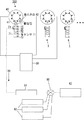
図1に示すように、火災用無線通信装置1は光センサ10と無線通信部20から概略構成される。
火災受信機30としてはP型とR型のいずれを使用してもよい。
火災感知器40の種類としては火災による温度上昇、火災の煙、火災の炎を自動的に検知できる一般的なものであれば特に限定されない。また、火災感知器40の取り付け場所も特に限定されないが、室内の天井や壁に取り付けるのが一般的である。
火災感知器40は火災の発生を火災受信機30に知らせると共に本体の赤色の作動灯41を点灯させる。
[First embodiment]
A first embodiment of a wireless communication apparatus for fire and a fire alarm system according to the present invention will be described.
As shown in FIG. 1, the fire
As the
The type of the
The
光センサ10は作動灯41の直前に配置されており、作動灯41の点灯を検知して火災信号50を出力する。光センサ10は作動灯41の点灯を検知して電気信号に変換できる能力を持ったセンサであればよく、光電効果型、熱効果型、光効果型のいずれでもよい。光センサ10は誤作動を防ぐために可能な限り作動灯41の近くに設置するのが好ましく、また、作動灯41が赤色であるため、赤色の光だけを検知する周知の光センサを用いることにすれば検知の精度を向上させることができる。
なお、「直前」とは作動灯41の光を光センサ10が検知できる範囲内を指す。
無線通信部20は光センサ10から出力された火災信号50を受信してインターネット回線60の基地局61と例えば3G,4G,LTE等の周知の手段で無線通信する。なお、室内に設置されているWi-Fiのアクセスポイントを介して基地局61と無線通信することにしてもよい。
光センサ10と無線通信部20は制御部70によってその駆動が制御される。
The
Note that “immediately before” refers to the range in which the
The
The driving of the
光センサ10と無線通信部20を1つの筺体71内に格納することで設置時の施工性を向上させることができ、また悪戯やゴミの堆積を防止できる。無線通信部20のアンテナ21を筺体71内に格納してもよい。
筺体71の材質は日本消防検定で定められている条件を満たした例えばポリカーボネート樹脂等を用いるのが好ましく、耐熱温度は−10℃〜55℃を満たすのが好ましい。
光センサ10と無線通信部20の駆動は一般的な乾電池又は充電池を利用すればよい。光センサ10を火災感知器40と電気的に接続することなく設置できるので、簡便な装置構成の自動火災報知設備を得られる。
本発明の火災用無線通信装置1は電池交換無しで3〜5年間は待機状態を維持できる。更に電池寿命を長くするために、火災用無線通信装置1の電源が入る条件として次のような一定の条件を満たした場合、例えば(1)温度センサで測定した周辺の温度が一定値以上になった場合、(2)急激な温度上昇が生じた場合、(3)煙センサで測定した周辺の煙(CO等)の濃度が一定値以上になった場合等に制限してもよく、これら(1)〜(3)を併用してもよい。
更に、例えば火災発生時の煙によって作動灯41の光が遮られてしまい、作動灯41の点灯を光センサ10が検知できない状況が想定される。したがって、上記(1)〜(3)のような一定の条件を満たした場合には、光センサ10が作動灯41の点灯を検知していない場合でも光センサ10から火災信号50が出力される仕組みにしてもよい。
動作試験部72を例えば赤色に点灯するペンライト等で照らすことで光センサ10の動作試験を行うことができる。筺体71の一部に光センサ10のオン・オフを示すランプ、電池残量や無線の通信状態を示す表示部を設けてもよい。
By storing the
As the material of the
The
The wireless communication device for
Further, for example, it is assumed that the light of the
The operation test of the
情報処理サーバ62はインターネットを介して情報携帯端末63と有線又は無線で相互に各種情報の送受信が可能になっている。情報処理サーバ62の設置場所は建物内やインターネット上など特に限定されない
光センサ10から出力された火災信号50は、必要に応じて室内のアクセスポイントを介して基地局61に送信され、基地局61から情報処理サーバ62に送信される。情報処理サーバ62は火災信号50を受信すると共に、火災信号50と関連付けられた火災源に関する情報を情報携帯端末63に送信する。
情報携帯端末63としてはいわゆる携帯電話、スマートフォン、タブレット等が挙げられ、建物の各部屋の入居者、管理人その他関係者が所有している。情報処理サーバ62は事前に登録された情報携帯端末63だけに上記火災源に関する情報を送信することにすればよい。或いは、情報携帯端末63からの要求に応じて情報処理サーバ62が当該情報携帯端末63に上記火災源に関する情報を送信することにしてもよい。更に、情報処理サーバ62が消防署に対して火災源に関する情報を送信することにしてもよい。
The
Examples of the information
[第2の実施の形態]
次に本発明の火災用無線通信装置1及び火災報知システム100の第2の実施の形態について説明するが、上記第1の実施の形態と同一の構成になる箇所については同一の符号を付してその説明を省略する。
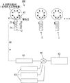
図2に示すように、本実施の形態では火災感知器40が火災発生時に警報音を出力する音出力部42を備えており、火災用無線通信装置1が警報音を検知して火災信号50を出力する音センサ11を備える点に特徴を有する。
例えば一般的な住宅用火災警報器では火災感知時に警報音として電子音を鳴らすことがある。このような警報音を音センサ11で検知して火災信号50を出力することにすれば、火災の発生を光センサ10と音センサ11の両方で検知できるので、火災の発生をより正確に把握できる。
なお、音センサ11が出力した火災信号50も上述のとおり基地局61を介して情報処理サーバ62に送信される。
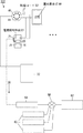
また、図3に示すように火災受信機30を備えないことにしてもよい。この構成の場合、火災感知器40は一般住宅用の「住宅用火災警報器」に該当し、各住宅用火災警報器は火災発生時に単体で或いは複数が連動して動作する。
[Second Embodiment]
Next, a second embodiment of the fire
As shown in FIG. 2, in the present embodiment, the
For example, a general residential fire alarm may sound an electronic sound as an alarm sound when a fire is detected. If such a warning sound is detected by the
The
Further, as shown in FIG. 3, the
[第3の実施の形態]
次に本発明の火災用無線通信装置1及び火災報知システム100の第3の実施の形態について説明するが、上記各実施の形態と同一の構成になる箇所については同一の符号を付してその説明を省略する。
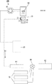
図4に示すように、本実施の形態では火災感知器40が取り付けられている空間を撮影するカメラ12を備えており、無線通信部20が、カメラ12で撮影した動画及び/又は静止画の画像データを火災信号50と共に基地局61に無線送信する点に特徴を有する。
カメラ12は火災感知時に光センサ10や音センサ11が出力する火災信号50を受信したタイミングで撮影を開始するようにすればよい。これにより関係者は火災が発生している空間に関する情報をより正確に把握できる。
[Third embodiment]
Next, a third embodiment of the wireless communication device for
As shown in FIG. 4, the present embodiment includes a camera 12 that captures the space in which the
The camera 12 may start shooting at the timing when the
[第4の実施の形態]
次に本発明の火災用無線通信装置1及び火災報知システム100の第4の実施の形態について説明するが、上記各実施の形態と同一の構成になる箇所については同一の符号を付してその説明を省略する。
図5に示すように、本実施の形態では室外表示灯80が取り付けられており、室外表示灯80を点灯させるための電流が流れたことを検知して火災信号50を出力する電流検知手段81を備える点に特徴を有する。
室外表示灯80は火災感知器40が火災を感知した際に点灯するものであり、例えば集合住宅等の各玄関ドアの周囲に設置されており、室外から視認できるようになっていることが多い。
室内に設置されている火災感知器40が火災を感知すると、室外表示灯80を点灯させるための電流が流れる。電流検知手段81は火災感知器40と室外表示灯80を電気的に繋いでいる配線コード82に接続されている。電流検知手段81は簡便な工事で設置できる。
そして、電流検知手段81は、室外表示灯80を点灯させるための電流が流れたことを検知した場合に火災信号50を出力し、無線端末装置は火災信号50を受信して基地局61と無線通信する。
[Fourth embodiment]
Next, a fourth embodiment of the wireless communication device for
As shown in FIG. 5, an
The
When the
The current detection means 81 outputs a
更に、図6に示すように室外表示灯80の直前に光センサ10を設置してもよい。光センサ10は室外表示灯80の点灯を検知して火災信号50を出力する。そして、無線通信部20が光センサ10からの火災信号50を受信して基地局61と無線通信する。
また、図7に示すように火災用無線通信装置1が電流検知手段81を備えずに、光センサ10と無線通信部20だけを備えることにしてもよい。更に、図示は省略するが室外表示灯80と光センサ10及び無線通信部20を一体化してもよい。
Further, as shown in FIG. 6, the
Further, as shown in FIG. 7, the fire
本発明は、消防用設備が設置されていて点検を要する防火対象物や一般住宅等の既設の火災感知器・室外表示灯の機能を補助する火災用無線通信装置であり、また、複数の火災感知器・室外表示灯のうちどの火災感知器・室外表示灯が作動したのかを既存の設備に大幅な改良を施すこと無く情報携帯端末から把握できる火災報知システムであり、産業上の利用可能性を有する。 The present invention is a wireless communication device for fire that is equipped with a fire-fighting equipment and assists the functions of existing fire detectors and outdoor indicator lights such as fire prevention objects and general houses that need to be inspected. It is a fire alarm system that can grasp from a portable information terminal without significant improvements to existing equipment which fire detector / outdoor indicator light of the detector / outdoor indicator light has been activated. Have
1 火災用無線通信装置
10 光センサ
11 音センサ
12 カメラ
20 無線通信部
21 アンテナ
30 火災受信機
40 火災感知器
41 作動灯
42 音出力部
50 火災信号
60 インターネット回線
61 基地局
62 情報処理サーバ
63 情報携帯端末
70 制御部
71 筺体
72 動作試験部
80 室外表示灯
81 電流検知手段
82 配線コード
100 火災報知システム
1 Wireless communication equipment for fire
10 Light sensor
11 Sound sensor
12 Camera
20 Wireless communication unit
21 Antenna
30 Fire receiver
40 Fire detector
41 Operation light
42 Sound output section
50 Fire signal
60 Internet access
61 base station
62 Information processing server
63 Mobile information terminal
70 Control unit
71 box
72 Operation test section
80 Outdoor indicator
81 Current detection means
82 Wiring cord
100 Fire alarm system
本発明の火災用無線通信装置は、室外表示灯の直前に配置されており火災発生時に前記室外表示灯が点灯したことを検知して火災信号を出力する光センサと、前記火災信号を受信して基地局と無線通信する無線通信部とを備えることを特徴とする。
また、火災感知器の作動灯又は室外表示灯の直前に配置されており火災発生時に前記作動灯又は前記室外表示灯が点灯したことを検知して火災信号を出力する光センサと、
前記火災信号を受信して基地局と無線通信する無線通信部とを備えており、
前記火災感知器が火災発生時に警報音を出力した場合に、前記警報音を検知して火災信号を出力する音センサを備えることを特徴とする。
また、前記火災感知器又は室外表示灯が取り付けられている空間を撮影するカメラを備えており、前記無線通信部は、前記カメラが撮影した画像データを前記火災信号と共に前記基地局に無線送信することを特徴とする。
本発明の火災報知システムは、上記火災用無線通信装置を用いる火災報知システムにおいて、情報通信網に接続された情報処理サーバを備えており、前記火災信号は前記基地局を介して前記情報処理サーバに送信され、前記情報処理サーバは前記火災信号を受信すると共に、前記火災信号と関連付けられた火災源に関する情報を情報携帯端末に送信することを特徴とする。
The wireless communication device for fire according to the present invention is disposed immediately before an outdoor indicator light , detects a light of the outdoor indicator light when a fire occurs, and outputs a fire signal, and receives the fire signal. And a wireless communication unit that wirelessly communicates with the base station.
In addition, an optical sensor that is arranged immediately before the operation light or outdoor indicator light of the fire detector and detects that the operation light or the outdoor indicator light is lit when a fire occurs, and outputs a fire signal;
A wireless communication unit that receives the fire signal and wirelessly communicates with a base station;
Said fire detector is when outputting the alarm sound in the event of a fire, characterized in that it comprises a sound sensor which outputs a fire signal by detecting the alarm sound.
The wireless communication unit wirelessly transmits image data captured by the camera together with the fire signal to the base station. The wireless communication unit includes a camera that captures a space where the fire detector or the outdoor indicator lamp is attached. It is characterized by that.
The fire alarm system according to the present invention includes an information processing server connected to an information communication network in the fire alarm system using the above wireless communication device for fire, and the fire signal is transmitted to the information processing server via the base station. The information processing server receives the fire signal and transmits information on the fire source associated with the fire signal to the information portable terminal.
Claims (5)
前記火災信号を受信して基地局と無線通信する無線通信部とを備えることを特徴とする火災用無線通信装置。
An optical sensor that is arranged immediately before the operation light of the fire detector or the outdoor indicator light and detects that the operation light or the outdoor indicator light is lit when a fire occurs, and outputs a fire signal;
A fire wireless communication apparatus comprising: a wireless communication unit that receives the fire signal and wirelessly communicates with a base station.
2. The fire wireless communication apparatus according to claim 1, further comprising a sound sensor that detects the alarm sound and outputs a fire signal when the fire detector outputs an alarm sound when a fire occurs.
前記火災信号を受信して基地局と無線通信する無線通信部とを備えることを特徴とする火災用無線通信装置。
Current detection means for detecting that a current for turning on the outdoor indicator lamp has flown and outputting a fire signal;
A fire wireless communication apparatus comprising: a wireless communication unit that receives the fire signal and wirelessly communicates with a base station.
前記無線通信部は、前記カメラが撮影した画像データを前記火災信号と共に前記基地局に無線送信することを特徴とする請求項1〜3のいずれか一項に記載の火災用無線通信装置。
A camera for photographing a space in which the fire detector or outdoor indicator lamp is mounted;
4. The fire wireless communication apparatus according to claim 1, wherein the wireless communication unit wirelessly transmits image data captured by the camera to the base station together with the fire signal.
情報通信網に接続された情報処理サーバを備えており、
前記火災信号は前記基地局を介して前記情報処理サーバに送信され、
前記情報処理サーバは前記火災信号を受信すると共に、前記火災信号と関連付けられた火災源に関する情報を情報携帯端末に送信することを特徴とする火災報知システム。
In the fire alarm system using the fire wireless communication device according to any one of claims 1 to 4,
An information processing server connected to the information communication network;
The fire signal is transmitted to the information processing server via the base station,
The information processing server receives the fire signal and transmits information on a fire source associated with the fire signal to an information portable terminal.
Priority Applications (1)
| Application Number | Priority Date | Filing Date | Title |
|---|---|---|---|
| JP2018072075A JP6399572B1 (en) | 2018-04-04 | 2018-04-04 | Wireless communication device for fire and fire alarm system |
Applications Claiming Priority (1)
| Application Number | Priority Date | Filing Date | Title |
|---|---|---|---|
| JP2018072075A JP6399572B1 (en) | 2018-04-04 | 2018-04-04 | Wireless communication device for fire and fire alarm system |
Publications (2)
| Publication Number | Publication Date |
|---|---|
| JP6399572B1 JP6399572B1 (en) | 2018-10-03 |
| JP2019185197A true JP2019185197A (en) | 2019-10-24 |
Family
ID=63708718
Family Applications (1)
| Application Number | Title | Priority Date | Filing Date |
|---|---|---|---|
| JP2018072075A Active JP6399572B1 (en) | 2018-04-04 | 2018-04-04 | Wireless communication device for fire and fire alarm system |
Country Status (1)
| Country | Link |
|---|---|
| JP (1) | JP6399572B1 (en) |
Families Citing this family (1)
| Publication number | Priority date | Publication date | Assignee | Title |
|---|---|---|---|---|
| JP7410537B2 (en) * | 2019-02-12 | 2024-01-10 | 友博 如南 | System to notify of disasters such as fire |
Citations (4)
| Publication number | Priority date | Publication date | Assignee | Title |
|---|---|---|---|---|
| JPH0662665U (en) * | 1993-02-03 | 1994-09-02 | スタンレー電気株式会社 | Fire reporting system |
| JPH10149490A (en) * | 1996-11-19 | 1998-06-02 | Chubu Denki Hoan Kyokai | Inspection reporting device for fire alarm |
| JP2010020422A (en) * | 2008-07-08 | 2010-01-28 | Yamaha Corp | Alarm device and alarm system |
| JP2017531332A (en) * | 2014-06-09 | 2017-10-19 | パク、サンレ | Heat ray imaging apparatus and intrusion detection system using the same |
-
2018
- 2018-04-04 JP JP2018072075A patent/JP6399572B1/en active Active
Patent Citations (4)
| Publication number | Priority date | Publication date | Assignee | Title |
|---|---|---|---|---|
| JPH0662665U (en) * | 1993-02-03 | 1994-09-02 | スタンレー電気株式会社 | Fire reporting system |
| JPH10149490A (en) * | 1996-11-19 | 1998-06-02 | Chubu Denki Hoan Kyokai | Inspection reporting device for fire alarm |
| JP2010020422A (en) * | 2008-07-08 | 2010-01-28 | Yamaha Corp | Alarm device and alarm system |
| JP2017531332A (en) * | 2014-06-09 | 2017-10-19 | パク、サンレ | Heat ray imaging apparatus and intrusion detection system using the same |
Also Published As
| Publication number | Publication date |
|---|---|
| JP6399572B1 (en) | 2018-10-03 |
Similar Documents
| Publication | Publication Date | Title |
|---|---|---|
| US10553086B2 (en) | Social safety network system having portable light for both wireless disaster fire detection and crime prevention | |
| US9390605B2 (en) | Auxiliary device for a hazard alarm constructed as a point type detector for function monitoring of the hazard alarm, and an arrangement and method of monitoring using a device of this kind | |
| US7619534B2 (en) | Method and apparatus for detection of hazardous or potentially hazardous conditions | |
| KR101223680B1 (en) | Smart type fire monitoring and detecting system | |
| JP3147873U (en) | Alarm | |
| KR101684374B1 (en) | Integrated fire control system equipped with fire detection capabilities of the House of Commons | |
| KR101644084B1 (en) | Fire fighting facility control system of apartment house | |
| US20180182218A1 (en) | Fire detection system | |
| KR102580356B1 (en) | Emergency evacuation alarm and guidance system | |
| CN209821986U (en) | Fire monitoring system | |
| KR101341155B1 (en) | Address type wire and wireless fire alarm system | |
| JP5908047B2 (en) | Lighting device and emergency lighting system | |
| JP6399572B1 (en) | Wireless communication device for fire and fire alarm system | |
| KR101663786B1 (en) | Fire fighting management and monitoring system of apartment house | |
| JP6253951B2 (en) | Alarm | |
| KR101950743B1 (en) | Control method of emergency lighting system in case of fire in apartment house | |
| KR101269232B1 (en) | Fire receiver having fire prompt reporting function | |
| KR20160093448A (en) | Electronic fire detector by bluetooth ibeacon transmitter and receiving system | |
| KR101950742B1 (en) | Emergency lighting system in case of fire in apartment | |
| JP2020144933A (en) | Fire alarm system | |
| KR101693215B1 (en) | An Integrated Sensor Control Apparatus and Method for DIY type Unmanned Security System | |
| KR101950745B1 (en) | Control method of emergency lighting system of apartment in case of fire | |
| JP2012048632A (en) | Illumination device and emergency illumination system | |
| KR20120113378A (en) | Wire and wireless disaster prevention system of ship | |
| KR101750933B1 (en) | Firefighting sensing and firehouse auto report system of apartment house |
Legal Events
| Date | Code | Title | Description |
|---|---|---|---|
| A621 | Written request for application examination |
Free format text: JAPANESE INTERMEDIATE CODE: A621 Effective date: 20180428 |
|
| A871 | Explanation of circumstances concerning accelerated examination |
Free format text: JAPANESE INTERMEDIATE CODE: A871 Effective date: 20180428 |
|
| A975 | Report on accelerated examination |
Free format text: JAPANESE INTERMEDIATE CODE: A971005 Effective date: 20180510 |
|
| A131 | Notification of reasons for refusal |
Free format text: JAPANESE INTERMEDIATE CODE: A131 Effective date: 20180525 |
|
| A521 | Request for written amendment filed |
Free format text: JAPANESE INTERMEDIATE CODE: A523 Effective date: 20180713 |
|
| TRDD | Decision of grant or rejection written | ||
| A01 | Written decision to grant a patent or to grant a registration (utility model) |
Free format text: JAPANESE INTERMEDIATE CODE: A01 Effective date: 20180803 |
|
| A61 | First payment of annual fees (during grant procedure) |
Free format text: JAPANESE INTERMEDIATE CODE: A61 Effective date: 20180829 |
|
| R150 | Certificate of patent or registration of utility model |
Ref document number: 6399572 Country of ref document: JP Free format text: JAPANESE INTERMEDIATE CODE: R150 |