JP2019178590A - Automatic door and method for controlling automatic door - Google Patents
Automatic door and method for controlling automatic door Download PDFInfo
- Publication number
- JP2019178590A JP2019178590A JP2018069696A JP2018069696A JP2019178590A JP 2019178590 A JP2019178590 A JP 2019178590A JP 2018069696 A JP2018069696 A JP 2018069696A JP 2018069696 A JP2018069696 A JP 2018069696A JP 2019178590 A JP2019178590 A JP 2019178590A
- Authority
- JP
- Japan
- Prior art keywords
- door
- opening operation
- opening
- automatic
- protection area
- Prior art date
- Legal status (The legal status is an assumption and is not a legal conclusion. Google has not performed a legal analysis and makes no representation as to the accuracy of the status listed.)
- Granted
Links
- 238000000034 method Methods 0.000 title claims abstract description 22
- 238000001514 detection method Methods 0.000 claims abstract description 106
- 230000008569 process Effects 0.000 claims abstract description 10
- 230000000670 limiting effect Effects 0.000 abstract description 8
- 230000004048 modification Effects 0.000 description 58
- 238000012986 modification Methods 0.000 description 58
- 230000004913 activation Effects 0.000 description 8
- 239000004065 semiconductor Substances 0.000 description 3
- 230000035945 sensitivity Effects 0.000 description 3
- 240000004050 Pentaglottis sempervirens Species 0.000 description 2
- 235000004522 Pentaglottis sempervirens Nutrition 0.000 description 2
- 230000009471 action Effects 0.000 description 2
- 230000005540 biological transmission Effects 0.000 description 2
- 230000008859 change Effects 0.000 description 2
- 238000004891 communication Methods 0.000 description 2
- 230000003247 decreasing effect Effects 0.000 description 2
- 238000010586 diagram Methods 0.000 description 2
- 241001465754 Metazoa Species 0.000 description 1
- 241000287107 Passer Species 0.000 description 1
- 230000001133 acceleration Effects 0.000 description 1
- 238000007792 addition Methods 0.000 description 1
- 238000012217 deletion Methods 0.000 description 1
- 230000037430 deletion Effects 0.000 description 1
- 230000000694 effects Effects 0.000 description 1
- 238000005516 engineering process Methods 0.000 description 1
- 230000006870 function Effects 0.000 description 1
- 238000003384 imaging method Methods 0.000 description 1
- 238000004519 manufacturing process Methods 0.000 description 1
- 238000005259 measurement Methods 0.000 description 1
- 230000036961 partial effect Effects 0.000 description 1
- 230000001681 protective effect Effects 0.000 description 1
- 230000002829 reductive effect Effects 0.000 description 1
- 230000002441 reversible effect Effects 0.000 description 1
Images


Abstract
Description
本発明は、自動ドアおよび自動ドアの制御方法に関する。 The present invention relates to an automatic door and an automatic door control method.
近年、自動ドアの安全基準が強化され、ドアの閉作動時の安全性だけでなく開作動時の安全性についても一定の基準が定められるようになった。開作動時の安全性に関する技術として、例えば、特許文献1には、引き戸の固定側全体を保護領域とするセンサを配置し、センサが保護領域内に物体を検知した際にドアを低速度で開作動させる自動ドアが開示されている。
In recent years, safety standards for automatic doors have been strengthened, and certain standards have been established not only for safety when doors are closed, but also for safety when doors are opened. As a technology related to safety at the time of opening operation, for example, in
しかしながら、安全基準に定められる開側保護領域を二重引き戸に適用する場合、ドアの開作動の途中に、開側保護領域が通行者の通行経路に重なる場合がある。この場合、通行経路を通行する通行者が開側保護領域で検知されてドアの開作動が制限されることで、通行者がドアに衝突する可能性がある。 However, when the open-side protection area defined in the safety standards is applied to the double sliding door, the open-side protection area may overlap the passer-by path of the passer-by during the door opening operation. In this case, a passerby may collide with the door by detecting a passerby passing through the traffic route in the open side protection area and restricting the opening operation of the door.
したがって、開側保護領域が通行経路に重なる態様のドアにおいては、開作動時の保護と、通行者の通行性(すなわち、通行の円滑性)とを両立させることが求められる。 Therefore, in a door in a mode in which the open side protection region overlaps the passage route, it is required to achieve both protection during opening operation and passability of the passerby (that is, smoothness of passage).
本発明は、このような点を考慮してなされたものであり、開作動時の保護と通行性とを両立させることができる自動ドアおよび自動ドアの制御方法を提供することを目的とする。 The present invention has been made in view of such points, and an object of the present invention is to provide an automatic door and an automatic door control method capable of achieving both protection during opening operation and trafficability.
本発明は、ドアの開行程において前記ドアが指定位置に到達したと判断される前は、前記ドアの開側に設定された人又は物体を検知するセンサが検知状態になった場合に、前記ドアの開作動を制限し、前記開行程において前記ドアが前記指定位置に到達したと判断された後は、前記センサが検知状態となっても前記開作動を制限しない制御を行う制御部を備えた自動ドアである。 In the present invention, before it is determined that the door has reached a specified position in the door opening stroke, the sensor for detecting a person or object set on the door opening side is in a detection state. A control unit that restricts the opening operation of the door and performs control that does not restrict the opening operation even if the sensor is in a detection state after it is determined that the door has reached the specified position in the opening stroke; Automatic door.
本発明による自動ドアにおいて、前記指定位置は、前記ドアの戸尻が固定部の戸先に一致した位置であってもよい。 In the automatic door according to the present invention, the specified position may be a position where the door bottom of the door coincides with the door tip of the fixed portion.
本発明による自動ドアにおいて、前記制御部は、前記ドアの移動距離に基づいて、前記ドアが前記指定位置に到達したと判断してもよい。 In the automatic door according to the present invention, the control unit may determine that the door has reached the designated position based on a movement distance of the door.
本発明による自動ドアにおいて、前記制御部は、前記ドアの移動時間に基づいて、前記ドアが前記指定位置に到達したと判断してもよい。 In the automatic door according to the present invention, the control unit may determine that the door has reached the designated position based on a movement time of the door.
本発明による自動ドアにおいて、前記制御部は、前記ドアを停止させることで前記開作動を制限してもよい。 In the automatic door according to the present invention, the control unit may limit the opening operation by stopping the door.
本発明による自動ドアにおいて、前記制御部は、前記ドアの移動速度を減少させることで前記開作動を制限してもよい。 In the automatic door according to the present invention, the control unit may limit the opening operation by decreasing a moving speed of the door.
本発明による自動ドアにおいて、前記少なくとも一部の領域は、前記指定位置に到達した前記ドアのドア面に面する領域であってもよい。 In the automatic door according to the present invention, the at least part of the region may be a region facing a door surface of the door that has reached the designated position.
本発明による自動ドアにおいて、前記制御部は、前記ドアの移動速度を増加させることで前記開作動を制限しないようにしてもよい。 In the automatic door according to the present invention, the control unit may not limit the opening operation by increasing a moving speed of the door.
本発明は、ドアの開行程において前記ドアが指定位置に到達したと判断される前は、前記ドアの開側に設定された人又は物体を検知するセンサが検知状態になった場合に、前記ドアの開作動を制限し、前記開行程において前記ドアが前記指定位置に到達したと判断された後は、前記センサが検知状態となっても前記開作動を制限しない、自動ドアの制御方法である。 In the present invention, before it is determined that the door has reached a specified position in the door opening stroke, the sensor for detecting a person or object set on the door opening side is in a detection state. An automatic door control method that restricts the opening operation of the door and does not restrict the opening operation even if the sensor is in a detection state after it is determined that the door has reached the specified position in the opening stroke. is there.
本発明によれば、開作動時の保護と通行性とを両立させることができる。 According to the present invention, it is possible to achieve both protection during opening operation and trafficability.
以下、本発明の実施形態に係る自動ドアおよび自動ドアの制御方法について、図面を参照しながら詳細に説明する。なお、以下に示す実施形態は、本発明の実施形態の一例であって、本発明はこれらの実施形態に限定して解釈されるものではない。また、本実施形態で参照する図面において、同一部分または同様な機能を有する部分には同一の符号または類似の符号を付し、その繰り返しの説明は省略する。また、図面の寸法比率は、説明の都合上、実際の比率とは異なる場合があり、また、構成の一部が図面から省略される場合がある。 Hereinafter, an automatic door and an automatic door control method according to an embodiment of the present invention will be described in detail with reference to the drawings. In addition, embodiment shown below is an example of embodiment of this invention, This invention is limited to these embodiment, and is not interpreted. In the drawings referred to in this embodiment, the same portions or portions having similar functions are denoted by the same or similar reference numerals, and repeated description thereof is omitted. In addition, the dimensional ratio in the drawing may be different from the actual ratio for convenience of description, and a part of the configuration may be omitted from the drawing.
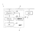
図1は、本実施形態による自動ドア2を備えた自動ドアシステム1を示すブロック図である。図2は、本実施形態による自動ドア2を備えた自動ドアシステム1を示す鳥瞰図である。
FIG. 1 is a block diagram showing an
図1に示すように、自動ドアシステム1は、自動ドア2と、センサ3と、バス4とを備える。自動ドア2は、ドア21と、ドアエンジン22と、位置検出器23と、制御部の一例であるドアコントローラ24とを備える。
As shown in FIG. 1, the
自動ドアシステム1は、ドア21の開口部を通行しようとする通行者をセンサ部3で検知し、センサ3の検知に応じて、通行者を通行させるためにドア21を開動作させる。以下、ドア21の開口部の通行者のことを、ドア21の通行者と呼ぶこともある。また、自動ドアシステム1は、ドア21の開動作時における戸尻側の安全性を確保するため、ドア21の戸尻側に存在する人をセンサ3で検知する。そして、自動ドアシステム1は、センサ3の検知に応じて、戸尻側の安全性を確保するためにドアの開作動を制限する。以下、このような自動ドアシステム1の構成を更に詳述する。
The
自動ドア2のドアエンジン22は、電源の電力を供給されることでドア21を自動で開閉するための回転力を発生させるモータ(図示せず)を内蔵する。モータの回転力は、プーリやタイミングベルトなどの動力伝達部材(図示せず)を介して図2に示す開閉方向d1への並進力としてドア21に伝達される。
The
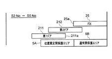
図2の例において、ドア21は、第1ドア211と、第1ドア211よりもストローク距離が短い第2ドア212とを有し、固定部25(すなわち、袖枠)側に向かってスライドすることで開動作を行い、固定部25から離反する側に向かってスライドすることで閉動作を行う片引きタイプの二重引き戸である。
In the example of FIG. 2, the
二重引き戸は、通常の引き戸と比較して固定部25の開閉方向d1の寸法を小さくすることができるため、制約された建物の開口を効率的に利用して自動ドア2の有効開口幅を大きくとることができる。すなわち、二重引き戸は、通常の引き戸と比較して通行性に優れている。なお、ドア21の具体的な態様は図2の態様に限定されず、後述する第5の変形例および第6の変形例に示されるような種々の態様を選択することができる。
Since the double sliding door can reduce the dimension in the opening / closing direction d1 of the fixed
位置検出器23は、ドアエンジン22のモータの回転に応じてドア21の位置を示す位置信号を生成し、生成された位置信号をドアコントローラ24に出力する。位置検出器23は、ドア21の位置を検知できるのであれば具体的な態様は特に限定されない。例えば、位置検出器23は、モータに設けられたホール素子の検出信号の位相に基づいて位置信号を生成してもよい。あるいは、位置検出器23は、モータ21の回転を検知する回転エンコーダの検出信号、またはドア21の開閉位置を検知するために設けられるリニアエンコーダの検出信号に基づいて位置信号を生成してもよい。
The
ドアコントローラ24は、バス4を介してセンサ3に接続されている。バス34は、例えば、CAN(Controller Area Network)通信が可能なCANバスである。ドアコントローラ24は、バス4を介した通信によって、センサ3から所定周期毎に後述する検知エリア内の通行者の検知状況を示す検知信号を取得する。また、ドアコントローラ24は、位置検出器23から出力された位置信号を取得する。
The
ドアコントローラ24は、センサ3から取得された検知信号および位置検出器23から取得された位置信号に基づいて、モータに供給する電力を制御することでモータの駆動制御を行う。モータの駆動制御は、モータの駆動の有無、駆動速度、駆動トルクおよび回転方向の少なくとも1つまたはこれらの2つ以上の組み合わせの制御である。
The
ドアコントローラ24は、モータの駆動制御が可能な構成であれば具体的な態様は特に限定されない。例えば、ドアコントローラ24は、直流電源とモータとの間に接続され、4つの半導体スイッチ(例えば、FET)を有するHブリッジ回路と、半導体スイッチをオンオフ制御することで直流電源からモータへの正回転または逆回転用の電流信号の印加を制御するCPUと、CPUが処理の実行に用いるためのプログラムやデータが記憶された記憶部とを備えていてもよい。この場合、ドアコントローラ24を構成するCPUは、半導体スイッチにPWM(Pulse Width Modulation)信号を出力し、PWM信号のデューティ比によってモータの駆動速度を制御してもよい。
The
ここで、ドアコントローラ24のより具体的な構成を説明する前に、センサ3の構成について説明する。図2に示すように、センサ3は、自動ドア2の無目部26の中央、より具体的には、第2ドア212の中央部の上方に設けられている。センサ3は、天井などの無目部26以外の場所に設けられていてもよい。
Here, before describing a more specific configuration of the
センサ3は、検知エリアを有する。検知エリアとは、センサ3を用いて検知対象を検知可能な床面6上の領域をいう。
The
検知エリアは、起動エリアと、保護エリアとを有する。起動エリアとは、検知エリアのうち、ドア21の起動(すなわち、開作動)に用いるエリアである。保護エリアとは、検知エリアのうち、ドア21による押圧(すなわち、挟み込み)から人を保護するために用いるエリアである。
The detection area has an activation area and a protection area. The activation area is an area used for activation (that is, opening operation) of the
保護エリアは、位置限定開保護エリアと、通常開保護エリアと、閉保護エリアとを有する。位置限定開保護エリアとは、保護エリアのうち、ドア21の開行程においてドア21の位置に応じて限定的にドア21による押圧から人を保護するために用いるエリアである。通常開保護エリアとは、保護エリアのうち、ドア21の開行程においてドア21の位置によらずに常にドア21による押圧から人を保護するために用いるエリアである。閉保護エリアとは、保護エリアのうち、ドア21の閉工程においてドア21による押圧から人を保護するために用いるエリアである。
The protection area has a position limited open protection area, a normally open protection area, and a closed protection area. The position-limited open protection area is an area used to protect a person from being pressed by the
位置限定開保護エリアを有することで、通常開保護エリアのみを有する場合と比較して開作動時の通行性を向上させることができる。 By having the position limited open protection area, it is possible to improve the trafficability at the time of opening operation compared to the case of having only the normal open protection area.
図2の例において、検知エリア5は、第1ドア211、第2ドア212および固定部25の正面においてドア21の開閉方向d1およびこれに直交する前後方向d2に間隔を空けて配置された複数の小検知エリア51で構成されている。個々の小検知エリア51は、例えば、センサ3に設けられた複数の投光素子のそれぞれから投光され、複数の受光素子によってそれぞれ受光される近赤外光の照射スポットに対応している。なお、図2の例では、ドア21に対する進入側の床面6上に配置された検知エリア5を示しているが、検知エリア5は、ドア21に対する退出側の床面上にも設定されていてもよい。
In the example of FIG. 2, the detection area 5 includes a plurality of detection areas 5 arranged at intervals in the opening / closing direction d1 of the
起動エリアは、例えば、6列×12個の小検知エリア51のうちの4〜6列目の小検知エリア51で構成されてもよい。
The activation area may be configured by, for example, the fourth to sixth rows of
また、図2の例において、位置限定開保護エリア5Aは、2列目および3列目の小検知エリア51のうちの一点鎖線の矩形枠で囲まれた第2ドア212の正面の複数の小検知エリア51で構成されている。ただし、位置限定開保護エリア5Aの態様は、図2の態様に限定されるものではなく、必要に応じて種々変更することができる。
Further, in the example of FIG. 2, the position limited open protection area 5 </ b> A includes a plurality of small fronts of the
また、図2の例において、通常開保護エリア5Bは、2列目および3列目の小検知エリア51のうちの位置限定開保護エリア5A対して開側(すなわち、固定部25側に)おいて隣接する二点鎖線の矩形枠で囲まれた複数の小検知エリア51で構成されている。
In the example of FIG. 2, the normal
閉保護エリアは、2列目および3列目の小検知エリア51のうちの位置限定開保護エリア5A対して閉側(すなわち、固定部25と反対側)おいて隣接する複数の小検知エリア51および1列目の小検知エリア51(すなわち、ドアウェイエリア)で構成されてもよい。
The closed protection area is a plurality of
図2の例において、小検知エリア51は、円形状を有する。この場合の照射スポットの床面における直径は、例えば10センチメートルから30センチメートルの間の任意の値にすることができる。小検知エリア51は、楕円形状、矩形状および多角形状などの円形状以外の形状を有していてもよい。
In the example of FIG. 2, the
以上のような検知エリア5を有するセンサ3は、例えば、全ての投光素子で、それぞれに対応する小検知エリア51に向けて近赤外光を投光する。そして、センサ3は、各投光素子のそれぞれに対応して設けられた全ての受光素子で、各小検知エリア51からの近赤外光の反射光を受光する。そして、センサ3は、小検知エリア51毎に、受光量に応じた検知信号を生成し、生成された検知信号をドアコントローラ24に出力する。
The
ドアコントローラ24は、センサ3から出力された検知信号を取得し、取得された検知信号の信号値が人の検知の閾値に達しているか否かを判断基準として、通行者が検知されたか否かを判断する。
The
具体的には、ドアコントローラ24は、検知信号の信号値(すなわち、受光量)の基準値と、検知の有無を判断するための基準値に対する信号値の変化量の閾値とを記憶しておく。ここで、閾値は、センサ3の感度であり、閾値が低いほどセンサ3の感度が高い。ドアコントローラ24は、信号値が閾値以上である場合に、通行者が検知されたと判断する。
Specifically, the
また、ドアコントローラ24は、自動ドアシステム1の電源投入直後に基準値を初期設定した後、一定時間信号値の変化が示されなかった場合に、都度、基準値を更新する。
Further, the
また、ドアコントローラ24は、検知エリアの種類に応じて、検知信号の信号値の閾値を異ならせる。例えば、ドアコントローラ24は、起動エリアの閾値よりも保護エリアの閾値を低く設定する。言い換えれば、ドアコントローラ24は、起動エリアよりも保護エリアのセンサの感度を高く設定する。
Further, the
ドアコントローラ24は、人に限らず、ドア21を除く人以外の物(例えば、荷物や動物等)も通行者として判断してもよい。また、ドアコントローラ24に代えて、センサ3が通行者を検知してもよい。また、センサ3は、小検知エリア51への近赤外光の投光以外にも、小検知エリア51への電波の発信や撮像などの方法によって検知信号を生成してもよい。
The
ドアコントローラ24は、センサ3から取得された検知信号に基づいて起動エリア内に通行者を検知した場合に、ドア21を開方向に駆動する開作動制御を行う。開作動制御において、ドアコントローラ24は、閉側の第1ドア211を開側の第2ドア212よりも高速で開作動させる。例えば、ドアコントローラ24は、第1ドア211を第2ドア212の2倍の速度で開作動させてもよい。
The
また、ドアコントローラ24は、センサ3から取得された検知信号に基づいて保護エリア内に通行者を検知した場合に、ドア21の開作動を制限する制御を行う。本実施形態において、ドアコントローラ24は、ドア21の開作動を停止することでドア21の開作動を制限する。
Further, the
より具体的には、ドアコントローラ24は、開作動時の保護を確保するため、ドア21の開行程においてドア21が指定位置に到達したと判断される前は、第1ドア211の開側に設定された位置限定開保護エリア5Aおよび通常開保護エリア5Bが検知状態になった場合に、ドア21の開作動を制限する。このとき、ドアコントローラ24は、位置検出器23から取得された位置信号に基づいて、ドア21が指定位置に到達したか否かを判断する。
More specifically, the
ここで、指定位置とは、位置限定開保護エリア5Aにおける通行者の検知状態をドア21の開作動の制限に用いない処理(すなわち、位置限定開保護エリア5Aでの検知状態を無視する処理)を開始するときのドア21の位置として、予めドアコントローラ24に指定されたドア21の位置である。
Here, the designated position is a process in which the detection state of the passerby in the position limited
指定位置は、例えば、自動ドア2の製造工程や、使用時の設定段階において、ドアコントローラ24の記憶部に記憶させるデータの一部として設定される。指定位置は、更新可能であってもよい。
The designated position is set, for example, as part of data stored in the storage unit of the
指定位置は、ドア21の開作動の進行にともなって通行者の通行経路(すなわち、人の動線)が位置限定開保護エリア5Aに重なり始めるときのドア21の位置であってもよい。
The designated position may be the position of the
より具体的には、指定位置は、第1ドア211の戸尻211aが固定部25の戸先25a(すなわち、閉側の端部)に一致した位置であってもよい。この場合、位置限定開保護エリア5Aは、指定位置に到達した第1ドア211のドア面に面する領域となる。
More specifically, the designated position may be a position where the door bottom 211a of the
開作動時の保護を確保することに加えて、更に、ドアコントローラ24は、通行性を向上するため、ドア21の開行程においてドア21が指定位置に到達したと判断された後は、位置限定開保護エリア5Aおよび通常開保護エリア5Bのうちの位置限定開保護エリア5Aが検知状態となっても、ドア21の開作動を制限しない。
In addition to ensuring protection during the opening operation, the
すなわち、ドアコントローラ24は、ドア21が指定位置に到達したと判断された後は、位置限定開保護エリア5Aが検知状態となっても、ドア21の開作動を維持する。
That is, after it is determined that the
(自動ドアの制御方法)
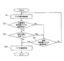
次に、以上のように構成された自動ドアシステム1を適用した自動ドア2の制御方法について説明する。図3は、本実施形態による自動ドア2の動作例を示すフローチャートである。図3のフローチャートは、必要に応じて繰り返される。図4は、本実施形態による自動ドア2の動作例を示す平面図である。図3の初期状態において、第1ドア211および第2ドア212は、図4に示すように全閉状態のドア21の位置にあるものとする。
(Automatic door control method)
Next, a method for controlling the
そして、初期状態から、図3に示すように、ドアコントローラ24は、センサ3から取得された検知信号に基づいて起動エリア内に通行者を検知した場合に、ドア21の開作動制御を開始する(ステップS1)。
Then, from the initial state, as shown in FIG. 3, when the
ドア21の開作動制御を開始した後、ドアコントローラ24は、位置限定開保護エリア5Aが検知状態になったか否かを判定する(ステップS2)。
After starting the opening operation control of the
位置限定開保護エリア5Aが検知状態になった場合(ステップS2:Yes)、ドアコントローラ24は、位置検出器23から取得された位置信号に基づいて、ドア21が指定位置に到達したか否かを判定する(ステップS3)。
When the position limited
一方、位置限定開保護エリア5Aが検知状態になっていない場合(ステップS2:No)、ドアコントローラ24は、センサ3から取得された検知信号に基づいて、通常開保護エリア5Bが検知状態になったか否かを判定する(ステップS5)。
On the other hand, when the position limited
ここで、図5は、図4に続く、本実施形態による自動ドア2の動作例を示す平面図である。位置限定開保護エリア5Aが検知状態になっていない場合(ステップS2:No)であって、通常開保護エリア5Bが検知状態になっていない場合(ステップS5:No)、図5に示すように、ドアコントローラ24は、ドア21の開作動を制限せず、ドア21の開作動制御を継続する(ステップS1)。
Here, FIG. 5 is a plan view showing an operation example of the
図6は、図5に続く、本実施形態による自動ドア2の動作例を示す平面図である。図6に示すように、位置限定開保護エリア5Aが検知状態になり(ステップS2:Yes)、かつ、ドア21が指定位置に到達した場合(ステップS3:Yes)、ドアコントローラ24は、通常開保護エリア5Bが検知状態になったか否かを判定する(ステップS5)。
FIG. 6 is a plan view showing an operation example of the
図7は、図6に続く、本実施形態による自動ドア2の動作例を示す平面図である。位置限定開保護エリア5Aが検知状態になり(ステップS2:Yes)、かつ、ドア21が指定位置に到達した場合(ステップS3:Yes)において、通常開保護エリア5Bが検知状態になっていない場合(ステップS5:No)、図7に示すように、ドアコントローラ24は、ドア21の開作動を制限せず、ドア21の開作動制御を継続する(ステップS1)。
FIG. 7 is a plan view showing an operation example of the
ここで、図6に示すように、片引き式の二重引き戸におけるドア21の有効開口幅Wは、固定部25と反対側の固定枠28から固定部25の戸先25aまでの距離に相当する。そして、図6に示すように、位置限定開保護エリア5Aは、有効開口幅Wに対応する通行動線の範囲内に設定されている。すなわち、位置限定開保護エリア5Aは、通行者の通行経路に重なっている。
Here, as shown in FIG. 6, the effective opening width W of the
もし、ドア21が指定位置に到達した状態で位置限定開保護エリア5Aの検知状態に応じてドア21を停止させた場合、通行者が第1ドア211に衝突するか、または、第1ドア211との衝突を避けるために通行を急停止または通行方向を急転換する動作を強いられることになる。この場合、通行者の通行性が阻害されてしまう。
If the
これに対して、図6の例では、ドア21が指定位置に到達した状態で位置限定開保護エリア5Aが検知状態になっても、ドア21を停止させない。なお、図6では、位置限定開保護エリア5Aにおける検知状態をドア21の開作動の制限に用いないことを、位置限定開保護エリア5Aを破線で図示することによって表現している(以下、同様)。
On the other hand, in the example of FIG. 6, even when the position limited open protection area 5 </ b> A enters the detection state with the
ドア21を停止させないことで、図7に示すように、通行者は、第1ドア211に衝突することなく、また、第1ドア211との衝突を回避するための急な動作を強いられることなく、ドア21を円滑に通行することができる。
By not stopping the
一方、図3に示すように、ドア21が指定位置に到達していない場合(ステップS3:No)または通常開保護エリア5Bが検知状態になった場合(ステップS5:Yes)、ドアコントローラ24は、ドア21を停止制御することでドア21の開作動を制限する(ステップS4)。
On the other hand, as shown in FIG. 3, when the
図8は、図7に続く、本実施形態による自動ドア2の第1の動作例を示す平面図である。上述したドア21の開作動制御によってドア21が全開位置に達した後、ドアコントローラ24は、予め設定された開保持時間(すなわち、オープンタイマ)が経過した後に、ドア21を閉作動させる。このとき、ドアコントローラ24は、ドアウェイの一部および位置限定開保護エリア5Aの閉側に設定された閉保護エリア5Cが検知状態になった場合に、閉作動を禁止する。これにより、閉作動時における保護を確保することができる。
FIG. 8 is a plan view showing a first operation example of the
図9は、図7に続く、本実施形態による自動ドア2の第2の動作例を示す平面図である。図8の例では、ドアウェイの一部を閉保護エリア5Cに設定する例について説明した。これに対して、図9に示すように、ドアウェイの全体に閉保護エリア5Cを設定してもよい。
FIG. 9 is a plan view showing a second operation example of the
以上述べたように、本実施形態において、ドアコントローラ24は、ドア21の開行程においてドア21が指定位置に到達したと判断される前は、第1ドア211の開側に設定されたセンサ3の保護エリア5A、5Bが検知状態になった場合に、ドア21の開作動を制限し、開行程においてドア21が指定位置に到達したと判断された後は、保護エリア5A、5Bのうちの位置限定開保護エリア5Aが検知状態となっても開作動を制限しない。
As described above, in this embodiment, the
このような構成によれば、ドア21が指定位置に到達する前の保護エリア5A、5Bの検知状態に応じたドア21の開作動の制限によって開側の保護を確保するとともに、ドア21が指定位置に到達した後の位置限定開保護エリア5Aの検知状態に反したドア21の開作動の継続によって通行性を確保することができる。これにより、開作動時の保護と通行性とを両立させることができる。
According to such a configuration, the opening side of the
また、既述したように、指定位置は、第1ドア211の戸尻211aが固定部25の戸先25aに一致した位置である。
Further, as described above, the designated position is a position where the door bottom 211a of the
このような構成によれば、開作動を制限されたドア21への衝突が生じ易い必要なタイミングでドア21の開作動を制限しないようにすることができるので、開作動時の保護と通行性とを更にバランス良く両立させることができる。
According to such a configuration, it is possible to prevent the opening operation of the
また、既述したように、ドアコントローラ24は、ドア21を停止させることで開作動を制限する。
As described above, the
このような構成によれば、ドア21が指定位置に到達した後は、位置限定開保護エリア5Aの検知状態にかかわらずドア21を停止させない簡便な手法によって通行性を確保することができる。
According to such a configuration, after the
また、既述したように、位置限定開保護エリア5Aは、指定位置に到達した第1ドア211のドア面に面する領域である。
Further, as described above, the position limited
このような構成によれば、ドア21への挟み込みの可能性が無くなったエリアの検知状態を無視することができるので、開側の保護を犠牲にせずに通行性を確保することができる。
According to such a configuration, it is possible to ignore the detection state of the area where the possibility of being caught in the
(第1の変形例)
次に、ドアの移動速度を減少させることで開作動を制限する第1の変形例について説明する。図10は、本実施形態の第1の変形例による自動ドア2の動作例を示すフローチャートである。
(First modification)
Next, a first modification example in which the opening operation is limited by reducing the moving speed of the door will be described. FIG. 10 is a flowchart showing an operation example of the
図3では、ドア21を停止制御することでドア21の開作動を制限する例について説明した。これに対して、第1の変形例においては、ドア21の移動速度を減少させることでドア21の開作動を制限する。
In FIG. 3, the example which restrict | limits the opening operation | movement of the
具体的には、図10に示すように、ドアコントローラ24は、ドア21が指定位置に到達していない場合(ステップS3:No)または通常開保護エリア5Bが検知状態になった場合(ステップS5:Yes)に、ドア21を減速制御することでドア21の開作動を制限する(ステップS41)。ドアコントローラ24は、第1ドア211の重量と第1ドア211の速度とに基づいて算出される運動エネルギが所定値(例えば、1.69J)以下になるように、第1ドア211の移動速度を減少させてもよい。
Specifically, as shown in FIG. 10, the
第1の変形例によれば、ドア21が指定位置に到達した後は、位置限定開保護エリア5Aの検知状態にかかわらずドア21を減速させない簡便な手法によって、通行性を確保することができる。
According to the first modified example, after the
(第2の変形例)
次に、ドアの移動速度を増加させることで開作動を制限しない第2の変形例について説明する。図11は、本実施形態の第2の変形例による自動ドア2の動作例を示すフローチャートである。
(Second modification)
Next, a second modification example in which the opening operation is not limited by increasing the moving speed of the door will be described. FIG. 11 is a flowchart showing an operation example of the
図3では、ドア21が指定位置に到達した後に位置限定開保護エリア5Aが検知状態になった場合に、ドア21の開作動を継続することでドア21の開作動を制限しない例について説明した。これに対して、第2の変形例においては、ドア21の移動速度を増加させることでドア21の開作動を制限しない。
FIG. 3 illustrates an example in which the opening operation of the
具体的には、図11に示すように、ドアコントローラ24は、通常開保護エリア5Bが検知状態になっていない場合(ステップS5:No)、ドア21を加速制御することで、ドア21の開作動を制限しない(ステップS6)。
Specifically, as shown in FIG. 11, when the normally
第2の変形例によれば、ドア21が指定位置に到達してドア21への挟み込みの可能性が無くなった後は、ドア21の移動速度を増加させることで、開側の保護を犠牲にせずに通行性を向上させることができる。
According to the second modification, after the
(第3の変形例)
次に、ドアの移動距離に基づいてドアが指定位置に到達したと判断する第3の変形例について説明する。図12は、本実施形態の第3の変形例による自動ドア2の動作例を示すフローチャートである。
(Third Modification)
Next, a third modification example in which it is determined that the door has reached the specified position based on the door movement distance will be described. FIG. 12 is a flowchart illustrating an operation example of the
図3においては、位置検出器23からの位置信号に基づいてドア21が指定位置に到達したか否かを判断する例について説明した。これに対して、第3の変形例においては、ドア21の移動距離に基づいて、ドア21が指定位置に到達したか否かを判断する。
In FIG. 3, the example which determines whether the
具体的には、ドアコントローラ24は、モータへの通電量(例えば、既述したPWM信号のパルス数)等に基づいて、ドア21の開作動の開始位置(例えば、全閉位置)からのドア21の移動距離を算出する。
Specifically, the
そして、ドアコントローラ24は、図12に示すように、移動距離が指定位置に相当する所定距離に達したか否かを判定する(ステップS31)。
Then, as shown in FIG. 12, the
移動距離が所定距離に達した場合(ステップS31:Yes)、ドアコントローラ24は、ドア21が指定位置に到達したと判断する(ステップS3:Yes)。
When the moving distance reaches the predetermined distance (step S31: Yes), the
一方、移動距離が所定距離に達していない場合(ステップS31:No)、ドアコントローラ24は、ドア21が指定位置に到達していないと判断する(ステップS3:No)。
On the other hand, when the movement distance has not reached the predetermined distance (step S31: No), the
第3の変形例によれば、移動距離に基づいてドア21が指定位置に到達したことを簡便に判断することができる。
According to the third modification, it is possible to easily determine that the
(第4の変形例)
次に、ドアの移動時間に基づいてドアが指定位置に到達したと判断する第4の変形例について説明する。図13は、本実施形態の第4の変形例による自動ドア2の動作例を示すフローチャートである。
(Fourth modification)
Next, a fourth modification example in which it is determined that the door has reached the specified position based on the door movement time will be described. FIG. 13 is a flowchart showing an operation example of the
第4の変形例においては、ドア21の移動時間に基づいて、ドア21が指定位置に到達したか否かを判断する。
In the fourth modification, it is determined whether the
具体的には、ドアコントローラ24は、タイマの計測時間等に基づいて、ドア21の開作動の開始時刻からのドア21の移動時間を算出する。
Specifically, the
そして、ドアコントローラ24は、図13に示すように、移動時間が指定位置に相当する所定時間に達したか否かを判定する(ステップS32)。
Then, as shown in FIG. 13, the
移動時間が所定時間に達した場合(ステップS32:Yes)、ドアコントローラ24は、ドア21が指定位置に到達したと判断する(ステップS3:Yes)。
When the movement time reaches the predetermined time (step S32: Yes), the
一方、移動時間が所定時間に達していない場合(ステップS32:No)、ドアコントローラ24は、ドア21が指定位置に到達していないと判断する(ステップS3:No)。
On the other hand, when the movement time has not reached the predetermined time (step S32: No), the
第4の変形例によれば、移動時間に基づいてドア21が指定位置に到達したことを簡便に判断することができる。
According to the fourth modification, it can be easily determined that the
(第5の変形例)
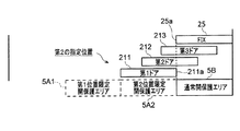
次に、三重引き戸の開作動を制御する第5の変形例について説明する。図14は、本実施形態の第5の変形例による自動ドア2の動作例を示す平面図である。図15は、図14に続く、本実施形態の第5の変形例による自動ドア2の動作例を示す平面図である。図16は、図15に続く、本実施形態の第5の変形例による自動ドア2の動作例を示す平面図である。図17は、図16に続く、本実施形態の第5の変形例による自動ドア2の動作例を示す平面図である。
(Fifth modification)
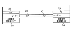
Next, a fifth modification for controlling the opening operation of the triple sliding door will be described. FIG. 14 is a plan view showing an operation example of the
これまでは、二重引き戸の開作動を制御する例について説明した。これに対して、第5の変形例では、三重引き戸の開作動を制御する。 Until now, the example which controls the opening operation of a double sliding door was demonstrated. On the other hand, in the fifth modification, the opening operation of the triple sliding door is controlled.
図14に示すように、第5の変形例のドア21は、第1ドア211および第2ドア212に加えて、更に、全閉状態において最も開側に位置する第3ドア213を有する。すなわち、第5の変形例のドア21は、三重引き戸である。
As shown in FIG. 14, the
図14に示すように、センサ3は、全閉状態における第2ドア212のドア面に面する位置に設定された第1位置限定開保護エリア5A1と、全閉状態における第3ドア213のドア面に面する位置に設定された第2位置限定開保護エリア5A2と、通常開保護エリア5Bとを有する。
As shown in FIG. 14, the
ドアコントローラ24は、図14に示される全閉状態から開作動制御を開始した後、ドア21が図15に示される第1の指定位置に到達する前は、第1位置限定開保護エリア5A1、第2位置限定開保護エリア5A2、または通常開保護エリア5Bが検知状態となった場合に、ドア21の開作動を制限する。開作動の制限の態様は、ドア21の停止およびドア21の減速のいずれであってもよい(以下、同様)。
After the
図15の例において、第1の指定位置は、第1ドア211の戸尻211aが第1位置限定開保護エリア5A1と第2位置限定開保護エリア5A2との境界位置に一致した位置である。
In the example of FIG. 15, the first designated position is a position where the door bottom 211a of the
図15に示すように、ドア21が第1の指定位置に到達した後は、ドアコントローラ24は、ドア21が図16に示される第2の指定位置に到達する前は、第1位置限定開保護エリア5A1が検知状態となってもドア21の開作動を制限しない。図15では、第1位置限定開保護エリア5A1における検知状態をドア21の開作動の制限に用いないことを、第1位置限定開保護エリア5A1を破線で図示することによって表現している(以下、同様)。
As shown in FIG. 15, after the
一方、ドアコントローラ24は、ドア21が第1の指定位置に到達した後においても、ドア21が第2の指定位置に到達する前は、第2位置限定開保護エリア5A2または通常開保護エリア5Bが検知状態となった場合には、ドア21の開作動を制限する。
On the other hand, even after the
図16の例において、第2の指定位置は、第1ドア211の戸尻211aが固定部25の戸先25aに一致した位置である。
In the example of FIG. 16, the second designated position is a position where the door bottom 211 a of the
図16に示すように、ドア21が第2の指定位置に到達した後は、ドアコントローラ24は、第2位置限定開保護エリア5A2が検知状態となってもドア21の開作動を制限しない。図16では、第2位置限定開保護エリア5A2における検知状態をドア21の開作動の制限に用いないことを、第2位置限定開保護エリア5A2を破線で図示することによって表現している(以下、同様)。
As shown in FIG. 16, after the
一方、ドアコントローラ24は、ドア21が第2の指定位置に到達した後においても、通常開保護エリア5Bが検知状態となった場合には、ドア21の開作動を制限する。
On the other hand, even after the
図17に示すように、ドア21が全開位置に到達したとき、ドアコントローラ24は、ドア21の開作動制御を終了する。
As shown in FIG. 17, when the
第5の変形例によれば、二重引き戸よりも通行性が向上された三重引き戸において、開作動時の保護と通行性とを両立させることができる。 According to the fifth modification, in the triple sliding door having improved passability as compared with the double sliding door, it is possible to achieve both protection during opening operation and passability.
(第6の変形例)
次に、ワイドオープンドアの開作動を制御する第6の変形例について説明する。図18は、本実施形態の第6の変形例による自動ドア2の動作例を示す平面図である。図19は、図18に続く、本実施形態の第6の変形例による自動ドア2の動作例を示す平面図である。図20は、図19に続く、本実施形態の第6の変形例による自動ドア2の動作例を示す平面図である。
(Sixth Modification)
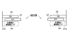
Next, a sixth modification for controlling the opening operation of the wide open door will be described. FIG. 18 is a plan view showing an operation example of the
第6の変形例では、ワイドオープンドアの開作動を制御する。ワイドオープンドアは、引き戸の開作動と開き戸の開作動とを複合した開作動を行うドアである。図18〜図20の例において、ワイドオープンドアは、両開きの2枚のドア21が引き戸の原理で固定部25に面する位置まで開作動した後、ドア21が固定部25ともに開き戸の原理で全開位置まで回動する。ワイドオープンドアは、引き戸の開作動と開き戸の開作動とを複合することで、二重引き戸や三重引き戸と同様に、ドア21の有効開口幅を大きくとることができる。
In the sixth modification, the opening operation of the wide open door is controlled. The wide open door is a door that performs an opening operation in which a sliding door opening operation and a hinged door opening operation are combined. In the examples of FIGS. 18 to 20, the wide open door is opened to the position where the two
図18に示すように、センサ3は、固定部25に面する位置に設定された位置限定開保護エリア5Aを有する。引き戸と違いワイドオープンドアでは、固定部25は完全に固定されてはおらず、引き戸の原理による開作動が終了した後に、開き戸の原理による開作動を行うため、ドア21とともに回動する。したがって、固定部25に面する位置に設定された位置限定開保護エリア5Aは、固定部25の回動にともなって通行者の通行経路に重なることになる。第6の変形例においては、このようなワイドオープンドアに設定される位置限定開保護エリア5Aの特性を考慮して、開側の保護と通行性とを両立するようにドア21の開作動を制御する。
As shown in FIG. 18, the
具体的には、ドアコントローラ24は、図18に示される全閉状態から開作動制御を開始した後、ドア21が図19に示される指定位置に到達する前は、位置限定開保護エリア5Aが検知状態となった場合に、ドア21の開作動を制限する。開作動の制限の態様は、ドア21の停止およびドア21の減速のいずれであってもよい(以下、同様)。
Specifically, the
図19の例において、指定位置は、ドア21が引き戸の原理による開作動から開き戸の原理による開作動に切り替えるときのドア21の位置である。
In the example of FIG. 19, the designated position is the position of the
図19に示すように、ドア21が指定位置に到達した後は、ドアコントローラ24は、位置限定開保護エリア5Aが検知状態となってもドア21の開作動を制限しない。図19では、位置限定開保護エリア5Aにおける検知状態をドア21の開作動の制限に用いないことを、位置限定開保護エリア5Aを破線で図示することによって表現している(以下、同様)。
As shown in FIG. 19, after the
第6の変形例によれば、ワイドオープンドアにおいて、開作動時の保護と通行性とを両立させることができる。 According to the sixth modified example, in the wide open door, it is possible to achieve both protection during opening operation and trafficability.
(第7の変形例)
次に、スライドグライドドアの開作動を制御する第7の変形例について説明する。図21は、本実施形態の第7の変形例による自動ドア2の動作例を示す平面図である。図22は、図21に続く、本実施形態の第7の変形例による自動ドア2の動作例を示す平面図である。図23は、図22に続く、本実施形態の第7の変形例による自動ドア2の動作例を示す平面図である。図24は、図23に続く、本実施形態の第7の変形例による自動ドア2の動作例を示す平面図である。
(Seventh Modification)
Next, a seventh modification for controlling the opening operation of the slide glide door will be described. FIG. 21 is a plan view showing an operation example of the
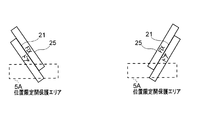
第7の変形例では、スライドグライドドアの開作動を制御する。スライドグライドドアは、引き戸の開作動と回動とを複合した開作動を行うドアである。図21〜図24の例において、スライドグライドドアは、両開きの2枚のドア21が引き戸の原理で固定部25に面する位置まで開作動した後、ドア21が固定部25ともに図24に示される全開位置まで回動する。ワイドオープンドアとの違いは、スライドグライドドアでは、ドア21の戸尻側が戸先側よりも大きく動く、すなわち、ワイドオープンドアに対して回動方向が逆方向である点である。ワイドオープンドアと同様に、スライドグライドドアでは、引き戸の開作動と回動とを複合することで、ドア21の有効開口幅を大きくとることができる。
In the seventh modification, the opening operation of the slide glide door is controlled. The slide glide door is a door that performs an opening operation that is a combination of opening operation and rotation of the sliding door. In the example of FIGS. 21 to 24, the slide glide door is shown in FIG. 24 after the
図21に示すように、センサ3は、固定部25に面する位置に設定された位置限定開保護エリア5Aを有する。ワイドオープンドアと同様にスライドグライドドアでは、固定部25は完全に固定されてはおらず、引き戸の原理による開作動が終了した後にドア21とともに回動する。したがって、固定部25に面する位置に設定された位置限定開保護エリア5Aは、固定部25の回動にともなって通行者の通行経路に重なることになる。
As shown in FIG. 21, the
また、ワイドオープンドアと異なり、スライドグライドドアでは、ドア21の回動の過程で、ドア21が位置限定開保護エリア5Aに重なる。
Further, unlike the wide open door, in the slide glide door, the
第7の変形例においては、このようなスライドグライドドアに設定される位置限定開保護エリア5Aの特性を考慮して、開側の保護と通行性とを両立するようにドア21の開作動を制御する。
In the seventh modified example, the opening operation of the
具体的には、ドアコントローラ24は、全閉状態(図18参照)から開作動制御を開始した後、ドア21が図21に示される指定位置に到達する前は、位置限定開保護エリア5Aが検知状態となった場合に、ドア21の開作動を制限する。開作動の制限の態様は、ドア21の停止およびドア21の減速のいずれであってもよい(以下、同様)。
Specifically, the
図21の例において、指定位置は、ドア21が引き戸の原理による開作動から回動に切り替えるときのドア21の位置である。
In the example of FIG. 21, the designated position is the position of the
図22〜図24に示すように、ドア21が指定位置に到達した後は、ドアコントローラ24は、位置限定開保護エリア5Aが検知状態となってもドア21の開作動を制限しない。図22〜図24では、位置限定開保護エリア5Aにおける検知状態をドア21の開作動の制限に用いないことを、位置限定開保護エリア5Aを破線で図示することによって表現している(以下、同様)。
As shown in FIGS. 22 to 24, after the
第7の変形例によれば、スライドグライドドアにおいて、開作動時の保護と通行性とを両立させることができる。また、ドア21の回動の際に、位置限定開保護エリア5Aにドア21が重なることよるドア21の検知状態を無視できることで、検知状態によってドア21の回動が制限されることを防止することができる。
According to the seventh modified example, in the slide glide door, it is possible to achieve both protection during opening operation and trafficability. Further, when the
本発明の態様は、上述した個々の実施形態に限定されるものではなく、当業者が想到しうる種々の変形も含むものであり、本発明の効果も上述した内容に限定されない。すなわち、特許請求の範囲に規定された内容およびその均等物から導き出される本発明の概念的な思想と趣旨を逸脱しない範囲で種々の追加、変更および部分的削除が可能である。 The aspect of the present invention is not limited to the individual embodiments described above, and includes various modifications that can be conceived by those skilled in the art, and the effects of the present invention are not limited to the contents described above. That is, various additions, modifications, and partial deletions can be made without departing from the concept and spirit of the present invention derived from the contents defined in the claims and equivalents thereof.
また、上述した変形例を含む実施の形態で説明した構成の一部を組み合わせたり、置き換えたりすることも可能である。更に、上述した変形例を含む実施の形態で説明した構成の一部のみを適用することも可能である。これらの場合、本明細書に明示されたものの他、それぞれの構成から導かれる特有の構成を有する。 Moreover, it is also possible to combine or replace some of the configurations described in the embodiments including the above-described modifications. Furthermore, it is possible to apply only a part of the configuration described in the embodiment including the above-described modification. In these cases, there are specific configurations derived from the respective configurations in addition to those specified in the present specification.
2 自動ドア
21 ドア
24 ドアコントローラ
2
Claims (9)
前記開行程において前記ドアが前記指定位置に到達したと判断された後は、前記センサが検知状態となっても前記開作動を制限しない制御を行う制御部を備えた自動ドア。 Before it is determined that the door has reached the specified position in the door opening process, the door opening operation is performed when a sensor that detects a person or an object set on the door opening side is in a detection state. Limit
An automatic door provided with a control unit that performs control that does not limit the opening operation even if the sensor is in a detection state after it is determined that the door has reached the designated position in the opening stroke.
前記開行程において前記ドアが前記指定位置に到達したと判断された後は、前記センサが検知状態となっても前記開作動を制限しない、自動ドアの制御方法。 Before it is determined that the door has reached the specified position in the door opening process, the door opening operation is performed when a sensor that detects a person or an object set on the door opening side is in a detection state. Limit
An automatic door control method in which, after it is determined that the door has reached the designated position in the opening stroke, the opening operation is not restricted even if the sensor is in a detection state.
Priority Applications (1)
| Application Number | Priority Date | Filing Date | Title |
|---|---|---|---|
| JP2018069696A JP7108445B2 (en) | 2018-03-30 | 2018-03-30 | Automatic door and automatic door control method |
Applications Claiming Priority (1)
| Application Number | Priority Date | Filing Date | Title |
|---|---|---|---|
| JP2018069696A JP7108445B2 (en) | 2018-03-30 | 2018-03-30 | Automatic door and automatic door control method |
Publications (2)
| Publication Number | Publication Date |
|---|---|
| JP2019178590A true JP2019178590A (en) | 2019-10-17 |
| JP7108445B2 JP7108445B2 (en) | 2022-07-28 |
Family
ID=68278116
Family Applications (1)
| Application Number | Title | Priority Date | Filing Date |
|---|---|---|---|
| JP2018069696A Active JP7108445B2 (en) | 2018-03-30 | 2018-03-30 | Automatic door and automatic door control method |
Country Status (1)
| Country | Link |
|---|---|
| JP (1) | JP7108445B2 (en) |
Cited By (2)
| Publication number | Priority date | Publication date | Assignee | Title |
|---|---|---|---|---|
| WO2023149092A1 (en) * | 2022-02-02 | 2023-08-10 | オプテックス株式会社 | Automatic door system |
| JP7425902B2 (en) | 2020-07-07 | 2024-01-31 | ナブテスコ株式会社 | Automatic door device, notification control device, and automatic door notification method |
Citations (3)
| Publication number | Priority date | Publication date | Assignee | Title |
|---|---|---|---|---|
| JP2008291598A (en) * | 2007-05-28 | 2008-12-04 | Nabtesco Corp | Automatic door, automatic door sensor, and adjusting device for automatic door |
| JP2012219522A (en) * | 2011-04-08 | 2012-11-12 | Mitsui Kinzoku Act Corp | Door opening/closing device |
| WO2018043511A1 (en) * | 2016-08-29 | 2018-03-08 | ナブテスコ株式会社 | Automatic door, automatic door sensor, and automatic door opening-closing method |
-
2018
- 2018-03-30 JP JP2018069696A patent/JP7108445B2/en active Active
Patent Citations (3)
| Publication number | Priority date | Publication date | Assignee | Title |
|---|---|---|---|---|
| JP2008291598A (en) * | 2007-05-28 | 2008-12-04 | Nabtesco Corp | Automatic door, automatic door sensor, and adjusting device for automatic door |
| JP2012219522A (en) * | 2011-04-08 | 2012-11-12 | Mitsui Kinzoku Act Corp | Door opening/closing device |
| WO2018043511A1 (en) * | 2016-08-29 | 2018-03-08 | ナブテスコ株式会社 | Automatic door, automatic door sensor, and automatic door opening-closing method |
Cited By (3)
| Publication number | Priority date | Publication date | Assignee | Title |
|---|---|---|---|---|
| JP7425902B2 (en) | 2020-07-07 | 2024-01-31 | ナブテスコ株式会社 | Automatic door device, notification control device, and automatic door notification method |
| JP7425901B2 (en) | 2020-07-07 | 2024-01-31 | ナブテスコ株式会社 | Automatic door device, notification control device, and automatic door notification method |
| WO2023149092A1 (en) * | 2022-02-02 | 2023-08-10 | オプテックス株式会社 | Automatic door system |
Also Published As
| Publication number | Publication date |
|---|---|
| JP7108445B2 (en) | 2022-07-28 |
Similar Documents
| Publication | Publication Date | Title |
|---|---|---|
| CN109312594B (en) | Automatic door, automatic door sensor, and method for opening and closing automatic door | |
| US11085227B2 (en) | Vehicle opening and closing apparatus | |
| US20050275363A1 (en) | Control device of opening and closing member | |
| JP5043354B2 (en) | Motor control device and motor duty control method | |
| JP2019178590A (en) | Automatic door and method for controlling automatic door | |
| JP2019052468A (en) | Open/close body driving device | |
| JPH0776973A (en) | Detecting method of position, direction of rotation and rotational speed or either of revolutionarily installed section | |
| JP2012101921A (en) | Door controller of elevator | |
| JP4734716B2 (en) | Opening and closing control device for opening and closing body | |
| JP2003027832A (en) | Automatic open-close device for open-close body for car | |
| JP2009127347A (en) | Automatic door driving device and automatic door device | |
| US8456111B2 (en) | Linear drive for sliding doors or the like | |
| WO2017014247A1 (en) | Opening/closing control device | |
| JP7201403B2 (en) | AUTOMATIC DOOR SYSTEM, AUTOMATIC DOOR SENSOR, AUTOMATIC DOOR DEVICE, AND CONTROL METHOD OF AUTOMATIC DOOR SYSTEM | |
| JP2003193745A (en) | Automatic door | |
| JP2022001733A (en) | Auto door sensor, auto door system and control method of auto door sensor | |
| KR102299494B1 (en) | Apparatus for controlling window of vehicle and method thereof | |
| JP6855256B2 (en) | How to control automatic door devices, automatic door sensors and automatic door devices | |
| JP6804406B2 (en) | Pinching detection device | |
| JP2013060775A (en) | Automatic door control device, automatic door control system, and automatic door control method | |
| JP2020084436A (en) | Automatic door system, automatic door sensor, automatic door device, and automatic door system control method | |
| JP7253935B2 (en) | DETECTION DEVICE, AUTOMATIC DOOR SYSTEM AND CONTROL METHOD OF AUTOMATIC DOOR SYSTEM | |
| JP7062468B2 (en) | How to control automatic door systems and automatic door sensors | |
| JP2000314271A (en) | Method for controlling opening and holding of automatic door | |
| JP2005008386A (en) | Door control device for elevator |
Legal Events
| Date | Code | Title | Description |
|---|---|---|---|
| A621 | Written request for application examination |
Free format text: JAPANESE INTERMEDIATE CODE: A621 Effective date: 20210302 |
|
| A977 | Report on retrieval |
Free format text: JAPANESE INTERMEDIATE CODE: A971007 Effective date: 20211130 |
|
| A131 | Notification of reasons for refusal |
Free format text: JAPANESE INTERMEDIATE CODE: A131 Effective date: 20211203 |
|
| A521 | Request for written amendment filed |
Free format text: JAPANESE INTERMEDIATE CODE: A523 Effective date: 20220126 |
|
| A131 | Notification of reasons for refusal |
Free format text: JAPANESE INTERMEDIATE CODE: A131 Effective date: 20220325 |
|
| A521 | Request for written amendment filed |
Free format text: JAPANESE INTERMEDIATE CODE: A523 Effective date: 20220422 |
|
| TRDD | Decision of grant or rejection written | ||
| A01 | Written decision to grant a patent or to grant a registration (utility model) |
Free format text: JAPANESE INTERMEDIATE CODE: A01 Effective date: 20220621 |
|
| A61 | First payment of annual fees (during grant procedure) |
Free format text: JAPANESE INTERMEDIATE CODE: A61 Effective date: 20220715 |
|
| R151 | Written notification of patent or utility model registration |
Ref document number: 7108445 Country of ref document: JP Free format text: JAPANESE INTERMEDIATE CODE: R151 |