JP2019175254A - Operation support system - Google Patents
Operation support system Download PDFInfo
- Publication number
- JP2019175254A JP2019175254A JP2018064503A JP2018064503A JP2019175254A JP 2019175254 A JP2019175254 A JP 2019175254A JP 2018064503 A JP2018064503 A JP 2018064503A JP 2018064503 A JP2018064503 A JP 2018064503A JP 2019175254 A JP2019175254 A JP 2019175254A
- Authority
- JP
- Japan
- Prior art keywords
- travel
- work vehicle
- tractor
- vehicle
- obstacle
- Prior art date
- Legal status (The legal status is an assumption and is not a legal conclusion. Google has not performed a legal analysis and makes no representation as to the accuracy of the status listed.)
- Granted
Links
- 238000004891 communication Methods 0.000 claims abstract description 25
- 238000001514 detection method Methods 0.000 claims description 97
- 238000010295 mobile communication Methods 0.000 claims description 54
- 238000005516 engineering process Methods 0.000 abstract description 2
- 238000005259 measurement Methods 0.000 description 77
- 230000007246 mechanism Effects 0.000 description 23
- 238000000034 method Methods 0.000 description 22
- 230000008569 process Effects 0.000 description 18
- 238000012545 processing Methods 0.000 description 12
- 230000005540 biological transmission Effects 0.000 description 11
- 230000000873 masking effect Effects 0.000 description 8
- 238000012790 confirmation Methods 0.000 description 5
- 238000003971 tillage Methods 0.000 description 5
- 230000007704 transition Effects 0.000 description 5
- 230000002093 peripheral effect Effects 0.000 description 4
- 230000008859 change Effects 0.000 description 3
- 238000013459 approach Methods 0.000 description 2
- 238000010586 diagram Methods 0.000 description 2
- 239000011521 glass Substances 0.000 description 2
- 238000003384 imaging method Methods 0.000 description 2
- 239000000463 material Substances 0.000 description 2
- 238000012546 transfer Methods 0.000 description 2
- 230000001133 acceleration Effects 0.000 description 1
- 239000003086 colorant Substances 0.000 description 1
- 230000003247 decreasing effect Effects 0.000 description 1
- 230000002706 hydrostatic effect Effects 0.000 description 1
- 238000009434 installation Methods 0.000 description 1
- 239000004973 liquid crystal related substance Substances 0.000 description 1
- 230000000116 mitigating effect Effects 0.000 description 1
- 238000011084 recovery Methods 0.000 description 1
- 238000009331 sowing Methods 0.000 description 1
- 238000005507 spraying Methods 0.000 description 1
Images


Abstract
Description
本発明は、牽引車を有する作業車両の運転を支援する運転支援システムに関する。 The present invention relates to a driving support system that supports driving of a work vehicle having a tow vehicle.
トラクタ等の作業車両により牽引される牽引車の走行軌跡は作業車両の走行軌跡に対して乖離するものとなる。そのため、牽引車を有する作業車両を走行させるには高度な運転技術が必要となる。特に、牽引車を有する作業車両を後退させる場合には、先頭側の牽引車が後方側の作業車両により押し出される形態となるため、牽引車と作業車両の連結点での折れ角が大きく変化して双方の走行軌跡が大きく乖離し易くなり、意図どおりに走行させることができない場合がある。
そこで、このような牽引車を有する作業車両の運転を支援するために、牽引車の走行軌跡と作業車両の走行軌跡とを一致させるように、牽引車の車輪を操向制御するシステムが提案されている(例えば、特許文献1を参照。)
The travel locus of the tow vehicle towed by a work vehicle such as a tractor deviates from the travel locus of the work vehicle. Therefore, advanced driving techniques are required to drive a work vehicle having a tow vehicle. In particular, when a work vehicle having a tow vehicle is moved backward, the leading tow vehicle is pushed out by the rear work vehicle, so that the folding angle at the connection point between the tow vehicle and the work vehicle changes greatly. In some cases, the travel trajectories of the two are greatly deviated and cannot be traveled as intended.
Therefore, in order to support the operation of a work vehicle having such a tow vehicle, a system for steering control of the wheels of the tow vehicle so that the travel locus of the tow vehicle matches the travel locus of the work vehicle has been proposed. (For example, refer to Patent Document 1)
上記特許文献1のシステムを採用して牽引車を有する作業車両の運転を支援した場合であっても、運転席に搭乗しているユーザからは、作業車両に対して牽引車がどの方向に位置するか等の当該作業車両及び当該牽引車の状態を把握することは困難である。そのため、特に作業車両を後退させて所定の駐車位置に駐車させる場合等のように、作業車両を走行させて所定の移動目標位置に適切に移動させるには、非常に高度な運転技術が必要となる。
Even when the system of the above-mentioned
この実情に鑑み、本発明の主たる課題は、例えば牽引車を有する作業車両を走行させて所定の移動目標位置に移動させる場合であっても、意図どおり走行させるように当該作業車両の運転を支援することができる技術を提供する点にある。 In view of this situation, the main problem of the present invention is that, for example, even when a work vehicle having a tow vehicle is traveled and moved to a predetermined movement target position, the operation of the work vehicle is supported so as to travel as intended. The point is to provide technology that can do.
本発明の第1特徴構成は、牽引車を有する作業車両の運転を支援する運転支援システムであって、
前記作業車両に備えられ、走行指示に従って当該走行車両の走行を制御する走行制御部と、
前記走行制御部との間で無線通信可能に構成され、タッチ操作可能な表示部を有する携帯通信端末と、
前記携帯通信端末の表示部に表示された走行操作画面に対する入力操作に基づいて前記走行指示を生成し、当該生成した走行指示を前記走行制御部に出力する走行指示生成部と、を備え、
前記携帯通信端末が、衛星測位システムを利用して測定した前記作業車両の現在位置を地図情報と共に前記走行操作画面に表示し、
前記走行指示生成部が、前記走行操作画面に表示した前記作業車両の現在位置に対するドラッグ操作に基づいて前記走行指示を生成する点にある。
A first characteristic configuration of the present invention is a driving support system that supports driving of a work vehicle having a tow vehicle,
A traveling control unit that is provided in the work vehicle and controls traveling of the traveling vehicle according to a traveling instruction;
A mobile communication terminal configured to be capable of wireless communication with the travel control unit and having a display unit capable of touch operation;
A travel instruction generating unit that generates the travel instruction based on an input operation on the travel operation screen displayed on the display unit of the mobile communication terminal, and outputs the generated travel instruction to the travel control unit;
The mobile communication terminal displays the current position of the work vehicle measured using a satellite positioning system together with map information on the travel operation screen,
The travel instruction generation unit generates the travel instruction based on a drag operation on the current position of the work vehicle displayed on the travel operation screen.
本構成によれば、例えば作業車両から降車して携帯通信端末を操作するユーザが、当該作業車両の周囲を確認しながら、当該携帯通信端末を用いて作業車両を遠隔で意図どおりに走行させることができる。
即ち、携帯通信端末のタッチ操作可能な表示部には、作業車両の現在位置が地図情報と共に表示された走行操作画面が表示される。ユーザは、その携帯通信端末の走行操作画面において、作業車両の現在位置を地図情報上で正確に視認しながら、その視認した作業車両の現在位置に対して、作業車両の走行方向や経路等を正確に示すドラッグ操作(選択(押圧)した状態で移動させる操作)を行うことができる。すると、そのドラッグ操作に基づいて走行指示が走行指示生成部により生成され、その走行指示が作業車両の走行制御部に入力される。結果、走行制御部は、そのような携帯通信端末側でのドラッグ操作により生成された走行指示に従って、作業車両を走行させることができる。
従って、本発明により、例えば牽引車を有する作業車両を走行させて所定の目標移動位置に移動させる場合であっても、意図どおり走行させるように当該作業車両の運転を支援することができる運転支援システムを提供することができる。
According to this configuration, for example, a user who gets off the work vehicle and operates the mobile communication terminal allows the work vehicle to travel remotely as intended using the mobile communication terminal while checking the surroundings of the work vehicle. Can do.
That is, a travel operation screen on which the current position of the work vehicle is displayed together with the map information is displayed on the display unit capable of touch operation of the mobile communication terminal. On the travel operation screen of the mobile communication terminal, the user can accurately view the current position of the work vehicle on the map information, and the travel direction and route of the work vehicle with respect to the current position of the work vehicle viewed. It is possible to perform a drag operation (an operation to move in a selected (pressed) state) accurately. Then, a travel instruction is generated by the travel instruction generation unit based on the drag operation, and the travel instruction is input to the travel control unit of the work vehicle. As a result, the traveling control unit can cause the work vehicle to travel in accordance with the traveling instruction generated by the drag operation on the mobile communication terminal side.
Therefore, according to the present invention, for example, even when a work vehicle having a tow vehicle is driven and moved to a predetermined target movement position, driving support that can support the operation of the work vehicle so as to run as intended. A system can be provided.
本発明の第2特徴構成は、前記走行指示生成部が、前記走行操作画面に表示した前記作業車両の現在位置に対するドラッグ操作のスライド方向を前記作業車両の走行方向として前記走行指示を生成する点にある。 According to a second characteristic configuration of the present invention, the travel instruction generation unit generates the travel instruction with the slide direction of the drag operation with respect to the current position of the work vehicle displayed on the travel operation screen as the travel direction of the work vehicle. It is in.
本構成によれば、走行指示生成部は、走行操作画面に表示した作業車両の現在位置に対して行われるドラッグ操作のスライド方向を検知し、その検知したスライド方向を作業車両の走行方向として走行指示を生成することができる。すると、走行制御部は、ユーザによるドラッグ操作のスライド方向で指定された走行方向に沿って、作業車両をユーザの意図どおりに走行させることができる。即ち、ユーザは、携帯通信端末の表示部に表示された走行操作画面において、ドラッグ操作により簡単に作業車両の自走走行時の走行方向を指定することができる。 According to this configuration, the travel instruction generation unit detects the slide direction of the drag operation performed on the current position of the work vehicle displayed on the travel operation screen, and travels using the detected slide direction as the travel direction of the work vehicle. An indication can be generated. Then, the traveling control unit can cause the work vehicle to travel as intended by the user along the traveling direction specified by the sliding direction of the drag operation by the user. That is, the user can easily specify the traveling direction when the work vehicle is traveling by itself on the traveling operation screen displayed on the display unit of the mobile communication terminal by a drag operation.
本発明の第3特徴構成は、前記走行指示生成部が、前記作業車両の現在位置から予め登録された移動目標位置に至る経路に沿って前記作業車両を走行させるための走行指示を生成可能に構成されている点にある。 According to a third characteristic configuration of the present invention, the travel instruction generation unit can generate a travel instruction for causing the work vehicle to travel along a route from a current position of the work vehicle to a movement target position registered in advance. It is in the point which is comprised.
本構成によれば、走行指示生成部は、作業車両を現在位置から予め登録された移動目標位置に至る経路に沿って走行させるための走行指示を生成することができる。すると、走行制御部は、その経路に沿って作業車両を走行させて、当該作業車両を登録された移動目標位置に正確に移動させることができる。 According to this configuration, the travel instruction generating unit can generate a travel instruction for causing the work vehicle to travel along a route from the current position to the movement target position registered in advance. Then, the traveling control unit can cause the work vehicle to travel along the route and accurately move the work vehicle to the registered movement target position.
本発明の第4特徴構成は、前記作業車両に備えられ、周囲の障害物を検知する障害物検知部を備え、
前記携帯通信端末が、前記障害物検知部で検知された障害物の配置状態を前記走行操作画面に表示する点にある。
A fourth characteristic configuration of the present invention is provided in the work vehicle, and includes an obstacle detection unit that detects surrounding obstacles,
The mobile communication terminal displays an obstacle arrangement state detected by the obstacle detection unit on the travel operation screen.
本構成によれば、携帯通信端末の表示部に表示された走行操作画面には、障害物検知部で検知された作業車両周囲の障害物の配置状態が作業車両の現在位置と共に表示される。よって、ユーザは、その走行操作画面において、作業車両の現在位置に加えて、その周囲の障害物の配置状態を正確に視認しながら、例えば障害物を避けるように作業車両の現在位置に対してドラッグ操作を行う形態で、作業車両を遠隔で障害物をできるだけ避けながら走行させることができる。 According to this configuration, on the traveling operation screen displayed on the display unit of the mobile communication terminal, the arrangement state of the obstacles around the work vehicle detected by the obstacle detection unit is displayed together with the current position of the work vehicle. Therefore, in addition to the current position of the work vehicle on the travel operation screen, the user can visually recognize the arrangement state of the obstacles around the work vehicle, for example, to avoid the obstacle with respect to the current position of the work vehicle. In the form of performing a drag operation, the work vehicle can be run remotely while avoiding obstacles as much as possible.
本発明の第5特徴構成は、上記第4特徴構成に加えて、前記障害物検知部で検知された障害物との衝突を回避した状態で前記走行指示に従って前記作業車両が走行可能か否かを判定する走行可否判定部を備え、
前記携帯通信端末が、前記走行可否判定部の判定結果を通知する点にある。
According to a fifth feature configuration of the present invention, in addition to the fourth feature configuration, whether or not the work vehicle can travel according to the travel instruction in a state where a collision with an obstacle detected by the obstacle detection unit is avoided. A travel propriety determination unit for determining
The mobile communication terminal is informed of the determination result of the travel propriety determination unit.
本構成によれば、ユーザのドラッグ操作により生成された走行指示に従って作業車両を走行させると想定した場合、障害物検知部で検知された障害物の配置状態に対して作業車両が走行可能であるか否かが走行可否判定部により判定される。そして、ユーザには、その走行可否判定部の判定結果が携帯通信端末にて通知される。
よって、携帯通信端末を操作するユーザは、作業車両を遠隔で走行させるべく、走行操作画面にて作業車両の走行方向等を指示するためのドラッグ操作を行うだけで、そのドラッグ操作に基づく走行指示に従って作業車両が走行できるか否かを、障害物を検知した段階で明確に把握することができる。そして、例えば障害物との干渉等により走行できないと判定されてその旨が通知された場合には、ユーザは、走行操作画面にてドラッグ操作をやり直すなどして、障害物と干渉しないように作業車両を遠隔で走行させることができる。
According to this configuration, when the work vehicle is assumed to travel according to the travel instruction generated by the user's drag operation, the work vehicle can travel with respect to the obstacle arrangement state detected by the obstacle detection unit. Is determined by the travel propriety determination unit. Then, the user is notified of the determination result of the travel propriety determination unit by the mobile communication terminal.
Therefore, a user operating the mobile communication terminal simply performs a drag operation for instructing the travel direction of the work vehicle on the travel operation screen in order to travel the work vehicle remotely, and the travel instruction based on the drag operation is performed. Whether or not the work vehicle can travel can be clearly grasped at the stage where the obstacle is detected. Then, for example, when it is determined that the vehicle cannot travel due to interference with an obstacle and the fact is notified, the user performs a drag operation on the traveling operation screen so as not to interfere with the obstacle. The vehicle can be driven remotely.
本発明の第6特徴構成は、上記第5特徴構成に加えて、前記走行指示生成部が、前記作業車両の現在位置から予め登録された入口を通過する経路に沿って前記作業車両を走行させるための走行指示を生成可能に構成され、
前記走行可否判定部が、前記障害物検知部で検知された前記入口の周囲の障害物を回避した状態で前記走行指示に従って前記作業車両が前記入口を通過可能か否かを判定する点にある。
According to a sixth characteristic configuration of the present invention, in addition to the fifth characteristic configuration, the travel instruction generation unit causes the work vehicle to travel along a route passing through a pre-registered entrance from the current position of the work vehicle. Configured to be able to generate driving instructions for
The travel propriety determination unit determines whether the work vehicle can pass through the entrance according to the travel instruction in a state where an obstacle around the entrance detected by the obstacle detection unit is avoided. .
本構成によれば、走行指示生成部は、作業車両を現在位置から予め登録された納屋等の入口を通過する経路に沿って走行させるための走行指示を生成することができる。すると、走行制御部は、その経路に沿って入口を通過するように作業車両を走行させることができる。また、障害物検知部で検知された入口周囲の障害物の配置状態に対して作業車両が納屋等の入口を通過可能であるか否かが走行可否判定部により判定される。そして、ユーザには、その走行可否判定部の判定結果が携帯通信端末にて通知される。
よって、携帯通信端末を操作するユーザは、作業車両を遠隔で走行させるべく、走行操作画面にて作業車両の走行方向等を指示するためのドラッグ操作を行うだけで、そのドラッグ操作に基づく走行指示に従って作業車両が入口を通過できるか否かを、入口の周囲の状態を検知した段階で明確に把握することができる。そして、例えば入口の周囲の障害物との干渉等により走行できないと判定されてその旨が通知された場合には、ユーザは、走行操作画面にてドラッグ操作をやり直すなどして、障害物と干渉しないように作業車両を遠隔で走行させることができる。
According to this configuration, the travel instruction generating unit can generate a travel instruction for causing the work vehicle to travel along a route passing through an entrance of a barn or the like registered in advance from the current position. Then, the traveling control unit can cause the work vehicle to travel so as to pass through the entrance along the route. Further, the traveling availability determination unit determines whether or not the work vehicle can pass through the entrance of a barn or the like with respect to the arrangement state of the obstacles around the entrance detected by the obstacle detection unit. Then, the user is notified of the determination result of the travel propriety determination unit by the mobile communication terminal.
Therefore, a user operating the mobile communication terminal simply performs a drag operation for instructing the travel direction of the work vehicle on the travel operation screen in order to travel the work vehicle remotely, and the travel instruction based on the drag operation is performed. Thus, it is possible to clearly grasp whether or not the work vehicle can pass through the entrance at the stage where the state around the entrance is detected. Then, for example, when it is determined that the vehicle cannot travel due to interference with obstacles around the entrance and the fact is notified, the user interferes with the obstacle by performing a drag operation again on the traveling operation screen. As a result, the work vehicle can be driven remotely.
本発明の第7特徴構成は、上記第4乃至第6特徴構成に加えて、前記衛星測位システムを利用した前記作業車両の現在位置の測位の可否を判定する測位可否判定部を備え、
前記走行制御部が、前記測位可否判定部により前記作業車両の現在位置の測位が可能である測位可能状態時においては、前記衛星測位システムを利用して測位された前記作業車両の現在位置を確認しながら前記走行指示に従って当該作業車両を走行させ、前記測位可否判定部により前記作業車両の現在位置の測位が不可である測位不可状態時においては、前記障害物検知部により検知された前記障害物の配置状態を確認しながら前記走行指示に従って当該作業車両を走行させる点にある。
In addition to the fourth to sixth feature configurations, a seventh feature configuration of the present invention includes a positioning availability determination unit that determines whether positioning of the current position of the work vehicle using the satellite positioning system is possible,
The travel control unit confirms the current position of the work vehicle that has been positioned using the satellite positioning system when the current position of the work vehicle can be measured by the positioning availability determination unit. The obstacle is detected by the obstacle detection unit when the positioning of the current position of the work vehicle is impossible by the positioning availability determination unit while the work vehicle is driven according to the traveling instruction. The work vehicle is caused to travel according to the travel instruction while confirming the arrangement state.
本構成によれば、作業車両が例えば屋外にあって衛星測位システムを利用した作業車両の現在位置の測位が可能となる測位可能状態においては、ユーザのドラッグ操作により生成された走行指示に従った作業車両の走行制御部による走行時において、衛星測位システムを利用して測位された比較的正確な作業車両の現在位置が確認される。よって、この測位可能状態においては、ユーザの遠隔操作に従いながら正確に作業車両を走行させることができる。
一方、作業車両が例えば納屋等の屋内にあって衛星測位システムを利用した作業車両の現在位置の測位が不可となる測位不可状態においては、ユーザのドラッグ操作により生成された走行指示に従った作業車両の走行制御部による走行時において、障害物検知部により検知された障害物の配置状態が確認される。よって、この測位不可状態においては、ユーザの遠隔操作に従いながら少なくとも障害物と干渉しないように作業車両を走行させることができる。
According to this configuration, in a positioning enabled state where the current position of the work vehicle can be measured using the satellite positioning system, for example, when the work vehicle is outdoors, the traveling instruction generated by the user's drag operation is followed. During traveling by the traveling control unit of the work vehicle, a relatively accurate current position of the work vehicle, which is measured using the satellite positioning system, is confirmed. Therefore, in this positioning enabled state, the work vehicle can be accurately driven while following the user's remote operation.
On the other hand, when the work vehicle is indoors such as a barn and the positioning of the current position of the work vehicle using the satellite positioning system is impossible, the operation according to the travel instruction generated by the user's drag operation is not possible. During travel by the travel control unit of the vehicle, the disposition state of the obstacle detected by the obstacle detection unit is confirmed. Therefore, in this positioning disabled state, the work vehicle can be driven so as not to interfere with at least an obstacle while following the user's remote operation.
本発明の第8特徴構成は、前記作業車両に対する前記牽引車の状態を検知する牽引車状態検知部を備え、
前記携帯通信端末が、前記走行操作画面において表示される前記作業車両の現在位置に、前記牽引車状態検知部で検知された状態で前記作業車両及び前記牽引車を表示する点にある。
An eighth characteristic configuration of the present invention includes a tow vehicle state detection unit that detects a state of the tow vehicle with respect to the work vehicle,
The mobile communication terminal displays the work vehicle and the tow vehicle at the current position of the work vehicle displayed on the traveling operation screen in a state detected by the tow vehicle state detection unit.
本構成によれば、携帯通信端末の表示部に表示された走行操作画面には、牽引車状態検知部で検知された作業車両に対する牽引車の状態にて、作業車両及び牽引車が表示される。よって、ユーザは、その走行操作画面において、作業車両の現在位置に加えて、作業車両と牽引車の状態を正確に視認しながら、その状態での作業車両の現在位置に対してドラッグ操作を行う形態で、作業車両を遠隔で意図どおりに走行させることができる。 According to this configuration, the work vehicle and the towing vehicle are displayed on the traveling operation screen displayed on the display unit of the mobile communication terminal in the state of the towing vehicle with respect to the working vehicle detected by the towing vehicle state detecting unit. . Therefore, in addition to the current position of the work vehicle, the user performs a drag operation on the current position of the work vehicle in that state while accurately viewing the state of the work vehicle and the towing vehicle on the travel operation screen. In this form, the work vehicle can be remotely operated as intended.
本発明に係る運転支援システムを自動走行システムに適用した場合の実施形態を図面に基づいて説明する。
この自動走行システムにおいては、図1に示すように、本発明に係る作業車両としてトラクタ1を適用しているが、トラクタ以外の作業車両を適用することができる。
An embodiment in which a driving support system according to the present invention is applied to an automatic travel system will be described with reference to the drawings.
In this automatic traveling system, as shown in FIG. 1, the
先ず、本実施形態の自動走行システムの基本構成について説明する。
この自動走行システムは、図1及び図2に示すように、トラクタ1に搭載された自動走行ユニット2、及び、自動走行ユニット2と通信可能に通信設定された携帯通信端末3を備えている。携帯通信端末3には、タッチ操作可能な表示部51(例えば、液晶パネル)等を有するタブレット型のパーソナルコンピュータやスマートフォン等を採用することができる。
First, the basic configuration of the automatic traveling system of this embodiment will be described.
As shown in FIGS. 1 and 2, the automatic traveling system includes an
トラクタ1は、駆動可能な操舵輪として機能する左右の前輪5、及び、駆動可能な左右の後輪6を有する走行機体7が備えられている。走行機体7の前方側には、ボンネット8が配置され、ボンネット8内には、コモンレールシステムを備えた電子制御式のディーゼルエンジン(以下、エンジンと称する)9が備えられている。走行機体7のボンネット8よりも後方側には、搭乗式の運転部を形成するキャビン10が備えられている。
The
走行機体7の後部には、リンク機構11を介して、牽引車12が連結されている。尚、このリンク機構11には、牽引車12ではなく、作業装置の一例であるロータリ耕耘装置を昇降可能かつローリング可能に連結することで、トラクタ1をロータリ耕耘仕様に構成することができる。また、ロータリ耕耘装置に代えて、プラウ、播種装置、散布装置、等の作業装置を連結することもできる。
A towing
トラクタ1には、図2に示すように、エンジン9からの動力を変速する電子制御式の変速装置13、左右の前輪5を操舵する全油圧式のパワーステアリング機構14、左右の後輪6を制動する左右のサイドブレーキ(図示せず)、左右のサイドブレーキの油圧操作を可能にする電子制御式のブレーキ操作機構15、ロータリ耕耘装置等の作業装置への伝動を断続する作業クラッチ(図示せず)、作業クラッチの油圧操作を可能にする電子制御式のクラッチ操作機構16、作業装置を昇降駆動する電子油圧制御式の昇降駆動機構17、トラクタ1の自動走行等に関する各種の制御プログラム等を有する車載電子制御ユニット18、トラクタ1の車速を検出する車速センサ19、前輪5の操舵角を検出する舵角センサ20、及び、トラクタ1の現在位置及び現在方位を測定する測位ユニット21等が備えられている。
As shown in FIG. 2, the
なお、エンジン9には、電子ガバナを備えた電子制御式のガソリンエンジンを採用してもよい。変速装置13には、油圧機械式無段変速装置(HMT)、静油圧式無段変速装置(HST)、又は、ベルト式無段変速装置等を採用することができる。パワーステアリング機構14には、電動モータを備えた電動式のパワーステアリング機構14等を採用してもよい。
The
キャビン10は、図4及び図5に示すように、キャビン10の骨組みを形成するキャビンフレーム31と、前方側を覆うフロントガラス32と、後方側を覆うリアガラス33と、上下方向に沿う軸心周りで揺動開閉可能な左右一対のドア34(図1参照)と、天井側のルーフ35とを備えた箱状に構成されている。キャビンフレーム31は、前端部に配置された左右一対の前側支柱36と、後端部に配置された左右一対の後側支柱37とを備えている。平面視において、前方側の左右両側の隅部に前側支柱36が配置され、後方側の左右両側の隅部に後側支柱37が配置されている。キャビンフレーム31は、弾性体等の防振部材を介して走行機体7上に支持されており、走行機体7等からの振動がキャビン10に伝達されるのを防止する防振対策が施された状態で、キャビン10が備えられている。
As shown in FIGS. 4 and 5, the
キャビン10の内部には、図1に示すように、パワーステアリング機構14(図2参照)を介した左右の前輪5の手動操舵を可能にするステアリングホイール38、搭乗者用の運転席39、タッチパネル式の表示部、及び、各種の操作具等が備えられている。キャビン10の前方側部位の両横側部には、キャビン10(運転席39)への乗降部となる乗降ステップ41が備えられている。
Inside the
図2に示すように、車載電子制御ユニット18は、変速装置13の作動を制御する変速制御部181、左右のサイドブレーキの作動を制御する制動制御部182、作業装置の作動を制御する作業装置制御部183、自動走行時に左右の前輪5の目標操舵角を設定してパワーステアリング機構14に出力する操舵角設定部184、及び、予め設定された自動走行用の目標走行経路P(例えば、図3参照)等を記憶する不揮発性の車載記憶部185等を有している。
As shown in FIG. 2, the on-vehicle
図2に示すように、測位ユニット21には、衛星測位システム(NSS:Navigation Satellite System)の一例であるGPS(Global Positioning System)を利用してトラクタ1の現在位置と現在方位とを測定する衛星航法装置22、及び、3軸のジャイロスコープ及び3方向の加速度センサ等を有してトラクタ1の姿勢や方位等を測定する慣性計測装置(IMU:Inertial Measurement Unit)23等が備えられている。GPSを利用した測位方法には、DGPS(Differential GPS:相対測位方式)やRTK−GPS(Real Time Kinematic GPS:干渉測位方式)等がある。本実施形態においては、移動体の測位に適したRTK−GPSが採用されている。そのため、圃場周辺の既知位置には、図1及び図2に示すように、RTK−GPSによる測位を可能にする基準局4が設置されている。
As shown in FIG. 2, the
トラクタ1と基準局4との夫々には、図2に示すように、GPS衛星71(図1参照)から送信された電波を受信するGPSアンテナ24,61、及び、トラクタ1と基準局4との間における測位データを含む各種データの無線通信を可能にする通信モジュール25,62等が備えられている。これにより、衛星航法装置22は、トラクタ側のGPSアンテナ24がGPS衛星71からの電波を受信して得た測位データと、基地局側のGPSアンテナ61がGPS衛星71からの電波を受信して得た測位データとに基づいて、トラクタ1の現在位置及び現在方位を高い精度で測定することができる。また、測位ユニット21は、衛星航法装置22と慣性計測装置23とを備えることにより、トラクタ1の現在位置、現在方位、姿勢角(ヨー角、ロール角、ピッチ角)を高精度に測定することができる。
Each of the
トラクタ1に備えられるGPSアンテナ24、通信モジュール25、及び、慣性計測装置23は、図1に示すように、アンテナユニット80に収納されている。アンテナユニット80は、キャビン10の前面側の上部位置に配置されている。
As shown in FIG. 1, the
図2に示すように、携帯通信端末3には、表示部51等の作動を制御する各種の制御プログラム等を有する端末電子制御ユニット52、及び、トラクタ側の通信モジュール25との間における測位データを含む各種データの無線通信を可能にする通信モジュール55、等が備えられている。端末電子制御ユニット52は、トラクタ1を自動走行させるための走行案内用の目標走行経路P(例えば、図3参照)を生成する走行経路生成部53、及び、ユーザ等が入力した各種の入力データや走行経路生成部53が生成した目標走行経路P等を記憶する不揮発性の端末記憶部54、等を有している。
As shown in FIG. 2, the
走行経路生成部53が目標走行経路Pを生成するに当たり、携帯通信端末3の表示部51に表示された目標走行経路設定用の入力案内に従って、運転者や管理者等のユーザ等が作業車両や牽引車12や作業装置の種類や機種等の車体データを入力しており、入力された車体データが端末記憶部54に記憶されている。目標走行経路Pの生成対象となる走行領域S(図3参照)を圃場としており、携帯通信端末3の端末電子制御ユニット52は、圃場の形状や位置を含む圃場データを取得して端末記憶部54に記憶している。
When the travel
圃場データの取得について説明すると、ユーザ等が運転してトラクタ1を実際に走行させることで、端末電子制御ユニット52は、測位ユニット21にて取得するトラクタ1の現在位置等から圃場の形状や位置等を特定するための位置情報を取得することができる。端末電子制御ユニット52は、取得した位置情報から圃場の形状及び位置を特定し、その特定した圃場の形状及び位置から特定した走行領域Sを含む圃場データを取得している。図3では、矩形状の走行領域Sが特定された例を示している。
The acquisition of the field data will be described. When the user or the like drives and actually travels the
特定された圃場の形状や位置等を含む圃場データが端末記憶部54に記憶されると、走行経路生成部53は、端末記憶部54に記憶されている圃場データや車体データを用いて、目標走行経路Pを生成する。
When the field data including the specified shape and position of the field is stored in the
図3に示すように、走行経路生成部53は、走行領域S内を中央領域R1と外周領域R2とに区分け設定している。中央領域R1は、走行領域Sの中央部に設定されており、先行してトラクタ1を往復方向に自動走行させて所定の作業(例えば、耕耘等の作業)を行う往復作業領域となっている。外周領域R2は、中央領域R1の周囲に設定されており、中央領域R1に後続してトラクタ1を周回方向に自動走行させて所定の作業を行う周回作業領域となっている。走行経路生成部53は、例えば、車体データに含まれる旋回半径やトラクタ1の前後幅及び左右幅等から、トラクタ1を圃場の畔際で旋回走行させるために必要となる旋回走行用のスペース等を求めている。走行経路生成部53は、中央領域R1の外周に求めたスペース等を確保するように、走行領域S内を中央領域R1と外周領域R2とに区分けしている。
As shown in FIG. 3, the travel
走行経路生成部53は、図3に示すように、車体データや圃場データ等を用いて、目標走行経路Pを生成している。例えば、目標走行経路Pは、中央領域R1において同じ直進距離を有して作業幅に対応する一定距離をあけて平行に配置設定された複数の作業経路P1と、隣接する作業経路P1の始端と終端とを連結する連結経路P2と、外周領域R2において周回する周回経路P3(図中点線にて示している)とを有している。複数の作業経路P1は、トラクタ1を直進走行させながら、所定の作業を行うための経路である。連結経路P2は、所定の作業を行わずに、トラクタ1の走行方向を180度転換させるためのUターン経路であり、作業経路P1の終端と隣接する次の作業経路P1の始端とを連結している。周回経路P3は、外周領域R2にてトラクタ1を周回走行させながら、所定の作業を行うための経路である。周回経路P3は、走行領域Sの四隅に相当する位置において、トラクタ1を前進走行と後進走行とに切り替えることで、トラクタ1の走行方向を90度転換させるようにしている。ちなみに、図3に示す目標走行経路Pは、あくまで一例であり、どのような目標走行経路を設定するかは適宜変更が可能である。
As illustrated in FIG. 3, the travel
走行経路生成部53にて生成された目標走行経路Pは、表示部51に表示可能であり、車体データ及び圃場データ等と関連付けた経路データとして端末記憶部54に記憶されている。経路データには、目標走行経路Pの方位角、及び、目標走行経路Pでのトラクタ1の走行形態等に応じて設定された設定エンジン回転速度や目標走行速度、等が含まれている。
The target travel route P generated by the travel
このようにして、走行経路生成部53が目標走行経路Pを生成すると、端末電子制御ユニット52が、携帯通信端末3からトラクタ1に経路データを転送することで、トラクタ1の車載電子制御ユニット18が、経路データを取得することができる。車載電子制御ユニット18は、取得した経路データに基づいて、測位ユニット21にて自己の現在位置(トラクタ1の現在位置)を取得しながら、目標走行経路Pに沿ってトラクタ1を自動走行させることができる。測位ユニット21にて取得するトラクタ1の現在位置については、リアルタイム(例えば、数秒周期)でトラクタ1から携帯通信端末3に送信されており、携帯通信端末3にてトラクタ1の現在位置を把握している。
In this way, when the travel
経路データの転送に関しては、トラクタ1が自動走行を開始する前の段階において、経路データの全体を端末電子制御ユニット52から車載電子制御ユニット18に一挙に転送することができる。また、例えば、目標走行経路Pを含む経路データを、データ量の少ない所定距離ごとの複数の経路部分に分割することもできる。この場合には、トラクタ1が自動走行を開始する前の段階においては、経路データの初期経路部分のみが端末電子制御ユニット52から車載電子制御ユニット18に転送される。自動走行の開始後は、トラクタ1がデータ量等に応じて設定された経路取得地点に達するごとに、その地点に対応する以後の経路部分のみの経路データが端末電子制御ユニット52から車載電子制御ユニット18に転送するようにしてもよい。
Regarding the transfer of the route data, the entire route data can be transferred from the terminal
トラクタ1の自動走行を開始する場合には、例えば、ユーザ等がスタート地点にトラクタ1を移動させて、各種の自動走行開始条件が満たされると、携帯通信端末3にて、ユーザ等が表示部51を操作して自動走行の開始を指示することで、携帯通信端末3は、自動走行の開始指示をトラクタ1に送信する。これにより、トラクタ1では、車載電子制御ユニット18が、自動走行の開始指示を受けることで、測位ユニット21にて自己の現在位置(トラクタ1の現在位置)を取得しながら、目標走行経路Pに沿ってトラクタ1を自動走行させる自動走行制御を開始する。車載電子制御ユニット18が、測位ユニット21(衛星測位システムに相当する)により取得されるトラクタ1の測位情報に基づいて、走行領域S内の目標走行経路Pに沿ってトラクタ1を自動走行させる自動走行制御を行う自動走行制御部(走行制御部の一例)として構成されている。
When starting automatic traveling of the
自動走行制御には、変速装置13の作動を自動制御する自動変速制御、ブレーキ操作機構15の作動を自動制御する自動制動制御、左右の前輪5を自動操舵する自動操舵制御、及び、ロータリ耕耘装置等の作業装置の作動を自動制御する作業用自動制御、等が含まれている。
The automatic travel control includes automatic shift control for automatically controlling the operation of the
自動変速制御においては、変速制御部181が、目標走行速度を含む目標走行経路Pの経路データと測位ユニット21の出力と車速センサ19の出力とに基づいて、目標走行経路Pでのトラクタ1の走行形態等に応じて設定された目標走行速度がトラクタ1の車速として得られるように変速装置13の作動を自動制御する。
In the automatic shift control, the
自動制動制御においては、制動制御部182が、目標走行経路Pと測位ユニット21の出力とに基づいて、目標走行経路Pの経路データに含まれている制動領域において左右のサイドブレーキが左右の後輪6を適正に制動するようにブレーキ操作機構15の作動を自動制御する。
In the automatic braking control, the
自動操舵制御においては、トラクタ1が目標走行経路Pを自動走行するように、操舵角設定部184が、目標走行経路Pの経路データと測位ユニット21の出力とに基づいて左右の前輪5の目標操舵角を求めて設定し、設定した目標操舵角をパワーステアリング機構14に出力する。パワーステアリング機構14が、目標操舵角と舵角センサ20の出力とに基づいて、目標操舵角が左右の前輪5の操舵角として得られるように左右の前輪5を自動操舵する。
In the automatic steering control, the steering
作業用自動制御においては、作業装置制御部183が、目標走行経路Pの経路データと測位ユニット21の出力とに基づいて、トラクタ1が作業経路P1(例えば、図3参照)の始端等の作業開始地点に達するのに伴って所定の作業(例えば耕耘作業)が開始され、かつ、トラクタ1が作業経路P1(例えば、図3参照)の終端等の作業終了地点に達するのに伴って所定の作業が停止されるように、クラッチ操作機構16及び昇降駆動機構17の作動を自動制御する。
In the automatic work control, the work
このようにして、トラクタ1においては、変速装置13、パワーステアリング機構14、ブレーキ操作機構15、クラッチ操作機構16、昇降駆動機構17、車載電子制御ユニット18、車速センサ19、舵角センサ20、測位ユニット21、及び、通信モジュール25、等によって自動走行ユニット2が構成されている。
Thus, in the
この実施形態では、キャビン10にユーザ等が搭乗せずにトラクタ1を自動走行させるだけでなく、キャビン10にユーザ等が搭乗した状態でトラクタ1を自動走行させることも可能となっている。よって、キャビン10にユーザ等が搭乗せずに、車載電子制御ユニット18による自動走行制御により、トラクタ1を目標走行経路Pに沿って自動走行させることができるだけでなく、キャビン10にユーザ等が搭乗している場合でも、車載電子制御ユニット18による自動走行制御により、トラクタ1を目標走行経路Pに沿って自動走行させることができる。
In this embodiment, not only the user or the like does not get on the
キャビン10にユーザ等が搭乗している場合には、車載電子制御ユニット18にてトラクタ1を自動走行させる自動走行状態と、ユーザ等の運転に基づいてトラクタ1を走行させる手動走行状態とに切り替えることができる。よって、自動走行状態にて目標走行経路Pを自動走行している途中に、自動走行状態から手動走行状態に切り替えることができ、逆に、手動走行状態にて走行している途中に、手動走行状態から自動走行状態に切り替えることができる。手動走行状態と自動走行状態との切り替えについては、例えば、運転席39の近傍に、自動走行状態と手動走行状態とに切り替えるための切替操作部を備えることができるとともに、その切替操作部を携帯通信端末3の表示部51に表示させることもできる。また、車載電子制御ユニット18による自動走行制御中に、ユーザ等がステアリングホイール38を操作すると、自動走行状態から手動走行状態に切り替えることができる。
When a user or the like is in the
トラクタ1には、図1及び図2に示すように、トラクタ1(走行機体7)の周囲における障害物を検知して、障害物との衝突を回避するための障害物検知システム100(障害物検知部の一例)が備えられている。障害物検知システム100は、レーザを用いて測定対象物までの距離を3次元で測定可能な複数のライダーセンサ(距離センサに相当する)101,102と、超音波を用いて測定対象物までの距離を測定可能な複数のソナーを有するソナーユニット103,104と、障害物用制御部107とが備えられている。ここで、ライダーセンサ101,102及びソナーユニット103,104にて測定する測定対象物は、物体や人等としている。
As shown in FIGS. 1 and 2, the
障害物用制御部107は、ライダーセンサ101,102及びソナーユニット103,104の測定情報に基づいて、所定距離内の物体や人等の測定対象物を障害物として検知する障害物検知処理を行い、その障害物検知処理において、障害物を検知すると、衝突回避制御を行うように構成されている。障害物用制御部107は、ライダーセンサ101,102及びソナーユニット103,104の測定情報に基づく障害物検知処理をリアルタイムで繰り返し行い、物体や人等の障害物を適切に検知して、その障害物との衝突を回避するための衝突回避制御を行うようにしている。
The
障害物用制御部107は、車載電子制御ユニット18に備えられている。車載電子制御ユニット18は、コモンレールシステムに含まれたエンジン用の電子制御ユニット、ライダーセンサ101,102、及び、ソナーユニット103,104、等にCAN(Controller Area Network)を介して通信可能に接続されている。
The
ライダーセンサ101,102は、レーザ光(例えば、パルス状の近赤外レーザ光)が測定対象物に当たって跳ね返ってくるまでの往復時間から測定対象物までの距離を測定している(Time Of Flight)。ライダーセンサ101,102は、レーザ光を上下方向及び左右方向に高速で走査し、各走査角における測定対象物までの距離を順次測定していくことで、測定対象物までの距離を3次元で測定している。ライダーセンサ101,102は、測定範囲内における測定対象物までの距離をリアルタイムで繰り返し測定している。ライダーセンサ101,102は、測定結果から3次元画像を生成して外部に出力可能に構成されている。ライダーセンサ101,102の測定結果から生成された3次元画像は、トラクタ1の表示部や携帯通信端末3の表示部51等の表示装置に表示させて、ユーザ等に障害物の有無を視認させることができる。ちなみに、3次元画像では、例えば、色等を用いて遠近方向での距離を示すことができる。
The
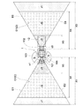
ライダーセンサ101,102として、図7に示すように、トラクタ1(走行機体7)の前方側を測定範囲Cとし、トラクタ1の前方側での障害物を検知するために用いる前ライダーセンサ101と、トラクタ1(走行機体7)の後方側を測定範囲Dとし、トラクタ1の後方側での障害物を検知するために用いる後ライダーセンサ102とが備えられている。
As the
以下、前ライダーセンサ101及び後ライダーセンサ102について説明するが、前ライダーセンサ101の支持構造、後ライダーセンサ102の支持構造、前ライダーセンサ101の測定範囲C、後ライダーセンサ102の測定範囲Dの順に説明する。
The
前ライダーセンサ101の支持構造について説明する。
前ライダーセンサ101は、図1に示すように、キャビン10の前面側の上部位置に配置されたアンテナユニット80の底部に取り付けられているので、まず、アンテナユニット80の支持構造について説明し、次に、アンテナユニット80の底部への前ライダーセンサ101の取り付け構造を説明する。
A support structure for the
As shown in FIG. 1, the
アンテナユニット80は、図1及び図4に示すように、走行機体7の左右方向においてキャビン10の全長に亘るパイプ状のアンテナユニット支持ステー81に取り付けられている。アンテナユニット80は、走行機体7の左右方向においてキャビン10の中央部に相当する位置に配置されている。アンテナユニット支持ステー81は、キャビン10の左右斜め前方側に位置する左右のミラー取付部45に亘る状態で固定連結されている。ミラー取付部45は、前側支柱36に固定されたミラー取付用基材46と、ミラー取付用基材46に固定されたミラー取付用ブラケット47と、ミラー取付用ブラケット47に設けられたヒンジ部49により回動自在なミラー取付用アーム48とが備えられている。アンテナユニット80は、アンテナユニット支持ステー81及びミラー取付部45を介して、キャビンフレーム31を構成する前側支柱36に支持されているので、アンテナユニット80への振動の伝達等を防止しながら、アンテナユニット80が強固に支持されている。
As shown in FIGS. 1 and 4, the
図4に示すように、キャビン10の前面側の上部位置には、前ライダーセンサ101に加えて、走行機体7の前方側を撮像範囲とする前カメラ108が取り付けられている。前カメラ108は、前ライダーセンサ101の上方側に配置されている。前カメラ108は、前ライダーセンサ101と同様に、前方側部位ほど下方側に位置する前下がり姿勢にて取り付けられている。前カメラ108は、走行機体7の前方側を斜め上方側から見下ろす状態で撮像するように備えられている。前カメラ108にて撮像した撮像画像を外部に出力可能に構成されている。前カメラ108の撮像画像は、トラクタ1の表示部や携帯通信端末3の表示部51等の表示装置に表示させて、ユーザ等にトラクタ1の周囲の状況を視認させることができる。
As shown in FIG. 4, in addition to the
次に、後ライダーセンサ102の支持構造について説明する。
後ライダーセンサ102は、図1及び図5に示すように、走行機体7の左右方向においてキャビン10の全長に亘るパイプ状のセンサ支持ステー301に取り付けられている。後ライダーセンサ102は、走行機体7の左右方向においてキャビン10の中央部に相当する位置に配置されている。センサ支持ステー301は、キャビン10の左右両端部に位置する左右の後側支柱37に亘る状態で固定連結されている。センサ支持ステー301は、その左右両端側部位が斜め前方側に湾曲された平面視でブリッジ状に形成されている。
Next, a support structure for the
As shown in FIGS. 1 and 5, the
図5に示すように、後ライダーセンサ102に加えて、走行機体7の後方側を撮像範囲とする後カメラ109が連結具等により取り付けられている。後カメラ109は、後ライダーセンサ102の上方側に配置されている。後カメラ109は、後ライダーセンサ102と同様に、後方側部位ほど下方側に位置する後下がり姿勢にて取り付けられている。後カメラ109は、走行機体7の後方側を斜め上方側から見下ろす状態で撮像するように備えられている。後カメラ109にて撮像した撮像画像を外部に出力可能に構成されている。後カメラ109の撮像画像は、トラクタ1の表示部や携帯通信端末3の表示部51等の表示装置に表示させて、ユーザ等にトラクタ1の周囲の状況を視認させることができる。
As shown in FIG. 5, in addition to the
前ライダーセンサ101の測定範囲Cについて説明する。
前ライダーセンサ101は、図7に示すように、左右方向における左右測定範囲C1を有しているとともに、図6に示すように、上下方向における上下測定範囲C2を有している。これにより、前ライダーセンサ101は、自己から第1設定距離X1(図7参照)だけ離れた位置までの範囲において、左右測定範囲C1と上下測定範囲C2に含まれる上下、左右及び前後の四角錐形状の測定範囲Cが設定されている。
The measurement range C of the
The
前ライダーセンサ101における左右測定範囲C1は、図7に示すように、走行機体7の左右方向において走行機体7の左右中心線を対称軸とする左右対称な範囲である。左右測定範囲C1は、前ライダーセンサ101から延びる第1境界線E1と第2境界線E2との間の第1設定角度α1の範囲に設定されている。左右測定範囲C1は、走行機体7の横幅方向において、トラクタ1の横幅、及び、牽引車12の横幅よりも大きな範囲に設定されている。左右測定範囲C1は、どのような大きさの範囲とするかは適宜変更が可能である。
As shown in FIG. 7, the left-right measurement range C <b> 1 in the
前ライダーセンサ101における上下測定範囲C2は、図6に示すように、前ライダーセンサ101から延びる第3境界線E3と第4境界線E4との間の第2設定角度α2の範囲に設定されている。第3境界線E3は、前ライダーセンサ101から前方側に水平方向に沿って延びる水平線に設定され、第4境界線E4は、前ライダーセンサ101から前輪5の前上部への第1接線G1よりも下方側に位置する直線に設定されている。上下測定範囲C2は、第3境界線E3と第4境界線E4との間の第1中心線F1が、ボンネット8よりも上方側に位置するように設定されており、ボンネット8の上方側に十分な大きさの測定範囲を確保している。第4境界線E4を第1接線G1よりも下方側に設定することで、走行機体7の前方側端部(ボンネット8の前方側端部)の近傍位置等に物体や人等の測定対象物が存在していても、その測定対象物を測定可能としている。
As shown in FIG. 6, the vertical measurement range C2 in the
前ライダーセンサ101における上下測定範囲C2には、図6に示すように、ボンネット8の一部、及び、前輪5の一部が入り込んでいるので、障害物用制御部107が、前ライダーセンサ101の測定情報に基づいて障害物検知処理を行うと、ボンネット8の一部や前輪5の一部を障害物として誤検知してしまう可能性がある。そこで、その誤検知を防止するための第1マスキング処理が施されている。第1マスキング処理では、前ライダーセンサ101の測定範囲C内において、ボンネット8の一部及び前輪5の一部が存在する範囲を、障害物としての検知を行わないマスキング範囲として予め設定している。
As shown in FIG. 6, a part of the
このようにして、障害物用制御部107は、前ライダーセンサ101の測定情報に基づいて障害物検知処理を行うことで、左右方向で左右測定範囲C1(図7参照)に含まれ、且つ、上下方向で上下測定範囲C2(図6参照)に含まれる範囲において、マスキング範囲を除く範囲にて障害物の存否を検知している。
In this way, the
後ライダーセンサ102の測定範囲Dについて説明する。
後ライダーセンサ102は、前ライダーセンサ101と同様に、図7に示すように、左右方向における左右測定範囲D1を有しているとともに、図6に示すように、上下方向における上下測定範囲D2を有している。これにより、後ライダーセンサ102は、自己から第3設定距離X3(図7参照)だけ離れた位置までの範囲において、左右測定範囲D1と上下測定範囲D2に含まれる上下、左右及び前後の四角錐形状の測定範囲Dが設定されている。ちなみに、X1とX3は、同じ距離に設定したり、異なる距離に設定することもできる。
The measurement range D of the
Like the
後ライダーセンサ102における左右測定範囲D1は、図7に示すように、前ライダーセンサ101と同様に、後ライダーセンサ102から延びる第5境界線E5と第6境界線E6との間の第3設定角度α3の範囲に設定されている。左右測定範囲D1は、前ライダーセンサ101と同様に、走行機体7の横幅方向において、トラクタ1の横幅、及び、牽引車12の横幅よりも大きな範囲に設定されている。
As shown in FIG. 7, the left and right measurement range D1 of the
後ライダーセンサ102における上下測定範囲D2は、図6に示すように、後ライダーセンサ102から延びる第7境界線E7と第8境界線E8との間の第4設定角度α4の範囲に設定されている。第7境界線E7は、後ライダーセンサ102から後方側に水平方向に沿って延びる水平線に設定され、第8境界線E8は、後ライダーセンサ102から牽引車12の後上部に向かう第2接線G2よりも下方側に位置する直線に設定されている。上下測定範囲D2は、第7境界線E7と第8境界線E8との間の第2中心線F2が、牽引車12よりも上方側に位置するように設定されており、牽引車12の上方側に十分な大きさの測定範囲を確保している。第8境界線E8を第2接線G2よりも下方側に設定することで、牽引車12の後方側端部の近傍位置等に物体や人等の測定対象物が存在していても、その測定対象物を測定可能としている。
As shown in FIG. 6, the vertical measurement range D2 of the
後ライダーセンサ102における上下測定範囲D2には、牽引車12の一部が入り込んでいるので、障害物用制御部107が、後ライダーセンサ102の測定情報に基づいて障害物検知処理を行うと、牽引車12の一部を障害物として誤検知してしまう可能性がある。そこで、その誤検知を防止するための第2マスキング処理が施されている。第2マスキング処理では、後ライダーセンサ102の測定範囲D内において、牽引車12の一部が存在する範囲を、障害物としての検知を行わないマスキング範囲として予め設定している。
Since a part of the towing
このようにして、障害物用制御部107は、後ライダーセンサ102の測定情報に基づいて障害物検知処理を行うことで、左右方向で左右測定範囲D1(図7参照)に含まれ、且つ、上下方向で上下測定範囲D2(図6参照)に含まれる範囲において、マスキング範囲を除く範囲にて障害物の存否を検知している。
In this way, the
以下、障害物用制御部107による衝突回避制御について説明するが、まず、ライダーセンサ101,102の測定情報に基づく障害物検知処理において障害物を検知した場合の衝突回避制御について説明し、次に、ソナーユニット103,104の測定情報に基づく障害物検知処理において障害物を検知した場合の衝突回避制御を説明する。
Hereinafter, collision avoidance control by the
ライダーセンサとして、前ライダーセンサ101と後ライダーセンサ102との2つのライダーセンサを備えているが、障害物用制御部107は、目標走行経路Pに含まれた前後進切り替え地点での前後進の切り替え、又は、キャビン10の内部に備えられた前後進切り替え用のリバーサレバーによる前後進の切り替えに基づいて障害物検知状態を切り替える。トラクタ1が前進走行する場合には、前ライダーセンサ101による測定を行い、障害物用制御部107が前ライダーセンサ101の測定情報に基づく障害物検知処理を行う前進検知状態に切り替え、トラクタ1が後進走行する場合には、後ライダーセンサ102による測定を行い、障害物用制御部107が後ライダーセンサ102の測定情報に基づく障害物検知処理を行う後進検知状態に切り替えている。このように、トラクタ1が前進走行しているか後進走行しているかによって、前ライダーセンサ101と後ライダーセンサ102のどちらのライダーセンサを用いて障害物の検知を行うかを切り替えることで、処理負担の軽減を図りながら、障害物の検知を行うようにしている。
Two rider sensors, a
前進検知状態では、障害物用制御部107が、前ライダーセンサ101の測定情報に基づいて障害物検知処理を行い、左右方向で検知範囲C(図7参照)に含まれる範囲において障害物の存否を検知している。後進検知状態では、障害物用制御部107が、後ライダーセンサ102の測定情報に基づいて障害物検知処理を行い、左右方向で検知範囲D(図7参照)に含まれる範囲において障害物の存否を検知している。
In the forward detection state, the
前ライダーセンサ101又は後ライダーセンサ102を用いて障害物を検知した場合には、図7に示すように、測定範囲C,Dである障害物検知用の検知範囲のうち、どの範囲にて障害物を検知したかによって、障害物用制御部107による衝突回避制御の制御内容が異なるように設定されている。測定範囲C,D(検知範囲)は、前ライダーセンサ101又は後ライダーセンサ102からの距離に応じて、第1検知範囲J1と第2検知範囲J2と第3検知範囲J3との3つの範囲が設定されている。第1検知範囲J1は、前ライダーセンサ101又は後ライダーセンサ102からの距離が、第4設定距離X4から第1設定距離X1まで又は第4設定距離X4から第3設定距離X3までの範囲に設定されている。第2検知範囲J2は、前ライダーセンサ101又は後ライダーセンサ102からの距離が第5設定距離X5から第4設定距離X4までの範囲に設定されている。第3検知範囲J3は、前ライダーセンサ101又は後ライダーセンサ102からの距離が第5設定距離X5までの範囲に設定されている。よって、前ライダーセンサ101、後ライダーセンサ102、及び、牽引車12を含むトラクタ1に対して、第1検知範囲J1、第2検知範囲J2、第3検知範囲J3がその順に近くなるように設定されている。
When an obstacle is detected using the
前ライダーセンサ101又は後ライダーセンサ102を用いて障害物を検知した場合の衝突回避制御の制御内容は、トラクタ1が前進走行している場合も後進走行している場合も同様であるので、以下、トラクタ1が前進走行している場合について説明する。
The control content of the collision avoidance control when an obstacle is detected using the
トラクタ1が前進走行しているときに、図7に示すように、障害物検知処理において第1検知範囲J1内で障害物を検知した場合には、障害物用制御部107が、衝突回避制御として、報知ブザーや報知ランプ等の報知装置26を制御して、第1検知範囲J1内に障害物が存在することを報知する第1報知制御を行う。第1報知制御では、例えば、障害物用制御部107が、報知ブザーを所定周波数にて断続作動させ、且つ、報知ランプを所定色にて点灯させるように、報知装置26を制御している。
When the
障害物検知処理において第2検知範囲J2内で障害物を検知した場合には、障害物用制御部107が、衝突回避制御として、報知ブザーや報知ランプ等の報知装置26を制御して、第2検知範囲J2内に障害物が存在することを報知する第2報知制御を行うとともに、トラクタ1の車速を減速させる第1減速制御を行う。第2報知制御では、例えば、障害物用制御部107が、報知ブザーを所定周波数にて断続作動させ、且つ、報知ランプを所定色にて点灯させるように、報知装置26を制御している。第1減速制御では、例えば、障害物用制御部107が、現在のトラクタ1の車速や障害物までの距離等に基づいて、トラクタ1が障害物に衝突するまでの衝突予測時間を求めている。障害物用制御部107は、求めた衝突予測時間が設定時間(例えば、3秒)に維持される状態でトラクタ1の車速を減速させるように、エンジン9、変速装置13及びブレーキ操作機構15等を制御している。
When an obstacle is detected in the second detection range J2 in the obstacle detection process, the
障害物検知処理において第3検知範囲J3内で障害物を検知した場合には、障害物用制御部107が、衝突回避制御として、報知ブザーや報知ランプ等の報知装置26を制御して、第3検知範囲J3内に障害物が存在することを報知する第3報知制御を行うとともに、トラクタ1を停止させる停止制御を行う。第3報知制御では、例えば、障害物用制御部107が、報知ブザーを連続作動させ、且つ、報知ランプを所定色にて点灯させるように、報知装置26を制御している。停止制御では、例えば、障害物用制御部107が、トラクタ1を停止させるように、ブレーキ操作機構15等を制御している。
In the obstacle detection process, when an obstacle is detected within the third detection range J3, the
ちなみに、第1報知制御及び第2報知制御において報知ブザーを断続させる所定周波数は、同じ周波数でもよく、異なる周波数でもよい。また、第1〜第3報知制御において報知ランプを点灯させる所定色は、同じ色でもよく、異なる色でもよい。障害物用制御部107は、第1〜第3報知制御において、トラクタ1の報知装置26の制御に加えて、第1〜第3検知範囲J1〜J3の何れかに障害物が存在することを示す表示内容を携帯通信端末3の表示部51に表示させるように、端末電子制御ユニット52を制御することもできる。
Incidentally, the predetermined frequency for intermittently generating the notification buzzer in the first notification control and the second notification control may be the same frequency or different frequencies. In addition, the predetermined color for lighting the notification lamp in the first to third notification control may be the same color or different colors. In the first to third notification control, the
例えば、第1検知範囲J1内で障害物が検知された場合には、障害物用制御部107が第1報知制御を行うことで、第1検知範囲J1内に障害物が存在することをユーザ等に報知することができる。そのままトラクタ1の走行が継続されて、障害物の検知範囲が第1検知範囲J1から第2検知範囲J2に近づくと、障害物用制御部107が、第2報知制御に加えて、第1減速制御を行うことで、トラクタ1と障害物との衝突を回避可能とするために、トラクタ1の車速を減速させておくことができる。トラクタ1を減速させても、障害物の検知範囲が第2検知範囲J2から第3検知範囲J3に近づくと、障害物用制御部107が、第3報知制御に加えて、停止制御を行うことで、トラクタ1を停止させることができ、トラクタ1と障害物との衝突を適切に回避することができる。
For example, when an obstacle is detected in the first detection range J1, the user is notified that the obstacle exists in the first detection range J1 by the
ライダーセンサ101,102を用いる場合には、人等の移動する測定対象物も障害物として検知する。よって、検知範囲C,D内で障害物が検知されても、障害物自体が移動することで、障害物が検知範囲C,Dら外れることがある。そこで、障害物が第1検知範囲J1から外れた場合には、障害物用制御部107が、第1報知制御を終了する。障害物が第2検知範囲J2から外れた場合には、障害物用制御部107が、第2報知制御を終了するとともに、トラクタ1の車速を設定車速まで増速させるように、エンジン9や変速装置13等を制御する車速回復制御を行う。障害物が第3検知範囲J3から外れた場合には、障害物用制御部107が、トラクタ1を走行停止状態に維持しながら、第3報知制御を終了する。この場合には、ユーザ等によりトラクタ1の自動走行の再開等が指令されることで、トラクタ1の自動走行を再開することができる。
When the
次に、ソナーユニット103,104の測定情報に基づく障害物検知処理にて障害物を検知した場合の衝突回避制御について説明する。
ソナーユニット103,104は、左右に備えられているが、トラクタ1が前進走行する場合もトラクタ1が後進走行する場合も、障害物用制御部107は、左右両側のソナーユニット103,104の全ての測定情報に基づいて障害物検知処理を行う。
Next, collision avoidance control when an obstacle is detected in the obstacle detection process based on the measurement information of the
Although the
ソナーユニット103,104の測定情報に基づく障害物検知処理にて障害物を検知した場合には、障害物用制御部107が、衝突回避制御として、報知ブザーや報知ランプ等の報知装置26を制御して、ソナーユニット103,104の何れかの測定範囲N内に障害物が存在することを報知する第4報知制御を行うとともに、トラクタ1の車速を減速させる第2減速制御を行う。第4報知制御では、例えば、障害物用制御部107が、報知ブザーを所定周波数にて断続作動させ、且つ、報知ランプを所定色にて点灯させるように、報知装置26を制御している。第2減速制御では、例えば、障害物用制御部107が、トラクタ1の車速を設定車速に減速させるように、エンジン9、変速装置13及びブレーキ操作機構15等を制御している。
When an obstacle is detected in the obstacle detection process based on the measurement information of the
このようにして、障害物検知システム100は、前ライダーセンサ101及び後ライダーセンサ102を用いて走行機体7の前方側及び後方側における障害物の存否を検知するとともに、ソナーユニット103,104を用いて走行機体7の左右における障害物の存否を検知することができる。障害物検知システム100は、障害物の存在を検知すると、障害物用制御部107が衝突回避制御を行うことによって、障害物の存在をユーザ等に報知して、ユーザ等に障害物との衝突を回避するように促すことができるとともに、仮にトラクタ1と障害物とが衝突する可能性が生じても、トラクタ1を減速や停止させて、トラクタ1と障害物との衝突を適切に回避することができる。
In this way, the
自動走行状態では、車載電子制御ユニット18にて自動走行制御が行われるので、障害物検知システム100によりトラクタ1を減速や停止させて、障害物との衝突を回避しながら、トラクタ1を自動走行させることができる。手動走行状態においても、運転しているユーザ等に対しても、障害物検知システム100により障害物の存在を報知したり、トラクタ1と障害物との衝突を回避するための運転をサポートすることができる。
In the automatic travel state, the on-vehicle
以上のように構成された本実施形態の自動走行システムは、図1に示すように、例えば牽引車12を有するトラクタ1を後退させて所定の駐車位置(移動目標位置の一例)に適切に移動させる場合であっても、携帯通信端末3を用いてトラクタ1を遠隔で意図どおりに走行させる形態で、トラクタ1の運転を支援することができる運転支援システムとしても機能する。
以下に、その運転支援システムとしての詳細構成について、説明を加える。
As shown in FIG. 1, the automatic traveling system according to the present embodiment configured as described above appropriately moves to a predetermined parking position (an example of a movement target position) by retracting the
Below, description is added about the detailed structure as the driving assistance system.
携帯通信端末3は、タッチ操作可能な表示部51等を有すると共に、その携帯通信端末3が備える端末電子制御ユニット52は、その表示部51の作動を制御して、図8,図9,及び図10に示すように、運転支援システムとして機能するためのモード選択画面W1、遠隔操作走行モード確認画面W2、及び遠隔操作走行モード操作画面W3等を表示部51の表示可能に構成されている。
The
図8に示すように、表示部51に表示されるモード選択画面W1には、「遠隔操作走行モード」と示された遠隔操作走行モード選択部W1aが表示されている。
この遠隔操作走行モード選択部W1aが選択(タップ操作)されると、表示部51の画面表示が下記の遠隔操作走行モード確認画面W2に遷移する。
As shown in FIG. 8, the mode selection screen W1 displayed on the
When the remote operation travel mode selection unit W1a is selected (tap operation), the screen display of the
図9に示すように、表示部51に表示される遠隔操作走行モード確認画面W2には、トラクタ1の車速等の状態を表示する状態表示ウインドウW2a、トラクタ1の前カメラ108(図4参照)の撮像画像を表示する前カメラ画像表示ウインドウW2b、トラクタ1の後カメラ109(図5参照)の撮像画像を表示する後カメラ画像表示ウインドウW2c、トラクタ1側の測位ユニット21(図2参照)で測定されたトラクタ1の現在位置を地図情報と共に表示するマップ表示ウインドウW2dが表示されている。
例えば、この遠隔操作走行モード確認画面W2が左右又は上下に移動(スワイプ操作)又はマップ表示ウインドウW2dや別途表示されたボタン等が選択(タップ操作)されると、表示部51の画面表示が下記の遠隔操作走行モード操作画面W3に遷移する。この画面W2において戻るボタン(図示省略)が操作されると、表示部51の画面表示が上記のモード選択画面W1に遷移する。
As shown in FIG. 9, the remote operation travel mode confirmation screen W2 displayed on the
For example, when the remote operation travel mode confirmation screen W2 moves left and right or up and down (swipe operation) or a map display window W2d or a separately displayed button or the like is selected (tap operation), the screen display of the
図9に示すマップ表示ウインドウW2dには、トラクタ1の現在位置を示すトラクタマークM1が略中央部に表示されている。そのトラクタマークM1の周囲には、当該トラクタ1が駐車される納屋A1内の駐車位置A3やその納屋A1内に浸入するための入口A2等が表示されている。これら駐車位置A3等の移動目標位置や納屋A1の入口A2の状態については、可能な範囲内で地図情報から取得することもできるが、携帯通信端末3は、例えばユーザ等によるマップ表示ウインドウW2d上でのタッチ操作等により予め登録可能に構成されている。
In the map display window W2d shown in FIG. 9, a tractor mark M1 indicating the current position of the
図10に示すように、表示部51に表示される遠隔操作走行モード操作画面W3には、トラクタ1のアラウンドビュー画像(真上から見ているかのような画像)を表示するアラウンドビュー画像表示ウインドウW3aと、上記マップ表示ウインドウW2dよりも拡大した状態でトラクタ1の現在位置を地図情報と共に表示する走行操作ウインドウW3bとが表示されている。
例えば、この遠隔操作走行モード操作画面W3が左右又は上下に移動(スワイプ操作)又はアラウンドビュー画像表示ウインドウW3aや別途表示されたボタン等が選択(タップ操作)されると、表示部51の画面表示が上記の遠隔操作走行モード確認画面W2に遷移する。この画面W3において戻るボタン(図示省略)が操作されると、表示部51の画面表示が上記のモード選択画面W1に遷移する。
As shown in FIG. 10, the remote view travel mode operation screen W3 displayed on the
For example, when the remote operation travel mode operation screen W3 moves left and right or up and down (swipe operation) or the around view image display window W3a or a separately displayed button or the like is selected (tap operation), the screen display of the
図10に示すアラウンドビュー画像表示ウインドウW3aに表示するトラクタ1のアラウンドビュー画像は、トラクタ1側の前カメラ108(図4参照)の撮像画像と後カメラ109(図5参照)の撮像画像とを合成することで生成される。このアラウンドビュー画像表示ウインドウW3a及び走行操作ウインドウW3bには、トラクタ1の障害物検知システム100で検知された当該トラクタ1の周囲の障害物Oの位置や形状などの配置状態が表示される。図10に示す走行操作ウインドウW3bでは、納屋A1の入口A2を挟む側壁部分A2aが障害物Oとして表示されている。
The around view image of the
図10に示す走行操作ウインドウW3bは、ユーザUがトラクタ1を遠隔で走行させるための操作を行うための走行操作画面として機能する。この走行操作ウインドウW3bには、トラクタ1の現在位置を示すトラクタマークM1とそれに牽引される牽引車12を示す牽引車マークM12とが略中央部に表示されている。更に、この走行操作ウインドウW3bにおけるトラクタマークM1に対する牽引車マークM12の接続状態については、後述する牽引車状態検知部58により検知された実際のトラクタ1に対する牽引車12の状態に合わせたものとして表示されている。そのトラクタマークM1の周囲には、上記マップ表示ウインドウW2d(図9参照)と同様に、当該トラクタ1が駐車される納屋A1やその入口A2等が表示されている。
The traveling operation window W3b shown in FIG. 10 functions as a traveling operation screen for the user U to perform an operation for traveling the
この走行操作ウインドウW3bにおいて、ユーザUがトラクタ1の現在位置を示すトラクタマークM1に対して所定の入力操作を行うと、その入力操作により識別される走行経路に沿って延びる矢印で示された経路マークMrが表示される。尚、詳細については後述するが、携帯通信端末3が備える走行指示生成部56は、トラクタ1や牽引車12の情報を参照しながら、その経路マークMrで示された経路を目標走行経路としてそれを含む走行指示を生成し、トラクタ1側の車載電子制御ユニット18に出力する。
When the user U performs a predetermined input operation on the tractor mark M1 indicating the current position of the
図2に示すように、携帯通信端末3の端末電子制御ユニット52には、走行指示生成部56、走行可否判定部57、及び牽引車状態検知部58が設けられている。
As shown in FIG. 2, the terminal
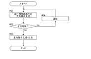
図2及び図10に示すように、走行指示生成部56は、表示部51に表示された走行操作ウインドウW3bに対するユーザUによる入力操作に基づいて所定の走行指示を生成し、当該生成した走行指示を無線通信によりトラクタ1側の車載電子制御ユニット18に出力するものとして構成されている。
そして、携帯通信端末3の端末電子制御ユニット52は、図11に示す処理フローを実行することにより、ユーザ1による入力操作に基づいてトラクタ1を走行させるための走行指示を適切に生成することができる。以下、その詳細について説明を加える。
As shown in FIGS. 2 and 10, the travel
And the terminal
走行操作ウインドウW3bにおいて、ユーザUが、トラクタ1の現在位置や牽引車12の姿勢やその周囲の障害物Oの形状や位置などの配置状態等を地図情報上で正確に視認しながら、トラクタ1の現在位置を示すトラクタマークM1に対して、トラクタ1を走行させたい方向に向けてドラッグ操作を行う。すると、上述したように、走行操作ウインドウW3bには、そのドラッグ操作により識別される走行経路に沿って延びる矢印で示された経路マークMrが表示される。そして、携帯通信端末3が備える走行指示生成部56は、経路マークMrで示された経路を、トラクタ1がそれに沿って走行すべき目標走行経路として認識する形態で、ユーザUによる入力操作を受け付ける(図11のステップ#01)。
In the travel operation window W3b, the user U can accurately view the current position of the
次に、走行可否判定部57は、上記走行経路生成部53により生成された走行指示に従ってトラクタ1が走行可能か否かを判定する(図11のステップ#02)。
この走行可否判定部57による判定処理では、トラクタ1の周囲の障害物Oを検知する障害物検知部として機能する前述の障害物検知システム100で検知された障害物Oとの衝突を回避した状態で、上記走行経路生成部53により生成された走行指示に従ってトラクタ1が走行可能か否かが判定される。
更に、納屋A1の入口A2の状態が予め登録されている場合には、この走行可否判定部57による判定処理では、その入口A2を挟む側壁部分A2aなどの障害物Oを回避した状態で、上記走行経路生成部53により生成された走行指示に従ってトラクタ1が入口A2を通過可能か否かが判定される。
そして、走行可否判定部57により走行不可と判定された場合(図11のステップ#02のNo)には、携帯通信端末3の端末電子制御ユニット52は、この走行可否判定部57の判定結果を、音声や表示部51への表示によりユーザU(図10参照)に通知する(図11のステップ#04)。
よって、ユーザUは、このような走行可否判定部57の判定結果の通知により、自己の入力操作により生成された走行指示に沿ってトラクタ1を走行させることができるか否かを明確に認識することができる。そして、走行できないと認識した場合には、走行操作ウインドウW3bにおける入力操作をやり直して、新たな走行指示を生成させることができる。
Next, the travel
In the determination processing by the traveling
Furthermore, when the state of the entrance A2 of the barn A1 is registered in advance, in the determination process by the traveling
And when it determines with driving | running | working
Therefore, the user U clearly recognizes whether or not the
更に、走行可否判定部57により走行可能と判定された場合(図11のステップ#02のYea)には、走行指示生成部56は、目標走行経路に沿ってトラクタ1を走行させるための走行指示を生成して、目標走行経路と共にトラクタ1側の車載電子制御ユニット18に出力する(図11のステップ#03)。
具体的に、走行指示生成部56は、トラクタ1や牽引車12の形状やサイズ、トラクタ1の操舵角の変更可能範囲、トラクタ1に対する牽引車12の接続角度等の状態の変化可能範囲等のトラクタ1や牽引車12の情報を参照し、目標走行経路に沿ってトラクタ1を走行させるための走行距離又は走行時間に対する操舵角の変更状態等の走行制御情報を含む走行指示を生成する。
Furthermore, when it is determined that the vehicle can be driven by the driving enable / disable determining unit 57 (Ya in
Specifically, the travel
すると、トラクタ1側の車載電子制御ユニット18は、測位ユニット21により測位されたトラクタ1の現在位置が目標走行経路上にあることを確認しながら、上記走行指示に含まれる走行制御情報に従ってトラクタ1を走行させることができる。
Then, the vehicle-mounted
尚、走行操作ウインドウW3bにおけるユーザUによる入力操作は、上記ドラッグ操作に限らず、トラクタ1の走行方向や経路を示すものであればよい。例えば、トラクタマークM1の表示位置を基準に、駐車位置A3(図9参照)等の移動目標位置に対してタップ操作を行って、トラクタマークM1からタップ操作された位置に向かう経路を目標走行経路として走行指示を生成することができる。
また、納屋A1の入口A2の状態が予め登録されている場合には、走行指示生成部56は、トラクタ1がその入口A2を通過して移動目標位置等に到達する経路を目標走行経路として走行指示を生成することができる。
Note that the input operation by the user U in the travel operation window W3b is not limited to the drag operation, but may be any operation that indicates the travel direction and route of the
In addition, when the state of the entrance A2 of the barn A1 is registered in advance, the travel
牽引車状態検知部58は、トラクタ1に対する牽引車12の姿勢等の状態を検知するものとして構成されている。例えば、牽引車状態検知部58は、牽引車12が撮像された後カメラ109の撮像画像を解析して、トラクタ1に対する牽引車12の接続角度を検知する。そして、携帯通信端末3の端末電子制御ユニット52は、走行操作ウインドウW3bにおいて、トラクタマークM1に対する牽引車マークM12の接続状態を、上記牽引車状態検知部58で検知されたトラクタ1に対する牽引車12の実際の状態に合うように、トラクタ1の現在位置にトラクタマークM1及び牽引車マークM12を表示する。
すると、ユーザUは、走行操作ウインドウW3bにおいて、トラクタ1に対する牽引車12の状態を常時正確に確認しながら、トラクタ1を遠隔で走行させるための入力操作を適切に行うことができる。
The tow vehicle
Then, the user U can appropriately perform an input operation for causing the
一方、トラクタ1側の車載電子制御ユニット18は、携帯通信端末3から無線通信により走行指示が入力され、その入力された走行指示に従ってトラクタ1を走行可能な走行制御部として機能する。この車載電子制御ユニット18による走行指示に従ったトラクタ1の走行については、前述の自動走行制御と同様に、測位ユニット21にてトラクタ1の現在位置を取得しながら、携帯通信端末3から入力された走行指示に含まれる目標走行経路に沿ってトラクタ1を自動走行させる形態で行われる。即ち、車載電子制御ユニット18は、携帯通信端末3側でのユーザUによる入力操作により生成された走行指示に従って、トラクタ1を走行させることができる。
On the other hand, the vehicle-mounted
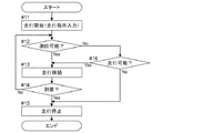
そして、トラクタ1側の車載電子制御ユニット18は、図12に示す処理フローを実行することにより、携帯通信端末3から無線通信により入力された走行指示に従って適切にトラクタ1を走行させることができる。以下、その詳細について説明を加える。
トラクタ1側の車載電子制御ユニット18には、測位可否判定部110が設けられている。測位可否判定部110は、携帯通信端末3から無線通信により走行指示が入力された走行が開始されると(図12のステップ#11)、衛星測位システムを利用した測位ユニット21によるトラクタ1の現在位置の測位の可否を判定する(図12のステップ#12)。具体的に、トラクタ1に設けられたGPSアンテナ24におけるGPS衛星71(図1参照)からの電波受信の有無が監視されており、トラクタ1が屋外にあって上記電波受信が有る場合には、トラクタ1の現在位置の測位が可能な測位可能状態であると判定され、トラクタ1が納屋等の屋内にあって上記電波受信が無い場合には、トラクタ1の現在位置の測位が不可な測位不可状態であると判定される。
And the vehicle-mounted
The in-vehicle
そして、車載電子制御ユニット18は、携帯通信端末3から入力された走行指示に従ってトラクタ1を走行させるにあたり、上記測位可能状態であると測位可否判定部110で判定されているとき(図12のステップ#12のYes)には、測位ユニット21により測位されたトラクタ1の現在位置が目標走行経路上にあることを確認しながら、上記走行指示に従ったトラクタ1の走行を継続させて(図12のステップ#13)、駐車位置に到着した時点(図12ステップ#14のYes)でトラクタ1を停止させる。尚、このステップ#13においてトラクタ1の走行を継続させている際に、障害物検知システム100により回避できない障害物Oが検知された場合には、トラクタ1の走行を停止して、その旨をユーザ等に適宜通知することができる。
When the vehicle-mounted
一方、車載電子制御ユニット18は、携帯通信端末3から入力された走行指示に従ってトラクタ1を走行させるにあたり、上記測位不可状態であると測位可否判定部110で判定されているとき(図12のステップ#12のNo)には、障害物検知システム100で検知された障害物Oの配置状態を確認しながら上記走行指示に含まれる走行距離又は走行時間に対する操舵角の変更状態等の走行制御情報に従ったトラクタ1の走行を継続させる。この際、障害物Oを回避した走行が可能であると判断される場合(図16のステップ#16のYes)には、上記走行指示に従ったトラクタ1の走行を継続させる(図12のステップ#13)。しかし、障害物Oを回避した走行が不可能であると判断される場合(図16のステップ#16のNo)には、その旨をユーザ等に適宜通知すると共に、トラクタ1を強制的に停止させる(図12のステップ#15)。
On the other hand, when the in-vehicle
また、車載電子制御ユニット18は、トラクタ1が納屋等の屋内にあって、上記測位不可状態であると測位可否判定部110で判定されている場合には、障害物検知システム100を利用して屋内の内壁等の配置状態を計測し、その計測結果から屋内でのトラクタ1の現在位置を把握することができる。そして、そのように把握した屋内でのトラクタ1の現在位置が目標走行経路上にあることを確認しながら、上記走行指示に従ってトラクタ1を走行させることもできる。
In addition, the vehicle-mounted
〔別実施形態〕
本発明の他の実施形態について説明する。
尚、以下に説明する各実施形態の構成は、夫々単独で適用することに限らず、他の実施形態の構成と組み合わせて適用することも可能である。
[Another embodiment]
Another embodiment of the present invention will be described.
Note that the configuration of each embodiment described below is not limited to being applied alone, but may be applied in combination with the configuration of another embodiment.
(1)作業車両やそれにより牽引される牽引車の構成は種々の変更が可能である。
例えば、作業車両は、エンジン9と走行用の電動モータとを備えるハイブリット仕様に構成されていてもよく、また、エンジン9に代えて走行用の電動モータを備える電動仕様に構成されていてもよい。
例えば、作業車両は、走行部として、左右の後輪6に代えて左右のクローラを備えるセミクローラ仕様に構成されていてもよい。
例えば、作業車両は、左右の後輪6が操舵輪として機能する後輪ステアリング仕様に構成されていてもよい。
(1) Various changes can be made to the configuration of the work vehicle and the towing vehicle towed by it.
For example, the work vehicle may be configured in a hybrid specification including an
For example, the work vehicle may be configured as a semi-crawler specification including left and right crawlers instead of the left and right
For example, the work vehicle may be configured to have a rear wheel steering specification in which the left and right
(2)上記実施形態では、トラクタ1を遠隔で走行させるための走行操作ウインドウW3bにおけるユーザUによる入力操作として、トラクタ1の走行方向を指定するためのドラッグ操作や、トラクタ1の目標位置を指定するためのタップ操作を行う例を説明したが、その入力操作の形態については適宜変更可能である。
(2) In the above embodiment, as an input operation by the user U in the travel operation window W3b for causing the
(3)上記実施形態では、牽引車状態検知部58は、牽引車12が撮像された後カメラ109の撮像画像を解析することで、トラクタ1に対する牽引車12の姿勢等の状態を検知するように構成したが、別の方法でトラクタ1に対する牽引車12の状態を検知しても構わない。例えば、トラクタ1と牽引車12との連結部においてセンサ等によりトラクタ1に対する牽引車12の接続角度を、トラクタ1に対する牽引車12の状態として検知することができる。また、この牽引車状態検知部58の設置箇所については、携帯通信端末3側に限らず、トラクタ1側であっても良い。
(3) In the above embodiment, the tow
1 トラクタ(作業車両)
3 携帯通信端末
18 車載電子制御ユニット(走行制御部)
51 表示部
56 走行指示生成部
57 走行可否判定部
58 牽引車状態検知部
110 測位可否判定部
O 障害物
U ユーザ
W3b 走行操作ウインドウ(走行操作画面)
1 Tractor (work vehicle)
3
51
Claims (8)
前記作業車両に備えられ、走行指示に従って当該走行車両の走行を制御する走行制御部と、
前記走行制御部との間で無線通信可能に構成され、タッチ操作可能な表示部を有する携帯通信端末と、
前記携帯通信端末の表示部に表示された走行操作画面に対する入力操作に基づいて前記走行指示を生成し、当該生成した走行指示を前記走行制御部に出力する走行指示生成部と、を備え、
前記携帯通信端末が、衛星測位システムを利用して測定した前記作業車両の現在位置を地図情報と共に前記走行操作画面に表示し、
前記走行指示生成部が、前記走行操作画面に表示した前記作業車両の現在位置に対するドラッグ操作に基づいて前記走行指示を生成する運転支援システム。 A driving support system that supports driving of a work vehicle having a tow vehicle,
A traveling control unit that is provided in the work vehicle and controls traveling of the traveling vehicle according to a traveling instruction;
A mobile communication terminal configured to be capable of wireless communication with the travel control unit and having a display unit capable of touch operation;
A travel instruction generating unit that generates the travel instruction based on an input operation on the travel operation screen displayed on the display unit of the mobile communication terminal, and outputs the generated travel instruction to the travel control unit;
The mobile communication terminal displays the current position of the work vehicle measured using a satellite positioning system together with map information on the travel operation screen,
The driving support system in which the travel instruction generating unit generates the travel instruction based on a drag operation on the current position of the work vehicle displayed on the travel operation screen.
前記携帯通信端末が、前記障害物検知部で検知された障害物の配置状態を前記走行操作画面に表示する請求項1〜3の何れか1項に記載の運転支援システム。 Provided in the work vehicle, comprising an obstacle detection unit for detecting surrounding obstacles,
The driving assistance system according to any one of claims 1 to 3, wherein the mobile communication terminal displays an obstacle arrangement state detected by the obstacle detection unit on the travel operation screen.
前記携帯通信端末が、前記走行可否判定部の判定結果を通知する請求項4に記載の運転支援システム。 A travel propriety determination unit that determines whether the work vehicle can travel according to the travel instruction in a state where a collision with an obstacle detected by the obstacle detection unit is avoided;
The driving support system according to claim 4, wherein the mobile communication terminal notifies a determination result of the travel propriety determination unit.
前記走行可否判定部が、前記障害物検知部で検知された前記入口の周囲の障害物を回避した状態で前記走行指示に従って前記作業車両が前記入口を通過可能か否かを判定する請求項5に記載の運転支援システム。 The travel instruction generation unit is configured to be capable of generating a travel instruction for causing the work vehicle to travel along a route passing through a pre-registered entrance from the current position of the work vehicle,
6. The travel propriety determination unit determines whether the work vehicle can pass through the entrance according to the travel instruction in a state where an obstacle around the entrance detected by the obstacle detection unit is avoided. The driving support system described in 1.
前記走行制御部が、前記測位可否判定部により前記作業車両の現在位置の測位が可能である測位可能状態時においては、前記衛星測位システムを利用して測位された前記作業車両の現在位置を確認しながら前記走行指示に従って当該作業車両を走行させ、前記測位可否判定部により前記作業車両の現在位置の測位が不可である測位不可状態時においては、前記障害物検知部により検知された前記障害物の配置状態を確認しながら前記走行指示に従って当該作業車両を走行させる請求項4〜6に記載の運転支援システム。 A positioning availability determination unit that determines whether positioning of the current position of the work vehicle using the satellite positioning system is possible;
The travel control unit confirms the current position of the work vehicle that has been positioned using the satellite positioning system when the current position of the work vehicle can be measured by the positioning availability determination unit. The obstacle is detected by the obstacle detection unit when the positioning of the current position of the work vehicle is impossible by the positioning availability determination unit while the work vehicle is driven according to the traveling instruction. The driving support system according to claim 4, wherein the work vehicle is caused to travel according to the travel instruction while confirming the arrangement state of the vehicle.
前記携帯通信端末が、前記走行操作画面において表示される前記作業車両の現在位置に、前記牽引車状態検知部で検知された状態で前記作業車両及び前記牽引車を表示する請求項1〜7の何れか1項に記載の運転支援システム。
A tow vehicle state detector for detecting the state of the tow vehicle relative to the work vehicle;
The mobile communication terminal displays the work vehicle and the tow vehicle in a state detected by the tow vehicle state detection unit at a current position of the work vehicle displayed on the travel operation screen. The driving support system according to any one of the preceding claims.
Priority Applications (1)
| Application Number | Priority Date | Filing Date | Title |
|---|---|---|---|
| JP2018064503A JP7016751B2 (en) | 2018-03-29 | 2018-03-29 | Driving support system |
Applications Claiming Priority (1)
| Application Number | Priority Date | Filing Date | Title |
|---|---|---|---|
| JP2018064503A JP7016751B2 (en) | 2018-03-29 | 2018-03-29 | Driving support system |
Publications (2)
| Publication Number | Publication Date |
|---|---|
| JP2019175254A true JP2019175254A (en) | 2019-10-10 |
| JP7016751B2 JP7016751B2 (en) | 2022-02-07 |
Family
ID=68168947
Family Applications (1)
| Application Number | Title | Priority Date | Filing Date |
|---|---|---|---|
| JP2018064503A Active JP7016751B2 (en) | 2018-03-29 | 2018-03-29 | Driving support system |
Country Status (1)
| Country | Link |
|---|---|
| JP (1) | JP7016751B2 (en) |
Cited By (5)
| Publication number | Priority date | Publication date | Assignee | Title |
|---|---|---|---|---|
| WO2021075315A1 (en) * | 2019-10-18 | 2021-04-22 | ヤンマーパワーテクノロジー株式会社 | Obstacle detection system |
| WO2021106278A1 (en) * | 2019-11-25 | 2021-06-03 | コベルコ建機株式会社 | Work assistance server, work assistance method, and work assistance system |
| EP3928604A1 (en) * | 2020-06-23 | 2021-12-29 | Deere & Company | Agricultural tractor with a system for detecting subsequent traffic participants |
| CN115735482A (en) * | 2022-12-01 | 2023-03-07 | 西北农林科技大学 | Multipurpose crops intelligence seeder |
| WO2023127353A1 (en) * | 2021-12-28 | 2023-07-06 | 株式会社クボタ | Agricultural machine, sensing system, sensing method, remote operation system, and control method |
Citations (18)
| Publication number | Priority date | Publication date | Assignee | Title |
|---|---|---|---|---|
| JPH08165681A (en) * | 1994-12-13 | 1996-06-25 | Nishimatsu Constr Co Ltd | Unmanned exhaust soil conveying vehicle and unmanned exhaust soil measuring method |
| JP2004114879A (en) * | 2002-09-27 | 2004-04-15 | Clarion Co Ltd | Parking assisting device, and image display device |
| JP2005332204A (en) * | 2004-05-20 | 2005-12-02 | Univ Waseda | Movement control device, environment recognition device, and program for controlling moving object |
| JP2009060499A (en) * | 2007-09-03 | 2009-03-19 | Sanyo Electric Co Ltd | Driving support system, and combination vehicle |
| JP2010134961A (en) * | 1998-02-13 | 2010-06-17 | Komatsu Ltd | Guiding system for vehicle |
| JP2011254704A (en) * | 2010-06-04 | 2011-12-22 | Chugoku Electric Power Co Inc:The | Method and system for automatic farming |
| KR20130074902A (en) * | 2011-12-27 | 2013-07-05 | 전자부품연구원 | A method for remote controlling robot using wrap around image and an apparatus thereof |
| JP2014232496A (en) * | 2013-05-30 | 2014-12-11 | 株式会社日立パワーソリューションズ | Autonomous mobile device, autonomous mobile system, and autonomous mobile method |
| WO2015087430A1 (en) * | 2013-12-12 | 2015-06-18 | 日立建機株式会社 | Vehicle travel system and vehicle travel control method |
| JP2015154406A (en) * | 2014-02-18 | 2015-08-24 | クラリオン株式会社 | Peripheral monitoring device for towing vehicle |
| WO2016076319A1 (en) * | 2014-11-13 | 2016-05-19 | ヤンマー株式会社 | Operation terminal |
| JP2016179674A (en) * | 2014-07-07 | 2016-10-13 | 株式会社リコー | Printed matter delivery device, image formation apparatus and image delivery system |
| US20170201617A1 (en) * | 2014-05-28 | 2017-07-13 | Samsung Electronics Co., Ltd | Mobile device, robot cleaner, and method for controlling the same |
| WO2017123880A1 (en) * | 2016-01-14 | 2017-07-20 | Continental Automotive Systems, Inc. | Vehicle-trailer backing system having targetless hitch angle detection and trailer geometry learning |
| JP2017216022A (en) * | 2017-09-19 | 2017-12-07 | 東芝ライフスタイル株式会社 | Traveling body and traveling body apparatus |
| CN107627959A (en) * | 2017-09-20 | 2018-01-26 | 鹰驾科技(深圳)有限公司 | The panoramic video monitoring method and system of motor vehicle |
| JP2018032282A (en) * | 2016-08-26 | 2018-03-01 | シャープ株式会社 | Autonomous travel vehicle controller, autonomous travel vehicle control system and autonomous travel vehicle control method |
| JP2018034612A (en) * | 2016-08-30 | 2018-03-08 | 井関農機株式会社 | Work vehicle |
-
2018
- 2018-03-29 JP JP2018064503A patent/JP7016751B2/en active Active
Patent Citations (18)
| Publication number | Priority date | Publication date | Assignee | Title |
|---|---|---|---|---|
| JPH08165681A (en) * | 1994-12-13 | 1996-06-25 | Nishimatsu Constr Co Ltd | Unmanned exhaust soil conveying vehicle and unmanned exhaust soil measuring method |
| JP2010134961A (en) * | 1998-02-13 | 2010-06-17 | Komatsu Ltd | Guiding system for vehicle |
| JP2004114879A (en) * | 2002-09-27 | 2004-04-15 | Clarion Co Ltd | Parking assisting device, and image display device |
| JP2005332204A (en) * | 2004-05-20 | 2005-12-02 | Univ Waseda | Movement control device, environment recognition device, and program for controlling moving object |
| JP2009060499A (en) * | 2007-09-03 | 2009-03-19 | Sanyo Electric Co Ltd | Driving support system, and combination vehicle |
| JP2011254704A (en) * | 2010-06-04 | 2011-12-22 | Chugoku Electric Power Co Inc:The | Method and system for automatic farming |
| KR20130074902A (en) * | 2011-12-27 | 2013-07-05 | 전자부품연구원 | A method for remote controlling robot using wrap around image and an apparatus thereof |
| JP2014232496A (en) * | 2013-05-30 | 2014-12-11 | 株式会社日立パワーソリューションズ | Autonomous mobile device, autonomous mobile system, and autonomous mobile method |
| WO2015087430A1 (en) * | 2013-12-12 | 2015-06-18 | 日立建機株式会社 | Vehicle travel system and vehicle travel control method |
| JP2015154406A (en) * | 2014-02-18 | 2015-08-24 | クラリオン株式会社 | Peripheral monitoring device for towing vehicle |
| US20170201617A1 (en) * | 2014-05-28 | 2017-07-13 | Samsung Electronics Co., Ltd | Mobile device, robot cleaner, and method for controlling the same |
| JP2016179674A (en) * | 2014-07-07 | 2016-10-13 | 株式会社リコー | Printed matter delivery device, image formation apparatus and image delivery system |
| WO2016076319A1 (en) * | 2014-11-13 | 2016-05-19 | ヤンマー株式会社 | Operation terminal |
| WO2017123880A1 (en) * | 2016-01-14 | 2017-07-20 | Continental Automotive Systems, Inc. | Vehicle-trailer backing system having targetless hitch angle detection and trailer geometry learning |
| JP2018032282A (en) * | 2016-08-26 | 2018-03-01 | シャープ株式会社 | Autonomous travel vehicle controller, autonomous travel vehicle control system and autonomous travel vehicle control method |
| JP2018034612A (en) * | 2016-08-30 | 2018-03-08 | 井関農機株式会社 | Work vehicle |
| JP2017216022A (en) * | 2017-09-19 | 2017-12-07 | 東芝ライフスタイル株式会社 | Traveling body and traveling body apparatus |
| CN107627959A (en) * | 2017-09-20 | 2018-01-26 | 鹰驾科技(深圳)有限公司 | The panoramic video monitoring method and system of motor vehicle |
Cited By (8)
| Publication number | Priority date | Publication date | Assignee | Title |
|---|---|---|---|---|
| WO2021075315A1 (en) * | 2019-10-18 | 2021-04-22 | ヤンマーパワーテクノロジー株式会社 | Obstacle detection system |
| JP2021065115A (en) * | 2019-10-18 | 2021-04-30 | ヤンマーパワーテクノロジー株式会社 | Obstacle detection system |
| WO2021106278A1 (en) * | 2019-11-25 | 2021-06-03 | コベルコ建機株式会社 | Work assistance server, work assistance method, and work assistance system |
| JP7392422B2 (en) | 2019-11-25 | 2023-12-06 | コベルコ建機株式会社 | Work support server and work support system |
| EP3928604A1 (en) * | 2020-06-23 | 2021-12-29 | Deere & Company | Agricultural tractor with a system for detecting subsequent traffic participants |
| US11891080B2 (en) | 2020-06-23 | 2024-02-06 | Deere & Company | Agricultural tractor having a system for identifying downstream road users |
| WO2023127353A1 (en) * | 2021-12-28 | 2023-07-06 | 株式会社クボタ | Agricultural machine, sensing system, sensing method, remote operation system, and control method |
| CN115735482A (en) * | 2022-12-01 | 2023-03-07 | 西北农林科技大学 | Multipurpose crops intelligence seeder |
Also Published As
| Publication number | Publication date |
|---|---|
| JP7016751B2 (en) | 2022-02-07 |
Similar Documents
| Publication | Publication Date | Title |
|---|---|---|
| JP7016751B2 (en) | Driving support system | |
| WO2021006321A1 (en) | Automatic travel system | |
| JP6832884B2 (en) | Automatic driving system and status notification device | |
| JP7108731B2 (en) | Automatic traveling device for work vehicle | |
| WO2020183906A1 (en) | Path generation system | |
| US20210018617A1 (en) | Obstacle Detection System for Work Vehicle | |
| JP2021073602A (en) | Automatic travel system and status notification device | |
| JP2019175261A (en) | Travel area shape specification device | |
| JP2019169059A (en) | Travel area shape specification device | |
| JP7192061B2 (en) | Work vehicle travel control system | |
| WO2020044802A1 (en) | Obstacle sensing system | |
| JP7122845B2 (en) | Automatic traveling device for work vehicle | |
| JP6923472B2 (en) | Obstacle detection system | |
| JP6942664B2 (en) | Travel control system for work vehicles | |
| JP2021182001A (en) | Work vehicle | |
| JP7100539B2 (en) | Autonomous driving system | |
| JP7016747B2 (en) | Collaborative work system | |
| JP7162704B2 (en) | Automatic traveling device for work vehicle | |
| JP2022159351A (en) | work vehicle | |
| JP6923480B2 (en) | Obstacle detection system | |
| JP7329645B2 (en) | Work support system | |
| JP2019175318A (en) | Travel control system for work vehicle | |
| WO2020044801A1 (en) | Obstacle detection system | |
| WO2020044800A1 (en) | Obstacle detection system |
Legal Events
| Date | Code | Title | Description |
|---|---|---|---|
| A621 | Written request for application examination |
Free format text: JAPANESE INTERMEDIATE CODE: A621 Effective date: 20200130 |
|
| RD03 | Notification of appointment of power of attorney |
Free format text: JAPANESE INTERMEDIATE CODE: A7423 Effective date: 20200814 |
|
| A977 | Report on retrieval |
Free format text: JAPANESE INTERMEDIATE CODE: A971007 Effective date: 20201202 |
|
| A131 | Notification of reasons for refusal |
Free format text: JAPANESE INTERMEDIATE CODE: A131 Effective date: 20201215 |
|
| A521 | Request for written amendment filed |
Free format text: JAPANESE INTERMEDIATE CODE: A523 Effective date: 20210208 |
|
| A131 | Notification of reasons for refusal |
Free format text: JAPANESE INTERMEDIATE CODE: A131 Effective date: 20210615 |
|
| TRDD | Decision of grant or rejection written | ||
| A01 | Written decision to grant a patent or to grant a registration (utility model) |
Free format text: JAPANESE INTERMEDIATE CODE: A01 Effective date: 20220118 |
|
| A61 | First payment of annual fees (during grant procedure) |
Free format text: JAPANESE INTERMEDIATE CODE: A61 Effective date: 20220126 |
|
| R150 | Certificate of patent or registration of utility model |
Ref document number: 7016751 Country of ref document: JP Free format text: JAPANESE INTERMEDIATE CODE: R150 |