JP2019170983A - Game machine - Google Patents
Game machine Download PDFInfo
- Publication number
- JP2019170983A JP2019170983A JP2018066291A JP2018066291A JP2019170983A JP 2019170983 A JP2019170983 A JP 2019170983A JP 2018066291 A JP2018066291 A JP 2018066291A JP 2018066291 A JP2018066291 A JP 2018066291A JP 2019170983 A JP2019170983 A JP 2019170983A
- Authority
- JP
- Japan
- Prior art keywords
- effect
- image
- special
- opening
- game
- Prior art date
- Legal status (The legal status is an assumption and is not a legal conclusion. Google has not performed a legal analysis and makes no representation as to the accuracy of the status listed.)
- Granted
Links
- 230000000694 effects Effects 0.000 claims description 3177
- 238000013461 design Methods 0.000 description 376
- 238000000034 method Methods 0.000 description 366
- 230000008569 process Effects 0.000 description 349
- 230000008859 change Effects 0.000 description 288
- 230000000875 corresponding effect Effects 0.000 description 192
- 238000003860 storage Methods 0.000 description 122
- 230000004048 modification Effects 0.000 description 113
- 238000012986 modification Methods 0.000 description 113
- 238000004519 manufacturing process Methods 0.000 description 110
- 238000010586 diagram Methods 0.000 description 98
- 238000012545 processing Methods 0.000 description 84
- 238000005034 decoration Methods 0.000 description 56
- 230000009467 reduction Effects 0.000 description 38
- 238000001514 detection method Methods 0.000 description 27
- 239000000872 buffer Substances 0.000 description 26
- 230000002441 reversible effect Effects 0.000 description 22
- 230000000007 visual effect Effects 0.000 description 22
- 230000002844 continuous effect Effects 0.000 description 18
- 230000003287 optical effect Effects 0.000 description 16
- 238000010924 continuous production Methods 0.000 description 11
- 230000029087 digestion Effects 0.000 description 10
- 230000009471 action Effects 0.000 description 8
- 238000004458 analytical method Methods 0.000 description 8
- 238000012423 maintenance Methods 0.000 description 8
- 230000008034 disappearance Effects 0.000 description 7
- 230000006870 function Effects 0.000 description 7
- 230000009191 jumping Effects 0.000 description 7
- 238000004088 simulation Methods 0.000 description 7
- 238000004904 shortening Methods 0.000 description 6
- 206010047571 Visual impairment Diseases 0.000 description 5
- 238000013459 approach Methods 0.000 description 5
- 230000005540 biological transmission Effects 0.000 description 5
- 230000001276 controlling effect Effects 0.000 description 5
- 238000010304 firing Methods 0.000 description 5
- 239000000779 smoke Substances 0.000 description 5
- 102220625996 HMG box transcription factor BBX_D72A_mutation Human genes 0.000 description 4
- 239000003086 colorant Substances 0.000 description 4
- 238000012790 confirmation Methods 0.000 description 4
- 102200041867 rs121918148 Human genes 0.000 description 4
- 230000001360 synchronised effect Effects 0.000 description 4
- 230000007704 transition Effects 0.000 description 4
- 238000011161 development Methods 0.000 description 3
- 238000009877 rendering Methods 0.000 description 3
- 230000000717 retained effect Effects 0.000 description 3
- 230000002730 additional effect Effects 0.000 description 2
- 238000004891 communication Methods 0.000 description 2
- 210000000887 face Anatomy 0.000 description 2
- 238000005562 fading Methods 0.000 description 2
- 230000001151 other effect Effects 0.000 description 2
- 230000000644 propagated effect Effects 0.000 description 2
- 230000004044 response Effects 0.000 description 2
- 101100400452 Caenorhabditis elegans map-2 gene Proteins 0.000 description 1
- 241000287127 Passeridae Species 0.000 description 1
- 238000003491 array Methods 0.000 description 1
- 230000008901 benefit Effects 0.000 description 1
- 230000008033 biological extinction Effects 0.000 description 1
- 230000001680 brushing effect Effects 0.000 description 1
- 230000002301 combined effect Effects 0.000 description 1
- 239000012141 concentrate Substances 0.000 description 1
- 238000006073 displacement reaction Methods 0.000 description 1
- 238000010494 dissociation reaction Methods 0.000 description 1
- 230000005593 dissociations Effects 0.000 description 1
- 238000009826 distribution Methods 0.000 description 1
- 239000002305 electric material Substances 0.000 description 1
- 238000005516 engineering process Methods 0.000 description 1
- 230000006872 improvement Effects 0.000 description 1
- 238000007562 laser obscuration time method Methods 0.000 description 1
- 239000004973 liquid crystal related substance Substances 0.000 description 1
- 239000011159 matrix material Substances 0.000 description 1
- 238000012544 monitoring process Methods 0.000 description 1
- 230000001105 regulatory effect Effects 0.000 description 1
- 238000005096 rolling process Methods 0.000 description 1
- 238000011144 upstream manufacturing Methods 0.000 description 1
Images


Abstract
Description
本発明は、パチンコ遊技機などの遊技機に関する。 The present invention relates to a gaming machine such as a pachinko gaming machine.
従来、始動口への遊技球の入賞を契機に表示装置を用いて、キャラクタ画像や図柄などを用いた表示演出を実行可能な遊技機が知られている(例えば、特許文献1参照)。 2. Description of the Related Art Conventionally, there is known a gaming machine capable of executing a display effect using a character image or a design by using a display device when a game ball is won at a start opening (for example, see Patent Document 1).
このような遊技機では、表示演出を用いてわくわく感を与えることができる。 In such a gaming machine, an exciting feeling can be given using the display effect.
しかしながら、上記の遊技機によっても、遊技の興趣を向上させるための技術については、なお改善の余地があった。 However, even with the above-described gaming machines, there is still room for improvement in the technology for improving the interest of the game.
本発明は、上述した課題を解決するためになされたものであり、遊技の興趣の向上を図ることを目的とする。 The present invention has been made to solve the above-described problems, and an object thereof is to improve the interest of games.
本発明は、上述の課題の少なくとも一部を解決するためになされたものであり、以下の適用例として実現することが可能である。なお、本欄における括弧内の参照符号や補足説明等は、本発明の理解を助けるために、後述する実施形態との対応関係を示したものであって、本発明を何ら限定するものではない。 SUMMARY An advantage of some aspects of the invention is to solve at least a part of the problems described above, and the invention can be implemented as the following application examples. Note that the reference numerals in parentheses and supplementary explanations in this column show the correspondence with the embodiments described later in order to help understanding of the present invention, and do not limit the present invention at all. .
[適用例1]
複数種類の表示演出を実行可能な表示手段を備える遊技機であって、
前記複数の表示演出のうちの一つの演出として、第1の表示演出をおこなう場合があり、
前記複数の表示演出のうちの一つの演出として、第2の表示演出をおこなう場合があり、
前記複数の表示演出のうちの一つの演出として、第3の表示演出をおこなう場合があり、
前記第1の表示演出は、保留を表示する保留表示領域に対応した保留対応領域に、第1の態様の表示を行う演出であり、
前記第2の表示演出は、前記保留表示領域に対応した前記保留対応領域に、第2の態様の表示を行う演出であり、
前記第3の表示演出は、前記第1の態様と前記第2の態様を含む複数の態様のうちの一つの態様を選択し、選択した態様の表示をおこなう演出である、
ことを特徴とする遊技機。
[Application Example 1]
A gaming machine comprising display means capable of executing a plurality of types of display effects,
As one effect of the plurality of display effects, a first display effect may be performed.
As one effect among the plurality of display effects, a second display effect may be performed.
As one effect of the plurality of display effects, a third display effect may be performed.
The first display effect is an effect of displaying the first mode in the hold corresponding area corresponding to the hold display area for displaying the hold,
The second display effect is an effect of displaying the second mode in the hold corresponding area corresponding to the hold display area,
The third display effect is an effect of selecting one of a plurality of modes including the first mode and the second mode and displaying the selected mode.
A gaming machine characterized by that.
[適用例2]
適用例1に記載の遊技機であって、
前記第1の表示演出の前記第1の態様の表示として、保留が変化することを示唆する保留変化示唆表示を含む、
ことを特徴とする遊技機。
[Application Example 2]
A gaming machine described in application example 1,
As the display of the first aspect of the first display effect, including a hold change suggestion display that suggests that the hold changes,
A gaming machine characterized by that.
[適用例3]
適用例1または適用例2に記載の遊技機であって、
前記第2の表示演出の前記第2の態様の表示として、当該変動で行われるリーチ演出の種類を示唆するリーチ示唆表示を含む、
ことを特徴とする遊技機。
[Application Example 3]
A gaming machine according to Application Example 1 or Application Example 2,
As the display of the second aspect of the second display effect, including a reach suggestion display that suggests the type of reach effect performed in the variation,
A gaming machine characterized by that.
[適用例4]
適用例1ないし適用例3までのいずれか一項に記載の遊技機であって、
前記保留表示領域は、第1の保留表示領域と第2の保留表示領域とを含む複数の領域に区分され、
前記保留対応領域は、前記保留表示領域において区分された複数の領域に、それぞれ対応する複数の対応領域を備える、
ことを特徴とする遊技機。
[Application Example 4]
The gaming machine according to any one of Application Example 1 to Application Example 3,
The hold display area is divided into a plurality of areas including a first hold display area and a second hold display area,
The holding corresponding area includes a plurality of corresponding areas respectively corresponding to the plurality of areas divided in the holding display area.
A gaming machine characterized by that.
[適用例5]
適用例1ないし適用例4までのいずれか一項に記載の遊技機であって、
前記保留対応領域は、前記保留表示領域に隣接して配置される、
ことを特徴とする遊技機。
[Application Example 5]
The gaming machine according to any one of Application Example 1 to Application Example 4,
The hold corresponding area is disposed adjacent to the hold display area.
A gaming machine characterized by that.
本発明によれば、遊技の興趣を向上させることができる。 According to the present invention, the interest of games can be improved.
<第1実施形態>
1.遊技機の構造
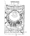
図1は、本発明の一実施形態としての遊技機1の正面図である。以下では、遊技機1の左右方向を、遊技機1に対面する遊技者から見た左右方向に一致させて説明する。また、遊技機1の前方向は、遊技機1から遊技者に向かう方向として説明し、遊技機1の後方向は、遊技者から遊技機1に向かう方向として説明する。
<First Embodiment>
1. FIG. 1 is a front view of a
遊技機1は、遊技者の発射操作に基づいて遊技球を発射させ、特定の入賞装置に遊技球が入賞すると、その入賞に基づいて所定数の遊技球を遊技者に払い出すパチンコ遊技機である。遊技機1は、遊技機枠50と、遊技盤2とを備え、遊技機枠50の内側に遊技盤2が取り付けられている。遊技機枠50は、前枠(前枠部)53のほか、遊技機の外郭部を形成する外枠(基枠部)と、外枠の内側において遊技盤2が取り付けられる内枠と、を備えている。前枠(前枠部)53は、外枠および内枠の前方側に配置される縦長方形状のユニットであり、ハンドル60と、打球供給皿(上皿)61と、余剰球受皿(下皿)62と、演出ボタン63と、剣部材64と、剣ボタン65と、枠ランプ66と、スピーカ67と、枠可動体600とを備えている。前枠53の中央には開口部が形成されており、開口部を介して、遊技盤2の遊技領域3を視認することができる。
The
ハンドル60は、前枠53の右側の下端に配置され、回転角度に応じた発射強度で遊技球を発射させる。打球供給皿(上皿)61は、前枠53の下方に設けられ、遊技球を貯留する。余剰球受皿(下皿)62は、打球供給皿(上皿)61の下方に配置され、打球供給皿61に収容しきれない遊技球を貯留する。演出ボタン63は、打球供給皿(上皿)61の近傍に配置された操作部であり、遊技の進行に伴って実行される演出時などに遊技者によって操作(押圧)される。剣部材64は、剣の形を模した操作部であり、遊技の進行に伴って実行される演出時等に遊技者が下方向に押し込むことができる。剣ボタン65は、剣部材64の上端部分、すなわち、剣の柄の端部に設けられた操作部であり、遊技の進行に伴って実行される演出時などに遊技者によって操作(押圧)される。剣部材64は、剣部材64全体を下方に押し込む第1の操作と、先端の剣ボタン65を押圧する第2の操作の異なる2つの操作を実行可能に構成されている。枠ランプ66は、前枠53の開口部周辺に配置され、遊技中などに発光演出をおこなう。スピーカ67は、前枠53の左上方と右上方に配置され、遊技中などに音演出をおこなう。枠可動体600は、前枠53の上部に設けられた可動式のいわゆるギミックである。枠可動体600は、前枠53の内部に格納されている格納状態から、前枠53の上方に突出する露出状態に変位可能に構成されている。
The
遊技盤2は、遊技領域3と、レール部材4と、盤ランプ5と、画像表示装置7と、センター装飾体10と、固定入賞装置(ヘソ)19と、普通可変入賞装置(電チュー)22と、ゲート(スルーチャッカー)28と、第1大入賞装置(第1アタッカー)31と、第2大入賞装置(第2アタッカー)36と、普通入賞口27と、アウト口16と、表示器類40と、を備えている。
The
遊技領域3は、ハンドル60の操作によって発射された遊技球が流下する領域であり、遊技球を誘導する複数の遊技釘が突設されている。レール部材4は、遊技領域3の左側端部に配置され、ハンドル60の操作によって発射された遊技球を遊技領域3の上方に向けて誘導する。盤ランプ5は、遊技領域3の背面側に配置され、遊技領域3の背面側から光を照射する。
The
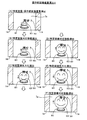
画像表示装置7は、遊技領域3の中央付近に設けられ、表示画面7aを備えている。画像表示装置7は、液晶表示装置であってもよいし、有機EL表示装置、プラズマディスプレイ、プロジェクター、ドットマトリクスなどの他の画像表示装置であってもよい。画像表示装置7の表示画面7aは、演出図柄(装飾図柄)8L、8C、8Rが可変表示(変動表示ともいう)される演出図柄表示領域と、保留画像9A、9Bが表示される保留画像表示領域と、保留消化画像9Cが表示される保留消化画像表示領域と、を有している。保留画像9A、9Bは、保留を表す画像であり、第1保留アイコン9A,9Bとも呼ぶ。保留消化画像9Cは、当該保留を表す画像であり、第2保留アイコン9Cとも呼ぶ。第1保留アイコンと第2保留アイコンとを総称して、単に保留アイコンとも呼ぶ。
The
第1演出図柄表示領域は、「左」「中」「右」の3つの図柄表示エリアを含んでいる。左の図柄表示エリアには左演出図柄(左装飾図柄)8Lが表示される。中の図柄表示エリアには中演出図柄(中装飾図柄)8Cが表示される。右の図柄表示エリアには右演出図柄(右装飾図柄)8Rが表示される。装飾図柄8L、8C、8Rは、例えば「1」〜「9」までの数字を表した複数の図柄によって構成されている。装飾図柄8L、8C、8Rの変動表示は、後述する第1特別図柄および第2特別図柄の変動表示と同期している。画像表示装置7は、左、中、右の図柄表示エリアに表示する演出図柄の組み合わせによって、後述の第1特別図柄表示器41aおよび第2特別図柄表示器41bによって表示される第1特別図柄および第2特別図柄の可変表示の結果(大当たり抽選結果)を、遊技者にわかりやすく表示することができる。
The first effect symbol display area includes three symbol display areas of “left”, “middle”, and “right”. In the left symbol display area, a left effect symbol (left decorative symbol) 8L is displayed. In the middle symbol display area, a medium effect symbol (medium decoration symbol) 8C is displayed. A right effect design (right decoration design) 8R is displayed in the right design display area. The
例えば、大当たりに当選した場合には「777」などのゾロ目で演出図柄を停止表示する。はずれであった場合には「637」などのバラケ目で演出図柄を停止表示する。これにより、遊技者による遊技の進行状況の把握が容易となる。遊技者は、大当たり抽選結果を第1特別図柄表示器41aや第2特別図柄表示器41bのほか、画像表示装置7によって把握することができる。なお、図柄表示エリアの位置は固定的でなくてもよい。また、演出図柄の変動表示の態様としては、上下方向にスクロールする態様であってもよいしそれ以外の態様であってもよい。各抽選結果に応じてどのような演出図柄の組み合わせを停止表示するかは上記に限定されず任意に設定することができる。
For example, when winning a jackpot, the effect symbol is stopped and displayed with a doublet such as “777”. If it is out of place, the effect symbol is stopped and displayed with a variation such as “637”. This makes it easier for the player to grasp the progress of the game. The player can grasp the jackpot lottery result by the
また、第2演出図柄表示領域は、「左」「中」「右」の3つの図柄表示エリアを含んでいる。左の図柄表示エリアには左演出図柄(左装飾図柄)9Lが表示される。中の図柄表示エリアには中演出図柄(中装飾図柄)9Cが表示される。右の図柄表示エリアには右演出図柄(右装飾図柄)9Rが表示される。演出図柄9L、9C、9Rは、例えば「1」〜「9」までの数字を表した複数の図柄によって構成されている。装飾図柄9L、9C、9Rの変動表示は、後述する第1特別図柄および第2特別図柄の変動表示と同期している。画像表示装置7は、左、中、右の図柄表示エリアに表示する演出図柄の組み合わせによって、後述の第1特別図柄表示器41aおよび第2特別図柄表示器41bによって表示される第1特別図柄および第2特別図柄の可変表示の結果(大当たり抽選結果)を、遊技者にわかりやすく表示することができる。装飾図柄9L,9C,9Rは、装飾図柄8L、8C、8Rよりも小さく形成される。
The second effect symbol display area includes three symbol display areas of “left”, “middle”, and “right”. A left effect design (left decoration design) 9L is displayed in the left design display area. In the middle symbol display area, a middle effect symbol (medium decorative symbol) 9C is displayed. In the right symbol display area, a right effect symbol (right decoration symbol) 9R is displayed. The
例えば、大当たりに当選した場合には「777」などのゾロ目で演出図柄を停止表示する。はずれであった場合には「637」などのバラケ目で演出図柄を停止表示する。これにより、遊技者による遊技の進行状況の把握が容易となる。遊技者は、大当たり抽選結果を第1特別図柄表示器41aや第2特別図柄表示器41bのほか、画像表示装置7によって把握することができる。なお、図柄表示エリアの位置は固定的でなくてもよい。また、演出図柄の変動表示の態様としては、上下方向にスクロールする態様であってもよいしそれ以外の態様であってもよい。各抽選結果に応じてどのような演出図柄の組み合わせを停止表示するかは上記に限定されず任意に設定することができる。以後、装飾図柄8L,8C,8R、または、装飾図柄9L、9C、9Rを表示する演出を「演出図柄の変動演出」、「装飾図柄の変動演出」または、単に「変動演出」とも呼ぶ。なお、この装飾図柄の変動演出は、特別図柄が変動開始してから停止するまでの期間(特別図柄変動期間とも呼ぶ)における演出を1回の変動演出(1サイクルの変動演出)としてカウントする。従って、特別図柄が変動開始してから停止するまでの期間に、装飾図柄を仮停止させる場合があったとしても、当該仮停止の演出は、装飾図柄の変動演出に含まれる。
For example, when winning a jackpot, the effect symbol is stopped and displayed with a doublet such as “777”. If it is out of place, the effect symbol is stopped and displayed with a variation such as “637”. This makes it easier for the player to grasp the progress of the game. The player can grasp the jackpot lottery result by the
画像表示装置7は、演出図柄変動演出のほか、大当たり遊技(特別遊技の一例)に並行しておこなわれる大当たり演出や、客待ち用のデモ演出などを表示画面7aに表示することができる。演出図柄変動演出では、演出図柄のほか、背景画像やキャラクタ画像などの演出画像も表示されてもよい。また、画像表示装置7は、演出図柄に加え、特別図柄が変動中であることを示唆したり、特別図柄の抽選結果を示唆したりすることが可能な識別表示(第四図柄、図示省略)を、表示画面7aに表示してもよい。なお、識別表示(第四図柄)は、遊技領域3に設けられたLEDなどの発光器によって表示させてもよい。
The
保留画像表示領域は、後述の第1特図保留の記憶数に応じて保留画像9Aを表示する第1保留表示エリアと、後述の第2特図保留の記憶数に応じて保留画像9Bを表示する第2保留表示エリアとを含んでいる。保留画像9A、9Bの表示によって、後述の第1特図保留表示器43aに表示される第1特図保留の記憶数と、第2特図保留表示器43bに表示される第2特図保留の記憶数を、遊技者にわかりやすく表示することができる。保留消化画像表示領域は、保留消化画像9Cを表示する保留消化表示エリアを含んでいる。保留消化画像9Cは、表示画面7aで現在変動中の演出図柄(装飾図柄8L、8C、8R)に対応しており、保留消化画像9Cの表示によって、第1特図保留または第2特図保留が消化(後述の「特図保留の消化」)されることを、遊技者にわかりやすく表示することができる。
The reserved image display area displays a first reserved display area for displaying a
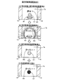
画像表示装置7の左右両側には、可動式のいわゆるギミックである第1盤可動体14(第1可動役物14とも呼ぶ)が設けられている。第1可動役物14は、透過性を有する左側板部材14Lと、透過性を有する右側板部材14Rを含んで構成されており。左側板部材14Lと右側板部材14Rは、それぞれ左右に移動可能あり、後述するように、画像表示装置7の全体を覆う閉状態と、画像表示装置7の中心部分を覆わない開状態とに遷移可能に構成されている。
On the left and right sides of the
センター装飾体10は、遊技領域3の中央付近であって、画像表示装置7の前方に配置されている。センター装飾体10には、可動式のいわゆるギミックである盤可動体15(盤可動役物15とも呼ぶ)が取り付けられている。センター装飾体10の下部には、ステージ部11が形成されている。ステージ部11は、ステージ部11の上面を転動する遊技球を後述の第1始動口20へと誘導可能な形状を有している。センター装飾体10の左下方には、ワープ部12が設けられている。ワープ部12は、遊技球が流入する入口部と遊技球が流出する出口部とを備え、入口部から流入した遊技球を出口部からステージ部11に流出させる。
The
固定入賞装置(ヘソ)19は、遊技領域3における画像表示装置7の下方に配置され、遊技球の入球し易さが常に変わらない第1始動口(第1始動入賞口、第1入球口、固定始動口)20を備えている。第1始動口20への遊技球の入賞は、第1特別図柄の抽選(大当たり抽選)の契機となっている。言い換えれば、第1始動口20への遊技球の入賞は、大当たり乱数等の取得および大当たり判定等の契機となっている。
The fixed winning device (jaw) 19 is disposed below the
普通可変入賞装置(電チュー)22は、遊技領域3における第1始動口20の下方に配置され、第2始動口(第2始動入賞口、第2入球口、可変始動口)21を備えている。第2始動口21への遊技球の入賞は、第2特別図柄の抽選(大当たり抽選)の契機となっている。電チュー22は、第2始動口21の前方に可動部材23を備えており、可動部材23の作動によって第2始動口21を開閉する。可動部材23は、電チューソレノイド24(図3)によって駆動される。第2始動口21は、可動部材23が開状態のとき遊技球が入球可能である。なお、電チュー22は、可動部材23が開状態のときの方が閉状態のときよりも第2始動口21への入球が容易であればよく、閉状態のときに第2始動口21への入球が可能であってもよい。
The normal variable winning device (electrical chew) 22 is disposed below the first starting port 20 in the
ゲート(スルーチャッカー)28は、遊技領域3における第1大入賞装置(第1アタッカー)31の上方に配置されており、遊技球が通過可能に構成されている。ゲート28への遊技球の通過は、電チュー22を開放するか否かを決定する普通図柄抽選の契機となっている。言い換えれば、ゲート28への遊技球の通過は、普通図柄乱数(当たり乱数)の取得および当たり判定等の契機となっている。
The gate (through chucker) 28 is disposed above the first big winning device (first attacker) 31 in the
ここで、「特別図柄の抽選」とは、第1始動口20または第2始動口21に遊技球が入賞したときに、特別図柄判定用の乱数を取得し、この取得した乱数を予め定められた「大当たり」に対応する値と比較することにより、大当たりか否かを判定する処理をいう。この「大当たり」の抽選結果は即座に遊技者に報知されるわけではなく、後述の第1特別図柄表示器41aまたは第2特別図柄表示器41bにおいて特別図柄の変動表示がおこなわれ、所定の変動時間を経過したところで、抽選結果に対応する特別図柄が停止表示(確定表示)され、遊技者に抽選結果が報知される。画像表示装置7では、特別図柄の変動表示と同期して演出図柄を変動表示する図柄合わせゲームが行われ、この図柄合わせゲームによって、より効果的に大当りの抽選結果が遊技者に報知される。
Here, the “special symbol lottery” means that when a game ball wins the first starting port 20 or the
また、「普通図柄の抽選」とは、ゲート28を遊技球が通過したときに、普通図柄判定用の乱数を取得し、この取得した乱数を予め定められた「当り」に対応する値と比較することにより、当りか否かを判定する処理をいう。この普通図柄の抽選結果についても、ゲート28を遊技球が通過して即座に抽選結果が報知されるわけではなく、後述の普通図柄表示器42において普通図柄の変動表示がおこなわれ、所定の変動時間を経過したところで、抽選結果に対応する普通図柄が確定表示(点灯または消灯)され、遊技者に抽選結果が報知される。
The “ordinary symbol lottery” means that when a game ball passes through the
第1大入賞装置(第1アタッカー、第1特別可変入賞装置)31は、遊技領域3における第1始動口20の右上方に配置され、第1大入賞口(第1特別入賞口)30と、V領域39と、非V領域70と、V開閉部材71とを備えている。第1大入賞口30は、スイング式の開閉動作により遊技球の受け入れを許容または阻害する開閉部材(第1特別入賞口開閉部材)32を備えている。開閉部材32は、第1大入賞口ソレノイド33(図3)によって駆動される。第1大入賞口30は、開閉部材32が開状態のとき遊技球が入球可能となる。
The first grand prize winning device (first attacker, first special variable prize winning device) 31 is arranged at the upper right of the first starting opening 20 in the
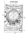
第1大入賞装置31は内部に、V領域(特定領域)39と、V領域センサ39a(図3)と、非V領域(非特定領域)70と、非V領域センサ70a(図3)と、第1大入賞口センサ30a(図3)と、V開閉部材71と、V開閉部材ソレノイド73(図3)と、を備えている。V領域(特定領域)39および非V領域(非特定領域)70は、第1大入賞装置31の内部において、第1大入賞口30を通過した遊技球が通過可能な領域として構成されている。第1大入賞口センサ30aは、V領域39および非V領域70の上流に配置され、第1大入賞口30への遊技球の入賞を検知する。V領域センサ39aは、V領域39に配置され、V領域39への遊技球の通過を検知する。非V領域センサ70aは、非V領域70に配置され、非V領域70への遊技球の通過を検知する。V開閉部材71は、第1大入賞口30を通過した遊技球をV領域39または非V領域70のいずれかに振り分ける。V開閉部材ソレノイド73は、V開閉部材71を駆動する。V開閉部材71は、回転移動(遊技盤2に対して時計回りおよび反時計回り)するように構成され、V開閉部材ソレノイド73の通電時には、原点位置から反時計回りに回転して遊技球をV領域39に振り分ける第1の状態(回動状態)となり、V開閉部材ソレノイド73の非通電時には、原点に位置して遊技球を非V領域70に振り分ける第2の状態(停止状態)となる。なお、V開閉部材71は、回転移動に限らず、第1大入賞口30を通過した遊技球をV領域39または非V領域70のいずれかに振り分ける機能を有しておればよく、例えば、遊技盤2に対して左右方向に移動するように構成してもよい。すなわち、V開閉部材ソレノイド73の通電時には、遊技球をV領域39に振り分ける退避状態(第1の状態)となり、V開閉部材ソレノイド73の非通電時には、遊技球を非V領域70に振り分ける進出状態(第2の状態)となるように構成してもよい。なお、遊技機1では、V領域39への遊技球の通過が後述の高確率状態への移行の契機となっている。つまり、V領域39は、確変作動口となっている。一方、非V領域70は、確変作動口となっていない。本実施形態の第1大入賞装置31は、さらに、第1大入賞装置31から排出される遊技球数を計数する第1大入賞装置排出センサ(図示しない)を備えている。第1大入賞装置排出センサは、V領域39と非V領域70が下流で合流した地点に設けられており、V領域センサ39aまたは非V領域センサ70aを通過した遊技球数を計数する。
The first grand
第2大入賞装置(第2アタッカー、第2特別可変入賞装置)36は、遊技領域3における第1大入賞口30の右上方に配置され、第2大入賞口(第2特別入賞口)35を備えている。第2大入賞口35は、スイング式の開閉動作により遊技球の受け入れを阻害または許容する開閉部材(第2特別入賞口開閉部材、可動部材)37を備えている。開閉部材37は、第2大入賞口ソレノイド38(図3)によって駆動される。第2大入賞口35は、開閉部材37が開状態のとき遊技球が入球可能となる。
The second grand prize winning device (second attacker, second special variable prize winning device) 36 is arranged on the upper right side of the first big
普通入賞口27は、遊技領域3の下部に設けられている。なお、普通入賞口27の数は任意に設定することができる。アウト口16は、遊技領域3の下部に設けられており、いずれの入賞口にも入賞しなかった遊技球を遊技領域3の外へ排出する。表示器類40は、遊技盤2の右側中央付近に配置されている。表示器類40の詳細については後述する。
The normal winning opening 27 is provided in the lower part of the
遊技領域3には、左右方向の中央より左側の左遊技領域3Aと、右側の右遊技領域3Bとがある。左遊技領域3Aを遊技球が流下するように遊技球を発射する打ち方を「左打ち」と呼ぶ。一方、右遊技領域3Bを遊技球が流下するように遊技球を発射する打ち方を「右打ち」と呼ぶ。遊技機1では、左打ちにて第1始動口20への入賞を狙うことができる。一方、右打ちにてゲート28への通過、第2始動口21、第1大入賞口30、および、第2大入賞口35への入賞が狙うことができるように構成されている。
The
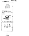
図2は、表示器類40の拡大図である。表示器類40は、第1特別図柄表示器41aと、第2特別図柄表示器41bと、普通図柄表示器42と、第1特図保留表示器43aと、第2特図保留表示器43bと、普図保留表示器44と、を含んでいる。第1特別図柄表示器41aは、第1特別図柄を可変表示する。第2特別図柄表示器41bは、第2特別図柄を可変表示する。普通図柄表示器42は、普通図柄を可変表示する。第1特図保留表示器43aは、第1特別図柄表示器41aの作動保留(第1特図保留)の記憶数を表示する。第2特図保留表示器43bは、第2特別図柄表示器41bの作動保留(第2特図保留)の記憶数を表示する。普図保留表示器44は、普通図柄表示器42の作動保留(普図保留)の記憶数を表示する。第1特別図柄の可変表示は、第1始動口20への遊技球の入賞を契機としておこなわれる。第2特別図柄の可変表示は、第2始動口21への遊技球の入賞を契機としておこなわれる。以下では、第1特別図柄および第2特別図柄を総称して「特別図柄」とも呼ぶ。また、第1特別図柄表示器41aおよび第2特別図柄表示器41bを総称して「特別図柄表示器41」とも呼ぶ。また、第1特図保留表示器43aおよび第2特図保留表示器43bを総称して「特図保留表示器43」とも呼ぶ。
FIG. 2 is an enlarged view of the
特別図柄表示器41は、特別図柄(識別情報)を可変表示(変動表示)した後、停止表示することによって第1始動口20または第2始動口21への入賞に基づく抽選(特別図柄当たり抽選、大当たり抽選)の結果を報知する。停止表示される特別図柄(停止図柄、可変表示の表示結果として導出表示される特別図柄)は、特別図柄抽選によって複数種類の特別図柄の中から選択された一つの特別図柄である。停止図柄が予め定めた大当たり停止態様の特別図柄(大当たり図柄)である場合には、停止表示された大当たり図柄の種類(当選した大当たりの種類)に応じた開放パターンにて第1大入賞口30または第2大入賞口35を開放させる特別遊技(大当たり遊技)がおこなわれる。なお、特別遊技における大入賞口(第1大入賞口30および第2大入賞口35)の開放パターンについては後述する。
The special symbol display 41 displays a special symbol (identification information) in a variable manner (variable display) and then stops and displays the lottery based on winning in the first start port 20 or the second start port 21 (lottery per special symbol). , The result of the jackpot lottery). The special symbol that is stopped and displayed (the special symbol that is derived and displayed as the display result of the stop symbol and variable display) is one special symbol that is selected from a plurality of types of special symbols by the special symbol lottery. When the stop symbol is a special symbol (a jackpot symbol) having a predetermined jackpot stop mode, the first
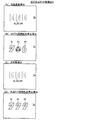
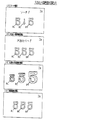
特別図柄表示器41は、横並びに配された8個のLEDから構成されており、その点灯態様によって特別図柄当たり抽選の結果に応じた特別図柄を表示する。例えば、大当たり(後述の複数種類の大当たりのうちの一つ)に当選した場合には、「○○●●○○●●」(○:点灯、●:消灯)というように左から1,2,5,6番目にあるLEDが点灯した大当たり図柄を表示する。ハズレである場合には、「●●●●●●●○」というように一番右にあるLEDのみが点灯したハズレ図柄を表示する。ハズレ図柄として全てのLEDを消灯させる態様を採用してもよい。特別図柄が停止表示される前には、所定の変動時間にわたって特別図柄の変動表示(可変表示)がなされる。変動表示の態様は、例えば、左から右へ光が繰り返し流れるように各LEDが点灯してもよい。変動表示の態様は、各LEDが停止表示(特定の態様での点灯表示)されていなければ、上記態様に限定されず、任意の点灯態様とすることができる。例えば、変動表示の態様は、全LEDが一斉に点滅してもよい。 The special symbol display 41 is composed of eight LEDs arranged side by side, and displays a special symbol corresponding to the result of the lottery per special symbol depending on the lighting mode. For example, if you win a jackpot (one of several types of jackpots to be described later), 1, 2 from the left such as “○ ●●● ○○ ●●” , 5th and 6th LEDs are lit and the jackpot symbol is displayed. In the case of losing, a losing pattern in which only the rightmost LED is lit, such as “●●●●●●● ○”, is displayed. You may employ | adopt the aspect which light-extinguishes all LED as a loss pattern. Before the special symbol is stopped and displayed, variation display (variable display) of the special symbol is performed for a predetermined variation time. For example, each LED may be lit so that light repeatedly flows from left to right. The mode of the variable display is not limited to the above mode as long as each LED is not stopped (lighted display in a specific mode), and can be any lighting mode. For example, in the variation display mode, all the LEDs may blink simultaneously.
遊技機1では、第1始動口20または第2始動口21への遊技球の入賞(入球)があると、その入賞に対して取得した大当たり乱数等の各種乱数の値(数値情報)は、特図保留記憶領域85(図5)に一旦記憶される。具体的には、第1始動口20への入賞であれば、第1特図保留として第1特図保留記憶領域85a(図5)に記憶され、第2始動口21への入賞であれば、第2特図保留として第2特図保留記憶領域85b(図5)に記憶される。各々の特図保留記憶領域85に記憶可能な特図保留の数には上限があり、本実施形態における上限値は、第1特図保留記憶領域85a、第2特図保留記憶領域85bともにそれぞれ4個となっている。特図保留記憶領域85に記憶された特図保留は、その特図保留に基づく特別図柄の可変表示が可能となったときに消化される。「特図保留の消化」とは、その特図保留に対応する大当たり乱数等を判定して、その判定結果を示すための特別図柄の可変表示を実行することをいう。従って、遊技機1では、第1始動口20または第2始動口21への遊技球の入賞に基づく特別図柄の可変表示がその入賞後にすぐにおこなえない場合、すなわち、特別図柄の可変表示の実行中や特別遊技の実行中に入賞があった場合であっても、所定個数を上限として、その入賞に対する大当たり抽選の権利を留保することができる。特図保留の数は、特図保留表示器43に表示される。第1特図保留表示器43aと第2特図保留表示器43bは、例えばそれぞれ4個のLEDで構成されている。各特図保留表示器43は、特図保留の数だけLEDを点灯させることによって特図保留の数を表示する。
In the
普通図柄の可変表示は、ゲート28への遊技球の通過を契機としておこなわれる。普通図柄表示器42は、普通図柄を可変表示(変動表示)した後、停止表示することによってゲート28への遊技球の通過に基づく普通図柄抽選の結果を報知する。停止表示される普通図柄(普図停止図柄、可変表示の表示結果として導出表示される普通図柄)は、普通図柄抽選によって複数種類の普通図柄の中から選択された一つの普通図柄である。普図停止図柄が予め定めた特定普通図柄(所定の停止態様の普通図柄すなわち普通当たり図柄)である場合には、現在の遊技状態に応じた開放パターンに第2始動口21を開放させる補助遊技が行われる。なお、第2始動口21の開放パターンについては後述する。
The variable display of the normal symbol is performed with the passage of the game ball to the
普通図柄表示器42は、2個のLEDから構成されており、その点灯態様によって普通図柄抽選の結果に応じた普通図柄を表示するものである。例えば、抽選結果が当たりである場合には、「○○」(○:点灯、●:消灯)というように両LEDが点灯した普通当たり図柄を表示する。抽選結果がハズレである場合には、「●○」というように右のLEDのみが点灯した普通ハズレ図柄を表示する。普通ハズレ図柄として全てのLEDを消灯させる態様を採用してもよい。普通図柄が停止表示される前には、所定の変動時間にわたって普通図柄の変動表示がなされる。変動表示の態様は、例えば、両LEDが交互に点灯してもよい。変動表示の態様は、各LEDが停止表示(特定の態様での点灯表示)されていなければ、上記態様に限定されず、任意の点灯態様とすることができる。例えば、変動表示の態様は、全LEDが一斉に点滅してもよい。
The
遊技機1では、ゲート28への遊技球の通過があると、その通過に対して取得した普通図柄乱数(当たり乱数)の値は、普図保留記憶領域86(図5)に普図保留として一旦記憶される。普図保留記憶領域86に記憶可能な普図保留の数には上限があり、本形態における上限値は4個となっている。普図保留記憶領域86に記憶された普図保留は、その普図保留に基づく普通図柄の可変表示が可能となったときに消化される。普図保留の消化とは、その普図保留に対応する普通図柄乱数(当たり乱数)を判定して、その判定結果を示すための普通図柄の可変表示を実行することをいう。従って、遊技機1では、ゲート28への遊技球の通過に基づく普通図柄の可変表示がその通過後にすぐにおこなえない場合、すなわち、普通図柄の可変表示の実行中や補助遊技の実行中に入賞があった場合であっても、所定個数を上限として、その通過に対する普通図柄抽選の権利を留保することができる。普図保留の数は、普図保留表示器44に表示される。普図保留表示器44は、例えば、4個のLEDで構成されており、普図保留の数だけLEDを点灯させることによって普図保留の数を表示する。
In the
2.遊技機の電気的構成
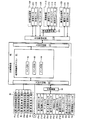
図3、図4に基づいて、遊技機1の電気的構成について説明する。図3は、遊技機1の主制御基板側の電気的な構成を示すブロック図である。図4は、遊技機1のサブ制御基板側の電気的な構成を示すブロック図である。遊技機1は、主制御基板80(図3)と、サブ制御基板90(図4)と、画像制御基板100(図4)と、ランプ制御基板107(図4)と、音声制御基板106(図4)と、払出制御基板110(図3)と、を備えている。主制御基板80は、大当たり抽選や遊技状態の移行などの遊技利益に関する制御をおこなう遊技制御基板であり、メイン制御部を構成する。サブ制御基板90は、遊技の進行に伴って実行する演出に関する制御をおこなう演出制御基板であり、画像制御基板100、ランプ制御基板107、音声制御基板106とともにサブ制御部を構成する。なお、サブ制御部は、少なくともサブ制御基板90を備えていれば構成可能である。
2. Electrical configuration of gaming machine The electrical configuration of the
主制御基板80は、遊技制御用マイコン81と、入出力回路87と、を備えている。遊技制御用マイコン81は、主制御基板80に実装されているワンチップマイコンであり、プログラムに従って遊技機1の遊技の進行を制御する。遊技制御用マイコン81は、遊技の進行を制御するためのプログラムなどを記憶するメインROM83と、ワークメモリとして使用されるメインRAM84と、メインROM83に記憶されているプログラムを実行するメインCPU82と、を含んでいる。メインROM83に記憶されているデータの詳細、および、メインRAM84に設けられている記憶領域の詳細については後述する。メインROM83は外付けROMとして構成されていてもよい。遊技制御用マイコン81は、入出力回路(I/Oポート部)87を介して他の基板等とデータの送受信をおこなう。入出力回路87は、遊技制御用マイコン81に内蔵されていてもよい。
The
主制御基板80には、入出力回路87および中継基板88を介して各種センサやソレノイドが接続されている。主制御基板80は、各センサから出力された信号が入力するとともに、各ソレノイドに対して信号を出力する。中継基板88を介して接続されるセンサ類としては、第1始動口センサ20a、第2始動口センサ21a、ゲートセンサ28a、第1大入賞口センサ30a、第2大入賞口センサ35a、V領域センサ39a、非V領域センサ70a、および、普通入賞口センサ27a、が例示される。中継基板88を介して接続されるソレノイド類としては、電チューソレノイド24、第1大入賞口ソレノイド33、第2大入賞口ソレノイド38、および、V開閉部材ソレノイド73が例示される。第1始動口センサ20aは、第1始動口20の内部に設けられ、第1始動口20に入賞した遊技球を検出する。第2始動口センサ21aは、第2始動口21の内部に設けられ、第2始動口21に入賞した遊技球を検出する。ゲートセンサ28aは、ゲート28の内部に設けられ、ゲート28を通過した遊技球を検出する。第1大入賞口センサ30aは、第1大入賞口30の内部に設けられ、第1大入賞口30に入賞した遊技球を検出する。第2大入賞口センサ35aは、第2大入賞口35の内部に設けられ、第2大入賞口35に入賞した遊技球を検出する。V領域センサ39aは、第1大入賞口30の内部のV領域39に設けられ、V領域39を通過した遊技球を検出する。非V領域センサ70aは、第1大入賞口30の内部の非V領域70に設けられ、非V領域70を通過した遊技球を検出する。普通入賞口センサ27aは、普通入賞口27の内部に設けられ、普通入賞口27に入賞した遊技球を検出する。電チューソレノイド24は、電チュー22の可動部材23を駆動する。第1大入賞口ソレノイド33は、第1大入賞装置31の開閉部材32を駆動する。第2大入賞口ソレノイド38は、第2大入賞装置36の開閉部材37を駆動する。V開閉部材ソレノイド73は、第1大入賞装置31のV開閉部材71を駆動する。
Various sensors and solenoids are connected to the
主制御基板80には、入出力回路87を介して表示器類40が接続されている。遊技制御用マイコン81は、第1特別図柄表示器41a、第2特別図柄表示器41b、普通図柄表示器42、第1特図保留表示器43a、第2特図保留表示器43b、普図保留表示器44についての表示制御おこなう。
主制御基板80には、入出力回路87を介して払出制御基板110が接続されている。主制御基板80は、払出制御基板110に各種コマンドを送信するとともに、払い出し監視のために払出制御基板110から信号を受信する。払出制御基板110には、賞球払出装置120と、貸球払出装置130と、カードユニット135と、が接続され、発射制御回路111を介して発射装置112が接続されている。賞球払出装置120は、賞球の払い出しをおこなう。払出制御基板110は、遊技制御用マイコン81からの信号に基づいて、賞球払出装置120の賞球モータ121を駆動して賞球の払い出しをおこなう。払い出される賞球は、計数のために賞球センサ122によって検知される。貸球払出装置130は、貸球の払い出しをおこなう。払出制御基板110は、遊技機1に接続されたカードユニット135からの信号に基づいて、貸球払出装置130の貸球モータ131を駆動して貸球の払い出しをおこなう。払い出される貸球は、計数のために貸球センサ132によって検知される。カードユニット135は、遊技機1に隣接して配置され、挿入されたプリペイドカードなどの情報に基づいて球貸に関する情報を出力する。発射装置112は、ハンドル60(図1)と、発射モータ113と、タッチスイッチ114と、発射ボリューム115と、を備えている。発射装置112は、遊技者によるハンドル60の操作があった場合に、タッチスイッチ114によってハンドル60の接触を検知し、発射ボリューム115によってハンドル60の回転量を検知する。そして、発射ボリューム115の検知信号の大きさに応じた強さで遊技球が発射されるように発射モータ113を駆動する。
A
主制御基板80には、入出力回路87を介してサブ制御基板90(図4)が接続されている。主制御基板80は、サブ制御基板90に対して各種コマンドを送信する。主制御基板80とサブ制御基板90との接続は、主制御基板80からサブ制御基板90への信号の送信のみが可能な単方向通信接続となっている。すなわち、主制御基板80とサブ制御基板90との間には、通信方向規制手段としての図示しない単方向性回路(例えばダイオードを用いた回路)が介在している。
A sub control board 90 (FIG. 4) is connected to the
サブ制御基板90は、演出制御用マイコン91と、入出力回路95と、を備えている。演出制御用マイコン91は、サブ制御基板90に実装されているワンチップマイコンであり、プログラムに従って遊技機1の遊技の演出を制御する。演出制御用マイコン91は、遊技の進行に伴って演出を制御するためのプログラム等を記憶するサブROM93と、ワークメモリとして使用されるサブRAM94と、サブROM93に記憶されているプログラムを実行するサブCPU92と、を含んでいる。サブROM93に記憶されているデータの詳細、および、サブRAM94に設けられている記憶領域の詳細については後述する。サブROM93は外付けROMとして構成されていてもよい。演出制御用マイコン91は、入出力回路(I/Oポート部)95を介して他の基板等とデータの送受信をおこなう。入出力回路95は、演出制御用マイコン91に内蔵されていてもよい。サブ制御基板90には、入出力回路95を介して、画像制御基板100と、音声制御基板106と、ランプ制御基板107と、中継基板108と、が接続されている。
The
画像制御基板100は、画像制御用マイコン101と、入力回路105aと、出力回路105bとを備えている。画像制御用マイコン101は、画像制御基板100に実装されているワンチップマイコンであり、プログラムに従って画像表示装置7の表示制御をおこなう。画像制御用マイコン101は、CPU102と、ROM103と、RAM104とを含んでいる。ROM103には、表示制御をおこなうためのプログラムのほか、画像表示装置7に表示される静止画データや動画データ、具体的には、キャラクタ、アイテム、図形、文字、数字および記号等(演出図柄を含む)や背景画像等の画像データが格納されている。RAM104は、画像データを展開するためのメモリとして使用される。CPU102は、ROM103に記憶されているプログラムを実行する。演出制御用マイコン91は、主制御基板80から受信したコマンドに基づいて、画像制御用マイコン101に画像表示装置7の表示制御をおこなわせる。画像制御用マイコン101は、演出制御用マイコン91からの指令に基づいてROM103から画像データを読み出し、読み出した画像データに基づいて表示制御をおこなう。
The
音声制御基板106には、スピーカ67が接続されており、演出制御用マイコン91は、主制御基板80から受信したコマンドに基づいて、音声制御基板106を介してスピーカ67から音声、楽曲、効果音等を出力させる。スピーカ67から出力する音声等の音響データは、サブ制御基板90のサブROM93に格納されている。なお、音声制御基板106は、CPUを実装していてもよく、そのCPUにコマンドに基づく音声制御を実行させてもよい。さらに、音声制御基板106は、ROMを実装してもよく、そのROMに音響データを格納してもよい。また、スピーカ67を画像制御基板100に接続し、画像制御基板100のCPU102に音声制御を実行させてもよい。さらに、画像制御基板100のROM103に音響データを格納してもよい。
A
ランプ制御基板107には、枠ランプ66と、盤ランプ5と、第1可動役物14と、第2可動役物15と、が接続されており、これらを制御する。演出制御用マイコン91は、主制御基板80から受信したコマンドに基づいて、ランプ制御基板107を介して枠ランプ66や盤ランプ5等のランプの点灯制御をおこなう。つまり、演出制御用マイコン91は、枠ランプ66や盤ランプ5等のランプの発光態様を決める発光パターンデータ(点灯/消灯や発光色等を決めるデータ、ランプデータともいう)を作成し、発光パターンデータに従って枠ランプ66や盤ランプ5などのランプの発光を制御する。発光パターンデータの作成にはサブ制御基板90のサブROM93に格納されているデータが用いられる。演出制御用マイコン91は、主制御基板80から受信したコマンドに基づいて、、第1可動役物14および第2可動役物15を動作させる。第1可動役物14は、画像表示装置7の左右両側に設けられた可動式のいわゆるギミックである。第2可動役物15は、センター装飾体10に設けられた可動式のいわゆるギミックである。演出制御用マイコン91は、第1可動役物14および第2可動役物15のそれぞれの動作態様を決める動作パターンデータ(駆動データ)を作成し、動作パターンデータに従って第1可動役物14および第2可動役物15の動作を制御する。動作パターンデータの作成にはサブROM93に格納されているデータを用いる。なお、ランプ制御基板107は、CPUを実装していてもよく、そのCPUにコマンドに基づくランプの点灯制御や可動役物14、15の動作制御を実行させてもよい。この場合、ランプ制御基板107はROMを実装してもよく、そのROMに発光パターンや動作パターンに関するデータを格納してもよい。
The
中継基板108には、演出ボタン検出スイッチ63aと、枠可動体600と、が接続されている。演出ボタン検出スイッチ63aは、演出ボタン63(図1)が押下操作されたことを検出する。演出ボタン63が押下されると、演出ボタン検出スイッチ63aから、中継基板108を介してサブ制御基板90にスイッチ信号が出力される。演出制御用マイコン91は、主制御基板80から受信したコマンドに基づいて、枠可動体600を動作させる。枠可動体600は、前枠53(図1)の上部に設けられた可動式のいわゆるギミックである。演出制御用マイコン91は、枠可動体600の動作態様を決める動作パターンデータ(駆動データ)を作成し、動作パターンデータに従って枠可動体600の動作を制御する。動作パターンデータの作成にはサブROM93に格納されているデータを用いる。なお、中継基板108には、セレクトボタン68(図1)が押下操作されたことを検出するセレクトボタン検出スイッチや、前枠53に設けられ、人体が接触すると検出信号を出力するタッチセンサなどが接続されていてもよい。
An effect button detection switch 63a and a
3.遊技機のデータ構成
図5、図6に基づいて、遊技機1のデータ構成について説明する。図5(A)は、メインROM83に記憶されているテーブルを説明するための図である。図5(B)は、メインRAM84に設けられている記憶領域を説明するための図である。図6(A)は、サブROM93に記憶されているテーブルを説明するための図である。図6(B)は、サブRAM94に設けられている記憶領域を説明するための図である。
3. Data structure of gaming machine The data structure of the
メインROM83(図5(A))には、大当たり判定テーブルT1と、リーチ判定テーブルT2と、普通図柄当たり判定テーブルT3と、普通図柄変動パターン判定テーブルT4と、大当たり種別判定テーブルT5と、変動パターン判定テーブルT6と、電チュー開放パターン判定テーブルT7と、大入賞口開放パターン判定テーブルT8と、V開閉部材開放パターン判定テーブルT9と、が格納されている。これらの判定テーブルは、遊技制御用マイコン81が実行する主制御メイン処理(後述)において、遊技制御用マイコン81によって参照される。各判定テーブルの具体的な内容については後述する。
The main ROM 83 (FIG. 5A) includes a jackpot determination table T1, a reach determination table T2, a normal symbol hit determination table T3, a normal symbol variation pattern determination table T4, a jackpot type determination table T5, and a variation pattern. A determination table T6, an electric chew opening pattern determination table T7, a special winning opening opening pattern determination table T8, and a V opening / closing member opening pattern determination table T9 are stored. These determination tables are referred to by the
メインRAM84(図5(B))には、コマンドセット領域84aと、フラグセット領域84bと、カウンタセット領域84cと、特別動作ステータスセット領域84dと、特図保留記憶領域85と、普図保留記憶領域86とが設けられている。コマンドセット領域84aは、主制御メイン処理(後述)において、メイン制御部側からサブ制御部側に出力されるコマンドがセットされる領域(出力バッファ)であり、事前判定コマンド、保留球数コマンド、変動開始コマンド、変動停止コマンド、オープニングコマンド、ラウンド指定コマンド、エンディングコマンド、遊技状態指定コマンド、V通過コマンド、客待ち待機コマンドなどがセットされる。フラグセット領域84bは、主制御メイン処理(後述)において、遊技機の状態や遊技状態を示すフラグがセットされる領域であり、大当たりフラグ、大当たり終了フラグ、第1入賞フラグ、第2入賞フラグ、Vフラグ、確変フラグ、時短フラグなどがセットされる。カウンタセット領域84cは、主制御メイン処理(後述)において使用されるカウンタがセットされる領域であり、乱数カウンタ、ラウンドカウンタ、確変カウンタ、時短カウンタなどがセットされる。特別動作ステータスセット領域84dは、後述する特別動作処理におけるステータスがセットされる領域である。特図保留記憶領域85は、第1特図保留が記憶される第1特図保留記憶領域85aと、第2特図保留が記憶される第2特図保留記憶領域85bとを含んでいる。第1特図保留記憶領域85aには、第1特図保留の1個目、2個目、3個目、4個目にそれぞれ対応する特別図柄当たり乱数等の乱数値群(保留情報)を記憶するための第1記憶領域、第2記憶領域、第3記憶領域、第4記憶領域が設けられている。第2特図保留記憶領域85bには、第2特図保留の1個目、2個目、3個目、4個目にそれぞれ対応する乱数値群(保留情報)を記憶するための第1記憶領域、第2記憶領域、第3記憶領域、第4記憶領域が設けられている。普図保留記憶領域86は、普図保留の1個目、2個目、3個目、4個目にそれぞれ対応する普通図柄乱数(あたり乱数)等の乱数値群(保留情報)を記憶するための第1記憶領域、第2記憶領域、第3記憶領域、第4記憶領域が設けられている。なお、メインRAM84には、上記の領域の他に、特図停止図柄データがセットされる当たり種別セットバッファや、可動体14,15や枠可動体600を駆動させるための駆動データがセットされる駆動データバッファ等が設けられている。
The main RAM 84 (FIG. 5B) includes a command set
サブROM93(図6(A))には、先読み演出パターン決定テーブルT51と、基幹演出パターン決定テーブルT52と、チャンスアップ演出パターン決定テーブルT53と、停止図柄パターン決定テーブルT54と、が格納されている。これらの決定テーブルは、演出制御用マイコン91が実行するサブ制御メイン処理(後述)において、演出制御用マイコン91によって参照される。各決定テーブルの具体的な内容については後述する。
In the sub ROM 93 (FIG. 6A), a prefetch effect pattern determination table T51, a basic effect pattern determination table T52, a chance up effect pattern determination table T53, and a stop symbol pattern determination table T54 are stored. . These determination tables are referred to by the
サブRAM94(図6(B))には、コマンド記憶領域94aと、演出コマンドセット領域94bと、事前判定情報記憶領域94cと、カウンタセット領域94dと、が設けられている。コマンド記憶領域94aは、サブ制御メイン処理(後述)において、メイン制御部側から入力されたコマンドが記憶される領域(入力バッファ)であり、事前判定コマンド、保留球数コマンド、変動開始コマンド、変動停止コマンド、オープニングコマンド、ラウンド指定コマンド、エンディングコマンド、遊技状態指定コマンド、V通過コマンド、客待ち待機コマンドなどが格納される。演出コマンドセット領域94bは、サブ制御メイン処理(後述)において、サブ制御基板90から画像制御基板100、音声制御基板106、ランプ制御基板107、中継基板108に出力されるコマンドがセットされる領域(出力バッファ)であり、変動演出開始コマンド、変動終了前コマンド、変動演出終了コマンド、オープニング演出開始コマンド、ラウンド演出開始コマンド、エンディング演出開始コマンドなどがセットされる。事前判定情報記憶領域94cは、サブ制御メイン処理(後述)において、事前判定情報が記憶される。カウンタセット領域94dは、サブ制御メイン処理(後述)において使用されるカウンタがセットされる領域であり、乱数カウンタ、第1特図保留演出カウンタ、第2特図保留演出カウンタ、普図保留演出カウンタ、確変演出カウンタ、時短演出カウンタなどがセットされる。
The sub RAM 94 (FIG. 6B) is provided with a
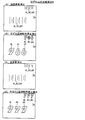
図7は、遊技機1において使用される各種の乱数を説明するための図である。図7(A)は、メイン制御部側の遊技制御用マイコン81が取得する乱数を示しており、図7(B)は、サブ制御部側の演出制御用マイコン91が取得する乱数を示している。遊技制御用マイコン81は、「大当たり乱数」と、「大当たり種別乱数」と、「リーチ乱数」と、「変動パターン乱数」と、「普通図柄乱数(当たり乱数)」とを後述するタイミングにおいて取得するように構成されている。「大当たり乱数」は、大当たりか否かの抽選(大当たり判定)に用いられる乱数であり、0〜65535までの範囲の値をとる。「大当たり種別乱数」は、当選した大当たりの種別の抽選(大当たり種別判定)に用いられる乱数であり、0〜127までの範囲の値をとる。「リーチ乱数」は、大当たり判定がハズレである場合に、その結果を示す演出図柄変動演出においてリーチを発生させるか否かを決定するために用いられる乱数であり、0〜127までの範囲の値をとる。リーチとは、複数の演出図柄(装飾図柄)のうち変動表示されている演出図柄が残り1つとなっている状態であって、変動表示されている演出図柄がどの図柄で停止表示されるか次第で大当たり当選を示す演出図柄の組み合わせとなる状態(例えば、「7↓7」の状態)のことである。なお、リーチ状態において停止表示されている演出図柄は、表示画面7a内で揺れているように表示されてもよい。「変動パターン乱数」は、変動時間を含む変動パターンを決定するために用いられる乱数であり、0〜127までの範囲の値をとる。「普通図柄乱数(当たり乱数)」は、電チュー22を開放させる補助遊技をおこなうか否かの抽選(普通図柄抽選)に用いられる。普通図柄乱数は、0〜255までの範囲の値をとる。「大当たり乱数」、「大当たり種別乱数」、「リーチ乱数」、「変動パターン乱数」は、始動口(第1始動口20または第2始動口21)への入球に基づいて取得される。第1始動口20への入球に基づいて取得された乱数値群は第1特図保留記憶領域85aに記憶され、第2始動口21への入球に基づいて取得された乱数値群は第2特図保留記憶領域85bに記憶される。「普通図柄乱数(当たり乱数)」は、ゲート28の通過に基づいて取得される。取得された普通図柄乱数値は、普図保留記憶領域86に記憶される。
FIG. 7 is a diagram for explaining various random numbers used in the
演出制御用マイコン91は、「先読み演出乱数」と、「チャンスアップ乱数」と、を後述するタイミングにおいて取得するように構成されている。「先読み演出乱数」は、変動演出時の先読み演出を決定するために用いられる乱数であり、0〜127までの範囲の値をとる。「チャンスアップ乱数」は、変動演出時のチャンスアップ演出を決定するために用いられる乱数であり、0〜127までの範囲の値をとる。「先読み演出乱数」は、メイン制御部側からサブ制御部側に事前判定コマンドが出力されたことに基づいて取得される。取得された乱数値群はサブRAM94に記憶される。「チャンスアップ乱数」は、メイン制御部側からサブ制御部側に変動開始コマンドが出力されたことに基づいて取得される。取得された乱数値はサブRAM94に記憶される。
The
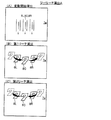
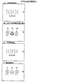
図8は、判定テーブルT1〜T4を説明するための図である。図8(A)には、大当たり判定テーブルT1を説明するための図が示され、図8(B)には、リーチ判定テーブルT2を説明するための図が示され、図8(C)には、普通図柄当たり判定テーブルT3を説明するための図が示され、図8(D)には、普通図柄変動パターン判定テーブルT4を説明するための図が示されている。 FIG. 8 is a diagram for explaining the determination tables T1 to T4. FIG. 8A shows a diagram for explaining the jackpot determination table T1, FIG. 8B shows a diagram for explaining the reach determination table T2, and FIG. 8C shows the diagram. FIG. 8A is a diagram for explaining the normal symbol hit determination table T3, and FIG. 8D shows a diagram for explaining the normal symbol variation pattern determination table T4.
大当たり判定テーブルT1は、遊技制御用マイコン81が主制御メイン処理(後述)において、取得した大当たり乱数値(0〜65535のいずれか)が「大当たり」に該当するか「ハズレ」に該当するかを判定するために参照されるテーブルである。図8(A)では、「通常確率状態」において、大当たり乱数値が「0〜164」の場合には、「大当たり」と判定され、大当たり乱数値が「0〜164以外の数値(165〜65535)」の場合には、「ハズレ」と判定されることが示されている。また、「高確率状態」において、大当たり乱数値が「0〜649」の場合には、「大当たり」と判定され、大当たり乱数値が「0〜649以外の数値(650〜65535)」の場合には、「ハズレ」と判定されることが示されている。「通常確率状態」および「高確率状態」の内容については後述する。
The jackpot determination table T1 indicates whether the jackpot random number value (any one of 0 to 65535) corresponds to “hit” or “losing” in the main control main process (described later) by the
リーチ判定テーブルT2は、遊技制御用マイコン81が主制御メイン処理(後述)において、取得したリーチ乱数値(0〜127のいずれか)が「リーチ有り」に該当するか「リーチ無し」に該当するかを判定するために参照されるテーブルである。図8(B)では、「非時短状態」において、リーチ乱数値が「0〜13」の場合には、「リーチ有り」と判定され、リーチ乱数値が「0〜13以外の数値(14〜127)」の場合には、「リーチ無し」と判定されることが示されている。また、「時短状態」において、リーチ乱数値が「0〜5」の場合には、「リーチ有り」と判定され、リーチ乱数値が「0〜5以外の数値(6〜127)」の場合には、「リーチ無し」と判定されることが示されている。「時短状態」および「非時短状態」の内容については後述する。リーチ判定テーブルT2では、時短状態の方が非時短状態よりもハズレ時のリーチがかかりにくくなっている。これは、時短状態において変動時間の短いリーチ無しハズレがより多く選択されることで、特図保留の消化スピードを速めるためである。
In the reach determination table T2, in the
普通図柄当たり判定テーブルT3は、遊技制御用マイコン81が主制御メイン処理(後述)において、取得した普通図柄乱数値(0〜255のいずれか)が「当たり」に該当するか「ハズレ」に該当するかを判定するために参照されるテーブルである。図8(C)では、「非時短状態」において、普通図柄乱数値が「0〜2」の場合には、「当たり」と判定され、普通図柄乱数値が「0〜2以外の数値(3〜255)」の場合には、「ハズレ」と判定されることが示されている。また、「時短状態」において、普通図柄乱数値が「0〜254」の場合には、「当たり」と判定され、普通図柄乱数値が「0〜254以外の数値(255)」の場合には、「ハズレ」と判定されることが示されている。
The normal symbol hit determination table T3 corresponds to whether the acquired normal symbol random number value (any of 0 to 255) corresponds to “win” or “lost” in the main control main process (described later) by the
普通図柄変動パターン判定テーブルT4は、遊技制御用マイコン81が主制御メイン処理(後述)において、遊技状態(非時短状態か時短状態か)に応じて、普通図柄の変動時間が何秒かを判定するために参照されるテーブルである。図8(D)では、「非時短状態」のとき、普通図柄の変動時間は「30秒」と判定され、「時短状態」のとき、普通図柄の変動時間が「1秒」と判定されることが示されている。
The normal symbol variation pattern determination table T4 determines how many seconds the variation time of the normal symbol depends on the game state (non-short time state or short time state) in the main control main process (described later) by the
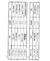
図9は、大当たり種別判定テーブルT5を説明するための図である。大当たり種別判定テーブルT5は、遊技制御用マイコン81が主制御メイン処理(後述)において、取得した大当たり種別乱数値(0〜127のいずれか)に応じて、「大当たりの種別」と「特別図柄の種類」を判定するために参照されるテーブルである。図9では、第1特別図柄(特図1)の抽選において当選したとき、大当たり種別乱数値が「0〜24」の場合には、大当たり種別が「16RV通過予定大当たり」と判定され、特図1の停止図柄(特図停止図柄)が「大当たり図柄1」と判定される。大当たり種別乱数値が「25〜49」の場合には、大当たり種別が「16RV通過予定大当たり」と判定され、特図停止図柄が「大当たり図柄2」と判定される。大当たり種別乱数値が「50〜55」の場合には、大当たり種別が「16R(実質15R)V通過予定大当たり」と判定され、特図停止図柄が「大当たり図柄3」と判定される。大当たり種別乱数値が「56〜67」の場合には、大当たり種別が「16R(実質13R)V通過予定大当たり」と判定され、特図停止図柄が「大当たり図柄4」と判定される。大当たり種別乱数値が「68〜127」の場合には、大当たり種別が「16R(実質13R)V非通過予定大当たり」と判定され、特図停止図柄が「大当たり図柄5」と判定される。一方、第2特別図柄(特図2)の抽選において当選した場合、大当たり種別乱数値によらず(0〜127のいずれであっても)、大当たり種別が「16RV通過予定大当たり」と判定され、特図2の停止図柄(特図停止図柄)が「大当たり図柄1」と判定されることが示されている。なお、大当たり種別判定テーブルT5を参照することによって、特図停止図柄に対応する「特図停止図柄データ」、特別遊技の「オープニング(OP)コマンド」、「ラウンド指定コマンド」、「エンディング(ED)コマンド」も特定することができる。「16RV通過予定大当たり」、「16R(実質15R)V通過予定大当たり」、「16R(実質13R)V通過予定大当たり」および「16R(実質13R)V非通過予定大当たり」の具体的な内容については後述する。
FIG. 9 is a diagram for explaining the jackpot type determination table T5. According to the jackpot type determination table T5, in the main control main process (described later), the
図10は、非時短状態時の変動パターン判定テーブルT6を説明するための図である。図11は、時短状態時の変動パターン判定テーブルT6を説明するための図である。変動パターン判定テーブルT6は、遊技制御用マイコン81が主制御メイン処理(後述)において、取得した変動パターン乱数値(0〜127)に応じて、変動パターンを判定するために参照されるテーブルである。図10では、例えば、非時短状態において第1始動口20に入賞し、大当たり判定テーブルT1において「ハズレ」と判定され、リーチ判定テーブルT2において「リーチ有り」と判定され、保留球数が「1〜2」であり、変動パターン乱数値が「0〜60」の場合には、変動パターンが「P7」と判定されることが示されている。図11では、例えば、時短状態において第2始動口21に入賞し、大当たり判定テーブルT1において「大当たり」と判定され、大当たり種別判定テーブルT5において「16RV通過予定大当たり」と判定され、変動パターン乱数値が「0〜10」の場合には、変動パターンが「P61」と判定されることが示されている。図10,11に示されるように、変動パターンが決定されれば、変動時間も決定される。また、リーチになる場合に、そのリーチがノーマルリーチとなるのかスーパーリーチ(SPリーチ)となるのかも決定される。スーパーリーチとは、ノーマルリーチよりもリーチ後の変動時間が長いリーチ演出である。ここでは、変動時間の異なる3種類のスーパーリーチ(SP1、SP2、SP3)が設定されている。変動時間の長さはSP3>SP2>SP1となっている。SP1〜3では、ノーマルリーチを経て発展的に実行される。SP1〜3の違いは、例えば、疑似連の有無であってもよい。
FIG. 10 is a diagram for explaining the variation pattern determination table T6 in the non-short-time state. FIG. 11 is a diagram for explaining the variation pattern determination table T6 in the time-short state. The variation pattern determination table T6 is a table that is referred to by the
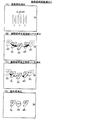
図12は、電チュー開放パターン判定テーブルT7を説明するための図である。電チュー開放パターン判定テーブルT7は、遊技制御用マイコン81が主制御メイン処理(後述)において、遊技状態(非時短状態か時短状態か)に応じて、電チュー22の開放パターンを判定するために参照されるテーブルである。図12(A)では、「非時短状態」のとき、電チュー22の開放パターンは「開放パターン11」と判定され、「時短状態」のとき、開放パターンは「開放パターン12」と判定されることが示されている。図12(B)には、開放パターン11と開放パターン12の内容が示されている。開放パターン11では、開放回数1回、開放時間0.2秒の電チュー22の開放をおこなう。開放パターン12では、開放回数が3回、1回あたりの開放時間2.0秒、インターバル(開放間隔)1.0秒の電チュー22の開放をおこなう。ただし、この電チュー22の開放は、予め定められた数の遊技球の入賞(規定入賞数、最大10個)があった場合、開放時間が残っていても閉鎖される。
FIG. 12 is a diagram for explaining the electric chew release pattern determination table T7. The electric chew release pattern determination table T7 is used for the
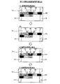
図13は、大入賞口開放パターン判定テーブルT8を説明するための図である。大入賞口開放パターン判定テーブルT8は、遊技制御用マイコン81が主制御メイン処理(後述)において、特図停止図柄データ(図9)に応じて、第1大入賞口30および第2大入賞口35の開放パターンを判定するために参照されるテーブルである。図13(A)では、特図停止図柄データが「11H」、「12H」、または、「21H」のとき、第1大入賞口30および第2大入賞口35の開放パターンは「開放パターン21」と判定され、特図停止図柄データが「14H」または「15H」のとき、開放パターンは「開放パターン22」と判定され、特図停止図柄データが「13H」のとき、開放パターンは「開放パターン23」と判定されることが示されている。図13(B)には、開放パターン21、開放パターン22および開放パターン23の内容が示されている。開放パターン21では1〜13、15R目において、開放回数1回、開放時間29.5秒の第1大入賞口30の開放(ロング開放)をおこない、14、16R目において、開放回数1回、開放時間29.5秒の第2大入賞口35の開放(ロング開放)をおこなう。開放パターン22では1〜13R目において、開放回数1回、開放時間29.5秒の第1大入賞口30の開放(ロング開放)をおこない、14、16R目において、開放回数1回、開放時間0.1秒の第2大入賞口35の開放(ショート開放)をおこない、15R目において、開放回数1回、開放時間0.1秒の第1大入賞口30の開放(ショート開放)をおこなう。開放パターン23では1〜13、15R目において、開放回数1回、開放時間29.5秒の第1大入賞口30の開放(ロング開放)をおこない、14R目において、開放回数1回、開放時間0.1秒の第2大入賞口35の開放(ショート開放)をおこない、16R目において、開放回数1回、開放時間29.5秒の第2大入賞口35の開放(ロング開放)をおこなう。ただし、第1大入賞口30および第2大入賞口35の開放は、予め定められた数の遊技球の入賞(規定入賞数、最大9個)があった場合、開放時間が残っていても閉鎖される。
FIG. 13 is a view for explaining the special winning opening opening pattern determination table T8. In the main winning opening opening pattern determination table T8, in the main control main process (described later), the
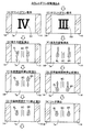
図14は、V開閉部材開放パターン判定テーブルT9を説明するための図である。V開閉部材開放パターン判定テーブルT9は、遊技制御用マイコン81が主制御メイン処理(後述)において、特図停止図柄データ(図9)に応じて、V開閉部材71の開放パターンを判定するために参照されるテーブルである。図14(A)では、特図停止図柄データが「11H」、「12H」、または、「21H」のとき、V開閉部材71の開放パターンは「開放パターン31」と判定され、特図停止図柄データが「13H」のとき、開放パターンは「開放パターン32」と判定され、特図停止図柄データが「14H」のとき、開放パターンは「開放パターン33」と判定され、特図停止図柄データが「15H」のとき、開放パターンは「開放パターン34」と判定されることが示されている。図14(B)には、開放パターン31、開放パターン32、開放パターン33、および、開放パターン34の内容が示されている。開放パターン31では2、4、6、8R目において、第1大入賞口30に1個目の入賞があったとき開放時間0.1秒のV開閉部材71のショート開放をおこなう。10、12R目において、第1大入賞口30に1個目の入賞があったとき開放時間0.1秒のV開閉部材71のショート開放をおこない、2個目の入賞があったとき開放時間最大31.5秒のV開閉部材71のロング開放をおこなう。開放パターン32では2、4、6、12R目において、第1大入賞口30に1個目の入賞があったとき開放時間0.1秒のV開閉部材71のショート開放をおこなう。8、10R目において、第1大入賞口30に1個目の入賞があったとき開放時間0.1秒のV開閉部材71のショート開放をおこない、2個目の入賞があったとき開放時間最大31.5秒のV開閉部材71のロング開放をおこなう。開放パターン33では2、6R目において、第1大入賞口30に1個目の入賞があったとき開放時間0.1秒のV開閉部材71のショート開放をおこない、2個目の入賞があったとき開放時間最大31.5秒のV開閉部材71のロング開放をおこなう。4、8、10、12R目において、第1大入賞口30に1個目の入賞があったとき開放時間0.1秒のV開閉部材71のショート開放をおこなう。開放パターン34では2、4、6、8、10、12R目において、第1大入賞口30に1個目の入賞があったとき開放時間0.1秒のV開閉部材71のショート開放をおこなう。
FIG. 14 is a diagram for explaining the V opening / closing member opening pattern determination table T9. The V opening / closing member opening pattern determination table T9 is used for the
4.大当たり等の説明
遊技機1では、大当たり抽選(特別図柄抽選)の結果としての「大当たり」と「ハズレ」がある。「大当たり」の場合には、特別図柄表示器41に「大当たり図柄」が停止表示される。「ハズレ」のときには、特別図柄表示器41に「ハズレ図柄」が停止表示される。大当たりに当選すると、停止表示された特別図柄の種類(大当たりの種類)に応じた開放パターンにて、大入賞口(第1大入賞口30および第2大入賞口35)を開放させる「大当たり遊技」が実行される。大当たり遊技は、特別遊技の一例である。大当たり遊技は、複数回のラウンド遊技(単位開放遊技)と、初回のラウンド遊技が開始される前のオープニング(OP)と、最終回のラウンド遊技が終了した後のエンディング(ED)とを含んでいる。各ラウンド遊技は、オープニングの終了、または、前のラウンド遊技の終了によって開始し、次のラウンド遊技の開始によって終了する。ラウンド遊技間の大入賞口の閉鎖の時間(インターバル時間)は、その閉鎖前の開放ラウンド遊技に含まれる。
4). Explanation of jackpot etc. In the
大当たりには複数の種別がある。大当たりの種別については、図9に示すとおりである。ここでは、大当たりの種別としては、大きく分けて「V通過予定大当たり」と「V非通過予定大当たり」の2つある。「V通過予定大当たり」は、その大当たり遊技中にV領域39への遊技球の通過が可能な開放パターン(V通過予定開放パターン)で開閉部材32、開閉部材37およびV開閉部材71を作動させる大当たりである。ここでは、特図停止図柄データが11H〜14H,21Hの大当たりが「V通過予定大当たり」に該当する。図13に示す開閉部材32および開閉部材37の開放パターンと、図14に示すV開閉部材71の開放パターンとの組み合わせが、(開放パターン21:開放パターン31)、(開放パターン22:開放パターン33)、または(開放パターン23:開放パターン32)のとき、その大当たり遊技中にV領域39への遊技球の通過が可能となる。「V非通過予定大当たり」は、その大当たり遊技中にV領域39への遊技球の通過が不可能な開放パターン(V非通過予定開放パターン)で開閉部材32、開閉部材37およびV開閉部材71を作動させる大当たりである。ここでは、特図停止図柄データが17Hの大当たりが「V非通過予定大当たり」に該当する。図13に示す開閉部材32および開閉部材37の開放パターンと、図14に示すV開閉部材71の開放パターンとの組み合わせが(開放パターン22:開放パターン34)のとき、その大当たり遊技中にV領域39への遊技球の通過が不可能となる。上記のように、開閉部材32および開閉部材37の開放パターン22は、V通過予定開放パターンとV非通過予定開放パターンとを兼ねている。
There are several types of jackpots. The jackpot type is as shown in FIG. Here, the types of jackpots are roughly divided into “V pass planned jackpot” and “V non-passed jackpot”. “V pass planned jackpot” operates the opening / closing
「V通過予定大当たり」は、「16RV通過予定大当たり」と、「16R(実質13R)V通過予定大当たり」と、「16R(実質15R)V通過予定大当たり」と、を含んでいる。「16RV通過予定大当たり」は、実質的な総ラウンド数が16Rである。1Rから13Rまでと15Rは第1大入賞口30を1R当たり最大29.5秒にわたって開放する。14Rと16Rは第2大入賞口35を1R当たり最大29.5秒にわたって開放する(図13:開放パターン21)。10Rおよび12Rでは、V開閉部材71がロング開放され(図14:開放パターン31)、第1大入賞口30内のV領域39への通過が容易に可能である。
“V-planned jackpot” includes “16RV-planned jackpot”, “16R (substantial 13R) V-planned jackpot” and “16R (substantial 15R) V-planned jackpot”. The “16RV expected jackpot” has a substantial total number of rounds of 16R. From 1R to 13R and 15R, the first
「16R(実質13R)V通過予定大当たり」は、総ラウンド数は16Rであるものの、実質的な総ラウンド数は13Rである。つまり、1Rから13Rまでは第1大入賞口30を1R当たり最大29.5秒にわたって開放するが、15Rでは第1大入賞口30を1R当たり0.1秒しか開放せず、また、14Rと16Rでも第2大入賞口35を1R当たり0.1秒しか開放しない(図13:開放パターン22)。従って、この「16R(実質13R)V通過予定大当たり」では14Rから16Rまでは、大入賞口の開放時間が極めて短く、賞球の見込めないラウンドとなっている。つまり、「16R(実質13R)V通過予定大当たり」は、実質13Rの大当たりとなっている。2Rおよび6Rでは、V開閉部材71がロング開放され(図14:開放パターン33)、第1大入賞口30内のV領域39への通過が容易に可能である。
“16R (substantial 13R) V passing expected jackpot” has a total number of rounds of 16R, but the total number of rounds is 13R. In other words, from 1R to 13R, the first
「16R(実質15R)V通過予定大当たり」は、総ラウンド数は16Rであるものの、実質的な総ラウンド数は15Rである。つまり、1Rから13Rまでと15Rは第1大入賞口30を1R当たり最大29.5秒にわたって開放し、16Rでは第2大入賞口35を1R当たり最大29.5秒にわたって開放するが、14Rでは第2大入賞口35を1R当たり0.1秒しか開放しない(図13:開放パターン23)。従って、この「16R(実質15R)V通過予定大当たり」では14Rは、大入賞口の開放時間が極めて短く、賞球の見込めないラウンドとなっている。つまり、「16R(実質15R)V通過予定大当たり」は、実質15Rの大当たりとなっている。8Rおよび10Rでは、V開閉部材71がロング開放され(図14:開放パターン32)、第1大入賞口30内のV領域39への通過が容易に可能である。
“16R (substantially 15R) V passing expected jackpot” has a total number of rounds of 16R, but the total number of rounds is 15R. That is, from 1R to 13R and 15R, the first
「V非通過予定大当たり」は、総ラウンド数は16Rであるものの、実質的な総ラウンド数は13となる開放パターン22の「16R(実質13R)V非通過予定大当たり」である。つまり、1Rから13Rまでは第1大入賞口30を1R当たり最大29.5秒にわたって開放するが、15Rでは第1大入賞口30を1R当たり0.1秒しか開放せず、また、14Rと16Rでも第2大入賞口35を1R当たり0.1秒しか開放しない(図13:開放パターン22)。従って、この「16R(実質13R)V非通過予定大当たり」では14Rから16Rまでは、大入賞口の開放時間が極めて短く、賞球の見込めないラウンドとなっている。つまり、「16R(実質13R)V非通過予定大当たり」は実質13Rの大当たりとなっている。2R,4R,6R,8R,10Rおよび12Rでは、V開閉部材71は開放されるもののその開放はショート開放であり(図14:開放パターン34)、第1大入賞口30内のV領域39に遊技球が通過することはほぼ不可能となっている。
“V non-passing jackpot” is “16R (substantial 13R) V non-passing jackpot” of the
上記の説明から明らかなように、「16R(実質13R)V非通過予定大当たり」と「16R(実質13R)V通過予定大当たり」とは、第1大入賞口30と第2大入賞口35(開閉部材32と開閉部材37)との開放パターンが同一(開放パターン22)であり、V開閉部材71の開放パターンのみが異なっている(開放パターン34と開放パターン33)。すなわち、「16R(実質13R)V非通過予定大当たり」は、第1大入賞口30内のV領域39に遊技球が通過することはほぼ不可能になっており、当該大当たり後の遊技状態は低確時短状態(低確高ベース状態)となる。一方、「16R(実質13R)V通過予定大当たり」は、第1大入賞口30内のV領域39への遊技球の通過が容易に可能になっており、当該大当たり後の遊技状態は高確時短状態(高確高ベース状態)となる。このことから、遊技者は、「16R(実質13R)V非通過予定大当たり」と「16R(実質13R)V通過予定大当たり」とを見分けることが困難になり、当該大当たり後の遊技状態が低確時短状態(低確高ベース状態)になるか高確時短状態(高確高ベース状態)になるかが判別し難くなる。すなわち、「16R(実質13R)V通過予定大当たり」後の遊技状態は、第1大入賞口30内のV領域39に遊技球が通過した場合には、高確時短状態(高確高ベース状態)でありながら高確率になっていることが潜伏した状態(潜伏確変状態)となる。
As apparent from the above description, the “16R (substantially 13R) V non-passing expected jackpot” and the “16R (substantially 13R) V expected passing jackpot” are the first
また、図9に示すように、第1特別図柄(特図1)の抽選における大当たりの振分率は、V通過予定大当たりが68/128(約53%)、V非通過予定大当たりが60/128(約47%)となっている。これに対して、第2特別図柄(特図2)の抽選において当選した大当たりは、全てV通過予定大当たりとなっている。すなわち、後述の電サポ制御の実行により入球可能となる第2始動口21への入賞に基づく抽選により大当たりに当選した場合には、必ずV通過予定大当たりとなる。このように遊技機1では、第1始動口20に遊技球が入賞して行われる大当たり抽選(第1特別図柄の抽選)よりも、第2始動口21に遊技球が入賞して行われる大当たり抽選(第2特別図柄の抽選)の方が、遊技者にとって有利となるように設定されている。
Further, as shown in FIG. 9, the jackpot distribution ratio in the lottery of the first special symbol (special diagram 1) is 68/128 (about 53%) for the V pass expected jackpot and 60/60 for the V non-passed jackpot. 128 (about 47%). On the other hand, the jackpots won in the lottery of the second special symbol (special map 2) are all the jackpots that are expected to pass V. In other words, when a big win is won by a lottery based on winning a prize to the
5.遊技状態の説明
遊技機1の遊技状態について説明する。遊技制御用マイコン81は、特別図柄表示器41に表示する特別図柄および普通図柄表示器42に表示する普通図柄に対して、それぞれ、「確率変動制御」と「変動時間短縮制御」とを実行可能である。ここでは、遊技制御用マイコン81が特別図柄表示器41の特別図柄に対して確率変動制御している状態を「高確率状態」と呼び、確率変動制御していない状態を単に「通常確率状態(非高確率状態、低確率状態)」と呼ぶ。遊技制御用マイコン81は、特別図柄の確率変動制御として、大当たりと判定される大当たり乱数値の数が通常確率状態よりも高確率状態の方が多い大当たり判定テーブル(図8(A))を用いた大当たり判定をおこなうことにより、高確率状態を実現する。従って、高確率状態は、通常確率状態よりも大当たりの確率が高くなる。つまり、遊技制御用マイコン81が特別図柄表示器41の特別図柄に対して確率変動制御を実行している場合には、確率変動制御を実行していない場合と比べて、特別図柄表示器41による特別図柄の可変表示の表示結果(停止図柄)が大当たり図柄となる確率が高くなる。
5. Description of the gaming state The gaming state of the
また、遊技制御用マイコン81が特別図柄表示器41の特別図柄に対して変動時間短縮制御している状態を「時短状態」といい、変動時間短縮制御していない状態を単に「非時短状態」という。時短状態は、特別図柄の変動時間(変動表示開始時から表示結果の導出表示時までの時間)が、非時短状態よりも短くなっている。遊技制御用マイコン81は、時短状態のときに、変動時間の短い変動パターンが選択されることが非時短状態よりも多くなるように定められた変動パターン判定テーブルT6(図10、図11)を用いた変動パターンの判定をおこなう。つまり、遊技制御用マイコン81が特別図柄表示器41の特別図柄に対して変動時間短縮制御を実行している場合には、変動時間短縮制御を実行していない場合と比べて、特別図柄の可変表示の変動時間として短い変動時間が選択されやすくなる。その結果、時短状態では、特図保留の消化のペースが速くなり、始動口への有効な入賞(特図保留として記憶され得る入賞)が発生しやすくなる。これにより、スムーズな遊技の進行のもとで大当たりを狙うことができる。なお、遊技制御用マイコン81は、特別図柄表示器41の特別図柄に対して、確率変動制御と変動時間短縮制御とを同時に実行することもあるし、片方のみ実行することもある。
In addition, the state in which the
遊技制御用マイコン81は、普通図柄表示器42の普通図柄に対する確率変動制御および変動時間短縮制御を、特別図柄表示器41の特別図柄に対する変動時間短縮制御に同期して実行する。すなわち、遊技制御用マイコン81は、普通図柄に対する確率変動制御および変動時間短縮制御を、時短状態の場合は実行し、非時短状態の場合には実行しない。遊技制御用マイコン81は、普通図柄の確率変動制御として、当たりと判定される普通図柄乱数値(当たり乱数値)の数が非時短状態よりも時短状態の方が多い普通図柄当たり判定テーブルT3(図8(C))を用いて、当たり判定(普通図柄の判定)をおこなう。従って、時短状態では、普通図柄通常確率状態よりも当たり確率が高くなる。つまり、遊技制御用マイコン81が普通図柄表示器42の普通図柄に対して確率変動制御を実行している場合には、確率変動制御を実行していない場合と比べて、普通図柄表示器42による普通図柄の可変表示の表示結果(停止図柄)が当たり図柄となる確率が高くなる。時短状態では、普通図柄の変動時間が非時短状態よりも短くなっている。ここでは、普通図柄の変動時間は非時短状態では30秒であるが、時短状態では1秒である(図8(D))。さらに時短状態では、補助遊技における電チュー22の開放時間が、非時短状態よりも長くなっている(図12)。すなわち、遊技制御用マイコン81は、電チュー22に対して開放時間延長制御を実行している。加えて、時短状態では、補助遊技における電チュー22の開放回数が非時短状態よりも多くなっている(図12)。すなわち、遊技制御用マイコン81は、電チュー22に対して開放回数増加制御を実行している。遊技制御用マイコン81が、普通図柄表示器42の普通図柄に対する確率変動制御と変動時間短縮制御、および、電チュー22に対する開放時間延長制御と開放回数増加制御とを実行している状況下では、これらの制御を実行していない場合と比べて、電チュー22が頻繁に開放され、第2始動口21へ遊技球が頻繁に入賞することとなる。その結果、発射球数に対する賞球数の割合であるベースが高くなる。従って、これらの制御が実行されている状態を「高ベース状態」といい、実行されていない状態を「低ベース状態」という。高ベース状態では、手持ちの遊技球を大きく減らすことなく大当たりを狙うことができる。なお、高ベース状態とは、いわゆる電サポ制御(電チュー22により第2始動口21への入賞をサポートする制御)が実行されている状態である。高ベース状態(電サポ制御状態)は、上記の全ての制御を実行するものでなくてもよい。すなわち、普通図柄表示器42の普通図柄に対する確率変動制御、普通図柄表示器42の普通図柄に対する変動時間短縮制御、電チュー22に対する開放時間延長制御、および、電チュー22に対する開放回数増加制御のうち一つ以上の制御を実行することによって、その制御が実行されていないときよりも電チュー22が開放され易くなっていればよい。また、高ベース状態(電サポ制御状態)は、時短状態に付随せずに独立して制御されるようにしてもよい。
The
遊技機1では、V通過予定大当たりへの当選による大当たり遊技後の遊技状態は、その大当たり遊技中にV領域39への通過がなされていれば、高確率状態かつ時短状態かつ高ベース状態である。この遊技状態を特に、「高確高ベース状態」、または、「高確時短状態」という。高確高ベース状態は、所定回数(ここでは160回)の特別図柄の可変表示が実行されるか、または、大当たりに当選してその大当たり遊技が実行されることにより終了する。また、V非通過予定大当たりへの当選による大当たり遊技後の遊技状態は、その大当たり遊技中にV領域39の通過がなされていなければ(なされることはほぼない)、通常確率状態(非高確率状態すなわち低確率の状態)かつ時短状態かつ高ベース状態である。この遊技状態を特に、「低確高ベース状態」、「低確時短状態」という。低確高ベース状態は、所定回数(ここでは100回)の特別図柄の可変表示が実行されるか、または、大当たりに当選してその大当たり遊技が実行されることにより終了する。遊技機1を初めて遊技する場合において電源投入後の遊技状態は、通常確率状態かつ非時短状態かつ低ベース状態(非電サポ制御状態)である。この遊技状態を特に、「低確低ベース状態」という。低確低ベース状態を「通常遊技状態」、または、「低確非時短状態(単に、非時短状態とも呼ぶ)」、と称することもある。また、特別遊技(大当たり遊技)の実行中の状態を「特別遊技状態(大当たり遊技状態)」と称することとする。さらに、高確率状態および高ベース状態のうち少なくとも一方の状態に制御されている状態を、「特定遊技状態」という。
In the
高確高ベース状態や低確高ベース状態といった高ベース状態では、右打ちによって右遊技領域3B(図1)へ遊技球を進入させた方が有利に遊技を進行させることができる。電サポ制御によって、低ベース状態と比べて電チュー22が開放されやすくなっており、第1始動口20への入賞よりも第2始動口21への入賞の方が容易となっているためである。このことから、高ベース状態では、普通図柄抽選の契機となるゲート28へ遊技球を通過させつつ、第2始動口21へ遊技球を入賞させるべく右打ちをおこなう。これにより左打ちをするよりも、多数の始動入賞(始動口への入賞)を得ることができる。なお、遊技機1では、大当たり遊技中も右打ちにて遊技をおこなう。一方、低ベース状態では、左打ちによって左遊技領域3A(図1)へ遊技球を進入させた方が有利に遊技を進行させることができる。電サポ制御が実行されていないため、高ベース状態と比べて電チュー22が開放されにくくなっており、第2始動口21への入賞よりも第1始動口20への入賞の方が容易となっているためである。このことから、低ベース状態では、第1始動口20へ遊技球を入賞させるべく左打ちをおこなう。これにより右打ちするよりも、多数の始動入賞を得ることができる。
In a high base state, such as a high-accuracy high-base state or a low-accuracy high-base state, it is possible to advance the game more advantageously when the game ball is advanced to the
6.遊技制御用マイコン81の動作
図15〜図34に基づいて主制御基板80(図3)に設けられた遊技制御用マイコン81の動作について説明する。遊技制御用マイコン81の動作説明にて登場するカウンタ、フラグ、ステータス、バッファ等はメインRAM84に設けられている。遊技制御用マイコン81は、当否判定手段(図23)、当否事前判定手段(図18、図19)に該当する。
6). Operation of
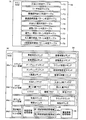
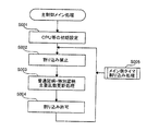
[主制御メイン処理]
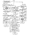
図15は、主制御メイン処理のフローチャートである。遊技制御用マイコン81は、遊技機1の電源がオンされると、メインROM83から主制御メイン処理を実行するためのプログラムを読み出す。主制御メイン処理では、遊技制御用マイコン81は、まず、初期設定をおこなう(ステップS001)。初期設定では、例えば、メインCPU82の設定、各種のフラグ、ステータスおよびカウンタなどのリセット等をおこなう。フラグの初期値は「0」つまり「OFF」であり、ステータスの初期値は「1」であり、カウンタの初期値は「0」である。なお、初期設定は、電源投入後に一度だけ実行され、それ以降は実行されない。
[Main control main processing]
FIG. 15 is a flowchart of the main control main process. When the
初期設定の後、遊技制御用マイコン81は、割り込み処理の割り込みを禁止し(ステップS002)、普通図柄・特別図柄主要乱数更新処理(ステップS003)をおこなう。この普通図柄・特別図柄主要乱数更新処理では、遊技制御用マイコン81は、図7(A)で示した種々の乱数カウンタ値(大当たり乱数値、大当たり種別乱数値、リーチ乱数値、変動パターン乱数値、普通図柄乱数値)を1加算して更新する。各乱数カウンタ値は設定された上限値に達すると「0」に戻って再び加算される。なお、各乱数カウンタの初期値は「0」以外の値であってもよく、ランダムに変更されるものであってもよい。また、各乱数は、カウンタIC等からなる公知の乱数生成回路を利用して生成されるいわゆるハードウェア乱数であってもよい。
After the initial setting, the
普通図柄・特別図柄主要乱数更新処理の後、遊技制御用マイコン81は、割り込み処理の割り込みを許可する(ステップS004)。割り込み許可中は、メイン側タイマ割り込み処理(ステップS005)の実行が可能となる。メイン側タイマ割り込み処理は、所定の周期(例えば、4msec周期)でメインCPU82に繰り返し入力される割り込みパルスに基づいて実行される。すなわち、メイン側タイマ割り込み処理は、所定周期(例えば4msec周期)ごとに実行される。そして、メイン側タイマ割り込み処理が終了してから、次にメイン側タイマ割り込み処理が開始されるまでの間に、普通図柄・特別図柄主要乱数更新処理による各種カウンタ値の更新処理が繰り返し実行される。なお、割り込み禁止状態のときに、メインCPU82に割り込みパルスが入力された場合は、メイン側タイマ割り込み処理はすぐには開始されず、割り込み許可がされてから開始される。
After the normal symbol / special symbol main random number update process, the
[メイン側タイマ割り込み処理]
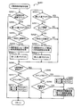
図16は、メイン側タイマ割り込み処理(図15:ステップS005)のフローチャートである。メイン側タイマ割り込み処理では、遊技制御用マイコン81は、まず、乱数更新処理をおこなう(ステップS101)。具体的には、遊技制御用マイコン81は、図7(A)で示した種々の乱数カウンタ値を更新する。この乱数更新処理は、上述した主制御メイン処理(図15)でおこなう普通図柄・特別図柄主要乱数更新処理と同じである。すなわち、各種乱数カウンタ値の更新処理は、メイン側タイマ割り込み処理の実行期間と、それ以外の期間(メイン側タイマ割り込み処理の終了後、次のメイン側タイマ割り込み処理が開始されるまでの期間)との両方でおこなわれる。
[Main timer interrupt processing]
FIG. 16 is a flowchart of the main-side timer interrupt process (FIG. 15: step S005). In the main timer interrupt process, the
乱数更新処理の後、遊技制御用マイコン81は、入力処理をおこなう(ステップS102)。入力処理では、遊技制御用マイコン81は、遊技機1に取り付けられている各種センサが検出した検出信号を読み込み、入賞口の種類に応じた賞球を払い出すための払い出しデータをメインRAM84の出力バッファにセットする。各種センサとは、例えば、第1始動口センサ20a、第2始動口センサ21a、第1大入賞口センサ30a、第2大入賞口センサ35a、普通入賞口センサ27a(図3)である。
After the random number update process, the
入力処理の後、遊技制御用マイコン81は、始動口センサ検出処理(ステップS103)、普通動作処理(ステップS104)、特別動作処理(ステップS105)、V領域センサ検出処理(ステップS106)、保留球数処理(ステップS107)を順に実行する。これらの処理の詳細については後述する。保留球数処理の後、遊技制御用マイコン81は、出力処理をおこなう(ステップS108)。出力処理では、遊技制御用マイコン81は、上述の各処理においてメインRAM84のコマンドセット領域84aにセットしたコマンド等をサブ制御基板90に出力する。出力処理の後、遊技制御用マイコン81は、その他の処理をおこなう(ステップS109)。その他の処理では、例えば、後述の特図2保留球数に基づいて第2特図保留表示器43bをその数を示す表示態様に制御し、特図1保留球数に基づいて第1特図保留表示器43aをその数を示す表示態様に制御する。
After the input process, the
[始動口センサ検出処理]
図17は、始動口センサ検出処理(図16:ステップS103)のフローチャートである。遊技制御用マイコン81は、まず、ゲート28に遊技球が通過したか否かの判定をおこなう(ステップS201)。この判定は、ゲートセンサ28aによって遊技球が検出されたか否かによっておこなわれる。ゲート28に遊技球が通過していない場合(ステップS201:NO)、処理はステップS205にスキップする。ゲート28に遊技球が通過した場合(ステップS201:YES)、遊技制御用マイコン81は、普通図柄保留球数が「4(上限値)」であるか否かの判定をおこなう(ステップS202)。普通図柄保留球数とは、普図保留の数であり、より具体的には、メインRAM84に設けられた普図保留の数をカウントするカウンタの値である。普通図柄保留球数が「4」であれば(ステップS202:YES)、処理はステップS205にスキップする。普通図柄保留球数が「3」以下の場合(ステップS202:NO)、普通図柄保留球数に「1」を加算した後(ステップS203)、普通図柄乱数取得処理をおこなう(ステップS204)。ここでは、遊技制御用マイコン81は、普通図柄乱数カウンタの値(図7:ラベル−TRND−Hの値)を取得し、取得した乱数値をメインRAM84の普図保留記憶領域86の第1〜第4記憶領域うち、現在の普通図柄保留球数に応じた記憶領域に格納する。
[Starting port sensor detection processing]
FIG. 17 is a flowchart of the start port sensor detection process (FIG. 16: Step S103). First, the
ステップS205では、遊技制御用マイコン81は、第2始動口21に遊技球が入賞したか否かの判定をおこなう。この判定は、第2始動口センサ21aによって遊技球が検出されたか否かによっておこなわれる。第2始動口21に遊技球が入賞していない場合(ステップS205:NO)、処理はステップS210にスキップする。遊技球が入賞した場合(ステップS205:YES)、遊技制御用マイコン81は、特図2保留球数が「4(上限値)」であるか否かの判定をおこなう(ステップS206)。特図2保留球数とは、第2特図保留の数であり、より具体的には、メインRAM84に設けられた第2特図保留の数をカウントするカウンタの値である。特図2保留球数が「4」であれば(ステップS206:YES)、処理はステップS210にスキップする。特図2保留球数が「3」以下の場合(ステップS206:NO)、特図2保留球数に「1」を加算した後(ステップS207)、特図2関係乱数取得処理をおこなう(ステップS208)。ここでは、大当たり乱数カウンタの値(図7:ラベル−TRND−Aの値)、大当たり種別乱数カウンタの値(図7:ラベル−TRND−ASの値)、リーチ乱数カウンタの値(図7:ラベル−TRND−RCの値)、変動パターン乱数カウンタの値(図7:ラベル−TRND−T1の値)を取得する。遊技制御用マイコン81は、取得した乱数値群を第2特図保留記憶領域85bの第1〜第4記憶領域うち、現在の特図2保留球数に応じた記憶領域に格納する。遊技制御用マイコン81は、後述の特図2事前判定処理(図18)のために、取得した乱数値群を第2特図保留記憶領域85bとは異なるバッファ(事前判定用バッファ)にも一時的に記憶(保持)させる。特図2関係乱数取得処理の後、遊技制御用マイコン81は、特図2事前判定処理をおこなう(ステップS209)。特図2事前判定処理の詳細については後述する。
In step S <b> 205, the
ステップS210では、遊技制御用マイコン81は、第1始動口20に遊技球が入賞したか否かの判定をおこなう。この判定は、第1始動口センサ20aによって遊技球が検出されたか否かによっておこなわれる。第1始動口20に遊技球が入賞していない場合(ステップS210:NO)、本処理を終了する。第1始動口20に遊技球が入賞した場合(ステップS210:YES)、遊技制御用マイコン81は、特図1保留球数が「4(上限値)」であるか否かの判定をおこなう(ステップS211)。特図1保留球数とは、第1特図保留の数であり、より具体的には、メインRAM84に設けられた第1特図保留の数をカウントするカウンタの値である。特図1保留球数が「4」であれば(ステップS211:YES)、本処理を終了する。特図1保留球数が「3」以下の場合(ステップS211:NO)、特図1保留球数に「1」を加算した後(ステップS212)、特図1関係乱数取得処理をおこなう(ステップS213)。ここでは、上述の特図2関係乱数取得処理(ステップS208)と同様に、大当たり乱数カウンタの値、大当たり種別乱数カウンタの値、リーチ乱数カウンタの値、変動パターン乱数カウンタの値を取得する。遊技制御用マイコン81は、取得した乱数値群を第1特図保留記憶領域85aの第1〜第4記憶領域うち、現在の特図1保留球数に応じた記憶領域に格納する。遊技制御用マイコン81は、後述の特図1事前判定処理(図19)のために、取得した乱数値群を第1特図保留記憶領域85aとは異なるバッファ(事前判定用バッファ)にも一時的に記憶(保持)させる。特図1関係乱数取得処理の後、遊技制御用マイコン81は、特図1事前判定処理をおこなう(ステップS214)。特図1事前判定処理の詳細については後述する。
In step S <b> 210, the
[特図2事前判定処理]
図18は、特図2事前判定処理(図17:ステップS209)のフローチャートである。遊技制御用マイコン81は、まず、確変フラグがONであるか否かの判定をおこなう(ステップS301)。確変フラグがOFFの場合(ステップS301:NO)、本処理を終える。すなわち、確変フラグがOFFの場合には、事前判定はおこなわれない。一方、確変フラグがONの場合、遊技制御用マイコン81は、大当たり判定テーブルT1(図8)のうちの高確率状態用テーブルを参照して大当たり事前判定をおこなう(ステップS302)。具体的には、遊技制御用マイコン81は、まず、特図2関係乱数取得処理(図17:ステップS208)によって事前判定用バッファに一時的に記憶されている判定値としての大当たり乱数値を取得する。次に、遊技制御用マイコン81は、参照する大当たり判定テーブルT1(図8)と大当たり乱数値とを用いて大当たりか否かの事前判定をおこなう。ここでは、高確率状態(確変フラグがON)であるため、遊技制御用マイコン81は、大当たり判定テーブルT1のうち、高確率状態用のテーブル(大当たり判定値が「0」〜「649」)を参照して大当たりか否かを事前判定する。すなわち、大当たり乱数値が「0」〜「649」のとき「大当たり」と事前判定し、それ以外の値のとき「ハズレ」と事前判定する。なお、本実施形態では、後述する大当たり判定処理(図23)で用いられる大当たり判定テーブルT1を用いて事前判定をおこなっているが、他の実施形態として、大当たり判定テーブルT1とは異なる事前判定用の大当たり判定テーブルを用いて事前判定をおこなってもよい。
[Special Figure 2 Prior Judgment Processing]
FIG. 18 is a flowchart of the special figure 2 preliminary determination process (FIG. 17: step S209). The
大当たり事前判定の結果が「ハズレ」の場合(ステップS304:NO)、処理はステップS306にスキップする。一方、大当たり事前判定の結果が「大当たり」の場合(ステップS304:YES)、遊技制御用マイコン81は、大当たり種別事前判定をおこなう(ステップS305)。大当たり種別事前判定では、遊技制御用マイコン81は、まず、特図2関係乱数取得処理(図17:ステップS208)によって事前判定用バッファに一時的に記憶されている判定値としての大当たり種別乱数値を取得する。次に、遊技制御用マイコン81は、取得した大当たり種別乱数値と大当たり種別判定テーブルT5(図9)に基づいて、大当たり種別の事前判定をおこなう。ここでは、大当たり種別乱数値が「0」〜「127」のいずれであっても「16RV通過予定大当たり」と事前判定する。なお、本実施形態では、後述する大当たり判定処理(図23)で用いられる大当たり種別判定テーブルT5を用いて事前判定をおこなっているが、他の実施形態として、大当たり種別判定テーブルT5とは異なる事前判定用の大当たり種別判定テーブルを用いて事前判定をおこなってもよい。
When the result of the big hit prior determination is “losing” (step S304: NO), the process skips to step S306. On the other hand, when the result of the jackpot prior determination is “big hit” (step S304: YES), the
ステップS306では、遊技制御用マイコン81は、変動パターン事前判定をおこなう。具体的には、遊技制御用マイコン81は、まず、特図2関係乱数取得処理(図17:ステップS208)によって事前判定用バッファに一時的に記憶されている判定値としての変動パターン乱数値、および、リーチ乱数値を取得する。次に、ここでは、時短状態(時短フラグがON)であるため、遊技制御用マイコン81は、時短状態用の変動パターン判定テーブルT6(図11)を参照し、ステップS304の大当たり事前判定結果、リーチ乱数値から得られるリーチの有無事前判定結果、および、変動パターン乱数値から変動パターンを特定する。なお、図11の変動パターン判定テーブルT6では、保留球数の違いによって選択される変動パターンが異なる場合がある。ここでは、保留球数の違いによって選択される可能性のあるすべての変動パターンが選択されるものとする。例えば、大当たり事前判定結果、および、リーチ有無事前判定結果から、リーチ有りハズレが事前判定され、変動パターン乱数値が「60」の場合、遊技制御用マイコン81は、保留球数が「1〜2」であれば選択される変動パターン「P64」と、保留球数が「3〜4」であれば選択される変動パターン「P68」の2つを選択する。なお、本実施形態では、後述する変動パターン選択処理(図24、図25)で用いられる変動パターン判定テーブルT6を用いて事前判定をおこなっているが、他の実施形態として、変動パターン判定テーブルT6とは異なる事前判定用の変動パターン判定テーブルを用いて事前判定をおこなってもよい。
In step S306, the
ステップS307では、遊技制御用マイコン81は、事前判定コマンドの作成をおこなう。事前判定コマンドには、大当たり事前判定結果、(当たりの場合には大当たり種別事前判定結果)、および、変動パターン事前判定結果が含まれる。遊技制御用マイコン81は、作成した事前判定コマンドをメインRAM84のコマンドセット領域84aにセットして(ステップS308)、本処理を終える。
In step S307, the
[特図1事前判定処理]
図19は、特図1事前判定処理(図17:ステップS214)のフローチャートである。遊技制御用マイコン81は、まず、確変フラグがONであるか否かの判定をおこなう(ステップS401)。上述の特図2事前判定処理とは反対に、確変フラグがONの場合(ステップS401:YES)、本処理を終える。すなわち、確変フラグがONの場合には、事前判定はおこなわれない。一方、確変フラグがOFFの場合(ステップS401:NO)、遊技制御用マイコン81は、大当たり判定テーブルT1(図8)のうちの通常確率状態用のテーブルを参照して大当たり事前判定をおこなう(ステップS402)。具体的には、遊技制御用マイコン81は、まず、特図1関係乱数取得処理(図17:ステップS213)によって事前判定用バッファに一時的に記憶されている判定値としての大当たり乱数値を取得する。次に、ここでは、通常確率状態(確変フラグがOFF)であるため、遊技制御用マイコン81は、大当たり判定テーブルT1のうち、通常確率状態用のテーブル(大当たり判定値が「0」〜「164」)に基づいて大当たりか否かを事前判定する。すなわち、大当たり乱数値が「0」〜「164」のとき「大当たり」と事前判定し、それ以外の値のとき「ハズレ」と事前判定する。なお、大当たり事前判定は、大当たり判定テーブルT1とは異なる事前判定用の大当たり判定テーブルを用いてもよい。以降、ステップS404〜S408の処理は、上述の特図2事前判定処理(図18)のステップS304〜S308と同様であるため説明を省略する。
[Special Figure 1 Pre-judgment process]
FIG. 19 is a flowchart of the special figure 1 preliminary determination process (FIG. 17: step S214). The
[普通動作処理]
図20は、普通動作処理(図16:ステップS104)のフローチャートである。遊技制御用マイコン81は、まず、電チュー22が作動中か否かの判定をおこなう(ステップS501)。電チュー22が作動中の場合(ステップS501:YES)、処理はステップS520に移行する。電チュー22が作動中ではない場合(ステップS501:NO)、遊技制御用マイコン81は、普通図柄の変動中か否かの判定をおこなう(ステップS502)。普通図柄の変動中の場合(ステップS502:YES)、処理はステップS508にスキップする。普通図柄の変動中ではない場合(ステップS502:NO)、遊技制御用マイコン81は、普通図柄の保留球数が「0」か否かの判定をおこなう(ステップS503)。保留球数が「0」の場合(ステップS503:YES)、本処理を終了する。保留球数が1以上ある場合(ステップS503:NO)、普通図柄保留球数を1ディクリメントする(ステップS504)。従って、普通図柄の保留球数が「0」の状態でゲート28を遊技球が通過した場合、始動口センサ検出処理(図17)のステップS203において、一旦、普通図柄の保留球数が「1」になり、その後、本ステップS504において保留が消化され即座に普通図柄の保留球数が「0」になる。これは、特別図柄の保留球数についても同様である。すなわち、始動口センサ検出処理(図17)のステップS207およびステップS212において、一旦、特別図柄の保留数が「1」になり、その後、後述の特別図柄待機処理(図22)におけるステップS1404およびステップS1410において保留が消化され特別図柄の保留球数が「0」になる。次に、遊技制御用マイコン81は、普通図柄当たり判定テーブルT3(図8(C))を参照して当たり判定をおこなう(ステップS505)。具体的には、遊技制御用マイコン81は、まず、普図保留記憶領域86の第1記憶領域(普図保留の1個目に対応)に記憶されている判定値としての普通図柄乱数値(当たり乱数値)を読み出す。そして、普通図柄乱数値と、遊技状態(時短状態か否か)と、普通図柄当たり判定テーブルT3とを用いて当たりか否かを判定する。例えば、非時短状態において、普通図柄乱数値が「0」〜「2」の場合には、「当たり」と判定され、普通図柄乱数値がそれ以外の場合には、「ハズレ」と判定される(図8(C)参照)。
[Normal operation processing]
FIG. 20 is a flowchart of the normal operation process (FIG. 16: step S104). The
次に、遊技制御用マイコン81は、普通図柄変動パターン判定テーブルT4(図8(D))を参照して変動パターンの選択をおこなう(ステップS506)。具体的には、遊技制御用マイコン81は、まず、遊技状態(時短状態か否か)の判定をおこない、遊技状態の判定結果と、普通図柄変動パターン判定テーブルT4とを用いて、普通図柄変動パターンとしての普通図柄の変動時間を選択する。ここでは、非時短状態のとき、普通図柄の変動時間は「30秒」と判定され、時短状態のとき、普通図柄の変動時間が「1秒」と判定される(図8(D)参照)。遊技制御用マイコン81は、選択した普通図柄変動パターンをセットすることで、普通図柄の変動表示を開始させる(ステップS507)。
Next, the
ステップS508では、遊技制御用マイコン81は、普通図柄の変動時間が経過して終了したか否かの判定をおこなう。普通図柄の変動時間とは、ステップS506で選択された変動時間である(図8(D)参照)。変動時間が終了していない場合(ステップS508:NO)、遊技制御用マイコン81は、本処理を終える。すなわち、普通図柄の変動表示が継続される。一方、変動時間が終了している場合(ステップS508:YES)、遊技制御用マイコン81は、変動表示を停止させ(ステップS509)、上述の当たり判定(ステップS505)において「ハズレ」の場合には(ステップS510:NO)、本処理を終える。一方、上述の当たり判定で「当たり」の場合には(ステップS510:YES)、遊技制御用マイコン81は、電チュー開放パターンのセットをおこなう(ステップS511)。電チュー22の開放パターンは、電チュー開放パターン判定テーブルT7(図12(A))を参照して選択される。具体的には、遊技制御用マイコン81は、遊技状態(時短状態か否か)の判定をおこない、遊技状態の判定結果と、電チュー開放パターン判定テーブルT7とを用いて電チュー22の開放パターンを選択する。ここでは、非時短状態のとき、「開放パターン11」が選択され、時短状態のとき、「開放パターン12」が選択される。開放パターンの選択後、遊技制御用マイコン81は、選択した開放パターンに従うように電チュー作動を開始させ(ステップS512)、本処理を終える。
In step S508, the
上述のステップS501において、電チュー22が作動中の場合(ステップS501:YES)、遊技制御用マイコン81は、電チュー22の閉鎖条件が成立しているか否かの判定をおこなう(ステップS520)。ここでの閉鎖条件は、電チュー22への入賞個数が規定の最大入賞個数(例えば6個)に達したこと、または、電チュー22の作動時間が経過して電チュー22を閉鎖させる時間に至ったことのいずれかが満たされていることである。電チュー22の作動時間とは、ステップS511で選択された開放パターンに対応する作動時間である。電チュー22の閉鎖条件が成立していない場合(ステップS520:NO)、遊技制御用マイコン81は、本処理を終える。一方、電チュー22の閉鎖条件が成立している場合(ステップS520:YES)、遊技制御用マイコン81は、電チュー22を閉鎖(閉塞)してその作動を停止し(ステップS521)、本処理を終える。
In step S501 described above, when the
[特別動作処理]
図21は、特別動作処理(図16:ステップS105)のフローチャートである。ここでは、特別図柄表示器41および大入賞装置(第1大入賞装置31および第2大入賞装置36)に関する処理を4つの段階に分け、各段階をそれぞれ「特別動作ステータス」の「1」、「2」、「3」、「4」と呼ぶ。遊技制御用マイコン81は、「特別動作ステータス」が「1」のとき(ステップS1301:YES)、特別図柄待機処理をおこなう(ステップS1302)。特別図柄待機処理では、大当たり判定や変動パターン選択等が実行される。「特別動作ステータス」が「2」のときには(ステップS1301:NO、ステップS1303:YES)、特別図柄変動中処理をおこなう(ステップS1304)。特別図柄変動中処理では、変動時間経過後に変動停止コマンドの出力等が実行される。「特別動作ステータス」が「3」のときには(ステップS1301、S1303:NO、ステップS1305:YES)、特別図柄確定処理をおこなう(ステップS1306)。特別図柄確定処理では、大当たり時にオープニングコマンドの出力等が実行される。「特別動作ステータス」が「4」のときには(ステップS1301、S1303、S1305:NO)、特別電動役物処理をおこなう(ステップS1308)。特別電動役物処理では、大当たり遊技が実行される。上記の各処理の詳細については後述する。なお、特別動作ステータスは、初期設定では「1」である。
[Special action processing]
FIG. 21 is a flowchart of the special operation process (FIG. 16: step S105). Here, the processing related to the special symbol display device 41 and the special prize winning device (the first big
[特別図柄待機処理]
図22は、特別図柄待機処理(図21:ステップS1302)のフローチャートである。特別図柄待機処理では、遊技制御用マイコン81は、まず、特図2保留球数が「0」であるか否かの判定をおこなう(ステップS1401)。特図2保留球数が「0」である場合(ステップS1401:YES)、すなわち、第2特図保留記憶領域85bに、第2始動口21への入賞に起因して取得した乱数値群の記憶がない場合には、処理はステップS1407に移行する。特図2保留球数が「1」以上である場合(ステップS1401:NO)、遊技制御用マイコン81は、大当たり判定処理(ステップS1402)、および、変動パターン選択処理(ステップS1403)を実行する。これらの処理の詳細については後述する。変動パターン選択処理の後、特図2保留球数を1つディクリメントする(ステップS1404)。次に、遊技制御用マイコン81は、第2特図保留記憶領域85bの第1〜第4記憶領域に格納されている保留情報(各種乱数値)の格納場所を現在の位置から読み出される側に1つシフトするとともに、第2特図保留記憶領域85bにおいて読み出される側から最も遠い場所に格納されている保留情報をクリアする(ステップS1405)。例えば、第1〜第3記憶領域に保留情報が格納されている場合には、第3記憶領域に格納されている保留情報をクリアし、第1〜第4記憶領域に保留情報が格納されている場合には、第4記憶領域に格納されている保留情報をクリアする。上記ステップによって、第2特図保留が保留された順に消化される。この場合、画像表示装置7の表示画面7aでは、第2特図保留記憶領域85bの第1記憶領域に対応する保留画像9B(4つの保留画像9Bのうち、一番左端の保留画像9B)が保留消化画像表示領域側にシフトし、保留消化画像9Cとして表示される。また、第2特図保留記憶領域85bの第2〜第4記憶領域に対応する保留画像9B(4つの保留画像9Bのうち、左から2、3、4番目の保留画像9B)がそれぞれ左側に1つシフトする(図1)。これにより、遊技者は、第2特図保留が1つ消化されたことを認識することができる。次に、遊技制御用マイコン81は、特図2変動開始処理をおこなう(ステップS1406)。特図2変動開始処理では、変動開始コマンドをメインRAM84のコマンドセット領域84aにセットし、第2特別図柄の変動表示を開始させるとともに、変動時間タイマのセットをおこなう。変動時間タイマには、変動パターン選択処理で選択された変動パターンに応じて決定される変動時間がセットされる。また、遊技制御用マイコン81は、特別動作ステータスを「2」にセットする。なお、特図2変動開始処理でセットされる変動開始コマンド(特図2変動開始コマンド)には、大当たり判定処理(ステップS1402)でセットされた特図停止図柄データに関する情報や変動パターン選択処理(ステップS1403)でセットされた変動パターンに関する情報(変動時間に関する情報を含む)が含まれている。
[Special symbol standby processing]
FIG. 22 is a flowchart of the special symbol standby process (FIG. 21: Step S1302). In the special symbol standby process, the
ステップS1401において、特図2保留球数が「0」の場合(ステップS1401:YES)、遊技制御用マイコン81は、特図1保留球数が「0」であるか否かの判定をおこなう(ステップS1407)。特図1保留球数が「0」である場合(ステップS1407:YES)、すなわち、第1特図保留記憶領域85aに、第1始動口20への入賞に起因して取得した乱数値群の記憶がない場合には、処理はステップS1413に移行する。特図1保留球数が「1」以上である場合(ステップS1407:NO)、遊技制御用マイコン81は、大当たり判定処理(ステップS1408)、および、変動パターン選択処理(ステップS1409)を実行する。これらの処理の詳細については後述する。変動パターン選択処理の後、特図1保留球数を1つディクリメントする(ステップS1410)。次に、遊技制御用マイコン81は、第1特図保留記憶領域85aの第1〜第4記憶領域に格納されている各種乱数値の格納場所を現在の位置から読み出される側に1つシフトするとともに、第1特図保留記憶領域85aにおいて読み出される側から最も遠い場所に格納されている保留情報をクリアする(ステップS1411)。上記ステップによって、第1特図保留が保留された順に消化される。この場合、画像表示装置7の表示画面7aでは、第1特図保留記憶領域85aの第1記憶領域に対応する保留画像9A(4つの保留画像9Aのうち、一番右端の保留画像9A)が保留消化画像表示領域側にシフトし、保留消化画像9Cとして表示される。また、第1特図保留記憶領域85aの第2〜第4記憶領域に対応する保留画像9A(4つの保留画像9Aのうち、左から2、3、4番目の保留画像9A)がそれぞれ右側に1つシフトする(図1)。これにより、遊技者は、第1特図保留が1つ消化されたことを認識することができる。次に、遊技制御用マイコン81は、特図1変動開始処理をおこなう(ステップS1412)。特図1変動開始処理では、変動開始コマンドをメインRAM84のコマンドセット領域84aにセットし、第1特別図柄の変動表示を開始させるとともに、変動時間タイマのセットをおこなう。変動時間タイマには、変動パターン選択処理で選択された変動パターンに応じて決定される変動時間がセットされる。また、遊技制御用マイコン81は、特別動作ステータスを「2」にセットする(ステップS1406)。なお、特図1変動開始処理でセットされる変動開始コマンド(特図1変動開始コマンド)には、大当たり判定処理(ステップS1408)でセットされた特図停止図柄データに関する情報や変動パターン選択処理(ステップS1409)でセットされた変動パターンに関する情報(変動時間に関する情報を含む)が含まれている。
In step S1401, when the special figure 2 reserved ball number is "0" (step S1401: YES), the
ステップS1407において、特図1保留球数が「0」の場合(ステップS1407:YES)、遊技制御用マイコン81は、画像表示装置7の表示画面7aが待機画面か否かの判定をおこなう(ステップS1413)。待機画面とは、客待ち用のデモ画面のことである。遊技制御用マイコン81は、例えば、客待ち用のデモ画面表示フラグのON/OFFによって判定してもよい。待機画面である場合(ステップS1413:YES)、本処理を終了する。待機画面でない場合(ステップS1413:NO)、遊技制御用マイコン81は、所定の待機時間の経過をまって、待機場面を表示させるための客待ち待機コマンドをメインRAM84のコマンドセット領域84aにセットし(ステップS1414)、本処理を終える。上記のように、本実施形態の特別図柄待機処理によれば、第1特図保留に基づく特別図柄の変動表示は、第2特図保留が「0」の場合に限って実行される。すなわち、第2特図保留の消化は、第1特図保留の消化に優先して実行される。また、本実施形態の大当たり種別判定テーブルT5によれば、第2特図保留に基づく抽選の方が、第1特図保留に基づく抽選よりも遊技者にとって利益の大きい大当たり(V通過予定大当たり)に当選しやすくなっている。
In step S1407, if the special figure 1 reserved ball number is “0” (step S1407: YES), the
[大当たり判定処理]
図23は、大当たり判定処理(図22:ステップS1402、S1408)のフローチャートである。特図2の大当たり判定処理(ステップS1402)と特図1の大当たり判定処理(ステップS1408)は処理の流れが同様であるため、まとめて説明する。大当たり判定処理では、まず、遊技制御用マイコン81は、確変フラグがONであるか否かの判定をおこなう(ステップS1501)。確変フラグがONの場合(ステップS1501:YES)、大当たり判定テーブルT1(図8)のうちの高確率状態用テーブルを参照して大当たり判定をおこなう(ステップS1502)。具体的には、遊技制御用マイコン81は、まず、判定値としての大当たり乱数値の読み出しをおこなう。例えば、特図2の大当たり判定処理では、第2特図保留記憶領域85bの第1記憶領域(第2特図保留の1個目に対応)に記憶されている大当たり乱数値を読み出す。特図1の大当たり判定処理では、第1特図保留記憶領域85aの第1記憶領域(第1特図保留の1個目に対応)に記憶されている大当たり乱数値を読み出す。次に、遊技制御用マイコン81は、参照する大当たり判定テーブルT1と大当たり乱数値とを用いて大当たりか否かを判定する。ここでは、高確率状態(確変フラグがON)であるため、大当たり判定テーブルT1のうち、高確率状態用のテーブル(大当たり判定値が「0」〜「649」)に基づいて大当たりか否かを判定する。
[Big hit judgment processing]
FIG. 23 is a flowchart of the jackpot determination process (FIG. 22: steps S1402 and S1408). The jackpot determination process (step S1402) in FIG. 2 and the jackpot determination process (step S1408) in FIG. 1 are the same in processing flow, and will be described together. In the jackpot determination process, first, the
ステップS1501において、確変フラグがOFFの場合(ステップS1501:NO)、遊技制御用マイコン81は、大当たり判定テーブルT1(図8)のうちの通常確率状態用のテーブルを参照して大当たり判定をおこなう(ステップS1504)。具体的には、遊技制御用マイコン81は、まず、ステップS1502と同様の方法によって大当たり乱数値の読み出しをおこなう。次に、ここでは、通常確率状態(確変フラグがOFF)であるため、大当たり判定テーブルT1のうち、通常確率状態用のテーブル(大当たり判定値が「0」〜「164」)に基づいて大当たりか否かを判定する。
When the probability variation flag is OFF in step S1501 (step S1501: NO), the
大当たり判定の結果が「大当たり」の場合(ステップS1503、S1505:YES)、遊技制御用マイコン81は、大当たりフラグをONにするとともに(ステップS1506)、大当たり種別の判定をおこなう(ステップS1507)。具体的には、遊技制御用マイコン81は、まず、判定値としての大当たり種別乱数値の読み出しをおこなう。例えば、特図2の大当たり判定処理では、第2特図保留記憶領域85bの第1記憶領域に記憶されている大当たり種別乱数値を読み出す。特図1の大当たり判定処理では、第1特図保留記憶領域85aの第1記憶領域に記憶されている大当たり種別乱数値を読み出す。次に、遊技制御用マイコン81は、読み出した大当たり種別乱数値と大当たり種別判定テーブルT5(図9)に基づいて、大当たり種別の判定をおこなう。大当たり種別の判定後、特定された大当たり種別に応じた特図停止図柄データ(図9)をメインRAM84に設けた大当たり種別バッファにセットして(ステップS1520)、本処理を終了する。一方、ステップS1503またはステップS1505において、大当たり判定の結果が「ハズレ」の場合、ハズレ図柄に応じた特図停止図柄データ(01H)をメインRAM84に設けた大当たり種別バッファにセットして(ステップS1520)、本処理を終了する。
When the result of the jackpot determination is “big hit” (steps S1503, S1505: YES), the
[変動パターン選択処理]
図24および図25は、変動パターン選択処理(図22:ステップS1403、S1409)のフローチャートである。特図2の変動パターン選択処理(ステップS1403)と特図1の変動パターン選択処理(ステップS1409)は処理の流れが同様であるため、まとめて説明する。変動パターン選択処理では、まず、遊技制御用マイコン81は、遊技状態が時短状態であるか否かの判定をおこなう(ステップS1600)。時短状態であるか否かの判定は、時短フラグがONか否かによっておこなわれる。時短状態である場合(ステップS1600:YES)、処理はステップS1612に移行する。時短状態でない場合(ステップS1600:NO)、遊技制御用マイコン81は、大当たりフラグがONか否かの判定をおこなう(ステップS1602)。大当たりフラグがOFFの場合(ステップS1602:NO)、処理はステップS1607に移行する。大当たりフラグがONの場合(ステップS1602:YES)、遊技制御用マイコン81は、大当たりが特図2か否かの判定をおこなう(ステップS1603)。大当たりが特図2の場合(ステップS1603:YES)、大当たり種別が必ずV通過予定大当たりとなるため、処理はステップS1605にスキップする。大当たりが特図1の場合(ステップS1603:NO)、遊技制御用マイコン81は、大当たり種別がV通過予定大当たりか否かの判定をおこなう(ステップS1604)、大当たり種別の判定は、メインRAM84にセットされている特図停止図柄データに基づいておこなわれる。
[Variation pattern selection processing]
24 and 25 are flowcharts of the variation pattern selection process (FIG. 22: steps S1403 and S1409). The variation pattern selection process (step S1403) in FIG. 2 and the variation pattern selection process (step S1409) in FIG. 1 have the same process flow and will be described together. In the variation pattern selection process, first, the
大当たり種別がV通過予定大当たりの場合(ステップS1604:YES)、遊技制御用マイコン81は、変動パターン判定テーブルT6(図10)のうち、非時短状態V通過予定大当たり用のテーブルを参照して変動パターンの選択をおこなう(ステップS1605)。具体的には、遊技制御用マイコン81は、まず、判定値としての変動パターン乱数値の読み出しをおこなう。例えば、特図2の変動パターン選択処理では、第2特図保留記憶領域85bの第1記憶領域(第2特図保留の1個目に対応)に記憶されている変動パターン乱数値を読み出す。特図1の変動パターン選択処理では、第1特図保留記憶領域85aの第1記憶領域(第1特図保留の1個目に対応)に記憶されている変動パターン乱数値を読み出す。次に、遊技制御用マイコン81は、変動パターン判定テーブルT6と変動パターン乱数値とを用いて変動パターンを選択する。ここでは、非時短状態V通過予定大当たり用のテーブルとして、図10に示す非時短状態用の変動パターン判定テーブルT6のうち、V通過予定大当たりに該当する部分(特図1では変動パターンが「P1」〜「P3」の部分、特図2では変動パターンが「P21」〜「P23」の部分)が参照される(アドレスがセットされる)。読み出した変動パターン乱数値から、特図1では変動パターンとして「P1」〜「P3」のいずれか、特図2では「P21」〜「P23」のいずれかが選択される。
When the jackpot type is a V passing planned jackpot (step S1604: YES), the
大当たり種別がV非通過予定大当たりの場合(ステップS1604:NO)、遊技制御用マイコン81は、変動パターン判定テーブルT6(図10)のうち、非時短状態V非通過予定大当たり用のテーブルを参照して変動パターンの選択をおこなう(ステップS1606)。ここでは、非時短状態V非通過予定大当たり用のテーブルとして、図10に示す非時短状態用の変動パターン判定テーブルT6のうち、V非通過予定大当たりに該当する部分(「P4」〜「P6」の部分)が参照される。読み出した変動パターン乱数値から、変動パターンとして「P4」〜「P6」のいずれかが選択される。
When the jackpot type is a V non-passing expected jackpot (step S1604: NO), the
ステップS1602において、大当たりフラグがOFFの場合(ステップS1602:NO)、遊技制御用マイコン81は、リーチ乱数値がリーチ成立乱数値か否かの判定をおこなう(ステップS1607)。具体的には、遊技制御用マイコン81は、まず、判定値としてのリーチ乱数値の読み出しをおこなう。特図2の変動パターン選択処理では、第2特図保留記憶領域85bの第1記憶領域(第2特図保留の1個目に対応)に記憶されているリーチ乱数値を読み出す。特図1の変動パターン選択処理では、第1特図保留記憶領域85aの第1記憶領域(第1特図保留の1個目に対応)に記憶されているリーチ乱数値を読み出す。次に、遊技制御用マイコン81は、リーチ判定テーブルT2(図8(B))と、リーチ乱数値とを用いてリーチの有無を判定する。ここでは、非時短状態であるため、リーチ判定テーブルT2のうち、非時短状態用のテーブル(リーチ有り判定値(リーチ成立乱数値)が「0」〜「13」の部分)に基づいてリーチの有無を判定する。
If the jackpot flag is OFF in step S1602 (step S1602: NO), the
リーチ乱数値がリーチ成立乱数値である場合(ステップS1607:YES)、すなわち、リーチ有りハズレの場合には、遊技制御用マイコン81は、変動パターン判定テーブルT6(図10)のうち、非時短状態リーチ有りハズレ用のテーブルを参照して変動パターンの選択をおこなう(ステップS1608)。ここでは、非時短状態リーチ有りハズレ用のテーブルとして、図10に示す非時短状態用の変動パターン判定テーブルT6のうち、リーチ有りハズレに該当する部分(特図1では変動パターンが「P7」〜「P14」の部分、特図2では変動パターンが「P24」〜「P31」の部分)が参照される。特図1では、読み出した変動パターン乱数値と、現在の特図1保留球数(1〜4)から、変動パターンとして「P7」〜「P14」のいずれかが選択される。特図2では、読み出した変動パターン乱数値と、現在の特図2保留球数(1〜4)から、変動パターンとして「P24」〜「P31」のいずれかが選択される。保留球数によって選択される変動パターンが変わるため、保留球数に応じた短縮変動の機能が働くようになっている。すなわち、特図1および特図2のいずれにおいても、保留球数が「3」〜「4」であるときは、保留球数が「1」〜「2」であるときに比べて変動時間の短い変動パターンがより多く選択されるようになっている。これにより、保留球数が多いときに特図保留の消化スピードを速めることができる。
When the reach random number value is a reach establishment random number value (step S1607: YES), that is, when the reach is lost, the
リーチ乱数値がリーチ成立乱数値ではない場合(ステップS1607:NO)、すなわち、リーチ無しハズレの場合には、遊技制御用マイコン81は、変動パターン判定テーブルT6(図10)のうち、非時短状態リーチ無しハズレ用のテーブルを参照して変動パターンの選択をおこなう(ステップS1609)。ここでは、非時短状態リーチ無しハズレ用のテーブルとして、図10に示す非時短状態用の変動パターン判定テーブルT6のうち、リーチ無しハズレに該当する部分(特図1では変動パターンが「P15」〜「P16」の部分、特図2では変動パターンが「P32」〜「P33」の部分)が参照される。特図1では、読み出した変動パターン乱数値と、現在の特図1保留球数(1〜4)から、変動パターンとして「P15」、「P16」のいずれかが選択される。特図2では、読み出した変動パターン乱数値と、現在の特図2保留球数(1〜4)から、変動パターンとして「P32」、「P33」のいずれかが選択される。ここでも、保留球数によって選択される変動パターンが変わるため、保留球数に応じた短縮変動の機能が働くようになっている。
When the reach random number value is not the reach establishment random number value (step S1607: NO), that is, in the case of no reach reach, the
ステップS1600において、遊技状態が時短状態であると判定した場合には、遊技制御用マイコン81は、大当たりフラグがONか否かの判定をおこなう(図25:ステップS1612)。以後、ステップS1613〜S1619の処理は、以下の点を除いては上述のステップS1603〜S1609の処理と同様であるため説明を省略する。ステップS1613〜S1619の処理とステップS1603〜S1609の処理との違いは、ステップS1615、S1616、S1618、S1619において、参照される変動パターン判定テーブルT6の部分が既述のステップS1605、S1606、S1608、S1609と異なる。具体的には、S1605、S1606、S1608、S1609では、非時短状態用の変動パターン判定テーブルT6(図10)が参照されるのに対して、ステップS1615、S1616、S1618、S1619では、時短状態用の変動パターン判定テーブルT6(図11)が参照される。例えば、ステップS1615の場合、すなわち、大当たり種別がV通過予定大当たりの場合、図11に示す時短状態用の変動パターン判定テーブルT6のうち、V通過予定大当たりに該当する部分(特図1では変動パターンが「P41」〜「P43」の部分、特図2では変動パターンが「P61」〜「P63」の部分)が参照される。読み出した変動パターン乱数値から、特図1では変動パターンとして「P41」〜「P43」のいずれか、特図2では「P61」〜「P63」のいずれかが選択される。また、例えば、ステップS1616の場合、すなわち、大当たり種別がV非通過予定大当たりの場合、図11に示す時短状態用の変動パターン判定テーブルT6のうち、V非通過予定大当たりに該当する部分(「P44」〜「P46」の部分)が参照される。読み出した変動パターン乱数値から、変動パターンとして「P44」〜「P46」のいずれかが選択される。
If it is determined in step S1600 that the gaming state is the short-time state, the
上記のように変動パターンの選択をおこなった後、遊技制御用マイコン81は、選択した変動パターンをセットして(ステップS1630)本処理を終える。セットされた変動パターンの情報は変動開始コマンドに含められて、出力処理(図16:ステップS108)においてサブ制御基板90に送信される。これにより特別図柄の変動表示が開始される。
After selecting the variation pattern as described above, the
[特別図柄変動中処理]
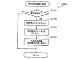
図26は、特別図柄変動中処理(図21:ステップS1304)のフローチャートである。遊技制御用マイコン81は、まず、特別図柄の変動時間が経過して終了したか否かの判定をおこなう(ステップS1701)。特別図柄の変動時間とは、上述の変動パターン選択処理(図24、図25)で選択された変動パターンに応じて決定される変動時間である。変動時間が終了していない場合(ステップS1701:NO)、本処理を終える。すなわち、特別図柄待機処理(図22)のステップS1406またはS1412において開始された特別図柄の変動表示が継続される。一方、変動時間が終了している場合(ステップS1701:YES)、変動停止コマンドをセットし(ステップS1702)、特別動作ステータスを「3」にセットする(ステップS1703)。また、遊技制御用マイコン81は、変動停止にともなうその他の処理をおこなう(ステップS1704)。例えば、遊技制御用マイコン81は、特別図柄の変動表示を、セットされている特図停止図柄データに応じた図柄で停止させる処理等をおこなう。その後、遊技制御用マイコン81は、本処理を終える。
[Special symbol change processing]
FIG. 26 is a flowchart of the special symbol changing process (FIG. 21: step S1304). First, the
[特別図柄確定処理]
図27は、特別図柄確定処理(図21:ステップS1306)のフローチャートである。遊技制御用マイコン81は、まず、遊技状態管理処理をおこなう(ステップS1801)。遊技状態管理処理とは、ST回数や時短回数を管理するための処理であり内容について後述する。遊技状態管理処理の後、大当たりフラグがONであるか否かの判定をおこなう(ステップS1802)。大当たりフラグがOFFである場合(ステップS1802:NO)、遊技制御用マイコン81は、特別動作ステータスを「1」にセットして(ステップS1808)、本処理を終了する。これにより、大当たり遊技は開始されず、再度、特別図柄待機処理(図22)に移行し、次の保留に対する大当たり判定等が実行される。
[Special symbol confirmation processing]
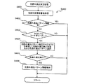
FIG. 27 is a flowchart of the special symbol confirmation process (FIG. 21: step S1306). The
大当たりフラグがONの場合(ステップS1802:YES)、遊技制御用マイコン81は、当選した大当たりの種別に応じた大入賞口およびV開閉部材の開放パターンのセットをおこなう(ステップS1803)。具体的には、遊技制御用マイコン81は、大入賞口開放パターン判定テーブルT8(図13)を参照して、特図停止図柄データから大入賞口の開放パターンを決定し、決定した開放パターンをセットする。例えば、特図停止図柄データが「11H」の場合には、大入賞口の開放パターンとして「開放パターン21」がセットされる。また、遊技制御用マイコン81は、V開閉部材開放パターン判定テーブルT9(図14)を参照して、特図停止図柄データからV開閉部材71の開放パターンを決定し、決定した開放パターンをセットする。例えば、特図停止図柄データが「11H」の場合には、V開閉部材71の開放パターンとして「開放パターン31」がセットされる。大入賞口およびV開閉部材の開放パターンのセットとあわせてラウンドカウンタの値を、当選した大当たりの種類に応じたラウンド数にセットする。ラウンドカウンタとは、大当たり遊技中に実行した単位開放遊技(ラウンド遊技)の回数をカウントするものである。ここでは、ラウンドカウンタには「16」がセットされる(図13(B))。
If the jackpot flag is ON (step S1802: YES), the
開放パターンのセット後、遊技制御用マイコン81は、遊技状態リセット処理をおこなう(ステップS1804)。遊技状態リセット処理とは、確変フラグや時短フラグをリセットする(OFFに戻す)ための処理であり内容について後述する。遊技状態リセット処理の後、大当たり遊技を開始するために、大当たりのオープニングコマンドをセットし(ステップS1805)、オープニングを開始する(ステップS1806)。その後、特別動作ステータスを「4」にセットして(ステップS1807)、本処理を終える。
After the opening pattern is set, the
[遊技状態管理処理]
図28は、遊技状態管理処理(図27:ステップS1801)のフローチャートである。遊技制御用マイコン81は、まず、確変フラグがONか否かの判定をおこなう(ステップS2001)。確変フラグがOFFの場合(ステップS2001:NO)、処理はステップS2005にスキップする。確変フラグがONの場合(ステップS2001:YES)、確変カウンタの値を1ディクリメントする(ステップS2002)。確変カウンタとは、高確率状態中に実行した特別図柄の変動回数をカウントするものである。ここでは、高確率状態への移行時に確変カウンタに「160」がセットされる。遊技制御用マイコン81は、確変カウンタを1ディクリメントした結果、カウンタの値が「0」になったか否かの判定をおこなう(ステップS2003)。確変カウンタの値が「0」ではない場合(ステップS2003:NO)、処理はステップS2005にスキップする。確変カウンタの値が「0」の場合(ステップS2003:YES)、確変フラグをOFFに切り替える(ステップS2004)。
[Game state management processing]
FIG. 28 is a flowchart of the game state management process (FIG. 27: step S1801). The
ステップS2005では、遊技制御用マイコン81は、時短フラグがONか否かの判定をおこなう。時短フラグがOFFの場合(ステップS2005:NO)、処理はステップS2009にスキップする。時短フラグがONの場合(ステップS2005:YES)、時短カウンタの値を1ディクリメントする(ステップS2006)。時短カウンタとは、時短状態中に実行した特別図柄の変動回数をカウントするものである。ここでは、時短状態への移行時に、低確高ベース状態であれば時短カウンタに「100」がセットされ、高確高ベース状態であれば時短カウンタに「160」がセットされる。遊技制御用マイコン81は、時短カウンタを1ディクリメントした結果、カウンタの値が「0」になったか否かの判定をおこなう(ステップS2007)。時短カウンタの値が「0」ではない場合(ステップS2007:NO)、処理はステップS2009にスキップする。時短カウンタの値が「0」の場合(ステップS2007:YES)、時短フラグをOFFに切り替える(ステップS2008)。
In step S2005, the
ステップS2009では、遊技制御用マイコン81は、遊技状態指定コマンドをメインRAM84のコマンドセット領域(出力バッファ)84aにセットして、本処理を終える。遊技状態指定コマンドには、今設定した現在の遊技状態に関する情報(確変状態か否か、確変カウンタ値、時短状態か否か、時短カウンタ値など)が含まれている。
In step S2009, the
[遊技状態リセット処理]
図29は、遊技状態リセット処理(図27:ステップS1804)のフローチャートである。遊技制御用マイコン81は、まず、確変フラグがONか否かの判定をおこなう(ステップS2101)。確変フラグがOFFの場合(ステップS2101:NO)、処理はステップS2103にスキップする。確変フラグがONの場合(ステップS2101:YES)、確変フラグをOFFに切り替える(ステップS2102)。ステップS2103において、遊技制御用マイコン81は、時短フラグがONか否かの判定をおこなう。時短フラグがOFFの場合(ステップS2103:NO)、本処理を終える。時短フラグがONの場合(ステップS2103:YES)、時短フラグをOFFに切り替える(ステップS2104)。つまり、大当たり遊技の実行中は、非高確率状態かつ非時短状態となる。遊技機1では、非時短状態時は常に低ベース状態となるため、大当たり遊技の実行中は低ベース状態となる。
[Game state reset processing]
FIG. 29 is a flowchart of the gaming state reset process (FIG. 27: step S1804). The
[特別電動役物処理]
図30は、特別電動役物処理(図21:ステップS1308)のフローチャートである。遊技制御用マイコン81は、まず、大当たり終了フラグがONか否かの判定をおこなう(ステップS2200)。「大当たり終了フラグ」とは、実行中の大当たり遊技において、開放パターンに基づく大入賞装置(第1大入賞装置31および第2大入賞装置36)の開放がすべて終了したことを示すフラグである。大当たり終了フラグがONの場合(ステップS2200:YES)、処理はステップS2230に移行する。大当たり終了フラグがOFFの場合(ステップS2200:NO)、V開閉部材71を作動させるためのV開閉部材動作処理をおこなう(ステップS2201)。本実施形態のV開閉部材71は、第1大入賞口30に所定個数の遊技球が入賞した時に作動するように構成されており、V開閉部材動作処理では、V開閉部材開放パターンT9に応じて所定番目の遊技球の入賞時にV開閉部材71を所定期間開放させる。V開閉部材動作処理の詳細については後述する。V開閉部材動作処理の後、遊技制御用マイコン81は、大入賞口(第1大入賞口30および第2大入賞口35)が開放中か否かの判定をおこなう(ステップS2202)。開放中の場合(ステップS2202:YES)、処理はステップS2210に移行する。
[Special electric material processing]
FIG. 30 is a flowchart of the special electric accessory process (FIG. 21: step S1308). The
大入賞口が開放中ではない場合(ステップS2202:NO)、遊技制御用マイコン81は、大入賞口を開放する時間(タイミング)か否かの判定をおこなう(ステップS2203)。大入賞口を開放する時間には、例えば、大当たりのオープニングの時間が経過して初回のラウンド遊技における開放開始の時期に至ったときや、開放後に一時的に閉鎖した大入賞口を再び開放させるまでのインターバル時間(閉鎖時間)が経過して、再度の開放開始の時期に至ったときが含まれる。大入賞口を開放する時間ではない場合(ステップS2203:NO)、処理はステップS2220に移行する。
If the special winning opening is not open (step S2202: NO), the
大入賞口を開放する時間(タイミング)である場合(ステップS2203:YES)、遊技制御用マイコン81は、大入賞口開放処理をおこなう(ステップS2207)。具体的には、遊技制御用マイコン81は、大当たりの種類に応じた開放パターン(図13)に従って大入賞口(第1大入賞口30または第2大入賞口35)を開放させる。大入賞口開放処理の後、遊技制御用マイコン81は、ラウンド指定コマンドのセットをおこなう(ステップS2208)。ラウンド指定コマンドには、実行中の大当たり遊技のラウンド数に関する情報が含まれており、遊技制御用マイコン81は、ラウンド指定コマンドをメインRAM84の出力バッファにセットする。なお、本実施形態では、1回のラウンド遊技中に複数回の大入賞口の開放がなされることがない。しかし、他の実施形態として、1回のラウンド遊技中に複数回の大入賞口の開放がなされる場合には、遊技制御用マイコン81は、大入賞口の開放が1回のラウンド中での初めての開放か否かを判定し、初めての開放の場合のみ、ラウンド指定コマンドをセットするようにしてもよい。ラウンド指定コマンドをセットした後、本処理を終える。
When it is time (timing) for opening the big winning opening (step S2203: YES), the
上述のステップS2202において、大入賞口の開放中の場合(ステップS2202:YES)、遊技制御用マイコン81は、大入賞口の閉鎖条件が成立しているか否かの判定をおこなう(ステップS2210)。ここでの閉鎖条件は、そのラウンド遊技における大入賞口への入賞個数が規定の最大入賞個数(例えば、1ラウンドあたり9個)に達したこと、または、大入賞口を閉鎖させる時間に至ったこと(すなわち、大入賞口を開放してから所定の開放時間(図13)が経過したこと)のいずれかが満たされていることである。そして、大入賞口の閉鎖条件が成立していなければ(ステップS2210:NO)、遊技制御用マイコン81は、本処理を終える。一方、大入賞口の閉鎖条件が成立している場合には(ステップS2210:YES)、遊技制御用マイコン81は、大入賞口を閉鎖(閉塞)する(ステップS2211)。
In the above-described step S2202, when the special winning opening is being opened (step S2202: YES), the
上述のステップS2203において、大入賞口を開放する時間(タイミング)ではない場合、遊技制御用マイコン81は、当該ラウンド遊技が終了しているか否かの判定をおこなう(ステップS2220)。ここでは1回のラウンドは、大入賞口が閉鎖してから所定の時間(ここでは2秒)経過後に終了する。上述のように、ラウンド遊技間の大入賞口の閉鎖の時間(インターバル時間)は、その閉鎖前の開放ラウンド遊技に含まれるためである。遊技制御用マイコン81は、大入賞口を閉鎖してから所定のインターバル時間が経過したか否かによって、当該ラウンド遊技が終了しているか否かの判定をおこなう。当該ラウンド遊技が終了していない場合(ステップS2220:NO)、遊技制御用マイコン81は本処理を終了する。
If it is not the time (timing) for opening the big winning opening in the above-described step S2203, the
当該ラウンド遊技が終了している場合(ステップS2220:YES)、遊技制御用マイコン81は、ラウンドカウンタの値を1ディクリメンとし(ステップS2221)、ラウンドカウンタの値が「0」であるか否かの判定をおこなう(ステップS2226)。ラウンドカウンタの値が「0」でなはい場合(ステップS2226:NO)、すなわち、規定のラウンド遊技回数をまだ消化していない場合、次のラウンド遊技を開始するために本処理を終える。一方、ラウンドカウンタの値が「0」の場合、大当たり遊技を終了させる大当たり終了処理として、大当たりのエンディングコマンドをセットするとともに(ステップS2227)、大当たりのエンディングを開始する(ステップS2228)。本実施形態では、「16R(実質13R)V通過予定大当たり」でV領域39への遊技球の通過があった場合のエンディング時間(例えば18秒)は、「16R(実質13R)V非通過予定大当たり」でV領域39への遊技球の通過が無かった場合のエンディング時間と同じ長さになっている。これにより、遊技者に対して、「16R(実質13R)V通過予定大当たり」でV領域39への遊技球の通過があった場合であっても、「16R(実質13R)V非通過予定大当たり」でV領域39への遊技球の通過が無かったと認識させることができる。なお、「16R(実質13R)V通過予定大当たり」でV領域39への遊技球の通過が無かった場合のエンディング時間もこれらと同じ長さになっている。大当たりのエンディングの開始後、大当たり終了フラグをONにセットして(ステップS2229)、本処理を終える。
When the round game has ended (step S2220: YES), the
上述のステップS2200において、大当たり終了フラグがONの場合(ステップS2200:YES)、最終ラウンドが終了しているので、遊技制御用マイコン81は、大当たりのエンディングの時間が経過したか否かを判定する(ステップS2230)。エンディング時間が経過していない場合(ステップS2230:NO)、遊技制御用マイコン81は、本処理を終える。一方、エンディング時間が経過している場合(ステップS2230:YES)、遊技制御用マイコン81は、大当たり終了フラグをOFFにするとともに(ステップS2231)、大当たりフラグをOFFにし(ステップS2232)、特別動作ステータスを「1」にセットする(ステップS2233)。これにより、次回の特別動作処理において、再び特別図柄待機処理(ステップS1302)が実行される。その後、後述の遊技状態設定処理(ステップS2234)を実行し本処理を終える。
In the above-described step S2200, when the jackpot end flag is ON (step S2200: YES), since the final round has ended, the
[V開閉部材動作処理]
図31は、V開閉部材動作処理(図30:ステップS2201)のフローチャートである。遊技制御用マイコン81は、まず、現在のラウンド遊技(当該ラウンド)がV開閉部材71の開放ラウンドであるか否かの判定をおこなう(ステップS2501)。ここでは、第2ラウンド,第4ラウンド,第6ラウンド,第8ラウンド,第10ラウンド,第12ラウンドがV開閉部材71の開放ラウンドに該当する。遊技制御用マイコン81は、ラウンドカウンタの値が「15」,「13」,「11」,「9」,「7」,「5」のとき、開放ラウンドであると判定することができる。V開閉部材71の開放ラウンドではない場合(ステップS2501:NO)、本処理を終える。当該ラウンドにおいてV開閉部材71を作動させる必要がないためである。
[V opening / closing member operation processing]
FIG. 31 is a flowchart of the V opening / closing member operation process (FIG. 30: step S2201). The
V開閉部材71の開放ラウンドである場合(ステップS2501:YES)、遊技制御用マイコン81は、第1入賞フラグがONか否かの判定をおこなう(ステップS2502)。「第1入賞フラグ」とは、当該ラウンドにおいて、第1大入賞口30に1球目の入賞があったことを示すフラグである。第1入賞フラグがONの場合(ステップS2502:YES)、処理はステップS2520に移行する。第1入賞フラグがOFFの場合(ステップS2502:NO)、1球目の入賞を検出したか否かの判定をおこなう(ステップS2503)。1球目の入賞を検出していない場合(ステップS2503:NO)、本処理を終える。当該ラウンドにおいて第1大入賞口30への入賞がまだなく、V開閉部材71を作動させる必要がないためである。
If it is the open round of the V opening / closing member 71 (step S2501: YES), the
1球目の入賞を検出した場合(ステップS2503:YES)、遊技制御用マイコン81は、V開閉部材71をショート開放させるとともに、V有効期間設定処理をおこなう(ステップS2504)。V開閉部材71をショート開放させるのは、V開閉部材71の開放パターン(図14(B))では、「ショート開放」、「ロング開放」のいずれの場合であっても、1球目の入賞時にショート開放(ここでは0.1秒)を実行させるためである。なお、V開閉部材71のショート開放では、V開閉部材71の開放時間が非常に短いため、第1大入賞口30に入賞した1球目の遊技球は、V領域39を通過せずに非V領域70を通過するように構成されている。V有効期間設定処理では、V開閉部材71の開放中、および、V開閉部材71の閉鎖後の数秒間を、V領域センサ39aによる遊技球の検知を有効とするV有効期間に設定する。ここでは、遊技制御用マイコン81は、V開閉部材71の開放パターン(図14(B))に従って、V開閉部材71をショート開放(ここでは0.1秒)させ、V開閉部材71の開放中および閉鎖後1秒間をV有効期間に設定する。遊技制御用マイコン81は、V有効期間以外の期間(大当たり遊技を実行していないときも含む)を、V領域センサ39aによる遊技球の検知を無効と判定するV無効期間に設定している。ここで「V領域センサ39aによる遊技球の検知を有効と判定する」とは、V領域センサ39aによる遊技球の検知に基づいてVフラグをONにすることを意味する(後述のV領域センサ検出処理(図33)参照)。また、「V領域センサ39aによる遊技球の検知を無効と判定する」とは、V領域センサ39aによる遊技球の検知があってもVフラグをONにしないことを意味する。なお、V有効期間にV開閉部材71の閉鎖後の数秒間(球ハケ期間)を含めているのは、V開閉部材71とV領域センサ39aとの間には物理的な距離があるため、V開閉部材71の閉鎖直前にV領域39側に入球した遊技球がV領域センサ39aによって検知されるまでの期間を考慮したものである。すなわち、ここでは、V有効期間中のV通過(V領域39への遊技球の通過)の検知時のみVフラグをONし、V有効期間外(V無効期間)のV通過検知時にはVフラグをONしないこととしている。なお、VフラグがONである場合には、確変フラグがONされる、すなわち、大当たり遊技後の遊技状態が高確率状態に設定される(後述の遊技状態設定処理(図32)参照)。このようにすることで、不正行為によるV通過に基づいてVフラグがONされ、高確率状態に設定されることのないようにしている。V開閉部材71のショート開放およびV有効期間設定処理の後、遊技制御用マイコン81は、第1入賞フラグをONに切り替え(ステップS2505)、ステップS2540に移行する。
When the first winning is detected (step S2503: YES), the
ステップS2502において、第1入賞フラグがONの場合、すなわち、既に1球目の入賞があった場合(ステップS2502:YES)、遊技制御用マイコン81は、第2入賞フラグがONか否かの判定をおこなう(ステップS2520)。「第2入賞フラグ」とは、当該ラウンドのV開閉部材71の開放パターンがロング開放の場合には、第1大入賞口30に2球目の入賞があったことを示すフラグである。第2入賞フラグがONの場合(ステップS2520:YES)、処理はステップS2540に移行する。第2入賞フラグがOFFの場合(ステップS2520:NO)、遊技制御用マイコン81は、当該ラウンドにおけるV開閉部材71の開放パターンがロング開放か否かの判定をおこなう(ステップS2521)。ロング開放ではない場合(ステップS2521:NO)、すなわち、ショート開放である場合、処理はステップS2540に移行する。一方、ロング開放である場合(ステップS2521:YES)、遊技制御用マイコン81は、2球目の入賞を検出したか否かの判定をおこなう(ステップS2522)。2球目の入賞を検出していない場合(ステップS2522:NO)、処理はステップS2540に移行する。
In step S2502, if the first winning flag is ON, that is, if the first ball has already been won (step S2502: YES), the
2球目の入賞を検出した場合(ステップS2522:YES)、遊技制御用マイコン81は、V開閉部材71をロング開放させるとともに、V有効期間設定処理をおこなう(ステップS2523)。V開閉部材71をロング開放させるのは、V開閉部材71の開放パターン(図14(B))では、「ロング開放」の場合、2球目の入賞時にロング開放(ここでは最大31.5秒)を実行させるためである。なお、ここでは、1回のラウンド遊技時間は最長で31.5秒(大入賞口最大開放時間29.5秒+インターバル閉鎖時間2秒)となるため、一般的には、2球目の入賞時からラウンドの終了時までの時間は31.5秒よりも短くなる。後述のように、V開閉部材71は、当該ラウンドの終了時に強制的に閉鎖されるため、V開閉部材71のロング開放の開放時間は、31.5秒よりも短くなる。しかし、V開閉部材71のロング開放は、V開閉部材71の開放時間が比較的長いため、第1大入賞口30に入賞した2球目以降の遊技球の少なくとも一部は、V領域39を通過するように構成されている。V有効期間設定処理では、遊技制御用マイコン81は、V開閉部材71の開放中をV有効期間に設定し、当該ラウンドの終了時にV開閉部材71の閉鎖とともにV無効期間を設定する。V開閉部材71のロング開放およびV有効期間設定処理の後、遊技制御用マイコン81は、第2入賞フラグをONに切り替え(ステップS2524)、ステップS2540に移行する。
When the second winning is detected (step S2522: YES), the
ステップS2540では、遊技制御用マイコン81は、V開閉部材71が開放中か否かの判定をおこなう。V開閉部材71が開放中の場合(ステップS2540:YES)、遊技制御用マイコン81は、当該ラウンド遊技が終了しているか否かの判定をおこなう(ステップS2550)。既述のように、遊技制御用マイコン81は、大入賞口を閉鎖してから所定のインターバル時間(ここでは2秒)が経過したか否かによって、当該ラウンド遊技が終了しているか否かの判定をおこなう。
In step S2540, the
当該ラウンド遊技が終了している場合(ステップS2550:YES)、遊技制御用マイコン81は、第1入賞フラグおよび第2入賞フラグをOFFに切り替え(ステップS2551)、V開閉部材閉鎖処理およびV無効期間設定処理をおこなう(ステップS2552)。ここでは、当該ラウンド遊技の終了時に遊技制御用マイコン81は、V開閉部材71を強制的に閉鎖させ、V開閉部材71の閉鎖後数秒間(ここでは1秒間)経過後から、V無効期間に設定し、本処理を終える。
When the round game has ended (step S2550: YES), the
当該ラウンド遊技が終了していない場合(ステップS2550:NO)、遊技制御用マイコン81は、V開閉部材71の閉鎖条件が成立しているか否かの判定をおこなう(ステップS2560)。V開閉部材71の閉鎖条件とは、例えば、ショート開放であれば、V開閉部材71の開放後に所定期間(例えば0.1秒)が経過していること等が例示できる。閉鎖条件が成立している場合(ステップS2560:YES)、V開閉部材閉鎖処理およびV無効期間設定処理をおこない(ステップS2552)、本処理を終える。閉鎖条件が成立していない場合(ステップS2560:NO)、V開閉部材71を開放状態、V有効期間を継続したまま本処理を終える。
If the round game has not ended (step S2550: NO), the
ステップS2540において、遊技制御用マイコン81は、V開閉部材71が閉鎖中と判定した場合(ステップS2540:NO)、当該ラウンド遊技が終了しているか否かの判定をおこなう(ステップS2571)。当該ラウンドが終了している場合(ステップS2571:YES)、遊技制御用マイコン81は、第1入賞フラグおよび第2入賞フラグをOFFに切り替えて(ステップS2572)、本処理を終える。ラウンドが終了していない場合には(ステップS2571:NO)、そのまま本処理を終える。
In step S2540, when it is determined that the V opening / closing member 71 is closed (step S2540: NO), the
[遊技状態設定処理]
図32は、遊技状態設定処理(図30:ステップS2234)のフローチャートである。遊技制御用マイコン81は、まず、VフラグがONか否かの判定をおこなう(ステップS2301)。VフラグがOFFの場合(ステップS2301:NO)、時短フラグをONにし(ステップS2302)、時短カウンタに「100」をセットする(ステップS2303)。これにより、今回の大当たり遊技後の遊技状態が「非高確率状態」かつ「時短状態」かつ「高ベース状態」(すなわち、低確高ベース)になる。この低確高ベース状態は、特別図柄の可変表示が100回おこなわれること、または、次の大当たりに当選すること、のいずれかの条件の成立によって終了する。
[Game state setting process]
FIG. 32 is a flowchart of the gaming state setting process (FIG. 30: step S2234). The
一方、ステップS2301において、VフラグがONの場合(ステップS2301:YES)、遊技制御用マイコン81は、確変フラグをONにし(ステップS2304)、確変カウンタに「160」をセットし(ステップS2305)、VフラグをOFFにする(ステップS2306)。また、遊技制御用マイコン81は、時短フラグをONにし(ステップS2307)、時短カウンタに「160」をセットする(ステップS2308)。これにより、今回の大当たり遊技後の遊技状態が「高確率状態」かつ「時短状態」かつ「高ベース状態」(すなわち、高確高ベース)になる。この高確高ベース状態は、特別図柄の可変表示が160回おこなわれること、または、次の大当たりに当選すること、のいずれかの条件の成立によって終了する。
On the other hand, if the V flag is ON in step S2301 (step S2301: YES), the
ステップS2309では、遊技制御用マイコン81は、遊技状態指定コマンドをメインRAM84のコマンドセット領域(出力バッファ)84aにセットして、本処理を終える。遊技状態指定コマンドには、今設定した遊技状態に関する情報が含まれている。
In step S2309, the
[V領域センサ検出処理]
図33は、V領域センサ検出処理(図16:ステップS106)のフローチャートである。遊技制御用マイコン81は、まず、V領域センサ39aによる遊技球の検知があったか否かの判定をおこなう(ステップS2601)。V領域センサ39aによる遊技球の検知がない場合には(ステップS2601:NO)、本処理を終える。一方、検知がある場合には(ステップS2601:YES)、遊技制御用マイコン81は、V有効期間中か否かの判定をおこなう(ステップS2602)。V有効期間は、V開閉部材動作処理(図31)のV有効期間設定処理(ステップS2504,S2523)によって設定される期間である。V有効期間は、第2ラウンド,第4ラウンド,第6ラウンド,第8ラウンド,第10ラウンド,第12ラウンド中のV開閉部材71の開放時や閉鎖後の数秒間(球ハケ期間)に設定される。V有効期間中ではない場合には(ステップS2602:NO)、本処理を終える。一方、V有効期間中である場合(ステップS2602:YES)、遊技制御用マイコン81は、VフラグをONするとともに(ステップS2603)、V通過コマンドをセットして(ステップS2604)、本処理を終える。
[V-area sensor detection processing]
FIG. 33 is a flowchart of the V region sensor detection process (FIG. 16: step S106). The
[保留球数処理]
図34は、保留球数処理(図16:ステップS107)のフローチャートである。遊技制御用マイコン81は、まず、メインRAM84に記憶されている特図1保留球数、特図2保留球数、および、普通図柄保留球数の読み出しをおこなう(ステップS2701)。次に、遊技制御用マイコン81は、保留球数コマンドをメインRAM84のコマンドセット領域(出力バッファ)84aにセットする(ステップS2702)。保留球数コマンドは、保留球数をサブ制御基板90に通知するためのコマンドであり、特図1保留球数、特図2保留球数、および、普通図柄保留球数に関する情報を含んでいる。保留球数コマンドのセット後、遊技制御用マイコン81は、本処理を終了する。
[Reserved ball count processing]
FIG. 34 is a flowchart of the reserved ball number process (FIG. 16: step S107). The
7.演出制御用マイコン91の動作
図35〜図45に基づいてサブ制御基板90(図4)に設けられた演出制御用マイコン91の動作について説明する。演出制御用マイコン91の動作説明にて登場するカウンタ、フラグ、ステータス、バッファ等はサブRAM94に設けられている。
7. Operation of
[サブ制御メイン処理]
図35は、サブ制御メイン処理を示すフローチャートである。演出制御用マイコン91は、遊技機1の電源がオンされると、サブROM93からサブ制御メイン処理を実行するためのプログラムを読み出す。サブ制御メイン処理では、演出制御用マイコン91は、まず、CPU初期化処理をおこなう(ステップS4000)。CPU初期化処理では、例えば、サブCPU92の設定、各種のフラグ、ステータスおよびカウンタなどのリセット等をおこなう。フラグの初期値は「0」つまり「OFF」であり、ステータスの初期値は「1」であり、カウンタの初期値は「0」である。なお、CPU初期化処理は、電源投入後に一度だけ実行され、それ以降は実行されない。
[Sub control main processing]
FIG. 35 is a flowchart showing the sub-control main process. When the power of the
CPU初期化処理の後、演出制御用マイコン91は、割り込み処理の割り込みを禁止し(ステップS4015)、乱数更新処理(ステップS4020)をおこなう。この乱数更新処理では、演出制御用マイコン91は、図7(B)で示した乱数カウンタ値を1加算して更新する。各乱数カウンタ値は設定された上限値に達すると「0」に戻って再び加算される。なお、各乱数カウンタの初期値は「0」以外の値であってもよく、ランダムに変更されるものであってもよい。また、乱数値は、1ずつ加算する以外に、2以上を加算するようにしてもよい。各乱数はいわゆるハードウェア乱数であってもよい。
After the CPU initialization process, the
乱数更新処理の後、演出制御用マイコン91は、割り込み処理の割り込みを許可する(ステップS4025)。割り込み許可中は、サブ側タイマ割り込み処理(ステップS4035)の実行が可能となる。サブ側タイマ割り込み処理は、所定の周期でサブCPU92に繰り返し入力される割り込みパルスに基づいて実行される。すなわち、サブ側タイマ割り込み処理は、所定周期ごとに実行される。そして、サブ側タイマ割り込み処理が終了してから、次にサブ側タイマ割り込み処理が開始されるまでの間に、乱数更新処理が繰り返し実行される。
After the random number update process, the
[サブ側タイマ割り込み処理]
図36は、サブ側タイマ割り込み処理(図35:ステップS4035)のフローチャートである。演出制御用マイコン91は、まず、受信コマンド解析処理をおこなう(ステップS4300)。受信コマンド解析処理の詳細については後述する。受信コマンド解析処理の後、演出制御用マイコン91は、変動演出中処理をおこなう(ステップS4305)。変動演出中処理は、変動演出中に特定のタイミングで変動終了前コマンドをセットして、表示画面7aに特定の表示演出を実行させるための処理であり、詳細については後述する。変動演出中処理の後、演出制御用マイコン91は、スイッチ処理をおこなう(ステップS4310)。スイッチ処理では、演出制御用マイコン91は、演出ボタン検出スイッチ63aからの検知信号に基づいて出力されたスイッチデータ(エッジデータおよびレベルデータ)に基づいて、表示画面7aの表示内容の設定等をおこなう。スイッチ処理の後、演出制御用マイコン91は、コマンド送信処理をおこなう(ステップS4315)。コマンド送信処理では、演出制御用マイコン91は、受信コマンド解析処理等でサブRAM94の演出コマンドセット領域94b(出力バッファ)にセットした各種コマンドを画像制御基板100、音声制御基板106、ランプ制御基板107、中継基板108に送信する。各種コマンドを受信した画像制御基板100は、画像表示装置7を用いて、受信したコマンドに応じた表示演出を実行する。また、各種コマンドを受信した音声制御基板106は、受信したコマンドに応じて、スピーカ67から音声を出力する音声演出を実行する。各種コマンドを受信したランプ制御基板107は、受信したコマンドに応じて盤ランプ5や枠ランプ66の発光制御を行うランプ演出を実行する。コマンド送信処理の後、演出制御用マイコン91は、その他の処理をおこない(ステップS4320)、本処理を終える。その他の処理では、例えば、乱数更新処理等がおこなわれる。
[Sub timer interrupt processing]
FIG. 36 is a flowchart of the sub timer interruption process (FIG. 35: step S4035). The
[受信コマンド解析処理]
図37は、受信コマンド解析処理(図36:ステップS4300)のフローチャートである。演出制御用マイコン91は、まず、主制御基板80から事前判定コマンドを受信したか否かの判定をおこなう(ステップS4415)。受信している場合(ステップS4415:YES)、先読み演出決定処理をおこなう(ステップS4420)。「先読み演出決定処理」は、先読み演出を実行するか否か、および実行する場合の先読み演出パターンを決定する処理である。先読み演出決定処理の詳細については後述する。一方、受信していない場合(ステップS4415:NO)、上述の先読み演出決定処理をスキップする。先読み演出とは、特図保留記憶領域85に新たに記憶された保留情報に大当たりが含まれている可能性が高いことを示唆する演出であり、変動演出中に実行される。
[Received command analysis processing]
FIG. 37 is a flowchart of the received command analysis process (FIG. 36: step S4300). The
続いて、演出制御用マイコン91は、主制御基板80から保留球数コマンドを受信したか否かの判定をおこなう(ステップS4445)。受信している場合(ステップS4445:YES)、保留表示処理をおこなう(ステップS4450)。保留表示処理では、保留球数コマンドに含まれている特図1保留球数、特図2保留球数、および、普通図柄保留球数に関する情報に基づいて、サブRAM94のカウンタセット領域94dに設けられた、第1特図保留演出カウンタ、第2特図保留演出カウンタ、および、普図保留演出カウンタの値を更新する。これにより、主制御基板80側だけでなく、サブ制御基板90側でも各保留球数の情報を保持することができる。また、演出制御用マイコン91は、第1特図保留演出カウンタ、第2特図保留演出カウンタ、および、普図保留演出カウンタの値に基づいて、表示画面7aに表示されている保留画像9A、9Bの更新をおこなう。一方、保留球数コマンドを受信していない場合(ステップS4445:NO)、上述の保留表示処理をスキップする。
Subsequently, the
続いて、演出制御用マイコン91は、主制御基板80から変動開始コマンドを受信したか否かの判定をおこなう(ステップS4455)。受信している場合(ステップS4455:YES)、変動演出開始処理をおこなう(ステップS4460)。「変動演出開始処理」は、特別図柄変動中に実行する変動演出パターン(内容)を選択する処理である。変動演出開始処理の詳細については後述する。一方、受信していない場合(ステップS4455:NO)、上述の変動演出開始処理をスキップする。
Subsequently, the
続いて、演出制御用マイコン91は、主制御基板80から変動停止コマンドを受信したか否かの判定をおこなう(ステップS4465)。受信している場合(ステップS4465:YES)、変動演出終了処理をおこなう(ステップS4470)。「変動演出終了処理」は、特別図柄変動中に実行される変動演出を停止させるための処理である。変動演出終了処理では、演出制御用マイコン91は、変動停止コマンドの解析結果に基づいてカウンタのセット等をおこなうとともに、変動演出を終了させるための変動演出終了コマンドをセットする。これにより変動中の特図1または特図2に対応する装飾図柄が停止表示される。また、演出制御用マイコン91は、後述する事前判定情報シフト処理(図39)をおこなう。なお、変動停止コマンドを受信していない場合(ステップS4465:NO)、上述の変動演出終了処理をスキップする。
Subsequently, the
続いて、演出制御用マイコン91は、主制御基板80からオープニングコマンドを受信したか否かの判定をおこなう(ステップS4475)。受信している場合(ステップS4475:YES)、オープニング演出パターン決定処理をおこなう(ステップS4480)。「オープニング演出パターン決定処理」は、特別遊技(大当たり遊技)開始時に実行するオープニング演出パターン(内容)を選択する処理である。オープニング演出パターン決定処理では、演出制御用マイコン91は、まず、オープニングコマンドの解析をおこない、オープニングコマンドに含まれる、大当たり当選判定時にセットされた特図停止図柄データに関する情報をサブRAM94にセットする。そして、特図停止図柄データが示す当たり種別に対応して予め設定されているオープニング演出の演出パターンを選択し、選択したオープニング演出を開始するためのオープニング演出開始コマンドをサブRAM94の演出コマンドセット領域94bにセットする。演出コマンドセット領域94bにセットされたオープニング演出開始コマンドがコマンド送信処理(図36:ステップS4315)において画像制御基板100に送信されると、画像制御基板100のCPU102は、所定のオープニング演出画像をROM103から読み出して、画像表示装置7の表示画面7aに表示させる。なお、ステップS4475において、オープニングコマンドを受信していない場合(ステップS4475:NO)、上述のオープニング演出パターン決定処理をスキップする。
Subsequently, the
続いて、演出制御用マイコン91は、主制御基板80からラウンド指定コマンドを受信したか否かの判定をおこなう(ステップS4485)。受信している場合(ステップS4485:YES)、ラウンド演出パターン決定処理をおこなう(ステップS4490)。「ラウンド演出パターン決定処理」は、特別遊技(大当たり遊技)において、大入賞口の開放中や開放間のインターバル中に実行する開放遊技演出パターン(内容)を選択する処理である。ラウンド演出パターン決定処理では、演出制御用マイコン91は、まず、ラウンド指定コマンドの解析をおこない、ラウンド指定コマンドに含まれる、特図停止図柄データに関する情報、および、ラウンド数に関する情報をサブRAM94にセットする。そして、特図停止図柄データが示す当たり種別およびラウンド数に対応して予め設定されているラウンド演出の演出パターンを選択し、選択したラウンド演出を開始するためのラウンド演出開始コマンドをサブRAM94の演出コマンドセット領域94bにセットする。演出コマンドセット領域94bにセットされたラウンド演出開始コマンドが画像制御基板100に送信されると、CPU102は、所定のラウンド演出画像をROM103から読み出して、表示画面7aに表示させる。なお、ステップS4485において、ラウンド指定コマンドを受信していない場合(ステップS4485:NO)、上述のラウンド演出パターン決定処理をスキップする。
Subsequently, the
続いて、演出制御用マイコン91は、主制御基板80からエンディングコマンドを受信したか否かの判定をおこなう(ステップS4495)。受信している場合(ステップS4495:YES)、エンディング演出パターン決定処理をおこなう(ステップS4500)。「エンディング演出パターン決定処理」は、特別遊技(大当たり遊技または小当たり遊技)のエンディング中に実行するエンディング演出パターン(内容)を選択する処理である。エンディング演出パターン決定処理では、演出制御用マイコン91は、まず、エンディングコマンドの解析をおこない、エンディングコマンドに含まれる特図停止図柄データに関する情報をサブRAM94にセットする。そして、特図停止図柄データが示す当たり種別に応じたエンディング演出パターンを選択し、選択したエンディング演出を開始するためのエンディング演出開始コマンドをサブRAM94の出力バッファにセットする。演出コマンドセット領域94bにセットされたエンディング演出開始コマンドが画像制御基板100に送信されると、CPU102は、所定のエンディング演出画像をROM103から読み出して、表示画面7aに表示させる。なお、エンディングコマンドを受信していない場合(ステップS4495:NO)、上述のエンディング演出パターン決定処理をスキップする。
Subsequently, the
続いて、演出制御用マイコン91は、その他の処理をおこなう(ステップS4545)。その他の処理では、例えば、演出制御用マイコン91は、遊技状態指定コマンドを受信したときに、遊技状態指定コマンドに含まれる遊技状態に関する情報(高確率状態か否か、時短状態か否か、確変カウンタ、時短カウンタの値など)をサブRAM94に保持させる。また、演出制御用マイコン91は、V通過コマンドを受信したときに、V通過した情報をサブRAM94に保持させる。また、演出制御用マイコン91は、上記以外のコマンド(客待ち待機コマンド、RAMクリア報知コマンドなど)に基づく処理をおこなって、本処理を終了する。
Subsequently, the
[先読み演出決定処理]
図38は、先読み演出決定処理(図37:ステップS4420)のフローチャートである。演出制御用マイコン91は、まず、事前判定情報書換処理をおこなう(ステップS4601)。具体的には、演出制御用マイコン91は、主制御基板80から受信した事前判定コマンドに含まれる、大当たり事前判定結果(大当たり判定情報)、大当たり種別事前判定結果(大当たり種別情報)、および、変動パターン事前判定結果(変動パターン情報)を事前判定情報記憶領域94cに記憶させる。
[Pre-reading effect determination process]
FIG. 38 is a flowchart of the prefetch effect determination process (FIG. 37: step S4420). The
図39は、事前判定情報記憶領域94cの構成を説明するための図である。事前判定情報記憶領域94cには、上述した、大当たり判定情報、大当たり種別情報、および、変動パターン情報のほか、先読み演出パターン情報が記憶される。先読み演出パターン情報とは、変動演出中に実行される先読み演出の内容を示す情報であり、後述するステップS4604において選択される。図39(A)は、特図2保留の1個目〜3個目にそれぞれ対応する事前判定結果として、大当たり判定情報「ハズレ」と、変動パターン情報「P72」「P73」が第1〜3格納領域に記憶され、また、当該変動に対応する事前判定結果が当該領域に記憶された状態が示されている。図39(B)は、図39(A)の状態から特図2の入賞があり、主制御基板80から受信した事前判定コマンドに含まれる事前判定情報を、特図2保留の4個目に対応する第4格納領域に記憶させた状態が示されている。ここでは、事前判定情報として、大当たり判定情報「大当たり」と、大当たり種別情報「21H」と、変動パターン情報「P61」が記憶されている。また、あわせて、特図2保留の1個目〜4個目に対応する第1〜4格納領域と、当該変動に対応する当該領域とのぞれぞれに先読み演出パターン情報として「パターンA」がセットされている。図39(C)は、図39(B)の状態から当該変動が終了して事前判定情報シフト処理が実行された状態が示されている。具体的には、第1格納領域に格納されていた事前判定情報が当該領域にシフトし、第2〜4格納領域に格納されていた事前判定情報が第1〜3格納領域にシフトし、第4記憶領域の事前判定情報がクリアされる。事前判定情報シフト処理は、変動演出終了処理(図37:ステップS4470)において実行される。
FIG. 39 is a diagram for explaining the configuration of the advance determination
図38に戻り、続いて、演出制御用マイコン91は、事前判定情報記憶領域94cに先読み演出パターン情報が記憶されているか否かの判定をおこなう(ステップS4602)。具体的には、演出制御用マイコン91は、事前判定情報記憶領域94cの当該領域、第1〜4格納領域のいずれかに先読み演出パターン情報が記憶されていないか否かの判定をおこなう。先読み演出パターン情報が記憶されている場合(ステップS4602:YES)には、本処理を終了する。すなわち、事前判定情報記憶領域94cの当該領域、第1〜4格納領域のいずれかに先読み演出パターン情報が記憶されている場合には、新たに先読み演出パターン情報を選択して記憶させない。一方、事前判定情報記憶領域94cに先読み演出パターン情報が記憶されていない場合(ステップS4602:NO)には、演出制御用マイコン91は、受信した事前判定コマンドに含まれる事前判定結果が「大当たり」または「リーチ有りハズレ」か否かの判定をおこなう(ステップS4603)。「大当たり」または「リーチ有りハズレ」か否かは、例えば、変動パターン事前判定結果(変動パターン情報)によって判別することができる。演出制御用マイコン91は、受信した事前判定コマンドに含まれる事前判定結果が「リーチ無しハズレ」の場合には(ステップS4603:NO)、本処理を終了する。先読み演出をおこなう必要が無いためである。一方、受信した事前判定コマンドに含まれる事前判定結果が「大当たり」または「リーチ有りハズレ」の場合(ステップS4603:YES)には、先読み演出を実行するか否かを判定する先読み演出実行判定、および、先読み演出パターン選択をおこなう(ステップS4604)。具体的には、演出制御用マイコン91は、先読み演出乱数乱数のカウンタの値を取得し、取得した乱数値と、サブROM93に記憶されている先読み演出パターン決定テーブルT51を参照して先読み演出をおこなうか否か、および、先読み演出をおこなう場合の先読み演出パターンを決定する。
Returning to FIG. 38, subsequently, the
図40は、先読み演出パターン決定テーブルT51を説明するための図である。図40では、事前判定結果が「大当たり」で、先読み演出乱数値が「0〜55」の場合、先読み演出は「無し」となり、先読み演出乱数値が「56〜67」の場合、先読み演出として「パターンA」が選択され、先読み演出乱数値が「68〜127」の場合、先読み演出として「パターンB」が選択される。また、事前判定結果が「リーチ有りハズレ」で、先読み演出乱数値が「0〜107」の場合、先読み演出は「無し」となり、先読み演出乱数値が「108〜114」の場合、先読み演出として「パターンA」が選択され、先読み演出乱数値が「115〜127」の場合、先読み演出として「パターンB」が選択される。なお、先読み演出パターンの種類、内容、選択される乱数値の範囲は任意に設定することができる。 FIG. 40 is a diagram for explaining the prefetch effect pattern determination table T51. In FIG. 40, when the pre-judgment result is “big hit” and the prefetch effect random value is “0 to 55”, the prefetch effect is “none”, and when the prefetch effect random number is “56 to 67”, the prefetch effect is When “pattern A” is selected and the prefetch effect random number is “68 to 127”, “pattern B” is selected as the prefetch effect. Further, when the pre-determined result is “Leach with reach” and the prefetch effect random value is “0 to 107”, the prefetch effect is “None”, and when the prefetch effect random value is “108 to 114”, the prefetch effect is When “pattern A” is selected and the pre-reading effect random value is “115 to 127”, “pattern B” is selected as the pre-reading effect. Note that the type and content of the prefetch effect pattern and the range of the selected random value can be arbitrarily set.
図38に戻り、ステップS4604において、先読み演出が実行されることが決定した場合(ステップS4605:YES)、選択された先読み演出パターンを事前判定情報記憶領域94cに記憶する(ステップS4606)。ここでは、先読み演出パターンを事前判定情報記憶領域94cに記憶するとき、第1〜4格納領域のうち、受信した事前判定コマンドに対応する格納領域のみでなく、対応する格納領域よりも前の格納領域および当該領域にも先読み演出パターンを格納する。具体的には、図39(B)に示すように、受信した事前判定コマンドに対応する第4格納領域に「パターンA」をセットするだけでなく、第1〜3格納領域、および、当該領域にも「パターンA」をセットする。これにより、第4格納領域に対応する変動演出が実行される前に実行される変動演出(当該領域および第1〜3格納領域に対応する変動演出)においても、先読み演出パターンAが実行される。なお、当該領域に対応する変動演出で先読み演出が実行されるか否かは、当該変動演出の進捗状況による。すなわち、当該変動演出において、先読み演出を実行するタイミングをもう過ぎている場合には、先読み演出が実行されないが、先読み演出を実行するタイミング前であれば、そのタイミングにおいて実行される。これについては後述する。ステップS4604において、先読み演出が実行されないことが決定した場合(ステップS4605:NO)、処理を終了する。
Returning to FIG. 38, when it is determined in step S4604 that the prefetch effect is to be executed (step S4605: YES), the selected prefetch effect pattern is stored in the prior determination
[変動演出開始処理]
図41は、変動演出開始処理(図37:ステップS4460)のフローチャートである。演出制御用マイコン91は、まず、変動開始コマンドの解析をおこなう(ステップS5000)。ここでは、演出制御用マイコン91は、変動開始コマンドに含まれる特図停止図柄データに関する情報、および、変動パターンに関する情報をサブRAM94にセットする。セットされた情報には、現在の遊技状態を示す遊技状態情報や、特図1または特図2の当たり判定処理の判定結果としての図柄を示す図柄情報等が含まれている。ここで取得された遊技状態情報や図柄情報は、演出制御用マイコン91によって適宜参照され得る。
[Variation production start processing]
FIG. 41 is a flowchart of the variable effect start process (FIG. 37: step S4460). The
続いて、演出制御用マイコン91は、基幹演出パターン決定処理をおこなう(ステップS5010)。基幹演出パターン決定処理は、変動演出の基本的な構成(例えば、画像表示装置7における背景画像の表示およびその切り換え、所定のキャラクタの表示およびその動作、スピーカ67を用いたメロディや効果音の出力、ランプ類の点灯制御など)を決定するための処理である。変動演出は、この基幹演出にチャンスアップ演出や先読み演出などの付加的な演出が重畳されて完成する。演出制御用マイコン91は、サブROM93に記憶されている基幹演出パターン決定テーブルT52を参照して基幹演出パターンを決定する。
Subsequently, the
図42は、基幹演出パターン決定テーブルT52を説明するための図である。図42では、ノーマルリーチ演出をおこなう複数種類の基幹演出パターンと、SP1演出をおこなう複数種類の基幹演出パターン、SP2演出をおこなう複数種類の基幹演出パターン、SP3演出をおこなう複数種類の基幹演出パターンと、リーチ無しハズレ演出をおこなう複数種類の基幹演出パターンが設定されている。基幹演出パターンの種類は任意に設定することができる。ここでは、例えば、変動開始コマンドに含まれていた変動パターンが「P1」の場合、SP1演出をおこなう基幹演出パターンが選択される。また、変動開始コマンドに含まれていた変動パターンが「P72」の場合、リーチ無しハズレ演出をおこなう基幹演出パターンが選択される。 FIG. 42 is a diagram for explaining the basic effect pattern determination table T52. In FIG. 42, a plurality of types of basic effect patterns for performing normal reach effects, a plurality of types of basic effect patterns for performing SP1 effects, a plurality of types of basic effect patterns for performing SP2 effects, and a plurality of types of basic effect patterns for performing SP3 effects, A plurality of types of basic production patterns for performing reach-less loss production are set. The kind of basic production pattern can be set arbitrarily. Here, for example, when the variation pattern included in the variation start command is “P1”, the basic effect pattern for performing the SP1 effect is selected. Further, when the variation pattern included in the variation start command is “P72”, the basic effect pattern that performs the reach-less loss effect is selected.
図41に戻り、基幹演出パターンを決定した後、演出制御用マイコン91は、チャンスアップ演出パターン決定処理をおこなう(ステップS5015)。チャンスアップ演出パターン決定処理は、変動演出に重畳させる付加的な演出を決定するための処理である。演出制御用マイコン91は、チャンスアップ乱数のカウンタの値を取得し、取得した乱数値と、サブROM93に記憶されているチャンスアップ演出パターン決定テーブルT53を参照してチャンスアップ演出パターンを決定する。
Returning to FIG. 41, after determining the basic effect pattern, the
図43は、チャンスアップ演出パターン決定テーブルT53を説明するための図である。ここでは、チャンスアップ演出パターン決定テーブルT53のうち、非時短状態時における特図1の変動演出パターンを決定する部分のみを示している。すなわち、図43は、変動開始コマンドに含まれていた変動パターンが「P1」〜「P16」の場合において実行されるチャンスアップ演出パターンを示している。なお、チャンスアップ演出パターン決定テーブルT53は、変動パターンが「P21」〜「P33」「P41」〜「P56」「61」〜「73」の場合において実行されるチャンスアップ演出パターンを決定する部分を備えていてもよいし備えていなくてもよい。 FIG. 43 is a diagram for explaining the chance-up effect pattern determination table T53. Here, only a portion of the chance-up effect pattern determination table T53 that determines the variable effect pattern of the special figure 1 in the non-time-short state is shown. That is, FIG. 43 shows a chance-up effect pattern that is executed when the variation patterns included in the variation start command are “P1” to “P16”. The chance-up effect pattern determination table T53 includes a part for determining a chance-up effect pattern to be executed when the variation pattern is “P21” to “P33”, “P41” to “P56”, “61” to “73”. It may or may not be provided.
図43では、チャンスアップ演出パターンとして「2−NO」「2−SP1」「2−SP2」「2−SP3」「3−NO」「3−SP1」「3−SP2」「3−SP3」「4−NO」「4−SP1」「4−SP2」「4−SP3」「ANO」が設定されている。これらのチャンス演出パターンは、後述の種々のチャンスアップ演出に対応する。 In FIG. 43, “2-NO” “2-SP1” “2-SP2” “2-SP3” “3-NO” “3-SP1” “3-SP2” “3-SP3” “ “4-NO”, “4-SP1”, “4-SP2”, “4-SP3”, and “ANO” are set. These chance effect patterns correspond to various chance up effects described later.
図41に戻り、チャンスアップ演出パターンを決定した後、演出制御用マイコン91は、さらに、乱数値と停止図柄パターン決定テーブルT54を参照して、停止表示する装飾図柄8L、8C、8Rの組み合わせなどを決定してもよい。これらにより、変動演出としてどのような演出をおこなうかが決定される。
Returning to FIG. 41, after determining the chance-up effect pattern, the
演出制御用マイコン91は、上記ステップS5010〜S5015にて決定された変動演出パターンに基づく変動演出が実現されるよう変動演出開始コマンドをサブRAM94の演出コマンドセット領域94b(出力バッファ)にセットする(ステップS5020)。サブRAM94の演出コマンドセット領域94bにセットされた変動演出開始コマンドがコマンド送信処理(図36:ステップS4315)において画像制御基板100に送信されると、画像制御基板100のCPU102は、変動演出画像をROM103から読み出して、画像表示装置7の表示画面7aに表示させる。
The
続いて、演出制御用マイコン91は、変動演出タイマをセットして(ステップS5030)、本処理を終了する。変動演出タイマには、変動開始コマンドに含まれる変動パターン変動パターンに応じた変動時間(図42)がセットされる。例えば、変動パターンが「P1」のとき、変動演出タイマには「40秒」がセットされる。
Subsequently, the
[変動演出中処理]
図44は、変動演出中処理(図36:ステップS4305)のフローチャートである。演出制御用マイコン91は、変動演出中か否かの判定をおこなう(ステップS4701)。変動演出中か否かは、例えば、変動演出タイマがゼロになっているか否かによって判定することができる。変動演出中ではない場合(ステップSS4701:NO)、本処理を終了する。一方、変動演出中の場合(ステップSS4701:YES)、演出制御用マイコン91は、変動終了前コマンドをサブRAM94の演出コマンドセット領域94bにセットするタイミングか否かの判定をおこなう(ステップS4702)。変動終了前コマンドは、演出制御用マイコン91が画像制御基板100などに対して、変動演出中の特定のタイミングであることを知らせるコマンドであり、画像制御基板100は、変動終了前コマンドを受信すると、変動終了前コマンドに含まれる情報にしたがって演出内容の切り替えや、特定の画像の表示等をおこなう。
[Processing during fluctuation production]
FIG. 44 is a flowchart of the fluctuating effect process (FIG. 36: step S4305). The
変動終了前コマンドをセットするタイミングではない場合(ステップS4702:NO)、本処理を終える。一方、変動終了前コマンドをセットするタイミングである場合(ステップS4702:YES)、事前判定情報記憶領域94cの当該領域に先読み演出パターン情報があるか否かの判定をおこなう(ステップS4703)。当該領域に先読み演出パターン情報がある場合(ステップS4703:YES)、先読み演出パターン情報を含んだ変動終了前コマンドをサブRAM94の演出コマンドセット領域94bにセットする(ステップS4704)。一方、当該領域に先読み演出パターン情報が無い場合(ステップS4703:NO)には、先読み演出パターン情報を含まない変動終了前コマンドをサブRAM94の演出コマンドセット領域94bにセットする(ステップS4705)。これにより、当該領域に先読み演出パターン情報がある場合には、当該変動演出の終了2秒前に先読み演出パターン情報を含んだ変動終了前コマンドが画像制御基板100に送信される。そして、画像制御用マイコン101は、画像表示装置7の表示画面7aに先読み演出画像を表示させる先読み演出を開始させる。一方、当該領域に先読み演出パターン情報が無い場合にも当該変動の終了2秒前に変動終了前コマンドが画像制御基板100に送信される。ここでは、画像制御用マイコン101は、画像表示装置7の表示画面7aに既に予告画像が表示されている場合、その予告画像をフェードさせる予告フェード演出を開始させる。
If it is not the time to set the command before the end of change (step S4702: NO), this process ends. On the other hand, when it is time to set the command before the end of change (step S4702: YES), it is determined whether or not there is pre-reading effect pattern information in the area of the prior determination
8.画像制御用マイコン101の動作
図45に基づいて画像制御基板100(図4)に設けられた画像制御用マイコン101の動作について説明する。画像制御用マイコン101の動作説明にて登場するバッファ等はRAM104に設けられている。図45は、表示制御処理のフローチャートである。画像制御用マイコン101は、遊技機1の電源がオンされると、ROM103からプログラムを読み出し、CPU初期化処理の後、表示制御処理が繰り返し実行される。表示制御処理では、まず、画像制御用マイコン101は、サブ制御基板90から変動演出開始コマンドを受信したか否かの判定をおこなう(ステップS5001)。受信している場合(ステップS5001:YES)、画像制御用マイコン101は、変動演出表示を開始させる(ステップS5002)。具体的には、画像制御用マイコン101は、受信した変動演出開始コマンドを解析し、変動演出開始コマンドにおいて指示された所定の変動演出画像をROM103から読み出して、画像表示装置7の表示画面7aに表示させる。一方、受信していない場合(ステップS5001:NO)、上述の処理をスキップする。
8). Operation of
続いて、画像制御用マイコン101は、サブ制御基板90から変動終了前コマンドを受信したか否かの判定をおこなう(ステップS5003)。受信している場合(ステップ5003:YES)、画像制御用マイコン101は、先読み演出表示を開始させる(ステップS5004)。具体的には、画像制御用マイコン101は、変動終了前コマンドを解析し、変動終了前コマンドに先読み演出パターン情報が含まれている場合、所定の先読み演出画像をROM103から読み出して、画像表示装置7の表示画面7aに表示させる。また、変動終了前コマンドに先読み演出パターン情報が含まれていない場合であっても、画像表示装置7の表示画面7aに予告画像が表示されていれば、その予告画像をフェードさせる予告フェード演出をおこなう。一方、受信していない場合(ステップS5003:NO)、上述の処理をスキップする。
Subsequently, the
続いて、画像制御用マイコン101は、サブ制御基板90から変動演出終了コマンドを受信したか否かの判定をおこなう(ステップS5005)。受信している場合(ステップ5005:YES)、画像制御用マイコン101は、変動演出を停止表示させた画像をROM103から読み出して、画像表示装置7の表示画面7aに表示させる変動演出停止表示をおこなう(ステップS5006)。一方、受信していない場合(ステップS5005:NO)、上述の処理をスキップする。
Subsequently, the
続いて、画像制御用マイコン101は、その他の処理をおこなう(ステップS4545)。その他の処理では、例えば、画像制御用マイコン101は、オープニング演出開始コマンドを受信したときに、オープニング演出開始コマンドにおいて指示された所定のオープニング演出画像をROM103から読み出して、画像表示装置7の表示画面7aに表示させる。また、ラウンド演出開始コマンドを受信したときに、ラウンド演出開始コマンドにおいて指示された所定のラウンド演出画像をROM103から読み出して、表示画面7aに表示させる。また、エンディング演出開始コマンドを受信したときに、エンディング演出開始コマンドにおいて指示された所定のエンディング演出画像をROM103から読み出して、表示画面7aに表示させて、本処理を終了する。
Subsequently, the
9.可動役物(盤可動体15)の動作 9. Operation of movable accessory (panel movable body 15)
9.盤可動体(第1可動役物14および第2可動役物15)の動作
図46〜図49を用いて、盤可動体(第1可動役物14および第2可動役物15)の動作について説明する。図46は、第1可動役物14の第1態様を例示した説明図である。図47は、第1可動役物14の第2態様を例示した説明図である。図48は、第2可動役物15の第2態様を例示した説明図である。図49は、第1可動役物14と第2可動役物15の組み合わせ演出を例示した説明図である。演出制御用マイコン91は、遊技演出(表示演出)中や電源投入時の初期動作等において、第1可動役物14および第2可動役物15を動作させる駆動制御をおこなう。
9. Operation of the movable board (first
第1可動役物14は、左側板部材14Lと、右側板部材14Rの2つの透過性を有する板部材を含んでいる。ここで「透過性を有する板部材」とは、この板部材を介して板部材の反対側に位置する画像等の少なくとも一部分が透けて視認可能となることを意味しており、反対側の画像等が完全に透ける必要はなく、ぼんやり透けてもよい。第1可動役物14は、図46に示すように、左側板部材14Lと右側板部材14Rによって、表示画面7aの一部を覆う第1ポジションで静止することができる(第1態様)。このとき、左側板部材14Lが表示画面7aの左側の一部を覆い、右側板部材14Rが表示画面7aの右側の一部を覆う状態となる。第1可動役物14は、図46の状態から、左側板部材14Lがさらに右側に進出し、右側板部材14Rがさらに左側に進出することによって、図47に示す第2ポジションで静止することができる(第2態様)。この第2ポジションでは、左側板部材14Lと右側板部材14Rが互いに接触し、表示画面7aの全体が第1可動役物14によって覆われる。一方、左側板部材14Lが左側に退避し、右側板部材14Rが右側に退避することによって、図48に示す第3ポジション(ホームポジション)で静止することができる(第3態様)。この第3ポジションでは、左側板部材14Lと右側板部材14Rがそれぞれ遊技者から視認困難な状態になる。第1可動役物14は、第3態様、第1態様、第2態様と順に遷移すると、表示画面7aを覆う面積が増加するように構成されている。
The first
第2可動役物15は、顔が描かれた回転体を含んでいる。第2可動役物15は、図1や図46に示すように、回転体がセンター装飾体10に格納される第1ポジション(ホームポジション)で静止することができる(第1態様)。このとき、回転体の下側の一部が視認可能な状態となる。第2可動役物15は、図1や図46の状態から、回転体が下方に進出し、表示画面7aの前方において、図48に示すように回転演出をおこなうことができる(第2態様)。第1可動役物14が第2態様となっている状態で、第2可動役物15が第2態様となると、図49に示すように、回転している第2可動役物15の回転体を、第1可動役物14を介して視認可能となる。このように、第1可動役物14と第2可動役物15は、互いの動作を組み合わせた組み合わせ演出をおこなうことができる。
The second
10.本実施形態の演出例、効果例、変形例、態様例
以下に、本実施形態の各演出例(表示演出例、役物可動演出例)を説明する。また、その演出例に対する効果例、変形例、および、態様例も合わせて説明する。
これから説明する演出は、上述したように、遊技制御用マイコン81から送信される種々の情報(大当たり判定情報、大当たり種別情報、変動パターン情報、事前判定情報など)に基づき、演出制御用マイコン91(画像制御用マイコン101)によって実現される演出である。なお、以下の表示演出例は、画像表示装置7の表示画面7aで実行される。また、表示演出例において特に必要がない場合には、保留表示(保留アイコン)や装飾図柄の変動表示については省略している。さらに、表示演出例でキャラクタCRAが表示される場合があるが、この場合に説明を省く場合もある。
10. Examples of Effects, Examples of Effects, Modifications, and Aspects of Embodiments Hereinafter, examples of effects (examples of display effects and examples of movable object effects) of the present embodiment will be described. In addition, an effect example, a modified example, and an example of the effect example will be described together.
As described above, the effects to be described are based on various information (such as jackpot determination information, jackpot type information, variation pattern information, prior determination information, etc.) transmitted from the
以下に図50〜図52を用いて保留アイコン表示演出A〜Cについて説明する。この保留アイコン表示演出は、装飾図柄の変動演出中や停止表示中などに実行され得る。例えば、画像制御用マイコン101がサブ制御基板90から受信した保留球数コマンドや変動停止コマンドを解析し、保留アイコン表示演出を実行する指示が含まれている場合に、ROM103から対応する画像データを読み出して表示画面7aに表示させる表示演出である。
The hold icon display effects A to C will be described below with reference to FIGS. This hold icon display effect can be executed during a decorative symbol variation effect or a stop display. For example, when the
[保留アイコン表示演出A]
図50は、保留アイコン表示演出Aを説明するための図である。保留アイコン表示演出Aでは、まず、図50(A)の4個保留表示が実行される。具体的には、まず、表示画面7aに、第1保留画像9A1と、第2保留画像9A2と、第3保留画像9A3と、第4保留画像9A4と、当該保留画像9Cと、第1画像IM1と、第2画像IM2と、装飾図柄8L,8C,8Rと、が表示される。第1保留画像9A1は、保留画像(保留アイコン)9Aのうちの一番左側の保留画像であり、第2保留画像9A2は、保留画像9Aのうちの左から2番目の保留画像であり、第3保留画像9A3は、保留画像9Aのうちの左から3番目の保留画像であり、第4保留画像9A4は、保留画像9Aのうちの一番右側の保留画像である。4つの保留画像9A1〜9A4は、大きさがほぼ等しい。
[Hold icon display effect A]
FIG. 50 is a diagram for explaining the hold icon display effect A. In the hold icon display effect A, first, the four hold display of FIG. 50 (A) is executed. Specifically, first, on the
第1画像IM1は、略半円状の画像であり、円周部に4つの保留画像9A1〜9A4が略等間隔に並んで配置される。これにより、第1保留画像9A1と第4保留画像9A4は、表示画面7aの垂直方向(上下方向)における位置が等しい。また、第2保留画像9A2と第3保留画像9A3は、表示画面7aの垂直方向(上下方向)における位置が等しい。すなわち、第2保留画像9A2は、第1保留画像9A1よりも上方に位置し、第3保留画像9A3は、第4保留画像9A4よりも上方に位置する。4つの保留画像9A1〜9A4の大きさは、当該保留画像9Cよりも小さい。また、当該保留画像9Cの上端は、第1保留画像9A1の上端よりも、表示画面7aの上方側に位置しており、第2保留画像9A2の上端よりも、表示画面7aの下方側に位置している。4つの保留画像9A1〜9A4は、表示画面7aの水平方向(左右方向)における位置が互いに異なっている。ここでは、表示画面7aの水平方向において、左側から順に、第1保留画像9A1、第2保留画像9A2、第3保留画像9A3、第4保留画像9A4が略等間隔に配置されている。
The first image IM1 is a substantially semicircular image, and four reserved images 9A1 to 9A4 are arranged at substantially equal intervals on the circumference. As a result, the first reserved image 9A1 and the fourth reserved image 9A4 have the same position in the vertical direction (vertical direction) of the
第2画像IM2は、第1画像IM1の両側に設けられた横長の略矩形画像であり、当該保留画像9Cが接触している。第1可動役物14は、第1態様となっており、当該保留画像9Cおよび第2画像IM2は、一部分が第1可動役物14を介して視認可能になっている。図50(A)では、装飾図柄8L,8C,8Rは変動表示されている。
The second image IM2 is a horizontally long and substantially rectangular image provided on both sides of the first image IM1, and the
装飾図柄8L,8C,8Rが停止表示された後、図50(B)に示す、保留消化演出が実行される。具体的には、当該保留画像9Cが消滅し、第1保留画像9A1が当該保留画像9Cのあった位置に移動する。その後、図50(C)に示す、保留アイコン移動演出が実行される。具体的には、第1画像IM1が所定の角度、左回転し、第2保留画像9A2が第1保留画像9A1のあった位置に移動する。また、第3保留画像9A3が第2保留画像9A2のあった位置に移動する。また、第4保留画像9A4が第3保留画像9A3のあった位置に移動する。その後、第1始動口20への遊技球の入球にともなって、図50(D)に示す保留アイコン追加表示が実行される。具体的には、第4保留画像9A4があった位置に第5保留画像9A5が表示される。
After the
[保留アイコン表示演出B]
図51は、保留アイコン表示演出Bを説明するための図である。保留アイコン表示演出Bは、図50の保留アイコン表示演出Aと比較して、4つの保留画像9A1〜9A4の互いの位置関係が異なる。図51(A)の4個保留表示では、表示画面7aに、第1保留画像9A1と、第2保留画像9A2と、第3保留画像9A3と、第4保留画像9A4と、当該保留画像9Cと、第4画像IM4と、装飾図柄8L,8C,8Rと、が表示される。
[Hold icon display effect B]
FIG. 51 is a diagram for explaining the hold icon display effect B. The hold icon display effect B differs from the hold icon display effect A of FIG. 50 in the positional relationship between the four hold images 9A1 to 9A4. In the four hold display in FIG. 51A, the
第4画像IM4は、略階段状の画像であり、4つの保留画像9A1〜9A4が略等間隔に並んで配置される。これにより、第2保留画像9A2と第3保留画像9A3は、表示画面7aの垂直方向(上下方向)における位置が等しい。一方、第1保留画像9A1と第4保留画像9A4と第2保留画像9A2は、表示画面7aの垂直方向(上下方向)における位置が互いに異なっている。すなわち、第2保留画像9A2は、第1保留画像9A1よりも上方に位置し、第4保留画像9A4は、第2保留画像9A2よりも上方に位置する。4つの保留画像9A1〜9A4の大きさは、当該保留画像9Cよりも小さい。また、当該保留画像9Cの上端は、第1保留画像9A1の上端よりも、表示画面7aの上方側に位置しており、第2保留画像9A2の上端よりも、表示画面7aの下方側に位置している。4つの保留画像9A1〜9A4は、表示画面7aの水平方向(左右方向)における位置が互いに異なっている。ここでは、表示画面7aの水平方向において、左側から順に、第1保留画像9A1、第2保留画像9A2、第3保留画像9A3、第4保留画像9A4が略等間隔に配置されている。
The fourth image IM4 is a substantially staircase image, and four reserved images 9A1 to 9A4 are arranged side by side at substantially equal intervals. As a result, the second reserved image 9A2 and the third reserved image 9A3 have the same position in the vertical direction (vertical direction) of the
第4画像IM4の左側には、当該保留画像9Cが接触している。第1可動役物14は、第1態様となっており、当該保留画像9Cおよび第4画像IM4は、一部分が第1可動役物14を介して視認可能になっている。図51(A)では、装飾図柄8L,8C,8Rは変動表示されている。
The
装飾図柄8L,8C,8Rが停止表示された後、図51(B)に示す、保留消化演出が実行される。具体的には、当該保留画像9Cが消滅し、第1保留画像9A1が当該保留画像9Cのあった位置に移動する。その後、図51(C)に示す、保留アイコン移動演出が実行される。具体的には、第2保留画像9A2が第1保留画像9A1のあった位置に移動する。また、第3保留画像9A3が第2保留画像9A2のあった位置に移動する。また、第4保留画像9A4が第3保留画像9A3のあった位置に移動する。その後、第1始動口20への遊技球の入球にともなって、図51(D)に示す保留アイコン追加表示が実行される。具体的には、第4保留画像9A4があった位置に第5保留画像9A5が表示される。
After the
[保留アイコン表示演出C]
図52は、保留アイコン表示演出Cを説明するための図である。保留アイコン表示演出Cは、図50の保留アイコン表示演出Aと比較して、4つの保留画像9A1〜9A4の互いの位置関係が異なる。図52(A)の4個保留表示では、表示画面7aに、第1保留画像9A1と、第2保留画像9A2と、第3保留画像9A3と、第4保留画像9A4と、当該保留画像9Cと、第5画像IM5と、装飾図柄8L,8C,8Rと、が表示される。
[Hold icon display effect C]
FIG. 52 is a diagram for explaining the hold icon display effect C. The hold icon display effect C differs from the hold icon display effect A of FIG. 50 in the positional relationship between the four hold images 9A1 to 9A4. In the four hold display of FIG. 52 (A), the first hold image 9A1, the second hold image 9A2, the third hold image 9A3, the fourth hold image 9A4, and the
第5画像IM5は、略斜面状の画像であり、4つの保留画像9A1〜9A4が略等間隔に並んで配置される。これにより、
4つの保留画像9A1〜9A4は、表示画面7aの垂直方向(上下方向)における位置が互いに異なっている。すなわち、第2保留画像9A2は、第1保留画像9A1よりも上方に位置し、第3保留画像9A3は、第2保留画像9A2よりも上方に位置し、、第4保留画像9A4は、第3保留画像9A3よりも上方に位置する。4つの保留画像9A1〜9A4の大きさは、当該保留画像9Cよりも小さい。また、当該保留画像9Cの上端は、第1保留画像9A1の上端よりも、表示画面7aの上方側に位置しており、第2保留画像9A2の上端よりも、表示画面7aの下方側に位置している。4つの保留画像9A1〜9A4は、表示画面7aの水平方向(左右方向)における位置が互いに異なっている。ここでは、表示画面7aの水平方向において、左側から順に、第1保留画像9A1、第2保留画像9A2、第3保留画像9A3、第4保留画像9A4が略等間隔に配置されている。
The fifth image IM5 is a substantially slope-like image, and four reserved images 9A1 to 9A4 are arranged side by side at substantially equal intervals. This
The four reserved images 9A1 to 9A4 have different positions in the vertical direction (up and down direction) of the
第5画像IM5の左側には、当該保留画像9Cが接触している。第1可動役物14は、第1態様となっており、当該保留画像9Cおよび第5画像IM5は、一部分が第1可動役物14を介して視認可能になっている。図52(A)では、装飾図柄8L,8C,8Rは変動表示されている。
The
装飾図柄8L,8C,8Rが停止表示された後、図52(B)に示す、保留消化演出が実行される。具体的には、当該保留画像9Cが消滅し、第1保留画像9A1が当該保留画像9Cのあった位置に移動する。その後、図52(C)に示す、保留アイコン移動演出が実行される。具体的には、第2保留画像9A2が第1保留画像9A1のあった位置に移動する。また、第3保留画像9A3が第2保留画像9A2のあった位置に移動する。また、第4保留画像9A4が第3保留画像9A3のあった位置に移動する。その後、第1始動口20への遊技球の入球にともなって、図52(D)に示す保留アイコン追加表示が実行される。具体的には、第4保留画像9A4があった位置に第5保留画像9A5が表示される。
After the
[効果例]
以下に、保留アイコン表示演出の効果例を示す。
[効果1]
上記実施形態の遊技機1では、図50〜図52に示すように、表示画面7aに第1保留画像9A1と、第2保留画像9A2と、第3保留画像9A3と、第4保留画像9A4とが表示されているとき、第1保留画像9A1と第2保留画像9A2は、表示画面7aの上下方向における位置が異なり、第3保留画像9A3と第4保留画像9A4は、表示画面7aの上下方向における位置が異なる。この構成によれば、遊技者を視覚的に楽しませることができ、興趣の向上を図ることができる。
[Example of effects]
Below, the example of an effect of a hold icon display effect is shown.
[Effect 1]
In the
[効果2]
上記実施形態の遊技機1では、図50、図51に示すように、表示画面7aに表示される第2保留画像9A2と、第3保留画像9A3は、表示画面7aの上下方向における位置が等しい。この構成によれば、遊技者を視覚的に楽しませることができ、興趣の向上を図ることができる。
[Effect 2]
In the
[効果3]
上記実施形態の遊技機1では、図50に示すように、表示画面7aに表示される第1保留画像9A1と、第4保留画像9A4は表示画面7aの上下方向における位置が等しい。この構成によれば、遊技者を視覚的に楽しませることができ、興趣の向上を図ることができる。
[Effect 3]
In the
[効果4]
上記実施形態の遊技機1では、図50〜図52に示すように、第1保留画像9A1は、当該保留画像9Cよりも小さい。この構成によれば、遊技者を視覚的に楽しませることができ、興趣の向上を図ることができる。
[Effect 4]
In the
[効果5]
上記実施形態の遊技機1では、図50〜図52に示すように、表示画面7aに表示される第1保留画像9A1と、第2保留画像9A2と、第3保留画像9A3と、第4保留画像9A4は、表示画面7aの左右方向における位置が互いに異なっている。この構成によれば、遊技者を視覚的に楽しませることができ、興趣の向上を図ることができる。
[Effect 5]
In the
[変形例]
以下に上述の保留アイコン表示演出の変形例を示す。
[変形例1]
上記実施形態の遊技機1では、4つの保留画像9A1〜9A4、および、当該保留画像9Cは、円形形状とした。しかし、これらの保留画像の形状は任意の形状とすることができる。
[Modification]
Below, the modified example of the above-mentioned hold icon display effect is shown.
[Modification 1]
In the
[変形例2]
上記実施形態の遊技機1では、当該保留画像9Cは、4つの保留画像9A1〜9A4よりも大きさが大きいものとした。しかし、当該保留画像9Cの大きさは、4つの保留画像9A1〜9A4と同じ大きさであってもよいし、これらよりも小さくてもよい。また、4つの保留画像9A1〜9A4の形状や色は互いに異なっていてもよい。
[Modification 2]
In the
[変形例3]
上記実施形態の遊技機1では、第1可動役物14によって、当該保留画像9Cの一部が覆われるものとした。しかし、当該保留画像9Cは、第1可動役物14によって、覆われなくてもよい。また、第2画像IM2、第4画像IM4、第5画像IM5についても同様に、第1可動役物14に覆われなくてもよい。
[Modification 3]
In the
[態様例]
本実施形態の遊技機では、以下の態様を実現可能である。
◇[態様C1−1]
複数種類の画像を表示可能な表示手段を備えた遊技機であって、
前記複数種類の画像のうちの一つは、第1保留アイコンであり、
前記複数種類の画像のうちの一つは、第2保留アイコンであり、
前記複数種類の画像のうちの一つは、第3保留アイコンであり、
前記複数種類の画像のうちの一つは、第4保留アイコンであり、
前記表示手段に前記第1保留アイコンと前記第2保留アイコンと前記第3保留アイコンと前記第4保留アイコンとが表示されているとき、前記第1保留アイコンと前記第2保留アイコンは、前記表示手段の第1の方向における位置が異なり、前記第3保留アイコンと前記第4保留アイコンは、前記表示手段の前記第1の方向における位置が異なる、
ことを特徴とする遊技機。
[Example]
In the gaming machine of this embodiment, the following modes can be realized.
◇ [Aspect C1-1]
A gaming machine provided with a display means capable of displaying a plurality of types of images,
One of the plurality of types of images is a first hold icon,
One of the plurality of types of images is a second hold icon,
One of the plurality of types of images is a third hold icon,
One of the plurality of types of images is a fourth hold icon,
When the first holding icon, the second holding icon, the third holding icon, and the fourth holding icon are displayed on the display means, the first holding icon and the second holding icon are displayed on the display unit. The position of the means in the first direction is different, and the third hold icon and the fourth hold icon are different in the position of the display means in the first direction.
A gaming machine characterized by that.
◇[態様C1−2]
態様C1−1に記載の遊技機であって、
前記表示手段に表示される前記第2保留アイコンと、前記第3保留アイコンは、前記表示手段の前記第1の方向における位置が等しい、
ことを特徴とする遊技機。
◇ [Aspect C1-2]
A gaming machine according to aspect C1-1,
The second hold icon and the third hold icon displayed on the display means have the same position in the first direction of the display means;
A gaming machine characterized by that.
◇[態様C1−3]
態様C1−1または態様C1−2に記載の遊技機であって、
前記表示手段に表示される前記第1保留アイコンと、前記第4保留アイコンは、前記表示手段の前記第1の方向における位置が等しい、
ことを特徴とする遊技機。
◇ [Aspect C1-3]
A gaming machine according to aspect C1-1 or aspect C1-2,
The first hold icon displayed on the display means and the fourth hold icon have the same position in the first direction of the display means,
A gaming machine characterized by that.
◇[態様C1−4]
態様C1−1から態様C1−3までのいずれか一項に記載の遊技機であって、
前記複数種類の画像のうちの一つは、当該保留画像あり、
前記第1保留アイコンは、前記当該保留画像よりも小さい、
ことを特徴とする遊技機。
◇ [Aspect C1-4]
A gaming machine according to any one of aspects C1-1 to C1-3,
One of the plurality of types of images is the reserved image,
The first hold icon is smaller than the hold image;
A gaming machine characterized by that.
◇[態様C1−5]
態様C1−1から態様C1−4までのいずれか一項に記載の遊技機であって、
前記表示手段に表示される前記第1保留アイコンと、前記第2保留アイコンと、前記第3保留アイコンと、前記第4保留アイコンは、前記表示手段の前記第2の方向における位置が互いに異なっている、
ことを特徴とする遊技機。
◇ [Aspect C1-5]
A gaming machine according to any one of aspects C1-1 to C1-4,
The first hold icon, the second hold icon, the third hold icon, and the fourth hold icon displayed on the display unit are different from each other in the position of the display unit in the second direction. Yes,
A gaming machine characterized by that.
以下に図53〜図55を用いて保留アイコン視認困難演出A〜Cについて説明する。この保留アイコン視認困難演出は、装飾図柄の変動演出中やリーチ演出(スーパーリーチ演出)中などに実行され得る。すなわち、画像制御用マイコン101がサブ制御基板90から受信した変動演出開始コマンドを解析し、保留アイコン視認困難演出を実行する指示が含まれている場合に、ROM103から対応する画像データを読み出して表示画面7aに表示させる表示演出である。
Hereinafter, the hold icon visual recognition difficult effects A to C will be described with reference to FIGS. 53 to 55. This on-hold icon visual difficulty effect can be executed during a decorative symbol variation effect or a reach effect (super reach effect). That is, when the
[保留アイコン視認困難演出A]
図53は、保留アイコン視認困難演出Aを説明するための図である。保留アイコン視認困難演出Aでは、図53(A)の保留消化演出が実行される。具体的には、表示画面7aに、4つの保留画像9Aと、当該保留画像9Cと、第1画像IM1と、第2画像IM2と、装飾図柄8L,8C,8Rと、が表示される。第1画像IM1は、略半円状の画像であり、第1画像IM1の円周部に4つの保留画像9Aが略等間隔に並んで配置される。4つの保留画像9Aの大きさは、当該保留画像9Cよりも小さい。第2画像IM2は、第1画像IM1の両側に設けられた横長の略矩形画像であり、当該保留画像9Cが接触している。第1可動役物14は、第1態様となっており、当該保留画像9Cおよび第2画像IM2は、一部分が第1可動役物14を介して視認可能になっている。
[On-hold icon visual difficulty A]
FIG. 53 is a diagram for explaining the hold icon visual difficulty production A. In the hold icon visual difficulty effect A, the hold digest effect of FIG. 53 (A) is executed. Specifically, four
装飾図柄8L,8C,8Rが変動表示後に停止表示されると、図53(A)に示すように、当該保留画像9Cが消滅し、4つの保留画像9Aのうちの一番左側の保留画像9Aが当該保留画像9Cのあった位置に移動する。その後、図53(B)に示す、保留アイコン移動演出が実行される。具体的には、第1画像IM1が所定の角度、左回転し、左から2番目にあった保留画像9Aが一番左側の位置に移動する。また、左から3番目にあった保留画像9Aが左から2番目の位置に移動する。また、一番右側の保留画像9Aも一つ左側に移動する。すなわち、保留画像9Aのシフトにともなって第1画像IM1が回転動作をする。そして、装飾図柄8L,8C,8Rの変動表示が開始される。
When the
装飾図柄8L,8C,8Rの変動表示中に、図53(C)に示す保留アイコンフェードアウト演出が実行される。ここでは、保留画像9Aと第1画像IM1が表示画面7aからフェードアウトし、視認困難な状態となる。具体的には、保留画像9Aと第1画像IM1が次第に薄くなることで、次第に視認困難な状態となる。このとき、当該保留画像9Cと第2画像IM2は、表示画面7aからフェードアウトしない。保留画像9Aと第1画像IM1が次第に薄くなることで、図53(D)に示す保留アイコン視認困難演出が実行される。すなわち、保留アイコンフェードアウト演出によって、保留画像9Aと第1画像IM1が視認困難な状態となる。一方、当該保留画像9Cと第2画像IM2は、視認困難な状態にならない。
During the variation display of the
[保留アイコン視認困難演出B]
図54は、保留アイコン視認困難演出Bを説明するための図である。保留アイコン視認困難演出Bは、図53の保留アイコン視認困難演出Aと比較して、第1画像IM1の態様が異なる。図54(A)の保留消化演出では、表示画面7aに、4つの保留画像9Aと、当該保留画像9Cと、第1画像IM1と、第2画像IM2と、装飾図柄8L,8C,8Rと、が表示される。第1画像IM1は、矩形形状の枠画像であり、枠内に4つの保留画像9Aが一つずつ配置される。ここでも、保留画像9Aは第1画像IM1上に表示されている。4つの保留画像9Aの大きさは、当該保留画像9Cよりも小さい。第2画像IM2は、第1画像IM1の両側に設けられた横長の略矩形画像であり、当該保留画像9Cが接触している。第1可動役物14は、第1態様となっており、当該保留画像9Cおよび第2画像IM2は、一部分が第1可動役物14を介して視認可能になっている。
[On-hold icon visual difficulty B]
FIG. 54 is a diagram for explaining the hold icon visual difficulty rendering B. The hold icon visual difficulty effect B is different from the hold icon visual difficulty effect A of FIG. 53 in the aspect of the first image IM1. 54A, the
装飾図柄8L,8C,8Rが変動表示後に停止表示されると、図54(A)に示すように、当該保留画像9Cが消滅し、4つの保留画像9Aのうちの一番左側の保留画像9Aが当該保留画像9Cのあった位置に移動する。その後、図54(B)に示す、保留アイコン移動演出が実行される。具体的には、第1画像IM1の内部の枠が所定の距離左方向に移動し、左から2番目にあった保留画像9Aが枠ごと一番左側の位置に移動する。また、左から3番目にあった保留画像9Aが左から2番目の位置に移動する。また、一番右側の保留画像9Aも一つ左側に移動する。第1画像IM1の右端には保留画像9Aが入っていない枠画像が右端から左方向に向かって現れる。言い換えれば、保留画像9Aのシフトにともなって第1画像IM1がスライド動作をする。そして、装飾図柄8L,8C,8Rの変動表示が開始される。
When the
装飾図柄8L,8C,8Rの変動表示中に、図54(C)に示す保留アイコンフェードアウト演出が実行される。ここでは、保留画像9Aと第1画像IM1が表示画面7aからフェードアウトし、視認困難な状態となる。具体的には、保留画像9Aと第1画像IM1が下方向に移動することで、次第に視認困難な状態となる。このとき、当該保留画像9Cと第2画像IM2は、表示画面7aからフェードアウトしない。保留画像9Aと第1画像IM1が下方向に移動することで、図54(D)に示す保留アイコン視認困難演出が実行される。すなわち、保留アイコンフェードアウト演出によって、保留画像9Aと第1画像IM1が視認困難な状態となる。一方、当該保留画像9Cと第2画像IM2は、視認困難な状態にならない。
While the
[保留アイコン視認困難演出C]
図55は、保留アイコン視認困難演出Cを説明するための図である。保留アイコン視認困難演出Cは、図53の保留アイコン視認困難演出Aと比較して、第1画像IM1の態様が異なる。図55(A)の保留消化演出では、表示画面7aに、4つの保留画像9Aと、当該保留画像9Cと、第1画像IM1と、第2画像IM2と、装飾図柄8L,8C,8Rと、が表示される。第1画像IM1は、コンベアー(ベルトコンベアー)を表した画像であり、コンベアー上に4つの保留画像9Aがほぼ等間隔に配置される。すなわち、ここでも、保留画像9Aは第1画像IM1上に表示されている。4つの保留画像9Aの大きさは、当該保留画像9Cよりも小さい。第2画像IM2は、7aの下端に沿って設けられた横長の略矩形画像であり、当該保留画像9Cと、第1画像IM1が接触している。第1可動役物14は、第1態様となっており、当該保留画像9Cおよび第2画像IM2は、一部分が第1可動役物14を介して視認可能になっている。
[On-hold icon visual difficulty C]
FIG. 55 is a diagram for explaining the hold icon visual difficulty effect C. The hold icon visual difficulty effect C differs from the hold icon visual difficulty effect A of FIG. 53 in the aspect of the first image IM1. In the reserved digest effect of FIG. 55 (A), the
装飾図柄8L,8C,8Rが変動表示後に停止表示されると、図55(A)に示すように、当該保留画像9Cが消滅し、4つの保留画像9Aのうちの一番左側の保留画像9Aが当該保留画像9Cのあった位置に移動する。その後、図55(B)に示す、保留アイコン移動演出が実行される。具体的には、第1画像IM1のコンベアーが駆動し、左から2番目にあった保留画像9Aが一番左側の位置に移動する。また、左から3番目にあった保留画像9Aが左から2番目の位置に移動する。また、一番右側の保留画像9Aも一つ左側に移動する。言い換えれば、保留画像9Aのシフトにともなって第1画像IM1が駆動動作をする。そして、装飾図柄8L,8C,8Rの変動表示が開始される。
When the
装飾図柄8L,8C,8Rの変動表示中に、図55(C)に示す保留アイコンフェードアウト演出が実行される。ここでは、保留画像9Aと第1画像IM1が表示画面7aからフェードアウトし、視認困難な状態となる。具体的には、表示画面7aの右下から矩形形状の第3画像IM3が現れ、保留画像9Aと第1画像IM1を覆うことで、次第に視認困難な状態となる。このとき、当該保留画像9Cと第2画像IM2は、第3画像IM3に覆われず、表示画面7aからフェードアウトしない。保留画像9Aと第1画像IM1が第3画像IM3に覆われることで、図55(D)に示す保留アイコン視認困難演出が実行される。すなわち、保留アイコンフェードアウト演出によって、保留画像9Aと第1画像IM1が視認困難な状態となる。一方、当該保留画像9Cと第2画像IM2は、視認困難な状態にならない。
During the variation display of the
[効果例]
以下に、保留アイコン視認困難演出の効果例を示す。
[効果1]
上記実施形態の遊技機1では、図53〜図55に示すように、表示画面7aに第1画像IM1が表示された状態で、第1画像IM1上に保留画像9Aが表示される第1の演出と、第1画像IM1が次第に視認困難な状態になる第2の演出と、を実行可能である。この構成によれば、遊技者を視覚的に楽しませることができ、興趣の向上を図ることができる。
[Example of effects]
Below, the example of an effect of a hold icon visual difficult production is shown.
[Effect 1]
In the
[効果2]
上記実施形態の遊技機1では、図53〜図55に示すように、第2の演出では、第1画像IM1が次第に薄くなることによって視認困難な状態になる。この構成によれば、遊技者を視覚的に楽しませることができ、興趣の向上を図ることができる。
[Effect 2]
In the
[効果3]
上記実施形態の遊技機1では、図53〜図55に示すように、第1画像IM1上に保留画像9Aが表示されている状態で、保留画像9Aの移動にともなって第1画像IM1が動作する第3の演出を実行可能である。この構成によれば、遊技者を視覚的に楽しませることができ、興趣の向上を図ることができる。
[Effect 3]
In the
[効果4]
上記実施形態の遊技機1では、図53〜図55に示すように、第1の演出では、表示画面7aに第2画像IM2が表示された状態で、当該保留画像9Cが第2画像IM2の少なくとも一部分に接するように表示される。この構成によれば、遊技者を視覚的に楽しませることができ、興趣の向上を図ることができる。
[Effect 4]
In the
[効果5]
上記実施形態の遊技機1では、図53〜図55に示すように、第2の演出では、表示画面7aに第2画像IM2と当該保留画像9Cとが表示され、第1画像IM1が次第に視認困難な状態になる一方、第2画像IM2と当該保留画像9Cは視認困難な状態にならない。この構成によれば、遊技者を視覚的に楽しませることができ、興趣の向上を図ることができる。
[Effect 5]
In the
[変形例]
以下に上述の保留アイコン視認困難演出の変形例を示す。
[変形例1]
上記実施形態の遊技機1では、保留画像9A、および、当該保留画像9Cは、円形形状とした。しかし、これらの保留画像の形状は任意の形状とすることができる。
[Modification]
Below, the modification of the above-mentioned holding | maintenance icon visual difficulty production is shown.
[Modification 1]
In the
[変形例2]
上記実施形態の遊技機1では、当該保留画像9Cは、保留画像9Aよりも大きさが大きいものとした。しかし、当該保留画像9Cの大きさは、保留画像9Aと同じ大きさであってもよいし、これらよりも小さくてもよい。また、保留画像9Aの形状や色は互いに異なっていてもよい。
[Modification 2]
In the
[変形例3]
上記実施形態の遊技機1では、第1可動役物14によって、当該保留画像9Cの一部が覆われるものとした。しかし、当該保留画像9Cは、第1可動役物14によって、覆われなくてもよい。また、第2画像IM2についても同様に、第1可動役物14に覆われなくてもよい。
[Modification 3]
In the
[態様例]
本実施形態の遊技機では、以下の態様を実現可能である。
◇[態様C2−1]
複数種類の画像を表示可能な表示手段を備えた遊技機であって、
前記複数種類の画像のうちの一つは、保留アイコンであり、
前記複数種類の画像のうちの一つは、第1の画像であり、
前記表示手段に前記第1の画像が表示された状態で、前記第1の画像上に前記保留アイコンが表示される第1の演出と、
前記第1の画像が次第に視認困難な状態になる第2の演出と、を実行可能な、
ことを特徴とする遊技機。
[Example]
In the gaming machine of this embodiment, the following modes can be realized.
◇ [Aspect C2-1]
A gaming machine provided with a display means capable of displaying a plurality of types of images,
One of the plurality of types of images is a hold icon,
One of the plurality of types of images is a first image,
A first effect in which the hold icon is displayed on the first image in a state where the first image is displayed on the display means;
A second effect in which the first image gradually becomes difficult to visually recognize; and
A gaming machine characterized by that.
◇[態様C2−2]
態様C2−1に記載の遊技機であって、
前記第2の演出では、前記第1の画像が次第に薄くなることによって視認困難な状態になる、
ことを特徴とする遊技機。
◇ [Aspect C2-2]
A gaming machine according to aspect C2-1,
In the second effect, the first image becomes difficult to visually recognize as it becomes gradually thinner.
A gaming machine characterized by that.
◇[態様C2−3]
態様C2−1または態様C2−2に記載の遊技機であって、
前記第1の画像上に前記保留アイコンが表示されている状態で、保留アイコンの移動にともなって前記第1の画像が動作する第3の演出を実行可能な、
ことを特徴とする遊技機。
◇ [Aspect C2-3]
A gaming machine according to aspect C2-1 or aspect C2-2,
In a state where the hold icon is displayed on the first image, a third effect in which the first image operates in accordance with the movement of the hold icon can be executed.
A gaming machine characterized by that.
◇[態様C2−4]
態様C2−1から態様C2−3までのいずれか一項に記載の遊技機であって、
前記複数種類の画像のうちの一つは、当該保留画像であり、
前記複数種類の画像のうちの一つは、第2の画像であり、
前記第1の演出では、前記表示手段に前記第2の画像が表示された状態で、前記当該保留画像が前記第2の画像の少なくとも一部分に接するように表示される、
ことを特徴とする遊技機。
◇ [Aspect C2-4]
A gaming machine according to any one of aspects C2-1 to C2-3,
One of the plurality of types of images is the reserved image,
One of the plurality of types of images is a second image,
In the first effect, the reserved image is displayed in contact with at least a part of the second image in a state where the second image is displayed on the display means.
A gaming machine characterized by that.
◇[態様C2−5]
態様C2−4に記載の遊技機であって、
前記第2の演出では、前記前記表示手段に前記第2の画像と前記当該保留画像とが表示され、前記第1の画像が次第に視認困難な状態になる一方、前記第2の画像と前記当該保留画像は視認困難な状態にならない、
ことを特徴とする遊技機。
◇ [Aspect C2-5]
A gaming machine according to aspect C2-4,
In the second effect, the second image and the reserved image are displayed on the display means, and the first image gradually becomes difficult to visually recognize, while the second image and the relevant image are displayed. The hold image does not become difficult to view.
A gaming machine characterized by that.
以下に図56〜図58を用いて装飾図柄変動表示演出について説明する。この装飾図柄変動表示演出は、第1特別図柄または第2特別図柄(以下、単に「特別図柄」ともよぶ)の変動に同期する装飾図柄の変動表示中(1回の変動表示中)であって、遊技状態が通常状態、高確率状態、時短状態、電チューサポート(電チュー22が頻繁に開放されて第2始動口21に入賞し易くなっている状態、以下「電サポ」ともよぶ)中などに実行され得る。
The decorative symbol variation display effect will be described below with reference to FIGS. 56 to 58. This decorative symbol variation display effect is during the variation display of the decorative symbol synchronized with the variation of the first special symbol or the second special symbol (hereinafter also referred to simply as “special symbol”) (during one variation display). , Gaming state is normal state, high probability state, short time state, electric Chu support (the state where the
[装飾図柄変動表示演出A]
図56は、装飾図柄変動表示演出Aを説明するための図である。
装飾図柄変動表示演出Aでは、まず、図56(A)に示すように、特別図柄の変動表示と同期して装飾図柄変動開始演出が実行される。この装飾図柄変動開始演出では、画像表示装置7の表示画面7aにおいて、左の図柄表示エリアに左装飾図柄8L、中の図柄表示エリアに中装飾図柄8C、右の図柄表示エリアには右装飾図柄8Rが表示される。左装飾図柄8Lと右装飾図柄8Rは、図56(A)に示すように、同じ高さ位置に並列状に表示され、矢印YL、矢印YRに示すように、下方にスクロールするように変動する。中装飾図柄8Cは、左右装飾図柄8L、8Rよりも上方に位置し、矢印YCに示すように、反時計回りに回転スクロールするように変動する。なお、この装飾図柄変動開始演出では、装飾図柄8L、8C、8Rはハズレ図柄配列(「589」)で停止した状態を示している。また、装飾図柄8L、8C、8Rの停止順は、最初に左装飾図柄8Lが停止し、次に右装飾図柄8Rが停止し、最後に中装飾図柄8Cが停止するようになっている。
[Decorative design variation display effect A]
FIG. 56 is a diagram for explaining the decorative symbol variation display effect A.
In the decorative symbol variation display effect A, first, as shown in FIG. 56A, a decorative symbol variation start effect is executed in synchronization with the special symbol variation display. In this decorative symbol variation start effect, on the
次に、図56(B)に示すように、装飾図柄リーチ演出が実行される。この装飾図柄リーチ演出では、装飾図柄8L、8C、8Rの変動において、左装飾図柄8Lと右装飾図柄8Rが大当たり図柄配列で停止し、中装飾図柄8Cが変動中のリーチ状態を示している。なお、本例では、左装飾図柄8Lと右装飾図柄8Rは「9」で停止し、中装飾図柄8Cは、矢印YCで変動中であることを示している。
Next, as shown in FIG. 56 (B), a decorative symbol reach effect is executed. In this decorative symbol reach production, the left
次に、図56(C)に示すように、中装飾図柄表示位置変化演出が実行される。この中装飾図柄表示位置変化演出では、装飾図柄8L、8C、8Rの変動において、図56(B)に示したリーチ図柄配列から、中装飾図柄8Cの表示位置が下方に変化する様子を示している。より詳しくは、左装飾図柄8Lと右装飾図柄8Rは、図56(B)に示した表示位置でリーチ図柄配列を示している。一方、中装飾図柄8Cは、図56(B)に示した表示位置から、矢印YDに示すように、まっすぐ下方に下降した位置であって、左装飾図柄8Lおよび右装飾図柄8Rよりも下がった位置に、表示位置が変化する。そして、中装飾図柄8Cは、その下がった位置において、反時計回りに回転スクロールするように変動する。
Next, as shown in FIG. 56 (C), the medium decoration symbol display position change effect is executed. This medium decorative symbol display position change effect shows how the display position of the medium
つまり、この図56に示した装飾図柄変動表示演出Aでは、装飾図柄8L、8C、8Rは、リーチになる前の変動では、中装飾図柄8Cは、左装飾図柄8Lおよび右装飾図柄8Rよりも上側で変動表示をおこない、左装飾図柄8Lと右装飾図柄8Rとでリーチが形成されると、中装飾図柄8Cは、表示位置が変化して左装飾図柄8Lおよび右装飾図柄8Rよりも下側で変動表示をおこなう。
すなわち、装飾図柄変動表示演出Aは、第1の装飾図柄としての左右装飾図柄8L、8Rは第1の方向としての上下方向に変動し、第2の装飾図柄としての中装飾図柄8Cは、第2の方向としての左右方向に変動し、第1の装飾図柄が所定の図柄配列としてのリーチになったときは、第2の装飾図柄は変動表示の表示位置が変化する構成となっている。
That is, in the decorative symbol variation display effect A shown in FIG. 56, the
That is, in the decorative symbol variation display effect A, the left and right
[装飾図柄変動表示演出B]
図57は、装飾図柄変動表示演出Bを説明するための図である。
装飾図柄変動表示演出Bでは、まず、図57(A)に示すように、特別図柄の変動表示と同期して装飾図柄変動開始・保留消化演出が実行される。この装飾図柄変動開始・保留消化演出では、画像表示装置7の表示画面7aにおいて、左の図柄表示エリアに左装飾図柄8L、中の図柄表示エリアに中装飾図柄8C、右の図柄表示エリアには右装飾図柄8Rが表示される。左装飾図柄8Lと右装飾図柄8Rは、図57(A)に示すように、同じ高さ位置に並列状に表示され、矢印YL、矢印YRに示すように、下方にスクロールするように変動する。中装飾図柄8Cは、左右装飾図柄8L、8Rよりも上方に位置し、矢印YCに示すように、反時計回りに回転スクロールするように変動する。なお、この装飾図柄変動開始・保留消化演出では、装飾図柄8L、8C、8Rはハズレ図柄配列(「589」)で停止した状態を示している。また、装飾図柄8L、8C、8Rの停止順は、最初に左装飾図柄8Lが停止し、次に右装飾図柄8Rが停止し、最後に中装飾図柄8Cが停止するようになっている。
また、装飾図柄変動開始・保留消化演出では、表示画面7aの中央下部に保留演出画像HGが表示される。保留演出画像HGは円弧形状に表示され、その表示領域内には、当該特別図柄の保留数を示す保留アイコンが表示されている。なお、図57(A)には、保留アイコンとして第1保留H1と第2保留H2が表示されている。また、保留演出画像HGの左方には、当該保留アイコンHTが表示されている。保留演出画像HGは、装飾図柄8L、8C、8Rの変動開始時に、矢印YH1に示すように、反時計回りに回転する。従って、保留演出画像HGの表示領域内にある保留アイコンも反時計回りに回転する。保留演出画像HGが回転すると、第1保留H1は、矢印YH2に示すように、当該保留アイコンHTの位置に移動し、同時に、保留演出画像HGの表示領域内にある保留アイコンが1個ずつズレる(例えば、第2保留H2は第1保留H1の表示位置に移動する態様で、その他の第3、4保留も同様)。なお、図57(A)では、保留が3つあった状態で装飾図柄の変動が開始されたときの状態を示している。
つまり、装飾図柄変動開始・保留消化演出では、装飾図柄の変動開時には、左装飾図柄8Lと右装飾図柄8Rは、矢印YL、矢印YRに示すように上下方向に変動し、中装飾図柄8Cは矢印YCに示すように、円弧に沿った方向であって反時計回りに変動し、保留アイコンは、矢印YH1に示すように、円弧に沿った方向であって反時計回りに移動する。つまり、中装飾図柄8Cと保留アイコンとは、互いに反対方向に移動する。
[Decoration pattern display effect B]
FIG. 57 is a diagram for explaining the decorative symbol variation display effect B.
In the decorative symbol variation display effect B, first, as shown in FIG. 57 (A), the decorative symbol variation start / holding digest effect is executed in synchronization with the special symbol variation display. In the decorative symbol variation start / hold digest effect, on the
In the decorative symbol change start / holding digest effect, the hold effect image HG is displayed at the lower center of the
That is, in the decorative symbol change start / holding digest effect, when the decorative symbol changes, the left
次に、図57(B)に示すように、装飾図柄リーチ演出が実行される。この装飾図柄リーチ演出では、装飾図柄8L、8C、8Rの変動において、左装飾図柄8Lと右装飾図柄8Rが大当たり図柄配列で停止し、中装飾図柄8Cが変動中のリーチ状態を示している。なお、本例では、左装飾図柄8Lと右装飾図柄8Rは「9」で停止し、中装飾図柄8Cは、矢印YCで変動中であることを示している。また、この装飾図柄リーチ演出では、当該特別図柄の保留数は、図57(A)に示す個数から第3保留H3および第4保留H4が増えた(2個増えた)様子を示している。
Next, as shown in FIG. 57 (B), a decorative symbol reach effect is executed. In this decorative symbol reach production, the left
次に、図57(C)に示すように、中装飾図柄表示位置変化演出が実行される。この中装飾図柄表示位置変化演出では、装飾図柄8L、8C、8Rの変動において、図57(B)に示したリーチ図柄配列から、中装飾図柄8Cの表示位置が下方に変化する様子を示している。より詳しくは、左装飾図柄8Lと右装飾図柄8Rは、図57(B)に示した表示位置でリーチ図柄配列を示している。一方、中装飾図柄8Cは、図57(B)に示した表示位置から、矢印YDに示すように、まっすぐ下方の保留アイコン(保留演出画像HG)側に近づく方向に下降した位置であって、左装飾図柄8Lおよび右装飾図柄8Rよりも下がった位置に、表示位置が変化する。そして、中装飾図柄8Cは、その下がった位置において、反時計回りに回転スクロールするように変動する。
Next, as shown in FIG. 57 (C), a medium decoration symbol display position change effect is executed. This medium decorative symbol display position change effect shows how the display position of the medium
つまり、この図57に示した装飾図柄変動表示演出Bでは、装飾図柄の変動開始時には、左装飾図柄8Lと右装飾図柄8Rは、上下方向に変動し、中装飾図柄8Cは、円弧に沿った方向であって反時計回りに変動し、保留アイコンは、円弧に沿った方向であって中装飾図柄8Cとは反対方向の反時計回りに移動する。また、装飾図柄8L、8C、8Rは、リーチになる前の変動では、中装飾図柄8Cは、左装飾図柄8Lおよび右装飾図柄8Rよりも上側で変動表示をおこない、左装飾図柄8Lと右装飾図柄8Rとでリーチが形成されると、中装飾図柄8Cは、表示位置が変化して保留アイコン(保留演出画像HG)側に近づく方向に下降し、左装飾図柄8Lおよび右装飾図柄8Rよりも下側で変動表示をおこなう。
すなわち、装飾図柄変動表示演出Bは、第1の装飾図柄としての左右装飾図柄8L、8Rは第1の方向としての上下方向に変動し、第2の装飾図柄としての中装飾図柄8Cは、第2の方向としての左右方向に変動し、保留アイコンは、第2の方向と反対方向である第3の方向としての左右方向に移動し、第1の装飾図柄が所定の図柄配列としてのリーチになったときは、第2の装飾図柄は、変動表示の表示位置が保留アイコン側に近づく方向に変化する構成となっている。
That is, in the decorative symbol variation display effect B shown in FIG. 57, at the start of the variation of the decorative symbol, the left
That is, in the decorative symbol variation display effect B, the left and right
[装飾図柄変動表示演出C]
図58は、装飾図柄変動表示演出Cを説明するための図である。
装飾図柄変動表示演出Cでは、まず、図58(A)に示すように、特別図柄の変動表示と同期して装飾図柄変動開始・保留消化演出が実行される。この装飾図柄変動開始・保留消化演出では、画像表示装置7の表示画面7aにおいて、左の図柄表示エリアに左装飾図柄8L、中の図柄表示エリアに中装飾図柄8C、右の図柄表示エリアには右装飾図柄8Rが表示される。左装飾図柄8Lと右装飾図柄8Rは、図(A)に示すように、同じ高さ位置に並列状に表示され、矢印YL、矢印YRに示すように、下方にスクロールするように変動する。中装飾図柄8Cは、左右装飾図柄8L、8Rよりも上方に位置し、矢印YCに示すように、反時計回りに回転スクロールするように変動する。なお、この装飾図柄変動開始・保留消化演出では、装飾図柄8L、8C、8Rはハズレ図柄配列(「589」)で停止した状態を示している。また、装飾図柄8L、8C、8Rの停止順は、最初に左装飾図柄8Lが停止し、次に右装飾図柄8Rが停止し、最後に中装飾図柄8Cが停止するようになっている。
また、装飾図柄変動開始・保留消化演出では、表示画面7aの中央下部に保留演出画像HGが表示される。保留演出画像HGは円弧形状に表示され、その表示領域内には、当該特別図柄の保留数を示す保留アイコンが表示されている。なお、図58(A)には、保留アイコンとして第1保留H1と第2保留H2が表示されている。また、保留演出画像HGの左方には、当該保留アイコンHTが表示されている。保留演出画像HGは、装飾図柄8L、8C、8Rの変動開始時に、矢印YH1に示すように、反時計回りに回転する。従って、保留演出画像HGの表示領域内にある保留アイコンも反時計回りに回転する。保留演出画像HGが回転すると、第1保留H1は、矢印YH2に示すように、当該保留アイコンHTの位置に移動し、同時に、保留演出画像HGの表示領域内にある保留アイコンが1個ずつズレる(例えば、第2保留H2は第1保留H1の表示位置に移動する態様で、その他の第3、4保留も同様)。なお、図58(A)では、保留が3つあった状態で装飾図柄の変動が開始されたときの状態を示している。
つまり、装飾図柄変動開始・保留消化演出では、装飾図柄の変動開時には、左装飾図柄8Lと右装飾図柄8Rは、矢印YL、矢印YRに示すように上下方向に変動し、中装飾図柄8Cは矢印YCに示すように、円弧に沿った方向であって反時計回りに変動し、保留アイコンは、矢印YH1に示すように、円弧に沿った方向であって反時計回りに移動する。つまり、中装飾図柄8Cと保留アイコンとは、互いに反対方向に移動する。
[Decorative design change display effect C]
FIG. 58 is a diagram for explaining the decorative symbol variation display effect C.
In the decorative symbol variation display effect C, as shown in FIG. 58 (A), first, the decorative symbol variation start / hold digest effect is executed in synchronization with the special symbol variation display. In the decorative symbol variation start / hold digest effect, on the
In the decorative symbol change start / holding digest effect, the hold effect image HG is displayed at the lower center of the
That is, in the decorative symbol change start / holding digest effect, when the decorative symbol changes, the left
次に、図58(B)に示すように、装飾図柄リーチ演出が実行される。この装飾図柄リーチ演出では、装飾図柄8L、8C、8Rの変動において、左装飾図柄8Lと右装飾図柄8Rが大当たり図柄配列で停止し、中装飾図柄8Cが変動中のリーチ状態を示している。なお、本例では、左装飾図柄8Lと右装飾図柄8Rは「9」で停止し、中装飾図柄8Cは、矢印YCで変動中であることを示している。また、この装飾図柄リーチ演出では、当該特別図柄の保留数は、図58(A)に示す個数から第3保留H3および第4保留H4が増えた(2個増えた)様子を示している。
Next, as shown in FIG. 58 (B), a decorative symbol reach effect is executed. In this decorative symbol reach production, the left
次に、図58(C)に示すように、中装飾図柄表示位置変化演出が実行される。この中装飾図柄表示位置変化演出では、装飾図柄8L、8C、8Rの変動において、図58(B)に示したリーチ図柄配列から、中装飾図柄8Cの表示位置が下方に変化する様子を示している。より詳しくは、左装飾図柄8Lと右装飾図柄8Rは、図58(B)に示した表示位置でリーチ図柄配列を示している。一方、中装飾図柄8Cは、図58(B)に示した表示位置から、矢印YDに示すように、まっすぐ下方の保留アイコン(保留演出画像HG)側に近づく方向に下降した位置に、表示位置が変化する。
Next, as shown in FIG. 58 (C), a medium decoration symbol display position change effect is executed. In this medium decorative symbol display position change effect, the display position of the medium
次に、図58(D)に示すように、中装飾図柄変動演出が実行される。この中装飾図柄変動演出では、図58(C)に示中装飾図柄表示位置変化演出が実行された後の、中装飾図柄8Cの変動表示態様が示されている。中装飾図柄8Cは、この下降した位置において、反時計回りに回転スクロールするように変動する。このとき、中装飾図柄8Cは、図58(D)に示すように、左装飾図柄8Lと右装飾図柄8Rの前側を通って変動する。したがって、この中装飾図柄8Cの変動により、左装飾図柄8Lと右装飾図柄8Rは、その一部の表示が中装飾図柄8Cと重なって見えなくなる。また、中装飾図柄8Cが、左装飾図柄8Lと右装飾図柄8Rのほぼ真ん中に到達したときは、中装飾図柄8Cは、左右装飾図柄8L、8Rとほぼ同じ高さに位置している。なお、中装飾図柄変動演出では、中装飾図柄8Cは、「8」が左装飾図柄8Lと右装飾図柄8Rの間に位置し、「9」が左装飾図柄8Lと重なり、「7」が右装飾図柄8Rと重なった様子を示している。
Next, as shown in FIG. 58 (D), the medium decoration symbol variation effect is executed. In the middle decoration symbol variation effect, the variation display mode of the
次に、図58(E)に示すように、大当たり報知演出が実行される。この大当たり報知演出では、図58(D)に示した中装飾図柄変動演出が実行された結果、装飾図柄8L、8C、8Rが大当たり図柄配列「999」で完全に停止した状態を示している。また、装飾図柄8L、8C、8Rの上方には、「大当たり〜!」という文字が表示される。これにより、大当たりが確定したことを報知する。
ここで、装飾図柄8L、8C、8Rが大当たり図柄配列で停止した状態では、水平線HLに示すように、中装飾図柄8Cは、左右装飾図柄8L、8Rとほぼ同じ高さに位置して水平状に並列停止する。つまり、中装飾図柄8Cは、リーチを経ずにバラケ目でハズレ図柄配列になる場合には、図58(A)に示すように、左右装飾図柄8L、8Rよりも上方に停止し、リーチを経たハズレ図柄配列および大当たり図柄配列になる場合には、図58(E)に示すように、左右装飾図柄8L、8Rと直線状に並んで停止する。
Next, as shown in FIG. 58 (E), a jackpot notification effect is executed. In this jackpot notification effect, the
Here, in a state where the
つまり、この図58に示した装飾図柄変動表示演出Cでは、左装飾図柄8Lと右装飾図柄8Rとでリーチが形成されると、中装飾図柄8Cは、表示位置が変化して保留アイコン(保留演出画像HG)側に近づく方向に下降し、この下降した位置で左装飾図柄8Lと右装飾図柄8Rの前側を通って変動し、左装飾図柄8Lと右装飾図柄8Rの間に水平状に並列停止する。
すなわち、装飾図柄変動表示演出Cは、第1の装飾図柄としての左右装飾図柄8L、8Rが所定の図柄配列としてのリーチになったときは、第2の装飾図柄としての中装飾図柄8Cは、第1の装飾図柄の前側を通って、第1の装飾図柄と直線状に並んで停止する構成となっている。
In other words, in the decorative symbol variation display effect C shown in FIG. 58, when the reach is formed by the left
That is, the decorative symbol variation display effect C is such that when the left and right
[効果例]
以下に、装飾図柄変動表示演出の効果例を示す。
[効果1]
上記実施形態の遊技機1では、図56〜図58に示すように、第1の装飾図柄としての左右装飾図柄8L、8Rは第1の方向としての上下方向に変動し、第2の装飾図柄としての中装飾図柄8Cは、第2の方向としての左右方向に変動し、第1の装飾図柄が所定の図柄配列としてのリーチになったときは、第2の装飾図柄は変動表示の表示位置が変化する構成になっている。この構成によれば、リーチになったときは、第2の装飾図柄は変動表示の表示位置が変化するので、遊技者は、リーチが発生した場合には、大いなる期待を持って遊技に臨むことができる。その結果、遊技の興趣を向上させることができる。
[Example of effects]
The following is an example of the effect of the decorative symbol variation display effect.
[Effect 1]
In the
[効果2]
上記実施形態の遊技機1では、図57、図58に示すように、装飾図柄の変動開始時に、第1の装飾図柄としての左右装飾図柄8L、8Rは第1の方向としての上下方向に変動し、第2の装飾図柄としての中装飾図柄8Cは、第2の方向としての円弧に沿った左右方向に変動し、保留アイコンは、第2の方向と反対方向である第3の方向としての円弧に沿った左右方向に移動する構成になっている。この構成によれば、装飾図柄が変動を開始すると、第1の装飾図柄と第2の装飾図柄と保留アイコンは、それぞれ異なる方向に異なる態様で移動するので、遊技者は、装飾図柄の変動開始時における様々な動きによる演出を大いに楽しむことができる。その結果、遊技の興趣を向上させることができる。
[Effect 2]
In the
[効果3]
上記実施形態の遊技機1では、図57、図58に示すように、第1の装飾図柄としての左右装飾図柄8L、8Rは第1の方向としての上下方向に変動し、第2の装飾図柄としての中装飾図柄8Cは、第2の方向としての円弧に沿った左右方向に変動し、保留アイコンは、第2の方向と反対方向である第3の方向としての円弧に沿った左右方向に移動し、第1の装飾図柄が所定の図柄配列としてのリーチになったときは、第2の装飾図柄は、変動表示の表示位置が保留アイコン側に近づく方向に変化する構成になっている。この構成によれば、リーチになったとき、第2の装飾図柄は、変動表示の表示位置が保留アイコン側に近づく方向に変化し、第2の装飾図柄と保留アイコンとが接近した状態で互いに反対方向に円弧に沿った移動をするので、遊技者は、リーチ時における第2の装飾図柄と保留アイコンの動きによる演出を大いに楽しむことができる。その結果、遊技の興趣を向上させることができる。
[Effect 3]
In the
[効果4]
上記実施形態の遊技機1では、図58に示すように、第1の装飾図柄としての左右装飾図柄8L、8Rが所定の図柄配列としてのリーチになったときは、第2の装飾図柄としての中装飾図柄8Cは、第1の装飾図柄の前側を通って、第1の装飾図柄と直線状に並んで停止する構成になっている。この構成によれば、リーチになったとき、最終停止図柄である第2の装飾図柄がクローズアップされるので、遊技者は、第2の装飾図柄の変動表示に集中して大当たりになるか否かで一喜一憂することができる。さらに、第2の装飾図柄が停止した状態では、第1の装飾図柄と直線状に並んで停止するので、確定した図柄配列が極めて見やすくなり、遊技者は、容易に確定した図柄配列を確認することができる。その結果、遊技の興趣を向上させることができる。
[Effect 4]
In the
[変形例]
以下に、装飾図柄変動表示演出の変形例を示す。
[変形例1]
上記実施形態の遊技機1では、図56〜図58に示すように、左装飾図柄8Lと右装飾図柄8Rは上下方向に変動し、中装飾図柄8Cは左右方向に変動するようにしたが、本発明はこれに限られるものではない。例えば、左装飾図柄8Lと右装飾図柄8Rは左右方向に変動し、中装飾図柄8Cは上下方向に変動するようにしてもよい。要は、最終停止図柄以外の図柄と最終停止図柄との変動方向が、異なる方向であればよい。
[Modification]
Below, the modification of a decoration design fluctuation display effect is shown.
[Modification 1]
In the
[変形例2]
上記実施形態の遊技機1では、図56〜図58に示すように、リーチになったときは、左装飾図柄8Lと右装飾図柄8Rが停止した状態で、中装飾図柄8Cの表示位置が変化するようにしたが、本発明はこれに限られるものではない。例えば、リーチになったときは、中装飾図柄8Cの表示位置は変化せず、左装飾図柄8Lと右装飾図柄8Rが停止した状態で表示位置を変化するようにしてもよい。
[Modification 2]
In the
[変形例3]
上記実施形態の遊技機1では、図57、図58に示すように、リーチになったときは、左装飾図柄8Lと右装飾図柄8Rが停止した状態で、中装飾図柄8Cの表示位置が、まっすぐ下方の保留アイコン(保留演出画像HG)側に近づく方向に下降した位置に、表示位置が変化するようにしたが、本発明はこれに限られるものではない。例えば、リーチになったときは、中装飾図柄8Cが下方に揺れ動きながら保留アイコン側に近づくようにしてもよい。あるいは、中装飾図柄8Cが保留アイコン側に近づくとともに、保留アイコンも中装飾図柄8C側に近づくように表示位置を上昇させてもよい。
[Modification 3]
In the
[変形例4]
上記実施形態の遊技機1では、図58に示すように、リーチになったときは、中装飾図柄8Cが左装飾図柄8Lと右装飾図柄8Rの前側を通って変動し、左装飾図柄8Lと右装飾図柄8Rは、その一部の表示が中装飾図柄8Cと重なって見えなくなるようになっているが、本発明はこれに限られるものではない。例えば、リーチになったときは、中装飾図柄8Cは、左装飾図柄8Lと右装飾図柄8Rがまったく見えなくなるように、左装飾図柄8Lと右装飾図柄8Rの前側を通って変動するようにしてもよい。この場合、中装飾図柄8Cのみを拡大表示するようにしてもよい。
[Modification 4]
In the
[変形例5]
上記実施形態の遊技機1では、図58に示すように、リーチになって中装飾図柄8Cの表示位置が保留アイコン(保留演出画像HG)側に下降したときには、中装飾図柄8Cと保留アイコン(保留演出画像HG)との間には、所定の間隔が形成されるようにしたが、本発明はこれに限られるものではない。例えば、リーチになって中装飾図柄8Cの表示位置が下降したときには、中装飾図柄8Cと保留アイコン(保留演出画像HG)とが接触、または一部が重なるようにしてもよい。
[Modification 5]
In the
[態様例]
本実施形態の遊技機では、以下の態様を実現可能である。
[態様C3−1]
装飾図柄の変動表示を表示可能な装飾図柄表示手段を備えた遊技機であって、
前記装飾図柄表示手段は、
少なくとも第1の装飾図柄と第2の装飾図柄とを変動表示可能であり、
前記第1の装飾図柄は第1の方向に変動し、
前記第2の装飾図柄は第2の方向に変動し、前記第1の装飾図柄の後で停止し、
前記第1の装飾図柄が所定の図柄配列になったときは、前記第2の装飾図柄は変動表示の表示位置が変化する、
ことを特徴とする遊技機。
[態様C3−2]
保留アイコンを表示可能な表示手段を備え、
前記表示手段は、前記装飾図柄の変動開始時に前記保留アイコンを前記第2の方向と反対方向である第3の方向に移動する、
ことを特徴とする態様C3−1に記載の遊技機。
[態様C3−3]
前記第1の装飾図柄が前記所定の図柄配列になったときは、前記第2の装飾図柄は、前記保留アイコン側に近づく方向に変動表示の表示位置が変化する、
ことを特徴とする態様C3−2に記載の遊技機。
[態様C3−4]
前記第1の装飾図柄は、左右装飾図柄とし、前記第2の装飾図柄は中装飾図柄とし、
前記第1の方向は上下方向とし、前記第2の方向と前記第3の方向は円弧に沿った方向である、
ことを特徴とする態様C3−2または態様C3−3に記載の遊技機。
[態様C3−5]
前記第1の装飾図柄が前記所定の図柄配列になったときは、前記第2の装飾図柄は、前記第1の装飾図柄の前側を通って、前記第1の装飾図柄と直線状に並んで停止する、
ことを特徴とする態様C3−1から態様C3−4までのいずれか一項に記載の遊技機。
[Example]
In the gaming machine of this embodiment, the following modes can be realized.
[Aspect C3-1]
A gaming machine provided with a decorative symbol display means capable of displaying a variable symbol display of a decorative symbol,
The decorative design display means includes:
At least the first decorative symbol and the second decorative symbol can be variably displayed.
The first decorative pattern varies in a first direction;
The second decorative design fluctuates in a second direction and stops after the first decorative design;
When the first decorative symbol has a predetermined symbol arrangement, the display position of the variable display of the second decorative symbol changes.
A gaming machine characterized by that.
[Aspect C3-2]
It has a display means that can display the hold icon,
The display means moves the hold icon in a third direction that is opposite to the second direction when the decoration symbol starts to change,
The gaming machine according to aspect C3-1, which is characterized in that.
[Aspect C3-3]
When the first decorative symbol is in the predetermined symbol arrangement, the display position of the variable display changes in a direction in which the second decorative symbol approaches the holding icon side.
The gaming machine according to aspect C3-2, which is characterized in that.
[Aspect C3-4]
The first decorative design is a left and right decorative design, the second decorative design is a medium decorative design,
The first direction is a vertical direction, and the second direction and the third direction are directions along an arc.
The gaming machine according to aspect C3-2 or aspect C3-3, which is characterized in that.
[Aspect C3-5]
When the first decorative symbol has the predetermined symbol arrangement, the second decorative symbol passes along the front side of the first decorative symbol and is aligned with the first decorative symbol in a straight line. Stop,
The gaming machine according to any one of aspects C3-1 to C3-4, characterized in that.
以下に図59〜図61を用いて保留対応演出について説明する。この保留対応演出は、例えば、特別図柄の変動表示の開始時などに実行され得る。 Hereinafter, the hold corresponding effect will be described with reference to FIGS. 59 to 61. This on-holding effect can be executed, for example, at the start of the special symbol variation display.
[保留対応演出A]
図59は、保留対応演出Aを説明するための図である。
まず、保留対応演出Aでは、図59(A)に示すように、保留表示演出が実行される。この保留表示演出では、保留表示領域C41と、キャラクタCRAとが表示される。保留表示領域C41には、保留アイコンを表示するための表示領域であり、第1保留アイコン9Aと第2保留アイコン9Cとが表示される。保留表示領域C41は、4つの第1保留アイコン9Aと1つの第2保留アイコン9Cとを格納可能に5つに区分されている。なお、保留表示演出では、装飾図柄8L、8C、8Rが変動中である。なお、この保留表示演出では、第1保留アイコン9A、第2保留アイコン9Cの色は、白色となっている。
[Direction A for Hold]
FIG. 59 is a diagram for explaining the hold corresponding effect A.
First, in the hold corresponding effect A, the hold display effect is executed as shown in FIG. In this hold display effect, a hold display area C41 and a character CRA are displayed. The hold display area C41 is a display area for displaying a hold icon, and a
次に、図59(B)に示すように、対応領域表示演出が実行される。この対応領域表示演出では、保留表示領域C41に対応する保留対応領域C42が表示される。保留対応領域C42は、保留表示領域C41に隣接して設けられ、詳しくは、保留表示領域C41の上部に接続して設けられる。保留対応領域C42は、保留表示領域C41において第1保留アイコン9Aを格納する4つの区画にそれぞれ対応する4つの領域を備えている。
Next, as shown in FIG. 59 (B), a corresponding area display effect is executed. In this corresponding area display effect, a hold corresponding area C42 corresponding to the hold display area C41 is displayed. The hold corresponding area C42 is provided adjacent to the hold display area C41, and more specifically, is connected to the upper part of the hold display area C41. The hold corresponding area C42 includes four areas respectively corresponding to the four sections storing the
次に、図59(C)に示すように、対応領域選択演出が実行される。この対応領域選択演出では、保留対応領域C42の4つの領域のうちのいずれかにおいて、複数の演出の選択肢が変動表示される。この選択肢には、保留変化を示唆する表示、今後に発展するリーチ演出を示唆する表示、「激アツ」や「チャンス」などのチャンスアップを示唆する表示、大当たりを示唆する表示などを含んでいる。 Next, as shown in FIG. 59 (C), a corresponding region selection effect is executed. In the corresponding area selection effect, a plurality of effects options are variably displayed in any of the four areas of the hold corresponding area C42. This option includes a display that suggests a pending change, a display that suggests a reach that will develop in the future, a display that suggests a chance up such as “super hot” or “chance”, a display that suggests a jackpot, etc. .
次に、図59(D)に示すように、保留変化示唆演出が実行される。この保留変化示唆演出では、保留対応領域C42において対応領域選択演出で変動していた選択肢が停止して、保留変化を示唆する表示が行われる。図59(D)の例では、保留変化を示唆する表示は、「保変」と表されている。 Next, as shown in FIG. 59 (D), a pending change suggestion effect is executed. In this reserved change suggestion effect, the options that have been changed in the corresponding region selection effect in the reserved corresponding region C42 are stopped, and a display indicating the reserved change is performed. In the example of FIG. 59D, the display suggesting the pending change is expressed as “holding change”.
次に、図59(E)に示すように、保留変化演出が実行される。この保留変化演出では、保留対応領域C42において保留変化を示唆する表示が行われた領域に対応する保留表示領域C41の区画にある第1保留アイコン9Aを対象として、保留アイコンを変化させる表示を行う。この場合、第1保留アイコン9Aの色を赤色等に変化させる。保留アイコンが変化する色の種類は、青、黄、緑、複数用意されていて、それぞれ大当たり期待度が異なる仕様としてもよい。
なお、図59(C)〜(E)は、少なくとも同じ変動での演出である。
Next, as shown in FIG. 59 (E), the hold change effect is executed. In the hold change effect, display is performed to change the hold icon for the
Note that FIGS. 59C to 59E are effects with at least the same variation.
[保留対応演出B]
図60は、保留対応演出Bを説明するための図である。
まず、保留対応演出Bでは、図60(A)に示すように、保留表示演出が実行される。この保留表示演出では、保留表示領域C41と、キャラクタCRAとが表示される。保留表示領域C41には、保留アイコンを表示するための表示領域であり、第1保留アイコン9Aと第2保留アイコン9Cとが表示される。保留表示領域C41は、4つの第1保留アイコン9Aと1つの第2保留アイコン9Cとを格納可能に5つに区分されている。なお、保留表示演出では、装飾図柄8L、8C、8Rが変動中である。なお、この保留表示演出では、第1保留アイコン9A、第2保留アイコン9Cの色は、白色となっている。
[Holding effect B]
FIG. 60 is a diagram for explaining the on-holding effect B.
First, in the hold corresponding effect B, the hold display effect is executed as shown in FIG. In this hold display effect, a hold display area C41 and a character CRA are displayed. The hold display area C41 is a display area for displaying a hold icon, and a
次に、図60(B)に示すように、対応領域表示演出が実行される。この対応領域表示演出では、保留表示領域C41に対応する保留対応領域C42が表示される。保留対応領域C42は、保留表示領域C41に隣接して設けられ、詳しくは、保留表示領域C41の上部に接続して設けられる。保留対応領域C42は、保留表示領域C41において第1保留アイコン9Aを格納する4つの区画にそれぞれ対応する4つの領域を備えている。
Next, as shown in FIG. 60B, a corresponding area display effect is executed. In this corresponding area display effect, a hold corresponding area C42 corresponding to the hold display area C41 is displayed. The hold corresponding area C42 is provided adjacent to the hold display area C41, and more specifically, is connected to the upper part of the hold display area C41. The hold corresponding area C42 includes four areas respectively corresponding to the four sections storing the
次に、図60(C)に示すように、対応領域選択演出が実行される。この対応領域選択演出では、保留対応領域C42の4つの領域のうちのいずれかにおいて、複数の演出の選択肢が変動表示される。この選択肢には、保留変化を示唆する表示、今後に発展するリーチ演出を示唆する表示、「激アツ」や「チャンス」などのチャンスアップを示唆する表示、大当たりを示唆する表示などを含んでいる。 Next, as shown in FIG. 60C, a corresponding area selection effect is executed. In the corresponding area selection effect, a plurality of effects options are variably displayed in any of the four areas of the hold corresponding area C42. This option includes a display that suggests a pending change, a display that suggests a reach that will develop in the future, a display that suggests a chance up such as “super hot” or “chance”, a display that suggests a jackpot, etc. .
次に、図60(D)に示すように、リーチ示唆演出が実行される。このリーチ示唆演出では、保留対応領域C42において対応領域選択演出で変動していた選択肢が停止して、今後に展開するリーチ演出を示唆する表示が行われる。図60(D)の例では、リーチ演出を示唆する表示は、「スーパーリーチA」と表されており、すなわち、今後に展開するリーチ演出がスーパーリーチ演出であり、スーパーリーチ演出の中のスーパーリーチAであることが表されている。 Next, as shown in FIG. 60D, a reach suggesting effect is executed. In this reach suggestion effect, the options that have fluctuated in the corresponding region selection effect in the hold corresponding region C42 are stopped, and a display that suggests a reach effect to be developed in the future is performed. In the example of FIG. 60D, the display indicating the reach effect is represented as “super reach A”, that is, the reach effect to be developed in the future is the super reach effect, and the super reach in the super reach effect. Reach A is indicated.
次に、図60(E)に示すように、スーパーリーチ演出が実行される。このスーパーリーチ演出では、味方キャラクタCRAと敵キャラクタCRBとが戦う演出が行われる。このスーパーリーチ演出は、図60(D)のリーチ示唆演出が行われた変動とは異なる変動で行われ、具体的には、リーチ示唆演出において、保留対応領域C42のリーチ演出を示唆する表示が行われた領域に対応する保留表示領域C41の区画にある第1保留アイコン9Aが当該保留となった変動で行われる。
Next, as shown in FIG. 60E, a super reach effect is executed. In this super reach effect, an effect in which the ally character CRA and the enemy character CRB fight is performed. This super reach production is performed with a variation different from the variation in which the reach suggestion effect in FIG. 60D is performed. Specifically, in the reach suggestion effect, a display that suggests the reach effect of the hold corresponding area C42 is displayed. The
[保留対応演出C]
図61は、保留対応演出Cを説明するための図である。
まず、保留対応演出Cでは、図61(A)に示すように、保留表示演出が実行される。この保留表示演出では、保留表示領域C41と、キャラクタCRAとが表示される。保留表示領域C41には、保留アイコンを表示するための表示領域であり、第1保留アイコン9Aと第2保留アイコン9Cとが表示される。保留表示領域C41は、4つの第1保留アイコン9Aと1つの第2保留アイコン9Cとを格納可能に5つに区分されている。なお、保留表示演出では、装飾図柄8L、8C、8Rが変動中である。なお、この保留表示演出では、第1保留アイコン9A、第2保留アイコン9Cの色は、白色となっている。
[Holding effect C]
FIG. 61 is a diagram for explaining the on-holding effect C.
First, in the hold corresponding effect C, the hold display effect is executed as shown in FIG. In this hold display effect, a hold display area C41 and a character CRA are displayed. The hold display area C41 is a display area for displaying a hold icon, and a
次に、図61(B)に示すように、対応領域表示演出が実行される。この対応領域表示演出では、保留表示領域C41に対応する保留対応領域C42が表示される。保留対応領域C42は、保留表示領域C41に隣接して設けられ、詳しくは、保留表示領域C41の上部に接続して設けられる。保留対応領域C42は、保留表示領域C41において第1保留アイコン9Aを格納する4つの区画に対応する1つの領域を備えている。
Next, as shown in FIG. 61 (B), a corresponding area display effect is executed. In this corresponding area display effect, a hold corresponding area C42 corresponding to the hold display area C41 is displayed. The hold corresponding area C42 is provided adjacent to the hold display area C41, and more specifically, is connected to the upper part of the hold display area C41. The hold corresponding area C42 includes one area corresponding to the four sections storing the
次に、図61(C)に示すように、対応領域選択演出が実行される。この対応領域選択演出では、保留対応領域C42において、複数の選択肢が変動表示される。この選択肢には、保留変化を示唆する表示、今後に発展するリーチ演出を示唆する表示、「激アツ」や「チャンス」などのチャンスアップを示唆する表示、大当たりを示唆する表示などを含んでいる。 Next, as shown in FIG. 61 (C), a corresponding region selection effect is executed. In this corresponding area selection effect, a plurality of options are variably displayed in the holding corresponding area C42. This option includes a display that suggests a pending change, a display that suggests a reach that will develop in the future, a display that suggests a chance up such as “super hot” or “chance”, a display that suggests a jackpot, etc. .
次に、図61(D)に示すように、リーチ示唆演出が実行される。このリーチ示唆演出では、保留対応領域C42において対応領域選択演出で変動していた選択肢が停止して、今後に展開するリーチ演出を示唆する表示が行われる。図61(D)の例では、リーチ演出を示唆する表示は、「スーパーリーチA」と表されており、すなわち、今後に展開するリーチ演出がスーパーリーチ演出であり、スーパーリーチ演出の中のスーパーリーチAであることが表されている。 Next, as shown in FIG. 61 (D), a reach suggesting effect is executed. In this reach suggestion effect, the options that have fluctuated in the corresponding region selection effect in the hold corresponding region C42 are stopped, and a display that suggests a reach effect to be developed in the future is performed. In the example of FIG. 61D, the display indicating the reach effect is represented as “super reach A”, that is, the reach effect to be developed in the future is the super reach effect, and the super Reach A is indicated.
次に、図61(E)に示すように、スーパーリーチ演出が実行される。このスーパーリーチ演出では、味方キャラクタCRAと敵キャラクタCRBとが戦う演出が行われる。このスーパーリーチ演出は、図61(D)のリーチ示唆演出が行われた変動、または、図61(D)のリーチ示唆演出が行われた変動とは異なる変動とは異なる変動で行われる。 Next, as shown in FIG. 61 (E), a super reach effect is executed. In this super reach effect, an effect in which the ally character CRA and the enemy character CRB fight is performed. This super reach effect is performed with a change different from the change in which the reach suggestion effect in FIG. 61D is performed or the change different from the change in which the reach suggestion effect in FIG. 61D is performed.
[効果例]
以下に、保留対応演出の効果例を示す。
[効果1]
上記実施形態の遊技機1では、保留対応演出において、保留表示領域C41に対応した保留対応領域C42に複数の演出の選択肢を変動表示し、その選択肢の中から一つを選択し、選択した演出を実行するようにしている。この構成によれば、複数の演出のうちの一つの演出が実行されるので、遊技の興趣を向上させることができる。
[Example of effects]
Below, the example of the effect of a hold corresponding | compatible effect is shown.
[Effect 1]
In the
[効果2]
上記実施形態の遊技機1では、保留対応演出において、保留表示領域C41に対応した保留対応領域C42に複数の演出の選択肢を変動表示し、その選択肢の中から保留変化を示唆する表示を選択し、選択した演出を実行するようにしている。この構成によれば、保留表示領域C41において保留変化を示唆する表示が行われるので、遊技の興趣を向上させることができる。
[Effect 2]
In the
[効果3]
上記実施形態の遊技機1では、保留対応演出において、保留表示領域C41に対応した保留対応領域C42に複数の演出の選択肢を変動表示し、その選択肢の中からリーチ演出を示唆する表示を選択し、選択した演出を実行するようにしている。この構成によれば、保留表示領域C41においてリーチ演出を示唆する表示が行われるので、遊技の興趣を向上させることができる。
[Effect 3]
In the
[効果4]
上記実施形態の遊技機1では、保留対応演出において、保留対応領域C42は、保留表示領域C41に対応するように、複数の領域に区分されている。この構成によれば、保留表示領域C41の保留アイコンに対応させて、保留対応領域C42に所定の演出の示唆表示することができるので、遊技の興趣を向上させることができる。
[Effect 4]
In the
[効果5]
上記実施形態の遊技機1では、保留対応演出において、保留対応領域C42は、保留表示領域C41に隣接して配置される。この構成によれば、保留表示領域C41の保留アイコンに対応させて、保留対応領域C42に所定の演出の示唆表示をすることができるので、遊技の興趣を向上させることができる。
[Effect 5]
In the
[変形例]
以下に、保留対応演出演出の変形例を示す。
[変形例1]
上記実施形態の遊技機1では、保留対応演出Aの保留変化演出において、保留変化させる第1保留アイコン9Aの対象を、保留対応領域C42において保留変化を示唆する表示が行われた領域に対応する保留表示領域C41の区画にある第1保留アイコン9Aとしているが、本発明はこれに限られるものではなく、保留変化させる第1保留アイコン9Aの対象を、保留対応領域C42において保留変化を示唆する表示が行われた領域に対応する保留表示領域C41の区画以外の第1保留アイコン9Aとしてもよいし、第2保留アイコン9Cとしてもよい。
[Modification]
Below, the modified example of the production | presentation effect corresponding to a holding | maintenance is shown.
[Modification 1]
In the
[変形例2]
上記実施形態の遊技機1では、保留対応演出Bのスーパーリーチ演出において、リーチ示唆演出で示唆されたリーチ演出をする対象を、保留対応領域C42においてリーチ演出を示唆する表示が行われた領域に対応する保留表示領域C41の区画にある第1保留アイコン9Aとしているが、本発明はこれに限られるものではなく、リーチ示唆演出で示唆されたリーチ演出をする対象を、保留対応領域C42においてリーチ演出を示唆する表示が行われた領域に対応する保留表示領域C41の区画以外の第1保留アイコン9Aとしてもよいし、第2保留アイコン9Cとしてもよい。
[Modification 2]
In the
[変形例3]
上記実施形態の遊技機1では、保留対応演出A〜Cにおいて、第2保留アイコン9Cに対応する保留対応領域C42を設けるようにしてもよい。
[Modification 3]
In the
[変形例4]
上記実施形態の遊技機1では、保留対応演出A,Bにおいて、保留対応領域C42は、保留表示領域C41において第1保留アイコン9Aを格納する4つの区画にそれぞれ対応するように4つの領域に区画されているが、本発明はこれに限られるものではなく、2つ、3つの領域に区分されていてもよい。
[Modification 4]
In the
[態様例]
本実施形態の遊技機では、以下の態様を実現可能である。
[態様C4−1]
複数種類の表示演出を実行可能な表示手段を備える遊技機であって、
前記複数の表示演出のうちの一つの演出として、第1の表示演出をおこなう場合があり、
前記複数の表示演出のうちの一つの演出として、第2の表示演出をおこなう場合があり、
前記複数の表示演出のうちの一つの演出として、第3の表示演出をおこなう場合があり、
前記第1の表示演出は、保留を表示する保留表示領域に対応した保留対応領域に、第1の態様の表示を行う演出であり、
前記第2の表示演出は、前記保留表示領域に対応した前記保留対応領域に、第2の態様の表示を行う演出であり、
前記第3の表示演出は、前記第1の態様と前記第2の態様を含む複数の態様のうちの一つの態様を選択し、選択した態様の表示をおこなう演出である、
ことを特徴とする遊技機。
[Example]
In the gaming machine of this embodiment, the following modes can be realized.
[Aspect C4-1]
A gaming machine comprising display means capable of executing a plurality of types of display effects,
As one effect of the plurality of display effects, a first display effect may be performed.
As one effect among the plurality of display effects, a second display effect may be performed.
As one effect of the plurality of display effects, a third display effect may be performed.
The first display effect is an effect of displaying the first mode in the hold corresponding area corresponding to the hold display area for displaying the hold,
The second display effect is an effect of displaying the second mode in the hold corresponding area corresponding to the hold display area,
The third display effect is an effect of selecting one of a plurality of modes including the first mode and the second mode and displaying the selected mode.
A gaming machine characterized by that.
[態様C4−2]
態様1に記載の遊技機であって、
前記第1の表示演出の前記第1の態様の表示として、保留が変化することを示唆する保留変化示唆表示を含む、
ことを特徴とする遊技機。
[Aspect C4-2]
A gaming machine according to
As the display of the first aspect of the first display effect, including a hold change suggestion display that suggests that the hold changes,
A gaming machine characterized by that.
[態様C4−3]
態様1または態様2に記載の遊技機であって、
前記第2の表示演出の前記第2の態様の表示として、当該変動で行われるリーチ演出の種類を示唆するリーチ示唆表示を含む、
ことを特徴とする遊技機。
[Aspect C4-3]
A gaming machine according to
As the display of the second aspect of the second display effect, including a reach suggestion display that suggests the type of reach effect performed in the variation,
A gaming machine characterized by that.
[態様C4−4]
態様1ないし態様3までのいずれか一項に記載の遊技機であって、
前記保留表示領域は、第1の保留表示領域と第2の保留表示領域とを含む複数の領域に区分され、
前記保留対応領域は、前記保留表示領域において区分された複数の領域に、それぞれ対応する複数の対応領域を備える、
ことを特徴とする遊技機。
[Aspect C4-4]
A gaming machine according to any one of
The hold display area is divided into a plurality of areas including a first hold display area and a second hold display area,
The holding corresponding area includes a plurality of corresponding areas respectively corresponding to the plurality of areas divided in the holding display area.
A gaming machine characterized by that.
[態様C4−5]
態様1ないし態様4までのいずれか一項に記載の遊技機であって、
前記保留対応領域は、前記保留表示領域に隣接して配置される、
ことを特徴とする遊技機。
[Aspect C4-5]
A gaming machine according to any one of
The hold corresponding area is disposed adjacent to the hold display area.
A gaming machine characterized by that.
以下に図62〜図64を用いて保留対応演出について説明する。この保留飛び越え演出は、例えば、特別図柄の変動表示の開始時などに実行され得る。 Hereinafter, the hold correspondence effect will be described with reference to FIGS. 62 to 64. This reserved jumping effect can be executed, for example, at the start of the special symbol variation display.
[保留飛び越え演出A]
図62は、保留飛び越え演出Aを説明するための図である。
まず、保留飛び越え演出Aでは、図62(A)に示すように、保留表示演出が実行される。この保留表示演出では、保留表示領域C51と、キャラクタCRAとが表示される。保留表示領域C51には、保留アイコンを表示するための表示領域であり、第1保留アイコン9Aと第2保留アイコン9Cとが表示される。保留表示領域C51は、4つの第1保留アイコン9Aと1つの第2保留アイコン9Cとを格納可能に5つに区分されている。なお、保留表示演出では、装飾図柄8L、8C、8Rが変動中である。なお、この保留表示演出では、第1保留アイコン9A、第2保留アイコン9Cの色は、白色となっている。
[Reserved jumping over effect A]
FIG. 62 is a diagram for explaining the hold jump effect A.
First, in the hold jump effect A, as shown in FIG. 62 (A), the hold display effect is executed. In this hold display effect, a hold display area C51 and a character CRA are displayed. The hold display area C51 is a display area for displaying a hold icon, and a
次に、図62(B)に示すように、保留変化示唆演出が実行される。この保留変化示唆演出では、味方キャラクタCRAが、保留アイコンと同様の形状の擬似保留アイコンC52を投げて、保留表示領域C51に表示される保留アイコンを跨ぐように移動させる演出である。なお、擬似保留アイコンC52は、赤色となっている。 Next, as shown in FIG. 62 (B), a pending change suggestion effect is executed. This hold change suggestion effect is an effect in which the teammate character CRA throws the pseudo hold icon C52 having the same shape as the hold icon and moves it across the hold icon displayed in the hold display area C51. The pseudo hold icon C52 is red.
次に、図62(C)に示すように、保留変化示唆画像重畳演出が実行される。この保留変化示唆画像重畳演出では、保留変化示唆演出で味方キャラクタCRAが投げた擬似保留アイコンC52が第2保留アイコン9Cのところまで移動して、擬似保留アイコンC52と第2保留アイコン9Cとが重畳する演出である。
Next, as shown in FIG. 62C, a pending change suggestion image superimposing effect is executed. In the hold change suggestion image superimposing effect, the pseudo hold icon C52 thrown by the teammate character CRA in the hold change suggestion effect moves to the
次に、図62(D)に示すように、保留変化演出が実行される。この保留変化演出では、保留表示領域C51において、擬似保留アイコンC52が移動して重畳した第2保留アイコン9Cを変化させる表示を行う。この場合、第2保留アイコン9Cの色を擬似保留アイコンC52と同様の赤色に変化させる。保留アイコンが変化する色の種類は、青、黄、緑、複数用意されていて、それぞれ大当たり期待度が異なる仕様としてもよい。
なお、図62(A)〜(D)は、同じ変動での演出である。
Next, as shown in FIG. 62 (D), the hold change effect is executed. In the hold change effect, display is performed in which the
62A to 62D are effects with the same fluctuation.
[保留飛び越え演出B]
図63は、保留飛び越え演出Bを説明するための図である。
まず、保留飛び越え演出Bでは、図63(A)に示すように、保留表示演出が実行される。この保留表示演出では、保留表示領域C51と、キャラクタCRAとが表示される。保留表示領域C51には、保留アイコンを表示するための表示領域であり、第1保留アイコン9Aと第2保留アイコン9Cとが表示される。保留表示領域C51は、4つの第1保留アイコン9Aと1つの第2保留アイコン9Cとを格納可能に5つに区分されている。なお、保留表示演出では、装飾図柄8L、8C、8Rが変動中である。なお、この保留表示演出では、第1保留アイコン9A、第2保留アイコン9Cの色は、白色となっている。
[Reserved jumping over effect B]
FIG. 63 is a diagram for explaining the hold jump effect B.
First, in the hold jump effect B, as shown in FIG. 63 (A), the hold display effect is executed. In this hold display effect, a hold display area C51 and a character CRA are displayed. The hold display area C51 is a display area for displaying a hold icon, and a
次に、図63(B)に示すように、保留変化示唆演出が実行される。この保留変化示唆演出では、味方キャラクタCRAが、保留アイコンと同様の形状の擬似保留アイコンC52を投げて、保留表示領域C51に表示される保留アイコンを跨ぐように移動させる演出である。なお、擬似保留アイコンC52は、赤色である。 Next, as shown in FIG. 63 (B), a pending change suggestion effect is executed. This hold change suggestion effect is an effect in which the teammate character CRA throws the pseudo hold icon C52 having the same shape as the hold icon and moves it across the hold icon displayed in the hold display area C51. The pseudo hold icon C52 is red.
次に、図63(C)に示すように、保留変化示唆画像消滅演出が実行させる。この保留変化示唆画像消滅演出では、保留変化示唆演出で味方キャラクタCRAが投げた擬似保留アイコンC52が第2保留アイコン9Cを通り越して、擬似保留アイコンC52が画面から消える演出である。なお、擬似保留アイコンC52は、第2保留アイコン9Cを通り越さずに、画面から消えてもいい。例えば、擬似保留アイコンC52は、第2保留アイコン9Cと第1保留アイコン9Aとの間を通って画面から消えてもいい。
Next, as shown in FIG. 63 (C), the hold change suggestion image disappearance effect is executed. In this hold change suggestion image disappearance effect, the pseudo hold icon C52 thrown by the teammate character CRA in the hold change suggestion effect passes over the
次に、図63(D)に示すように、保留非変化演出が実行される。この保留非変化演出では、保留表示領域C51において、擬似保留アイコンC52が作用せずに、第2保留アイコン9C、第1保留アイコン9A共に保留変化しない演出である。
なお、図63(A)〜(D)は、同じ変動での演出である。
Next, as shown in FIG. 63 (D), the hold non-change effect is executed. In the hold non-change effect, the pseudo hold icon C52 does not act in the hold display area C51, and neither the
63A to 63D are effects with the same fluctuation.
[保留飛び越え演出C]
図64は、保留飛び越え演出Cを説明するための図である。
まず、保留飛び越え演出Bでは、図64(A)に示すように、保留表示演出が実行される。この保留表示演出では、保留表示領域C51と、キャラクタCRAとが表示される。保留表示領域C51には、保留アイコンを表示するための表示領域であり、第1保留アイコン9Aと第2保留アイコン9Cとが表示される。保留表示領域C51は、4つの第1保留アイコン9Aと1つの第2保留アイコン9Cとを格納可能に5つに区分されている。なお、保留表示演出では、装飾図柄8L、8C、8Rが変動中である。なお、この保留表示演出では、第1保留アイコン9A、第2保留アイコン9Cの色は、白色となっている。
[Reserved jumping over effect C]
FIG. 64 is a diagram for explaining the hold jump effect C.
First, in the hold jump effect B, as shown in FIG. 64 (A), the hold display effect is executed. In this hold display effect, a hold display area C51 and a character CRA are displayed. The hold display area C51 is a display area for displaying a hold icon, and a
次に、図64(B)に示すように、保留変化示唆演出が実行される。この保留変化示唆演出では、味方キャラクタCRAが、保留アイコンと同様の形状の擬似保留アイコンC52を投げて、保留表示領域C51に表示される保留アイコンを跨ぐように移動させる演出である。なお、擬似保留アイコンC52は、赤色となっている。 Next, as shown in FIG. 64 (B), a pending change suggestion effect is executed. This hold change suggestion effect is an effect in which the teammate character CRA throws the pseudo hold icon C52 having the same shape as the hold icon and moves it across the hold icon displayed in the hold display area C51. The pseudo hold icon C52 is red.
次に、図64(C)に示すように、保留変化示唆画像消滅演出が実行させる。この保留変化示唆画像消滅演出では、保留変化示唆演出で味方キャラクタCRAが投げた擬似保留アイコンC52が第2保留アイコン9Cを通り越して、擬似保留アイコンC52が画面から消える演出である。なお、擬似保留アイコンC52は、第2保留アイコン9Cを通り越さずに、画面から消えてもいい。例えば、擬似保留アイコンC52は、第2保留アイコン9Cと第1保留アイコン9Aとの間を通って画面から消えてもいい。
Next, as shown in FIG. 64 (C), the hold change suggestion image disappearance effect is executed. In this hold change suggestion image disappearance effect, the pseudo hold icon C52 thrown by the teammate character CRA in the hold change suggestion effect passes over the
次に、図64(D)に示すように、保留非変化演出が実行される。この保留非変化演出では、保留表示領域C51において、擬似保留アイコンC52が作用せずに、第2保留アイコン9C、第1保留アイコン9A共に保留変化しない演出である。
Next, as shown in FIG. 64 (D), the hold non-change effect is executed. In the hold non-change effect, the pseudo hold icon C52 does not act in the hold display area C51, and neither the
次に、図64(E)に示すように、保留変化示唆演出が実行される。この保留変化示唆演出では、味方キャラクタCRAが、再度、擬似保留アイコンC52を投げて、保留表示領域C51に表示される保留アイコンを跨ぐように移動させる演出である。 Next, as shown in FIG. 64 (E), a pending change suggestion effect is executed. In the hold change suggestion effect, the teammate character CRA throws the pseudo hold icon C52 again and moves it so as to straddle the hold icon displayed in the hold display area C51.
次に、図64(F)に示すように、保留変化示唆画像重畳演出が実行される。この保留変化示唆画像重畳演出では、保留変化示唆演出で味方キャラクタCRAが投げた擬似保留アイコンC52が第2保留アイコン9Cのところまで移動して、擬似保留アイコンC52と第2保留アイコン9Cとが重畳する演出である。
Next, as shown in FIG. 64 (F), a pending change suggestion image superimposing effect is executed. In the hold change suggestion image superimposing effect, the pseudo hold icon C52 thrown by the teammate character CRA in the hold change suggestion effect moves to the
次に、図64(G)に示すように、保留変化演出が実行される。この保留変化演出では、保留表示領域C51において、擬似保留アイコンC52が移動して重畳した第2保留アイコン9Cを変化させる表示を行う。この場合、第2保留アイコン9Cの色を擬似保留アイコンC52と同様の赤色に変化させる。保留アイコンが変化する色の種類は、青、黄、緑、複数用意されていて、それぞれ大当たり期待度が異なる仕様としてもよい。
なお、図64(A)〜(G)は、同じ変動での演出である。
Next, as shown in FIG. 64 (G), the hold change effect is executed. In the hold change effect, display is performed in which the
64A to 64G are effects with the same fluctuation.
[効果例]
以下に、保留飛び越え演出の効果例を示す。
[効果1]
上記実施形態の遊技機1では、保留飛び越え演出において、保留表示領域C51をおこなっているときに、保留変化示唆演出をおこない、その後、保留変化演出を行う構成となっている。この構成によれば、保留変化示唆演出および保留変化演出により、遊技の興趣を向上させることができる。
[Example of effects]
The following is an example of the effect of holding and jumping effects.
[Effect 1]
In the
[効果2]
上記実施形態の遊技機1では、保留飛び越え演出において、保留変化示唆演出の後に、保留変化示唆画像重畳演出を行い、その後に、保留変化演出を行う構成となっている。この構成によれば、保留変化示唆画像重畳演出の後に保留変化演出が行われるので、遊技の興趣を向上させることができる。
[Effect 2]
In the
[効果3]
上記実施形態の遊技機1では、保留飛び越え演出において、保留変化示唆演出の後に、保留変化示唆画像消滅演出を行い、その後に、保留変化演出を行う構成となっている。この構成によれば、保留変化示唆画像消滅演出により遊技者を一旦落胆させてから、その後に、保留変化演出を行うので、遊技の興趣を向上させることができる。
[Effect 3]
In the
[効果4]
上記実施形態の遊技機1では、保留飛び越え演出において、保留変化示唆演出の後に、保留変化示唆画像消滅演出を行い、その後に、保留変化示唆演出が再び行われてから保留変化演出を行う構成となっている。この構成によれば、保留変化示唆画像消滅演出により遊技者を一旦落胆させてから、その後に、保留変化示唆演出を介して保留変化演出を行うので、遊技の興趣を向上させることができる。
[Effect 4]
In the
[効果5]
上記実施形態の遊技機1では、保留飛び越え演出において、擬似保留アイコンC52は、保留アイコンと同形状となっている。この構成によれば、遊技者は、擬似保留アイコンC52を見て保留変化を期待することができ、遊技の興趣を向上させることができる。
[Effect 5]
In the
[変形例]
以下に、保留飛び越え演出の変形例を示す。
[変形例1]
上記実施形態の遊技機1では、保留飛び越え演出A,Cにおいて、擬似保留アイコンC52は、第2保留アイコン9Cに重畳して、当該第2保留アイコン9Cが保留変化をする構成となっているが、本発明はこれに限られるものではない。例えば、擬似保留アイコンC52は、第1保留アイコン9Aに重畳して、当該第1保留アイコン9Aが保留変化してもよい。
[Modification]
Below, the modified example of the reservation jumping effect is shown.
[Modification 1]
In the
[変形例2]
上記実施形態の遊技機1では、保留飛び越え演出A〜Cにおいて、擬似保留アイコンC52は第1保留アイコン9A、第2保留アイコン9Cと同様の形状であるが、本発明はこれに限られるものではなく、擬似保留アイコンC52は、異なる形状でもよい。この場合も、擬似保留アイコンC52の色は、保留変化させたい色とする。
[Modification 2]
In the
[態様例]
本実施形態の遊技機では、以下の態様を実現可能である。
[態様C5−1]
複数種類の表示演出を実行可能な表示手段を備える遊技機であって、
前記表示手段は、複数の保留アイコンを表示可能な手段であり、
前記保留アイコンは、保留を表すアイコンと、当該保留を表すアイコンとを含み、
前記複数の表示演出のうちの一つの演出として、第1の表示演出をおこなう場合があり、
前記複数の表示演出のうちの一つの演出として、第2の表示演出をおこなう場合があり、
前記複数の表示演出のうちの一つの演出として、第3の表示演出をおこなう場合があり、
前記第1の表示演出は、前記保留アイコンを表示する保留表示領域を表示する演出であり、
前記第2の表示演出は、保留の変化を示唆する保留変化示唆画像を、前記保留表示領域に表示される前記保留アイコンを跨ぐように移動させる演出であり、
前記第3の表示演出は、保留を変化させる演出であり、
前記第1の表示演出と前記第2の表示演出と前記第3の表示演出とを含む組み合わせ演出がおこなわれる場合があり、
前記組み合わせ演出では、前記第1の表示演出をおこなっているときに、前記第2の表示演出をおこない、前記第2の表示演出の後に、前記第3の表示演出がおこなわれる、
ことを特徴とする遊技機。
[Example]
In the gaming machine of this embodiment, the following modes can be realized.
[Aspect C5-1]
A gaming machine comprising display means capable of executing a plurality of types of display effects,
The display means is a means capable of displaying a plurality of hold icons,
The hold icon includes an icon representing a hold and an icon representing the hold,
As one effect of the plurality of display effects, a first display effect may be performed.
As one effect among the plurality of display effects, a second display effect may be performed.
As one effect of the plurality of display effects, a third display effect may be performed.
The first display effect is an effect of displaying a hold display area for displaying the hold icon,
The second display effect is an effect of moving a hold change suggestion image that suggests a change of hold so as to straddle the hold icon displayed in the hold display area,
The third display effect is an effect of changing the hold,
A combination effect including the first display effect, the second display effect, and the third display effect may be performed.
In the combination effect, when the first display effect is performed, the second display effect is performed, and after the second display effect, the third display effect is performed.
A gaming machine characterized by that.
[態様C5−2]
態様1に記載の遊技機であって、
前記複数の表示演出のうちの一つの演出として、第4の表示演出をおこなう場合があり、
前記第4の表示演出は、前記保留変化示唆画像を、前記保留表示領域に表示される特定の保留アイコンに重畳させる演出であり、
前記組み合わせ演出は、前記第4の表示演出を含む場合がある演出であり、
前記組み合わせ演出では、前記第2の表示演出の後に、前記第4の表示演出がおこなわれ、その後、前記第3の表示演出がおこなわれる、
ことを特徴とする遊技機。
[Aspect C5-2]
A gaming machine according to
As one effect of the plurality of display effects, a fourth display effect may be performed.
The fourth display effect is an effect of superimposing the hold change suggestion image on a specific hold icon displayed in the hold display area,
The combination effect is an effect that may include the fourth display effect,
In the combination effect, the fourth display effect is performed after the second display effect, and then the third display effect is performed.
A gaming machine characterized by that.
[態様C5−3]
態様1または態様2に記載の遊技機であって、
前記複数の表示演出のうちの一つの演出として、第5の表示演出をおこなう場合があり、
前記第5の表示演出は、前記保留変化示唆画像を、前記保留表示領域外で一旦消滅させる演出であり、
前記組み合わせ演出は、前記第5の表示演出を含む場合がある演出であり、
前記組み合わせ演出では、前記第2の表示演出の後に、前記第5の表示演出がおこなわれ、その後、前記第3の表示演出がおこなわれる、
ことを特徴とする遊技機。
[Aspect C5-3]
A gaming machine according to
As one effect of the plurality of display effects, a fifth display effect may be performed.
The fifth display effect is an effect of temporarily erasing the hold change suggestion image outside the hold display area,
The combination effect is an effect that may include the fifth display effect,
In the combination effect, the fifth display effect is performed after the second display effect, and then the third display effect is performed.
A gaming machine characterized by that.
[態様C5−4]
態様3に記載の遊技機であって、
前記組み合わせ演出では、前記第2の表示演出の後に、前記第5の表示演出がおこなわれ、その後、再び、前記第2の表示演出がおこなわれ、その後、前記第3の表示演出がおこなわれる、
ことを特徴とする遊技機。
[Aspect C5-4]
A gaming machine according to
In the combination effect, the fifth display effect is performed after the second display effect, and then the second display effect is performed again, and then the third display effect is performed.
A gaming machine characterized by that.
[態様C5−5]
態様1ないし態様4までのいずれか一項に記載の遊技機であって、
前記保留変化示唆画像は、前記保留アイコンと同様の形状である、
ことを特徴とする遊技機。
[Aspect C5-5]
A gaming machine according to any one of
The hold change suggestion image has the same shape as the hold icon.
A gaming machine characterized by that.
以下に図65〜図67を用いて装飾図柄表示演出A〜Cについて説明する。この装飾図柄表示演出は、装飾図柄の変動演出中や停止表示前などに実行され得る。すなわち、画像制御用マイコン101がサブ制御基板90から受信した変動演出開始コマンドを解析し、装飾図柄表示演出を実行する指示が含まれている場合に、ROM103から対応する画像データを読み出して表示画面7aに表示させる表示演出である。
The decorative symbol display effects A to C will be described below with reference to FIGS. This decorative symbol display effect can be executed during a decorative symbol variation effect or before stop display. That is, when the
[装飾図柄表示演出A]
図65は、装飾図柄表示演出Aを説明するための図である。装飾図柄表示演出Aでは、まず、図65(A)の装飾図柄回転演出が実行される。具体的には、表示画面7aに、装飾図柄8L,8C,8Rが表示される。装飾図柄8L,8C,8Rは、右装飾図柄8Rが中装飾図柄8Cよりも大きく、中装飾図柄8Cが左装飾図柄8Lよりも大きい。左装飾図柄8L、中装飾図柄8C、右装飾図柄8Rは、それぞれが、表示画面7aの上下方向を回転軸にして横回転をしている。第1可動役物14は、第1態様となっている。
[Decorative design display effect A]
FIG. 65 is a diagram for explaining the decorative symbol display effect A. In the decorative symbol display effect A, first, the decorative symbol rotation effect of FIG. 65 (A) is executed. Specifically,
次に、図65(B)に示す装飾図柄右重畳演出が実行される。具体的には、左装飾図柄8Lの一部分に中装飾図柄8Cが重なり、中装飾図柄8Cの一部分に右装飾図柄8Rが重なって表示される。また、右装飾図柄8Rが中装飾図柄8Cよりも大きく表示され、中装飾図柄8Cが左装飾図柄8Lよりも大きく表示される。右装飾図柄8Rの一部は、第1可動役物14に覆われており、第1可動役物14を介して視認可能となっている。左装飾図柄8L、中装飾図柄8C、右装飾図柄8Rは、それぞれ主面が左方向を向いている。主面とは、立体的な形状の装飾図柄8L,8C,8Rにおいて、数字が表されている主たる面であり、図65(A)に示す端面の両側に形成されている。ここでは、数字の「7」の向いている方向がみな左方向という意味である。
Next, the decorative symbol right superimposed effect shown in FIG. 65 (B) is executed. Specifically, the middle
次に、図65(C)に示す装飾図柄左重畳演出が実行される。具体的には、右装飾図柄8Rの一部分に中装飾図柄8Cが重なり、中装飾図柄8Cの一部分に左装飾図柄8Lが重なって表示される。また、左装飾図柄8Lが中装飾図柄8Cよりも大きく表示され、中装飾図柄8Cが右装飾図柄8Rよりも大きく表示される。左装飾図柄8Lの一部は、第1可動役物14に覆われており、第1可動役物14を介して視認可能となっている。左装飾図柄8L、中装飾図柄8C、右装飾図柄8Rは、それぞれ主面が右方向を向いている。すなわち、数字の「7」の向いている方向がみな右方向という意味である。
Next, the decorative symbol left superimposed effect shown in FIG. 65 (C) is executed. Specifically, the middle
次に、図65(D)に示す中装飾図柄小表示演出が実行される。具体的には、左装飾図柄8Lと右装飾図柄8Rの両方よりも小さい中装飾図柄8Cが、左装飾図柄8Lと右装飾図柄8Rの両方と重ならずに表示される。また、左装飾図柄8Lと中装飾図柄8Cと右装飾図柄8Rは、それぞれ主面の向きが異なって表示される。ここでは、数字の「7」の向いている方向がそれぞれ異なっているという意味である。左装飾図柄8Lと右装飾図柄8Rのそれぞれの一部は、第1可動役物14に覆われており、第1可動役物14を介して視認可能となっている。
Next, the medium decoration symbol small display effect shown in FIG. 65 (D) is executed. Specifically, the middle
次に、図65(E)に示す装飾図柄中央重畳演出が実行される。具体的には、右装飾図柄8Rと左装飾図柄8Lのそれぞれの一部分に中装飾図柄8Cが重なって表示される。また、左装飾図柄8Lと、中装飾図柄8Cと、右装飾図柄8Rは、それぞれの一部分が表示画面7aからはみ出した状態となるように表示される。次に、図65(F)に示す装飾図柄等形状演出が実行される。具体的には、左装飾図柄8Lと、中装飾図柄8Cと、右装飾図柄8Rは、同じ大きさで等間隔に並んで表示される。
Next, the decorative symbol center superposition effect shown in FIG. Specifically, the middle
[装飾図柄表示演出B]
図66は、装飾図柄表示演出Bを説明するための図である。装飾図柄表示演出Bは、図65の装飾図柄表示演出Aと比較して、左装飾図柄8Lと、中装飾図柄8Cと、右装飾図柄8Rの態様が異なる。図66(A)の装飾図柄回転演出では、図65の装飾図柄表示演出Aと同様に、表示画面7aに、装飾図柄8L,8C,8Rが表示される。一方、図65の装飾図柄表示演出Aとは異なり、装飾図柄8L,8C,8Rは、左装飾図柄8Lと中装飾図柄8Cと右装飾図柄8Rの大きさが等しい。
[Decorative design display effect B]
FIG. 66 is a diagram for explaining the decorative symbol display effect B. FIG. The decorative symbol display effect B differs from the decorative symbol display effect A of FIG. 65 in the aspects of the left
次に、図66(B)に示す装飾図柄右重畳演出が実行される。具体的には、図65の装飾図柄表示演出Aと同様に、左装飾図柄8Lの一部分に中装飾図柄8Cが重なり、中装飾図柄8Cの一部分に右装飾図柄8Rが重なって表示される。一方、図65の装飾図柄表示演出Aとは異なり、左装飾図柄8Lと中装飾図柄8Cと右装飾図柄8Rの大きさは等しい。次に、図66(C)に示す装飾図柄左重畳演出が実行される。具体的には、右装飾図柄8Rの一部分に中装飾図柄8Cが重なり、中装飾図柄8Cの一部分に左装飾図柄8Lが重なって表示される。左装飾図柄8Lと中装飾図柄8Cと右装飾図柄8Rの大きさは等しい。
Next, the decorative symbol right superposition effect shown in FIG. 66 (B) is executed. Specifically, in the same manner as the decorative design display effect A of FIG. 65, the middle
次に、図66(D)に示す中装飾図柄小表示演出が実行される。具体的には、左装飾図柄8Lと右装飾図柄8Rの両方よりも小さい中装飾図柄8Cが、左装飾図柄8Lと右装飾図柄8Rの両方と重ならずに表示される。図65の装飾図柄表示演出Aとは異なり、左装飾図柄8Lと中装飾図柄8Cと右装飾図柄8Rは、それぞれ主面が同じ方向を向いている。
Next, the medium decoration symbol small display effect shown in FIG. 66 (D) is executed. Specifically, the middle
次に、図66(E)に示す装飾図柄中央重畳演出が実行される。具体的には、右装飾図柄8Rと左装飾図柄8Lのそれぞれの一部分に中装飾図柄8Cが重なって表示される。図65の装飾図柄表示演出Aとは異なり、左装飾図柄8Lと中装飾図柄8Cと右装飾図柄8Rは、表示画面7aからはみ出でいない。次に、図66(F)に示す装飾図柄等形状演出が実行される。具体的には、左装飾図柄8Lと、中装飾図柄8Cと、右装飾図柄8Rは、同じ大きさで等間隔に並んで表示される。
Next, the decorative symbol center superimposed effect shown in FIG. 66 (E) is executed. Specifically, the middle
[装飾図柄表示演出C]
図67は、装飾図柄表示演出Cを説明するための図である。装飾図柄表示演出Cは、図65の装飾図柄表示演出Aと比較して、左装飾図柄8Lと、中装飾図柄8Cと、右装飾図柄8Rの態様が異なる。図67(A)では、装飾図柄反転演出が実行される。具体的には、表示画面7aに、装飾図柄8L,8C,8Rが表示される。装飾図柄8L,8C,8Rは、左装飾図柄8Lと中装飾図柄8Cと右装飾図柄8Rの大きさが等しい。左装飾図柄8L、中装飾図柄8C、右装飾図柄8Rは、それぞれが、左右反転した数字が表示される。第1可動役物14は、第1態様となっている。
[Decorative design display effect C]
FIG. 67 is a diagram for explaining the decorative symbol display effect C. FIG. The decorative symbol display effect C differs from the decorative symbol display effect A of FIG. 65 in the aspects of the left
次に、図67(B)に示す装飾図柄右重畳演出が実行される。具体的には、左装飾図柄8Lの一部分に中装飾図柄8Cが重なり、中装飾図柄8Cの一部分に右装飾図柄8Rが重なって表示される。左装飾図柄8Lと中装飾図柄8Cと右装飾図柄8Rの大きさは等しい。左装飾図柄8L、中装飾図柄8C、右装飾図柄8Rは、それぞれ主面が正面を向いている。次に、図67(C)に示す装飾図柄左重畳演出が実行される。具体的には、右装飾図柄8Rの一部分に中装飾図柄8Cが重なり、中装飾図柄8Cの一部分に左装飾図柄8Lが重なって表示される。左装飾図柄8Lと中装飾図柄8Cと右装飾図柄8Rの大きさは等しい。左装飾図柄8L、中装飾図柄8C、右装飾図柄8Rは、それぞれ主面が正面を向いている。
Next, the decorative symbol right superposition effect shown in FIG. 67 (B) is executed. Specifically, the middle
次に、図67(D)に示す中装飾図柄小表示演出が実行される。具体的には、左装飾図柄8Lと右装飾図柄8Rの両方よりも小さい中装飾図柄8Cが、左装飾図柄8Lと右装飾図柄8Rの両方と重ならずに表示される。左装飾図柄8Lと中装飾図柄8Cと右装飾図柄8Rは、それぞれ主面が正面を向いている。
Next, the medium decoration symbol small display effect shown in FIG. 67 (D) is executed. Specifically, the middle
次に、図67(E)に示す装飾図柄中央重畳演出が実行される。具体的には、右装飾図柄8Rと左装飾図柄8Lのそれぞれの一部分に中装飾図柄8Cが重なって表示される。左装飾図柄8Lと中装飾図柄8Cと右装飾図柄8Rは、表示画面7aからはみ出でいない。次に、図67(F)に示す装飾図柄等形状演出が実行される。具体的には、左装飾図柄8Lと、中装飾図柄8Cと、右装飾図柄8Rは、同じ大きさで等間隔に並んで表示される。
Next, the decorative symbol center superimposed effect shown in FIG. 67 (E) is executed. Specifically, the middle
[効果例]
以下に、装飾図柄表示演出の効果例を示す。
[効果1]
上記実施形態の遊技機1では、図65〜図67に示すように、表示画面7aに左装飾図柄8Lと、中装飾図柄8Cと、右装飾図柄8Rとが表示された状態で、右装飾図柄8Rの一部分に中装飾図柄8Cが重なり、中装飾図柄8Cの一部分に左装飾図柄8Lが重なって表示される第1の演出と、第1の演出の後、左装飾図柄8Lと右装飾図柄8Rの両方よりも小さい中装飾図柄8Cが、左装飾図柄8Lと右装飾図柄8Rの両方と重ならずに表示される第2の演出と、を実行可能である。この構成によれば、遊技者を視覚的に楽しませることができ、興趣の向上を図ることができる。
[Example of effects]
Below, the example of an effect of a decoration symbol display effect is shown.
[Effect 1]
In the
[効果2]
上記実施形態の遊技機1では、図65〜図67に示すように、第2の演出の後、右装飾図柄8Rと左装飾図柄8Lのそれぞれの一部分に中装飾図柄8Cが重なって表示される第3の演出を実行可能である。この構成によれば、遊技者を視覚的に楽しませることができ、興趣の向上を図ることができる。
[Effect 2]
In the
[効果3]
上記実施形態の遊技機1では、図65〜図67に示すように、第1の演出では、左装飾図柄8Lが中装飾図柄8Cよりも大きく表示され、中装飾図柄8Cが右装飾図柄8Rよりも大きく表示される。この構成によれば、遊技者を視覚的に楽しませることができ、興趣の向上を図ることができる。
[Effect 3]
In the
[効果4]
上記実施形態の遊技機1では、図65〜図67に示すように、第2の演出では、左装飾図柄8Lと中装飾図柄8Cと右装飾図柄8Rは、それぞれ主面の向きが異なって表示される。この構成によれば、遊技者を視覚的に楽しませることができ、興趣の向上を図ることができる。
[Effect 4]
In the
[効果5]
上記実施形態の遊技機1では、図65〜図67に示すように、第3の演出では、左装飾図柄8Lと右装飾図柄8Rは、それぞれの一部分が表示画面7aからはみ出した状態となるように表示される。この構成によれば、遊技者を視覚的に楽しませることができ、興趣の向上を図ることができる。
[Effect 5]
In the
[変形例]
以下に上述の装飾図柄表示演出の変形例を示す。
[変形例1]
上記実施形態の遊技機1では、装飾図柄8L,8C,8Rはいずれも「7」とした。しかし、装飾図柄表示演出は、装飾図柄8L,8C,8Rが「7」以外の数字の場合でも実行可能である。また、装飾図柄表示演出は、装飾図柄8L,8C,8Rがそれぞれ違う数字の場合に実行されてもよい。
[Modification]
Below, the modification of the above-mentioned decoration design display effect is shown.
[Modification 1]
In the
[変形例2]
図67(A)の装飾図柄反転演出は、左装飾図柄8L、中装飾図柄8C、右装飾図柄8Rが一瞬でも左右反転した状態となればよい。すなわち、左装飾図柄8L、中装飾図柄8C、右装飾図柄8Rがそれぞれ縦回転や横回転をしており、一時的に、左右反転した状態となってもよいし、左装飾図柄8L、中装飾図柄8C、右装飾図柄8Rが全体として縦回転または横回転し、一時的に、左右反転した状態となってもよい。
[Modification 2]
The decorative design reversal effect of FIG. 67 (A) may be such that the left
[変形例3]
図65〜図67の装飾図柄表示演出は、装飾図柄右重畳演出、装飾図柄左重畳演出、中装飾図柄小表示演出、装飾図柄中央重畳演出、装飾図柄等形状演出などの演出を含むものとした。しかし、これらの一部を含んでいなくてもよい。また、これらの演出以外の演出を含んでいてもよい。
[Modification 3]
The decorative symbol display effects in FIGS. 65 to 67 include effects such as a decorative symbol right superimposed effect, a decorative symbol left superimposed effect, a medium decorative symbol small display effect, a decorative symbol center superimposed effect, a shape effect such as a decorative symbol, etc. . However, some of these may not be included. Moreover, effects other than these effects may be included.
[態様例]
本実施形態の遊技機では、以下の態様を実現可能である。
◇[態様D1−1]
複数種類の画像を表示可能な表示手段を備えた遊技機であって、
前記複数種類の画像のうちの一つは、左装飾図柄であり、
前記複数種類の画像のうちの一つは、中装飾図柄であり、
前記複数種類の画像のうちの一つは、右装飾図柄であり、
前記表示手段に前記左装飾図柄と前記中装飾図柄と前記右装飾図柄とが表示された状態で、前記右装飾図柄の一部分に前記中装飾図柄が重なり、前記中装飾図柄の一部分に前記左装飾図柄が重なって表示される第1の演出と、
前記第1の演出の後、前記左装飾図柄と前記右装飾図柄の両方よりも小さい前記中装飾図柄が、前記左装飾図柄と前記右装飾図柄の両方と重ならずに表示される第2の演出と、を実行可能な、
ことを特徴とする遊技機。
[Example]
In the gaming machine of this embodiment, the following modes can be realized.
◇ [Aspect D1-1]
A gaming machine provided with a display means capable of displaying a plurality of types of images,
One of the plurality of types of images is a left decorative design,
One of the plurality of types of images is a medium decorative design,
One of the plurality of types of images is a right decorative design,
In a state where the left decorative design, the middle decorative design, and the right decorative design are displayed on the display means, the middle decorative design overlaps a part of the right decorative design, and the left decorative design is part of the middle decorative design. A first effect in which symbols are displayed in an overlapping manner;
After the first effect, the second decoration pattern is displayed so that the middle decoration symbol smaller than both the left decoration symbol and the right decoration symbol is displayed without overlapping both the left decoration symbol and the right decoration symbol. Production and execution,
A gaming machine characterized by that.
◇[態様D1−2]
態様D1−1に記載の遊技機であって、
前記第2の演出の後、前記右装飾図柄と前記左装飾図柄のそれぞれの一部分に前記中装飾図柄が重なって表示される第3の演出を実行可能な、
ことを特徴とする遊技機。
◇ [Aspect D1-2]
A gaming machine according to aspect D1-1,
After the second effect, it is possible to execute a third effect in which the middle decorative symbol is displayed so as to overlap a part of each of the right decorative symbol and the left decorative symbol.
A gaming machine characterized by that.
◇[態様D1−3]
態様D1−1または態様D1−2に記載の遊技機であって、
前記第1の演出では、前記左装飾図柄が前記中装飾図柄よりも大きく表示され、前記中装飾図柄が前記右装飾図柄よりも大きく表示される、
ことを特徴とする遊技機。
◇ [Aspect D1-3]
A gaming machine according to aspect D1-1 or aspect D1-2,
In the first effect, the left decorative symbol is displayed larger than the middle decorative symbol, and the middle decorative symbol is displayed larger than the right decorative symbol.
A gaming machine characterized by that.
◇[態様D1−4]
態様D1−1から態様D1−3までのいずれか一項に記載の遊技機であって、
前記第2の演出では、前記左装飾図柄と前記中装飾図柄と前記右装飾図柄は、それぞれ主面の向きが異なって表示される、
ことを特徴とする遊技機。
◇ [Aspect D1-4]
A gaming machine according to any one of aspects D1-1 to D1-3,
In the second effect, the left decorative design, the middle decorative design, and the right decorative design are displayed with different main surface orientations, respectively.
A gaming machine characterized by that.
◇[態様D1−5]
態様D1−4に記載の遊技機であって、
前記第3の演出では、前記左装飾図柄と前記右装飾図柄は、それぞれの一部分が前記表示手段からはみ出した状態となるように表示される、
ことを特徴とする遊技機。
◇ [Aspect D1-5]
A gaming machine according to aspect D1-4,
In the third effect, the left decorative design and the right decorative design are displayed so that each part protrudes from the display means.
A gaming machine characterized by that.
以下に図68〜図70を用いて当たり種別示唆画像表示演出A〜Cについて説明する。この当たり種別示唆画像表示演出は、例えば、ラッシュ時の装飾図柄の変動演出中などに実行され得る。すなわち、画像制御用マイコン101がサブ制御基板90から受信した変動演出開始コマンドを解析し、当たり種別示唆画像表示演出を実行する指示が含まれている場合に、ROM103から対応する画像データを読み出して表示画面7aに表示させる表示演出である。
Hereinafter, the hit suggestion image display effects A to C will be described with reference to FIGS. This hit type suggestion image display effect can be executed, for example, during a decorative effect change effect during a rush hour. That is, when the
[当たり種別示唆画像表示演出A]
図68は、当たり種別示唆画像表示演出Aを説明するための図である。当たり種別示唆画像表示演出Aでは、まず、図68(A)の装飾図柄変動演出が実行される。具体的には、表示画面7aに、装飾図柄8L,8C,8Rと、当たり種別示唆画像SHが表示される。当たり種別示唆画像SHは、ラッシュ時において一連の当たり遊技の内容を示唆する画像である。言い換えれば、当たり種別示唆画像SHは、過去に実行された大当たり種別を示唆する画像である。図68(A)では、「Super」「Miracle」「Bonus」の3種類の大当たり種別が表示されている。また、図68(A)では、8つの当たり種別示唆画像SHが2列に並んで表示されており、過去に8回の大当たり遊技が実行されたことが示唆されている。図68(A)では、1回目〜5回目までの大当たり種別が上段に表示され、6回目〜8回目の大当たり種別が下段に表示されている。当たり種別示唆画像SHは、表示画面7aの中央付近において、左側から右側に向かって順に表示される。第1可動役物14は、第1態様となっており、当たり種別示唆画像SHの一部分は、第1可動役物14を介して視認可能になっている。
[Batch type suggestion image display effect A]
FIG. 68 is a diagram for explaining the hit type suggestion image display effect A. In the hit type suggestion image display effect A, first, the decorative symbol variation effect of FIG. 68 (A) is executed. Specifically, the
装飾図柄8L,8C,8Rは、図68(A)〜図68(C)の順に示すように、変動表示から停止表示に移行する。このとき、装飾図柄8L,8C,8Rは、図68(A)〜図68(C)に示すように、当たり種別示唆画像SHの一部分に重なって表示される。すなわち、装飾図柄8L,8C,8Rは、図68(A)に示す変動表示時にも一部が当たり種別示唆画像SHに重なって表示され、図68(C)に示す停止表示時にも一部が当たり種別示唆画像SHに重なって表示される。図68(C)の装飾図柄停止表示後、図68(D)に示すように再度、装飾図柄変動演出が実行される。このときも、装飾図柄8L,8C,8Rは、当たり種別示唆画像SHの一部分に重なって表示される。
The
[当たり種別示唆画像表示演出B]
図69は、当たり種別示唆画像表示演出Bを説明するための図である。当たり種別示唆画像表示演出Bは、図68の当たり種別示唆画像表示演出Aと比較して、示唆画像IS1、獲得球数画像BA1、残り期間示唆画像が表示される点が異なる。図69(A)の装飾図柄変動演出では、表示画面7aに、装飾図柄8L,8C,8Rと、当たり種別示唆画像SHと、示唆画像IS1と、獲得球数画像BA1と、第1画像IM1と、第2画像IM2と、第3画像IM3と、が表示される。当たり種別示唆画像SHは、図68の当たり種別示唆画像表示演出Aと同様である。なお、ここでは、9つの当たり種別示唆画像SHが2列に並んで表示されており、過去に9回の大当たり遊技が実行されたことが示唆されている。示唆画像IS1は、遊技者に右打ちを示唆する画像である。獲得球数画像BA1は、一連の当たり遊技において遊技者が獲得した球数を表す。
[Hit type suggestion image display effect B]
FIG. 69 is a diagram for explaining the hit type suggestion image display effect B. The hit type suggestion image display effect B is different from the hit type suggestion image display effect A in FIG. 68 in that the suggestion image IS1, the acquired ball number image BA1, and the remaining period suggestion image are displayed. In the decorative symbol variation effect of FIG. 69 (A), on the
第1画像IM1は、特定の対象を表した画像であり、ここでは、笑顔の形状を表している。なお、特定の対象とは、1つの独立した対象として認識可能なすべてのものを意味しており、キャラクタや物などの画像のほか、抽象的な図形や文字、記号、煙、線、残像、等も含まれる。第1画像IM1は、第2画像IM2上に表示される。ここでは、第1画像IM1は、第2画像IM2上の左端に表示される。第2画像IM2は、水平方向に長い略矩形形状の図形であり、表示画面7aの下方に表示される。第3画像IM3は、保留数を表す保留アイコン(保留画像)であり、第2画像IM2上に表示される。ここでは保留数4が示唆されている。
The first image IM1 is an image representing a specific target, and here represents the shape of a smile. A specific object means anything that can be recognized as one independent object. In addition to images of characters and objects, abstract figures and characters, symbols, smoke, lines, afterimages, Etc. are also included. The first image IM1 is displayed on the second image IM2. Here, the first image IM1 is displayed at the left end on the second image IM2. The second image IM2 is a substantially rectangular figure that is long in the horizontal direction, and is displayed below the
第1画像IM1が第2画像IM2上を右方向に移動する。第1画像IM1と第2画像IM2は、第2画像IM2に対する第1画像IM1の位置によって、所定の期間が満了するまでの残り期間を示唆する残り期間示唆画像として機能する。すなわち、第1画像IM1が第2画像IM2の右端に位置したときに所定の期間が満了したことを示唆する。所定の期間とは、例えば、1つの変動パターンの開始から終了までの期間である。 The first image IM1 moves rightward on the second image IM2. The first image IM1 and the second image IM2 function as remaining period suggestion images that suggest the remaining period until the predetermined period expires depending on the position of the first image IM1 with respect to the second image IM2. That is, it indicates that the predetermined period has expired when the first image IM1 is positioned at the right end of the second image IM2. The predetermined period is, for example, a period from the start to the end of one variation pattern.
第1可動役物14は、第1態様となっている。すなわち、表示画面7aの前方に位置している。示唆画像IS1と、獲得球数画像BA1と、第1画像IM1と、第2画像IM2と、当たり種別示唆画像SHと、のそれぞれの一部分は、第1可動役物14に覆われ、第1可動役物14を介して視認可能になっている。
The first
装飾図柄8L,8C,8Rは、図69(A)〜図69(C)の順に示すように、変動表示から停止表示に移行する。このとき、装飾図柄8L,8C,8Rは、図69(A)〜図69(C)に示すように、当たり種別示唆画像SHの一部分に重なって表示される。すなわち、装飾図柄8L,8C,8Rは、図69(A)に示す変動表示時にも一部が当たり種別示唆画像SHに重なって表示され、図69(C)に示す停止表示時にも一部が当たり種別示唆画像SHに重なって表示される。図69(C)の装飾図柄停止表示後、図69(D)に示すように再度、装飾図柄変動演出が実行される。このときも、装飾図柄8L,8C,8Rは、当たり種別示唆画像SHの一部分に重なって表示される。
The
[当たり種別示唆画像表示演出C]
図70は、当たり種別示唆画像表示演出Cを説明するための図である。当たり種別示唆画像表示演出Cは、図68の当たり種別示唆画像表示演出Aと比較して、第2装飾図柄8l,8c,8r、残り期間示唆画像が表示される点が異なる。図70(A)の装飾図柄変動演出では、表示画面7aに、装飾図柄8L,8C,8Rと、当たり種別示唆画像SHと、第2装飾図柄8l,8c,8rと、第1画像IM1と、第2画像IM2と、第3画像IM3と、が表示される。当たり種別示唆画像SHは、図68の当たり種別示唆画像表示演出Aと同様である。なお、ここでは、3つの当たり種別示唆画像SHが1列に並んで表示されており、過去に3回の大当たり遊技が実行されたことが示唆されている。ここでは、第2装飾図柄8l,8c,8rの一回の変動表示から停止表示までの期間中、装飾図柄8L,8C,8Rは複数回の変動表示と仮停止表示とを繰り返す疑似連演出をおこなう。
[Hit type suggestion image display effect C]
FIG. 70 is a diagram for explaining the hit type suggestion image display effect C. The hit type suggestion image display effect C is different from the hit type suggestion image display effect A of FIG. 68 in that the second
第1画像IM1と第2画像IM2と第3画像は、図69の当たり種別示唆画像表示演出Bと同様である。すなわち、第1画像IM1と第2画像IM2は、第2画像IM2に対する第1画像IM1の位置によって、所定の期間が満了するまでの残り期間を示唆する残り期間示唆画像として機能する。ここでは、第2装飾図柄8l,8c,8rの一回の変動表示から停止表示までの期間と対応している。
The first image IM1, the second image IM2, and the third image are the same as the hit type suggestion image display effect B in FIG. That is, the first image IM1 and the second image IM2 function as remaining period suggestion images that suggest the remaining period until the predetermined period expires depending on the position of the first image IM1 with respect to the second image IM2. Here, it corresponds to the period from the first variation display to the stop display of the second
第1可動役物14は、第1態様となっている。すなわち、表示画面7aの前方に位置している。第2装飾図柄8l,8c,8rと、第1画像IM1と、第2画像IM2と、当たり種別示唆画像SHと、のそれぞれの一部分は、第1可動役物14に覆われ、第1可動役物14を介して視認可能になっている。
The first
装飾図柄8L,8C,8Rは、図70(A)〜図70(D)の順に示すように、疑似連演出を実行する。このとき、装飾図柄8L,8C,8Rは、図70(A)〜図69(D)に示すように、当たり種別示唆画像SHの一部分に重なって表示される。すなわち、装飾図柄8L,8C,8Rは、図70(A)に示す変動表示時にも一部が当たり種別示唆画像SHに重なって表示され、図70(B)に示す停止表示時にも一部が当たり種別示唆画像SHに重なって表示される。
The
[効果例]
以下に、当たり種別示唆画像表示演出の効果例を示す。
[効果1]
上記実施形態の遊技機1では、図68〜図70に示すように、表示画面7aに、過去に実行された大当たり種別を示唆する当たり種別示唆画像SHが表示された状態において、当たり種別示唆画像SHの一部分に重なって装飾図柄8L,8C,8Rが表示される第1の演出を実行可能である。この構成によれば、遊技者を視覚的に楽しませることができ、興趣の向上を図ることができる。
[Example of effects]
Below, the effect example of a hit classification suggestion image display effect is shown.
[Effect 1]
In the
[効果2]
上記実施形態の遊技機1では、図68〜図70に示すように、装飾図柄8L,8C,8Rが当たり種別示唆画像SHに少なくとも一部分が重なった状態で変動演出が開始される第2の演出を実行可能である。この構成によれば、遊技者を視覚的に楽しませることができ、興趣の向上を図ることができる。
[Effect 2]
In the
[効果3]
上記実施形態の遊技機1では、図69、図70に示すように、第1の演出では、所定の期間が満了するまでの残り期間を示す残り期間示唆画像IM1、IM2が表示される。この構成によれば、遊技者を視覚的に楽しませることができ、興趣の向上を図ることができる。
[Effect 3]
In the
[効果4]
上記実施形態の遊技機1では、図69に示すように、第1の演出では、過去に実行された大当たりによって獲得された球数を示す獲得球数画像BA1が表示される。この構成によれば、遊技者を視覚的に楽しませることができ、興趣の向上を図ることができる。
[Effect 4]
In the
[効果5]
上記実施形態の遊技機1では、図69に示すように、獲得球数画像BA1の少なくとも一部分は、第1可動役物14を介して視認可能になっている。この構成によれば、遊技者を視覚的に楽しませることができ、興趣の向上を図ることができる。
[Effect 5]
In the
[変形例]
以下に当たり種別示唆画像表示演出の変形例を示す。
[変形例1]
図68〜図70で示した、当たり種別示唆画像SHの内容は上記に限定されず任意の当たり種別とすることができる。また、当たり種別示唆画像SHの形状や、配置についても上記に限定されず任意の形状、配置とすることができる。
[Modification]
A variation of the hit type suggestion image display effect is shown below.
[Modification 1]
The content of the hit type suggestion image SH shown in FIGS. 68 to 70 is not limited to the above, and can be any hit type. Further, the shape and arrangement of the hit type suggestion image SH are not limited to the above, and can be any shape and arrangement.
[変形例2]
上記実施形態の遊技機1では、第1可動役物14は第1態様であるものとした。しかし、第1可動役物14は、それ以外の態様であってもよい。例えば、第1可動役物14は、第3態様としてホームポジションで静止しており、視認困難な状態となっていてもよいし、第2態様として表示画面7aの全体を覆っていてもよい。
[Modification 2]
In the
[態様例]
本実施形態の遊技機では、以下の態様を実現可能である。
◇[態様D2−1]
複数種類の画像を表示可能な表示手段を備えた遊技機であって、
前記複数種類の画像のうちの一つは、過去に実行された大当たり種別を示唆する当たり種別示唆画像であり、
前記複数種類の画像のうちの一つは、装飾図柄であり、
前記表示手段に前記当たり種別示唆画像が表示された状態において、前記当たり種別示唆画像の一部分に重なって前記装飾図柄が表示される第1の演出を実行可能な、
ことを特徴とする遊技機。
[Example]
In the gaming machine of this embodiment, the following modes can be realized.
◇ [Aspect D2-1]
A gaming machine provided with a display means capable of displaying a plurality of types of images,
One of the plurality of types of images is a hit type suggestion image that suggests a jackpot type executed in the past,
One of the plurality of types of images is a decorative design,
In a state where the hit type suggestion image is displayed on the display means, it is possible to execute a first effect in which the decorative design is displayed overlapping a part of the hit type suggestion image,
A gaming machine characterized by that.
◇[態様D2−2]
態様D2−1に記載の遊技機であって、
前記装飾図柄が前記当たり種別示唆画像に少なくとも一部分が重なった状態で変動演出が開始される第2の演出を実行可能な、
ことを特徴とする遊技機。
◇ [Aspect D2-2]
A gaming machine according to aspect D2-1,
A second effect can be executed in which a fluctuating effect is started in a state where at least a part of the decorative design overlaps the hit type suggestion image,
A gaming machine characterized by that.
◇[態様D2−3]
態様D2−1または態様D2−2に記載の遊技機であって、
前記第1の演出では、所定の期間が満了するまでの残り期間を示す残り期間示唆画像が表示される、
ことを特徴とする遊技機。
◇ [Aspect D2-3]
A gaming machine according to aspect D2-1 or aspect D2-2,
In the first effect, a remaining period suggestion image indicating a remaining period until the predetermined period expires is displayed.
A gaming machine characterized by that.
◇[態様D2−4]
態様D2−1から態様D2−3までのいずれか一項に記載の遊技機であって、
前記第1の演出では、過去に実行された大当たりによって獲得された球数を示す獲得球数画像が表示される、
ことを特徴とする遊技機。
◇ [Aspect D2-4]
A gaming machine according to any one of aspects D2-1 to D2-3,
In the first performance, an acquired ball number image indicating the number of balls acquired by a jackpot executed in the past is displayed.
A gaming machine characterized by that.
◇[態様D2−5]
態様D2−4に記載の遊技機は、さらに、
透過性を有する役物を備え、
前記獲得球数画像の少なくとも一部分は、前記役物を介して視認可能になっている、
ことを特徴とする遊技機。
◇ [Aspect D2-5]
The gaming machine according to aspect D2-4 further includes
It has a permeable accessory,
At least a part of the acquired ball number image is visible through the accessory,
A gaming machine characterized by that.
以下に図71〜図73を用いてツーリーチ演出について説明する。このツーリーチ演出は、例えば、特別図柄の変動表示の開始時などに実行され得る。 The toreach effect will be described below with reference to FIGS. This toreach effect can be executed, for example, at the start of variable symbol special display.
[ツーリーチ演出A]
図71は、ツーリーチ演出Aを説明するための図である。
まず、ツーリーチ演出Aでは、図71(A)に示すように、変動開始演出が実行される。この変動開始演出は、装飾図柄8L,8C,8Rが変動を開始する演出である。
[Tourach Production A]
FIG. 71 is a diagram for explaining the tour reach effect A.
First, in the reach reach effect A, as shown in FIG. 71 (A), a change start effect is executed. This variation start effect is an effect in which the
次に、図71(B)に示すように、第1リーチ演出が実行される。この第1リーチ演出では、装飾図柄8Lと装飾図柄8Rが同じ図柄で停止し、装飾図柄8Cが変動しているリーチ状態が形成され、リーチ状態において、装飾図柄8Cが左から右方向に移動する演出である。図71(B)では、7図柄を用いたリーチ状態が形成されている。
Next, as shown in FIG. 71 (B), the first reach effect is executed. In the first reach production, the
次に、図71(C)に示すように、第2リーチ演出が実行される。この第2リーチ演出では、装飾図柄8Lと装飾図柄8Rが同じ図柄で停止し、装飾図柄8Cが変動しているリーチ状態が形成され、リーチ状態において、装飾図柄8Cが右から左方向に移動する演出である。図71(C)では、7図柄を用いたリーチ状態が形成されている。
なお、図71(A)〜(C)は同じ変動の演出である。従って、同一変動において、第1リーチ演出と第2リーチ演出が実行され、言い換えれば、2つの異なるリーチ演出が実行される。
Next, as shown in FIG. 71 (C), the second reach effect is executed. In this second reach effect, the
71A to 71C show the same fluctuation effects. Therefore, in the same variation, the first reach effect and the second reach effect are executed, in other words, two different reach effects are executed.
[ツーリーチ演出B]
図72は、ツーリーチ演出Bを説明するための図である。
まず、ツーリーチ演出Bでは、図72(A)に示すように、変動開始演出が実行される。この変動開始演出は、装飾図柄8L,8C,8Rが変動を開始する演出である。
[Tourach Production B]
FIG. 72 is a diagram for explaining the tour reach effect B. FIG.
First, in the reach reach effect B, as shown in FIG. 72 (A), a change start effect is executed. This variation start effect is an effect in which the
次に、図72(B)に示すように、第1リーチ演出が実行される。この第1リーチ演出では、装飾図柄8Lと装飾図柄8Rが同じ図柄で停止し、装飾図柄8Cが変動しているリーチ状態が形成され、リーチ状態において、装飾図柄8Cが左から右方向に移動する演出である。図72(B)では、7図柄を用いたリーチ状態が形成されている。
Next, as shown in FIG. 72 (B), the first reach effect is executed. In the first reach production, the
次に、図72(C)に示すように、擬似連演出が実行される。この擬似連演出では、装飾図柄8Lと装飾図柄8Rが同じ図柄で停止した状態で、装飾図柄8Cが擬似連を示唆する図柄(以下では擬似連示唆図柄とも呼ぶ)で停止される演出である。
Next, as shown in FIG. 72 (C), a pseudo-continuous effect is executed. In this pseudo-continuous effect, the
なお、擬似連演出とは、変動変出の開始時やリーチ演出中等において実行される演出であり、例えば、装飾図柄を変動開始させ仮停止させる演出を繰り返す演出、装飾図柄の所定の図柄配列の少なくとも一部を仮停止させる演出を繰り返す演出、予め決められたロゴを仮停止させる演出を繰り返す演出、または、「×2」、「×3」、「擬似」など擬似連を連想させる表示と共に、装飾図柄の変動演出を実行させる演出を含む。以下で示される擬似連演出も同様である。 Note that the pseudo-continuous effect is an effect that is executed at the start of fluctuation change or during reach effect, for example, an effect that repeats the effect of starting and temporarily stopping the decorative symbol, or a predetermined symbol arrangement of the decorative symbol An effect that repeats an effect that temporarily stops at least a part, an effect that repeats an effect that temporarily stops a predetermined logo, or a display reminiscent of a pseudo-relation such as “× 2”, “× 3”, “pseudo”, Includes an effect to execute a decorative design variation effect. The same applies to the pseudo-continuous effects shown below.
次に、図72(D)に示すように、第2リーチ演出が実行される。この第2リーチ演出では、装飾図柄8Lと装飾図柄8Rが同じ図柄で停止し、装飾図柄8Cが変動しているリーチ状態が形成され、リーチ状態において、装飾図柄8Cが右から左方向に移動する演出である。図72(D)では、7図柄を用いたリーチ状態が形成されている。
なお、図72(A)〜(D)は同じ変動の演出である。従って、同一変動において、第1リーチ演出と第2リーチ演出が実行され、言い換えれば、2つの異なるリーチ演出が実行される。
Next, as shown in FIG. 72D, the second reach effect is executed. In this second reach effect, the
72A to 72D show the same fluctuation effects. Therefore, in the same variation, the first reach effect and the second reach effect are executed, in other words, two different reach effects are executed.
[ツーリーチ演出C]
図73は、ツーリーチ演出Cを説明するための図である。
まず、ツーリーチ演出Cでは、図73(A)に示すように、変動開始演出が実行される。この変動開始演出は、装飾図柄8L,8C,8Rが変動を開始する演出である。
[Tourach Production C]
FIG. 73 is a view for explaining the to reach effect C.
First, in the reach reach effect C, a change start effect is executed as shown in FIG. This variation start effect is an effect in which the
次に、図73(B)に示すように、第1リーチ演出が実行される。この第1リーチ演出では、装飾図柄8Lと装飾図柄8Rが同じ図柄で停止し、装飾図柄8Cが変動しているリーチ状態が形成され、リーチ状態において、装飾図柄8Cが左から右方向に移動する演出である。図73(B)では、7図柄を用いたリーチ状態が形成されている。
Next, as shown in FIG. 73 (B), the first reach effect is executed. In the first reach production, the
次に、図73(C)に示すように、擬似連演出が実行される。この擬似連演出では、装飾図柄8Lと装飾図柄8Rが同じ図柄で停止した状態で、装飾図柄8Cが擬似連を示唆する図柄(以下では擬似連示唆図柄とも呼ぶ)で停止される演出である。
Next, as shown in FIG. 73C, a pseudo-continuous effect is executed. In this pseudo-continuous effect, the
次に、図73(D)に示すように、第2リーチ演出が実行される。この第2リーチ演出では、装飾図柄8Lと装飾図柄8Rが同じ図柄で停止し、装飾図柄8Cが変動しているリーチ状態が形成され、リーチ状態において、装飾図柄8Cが下から上方向に移動する演出である。図73(D)では、7図柄を用いたリーチ状態が形成されている。
なお、図73(A)〜(D)は同じ変動の演出である。従って、同一変動において、第1リーチ演出と第2リーチ演出が実行され、言い換えれば、2つの異なるリーチ演出が実行される。
Next, as shown in FIG. 73 (D), the second reach effect is executed. In the second reach production, the
73A to 73D show the same fluctuation effects. Therefore, in the same variation, the first reach effect and the second reach effect are executed, in other words, two different reach effects are executed.
[効果例]
以下に、ツーリーチ演出の効果例を示す。
[効果1]
上記実施形態の遊技機1では、ツーリーチ演出において、同一変動で、第1リーチ演出と第2リーチ演出を行うようにしている。この構成によれば、同一変動で、2つの態様のリーチ演出が行われるので、遊技の興趣を向上させることができる。。
[Example of effects]
The following is an example of the effect of a to reach effect.
[Effect 1]
In the
[効果2]
上記実施形態の遊技機1では、ツーリーチ演出において、第1リーチ演出の後に第2リーチ演出が行われる構成となっている。この構成によれば、2つのリーチ演出が順番に行われるので、遊技の興趣を向上させることができる。
[Effect 2]
In the
[効果3]
上記実施形態の遊技機1では、ツーリーチ演出において、第1リーチ演出は、装飾図柄が左方向に変動し、第2リーチ演出では、装飾図柄が右方向に変動する演出である。この構成によれば、2つのリーチ演出において、異なる方向に装飾図柄が変動するので、遊技の興趣を向上させることができる。
[Effect 3]
In the
[効果4]
上記実施形態の遊技機1では、ツーリーチ演出において、第1リーチ演出は、装飾図柄が左方向に変動し、第2リーチ演出では、装飾図柄が右方向に変動する演出である。この構成によれば、2つのリーチ演出において、反対方向に装飾図柄が変動するので、遊技の興趣を向上させることができる。
[Effect 4]
In the
[効果5]
上記実施形態の遊技機1では、ツーリーチ演出において、
前記第4の表示演出は、擬似連をおこなう演出であり、
前記組み合わせ演出では、前記第1の表示演出の後、前記第4の表示演出がおこなわれ、その後、前記第2の表示演出がおこなわれる、
ことを特徴とする遊技機。
[Effect 5]
In the
The fourth display effect is an effect of performing a pseudo-ream,
In the combination effect, the fourth display effect is performed after the first display effect, and then the second display effect is performed.
A gaming machine characterized by that.
[変形例]
以下に、ツーリーチ演出の変形例を示す。
[変形例1]
上記実施形態の遊技機1では、第1リーチ演出において変動する装飾図柄8Cが左から右に移動し、第2リーチ演出において変動する中装飾図柄8Cが右から左に移動することで、同一変動において、異なる2つのリーチ演出を実現する構成となっているが、本発明はこれに限られるものではない。例えば、第1リーチ演出において変動する装飾図柄8Cが右から左に移動し、第2リーチ演出において変動する装飾図柄8Cが左から右に移動することで、同一変動において、異なる2つのリーチ演出を実現する構成としてもよいし、第1リーチ演出において変動する装飾図柄8Cが下から上に移動し、第2リーチ演出において変動する装飾図柄8Cが上から下に移動することで、同一変動において、異なる2つのリーチ演出を実現する構成としてもよい。また、第1リーチ演出において変動する装飾図柄8Cが停止する装飾図柄8L,8Rの手前を移動し、第2リーチ演出において変動する中装飾図柄8Cが停止する装飾図柄8L,8Rの後ろ側を移動することで、同一変動において、異なる2つのリーチ演出を実現する構成としてもよい。
また、第1リーチ演出においてリーチ状態を形成する装飾図柄8L,8Rと、第2のリーチ演出においてリーチ状態を形成する装飾図柄8L,8Rとの図柄を異なるようにすることで、同一変動において、異なる2つのリーチ演出を実現する構成としてもよい。
さらに、第1リーチ演出において変動する装飾図柄8Cがランダムに移動し、第2リーチ演出において変動する装飾図柄8Cもランダムに移動することで、同一変動において、異なる2つのリーチ演出を実現する構成としてもよい。
なお、第1リーチ演出と第2リーチ演出の順番を逆にして、第2リーチ演出の後に第1リーチ演出を実行するようにしてもよい。
[Modification]
Below, the modification of a to reach production is shown.
[Modification 1]
In the
In addition, in the same variation, the
Furthermore, the
Note that the order of the first reach effect and the second reach effect may be reversed, and the first reach effect may be executed after the second reach effect.
[態様例]
本実施形態の遊技機では、以下の態様を実現可能である。
[態様D3−1]
複数種類の表示演出を実行可能な表示手段を備える遊技機であって、
前記複数の表示演出のうちの一つの演出として、第1の表示演出をおこなう場合があり、
前記複数の表示演出のうちの一つの演出として、第2の表示演出をおこなう場合があり、
前記第1の表示演出は、装飾図柄を用いて第1の態様のリーチ状態を形成する演出であり、
前記第2の表示演出は、前記装飾図柄を用いて前記第1の態様とは異なる第2の態様のリーチ状態を形成する演出であり、
前記第1の表示演出と前記第2の表示演出とを含む組み合わせ演出がおこなわれる場合があり、
前記組み合わせ演出では、同一変動において、前記第1の表示演出と前記第2の表示演出とがおこなわれる、
ことを特徴とする遊技機。
[Example]
In the gaming machine of this embodiment, the following modes can be realized.
[Aspect D3-1]
A gaming machine comprising display means capable of executing a plurality of types of display effects,
As one effect of the plurality of display effects, a first display effect may be performed.
As one effect among the plurality of display effects, a second display effect may be performed.
The first display effect is an effect of forming the reach state of the first aspect using a decorative design,
The second display effect is an effect of forming the reach state of the second aspect different from the first aspect using the decorative design,
A combination effect including the first display effect and the second display effect may be performed.
In the combination effect, the first display effect and the second display effect are performed in the same variation.
A gaming machine characterized by that.
[態様D3−2]
態様1に記載の遊技機であって、
前記組み合わせ演出では、前記第1の表示演出の後、前記第2の表示演出がおこなわれる、
ことを特徴とする遊技機。
[Aspect D3-2]
A gaming machine according to
In the combination effect, the second display effect is performed after the first display effect.
A gaming machine characterized by that.
[態様D3−3]
態様1または態様2に記載の遊技機であって、
前記第1の態様のリーチ状態は、停止された装飾図柄と変動する装飾図柄とを含んでおり、前記変動する装飾図柄が第1の方向に移動する態様であり、
前記第2の態様のリーチ状態は、停止された装飾図柄と変動する装飾図柄とを含んでおり、前記変動する装飾図柄が前記第1の方向とは異なる第2の方向に移動する態様である、
ことを特徴とする遊技機。
[Aspect D3-3]
A gaming machine according to
The reach state of the first aspect includes a stopped decorative design and a changing decorative design, and the changing decorative design is a mode of moving in the first direction,
The reach state of the second aspect includes a stopped decorative symbol and a changing decorative symbol, and the variable decorative symbol moves in a second direction different from the first direction. ,
A gaming machine characterized by that.
[態様D3−4]
態様1ないし態様3までのいずれか一項に記載の遊技機であって、
前記第2の方向は、前記第1の方向の反対方向である、
ことを特徴とする遊技機。
[Aspect D3-4]
A gaming machine according to any one of
The second direction is opposite to the first direction.
A gaming machine characterized by that.
[態様D3−5]
態様1ないし態様4までのいずれか一項に記載の遊技機であって、
前記複数の表示演出のうちの一つの演出として、第4の表示演出をおこなう場合があり、
前記第4の表示演出は、擬似連をおこなう演出であり、
前記組み合わせ演出では、前記第1の表示演出の後、前記第4の表示演出がおこなわれ、その後、前記第2の表示演出がおこなわれる、
ことを特徴とする遊技機。
[Aspect D3-5]
A gaming machine according to any one of
As one effect of the plurality of display effects, a fourth display effect may be performed.
The fourth display effect is an effect of performing a pseudo-ream,
In the combination effect, the fourth display effect is performed after the first display effect, and then the second display effect is performed.
A gaming machine characterized by that.
以下に図74〜図76を用いて特殊図柄変動演出について説明する。この特殊図柄変動演出は、例えば、特別図柄の変動表示の開始時などに実行され得る。 Hereinafter, the special symbol variation effect will be described with reference to FIGS. This special symbol variation effect can be executed, for example, when the special symbol variation display is started.
[特殊図柄変動演出A]
図74は、特殊図柄変動演出Aを説明するための図である。
まず、特殊図柄変動演出Aでは、図74(A)に示すように、第1図柄変動演出が実行される。この第1図柄変動演出では、数字図柄のみから構成される装飾図柄8L,8C,8Rを用いて変動演出が実行される。この数字図柄のみから構成される装飾図柄8L,8C,8Rを、通常装飾図柄8L,8C,8Rとも呼ぶ。
[Special design variation production A]
FIG. 74 is a diagram for explaining the special symbol variation effect A.
First, in the special symbol variation effect A, as shown in FIG. 74 (A), the first symbol variation effect is executed. In the first symbol variation effect, the variation effect is executed using the
次に、図74(B)に示すように、第1図柄擬似連演出が実行される。この第1図柄擬似連演出は、装飾図柄8Lと装飾図柄8Rが停止した状態で、装飾図柄8Cが擬似連示唆図柄で停止される演出である。装飾図柄8Lと装飾図柄8Rとは、数字図柄の数字が一つ違う状態となっている。
Next, as shown in FIG. 74 (B), the first symbol pseudo-continuous effect is executed. The first symbol pseudo-continuous effect is an effect in which the
次に、図74(C)に示すように、第2図柄変動演出が実行される。この第2図柄変動演出では、数字図柄に見方キャラクタ画像D41が付加された装飾図柄8L,8C,8Rを用いて変動演出が実行される。この数字図柄に見方キャラクタ画像D41が付加された装飾図柄8L,8C,8Rを、第1特殊装飾図柄8L,8C,8Rとも呼ぶ。第1特殊装飾図柄8L,8C,8Rでは、数字図柄が異なっていてもすべての図柄に見方キャラクタ画像D41が付加された状態である。
Next, as shown in FIG. 74 (C), the second symbol variation effect is executed. In the second symbol variation effect, the variation effect is executed using the
次に、図74(D)に示すように、第2図柄擬似連演出が実行される。この第2図柄擬似連演出は、第1特殊装飾図柄8Lと第1特殊装飾図柄8Rが停止した状態で、装飾図柄8Cが擬似連示唆図柄で停止される演出である。第1特殊装飾図柄8Lと第1特殊装飾図柄8Rとは、数字図柄の数字が一つ違う状態となっている。
なお、図74(A)〜(D)は、同じ変動の演出である。
Next, as shown in FIG. 74 (D), the second symbol pseudo-continuous effect is executed. This second symbol pseudo-continuous effect is an effect in which the
74A to 74D show the same fluctuation effects.
[特殊図柄変動演出B]
図75は、特殊図柄変動演出Bを説明するための図である。
まず、特殊図柄変動演出Bでは、図75(A)に示すように、第1図柄変動演出が実行される。この第1図柄変動演出では、第1特殊装飾図柄8L,8C,8Rを用いて変動演出が実行される。
[Special design variation effect B]
FIG. 75 is a diagram for explaining the special symbol variation effect B.
First, in the special symbol variation effect B, as shown in FIG. 75 (A), the first symbol variation effect is executed. In the first symbol variation effect, the variation effect is executed using the first special
次に、図75(B)に示すように、第1図柄擬似連演出が実行される。この第1図柄擬似連演出は、装飾図柄8Lと装飾図柄8Rが停止した状態で、装飾図柄8Cが擬似連示唆図柄で停止される演出である。装飾図柄8Lと装飾図柄8Rとは、数字図柄の数字が一つ違う状態となっている。
Next, as shown in FIG. 75 (B), the first symbol pseudo-continuous effect is executed. The first symbol pseudo-continuous effect is an effect in which the
次に、図75(C)に示すように、第2図柄変動演出が実行される。この第2図柄変動演出では、数字図柄に見方キャラクタ画像D41が付加された第1特殊装飾図柄にさらに見方キャラクタの名前画像D42が付加された装飾図柄8L,8C,8Rを用いて変動演出が実行される。この第1特殊装飾図柄にさらに見方キャラクタの名前画像D42が付加された装飾図柄8L,8C,8Rを、第2特殊装飾図柄8L,8C,8Rとも呼ぶ。図75(C)の名前画像D42は、「OARO」と表されている。第特殊装飾図柄8L,8C,8Rでは、数字図柄が異なっていてもすべての図柄に名前画像D42が付加された状態である。
Next, as shown in FIG. 75 (C), the second symbol variation effect is executed. In this second symbol variation effect, the variation effect is executed using the
次に、図75(D)に示すように、第2図柄擬似連演出が実行される。この第2図柄擬似連演出は、第2特殊装飾図柄8Lと第2特殊装飾図柄8Rが停止した状態で、装飾図柄8Cが擬似連示唆図柄で停止される演出である。第2特殊装飾図柄8Lと第2特殊装飾図柄8Rとは、数字図柄の数字が一つ違う状態となっている。
なお、図75(A)〜(D)は、同じ変動の演出である。
Next, as shown in FIG. 75D, the second symbol pseudo-continuous effect is executed. The second symbol pseudo-continuous effect is an effect in which the
Note that FIGS. 75A to 75D show the same variation effects.
[特殊図柄変動演出C]
図76は、特殊図柄変動演出Cを説明するための図である。
まず、特殊図柄変動演出Cでは、図76(A)に示すように、第1図柄変動演出が実行される。この第1図柄変動演出では、第3特殊装飾図柄8L,8C,8Rを用いて変動演出が実行される状態となっている。この第3特殊装飾図柄8L,8C,8Rは、数字図柄とキャラクタ画像とが付加され、数字図柄ごとに付加されるキャラクタが異なる構成となっている。例えば、数字図柄が7の装飾図柄には、見方キャラクタ画像D41が付加され、数字図柄が6の装飾図柄には、敵キャラクタD43が付加される。
[Special design variation effect C]
FIG. 76 is a diagram for explaining the special symbol variation effect C.
First, in the special symbol variation effect C, as shown in FIG. 76 (A), the first symbol variation effect is executed. In the first symbol variation effect, the variation effect is executed using the third special
次に、図76(B)に示すように、第1図柄擬似連演出が実行される。この第1図柄擬似連演出は、第3特殊装飾図柄8Lと第3特殊装飾図柄8Rが停止した状態で、装飾図柄8Cが擬似連示唆図柄で停止される演出である。装飾図柄8Lと装飾図柄8Rとは、数字図柄の数字が一つ違う状態となっている。
Next, as shown in FIG. 76 (B), the first symbol pseudo-continuous effect is executed. This first symbol pseudo-continuous effect is an effect in which the
次に、図76(C)に示すように、第2図柄変動演出が実行される。この第2図柄変動演出では、第4特殊装飾図柄8L,8C,8Rを用いて変動演出が実行される。この第4特殊装飾図柄8L,8C,8Rは、数字図柄とキャラクタ画像と名前画像とが付加され、数字図柄ごとに付加されるキャラクタおよび名前画像とが異なる構成となっている。例えば、数字図柄が7の装飾図柄には、見方キャラクタ画像D41と名前画像D42が付加され、数字図柄が6の装飾図柄には、敵キャラクタD43と名前画像D44が付加される。名前画像D44は、「OORO」と表されている。
Next, as shown in FIG. 76 (C), the second symbol variation effect is executed. In the second symbol variation effect, the variation effect is executed using the fourth special
次に、図76(D)に示すように、第2図柄擬似連演出が実行される。この第2図柄擬似連演出は、第4特殊装飾図柄8Lと第4特殊装飾図柄8Rが停止した状態で、装飾図柄8Cが擬似連示唆図柄で停止される演出である。第4特殊装飾図柄8Lと第4特殊装飾図柄8Rとは、数字図柄の数字が一つ違う状態となっている。
なお、図76(A)〜(D)は、同じ変動の演出である。
Next, as shown in FIG. 76 (D), the second symbol pseudo-continuous effect is executed. This second symbol pseudo-continuous effect is an effect in which the
Note that FIGS. 76A to 76D show the same fluctuation effects.
[効果例]
以下に、演出の効果例を示す。
[効果1]
上記実施形態の遊技機1では、特殊図柄変動演出において、第1図柄変動演出の装飾図柄8L,8C,8Rは、1つ以上の要素を含み、第2図柄変動演出の装飾図柄8L,8C,8Rは、第1図柄変動演出での装飾図柄8L,8C,8Rに含まれる要素に加えて、第1図柄変動演出での装飾図柄8L,8C,8Rにはない新たな要素を含む構成となっている。この構成によれば、要素が異なる装飾図柄によって2つの変動演出が行われるので、遊技の興趣を向上させることができる。
[Example of effects]
The following are examples of effects of production.
[Effect 1]
In the
[効果2]
上記実施形態の遊技機1では、特殊図柄変動演出において、第1図柄変動演出の後に第2図柄変動演出が実行される。この構成によれば、第1図柄変動演出の後に、第2図柄変動演出が行われるので、遊技の興趣を向上させることができる。
[Effect 2]
In the
[効果3]
上記実施形態の遊技機1では、特殊図柄変動演出において、同一変動において、第1図柄変動演出と第2図柄変動演出とは行われる。この構成によれば、同一変動で第1図柄変動演出と第2図柄変動演出とが行われるので、遊技の興趣を向上させることができる。
[Effect 3]
In the
[効果4]
上記実施形態の遊技機1では、特殊図柄変動演出Bにおいて、第2図柄変動演出では、特殊図柄変動演出における第2図柄変動演出の装飾図柄に含まれる要素(見方キャラクタ画像D41)を用いて、所定の演出がおこなわれる(後述の変形例3)。この構成によれば、装飾図柄に含まれる要素を用いた演出が行われるので、遊技の興趣を向上させることができる。
[Effect 4]
In the
[効果5]
上記実施形態の遊技機1では、特殊図柄変動演出において、数字図柄を含む装飾図柄による変動演出を行い、数字図柄と見方キャラクタ画像D41を含む装飾図柄による変動演出を行い、その後、数字図柄と見方キャラクタ画像D41とさらに味方キャラクタの名前画像D42とを含む装飾図柄による変動演出を行う(後述の変形例1)。この構成によれば、要素の数がそれぞれ異なる3つの変動演出を行うので、遊技の興趣を向上させることができる。
[Effect 5]
In the
[変形例]
以下に、演出の変形例を示す。
[変形例1]
上記実施形態の遊技機1では、特殊図柄変動演出において、通常装飾図柄8L,8C,8R、第1特殊装飾図柄8L,8C,8R、第2特殊装飾図柄8L,8C,8R、第3特殊装飾図柄8L,8C,8R、および、第4特殊装飾図柄8L,8C,8Rのうちの3つ以上を組み合わせて、同一変動内で、変動演出を実現するようにしてもよい。
例えば、同一変動内において、通常装飾図柄8L,8C,8Rを用いて演出を行い、次に、第1特殊装飾図柄8L,8C,8Rを用いて演出を行い、次に、第2特殊装飾図柄8L,8C,8Rを用いて演出を行うようにしてもよい。
また、同一変動内において、通常装飾図柄8L,8C,8Rを用いて演出を行い、次に、第3特殊装飾図柄8L,8C,8Rを用いて演出を行い、次に、第4特殊装飾図柄8L,8C,8Rを用いて演出を行うようにしてもよい。
さらに、同一変動内において、通常装飾図柄8L,8C,8Rを用いて演出を行い、次に、第1特殊装飾図柄8L,8C,8Rを用いて演出を行い、次に、第2特殊装飾図柄8L,8C,8Rを用いて演出を行い、次に、第3特殊装飾図柄8L,8C,8Rを用いて演出を行うようにしてもよい。
また、これらの演出の順番を組み替えてもいい。例えば、同一変動内において、第2装飾図柄8L,8C,8Rを用いて演出を行い、次に、第1特殊装飾図柄8L,8C,8Rを用いて演出を行い、次に、通常装飾図柄8L,8C,8Rを用いて演出を行うようにしてもよい。
また、これらの装飾図柄8L,8C,8Rの組み合わせ演出をモードごとに対応させてもいい。例えば、モードAでは、特殊図柄変動演出Aを行い、モードBでは、特殊図柄変動演出Bを行い、モードCでは、特殊図柄変動演出Cを行うようにしてもよい。
[Modification]
Below, the modification of an effect is shown.
[Modification 1]
In the
For example, within the same variation, an effect is performed using the normal
In addition, within the same variation, an effect is performed using the normal
Further, within the same variation, the effect is performed using the normal
Moreover, you may rearrange the order of these productions. For example, within the same variation, an effect is performed using the second
Further, the combined effects of these
[変形例2]
上記実施形態の遊技機1では、特殊図柄変動演出を同一変動内で行うようにしているが、本発明はこれに限られるものではなく、複数の変動に別けて行うようにしてもよい。例えば、特殊図柄変動演出Aにおいて、図74(A),(B)を同一変動内で行い、図74(C),(D)を次の変動内で行うようにしてもよい。
[Modification 2]
In the
[変形例3]
上記実施形態の遊技機1では、特殊図柄変動演出A〜Cにおいて、装飾図柄8L,8C,8Rに含まれる要素を含む画像を用いて所定の演出(例えば、リーチ演出、擬似連演出、チャンスアップ演出、先読み演出、大当たり示唆演出)を行うようにしてもよい。例えば、特殊図柄変動演出Aの第2図柄変動演出の装飾図柄8L,8C,8Rが含む見方キャラクタ画像D41を用いて、チャンスアップ演出を行うようにしてもよい。この場合、見方キャラクタ画像D41を用いたチャンスアップ演出を第2図柄変動演出の後に行うようにしてもよい。
[Modification 3]
In the
[態様例]
本実施形態の遊技機では、以下の態様を実現可能である。
[態様D4−1]
複数種類の表示演出を実行可能な表示手段を備える遊技機であって、
前記複数の表示演出のうちの一つの演出として、第1の表示演出をおこなう場合があり、
前記複数の表示演出のうちの一つの演出として、第2の表示演出をおこなう場合があり、
前記第1の表示演出は、装飾図柄を第1の態様で表示する演出であり、
前記第2の表示演出は、前記装飾図柄を前記第1の態様とは異なる前記第2の態様で表示する演出であり、
前記第1の態様の装飾図柄は、1つ以上の要素を含み、
前記第2の態様の装飾図柄は、前記第1の態様の装飾図柄に含まれる要素に加えて、前記第1の態様の装飾図柄にはない新たな要素を含む、
ことを特徴とする遊技機。
[Example]
In the gaming machine of this embodiment, the following modes can be realized.
[Aspect D4-1]
A gaming machine comprising display means capable of executing a plurality of types of display effects,
As one effect of the plurality of display effects, a first display effect may be performed.
As one effect among the plurality of display effects, a second display effect may be performed.
The first display effect is an effect of displaying a decorative design in a first aspect,
The second display effect is an effect of displaying the decorative design in the second mode different from the first mode,
The decorative design of the first aspect includes one or more elements,
The decorative design of the second aspect includes a new element not included in the decorative design of the first aspect in addition to the elements included in the decorative design of the first aspect.
A gaming machine characterized by that.
[態様D4−2]
態様1に記載の遊技機であって、
前記第1の表示演出と前記第2の表示演出とを含む組み合わせ演出がおこなわれる場合があり、
前記組み合わせ演出では、前記第1の表示演出の後に、前記第2の表示演出がおこなわれる、
ことを特徴とする遊技機。
[Aspect D4-2]
A gaming machine according to
A combination effect including the first display effect and the second display effect may be performed.
In the combination effect, the second display effect is performed after the first display effect.
A gaming machine characterized by that.
[態様D4−3]
態様2に記載の遊技機であって、
前記第1の表示演出と前記第2の表示演出とを含む組み合わせ演出がおこなわれる場合があり、
前記組み合わせ演出では、同一変動において、前記第1の表示演出の後に、前記第2の表示演出がおこなわれる、
ことを特徴とする遊技機。
[Aspect D4-3]
A gaming machine according to
A combination effect including the first display effect and the second display effect may be performed.
In the combination effect, the second display effect is performed after the first display effect in the same variation.
A gaming machine characterized by that.
[態様D4−4]
態様1ないし態様3までのいずれか一項に記載の遊技機であって、
前記複数の表示演出のうちの一つの演出として、第3の表示演出をおこなう場合があり、
前記第3の表示演出は、前記第2の態様の前記装飾図柄に含まれる要素を含む画像とを用いておこなう演出である、
ことを特徴とする遊技機。
[Aspect D4-4]
A gaming machine according to any one of
As one effect of the plurality of display effects, a third display effect may be performed.
The third display effect is an effect performed using an image including an element included in the decorative design of the second aspect.
A gaming machine characterized by that.
[態様D4−5]
態様1ないし態様4までのいずれか一項に記載の遊技機であって、
前記複数の表示演出のうちの一つの演出として、第4の表示演出をおこなう場合があり、
前記第4の表示演出は、前記装飾図柄を前記第2の態様とは異なる第3の態様で表示する演出であり、
前記第3の態様の装飾図柄は、前記第2の態様の装飾図柄に含まれる要素に加えて、前記第2の態様の装飾図柄にはない新たな要素を含み、
前記第1の表示演出と前記第2の表示演出と前記第4の表示演出とを含む組み合わせ演出がおこなわれる場合があり、
前記組み合わせ演出では、前記第1の表示演出の後に、前記第2の表示演出がおこなわれ、前記第2の表示演出の後に、前記第4の表示演出がおこなわれる、
ことを特徴とする遊技機。
[Aspect D4-5]
A gaming machine according to any one of
As one effect of the plurality of display effects, a fourth display effect may be performed.
The fourth display effect is an effect of displaying the decorative design in a third aspect different from the second aspect,
The decorative design of the third aspect includes a new element not included in the decorative design of the second aspect in addition to the elements included in the decorative design of the second aspect,
A combination effect including the first display effect, the second display effect, and the fourth display effect may be performed.
In the combination effect, the second display effect is performed after the first display effect, and the fourth display effect is performed after the second display effect.
A gaming machine characterized by that.
以下に図77〜図79を用いてはずれ以外示唆演出について説明する。このはずれ以外示唆演出は、例えば、特別図柄の変動表示の開始時などに実行され得る。 The following suggestive effects other than the deviation will be described with reference to FIGS. 77 to 79. The suggestion effect other than the disconnection can be executed, for example, at the start of the special symbol variation display.
[はずれ以外示唆演出A]
図77は、はずれ以外示唆演出Aを説明するための図である。
まず、はずれ以外示唆演出Aでは、図77(A)に示すように、当該変動演出が実行される。この当該変動演出は、装飾図柄8L,8C,8Rを変動させ、種々のキャラクタなどを登場させ、種々の表示を行う演出である。
[Indication other than outliers A]
FIG. 77 is a diagram for explaining a suggestion effect A other than a break.
First, in the suggestion effect A other than the deviation, the variation effect is executed as shown in FIG. 77 (A). This variation effect is an effect in which the
次に、図77(B)に示すように、はずれ図柄配列停止演出が実行される。このはずれ図柄配列停止演出は、装飾図柄8L,8C,8Rを用いてはずれを表すはずれ図柄配列を停止させる演出である。図77(B)では、はずれ図柄配列として、装飾図柄8Lに7図柄、装飾図柄8Rに6図柄が用いられ、装飾図柄8Cに特殊図柄が用いられる。この特殊図柄を含むはずれ図柄配列は、はずれ以外の示唆をしている。具体的には、この特殊図柄を含むはずれ図柄配列は、はずれとは別に、保留のいずれかで大当たりすることを示唆している。
Next, as shown in FIG. 77 (B), the off symbol arrangement stop effect is executed. This off symbol arrangement stop effect is an effect of stopping the off symbol array that represents a deviation using the
次に、図77(C)に示すように、次変動演出が実行される。この次変動演出は、装飾図柄8L,8C,8Rを変動させ、種々のキャラクタなどを登場させ、種々の表示を行う演出である。
Next, as shown in FIG. 77 (C), the next variation effect is executed. This next variation effect is an effect in which the
次に、図77(D)に示すように、大当たり図柄配列停止演出が実行される。この大当たり図柄配列停止演出は、装飾図柄8L,8C,8Rを用いて大当たりを表す大当たり図柄配列を停止させる演出である。図77(D)では、大当たり図柄配列として、装飾図柄8L,8C,8Rを用いて7図柄のぞろ目を形成している。
なお、図77(A),(B)が当該変動にかかる演出であり、図77(C),(D)が次変動にかかる演出である。図77(C),(D)は、当該変動演出に対して次の次の変動にかかる演出でもいいし、当該変動に対して次の次の次の変動にかかる演出でもいいし、当該変動に対して次の次の次の次の変動にかかる演出でもいい。すなわち、図77(B)で特殊図柄を含むはずれ図柄配列を停止した後、大当たりのある変動で図77(C),(D)が実行される。この場合、図77(A),(B)の当該変動にかかる演出が行われた後、図77(C),(D)にかかる演出(大当たりする演出)が行われるまでの間に、所定の変動がある場合には、その変動においても、特殊図柄を含むはずれ図柄配列を停止表示させる。
Next, as shown in FIG. 77 (D), a jackpot symbol arrangement stop effect is executed. This jackpot symbol array stop effect is an effect of stopping the jackpot symbol array representing the jackpot using the
77 (A) and 77 (B) are effects relating to the fluctuation, and FIGS. 77 (C) and (D) are effects relating to the next fluctuation. 77 (C) and (D) may be an effect relating to the next variation with respect to the variation effect, or may be an effect relating to the next variation next to the variation, and the variation. In contrast, it may be an effect related to the next change. That is, FIG. 77 (C) and FIG. 77 (D) are executed with a big hit after stopping the off-set symbol arrangement including the special symbol in FIG. 77 (B). In this case, after the effect relating to the fluctuations in FIGS. 77A and 77B is performed, the predetermined time is required until the effect relating to FIGS. 77C and 77D (the effect of winning a big hit) is performed. If there is a variation, the outlier symbol arrangement including the special symbol is also stopped and displayed.
[はずれ以外示唆演出B]
図78は、はずれ以外示唆演出Bを説明するための図である。
まず、はずれ以外示唆演出Bでは、図78(A)に示すように、当該変動演出が実行される。この当該変動演出は、表示画面7aの略中央で装飾図柄8L,8C,8Rを変動させ、また、表示画面7aの上部右で装飾図柄9L,9C,9Rを変動させ、種々のキャラクタなどを登場させ、種々の表示を行う演出である。装飾図柄8L,8C,8Rは、装飾図柄9L,9C,9Rよりも大きく形成されている。
[Suggested production B other than outliers]
FIG. 78 is a diagram for explaining a suggestion effect B other than a break.
First, in the suggestion effect B other than the deviation, the variation effect is executed as shown in FIG. This variation effect changes the
次に、図78(B)に示すように、はずれ図柄配列停止演出が実行される。このはずれ図柄配列停止演出は、表示画面7aの略中央で装飾図柄8L,8C,8Rを用いてはずれを表すはずれ図柄配列を停止させる共に、表示画面7aの上部右で装飾図柄9L,9C,9Rを用いてはずれ図柄配列を停止させる演出である。図78(B)では、装飾図柄8L,8C,8Rを用いたはずれ図柄配列として、装飾図柄8Lに7図柄、装飾図柄8Cと装飾図柄8Rに6図柄が用いられている。また、装飾図柄9L,9C,9Rを用いたはずれ図柄配列として、装飾図柄9Lに7図柄、装飾図柄9Rに6図柄が用いられ、装飾図柄9Cに特殊図柄が用いられる。この特殊図柄を含む装飾図柄9L,9C,9Rによるはずれ図柄配列は、はずれ以外の示唆をしている。具体的には、この特殊図柄を含む装飾図柄9L,9C,9Rによるはずれ図柄配列は、はずれとは別に、保留のいずれかで大当たりすることを示唆している。
Next, as shown in FIG. 78 (B), the off symbol arrangement stop effect is executed. This off symbol arrangement stop effect is to stop the off symbol arrangement representing the off using the
次に、図78(C)に示すように、次変動演出が実行される。この次変動演出は、表示画面7aの略中央で装飾図柄8L,8C,8Rを変動させ、また、表示画面7aの上部右で装飾図柄9L,9C,9Rを変動させ、種々のキャラクタなどを登場させ、種々の表示を行う演出である。
Next, as shown in FIG. 78 (C), the next variation effect is executed. This next variation effect changes the
次に、図78(D)に示すように、大当たり図柄配列停止演出が実行される。この大当たり図柄配列停止演出は、表示画面7aの略中央で装飾図柄8L,8C,8Rを用いて大当たりを表す大当たり図柄配列を停止させると共に、表示画面7aの上部右で装飾図柄9L,9C,9Rを用いて大当たり図柄配列を停止させる演出である。図78(D)では、大当たり図柄配列として、装飾図柄8L,8C,8Rおよび装飾図柄9L,9C,9Rを用いて7図柄のぞろ目を形成している。
Next, as shown in FIG. 78 (D), a jackpot symbol arrangement stop effect is executed. This jackpot symbol array stop effect stops the jackpot symbol array representing the jackpot using the
なお、図78(A),(B)が当該変動にかかる演出であり、図78(C),(D)が次変動にかかる演出である。図78(C),(D)は、当該変動演出に対して次の次の変動にかかる演出でもいいし、当該変動に対して次の次の次の変動にかかる演出でもいいし、当該変動に対して次の次の次の次の変動にかかる演出でもいい。すなわち、図78(B)で特殊図柄を含むはずれ図柄配列を停止した後、大当たりのある変動で図78(C),(D)が実行される。この場合、図78(A),(B)の当該変動にかかる演出が行われた後、図78(C),(D)にかかる演出(大当たりする演出)が行われるまでの間に、所定の変動がある場合には、その変動においても、特殊図柄を含むはずれ図柄配列を停止表示させる。 78 (A) and 78 (B) are effects relating to the fluctuation, and FIGS. 78 (C) and 78 (D) are effects relating to the next fluctuation. 78 (C) and 78 (D) may be an effect related to the next variation with respect to the variation effect, or may be an effect related to the next change next to the variation, or the variation. In contrast, it may be an effect related to the next change. That is, in FIG. 78 (B), after the off symbol arrangement including the special symbols is stopped, FIGS. 78 (C) and (D) are executed with a big hit variation. In this case, after the effects related to the fluctuations shown in FIGS. 78A and 78B are performed, there is a predetermined time until the effects related to FIGS. 78C and 78D (a big hit effect) are performed. If there is a variation, the outlier symbol arrangement including the special symbol is also stopped and displayed.
[はずれ以外示唆演出C]
図79は、はずれ以外示唆演出Cを説明するための図である。
まず、はずれ以外示唆演出Cでは、図79(A)に示すように、当該変動演出が実行される。この当該変動演出は、装飾図柄8L,8C,8Rを変動させ、種々のキャラクタなどを登場させ、種々の表示を行う演出である。
[Suggested production C other than detachment]
FIG. 79 is a diagram for explaining the suggestion effect C other than the deviation.
First, in the suggestion effect C other than the deviation, the variation effect is executed as shown in FIG. This variation effect is an effect in which the
次に、図79(B)に示すように、はずれ図柄配列停止演出が実行される。このはずれ図柄配列停止演出は、装飾図柄8L,8C,8Rを用いてはずれを表すはずれ図柄配列を停止させる演出である。図79(B)では、はずれ図柄配列として、装飾図柄8Lに7図柄、装飾図柄8Rに6図柄が用いられ、装飾図柄8Cに特殊図柄が用いられる。この特殊図柄を含むはずれ図柄配列は、はずれ以外の示唆をしている。具体的には、この特殊図柄を含むはずれ図柄配列は、はずれとは別に、保留のいずれかで擬似連演出が起こることを示唆している。
Next, as shown in FIG. 79 (B), the off symbol arrangement stop effect is executed. This off symbol arrangement stop effect is an effect of stopping the off symbol array that represents a deviation using the
次に、図79(C)に示すように、次変動演出が実行される。この次変動演出は、装飾図柄8L,8C,8Rを変動させ、種々のキャラクタなどを登場させ、種々の表示を行う演出である。
Next, as shown in FIG. 79 (C), the next variation effect is executed. This next variation effect is an effect in which the
次に、図79(D)に示すように、擬似連演出が実行される。この擬似連演出は、装飾図柄8Lと装飾図柄8Rが停止した状態で、装飾図柄8Cが擬似連示唆図柄で停止される演出である。
なお、図79(A),(B)が当該変動にかかる演出であり、図79(C),(D)が次変動にかかる演出である。図79(C),(D)は、当該変動演出に対して次の次の変動にかかる演出でもいいし、当該変動に対して次の次の次の変動にかかる演出でもいいし、当該変動に対して次の次の次の次の変動にかかる演出でもいい。すなわち、図79(B)で特殊図柄を含むはずれ図柄配列を停止した後、大当たりのある変動で図79(C),(D)が実行される。この場合、図79(A),(B)の当該変動にかかる演出が行われた後、図79(C),(D)にかかる演出(大当たりする演出)が行われるまでの間に、所定の変動がある場合には、その変動においても、特殊図柄を含むはずれ図柄配列を停止表示させる。
Next, as shown in FIG. 79D, a pseudo-continuous effect is executed. This pseudo continuous effect is an effect in which the
79 (A) and 79 (B) are effects related to the change, and FIGS. 79 (C) and 79 (D) are effects related to the next change. 79 (C) and 79 (D) may be an effect relating to the next variation with respect to the variation effect, or may be an effect relating to the next variation next to the variation, and the variation. In contrast, it may be an effect related to the next change. That is, in FIG. 79 (B), after the off symbol arrangement including the special symbols is stopped, FIGS. 79 (C) and (D) are executed with a big hit variation. In this case, after the effects related to the fluctuations shown in FIGS. 79A and 79B are performed, there is a predetermined time period until the effects related to FIGS. 79C and 79D (a big hit effect) are performed. If there is a variation, the outlier symbol arrangement including the special symbol is also stopped and displayed.
[効果例]
以下に、はずれ以外示唆演出の効果例を示す。
[効果1]
上記実施形態の遊技機1では、はずれ以外示唆演出において、変動演出の後にはずれ図柄配列停止演出が行われ、はずれ図柄配列停止演出で停止表示されるはずれ図柄配列は、はずれ以外の所定の示唆を行う特殊図柄を含む。この構成によれば、はずれ図柄配列が停止されても特殊図柄により所定の示唆が行われるので、遊技の興趣を向上させることができる。
[Example of effects]
The following is an example of the effect of suggesting effects other than dissociation.
[Effect 1]
In the
[効果2]
上記実施形態の遊技機1では、はずれ以外示唆演出において、装飾図柄9L,9C,9Rを変動表示させるときに、装飾図柄8L,8C,8Rを変動表示させる構成となっている。この構成によれば、2つの装飾図柄による変動表示がおこなわれるので、遊技の興趣を向上させることができる。
[Effect 2]
In the
[効果3]
上記実施形態の遊技機1では、はずれ以外示唆演出において、特殊図柄を含むはずれ図柄配列は、保留に大当たりがあることを示唆する表示を含む構成である。この構成によれば、はずれ図柄配列により保留に大当たりがあることが示唆されるので、遊技の興趣を向上させることができる。
[Effect 3]
In the
[効果4]
上記実施形態の遊技機1では、はずれ以外示唆演出において、当該変動演出の後、特殊図柄を含むはずれ図柄配列で停止表示させた後、次変動でも特殊図柄を含むはずれ図柄配列で停止表示させる。この構成によれば、特殊図柄による所定の示唆が継続されるので、遊技の興趣を向上させることができる。
[Effect 4]
In the
[効果5]
上記実施形態の遊技機1では、はずれ以外示唆演出Bにおいて、特殊図柄を含むはずれ図柄配列停止演出の後、次の変動において、大当たり図柄配列停止演出がおおこなわれ、大当たり図柄配列には特殊図柄は含まない構成となっている。この構成によれば、遊技の興趣を向上させることができる。
[Effect 5]
In the
[変形例]
以下に、はずれ以外示唆演出の変形例を示す。
[変形例1]
上記実施形態の遊技機1では、はずれ以外示唆演出A〜Cにおいて、特殊図柄を含むはずれ図柄配列は、はずれ以外の示唆として、保留のいずれかで大当たりすることの示唆や保留のいずれで擬似連演出が起こることの示唆をおこなっているが、本発明はこれに限られるものではない。例えば、特殊図柄を含むはずれ図柄配列は、はずれ以外の示唆として、保留のいずれかで特定のリーチ演出(例えば、ストリーリーチ演出やプレミアムリーチ演出)が出現することの示唆、または、保留のいずれかで特定のキャラクタ(例えば、プレミアムキャラクタ)が出現することの示唆などをおこなうようにしてもよい。
[Modification]
In the following, a modified example of a suggestion effect other than a break is shown.
[Modification 1]
In the
[変形例2]
上記実施形態の遊技機1では、はずれ以外示唆演出Bにおいて、装飾図柄9L,9C,9Rにのみ特殊図柄を含むはずれ図柄配列が形成される構成であったが、本発明はこれに限られるものではない。例えば、装飾図柄9L,9C,9Rと装飾図柄8L,8C,8Rのいずれか一方、または、装飾図柄9L,9C,9Rと装飾図柄8L,8C,8Rの両方に特殊図柄を含むはずれ図柄配列が形成される構成としてもよい。この場合、装飾図柄9L,9C,9Rと装飾図柄8L,8C,8Rの両方に特殊図柄を含むはずれ図柄配列が形成された場合には、装飾図柄9L,9C,9Rと装飾図柄8L,8C,8Rのいずれか一方に特殊図柄を含むはずれ図柄配列が形成された場合よりも遊技者に有利な状態になることを示唆する構成であってもよい。例えば、装飾図柄9L,9C,9Rと装飾図柄8L,8C,8Rの両方に特殊図柄を含むはずれ図柄配列が形成された場合には、保留内に2つ以上の大当たりが存在することを示唆するようにしてもよい。
[Modification 2]
In the
[変形例3]
上記実施形態の遊技機1では、はずれ以外示唆演出A〜Cにおいて、特殊図柄を含むはずれ図柄配列を停止した後、大当たりのある変動までの間に所定の変動がある場合には、その変動においても、特殊図柄を含むはずれ図柄配列を停止表示させる構成としているが、本発明はこれに限られるものではなく、特殊図柄を含むはずれ図柄配列を停止表示させないようにしてもよい。
[Modification 3]
In the
[態様例]
本実施形態の遊技機では、以下の態様を実現可能である。
[態様D5−1]
複数種類の表示演出を実行可能な表示手段を備える遊技機であって、
前記複数の表示演出のうちの一つの演出として、第1の表示演出をおこなう場合があり、
前記複数の表示演出のうちの一つの演出として、第2の表示演出をおこなう場合があり、
前記第1の表示演出は、装飾図柄を変動させる演出であり、
前記第2の表示演出は、前記装飾図柄を複数の態様のうちの一つの態様であるはずれ図柄配列で停止させる演出であり、
前記第1の表示演出と前記第2の表示演出とを含む組み合わせ演出がおこなわれる場合があり、
前記組み合わせ演出では、前記第1の表示演出の後、前記第2の表示演出がおこなわれ、前記第2の表示演出において、前記装飾図柄を第1の態様のはずれ図柄配列で停止させる場合があり、
前記第1の態様のはずれ図柄配列は、はずれ以外の所定の示唆表示を含む、
ことを特徴とする遊技機。
[Example]
In the gaming machine of this embodiment, the following modes can be realized.
[Aspect D5-1]
A gaming machine comprising display means capable of executing a plurality of types of display effects,
As one effect of the plurality of display effects, a first display effect may be performed.
As one effect among the plurality of display effects, a second display effect may be performed.
The first display effect is an effect of changing a decorative design,
The second display effect is an effect of stopping the decorative symbol in an off symbol arrangement that is one of a plurality of modes.
A combination effect including the first display effect and the second display effect may be performed.
In the combination effect, after the first display effect, the second display effect is performed, and in the second display effect, the decorative design may be stopped in the pattern arrangement of the first mode. ,
The outlier design array of the first aspect includes a predetermined suggestion display other than outliers,
A gaming machine characterized by that.
[態様D5−2]
態様1に記載の遊技機であって、
前記複数の表示演出のうちの一つの演出として、第3の表示演出をおこなう場合があり、
前記第3の表示演出は、前記装飾図柄よりも大きい他の装飾図柄を変動させる演出であり、
前記組み合わせ演出は、前記第3の表示演出を含む場合があり、
前記組み合わせ演出では、前記第1の表示演出のときに、前記第3の表示演出がおこなわれる、
ことを特徴とする遊技機。
[Aspect D5-2]
A gaming machine according to
As one effect of the plurality of display effects, a third display effect may be performed.
The third display effect is an effect of changing another decorative design larger than the decorative design,
The combination effect may include the third display effect,
In the combination effect, the third display effect is performed at the time of the first display effect.
A gaming machine characterized by that.
[態様D5−3]
態様1または態様2に記載の遊技機であって、
前記第1の態様のはずれ図柄配列は、前記所定の示唆表示として、保留に当たりがあることを示唆する表示を含む、
ことを特徴とする遊技機。
[Aspect D5-3]
A gaming machine according to
The outlier symbol arrangement of the first aspect includes a display suggesting that there is a hold as the predetermined suggestion display,
A gaming machine characterized by that.
[態様D5−4]
態様1ないし態様3までのいずれか一項に記載の遊技機であって、
前記組み合わせ演出では、前記装飾図柄を前記第1の態様のはずれ図柄配列で停止させた後、次の変動において、再度、前記第1の表示演出がおこなわれ、その後、前記第2の表示演出がおこなわれ、当該第2の表示演出において、前記所定の示唆表示として特定の図柄を含む前記第1の態様のはずれ図柄配列で停止させる、
ことを特徴とする遊技機。
[Aspect D5-4]
A gaming machine according to any one of
In the combination effect, the first display effect is performed again in the next variation after the decorative design is stopped at the off-design pattern of the first mode, and then the second display effect is performed. And in the second display effect, the predetermined display is stopped at the off-design pattern of the first aspect including the specific design as the predetermined suggestion display,
A gaming machine characterized by that.
[態様D5−5]
態様1ないし態様4までのいずれか一項に記載の遊技機であって、
前記複数の表示演出のうちの一つの演出として、第4の表示演出をおこなう場合があり、
前記第4の表示演出は、前記装飾図柄を大当たり図柄配列で停止させる演出であり、
前記組み合わせ演出は、前記第4の表示演出を含む場合があり、
前記組み合わせ演出では、前記装飾図柄を前記第1の態様のはずれ図柄配列で停止させた後、次の変動において、再度、前記第1の表示演出がおこなわれ、その後、前記第4の表示演出がおこなわれ、
前記装飾図柄の大当たり配列は、前記所定の示唆表示を含まない
ことを特徴とする遊技機。
[Aspect D5-5]
A gaming machine according to any one of
As one effect of the plurality of display effects, a fourth display effect may be performed.
The fourth display effect is an effect of stopping the decorative symbol in a jackpot symbol arrangement,
The combination effect may include the fourth display effect,
In the combination effect, the first display effect is performed again in the next change after the decorative symbols are stopped at the off-design pattern of the first mode, and then the fourth display effect is performed. Done,
The gaming machine characterized in that the jackpot arrangement of the decorative symbols does not include the predetermined suggestion display.
以下に図80〜図82を用いて装飾図柄移動演出について説明する。この装飾図柄移動演出は、例えば、特別図柄の変動表示の開始時などに実行され得る。 The decorative symbol movement effect will be described below with reference to FIGS. This decorative symbol movement effect can be executed, for example, at the start of the special symbol variation display.
[装飾図柄移動演出A]
図80は、装飾図柄移動演出Aを説明するための図である。
まず、装飾図柄移動演出Aでは、図80(A)に示すように、変動開始演出が実行される。この変動開始演出は、装飾図柄8L,8C,8Rが変動を開始する演出である。
[Decorated design movement effect A]
FIG. 80 is a diagram for explaining the decorative symbol movement effect A.
First, in the decorative symbol movement effect A, a variation start effect is executed as shown in FIG. This variation start effect is an effect in which the
次に、図80(B)に示すように、装飾図柄手前移動リーチ演出が実行される。この装飾図柄手前移動リーチ演出では、装飾図柄8Lと装飾図柄8Rが同じ図柄で停止し、装飾図柄8Cが変動しているリーチ状態が形成され、リーチ状態において、装飾図柄8Cが左から右方向に移動すると共に、装飾図柄8Cが停止している装飾図柄8Lと装飾図柄8Rの手前側を移動する演出である。図80(B)では、7図柄を用いたリーチ状態が形成されている。
Next, as shown in FIG. 80 (B), the decorative symbol front movement reach effect is executed. In this decorative pattern front movement reach production, the
次に、図80(C)に示すように、擬似連演出が実行される。この擬似連演出では、装飾図柄8Lと装飾図柄8Rが同じ図柄で停止した状態で、装飾図柄8Cが擬似連示唆図柄で停止される演出である。装飾図柄8Cは、装飾図柄8Lと装飾図柄8Rに隣接して配置されると共に、装飾図柄8Lと装飾図柄8Rとの間に停止する。
なお、図80(A)〜(C)は同じ変動の演出である。
Next, as shown in FIG. 80C, a pseudo-continuous effect is executed. This pseudo-continuous effect is an effect in which the
80A to 80C show the same fluctuation effects.
[装飾図柄移動演出B]
図81は、装飾図柄移動演出Bを説明するための図である。
まず、装飾図柄移動演出Bでは、図81(A)に示すように、変動開始演出が実行される。この変動開始演出は、装飾図柄8L,8C,8Rが変動を開始する演出である。
[Decorated design movement effect B]
FIG. 81 is a diagram for explaining the decorative symbol movement effect B.
First, in the decorative symbol movement effect B, a variation start effect is executed as shown in FIG. This variation start effect is an effect in which the
次に、図81(B)に示すように、装飾図柄手前移動リーチ演出が実行される。この装飾図柄手前移動リーチ演出では、装飾図柄8Lと装飾図柄8Rが同じ図柄で停止し、装飾図柄8Cが変動しているリーチ状態が形成され、リーチ状態において、装飾図柄8Cが左から右方向に移動すると共に、装飾図柄8Cが停止している装飾図柄8Lと装飾図柄8Rの手前側を移動する演出である。図81(B)では、7図柄を用いたリーチ状態が形成されている。
Next, as shown in FIG. 81 (B), the decorative symbol front movement reach effect is executed. In this decorative pattern front movement reach production, the
次に、図81(C)に示すように、装飾図柄後方移動リーチ演出が実行される。この装飾図柄後方移動リーチ演出では、装飾図柄8Lと装飾図柄8Rが同じ図柄で停止し、装飾図柄8Cが変動しているリーチ状態が形成され、リーチ状態において、装飾図柄8Cが左から右方向に移動すると共に、装飾図柄8Cが停止している装飾図柄8Lと装飾図柄8Rの後方側を移動する演出である。図81(C)では、7図柄を用いたリーチ状態が形成されている。
なお、図81(C)の装飾図柄後方移動リーチ演出の後に、図81(B)の装飾図柄手前移動リーチ演出を行うようにしてもよい。
Next, as shown in FIG. 81 (C), the decorative symbol backward movement reach effect is executed. In the decorative symbol rearward movement reach effect, the
Note that, after the decorative symbol rearward movement reach effect of FIG. 81 (C), the decorative symbol frontward movement reach effect of FIG. 81 (B) may be performed.
次に、図81(D)に示すように、擬似連演出が実行される。この擬似連演出では、装飾図柄8Lと装飾図柄8Rが同じ図柄で停止した状態で、装飾図柄8Cが擬似連示唆図柄で停止される演出である。装飾図柄8Cは、装飾図柄8Lと装飾図柄8Rに隣接して配置されると共に、装飾図柄8Lと装飾図柄8Rとの間に停止する。
なお、図81(A)〜(D)は同じ変動の演出である。
Next, as shown in FIG. 81 (D), a pseudo-continuous effect is executed. This pseudo-continuous effect is an effect in which the
81A to 81D show the same fluctuation effects.
[装飾図柄移動演出C]
図82は、装飾図柄移動演出Cを説明するための図である。
まず、装飾図柄移動演出Cでは、図82(A)に示すように、変動開始演出が実行される。この変動開始演出は、装飾図柄8L,8C,8Rが変動を開始する演出である。
[Decoration Pattern Movement Production C]
FIG. 82 is a diagram for explaining the decorative symbol movement effect C.
First, in the decorative symbol movement effect C, a variation start effect is executed as shown in FIG. This variation start effect is an effect in which the
次に、図82(B)に示すように、装飾図柄手前移動リーチ演出が実行される。この装飾図柄手前移動リーチ演出では、装飾図柄8Lと装飾図柄8Rが同じ図柄で停止し、装飾図柄8Cが変動しているリーチ状態が形成され、リーチ状態において、装飾図柄8Cが左から右方向に移動すると共に、装飾図柄8Cが停止している装飾図柄8Lと装飾図柄8Rの手前側を移動する演出である。図82(B)では、7図柄を用いたリーチ状態が形成されている。
Next, as shown in FIG. 82 (B), the decorative symbol front movement reach effect is executed. In this decorative pattern front movement reach production, the
次に、図82(C)に示すように、装飾図柄後方移動リーチ演出が実行される。この装飾図柄後方移動リーチ演出では、装飾図柄8Lと装飾図柄8Rが同じ図柄で停止し、装飾図柄8Cが変動しているリーチ状態が形成され、リーチ状態において、装飾図柄8Cが右から左方向に移動すると共に、装飾図柄8Cが停止している装飾図柄8Lと装飾図柄8Rの後方側を移動する演出である。図82(C)では、7図柄を用いたリーチ状態が形成されている。
Next, as shown in FIG. 82 (C), the decorative symbol rearward movement reach effect is executed. In the decorative symbol rearward movement reach effect, the
次に、図82(D)に示すように、擬似連演出が実行される。この擬似連演出では、装飾図柄8Lと装飾図柄8Rが同じ図柄で停止した状態で、装飾図柄8Cが擬似連示唆図柄で停止される演出である。装飾図柄8Cは、装飾図柄8Lと装飾図柄8Rに隣接して配置されると共に、装飾図柄8Lと装飾図柄8Rとの間に停止する。
なお、図82(A)〜(D)は同じ変動の演出である。
Next, as shown in FIG. 82D, a pseudo-continuous effect is executed. This pseudo-continuous effect is an effect in which the
82A to 82D show the same fluctuation effects.
[効果例]
以下に、装飾図柄移動演出の効果例を示す。
[効果1]
上記実施形態の遊技機1では、装飾図柄移動演出において、変動開始演出後、装飾図柄手前移動リーチ演出が行われる。この構成によれば、装飾図柄が他の装飾図柄の手前を通過するように移動するので、遊技の興趣を向上させることができる。
[Example of effects]
Below, the effect example of a decoration symbol movement effect is shown.
[Effect 1]
In the
[効果2]
上記実施形態の遊技機1では、装飾図柄移動演出において、装飾図柄8L,8Rとでリーチ状態が形成された状態で、装飾図柄8Cを装飾図柄8L,8Rの手前を通過させる演出である。この構成によれば、装飾図柄8Cが装飾図柄8L,8Rの手前を通過するように移動するので、遊技の興趣を向上させることができる。
[Effect 2]
In the
[効果3]
上記実施形態の遊技機1では、装飾図柄移動演出において、変動開始演出における装飾図柄8Cの移動方向は下方向であり、装飾図柄手前移動リーチ演出における装飾図柄8Cの移動方向は横方向である。この構成によれば、遊技者は装飾図柄の動きを楽しむことができ、遊技の興趣を向上させることができる。
[Effect 3]
In the
[効果4]
上記実施形態の遊技機1では、装飾図柄移動演出Bにおいて、装飾図柄手前移動リーチ演出が行われ、その後、装飾図柄後方移動リーチ演出が行われる。この構成によれば、遊技者は、装飾図柄の動きを楽しむことができ、遊技の興趣を向上させることができる。
[Effect 4]
In the
[効果5]
上記実施形態の遊技機1では、装飾図柄移動演出において、装飾図柄手前移動リーチ演出の後、装飾図柄8Cを装飾図柄8L,8Rに隣接して停止表示させる擬似連演出が行われる。この構成によれば、遊技の興趣を向上させることができる。
[Effect 5]
In the
[変形例]
以下に、装飾図柄移動演出の変形例を示す。
[変形例1]
上記実施形態の遊技機1では、装飾図柄移動演出A〜Cにおいて、装飾図柄8Cは、装飾図柄8Lと装飾図柄8Rに隣接して配置されると共に、装飾図柄8Lと装飾図柄8Rとの間に停止する構成となっているが、本発明はこれに限られるものではなく、装飾図柄8Cは、装飾図柄8Lと装飾図柄8Rから離れて停止される構成でもよい。
[Modification]
Below, the modification of a decoration symbol movement effect is shown.
[Modification 1]
In the
[変形例2]
上記実施形態の遊技機1では、装飾図柄移動演出A〜Cにおいて、装飾図柄手前移動リーチ演出は、リーチ状態(装飾図柄8Lと装飾図柄8Rとが同じ図柄)のときに、装飾図柄8Cが停止した装飾図柄8L,8Rの手前を移動する構成となっているが、本発明はこれに限られるものではない。例えば、装飾図柄8Lと装飾図柄8Rとが異なる図柄で停止しているときにおいて、装飾図柄8Cが装飾図柄8L,8Rの手前を移動する構成でもよい。
[Modification 2]
In the
[変形例3]
上記実施形態の遊技機1では、装飾図柄移動演出A〜Cにおいて、装飾図柄手前移動リーチ演出は、装飾図柄8Lと装飾図柄8Rとが停止状態のときに、装飾図柄8Cが、装飾図柄8Lと装飾図柄8Rの手前を移動する構成となっているが、本発明はこれに限られるものではない。例えば、装飾図柄8Lと装飾図柄8Rとが動いている状態のときに、装飾図柄8Cが装飾図柄8L,8Rの手前を移動する構成でもよい。
[Modification 3]
In the
[態様例]
本実施形態の遊技機では、以下の態様を実現可能である。
[態様D6−1]
複数種類の表示演出を実行可能な表示手段を備える遊技機であって、
前記複数の表示演出のうちの一つの演出として、第1の表示演出をおこなう場合があり、
前記複数の表示演出のうちの一つの演出として、第2の表示演出をおこなう場合があり、
前記第1の表示演出は、第1の装飾図柄と第2の装飾図柄とを含む複数の装飾図柄を変動表示させる演出であり、
前記第2の表示演出は、前記第1の装飾図柄を停止状態とし、前記第2の装飾図柄を前記第1の装飾図柄の手前を通過するように移動させる演出であり、
前記第1の表示演出と前記第2の表示演出とを含む組み合わせ演出がおこなわれる場合があり、
前記組み合わせ演出では、前記第1の表示演出の後に、前記第2の表示演出がおこなわれる、
ことを特徴とする遊技機。
[Example]
In the gaming machine of this embodiment, the following modes can be realized.
[Aspect D6-1]
A gaming machine comprising display means capable of executing a plurality of types of display effects,
As one effect of the plurality of display effects, a first display effect may be performed.
As one effect among the plurality of display effects, a second display effect may be performed.
The first display effect is an effect of variably displaying a plurality of decorative symbols including a first decorative symbol and a second decorative symbol,
The second display effect is an effect of stopping the first decorative symbol and moving the second decorative symbol so as to pass in front of the first decorative symbol,
A combination effect including the first display effect and the second display effect may be performed.
In the combination effect, the second display effect is performed after the first display effect.
A gaming machine characterized by that.
[態様D6−2]
態様1に記載の遊技機であって、
前記第2の表示演出は、前記第1の装飾図柄を含む装飾図柄によってリーチ状態が形成された状態で、前記第2の装飾図柄が前記第1の装飾図柄の手前を通過するように移動させる演出である、
ことを特徴とする遊技機。
[Aspect D6-2]
A gaming machine according to
The second display effect moves the second decorative symbol so as to pass in front of the first decorative symbol in a state where the reach state is formed by the decorative symbol including the first decorative symbol. Directing,
A gaming machine characterized by that.
[態様D6−3]
態様1または態様2に記載の遊技機であって、
前記第1の表示演出において、前記第2の装飾図柄の変動方向は、第1の方向であり、
前記第2の表示演出において、前記第2の装飾図柄の移動方向は、前記第1の方向とは異なる第2の方向である、
ことを特徴とする遊技機。
[Aspect D6-3]
A gaming machine according to
In the first display effect, the variation direction of the second decorative design is the first direction,
In the second display effect, the moving direction of the second decorative symbol is a second direction different from the first direction.
A gaming machine characterized by that.
[態様D6−4]
態様1ないし態様3までのいずれか一項に記載の遊技機であって、
前記複数の表示演出のうちの一つの演出として、第3の表示演出をおこなう場合があり、
前記第3の表示演出は、前記第1の装飾図柄を停止状態とし、前記第2の装飾図柄を前記第1の装飾図柄の後方を通過するように移動させる演出であり、
前記組み合わせ演出は、前記第3の表示演出を含む場合があり、
前記組み合わせ演出では、前記第1の表示演出の後に、前記第2の表示演出または前記第3の表示演出のうちのどちらか一方がおこなわれ、その後に、他方の表示演出がおこなわれる、
ことを特徴とする遊技機。
[Aspect D6-4]
A gaming machine according to any one of
As one effect of the plurality of display effects, a third display effect may be performed.
The third display effect is an effect in which the first decorative symbol is stopped and the second decorative symbol is moved so as to pass behind the first decorative symbol.
The combination effect may include the third display effect,
In the combination effect, after the first display effect, one of the second display effect and the third display effect is performed, and then the other display effect is performed.
A gaming machine characterized by that.
[態様D6−5]
態様1ないし態様4までのいずれか一項に記載の遊技機であって、
前記複数の表示演出のうちの一つの演出として、第4の表示演出をおこなう場合があり、
前記第4の表示演出は、停止状態の前記第1の装飾図柄に隣接させて、前記第2の装飾図柄を停止させる演出であり、
前記組み合わせ演出は、前記第4の表示演出を含む場合があり、
前記組み合わせ演出では、前記第1の表示演出の後に、前記第2の表示演出がおこなわれ、その後に前記第4の表示演出がおこなわれる、
ことを特徴とする遊技機。
[Aspect D6-5]
A gaming machine according to any one of
As one effect of the plurality of display effects, a fourth display effect may be performed.
The fourth display effect is an effect of stopping the second decorative symbol adjacent to the first decorative symbol in a stopped state,
The combination effect may include the fourth display effect,
In the combination effect, the second display effect is performed after the first display effect, and then the fourth display effect is performed.
A gaming machine characterized by that.
以下に図83〜図85を用いて特殊擬似連演出A〜Cについて説明する。この特殊擬似連演出は、例えば、特別図柄の変動表示の開始時などに実行され得る。 The special pseudo-continuous effects A to C will be described below with reference to FIGS. This special pseudo-continuous effect can be executed, for example, at the start of variable symbol display.
[特殊擬似連演出A]
図83は、特殊擬似連演出Aを説明するための図である。
まず、特殊擬似連演出Aでは、図83(A)に示すように、変動開始演出が実行される。この変動開始演出は、装飾図柄8L,8C,8Rが変動を開始する演出である。
[Special pseudo-continuous production A]
FIG. 83 is a diagram for explaining the special pseudo-continuous effect A.
First, in the special pseudo-continuous effect A, a change start effect is executed as shown in FIG. This variation start effect is an effect in which the
次に、図83(B)に示すように、第1擬似連演出が実行される。この第1擬似連演出では、装飾図柄8Lと装飾図柄8Rが同じ図柄で停止した状態で、装飾図柄8Cが擬似連示唆図柄D72で停止される演出である。この擬似連示唆図柄D72には、擬似連の継続を表すNEXT画像と、リーチ演出示唆画像D71とを含んでいる。リーチ演出示唆画像D71は、味方キャラクタを表しており、言い換えれば、味方キャラクタが出現するリーチ演出に発展することを示唆している。すなわち、リーチ演出示唆画像D71は、今後に発展するリーチ演出の種類を表している。また、リーチ演出示唆画像D71は、擬似連示唆図柄D72の背景画像として用いられている。リーチ演出示唆画像D71は、青色を基調とした色で表される。
Next, as shown in FIG. 83 (B), the first pseudo-continuous effect is executed. This first pseudo-continuous effect is an effect in which the
次に、図83(C)に示すように、第2擬似連演出が実行される。この第2擬似連演出では、装飾図柄8Lと装飾図柄8Rが同じ図柄で停止した状態で、装飾図柄8Cが擬似連示唆図柄D72Aで停止される演出である。擬似連示唆図柄D72Aは、NEXT画像のみが示される。
Next, as shown in FIG. 83C, the second pseudo-continuous effect is executed. The second pseudo-continuous effect is an effect in which the
[特殊擬似連演出B]
図84は、特殊擬似連演出Bを説明するための図である。
まず、特殊擬似連演出Bでは、図84(A)に示すように、変動開始演出が実行される。この変動開始演出は、装飾図柄8L,8C,8Rが変動を開始する演出である。
[Special Pseudo Continuous Production B]
FIG. 84 is a diagram for explaining the special pseudo-continuous effect B.
First, in the special pseudo-continuous effect B, a change start effect is executed as shown in FIG. This variation start effect is an effect in which the
次に、図84(B)に示すように、第1擬似連演出が実行される。この第1擬似連演出では、装飾図柄8Lと装飾図柄8Rが同じ図柄で停止した状態で、装飾図柄8Cが擬似連示唆図柄D72で停止される演出である。この擬似連示唆図柄D72には、擬似連の継続を表すNEXT画像と、リーチ演出示唆画像D71とを含んでいる。リーチ演出示唆画像D71は、味方キャラクタを表しており、言い換えれば、味方キャラクタが出現するリーチ演出に発展することを示唆している。すなわち、リーチ演出示唆画像D71は、今後に発展するリーチ演出の種類を表している。また、リーチ演出示唆画像D71は、擬似連示唆図柄D72の背景画像として用いられている。リーチ演出示唆画像D71は、青色を基調とした色で表される。
Next, as shown in FIG. 84 (B), the first pseudo-continuous effect is executed. This first pseudo-continuous effect is an effect in which the
次に、図84(C)に示すように、第2擬似連演出が実行される。この第2擬似連演出では、装飾図柄8Lと装飾図柄8Rが同じ図柄で停止した状態で、装飾図柄8Cが擬似連示唆図柄D73で停止される演出である。擬似連示唆図柄D73には、擬似連の継続を表すNEXT画像と、リーチ演出示唆画像D74とを含んでいる。リーチ演出示唆画像D74は、敵キャラクタを表しており、言い換えれば、敵キャラクタが出現するリーチ演出に発展することを示唆している。すなわち、リーチ演出示唆画像D74は、今後に発展するリーチ演出の種類を表している。また、リーチ演出示唆画像D74は、擬似連示唆図柄D72の背景画像として用いられている。リーチ演出示唆画像D74は、赤色を基調とした色で表される。リーチ演出示唆画像D74は、リーチ演出示唆画像D71と比較して、大当たり期待度が高いリーチ演出に発展することを示唆している。言い換えれば、リーチ演出示唆画像D74の色(赤色)は、リーチ演出示唆画像D71の色(青色)よりも大当たり期待度が高いことを示唆している。
Next, as shown in FIG. 84C, the second pseudo-continuous effect is executed. This second pseudo-continuous effect is an effect in which the
[特殊擬似連演出C]
図85は、特殊擬似連演出Cを説明するための図である。
まず、特殊擬似連演出Cでは、図85(A)に示すように、変動開始演出が実行される。この変動開始演出は、装飾図柄8L,8C,8Rが変動を開始する演出である。
[Special pseudo-continuous production C]
FIG. 85 is a diagram for explaining the special pseudo-continuous effect C.
First, in the special pseudo-continuous effect C, a variation start effect is executed as shown in FIG. This variation start effect is an effect in which the
次に、図85(B)に示すように、第1リーチ予告演出が実行される。第1リーチ予告演出は、リーチ予告画像D75が表示される演出である。リーチ予告画像D75は、今後に発展するリーチ演出を予告している。図85(B)に示されるリーチ予告画像D75は、リーチ予告として、味方キャラクタが出現するOAROリーチに発展することを示唆している。 Next, as shown in FIG. 85 (B), the first reach notice effect is executed. The first reach notice effect is an effect in which the reach notice image D75 is displayed. The reach notice image D75 gives a notice of a reach effect that will develop in the future. The reach notice image D75 shown in FIG. 85 (B) suggests that, as a reach notice, the OARO reach where a teammate character appears is developed.
次に、図85(C)に示すように、第1擬似連演出が実行される。この第1擬似連演出では、装飾図柄8Lと装飾図柄8Rが同じ図柄で停止した状態で、装飾図柄8Cが擬似連示唆図柄D72で停止される演出である。この擬似連示唆図柄D72には、擬似連の継続を表すNEXT画像と、リーチ演出示唆画像D71とを含んでいる。リーチ演出示唆画像D71は、味方キャラクタを表しており、言い換えれば、味方キャラクタが出現するリーチ演出に発展することを示唆している。すなわち、リーチ演出示唆画像D71は、今後に発展するリーチ演出の種類を表している。このリーチ演出示唆画像D71は、リーチ予告画像D75と連携しており、共に味方キャラクタが出現するOAROリーチに発展することを示唆している。また、リーチ演出示唆画像D71は、擬似連示唆図柄D72の背景画像として用いられている。リーチ演出示唆画像D71は、青色を基調とした色で表される。
Next, as shown in FIG. 85 (C), the first pseudo-continuous effect is executed. This first pseudo-continuous effect is an effect in which the
次に、図85(D)に示すように、第2リーチ予告演出が実行される。第2リーチ予告演出は、リーチ予告画像D76が表示される演出である。リーチ予告画像D76は、今後に発展するリーチ演出を予告している。図85(D)に示されるリーチ予告画像D76は、リーチ予告として、敵キャラクタが出現するOOROリーチに発展することを示唆している。 Next, as shown in FIG. 85 (D), the second reach notice effect is executed. The second reach notice effect is an effect in which the reach notice image D76 is displayed. The reach notice image D76 gives a notice of a reach effect that will develop in the future. The reach notice image D76 shown in FIG. 85 (D) suggests that the reach notice is developed into an OORO reach in which an enemy character appears.
次に、図85(E)に示すように、第2擬似連演出が実行される。この第2擬似連演出では、装飾図柄8Lと装飾図柄8Rが同じ図柄で停止した状態で、装飾図柄8Cが擬似連示唆図柄D73で停止される演出である。擬似連示唆図柄D73には、擬似連の継続を表すNEXT画像と、リーチ演出示唆画像D74とを含んでいる。リーチ演出示唆画像D74は、敵キャラクタを表しており、言い換えれば、敵キャラクタが出現するリーチ演出に発展することを示唆している。すなわち、リーチ演出示唆画像D74は、今後に発展するリーチ演出の種類を表している。このリーチ演出示唆画像D74は、リーチ予告画像D76と連携しており、共に敵キャラクタが出現するOOROリーチに発展することを示唆している。また、リーチ演出示唆画像D74は、擬似連示唆図柄D72の背景画像として用いられている。リーチ演出示唆画像D74は、赤色を基調とした色で表される。
Next, as shown in FIG. 85 (E), the second pseudo-continuous effect is executed. This second pseudo-continuous effect is an effect in which the
[効果例]
以下に、特殊擬似連演出の効果例を示す。
[効果1]
上記実施形態の遊技機1では、特殊擬似連演出において、第1擬似連演出が行われ、第1擬似連演出では、擬似連演出を示唆する擬似連示唆図柄D72が表示され、擬似連示唆図柄D72内に擬似連演出とは異なる示唆をするリーチ演出示唆画像D71が表示される。この構成によれば、擬似連示唆図柄D72内に擬似連演出とは異なる示唆をするリーチ演出示唆画像D71が表示されるので、遊技の興趣を向上させることができる。
[Example of effects]
The following are examples of special pseudo-series effects.
[Effect 1]
In the
[効果2]
上記実施形態の遊技機1では、特殊擬似連演出Bにおいて、第1擬似連演出の後に、第2擬似連演出が行われ、第2擬似連演出でも、擬似連演出を示唆する擬似連示唆図柄D73が表示され、擬似連示唆図柄D73内に擬似連演出とは異なる示唆をするリーチ演出示唆画像D74が表示される。この構成によれば、第1擬似連演出に加えて第2擬似連演出でも、擬似連示唆図柄D73内に擬似連演出とは異なる示唆をするリーチ演出示唆画像D74が表示されるので、遊技の興趣を向上させることができる。
[Effect 2]
In the
[効果3]
上記実施形態の遊技機1では、特殊擬似連演出において、第1擬似連演出や第2擬似連演出で用いられるリーチ演出示唆画像D71やリーチ演出示唆画像D74は、リーチ演出の種類を示唆する画像である。この構成によれば、リーチ演出の種類を遊技者は知ることができるので、遊技の興趣を向上させることができる。
[Effect 3]
In the
[効果4]
上記実施形態の遊技機1では、特殊擬似連演出において、特殊擬似連演出において、第1擬似連演出や第2擬似連演出で用いられるリーチ演出示唆画像D71やリーチ演出示唆画像D74は、擬似連示唆図柄D72や擬似連示唆図柄D73の背景画像である。この構成によれば、背景画像によりリーチ演出の種類を遊技者は知ることができるので、遊技の興趣を向上させることができる。
[Effect 4]
In the
[効果5]
上記実施形態の遊技機1では、特殊擬似連演出において、第1擬似連演出や第2擬似連演出で用いられるリーチ演出示唆画像D71やリーチ演出示唆画像D74は、キャラクタ画像である。この構成によれば、キャラクタ画像により容易にリーチ演出の種類を遊技者は知ることができるので、遊技の興趣を向上させることができる。
[Effect 5]
In the
[変形例]
以下に、特殊擬似連演出の変形例を示す。
[変形例1]
上記実施形態の遊技機1では、特殊擬似連演出Aにおいて、第1擬似連演出で擬似連示唆図柄D72の背景画像としてリーチ演出示唆画像D71を表示し、第2擬似連演出では、リーチ演出示唆画像D71を含まない擬似連示唆図柄D72Aを表示するようにしているが、本発明はこれに限られるものではない。例えば、第3擬似連演出がある場合に、第2擬似連演出で擬似連示唆図柄D72の背景画像としてリーチ演出示唆画像D71を表示し、第3擬似連演出では、リーチ演出示唆画像D71を含まない擬似連示唆図柄D72Aを表示するようにしてもよい。
[Modification]
Below, the modification of a special pseudo-continuous production is shown.
[Modification 1]
In the
[変形例2]
上記実施形態の遊技機1では、特殊擬似連演出A〜Cにおいて、擬似連示唆図柄D72や擬似連示唆図柄D73内に表示するリーチ演出示唆画像D71やリーチ演出示唆画像D74は、特定のリーチ演出への発展を示唆しているが、本発明はこれに限られるものではない。例えば、擬似連示唆図柄D72や擬似連示唆図柄D73内に、チャンスアップを示唆するチャンスアップ示唆画像を表示してもいいし、大当たりを示唆する大当たり示唆画像を表示してもいいし、先読み演出を示唆する先読み演出示唆画像を表示するようにしてもよい。
[Modification 2]
In the
[変形例3]
上記実施形態の遊技機1では、特殊擬似連演出A〜Cにおいて、リーチ演出示唆画像D71やリーチ演出示唆画像D74は、擬似連示唆図柄D72や擬似連示唆図柄D73の背景画像として表示されているが、本発明はこれに限られるものではない。例えば、リーチ演出示唆画像D71やリーチ演出示唆画像D74は、擬似連示唆図柄D72や擬似連示唆図柄D73の一部分として表示されてもいいし、リーチ演出示唆画像D71やリーチ演出示唆画像D74は、擬似連示唆図柄D72や擬似連示唆図柄D73の前面に表示され、NEXT画像が背景にある状態でもいい。
[Modification 3]
In the
[変形例4]
上記実施形態の遊技機1では、特殊擬似連演出A〜Cにおいて、リーチ演出示唆画像D71やリーチ演出示唆画像D74は、キャラクタ画像であるが、本発明はこれに限られるものではなく、文字画像や風景画像など他の画像でもよい。
[Modification 4]
In the
[態様例]
本実施形態の遊技機では、以下の態様を実現可能である。
[態様D7−1]
複数種類の表示演出を実行可能な表示手段を備える遊技機であって、
前記複数の表示演出のうちの一つの演出として、第1の表示演出をおこなう場合があり、
前記複数の表示演出のうちの一つの演出として、第2の表示演出をおこなう場合があり、
前記第1の表示演出は、第1の擬似連演出を行う演出であり、
前記第2の表示演出は、前記第1の擬似連演出とは異なる第2の擬似連演出を行う演出であり、
前記第1の擬似連演出は、擬似連演出を示唆する第1の擬似連示唆画像を表示する演出であり、
前記第1の表示演出と前記第2の表示演出とを含む組み合わせ演出がおこなわれる場合があり、
前記組み合わせ演出では、前記第1の表示演出の後に、前記第2の表示演出がおこなわれ、前記第1の表示演出では、前記第1の擬似連示唆画像内に擬似連演出とは異なる演出の示唆をする第1の特定示唆画像が表示される場合がある、
ことを特徴とする遊技機。
[Example]
In the gaming machine of this embodiment, the following modes can be realized.
[Aspect D7-1]
A gaming machine comprising display means capable of executing a plurality of types of display effects,
As one effect of the plurality of display effects, a first display effect may be performed.
As one effect among the plurality of display effects, a second display effect may be performed.
The first display effect is an effect of performing a first pseudo-continuous effect,
The second display effect is an effect of performing a second pseudo-continuous effect different from the first pseudo-continuous effect,
The first pseudo-continuous effect is an effect of displaying a first pseudo-continuous suggestion image that suggests a pseudo-continuous effect,
A combination effect including the first display effect and the second display effect may be performed.
In the combination effect, the second display effect is performed after the first display effect. In the first display effect, an effect different from the pseudo-continuous effect is included in the first pseudo-continuous suggestion image. The first specific suggestion image that suggests may be displayed.
A gaming machine characterized by that.
[態様D7−2]
態様1に記載の遊技機であって、
前記複数の表示演出のうちの一つの演出として、第4の表示演出をおこなう場合があり、
前記第2の擬似連演出は、擬似連演出を示唆する第2の擬似連示唆画像を表示する演出であり、
前記組み合わせ演出において、前記第2の表示表示では、前記第2の擬似連示唆画像内に擬似連演出とは異なる演出の示唆をする第2の特定示唆画像が表示される場合がある、
ことを特徴とする遊技機。
[Aspect D7-2]
A gaming machine according to
As one effect of the plurality of display effects, a fourth display effect may be performed.
The second pseudo-continuous effect is an effect of displaying a second pseudo-continuous suggestion image that suggests a pseudo-continuous effect,
In the combination effect, in the second display display, a second specific suggestion image that suggests an effect different from the pseudo continuous effect may be displayed in the second pseudo continuous suggestion image.
A gaming machine characterized by that.
[態様D7−3]
態様1または態様2に記載の遊技機であって、
前記特定示唆画像は、リーチ演出の種類を示唆する画像である、
ことを特徴とする遊技機。
[Aspect D7-3]
A gaming machine according to
The specific suggestion image is an image that suggests the type of reach production.
A gaming machine characterized by that.
[態様D7−4]
態様1ないし態様3までのいずれか一項に記載の遊技機であって、
前記特定示唆画像は、前記擬似連示唆画像の背景画像である、
ことを特徴とする遊技機。
[Aspect D7-4]
A gaming machine according to any one of
The specific suggestion image is a background image of the pseudo-continuous suggestion image,
A gaming machine characterized by that.
[態様D7−5]
態様1ないし態様4までのいずれか一項に記載の遊技機であって、
前記特定示唆画像は、キャラクタ画像である、
ことを特徴とする遊技機。
[Aspect D7-5]
A gaming machine according to any one of
The specific suggestion image is a character image.
A gaming machine characterized by that.
以下に図86〜図88を用いて通常擬似連演出、擬似連示唆画像使用演出A,Bについて説明する。この保留対応演出は、例えば、特別図柄の変動表示の開始時などに実行され得る。 Hereinafter, the normal pseudo-continuous effect and the pseudo-continuous suggestion image use effects A and B will be described with reference to FIGS. This on-holding effect can be executed, for example, at the start of the special symbol variation display.
[通常擬似連演出]
図86は、通常擬似連演出を説明するための図である。
まず、通常擬似連演出では、図86(A)に示すように、変動開始演出が実行される。この変動開始演出は、装飾図柄8L,8C,8Rが変動を開始する演出である。
[Normal pseudo-continuous production]
FIG. 86 is a diagram for explaining the normal pseudo-continuous performance.
First, in the normal pseudo-continuous effect, as shown in FIG. 86 (A), a change start effect is executed. This variation start effect is an effect in which the
次に、図86(B)に示すように、第1擬似連演出が実行される。この第1擬似連演出では、装飾図柄8Lと装飾図柄8Rが同じ図柄で停止した状態で、装飾図柄8Cが擬似連示唆図柄で停止される演出である。この擬似連示唆図柄は、擬似連演出を示唆するNEXT画像D81を含んでいる。
Next, as shown in FIG. 86 (B), the first pseudo-continuous effect is executed. The first pseudo-continuous effect is an effect in which the
次に、図86(C)に示すように、第2擬似連演出が実行される。この第2擬似連演出では、装飾図柄8Lと装飾図柄8Rが同じ図柄で停止した状態で、装飾図柄8Cが擬似連示唆図柄で停止される演出である。この擬似連示唆図柄は、擬似連演出を示唆するNEXT画像D81を含んでいる。
なお、図86(A)〜(C)は、同じ変動での演出である。
Next, as shown in FIG. 86 (C), the second pseudo-continuous effect is executed. The second pseudo-continuous effect is an effect in which the
86A to 86C are effects with the same fluctuation.
[擬似連示唆画像使用演出A]
図87は、擬似連示唆画像使用演出Aを説明するための図である。
まず、擬似連示唆画像使用演出Aでは、図87(A)に示すように、変動開始演出が実行される。この変動開始演出は、装飾図柄8L,8C,8Rが変動を開始する演出である。
[Pseudo-continuous suggestion image use effect A]
FIG. 87 is a diagram for explaining the pseudo-continuous suggestion image use effect A.
First, in the pseudo-continuous suggestion image use effect A, as shown in FIG. 87 (A), a change start effect is executed. This variation start effect is an effect in which the
次に、図87(B)に示すように、大当たり示唆演出が実行される。この大当たり示唆演出では、通常擬似連演出で使用したNEXT画像D81が表示される。このNEXT画像D81は、大当たりを示唆する画像として機能する。 Next, as shown in FIG. 87 (B), a jackpot suggesting effect is executed. In this jackpot suggesting effect, the NEXT image D81 used in the normal pseudo-continuous effect is displayed. The NEXT image D81 functions as an image that suggests a jackpot.
次に、図87(C)に示すように、リーチ演出が実行される。このリーチ演出では、味方キャラクタCRAが表示され、種々のアクションを起こす。 Next, as shown in FIG. 87 (C), a reach effect is executed. In this reach production, the teammate character CRA is displayed and various actions are taken.
次に、図87(D)に示すように、大当たり図柄配列停止演出が実行される。この大当たり図柄配列停止演出は、装飾図柄8L,8C,8Rを用いて大当たりを表す大当たり図柄配列を停止させる演出である。図87(D)では、大当たり図柄配列として、装飾図柄8L,8C,8Rを用いて7図柄のぞろ目を形成している。
なお、図87(A)〜(D)は、同じ変動での演出である。
Next, as shown in FIG. 87 (D), a jackpot symbol arrangement stop effect is executed. This jackpot symbol array stop effect is an effect of stopping the jackpot symbol array representing the jackpot using the
87A to 87D are effects with the same variation.
[擬似連示唆画像使用演出B]
図88は、擬似連示唆画像使用演出Bを説明するための図である。
まず、擬似連示唆画像使用演出Bでは、図88(A)に示すように、変動開始演出が実行される。この変動開始演出は、装飾図柄8L,8C,8Rが変動を開始する演出である。
[Pseudo-suggested image use effect B]
FIG. 88 is a diagram for explaining the pseudo-continuous suggestion image use effect B.
First, in the pseudo-continuous suggestion image use effect B, as shown in FIG. 88 (A), a change start effect is executed. This variation start effect is an effect in which the
次に、図88(B)に示すように、大当たり示唆演出が実行される。この大当たり示唆演出では、通常擬似連演出で使用したNEXT画像D81が表示されると共に、第2可動役物15が可動して第2態様(図48参照)となる演出である。このNEXT画像D81は、大当たりを示唆する画像として機能する。
Next, as shown in FIG. 88 (B), a jackpot suggesting effect is executed. In this jackpot suggestion effect, the NEXT image D81 used in the normal pseudo-continuous effect is displayed, and the second
次に、図88(C)に示すように、リーチ演出が実行される。このリーチ演出では、味方キャラクタCRAが表示され、種々のアクションを起こす。 Next, as shown in FIG. 88 (C), a reach effect is executed. In this reach production, the teammate character CRA is displayed and various actions are taken.
次に、図88(D)に示すように、大当たり図柄配列停止演出が実行される。この大当たり図柄配列停止演出は、装飾図柄8L,8C,8Rを用いて大当たりを表す大当たり図柄配列を停止させる演出である。図88(D)では、大当たり図柄配列として、装飾図柄8L,8C,8Rを用いて7図柄のぞろ目を形成している。
なお、図88(A)〜(D)は、同じ変動での演出である。
Next, as shown in FIG. 88 (D), a jackpot symbol arrangement stop effect is executed. This jackpot symbol array stop effect is an effect of stopping the jackpot symbol array representing the jackpot using the
88 (A) to 88 (D) are effects with the same fluctuation.
[効果例]
以下に、通常擬似連演出、擬似連示唆画像使用演出の効果例を示す。
[効果1]
上記実施形態の遊技機1では、通常擬似連演出において、NEXT画像D81を用いた擬似連演出を行い、擬似連示唆画像使用演出において、NEXT画像D81を用いて大当たり示唆演出を実行している。この構成によれば、NEXT画像D81に種々の作用を持たせることができ、遊技の興趣を向上させることができる。
[Example of effects]
Below, the effect example of a normal pseudo | simulation continuous effect and a pseudo | simulation continuous suggestion image use effect is shown.
[Effect 1]
In the
[効果2]
上記実施形態の遊技機1では、擬似連示唆画像使用演出Bにおいて、NEXT画像D81を用いた大当たり示唆演出をおこなっているときに、第2可動役物15を可動させて役物演出を実行するようにしている。この構成によれば、NEXT画像D81の大当たり示唆の作用をより強調することができ、遊技の興趣を向上させることができる。
[Effect 2]
In the
[効果3]
上記実施形態の遊技機1では、擬似連示唆画像使用演出は、大当たり遊技終了直後の変動においておこなわれる。この構成によれば、NEXT画像D81の出現により大当たり示唆をより強調することができ、遊技の興趣を向上させることができる。
[Effect 3]
In the
[効果4]
上記実施形態の遊技機1では、擬似連示唆画像使用演出において、NEXT画像D81は、大当たりを示唆する大当たり示唆演出で用いられる。この構成によれば、NEXT画像D81は、大当たりを示唆する大当たり示唆演出で用いられ、遊技の興趣を向上させることができる。
[Effect 4]
In the
[効果5]
上記実施形態の遊技機1では、擬似連示唆画像使用演出において、NEXT画像D81は、遊技状態を示唆する示唆演出で用いられる(変形例1)。この構成によれば、NEXT画像D81は、遊技状態を示唆する示唆演出で用いられ、遊技の興趣を向上させることができる。
[Effect 5]
In the
[変形例]
以下に、通常擬似連演出、擬似連示唆画像使用演出の変形例を示す。
[変形例1]
上記実施形態の遊技機1では、擬似連示唆画像使用演出において、NEXT画像D81を大当たり示唆として用いているが、本発明はこれに限られるものではない。例えば、NEXT画像D81を、チャンスアップ演出の示唆として用いてもいいし、先読み演出の示唆として用いてもいいし、遊技状態の示唆として用いてもいい。この場合において、NEXT画像D81がチャンスアップ演出を示唆している場合には、その後に、チャンスアップ演出を行う。また、NEXT画像D81が先読み演出を示唆している場合には、その後に、先読み演出を行う。また、NEXT画像D81が遊技状態を示唆している場合には、その後に、遊技状態の報知を行う。
[変形例2]
上記実施形態の遊技機1では、擬似連示唆画像使用演出において、NEXT画像D81を大当たり示唆として用いているが、本発明はこれに限られるものではない。例えば、NEXT画像D81を、チャンスアップ演出として用いてもいいし、先読み演出としても用いてもいいし、遊技状態報知として用いてもいい。
[Modification]
Below, the modification of a normal pseudo | simulation continuous production | presentation and a pseudo | simulation continuous suggestion image use production | presentation is shown.
[Modification 1]
In the
[Modification 2]
In the
[変形例3]
上記実施形態の遊技機1では、擬似連示唆画像使用演出は、大当たり遊技終了直後(大当たり遊技終了後の1回転目)の変動において行われるようにしてもよいし、時短中に行われるようにしてもよいし、大当たり遊技中に行われるようにしてもよい。
[Modification 3]
In the
[態様例]
本実施形態の遊技機では、以下の態様を実現可能である。
[態様D8−1]
複数種類の表示演出を実行可能な表示手段を備える遊技機であって、
前記複数の表示演出のうちの一つの演出として、第1の表示演出をおこなう場合があり、
前記複数の表示演出のうちの一つの演出として、第2の表示演出をおこなう場合があり、
前記第1の表示演出は、特定画像を用いて擬似連演出をおこなう演出であり、
前記第2の表示演出は、所定の演出をおこなう演出であり、
前記所定の演出は、前記特定画像を用いた演出であり、
前記特定画像は、少なくとも擬似連演出を示唆する画像である、
ことを特徴とする遊技機。
[Example]
In the gaming machine of this embodiment, the following modes can be realized.
[Aspect D8-1]
A gaming machine comprising display means capable of executing a plurality of types of display effects,
As one effect of the plurality of display effects, a first display effect may be performed.
As one effect among the plurality of display effects, a second display effect may be performed.
The first display effect is an effect of performing a pseudo-continuous effect using a specific image,
The second display effect is an effect of performing a predetermined effect,
The predetermined effect is an effect using the specific image,
The specific image is an image suggesting at least a pseudo-continuous effect,
A gaming machine characterized by that.
[態様D8−2]
態様1に記載の遊技機であって、
前記複数の表示演出のうちの一つの演出として、第3の表示演出をおこなう場合があり、
前記第3の表示演出は、所定の役物を用いた役物演出がおこなわれる演出であり、
前記第2の表示演出と前記第3の表示演出とを含む組み合わせ演出がおこなわれる場合があり、
前記組み合わせ演出では、前記第2の表示演出がおこなわれているときに、前記第3の表示演出がおこなわれる、
ことを特徴とする遊技機。
[Aspect D8-2]
A gaming machine according to
As one effect of the plurality of display effects, a third display effect may be performed.
The third display effect is an effect in which an accessory effect using a predetermined accessory is performed,
A combination effect including the second display effect and the third display effect may be performed.
In the combination effect, the third display effect is performed when the second display effect is performed.
A gaming machine characterized by that.
[態様D8−3]
態様1または態様2に記載の遊技機であって、
前記所定の演出は、大当たり遊技終了直後の変動においておこなわれる、
ことを特徴とする遊技機。
[Aspect D8-3]
A gaming machine according to
The predetermined performance is performed in a change immediately after the jackpot game ends.
A gaming machine characterized by that.
[態様D8−4]
態様1ないし態様3までのいずれか一項に記載の遊技機であって、
前記所定の演出は、大当たりを示唆する大当たり示唆演出である、
ことを特徴とする遊技機。
[Aspect D8-4]
A gaming machine according to any one of
The predetermined effect is a jackpot suggesting effect that suggests a jackpot,
A gaming machine characterized by that.
[態様D8−5]
態様1ないし態様4までのいずれか一項に記載の遊技機であって、
前記所定の示唆演出は、遊技状態を示唆する遊技状態示唆演出である、
ことを特徴とする遊技機。
[Aspect D8-5]
A gaming machine according to any one of
The predetermined suggestion effect is a game state suggestion effect that suggests a game state,
A gaming machine characterized by that.
以下に図89〜図91を用いて全回転演出について説明する。この全回転演出は、例えば、特別図柄の変動表示の開始時などに実行され得る。 The full rotation effect will be described below with reference to FIGS. This full-rotation effect can be executed, for example, at the start of variable symbol display.
[全回転演出A]
図89は、全回転演出Aを説明するための図である。
まず、全回転演出Aでは、図89(A)に示すように、変動開始演出が実行される。この変動開始演出は、装飾図柄8L,8C,8Rが変動を開始する演出である。
[Full rotation production A]
FIG. 89 is a diagram for explaining the full rotation effect A. FIG.
First, in the full rotation effect A, as shown in FIG. 89 (A), a change start effect is executed. This variation start effect is an effect in which the
次に、図89(B)に示すように、リーチ演出が実行される。このリーチ演出では、味方キャラクタCRAが表示され、種々のアクションを起こす。 Next, as shown in FIG. 89 (B), a reach effect is executed. In this reach production, the teammate character CRA is displayed and various actions are taken.
次に、図89(C)に示すように、スクロール演出が実行される。このスクロール演出では、装飾図柄8L,8C,8Rが消えて、装飾図柄9L,9C,9Rがそれぞれ同じ図柄の状態(ぞろ目の状態)で下方向にスクロールする演出である。
Next, as shown in FIG. 89C, a scroll effect is executed. In this scroll effect, the
次に、図89(D)に示すように、大当たり図柄停止演出が実行される。この大当たり図柄配列停止演出は、スクロールする装飾図柄9L,9C,9Rを停止させることにより、大当たりを表す大当たり図柄配列を表示する演出である。図89(D)では、大当たり図柄配列として、装飾図柄9L,9C,9Rを用いて7図柄のぞろ目を形成している。なお、大当たり図柄停止演出においても装飾図柄8L,8C,8Rは消えた状態となっている。
Next, as shown in FIG. 89D, a jackpot symbol stop effect is executed. This jackpot symbol array stop effect is an effect of displaying a jackpot symbol array representing a jackpot by stopping the scrolling
なお、図89(A)〜(D)は、同じ変動での演出である。また、変動開始演出、リーチ演出、スクロール演出、大当たり図柄停止演出での装飾図柄9L,9C,9Rの大きさは、同じとなっている。
89 (A) to 89 (D) are effects with the same fluctuation. Further, the sizes of the
[全回転演出B]
図90は、全回転演出Bを説明するための図である。
まず、全回転演出Bでは、図90(A)に示すように、変動開始演出が実行される。この変動開始演出は、装飾図柄8L,8C,8Rが変動を開始する演出である。
[Full rotation effect B]
FIG. 90 is a diagram for explaining the full rotation effect B. FIG.
First, in the full rotation effect B, as shown in FIG. 90 (A), a change start effect is executed. This variation start effect is an effect in which the
次に、図90(B)に示すように、リーチ演出が実行される。このリーチ演出では、味方キャラクタCRAが表示され、種々のアクションを起こす。 Next, as shown in FIG. 90B, a reach effect is executed. In this reach production, the teammate character CRA is displayed and various actions are taken.
次に、図90(C)に示すように、スクロール演出が実行される。このスクロール演出では、装飾図柄8L,8C,8Rが消えて、装飾図柄9L,9C,9Rがそれぞれ同じ図柄の状態(ぞろ目の状態)で下方向にスクロールする演出である。
Next, as shown in FIG. 90C, a scroll effect is executed. In this scroll effect, the
次に、図90(D)に示すように、大当たり図柄停止演出が実行される。この大当たり図柄配列停止演出は、スクロールする装飾図柄9L,9C,9Rを停止させることにより、装飾図柄9L,9C,9Rを用いて大当たりを表す大当たり図柄配列を表示する演出である。また、この大当たり図柄配列停止演出では、装飾図柄8L,8C,8Rも大当たり図柄配列を形成して停止表示される。図90(D)では、大当たり図柄配列として、装飾図柄8L,8C,8Rおよび装飾図柄9L,9C,9Rを用いてそれぞれ7図柄のぞろ目を形成している。
Next, as shown in FIG. 90D, a jackpot symbol stop effect is executed. This jackpot symbol array stop effect is an effect of displaying the jackpot symbol array representing the jackpot using the
なお、図90(A)〜(D)は、同じ変動での演出である。また、変動開始演出、リーチ演出、スクロール演出、大当たり図柄停止演出での装飾図柄9L,9C,9Rの大きさは、同じとなっている。
90A to 90D are effects with the same variation. Further, the sizes of the
[全回転演出C]
図91は、全回転演出Cを説明するための図である。
まず、全回転演出Cでは、図91(A)に示すように、変動開始演出が実行される。この変動開始演出は、装飾図柄8L,8C,8Rが変動を開始する演出である。
[Full rotation effect C]
FIG. 91 is a diagram for explaining the full rotation effect C. FIG.
First, in the full rotation effect C, a variation start effect is executed as shown in FIG. 91 (A). This variation start effect is an effect in which the
次に、図91(B)に示すように、リーチ演出が実行される。このリーチ演出では、味方キャラクタCRAが表示され、種々のアクションを起こす。 Next, as shown in FIG. 91 (B), a reach effect is executed. In this reach production, the teammate character CRA is displayed and various actions are taken.
次に、図91(C)に示すように、第1スクロール演出が実行される。この第1スクロール演出では、装飾図柄9L,9C,9Rがそれぞれ同じ図柄の状態(ぞろ目の状態)で下方向にスクロールすると共に、装飾図柄8L,8C,8Rがそれぞれ同じ図柄の状態(ぞろ目の状態)で下方向にスクロールする演出である。装飾図柄8L,8C,8Rと装飾図柄9L,9C,9Rにおいて図柄の配列を同期させてスクロールさせてもいいし、同期させずにスクロールさせてもよい。
Next, as shown in FIG. 91C, the first scroll effect is executed. In this first scroll effect, the
次に、図91(D)に示すように、第2スクロール演出が実行される。この第2スクロール演出では、装飾図柄9L,9C,9Rは、第1スクロール演出と同様にスクロールし、装飾図柄8L,8C,8Rは、第1スクロール演出よりも大きくなった状態でスクロールする演出である。なお、装飾図柄8L,8C,8Rは、第1スクロール演出よりも小さくなった状態でスクロールするようにしてもよい。また、装飾図柄8L,8C,8Rと装飾図柄9L,9C,9Rにおいて図柄の配列を同期させてスクロールさせてもいいし、同期させずにスクロールさせてもよい。
Next, as shown in FIG. 91 (D), the second scroll effect is executed. In the second scroll effect, the
次に、図91(D)に示すように、大当たり図柄停止演出が実行される。この大当たり図柄配列停止演出は、スクロールする装飾図柄9L,9C,9Rを停止させることにより、装飾図柄9L,9C,9Rを用いて大当たりを表す大当たり図柄配列を表示すると共に、スクロールする装飾図柄8L,8C,8Rを停止させることにより、装飾図柄8L,8C,8Rを用いて大当たりを表す大当たり図柄配列を表示する演出である。図91(D)では、大当たり図柄配列として、装飾図柄8L,8C,8Rおよび装飾図柄9L,9C,9Rを用いてそれぞれ7図柄のぞろ目を形成している。
Next, as shown in FIG. 91 (D), a jackpot symbol stop effect is executed. In this jackpot symbol arrangement stop effect, by stopping the
なお、図91(A)〜(D)は、同じ変動での演出である。また、変動開始演出、リーチ演出、スクロール演出、大当たり図柄停止演出での装飾図柄9L,9C,9Rの大きさは、同じとなっている。
91A to 91D are effects with the same fluctuation. Further, the sizes of the
[効果例]
以下に、演出の効果例を示す。
[効果1]
上記実施形態の遊技機1では、全回転演出において、装飾図柄8L,8C,8Rと装飾図柄9L,9C,9Rとを用いて変動開始演出が行われ、装飾図柄9L,9C,9Rを大当たり図柄配列の状態でスクロールするスクロール演出が行われる構成となっている。この構成によれば、装飾図柄8L,8C,8Rよりも小さい装飾図柄9L,9C,9Rを用いてスクロール演出が実行されるので、遊技者を驚かせることができ、遊技の興趣を向上させることができる。
[Example of effects]
The following are examples of effects of production.
[Effect 1]
In the
[効果2]
上記実施形態の遊技機1では、全回転演出A、Bにおいて、スクロール演出で装飾図柄9L,9C,9Rをスクロールしているときに、装飾図柄8L,8C,8Rが表示されない構成となっている。この構成によれば、装飾図柄9L,9C,9Rに注目することができるので、遊技の興趣を向上させることができる。
[Effect 2]
In the
[効果3]
上記実施形態の遊技機1では、全回転演出B,Cにおいて、大当たり図柄停止処理で装飾図柄9L,9C,9Rと装飾図柄8L,8C,8Rの両方を用いて大当たり図柄配列を停止表示するようにしている。この構成によれば、遊技者に大当たりをしっかりと強調することができ、遊技の興趣を向上させることができる。
[Effect 3]
In the
[効果4]
上記実施形態の遊技機1では、全回転演出において、装飾図柄9L,9C,9Rの大きさは変化しない構成となっている。この構成によれば、スクロール演出以外の遊技演出に注目をもっていくことができ、遊技の興趣を向上させることができる。
[Effect 4]
In the
[効果5]
上記実施形態の遊技機1では、全回転演出Cにおいて、装飾図柄8L,8C,8Rの大きさを第1スクロール演出から第2スクロール演出で変化させるようにしている。この構成によれば、装飾図柄の抑揚により、遊技の興趣を向上させることができる。
[Effect 5]
In the
[変形例]
以下に、演出の変形例を示す。
[変形例1]
上記実施形態の遊技機1では、全回転演出A〜Cにおいて、変動開始演出、リーチ演出、スクロール演出、大当たり図柄停止演出での装飾図柄9L,9C,9Rの大きさは、同じであったが本発明はこれに限られるものではなく、それぞれ異なっていても良いし、一部の演出でのみ異なっていてもよい。例えば、変動開始演出、リーチ演出での装飾図柄9L,9C,9Rの大きさと、スクロール演出、大当たり図柄停止演出での装飾図柄9L,9C,9Rの大きさが異なっていてもよい。
[Modification]
Below, the modification of an effect is shown.
[Modification 1]
In the
[変形例2]
上記実施形態の遊技機1では、全回転演出A,Bにおいて、スクロール演出時に、装飾図柄8L,8C,8Rは消える構成となっているが、本発明はこれに限られるものではなく、例えば、スクロール演出時に、装飾図柄8L,8C,8Rは一瞬だけ消える場合があってもよい。また、スクロール演出時、装飾図柄8L,8C,8Rを表示し続けてもよい。
[Modification 2]
In the
[態様例]
本実施形態の遊技機では、以下の態様を実現可能である。
[態様D9−1]
複数種類の表示演出を実行可能な表示手段を備える遊技機であって、
前記複数の表示演出のうちの一つの演出として、第1の表示演出をおこなう場合があり、
前記複数の表示演出のうちの一つの演出として、第2の表示演出をおこなう場合があり、
前記複数の表示演出のうちの一つの演出として、第3の表示演出をおこなう場合があり、
前記第1の表示演出は、第1の装飾図柄を変動させる演出を行う演出であり、
前記第2の表示演出は、前記第1の装飾図柄よりも小さい第2の装飾図柄を変動させる演出であり、
前記第3の表示演出は、前記第2の装飾図柄を大当たり図柄配列とした状態でスクロールさせる全回転演出を行う演出であり、
前記第1の表示演出と前記第2の表示演出と前記第3の表示演出とを含む組み合わせ演出がおこなわれる場合があり、
前記組み合わせ演出では、前記第1の表示演出と、前記第2の表示演出とがおこなわれた後、第3の表示演出がおこなわれる、
ことを特徴とする遊技機。
[Example]
In the gaming machine of this embodiment, the following modes can be realized.
[Aspect D9-1]
A gaming machine comprising display means capable of executing a plurality of types of display effects,
As one effect of the plurality of display effects, a first display effect may be performed.
As one effect among the plurality of display effects, a second display effect may be performed.
As one effect of the plurality of display effects, a third display effect may be performed.
The first display effect is an effect of performing an effect of changing the first decorative design,
The second display effect is an effect of changing a second decorative design smaller than the first decorative design,
The third display effect is an effect of performing a full rotation effect of scrolling in a state where the second decorative symbol is a jackpot symbol arrangement,
A combination effect including the first display effect, the second display effect, and the third display effect may be performed.
In the combination effect, the third display effect is performed after the first display effect and the second display effect are performed.
A gaming machine characterized by that.
[態様D9−2]
態様1に記載の遊技機であって、
前記複数の表示演出のうちの一つの演出として、第4の表示演出をおこなう場合があり、
前記第4の表示演出は、前記第1の装飾図柄を表示しない非表示演出を行う演出であり、
前記組み合わせ演出は、前記第4の表示演出を含む場合がある演出であり、
前記組み合わせ演出では、前記第3の表示演出がおこなわれているときに、前記第4の表示演出がおこなわれる、
ことを特徴とする遊技機。
[Aspect D9-2]
A gaming machine according to
As one effect of the plurality of display effects, a fourth display effect may be performed.
The fourth display effect is an effect of performing a non-display effect that does not display the first decorative symbol,
The combination effect is an effect that may include the fourth display effect,
In the combination effect, the fourth display effect is performed when the third display effect is performed.
A gaming machine characterized by that.
[態様D9−3]
態様1または態様2に記載の遊技機であって、
前記複数の表示演出のうちの一つの演出として、第5の表示演出をおこなう場合があり、
前記第5の表示演出は、前記第1の装飾図柄を用いて大当たり図柄配列を停止表示し、さらに、前記第2の装飾図柄を用いて大当たり図柄配列を停止表示する演出であり、
前記組み合わせ演出は、前記第5の表示演出を含む場合がある演出であり、
前記組み合わせ演出では、前記第3の表示演出の後に、前記第5の表示演出がおこなわれる、
ことを特徴とする遊技機。
[Aspect D9-3]
A gaming machine according to
As one effect of the plurality of display effects, a fifth display effect may be performed.
The fifth display effect is an effect of stopping and displaying the jackpot symbol arrangement using the first decorative symbol, and further stopping and displaying the jackpot symbol arrangement using the second decorative symbol,
The combination effect is an effect that may include the fifth display effect,
In the combination effect, the fifth display effect is performed after the third display effect.
A gaming machine characterized by that.
[態様D9−4]
態様1ないし態様3までのいずれか一項に記載の遊技機であって、
前記第2の表示演出における前記第2の装飾図柄と、前記第3の表示演出における前記第2の装飾図柄の大きさは、変化しない、
ことを特徴とする遊技機。
[Aspect D9-4]
A gaming machine according to any one of
The size of the second decorative symbol in the second display effect and the size of the second decorative symbol in the third display effect do not change,
A gaming machine characterized by that.
[態様D9−5]
態様1ないし態様4までのいずれか一項に記載の遊技機であって、
前記複数の表示演出のうちの一つの演出として、第6の表示演出をおこなう場合があり、
前記第6の表示演出は、前記第1の装飾図柄の大きさが変化する演出であり、
前記組み合わせ演出は、前記第6の表示演出を含む場合がある演出であり、
前記組み合わせ演出では、前記第3の表示演出がおこなわれているときに、前記第6の表示演出がおこなわれる、
ことを特徴とする遊技機。
[Aspect D9-5]
A gaming machine according to any one of
As one effect of the plurality of display effects, a sixth display effect may be performed.
The sixth display effect is an effect in which the size of the first decorative design changes,
The combination effect is an effect that may include the sixth display effect,
In the combination effect, the sixth display effect is performed when the third display effect is performed.
A gaming machine characterized by that.
以下に図92〜図94を用いてカウントダウン変動演出A〜Cについて説明する。このカウントダウン変動演出は、装飾図柄の変動演出中などに実行され得る。すなわち、画像制御用マイコン101がサブ制御基板90から受信した変動演出開始コマンドを解析し、カウントダウン変動演出を実行する指示が含まれている場合に、ROM103から対応する画像データを読み出して表示画面7aに表示させる表示演出である。
The countdown fluctuation effects A to C will be described below with reference to FIGS. This countdown variation effect may be executed during a variation effect of a decorative symbol. That is, when the
[カウントダウン変動演出A]
図92は、カウントダウン変動演出Aを説明するための図である。カウントダウン変動演出Aでは、まず、図92(A)のカウントダウン表示が実行される。具体的には、まず、表示画面7aに、数値画像IN1が表示される。数値画像IN1は、特定の値の数値であり、ここではローマ字で表記されている。なお、ここでは、数値画像IN1はローマ字表記としたが、これ以外の表記であってもよい。また、ここでは、数値として4が示されているが、これも例示であり、数値は、任意の値とすることができる。第1可動役物14は、第1態様となっている。すなわち、表示画面7aの前方に位置している。
[Countdown fluctuation effect A]
FIG. 92 is a diagram for explaining the countdown variation effect A. FIG. In the countdown variation effect A, first, the countdown display of FIG. 92 (A) is executed. Specifically, first, the numerical image IN1 is displayed on the
次に、図92(B)に示す順方向変動演出が実行される。具体的には、数値画像IN1の表示後、装飾図柄8L,8C,8Rの変動表示が開始される。このとき、左装飾図柄8Lと右装飾図柄8Rは、下方向に移動し、表示画面7aの上方から現れる順方向で変動を開始する。中装飾図柄8Cは既に変動表示されている。
Next, the forward direction changing effect shown in FIG. 92 (B) is executed. Specifically, after the numerical image IN1 is displayed, the variation display of the
次に、図92(C)に示す右装飾図柄停止前演出が実行される。具体的には、左装飾図柄8Lが停止表示中、中装飾図柄8Cが変動表示中の状態において、右装飾図柄8Rの変動が減速する。そして、左装飾図柄8Lで停止表示されている数値(ここでは「6」)と同じ数値の右装飾図柄8Rが停止表示されると遊技者に思わせる程度に減速した後、図92(D)に示す右装飾図柄すべり停止表示が実行される。具体的には、左装飾図柄8Lで停止表示されている数値(ここでは「6」)と同じ数値の右装飾図柄8Rが停止表示されず、次の数値(ここでは「5」)が停止表示される。
Next, the effect before the right decoration symbol stop shown in FIG. 92 (C) is executed. Specifically, in the state where the left
次に、図92(E)に示すカウントダウン表示が実行される。具体的には、表示画面7aに、図92(A)で表示された数値画像IN1よりも1ディクリメント(減算)された数値の数値画像IN2が表示される。ここでは、数値画像IN2は、3を示す画像であり、数値画像IN1と同様に、ローマ字で表記されている。
Next, the countdown display shown in FIG. 92 (E) is executed. Specifically, a numerical image IN2 having a numerical value that is decremented (subtracted) by 1 from the numerical image IN1 displayed in FIG. 92A is displayed on the
次に、図92(F)に示す逆方向変動演出が実行される。具体的には、数値画像IN2の表示後、装飾図柄8L,8C,8Rの変動表示が開始される。このとき、左装飾図柄8Lと右装飾図柄8Rは、上方向に移動し、表示画面7aの下方から現れる逆方向で変動を開始する。中装飾図柄8Cは既に変動表示されている。
Next, the reverse direction fluctuation effect shown in FIG. 92 (F) is executed. Specifically, after the numerical image IN2 is displayed, the variation display of the
次に、図92(G)に示す左右装飾図柄停止前演出が実行される。具体的には、中装飾図柄8Cが変動表示中の状態において、左装飾図柄8Lと右装飾図柄8Rが並行して減速する。このとき、左装飾図柄8Lと右装飾図柄8Rは、同じ数値(ここでは「6」)となっている。そして、左装飾図柄8Lと右装飾図柄8Rが停止表示されることで、図92(H)に示すリーチ演出が実行される。
Next, the left-right decorative symbol stop effect shown in FIG. 92 (G) is executed. Specifically, the left
[カウントダウン変動演出B]
図93は、カウントダウン変動演出Bを説明するための図である。カウントダウン変動演出Bは、図92のカウントダウン変動演出Aと比較して、数値画像IN1の態様が異なる。図93(A)のカウントダウン表示では、表示画面7aに、枠で囲まれた数値画像IN1が表示される。ここでは、数値として1が示されているが、これも例示であり、数値は、任意の値とすることができる。第1可動役物14は、第1態様となっている。すなわち、表示画面7aの前方に位置している。
[Countdown variation effect B]
FIG. 93 is a diagram for explaining the countdown variation effect B. FIG. The countdown variation effect B is different from the countdown variation effect A of FIG. 92 in the form of the numerical image IN1. In the countdown display of FIG. 93A, a numerical image IN1 surrounded by a frame is displayed on the
次に、図93(B)に示す順方向変動演出が実行される。ここでは、装飾図柄8L,8C,8Rの変動表示中、数値画像IN1の表示が継続される。このとき、左装飾図柄8L、中装飾図柄8C、右装飾図柄8Rは、それぞれが、下方向に移動し、表示画面7aの上方から現れる順方向で変動を開始する。
Next, the forward direction changing effect shown in FIG. 93 (B) is executed. Here, the display of the numerical image IN1 is continued during the variable display of the
図93(C)の右装飾図柄停止前演出と、図93(D)の右装飾図柄すべり停止表示は、数値画像IN1の表示が継続されている点以外は、図92のカウントダウン変動演出Aと同様である。 93C is the same as the countdown variation effect A of FIG. 92 except that the display of the numerical image IN1 is continued. It is the same.
次に、図93(E)に示すカウントダウン表示が実行される。具体的には、まず、表示画面7aに、図93(A)で表示された数値画像IN1よりも1ディクリメント(減算)された数値の数値画像IN2が枠に囲まれて表示される。ここでは、数値画像IN2は、0(ゼロ)を示す画像である。
Next, the countdown display shown in FIG. 93 (E) is executed. Specifically, first, a numerical value image IN2 that is decremented (subtracted) from the numerical value image IN1 displayed in FIG. 93A is displayed on the
次に、図93(F)に示す逆方向変動演出が実行される。ここでは、装飾図柄8L,8C,8Rの変動表示中、数値画像IN1の表示が継続される。このとき、左装飾図柄8L、中装飾図柄8C、右装飾図柄8Rは、それぞれが、上方向に移動し、表示画面7aの下方から現れる逆方向で変動を開始する。
Next, the reverse direction fluctuation effect shown in FIG. 93 (F) is executed. Here, the display of the numerical image IN1 is continued during the variable display of the
図93(G)の左右装飾図柄停止前演出と、図93(H)のリーチ演出は、数値画像IN2の表示が継続されている点以外は、図92のカウントダウン変動演出Aと同様である。 93G is the same as countdown variation effect A in FIG. 92 except that the display of numerical image IN2 is continued.
[カウントダウン変動演出C]
図94は、カウントダウン変動演出Cを説明するための図である。カウントダウン変動演出Cは、図92のカウントダウン変動演出Aと比較して、カウントダウン変動演出Bは、図92のカウントダウン変動演出Aと比較して、数値画像IN1の態様、および、特定画像IMCが表示される点が異なる。図94(A)のカウントダウン表示では、表示画面7aに、半透明の数値画像IN1と、特定画像IMCと、が表示される。ここでは、数値画像IN1はローマ字表記としたが、これ以外の表記であってもよい。数値は、任意の値とすることができる。特定画像IMCは、特定の対象を表した画像であり、ここでは、笑顔の形状を表している。なお、特定の対象とは、1つの独立した対象として認識可能なすべてのものを意味しており、キャラクタや物などの画像のほか、抽象的な図形や文字、記号、煙、線、残像、等も含まれる。特定画像IMCは、半透明の数値画像IN1と重なって表示される。第1可動役物14は、第1態様となっている。すなわち、表示画面7aの前方に位置している。
[Countdown variation effect C]
FIG. 94 is a diagram for explaining the countdown variation effect C. In FIG. The countdown variation effect C is compared with the countdown variation effect A of FIG. 92, and the countdown variation effect B is displayed with the aspect of the numerical image IN1 and the specific image IMC compared with the countdown variation effect A of FIG. Is different. In the countdown display of FIG. 94A, the translucent numerical image IN1 and the specific image IMC are displayed on the
次に、図94(B)に示す順方向変動演出が実行される。ここでは、中装飾図柄8Cのかわりに特定画像IMCが表示される。すなわち、左装飾図柄8Lと右装飾図柄8Rの間に特定画像IMCが表示された状態で、左装飾図柄8Lと右装飾図柄8Rが、下方向に移動し、表示画面7aの上方から現れる順方向で変動を開始する。
Next, the forward direction changing effect shown in FIG. 94 (B) is executed. Here, the specific image IMC is displayed instead of the medium
図94(C)の右装飾図柄停止前演出と、図94(D)の右装飾図柄すべり停止表示は、中装飾図柄8Cのかわりに特定画像IMCが表示される点以外は、図92のカウントダウン変動演出Aと同様である。
The right decorative symbol stop effect in FIG. 94 (C) and the right decorative symbol slip stop display in FIG. 94 (D) count down in FIG. 92 except that the specific image IMC is displayed instead of the middle
次に、図94(E)に示すカウントダウン表示が実行される。具体的には、まず、表示画面7aに、図94(A)で表示された数値画像IN1よりも1ディクリメント(減算)された数値の数値画像IN2と、特定画像IMCと、が表示される。ここでは、数値画像IN2は、ローマ字表記で3を示す画像であり、数値画像IN1と同様に半透明で表示される。特定画像IMCは、半透明の数値画像IN2と重なって表示される。
Next, the countdown display shown in FIG. 94 (E) is executed. Specifically, first, a numerical value image IN2 that is decremented (subtracted) from the numerical value image IN1 displayed in FIG. 94A and the specific image IMC are displayed on the
次に、図94(F)に示す逆方向変動演出が実行される。ここでは、中装飾図柄8Cのかわりに特定画像IMCが表示される。すなわち、左装飾図柄8Lと右装飾図柄8Rの間に特定画像IMCが表示された状態で、左装飾図柄8Lと右装飾図柄8Rが、上方向に移動し、表示画面7aの下方から現れる逆方向で変動を開始する。
Next, the reverse direction fluctuation effect shown in FIG. 94 (F) is executed. Here, the specific image IMC is displayed instead of the medium
図94(G)の左右装飾図柄停止前演出と、図94(H)のリーチ演出は、中装飾図柄8Cのかわりに特定画像IMCが表示される点以外は、図92のカウントダウン変動演出Aと同様である。
The effect before stoppage of the left and right decorative symbols in FIG. 94 (G) and the reach effect in FIG. 94 (H) are the same as the countdown variation effect A in FIG. 92 except that the specific image IMC is displayed instead of the middle
[効果例]
以下に、カウントダウン変動演出の効果例を示す。
[効果1]
上記実施形態の遊技機1では、図92〜図94に示すように、表示画面7aに数値画像IN1が表示される第1の演出と、第1の演出の後、装飾図柄8L,8C,8Rが変動表示される第2の演出と、を実行可能である。この構成によれば、遊技者を視覚的に楽しませることができ、興趣の向上を図ることができる。
[Example of effects]
The following is an example of the effect of the countdown fluctuation effect.
[Effect 1]
In the
[効果2]
上記実施形態の遊技機1では、図92〜図94に示すように、第2の演出の後、装飾図柄8L,8C,8Rが停止表示される第3の演出と、第3の演出の後、第1の演出で表示された数値画像IN2よりも1ディクリメントされた数値画像IN2が表示される第4の演出と、を実行可能である。この構成によれば、遊技者を視覚的に楽しませることができ、興趣の向上を図ることができる。
[Effect 2]
In the
[効果3]
上記実施形態の遊技機1では、図92〜図94に示すように、第4の演出の後、装飾図柄8L,8C,8Rが変動表示とは反対の方向に移動する逆変動表示がおこなわれる第5の演出を実行可能である。この構成によれば、遊技者を視覚的に楽しませることができ、興趣の向上を図ることができる。
[Effect 3]
In the
[効果4]
上記実施形態の遊技機1では、図92〜図94に示すように、第3の演出では、装飾図柄8L,8C,8Rによるリーチ演出は実行されず、第5の演出の後、装飾図柄8L,8C,8Rによってリーチ演出が実行される。この構成によれば、遊技者を視覚的に楽しませることができ、興趣の向上を図ることができる。
[Effect 4]
In the
[効果5]
上記実施形態の遊技機1では、図92〜図94に示すように、第5の演出では、装飾図柄8L,8C,8Rが下方向から上方向に向かって移動する。この構成によれば、遊技者を視覚的に楽しませることができ、興趣の向上を図ることができる。
[Effect 5]
In the
[変形例]
以下に上述のカウントダウン変動演出の変形例を示す。
[変形例1]
上記実施形態の遊技機1では、カウントダウン表示の後、順方向変動演出が開始されるものとした。しかし、カウントダウン表示の後、順方向変動演出の前に他の演出が実行されてもよい。例えば、装飾図柄8L,8C,8Rのが停止表示された状態が表示されてもよい。カウントダウン表示と逆方向変動演出との間においても同様である。また、上記のカウントダウン変動演出は、図92〜図94で示した各演出の一部を含んでよい。例えば、カウントダウン変動演出は、右装飾図柄すべり停止演出を含んでいなくてもよい。
[Modification]
Below, the modification of the above-mentioned countdown fluctuation effect is shown.
[Modification 1]
In the
[変形例2]
上記実施形態の遊技機1では、順方向変動演出は、表示画面7aの上方向から下方向に装飾図柄が移動するものとした。しかし、順方向変動演出は、これ以外の変動態様の演出であってもよい。例えば、順方向変動演出は、表示画面7aの左方向から右方向に装飾図柄が移動する演出であってもよい。逆方向変動演出についても同様である。
[Modification 2]
In the
[変形例3]
上記のカウントダウン変動演出では、カウントダウン表示は2回(例えば、図92(A)、図92(E))実行されていた。しかし、カウントダウン表示の回数は任意の回数設定することができる。例えば、カウントダウン変動演出Aにおいて、図92(A)〜図92(D)を複数回繰り返し、その後、図92(E)〜図92(H)を実行してもよい。このとき、数値画像IN1は、順次、1ディクリメントされる。
[Modification 3]
In the countdown variation effect, the countdown display is executed twice (for example, FIG. 92A and FIG. 92E). However, the number of countdown displays can be set arbitrarily. For example, in the countdown variation effect A, FIG. 92 (A) to FIG. 92 (D) may be repeated a plurality of times, and thereafter FIG. 92 (E) to FIG. 92 (H) may be executed. At this time, the numerical image IN1 is sequentially decremented by one.
[態様例]
本実施形態の遊技機では、以下の態様を実現可能である。
◇[態様D10−1]
複数種類の画像を表示可能な表示手段を備えた遊技機であって、
前記複数種類の画像のうちの一つは、数値画像であり、
前記複数種類の画像のうちの一つは、装飾図柄であり、
前記表示手段に前記数値画像が表示される第1の演出と、
前記第1の演出の後、前記装飾図柄が変動表示される第2の演出と、を実行可能な、
ことを特徴とする遊技機。
[Example]
In the gaming machine of this embodiment, the following modes can be realized.
◇ [Aspect D10-1]
A gaming machine provided with a display means capable of displaying a plurality of types of images,
One of the plurality of types of images is a numerical image,
One of the plurality of types of images is a decorative design,
A first effect in which the numerical image is displayed on the display means;
After the first effect, it is possible to execute a second effect in which the decorative design is variably displayed.
A gaming machine characterized by that.
◇態様D10−2]
態様D10−1に記載の遊技機であって、
前記第2の演出の後、前記装飾図柄が停止表示される第3の演出と、
前記第3の演出の後、前記第1の演出で表示された前記数値画像よりも1ディクリメントされた数値画像が表示される第4の演出と、を実行可能な、
ことを特徴とする遊技機。
◇ Aspect D10-2]
A gaming machine according to aspect D10-1,
After the second effect, a third effect in which the decorative design is stopped and displayed,
After the third effect, it is possible to execute a fourth effect in which a numerical image decremented by 1 from the numerical image displayed in the first effect is displayed.
A gaming machine characterized by that.
◇態様D10−3]
態様D10−2に記載の遊技機であって、
前記第4の演出の後、前記装飾図柄が前記変動表示とは反対の方向に移動する逆変動表示がおこなわれる第5の演出を実行可能な、
ことを特徴とする遊技機。
◇ Aspect D10-3]
A gaming machine according to aspect D10-2,
After the fourth effect, it is possible to execute a fifth effect in which a reverse variation display is performed in which the decorative design moves in a direction opposite to the variation display.
A gaming machine characterized by that.
◇[態様D10−4]
態様D10−3に記載の遊技機であって、
前記第3の演出では、前記装飾図柄によるリーチ演出は実行されず、
前記第5の演出の後、前記装飾図柄によってリーチ演出が実行される、
ことを特徴とする遊技機。
◇ [Aspect D10-4]
A gaming machine according to aspect D10-3,
In the third effect, the reach effect by the decorative design is not executed,
After the fifth effect, a reach effect is executed by the decorative design.
A gaming machine characterized by that.
◇態様D10−5]
態様D10−3または態様D10−4に記載の遊技機であって、
前記第5の演出では、前記装飾図柄が下方向から上方向に向かって移動する、
ことを特徴とする遊技機。
◇ Aspect D10-5]
A gaming machine according to aspect D10-3 or aspect D10-4,
In the fifth effect, the decorative design moves upward from the lower direction.
A gaming machine characterized by that.
以下に図95〜図97を用いて操作部画像重畳演出A〜Cについて説明する。この操作部画像重畳演出は、装飾図柄の変動演出中などに実行され得る。すなわち、画像制御用マイコン101がサブ制御基板90から受信した変動演出開始コマンドを解析し、操作部画像重畳演出を実行する指示が含まれている場合に、ROM103から対応する画像データを読み出して表示画面7aに表示させる表示演出である。
The operation unit image superimposing effects A to C will be described below with reference to FIGS. This operation unit image superimposing effect can be executed during a decorative symbol variation effect. That is, when the
[操作部画像重畳演出A]
図95は、操作部画像重畳演出Aを説明するための図である。操作部画像重畳演出Aでは、まず、図95(A)の特定画像・操作部画像重畳演出が実行される。具体的には、まず、表示画面7aに、操作部画像BI1と、第1特定画像IC1と、文字画像IW1と、が表示される。操作部画像BI1は、遊技機1が備える操作手段の外観を表した画像であり、ここでは演出ボタン63の外観を表している。なお、操作部画像BI1は、遊技機1が備える操作手段であれば、演出ボタン63以外の操作手段の外観を表していてもよい。第1特定画像IC1は、特定の対象を表した画像であり、ここでは、笑顔の形状を表している。なお、特定の対象とは、1つの独立した対象として認識可能なすべてのものを意味しており、キャラクタや物などの画像のほか、抽象的な図形や文字、記号、煙、線、残像、等も含まれる。操作部画像BI1は、第1特定画像IC1の下側の一部分を覆うように表示される。文字画像IW1は、操作部画像BI1の操作方法に関連する文字が表されている。ここでは、操作部画像BI1が表す演出ボタン63の操作方法に関連する文字として「押せ!」が表示されている。なお、操作部画像BI1が演出ボタン63を表している場合、操作方法に関連する文字画像としては、ほかに、「連打」や「PUSH」などを例示できる。文字画像IW1は、第1特定画像IC1に重なって表示される。
[Operation section image superimposing effect A]
FIG. 95 is a diagram for explaining the operation unit image superimposing effect A. FIG. In the operation unit image superimposing effect A, first, the specific image / operation unit image superimposing effect of FIG. 95 (A) is executed. Specifically, first, the operation unit image BI1, the first specific image IC1, and the character image IW1 are displayed on the
次に、図95(B)に示す特定画像対応移動演出が実行される。具体的には、第1特定画像IC1が、操作部画像BI1の操作方向に対応する方向に移動する。ここでは、第1特定画像IC1が上下方向に移動(振動)する。すなわち、操作部画像BI1が表す演出ボタン63は、操作方向が上下方向となるためである。例えば、第1特定画像IC1がハンドル60を表している場合、第1特定画像IC1は、左右に回転する。
Next, the specific image corresponding movement effect shown in FIG. 95 (B) is executed. Specifically, the first specific image IC1 moves in a direction corresponding to the operation direction of the operation unit image BI1. Here, the first specific image IC1 moves (vibrates) in the vertical direction. That is, the
次に、図95(C)に示す特定画像巨大化演出が実行される。具体的には、第1特定画像IC1の代わりに第2特定画像IC2が表示される。第2特定画像IC2は、第1特定画像IC1と同じ特定の対象を表す画像であり、第1特定画像IC1よりも大きさが大きい。すなわち、特定画像巨大化演出では、第1特定画像IC1から第2特定画像IC2に切り替わることによって、特定の対象(ここでは笑顔)を表す画像が巨大化する演出がおこなわれる。第1特定画像IC1と同様に、第2特定画像IC2の下側の一部分は、操作部画像BI1に覆われている。文字画像IW1は、継続して表示されており、第2特定画像IC2に重なって表示される。 Next, the specific image enlarging effect shown in FIG. 95 (C) is executed. Specifically, the second specific image IC2 is displayed instead of the first specific image IC1. The second specific image IC2 is an image representing the same specific object as the first specific image IC1, and is larger in size than the first specific image IC1. That is, in the specific image enlarging effect, the effect of enlarging the image representing the specific target (here, smile) is performed by switching from the first specific image IC1 to the second specific image IC2. Similar to the first specific image IC1, the lower part of the second specific image IC2 is covered with the operation unit image BI1. The character image IW1 is continuously displayed and is displayed so as to overlap the second specific image IC2.
次に、図95(D)に示す特定画像対応移動演出が実行される。具体的には、第1特定画像IC1と同様に、第2特定画像IC2が操作部画像BI1の操作方向に対応する方向に移動する。すなわち、上下方向に振動する。図95(A)〜図95(D)の一連の流れにより、上下方向に振動している第1特定画像IC1が上下方向に振動している第2特定画像IC2に切り替わる演出がおこなわれる。 Next, the specific image corresponding movement effect shown in FIG. 95 (D) is executed. Specifically, like the first specific image IC1, the second specific image IC2 moves in a direction corresponding to the operation direction of the operation unit image BI1. That is, it vibrates in the vertical direction. 95A to 95D, the first specific image IC1 vibrating in the vertical direction is switched to the second specific image IC2 vibrating in the vertical direction.
次に、図95(E)に示す特定画像巨大化演出が実行される。具体的には、第2特定画像IC2の代わりに第3特定画像IC3が表示される。第3特定画像IC3は、第2特定画像IC2と同じ特定の対象を表す画像であり、第2特定画像IC2よりも大きさが大きい。すなわち、図95(C)と図95(E)の特定画像巨大化演出によって、第1特定画像IC1から第2特定画像IC2に切り替わり、さらに、第2特定画像IC1から第3特定画像IC2に切り替わることによって、特定の対象(ここでは笑顔)を表す画像が次第に巨大化する演出がおこなわれる。第1特定画像IC1および第2特定画像IC2と同様に、第3特定画像IC3の下側の一部分は、操作部画像BI1に覆われている。文字画像IW1は、継続して表示されており、第3特定画像IC3に重なって表示される。 Next, the specific image enlarging effect shown in FIG. 95 (E) is executed. Specifically, the third specific image IC3 is displayed instead of the second specific image IC2. The third specific image IC3 is an image representing the same specific object as the second specific image IC2, and is larger in size than the second specific image IC2. That is, the first specific image IC1 is switched to the second specific image IC2 and the second specific image IC1 is switched to the third specific image IC2 by the specific image enlarging effect in FIGS. 95 (C) and 95 (E). Thus, an effect is produced in which an image representing a specific target (here, a smile) gradually becomes larger. Similar to the first specific image IC1 and the second specific image IC2, the lower part of the third specific image IC3 is covered with the operation unit image BI1. The character image IW1 is continuously displayed, and is displayed so as to overlap the third specific image IC3.
次に、図95(F)に示す特定画像対応移動演出が実行される。具体的には、第1特定画像IC1および第2特定画像IC2と同様に、第3特定画像IC3が操作部画像BI1の操作方向に対応する方向に移動する。すなわち、上下方向に振動する。図95(A)〜図95(F)の一連の流れにより、上下方向に振動している第1特定画像IC1が上下方向に振動している第2特定画像IC2に切り替わり、さらに、上下方向に振動している第3特定画像IC3に切り替わる演出がおこなわれる。 Next, the specific image corresponding movement effect shown in FIG. 95 (F) is executed. Specifically, similarly to the first specific image IC1 and the second specific image IC2, the third specific image IC3 moves in a direction corresponding to the operation direction of the operation unit image BI1. That is, it vibrates in the vertical direction. 95A to 95F, the first specific image IC1 vibrating in the vertical direction is switched to the second specific image IC2 vibrating in the vertical direction, and further in the vertical direction. An effect of switching to the vibrating third specific image IC3 is performed.
[操作部画像重畳演出B]
図96は、操作部画像重畳演出Bを説明するための図である。操作部画像重畳演出Bは、図95の操作部画像重畳演出Aと比較して、特定画像の変化の態様が異なる。図96(A)の特定画像・操作部画像重畳演出では、表示画面7aに、第1操作部画像BI1と、第1特定画像IC1と、第1文字画像IW1と、が表示される。第1文字画像IW1の文字内容以外の点は、図95(A)の特定画像・操作部画像重畳演出と同様である。
[Operation part image superimposition effect B]
FIG. 96 is a diagram for explaining the operation unit image superimposing effect B. The operation unit image superimposing effect B is different from the operation unit image superimposing effect A of FIG. In the specific image / operation unit image superimposing effect in FIG. 96A, the first operation unit image BI1, the first specific image IC1, and the first character image IW1 are displayed on the
次に、図96(B)に示す巨大化・対応移動演出が実行される。具体的には、第1特定画像IC1が、次第に巨大化しつつ、第1操作部画像BI1の操作方向に対応する方向に移動する。ここでは、第1特定画像IC1が上下方向に移動(振動)する。すなわち、第1操作部画像BI1が表す演出ボタン63は、操作方向が上下方向となるためである。そして、さらに、図96(C)に示すに巨大化・対応移動演出が実行される。具体的には、第1特定画像IC1が、さらに、次第に巨大化しつつ、第1操作部画像BI1の操作方向に対応する方向に移動する。
Next, the enlarging / corresponding movement effect shown in FIG. 96 (B) is executed. Specifically, the first specific image IC1 moves in a direction corresponding to the operation direction of the first operation unit image BI1 while gradually increasing in size. Here, the first specific image IC1 moves (vibrates) in the vertical direction. That is, the
次に、図96(D)に示す特定画像・操作部画像重畳演出が実行される。具体的には、表示画面7aに、第2操作部画像AS1と、第4特定画像IC4と、第2文字画像IW2と、が表示される。第2操作部画像AS1は、遊技機1が備える操作手段の外観を表した画像であり、ここでは剣ボタン65を含む剣部材64の外観を表している。第4特定画像IC4は、特定の対象を表した画像であり、ここでは、第1特定画像IC1とは異なる笑顔の形状を表している。第2操作部画像AS1は、第4特定画像IC4の一部分を覆うように表示される。第2文字画像IW2は、第2操作部画像AS1の操作方法に関連する文字が表されている。ここでは、第2操作部画像AS1が表す剣部材64の操作方法に関連する文字として「押し込め!」が表示されている。第2文字画像IW2は、第4特定画像IC4に重なって表示される。
Next, the specific image / operation unit image superimposing effect shown in FIG. 96 (D) is executed. Specifically, the second operation unit image AS1, the fourth specific image IC4, and the second character image IW2 are displayed on the
次に、図96(E)に示す巨大化・対応移動演出が実行される。具体的には、第4特定画像IC4が、次第に巨大化しつつ、第2操作部画像AS1の操作方向に対応する方向に移動する。ここでは、第4特定画像IC4が上下方向に移動する。すなわち、第2操作部画像AS1が表す剣部材64は、操作方向が上下方向となるためである。そして、さらに、図96(F)に示すに巨大化・対応移動演出が実行される。具体的には、第4特定画像IC4が、さらに、次第に巨大化しつつ、第2操作部画像AS1の操作方向に対応する方向に移動する。
Next, the enlarging / corresponding movement effect shown in FIG. 96 (E) is executed. Specifically, the fourth specific image IC4 moves in a direction corresponding to the operation direction of the second operation unit image AS1 while gradually increasing in size. Here, the fourth specific image IC4 moves in the vertical direction. That is, the operation direction of the
[操作部画像重畳演出C]
図97は、操作部画像重畳演出Cを説明するための図である。操作部画像重畳演出Cでは、まず、図97(A)の特定画像・操作部画像重畳演出が実行される。具体的には、表示画面7aに、操作部画像BI1と、特定画像IC1と、第1文字画像IW1と、が表示される。特定画像IC1が上下に動作しない点以外の点は、図95(A)の特定画像・操作部画像重畳演出と同様である。
[Operation unit image superimposing effect C]
FIG. 97 is a diagram for explaining the operation unit image superimposing effect C. In the operation unit image superimposing effect C, first, the specific image / operation unit image superimposing effect of FIG. 97 (A) is executed. Specifically, the operation unit image BI1, the specific image IC1, and the first character image IW1 are displayed on the
次に、図97(B)に示す特定画像視認困難演出が実行される。具体的には、遊技者による演出ボタン63の操作によって、特定画像IC1が爆発して消滅し、特定画像IC1が視認困難な状態になる。このとき、表示画面7aには、操作部画像BI1と、第2文字画像IW2が表示される。第2文字画像IW2は、遊技者による操作が検出されたことを示唆する文字であり、ここでは「やったー」と表示される。次に、図97(C)に示すに操作部画像視認困難演出が実行される。具体的には、操作部画像BI1が表示画面7aから消えて、表示画面7aには、特定画像IC1と、第2文字画像IW2が表示される。次に、図97(D)に示す特定画像変化演出が実行される。具体的には、特定画像IC1の態様が変化する。態様の変化とは、例えば、色や形状が変化することである。ここでは、特定画像IC1の色が第1の色から第2の色に変化する。なお、特定画像IC1の色の変化は第1の色と第2の色を交互に繰り返す態様であってもよい。
Next, the specific image viewing difficulty effect shown in FIG. 97 (B) is executed. Specifically, when the player operates the
[効果例]
以下に、操作部画像重畳演出の効果例を示す。
[効果1]
上記実施形態の遊技機1では、図95〜図97に示すように、表示画面7aに第1特定画像IC1が表示された状態で、第1特定画像IC1の少なくとも一部分を覆うように操作部画像BI1が表示される第1の演出と、第1の演出の後、第1特定画像IC1よりも大きい第2特定画像IC2が表示される第2の演出と、を実行可能である。この構成によれば、遊技者を視覚的に楽しませることができ、興趣の向上を図ることができる。
[Example of effects]
Below, the example of an effect of an operation part image superimposition effect is shown.
[Effect 1]
In the
[効果2]
上記実施形態の遊技機1では、図95〜図97に示すように、第2の演出の後、第2特定画像IC2よりも大きい第3特定画像IC3が表示される第3の演出を実行可能である。この構成によれば、遊技者を視覚的に楽しませることができ、興趣の向上を図ることができる。
[Effect 2]
In the
[効果3]
上記実施形態の遊技機1では、図95〜図97に示すように、第2の演出では、第2特定画像IC2の少なくとも一部分が操作部画像BI1に覆われている。。この構成によれば、遊技者を視覚的に楽しませることができ、興趣の向上を図ることができる。
[Effect 3]
In the
[効果4]
上記実施形態の遊技機1では、図95〜図97に示すように、第3の演出では、第3特定画像IC3の少なくとも一部分が操作部画像BI1に覆われている。この構成によれば、遊技者を視覚的に楽しませることができ、興趣の向上を図ることができる。
[Effect 4]
In the
[効果5]
上記実施形態の遊技機1では、図95〜図97に示すように、第1の演出では、第1特定画像IC1は、操作部画像BI1の操作方向に対応する方向に移動する。この構成によれば、遊技者を視覚的に楽しませることができ、興趣の向上を図ることができる。
[Effect 5]
In the
[効果6]
上記実施形態の遊技機1では、図95〜図97に示すように、第1の演出では、第1特定画像IC1の少なくとも一部分に操作部画像BI1の操作方法に関連する画像が表示される。この構成によれば、遊技者を視覚的に楽しませることができ、興趣の向上を図ることができる。
[Effect 6]
In the
[変形例]
以下に操作部画像重畳演出の変形例を示す。
[変形例1]
図95の操作部画像重畳演出Aでは、操作部画像BI1は、第1特定画像IC1の少なくとも一部分を覆うものとした。しかし、操作部画像BI1は、第1特定画像IC1の全部を覆ってもよい。また、操作部画像BI1は、第2特定画像IC2、および、第3特定画像IC3のそれぞれの一部を覆うものとした。しかし、操作部画像BI1は、第2特定画像IC2と第3特定画像IC3の少なくとも一方を覆わなくてもよい。
[Modification]
Below, the modification of an operation part image superimposition effect is shown.
[Modification 1]
In the operation unit image superimposing effect A in FIG. 95, the operation unit image BI1 covers at least a part of the first specific image IC1. However, the operation unit image BI1 may cover the entire first specific image IC1. The operation unit image BI1 covers a part of each of the second specific image IC2 and the third specific image IC3. However, the operation unit image BI1 may not cover at least one of the second specific image IC2 and the third specific image IC3.
[変形例2]
図95〜図97で示した操作部画像重畳演出A〜Cは、一部の例示であり、図95〜図97で示した一連の演出の一部を備えていなくてもよい。また、図95〜図97で示した一連の演出間に他の演出が入っていてもよい。例えば、図95の操作部画像重畳演出Aでは、特定画像巨大化演出を2回おこなっているが1回であってもよいし、3回以上であってもよい。
[Modification 2]
The operation unit image superimposing effects A to C shown in FIGS. 95 to 97 are a part of examples, and may not include a part of the series of effects shown in FIGS. 95 to 97. In addition, other effects may be included between the series of effects shown in FIGS. For example, in the operation unit image superimposing effect A in FIG. 95, the specific image enlarging effect is performed twice, but it may be performed once or may be performed three times or more.
[変形例3]
図95〜図97で示した操作部画像重畳演出A〜Cは、一部の例示であり、図95〜図97の表示画面7aで表示されている画像の一部が表示されていなくてもよいし、他の画像がさらに表示されていてもよい。例えば、図95の操作部画像重畳演出Aでは、文字画像IW1が表示されていなくてもよい。
[Modification 3]
The operation unit image superimposing effects A to C shown in FIGS. 95 to 97 are only a part of examples, and even if a part of the image displayed on the
[態様例]
本実施形態の遊技機では、以下の態様を実現可能である。
◇[態様E1−1]
遊技者が操作可能な操作手段と、
複数種類の画像を表示可能な表示手段と、を備えた遊技機であって、
前記複数種類の画像のうちの一つは、前記操作手段の外観を表した操作手段画像であり、
前記複数種類の画像のうちの一つは、特定の対象を表した特定画像であり、
前記表示手段に第1の前記特定画像が表示された状態で、前記第1の特定画像の少なくとも一部分を覆うように前記操作手段画像が表示される第1の演出と、
前記第1の演出の後、前記第1の特定画像よりも大きい第2の前記特定画像が表示される第2の演出と、を実行可能な、
ことを特徴とする遊技機。
[Example]
In the gaming machine of this embodiment, the following modes can be realized.
◇ [Aspect E1-1]
Operation means that can be operated by the player;
A gaming machine comprising display means capable of displaying a plurality of types of images,
One of the plurality of types of images is an operation unit image representing an appearance of the operation unit,
One of the plurality of types of images is a specific image representing a specific target,
A first effect in which the operation means image is displayed so as to cover at least a part of the first specific image in a state where the first specific image is displayed on the display means;
After the first effect, it is possible to execute a second effect in which the second specific image larger than the first specific image is displayed.
A gaming machine characterized by that.
◇[態様E1−2]
態様E1−1に記載の遊技機であって、
前記第2の演出の後、前記第2の特定画像よりも大きい第3の前記特定画像が表示される第3の演出を実行可能な、
ことを特徴とする遊技機。
◇ [Aspect E1-2]
A gaming machine according to aspect E1-1,
After the second effect, it is possible to execute a third effect in which the third specific image larger than the second specific image is displayed.
A gaming machine characterized by that.
◇[態様E1−3]
態様E1−1または態様E1−2に記載の遊技機であって、
前記第2の演出では、前記第2の特定画像の少なくとも一部分が前記操作手段画像に覆われている、
ことを特徴とする遊技機。
◇ [Aspect E1-3]
A gaming machine according to aspect E1-1 or aspect E1-2,
In the second effect, at least a part of the second specific image is covered with the operation means image.
A gaming machine characterized by that.
◇[態様E1−4]
態様E1−2に記載の遊技機であって、
前記第3の演出では、前記第3の特定画像の少なくとも一部分が前記操作手段画像に覆われている、
ことを特徴とする遊技機。
◇ [Aspect E1-4]
A gaming machine according to aspect E1-2,
In the third effect, at least a part of the third specific image is covered with the operation means image.
A gaming machine characterized by that.
◇[態様E1−5]
態様E1−1から態様E1−4までのいずれか一項に記載の遊技機であって、
前記第1の演出では、前記第1の特定画像は、前記操作手段の操作方向に対応する方向に移動する、
ことを特徴とする遊技機。
◇ [Aspect E1-5]
A gaming machine according to any one of aspects E1-1 to E1-4,
In the first effect, the first specific image moves in a direction corresponding to an operation direction of the operation means.
A gaming machine characterized by that.
◇[態様E1−6]
態様E1−1から態様E1−5までのいずれか一項に記載の遊技機であって、
前記第1の演出では、前記第1の特定画像の少なくとも一部分に前記操作手段の操作方法に関連する画像が表示される、
ことを特徴とする遊技機。
◇ [Aspect E1-6]
A gaming machine according to any one of aspects E1-1 to E1-5,
In the first effect, an image related to the operation method of the operation means is displayed on at least a part of the first specific image.
A gaming machine characterized by that.
以下に図98〜図100を用いてキャラクタ出現演出について説明する。このキャラクタ出現演出は、例えば、特別図柄の変動表示の開始時などに実行され得る。 The character appearance effects will be described below with reference to FIGS. This character appearance effect can be executed, for example, at the start of variable symbol special display.
[キャラクタ出現演出A]
図98は、キャラクタ出現演出Aを説明するための図である。
まず、キャラクタ出現演出Aでは、図98(A)に示すように、変動開始演出が実行される。この変動開始演出では、装飾図柄8L,8C,8Rが変動を開始する演出である。また、この変動開始演出は、図98(A)の左下に示すように、演出モードがモードAであることを示している。
[Character appearance effect A]
FIG. 98 is a diagram for explaining the character appearance effect A. FIG.
First, in the character appearance effect A, as shown in FIG. 98 (A), a change start effect is executed. In this variation start effect, the
次に、図98(B)に示すように、第1キャラクタ出現演出が実行される。この第1キャラクタ出現演出は、装飾図柄8L,8C,8Rが表示画面7aの中央付近に停止表示された状態で、ニコニコキャラクタE21が表示画面7aの縁部分を埋めるように出現する演出である。
Next, as shown in FIG. 98 (B), the first character appearance effect is executed. This first character appearance effect is an effect that the smiling character E21 appears so as to fill the edge of the
また、第1キャラクタ出現演出において、ニコニコキャラクタE21は、表示画面7aの縁部分を埋めるように出現しているが、表示画面7aの縁部分の一部に出現するようにしてもよい。
In the first character appearance effect, the smiling character E21 appears so as to fill in the edge portion of the
次に、図98(C)に示すように、第2キャラクタ出現演出が実行される。この第2キャラクタ出現演出は、第1キャラクタ出現演出の状態からさらに、ニコニコキャラクタE21が装飾図柄8L,8C,8R周辺まで増殖する演出である。
Next, as shown in FIG. 98 (C), the second character appearance effect is executed. This second character appearance effect is an effect in which the smiling character E21 further proliferates around the
この場合、第2キャラクタ出現演出では、ニコニコキャラクタE21は、表示画面7aの装飾図柄8L,8C,8Rに向かって増殖(移動)する。すなわち、ニコニコキャラクタE21は、所定のスポットに向かって増殖(移動)している。
In this case, in the second character appearance effect, the smiling character E21 grows (moves) toward the
次に、図98(D)に示すように、モード変更演出が実行される。このモード変更演出は、演出モードをモードAからモードBに変更する演出であり、モードB画像E22が表示される演出である。モードB画像E22は、モードBになることを示唆する画像である。
なお、図98(A)〜(D)は、同じ変動の演出である。
Next, as shown in FIG. 98 (D), a mode change effect is executed. This mode change effect is an effect of changing the effect mode from mode A to mode B, and is an effect in which the mode B image E22 is displayed. The mode B image E22 is an image suggesting that the mode B is set.
98 (A) to 98 (D) are the same variation effects.
[キャラクタ出現演出B]
図99は、キャラクタ出現演出Bを説明するための図である。
まず、キャラクタ出現演出Bでは、図99(A)に示すように、変動開始演出が実行される。この変動開始演出では、装飾図柄8L,8C,8Rが変動を開始する演出である。また、この変動開始演出は、図99(A)の左下に示すように、演出モードがモードAであることを示している。
[Character appearance effect B]
FIG. 99 is a diagram for explaining the character appearance effect B. FIG.
First, in the character appearance effect B, a variation start effect is executed as shown in FIG. In this variation start effect, the
次に、図99(B)に示すように、第1キャラクタ出現演出が実行される。この第1キャラクタ出現演出は、装飾図柄8L,8C,8Rが表示画面7aの中央付近に停止表示された状態で、ニコニコキャラクタE21が表示画面7aの縁部分を埋めるように出現する演出である。
Next, as shown in FIG. 99 (B), the first character appearance effect is executed. This first character appearance effect is an effect that the smiling character E21 appears so as to fill the edge of the
なお、第1キャラクタ出現演出において、ニコニコキャラクタE21は、表示画面7aの縁部分を埋めるように出現しているが、表示画面7aの縁部分の一部に出現するようにしてもよい。
In the first character appearance effect, the smiling character E21 appears so as to fill in the edge portion of the
次に、図99(C)に示すように、第2キャラクタ出現演出が実行される。この第2キャラクタ出現演出は、第1キャラクタ出現演出の状態からさらに、ニコニコキャラクタE21が装飾図柄8L,8C,8R周辺まで増殖し、ついには、ニコニコキャラクタE21が表示画面7aを埋め尽くし、装飾図柄8L,8C,8Rが見えなくなる演出である。
Next, as shown in FIG. 99C, the second character appearance effect is executed. In this second character appearance effect, the smiley character E21 is further propagated from the state of the first character appearance effect to the vicinity of the
この場合、第2キャラクタ出現演出では、ニコニコキャラクタE21は、表示画面7aの装飾図柄8L,8C,8Rに向かって増殖(移動)する。すなわち、ニコニコキャラクタE21は、所定のスポットに向かって増殖(移動)している。
In this case, in the second character appearance effect, the smiling character E21 grows (moves) toward the
次に、図99(D)に示すように、モード変更演出が実行される。このモード変更演出は、演出モードをモードAからモードBに変更する演出であり、モードB画像E22が表示される演出である。モードB画像E22は、モードBになることを示唆する画像である。
なお、図99(A)〜(D)は、同じ変動の演出である。
Next, as shown in FIG. 99 (D), a mode change effect is executed. This mode change effect is an effect of changing the effect mode from mode A to mode B, and is an effect in which the mode B image E22 is displayed. The mode B image E22 is an image suggesting that the mode B is set.
99 (A) to 99 (D) are the same variation effects.
[キャラクタ出現演出C]
図100は、キャラクタ出現演出Cを説明するための図である。
まず、キャラクタ出現演出Cでは、図100(A)に示すように、変動開始演出が実行される。この変動開始演出では、装飾図柄8L,8C,8Rが変動を開始する演出である。また、この変動開始演出は、図100(A)の左下に示すように、演出モードがモードAであることを示している。
[Character appearance effect C]
FIG. 100 is a diagram for explaining the character appearance effect C. FIG.
First, in the character appearance effect C, a variation start effect is executed as shown in FIG. In this variation start effect, the
次に、図100(B)に示すように、第1キャラクタ出現演出が実行される。この第1キャラクタ出現演出は、装飾図柄8L,8C,8Rが表示画面7aの中央付近に停止表示された状態で、ニコニコキャラクタE21が表示画面7aの縁部分を埋めるように出現する演出である。この場合、装飾図柄8L,8C,8Rは、数字図柄と共に、ニコニコ図柄E23を含んでいる。ニコニコ図柄E23は、ニコニコキャラクタE21と同じ画像である。なお、ニコニコ図柄E23は、ニコニコキャラクタE21の一部が同じであってもよい。また、ニコニコ図柄E23の一部と、ニコニコキャラクタE21の一部とが同じであってもよい。
Next, as shown in FIG. 100 (B), the first character appearance effect is executed. This first character appearance effect is an effect that the smiling character E21 appears so as to fill the edge of the
また、第1キャラクタ出現演出において、ニコニコキャラクタE21は、表示画面7aの縁部分を埋めるように出現しているが、表示画面7aの縁部分の一部に出現するようにしてもよい。
In the first character appearance effect, the smiling character E21 appears so as to fill in the edge portion of the
次に、図100(C)に示すように、第2キャラクタ出現演出が実行される。この第2キャラクタ出現演出は、第1キャラクタ出現演出の状態からさらに、ニコニコキャラクタE21が装飾図柄8L,8C,8R周辺まで増殖し、ついには、ニコニコキャラクタE21が表示画面7aを埋め尽くし、装飾図柄8L,8C,8Rが見えなくなる演出である。
Next, as shown in FIG. 100 (C), the second character appearance effect is executed. In this second character appearance effect, the smiley character E21 is further propagated from the state of the first character appearance effect to the vicinity of the
この場合、第2キャラクタ出現演出では、ニコニコキャラクタE21は、表示画面7aの装飾図柄8L,8C,8Rに向かって増殖(移動)する。すなわち、ニコニコキャラクタE21は、所定のスポットに向かって増殖(移動)している。
In this case, in the second character appearance effect, the smiling character E21 grows (moves) toward the
次に、図100(D)に示すように、モード変更演出が実行される。このモード変更演出は、演出モードをモードAからモードBに変更する演出であり、モードB画像E22が表示される演出である。モードB画像E22は、モードBになることを示唆する画像である。
なお、図100(A)〜(D)は、同じ変動の演出である。
Next, as shown in FIG. 100 (D), a mode change effect is executed. This mode change effect is an effect of changing the effect mode from mode A to mode B, and is an effect in which the mode B image E22 is displayed. The mode B image E22 is an image suggesting that the mode B is set.
100A to 100D show the same fluctuation effects.
[効果例]
以下に、キャラクタ出現演出の効果例を示す。
[効果1]
上記実施形態の遊技機1では、キャラクタ出現演出において、ニコニコキャラクタE21が出現する第1キャラクタ出現演出が行われ、その後、第1キャラクタ出現演出よりも多くのニコニコキャラクタE21が出現する第2キャラクタ出現演出が行われ、その後に、モード変更演出が行われる。この構成によれば、ニコニコキャラクタE21の増加によってモード変更演出への移行期待が高まり、そして、モード変更演出へ移行する場合があるので、遊技の興趣を向上させることができる。
[Example of effects]
The following are examples of effects for character appearance effects.
[Effect 1]
In the
[効果2]
上記実施形態の遊技機1では、キャラクタ出現演出の第2キャラクタ出現演出において、ニコニコキャラクタE21が装飾図柄8L,8C,8Rに向かって移動する演出を含む構成になっている。この構成によれば、ニコニコキャラクタE21が装飾図柄8L,8C,8Rに向かって移動するので、遊技の興趣を向上させることができる。
[Effect 2]
In the
[効果3]
上記実施形態の遊技機1では、キャラクタ出現演出B,Cにおいて、第2キャラクタ出現演出で、ニコニコキャラクタE21が表示画面7aを覆い尽くすように構成されている。この構成によれば、遊技者にインパクトを与えることができ、遊技の興趣を向上させることができる。
[Effect 3]
In the
[効果4]
上記実施形態の遊技機1では、キャラクタ出現演出Cにおいて、第1キャラクタ出現演出で、ニコニコキャラクタE21と同じニコニコ図柄E23を備える装飾図柄8L,8C,8Rが変動する構成となっている。この構成によれば、ニコニコキャラクタE21とニコニコ図柄E23とを用いて、ニコニコキャラクタを強調することができ、遊技の興趣を向上させることができる。
[Effect 4]
In the
[効果5]
上記実施形態の遊技機1では、キャラクタ出現演出において、第2キャラクタ出現演出の後に、モード変更演出が実行される。この構成によれば、ニコニコキャラクタE21が増えることによってモード変更の期待度が向上し、その結果、遊技の興趣を向上させることができる。
[Effect 5]
In the
[変形例]
以下に、キャラクタ出現演出の変形例を示す。
[変形例1]
上記実施形態の遊技機1では、キャラクタ出現演出A〜Cにおいて、装飾図柄8L,8C,8Rが停止表示された状態で、ニコニコキャラクタE21が出現する構成となっていたが、本発明はこれに限られるものではない。例えば、装飾図柄8L,8C,8Rが変動した状態で、ニコニコキャラクタE21が出現する構成でもよい。
[Modification]
Below, the modification of a character appearance effect is shown.
[Modification 1]
In the
[変形例2]
上記実施形態の遊技機1では、キャラクタ出現演出A〜Cにおいて、第2キャラクタ出現演出の後、モード変更演出が実行されているが、本発明はこれに限られるものではない。例えば、第2キャラクタ出現演出の後、チャンスアップ演出、先読み演出、大当たり示唆演出、擬似連演出、大当たり報知演出、リーチ予告演出などの演出を実行するようにしてもよい。
[Modification 2]
In the
[変形例3]
上記実施形態の遊技機1では、キャラクタ出現演出A〜Cにおいて、ニコニコキャラクタE21と同じキャラクタである第2可動役物15を可動する役物可動演出を行うようにしてもよい。
[Modification 3]
In the
[態様例]
本実施形態の遊技機では、以下の態様を実現可能である。
[態様E2−1]
複数種類の表示演出を実行可能な表示手段を備える遊技機であって、
前記複数の表示演出のうちの一つの演出として、第1の表示演出をおこなう場合があり、
前記複数の表示演出のうちの一つの演出として、第2の表示演出をおこなう場合があり、
前記複数の表示演出のうちの一つの演出として、第3の表示演出をおこなう場合があり、
前記第1の表示演出は、所定のキャラクタが出現する第1のキャラクタ演出がおこなわれる演出であり、
前記第2の表示演出は、前記第1のキャラクタ演出よりも多くの前記所定のキャラクタが出現する第2のキャラクタ演出がおこなわれる演出であり、
前記第3の表示演出は、所定の演出をおこなう演出であり、
前記第1の表示演出と前記第2の表示演出と前記第3の表示演出とを含む組み合わせ演出がおこなわれる場合があり、
前記組み合わせ演出では、前記第1の表示演出の後に、前記第2の表示演出がおこなわれ、その後に、前記第3の表示演出がおこなわれる、
ことを特徴とする遊技機。
[Example]
In the gaming machine of this embodiment, the following modes can be realized.
[Aspect E2-1]
A gaming machine comprising display means capable of executing a plurality of types of display effects,
As one effect of the plurality of display effects, a first display effect may be performed.
As one effect among the plurality of display effects, a second display effect may be performed.
As one effect of the plurality of display effects, a third display effect may be performed.
The first display effect is an effect in which a first character effect in which a predetermined character appears is performed,
The second display effect is an effect in which a second character effect in which more of the predetermined character appears than the first character effect is performed,
The third display effect is an effect of performing a predetermined effect,
A combination effect including the first display effect, the second display effect, and the third display effect may be performed.
In the combination effect, the second display effect is performed after the first display effect, and then the third display effect is performed.
A gaming machine characterized by that.
[態様E2−2]
態様1に記載の遊技機であって、
前記第2の表示演出では、前記所定のキャラクタが前記表示手段の所定位置に向かって移動する演出を含む、
ことを特徴とする遊技機。
[Aspect E2-2]
A gaming machine according to
The second display effect includes an effect in which the predetermined character moves toward a predetermined position of the display means.
A gaming machine characterized by that.
[態様E2−3]
態様1または態様2に記載の遊技機であって、
前記複数の表示演出のうちの一つの演出として、第4の表示演出をおこなう場合があり、
前記第4の表示演出は、前記所定のキャラクタが前記表示手段の所定領域を覆い尽くす演出であり、
前記組み合わせ演出は、前記第4の表示演出を含む場合がある演出であり、
前記組み合わせ演出では、前記第2の表示演出がおこなわれた後に、前記第5の表示演出がおこなわれ、その後に、前記第3の表示演出がおこなわれる、
ことを特徴とする遊技機。
[Aspect E2-3]
A gaming machine according to
As one effect of the plurality of display effects, a fourth display effect may be performed.
The fourth display effect is an effect in which the predetermined character covers the predetermined area of the display means,
The combination effect is an effect that may include the fourth display effect,
In the combination effect, the fifth display effect is performed after the second display effect is performed, and then the third display effect is performed.
A gaming machine characterized by that.
[態様E2−4]
態様1ないし態様3までのいずれか一項に記載の遊技機であって、
前記複数の表示演出のうちの一つの演出として、第5の表示演出をおこなう場合があり、
前記第5の表示演出は、装飾図柄の変動を行う演出であり、
前記組み合わせ演出は、前記第5の表示演出を含む場合がある演出であり、
前記組み合わせ演出では、前記第1の表示演出は、前記第5の表示演出がおこなわれているときにおこなわれ、
前記装飾図柄の一部と、前記所定のキャラクタの一部とが同じ形状している、
ことを特徴とする遊技機。
[Aspect E2-4]
A gaming machine according to any one of
As one effect of the plurality of display effects, a fifth display effect may be performed.
The fifth display effect is an effect of changing the decorative design,
The combination effect is an effect that may include the fifth display effect,
In the combination effect, the first display effect is performed when the fifth display effect is performed,
A part of the decorative design and a part of the predetermined character have the same shape,
A gaming machine characterized by that.
[態様E2−5]
態様1ないし態様4までのいずれか一項に記載の遊技機であって、
前記所定の演出は、モードを変更するモード変更演出である、
ことを特徴とする遊技機。
[Aspect E2-5]
A gaming machine according to any one of
The predetermined effect is a mode change effect for changing the mode,
A gaming machine characterized by that.
以下に図101〜図103を用いて保留連示唆演出について説明する。この保留連示唆演出は、例えば、特別図柄の変動表示の開始時などに実行され得る。 Hereinafter, the reserved continuous suggestion effect will be described with reference to FIGS. 101 to 103. This reserved continuous suggestion effect can be executed, for example, at the start of the special symbol variation display.
[保留連示唆演出A]
図101は、保留連示唆演出Aを説明するための図である。
まず、保留連示唆演出Aでは、図101(A)に示すように、第1特定保留演出が実行される。この第1特定保留演出は、第1の特定保留を対象として、その対象保留が大当たりであるのか大当たりでないのかを占う演出であり、ボタン画像E31が示される。ボタン画像E31は、遊技者が演出ボタン63を押下することを促すための画像である。この第1特定保留演出は、例えば、第1保留を第1の特定保留として、第1保留が大当たりであるのか大当たりでないのかを占う。また、この第1特定保留演出は、例えば、第1保留と第2保留とを第1の特定保留として、第1保留または第2保留が大当たりであるのか大当たりでないのかを占う。
[Reserved continuous suggestion effect A]
FIG. 101 is a diagram for explaining the reserved continuous suggestion effect A. FIG.
First, in the reserved continuous suggestion effect A, as shown in FIG. 101 (A), the first specific hold effect is executed. This first specific hold effect is an effect that uses the first specific hold as an object to determine whether the object hold is a big hit or not, and a button image E31 is shown. The button image E31 is an image for prompting the player to press the
なお、例えば、保留が4つがある場合、最も古い保留が第1保留となり、次に古い保留が第2保留となり、その次に古い保留が第3保留となり、最も新しい保留が第4保留となる。これは、以下も同様にである。 For example, when there are four holds, the oldest hold becomes the first hold, the next old hold becomes the second hold, the next oldest hold becomes the third hold, and the newest hold becomes the fourth hold. . The same applies to the following.
第1の特定保留に大当たりがある場合には、第1特定保留演出の後に、図101(B)に示す保留連成功演出に移行する。一方、第1の特定保留に大当たりがない場合には、第1特定保留演出の後に、図101(C)に示す保留連失敗演出に移行する。 If the first specific hold has a big hit, after the first specific hold effect, the process proceeds to the hold continuous success effect shown in FIG. On the other hand, when there is no big hit in the first specific hold, the process shifts to the hold continuous failure effect shown in FIG. 101 (C) after the first specific hold effect.
第1特定保留演出の後、図101(B)に示すように、保留連成功演出が実行され得る。この保留連成功演出は、遊技者により演出ボタン63が押下された場合には、ボタン画像E31があった場所に、第1特定保留に大当たりがあることを示唆する光画像E33を表示すると共に、光画像E33の下側に、第1特定保留に大当たりがあることを示唆する文字画像E32を表示する。光画像E33は、光っている様子を表す画像であり、文字画像E32は、「成功」の文字を表す画像である。
After the first specific hold effect, as shown in FIG. 101 (B), the hold continuous success effect can be executed. When the
第1特定保留演出の後、図101(C)に示すように、保留連失敗演出が実行され得る。この保留連失敗演出は、遊技者により演出ボタン63が押下されても、ボタン画像E31があった場所には光画像E33を表示せず、第1特定保留に大当たりがないことを示唆する文字画像E34を表示する。文字画像E34は、「失敗」の文字を表す画像である。
After the first specific hold effect, as shown in FIG. 101 (C), the hold continuous failure effect can be executed. Even if the
次に、図101(D)に示すように、第2特定保留演出が実行される。この第2特定保留演出は、第1の特定保留とは異なる第2の特定保留を対象として、その対象保留が大当たりであるのか大当たりでないのかを占う演出であり、ボタン画像E31が示される。この第2特定保留演出は、例えば、第3保留を第2の特定保留として、第3保留が大当たりであるのか大当たりでないのかを占う。また、この第2特定保留演出は、例えば、第3保留と第4保留とを第2の特定保留として、第3保留または第4保留が大当たりであるのか大当たりでないのかを占う。 Next, as shown in FIG. 101 (D), the second specific hold effect is executed. This second specific hold effect is an effect that uses a second specific hold different from the first specific hold as an object and determines whether the target hold is a big hit or a big hit, and a button image E31 is shown. This second specific hold effect, for example, tells whether the third hold is a big hit or not a big win, with the third hold as the second specific hold. In addition, the second specific hold effect, for example, uses the third hold and the fourth hold as the second specific hold, and divides whether the third hold or the fourth hold is a big hit or a big hit.
第2の特定保留に大当たりがある場合には、第2特定保留演出の後に、図101(E)に示す保留連成功演出に移行する。一方、第2の特定保留に大当たりがない場合には、第2特定保留演出の後に、図101(F)に示す保留連失敗演出に移行する。 If the second specific hold has a big hit, after the second specific hold effect, the process proceeds to the hold continuous success effect shown in FIG. On the other hand, if the second specific hold is not a big hit, after the second specific hold effect, the process proceeds to the hold continuous failure effect shown in FIG.
第2特定保留演出の後、図101(E)に示すように、保留連成功演出が実行され得る。この保留連成功演出は、遊技者により演出ボタン63が押下された場合には、ボタン画像E31があった場所に、第1特定保留に大当たりがあることを示唆する光画像E33を表示すると共に、光画像E33の下側に、第1特定保留に大当たりがあることを示唆する文字画像E32を表示する。
After the second specific hold effect, as shown in FIG. 101 (E), the hold continuous success effect can be executed. When the
第2特定保留演出の後、図101(F)に示すように、保留連失敗演出が実行され得る。この保留連失敗演出は、遊技者により演出ボタン63が押下されても、ボタン画像E31があった場所には光画像E33を表示せず、第1特定保留に大当たりがないことを示唆する文字画像E34を表示する。
なお、図101(A)〜(F)に示す演出は、同じ変動の演出である。
After the second specific hold effect, as shown in FIG. 101 (F), the hold continuous failure effect can be executed. Even if the
Note that the effects shown in FIGS. 101A to 101F are the same fluctuation effects.
[保留連示唆演出B]
図102は、保留連示唆演出Bを説明するための図である。この保留連示唆演出Bは、少なくとも保留が4つある場合の演出である。
まず、保留連示唆演出Bでは、図102(A)に示すように、第1保留演出が実行される。この第1保留演出は、第1保留を対象として、その対象保留が大当たりであるのか大当たりでないのかを占う演出であり、ボタン画像E31が示される。ボタン画像E31は、遊技者が演出ボタン63を押下することを促すための画像である。
[Reserved continuous suggestion effect B]
FIG. 102 is a diagram for explaining the reserved continuous suggestion effect B. FIG. This reserved continuous suggestion effect B is an effect when there are at least four reservations.
First, as shown in FIG. 102 (A), the first hold effect is executed in the hold continuous suggestion effect B. The first hold effect is an effect that tells whether the target hold is a jackpot or not a jackpot for the first hold, and a button image E31 is shown. The button image E31 is an image for prompting the player to press the
第1保留に大当たりがある場合には、第1保留演出の後に、図102(B)に示す保留連成功演出に移行する。一方、第1保留に大当たりがない場合には、第1特定保留演出の後に、図102(C)に示す保留連失敗演出に移行する。 When there is a big hit in the first hold, after the first hold effect, the process shifts to the hold continuous success effect shown in FIG. On the other hand, when there is no big hit in the first hold, after the first specific hold effect, the process shifts to the hold continuous failure effect shown in FIG.
第1保留演出の後、図102(B)に示すように、保留連成功演出が実行され得る。この保留連成功演出は、遊技者により演出ボタン63が押下された場合には、ボタン画像E31があった場所に、第1保留に大当たりがあることを示唆する光画像E33を表示すると共に、光画像E33の下側に、第1保留に大当たりがあることを示唆する文字画像E32を表示する。光画像E33は、光っている様子を表す画像であり、文字画像E32は、「成功」の文字を表す画像である。
After the first hold effect, as shown in FIG. 102 (B), the hold continuous success effect can be executed. When the
第1保留演出の後、図102(C)に示すように、保留連失敗演出が実行され得る。この保留連失敗演出は、遊技者により演出ボタン63が押下されても、ボタン画像E31があった場所には光画像E33を表示せず、第1保留に大当たりがないことを示唆する文字画像E34を表示する。文字画像E34は、「失敗」の文字を表す画像である。
After the first hold effect, as shown in FIG. 102 (C), the hold continuous failure effect may be executed. Even if the
次に、図102(D)に示すように、第2保留演出が実行される。この第2保留演出は、第2保留を対象として、その対象保留が大当たりであるのか大当たりでないのかを占う演出であり、ボタン画像E31が示される。 Next, as shown in FIG. 102 (D), the second hold effect is executed. This second hold effect is an effect that tells whether the target hold is a jackpot or not a jackpot for the second hold, and shows a button image E31.
第2保留に大当たりがある場合には、第2保留演出の後に、図102(E)に示す保留連成功演出に移行する。一方、第2保留に大当たりがない場合には、第2保留演出の後に、図102(F)に示す保留連失敗演出に移行する。 When there is a big hit in the second hold, after the second hold effect, the process shifts to the hold continuous success effect shown in FIG. On the other hand, when there is no big hit in the 2nd hold, after the 2nd hold production, it shifts to the hold continuous failure production shown in FIG.
第2保留演出の後、図102(E)に示すように、保留連成功演出が実行され得る。この保留連成功演出は、遊技者により演出ボタン63が押下された場合には、ボタン画像E31があった場所に、第2保留に大当たりがあることを示唆する光画像E33を表示すると共に、光画像E33の下側に、第2保留に大当たりがあることを示唆する文字画像E32を表示する。
After the second hold effect, as shown in FIG. 102 (E), the hold continuous success effect can be executed. When the
第2保留演出の後、図102(F)に示すように、保留連失敗演出が実行され得る。この保留連失敗演出は、遊技者により演出ボタン63が押下されても、ボタン画像E31があった場所には光画像E33を表示せず、第2保留に大当たりがないことを示唆する文字画像E34を表示する。
After the second hold effect, as shown in FIG. 102 (F), the hold continuous failure effect can be executed. Even if the
次に、図102(G)に示すように、第3保留演出が実行される。この第3保留演出は、第3保留を対象として、その対象保留が大当たりであるのか大当たりでないのかを占う演出であり、ボタン画像E31が示される。 Next, as shown in FIG. 102 (G), the third hold effect is executed. This third hold effect is an effect that tells whether the target hold is a jackpot or not a jackpot for the third hold, and shows a button image E31.
第3保留に大当たりがある場合には、第3保留演出の後に、図102(H)に示す保留連成功演出に移行する。一方、第3保留に大当たりがない場合には、第3保留演出の後に、図102(I)に示す保留連失敗演出に移行する。 When there is a big hit in the third hold, after the third hold effect, the process shifts to the hold continuous success effect shown in FIG. On the other hand, if there is no big hit in the third hold, after the third hold effect, the process shifts to the hold continuous failure effect shown in FIG.
第3保留演出の後、図102(H)に示すように、保留連成功演出が実行され得る。この保留連成功演出は、遊技者により演出ボタン63が押下された場合には、ボタン画像E31があった場所に、第3保留に大当たりがあることを示唆する光画像E33を表示すると共に、光画像E33の下側に、第3保留に大当たりがあることを示唆する文字画像E32を表示する。
After the third hold effect, as shown in FIG. 102 (H), the hold continuous success effect can be executed. When the player presses the
第3保留演出の後、図102(I)に示すように、保留連失敗演出が実行され得る。この保留連失敗演出は、遊技者により演出ボタン63が押下されても、ボタン画像E31があった場所には光画像E33を表示せず、第3保留に大当たりがないことを示唆する文字画像E34を表示する。
After the third hold effect, as shown in FIG. 102 (I), the hold continuous failure effect may be executed. Even if the
次に、図102(J)に示すように、第4保留演出が実行される。この第4保留演出は、第4保留を対象として、その対象保留が大当たりであるのか大当たりでないのかを占う演出であり、ボタン画像E31が示される。 Next, as shown in FIG. 102 (J), the fourth hold effect is executed. This fourth hold effect is an effect that tells whether the target hold is a jackpot or not a jackpot for the fourth hold, and shows a button image E31.
第4保留に大当たりがある場合には、第4保留演出の後に、図102(K)に示す保留連成功演出に移行する。一方、第4保留に大当たりがない場合には、第4保留演出の後に、図102(L)に示す保留連失敗演出に移行する。 When the fourth hold has a big hit, after the fourth hold effect, the process shifts to the hold continuous success effect shown in FIG. On the other hand, when there is no big hit in the 4th hold, after the 4th hold production, it shifts to the hold continuous failure production shown in FIG.
第4保留演出の後、図102(K)に示すように、保留連成功演出が実行され得る。この保留連成功演出は、遊技者により演出ボタン63が押下された場合には、ボタン画像E31があった場所に、第4保留に大当たりがあることを示唆する光画像E33を表示すると共に、光画像E33の下側に、第4保留に大当たりがあることを示唆する文字画像E32を表示する。
After the fourth hold effect, as shown in FIG. 102 (K), the hold continuous success effect can be executed. When the player presses the
第4保留演出の後、図102(L)に示すように、保留連失敗演出が実行され得る。この保留連失敗演出は、遊技者により演出ボタン63が押下されても、ボタン画像E31があった場所には光画像E33を表示せず、第4保留に大当たりがないことを示唆する文字画像E34を表示する。
なお、図102(A)〜(L)に示す演出は、同じ変動の演出である。
After the fourth hold effect, as shown in FIG. 102 (L), the hold continuous failure effect may be executed. Even if the
Note that the effects shown in FIGS. 102A to 102L are the same fluctuation effects.
[保留連示唆演出C]
図103は、保留連示唆演出Cを説明するための図である。
まず、保留連示唆演出Cでは、図103(A)に示すように、当該保留演出が実行される。この当該保留演出は、当該保留を対象として、当該保留が大当たりであるのか大当たりでないのかを占う演出であり、ボタン画像E31が示される。ボタン画像E31は、遊技者が演出ボタン63を押下することを促すための画像である。
[Reserved continuous suggestion effect C]
FIG. 103 is a diagram for explaining the reserved continuous suggestion effect C.
First, in the hold continuous suggestion effect C, the hold effect is executed as shown in FIG. This on-hold effect is an effect that tells whether the on-hold is a big hit or a big hit, and a button image E31 is shown. The button image E31 is an image for prompting the player to press the
当該保留が大当たりである場合には、当該保留演出の後に、図103(B)に示す保留連成功演出に移行する。一方、当該保留が大当たりでない場合には、当該保留演出の後に、図103(C)に示す保留連失敗演出に移行する。 If the hold is a big hit, after the hold effect, the process proceeds to the hold continuous success effect shown in FIG. On the other hand, if the hold is not a big hit, after the hold effect, the process shifts to a hold continuous failure effect shown in FIG.
当該保留演出の後、図103(B)に示すように、保留連成功演出が実行され得る。この保留連成功演出は、遊技者により演出ボタン63が押下された場合には、ボタン画像E31があった場所に、当該保留が大当たりであることを示唆(当該変動で大当たりすることを示唆)する光画像E33を表示すると共に、光画像E33の下側に、当該保留が大当たりであることを示唆(当該変動で大当たりすることを示唆)する文字画像E32を表示する。光画像E33は、光っている様子を表す画像であり、文字画像E32は、「成功」の文字を表す画像である。
After the hold effect, as shown in FIG. 103 (B), the hold continuous success effect can be executed. If the player presses the
当該保留演出の後、図103(C)に示すように、保留連失敗演出が実行され得る。この保留連失敗演出は、遊技者により演出ボタン63が押下されても、ボタン画像E31があった場所には光画像E33を表示せず、第1特定保留に大当たりがないことを示唆する文字画像E34を表示する。文字画像E34は、「失敗」の文字を表す画像である。
After the hold effect, as shown in FIG. 103 (C), the hold continuous failure effect can be executed. Even if the
次に、図103(D)に示すように、第1特定保留演出が実行される。この第1特定保留演出は、第1の特定保留を対象として、その対象保留が大当たりであるのか大当たりでないのかを占う演出であり、ボタン画像E31が示される。この第1特定保留演出は、例えば、第1保留を第1の特定保留として、第1保留が大当たりであるのか大当たりでないのかを占う。また、この第1特定保留演出は、例えば、第1保留と第2保留とを第1の特定保留として、第1保留または第2保留が大当たりであるのか大当たりでないのかを占う。 Next, as shown in FIG. 103 (D), the first specific hold effect is executed. This first specific hold effect is an effect that fortunes whether the target hold is a big hit or not a big win for the first specific hold, and a button image E31 is shown. For example, the first specific hold effect is based on whether the first hold is a big hit or a big hit, with the first hold as the first specific hold. Moreover, this 1st specific holding | maintenance effect divides whether the 1st holding or the 2nd holding is a big hit or a big hit, for example by making the 1st holding and the 2nd holding into the 1st specific holding.
第1の特定保留に大当たりがある場合には、第1特定保留演出の後に、図103(E)に示す保留連成功演出に移行する。一方、第1の特定保留に大当たりがない場合には、第1特定保留演出の後に、図103(F)に示す保留連失敗演出に移行する。 When the first specific hold has a big hit, after the first specific hold effect, the process proceeds to the hold continuous success effect shown in FIG. On the other hand, if the first specific hold is not a big hit, after the first specific hold effect, the process shifts to the hold continuous failure effect shown in FIG.
第1特定保留演出の後、図103(E)に示すように、保留連成功演出が実行され得る。この保留連成功演出は、遊技者により演出ボタン63が押下された場合には、ボタン画像E31があった場所に、第1特定保留に大当たりがあることを示唆する光画像E33を表示すると共に、光画像E33の下側に、第1特定保留に大当たりがあることを示唆する文字画像E32を表示する。
After the first specific hold effect, as shown in FIG. 103 (E), the hold continuous success effect can be executed. When the
第1特定保留演出の後、図103(F)に示すように、保留連失敗演出が実行され得る。この保留連失敗演出は、遊技者により演出ボタン63が押下されても、ボタン画像E31があった場所には光画像E33を表示せず、第1特定保留に大当たりがないことを示唆する文字画像E34を表示する。
After the first specific hold effect, as shown in FIG. 103 (F), the hold continuous failure effect may be executed. Even if the
次に、図103(G)に示すように、第2特定保留演出が実行される。この第2特定保留演出は、第1の特定保留とは異なる第2の特定保留を対象として、その対象保留が大当たりであるのか大当たりでないのかを占う演出であり、ボタン画像E31が示される。この第2特定保留演出は、例えば、第3保留を第2の特定保留として、第3保留が大当たりであるのか大当たりでないのかを占う。また、この第2特定保留演出は、例えば、第3保留と第4保留とを第2の特定保留として、第3保留または第4保留が大当たりであるのか大当たりでないのかを占う。 Next, as shown in FIG. 103 (G), the second specific hold effect is executed. This second specific hold effect is an effect that uses a second specific hold different from the first specific hold as an object and determines whether the target hold is a big hit or a big hit, and a button image E31 is shown. This second specific hold effect, for example, tells whether the third hold is a big hit or not a big win, with the third hold as the second specific hold. In addition, the second specific hold effect, for example, uses the third hold and the fourth hold as the second specific hold, and divides whether the third hold or the fourth hold is a big hit or a big hit.
第2の特定保留に大当たりがある場合には、第2特定保留演出の後に、図103(H)に示す保留連成功演出に移行する。一方、第2の特定保留に大当たりがない場合には、第2特定保留演出の後に、図103(I)に示す保留連失敗演出に移行する。 When the second specific hold has a big hit, after the second specific hold effect, the process proceeds to the hold continuous success effect shown in FIG. On the other hand, if the second specific hold is not a big hit, after the second specific hold effect, the process proceeds to the hold continuous failure effect shown in FIG.
第2特定保留演出の後、図103(H)に示すように、保留連成功演出が実行され得る。この保留連成功演出は、遊技者により演出ボタン63が押下された場合には、ボタン画像E31があった場所に、第1特定保留に大当たりがあることを示唆する光画像E33を表示すると共に、光画像E33の下側に、第1特定保留に大当たりがあることを示唆する文字画像E32を表示する。
After the second specific hold effect, as shown in FIG. 103 (H), the hold continuous success effect can be executed. When the
第2特定保留演出の後、図103(I)に示すように、保留連失敗演出が実行され得る。この保留連失敗演出は、遊技者により演出ボタン63が押下されても、ボタン画像E31があった場所には光画像E33を表示せず、第1特定保留に大当たりがないことを示唆する文字画像E34を表示する。
なお、図103(A)〜(I)に示す演出は、同じ変動の演出である。
After the second specific hold effect, as shown in FIG. 103 (I), the hold continuous failure effect can be executed. Even if the
Note that the effects shown in FIGS. 103A to 103I are the same fluctuation effects.
[効果例]
以下に、保留連示唆演出の効果例を示す。
[効果1]
上記実施形態の遊技機1では、保留連示唆演出A,Cにおいて、第1特定保留演出、保留連成功または保留連失敗の後、第2特定保留演出,保留連成功または保留連失敗が実行される。また、保留連示唆演出Bにおいて、第1保留演出,保留連成功または保留連失敗の後、第2保留演出、保留連成功または保留連失敗が実行される。この構成によれば、2つ以上の保留連を示唆することが可能となるので、遊技の興趣を向上させることができる。
[Example of effects]
The following shows an example of the effect of the reserved continuous suggestion effect.
[Effect 1]
In the
[効果2]
上記実施形態の遊技機1では、保留連示唆演出は、同一変動において実行される。この構成によれば、一回の変動で、複数の保留連を報知可能であるので、遊技の興趣を向上させることができる。
[Effect 2]
In the
[効果3]
上記実施形態の遊技機1では、保留連示唆演出Cにおいて、複数の保留連示唆に加えて、当該変動において大当たりの場合には、当該変動が大当たりであることを示唆する演出を実行するようにしている。この構成によれば、複数の保留連の報知に加えて、当該変動の大当たりの報知を行うことができるので、遊技の興趣を向上させることができる。
[Effect 3]
In the
[効果4]
上記実施形態の遊技機1では、保留連示唆演出は、大当たり遊技後の所定回数以内の変動でおこなわれる。この構成によれば、大当たり後の余韻が強いときに、保留連示唆を可能となり、遊技の興趣を向上させることができる。
[Effect 4]
In the
[効果5]
上記実施形態の遊技機1では、保留連示唆演出は、大当たり遊技中におこなわれる。この構成によれば、大当たり遊技をより興趣あるものにすることができ、遊技の興趣を向上させることができる。
[Effect 5]
In the
[変形例]
以下に、保留連示唆演出の変形例を示す。
[変形例1]
上記実施形態の遊技機1では、保留連示唆演出A〜Cは、同じ変動の演出としているが、本発明はこれに限られるものではなく、保留連示唆演出の一部を未来の変動で行うようにしてもよい。例えば、保留連示唆演出Aにおいて、図101(A)〜(C)を当該変動でおこない、図101(D)〜(F)を次の変動でおこなうようにしてもよい。
[Modification]
Below, the modification of a reservation continuous suggestion effect is shown.
[Modification 1]
In the
[変形例2]
上記実施形態の遊技機1では、保留連示唆演出A〜Cは、特に、大当たり遊技後の所定回数以内の変動でおこなうようにしてもよい。また、保留連示唆演出A〜Cは、大当たり遊技中におこなうようにしてもよい。
[Modification 2]
In the
[変形例3]
上記実施形態の遊技機1では、保留連示唆演出Bは、保留が4つある場合の演出例としたが、保留が3つある場合には、図103(A)〜(I)を行うようにしてもよいし、保留が2つある場合には、図103(A)〜(F)を行うようにしてもよいし、保留が1つある場合には、図103(A)〜(C)を行うようにしてもよい。
[Modification 3]
In the
[態様例]
本実施形態の遊技機では、以下の態様を実現可能である。
[態様E3−1]
複数種類の表示演出を実行可能な表示手段を備える遊技機であって、
前記複数の表示演出のうちの一つの演出として、第1の表示演出をおこなう場合があり、
前記複数の表示演出のうちの一つの演出として、第2の表示演出をおこなう場合があり、
前記第1の表示演出は、第1の保留に大当たりがあるか否かを示唆する第1の保留連示唆演出をおこなう演出であり、
前記第2の表示演出は、前記第1の保留とは異なる第2の保留に大当たりがあるか否かを示唆する第2の保留連示唆演出をおこなう演出であり、
前記第1の表示演出と前記第2の表示演出とを含む組み合わせ演出がおこなわれる場合があり、
前記組み合わせ演出では、前記第1の表示演出がおこなわれ、その後に、前記第2の表示演出がおこなわれる、
ことを特徴とする遊技機。
[Example]
In the gaming machine of this embodiment, the following modes can be realized.
[Aspect E3-1]
A gaming machine comprising display means capable of executing a plurality of types of display effects,
As one effect of the plurality of display effects, a first display effect may be performed.
As one effect among the plurality of display effects, a second display effect may be performed.
The first display effect is an effect that performs a first hold continuous suggestion effect that suggests whether or not there is a big hit in the first hold,
The second display effect is an effect of performing a second hold continuous suggestion effect that suggests whether there is a big hit in the second hold different from the first hold,
A combination effect including the first display effect and the second display effect may be performed.
In the combination effect, the first display effect is performed, and then the second display effect is performed.
A gaming machine characterized by that.
[態様E3−2]
態様1に記載の遊技機であって、
前記組み合わせ演出は、同一変動において、おこなわれる、
ことを特徴とする遊技機。
[Aspect E3-2]
A gaming machine according to
The combination effect is performed in the same variation,
A gaming machine characterized by that.
[態様E3−3]
態様1または態様2に記載の遊技機であって、
前記複数の表示演出のうちの一つの演出として、第3の表示演出をおこなう場合があり、
前記第3の表示演出は、当該変動において、大当たりの場合には、当該変動が大当たりであることを示唆する当該変動大当たり示唆演出をおこなう演出であり、
前記組み合わせ演出は、前記第5の表示演出を含む、
ことを特徴とする遊技機。
[Aspect E3-3]
A gaming machine according to
As one effect of the plurality of display effects, a third display effect may be performed.
The third display effect is an effect of performing the variation jackpot suggesting effect that suggests that the variation is a jackpot in the case of a jackpot in the variation,
The combination effect includes the fifth display effect,
A gaming machine characterized by that.
[態様E3−4]
態様1ないし態様3までのいずれか一項に記載の遊技機であって、
前記第1の保留示唆演出または前記第2の保留示唆演出は、大当たり遊技後の所定回数以内の変動でおこなわれる、
ことを特徴とする遊技機。
[Aspect E3-4]
A gaming machine according to any one of
The first hold suggesting effect or the second hold suggesting effect is performed with a variation within a predetermined number of times after the jackpot game,
A gaming machine characterized by that.
[態様E3−5]
態様1ないし態様4までのいずれか一項に記載の遊技機であって、
前記第1の保留示唆演出または前記第2の保留示唆演出は、大当たり遊技中におこなわれる、
ことを特徴とする遊技機。
[Aspect E3-5]
A gaming machine according to any one of
The first hold suggesting effect or the second hold suggesting effect is performed during a jackpot game.
A gaming machine characterized by that.
以下に図104〜図106を用いて領域表示演出について説明する。この領域表示演出は、例えば、特別図柄の変動表示の開始時などに実行され得る。 The area display effects will be described below with reference to FIGS. This area display effect may be executed, for example, at the start of the special symbol variation display.
[領域表示演出A]
図104は、領域表示演出Aを説明するための図である。
まず、領域表示演出Aでは、図104(A)に示すように、変動開始演出が実行される。この変動開始演出では、装飾図柄8L,8C,8Rが変動を開始し、保留表示領域C41が表示される。保留表示領域C41には、保留画像9Aと保留消化画像9Cとが示されている。
[Area display effect A]
FIG. 104 is a diagram for explaining the area display effect A. FIG.
First, in the area display effect A, as shown in FIG. 104 (A), a change start effect is executed. In this variation start effect, the
次に、図104(B)に示すように、第1領域表示演出が実行される。この第1領域表示演出では、第1領域E41が表示画面7aの中央付近に表示される。
Next, as shown in FIG. 104 (B), the first area display effect is executed. In this first area display effect, the first area E41 is displayed near the center of the
次に、図104(C)に示すように、第2領域表示演出が実行される。この第2領域表示演出では、第2領域E42が表示画面7aの右周辺に表示される。この第2領域表示演出では、第1領域E41の状態は第1領域表示演出時と変わらない。
Next, as shown in FIG. 104 (C), the second area display effect is executed. In this second area display effect, the second area E42 is displayed around the right side of the
次に、図104(D)に示すように、第2領域移動演出が実行される。この第2領域移動演出では、第2領域E42が上方向に移動する演出である。詳しくは、第2領域E42は、保留表示領域C41を基準に移動する。なお、これに限られず、第2領域E42は、他の基準位置(例えば、第2保留アイコン9C、装飾図柄8L,8C,8R、表示画面7aの角、表示画面7aに現れた基準点)を基準に移動してもいい。この第2領域表示演出では、第1領域E41の状態は第1領域表示演出時と変わらない。
Next, as shown in FIG. 104 (D), the second region movement effect is executed. In the second area movement effect, the second area E42 is an effect of moving upward. Specifically, the second area E42 moves based on the hold display area C41. The second region E42 is not limited to this, and other reference positions (for example, the second
次に、図104(E)に示すように、チャンスアップ演出が実行される。このチャンスアップ演出では、第2領域E42内にチャンスアップ表示を行う演出である。このチャンスアップ表示は、「激アツ」と表されており、大当たりの期待が高いことが示唆されている。 Next, as shown in FIG. 104 (E), a chance-up effect is executed. In this chance up effect, the chance up display is performed in the second area E42. This chance-up display is expressed as “super hot”, suggesting that the expectation of jackpot is high.
[領域表示演出B]
図105は、領域表示演出Bを説明するための図である。
まず、領域表示演出Bでは、図105(A)に示すように、変動開始演出が実行される。この変動開始演出では、装飾図柄8L,8C,8Rが変動を開始し、保留表示領域C41が表示される。保留表示領域C41には、保留画像9Aと保留消化画像9Cとが示されている。
[Area display effect B]
FIG. 105 is a diagram for explaining the area display effect B. In FIG.
First, in the area display effect B, as shown in FIG. 105 (A), a change start effect is executed. In this variation start effect, the
次に、図105(B)に示すように、第1領域表示演出が実行される。この第1領域表示演出では、第1領域E41が表示画面7aの中央付近に表示される。
Next, as shown in FIG. 105 (B), the first area display effect is executed. In this first area display effect, the first area E41 is displayed near the center of the
次に、図105(C)に示すように、第2領域表示演出が実行される。この第2領域表示演出では、第2領域E42が表示画面7aの右周辺に表示される。また、この第2領域表示演出では、第1領域E41は、第1領域表示演出時よりも縮小される。
Next, as shown in FIG. 105 (C), the second area display effect is executed. In this second area display effect, the second area E42 is displayed around the right side of the
次に、図105(D)に示すように、第2領域移動演出が実行される。この第2領域移動演出では、第2領域E42が拡大しながら上方向に移動する演出である。詳しくは、第2領域E42は、保留表示領域C41を基準に移動する。なお、これに限られず、第2領域E42は、他の基準位置(例えば、第2保留アイコン9C、装飾図柄8L,8C,8R、表示画面7aの角、表示画面7aに現れた基準点)を基準に移動してもいい。この第2領域表示演出では、第1領域E41の状態は第2領域表示演出時よりも縮小される。
Next, as shown in FIG. 105 (D), the second region movement effect is executed. In the second region movement effect, the second region E42 is an effect of moving upward while expanding. Specifically, the second area E42 moves based on the hold display area C41. The second region E42 is not limited to this, and other reference positions (for example, the second
次に、図105(E)に示すように、チャンスアップ演出が実行される。このチャンスアップ演出では、第2領域E42内にチャンスアップ表示を行う演出である。このチャンスアップ表示は、「激アツ」と表されており、大当たりの期待が高いことが示唆されている。このチャンスアップ演出では、第1領域E41は、所滅している。 Next, as shown in FIG. 105 (E), a chance-up effect is executed. In this chance up effect, the chance up display is performed in the second area E42. This chance-up display is expressed as “super hot”, suggesting that the expectation of jackpot is high. In this chance-up effect, the first area E41 is destroyed.
[領域表示演出C]
図106は、領域表示演出Cを説明するための図である。
まず、領域表示演出Cでは、図106(A)に示すように、変動開始演出が実行される。この変動開始演出では、装飾図柄8L,8C,8Rが変動を開始し、保留表示領域C41が表示される。保留表示領域C41には、保留画像9Aと保留消化画像9Cとが示されている。
[Area display effect C]
FIG. 106 is a diagram for explaining the area display effect C. In FIG.
First, in the area display effect C, a change start effect is executed as shown in FIG. In this variation start effect, the
次に、図106(B)に示すように、第1領域表示演出が実行される。この第1領域表示演出では、第1領域E41が表示画面7aの中央付近に表示される。
Next, as shown in FIG. 106 (B), the first area display effect is executed. In this first area display effect, the first area E41 is displayed near the center of the
次に、図106(C)に示すように、第2領域表示演出が実行される。この第2領域表示演出では、第2領域E42が表示画面7aの右周辺に表示される。また、この第2領域表示演出では、第1領域E41は、保留表示領域C41を回転軸として、反時計回りに回転移動し、一部が表示画面7aから消えることで、第1領域表示演出時よりも縮小される。
Next, as shown in FIG. 106C, the second region display effect is executed. In this second area display effect, the second area E42 is displayed around the right side of the
次に、図106(D)に示すように、第2領域移動演出が実行される。この第2領域移動演出では、第2領域E42が保留表示領域C41を回転軸として反時計回りに回転移動し、第2領域E42の領域を拡大していく演出である。この第2領域表示演出では、第1領域E41は、保留表示領域C41を回転軸として反時計回りに回転移動し、一部が表示画面7aから消えることで、第2領域表示演出時よりもさらに縮小される。
Next, as shown in FIG. 106 (D), the second region movement effect is executed. In the second area movement effect, the second area E42 rotates counterclockwise with the holding display area C41 as the rotation axis, and the area of the second area E42 is enlarged. In the second area display effect, the first area E41 rotates counterclockwise around the holding display area C41 as a rotation axis, and a part of the first area E41 disappears from the
次に、図106(E)に示すように、チャンスアップ演出が実行される。このチャンスアップ演出では、第2領域E42内にチャンスアップ表示を行う演出である。このチャンスアップ表示は、「激アツ」と表されており、大当たりの期待が高いことが示唆されている。このチャンスアップ演出では、第1領域E41は、所滅している。 Next, as shown in FIG. 106 (E), a chance-up effect is executed. In this chance up effect, the chance up display is performed in the second area E42. This chance-up display is expressed as “super hot”, suggesting that the expectation of jackpot is high. In this chance-up effect, the first area E41 is destroyed.
[効果例]
以下に、領域表示演出の効果例を示す。
[効果1]
上記実施形態の遊技機1では、領域表示演出において、第1領域表示演出を行い、その後、第2領域表示演出を行い、その後、第2領域移動演出を行い、その後、チャンスアップ演出を行う構成となっている。この構成によれば、領域の変化で所定の期待感を付与でき、遊技の興趣を向上させることができる。
[Example of effects]
Below, the example of an effect of an area | region display effect is shown.
[Effect 1]
In the
[効果2]
上記実施形態の遊技機1では、領域表示演出B,Cにおいて、第2領域E42を表示させる第2領域表示演出後に、第2領域E42を拡大させる第2領域移動演出を実行するようにしている。この構成によれば、第2領域E42を遊技者に注目させることができ、遊技の興趣を向上させることができる。
[Effect 2]
In the
[効果3]
上記実施形態の遊技機1では、領域表示演出B,Cにおいて、第2領域E42を表示させる第2領域表示演出後に、第1領域E41を縮小させる第2領域移動演出を実行するようにしている。この構成によれば、第2領域E42をより遊技者に注目させることができ、遊技の興趣を向上させることができる。
[Effect 3]
In the
[効果4]
上記実施形態の遊技機1では、領域表示演出B,Cにおいて、第2領域E42を表示させる第2領域表示演出後に、第1領域E41を縮小させる第2領域移動演出を実行し、さらに、第1領域E41を消滅させるチャンスアップ演出が実行される。この構成によれば、第2領域E42を強調することができ、すなわち、第2領域E42を用いた演出をより強調することができる。その結果、遊技の興趣を向上させることができる。
[Effect 4]
In the
[効果5]
上記実施形態の遊技機1では、領域表示演出Cにおいて、第2領域E42を移動させる場合には、保留表示領域C41を回転軸として、第2領域E42を回転移動させる。この構成によれば、第2領域E42の移動をダイナミックに行うことができ、遊技の興趣を向上させることができる。
[Effect 5]
In the
[変形例]
以下に、領域表示演出の変形例を示す。
[変形例1]
上記実施形態の遊技機1では、領域表示演出A〜Cにおいて、第2領域移動演出の後、第2領域E42を用いてチャンスアップ演出を行っているが、本発明はこれに限られるものではない。例えば、第2領域移動演出の後、第2領域E42を用いて、モード示唆演出、先読み演出、大当たり示唆演出、リーチ予告演出、保留変化示唆演出など種々の演出を行うようにしてもよい。
[Modification]
Below, the modification of an area | region display effect is shown.
[Modification 1]
In the
[態様例]
本実施形態の遊技機では、以下の態様を実現可能である。
[態様E4−1]
複数種類の表示演出を実行可能な表示手段を備える遊技機であって、
前記複数の表示演出のうちの一つの演出として、第1の表示演出をおこなう場合があり、
前記複数の表示演出のうちの一つの演出として、第2の表示演出をおこなう場合があり、
前記複数の表示演出のうちの一つの演出として、第3の表示演出をおこなう場合があり、
前記複数の表示演出のうちの一つの演出として、第4の表示演出をおこなう場合があり、
前記第1の表示演出は、前記表示手段の表示画面に第1の領域を表示させる演出をおこなう演出であり、
前記第2の表示演出は、前記表示手段の表示画面に第2の領域を表示させる演出をおこなう演出であり、
前記第3の表示演出は、前記第2の領域をある基準に対して移動する演出をおこなう演出であり、
前記第4の表示演出は、前記第2の領域で所定の演出をおこなう演出であり、
前記第1の表示演出と前記第2の表示演出と前記第3の表示演出と前記第4の表示演出とを含む組み合わせ演出がおこなわれる場合があり、
前記組み合わせ演出では、前記第1の表示演出がおこなわれた後に、前記第2の表示演出がおこなわれ、その後に、前記第3の表示演出がおこなわれ、その後に、前記第4の表示演出がおこなわれる、
ことを特徴とする遊技機。
[Example]
In the gaming machine of this embodiment, the following modes can be realized.
[Aspect E4-1]
A gaming machine comprising display means capable of executing a plurality of types of display effects,
As one effect of the plurality of display effects, a first display effect may be performed.
As one effect among the plurality of display effects, a second display effect may be performed.
As one effect of the plurality of display effects, a third display effect may be performed.
As one effect of the plurality of display effects, a fourth display effect may be performed.
The first display effect is an effect of performing an effect of displaying the first region on the display screen of the display means,
The second display effect is an effect of performing an effect of displaying the second area on the display screen of the display means,
The third display effect is an effect of performing an effect of moving the second area with respect to a certain reference,
The fourth display effect is an effect of performing a predetermined effect in the second area,
A combination effect including the first display effect, the second display effect, the third display effect, and the fourth display effect may be performed.
In the combination effect, after the first display effect is performed, the second display effect is performed, after which the third display effect is performed, and then, the fourth display effect is performed. It is carried out,
A gaming machine characterized by that.
[態様E4−2]
態様1に記載の遊技機であって、
前記複数の表示演出のうちの一つの演出として、第5の表示演出をおこなう場合があり、
前記第5の表示演出は、前記第2の領域を拡大させる演出をおこなう演出であり、
前記組み合わせ演出は、前記第5の表示演出を含む場合があり、
前記組み合わせ演出では、前記第2の表示演出の後に、前記第5の表示演出がおこなわれる、
ことを特徴とする遊技機。
[Aspect E4-2]
A gaming machine according to
As one effect of the plurality of display effects, a fifth display effect may be performed.
The fifth display effect is an effect of performing an effect of enlarging the second area,
The combination effect may include the fifth display effect,
In the combination effect, the fifth display effect is performed after the second display effect.
A gaming machine characterized by that.
[態様E4−3]
態様1または態様2に記載の遊技機であって、
前記複数の表示演出のうちの一つの演出として、第6の表示演出をおこなう場合があり、
前記第6の表示演出は、前記第1の領域を縮小させる演出をおこなう演出であり、
前記組み合わせ演出は、前記第6の表示演出を含む場合がある演出であり、
前記組み合わせ演出では、前記第2の表示演出の後に、前記第6の表示演出がおこなわれる、
ことを特徴とする遊技機。
[Aspect E4-3]
A gaming machine according to
As one effect of the plurality of display effects, a sixth display effect may be performed.
The sixth display effect is an effect of performing an effect of reducing the first area,
The combination effect is an effect that may include the sixth display effect,
In the combination effect, the sixth display effect is performed after the second display effect.
A gaming machine characterized by that.
[態様E4−4]
態様3のに記載の遊技機であって、
前記複数の表示演出のうちの一つの演出として、第7の表示演出をおこなう場合があり、
前記第7の表示演出は、前記第1の領域を消滅させる演出をおこなう演出であり、
前記組み合わせ演出は、前記第7の表示演出を含む場合がある演出であり、
前記組み合わせ演出では、前記第6の表示演出の後に、前記第7の表示演出がおこなわれる、
ことを特徴とする遊技機。
[Aspect E4-4]
A gaming machine according to
As one effect of the plurality of display effects, a seventh display effect may be performed.
The seventh display effect is an effect that performs an effect of annihilating the first region,
The combination effect is an effect that may include the seventh display effect,
In the combination effect, the seventh display effect is performed after the sixth display effect.
A gaming machine characterized by that.
[態様E4−5]
態様1ないし態様4までのいずれか一項に記載の遊技機であって、
前記第3の表示演出は、前記第2の領域をある基準軸に対して回転移動する演出をおこなう演出である、
ことを特徴とする遊技機。
[Aspect E4-5]
A gaming machine according to any one of
The third display effect is an effect of performing an effect of rotating and moving the second region with respect to a certain reference axis.
A gaming machine characterized by that.
以下に図107〜図109を用いて時短モード演出について説明する。この時短モード演出は、例えば、特別図柄の変動表示の開始時などに実行され得る。 The short time mode effect will be described below with reference to FIGS. The short-time mode effect can be executed, for example, at the start of the special symbol variation display.
[時短モード演出A]
図107は、時短モード演出Aを説明するための図である。この時短モード演出Aは、2変動分のはずれ時の演出を表している。遊技状態が時短状態の場合には、このようなはずれ時の演出が継続して行われる。
[Time reduction mode production A]
FIG. 107 is a diagram for explaining the short-time mode effect A. At this time, the short mode effect A represents an effect at the time of deviation of two fluctuations. When the gaming state is a short-time state, such an effect at the time of losing is continuously performed.
まず、時短モード演出Aでは、図107(A)に示すように、当該変動演出が実行される。この当該変動演出は、装飾図柄8L,8C,8Rを変動させ、種々のキャラクタなどを登場させ、種々の表示を行う演出である。
First, in the short time mode effect A, as shown in FIG. 107 (A), the variation effect is executed. This variation effect is an effect in which the
次に、図107(B)に示すように、はずれ図柄配列停止演出が実行される。このはずれ図柄配列停止演出は、装飾図柄8L,8C,8Rを用いてはずれを表すはずれ図柄配列を停止させる演出である。図107(B)では、はずれ図柄配列として、装飾図柄8Lに7図柄、装飾図柄8Cと装飾図柄8Rに6図柄が用いられる。
Next, as shown in FIG. 107 (B), the off symbol arrangement stop effect is executed. This off symbol arrangement stop effect is an effect of stopping the off symbol array that represents a deviation using the
次に、図107(C)に示すように、次変動演出が実行される。この次変動演出は、装飾図柄8L,8C,8Rを変動させ、種々のキャラクタなどを登場させ、種々の表示を行う演出である。
Next, as shown in FIG. 107 (C), the next variation effect is executed. This next variation effect is an effect in which the
次に、図107(D)に示すように、はずれ図柄配列停止演出が実行される。このはずれ図柄配列停止演出は、装飾図柄8L,8C,8Rを用いてはずれを表すはずれ図柄配列を停止させる演出である。図107(D)では、はずれ図柄配列として、装飾図柄8Lに7図柄、装飾図柄8Cと装飾図柄8Rに6図柄が用いられる。
Next, as shown in FIG. 107 (D), the off symbol arrangement stop effect is executed. This off symbol arrangement stop effect is an effect of stopping the off symbol array that represents a deviation using the
このように、時短モード演出Aでは、変動が開始されてから、リーチ演出などの時間のかかる演出を挟まずに比較的短時間ではずれ報知が行われる。 As described above, in the short-time mode effect A, the shift notification is performed in a relatively short time without interposing a time-consuming effect such as a reach effect after the change is started.
[時短モード演出B]
図108は、時短モード演出Bを説明するための図である。この時短モード演出Bは、遊技状態が時短状態の場合に行われる演出であり、1変動分のはずれ時の演出の後に、大当たりする変動の演出を表している。
[Time reduction mode production B]
FIG. 108 is a diagram for explaining the time reduction mode effect B. FIG. The short-time mode effect B is an effect that is performed when the gaming state is the short-time state, and represents an effect of fluctuation that is a big hit after the effect at the time of a deviation of one change.
まず、時短モード演出Bでは、図108(A)に示すように、当該変動演出が実行される。この当該変動演出は、装飾図柄8L,8C,8Rを変動させ、種々のキャラクタなどを登場させ、種々の表示を行う演出である。
First, in the short time mode effect B, the variation effect is executed as shown in FIG. This variation effect is an effect in which the
次に、図108(B)に示すように、はずれ図柄配列停止演出が実行される。このはずれ図柄配列停止演出は、装飾図柄8L,8C,8Rを用いてはずれを表すはずれ図柄配列を停止させる演出である。図108(B)では、はずれ図柄配列として、装飾図柄8Lに7図柄、装飾図柄8Cと装飾図柄8Rに6図柄が用いられる。
Next, as shown in FIG. 108 (B), the off symbol arrangement stop effect is executed. This off symbol arrangement stop effect is an effect of stopping the off symbol array that represents a deviation using the
次に、図108(C)に示すように、次変動演出が実行される。この次変動演出は、装飾図柄8L,8C,8Rを変動させ、種々のキャラクタなどを登場させ、種々の表示を行う演出である。
Next, as shown in FIG. 108 (C), the next variation effect is executed. This next variation effect is an effect in which the
次に、図108(D)に示すように、大当たり図柄配列停止演出が実行される。この大当たり図柄配列停止演出は、装飾図柄8L,8C,8Rを用いて大当たりを表す大当たり図柄配列を停止させる演出である。図108(D)では、大当たり図柄配列として、装飾図柄8L,8C,8Rを用いて7図柄のぞろ目を形成している。
Next, as shown in FIG. 108 (D), a jackpot symbol arrangement stop effect is executed. This jackpot symbol array stop effect is an effect of stopping the jackpot symbol array representing the jackpot using the
このように、時短モード演出Bでは、大当たりの場合の変動であっても、変動が開始されてから、リーチ演出などの時間のかかる演出を挟まずに比較的短時間で大当たり報知が行われる。 As described above, in the short-time mode effect B, even if it is a change in the case of a big win, after the change is started, a big hit notification is performed in a relatively short time without interposing a time-consuming effect such as a reach effect.
[通常モード演出]
図109は、通常モード演出を説明するための図である。この通常モード演出は、遊技状態が通常状態の場合に行われる演出であり、1変動分のはずれ時の演出を表している。
[Normal mode production]
FIG. 109 is a diagram for explaining the normal mode effect. This normal mode effect is an effect that is performed when the gaming state is in the normal state, and represents an effect at the time of deviation of one change.
まず、通常モード演出では、図109(A)に示すように、当該変動演出が実行される。この当該変動演出は、装飾図柄8L,8C,8Rを変動させ、種々のキャラクタなどを登場させ、種々の表示を行う演出である。
First, in the normal mode effect, as shown in FIG. 109 (A), the variation effect is executed. This variation effect is an effect in which the
次に、図109(B)に示すように、リーチ演出が実行される。このリー演出では、装飾図柄8L,8C,8Rを用いてリーチ状態が形成され、味方キャラクタCRAが種々の演出を繰り広げる。
Next, as shown in FIG. 109 (B), a reach effect is executed. In this Lee effect, a reach state is formed using the
次に、図109(C)に示すように、はずれ図柄配列停止演出が実行される。このはずれ図柄配列停止演出は、装飾図柄8L,8C,8Rを用いてはずれを表すはずれ図柄配列を停止させる演出である。図109(C)では、はずれ図柄配列として、装飾図柄8Lに7図柄、装飾図柄8Cと装飾図柄8Rに6図柄が用いられる。
Next, as shown in FIG. 109 (C), the off symbol arrangement stop effect is executed. This off symbol arrangement stop effect is an effect of stopping the off symbol array that represents a deviation using the
なお、遊技状態が通常状態の場合において、大当たりする場合には、リーチ演出を経由して大当たり報知が行われる。また、遊技状態が通常状態の場合において、はずれの場合には、図107(A),(B)や図107(C),(D)のような比較的短い演出も含む In the case where the gaming state is the normal state, when a big hit is made, the big hit notification is made via the reach effect. Further, in the case where the gaming state is the normal state, in the case of losing, a relatively short effect as shown in FIGS. 107 (A) and 107 (B) and FIGS.
遊技状態が時短状態のとき(時短中)は、大当たりするまで時短モード演出Aの図107(A),(B)や図107(C),(D)のはずれ変動演出を継続して行う。すなわち、時短状態のときのはずれの場合の変動(はずれ変動)では、時間を使う演出、例えば、リーチ演出などが実行されないので、変動時間が比較的短い。一方、遊技状態が通常状態のときのはずれ変動では、図109の通常モード演出が示すように、リーチ演出などをの比較的長い演出が行われる場合もあり、変動時間が比較的長い。
また、時短状態のときの大当たりの場合の変動(大当たり変動)では、時間を使う演出、例えば、リーチ演出などが実行されないので、変動時間が比較的短い。一方、遊技状態が通常状態のときの大当たり変動では、リーチ演出などの比較的長い演出が行われる場合もあり、変動時間が比較的長い。
When the gaming state is the short time state (short time), the shift variation effect of the short time mode effect A in FIGS. 107 (A) and 107 (B) and 107 (C) and (D) is continuously performed until the big hit. In other words, in the case of a deviation in the time-short state (displacement fluctuation), an effect using time, for example, a reach effect or the like is not executed, so the variation time is relatively short. On the other hand, in the deviation variation when the game state is the normal state, as shown in the normal mode effect in FIG. 109, a relatively long effect such as a reach effect may be performed, and the variation time is relatively long.
Also, in the case of a big hit in the short-running state (big hit change), the time-consuming effect, such as the reach effect, is not executed, so the change time is relatively short. On the other hand, in the big hit fluctuation when the game state is the normal state, a relatively long effect such as a reach effect may be performed, and the change time is relatively long.
言い換えれば、時短状態のはずれ変動では、平均変動時間が比較的短い。一方、通常状態のはずれ変動では、平均変動時間が比較的長い。
また、時短状態の大当たり変動では、平均変動時間が比較的短い。一方、通常状態の大当たり変動では、平均変動時間が比較的長い。
In other words, the average fluctuation time is relatively short in the short-time state deviation fluctuation. On the other hand, the average fluctuation time is relatively long in the normal state deviation fluctuation.
Moreover, the average fluctuation time is relatively short in the jackpot fluctuation in the short-time state. On the other hand, in the big hit fluctuation in the normal state, the average fluctuation time is relatively long.
[効果例]
以下に、時短モード演出、通常モード演出の効果例を示す。
[効果1]
上記実施形態の遊技機1において、時短モード演出では、はずれの場合には、装飾図柄の変動開始後、リーチ状態を経由せずに装飾図柄をはずれ図柄配列で停止表示する演出がおこなわれ、通常モード演出では、はずれの場合には、装飾図柄の変動開始後、リーチ状態を経由して装飾図柄をはずれ図柄配列で停止表示する演出がおこなわれる。この構成によれば、時短モード演出では、高速消化が可能となり、次の大当たりを素早く獲得することが可能となる。その結果、遊技の興趣を向上させることができる。
[Example of effects]
Below, the effect example of a time-short mode effect and a normal mode effect is shown.
[Effect 1]
In the
[効果2]
上記実施形態の遊技機1では、時短モード演出は、大当たり後の所定の変動回数まで、図107(A),(B)や図107(C),(D)のはずれ変動演出を継続して行う(後述の変形例1参照)。この構成によれば、大当たり後の所定の変動回数まで、高速消化が可能となり、次の大当たりを素早く獲得することが可能となる。その結果、遊技の興趣を向上させることができる。
[Effect 2]
In the
[効果3]
上記実施形態の遊技機1では、時短モード演出は、大当たりするまで時短モード演出Aの図107(A),(B)や図107(C),(D)のはずれ変動演出を継続して行う。この構成によれば、大当たりするまで、高速消化が可能となり、次の大当たりを素早く獲得することが可能となる。その結果、遊技の興趣を向上させることができる。
[Effect 3]
In the
[効果4]
上記実施形態の遊技機1では、通常モード演出は、装飾図柄の変動開始後、リーチ状態を経由して装飾図柄をはずれ図柄配列で停止表示する演出と、装飾図柄の変動開始後、リーチ状態を経由せずに装飾図柄をはずれ図柄配列で停止表示する演出とを含む複数の演出のうちの一つの演出が行われる。この構成によれば、通常モード演出では、間のある遊技者を楽しめる演出を提供することができ、遊技の興趣を向上させることができる。
[Effect 4]
In the
[効果5]
上記実施形態の遊技機1では、時短モード演出の変動時間(平均変動時間)は、通常モード演出の変動時間(平均変動時間)よりも短い。この構成によれば、時短モード演出では、高速消化が可能となり、次の大当たりを素早く獲得することが可能となる。その結果、遊技の興趣を向上させることができる。
[Effect 5]
In the
[変形例]
以下に、時短モード演出、通常モード演出の変形例を示す。
[変形例1]
上記実施形態の遊技機1では、遊技状態が時短状態のとき(時短中)は、大当たりするまで時短モード演出Aの図107(A),(B)や図107(C),(D)のはずれ変動演出を継続して行う構成となっているが、本発明はこれに限られるものではない。例えば、遊技状態が時短状態のとき(時短中)は、大当たりしない限り、大当たり後の所定の変動回数まで、図107(A),(B)や図107(C),(D)のはずれ変動演出を継続して行うようにしてもよい。
[Modification]
Below, the modification of a time-short mode effect and a normal mode effect is shown.
[Modification 1]
In the
[態様例]
本実施形態の遊技機では、以下の態様を実現可能である。
[態様E5−1]
複数種類の表示演出を実行可能な表示手段を備える遊技機であって、
前記複数の表示演出のうちの一つの演出として、第1の表示演出をおこなう場合があり、
前記複数の表示演出のうちの一つの演出として、第2の表示演出をおこなう場合があり、
前記第1の表示演出は、第1の大当たり後に突入する第1のモード演出をおこなう演出であり、
前記第2の表示演出は、前記第1の大当たりとは異なる第2の大当たり後に突入する第2のモード演出をおこなう演出であり、
前記第1のモード演出では、装飾図柄の変動開始後、リーチ状態を経由せずにハズレ図柄の確定停止をおこなうハズレ変動演出がおこなわれ、
前記第2のモード演出では、前記装飾図柄の変動開始後、前記リーチ状態を経由してハズレ図柄の確定停止をおこなうリーチ変動演出がおこなわれる、
ことを特徴とする遊技機。
[Example]
In the gaming machine of this embodiment, the following modes can be realized.
[Aspect E5-1]
A gaming machine comprising display means capable of executing a plurality of types of display effects,
As one effect of the plurality of display effects, a first display effect may be performed.
As one effect among the plurality of display effects, a second display effect may be performed.
The first display effect is an effect that performs a first mode effect that enters after the first jackpot,
The second display effect is an effect of performing a second mode effect that rushes after a second jackpot different from the first jackpot,
In the first mode effect, after the start of the variation of the decorative symbol, a loss variation effect is performed in which the final symbol is stopped without going through the reach state.
In the second mode effect, after the start of the variation of the decorative symbol, a reach variation effect is performed in which the losing symbol is confirmed and stopped via the reach state.
A gaming machine characterized by that.
[態様E5−2]
態様1に記載の遊技機であって、
前記第1のモード演出では、前記第1の大当たり後の所定の変動回数まで、前記ハズレ変動演出が継続される、
ことを特徴とする遊技機。
[Aspect E5-2]
A gaming machine according to
In the first mode effect, the loss change effect is continued until a predetermined number of changes after the first jackpot.
A gaming machine characterized by that.
[態様E5−3]
態様1または態様2に記載の遊技機であって、
前記第1のモード演出では、前記第1の大当たり後の次の大当たりまで、前記ハズレ変動演出が継続される、
ことを特徴とする遊技機。
[Aspect E5-3]
A gaming machine according to
In the first mode effect, the loss variation effect is continued until the next jackpot after the first jackpot.
A gaming machine characterized by that.
[態様E5−4]
態様1ないし態様3までのいずれか一項に記載の遊技機であって、
前記第2のモード演出では、前記リーチ変動演出と前記ハズレ変動演出とを含む複数の変動演出のうちの一つの演出がおこなわれる、
ことを特徴とする遊技機。
[Aspect E5-4]
A gaming machine according to any one of
In the second mode effect, one effect among a plurality of change effects including the reach change effect and the loss change effect is performed.
A gaming machine characterized by that.
[態様E5−5]
態様1ないし態様4までのいずれか一項に記載の遊技機であって、
前記第1のモード演出では、大当たりする変動における変動時間は、前記リーチ変動演出の変動時間よりも短い、
ことを特徴とする遊技機。
[Aspect E5-5]
A gaming machine according to any one of
In the first mode effect, the change time in the big hit change is shorter than the change time of the reach change effect.
A gaming machine characterized by that.
以下に図110〜図112を用いて保留連無し演出、保留連有り演出、復活演出について説明する。これらの演出は、例えば、時短中における大当たり遊技後の所定回転数経過後の変動、時短状態の最後の変動、大当たり遊技後の1回目の変動、または、確変状態の最後の変動などに実行され得る。 In the following, the no-reserved-continuation effect, the reserved-representation effect, and the resurrection effect will be described with reference to FIGS. These effects are executed, for example, for fluctuations after a predetermined number of revolutions after the jackpot game during the short working hours, the last fluctuation in the short running state, the first fluctuation after the big hit game, or the last fluctuation in the probability variation state. obtain.
[保留連無し演出]
図110は、保留連無し演出を説明するための図である。
まず、保留連無し演出では、図110(A)に示すように、変動開始演出が実行される。この変動開始演出は、装飾図柄8L,8C,8Rを変動させ、種々のキャラクタなどを登場させ、種々の表示を行う演出である。
[On-hold continuous production]
FIG. 110 is a diagram for explaining a reserved continuous absence effect.
First, as shown in FIG. 110 (A), the change start effect is executed in the reserved continuous absence effect. This variation start effect is an effect in which the
次に、保留の大当たりの有無を示唆する示唆演出が行われる(上述の図101(A)等参照)。次に、図110(B)に示すように、保留連無し示唆演出が実行される。この保留連無し示唆演出では、ボタン画像E61と文字画像E62Aとが表示される。ボタン画像E61は、後述する光画像E64を含まない画像であり、保留内に大当たりがないことを示唆する画像である。また、文字画像E62Aも保留内に大当たりがないことを示唆する画像であり、「失敗」の文字を表す画像である。 Next, a suggestion effect that suggests whether there is a holding jackpot is performed (see FIG. 101A and the like). Next, as shown in FIG. 110 (B), a reserved continuous absence suggestion effect is executed. In this reserved continuous absence suggestion effect, a button image E61 and a character image E62A are displayed. The button image E61 is an image that does not include an optical image E64, which will be described later, and is an image that suggests that there is no big hit in the hold. Also, the character image E62A is an image suggesting that there is no big hit in the hold, and is an image representing the character “failure”.
次に、図110(C)に示すように、リザルト演出が実行される。このリザルト演出では、リザルト画像E63が表示される。このリザルト画像E63は、時短状態が終了することを示唆する画像であり、RUSH回数(連チャン回数)を表したり、RUSH中(時短中、連チャン中)における獲得出玉を表している。
この保留連無し演出が終了すると、時短状態(RUSH)が終了する。
なお、図110(A),(B),(C)は、同一変動の演出である。
Next, as shown in FIG. 110 (C), a result effect is executed. In this result effect, a result image E63 is displayed. This result image E63 is an image that suggests that the time-short state is ended, and represents the number of RUSH times (number of consecutive chants) or the earned appearances during RUSH (during time shortening, during mid-term chants).
When this uninterrupted rendition effect ends, the short time state (RUSH) ends.
110A, 110B, and 110C are the same variation effects.
[保留連有り演出]
図111は、保留連有り演出を説明するための図である。
まず、保留連有り演出では、図111(A)に示すように、変動開始演出が実行される。この変動開始演出は、装飾図柄8L,8C,8Rを変動させ、種々のキャラクタなどを登場させ、種々の表示を行う演出である。
[Direction with hold ream]
FIG. 111 is a diagram for explaining a reserved continuous presence effect.
First, as shown in FIG. 111 (A), the variation start effect is executed in the reserved continuous presence effect. This variation start effect is an effect in which the
次に、保留の大当たりの有無を示唆する示唆演出が行われる(上述の図101(A)等参照)。次に、図111(B)に示すように、保留連有り示唆演出が実行される。この保留連有り示唆演出では、ボタン画像E61と文字画像E62Bと光画像E64とが表示される。光画像E64は、光っている様子を表す画像であり、保留内に大当たりがあることを示唆する画像である。また、文字画像E62Bも保留内に大当たりがないことを示唆する画像であり、「成功」の文字を表す画像である。 Next, a suggestion effect that suggests whether there is a holding jackpot is performed (see FIG. 101A and the like). Next, as shown in FIG. 111 (B), a reserved continuous presence suggestion effect is executed. In the reserved continuous presence suggestion effect, a button image E61, a character image E62B, and an optical image E64 are displayed. The optical image E64 is an image representing a shining state and is an image that suggests that there is a big hit in the hold. Also, the character image E62B is an image that suggests that there is no big hit in the hold, and is an image representing a character of “success”.
次に、図111(C)に示すように、大当たり図柄配列停止演出が実行される。この大当たり図柄配列停止演出は、装飾図柄8L,8C,8Rを用いて大当たりを表す大当たり図柄配列を停止させる演出である。図111(C)では、大当たり図柄配列として、装飾図柄8L,8C,8Rを用いて7図柄のぞろ目を形成している。
Next, as shown in FIG. 111 (C), a jackpot symbol arrangement stop effect is executed. This jackpot symbol array stop effect is an effect of stopping the jackpot symbol array representing the jackpot using the
なお、図111(A),(B)は、当該変動の演出であるが、図111(C)は、その後の変動であって、保留内の大当たりである変動の演出である。
この保留連有り演出が終了すると、大当たり遊技となり、その後、時短状態(RUSH)が継続する。
111 (A) and (B) show the effect of the change, while FIG. 111 (C) shows the subsequent change and the effect of the change that is a big hit in the hold.
When this rendition effect is completed, the game is a big hit game, and then the short time state (RUSH) continues.
[復活演出]
図112は、復活演出を説明するための図である。
まず、復活演出では、図112(A)に示すように、変動開始演出が実行される。この変動開始演出は、装飾図柄8L,8C,8Rを変動させ、種々のキャラクタなどを登場させ、種々の表示を行う演出である。
[Restoration production]
FIG. 112 is a diagram for explaining the revival effect.
First, in the revival effect, a change start effect is executed as shown in FIG. This variation start effect is an effect in which the
次に、保留の大当たりの有無を示唆する示唆演出が行われる(上述の図101(A)等参照)。次に、図112(B)に示すように、保留連無し示唆演出が実行される。この保留連無し示唆演出では、ボタン画像E61と文字画像E62Aとが表示される。ボタン画像E61は、後述する光画像E64を含まない画像であり、保留内に大当たりがないことを示唆する画像である。また、文字画像E62Aも保留内に大当たりがないことを示唆する画像であり、「失敗」の文字を表す画像である。 Next, a suggestion effect that suggests whether there is a holding jackpot is performed (see FIG. 101A and the like). Next, as shown in FIG. 112 (B), a reserved continuous absence suggestion effect is executed. In this reserved continuous absence suggestion effect, a button image E61 and a character image E62A are displayed. The button image E61 is an image that does not include an optical image E64, which will be described later, and is an image that suggests that there is no big hit in the hold. Also, the character image E62A is an image suggesting that there is no big hit in the hold, and is an image representing the character “failure”.
次に、図112(C)に示すように、リザルト演出が実行される。このリザルト演出では、リザルト画像E63が表示される。このリザルト画像E63は、時短状態が終了することを示唆する画像であり、RUSH回数(連チャン回数)を表したり、RUSH中(時短中、連チャン中)における獲得出玉を表している。 Next, as shown in FIG. 112 (C), a result effect is executed. In this result effect, a result image E63 is displayed. This result image E63 is an image that suggests that the time-short state is ended, and represents the number of RUSH times (number of consecutive chants) or the earned appearances during RUSH (during time shortening, during mid-term chants).
次に、図112(D)に示すように、役物可動演出が実行される。この役物可動演出は、保留内に大当たりがあることを示唆する表示を行うと共に、第2可動役物15が可動して第2態様(図48参照)となる演出である。保留内に大当たりがあることを示唆する表示としては、装飾図柄8L,8C,8Rにおいて装飾図柄8Cに特殊図柄を停止させ、さらに、保留内大当たり示唆画像E65を表示させる。この保留内大当たり示唆画像E65は、「これから来るよ」と記載されている。この役物可動演出では、盤ランプ5と枠ランプ66を用いてランプ演出が行われる。これらの演出により、保留に大当たりがあることを示唆することができる。
Next, as shown in FIG. 112 (D), an accessory movable effect is executed. This accessory movable effect is an effect that displays that suggests that there is a big hit in the hold, and that the second
次に、図112(E)に示すように、大当たり図柄配列停止演出が実行される。この大当たり図柄配列停止演出は、装飾図柄8L,8C,8Rを用いて大当たりを表す大当たり図柄配列を停止させる演出である。図112(E)では、大当たり図柄配列として、装飾図柄8L,8C,8Rを用いて7図柄のぞろ目を形成している。
この復活演出が終了すると、大当たり遊技となり、その後、時短状態(RUSH)が継続する。
Next, as shown in FIG. 112 (E), a jackpot symbol arrangement stop effect is executed. This jackpot symbol array stop effect is an effect of stopping the jackpot symbol array representing the jackpot using the
When this revival effect ends, it becomes a jackpot game, and then the short time state (RUSH) continues.
なお、図112(A)〜(D)は、当該変動の演出であるが、図112(E)は、その後の変動であって、保留内の大当たりである変動の演出である。
この保留連有り演出が終了すると、大当たり遊技となり、その後、時短状態(RUSH)が継続する。
112 (A) to 112 (D) show the effect of the change, but FIG. 112 (E) shows the subsequent change and the effect of the change that is a big hit in the hold.
When this rendition effect is completed, the game is a big hit game, and then the short time state (RUSH) continues.
[効果例]
以下に、保留連無し演出、保留連有り演出、復活演出の効果例を示す。
[効果1]
上記実施形態の遊技機1において、復活演出では、保留の大当たりの有無を示唆する示唆演出が行われ、その後、リザルト演出が実行され、その後、保留に大当たりがあることを示唆する表示(役物可動演出)が実行される。この構成によれば、遊技者は、リザルト演出によって落胆するが、その後に、役物可動演出が実行されて大きな喜びを得ることができる。その結果、遊技の興趣を向上させることができる。
[Example of effects]
In the following, examples of effects of a reserved continuous absence effect, a reserved continuous presence effect, and a resurrection effect are shown.
[Effect 1]
In the
[効果2]
上記実施形態の遊技機1では、復活演出において、保留に大当たりがあることを示唆する表示を行っているときに、第2可動役物15を可動させる演出が実行される。この構成によれば、第2可動役物15の可動によって、保留に大当たりがあることを示唆することを強調することができ、遊技の興趣を向上させることができる。
[Effect 2]
In the
[効果3]
上記実施形態の遊技機1では、復活演出において、保留に大当たりがあることを示唆する表示を行っているときに、盤ランプ5と枠ランプ66を用いてランプ演出が実行される。この構成によれば、ランプ演出によって、保留に大当たりがあることを示唆することを強調することができ、遊技の興趣を向上させることができる。
[Effect 3]
In the
[効果4]
上記実施形態の遊技機1では、復活演出において、保留に大当たりがあることを示唆する表示を行われた後、大当たり図柄配列停止演出が実行される。この構成によれば、遊技者は保留連を認識してからまもなく大当たりを認識することができ、遊技の興趣を向上させることができる。
[Effect 4]
In the
[効果5]
上記実施形態の遊技機1では、復活演出において、大当たり図柄配列停止演出で大当たり図柄配列を形成する場合に、装飾図柄8L,8C,8Rのうちの少なくとも一つに特殊な図柄を用いて大当たり図柄配列を形成する(上述の変形例2参照)。この構成によれば、遊技者は、リザルト演出後の復活からさらに保留連もゲットできるので、大きな喜びを得ることができ、遊技の興趣を向上させることができる。
[Effect 5]
In the
[変形例]
以下に、保留連無し演出、保留連有り演出、復活演出の変形例を示す。
[変形例1]
上記実施形態の遊技機1において、保留連無し演出の図110(B),(C)、保留連有り演出の図111(B)、復活演出の図112(B)〜(D)を大当たり遊技中に実行してもよい。
[Modification]
In the following, there will be shown modifications of the reserved continuous absence effect, the reserved continuous presence effect, and the revival effect.
[Modification 1]
In the
[変形例2]
上記実施形態の遊技機1の復活演出において、図112(E)の大当たり図柄配列停止演出では、装飾図柄8L,8C,8Rを用いて7図柄のぞろ目で大当たり図柄配列を形成するようにしているが、本発明はこれに限られるものではない。例えば、保留内に大当たりがある場合などには、装飾図柄8L,8C,8Rのうちの少なくとも一つに特殊な図柄を用いて大当たり図柄配列を形成するようにしてもよい。
[Modification 2]
In the rebirth effect of the
[変形例3]
上記実施形態の遊技機1の保留連無し演出、または、復活演出において、図110(C)のリザルト演出、または、図112(C)のリザルト演出で、リザルト画像E63の色を変化させたり、所定のキャラクタを登場させることで、時短状態(RUSH)の継続期待度(以下では、復活期待度とも呼ぶ)を示唆するようにしてもよい。例えば、図110(C)のリザルト演出において、リザルト画像E63の色を復活期待度の低い青色とする確率を高く設定し、図112(C)のリザルト演出において、リザルト画像E63の色を復活期待度の高い赤色とする確率を高く設定することで、遊技者は、リザルト画像E63の出現時に、青色だった場合には、復活期待度が低いことを認識することができ、赤色だった場合には、復活期待度が高いことを認識することができる。
[Modification 3]
In the reserved continuous absence effect or the resurrection effect of the
[態様例]
本実施形態の遊技機では、以下の態様を実現可能である。
[態様E6−1]
複数種類の表示演出を実行可能な表示手段を備える遊技機であって、
前記複数の表示演出のうちの一つの演出として、第1の表示演出をおこなう場合があり、
前記複数の表示演出のうちの一つの演出として、第2の表示演出をおこなう場合があり、
前記複数の表示演出のうちの一つの演出として、第3の表示演出をおこなう場合があり、
前記第1の表示演出は、保留の大当たりの有無を示唆する示唆演出をおこなう演出であり、
前記第2の表示演出は、前記示唆演出において、保留に大当たりがないことが示唆された場合に、リザルト画像を表示する演出であり、
前記第3の表示演出は、保留に大当たりがあることを示唆する画像を表示する演出であり、
前記第1の表示演出と前記第2の表示演出と前記第3の表示演出とを含む組み合わせ演出がおこなわれる場合があり、
前記組み合わせ演出では、前記第1の表示演出の後に、前記第2の表示演出がおこなわれ、その後に、前記第3の表示演出がおこなわれる、
ことを特徴とする遊技機。
[Example]
In the gaming machine of this embodiment, the following modes can be realized.
[Aspect E6-1]
A gaming machine comprising display means capable of executing a plurality of types of display effects,
As one effect of the plurality of display effects, a first display effect may be performed.
As one effect among the plurality of display effects, a second display effect may be performed.
As one effect of the plurality of display effects, a third display effect may be performed.
The first display effect is an effect that performs a suggestive effect that suggests whether there is a jackpot for holding,
The second display effect is an effect of displaying a result image when it is suggested that there is no big hit in the hold in the suggestion effect,
The third display effect is an effect of displaying an image suggesting that there is a big hit in the hold,
A combination effect including the first display effect, the second display effect, and the third display effect may be performed.
In the combination effect, the second display effect is performed after the first display effect, and then the third display effect is performed.
A gaming machine characterized by that.
[態様E6−2]
態様1に記載の遊技機であって、
前記複数の表示演出のうちの一つの演出として、第4の表示演出をおこなう場合があり、
前記第4の表示演出は、役物を可動する役物演出をおこなう演出であり、
前記組み合わせ演出は、前記第4の表示演出を含む場合があり、
前記組み合わせ演出では、前記第3の表示演出がおこなわれているときに、前記第4の表示演出がおこなわれる、
ことを特徴とする遊技機。
[Aspect E6-2]
A gaming machine according to
As one effect of the plurality of display effects, a fourth display effect may be performed.
The fourth display effect is an effect of performing an accessory effect that moves an accessory,
The combination effect may include the fourth display effect,
In the combination effect, the fourth display effect is performed when the third display effect is performed.
A gaming machine characterized by that.
[態様E6−3]
態様1または態様2に記載の遊技機であって、
前記複数の表示演出のうちの一つの演出として、第5の表示演出をおこなう場合があり、
前記第5の表示演出は、装飾ランプを用いてランプ演出をおこなう演出であり、
前記組み合わせ演出は、前記第5の表示演出を含む場合がある演出であり、
前記組み合わせ演出では、前記第3の表示演出がおこなわれているときに、前記第5の表示演出がおこなわれる、
ことを特徴とする遊技機。
[Aspect E6-3]
A gaming machine according to
As one effect of the plurality of display effects, a fifth display effect may be performed.
The fifth display effect is an effect of performing a lamp effect using a decorative lamp,
The combination effect is an effect that may include the fifth display effect,
In the combination effect, the fifth display effect is performed when the third display effect is performed.
A gaming machine characterized by that.
[態様E6−4]
態様1ないし態様3までのいずれか一項に記載の遊技機であって、
前記複数の表示演出のうちの一つの演出として、第6の表示演出をおこなう場合があり、
前記第6の表示演出は、装飾図柄を用いて大当たり図柄配列を表示する演出であり、
前記組み合わせ演出は、前記第6の表示演出を含む場合がある演出であり、
前記組み合わせ演出では、前記第3の表示演出がおこなわれる場合に、前記第6の表示演出がおこなわれる、
ことを特徴とする遊技機。
[Aspect E6-4]
A gaming machine according to any one of
As one effect of the plurality of display effects, a sixth display effect may be performed.
The sixth display effect is an effect of displaying a jackpot symbol arrangement using a decorative symbol,
The combination effect is an effect that may include the sixth display effect,
In the combination effect, when the third display effect is performed, the sixth display effect is performed.
A gaming machine characterized by that.
[態様E6−5]
態様4に記載の遊技機であって、
前記装飾図柄を用いた大当たり図柄配列は、特定の図柄を含む、
ことを特徴とする遊技機。
[Aspect E6-5]
A gaming machine according to
The jackpot symbol arrangement using the decorative symbol includes a specific symbol,
A gaming machine characterized by that.
以下に図92〜図94を用いてカウントダウン変動演出A〜Cについて説明する。このカウントダウン変動演出は、装飾図柄の変動演出中などに実行され得る。すなわち、画像制御用マイコン101がサブ制御基板90から受信した変動演出開始コマンドを解析し、カウントダウン変動演出を実行する指示が含まれている場合に、ROM103から対応する画像データを読み出して表示画面7aに表示させる表示演出である。
The countdown fluctuation effects A to C will be described below with reference to FIGS. This countdown variation effect may be executed during a variation effect of a decorative symbol. That is, when the
[カウントダウン変動演出A]
図92は、カウントダウン変動演出Aを説明するための図である。カウントダウン変動演出Aでは、まず、図92(A)のカウントダウン表示が実行される。具体的には、まず、表示画面7aに、数値画像IN1が表示される。数値画像IN1は、特定の値の数値であり、ここではローマ字で表記されている。なお、ここでは、数値画像IN1はローマ字表記としたが、これ以外の表記であってもよい。また、ここでは、数値として4が示されているが、これも例示であり、数値は、任意の値とすることができる。第1可動役物14は、第1態様となっている。すなわち、表示画面7aの前方に位置している。
[Countdown fluctuation effect A]
FIG. 92 is a diagram for explaining the countdown variation effect A. FIG. In the countdown variation effect A, first, the countdown display of FIG. 92 (A) is executed. Specifically, first, the numerical image IN1 is displayed on the
次に、図92(B)に示す順方向変動演出が実行される。具体的には、数値画像IN1の表示後、装飾図柄8L,8C,8Rの変動表示が開始される。このとき、左装飾図柄8Lと右装飾図柄8Rは、下方向に移動し、表示画面7aの上方から現れる順方向で変動を開始する。中装飾図柄8Cは既に変動表示されている。
Next, the forward direction changing effect shown in FIG. 92 (B) is executed. Specifically, after the numerical image IN1 is displayed, the variation display of the
次に、図92(C)に示す右装飾図柄停止前演出が実行される。具体的には、左装飾図柄8Lが停止表示中、中装飾図柄8Cが変動表示中の状態において、右装飾図柄8Rの変動が減速する。そして、左装飾図柄8Lで停止表示されている数値(ここでは「6」)と同じ数値の右装飾図柄8Rが停止表示されると遊技者に思わせる程度に減速した後、図92(D)に示す右装飾図柄すべり停止表示が実行される。具体的には、左装飾図柄8Lで停止表示されている数値(ここでは「6」)と同じ数値の右装飾図柄8Rが停止表示されず、次の数値(ここでは「5」)が停止表示される。
Next, the effect before the right decoration symbol stop shown in FIG. 92 (C) is executed. Specifically, in the state where the left
次に、図92(E)に示すカウントダウン表示が実行される。具体的には、表示画面7aに、図92(A)で表示された数値画像IN1よりも1ディクリメント(減算)された数値の数値画像IN2が表示される。ここでは、数値画像IN2は、3を示す画像であり、数値画像IN1と同様に、ローマ字で表記されている。
Next, the countdown display shown in FIG. 92 (E) is executed. Specifically, a numerical image IN2 having a numerical value that is decremented (subtracted) by 1 from the numerical image IN1 displayed in FIG. 92A is displayed on the
次に、図92(F)に示す逆方向変動演出が実行される。具体的には、数値画像IN2の表示後、装飾図柄8L,8C,8Rの変動表示が開始される。このとき、左装飾図柄8Lと右装飾図柄8Rは、上方向に移動し、表示画面7aの下方から現れる逆方向で変動を開始する。中装飾図柄8Cは既に変動表示されている。
Next, the reverse direction fluctuation effect shown in FIG. 92 (F) is executed. Specifically, after the numerical image IN2 is displayed, the variation display of the
次に、図92(G)に示す左右装飾図柄停止前演出が実行される。具体的には、中装飾図柄8Cが変動表示中の状態において、左装飾図柄8Lと右装飾図柄8Rが並行して減速する。このとき、左装飾図柄8Lと右装飾図柄8Rは、同じ数値(ここでは「6」)となっている。そして、左装飾図柄8Lと右装飾図柄8Rが停止表示されることで、図92(H)に示すリーチ演出が実行される。
Next, the left-right decorative symbol stop effect shown in FIG. 92 (G) is executed. Specifically, the left
[カウントダウン変動演出B]
図93は、カウントダウン変動演出Bを説明するための図である。カウントダウン変動演出Bは、図92のカウントダウン変動演出Aと比較して、数値画像IN1の態様が異なる。図93(A)のカウントダウン表示では、表示画面7aに、枠で囲まれた数値画像IN1が表示される。ここでは、数値として1が示されているが、これも例示であり、数値は、任意の値とすることができる。第1可動役物14は、第1態様となっている。すなわち、表示画面7aの前方に位置している。
[Countdown variation effect B]
FIG. 93 is a diagram for explaining the countdown variation effect B. FIG. The countdown variation effect B is different from the countdown variation effect A of FIG. 92 in the form of the numerical image IN1. In the countdown display of FIG. 93A, a numerical image IN1 surrounded by a frame is displayed on the
次に、図93(B)に示す順方向変動演出が実行される。ここでは、装飾図柄8L,8C,8Rの変動表示中、数値画像IN1の表示が継続される。このとき、左装飾図柄8L、中装飾図柄8C、右装飾図柄8Rは、それぞれが、下方向に移動し、表示画面7aの上方から現れる順方向で変動を開始する。
Next, the forward direction changing effect shown in FIG. 93 (B) is executed. Here, the display of the numerical image IN1 is continued during the variable display of the
図93(C)の右装飾図柄停止前演出と、図93(D)の右装飾図柄すべり停止表示は、数値画像IN1の表示が継続されている点以外は、図92のカウントダウン変動演出Aと同様である。 93C is the same as the countdown variation effect A of FIG. 92 except that the display of the numerical image IN1 is continued. It is the same.
次に、図93(E)に示すカウントダウン表示が実行される。具体的には、まず、表示画面7aに、図93(A)で表示された数値画像IN1よりも1ディクリメント(減算)された数値の数値画像IN2が枠に囲まれて表示される。ここでは、数値画像IN2は、0(ゼロ)を示す画像である。
Next, the countdown display shown in FIG. 93 (E) is executed. Specifically, first, a numerical value image IN2 that is decremented (subtracted) from the numerical value image IN1 displayed in FIG. 93A is displayed on the
次に、図93(F)に示す逆方向変動演出が実行される。ここでは、装飾図柄8L,8C,8Rの変動表示中、数値画像IN1の表示が継続される。このとき、左装飾図柄8L、中装飾図柄8C、右装飾図柄8Rは、それぞれが、上方向に移動し、表示画面7aの下方から現れる逆方向で変動を開始する。
Next, the reverse direction fluctuation effect shown in FIG. 93 (F) is executed. Here, the display of the numerical image IN1 is continued during the variable display of the
図93(G)の左右装飾図柄停止前演出と、図93(H)のリーチ演出は、数値画像IN2の表示が継続されている点以外は、図92のカウントダウン変動演出Aと同様である。 93G is the same as countdown variation effect A in FIG. 92 except that the display of numerical image IN2 is continued.
[カウントダウン変動演出C]
図94は、カウントダウン変動演出Cを説明するための図である。カウントダウン変動演出Cは、図92のカウントダウン変動演出Aと比較して、カウントダウン変動演出Bは、図92のカウントダウン変動演出Aと比較して、数値画像IN1の態様、および、特定画像IMCが表示される点が異なる。図94(A)のカウントダウン表示では、表示画面7aに、半透明の数値画像IN1と、特定画像IMCと、が表示される。ここでは、数値画像IN1はローマ字表記としたが、これ以外の表記であってもよい。数値は、任意の値とすることができる。特定画像IMCは、特定の対象を表した画像であり、ここでは、笑顔の形状を表している。なお、特定の対象とは、1つの独立した対象として認識可能なすべてのものを意味しており、キャラクタや物などの画像のほか、抽象的な図形や文字、記号、煙、線、残像、等も含まれる。特定画像IMCは、半透明の数値画像IN1と重なって表示される。第1可動役物14は、第1態様となっている。すなわち、表示画面7aの前方に位置している。
[Countdown variation effect C]
FIG. 94 is a diagram for explaining the countdown variation effect C. In FIG. The countdown variation effect C is compared with the countdown variation effect A of FIG. 92, and the countdown variation effect B is displayed with the aspect of the numerical image IN1 and the specific image IMC compared with the countdown variation effect A of FIG. Is different. In the countdown display of FIG. 94A, the translucent numerical image IN1 and the specific image IMC are displayed on the
次に、図94(B)に示す順方向変動演出が実行される。ここでは、中装飾図柄8Cのかわりに特定画像IMCが表示される。すなわち、左装飾図柄8Lと右装飾図柄8Rの間に特定画像IMCが表示された状態で、左装飾図柄8Lと右装飾図柄8Rが、下方向に移動し、表示画面7aの上方から現れる順方向で変動を開始する。
Next, the forward direction changing effect shown in FIG. 94 (B) is executed. Here, the specific image IMC is displayed instead of the medium
図94(C)の右装飾図柄停止前演出と、図94(D)の右装飾図柄すべり停止表示は、中装飾図柄8Cのかわりに特定画像IMCが表示される点以外は、図92のカウントダウン変動演出Aと同様である。
The right decorative symbol stop effect in FIG. 94 (C) and the right decorative symbol slip stop display in FIG. 94 (D) count down in FIG. 92 except that the specific image IMC is displayed instead of the middle
次に、図94(E)に示すカウントダウン表示が実行される。具体的には、まず、表示画面7aに、図94(A)で表示された数値画像IN1よりも1ディクリメント(減算)された数値の数値画像IN2と、特定画像IMCと、が表示される。ここでは、数値画像IN2は、ローマ字表記で3を示す画像であり、数値画像IN1と同様に半透明で表示される。特定画像IMCは、半透明の数値画像IN2と重なって表示される。
Next, the countdown display shown in FIG. 94 (E) is executed. Specifically, first, a numerical value image IN2 that is decremented (subtracted) from the numerical value image IN1 displayed in FIG. 94A and the specific image IMC are displayed on the
次に、図94(F)に示す逆方向変動演出が実行される。ここでは、中装飾図柄8Cのかわりに特定画像IMCが表示される。すなわち、左装飾図柄8Lと右装飾図柄8Rの間に特定画像IMCが表示された状態で、左装飾図柄8Lと右装飾図柄8Rが、上方向に移動し、表示画面7aの下方から現れる逆方向で変動を開始する。
Next, the reverse direction fluctuation effect shown in FIG. 94 (F) is executed. Here, the specific image IMC is displayed instead of the medium
図94(G)の左右装飾図柄停止前演出と、図94(H)のリーチ演出は、中装飾図柄8Cのかわりに特定画像IMCが表示される点以外は、図92のカウントダウン変動演出Aと同様である。
The effect before stoppage of the left and right decorative symbols in FIG. 94 (G) and the reach effect in FIG. 94 (H) are the same as the countdown variation effect A in FIG. 92 except that the specific image IMC is displayed instead of the middle
[効果例]
以下に、カウントダウン変動演出の効果例を示す。
[効果1]
上記実施形態の遊技機1では、図92〜図94に示すように、表示画面7aに数値画像IN1が表示される第1の演出と、第1の演出の後、装飾図柄8L,8C,8Rが変動表示される第2の演出と、を実行可能である。この構成によれば、遊技者を視覚的に楽しませることができ、興趣の向上を図ることができる。
[Example of effects]
The following is an example of the effect of the countdown fluctuation effect.
[Effect 1]
In the
[効果2]
上記実施形態の遊技機1では、図92〜図94に示すように、第2の演出の後、装飾図柄8L,8C,8Rが停止表示される第3の演出と、第3の演出の後、第1の演出で表示された数値画像IN2よりも1ディクリメントされた数値画像IN2が表示される第4の演出と、を実行可能である。この構成によれば、遊技者を視覚的に楽しませることができ、興趣の向上を図ることができる。
[Effect 2]
In the
[効果3]
上記実施形態の遊技機1では、図92〜図94に示すように、第4の演出の後、装飾図柄8L,8C,8Rが変動表示とは反対の方向に移動する逆変動表示がおこなわれる第5の演出を実行可能である。この構成によれば、遊技者を視覚的に楽しませることができ、興趣の向上を図ることができる。
[Effect 3]
In the
[効果4]
上記実施形態の遊技機1では、図92〜図94に示すように、第3の演出では、装飾図柄8L,8C,8Rによるリーチ演出は実行されず、第5の演出の後、装飾図柄8L,8C,8Rによってリーチ演出が実行される。この構成によれば、遊技者を視覚的に楽しませることができ、興趣の向上を図ることができる。
[Effect 4]
In the
[効果5]
上記実施形態の遊技機1では、図92〜図94に示すように、第5の演出では、装飾図柄8L,8C,8Rが下方向から上方向に向かって移動する。この構成によれば、遊技者を視覚的に楽しませることができ、興趣の向上を図ることができる。
[Effect 5]
In the
[変形例]
以下に上述のカウントダウン変動演出の変形例を示す。
[変形例1]
上記実施形態の遊技機1では、カウントダウン表示の後、順方向変動演出が開始されるものとした。しかし、カウントダウン表示の後、順方向変動演出の前に他の演出が実行されてもよい。例えば、装飾図柄8L,8C,8Rのが停止表示された状態が表示されてもよい。カウントダウン表示と逆方向変動演出との間においても同様である。また、上記のカウントダウン変動演出は、図92〜図94で示した各演出の一部を含んでよい。例えば、カウントダウン変動演出は、右装飾図柄すべり停止演出を含んでいなくてもよい。
[Modification]
Below, the modification of the above-mentioned countdown fluctuation effect is shown.
[Modification 1]
In the
[変形例2]
上記実施形態の遊技機1では、順方向変動演出は、表示画面7aの上方向から下方向に装飾図柄が移動するものとした。しかし、順方向変動演出は、これ以外の変動態様の演出であってもよい。例えば、順方向変動演出は、表示画面7aの左方向から右方向に装飾図柄が移動する演出であってもよい。逆方向変動演出についても同様である。
[Modification 2]
In the
[変形例3]
上記のカウントダウン変動演出では、カウントダウン表示は2回(例えば、図92(A)、図92(E))実行されていた。しかし、カウントダウン表示の回数は任意の回数設定することができる。例えば、カウントダウン変動演出Aにおいて、図92(A)〜図92(D)を複数回繰り返し、その後、図92(E)〜図92(H)を実行してもよい。このとき、数値画像IN1は、順次、1ディクリメントされる。
[Modification 3]
In the countdown variation effect, the countdown display is executed twice (for example, FIG. 92A and FIG. 92E). However, the number of countdown displays can be set arbitrarily. For example, in the countdown variation effect A, FIG. 92 (A) to FIG. 92 (D) may be repeated a plurality of times, and thereafter FIG. 92 (E) to FIG. 92 (H) may be executed. At this time, the numerical image IN1 is sequentially decremented by one.
[態様例]
本実施形態の遊技機では、以下の態様を実現可能である。
◇[態様D10−1]
複数種類の画像を表示可能な表示手段を備えた遊技機であって、
前記複数種類の画像のうちの一つは、数値画像であり、
前記複数種類の画像のうちの一つは、装飾図柄であり、
前記表示手段に前記数値画像が表示される第1の演出と、
前記第1の演出の後、前記装飾図柄が変動表示される第2の演出と、を実行可能な、
ことを特徴とする遊技機。
[Example]
In the gaming machine of this embodiment, the following modes can be realized.
◇ [Aspect D10-1]
A gaming machine provided with a display means capable of displaying a plurality of types of images,
One of the plurality of types of images is a numerical image,
One of the plurality of types of images is a decorative design,
A first effect in which the numerical image is displayed on the display means;
After the first effect, it is possible to execute a second effect in which the decorative design is variably displayed.
A gaming machine characterized by that.
◇態様D10−2]
態様D10−1に記載の遊技機であって、
前記第2の演出の後、前記装飾図柄が停止表示される第3の演出と、
前記第3の演出の後、前記第1の演出で表示された前記数値画像よりも1ディクリメントされた数値画像が表示される第4の演出と、を実行可能な、
ことを特徴とする遊技機。
◇ Aspect D10-2]
A gaming machine according to aspect D10-1,
After the second effect, a third effect in which the decorative design is stopped and displayed,
After the third effect, it is possible to execute a fourth effect in which a numerical image decremented by 1 from the numerical image displayed in the first effect is displayed.
A gaming machine characterized by that.
◇態様D10−3]
態様D10−2に記載の遊技機であって、
前記第4の演出の後、前記装飾図柄が前記変動表示とは反対の方向に移動する逆変動表示がおこなわれる第5の演出を実行可能な、
ことを特徴とする遊技機。
◇ Aspect D10-3]
A gaming machine according to aspect D10-2,
After the fourth effect, it is possible to execute a fifth effect in which a reverse variation display is performed in which the decorative design moves in a direction opposite to the variation display.
A gaming machine characterized by that.
◇[態様D10−4]
態様D10−3に記載の遊技機であって、
前記第3の演出では、前記装飾図柄によるリーチ演出は実行されず、
前記第5の演出の後、前記装飾図柄によってリーチ演出が実行される、
ことを特徴とする遊技機。
◇ [Aspect D10-4]
A gaming machine according to aspect D10-3,
In the third effect, the reach effect by the decorative design is not executed,
After the fifth effect, a reach effect is executed by the decorative design.
A gaming machine characterized by that.
◇態様D10−5]
態様D10−3または態様D10−4に記載の遊技機であって、
前記第5の演出では、前記装飾図柄が下方向から上方向に向かって移動する、
ことを特徴とする遊技機。
◇ Aspect D10-5]
A gaming machine according to aspect D10-3 or aspect D10-4,
In the fifth effect, the decorative design moves upward from the lower direction.
A gaming machine characterized by that.
以下に図95〜図97を用いて操作部画像重畳演出A〜Cについて説明する。この操作部画像重畳演出は、装飾図柄の変動演出中などに実行され得る。すなわち、画像制御用マイコン101がサブ制御基板90から受信した変動演出開始コマンドを解析し、操作部画像重畳演出を実行する指示が含まれている場合に、ROM103から対応する画像データを読み出して表示画面7aに表示させる表示演出である。
The operation unit image superimposing effects A to C will be described below with reference to FIGS. This operation unit image superimposing effect can be executed during a decorative symbol variation effect. That is, when the
[操作部画像重畳演出A]
図95は、操作部画像重畳演出Aを説明するための図である。操作部画像重畳演出Aでは、まず、図95(A)の特定画像・操作部画像重畳演出が実行される。具体的には、まず、表示画面7aに、操作部画像BI1と、第1特定画像IC1と、文字画像IW1と、が表示される。操作部画像BI1は、遊技機1が備える操作手段の外観を表した画像であり、ここでは演出ボタン63の外観を表している。なお、操作部画像BI1は、遊技機1が備える操作手段であれば、演出ボタン63以外の操作手段の外観を表していてもよい。第1特定画像IC1は、特定の対象を表した画像であり、ここでは、笑顔の形状を表している。なお、特定の対象とは、1つの独立した対象として認識可能なすべてのものを意味しており、キャラクタや物などの画像のほか、抽象的な図形や文字、記号、煙、線、残像、等も含まれる。操作部画像BI1は、第1特定画像IC1の下側の一部分を覆うように表示される。文字画像IW1は、操作部画像BI1の操作方法に関連する文字が表されている。ここでは、操作部画像BI1が表す演出ボタン63の操作方法に関連する文字として「押せ!」が表示されている。なお、操作部画像BI1が演出ボタン63を表している場合、操作方法に関連する文字画像としては、ほかに、「連打」や「PUSH」などを例示できる。文字画像IW1は、第1特定画像IC1に重なって表示される。
[Operation section image superimposing effect A]
FIG. 95 is a diagram for explaining the operation unit image superimposing effect A. FIG. In the operation unit image superimposing effect A, first, the specific image / operation unit image superimposing effect of FIG. 95 (A) is executed. Specifically, first, the operation unit image BI1, the first specific image IC1, and the character image IW1 are displayed on the
次に、図95(B)に示す特定画像対応移動演出が実行される。具体的には、第1特定画像IC1が、操作部画像BI1の操作方向に対応する方向に移動する。ここでは、第1特定画像IC1が上下方向に移動(振動)する。すなわち、操作部画像BI1が表す演出ボタン63は、操作方向が上下方向となるためである。例えば、第1特定画像IC1がハンドル60を表している場合、第1特定画像IC1は、左右に回転する。
Next, the specific image corresponding movement effect shown in FIG. 95 (B) is executed. Specifically, the first specific image IC1 moves in a direction corresponding to the operation direction of the operation unit image BI1. Here, the first specific image IC1 moves (vibrates) in the vertical direction. That is, the
次に、図95(C)に示す特定画像巨大化演出が実行される。具体的には、第1特定画像IC1の代わりに第2特定画像IC2が表示される。第2特定画像IC2は、第1特定画像IC1と同じ特定の対象を表す画像であり、第1特定画像IC1よりも大きさが大きい。すなわち、特定画像巨大化演出では、第1特定画像IC1から第2特定画像IC2に切り替わることによって、特定の対象(ここでは笑顔)を表す画像が巨大化する演出がおこなわれる。第1特定画像IC1と同様に、第2特定画像IC2の下側の一部分は、操作部画像BI1に覆われている。文字画像IW1は、継続して表示されており、第2特定画像IC2に重なって表示される。 Next, the specific image enlarging effect shown in FIG. 95 (C) is executed. Specifically, the second specific image IC2 is displayed instead of the first specific image IC1. The second specific image IC2 is an image representing the same specific object as the first specific image IC1, and is larger in size than the first specific image IC1. That is, in the specific image enlarging effect, the effect of enlarging the image representing the specific target (here, smile) is performed by switching from the first specific image IC1 to the second specific image IC2. Similar to the first specific image IC1, the lower part of the second specific image IC2 is covered with the operation unit image BI1. The character image IW1 is continuously displayed and is displayed so as to overlap the second specific image IC2.
次に、図95(D)に示す特定画像対応移動演出が実行される。具体的には、第1特定画像IC1と同様に、第2特定画像IC2が操作部画像BI1の操作方向に対応する方向に移動する。すなわち、上下方向に振動する。図95(A)〜図95(D)の一連の流れにより、上下方向に振動している第1特定画像IC1が上下方向に振動している第2特定画像IC2に切り替わる演出がおこなわれる。 Next, the specific image corresponding movement effect shown in FIG. 95 (D) is executed. Specifically, like the first specific image IC1, the second specific image IC2 moves in a direction corresponding to the operation direction of the operation unit image BI1. That is, it vibrates in the vertical direction. 95A to 95D, the first specific image IC1 vibrating in the vertical direction is switched to the second specific image IC2 vibrating in the vertical direction.
次に、図95(E)に示す特定画像巨大化演出が実行される。具体的には、第2特定画像IC2の代わりに第3特定画像IC3が表示される。第3特定画像IC3は、第2特定画像IC2と同じ特定の対象を表す画像であり、第2特定画像IC2よりも大きさが大きい。すなわち、図95(C)と図95(E)の特定画像巨大化演出によって、第1特定画像IC1から第2特定画像IC2に切り替わり、さらに、第2特定画像IC1から第3特定画像IC2に切り替わることによって、特定の対象(ここでは笑顔)を表す画像が次第に巨大化する演出がおこなわれる。第1特定画像IC1および第2特定画像IC2と同様に、第3特定画像IC3の下側の一部分は、操作部画像BI1に覆われている。文字画像IW1は、継続して表示されており、第3特定画像IC3に重なって表示される。 Next, the specific image enlarging effect shown in FIG. 95 (E) is executed. Specifically, the third specific image IC3 is displayed instead of the second specific image IC2. The third specific image IC3 is an image representing the same specific object as the second specific image IC2, and is larger in size than the second specific image IC2. That is, the first specific image IC1 is switched to the second specific image IC2 and the second specific image IC1 is switched to the third specific image IC2 by the specific image enlarging effect in FIGS. 95 (C) and 95 (E). Thus, an effect is produced in which an image representing a specific target (here, a smile) gradually becomes larger. Similar to the first specific image IC1 and the second specific image IC2, the lower part of the third specific image IC3 is covered with the operation unit image BI1. The character image IW1 is continuously displayed, and is displayed so as to overlap the third specific image IC3.
次に、図95(F)に示す特定画像対応移動演出が実行される。具体的には、第1特定画像IC1および第2特定画像IC2と同様に、第3特定画像IC3が操作部画像BI1の操作方向に対応する方向に移動する。すなわち、上下方向に振動する。図95(A)〜図95(F)の一連の流れにより、上下方向に振動している第1特定画像IC1が上下方向に振動している第2特定画像IC2に切り替わり、さらに、上下方向に振動している第3特定画像IC3に切り替わる演出がおこなわれる。 Next, the specific image corresponding movement effect shown in FIG. 95 (F) is executed. Specifically, similarly to the first specific image IC1 and the second specific image IC2, the third specific image IC3 moves in a direction corresponding to the operation direction of the operation unit image BI1. That is, it vibrates in the vertical direction. 95A to 95F, the first specific image IC1 vibrating in the vertical direction is switched to the second specific image IC2 vibrating in the vertical direction, and further in the vertical direction. An effect of switching to the vibrating third specific image IC3 is performed.
[操作部画像重畳演出B]
図96は、操作部画像重畳演出Bを説明するための図である。操作部画像重畳演出Bは、図95の操作部画像重畳演出Aと比較して、特定画像の変化の態様が異なる。図96(A)の特定画像・操作部画像重畳演出では、表示画面7aに、第1操作部画像BI1と、第1特定画像IC1と、第1文字画像IW1と、が表示される。第1文字画像IW1の文字内容以外の点は、図95(A)の特定画像・操作部画像重畳演出と同様である。
[Operation part image superimposition effect B]
FIG. 96 is a diagram for explaining the operation unit image superimposing effect B. The operation unit image superimposing effect B is different from the operation unit image superimposing effect A of FIG. In the specific image / operation unit image superimposing effect in FIG. 96A, the first operation unit image BI1, the first specific image IC1, and the first character image IW1 are displayed on the
次に、図96(B)に示す巨大化・対応移動演出が実行される。具体的には、第1特定画像IC1が、次第に巨大化しつつ、第1操作部画像BI1の操作方向に対応する方向に移動する。ここでは、第1特定画像IC1が上下方向に移動(振動)する。すなわち、第1操作部画像BI1が表す演出ボタン63は、操作方向が上下方向となるためである。そして、さらに、図96(C)に示すに巨大化・対応移動演出が実行される。具体的には、第1特定画像IC1が、さらに、次第に巨大化しつつ、第1操作部画像BI1の操作方向に対応する方向に移動する。
Next, the enlarging / corresponding movement effect shown in FIG. 96 (B) is executed. Specifically, the first specific image IC1 moves in a direction corresponding to the operation direction of the first operation unit image BI1 while gradually increasing in size. Here, the first specific image IC1 moves (vibrates) in the vertical direction. That is, the
次に、図96(D)に示す特定画像・操作部画像重畳演出が実行される。具体的には、表示画面7aに、第2操作部画像AS1と、第4特定画像IC4と、第2文字画像IW2と、が表示される。第2操作部画像AS1は、遊技機1が備える操作手段の外観を表した画像であり、ここでは剣ボタン65を含む剣部材64の外観を表している。第4特定画像IC4は、特定の対象を表した画像であり、ここでは、第1特定画像IC1とは異なる笑顔の形状を表している。第2操作部画像AS1は、第4特定画像IC4の一部分を覆うように表示される。第2文字画像IW2は、第2操作部画像AS1の操作方法に関連する文字が表されている。ここでは、第2操作部画像AS1が表す剣部材64の操作方法に関連する文字として「押し込め!」が表示されている。第2文字画像IW2は、第4特定画像IC4に重なって表示される。
Next, the specific image / operation unit image superimposing effect shown in FIG. 96 (D) is executed. Specifically, the second operation unit image AS1, the fourth specific image IC4, and the second character image IW2 are displayed on the
次に、図96(E)に示す巨大化・対応移動演出が実行される。具体的には、第4特定画像IC4が、次第に巨大化しつつ、第2操作部画像AS1の操作方向に対応する方向に移動する。ここでは、第4特定画像IC4が上下方向に移動する。すなわち、第2操作部画像AS1が表す剣部材64は、操作方向が上下方向となるためである。そして、さらに、図96(F)に示すに巨大化・対応移動演出が実行される。具体的には、第4特定画像IC4が、さらに、次第に巨大化しつつ、第2操作部画像AS1の操作方向に対応する方向に移動する。
Next, the enlarging / corresponding movement effect shown in FIG. 96 (E) is executed. Specifically, the fourth specific image IC4 moves in a direction corresponding to the operation direction of the second operation unit image AS1 while gradually increasing in size. Here, the fourth specific image IC4 moves in the vertical direction. That is, the operation direction of the
[操作部画像重畳演出C]
図97は、操作部画像重畳演出Cを説明するための図である。操作部画像重畳演出Cでは、まず、図97(A)の特定画像・操作部画像重畳演出が実行される。具体的には、表示画面7aに、操作部画像BI1と、特定画像IC1と、第1文字画像IW1と、が表示される。特定画像IC1が上下に動作しない点以外の点は、図95(A)の特定画像・操作部画像重畳演出と同様である。
[Operation unit image superimposing effect C]
FIG. 97 is a diagram for explaining the operation unit image superimposing effect C. In the operation unit image superimposing effect C, first, the specific image / operation unit image superimposing effect of FIG. 97 (A) is executed. Specifically, the operation unit image BI1, the specific image IC1, and the first character image IW1 are displayed on the
次に、図97(B)に示す特定画像視認困難演出が実行される。具体的には、遊技者による演出ボタン63の操作によって、特定画像IC1が爆発して消滅し、特定画像IC1が視認困難な状態になる。このとき、表示画面7aには、操作部画像BI1と、第2文字画像IW2が表示される。第2文字画像IW2は、遊技者による操作が検出されたことを示唆する文字であり、ここでは「やったー」と表示される。次に、図97(C)に示すに操作部画像視認困難演出が実行される。具体的には、操作部画像BI1が表示画面7aから消えて、表示画面7aには、特定画像IC1と、第2文字画像IW2が表示される。次に、図97(D)に示す特定画像変化演出が実行される。具体的には、特定画像IC1の態様が変化する。態様の変化とは、例えば、色や形状が変化することである。ここでは、特定画像IC1の色が第1の色から第2の色に変化する。なお、特定画像IC1の色の変化は第1の色と第2の色を交互に繰り返す態様であってもよい。
Next, the specific image viewing difficulty effect shown in FIG. 97 (B) is executed. Specifically, when the player operates the
[効果例]
以下に、操作部画像重畳演出の効果例を示す。
[効果1]
上記実施形態の遊技機1では、図95〜図97に示すように、表示画面7aに第1特定画像IC1が表示された状態で、第1特定画像IC1の少なくとも一部分を覆うように操作部画像BI1が表示される第1の演出と、第1の演出の後、第1特定画像IC1よりも大きい第2特定画像IC2が表示される第2の演出と、を実行可能である。この構成によれば、遊技者を視覚的に楽しませることができ、興趣の向上を図ることができる。
[Example of effects]
Below, the example of an effect of an operation part image superimposition effect is shown.
[Effect 1]
In the
[効果2]
上記実施形態の遊技機1では、図95〜図97に示すように、第2の演出の後、第2特定画像IC2よりも大きい第3特定画像IC3が表示される第3の演出を実行可能である。この構成によれば、遊技者を視覚的に楽しませることができ、興趣の向上を図ることができる。
[Effect 2]
In the
[効果3]
上記実施形態の遊技機1では、図95〜図97に示すように、第2の演出では、第2特定画像IC2の少なくとも一部分が操作部画像BI1に覆われている。。この構成によれば、遊技者を視覚的に楽しませることができ、興趣の向上を図ることができる。
[Effect 3]
In the
[効果4]
上記実施形態の遊技機1では、図95〜図97に示すように、第3の演出では、第3特定画像IC3の少なくとも一部分が操作部画像BI1に覆われている。この構成によれば、遊技者を視覚的に楽しませることができ、興趣の向上を図ることができる。
[Effect 4]
In the
[効果5]
上記実施形態の遊技機1では、図95〜図97に示すように、第1の演出では、第1特定画像IC1は、操作部画像BI1の操作方向に対応する方向に移動する。この構成によれば、遊技者を視覚的に楽しませることができ、興趣の向上を図ることができる。
[Effect 5]
In the
[効果6]
上記実施形態の遊技機1では、図95〜図97に示すように、第1の演出では、第1特定画像IC1の少なくとも一部分に操作部画像BI1の操作方法に関連する画像が表示される。この構成によれば、遊技者を視覚的に楽しませることができ、興趣の向上を図ることができる。
[Effect 6]
In the
[変形例]
以下に操作部画像重畳演出の変形例を示す。
[変形例1]
図95の操作部画像重畳演出Aでは、操作部画像BI1は、第1特定画像IC1の少なくとも一部分を覆うものとした。しかし、操作部画像BI1は、第1特定画像IC1の全部を覆ってもよい。また、操作部画像BI1は、第2特定画像IC2、および、第3特定画像IC3のそれぞれの一部を覆うものとした。しかし、操作部画像BI1は、第2特定画像IC2と第3特定画像IC3の少なくとも一方を覆わなくてもよい。
[Modification]
Below, the modification of an operation part image superimposition effect is shown.
[Modification 1]
In the operation unit image superimposing effect A in FIG. 95, the operation unit image BI1 covers at least a part of the first specific image IC1. However, the operation unit image BI1 may cover the entire first specific image IC1. The operation unit image BI1 covers a part of each of the second specific image IC2 and the third specific image IC3. However, the operation unit image BI1 may not cover at least one of the second specific image IC2 and the third specific image IC3.
[変形例2]
図95〜図97で示した操作部画像重畳演出A〜Cは、一部の例示であり、図95〜図97で示した一連の演出の一部を備えていなくてもよい。また、図95〜図97で示した一連の演出間に他の演出が入っていてもよい。例えば、図95の操作部画像重畳演出Aでは、特定画像巨大化演出を2回おこなっているが1回であってもよいし、3回以上であってもよい。
[Modification 2]
The operation unit image superimposing effects A to C shown in FIGS. 95 to 97 are a part of examples, and may not include a part of the series of effects shown in FIGS. 95 to 97. In addition, other effects may be included between the series of effects shown in FIGS. For example, in the operation unit image superimposing effect A in FIG. 95, the specific image enlarging effect is performed twice, but it may be performed once or may be performed three times or more.
[変形例3]
図95〜図97で示した操作部画像重畳演出A〜Cは、一部の例示であり、図95〜図97の表示画面7aで表示されている画像の一部が表示されていなくてもよいし、他の画像がさらに表示されていてもよい。例えば、図95の操作部画像重畳演出Aでは、文字画像IW1が表示されていなくてもよい。
[Modification 3]
The operation unit image superimposing effects A to C shown in FIGS. 95 to 97 are only a part of examples, and even if a part of the image displayed on the
[態様例]
本実施形態の遊技機では、以下の態様を実現可能である。
◇[態様E1−1]
遊技者が操作可能な操作手段と、
複数種類の画像を表示可能な表示手段と、を備えた遊技機であって、
前記複数種類の画像のうちの一つは、前記操作手段の外観を表した操作手段画像であり、
前記複数種類の画像のうちの一つは、特定の対象を表した特定画像であり、
前記表示手段に第1の前記特定画像が表示された状態で、前記第1の特定画像の少なくとも一部分を覆うように前記操作手段画像が表示される第1の演出と、
前記第1の演出の後、前記第1の特定画像よりも大きい第2の前記特定画像が表示される第2の演出と、を実行可能な、
ことを特徴とする遊技機。
[Example]
In the gaming machine of this embodiment, the following modes can be realized.
◇ [Aspect E1-1]
Operation means that can be operated by the player;
A gaming machine comprising display means capable of displaying a plurality of types of images,
One of the plurality of types of images is an operation unit image representing an appearance of the operation unit,
One of the plurality of types of images is a specific image representing a specific target,
A first effect in which the operation means image is displayed so as to cover at least a part of the first specific image in a state where the first specific image is displayed on the display means;
After the first effect, it is possible to execute a second effect in which the second specific image larger than the first specific image is displayed.
A gaming machine characterized by that.
◇[態様E1−2]
態様E1−1に記載の遊技機であって、
前記第2の演出の後、前記第2の特定画像よりも大きい第3の前記特定画像が表示される第3の演出を実行可能な、
ことを特徴とする遊技機。
◇ [Aspect E1-2]
A gaming machine according to aspect E1-1,
After the second effect, it is possible to execute a third effect in which the third specific image larger than the second specific image is displayed.
A gaming machine characterized by that.
◇[態様E1−3]
態様E1−1または態様E1−2に記載の遊技機であって、
前記第2の演出では、前記第2の特定画像の少なくとも一部分が前記操作手段画像に覆われている、
ことを特徴とする遊技機。
◇ [Aspect E1-3]
A gaming machine according to aspect E1-1 or aspect E1-2,
In the second effect, at least a part of the second specific image is covered with the operation means image.
A gaming machine characterized by that.
◇[態様E1−4]
態様E1−2に記載の遊技機であって、
前記第3の演出では、前記第3の特定画像の少なくとも一部分が前記操作手段画像に覆われている、
ことを特徴とする遊技機。
◇ [Aspect E1-4]
A gaming machine according to aspect E1-2,
In the third effect, at least a part of the third specific image is covered with the operation means image.
A gaming machine characterized by that.
◇[態様E1−5]
態様E1−1から態様E1−4までのいずれか一項に記載の遊技機であって、
前記第1の演出では、前記第1の特定画像は、前記操作手段の操作方向に対応する方向に移動する、
ことを特徴とする遊技機。
◇ [Aspect E1-5]
A gaming machine according to any one of aspects E1-1 to E1-4,
In the first effect, the first specific image moves in a direction corresponding to an operation direction of the operation means.
A gaming machine characterized by that.
◇[態様E1−6]
態様E1−1から態様E1−5までのいずれか一項に記載の遊技機であって、
前記第1の演出では、前記第1の特定画像の少なくとも一部分に前記操作手段の操作方法に関連する画像が表示される、
ことを特徴とする遊技機。
◇ [Aspect E1-6]
A gaming machine according to any one of aspects E1-1 to E1-5,
In the first effect, an image related to the operation method of the operation means is displayed on at least a part of the first specific image.
A gaming machine characterized by that.
[その他の変形例]
上記実施形態の遊技機1は、パチンコ遊技機を例に挙げて説明したが、これに限られるものではない。例えば、パチンコ遊技機に代えて、スロットマシン等の回胴式遊技機、アレンジボール遊技機、または、雀球遊技機に本発明を適用するようにしてもよい。遊技機1をスロットマシンとする場合には、遊技媒体を遊技球から遊技メダルに変更すればよい。
[Other variations]
The
上記実施形態の遊技機1では、遊技者に操作させる操作部として演出ボタン63を備えているが、これに限られず、遊技者に操作させる操作部として、レバーや、トリガーなどを用いてもよい。また、上記実施形態の遊技機1における表示演出において、演出ボタン63を表すボタン画像を用いて表示演出を実行する場合があるが、これに代えて剣部材64を表す画像を用いて表示演出を実行するようにしてもよいし、レバーやトリガーを表す画像を用いて表示演出を実行するようにしてもよい。
In the
上記実施形態の遊技機1は、玉を払出すための払出装置を搭載した遊技機であったが、これに限られるものではない。例えば、上記遊技機1に代えて、所謂封入式遊技機のように、払い出し装置を搭載しない遊技機に本発明を適用するようにしてもよい。
The
また、上述した複数の演出例および/または変形例のうち、2つ以上の演出例および/または変形例を組み合わせてもよい。さらに、遊技機1は、画像表示装置7の他にサブ表示装置を備えてもよい。この場合、上述した表示演出を当該サブ表示装置で実行するようにしてもよい。
Further, two or more effects and / or modifications may be combined among the above-described effects and / or modifications. Further, the
以上、実施形態、変形例に基づき本態様について説明してきたが、上記した態様の実施の形態は、本態様の理解を容易にするためのものであり、本態様を限定するものではない。本態様は、その趣旨並びに特許請求の範囲を逸脱することなく、変更、改良され得ると共に、本態様にはその等価物が含まれる。 As mentioned above, although this aspect was demonstrated based on embodiment and a modification, embodiment of an above-described aspect is for making an understanding of this aspect easy, and does not limit this aspect. This aspect can be changed and improved without departing from the spirit and scope of the claims, and equivalents are included in this aspect.
1…遊技機
3…遊技領域
7…画像表示装置
9A…第1保留アイコン
9B…第1保留アイコン
9C…第2保留アイコン
15…盤可動体
20…第1始動口(第1入球口)
21…第2始動口(第2入球口)
81…遊技制御用マイコン
91…演出制御用マイコン
101…画像制御用マイコン
DESCRIPTION OF
21 ... 2nd starting port (2nd entrance)
81 ...
Claims (1)
複数種類の表示演出を実行可能な表示手段を備え、
前記複数の表示演出のうちの一つの演出として、第1の表示演出をおこなう場合があり、
前記複数の表示演出のうちの一つの演出として、第2の表示演出をおこなう場合があり、
前記複数の表示演出のうちの一つの演出として、第3の表示演出をおこなう場合があり、
前記第1の表示演出は、保留を表示する保留表示領域に対応した保留対応領域に、第1の態様の表示を行う演出であり、
前記第2の表示演出は、前記保留表示領域に対応した前記保留対応領域に、第2の態様の表示を行う演出であり、
前記第3の表示演出は、前記第1の態様と前記第2の態様を含む複数の態様のうちの一つの態様を選択し、選択した態様の表示をおこなう演出であり、
前記第1の表示演出と、前記第2の表示演出と、前記第3の表示演出とは、同一の変動でおこなわれる、
ことを特徴とする遊技機。 A gaming machine,
Provided with display means that can execute multiple types of display effects,
As one effect of the plurality of display effects, a first display effect may be performed.
As one effect among the plurality of display effects, a second display effect may be performed.
As one effect of the plurality of display effects, a third display effect may be performed.
The first display effect is an effect of displaying the first mode in the hold corresponding area corresponding to the hold display area for displaying the hold,
The second display effect is an effect of displaying the second mode in the hold corresponding area corresponding to the hold display area,
The third display effect is an effect of selecting one of a plurality of modes including the first mode and the second mode and displaying the selected mode.
The first display effect, the second display effect, and the third display effect are performed with the same variation.
A gaming machine characterized by that.
Priority Applications (1)
| Application Number | Priority Date | Filing Date | Title |
|---|---|---|---|
| JP2018066291A JP7141684B2 (en) | 2018-03-29 | 2018-03-29 | game machine |
Applications Claiming Priority (1)
| Application Number | Priority Date | Filing Date | Title |
|---|---|---|---|
| JP2018066291A JP7141684B2 (en) | 2018-03-29 | 2018-03-29 | game machine |
Publications (3)
| Publication Number | Publication Date |
|---|---|
| JP2019170983A true JP2019170983A (en) | 2019-10-10 |
| JP2019170983A5 JP2019170983A5 (en) | 2021-04-30 |
| JP7141684B2 JP7141684B2 (en) | 2022-09-26 |
Family
ID=68169353
Family Applications (1)
| Application Number | Title | Priority Date | Filing Date |
|---|---|---|---|
| JP2018066291A Active JP7141684B2 (en) | 2018-03-29 | 2018-03-29 | game machine |
Country Status (1)
| Country | Link |
|---|---|
| JP (1) | JP7141684B2 (en) |
Citations (4)
| Publication number | Priority date | Publication date | Assignee | Title |
|---|---|---|---|---|
| JP2013208243A (en) * | 2012-03-30 | 2013-10-10 | Daito Giken:Kk | Game machine |
| JP2017018653A (en) * | 2016-09-27 | 2017-01-26 | 京楽産業.株式会社 | Game machine |
| JP2017099470A (en) * | 2015-11-30 | 2017-06-08 | 株式会社三洋物産 | Game machine |
| JP6829891B2 (en) * | 2018-03-29 | 2021-02-17 | 株式会社サンセイアールアンドディ | Game machine |
-
2018
- 2018-03-29 JP JP2018066291A patent/JP7141684B2/en active Active
Patent Citations (4)
| Publication number | Priority date | Publication date | Assignee | Title |
|---|---|---|---|---|
| JP2013208243A (en) * | 2012-03-30 | 2013-10-10 | Daito Giken:Kk | Game machine |
| JP2017099470A (en) * | 2015-11-30 | 2017-06-08 | 株式会社三洋物産 | Game machine |
| JP2017018653A (en) * | 2016-09-27 | 2017-01-26 | 京楽産業.株式会社 | Game machine |
| JP6829891B2 (en) * | 2018-03-29 | 2021-02-17 | 株式会社サンセイアールアンドディ | Game machine |
Also Published As
| Publication number | Publication date |
|---|---|
| JP7141684B2 (en) | 2022-09-26 |
Similar Documents
| Publication | Publication Date | Title |
|---|---|---|
| JP6404439B2 (en) | Game machine | |
| JP6404441B2 (en) | Game machine | |
| JP6868170B2 (en) | Game machine | |
| JP2019170984A (en) | Game machine | |
| JP6515315B2 (en) | Gaming machine | |
| JP2018102982A (en) | Game machine | |
| JP6471339B2 (en) | Game machine | |
| JP6582206B2 (en) | Game machine | |
| JP2019170840A (en) | Game machine | |
| JP2018099600A (en) | Game machine | |
| JP2018099625A (en) | Game machine | |
| JP2018099596A (en) | Game machine | |
| JP7276794B2 (en) | game machine | |
| JP6762522B2 (en) | Game machine | |
| JP2019170842A (en) | Game machine | |
| JP2019170838A (en) | Game machine | |
| JP2019170983A (en) | Game machine | |
| JP2019170836A (en) | Game machine | |
| JP2019170917A (en) | Game machine | |
| JP2019170914A (en) | Game machine | |
| JP2019170839A (en) | Game machine | |
| JP2019170915A (en) | Game machine | |
| JP2019170918A (en) | Game machine | |
| JP2019170916A (en) | Game machine | |
| JP2019170841A (en) | Game machine |
Legal Events
| Date | Code | Title | Description |
|---|---|---|---|
| A521 | Request for written amendment filed |
Free format text: JAPANESE INTERMEDIATE CODE: A523 Effective date: 20180403 |
|
| A521 | Request for written amendment filed |
Free format text: JAPANESE INTERMEDIATE CODE: A523 Effective date: 20210318 |
|
| A621 | Written request for application examination |
Free format text: JAPANESE INTERMEDIATE CODE: A621 Effective date: 20210318 |
|
| A131 | Notification of reasons for refusal |
Free format text: JAPANESE INTERMEDIATE CODE: A131 Effective date: 20220125 |
|
| A977 | Report on retrieval |
Free format text: JAPANESE INTERMEDIATE CODE: A971007 Effective date: 20220126 |
|
| A521 | Request for written amendment filed |
Free format text: JAPANESE INTERMEDIATE CODE: A523 Effective date: 20220323 |
|
| A131 | Notification of reasons for refusal |
Free format text: JAPANESE INTERMEDIATE CODE: A131 Effective date: 20220405 |
|
| A521 | Request for written amendment filed |
Free format text: JAPANESE INTERMEDIATE CODE: A523 Effective date: 20220526 |
|
| TRDD | Decision of grant or rejection written | ||
| A01 | Written decision to grant a patent or to grant a registration (utility model) |
Free format text: JAPANESE INTERMEDIATE CODE: A01 Effective date: 20220809 |
|
| A61 | First payment of annual fees (during grant procedure) |
Free format text: JAPANESE INTERMEDIATE CODE: A61 Effective date: 20220905 |
|
| R150 | Certificate of patent or registration of utility model |
Ref document number: 7141684 Country of ref document: JP Free format text: JAPANESE INTERMEDIATE CODE: R150 |